WO2012165204A1 - 内視鏡装置 - Google Patents
内視鏡装置 Download PDFInfo
- Publication number
- WO2012165204A1 WO2012165204A1 PCT/JP2012/062977 JP2012062977W WO2012165204A1 WO 2012165204 A1 WO2012165204 A1 WO 2012165204A1 JP 2012062977 W JP2012062977 W JP 2012062977W WO 2012165204 A1 WO2012165204 A1 WO 2012165204A1
- Authority
- WO
- WIPO (PCT)
- Prior art keywords
- unit
- attention area
- region
- endoscope apparatus
- image
- Prior art date
Links
- 0 CCC(*1)(C1C(*CC1CCC1)C1)C1C(C)(C1)*1C=C Chemical compound CCC(*1)(C1C(*CC1CCC1)C1)C1C(C)(C1)*1C=C 0.000 description 3
- RPNCYJBUAFCTKU-UHFFFAOYSA-N CCC(C)CC1CC2(C3CC)C3C2C1 Chemical compound CCC(C)CC1CC2(C3CC)C3C2C1 RPNCYJBUAFCTKU-UHFFFAOYSA-N 0.000 description 1
- OROWYXTZMWZYPS-UHFFFAOYSA-N CN1C(C2)C2C1 Chemical compound CN1C(C2)C2C1 OROWYXTZMWZYPS-UHFFFAOYSA-N 0.000 description 1
Images


Classifications
-
- A—HUMAN NECESSITIES
- A61—MEDICAL OR VETERINARY SCIENCE; HYGIENE
- A61B—DIAGNOSIS; SURGERY; IDENTIFICATION
- A61B1/00—Instruments for performing medical examinations of the interior of cavities or tubes of the body by visual or photographical inspection, e.g. endoscopes; Illuminating arrangements therefor
- A61B1/04—Instruments for performing medical examinations of the interior of cavities or tubes of the body by visual or photographical inspection, e.g. endoscopes; Illuminating arrangements therefor combined with photographic or television appliances
- A61B1/044—Instruments for performing medical examinations of the interior of cavities or tubes of the body by visual or photographical inspection, e.g. endoscopes; Illuminating arrangements therefor combined with photographic or television appliances for absorption imaging
-
- A—HUMAN NECESSITIES
- A61—MEDICAL OR VETERINARY SCIENCE; HYGIENE
- A61B—DIAGNOSIS; SURGERY; IDENTIFICATION
- A61B1/00—Instruments for performing medical examinations of the interior of cavities or tubes of the body by visual or photographical inspection, e.g. endoscopes; Illuminating arrangements therefor
- A61B1/00163—Optical arrangements
- A61B1/00174—Optical arrangements characterised by the viewing angles
- A61B1/00177—Optical arrangements characterised by the viewing angles for 90 degrees side-viewing
-
- A—HUMAN NECESSITIES
- A61—MEDICAL OR VETERINARY SCIENCE; HYGIENE
- A61B—DIAGNOSIS; SURGERY; IDENTIFICATION
- A61B1/00—Instruments for performing medical examinations of the interior of cavities or tubes of the body by visual or photographical inspection, e.g. endoscopes; Illuminating arrangements therefor
- A61B1/00163—Optical arrangements
- A61B1/00174—Optical arrangements characterised by the viewing angles
- A61B1/00181—Optical arrangements characterised by the viewing angles for multiple fixed viewing angles
-
- A—HUMAN NECESSITIES
- A61—MEDICAL OR VETERINARY SCIENCE; HYGIENE
- A61B—DIAGNOSIS; SURGERY; IDENTIFICATION
- A61B1/00—Instruments for performing medical examinations of the interior of cavities or tubes of the body by visual or photographical inspection, e.g. endoscopes; Illuminating arrangements therefor
- A61B1/04—Instruments for performing medical examinations of the interior of cavities or tubes of the body by visual or photographical inspection, e.g. endoscopes; Illuminating arrangements therefor combined with photographic or television appliances
- A61B1/043—Instruments for performing medical examinations of the interior of cavities or tubes of the body by visual or photographical inspection, e.g. endoscopes; Illuminating arrangements therefor combined with photographic or television appliances for fluorescence imaging
-
- A—HUMAN NECESSITIES
- A61—MEDICAL OR VETERINARY SCIENCE; HYGIENE
- A61B—DIAGNOSIS; SURGERY; IDENTIFICATION
- A61B1/00—Instruments for performing medical examinations of the interior of cavities or tubes of the body by visual or photographical inspection, e.g. endoscopes; Illuminating arrangements therefor
- A61B1/04—Instruments for performing medical examinations of the interior of cavities or tubes of the body by visual or photographical inspection, e.g. endoscopes; Illuminating arrangements therefor combined with photographic or television appliances
- A61B1/046—Instruments for performing medical examinations of the interior of cavities or tubes of the body by visual or photographical inspection, e.g. endoscopes; Illuminating arrangements therefor combined with photographic or television appliances for infrared imaging
-
- A—HUMAN NECESSITIES
- A61—MEDICAL OR VETERINARY SCIENCE; HYGIENE
- A61B—DIAGNOSIS; SURGERY; IDENTIFICATION
- A61B1/00—Instruments for performing medical examinations of the interior of cavities or tubes of the body by visual or photographical inspection, e.g. endoscopes; Illuminating arrangements therefor
- A61B1/04—Instruments for performing medical examinations of the interior of cavities or tubes of the body by visual or photographical inspection, e.g. endoscopes; Illuminating arrangements therefor combined with photographic or television appliances
- A61B1/05—Instruments for performing medical examinations of the interior of cavities or tubes of the body by visual or photographical inspection, e.g. endoscopes; Illuminating arrangements therefor combined with photographic or television appliances characterised by the image sensor, e.g. camera, being in the distal end portion
-
- A—HUMAN NECESSITIES
- A61—MEDICAL OR VETERINARY SCIENCE; HYGIENE
- A61B—DIAGNOSIS; SURGERY; IDENTIFICATION
- A61B1/00—Instruments for performing medical examinations of the interior of cavities or tubes of the body by visual or photographical inspection, e.g. endoscopes; Illuminating arrangements therefor
- A61B1/06—Instruments for performing medical examinations of the interior of cavities or tubes of the body by visual or photographical inspection, e.g. endoscopes; Illuminating arrangements therefor with illuminating arrangements
- A61B1/0646—Instruments for performing medical examinations of the interior of cavities or tubes of the body by visual or photographical inspection, e.g. endoscopes; Illuminating arrangements therefor with illuminating arrangements with illumination filters
-
- A—HUMAN NECESSITIES
- A61—MEDICAL OR VETERINARY SCIENCE; HYGIENE
- A61B—DIAGNOSIS; SURGERY; IDENTIFICATION
- A61B1/00—Instruments for performing medical examinations of the interior of cavities or tubes of the body by visual or photographical inspection, e.g. endoscopes; Illuminating arrangements therefor
- A61B1/06—Instruments for performing medical examinations of the interior of cavities or tubes of the body by visual or photographical inspection, e.g. endoscopes; Illuminating arrangements therefor with illuminating arrangements
- A61B1/0655—Control therefor
-
- A—HUMAN NECESSITIES
- A61—MEDICAL OR VETERINARY SCIENCE; HYGIENE
- A61B—DIAGNOSIS; SURGERY; IDENTIFICATION
- A61B1/00—Instruments for performing medical examinations of the interior of cavities or tubes of the body by visual or photographical inspection, e.g. endoscopes; Illuminating arrangements therefor
- A61B1/273—Instruments for performing medical examinations of the interior of cavities or tubes of the body by visual or photographical inspection, e.g. endoscopes; Illuminating arrangements therefor for the upper alimentary canal, e.g. oesophagoscopes, gastroscopes
- A61B1/2736—Gastroscopes
Definitions
- the present invention relates to an endoscope apparatus and the like.
- Endoscope apparatuses that perform diagnosis and treatment using an image obtained by irradiating illumination light to a tissue in a body cavity and imaging the reflected light are widely used.
- An imaging element such as a CCD or CMOS and an objective lens that optically forms a subject image are provided at the distal end of the insertion portion.
- a wide-angle objective lens is used as an objective lens for an endoscope in order to prevent oversight of a lesion.
- an objective lens having a viewing angle of 170 ° is used.
- Patent Document 1 an objective lens that forms an image of a side field of view at the tip of the insertion portion.
- Patent Document 2 discloses a dimming processing technique for calculating a luminance average value for pixels in an effective area from a scope mask shape and maintaining the brightness of a subject image.
- Patent Document 3 discloses a technique for securing a good light distribution by disposing light guides on at least three sides of an imaging surface of an imaging element in an endoscope apparatus that acquires a wide-angle image.
- an endoscope apparatus or the like that can maintain a region of interest at appropriate brightness.
- An aspect of the present embodiment includes an image acquisition unit that acquires a captured image including a subject image, an attention area setting unit that sets an attention area for the captured image based on information from the endoscope device,
- the present invention relates to an endoscope apparatus including a dimming control unit that performs dimming control on the amount of illumination light based on the set region of interest.
- a region of interest is set for a captured image based on information from the endoscope apparatus, and dimming control of the amount of illumination light is performed based on the region of interest.
- FIG. 1 is a configuration example of an objective optical system.
- FIG. 2A to FIG. 2D are explanatory diagrams of the outline of this embodiment.
- FIG. 3 is a configuration example of the endoscope apparatus according to the first embodiment.
- FIG. 4 is a detailed configuration example of a rotating color filter.
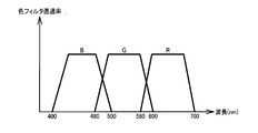
- FIG. 5 shows an example of spectral characteristics of the color filter.
- FIG. 6 is a detailed configuration example of the image processing unit according to the first embodiment.
- FIG. 7 shows a detailed configuration example of the gradation conversion unit.
- FIG. 8 is an explanatory diagram of processing performed by the attention area setting unit.
- FIGS. 9A and 9B are explanatory diagrams of processing performed by the attention area setting unit.
- FIG. 10 is an explanatory diagram of processing performed by the attention area setting unit.
- FIG. 11 is an explanatory diagram of processing performed by the attention area setting unit.
- FIG. 12 is an explanatory diagram of processing performed by the attention area setting unit.
- FIG. 13 is an explanatory diagram of processing performed by the attention area setting unit.
- FIG. 14 is a modified configuration example of the image processing unit.
- FIG. 15 is an explanatory diagram of processing performed by the scaling processing unit.
- FIG. 16 is a configuration example of an endoscope apparatus according to the second embodiment.
- FIG. 17 is a detailed configuration example of an image processing unit according to the second embodiment.
- FIG. 18 is an explanatory diagram of processing performed by the attention area setting unit according to the second embodiment.
- FIG. 19 is a configuration example of an endoscope apparatus according to the third embodiment.
- FIG. 16 is a configuration example of an endoscope apparatus according to the second embodiment.
- FIG. 17 is a detailed configuration example of an image processing unit according to the second embodiment.
- FIG. 18 is an explanatory diagram of processing performed by the attention area setting unit
- FIG. 20 is a detailed configuration example of a state information acquisition unit according to the third embodiment.
- FIG. 21A to FIG. 21C are explanatory diagrams of the bending operation.
- FIG. 22 is a detailed configuration example of an image processing unit according to the third embodiment.
- FIG. 23 is a configuration example of an endoscope apparatus according to the fourth embodiment.
- FIGS. 24A to 24D are explanatory diagrams of the distance estimation method.
- FIG. 25 is a modified configuration example of the endoscope apparatus.
- FIG. 26 is a detailed configuration example of an attention area setting unit in the fifth embodiment.
- FIG. 27 is an explanatory diagram of processing performed by the attention area setting unit according to the fifth embodiment.
- FIG. 28 is an explanatory diagram of a modification of the fifth embodiment.
- FIG. 29 is a configuration example of an endoscope apparatus according to the sixth embodiment.
- FIG. 30 is a configuration example of a color filter of the second image sensor.
- FIG. 31 shows an example of transmittance characteristics of the color filter of the second image sensor.
- FIG. 32 is a detailed configuration example of an image processing unit according to the sixth embodiment.
- FIG. 33 is an example of a single plate image signal imaged by the second image sensor.
- FIG. 34 is a detailed configuration example of an attention area setting unit in the sixth embodiment.
- FIG. 35 shows an example of setting a local region.
- FIG. 36 is an explanatory diagram of processing performed by the attention area setting unit according to the sixth embodiment.
- FIG. 37 is a configuration example of an endoscope apparatus according to the seventh embodiment.
- FIG. 30 is a configuration example of a color filter of the second image sensor.
- FIG. 31 shows an example of transmittance characteristics of the color filter of the second image sensor.
- FIG. 32 is a detailed configuration example of an image processing unit
- FIG. 38 is a detailed configuration example of an image processing unit according to the seventh embodiment.
- FIG. 39 is a detailed configuration example of an attention area setting unit according to the eighth embodiment.
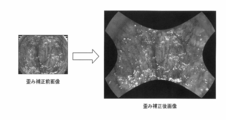
- FIG. 40 shows examples of images before and after distortion correction processing.
- FIG. 41 shows an example of setting representative points.
- 42 (A) to 42 (D) are explanatory views of the removal state determination method.
- FIG. 43 is a configuration example of an endoscope apparatus according to the ninth embodiment.
- FIG. 44 is a detailed configuration example of a state information acquisition unit according to the ninth embodiment.
- FIG. 45 is an explanatory diagram of the red ball region.
- FIG. 46A is an explanatory diagram of the red ball region.
- FIG. 46B is an explanatory diagram of the scaling process in the tenth embodiment.
- FIG. 47 is a detailed configuration example of an image processing unit according to the tenth embodiment.
- FIG. 48 is a detailed configuration example of an attention area setting unit according to the tenth embodiment.
- FIG. 49 is an explanatory diagram of processing performed by the attention area setting unit according to the tenth embodiment.
- FIG. 50 is a detailed configuration example of the red ball region candidate detection unit.
- FIG. 51 is a detailed configuration example of a defocus detection unit.
- FIG. 52 is an explanatory diagram of processing performed by the attention area setting unit according to the tenth embodiment.
- FIG. 53 shows a detailed configuration example of the scaling parameter setting unit.
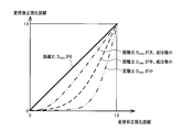
- FIG. 54 is an example of a correspondence curve of a plurality of normalized distances after scaling with respect to a normalized distance before scaling.
- Patent Document 1 discloses an objective optical system capable of observing the front field and the side field of the scope tip.
- FIG. 1 shows a configuration example of the objective optical system.
- the light beam LC1 from the front visual field enters from the surface SF1
- the light beam LC2 from the side visual field enters from the surface SF3.
- These light rays LC1 and LC2 are refracted or reflected by the surfaces SF1 and SF2, thereby forming an image of the front field and the side field.
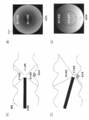
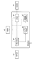
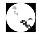
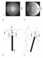
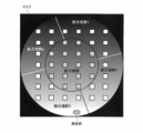
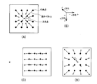
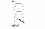
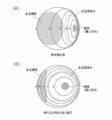
- the inside of the body cavity can be observed with a wider field of view than the conventional endoscope apparatus. That is, as shown in FIG. 2A, when a lesion is screened in a luminal organ, observation is performed while the scope is parallel to the axial direction of the organ and the scope is inserted or removed. When there is a lateral visual field, it is possible to observe the lesioned part behind the folds, so that the oversight of the lesion can be reduced.
- FIG. 2A when the endoscope imaging unit is located at the center of the luminal organ, the distance from the endoscope imaging unit to the subject differs between the front visual field and the side visual field. Therefore, as shown in FIG. 2B, a difference in brightness occurs for each region in the image. Further, as shown in FIG. 2C, it is assumed that the distal end of the endoscope is brought close to the wall surface of the organ in order to observe a lesion portion existing on the wall surface of the luminal organ. Then, as shown in FIG. 2D, the attention area (for example, a lesion) causes halation. In such an image, it is difficult to perform appropriate observation and treatment on the region that the operator wants to pay attention to.
- the attention area for example, a lesion
- Patent Document 2 discloses a dimming processing method that calculates a luminance average value for pixels in an effective region from a scope mask shape and maintains the brightness of a subject image.
- the average value of the entire effective area can take an appropriate value, but the light cannot be dimmed for each area in the image. Therefore, when a difference in brightness occurs in each region, the region that the operator wants to pay attention to cannot be adjusted to an appropriate brightness.
- Patent Document 3 discloses a technique for securing a good light distribution by disposing light guides on at least three sides of an imaging surface of an imaging element in an endoscope apparatus that acquires a wide-angle image. .
- a region of interest is set in the captured image based on information (for example, a captured image) from the endoscope apparatus, and the light control is performed using the region of interest as a light control target region. I do.
- information for example, a captured image
- the light control is performed using the region of interest as a light control target region. I do.
- the brightness average value is calculated using the entire image as a photometric area, and the light source light quantity is adjusted so that the brightness average value approaches the target value. Maintain the properness.
- the luminance average value is calculated using the attention area as the photometry area, even if the brightness is biased as shown in FIG. Brightness can be maintained.
- Light Control Processing A conventional light control processing will be described in detail.
- photometry processing for measuring the brightness of the subject is performed.
- the average value of the luminance signals in the image signals for one frame or one field sequentially obtained from the image sensor is calculated.
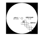
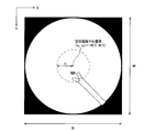
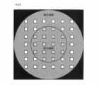
- the effective area of the image signal is generally used as the photometric area.
- the effective area of the image signal indicates a front area and a side area obtained by removing the mask area from the image signal shown in FIG.
- the measured brightness of the subject is adjusted to the target brightness. Specifically, by controlling the aperture of the light source to adjust the light amount, the brightness of the photometric subject is matched with the target brightness.
- the above-mentioned luminance average value is temporarily lower than the luminance reference value (target brightness). At this time, the light source aperture is widened to increase the amount of illumination light.
- the above-mentioned luminance average value is higher than the luminance reference value (target brightness). Is narrowed and the amount of illumination light is reduced.
- the brightness of the image signal is adjusted by applying a digital gain to the image signal. In this way, the image signal is maintained in an appropriate state corresponding to the luminance reference value regardless of the distance of the subject.
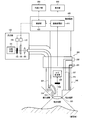
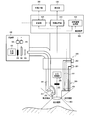
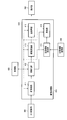
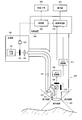
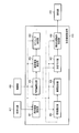
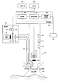
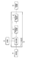
- FIG. 3 shows a configuration example of the endoscope apparatus according to the first embodiment.
- the endoscope apparatus includes a light source unit 100, an operation unit 200, an insertion unit 300, a control device 400 (processor unit), a display unit 500, and an external I / F unit 550.
- the light source unit 100 includes a white light source 101, a light source stop 102, a light source stop driving unit 103 for driving the light source stop 102, and a rotating color filter 104 having a plurality of spectral transmittance filters.
- the light source unit 100 includes a rotation driving unit 105 that drives the rotation color filter 104 and a condensing lens 106 that condenses the light transmitted through the rotation color filter 104 on the incident end face of the light guide fiber 301.
- the light source aperture driving unit 103 adjusts the amount of light by opening and closing the light source aperture 102 based on a control signal from the control unit 420 of the control device 400.
- FIG. 4 shows a detailed configuration example of the rotating color filter 104.
- the rotation color filter 104 includes three primary color red (hereinafter abbreviated as R) filter 701, green (hereinafter abbreviated as G) filter 702, blue (hereinafter abbreviated as B) filter 703, and a rotary motor 704. Yes.
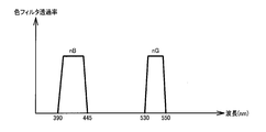
- FIG. 5 shows an example of spectral characteristics of these color filters 701 to 703.
- the rotation driving unit 105 rotates the rotating color filter 104 at a predetermined number of rotations in synchronization with the imaging period of the imaging element 304 based on a control signal from the control unit 420. For example, if the rotating color filter 104 is rotated 20 times per second, each color filter crosses incident white light at 1/60 second intervals. In this case, the image sensor 304 completes imaging and transfer of image signals at 1/60 second intervals.
- the image sensor 304 is, for example, a monochrome image sensor. That is, in the present embodiment, frame sequential imaging is performed in which images of light of each of the three primary colors (R, G, or B) are captured at 1/60 second intervals.
- the operation unit 200 is provided with a bending operation lever 201 that performs a bending operation of the insertion unit 300 and an insertion port 202 into which a treatment instrument such as a forceps is inserted.
- the bending operation lever 201 is connected to the bending operation wire 306.
- the bending operation wire 306 is inserted through the insertion portion 300 and fixed to the distal end of the insertion portion 300.
- the surgeon operates the bending operation lever 201 to pull or relax the bending operation wire 306 to bend the insertion portion 300.
- the insertion port 202 communicates with an insertion channel 307 through which the treatment tool is inserted.
- the insertion portion 300 is formed to be elongate and bendable, for example, to enable insertion into a body cavity.
- the insertion unit 300 diffuses the light guide fiber 301 for guiding the light collected by the light source unit 100 to the illumination lenses 314 and 315 and the light guided to the tip by the light guide fiber 301 to be an observation target.
- illumination lenses 314 and 315 for irradiating.
- the illumination lens 314 is a lens for illuminating the observation object with the front visual field
- the illumination lens 315 is a lens for illuminating the observation object with the lateral visual field.
- the insertion unit 300 also includes an objective optical system 303 that collects reflected light returning from the observation target, an image sensor 304 that detects the collected reflected light, and an analog image obtained by photoelectric conversion of the image sensor 304.
- An A / D conversion unit 305 that converts the signal into a digital image signal.
- the insertion unit 300 includes a bending operation wire 306 that is inserted through the insertion unit 300 and is fixed to the distal end portion, and an insertion channel 307 through which the treatment instrument inserted by the operation unit 200 is inserted.
- the objective optical system 303 protrudes from the distal end portion of the insertion portion 300 and forms an image of the front field and the side field.
- the objective optical system 303 has a viewing angle of 230 °.
- the image sensor 304 is, for example, a monochrome single-plate image sensor, and is configured by, for example, a CCD or a CMOS image sensor.
- the control device 400 controls each part of the endoscope device and performs image processing.
- the control device 400 includes an image processing unit 410 that performs setting of a region of interest and photometry processing, and a control unit 420.
- the image signal converted into a digital signal by the A / D conversion unit 305 is transferred to the image processing unit 410.
- the image signal processed by the image processing unit 410 is transferred to the display unit 500.
- the control unit 420 controls each unit of the endoscope apparatus. Specifically, the control unit 420 is connected to the light source aperture driving unit 103, the rotation driving unit 105, the image processing unit 410, and the external I / F unit 550, and performs these controls.
- the display unit 500 is a display device capable of displaying a moving image, and includes, for example, a CRT or a liquid crystal monitor.
- the external I / F unit 550 is an interface for performing input from the user to the endoscope apparatus.
- the external I / F unit 550 includes, for example, a power switch for turning on / off the power, a mode switching button for switching a photographing mode and other various modes.
- the external I / F unit 550 transfers the input information to the control unit 420.
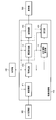
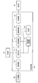
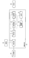
- FIG. 6 shows a detailed configuration example of the image processing unit 410 in the first embodiment.
- the image processing unit 410 includes a preprocessing unit 411, a synchronization unit 412, an attention area setting unit 413, a post-processing unit 415, a photometry unit 416, and a gradation conversion unit 419.
- the A / D conversion unit 305 is connected to the preprocessing unit 411.
- the preprocessing unit 411 is connected to the synchronization unit 412.
- the synchronization unit 412 is connected to the gradation conversion unit 419, the attention area setting unit 413, and the photometry unit 416.
- the tone conversion unit 419 is connected to the post-processing unit 415.
- the post-processing unit 415 is connected to the display unit 500.
- the attention area setting unit 413 is connected to the photometry unit 416.
- the control unit 420 is bidirectionally connected to the preprocessing unit 411, the synchronization unit 412, the gradation conversion unit 419, the post-processing unit 415, the attention area setting unit 413, and the photometry unit 416. These are designed to control.
- the preprocessing unit 411 uses the OB clamp value, the WB coefficient value, and the noise reduction coefficient value stored in advance in the control unit 420 for the image signal input from the A / D conversion unit 305 to perform OB clamp processing. , WB correction processing and noise reduction processing are performed.
- the preprocessing unit 411 transfers the preprocessed image signal to the synchronization unit 412.
- the synchronizer 412 synchronizes the frame sequential image signal with the image signal processed by the preprocessor 411 based on the control signal of the controller 420. Specifically, the synchronization unit 412 accumulates image signals of each color light (R, G, or B) input in frame order for each frame, and simultaneously reads the accumulated image signals of each color light. The synchronization unit 412 transfers the synchronized image signal to the attention area setting unit 413 and the photometry unit 416.
- the gradation conversion unit 419 performs gradation conversion processing on the synchronized image.
- the gradation conversion process is a process for flattening a histogram of pixel values of the entire image, for example. Specifically, the gradation conversion unit 419 divides an image into a plurality of areas, obtains gradation conversion characteristics of each divided area, and performs gradation conversion of each divided area based on the gradation conversion characteristics. The processing performed by the tone conversion unit 419 will be described later in detail.
- the attention area setting unit 413 sets the attention area based on the image signal subjected to the synchronization processing. Specifically, the attention area setting unit 413 detects an area where the treatment instrument is imaged, and sets a peripheral area at the tip of the treatment instrument as the attention area. The processing performed by the attention area setting unit 413 will be described in detail later.
- the photometry unit 416 calculates the average luminance value (brightness information in a broad sense) of the subject in the set attention area, and transfers the calculated average luminance value to the control unit 420.
- the control unit 420 adjusts the aperture area of the light source stop 102 by controlling the light source stop drive unit 103 based on the average luminance value from the photometry unit 416. The light control performed by the photometry unit 416 and the control unit 420 will be described later in detail.
- the post-processing unit 415 performs color processing, contour enhancement processing, and enlargement processing on the image after the gradation conversion processing using the color conversion coefficient, the contour enhancement coefficient, and the enlargement factor that are stored in the control unit 420 in advance. Do.
- the post-processing unit 415 transfers the post-processed image signal to the display unit 500.
- FIG. 7 shows a detailed configuration example of the gradation conversion unit 419.
- the gradation conversion unit 419 includes an area dividing unit 445, a histogram calculation unit 446, a gradation conversion characteristic calculation unit 447, and a conversion unit 448.
- the image signal from the synchronization unit 412 is input to the region dividing unit 445.
- the area dividing unit 445 is connected to the histogram calculating unit 446 and the converting unit 448.
- the histogram calculation unit 446 is connected to the gradation conversion characteristic calculation unit 447.
- the gradation conversion characteristic calculation unit 447 is connected to the conversion unit 448.
- the conversion unit 448 is connected to the post-processing unit 415.
- the control unit 420 is connected to the region dividing unit 445, the histogram calculation unit 446, the gradation conversion characteristic calculation unit 447, and the conversion unit 448, and performs these controls.
- the gradation conversion unit 419 performs gradation conversion processing for each area of the image signal.
- the region dividing unit 445 divides the input image signal (maximum value image signal) into local regions.
- the area dividing unit 445 divides the image signal into rectangular areas of a predetermined size, and sets each divided rectangular area as a local area.
- the size of the rectangular area is 16 ⁇ 16 pixels, but is not limited thereto, and can be set as appropriate.
- the area dividing unit 445 outputs the divided local areas to the histogram calculating unit 446 and the converting unit 448.
- the region dividing method is not limited to the above method. For example, a known area dividing method represented by texture analysis may be applied to divide the area.
- the histogram calculation unit 446 calculates a histogram (pixel value histogram) of each input local region, and outputs the calculated histogram of each local region to the gradation conversion characteristic calculation unit 447.
- the gradation conversion characteristic calculation unit 447 calculates a cumulative histogram of local regions based on the input local region histogram. In the following, processing for one local region will be described, but the same processing is performed for each local region.
- the gradation conversion characteristic calculation unit 447 normalizes the accumulated histogram so that the maximum value of the obtained accumulated histogram matches the output gradation width of the conversion unit 448.
- the gradation conversion characteristic calculation unit 447 outputs the normalized cumulative histogram to the conversion unit 448 as the local area gradation conversion characteristic.
- the conversion unit 448 performs the gradation conversion process by applying the gradation conversion characteristic input from the gradation conversion characteristic calculation unit 447 to the local region input from the region dividing unit 445.
- the conversion unit 448 returns each of the gradation-converted local regions to an image signal for one frame, and outputs the image signal to the post-processing unit 415.
- the attention area setting unit 413 detects a treatment instrument area composed of pixels having an image of the treatment instrument from the image signal subjected to the synchronization processing, and sets the attention area based on the detected treatment instrument area.
- a treatment instrument area composed of pixels having an image of the treatment instrument from the image signal subjected to the synchronization processing, and sets the attention area based on the detected treatment instrument area.
- a highly reflective metal treatment tool such as forceps
- the luminance signal value of the treatment tool is sufficiently larger than that of the organ. Therefore, a high luminance area in the image signal is detected as a treatment instrument area.
- the luminance signal value Y (x, y) of the pixel of interest is calculated by the following equation (1), where the coordinate of the pixel of interest (processing target pixel) is (x, y).
- R (x, y), G (x, y), and B (x, y) are image signals of respective colors at coordinates (x, y).
- the average value Yave (x, y) of the luminance values from the coordinates (x ⁇ a, y) to the coordinates (x ⁇ 1, y) on the left side of the target pixel is expressed by the following formula ( 2).
- the image signal is assumed to be N ⁇ M pixels.
- the coordinate located at the upper left of the image signal is (0, 0)
- the right direction is the positive direction of the X axis
- the lower direction is the positive direction of the Y axis.
- the X axis is an axis along the horizontal scanning line
- the Y axis is an axis orthogonal to the X axis.
- a is a constant and is set according to the horizontal width N of the image signal.
- the constant a is set to 3% of the horizontal width N of the image signal.
- Yp is a value preset as a parameter.
- a pixel for which the above expression (3) is satisfied is a treatment tool candidate pixel.
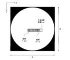
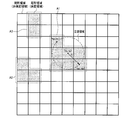
- FIG. 9A in the case of an image signal including a treatment tool and an image of a bright spot, a treatment tool candidate pixel is detected as shown in FIG. 9B.
- an area where a plurality of treatment tool candidate pixels are adjacent is extracted as a treatment tool candidate area.
- the image signal is searched from the upper left, the value of the target pixel (x, y) is “treatment tool candidate pixel”, and the left (x ⁇ 1, y) and upper left (x ⁇ 1) of the target pixel.
- Y ⁇ 1), upper (x, y ⁇ 1), and upper right (x + 1, y ⁇ 1), the pixel of interest “not a treatment tool candidate pixel” is set as the start point pixel.
- the hatched pixel corresponds to the start point pixel.
- a treatment tool candidate pixel is searched counterclockwise from the lower left (x-1, y-1) of the start point pixel (x, y).
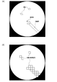
- the treatment tool candidate pixel is searched from the next start point pixel.
- the treatment tool candidate pixel is searched again counterclockwise from the periphery of the detected treatment tool candidate pixel. The search is continued until the detected treatment tool candidate pixel returns to the start point pixel again. If the Y coordinate of the treatment tool candidate pixel becomes smaller than the start point pixel during the search, the search is terminated and the next start point pixel is searched.
- FIG. 11 when the treatment tool candidate pixel returns to the start point pixel again, a region surrounded by the detected treatment tool candidate pixels is set as a treatment tool candidate region.
- hatched pixels are treatment tool candidate pixels detected by the search.
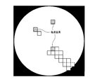
- the region having the largest number of pixels is extracted.
- the region is set as a treatment tool region.
- the image signal is determined as “there is no treatment tool”. Do not set the treatment tool area. For example, as shown in FIG.
- the treatment tool candidate area 2 when the number of pixels included in the treatment tool candidate area 2 is the largest, it is determined whether or not the number of treatment tool candidate pixels included in the treatment tool candidate area 2 is larger than a preset threshold value. judge. When larger than the threshold value, the treatment tool candidate area 2 is set as the treatment tool area.
- an area corresponding to the distal end of the treatment instrument is extracted from the treatment instrument area, and the area is set as the treatment instrument distal end pixel.
- a pixel closest to the center of the image is extracted from the pixels included in the treatment instrument region as the treatment instrument tip pixel.
- the coordinates of the image center are (N / 2, M / 2)
- the coordinates of the treatment instrument tip pixel are (x 0 , y 0 ).
- a plurality of pixels close to the coordinates (N / 2, M / 2) of the image center are selected from the pixels included in the treatment instrument region and selected.
- the center of gravity of the plurality of pixels may be used as the treatment instrument tip pixel.
- a pixel inside a circle with a radius R centering on the treatment instrument tip pixel (x 0 , y 0 ) is set as a region of interest.
- the radius R is a constant and is set according to the horizontal width N of the image signal.
- the radius R is set to 10% of the horizontal width N of the image signal.
- the attention area setting section 413 transfers the set attention area and the central pixel (x 0 , y 0 ) to the photometry section 416.
- the radius R is a constant.
- the present embodiment is not limited to this, and for example, the radius R is determined between the region of interest (x 0 , y 0 ) and the image center (N / 2, M / 2). It is good also as a variable which changes according to the distance L.
- a distance L between the center (x 0 , y 0 ) of the attention area and the image center (N / 2, M / 2) is calculated by the following equation (5).
- the attention area is a circle centered on the coordinates (x 0 , y 0 ).
- the present embodiment is not limited to this.
- the attention area is centered on the coordinates (x 0 , y 0 ). It may be a rectangle or an ellipse.
- the photometry unit 416 calculates the brightness of the subject from the image signal based on the control signal of the control unit 420. Specifically, when the attention area is set by the attention area setting section 413, the photometry section 416 calculates the average luminance value of the attention area from the image signal input from the synchronization section 412. On the other hand, when the attention area is not set by the attention area setting section 413, the photometry section 416 calculates the average brightness value of the effective pixel area of the image signal input from the synchronization section 412. The photometric unit 416 transfers the calculated average brightness value to the control unit 420 as the photometric value Yd.
- the method for calculating the brightness of the subject is not limited to the above method.
- the luminance average value of the attention area and the luminance average value of the area other than the attention area are multiplied by different weighting factors, and the weighted average value is calculated. It may be calculated as the brightness of the subject. In this case, a larger coefficient is set as the weighting coefficient of the attention area than the weighting coefficients other than the attention area.
- the control unit 420 calculates the light source aperture adjustment coefficient Lc by the following equation (6) using the photometric value Yd calculated by the photometric unit 416 and the preset target brightness Ybase.
- the control unit 420 controls the aperture of the light source aperture 102 by controlling the light source aperture driving unit 103 using the calculated light source aperture adjustment coefficient Lc.
- the brightness of the lesioned part present around the treatment tool can be maintained at an optimum brightness. Thereby, the observation performance of a lesioned part can be improved and an image suitable for treatment can be obtained.
- FIG. 14 shows a modified configuration example of the image processing unit 410 when the scaling process is performed.
- the image processing unit 410 includes a preprocessing unit 411, a synchronization unit 412, an attention area setting unit 413, a scaling processing unit 414, a post-processing unit 415, a photometry unit 416, and a gradation conversion unit 419.
- symbol is attached
- the scaling processing unit 414 performs image scaling processing while maintaining (substantially maintaining) the angle of view, and enlarges the region of interest. Specifically, the scaling processing unit 414 performs a process of expanding the attention area and reducing other areas. Alternatively, only the process of enlarging the attention area at a predetermined magnification may be performed.
- the scaling processing unit 414 locally scales the image signal based on the set attention area and the center pixel (x 0 , y 0 ).
- the scaling process is not performed, and the input image signal is output to the post-processing unit 415 as it is.
- the scaling processing unit 414 enlarges the region of interest at an enlargement ratio ⁇ (magnification in a broad sense) and superimposes the enlarged image on the original image. Specifically, the center of the circle is enlarged in the radial direction at an enlargement ratio ⁇ , and the center of the enlarged circle area is overlapped with the center pixel (x 0 , y 0 ) of the original attention area.
- the attention area after enlargement is referred to as an enlargement area.
- a coordinate (x ′, y ′) obtained by converting the pixel of the coordinate (x, y) by ⁇ times is calculated by the following equation (7).
- the enlargement ratio ⁇ is not limited to a fixed constant, and may be freely input by an operator from the outside. As shown in FIG. 14, the enlargement ratio ⁇ may be a variable that changes according to the distance L between the center (x 0 , y 0 ) of the region of interest and the image center (N / 2, M / 2). .
- the scaling processing unit 414 generates an interpolation pixel at a pixel position included in the enlargement area in the enlargement process. Specifically, linear interpolation is performed on the pixel positions in the enlarged region using the four neighboring pixels after the coordinate conversion by the above equation (7).
- the interpolation processing is not limited to linear interpolation, and for example, an interpolation method such as a nearest neighbor method or a cubic convolution interpolation method (bicubic) may be used.
- the scaling processing unit 414 provides a reduced area outside the above-described enlarged area, and performs a process of reducing and converting the reduced area.
- the reduced area is an area inside the radius R s with the coordinates (x 0 , y 0 ) as the center, and is an area outside the enlarged area.
- Scaling section 414 reduced by the circle and the radius R s reduction rate region between a circle of radius R beta (magnification in a broad sense).
- the reduction ratio ⁇ is a variable that changes according to the distance rd between the processing target pixel (x, y) and the center coordinates (x 0 , y 0 ).
- the distance rd is calculated by the following equation (8).
- the scaling processing unit 414 generates an interpolation pixel at a pixel position included in the reduced area in the reduction process. Specifically, linear interpolation is performed on the pixel position in the reduced region using the pixels that have been reduced at the reduction rate ⁇ .
- the interpolation processing is not limited to linear interpolation, and for example, an interpolation method such as a nearest neighbor method or a cubic convolution interpolation method (bicubic) may be used.
- the attention area can be enlarged while maintaining the angle of view, so that the visibility of the attention area can be improved while ensuring a wide field of view necessary for scope operation and the like.
- the continuity of the image is maintained at the boundary portion of the enlarged area, so that it is possible to obtain an image signal that has been subjected to the scaling process without any sense of incongruity.
- the embodiment is not limited thereto, for example, all outer expansion region may be reduced region.
- the reduction ratio ⁇ decreases toward the edge of the image, and the enlargement ratio is 1 at the edge of the image.
- the reduced area is provided.
- the present embodiment is not limited to this.
- only the enlarged area may be provided and enlarged at the magnification ⁇ , and the enlarged area may be superimposed on the original image.
- the endoscope apparatus includes an image acquisition unit (for example, A / D conversion unit 305), an attention area setting unit 413, and a dimming control unit (in a broad sense, a light amount). Control unit).
- the image acquisition unit acquires a captured image including a subject image.
- the attention area setting unit 413 sets an attention area for the captured image based on information from the endoscope apparatus.
- the dimming control unit performs dimming control of the amount of illumination light based on the set attention area.
- the attention area can be set based on information from the endoscope apparatus, and the brightness of the attention area can be controlled by dimming. Thereby, the surgeon can observe the region of interest with appropriate brightness, and can perform appropriate diagnosis and treatment.
- the photometry unit 416 and the control unit 420 correspond to the dimming control unit.
- the photometry unit 416 performs photometry processing of the set attention area
- the control unit 420 controls the dimming control by controlling the amount of light emitted from the light source unit 100 based on the result of the photometry processing. Do.
- the information from the endoscope apparatus is information acquired by each unit of the endoscope apparatus, and controls, for example, a captured image by the imaging unit, a signal obtained by processing the captured image, and each unit. These are control signals and sensing signals from various sensors provided in the endoscope apparatus.
- the attention area is an area where the priority of observation for the user is relatively higher than other areas. For example, if the user is a doctor and desires treatment, a mucous membrane part or a lesion part is copied. Refers to an area. As another example, if the object that the doctor desires to observe is a bubble or stool, the region of interest is a region in which the bubble or stool portion is copied. In other words, the object that the user should pay attention to depends on the purpose of observation, but in any case, in the observation, the region where the priority of observation for the user is relatively higher than other regions becomes the region of interest. .
- the dimming control unit calculates brightness information (photometric value Yd, for example, luminance average value) indicating the brightness of the attention area. Dimming control is performed based on the brightness information.
- the dimming control unit performs dimming control so that the brightness of the attention area becomes a predetermined brightness (target brightness information Ybase, for example, a target luminance value). For example, the dimming control unit performs dimming control so that the brightness of the attention area matches a predetermined brightness.
- target brightness information Ybase for example, a target luminance value
- the brightness of the attention area can be brought close to the target brightness by dimming control, and the attention area can be maintained at an appropriate constant brightness.
- the attention area setting unit 413 sets the attention area using the captured image as information from the endoscope apparatus.
- the attention area setting unit 413 has a treatment instrument detection unit (not shown). As described with reference to FIG. 13 and the like, the treatment instrument detection unit detects a treatment instrument region in which a treatment instrument for performing treatment on a subject is imaged based on the captured image. The attention area setting unit 413 sets an attention area based on the detected treatment instrument area.
- the treatment instrument detection unit detects the tip of the treatment instrument region.
- the attention area setting unit 413 sets an attention area within a circle having a predetermined radius from the detected tip.
- the treatment instrument detection unit detects the pixel closest to the center (N / 2, M / 2) of the captured image among the pixels included in the treatment instrument region (the treatment instrument). Set to the tool tip pixel (x 0 , y 0 )).
- the circle (circular region) set as the attention region is not limited to a perfect circle, and may be a circular region.
- an ellipse or the like may be used.
- the treatment instrument detection unit includes a luminance feature amount calculation unit (not shown).
- the luminance feature amount calculation unit calculates a luminance feature amount (for example, a luminance signal value Y (x, y)) related to the luminance of the pixel of the captured image.
- the treatment tool detection unit detects a treatment tool region based on the calculated luminance feature amount.
- the treatment instrument detection unit detects a treatment instrument candidate pixel that is a candidate for the treatment instrument region based on the luminance feature amount, and detects the detected treatment instrument candidate pixel.
- the treatment tool region is determined based on the above.
- the treatment instrument detection unit has a comparison unit (not shown). As described with reference to FIG. 8 and the like, the comparison unit performs the luminance feature amount (luminance signal value Y (x, y)) of the processing target pixel and the average luminance feature amount (average value Yave (x) of peripheral pixels of the processing target pixel. , Y)). The treatment instrument detection unit sets a pixel whose luminance feature amount is larger than the average luminance feature amount as a treatment instrument candidate pixel.
- the treatment tool is made of metal or the like and has a high reflectance of illumination light, the treatment tool is picked up as an image with higher brightness than other subjects. Therefore, the treatment tool can be detected from the image by setting the treatment tool candidate pixel based on the luminance feature amount.
- the treatment instrument detection unit determines that the treatment instrument candidate pixel is one or more treatment instrument candidate areas (for example, a treatment instrument candidate area) based on the position information of the treatment instrument candidate pixels. 1 and 2) (for example, by a classifying unit (not shown)).
- the treatment tool detection unit selects a treatment tool region from the one or more treatment tool candidate regions.
- the treatment tool detection unit extracts a pixel that is a boundary between the treatment tool candidate region and another region from the treatment tool candidate pixels, and the treatment tool candidate pixel surrounded by the boundary is extracted from the treatment tool candidate region. 1 or a plurality of treatment tool candidate areas are set.
- the treatment tool detection unit determines the treatment tool region based on the number of treatment tool candidate pixels included in each treatment tool candidate region.
- the treatment tool detection unit is an area including the largest number of treatment tool candidate pixels in one or a plurality of treatment tool candidate areas, and has more treatment tool candidate pixels than a predetermined threshold (TH t ).
- a region including the treatment tool candidate region 2 is determined as a treatment tool region.
- the endoscope apparatus may include a scaling unit 414.
- the scaling processing unit 414 performs local scaling processing that enlarges the region of interest relatively than other regions.
- the region of interest can be enlarged relative to other regions, so that more detailed information can be obtained even for minute lesions, and appropriate diagnosis and treatment can be performed on the region of interest. Is possible.
- the scaling processing unit 414 performs local scaling processing while maintaining the angle of view of the captured image.
- maintaining the angle of view means that the range of the subject displayed in the image is not changed by the scaling process.
- the angle of view does not need to be strictly maintained, and may be maintained substantially.
- the light source part 100, the 1st irradiation part (illumination lens 314), and the 2nd irradiation part (illumination lens 315) are included.
- the first irradiating unit irradiates light emitted from one light source unit 100 in a first direction (for example, a direction along the optical axis of the objective optical system).
- the second irradiation unit irradiates light emitted from one light source unit 100 in a second direction (for example, a direction at a predetermined angle with respect to the optical axis of the objective optical system).
- the dimming control unit performs dimming control by controlling the amount of light emitted from one light source unit 100.
- the first direction is the direction of the forward visual field of the scope (insertion unit 300), and the second direction is the direction of the lateral visual field of the scope.
- the image acquisition unit acquires a captured image including subject images of a front visual field and a side visual field.
- the attention area may not be appropriately dimmed.
- the attention area can be adjusted to an appropriate brightness.
- the image acquisition unit acquires a captured image in which the front visual field and the lateral visual field at the distal end of the scope (insertion unit 300) are captured.
- the captured image is an image obtained by an objective optical system that forms an image of the front field and the side field.
- the objective optical system has a viewing angle greater than 180 ° (for example, a viewing angle of 230 °).
- the objective optical system is not limited to the objective lens but may be a reflective optical system, or may be an optical system in which a lens and a reflective optical system are combined as shown in FIG. In addition, it is not limited to the objective optical system of FIG. 1, You may use the fisheye lens which a viewing angle exceeds 180 degrees.
- the front visual field is a visual field range including the optical axis direction of the objective optical system, for example, a range of 0 to 45 degrees with respect to the optical axis.
- the side view is a view range including a direction orthogonal to the optical axis, and is, for example, a range of 45 degrees to 135 degrees with respect to the optical axis.
- the objective optical system 303 of the present embodiment has a visual field range of 0 degree to 115 degrees with respect to the optical axis, for example.
- Second Embodiment A second embodiment that senses insertion of a treatment tool and sets a region of interest will be described.
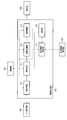
- FIG. 16 shows a configuration example of the endoscope apparatus according to the second embodiment.
- the endoscope apparatus includes a light source unit 100, an operation unit 200, an insertion unit 300, a control device 400, a display unit 500, and an external I / F unit 550.
- symbol is attached
- the insertion unit 300 includes a treatment instrument sensor 308.
- the treatment instrument sensor 308 is provided in the insertion channel 307.
- the treatment instrument sensor 308 detects a treatment instrument that has passed through the insertion channel 307 and protruded forward of the insertion portion 300.
- the treatment instrument sensor 308 is connected to a state information acquisition unit 430 described later.
- the control device 400 includes a state information acquisition unit 430.
- the state information acquisition unit 430 is connected to the image processing unit 410.
- the control unit 420 is bidirectionally connected to the state information acquisition unit 430.
- the state information acquisition unit 430 sends a control signal indicating that “the treatment instrument is present in the image signal” to the image processing unit. 410.
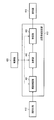
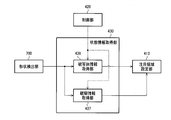
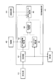
- FIG. 17 shows a detailed configuration example of the image processing unit 410 in the second embodiment.
- the state information acquisition unit 430 is connected to the attention area setting unit 413.
- the processing performed by the attention area setting unit 413 is different from that in the first embodiment.
- the attention area setting unit 413 sets the attention area in the image signal when receiving the control signal indicating that “the treatment tool is present in the image signal” from the state information acquisition unit 430.
- the center of the image N / 2, M / 2
- an area within the radius R (including the value) from the center of the attention area is set as the attention area.
- the attention area setting section 413 transfers the set attention area to the photometry section 416.
- the center of the attention area is not limited to the image center (N / 2, M / 2), and may be set in advance depending on the relative positional relationship between the image sensor and the insertion channel.
- the region of interest may be set on the Y axis positive direction side of the image center.
- the endoscope apparatus includes the state information acquisition unit 430 that acquires the state information of the endoscope apparatus.
- the attention area setting unit 413 sets the attention area using the state information as information from the endoscope apparatus.
- the state information acquisition unit 430 detects whether or not a treatment tool for performing treatment on the subject protrudes from the distal end of the scope (detected based on the sensing signal of the treatment tool sensor 308), The detection result is acquired as state information.
- the attention area setting unit 413 sets the attention area based on the detection result.
- the attention area setting unit 413 inserts the treatment tool from the center area of the captured image or the center of the captured image when the protrusion of the treatment tool is detected.
- a region on the side (for example, a region on the Y axis positive direction side of the image center) is set as a region of interest.
- the attention area can be set, and the brightness of the attention area can be dimmed. Further, the image center or the lower part of the image where the surgeon normally positions the lesion can be set as the attention area. As a result, it becomes possible to display the lesion area to be treated with appropriate brightness regardless of the image quality of the image signal, and an image suitable for the surgeon's treatment can be obtained.
- the state information of the endoscope apparatus is information representing the state of each part of the endoscope apparatus. For example, information such as a traveling direction of a scope obtained by processing a captured image and the state of each part are controlled. And a sensing signal by various sensors that sense the state of each part.
- Third Embodiment 4.1 Endoscope Device A third embodiment in which a region of interest is set based on a bending angle or a bending movement amount of a scope will be described.
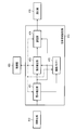
- FIG. 19 shows a configuration example of the endoscope apparatus according to the third embodiment.
- the endoscope apparatus includes a light source unit 100, an operation unit 200, an insertion unit 300, a control device 400, a display unit 500, and an external I / F unit 550.
- symbol is attached
- the light source unit 100 includes a white light source 101, a light source aperture 102, a light source aperture drive unit 103, and a condenser lens 106.
- the operation unit 200 includes a bending operation lever 201 that performs a bending operation of the insertion unit 300, an insertion port 202 into which a treatment instrument such as a forceps is inserted, and operation information of a bending operation such as a bending angle and a bending movement amount of a distal end portion. And an operation amount detection sensor 203 for detecting.
- the operation amount detection sensor 203 is connected to the state information acquisition unit 430 and transmits operation information of the bending operation to the state information acquisition unit 430.
- the image sensor 304 of the insertion unit 300 is a Bayer-type array image sensor, and is configured by, for example, a CCD or a CMOS image sensor.
- the control device 400 includes an image processing unit 410, a control unit 420, and a state information acquisition unit 430.
- the components of the image processing unit 410 are the same as those in the configuration example described above with reference to FIG.
- the state information acquisition unit 430 acquires information related to the operation of the endoscope in the operation unit 200. Specifically, the state information acquisition unit 430 acquires at least one of the bending angle and the bending movement amount of the scope tip as state information.
- FIG. 20 shows a detailed configuration example of the state information acquisition unit 430 in the third embodiment.
- the state information acquisition unit 430 includes at least one of a bending angle detection unit 431 and a bending movement amount detection unit 432.
- the bending angle detection unit 431 detects the current bending angle of the insertion unit 300 that is bent by the operation unit 200.
- the bending movement amount detection unit 432 detects the bending movement amount of the insertion unit 300 that is bent by the operation unit 200.
- the bending movement amount is a change amount per unit time of the bending angle.
- the bending operation lever 201 is of a dial type, and when the operator rotates the dial, the bending operation wire 306 connected to the dial is pulled or pushed and inserted accordingly.
- the tip of the part 300 is curved.
- the operation amount detection sensor 203 detects the “length” in which the bending operation wire 306 is pulled or pushed as an operation amount.
- the state information acquisition unit 430 obtains a bending angle from the detected operation amount. For example, the state information acquisition unit 430 obtains the bending angle from the operation amount using a lookup table, a polynomial, or the like.
- the bending angle ⁇ 0 degrees.
- the bending angle ⁇ 45 degrees.
- the bending angle ⁇ ⁇ 90 degrees when the wire 306 is pushed 2 LW cm.
- the bending angle may be obtained as information representing the bending angle, and may not be the bending angle itself.
- the bending angle information may be the length by which the wire 306 is operated. That is, the operation amount in the rotation direction of the bending operation lever 201 and the length of the bending operation wire 306 being pulled or pushed are 1: 1, and if it is determined, the bending angle is also obtained.
- the operation amount detected by the operation amount detection sensor 203 is not limited to the length, and may be an operation amount in the rotation direction of the bending operation lever 201, for example.
- the bending angle information may be a bending angle obtained from the rotational operation amount or a rotational operation amount.
- the bending operation lever 201 is operated to bend the insertion part 300 so that the lesioned part enters the front visual field.
- the attention area setting unit 413 sets the lateral visual field area as the attention area in accordance with the bending angle acquired by the bending angle detection unit 431. For example, when the bending angle is equal to or greater than a certain threshold value, the lateral visual field region is set as the attention region.
- the operation amount detection sensor 203 detects the rotation operation amount per unit time of the bending operation lever 201.
- the bending motion amount detection unit 432 obtains a bending motion amount from the detected rotational operation amount.
- the present invention is not limited to this, and the bending movement amount may be obtained based on the length by which the bending operation wire 306 is pulled or pushed per unit time. Further, the amount of bending motion is not limited to the amount of change in the bending angle per unit time, but may be obtained as information representing the amount of bending motion.
- the bending movement amount information may be a rotation operation amount per unit time of the bending operation lever 201 or a length that the bending operation wire 306 is pulled or pushed per unit time. .
- the bending operation lever 201 is operated to bend the insertion part 300 so that the lesioned part enters the front visual field. That is, it is considered that there is a lesion in the lateral visual field during the bending operation.
- the lesion is in the anterior visual field, stop the curving operation.
- the side field of view is set as the attention area when the curve starts, and the front field of view is set as the attention area when the curve stops.
- the side view is set as the view region.
- the attention area setting unit 413 sets the attention area according to the bending motion amount acquired by the bending motion amount detection unit 432.
- the attention area setting unit 413 sets the area of the side field of view as the attention area when the amount of bending movement is large (when it is bent sharply). For example, the attention area is set when the amount of bending motion is equal to or greater than a certain threshold.
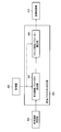
- FIG. 22 shows a detailed configuration example of the image processing unit 410 according to the third embodiment.
- the image processing unit 410 includes a preprocessing unit 411, a synchronization unit 412, an attention area setting unit 413, a post-processing unit 415, a photometry unit 416, and a gradation conversion unit 419.
- symbol is attached
- the state information acquisition unit 430 is connected to the attention area setting unit 413 and the photometry unit 416.
- the synchronization unit 412 is connected to the gradation conversion unit 419 and the photometry unit 416.
- the synchronizer 412 converts a Bayer-type array single-plate image into a three-plate image (RGB image) by interpolation processing.
- the synchronization unit 412 transfers the three-plate image signal to the gradation conversion unit 419 and the photometry unit 416.
- the attention area setting section 413 sets the attention area according to the bending angle acquired by the bending angle detection section 431 and the bending movement amount acquired by the bending movement amount detection section 432. Specifically, the attention area setting unit 413 determines the region of the lateral visual field as the attention area when the bending angle is equal to or larger than a predetermined threshold value or when the bending motion amount (curving speed) is equal to or larger than the predetermined threshold value. Set as. The attention area setting section 413 transfers the set attention area to the photometry section 416.
- the photometry unit 416 calculates the brightness of the subject from the image signal. Specifically, when the attention area is set by the attention area setting section 413, the photometry section 416 multiplies the attention area and the area other than the attention area by different weighting factors, and performs weighted addition represented by the following equation (9). An average value Ywa is calculated.
- Yc (x, y) is a luminance signal value of a pixel included in the front visual field
- Ya (x, y) is a luminance signal value of a pixel included in the lateral visual field.
- Nc is the number of pixels included in the front view
- Na is the number of pixels included in the side view.
- A is a weighting factor for the front field of view
- B is a weighting factor for the side field of view.
- Rc is a region corresponding to the front visual field
- Ra is a region corresponding to the lateral visual field.
- the sum ( ⁇ ) is the sum for the pixels belonging to each region.
- the photometry unit 416 sets the weighting coefficient of the attention area to a relatively large coefficient as compared with the weighting coefficients other than the attention area. For example, when the side area is the attention area, A ⁇ B. Further, the photometry unit 416 sets the weighting coefficient according to the bending angle (or bending movement amount). Specifically, the larger the bending angle (or the amount of bending movement), the larger the side view weighting coefficient B compared to the front viewing weighting coefficient A.
- the photometry unit 416 calculates the average luminance value of the effective pixel region of the image signal input from the synchronization unit 412 when the attention region is not set by the attention region setting unit 413.
- the photometry unit 416 transfers the calculated luminance addition average value Ywa of the attention area to the control unit 420.
- the dimming control unit includes the first brightness information (luminance signal value Ya (x, y)) indicating the brightness of the attention area and the brightness of the area other than the attention area. 2nd brightness information (luminance signal value Yc (x, y)) showing the brightness is calculated.
- the dimming control unit weights and adds the first brightness information and the second brightness information with the first weighting factor B and the second weighting factor A, respectively, and adjusts the brightness based on the obtained weighted addition value. Perform light control.
- the dimming control unit uses a coefficient larger than the second weighting coefficient A as the first weighting coefficient B.
- the brightness of the entire image can be controlled by dimming while the brightness of the attention area is mainly controlled by dimming.
- the visibility of the whole image can be improved while improving the visibility of the attention area.
- the state information acquisition unit 430 includes the bending angle detection unit 431.
- the bending angle detection unit 431 acquires bending angle information representing the bending angle of the scope tip (angle ⁇ in FIGS. 21A to 21C) as state information.
- the attention area setting unit 413 sets the attention area based on the acquired bending angle information.
- an observation region in which the operator is interested can be estimated from the bending angle, and an image that can be easily observed by the operator can be provided by dimming control of the brightness of the region.
- the attention area setting unit 413 sets an area corresponding to the side field of view in the captured image as the attention area when it is determined that the bending angle is larger than the threshold value.
- the region corresponding to the front visual field is a region where the subject in the front visual field is imaged, for example, a region where the subject in the optical axis direction of the objective optical system is imaged.
- the region corresponding to the front visual field is a central region including the image center.
- the region corresponding to the side field is a region where the subject of the side field is imaged, for example, a region where the subject in the direction orthogonal to the optical axis of the objective optical system is imaged.
- the region corresponding to the side field of view is a peripheral region of the central region.
- the attention area setting unit 413 sets an area corresponding to the side field of view in the captured image as the attention area.
- the dimming control unit makes the first weighting factor B larger than the second weighting factor A as the bending angle increases.
- the state information acquisition unit 430 includes a bending motion amount detection unit 432.
- the bending motion amount detection unit 432 acquires, as state information, bending motion amount information representing the bending motion amount of the scope tip (change in the angle ⁇ in FIGS. 21A to 21C per unit time).
- the attention area setting unit 413 sets the attention area based on the acquired bending motion amount information.
- an observation area of interest to the operator can be estimated from the amount of bending movement, and an image that can be easily observed by the operator can be provided by dimming control of the brightness of the area.
- the attention area setting unit sets, as the attention area, the area corresponding to the side field of view in the captured image when it is determined that the bending motion amount is larger than the threshold value.
- the attention area setting unit 413 sets an area corresponding to the side field of view in the captured image as the attention area.
- the dimming control unit makes the first weighting factor B larger than the second weighting factor A as the bending motion amount increases.
- Endoscope Device A fourth embodiment in which a region of interest is set based on distance information to a subject estimated from the amount of light emitted from a light source will be described.
- FIG. 23 shows a configuration example of the endoscope apparatus according to the fourth embodiment.
- the endoscope apparatus includes a light source unit 100, an operation unit 200, an insertion unit 300, a control device 400, a display unit 500, and an external I / F unit 550.
- symbol is attached
- the control device 400 includes an image processing unit 410, a control unit 420, and a state information acquisition unit 430.
- the state information acquisition unit 430 is connected to the image processing unit 410.
- the control unit 420 is connected to the light source aperture driving unit 103, the rotation driving unit 105, the image processing unit 410, the state information acquisition unit 430, and the external I / F unit 550, and performs these controls.
- information on the amount of light emitted from the light source unit 100 is acquired in a state where the dimming process is in operation, distance information on the subject is estimated based on the information on the amount of emitted light, and based on the distance information.
- the state information acquisition unit 430 performs dimming processing, controls the light source diaphragm driving unit 103 via the control unit 420, and reduces the aperture area of the light source diaphragm 102 until the image reaches the target observation brightness. To do.
- the state information acquisition unit 430 controls the light source aperture driving unit 103 via the control unit 420 and expands the aperture area of the light source aperture 102 until the image reaches the target observation brightness. That is, in the dimming process, when the opening area of the light source stop 102 is small, the tip of the insertion unit 300 is close to the subject, and when the opening area of the light source stop 102 is large, the tip of the insertion unit 300 is The subject is away.
- FIGS. 24 (A) and 24 (B) when the surgeon finds a region that is assumed to be a lesioned part, the lesioned part is usually matched with the central part (front visual field) of the image signal.
- FIG. 24C and FIG. 24D when examining an elongated tubular portion such as the intestine, it is difficult to match the lesion to the front field of view of the image signal due to the limitation of the spatial region. That is, since the space is narrow, it is difficult to rotate the distal end of the insertion portion 300. Therefore, as shown in FIG. 24D, there is no choice but to adjust the lesioned part to the lateral visual field of the image signal.
- the scope tip is close to the subject based on the aperture information of the light source diaphragm 102.
- the front view area or the side view area is set as the attention area according to the photometry mode, and the light control of the attention area is performed.
- the state information acquisition unit 430 acquires the opening area (opening information in a broad sense) of the light source diaphragm 102 via the control unit 420, and when the opening area is equal to or smaller than a predetermined threshold, It is determined that the tip is “close to” the attention area.
- the state information acquisition unit 430 transfers the determination result to the attention area setting unit 413 as state information.
- a plurality of photometry modes are prepared in accordance with the observation situation described above with reference to FIG.
- the operator sets the photometry mode via the external I / F unit 550.
- the photometry mode is set to “front mode”.
- the attention area setting section 413 sets the attention area based on the state information transferred from the state information acquisition section 430 and the photometry mode. Specifically, the attention area setting unit 413 determines that the photometric mode is “front mode” and the scope tip is “close” to the subject, the coordinates of the image center (N / 2, A front visual field centered on M / 2) is set as a region of interest. The attention area setting unit 413 sets the side field of view as the attention area when it is determined that the photometry mode is “side mode” and the distal end of the scope is “close to” the subject. If it is not determined that the scope tip is “close to” the subject, the attention area is not set. The attention area setting section 413 transfers the set attention area to the photometry section 416.
- the region of interest (front field of view or side field of view) is adaptively set according to the diaphragm condition of the light source, and the dimming control of the region of interest is performed, which improves the lesion site visibility for the surgeon. Connected.
- the photometric processing is adaptively performed according to the opening state of the light source stop 102, but the present embodiment is not limited to this.
- a photometric process may be performed using an LED light source based on light amount control information (for example, drive current) of the LED light source.
- FIG. 25 shows a modified configuration example of the endoscope apparatus when such processing is performed.
- the endoscope apparatus includes a light source unit 100, an operation unit 200, an insertion unit 300, a control device 400, a display unit 500, and an external I / F unit 550.
- symbol is attached
- the light source unit 100 includes a white light source 101, a rotary color filter 104, a rotation driving unit 105, a condenser lens 106, and a light source control unit 107 that controls the amount of light emitted from the light source.
- the white light source 101 is constituted by an LED light source.
- the light source control unit 107 controls the intensity of the emitted light amount of the LED light source based on the control signal from the control unit 420.
- the control unit 420 adjusts the amount of emitted light based on the adjustment coefficient Lc described in the above equation (6).
- the attention area setting section 413 sets the attention area based on the control signal of the amount of emitted light from the control section 420. That is, when the amount of emitted light is smaller than the threshold value, it is determined that the scope tip is close to the subject, and an attention area corresponding to the photometry mode is set.
- the photometry unit 416 performs photometry processing on the set attention area.
- the state information acquisition unit 430 acquires distance information representing the distance between the subject and the scope tip based on the amount of light emitted from the light source unit 100 that illuminates the subject.
- the attention area setting unit 413 sets the attention area using the distance information as state information.
- the attention area setting unit 413 sets the attention area when it is determined that the distance is closer than the threshold.
- the endoscope apparatus includes a mode setting unit (control unit 420 in FIG. 23) and a dimming control unit (state information acquisition unit 430 and control unit 420 in FIG. 23).
- the mode setting unit sets the first photometry mode (front mode) or the second photometry mode (side mode).
- the dimming control unit controls the amount of emitted light by controlling the aperture area of the diaphragm of the light source unit 100 (the light source diaphragm 102 in FIG. 23).
- the distance information is an opening area controlled by the dimming control unit.
- the attention area setting unit 413 sets an area corresponding to the front visual field in the captured image as the attention area.
- the attention area setting unit 413 sets an area corresponding to the side field of view in the captured image as the attention area.
- the dimming control unit controls the opening area based on the brightness of the set attention area.
- the region where the scope tip is close is considered to be the region that the operator wants to observe, by setting the region of interest according to the distance, the region that the operator wants to observe is appropriately dimmed and controlled it can. Further, since the brightness of the image is kept constant by the light control, it is possible to determine whether or not the scope tip has approached the subject by estimating the distance based on the light control instead of the image.
- Endoscope Device A fifth embodiment in which a region of interest is set based on distance information to a subject estimated from the brightness of an image will be described.
- the endoscope apparatus includes a light source unit 100, an operation unit 200, an insertion unit 300, a control device 400, a display unit 500, and an external I / F unit 550.
- the configuration is the same as that of the first embodiment described in FIG. In the following, description of components having the same operations and processes as those of the first embodiment will be omitted as appropriate.
- the image processing unit 410 includes a preprocessing unit 411, a synchronization unit 412, an attention area setting unit 413, a post-processing unit 415, a photometry unit 416, and a gradation conversion unit 419.
- the configuration is the same as that of the first embodiment described in FIG.
- the relatively bright area in the image signal is considered to be an area where the distance between the tip of the insertion unit 300 and the subject is short. Therefore, in the present embodiment, brightness is calculated for each local region in the image signal, and a relatively bright local region among the plurality of local regions is set as a region of interest.
- FIG. 26 shows a detailed configuration example of the attention area setting unit 413 according to the fifth embodiment.
- the attention area setting unit 413 includes a luminance conversion unit 441, an addition unit 442, and a specification unit 443.
- the synchronization unit 412 is connected to the luminance conversion unit 441.
- the luminance conversion unit 441 is connected to the addition unit 442.
- the adding unit 442 is connected to the specifying unit 443.
- the specifying unit 443 is connected to the photometry unit 416.
- the control unit 420 is bi-directionally connected to the luminance conversion unit 441, the addition unit 442, and the specification unit 443.
- the luminance conversion unit 441 calculates the luminance signal value Yi (x, y) of the sampling pixel of the image signal after synchronization by the above equation (1), and the luminance signal value Yi of the sampling pixel. Transfer (x, y) to the adder 442.
- the adder 442 adds and averages the luminance signals Yi (x, y) of the sampling pixels in the forward visual field and the lateral visual field according to the following expression (10), and measures the brightness value Ydf of the forward visual field and the brightness of the lateral visual field.
- the measured value Yds is calculated.
- the center coordinates (N / 2, M / 2) of the image signal are set as the origin, pixels within a predetermined radius are set as the front field of view, and other pixels are set as the side field of view.
- m is the number of sampling pixels (constant) in the front field of view
- n is the number of sampling pixels (constant) in the side field of view.
- the present embodiment is not limited to this.
- the side field of view is further divided into a plurality of regions, and the luminance signals Yi (x, y) of the sampling pixels included in each region are added and averaged.
- An area brightness measurement value may be calculated.
- the maximum value among the calculated brightness measurement values of the plurality of side regions is set as the brightness measurement value Yds of the side region.
- the brightness measurement value of the side visual field 3 is the maximum value.
- the brightness measurement value of the side visual field 3 is transferred to the specifying unit 443 as the brightness measurement value Yds of the side area.
- the identifying unit 443 sets a region of interest based on the brightness measurement values Ydf and Yds calculated by the adding unit 442. Specifically, when the brightness measurement value Ydf of the front visual field is larger than a predetermined threshold, the specifying unit 443 sets the region corresponding to the front visual field as the attention region. In addition, when the brightness measurement value Yds of the side field of view is larger than a predetermined threshold, the specifying unit 443 sets a region corresponding to the side field of view as the attention region. When the brightness measurement values Ydf and Yds are both greater than a predetermined threshold, a brighter area is set as the attention area. The specifying unit 443 transfers the set attention area information to the photometry unit 416.
- the specifying unit 443 sets the region as the attention region.
- the distance between the distal end of the insertion unit 300 and the subject is estimated from the brightness of the image signal, and the front visual field and the lateral visual field are adaptively dimmed based on the distance, It is possible for a person to improve the visibility of a lesioned part.
- the attention area setting unit 413 includes the distance information acquisition unit (the luminance conversion unit 441 and the addition unit 442 in FIG. 26).
- the distance information acquisition unit acquires distance information representing the distance between the subject and the scope tip based on the brightness of the captured image (for example, the luminance signal Yi (x, y)).
- the attention area setting unit 413 sets the attention area based on the acquired distance information.
- the distance information acquisition unit calculates a luminance feature amount related to the luminance of the pixel of the captured image (for example, a luminance conversion unit 441 (brightness feature amount calculation unit in a broad sense)) and calculates the calculated luminance feature amount. Get distance information based on.
- the distance information acquisition unit divides the captured image into a plurality of regions (for example, a region corresponding to the front visual field and a region corresponding to the side visual field), and brightness (brightness) of each divided region. Measurement values Ydf, Yds) are acquired as distance information.
- the attention area setting unit 413 sets the brightest area among the plurality of areas as the attention area as the area closest to the distal end portion of the scope.
- the attention area can be set based on the brightness of the image, and the brightness of the attention area can be dimmed. That is, when the scope tip is brought close to an area that the operator wants to observe, the area is brightened by illumination, so that the attention area can be set according to the brightness of the image.
- FIG. 29 shows a configuration example of the endoscope apparatus according to the sixth embodiment.
- the endoscope apparatus includes a light source unit 100, an insertion unit 300, a control device 400, a display unit 500, and an external I / F unit 550.
- symbol is attached
- the light source unit 100 includes a white light source 101, a light source aperture 102, a light source aperture drive unit 103, and a condenser lens 106. Compared to the first embodiment, the rotation color filter 104 and the rotation drive unit 105 are omitted.
- the insertion unit 300 includes a light guide fiber 301, illumination lenses 314 and 315, and an objective optical system 303.
- the insertion unit 300 also includes a half mirror 309 that separates the reflected light collected by the objective optical system 303 into two parts, a first imaging element 304 and a second imaging element 310 that detect the separated reflected light, and
- the first A / D conversion unit 305 and the second A / D conversion unit 311 are included.
- the A / D converter 311 converts the analog image signal detected by the second image sensor 310 into a digital image signal.
- the first image sensor 304 is a Bayer-type array image sensor.
- the second image sensor 310 is an image sensor in which two types of color filters nB and nG are arranged on a checkered pattern.
- each color filter nB, nG has a characteristic of transmitting light in a narrow band.
- the color filter nB has a characteristic of transmitting light of 390 to 445 nm
- the color filter nG has a characteristic of transmitting light of 530 to 550 nm.
- the first imaging element 304 and the second imaging element 310 have the same number of pixels.
- the control device 400 includes an image processing unit 410 and a control unit 420.
- the A / D conversion units 305 and 311 transfer the digitally converted image signal to the image processing unit 410.
- the image processing unit 410 transfers the processed image signal to the display unit 500.
- the control unit 420 is connected to the light source aperture driving unit 103, the image processing unit 410, and the external I / F unit 550, and performs these controls.
- FIG. 32 shows a detailed configuration example of the image processing unit 410 in the sixth embodiment.
- the image processing unit 410 includes a first preprocessing unit 411, a second preprocessing unit 418, a first synchronization unit 412, a second synchronization unit 417, a region of interest setting unit 413, a post processing unit 415, and photometry. Part 416 and a gradation conversion part 419. Note that the processes of the pre-processing unit 411, the gradation conversion unit 419, the post-processing unit 415, and the photometry unit 416 are the same as those in the first embodiment, and a description thereof will be omitted.
- the synchronization unit 412 is connected to the gradation conversion unit 419 and the photometry unit 416.
- the preprocessing unit 418 is connected to the synchronization unit 417.
- the synchronization unit 417 is connected to the attention area setting unit 413.
- the attention area setting unit 413 is connected to the photometry unit 416.
- the control unit 420 is bi-directionally connected to the preprocessing unit 418 and the synchronization unit 417, and performs these controls.
- the synchronization unit 412 performs a synchronization process on the image signal processed by the preprocessing unit 411.
- the image signal acquired by the first image sensor 304 is a single-plate image signal in a Bayer type array.
- the synchronization unit 412 generates an RGB three-plate image signal from the single-plate image signal using interpolation processing. For example, a known bicubic interpolation process may be used as the interpolation process.
- the image signal output from the synchronization unit 412 is referred to as a normal light image.
- the pre-processing unit 418 uses the OB clamp value, gain correction value, and WB coefficient value stored in advance in the control unit 420 for the image signal input from the A / D conversion unit 311, Gain correction processing and WB correction processing are performed.
- the preprocessing unit 418 transfers the preprocessed image signal to the synchronization unit 417.
- the synchronization unit 417 performs synchronization processing on the image signal processed by the preprocessing unit 418.
- the second image sensor 310 is an image sensor in which two types of color filters nB and nG are arranged on a checkered pattern. Therefore, the image signal processed by the preprocessing unit 418 becomes a single-plate image signal as shown in FIG. In FIG. 33, the image signal acquired by the color filter nB is represented as B2, and the image signal acquired by the color filter nG is represented as G2.
- the synchronization unit 417 generates a B2 image signal and a G2 image signal from the single plate image signal by the following equations (11) and (12).
- the B2 image signal is an image signal having a B2 signal at all pixels
- the G2 image signal is an image signal having a G2 signal at all pixels.
- the image signal B2 (1,1) of the nB filter at the position G2 (1,1) in FIG. 33 may be calculated using the following equation (11).
- the image signal G2 (1,2) of the nG filter at the position B2 (1,2) in FIG. 33 may be calculated using the following equation (12).
- the synchronization unit 417 generates an RGB three-plate image signal using the B2 image signal and the G2 image signal generated by the above equations (11) and (12). Specifically, the synchronization unit 417 generates a three-plate image signal by using the G2 image signal as the R image signal and using the B2 image signal as the G and B image signals.
- the image signal output from the synchronization unit 417 is referred to as a narrow-band light image (special light image in a broad sense).
- the attention area setting unit 413 detects a lesion area from the narrowband light image by a method described later, and sets the attention area based on the lesion area.
- a lesion area can be detected by detecting an area having a specific hue (brown area) from a narrow-band light image.
- FIG. 34 shows a detailed configuration example of the attention area setting unit 413 according to the sixth embodiment.
- the attention area setting section 413 includes a local area setting section 451, a feature amount calculation section 452, a lesion area detection section 453, a labeling processing section 454, an area selection section 455, a coordinate calculation section 456, and an association section 457. And a photometric processing condition setting unit 459.
- the synchronization unit 417 is connected to the local region setting unit 451.
- the local region setting unit 451 is connected to the feature amount calculation unit 452 and the association unit 457.
- the feature amount calculation unit 452 is connected to the lesion area detection unit 453.
- the lesion area detection unit 453 is connected to the labeling processing unit 454.
- the labeling processing unit 454 is connected to the area selection unit 455.
- the area selection unit 455 is connected to the coordinate calculation unit 456.
- the coordinate calculation unit 456 is connected to the association unit 457.
- the associating unit 457 is connected to the photometric processing condition setting unit 459.
- the photometric processing condition setting unit 459 is connected to the photometric unit 416.
- the local region setting unit 451 sets a plurality of local regions for the narrowband light image output from the synchronization unit 417.
- a narrowband light image is divided into rectangular areas and each divided area is set as a local area will be described as an example.
- 5 ⁇ 5 pixels are defined as one local region.
- the narrowband image signal is composed of M ⁇ N local regions, and the coordinates of each region are represented by (m, n).
- a local area of coordinates (m, n) is represented by a (m, n).
- the coordinates of the local region located at the upper left of the image are defined as (0, 0)
- the right direction is defined as the positive direction of m
- the downward direction is defined as the positive direction of n.
- an area composed of a plurality of adjacent pixel groups is set as one local area, but one pixel can be set as one local area. Also in this case, the subsequent processing is the same.
- the local region setting unit 451 outputs the size of the local region and the coordinates of all the local regions to the feature amount calculating unit 452.
- the local region setting unit 451 outputs the coordinates of all the local regions and the coordinates on the narrowband light image corresponding to the coordinates to the associating unit 457.
- the coordinates on the narrow-band light image are the coordinates of the pixel existing at the center of the local region.
- the feature amount calculation unit 452 calculates a feature amount from all the local regions set by the local region setting unit 451.
- hue used as the feature amount
- the hue of the local region a (m, n) is expressed as H (m, n).
- the feature amount calculation unit 452 first calculates average values R_ave, G_ave, and B_ave of R, G, and B signals in each local region.
- R_ave is an average value of R signals of all pixels included in each local region.
- G_ave and B_ave For example, each signal value is 8 bits (0 to 255).
- the feature amount calculation unit 452 calculates the hue H (m, n) of each local region from R_ave, G_ave, B_ave, using, for example, the following equations (13) to (18). First, max is obtained by the following equation (13).
- the MAX () function is a function that outputs the maximum value of a plurality of arguments in parentheses.
- the MIN () function is a function that outputs the minimum value of a plurality of arguments in parentheses.
- hue H is calculated by the following equation (16).
- hue H is calculated by the following equation (17).
- B_ave is the maximum among R_ave, G_ave, and B_ave
- the hue H is calculated by the following equation (18).
- the lesion area detection unit 453 detects a local area having a specific hue H as a lesion area, and outputs the coordinates of all the local areas detected as the lesion area to the labeling processing unit 454. For example, the lesion area detection unit 453 detects an area where the hue H has a value of 5 to 35 (corresponding to a brown area) as a lesion area.
- the labeling processing unit 454 assigns the same label to the adjacent lesion areas among the lesion areas output from the lesion area detection unit 453.
- a set of lesion areas assigned the same label is referred to as a lesion area group.
- the labeling processing unit 454 calculates the size of the lesion area group given the same label.
- the size of the lesion area group may be the number of lesion areas to which the same label is assigned.
- the present invention is not limited to this, and the size of the lesion area group may be information indicating the area of the lesion area group.
- the process performed by the labeling processing unit 454 will be described in detail with reference to FIG.
- the label 1 is assigned to the lesion area belonging to the area A1.
- the label 2 is assigned to the lesion area belonging to the area indicated by A2, and the label 3 is assigned to the lesion area belonging to the area indicated by A3.
- the labeling processing unit 454 calculates the size of the lesion area group given the same label.
- the size of lesion area group 1 (A1) to which label 1 is assigned is 7.
- the size of the lesion area group 2 (A2) is 3, and the size of the lesion area group 3 (A3) is 2.
- the region selection unit 455 selects a lesion region group having the maximum size as a region of interest from among a plurality of lesion region groups that have been labeled by the labeling processing unit 454. Then, the coordinates of all the local areas included in the attention area are output to the coordinate calculation unit 456. In the case of FIG. 36, the lesion area group 1 indicated by A1 is selected as the attention area.
- the coordinate calculation unit 456 calculates and calculates the maximum value (m MAX , n MAX ) and the minimum value (m MIN , n MIN ) of the local region coordinates from all the local region coordinates output from the region selection unit 455. The value is output to the associating unit 457.
- the number of all local regions output from the region selection unit 455 is K, and all the local regions are referred to as a (m 1 , n 1 ) to a (m K , n K ) for convenience.
- the coordinate calculation unit 456 calculates the maximum value (m MAX , n MAX ) and the minimum value (m MIN , n MIN ) of the local region coordinates using the following equation (19).
- the associating unit 457 calculates the coordinates of the narrowband light image corresponding to the maximum value (m MAX , n MAX ) and the minimum value (m MIN , n MIN ). Specifically, the coordinates are calculated based on the correspondence between the local area output from the local area setting unit 451 and the coordinates of the narrowband light image.
- the coordinates of the narrowband light image corresponding to (m MAX , n MAX ), (m MIN , n MIN ) are represented as (x MAX , y MAX ), (x MIN , y MIN ).
- the photometric processing condition setting unit 459 determines a photometric processing condition that is a condition of an attention area that is a target of the photometric processing, and outputs the photometric processing condition to the photometric unit 416. Specifically, the photometric processing condition setting unit 459 calculates the center coordinates (x 0 , y 0 ) of the attention area by the following expression (20), calculates the radius R of the attention area by the following expression (21), The calculated center coordinates (x 0 , y 0 ) and radius R are used as photometric processing conditions. In the example described with reference to FIG. 36, a circle with a radius R is set as a region of interest for photometry as shown.
- int () is a function that returns a real integer value in parentheses.
- the attention area setting unit 413 calculates a feature amount (for example, a hue value) based on the captured image, and based on an area having a predetermined feature amount (for example, a range of hue values of 5 to 35). To set the attention area.
- a feature amount for example, a hue value
- a predetermined feature amount for example, a range of hue values of 5 to 35
- the attention area can be set based on the feature amount of the image that appears characteristically in the lesion, and the brightness of the attention area can be dimmed. Thereby, the surgeon can observe the lesioned part with appropriate brightness.
- the attention area setting unit 413 selects an area having the largest area among areas having a predetermined feature amount, and selects a circular area including the selected area as the attention area. Set as.
- the lesion area group having the maximum size as the attention area it is possible to display the area that is considered to be noticed by the operator with appropriate brightness.
- the feature value is a hue value
- the present embodiment is not limited to this.
- the feature amount may be anything that can identify a lesion and another region.
- the R pixel value may be the feature amount.
- the attention area is set based on the lesion area group having the maximum size among the lesion area groups labeled by the labeling processing unit 454 . It is not limited to this.
- the attention area may be set based on all the lesion areas detected by the lesion area detection unit 453.
- the region selection unit 455 may output the coordinates of the local regions included in all the lesion region groups output from the labeling processing unit 454 to the coordinate calculation unit 456.
- a normal light image is used as a display image.
- the present embodiment is not limited to this.
- a narrow band light image may be used as the display image.
- the captured image includes a special light image in which a subject image having information in a specific wavelength band is captured and a normal light image (white light) in which a subject image having information in the wavelength band of white light is captured.
- Image The attention area setting unit 413 sets the attention area based on the special light image.
- the dimming control unit performs dimming control of the normal light image based on the set attention area.
- the specific wavelength band is a band narrower than the white wavelength band (for example, 380 nm to 650 nm) (NBI: Narrow Band Imaging).
- the normal light image and the special light image are in-vivo images of the living body
- a specific wavelength band included in the in-vivo image is a wavelength band of a wavelength that is absorbed by hemoglobin in blood.
- the wavelength absorbed by the hemoglobin is 390 nm to 445 nm (first narrowband light nB) or 530 nm to 550 nm (second narrowband light nG).
- the wavelength band in this case is not limited to this, and the lower limit of the wavelength band is reduced by about 0 to 10% due to factors such as absorption by hemoglobin and experimental results related to the arrival of the living body on the surface or deep. It is also conceivable that the upper limit value increases by about 0 to 10%.
- the normal light image and the special light image are in-vivo images obtained by copying the inside of the living body
- the specific wavelength band included in the in-vivo image is a wavelength band of fluorescence emitted from the fluorescent substance.
- the specific wavelength band may be a wavelength band of 490 nm to 625 nm.
- AFI Auto-Fluorescence-Imaging
- excitation light 390 nm to 470 nm
- autofluorescence intrinsic fluorescence
- 490 nm to 625 nm indicates the wavelength band of autofluorescence emitted by a fluorescent substance such as collagen when irradiated with the above-described excitation light.
- the wavelength band in this case is not limited to this.
- the lower limit of the wavelength band is reduced by about 0 to 10% and the upper limit is 0 due to a variation factor such as an experimental result regarding the wavelength band of the fluorescence emitted by the fluorescent material.
- a variation factor such as an experimental result regarding the wavelength band of the fluorescence emitted by the fluorescent material.
- An increase of about 10% is also possible.
- a pseudo color image may be generated by simultaneously irradiating a wavelength band (540 nm to 560 nm) absorbed by hemoglobin.
- the specific wavelength band included in the in-vivo image may be an infrared light wavelength band.
- the specific wavelength band may be a wavelength band of 790 nm to 820 nm, or 905 nm to 970 nm.
- IRI infra®Red®Imaging
- ICG Intravenously ICG
- ICG Indocyanine Green
- the numbers 790 nm to 820 nm are obtained from the characteristic that the absorption of the infrared index drug is the strongest, and the numbers 905 nm to 970 nm are determined from the characteristic that the absorption of the infrared index drug is the weakest.
- the wavelength band in this case is not limited to this.
- the lower limit of the wavelength band is reduced by about 0 to 10% and the upper limit is 0 to 10 due to a variation factor such as an experimental result regarding absorption of the infrared index drug. It can also be expected to increase by about%.
- a special light image acquisition unit that generates a special light image based on the acquired normal light image may be included.
- the half mirror 309, the image sensor 310, and the A / D conversion unit 311 are omitted, and the preprocessing unit 418 and the synchronization unit 417 in FIG. 32 serve as the special light image acquisition unit from the normal light image to the special light image. May be generated.
- the special light image acquisition unit includes a signal extraction unit that extracts a signal in the white wavelength band from the acquired normal light image.
- the special light image acquisition unit may generate a special light image including a signal in a specific wavelength band based on the extracted signal in the wavelength band of normal light.
- the signal extraction unit estimates the spectral reflectance characteristics of the subject in 10 nm increments from the RGB signal of the normal light image, and the special light image acquisition unit integrates the estimated signal component in the specific band and performs special processing. Generate a light image.
- the special light image acquisition unit may include a matrix data setting unit that sets matrix data for calculating a signal in a specific wavelength band from a signal in the normal light wavelength band. Then, the special light image acquisition unit may generate a special light image by calculating a signal in a specific wavelength band from a signal in the white wavelength band using the set matrix data.
- the matrix data setting unit sets table data in which spectral characteristics of irradiation light in a specific wavelength band are described in increments of 10 nm as matrix data. Then, the spectral characteristics (coefficients) described in the table data are multiplied by the spectral reflectance characteristics of the subject estimated in increments of 10 nm and integrated to generate a special light image.
- the special light image can be generated based on the normal light image, so that the system can be realized with only one light source that irradiates the normal light and one image sensor that images the normal light. . Therefore, the capsule endoscope and the insertion part of the scope endoscope can be made small, and the cost can be expected to be reduced because the number of parts is reduced.
- FIG. 37 shows a configuration example of the endoscope apparatus according to the seventh embodiment.
- the endoscope apparatus includes a light source unit 100, an insertion unit 300, a control device 400, a display unit 500, and an external I / F unit 550.
- symbol is attached
- the insertion unit 300 includes a light guide fiber 301, illumination lenses 314 and 315, an objective optical system 303, an image sensor 304, an A / D conversion unit 305, and a memory 313. Since the configuration of each unit other than the memory 313 is the same as that of the first embodiment, description thereof is omitted.
- the insertion unit 300 is generally called a scope. Therefore, in the following, the insertion unit 300 is appropriately referred to as a scope.
- the insertion unit 300 is appropriately referred to as a scope.
- different scopes are used depending on the site to be diagnosed. For example, the upper gastrointestinal scope is used for diagnosis of the esophagus and stomach, and the lower gastrointestinal scope is used for diagnosis of the large intestine.
- the scope memory 313 holds an identification number (scope ID) unique to each scope.
- the control device 400 includes an image processing unit 410, a control unit 420, and a state information acquisition unit 430.
- the status information acquisition unit 430 refers to the identification number unique to each scope held in the memory 313 and identifies the type of scope to be connected.
- the type of scope is, for example, either the upper digestive scope or the lower digestive scope.
- the state information acquisition unit 430 outputs the identified scope type to the attention area setting unit 413 described later.
- FIG. 38 shows a detailed configuration example of the image processing unit 410 in the seventh embodiment.
- the image processing unit 410 includes a preprocessing unit 411, a synchronization unit 412, an attention area setting unit 413, a post-processing unit 415, a photometry unit 416, and a gradation conversion unit 419. Since the processing other than the attention area setting unit 413 is the same as that of the first embodiment, the description thereof is omitted.
- the attention area setting section 413 sets the attention area in accordance with the type of scope output from the state information acquisition section 430.
- the attention area setting method is the same as that of the third embodiment. Specifically, when the scope type is the lower digestive organ scope, the region of the side field of view is set as the attention region. When the scope type is the upper digestive scope, the area of the front visual field is set as the attention area.
- the scope (insertion unit 300) can be attached to and detached from the endoscope apparatus.
- the state information acquisition unit 430 acquires identification information (scope ID) for identifying the attached scope.
- the attention area setting unit 413 sets the attention area based on the acquired identification information.
- the scope has an objective optical system that forms an image of the front field and the side field.
- the attention area setting unit 413 sets an area corresponding to the lateral visual field in the captured image as the attention area.
- the attention area setting unit 413 determines the area corresponding to the front visual field in the captured image as the attention area when the identification information is identification information indicating a scope for the upper digestive tract (for example, stomach or esophagus). Set to.
- the front visual field is more important for diagnosis than the lateral visual field. Therefore, by controlling the brightness of the area corresponding to the front visual field, the important visual field can be easily seen.
- FIG. 39 shows a detailed configuration example of the attention area setting unit 413 in the eighth embodiment.
- the attention area setting unit 413 includes a distortion correction unit 471, an image memory 472, a motion detection unit 473 (a motion information acquisition unit in a broad sense), and a setting unit 474.
- the synchronization unit 412 outputs the synchronized image signal to the distortion correction unit 471.
- the distortion correction unit 471 is connected to the image memory 472, the motion detection unit 473, and the setting unit 474.
- the motion detection unit 473 is connected to the setting unit 474.
- the setting unit 474 is connected to the photometry unit 416.
- the control unit 420 is bidirectionally connected to the distortion correction unit 471, the image memory 472, the motion detection unit 473, and the setting unit 474, and performs these controls.
- the distortion correction unit 471 corrects distortion aberration (hereinafter referred to as distortion as appropriate), which is a kind of aberration, with respect to the synchronized image signal.
- distortion as appropriate
- FIG. 40 shows examples of images before and after the distortion correction process.
- the distortion correction unit 471 acquires pixel coordinates of the image after the distortion correction processing. It is assumed that the image size after the distortion correction processing is acquired in advance based on the distortion of the optical system.
- the distortion correction unit 471 converts the acquired pixel coordinates (x, y) into coordinates (x ′, y ′) having the optical axis center as the origin using the following expression (22).
- (center_x, center_y) is the coordinates of the optical axis center after the distortion correction processing.
- the center of the optical axis after the distortion correction process is the center of the image after the distortion correction process.
- the distortion correction unit 471 calculates the object height r using the following equation (23) based on the converted pixel coordinates (x ′, y ′).
- max_r is the maximum object height in the image after the distortion correction processing.
- the distortion correction unit 471 calculates a ratio (R / r) between the image height and the object height based on the calculated object height r. Specifically, the distortion correction unit 471 holds a relationship between the ratio R / r and the object height r as a table, and acquires the ratio R / r corresponding to the object height r by referring to the table. . Next, the distortion correction unit 471 acquires the pixel coordinates (X, Y) before the distortion correction processing corresponding to the pixel coordinates (x, y) after the distortion correction processing using the following expression (24).
- center_X, center_Y are the coordinates of the optical axis center before the distortion correction processing.
- the center of the optical axis before the distortion correction process is the center of the image before the distortion correction process.
- the distortion correction unit 471 calculates a pixel value at the pixel coordinates (x, y) after the distortion correction process based on the calculated pixel coordinates (X, Y) before the distortion correction process.
- (X, Y) is not an integer
- the pixel value is calculated by linear interpolation based on surrounding pixel values.
- the distortion correction unit 471 performs the above process on all the pixels of the image after the distortion correction process.
- the distortion correction unit 471 outputs the image corrected in this way to the image memory 472 and the motion detection unit 473.
- the image memory 472 stores the distortion corrected image corrected by the distortion correcting unit 471.
- the stored image after distortion correction is output to the motion detection unit 473 in synchronization with the timing at which a new image after distortion correction is output from the distortion correction unit 471.
- the motion detection unit 473 detects a local motion of the image based on the distortion-corrected image corrected by the distortion correction unit 471 and the distortion-corrected image stored in the image memory 472.
- the former image after distortion correction is referred to as a current frame image
- the latter image after distortion correction is referred to as a previous frame image.
- the motion detection unit 473 sets a representative point, which is a point for detecting a local motion, on the current frame image. For example, as shown in FIG. 41, representative points ( ⁇ shown in FIG. 41) are set at regular intervals and in a grid pattern in the pixels of the current frame image.
- the motion detection unit 473 calculates a motion vector of a representative point between the current frame image and the previous frame image as a local motion amount. For example, a motion vector is detected using block matching which is a known technique.
- the motion detection unit 473 outputs the set coordinates of the representative points and the motion vector detected at each representative point to the setting unit 474.
- the setting unit 474 sets a region of interest based on the current frame image from the distortion correction unit 471, the coordinates of the representative point from the motion detection unit 473, and the motion vector of each representative point. Specifically, the setting unit 474 determines whether or not the extracted state is based on the current frame image and the motion vector. If the extracted state, the side field of view is set as the attention area. Is set as the attention area. The setting unit 474 outputs the set attention area to the photometry unit 416.
- the extracted state refers to a state in which observation is performed while the endoscope is removed after the endoscope has been inserted deep into the hollow organ. Since this type of observation is generally performed on the large intestine, the side field of view is set as a region of interest so that it is easy to observe the back of the folds when it is in the removed state. The front field of view is set as a region of interest so that
- Extraction State Determination Method The extraction state determination method will be described with reference to FIGS. 42 (A) to 42 (D). First, the vanishing point of the motion vector is detected based on the motion vector at the representative point.
- ⁇ represents a representative point
- a solid arrow represents a motion vector
- x represents a vanishing point.
- the vanishing point is an intersection of straight lines that start from each representative point and extend in the direction along the motion vector at each representative point.
- the observation target is a cylindrical shape with a constant inner diameter and the motion vector is generated only by the movement of the endoscope, in the removed state, straight lines extending from the representative points intersect at one point at the vanishing point.
- the inner diameter of the luminal organ to be observed is not constant, and the motion vector is also generated by the pulsation of the living body. Therefore, even in the removed state, the straight lines do not intersect at the vanishing point.
- the first evaluation value D is obtained by the following equation (25).
- the sum in the above equation (25) represents the sum of the squares of the distances for all straight lines extended from the representative points.
- the coordinates (xsk, ysk) of the vanishing point candidate that minimizes the first evaluation value D are calculated using the following equation (26).
- the vanishing point candidate is set as the vanishing point. If the vanishing point candidate does not satisfy this condition, it is determined that the vanishing point cannot be detected.
- the moving direction of the endoscope tip is defined.
- the x direction, the y direction, and the z direction correspond to the horizontal direction, the vertical direction, the horizontal direction, and the depth direction orthogonal to the vertical direction on the image, respectively.
- the movement along the arrow in the x direction, the y direction, and the z direction is defined as a positive movement
- the opposite movement is defined as a negative movement.
- the endoscope tip moves negatively in the z direction. For example, when the movement of the tip of the endoscope is positive in the x direction, as shown in FIG.
- the motion vectors are almost parallel, so that the vanishing point candidate is outside the image. Exists.
- the first evaluation value D in the vanishing point candidate is a large value. That is, the motion in the z direction can be detected on the condition that the vanishing point candidate exists in the image and the first evaluation value D is smaller than the first threshold value.
- the vanishing point is detected even when the endoscope is inserted. Therefore, a determination is made based on a vector (broken arrow) from each representative point to the vanishing point and a motion vector (solid arrow). Specifically, when there are a predetermined number or more of representative points where the inner product of the vector to the vanishing point and the motion vector is negative, it is determined that no vanishing point is detected. When the vanishing point is not detected, it is determined that the removal state is not established.
- the pixel value of the current frame image at the detected vanishing point coordinates is set as a second evaluation value, and it is determined whether or not the observation target is a luminal organ based on the second evaluation value. If the vanishing point coordinates are not an integer, the second evaluation value is calculated by linear interpolation based on the surrounding pixel values. When the second evaluation value is equal to or less than a predetermined second threshold value, it is determined as a luminal organ. Even when the observation target is flat rather than luminal, the vanishing point is detected when the endoscope tip moves negatively in the z direction, so such a determination is necessary.
- the second evaluation value is small because the vanishing point is located in the back of the luminal organ that is not irradiated with much illumination light on the current frame image.
- the second evaluation value is large because the vanishing point is located in a region where the illumination light is relatively irradiated on the current frame image. Therefore, by determining whether or not the second evaluation value is equal to or less than the second threshold value, it is possible to determine an extraction state that is an observation performed while removing the endoscope from the luminal observation target.
- the front visual field is immediately set as the attention area
- the present embodiment is not limited to this.
- the front view may be set as the attention area.
- the side field of view may be set as the attention area when the determination of the extraction state continues for a predetermined frame.
- the attention area setting unit 413 includes the motion detection unit 473.
- the motion detection unit 473 acquires the amount of motion of the subject based on the captured image.
- the attention area setting unit sets the attention area based on the acquired amount of motion.
- the attention area setting unit 413 determines that the scope has been removed based on the amount of motion.
- An endoscope apparatus characterized in that an area corresponding to a side visual field is set as an attention area.
- information useful for diagnosis such as the back of the folds of the large intestine, can be suitably acquired by setting the region corresponding to the lateral visual field as the region of interest at the time of extraction and performing dimming control.
- the motion detection unit 473 calculates the motion vectors of a plurality of representative points as the motion amount, and obtains the vanishing point of the calculated motion vector.
- the attention area setting unit 413 is in a state where the scope has been removed when the obtained vanishing point exists in the captured image and the inner product of the vector from the representative point to the vanishing point and the motion vector is positive. Is determined.
- the attention area setting unit 413 determines that the scope has been removed when it is determined that the pixel value of the vanishing point is smaller than the threshold (second threshold).
- the extraction is a movement in the direction along the lumen.
- the state can be determined.
- the attention area setting unit 413 sets the area corresponding to the front visual field in the captured image as the attention area when it is determined that the scope is not removed based on the amount of movement. .
- dimming control can be performed by setting the front field of view considered to be mainly used at the time of removal other than at the time of removal as the attention area.
- the endoscope since the endoscope is operated using the front visual field at the time of insertion, it is possible to present forward information including a lot of information useful for the operation.
- the motion detection unit 473 includes a distortion correction unit 471.
- the distortion correction unit 471 corrects the distortion of the captured image based on the distortion aberration of the optical system of the scope.
- the motion detection unit 473 acquires a motion amount based on the captured image after distortion correction.
- Endoscope Device A ninth embodiment in which shape information of a subject is acquired by a shape detection unit, and a region of interest is set based on the shape information will be described.
- FIG. 43 shows a configuration example of the endoscope apparatus according to the ninth embodiment.
- the endoscope apparatus includes a light source unit 100, an insertion unit 300, a control device 400, a display unit 500, an external I / F unit 550, and a shape detection unit 700 (for example, UPD (Position Detection Unit)).
- a shape detection unit 700 for example, UPD (Position Detection Unit)
- UPD Part Detection Unit
- the insertion unit 300 includes a light guide fiber 301, illumination lenses 314 and 315, an objective optical system 303, an image sensor 304, an A / D conversion unit 305, and a magnetic coil 312. Except for the magnetic coil 312, the second embodiment is the same as the first embodiment, and a description thereof will be omitted.
- Ten or more magnetic coils 312 are provided in the insertion unit 300, for example, and each transmits magnetism to the shape detection unit 700 (shape information acquisition unit in a broad sense).
- the plurality of magnetic coils 312 are arranged along the length direction of the insertion portion 300, for example.
- the shape detection unit 700 receives magnetism transmitted by the magnetic coils 312 provided in the respective units of the insertion unit 300 by an antenna (not shown), and acquires the three-dimensional position information of each magnetic coil in real time.
- the shape detection unit 700 acquires endoscope shape information representing the shape of the insertion unit 300 in real time from the acquired three-dimensional position information of the magnetic coil.
- the control device 400 includes an image processing unit 410, a control unit 420, and a state information acquisition unit 430. Since the control unit 420 is the same as that of the first embodiment, description thereof is omitted.
- FIG. 44 shows a detailed configuration example of the status information acquisition unit 430 in the ninth embodiment.
- the state information acquisition unit 430 includes a subject information acquisition unit 436 and an observation information acquisition unit 437.
- the shape detection unit 700 outputs the detected endoscope shape information to the subject information acquisition unit 436 and the observation information acquisition unit 437.
- the subject information acquisition unit 436 is connected to the attention area setting unit 413.
- the observation information acquisition unit 437 is connected to the attention area setting unit 413.
- the subject information acquisition unit 436 determines whether or not the subject is the lower digestive tract based on the endoscope shape information acquired by the shape detection unit 700. Specifically, the subject information acquisition unit 436 determines, based on the endoscope shape information, the length of the endoscope inserted into the body and whether or not the endoscope shape forms a loop. And whether or not it is the lower digestive tract is determined based on the length and the determination result.
- the subject information acquisition unit 436 determines that the subject is the lower digestive tract if the endoscope is inserted into the body for a predetermined length or more.
- a loop is formed with an endoscope to facilitate insertion only when the endoscope is inserted into the lower digestive tract. Therefore, the subject information acquisition unit 436 determines that the subject is the lower digestive tract if a loop is formed in the endoscope.
- the subject information acquisition unit 436 determines that the subject is not the lower digestive tract until the endoscope inserted into the body exceeds a predetermined length or until the endoscope forms a loop. If either condition is satisfied, it is determined that the subject is the lower digestive tract, and the determination result is not changed thereafter.
- the subject information acquisition unit 436 outputs the determination result to the attention area setting unit 413 as subject information.
- the observation information acquisition unit 437 determines whether or not the endoscope is in the removal state based on the endoscope shape information acquired by the shape detection unit 700. Specifically, the observation information acquisition unit 437 determines whether or not the length of the endoscope inserted into the body is shortened over time based on the endoscope shape information. When it is shortened, it is determined that it is in the removed state. The observation information acquisition unit 437 outputs the determination result of the removal state to the attention area setting unit 413 as observation information.
- the image processing unit 410 includes a preprocessing unit 411, a synchronization unit 412, a region of interest setting unit 413, a post processing unit 415, a photometry unit 416, and a gradation conversion unit 419. including.
- the configuration is the same as that of the second embodiment described in FIG. Since operations and processes other than the attention area setting unit 413 are the same as those in the second embodiment, description thereof will be omitted.
- the attention area setting section 413 sets the attention area based on the subject information and the observation information output from the state information acquisition section 430. Specifically, the attention area setting unit 413 determines that the subject is the lower digestive tract based on the subject information, and determines that the endoscope is in the removed state based on the observation information. Is set as the attention area. In other cases, the front visual field is set as the attention area. The attention area setting section 413 outputs the set attention area to the photometry section 416.
- the endoscope apparatus acquires shape information of the scope insertion unit (insertion unit 300) (for example, three-dimensional position information of the magnetic coil 312 in FIG. 43).
- a shape detection unit 700 is included.
- the state information acquisition unit 430 includes a subject information acquisition unit 436.
- the subject information acquisition unit 436 acquires the acquired shape information as state information, and acquires subject information based on the shape information.
- the attention area setting unit 413 sets the attention area based on the acquired subject information.
- the subject information acquisition unit 436 determines a part of the subject based on the shape information, and acquires the determined part as subject information.
- the attention area setting unit 413 sets an area corresponding to the lateral visual field in the captured image as the attention area.
- the subject information acquisition unit 436 determines that the subject site is the lower digestive tract when it is determined that the scope insertion unit has a loop shape.
- light control can be performed by setting a region of interest according to the part determined based on the shape information of the subject.
- information useful for diagnosis such as the back of the fold of the large intestine, can be suitably presented to the surgeon during removal.
- the subject information is information about the subject.
- the subject information is not limited to the part of the subject, and may be information estimated from the shape information of the subject.
- the subject information may be the size or length of the subject.
- the state information acquisition unit 430 includes an observation information acquisition unit 437.
- the observation information acquisition unit 437 acquires the acquired shape information as state information, and acquires observation state information based on the shape information.
- the attention area setting unit 413 sets the attention area based on the acquired observation state information.
- the observation information acquisition unit 437 determines the traveling direction of the scope based on the shape information, and acquires the determined traveling direction as observation state information.
- the attention area setting unit 413 sets an area corresponding to the lateral visual field in the captured image as the attention area.
- the brightness of the side field of view can be dimmed when the scope is being removed.
- the brightness of the side visual field is dimmed and controlled so that the operator can easily observe the back of the folds.
- the attention area setting unit 413 determines the area corresponding to the front visual field in the captured image as the attention area, except when the subject is determined to be the lower digestive tract and is determined to be in the removed state. Set as.
- the reason why it is difficult to insert an endoscope into the large intestine is that the large intestine is a narrow lumen, is bent and twisted, and is further stretched and deformed depending on the insertion of the endoscope.
- the operator performs a technique of guiding in the insertion direction by making full use of the operation of the endoscope while observing the endoscope image to determine the insertion direction.
- the operation of the endoscope includes an up / down / left / right angle operation of the endoscope tip, a push / pull twist of an endoscope insertion portion (referred to as a scope as appropriate), and the like.
- an endoscope having an optical system with a wide field of view of 180 degrees or more (including that value) at the tip even if the tip of the endoscope contacts the intestinal wall, the entire field of view is not blocked. The state does not occur in the entire endoscopic image, and a part of the visual field can be secured. That is, there is a possibility that the insertion direction can be confirmed even when the endoscope tip is in contact with the intestinal wall.
- the red ball region is detected in the endoscopic image of the optical system of 180 degrees or more (including the value), and the region other than the red ball region is set as the attention region, thereby improving the visibility of the attention region.
- the state in which the visibility is improved is a state in which the attention area is adjusted to appropriate exposure by light control for the attention area.
- FIG. 45 shows a state where the distal end of the endoscope insertion portion is in contact with the wall surface of the lumen modeling the large intestine at an angle.
- the red ball region occupies most of the endoscopic image. Even in this state, when the lumen is straight and the mouth is open, the insertion direction can be determined as a dark part.
- the insertion direction is not a clear dark part and it is difficult to distinguish. I want to observe in a more magnified state. Therefore, as shown in FIG. 46B, a small region of interest other than the red ball region is enlarged and displayed. In this way, it is possible to determine an insertion direction that is difficult to identify.
- the amount of illumination light is adjusted (light adjustment processing), and the endoscopic image is controlled to an appropriate exposure state.
- the light control is performed so that the brightness of the red ball region is in an appropriate exposure state.
- a dimming process is performed by designating a region of interest other than the red ball region as the dimming target region. As a result, the attention area can be observed in the proper exposure state, and the insertion direction can be easily identified.
- FIG. 46 (A) is an example in which the intestinal wall is contacted at an angle, so that even if the insertion direction is roughly determined as a region other than the red ball region, it can be inserted to some extent.
- the endoscope tip may come into contact with the intestinal wall while facing the intestinal wall.
- the central portion of the endoscopic image is a red ball region
- the peripheral portion is a region of interest other than the red ball region.
- the insertion direction cannot be recognized only by finding an area other than the red ball area. Therefore, similarly to the above, the peripheral area which is the attention area is enlarged and displayed, and the peripheral area is designated as the dimming target area to perform the dimming process.
- the direction to be inserted can be more easily recognized from the 360 ° directions of the enlarged peripheral region.
- FIG. 47 shows a detailed configuration example of the image processing unit 410 in the tenth embodiment.
- the image processing unit 410 includes a preprocessing unit 411, a synchronization unit 412, an attention area setting unit 413, a scaling processing unit 414, a post processing unit 415, and a photometry unit 416.
- the same components as those described in FIG. 6 and the like are denoted by the same reference numerals, and description thereof will be omitted as appropriate.
- the endoscope apparatus according to the tenth embodiment is the same as that of the first embodiment described above with reference to FIG.
- the preprocessing unit 411 is connected to the synchronization unit 412.
- the synchronization unit 412 is connected to the attention area setting unit 413 and the scaling processing unit 414.
- the attention area setting unit 413 is connected to the scaling processing unit 414 and the photometry unit 416.
- the scaling processing unit 414 is connected to the post-processing unit 415.
- the post-processing unit 415 is connected to the display unit 500.
- the control unit 420 is connected to the pre-processing unit 411, the synchronization unit 412, the attention area setting unit 413, the scaling processing unit 414, the post-processing unit 415, and the photometry unit 416.
- the attention area setting unit 413 sets an area other than the red ball area as the attention area.
- the scaling processing unit 414 performs processing for enlarging the set attention area. These processes will be described later in detail.
- the photometry unit 416 calculates the brightness (for example, luminance) of the image.
- the photometry unit 416 calculates the brightness of the attention area when the attention area is set.
- the photometry unit 416 outputs the calculated brightness to the control unit 420.
- the control unit 420 controls the light source aperture driving unit 103 based on the brightness and performs a light control process.
- FIG. 48 shows a detailed configuration example of the attention area setting unit 413 in the tenth embodiment.
- the attention area setting unit 413 includes a color conversion unit 461, a red ball region candidate detection unit 462, a defocus detection unit 463, a red ball region determination unit 464, and a scaling parameter setting unit 465.
- the color conversion unit 461 is connected to the red ball region candidate detection unit 462 and the defocus detection unit 463.
- the red ball region candidate detection unit 462 is connected to the red ball region determination unit 464.
- the defocus detection unit 463 is connected to the red ball region determination unit 464.
- the red ball region determination unit 464 is connected to the zoom parameter setting unit 465 and the photometry unit 416.
- the scaling parameter setting unit 465 is connected to the scaling processing unit 414.
- the control unit 420 is connected to the red ball region candidate detection unit 462, the defocus detection unit 463, and the scaling parameter setting unit 465.
- the color conversion unit 461 converts the RGB signal of the color image output from the synchronization unit 412 into a luminance signal and a color signal. In the following description, an example in which an RGB signal is converted into a YCbCr signal will be described.
- the color conversion unit 461 outputs the calculated luminance signal Y to the defocus detection unit 463 and the photometry unit 416, and outputs the color difference signals Cb and Cr to the red ball region candidate detection unit 462.
- the red ball region candidate detection unit 462 divides the input color difference signals Cb and Cr into block regions based on block size information (for example, N ⁇ N blocks) from the control unit 420. Then, the red ball region candidate detection unit 462 determines a red ball region candidate from the statistic of the color difference signal in the block region, and outputs determination information for each block region to the red ball region determination unit 464.
- block size information for example, N ⁇ N blocks
- the defocus detection unit 463 divides the input luminance signal Y into block areas based on the block size information from the control unit 420. Then, the defocus detection unit 463 determines whether or not the block region is in a defocus state from the presence or absence of a high frequency component in the block region, and outputs determination information for each block region to the red ball region determination unit 464.
- the red ball region determination unit 464 determines that the block region determined as the red ball candidate region by the red ball region candidate detection unit 462 and determined as the defocused state by the defocus detection unit 463 is the red ball region.
- the red ball region determination unit 464 outputs the determination result to the magnification parameter setting unit 465 and the photometry unit 416.
- the scaling parameter setting unit 465 sets scaling parameters for each divided block area (each block of N ⁇ N blocks). Specifically, the scaling parameter setting unit 465 sets, as a region of interest, a block region that is determined not to be a red ball region among block regions in the imaging region based on the determination result of the red ball region determination unit 464. . The scaling parameter setting unit 465 sets a scaling parameter for each block area based on the relationship between the attention area and the red ball area, and outputs the set scaling parameter to the scaling processing unit 414.
- the scaling processing unit 414 resets the display magnification with respect to the non-target region so that the target region in the imaging region is displayed in an enlarged manner, and the target region is enlarged relative to the red ball region. Is generated.
- the resetting is to create a conversion table of the coordinate position (real number accuracy) before the scaling process with respect to the pixel position after the scaling process (integer precision) with the change of the display magnification.
- the photometry unit 416 calculates the average luminance level of the attention area based on the attention area information other than the red ball area output from the attention area setting section 413 and the luminance signal output from the color conversion section 461.
- FIG. 50 shows a detailed configuration example of the red ball region candidate detection unit 462.
- the red ball region candidate detection unit 462 includes a region division unit 481, a statistic calculation unit 482, a specific color region determination unit 483, and a memory 484.
- the area dividing unit 481 is connected to the statistic calculating unit 482.
- the statistic calculation unit 482 is connected to the specific color region determination unit 483.
- the specific color area determination unit 483 is connected to the memory 484 and the red ball area determination unit 464.
- the control unit 420 is connected to the region dividing unit 481 and the specific color region determining unit 483.
- the area dividing unit 481 divides the Cb signal and the Cr signal output from the color conversion unit 461 into block areas based on the block size from the control unit 420, and outputs the block areas to the statistic calculation unit 482. To do.
- the statistic calculation unit 482 calculates the average value Cba (x, y) and the standard deviation value Cbs (x, y) of the Cb signal in the block region of the Cb signal, and the average value Cra of the Cr signal in the block region of the Cr signal. (X, y) and the standard deviation value Crs (x, y) are calculated.
- the statistic calculation unit 482 outputs these calculated values to the specific color region determination unit 483.
- x represents the coordinates of the block area in the horizontal direction
- y represents the coordinates of the block area in the vertical direction.
- the upper left of the image is the origin (0, 0).
- the value of x increases as the image moves to the right (horizontal scanning direction).
- the value of y increases toward the bottom of the image (the direction orthogonal to the horizontal scanning direction).
- the specific color area determination unit 483 receives, from the control unit 420, specific color area information that defines a red ball area candidate in a two-dimensional plane (hereinafter referred to as a hue plane) having the Cb signal and the Cr signal as coordinate axes.
- the specific color region information is information for specifying a region in the hue plane, and may be specified by, for example, a hue angle and saturation, or may be specified by CbCr coordinates.
- the specific color area determination unit 483 receives normal color area information defining the color areas of the mucous membrane and blood vessels when the large intestine is generally observed from the control unit 420.
- the normal color area information is information for specifying an area in the hue plane, and may be specified in the same format as the specific color area information.
- the hue plane area represented by the specific color area information is referred to as a specific color area
- the hue plane area represented by the normal color area information is referred to as a normal color area.
- the specific color area determination unit 483 has a red ball area candidate flag Frc ( x, y) is set to “ON”, and the flag Frc (x, y) is recorded in the memory 484.
- the red ball region candidate flag Frc (x, y) is assigned to each block region as a flag representing the red ball region candidate. If the block area is not determined to be a red ball area candidate, the specific color area determination unit 483 sets the red ball area candidate flag Frc (x, y) of the block area to “OFF” and the flag Frc (x, y). Is stored in the memory 484.
- the specific color area determination unit 483 determines the red ball area candidate flag of the block area. Leave Frc (x, y) unchanged.
- the threshold values ThCb and ThCr are stored in the memory 484.
- the standard deviation value Cbs (x, y) is greater than or equal to the threshold ThCb (including that value)
- the standard deviation value Crs (x, y) is greater than or equal to the threshold ThCr (including that value).
- the specific color region determination unit 483 outputs the set red ball region candidate flag Frc (x, y) to the red ball region determination unit 464.
- the threshold value ThCb and the threshold value ThCr are the cases where the average value Cba (x, y) and Cra (x, y) of the block area in the color image captured in the past are included in the normal color area, and The maximum deviations MaxCbss and MaxCrss of the standard deviation values Cbs (x, y) and Crs (x, y) in the block area are multiplied by a predetermined coefficient (less than 1).
- the predetermined coefficient is stored in advance in the control unit 420 and acquired from the control unit 420.
- the block area where the color variation contained in the specific color area is smaller than the normal observed mucosal area is detected as the red ball area candidate. It is to do. That is, in the defocused red ball region, blood vessels in the mucous membrane are not decomposed due to blurring, and color variation between the mucosa and the blood vessels is reduced.
- FIG. 51 shows a detailed configuration example of the defocus detection unit 463.
- the defocus detection unit 463 includes a region division unit 491, a frequency component generation unit 492, and a high frequency presence / absence determination unit 493.
- the region dividing unit 491 is connected to the frequency component generation unit 492.
- the frequency component generation unit 492 is connected to the high frequency presence / absence determination unit 493.
- the control unit 420 is connected to the region dividing unit 491 and the high frequency presence / absence determining unit 493.
- the region dividing unit 491 divides the luminance signal output from the color conversion unit 461 into block regions based on the block size from the control unit 420, and outputs the divided block cool air to the frequency component generation unit 492.
- the frequency component generation unit 492 performs, for example, DCT (Discrete Cosine Transform) or FFT (Fast Fourier Transform) on the block region, and converts the block region into frequency components.
- the frequency component generation unit 492 outputs the generated frequency component of each block region to the high frequency presence / absence determination unit 493.
- the high frequency presence / absence determination unit 493 receives the frequency component of each block area, the high frequency determination threshold Thf and the high frequency presence / absence determination threshold Thp from the control unit 420.
- the high frequency presence / absence determination unit 493 determines that the block region is in the focus state when the maximum frequency of the frequency component having an amplitude value larger than the predetermined value is greater than the high frequency determination threshold Thf and the sum of the frequency components is greater than the high frequency presence / absence determination threshold Thp.
- the defocus state flag Fdf (x, y) is set to “OFF”.
- the high frequency presence / absence determination unit 493 determines that the defocus state is present and sets the defocus state flag Fdf (x, y) to “ON”. To do.
- the high frequency presence / absence determining unit 493 outputs the set defocus state flag Fdf (x, y) to the red ball region determining unit 464.
- the defocus detection unit 463 is not limited to the above configuration.
- the defocus detection unit 463 processes the luminance signal by a simple high-pass filter or band-pass filter, adds the absolute value of the extracted high-frequency component signal in the block region, and determines the threshold value using a predetermined threshold value.
- the defocus state may be determined.
- the red ball region determination unit 464 obtains the red ball region flag Fr (x, y) by taking the logical product of the red ball region candidate flag Frc (x, y) and the defocus state flag Fdf (x, y). As shown in FIG. 52, the red ball region determination unit 464 sets a boundary line including a plurality of block regions whose red ball region flag Fr (x, y) is “ON”, for example, by approximating it with a closed curve, and this boundary line The inside area is taken as the final determination result of the red ball area. Then, the red ball region determination unit 464 sets all red ball region flags Fr (x, y) in this region to “ON” and outputs the red ball region flag Fr (x, y) to the scaling parameter setting unit 465. To do.
- FIG. 53 shows a detailed configuration example of the scaling parameter setting unit 465.
- the scaling parameter setting unit 465 includes an akadama area parameter calculation unit 495 and a block scaling parameter calculation unit 496.
- the red ball region parameter calculation unit 495 is connected to the block scaling parameter calculation unit 496.
- the block scaling parameter calculation unit 496 is connected to the scaling processing unit 414.
- the control unit 420 is connected to the red ball region parameter calculation unit 495 and the block scaling parameter calculation unit 496.
- the red ball region parameter calculation unit 495 displays the center of gravity position R 0 of the region where the input red ball region flag Fr (x, y) is “ON”, and the red ball region boundary from the center of gravity position R 0.
- the maximum distance Rr is calculated. Specifically, based on the block size from the control unit 420, the center coordinates of all the block areas whose red ball area flag Fr (x, y) is “ON” are calculated, and the average of the calculated center coordinates in the red ball area is calculated. Let the value be the center of gravity position R0 . Further, the maximum distance between the center coordinates of the block area in the red ball area and the gravity center position R 0 is searched to obtain the maximum distance Rr. The red ball region parameter calculation unit 495 outputs the calculated center of gravity position R 0 and the maximum distance Rr to the block scaling parameter calculation unit 496.
- the block scaling parameter calculation unit 496 defines a red ball region as a circle based on the input center-of-gravity position R 0 and the maximum distance Rr (hereinafter, this circle is referred to as a red ball region).
- the center of the red ball region is the gravity center position R0
- the radius of the red ball region is the maximum distance Rr.
- the entire imaging region is also defined by a circle (hereinafter, this circle is called an imaging region).
- the center of the imaging region is the center of the optical axis and is determined in advance based on the optical system together with the radius of the imaging region.
- the center and radius of the imaging region are input from the control unit 420 to the block scaling parameter calculation unit 496.
- the block scaling parameter calculation unit 496 determines a scaling parameter for each block region from the red ball region and the imaging region. Specifically, the center position of the red-out area as R 0, when the center position of the block area B 0 (x, y) and determines a straight line passing through the R 0 and B 0 (x, y). Then, an intersection point IS b (x, y) between the straight line and the boundary of the imaging region is calculated, and an intersection point Rb (x, y) between the straight line and the boundary of the red ball region is calculated.
- the block scaling parameter calculation unit 496 calculates a distance Rr of the line segment
- the ratio DRatio (x, y) with x, y) is calculated by the following equation (27). Further, the distance DB (x, y) between R 0 and B 0 (x, y) is calculated by the following equation (28). DRatio (x, y) and DB (x, y) are calculated for all block areas.
- the block scaling parameter calculation unit 496 performs scaling processing on the ratio DRatio (x, y), the distance DB (x, y), the center R 0 of the red ball region, and the radius Rr of the red ball region calculated corresponding to each block. To the unit 414.
- the scaling processing unit 414 accumulates parameters for each block area input from the block scaling parameter calculation unit 496 for one screen, and creates a magnification conversion table for each pixel.
- the distance ratio DRatio (x, y) between the red ball region and the non-red ball region is used to select one from the correspondence curves of the normalized distances after scaling with respect to the normalized distance before scaling. Used.
- This curve may be described by a look-up table (LUT) or may be described by a polynomial coefficient.
- This curve is stored in a ROM table (not shown) in the scaling unit 414, and the address of the ROM table corresponds to the distance ratio DRatio (x, y).
- the scaling processing unit 414 calculates the normalized distance ND (x, y) of each block area by the following equation (29).
- ND (x, y) DB (x, y) / (1 + DRatio (x, y)) ⁇ Rr (29)
- the scaling processing unit 414 determines a correspondence relationship between normalized distances before and after scaling that represents each block region (hereinafter, referred to as a representative correspondence relationship). To do.
- the representative correspondence is a normalized distance before scaling with respect to the normalized distance after scaling shown in FIG.
- the scaling processing unit 414 calculates the correspondence between the normalized distances before and after scaling for each pixel in the target block area by interpolation using the representative correspondence relation of the target block area and the representative correspondence relation of the surrounding block areas. To do. For example, linear interpolation can be used as the interpolation process.
- the scaling processing unit 414 determines the correspondence between the actual distance from the center position R 0 of the red ball area to the pixel position P (i, j) in the target block area and the normalized distance before and after scaling at the pixel position. Multiply and convert the correspondence at the normalized distance to the correspondence at the actual distance.
- i and j indicate the horizontal coordinate and vertical coordinate of pixel pitch accuracy, respectively.
- the pixel position (real number accuracy) before scaling corresponding to the pixel position after scaling (integer precision) is a line connecting the pixel position P ′ (i, j) after scaling and the center position R 0 of the red ball area. Since it is on the minute, it is uniquely determined as a coordinate value corresponding to the actual distance.
- the scaling processing unit 414 calculates the pixel value at the determined coordinate value before scaling by interpolation using a plurality of pixel values around the coordinate value (the pixel value is at an integer precision pixel position). For example, linear interpolation or BiCubic can be used as the interpolation process. In this manner, it is possible to generate a zoomed image in which the attention area that is not the red ball area is relatively enlarged with respect to the red ball area.
- the determination process of the red ball area may always be performed, or the determination process of the red ball area may be manually turned ON / OFF by a switch (not illustrated) included in the external I / F unit 550. That is, when the user determines that a red ball region has occurred, the red ball region determination process may be performed by turning on the switch.
- the captured image is an image in which a living body is captured.
- the attention area setting section 413 includes a contact state information acquisition section (color conversion section 461, red ball area candidate detection section 462, defocus detection section 463, red ball area determination section 464 in FIG. 48).
- the contact state information acquisition unit acquires contact state information (red ball region information) between the scope tip and the living body based on the captured image.
- the attention area setting unit 413 sets the attention area based on the contact state information.
- the contact state information acquisition unit detects a specific color region (a color region representing a red ball region on the hue plane) having a color in a specific color range in the captured image, and determines the contact region based on the specific color region.
- the attention area setting unit 413 sets an area other than the contact area as the attention area.
- the red ball region candidate detection unit 462 (specific color region detection unit in a broad sense) detects a specific color region
- the red ball region determination unit 464 detects the contact region.
- the contact state information acquisition unit converts the image of the specific color region into a spatial frequency component, and sets the specific color region as the contact region when the converted spatial frequency component is equal to or less than a predetermined threshold. For example, when it is determined that the maximum frequency at which the amplitude value of the converted spatial frequency component is greater than or equal to a predetermined value is less than the first threshold value, or the sum of the amplitude values of the spatial frequency components is less than or equal to the second threshold value, the specific color region Set as the contact area
- the defocus detection unit 463 (spatial frequency conversion unit in a broad sense) converts an image of a specific color region into a spatial frequency component, and whether or not the converted spatial frequency component is equal to or less than a predetermined threshold value. Determine whether.
- the contact area can be detected by determining the threshold value of the high-frequency component of the specific color area.
- the contact state information acquisition unit sets a circle including the specific color area, and sets the inside of the circle as the contact area.
- the dimming control unit performs dimming control on a region outside the circle of the contact region.
- the contact state information is information indicating the position of the contact region (the center position R 0 of the circle) and the size (radius Rr).
- the endoscope apparatus may include a scaling unit 414.
- the scaling processing unit 414 determines the distance Rr from the center of the circle to the circumference and the circle on the straight line connecting the center of the circle of the contact area and the outer circumference of the captured image (the outer circumference of the imaging area). Based on the ratio DRatio (x, y) of the distance DS (x, y) from the circumference to the circumference, the enlargement ratio of the attention area (corresponding relationship between the normalized distances before and after zooming in FIG. 54) is set.
- the attention area can be enlarged and displayed by a scaling process along a straight line connecting the outer periphery of the captured image from the center of the circle of the contact area.
Abstract
内視鏡装置は、画像取得部と、注目領域設定部413と、調光制御部を含む。画像処理部は、被写体像を含む撮像画像を取得する。注目領域設定部413は、内視鏡装置からの情報に基づいて、撮像画像に対して注目領域を設定する。調光制御部は、設定された注目領域に基づいて、照明光の光量を調光制御する。
Description
本発明は、内視鏡装置等に関する。
体腔内の組織に対して照明光を照射し、その反射光を撮像した画像を用いて診断・処置を行う内視鏡装置が広く使用されている。挿入部の先端には、CCDやCMOSなどの撮像素子と、被写体像を光学的に結像する対物レンズが設けられている。一般的に、内視鏡の対物レンズとして、病変部の見落としを防止するため広角の対物レンズが用いられる。例えば、170°の視野角をもつ対物レンズが用いられている。
さて、挿入部の先端の側方視野を結像する対物レンズ(例えば特許文献1)を用いることで、より広い視野を観察可能にすることが考えられる。
しかしながら、視野を広くすると、従来の内視鏡に比べて画像に含まれる情報量が相対的に多くなるため、画像全体を良好な明るさに保つことが難しくなるという課題がある。
なお、特許文献2には、スコープのマスク形状から有効領域内の画素を対象として輝度平均値を算出し、被写体像の明るさを維持する調光処理の手法が開示されている。特許文献3には、広角画像を取得する内視鏡装置において、ライトガイドを撮像素子の撮像面の少なくとも3辺に配設することで良好な配光を確保する手法が開示されている。
本発明の幾つかの態様によれば、注目領域を適正な明るさに維持することが可能な内視鏡装置等を提供できる。
本実施形態の一態様は、被写体像を含む撮像画像を取得する画像取得部と、内視鏡装置からの情報に基づいて、前記撮像画像に対して注目領域を設定する注目領域設定部と、設定された前記注目領域に基づいて、前記照明光の光量を調光制御する調光制御部と、を含む内視鏡装置に関係する。
本実施形態の一態様によれば、内視鏡装置からの情報に基づいて撮像画像に対して注目領域が設定され、その注目領域に基づいて照明光の光量の調光制御が行われる。これにより、術者が注目する注目領域を適正な明るさに維持することが可能になる。
以下、本実施形態について説明する。なお、以下に説明する本実施形態は、請求の範囲に記載された本発明の内容を不当に限定するものではない。また本実施形態で説明される構成の全てが、本発明の必須構成要件であるとは限らない。
1.本実施形態の概要
1.1.本実施形態の手法
まず本実施形態の概要について説明する。上記の特許文献1には、スコープ先端部の前方視野と側方視野を観察可能な対物光学系が開示されている。図1にこの対物光学系の構成例を示す。図1に示すように、前方視野からの光線LC1は面SF1から入射し、側方視野からの光線LC2は面SF3から入射する。これらの光線LC1、LC2が面SF1、SF2により屈折又は反射されることにより、前方視野と側方視野が結像される。
1.1.本実施形態の手法
まず本実施形態の概要について説明する。上記の特許文献1には、スコープ先端部の前方視野と側方視野を観察可能な対物光学系が開示されている。図1にこの対物光学系の構成例を示す。図1に示すように、前方視野からの光線LC1は面SF1から入射し、側方視野からの光線LC2は面SF3から入射する。これらの光線LC1、LC2が面SF1、SF2により屈折又は反射されることにより、前方視野と側方視野が結像される。
このような対物光学系を用いれば、従来の内視鏡装置よりも広い視野で体腔内を観察することができる。即ち、図2(A)に示すように、管腔状の臓器において病変部をスクリーニングする場合、スコープを臓器の軸方向と平行にし、スコープを挿入又は抜去しながら観察を行う。側方視野がある場合、ヒダの裏にある病変部を観察することが可能になるため、病変の見落としを減らすことができる。
しかしながら、このように視野を広くすると、従来の内視鏡に比べて画像に含まれる情報量が相対的に多くなるため、画像全体を良好な明るさに保つことが難しくなるという課題がある。この点について図2(A)~図2(D)を用いて説明する。
図2(A)に示すように、内視鏡撮像部が管腔状の臓器の中心に位置する場合、前方視野と側方視野では、内視鏡撮像部から被写体までの距離が異なる。そのため、図2(B)に示すように、画像中の領域毎に明るさの差が発生する。また、図2(C)に示すように、管腔状の臓器の壁面に存在する病変部を観察するため、内視鏡先端を臓器の壁面に近接させたとする。そうすると、図2(D)に示すように、注目領域(例えば病変部)がハレーションを起こしてしまう。このような画像では、術者が注目したい領域に対して、適切な観察・処置を行うことが困難となる。
このような課題に対し、内視鏡装置では被写体像の明るさを適正に維持する調光処理を行う。例えば、特許文献2には、スコープのマスク形状から有効領域内の画素を対象として輝度平均値を算出し、被写体像の明るさを維持する調光処理の手法が開示されている。
しかしながら、この手法では、有効領域全体の平均値は適正な値をとりうるが、画像内の領域毎に調光することはできない。そのため、領域毎に明るさの差が発生する場合は、術者の注目したい領域を適正な明るさに調整できない。
また、特許文献3には、広角画像を取得する内視鏡装置において、ライトガイドを撮像素子の撮像面の少なくとも3辺に配設することで良好な配光を確保する手法が開示されている。
しかしながら、この手法では、図2(C)に示すように病変部に対して斜め方向から被写体を撮像した場合は、注目領域にハレーションが生じる課題は解決できない。
そこで、本実施形態では、図13に示すように、内視鏡装置からの情報(例えば撮像画像)に基づいて撮像画像に注目領域を設定し、その注目領域を調光対象領域として調光制御を行う。これにより、術者が注目する領域を適正な明るさに維持することができ、術者が診断・処置をする際の負荷を低減することができる。
以下で説明するように、従来の調光処理では、画像全体を測光領域として輝度平均値を算出し、その輝度平均値が目標値に近づくように光源光量を調整することで、画像全体の明るさを適正に維持する。本実施形態では、注目領域を測光領域として輝度平均値を算出することで、図2(D)に示すように明るさに偏りがある場合であっても、術者が注目する領域を適正な明るさに維持できる。
1.2.調光処理
従来の調光処理について詳細に説明する。調光処理では、まず、被写体の明るさを測定する測光処理を行う。具体的には、撮像素子から順次得られる1フレーム分又は1フィールド分の画像信号中の輝度信号の平均値が算出される。ここで、測光領域としては、一般的に、画像信号の有効領域が用いられる。画像信号の有効領域とは、図2(B)に示される画像信号からマスク領域を除いた、前方領域と側方領域を指す。
従来の調光処理について詳細に説明する。調光処理では、まず、被写体の明るさを測定する測光処理を行う。具体的には、撮像素子から順次得られる1フレーム分又は1フィールド分の画像信号中の輝度信号の平均値が算出される。ここで、測光領域としては、一般的に、画像信号の有効領域が用いられる。画像信号の有効領域とは、図2(B)に示される画像信号からマスク領域を除いた、前方領域と側方領域を指す。
次に、測定された被写体の明るさを、目標の明るさに調整する。具体的には、光源光量を調整する絞り開度を制御することにより、測光された被写体の明るさを目標とする明るさに一致させる。
例えば、被写体の全体が内視鏡先端の対物レンズから比較的遠くに離れている場合には、上述の輝度平均値は一時的に輝度参照値(目標とする明るさ)に比べて低くなるので、このときは光源絞り開度が広げられて照明光量が増大させられる。一方、被写体の全体が内視鏡先端の対物レンズに接近した場合には、上述の輝度平均値は輝度参照値(目標とする明るさ)に比べて高くなるので、このときは光源絞り開度が狭められて照明光量が減少させられる。また、光源絞りの調整により、輝度平均値が輝度参照値(目標とする明るさ)に達しない場合は、画像信号にデジタルゲインをかけることにより画像信号の明るさを調整する。このようにして、被写体の遠近に拘らず画像信号は輝度参照値に見合った適正な状態に維持されることになる。
2.第1の実施形態
2.1.内視鏡装置
上記のように撮像画像に注目領域を設定し、その注目領域の明るさを調光により制御する本実施形態の内視鏡装置について詳細に説明する。
2.1.内視鏡装置
上記のように撮像画像に注目領域を設定し、その注目領域の明るさを調光により制御する本実施形態の内視鏡装置について詳細に説明する。
図3に、第1の実施形態における内視鏡装置の構成例を示す。内視鏡装置は、光源部100、操作部200、挿入部300、制御装置400(プロセッサ部)、表示部500、外部I/F部550を含む。
光源部100は、白色光源101と、光源絞り102と、光源絞り102を駆動させる光源絞り駆動部103と、複数の分光透過率のフィルターを有する回転色フィルター104を有する。また光源部100は、回転色フィルター104を駆動させる回転駆動部105と、回転色フィルター104を透過した光をライトガイドファイバー301の入射端面に集光させる集光レンズ106を含む。
光源絞り駆動部103は、制御装置400の制御部420からの制御信号に基づいて、光源絞り102の開閉を行うことで光量の調整を行う。
図4に回転色フィルター104の詳細な構成例を示す。回転色フィルター104は、三原色の赤色(以下Rと略す)フィルター701と、緑色(以下Gと略す)フィルター702と、青色(以下Bと略す)フィルター703と、回転モーター704と、から構成されている。図5に、これらの色フィルター701~703の分光特性例を示す。
回転駆動部105は、制御部420からの制御信号に基づいて、撮像素子304の撮像期間と同期して回転色フィルター104を所定回転数で回転させる。例えば、回転色フィルター104を1秒間に20回転させると、各色フィルターは60分の1秒間隔で入射白色光を横切ることになる。この場合、撮像素子304は、60分の1秒間隔で画像信号の撮像と転送を完了することになる。
ここで、撮像素子304は例えばモノクロ用撮像素子である。即ち、本実施形態では、3原色の各色光(R或はG或はB)の画像が60分の1秒間隔で撮像される面順次方式の撮像が行われる。
操作部200は、挿入部300の湾曲操作を行う湾曲操作レバー201と、例えば鉗子のような処置具を挿入する挿入口202と、が設けられている。
湾曲操作レバー201は、湾曲操作ワイヤー306と連結されている。湾曲操作ワイヤー306は、挿入部300の内部を挿通して挿入部300先端に固定されている。術者は、湾曲操作レバー201を操作することにより、湾曲操作ワイヤー306を牽引又は弛緩させ、挿入部300を湾曲させる。挿入口202は、処置具を挿通する挿通チャンネル307と連通している。
挿入部300は、例えば、体腔への挿入を可能にするため細長くかつ湾曲可能に形成されている。挿入部300は、光源部100で集光された光を照明レンズ314、315に導くためのライトガイドファイバー301と、そのライトガイドファイバー301により先端まで導かれてきた光を拡散させて観察対象に照射する照明レンズ314、315と、を含む。照明レンズ314は、前方視野の観察対象を照明するためのレンズであり、照明レンズ315は、側方視野の観察対象を照明するためのレンズである。また、挿入部300は、観察対象から戻る反射光を集光する対物光学系303と、集光した反射光を検出するための撮像素子304と、撮像素子304の光電変換により得られたアナログ画像信号をデジタル画像信号に変換するA/D変換部305と、を含む。また、挿入部300は、挿入部300の内部を挿通して先端部に固定される湾曲操作ワイヤー306と、操作部200で挿入された処置具を挿通する挿通チャンネル307と、を含む。
対物光学系303(狭義には対物レンズ)は、挿入部300の先端部から突出しており、前方視野及び側方視野を結像する。例えば、対物光学系303は、230°の視野角を有する。
撮像素子304は、例えばモノクロ単板撮像素子であり、例えばCCDやCMOSイメージセンサー等により構成される。
制御装置400は、内視鏡装置の各部の制御や画像処理を行う。制御装置400は、注目領域の設定や測光処理を行う画像処理部410と、制御部420と、を含む。
A/D変換部305によりデジタル信号に変換された画像信号は、画像処理部410に転送される。画像処理部410により処理された画像信号は、表示部500に転送される。制御部420は、内視鏡装置の各部の制御を行う。具体的には制御部420は、光源絞り駆動部103と、回転駆動部105と、画像処理部410と、外部I/F部550に接続されており、これらの制御を行う。
表示部500は、動画表示可能な表示装置であり、例えばCRTや液晶モニター等により構成される。
外部I/F部550は、内視鏡装置に対するユーザーからの入力等を行うためのインターフェースである。外部I/F部550は、例えば電源のオン/オフを行うための電源スイッチや、撮影モードやその他各種のモードを切り換えるためのモード切換ボタンなどを含む。外部I/F部550は、入力された情報を制御部420へ転送する。
2.2.画像処理部
図6に、第1の実施形態における画像処理部410の詳細な構成例を示す。画像処理部410は、前処理部411と、同時化部412と、注目領域設定部413と、後処理部415と、測光部416と、階調変換部419を含む。
図6に、第1の実施形態における画像処理部410の詳細な構成例を示す。画像処理部410は、前処理部411と、同時化部412と、注目領域設定部413と、後処理部415と、測光部416と、階調変換部419を含む。
A/D変換部305は、前処理部411に接続される。前処理部411は、同時化部412に接続される。同時化部412は、階調変換部419と、注目領域設定部413と、測光部416とに接続される。階調変換部419は、後処理部415に接続される。後処理部415は、表示部500に接続される。注目領域設定部413は、測光部416に接続される。制御部420は、前処理部411と、同時化部412と、階調変換部419と、後処理部415と、注目領域設定部413と、測光部416と、に双方向に接続されていて、これらを制御するようになっている。
前処理部411は、A/D変換部305から入力される画像信号に対して、制御部420に予め保存されているOBクランプ値、WB係数値、ノイズ低減係数値を用いて、OBクランプ処理、WB補正処理、ノイズ低減処理を行う。前処理部411は、前処理後の画像信号を同時化部412へ転送する。
同時化部412は、前処理部411により処理された画像信号に対して、制御部420の制御信号に基づいて、面順次の画像信号を同時化する。具体的には、同時化部412は、面順次で入力された各色光(R或はG或はB)の画像信号を1フレーム分ずつ蓄積し、蓄積した各色光の画像信号を同時に読み出す。同時化部412は、同時化された画像信号を、注目領域設定部413と測光部416へ転送する。
階調変換部419は、同時化処理された画像に対して階調変換処理を行う。階調変換処理は、例えば画像全体の画素値のヒストグラムを平坦化する処理である。具体的には、階調変換部419は、画像を複数の領域に分割し、各分割領域の階調変換特性を求め、その階調変換特性により各分割領域の階調変換を行う。階調変換部419が行う処理については詳細に後述する。
注目領域設定部413は、同時化処理された画像信号に基づいて注目領域を設定する。具体的には、注目領域設定部413は、処置具が撮像された領域を検出し、処置具の先端の周辺領域を注目領域として設定する。注目領域設定部413が行う処理については詳細に後述する。
測光部416は、設定された注目領域における被写体の輝度平均値(広義には明るさ情報)を算出し、算出した輝度平均値を制御部420に転送する。制御部420は、測光部416からの輝度平均値に基づいて光源絞り駆動部103を制御することにより、光源絞り102の開口面積を調整する。測光部416と制御部420が行う調光制御については、詳細に後述する。
後処理部415は、階調変換処理後の画像に対して、制御部420に予め保存されている色変換係数や輪郭強調係数、拡大率を用いて、色処理や輪郭強調処理、拡大処理を行う。後処理部415は、後処理後の画像信号を表示部500へ転送する。
2.3.階調変換部
階調変換部419が行う処理について詳細に説明する。図7に、階調変換部419の詳細な構成例を示す。階調変換部419は、領域分割部445と、ヒストグラム算出部446と、階調変換特性算出部447と、変換部448を含む。
階調変換部419が行う処理について詳細に説明する。図7に、階調変換部419の詳細な構成例を示す。階調変換部419は、領域分割部445と、ヒストグラム算出部446と、階調変換特性算出部447と、変換部448を含む。
同時化部412からの画像信号は、領域分割部445に入力される。領域分割部445は、ヒストグラム算出部446と、変換部448とに接続される。ヒストグラム算出部446は階調変換特性算出部447に接続される。階調変換特性算出部447は変換部448に接続される。変換部448は後処理部415に接続される。制御部420は、領域分割部445と、ヒストグラム算出部446と、階調変換特性算出部447と、変換部448とに接続され、これらの制御を行う。
階調変換部419は、画像信号の領域毎に階調変換処理を行う。具体的には、領域分割部445は、入力された画像信号(最大値画像信号)を局所領域に領域分割する。例えば、領域分割部445は、画像信号を所定サイズの矩形領域に分割し、分割した各矩形領域を局所領域とする。例えば矩形領域のサイズは16×16画素であるが、これに限定されず、適宜設定できる。領域分割部445は、これら分割された局所領域を、ヒストグラム算出部446と、変換部448に出力する。なお、領域分割の手法は上記手法に限定されない。例えば、テクスチュア解析に代表される公知の領域分割方法を適用して領域分割する構成としてもよい。
ヒストグラム算出部446は、入力された各局所領域のヒストグラム(画素値のヒストグラム)を算出し、算出した各局所領域のヒストグラムを階調変換特性算出部447へ出力する。
階調変換特性算出部447は、入力された局所領域のヒストグラムに基づいて局諸領域の累積ヒストグラムを算出する。なお以下では1つの局所領域に対する処理について説明するが、同様の処理を各局所領域について行う。階調変換特性算出部447は、得られた累積ヒストグラムの最大値が変換部448の出力階調幅に適合するように、累積ヒストグラムを正規化する。階調変換特性算出部447は、正規化後の累積ヒストグラムを局所領域の階調変換特性として、変換部448へ出力する。
変換部448は、領域分割部445から入力された局所領域に対して、階調変換特性算出部447から入力された階調変換特性を作用させて、階調変換処理を行う。変換部448は、階調変換した各局所領域を1フレーム分の画像信号に戻し、その画像信号を後処理部415へ出力する。
2.4.注目領域設定部
注目領域設定部413が行う処理について詳細に説明する。注目領域設定部413は、同時化処理された画像信号から、処置具の像を有した画素からなる処置具領域を検出し、検出した処置具領域に基づいて注目領域を設定する。以下では、鉗子等の高反射性の金属の処置具を検出する場合を例にとり説明する。
注目領域設定部413が行う処理について詳細に説明する。注目領域設定部413は、同時化処理された画像信号から、処置具の像を有した画素からなる処置具領域を検出し、検出した処置具領域に基づいて注目領域を設定する。以下では、鉗子等の高反射性の金属の処置具を検出する場合を例にとり説明する。
処置具は、撮像素子304に極めて接近した位置に置かれるため、処置具の輝度信号値は、臓器に比べ十分に大きくなる。そのため、画像信号中の高輝度領域を処置具領域として検出する。具体的には、注目画素(処理対象画素)の座標を(x,y)として、注目画素の輝度信号値Y(x,y)を下式(1)により算出する。

ここで、R(x,y)、G(x,y)、B(x,y)は、座標(x,y)における各色の画像信号である。
次に、図8に示すように、注目画素より左側の、座標(x-a,y)から座標(x-1,y)までの輝度値の平均値Yave(x,y)を下式(2)により算出する。図8では、画像信号はN×M画素とする。また、画像信号の左上に位置する座標を(0,0)とし、右方向をX軸の正方向とし、下方向をY軸の正方向として表している。例えばX軸は水平走査線に沿った軸であり、Y軸はX軸に直交する軸である。

ここで、aは定数であり、画像信号の横幅Nに応じて設定される。例えば、定数aは画像信号の横幅Nの3%に設定される。
次に、下式(3)を用いて、注目画素の輝度信号値が周辺の輝度平均値に比べて十分に大きいか否かを検出する。

ここで、Ypは、パラメーターとして予め設定される値である。上式(3)が成立する画素を、処置具候補画素とする。例えば、図9(A)に示すように、処置具と輝点の像が含まれる画像信号の場合、図9(B)に示すように、処置具候補画素が検出される。
次に、処置具候補画素が複数隣接している領域を、処置具候補領域として抽出する。具体的には、画像信号を左上から探索して、注目画素(x,y)の値が“処置具候補画素であり”、注目画素の左(x-1,y)と左上(x-1,y-1)と上(x,y-1)と右上(x+1,y-1)の4画素が“処置具候補画素ではない”注目画素を、始点画素に設定する。図10に示すように、ハッチングの画素が始点画素にあたる。
次に、始点画素(x,y)の左下(x-1,y-1)から反時計回りに処置具候補画素を探索する。始点画素の周辺に“処置具候補画素が検出されなかった”場合、次の始点画素から処置具候補画素を探索する。始点画素の周辺に“処置具候補画素が検出された”場合、検出された処置具候補画素の周辺から再び反時計回りに処置具候補画素を探索する。検出された処置具候補画素が再び始点画素に戻るまで探索を続ける。探索の途中で処置具候補画素が、始点画素よりもY座標が小さくなった場合は探索を打ち切り、次の始点画素を探索する。図11に示すように、処置具候補画素が再び始点画素に戻ると、検出された処置具候補画素に囲まれた領域を処置具候補領域とする。図11において、ハッチングの画素が、探索により検出された処置具候補画素である。
次に、処置具候補領域として抽出された各領域に含まれる画素数を各々カウントし、画素数が最も多い領域を抽出する。画素数が最も多い領域に含まれる画素数Tmaxが、予め設定された閾値THtより大きい(Tmax>THt)場合は、その領域を処置具領域とする。一方、画素数が最も多い領域に含まれる画素数Tmaxが、予め設定された閾値THt以下(その値を含む)の場合は、画像信号中に“処置具は存在しない”として、画像信号に処置具領域を設定しない。例えば、図11に示すように、処置具候補領域2に含まれる画素数が最も多い場合、処置具候補領域2に含まれる処置具候補画素の数が予め設定された閾値より大きいか否かを判定する。閾値より大きい場合、処置具候補領域2を処置具領域に設定する。
次に、処置具の先端にあたる領域を処置具領域から抽出し、その領域を処置具先端画素として設定する。例えば図12に示すように、処置具領域に含まれる画素の中から画像中心に最も近い画素を処置具先端画素として抽出する。図12では、画像中心の座標を(N/2,M/2)とし、処置具先端画素の座標を(x0,y0)とする。なお、処置具先端画素を抽出する別の手法としては、画像中心の座標(N/2,M/2)に近い複数の画素を、処置具領域に含まれる画素の中から選択し、選択された複数の画素の重心を処置具先端画素としてもよい。
次に、図13に示すように、処置具先端画素(x0,y0)を中心とする半径Rの円よりも内側の画素を、注目領域として設定する。ここで、半径Rは定数であり、画像信号の横幅Nに応じて設定される。例えば、半径Rは、画像信号の横幅Nの10%に設定される。座標(x,y)の画素が、半径Rの円よりも内側に含まれるか否かは下式(4)により判定する。

注目領域設定部413は、設定した注目領域と中心画素(x0,y0)を測光部416へ転送する。
なお、上記では半径Rを定数としたが、本実施形態はこれに限定されず、例えば半径Rを、注目領域(x0,y0)と画像中心(N/2,M/2)との距離Lに応じて変化する変数としてもよい。注目領域の中心(x0,y0)と画像中心(N/2,M/2)との距離Lは、下式(5)により算出する。

また、上記では注目領域を、座標(x0,y0)を中心とする円形としたが、本実施形態はこれに限定されず、例えば注目領域を、座標(x0,y0)を中心とした矩形或いは楕円形としてもよい。
2.5.調光制御
次に、測光部416と制御部420が行う調光制御について詳細に説明する。
次に、測光部416と制御部420が行う調光制御について詳細に説明する。
測光部416は、制御部420の制御信号に基づいて、画像信号から被写体の明るさを算出する。具体的には、注目領域設定部413により注目領域が設定された場合、測光部416は、同時化部412から入力された画像信号から、注目領域の輝度平均値を算出する。一方、注目領域設定部413で注目領域が設定されなかった場合、測光部416は、同時化部412から入力された画像信号の有効画素領域の輝度平均値を算出する。測光部416は、算出した輝度平均値を測光値Ydとして制御部420に転送する。
なお、被写体の明るさの算出手法は上記手法に限定されず、例えば、注目領域の輝度平均値と注目領域以外の領域の輝度平均値に各々異なる重み係数を乗算し、その重み付け加算平均値を被写体の明るさとして算出してもよい。この場合、注目領域の重み係数として、注目領域以外の重み係数に比べて大きい係数を設定する。
制御部420は、測光部416により算出された測光値Ydと、予め設定されている目標明るさYbaseを用いて、下式(6)により光源絞り調整係数Lcを算出する。

制御部420は、算出された光源絞り調整係数Lcを用いて光源絞り駆動部103を制御することにより、光源絞り102の開口を制御する。
以上の処理を行うことで、処置具が挿入された場合、処置具周辺に存在する病変部の明るさを最適な明るさに維持できる。これにより、病変部の観察性能を向上させ、処置に好適な画像を得ることができる。
2.6.変形例
本実施形態では、上記のようにして設定した注目領域を拡大する変倍処理を行ってもよい。以下では、この変形例について詳細に説明する。
本実施形態では、上記のようにして設定した注目領域を拡大する変倍処理を行ってもよい。以下では、この変形例について詳細に説明する。
図14に、変倍処理を行う場合の画像処理部410の変形構成例を示す。画像処理部410は、前処理部411と、同時化部412と、注目領域設定部413と、変倍処理部414と、後処理部415と、測光部416と、階調変換部419を含む。なお、図6等で説明した構成要素と同一の構成要素については同一の符号を付し、適宜説明を省略する。
変倍処理部414は、画角を維持(ほぼ維持)しながら画像の変倍処理を行い、注目領域を拡大する。具体的には、変倍処理部414は、注目領域を拡大するとともに他の領域を縮小する処理を行う。あるいは、注目領域を所定の倍率で拡大する処理のみを行ってもよい。
具体的には、変倍処理部414は、設定された注目領域と中心画素(x0,y0)に基づいて、画像信号を局所的に変倍処理する。なお、注目領域設定部413により注目領域が設定されていない場合は、変倍処理は行われず、入力された画像信号がそのまま後処理部415に出力される。
図15に示すように、変倍処理部414は、注目領域を拡大率α(広義には倍率)で拡大し、拡大した画像を元の画像に重畳する。具体的には、円の中心を基準に半径方向に拡大率αで拡大し、拡大後の円領域の中心を元の注目領域の中心画素(x0,y0)に一致させて重畳する。以下では、拡大後の注目領域を拡大領域と呼ぶ。座標(x,y)の画素をα倍に座標変換した座標(x’,y’)は、下式(7)により算出する。
ここで、αは、予め設定される1より大きい定数であり、例えば、α=1.5に設定する。また、拡大率αは固定の定数に限らず、外部より術者が自由に入力してもよい。また、図14に示すように、拡大率αは、注目領域の中心(x0,y0)と画像中心(N/2,M/2)との距離Lに応じて変化する変数としてもよい。
変倍処理部414は、上記の拡大処理において、拡大領域内に含まれる画素位置における補間画素を生成する。具体的には、拡大領域内の画素位置について、上式(7)による座標変換後の近傍4画素を用いて線形補間を行う。なお、補間処理は線形補間に限らず、例えば最近傍法や、三次畳み込み内挿法(バイキュービック)等の補間手法を用いてもよい。
また変倍処理部414は、上記の拡大領域の外側に縮小領域を設け、その縮小領域を縮小変換する処理を行う。具体的には、縮小領域は、座標(x0,y0)を中心とした半径Rsの内側の領域であり、かつ、拡大領域の外側の領域である。変倍処理部414は、半径Rの円と半径Rsの円に挟まれる領域を縮小率β(広義には倍率)で縮小する。縮小率βは、処理対象画素(x,y)と中心座標(x0,y0)の距離rdに応じて変化する変数である。距離rdは、下式(8)により算出する。縮小率βは、距離rdが大きいほど減少する係数であり、距離rdがRのときβ=αとなり、Rsのときβ=1となる。

変倍処理部414は、縮小処理において、縮小領域内に含まれる画素位置における補間画素を生成する。具体的には、縮小領域内の画素位置について、縮小率βで縮小処理された画素を用いて線形補間を行う。なお、補間処理は線形補間に限らず、例えば最近傍法や、三次畳み込み内挿法(バイキュービック)等の補間手法を用いてもよい。
上記の変形例によれば、画角を維持しながら注目領域を拡大できるため、スコープ操作等に必要な広視野を確保しながら注目領域の視認性を向上できる。また、拡大領域の外側に縮小領域を設けることにより、拡大領域の境界部分で画像の連続性が保たれるため、違和感のない変倍処理を施された画像信号を得ることができる。
なお、上記では縮小領域を半径Rsより内側に含まれる画素としたが、本実施形態はこれに限定されず、例えば拡大領域の外側全てを縮小領域としてもよい。その場合、縮小率βは画像端部に向かうほど減少し、画像端部において拡大率1である。
また、上記では縮小領域を設けたが、本実施形態はこれに限定されず、例えば、拡大領域のみを設けて倍率αで拡大し、その拡大領域を元の画像に重畳してもよい。
以上の実施形態によれば、図6に示すように、内視鏡装置は、画像取得部(例えばA/D変換部305)と注目領域設定部413と調光制御部(広義には、光量制御部)を含む。画像取得部は、被写体像を含む撮像画像を取得する。注目領域設定部413は、内視鏡装置からの情報に基づいて、撮像画像に対して注目領域を設定する。調光制御部は、設定された注目領域に基づいて、照明光の光量を調光制御する。
このようにすれば、内視鏡装置からの情報に基づいて注目領域を設定し、その注目領域の明るさを調光により制御できる。これにより、術者は、注目する領域を適正な明るさで観察でき、適切な診断や処置を行うことが可能になる。
例えば本実施形態では、測光部416と制御部420が調光制御部に対応する。上述のように、測光部416が、設定された注目領域の測光処理を行い、制御部420が、その測光処理の結果に基づいて光源部100の出射光量を制御することで、調光制御を行う。
ここで、内視鏡装置からの情報とは、内視鏡装置の各部により取得される情報であり、例えば撮像部による撮像画像や、撮像画像を処理して得られる信号や、各部を制御する制御信号や、内視鏡装置に設けられた種々のセンサーによるセンシング信号である。
また、注目領域とは、使用者にとって観察の優先順位が他の領域よりも相対的に高い領域であり、例えば、使用者が医者であり治療を希望した場合、粘膜部や病変部を写した領域を指す。また、他の例として、医者が観察したいと欲した対象が泡や便であれば、注目領域は、その泡部分や便部分を写した領域になる。即ち、使用者が注目すべき対象は、その観察目的によって異なるが、いずれにしても、その観察に際し、使用者にとって観察の優先順位が他の領域よりも相対的に高い領域が注目領域となる。
また本実施形態では、上式(6)等で説明したように、調光制御部は、注目領域の明るさを表す明るさ情報(測光値Yd。例えば、輝度平均値)を算出し、算出した明るさ情報に基づいて調光制御を行う。
具体的には、調光制御部は、注目領域の明るさが所定の明るさ(目標明るさ情報Ybase。例えば目標輝度値)になるように調光制御を行う。例えば、調光制御部は、注目領域の明るさが所定の明るさに一致するように調光制御を行う。
このようにすれば、注目領域の明るさを調光制御により目標の明るさに近づけることができ、注目領域を適切な一定の明るさに維持することができる。
また本実施形態では、注目領域設定部413は、撮像画像を内視鏡装置からの情報として、注目領域を設定する。
具体的には、注目領域設定部413は、図示しない処置具検出部を有する。図13等で説明したように、処置具検出部は、被写体に対して処置を施すための処置具が撮像された処置具領域を、撮像画像に基づいて検出する。注目領域設定部413は、検出された処置具領域に基づいて注目領域を設定する。
このようにすれば、術者が注目する領域であると考えられる処置具の周辺を、適正な明るさに維持することが可能となる。これにより、術者が処置をする際に病変部がハレーションすることなく、病変部を処置することが可能となるため、術者の負荷を低減することができる。また、撮像画像から処置具領域を検出するため、内視鏡の挿入部300に新たな処置具検出器を設ける必要がない。
また本実施形態では、処置具検出部は、処置具領域の先端を検出する。注目領域設定部413は、検出された先端から所定半径の円内を注目領域に設定する。
具体的には図12で説明したように、処置具検出部は、処置具領域に含まれる画素のうちの、撮像画像の中心(N/2,M/2)に最も近い画素を先端(処置具先端画素(x0,y0))に設定する。
このようにすれば、処置具先端部に存在すると考えられる処置対象領域を注目領域に設定し、その注目領域の明るさを調光制御できる。
なお、注目領域として設定する円(円形領域)は、真円に限定されず、円状の領域であればよい。例えば、楕円等であってもよい。
また本実施形態では、処置具検出部は、図示しない輝度特徴量算出部を有する。輝度特徴量算出部は、撮像画像の画素の輝度に関する輝度特徴量(例えば輝度信号値Y(x,y))を算出する。処置具検出部は、算出された輝度特徴量に基づいて、処置具領域を検出する。
具体的には図9(B)等で説明したように、処置具検出部は、輝度特徴量に基づいて、処置具領域の候補である処置具候補画素を検出し、検出した処置具候補画素に基づいて処置具領域を決定する。
より具体的には、処置具検出部は、図示しない比較部を有する。図8等で説明したように、比較部は、処理対象画素の輝度特徴量(輝度信号値Y(x,y))と、処理対象画素の周辺画素の平均輝度特徴量(平均値Yave(x,y))とを比較する。処置具検出部は、輝度特徴量が平均輝度特徴量よりも大きい画素を、処置具候補画素に設定する。
処置具は、金属等で形成されており照明光の反射率が高いため、他の被写体よりも高輝度の像として撮像される。そのため、輝度特徴量に基づいて処置具候補画素を設定することで、画像から処置具を検出することができる。
また本実施形態では図11等で説明したように、処置具検出部は、処置具候補画素の位置情報に基づいて、処置具候補画素を1又は複数の処置具候補領域(例えば処置具候補領域1、2)に分類する(例えば図示しない分類部が行う)。処置具検出部は、その1又は複数の処置具候補領域の中から処置具領域を選択する。
具体的には、処置具検出部は、処置具候補領域と他の領域の境界となる画素を処置具候補画素の中から抽出し、その境界で囲まれた処置具候補画素を処置具候補領域に設定することにより、1又は複数の処置具候補領域を設定する。
また処置具検出部は、各処置具候補領域に含まれる処置具候補画素の数に基づいて、処置具領域を決定する。
具体的には、処置具検出部は、1又は複数の処置具候補領域の中の最多数の処置具候補画素を含む領域であり、所定の閾値(THt)よりも多い処置具候補画素を含む領域(例えば処置具候補領域2)を、処置具領域として決定する。
このようにすれば、粘膜で照明光が反射されて発生する輝点等の高輝度領域により、処置具候補領域が複数発生した場合であっても、その中から処置具が撮像された領域を選択することができる。
また本実施形態では、図14に示すように、内視鏡装置は変倍処理部414を含んでもよい。変倍処理部414は、注目領域を他の領域よりも相対的に拡大する局所的な変倍処理を行う。
このようにすれば、注目領域を他の領域よりも相対的に拡大できるため、微小な病変部についてもより詳細な情報を得ることができ、注目領域に対して適切な診断や処置を行うことが可能になる。
また本実施形態では、図15等で説明したように、変倍処理部414は、撮像画像の画角を維持しながら局所的な変倍処理を行う。
このようにすれば、術者は被写体の全体像を把握しながら注目したい領域を適正な大きさで観察することが可能になる。また、これらの被写体の全体像と注目したい領域は同一の画像に表示できるため、複数の画像を観察する場合に比べ、術者の負担を軽減することができる。また、広角画像と拡大画像を切り替える必要もないため、術者が煩雑な作業をする必要もない。
ここで、画角を維持するとは、画像に表示される被写体の範囲が変倍処理により変化しないことである。画角は厳密に維持される必要はなく、実質的に維持されていればよい。
また本実施形態では、図3に示すように、1つの光源部100と第1の照射部(照明レンズ314)と第2の照射部(照明レンズ315)を含む。第1の照射部は、1つの光源部100からの出射光を第1の方向(例えば対物光学系の光軸に沿った方向)に照射する。第2の照射部は、1つの光源部100からの出射光を第2の方向(例えば対物光学系の光軸に対して所定角度の方向)に照射する。調光制御部は、1つの光源部100からの出射光量を制御することにより、調光制御を行う。
具体的には、第1の方向は、スコープ(挿入部300)の前方視野の方向であり、第2の方向は、スコープの側方視野の方向である。画像取得部は、前方視野と側方視野の被写体像を含む撮像画像を取得する。
図2(A)~図2(D)で説明したように、前方視野と側方視野の照明として1つの光源部100を共有する場合、画像内において明るさの偏りが生じるため、術者の注目領域が適切に調光されない場合がある。この点、本実施形態によれば、注目領域の明るさに基づいて調光制御を行うため、注目領域を適正な明るさに調整できる。
また本実施形態では図1、図3等で説明したように、画像取得部は、スコープ(挿入部300)先端部の前方視野及び側方視野が撮像された撮像画像を取得する。
具体的には、撮像画像は、前方視野及び側方視野を結像する対物光学系により得られた画像である。
対物光学系は、180°より大きい視野角(例えば、視野角230°)を有する。
このようにすれば、図2(A)等で説明したように、スコープ前方の被写体の観察と同時にスコープ側方の被写体の観察を行うことが可能になる。これにより、管腔状の臓器における壁面の病変部の見落としを防止することができる。
ここで、対物光学系とは、対物レンズに限らず、反射光学系であってもよいし、図1に示すようにレンズと反射光学系を組み合わせた光学系であってもよい。なお、図1の対物光学系に限定されず、視野角が180°を超えるような魚眼レンズを用いてもよい。
また、前方視野(前方の視野範囲)とは、対物光学系の光軸方向を含む視野範囲であり、例えば光軸に対して0度~45度の範囲である。側方視野(側方の視野範囲)とは、光軸に直交する方向を含む視野範囲であり、例えば光軸に対して45度~135度の範囲である。本実施形態の対物光学系303は、例えば光軸に対して0度~115度の視野範囲を有する。
3.第2の実施形態
処置具の挿入をセンシングして注目領域を設定する第2の実施形態について説明する。
処置具の挿入をセンシングして注目領域を設定する第2の実施形態について説明する。
図16に、第2の実施形態における内視鏡装置の構成例を示す。内視鏡装置は、光源部100、操作部200、挿入部300、制御装置400、表示部500、外部I/F部550を含む。なお、図3等で説明した構成要素と同一の構成要素については同一の符号を付し、適宜説明を省略する。
挿入部300は、処置具センサー308を含む。処置具センサー308は、挿通チャンネル307に設けられる。処置具センサー308は、挿通チャンネル307を挿通し挿入部300の前方に突出した処置具を、検出する。処置具センサー308は、後述する状態情報取得部430に接続される。
制御装置400は、状態情報取得部430を含む。状態情報取得部430は、画像処理部410に接続される。また、制御部420は、状態情報取得部430と双方向で接続される。
状態情報取得部430は、挿入部300の先端から処置具が突出したことが処置具センサー308により検出された場合、“画像信号中に処置具が存在する”ことを示す制御信号を画像処理部410に転送する。
図17に、第2の実施形態における画像処理部410の詳細な構成例を示す。状態情報取得部430は、注目領域設定部413に接続される。
第2の実施形態では、注目領域設定部413が行う処理が第1の実施形態と異なる。具体的には、注目領域設定部413は、状態情報取得部430から“画像信号中に処置具が存在する”ことを示す制御信号を受信した場合、画像信号に注目領域を設定する。例えば図18に示すように、画像中心(N/2,M/2)を注目領域の中心とし、注目領域の中心から半径R以内(その値を含む)の領域を注目領域として設定する。注目領域設定部413は、設定した注目領域を測光部416へ転送する。
なお、注目領域の中心は、画像中心(N/2,M/2)に限定されず、撮像素子と挿通チャンネルの相対的な位置関係により予め設定されるものでもよい。例えば、挿通チャンネルが、画像中心から見てY軸正方向に設けられる場合、注目領域を画像中心よりもY軸正方向側に設定してもよい。
以上の実施形態によれば、図16に示すように、内視鏡装置は、内視鏡装置の状態情報を取得する状態情報取得部430を含む。注目領域設定部413は、状態情報を内視鏡装置からの情報として、注目領域を設定する。
具体的には、状態情報取得部430は、被写体に対して処置を施すための処置具がスコープ先端部から突出したか否かを検出(処置具センサー308のセンシング信号に基づいて検出)し、検出結果を状態情報として取得する。注目領域設定部413は、検出結果に基づいて注目領域を設定する。
より具体的には図18等で説明したように、注目領域設定部413は、処置具の突出が検出された場合、撮像画像の中央領域又は、撮像画像の中心よりも処置具が挿入される側の領域(例えば画像中心よりもY軸正方向側の領域)を、注目領域に設定する。
このようにすれば、術者が処置具を操作した場合に注目領域を設定し、その注目領域の明るさを調光制御できる。また、術者が通常において病変部を位置させると考えられる画像中心又は画像下方を、注目領域に設定できる。これにより、処置対象となる病変部を適切な明るさで表示することが画像信号の画質に関わらず可能となり、術者の処置に好適な画像を得ることができる。
ここで、内視鏡装置の状態情報とは、内視鏡装置の各部の状態を表す情報であり、例えば撮像画像を処理して得られるスコープの進行方向等の情報や、各部の状態を制御する制御信号や、各部の状態をセンシングする種々のセンサーによるセンシング信号である。
4.第3の実施形態
4.1.内視鏡装置
スコープの湾曲角度又は湾曲動き量に基づいて注目領域を設定する第3の実施形態について説明する。
4.1.内視鏡装置
スコープの湾曲角度又は湾曲動き量に基づいて注目領域を設定する第3の実施形態について説明する。
図19に、第3の実施形態における内視鏡装置の構成例を示す。内視鏡装置は、光源部100、操作部200、挿入部300、制御装置400、表示部500、外部I/F部550を含む。なお、図3等で説明した構成要素と同一の構成要素については同一の符号を付し、適宜説明を省略する。
光源部100は、白色光源101と、光源絞り102と、光源絞り駆動部103と、集光レンズ106を含む。
操作部200は、挿入部300の湾曲操作を行う湾曲操作レバー201と、例えば鉗子のような処置具を挿入する挿入口202と、先端部の湾曲角度や湾曲動き量などの湾曲操作の操作情報を検出する操作量検出センサー203と、が設けられている。操作量検出センサー203は、状態情報取得部430と接続されており、湾曲操作の操作情報を状態情報取得部430に対して送信する。
挿入部300の撮像素子304は、ベイヤー(Bayer)型配列の撮像素子であり、例えばCCDやCMOSイメージセンサー等により構成される。
制御装置400は、画像処理部410と、制御部420と、状態情報取得部430を含む。画像処理部410の構成要素は、図17で上述の構成例と同様である。
状態情報取得部430は、操作部200における内視鏡の操作に関する情報を取得する。具体的には、状態情報取得部430は、スコープ先端部の湾曲角度及び湾曲動き量の少なくとも一方を状態情報として取得する。
4.2.湾曲角度検出部
図20に、第3の実施形態における状態情報取得部430の詳細な構成例を示す。状態情報取得部430は、湾曲角度検出部431及び湾曲動き量検出部432の少なくとも一方を含む。
図20に、第3の実施形態における状態情報取得部430の詳細な構成例を示す。状態情報取得部430は、湾曲角度検出部431及び湾曲動き量検出部432の少なくとも一方を含む。
湾曲角度検出部431は、操作部200により湾曲操作された挿入部300の現在の湾曲角度を検出する。湾曲動き量検出部432は、操作部200により湾曲操作された挿入部300の湾曲動き量を検出する。湾曲動き量は、湾曲角度の単位時間当たりの変化量である。
具体的には、湾曲操作レバー201はダイヤル式になっており、術者がダイヤルを回転操作することにより、ダイヤルに連結されている湾曲操作ワイヤー306が引っ張られたり押されたりし、それに伴い挿入部300の先端が湾曲する。操作量検出センサー203は、湾曲操作ワイヤー306が引っ張られたり押されたりした「長さ」を操作量として検出する。状態情報取得部430は、検出された操作量から湾曲角度を求める。例えば、状態情報取得部430は、ルックアップテーブルや多項式等を用いて、操作量から湾曲角度を求める。
例えば、図21(A)に示すように、ワイヤー306の操作量がゼロのとき湾曲角度θ=0度である。図21(B)に示すように、ワイヤー306がLWcm引っ張られたとき湾曲角度θ=45度である。図21(C)に示すように、ワイヤー306が2LWcm押されたとき湾曲角度θ=-90度である。
なお、湾曲角度は、湾曲角度を表す情報として得られればよく、湾曲角度自体でなくともよい。例えば、湾曲角度情報は、ワイヤー306が操作された長さであってもよい。即ち、湾曲操作レバー201の回転方向の操作量と湾曲操作ワイヤー306が引っ張られたり押されたりした長さは1対1であり、それが決まれば湾曲角度も求められる。
また、操作量検出センサー203が検出する操作量は、長さに限定されず、例えば湾曲操作レバー201の回転方向の操作量であってもよい。この場合も、湾曲角度情報は、回転操作量から求めた湾曲角度であってもよいし、回転操作量であってもよい。
図2(A)等で上述のように、広視野内視鏡を用いてスクリーニングをする場合、ヒダの裏にある病変部を側方視野により発見することができる。術者は病変部を発見すると、前方視野の方が観察しやすいため、病変部を前方視野に入らせるべく湾曲操作レバー201を操作して挿入部300を湾曲させる。
そこで本実施形態では、注目領域設定部413は、湾曲角度検出部431により取得した湾曲角度に応じて側方視野の領域を注目領域に設定する。例えば、湾曲角度がある閾値以上の場合のときに側方視野の領域を注目領域に設定する。
4.3.湾曲動き量検出部
次に、湾曲動き量検出部432が行う処理について詳細に説明する。操作量検出センサー203は、湾曲操作レバー201の単位時間当たりの回転操作量を検出する。湾曲動き量検出部432は、検出された回転操作量から湾曲動き量を求める。
次に、湾曲動き量検出部432が行う処理について詳細に説明する。操作量検出センサー203は、湾曲操作レバー201の単位時間当たりの回転操作量を検出する。湾曲動き量検出部432は、検出された回転操作量から湾曲動き量を求める。
なお、本実施形態ではこれに限定されず、湾曲操作ワイヤー306が単位時間当たりに引っ張られたり押されたりした長さに基づいて湾曲動き量を求めてもよい。また、湾曲動き量は、単位時間当たりの湾曲角度の変化量に限定されず、湾曲動き量を表す情報として得られればよい。例えば、湾曲動き量情報は、湾曲操作レバー201の単位時間当たりの回転操作量であってもよいし、湾曲操作ワイヤー306が単位時間当たりに引っ張られたり押されたりした長さであってもよい。
図2(A)等で上述のように、広視野内視鏡を用いてスクリーニングをする場合、ヒダの裏にある病変部を側方視野により発見することができる。術者は病変部を発見すると、前方視野の方が観察しやすいため、病変部を前方視野に入らせるべく湾曲操作レバー201を操作して挿入部300を湾曲させる。即ち、湾曲操作中は側方視野に病変部があると考えられる。前方視野に病変部がきたら湾曲操作を止める。
そこで本実施形態では、湾曲し始めは側方視野を注目領域に設定し、湾曲が止まったら前方視野を注目領域に設定する。なお、湾曲角度が最大角度まで行って止まった場合は、術者の注目する領域が前方視野まで入らずに側方視野にあるものと推測できるので、側方視野を注目領域に設定する。
具体的には、注目領域設定部413は、湾曲動き量検出部432により取得した湾曲動き量に応じて、注目領域を設定する。注目領域設定部413は、湾曲動き量が大きい場合(激しく湾曲させているとき)は側方視野の領域を注目領域に設定する。例えば、湾曲動き量がある閾値以上の場合のときに注目領域を設定する。
4.4.画像処理部
次に、注目領域設定処理や測光処理を行う画像処理部410について詳細に説明する。図22に、第3の実施形態における画像処理部410の詳細な構成例を示す。画像処理部410は、前処理部411と、同時化部412と、注目領域設定部413と、後処理部415と、測光部416と、階調変換部419を含む。なお、図6等で説明した構成要素と同一の構成要素については同一の符号を付し、適宜説明を省略する。
次に、注目領域設定処理や測光処理を行う画像処理部410について詳細に説明する。図22に、第3の実施形態における画像処理部410の詳細な構成例を示す。画像処理部410は、前処理部411と、同時化部412と、注目領域設定部413と、後処理部415と、測光部416と、階調変換部419を含む。なお、図6等で説明した構成要素と同一の構成要素については同一の符号を付し、適宜説明を省略する。
状態情報取得部430は、注目領域設定部413と測光部416とに接続される。同時化部412は、階調変換部419と測光部416に接続される。
同時化部412は、ベイヤー型配列の単板画像を補間処理により3板画像(RGB画像)へ変換する。同時化部412は、3板化した画像信号を階調変換部419と測光部416に転送する。
注目領域設定部413は、湾曲角度検出部431で取得した湾曲角度と湾曲動き量検出部432で取得した湾曲動き量に応じて、注目領域を設定する。具体的には、注目領域設定部413は、湾曲角度が所定の閾値以上である場合、または、湾曲動き量(湾曲速度)が所定の閾値以上である場合に、側方視野の領域を注目領域として設定する。注目領域設定部413は、設定した注目領域を測光部416に転送する。
測光部416は、画像信号から被写体の明るさを算出する。具体的には、測光部416は、注目領域設定部413により注目領域が設定された場合、注目領域と注目領域以外の領域に各々異なる重み係数を乗算し、下式(9)に示す重み付け加算平均値Ywaを算出する。
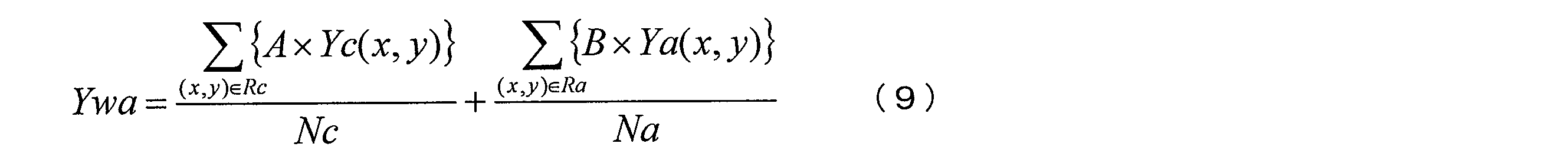
ここで、Yc(x,y)は前方視野に含まれる画素の輝度信号値であり、Ya(x,y)は側方視野に含まれる画素の輝度信号値である。Ncは前方視野に含まれる画素の画素数であり、Naは側方視野に含まれる画素の画素数である。Aは前方視野の重み係数であり、Bは側方視野の重み係数である。Rcは前方視野に対応する領域であり、Raは側方視野に対応する領域である。和(Σ)は、各領域に属する画素についての和である。
測光部416は、注目領域の重み係数を、注目領域以外の重み係数に比べて相対的に大きい係数に設定する。例えば、側方領域が注目領域の場合、A<Bとなる。また、測光部416は、重み係数を湾曲角度(又は湾曲動き量)に応じて設定する。具体的には、湾曲角度(又は湾曲動き量)が大きいほど、側方視野の重み係数Bを前方視野の重み係数Aに比べて大きくする。
測光部416は、注目領域設定部413により注目領域が設定されなかった場合、同時化部412から入力された画像信号の有効画素領域の輝度平均値を算出する。測光部416は、算出した注目領域の輝度加算平均値Ywaを制御部420に転送する。
上式(9)で説明したように、調光制御部は、注目領域の明るさを表す第1の明るさ情報(輝度信号値Ya(x,y))と、注目領域以外の領域の明るさを表す第2の明るさ情報(輝度信号値Yc(x,y))を算出する。調光制御部は、第1の明るさ情報と第2の明るさ情報を、それぞれ第1の重み係数Bと第2の重み係数Aで重み付け加算し、得られた重み付け加算値に基づいて調光制御を行う。調光制御部は、第1の重み係数Bとして、第2の重み係数Aよりも大きい係数を用いる。
このようにすれば、主に注目領域の明るさを調光により制御しながら、画像全体の明るさも調光により制御できる。これにより、注目領域の視認性を向上しながら画像全体の視認性も向上可能である。
以上の実施形態によれば、図20に示すように、状態情報取得部430は、湾曲角度検出部431を有する。湾曲角度検出部431は、スコープ先端部の湾曲角度(図21(A)~図21(C)の角度θ)を表す湾曲角度情報を状態情報として取得する。注目領域設定部413は、取得された湾曲角度情報に基づいて注目領域を設定する。
このようにすれば、湾曲角度から術者が興味のある観察領域を推測でき、その領域の明るさを調光制御することで術者が観察しやすい画像を提供できる。
また本実施形態では、注目領域設定部413は、湾曲角度が閾値よりも大きいと判断された場合、撮像画像の中の側方視野に対応する領域を注目領域として設定する。
このようにすれば、側方視野に病変がある場合に術者はスコープ先端を湾曲操作すると考えられるため、その側方視野を注目領域に設定できる。また、湾曲角度が小さい(閾値以下の)わずかな湾曲操作は、誤差あるいは前方視野の微調整と推測できる。そのため、閾値判定を行うことにより、不必要な測光対象領域の切り替わりを防止できる。
ここで、前方視野に対応する領域とは、前方視野の被写体が撮像された領域であり、例えば対物光学系の光軸方向の被写体が撮像された領域である。例えば光軸が画像中心と一致する場合、前方視野に対応する領域は、画像中心を含む中央領域である。
また側方視野に対応する領域とは、側方視野の被写体が撮像された領域であり、例えば対物光学系の光軸に直交する方向の被写体が撮像された領域である。例えば光軸が画像中心と一致する場合、側方視野に対応する領域は、上記中央領域の周辺領域である。
また本実施形態では、注目領域設定部413は、撮像画像の中の側方視野に対応する領域を注目領域として設定する。上式(9)で説明したように、調光制御部は、湾曲角度が大きいほど、第1の重み係数Bを第2の重み係数Aよりも大きくする。
このようにすれば、湾曲角度が大きいほど術者は側方視野を注目していると推測できるため、その領域の重み係数を大きくして測光処理することで、術者が観察しやすい画像を提供することができる。
また本実施形態では、図20に示すように、状態情報取得部430は、湾曲動き量検出部432を有する。湾曲動き量検出部432は、スコープ先端部の湾曲動き量(図21(A)~図21(C)の角度θの単位時間当たりの変化)を表す湾曲動き量情報を状態情報として取得する。注目領域設定部413は、取得された湾曲動き量情報に基づいて注目領域を設定する。
このようにすれば、湾曲動き量から術者の興味のある観察領域を推測でき、その領域の明るさを調光制御することで術者が観察しやすい画像を提供できる。
また本実施形態では、注目領域設定部は、湾曲動き量が閾値よりも大きいと判断された場合、撮像画像の中の側方視野に対応する領域を注目領域として設定する。
このようにすれば、側方視野に病変がある場合に術者はスコープ先端を湾曲操作すると考えられるため、その側方視野を注目領域に設定できる。また、湾曲動き量が小さい(閾値以下の)わずかな湾曲操作は、誤差あるいは前方視野の微調整と推測できる。そのため、閾値判定を行うことにより、不必要な測光対象領域の切り替わりを防止できる。
また本実施形態では、注目領域設定部413は、撮像画像の中の側方視野に対応する領域を注目領域として設定する。上式(9)で説明したように、調光制御部は、湾曲動き量が大きいほど、第1の重み係数Bを第2の重み係数Aよりも大きくする。
このようにすれば、湾曲動き量が大きいほど術者は側方視野を注目していると推測できるため、その領域の重み係数を大きくして測光処理することで、術者が観察しやすい画像を提供することができる。
5.第4の実施形態
5.1.内視鏡装置
光源の出射光量から推定した被写体までの距離情報に基づいて注目領域を設定する第4の実施形態について説明する。
5.1.内視鏡装置
光源の出射光量から推定した被写体までの距離情報に基づいて注目領域を設定する第4の実施形態について説明する。
図23に、第4の実施形態における内視鏡装置の構成例を示す。内視鏡装置は、光源部100、操作部200、挿入部300、制御装置400、表示部500、外部I/F部550を含む。なお、図3等で説明した構成要素と同一の構成要素については同一の符号を付し、適宜説明を省略する。
制御装置400は、画像処理部410と、制御部420と、状態情報取得部430を含む。状態情報取得部430は、画像処理部410に接続される。制御部420は、光源絞り駆動部103と、回転駆動部105と、画像処理部410と、状態情報取得部430と、外部I/F部550に接続され、これらの制御を行う。
本実施形態では、調光処理が稼動している状態において光源部100の出射光量の情報を取得し、その出射光量の情報に基づいて被写体との距離情報を推定し、その距離情報に基づいて注目領域やそれ以外の領域の測光処理を適応的に制御する。
5.2.状態情報取得部
被写体までの距離を推定し、その距離に基づいて注目領域を設定する手法について詳細に説明する。
被写体までの距離を推定し、その距離に基づいて注目領域を設定する手法について詳細に説明する。
術者は、内視鏡装置による観察において病変部と推測される領域を発見すると、挿入部300の先端をその領域に近接させる。この場合、被写体からの反射光量は強くなり、撮像された画像信号は明るくなる。本実施形態では、状態情報取得部430が調光処理を行い、制御部420を介して光源絞り駆動部103を制御し、画像が目標の観察明るさになるまで光源絞り102の開口面積を縮小する。
一方、挿入部300の先端が観察領域から離れている状態では、被写体からの反射光量は弱くなり、撮像された画像信号は暗くなる。状態情報取得部430は、制御部420を介して光源絞り駆動部103を制御し、画像が目標の観察明るさになるまで光源絞り102の開口面積を拡張する。即ち調光処理において、光源絞り102の開口面積が小さい場合は、挿入部300の先端と被写体が近接している状態であり、光源絞り102の開口面積が大きい場合は、挿入部300の先端と被写体が離れている状態である。
本実施形態では、被写体のより広い範囲を観察するため、図1で上述のように前方の物体の観察と同時に側方(略側方を含む)の物体の観察を行うことが可能な対物光学系を用いる。そのため、図2(B)で上述のように、画像中心の座標(N/2,M/2)を領域中心とする前方視野(中央部)と側方視野(周辺部)が表示される。
図24(A)、図24(B)に示すように、術者が病変部と推測される領域を見つけた場合、通常は、その病変部を画像信号の中央部(前方視野)に合わせる。しかしながら、図24(C)、図24(D)に示すように、腸など細長い管腔状の部位を診察する場合、空間領域の制限によって病変部を画像信号の前方視野に合わせることが難しい。即ち、空間が狭いため、挿入部300の先端を回転させにくい。そのため、図24(D)に示すように、画像信号の側方視野に病変部を合わせるしかない。
そこで本実施形態では、被写体にスコープ先端が近接しているか否かの判定を、光源絞り102の開口情報に基づいて行う。近接していると判定した場合、測光モードに応じて前方視野領域又は側方視野領域を注目領域に設定し、その注目領域の調光制御を行う。
具体的には、状態情報取得部430は、制御部420を介して光源絞り102の開口面積(広義には開口情報)を取得し、開口面積が所定の閾値以下の場合は、挿入部300の先端が注目領域に「近接している」状態と判定する。状態情報取得部430は、判定結果を状態情報として注目領域設定部413に転送する。
本実施形態では、図24(A)等で上述した観察状況に合わせて、複数の測光モードが用意される。測光モードは、外部I/F部550を介して、術者が設定する。例えば、術者が画像信号の前方視野を注目したい場合、測光モードを「前方モード」に設定する。
注目領域設定部413は、状態情報取得部430から転送された状態情報と、測光モードと、に基づいて注目領域を設定する。具体的には、注目領域設定部413は、測光モードが「前方モード」であり、スコープ先端が被写体に「近接している」と判断された場合には、画像中心の座標(N/2,M/2)を領域中心とする前方視野を注目領域として設定する。また、注目領域設定部413は、測光モードが「側方モード」であり、スコープ先端が被写体に「近接している」と判断された場合には、側方視野を注目領域として設定する。またスコープ先端が被写体に「近接している」と判断されなかった場合には、注目領域を設定しない。注目領域設定部413は、設定した注目領域を測光部416へ転送する。
このように、光源の絞り状況に応じて適応的に注目領域(前方視野又は側方視野)を設定し、その注目領域の調光制御を行うことで、術者にとって病変部視認性の向上に繋がる。
5.3.変形例
上記の実施形態では、光源絞り102の開口状況に応じて適応的に測光処理を行うが、本実施形態はこれに限定されない。例えば、LED光源を用いて、そのLED光源の光量制御情報(例えば駆動電流)に基づいて測光処理を行ってもよい。
上記の実施形態では、光源絞り102の開口状況に応じて適応的に測光処理を行うが、本実施形態はこれに限定されない。例えば、LED光源を用いて、そのLED光源の光量制御情報(例えば駆動電流)に基づいて測光処理を行ってもよい。
図25に、このような処理を行う場合の内視鏡装置の変形構成例を示す。内視鏡装置は、光源部100、操作部200、挿入部300、制御装置400、表示部500、外部I/F部550を含む。なお、図3等で説明した構成要素と同一の構成要素については同一の符号を付し、適宜説明を省略する。
光源部100は、白色光源101と、回転色フィルター104と、回転駆動部105と、集光レンズ106と、光源の出射光量を制御する光源制御部107と、を含む。白色光源101はLED光源により構成される。光源制御部107は、制御部420からの制御信号に基づいて、LED光源の出射光量の強度を制御する。制御部420は、上式(6)で説明した調整係数Lcに基づいて出射光量を調整する。
注目領域設定部413は、制御部420からの出射光量の制御信号に基づいて、注目領域を設定する。即ち、出射光量が閾値よりも小さい場合、スコープ先端を被写体に近づけたと判断し、測光モードに応じた注目領域を設定する。測光部416は、設定された注目領域の測光処理を行う。
以上の実施形態によれば、状態情報取得部430は、被写体とスコープ先端部の間の距離を表す距離情報を、被写体を照明する光源部100の出射光量に基づいて取得する。注目領域設定部413は、距離情報を状態情報として注目領域を設定する。
具体的には、注目領域設定部413は、距離が閾値よりも近いと判断された場合に注目領域を設定する。
より具体的には、内視鏡装置は、モード設定部(図23の制御部420)と調光制御部(図23の状態情報取得部430と制御部420)を含む。モード設定部は、第1の測光モード(前方モード)又は第2の測光モード(側方モード)を設定する。調光制御部は、光源部100の絞り(図23の光源絞り102)の開口面積を制御することにより、出射光量を制御する。距離情報は、調光制御部により制御された開口面積である。注目領域設定部413は、第1の測光モードにおいて開口面積が閾値よりも小さいと判断された場合に、撮像画像の中の前方視野に対応する領域を注目領域に設定する。注目領域設定部413は、第2の測光モードにおいて開口面積が閾値よりも小さいと判断された場合に、撮像画像の中の側方視野に対応する領域を注目領域に設定する。調光制御部は、設定された注目領域の明るさに基づいて開口面積を制御する。
このようにすれば、スコープ先端を近づけた領域は術者が観察したい領域であると考えられるため、距離に応じて注目領域を設定することで、術者が観察したい領域を適切に調光制御できる。また、調光制御により画像の明るさは一定に保たれるため、画像ではなく調光制御に基づいて距離を推定することにより、スコープ先端が被写体に近づいたか否かを判定できる。
6.第5の実施形態
6.1.内視鏡装置
画像の明るさから推定した被写体までの距離情報に基づいて注目領域を設定する第5の実施形態について説明する。
6.1.内視鏡装置
画像の明るさから推定した被写体までの距離情報に基づいて注目領域を設定する第5の実施形態について説明する。
第5の実施形態における内視鏡装置は、光源部100、操作部200、挿入部300、制御装置400、表示部500、外部I/F部550を含む。なお、構成は、図3で説明した第1の実施形態と同様である。以下では、第1の実施形態と動作や処理が同一の構成要素については適宜説明を省略する。
画像処理部410は、前処理部411と、同時化部412と、注目領域設定部413と、後処理部415と、測光部416と、階調変換部419を含む。なお、構成は、図6で説明した第1の実施形態と同様である。
画像信号中で相対的に明るい領域は、挿入部300の先端と被写体との距離が近い領域と考えられる。そのため本実施形態では、画像信号中の局所領域毎に明るさを算出し、その複数の局所領域の中で相対的に明るい局所領域を注目領域として設定する。
6.2.注目領域設定部
図26に、第5の実施形態における注目領域設定部413の詳細な構成例を示す。注目領域設定部413は、輝度換算部441、加算部442、特定部443を含む。同時化部412は、輝度換算部441へ接続する。輝度換算部441は加算部442へ接続する。加算部442は特定部443へ接続する。特定部443は測光部416へ接続している。制御部420は、輝度換算部441、加算部442、特定部443と双方向に接続している。
図26に、第5の実施形態における注目領域設定部413の詳細な構成例を示す。注目領域設定部413は、輝度換算部441、加算部442、特定部443を含む。同時化部412は、輝度換算部441へ接続する。輝度換算部441は加算部442へ接続する。加算部442は特定部443へ接続する。特定部443は測光部416へ接続している。制御部420は、輝度換算部441、加算部442、特定部443と双方向に接続している。
輝度換算部441は、図27に示すように、同時化後の画像信号のサンプリング画素の輝度信号値Yi(x,y)を上式(1)により算出し、そのサンプリング画素の輝度信号値Yi(x,y)を加算部442へ転送する。
加算部442は、前方視野と側方視野それぞれにおいて、サンプリング画素の輝度信号Yi(x,y)を下式(10)により加算平均し、前方視野の明るさ測定値Ydfと側方視野の明るさ測定値Ydsを算出する。ここで、画像信号の中心座標(N/2,M/2)を原点とし、所定の半径内の画素を前方視野、それ以外の画素を側方視野と設定する。

ここで、mは前方視野のサンプリング画素数(定数)であり、nは側方視野のサンプリング画素数(定数)である。これらは、画像信号の画角大きさに応じて設定される。a(x,y)、b(x,y)は、重み係数である。
なお、上記の実施形態では、前方視野と側方視野の2つの領域に分割し、それぞれの視野の明るさ測定値を算出するが、本実施形態はこれに限定されない。例えば、挿入部300の先端の側方を被写体に接近して観察する場合、その側方視野がすべて明るくなる可能性が低い。図28に示すように、このようなことを想定して、例えば側方視野を更に複数領域に分割し、各領域に含まれるサンプリング画素の輝度信号Yi(x,y)を加算平均して各領域の明るさ測定値を算出してもよい。この場合、算出した複数の側方領域の明るさ測定値中の最大値を、側方領域の明るさ測定値Ydsとする。例えば、図28では、側方視野3の明るさ測定値が最大値となる。この場合、側方視野3の明るさ測定値を側方領域の明るさ測定値Ydsとして特定部443へ転送する。
特定部443は、加算部442により算出された明るさ測定値Ydf、Ydsに基づいて注目領域を設定する。具体的には、特定部443は、前方視野の明るさ測定値Ydfが所定の閾値より大きい場合、前方視野に対応する領域を注目領域として設定する。また特定部443は、側方視野の明るさ測定値Ydsが所定の閾値より大きい場合、側方視野に対応する領域を注目領域として設定する。明るさ測定値Ydf、Ydsがともに所定の閾値より大きい場合は、より明るい領域を注目領域として設定する。特定部443は、設定した注目領域情報を測光部416へ転送する。
なお、図28で説明したように側方視野が分割されている場合、分割された領域を注目領域として設定する。具体的には、特定部443は、分割された側方視野のうちの最も測定値Ydsが大きい領域の測定値Ydsが所定の閾値より大きい場合、その領域を注目領域として設定する。
上記の実施形態によれば、画像信号の明るさから挿入部300の先端と被写体の距離を推定し、その距離に基づいて前方視野と側方視野を適応的に調光処理することで、術者にとって病変部視認性の向上させることができる。
以上の実施形態によれば、注目領域設定部413は、距離情報取得部(図26の輝度換算部441、加算部442)を有する。距離情報取得部は、被写体とスコープ先端部の間の距離を表す距離情報を、撮像画像の明るさ(例えば輝度信号Yi(x,y))に基づいて取得する。注目領域設定部413は、取得された距離情報に基づいて注目領域を設定する。
具体的には、距離情報取得部は、撮像画像の画素の輝度に関する輝度特徴量を算出(例えば、輝度換算部441(広義には輝度特徴量算出部)が算出)し、算出した輝度特徴量に基づいて距離情報を取得する。
より具体的には、距離情報取得部は、撮像画像を複数の領域(例えば前方視野に対応する領域と、側方視野に対応する領域)に分割し、分割した各領域の明るさ(明るさ測定値Ydf、Yds)を距離情報として取得する。注目領域設定部413は、その複数の領域のうち最も明るい領域をスコープ先端部に最も近い領域として注目領域に設定する。
このようにすれば、画像の明るさに基づいて注目領域を設定し、その注目領域の明るさを調光制御できる。即ち、術者が観察したい領域にスコープ先端を近づけると、その領域が照明により明るくなるため、画像の明るさに応じて注目領域を設定できる。
7.第6の実施形態
7.1.内視鏡装置
特殊光により病変領域を検出し、検出した病変領域を注目領域として設定する第6の実施形態について説明する。
7.1.内視鏡装置
特殊光により病変領域を検出し、検出した病変領域を注目領域として設定する第6の実施形態について説明する。
図29に、第6の実施形態における内視鏡装置の構成例を示す。内視鏡装置は、光源部100、挿入部300、制御装置400、表示部500、外部I/F部550を含む。なお、図3等で説明した構成要素と同一の構成要素については同一の符号を付し、適宜説明を省略する。
光源部100は、白色光源101と、光源絞り102と、光源絞り駆動部103と、集光レンズ106を含む。第1の実施形態に比べて、回転色フィルター104、回転駆動部105が削除されている。
挿入部300は、ライトガイドファイバー301と、照明レンズ314、315と、対物光学系303を含む。また挿入部300は、対物光学系303で集光された反射光を2つに分離するハーフミラー309と、分離された反射光を検出する第1の撮像素子304及び第2の撮像素子310と、第1のA/D変換部305と、第2のA/D変換部311を含む。
A/D変換部311は、第2の撮像素子310により検出されたアナログの画像信号を、デジタルの画像信号に変換する。
第1の撮像素子304は、Bayer型配列の撮像素子である。図30に示すように、第2の撮像素子310は、2種類の色フィルターnB、nGが市松上に配置された撮像素子である。図31に示すように、各色フィルターnB、nGは、狭帯域の光を透過する特性を有している。例えば、色フィルターnBは390~445nmの光を透過する特性を有し、色フィルターnGは530~550nmの光を透過する特性を有する。例えば、第1の撮像素子304と、第2の撮像素子310の画素数は同一である。
制御装置400は、画像処理部410と、制御部420を含む。A/D変換部305、311は、デジタルに変換した画像信号を画像処理部410に転送する。画像処理部410は、処理した画像信号を表示部500に転送する。制御部420は、光源絞り駆動部103と、画像処理部410と、外部I/F部550に接続されており、これらの制御を行う。
7.2.画像処理部
図32に、第6の実施形態における画像処理部410の詳細な構成例を示す。画像処理部410は、第1の前処理部411、第2の前処理部418、第1の同時化部412、第2の同時化部417、注目領域設定部413、後処理部415、測光部416、階調変換部419を含む。なお、前処理部411と、階調変換部419と、後処理部415と、測光部416の処理は、第1の実施形態と同一であるため、説明を省略する。
図32に、第6の実施形態における画像処理部410の詳細な構成例を示す。画像処理部410は、第1の前処理部411、第2の前処理部418、第1の同時化部412、第2の同時化部417、注目領域設定部413、後処理部415、測光部416、階調変換部419を含む。なお、前処理部411と、階調変換部419と、後処理部415と、測光部416の処理は、第1の実施形態と同一であるため、説明を省略する。
同時化部412は、階調変換部419と、測光部416とに接続される。前処理部418は同時化部417に接続される。同時化部417は注目領域設定部413に接続される。注目領域設定部413は、測光部416に接続される。また、制御部420は、前処理部418、同時化部417と双方向に接続され、これらの制御を行う。
同時化部412は、前処理部411により処理された画像信号に対して同時化処理を施す。上述のように、第1の撮像素子304で取得される画像信号は、Bayer型配列の単板画像信号である。同時化部412は、補間処理を用いて、単板画像信号からRGBの3板画像信号を生成する。例えば、補間処理としては公知のバイキュービック補間処理を用いればよい。以下では、同時化部412より出力される画像信号を通常光画像と呼ぶ。
前処理部418は、A/D変換部311から入力される画像信号に対して、制御部420に予め保存されているOBクランプ値、ゲイン補正値、WB係数値を用いて、OBクランプ処理、ゲイン補正処理、WB補正処理を行う。前処理部418は、前処理を施した画像信号を同時化部417へ転送する。
同時化部417は、前処理部418により処理された画像信号に対して同時化処理を施す。図30で上述のように、第2の撮像素子310は、2種類の色フィルターnB、nGが市松上に配置された撮像素子である。従って前処理部418により処理された画像信号は、図33に示すような単板画像信号となる。図33では、色フィルターnBで取得される画像信号をB2と表し、色フィルターnGで取得される画像信号をG2と表す。
同時化部417は、下式(11)、(12)により、この単板画像信号からB2画像信号とG2画像信号を生成する。B2画像信号は、全画素でB2信号を有する画像信号であり、G2画像信号は、全画素でG2信号を有する画像信号である。例えば、図33のG2(1,1)の位置におけるnBフィルターの画像信号B2(1,1)は、下式(11)を用いて算出すればよい。また、図33のB2(1,2)の位置におけるnGフィルターの画像信号G2(1,2)は、下式(12)を用いて算出すればよい。


同時化部417は、上式(11)、(12)により生成したB2画像信号とG2画像信号を用いて、RGBの3板画像信号を生成する。具体的には、同時化部417は、R画像信号としてG2画像信号を用い、G、B画像信号としてB2画像信号を用いることにより、3板画像信号を生成する。以下では、同時化部417より出力される画像信号を狭帯域光画像(広義には特殊光画像)と呼ぶ。
注目領域設定部413は、後述する手法により狭帯域光画像から病変領域を検出し、その病変領域に基づいて注目領域を設定する。狭帯域光画像上では、扁平上皮癌等の病変部が、褐色の領域として描出される特徴がある。そのため、特定の色相を有する領域(褐色の領域)を狭帯域光画像から検出することで、病変領域を検出可能である。
7.3.注目領域設定部
図34に、第6の実施形態における注目領域設定部413の詳細な構成例を示す。注目領域設定部413は、局所領域設定部451と、特徴量算出部452と、病変領域検出部453と、ラベリング処理部454と、領域選出部455と、座標算出部456と、対応付け部457と、測光処理条件設定部459を含む。
図34に、第6の実施形態における注目領域設定部413の詳細な構成例を示す。注目領域設定部413は、局所領域設定部451と、特徴量算出部452と、病変領域検出部453と、ラベリング処理部454と、領域選出部455と、座標算出部456と、対応付け部457と、測光処理条件設定部459を含む。
同時化部417は、局所領域設定部451に接続される。局所領域設定部451は、特徴量算出部452と対応付け部457に接続される。特徴量算出部452は、病変領域検出部453に接続される。病変領域検出部453は、ラベリング処理部454に接続される。ラベリング処理部454は、領域選出部455に接続される。領域選出部455は、座標算出部456に接続される。座標算出部456は、対応付け部457に接続される。対応付け部457は、測光処理条件設定部459に接続される。測光処理条件設定部459は測光部416に接続される。
局所領域設定部451は、同時化部417から出力される狭帯域光画像に対して、複数の局所領域を設定する。以下では、狭帯域光画像を矩形領域に分割し、分割した各領域を局所領域として設定する場合を例に挙げて説明する。
図35に示すように、例えば5×5画素を1つの局所領域とする。狭帯域画像信号は、M×N個の局所領域で構成されていることとし、各領域の座標を(m,n)で表す。また、座標(m,n)の局所領域をa(m,n)で表す。また、画像の左上に位置する局所領域の座標を(0,0)とし、右方向をmの正方向、下方向をnの正方向と定義する。なお、計算量を削減するために、複数の隣接する画素群からなる領域を一つの局所領域としているが、1画素を1つの局所領域とすることも可能である。この場合も、後の処理は同一である。
局所領域設定部451は、局所領域の大きさ、及び全ての局所領域の座標を、特徴量算出部452に出力する。局所領域設定部451は、全ての局所領域の座標と、その座標に対応する狭帯域光画像上における座標を、対応付け部457に出力する。ここで、狭帯域光画像上における座標とは、局所領域の中心に存在する画素の座標である。
特徴量算出部452は、局所領域設定部451により設定された全ての局所領域から、特徴量を算出する。以下では、特徴量として色相を用いる場合を例にとり説明する。
局所領域a(m,n)の色相を、H(m,n)と表記する。特徴量算出部452は、H(m,n)を算出するため、まず各局所領域における、R,G,B信号の平均値R_ave,G_ave,B_aveを算出する。ここで、R_aveは、各局所領域に含まれる全画素のR信号の平均値である。G_ave,B_aveも同様である。例えば、各信号値は8ビット(0~255)である。
特徴量算出部452は、例えば下式(13)~(18)を用いて、R_ave,G_ave,B_aveから各局所領域の色相H(m,n)を算出する。まず、下式(13)によりmaxを求める。

ここでMAX()関数は、括弧内における複数の引数の最大値を出力する関数である。
maxが0の場合、下式(14)により色相Hを算出する。

maxが0以外の場合、下式(15)によりdを算出する。

ここで、MIN()関数は、括弧内における複数の引数の最小値を出力する関数である。
R_ave,G_ave,B_aveのうちR_aveが最大の場合、下式(16)により色相Hを算出する。

R_ave,G_ave,B_aveのうちG_aveが最大の場合、下式(17)により色相Hを算出する。

R_ave,G_ave,B_aveのうちB_aveが最大の場合、下式(18)により色相Hを算出する。

R_ave,G_ave,B_aveのうちB_aveが最大の場合、下式(18)により色相Hを算出する。
なお、H<0になった場合には、Hに360を加える。またH=360の場合、H=0とする。
病変領域検出部453は、特定の色相Hを有する局所領域を病変領域として検出し、病変領域として検出された全ての局所領域の座標を、ラベリング処理部454に出力する。例えば病変領域検出部453は、色相Hが5~35の値を有する領域(褐色領域に相当)を、病変領域として検出する。
ラベリング処理部454は、病変領域検出部453より出力された病変領域のうちの互いに隣接する病変領域に対して、同一のラベルを付与する。以下では、同一のラベルを付与された病変領域の集合を、病変領域群と呼ぶ。ラベリング処理部454は、同一のラベルを付与された病変領域群の大きさを算出する。ここで、病変領域群の大きさとは、同一のラベルを付与された病変領域の数とすればよい。なおこれに限定されず、病変領域群の大きさは、病変領域群の面積を表す情報であればよい。
図36を用いて、ラベリング処理部454が行う処理について詳細に説明する。例えば図36に示す病変領域が検出された場合、A1に示す領域に属する病変領域には、ラベル1が付与される。同様にA2に示される領域に属する病変領域にはラベル2が付与され、A3に示される領域に属する病変領域には、ラベル3が付与される。ラベリング処理部454は、同一のラベルを付与された病変領域群の大きさを算出する。ラベル1を付与された病変領域群1(A1)の大きさは7となる。同様に、病変領域群2(A2)の大きさは3となり、病変領域群3(A3)の大きさは2となる。
領域選出部455は、ラベリング処理部454でラベルを付与された複数の病変領域群のうち、最大の大きさを有する病変領域群を注目領域として選出する。そして、その注目領域に含まれる全ての局所領域の座標を座標算出部456に出力する。図36の場合には、A1で示される病変領域群1が、注目領域として選出される。
座標算出部456は、領域選出部455より出力される全ての局所領域座標から、局所領域座標の最大値(mMAX,nMAX)及び最小値(mMIN,nMIN)を算出し、算出した値を対応付け部457に出力する。
具体的には、領域選出部455より出力される全ての局所領域の数をKとし、その全ての局所領域を便宜的にa(m1,n1)~a(mK,nK)と表す。この場合、座標算出部456は、局所領域座標の最大値(mMAX,nMAX)及び最小値(mMIN,nMIN)を、下式(19)により算出する。

対応付け部457は、この最大値(mMAX,nMAX)、最小値(mMIN,nMIN)に対応する、狭帯域光画像の座標を算出する。具体的には、その座標を、局所領域設定部451より出力される局所領域と狭帯域光画像の座標の対応関係に基づいて算出する。以下では、(mMAX,nMAX)、(mMIN,nMIN)に対応する狭帯域光画像の座標を(xMAX,yMAX)、(xMIN,yMIN)と表す。対応付け部457は、座標(xMAX,yMAX)、(xMIN,yMIN)を、測光処理条件設定部459に出力する。
測光処理条件設定部459は、測光処理の対象となる注目領域の条件である測光処理条件を決定し、その測光処理条件を測光部416に出力する。具体的には、測光処理条件設定部459は、下式(20)により注目領域の中心座標(x0,y0)を算出し、下式(21)により注目領域の半径Rを算出し、算出した中心座標(x0,y0)と半径Rを測光処理条件とする。図36で説明した例では、図示のように半径Rの円内が測光対象の注目領域に設定される。

ここで、int()は、括弧内の実数の整数値を返す関数である。
以上の実施形態によれば、注目領域設定部413は、撮像画像に基づいて特徴量(例えば色相値)を算出し、所定の特徴量(例えば色相値5~35の範囲)を有する領域に基づいて注目領域を設定する。
このようにすれば、病変部に特徴的に現れる画像の特徴量に基づいて注目領域を設定し、その注目領域の明るさを調光制御できる。これにより、術者は、病変部を適正な明るさで観察できる。
また本実施形態では図36等で説明したように、注目領域設定部413は、所定の特徴量を有する領域のうちの最大の面積の領域を選択し、選択した領域を含む円形領域を注目領域として設定する。
術者は、観察したい病変部にスコープを近づけるため、その観察したい病変部が大きく表示されると考えられる。そのため、大きさが最大となる病変領域群を注目領域として設定することで、術者が注目していると思われる領域を適正な明るさで表示できる。
なお、上記の実施形態では特徴量が色相値である場合を例に説明したが、本実施形態はこれに限定されない。例えば、特徴量は、病変部と他の領域を識別できるものであればよく、例えば出血部位を識別する場合にはR画素値が特徴量であってもよい。
また、上記の実施形態では、ラベリング処理部454でラベル付けされた病変領域群のうち、最大の大きさを有する病変領域群に基づいて注目領域を設定する例を説明したが、本実施形態はこれに限定されない。例えば、病変領域検出部453で検出された全ての病変領域に基づいて注目領域を設定してもよい。この場合、領域選出部455は、ラベリング処理部454より出力される全ての病変領域群に含まれる局所領域の座標を、座標算出部456に出力すればよい。
これにより、複数の病変領域群が存在する場合にも、全ての病変領域群を適正な明るさで表示することが可能となる。
また、上記の実施形態では、表示画像として通常光画像を用いる例を示したが、本実施形態はこれに限定されない。例えば、狭帯域光画像を表示画像として用いてもよい。
また本実施形態では、撮像画像は、特定の波長帯域における情報を有する被写体像が撮像された特殊光画像と、白色光の波長帯域における情報を有する被写体像が撮像された通常光画像(白色光画像)である。注目領域設定部413は、特殊光画像に基づいて注目領域を設定する。
調光制御部は、設定された注目領域に基づいて、通常光画像の調光制御を行う。
このようにすれば、検出したい病変部に応じた特殊光画像を取得することにより、その病変部の特徴量を抽出しやすくなり、その抽出した特徴量により注目領域を設定できる。また、特殊光画像により設定した注目領域に応じて、観察において通常用いられる通常光画像の調光制御を行うことができる。
また、本実施形態では、特定の波長帯域は、白色の波長帯域(例えば380nm~650nm)よりも狭い帯域である(NBI: Narrow Band Imaging)。例えば、通常光画像及び特殊光画像は、生体内を写した生体内画像であり、その生体内画像に含まれる特定の波長帯域は、血液中のヘモグロビンに吸収される波長の波長帯域である。例えば、このヘモグロビンに吸収される波長は、390nm~445nm(第1の狭帯域光nB)、又は530nm~550nm(第2の狭帯域光nG)である。
これにより、生体の表層部及び、深部に位置する血管の構造を観察することが可能になる。また得られた信号を特定のチャンネル(G2→R、B2→G,B)に入力することで、扁平上皮癌等の通常光では視認が難しい病変などを褐色等で表示することができ、病変部の見落としを抑止することができる。なお、390nm~445nm又は530nm~550nmとは、ヘモグロビンに吸収されるという特性及び、それぞれ生体の表層部又は深部まで到達するという特性から得られた数字である。ただし、この場合の波長帯域はこれに限定されず、例えばヘモグロビンによる吸収と生体の表層部又は深部への到達に関する実験結果等の変動要因により、波長帯域の下限値が0~10%程度減少し、上限値が0~10%程度上昇することも考えられる。
また、本実施形態では、通常光画像及び特殊光画像は生体内を写した生体内画像であり、その生体内画像に含まれる特定の波長帯域は、蛍光物質が発する蛍光の波長帯域であってもよい。例えば、特定の波長帯域は、490nm~625nmの波長帯域であってもよい。
これにより、AFI(Auto Fluorescence Imaging)と呼ばれる蛍光観察が可能となる。この蛍光観察では、励起光(390nm~470nm)を照射することで、コラーゲンなどの蛍光物質からの自家蛍光(intrinsic fluorescence。490nm~625nm)を観察することができる。このような観察では病変を正常粘膜とは異なった色調で強調表示することができ、病変部の見落としを抑止すること等が可能になる。なお490nm~625nmとは、上述の励起光を照射した際、コラーゲン等の蛍光物質が発する自家蛍光の波長帯域を示したものである。ただし、この場合の波長帯域はこれに限定されず、例えば蛍光物質が発する蛍光の波長帯域に関する実験結果等の変動要因により、波長帯域の下限値が0~10%程度減少し、上限値が0~10%程度上昇することも考えられる。また、ヘモグロビンに吸収される波長帯域(540nm~560nm)を同時に照射し、擬似カラー画像を生成してもよい。
また、本実施形態では、生体内画像に含まれる特定の波長帯域は、赤外光の波長帯域であってもよい。例えば、特定の波長帯域は、790nm~820nm、又は905nm~970nmの波長帯域であってもよい。
これにより、IRI(Infra Red Imaging)と呼ばれる赤外光観察が可能となる。この赤外光観察では、赤外光が吸収されやすい赤外指標薬剤であるICG(インドシアニングリーン)を静脈注射した上で、上記波長帯域の赤外光を照射することで、人間の目では視認が難しい粘膜深部の血管や血流情報を強調表示することができ、胃癌の深達度診断や治療方針の判定などが可能になる。なお、790nm~820nmという数字は赤外指標薬剤の吸収がもっとも強いという特性から求められ、905nm~970nmという数字は赤外指標薬剤の吸収がもっとも弱いという特性から求められたものである。ただし、この場合の波長帯域はこれに限定されず、例えば赤外指標薬剤の吸収に関する実験結果等の変動要因により、波長帯域の下限値が0~10%程度減少し、上限値が0~10%程度上昇することも考えられる。
また、本実施形態では、取得された通常光画像に基づいて、特殊光画像を生成する特殊光画像取得部を含んでもよい。例えば、図29において、ハーフミラー309と撮像素子310とA/D変換部311を省略し、図32の前処理部418と同時化部417が特殊光画像取得部として通常光画像から特殊光画像を生成してもよい。
具体的には、特殊光画像取得部は、取得された通常光画像から、白色の波長帯域における信号を抽出する信号抽出部を含む。そして、特殊光画像取得部は、抽出された通常光の波長帯域における信号に基づいて、特定の波長帯域における信号を含む特殊光画像を生成してもよい。例えば、信号抽出部は、通常光画像のRGB信号から10nm刻みに被写体の分光反射率特性を推定し、特殊光画像取得部は、その推定された信号成分を上記特定の帯域で積算して特殊光画像を生成する。
より具体的には、特殊光画像取得部は、通常光の波長帯域における信号から、特定の波長帯域における信号を算出するためのマトリクスデータを設定するマトリクスデータ設定部を含んでもよい。そして、特殊光画像取得部は、設定されたマトリクスデータを用いて、白色の波長帯域における信号から特定の波長帯域における信号を算出して、特殊光画像を生成してもよい。例えば、マトリクスデータ設定部は、特定の波長帯域の照射光の分光特性が10nm刻みに記述されたテーブルデータをマトリクスデータとして設定する。そして、このテーブルデータに記述された分光特性(係数)を、10nm刻みに推定された被写体の分光反射率特性に乗算して積算し、特殊光画像を生成する。
これにより、通常光画像に基づいて特殊光画像を生成することができるため、通常光を照射する1つの光源と、通常光を撮像する1つの撮像素子のみでもシステムを実現することが可能になる。そのため、カプセル型内視鏡や、スコープ型内視鏡の挿入部を小さくすることができ、また部品が少なくてすむためコストを下げる効果も期待できる。
8.第7の実施形態
8.1.内視鏡装置
スコープIDに基づいて注目領域を設定する第7の実施形態について説明する。
8.1.内視鏡装置
スコープIDに基づいて注目領域を設定する第7の実施形態について説明する。
図37に、第7の実施形態における内視鏡装置の構成例を示す。内視鏡装置は、光源部100、挿入部300、制御装置400、表示部500、外部I/F部550を含む。なお、図3等で説明した構成要素と同一の構成要素については同一の符号を付し、適宜説明を省略する。
挿入部300は、ライトガイドファイバー301と、照明レンズ314、315と、対物光学系303と、撮像素子304と、A/D変換部305と、メモリー313を含む。メモリー313以外の各部の構成は、第1の実施形態と同一であるため、説明を省略する。
挿入部300は、一般にスコープと呼ばれる。そのため以下では、挿入部300を適宜スコープと呼ぶ。内視鏡診断では、診断する部位に応じて異なるスコープが用いられる。例えば、食道や胃の診断には、上部消化器スコープが用いられ、大腸の診断には下部消化器スコープが用いられる。一方、スコープのメモリー313には、各スコープ固有の識別番号(スコープID)が保持されている。
制御装置400は、画像処理部410と、制御部420と、状態情報取得部430を含む。状態情報取得部430は、メモリー313に保持されている各スコープ固有の識別番号を参照し、接続されるスコープの種類を識別する。スコープの種類とは、例えば、上部消化器スコープ又は下部消化器スコープの何れかである。状態情報取得部430は、識別したスコープの種類を、後述する注目領域設定部413に出力する。
8.2.画像処理部
図38に、第7の実施形態における画像処理部410の詳細な構成例を示す。画像処理部410は、前処理部411と、同時化部412と、注目領域設定部413と、後処理部415と、測光部416と、階調変換部419を含む。注目領域設定部413以外の処理は第1の実施形態と同一であるため、説明を省略する。
図38に、第7の実施形態における画像処理部410の詳細な構成例を示す。画像処理部410は、前処理部411と、同時化部412と、注目領域設定部413と、後処理部415と、測光部416と、階調変換部419を含む。注目領域設定部413以外の処理は第1の実施形態と同一であるため、説明を省略する。
注目領域設定部413は、状態情報取得部430より出力されるスコープの種類に応じて、注目領域を設定する。注目領域の設定手法は、第3の実施形態と同様である。具体的には、スコープの種類が下部消化器スコープの場合、側方視野の領域を注目領域に設定する。スコープの種類が上部消化器スコープの場合、前方視野の領域を注目領域に設定する。
以上の実施形態によれば、図37等で説明したように、内視鏡装置にはスコープ(挿入部300)が着脱可能である。状態情報取得部430は、装着されたスコープを識別する識別情報(スコープID)を取得する。注目領域設定部413は、取得された識別情報に基づいて注目領域を設定する。
このようにすれば、接続されるスコープに応じて適切な調光制御を施すことで、術者は、病変領域を適正な明るさで観察することができる。
具体的には、スコープは、前方視野と側方視野を結像する対物光学系を有する。注目領域設定部413は、識別情報が下部消化管用のスコープを表す識別情報である場合、撮像画像の中の側方視野に対応する領域を注目領域に設定する。
下部消化器スコープの診断対象となる大腸では、ヒダの裏にある病変が画像の側方領域に表示されると想定される。そのため、側方視野に対応する領域の明るさを調光制御することで、病変の見落としの危険性を改善することが可能である。
また本実施形態では、注目領域設定部413は、識別情報が上部消化管(例えば胃や食道)用のスコープを表す識別情報である場合、撮像画像の中の前方視野に対応する領域を注目領域に設定する。
上部消化器の診断対象となる食道や胃にはヒダが少ないため、側方視野よりも前方視野が診断の際に重要となる。そのため、前方視野に対応する領域の明るさを調光制御することで、重要な視野を見やすくすることができる。
9.第8の実施形態
9.1.注目領域設定部
画像から被写体の動き量(広義には動き情報)を算出し、その動き量に基づいて注目領域を設定する第8の実施形態について説明する。
9.1.注目領域設定部
画像から被写体の動き量(広義には動き情報)を算出し、その動き量に基づいて注目領域を設定する第8の実施形態について説明する。
内視鏡装置と画像処理部410の構成は、図3、図6で上述の第1の実施形態と同様であるため、適宜説明を省略する。以下では、第1の実施形態と構成が異なる注目領域設定部413について詳細に説明する。
図39に、第8の実施形態における注目領域設定部413の詳細な構成例を示す。注目領域設定部413は、歪み補正部471と、画像メモリー472と、動き検出部473(広義には動き情報取得部)と、設定部474を含む。
同時化部412は、同時化した画像信号を歪み補正部471に出力する。歪み補正部471は、画像メモリー472と、動き検出部473と、設定部474に接続される。動き検出部473は、設定部474に接続される。設定部474は、測光部416に接続される。制御部420は、歪み補正部471と、画像メモリー472と、動き検出部473と、設定部474と双方向に接続されており、これらの制御を行う。
歪み補正部471は、同時化処理された画像信号に対し、収差の一種である歪曲収差(以下では適宜、歪みと呼ぶ)を補正する。図40に、歪み補正処理前後の画像例を示す。
具体的には、歪み補正部471は、歪み補正処理後の画像の画素座標を取得する。歪み補正処理後の画像サイズは、光学系の歪みに基づいて予め取得されているとする。歪み補正部471は、取得した画素座標(x,y)を、下式(22)を用いて光軸中心を原点とする座標(x’,y’)に変換する。
ここで、(center_x,center_y)は、歪み補正処理後の光軸中心の座標である。例えば、歪み補正処理後の光軸中心は、歪み補正処理後画像の中心である。
次に、歪み補正部471は、変換した画素座標(x’,y’)に基づいて、下式(23)を用いて物体高rを算出する。

ここで、max_rは、歪み補正処理後の画像における最大物体高である。
次に、歪み補正部471は、算出した物体高rに基づいて像高と物体高の比(R/r)を算出する。具体的には、歪み補正部471は、比R/rと物体高rとの関係をテーブルとして保持しておき、そのテーブルを参照することで物体高rに対応する比R/rを取得する。次に、歪み補正部471は、歪み補正処理後の画素座標(x,y)に対応する、歪み補正処理前の画素座標(X,Y)を下式(24)を用いて取得する。

ここで、(center_X,center_Y)は、歪み補正処理前の光軸中心の座標である。例えば、歪み補正処理前の光軸中心は、歪み補正処理前の画像の中心である。
次に、歪み補正部471は、算出した歪み補正処理前の画素座標(X,Y)に基づいて、歪み補正処理後の画素座標(x,y)における画素値を算出する。(X,Y)が整数でない場合、周囲の画素値に基づく線形補間により画素値を算出する。歪み補正部471は、以上の処理を歪み補正処理後の画像の全画素に対して行う。歪み補正部471は、このようにして歪み補正された画像を、画像メモリー472及び動き検出部473に出力する。
画像メモリー472は、歪み補正部471により歪み補正された歪み補正後画像を保存する。保存された歪み補正後画像は、新たな歪み補正後画像が歪み補正部471より出力されるタイミングと同期して、動き検出部473に出力される。
動き検出部473は、歪み補正部471により歪み補正された歪み補正後画像と、画像メモリー472に保存されていた歪み補正後画像とに基づいて、画像の局所的な動きを検出する。以下では説明を簡単にするため、前者の歪み補正後画像を現フレーム画像とし、後者の歪み補正後画像を前フレーム画像とする。
具体的には、動き検出部473は、局所的な動きを検出する点である代表点を、現フレーム画像上に設定する。例えば図41に示すように、現フレーム画像の画素において一定間隔かつ格子状に代表点(図41に示す●)を設定する。動き検出部473は、現フレーム画像と前フレーム画像の間の代表点の動きベクトルを、局所的な動き量として算出する。例えば、公知の技術であるブロックマッチングを用いて動きベクトルを検出する。動き検出部473は、設定した代表点の座標と、各代表点において検出した動きベクトルとを、設定部474に出力する。
設定部474は、歪み補正部471からの現フレーム画像と、動き検出部473からの代表点の座標及び各代表点の動きベクトルとに基づいて、注目領域を設定する。具体的には、設定部474は、現フレーム画像と動きベクトルに基づいて抜去状態か否かを判定し、抜去状態であれば側方視野を注目領域に設定し、抜去状態でなければ前方視野を注目領域に設定する。設定部474は、設定した注目領域を測光部416に出力する。
ここで、抜去状態とは、管腔状臓器の奥まで内視鏡を挿入した後に、内視鏡を抜きながら観察を行う状態を指す。大腸に対しては一般的にこのような観察が行われるため、抜去状態であればヒダ裏観察が容易になるように側方視野を注目領域に設定し、抜去状態でなければ内視鏡操作が容易になるように前方視野を注目領域に設定する。
9.2.抜去状態の判定手法
図42(A)~図42(D)を用いて、抜去状態の判定手法について説明する。まず、代表点における動きベクトルに基づいて、動きベクトルの消失点を検出する。
図42(A)~図42(D)を用いて、抜去状態の判定手法について説明する。まず、代表点における動きベクトルに基づいて、動きベクトルの消失点を検出する。
具体的には図42(A)において、●が代表点を表し、実線矢印が動きベクトルを表し、×が消失点を表す。消失点とは、各代表点を始点として各代表点における動きベクトルに沿った方向に延長した直線の交点である。例えば観察対象が内径の一定な円筒状であり、動きベクトルが内視鏡の動きのみにより生じるとすると、抜去状態の場合には、各代表点から延長した直線は消失点において一点で交わる。実際には、観察対象である管腔状臓器の内径は一定ではなく、また動きベクトルは生体拍動によっても生じるため、抜去状態であっても直線が消失点において一点で交わらない。そのため、全ての直線からの距離の二乗和を第1の評価値とし、その第1の評価値が最も小さい点を消失点候補とする。直線をax+by+c=0とし、点を(p,q)とすると、第1の評価値Dは下式(25)により求められる。

ここで、上式(25)における和は、代表点から延長した全ての直線についての距離の二乗の総和を表す。
最小二乗法により、第1の評価値Dを最小とする消失点候補の座標(xsk,ysk)を、下式(26)を用いて算出する。

ここで、代表点の座標を(Px,Py)とし、代表点における動きベクトルを(Mx,My)とすると、a=My、b=-Mx、c=MxPy-MyPxである。
次に、その消失点候補における第1の評価値Dが所定の第1の閾値以下であり、その消失点候補が画像内に存在する場合、その消失点候補を消失点とする。消失点候補がこの条件を満たさない場合、消失点が検出できないと判定する。
この条件で抜去状態が検出可能な理由について詳細に説明する。ここで、図42(B)に示すように、内視鏡先端の動く方向を定義する。x方向、y方向、z方向は、画像上においてそれぞれ水平方向、鉛直方向、水平方向及び鉛直方向と直交する奥行きの方向に対応する。またx方向、y方向、z方向について矢印に沿う動きを正の動きと定義し、反対の動きを負の動きと定義する。抜去状態では、内視鏡先端はz方向負の動きとなる。抜去状態ではなく、例えば内視鏡の先端の動きがx方向正の動きである場合、図42(C)に示すように、動きベクトルはほぼ平行となるため、その消失点候補は画像外に存在する。あるいは、消失点候補が画像内に存在したとしてもその消失点候補における第1の評価値Dは大きな値となる。即ち、消失点候補が画像内に存在し、第1の評価値Dが第1の閾値より小さいという条件により、z方向の動きを検出できる。
次に、抜去状態か否かの判定を行う。図42(D)に示すように、内視鏡を挿入した場合でも消失点が検出される。そのため、各代表点からその消失点へのベクトル(破線矢印)と動きベクトル(実線矢印)に基づいた判定を行う。具体的には、その消失点へのベクトルと動きベクトルとの内積が負となる代表点が所定の個数以上ある場合、消失点が検出されないと判定する。消失点が検出されない場合、抜去状態ではないと判定する。
次に、検出した消失点座標における現フレーム画像の画素値を第2の評価値とし、その第2の評価値に基づいて観察対象が管腔状臓器か否かを判定する。消失点座標が整数でない場合、第2の評価値を周囲の画素値に基づいて線形補間により算出する。そして、第2の評価値が所定の第2の閾値以下の場合、管腔状臓器と判定する。観察対象が管腔状でなく平坦な場合でも、内視鏡先端がz方向負の動きをすると消失点が検出されるため、このような判定が必要となる。
具体的には、観察対象が管腔状の場合、現フレーム画像上において照明光があまり照射されない管腔状臓器の奥に消失点が位置するため、第2の評価値は小さくなる。一方観察対象が平坦な場合、現フレーム画像上において照明光が比較的照射される領域に消失点が位置するため、第2の評価値は大きくなる。よって、第2の評価値が第2の閾値以下であるか否かを判定することで、管腔状の観察対象に対して内視鏡を抜きながら行う観察である抜去状態を判定できる。
なお、上記の実施形態では、抜去状態から非抜去状態へと判定が切り替わる場合、即座に前方視野が注目領域に設定されるが、本実施形態はこれに限定されない。例えば、非抜去状態という判定が所定フレーム連続した場合に、前方視野を注目領域に設定しても構わない。非抜去状態から抜去状態へと判定が切り替わる場合も同様に、抜去状態という判定が所定フレーム連続した場合に側方視野を注目領域に設定しても構わない。このようにして注目領域を設定することで、挿入と抜去を小刻みに繰り返した場合、注目領域が頻繁に切り替わり表示画面が不安定となることを防ぐことができる。
以上の実施形態によれば、図39に示すように、注目領域設定部413は動き検出部473を有する。動き検出部473は、撮像画像に基づいて被写体の動き量を取得する。注目領域設定部は、取得した動き量に基づいて注目領域を設定する。
具体的には、図42(A)等で説明したように、注目領域設定部413は、動き量に基づいて、スコープが抜去されている状態であると判定された場合、撮像画像の中の側方視野に対応する領域を注目領域に設定することを特徴とする内視鏡装置。
通常、大腸を観察する場合にはスコープを抜去しながら観察を行う。そのため、抜去時に側方視野に対応する領域を注目領域に設定して調光制御することで、大腸のヒダ裏など診断に有用な情報を好適に取得することができる。
また本実施形態では、動き検出部473は、複数の代表点の動きベクトルを動き量として算出し、算出された動きベクトルの消失点を求める。注目領域設定部413は、求められた消失点が撮像画像の中に存在し、代表点から消失点に向かうベクトルと動きベクトルとの内積が正である場合、スコープが抜去されている状態であると判定する。
このようにすれば、消失点の位置を判定することで、スコープが挿入又は抜去されていることを判定でき、動きベクトルの向きを判定することで挿入か抜去かを判定できる。
また本実施形態では、注目領域設定部413は、消失点の画素値が閾値(第2の閾値)より小さいと判断された場合に、スコープが抜去されている状態であると判定する。
このようにすれば、上述したようにスコープが壁面に正対した状態であるか管腔に沿った方向に向いた状態であるかを判定できるため、管腔に沿った方向の移動である抜去状態を判定できる。
また本実施形態では、注目領域設定部413は、動き量に基づいて、スコープが抜去されている状態でないと判定された場合、撮像画像の中の前方視野に対応する領域を注目領域に設定する。
このようにすれば、抜去時以外において主に使用すると考えられる前方視野を注目領域に設定して調光制御できる。例えば、挿入時には前方視野を使って内視鏡を操作するため、その操作に有用な情報が多く含まれる前方の情報を提示できる。
また本実施形態では、図39に示すように、動き検出部473は歪み補正部471を有する。歪み補正部471は、スコープの光学系が有する歪曲収差に基づいて、撮像画像の歪み補正を行う。動き検出部473は、歪み補正後の撮像画像に基づいて動き量を取得する。
このようにすれば、例えば図1の対物光学系等の視野範囲の広い光学系を使用した場合に、その歪曲収差による画像の歪みを補正できる。これにより、動き量検出に対する歪みの影響を軽減できる。
10.第9の実施形態
10.1.内視鏡装置
形状検出部により被写体の形状情報を取得し、その形状情報に基づいて注目領域を設定する第9の実施形態について説明する。
10.1.内視鏡装置
形状検出部により被写体の形状情報を取得し、その形状情報に基づいて注目領域を設定する第9の実施形態について説明する。
図43に、第9の実施形態における内視鏡装置の構成例を示す。内視鏡装置は、光源部100、挿入部300、制御装置400、表示部500、外部I/F部550、形状検出部700(例えばUPD(Position Detecting Unit))を含む。なお、図3等で説明した構成要素と同一の構成要素については同一の符号を付し、適宜説明を省略する。
挿入部300は、ライトガイドファイバー301と、照明レンズ314、315と、対物光学系303と、撮像素子304と、A/D変換部305と、磁気コイル312を含む。磁気コイル312以外は、第1の実施形態と同一であるため、説明を省略する。
磁気コイル312は、挿入部300に例えば十数個設けられており、それぞれが形状検出部700(広義には形状情報取得部)に対して磁気を発信する。複数の磁気コイル312は、例えば挿入部300の長さ方向に沿って配列される。
形状検出部700は、挿入部300の各部に設けられた磁気コイル312が発信する磁気を、図示しないアンテナにより受信し、各磁気コイルの三次元位置情報をリアルタイムに取得する。形状検出部700は、取得した磁気コイルの三次元位置情報から、挿入部300の形状を表す内視鏡形状情報をリアルタイムに取得する。
制御装置400は、画像処理部410と、制御部420と、状態情報取得部430を含む。制御部420は、第1の実施形態と同一であるため、説明を省略する。
10.2.状態情報取得部
図44に、第9の実施形態における状態情報取得部430の詳細な構成例を示す。状態情報取得部430は、被写体情報取得部436と、観察情報取得部437を含む。形状検出部700は、検出した内視鏡形状情報を、被写体情報取得部436と、観察情報取得部437に出力する。被写体情報取得部436は、注目領域設定部413に接続される。観察情報取得部437は、注目領域設定部413に接続される。
図44に、第9の実施形態における状態情報取得部430の詳細な構成例を示す。状態情報取得部430は、被写体情報取得部436と、観察情報取得部437を含む。形状検出部700は、検出した内視鏡形状情報を、被写体情報取得部436と、観察情報取得部437に出力する。被写体情報取得部436は、注目領域設定部413に接続される。観察情報取得部437は、注目領域設定部413に接続される。
被写体情報取得部436は、形状検出部700により取得された内視鏡形状情報に基づいて、被写体が下部消化管であるか否かを判定する。具体的には、被写体情報取得部436は、内視鏡形状情報に基づいて、体内に挿入されている内視鏡の長さ及び内視鏡形状がループを形成しているか否かの判定結果を取得し、その長さと判定結果に基づいて下部消化管であるか否かを判定する。
より具体的には、一般的に、下部消化管を内視鏡検査する場合、それ以外の臓器を内視鏡検査する場合に比べて内視鏡を奥深くまで挿入する。そのため、被写体情報取得部436は、所定の長さ以上内視鏡が体内に挿入されていれば、被写体が下部消化管であると判定する。また、下部消化管に内視鏡を挿入する場合においてのみ、挿入を容易にするため内視鏡でループを形成する挿入法がある。そのため、被写体情報取得部436は、内視鏡でループが形成されていれば、被写体が下部消化管であると判定する。
被写体情報取得部436は、体内に挿入されている内視鏡が所定の長さを超えるか、または内視鏡がループを形成するまでは被写体は下部消化管ではないと判定する。そして、いずれかの条件を満たした場合、被写体は下部消化管であると判定し、以降はその判定結果を変更しない。被写体情報取得部436は、その判別結果を被写体情報として注目領域設定部413に出力する。
観察情報取得部437は、形状検出部700により取得された内視鏡形状情報に基づいて、内視鏡が抜去状態であるか否かを判定する。具体的には、観察情報取得部437は、内視鏡形状情報に基づいて、体内に挿入されている内視鏡の長さが経時的に短くなっているか否かを判定し、経時的に短くなっている場合に抜去状態であると判定する。観察情報取得部437は、抜去状態の判定結果を、観察情報として注目領域設定部413に出力する。
10.3.画像処理部
第9の実施形態における画像処理部410は、前処理部411と、同時化部412と、注目領域設定部413と、後処理部415と、測光部416と、階調変換部419を含む。なお、構成は、図17で説明した第2の実施形態と同様である。注目領域設定部413以外の動作や処理は第2の実施形態と同一であるため、説明を省略する。
第9の実施形態における画像処理部410は、前処理部411と、同時化部412と、注目領域設定部413と、後処理部415と、測光部416と、階調変換部419を含む。なお、構成は、図17で説明した第2の実施形態と同様である。注目領域設定部413以外の動作や処理は第2の実施形態と同一であるため、説明を省略する。
注目領域設定部413は、状態情報取得部430より出力される被写体情報と観察情報に基づいて、注目領域を設定する。具体的には、注目領域設定部413は、被写体情報に基づいて被写体が下部消化管であると判定され、観察情報に基づいて内視鏡が抜去状態であると判定される場合、側方視野を注目領域として設定する。それ以外の場合は、前方視野を注目領域として設定する。注目領域設定部413は、設定した注目領域を測光部416に出力する。
以上の実施形態によれば、図44に示すように、内視鏡装置は、スコープ挿入部(挿入部300)の形状情報(例えば、図43の磁気コイル312の三次元位置情報)を取得する形状検出部700を含む。状態情報取得部430は、被写体情報取得部436を有する。被写体情報取得部436は、取得された形状情報を状態情報として取得し、その形状情報に基づいて被写体情報を取得する。注目領域設定部413は、取得された被写体情報に基づいて注目領域を設定する。
具体的には、被写体情報取得部436は、形状情報に基づいて被写体の部位を判定し、判定した部位を被写体情報として取得する。注目領域設定部413は、被写体の部位が下部消化管であると判定された場合、撮像画像の中の側方視野に対応する領域を注目領域として設定する。
より具体的には、被写体情報取得部436は、スコープ挿入部がループ形状であると判断された場合に、被写体の部位が下部消化管であると判定する。
このようにすれば、被写体の形状情報に基づいて判定した部位に応じて注目領域を設定して調光制御できる。また下部消化管の場合に側方視野の明るさを調光制御することで、抜去時等において大腸のヒダ裏など診断に有用な情報を、術者に好適に提示できる。
ここで、被写体情報とは、被写体に関する情報である。被写体情報は被写体の部位に限定されず、被写体の形状情報から推定される情報であればよく、例えば被写体の大きさや長さであってもよい。
また本実施形態では、状態情報取得部430は、観察情報取得部437を有する。観察情報取得部437は、取得された形状情報を状態情報として取得し、その形状情報に基づいて観察状態情報を取得する。注目領域設定部413は、取得された観察状態情報に基づいて注目領域を設定する。
具体的には、観察情報取得部437は、形状情報に基づいてスコープの進行方向を判定し、判定した進行方向を観察状態情報として取得する。注目領域設定部413は、スコープが抜去されていると判定された場合、撮像画像の中の側方視野に対応する領域を注目領域として設定する。
このようにすれば、スコープが抜去操作されている場合に側方視野の明るさを調光制御できる。例えば被写体が下部消化管でありスコープが抜去操作されている場合に側方視野の明るさを調光制御することで、術者がヒダ裏等を観察しやすくなる。
また本実施形態では、注目領域設定部413は、被写体が下部消化管であると判定され抜去状態であると判定された場合以外の場合、撮像画像の中の前方視野に対応する領域を注目領域として設定する。
このようにすれば、上部消化管の観察や下部消化管における挿入操作において重要な前方視野を注目領域に設定し、その注目領域の明るさを調光制御できる。
11.第10の実施形態
11.1.概要
画像から赤玉領域を検出し、その赤玉領域以外の領域を注目領域に設定する第10の実施形態について説明する。
11.1.概要
画像から赤玉領域を検出し、その赤玉領域以外の領域を注目領域に設定する第10の実施形態について説明する。
内視鏡を大腸に挿入するのが難しい理由は、大腸が狭い管腔であり、屈曲し捩れており、更に内視鏡挿入に依存して伸縮変形する事にある。このような状況にあって操作者は内視鏡像を観察して挿入方向を判断しながら、内視鏡の操作を駆使して挿入方向へ導く手技を行う。内視鏡の操作は、内視鏡先端の上下左右のアングル操作や、内視鏡挿入部(適宜スコープと呼ぶ)の押し引き捻り等である。
このような挿入手技は、熟練していないドクターにとっては難しいものである。特に挿入時は内視鏡挿入部を押す操作が多いので内視鏡先端が腸壁に頻繁に接触し、内視鏡像は赤玉と呼ばれる画像全体が赤いピンボケ状態となり、挿入方向がまったく判断できなくなる。このような状態となると、内視鏡挿入部を若干引き戻すことにより、赤玉状態から挿入方向を確認できる状態に戻して再度挿入操作を行う必要があり、挿入時間が長引く原因の1つとなっている。
180度以上(その値を含む)の広視野の光学系を先端に有する内視鏡においては、内視鏡先端が腸壁に接触しても広い視野全てを塞ぐことがないので、上記の赤玉状態は内視鏡像全域で発生するわけでなく、一部の視野は確保できる。即ち、内視鏡先端が腸壁に接触した状態でも挿入方向を確認できる可能性があるということである。
そこで本実施形態では、180度以上(その値を含む)の光学系の内視鏡像において赤玉領域を検出し、その赤玉領域以外の領域を注目領域として設定し、その注目領域の視認性を向上させた状態でドクターに提示することで、挿入時間の短縮に繋げる。視認性を向上させた状態とは、注目領域に対する調光制御により注目領域が適正露光に調整された状態である。
図45に、大腸をモデル化した管腔の壁面に、内視鏡挿入部の先端が斜めから接触している状態を示す。図46(A)に示すように、この状態の内視鏡像では、赤玉領域が内視鏡像の大半を占める状態となっている。この状態でも、管腔がまっすぐで口が開いている場合には、暗部として挿入方向は判断できる。一方、管腔が屈曲している状態、或は管腔の口が閉じた状態では、挿入方向は明確な暗部にならず見分けが付け難くなるので、内視鏡像の赤玉以外の小さな注目領域をより拡大した状態で観察したくなる。そこで、図46(B)に示すように、赤玉領域以外の小さな注目領域を拡大表示する。このようにして、識別しにくい挿入方向を判断できるようになる。
また、図46(A)の赤玉領域は、挿入部の先端が腸壁に接触した状態で照明光が腸壁に当たっているので、赤玉領域とそれ以外の注目領域で相対的に明暗差が発生する。特に内視鏡では、照明光量を調整(調光処理)して、内視鏡像を適正露光状態に制御する。そのため、赤玉領域が多くを占めると、赤玉領域の明るさが適正露光状態となるように調光制御してしまう。これだと、せっかく赤玉領域以外の注目領域が視野内にあっても、その注目領域が暗く適正露光にならない可能性があるため、注目領域に対して拡大処理を行っても挿入方向の視認性を確保できない。そこで、赤玉領域以外の注目領域を調光対象領域に指定して調光処理を行う。これにより、注目領域を適正露光状態で観察できるようになり、挿入方向の識別が容易になる。
図46(A)は、腸壁に対して斜めから接触する場合の例であるため、挿入方向を赤玉領域以外の領域として大雑把に判断しても、ある程度挿入していくことは可能である。しかしながら、大腸(管腔)の屈曲部等では、腸壁に対して正対した状態で内視鏡先端が腸壁に接触する場合もある。この場合には、内視鏡像の中央部分が赤玉領域となり、周辺部分が赤玉領域以外の注目領域となる。この場合は、赤玉領域以外の領域を見つけただけでは挿入方向を認識できない。そこで、上記と同様に注目領域である周辺領域を拡大表示し、周辺領域を調光対象領域に指定して調光処理を行う。これにより、拡大された周辺領域の360度の方向の中から、挿入すべき方向をより簡単に認識できるようになる。
11.2.画像処理部
次に、本実施形態の赤玉領域を検出する手法と、赤玉領域以外の領域を注目領域に設定する手法について詳細に説明する。
次に、本実施形態の赤玉領域を検出する手法と、赤玉領域以外の領域を注目領域に設定する手法について詳細に説明する。
図47に、第10の実施形態における画像処理部410の詳細な構成例を示す。画像処理部410は、前処理部411、同時化部412、注目領域設定部413、変倍処理部414、後処理部415、測光部416を含む。以下では、図6等で説明した構成要素と同一の構成要素については同一の符号を付し、適宜説明を省略する。なお、第10の実施形態における内視鏡装置は、図3等で上述した第1の実施形態と同様である。
前処理部411は同時化部412に接続される。同時化部412は注目領域設定部413と変倍処理部414に接続される。注目領域設定部413は変倍処理部414と測光部416に接続される。変倍処理部414は後処理部415に接続される。後処理部415は表示部500に接続される。制御部420は、前処理部411、同時化部412、注目領域設定部413、変倍処理部414、後処理部415、測光部416に接続される。
注目領域設定部413は、赤玉領域以外の領域を注目領域に設定する。変倍処理部414は、設定された注目領域を拡大する処理を行う。これらの処理については、詳細に後述する。測光部416は、画像の明るさ(例えば輝度)を算出する。測光部416は、注目領域が設定された場合、注目領域の明るさを算出する。測光部416は、算出した明るさを制御部420に出力する。制御部420は、その明るさに基づいて光源絞り駆動部103を制御し、調光処理を行う。
11.3.注目領域設定部
図48に、第10の実施形態における注目領域設定部413の詳細な構成例を示す。注目領域設定部413は、色変換部461と、赤玉領域候補検出部462と、デフォーカス検出部463と、赤玉領域判定部464と、変倍パラメーター設定部465を含む。
図48に、第10の実施形態における注目領域設定部413の詳細な構成例を示す。注目領域設定部413は、色変換部461と、赤玉領域候補検出部462と、デフォーカス検出部463と、赤玉領域判定部464と、変倍パラメーター設定部465を含む。
色変換部461は、赤玉領域候補検出部462とデフォーカス検出部463に接続される。赤玉領域候補検出部462は赤玉領域判定部464に接続される。デフォーカス検出部463は赤玉領域判定部464に接続される。赤玉領域判定部464は変倍パラメーター設定部465と測光部416に接続される。変倍パラメーター設定部465は変倍処理部414に接続される。制御部420は、赤玉領域候補検出部462とデフォーカス検出部463と変倍パラメーター設定部465と接続される。
色変換部461は、同時化部412から出力されるカラー画像のRGB信号を、輝度信号と色信号に変換する。なお以下では、RGB信号をYCbCr信号に変換する場合を例に説明する。色変換部461は、算出した輝度信号Yをデフォーカス検出部463と測光部416へ出力し、色差信号Cb、Crを赤玉領域候補検出部462へ出力する。
赤玉領域候補検出部462は、入力される色差信号Cb、Crを、制御部420からのブロックサイズ情報(例えばN×Nブロック)に基づいて、ブロック領域に分割する。そして、赤玉領域候補検出部462は、ブロック領域内の色差信号の統計量から赤玉領域候補を判定し、ブロック領域毎の判定情報を赤玉領域判定部464へ出力する。
デフォーカス検出部463は、入力される輝度信号Yを、制御部420からのブロックサイズ情報に基づいて、ブロック領域に分割する。そして、デフォーカス検出部463は、ブロック領域内の高周波数成分の有無からブロック領域がデフォーカス状態か否かを判定し、ブロック領域毎の判定情報を赤玉領域判定部464へ出力する。
赤玉領域判定部464は、赤玉領域候補検出部462により赤玉候補領域と判定され、デフォーカス検出部463によりデフォーカス状態と判定されたブロック領域を、赤玉領域と判定する。赤玉領域判定部464は、その判定結果を、変倍パラメーター設定部465と測光部416へ出力する。
図49に示すように、変倍パラメーター設定部465は、分割された各ブロック領域(N×Nブロックの各ブロック)に対する変倍パラメーターを設定する。具体的には、変倍パラメーター設定部465は、赤玉領域判定部464の判定結果に基づいて、結像領域内のブロック領域のうち赤玉領域でないと判定されたブロック領域を、注目領域に設定する。変倍パラメーター設定部465は、注目領域と赤玉領域との関係に基づいて、各ブロック領域に対する変倍パラメーターを設定し、設定した変倍パラメーターを変倍処理部414へ出力する。
変倍処理部414は、結像領域内の注目領域が拡大表示されるように非注目領域との間の表示倍率を再設定し、注目領域が赤玉領域に対して相対的に拡大された画像を生成する。再設定とは、表示倍率の変更にともなって、変倍処理後の画素位置(整数精度)に対する変倍処理前の座標位置(実数精度)の変換テーブルを作成することである。
測光部416は、注目領域設定部413から出力された赤玉領域以外の注目領域情報と、色変換部461から出力される輝度信号とに基づいて、注目領域の平均輝度レベルを算出する。
11.4.赤玉領域候補検出部
図50に、赤玉領域候補検出部462の詳細な構成例を示す。赤玉領域候補検出部462は、領域分割部481と、統計量算出部482と、特定色領域判定部483と、メモリー484を含む。
図50に、赤玉領域候補検出部462の詳細な構成例を示す。赤玉領域候補検出部462は、領域分割部481と、統計量算出部482と、特定色領域判定部483と、メモリー484を含む。
領域分割部481は統計量算出部482に接続される。統計量算出部482は特定色領域判定部483に接続される。特定色領域判定部483は、メモリー484と赤玉領域判定部464に接続される。また制御部420は、領域分割部481と特定色領域判定部483に接続される。
領域分割部481は、色変換部461から出力されるCb信号、Cr信号を、制御部420からのブロックサイズに基づいて、それぞれブロック領域に分割し、そのブロック領域を統計量算出部482へ出力する。
統計量算出部482は、Cb信号のブロック領域におけるCb信号の平均値Cba(x,y)と標準偏差値Cbs(x,y)を算出し、Cr信号のブロック領域におけるCr信号の平均値Cra(x,y)と標準偏差値Crs(x,y)を算出する。統計量算出部482は、算出したこれらの値を特定色領域判定部483へ出力する。ここで、xは水平方向のブロック領域の座標を表し、yは垂直方向のブロック領域の座標を表す。画像の左上が原点(0,0)である。画像の右(水平走査方向)へ行くに従ってxの値が大きくなる。画像の下(水平走査方向に直交する方向)へ行くに従ってyの値が大きくなる。
特定色領域判定部483には、上記の平均値と標準偏差値が入力される。また特定色領域判定部483には、Cb信号とCr信号を座標軸とする2次元平面(以下では、色相平面と呼ぶ)において、赤玉領域候補を規定する特定色領域情報が制御部420から入力される。
ここで、特定色領域情報とは、色相平面内における領域を指定する情報であり、例えば色相角と彩度で指定してもよいし、CbCr座標で指定してもよい。
また特定色領域判定部483には、大腸を一般的に観察した場合の粘膜及び血管の色領域を規定する通常色領域情報が制御部420から入力される。通常色領域情報は、色相平面内における領域を指定する情報であり、特定色領域情報と同様の形式により指定すればよい。なお以下では、特定色領域情報が表す色相平面の領域を特定色領域と呼び、通常色領域情報が表す色相平面の領域を通常色領域と呼ぶ。
図49に示すように、特定色領域判定部483は、平均値Cba(x,y)、Cra(x,y)が特定色領域内に入る場合は、そのブロック領域の赤玉領域候補フラグFrc(x,y)を‘ON’に設定し、そのフラグFrc(x,y)をメモリー484に記録する。赤玉領域候補フラグFrc(x,y)は、赤玉領域候補を表すフラグとして各ブロック領域に割り当てられている。特定色領域判定部483は、ブロック領域が赤玉領域候補と判定されない場合は、そのブロック領域の赤玉領域候補フラグFrc(x,y)を‘OFF’に設定し、そのフラグFrc(x,y)をメモリー484に記録する。
特定色領域判定部483は、標準偏差値Cbs(x,y)が閾値ThCbより小さく、かつ、標準偏差値Crs(x,y)が閾値ThCrより小さい場合は、そのブロック領域の赤玉領域候補フラグFrc(x,y)を変更せず、そのままにする。閾値ThCb、ThCrは、メモリー484に格納されている。一方、標準偏差値Cbs(x,y)が閾値ThCb以上(その値を含む)であるか、或は、標準偏差値Crs(x,y)が閾値ThCr以上(その値を含む)である場合は、そのブロック領域の赤玉領域候補フラグFrc(x,y)を‘OFF’に設定する。特定色領域判定部483は、設定した赤玉領域候補フラグFrc(x,y)を赤玉領域判定部464へ出力する。
ここで、閾値ThCbと閾値ThCrは、過去に撮像されたカラー画像におけるブロック領域の平均値Cba(x,y)、Cra(x,y)が、通常色領域に含まれている場合で、且つ、ブロック領域の標準偏差値Cbs(x,y)、Crs(x,y)の最大値MaxCbss、MaxCrssに所定係数(1より小さい)を乗算したものである。所定係数は、予め制御部420内に保存され、制御部420から取得される。
過去の標準的な粘膜領域の最大標準偏差MaxCbss、MaxCrssを基準にしたのは、特定色領域に含まれる色バラツキが、通常観察している粘膜領域よりも小さいブロック領域を、赤玉領域候補として検出するためである。即ち、デフォーカス状態の赤玉領域では、ボケのために粘膜内の血管が分解されず、粘膜と血管との間の色バラツキが低減するためである。
11.5.デフォーカス検出部
図51に、デフォーカス検出部463の詳細な構成例を示す。デフォーカス検出部463は、領域分割部491と、周波数成分生成部492と、高周波有無判定部493を含む。
図51に、デフォーカス検出部463の詳細な構成例を示す。デフォーカス検出部463は、領域分割部491と、周波数成分生成部492と、高周波有無判定部493を含む。
領域分割部491は周波数成分生成部492に接続される。周波数成分生成部492は高周波有無判定部493に接続される。また制御部420は、領域分割部491と高周波有無判定部493に接続される。
領域分割部491は、色変換部461から出力される輝度信号を、制御部420からのブロックサイズに基づいて、ブロック領域に分割し、分割したブロック涼気を周波数成分生成部492へ出力する。
周波数成分生成部492は、ブロック領域に対して例えばDCT(離散コサイン変換)やFFT(高速フーリエ変換)を行い、周波数成分に変換する。周波数成分生成部492は、生成した各ブロック領域の周波数成分を、高周波有無判定部493へ出力する。
高周波有無判定部493には、各ブロック領域の周波数成分と、制御部420からの高周波判定閾値Thf及び高周波有無判定閾値Thpとが、入力される。高周波有無判定部493は、所定値より大きな振幅値の周波数成分の最高周波数が高周波判定閾値Thfより大きく、周波数成分総和が高周波有無判定閾値Thpより大きい場合は、ブロック領域がフォーカス状態にあると判定し、デフォーカス状態フラグFdf(x,y)を‘OFF’に設定する。高周波有無判定部493は、周波数成分総和が高周波有無判定閾値Thp以下(その値を含む)の場合は、デフォーカス状態と判定し、デフォーカス状態フラグFdf(x,y)を‘ON’に設定する。高周波有無判定部493は、設定したデフォーカス状態フラグFdf(x,y)を赤玉領域判定部464へ出力する。
なお、デフォーカス検出部463は上記構成に限定されない。例えば、デフォーカス検出部463は、単純なハイパスフィルター或はバンドパスフィルターにより輝度信号を処理し、抽出した高周波成分信号をブロック領域内において絶対値加算し、その値を所定閾値により閾値判定することで、デフォーカス状態を判定してもよい。
赤玉領域判定部464は、赤玉領域候補フラグFrc(x,y)とデフォーカス状態フラグFdf(x,y)の論理積を取ることにより、赤玉領域フラグFr(x,y)を得る。図52に示すように、赤玉領域判定部464は、赤玉領域フラグFr(x,y)が‘ON’である複数ブロック領域を包含する境界線を例えば閉曲線で近似して設定し、この境界線内の領域を最終的な赤玉領域の判定結果とする。そして、赤玉領域判定部464は、この領域内の赤玉領域フラグFr(x,y)を全て‘ON’に設定し、その赤玉領域フラグFr(x,y)を変倍パラメーター設定部465へ出力する。
11.6.変倍パラメーター設定部
図53に、変倍パラメーター設定部465の詳細な構成例を示す。変倍パラメーター設定部465は、赤玉領域パラメーター算出部495と、ブロック変倍パラメーター算出部496を含む。
図53に、変倍パラメーター設定部465の詳細な構成例を示す。変倍パラメーター設定部465は、赤玉領域パラメーター算出部495と、ブロック変倍パラメーター算出部496を含む。
赤玉領域パラメーター算出部495はブロック変倍パラメーター算出部496に接続される。ブロック変倍パラメーター算出部496は、変倍処理部414に接続される。また制御部420は、赤玉領域パラメーター算出部495とブロック変倍パラメーター算出部496に接続される。
図52に示すように、赤玉領域パラメーター算出部495は、入力された赤玉領域フラグFr(x,y)が‘ON’である領域の重心位置R0と、その重心位置R0から赤玉領域境界までの最大距離Rrを算出する。具体的には、制御部420からのブロックサイズに基づいて、赤玉領域フラグFr(x,y)が‘ON’である全ブロック領域の中心座標を算出し、算出した中心座標の赤玉領域内平均値を重心位置R0とする。また、赤玉領域内のブロック領域の中心座標と重心位置R0の最大距離を探索し、最大距離Rrを求める。赤玉領域パラメーター算出部495は、算出した重心位置R0と最大距離Rrをブロック変倍パラメーター算出部496へ出力する。
ブロック変倍パラメーター算出部496は、入力される重心位置R0と最大距離Rrに基づいて、赤玉領域を円で定義(以下では、この円内を赤玉領域と呼ぶ)する。赤玉領域の中心は重心位置R0であり、赤玉領域の半径は最大距離Rrである。また、全体の結像領域も円で定義(以下では、この円内を結像領域と呼ぶ)される。結像領域の中心は光軸中心であり、結像領域の半径と共に光学系に基づいて予め決定されている。結像領域の中心と半径は制御部420からブロック変倍パラメーター算出部496へ入力される。
ブロック変倍パラメーター算出部496は、赤玉領域と結像領域から各ブロック領域の変倍パラメーターを決定する。具体的には、赤玉領域の中心位置をR0とし、ブロック領域の中心位置をB0(x,y)とする場合に、R0とB0(x,y)を通る直線を求める。そして、この直線と結像領域の境界との交点ISb(x,y)を算出し、この直線と赤玉領域の境界との交点Rb(x,y)を算出する。
ブロック変倍パラメーター算出部496は、線分|R0-Rb(x,y)|の距離Rrと線分|ISb(x,y)-Rb(x,y)|の距離DS(x,y)との比DRatio(x,y)を、下式(27)により算出する。また、R0とB0(x,y)との距離DB(x,y)を、下式(28)により算出する。DRatio(x,y)とDB(x,y)は全ブロック領域に対して算出される。
DRatio(x,y)
=|ISb(x,y)-Rb(x,y)|/|R0-Rb(x,y)|
=|ISb(x,y)-Rb(x,y)|/Rr (27)
DB(x,y)
=|R0-B0(x,y)| (28)
DRatio(x,y)
=|ISb(x,y)-Rb(x,y)|/|R0-Rb(x,y)|
=|ISb(x,y)-Rb(x,y)|/Rr (27)
DB(x,y)
=|R0-B0(x,y)| (28)
ブロック変倍パラメーター算出部496は、各ブロックに対応して算出した比DRatio(x,y)、距離DB(x,y)、赤玉領域の中心R0、赤玉領域の半径Rrを、変倍処理部414に出力する。
変倍処理部414は、ブロック変倍パラメーター算出部496から入力されるブロック領域毎のパラメーターを1画面分蓄積し、画素単位の倍率変換テーブルを作成する。図54に示すように、赤玉領域と非赤玉領域の距離比DRatio(x,y)は、変倍前正規化距離に対する複数の変倍後正規化距離の対応曲線から1つを選択する為に用いられる。この曲線は、ルックアップテーブル(LUT)で記述してもよいし、多項式の係数で記述してもよい。この曲線は、変倍処理部414内の不図示のROMテーブルに格納され、ROMテーブルのアドレスが距離比DRatio(x,y)に対応している。
変倍処理部414は、各ブロック領域の正規化距離ND(x,y)を下式(29)により算出する。
ND(x,y)=DB(x,y)/(1+DRatio(x,y))×Rr
(29)
ND(x,y)=DB(x,y)/(1+DRatio(x,y))×Rr
(29)
変倍処理部414は、算出した正規化距離ND(x,y)に基づいて、各ブロック領域を代表する変倍前後の正規化距離の対応関係(以下では、代表対応関係と呼ぶ)を決定する。代表対応関係は、図54に示す変倍後の正規化距離に対する変倍前の正規化距離である。変倍処理部414は、注目ブロック領域内の各画素における変倍前後の正規化距離の対応関係を、注目ブロック領域の代表対応関係とその周辺ブロック領域の代表対応関係を用いて、補間により算出する。例えば、補間処理として線形補間が利用できる。
変倍処理部414は、赤玉領域の中心位置R0から注目ブロック領域内の画素位置P(i,j)までの実距離と、その画素位置での変倍前後の正規化距離の対応関係を乗算し、正規化距離での対応関係を実距離での対応関係に変換する。ここで、i、jは、それぞれ画素ピッチ精度の水平座標、垂直座標を示す。変倍後の画素位置(整数精度)に対応する変倍前の画素位置(実数精度)は、変倍後の画素位置P’(i,j)と赤玉領域の中心位置R0を結んだ線分上にあるので、実距離に対応する座標値として一意に決定される。
変倍処理部414は、決定した変倍前の座標値における画素値を、その座標値の周辺複数画素値(画素値は整数精度の画素位置にある)を用いて補間により算出する。例えば、補間処理として線形補間やBiCubic等が利用できる。このよういして、赤玉領域に対して赤玉領域でない注目領域を相対的に拡大した変倍画像が生成できる。
なお、赤玉領域の判定処理は、常に実施してもよいし、外部I/F部550が有する不図示のスイッチにより赤玉領域の判定処理を手動でON・OFF制御してもよい。即ち、赤玉領域が発生したとユーザーが判断したら、スイッチをONすることにより赤玉領域の判定処理を実施するようにしてもよい。
以上の実施形態によれば、撮像画像は、生体内が撮像された画像である。注目領域設定部413は、接触状態情報取得部(図48の色変換部461、赤玉領域候補検出部462、デフォーカス検出部463、赤玉領域判定部464)を有する。接触状態情報取得部は、スコープ先端部と生体との接触状態情報(赤玉領域の情報)を、撮像画像に基づいて取得する。注目領域設定部413は、その接触状態情報に基づいて注目領域を設定する。
具体的には、接触状態情報取得部は、撮像画像において特定の色範囲の色を有する特定色領域(色相平面において赤玉領域を表す色領域)を検出し、特定色領域に基づいて接触領域を設定する。注目領域設定部413は、その接触領域以外の領域を注目領域に設定する。
例えば本実施形態では、赤玉領域候補検出部462(広義には、特定色領域検出部)が特定色領域を検出し、赤玉領域判定部464(広義には、接触領域設定部)が接触領域を設定する。
このようにすれば、生体との接触領域(赤玉領域。広義には観察不可領域)を判定し、その接触領域以外の領域を注目領域に設定して調光制御できる。上述のように、歪曲収差により画像歪が発生するような広視野の光学系では、接触領域があっても他の領域に管腔の挿入方向が写っている場合がある。そのため、接触領域以外の領域の明るさを調光制御することで、挿入方向の視認性を向上でき、挿入時間の短縮が図れる。
また本実施形態では、接触状態情報取得部は、特定色領域の画像を空間周波数成分に変換し、変換された空間周波数成分が所定の閾値以下である場合、特定色領域を接触領域に設定する。例えば変換された空間周波数成分の振幅値が所定値以上となる最高周波数が第1の閾値以下、或いは空間周波数成分の振幅値の総和が第2の閾値以下であると判定した場合、特定色領域を接触領域に設定する
例えば本実施形態では、デフォーカス検出部463(広義には、空間周波数変換部)が特定色領域の画像を空間周波数成分に変換し、変換された空間周波数成分が所定の閾値以下であるか否かを判定する。
このようにすれば、接触領域ではデフォーカスにより画像の高周波成分が小さいと考えられるため、特定色領域の高周波成分を閾値判定することで、接触領域を検出できる。
また本実施形態では図52で説明したように、接触状態情報取得部は、特定色領域を含む円を設定し、円の内側を接触領域に設定する。調光制御部は、その接触領域の円の外側の領域の調光制御を行う。
接触状態情報は、接触領域の位置(円の中心位置R0)と大きさ(半径Rr)を表す情報である。
このようにすれば、接触領域を円領域に設定し、その円の外側の領域の明るさを調光により制御することで、接触領域以外の領域を適正露光で表示できる。
また本実施形態では、図47に示すように、内視鏡装置は変倍処理部414を含んでもよい。図52で説明したように、変倍処理部414は、接触領域の円の中心と撮像画像の外周(結像領域の外周)を結ぶ直線において、円の中心から円周までの距離Rrと円周から外周までの距離DS(x,y)の比DRatio(x,y)に基づいて、注目領域の拡大率(図54の変倍前後の正規化距離の対応関係)を設定する。
このようにすれば、接触領域の円の中心から撮像画像の外周を結ぶ直線に沿った変倍処理により、注目領域を拡大表示することができる。
以上、本発明を適用した実施形態およびその変形例について説明したが、本発明は、各実施形態やその変形例そのままに限定されるものではなく、実施段階では、発明の要旨を逸脱しない範囲内で構成要素を変形して具体化することができる。また、上記した各実施形態や変形例に開示されている複数の構成要素を適宜組み合わせることによって、種々の発明を形成することができる。例えば、各実施形態や変形例に記載した全構成要素からいくつかの構成要素を削除してもよい。更に、異なる実施の形態や変形例で説明した構成要素を適宜組み合わせてもよい。このように、発明の主旨を逸脱しない範囲内において種々の変形や応用が可能である。
また、明細書又は図面において、少なくとも一度、より広義又は同義な異なる用語と共に記載された用語は、明細書又は図面のいかなる箇所においても、その異なる用語に置き換えることができる。
100 光源部、101 白色光源、102 光源絞り、103 駆動部、
104 回転色フィルター、105 回転駆動部、106 集光レンズ、
107 光源制御部、200 操作部、201 湾曲操作レバー、
202 挿入口、203 操作量検出センサー、
300 挿入部、301 ライトガイドファイバー、303 対物光学系、
304 撮像素子、305 A/D変換部、306 湾曲操作ワイヤー、
307 挿通チャンネル、308 処置具センサー、309 ハーフミラー、
310 撮像素子、311 A/D変換部、312 磁気コイル、
313 メモリー、314,315 照明レンズ
400 制御装置、410 画像処理部、411 前処理部、
412 同時化部、413 注目領域設定部、414 変倍処理部、
415 後処理部、416 測光部、417 同時化部、418 前処理部、
419 階調変換部、420 制御部、430 状態情報取得部、
431 湾曲角度検出部、432 湾曲動き量検出部、
436 被写体情報取得部、437 観察情報取得部、441 輝度換算部、
442 加算部、443 特定部、445 領域分割部、
446 ヒストグラム算出部、447 階調変換特性算出部、
448 変換部、451 局所領域設定部、452 特徴量算出部、
453 病変領域検出部、454 ラベリング処理部、455 領域選出部、
456 座標算出部、457 対応付け部、459 測光処理条件設定部、
461 色変換部、462 赤玉領域候補検出部、
463 デフォーカス検出部、464 赤玉領域判定部、
465 変倍パラメーター設定部、471 歪み補正部、
472 画像メモリー、473 動き検出部、474 設定部、
481 領域分割部、482 統計量算出部、483 特定色領域判定部、
484 メモリー、491 領域分割部、492 周波数成分生成部、
493 高周波有無判定部、495 赤玉領域パラメーター算出部、
496 ブロック変倍パラメーター算出部、500 表示部、
550 外部I/F部、700 形状検出部、701~703 色フィルター、
704 回転モーター、
A,B 重み係数、a(m,n) 局所領域、B0(x,y) ブロック中心、
B2,G2 画像信号、DB(x,y) 距離、DRatio 距離比、
DS(x,y) 距離、ISb(x,y) 交点、LC1,LC2 光線、
LW 長さ、N,M 横幅の画素数、(N/2,M/2) 画像中心の座標、
nB,nG 色フィルター、R 半径、rd 距離、R0 中心位置、
Rb(x,y) 交点、Rr 半径、Rs 半径、SF1~SF3 面、
(x,y) 座標、(x0,y0) 注目領域中心画素の座標、
α 拡大率、β 縮小率、θ 湾曲角度
Claims (67)
- 光源部からの照明光を被写体に照射することにより得られた被写体像を含む撮像画像を取得する画像取得部と、
内視鏡装置からの情報に基づいて、前記撮像画像に対して注目領域を設定する注目領域設定部と、
設定された前記注目領域に基づいて、前記照明光の光量を調光制御する調光制御部と、
を含むことを特徴とする内視鏡装置。 - 請求項1において、
内視鏡装置の状態情報を取得する状態情報取得部を含み、
前記注目領域設定部は、
前記状態情報を前記内視鏡装置からの情報として、前記注目領域を設定することを特徴とする内視鏡装置。 - 請求項2において、
前記状態情報取得部は、
前記被写体とスコープ先端部との間の距離を表す距離情報を、前記光源部の出射光量に基づいて取得し、
前記注目領域設定部は、
前記距離情報を前記状態情報として、前記注目領域を設定することを特徴とする内視鏡装置。 - 請求項3において、
前記注目領域設定部は、
前記距離が閾値よりも近いと判断された場合に、前記注目領域を設定することを特徴とする内視鏡装置。 - 請求項3において、
第1の測光モード又は第2の測光モードを設定するモード設定部を含み、
前記調光制御部は、
前記光源部の絞りの開口面積を制御することにより、前記出射光量を制御する調光制御部を含み、
前記距離情報は、
前記調光制御部により制御された前記開口面積であり、
前記注目領域設定部は、
前記第1の測光モードにおいて前記開口面積が閾値よりも小さいと判断された場合に、前記撮像画像の中の前方視野に対応する領域を前記注目領域に設定し、
前記第2の測光モードにおいて前記開口面積が閾値よりも小さいと判断された場合に、前記撮像画像の中の側方視野に対応する領域を前記注目領域に設定し、
前記調光制御部は、
設定された前記注目領域の明るさに基づいて前記開口面積を制御することを特徴とする内視鏡装置。 - 請求項2において、
内視鏡装置にはスコープが着脱可能であり、
前記状態情報取得部は、
装着された前記スコープを識別する識別情報を前記状態情報として取得し、
前記注目領域設定部は、
取得された前記識別情報に基づいて前記注目領域を設定することを特徴とする内視鏡装置。 - 請求項6において、
前記スコープは、
前方視野と側方視野を結像する対物光学系を有し、
前記注目領域設定部は、
前記識別情報が下部消化管用のスコープを表す識別情報である場合、前記撮像画像の中の前記側方視野に対応する領域を前記注目領域に設定することを特徴とする内視鏡装置。 - 請求項6において、
前記スコープは、
前方視野と側方視野を結像する対物光学系を有し、
前記注目領域設定部は、
前記識別情報が上部消化管用のスコープを表す識別情報である場合、前記撮像画像の中の前記前方視野に対応する領域を前記注目領域に設定することを特徴とする内視鏡装置。 - 請求項2において、
前記状態情報取得部は、
スコープ先端部の湾曲角度を表す湾曲角度情報を、前記状態情報として取得する湾曲角度検出部を有し、
前記注目領域設定部は、
取得された前記湾曲角度情報に基づいて、前記注目領域を設定することを特徴とする内視鏡装置。 - 請求項9において、
前記スコープは、
前方視野と側方視野を結像する対物光学系を有し、
前記注目領域設定部は、
前記湾曲角度が閾値よりも大きいと判断された場合、前記撮像画像の中の前記側方視野に対応する領域を前記注目領域として設定することを特徴とする内視鏡装置。 - 請求項9において、
前記スコープは、
前方視野と側方視野を結像する対物光学系を有し、
前記注目領域設定部は、
前記撮像画像の中の前記側方視野に対応する領域を前記注目領域として設定し、
前記調光制御部は、
前記注目領域の明るさを表す第1の明るさ情報と、前記注目領域以外の領域の明るさを表す第2の明るさ情報を算出し、
前記第1の明るさ情報と前記第2の明るさ情報を、それぞれ第1の重み係数と第2の重み係数で重み付け加算し、得られた重み付け加算値に基づいて前記調光制御を行い、
前記湾曲角度が大きいほど、前記第1の重み係数を前記第2の重み係数よりも大きくすることを特徴とする内視鏡装置。 - 請求項2において、
前記状態情報取得部は、
スコープ先端部の湾曲動き量を表す湾曲動き量情報を、前記状態情報として取得する湾曲動き量検出部を有し、
前記注目領域設定部は、
取得された前記湾曲動き量情報に基づいて、前記注目領域を設定することを特徴とする内視鏡装置。 - 請求項12において、
前記スコープは、
前方視野と側方視野を結像する対物光学系を有し、
前記注目領域設定部は、
前記湾曲動き量が閾値よりも大きいと判断された場合、前記撮像画像の中の前記側方視野に対応する領域を前記注目領域として設定することを特徴とする内視鏡装置。 - 請求項12において、
前記スコープは、
前方視野と側方視野を結像する対物光学系を有し、
前記注目領域設定部は、
前記撮像画像の中の前記側方視野に対応する領域を前記注目領域として設定し、
前記調光制御部は、
前記注目領域の明るさを表す第1の明るさ情報と、前記注目領域以外の領域の明るさを表す第2の明るさ情報を算出し、
前記第1の明るさ情報と前記第2の明るさ情報を、それぞれ第1の重み係数と第2の重み係数で重み付け加算し、得られた重み付け加算値に基づいて前記調光制御を行い、
前記湾曲動き量が大きいほど、前記第1の重み係数を前記第2の重み係数よりも大きくすることを特徴とする内視鏡装置。 - 請求項2において、
スコープ挿入部の形状情報を取得する形状検出部を含み、
前記状態情報取得部は、
取得された前記形状情報を前記状態情報として取得し、前記形状情報に基づいて被写体情報を取得する被写体情報取得部を有し、
前記注目領域設定部は、
取得された前記被写体情報に基づいて、前記注目領域を設定することを特徴とする内視鏡装置。 - 請求項15において、
前記被写体情報取得部は、
前記形状情報に基づいて被写体の部位を判定し、判定した部位を被写体情報として取得し、
前記注目領域設定部は、
前記被写体の部位が下部消化管であると判定された場合、前記撮像画像の中の側方視野に対応する領域を前記注目領域として設定することを特徴とする内視鏡装置。 - 請求項16において、
前記被写体情報取得部は、
前記スコープ挿入部がループ形状であると判断された場合に、前記被写体の部位が前記下部消化管であると判定することを特徴とする内視鏡装置。 - 請求項2において、
スコープ挿入部の形状情報を取得する形状取得部を含み、
前記状態情報取得部は、
取得された前記形状情報を前記状態情報として取得し、前記形状情報に基づいて観察状態情報を取得する観察情報取得部を有し、
前記注目領域設定部は、
取得された前記観察状態情報に基づいて、前記注目領域を設定することを特徴とする内視鏡装置。 - 請求項18において、
前記観察情報取得部は、
前記形状情報に基づいてスコープの進行方向を判定し、判定した進行方向を前記観察状態情報として取得し、
前記注目領域設定部は、
前記スコープが抜去されていると判定された場合、前記撮像画像の中の側方視野に対応する領域を前記注目領域として設定することを特徴とする内視鏡装置。 - 請求項2において、
前記状態情報取得部は、
前記被写体に対して処置を施すための処置具がスコープ先端部から突出したか否かを検出し、検出結果を前記状態情報として取得する処置具検出部を有し、
前記注目領域設定部は、
前記検出結果に基づいて、前記注目領域を設定することを特徴とする内視鏡装置。 - 請求項20において、
前記注目領域設定部は、
前記処置具の突出が検出された場合、前記撮像画像の中央領域又は、前記撮像画像の中心よりも前記処置具が挿入される側の領域を、前記注目領域に設定することを特徴とする内視鏡装置。 - 請求項1において、
前記注目領域設定部は、
前記撮像画像を前記内視鏡装置からの情報として、前記注目領域を設定することを特徴とする内視鏡装置。 - 請求項22において、
前記注目領域設定部は、
前記被写体に対して処置を施すための処置具が撮像された処置具領域を、前記撮像画像に基づいて検出する処置具検出部を有し、
前記注目領域設定部は、
検出された前記処置具領域に基づいて前記注目領域を設定することを特徴とする内視鏡装置。 - 請求項23において、
前記処置具検出部は、
前記処置具領域の先端を検出し、
前記注目領域設定部は、
検出された前記先端から所定半径の円内を前記注目領域に設定することを特徴とする内視鏡装置。 - 請求項24において、
前記処置具検出部は、
前記処置具領域に含まれる画素のうちの、前記撮像画像の中心に最も近い画素を前記先端に設定することを特徴とする内視鏡装置。 - 請求項23において、
前記処置具検出部は、
前記撮像画像の画素の輝度に関する輝度特徴量を算出する輝度特徴量算出部を有し、
前記処置具検出部は、
算出された前記輝度特徴量に基づいて、前記処置具領域を検出することを特徴とする内視鏡装置。 - 請求項26において、
前記処置具検出部は、
前記輝度特徴量に基づいて、前記処置具領域の候補である処置具候補画素を検出し、検出した前記処置具候補画素に基づいて前記処置具領域を決定することを特徴とする内視鏡装置。 - 請求項27において、
前記処置具検出部は、
処理対象画素の前記輝度特徴量と、前記処理対象画素の周辺画素の平均輝度特徴量とを比較する比較部を有し、
前記処置具検出部は、
前記輝度特徴量が前記平均輝度特徴量よりも大きい画素を、前記処置具候補画素に設定することを特徴とする内視鏡装置。 - 請求項27において、
前記処置具検出部は、
前記処置具候補画素の位置情報に基づいて、前記処置具候補画素を1又は複数の処置具候補領域に分類し、
前記処置具検出部は、
前記1又は複数の処置具候補領域の中から前記処置具領域を選択することを特徴とする内視鏡装置。 - 請求項29において、
前記処置具検出部は、
処置具候補領域と他の領域の境界となる画素を前記処置具候補画素の中から抽出し、前記境界で囲まれた前記処置具候補画素を処置具候補領域に設定することにより、前記1又は複数の処置具候補領域を設定することを特徴とする内視鏡装置。 - 請求項29において、
前記処置具検出部は、
各処置具候補領域に含まれる前記処置具候補画素の数に基づいて、前記処置具領域を決定することを特徴とする内視鏡装置。 - 請求項31において、
前記処置具検出部は、
前記1又は複数の処置具候補領域の中の最多数の前記処置具候補画素を含む領域であり、所定の閾値よりも多い前記処置具候補画素を含む領域を、前記処置具領域として決定することを特徴とする内視鏡装置。 - 請求項22において、
前記注目領域設定部は、
前記撮像画像に基づいて、被写体の動き量を取得する動き検出部を有し、
前記注目領域設定部は、
取得した前記動き量に基づいて、前記注目領域を設定することを特徴とする内視鏡装置。 - 請求項33において、
前記注目領域設定部は、
前記動き量に基づいて、スコープが抜去されている状態であると判定された場合、前記撮像画像の中の側方視野に対応する領域を前記注目領域に設定することを特徴とする内視鏡装置。 - 請求項34において、
前記動き検出部は、
複数の代表点の動きベクトルを前記動き量として算出し、算出された前記動きベクトルの消失点を求め、
前記注目領域設定部は、
求められた前記消失点が前記撮像画像の中に存在し、前記代表点から前記消失点に向かうベクトルと前記動きベクトルとの内積が正である場合、前記スコープが抜去されている状態であると判定することを特徴とする内視鏡装置。 - 請求項35において、
前記注目領域設定部は、
前記消失点の画素値が閾値より小さいと判断された場合に、前記スコープが抜去されている状態であると判定することを特徴とする内視鏡装置。 - 請求項33において、
前記注目領域設定部は、
前記動き量に基づいて、スコープが抜去されている状態でないと判定された場合、前記撮像画像の中の前方視野に対応する領域を前記注目領域に設定することを特徴とする内視鏡装置。 - 請求項33において、
前記動き検出部は、
スコープの光学系が有する歪曲収差に基づいて、前記撮像画像の歪み補正を行う歪み補正部を有し、
前記動き検出部は、
歪み補正後の前記撮像画像に基づいて、前記動き量を取得することを特徴とする内視鏡装置。 - 請求項22において、
前記注目領域設定部は、
前記被写体とスコープ先端部の間の距離を表す距離情報を、前記撮像画像の明るさに基づいて取得する距離情報取得部を有し、
前記注目領域設定部は、
取得された前記距離情報に基づいて前記注目領域を設定することを特徴とする内視鏡装置。 - 請求項39において、
前記距離情報取得部は、
前記撮像画像の画素の輝度に関する輝度特徴量を算出し、算出した前記輝度特徴量に基づいて前記距離情報を取得することを特徴とする内視鏡装置。 - 請求項39において、
前記距離情報取得部は、
前記撮像画像を複数の領域に分割し、分割した各領域の明るさを前記距離情報として取得し、
前記注目領域設定部は、
前記複数の領域のうち最も明るい領域を前記スコープ先端部に最も近い領域として前記注目領域に設定することを特徴とする内視鏡装置。 - 請求項22において、
前記注目領域設定部は、
前記撮像画像に基づいて特徴量を算出し、所定の特徴量を有する領域に基づいて前記注目領域を設定することを特徴とする内視鏡装置。 - 請求項42において、
前記注目領域設定部は、
前記所定の特徴量を有する領域のうちの最大の面積の領域を選択し、選択した領域を含む円形領域を前記注目領域として設定することを特徴とする内視鏡装置。 - 請求項42において、
前記撮像画像は、
特定の波長帯域における情報を有する被写体像が撮像された特殊光画像と、白色光の波長帯域における情報を有する被写体像が撮像された通常光画像であり、
前記注目領域設定部は、
前記特殊光画像に基づいて注目領域を設定することを特徴とする内視鏡装置。 - 請求項44において、
前記調光制御部は、
設定された前記注目領域に基づいて、前記通常光画像の前記調光制御を行うことを特徴とする内視鏡装置。 - 請求項44において、
前記特定の波長帯域は、
前記白色の波長帯域よりも狭い帯域であることを特徴とする内視鏡装置。 - 請求項46において、
前記特殊光画像及び通常光画像は、
生体内を撮像した生体内画像であり、
前記生体内画像に含まれる前記特定の波長帯域は、
血液中のヘモグロビンに吸収される波長の波長帯域であることを特徴とする内視鏡装置。 - 請求項47において、
前記特定の波長帯域は、
390nm~445nm、又は530nm~550nmであることを特徴とする内視鏡装置。 - 請求項44において、
前記特殊光画像及び通常光画像は、
生体内を写した生体内画像であり、
前記生体内画像に含まれる前記特定の波長帯域は、
蛍光物質が発する蛍光の波長帯域であることを特徴とする内視鏡装置。 - 請求項49において、
前記特定の波長帯域は、
490nm~625nmの波長帯域であることを特徴とする内視鏡装置。 - 請求項44において、
前記特殊光画像及び通常光画像は、
生体内を写した生体内画像であり、
前記生体内画像に含まれる前記特定の波長帯域は、
赤外光の波長帯域であることを特徴とする内視鏡装置。 - 請求項51において、
前記特定の波長帯域は、
790nm~820nm、又は905nm~970nmの波長帯域であることを特徴とする内視鏡装置。 - 請求項22において、
前記撮像画像は、
生体内が撮像された画像であり、
前記注目領域設定部は、
スコープ先端部と前記生体との接触状態情報を、前記撮像画像に基づいて取得する接触状態情報取得部を有し、
前記注目領域設定部は、
前記接触状態情報に基づいて前記注目領域を設定することを特徴とする内視鏡装置。 - 請求項53において、
前記接触状態情報取得部は、
前記撮像画像において特定の色範囲の色を有する特定色領域を検出し、前記特定色領域に基づいて接触領域を設定し、
前記注目領域設定部は、
前記接触領域以外の領域を前記注目領域に設定することを特徴とする内視鏡装置。 - 請求項54において、
前記接触状態情報取得部は、
前記特定色領域の画像を空間周波数成分に変換し、変換された前記空間周波数成分の振幅値が所定値以上となる最高周波数が第1の閾値以下、或いは前記空間周波数成分の振幅値の総和が第2の閾値以下であると判定した場合、前記特定色領域を前記接触領域に設定することを特徴とする内視鏡装置。 - 請求項54において、
前記接触状態情報取得部は、
前記特定色領域を含む円を設定し、前記円の内側を前記接触領域に設定し、
前記調光制御部は、
前記接触領域の円の外側の領域の調光制御を行うことを特徴とする内視鏡装置。 - 請求項54において、
前記接触状態情報は、
前記接触領域の位置と大きさを表す情報であることを特徴とする内視鏡装置。 - 請求項1において、
前記調光制御部は、
前記注目領域の明るさを表す明るさ情報を算出し、算出した前記明るさ情報に基づいて前記調光制御を行うことを特徴とする内視鏡装置。 - 請求項58において、
前記調光制御部は、
前記注目領域の明るさが所定の明るさになるように前記調光制御を行うことを特徴とする内視鏡装置。 - 請求項59において、
前記調光制御部は、
前記注目領域の明るさを表す第1の明るさ情報と、前記注目領域以外の領域の明るさを表す第2の明るさ情報を算出し、
前記第1の明るさ情報と前記第2の明るさ情報を、それぞれ第1の重み係数と第2の重み係数で重み付け加算し、得られた重み付け加算値に基づいて前記調光制御を行い、
前記第1の重み係数として、前記第2の重み係数よりも大きい係数を用いることを特徴とする内視鏡装置。 - 請求項1において、
前記注目領域を他の領域よりも相対的に拡大する局所的な変倍処理を行う変倍処理部を含むことを特徴とする内視鏡装置。 - 請求項61において、
前記変倍処理部は、
前記撮像画像の画角を維持しながら前記局所的な変倍処理を行うことを特徴とする内視鏡装置。 - 請求項1において、
1つの光源部と、
前記1つの光源部からの出射光を第1の方向に照射する第1の照射部と、
前記1つの光源部からの前記出射光を第2の方向に照射する第2の照射部と、
を含み、
前記調光制御部は、
前記1つの光源部からの出射光量を制御することにより、前記調光制御を行うことを特徴とする内視鏡装置。 - 請求項63において、
前記第1の方向は、
スコープの前方視野の方向であり、
前記第2の方向は、
前記スコープの側方視野の方向であり、
前記画像取得部は、
前記前方視野と前記側方視野の前記被写体像を含む前記撮像画像を取得することを特徴とする内視鏡装置。 - 請求項1において、
前記画像取得部は、
スコープ先端部の前方視野及び側方視野が撮像された前記撮像画像を取得することを特徴とする内視鏡装置。 - 請求項65において、
前記撮像画像は、
前記前方視野及び前記側方視野を結像する対物光学系により得られた画像であることを特徴とする内視鏡装置。 - 請求項66において、
前記対物光学系は、
180°より大きい視野角を有することを特徴とする内視鏡装置。
Priority Applications (4)
| Application Number | Priority Date | Filing Date | Title |
|---|---|---|---|
| EP12792789.5A EP2716207A4 (en) | 2011-05-27 | 2012-05-22 | ENDOSCOPE DEVICE |
| CN201280025678.4A CN103561632B (zh) | 2011-05-27 | 2012-05-22 | 内窥镜装置 |
| US14/086,330 US9801531B2 (en) | 2011-05-27 | 2013-11-21 | Endoscope system and method for operating endoscope system |
| US15/709,936 US20180008134A1 (en) | 2011-05-27 | 2017-09-20 | Endoscope system |
Applications Claiming Priority (2)
| Application Number | Priority Date | Filing Date | Title |
|---|---|---|---|
| JP2011-119186 | 2011-05-27 | ||
| JP2011119186A JP5865606B2 (ja) | 2011-05-27 | 2011-05-27 | 内視鏡装置及び内視鏡装置の作動方法 |
Related Child Applications (1)
| Application Number | Title | Priority Date | Filing Date |
|---|---|---|---|
| US14/086,330 Continuation US9801531B2 (en) | 2011-05-27 | 2013-11-21 | Endoscope system and method for operating endoscope system |
Publications (1)
| Publication Number | Publication Date |
|---|---|
| WO2012165204A1 true WO2012165204A1 (ja) | 2012-12-06 |
Family
ID=47259065
Family Applications (1)
| Application Number | Title | Priority Date | Filing Date |
|---|---|---|---|
| PCT/JP2012/062977 WO2012165204A1 (ja) | 2011-05-27 | 2012-05-22 | 内視鏡装置 |
Country Status (5)
| Country | Link |
|---|---|
| US (2) | US9801531B2 (ja) |
| EP (1) | EP2716207A4 (ja) |
| JP (1) | JP5865606B2 (ja) |
| CN (2) | CN107252299B (ja) |
| WO (1) | WO2012165204A1 (ja) |
Cited By (6)
| Publication number | Priority date | Publication date | Assignee | Title |
|---|---|---|---|---|
| WO2015122355A1 (ja) * | 2014-02-14 | 2015-08-20 | オリンパス株式会社 | 内視鏡システム |
| CN105358044A (zh) * | 2013-06-05 | 2016-02-24 | 亚利桑那州立大学董事会 | 用于照明和成像的双视探头及其使用 |
| US20170215710A1 (en) * | 2014-11-25 | 2017-08-03 | Olympus Corporation | Endoscope system |
| JP2021065718A (ja) * | 2016-06-28 | 2021-04-30 | ソニー株式会社 | 画像処理装置および画像処理装置の作動方法、並びに医療用撮像システム |
| WO2022044617A1 (ja) * | 2020-08-24 | 2022-03-03 | 富士フイルム株式会社 | 画像処理装置、方法及びプログラム |
| WO2022180753A1 (ja) * | 2021-02-25 | 2022-09-01 | オリンパスメディカルシステムズ株式会社 | 内視鏡画像処理装置および内視鏡画像処理方法 |
Families Citing this family (149)
| Publication number | Priority date | Publication date | Assignee | Title |
|---|---|---|---|---|
| US11871901B2 (en) | 2012-05-20 | 2024-01-16 | Cilag Gmbh International | Method for situational awareness for surgical network or surgical network connected device capable of adjusting function based on a sensed situation or usage |
| JP2015102614A (ja) * | 2013-11-22 | 2015-06-04 | セイコーエプソン株式会社 | 表示装置 |
| TWI533834B (zh) * | 2013-12-10 | 2016-05-21 | Ying-Jie Su | Magnetic manipulation of the surgical lighting device and a hand with a lighting function Assisted system |
| KR102524391B1 (ko) | 2014-03-17 | 2023-04-24 | 인튜어티브 서지컬 오퍼레이션즈 인코포레이티드 | 조직 접촉 검출과 자동-노출 및 조명 제어를 위한 시스템 및 방법 |
| CN105813538B (zh) * | 2014-03-28 | 2018-04-20 | 奥林巴斯株式会社 | 活体观察系统 |
| JP5959756B2 (ja) * | 2014-03-31 | 2016-08-02 | オリンパス株式会社 | 内視鏡システム |
| CN103957396A (zh) * | 2014-05-14 | 2014-07-30 | 姚杰 | 利用智能设备进行舌诊时的图像处理方法、装置及设备 |
| JP6050286B2 (ja) * | 2014-06-27 | 2016-12-21 | 富士フイルム株式会社 | 医用画像処理装置及びその作動方法並びに内視鏡システム |
| CN104042178A (zh) * | 2014-07-04 | 2014-09-17 | 北京邮电大学 | 平面镜反射式360°广域视角内窥镜 |
| CN106102553B (zh) * | 2014-09-09 | 2018-09-28 | 奥林巴斯株式会社 | 内窥镜系统、内窥镜系统的工作方法 |
| US11504192B2 (en) | 2014-10-30 | 2022-11-22 | Cilag Gmbh International | Method of hub communication with surgical instrument systems |
| WO2016088187A1 (ja) * | 2014-12-02 | 2016-06-09 | オリンパス株式会社 | フォーカス制御装置、内視鏡装置及びフォーカス制御装置の制御方法 |
| JPWO2016098444A1 (ja) * | 2014-12-17 | 2017-04-27 | オリンパス株式会社 | 内視鏡システム |
| WO2016104368A1 (ja) * | 2014-12-22 | 2016-06-30 | オリンパス株式会社 | 内視鏡システム及び画像処理方法 |
| KR101556881B1 (ko) * | 2015-02-10 | 2015-10-01 | 강윤식 | 내시경 |
| JP6736550B2 (ja) * | 2015-05-25 | 2020-08-05 | オリンパス株式会社 | 内視鏡システム及び内視鏡システムの制御方法 |
| JP6599728B2 (ja) * | 2015-10-26 | 2019-10-30 | オリンパス株式会社 | 走査型内視鏡装置 |
| EP3406184A4 (en) * | 2016-01-20 | 2019-10-23 | Olympus Corporation | PROCESSOR FOR ENDOSCOPE |
| US9986169B2 (en) | 2016-02-04 | 2018-05-29 | KARL STORZ, Imaging, Inc. | Exposure control method and system for an image capture device |
| WO2017199509A1 (ja) * | 2016-05-19 | 2017-11-23 | オリンパス株式会社 | 生体観察システム |
| WO2018003263A1 (ja) * | 2016-06-27 | 2018-01-04 | ソニー株式会社 | 観察装置、および観察装置の制御方法 |
| CN110167417B (zh) * | 2017-01-26 | 2022-01-07 | 奥林巴斯株式会社 | 图像处理装置、动作方法和存储介质 |
| WO2018154661A1 (ja) * | 2017-02-22 | 2018-08-30 | オリンパス株式会社 | 内視鏡のための画像処理装置及び内視鏡システム |
| JP6904727B2 (ja) * | 2017-02-24 | 2021-07-21 | ソニー・オリンパスメディカルソリューションズ株式会社 | 内視鏡装置 |
| CN110475503A (zh) | 2017-03-30 | 2019-11-19 | 富士胶片株式会社 | 医疗用图像处理装置及内窥镜系统以及医疗用图像处理装置的工作方法 |
| EP3610779A4 (en) * | 2017-05-17 | 2020-05-13 | Sony Corporation | IMAGE ACQUISITION SYSTEM, CONTROL DEVICE AND IMAGE ACQUISITION METHOD |
| WO2018211674A1 (ja) * | 2017-05-18 | 2018-11-22 | オリンパス株式会社 | 画像処理装置、画像処理方法およびプログラム |
| US11291510B2 (en) | 2017-10-30 | 2022-04-05 | Cilag Gmbh International | Method of hub communication with surgical instrument systems |
| US11801098B2 (en) | 2017-10-30 | 2023-10-31 | Cilag Gmbh International | Method of hub communication with surgical instrument systems |
| US11311342B2 (en) | 2017-10-30 | 2022-04-26 | Cilag Gmbh International | Method for communicating with surgical instrument systems |
| US11229436B2 (en) | 2017-10-30 | 2022-01-25 | Cilag Gmbh International | Surgical system comprising a surgical tool and a surgical hub |
| US11317919B2 (en) | 2017-10-30 | 2022-05-03 | Cilag Gmbh International | Clip applier comprising a clip crimping system |
| US11911045B2 (en) | 2017-10-30 | 2024-02-27 | Cllag GmbH International | Method for operating a powered articulating multi-clip applier |
| US11026712B2 (en) | 2017-10-30 | 2021-06-08 | Cilag Gmbh International | Surgical instruments comprising a shifting mechanism |
| US11564756B2 (en) | 2017-10-30 | 2023-01-31 | Cilag Gmbh International | Method of hub communication with surgical instrument systems |
| US11510741B2 (en) | 2017-10-30 | 2022-11-29 | Cilag Gmbh International | Method for producing a surgical instrument comprising a smart electrical system |
| US11123070B2 (en) | 2017-10-30 | 2021-09-21 | Cilag Gmbh International | Clip applier comprising a rotatable clip magazine |
| US20190200980A1 (en) * | 2017-12-28 | 2019-07-04 | Ethicon Llc | Surgical system for presenting information interpreted from external data |
| US11857152B2 (en) | 2017-12-28 | 2024-01-02 | Cilag Gmbh International | Surgical hub spatial awareness to determine devices in operating theater |
| US11253315B2 (en) | 2017-12-28 | 2022-02-22 | Cilag Gmbh International | Increasing radio frequency to create pad-less monopolar loop |
| US11744604B2 (en) | 2017-12-28 | 2023-09-05 | Cilag Gmbh International | Surgical instrument with a hardware-only control circuit |
| US11096693B2 (en) | 2017-12-28 | 2021-08-24 | Cilag Gmbh International | Adjustment of staple height of at least one row of staples based on the sensed tissue thickness or force in closing |
| US11576677B2 (en) | 2017-12-28 | 2023-02-14 | Cilag Gmbh International | Method of hub communication, processing, display, and cloud analytics |
| US11284936B2 (en) | 2017-12-28 | 2022-03-29 | Cilag Gmbh International | Surgical instrument having a flexible electrode |
| US11419667B2 (en) | 2017-12-28 | 2022-08-23 | Cilag Gmbh International | Ultrasonic energy device which varies pressure applied by clamp arm to provide threshold control pressure at a cut progression location |
| US11100631B2 (en) | 2017-12-28 | 2021-08-24 | Cilag Gmbh International | Use of laser light and red-green-blue coloration to determine properties of back scattered light |
| US11633237B2 (en) | 2017-12-28 | 2023-04-25 | Cilag Gmbh International | Usage and technique analysis of surgeon / staff performance against a baseline to optimize device utilization and performance for both current and future procedures |
| US11179208B2 (en) | 2017-12-28 | 2021-11-23 | Cilag Gmbh International | Cloud-based medical analytics for security and authentication trends and reactive measures |
| US11659023B2 (en) | 2017-12-28 | 2023-05-23 | Cilag Gmbh International | Method of hub communication |
| US11969142B2 (en) | 2017-12-28 | 2024-04-30 | Cilag Gmbh International | Method of compressing tissue within a stapling device and simultaneously displaying the location of the tissue within the jaws |
| US11602393B2 (en) | 2017-12-28 | 2023-03-14 | Cilag Gmbh International | Surgical evacuation sensing and generator control |
| US11291495B2 (en) | 2017-12-28 | 2022-04-05 | Cilag Gmbh International | Interruption of energy due to inadvertent capacitive coupling |
| US11056244B2 (en) | 2017-12-28 | 2021-07-06 | Cilag Gmbh International | Automated data scaling, alignment, and organizing based on predefined parameters within surgical networks |
| US20190201039A1 (en) | 2017-12-28 | 2019-07-04 | Ethicon Llc | Situational awareness of electrosurgical systems |
| US11696760B2 (en) | 2017-12-28 | 2023-07-11 | Cilag Gmbh International | Safety systems for smart powered surgical stapling |
| US11571234B2 (en) | 2017-12-28 | 2023-02-07 | Cilag Gmbh International | Temperature control of ultrasonic end effector and control system therefor |
| US11278281B2 (en) | 2017-12-28 | 2022-03-22 | Cilag Gmbh International | Interactive surgical system |
| US11324557B2 (en) | 2017-12-28 | 2022-05-10 | Cilag Gmbh International | Surgical instrument with a sensing array |
| US11109866B2 (en) | 2017-12-28 | 2021-09-07 | Cilag Gmbh International | Method for circular stapler control algorithm adjustment based on situational awareness |
| US10898622B2 (en) | 2017-12-28 | 2021-01-26 | Ethicon Llc | Surgical evacuation system with a communication circuit for communication between a filter and a smoke evacuation device |
| US11076921B2 (en) | 2017-12-28 | 2021-08-03 | Cilag Gmbh International | Adaptive control program updates for surgical hubs |
| US11589888B2 (en) | 2017-12-28 | 2023-02-28 | Cilag Gmbh International | Method for controlling smart energy devices |
| US11446052B2 (en) | 2017-12-28 | 2022-09-20 | Cilag Gmbh International | Variation of radio frequency and ultrasonic power level in cooperation with varying clamp arm pressure to achieve predefined heat flux or power applied to tissue |
| US10892995B2 (en) | 2017-12-28 | 2021-01-12 | Ethicon Llc | Surgical network determination of prioritization of communication, interaction, or processing based on system or device needs |
| US11559308B2 (en) | 2017-12-28 | 2023-01-24 | Cilag Gmbh International | Method for smart energy device infrastructure |
| US20190201139A1 (en) | 2017-12-28 | 2019-07-04 | Ethicon Llc | Communication arrangements for robot-assisted surgical platforms |
| US11464535B2 (en) | 2017-12-28 | 2022-10-11 | Cilag Gmbh International | Detection of end effector emersion in liquid |
| US11213359B2 (en) | 2017-12-28 | 2022-01-04 | Cilag Gmbh International | Controllers for robot-assisted surgical platforms |
| US11529187B2 (en) | 2017-12-28 | 2022-12-20 | Cilag Gmbh International | Surgical evacuation sensor arrangements |
| US11896322B2 (en) | 2017-12-28 | 2024-02-13 | Cilag Gmbh International | Sensing the patient position and contact utilizing the mono-polar return pad electrode to provide situational awareness to the hub |
| US11832899B2 (en) | 2017-12-28 | 2023-12-05 | Cilag Gmbh International | Surgical systems with autonomously adjustable control programs |
| US11160605B2 (en) | 2017-12-28 | 2021-11-02 | Cilag Gmbh International | Surgical evacuation sensing and motor control |
| US11559307B2 (en) | 2017-12-28 | 2023-01-24 | Cilag Gmbh International | Method of robotic hub communication, detection, and control |
| US11423007B2 (en) | 2017-12-28 | 2022-08-23 | Cilag Gmbh International | Adjustment of device control programs based on stratified contextual data in addition to the data |
| US11202570B2 (en) | 2017-12-28 | 2021-12-21 | Cilag Gmbh International | Communication hub and storage device for storing parameters and status of a surgical device to be shared with cloud based analytics systems |
| US11147607B2 (en) | 2017-12-28 | 2021-10-19 | Cilag Gmbh International | Bipolar combination device that automatically adjusts pressure based on energy modality |
| US11419630B2 (en) | 2017-12-28 | 2022-08-23 | Cilag Gmbh International | Surgical system distributed processing |
| US11026751B2 (en) | 2017-12-28 | 2021-06-08 | Cilag Gmbh International | Display of alignment of staple cartridge to prior linear staple line |
| US11132462B2 (en) | 2017-12-28 | 2021-09-28 | Cilag Gmbh International | Data stripping method to interrogate patient records and create anonymized record |
| US11864728B2 (en) | 2017-12-28 | 2024-01-09 | Cilag Gmbh International | Characterization of tissue irregularities through the use of mono-chromatic light refractivity |
| US11266468B2 (en) | 2017-12-28 | 2022-03-08 | Cilag Gmbh International | Cooperative utilization of data derived from secondary sources by intelligent surgical hubs |
| US11389164B2 (en) | 2017-12-28 | 2022-07-19 | Cilag Gmbh International | Method of using reinforced flexible circuits with multiple sensors to optimize performance of radio frequency devices |
| US11376002B2 (en) | 2017-12-28 | 2022-07-05 | Cilag Gmbh International | Surgical instrument cartridge sensor assemblies |
| US11666331B2 (en) | 2017-12-28 | 2023-06-06 | Cilag Gmbh International | Systems for detecting proximity of surgical end effector to cancerous tissue |
| US10966791B2 (en) | 2017-12-28 | 2021-04-06 | Ethicon Llc | Cloud-based medical analytics for medical facility segmented individualization of instrument function |
| US11540855B2 (en) | 2017-12-28 | 2023-01-03 | Cilag Gmbh International | Controlling activation of an ultrasonic surgical instrument according to the presence of tissue |
| US11051876B2 (en) | 2017-12-28 | 2021-07-06 | Cilag Gmbh International | Surgical evacuation flow paths |
| US11304763B2 (en) | 2017-12-28 | 2022-04-19 | Cilag Gmbh International | Image capturing of the areas outside the abdomen to improve placement and control of a surgical device in use |
| US11937769B2 (en) | 2017-12-28 | 2024-03-26 | Cilag Gmbh International | Method of hub communication, processing, storage and display |
| US11304745B2 (en) | 2017-12-28 | 2022-04-19 | Cilag Gmbh International | Surgical evacuation sensing and display |
| US11612444B2 (en) | 2017-12-28 | 2023-03-28 | Cilag Gmbh International | Adjustment of a surgical device function based on situational awareness |
| US11464559B2 (en) | 2017-12-28 | 2022-10-11 | Cilag Gmbh International | Estimating state of ultrasonic end effector and control system therefor |
| US11311306B2 (en) | 2017-12-28 | 2022-04-26 | Cilag Gmbh International | Surgical systems for detecting end effector tissue distribution irregularities |
| US11308075B2 (en) | 2017-12-28 | 2022-04-19 | Cilag Gmbh International | Surgical network, instrument, and cloud responses based on validation of received dataset and authentication of its source and integrity |
| US11432885B2 (en) | 2017-12-28 | 2022-09-06 | Cilag Gmbh International | Sensing arrangements for robot-assisted surgical platforms |
| US11317937B2 (en) | 2018-03-08 | 2022-05-03 | Cilag Gmbh International | Determining the state of an ultrasonic end effector |
| US11896443B2 (en) | 2017-12-28 | 2024-02-13 | Cilag Gmbh International | Control of a surgical system through a surgical barrier |
| US11364075B2 (en) | 2017-12-28 | 2022-06-21 | Cilag Gmbh International | Radio frequency energy device for delivering combined electrical signals |
| US20190201042A1 (en) | 2017-12-28 | 2019-07-04 | Ethicon Llc | Determining the state of an ultrasonic electromechanical system according to frequency shift |
| US10758310B2 (en) | 2017-12-28 | 2020-09-01 | Ethicon Llc | Wireless pairing of a surgical device with another device within a sterile surgical field based on the usage and situational awareness of devices |
| US11832840B2 (en) | 2017-12-28 | 2023-12-05 | Cilag Gmbh International | Surgical instrument having a flexible circuit |
| US11969216B2 (en) | 2017-12-28 | 2024-04-30 | Cilag Gmbh International | Surgical network recommendations from real time analysis of procedure variables against a baseline highlighting differences from the optimal solution |
| US11678881B2 (en) | 2017-12-28 | 2023-06-20 | Cilag Gmbh International | Spatial awareness of surgical hubs in operating rooms |
| US11304699B2 (en) | 2017-12-28 | 2022-04-19 | Cilag Gmbh International | Method for adaptive control schemes for surgical network control and interaction |
| US11903601B2 (en) | 2017-12-28 | 2024-02-20 | Cilag Gmbh International | Surgical instrument comprising a plurality of drive systems |
| US11304720B2 (en) | 2017-12-28 | 2022-04-19 | Cilag Gmbh International | Activation of energy devices |
| US11069012B2 (en) | 2017-12-28 | 2021-07-20 | Cilag Gmbh International | Interactive surgical systems with condition handling of devices and data capabilities |
| US11818052B2 (en) | 2017-12-28 | 2023-11-14 | Cilag Gmbh International | Surgical network determination of prioritization of communication, interaction, or processing based on system or device needs |
| US11234756B2 (en) | 2017-12-28 | 2022-02-01 | Cilag Gmbh International | Powered surgical tool with predefined adjustable control algorithm for controlling end effector parameter |
| US11273001B2 (en) | 2017-12-28 | 2022-03-15 | Cilag Gmbh International | Surgical hub and modular device response adjustment based on situational awareness |
| US11786251B2 (en) | 2017-12-28 | 2023-10-17 | Cilag Gmbh International | Method for adaptive control schemes for surgical network control and interaction |
| US11166772B2 (en) | 2017-12-28 | 2021-11-09 | Cilag Gmbh International | Surgical hub coordination of control and communication of operating room devices |
| US11257589B2 (en) | 2017-12-28 | 2022-02-22 | Cilag Gmbh International | Real-time analysis of comprehensive cost of all instrumentation used in surgery utilizing data fluidity to track instruments through stocking and in-house processes |
| US11410259B2 (en) | 2017-12-28 | 2022-08-09 | Cilag Gmbh International | Adaptive control program updates for surgical devices |
| US11786245B2 (en) | 2017-12-28 | 2023-10-17 | Cilag Gmbh International | Surgical systems with prioritized data transmission capabilities |
| US11424027B2 (en) | 2017-12-28 | 2022-08-23 | Cilag Gmbh International | Method for operating surgical instrument systems |
| US10943454B2 (en) | 2017-12-28 | 2021-03-09 | Ethicon Llc | Detection and escalation of security responses of surgical instruments to increasing severity threats |
| US11678927B2 (en) | 2018-03-08 | 2023-06-20 | Cilag Gmbh International | Detection of large vessels during parenchymal dissection using a smart blade |
| US11534196B2 (en) | 2018-03-08 | 2022-12-27 | Cilag Gmbh International | Using spectroscopy to determine device use state in combo instrument |
| US11259830B2 (en) | 2018-03-08 | 2022-03-01 | Cilag Gmbh International | Methods for controlling temperature in ultrasonic device |
| JP7073145B2 (ja) * | 2018-03-12 | 2022-05-23 | ソニー・オリンパスメディカルソリューションズ株式会社 | 医療用調光制御装置、および医療用調光制御装置の作動方法 |
| US11207067B2 (en) | 2018-03-28 | 2021-12-28 | Cilag Gmbh International | Surgical stapling device with separate rotary driven closure and firing systems and firing member that engages both jaws while firing |
| US11129611B2 (en) | 2018-03-28 | 2021-09-28 | Cilag Gmbh International | Surgical staplers with arrangements for maintaining a firing member thereof in a locked configuration unless a compatible cartridge has been installed therein |
| US10973520B2 (en) | 2018-03-28 | 2021-04-13 | Ethicon Llc | Surgical staple cartridge with firing member driven camming assembly that has an onboard tissue cutting feature |
| US11278280B2 (en) | 2018-03-28 | 2022-03-22 | Cilag Gmbh International | Surgical instrument comprising a jaw closure lockout |
| US11096688B2 (en) | 2018-03-28 | 2021-08-24 | Cilag Gmbh International | Rotary driven firing members with different anvil and channel engagement features |
| US11589865B2 (en) | 2018-03-28 | 2023-02-28 | Cilag Gmbh International | Methods for controlling a powered surgical stapler that has separate rotary closure and firing systems |
| US11219453B2 (en) | 2018-03-28 | 2022-01-11 | Cilag Gmbh International | Surgical stapling devices with cartridge compatible closure and firing lockout arrangements |
| US11471156B2 (en) | 2018-03-28 | 2022-10-18 | Cilag Gmbh International | Surgical stapling devices with improved rotary driven closure systems |
| US11090047B2 (en) | 2018-03-28 | 2021-08-17 | Cilag Gmbh International | Surgical instrument comprising an adaptive control system |
| CN108803014A (zh) * | 2018-05-30 | 2018-11-13 | 天津煋鸟科技有限公司 | 一种基于环视透镜的成像光学系统 |
| WO2020012564A1 (ja) * | 2018-07-10 | 2020-01-16 | オリンパス株式会社 | 内視鏡装置及び内視鏡装置の作動方法 |
| CN112423645B (zh) * | 2018-07-20 | 2023-10-31 | 富士胶片株式会社 | 内窥镜系统 |
| EP3858223B1 (en) * | 2018-09-26 | 2024-04-24 | FUJIFILM Corporation | Medical image processing device, endoscope system, and operation method for medical image processing device |
| US11751872B2 (en) | 2019-02-19 | 2023-09-12 | Cilag Gmbh International | Insertable deactivator element for surgical stapler lockouts |
| US11317915B2 (en) | 2019-02-19 | 2022-05-03 | Cilag Gmbh International | Universal cartridge based key feature that unlocks multiple lockout arrangements in different surgical staplers |
| US11369377B2 (en) | 2019-02-19 | 2022-06-28 | Cilag Gmbh International | Surgical stapling assembly with cartridge based retainer configured to unlock a firing lockout |
| US11331100B2 (en) | 2019-02-19 | 2022-05-17 | Cilag Gmbh International | Staple cartridge retainer system with authentication keys |
| US11357503B2 (en) | 2019-02-19 | 2022-06-14 | Cilag Gmbh International | Staple cartridge retainers with frangible retention features and methods of using same |
| JP7281308B2 (ja) | 2019-03-07 | 2023-05-25 | ソニー・オリンパスメディカルソリューションズ株式会社 | 医療用画像処理装置及び医療用観察システム |
| JP7247702B2 (ja) * | 2019-03-27 | 2023-03-29 | ソニーグループ株式会社 | 内視鏡システム、内視鏡制御方法、及び、撮像制御装置 |
| USD952144S1 (en) | 2019-06-25 | 2022-05-17 | Cilag Gmbh International | Surgical staple cartridge retainer with firing system authentication key |
| USD964564S1 (en) | 2019-06-25 | 2022-09-20 | Cilag Gmbh International | Surgical staple cartridge retainer with a closure system authentication key |
| USD950728S1 (en) | 2019-06-25 | 2022-05-03 | Cilag Gmbh International | Surgical staple cartridge |
| JPWO2021060064A1 (ja) * | 2019-09-27 | 2021-04-01 | ||
| JP2021145859A (ja) * | 2020-03-18 | 2021-09-27 | ソニー・オリンパスメディカルソリューションズ株式会社 | 医療用画像処理装置及び医療用観察システム |
| JP2022050280A (ja) * | 2020-09-17 | 2022-03-30 | 株式会社Jvcケンウッド | 撮像制御装置、内視鏡システム、および撮像制御方法 |
| JP7411527B2 (ja) * | 2020-09-25 | 2024-01-11 | Hoya株式会社 | 内視鏡、プログラム及び情報処理方法 |
| DE102021124010A1 (de) * | 2021-09-16 | 2023-03-16 | Xion Gmbh | Verfahren und Vorrichtung zur Videoendoskopie mit Fluoreszenzlicht |
Citations (11)
| Publication number | Priority date | Publication date | Assignee | Title |
|---|---|---|---|---|
| JPS63271217A (ja) * | 1987-04-30 | 1988-11-09 | Toshiba Corp | 電子内視鏡装置 |
| JPH01213615A (ja) * | 1988-02-22 | 1989-08-28 | Olympus Optical Co Ltd | 電子式内視鏡装置 |
| JPH04221527A (ja) * | 1990-12-25 | 1992-08-12 | Olympus Optical Co Ltd | 内視鏡装置 |
| JPH0998943A (ja) | 1995-10-04 | 1997-04-15 | Olympus Optical Co Ltd | 電子内視鏡 |
| JPH09262206A (ja) * | 1996-03-28 | 1997-10-07 | Asahi Optical Co Ltd | 電子内視鏡の照明制御装置 |
| JP2002263064A (ja) | 2001-03-07 | 2002-09-17 | Asahi Optical Co Ltd | 内視鏡用自動調光装置およびそれを含む電子内視鏡装置のプロセッサ |
| JP2003180631A (ja) * | 2001-10-01 | 2003-07-02 | Pentax Corp | 内視鏡用自動調光装置および電子内視鏡装置 |
| JP2006021035A (ja) * | 2004-06-11 | 2006-01-26 | Pentax Corp | 電子内視鏡装置 |
| JP2009072316A (ja) * | 2007-09-19 | 2009-04-09 | Olympus Medical Systems Corp | 生体内画像取得装置、生体内画像受信装置および生体内画像取得システム |
| WO2010055800A1 (ja) * | 2008-11-11 | 2010-05-20 | オリンパスメディカルシステムズ株式会社 | 内視鏡用照明光学系 |
| JP2010169792A (ja) | 2009-01-21 | 2010-08-05 | Olympus Corp | 光学素子及びそれを用いた光学ユニット |
Family Cites Families (54)
| Publication number | Priority date | Publication date | Assignee | Title |
|---|---|---|---|---|
| JPH0763443B2 (ja) | 1986-09-30 | 1995-07-12 | 株式会社東芝 | 電子内視鏡 |
| JPH04102437A (ja) | 1990-08-22 | 1992-04-03 | Olympus Optical Co Ltd | 電子内視鏡装置 |
| US5469254A (en) * | 1992-04-06 | 1995-11-21 | Olympus Optical Co., Ltd. | Method and apparatus for measuring three-dimensional position of a pipe from image of the pipe in an endoscopic observation system |
| JP3523672B2 (ja) | 1993-12-02 | 2004-04-26 | オリンパス株式会社 | 内視鏡装置 |
| JP2776246B2 (ja) | 1994-05-31 | 1998-07-16 | 日本電気株式会社 | マウスカーソル追従型拡大表示の移動装置 |
| JPH0838433A (ja) | 1994-07-31 | 1996-02-13 | Shimadzu Corp | 医用画像診断装置 |
| JPH08164148A (ja) | 1994-12-13 | 1996-06-25 | Olympus Optical Co Ltd | 内視鏡下手術装置 |
| JPH0980323A (ja) * | 1995-09-11 | 1997-03-28 | Olympus Optical Co Ltd | 内視鏡装置 |
| JPH09149876A (ja) | 1995-11-30 | 1997-06-10 | Olympus Optical Co Ltd | 内視鏡装置 |
| JPH10243919A (ja) | 1997-03-07 | 1998-09-14 | Olympus Optical Co Ltd | 内視鏡装置 |
| JP3762512B2 (ja) | 1997-04-03 | 2006-04-05 | オリンパス株式会社 | 内視鏡装置 |
| JP4242491B2 (ja) * | 1998-12-09 | 2009-03-25 | オリンパス株式会社 | 内視鏡治療装置 |
| JP2000279380A (ja) | 1999-03-29 | 2000-10-10 | Fuji Photo Optical Co Ltd | デジタル出力可能な電子内視鏡装置 |
| JP4493141B2 (ja) | 2000-02-08 | 2010-06-30 | オリンパス株式会社 | 内視鏡 |
| JP4172898B2 (ja) | 2000-05-31 | 2008-10-29 | Hoya株式会社 | 電子内視鏡装置 |
| EP1467197A1 (en) * | 2000-06-26 | 2004-10-13 | Fuji Photo Film Co., Ltd. | Fluorescent image obtaining apparatus |
| US6475141B2 (en) * | 2000-06-29 | 2002-11-05 | Fuji Photo Optical Co., Ltd. | Electronic endoscope device using separated area photometry |
| EP1301118B1 (en) * | 2000-07-14 | 2006-09-06 | Xillix Technologies Corp. | Compact fluorescence endoscopy video system |
| JP2002125926A (ja) | 2000-10-19 | 2002-05-08 | Olympus Optical Co Ltd | 内視鏡装置 |
| US6980227B2 (en) * | 2001-10-01 | 2005-12-27 | Pentax Corporation | Electronic endoscope with light-amount adjustment apparatus |
| JP4474106B2 (ja) | 2003-02-27 | 2010-06-02 | キヤノン株式会社 | 画像処理装置、画像処理方法、記録媒体及びプログラム |
| JP4139265B2 (ja) * | 2003-04-25 | 2008-08-27 | オリンパス株式会社 | 電子内視鏡の光量制御装置 |
| JP2005124756A (ja) * | 2003-10-22 | 2005-05-19 | Olympus Corp | 内視鏡用画像処理装置 |
| JP2006115964A (ja) * | 2004-10-20 | 2006-05-11 | Fujinon Corp | 電子内視鏡装置 |
| US20060178561A1 (en) | 2005-02-07 | 2006-08-10 | Olympus Corporation | Endoscope apparatus |
| WO2006113394A2 (en) * | 2005-04-15 | 2006-10-26 | Surgisense Corporation | Surgical instruments with sensors for detecting tissue properties, and systems using such instruments |
| JP4773217B2 (ja) | 2006-01-31 | 2011-09-14 | 富士フイルム株式会社 | 電子内視鏡装置 |
| JP4994737B2 (ja) * | 2006-07-27 | 2012-08-08 | オリンパスメディカルシステムズ株式会社 | 医療用画像処理装置及び医療用画像処理方法 |
| JP2008048905A (ja) * | 2006-08-24 | 2008-03-06 | Olympus Medical Systems Corp | 内視鏡装置 |
| JP2008229205A (ja) | 2007-03-23 | 2008-10-02 | Fujinon Corp | 電子内視鏡装置 |
| JP5052279B2 (ja) * | 2007-09-28 | 2012-10-17 | 富士フイルム株式会社 | 光断層画像化装置 |
| JP5006759B2 (ja) * | 2007-10-29 | 2012-08-22 | Hoya株式会社 | 電子内視鏡用信号処理装置および電子内視鏡装置 |
| US9860536B2 (en) | 2008-02-15 | 2018-01-02 | Enforcement Video, Llc | System and method for high-resolution storage of images |
| JP2009195489A (ja) * | 2008-02-21 | 2009-09-03 | Olympus Medical Systems Corp | マニピュレータ操作システム |
| JP5296396B2 (ja) * | 2008-03-05 | 2013-09-25 | オリンパスメディカルシステムズ株式会社 | 生体内画像取得装置、生体内画像受信装置、生体内画像表示装置およびノイズ除去方法 |
| US8808164B2 (en) | 2008-03-28 | 2014-08-19 | Intuitive Surgical Operations, Inc. | Controlling a robotic surgical tool with a display monitor |
| WO2010047357A1 (ja) | 2008-10-24 | 2010-04-29 | オリンパスメディカルシステムズ株式会社 | カプセル型内視鏡システム |
| JP2010113312A (ja) | 2008-11-10 | 2010-05-20 | Hoya Corp | 内視鏡装置および内視鏡プロセッサ |
| JP5342869B2 (ja) * | 2008-12-22 | 2013-11-13 | Hoya株式会社 | 内視鏡装置、内視鏡照明装置、画像形成装置、内視鏡照明装置の作動方法および画像形成装置の作動方法 |
| US8730592B2 (en) | 2009-01-21 | 2014-05-20 | Olympus Corporation | Optical system |
| WO2010084914A1 (ja) | 2009-01-21 | 2010-07-29 | オリンパス株式会社 | 光学素子及びそれを用いた光学ユニット |
| JP5666781B2 (ja) | 2009-02-27 | 2015-02-12 | 株式会社東芝 | X線撮影装置及びx線画像処理方法 |
| JP2010200883A (ja) | 2009-03-02 | 2010-09-16 | Fujifilm Corp | 内視鏡画像処理装置および方法ならびにプログラム |
| DE102009024943A1 (de) * | 2009-06-10 | 2010-12-16 | W.O.M. World Of Medicine Ag | Bildgebungssystem und Verfahren zur fluoreszenz-optischen Visualisierung eines Objekts |
| JP2011027912A (ja) | 2009-07-23 | 2011-02-10 | Olympus Corp | 内視鏡装置、計測方法、およびプログラム |
| JP5460506B2 (ja) * | 2009-09-24 | 2014-04-02 | 富士フイルム株式会社 | 内視鏡装置の作動方法及び内視鏡装置 |
| WO2011055613A1 (ja) * | 2009-11-06 | 2011-05-12 | オリンパスメディカルシステムズ株式会社 | 内視鏡システム |
| CN102469930B (zh) | 2009-11-06 | 2014-09-10 | 奥林巴斯医疗株式会社 | 内窥镜系统 |
| JP5802364B2 (ja) * | 2009-11-13 | 2015-10-28 | オリンパス株式会社 | 画像処理装置、電子機器、内視鏡システム及びプログラム |
| EP2339534A1 (en) * | 2009-11-18 | 2011-06-29 | Panasonic Corporation | Specular reflection compensation |
| WO2011129176A1 (ja) * | 2010-04-12 | 2011-10-20 | オリンパスメディカルシステムズ株式会社 | 医用画像処理装置及び医用画像処理方法 |
| JP5684033B2 (ja) | 2011-04-11 | 2015-03-11 | オリンパス株式会社 | 撮像装置及び内視鏡装置の作動方法 |
| US8504941B2 (en) | 2011-10-31 | 2013-08-06 | Utc Fire & Security Corporation | Digital image magnification user interface |
| US9060674B2 (en) | 2012-10-11 | 2015-06-23 | Karl Storz Imaging, Inc. | Auto zoom for video camera |
-
2011
- 2011-05-27 JP JP2011119186A patent/JP5865606B2/ja active Active
-
2012
- 2012-05-22 CN CN201710264032.6A patent/CN107252299B/zh active Active
- 2012-05-22 WO PCT/JP2012/062977 patent/WO2012165204A1/ja unknown
- 2012-05-22 EP EP12792789.5A patent/EP2716207A4/en not_active Withdrawn
- 2012-05-22 CN CN201280025678.4A patent/CN103561632B/zh active Active
-
2013
- 2013-11-21 US US14/086,330 patent/US9801531B2/en active Active
-
2017
- 2017-09-20 US US15/709,936 patent/US20180008134A1/en not_active Abandoned
Patent Citations (11)
| Publication number | Priority date | Publication date | Assignee | Title |
|---|---|---|---|---|
| JPS63271217A (ja) * | 1987-04-30 | 1988-11-09 | Toshiba Corp | 電子内視鏡装置 |
| JPH01213615A (ja) * | 1988-02-22 | 1989-08-28 | Olympus Optical Co Ltd | 電子式内視鏡装置 |
| JPH04221527A (ja) * | 1990-12-25 | 1992-08-12 | Olympus Optical Co Ltd | 内視鏡装置 |
| JPH0998943A (ja) | 1995-10-04 | 1997-04-15 | Olympus Optical Co Ltd | 電子内視鏡 |
| JPH09262206A (ja) * | 1996-03-28 | 1997-10-07 | Asahi Optical Co Ltd | 電子内視鏡の照明制御装置 |
| JP2002263064A (ja) | 2001-03-07 | 2002-09-17 | Asahi Optical Co Ltd | 内視鏡用自動調光装置およびそれを含む電子内視鏡装置のプロセッサ |
| JP2003180631A (ja) * | 2001-10-01 | 2003-07-02 | Pentax Corp | 内視鏡用自動調光装置および電子内視鏡装置 |
| JP2006021035A (ja) * | 2004-06-11 | 2006-01-26 | Pentax Corp | 電子内視鏡装置 |
| JP2009072316A (ja) * | 2007-09-19 | 2009-04-09 | Olympus Medical Systems Corp | 生体内画像取得装置、生体内画像受信装置および生体内画像取得システム |
| WO2010055800A1 (ja) * | 2008-11-11 | 2010-05-20 | オリンパスメディカルシステムズ株式会社 | 内視鏡用照明光学系 |
| JP2010169792A (ja) | 2009-01-21 | 2010-08-05 | Olympus Corp | 光学素子及びそれを用いた光学ユニット |
Non-Patent Citations (1)
| Title |
|---|
| See also references of EP2716207A4 |
Cited By (9)
| Publication number | Priority date | Publication date | Assignee | Title |
|---|---|---|---|---|
| CN105358044A (zh) * | 2013-06-05 | 2016-02-24 | 亚利桑那州立大学董事会 | 用于照明和成像的双视探头及其使用 |
| US10536617B2 (en) | 2013-06-05 | 2020-01-14 | Arizona Board Of Regents On Behalf Of The University Of Arizona | Dual-view probe for illumination and imaging, and use thereof |
| WO2015122355A1 (ja) * | 2014-02-14 | 2015-08-20 | オリンパス株式会社 | 内視鏡システム |
| JP5942044B2 (ja) * | 2014-02-14 | 2016-06-29 | オリンパス株式会社 | 内視鏡システム |
| JPWO2015122355A1 (ja) * | 2014-02-14 | 2017-03-30 | オリンパス株式会社 | 内視鏡システム |
| US20170215710A1 (en) * | 2014-11-25 | 2017-08-03 | Olympus Corporation | Endoscope system |
| JP2021065718A (ja) * | 2016-06-28 | 2021-04-30 | ソニー株式会社 | 画像処理装置および画像処理装置の作動方法、並びに医療用撮像システム |
| WO2022044617A1 (ja) * | 2020-08-24 | 2022-03-03 | 富士フイルム株式会社 | 画像処理装置、方法及びプログラム |
| WO2022180753A1 (ja) * | 2021-02-25 | 2022-09-01 | オリンパスメディカルシステムズ株式会社 | 内視鏡画像処理装置および内視鏡画像処理方法 |
Also Published As
| Publication number | Publication date |
|---|---|
| CN107252299B (zh) | 2019-11-08 |
| US20180008134A1 (en) | 2018-01-11 |
| US20140081083A1 (en) | 2014-03-20 |
| JP5865606B2 (ja) | 2016-02-17 |
| CN103561632A (zh) | 2014-02-05 |
| CN107252299A (zh) | 2017-10-17 |
| JP2012245161A (ja) | 2012-12-13 |
| EP2716207A4 (en) | 2015-07-22 |
| EP2716207A1 (en) | 2014-04-09 |
| US9801531B2 (en) | 2017-10-31 |
| CN103561632B (zh) | 2017-05-17 |
Similar Documents
| Publication | Publication Date | Title |
|---|---|---|
| JP5865606B2 (ja) | 内視鏡装置及び内視鏡装置の作動方法 | |
| JP5855358B2 (ja) | 内視鏡装置及び内視鏡装置の作動方法 | |
| JP6132901B2 (ja) | 内視鏡装置 | |
| JP5814698B2 (ja) | 自動露光制御装置、制御装置、内視鏡装置及び内視鏡装置の作動方法 | |
| WO2018105063A1 (ja) | 画像処理装置 | |
| US9554097B2 (en) | Endoscope image processing device, endoscope system, and image processing method | |
| US9154745B2 (en) | Endscope apparatus and program | |
| US10335014B2 (en) | Endoscope system, processor device, and method for operating endoscope system | |
| US20150339817A1 (en) | Endoscope image processing device, endoscope apparatus, image processing method, and information storage device | |
| US20120262559A1 (en) | Endoscope apparatus and shake correction processing method | |
| US20090237498A1 (en) | System and methods for the improvement of images generated by fiberoptic imaging bundles | |
| WO2016136700A1 (ja) | 画像処理装置 | |
| US20150294463A1 (en) | Image processing device, endoscope apparatus, image processing method, and information storage device | |
| JP7135082B2 (ja) | 内視鏡装置、内視鏡装置の作動方法、及びプログラム | |
| JP7048732B2 (ja) | 画像処理装置、内視鏡システム、及び画像処理方法 | |
| JP5593009B1 (ja) | 医療用画像処理装置 | |
| US20150363942A1 (en) | Image processing device, endoscope apparatus, image processing method, and information storage device | |
| JP2022189900A (ja) | 画像処理装置、内視鏡システム及び画像処理装置の作動方法 | |
| US20150363929A1 (en) | Endoscope apparatus, image processing method, and information storage device | |
| EP3851026A1 (en) | Endoscope device, endoscope processor, and endoscope device operation method | |
| JP2023014288A (ja) | 医用画像処理装置、プロセッサ装置、内視鏡システム、医用画像処理装置の作動方法及びプログラム |
Legal Events
| Date | Code | Title | Description |
|---|---|---|---|
| 121 | Ep: the epo has been informed by wipo that ep was designated in this application |
Ref document number: 12792789 Country of ref document: EP Kind code of ref document: A1 |
|
| NENP | Non-entry into the national phase |
Ref country code: DE |