WO2012124070A1 - 車両および蓄電装置の劣化診断方法 - Google Patents
車両および蓄電装置の劣化診断方法 Download PDFInfo
- Publication number
- WO2012124070A1 WO2012124070A1 PCT/JP2011/056189 JP2011056189W WO2012124070A1 WO 2012124070 A1 WO2012124070 A1 WO 2012124070A1 JP 2011056189 W JP2011056189 W JP 2011056189W WO 2012124070 A1 WO2012124070 A1 WO 2012124070A1
- Authority
- WO
- WIPO (PCT)
- Prior art keywords
- battery
- storage device
- power storage
- vehicle
- voltage
- Prior art date
- Legal status (The legal status is an assumption and is not a legal conclusion. Google has not performed a legal analysis and makes no representation as to the accuracy of the status listed.)
- Ceased
Links
Images


Classifications
-
- B—PERFORMING OPERATIONS; TRANSPORTING
- B60—VEHICLES IN GENERAL
- B60W—CONJOINT CONTROL OF VEHICLE SUB-UNITS OF DIFFERENT TYPE OR DIFFERENT FUNCTION; CONTROL SYSTEMS SPECIALLY ADAPTED FOR HYBRID VEHICLES; ROAD VEHICLE DRIVE CONTROL SYSTEMS FOR PURPOSES NOT RELATED TO THE CONTROL OF A PARTICULAR SUB-UNIT
- B60W20/00—Control systems specially adapted for hybrid vehicles
- B60W20/10—Controlling the power contribution of each of the prime movers to meet required power demand
- B60W20/15—Control strategies specially adapted for achieving a particular effect
-
- B—PERFORMING OPERATIONS; TRANSPORTING
- B60—VEHICLES IN GENERAL
- B60K—ARRANGEMENT OR MOUNTING OF PROPULSION UNITS OR OF TRANSMISSIONS IN VEHICLES; ARRANGEMENT OR MOUNTING OF PLURAL DIVERSE PRIME-MOVERS IN VEHICLES; AUXILIARY DRIVES FOR VEHICLES; INSTRUMENTATION OR DASHBOARDS FOR VEHICLES; ARRANGEMENTS IN CONNECTION WITH COOLING, AIR INTAKE, GAS EXHAUST OR FUEL SUPPLY OF PROPULSION UNITS IN VEHICLES
- B60K6/00—Arrangement or mounting of plural diverse prime-movers for mutual or common propulsion, e.g. hybrid propulsion systems comprising electric motors and internal combustion engines
- B60K6/20—Arrangement or mounting of plural diverse prime-movers for mutual or common propulsion, e.g. hybrid propulsion systems comprising electric motors and internal combustion engines the prime-movers consisting of electric motors and internal combustion engines, e.g. HEVs
- B60K6/42—Arrangement or mounting of plural diverse prime-movers for mutual or common propulsion, e.g. hybrid propulsion systems comprising electric motors and internal combustion engines the prime-movers consisting of electric motors and internal combustion engines, e.g. HEVs characterised by the architecture of the hybrid electric vehicle
- B60K6/44—Series-parallel type
- B60K6/445—Differential gearing distribution type
-
- B—PERFORMING OPERATIONS; TRANSPORTING
- B60—VEHICLES IN GENERAL
- B60W—CONJOINT CONTROL OF VEHICLE SUB-UNITS OF DIFFERENT TYPE OR DIFFERENT FUNCTION; CONTROL SYSTEMS SPECIALLY ADAPTED FOR HYBRID VEHICLES; ROAD VEHICLE DRIVE CONTROL SYSTEMS FOR PURPOSES NOT RELATED TO THE CONTROL OF A PARTICULAR SUB-UNIT
- B60W10/00—Conjoint control of vehicle sub-units of different type or different function
- B60W10/04—Conjoint control of vehicle sub-units of different type or different function including control of propulsion units
- B60W10/06—Conjoint control of vehicle sub-units of different type or different function including control of propulsion units including control of combustion engines
-
- B—PERFORMING OPERATIONS; TRANSPORTING
- B60—VEHICLES IN GENERAL
- B60W—CONJOINT CONTROL OF VEHICLE SUB-UNITS OF DIFFERENT TYPE OR DIFFERENT FUNCTION; CONTROL SYSTEMS SPECIALLY ADAPTED FOR HYBRID VEHICLES; ROAD VEHICLE DRIVE CONTROL SYSTEMS FOR PURPOSES NOT RELATED TO THE CONTROL OF A PARTICULAR SUB-UNIT
- B60W10/00—Conjoint control of vehicle sub-units of different type or different function
- B60W10/04—Conjoint control of vehicle sub-units of different type or different function including control of propulsion units
- B60W10/08—Conjoint control of vehicle sub-units of different type or different function including control of propulsion units including control of electric propulsion units, e.g. motors or generators
-
- B—PERFORMING OPERATIONS; TRANSPORTING
- B60—VEHICLES IN GENERAL
- B60W—CONJOINT CONTROL OF VEHICLE SUB-UNITS OF DIFFERENT TYPE OR DIFFERENT FUNCTION; CONTROL SYSTEMS SPECIALLY ADAPTED FOR HYBRID VEHICLES; ROAD VEHICLE DRIVE CONTROL SYSTEMS FOR PURPOSES NOT RELATED TO THE CONTROL OF A PARTICULAR SUB-UNIT
- B60W10/00—Conjoint control of vehicle sub-units of different type or different function
- B60W10/24—Conjoint control of vehicle sub-units of different type or different function including control of energy storage means
- B60W10/26—Conjoint control of vehicle sub-units of different type or different function including control of energy storage means for electrical energy, e.g. batteries or capacitors
-
- B—PERFORMING OPERATIONS; TRANSPORTING
- B60—VEHICLES IN GENERAL
- B60W—CONJOINT CONTROL OF VEHICLE SUB-UNITS OF DIFFERENT TYPE OR DIFFERENT FUNCTION; CONTROL SYSTEMS SPECIALLY ADAPTED FOR HYBRID VEHICLES; ROAD VEHICLE DRIVE CONTROL SYSTEMS FOR PURPOSES NOT RELATED TO THE CONTROL OF A PARTICULAR SUB-UNIT
- B60W20/00—Control systems specially adapted for hybrid vehicles
-
- B—PERFORMING OPERATIONS; TRANSPORTING
- B60—VEHICLES IN GENERAL
- B60W—CONJOINT CONTROL OF VEHICLE SUB-UNITS OF DIFFERENT TYPE OR DIFFERENT FUNCTION; CONTROL SYSTEMS SPECIALLY ADAPTED FOR HYBRID VEHICLES; ROAD VEHICLE DRIVE CONTROL SYSTEMS FOR PURPOSES NOT RELATED TO THE CONTROL OF A PARTICULAR SUB-UNIT
- B60W20/00—Control systems specially adapted for hybrid vehicles
- B60W20/10—Controlling the power contribution of each of the prime movers to meet required power demand
- B60W20/13—Controlling the power contribution of each of the prime movers to meet required power demand in order to stay within battery power input or output limits; in order to prevent overcharging or battery depletion
-
- B—PERFORMING OPERATIONS; TRANSPORTING
- B60—VEHICLES IN GENERAL
- B60W—CONJOINT CONTROL OF VEHICLE SUB-UNITS OF DIFFERENT TYPE OR DIFFERENT FUNCTION; CONTROL SYSTEMS SPECIALLY ADAPTED FOR HYBRID VEHICLES; ROAD VEHICLE DRIVE CONTROL SYSTEMS FOR PURPOSES NOT RELATED TO THE CONTROL OF A PARTICULAR SUB-UNIT
- B60W20/00—Control systems specially adapted for hybrid vehicles
- B60W20/50—Control strategies for responding to system failures, e.g. for fault diagnosis, failsafe operation or limp mode
-
- B—PERFORMING OPERATIONS; TRANSPORTING
- B60—VEHICLES IN GENERAL
- B60W—CONJOINT CONTROL OF VEHICLE SUB-UNITS OF DIFFERENT TYPE OR DIFFERENT FUNCTION; CONTROL SYSTEMS SPECIALLY ADAPTED FOR HYBRID VEHICLES; ROAD VEHICLE DRIVE CONTROL SYSTEMS FOR PURPOSES NOT RELATED TO THE CONTROL OF A PARTICULAR SUB-UNIT
- B60W30/00—Purposes of road vehicle drive control systems not related to the control of a particular sub-unit, e.g. of systems using conjoint control of vehicle sub-units
- B60W30/18—Propelling the vehicle
- B60W30/192—Mitigating problems related to power-up or power-down of the driveline, e.g. start-up of a cold engine
-
- B—PERFORMING OPERATIONS; TRANSPORTING
- B60—VEHICLES IN GENERAL
- B60W—CONJOINT CONTROL OF VEHICLE SUB-UNITS OF DIFFERENT TYPE OR DIFFERENT FUNCTION; CONTROL SYSTEMS SPECIALLY ADAPTED FOR HYBRID VEHICLES; ROAD VEHICLE DRIVE CONTROL SYSTEMS FOR PURPOSES NOT RELATED TO THE CONTROL OF A PARTICULAR SUB-UNIT
- B60W50/00—Details of control systems for road vehicle drive control not related to the control of a particular sub-unit, e.g. process diagnostic or vehicle driver interfaces
- B60W50/02—Ensuring safety in case of control system failures, e.g. by diagnosing, circumventing or fixing failures
- B60W50/0205—Diagnosing or detecting failures; Failure detection models
-
- Y—GENERAL TAGGING OF NEW TECHNOLOGICAL DEVELOPMENTS; GENERAL TAGGING OF CROSS-SECTIONAL TECHNOLOGIES SPANNING OVER SEVERAL SECTIONS OF THE IPC; TECHNICAL SUBJECTS COVERED BY FORMER USPC CROSS-REFERENCE ART COLLECTIONS [XRACs] AND DIGESTS
- Y02—TECHNOLOGIES OR APPLICATIONS FOR MITIGATION OR ADAPTATION AGAINST CLIMATE CHANGE
- Y02T—CLIMATE CHANGE MITIGATION TECHNOLOGIES RELATED TO TRANSPORTATION
- Y02T10/00—Road transport of goods or passengers
- Y02T10/60—Other road transportation technologies with climate change mitigation effect
- Y02T10/62—Hybrid vehicles
-
- Y—GENERAL TAGGING OF NEW TECHNOLOGICAL DEVELOPMENTS; GENERAL TAGGING OF CROSS-SECTIONAL TECHNOLOGIES SPANNING OVER SEVERAL SECTIONS OF THE IPC; TECHNICAL SUBJECTS COVERED BY FORMER USPC CROSS-REFERENCE ART COLLECTIONS [XRACs] AND DIGESTS
- Y10—TECHNICAL SUBJECTS COVERED BY FORMER USPC
- Y10S—TECHNICAL SUBJECTS COVERED BY FORMER USPC CROSS-REFERENCE ART COLLECTIONS [XRACs] AND DIGESTS
- Y10S903/00—Hybrid electric vehicles, HEVS
- Y10S903/902—Prime movers comprising electrical and internal combustion motors
- Y10S903/903—Prime movers comprising electrical and internal combustion motors having energy storing means, e.g. battery, capacitor
Definitions
- the present invention relates to a deterioration diagnosis of a power storage device mounted on a vehicle.
- a hybrid vehicle equipped with an internal combustion engine, a drive motor, and a power storage device for supplying power to the drive motor is known. In such a vehicle, it is necessary to accurately diagnose whether or not the power storage device has deteriorated.
- Japanese Unexamined Patent Publication No. 2000-131404 discloses a deterioration degree determination device that diagnoses whether or not a power storage device has deteriorated based on a discharge amount from a fully charged state to a predetermined discharge voltage value.
- the degradation determination device disclosed in the above-mentioned publication does not take into account such problems and cannot solve them.
- the present invention has been made to solve the above-described problems, and an object of the present invention is to provide a vehicle and a storage device deterioration diagnosis method for accurately determining whether or not the power storage device has deteriorated. That is.
- a vehicle includes an internal combustion engine, a power storage device, a rotating electric machine for receiving power supplied from the power storage device and starting the internal combustion engine, and a detection unit for detecting the state of the power storage device And a control unit for executing a deterioration diagnosis process for diagnosing whether or not the power storage device is deteriorated based on the state of the power storage device when the predetermined condition is satisfied.
- the control unit suppresses the start of the internal combustion engine.
- control unit prohibits starting of the internal combustion engine until the deterioration diagnosis process is completed. More preferably, the control unit delays starting of the internal combustion engine until the deterioration diagnosis process is completed.
- control unit cancels the suppression of the start of the internal combustion engine.
- control unit when a predetermined condition is satisfied, either one of the charge amount and the discharge amount of the power storage device when the voltage of the power storage device is changed from the diagnosis start voltage to the diagnosis end voltage. Based on this, it is diagnosed whether the power storage device has deteriorated.
- control unit suppresses starting of the internal combustion engine while changing the voltage of the power storage device from the diagnosis start voltage to the diagnosis end voltage.
- control unit suppresses starting of the internal combustion engine while changing the voltage of the power storage device from a predetermined voltage between the diagnosis start voltage and the diagnosis end voltage to the diagnosis end voltage.
- the vehicle further includes a power conversion device for converting the power of the power storage device into the power supplied to the rotating electrical machine.
- the control unit suppresses the start of the internal combustion engine by controlling the power converter so that the supply of electric power to the rotating electrical machine is interrupted.
- a method for diagnosing deterioration of a power storage device is a power storage used in a vehicle including an internal combustion engine, a power storage device, and a rotating electrical machine that receives power supplied from the power storage device and starts the internal combustion engine.
- This is a device deterioration diagnosis method.
- the deterioration diagnosis method includes a step of detecting the state of the power storage device and a deterioration diagnosis for diagnosing whether the power storage device is deteriorated based on the state of the power storage device when a predetermined condition is satisfied.
- the start of the internal combustion engine is suppressed until the deterioration diagnosis process of the power storage device is completed, the occurrence of voltage fluctuations in the power storage device that occurs when the internal combustion engine is started is suppressed.
- the integrated discharge amount can be calculated with high accuracy during the execution of the deterioration diagnosis process.
- by suppressing the start of the internal combustion engine it is possible to secure an opportunity for executing a highly accurate deterioration diagnosis. Therefore, it is possible to provide a vehicle and a method for diagnosing deterioration of a power storage device for accurately determining whether or not the power storage device has deteriorated.
- FIG. 1 is an overall block diagram of a vehicle according to a first embodiment. It is a functional block diagram of ECU mounted in the vehicle which concerns on 1st Embodiment. It is a figure for demonstrating the degradation diagnosis method of the electrical storage apparatus based on the relationship between OCV and discharge integrated amount. It is a flowchart which shows the control structure of the program performed by ECU mounted in the vehicle which concerns on 1st Embodiment. It is a timing chart which shows operation
- the vehicle 1 includes an engine 10, a drive shaft 16, a first motor generator (hereinafter referred to as a first MG) 20, a second motor generator (hereinafter referred to as a second MG) 30, and a power split device 40. , A reduction gear 58, a PCU (Power Control Unit) 60, a battery 70, a charging device 78, a drive wheel 80, a start switch 150, and an ECU (Electronic Control Unit) 200.
- a first motor generator hereinafter referred to as a first MG
- a second motor generator hereinafter referred to as a second MG
- a reduction gear 58 A reduction gear 58, a PCU (Power Control Unit) 60, a battery 70, a charging device 78, a drive wheel 80, a start switch 150, and an ECU (Electronic Control Unit) 200.
- PCU Power Control Unit
- the vehicle 1 travels by driving force output from at least one of the engine 10 and the second MG 30.
- the power generated by the engine 10 is divided into two paths by the power split device 40.
- One of the two routes is a route transmitted to the drive wheel 80 via the speed reducer 58, and the other route is a route transmitted to the first MG 20.
- the first MG 20 and the second MG 30 are, for example, three-phase AC rotating electric machines.
- First MG 20 and second MG 30 are driven by PCU 60.
- the first MG 20 has a function as a generator that generates power using the power of the engine 10 divided by the power split device 40 and charges the battery 70 via the PCU 60. Further, first MG 20 receives electric power from battery 70 and rotates a crankshaft that is an output shaft of engine 10. Thus, the first MG 20 has a function as a starter for starting the engine 10.
- the second MG 30 has a function as a driving motor that applies driving force to the driving wheels 80 using at least one of the electric power stored in the battery 70 and the electric power generated by the first MG 20. Second MG 30 also has a function as a generator for charging battery 70 via PCU 60 using electric power generated by regenerative braking.
- the engine 10 is an internal combustion engine such as a gasoline engine or a diesel engine.
- the engine 10 includes a plurality of cylinders 102 and a fuel injection device 104 that supplies fuel to each of the plurality of cylinders 102. Based on the control signal S1 from the ECU 200, the fuel injection device 104 injects an appropriate amount of fuel to each cylinder at an appropriate time, or stops fuel injection to each cylinder.
- the engine 10 is provided with an engine rotation speed sensor 11 for detecting the rotation speed of the crankshaft of the engine 10 (hereinafter referred to as engine rotation speed) Ne.
- the engine rotation speed sensor 11 transmits a signal indicating the detected engine rotation speed Ne to the ECU 200.
- the power split device 40 mechanically connects each of the three elements of the drive shaft 16 for rotating the drive wheels 80, the output shaft of the engine 10, and the rotary shaft of the first MG 20.
- the power split device 40 enables transmission of power between the other two elements by using any one of the three elements described above as a reaction force element.
- the rotation shaft of second MG 30 is connected to drive shaft 16.
- the power split device 40 is a planetary gear mechanism including a sun gear 50, a pinion gear 52, a carrier 54, and a ring gear 56.
- Pinion gear 52 meshes with each of sun gear 50 and ring gear 56.
- the carrier 54 supports the pinion gear 52 so as to be capable of rotating, and is connected to the crankshaft of the engine 10.
- Sun gear 50 is coupled to the rotation shaft of first MG 20.
- Ring gear 56 is coupled to the rotation shaft of second MG 30 and reduction gear 58 via drive shaft 16.
- Reduction gear 58 transmits power from power split device 40 and second MG 30 to drive wheels 80. Reducer 58 transmits the reaction force from the road surface received by drive wheels 80 to power split device 40 and second MG 30.
- the PCU 60 includes a plurality of switching elements 62.
- PCU 60 converts the DC power stored in battery 70 into AC power for driving first MG 20 and second MG 30 by controlling the on / off operation of switching element 62.
- PCU 60 includes a converter and an inverter (both not shown) controlled based on control signal S2 from ECU 200.
- the converter boosts the voltage of the DC power received from battery 70 and outputs it to the inverter.
- the inverter converts the DC power output from the converter into AC power and outputs the AC power to first MG 20 and / or second MG 30.
- first MG 20 and / or second MG 30 are driven using the electric power stored in battery 70.
- the inverter converts AC power generated by the first MG 20 and / or the second MG 30 into DC power and outputs the DC power to the converter.
- the converter steps down the voltage of the DC power output from the inverter and outputs the voltage to battery 70. Thereby, battery 70 is charged using the electric power generated by first MG 20 and / or second MG 30.
- the converter may be omitted.
- the battery 70 is a power storage device and a rechargeable DC power source.
- a lithium ion battery will be described as an example of battery 70.
- the battery 70 is not particularly limited to a lithium ion battery, and may be any battery that may be deteriorated, for example.
- the battery 70 may be a secondary battery such as a nickel metal hydride battery or a lead storage battery.
- the battery 70 is not limited to a secondary battery, and may be a battery that can generate a DC voltage, such as a capacitor, a solar battery, or a fuel battery.
- the voltage of the battery 70 is about 200V, for example.
- Battery 70 may be charged using electric power supplied from an external power source (not shown) in addition to being charged using electric power generated by first MG 20 and / or second MG 30 as described above.
- the battery 70 includes a battery temperature sensor 156 for detecting the battery temperature TB of the battery 70, a current sensor 158 for detecting the current IB of the battery 70, and a voltage sensor 160 for detecting the voltage VB of the battery 70. And are provided.
- the battery temperature sensor 156 transmits a signal indicating the battery temperature TB to the ECU 200.
- Current sensor 158 transmits a signal indicating current IB to ECU 200.
- Voltage sensor 160 transmits a signal indicating voltage VB to ECU 200.
- the start switch 150 is, for example, a push-type switch.
- the start switch 150 may be configured to insert a key into a key cylinder and rotate it to a predetermined position.
- Start switch 150 is connected to ECU 200.
- the start switch 150 transmits a signal ST to the ECU 200.
- the ECU200 judges that it received the start instruction, for example, when signal ST is received when the system of vehicle 1 is a stop state, and makes the system of vehicle 1 shift from a stop state to a start state. Further, when the signal ST is received when the system of the vehicle 1 is in the activated state, the ECU 200 determines that a stop instruction has been received, and shifts the system of the vehicle 1 from the activated state to the stopped state.
- the operation of the start switch 150 by the driver when the system of the vehicle 1 is in the activated state is referred to as an IG off operation, and the driver operates the start switch 150 when the system of the vehicle 1 is in the stopped state.
- the operation is called IG on operation.
- the plurality of devices are in an operable state by supplying power to the plurality of devices necessary for the vehicle 1 to travel.
- some devices are stopped by supplying power to some of the plurality of devices necessary for the vehicle 1 to travel. Will stop operating.
- the first resolver 12 is provided in the first MG 20.
- the first resolver 12 detects the rotational speed Nm1 of the first MG 20.
- the second resolver 13 is provided in the second MG 30.
- the first resolver 12 transmits a signal indicating the detected rotation speed Nm1 to the ECU 200.
- the second resolver 13 detects the rotational speed Nm2 of the second MG 30.
- the second resolver 13 transmits a signal indicating the detected rotation speed Nm2 to the ECU 200.
- a wheel speed sensor 14 is provided on the drive shaft 82 between the speed reducer 58 and the drive wheel 80.
- the wheel speed sensor 14 detects the rotational speed Nw of the drive wheel 80.
- the wheel speed sensor 14 transmits a signal indicating the detected rotation speed Nw to the ECU 200.
- ECU 200 calculates vehicle speed V based on the received rotational speed Nw.
- ECU 200 may calculate vehicle speed V based on rotation speed Nm2 of second MG 30 instead of rotation speed Nw.
- the charging device 78 charges the battery 70 using the electric power supplied from the external power supply 302 when the charging plug 300 is attached to the vehicle 1.
- Charging plug 300 is connected to one end of charging cable 304.
- the other end of charging cable 304 is connected to external power supply 302.
- the positive terminal of the charging device 78 is connected to a power supply line PL that connects the positive terminal of the PCU 60 and the positive terminal of the battery 70.
- the negative terminal of the charging device 78 is connected to the earth line NL that connects the negative terminal of the PCU 60 and the negative terminal of the battery 70.
- the ECU 200 generates a control signal S1 for controlling the engine 10 and outputs the generated control signal S1 to the engine 10.
- ECU 200 also generates a control signal S2 for controlling PCU 60 and outputs the generated control signal S2 to PCU 60.
- the ECU 200 controls the entire hybrid system, that is, the charging / discharging state of the battery 70 and the operating states of the engine 10, the first MG 20 and the second MG 30 so that the vehicle 1 can operate most efficiently by controlling the engine 10, the PCU 60, and the like. .
- ECU 200 calculates a required driving force corresponding to the amount of depression of an accelerator pedal (not shown) provided in the driver's seat. ECU 200 controls the torque of first MG 20 and second MG 30 and the output of engine 10 in accordance with the calculated required driving force.
- the vehicle 1 when the engine 10 is inefficient at the time of starting or running at a low speed, the vehicle 1 travels only by the second MG 30. Further, during normal travel, for example, the power split device 40 divides the power of the engine 10 into two paths of power.
- the drive wheel 80 is directly driven by one power.
- the first MG 20 is driven with the other power to generate power.
- ECU 200 drives second MG 30 using the generated electric power. In this way, driving of the driving wheel 80 is performed by driving the second MG 30.
- the second MG 30 driven by the rotation of the drive wheel 80 functions as a generator to perform regenerative braking.
- the electric power recovered by regenerative braking is stored in the battery 70.
- ECU 200 increases the output of engine 10 to increase the first MG 20 when the remaining capacity of the power storage device (described in the following description as SOC (State of Charge)) decreases and charging is particularly necessary. Increase the amount of power generated by Thereby, the SOC of the battery 70 is increased.
- the ECU 200 may perform control to increase the driving force from the engine 10 as necessary even during low-speed traveling. For example, the battery 70 needs to be charged as described above, an auxiliary machine such as an air conditioner is driven, or the temperature of the cooling water of the engine 10 is raised to a predetermined temperature.
- the ECU 200 determines the input power allowed when the battery 70 is charged based on the battery temperature TB and the current SOC (in the following description, “charging power upper limit value”). Output power (to be described as “discharge power upper limit value Wout” in the following description). For example, when the current SOC decreases, discharge power upper limit Wout is set to be gradually lower. On the other hand, when the current SOC increases, charging power upper limit value Win is set to gradually decrease.
- the secondary battery used as the battery 70 has a temperature dependency in which the internal resistance increases at a low temperature. Further, at a high temperature, it is necessary to prevent the temperature from excessively rising due to further heat generation. For this reason, it is preferable to reduce each of the discharge power upper limit value Wout and the charge power upper limit value Win when the battery temperature TB is low and high. ECU 200 sets charge power upper limit value Win and discharge power upper limit value Wout by using, for example, a map or the like according to battery temperature TB and the current SOC.
- the ECU 200 executes a deterioration diagnosis process for diagnosing whether or not the battery 70 is deteriorated based on the discharge amount when a predetermined condition is satisfied.
- the voltage of the battery 70 may fluctuate and the discharge amount of the battery 70 may not be calculated with high accuracy. Therefore, it may be impossible to accurately diagnose whether or not the battery 70 is deteriorated.
- ECU 200 suppresses starting of engine 10 when the starting condition of engine 10 is satisfied before the deterioration diagnosis process for diagnosing whether battery 70 has deteriorated or not is completed. It is characterized in that
- FIG. 2 shows a functional block diagram of ECU 200 mounted on the vehicle according to the present embodiment.
- ECU 200 includes a deterioration diagnosis processing unit 202, a diagnosis determination unit 204, a start suppression unit 206, a completion determination unit 208, and a suppression release unit 210.
- the deterioration diagnosis processing unit 202 executes the deterioration diagnosis process on the condition that a predetermined condition is satisfied when execution of the deterioration diagnosis process for diagnosing whether or not the battery 70 is deteriorated is required. .
- the case where the execution of the deterioration diagnosis is required is, for example, a case where a predetermined number of years has passed since the battery 70 may be deteriorated after the manufacture of the vehicle 1 or after the battery 70 is replaced with a new one. is there.
- required is a case where the predetermined period passed, without replacing
- required is a case where the user or operator of the vehicle 1 requests
- the user or the operator performs, for example, the deterioration diagnosis process by performing a predetermined special operation different from the normal operation on the equipment (accelerator pedal, brake pedal, various switches, etc.) mounted on the vehicle 1. You may request
- FIG. The user or the operator requests the vehicle 1 to execute the deterioration diagnosis process by connecting a predetermined device (for example, an abnormality diagnosis device) to the vehicle 1 and then performing a predetermined operation on the device. Also good.
- a predetermined device for example, an abnormality diagnosis device
- the predetermined conditions are, for example, a condition that the battery temperature TB is equal to or higher than the threshold value TB (0), and an OCV (Open Circuit Voltage) of the battery 70 is equal to or higher than the threshold value OCV (0). It is assumed that the above condition is included.
- the threshold value TB (0) is a threshold value for determining whether or not it is affected by the voltage fluctuation due to the internal resistance of the battery 70. In this way, the deterioration diagnosis process is executed when the condition that the battery temperature TB is equal to or higher than the threshold value TB (0), whereby the diagnosis result is affected by the voltage fluctuation due to the internal resistance of the battery 70. You can avoid that.
- the deterioration diagnosis processing unit 202 estimates the OCV of the battery 70 based on the voltage VB and the battery temperature TB. Degradation diagnosis processing unit 202 estimates the OCV corresponding to voltage VB and battery temperature TB detected using, for example, a map showing the relationship between voltage VB, battery temperature TB and OCV. The deterioration diagnosis processing unit 202 may estimate the OCV based on the SOC of the battery 70, the degree of deterioration of the battery 70, and the like in addition to the voltage VB and the battery temperature TB, for example.
- Threshold OCV (0) is a diagnosis start voltage.
- the threshold value OCV (0) a value that can secure an integrated discharge amount that can obtain a sufficiently accurate diagnosis result is determined.
- the integrated discharge amount is an integrated value of the discharge amount (discharge current) when the battery 70 is discharged with a constant discharge amount from the diagnosis start voltage OCV (0) to the diagnosis completion voltage OCV (1).
- the threshold value OCV (0) is preferably a value close to the SOC corresponding to the fully charged state (upper limit value) of the battery 70.
- Diagnosis completion voltage OCV (1) is preferably a value close to the SOC corresponding to the lower limit value of the SOC of battery 70. In this way, diagnostic accuracy can be improved.
- the threshold value of OCV which is a predetermined condition, may be a value larger than OCV (0).
- the OCV of the battery 70 is converted into the diagnosis start voltage OCV as shown in FIG. 3 when a predetermined condition is satisfied.
- the battery 70 is discharged with a constant discharge amount from (0) to the diagnosis completion voltage OCV (1), and the discharge amount (current at the time of discharge) is integrated.
- Degradation diagnosis processing unit 202 includes integrated discharge amount D (0) from diagnosis start voltage OCV (0) to diagnosis completion voltage OCV (1), and OCV (0) to OCV (1) when battery 70 is new. A comparison is made with the accumulated discharge amount D (1) until whether the battery 70 is deteriorated or not.
- Battery 70 may be discharged using, for example, a discharge resistor provided in PCU 60, first MG 20 or second MG 30, or by operating an electric device other than PCU 60 connected to battery 70. Also good.
- the electric equipment other than the PCU 60 connected to the battery 70 is, for example, a DC / DC converter or an air conditioner compressor.
- the accumulated discharge amount D (1) may be a predetermined value adapted by experiments or the like.
- the accumulated discharge amount D (1) is the accumulated discharge amount when the battery 70 is new in a predetermined period from the diagnosis start voltage OCV (0) to the diagnosis completion voltage OCV (1) when discharged at a constant discharge amount.
- the accumulated discharge amount D (1) may be stored in a memory or the like.
- the predetermined period is, for example, a period during the manufacturing stage of the vehicle 1, a period before shipment of the vehicle 1, a period before the vehicle 1 is delivered to the user, or a predetermined usage period after being delivered to the user. Including the period until the lapse.
- the deterioration diagnosis processing unit 202 may diagnose that the battery 70 is deteriorated when the absolute value of the difference between the integrated discharge amounts D (0) and D (1) is equal to or greater than a threshold value. Good. Alternatively, the deterioration diagnosis processing unit 202 may diagnose that the battery 70 is deteriorated when the ratio of D (0) to the integrated discharge amount D (1) is equal to or less than a threshold value. Alternatively, the deterioration diagnosis processing unit 202 may calculate a degree of deterioration indicating a stepwise or continuous change with respect to the above difference or ratio.
- the constant discharge amount is set to a value that is not too small, for example, so that the diagnosis time from the start to the end of the deterioration diagnosis does not become unnecessarily long.
- the constant discharge amount is set to a value that is not too large so that the battery 70 is not deteriorated by the deterioration diagnosis.
- the constant discharge amount may be a predetermined value, or may be determined when discharge is started based on the state of the battery 70 or the state of the auxiliary machine load.
- the deterioration diagnosis processing unit 202 when diagnosing that the battery 70 is deteriorated, notifies the driver or the operator to prompt the user to replace the battery 70.
- the deterioration diagnosis processing unit 202 turns on a predetermined lamp of a meter (not shown), displays a message to prompt the user to replace the battery 70 on the display device, or prompts the user to replace the battery 70 by sound or sound. May be notified, or an abnormality diagnosing device connected to the vehicle 1 may be displayed to prompt the user to replace the battery 70.
- the deterioration diagnosis processing unit 202 turns on the diagnosis request flag when the execution of the deterioration diagnosis process of the battery 70 is requested, and further, during the execution of the deterioration diagnosis process of the battery 70, that is, performs the deterioration diagnosis. From the start to the end, a diagnosis execution flag indicating that the deterioration diagnosis process is being executed may be turned on.
- the diagnosis determination unit 204 determines whether or not the execution of the deterioration diagnosis process of the battery 70 is requested and the deterioration diagnosis process of the battery 70 is being executed. For example, when both the diagnosis request flag and the diagnosis execution flag are on, the diagnosis determination unit 204 determines that execution of the deterioration diagnosis process is requested and the deterioration diagnosis process of the battery 70 is being executed. Also good. For example, the diagnosis determination unit 204 may turn on the diagnosis determination flag when it is determined that the deterioration diagnosis process is requested and the deterioration diagnosis process of the battery 70 is being executed. .
- the start suppression unit 206 performs the deterioration diagnosis process of the battery 70 when the diagnosis determination unit 204 requests execution of the deterioration diagnosis process of the battery 70 and determines that the deterioration diagnosis process of the battery 70 is being executed. Start of the engine 10 is suppressed until completion.
- the start suppression unit 206 prohibits starting of the engine 10 from the start of the deterioration diagnosis process of the battery 70 until the deterioration diagnosis process is completed. That is, the start suppressing unit 206 does not start the engine 10 even when the start condition of the engine 10 is satisfied based on the state of the vehicle 1. For example, the start suppressing unit 206 invalidates the start request for the engine 10 or delays the execution of the start control based on the start request for the engine 10 until the deterioration diagnosis process is completed.
- the starting condition of engine 10 is a condition other than the condition that the deterioration diagnosis process is completed.
- the condition that IG is on, and the cooling water temperature is equal to or lower than a threshold value, etc.
- the condition that the engine 10 is required to be warmed up, the condition that the brake pedal depressing force is below a threshold value, and the like that the brake is off, and the power required for the vehicle 1 exceeds the output of the second MG 30.
- the starting condition of the engine 10 may include at least one of the plurality of conditions listed above.
- the completion determination unit 208 determines whether the deterioration diagnosis process for the battery 70 is completed. Completion determination unit 208 may determine, for example, that the deterioration diagnosis process for battery 70 has been completed when the OCV has reached (decreased) diagnosis completion voltage OCV (1). Alternatively, the completion determination unit 208 completes the deterioration diagnosis process for the battery 70 when a predetermined time has elapsed since the deterioration diagnosis process for the battery 70 has been started, for example. You may determine that you did.
- the completion determination unit 208 may turn on the completion determination flag when the deterioration diagnosis process of the battery 70 is completed, for example.
- the suppression cancellation unit 210 cancels the suppression of the start of the engine 10. For example, when the completion determination flag is in an off state, suppression release unit 210 may release the suppression of starting of engine 10. After canceling the suppression of the start of the engine 10, the start request for the engine 10 that has been invalidated is validated, so that the start control of the engine 10 may be executed, or the battery 70 may be executed. The start control of the engine 10 may be executed in response to the start request of the engine 10 received after the completion of the deterioration diagnosis process.
- degradation diagnosis processing unit 202 diagnosis determination unit 204, start suppression unit 206, completion determination unit 208, and suppression release unit 210 shown in FIG.
- diagnosis determination unit 204 diagnosis determination unit 204
- start suppression unit 206 start suppression unit 206
- completion determination unit 208 suppression release unit 210
- suppression release unit 210 suppression release unit 210
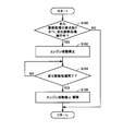
- step (hereinafter, step is referred to as S) 100 ECU 200 determines whether or not the deterioration diagnosis process of battery 70 is requested and the deterioration diagnosis process is being executed. If execution of the deterioration diagnosis process is requested and the deterioration diagnosis process is being executed (YES in S100), the process proceeds to S102. If not (NO in S100), this process ends. In S102, ECU 200 prohibits starting of engine 10.
- ECU 200 determines whether or not the deterioration diagnosis process for battery 70 has been completed. If the deterioration diagnosis process for battery 70 has been completed (YES in S104), the process proceeds to S106. If not (NO in S104), the process returns to S104. In S106, ECU 200 cancels the prohibition of starting engine 10.
- the deterioration diagnosis process is not executed (NO in S100), so that the engine 10 is not prohibited from starting. Therefore, the engine 10 is started in response to the start request for the engine 10.
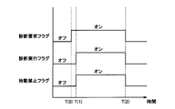
- the battery 70 is discharged with a constant discharge amount from a state where the OCV of the battery 70 is equal to or higher than the diagnosis start voltage OCV (0).
- the OCV of the battery 70 becomes equal to or lower than the diagnosis completion voltage OCV (1) at time T (2), the deterioration diagnosis process is completed.
- the ECU 200 calculates the accumulated discharge amount D (0) until the OCV decreases from the diagnosis start voltage OCV (0) to the diagnosis completion voltage OCV (1) and the accumulated discharge amount D (1) when the battery 70 is new. Whether or not the battery 70 is deteriorated is diagnosed based on the comparison result.
- FIG. 5 it has been described that the execution of the deterioration diagnosis process is started after receiving the request for execution of the deterioration diagnosis process, but the predetermined condition is satisfied when the request for execution of the deterioration diagnosis process is received. In this case, the deterioration diagnosis process is executed from the time when the request for execution of the deterioration diagnosis process is received.
- the start of the engine 10 is prohibited until the deterioration diagnosis process for the battery 70 is completed. Since starting of engine 10 is prohibited, occurrence of voltage fluctuation in battery 70 that occurs when engine 10 is started is suppressed. By suppressing the fluctuation of the voltage in the battery 70, the accumulated discharge amount can be calculated with high accuracy during the execution of the deterioration diagnosis process of the battery 70. As a result, it is possible to accurately diagnose whether or not the battery 70 has deteriorated. Further, by prohibiting the engine 10 from starting, it is possible to secure an opportunity for executing a highly accurate deterioration diagnosis. Therefore, it is possible to provide a vehicle and a method for diagnosing deterioration of a power storage device for accurately determining whether or not the power storage device has deteriorated.
- the vehicle 1 having the driving wheel 80 as the front wheel is shown as an example, but the driving method is not particularly limited thereto.
- the vehicle 1 may have a rear wheel as a driving wheel.
- vehicle 1 is not particularly limited to the type of hybrid vehicle shown in FIG.
- vehicle 1 may be a vehicle in which second MG 30 in FIG. 1 is omitted.
- vehicle 1 may be a vehicle in which second MG 30 in FIG. 1 is coupled to a drive shaft for driving rear wheels instead of front wheel drive shaft 16.
- a speed change mechanism may be provided between drive shaft 16 and speed reducer 58 or between drive shaft 16 and second MG 30.
- vehicle 1 only needs to be equipped with a power storage device.
- the present invention may be applied to a vehicle in which only engine 10 is used as a drive source and an auxiliary battery is mounted.
- the ECU 200 has been described as one ECU, but two or more ECUs may be used.
- the operation of ECU 200 in FIG. 1 may be shared between an engine ECU for controlling engine 10 and a hybrid ECU for controlling PCU 60.
- the start suppressing unit 206 has been described as prohibiting the start of the engine 10 from the time when the deterioration diagnosis process is started, but the start of the engine 10 is prohibited at a time after the start of the deterioration diagnosis process. May be. That is, the start suppressing unit 206 may prohibit the start of the engine 10 after the time point when the deterioration diagnosis process is started.
- the start suppressing unit 206 prohibits starting of the engine 10 when the OCV reaches a predetermined value OCV (2) ( ⁇ OCV (0)) before reaching the diagnosis completion voltage OCV (1). Also good. In this way, it is possible to prevent the engine 10 from starting immediately before the OCV of the battery 70 reaches the diagnosis completion voltage OCV (1). Therefore, it is possible to suppress the deterioration of the accuracy of the diagnosis result due to the OCV temporarily decreasing below the diagnosis completion voltage OCV (1) due to the voltage fluctuation caused by the start of the engine 10.
- the predetermined condition has been described as including the condition that the OCV of battery 70 is equal to or greater than threshold value OCV (0).
- the SOC of battery 70 is set to the threshold value.
- a condition that the voltage is SOC (0) or higher may be included, or a condition that the voltage VB of the battery 70 is equal to or higher than the threshold value VB (0) may be included.
- the threshold values SOC (0) and VB (0) are values corresponding to OCV (0).
- ECU 200 starts engine 10 when the condition that the OCV of battery 70 is equal to or greater than threshold value OCV (0) is not satisfied among the predetermined conditions, and the OCV of battery 70 has threshold value OCV (0 )
- the deterioration diagnosis process may be executed after charging the battery 70 until the above is reached.
- the deterioration diagnosis processing unit 202 shown in FIG. 2 performs the discharge integrated amount D () as a result of discharging at a constant discharge amount from the diagnosis start voltage OCV (0) to the diagnosis completion voltage OCV (1). 0) and the accumulated discharge amount D (1) in the case where the battery 70 is new is described as diagnosing whether or not the battery 70 has deteriorated.
- the deterioration diagnosis process is not limited to such a process.
- the deterioration diagnosis processing unit 202 may repeat the operation of directly detecting the OCV after stopping the discharge with a constant discharge amount immediately before the OCV of the battery 70 reaches the diagnosis completion voltage OCV (1). In this way, it is possible to determine with high accuracy whether or not the OCV of the battery 70 has reached the diagnosis completion voltage OCV (1).
- the above-described operation may be repeated every predetermined time.
- the deterioration diagnosis processing unit 202 may discharge the voltage VB from the diagnosis start voltage VB (0) to the diagnosis completion voltage VB (1) with a constant discharge amount. In this case, the deterioration diagnosis processing unit 202 calculates the integrated discharge amount D (2) from the diagnosis start voltage VB (0) to the diagnosis completion voltage VB (1). The deterioration diagnosis processing unit 202 determines whether or not the battery 70 has deteriorated based on the result of comparing the calculated integrated discharge amount D (2) and the integrated discharge amount D (3) when the battery 70 is new. Diagnose. The accumulated discharge amount D (3) is an accumulated discharge amount until the voltage VB changes from the diagnosis start voltage VB (0) to the diagnosis completion voltage VB (1) when the battery 70 is new.
- the deterioration diagnosis processing unit 202 charges at a constant charge amount from the diagnosis start voltage OCV (3) to the diagnosis completion voltage OCV (4) (> OCV (3)), and integrates the charge current to integrate the charge.
- the quantity C (0) may be calculated.
- the deterioration diagnosis processing unit 202 determines whether or not the battery 70 has deteriorated based on the result of comparing the calculated accumulated charge amount C (0) and the accumulated charge amount C (1) when the battery 70 is new. You may make it diagnose.
- Charging with a constant charge amount is realized, for example, by charging using the external power supply 302.
- the predetermined condition includes a condition that the OCV of the battery 70 is equal to or less than the threshold value OCV (3) instead of the condition that the OCV of the battery 70 is equal to or more than the threshold value OCV (0).
- Threshold OCV (3) is a diagnosis start voltage.
- the threshold value OCV (3) a value that can secure a charge integration amount that can obtain a sufficiently accurate diagnosis result is determined.
- the accumulated charge amount is an accumulated value of the charge amount (charge current) when the battery 70 is charged with a constant charge amount from the diagnosis start voltage OCV (3) to the diagnosis completion voltage OCV (4).
- the threshold value OCV (3) is preferably a value close to the SOC corresponding to the lower limit value of the SOC of the battery 70.
- the diagnosis completion voltage OCV (4) is preferably a value close to the SOC corresponding to the fully charged state (upper limit value) of the battery 70. In this way, diagnostic accuracy can be improved. Further, the threshold value of the OCV that is the predetermined condition may be a value smaller than OCV (3).
- diagnosis start voltage and the diagnosis completion voltage may be values of the voltage VB instead of the OCV.
- the predetermined condition when the deterioration diagnosis process is performed by charging with a constant charge amount is replaced with the condition that the OCV of the battery 70 is equal to or lower than the threshold value OCV (3), and the SOC of the battery 70 is the threshold A condition that the voltage SOC is less than or equal to the value SOC (1) may be included, or a condition that the voltage VB of the battery 70 is less than or equal to the threshold value VB (1) may be included.
- Threshold values SOC (1) and VB (1) are values corresponding to OCV (3).
- the predetermined condition when the deterioration diagnosis process is executed by charging with a constant charge amount or discharging with a constant discharge amount may include a condition that the engine 10 is in a stopped state. Whether or not the engine 10 is in a stopped state depends on the state of the engine 10 (for example, when the engine speed Ne is lower than the threshold value Ne (0)) or the control state of the engine 10 (for example, the IG off state, It may be determined based on the accessory selection state or the control signal S2 is not output.
- the predetermined condition when the deterioration diagnosis process is executed by charging with a constant charge amount or discharging with a constant discharge amount may include a condition that the vehicle 1 is in a stopped state.
- the predetermined condition may include a condition that the vehicle 1 is in a traveling state. Whether the vehicle 1 is in a stopped state or in a running state may be determined based on the vehicle speed V, the rotational speed Nw of the drive wheel 80, or the rotational speed Nm2 of the second MG 30.
- ECU 200 may determine that the vehicle is stopped if vehicle speed V is smaller than a threshold value.
- ECU 200 may determine that the vehicle is in a traveling state if vehicle speed V is greater than a threshold value.
- the vehicle according to the present embodiment differs in the operation of ECU 200 compared to the configuration of vehicle 1 according to the first embodiment described above.
- the vehicle according to the present embodiment differs in the operation of ECU 200 compared to the configuration of vehicle 1 according to the first embodiment described above.
- the vehicle according to the present embodiment is the same structure as the structure of the vehicle 1 which concerns on the above-mentioned 1st Embodiment. They are given the same reference numerals. Their functions are the same. Therefore, detailed description thereof will not be repeated here.
- the present embodiment is characterized in that the ECU 200 shuts off the gate of the PCU 60 when the deterioration diagnosis process for diagnosing whether or not the deterioration diagnosis process has deteriorated in the battery 70 is being executed. Have.
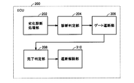
- FIG. 6 shows a functional block diagram of ECU 200 mounted on the vehicle according to the present embodiment.
- the functional block diagram of ECU 200 shown in FIG. 6 includes a gate blocking unit 306 in place of start suppression unit 206, as compared to the functional block diagram of ECU 200 in the first embodiment shown in FIG. The difference is that a blocking release unit 310 is included instead of the suppression release unit 210.
- Other configurations are the same as those in the functional block diagram of ECU 200 shown in FIG. Therefore, detailed description thereof will not be repeated.
- the gate blocking unit 306 blocks the gate of the PCU 60 when the diagnosis determining unit 204 requests execution of the deterioration diagnosis process of the battery 70 and determines that the deterioration diagnosis process of the battery 70 is being executed.
- the gate blocking unit 306 blocks the gate of the PCU 60 by turning off all of the plurality of switching elements 62 provided in the PCU 60. By shutting off the gate of the PCU 60, the first MG 20 cannot be operated. Therefore, even when the engine 10 is requested to start based on the state of the vehicle 1, the engine 10 cannot be started.
- the gate blocking unit 306 will be described as blocking the gate of the PCU 60 from the start of the deterioration diagnosis process of the battery 70 until the completion, but the PCU 60 after the deterioration diagnosis process of the battery 70 is started. You may block the gate.
- the cutoff release unit 310 releases the gate of the PCU 60. For example, when the completion determination flag is in an off state, the cutoff release unit 310 may release the cutoff of the PCU 60 gate. After the PCU 60 gate is released, the first MG 20 can be operated. Therefore, the start control of the engine 10 is executed in response to the start request of the engine 10.
- the deterioration diagnosis processing unit 202, the diagnosis determination unit 204, the gate block unit 306, the completion determination unit 208, and the block release unit 310 shown in FIG. Although described as functioning as software realized by executing a program stored in a memory, it may be realized by hardware. Such a program is recorded in a storage medium and installed in the vehicle 1.
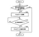
- ECU 200 When execution of the deterioration diagnosis process for battery 70 is requested and the deterioration diagnosis process is being executed (YES in S100), ECU 200 causes PCU 60 to turn off a plurality of switching elements 62 in S200. Shut off the gate.
- ECU 200 cancels the blocking of the gate of PCU 60 in S202.
- the engine 10 is started in response to the start request for the engine 10.
- the battery 70 is discharged with a constant discharge amount from a state where the OCV of the battery 70 is equal to or higher than the diagnosis start voltage OCV (0).
- the diagnosis completion voltage OCV (1) the deterioration diagnosis process is completed.
- the ECU 200 calculates the accumulated discharge amount D (0) until the OCV decreases from the diagnosis start voltage OCV (0) to the diagnosis completion voltage OCV (1) and the accumulated discharge amount D (1) when the battery 70 is new. Whether or not the battery 70 is deteriorated is diagnosed based on the comparison result.
- the PCU 60 is unblocked (S202). Therefore, the first MG 20 becomes operable. Therefore, when the engine 10 is requested to start, the engine 10 is started using the first MG 20.
- the gate of the PCU 60 is blocked until the deterioration diagnosis process for the battery 70 is completed.
- the gate of the PCU 60 is shut off, the engine 10 cannot start. Since engine 10 cannot be started, the occurrence of voltage fluctuation in battery 70 that occurs when engine 10 is started is suppressed.
- the integrated discharge amount can be calculated with high accuracy during the execution of the deterioration diagnosis process. As a result, it is possible to accurately diagnose whether or not the battery 70 has deteriorated. Further, by prohibiting the engine 10 from starting, it is possible to secure an opportunity for executing a highly accurate deterioration diagnosis. Therefore, it is possible to provide a vehicle and a deterioration diagnosis method for accurately determining whether or not the power storage device has deteriorated.
Landscapes
- Engineering & Computer Science (AREA)
- Mechanical Engineering (AREA)
- Transportation (AREA)
- Combustion & Propulsion (AREA)
- Chemical & Material Sciences (AREA)
- Automation & Control Theory (AREA)
- Human Computer Interaction (AREA)
- Health & Medical Sciences (AREA)
- Biomedical Technology (AREA)
- General Health & Medical Sciences (AREA)
- Electric Propulsion And Braking For Vehicles (AREA)
- Secondary Cells (AREA)
- Hybrid Electric Vehicles (AREA)
- Fixed Capacitors And Capacitor Manufacturing Machines (AREA)
Abstract
Description
さらに好ましくは、制御部は、劣化診断処理が完了するまで内燃機関の始動を遅らせる。
図1を参照して、本実施の形態に係る車両1の全体ブロック図が説明される。車両1は、エンジン10と、駆動軸16と、第1モータジェネレータ(以下、第1MGと記載する)20と、第2モータジェネレータ(以下、第2MGと記載する)30と、動力分割装置40と、減速機58と、PCU(Power Control Unit)60と、バッテリ70と、充電装置78と、駆動輪80と、スタートスイッチ150と、ECU(Electronic Control Unit)200とを含む。
以下、第2の実施の形態に係る車両について説明する。本実施の形態に係る車両は、上述の第1の実施の形態に係る車両1の構成と比較して、ECU200の動作が異なる。それ以外の構成については、上述の第1の実施の形態に係る車両1の構成と同じ構成である。それらについては同じ参照符号が付してある。それらの機能も同じである。したがって、それらについての詳細な説明はここでは繰返されない。
Claims (9)
- 内燃機関(10)と、
蓄電装置(70)と、
前記蓄電装置(70)から電力の供給を受けて前記内燃機関(10)を始動させるための回転電機(20)と、
前記蓄電装置(70)の状態を検出するための検出部(156,158,160)と、
所定条件が成立している場合に、前記蓄電装置(70)の状態に基づいて前記蓄電装置(70)が劣化しているか否かを診断するための劣化診断処理を実行するための制御部(200)とを含み、
前記制御部(200)は、前記劣化診断処理が完了するまでに前記内燃機関(10)の始動条件が成立した場合には、前記内燃機関(10)の始動を抑制する、車両。 - 前記制御部(200)は、前記劣化診断処理が完了するまで前記内燃機関(10)の始動を禁止する、請求項1に記載の車両。
- 前記制御部(200)は、前記劣化診断処理が完了するまで前記内燃機関(10)の始動を遅らせる、請求項2に記載の車両。
- 前記制御部(200)は、前記劣化診断処理が完了した場合には、前記内燃機関(10)の始動の抑制を解除する、請求項1に記載の車両。
- 前記制御部(200)は、前記所定条件が成立している場合に、前記蓄電装置(70)の電圧を診断開始電圧から診断終了電圧まで変化させたときの前記蓄電装置(70)の充電量および放電量のうちのいずれか一方に基づいて前記蓄電装置(70)が劣化しているか否かを診断する、請求項1に記載の車両。
- 前記制御部(200)は、前記蓄電装置(70)の電圧を前記診断開始電圧から前記診断終了電圧まで変化させている間、前記内燃機関(10)の始動を抑制する、請求項5に記載の車両。
- 前記制御部(200)は、前記蓄電装置(70)の電圧を前記診断開始電圧と前記診断終了電圧との間の所定電圧から前記診断終了電圧まで変化させている間、前記内燃機関(10)の始動を抑制する、請求項5に記載の車両。
- 前記車両(1)は、前記蓄電装置(70)の電力を前記回転電機(20)に供給される電力に変換するための電力変換装置(60)をさらに含み、
前記制御部(200)は、前記回転電機(20)への電力の供給が遮断されるように前記電力変換装置(60)を制御することによって、前記内燃機関(10)の始動を抑制する、請求項1に記載の車両。 - 内燃機関(10)と、蓄電装置(70)と、前記蓄電装置(70)から電力の供給を受けて前記内燃機関(10)を始動させるための回転電機(20)とを含む車両(1)に用いられる蓄電装置の劣化診断方法であって、
前記蓄電装置(70)の状態を検出するステップと、
所定の条件が成立している場合に、前記蓄電装置(70)の状態に基づいて前記蓄電装置(70)が劣化しているか否かを診断するための劣化診断処理を実行するステップと、
前記劣化診断処理が完了するまでに前記内燃機関(10)の始動条件が成立した場合には、前記内燃機関(10)の始動を抑制するステップとを含む、蓄電装置の劣化診断方法。
Priority Applications (5)
| Application Number | Priority Date | Filing Date | Title |
|---|---|---|---|
| DE112011105036.4T DE112011105036T5 (de) | 2011-03-16 | 2011-03-16 | Fahrzeug und Verschlechterungsdiagnoseverfahren für eine Energiespeichervorrichtung |
| PCT/JP2011/056189 WO2012124070A1 (ja) | 2011-03-16 | 2011-03-16 | 車両および蓄電装置の劣化診断方法 |
| US14/002,633 US9145132B2 (en) | 2011-03-16 | 2011-03-16 | Vehicle and deterioration diagnosis method for power storage device |
| JP2013504453A JP5716823B2 (ja) | 2011-03-16 | 2011-03-16 | 車両および蓄電装置の劣化診断方法 |
| CN201180069173.3A CN103415428B (zh) | 2011-03-16 | 2011-03-16 | 车辆以及蓄电装置的劣化诊断方法 |
Applications Claiming Priority (1)
| Application Number | Priority Date | Filing Date | Title |
|---|---|---|---|
| PCT/JP2011/056189 WO2012124070A1 (ja) | 2011-03-16 | 2011-03-16 | 車両および蓄電装置の劣化診断方法 |
Publications (1)
| Publication Number | Publication Date |
|---|---|
| WO2012124070A1 true WO2012124070A1 (ja) | 2012-09-20 |
Family
ID=46830199
Family Applications (1)
| Application Number | Title | Priority Date | Filing Date |
|---|---|---|---|
| PCT/JP2011/056189 Ceased WO2012124070A1 (ja) | 2011-03-16 | 2011-03-16 | 車両および蓄電装置の劣化診断方法 |
Country Status (5)
| Country | Link |
|---|---|
| US (1) | US9145132B2 (ja) |
| JP (1) | JP5716823B2 (ja) |
| CN (1) | CN103415428B (ja) |
| DE (1) | DE112011105036T5 (ja) |
| WO (1) | WO2012124070A1 (ja) |
Cited By (6)
| Publication number | Priority date | Publication date | Assignee | Title |
|---|---|---|---|---|
| JP5716823B2 (ja) * | 2011-03-16 | 2015-05-13 | トヨタ自動車株式会社 | 車両および蓄電装置の劣化診断方法 |
| JP2017171126A (ja) * | 2016-03-24 | 2017-09-28 | トヨタ自動車株式会社 | ハイブリッド自動車 |
| JP2021180068A (ja) * | 2020-05-11 | 2021-11-18 | トヨタ自動車株式会社 | 燃料電池システムおよび燃料電池システムの制御プログラム |
| JP2022034917A (ja) * | 2020-08-19 | 2022-03-04 | スズキ株式会社 | ハイブリッド車両の制御装置 |
| JP2023068913A (ja) * | 2021-11-04 | 2023-05-18 | トヨタ自動車株式会社 | 組電池の劣化診断装置、及び組電池の劣化診断方法 |
| JP2023099559A (ja) * | 2019-09-17 | 2023-07-13 | 株式会社東芝 | 電池制御装置、充放電システム、駐車場システム、二次電池リユースシステム、電池制御方法、及び電池制御プログラム |
Families Citing this family (13)
| Publication number | Priority date | Publication date | Assignee | Title |
|---|---|---|---|---|
| US9181915B2 (en) * | 2011-08-31 | 2015-11-10 | Bae Systems Controls Inc. | Engine automatic stop/start mechanism |
| JP5513685B2 (ja) * | 2011-12-12 | 2014-06-04 | 本田技研工業株式会社 | ハイブリッド車両の診断装置および診断方法 |
| US9272706B2 (en) * | 2013-04-17 | 2016-03-01 | Ford Global Technologies, Llc | Laser ignition system based diagnostics |
| JP2017218975A (ja) * | 2016-06-08 | 2017-12-14 | 三菱電機株式会社 | 劣化診断装置 |
| JP6741211B2 (ja) * | 2016-08-05 | 2020-08-19 | 株式会社Gsユアサ | 蓄電装置、車両、及び蓄電装置の充電制御方法 |
| JP6583298B2 (ja) * | 2017-01-24 | 2019-10-02 | トヨタ自動車株式会社 | 電動車両 |
| KR102322260B1 (ko) * | 2017-05-18 | 2021-11-04 | 현대자동차 주식회사 | 하이브리드 자동차의 isg 시스템 |
| JP7073865B2 (ja) | 2018-04-09 | 2022-05-24 | トヨタ自動車株式会社 | 冗長電源システム |
| JP6713030B2 (ja) * | 2018-10-12 | 2020-06-24 | 本田技研工業株式会社 | 診断システム、診断方法、及びプログラム |
| US11186198B2 (en) * | 2019-05-31 | 2021-11-30 | Ford Global Technologies, Llc | Methods and systems for vehicle battery cell failure detection and overcharge protection |
| JP7311458B2 (ja) * | 2020-04-07 | 2023-07-19 | トヨタ自動車株式会社 | バッテリー診断装置、方法、プログラム、及び車両 |
| JP7484870B2 (ja) * | 2021-11-01 | 2024-05-16 | トヨタ自動車株式会社 | 組電池の劣化診断装置、及び組電池の劣化診断方法 |
| JP2023088091A (ja) * | 2021-12-14 | 2023-06-26 | 本田技研工業株式会社 | エンジン駆動発電機 |
Citations (3)
| Publication number | Priority date | Publication date | Assignee | Title |
|---|---|---|---|---|
| JP2000104649A (ja) * | 1998-09-29 | 2000-04-11 | Hanshin Electric Co Ltd | エンジン自動始動方法及び装置 |
| JP2010116077A (ja) * | 2008-11-13 | 2010-05-27 | Toyota Motor Corp | バッテリ劣化判定装置 |
| JP2010129298A (ja) * | 2008-11-26 | 2010-06-10 | Toyota Motor Corp | システムの制御装置 |
Family Cites Families (28)
| Publication number | Priority date | Publication date | Assignee | Title |
|---|---|---|---|---|
| DE4341826C2 (de) * | 1992-12-18 | 2002-11-07 | Volkswagen Ag | Verfahren und Vorrichtung zur Bestimmung des Ladezustandes eines elektrischen Energiespeichers |
| JP3450906B2 (ja) * | 1994-08-25 | 2003-09-29 | 本田技研工業株式会社 | 電気自動車用充電制御装置 |
| JP2000131404A (ja) * | 1998-10-27 | 2000-05-12 | Denso Corp | 電池劣化度判定装置 |
| JP3705008B2 (ja) | 1999-05-06 | 2005-10-12 | 日産自動車株式会社 | ハイブリッド車両用充放電制御装置 |
| US6621250B1 (en) * | 1999-09-09 | 2003-09-16 | Toyota Jidosha Kabushiki Kaisha | Battery capacity measuring and remaining capacity calculating system |
| JP4477185B2 (ja) | 2000-02-22 | 2010-06-09 | 古河電気工業株式会社 | 鉛蓄電池の特性評価方法および鉛蓄電池の特性評価装置 |
| DE10036341A1 (de) * | 2000-07-26 | 2002-02-07 | Bayerische Motoren Werke Ag | Elektronische Einheit zur Erkennung des Ladezustands und/oder des Verschleißes einer Kraftfahrzeugbatterie |
| JP4302307B2 (ja) * | 2000-09-21 | 2009-07-22 | 古河電気工業株式会社 | アイドリングストップ機能を有する車両、および、車両に搭載した蓄電池の残存容量算出方法と装置 |
| US6268712B1 (en) * | 2000-09-26 | 2001-07-31 | Vb Autobatterie Gmbh | Method for determining the starting ability of a starter battery in a motor vehicle |
| JP3788736B2 (ja) * | 2000-12-18 | 2006-06-21 | スズキ株式会社 | エンジンの自動停止始動制御装置 |
| DE10107583A1 (de) * | 2001-02-17 | 2002-08-29 | Vb Autobatterie Gmbh | Verfahren zur Bestimmung der Leistungsfähigkeit einer Speicherbatterie |
| JP4258348B2 (ja) * | 2003-10-23 | 2009-04-30 | 日産自動車株式会社 | バッテリの劣化診断装置及び車載電源装置の制御装置 |
| JP4969029B2 (ja) * | 2004-08-16 | 2012-07-04 | 株式会社日立製作所 | 電源装置及びその制御方法 |
| JP5314235B2 (ja) * | 2006-03-07 | 2013-10-16 | プライムアースEvエナジー株式会社 | 二次電池の温度制御装置、二次電池の加温システム、およびプログラム |
| JP2007245999A (ja) * | 2006-03-17 | 2007-09-27 | Toyota Motor Corp | 車両の制御装置および車両 |
| JP2008039526A (ja) | 2006-08-03 | 2008-02-21 | Auto Network Gijutsu Kenkyusho:Kk | 電池劣化診断方法、電池劣化診断装置及びコンピュータプログラム |
| JP4866187B2 (ja) * | 2006-09-05 | 2012-02-01 | プライムアースEvエナジー株式会社 | 電池制御装置、電動車両、及び二次電池の充電状態を推定するための処理をコンピュータに実行させるためのプログラム |
| JP4245624B2 (ja) * | 2006-09-20 | 2009-03-25 | トヨタ自動車株式会社 | ハイブリッド車両の電源制御装置および電源制御方法 |
| JP4432958B2 (ja) * | 2006-11-10 | 2010-03-17 | トヨタ自動車株式会社 | 燃料電池を搭載した移動体 |
| JP2008215310A (ja) | 2007-03-07 | 2008-09-18 | Toyota Motor Corp | 車両および内燃機関の始動制御方法 |
| JP2009137308A (ja) | 2007-06-08 | 2009-06-25 | Autonetworks Technologies Ltd | 開放電圧値推定方法及び開放電圧値推定装置 |
| JP5129029B2 (ja) | 2007-11-14 | 2013-01-23 | 株式会社オートネットワーク技術研究所 | 開放電圧値推定方法及び開放電圧値推定装置 |
| JP2009228464A (ja) | 2008-03-19 | 2009-10-08 | Toyota Motor Corp | 車両用電源制御装置及び車両用電源制御方法 |
| JP2009274527A (ja) | 2008-05-13 | 2009-11-26 | Autonetworks Technologies Ltd | 放電電流推定方法、放電電流推定装置及び車両用電源装置 |
| JP5173609B2 (ja) * | 2008-06-04 | 2013-04-03 | トヨタ自動車株式会社 | 車両制御装置 |
| CN101639522B (zh) * | 2008-08-01 | 2014-06-04 | 株式会社杰士汤浅国际 | 二次电池的劣化状态诊断装置 |
| JP2011025860A (ja) | 2009-07-28 | 2011-02-10 | Toyota Motor Corp | 車載バッテリ放電装置およびそれを用いた車載バッテリ診断システム |
| JP5716823B2 (ja) * | 2011-03-16 | 2015-05-13 | トヨタ自動車株式会社 | 車両および蓄電装置の劣化診断方法 |
-
2011
- 2011-03-16 JP JP2013504453A patent/JP5716823B2/ja active Active
- 2011-03-16 US US14/002,633 patent/US9145132B2/en active Active
- 2011-03-16 WO PCT/JP2011/056189 patent/WO2012124070A1/ja not_active Ceased
- 2011-03-16 DE DE112011105036.4T patent/DE112011105036T5/de active Granted
- 2011-03-16 CN CN201180069173.3A patent/CN103415428B/zh active Active
Patent Citations (3)
| Publication number | Priority date | Publication date | Assignee | Title |
|---|---|---|---|---|
| JP2000104649A (ja) * | 1998-09-29 | 2000-04-11 | Hanshin Electric Co Ltd | エンジン自動始動方法及び装置 |
| JP2010116077A (ja) * | 2008-11-13 | 2010-05-27 | Toyota Motor Corp | バッテリ劣化判定装置 |
| JP2010129298A (ja) * | 2008-11-26 | 2010-06-10 | Toyota Motor Corp | システムの制御装置 |
Cited By (11)
| Publication number | Priority date | Publication date | Assignee | Title |
|---|---|---|---|---|
| JP5716823B2 (ja) * | 2011-03-16 | 2015-05-13 | トヨタ自動車株式会社 | 車両および蓄電装置の劣化診断方法 |
| JP2017171126A (ja) * | 2016-03-24 | 2017-09-28 | トヨタ自動車株式会社 | ハイブリッド自動車 |
| JP2023099559A (ja) * | 2019-09-17 | 2023-07-13 | 株式会社東芝 | 電池制御装置、充放電システム、駐車場システム、二次電池リユースシステム、電池制御方法、及び電池制御プログラム |
| JP7524397B2 (ja) | 2019-09-17 | 2024-07-29 | 株式会社東芝 | 駐車場システム、駐車場システムの運用方法、及び駐車場システムの運用プログラム |
| JP2021180068A (ja) * | 2020-05-11 | 2021-11-18 | トヨタ自動車株式会社 | 燃料電池システムおよび燃料電池システムの制御プログラム |
| JP7306320B2 (ja) | 2020-05-11 | 2023-07-11 | トヨタ自動車株式会社 | 燃料電池システムおよび燃料電池システムの制御プログラム |
| US11705567B2 (en) | 2020-05-11 | 2023-07-18 | Toyota Jidosha Kabushiki Kaisha | Fuel cell system, non-transitory storage medium and control method for fuel cell system |
| JP2022034917A (ja) * | 2020-08-19 | 2022-03-04 | スズキ株式会社 | ハイブリッド車両の制御装置 |
| JP7484562B2 (ja) | 2020-08-19 | 2024-05-16 | スズキ株式会社 | ハイブリッド車両の制御装置 |
| JP2023068913A (ja) * | 2021-11-04 | 2023-05-18 | トヨタ自動車株式会社 | 組電池の劣化診断装置、及び組電池の劣化診断方法 |
| JP7509118B2 (ja) | 2021-11-04 | 2024-07-02 | トヨタ自動車株式会社 | 組電池の劣化診断装置、及び組電池の劣化診断方法 |
Also Published As
| Publication number | Publication date |
|---|---|
| JPWO2012124070A1 (ja) | 2014-07-17 |
| US20130338867A1 (en) | 2013-12-19 |
| CN103415428B (zh) | 2016-03-16 |
| DE112011105036T5 (de) | 2014-01-02 |
| US9145132B2 (en) | 2015-09-29 |
| CN103415428A (zh) | 2013-11-27 |
| JP5716823B2 (ja) | 2015-05-13 |
Similar Documents
| Publication | Publication Date | Title |
|---|---|---|
| JP5716823B2 (ja) | 車両および蓄電装置の劣化診断方法 | |
| JP5218661B2 (ja) | 内燃機関の制御装置および内燃機関の制御方法 | |
| JP5786962B2 (ja) | プラグインハイブリッド車両 | |
| JP6011541B2 (ja) | 充電制御装置および充電制御方法 | |
| JP6520908B2 (ja) | ハイブリッド車両 | |
| JP5673862B2 (ja) | 車両および車両用制御方法 | |
| JP5629657B2 (ja) | ハイブリッド車両およびハイブリッド車両の制御方法 | |
| JP5845930B2 (ja) | 少なくとも電動機を用いて走行可能な車両の電動走行可能距離表示装置 | |
| JP6288055B2 (ja) | ハイブリッド自動車 | |
| WO2012101796A1 (ja) | 車両および車両用制御方法 | |
| WO2013042217A1 (ja) | 車両および車両用制御方法 | |
| JP5930018B2 (ja) | 車両および車両用制御方法 | |
| JP2008094178A (ja) | 車両の制御装置、制御方法、その方法を実現するプログラムおよびそのプログラムを記録した記録媒体 | |
| CN103476655B (zh) | 车辆和车辆用控制方法 | |
| JP6361299B2 (ja) | ハイブリッド車両 | |
| JP5896127B2 (ja) | 電動機を駆動源として備える車両 | |
| JP2007185986A (ja) | 車両の制御装置 | |
| JP2006211859A (ja) | 車両の制御装置 | |
| JP4983635B2 (ja) | 動力出力装置およびその制御方法並びに車両 | |
| JP4165321B2 (ja) | 動力出力装置およびその制御方法並びに自動車 | |
| JP2007237809A (ja) | 車両用電源システム | |
| JP2013154719A (ja) | ハイブリッド車両の電費算出装置 | |
| JP2023068913A (ja) | 組電池の劣化診断装置、及び組電池の劣化診断方法 | |
| JP2013032096A (ja) | ハイブリッド車両 | |
| JP2012158310A (ja) | 車両 |
Legal Events
| Date | Code | Title | Description |
|---|---|---|---|
| WWE | Wipo information: entry into national phase |
Ref document number: 201180069173.3 Country of ref document: CN |
|
| 121 | Ep: the epo has been informed by wipo that ep was designated in this application |
Ref document number: 11861138 Country of ref document: EP Kind code of ref document: A1 |
|
| ENP | Entry into the national phase |
Ref document number: 2013504453 Country of ref document: JP Kind code of ref document: A |
|
| WWE | Wipo information: entry into national phase |
Ref document number: 14002633 Country of ref document: US |
|
| WWE | Wipo information: entry into national phase |
Ref document number: 112011105036 Country of ref document: DE Ref document number: 1120111050364 Country of ref document: DE |
|
| 122 | Ep: pct application non-entry in european phase |
Ref document number: 11861138 Country of ref document: EP Kind code of ref document: A1 |