WO2012108059A1 - Dispositif de purification de gaz d'échappement pour moteur à combustion interne - Google Patents
Dispositif de purification de gaz d'échappement pour moteur à combustion interne Download PDFInfo
- Publication number
- WO2012108059A1 WO2012108059A1 PCT/JP2011/052969 JP2011052969W WO2012108059A1 WO 2012108059 A1 WO2012108059 A1 WO 2012108059A1 JP 2011052969 W JP2011052969 W JP 2011052969W WO 2012108059 A1 WO2012108059 A1 WO 2012108059A1
- Authority
- WO
- WIPO (PCT)
- Prior art keywords
- hydrocarbon
- exhaust
- temperature
- hydrocarbons
- purification catalyst
- Prior art date
Links
Images


Classifications
-
- F—MECHANICAL ENGINEERING; LIGHTING; HEATING; WEAPONS; BLASTING
- F01—MACHINES OR ENGINES IN GENERAL; ENGINE PLANTS IN GENERAL; STEAM ENGINES
- F01N—GAS-FLOW SILENCERS OR EXHAUST APPARATUS FOR MACHINES OR ENGINES IN GENERAL; GAS-FLOW SILENCERS OR EXHAUST APPARATUS FOR INTERNAL COMBUSTION ENGINES
- F01N3/00—Exhaust or silencing apparatus having means for purifying, rendering innocuous, or otherwise treating exhaust
- F01N3/08—Exhaust or silencing apparatus having means for purifying, rendering innocuous, or otherwise treating exhaust for rendering innocuous
- F01N3/10—Exhaust or silencing apparatus having means for purifying, rendering innocuous, or otherwise treating exhaust for rendering innocuous by thermal or catalytic conversion of noxious components of exhaust
- F01N3/18—Exhaust or silencing apparatus having means for purifying, rendering innocuous, or otherwise treating exhaust for rendering innocuous by thermal or catalytic conversion of noxious components of exhaust characterised by methods of operation; Control
- F01N3/20—Exhaust or silencing apparatus having means for purifying, rendering innocuous, or otherwise treating exhaust for rendering innocuous by thermal or catalytic conversion of noxious components of exhaust characterised by methods of operation; Control specially adapted for catalytic conversion ; Methods of operation or control of catalytic converters
- F01N3/206—Adding periodically or continuously substances to exhaust gases for promoting purification, e.g. catalytic material in liquid form, NOx reducing agents
-
- F—MECHANICAL ENGINEERING; LIGHTING; HEATING; WEAPONS; BLASTING
- F01—MACHINES OR ENGINES IN GENERAL; ENGINE PLANTS IN GENERAL; STEAM ENGINES
- F01N—GAS-FLOW SILENCERS OR EXHAUST APPARATUS FOR MACHINES OR ENGINES IN GENERAL; GAS-FLOW SILENCERS OR EXHAUST APPARATUS FOR INTERNAL COMBUSTION ENGINES
- F01N3/00—Exhaust or silencing apparatus having means for purifying, rendering innocuous, or otherwise treating exhaust
- F01N3/08—Exhaust or silencing apparatus having means for purifying, rendering innocuous, or otherwise treating exhaust for rendering innocuous
- F01N3/0807—Exhaust or silencing apparatus having means for purifying, rendering innocuous, or otherwise treating exhaust for rendering innocuous by using absorbents or adsorbents
- F01N3/0828—Exhaust or silencing apparatus having means for purifying, rendering innocuous, or otherwise treating exhaust for rendering innocuous by using absorbents or adsorbents characterised by the absorbed or adsorbed substances
- F01N3/0842—Nitrogen oxides
-
- F—MECHANICAL ENGINEERING; LIGHTING; HEATING; WEAPONS; BLASTING
- F01—MACHINES OR ENGINES IN GENERAL; ENGINE PLANTS IN GENERAL; STEAM ENGINES
- F01N—GAS-FLOW SILENCERS OR EXHAUST APPARATUS FOR MACHINES OR ENGINES IN GENERAL; GAS-FLOW SILENCERS OR EXHAUST APPARATUS FOR INTERNAL COMBUSTION ENGINES
- F01N13/00—Exhaust or silencing apparatus characterised by constructional features ; Exhaust or silencing apparatus, or parts thereof, having pertinent characteristics not provided for in, or of interest apart from, groups F01N1/00 - F01N5/00, F01N9/00, F01N11/00
- F01N13/009—Exhaust or silencing apparatus characterised by constructional features ; Exhaust or silencing apparatus, or parts thereof, having pertinent characteristics not provided for in, or of interest apart from, groups F01N1/00 - F01N5/00, F01N9/00, F01N11/00 having two or more separate purifying devices arranged in series
-
- F—MECHANICAL ENGINEERING; LIGHTING; HEATING; WEAPONS; BLASTING
- F01—MACHINES OR ENGINES IN GENERAL; ENGINE PLANTS IN GENERAL; STEAM ENGINES
- F01N—GAS-FLOW SILENCERS OR EXHAUST APPARATUS FOR MACHINES OR ENGINES IN GENERAL; GAS-FLOW SILENCERS OR EXHAUST APPARATUS FOR INTERNAL COMBUSTION ENGINES
- F01N3/00—Exhaust or silencing apparatus having means for purifying, rendering innocuous, or otherwise treating exhaust
- F01N3/08—Exhaust or silencing apparatus having means for purifying, rendering innocuous, or otherwise treating exhaust for rendering innocuous
- F01N3/0807—Exhaust or silencing apparatus having means for purifying, rendering innocuous, or otherwise treating exhaust for rendering innocuous by using absorbents or adsorbents
- F01N3/0814—Exhaust or silencing apparatus having means for purifying, rendering innocuous, or otherwise treating exhaust for rendering innocuous by using absorbents or adsorbents combined with catalytic converters, e.g. NOx absorption/storage reduction catalysts
-
- F—MECHANICAL ENGINEERING; LIGHTING; HEATING; WEAPONS; BLASTING
- F01—MACHINES OR ENGINES IN GENERAL; ENGINE PLANTS IN GENERAL; STEAM ENGINES
- F01N—GAS-FLOW SILENCERS OR EXHAUST APPARATUS FOR MACHINES OR ENGINES IN GENERAL; GAS-FLOW SILENCERS OR EXHAUST APPARATUS FOR INTERNAL COMBUSTION ENGINES
- F01N3/00—Exhaust or silencing apparatus having means for purifying, rendering innocuous, or otherwise treating exhaust
- F01N3/08—Exhaust or silencing apparatus having means for purifying, rendering innocuous, or otherwise treating exhaust for rendering innocuous
- F01N3/0807—Exhaust or silencing apparatus having means for purifying, rendering innocuous, or otherwise treating exhaust for rendering innocuous by using absorbents or adsorbents
- F01N3/0871—Regulation of absorbents or adsorbents, e.g. purging
-
- F—MECHANICAL ENGINEERING; LIGHTING; HEATING; WEAPONS; BLASTING
- F01—MACHINES OR ENGINES IN GENERAL; ENGINE PLANTS IN GENERAL; STEAM ENGINES
- F01N—GAS-FLOW SILENCERS OR EXHAUST APPARATUS FOR MACHINES OR ENGINES IN GENERAL; GAS-FLOW SILENCERS OR EXHAUST APPARATUS FOR INTERNAL COMBUSTION ENGINES
- F01N3/00—Exhaust or silencing apparatus having means for purifying, rendering innocuous, or otherwise treating exhaust
- F01N3/08—Exhaust or silencing apparatus having means for purifying, rendering innocuous, or otherwise treating exhaust for rendering innocuous
- F01N3/10—Exhaust or silencing apparatus having means for purifying, rendering innocuous, or otherwise treating exhaust for rendering innocuous by thermal or catalytic conversion of noxious components of exhaust
- F01N3/18—Exhaust or silencing apparatus having means for purifying, rendering innocuous, or otherwise treating exhaust for rendering innocuous by thermal or catalytic conversion of noxious components of exhaust characterised by methods of operation; Control
- F01N3/20—Exhaust or silencing apparatus having means for purifying, rendering innocuous, or otherwise treating exhaust for rendering innocuous by thermal or catalytic conversion of noxious components of exhaust characterised by methods of operation; Control specially adapted for catalytic conversion ; Methods of operation or control of catalytic converters
- F01N3/2006—Periodically heating or cooling catalytic reactors, e.g. at cold starting or overheating
- F01N3/2033—Periodically heating or cooling catalytic reactors, e.g. at cold starting or overheating using a fuel burner or introducing fuel into exhaust duct
-
- F—MECHANICAL ENGINEERING; LIGHTING; HEATING; WEAPONS; BLASTING
- F01—MACHINES OR ENGINES IN GENERAL; ENGINE PLANTS IN GENERAL; STEAM ENGINES
- F01N—GAS-FLOW SILENCERS OR EXHAUST APPARATUS FOR MACHINES OR ENGINES IN GENERAL; GAS-FLOW SILENCERS OR EXHAUST APPARATUS FOR INTERNAL COMBUSTION ENGINES
- F01N9/00—Electrical control of exhaust gas treating apparatus
-
- F—MECHANICAL ENGINEERING; LIGHTING; HEATING; WEAPONS; BLASTING
- F02—COMBUSTION ENGINES; HOT-GAS OR COMBUSTION-PRODUCT ENGINE PLANTS
- F02D—CONTROLLING COMBUSTION ENGINES
- F02D41/00—Electrical control of supply of combustible mixture or its constituents
- F02D41/02—Circuit arrangements for generating control signals
- F02D41/021—Introducing corrections for particular conditions exterior to the engine
- F02D41/0235—Introducing corrections for particular conditions exterior to the engine in relation with the state of the exhaust gas treating apparatus
- F02D41/024—Introducing corrections for particular conditions exterior to the engine in relation with the state of the exhaust gas treating apparatus to increase temperature of the exhaust gas treating apparatus
- F02D41/025—Introducing corrections for particular conditions exterior to the engine in relation with the state of the exhaust gas treating apparatus to increase temperature of the exhaust gas treating apparatus by changing the composition of the exhaust gas, e.g. for exothermic reaction on exhaust gas treating apparatus
-
- F—MECHANICAL ENGINEERING; LIGHTING; HEATING; WEAPONS; BLASTING
- F02—COMBUSTION ENGINES; HOT-GAS OR COMBUSTION-PRODUCT ENGINE PLANTS
- F02D—CONTROLLING COMBUSTION ENGINES
- F02D41/00—Electrical control of supply of combustible mixture or its constituents
- F02D41/02—Circuit arrangements for generating control signals
- F02D41/021—Introducing corrections for particular conditions exterior to the engine
- F02D41/0235—Introducing corrections for particular conditions exterior to the engine in relation with the state of the exhaust gas treating apparatus
- F02D41/027—Introducing corrections for particular conditions exterior to the engine in relation with the state of the exhaust gas treating apparatus to purge or regenerate the exhaust gas treating apparatus
- F02D41/0275—Introducing corrections for particular conditions exterior to the engine in relation with the state of the exhaust gas treating apparatus to purge or regenerate the exhaust gas treating apparatus the exhaust gas treating apparatus being a NOx trap or adsorbent
-
- F—MECHANICAL ENGINEERING; LIGHTING; HEATING; WEAPONS; BLASTING
- F01—MACHINES OR ENGINES IN GENERAL; ENGINE PLANTS IN GENERAL; STEAM ENGINES
- F01N—GAS-FLOW SILENCERS OR EXHAUST APPARATUS FOR MACHINES OR ENGINES IN GENERAL; GAS-FLOW SILENCERS OR EXHAUST APPARATUS FOR INTERNAL COMBUSTION ENGINES
- F01N2240/00—Combination or association of two or more different exhaust treating devices, or of at least one such device with an auxiliary device, not covered by indexing codes F01N2230/00 or F01N2250/00, one of the devices being
- F01N2240/30—Combination or association of two or more different exhaust treating devices, or of at least one such device with an auxiliary device, not covered by indexing codes F01N2230/00 or F01N2250/00, one of the devices being a fuel reformer
-
- F—MECHANICAL ENGINEERING; LIGHTING; HEATING; WEAPONS; BLASTING
- F01—MACHINES OR ENGINES IN GENERAL; ENGINE PLANTS IN GENERAL; STEAM ENGINES
- F01N—GAS-FLOW SILENCERS OR EXHAUST APPARATUS FOR MACHINES OR ENGINES IN GENERAL; GAS-FLOW SILENCERS OR EXHAUST APPARATUS FOR INTERNAL COMBUSTION ENGINES
- F01N2250/00—Combinations of different methods of purification
- F01N2250/14—Combinations of different methods of purification absorption or adsorption, and filtering
-
- F—MECHANICAL ENGINEERING; LIGHTING; HEATING; WEAPONS; BLASTING
- F01—MACHINES OR ENGINES IN GENERAL; ENGINE PLANTS IN GENERAL; STEAM ENGINES
- F01N—GAS-FLOW SILENCERS OR EXHAUST APPARATUS FOR MACHINES OR ENGINES IN GENERAL; GAS-FLOW SILENCERS OR EXHAUST APPARATUS FOR INTERNAL COMBUSTION ENGINES
- F01N2430/00—Influencing exhaust purification, e.g. starting of catalytic reaction, filter regeneration, or the like, by controlling engine operating characteristics
- F01N2430/06—Influencing exhaust purification, e.g. starting of catalytic reaction, filter regeneration, or the like, by controlling engine operating characteristics by varying fuel-air ratio, e.g. by enriching fuel-air mixture
-
- F—MECHANICAL ENGINEERING; LIGHTING; HEATING; WEAPONS; BLASTING
- F01—MACHINES OR ENGINES IN GENERAL; ENGINE PLANTS IN GENERAL; STEAM ENGINES
- F01N—GAS-FLOW SILENCERS OR EXHAUST APPARATUS FOR MACHINES OR ENGINES IN GENERAL; GAS-FLOW SILENCERS OR EXHAUST APPARATUS FOR INTERNAL COMBUSTION ENGINES
- F01N2610/00—Adding substances to exhaust gases
- F01N2610/03—Adding substances to exhaust gases the substance being hydrocarbons, e.g. engine fuel
-
- F—MECHANICAL ENGINEERING; LIGHTING; HEATING; WEAPONS; BLASTING
- F02—COMBUSTION ENGINES; HOT-GAS OR COMBUSTION-PRODUCT ENGINE PLANTS
- F02D—CONTROLLING COMBUSTION ENGINES
- F02D41/00—Electrical control of supply of combustible mixture or its constituents
- F02D41/02—Circuit arrangements for generating control signals
- F02D41/14—Introducing closed-loop corrections
- F02D41/1438—Introducing closed-loop corrections using means for determining characteristics of the combustion gases; Sensors therefor
- F02D41/1444—Introducing closed-loop corrections using means for determining characteristics of the combustion gases; Sensors therefor characterised by the characteristics of the combustion gases
- F02D41/1446—Introducing closed-loop corrections using means for determining characteristics of the combustion gases; Sensors therefor characterised by the characteristics of the combustion gases the characteristics being exhaust temperatures
-
- F—MECHANICAL ENGINEERING; LIGHTING; HEATING; WEAPONS; BLASTING
- F02—COMBUSTION ENGINES; HOT-GAS OR COMBUSTION-PRODUCT ENGINE PLANTS
- F02D—CONTROLLING COMBUSTION ENGINES
- F02D41/00—Electrical control of supply of combustible mixture or its constituents
- F02D41/02—Circuit arrangements for generating control signals
- F02D41/14—Introducing closed-loop corrections
- F02D41/1438—Introducing closed-loop corrections using means for determining characteristics of the combustion gases; Sensors therefor
- F02D41/1444—Introducing closed-loop corrections using means for determining characteristics of the combustion gases; Sensors therefor characterised by the characteristics of the combustion gases
- F02D41/146—Introducing closed-loop corrections using means for determining characteristics of the combustion gases; Sensors therefor characterised by the characteristics of the combustion gases the characteristics being an NOx content or concentration
-
- Y—GENERAL TAGGING OF NEW TECHNOLOGICAL DEVELOPMENTS; GENERAL TAGGING OF CROSS-SECTIONAL TECHNOLOGIES SPANNING OVER SEVERAL SECTIONS OF THE IPC; TECHNICAL SUBJECTS COVERED BY FORMER USPC CROSS-REFERENCE ART COLLECTIONS [XRACs] AND DIGESTS
- Y02—TECHNOLOGIES OR APPLICATIONS FOR MITIGATION OR ADAPTATION AGAINST CLIMATE CHANGE
- Y02T—CLIMATE CHANGE MITIGATION TECHNOLOGIES RELATED TO TRANSPORTATION
- Y02T10/00—Road transport of goods or passengers
- Y02T10/10—Internal combustion engine [ICE] based vehicles
- Y02T10/12—Improving ICE efficiencies
-
- Y—GENERAL TAGGING OF NEW TECHNOLOGICAL DEVELOPMENTS; GENERAL TAGGING OF CROSS-SECTIONAL TECHNOLOGIES SPANNING OVER SEVERAL SECTIONS OF THE IPC; TECHNICAL SUBJECTS COVERED BY FORMER USPC CROSS-REFERENCE ART COLLECTIONS [XRACs] AND DIGESTS
- Y02—TECHNOLOGIES OR APPLICATIONS FOR MITIGATION OR ADAPTATION AGAINST CLIMATE CHANGE
- Y02T—CLIMATE CHANGE MITIGATION TECHNOLOGIES RELATED TO TRANSPORTATION
- Y02T10/00—Road transport of goods or passengers
- Y02T10/10—Internal combustion engine [ICE] based vehicles
- Y02T10/40—Engine management systems
Definitions
- the present invention relates to an exhaust purification device for an internal combustion engine.
- the engine exhaust passage, NO X storage catalyst air-fuel ratio of the inflowing exhaust gas when the lean that releases NO X air-fuel ratio of the exhaust gas which is occluded becomes rich for occluding NO X contained in the exhaust gas inflow was placed, NO X occluding catalyst upstream of the engine oxidation catalyst having an adsorbing function in the exhaust passage disposed, NO X from occluding catalyst when releasing the NO X is feeding hydrocarbons into the engine exhaust passage an oxidation catalyst upstream
- An internal combustion engine in which the air-fuel ratio of the exhaust gas flowing into the NO X storage catalyst is made rich is known (see, for example, Patent Document 1).
- An object of the present invention is to provide a post-treatment device that can obtain a high NO x purification rate even when the temperature of the exhaust purification catalyst becomes high and is arranged downstream of the exhaust purification catalyst while ensuring a high NO x purification rate.
- An object of the present invention is to provide an exhaust emission control device for an internal combustion engine that can be easily heated.
- the hydrocarbon supply valve for supplying hydrocarbons is disposed in the engine exhaust passage, and reformed with NO X contained in the exhaust gas in the engine exhaust passage downstream of the hydrocarbon supply valve.
- An exhaust purification catalyst for reacting with hydrocarbons is disposed, and a noble metal catalyst is supported on the exhaust gas flow surface of the exhaust purification catalyst, and a basic exhaust gas flow surface portion is formed around the noble metal catalyst.
- the concentration of hydrocarbons flowing into the exhaust purification catalyst is vibrated with a predetermined range of amplitude and a predetermined range, NO X contained in the exhaust gas is which has a property for reducing, has the property of absorbing the amount of the NO X contained a longer than a predetermined range vibration period of the hydrocarbon concentration in the exhaust gas increases, the exhaust purification during engine operation
- the amount of hydrocarbon injection from the hydrocarbon feed valve is controlled so that the amplitude of the change in the concentration of hydrocarbon flowing into the medium is within the predetermined range described above, and the carbon flowing into the exhaust purification catalyst is controlled.
- the injection cycle of hydrocarbons from the hydrocarbon feed valve is controlled so that the hydrogen concentration oscillates with a cycle within the above-mentioned predetermined range, and when hydrocarbons are supplied, the temperature is increased by the heat of oxidation reaction of the hydrocarbons.
- An ascending aftertreatment device is disposed in the engine exhaust passage downstream of the exhaust purification catalyst, and when the temperature of the aftertreatment device is to be increased, the amplitude of the change in the concentration of hydrocarbons flowing into the exhaust purification catalyst is increased to pass through the exhaust purification catalyst.
- An exhaust emission control device for an internal combustion engine is provided that increases the amount of passing through hydrocarbons.
- FIG. 1 is an overall view of a compression ignition type internal combustion engine.
- FIG. 2 is a view schematically showing the surface portion of the catalyst carrier.
- FIG. 3 is a view for explaining an oxidation reaction in the exhaust purification catalyst.
- FIG. 4 is a diagram showing changes in the air-fuel ratio of the exhaust gas flowing into the exhaust purification catalyst.
- Figure 5 is a diagram illustrating a NO X purification rate.
- 6A and 6B are diagrams for explaining the oxidation-reduction reaction in the exhaust purification catalyst.
- 7A and 7B are diagrams for explaining the oxidation-reduction reaction in the exhaust purification catalyst.
- FIG. 8 is a diagram showing a change in the air-fuel ratio of the exhaust gas flowing into the exhaust purification catalyst.
- FIG. 9 is a diagram illustrating a NO X purification rate.
- FIG. 10 is a time chart showing changes in the air-fuel ratio of the exhaust gas flowing into the exhaust purification catalyst.
- FIG. 11 is a time chart showing changes in the air-fuel ratio of the exhaust gas flowing into the exhaust purification catalyst.
- FIG. 12 is a diagram showing the relationship between the oxidizing power of the exhaust purification catalyst and the required minimum air-fuel ratio X.
- FIG. 13 is a graph showing the relationship between the oxygen concentration in the exhaust gas and the amplitude ⁇ H of the hydrocarbon concentration, with which the same NO x purification rate can be obtained.
- Figure 14 is a diagram showing a relationship between an amplitude ⁇ H and NO X purification rate of hydrocarbon concentration.
- FIG. 15 is a diagram showing the relationship between the vibration period ⁇ T and NO X purification rate of hydrocarbon concentration.
- FIG. 16 is a diagram showing changes in the air-fuel ratio of exhaust gas flowing into the exhaust purification catalyst.
- Figure 17 is a diagram illustrating a map of exhaust amount of NO X NOXA.
- FIG. 18 is a diagram showing the fuel injection timing.
- FIG. 19 is a diagram showing a map of the hydrocarbon supply amount WR.
- FIG. 20 is a diagram showing a hydrocarbon injection pattern from a hydrocarbon feed valve, a change in hydrocarbon concentration in exhaust gas flowing into the exhaust purification catalyst, and the like.
- FIG. 21 is a diagram showing a hydrocarbon injection pattern from a hydrocarbon supply valve and a change in hydrocarbon concentration in exhaust gas flowing into the exhaust purification catalyst.
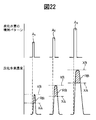
- FIG. 22 is a diagram showing a hydrocarbon injection pattern from a hydrocarbon feed valve and a change in hydrocarbon concentration in exhaust gas flowing into the exhaust purification catalyst.
- FIGS. 23A to 23C are views showing a hydrocarbon injection time and the like.
- FIG. 24 is a diagram showing a hydrocarbon injection pattern from a hydrocarbon feed valve and a change in hydrocarbon concentration in exhaust gas flowing into the exhaust purification catalyst.
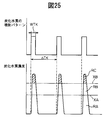
- FIG. 25 is a diagram showing a hydrocarbon injection pattern from a hydrocarbon feed valve and a change in hydrocarbon concentration in exhaust gas flowing into the exhaust purification catalyst.
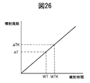
- FIG. 26 is a diagram showing the relationship between the hydrocarbon injection time and the injection cycle.
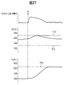
- FIG. 27 is a time chart during the regeneration control of the particulate filter.
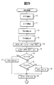
- FIG. 28 is a flowchart for performing NO X purification control.
- 29 and 30 are flowcharts for performing the reproduction control.
- 31A to 31C are diagrams showing various embodiments.
- Fig. 1 shows an overall view of a compression ignition type internal combustion engine.
- 1 is an engine body
- 2 is a combustion chamber of each cylinder
- 3 is an electronically controlled fuel injection valve for injecting fuel into each combustion chamber
- 4 is an intake manifold
- 5 is an exhaust manifold.
- the intake manifold 4 is connected to the outlet of the compressor 7 a of the exhaust turbocharger 7 via the intake duct 6, and the inlet of the compressor 7 a is connected to the air cleaner 9 via the intake air amount detector 8.
- a throttle valve 10 driven by a step motor is disposed in the intake duct 6, and a cooling device 11 for cooling intake air flowing through the intake duct 6 is disposed around the intake duct 6.
- a cooling device 11 for cooling intake air flowing through the intake duct 6 is disposed around the intake duct 6.
- the engine cooling water is guided into the cooling device 11, and the intake air is cooled by the engine cooling water.
- the exhaust manifold 5 is connected to the inlet of the exhaust turbine 7 b of the exhaust turbocharger 7.
- the outlet of the exhaust turbine 7b is connected to the inlet of the exhaust purification catalyst 13 via the exhaust pipe 12, and the outlet of the exhaust purification catalyst 13 is a post-treatment device that rises in temperature due to the oxidation reaction heat of hydrocarbons when hydrocarbons are supplied. 14 through an exhaust pipe 12a.
- the post-processing device 14 comprises a particulate filter for collecting particulates contained in the exhaust gas.
- a hydrocarbon supply valve 15 for supplying hydrocarbons composed of light oil and other fuels used as fuel for the compression ignition internal combustion engine is disposed.
- light oil is used as the hydrocarbon supplied from the hydrocarbon supply valve 15.
- the present invention can also be applied to a spark ignition type internal combustion engine in which combustion is performed under a lean air-fuel ratio.
- the hydrocarbon supply valve 15 supplies hydrocarbons made of gasoline or other fuel used as fuel for the spark ignition internal combustion engine.
- the exhaust manifold 5 and the intake manifold 4 are connected to each other via an exhaust gas recirculation (hereinafter referred to as EGR) passage 16, and an electronically controlled EGR control valve 17 is disposed in the EGR passage 16.
- EGR exhaust gas recirculation
- a cooling device 18 for cooling the EGR gas flowing in the EGR passage 16 is disposed around the EGR passage 16.
- the engine cooling water is guided into the cooling device 18, and the EGR gas is cooled by the engine cooling water.
- each fuel injection valve 3 is connected to a common rail 20 via a fuel supply pipe 19, and this common rail 20 is connected to a fuel tank 22 via an electronically controlled fuel pump 21 having a variable discharge amount.
- the fuel stored in the fuel tank 22 is supplied into the common rail 20 by the fuel pump 21, and the fuel supplied into the common rail 20 is supplied to the fuel injection valve 3 through each fuel supply pipe 19.
- the electronic control unit 30 is composed of a digital computer, and is connected to each other by a bidirectional bus 31.
- a temperature sensor 23 for detecting the temperature of the exhaust purification catalyst 13 is attached downstream of the exhaust purification catalyst 13.
- a temperature sensor 25 for detecting the temperature of the particulate filter 14 is attached downstream of the particulate filter 14, and the particulate filter 14 is for detecting a differential pressure before and after the particulate filter 14.
- a differential pressure sensor 24 is attached. Output signals of the temperature sensors 23 and 25, the differential pressure sensor 24, and the intake air amount detector 8 are input to the input port 35 via corresponding AD converters 37, respectively.
- a load sensor 41 that generates an output voltage proportional to the depression amount L of the accelerator pedal 40 is connected to the accelerator pedal 40, and the output voltage of the load sensor 41 is input to the input port 35 via the corresponding AD converter 37. Is done.
- FIG. 2 schematically shows the surface portion of the catalyst carrier carried on the substrate of the exhaust purification catalyst 13.
- the catalyst support 50 made of alumina, for example, and further on this catalyst support 50 potassium K, sodium Na, cesium Cs.
- Alkaline metals such as barium Ba, alkaline earth metals such as calcium Ca, rare earths such as lanthanoids and silver Ag, copper Cu, iron Fe, NO such as iridium Ir X
- a basic layer 53 containing at least one selected from metals capable of donating electrons is formed. Since the exhaust gas flows along the catalyst carrier 50, it can be said that the noble metal catalysts 51 and 52 are supported on the exhaust gas flow surface of the exhaust purification catalyst 13. Further, since the surface of the basic layer 53 is basic, the surface of the basic layer 53 is referred to as a basic exhaust gas flow surface portion 54.
- the noble metal catalyst 51 is made of platinum Pt, and the noble metal catalyst 52 is made of rhodium Rh.
- the noble metal catalysts 51 and 52 carried on the catalyst carrier 50 are composed of platinum Pt and rhodium Rh.
- palladium Pd can be further supported on the catalyst carrier 50 of the exhaust purification catalyst 13, or palladium Pd can be supported instead of rhodium Rh.
- the noble metal catalysts 51 and 52 supported on the catalyst carrier 50 are composed of platinum Pt and at least one of rhodium Rh and palladium Pd.
- FIG. 3 schematically shows the reforming action performed in the exhaust purification catalyst 13 at this time.
- the hydrocarbon HC injected from the hydrocarbon feed valve 15 is converted into a radical hydrocarbon HC having a small number of carbons by the catalyst 51.
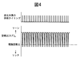
- FIG. 4 shows the supply timing of hydrocarbons from the hydrocarbon supply valve 15 and the change in the air-fuel ratio (A / F) in of the exhaust gas flowing into the exhaust purification catalyst 13. Since the change in the air-fuel ratio (A / F) in depends on the change in the concentration of hydrocarbons in the exhaust gas flowing into the exhaust purification catalyst 13, the air-fuel ratio (A / F) in shown in FIG. It can be said that the change represents a change in hydrocarbon concentration.
- FIG. 5 shows a change in the air-fuel ratio (A / F) in of the exhaust gas flowing into the exhaust purification catalyst 13 as shown in FIG. 4 by periodically changing the concentration of hydrocarbons flowing into the exhaust purification catalyst 13. NO by the exhaust purification catalyst 13 when X The purification rate is shown for each catalyst temperature TC of the exhaust purification catalyst 13. The inventor has NO over a long period of time.
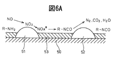
- FIG. 6A and 6B In the research course, when the concentration of hydrocarbons flowing into the exhaust purification catalyst 13 is vibrated with an amplitude within a predetermined range and a period within a predetermined range, FIG. As shown in Fig. 4, extremely high NO even in a high temperature region of 400 ° C or higher. X It has been found that a purification rate can be obtained. Further, at this time, a large amount of the reducing intermediate containing nitrogen and hydrocarbon continues to be held or adsorbed on the surface of the basic layer 53, that is, on the basic exhaust gas flow surface portion 54 of the exhaust purification catalyst 13. Reducing intermediate is high NO X It turns out that it plays a central role in obtaining the purification rate. Next, this will be described with reference to FIGS. 6A and 6B.
- FIGS. 6A and 6B schematically show the surface portion of the catalyst carrier 50 of the exhaust purification catalyst 13, and in these FIGS. 6A and 6B, the concentration of hydrocarbons flowing into the exhaust purification catalyst 13 is predetermined. Shown is a reaction that is presumed to occur when oscillated with an amplitude within a range and a period within a predetermined range.
- FIG. 6A shows a case where the concentration of hydrocarbons flowing into the exhaust purification catalyst 13 is low
- FIG. 6B shows that the concentration of hydrocarbons flowing into the exhaust purification catalyst 13 when hydrocarbons are supplied from the hydrocarbon supply valve 15 is high. It shows when As can be seen from FIG.
- the first reducing intermediate produced at this time is the nitro compound R-NO. 2 It is thought that.
- This nitro compound R-NO 2 Is produced, it becomes a nitrile compound R-CN, but this nitrile compound R-CN can only survive for a moment in that state, so it immediately becomes an isocyanate compound R-NCO.
- this isocyanate compound R-NCO is hydrolyzed, the amine compound R-NH 2 It becomes. However, in this case, it is considered that a part of the isocyanate compound R-NCO is hydrolyzed. Therefore, as shown in FIG.
- Active NO at this time X * Is a reducing intermediate R-NCO or R-NH 2 Reacts with N 2 , CO 2 , H 2 O, so NO X Will be purified.
- a reducing intermediate is generated by increasing the concentration of hydrocarbons flowing into the exhaust purification catalyst 13, and the concentration of hydrocarbons flowing into the exhaust purification catalyst 13 is decreased to reduce the oxygen concentration.
- the active NO X * Reacts with reducing intermediates and NO X Is purified That is, the exhaust purification catalyst 13 makes NO. X In order to purify, it is necessary to periodically change the concentration of hydrocarbons flowing into the exhaust purification catalyst 13.
- the produced reducing intermediate is activated NO.
- X * It is necessary to reduce the hydrocarbon concentration to a concentration low enough to react with. That is, it is necessary to vibrate the hydrocarbon concentration flowing into the exhaust purification catalyst 13 with an amplitude within a predetermined range.
- the generated reducing intermediate is active NO.
- X * Sufficient amounts of reducing intermediates R-NCO and R-NH until 2 Must be retained on the basic layer 53, that is, on the basic exhaust gas flow surface portion 24.
- a basic exhaust gas flow surface portion 24 is provided.
- noble metal catalysts 51 and 52 are supported on the exhaust gas flow surface of the exhaust purification catalyst 13, and the generated reducing intermediates R-NCO and R-NH 2 Is maintained around the noble metal catalyst 51, 52, a basic exhaust gas flow surface portion 54 is formed around the noble metal catalyst 51, 52, and is held on the basic exhaust gas flow surface portion 54.
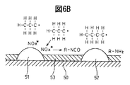
- the injection interval is 3 seconds.
- the oscillation period of hydrocarbon concentration that is, the supply period of hydrocarbon HC is longer than the period within the above-mentioned predetermined range
- the reducing intermediates R-NCO and R-NH are formed on the surface of the basic layer 53. 2 Disappears, and at this time, the active NO produced on platinum Pt53 X * Is nitrate ion NO as shown in FIG. 7A. 3 ⁇ In the form of nitrate in the form of nitrate. That is, at this time, NO in the exhaust gas X Will be absorbed in the basic layer 53 in the form of nitrate.
- FIG. 1 In the form of nitrate in the form of nitrate. That is, at this time, NO in the exhaust gas X Will be absorbed in the basic layer 53 in the form of nitrate.
- X NO for temporary storage X It plays the role of a storage agent. That is, in this case, if the ratio of air and fuel (hydrocarbon) supplied into the engine intake passage, the combustion chamber 2 and the exhaust passage upstream of the exhaust purification catalyst 13 is referred to as the air-fuel ratio of the exhaust gas, the exhaust purification catalyst. 13 is NO when the air-fuel ratio of the exhaust gas is lean X NO is stored when the oxygen concentration in the exhaust gas decreases. X NO release X It functions as a storage catalyst. FIG. 9 shows that the exhaust purification catalyst 13 is NO in this way.
- the purification rate is shown.
- the horizontal axis in FIG. 9 indicates the catalyst temperature TC of the exhaust purification catalyst 13.
- Set the exhaust purification catalyst 13 to NO X When functioning as an occlusion catalyst, as shown in FIG. 9, when the catalyst temperature TC is 300 ° C. to 400 ° C., extremely high NO X A purification rate can be obtained, but NO when the catalyst temperature TC reaches 400 ° C or higher.
- X The purification rate decreases. ⁇ If the catalyst temperature TC reaches 400 ° C or higher, NO X The purification rate decreases because when the catalyst temperature TC reaches 400 ° C. or higher, the nitrate is thermally decomposed and NO.
- the hydrocarbon supply valve 15 for supplying hydrocarbons is arranged in the engine exhaust passage, and NO contained in the exhaust gas in the engine exhaust passage downstream of the hydrocarbon supply valve 15.
- An exhaust purification catalyst 13 for reacting with the reformed hydrocarbon is disposed.
- Noble metal catalysts 51 and 52 are supported on the exhaust gas flow surface of the exhaust purification catalyst 13 and around the noble metal catalysts 51 and 52. Is formed with a basic exhaust gas flow surface portion 54, and the exhaust purification catalyst 13 has a concentration of hydrocarbons flowing into the exhaust purification catalyst 13 within a predetermined range and an amplitude within a predetermined range. If it is vibrated with the period of NO, NO contained in the exhaust gas X NO and contained in the exhaust gas when the oscillation period of the hydrocarbon concentration is longer than this predetermined range.
- FIG. 10 shows an enlarged view of the change in the air-fuel ratio (A / F) in shown in FIG.
- the change in the air-fuel ratio (A / F) in of the exhaust gas flowing into the exhaust purification catalyst 13 indicates the change in the concentration of hydrocarbons flowing into the exhaust purification catalyst 13 at the same time.
- ⁇ H indicates the amplitude of the change in the concentration of hydrocarbon HC flowing into the exhaust purification catalyst 13, and ⁇ T indicates the oscillation period of the concentration of hydrocarbon flowing into the exhaust purification catalyst 13.
- (A / F) b represents the base air-fuel ratio indicating the air-fuel ratio of the combustion gas for generating the engine output.
- the base air-fuel ratio (A / F) b represents the air-fuel ratio of the exhaust gas flowing into the exhaust purification catalyst 13 when the supply of hydrocarbons is stopped.
- X represents the generated active NO.
- X * Represents the upper limit of the air-fuel ratio (A / F) in used for the production of the reducing intermediate without being occluded in the basic layer 53 in the form of nitrate, X * It is necessary to make the air-fuel ratio (A / F) in lower than the upper limit X of this air-fuel ratio in order to cause the reduced hydrocarbon to react with the reformed hydrocarbon.
- X in Fig. 10 is active NO X * Represents the lower limit of the hydrocarbon concentration required to produce a reducing intermediate by reacting the modified hydrocarbon with the modified hydrocarbon. It is necessary to make it higher than the lower limit X. In this case, whether or not a reducing intermediate is generated depends on the active NO.
- the ratio between the surrounding oxygen concentration and the hydrocarbon concentration, that is, the air-fuel ratio (A / F) in, is determined by the above-mentioned upper limit X of the air-fuel ratio necessary for generating the reducing intermediate, Called.
- the required minimum air-fuel ratio X is rich. Therefore, in this case, the air-fuel ratio (A / F) in is instantaneously required to generate the reducing intermediate. The following is made rich:
- the required minimum air-fuel ratio X is lean.
- the reducing intermediate is generated by periodically reducing the air-fuel ratio (A / F) in while maintaining the air-fuel ratio (A / F) in lean.
- the required minimum air-fuel ratio X becomes rich or lean depends on the oxidizing power of the exhaust purification catalyst 13.
- the exhaust purification catalyst 13 becomes stronger in oxidizing power, and if it becomes more acidic, the oxidizing power becomes stronger. Accordingly, the oxidizing power of the exhaust purification catalyst 13 varies depending on the amount of the precious metal 51 supported and the acidity.
- the air-fuel ratio (A / F) in is periodically decreased while maintaining the air-fuel ratio (A / F) in lean as shown in FIG.
- the exhaust purification catalyst 13 having a weak oxidizing power when used, the air-fuel ratio (A / F) in is periodically decreased while maintaining the air-fuel ratio (A / F) in lean as shown in FIG. In this case, the hydrocarbon is not completely oxidized but partially oxidized, that is, the hydrocarbon is reformed, and thus a reducing intermediate is produced.
- the exhaust purification catalyst 13 having a weak oxidizing power when used, if the air-fuel ratio (A / F) in is periodically made rich as shown in FIG. 10, a large amount of hydrocarbons are not oxidized. The exhaust gas is simply exhausted from the exhaust purification catalyst 13, and the amount of hydrocarbons that are wasted is increased.
- the required minimum air-fuel ratio X needs to be made lean. That is, it can be seen that the required minimum air-fuel ratio X needs to be lowered as the oxidizing power of the exhaust purification catalyst 13 becomes stronger, as shown in FIG. As described above, the required minimum air-fuel ratio X becomes lean or rich due to the oxidizing power of the exhaust purification catalyst 13, but the case where the required minimum air-fuel ratio X is rich will be described as an example. The amplitude of the change in the concentration of the inflowing hydrocarbon and the oscillation period of the concentration of the hydrocarbon flowing into the exhaust purification catalyst 13 will be described.
- the air-fuel ratio (A / F) in is made equal to or less than the required minimum air-fuel ratio X.
- NO X As described above, it is necessary to oxidize the surplus hydrocarbons in order to purify the water well. X In order to purify the water well, a larger amount of excess hydrocarbon requires more oxygen. In this case, the amount of oxygen can be increased by increasing the oxygen concentration in the exhaust gas.
- NO X In order to purify the gas well, it is necessary to increase the oxygen concentration in the exhaust gas after the hydrocarbon is supplied when the oxygen concentration in the exhaust gas before the hydrocarbon is supplied is high. That is, it is necessary to increase the amplitude of the hydrocarbon concentration as the oxygen concentration in the exhaust gas before the hydrocarbon is supplied is higher.
- Figure 13 shows the same NO X It shows the relationship between the oxygen concentration in the exhaust gas before the hydrocarbon is supplied and the amplitude ⁇ H of the hydrocarbon concentration when the purification rate is obtained. The same NO from FIG. X It can be seen that in order to obtain the purification rate, it is necessary to increase the amplitude ⁇ H of the hydrocarbon concentration as the oxygen concentration in the exhaust gas before the hydrocarbon is supplied is higher.
- the same NO X In order to obtain the purification rate, it is necessary to increase the amplitude ⁇ T of the hydrocarbon concentration as the base air-fuel ratio (A / F) b increases. In other words, NO X In order to purify the gas well, the amplitude ⁇ T of the hydrocarbon concentration can be reduced as the base air-fuel ratio (A / F) b becomes lower.
- the base air-fuel ratio (A / F) b is the lowest during acceleration operation, and if the hydrocarbon concentration amplitude ⁇ H is about 200 ppm, NO X Can be purified well.
- the base air-fuel ratio (A / F) b is usually larger than that during acceleration operation. Therefore, as shown in FIG.
- the predetermined range of the amplitude of the hydrocarbon concentration is set to 200 ppm to 10,000 ppm.
- the vibration period ⁇ T of the hydrocarbon concentration becomes long, after the hydrocarbon is supplied, the active NO is X * The surrounding oxygen concentration becomes high.
- the vibration period ⁇ T of the hydrocarbon concentration when the vibration period ⁇ T of the hydrocarbon concentration is longer than about 5 seconds, the active NO X * Will begin to be absorbed in the basic layer 53 in the form of nitrate, and therefore, as shown in FIG. 15, when the vibration period ⁇ T of the hydrocarbon concentration becomes longer than about 5 seconds, NO X The purification rate will decrease. Therefore, the vibration period ⁇ T of the hydrocarbon concentration needs to be 5 seconds or less.
- the vibration period ⁇ T of the hydrocarbon concentration becomes approximately 0.3 seconds or less, the supplied hydrocarbon starts to accumulate on the exhaust gas flow surface of the exhaust purification catalyst 13, and therefore, as shown in FIG.
- NO X When the vibration period ⁇ T of the motor becomes approximately 0.3 seconds or less, NO X The purification rate decreases.
- the vibration period of the hydrocarbon concentration is set to be between 0.3 seconds and 5 seconds.
- the purification method will be specifically described. In this way, the exhaust purification catalyst 13 is changed to NO. X NO when functioning as a storage catalyst X
- the purification method is hereinafter referred to as the second NO. X This is called a purification method.
- This second NO X In the purification method, the occluded NO occluded in the basic layer 53 as shown in FIG.
- the air-fuel ratio (A / F) in of the exhaust gas flowing into the exhaust purification catalyst 13 is temporarily made rich.
- the air-fuel ratio (A / F) in of the exhaust gas is made rich, the NO stored in the basic layer 53 when the air-fuel ratio (A / F) in of the exhaust gas is lean X Are released from the basic layer 53 at once and reduced. NO X Is purified. Occlusion NO X
- the amount ⁇ NOX is, for example, NO discharged from the engine X Calculated from the quantity.
- the emission NO discharged from the engine per unit time X The amount NOXA is stored in advance in the ROM 32 as a function of the injection amount Q and the engine speed N in the form of a map as shown in FIG. X From NOXA to NO X An amount ⁇ NOX is calculated.
- the period during which the air-fuel ratio (A / F) in of the exhaust gas is made rich is usually 1 minute or more.
- This second NO X In the purification method, as shown in FIG. 18, the air-fuel ratio (A) of the exhaust gas flowing into the exhaust purification catalyst 13 by injecting additional fuel WR into the combustion chamber 2 from the fuel injection valve 3 in addition to the fuel Q for combustion. / F) in is made rich.
- the horizontal axis in FIG. 18 indicates the crank angle.
- This additional fuel WR is injected when it burns but does not appear as engine output, that is, slightly before ATDC 90 ° after compression top dead center.
- This fuel amount WR is stored in advance in the ROM 32 as a function of the injection amount Q and the engine speed N in the form of a map as shown in FIG.
- the air-fuel ratio (A / F) in of the exhaust gas can be made rich by increasing the amount of hydrocarbons supplied from the hydrocarbon supply valve 15 in this case.
- the first NO X NO using the purification method X As described above, it is necessary to appropriately control the amplitude ⁇ H and the vibration period ⁇ T of the hydrocarbon concentration. That is, the first NO X NO using the purification method X In order to purify the gas well, the amplitude ⁇ H of the hydrocarbon concentration is controlled so that the air-fuel ratio (A / F) in of the exhaust gas flowing into the exhaust purification catalyst 13 is equal to or less than the required minimum air-fuel ratio X, It is necessary to control the oscillation period ⁇ T of the concentration between 0.3 seconds and 5 seconds.
- the vibration period ⁇ T of the hydrocarbon concentration is controlled to control the injection amount of hydrocarbons from the hydrocarbon supply valve 15, and the vibration period ⁇ T of the hydrocarbon concentration is controlled from the hydrocarbon supply valve 15. It is controlled by controlling the hydrogen injection period.
- the injection amount of hydrocarbons from the hydrocarbon supply valve 15 is controlled to control at least one of the injection time or injection pressure of hydrocarbons from the hydrocarbon supply valve 15.
- FIG. 20 shows three injection patterns A, B, and C of hydrocarbons injected from the hydrocarbon supply valve 15 under the same injection pressure and with different injection times.
- the injection pattern A has the shortest injection pattern A and the injection pattern C has the longest injection time.
- FIG. 20 shows a temporal change in the hydrocarbon concentration in the exhaust gas flowing into the exhaust purification catalyst 13 after the injection is performed by the respective injection patterns A, B, and C. Further, FIG.
- the hydrocarbon concentration in the exhaust gas has a limit at which all the hydrocarbons are completely oxidized in the exhaust purification catalyst 13, and this limit is indicated by XA in FIG. That is, in FIG. 20, when the hydrocarbon concentration is lower than the limit XA, all the hydrocarbons are completely oxidized. Therefore, in FIG. 20, all hydrocarbons are completely oxidized in the hatching region RA below the limit XA. become. In this case, the area of the hatching region RA represents the amount of hydrocarbons, and therefore, the amount of hydrocarbons corresponding to the hatching region RA is completely oxidized.
- this limit XA is referred to as a complete oxidation limit.
- the exhaust purification catalyst 13 performs partial oxidation of hydrocarbons.
- the hatched region RB represents the amount of hydrocarbons that are partially oxidized. Since the reducing intermediate is produced from the partially oxidized hydrocarbon, the first NO is generated by the partially oxidized hydrocarbon. X NO by purification method X The purifying action is performed. Actually, a part of the partially oxidized hydrocarbon is oxidized without being used for the production of the reducing intermediate, and the reducing intermediate is produced by the remaining partially oxidized hydrocarbon.
- the concentration of hydrocarbons in the exhaust gas flowing into the exhaust purification catalyst 13, that is, the amount of hydrocarbons per unit exhaust gas amount is further increased, some of the hydrocarbons are not completely oxidized in the exhaust purification catalyst 13. In this case, some hydrocarbons that are not oxidized pass through the exhaust purification catalyst 13.
- the limit of hydrocarbons that cause this hydrocarbon slip-through is indicated by XB in FIG. 20, and this limit XB is hereinafter referred to as a slip-through limit.
- the hatching region RC above the slip-through limit XB represents the amount of passing through hydrocarbons.
- the first NO X In order to purify using the purification method, NO contained in the exhaust gas X It is necessary that a sufficient amount of hydrocarbons with respect to the amount be partially oxidized, and NO when the amount of partially oxidized hydrocarbons RB is insufficient. X The purification rate will decrease.
- the injection pattern A in FIG. 20 shows a case where the amount of hydrocarbon RB to be partially oxidized is insufficient as described above. In this case, as shown in FIG. X The purification rate will decrease.
- the injection pattern B shows a case where the injection time is made longer than that of the injection pattern A in order to increase the amount of partially oxidized hydrocarbon RB. As shown in FIG.
- FIG. 20 shows a case where the hydrocarbon amount RB partially oxidized is slightly insufficient even in the injection pattern B.
- the injection pattern C shows a case where the injection time is further increased compared to the injection pattern B in order to further increase the amount of partially oxidized hydrocarbon RB.
- the purification rate is improved. In this case, however, the hydrocarbon concentration exceeds the slip-through limit XB, so that hydrocarbon slip-through occurs. 1st NO X NO by purification method X When performing the purification action, it is usually necessary to prevent hydrocarbons from slipping through.
- the first NO X NO by purification method X When performing the purification action, the injection pattern B in which the peak of the hydrocarbon concentration becomes the slip-through limit XB is usually used in the example shown in FIG. Of course, as shown in the injection pattern A, NO is sufficiently high even if the peak of the hydrocarbon concentration does not reach the slip-through limit XB. X When the purification rate is obtained, the injection pattern A is used. That is, in the present invention, the first NO X NO by purification method X When performing the purification action, either the injection pattern A or the injection pattern B is usually used.
- FIG. 21 and 22 show an example when hydrocarbon injection control is performed in consideration of this.
- the example shown in FIG. 21 shows a case where the injection amount of hydrocarbons is controlled by controlling the injection time while maintaining the injection pressure constant, and the example shown in FIG. The case where the injection amount of hydrocarbons is controlled by controlling both the pressure and the injection time is shown.
- FIG. 21 and FIG. 1 Indicates the injection pattern when the engine speed and load are relatively low.
- 3 Indicates the injection pattern when the engine speed and load are relatively high. 2
- the engine speed and load are A respectively. 1 A and A 3
- the injection pattern in the middle of the case shown by is shown.
- the injection pattern becomes A as the engine speed and load increase. 1 To A 3 It will be changed towards.
- the higher the engine speed and load the higher the temperature of the exhaust purification catalyst 13, and the higher the engine speed and load, the higher the complete oxidation limit XA and the slip-through limit XB.
- the higher the engine speed and load the more exhaust NO from the engine per unit time.
- the amount of hydrocarbon RB that is partially oxidized needs to be increased as the amount increases, and as the engine speed and load increase. In this case, in order to increase the amount RB of partially oxidized hydrocarbons, it is necessary to increase the injection amount of hydrocarbons. Therefore NO X In the example shown in FIG.
- the injection amount is increased by increasing the injection time as the engine speed and the load increase so that the amount of partially oxidized hydrocarbons necessary for purification can be generated.
- the injection amount is increased by increasing both the injection pressure and the injection time as the engine speed and load increase.
- the injection amount can be controlled by controlling only the injection time or by controlling both the injection pressure and the injection time.
- the injection amount is controlled only by controlling the injection time. The present invention will be described by taking the case of doing so as an example.
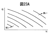
- Fig. 23A shows NO when the injection amount is controlled by controlling only the injection time in this way.
- X The equal injection time line which can produce
- the hydrocarbon injection time increases as the fuel injection amount Q into the combustion chamber 2 increases, that is, as the engine load increases, and increases as the engine speed N increases.
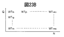
- This injection time WT is stored in advance in the ROM 32 in the form of a map as shown in FIG. 23B as a function of the fuel injection amount Q and the engine speed N.
- the vibration amplitude ⁇ T of the optimum hydrocarbon concentration that is, the hydrocarbon injection period ⁇ T, is also stored in the ROM 32 in advance in the form of a map as shown in FIG. 23C as a function of the injection amount Q and the engine speed N. Yes.
- the first NO X Good NO by purification method X Purifying action is performed.
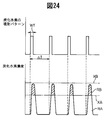
- FIG. 24 shows the first NO in this way.
- X Good NO by purification method X The hydrocarbon injection pattern and the change in hydrocarbon concentration when the purification action is performed are shown. At this time, the amount of hydrocarbon shown in the region RA in FIG. 24 is completely oxidized, and at this time, the exhaust purification catalyst 13 is maintained in an activated state by the oxidation reaction heat of the hydrocarbon.
- the post-processing device 14 includes a particulate filter, and a noble metal such as platinum Pt is supported on the particulate filter 14.
- the particulate filter 14 has an oxidation function. Therefore, when hydrocarbons are supplied to the particulate filter 14, the temperature of the particulate filter 14 rises due to the oxidation reaction heat of the hydrocarbons.
- the first NO X NO by purification method X When the purification action is being performed, the injection amount of hydrocarbon is normally controlled so that the hydrocarbon does not pass through the exhaust purification catalyst 13 as can be seen from FIG. Therefore, normally, the particulate filter 14 is heated by the exhaust gas to which heat is applied in the exhaust purification catalyst 13 without the temperature of the particulate filter 14 being raised by the oxidation reaction heat of hydrocarbons.
- the temperature of the particulate filter 14 is lower than the temperature of the exhaust purification catalyst 13, and when the particulate filter 14 is arranged further away from the exhaust purification catalyst 13, the temperature of the particulate filter 14 is further lowered. .
- the particulate collection amount of the particulate filter 14 exceeds a certain level, it is necessary to raise the temperature of the particulate filter 14 to about 650 ° C. and burn and remove the accumulated particulates. That is, it is necessary to regenerate the particulate filter 14.
- the amplitude of the change in the hydrocarbon concentration is increased to increase the amount RC of the hydrocarbon that passes through the exhaust purification catalyst 13, and the particulate filter 14 of the hydrocarbon that has passed through.
- the particulate filter 14 is heated by the oxidation reaction heat. That is, in general terms, in the present invention, an aftertreatment device 14 that rises in temperature due to the oxidation reaction heat of hydrocarbons when hydrocarbons are supplied is disposed in the engine exhaust passage downstream of the exhaust purification catalyst 13, and When the temperature of the processing device 14 is to be increased, the amplitude of the change in the concentration of hydrocarbons flowing into the exhaust purification catalyst 13 is increased to increase the amount RC of hydrocarbons passing through the exhaust purification catalyst 13. In this case, in the embodiment according to the present invention, as shown by WTK in FIG. X NO by purification method X The injection time is made longer than the injection time TW (FIG.
- the amount of hydrocarbons that are completely oxidized per unit time can be expressed by a value (RA / ⁇ TK) obtained by gradually grading the amount of fully oxidized hydrocarbons RA per injection with an injection period ⁇ TK.
- FIG. 27 shows the amount of passing through RC of hydrocarbons during the regeneration control of the particulate filter, the change in the temperature TC of the exhaust purification catalyst 13, and the change in the temperature TM of the particulate filter 14.
- TMX indicates a target temperature during regeneration of the particulate filter 14, that is, a regeneration temperature.
- time t 0 Assuming that the regeneration control of the particulate filter 14 is started, the amount of injected hydrocarbons is increased, thereby increasing the amount of passing through RC of hydrocarbons.
- the temperature TM of the particulate filter 14 is raised by the heat of oxidation reaction of the hydrocarbons passed through.
- the slip-through amount RC of the hydrocarbon is decreased as the temperature TM of the particulate filter 14 approaches the regeneration temperature TMX, and when the temperature TM of the particulate filter 14 reaches the regeneration temperature TMX, the particulate filter 14.
- the hydrocarbon slip-through amount RC is controlled so that the temperature TM is maintained at the regeneration temperature TMX. That is, in this embodiment, the target temperature at the time of raising the temperature of the post-treatment device 13 is determined in advance, and when the temperature of the post-treatment device 13 is to be raised, the hydrocarbon so that the temperature of the post-treatment device 13 rises to the target temperature.
- the slip-through amount RC is controlled.
- the injection amount of hydrocarbons is increased in order to raise the temperature of the particulate filter 14, the injection cycle is lengthened to keep the temperature TC of the exhaust purification catalyst 13 constant.
- the temperature TC of the particulate filter 14 often varies without being maintained constant.
- the allowable upper limit temperature TCX of the exhaust purification catalyst 13 that may cause thermal deterioration of the exhaust purification catalyst 13 is set in advance, and the temperature rise control of the particulate filter 14 is performed.
- the temperature TC of the exhaust purification catalyst 13 exceeds the allowable upper limit temperature TCX when the temperature increase control of the aftertreatment device 14 is being performed, hydrocarbon injection is performed in order to lower the temperature of the exhaust purification catalyst 13. The cycle is lengthened.
- the temperature TC of the exhaust purification catalyst 13 is the activation temperature TC when the temperature increase control of the particulate filter 14 is performed, that is, when the temperature increase control of the aftertreatment device 14 is performed.
- the temperature raising action of the aftertreatment device 14 is controlled by changing the injection amount of hydrocarbons
- the temperature TC of the exhaust purification catalyst 13 is controlled by changing the injection cycle of hydrocarbons. Is done. NO in Figure 28 X
- the purification control routine is shown. This routine is executed by interruption every predetermined time. Referring to FIG. 28, first, in step 60, the temperature TC of the exhaust purification catalyst 13 is determined from the output signal of the temperature sensor 23 to the activation temperature TC. 0 It is discriminated whether or not it exceeds.
- step 61 it is judged if regeneration control of the particulate filter 14 is being performed.
- the processing cycle is completed.
- step 62 the differential pressure P indicating that the differential pressure across the particulate filter 14 should be regenerated based on the output signal of the differential pressure sensor 24. 0 It is determined whether or not the value has been exceeded.
- ⁇ P ⁇ P 0 the routine proceeds to step 64, where hydrocarbon supply processing is performed with the injection time WTij calculated from FIG.
- step 62 the routine proceeds to step 63 where regeneration control of the particulate filter 14 is executed. A routine for performing this reproduction control is shown in FIGS.
- step 60 TC ⁇ TC 0
- step 65 the discharge NO per unit time is determined from the map shown in FIG. X The quantity NOXA is calculated.
- step 66 NO is discharged to ⁇ NOX.
- step 67 NO is stored.
- X It is determined whether or not the amount ⁇ NOX exceeds the allowable value MAX.
- the routine proceeds to step 68 where the additional fuel amount WR is calculated from the map shown in FIG. 19 and the additional fuel injection action is performed.
- step 69 ⁇ NOX is cleared. 29 and 30 are also executed by interruption every predetermined time when the reproduction control is started. In this regeneration control routine, first, in step 70, the injection time WT corresponding to the operating state is calculated from the map shown in FIG.
- step 71 the injection cycle ⁇ T corresponding to the operating state is calculated from the map shown in FIG. Calculated.
- step 72 the temperature TM of the particulate filter 14 detected by the temperature sensor 25 is read, and then at step 73, the temperature TC of the exhaust purification catalyst 13 detected by the temperature sensor 23 is read.
- step 74 the hydrocarbon injection time WTK at the time of regeneration is calculated based on the following equation. WTK ⁇ WT ⁇ [1 + C ⁇ (TMX-TM)]
- C is a constant
- TMX is the regeneration temperature shown in FIG.
- C ⁇ (TMX-TM) indicates the increase rate of the injection time WT, and the increase rate of the injection time WT increases as the difference between the temperature TM of the particulate filter 14 and the regeneration temperature TMX increases.
- the hydrocarbon injection period ⁇ TK during regeneration is calculated based on the following equation. ⁇ TK ⁇ (WTK / WT) ⁇ ⁇ T As can be seen from the above equation, the injection period ⁇ TK during regeneration is lengthened as the injection time WTK during regeneration is increased.
- the temperature TC of the exhaust purification catalyst 13 is the activation temperature TC. 0 And the allowable upper temperature TCX are corrected so that the injection cycle ⁇ TK during regeneration is corrected.
- step 76 it is judged if the temperature TC of the exhaust purification catalyst 13 has exceeded the allowable upper limit temperature TCX.
- the routine proceeds to step 77, where the constant value ⁇ is added to the injection cycle correction value ⁇ d.
- step 80 the correction value ⁇ d is added to the injection cycle ⁇ TK. Accordingly, at this time, the injection cycle ⁇ TK is lengthened.
- step 78 the routine proceeds to step 78 where the temperature TC of the exhaust purification catalyst 13 becomes the activation temperature TC.
- step 79 the routine proceeds to step 79 where a fixed value is subtracted from the correction value ⁇ d, and then the routine proceeds to step 80. Accordingly, at this time, the injection cycle ⁇ TK is shortened.
- step 78 TC> TC 0 If it is determined that the process is in progress, the process proceeds to step 80.
- step 81 hydrocarbon supply processing is performed with the injection time WTK calculated at step 74 and the injection cycle ⁇ TK calculated at step 80. At this time, the first NO X NO by purification method X The regeneration process of the particulate filter 14 is performed while the purification action is performed.
- step 82 it is determined whether or not the regeneration process of the particulate filter 14 is completed.
- the routine proceeds to step 83 where the correction value ⁇ d is cleared.
- An exhaust gas mixer 45 is preferably disposed in the exhaust pipe 12a upstream of the curate filter 14.
- FIG. 31B shows NO as the post-processing device 14.
- FIG. 31C shows NO as the post-processing device 14.
- a selective reduction catalyst is used is shown.
- a urea water supply valve 46 is arranged in the exhaust pipe 12a upstream of the post-processing device 14, and urea water is supplied into the exhaust gas from the urea water supply valve 46.
- the NO contained in exhaust gas X NO by ammonia produced from urea water X It is reduced in a selective reduction catalyst.
- the selective reduction catalyst is made of, for example, Cu zeolite, and therefore NO.
- the selective reduction catalyst is not strong but has an oxidizing function.
- the target temperature rise during the temperature rise control of the post-processing device 14 is the regeneration temperature of the particulate filter.
- the temperature rise during the temperature rise control of the post-processing device 14 ⁇ the target temperature is NO.
- the activation temperature of the selective reduction catalyst is used. That is, in the embodiment shown in FIG. X
- the hydrocarbon injection amount is increased when the selective reduction catalyst is to be activated. Note that if the injection amount of hydrocarbons is greatly increased, ammonia is generated in the exhaust purification catalyst 13, so that the exhaust gas flowing into the aftertreatment device 14 contains ammonia.
- This ammonia is also NO if there is no oxygen X
- the selective reduction action does not occur. Therefore, in the embodiment shown in FIGS. 31B and 31C, when there is a risk that the rich air-fuel ratio exhaust gas and the lean air-fuel ratio exhaust gas will not be sufficiently mixed in the aftertreatment device 14, as shown in FIG. 31A. It is preferable to arrange the exhaust gas mixer 45 in the exhaust pipe 12a.
- an oxidation catalyst for reforming hydrocarbons can be disposed in the engine exhaust passage upstream of the exhaust purification catalyst 13.
Abstract
Priority Applications (5)
| Application Number | Priority Date | Filing Date | Title |
|---|---|---|---|
| CN201180001927.1A CN102753794B (zh) | 2011-02-07 | 2011-02-07 | 内燃机的排气净化装置 |
| US13/264,884 US9109491B2 (en) | 2011-02-07 | 2011-02-07 | Exhaust purification system of internal combustion engine |
| EP11767150.3A EP2503121B1 (fr) | 2011-02-07 | 2011-02-07 | Système de purification de gaz d'échappement pour moteur à combustion interne |
| JP2011531295A JP5131392B2 (ja) | 2011-02-07 | 2011-02-07 | 内燃機関の排気浄化装置 |
| PCT/JP2011/052969 WO2012108059A1 (fr) | 2011-02-07 | 2011-02-07 | Dispositif de purification de gaz d'échappement pour moteur à combustion interne |
Applications Claiming Priority (1)
| Application Number | Priority Date | Filing Date | Title |
|---|---|---|---|
| PCT/JP2011/052969 WO2012108059A1 (fr) | 2011-02-07 | 2011-02-07 | Dispositif de purification de gaz d'échappement pour moteur à combustion interne |
Publications (1)
| Publication Number | Publication Date |
|---|---|
| WO2012108059A1 true WO2012108059A1 (fr) | 2012-08-16 |
Family
ID=46638297
Family Applications (1)
| Application Number | Title | Priority Date | Filing Date |
|---|---|---|---|
| PCT/JP2011/052969 WO2012108059A1 (fr) | 2011-02-07 | 2011-02-07 | Dispositif de purification de gaz d'échappement pour moteur à combustion interne |
Country Status (5)
| Country | Link |
|---|---|
| US (1) | US9109491B2 (fr) |
| EP (1) | EP2503121B1 (fr) |
| JP (1) | JP5131392B2 (fr) |
| CN (1) | CN102753794B (fr) |
| WO (1) | WO2012108059A1 (fr) |
Cited By (5)
| Publication number | Priority date | Publication date | Assignee | Title |
|---|---|---|---|---|
| WO2014038088A1 (fr) * | 2012-09-10 | 2014-03-13 | トヨタ自動車株式会社 | Dispositif d'épuration d'échappement d'un moteur à combustion interne |
| WO2014115228A1 (fr) * | 2013-01-24 | 2014-07-31 | 日野自動車株式会社 | Purificateur de gaz d'échappement |
| WO2014132839A1 (fr) * | 2013-02-28 | 2014-09-04 | いすゞ自動車株式会社 | Dispositif de purification d'échappement pour moteur à combustion interne |
| JP2015034504A (ja) * | 2013-08-08 | 2015-02-19 | トヨタ自動車株式会社 | 内燃機関の排気浄化装置 |
| US20160069234A1 (en) * | 2013-04-09 | 2016-03-10 | Toyota Jidosha Kabushiki Kaisha | Exhaust purification system for internal combustion engine |
Families Citing this family (6)
| Publication number | Priority date | Publication date | Assignee | Title |
|---|---|---|---|---|
| US9010097B2 (en) * | 2011-03-17 | 2015-04-21 | Toyota Jidosha Kabushiki Kaisha | Exhaust purification system of internal combustion engine |
| BR112015008400B1 (pt) * | 2012-10-18 | 2021-01-19 | Johnson Matthey Public Limited Company | sistema para tratar gases de exaustão contendo nox de um motor, e, método para tratar uma corrente de gás de exaustão do motor contendo nox e fuligem |
| WO2014122728A1 (fr) * | 2013-02-05 | 2014-08-14 | トヨタ自動車株式会社 | Épurateur de gaz d'échappement pour moteur à combustion interne |
| WO2014167652A1 (fr) * | 2013-04-09 | 2014-10-16 | トヨタ自動車株式会社 | Dispositif d'épuration des gaz d'échappement de moteur à combustion interne |
| WO2014178110A1 (fr) * | 2013-04-30 | 2014-11-06 | トヨタ自動車株式会社 | Dispositif d'epuration de gaz d'échappement pour moteur à combustion interne |
| BR112016013746A2 (pt) | 2013-12-20 | 2017-08-08 | Toyota Motor Co Ltd | Aparelho para controle de gás de escapamento para motor de combustão interna |
Citations (4)
| Publication number | Priority date | Publication date | Assignee | Title |
|---|---|---|---|---|
| JP2005113801A (ja) * | 2003-10-08 | 2005-04-28 | Toyota Motor Corp | 内燃機関の排気浄化装置 |
| JP3969450B2 (ja) | 2003-12-01 | 2007-09-05 | トヨタ自動車株式会社 | 圧縮着火式内燃機関の排気浄化装置 |
| JP2008002451A (ja) * | 2006-05-23 | 2008-01-10 | Honda Motor Co Ltd | ディーゼルエンジン用排気ガス浄化装置およびディーゼルエンジンの排気ガスの浄化方法 |
| JP2009168031A (ja) * | 2001-12-03 | 2009-07-30 | Eaton Corp | 内燃エンジンの改善された排気制御のためのシステムおよび方法 |
Family Cites Families (122)
| Publication number | Priority date | Publication date | Assignee | Title |
|---|---|---|---|---|
| US5075274A (en) | 1989-03-15 | 1991-12-24 | Kabushiki Kaisha Riken | Exhaust gas cleaner |
| US5052178A (en) | 1989-08-08 | 1991-10-01 | Cummins Engine Company, Inc. | Unitary hybrid exhaust system and method for reducing particulate emmissions from internal combustion engines |
| US5057483A (en) | 1990-02-22 | 1991-10-15 | Engelhard Corporation | Catalyst composition containing segregated platinum and rhodium components |
| JP2605586B2 (ja) | 1992-07-24 | 1997-04-30 | トヨタ自動車株式会社 | 内燃機関の排気浄化装置 |
| US6667018B2 (en) | 1994-07-05 | 2003-12-23 | Ngk Insulators, Ltd. | Catalyst-adsorbent for purification of exhaust gases and method for purification of exhaust gases |
| EP0710499A3 (fr) | 1994-11-04 | 1997-05-21 | Agency Ind Science Techn | Nettoyeur de gaz d'échappement et méthode pour nettoyer un gaz d'échappement |
| EP0982487B1 (fr) | 1997-05-12 | 2003-07-16 | Toyota Jidosha Kabushiki Kaisha | Appareil de reduction des emissions de gaz d'echappement pour moteur a combustion interne |
| JP3456408B2 (ja) | 1997-05-12 | 2003-10-14 | トヨタ自動車株式会社 | 内燃機関の排気浄化装置 |
| GB9713428D0 (en) | 1997-06-26 | 1997-08-27 | Johnson Matthey Plc | Improvements in emissions control |
| FR2778205B1 (fr) | 1998-04-29 | 2000-06-23 | Inst Francais Du Petrole | Procede d'injection controlee d'hydrocarbures dans une ligne d'echappement d'un moteur a combustion interne |
| US7707821B1 (en) | 1998-08-24 | 2010-05-04 | Legare Joseph E | Control methods for improved catalytic converter efficiency and diagnosis |
| US6718756B1 (en) | 1999-01-21 | 2004-04-13 | Mitsubishi Jidosha Kogyo Kabushiki Kaisha | Exhaust gas purifier for use in internal combustion engine |
| JP2000257419A (ja) | 1999-03-03 | 2000-09-19 | Toyota Motor Corp | 排気浄化方法及び装置 |
| US6685897B1 (en) | 2000-01-06 | 2004-02-03 | The Regents Of The University Of California | Highly-basic large-pore zeolite catalysts for NOx reduction at low temperatures |
| US6311484B1 (en) | 2000-02-22 | 2001-11-06 | Engelhard Corporation | System for reducing NOx transient emission |
| DE10023439A1 (de) | 2000-05-12 | 2001-11-22 | Dmc2 Degussa Metals Catalysts | Verfahren zur Entfernung von Stickoxiden und Rußpartikeln aus dem mageren Abgas eines Verbrennungsmotors und Abgasreinigungssystem hierfür |
| JP4889873B2 (ja) | 2000-09-08 | 2012-03-07 | 日産自動車株式会社 | 排気ガス浄化システム、これに用いる排気ガス浄化触媒及び排気浄化方法 |
| WO2002066155A1 (fr) | 2001-02-19 | 2002-08-29 | Toyota Jidosha Kabushiki Kaisha | Catalyseur de clarification de gaz d'échappement |
| JP2002364415A (ja) | 2001-06-07 | 2002-12-18 | Mazda Motor Corp | エンジンの排気浄化装置 |
| LU90795B1 (en) | 2001-06-27 | 2002-12-30 | Delphi Tech Inc | Nox release index |
| US6677272B2 (en) | 2001-08-15 | 2004-01-13 | Corning Incorporated | Material for NOx trap support |
| US7082753B2 (en) | 2001-12-03 | 2006-08-01 | Catalytica Energy Systems, Inc. | System and methods for improved emission control of internal combustion engines using pulsed fuel flow |
| US20030113242A1 (en) | 2001-12-18 | 2003-06-19 | Hepburn Jeffrey Scott | Emission control device for an engine |
| WO2003071106A1 (fr) | 2002-02-19 | 2003-08-28 | Kabushiki Kaisha Chemical Auto | Filtre de purification des gaz d'echappement des diesels |
| JP3963130B2 (ja) | 2002-06-27 | 2007-08-22 | トヨタ自動車株式会社 | 触媒劣化判定装置 |
| ATE421375T1 (de) | 2002-07-31 | 2009-02-15 | Umicore Ag & Co Kg | Verfahren zur regenerierung eines stickoxid- speicherkatalysators |
| JP2004068700A (ja) | 2002-08-06 | 2004-03-04 | Toyota Motor Corp | 排気ガス浄化方法 |
| KR100636567B1 (ko) | 2002-09-10 | 2006-10-19 | 도요다 지도샤 가부시끼가이샤 | 내연 기관의 배기 정화 장치 |
| US7332135B2 (en) * | 2002-10-22 | 2008-02-19 | Ford Global Technologies, Llc | Catalyst system for the reduction of NOx and NH3 emissions |
| EP1563169A1 (fr) | 2002-11-15 | 2005-08-17 | Catalytica Energy Systems, Inc. | Dispositifs et procedes pour reduire les emissions de no sb x /sb de moteurs a melange pauvre |
| JP4385593B2 (ja) | 2002-12-10 | 2009-12-16 | トヨタ自動車株式会社 | 内燃機関の排気浄化装置 |
| DE10300298A1 (de) | 2003-01-02 | 2004-07-15 | Daimlerchrysler Ag | Abgasnachbehandlungseinrichtung und -verfahren |
| DE10308287B4 (de) | 2003-02-26 | 2006-11-30 | Umicore Ag & Co. Kg | Verfahren zur Abgasreinigung |
| US7043902B2 (en) | 2003-03-07 | 2006-05-16 | Honda Motor Co., Ltd. | Exhaust gas purification system |
| US6854264B2 (en) | 2003-03-27 | 2005-02-15 | Ford Global Technologies, Llc | Computer controlled engine adjustment based on an exhaust flow |
| JP4288985B2 (ja) | 2003-03-31 | 2009-07-01 | 株式会社デンソー | 内燃機関の排気浄化装置 |
| DE10315593B4 (de) | 2003-04-05 | 2005-12-22 | Daimlerchrysler Ag | Abgasnachbehandlungseinrichtung und -verfahren |
| US6983589B2 (en) | 2003-05-07 | 2006-01-10 | Ford Global Technologies, Llc | Diesel aftertreatment systems |
| JP4158697B2 (ja) | 2003-06-17 | 2008-10-01 | トヨタ自動車株式会社 | 内燃機関の排気浄化装置および排気浄化方法 |
| CA2527006A1 (fr) | 2003-06-18 | 2004-12-29 | Johnson Matthey Public Limited Company | Procedes de commande d'ajout de reducteur |
| GB0318776D0 (en) | 2003-08-09 | 2003-09-10 | Johnson Matthey Plc | Lean NOx catalyst |
| JP4020054B2 (ja) | 2003-09-24 | 2007-12-12 | トヨタ自動車株式会社 | 内燃機関の排気浄化システム |
| JP3876874B2 (ja) | 2003-10-28 | 2007-02-07 | トヨタ自動車株式会社 | 触媒再生方法 |
| GB0329095D0 (en) | 2003-12-16 | 2004-01-14 | Johnson Matthey Plc | Exhaust system for lean burn IC engine including particulate filter |
| US20050135977A1 (en) | 2003-12-19 | 2005-06-23 | Caterpillar Inc. | Multi-part catalyst system for exhaust treatment elements |
| JP4321332B2 (ja) | 2004-04-01 | 2009-08-26 | トヨタ自動車株式会社 | 内燃機関の排気浄化装置 |
| JP4232690B2 (ja) | 2004-05-24 | 2009-03-04 | トヨタ自動車株式会社 | 内燃機関の排気浄化装置に適用される燃料添加制御方法、及び排気浄化装置 |
| JP4338586B2 (ja) | 2004-05-26 | 2009-10-07 | 株式会社日立製作所 | エンジンの排気系診断装置 |
| US7137379B2 (en) | 2004-08-20 | 2006-11-21 | Southwest Research Institute | Method for rich pulse control of diesel engines |
| JP3852461B2 (ja) | 2004-09-03 | 2006-11-29 | いすゞ自動車株式会社 | 排気ガス浄化方法及び排気ガス浄化システム |
| DE602004007276T2 (de) | 2004-11-23 | 2008-03-06 | Ford Global Technologies, LLC, Dearborn | Verfahren und Vorrichtung zur NOx-Umsetzung |
| RU2007147908A (ru) | 2005-06-03 | 2009-09-10 | Эмитек Гезельшафт фюр Эмиссионстехнологи мбХ (DE) | Способ и устройство для обработки отработавших газов, образующихся при работе двигателей внутреннего сгорания |
| US7685813B2 (en) | 2005-06-09 | 2010-03-30 | Eaton Corporation | LNT regeneration strategy over normal truck driving cycle |
| US7743602B2 (en) | 2005-06-21 | 2010-06-29 | Exxonmobil Research And Engineering Co. | Reformer assisted lean NOx catalyst aftertreatment system and method |
| US7803338B2 (en) | 2005-06-21 | 2010-09-28 | Exonmobil Research And Engineering Company | Method and apparatus for combination catalyst for reduction of NOx in combustion products |
| JP4464876B2 (ja) | 2005-07-01 | 2010-05-19 | 日立オートモティブシステムズ株式会社 | エンジンの制御装置 |
| JP2007064167A (ja) | 2005-09-02 | 2007-03-15 | Toyota Motor Corp | 内燃機関の排気浄化装置および排気浄化方法 |
| FR2890577B1 (fr) | 2005-09-12 | 2009-02-27 | Rhodia Recherches & Tech | Procede de traitement d'un gaz contenant des oxydes d'azote (nox), utilisant comme piege a nox une composition a base d'oxyde de zirconium et d'oxyde de praseodyme |
| US7063642B1 (en) | 2005-10-07 | 2006-06-20 | Eaton Corporation | Narrow speed range diesel-powered engine system w/ aftertreatment devices |
| JP4548309B2 (ja) | 2005-11-02 | 2010-09-22 | トヨタ自動車株式会社 | 内燃機関の排気浄化装置 |
| US7412823B2 (en) | 2005-12-02 | 2008-08-19 | Eaton Corporation | LNT desulfation strategy |
| JP4270201B2 (ja) | 2005-12-05 | 2009-05-27 | トヨタ自動車株式会社 | 内燃機関 |
| JP5087836B2 (ja) | 2005-12-14 | 2012-12-05 | いすゞ自動車株式会社 | 排気ガス浄化システムの制御方法及び排気ガス浄化システム |
| JP2007260618A (ja) | 2006-03-29 | 2007-10-11 | Toyota Motor Corp | 排ガス浄化触媒及び排ガス浄化装置 |
| JP2007297918A (ja) | 2006-04-27 | 2007-11-15 | Toyota Motor Corp | 内燃機関の排気浄化装置 |
| WO2007136141A1 (fr) | 2006-05-24 | 2007-11-29 | Toyota Jidosha Kabushiki Kaisha | Purificateur d'émission d'échappement de moteur à combustion interne |
| JP5373255B2 (ja) | 2006-05-29 | 2013-12-18 | 株式会社キャタラー | NOx還元触媒、NOx還元触媒システム、及びNOx還元方法 |
| US7562522B2 (en) * | 2006-06-06 | 2009-07-21 | Eaton Corporation | Enhanced hybrid de-NOx system |
| JP4404073B2 (ja) | 2006-06-30 | 2010-01-27 | トヨタ自動車株式会社 | 内燃機関の排気浄化装置 |
| JP4487982B2 (ja) | 2006-07-12 | 2010-06-23 | トヨタ自動車株式会社 | 内燃機関の排気浄化システム |
| US7614214B2 (en) | 2006-07-26 | 2009-11-10 | Eaton Corporation | Gasification of soot trapped in a particulate filter under reducing conditions |
| US7624570B2 (en) | 2006-07-27 | 2009-12-01 | Eaton Corporation | Optimal fuel profiles |
| JP4155320B2 (ja) | 2006-09-06 | 2008-09-24 | トヨタ自動車株式会社 | 内燃機関の排気浄化装置 |
| JP4329799B2 (ja) | 2006-09-20 | 2009-09-09 | トヨタ自動車株式会社 | 内燃機関の空燃比制御装置 |
| DE502006004606D1 (de) | 2006-10-06 | 2009-10-01 | Umicore Ag & Co Kg | Stickoxidspeicherkatalysator mit abgesenkter Entschwefelungstemperatur |
| JP4733002B2 (ja) | 2006-11-24 | 2011-07-27 | 本田技研工業株式会社 | 内燃機関の排ガス浄化装置 |
| EP2224116B1 (fr) | 2006-12-22 | 2011-11-23 | Ford Global Technologies, LLC | Système de moteur à combustion interne et procédé de détermination de l'état d'un dispositif de traitement des gaz d'échappement dans un tel système |
| JP4221026B2 (ja) | 2006-12-25 | 2009-02-12 | 三菱電機株式会社 | 内燃機関の空燃比制御装置 |
| JP4221025B2 (ja) | 2006-12-25 | 2009-02-12 | 三菱電機株式会社 | 内燃機関の空燃比制御装置 |
| US20080196398A1 (en) | 2007-02-20 | 2008-08-21 | Eaton Corporation | HC mitigation to reduce NOx spike |
| JP4665923B2 (ja) | 2007-03-13 | 2011-04-06 | トヨタ自動車株式会社 | 触媒劣化判定装置 |
| JP4710924B2 (ja) * | 2007-03-19 | 2011-06-29 | トヨタ自動車株式会社 | 内燃機関の排気浄化装置 |
| JP4420048B2 (ja) | 2007-03-20 | 2010-02-24 | トヨタ自動車株式会社 | 内燃機関の排気浄化装置 |
| JP2008255858A (ja) | 2007-04-03 | 2008-10-23 | Yanmar Co Ltd | ディーゼルエンジン用黒煙浄化装置 |
| JP4702318B2 (ja) | 2007-04-10 | 2011-06-15 | トヨタ自動車株式会社 | 内燃機関の排気浄化システム |
| JP4710866B2 (ja) | 2007-04-18 | 2011-06-29 | トヨタ自動車株式会社 | 内燃機関の排気浄化装置 |
| US7788910B2 (en) | 2007-05-09 | 2010-09-07 | Ford Global Technologies, Llc | Particulate filter regeneration and NOx catalyst re-activation |
| JP4304539B2 (ja) | 2007-05-17 | 2009-07-29 | いすゞ自動車株式会社 | NOx浄化システムの制御方法及びNOx浄化システム |
| JP5590640B2 (ja) | 2007-08-01 | 2014-09-17 | 日産自動車株式会社 | 排気ガス浄化システム |
| JP5067614B2 (ja) | 2007-08-21 | 2012-11-07 | 株式会社デンソー | 内燃機関の排気浄化装置 |
| JP5037283B2 (ja) | 2007-09-26 | 2012-09-26 | 本田技研工業株式会社 | 内燃機関の排気浄化装置 |
| JP2009114879A (ja) | 2007-11-02 | 2009-05-28 | Toyota Motor Corp | 内燃機関の排気浄化装置 |
| US8074443B2 (en) | 2007-11-13 | 2011-12-13 | Eaton Corporation | Pre-combustor and large channel combustor system for operation of a fuel reformer at low exhaust temperatures |
| JP4428443B2 (ja) | 2007-12-18 | 2010-03-10 | トヨタ自動車株式会社 | 内燃機関の排気浄化装置 |
| EP2239432B1 (fr) | 2007-12-26 | 2013-05-29 | Toyota Jidosha Kabushiki Kaisha | Dispositif de purification de gaz d'échappement pour moteur à combustion interne |
| WO2009087818A1 (fr) | 2008-01-08 | 2009-07-16 | Honda Motor Co., Ltd. | Dispositif de régulation d'émissions de gaz d'échappement pour moteur à combustion interne |
| JP2009209839A (ja) | 2008-03-05 | 2009-09-17 | Denso Corp | 内燃機関の排気浄化装置 |
| JP2009221939A (ja) | 2008-03-14 | 2009-10-01 | Denso Corp | 排気浄化システムおよびその排気浄化制御装置 |
| JP4527792B2 (ja) | 2008-06-20 | 2010-08-18 | 本田技研工業株式会社 | 排ガス浄化装置の劣化判定装置 |
| JP5386121B2 (ja) | 2008-07-25 | 2014-01-15 | エヌ・イーケムキャット株式会社 | 排気ガス浄化触媒装置、並びに排気ガス浄化方法 |
| JP5157739B2 (ja) | 2008-08-11 | 2013-03-06 | 日産自動車株式会社 | 排ガス浄化システム及びこれを用いた排ガス浄化方法 |
| KR101020819B1 (ko) | 2008-11-28 | 2011-03-09 | 기아자동차주식회사 | 흡장형 NOx 촉매의 후분사용 가변 분사장치와 그 분사방법 |
| EP2357038A4 (fr) | 2008-12-03 | 2014-11-05 | Daiichi Kigenso Kagaku Kogyo | Catalyseur de purification de gaz d'échappement, appareil de purification de gaz d'échappement utilisant ce catalyseur et procédé de purification de gaz d'échappement |
| US20100154387A1 (en) | 2008-12-19 | 2010-06-24 | Toyota Jidosha Kabushiki Kaisha | Abnormality detection device for reductant addition valve |
| KR101448734B1 (ko) * | 2009-03-09 | 2014-10-08 | 현대자동차 주식회사 | 질소 산화물 저감 촉매 및 이를 이용한 배기 장치 |
| WO2010108083A1 (fr) * | 2009-03-20 | 2010-09-23 | Basf Catalysts Llc | Système de traitement d'émissions avec piège de nox pauvre |
| US9662611B2 (en) | 2009-04-03 | 2017-05-30 | Basf Corporation | Emissions treatment system with ammonia-generating and SCR catalysts |
| US8353155B2 (en) | 2009-08-31 | 2013-01-15 | General Electric Company | Catalyst and method of manufacture |
| KR101091627B1 (ko) | 2009-08-31 | 2011-12-08 | 기아자동차주식회사 | 배기 시스템 |
| US20110120100A1 (en) | 2009-11-24 | 2011-05-26 | General Electric Company | Catalyst and method of manufacture |
| KR102014664B1 (ko) | 2010-02-01 | 2019-08-26 | 존슨 맛쎄이 퍼블릭 리미티드 컴파니 | NOx 흡수제 촉매 |
| US8459010B2 (en) | 2010-02-26 | 2013-06-11 | General Electric Company | System and method for controlling nitrous oxide emissions of an internal combustion engine and regeneration of an exhaust treatment device |
| EP2460988B1 (fr) * | 2010-03-15 | 2016-11-09 | Toyota Jidosha Kabushiki Kaisha | Dispositif d'épuration des gaz d'échappement d'un moteur à combustion interne |
| RU2479730C1 (ru) | 2010-03-15 | 2013-04-20 | Тойота Дзидося Кабусики Кайся | Система очистки выхлопных газов двигателя внутреннего сгорания |
| RU2485333C1 (ru) | 2010-03-15 | 2013-06-20 | Тойота Дзидося Кабусики Кайся | Система очистки выхлопных газов двигателя внутреннего сгорания |
| BRPI1012611B1 (pt) | 2010-03-15 | 2020-08-11 | Toyota Jidosha Kabushiki Kaisha | Sistema de purificação de exaustão de motor de combustão interna |
| EP2460997B1 (fr) * | 2010-03-18 | 2018-05-16 | Toyota Jidosha Kabushiki Kaisha | Système de purification des gaz d'échappement pour moteur à combustion interne |
| ES2567463T3 (es) | 2010-03-23 | 2016-04-22 | Toyota Jidosha Kabushiki Kaisha | Dispositivo de purificación de gases de escape de motor de combustión interna |
| EP2460987B1 (fr) | 2010-04-01 | 2016-08-17 | Toyota Jidosha Kabushiki Kaisha | Procédé de purification de gaz d'échappement pour moteur à combustion interne |
| ES2554637T3 (es) | 2010-08-30 | 2015-12-22 | Toyota Jidosha Kabushiki Kaisha | Dispositivo de purificación de gases de escape para motor de combustión interna |
| ES2600959T3 (es) | 2010-09-02 | 2017-02-13 | Toyota Jidosha Kabushiki Kaisha | Método de purificación de NOx de un sistema de purificación de gases de escape de un motor de combustión interna |
| US8701390B2 (en) | 2010-11-23 | 2014-04-22 | International Engine Intellectual Property Company, Llc | Adaptive control strategy |
-
2011
- 2011-02-07 JP JP2011531295A patent/JP5131392B2/ja not_active Expired - Fee Related
- 2011-02-07 WO PCT/JP2011/052969 patent/WO2012108059A1/fr active Application Filing
- 2011-02-07 EP EP11767150.3A patent/EP2503121B1/fr not_active Not-in-force
- 2011-02-07 US US13/264,884 patent/US9109491B2/en not_active Expired - Fee Related
- 2011-02-07 CN CN201180001927.1A patent/CN102753794B/zh not_active Expired - Fee Related
Patent Citations (4)
| Publication number | Priority date | Publication date | Assignee | Title |
|---|---|---|---|---|
| JP2009168031A (ja) * | 2001-12-03 | 2009-07-30 | Eaton Corp | 内燃エンジンの改善された排気制御のためのシステムおよび方法 |
| JP2005113801A (ja) * | 2003-10-08 | 2005-04-28 | Toyota Motor Corp | 内燃機関の排気浄化装置 |
| JP3969450B2 (ja) | 2003-12-01 | 2007-09-05 | トヨタ自動車株式会社 | 圧縮着火式内燃機関の排気浄化装置 |
| JP2008002451A (ja) * | 2006-05-23 | 2008-01-10 | Honda Motor Co Ltd | ディーゼルエンジン用排気ガス浄化装置およびディーゼルエンジンの排気ガスの浄化方法 |
Non-Patent Citations (1)
| Title |
|---|
| See also references of EP2503121A4 |
Cited By (13)
| Publication number | Priority date | Publication date | Assignee | Title |
|---|---|---|---|---|
| JPWO2014038088A1 (ja) * | 2012-09-10 | 2016-08-08 | トヨタ自動車株式会社 | 内燃機関の排気浄化装置 |
| WO2014038088A1 (fr) * | 2012-09-10 | 2014-03-13 | トヨタ自動車株式会社 | Dispositif d'épuration d'échappement d'un moteur à combustion interne |
| JP5664802B2 (ja) * | 2012-09-10 | 2015-02-04 | トヨタ自動車株式会社 | 内燃機関の排気浄化装置 |
| US9517436B2 (en) | 2012-09-10 | 2016-12-13 | Toyota Jidosha Kabushiki Kaisha | Exhaust purification system of internal combustion engine |
| WO2014115228A1 (fr) * | 2013-01-24 | 2014-07-31 | 日野自動車株式会社 | Purificateur de gaz d'échappement |
| JP2014141923A (ja) * | 2013-01-24 | 2014-08-07 | Hino Motors Ltd | 排気浄化装置 |
| US9765675B2 (en) | 2013-01-24 | 2017-09-19 | Hino Motors, Ltd. | Exhaust gas purifier |
| WO2014132839A1 (fr) * | 2013-02-28 | 2014-09-04 | いすゞ自動車株式会社 | Dispositif de purification d'échappement pour moteur à combustion interne |
| JP2014167274A (ja) * | 2013-02-28 | 2014-09-11 | Isuzu Motors Ltd | 内燃機関の排気浄化装置 |
| US20160069234A1 (en) * | 2013-04-09 | 2016-03-10 | Toyota Jidosha Kabushiki Kaisha | Exhaust purification system for internal combustion engine |
| US9784155B2 (en) * | 2013-04-09 | 2017-10-10 | Toyota Jidosha Kabushiki Kaisha | Exhaust purification system for internal combustion engine |
| JP2015034504A (ja) * | 2013-08-08 | 2015-02-19 | トヨタ自動車株式会社 | 内燃機関の排気浄化装置 |
| US9890679B2 (en) | 2013-08-08 | 2018-02-13 | Toyota Jidosha Kabushiki Kaisha | Exhaust purification system of internal combustion engine |
Also Published As
| Publication number | Publication date |
|---|---|
| EP2503121A1 (fr) | 2012-09-26 |
| EP2503121A4 (fr) | 2014-08-20 |
| EP2503121B1 (fr) | 2017-03-22 |
| CN102753794A (zh) | 2012-10-24 |
| JP5131392B2 (ja) | 2013-01-30 |
| US9109491B2 (en) | 2015-08-18 |
| US20130315790A1 (en) | 2013-11-28 |
| JPWO2012108059A1 (ja) | 2014-07-03 |
| CN102753794B (zh) | 2015-05-13 |
Similar Documents
| Publication | Publication Date | Title |
|---|---|---|
| JP4868097B1 (ja) | 内燃機関の排気浄化装置 | |
| JP5131391B2 (ja) | 内燃機関の排気浄化装置 | |
| JP5131392B2 (ja) | 内燃機関の排気浄化装置 | |
| JP5182429B2 (ja) | 内燃機関の排気浄化装置 | |
| JP5218672B2 (ja) | 内燃機関の排気浄化装置 | |
| WO2011114499A1 (fr) | Dispositif pour nettoyer des gaz d'échappement provenant d'un moteur à combustion interne | |
| WO2011125198A1 (fr) | Dispositif de purification de gaz d'échappement pour moteur à combustion interne | |
| WO2012029189A1 (fr) | Dispositif de purification des gaz d'échappement pour un moteur à combustion interne | |
| WO2013008342A1 (fr) | Dispositif de purification de gaz d'échappement pour moteur à combustion interne | |
| JP5067511B2 (ja) | 内燃機関の排気浄化装置 | |
| JP5152416B2 (ja) | 内燃機関の排気浄化装置 | |
| JP5182428B2 (ja) | 内燃機関の排気浄化装置 | |
| JP5152415B2 (ja) | 内燃機関の排気浄化装置 | |
| JP5131393B2 (ja) | 内燃機関の排気浄化装置 | |
| JP5880776B2 (ja) | 内燃機関の排気浄化装置 | |
| JP5177302B2 (ja) | 内燃機関の排気浄化装置 | |
| JP5152417B2 (ja) | 内燃機関の排気浄化装置 | |
| JP5561059B2 (ja) | 内燃機関の排気浄化装置 | |
| JP5392411B1 (ja) | 内燃機関の排気浄化装置 | |
| JP5131389B2 (ja) | 内燃機関の排気浄化装置 | |
| JPWO2013031028A1 (ja) | 内燃機関の排気浄化装置 | |
| WO2012108063A1 (fr) | Dispositif de purification de gaz d'échappement pour moteur à combustion interne | |
| JPWO2013069085A1 (ja) | 内燃機関の排気浄化装置 |
Legal Events
| Date | Code | Title | Description |
|---|---|---|---|
| WWE | Wipo information: entry into national phase |
Ref document number: 201180001927.1 Country of ref document: CN |
|
| WWE | Wipo information: entry into national phase |
Ref document number: 2011531295 Country of ref document: JP |
|
| REEP | Request for entry into the european phase |
Ref document number: 2011767150 Country of ref document: EP |
|
| WWE | Wipo information: entry into national phase |
Ref document number: 13264884 Country of ref document: US Ref document number: 2011767150 Country of ref document: EP |
|
| NENP | Non-entry into the national phase |
Ref country code: DE |