WO2012098834A1 - Élastomère de type caoutchouc électriquement conducteur, élément de charge, et appareil électrophotographique - Google Patents
Élastomère de type caoutchouc électriquement conducteur, élément de charge, et appareil électrophotographique Download PDFInfo
- Publication number
- WO2012098834A1 WO2012098834A1 PCT/JP2012/000092 JP2012000092W WO2012098834A1 WO 2012098834 A1 WO2012098834 A1 WO 2012098834A1 JP 2012000092 W JP2012000092 W JP 2012000092W WO 2012098834 A1 WO2012098834 A1 WO 2012098834A1
- Authority
- WO
- WIPO (PCT)
- Prior art keywords
- rubber
- carbon atoms
- carbon
- group
- terminal
- Prior art date
Links
- 0 O=C(CCC1[N+]**I)N1c1ccccc1 Chemical compound O=C(CCC1[N+]**I)N1c1ccccc1 0.000 description 3
Images


Classifications
-
- G—PHYSICS
- G03—PHOTOGRAPHY; CINEMATOGRAPHY; ANALOGOUS TECHNIQUES USING WAVES OTHER THAN OPTICAL WAVES; ELECTROGRAPHY; HOLOGRAPHY
- G03G—ELECTROGRAPHY; ELECTROPHOTOGRAPHY; MAGNETOGRAPHY
- G03G15/00—Apparatus for electrographic processes using a charge pattern
- G03G15/02—Apparatus for electrographic processes using a charge pattern for laying down a uniform charge, e.g. for sensitising; Corona discharge devices
- G03G15/0208—Apparatus for electrographic processes using a charge pattern for laying down a uniform charge, e.g. for sensitising; Corona discharge devices by contact, friction or induction, e.g. liquid charging apparatus
- G03G15/0216—Apparatus for electrographic processes using a charge pattern for laying down a uniform charge, e.g. for sensitising; Corona discharge devices by contact, friction or induction, e.g. liquid charging apparatus by bringing a charging member into contact with the member to be charged, e.g. roller, brush chargers
- G03G15/0233—Structure, details of the charging member, e.g. chemical composition, surface properties
-
- C—CHEMISTRY; METALLURGY
- C08—ORGANIC MACROMOLECULAR COMPOUNDS; THEIR PREPARATION OR CHEMICAL WORKING-UP; COMPOSITIONS BASED THEREON
- C08K—Use of inorganic or non-macromolecular organic substances as compounding ingredients
- C08K3/00—Use of inorganic substances as compounding ingredients
- C08K3/02—Elements
- C08K3/04—Carbon
-
- C—CHEMISTRY; METALLURGY
- C08—ORGANIC MACROMOLECULAR COMPOUNDS; THEIR PREPARATION OR CHEMICAL WORKING-UP; COMPOSITIONS BASED THEREON
- C08L—COMPOSITIONS OF MACROMOLECULAR COMPOUNDS
- C08L25/00—Compositions of, homopolymers or copolymers of compounds having one or more unsaturated aliphatic radicals, each having only one carbon-to-carbon double bond, and at least one being terminated by an aromatic carbocyclic ring; Compositions of derivatives of such polymers
- C08L25/02—Homopolymers or copolymers of hydrocarbons
- C08L25/04—Homopolymers or copolymers of styrene
- C08L25/08—Copolymers of styrene
- C08L25/10—Copolymers of styrene with conjugated dienes
-
- C—CHEMISTRY; METALLURGY
- C08—ORGANIC MACROMOLECULAR COMPOUNDS; THEIR PREPARATION OR CHEMICAL WORKING-UP; COMPOSITIONS BASED THEREON
- C08L—COMPOSITIONS OF MACROMOLECULAR COMPOUNDS
- C08L71/00—Compositions of polyethers obtained by reactions forming an ether link in the main chain; Compositions of derivatives of such polymers
- C08L71/02—Polyalkylene oxides
- C08L71/03—Polyepihalohydrins
-
- Y—GENERAL TAGGING OF NEW TECHNOLOGICAL DEVELOPMENTS; GENERAL TAGGING OF CROSS-SECTIONAL TECHNOLOGIES SPANNING OVER SEVERAL SECTIONS OF THE IPC; TECHNICAL SUBJECTS COVERED BY FORMER USPC CROSS-REFERENCE ART COLLECTIONS [XRACs] AND DIGESTS
- Y10—TECHNICAL SUBJECTS COVERED BY FORMER USPC
- Y10T—TECHNICAL SUBJECTS COVERED BY FORMER US CLASSIFICATION
- Y10T428/00—Stock material or miscellaneous articles
- Y10T428/25—Web or sheet containing structurally defined element or component and including a second component containing structurally defined particles
-
- Y—GENERAL TAGGING OF NEW TECHNOLOGICAL DEVELOPMENTS; GENERAL TAGGING OF CROSS-SECTIONAL TECHNOLOGIES SPANNING OVER SEVERAL SECTIONS OF THE IPC; TECHNICAL SUBJECTS COVERED BY FORMER USPC CROSS-REFERENCE ART COLLECTIONS [XRACs] AND DIGESTS
- Y10—TECHNICAL SUBJECTS COVERED BY FORMER USPC
- Y10T—TECHNICAL SUBJECTS COVERED BY FORMER US CLASSIFICATION
- Y10T428/00—Stock material or miscellaneous articles
- Y10T428/31504—Composite [nonstructural laminate]
- Y10T428/31652—Of asbestos
- Y10T428/31663—As siloxane, silicone or silane
-
- Y—GENERAL TAGGING OF NEW TECHNOLOGICAL DEVELOPMENTS; GENERAL TAGGING OF CROSS-SECTIONAL TECHNOLOGIES SPANNING OVER SEVERAL SECTIONS OF THE IPC; TECHNICAL SUBJECTS COVERED BY FORMER USPC CROSS-REFERENCE ART COLLECTIONS [XRACs] AND DIGESTS
- Y10—TECHNICAL SUBJECTS COVERED BY FORMER USPC
- Y10T—TECHNICAL SUBJECTS COVERED BY FORMER US CLASSIFICATION
- Y10T428/00—Stock material or miscellaneous articles
- Y10T428/31504—Composite [nonstructural laminate]
- Y10T428/31855—Of addition polymer from unsaturated monomers
- Y10T428/31931—Polyene monomer-containing
Definitions
- the present invention relates to a conductive rubber elastic body, a charging member, and an electrophotographic apparatus.
- Patent Document 1 a semiconductive rubber composition in which an electric resistance value can be easily set and voltage dependency and environmental fluctuation is small, a matrix made of an ion conductive rubber material, and electronic conductivity A semiconductive rubber composition having a matrix domain structure including a domain made of a conductive rubber material and a charging member using the same are proposed.
- the present inventors have confirmed that the invention according to Patent Document 1 is effective in solving the above-described problem.
- the present invention is directed to providing a conductive rubber elastic body suitable for a conductive elastic layer of a charging member that has a stable charging performance, and whose electric resistance hardly changes even when an applied voltage or surrounding environment changes. Is.
- the present invention is directed to providing a charging member in which charging performance is not easily changed by an applied voltage or ambient environmental fluctuations.
- the present invention is directed to providing an electrophotographic apparatus that can stably form a high-quality electrophotographic image.
- At least one ionic conductivity selected from the group consisting of epichlorohydrin rubber, epichlorohydrin-ethylene oxide rubber, epichlorohydrin-ethylene oxide-allyl glycidyl ether rubber, acrylonitrile-butadiene rubber and hydrogenated acrylonitrile-butadiene rubber.
- X 1 represents OH or SH
- R 101 to R 105 and R 201 to R 205 each represents Independently represents a hydrogen atom or a monovalent substituent.
- P represents a main chain of rubber having a butadiene skeleton
- R 6 is an alkylene group having 1 to 12 carbon atoms.
- R 7 and R 8 are each independently one having 1 to 20 carbon atoms.
- An alkyl group, n is an integer from 1 to 2
- m is an integer from 1 to 2
- k is an integer from 1 to 2
- n + m + k is an integer from 3 to 4.
- P represents a main chain of rubber having a butadiene skeleton
- R 9 is an alkylene group having 1 to 12 carbon atoms
- R 10 and R 11 are each independently an independently substituted group having 1 to 20 carbon atoms.
- An alkyl group, j is an integer of 1 to 3
- h is an integer of 1 to 3
- j + h is an integer of 2 to 4.
- R 12 represents an alkyl group having 1 to 18 carbon atoms
- R 13 represents 1 to 6 carbon atoms.
- X 3 represents OH or SH
- M 1 represents an alkyl group having 1 to 18 carbon atoms or an alkoxy group having 1 to 18 carbon atoms.
- R 14 and R 15 having 1 to carbon atoms are each independently 6, X 4 And X 5 each independently represents OH or SH, and M 2 and M 3 each independently represent an alkyl group having 1 to 18 carbon atoms or an alkoxy group having 1 to 18 carbon atoms.
- a charging member that has a conductive support and an elastic layer, and the elastic layer is formed of the above-described conductive rubber elastic body. Furthermore, according to the present invention, there is provided an electrophotographic apparatus comprising the above charging member and an electrophotographic photosensitive member charged by the charging member.
- the present invention it is possible to obtain a conductive rubber elastic body that is less dependent on the applied voltage of electrical resistance and the surrounding environment (temperature, humidity, etc.). Further, according to the present invention, it is possible to obtain a charging member that has a stable charging performance because the charging performance hardly changes even when the applied voltage changes in the ambient temperature, humidity, and the like. Furthermore, according to the present invention, an electrophotographic apparatus capable of stably forming a high-quality electrophotographic image can be obtained.
- FIG. 3 is a schematic cross-sectional view illustrating a configuration of a charging roller.
- 1 is a diagram illustrating a schematic configuration of an electrophotographic apparatus having a charging member. It is a schematic diagram which shows the rubber composition of a matrix domain structure. It is a figure which shows schematic structure of the apparatus which measures the electrical resistance of a charging roller. It is explanatory drawing of the production
- FIG. 3 is a view showing a reaction between a polymer polymerization terminal and 1-trimethylsilyl-2,2-dimethoxy-1-aza-2-silacyclopentane.
- the present inventors provide a matrix-domain structure rubber composition having a matrix made of an ion conductive rubber material and a domain made of an electronic conductive rubber material. A method to prevent migration to the matrix was studied.
- the domain conductive agent is carbon black, and a terminal-modified polymer that forms a bond with carbon black is used for the binder polymer that forms the domain.
- carbon black which is a conductive agent, is fixed to the domain, can be prevented from moving to the matrix, has a uniform electrical characteristic, and obtains a conductive rubber elastic body that has low voltage dependency and environmental dependency of resistance. I found out that I can do it.
- the present invention is based on such knowledge.
- a conductive rubber elastic body used for forming an elastic body layer of a roller-shaped charging member (hereinafter also referred to as “charging roller”) will be described as an example of a conductive rubber elastic body.
- the use of the conductive rubber elastic body is not limited to the elastic body layer of the charging member.
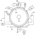
- FIG. 2 shows a schematic configuration of the electrophotographic apparatus.
- a drum-shaped electrophotographic photosensitive member 21 as a member to be charged shown in FIG. 2 includes a support 21b having conductivity such as aluminum and a photosensitive layer 21a formed on the support 21b as basic constituent layers, and a shaft 21c. 2 is driven to rotate at a predetermined peripheral speed in the clockwise direction in FIG.
- the charging roller 1 is disposed in contact with the electrophotographic photosensitive member 21 and charges (primary charging) the electrophotographic photosensitive member 21 to a predetermined polarity and potential.
- the charging roller 1 includes a cored bar 11 and an elastic body layer 12 formed on the cored bar 11. Both ends of the cored bar 11 are pressed against the electrophotographic photosensitive member 21 by pressing means (not shown). As the photographic photosensitive member 21 is driven to rotate, it is driven to rotate.
- the electrophotographic photosensitive member 21 When a predetermined direct current (DC) bias is applied to the metal core 11 by the rubbing power source 23a connected to the power source 23, the electrophotographic photosensitive member 21 is contact-charged to a predetermined polarity and potential.
- the electrophotographic photosensitive member 21 whose peripheral surface is charged by the charging roller 1 is then subjected to exposure of target image information (laser beam scanning exposure, slit exposure of a document image, etc.) by the exposure means 24, so that the peripheral surface has a target.
- target image information laser beam scanning exposure, slit exposure of a document image, etc.
- the electrostatic latent image is sequentially visualized as a toner image by the developing means 25.
- This toner image is then synchronized with the rotation of the electrophotographic photosensitive member 21 from a paper feeding unit (not shown) by the transfer unit 26 and transferred at a proper timing between the electrophotographic photosensitive member 21 and the transfer unit 26.
- a transfer material 27 such as paper.
- the transfer means 26 shown in FIG. 2 is a transfer roller connected to the power source 22, and the toner image on the electrophotographic photosensitive member 21 side is transferred to the transfer material 27 by charging the reverse polarity of the toner from the back of the transfer material 27. It will be done.
- the transfer material 27 that has received the transfer of the toner image on the surface is separated from the electrophotographic photosensitive member 21, conveyed to a fixing means (not shown), subjected to image fixing, and output as an image formed product.
- a fixing means not shown
- the image is conveyed to a re-conveying means to the transfer unit.
- the peripheral surface of the electrophotographic photosensitive member 21 after image transfer is subjected to pre-exposure by the pre-exposure means 28, and the residual charges on the electrophotographic photosensitive member 21 are removed (static elimination).
- Known means can be used for the pre-exposure means 28.
- an LED chip array, a fuse lamp, a halogen lamp, and a fluorescent lamp can be preferably exemplified.
- the peripheral surface of the electrophotographic photosensitive member 21 that has been neutralized is cleaned by the cleaning means 29 to remove adhered contaminants such as transfer residual toner, and is repeatedly used for image formation.
- the charging roller 1 may be driven by the electrophotographic photosensitive member 21 driven to move the surface, may be non-rotated, or may be a predetermined direction in the forward or reverse direction of the surface movement of the electrophotographic photosensitive member 21. You may make it actively rotate at a peripheral speed.
- the exposure is performed by converting reflected light or transmitted light from a document, or reading a document into a signal, scanning a laser beam based on this signal, driving an LED array, or driving a liquid crystal shutter array.
- Examples of the electrophotographic apparatus that can use the conductive rubber elastic body of the present invention include electrophotographic application apparatuses such as copying machines, laser beam printers, LED printers, and electrophotographic plate making systems.
- the conductive rubber elastic body of the present invention can be used as an elastic member for a conveying member such as a developing member, a transfer member, a charge eliminating member, and a paper feed roller, in addition to the elastic layer of the charging roller.
- a conveying member such as a developing member, a transfer member, a charge eliminating member, and a paper feed roller
- FIG. 1 is a schematic diagram of a charging roller 1 as an example using the conductive rubber elastic body of the present invention.
- the charging roller 1 includes a cored bar 11 and an elastic body layer 12 provided on the outer periphery thereof, and a surface layer 13 can be provided outside the elastic body layer 12 as necessary.
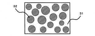
- the elastic layer has a matrix-domain structure composed of a matrix 31 formed of ion conductive rubber and a domain 32 formed of an electronic conductive rubber material.
- ionic conductive rubber as a matrix, uniformity of electrical resistance and reduction of voltage dependence are achieved.
- the electrical resistance of the semiconductive rubber composition is changed by changing the blend ratio of the ion conductive rubber that forms the matrix and the electronic conductive rubber material that forms the domain, and changing the abundance ratio of the domains. Can be made. For this reason, the electrical resistance of the obtained conductive rubber elastic body can be easily set to a desired value.
- the ion conductive rubber forming the matrix has a large electrical resistance environmental fluctuation, but the elastic resistance of the rubber elastic body is determined by the existence ratio of domains having low resistance. It becomes possible to reduce.
- the ion conductive rubber of the present invention means a temperature 23 ° C./humidity 50% R.I. H.
- the rubber has a volume resistivity of 1 ⁇ 10 12 ⁇ ⁇ cm or less.
- examples of rubbers having a volume resistivity of 1 ⁇ 10 12 ⁇ ⁇ cm or less include epichlorohydrin rubber, epichlorohydrin-ethylene oxide rubber, epichlorohydrin-ethylene oxide-allyl glycidyl ether rubber, acrylonitrile-butadiene rubber, and acrylonitrile-butadiene rubber. Examples include hydrogenated products.
- the ion conductive rubber according to the present invention includes one or more of the above rubbers.
- an ionic conductive agent may be blended so as not to bleed out.
- the ionic conductive agent include inorganic ionic substances such as lithium perchlorate, sodium perchlorate, and calcium perchlorate; lauryl trimethyl ammonium chloride, stearyl trimethyl ammonium chloride, octadecyl trimethyl ammonium chloride, dodecyl trimethyl ammonium chloride, hexadecyl trimethyl.
- Cationic surfactants such as ammonium chloride, trioctylpropylammonium bromide, modified aliphatic dimethylethylammonium etosulphate; amphoteric surfactants such as lauryl betaine, stearyl betaine, dimethylalkyl lauryl betaine; tetraethylammonium perchlorate , Quaternary ammonia such as tetrabutylammonium perchlorate and trimethyloctadecylammonium perchlorate Umushio; it can be exemplified organic acid lithium salts of lithium trifluoromethanesulfonate and the like.
- the blending amount of the ion conductive agent as described above is, for example, 0.5 parts by mass or more and 5.0 parts by mass or less with respect to 100 parts by mass of the ion conductive rubber.
- the volume specific resistivity of the ion conductive rubber thus adjusted is, for example, 1 ⁇ 10 12 ⁇ ⁇ cm or less, and more preferably 1 ⁇ 10 10 ⁇ ⁇ cm or less.
- the electric characteristics of the matrix tend to greatly contribute to the electric characteristics of the entire conductive rubber composition as compared with the electric characteristics of the domain. For this reason, when the volume resistivity of the matrix is 1 ⁇ 10 10 ⁇ ⁇ cm or less, the conductive rubber composition in the middle resistance region can be easily produced. Further, if the volume resistivity of the matrix is 1 ⁇ 10 10 ⁇ ⁇ cm or less, the electric resistance is lowered, and therefore it is not necessary to increase the domain ratio.
- the matrix domain structure tends to be a matrix of a polymer having a large composition ratio, although it depends on the viscosity of each polymer and blending conditions. Accordingly, as described above, by using an ion conductive rubber material having a volume resistivity of 1 ⁇ 10 10 ⁇ ⁇ cm or less, the blend ratio of the electronic conductive rubber material can be reduced, and the ratio of the domains can be reduced. Can be reduced. As a result, a stable domain can be formed, and the matrix domain structure of the entire conductive rubber composition is stabilized.
- the domain is made of an electronically conductive rubber material.
- the electronically conductive rubber material is a material in which electrical resistance is adjusted by dispersing conductive particles such as carbon black and conductive zinc oxide in a binder polymer that does not exhibit electrical conductivity.
- the matrix domain is formed by mixing the electron conductive rubber material and the ion conductive rubber in a predetermined ratio.
- the ion conductive rubber is a polar rubber, and the solubility constant (SP value) is usually 17.8 (MPa) 1/2 or more. In general, when two types of rubber are blended, depending on the mixing conditions and the like, the greater the difference in SP value of the respective rubbers, the stronger the incompatibility, and the more stable the matrix / domain structure is formed.
- the binder polymer constituting the electronically conductive rubber material is preferably a nonpolar rubber having an SP value of less than 17.8 (MPa) 1/2 .
- the difference in SP value between the ion conductive rubber forming the matrix and the binder polymer forming the domain is preferably 1.0 (MPa) 1/2 or more. This is because a stable matrix domain structure can be realized.
- the SP value in the present invention may be a literature value or a Small calculation method calculated from the molar attractive force of the atomic group constituting the molecule from the molecular structure, a viscosity method, a swelling method, gas chromatography. You may obtain
- substantially only the domains are made conductive by the conductive particles, and the conductive particles are unevenly distributed in the domains.
- conductive particles such as conductive carbon black are blended in a mixture of two types of polymers, depending on the viscosity of each polymer and the affinity with the conductive particles, it is generally conductive to polymers having a large SP value. There is a tendency for particles to be unevenly distributed. Therefore, a method of mixing conductive particles in a rubber mixture in which a binder polymer that forms domains and an ion conductive rubber that forms a matrix are mixed, and a method of mixing ion conductive rubber, a binder polymer, and conductive particles all together Etc., the conductive particles are likely to be unevenly distributed in the ion conductive rubber having a large SP value.
- a master batch in which conductive particles are added only to the binder polymer is prepared in advance, and then a conductive rubber elastic body is prepared using a rubber mixture obtained by mixing the obtained master batch and ionic conductive rubber. The method is effective.
- the conductive particles to be blended with the binder polymer are carbon black, and the binder polymer contains a rubber that is end-modified with an atomic group that forms a bond with the carbon black.
- the terminal-modified group of the rubber is firmly bonded to the carbon black, so that the surface of the carbon black is included in the terminal-modified rubber.
- Examples of a method for producing a terminal-modified rubber having a butadiene skeleton include the following methods.
- (A) A method in which a rubber having a butadiene skeleton is synthesized using an alkali metal and / or alkaline earth metal catalyst, and then a modification treatment agent is added to the polymerization solution for reaction.
- the former method (a) is more preferable because synthesis of rubber having a butadiene skeleton and terminal modification treatment thereof can be carried out continuously.
- Examples of the rubber having a butadiene skeleton subjected to terminal modification treatment include polybutadiene obtained by polymerizing 1,3-butadiene monomer, or 1,3-butadiene, isoprene, 1,3-pentadiene, 2,3-dimethyl-1 , 3-butadiene, 1,3-hexadiene, styrene, ⁇ -methylstyrene, p-methylstyrene, vinyltoluene, vinylnaphthalene, and the like. Since such a polymer has a butadiene skeleton in the main chain, sulfur vulcanization is possible, and a charging member having high vulcanization productivity can be obtained.
- Preferred rubbers having a butadiene skeleton are, for example, polybutadiene rubber or styrene-butadiene rubber.
- the rubber having a butadiene skeleton has a molecular end modified with an atomic group represented by the following formulas (1) to (6).
- the symbol “*” represents a bonding site to the terminal carbon atom of the polymer.
- X 1 represents OH or SH.
- R 101 to R 105 and R 201 to R 205 each independently represent a hydrogen atom or a monovalent substituent.
- the symbol “*” represents a bonding site to the terminal carbon atom of the polymer.
- X 2 represents OH or SH, and R 4 represents a hydrogen atom or a monovalent substituent.
- R 3 and R 5 each represent a hydrocarbon chain necessary for bonding to each other to form a nitrogen-containing 4- to 6-membered ring together with the carbon atom and the nitrogen atom in the formula (2), or each independently represents hydrogen An atom or a monovalent substituent is shown.
- P represents a main chain of rubber having a butadiene skeleton.
- R 6 is an alkylene group having 1 to 12 carbon atoms.
- R 7 and R 8 are each independently an alkyl group having 1 to 20 carbon atoms.
- n is an integer of 1 to 2
- m is an integer of 1 to 2
- k is an integer of 1 to 2.
- n + m + k is an integer of 3 to 4.
- P represents a main chain of rubber having a butadiene skeleton.
- R 9 is an alkylene group having 1 to 12 carbon atoms.
- R 10 and R 11 are each independently an alkyl group having 1 to 20 carbon atoms.
- j is an integer of 1 to 3
- h is an integer of 1 to 3
- j + h is an integer of 2 to 4.
- R 12 represents an alkyl group having 1 to 18 carbon atoms.
- R 13 represents an alkylene group having 1 to 6 carbon atoms, X 3 represents OH or SH, and M 1 represents an alkyl group having 1 to 18 carbon atoms or an alkoxy group having 1 to 18 carbon atoms.
- R 14 and R 15 each independently represent an alkylene group having 1 to 6 carbon atoms
- X 4 and X 5 each independently represent OH or SH
- M 2 and M 3 each independently represent an alkyl group having 1 to 18 carbon atoms or an alkoxy group having 1 to 18 carbon atoms.
- terminal modifier that introduces the atomic group of the formula (1) into the molecular terminal are given below.
- terminal modifier for introducing the atomic group of the formula (2) into the polymer terminal are given below.
- Amides or imides eg, formamide, N, N-dimethylformamide, N, N-diethylformamide, acetamide, N, N-dimethylacetamide, N, N-diethylacetamide, aminoacetamide, N, N-dimethyl-N ', N'-dimethylaminoacetamide, N', N'-dimethylaminoacetamide, N'-ethylaminoacetamide, N, N-dimethyl-N'-ethylaminoacetamide, N, N-dimethylaminoacetamide, N-phenyl Diacetamide, acrylamide, N, N-dimethylacrylamide, N, N-dimethylmethacrylamide, propionamide, N, N-dimethylpropionamide, 4-pyridylamide, N, N-dimethyl-4-pyridylamide, benzamide, N -Ethylbenz Amide, N-phenylbenzamide, N, N
- Ureas eg, urea, N, N′-dimethylurea, N, N, N ′, N′-tetramethylurea, etc.
- Anilides eg, formanilide, N-methylacetanilide, aminoacetanilide, benzanilide, p, p'-di (N, N-diethyl) aminobenzanilide, etc.).
- Lactams for example, N-methyl- ⁇ -propiolactam, N-phenyl- ⁇ -propiolactam, ⁇ -caprolactam, N-methyl- ⁇ -caprolactam, N-phenyl- ⁇ -caprolactam, N-acetyl- ⁇ -Caprolactam, 2-pyrrolidone, N-methyl-2-pyrrolidone, N-acetyl-2-pyrrolidone, N-phenyl-2-pyrrolidone, Nt-butyl-2-pyrrolidone, 2-piperidone, N-methyl-2 -Piperidone, N-phenyl-2-piperidone, 2-quinolone, N-methyl-2-quinolone, 2-indolinone, N-methyl-2-indolinone).
- Isocyanuric acids for example, isocyanuric acid, N, N ′, N ′′ -trimethylisocyanuric acid, etc.
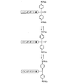
- the living polymer terminal is reacted with a compound having a protected primary amino group and an alkoxysilyl group, and then deprotected (hydrolyzed). Can be obtained.
- FIG. 7 shows the reaction between the polymer polymerization terminal and N, N-bis (trimethylsilyl) aminopropylmethyldimethoxysilane
- FIG. 8 shows the polymer polymerization terminal and 1-trimethylsilyl-2,2-dimethoxy-1-aza-2.
- FIG. 8 Shows reaction with silacyclopentane.
- silacyclopentane there may be a case of reacting with two molecules of polymer polymerization terminals as shown in the figure and a case of reaction with one molecule of polymer polymerization terminals.
- terminal modifier for introducing the atomic group of the formula (5) into the polymer terminal are given below.
- terminal modifier for introducing the atomic group of the formula (6) into the polymer terminal are given below.
- the rubber having a butadiene skeleton according to the present invention has a molecular end represented by the following formula (7) in the category of the formula (1) or the atomic group represented by the following formula (8) in the category of the formula (2). Those that have been modified are preferably used.
- R 71 to R 74 each independently represents a hydrogen atom or an alkyl group having 1 to 4 carbon atoms.
- X 6 represents OH or SH.
- X 7 represents OH or SH
- R 81 represents a hydrogen atom, an alkyl group having 1 to 6 carbon atoms or a phenyl group
- n represents an integer of 2 to 6.
- end modifier that introduces the atomic group of formula (7) into the molecular end include the following compounds.
- a rubber having a butadiene skeleton whose terminal is modified with an atomic group represented by the above formula (7) or (8) has a cation (iminium ion) at the terminal functional group due to heat or the like during kneading with carbon black. ) (See FIGS. 5 and 6).
- the generated cation is presumed to form a bond between the carbon black and the binder polymer by bonding with a functional group such as quinone, hydroxyl, ester, carboxyl, or ether existing on the surface of the carbon black.
- distribution state in the binder polymer of carbon black becomes stable by this coupling
- the binding of the iminium ion generated at the terminal functional group part with the functional group on the surface of the carbon black is described in paragraph “4.1” on page 635 of “Rubber Association” Vol. 62, No. 10 (1989). Is also described.
- the carbon black and the rubber are chemically strongly bonded.
- the carbon black is fixed to the domain and does not move to the matrix.
- lactams represented by the above formulas (8-1) to (8-9) are particularly suitable.
- the present inventors consider the reason as follows. That is, as shown in FIG. 5, when a binder polymer having a terminal modification group derived from lactam is kneaded with carbon black, a cation is generated in the terminal modification part.
- the lactam listed in the following formulas (8-1) to (8-9) is used as a terminal modifier, a lower alkyl group having 1 to 3 carbon atoms or a phenyl group is bonded to the nitrogen atom.
- a cation is more easily generated in the terminal functional group. Therefore, it is considered that this is because bonds with carbon black are more easily formed.
- the type of carbon black blended in the domain is not particularly limited. Specific examples include gas furnace black, oil furnace black, thermal black, lamp black, acetylene black, and ketjen black. There are functional groups on the surface of these carbon blacks, and these functional groups are bonded to the molecular terminal functional groups represented by the formulas (1) to (8). It is formed.
- the number of surface functional groups of carbon black is based on the pH of carbon black measured according to DIN ISO 787/9 and the volatile content of carbon black measured according to DIN 53552. The smaller the pH of carbon black and the greater the volatile content, the more surface functional groups of carbon black. If there are too many surface functional groups on the carbon black, there may be too many bonding points with the binder polymer on the carbon surface, resulting in an increase in the electrical resistance of the elastic layer. If the number of surface functional groups on the carbon black is too small, the bond between the binder polymer and the carbon black is weak, and the effect of suppressing current deterioration may be insufficient. Therefore, the pH of carbon black is preferably 3 to 9, and more preferably 5 to 8.
- the volatile content of carbon black is preferably 0.3 to 5.0 wt%, and more preferably 0.5 to 2.0 wt%.
- the viscosity and blend ratio of both rubber materials are important.
- a polymer having a larger volume ratio or a lower material viscosity tends to be a matrix.
- the material viscosity tends to increase.
- the electronic conductive rubber material easily forms the domain.
- the viscosity of the ion conductive rubber material is sufficiently lower than that of the electronic conductive rubber material.
- the blend ratio of the ion conductive rubber material and the electronic conductive rubber material is preferably in the range of 95/5 to 40/60.
- the difference in viscosity between the two is more preferably a difference in viscosity of 5 points or more and 60 points or less in the value of ML1 + 4 at 100 ° C. using a Mooney viscometer.
- the matrix-domain structure of the elastic body can be confirmed by morphological observation using a transmission electron microscope (TEM) or a scanning electron microscope (SEM).
- TEM transmission electron microscope
- SEM scanning electron microscope
- a test piece is cut out from an elastic body, subjected to phosphotungstic acid staining or osmium staining, and then observed with an electron microscope.
- a method of preparing an ultrathin section having a thickness of about 0.1 ⁇ m from a dyed test piece and observing a transmission image by TEM is suitable.
- the elastic member layer of the charging member should have a low hardness in order to ensure uniform contact with the photosensitive member in addition to having uniform conductivity in order to uniformly charge the member to be charged. desirable.
- a method of blending a plasticizer is used.
- these plasticizers bloom on the surface of the elastic body layer so that the photoconductor is formed. May be contaminated.
- the ion conductive rubber material of the matrix is a rubber having high oil resistance, and since the oil swellability is low, a bloom of plasticizer tends to occur.
- a large amount of plasticizer can be blended with the electronic conductive rubber material forming the domain. And the bloom to the elastic body layer surface of the plasticizer mix
- plasticizer paraffin oil, naphthene oil, aroma oil, etc. can be illustrated, These plasticizers are 1 mass part or more and 100 mass parts or less with respect to 100 mass parts of binder polymer B, for example. It can mix
- a filler a processing aid, a crosslinking aid, a crosslinking accelerator, a crosslinking accelerator, a crosslinking agent generally used as a rubber compounding agent are optionally added.
- Delay agents, softeners, dispersants, colorants, and the like can be added.
- a mixing method using a closed mixer such as a Banbury mixer or a pressure kneader
- a mixing method using an open mixer such as an open roll, and the like should be exemplified. Can do.
- Examples of methods for forming the elastic layer include the following methods.
- the unvulcanized rubber composition forming the mixed elastic layer is extruded into a tube shape by an extruder and vulcanized with a vulcanizing can to obtain a tube made of vulcanized rubber.
- a metal core is press-fitted into the tube, and the surface of the tube made of vulcanized rubber is polished to obtain a desired outer diameter.
- the unvulcanized rubber composition forming the mixed elastic body layer is coextruded into a cylindrical shape around the core metal by an extruder equipped with a crosshead, and is fixed and heated inside a mold having a desired outer diameter. Then, an elastic layer made of vulcanized rubber is formed around the core metal.
- the latter method 2 can provide a roller with high productivity and low cost, but on the other hand, the electric resistance is increased at the weld portion of the crosshead extrusion, and the electric resistance tends to be uneven. There is.
- the surface of the elastic body layer may be subjected to surface modification by irradiating the surface of the elastic body layer with ultraviolet rays or an electron beam so that dirt such as toner and paper powder is difficult to adhere. Further, a surface layer may be further formed on the surface of the elastic body layer.
- Terminal-modified SBR-2 was obtained in the same manner as terminal-modified SBR-1, except that N-methyl- ⁇ -caprolactam (Formula 8-8) was used as the terminal modification agent.
- Terminal modified SBR-4 1-Trimethylsilyl-2,2-dimethoxy-1-aza-2-silacyclopentane (formula 10) is used as a terminal modifier, and n-butyllithium is used as 3- [N, N-bis] as a polymerization initiator. Terminal-modified SBR-4 was obtained in the same manner as terminal-modified SBR-3 except that (trimethylsilyl)]-1-propyllithium was used.
- Terminal-modified SBR-5 was obtained in the same manner as terminal-modified SBR-1, except that methyl 3-methylthiopropionate (Formula 11) was used as the terminal modification agent.
- Terminal modified SBR-6 was obtained in the same manner as terminal modified SBR-1, except that dimethyl 3,3′-thiodipropionate (Formula 12) was used as the terminal modified agent.
- Base polymer Terminal modified SBR-1 SP value 17.4 (MPa) 1/2 ): 100 parts by mass Zinc stearate (trade name; zinc stearate, manufactured by NOF Corporation): 1 part by mass Zinc oxide ( Product name: 2 types of zinc white, manufactured by Sakai Chemical Co., Ltd.): 5 parts by mass Conductive agent carbon black (Product name: Toka Black # 5500, manufactured by Tokai Carbon Co., Ltd., pH 6): 40 parts by mass
- Carbon masterbatch-2 was produced by the same production method as carbon masterbatch-1, except that the base polymer was terminal-modified SBR-2 (SP value 17.4 (MPa) 1/2 ).
- Carbon masterbatch-3 was produced by the same production method as carbon masterbatch-1, except that the base polymer was terminal-modified SBR-3 (SP value 17.5 (MPa) 1/2 ).
- Carbon masterbatch-4 was produced by the same production method as carbon masterbatch-1, except that the base polymer was terminal-modified SBR-4 (SP value 17.5 (MPa) 1/2 ).
- a carbon masterbatch-5 was produced by the same production method as the carbon masterbatch-1, except that the base polymer was terminal-modified SBR-5 (SP value 17.4 (MPa) 1/2 ).
- Carbon masterbatch-6 was produced by the same production method as carbon masterbatch-1, except that the base polymer was terminal-modified SBR-6 (SP value 17.4 (MPa) 1/2 ).
- Carbon masterbatch-7 was prepared by the same production method as carbon masterbatch-1, except that 10 parts by mass of naphthenic oil (trade name; FUCKOL NEWFLEX 2040E, manufactured by Fujikosan) was added as a plasticizer.
- naphthenic oil trade name; FUCKOL NEWFLEX 2040E, manufactured by Fujikosan
- a carbon master batch-8 was produced by the same production method as the carbon master batch-7 except that the base polymer was terminal-modified BR-1 (SP value 17.2 (MPa) 1/2 ).
- a carbon masterbatch-9 was produced by the same production method as the carbon masterbatch-1, except that the base polymer was unmodified SBR (SP value 17.4 (MPa) 1/2 ).
- a carbon master batch-10 was produced by the same production method as the carbon master batch-7 except that the base polymer was unmodified BR (SP value 17.2 (MPa) 1/2 ).
- Example 1> (Preparation of unvulcanized rubber composition) The following materials were mixed with a 6 liter pressure kneader (product name: TD6-15MDX, manufactured by Toshin Co., Ltd.) for 12 minutes at a filling rate of 70 vol% and a blade rotation speed of 30 rpm to obtain an A-kneaded rubber composition.
- a 6 liter pressure kneader product name: TD6-15MDX, manufactured by Toshin Co., Ltd.
- Carbon master batch-1 43.8 parts by mass NBR (SP value 20.3 (MPa) 1/2 trade name; N230SV, manufactured by JSR): 70 parts by mass Zinc stearate (trade name; zinc stearate) , Manufactured by Nippon Oil & Fats Co., Ltd.): 0.7 parts by mass.
- Zinc oxide (trade name; 2 types of zinc white, manufactured by Sakai Chemical Co., Ltd.): 3.5 parts by mass. : 20 parts by mass
- the temperature during extrusion was 90 ° C., 90 ° C. cylinder, and 90 ° C. screw. Both ends of the molded unvulcanized rubber roller were cut so that the axial width of the elastic layer portion was 228 mm, followed by heat treatment at 160 ° C. for 40 minutes in an electric furnace to obtain a vulcanized rubber roller.
- the surface of the obtained vulcanized rubber roller was polished with a plunge cut grinding type polishing machine to obtain a rubber roller having a crown-shaped elastic elastic body layer having an end diameter of 8.35 mm and a center diameter of 8.50 mm.
- UV ultraviolet rays
- a low-pressure mercury lamp manufactured by Harrison Toshiba Lighting Co., Ltd. was used, and ultraviolet rays having a wavelength of 254 nm were irradiated so that the integrated light amount became 15000 mJ / cm 2 .
- the roller was irradiated with ultraviolet rays while being rotated by a roller rotating member at a speed of 60 rpm.
- the integrated light quantity of ultraviolet rays is defined as follows.
- UV integrated light quantity [mJ / cm 2 ] UV intensity [mW / cm 2 ] ⁇ irradiation time [s]
- the adjustment of the integrated amount of ultraviolet light can be performed by adjusting the irradiation time, lamp output, distance between the lamp and the object to be irradiated, etc.
- a sample for observation with a microscope was prepared. This sample was observed using a transmission electron microscope (trade name: H-7500, manufactured by Hitachi, Ltd.) to confirm the presence or absence of a matrix domain structure. As a result, it was confirmed that the elastic layer according to this example had a matrix domain structure.
- FIG. 4 shows a schematic configuration of an apparatus for measuring the electric resistance of the charging roller.
- the charging roller 1 is in pressure contact with a cylindrical aluminum drum 41 having a diameter of 30 mm by pressing means (not shown) at both ends of the core metal 11, and rotates following the rotation of the aluminum drum 41.
- a DC voltage is applied to the core part 11 of the charging roller 1 using an external power source 42, and the voltage applied to the reference resistor 43 connected in series to the aluminum drum 41 is measured.
- the electrical resistance of the charging roller 1 can be calculated from the measured voltage of the reference resistance 43 by the following formula.
- the electrical resistance of the charging roller is 23 ° C / humidity 50% R. H.
- measurement was performed by applying a voltage of DC 200 V between the metal core and the aluminum drum for 2 seconds using the apparatus of FIG. The rotation speed of the aluminum drum at this time was 30 rpm. Further, the resistance value of the reference resistance was adjusted to be 1/100 of the roller resistance. Data sampling was performed at a frequency of 100 Hz from 1 second to 1 second after voltage application, and the average value of the obtained electrical resistance was used as the resistance value of the charging roller. The measured ratio between the maximum value and the minimum value of the electric resistance of the charging roller was calculated as the unevenness in the circumferential direction of the electric resistance of the charging roller.
- the above measurement was performed by changing the applied voltage to DC 20V, and the difference in common logarithm of the electrical resistance value when DC 20V was applied and when DC 200V was applied was defined as voltage dependency.
- the measurement of the electric resistance value when DC 200V is applied is as follows: temperature 15 ° C./humidity 10% H. (Also described as LL) under the environment, temperature 30 ° C./humidity 80% H. It was also performed in an environment (also referred to as HH). Then, the difference in common logarithm of the electrical resistance of the charging roller under the LL environment and the HH environment was calculated as the environmental dependency of the electrical resistance of the charging roller. As a result, the circumferential unevenness of the resistance was 1.20 times, the voltage dependency was on the order of 0.88, and the environment dependency was on the order of 0.10.
- the MD-1 hardness of the charging roller surface was measured. The measurement was performed in a peak hold mode in a temperature 23 ° C./55% RH environment using a micro hardness meter (trade name: MD-1 type, manufactured by Kobunshi Keiki Co., Ltd.). In more detail, place the rubber roller on a metal plate, place a metal block and fix it easily so that the rubber roller does not roll, and place the measurement terminal accurately at the center of the charging member from the perpendicular direction to the metal plate. Read the peak value of the measurement for 5 seconds while pressing.
- Example 2 A charging roller was prepared in the same manner as in Example 1 except that the carbon master batch used in the adjustment of the unvulcanized rubber in Example 1 was changed to Carbon Master Batch-2.
- Example 2 In the same manner as in Example 1, it was confirmed that the elastic layer had a matrix and a domain. Further, as a result of evaluating the electrical resistance of the roller in the same manner as in Example 1, the circumferential unevenness of the resistance was 1.22 times, the voltage dependency was on the order of 0.86, and the environment dependency was on the order of 0.09. Further, the MD-1 hardness measured in the same manner as in Example 1 was 52 °.
- Example 3 A charging roller was prepared in the same manner as in Example 1 except that the composition of the kneaded rubber composition A was adjusted as follows in preparing the unvulcanized rubber in Example 1.
- Carbon masterbatch-3 36.5 parts by mass NBR (trade name: N230SV, manufactured by JSR): 75 parts by mass Zinc stearate (trade name: Zinc stearate, manufactured by NOF Corporation): 0.75 parts by mass Zinc oxide (trade name: 2 types of zinc white, manufactured by Sakai Chemical Co., Ltd.): 3.75 parts by mass, calcium carbonate (trade name: Silver W, manufactured by Shiroishi Kogyo Co., Ltd.): 20 parts by mass
- NBR trade name: N230SV, manufactured by JSR
- Zinc stearate trade name: Zinc stearate, manufactured by NOF Corporation
- Zinc oxide trade name: 2 types of zinc white, manufactured by Sakai Chemical Co., Ltd.
- calcium carbonate trade name: Silver W, manufactured by Shiroishi Kogyo Co., Ltd.
- Example 2 In the same manner as in Example 1, it was confirmed that the elastic layer had a matrix and a domain.
- the circumferential unevenness of the resistance was 1.31 times, the voltage dependency was on the order of 1.03, and the environment dependency was on the order of 0.13. Further, the result of measuring the MD-1 hardness in the same manner as in Example 1 was 49 °.
- Example 4 A charging roller was prepared in the same manner as in Example 3 except that the carbon masterbatch used was changed to carbon masterbatch-4 in the adjustment of the unvulcanized rubber in Example 3.
- Example 2 In the same manner as in Example 1, it was confirmed that the elastic layer had a matrix and a domain. Further, as a result of evaluating the electrical resistance of the roller in the same manner as in Example 1, the circumferential unevenness of the resistance was 1.72 times, the voltage dependency was on the order of 1.09, and the environment dependency was on the order of 0.15. Further, the result of measuring the MD-1 hardness in the same manner as in Example 1 was 50 °.
- Example 5 A charging roller was prepared in the same manner as in Example 3 except that the carbon masterbatch used was changed to carbon masterbatch-5 in the adjustment of the unvulcanized rubber in Example 3.
- Example 2 In the same manner as in Example 1, it was confirmed that the elastic layer had a matrix and a domain. Further, as a result of evaluating the electrical resistance of the roller in the same manner as in Example 1, the circumferential unevenness of the resistance was 1.65 times, the voltage dependency was on the order of 1.15, and the environment dependency was on the order of 0.12. Further, the result of measuring the MD-1 hardness in the same manner as in Example 1 was 49 °.
- Example 6 A charging roller was prepared in the same manner as in Example 3 except that the carbon master batch used in the adjustment of the unvulcanized rubber in Example 3 was changed to carbon master batch-6.
- Example 2 In the same manner as in Example 1, it was confirmed that the elastic layer had a matrix and a domain. Further, as a result of evaluating the electrical resistance of the roller in the same manner as in Example 1, the circumferential unevenness of the resistance was 1.84 times, the voltage dependency was on the order of 1.10, and the environment dependency was on the order of 0.13. Further, the result of measuring the MD-1 hardness in the same manner as in Example 1 was 50 °.
- Example 7 A charging roller was prepared in the same manner as in Example 1 except that the carbon masterbatch used was carbon masterbatch-7 and the blending amount was 46.8 parts by mass in the adjustment of the unvulcanized rubber in Example 1.
- Example 2 In the same manner as in Example 1, it was confirmed that the elastic layer had a matrix and a domain. Further, as a result of evaluating the electrical resistance of the roller in the same manner as in Example 1, the circumferential unevenness of the resistance was 1.25 times, the voltage dependency was on the order of 0.93, and the environment dependency was on the order of 0.09. Further, the MD-1 hardness measured in the same manner as in Example 1 was 48 °.
- Example 8 A charging roller was prepared in the same manner as in Example 3 except that the carbon masterbatch used was carbon masterbatch-7 and the blending amount was 39.0 parts by mass in the adjustment of the unvulcanized rubber in Example 3.
- Example 2 In the same manner as in Example 1, it was confirmed that the elastic layer had a matrix and a domain. Further, as a result of evaluating the electrical resistance of the roller in the same manner as in Example 1, the circumferential unevenness of the resistance was 1.23 times, the voltage dependency was on the order of 0.87, and the environment dependency was on the order of 0.08. The MD-1 hardness measured in the same manner as in Example 1 was 47 °.
- Example 9 A charging roller was prepared in the same manner as in Example 8 except that the carbon masterbatch used was changed to carbon masterbatch-8 in the adjustment of the unvulcanized rubber in Example 8.
- Example 2 In the same manner as in Example 1, it was confirmed that the elastic layer had a matrix and a domain. Further, as a result of evaluating the electrical resistance of the roller in the same manner as in Example 1, the circumferential unevenness of the resistance was 1.26 times, the voltage dependency was on the order of 0.89, and the environment dependency was on the order of 0.08. Further, the MD-1 hardness measured in the same manner as in Example 1 was 46 °.
- Example 10 A charging roller was prepared in the same manner as in Example 1 except that the composition of the kneaded rubber composition A was adjusted as follows in preparing the unvulcanized rubber in Example 1.
- Carbon masterbatch-1 29.2 parts by mass Epichlorohydrin-ethylene oxide-allyl glycidyl ether rubber (SP value 18.5 (MPa) 1/2 , trade name: Epichromer CG105, manufactured by Daiso Corporation): 80 parts by mass Zinc stearate (trade name; zinc stearate, manufactured by Nippon Oil & Fats Co., Ltd.): 0.80 parts by mass. Zinc oxide (trade name; 2 types of zinc white, manufactured by Sakai Chemical Co., Ltd.): 4.0 parts by mass. Name: Silver W, manufactured by Shiroishi Kogyo Co., Ltd .: 40 parts by mass, MT carbon for coloring (trade name: Thermax Flow Foam N990, manufactured by CanCab): 5 parts by mass
- Example 2 In the same manner as in Example 1, it was confirmed that the elastic layer had a matrix and a domain. Further, as a result of evaluating the electrical resistance of the roller in the same manner as in Example 1, the circumferential unevenness of the resistance was 1.16 times, the voltage dependency was on the order of 0.82, and the environment dependency was on the order of 0.25. The MD-1 hardness measured in the same manner as in Example 1 was 53 °.
- Example 1 A charging roller was prepared in the same manner as in Example 3 except that the carbon masterbatch used was changed to carbon masterbatch-9 in the adjustment of the unvulcanized rubber in Example 3.
- Example 2 In the same manner as in Example 1, it was confirmed that the elastic layer had a matrix and a domain. Further, as a result of evaluating the electrical resistance of the roller in the same manner as in Example 1, the circumferential unevenness of the resistance was 2.20 times, the voltage dependency was on the order of 1.46, and the environmental dependency was on the order of 0.48. The MD-1 hardness measured in the same manner as in Example 1 was 51 °.
- Example 2 A charging roller was prepared in the same manner as in Example 9 except that the carbon masterbatch used was changed to carbon masterbatch-10 in the adjustment of the unvulcanized rubber in Example 9.
- Example 2 In the same manner as in Example 1, it was confirmed that the elastic layer had a matrix and a domain. Further, as a result of evaluating the electrical resistance of the roller in the same manner as in Example 1, the circumferential unevenness of the resistance was 2.40 times, the voltage dependency was on the order of 1.49, and the environment dependency was on the order of 0.42. Further, the result of measuring the MD-1 hardness in the same manner as in Example 1 was 49 °.
- Example 3 A charging roller was prepared in the same manner as in Example 1 except that the composition of the kneaded rubber composition A was adjusted as follows in preparing the unvulcanized rubber in Example 1.
- -NBR (trade name; N230SV, manufactured by JSR Corporation): 100 parts by mass-Zinc stearate (trade name; zinc stearate, manufactured by NOF Corporation): 1.00 parts by mass-Zinc oxide (trade name: 2 types of zinc white) , Manufactured by Sakai Chemical Co., Ltd.): 5.00 parts by mass, calcium carbonate (trade name; Silver W, manufactured by Shiroishi Kogyo Co., Ltd.): 20 parts by mass, conductive agent carbon black (trade name; Toka Black # 5500, manufactured by Tokai Carbon Co., Ltd.) : 26 parts by mass
- the elastic layer was observed with an electron microscope in the same manner as in Example 1, but no matrix-domain structure was confirmed. Further, as a result of evaluating the electrical resistance of the roller in the same manner as in Example 1, the circumferential unevenness of the resistance was 3.40 times, the voltage dependency was 2.04 order, and the environment dependency was 0.05 order. Further, the MD-1 hardness measured in the same manner as in Example 1 was 65 °.
- a charging roller was prepared in the same manner as in Example 1 except that the composition of the kneaded rubber composition A was adjusted as follows in preparing the unvulcanized rubber in Example 1.
- Epichlorohydrin-ethylene oxide-allyl glycidyl ether rubber (trade name; epichromer CG105, manufactured by Daiso Corporation): 100 parts by mass Zinc stearate (trade name: zinc stearate, manufactured by Nippon Oil & Fats Co., Ltd.): 1.00 parts by mass Zinc (trade name; 2 types of zinc oxide, manufactured by Sakai Chemical Co., Ltd.): 5.00 parts by mass, calcium carbonate (trade name; Silver W, manufactured by Shiroishi Kogyo Co., Ltd.): 45 parts by mass, ion conductive agent Lithium trifluoromethanesulfonate: 1 part by mass / MT carbon for coloring (trade name: Thermax Flow Foam N990, manufactured by CanCab): 5 parts by mass
- the elastic layer was observed with an electron microscope in the same manner as in Example 1, but no matrix-domain structure was confirmed. Further, as a result of evaluating the electrical resistance of the roller in the same manner as in Example 1, the circumferential unevenness of the resistance was 1.05 times, the voltage dependency was on the order of 0.18, and the environment dependency was on the order of 1.20. Further, the MD-1 hardness measured in the same manner as in Example 1 was 55 °.
- Tables 2 and 3 show the composition ratios of the elastic layer materials according to Examples and Comparative Examples, respectively.
- Table 4 shows the evaluation results of the rollers according to the example, and Table 5 shows the evaluation results of the rollers according to the comparative example.
- the circumferential unevenness of the electric resistance is a high resistance portion corresponding to the weld portion at the time of extrusion production.
- the roller electric resistance is large, a horizontal streak image defect of the charging roller pitch may be caused.
- the unevenness of the electrical resistance in the circumferential direction is twice or less.
- the charging uniformity of the charging roller tends to be better as the electric resistance when a low voltage is applied is smaller.
- the electric resistance on the high voltage side is small, leakage is likely to occur at the defective portion on the surface of the photoreceptor. Therefore, it is preferable that the voltage dependency of the electric resistance is small, and the difference in electric resistance between 20V and 200V is preferably less than 1.40 order.
- the electrical dependency of the charging roller is also small, and the environmental dependency between LL and HH is less than 0.4 order. Is preferred.
- Comparative Example 3 is an electronically conductive rubber material that does not have a matrix-domain structure, and has a large electrical resistance unevenness in the circumferential direction and voltage dependency.
- Comparative Example 4 is an ion conductive rubber material that does not have a matrix domain structure, and the electrical resistance is highly dependent on the environment.
- the electrical resistance in the circumferential direction is twice or more, the voltage dependency is 1.40 order or more, and the environment dependency is 0.40 order or more.
- the circumferential unevenness of the electrical resistance was less than 2.0 times, the voltage dependency was less than 1.40 order, and the environment dependency was less than 0.40 order.
Landscapes
- Chemical & Material Sciences (AREA)
- Health & Medical Sciences (AREA)
- Chemical Kinetics & Catalysis (AREA)
- Medicinal Chemistry (AREA)
- Polymers & Plastics (AREA)
- Organic Chemistry (AREA)
- Physics & Mathematics (AREA)
- Engineering & Computer Science (AREA)
- Plasma & Fusion (AREA)
- General Physics & Mathematics (AREA)
- Electrostatic Charge, Transfer And Separation In Electrography (AREA)
- Compositions Of Macromolecular Compounds (AREA)
- Electrophotography Configuration And Component (AREA)
- Rolls And Other Rotary Bodies (AREA)
Abstract
Cette invention concerne un élastomère de type caoutchouc électriquement conducteur stable à partir duquel un élément de charge peut être obtenu, l'élément de charge fluctuant peu en termes de résistance électrique quand la tension appliquée varie et ayant des propriétés électriques stables, qui ne sont pas affectées par des changements de conditions ambiantes telles que la température et l'humidité. L'élément de charge ne peut pas encrasser l'élément à charger, par ex., un photorécepteur. L'élastomère de type caoutchouc électriquement conducteur selon l'invention comprend : une matrice comprenant un ou plusieurs caoutchoucs conducteurs d'ions choisis dans le groupe constitué par un caoutchouc épichlorhydrine, un caoutchouc épichlorhydrine/oxyde d'éthylène, un caoutchouc épichlorhydrine/oxyde d'éthylène/éther allylglycidylique, un caoutchouc acrylonitrile/butadiène, et un caoutchouc acrylonitrile/butadiène hydrogéné ; et des domaines comprenant un matériau de caoutchouc conducteur d'électrons qui comprend à la fois un caoutchouc ayant un squelette butadiène et du noir de carbone, les extrémités du caoutchouc ayant le squelette butadiène ayant été modifiées avec un groupe spécifique d'atomes.
Priority Applications (3)
| Application Number | Priority Date | Filing Date | Title |
|---|---|---|---|
| EP12736754.8A EP2666814B1 (fr) | 2011-01-21 | 2012-01-10 | Élastomère de type caoutchouc électriquement conducteur, élément de charge, et appareil électrophotographique |
| CN201280005996.4A CN103328561B (zh) | 2011-01-21 | 2012-01-10 | 导电性橡胶弹性材料、充电构件和电子照相设备 |
| US13/471,338 US8491994B2 (en) | 2011-01-21 | 2012-05-14 | Conductive rubber elastic material, charging member and electrophotographic apparatus |
Applications Claiming Priority (2)
| Application Number | Priority Date | Filing Date | Title |
|---|---|---|---|
| JP2011010891 | 2011-01-21 | ||
| JP2011-010891 | 2011-01-21 |
Related Child Applications (1)
| Application Number | Title | Priority Date | Filing Date |
|---|---|---|---|
| US13/471,338 Continuation US8491994B2 (en) | 2011-01-21 | 2012-05-14 | Conductive rubber elastic material, charging member and electrophotographic apparatus |
Publications (1)
| Publication Number | Publication Date |
|---|---|
| WO2012098834A1 true WO2012098834A1 (fr) | 2012-07-26 |
Family
ID=46515470
Family Applications (1)
| Application Number | Title | Priority Date | Filing Date |
|---|---|---|---|
| PCT/JP2012/000092 WO2012098834A1 (fr) | 2011-01-21 | 2012-01-10 | Élastomère de type caoutchouc électriquement conducteur, élément de charge, et appareil électrophotographique |
Country Status (5)
| Country | Link |
|---|---|
| US (1) | US8491994B2 (fr) |
| EP (1) | EP2666814B1 (fr) |
| JP (1) | JP5843625B2 (fr) |
| CN (1) | CN103328561B (fr) |
| WO (1) | WO2012098834A1 (fr) |
Cited By (1)
| Publication number | Priority date | Publication date | Assignee | Title |
|---|---|---|---|---|
| WO2021075441A1 (fr) * | 2019-10-18 | 2021-04-22 | キヤノン株式会社 | Élément conducteur, cartouche de traitement et dispositif de formation d'image électrophotographique |
Families Citing this family (46)
| Publication number | Priority date | Publication date | Assignee | Title |
|---|---|---|---|---|
| CN102549506B (zh) * | 2009-10-15 | 2014-10-29 | 佳能株式会社 | 充电构件和电子照相设备 |
| WO2011077635A1 (fr) * | 2009-12-22 | 2011-06-30 | キヤノン株式会社 | Élément chargeur, dispositif électrophotographique et cartouche de traitement |
| WO2012049814A1 (fr) * | 2010-10-15 | 2012-04-19 | キヤノン株式会社 | Organe d'électrisation |
| KR101599647B1 (ko) | 2011-06-30 | 2016-03-03 | 캐논 가부시끼가이샤 | 대전 부재, 대전 부재의 제조 방법 및 전자 사진 장치 |
| JP6053354B2 (ja) | 2011-07-06 | 2016-12-27 | キヤノン株式会社 | 帯電部材とその製造方法、および電子写真装置 |
| CN104011601B (zh) | 2011-12-22 | 2016-09-28 | 佳能株式会社 | 充电构件、其制造方法和电子照相设备 |
| CN104024957B (zh) | 2011-12-28 | 2016-03-02 | 佳能株式会社 | 电子照相用构件、其制造方法、处理盒和电子照相设备 |
| JP6049435B2 (ja) | 2012-03-16 | 2016-12-21 | キヤノン株式会社 | 帯電部材、プロセスカートリッジおよび電子写真装置 |
| US8622881B1 (en) | 2012-09-21 | 2014-01-07 | Canon Kabushiki Kaisha | Conductive member, electrophotographic apparatus, and process cartridge |
| CA2899611A1 (fr) * | 2013-03-12 | 2014-10-09 | Avon Products, Inc. | Composition topique eclaircissante et ses procedes d'utilisation |
| JP6322366B2 (ja) * | 2013-05-09 | 2018-05-09 | 山屋産業株式会社 | 補強部材付きサポータ |
| CN105017749B (zh) * | 2015-08-10 | 2017-06-16 | 平田精密器材(深圳)有限公司 | 一种高分子复合材料充电辊及其制备方法 |
| KR102016204B1 (ko) * | 2015-10-08 | 2019-08-29 | 캐논 가부시끼가이샤 | 전자사진용 도전성 부재, 그의 제조 방법, 프로세스 카트리지 및 전자사진 장치 |
| US9904199B2 (en) | 2015-10-26 | 2018-02-27 | Canon Kabushiki Kaisha | Charging member having outer surface with concave portions bearing exposed elastic particles, and electrophotographic apparatus |
| US9910379B2 (en) | 2015-10-26 | 2018-03-06 | Canon Kabushiki Kaisha | Charging member with concave portions containing insulating particles and electrophotographic apparatus |
| CN108604077B (zh) | 2016-04-28 | 2021-04-23 | 惠普深蓝有限责任公司 | 液体电子照相打印机及其显影单元干燥方法 |
| JP6784079B2 (ja) * | 2016-07-07 | 2020-11-11 | 富士ゼロックス株式会社 | 帯電部材、帯電装置、プロセスカートリッジ及び画像形成装置 |
| US10317811B2 (en) | 2016-10-07 | 2019-06-11 | Canon Kabushiki Kaisha | Charging member, method for producing same, process cartridge and electrophotographic image forming apparatus |
| JP7034815B2 (ja) | 2017-04-27 | 2022-03-14 | キヤノン株式会社 | 帯電部材、電子写真プロセスカートリッジ及び電子写真画像形成装置 |
| JP6376247B1 (ja) | 2017-05-11 | 2018-08-22 | 横浜ゴム株式会社 | 変性ブタジエンポリマー及びゴム組成物 |
| JP7009881B2 (ja) * | 2017-09-26 | 2022-01-26 | 富士フイルムビジネスイノベーション株式会社 | 帯電部材、帯電部材の製造方法、プロセスカートリッジ及び画像形成装置 |
| CN112005173B (zh) | 2018-04-18 | 2023-03-24 | 佳能株式会社 | 导电性构件、处理盒和图像形成设备 |
| JP7229811B2 (ja) * | 2018-04-18 | 2023-02-28 | キヤノン株式会社 | 帯電部材、帯電部材の製造方法、電子写真装置およびプロセスカートリッジ |
| EP3783440A4 (fr) | 2018-04-18 | 2022-01-19 | Canon Kabushiki Kaisha | Élément conducteur, cartouche de traitement et dispositif de formation d'images |
| JP7195999B2 (ja) * | 2019-03-29 | 2022-12-26 | キヤノン株式会社 | 導電性部材、プロセスカートリッジ並びに電子写真画像形成装置 |
| CN111989622B (zh) | 2018-04-18 | 2022-11-11 | 佳能株式会社 | 显影构件、处理盒和电子照相设备 |
| US10558136B2 (en) | 2018-04-18 | 2020-02-11 | Canon Kabushiki Kaisha | Charging member, manufacturing method of charging member, electrophotographic apparatus, and process cartridge |
| WO2019203238A1 (fr) | 2018-04-18 | 2019-10-24 | キヤノン株式会社 | Élément électroconducteur et procédé de production associé, cartouche de traitement, et dispositif de formation d'image électrostatique |
| JP7225005B2 (ja) * | 2019-03-29 | 2023-02-20 | キヤノン株式会社 | 導電性部材及びその製造方法、プロセスカートリッジ並びに電子写真画像形成装置 |
| CN112020678B (zh) | 2018-04-18 | 2022-11-01 | 佳能株式会社 | 导电性构件、处理盒和电子照相图像形成设备 |
| WO2019203225A1 (fr) * | 2018-04-18 | 2019-10-24 | キヤノン株式会社 | Élément conducteur, cartouche de traitement et dispositif de formation d'image électrophotographique |
| JP7250486B2 (ja) * | 2018-11-14 | 2023-04-03 | キヤノン株式会社 | プロセスカートリッジ及び画像形成装置 |
| JP7250487B2 (ja) * | 2018-11-14 | 2023-04-03 | キヤノン株式会社 | プロセスカートリッジ及び画像形成装置 |
| JP7446878B2 (ja) | 2019-03-29 | 2024-03-11 | キヤノン株式会社 | 導電性部材、電子写真用プロセスカートリッジ、及び電子写真画像形成装置 |
| US11169454B2 (en) | 2019-03-29 | 2021-11-09 | Canon Kabushiki Kaisha | Electrophotographic electro-conductive member, process cartridge, and electrophotographic image forming apparatus |
| US10845724B2 (en) | 2019-03-29 | 2020-11-24 | Canon Kabushiki Kaisha | Electro-conductive member, process cartridge and image forming apparatus |
| JP7337648B2 (ja) | 2019-10-18 | 2023-09-04 | キヤノン株式会社 | プロセスカートリッジ及び画像形成装置 |
| JP7458827B2 (ja) | 2019-10-18 | 2024-04-01 | キヤノン株式会社 | 導電性部材、プロセスカートリッジ、および画像形成装置 |
| JP7337652B2 (ja) | 2019-10-18 | 2023-09-04 | キヤノン株式会社 | プロセスカートリッジ及びそれを用いた電子写真装置 |
| JP7337649B2 (ja) | 2019-10-18 | 2023-09-04 | キヤノン株式会社 | プロセスカートリッジ及び電子写真装置 |
| JP7463128B2 (ja) | 2019-10-18 | 2024-04-08 | キヤノン株式会社 | 導電性部材、プロセスカートリッジ並びに電子写真画像形成装置 |
| CN114556230B (zh) * | 2019-10-18 | 2024-03-08 | 佳能株式会社 | 电子照相用导电性构件、处理盒和电子照相图像形成装置 |
| JP2021067940A (ja) * | 2019-10-18 | 2021-04-30 | キヤノン株式会社 | 導電性部材、プロセスカートリッジ並びに電子写真画像形成装置 |
| JP7337651B2 (ja) * | 2019-10-18 | 2023-09-04 | キヤノン株式会社 | プロセスカートリッジ及び電子写真装置 |
| JP7321884B2 (ja) * | 2019-10-18 | 2023-08-07 | キヤノン株式会社 | 電子写真装置、プロセスカートリッジ及びカートリッジセット |
| JP7337650B2 (ja) | 2019-10-18 | 2023-09-04 | キヤノン株式会社 | プロセスカートリッジおよび電子写真装置 |
Citations (8)
| Publication number | Priority date | Publication date | Assignee | Title |
|---|---|---|---|---|
| JPS59117514A (ja) * | 1982-12-23 | 1984-07-06 | Nippon Zeon Co Ltd | 変性共役ジエン系ゴム |
| JPS6142552A (ja) * | 1984-08-02 | 1986-03-01 | Nippon Zeon Co Ltd | ゴム組成物 |
| JPH01153740A (ja) * | 1987-12-11 | 1989-06-15 | Yokohama Rubber Co Ltd:The | 低発熱性ゴム組成物 |
| JPH05134515A (ja) * | 1991-11-08 | 1993-05-28 | Bando Chem Ind Ltd | 帯電体 |
| JPH09165470A (ja) * | 1995-12-18 | 1997-06-24 | Ricoh Co Ltd | 画像形成装置用ゴム部材 |
| JP2001254022A (ja) * | 2000-01-07 | 2001-09-18 | Fuji Xerox Co Ltd | 半導電性部材、半導電性ベルト、半導電性ロール、および画像形成装置 |
| JP2002003651A (ja) | 2000-06-19 | 2002-01-09 | Canon Inc | 半導電性ゴム組成物、帯電部材、電子写真装置、プロセスカートリッジ |
| JP2003171418A (ja) * | 2001-09-27 | 2003-06-20 | Jsr Corp | 共役ジオレフィン(共)重合ゴム、該(共)重合ゴムの製造方法、ゴム組成物およびタイヤ |
Family Cites Families (16)
| Publication number | Priority date | Publication date | Assignee | Title |
|---|---|---|---|---|
| DE3482472D1 (de) * | 1983-12-26 | 1990-07-19 | Nippon Zeon Co | Verfahren zur modifizierung von polymeren von konjugierten dienen. |
| JPH05214004A (ja) * | 1992-01-31 | 1993-08-24 | Nippon Zeon Co Ltd | ゴム組成物の製造方法及びゴム組成物 |
| JP2000336206A (ja) * | 1999-05-31 | 2000-12-05 | Toyo Tire & Rubber Co Ltd | 防振ゴム組成物 |
| JP4348776B2 (ja) * | 1999-05-31 | 2009-10-21 | Jsr株式会社 | 導電性ゴム組成物および事務機器用ゴム部材 |
| JP3985477B2 (ja) * | 2001-08-23 | 2007-10-03 | 東海ゴム工業株式会社 | 電子写真装置用部材用硬化性ゴム組成物およびそれを用いた電子写真装置用部材 |
| DE60231905D1 (de) * | 2001-09-27 | 2009-05-20 | Jsr Corp | (co)polymerkautschuk auf basis von konjugiertem diolefin, verfahren zur herstellung von (co)polymerkautschuk, kautschukzusammensetzung, verbundwerkstoff und reifen |
| US7486911B2 (en) | 2003-01-17 | 2009-02-03 | Canon Kabushiki Kaisha | Elastic member, process for manufacturing thereof and mass production process thereof, process cartridge, and electrophotographic apparatus |
| JP5183018B2 (ja) * | 2004-08-05 | 2013-04-17 | キヤノン株式会社 | 帯電部材、プロセスカートリッジ及び電子写真装置 |
| JP2007155769A (ja) * | 2005-11-30 | 2007-06-21 | Canon Inc | 導電性ゴムローラ |
| CN101724184B (zh) * | 2008-10-29 | 2013-05-01 | 住友橡胶工业株式会社 | 橡胶组合物及轮胎 |
| CN102549506B (zh) | 2009-10-15 | 2014-10-29 | 佳能株式会社 | 充电构件和电子照相设备 |
| JP5875264B2 (ja) | 2010-07-13 | 2016-03-02 | キヤノン株式会社 | 帯電部材の製造方法 |
| KR101454135B1 (ko) | 2010-08-20 | 2014-10-22 | 캐논 가부시끼가이샤 | 대전 부재 |
| JP4921607B2 (ja) * | 2010-09-03 | 2012-04-25 | キヤノン株式会社 | 帯電部材およびその製造方法 |
| WO2012049814A1 (fr) | 2010-10-15 | 2012-04-19 | キヤノン株式会社 | Organe d'électrisation |
| JP4975184B2 (ja) | 2010-11-11 | 2012-07-11 | キヤノン株式会社 | 帯電部材 |
-
2012
- 2012-01-10 CN CN201280005996.4A patent/CN103328561B/zh active Active
- 2012-01-10 WO PCT/JP2012/000092 patent/WO2012098834A1/fr active Application Filing
- 2012-01-10 EP EP12736754.8A patent/EP2666814B1/fr active Active
- 2012-01-20 JP JP2012010203A patent/JP5843625B2/ja active Active
- 2012-05-14 US US13/471,338 patent/US8491994B2/en active Active
Patent Citations (8)
| Publication number | Priority date | Publication date | Assignee | Title |
|---|---|---|---|---|
| JPS59117514A (ja) * | 1982-12-23 | 1984-07-06 | Nippon Zeon Co Ltd | 変性共役ジエン系ゴム |
| JPS6142552A (ja) * | 1984-08-02 | 1986-03-01 | Nippon Zeon Co Ltd | ゴム組成物 |
| JPH01153740A (ja) * | 1987-12-11 | 1989-06-15 | Yokohama Rubber Co Ltd:The | 低発熱性ゴム組成物 |
| JPH05134515A (ja) * | 1991-11-08 | 1993-05-28 | Bando Chem Ind Ltd | 帯電体 |
| JPH09165470A (ja) * | 1995-12-18 | 1997-06-24 | Ricoh Co Ltd | 画像形成装置用ゴム部材 |
| JP2001254022A (ja) * | 2000-01-07 | 2001-09-18 | Fuji Xerox Co Ltd | 半導電性部材、半導電性ベルト、半導電性ロール、および画像形成装置 |
| JP2002003651A (ja) | 2000-06-19 | 2002-01-09 | Canon Inc | 半導電性ゴム組成物、帯電部材、電子写真装置、プロセスカートリッジ |
| JP2003171418A (ja) * | 2001-09-27 | 2003-06-20 | Jsr Corp | 共役ジオレフィン(共)重合ゴム、該(共)重合ゴムの製造方法、ゴム組成物およびタイヤ |
Non-Patent Citations (2)
| Title |
|---|
| GOMU KYOKAISHI, vol. 62, no. 10, 1989, pages 635 |
| See also references of EP2666814A4 |
Cited By (2)
| Publication number | Priority date | Publication date | Assignee | Title |
|---|---|---|---|---|
| WO2021075441A1 (fr) * | 2019-10-18 | 2021-04-22 | キヤノン株式会社 | Élément conducteur, cartouche de traitement et dispositif de formation d'image électrophotographique |
| US11586121B2 (en) | 2019-10-18 | 2023-02-21 | Canon Kabushiki Kaisha | Electrophotographic electro-conductive member, process cartridge, and electrophotographic image forming device |
Also Published As
| Publication number | Publication date |
|---|---|
| CN103328561B (zh) | 2014-12-10 |
| EP2666814B1 (fr) | 2018-03-14 |
| US20120224887A1 (en) | 2012-09-06 |
| EP2666814A4 (fr) | 2017-07-12 |
| CN103328561A (zh) | 2013-09-25 |
| US8491994B2 (en) | 2013-07-23 |
| EP2666814A1 (fr) | 2013-11-27 |
| JP2012163954A (ja) | 2012-08-30 |
| JP5843625B2 (ja) | 2016-01-13 |
Similar Documents
| Publication | Publication Date | Title |
|---|---|---|
| JP5843625B2 (ja) | 導電性ゴム弾性体、帯電部材および電子写真装置 | |
| JP5014480B2 (ja) | 帯電部材及び電子写真装置 | |
| JP4975183B2 (ja) | 帯電部材、電子写真装置およびプロセスカートリッジ | |
| US6697587B2 (en) | Semiconductive rubber composition, charging member, electrophotographic apparatus, and process cartridge | |
| JP5882724B2 (ja) | 導電部材、プロセスカートリッジ及び電子写真装置 | |
| WO2013136400A1 (fr) | Élément de charge, cartouche de traitement et dispositif électrophotographique | |
| CN104115071A (zh) | 充电构件和电子照相设备 | |
| JP4693941B1 (ja) | 帯電部材、電子写真装置およびプロセスカートリッジ | |
| WO2014045330A1 (fr) | Élément conducteur, appareil électro-photographique, et cartouche de traitement | |
| JP2006251008A (ja) | 帯電部材、プロセスカートリッジ及び画像形成装置 | |
| JP5766020B2 (ja) | 帯電部材 | |
| JP2003012935A (ja) | 帯電部材 | |
| JP2005025021A (ja) | 帯電部材及びそれを有するカートリッジ、並びに、カートリッジを有する画像形成装置 | |
| JP2003098784A (ja) | 導電性ローラ | |
| JP2006096853A (ja) | 導電性ローラ用ゴム組成物の混練方法 | |
| JP2003149892A (ja) | 導電性ゴムローラ及び転写ローラ | |
| JP2009058741A (ja) | 電子写真装置用導電性部材 |
Legal Events
| Date | Code | Title | Description |
|---|---|---|---|
| 121 | Ep: the epo has been informed by wipo that ep was designated in this application |
Ref document number: 12736754 Country of ref document: EP Kind code of ref document: A1 |
|
| WWE | Wipo information: entry into national phase |
Ref document number: 2012736754 Country of ref document: EP |
|
| NENP | Non-entry into the national phase |
Ref country code: DE |