WO2012057053A1 - インジウム錫酸化物粉末、その製造方法、分散液、塗料、及び機能性薄膜 - Google Patents
インジウム錫酸化物粉末、その製造方法、分散液、塗料、及び機能性薄膜 Download PDFInfo
- Publication number
- WO2012057053A1 WO2012057053A1 PCT/JP2011/074387 JP2011074387W WO2012057053A1 WO 2012057053 A1 WO2012057053 A1 WO 2012057053A1 JP 2011074387 W JP2011074387 W JP 2011074387W WO 2012057053 A1 WO2012057053 A1 WO 2012057053A1
- Authority
- WO
- WIPO (PCT)
- Prior art keywords
- indium tin
- tin oxide
- oxide powder
- powder
- aqueous solution
- Prior art date
- Legal status (The legal status is an assumption and is not a legal conclusion. Google has not performed a legal analysis and makes no representation as to the accuracy of the status listed.)
- Ceased
Links
Images

Classifications
-
- B—PERFORMING OPERATIONS; TRANSPORTING
- B82—NANOTECHNOLOGY
- B82Y—SPECIFIC USES OR APPLICATIONS OF NANOSTRUCTURES; MEASUREMENT OR ANALYSIS OF NANOSTRUCTURES; MANUFACTURE OR TREATMENT OF NANOSTRUCTURES
- B82Y30/00—Nanotechnology for materials or surface science, e.g. nanocomposites
-
- C—CHEMISTRY; METALLURGY
- C09—DYES; PAINTS; POLISHES; NATURAL RESINS; ADHESIVES; COMPOSITIONS NOT OTHERWISE PROVIDED FOR; APPLICATIONS OF MATERIALS NOT OTHERWISE PROVIDED FOR
- C09D—COATING COMPOSITIONS, e.g. PAINTS, VARNISHES OR LACQUERS; FILLING PASTES; CHEMICAL PAINT OR INK REMOVERS; INKS; CORRECTING FLUIDS; WOODSTAINS; PASTES OR SOLIDS FOR COLOURING OR PRINTING; USE OF MATERIALS THEREFOR
- C09D5/00—Coating compositions, e.g. paints, varnishes or lacquers, characterised by their physical nature or the effects produced; Filling pastes
- C09D5/24—Electrically-conducting paints
-
- C—CHEMISTRY; METALLURGY
- C01—INORGANIC CHEMISTRY
- C01G—COMPOUNDS CONTAINING METALS NOT COVERED BY SUBCLASSES C01D OR C01F
- C01G15/00—Compounds of gallium, indium or thallium
-
- C—CHEMISTRY; METALLURGY
- C01—INORGANIC CHEMISTRY
- C01G—COMPOUNDS CONTAINING METALS NOT COVERED BY SUBCLASSES C01D OR C01F
- C01G19/00—Compounds of tin
-
- C—CHEMISTRY; METALLURGY
- C01—INORGANIC CHEMISTRY
- C01G—COMPOUNDS CONTAINING METALS NOT COVERED BY SUBCLASSES C01D OR C01F
- C01G19/00—Compounds of tin
- C01G19/02—Oxides
-
- C—CHEMISTRY; METALLURGY
- C09—DYES; PAINTS; POLISHES; NATURAL RESINS; ADHESIVES; COMPOSITIONS NOT OTHERWISE PROVIDED FOR; APPLICATIONS OF MATERIALS NOT OTHERWISE PROVIDED FOR
- C09C—TREATMENT OF INORGANIC MATERIALS, OTHER THAN FIBROUS FILLERS, TO ENHANCE THEIR PIGMENTING OR FILLING PROPERTIES ; PREPARATION OF CARBON BLACK ; PREPARATION OF INORGANIC MATERIALS WHICH ARE NO SINGLE CHEMICAL COMPOUNDS AND WHICH ARE MAINLY USED AS PIGMENTS OR FILLERS
- C09C1/00—Treatment of specific inorganic materials other than fibrous fillers; Preparation of carbon black
-
- H—ELECTRICITY
- H01—ELECTRIC ELEMENTS
- H01B—CABLES; CONDUCTORS; INSULATORS; SELECTION OF MATERIALS FOR THEIR CONDUCTIVE, INSULATING OR DIELECTRIC PROPERTIES
- H01B1/00—Conductors or conductive bodies characterised by the conductive materials; Selection of materials as conductors
- H01B1/06—Conductors or conductive bodies characterised by the conductive materials; Selection of materials as conductors mainly consisting of other non-metallic substances
- H01B1/08—Conductors or conductive bodies characterised by the conductive materials; Selection of materials as conductors mainly consisting of other non-metallic substances oxides
-
- C—CHEMISTRY; METALLURGY
- C01—INORGANIC CHEMISTRY
- C01P—INDEXING SCHEME RELATING TO STRUCTURAL AND PHYSICAL ASPECTS OF SOLID INORGANIC COMPOUNDS
- C01P2002/00—Crystal-structural characteristics
- C01P2002/50—Solid solutions
- C01P2002/52—Solid solutions containing elements as dopants
- C01P2002/54—Solid solutions containing elements as dopants one element only
-
- C—CHEMISTRY; METALLURGY
- C01—INORGANIC CHEMISTRY
- C01P—INDEXING SCHEME RELATING TO STRUCTURAL AND PHYSICAL ASPECTS OF SOLID INORGANIC COMPOUNDS
- C01P2002/00—Crystal-structural characteristics
- C01P2002/70—Crystal-structural characteristics defined by measured X-ray, neutron or electron diffraction data
- C01P2002/72—Crystal-structural characteristics defined by measured X-ray, neutron or electron diffraction data by d-values or two theta-values, e.g. as X-ray diagram
-
- C—CHEMISTRY; METALLURGY
- C01—INORGANIC CHEMISTRY
- C01P—INDEXING SCHEME RELATING TO STRUCTURAL AND PHYSICAL ASPECTS OF SOLID INORGANIC COMPOUNDS
- C01P2004/00—Particle morphology
- C01P2004/51—Particles with a specific particle size distribution
-
- C—CHEMISTRY; METALLURGY
- C01—INORGANIC CHEMISTRY
- C01P—INDEXING SCHEME RELATING TO STRUCTURAL AND PHYSICAL ASPECTS OF SOLID INORGANIC COMPOUNDS
- C01P2004/00—Particle morphology
- C01P2004/51—Particles with a specific particle size distribution
- C01P2004/52—Particles with a specific particle size distribution highly monodisperse size distribution
-
- C—CHEMISTRY; METALLURGY
- C01—INORGANIC CHEMISTRY
- C01P—INDEXING SCHEME RELATING TO STRUCTURAL AND PHYSICAL ASPECTS OF SOLID INORGANIC COMPOUNDS
- C01P2004/00—Particle morphology
- C01P2004/60—Particles characterised by their size
- C01P2004/64—Nanometer sized, i.e. from 1-100 nanometer
-
- C—CHEMISTRY; METALLURGY
- C01—INORGANIC CHEMISTRY
- C01P—INDEXING SCHEME RELATING TO STRUCTURAL AND PHYSICAL ASPECTS OF SOLID INORGANIC COMPOUNDS
- C01P2006/00—Physical properties of inorganic compounds
- C01P2006/12—Surface area
-
- C—CHEMISTRY; METALLURGY
- C01—INORGANIC CHEMISTRY
- C01P—INDEXING SCHEME RELATING TO STRUCTURAL AND PHYSICAL ASPECTS OF SOLID INORGANIC COMPOUNDS
- C01P2006/00—Physical properties of inorganic compounds
- C01P2006/60—Optical properties, e.g. expressed in CIELAB-values
- C01P2006/62—L* (lightness axis)
-
- Y—GENERAL TAGGING OF NEW TECHNOLOGICAL DEVELOPMENTS; GENERAL TAGGING OF CROSS-SECTIONAL TECHNOLOGIES SPANNING OVER SEVERAL SECTIONS OF THE IPC; TECHNICAL SUBJECTS COVERED BY FORMER USPC CROSS-REFERENCE ART COLLECTIONS [XRACs] AND DIGESTS
- Y10—TECHNICAL SUBJECTS COVERED BY FORMER USPC
- Y10T—TECHNICAL SUBJECTS COVERED BY FORMER US CLASSIFICATION
- Y10T428/00—Stock material or miscellaneous articles
- Y10T428/29—Coated or structually defined flake, particle, cell, strand, strand portion, rod, filament, macroscopic fiber or mass thereof
- Y10T428/2982—Particulate matter [e.g., sphere, flake, etc.]
Definitions
- the present invention relates to indium tin oxide powder (hereinafter referred to as “ITO powder”) and a method for producing the same. More specifically, the present invention relates to a fine ITO powder, a method for producing the same, a dispersion containing the ITO powder, a paint, and a functional thin film (conductive film, heat ray shielding film).
- ITO powder indium tin oxide powder
- a dispersion containing the ITO powder a paint
- a functional thin film conductive film, heat ray shielding film
- Indium tin oxide is known as a transparent conductive material.
- Sn / In ratio 0.005 to 0.3
- specific surface area 10 m 2 / g or more
- specific resistance 70 ⁇ ⁇ cm or less
- Cl content 0.1%.
- an ITO powder having a Na and K content of 10 ppm or less and a free In and Sn content of 10 ppm or less is described.
- ITO powder is used as a material for forming a conductive film, a conductive layer, a heat ray shielding layer, and the like.
- a paint is prepared by dispersing ITO powder in a resin. By applying this paint to the substrate, a conductive film is formed. Or ITO powder is disperse
- a conductive film is formed by bonding the obtained film on a substrate.
- the ITO powder is preferably as fine as possible in order to increase the transparency of the film.
- the specific surface area of the ITO powders described in Patent Documents 1 and 2 is at most 20 m 2 / g, which is not so large.
- the specific surface area of the ITO powder is 20 m 2 / g, the BET diameter is calculated to be 42 nm. In the coating film produced using this ITO powder, scattering occurs and the haze value of the film increases.
- ITO is known to improve conductivity by doping trivalent indium with tetravalent tin. Oxygen vacancies present in the ITO crystal cause a donor effect, increasing the carrier electron density and improving the conductivity.
- oxygen vacancies present in the ITO crystal cause a donor effect, increasing the carrier electron density and improving the conductivity.
- oxygen vacancy points increase and the volume resistivity of ITO decreases. For this reason, by performing surface modification, oxygen defects increase and conductivity can be increased.
- the conventional product currently on the market has a large particle size (BET specific surface area: 20 m 2 / g, primary particle size: 42 nm) when the crystallinity is good, and the crystallinity is poor when the particle size is small. (BET specific surface area: 30 m 2 / g to 60 m 2 / g, primary particle diameter: 23 nm, 12 nm).
- the median diameter is 58 nm to 72 nm
- D 90 is 80 nm to 94 nm.
- the dispersion time (the time required to disperse the ITO particles) is long and the production efficiency is poor.
- the dispersion time is long, the crystallinity of ITO deteriorates, and the conductivity and the heat ray shielding performance deteriorate. Furthermore, conventionally, since the dry pulverization after firing is performed in an air atmosphere, the surface of the ITO powder is oxidized, which deteriorates the conductivity.
- An object of the present invention is to provide an ITO powder having a small particle size, a sharp particle size distribution, and improved crystallinity, a method for producing the same, a dispersion containing the ITO, and a coating material.
- Another object of the present invention is to provide a functional thin film (conductive film, heat ray shielding film) containing the ITO, having extremely high film strength, and extremely good conductivity and heat ray shielding performance.
- the inventors of the present invention have solved the above-mentioned problems by improving the production method of ITO powder and completed the present invention.
- the requirements of the embodiments of the present invention are shown below.
- the median diameter of the particle size distribution is 30 nm ⁇ 45 nm, indium tin oxide powder, wherein the D 90 of at 60nm or less.
- a paint comprising the indium tin oxide powder according to the above [1] or [2], a solvent, and a resin.
- a functional thin film comprising the indium tin oxide powder according to [1] or [2].
- the functional thin film according to [5] which is used as a conductive film or a heat ray shielding film.
- a method for producing an indium tin oxide powder comprising the step (C) of dry pulverization in this order.
- step (A) the mixed solution of indium trichloride and tin dichloride and the alkaline aqueous solution are simultaneously dropped into water to coprecipitate the indium tin hydroxide, or the alkaline aqueous solution
- step (B) simultaneously with drying, simultaneously with baking, or after baking, in an atmosphere of only nitrogen gas, or an atmosphere of nitrogen gas containing one or more selected from water vapor, alcohol, and ammonia
- the indium tin hydroxide or the indium tin oxide is heated under the surface to thereby modify the surface thereof, the specific surface area is 40 m 2 / g or more, and the indium tin oxide powder has a dark blue color tone
- the method for producing an indium tin oxide powder according to the above [7] or [8].
- the flow rate of the atmosphere gas supplied to the atmosphere of only the nitrogen gas or the atmosphere of the nitrogen gas containing one or more selected from water vapor, alcohol, and ammonia is a linear velocity of 8 ⁇ 10 ⁇ 6 m.
- the particle size is small, the particle size distribution is sharp, and the dispersibility is good. For this reason, time when producing a dispersion liquid can be shortened, and the fall of the crystallinity of ITO powder can be suppressed in a dispersion
- an ITO powder having a small particle size, a sharp particle size distribution, and high dispersibility, conductivity, and heat ray shielding properties can be easily produced.
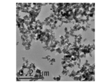
- FIG. 2 is a transmission electron micrograph of the ITO powder of Example 1.
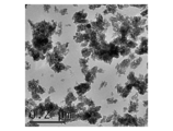
- 2 is a transmission electron micrograph of the ITO powder of Comparative Example 1.
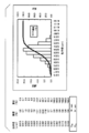
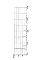
- 2 is an example of a particle size distribution of ITO powder of Example 1.
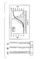
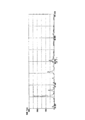
- FIG. 2 is an example of particle size distribution of ITO powder of Comparative Example 1.
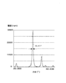
- 2 is an X-ray diffraction chart of ITO powder of Example 1.
- FIG. 6 is an enlarged view (X-ray diffraction chart) of the range of 20 ° to 40 ° of the X-ray diffraction chart (FIG. 5) of the ITO powder of Example 1.
- 4 is an X-ray diffraction chart of ITO powder of Comparative Example 1.
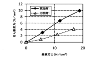
- FIG. 8 is an enlarged view (X-ray diffraction chart) of a range of 20 ° to 40 ° of the X-ray diffraction chart (FIG. 7) of the ITO powder of Comparative Example 1. It is a graph which shows the result of a shear stress.
- the ITO powder of this embodiment has a median diameter of particle size distribution of 30 nm to 45 nm and D 90 of 60 nm or less.
- the median diameter is preferably 30 nm to 40 nm.
- D 90 is preferably 45 nm to 60 nm.
- the median diameter and D 90 of the particle size distribution is within the above range, small particle size, and particle size distribution (as uniform particle size) is sharp, not aggregates almost nonexistent. For this reason, excellent dispersibility can be obtained. Thereby, the time when producing a dispersion liquid can be shortened.
- membrane produced using ITO powder has high intensity
- the median diameter is a particle diameter at which the cumulative value becomes 50% in the cumulative distribution of the particle size of the powder.
- D 90 is the particle size at which the cumulative value becomes 90% in the cumulative distribution of particle sizes.
- the particle size distribution of the ITO powder is measured by the following method. Using a paint shaker manufactured by Asada Iron Works, 60 g of ITO powder is dispersed in 60 cm 3 of water as a dispersion medium for 3 hours. Dilute the obtained dispersion 50 ⁇ 10 ⁇ 3 cm 3 into 50 cm 3 of water and measure the particle size distribution using a dynamic light scattering particle size distribution analyzer (model number: LB-550) manufactured by Horiba. To do. And from the obtained particle size distribution, to calculate a median diameter, and D 90.
- the shape of the ITO powder is preferably spherical or dice (cubic).
- 1 shows a transmission electron micrograph of the ITO powder of Example 1
- FIG. 2 shows a transmission electron micrograph of Comparative Example 1.
- the ITO powder of Example 1 has a small particle size, is uniform, and is dispersed independently.
- the ITO powder of Comparative Example 1 is agglomerated and the particle size is not uniform.
- 3 shows an example of the particle size distribution of the ITO powder of Example 1
- FIG. 4 shows an example of the particle size distribution of the ITO powder of Comparative Example 1.
- the line graph represents the integrated value (cumulative value) (%) on the right axis (cumulative distribution), and the bar graph represents the frequency (%) on the left axis (frequency distribution).
- the median size was 39 nm
- D 90 is 54 nm
- the median size was 65 nm
- D 90 is 87 nm.
- the ITO powder of the present embodiment has a small particle size and a sharp particle size distribution.
- FIG. 5 shows an X-ray diffraction chart of the ITO powder of Example 1
- FIG. 6 shows an enlarged view of the X-ray diffraction chart (FIG. 5) of the ITO powder of Example 1 in the range of 20 ° to 40 °.
- . 7 shows an X-ray diffraction chart of the ITO powder of Comparative Example 1
- FIG. 8 is an enlarged view of a range of 20 ° to 40 ° of the X-ray diffraction chart of the ITO powder of Comparative Example 1 (FIG. 7). Indicates. As shown in FIG.
- the half width of the diffraction peak of the (222) plane is smaller than 0.6 ° (specifically, 0.47 °).
- the relative intensity of the diffraction peak on the (222) plane is 2500 cps or less.
- the half width of the diffraction peak of the (222) plane is larger than 0.6 ° (specifically, 0.65 °).
- the half width of the diffraction peak of the (222) plane of the ITO powder of this embodiment is considerably smaller than that of the ITO powder of Comparative Example 1. Therefore, the ITO powder of this embodiment is a highly crystalline powder.
- the specific surface area is more preferably 60 m 2 / g to 85 m 2 / g, and most preferably 70 m 2 / g to 85 m 2 / g.
- the specific surface area is measured by the BET method.
- the L value is measured using, for example, an apparatus (SM-7-IS-2B) manufactured by Suga Test Instruments.
- the mass ratio [Sn / (Sn + In)] of the Sn content to the sum of the Sn and In contents in the ITO powder is preferably 1% to 20%, more preferably 5% to 20%. .
- the mass ratio of Sn content is less than 1%, conductivity and heat ray shielding tend to be inferior. Moreover, since the In component increases, the cost becomes high.
- the mass ratio of Sn content is more than 20%, there is a tendency to be inferior in conductivity and heat ray shielding properties as described above, which is not preferable.
- the method for producing indium tin oxide powder of this embodiment includes a step (A) of obtaining indium tin hydroxide by coprecipitation, and a step of drying and baking the indium tin hydroxide to obtain indium tin oxide. (B) and the step (C) of dry pulverizing the obtained indium tin oxide in a nitrogen atmosphere are provided in this order.
- a divalent tin compound is used, the pH is 4.0 to 9.3, and the coprecipitation is performed under the condition that the liquid temperature is 5 ° C. or higher.
- indium tin hydroxide having a color tone of bright yellow to amber color of persimmon (reddish brown or orange-red) is prepared by coprecipitation.
- a mixed aqueous solution containing indium ions and tin ions and an alkaline aqueous solution are mixed, and indium ions and tin ions in the mixture (reaction aqueous solution) are precipitated in the presence of alkali. Thereby, a coprecipitated hydroxide of indium and tin (indium tin hydroxide) is generated.
- a mixed aqueous solution containing indium ions and tin ions is prepared using a divalent tin compound (such as SnCl 2 ⁇ H 2 O).
- divalent tin compounds include stannous fluoride, stannous chloride, stannous borofluoride, stannous sulfate, stannous oxide, stannous nitrate, tin pyrophosphate, tin sulfamate, and tin.
- examples thereof include inorganic salts such as acid salts and organic salts such as stannous alkanol sulfonate, stannous sulfosuccinate and stannous aliphatic carboxylate.
- stannous chloride an excellent crystalline coprecipitate is obtained, which is preferable because it is easily industrialized.
- indium trichloride (SnCl 3 ) or indium nitrate can be used as a raw material for indium ions.
- indium nitrate and indium chloride are compared, a coprecipitated oxide having excellent crystallinity can be obtained by using indium chloride.
- the pH of the reaction aqueous solution (mixed aqueous solution containing indium ions and tin ions and the alkaline aqueous solution) is adjusted to 4.0 to 9.3, preferably pH 6.0 to 8.0, and the liquid temperature is adjusted. Adjust to 5 ° C or higher, preferably 10 ° C to 80 ° C.
- indium tin hydroxide having a color tone from a yellowish color to an amber color can be co-precipitated.
- Indium tin hydroxide having a yellowish to dark blue color tone in a dry powder state has a more uniform particle size and superior crystallinity than conventional white indium tin hydroxide. Are distributed independently.
- a tetravalent tin compound (SnCl 4 or the like) is used as a raw material for tin ions, a white precipitate (indium tin hydroxide) is generated, and in a dry powder state, a precipitate having a yellowish to amber color tone is formed. I can't get it.
- a pH of the reaction aqueous solution is lower than 4.0 (acidic side), or when the pH of the aqueous reaction solution is higher than 9.3 (alkali side)
- a pale yellowish white precipitate Indium tin hydroxide
- a precipitate having a yellowish to dark blue color tone cannot be obtained.
- the white precipitate from the tetravalent tin compound and the above-mentioned pale yellowish white precipitate are all non-uniform in particle size and low in crystallinity compared with the precipitate having a yellowish to dark blue color tone. , Not independently distributed. Even if these precipitates are baked, it is not possible to obtain an ITO powder having a uniform particle diameter, high crystallinity, and independently dispersed as in this embodiment.
- the tin tetrachloride since the tin tetrachloride is used, the precipitate of the white indium tin hydroxide has arisen, and the deposit which has the color tone of a deep-brown to amber color in the state of a dry powder is I can't get it.
- a mixed aqueous solution containing indium ions and tin ions and an aqueous alkaline solution are simultaneously dropped into water in the vessel. It is preferable.
- the mixed aqueous solution is preferably dropped into the alkaline aqueous solution.
- an ammonia (NH 3 ) aqueous solution an ammonium hydrogen carbonate (NH 4 HCO 3 ) aqueous solution, a KOH aqueous solution, an NaOH aqueous solution, or the like can be used.
- a mixed aqueous solution using tin dichloride as a divalent tin compound by preparing a mixed aqueous solution using tin dichloride as a divalent tin compound, adjusting the pH of the reaction aqueous solution to 7, and adjusting the liquid temperature to 10 ° C. to 60 ° C., a dry powder In this state, a precipitate having a yellowish to dark blue color tone is formed.
- the pH of the reaction aqueous solution is less than 4 (for example, pH 3) or when the pH of the reaction aqueous solution is more than 9.3 (for example, pH 9.5), a light yellowish white precipitate is generated.
- the mass ratio of the Sn content to the sum of the Sn and In contents [Sn / (Sn + In)] is preferably 1% to 20%, more preferably 5% to 20%. It is preferable to adjust the contents of Sn and In in the mixed aqueous solution so that the content of indium tin hydroxide to be generated is 0.01 to 25 parts by mass with respect to 100 parts by mass of the reaction aqueous solution. .
- the content of indium tin hydroxide produced is more preferably 0.1 to 25 parts by mass, and most preferably 1 to 25 parts by mass.
- the produced indium tin hydroxide coprecipitate is washed with pure water or ion-exchanged water.
- the supernatant is washed until the electrical resistivity becomes 5000 ⁇ ⁇ cm or more, preferably 50000 ⁇ ⁇ cm or more, and then solid-liquid separation is performed to recover the coprecipitate.
- the electrical resistivity of the supernatant is lower than 5000 ⁇ ⁇ cm, impurities such as chlorine are not sufficiently removed, and high-purity ITO powder cannot be obtained.
- L 60 to 75
- a ⁇ 2.5 to +1.5
- b + 22 to +32.
- [(B) step] In the step of drying the obtained indium tin hydroxide, for example, it is heated in the atmosphere at a temperature of 100 ° C. to 200 ° C. for 2 hours to 24 hours. Next, in the firing step, for example, heating is performed at a temperature of 250 ° C. or higher, preferably 400 ° C. to 800 ° C. for 1 hour to 6 hours. When the firing temperature is less than 250 ° C., the hydroxide remains or the hydroxide remains. By this firing step, the indium tin hydroxide becomes indium tin oxide (indium tin oxide, ITO) having a color tone of bright yellow to amber.
- ITO indium tin oxide
- ITO Indium tin oxide
- the ITO powder obtained by firing the white precipitate (indium tin hydroxide) in the atmosphere is olive-green, and its color tone is a ⁇ ⁇ in the Lab color system. 5.
- the calcined indium tin oxide is a fine powder having a specific surface area of 55 m 2 / g or more, preferably 60 m 2 / g or more.
- the specific surface area is, for example, 60 m 2 / g to 85 m 2 / g.
- the specific surface area of the ITO powder obtained by firing the white precipitate (indium tin hydroxide) in the air is, for example, 45 m 2 / g to 48 m 2 / g.
- the surface modification described above can be performed as follows, for example.
- the indium tin hydroxide obtained in the step (A) is not dried in the atmosphere, but in an atmosphere containing only nitrogen gas, or water vapor or alcohol. And heating at a temperature of 250 ° C. to 800 ° C. for 30 minutes to 6 hours in an atmosphere of nitrogen gas containing at least one selected from ammonia.
- drying and baking are simultaneously performed by the heat treatment for surface modification.
- surface modification is performed at a low temperature and then firing is performed, it is preferable to perform the firing in an inert atmosphere rather than in the air.
- the flow rate of the atmospheric gas (nitrogen gas or nitrogen gas containing one or more selected from water vapor, alcohol, and ammonia) in this surface modification step is linear velocity: 8 ⁇ 10 ⁇ 6 m / s or more 5 ⁇ 10 ⁇ 5 m / s to 10 m / s is more preferable, and 5 ⁇ 10 ⁇ 5 m / s to 1 m / s is most preferable.
- the ITO powder can be miniaturized, the specific surface area can be increased, and a particle size distribution with a uniform particle size (sharp particle size distribution) can be obtained.
- the outstanding electroconductivity is obtained.
- the flow rate of the atmospheric gas is desirably a linear velocity of 1 m / s or less.
- the flow rate of the atmospheric gas is set at a linear velocity: 0.00. A range of 01 m / s to 10 m / s is preferable.
- step (B) is performed as follows. First, indium tin hydroxide is dried in air at a temperature of 100 ° C. to 110 ° C. for 10 hours. Next, without firing in air, a temperature of 250 ° C. to 800 ° C. in an atmosphere of only nitrogen gas or in an atmosphere of nitrogen gas containing one or more selected from water vapor, alcohol, and ammonia For 30 minutes to 6 hours.
- step (B) is performed as follows. First, indium tin hydroxide is dried and fired in the air. Next, heating is performed at a temperature of 250 ° C. to 800 ° C. for 30 minutes to 6 hours in an atmosphere of only nitrogen gas or in an atmosphere of nitrogen gas containing one or more selected from water vapor, alcohol, and ammonia.
- the surface-modified indium tin oxide has a specific surface area according to the BET method of 40 m 2 / g, preferably 60 m 2 / g. Further, it is a deep blue color, and in the Lab color system, L ⁇ 30, a ⁇ 0, b ⁇ 0. By using indium tin oxide satisfying this range, it is possible to form a coating film excellent in transparency, conductivity and heat ray shielding.
- Step (C) The obtained indium tin oxide is dry-ground in a nitrogen atmosphere.
- the dry pulverization method is not particularly limited, and can be performed using an apparatus known to those skilled in the art, such as a hammer mill (for example, a hammer type fine pulverizer), a jet mill, a ball mill, a pin mill, and a mortar. This crushing step, the median diameter of particle size distribution of the ITO powder, and D 90 and can be adjusted to a desired value.
- the ITO powder of the present embodiment can be supplied in the form of a dispersion liquid, a paint, a paste, etc., which will be described later.
- the dispersion liquid of the present embodiment contains the ITO powder of the present embodiment and a solvent.
- the solvent include water, ethanol, methanol, isopropyl alcohol, toluene, methyl ethyl ketone, propylene glycol monomethyl ether and the like.
- the content of the ITO powder is 1% to 70%, preferably 10% to 50%, based on mass.
- the pH of the dispersion is 2 to 10, preferably 3 to 5.
- various conventional additives may be blended within a range that does not impair the purpose.
- additives include a dispersant, a dispersion aid, a polymerization inhibitor, a curing catalyst, an antioxidant, a leveling agent, and a film-forming resin.
- the paint (paste) of the present embodiment contains the dispersion liquid of the present embodiment and a resin. Since the ITO powder of the present embodiment is excellent in dispersibility, the dispersion energy can be reduced when the dispersion is made into a paint (coating).
- the resin include polyvinyl alcohol resin, vinyl chloride-vinyl acetate resin, acrylic resin, epoxy resin, urethane resin, alkyd resin, polyester resin, ethylene vinyl acetate copolymer, acrylic-styrene copolymer, fiber base resin, phenol Examples thereof include natural resins such as resin, amino resin, fluororesin, silicone resin, petroleum resin, shellac, rosin derivative, and rubber derivative.
- the blending amount of the ITO powder into the resin is 0.1 to 950 parts by mass, preferably 0.7 to 800 parts by mass with respect to 100 parts by mass of the resin.
- the content of the ITO powder is appropriately adjusted depending on the electrical resistivity and film thickness required for the film formed using the paint.
- the functional thin film of this embodiment contains the ITO powder of this embodiment.
- the functional thin film is formed by applying the dispersion or paint of the present embodiment to a substrate or the like.
- the substrate include substrates widely used in various fields such as electrical / electronic devices.
- Specific examples include substrates made of various synthetic resins, glass, ceramics, and the like.
- the shape of the substrate is not particularly limited, and may be any shape such as a sheet shape, a film shape, or a plate shape.
- Specific examples of the synthetic resin include, but are not limited to, polyethylene, polypropylene, polycarbonate, polyethylene terephthalate (PET) resin, acrylic resin, methacrylic resin, polyvinyl chloride, polyester resin, polyamide resin, and phenol resin. .
- Dispersion and paint are applied to the substrate by conventional methods.
- the coating method include roll coating, spin coating, screen printing, and coating using an instrument such as an applicator.
- the coating film is heated as necessary, the solvent (solvent) is evaporated, and the coating film is dried and cured.
- the solvent solvent
- UV rays may be irradiated.
- the thickness of the functional thin film is 0.1 ⁇ m or more from the viewpoint of transparency, conductivity, and infrared shielding properties. 5 ⁇ m is preferable, and 0.5 ⁇ m to 2 ⁇ m is more preferable.
- the thickness is not limited.
- the functional thin film of this embodiment is excellent in transparency, conductivity, and infrared shielding properties, and can be used as a conductive film or a heat ray shielding film. Specifically, it is widely applied to various types of window glass for vehicles such as displays, touch panels and automobiles, window glass for building materials, various types of glass for medical devices, and transparent parts such as general packaging or showcases. it can.
- the particle size distribution was measured by the following method.
- ITO powder 60 g was dispersed in water: 60 cm 3 as a dispersion medium for 3 hours using a paint shaker manufactured by Asada Iron Works.
- the obtained dispersion 50 ⁇ 10 ⁇ 3 cm 3 was diluted with 50 cm 3 of water, and the particle size distribution was measured under the following conditions using a dynamic light scattering particle size distribution analyzer (model number: LB-550) manufactured by Horiba. Distribution was measured. (Measurement condition)
- Data acquisition frequency 100 times
- repetition frequency 50 times
- particle diameter standard volume standard
- measurement temperature 24.5 ° C. to 25.5 ° C.
- the median diameter 50% cumulative particle diameter
- D 90 90% cumulative particle diameter
- Example 1 Indium chloride (InCl 3 ) aqueous solution (In content 18 g): 50 cm 3 and tin dichloride (SnCl 2 .2H 2 O): 3.6 g were mixed to prepare a mixed aqueous solution. Further, to produce ammonia (NH 3) solution as an alkaline aqueous solution. A mixed aqueous solution and an aqueous ammonia (NH 3 ) solution were simultaneously dropped into a container containing 500 cm 3 of water. The addition amount of the alkaline aqueous solution was adjusted, the pH of the mixture (reaction aqueous solution) in the container was adjusted to 7, and the liquid temperature was adjusted to 30 ° C. to react for 30 minutes.
- the produced precipitate was repeatedly washed with ion-exchanged water by tilting. Specifically, in the slant washing, the supernatant was discarded, and then, ion exchange water was newly added, mixed and allowed to stand, and the precipitate was washed. When the electrical resistivity of the supernatant liquid reached 50000 ⁇ ⁇ cm or more, the precipitate (In / Sn coprecipitated hydroxide) was separated by filtration to obtain coprecipitated indium tin hydroxide. The coprecipitated indium tin hydroxide was found to be a color of persimmon (reddish brown or orange-red) in the dry powder state.
- the solid-liquid separated indium tin hydroxide was dried at 110 ° C. overnight and then calcined in the atmosphere at 550 ° C. for 3 hours.
- the aggregates in the obtained fired product were pulverized and loosened to obtain bright yellow ITO powder: about 25 g.
- Table 1 shows the Lab value and specific surface area of the ITO powder.
- Example 1 25 g of the ITO powder was put in a glass petri dish and heated at 330 ° C. for 2 hours in a nitrogen gas atmosphere containing ethanol and water vapor to perform surface modification treatment.
- Table 1 shows the color tone (L, a, b) and BET value of the surface-modified ITO powder. Further, dry pulverization treatment was performed on the surface-modified ITO powder using an agate mortar in a nitrogen atmosphere booth. In addition, 20 lots of ITO powder obtained in Example 1 were produced and mixed uniformly. Next, a surface modification treatment was performed in the same manner as described above.
- the dispersion powder was prepared by dispersing 50 g of ITO powder subjected to the surface modification treatment and the dry pulverization treatment in 50 g of water. This dispersion aqueous solution was diluted with ethanol to obtain a dispersion having an ITO powder concentration of 10%. This ITO dispersion was applied to a glass plate by spin coating at 150 revolutions to form a film (ITO concentration 10%). Further, a silica sol-gel solution (silica: 1%) was applied onto the dispersion coating film by spin coating at 150 rotations to form a film. Next, the glass plate on which the coating film was formed was baked at 160 ° C. for 30 minutes to form a coating film (film thickness 0.2 ⁇ m).
- the dispersion residence time during the preparation of the dispersion was calculated from the following equation.
- the relative values when the dispersion residence time of Comparative Example 1 is 100 are shown in Table 3.
- (Dispersion residence time) (dispersion time) / ⁇ (volume of dispersion) / (effective volume of mill) ⁇
- the unit of “dispersion time” uses the same unit (for example, “cm 3 ”) for “time”, “volume of dispersion”, and “effective volume of mill”.
- the total light transmittance and surface resistivity of the glass plate on which the film was formed were measured. The results are shown in Table 3.
- the surface resistivity was measured by Resta AP (MCP-T400) manufactured by Mitsubishi Chemical.
- the total light transmittance was measured in the visible light region of 400 nm to 750 nm using a device (HGM-3D) manufactured by Suga Test Instruments in accordance with the standard (JIS K7150).
- the measured value of the total light transmittance includes the transmittance of the glass plate (the transmittance of the glass plate is 89.0%, the thickness is 1 mm), and is the value at the thickness of the coating film of 0.2 ⁇ m.
- Table 3 also shows a value ( ⁇ transmittance) obtained by subtracting the transmittance (89.0%) of the glass plate from the measured value of the total light transmittance.
- the visible light transmittance (% Tv), solar radiation transmittance (% Ts), and haze of the dispersion of ITO powder shown in Table 3 were measured. The measurement method is shown below.
- the prepared dispersion was diluted with triethylene glycol-di-2-ethylhexanoate to prepare a diluted solution (sample for measuring spectral characteristics) having an ITO powder content of 0.7% by mass.
- This diluted solution is placed in a glass cell having an optical path length of 1 mm, and a visible light transmittance (% Tv) of 380 nm to 780 nm is used according to a standard (JIS R 3216-1998) using a self-recording spectrophotometer (U-4000 manufactured by Hitachi, Ltd.) ) And solar transmittance (% Ts) from 300 nm to 2100 nm. Table 3 shows these results.
- aqueous SnCl 4 solution having a concentration of 55% was prepared using tin tetrachloride as the tin compound.
- This SnCl 4 aqueous solution: 14.4 g and indium chloride (InCl 3 ) aqueous solution (containing 35 g of In metal): 90 cm 3 were mixed to prepare a mixed aqueous solution.
- an aqueous alkaline solution containing 0.6 g of ammonium bicarbonate (NH 4 HCO 3 ): 190 g: 0.6 dm 3 was added to obtain a mixture (reaction aqueous solution).
- the pH of the aqueous reaction solution was adjusted to 8, and the temperature of the solution was adjusted to 30 ° C. to react for 30 minutes.
- the produced precipitate was repeatedly washed with ion-exchange water.
- the electrical resistivity of the supernatant liquid was 50000 ⁇ ⁇ cm or more
- the coprecipitated indium tin hydroxide was filtered off.
- the coprecipitated indium tin hydroxide was white.
- the coprecipitated indium tin hydroxide was dried at 110 ° C. overnight and then calcined at 550 ° C. for 3 hours in air. Aggregates in the obtained fired product were pulverized and loosened to obtain ITO powder: about 44 g.
- 25 g of the above ITO powder was put in a glass petri dish, and surface-modified by heating at 330 ° C. for 2 hours in a nitrogen gas atmosphere containing ethanol and water vapor.
- Table 2 shows the color tone (Lab value (L, a, b)) and specific surface area (BET value) of the surface-modified ITO powder.
- the surface-modified ITO powder was dry pulverized in an air atmosphere. Conductivity evaluation, heat ray cut evaluation, haze measurement, and the like were performed on the ITO powder subjected to the surface modification treatment and the dry pulverization treatment. Table 3 shows these results.
- Comparative Example 2 An ITO powder was prepared in the same manner as in Comparative Example 1 except that the powder was dry-ground in a nitrogen atmosphere instead of in the air, and conductivity evaluation, heat ray cut evaluation, and the like were performed. Tables 2 and 4 show these results.
- Examples 2 to 5 Comparative Examples 3 to 6
- An ITO powder was produced in the same manner as in Example 1 except that the conditions described in Table 1 were applied, and conductivity evaluation, heat ray cut evaluation, and the like were performed. Tables 1 to 4 show these results.
- the shear stress of the ITO powders of Example 1 and Comparative Example 1 was measured using a powder layer shear force measuring device NS-S500 manufactured by Nano Seeds.
- the height of the cell used for the high load shear test was 30 mm, and the measurement was carried out by applying a force of 50 N, 100 N, and 150 N with a vertical load.
- the indentation speed into the cell was 0.2 mm / second, the indentation gap was 0.05 mm, and the side sliding speed was 10 ⁇ m / second.
- Table 5 and FIG. 9 show the results.
- Example 1 increases the shearing force as the normal stress increases, so that the internal friction angle also increases and the powder adhesion increases. I understood it. Therefore, it was found that when the ITO powder of the present embodiment was made into a film, the powder was excellent in adhesiveness, so that the film strength was high and the moldability was also excellent.
- the ITO powder of this embodiment has a small particle size and good dispersibility. That is, in this embodiment, it is possible to provide an ITO powder having a short time for producing a dispersion. Furthermore, it was found that a film using this ITO powder has high strength, and is excellent in transparency and conductivity.
- the ITO powder of the present embodiment has a small particle size, a sharp particle size distribution, and high crystallinity. For this reason, by using the ITO powder of this embodiment, it is possible to form a conductive film having a very high film strength and a remarkably good conductivity and heat ray shielding performance. For this reason, it can apply suitably to the manufacturing process of functional materials, such as a transparent conductive film and a heat ray shielding film.
Landscapes
- Chemical & Material Sciences (AREA)
- Organic Chemistry (AREA)
- Engineering & Computer Science (AREA)
- Inorganic Chemistry (AREA)
- Nanotechnology (AREA)
- Materials Engineering (AREA)
- Condensed Matter Physics & Semiconductors (AREA)
- Crystallography & Structural Chemistry (AREA)
- General Physics & Mathematics (AREA)
- Physics & Mathematics (AREA)
- Composite Materials (AREA)
- Life Sciences & Earth Sciences (AREA)
- Wood Science & Technology (AREA)
- Paints Or Removers (AREA)
- Conductive Materials (AREA)
- Non-Insulated Conductors (AREA)
Priority Applications (3)
| Application Number | Priority Date | Filing Date | Title |
|---|---|---|---|
| KR1020137010247A KR101568561B1 (ko) | 2010-10-26 | 2011-10-24 | 인듐주석 산화물 분말, 그 제조 방법, 분산액, 도료 및 기능성 박막 |
| EP11836187.2A EP2634146B1 (en) | 2010-10-26 | 2011-10-24 | Indium tin oxide powder, method for producing same, dispersion, paint, and functional thin film |
| US13/878,032 US20130187104A1 (en) | 2010-10-26 | 2011-10-24 | Indium tin oxide powder, method for producing same, dispersion, paint, and functional thin film |
Applications Claiming Priority (2)
| Application Number | Priority Date | Filing Date | Title |
|---|---|---|---|
| JP2010-239442 | 2010-10-26 | ||
| JP2010239442A JP5754580B2 (ja) | 2010-10-26 | 2010-10-26 | インジウム錫酸化物粉末 |
Publications (1)
| Publication Number | Publication Date |
|---|---|
| WO2012057053A1 true WO2012057053A1 (ja) | 2012-05-03 |
Family
ID=45993763
Family Applications (1)
| Application Number | Title | Priority Date | Filing Date |
|---|---|---|---|
| PCT/JP2011/074387 Ceased WO2012057053A1 (ja) | 2010-10-26 | 2011-10-24 | インジウム錫酸化物粉末、その製造方法、分散液、塗料、及び機能性薄膜 |
Country Status (5)
| Country | Link |
|---|---|
| US (1) | US20130187104A1 (enExample) |
| EP (1) | EP2634146B1 (enExample) |
| JP (1) | JP5754580B2 (enExample) |
| KR (1) | KR101568561B1 (enExample) |
| WO (1) | WO2012057053A1 (enExample) |
Cited By (3)
| Publication number | Priority date | Publication date | Assignee | Title |
|---|---|---|---|---|
| JP2013166661A (ja) * | 2012-02-14 | 2013-08-29 | Ulvac Japan Ltd | Ito粉末の製造方法及びitoスパッタリングターゲットの製造方法 |
| CN113666412A (zh) * | 2021-09-26 | 2021-11-19 | 烟台佳隆纳米产业有限公司 | 竹节状纳米氧化铟锡粉体的制备方法 |
| JPWO2022244779A1 (enExample) * | 2021-05-18 | 2022-11-24 |
Families Citing this family (23)
| Publication number | Priority date | Publication date | Assignee | Title |
|---|---|---|---|---|
| WO2013002919A1 (en) * | 2011-06-28 | 2013-01-03 | 3M Innovative Properties Company | Tin dioxide nanopartcles and method for making the same |
| JP6111538B2 (ja) * | 2012-06-12 | 2017-04-12 | 三菱マテリアル株式会社 | Ito膜の製造に用いられるito粉末の製造方法 |
| JP5924214B2 (ja) * | 2012-09-27 | 2016-05-25 | 三菱マテリアル株式会社 | Ito粉末及びその製造方法 |
| JP5954082B2 (ja) * | 2012-09-27 | 2016-07-20 | 三菱マテリアル株式会社 | Ito粉末及びその製造方法 |
| JP2014080466A (ja) * | 2012-10-15 | 2014-05-08 | Mitsubishi Materials Corp | 熱線遮蔽組成物 |
| JP6122304B2 (ja) * | 2013-02-12 | 2017-04-26 | 三菱マテリアル電子化成株式会社 | 酸化錫インジウム粉末の製造方法 |
| CN106661293B (zh) | 2014-08-06 | 2019-05-10 | 住友金属矿山股份有限公司 | 热射线遮蔽膜、热射线遮蔽用夹层透明基材、汽车、建造物 |
| JP6427381B2 (ja) * | 2014-10-10 | 2018-11-21 | 国立大学法人茨城大学 | Ito粒子の製造方法 |
| JP6530644B2 (ja) * | 2015-03-31 | 2019-06-12 | 三菱マテリアル電子化成株式会社 | Ito導電膜形成用組成物及びito導電膜 |
| EP3318610B1 (en) | 2015-06-30 | 2020-10-21 | Sumitomo Metal Mining Co., Ltd. | Heat-ray shielding film, heat-ray shielding laminated transparent base material, automobile, building, dispersion, mixed composition, dispersion production method, dispersion solution, and dispersion solution production method |
| KR102031403B1 (ko) * | 2016-03-31 | 2019-10-11 | 주식회사 엘지화학 | 씨앗 입자를 이용한 ito 중공 나노 입자의 제조방법 및 이에 의하여 제조된 ito 중공 나노 입자 |
| US20170363788A1 (en) * | 2016-06-20 | 2017-12-21 | Sumitomo Metal Mining Co., Ltd. | Heat-ray shielding particle dispersing liquid, heat-ray shielding particle dispersing body, heat-ray shielding laminated transparent substrate and heat-ray shielding transparent substrate |
| US10587221B2 (en) | 2017-04-03 | 2020-03-10 | Epic Battery Inc. | Modular solar battery |
| US10457148B2 (en) | 2017-02-24 | 2019-10-29 | Epic Battery Inc. | Solar car |
| JP7029236B2 (ja) * | 2017-07-04 | 2022-03-03 | 三菱マテリアル電子化成株式会社 | 熱線遮蔽粒子分散液及びその製造方法 |
| KR102454200B1 (ko) | 2017-12-14 | 2022-10-14 | 엘티메탈 주식회사 | 인듐 주석 산화물 분말 제조방법 및 이를 이용하여 제조된 인듐 주석 산화물 분말 |
| JPWO2019138708A1 (ja) * | 2018-01-15 | 2021-01-07 | 国立大学法人東北大学 | Ito粒子、分散液及びito膜の製造方法 |
| CN111601773A (zh) * | 2018-01-15 | 2020-08-28 | 国立大学法人东北大学 | Ito颗粒、分散液、ito颗粒的制造方法、分散液的制造方法和ito膜的制造方法 |
| JP2019185310A (ja) * | 2018-04-06 | 2019-10-24 | 株式会社ダイセル | テーブル型表示装置 |
| US11489082B2 (en) | 2019-07-30 | 2022-11-01 | Epic Battery Inc. | Durable solar panels |
| JP6729779B1 (ja) * | 2019-11-25 | 2020-07-22 | 東洋インキScホールディングス株式会社 | 錫ドープ酸化インジウム粒子分散体、成形用組成物および成形体 |
| CN113213719B (zh) * | 2021-06-18 | 2022-09-23 | 广东工业大学 | 导光导电纤维电极联合光-电活性微生物原位修复底泥的装置与方法 |
| CN117142848B (zh) * | 2023-09-06 | 2025-08-22 | 株洲火炬安泰新材料有限公司 | 一种LaSm共掺杂ITO靶材及其制备方法与应用 |
Citations (9)
| Publication number | Priority date | Publication date | Assignee | Title |
|---|---|---|---|---|
| JPH05201731A (ja) * | 1991-10-15 | 1993-08-10 | Mitsubishi Materials Corp | 超微粒低抵抗スズドープ酸化インジウム粉末とその製法 |
| JPH0721831A (ja) * | 1993-06-30 | 1995-01-24 | Mitsubishi Materials Corp | 導電性酸化物粉末の製造方法 |
| JPH0841441A (ja) * | 1994-05-25 | 1996-02-13 | Sumitomo Metal Mining Co Ltd | 紫外線、近赤外線遮へい用インジウム−錫酸化物粉末とこれを用いた紫外線、近赤外線遮へいガラスおよびその製造方法 |
| JP2001261336A (ja) * | 2000-03-22 | 2001-09-26 | Fuji Titan Kogyo Kk | スズ含有酸化インジウム微粒子粉体およびその製造方法 |
| JP2002068744A (ja) * | 2000-08-30 | 2002-03-08 | Mitsui Mining & Smelting Co Ltd | 酸化錫添加酸化インジウム粉末及びその製造方法 |
| JP2002524374A (ja) * | 1998-09-06 | 2002-08-06 | インスティトゥート フィア ノイエ マテリアーリエン ゲマインニュッツィゲ ゲゼルシャフト ミット ベシュレンクタ ハフトゥンク | インジウムスズ酸化物に基づくサスペンション及び粉末の調製方法並びにその使用 |
| JP2005322626A (ja) * | 2004-04-09 | 2005-11-17 | Sumitomo Metal Mining Co Ltd | 導電性酸化物針状粉末 |
| JP2008110915A (ja) * | 2008-01-16 | 2008-05-15 | Dowa Holdings Co Ltd | スズドープ酸化インジウム粉 |
| JP2010092629A (ja) * | 2008-10-03 | 2010-04-22 | Sumitomo Metal Mining Co Ltd | 透光性導電塗料及び透光性導電膜 |
Family Cites Families (13)
| Publication number | Priority date | Publication date | Assignee | Title |
|---|---|---|---|---|
| JP3072862B2 (ja) * | 1991-07-31 | 2000-08-07 | 住友金属鉱山株式会社 | 透明導電膜の成膜方法 |
| JP4171790B2 (ja) * | 1998-06-12 | 2008-10-29 | Dowaエレクトロニクス株式会社 | スズドープ酸化インジウム粉の製造方法 |
| JP4389368B2 (ja) * | 1999-12-02 | 2009-12-24 | 三菱マテリアル株式会社 | 導電性顔料粉末及びこれを用いて作られた透明導電膜 |
| JP2002201027A (ja) * | 2000-11-02 | 2002-07-16 | Sumitomo Metal Mining Co Ltd | 日射遮蔽用インジウム錫酸化物微粒子とその製造方法およびこれを用いた塗布液および日射遮蔽膜 |
| JP2002194291A (ja) * | 2000-12-22 | 2002-07-10 | Sumitomo Metal Mining Co Ltd | 日射遮蔽膜形成用塗布液の製造方法 |
| DE10205920A1 (de) * | 2002-02-12 | 2003-08-21 | Itn Nanovation Gmbh | Nanoskaliger Rutil, sowie Verfahren zu dessen Herstellung |
| JP4512940B2 (ja) * | 2003-12-24 | 2010-07-28 | 三菱マテリアル株式会社 | 錫ドープ酸化インジウム微粒子分散液とその製造方法、および該分散液を用いた熱線遮蔽性を有する合わせガラス用中間膜、ならびにその合わせガラス |
| JP2005232399A (ja) * | 2004-02-23 | 2005-09-02 | Sumitomo Metal Mining Co Ltd | 日射遮蔽用微粒子とこの微粒子を含有する日射遮蔽体並びに日射遮蔽複合体および日射遮蔽体または日射遮蔽複合体の製造に用いられる分散液 |
| JP4586126B2 (ja) * | 2006-03-03 | 2010-11-24 | Dowaエレクトロニクス株式会社 | Ito粉体およびその製造方法、ito塗料、並びにito導電膜 |
| JP4617499B2 (ja) * | 2006-03-31 | 2011-01-26 | Dowaエレクトロニクス株式会社 | Ito粉体およびその製造方法、透明導電材用塗料、並びに透明導電膜 |
| JP5589214B2 (ja) * | 2007-10-01 | 2014-09-17 | Dowaエレクトロニクス株式会社 | Ito粉体およびその製造方法、透明導電材用塗料、並びに透明導電膜 |
| JP2010215461A (ja) * | 2009-03-17 | 2010-09-30 | Mitsui Mining & Smelting Co Ltd | 酸化インジウム粉末 |
| JP5829386B2 (ja) * | 2009-10-16 | 2015-12-09 | 三菱マテリアル電子化成株式会社 | 結晶性の高い微細なito粉末とその用途および製造方法等 |
-
2010
- 2010-10-26 JP JP2010239442A patent/JP5754580B2/ja active Active
-
2011
- 2011-10-24 US US13/878,032 patent/US20130187104A1/en not_active Abandoned
- 2011-10-24 WO PCT/JP2011/074387 patent/WO2012057053A1/ja not_active Ceased
- 2011-10-24 KR KR1020137010247A patent/KR101568561B1/ko active Active
- 2011-10-24 EP EP11836187.2A patent/EP2634146B1/en active Active
Patent Citations (9)
| Publication number | Priority date | Publication date | Assignee | Title |
|---|---|---|---|---|
| JPH05201731A (ja) * | 1991-10-15 | 1993-08-10 | Mitsubishi Materials Corp | 超微粒低抵抗スズドープ酸化インジウム粉末とその製法 |
| JPH0721831A (ja) * | 1993-06-30 | 1995-01-24 | Mitsubishi Materials Corp | 導電性酸化物粉末の製造方法 |
| JPH0841441A (ja) * | 1994-05-25 | 1996-02-13 | Sumitomo Metal Mining Co Ltd | 紫外線、近赤外線遮へい用インジウム−錫酸化物粉末とこれを用いた紫外線、近赤外線遮へいガラスおよびその製造方法 |
| JP2002524374A (ja) * | 1998-09-06 | 2002-08-06 | インスティトゥート フィア ノイエ マテリアーリエン ゲマインニュッツィゲ ゲゼルシャフト ミット ベシュレンクタ ハフトゥンク | インジウムスズ酸化物に基づくサスペンション及び粉末の調製方法並びにその使用 |
| JP2001261336A (ja) * | 2000-03-22 | 2001-09-26 | Fuji Titan Kogyo Kk | スズ含有酸化インジウム微粒子粉体およびその製造方法 |
| JP2002068744A (ja) * | 2000-08-30 | 2002-03-08 | Mitsui Mining & Smelting Co Ltd | 酸化錫添加酸化インジウム粉末及びその製造方法 |
| JP2005322626A (ja) * | 2004-04-09 | 2005-11-17 | Sumitomo Metal Mining Co Ltd | 導電性酸化物針状粉末 |
| JP2008110915A (ja) * | 2008-01-16 | 2008-05-15 | Dowa Holdings Co Ltd | スズドープ酸化インジウム粉 |
| JP2010092629A (ja) * | 2008-10-03 | 2010-04-22 | Sumitomo Metal Mining Co Ltd | 透光性導電塗料及び透光性導電膜 |
Non-Patent Citations (1)
| Title |
|---|
| P. SUJATHA DEVI ET AL.: "Indium tin oxide nano- particles through an emulsion technique", MATERIALS LETTERS, vol. 55, August 2002 (2002-08-01), pages 205 - 210, XP004373845 * |
Cited By (5)
| Publication number | Priority date | Publication date | Assignee | Title |
|---|---|---|---|---|
| JP2013166661A (ja) * | 2012-02-14 | 2013-08-29 | Ulvac Japan Ltd | Ito粉末の製造方法及びitoスパッタリングターゲットの製造方法 |
| JPWO2022244779A1 (enExample) * | 2021-05-18 | 2022-11-24 | ||
| WO2022244779A1 (ja) * | 2021-05-18 | 2022-11-24 | 積水化学工業株式会社 | 分散液、樹脂組成物、合わせガラス用中間膜及び合わせガラス |
| CN117321004A (zh) * | 2021-05-18 | 2023-12-29 | 积水化学工业株式会社 | 分散液、树脂组合物、夹层玻璃用中间膜和夹层玻璃 |
| CN113666412A (zh) * | 2021-09-26 | 2021-11-19 | 烟台佳隆纳米产业有限公司 | 竹节状纳米氧化铟锡粉体的制备方法 |
Also Published As
| Publication number | Publication date |
|---|---|
| EP2634146B1 (en) | 2018-08-15 |
| KR101568561B1 (ko) | 2015-11-11 |
| EP2634146A1 (en) | 2013-09-04 |
| EP2634146A4 (en) | 2015-03-11 |
| KR20130093123A (ko) | 2013-08-21 |
| JP5754580B2 (ja) | 2015-07-29 |
| JP2012091953A (ja) | 2012-05-17 |
| US20130187104A1 (en) | 2013-07-25 |
Similar Documents
| Publication | Publication Date | Title |
|---|---|---|
| JP5754580B2 (ja) | インジウム錫酸化物粉末 | |
| KR101568629B1 (ko) | 안티몬 도프 산화 주석 분말 및 그 제조 방법 | |
| KR102371493B1 (ko) | 근적외선 차폐 재료 미립자 분산체, 근적외선 차폐체 및 근적외선 차폐용 적층 구조체 및 이들의 제조방법 | |
| JP5301370B2 (ja) | 酸化スズ粒子及びその製造方法 | |
| CN102596811B (zh) | 热射线屏蔽组合物及其制造方法 | |
| JP4389368B2 (ja) | 導電性顔料粉末及びこれを用いて作られた透明導電膜 | |
| CN110740975A (zh) | 六角板状氧化锌的制造方法 | |
| JPWO2004089829A1 (ja) | 複合化酸化インジウム粒子およびその製造方法ならびに導電性塗料、導電性塗膜および導電性シート | |
| JPWO2010131674A1 (ja) | Ito粉体、ito塗料、並びに、ito塗料を用いて成膜される透明導電膜 | |
| JP4702615B2 (ja) | 紫外線遮蔽用酸化亜鉛微粒子の製造方法、および該微粒子を用いた紫外線遮蔽体形成用分散液並びに紫外線遮蔽体 | |
| EP3357865B1 (en) | Infrared absorbing particles, and dispersion liquid, dispersion, laminated transparent substrate, film, and glass using same, and method for manufacturing same | |
| JP2015160759A (ja) | 透明導電性複合酸化物微粉末及びその製造方法並びに透明導電性膜 | |
| US8927104B2 (en) | Indium tin oxide powder, production method therefor, transparent conductive composition, and indium tin hydroxide | |
| JP4906027B2 (ja) | 複合化酸化インジウム粒子およびその製造方法、ならびに導電性塗料、導電性塗膜および導電性シート | |
| EP2599751B1 (en) | Indium tin oxide powder, production method therefor, and a transparent conductive composition | |
| Zhang et al. | Fabrication and thermal insulating properties of ATO/PVB nanocomposites for energy saving glass | |
| CN119101390A (zh) | 表面处理红外线吸收微粒分散液及红外线吸收透明基材 | |
| JP6952051B2 (ja) | 赤外線遮蔽材、及び酸化スズ粒子の製造方法 | |
| JP6530644B2 (ja) | Ito導電膜形成用組成物及びito導電膜 | |
| JP6530673B2 (ja) | リンドープ酸化錫導電膜形成用組成物及びリンドープ酸化錫導電膜 | |
| JP5885507B2 (ja) | インジウム錫酸化物粉末およびその製造方法 | |
| TWI832929B (zh) | 經表面處理之紅外線吸收微粒子分散液及其製造方法 | |
| JP2010146878A (ja) | 導電性酸化亜鉛微粒子及びその製造方法 | |
| JP2010040397A (ja) | 導電性微粒子及びその製造方法 | |
| JP2011173740A (ja) | 酸化スズ微粒子、及びそれを含んでなる分散液、塗布液並びに樹脂組成物 |
Legal Events
| Date | Code | Title | Description |
|---|---|---|---|
| 121 | Ep: the epo has been informed by wipo that ep was designated in this application |
Ref document number: 11836187 Country of ref document: EP Kind code of ref document: A1 |
|
| WWE | Wipo information: entry into national phase |
Ref document number: 13878032 Country of ref document: US |
|
| WWE | Wipo information: entry into national phase |
Ref document number: 2011836187 Country of ref document: EP |
|
| ENP | Entry into the national phase |
Ref document number: 20137010247 Country of ref document: KR Kind code of ref document: A |
|
| NENP | Non-entry into the national phase |
Ref country code: DE |