WO2012057053A1 - Indium tin oxide powder, method for producing same, dispersion, paint, and functional thin film - Google Patents
Indium tin oxide powder, method for producing same, dispersion, paint, and functional thin film Download PDFInfo
- Publication number
- WO2012057053A1 WO2012057053A1 PCT/JP2011/074387 JP2011074387W WO2012057053A1 WO 2012057053 A1 WO2012057053 A1 WO 2012057053A1 JP 2011074387 W JP2011074387 W JP 2011074387W WO 2012057053 A1 WO2012057053 A1 WO 2012057053A1
- Authority
- WO
- WIPO (PCT)
- Prior art keywords
- indium tin
- tin oxide
- oxide powder
- powder
- aqueous solution
- Prior art date
Links
Images

Classifications
-
- B—PERFORMING OPERATIONS; TRANSPORTING
- B82—NANOTECHNOLOGY
- B82Y—SPECIFIC USES OR APPLICATIONS OF NANOSTRUCTURES; MEASUREMENT OR ANALYSIS OF NANOSTRUCTURES; MANUFACTURE OR TREATMENT OF NANOSTRUCTURES
- B82Y30/00—Nanotechnology for materials or surface science, e.g. nanocomposites
-
- C—CHEMISTRY; METALLURGY
- C09—DYES; PAINTS; POLISHES; NATURAL RESINS; ADHESIVES; COMPOSITIONS NOT OTHERWISE PROVIDED FOR; APPLICATIONS OF MATERIALS NOT OTHERWISE PROVIDED FOR
- C09D—COATING COMPOSITIONS, e.g. PAINTS, VARNISHES OR LACQUERS; FILLING PASTES; CHEMICAL PAINT OR INK REMOVERS; INKS; CORRECTING FLUIDS; WOODSTAINS; PASTES OR SOLIDS FOR COLOURING OR PRINTING; USE OF MATERIALS THEREFOR
- C09D5/00—Coating compositions, e.g. paints, varnishes or lacquers, characterised by their physical nature or the effects produced; Filling pastes
- C09D5/24—Electrically-conducting paints
-
- C—CHEMISTRY; METALLURGY
- C01—INORGANIC CHEMISTRY
- C01G—COMPOUNDS CONTAINING METALS NOT COVERED BY SUBCLASSES C01D OR C01F
- C01G15/00—Compounds of gallium, indium or thallium
-
- C—CHEMISTRY; METALLURGY
- C01—INORGANIC CHEMISTRY
- C01G—COMPOUNDS CONTAINING METALS NOT COVERED BY SUBCLASSES C01D OR C01F
- C01G19/00—Compounds of tin
-
- C—CHEMISTRY; METALLURGY
- C01—INORGANIC CHEMISTRY
- C01G—COMPOUNDS CONTAINING METALS NOT COVERED BY SUBCLASSES C01D OR C01F
- C01G19/00—Compounds of tin
- C01G19/02—Oxides
-
- C—CHEMISTRY; METALLURGY
- C09—DYES; PAINTS; POLISHES; NATURAL RESINS; ADHESIVES; COMPOSITIONS NOT OTHERWISE PROVIDED FOR; APPLICATIONS OF MATERIALS NOT OTHERWISE PROVIDED FOR
- C09C—TREATMENT OF INORGANIC MATERIALS, OTHER THAN FIBROUS FILLERS, TO ENHANCE THEIR PIGMENTING OR FILLING PROPERTIES ; PREPARATION OF CARBON BLACK ; PREPARATION OF INORGANIC MATERIALS WHICH ARE NO SINGLE CHEMICAL COMPOUNDS AND WHICH ARE MAINLY USED AS PIGMENTS OR FILLERS
- C09C1/00—Treatment of specific inorganic materials other than fibrous fillers; Preparation of carbon black
-
- H—ELECTRICITY
- H01—ELECTRIC ELEMENTS
- H01B—CABLES; CONDUCTORS; INSULATORS; SELECTION OF MATERIALS FOR THEIR CONDUCTIVE, INSULATING OR DIELECTRIC PROPERTIES
- H01B1/00—Conductors or conductive bodies characterised by the conductive materials; Selection of materials as conductors
- H01B1/06—Conductors or conductive bodies characterised by the conductive materials; Selection of materials as conductors mainly consisting of other non-metallic substances
- H01B1/08—Conductors or conductive bodies characterised by the conductive materials; Selection of materials as conductors mainly consisting of other non-metallic substances oxides
-
- C—CHEMISTRY; METALLURGY
- C01—INORGANIC CHEMISTRY
- C01P—INDEXING SCHEME RELATING TO STRUCTURAL AND PHYSICAL ASPECTS OF SOLID INORGANIC COMPOUNDS
- C01P2002/00—Crystal-structural characteristics
- C01P2002/50—Solid solutions
- C01P2002/52—Solid solutions containing elements as dopants
- C01P2002/54—Solid solutions containing elements as dopants one element only
-
- C—CHEMISTRY; METALLURGY
- C01—INORGANIC CHEMISTRY
- C01P—INDEXING SCHEME RELATING TO STRUCTURAL AND PHYSICAL ASPECTS OF SOLID INORGANIC COMPOUNDS
- C01P2002/00—Crystal-structural characteristics
- C01P2002/70—Crystal-structural characteristics defined by measured X-ray, neutron or electron diffraction data
- C01P2002/72—Crystal-structural characteristics defined by measured X-ray, neutron or electron diffraction data by d-values or two theta-values, e.g. as X-ray diagram
-
- C—CHEMISTRY; METALLURGY
- C01—INORGANIC CHEMISTRY
- C01P—INDEXING SCHEME RELATING TO STRUCTURAL AND PHYSICAL ASPECTS OF SOLID INORGANIC COMPOUNDS
- C01P2004/00—Particle morphology
- C01P2004/51—Particles with a specific particle size distribution
-
- C—CHEMISTRY; METALLURGY
- C01—INORGANIC CHEMISTRY
- C01P—INDEXING SCHEME RELATING TO STRUCTURAL AND PHYSICAL ASPECTS OF SOLID INORGANIC COMPOUNDS
- C01P2004/00—Particle morphology
- C01P2004/51—Particles with a specific particle size distribution
- C01P2004/52—Particles with a specific particle size distribution highly monodisperse size distribution
-
- C—CHEMISTRY; METALLURGY
- C01—INORGANIC CHEMISTRY
- C01P—INDEXING SCHEME RELATING TO STRUCTURAL AND PHYSICAL ASPECTS OF SOLID INORGANIC COMPOUNDS
- C01P2004/00—Particle morphology
- C01P2004/60—Particles characterised by their size
- C01P2004/64—Nanometer sized, i.e. from 1-100 nanometer
-
- C—CHEMISTRY; METALLURGY
- C01—INORGANIC CHEMISTRY
- C01P—INDEXING SCHEME RELATING TO STRUCTURAL AND PHYSICAL ASPECTS OF SOLID INORGANIC COMPOUNDS
- C01P2006/00—Physical properties of inorganic compounds
- C01P2006/12—Surface area
-
- C—CHEMISTRY; METALLURGY
- C01—INORGANIC CHEMISTRY
- C01P—INDEXING SCHEME RELATING TO STRUCTURAL AND PHYSICAL ASPECTS OF SOLID INORGANIC COMPOUNDS
- C01P2006/00—Physical properties of inorganic compounds
- C01P2006/60—Optical properties, e.g. expressed in CIELAB-values
- C01P2006/62—L* (lightness axis)
-
- Y—GENERAL TAGGING OF NEW TECHNOLOGICAL DEVELOPMENTS; GENERAL TAGGING OF CROSS-SECTIONAL TECHNOLOGIES SPANNING OVER SEVERAL SECTIONS OF THE IPC; TECHNICAL SUBJECTS COVERED BY FORMER USPC CROSS-REFERENCE ART COLLECTIONS [XRACs] AND DIGESTS
- Y10—TECHNICAL SUBJECTS COVERED BY FORMER USPC
- Y10T—TECHNICAL SUBJECTS COVERED BY FORMER US CLASSIFICATION
- Y10T428/00—Stock material or miscellaneous articles
- Y10T428/29—Coated or structually defined flake, particle, cell, strand, strand portion, rod, filament, macroscopic fiber or mass thereof
- Y10T428/2982—Particulate matter [e.g., sphere, flake, etc.]
Definitions
- the present invention relates to indium tin oxide powder (hereinafter referred to as “ITO powder”) and a method for producing the same. More specifically, the present invention relates to a fine ITO powder, a method for producing the same, a dispersion containing the ITO powder, a paint, and a functional thin film (conductive film, heat ray shielding film).
- ITO powder indium tin oxide powder
- a dispersion containing the ITO powder a paint
- a functional thin film conductive film, heat ray shielding film
- Indium tin oxide is known as a transparent conductive material.
- Sn / In ratio 0.005 to 0.3
- specific surface area 10 m 2 / g or more
- specific resistance 70 ⁇ ⁇ cm or less
- Cl content 0.1%.
- an ITO powder having a Na and K content of 10 ppm or less and a free In and Sn content of 10 ppm or less is described.
- ITO powder is used as a material for forming a conductive film, a conductive layer, a heat ray shielding layer, and the like.
- a paint is prepared by dispersing ITO powder in a resin. By applying this paint to the substrate, a conductive film is formed. Or ITO powder is disperse
- a conductive film is formed by bonding the obtained film on a substrate.
- the ITO powder is preferably as fine as possible in order to increase the transparency of the film.
- the specific surface area of the ITO powders described in Patent Documents 1 and 2 is at most 20 m 2 / g, which is not so large.
- the specific surface area of the ITO powder is 20 m 2 / g, the BET diameter is calculated to be 42 nm. In the coating film produced using this ITO powder, scattering occurs and the haze value of the film increases.
- ITO is known to improve conductivity by doping trivalent indium with tetravalent tin. Oxygen vacancies present in the ITO crystal cause a donor effect, increasing the carrier electron density and improving the conductivity.
- oxygen vacancies present in the ITO crystal cause a donor effect, increasing the carrier electron density and improving the conductivity.
- oxygen vacancy points increase and the volume resistivity of ITO decreases. For this reason, by performing surface modification, oxygen defects increase and conductivity can be increased.
- the conventional product currently on the market has a large particle size (BET specific surface area: 20 m 2 / g, primary particle size: 42 nm) when the crystallinity is good, and the crystallinity is poor when the particle size is small. (BET specific surface area: 30 m 2 / g to 60 m 2 / g, primary particle diameter: 23 nm, 12 nm).
- the median diameter is 58 nm to 72 nm
- D 90 is 80 nm to 94 nm.
- the dispersion time (the time required to disperse the ITO particles) is long and the production efficiency is poor.
- the dispersion time is long, the crystallinity of ITO deteriorates, and the conductivity and the heat ray shielding performance deteriorate. Furthermore, conventionally, since the dry pulverization after firing is performed in an air atmosphere, the surface of the ITO powder is oxidized, which deteriorates the conductivity.
- An object of the present invention is to provide an ITO powder having a small particle size, a sharp particle size distribution, and improved crystallinity, a method for producing the same, a dispersion containing the ITO, and a coating material.
- Another object of the present invention is to provide a functional thin film (conductive film, heat ray shielding film) containing the ITO, having extremely high film strength, and extremely good conductivity and heat ray shielding performance.
- the inventors of the present invention have solved the above-mentioned problems by improving the production method of ITO powder and completed the present invention.
- the requirements of the embodiments of the present invention are shown below.
- the median diameter of the particle size distribution is 30 nm ⁇ 45 nm, indium tin oxide powder, wherein the D 90 of at 60nm or less.
- a paint comprising the indium tin oxide powder according to the above [1] or [2], a solvent, and a resin.
- a functional thin film comprising the indium tin oxide powder according to [1] or [2].
- the functional thin film according to [5] which is used as a conductive film or a heat ray shielding film.
- a method for producing an indium tin oxide powder comprising the step (C) of dry pulverization in this order.
- step (A) the mixed solution of indium trichloride and tin dichloride and the alkaline aqueous solution are simultaneously dropped into water to coprecipitate the indium tin hydroxide, or the alkaline aqueous solution
- step (B) simultaneously with drying, simultaneously with baking, or after baking, in an atmosphere of only nitrogen gas, or an atmosphere of nitrogen gas containing one or more selected from water vapor, alcohol, and ammonia
- the indium tin hydroxide or the indium tin oxide is heated under the surface to thereby modify the surface thereof, the specific surface area is 40 m 2 / g or more, and the indium tin oxide powder has a dark blue color tone
- the method for producing an indium tin oxide powder according to the above [7] or [8].
- the flow rate of the atmosphere gas supplied to the atmosphere of only the nitrogen gas or the atmosphere of the nitrogen gas containing one or more selected from water vapor, alcohol, and ammonia is a linear velocity of 8 ⁇ 10 ⁇ 6 m.
- the particle size is small, the particle size distribution is sharp, and the dispersibility is good. For this reason, time when producing a dispersion liquid can be shortened, and the fall of the crystallinity of ITO powder can be suppressed in a dispersion
- an ITO powder having a small particle size, a sharp particle size distribution, and high dispersibility, conductivity, and heat ray shielding properties can be easily produced.
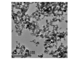
- FIG. 2 is a transmission electron micrograph of the ITO powder of Example 1.
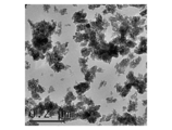
- 2 is a transmission electron micrograph of the ITO powder of Comparative Example 1.
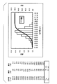
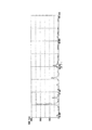
- 2 is an example of a particle size distribution of ITO powder of Example 1.
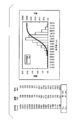
- FIG. 2 is an example of particle size distribution of ITO powder of Comparative Example 1.
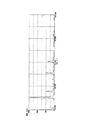
- 2 is an X-ray diffraction chart of ITO powder of Example 1.
- FIG. 6 is an enlarged view (X-ray diffraction chart) of the range of 20 ° to 40 ° of the X-ray diffraction chart (FIG. 5) of the ITO powder of Example 1.
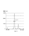
- 4 is an X-ray diffraction chart of ITO powder of Comparative Example 1.
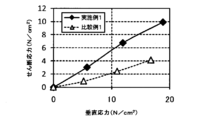
- FIG. 8 is an enlarged view (X-ray diffraction chart) of a range of 20 ° to 40 ° of the X-ray diffraction chart (FIG. 7) of the ITO powder of Comparative Example 1. It is a graph which shows the result of a shear stress.
- the ITO powder of this embodiment has a median diameter of particle size distribution of 30 nm to 45 nm and D 90 of 60 nm or less.
- the median diameter is preferably 30 nm to 40 nm.
- D 90 is preferably 45 nm to 60 nm.
- the median diameter and D 90 of the particle size distribution is within the above range, small particle size, and particle size distribution (as uniform particle size) is sharp, not aggregates almost nonexistent. For this reason, excellent dispersibility can be obtained. Thereby, the time when producing a dispersion liquid can be shortened.
- membrane produced using ITO powder has high intensity
- the median diameter is a particle diameter at which the cumulative value becomes 50% in the cumulative distribution of the particle size of the powder.
- D 90 is the particle size at which the cumulative value becomes 90% in the cumulative distribution of particle sizes.
- the particle size distribution of the ITO powder is measured by the following method. Using a paint shaker manufactured by Asada Iron Works, 60 g of ITO powder is dispersed in 60 cm 3 of water as a dispersion medium for 3 hours. Dilute the obtained dispersion 50 ⁇ 10 ⁇ 3 cm 3 into 50 cm 3 of water and measure the particle size distribution using a dynamic light scattering particle size distribution analyzer (model number: LB-550) manufactured by Horiba. To do. And from the obtained particle size distribution, to calculate a median diameter, and D 90.
- the shape of the ITO powder is preferably spherical or dice (cubic).
- 1 shows a transmission electron micrograph of the ITO powder of Example 1
- FIG. 2 shows a transmission electron micrograph of Comparative Example 1.
- the ITO powder of Example 1 has a small particle size, is uniform, and is dispersed independently.
- the ITO powder of Comparative Example 1 is agglomerated and the particle size is not uniform.
- 3 shows an example of the particle size distribution of the ITO powder of Example 1
- FIG. 4 shows an example of the particle size distribution of the ITO powder of Comparative Example 1.
- the line graph represents the integrated value (cumulative value) (%) on the right axis (cumulative distribution), and the bar graph represents the frequency (%) on the left axis (frequency distribution).
- the median size was 39 nm
- D 90 is 54 nm
- the median size was 65 nm
- D 90 is 87 nm.
- the ITO powder of the present embodiment has a small particle size and a sharp particle size distribution.
- FIG. 5 shows an X-ray diffraction chart of the ITO powder of Example 1
- FIG. 6 shows an enlarged view of the X-ray diffraction chart (FIG. 5) of the ITO powder of Example 1 in the range of 20 ° to 40 °.
- . 7 shows an X-ray diffraction chart of the ITO powder of Comparative Example 1
- FIG. 8 is an enlarged view of a range of 20 ° to 40 ° of the X-ray diffraction chart of the ITO powder of Comparative Example 1 (FIG. 7). Indicates. As shown in FIG.
- the half width of the diffraction peak of the (222) plane is smaller than 0.6 ° (specifically, 0.47 °).
- the relative intensity of the diffraction peak on the (222) plane is 2500 cps or less.
- the half width of the diffraction peak of the (222) plane is larger than 0.6 ° (specifically, 0.65 °).
- the half width of the diffraction peak of the (222) plane of the ITO powder of this embodiment is considerably smaller than that of the ITO powder of Comparative Example 1. Therefore, the ITO powder of this embodiment is a highly crystalline powder.
- the specific surface area is more preferably 60 m 2 / g to 85 m 2 / g, and most preferably 70 m 2 / g to 85 m 2 / g.
- the specific surface area is measured by the BET method.
- the L value is measured using, for example, an apparatus (SM-7-IS-2B) manufactured by Suga Test Instruments.
- the mass ratio [Sn / (Sn + In)] of the Sn content to the sum of the Sn and In contents in the ITO powder is preferably 1% to 20%, more preferably 5% to 20%. .
- the mass ratio of Sn content is less than 1%, conductivity and heat ray shielding tend to be inferior. Moreover, since the In component increases, the cost becomes high.
- the mass ratio of Sn content is more than 20%, there is a tendency to be inferior in conductivity and heat ray shielding properties as described above, which is not preferable.
- the method for producing indium tin oxide powder of this embodiment includes a step (A) of obtaining indium tin hydroxide by coprecipitation, and a step of drying and baking the indium tin hydroxide to obtain indium tin oxide. (B) and the step (C) of dry pulverizing the obtained indium tin oxide in a nitrogen atmosphere are provided in this order.
- a divalent tin compound is used, the pH is 4.0 to 9.3, and the coprecipitation is performed under the condition that the liquid temperature is 5 ° C. or higher.
- indium tin hydroxide having a color tone of bright yellow to amber color of persimmon (reddish brown or orange-red) is prepared by coprecipitation.
- a mixed aqueous solution containing indium ions and tin ions and an alkaline aqueous solution are mixed, and indium ions and tin ions in the mixture (reaction aqueous solution) are precipitated in the presence of alkali. Thereby, a coprecipitated hydroxide of indium and tin (indium tin hydroxide) is generated.
- a mixed aqueous solution containing indium ions and tin ions is prepared using a divalent tin compound (such as SnCl 2 ⁇ H 2 O).
- divalent tin compounds include stannous fluoride, stannous chloride, stannous borofluoride, stannous sulfate, stannous oxide, stannous nitrate, tin pyrophosphate, tin sulfamate, and tin.
- examples thereof include inorganic salts such as acid salts and organic salts such as stannous alkanol sulfonate, stannous sulfosuccinate and stannous aliphatic carboxylate.
- stannous chloride an excellent crystalline coprecipitate is obtained, which is preferable because it is easily industrialized.
- indium trichloride (SnCl 3 ) or indium nitrate can be used as a raw material for indium ions.
- indium nitrate and indium chloride are compared, a coprecipitated oxide having excellent crystallinity can be obtained by using indium chloride.
- the pH of the reaction aqueous solution (mixed aqueous solution containing indium ions and tin ions and the alkaline aqueous solution) is adjusted to 4.0 to 9.3, preferably pH 6.0 to 8.0, and the liquid temperature is adjusted. Adjust to 5 ° C or higher, preferably 10 ° C to 80 ° C.
- indium tin hydroxide having a color tone from a yellowish color to an amber color can be co-precipitated.
- Indium tin hydroxide having a yellowish to dark blue color tone in a dry powder state has a more uniform particle size and superior crystallinity than conventional white indium tin hydroxide. Are distributed independently.
- a tetravalent tin compound (SnCl 4 or the like) is used as a raw material for tin ions, a white precipitate (indium tin hydroxide) is generated, and in a dry powder state, a precipitate having a yellowish to amber color tone is formed. I can't get it.
- a pH of the reaction aqueous solution is lower than 4.0 (acidic side), or when the pH of the aqueous reaction solution is higher than 9.3 (alkali side)
- a pale yellowish white precipitate Indium tin hydroxide
- a precipitate having a yellowish to dark blue color tone cannot be obtained.
- the white precipitate from the tetravalent tin compound and the above-mentioned pale yellowish white precipitate are all non-uniform in particle size and low in crystallinity compared with the precipitate having a yellowish to dark blue color tone. , Not independently distributed. Even if these precipitates are baked, it is not possible to obtain an ITO powder having a uniform particle diameter, high crystallinity, and independently dispersed as in this embodiment.
- the tin tetrachloride since the tin tetrachloride is used, the precipitate of the white indium tin hydroxide has arisen, and the deposit which has the color tone of a deep-brown to amber color in the state of a dry powder is I can't get it.
- a mixed aqueous solution containing indium ions and tin ions and an aqueous alkaline solution are simultaneously dropped into water in the vessel. It is preferable.
- the mixed aqueous solution is preferably dropped into the alkaline aqueous solution.
- an ammonia (NH 3 ) aqueous solution an ammonium hydrogen carbonate (NH 4 HCO 3 ) aqueous solution, a KOH aqueous solution, an NaOH aqueous solution, or the like can be used.
- a mixed aqueous solution using tin dichloride as a divalent tin compound by preparing a mixed aqueous solution using tin dichloride as a divalent tin compound, adjusting the pH of the reaction aqueous solution to 7, and adjusting the liquid temperature to 10 ° C. to 60 ° C., a dry powder In this state, a precipitate having a yellowish to dark blue color tone is formed.
- the pH of the reaction aqueous solution is less than 4 (for example, pH 3) or when the pH of the reaction aqueous solution is more than 9.3 (for example, pH 9.5), a light yellowish white precipitate is generated.
- the mass ratio of the Sn content to the sum of the Sn and In contents [Sn / (Sn + In)] is preferably 1% to 20%, more preferably 5% to 20%. It is preferable to adjust the contents of Sn and In in the mixed aqueous solution so that the content of indium tin hydroxide to be generated is 0.01 to 25 parts by mass with respect to 100 parts by mass of the reaction aqueous solution. .
- the content of indium tin hydroxide produced is more preferably 0.1 to 25 parts by mass, and most preferably 1 to 25 parts by mass.
- the produced indium tin hydroxide coprecipitate is washed with pure water or ion-exchanged water.
- the supernatant is washed until the electrical resistivity becomes 5000 ⁇ ⁇ cm or more, preferably 50000 ⁇ ⁇ cm or more, and then solid-liquid separation is performed to recover the coprecipitate.
- the electrical resistivity of the supernatant is lower than 5000 ⁇ ⁇ cm, impurities such as chlorine are not sufficiently removed, and high-purity ITO powder cannot be obtained.
- L 60 to 75
- a ⁇ 2.5 to +1.5
- b + 22 to +32.
- [(B) step] In the step of drying the obtained indium tin hydroxide, for example, it is heated in the atmosphere at a temperature of 100 ° C. to 200 ° C. for 2 hours to 24 hours. Next, in the firing step, for example, heating is performed at a temperature of 250 ° C. or higher, preferably 400 ° C. to 800 ° C. for 1 hour to 6 hours. When the firing temperature is less than 250 ° C., the hydroxide remains or the hydroxide remains. By this firing step, the indium tin hydroxide becomes indium tin oxide (indium tin oxide, ITO) having a color tone of bright yellow to amber.
- ITO indium tin oxide
- ITO Indium tin oxide
- the ITO powder obtained by firing the white precipitate (indium tin hydroxide) in the atmosphere is olive-green, and its color tone is a ⁇ ⁇ in the Lab color system. 5.
- the calcined indium tin oxide is a fine powder having a specific surface area of 55 m 2 / g or more, preferably 60 m 2 / g or more.
- the specific surface area is, for example, 60 m 2 / g to 85 m 2 / g.
- the specific surface area of the ITO powder obtained by firing the white precipitate (indium tin hydroxide) in the air is, for example, 45 m 2 / g to 48 m 2 / g.
- the surface modification described above can be performed as follows, for example.
- the indium tin hydroxide obtained in the step (A) is not dried in the atmosphere, but in an atmosphere containing only nitrogen gas, or water vapor or alcohol. And heating at a temperature of 250 ° C. to 800 ° C. for 30 minutes to 6 hours in an atmosphere of nitrogen gas containing at least one selected from ammonia.
- drying and baking are simultaneously performed by the heat treatment for surface modification.
- surface modification is performed at a low temperature and then firing is performed, it is preferable to perform the firing in an inert atmosphere rather than in the air.
- the flow rate of the atmospheric gas (nitrogen gas or nitrogen gas containing one or more selected from water vapor, alcohol, and ammonia) in this surface modification step is linear velocity: 8 ⁇ 10 ⁇ 6 m / s or more 5 ⁇ 10 ⁇ 5 m / s to 10 m / s is more preferable, and 5 ⁇ 10 ⁇ 5 m / s to 1 m / s is most preferable.
- the ITO powder can be miniaturized, the specific surface area can be increased, and a particle size distribution with a uniform particle size (sharp particle size distribution) can be obtained.
- the outstanding electroconductivity is obtained.
- the flow rate of the atmospheric gas is desirably a linear velocity of 1 m / s or less.
- the flow rate of the atmospheric gas is set at a linear velocity: 0.00. A range of 01 m / s to 10 m / s is preferable.
- step (B) is performed as follows. First, indium tin hydroxide is dried in air at a temperature of 100 ° C. to 110 ° C. for 10 hours. Next, without firing in air, a temperature of 250 ° C. to 800 ° C. in an atmosphere of only nitrogen gas or in an atmosphere of nitrogen gas containing one or more selected from water vapor, alcohol, and ammonia For 30 minutes to 6 hours.
- step (B) is performed as follows. First, indium tin hydroxide is dried and fired in the air. Next, heating is performed at a temperature of 250 ° C. to 800 ° C. for 30 minutes to 6 hours in an atmosphere of only nitrogen gas or in an atmosphere of nitrogen gas containing one or more selected from water vapor, alcohol, and ammonia.
- the surface-modified indium tin oxide has a specific surface area according to the BET method of 40 m 2 / g, preferably 60 m 2 / g. Further, it is a deep blue color, and in the Lab color system, L ⁇ 30, a ⁇ 0, b ⁇ 0. By using indium tin oxide satisfying this range, it is possible to form a coating film excellent in transparency, conductivity and heat ray shielding.
- Step (C) The obtained indium tin oxide is dry-ground in a nitrogen atmosphere.
- the dry pulverization method is not particularly limited, and can be performed using an apparatus known to those skilled in the art, such as a hammer mill (for example, a hammer type fine pulverizer), a jet mill, a ball mill, a pin mill, and a mortar. This crushing step, the median diameter of particle size distribution of the ITO powder, and D 90 and can be adjusted to a desired value.
- the ITO powder of the present embodiment can be supplied in the form of a dispersion liquid, a paint, a paste, etc., which will be described later.
- the dispersion liquid of the present embodiment contains the ITO powder of the present embodiment and a solvent.
- the solvent include water, ethanol, methanol, isopropyl alcohol, toluene, methyl ethyl ketone, propylene glycol monomethyl ether and the like.
- the content of the ITO powder is 1% to 70%, preferably 10% to 50%, based on mass.
- the pH of the dispersion is 2 to 10, preferably 3 to 5.
- various conventional additives may be blended within a range that does not impair the purpose.
- additives include a dispersant, a dispersion aid, a polymerization inhibitor, a curing catalyst, an antioxidant, a leveling agent, and a film-forming resin.
- the paint (paste) of the present embodiment contains the dispersion liquid of the present embodiment and a resin. Since the ITO powder of the present embodiment is excellent in dispersibility, the dispersion energy can be reduced when the dispersion is made into a paint (coating).
- the resin include polyvinyl alcohol resin, vinyl chloride-vinyl acetate resin, acrylic resin, epoxy resin, urethane resin, alkyd resin, polyester resin, ethylene vinyl acetate copolymer, acrylic-styrene copolymer, fiber base resin, phenol Examples thereof include natural resins such as resin, amino resin, fluororesin, silicone resin, petroleum resin, shellac, rosin derivative, and rubber derivative.
- the blending amount of the ITO powder into the resin is 0.1 to 950 parts by mass, preferably 0.7 to 800 parts by mass with respect to 100 parts by mass of the resin.
- the content of the ITO powder is appropriately adjusted depending on the electrical resistivity and film thickness required for the film formed using the paint.
- the functional thin film of this embodiment contains the ITO powder of this embodiment.
- the functional thin film is formed by applying the dispersion or paint of the present embodiment to a substrate or the like.
- the substrate include substrates widely used in various fields such as electrical / electronic devices.
- Specific examples include substrates made of various synthetic resins, glass, ceramics, and the like.
- the shape of the substrate is not particularly limited, and may be any shape such as a sheet shape, a film shape, or a plate shape.
- Specific examples of the synthetic resin include, but are not limited to, polyethylene, polypropylene, polycarbonate, polyethylene terephthalate (PET) resin, acrylic resin, methacrylic resin, polyvinyl chloride, polyester resin, polyamide resin, and phenol resin. .
- Dispersion and paint are applied to the substrate by conventional methods.
- the coating method include roll coating, spin coating, screen printing, and coating using an instrument such as an applicator.
- the coating film is heated as necessary, the solvent (solvent) is evaporated, and the coating film is dried and cured.
- the solvent solvent
- UV rays may be irradiated.
- the thickness of the functional thin film is 0.1 ⁇ m or more from the viewpoint of transparency, conductivity, and infrared shielding properties. 5 ⁇ m is preferable, and 0.5 ⁇ m to 2 ⁇ m is more preferable.
- the thickness is not limited.
- the functional thin film of this embodiment is excellent in transparency, conductivity, and infrared shielding properties, and can be used as a conductive film or a heat ray shielding film. Specifically, it is widely applied to various types of window glass for vehicles such as displays, touch panels and automobiles, window glass for building materials, various types of glass for medical devices, and transparent parts such as general packaging or showcases. it can.
- the particle size distribution was measured by the following method.
- ITO powder 60 g was dispersed in water: 60 cm 3 as a dispersion medium for 3 hours using a paint shaker manufactured by Asada Iron Works.
- the obtained dispersion 50 ⁇ 10 ⁇ 3 cm 3 was diluted with 50 cm 3 of water, and the particle size distribution was measured under the following conditions using a dynamic light scattering particle size distribution analyzer (model number: LB-550) manufactured by Horiba. Distribution was measured. (Measurement condition)
- Data acquisition frequency 100 times
- repetition frequency 50 times
- particle diameter standard volume standard
- measurement temperature 24.5 ° C. to 25.5 ° C.
- the median diameter 50% cumulative particle diameter
- D 90 90% cumulative particle diameter
- Example 1 Indium chloride (InCl 3 ) aqueous solution (In content 18 g): 50 cm 3 and tin dichloride (SnCl 2 .2H 2 O): 3.6 g were mixed to prepare a mixed aqueous solution. Further, to produce ammonia (NH 3) solution as an alkaline aqueous solution. A mixed aqueous solution and an aqueous ammonia (NH 3 ) solution were simultaneously dropped into a container containing 500 cm 3 of water. The addition amount of the alkaline aqueous solution was adjusted, the pH of the mixture (reaction aqueous solution) in the container was adjusted to 7, and the liquid temperature was adjusted to 30 ° C. to react for 30 minutes.
- the produced precipitate was repeatedly washed with ion-exchanged water by tilting. Specifically, in the slant washing, the supernatant was discarded, and then, ion exchange water was newly added, mixed and allowed to stand, and the precipitate was washed. When the electrical resistivity of the supernatant liquid reached 50000 ⁇ ⁇ cm or more, the precipitate (In / Sn coprecipitated hydroxide) was separated by filtration to obtain coprecipitated indium tin hydroxide. The coprecipitated indium tin hydroxide was found to be a color of persimmon (reddish brown or orange-red) in the dry powder state.
- the solid-liquid separated indium tin hydroxide was dried at 110 ° C. overnight and then calcined in the atmosphere at 550 ° C. for 3 hours.
- the aggregates in the obtained fired product were pulverized and loosened to obtain bright yellow ITO powder: about 25 g.
- Table 1 shows the Lab value and specific surface area of the ITO powder.
- Example 1 25 g of the ITO powder was put in a glass petri dish and heated at 330 ° C. for 2 hours in a nitrogen gas atmosphere containing ethanol and water vapor to perform surface modification treatment.
- Table 1 shows the color tone (L, a, b) and BET value of the surface-modified ITO powder. Further, dry pulverization treatment was performed on the surface-modified ITO powder using an agate mortar in a nitrogen atmosphere booth. In addition, 20 lots of ITO powder obtained in Example 1 were produced and mixed uniformly. Next, a surface modification treatment was performed in the same manner as described above.
- the dispersion powder was prepared by dispersing 50 g of ITO powder subjected to the surface modification treatment and the dry pulverization treatment in 50 g of water. This dispersion aqueous solution was diluted with ethanol to obtain a dispersion having an ITO powder concentration of 10%. This ITO dispersion was applied to a glass plate by spin coating at 150 revolutions to form a film (ITO concentration 10%). Further, a silica sol-gel solution (silica: 1%) was applied onto the dispersion coating film by spin coating at 150 rotations to form a film. Next, the glass plate on which the coating film was formed was baked at 160 ° C. for 30 minutes to form a coating film (film thickness 0.2 ⁇ m).
- the dispersion residence time during the preparation of the dispersion was calculated from the following equation.
- the relative values when the dispersion residence time of Comparative Example 1 is 100 are shown in Table 3.
- (Dispersion residence time) (dispersion time) / ⁇ (volume of dispersion) / (effective volume of mill) ⁇
- the unit of “dispersion time” uses the same unit (for example, “cm 3 ”) for “time”, “volume of dispersion”, and “effective volume of mill”.
- the total light transmittance and surface resistivity of the glass plate on which the film was formed were measured. The results are shown in Table 3.
- the surface resistivity was measured by Resta AP (MCP-T400) manufactured by Mitsubishi Chemical.
- the total light transmittance was measured in the visible light region of 400 nm to 750 nm using a device (HGM-3D) manufactured by Suga Test Instruments in accordance with the standard (JIS K7150).
- the measured value of the total light transmittance includes the transmittance of the glass plate (the transmittance of the glass plate is 89.0%, the thickness is 1 mm), and is the value at the thickness of the coating film of 0.2 ⁇ m.
- Table 3 also shows a value ( ⁇ transmittance) obtained by subtracting the transmittance (89.0%) of the glass plate from the measured value of the total light transmittance.
- the visible light transmittance (% Tv), solar radiation transmittance (% Ts), and haze of the dispersion of ITO powder shown in Table 3 were measured. The measurement method is shown below.
- the prepared dispersion was diluted with triethylene glycol-di-2-ethylhexanoate to prepare a diluted solution (sample for measuring spectral characteristics) having an ITO powder content of 0.7% by mass.
- This diluted solution is placed in a glass cell having an optical path length of 1 mm, and a visible light transmittance (% Tv) of 380 nm to 780 nm is used according to a standard (JIS R 3216-1998) using a self-recording spectrophotometer (U-4000 manufactured by Hitachi, Ltd.) ) And solar transmittance (% Ts) from 300 nm to 2100 nm. Table 3 shows these results.
- aqueous SnCl 4 solution having a concentration of 55% was prepared using tin tetrachloride as the tin compound.
- This SnCl 4 aqueous solution: 14.4 g and indium chloride (InCl 3 ) aqueous solution (containing 35 g of In metal): 90 cm 3 were mixed to prepare a mixed aqueous solution.
- an aqueous alkaline solution containing 0.6 g of ammonium bicarbonate (NH 4 HCO 3 ): 190 g: 0.6 dm 3 was added to obtain a mixture (reaction aqueous solution).
- the pH of the aqueous reaction solution was adjusted to 8, and the temperature of the solution was adjusted to 30 ° C. to react for 30 minutes.
- the produced precipitate was repeatedly washed with ion-exchange water.
- the electrical resistivity of the supernatant liquid was 50000 ⁇ ⁇ cm or more
- the coprecipitated indium tin hydroxide was filtered off.
- the coprecipitated indium tin hydroxide was white.
- the coprecipitated indium tin hydroxide was dried at 110 ° C. overnight and then calcined at 550 ° C. for 3 hours in air. Aggregates in the obtained fired product were pulverized and loosened to obtain ITO powder: about 44 g.
- 25 g of the above ITO powder was put in a glass petri dish, and surface-modified by heating at 330 ° C. for 2 hours in a nitrogen gas atmosphere containing ethanol and water vapor.
- Table 2 shows the color tone (Lab value (L, a, b)) and specific surface area (BET value) of the surface-modified ITO powder.
- the surface-modified ITO powder was dry pulverized in an air atmosphere. Conductivity evaluation, heat ray cut evaluation, haze measurement, and the like were performed on the ITO powder subjected to the surface modification treatment and the dry pulverization treatment. Table 3 shows these results.
- Comparative Example 2 An ITO powder was prepared in the same manner as in Comparative Example 1 except that the powder was dry-ground in a nitrogen atmosphere instead of in the air, and conductivity evaluation, heat ray cut evaluation, and the like were performed. Tables 2 and 4 show these results.
- Examples 2 to 5 Comparative Examples 3 to 6
- An ITO powder was produced in the same manner as in Example 1 except that the conditions described in Table 1 were applied, and conductivity evaluation, heat ray cut evaluation, and the like were performed. Tables 1 to 4 show these results.
- the shear stress of the ITO powders of Example 1 and Comparative Example 1 was measured using a powder layer shear force measuring device NS-S500 manufactured by Nano Seeds.
- the height of the cell used for the high load shear test was 30 mm, and the measurement was carried out by applying a force of 50 N, 100 N, and 150 N with a vertical load.
- the indentation speed into the cell was 0.2 mm / second, the indentation gap was 0.05 mm, and the side sliding speed was 10 ⁇ m / second.
- Table 5 and FIG. 9 show the results.
- Example 1 increases the shearing force as the normal stress increases, so that the internal friction angle also increases and the powder adhesion increases. I understood it. Therefore, it was found that when the ITO powder of the present embodiment was made into a film, the powder was excellent in adhesiveness, so that the film strength was high and the moldability was also excellent.
- the ITO powder of this embodiment has a small particle size and good dispersibility. That is, in this embodiment, it is possible to provide an ITO powder having a short time for producing a dispersion. Furthermore, it was found that a film using this ITO powder has high strength, and is excellent in transparency and conductivity.
- the ITO powder of the present embodiment has a small particle size, a sharp particle size distribution, and high crystallinity. For this reason, by using the ITO powder of this embodiment, it is possible to form a conductive film having a very high film strength and a remarkably good conductivity and heat ray shielding performance. For this reason, it can apply suitably to the manufacturing process of functional materials, such as a transparent conductive film and a heat ray shielding film.
Abstract
Description
本願は、2010年10月26日に、日本に出願された特願2010-239442号に基づき優先権を主張し、その内容をここに援用する。 The present invention relates to indium tin oxide powder (hereinafter referred to as “ITO powder”) and a method for producing the same. More specifically, the present invention relates to a fine ITO powder, a method for producing the same, a dispersion containing the ITO powder, a paint, and a functional thin film (conductive film, heat ray shielding film).
This application claims priority based on Japanese Patent Application No. 2010-239442 filed in Japan on October 26, 2010, the contents of which are incorporated herein by reference.
本発明の態様の要件を以下に示す。
〔1〕粒度分布のメジアン径が30nm~45nmであり、D90が60nm以下であることを特徴とするインジウム錫酸化物粉末。
〔2〕比表面積が40m2/g以上であり、かつLab表色系においてL=30以下の濃青色の色調を有する上記〔1〕に記載のインジウム錫酸化物粉末。
〔3〕上記〔1〕または〔2〕に記載のインジウム錫酸化物粉末と、溶媒を含有することを特徴とする分散液。
〔4〕上記〔1〕または〔2〕に記載のインジウム錫酸化物粉末と、溶媒と、樹脂を含有することを特徴とする塗料。
〔5〕上記〔1〕または〔2〕に記載のインジウム錫酸化物粉末を含有することを特徴とする機能性薄膜。
〔6〕導電性膜または熱線遮蔽用膜として用いられる上記〔5〕に記載の機能性薄膜。
〔7〕2価の錫化合物を用い、pHが4.0~9.3であり、液温が5℃以上である条件により、乾燥粉末の状態では色が山吹色から柿色の色調を有するインジウム錫水酸化物を共沈させる工程(A)と、前記インジウム錫水酸化物を乾燥し、焼成してインジウム錫酸化物を得る工程(B)と、得られた前記インジウム錫酸化物を窒素雰囲気中で乾式粉砕する工程(C)をこの順で具備することを特徴とするインジウム錫酸化物粉末の製造方法。
〔8〕前記工程(A)において、三塩化インジウムと二塩化錫の混合水溶液と、アルカリ水溶液とを同時に水に滴下することによって、前記インジウム錫水酸化物を共沈させるか、または、アルカリ水溶液に前記混合水溶液を滴下することによって、前記インジウム錫水酸化物を共沈させる上記〔7〕に記載のインジウム錫酸化物粉末の製造方法。
〔9〕前記工程(B)において、乾燥と同時、焼成と同時、または焼成後に、窒素ガスのみの雰囲気下、または水蒸気、アルコール、及びアンモニアから選択される1種以上を含有する窒素ガスの雰囲気下で、前記インジウム錫水酸化物又は前記インジウム錫酸化物を加熱し、これによって、表面改質し、比表面積が40m2/g以上であり、かつ濃青色の色調を有するインジウム錫酸化物粉末を製造する上記〔7〕又は〔8〕に記載のインジウム錫酸化物粉末の製造方法。
〔10〕前記窒素ガスのみの雰囲気、または水蒸気、アルコール、及びアンモニアから選択される1種以上を含有する前記窒素ガスの雰囲気に供給される雰囲気ガスの流量を、線速度8×10⁻⁶m/s以上に調整して、前記インジウム錫酸化物粉末を表面改質する上記〔9〕に記載のインジウム錫酸化物粉末の製造方法。 The inventors of the present invention have solved the above-mentioned problems by improving the production method of ITO powder and completed the present invention.
The requirements of the embodiments of the present invention are shown below.
[1] The median diameter of the particle size distribution is 30 nm ~ 45 nm, indium tin oxide powder, wherein the D 90 of at 60nm or less.
[2] The indium tin oxide powder according to the above [1], having a specific surface area of 40 m 2 / g or more and having a dark blue color tone of L = 30 or less in the Lab color system.
[3] A dispersion containing the indium tin oxide powder according to the above [1] or [2] and a solvent.
[4] A paint comprising the indium tin oxide powder according to the above [1] or [2], a solvent, and a resin.
[5] A functional thin film comprising the indium tin oxide powder according to [1] or [2].
[6] The functional thin film according to [5], which is used as a conductive film or a heat ray shielding film.
[7] Indium having a color tone ranging from a deep yellow to an amber color in a dry powder state under the condition that a divalent tin compound is used, the pH is 4.0 to 9.3, and the liquid temperature is 5 ° C. or higher. A step (A) of coprecipitation of tin hydroxide, a step (B) of drying and baking the indium tin hydroxide to obtain indium tin oxide, and the obtained indium tin oxide in a nitrogen atmosphere. A method for producing an indium tin oxide powder comprising the step (C) of dry pulverization in this order.
[8] In the step (A), the mixed solution of indium trichloride and tin dichloride and the alkaline aqueous solution are simultaneously dropped into water to coprecipitate the indium tin hydroxide, or the alkaline aqueous solution The method for producing an indium tin oxide powder according to the above [7], wherein the indium tin hydroxide is coprecipitated by dropping the mixed aqueous solution into the mixture.
[9] In the step (B), simultaneously with drying, simultaneously with baking, or after baking, in an atmosphere of only nitrogen gas, or an atmosphere of nitrogen gas containing one or more selected from water vapor, alcohol, and ammonia The indium tin hydroxide or the indium tin oxide is heated under the surface to thereby modify the surface thereof, the specific surface area is 40 m 2 / g or more, and the indium tin oxide powder has a dark blue color tone The method for producing an indium tin oxide powder according to the above [7] or [8].
[10] The flow rate of the atmosphere gas supplied to the atmosphere of only the nitrogen gas or the atmosphere of the nitrogen gas containing one or more selected from water vapor, alcohol, and ammonia is a linear velocity of 8 × 10 −6 m. The method for producing indium tin oxide powder according to [9] above, wherein the surface of the indium tin oxide powder is modified by adjusting to / s or more.
また、ITO粉末は還元されるとL値が低くなるため、ITO粉末の光の吸収率が大きくなり、赤外線吸収能力が向上する。本発明の上記〔2〕の態様によれば、より導電性に優れ、かつ熱線遮蔽性に優れる透明導電膜を容易に形成できる。 According to the aspect [1] of the present invention, the particle size is small, the particle size distribution is sharp, and the dispersibility is good. For this reason, time when producing a dispersion liquid can be shortened, and the fall of the crystallinity of ITO powder can be suppressed in a dispersion | distribution process. Further, by using this ITO powder, a functional thin film having high strength and excellent transparency and conductivity can be produced.
Further, when the ITO powder is reduced, the L value decreases, so that the light absorption rate of the ITO powder increases and the infrared absorption ability improves. According to the above aspect [2] of the present invention, it is possible to easily form a transparent conductive film that is more excellent in conductivity and excellent in heat ray shielding properties.
本実施形態のITO粉末は、粒度分布のメジアン径が30nm~45nmであり、D90が60nm以下である。メジアン径は、好ましくは、30nm~40nmである。D90は、好ましくは、45nm~60nmである。
粒度分布のメジアン径及びD90が上記の範囲内であると、粒子径が小さく、かつ粒度分布がシャープであり(粒度が揃っている)、凝集体がほとんど存在しない。このため、優れた分散性が得られる。これにより、分散液を作製するときの時間を短くすることができる。さらにITO粉末を用いて作製された膜は、強度が高く、透明性、導電性に優れる。
ここで、メジアン径は、粉末の粒度の累積分布において、累積値が50%となる粒子径である。D90は、粒度の累積分布において、累積値が90%となる粒子径である。ITO粉末の粒度分布は、以下の方法により測定される。浅田鉄工製のペイントシェーカーを用いて、ITO粉末:60gを、分散媒としての水:60cm3に3時間分散させる。得られた分散液50×10-3cm3を50cm3の水に希釈し、堀場製作所製の動的光散乱式粒径分布測定装置(型番:LB-550)を用いて、粒度分布を測定する。そして得られた粒度分布より、メジアン径、およびD90を算出する。
ITO粉末の形状は、球状又はサイコロ(立方体)状が好ましい。図1は、実施例1のITO粉末の透過型電子顕微鏡写真を示し、図2は、比較例1の透過型電子顕微鏡写真を示す。図1からわかるように、実施例1のITO粉末は、粒径が小さく、かつ均一で、独立分散していることがわかる。これに対して、比較例1のITO粉末は、凝集しており、粒径が不均一である。
図3は、実施例1のITO粉末の粒度分布の一例を示し、図4は、比較例1のITO粉末の粒度分布の一例を示す。図3,4において、線グラフは、右軸の積算値(累計値)(%)を表し(累積分布)、棒グラフは、左軸の頻度(%)を表す(頻度分布)。図3では、メジアン径は39nm、D90は54nmであり、図4では、メジアン径は65nm、D90は87nmである。このように、本実施形態のITO粉末は、粒子径が小さく、粒度分布がシャープである。 [Indium tin oxide powder]
The ITO powder of this embodiment has a median diameter of particle size distribution of 30 nm to 45 nm and D 90 of 60 nm or less. The median diameter is preferably 30 nm to 40 nm. D 90 is preferably 45 nm to 60 nm.
When the median diameter and D 90 of the particle size distribution is within the above range, small particle size, and particle size distribution (as uniform particle size) is sharp, not aggregates almost nonexistent. For this reason, excellent dispersibility can be obtained. Thereby, the time when producing a dispersion liquid can be shortened. Furthermore, the film | membrane produced using ITO powder has high intensity | strength, and is excellent in transparency and electroconductivity.
Here, the median diameter is a particle diameter at which the cumulative value becomes 50% in the cumulative distribution of the particle size of the powder. D 90 is the particle size at which the cumulative value becomes 90% in the cumulative distribution of particle sizes. The particle size distribution of the ITO powder is measured by the following method. Using a paint shaker manufactured by Asada Iron Works, 60 g of ITO powder is dispersed in 60 cm 3 of water as a dispersion medium for 3 hours. Dilute the obtained dispersion 50 × 10 −3 cm 3 into 50 cm 3 of water and measure the particle size distribution using a dynamic light scattering particle size distribution analyzer (model number: LB-550) manufactured by Horiba. To do. And from the obtained particle size distribution, to calculate a median diameter, and D 90.
The shape of the ITO powder is preferably spherical or dice (cubic). 1 shows a transmission electron micrograph of the ITO powder of Example 1, and FIG. 2 shows a transmission electron micrograph of Comparative Example 1. As can be seen from FIG. 1, the ITO powder of Example 1 has a small particle size, is uniform, and is dispersed independently. On the other hand, the ITO powder of Comparative Example 1 is agglomerated and the particle size is not uniform.
3 shows an example of the particle size distribution of the ITO powder of Example 1, and FIG. 4 shows an example of the particle size distribution of the ITO powder of Comparative Example 1. 3 and 4, the line graph represents the integrated value (cumulative value) (%) on the right axis (cumulative distribution), and the bar graph represents the frequency (%) on the left axis (frequency distribution). In Figure 3, the median size was 39 nm, D 90 is 54 nm, in FIG. 4, the median size was 65 nm, D 90 is 87 nm. Thus, the ITO powder of the present embodiment has a small particle size and a sharp particle size distribution.
この物性値を満たすITO粉末を用いると、導電性および熱線遮蔽性に優れた膜を作製できる。
ここで、比表面積は、BET法で測定される。L値は、例えば、スガ試験機社製装置(SM-7-IS-2B)を用いて測定される。 The ITO powder preferably has a specific surface area of 40 m 2 / g or more and a navy blue color tone of L = 30 or less in the Lab color system. The specific surface area is more preferably 60 m 2 / g to 85 m 2 / g, and most preferably 70 m 2 / g to 85 m 2 / g.
When ITO powder satisfying these physical property values is used, a film excellent in conductivity and heat ray shielding properties can be produced.
Here, the specific surface area is measured by the BET method. The L value is measured using, for example, an apparatus (SM-7-IS-2B) manufactured by Suga Test Instruments.
本実施形態のインジウム錫酸化物粉末の製造方法は、共沈によりインジウム錫水酸化物を得る工程(A)と、前記インジウム錫水酸化物を乾燥し、焼成してインジウム錫酸化物を得る工程(B)と、得られたインジウム錫酸化物を窒素雰囲気中で乾式粉砕をする工程(C)をこの順で具備する。詳細には、工程(A)では、2価の錫化合物を用い、pHが4.0~9.3であり、液温が5℃以上である条件で共沈を行う。そして、乾燥粉末の状態では色が山吹色(bright yellow)から柿色(color of persimmon (reddish brown or orange-red))の色調を有するインジウム錫水酸化物を共沈により作製する。 [Method for producing indium tin oxide powder]
The method for producing indium tin oxide powder of this embodiment includes a step (A) of obtaining indium tin hydroxide by coprecipitation, and a step of drying and baking the indium tin hydroxide to obtain indium tin oxide. (B) and the step (C) of dry pulverizing the obtained indium tin oxide in a nitrogen atmosphere are provided in this order. Specifically, in the step (A), a divalent tin compound is used, the pH is 4.0 to 9.3, and the coprecipitation is performed under the condition that the liquid temperature is 5 ° C. or higher. Then, in the dry powder state, indium tin hydroxide having a color tone of bright yellow to amber (color of persimmon (reddish brown or orange-red)) is prepared by coprecipitation.
インジウムイオンと錫イオンを含む混合水溶液と、アルカリ水溶液とを混合し、混合物(反応水溶液)中のインジウムイオンと錫イオンをアルカリの存在下で沈殿させる。これにより、インジウムと錫の共沈水酸化物(インジウム錫水酸化物)が生成する。
インジウムイオンと錫イオンを含む混合水溶液は、2価の錫化合物(SnCl2・H2Oなど)を用いて作製される。
2価の錫化合物としては、フッ化第一錫、塩化第一錫、ホウフッ化第一錫、硫酸第一錫、酸化第一錫、硝酸第一錫、ピロリン酸錫、スルファミン酸錫、亜錫酸塩などの無機系の塩、及びアルカノールスルホン酸第一錫、スルホコハク酸第一錫、脂肪族カルボン酸第一錫などの有機系の塩などが挙げられる。これらのうち、塩化第一錫を用いた場合、優れた結晶性の共沈物が得られ、工業化し易いので、好ましい。
インジウムイオンの原料としては、三塩化インジウム(SnCl3)、硝酸インジウムを用いることができる。硝酸インジウムと塩化インジウムを比較すると、塩化インジウムを用いた方が、優れた結晶性を有する共沈酸化物が得られる。
反応水溶液(インジウムイオンと錫イオンを含む混合水溶液と、アルカリ水溶液との混合溶液)のpHを4.0~9.3、好ましくは、pH6.0~8.0に調整し、かつ液温を5℃以上、好ましくは10℃~80℃に調整する。これによって、乾燥粉末の状態では色が山吹色から柿色の色調を有するインジウム錫水酸化物を共沈させることができる。乾燥粉末の状態では山吹色から柿色の色調を有するインジウム錫水酸化物は、従来の白色のインジウム錫水酸化物よりも、粒子径が均一であり、かつ結晶性に優れており、個々の粒子が独立に分散している。 [(A) Process]
A mixed aqueous solution containing indium ions and tin ions and an alkaline aqueous solution are mixed, and indium ions and tin ions in the mixture (reaction aqueous solution) are precipitated in the presence of alkali. Thereby, a coprecipitated hydroxide of indium and tin (indium tin hydroxide) is generated.
A mixed aqueous solution containing indium ions and tin ions is prepared using a divalent tin compound (such as SnCl 2 · H 2 O).
Examples of divalent tin compounds include stannous fluoride, stannous chloride, stannous borofluoride, stannous sulfate, stannous oxide, stannous nitrate, tin pyrophosphate, tin sulfamate, and tin. Examples thereof include inorganic salts such as acid salts and organic salts such as stannous alkanol sulfonate, stannous sulfosuccinate and stannous aliphatic carboxylate. Of these, when stannous chloride is used, an excellent crystalline coprecipitate is obtained, which is preferable because it is easily industrialized.
As a raw material for indium ions, indium trichloride (SnCl 3 ) or indium nitrate can be used. When indium nitrate and indium chloride are compared, a coprecipitated oxide having excellent crystallinity can be obtained by using indium chloride.
The pH of the reaction aqueous solution (mixed aqueous solution containing indium ions and tin ions and the alkaline aqueous solution) is adjusted to 4.0 to 9.3, preferably pH 6.0 to 8.0, and the liquid temperature is adjusted. Adjust to 5 ° C or higher, preferably 10 ° C to 80 ° C. Thereby, in the state of dry powder, indium tin hydroxide having a color tone from a yellowish color to an amber color can be co-precipitated. Indium tin hydroxide having a yellowish to dark blue color tone in a dry powder state has a more uniform particle size and superior crystallinity than conventional white indium tin hydroxide. Are distributed independently.
一方、反応水溶液のpHが4未満(例えば、pH3)の場合や、反応水溶液のpHが9.3超(例えば、pH9.5)の場合では、薄い黄色を帯びた白色の沈澱物が生じる。
従って、乾燥粉末の状態では山吹色から柿色の色調を有するインジウム錫水酸化物の共沈澱物を生成させるには、反応水溶液のpHを4.0~9.3の範囲に調整する必要がある。なお、pHが中性に近いほど、沈澱物は、乾燥粉末の状態での色調が柿色になる傾向がある。また、pHが4.0~9.3の範囲(例えば、pH8)であっても、四塩化錫を用いると白色の沈殿物が生じる。 Specifically, for example, by preparing a mixed aqueous solution using tin dichloride as a divalent tin compound, adjusting the pH of the reaction aqueous solution to 7, and adjusting the liquid temperature to 10 ° C. to 60 ° C., a dry powder In this state, a precipitate having a yellowish to dark blue color tone is formed.
On the other hand, when the pH of the reaction aqueous solution is less than 4 (for example, pH 3) or when the pH of the reaction aqueous solution is more than 9.3 (for example, pH 9.5), a light yellowish white precipitate is generated.
Therefore, in order to produce a coprecipitate of indium tin hydroxide having a yellowish to dark blue color tone in the dry powder state, it is necessary to adjust the pH of the reaction aqueous solution to a range of 4.0 to 9.3. . In addition, there exists a tendency for the color tone in the state of a dry powder to become darker, so that pH is near neutrality. Even when the pH is in the range of 4.0 to 9.3 (for example, pH 8), a white precipitate is formed when tin tetrachloride is used.
反応水溶液100質量部に対して、生成するインジウム錫水酸化物の含有量が0.01質量部~25質量部となるように、混合水溶液中のSn及びInの含有量を調整することが好ましい。生成するインジウム錫水酸化物の含有量は、より好ましくは0.1質量部~25質量部であり、最も好ましくは1質量部~25質量部である。生成するインジウム錫水酸化物の含有量が少なく、反応水溶液の量が多いほど、微細なITO粉末を製造しやすいが、生産性に劣る。生成するインジウム錫水酸化物の含有量が25質量部を超えると、反応中にインジウム錫水酸化物の凝集が生じ、粗大な粒子となる。またスラリーの粘度が高く、生産性に劣る。 In the mixed aqueous solution containing indium ions and tin ions, the mass ratio of the Sn content to the sum of the Sn and In contents [Sn / (Sn + In)] is preferably 1% to 20%, more preferably 5% to 20%.
It is preferable to adjust the contents of Sn and In in the mixed aqueous solution so that the content of indium tin hydroxide to be generated is 0.01 to 25 parts by mass with respect to 100 parts by mass of the reaction aqueous solution. . The content of indium tin hydroxide produced is more preferably 0.1 to 25 parts by mass, and most preferably 1 to 25 parts by mass. The smaller the content of indium tin hydroxide produced and the greater the amount of aqueous reaction solution, the easier it is to produce fine ITO powder, but the productivity is inferior. When the content of indium tin hydroxide to be generated exceeds 25 parts by mass, indium tin hydroxide aggregates during the reaction, resulting in coarse particles. Moreover, the viscosity of a slurry is high and it is inferior to productivity.
得られたインジウム錫水酸化物を乾燥する工程では、例えば、大気中、100℃~200℃の温度で、2時間~24時間加熱する。次いで焼成する工程では、例えば、250℃以上、好ましくは400℃~800℃の温度で、1時間~6時間加熱する。焼成の温度が250℃未満の場合、水酸化物のままであるか、または水酸化物が残留する。この焼成工程によってインジウム錫水酸化物が、山吹色から柿色の色調を有するインジウム酸化錫(インジウム錫酸化物,ITO)になる。 [(B) step]
In the step of drying the obtained indium tin hydroxide, for example, it is heated in the atmosphere at a temperature of 100 ° C. to 200 ° C. for 2 hours to 24 hours. Next, in the firing step, for example, heating is performed at a temperature of 250 ° C. or higher, preferably 400 ° C. to 800 ° C. for 1 hour to 6 hours. When the firing temperature is less than 250 ° C., the hydroxide remains or the hydroxide remains. By this firing step, the indium tin hydroxide becomes indium tin oxide (indium tin oxide, ITO) having a color tone of bright yellow to amber.
なお、白色沈殿物(インジウム錫水酸化物)を大気雰囲気中で焼成して得られたITO粉末は、鴬色(olive-green)であり、その色調は、Lab表色系において、a≦-5である。 Indium tin oxide (ITO) baked in the air has a color from yellow to dark blue, and in the Lab color system, L ≦ 80, a = −10 to +10, b ≧ + 26. L = 56 to 67, a = −1.2 to +1.2, and b = + 29 to +31.
The ITO powder obtained by firing the white precipitate (indium tin hydroxide) in the atmosphere is olive-green, and its color tone is a ≦ − in the Lab color system. 5.
この表面改質の工程での雰囲気ガス(窒素ガス、または水蒸気、アルコール、及びアンモニアから選択される1種以上を含有する窒素ガス)の流量は、線速度:8×10⁻⁶m/s以上が好ましく、5×10-5m/s~10m/sがより好ましく、5×10-5m/s~1m/sが最も好ましい。これにより、ITO粉末を微細化でき、比表面積を大きくできると共に、粒度の揃った粒度分布(シャープな粒度分布)が得られる。また優れた導電性が得られる。粉体を容器にのせて、窒素化処理(表面改質)する場合は、雰囲気ガスの流量が大きすぎると、粉体が飛散してしまう。このため、雰囲気ガスの流量は、線速度:1m/s以下が望ましい。振動や雰囲気ガスの流れによって、加熱炉内のインジウム錫水酸化物を流動させて流動層を形成し、窒素化処理(表面改質)する場合は、雰囲気ガスの流量は、線速度:0.01m/s~10m/sが好ましい。 The surface modification described above can be performed as follows, for example. When surface modification is performed simultaneously with drying, for example, the indium tin hydroxide obtained in the step (A) is not dried in the atmosphere, but in an atmosphere containing only nitrogen gas, or water vapor or alcohol. And heating at a temperature of 250 ° C. to 800 ° C. for 30 minutes to 6 hours in an atmosphere of nitrogen gas containing at least one selected from ammonia. In this case, drying and baking are simultaneously performed by the heat treatment for surface modification. In addition, when surface modification is performed at a low temperature and then firing is performed, it is preferable to perform the firing in an inert atmosphere rather than in the air.
The flow rate of the atmospheric gas (nitrogen gas or nitrogen gas containing one or more selected from water vapor, alcohol, and ammonia) in this surface modification step is linear velocity: 8 × 10 −6 m / s or more 5 × 10 −5 m / s to 10 m / s is more preferable, and 5 × 10 −5 m / s to 1 m / s is most preferable. Thereby, the ITO powder can be miniaturized, the specific surface area can be increased, and a particle size distribution with a uniform particle size (sharp particle size distribution) can be obtained. Moreover, the outstanding electroconductivity is obtained. When the powder is placed in a container and subjected to nitrogenation treatment (surface modification), if the flow rate of the atmospheric gas is too large, the powder will be scattered. For this reason, the flow rate of the atmospheric gas is desirably a linear velocity of 1 m / s or less. When indium tin hydroxide in the heating furnace is caused to flow by vibration or the flow of the atmospheric gas to form a fluidized bed, and the nitrogen treatment (surface modification) is performed, the flow rate of the atmospheric gas is set at a linear velocity: 0.00. A range of 01 m / s to 10 m / s is preferable.
得られたインジウム錫酸化物を窒素雰囲気中で乾式粉砕する。乾式粉砕の方法は、特に限定されず、ハンマーミル(例えば、ハンマー式微粉砕機)、ジェットミル、ボールミル、ピンミル、乳鉢などの当業者に公知の装置を用いて行うことができる。この粉砕工程により、ITO粉末の粒度分布のメジアン径、およびD90を所望の値に調整できる。 [Step (C)]
The obtained indium tin oxide is dry-ground in a nitrogen atmosphere. The dry pulverization method is not particularly limited, and can be performed using an apparatus known to those skilled in the art, such as a hammer mill (for example, a hammer type fine pulverizer), a jet mill, a ball mill, a pin mill, and a mortar. This crushing step, the median diameter of particle size distribution of the ITO powder, and D 90 and can be adjusted to a desired value.
本実施形態のITO粉末は、後述する分散液、塗料、ペーストなどの形態で供給が可能である。 By the above production method, an indium tin oxide powder having a small particle size and a sharp particle size distribution can be easily produced.
The ITO powder of the present embodiment can be supplied in the form of a dispersion liquid, a paint, a paste, etc., which will be described later.
本実施形態の分散液は、上記の本実施形態のITO粉末と、溶媒とを含有する。溶媒としては、水、エタノール、メタノール、イソプロピルアルコール、トルエン、メチルエチルケトン、プロピレングリコールモノメチルエーテルなどが挙げられる。ITO粉末の含有量は、質量基準で1%~70%であり、好ましくは10%~50%である。分散液のpHは2~10であり、好ましくは3~5である。 [Dispersion]
The dispersion liquid of the present embodiment contains the ITO powder of the present embodiment and a solvent. Examples of the solvent include water, ethanol, methanol, isopropyl alcohol, toluene, methyl ethyl ketone, propylene glycol monomethyl ether and the like. The content of the ITO powder is 1% to 70%, preferably 10% to 50%, based on mass. The pH of the dispersion is 2 to 10, preferably 3 to 5.
本実施形態の塗料(ペースト)は、上記の本実施形態の分散液と、樹脂を含有する。本実施形態のITO粉末は、分散性に優れるため、分散液を塗料にする際(塗料化)、分散エネルギーを軽減できる。
樹脂としては、例えば、ポリビニルアルコール樹脂、塩ビ-酢ビ樹脂、アクリル樹脂、エポキシ樹脂、ウレタン樹脂、アルキッド樹脂、ポリエステル樹脂、エチレン酢酸ビニル共重合体、アクリル-スチレン共重合体、繊維素樹脂、フェノール樹脂、アミノ樹脂、フッ素樹脂、シリコーン樹脂、石油樹脂、セラック、ロジン誘導体、ゴム誘導体などの天然系樹脂などが挙げられる。 〔paint〕
The paint (paste) of the present embodiment contains the dispersion liquid of the present embodiment and a resin. Since the ITO powder of the present embodiment is excellent in dispersibility, the dispersion energy can be reduced when the dispersion is made into a paint (coating).
Examples of the resin include polyvinyl alcohol resin, vinyl chloride-vinyl acetate resin, acrylic resin, epoxy resin, urethane resin, alkyd resin, polyester resin, ethylene vinyl acetate copolymer, acrylic-styrene copolymer, fiber base resin, phenol Examples thereof include natural resins such as resin, amino resin, fluororesin, silicone resin, petroleum resin, shellac, rosin derivative, and rubber derivative.
本実施形態の機能性薄膜は、本実施形態のITO粉末を含有する。機能性薄膜は、上記の本実施形態の分散液や塗料を基板などに塗布することによって、形成される。
基板としては、電気・電子機器などの様々な分野において広く用いられている基板が挙げられる。具体的には、各種の合成樹脂、ガラス、セラミックスなどからなる基板が挙げられる。基板の形状は、特に限定されず、シート状、フィルム状、板状などの任意の形状であり得る。合成樹脂の具体例としては、ポリエチレン、ポリプロピレン、ポリカーボネート、ポリエチレンテレフタレート(PET)樹脂、アクリル樹脂、メタクリル樹脂、ポリ塩化ビニル、ポリエステル樹脂、ポリアミド樹脂、及びフェノール樹脂などが挙げられるが、これらに制限されない。 [Functional thin film]
The functional thin film of this embodiment contains the ITO powder of this embodiment. The functional thin film is formed by applying the dispersion or paint of the present embodiment to a substrate or the like.
Examples of the substrate include substrates widely used in various fields such as electrical / electronic devices. Specific examples include substrates made of various synthetic resins, glass, ceramics, and the like. The shape of the substrate is not particularly limited, and may be any shape such as a sheet shape, a film shape, or a plate shape. Specific examples of the synthetic resin include, but are not limited to, polyethylene, polypropylene, polycarbonate, polyethylene terephthalate (PET) resin, acrylic resin, methacrylic resin, polyvinyl chloride, polyester resin, polyamide resin, and phenol resin. .
粒度分布の測定は、以下の方法により行った。まず、浅田鉄工製のペイントシェーカーを用いて、ITO粉末:60gを、分散媒としての水:60cm3に3時間分散させた。得られた分散液50×10-3cm3を50cm3の水に希釈し、堀場製作所製の動的光散乱式粒径分布測定装置(型番:LB-550)により、以下の条件にて粒度分布を測定した。
(測定条件)
データ取り込み回数:100回、反復回数:50回、粒子径の基準:体積基準、測定温度:24.5℃~25.5℃。
測定された粒度分布より、メジアン径(50%積算粒子径)とD90(90%積算粒子径)を算出した。 Hereinafter, the present invention will be described in detail by way of examples, but the present invention is not limited thereto.
The particle size distribution was measured by the following method. First, ITO powder: 60 g was dispersed in water: 60 cm 3 as a dispersion medium for 3 hours using a paint shaker manufactured by Asada Iron Works. The obtained dispersion 50 × 10 −3 cm 3 was diluted with 50 cm 3 of water, and the particle size distribution was measured under the following conditions using a dynamic light scattering particle size distribution analyzer (model number: LB-550) manufactured by Horiba. Distribution was measured.
(Measurement condition)
Data acquisition frequency: 100 times, repetition frequency: 50 times, particle diameter standard: volume standard, measurement temperature: 24.5 ° C. to 25.5 ° C.
From the measured particle size distribution, the median diameter (50% cumulative particle diameter) and D 90 (90% cumulative particle diameter) were calculated.
塩化インジウム(InCl3)水溶液(In含有量18g):50cm3と、二塩化錫(SnCl2・2H2O):3.6gとを混合して混合水溶液を作製した。また、アルカリ水溶液としてアンモニア(NH3)水溶液を作製した。水500cm3の入った容器内に、混合水溶液とアンモニア(NH3)水溶液とを同時に滴下した。アルカリ水溶液の添加量を調整して、容器内の混合物(反応水溶液)のpHを7とし、かつ液温を30℃に調整して、30分間反応させた。生成した沈殿物をイオン交換水によって繰り返し傾斜洗浄した。詳細には、傾斜洗浄では、上澄みを廃棄し、次いで、新たにイオン交換水を入れて、混合し、静置する作業を行ない、沈殿物の洗浄を行った。上澄み液の電気抵抗率が50000Ω・cm以上になったところで、沈殿物(In/Sn共沈水酸化物)を濾別し、共沈インジウム錫水酸化物を得た。共沈インジウム錫水酸化物は、乾燥粉末の状態では色調が柿色(color of persimmon (reddish brown or orange-red))であることが分かった。 [Example 1]
Indium chloride (InCl 3 ) aqueous solution (In content 18 g): 50 cm 3 and tin dichloride (SnCl 2 .2H 2 O): 3.6 g were mixed to prepare a mixed aqueous solution. Further, to produce ammonia (NH 3) solution as an alkaline aqueous solution. A mixed aqueous solution and an aqueous ammonia (NH 3 ) solution were simultaneously dropped into a container containing 500 cm 3 of water. The addition amount of the alkaline aqueous solution was adjusted, the pH of the mixture (reaction aqueous solution) in the container was adjusted to 7, and the liquid temperature was adjusted to 30 ° C. to react for 30 minutes. The produced precipitate was repeatedly washed with ion-exchanged water by tilting. Specifically, in the slant washing, the supernatant was discarded, and then, ion exchange water was newly added, mixed and allowed to stand, and the precipitate was washed. When the electrical resistivity of the supernatant liquid reached 50000 Ω · cm or more, the precipitate (In / Sn coprecipitated hydroxide) was separated by filtration to obtain coprecipitated indium tin hydroxide. The coprecipitated indium tin hydroxide was found to be a color of persimmon (reddish brown or orange-red) in the dry powder state.
このITO粉末のLab値、比表面積を表1に示す。 The solid-liquid separated indium tin hydroxide was dried at 110 ° C. overnight and then calcined in the atmosphere at 550 ° C. for 3 hours. The aggregates in the obtained fired product were pulverized and loosened to obtain bright yellow ITO powder: about 25 g.
Table 1 shows the Lab value and specific surface area of the ITO powder.
表面改質されたITO粉末の色調(L、a、b)とBET値を表1に示す。
さらに、表面改質されたITO粉末に対して、窒素雰囲気のブースにて、メノウ乳鉢を用いて、乾式粉砕処理を実施した。
また、実施例1で得られたITO粉末を20ロット作製し、均一に混合した。次いで、上記した方法と同様にして表面改質処理を実施した。そして、窒素雰囲気中で、ハンマー式微粉砕機(装置名:ダルトン製ラボミルLM05)により乾式粉砕処理を実施し、500gのITO粉末(表面改質処理及び乾式粉砕処理が施されたITO粉末)を得た。 Next, 25 g of the ITO powder was put in a glass petri dish and heated at 330 ° C. for 2 hours in a nitrogen gas atmosphere containing ethanol and water vapor to perform surface modification treatment.
Table 1 shows the color tone (L, a, b) and BET value of the surface-modified ITO powder.
Further, dry pulverization treatment was performed on the surface-modified ITO powder using an agate mortar in a nitrogen atmosphere booth.
In addition, 20 lots of ITO powder obtained in Example 1 were produced and mixed uniformly. Next, a surface modification treatment was performed in the same manner as described above. Then, in a nitrogen atmosphere, dry pulverization processing was performed with a hammer type fine pulverizer (device name: Dalton Lab Mill LM05) to obtain 500 g of ITO powder (ITO powder subjected to surface modification processing and dry pulverization processing). It was.
分散液の作製時の分散滞留時間を以下の式から算出した。比較例1の分散滞留時間を100とした場合の相対値を表3に表記した。
(分散滞留時間)=(分散時間)/{(分散液の体積)/(ミルの有効容積)}
ここで、「分散時間」の単位は、「時間」、「分散液の体積」および「ミルの有効容積」は、同じ単位(例えば、「cm3」)を用いる。 [Measurement of dispersion residence time]
The dispersion residence time during the preparation of the dispersion was calculated from the following equation. The relative values when the dispersion residence time of Comparative Example 1 is 100 are shown in Table 3.
(Dispersion residence time) = (dispersion time) / {(volume of dispersion) / (effective volume of mill)}
Here, the unit of “dispersion time” uses the same unit (for example, “cm 3 ”) for “time”, “volume of dispersion”, and “effective volume of mill”.
被膜が形成されたガラス板の全光線透過率、表面抵抗率を測定した。この結果を表3に示す。表面抵抗率は、三菱化学製のレスタAP(MCP-T400)で測定した。全光線透過率は、規格(JIS K7150)に従い、スガ試験機製の装置(HGM-3D)を用い、400nm~750nmの可視光線領域において測定した。全光線透過率の測定値は、ガラス板の透過率(ガラス板の透過率89.0%、厚さ1mm)を含み、被膜の厚さ0.2μmにおける値である。表3には、全光線透過率の測定値からガラス板の透過率(89.0%)を差し引いた値(Δ透過率)も併記した。 [Measures total light transmittance and surface resistivity]
The total light transmittance and surface resistivity of the glass plate on which the film was formed were measured. The results are shown in Table 3. The surface resistivity was measured by Resta AP (MCP-T400) manufactured by Mitsubishi Chemical. The total light transmittance was measured in the visible light region of 400 nm to 750 nm using a device (HGM-3D) manufactured by Suga Test Instruments in accordance with the standard (JIS K7150). The measured value of the total light transmittance includes the transmittance of the glass plate (the transmittance of the glass plate is 89.0%, the thickness is 1 mm), and is the value at the thickness of the coating film of 0.2 μm. Table 3 also shows a value (Δ transmittance) obtained by subtracting the transmittance (89.0%) of the glass plate from the measured value of the total light transmittance.
蒸留水:0.020g、トリエチレングリコール-ジ-2-エチルヘキサノエート[3G]:23.8g、無水エタノール:2.1g、リン酸ポリエステル:1.0g、2-エチルヘキサン酸:2.0g、及び2,4-ペンタンジオン:0.5gを混合し、混合液を作製した。この混合液にITO粉:20gを入れて分散させた。 [Evaluation of visible light transmittance and solar transmittance]
Distilled water: 0.020 g, triethylene glycol-di-2-ethylhexanoate [3G]: 23.8 g, absolute ethanol: 2.1 g, phosphoric acid polyester: 1.0 g, 2-ethylhexanoic acid: 2. 0 g and 2,4-pentanedione: 0.5 g were mixed to prepare a mixed solution. 20 g of ITO powder: 20 g was added to this mixed solution and dispersed.
分光特性測定用の試料と同様にして希釈液を作製した。ヘーズコンピュータ(スガ試験機株式会社製Hz-2)を用い、規格(JIS K7136)に従って希釈液のヘーズを測定した。表3に、この結果を示す。 [Measurement of haze]
A diluent was prepared in the same manner as the sample for measuring spectral characteristics. Using a haze computer (Hz-2 manufactured by Suga Test Instruments Co., Ltd.), the haze of the diluted solution was measured according to the standard (JIS K7136). Table 3 shows the results.
表面改質の工程まで、実施例1と同一の条件で実施した。次いで、ハンマー式微粉砕機(装置名:ダルトン製ラボミルLM05)を用いて、大気中で乾式粉砕を実施した。上記実施例1と同様に、特性の評価(導電性の評価、熱線遮蔽性の評価など)を実施した。表1,3に、これらの結果を示す。 [Reference Example 1]
The process was performed under the same conditions as in Example 1 until the surface modification step. Next, dry pulverization was carried out in the air using a hammer type fine pulverizer (device name: Dalton Lab Mill LM05). Similar to Example 1, evaluation of characteristics (evaluation of conductivity, evaluation of heat ray shielding, etc.) was performed. Tables 1 and 3 show these results.
錫化合物として四塩化錫を用いて濃度55%のSnCl4水溶液を作製した。このSnCl4水溶液:14.4gと、塩化インジウム(InCl3)水溶液(In金属35g含有):90cm3を混合し、混合水溶液を作製した。この混合水溶液に、炭酸水素アンモニウム(NH4HCO3):190gを含有するアルカリ水溶液:0.6dm3を加えて混合物(反応水溶液)を得た。反応水溶液のpHを8に調整し、かつ液温を30℃に調整して30分間反応させた。生成した沈殿を、イオン交換水によって繰り返し傾斜洗浄を行った。上澄み液の電気抵抗率が50000Ω・cm以上になったところで、共沈インジウム錫水酸化物を濾別した。この共沈インジウム錫水酸化物は、白色であった。 [Comparative Example 1]
An aqueous SnCl 4 solution having a concentration of 55% was prepared using tin tetrachloride as the tin compound. This SnCl 4 aqueous solution: 14.4 g and indium chloride (InCl 3 ) aqueous solution (containing 35 g of In metal): 90 cm 3 were mixed to prepare a mixed aqueous solution. To this mixed aqueous solution, an aqueous alkaline solution containing 0.6 g of ammonium bicarbonate (NH 4 HCO 3 ): 190 g: 0.6 dm 3 was added to obtain a mixture (reaction aqueous solution). The pH of the aqueous reaction solution was adjusted to 8, and the temperature of the solution was adjusted to 30 ° C. to react for 30 minutes. The produced precipitate was repeatedly washed with ion-exchange water. When the electrical resistivity of the supernatant liquid was 50000 Ω · cm or more, the coprecipitated indium tin hydroxide was filtered off. The coprecipitated indium tin hydroxide was white.
次に、上記ITO粉末:25gをガラスシャーレに入れて、エタノール及び水蒸気を含有する窒素ガス雰囲気下、330℃で2時間加熱して表面改質処理した。
表面改質されたITO粉末の色調(Lab値(L、a、b))と比表面積(BET値)を表2に示す。
表面改質されたITO粉末を大気雰囲気中で乾式粉砕した。表面改質処理及び乾式粉砕処理が施されたITO粉末に対して、導電性評価、熱線カット評価、ヘーズ測定などを実施した。表3に、これらの結果を示す。 The coprecipitated indium tin hydroxide was dried at 110 ° C. overnight and then calcined at 550 ° C. for 3 hours in air. Aggregates in the obtained fired product were pulverized and loosened to obtain ITO powder: about 44 g.
Next, 25 g of the above ITO powder was put in a glass petri dish, and surface-modified by heating at 330 ° C. for 2 hours in a nitrogen gas atmosphere containing ethanol and water vapor.
Table 2 shows the color tone (Lab value (L, a, b)) and specific surface area (BET value) of the surface-modified ITO powder.
The surface-modified ITO powder was dry pulverized in an air atmosphere. Conductivity evaluation, heat ray cut evaluation, haze measurement, and the like were performed on the ITO powder subjected to the surface modification treatment and the dry pulverization treatment. Table 3 shows these results.
粉末を大気中ではなく、窒素雰囲気中で乾式粉砕したこと以外は、比較例1と同様にして、ITO粉末を作製し、導電性評価、熱線カット評価などを実施した。表2,4に、これらの結果を示す。 [Comparative Example 2]
An ITO powder was prepared in the same manner as in Comparative Example 1 except that the powder was dry-ground in a nitrogen atmosphere instead of in the air, and conductivity evaluation, heat ray cut evaluation, and the like were performed. Tables 2 and 4 show these results.
表1に記載した条件を適用したこと以外は、実施例1と同様にして、ITO粉末を作製し、導電性評価、熱線カット評価などを実施した。表1~4に、これらの結果を示す。 [Examples 2 to 5, Comparative Examples 3 to 6]
An ITO powder was produced in the same manner as in Example 1 except that the conditions described in Table 1 were applied, and conductivity evaluation, heat ray cut evaluation, and the like were performed. Tables 1 to 4 show these results.
実施例1と比較例1のITO粉末について、粉末成形試験を、以下のように行った。
1.20mmφの金型に、粉末を10g充填する。
2.金型に成形圧200MPaの圧力をかける。
3.金型から成形体を取り出す。
4.成形体の状態(ひび割れ、はく離など)を、目視確認する。
この試験では、せん断応力が高い粉末の方が、成形体に、ひび割れ、剥離などが生じにくい。 [Powder molding test]
About the ITO powder of Example 1 and Comparative Example 1, a powder molding test was performed as follows.
1. Fill a 20 mmφ mold with 10 g of powder.
2. A mold pressure of 200 MPa is applied to the mold.
3. Remove the molded body from the mold.
4). The state of the molded body (cracking, peeling, etc.) is visually confirmed.
In this test, the powder having a higher shear stress is less likely to cause cracking or peeling on the molded body.
実施例1と比較例1のITO粉末の剪断応力を、ナノシーズ社製の粉体層せん断力測定装置NS-S500を用いて測定した。高荷重せん断試験に用いたセルの高さは、30mmであり、垂直荷重で50N、100N、150Nの力を加えて測定を実施した。なお、セルへの押し込み速度は0.2mm/秒、押し込み隙間は0.05mm、横摺り速度は10μm/秒の条件で測定した。表5と図9に、この結果を示す。 [Measurement of shear stress]
The shear stress of the ITO powders of Example 1 and Comparative Example 1 was measured using a powder layer shear force measuring device NS-S500 manufactured by Nano Seeds. The height of the cell used for the high load shear test was 30 mm, and the measurement was carried out by applying a force of 50 N, 100 N, and 150 N with a vertical load. The indentation speed into the cell was 0.2 mm / second, the indentation gap was 0.05 mm, and the side sliding speed was 10 μm / second. Table 5 and FIG. 9 show the results.


本実施形態のITO粉末は、粒子径が小さく、分散性がよい。すなわち本実施形態では、分散液を作製するときの時間が短いITO粉末を提供することができる。さらに、このITO粉末を用いた膜は、強度が高く、透明性、導電性に優れることがわかった。 Further, as can be seen from Table 5, the shear force of Example 1 was larger than that of Comparative Example 1. As can be seen from FIG. 9, compared to Comparative Example 1, Example 1 increases the shearing force as the normal stress increases, so that the internal friction angle also increases and the powder adhesion increases. I understood it. Therefore, it was found that when the ITO powder of the present embodiment was made into a film, the powder was excellent in adhesiveness, so that the film strength was high and the moldability was also excellent.
The ITO powder of this embodiment has a small particle size and good dispersibility. That is, in this embodiment, it is possible to provide an ITO powder having a short time for producing a dispersion. Furthermore, it was found that a film using this ITO powder has high strength, and is excellent in transparency and conductivity.
Claims (10)
- 粒度分布のメジアン径が30nm~45nmであり、D90が60nm以下であることを特徴とするインジウム錫酸化物粉末。 An indium tin oxide powder having a median diameter of particle size distribution of 30 nm to 45 nm and a D 90 of 60 nm or less.
- 比表面積が40m2/g以上であり、かつLab表色系においてL=30以下の濃青色の色調を有する請求項1に記載のインジウム錫酸化物粉末。 2. The indium tin oxide powder according to claim 1, having a specific surface area of 40 m 2 / g or more and a dark blue color tone of L = 30 or less in the Lab color system.
- 請求項1又は2に記載のインジウム錫酸化物粉末と、溶媒を含有することを特徴とする分散液。 A dispersion liquid comprising the indium tin oxide powder according to claim 1 or 2 and a solvent.
- 請求項1又は2に記載のインジウム錫酸化物粉末と、溶媒と、樹脂を含有することを特徴とする塗料。 3. A paint comprising the indium tin oxide powder according to claim 1 or 2, a solvent, and a resin.
- 請求項1又は2に記載のインジウム錫酸化物粉末を含有することを特徴とする機能性薄膜。 A functional thin film comprising the indium tin oxide powder according to claim 1 or 2.
- 導電性膜または熱線遮蔽用膜として用いられる請求項5に記載の機能性薄膜。 The functional thin film according to claim 5, which is used as a conductive film or a heat ray shielding film.
- 2価の錫化合物を用い、pHが4.0~9.3であり、液温が5℃以上である条件により、乾燥粉末の状態では色が山吹色から柿色の色調を有するインジウム錫水酸化物を共沈させる工程(A)と、
前記インジウム錫水酸化物を乾燥し、焼成してインジウム錫酸化物を得る工程(B)と、
得られた前記インジウム錫酸化物を窒素雰囲気中で乾式粉砕する工程(C)をこの順で具備することを特徴とするインジウム錫酸化物粉末の製造方法。 Using a divalent tin compound, the pH is 4.0 to 9.3, and the temperature of the liquid is 5 ° C. or higher, so that indium tin hydroxide having a yellowish to dark blue color in the dry powder state. A step (A) of co-precipitation of an object;
Drying the indium tin hydroxide and firing to obtain indium tin oxide (B);
A method for producing an indium tin oxide powder comprising a step (C) of dry-pulverizing the obtained indium tin oxide in a nitrogen atmosphere in this order. - 前記工程(A)において、三塩化インジウムと二塩化錫の混合水溶液と、アルカリ水溶液とを同時に水に滴下することによって、前記インジウム錫水酸化物を共沈させるか、または、アルカリ水溶液に前記混合水溶液を滴下することによって、前記インジウム錫水酸化物を共沈させる請求項7に記載のインジウム錫酸化物粉末の製造方法。 In the step (A), a mixed aqueous solution of indium trichloride and tin dichloride and an alkaline aqueous solution are simultaneously dropped into water to coprecipitate the indium tin hydroxide, or the mixed aqueous solution is added to the alkaline aqueous solution. The method for producing indium tin oxide powder according to claim 7, wherein the indium tin hydroxide is coprecipitated by dropping an aqueous solution.
- 前記工程(B)において、乾燥と同時、焼成と同時、または焼成後に、窒素ガスのみの雰囲気下、または水蒸気、アルコール、及びアンモニアから選択される1種以上を含有する窒素ガスの雰囲気下で、前記インジウム錫水酸化物又は前記インジウム錫酸化物を加熱し、これによって、表面改質し、比表面積が40m2/g以上であり、かつ濃青色の色調を有するインジウム錫酸化物粉末を製造する請求項7又は8に記載のインジウム錫酸化物粉末の製造方法。 In the step (B), simultaneously with drying, simultaneously with firing, or after firing, in an atmosphere of only nitrogen gas, or in an atmosphere of nitrogen gas containing one or more selected from water vapor, alcohol, and ammonia, The indium tin hydroxide or the indium tin oxide is heated to thereby modify the surface thereof to produce an indium tin oxide powder having a specific surface area of 40 m 2 / g or more and having a dark blue color tone. The manufacturing method of the indium tin oxide powder of Claim 7 or 8.
- 前記窒素ガスのみの雰囲気、または水蒸気、アルコール、及びアンモニアから選択される1種以上を含有する前記窒素ガスの雰囲気に供給される雰囲気ガスの流量を、線速度8×10⁻⁶m/s以上に調整して、前記インジウム錫酸化物粉末を表面改質する請求項9に記載のインジウム錫酸化物粉末の製造方法。 The flow rate of the atmospheric gas supplied to the nitrogen gas atmosphere or the nitrogen gas atmosphere containing one or more selected from water vapor, alcohol, and ammonia is a linear velocity of 8 × 10 −6 m / s or more. The method for producing an indium tin oxide powder according to claim 9, wherein the surface of the indium tin oxide powder is modified by adjusting the surface.
Priority Applications (3)
| Application Number | Priority Date | Filing Date | Title |
|---|---|---|---|
| KR1020137010247A KR101568561B1 (en) | 2010-10-26 | 2011-10-24 | Indium tin oxide powder, method for producing same, dispersion, paint, and functional thin film |
| US13/878,032 US20130187104A1 (en) | 2010-10-26 | 2011-10-24 | Indium tin oxide powder, method for producing same, dispersion, paint, and functional thin film |
| EP11836187.2A EP2634146B1 (en) | 2010-10-26 | 2011-10-24 | Indium tin oxide powder, method for producing same, dispersion, paint, and functional thin film |
Applications Claiming Priority (2)
| Application Number | Priority Date | Filing Date | Title |
|---|---|---|---|
| JP2010-239442 | 2010-10-26 | ||
| JP2010239442A JP5754580B2 (en) | 2010-10-26 | 2010-10-26 | Indium tin oxide powder |
Publications (1)
| Publication Number | Publication Date |
|---|---|
| WO2012057053A1 true WO2012057053A1 (en) | 2012-05-03 |
Family
ID=45993763
Family Applications (1)
| Application Number | Title | Priority Date | Filing Date |
|---|---|---|---|
| PCT/JP2011/074387 WO2012057053A1 (en) | 2010-10-26 | 2011-10-24 | Indium tin oxide powder, method for producing same, dispersion, paint, and functional thin film |
Country Status (5)
| Country | Link |
|---|---|
| US (1) | US20130187104A1 (en) |
| EP (1) | EP2634146B1 (en) |
| JP (1) | JP5754580B2 (en) |
| KR (1) | KR101568561B1 (en) |
| WO (1) | WO2012057053A1 (en) |
Cited By (3)
| Publication number | Priority date | Publication date | Assignee | Title |
|---|---|---|---|---|
| JP2013166661A (en) * | 2012-02-14 | 2013-08-29 | Ulvac Japan Ltd | Method for producing ito powder and method for producing ito sputtering target |
| CN113666412A (en) * | 2021-09-26 | 2021-11-19 | 烟台佳隆纳米产业有限公司 | Preparation method of bamboo-shaped nano indium tin oxide powder |
| WO2022244779A1 (en) * | 2021-05-18 | 2022-11-24 | 積水化学工業株式会社 | Dispersion, resin composition, intermediate film for laminated glass, and laminated glass |
Families Citing this family (22)
| Publication number | Priority date | Publication date | Assignee | Title |
|---|---|---|---|---|
| US9273073B2 (en) * | 2011-06-28 | 2016-03-01 | 3M Innovative Properties Company | Tin dioxide nanopartcles and method for making the same |
| JP6111538B2 (en) * | 2012-06-12 | 2017-04-12 | 三菱マテリアル株式会社 | Manufacturing method of ITO powder used for manufacturing ITO film |
| JP5954082B2 (en) * | 2012-09-27 | 2016-07-20 | 三菱マテリアル株式会社 | ITO powder and method for producing the same |
| JP5924214B2 (en) * | 2012-09-27 | 2016-05-25 | 三菱マテリアル株式会社 | ITO powder and method for producing the same |
| JP2014080466A (en) * | 2012-10-15 | 2014-05-08 | Mitsubishi Materials Corp | Heat-ray shielding composition |
| JP6122304B2 (en) * | 2013-02-12 | 2017-04-26 | 三菱マテリアル電子化成株式会社 | Method for producing indium tin oxide powder |
| JP6436170B2 (en) | 2014-08-06 | 2018-12-12 | 住友金属鉱山株式会社 | Heat ray shielding film, heat ray shielding laminated transparent base material, automobile, building |
| JP6427381B2 (en) * | 2014-10-10 | 2018-11-21 | 国立大学法人茨城大学 | Method of producing ITO particles |
| JP6530644B2 (en) * | 2015-03-31 | 2019-06-12 | 三菱マテリアル電子化成株式会社 | Composition for forming ITO conductive film and ITO conductive film |
| JP6673353B2 (en) | 2015-06-30 | 2020-03-25 | 住友金属鉱山株式会社 | Heat ray shielding film, heat ray shielding combined transparent substrate, automobile, building |
| KR102031403B1 (en) * | 2016-03-31 | 2019-10-11 | 주식회사 엘지화학 | Method for preparing ito hollow nano particles using seed particle and ito hollow nano particles by the same |
| US20170363788A1 (en) * | 2016-06-20 | 2017-12-21 | Sumitomo Metal Mining Co., Ltd. | Heat-ray shielding particle dispersing liquid, heat-ray shielding particle dispersing body, heat-ray shielding laminated transparent substrate and heat-ray shielding transparent substrate |
| US10457148B2 (en) | 2017-02-24 | 2019-10-29 | Epic Battery Inc. | Solar car |
| US10587221B2 (en) | 2017-04-03 | 2020-03-10 | Epic Battery Inc. | Modular solar battery |
| JP7029236B2 (en) * | 2017-07-04 | 2022-03-03 | 三菱マテリアル電子化成株式会社 | Heat ray shielding particle dispersion liquid and its manufacturing method |
| KR102454200B1 (en) | 2017-12-14 | 2022-10-14 | 엘티메탈 주식회사 | Manufacturing method of Indium-Tin-Oxide powder and Indium-Tin-Oxide powder using it |
| EP3741728A4 (en) * | 2018-01-15 | 2021-10-06 | Tohoku University | Ito particles, dispersion, and production method of ito film |
| JP7089537B2 (en) | 2018-01-15 | 2022-06-22 | 国立大学法人東北大学 | ITO particles, dispersion liquid, production method of ITO particles, production method of dispersion liquid, and production method of ITO film |
| JP2019185310A (en) * | 2018-04-06 | 2019-10-24 | 株式会社ダイセル | Table type display device |
| US11489082B2 (en) | 2019-07-30 | 2022-11-01 | Epic Battery Inc. | Durable solar panels |
| JP6729779B1 (en) * | 2019-11-25 | 2020-07-22 | 東洋インキScホールディングス株式会社 | Tin-doped indium oxide particle dispersion, molding composition and molded body |
| CN113213719B (en) * | 2021-06-18 | 2022-09-23 | 广东工业大学 | Device and method for in-situ remediation of sediment by combining light-guide conductive fiber electrode with photo-electro active microorganisms |
Citations (9)
| Publication number | Priority date | Publication date | Assignee | Title |
|---|---|---|---|---|
| JPH05201731A (en) * | 1991-10-15 | 1993-08-10 | Mitsubishi Materials Corp | Hyperfine particle low resistant tin dope indium oxide powder and production thereof |
| JPH0721831A (en) * | 1993-06-30 | 1995-01-24 | Mitsubishi Materials Corp | Manufacture of conductive oxide powder |
| JPH0841441A (en) * | 1994-05-25 | 1996-02-13 | Sumitomo Metal Mining Co Ltd | Indium-tin oxide powder for shielding ultraviolet and near infrared rays, ultraviolet and near-infrared ray-shielding glass and production thereof |
| JP2001261336A (en) * | 2000-03-22 | 2001-09-26 | Fuji Titan Kogyo Kk | Tin-containing indium oxide microparticulate powder and method of producing the same |
| JP2002068744A (en) * | 2000-08-30 | 2002-03-08 | Mitsui Mining & Smelting Co Ltd | Tin oxide-added indium oxide powder and its manufacturing method |
| JP2002524374A (en) * | 1998-09-06 | 2002-08-06 | インスティトゥート フィア ノイエ マテリアーリエン ゲマインニュッツィゲ ゲゼルシャフト ミット ベシュレンクタ ハフトゥンク | Method for preparing suspensions and powders based on indium tin oxide and uses thereof |
| JP2005322626A (en) * | 2004-04-09 | 2005-11-17 | Sumitomo Metal Mining Co Ltd | Needle-shaped powder of conductive oxide |
| JP2008110915A (en) * | 2008-01-16 | 2008-05-15 | Dowa Holdings Co Ltd | Tin-doped indium oxide powder |
| JP2010092629A (en) * | 2008-10-03 | 2010-04-22 | Sumitomo Metal Mining Co Ltd | Translucent conductive paint and translucent conductive film |
Family Cites Families (13)
| Publication number | Priority date | Publication date | Assignee | Title |
|---|---|---|---|---|
| JP3072862B2 (en) * | 1991-07-31 | 2000-08-07 | 住友金属鉱山株式会社 | Method for forming transparent conductive film |
| JP4171790B2 (en) * | 1998-06-12 | 2008-10-29 | Dowaエレクトロニクス株式会社 | Method for producing tin-doped indium oxide powder |
| JP4389368B2 (en) * | 1999-12-02 | 2009-12-24 | 三菱マテリアル株式会社 | Conductive pigment powder and transparent conductive film made using the same |
| JP2002201027A (en) * | 2000-11-02 | 2002-07-16 | Sumitomo Metal Mining Co Ltd | Ito microparticle for daylight screening, method for producing the same, and coating liquid and daylight screening film using the same |
| JP2002194291A (en) * | 2000-12-22 | 2002-07-10 | Sumitomo Metal Mining Co Ltd | Method for preparing coating fluid for forming insolation shielding film |
| DE10205920A1 (en) * | 2002-02-12 | 2003-08-21 | Itn Nanovation Gmbh | Nanoscale rutile and process for its production |
| JP4512940B2 (en) * | 2003-12-24 | 2010-07-28 | 三菱マテリアル株式会社 | Tin-doped indium oxide fine particle dispersion and method for producing the same, interlayer film for laminated glass having heat ray shielding properties using the dispersion, and laminated glass thereof |
| JP2005232399A (en) * | 2004-02-23 | 2005-09-02 | Sumitomo Metal Mining Co Ltd | Sunlight-screening fine particle, sunlight-screening material and sunlight-screening composite material containing the same, and dispersion used for producing sunlight-screening material or sunlight-screening composite material |
| JP4586126B2 (en) * | 2006-03-03 | 2010-11-24 | Dowaエレクトロニクス株式会社 | ITO powder and manufacturing method thereof, ITO paint, and ITO conductive film |
| JP4617499B2 (en) * | 2006-03-31 | 2011-01-26 | Dowaエレクトロニクス株式会社 | ITO powder and manufacturing method thereof, coating material for transparent conductive material, and transparent conductive film |
| JP5589214B2 (en) * | 2007-10-01 | 2014-09-17 | Dowaエレクトロニクス株式会社 | ITO powder and manufacturing method thereof, coating material for transparent conductive material, and transparent conductive film |
| JP2010215461A (en) * | 2009-03-17 | 2010-09-30 | Mitsui Mining & Smelting Co Ltd | Indium oxide powder |
| JP5829386B2 (en) * | 2009-10-16 | 2015-12-09 | 三菱マテリアル電子化成株式会社 | Fine ITO powder with high crystallinity, its use and manufacturing method, etc. |
-
2010
- 2010-10-26 JP JP2010239442A patent/JP5754580B2/en active Active
-
2011
- 2011-10-24 US US13/878,032 patent/US20130187104A1/en not_active Abandoned
- 2011-10-24 EP EP11836187.2A patent/EP2634146B1/en active Active
- 2011-10-24 WO PCT/JP2011/074387 patent/WO2012057053A1/en active Application Filing
- 2011-10-24 KR KR1020137010247A patent/KR101568561B1/en active IP Right Grant
Patent Citations (9)
| Publication number | Priority date | Publication date | Assignee | Title |
|---|---|---|---|---|
| JPH05201731A (en) * | 1991-10-15 | 1993-08-10 | Mitsubishi Materials Corp | Hyperfine particle low resistant tin dope indium oxide powder and production thereof |
| JPH0721831A (en) * | 1993-06-30 | 1995-01-24 | Mitsubishi Materials Corp | Manufacture of conductive oxide powder |
| JPH0841441A (en) * | 1994-05-25 | 1996-02-13 | Sumitomo Metal Mining Co Ltd | Indium-tin oxide powder for shielding ultraviolet and near infrared rays, ultraviolet and near-infrared ray-shielding glass and production thereof |
| JP2002524374A (en) * | 1998-09-06 | 2002-08-06 | インスティトゥート フィア ノイエ マテリアーリエン ゲマインニュッツィゲ ゲゼルシャフト ミット ベシュレンクタ ハフトゥンク | Method for preparing suspensions and powders based on indium tin oxide and uses thereof |
| JP2001261336A (en) * | 2000-03-22 | 2001-09-26 | Fuji Titan Kogyo Kk | Tin-containing indium oxide microparticulate powder and method of producing the same |
| JP2002068744A (en) * | 2000-08-30 | 2002-03-08 | Mitsui Mining & Smelting Co Ltd | Tin oxide-added indium oxide powder and its manufacturing method |
| JP2005322626A (en) * | 2004-04-09 | 2005-11-17 | Sumitomo Metal Mining Co Ltd | Needle-shaped powder of conductive oxide |
| JP2008110915A (en) * | 2008-01-16 | 2008-05-15 | Dowa Holdings Co Ltd | Tin-doped indium oxide powder |
| JP2010092629A (en) * | 2008-10-03 | 2010-04-22 | Sumitomo Metal Mining Co Ltd | Translucent conductive paint and translucent conductive film |
Non-Patent Citations (1)
| Title |
|---|
| P. SUJATHA DEVI ET AL.: "Indium tin oxide nano- particles through an emulsion technique", MATERIALS LETTERS, vol. 55, August 2002 (2002-08-01), pages 205 - 210, XP004373845 * |
Cited By (3)
| Publication number | Priority date | Publication date | Assignee | Title |
|---|---|---|---|---|
| JP2013166661A (en) * | 2012-02-14 | 2013-08-29 | Ulvac Japan Ltd | Method for producing ito powder and method for producing ito sputtering target |
| WO2022244779A1 (en) * | 2021-05-18 | 2022-11-24 | 積水化学工業株式会社 | Dispersion, resin composition, intermediate film for laminated glass, and laminated glass |
| CN113666412A (en) * | 2021-09-26 | 2021-11-19 | 烟台佳隆纳米产业有限公司 | Preparation method of bamboo-shaped nano indium tin oxide powder |
Also Published As
| Publication number | Publication date |
|---|---|
| KR101568561B1 (en) | 2015-11-11 |
| JP2012091953A (en) | 2012-05-17 |
| EP2634146A1 (en) | 2013-09-04 |
| JP5754580B2 (en) | 2015-07-29 |
| US20130187104A1 (en) | 2013-07-25 |
| EP2634146B1 (en) | 2018-08-15 |
| KR20130093123A (en) | 2013-08-21 |
| EP2634146A4 (en) | 2015-03-11 |
Similar Documents
| Publication | Publication Date | Title |
|---|---|---|
| WO2012057053A1 (en) | Indium tin oxide powder, method for producing same, dispersion, paint, and functional thin film | |
| KR101568629B1 (en) | Antimony-doped tin oxide powder and process for manufacturing same | |
| AU2008246747B2 (en) | Composition for producing vinyl chloride film for shielding heat ray, method for production of the composition, and vinyl chloride film for shielding heat ray | |
| JP4702615B2 (en) | Method for producing zinc oxide fine particles for ultraviolet shielding, dispersion for forming ultraviolet shielding using the fine particles, and ultraviolet shielding | |
| JP5629344B2 (en) | Tin oxide particles and method for producing the same | |
| EP2495217B1 (en) | Heat-ray shielding composition and method for producing the same | |
| JP4389368B2 (en) | Conductive pigment powder and transparent conductive film made using the same | |
| JPWO2004089829A1 (en) | Composite indium oxide particles, production method thereof, conductive paint, conductive coating film and conductive sheet | |
| EP3357865B1 (en) | Infrared absorbing particles, and dispersion liquid, dispersion, laminated transparent substrate, film, and glass using same, and method for manufacturing same | |
| CN110740975A (en) | Method for producing hexagonal plate-like zinc oxide | |
| US8927104B2 (en) | Indium tin oxide powder, production method therefor, transparent conductive composition, and indium tin hydroxide | |
| JP2015160759A (en) | Transparent electroconductive compound oxide fine powder, production method thereof, and transparent electroconductive film | |
| JP5726728B2 (en) | ITO powder, ITO paint, and transparent conductive film formed using ITO paint | |
| JP4906027B2 (en) | Composite indium oxide particles and method for producing the same, and conductive paint, conductive coating film and conductive sheet | |
| EP2599751B1 (en) | Indium tin oxide powder, production method therefor, and a transparent conductive composition | |
| CN112074582A (en) | Surface-treated infrared-absorbing fine particle dispersion and infrared-absorbing transparent substrate | |
| JP6952051B2 (en) | Method for manufacturing infrared shielding material and tin oxide particles | |
| JP6530644B2 (en) | Composition for forming ITO conductive film and ITO conductive film | |
| JP6530673B2 (en) | Composition for forming phosphorus-doped tin oxide conductive film and phosphorus-doped tin oxide conductive film | |
| JP5885507B2 (en) | Indium tin oxide powder and method for producing the same | |
| TWI832929B (en) | Surface-treated infrared absorbing fine particle dispersion liquid and method for producing the same | |
| JP2010146878A (en) | Conductive zinc oxide particulate and its manufacturing method | |
| JP2010040397A (en) | Conductive particulate and its manufacturing method | |
| JP2010135227A (en) | Conductive zinc oxide particultes, its dispersion solution, paint, and its manufacturing method | |
| JP2009302020A (en) | Conductive particle and its manufacturing method |
Legal Events
| Date | Code | Title | Description |
|---|---|---|---|
| 121 | Ep: the epo has been informed by wipo that ep was designated in this application |
Ref document number: 11836187 Country of ref document: EP Kind code of ref document: A1 |
|
| WWE | Wipo information: entry into national phase |
Ref document number: 13878032 Country of ref document: US |
|
| WWE | Wipo information: entry into national phase |
Ref document number: 2011836187 Country of ref document: EP |
|
| ENP | Entry into the national phase |
Ref document number: 20137010247 Country of ref document: KR Kind code of ref document: A |
|
| NENP | Non-entry into the national phase |
Ref country code: DE |