WO2011142281A1 - 自動車の車体構造 - Google Patents
自動車の車体構造 Download PDFInfo
- Publication number
- WO2011142281A1 WO2011142281A1 PCT/JP2011/060451 JP2011060451W WO2011142281A1 WO 2011142281 A1 WO2011142281 A1 WO 2011142281A1 JP 2011060451 W JP2011060451 W JP 2011060451W WO 2011142281 A1 WO2011142281 A1 WO 2011142281A1
- Authority
- WO
- WIPO (PCT)
- Prior art keywords
- glass
- air box
- vehicle
- vertical wall
- wall surface
- Prior art date
- Legal status (The legal status is an assumption and is not a legal conclusion. Google has not performed a legal analysis and makes no representation as to the accuracy of the status listed.)
- Ceased
Links
Images


Classifications
-
- B—PERFORMING OPERATIONS; TRANSPORTING
- B60—VEHICLES IN GENERAL
- B60R—VEHICLES, VEHICLE FITTINGS, OR VEHICLE PARTS, NOT OTHERWISE PROVIDED FOR
- B60R13/00—Elements for body-finishing, identifying, or decorating; Arrangements or adaptations for advertising purposes
- B60R13/08—Insulating elements, e.g. for sound insulation
- B60R13/0815—Acoustic or thermal insulation of passenger compartments
-
- B—PERFORMING OPERATIONS; TRANSPORTING
- B62—LAND VEHICLES FOR TRAVELLING OTHERWISE THAN ON RAILS
- B62D—MOTOR VEHICLES; TRAILERS
- B62D25/00—Superstructure or monocoque structure sub-units; Parts or details thereof not otherwise provided for
- B62D25/08—Front or rear portions
- B62D25/081—Cowls
Definitions
- the present invention relates to an automobile body structure that can exhibit good sound vibration performance.
- Japanese Patent Application Laid-Open No. 2009-83745 discloses a vehicle body structure in which a front edge portion of a front window shield glass is connected to an upper surface of a cowl panel member.
- the front edge of the cowl panel member is on the rear wall side of the engine room, up to a position above the air box configured by extending a vertical wall surface portion facing the vehicle interior side in the vehicle width direction. It extends toward the front.
- the front edge part of the front window shield glass is placed on the upper surface side of the front edge part of the cowl panel member, and the lower surface side is connected to the front edge part of the cowl panel member. Is supported from below.
- the portion of the air box that supports the front window shield glass has a cantilever structure, and therefore, when glass film vibration occurs, the amplitude tends to increase.
- the volume is greatly changed, and the booming noise increases, which causes discomfort to passengers in the passenger compartment.
- An object of the present invention is to provide a vehicle body structure for an automobile capable of improving the sound vibration performance by suppressing a change in the volume of the passenger compartment.
- One aspect of the present invention is a vehicle body structure in which a front edge portion of a front window shield glass is supported by an air box having a vertical wall surface facing the vehicle interior side.
- the vertical wall surface portion of the air box is displaced in the vehicle interior outer direction
- the vertical wall surface of the air box is displaced in the vehicle interior direction.
- a front edge portion is connected to the air box.
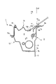
- FIG. 1 is a cross-sectional view of an automobile body structure according to an embodiment of the present invention, in which an air box and a cowl top member are cut along a plane perpendicular to the vehicle width direction.
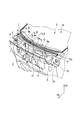
- FIG. 2 is an exploded perspective view for explaining the overall structure of the vehicle body structure of FIG. 1 and shows the vicinity of the air box with the cowl top member removed.
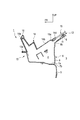
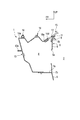
- FIG. 3 is a sectional view taken along line III-III in FIG. 4 is a cross-sectional view taken along line IV-IV in FIG.
- FIG. 5 is a sectional view taken along line VV in FIG.
- FIG. 6 schematically shows a state in which the vertical wall surface portion of the air box vibrates in the opposite phase with respect to the glass film vibration in the in-plane / outside direction of the front window shield glass in the vehicle body training of FIG. It is sectional drawing.
- An air box 4 is provided in the front part of the automobile 1, between an engine room 2 provided with an engine or a motor as a drive source of the automobile 1 and a passenger compartment 3 as a passenger compartment in which an occupant is boarded.
- the air box 4 extends in the vehicle width direction and exhibits a substantially rectangular closed cross section in a longitudinal section (a section perpendicular to the vehicle width direction).
- the inner side surface of the passenger compartment 3 of the air box 4 is provided with a dash upper panel member 6.
- the dash upper panel member 6 includes, in a longitudinal section, a substantially horizontal joint portion 7a that is joined to the dash lower panel member 5, a rising portion 7b that is bent at the rear end of the joint portion 7a, and a rear end of the rising portion 7b.
- the vehicle has a vertical wall surface portion 8 that extends substantially vertically toward the vehicle upper side and faces the space inside the passenger compartment 3.
- the dash upper panel member 6 and the dash lower panel member 5 are connected so that the vertical wall surface portion 8 and the dash lower panel member 5 are substantially flush with each other at the joint portion 7a.
- the rising portion 7 b may be bent so as to extend from the rear end of the joint portion 7 a so as to incline upward and rearward of the vehicle.
- An air conditioning opening 8a is formed at a substantially central portion of the vertical wall surface portion 8 in the vehicle width direction.
- the upper edge portion of the dash upper panel member 6 is connected to the dash upper panel member 6 via a corner portion 9b that is bent from the upper end of the vertical wall surface portion 8 so as to exhibit a substantially obtuse angle L shape in the vertical cross section.
- a corner portion 9b that is bent from the upper end of the vertical wall surface portion 8 so as to exhibit a substantially obtuse angle L shape in the vertical cross section.
- an upper inclined seat portion 9 that extends obliquely upward and rearward of the vehicle is integrally formed.
- a cowl top cover bracket member 12 is fixed on the upper surface of the upper inclined seat surface portion 9.
- a seal member 11 as a support portion is attached to the upper surface 12 a of the cowl top cover bracket member 12.
- the seal member 11 extends in the vehicle width direction of the air box 4 over substantially the entire length in the vehicle width direction along the longitudinal direction thereof.
- the side surface of the air box 4 on the engine room 2 side is composed of an extension panel member 13 that extends forward from the joint portion 7a of the dash upper panel member 6 to the vehicle.
- the front edge 14a of the cowl top cover member 14 is locked to the upper surface 13a of the front edge of the extension panel member 13.
- the cowl top cover member 14 is mounted so as to substantially cover the upper opening of the air box 4 and constitutes the upper side surface of the air box 4.
- an elastic contact piece member 16 that abuts the back side near the rear edge of the engine hood (not shown) extends along the longitudinal direction in the vehicle width direction. ing.
- cowl top cover member 14 has an outside air introduction surface portion 14b formed by a plurality of vent holes 14c, which is concavely curved (so as to protrude downward).
- the rear end edge of the cowl top cover member 14 is formed in a concave shape, and a glass fitting portion 14d that fits into a front edge portion 15a of a front window shield glass (hereinafter also simply referred to as glass) 15 is provided. It is integrally formed.
- a substantially rectangular closed cross section of the air box 4 is formed by the joining portion 7a, the rising portion 7b, the vertical wall surface portion 8, the extension panel member 13, and the cowl top cover member 14 of the dash upper panel member 6. .
- the position where the front edge portion 15a of the glass 15 is fitted and supported by the glass fitting portion 14d is directly above the vertical wall surface portion 8 facing the inside of the passenger compartment 3, and is the position of the air box 4. It is provided so as to be located on the vehicle rear side from the position where the cross-sectional shape is formed. That is, the joint between the front edge portion 15a of the glass 15 and the cowl top cover member 14 is located above the vertical wall surface portion 8 and on the vehicle rear side with respect to the member constituting the substantially rectangular closed cross section of the air box 4. positioned.
- the front edge portion 15a of the glass 15 of the present embodiment is supported at a vehicle rear position with respect to the vertical wall surface portion 8. More specifically, the back surface side of the glass 15 near the front edge portion 15a is positioned below the vertical wall surface portion 8 via the seal member 11 attached to the upper surface 12a of the cowl top cover bracket member 12 and below. It is supported from.
- front edge portion 15a of the glass 15 is connected to the upper inclined seat surface portion 9 via the seal member 11 and the cowl top cover bracket member 12 at the vehicle rear position of the air box 4.
- the vertical wall surface portion 8 is configured to vibrate in the opposite phase to the glass 15 in any glass film vibration direction.
- the dash lower panel member 5 moves in the inward / outward direction dwl, dw2 of the passenger compartment 3 with the displacement of the vertical wall surface portion 8 with respect to the glass 15 in the opposite phase. It is configured to be displaced in phase.
- the rear surface side of the glass 15 near the front edge 15a is connected to the dash upper panel member 6 via the seal member 11 attached to the upper surface 12a of the cowl top cover bracket member 12, as shown in FIG. It is supported from below at a position behind the vertical wall 8.
- the front edge portion 15a of the glass 15 is connected to the upper inclined seat surface portion 9 at a position behind the air box 4 so that the glass film vibrates in the in-plane / outside direction hw of the glass 15.
- the white arrow in FIG. 6 when the glass 15 is displaced in the passenger compartment 3 inside direction hw1, the bending angle ⁇ 1 of the corner portion 9b is set to ⁇ 1 as shown by the two-dot chain line in FIG. The larger deformation of ⁇ 2 is excited, and the lower portion of the vertical wall surface portion 8 of the air box 4 and the upper portion of the dash lower panel member 5 are displaced in the passenger compartment 3 outer direction dw1 as indicated by white arrows.
- the bending angle ⁇ 2 of the corner portion 9 b occurs during the phase in which the glass 15 is displaced in the direction hw 2 outside the passenger compartment 3.
- the bending angle ⁇ 1 changes.
- the lower part of the vertical wall surface part 8 of the air box 4 and the upper part of the dash lower panel member 5 are displaced in the passenger compartment 3 inside direction dw2 as shown by the arrow in FIG.
- the dash lower panel member 5 is moved in the opposite direction from the glass 15 to the inside / outside direction dwl, dw2 of the passenger compartment 3 along with the displacement of the vertical wall surface portion 8 to the opposite phase with respect to the glass 15. Displace.
- the volume in the passenger compartment 3 (volume in the passenger compartment 3 space) indicated by the region S1 in FIG. Since the decrease (or increase) balances with the increase (or decrease) in the volume in the passenger compartment 3 indicated by the region S2 in FIG. 6, the volume change in the entire passenger chamber 3 due to glass film vibration is reduced. Can be made.
- the dash lower panel member 5 is displaced together with the vertical wall surface portion 8 in the inward / outward direction dw of the passenger compartment 3 in the opposite phase to the glass 15.
- the seal member 11 attached to the upper surface 12a of the cowl top cover bracket member 12 located on the upper inclined seating surface portion 9 on the vehicle rear side with respect to the vertical wall surface portion 8.
- the glass 15 is supported from below via.
- a glass fitting portion 14d is formed on the rear edge portion of the cowl top cover member 14 that covers the upper surface of the air box 4, and the front edge portion 15a of the glass 15 fitted to the glass fitting portion 14d is formed. As shown in FIG. 1, the position can be set to a vehicle rear position rather than the cross-sectional position of the air box 4.
- the surface area of the cowl top cover member 14 can be set large, and a large number of ventilation openings 14c can be formed in the outside air introduction surface portion 14b.
- the back side of the glass 15 in the vicinity of the front edge portion 15a is illustrated as being supported from below via the seal member 11 attached to the upper surface 12a of the cowl top cover bracket member 12.
- the support structure of the glass 15 is not limited to this, and the back side of the glass 15 in the vicinity of the front edge portion 15a is disposed on the upper inclined seating surface portion 9 without providing the seal member 11 on the cowl top cover bracket member 12.
- the structure may be supported from below via a seal member 11 directly attached thereto.
- the support structure of the glass 15 may be any structure as long as the vertical wall surface portion 8 vibrates in an opposite phase with respect to the direction of glass film vibration, and is supported by the front edge portion 15a of the glass 15.
- the shape and material of the part are not particularly limited.
- the engine is housed in the engine room 2 as a power source
- the vehicle in which the air box 4 is disposed behind the engine room 2 and in front of the passenger compartment 3 has been described as an example.
- the vehicle to which the vehicle body structure of the automobile is applied is not limited to this, and an electric vehicle in which a motor, a battery, an electronic control device or the like is provided in the engine room 2 at the front of the vehicle, or a plurality of engines and motors, etc. Any vehicle may be used as long as it has a vertical wall surface portion 8 facing the passenger compartment 3 such as a hybrid vehicle having a power source.
- the vertical wall surface portion of the air box can be vibrated in an opposite phase with respect to the glass film vibration in the in-plane and outward directions of the front window shield glass.
Landscapes
- Engineering & Computer Science (AREA)
- Mechanical Engineering (AREA)
- Physics & Mathematics (AREA)
- Acoustics & Sound (AREA)
- Chemical & Material Sciences (AREA)
- Combustion & Propulsion (AREA)
- Transportation (AREA)
- Body Structure For Vehicles (AREA)
Priority Applications (3)
| Application Number | Priority Date | Filing Date | Title |
|---|---|---|---|
| CN201180023265.8A CN102883943B (zh) | 2010-05-11 | 2011-04-28 | 汽车的车体构造 |
| US13/697,114 US8608235B2 (en) | 2010-05-11 | 2011-04-28 | Vehicle body structure |
| EP11780538.2A EP2570333B1 (en) | 2010-05-11 | 2011-04-28 | Vehicle body structure |
Applications Claiming Priority (2)
| Application Number | Priority Date | Filing Date | Title |
|---|---|---|---|
| JP2010-108913 | 2010-05-11 | ||
| JP2010108913A JP4924739B2 (ja) | 2010-05-11 | 2010-05-11 | 自動車の車体構造 |
Publications (1)
| Publication Number | Publication Date |
|---|---|
| WO2011142281A1 true WO2011142281A1 (ja) | 2011-11-17 |
Family
ID=44914337
Family Applications (1)
| Application Number | Title | Priority Date | Filing Date |
|---|---|---|---|
| PCT/JP2011/060451 Ceased WO2011142281A1 (ja) | 2010-05-11 | 2011-04-28 | 自動車の車体構造 |
Country Status (5)
| Country | Link |
|---|---|
| US (1) | US8608235B2 (enExample) |
| EP (1) | EP2570333B1 (enExample) |
| JP (1) | JP4924739B2 (enExample) |
| CN (1) | CN102883943B (enExample) |
| WO (1) | WO2011142281A1 (enExample) |
Families Citing this family (6)
| Publication number | Priority date | Publication date | Assignee | Title |
|---|---|---|---|---|
| EP2623400B1 (en) * | 2010-09-28 | 2014-12-03 | Honda Motor Co., Ltd. | Structure for positioning cowl top for vehicle |
| CN103648891B (zh) * | 2011-07-04 | 2017-05-17 | 本田技研工业株式会社 | 车辆前部构造 |
| DE102012023655A1 (de) * | 2012-11-28 | 2014-05-28 | GM Global Technology Operations LLC (n. d. Gesetzen des Staates Delaware) | Kraftfahrzeug-Muldenmodul mit Dichtung |
| JP2015067015A (ja) * | 2013-09-27 | 2015-04-13 | 日本プラスト株式会社 | カウルトップカバー |
| JP2015104995A (ja) * | 2013-11-29 | 2015-06-08 | 日本プラスト株式会社 | 車両のカウル部構造 |
| WO2015152096A1 (ja) * | 2014-04-03 | 2015-10-08 | トヨタ自動車株式会社 | 車両用カウル構造 |
Citations (6)
| Publication number | Priority date | Publication date | Assignee | Title |
|---|---|---|---|---|
| JPH0416088U (enExample) * | 1990-05-30 | 1992-02-10 | ||
| JPH0546669U (ja) * | 1991-12-03 | 1993-06-22 | トヨタ車体株式会社 | 車体の前部構造 |
| JP2003191750A (ja) * | 2001-12-27 | 2003-07-09 | Toyota Motor Corp | ウインドシールドガラス支持構造 |
| JP2006206004A (ja) * | 2005-01-31 | 2006-08-10 | Toyota Motor Corp | ウインドシールドガラスの支持構造 |
| JP2007331720A (ja) * | 2006-06-19 | 2007-12-27 | Toyota Motor Corp | 車両用カウル構造 |
| JP2009083745A (ja) | 2007-10-02 | 2009-04-23 | Mazda Motor Corp | 車両のカウル部構造 |
Family Cites Families (10)
| Publication number | Priority date | Publication date | Assignee | Title |
|---|---|---|---|---|
| US4750780A (en) * | 1985-04-23 | 1988-06-14 | Mazda Motor Corporation | Dash panel configuration for a motor vehicle front body structure |
| JP2528978B2 (ja) * | 1989-11-24 | 1996-08-28 | 日産自動車株式会社 | 自動車のエアボックス構造 |
| JP2910777B2 (ja) * | 1990-05-09 | 1999-06-23 | 鐘淵化学工業株式会社 | リング状ボンデッドマグネット及びリング状樹脂スペーサー並びにそれらを用いたコンバージェンス調整装置 |
| JP3792412B2 (ja) * | 1998-10-15 | 2006-07-05 | カルソニックカンセイ株式会社 | 電気制御機器の防水機器ケース構造 |
| JP4731742B2 (ja) * | 2001-06-29 | 2011-07-27 | 富士重工業株式会社 | 車両の前部車体構造 |
| JP4329469B2 (ja) * | 2003-09-29 | 2009-09-09 | マツダ株式会社 | 車両の前部車体構造 |
| US7000979B2 (en) * | 2003-12-22 | 2006-02-21 | Nissan Technical Center North America, Inc. | Vehicle cowl structure with vent pipe |
| JP4872586B2 (ja) * | 2005-11-10 | 2012-02-08 | 日産自動車株式会社 | 車体前部構造および連結部材 |
| JP5003463B2 (ja) * | 2007-04-05 | 2012-08-15 | 日産自動車株式会社 | 車体構造 |
| JP2010064518A (ja) * | 2008-09-08 | 2010-03-25 | Nippon Plast Co Ltd | カウルトップカバーの取付構造 |
-
2010
- 2010-05-11 JP JP2010108913A patent/JP4924739B2/ja not_active Expired - Fee Related
-
2011
- 2011-04-28 EP EP11780538.2A patent/EP2570333B1/en not_active Not-in-force
- 2011-04-28 CN CN201180023265.8A patent/CN102883943B/zh not_active Expired - Fee Related
- 2011-04-28 WO PCT/JP2011/060451 patent/WO2011142281A1/ja not_active Ceased
- 2011-04-28 US US13/697,114 patent/US8608235B2/en active Active
Patent Citations (6)
| Publication number | Priority date | Publication date | Assignee | Title |
|---|---|---|---|---|
| JPH0416088U (enExample) * | 1990-05-30 | 1992-02-10 | ||
| JPH0546669U (ja) * | 1991-12-03 | 1993-06-22 | トヨタ車体株式会社 | 車体の前部構造 |
| JP2003191750A (ja) * | 2001-12-27 | 2003-07-09 | Toyota Motor Corp | ウインドシールドガラス支持構造 |
| JP2006206004A (ja) * | 2005-01-31 | 2006-08-10 | Toyota Motor Corp | ウインドシールドガラスの支持構造 |
| JP2007331720A (ja) * | 2006-06-19 | 2007-12-27 | Toyota Motor Corp | 車両用カウル構造 |
| JP2009083745A (ja) | 2007-10-02 | 2009-04-23 | Mazda Motor Corp | 車両のカウル部構造 |
Also Published As
| Publication number | Publication date |
|---|---|
| US20130057027A1 (en) | 2013-03-07 |
| JP2011235759A (ja) | 2011-11-24 |
| US8608235B2 (en) | 2013-12-17 |
| CN102883943B (zh) | 2015-03-18 |
| JP4924739B2 (ja) | 2012-04-25 |
| EP2570333B1 (en) | 2018-04-18 |
| EP2570333A1 (en) | 2013-03-20 |
| EP2570333A4 (en) | 2014-05-14 |
| CN102883943A (zh) | 2013-01-16 |
Similar Documents
| Publication | Publication Date | Title |
|---|---|---|
| CN102343946B (zh) | 前窗的支撑结构 | |
| WO2011142281A1 (ja) | 自動車の車体構造 | |
| JP2016153279A (ja) | 車両用電池パックの冷却ユニット | |
| US9426550B2 (en) | Speaker system for a motor vehicle | |
| JP2008260331A (ja) | 自動車の前部構造 | |
| JP2009137416A (ja) | 自動車用ドア | |
| JPWO2011162060A1 (ja) | 車体前部構造 | |
| JP4773900B2 (ja) | 車両のドア構造 | |
| JP2011173568A (ja) | 自動車のカウル構造 | |
| KR101580917B1 (ko) | 전동 압축기의 제진장치 | |
| JP2010228717A (ja) | 車両における車体前部構造 | |
| KR20110058436A (ko) | 차량용 카울 언더커버 | |
| JP2010228718A (ja) | 車両における車体前部構造 | |
| JP2012245803A (ja) | 車両の後部車体構造 | |
| JP2006281932A (ja) | 自動車のドア構造 | |
| JP6592799B2 (ja) | 車体前部構造 | |
| JP2018176762A (ja) | 車両の防音構造 | |
| JP2003165420A (ja) | 自動車の前部構造 | |
| JP2006256402A (ja) | 自動車のリヤパーセル構造 | |
| JP2011178271A (ja) | 自動車のカウル構造 | |
| JP2020050274A (ja) | 自動車のパネル構造 | |
| JP2022070586A (ja) | エンジンフード | |
| JP2021178558A (ja) | 車体前部構造 | |
| JP4055455B2 (ja) | 車体パネルの振動低減構造 | |
| JP5736813B2 (ja) | 車体前部構造 |
Legal Events
| Date | Code | Title | Description |
|---|---|---|---|
| WWE | Wipo information: entry into national phase |
Ref document number: 201180023265.8 Country of ref document: CN |
|
| 121 | Ep: the epo has been informed by wipo that ep was designated in this application |
Ref document number: 11780538 Country of ref document: EP Kind code of ref document: A1 |
|
| WWE | Wipo information: entry into national phase |
Ref document number: 13697114 Country of ref document: US |
|
| NENP | Non-entry into the national phase |
Ref country code: DE |
|
| WWE | Wipo information: entry into national phase |
Ref document number: 2011780538 Country of ref document: EP |