EP2570333B1 - Vehicle body structure - Google Patents
Vehicle body structure Download PDFInfo
- Publication number
- EP2570333B1 EP2570333B1 EP11780538.2A EP11780538A EP2570333B1 EP 2570333 B1 EP2570333 B1 EP 2570333B1 EP 11780538 A EP11780538 A EP 11780538A EP 2570333 B1 EP2570333 B1 EP 2570333B1
- Authority
- EP
- European Patent Office
- Prior art keywords
- glass
- vertical wall
- air box
- wall surface
- vehicle
- Prior art date
- Legal status (The legal status is an assumption and is not a legal conclusion. Google has not performed a legal analysis and makes no representation as to the accuracy of the status listed.)
- Not-in-force
Links
- 239000011521 glass Substances 0.000 claims description 72
- 239000012528 membrane Substances 0.000 claims description 16
- 238000005452 bending Methods 0.000 description 5
- 230000000630 rising effect Effects 0.000 description 4
- 238000004378 air conditioning Methods 0.000 description 3
- 238000009423 ventilation Methods 0.000 description 2
- 238000007796 conventional method Methods 0.000 description 1
- 230000000694 effects Effects 0.000 description 1
- 239000000446 fuel Substances 0.000 description 1
- 239000000463 material Substances 0.000 description 1
- 238000000034 method Methods 0.000 description 1
- 238000012986 modification Methods 0.000 description 1
- 230000004048 modification Effects 0.000 description 1
Images

Classifications
-
- B—PERFORMING OPERATIONS; TRANSPORTING
- B60—VEHICLES IN GENERAL
- B60R—VEHICLES, VEHICLE FITTINGS, OR VEHICLE PARTS, NOT OTHERWISE PROVIDED FOR
- B60R13/00—Elements for body-finishing, identifying, or decorating; Arrangements or adaptations for advertising purposes
- B60R13/08—Insulating elements, e.g. for sound insulation
- B60R13/0815—Acoustic or thermal insulation of passenger compartments
-
- B—PERFORMING OPERATIONS; TRANSPORTING
- B62—LAND VEHICLES FOR TRAVELLING OTHERWISE THAN ON RAILS
- B62D—MOTOR VEHICLES; TRAILERS
- B62D25/00—Superstructure or monocoque structure sub-units; Parts or details thereof not otherwise provided for
- B62D25/08—Front or rear portions
- B62D25/081—Cowls
Description
- The present invention relates to a vehicle body structure of an automobile capable of providing an excellent noise vibration performance.
- Japanese Patent Application Publication No.
2009-83745 - However, in the above vehicle body structure, a portion of the air box which supports the front windshield glass has a cantilever structure. For this reason, when glass membrane vibrations occur, the amplitude of the vibrations increases easily. This changes the capacity of the vehicle compartment largely and increases muffled sound, making passengers in the vehicle compartment feel uncomfortable. In order to avoid this, it has been necessary to increase the supporting rigidity by, for example, increasing a plate thickness of a portion for supporting the front windshield glass.
-
JP 2010-064518 A claim 1, discloses a vehicle body structure comprising a front window shield panel and an air box supporting a portion of the window shield panel and including a vertical dashed panel facing an inner side of a vehicle inner space. - The document
US 5,127,703 A discloses a vehicle body structure comprising a windshield and a cowl box supporting a portion of the windshield. The cowl box includes a dash upper panel including a vertical portion. - An object of the present invention is to provide a vehicle body structure of an automobile capable of suppressing changes in capacity of a vehicle compartment and improving a noise vibration performance.
- One aspect of the present invention is a vehicle body structure of an automobile in which a front edge portion of a front windshield glass is supported by an air box including a vertical wall surface portion facing an inner side of a vehicle compartment. In the vehicle structure, the front edge portion of the glass is connected to the air box in such a way that when glass membrane vibrations of the glass in surface inward-outward directions are in a phase shifting in an inward direction to the vehicle compartment, the vertical wall surface portion of the air box shifts in an outward direction from the vehicle compartment, and when the glass membrane vibrations of the glass in the surface inward-outward directions are in a phase shifting in an outward direction from the vehicle compartment, the vertical wall surface portion of the air box shifts in an inward direction to the vehicle compartment.
-
- [
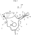
Fig. 1] Fig. 1 shows a vehicle body structure of an automobile according to an embodiment of the present invention, and is a cross-sectional view of an air box and a cowl top member which is taken along a plane perpendicular to a vehicle width direction. - [
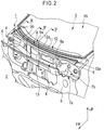
Fig. 2] Fig. 2 is an exploded perspective view for explaining an overall configuration of the vehicle body structure inFig. 1 , and shows a region near the air box with the cowl top member removed. - [
Fig. 3] Fig. 3 is a cross-sectional view schematically showing a state where in the vehicle body structure ofFig. 1 , a vertical wall surface portion of the air box vibrates in an opposite phase to glass membrane vibrations of a front windshield glass in surface inward-outward directions. - A vehicle body structure of an
automobile 1 according to an embodiment of the present invention will be described below with reference toFigs 1 to 3 . - As shown in
Fig. 2 , in a front portion of theautomobile 1, anair box 4 is provided between anengine room 2 in which an engine, a motor or the like is provided as a driving source of theautomobile 1 and apassenger compartment 3 which serves as a vehicle compartment for accommodating passengers. Theair box 4 extends in a vehicle width direction, and has a substantially rectangular closed section in a vertical cross section (a cross section perpendicular to the vehicle width direction). - A lateral surface of the
air box 4 on a side close to the inner side of thepassenger compartment 3 includes a dashupper panel member 6. The dashupper panel member 6 includes, in the vertical cross section: a substantiallyhorizontal connection portion 7a to be connected to a dashlower panel member 5; a risingportion 7b formed to be bent at a rear end of theconnection portion 7a; and a verticalwall surface portion 8 provided to extend substantially vertically from a rear end of the risingportion 7b toward the top of the vehicle and to face an inner space of thepassenger compartment 3. The dashupper panel member 6 and the dashlower panel member 5 are connected together at theconnection portion 7a in such a way that the verticalwall surface portion 8 and the dashlower panel member 5 are substantially flush with each other. As shown inFig. 1 , the risingportion 7b may be formed to be bent to obliquely extend upward and rearward in the vehicle from the rear end of theconnection portion 7a. - An air-conditioning opening 8a is formed in a substantially center portion of the vertical
wall surface portion 8 in the vehicle width direction. - In addition, in the dash
upper panel member 6, an upper inclinedbearing surface portion 9 obliquely extending upward and rearward in the vehicle is integrally formed from an upper end of the verticalwall surface portion 8 to anupper edge portion 9a of the dashupper panel member 6, through acorner portion 9b formed to be bent to have a substantially obtuse-angled L shape in the vertical cross section. - As shown in
Fig. 1 , a cowl topcover bracket member 12 is fixedly provided on an upper surface of the upper inclinedbearing surface portion 9. - A
seal member 11 serving as a supporting portion is attached to anupper surface 12a of the cowl topcover bracket member 12. Theseal member 11 has its longitudinal direction along the vehicle width direction and extends substantially over the entire length of theair box 4 in the vehicle width direction. - Additionally, a lateral surface of the
air box 4 on theengine room 2 side is formed of anextension panel member 13 extending toward the front of the vehicle from theconnection portion 7a of the dashupper panel member 6. - A
front end edge 14a of a cowltop cover member 14 is locked to a front-edge-portionupper surface 13a of theextension panel member 13. The cowltop cover member 14 is mounted to substantially cover an upper-side opening of theair box 4, and forms an upper-side lateral surface of theair box 4. - On an upper surface of the
front end edge 14a of the cowltop cover member 14, an elasticcontact piece member 16 which a back surface of an engine hood (not illustrated) near an rear edge portion thereof is to be brought into contact with is provided to extend with the longitudinal direction thereof along the vehicle width direction. - In addition, in the cowl
top cover member 14, an outside-airintroduction surface portion 14b includingmultiple ventilation holes 14c... is formed curvedly in a concave shape (in a convex shape protruding downward). - Moreover, at a rear end edge of the cowl
top cover member 14, aglass fitting portion 14d is integrally formed in a concave shape to be fitted with afront edge portion 15a of a front windshield glass (hereinafter, also simply referred to as a glass) 15. - A substantially rectangular closed section of the
air box 4 is formed of: theconnection portion 7a, the risingportion 7b, and the verticalwall surface portion 8 of the dashupper panel member 6; theextension panel member 13; and the cowltop cover member 14. - In the embodiment, a position where the
front edge portion 15a of theglass 15 is fitted to and supported by theglass fitting portion 14d is located immediately above the verticalwall surface portion 8 facing the inner side of thepassenger compartment 3, and is located on a vehicle rear side of a position where the shape of cross section of theair box 4 is formed. In other words, a connection portion between thefront edge portion 15a of theglass 15 and the cowltop cover member 14 is located above the verticalwall surface portion 8, on the vehicle rear side of the members forming the substantially rectangular closed section of theair box 4. - In addition, the
front edge portion 15a of theglass 15 in the embodiment is supported at the position on the vehicle rear side of the verticalwall surface portion 8. To be more specific, the back surface side of theglass 15 near thefront edge portion 15a is supported, by means of theseal member 11 attached to theupper surface 12a of the cowl topcover bracket member 12, from below at the position on the vehicle rear side of the verticalwall surface portion 8. - Moreover, the
front edge portion 15a of theglass 15 is connected to the upper inclinedbearing surface portion 9, through theseal member 11 and the cowl topcover bracket member 12, at the position on the vehicle rear side of in theair box 4. - For this reason, as shown by a hollow arrow in
Fig. 3 , when glass membrane vibrations of theglass 15 in surface inward-outward directions hw are in the phase shifting in an inward direction hw1 to thepassenger compartment 3, the verticalwall surface portion 8 of theair box 4 shifts in an outward direction dw1 from thepassenger compartment 3, as shown by a hollow arrow inFig. 3 . - Additionally, as shown by an arrow in
Fig. 3 , when glass membrane vibrations of theglass 15 in the surface inward-outward directions hw are in the phase shifting in an outward direction hw2 from thepassenger compartment 3, the verticalwall surface portion 8 of theair box 4 shifts in an inward direction dw2 to thepassenger compartment 3, as shown by an arrow inFig. 3 . In other words, the verticalwall surface portion 8 is configured to vibrate in the opposite phase to theglass 15, in a case of glass membrane vibrations in any direction. - Furthermore, in the vehicle body structure of an automobile according to the embodiment, the dash
lower panel member 5 is configured to shift in the opposite phase to theglass 15 in the outward and inward directions dw1, dw2 from and to thepassenger compartment 3, along with the shifting of the verticalwall surface portion 8 in the opposite phase to theglass 15. - Next, operations and effects of the vehicle body structure of an automobile according to the embodiment will be described.
- In the embodiment, as shown in
Fig. 1 , the back surface side of theglass 15 near thefront edge portion 15a is supported, by means of theseal member 11 attached to theupper surface 12a of the cowl topcover bracket member 12, from below at the position on the vehicle rear side of the verticalwall surface portion 8 of the dashupper panel member 6. - As described above, the
front edge portion 15a of theglass 15 is connected to the upper inclinedbearing surface portion 9 at the position on the vehicle rear side of theair box 4. Thereby, when glass membrane vibrations of theglass 15 in the surface inward-outward directions hw are in such a phase that theglass 15 shifts in the inward direction hw1 to thepassenger compartment 3 as shown by the hollow arrow inFig. 3 , deformation is generated in which a bending angle α1 of thecorner portion 9b is caused to be a bending angle α2 larger than the bending angle α1, as shown by a chain double-dashed line inFig. 3 . Thus, a lower portion of the verticalwall surface portion 8 of theair box 4 and an upper portion of the dashlower panel member 5 shift in the outward direction dw1 from thepassenger compartment 3, as shown by the hollow arrow inFig. 3 . - In addition, when glass membrane vibrations of the
glass 15 in the surface inward-outward directions hw are in such a phase that theglass 15 is shifting in the outward direction hw2 from thepassenger compartment 3 as shown by the arrow inFig. 3 , the bending angle α2 of thecorner portion 9b changes to the bending angle α1, as shown by a solid line inFig. 3 . For this reason, a lower portion of the verticalwall surface portion 8 of theair box 4 and an upper portion of the dashlower panel member 5 shift in the inward direction dw2 to thepassenger compartment 3, as shown by the arrow inFig. 3 . - In the vehicle body structure of an automobile according to the embodiment, the dash
lower panel member 5 shifts in the opposite phase to theglass 15 in outward and inward directions dw1, dw2 from and to thepassenger compartment 3, along with the shifting of the verticalwall surface portion 8 in the opposite phase to theglass 15. - For this reason, in the vehicle body structure of an automobile according to the embodiment, when glass membrane vibrations of the
glass 15 in the surface inward-outward directions hw occur, an amount of reduction (or an amount of increase) in capacity (volume of an inner space of the passenger compartment 3) of thepassenger compartment 3 shown by a region S1 inFig. 3 and an amount of increase (or an amount of reduction) in capacity of thepassenger compartment 3 shown by a region S2 inFig. 3 are balanced. Accordingly, it is possible to reduce capacity changes in theentire passenger compartment 3, which are caused by glass membrane vibrations. - Hence, unlike the conventional technique, it is no longer necessary to increase the supporting rigidity by, for example, increasing a plate thickness of a portion for supporting the
glass 15 for the purpose of suppressing the vibrations of theglass 15. Hence, it is possible to improve a noise vibration performance by reducing muffled sound while suppressing increase in weight. - Moreover, in the vehicle body structure of an automobile according to the embodiment, the dash
lower panel member 5 shifts in the opposite phase to theglass 15 in the inward-outward directions dw to and from thepassenger compartment 3, together with the verticalwall surface portion 8. - For this reason, even when the shifting amount in the inward-outward directions dw to and from the
passenger compartment 3 in the verticalwall surface portion 8 of theair box 4 is small, increase (or reduction) in capacity of thepassenger compartment 3 which compensates reduction (or increase) in capacity of thepassenger compartment 3 caused by shifting of theglass 15 can be secured easily (inFig. 3 , to obtain S2 which has substantially the same area as S1, and which changes in the opposite phase to S1). Thus, capacity changes in theentire passenger compartment 3 at the time of glass membrane vibrations can be suppressed reliably. - Additionally, in the vehicle body structure of an automobile according to the embodiment, the
glass 15 is supported from below by means of theseal member 11 which is located on the upper surface of the upper inclined bearingsurface portion 9, on the vehicle rear side of the verticalwall surface portion 8 and which is attached to theupper surface 12a of the cowl topcover bracket member 12. - Accordingly, it is possible to form the glass
fitting portion 14d at the rear edge portion of the cowltop cover member 14 covering the upper surface of theair box 4, and to set thefront edge portion 15a of theglass 15, fitted to the glassfitting portion 14d, at the position on the vehicle rear side of the position of cross section of theair box 4, as shown inFig. 1 . - Hence, the surface area of the cowl
top cover member 14 can be set large, and a large number of the ventilation holes 14c... can be formed in the outside-airintroduction surface portion 14b. - Accordingly, a large amount of air-conditioning air can be introduced into the
air box 4 from the outside of the vehicle, and thus a fuel consumption performance can be further enhanced by improving the efficiency of air-conditioning equipment. - Although the embodiment of the present invention has been described above, the embodiment is only an example described for facilitating the understanding of the present invention, and the present invention is not limited to the embodiment. The technical scope of the present invention is not limited to the specific technical matters disclosed in the above embodiment, but includes various modifications, changes, alternative techniques and the like which can be easily derived from the embodiment.
- For example, in the above embodiment, a description has been given of an example in which the back surface side of the
glass 15 near thefront edge portion 15a is supported, by means of theseal member 11 attached to theupper surface 12a of the cowl topcover bracket member 12, from below. However, the supporting structure of theglass 15 is not particularly limited thereto, and may be a structure in which theseal member 11 is not provided on the cowl topcover bracket member 12 and the back surface side of theglass 15 near thefront edge portion 15a is supported, by means of theseal member 11 attached directly to the upper inclined bearingsurface portion 9, from below. The supporting structure of theglass 15 only needs to be a structure configured such that the verticalwall surface portion 8 vibrates in the opposite phase to the directions of glass membrane vibrations, and the shape and material of the supporting portion to be connected to thefront edge portion 15a of theglass 15 are not particularly limited. - Additionally, in the above embodiment, a description has been given of an example of such a vehicle that the engine as the driving source is housed in the
engine room 2, and theair box 4 is arranged in the rear of theengine room 2 and in the front of thepassenger compartment 3. However, a vehicle to which the vehicle body structure of an automobile according to the present invention is to be employed is not particularly limited thereto, and may be any automobile as long as the automobile includes the verticalwall surface portion 8 facing thepassenger compartment 3 such as: an electric vehicle having a motor, a battery, an electronic control device or the like in theengine room 2 in the front portion of vehicle; or a hybrid vehicle having multiple driving sources such as an engine and a motor. - According to the present invention, the vertical wall surface portion of the air box can vibrate in the opposite phase to glass membrane vibrations of the front windshield glass in the surface inward-outward directions. Hence, changes in the capacity of the entire vehicle compartment are suppressed, and thus muffled sound can be reduced without increasing the supporting rigidity by, for example, increasing a plate thickness of a member for supporting the glass.
-
- 3
- passenger compartment (vehicle compartment)
- 4
- air box
- 8
- vertical wall surface portion
- 15
- front windshield glass (glass)
- 15a
- front edge portion
Claims (2)
- A vehicle body structure of an automobile comprising:a front windshield glass (15);an air box (4) supporting a portion of the glass (15) and including a vertical wall surface portion (8) facing an inner side of a vehicle compartment (3); anda dash lower panel member (5) connected to the vertical wall surface portion (8) of the air box (4), characterized in thata front edge portion (15a) of the glass (15) is supported by the air box (4) at a position on a vehicle rear side of the vertical wall surface portion (8) so that when glass membrane vibrations of the glass (15) in surface inward-outward directions (hw) are in a phase shifting in an inward direction (hw1) to the vehicle compartment (3), the vertical wall surface portion (8) of the air box (4) and the dash lower panel member (5) shift in an outward direction (dw1) from the vehicle compartment (3), and when the glass membrane vibrations of the glass (15) in the surface inward-outward directions (hw) are in a phase shifting in an outward direction (hw2) from the vehicle compartment (3), the vertical wall surface portion (8) of the air box (4) and the dash lower panel member (5) shift in an inward direction (dw2) to the vehicle compartment (3).
- The vehicle body structure of an automobile according to claim 1, wherein the dash lower panel member (5) is connected to the vertical wall surface portion (8) of the air box (4) to be substantially flush with the vertical wall surface portion (8).
Applications Claiming Priority (2)
| Application Number | Priority Date | Filing Date | Title |
|---|---|---|---|
| JP2010108913A JP4924739B2 (en) | 2010-05-11 | 2010-05-11 | Auto body structure |
| PCT/JP2011/060451 WO2011142281A1 (en) | 2010-05-11 | 2011-04-28 | Vehicle body structure |
Publications (3)
| Publication Number | Publication Date |
|---|---|
| EP2570333A1 EP2570333A1 (en) | 2013-03-20 |
| EP2570333A4 EP2570333A4 (en) | 2014-05-14 |
| EP2570333B1 true EP2570333B1 (en) | 2018-04-18 |
Family
ID=44914337
Family Applications (1)
| Application Number | Title | Priority Date | Filing Date |
|---|---|---|---|
| EP11780538.2A Not-in-force EP2570333B1 (en) | 2010-05-11 | 2011-04-28 | Vehicle body structure |
Country Status (5)
| Country | Link |
|---|---|
| US (1) | US8608235B2 (en) |
| EP (1) | EP2570333B1 (en) |
| JP (1) | JP4924739B2 (en) |
| CN (1) | CN102883943B (en) |
| WO (1) | WO2011142281A1 (en) |
Families Citing this family (6)
| Publication number | Priority date | Publication date | Assignee | Title |
|---|---|---|---|---|
| CN103153760B (en) * | 2010-09-28 | 2015-09-09 | 本田技研工业株式会社 | Vehicle cowl upper locating structure |
| WO2013005685A1 (en) * | 2011-07-04 | 2013-01-10 | 本田技研工業株式会社 | Structure for front portion of vehicle |
| DE102012023655A1 (en) * | 2012-11-28 | 2014-05-28 | GM Global Technology Operations LLC (n. d. Gesetzen des Staates Delaware) | Motor vehicle tray module with seal |
| JP2015067015A (en) * | 2013-09-27 | 2015-04-13 | 日本プラスト株式会社 | Cowl top cover |
| JP2015104995A (en) * | 2013-11-29 | 2015-06-08 | 日本プラスト株式会社 | Cowl part structure of vehicle |
| CN106132814B (en) * | 2014-04-03 | 2018-02-06 | 丰田自动车株式会社 | Vehicle front wall harden structure |
Family Cites Families (16)
| Publication number | Priority date | Publication date | Assignee | Title |
|---|---|---|---|---|
| US4750780A (en) * | 1985-04-23 | 1988-06-14 | Mazda Motor Corporation | Dash panel configuration for a motor vehicle front body structure |
| JP2528978B2 (en) * | 1989-11-24 | 1996-08-28 | 日産自動車株式会社 | Car air box structure |
| JP2910777B2 (en) * | 1990-05-09 | 1999-06-23 | 鐘淵化学工業株式会社 | Ring-shaped bonded magnet, ring-shaped resin spacer, and convergence adjusting device using them |
| JPH0416088U (en) | 1990-05-30 | 1992-02-10 | ||
| JP2583114Y2 (en) * | 1991-12-03 | 1998-10-15 | トヨタ車体株式会社 | Body front structure |
| JP3792412B2 (en) * | 1998-10-15 | 2006-07-05 | カルソニックカンセイ株式会社 | Waterproof equipment case structure for electrical control equipment |
| JP4731742B2 (en) * | 2001-06-29 | 2011-07-27 | 富士重工業株式会社 | Front body structure of the vehicle |
| JP3711930B2 (en) * | 2001-12-27 | 2005-11-02 | トヨタ自動車株式会社 | Windshield glass support structure |
| JP4329469B2 (en) * | 2003-09-29 | 2009-09-09 | マツダ株式会社 | Front body structure of the vehicle |
| US7000979B2 (en) * | 2003-12-22 | 2006-02-21 | Nissan Technical Center North America, Inc. | Vehicle cowl structure with vent pipe |
| JP4207006B2 (en) * | 2005-01-31 | 2009-01-14 | トヨタ自動車株式会社 | Windshield glass support structure |
| JP4872586B2 (en) * | 2005-11-10 | 2012-02-08 | 日産自動車株式会社 | Car body front structure and connecting member |
| JP4743009B2 (en) * | 2006-06-19 | 2011-08-10 | トヨタ自動車株式会社 | Vehicle cowl structure |
| JP5003463B2 (en) * | 2007-04-05 | 2012-08-15 | 日産自動車株式会社 | Body structure |
| JP2009083745A (en) * | 2007-10-02 | 2009-04-23 | Mazda Motor Corp | Structure of vehicular cowl part |
| JP2010064518A (en) * | 2008-09-08 | 2010-03-25 | Nippon Plast Co Ltd | Mounting structure of cowl top cover |
-
2010
- 2010-05-11 JP JP2010108913A patent/JP4924739B2/en not_active Expired - Fee Related
-
2011
- 2011-04-28 US US13/697,114 patent/US8608235B2/en active Active
- 2011-04-28 WO PCT/JP2011/060451 patent/WO2011142281A1/en active Application Filing
- 2011-04-28 CN CN201180023265.8A patent/CN102883943B/en active Active
- 2011-04-28 EP EP11780538.2A patent/EP2570333B1/en not_active Not-in-force
Non-Patent Citations (1)
| Title |
|---|
| None * |
Also Published As
| Publication number | Publication date |
|---|---|
| CN102883943A (en) | 2013-01-16 |
| JP2011235759A (en) | 2011-11-24 |
| CN102883943B (en) | 2015-03-18 |
| WO2011142281A1 (en) | 2011-11-17 |
| JP4924739B2 (en) | 2012-04-25 |
| US8608235B2 (en) | 2013-12-17 |
| EP2570333A4 (en) | 2014-05-14 |
| US20130057027A1 (en) | 2013-03-07 |
| EP2570333A1 (en) | 2013-03-20 |
Similar Documents
| Publication | Publication Date | Title |
|---|---|---|
| EP2570333B1 (en) | Vehicle body structure | |
| JP2008100533A (en) | Cowl top structure of automobile | |
| JP2004155351A (en) | Front deck structure for vehicle | |
| JP2007106280A (en) | Vehicle door structure | |
| JP2013136319A (en) | Vehicle door | |
| JP2013107444A (en) | Support structure of pull handle box | |
| US9426550B2 (en) | Speaker system for a motor vehicle | |
| JP2011031701A (en) | Cowl part structure of vehicle | |
| JP2011173568A (en) | Cowl structure of automobile | |
| JP2012066687A (en) | Cowl cover structure | |
| KR20110000431A (en) | Dash panel of a car | |
| JP2014139060A (en) | Trim board attachment part structure in vehicle | |
| JP6178837B2 (en) | Vehicle interior structure | |
| WO2017002191A1 (en) | Electronic control unit bracket and vehicle | |
| JP2009083559A (en) | Cowl top garnish | |
| JP6471708B2 (en) | Hood lower structure | |
| JP5939155B2 (en) | Soundproof structure around the dash panel | |
| JP2008195149A (en) | Front part structure of automobile | |
| JP2011178271A (en) | Cowl structure of automobile | |
| JP4296823B2 (en) | Vehicle ceiling structure | |
| JP2018176762A (en) | Vehicle sound insulation structure | |
| JP2003072593A (en) | Noise reduction structure for car body front part | |
| JP2015120390A (en) | Roof structure of bus vehicle body | |
| JP6232939B2 (en) | Sound insulation structure at the front of the instrument panel | |
| JP2022139479A (en) | Vehicle front part structure |
Legal Events
| Date | Code | Title | Description |
|---|---|---|---|
| PUAI | Public reference made under article 153(3) epc to a published international application that has entered the european phase |
Free format text: ORIGINAL CODE: 0009012 |
|
| 17P | Request for examination filed |
Effective date: 20121211 |
|
| AK | Designated contracting states |
Kind code of ref document: A1 Designated state(s): AL AT BE BG CH CY CZ DE DK EE ES FI FR GB GR HR HU IE IS IT LI LT LU LV MC MK MT NL NO PL PT RO RS SE SI SK SM TR |
|
| DAX | Request for extension of the european patent (deleted) | ||
| A4 | Supplementary search report drawn up and despatched |
Effective date: 20140414 |
|
| RIC1 | Information provided on ipc code assigned before grant |
Ipc: B62D 25/08 20060101AFI20140408BHEP |
|
| 17Q | First examination report despatched |
Effective date: 20170214 |
|
| GRAP | Despatch of communication of intention to grant a patent |
Free format text: ORIGINAL CODE: EPIDOSNIGR1 |
|
| INTG | Intention to grant announced |
Effective date: 20171205 |
|
| GRAS | Grant fee paid |
Free format text: ORIGINAL CODE: EPIDOSNIGR3 |
|
| GRAA | (expected) grant |
Free format text: ORIGINAL CODE: 0009210 |
|
| AK | Designated contracting states |
Kind code of ref document: B1 Designated state(s): AL AT BE BG CH CY CZ DE DK EE ES FI FR GB GR HR HU IE IS IT LI LT LU LV MC MK MT NL NO PL PT RO RS SE SI SK SM TR |
|
| REG | Reference to a national code |
Ref country code: GB Ref legal event code: FG4D |
|
| REG | Reference to a national code |
Ref country code: CH Ref legal event code: EP |
|
| REG | Reference to a national code |
Ref country code: FR Ref legal event code: PLFP Year of fee payment: 8 |
|
| REG | Reference to a national code |
Ref country code: AT Ref legal event code: REF Ref document number: 990131 Country of ref document: AT Kind code of ref document: T Effective date: 20180515 |
|
| REG | Reference to a national code |
Ref country code: IE Ref legal event code: FG4D |
|
| REG | Reference to a national code |
Ref country code: DE Ref legal event code: R096 Ref document number: 602011047615 Country of ref document: DE |
|
| REG | Reference to a national code |
Ref country code: NL Ref legal event code: MP Effective date: 20180418 |
|
| REG | Reference to a national code |
Ref country code: LT Ref legal event code: MG4D |
|
| PG25 | Lapsed in a contracting state [announced via postgrant information from national office to epo] |
Ref country code: NL Free format text: LAPSE BECAUSE OF FAILURE TO SUBMIT A TRANSLATION OF THE DESCRIPTION OR TO PAY THE FEE WITHIN THE PRESCRIBED TIME-LIMIT Effective date: 20180418 |
|
| PG25 | Lapsed in a contracting state [announced via postgrant information from national office to epo] |
Ref country code: FI Free format text: LAPSE BECAUSE OF FAILURE TO SUBMIT A TRANSLATION OF THE DESCRIPTION OR TO PAY THE FEE WITHIN THE PRESCRIBED TIME-LIMIT Effective date: 20180418 Ref country code: NO Free format text: LAPSE BECAUSE OF FAILURE TO SUBMIT A TRANSLATION OF THE DESCRIPTION OR TO PAY THE FEE WITHIN THE PRESCRIBED TIME-LIMIT Effective date: 20180718 Ref country code: BG Free format text: LAPSE BECAUSE OF FAILURE TO SUBMIT A TRANSLATION OF THE DESCRIPTION OR TO PAY THE FEE WITHIN THE PRESCRIBED TIME-LIMIT Effective date: 20180718 Ref country code: SE Free format text: LAPSE BECAUSE OF FAILURE TO SUBMIT A TRANSLATION OF THE DESCRIPTION OR TO PAY THE FEE WITHIN THE PRESCRIBED TIME-LIMIT Effective date: 20180418 Ref country code: AL Free format text: LAPSE BECAUSE OF FAILURE TO SUBMIT A TRANSLATION OF THE DESCRIPTION OR TO PAY THE FEE WITHIN THE PRESCRIBED TIME-LIMIT Effective date: 20180418 Ref country code: LT Free format text: LAPSE BECAUSE OF FAILURE TO SUBMIT A TRANSLATION OF THE DESCRIPTION OR TO PAY THE FEE WITHIN THE PRESCRIBED TIME-LIMIT Effective date: 20180418 Ref country code: ES Free format text: LAPSE BECAUSE OF FAILURE TO SUBMIT A TRANSLATION OF THE DESCRIPTION OR TO PAY THE FEE WITHIN THE PRESCRIBED TIME-LIMIT Effective date: 20180418 Ref country code: PL Free format text: LAPSE BECAUSE OF FAILURE TO SUBMIT A TRANSLATION OF THE DESCRIPTION OR TO PAY THE FEE WITHIN THE PRESCRIBED TIME-LIMIT Effective date: 20180418 |
|
| PG25 | Lapsed in a contracting state [announced via postgrant information from national office to epo] |
Ref country code: RS Free format text: LAPSE BECAUSE OF FAILURE TO SUBMIT A TRANSLATION OF THE DESCRIPTION OR TO PAY THE FEE WITHIN THE PRESCRIBED TIME-LIMIT Effective date: 20180418 Ref country code: LV Free format text: LAPSE BECAUSE OF FAILURE TO SUBMIT A TRANSLATION OF THE DESCRIPTION OR TO PAY THE FEE WITHIN THE PRESCRIBED TIME-LIMIT Effective date: 20180418 Ref country code: GR Free format text: LAPSE BECAUSE OF FAILURE TO SUBMIT A TRANSLATION OF THE DESCRIPTION OR TO PAY THE FEE WITHIN THE PRESCRIBED TIME-LIMIT Effective date: 20180719 Ref country code: HR Free format text: LAPSE BECAUSE OF FAILURE TO SUBMIT A TRANSLATION OF THE DESCRIPTION OR TO PAY THE FEE WITHIN THE PRESCRIBED TIME-LIMIT Effective date: 20180418 |
|
| REG | Reference to a national code |
Ref country code: CH Ref legal event code: PL |
|
| REG | Reference to a national code |
Ref country code: AT Ref legal event code: MK05 Ref document number: 990131 Country of ref document: AT Kind code of ref document: T Effective date: 20180418 |
|
| REG | Reference to a national code |
Ref country code: BE Ref legal event code: MM Effective date: 20180430 |
|
| PG25 | Lapsed in a contracting state [announced via postgrant information from national office to epo] |
Ref country code: PT Free format text: LAPSE BECAUSE OF FAILURE TO SUBMIT A TRANSLATION OF THE DESCRIPTION OR TO PAY THE FEE WITHIN THE PRESCRIBED TIME-LIMIT Effective date: 20180820 |
|
| REG | Reference to a national code |
Ref country code: DE Ref legal event code: R097 Ref document number: 602011047615 Country of ref document: DE |
|
| REG | Reference to a national code |
Ref country code: IE Ref legal event code: MM4A |
|
| PG25 | Lapsed in a contracting state [announced via postgrant information from national office to epo] |
Ref country code: EE Free format text: LAPSE BECAUSE OF FAILURE TO SUBMIT A TRANSLATION OF THE DESCRIPTION OR TO PAY THE FEE WITHIN THE PRESCRIBED TIME-LIMIT Effective date: 20180418 Ref country code: RO Free format text: LAPSE BECAUSE OF FAILURE TO SUBMIT A TRANSLATION OF THE DESCRIPTION OR TO PAY THE FEE WITHIN THE PRESCRIBED TIME-LIMIT Effective date: 20180418 Ref country code: LU Free format text: LAPSE BECAUSE OF NON-PAYMENT OF DUE FEES Effective date: 20180428 Ref country code: CZ Free format text: LAPSE BECAUSE OF FAILURE TO SUBMIT A TRANSLATION OF THE DESCRIPTION OR TO PAY THE FEE WITHIN THE PRESCRIBED TIME-LIMIT Effective date: 20180418 Ref country code: MC Free format text: LAPSE BECAUSE OF FAILURE TO SUBMIT A TRANSLATION OF THE DESCRIPTION OR TO PAY THE FEE WITHIN THE PRESCRIBED TIME-LIMIT Effective date: 20180418 Ref country code: AT Free format text: LAPSE BECAUSE OF FAILURE TO SUBMIT A TRANSLATION OF THE DESCRIPTION OR TO PAY THE FEE WITHIN THE PRESCRIBED TIME-LIMIT Effective date: 20180418 Ref country code: DK Free format text: LAPSE BECAUSE OF FAILURE TO SUBMIT A TRANSLATION OF THE DESCRIPTION OR TO PAY THE FEE WITHIN THE PRESCRIBED TIME-LIMIT Effective date: 20180418 Ref country code: SK Free format text: LAPSE BECAUSE OF FAILURE TO SUBMIT A TRANSLATION OF THE DESCRIPTION OR TO PAY THE FEE WITHIN THE PRESCRIBED TIME-LIMIT Effective date: 20180418 |
|
| PLBE | No opposition filed within time limit |
Free format text: ORIGINAL CODE: 0009261 |
|
| STAA | Information on the status of an ep patent application or granted ep patent |
Free format text: STATUS: NO OPPOSITION FILED WITHIN TIME LIMIT |
|
| PG25 | Lapsed in a contracting state [announced via postgrant information from national office to epo] |
Ref country code: LI Free format text: LAPSE BECAUSE OF NON-PAYMENT OF DUE FEES Effective date: 20180430 Ref country code: SM Free format text: LAPSE BECAUSE OF FAILURE TO SUBMIT A TRANSLATION OF THE DESCRIPTION OR TO PAY THE FEE WITHIN THE PRESCRIBED TIME-LIMIT Effective date: 20180418 Ref country code: IT Free format text: LAPSE BECAUSE OF FAILURE TO SUBMIT A TRANSLATION OF THE DESCRIPTION OR TO PAY THE FEE WITHIN THE PRESCRIBED TIME-LIMIT Effective date: 20180418 Ref country code: BE Free format text: LAPSE BECAUSE OF NON-PAYMENT OF DUE FEES Effective date: 20180430 Ref country code: CH Free format text: LAPSE BECAUSE OF NON-PAYMENT OF DUE FEES Effective date: 20180430 |
|
| 26N | No opposition filed |
Effective date: 20190121 |
|
| PG25 | Lapsed in a contracting state [announced via postgrant information from national office to epo] |
Ref country code: IE Free format text: LAPSE BECAUSE OF NON-PAYMENT OF DUE FEES Effective date: 20180428 |
|
| PG25 | Lapsed in a contracting state [announced via postgrant information from national office to epo] |
Ref country code: SI Free format text: LAPSE BECAUSE OF FAILURE TO SUBMIT A TRANSLATION OF THE DESCRIPTION OR TO PAY THE FEE WITHIN THE PRESCRIBED TIME-LIMIT Effective date: 20180418 |
|
| PG25 | Lapsed in a contracting state [announced via postgrant information from national office to epo] |
Ref country code: MT Free format text: LAPSE BECAUSE OF NON-PAYMENT OF DUE FEES Effective date: 20180428 |
|
| PG25 | Lapsed in a contracting state [announced via postgrant information from national office to epo] |
Ref country code: TR Free format text: LAPSE BECAUSE OF FAILURE TO SUBMIT A TRANSLATION OF THE DESCRIPTION OR TO PAY THE FEE WITHIN THE PRESCRIBED TIME-LIMIT Effective date: 20180418 |
|
| PG25 | Lapsed in a contracting state [announced via postgrant information from national office to epo] |
Ref country code: HU Free format text: LAPSE BECAUSE OF FAILURE TO SUBMIT A TRANSLATION OF THE DESCRIPTION OR TO PAY THE FEE WITHIN THE PRESCRIBED TIME-LIMIT; INVALID AB INITIO Effective date: 20110428 |
|
| PG25 | Lapsed in a contracting state [announced via postgrant information from national office to epo] |
Ref country code: CY Free format text: LAPSE BECAUSE OF FAILURE TO SUBMIT A TRANSLATION OF THE DESCRIPTION OR TO PAY THE FEE WITHIN THE PRESCRIBED TIME-LIMIT Effective date: 20180418 Ref country code: MK Free format text: LAPSE BECAUSE OF NON-PAYMENT OF DUE FEES Effective date: 20180418 |
|
| PG25 | Lapsed in a contracting state [announced via postgrant information from national office to epo] |
Ref country code: IS Free format text: LAPSE BECAUSE OF FAILURE TO SUBMIT A TRANSLATION OF THE DESCRIPTION OR TO PAY THE FEE WITHIN THE PRESCRIBED TIME-LIMIT Effective date: 20180818 |
|
| PGFP | Annual fee paid to national office [announced via postgrant information from national office to epo] |
Ref country code: GB Payment date: 20220310 Year of fee payment: 12 |
|
| PGFP | Annual fee paid to national office [announced via postgrant information from national office to epo] |
Ref country code: FR Payment date: 20220308 Year of fee payment: 12 |
|
| PGFP | Annual fee paid to national office [announced via postgrant information from national office to epo] |
Ref country code: DE Payment date: 20220302 Year of fee payment: 12 |
|
| REG | Reference to a national code |
Ref country code: DE Ref legal event code: R119 Ref document number: 602011047615 Country of ref document: DE |
|
| GBPC | Gb: european patent ceased through non-payment of renewal fee |
Effective date: 20230428 |
|
| PG25 | Lapsed in a contracting state [announced via postgrant information from national office to epo] |
Ref country code: GB Free format text: LAPSE BECAUSE OF NON-PAYMENT OF DUE FEES Effective date: 20230428 |
|
| PG25 | Lapsed in a contracting state [announced via postgrant information from national office to epo] |
Ref country code: GB Free format text: LAPSE BECAUSE OF NON-PAYMENT OF DUE FEES Effective date: 20230428 Ref country code: FR Free format text: LAPSE BECAUSE OF NON-PAYMENT OF DUE FEES Effective date: 20230430 Ref country code: DE Free format text: LAPSE BECAUSE OF NON-PAYMENT OF DUE FEES Effective date: 20231103 |