JP3711930B2 - Windshield glass support structure - Google Patents
Windshield glass support structure Download PDFInfo
- Publication number
- JP3711930B2 JP3711930B2 JP2001396678A JP2001396678A JP3711930B2 JP 3711930 B2 JP3711930 B2 JP 3711930B2 JP 2001396678 A JP2001396678 A JP 2001396678A JP 2001396678 A JP2001396678 A JP 2001396678A JP 3711930 B2 JP3711930 B2 JP 3711930B2
- Authority
- JP
- Japan
- Prior art keywords
- windshield
- windshield glass
- panel
- cowl reinforcement
- vehicle
- Prior art date
- Legal status (The legal status is an assumption and is not a legal conclusion. Google has not performed a legal analysis and makes no representation as to the accuracy of the status listed.)
- Expired - Fee Related
Links
Images


Description
【0001】
【発明の属する技術分野】
本発明はウインドシールドガラス支持構造に係り、特に、カウルリインフォースメントの上方においてウインドシールドガラスを支持する自動車等の車両のウインドシールドガラス支持構造に関する。
【0002】
【従来の技術】
従来、カウルリインフォースメントの上方においてウインドシールドガラスを支持する自動車等の車両のウインドシールドガラス支持構造においては、その一例が特開平11−321709号公報に開示されている。
【0003】
図17に示される如く、この構造では、ウインドシールドガラス100の下端縁部100Aを支持するウインドシールドサポート102を、ダッシュボード上部104から延ばした略く字断面の屈曲部106と、中空矩形断面のボックス部108と、ウインドシールドガラス100を受けるフランジ部110とで構成しており、これらを連続的に形成している。また、ボックス部108をダッシュボード上部104から充分に離して配置した片持ち形状サポートとし、且つ、ウインドシールドガラス100の下部に作用する前方斜め上方からの外力Fで屈曲部106が折れ曲がった時に、ボックス部108の下部108Aを収納する凹部104Aをダッシュボード上部104に設けている。この結果、ウインドシールドサポート102を屈曲部で容易に折り曲げることができ、更にウインドシールドサポート102の変形量を充分に確保することができるようになっている。
【0004】
【発明が解決しようとする課題】
しかしながら、このような構造においては、閉断面構造としたボックス部108の変形荷重が大きいと共に、ボックス部108の下部108Aと凹部104Aとの隙間Sの制約により、ボックス部108の充分なストロークを確保できず、隙間Sを大きくすると車体も大型化する。
【0005】
本発明は上記事実を考慮し、車体を大型化することなく、ウインドシールドガラス支持部の変形荷重を小さくできるウインドシールドガラス支持構造を得ることが目的である。
【0006】
【課題を解決するための手段】
請求項1記載の本発明のウインドシールドガラス支持構造は、パネルで構成され、カウルリインフォースメントからウインドシールドガラスの下端縁部に向かって延設されたウインドシールドサポートパネルを有し、
前記ウインドシールドサポートパネルは、ウインドシールドガラスとの角度が鋭角となるように車両前方上側に向かって上り傾斜に配設されており、前記ウインドシールドサポートパネルの車両後方側に配設されるデフロスタノズルの下方に前記カウルリインフォースメントが配設されていることを特徴とする。
【0007】
従って、パネルで構成されたウインドシールドサポートパネルが、カウルリインフォースメントからウインドシールドガラスの下端縁部に向かって延設されていると共に、ウインドシールドサポートパネルは、ウインドシールドガラスとの角度が鋭角となるように車両前方上側に向かって上り傾斜に配設されている。この結果、ウインドシールドガラスの下部に前方斜め上方からの外力が作用した場合には、ウインドシールドサポートパネルが車両前方下側に向かって容易に変形する。このため、ウインドシールドガラス支持部の変形荷重を小さくできる。また、ウインドシールドサポートパネルの変形を制約する部材の無い車両前方下側に向かってウインドシールドサポートパネルが変形するため、車体を大型化することなく、ウインドシールドガラス支持部の変形荷重を小さくできる。また、ウインドシールドサポートパネルの車両後方側に配設されるデフロスタノズルの下方にカウルリインフォースメントが配設されており、カウルリインフォースメントが従来構造に比べ、車両下方に配設されている。この結果、衝突時に、エンジンによって押圧される部位にカウルリインフォースメントが近づくため、ダッシュパネルの変形量を低減できる。
【0008】
請求項2記載の本発明のウインドシールドガラス支持構造は、パネルで構成され、カウルリインフォースメントからウインドシールドガラスの下端縁部に向かって延設されたウインドシールドサポートパネルを有し、
前記ウインドシールドサポートパネルは、ウインドシールドガラスとの角度が鋭角となるように車両前方上側に向かって上り傾斜に配設されており、前記ウインドシールドサポートパネルに外気導入口が設定されていることを特徴とする。
【0009】
従って、パネルで構成されたウインドシールドサポートパネルが、カウルリインフォースメントからウインドシールドガラスの下端縁部に向かって延設されていると共に、ウインドシールドサポートパネルは、ウインドシールドガラスとの角度が鋭角となるように車両前方上側に向かって上り傾斜に配設されている。この結果、ウインドシールドガラスの下部に前方斜め上方からの外力が作用した場合には、ウインドシールドサポートパネルが車両前方下側に向かって容易に変形する。このため、ウインドシールドガラス支持部の変形荷重を小さくできる。また、ウインドシールドサポートパネルの変形を制約する部材の無い車両前方下側に向かってウインドシールドサポートパネルが変形するため、車体を大型化することなく、ウインドシールドガラス支持部の変形荷重を小さくできる。また、外気導入口をウインドシールドサポートパネルに設定したことによって、外気導入口をカウルリインフォースメントに設定する構成に比べ、カウルリインフォースメントをウインドシールドガラスから遠ざけることができ、ウインドシールドサポートパネルの変形スペースを確保することができると共に、ウインドシールドサポートパネルを更に容易に変形させることができる。
請求項3記載の本発明は、請求項1、2の何れか1項に記載のウインドシールドガラス支持構造において、前記カウルリインフォースメントを、車幅方向に沿って直線状に配設したことを特徴とする。
従って、従来のカウルリインフォースメントは、車幅方向中央部がウインドシールドガラス面に沿うような形で湾曲していたため、上方からの荷重に対して捩じりモーメントが発生し易かったが、カウルリインフォースメントを、車幅方向に沿って直線状に配設することで、上方からの荷重に対して捩じりモーメントの発生を抑制できる。この結果、ウインドシールドガラスの支持剛性が向上する。
【0010】
【発明の実施の形態】
本発明におけるウインドシールドガラス支持構造の一実施形態を図1〜図5に従って説明する。
【0011】
なお、図中矢印FRは車両前方方向を、矢印UPは車両上方方向を、矢印INは車幅内側方向を示す。
【0012】
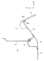
図2に示される如く、本実施形態における自動車車体においては、ダッシュパネル10が、車室内12とエンジンルーム14との間に配設されており、ダッシュパネル10の上部にはカウルリインフォースメント16が配設されている。なお、カウルリインフォースメント16は、左右のエプロン18を車幅方向に沿って直線状に連結している。
【0013】
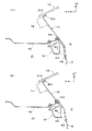
図1に示される如く、カウルリインフォースメント16は、アルミ等の軽金属の押出し材で構成されており、5角形状の閉断面構造となっている。カウルリインフォースメント16の上端部には、車幅方向に沿って上方に延びるフランジ16Aが形成されており、カウルリインフォースメント16の上端部と下壁部16Bとの間には、縦壁部16Cが形成されている。また、カウルリインフォースメント16の下壁部16Bの後端部には、車幅方向に沿って下方に延びるフランジ16Dが形成されている。
【0014】
カウルリインフォースメント16のフランジ16Aとフランジ16Dは、それぞれダッシュパネル10の前面に結合されており、ダッシュパネル10の上部は、ウインドシールドサポートパネル20となっている。ウインドシールドサポートパネル20は、平板状のパネルで構成されており、カウルリインフォースメント16からウインドシールドガラス24の下端縁部24Aに向かって延設されている。即ち、ウインドシールドサポートパネル20は、ウインドシールドガラス24との角度θが鋭角となるように車両前方上側に向かって上り傾斜に配設されている。
【0015】
なお、ウインドシールドサポートパネル20とウインドシールドガラス24との角度θは、ウインドシールドサポートパネル20の車両後方側に配設されるデフロスタノズル30の曲げ角αが小さくなり、デフロスタ性能が低下することがないように、60°≦θ<90°が好ましい。また、カウルリインフォースメント16はデフロスタノズル30の下方に配設されている。
【0016】
ウインドシールドサポートパネル20の上端縁部には、車両後方上側に向かってフランジ20Aが形成されており、このフランジ20A上にウインドシールドガラス24の下端縁部24Aが支持されている。
【0017】
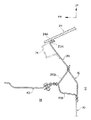
図3に示される如く、ウインドシールドサポートパネル20における助手席の略前方となる部位には、外気導入口32が形成されており、ダッシュパネル10の車室内12側には、ダッシュ縦ブレース34、36が車体上下方向に沿って配設されている。
【0018】
図4(A)に示される如く、ダッシュ縦ブレース34、36の上方から見た断面形状は、開口部を車両前方側へ向けたハット状となっており、開口部の両端部には、フランジ34A、36Aとフランジ34B、36Bが形成されている。また、これらのフランジ34A、36Aとフランジ34B、36Bはそれぞれダッシュパネル10の後面に結合されている。なお、図4(B)に示される如く、ダッシュパネル10とカウルリインフォースメント16との間に隙間37を形成し、リベットにより接合しても良い。
【0019】
図3に示される如く、ダッシュ縦ブレース34、36のフランジ34A、36Aとフランジ34B、36Bはそれぞれ、ダッシュパネル10を介してカウルリインフォースメント16の上端部となるフランジ16Aと下端部となるフランジ16Dとに結合されている(結合部P)。
【0020】
図1に示される如く、ウインドシールドサポートパネル20の前方には、ワイパーモータ40が配設されており、ワイパーモータ40はカウルアッパ42とカウルロア43との間に配設されている。また、カウルアッパ42の頂部42Aの前方近傍には、フード44の後端上面44Aが配設されている。
【0021】
カウルリインフォースメント16の下方近傍には、ブレーキマスターシリンダー46が配設されており、ブレーキマスターシリンダー46は、ダッシュパネル10を挟んでダッシュ縦ブレース34にボルト48とナット50によって固定されている。また、カウルリインフォースメント16の後方には、車幅方向に沿って、パイプ材からなるインパネリインフォースメント52が配設されており、カウルリインフォースメント16とインパネリインフォースメント52との間には、ブラケット54が架設されている。このブラケット54には、ブラケット56を介して、ブレーキペダル58が回転可能に軸支されている。
【0022】
次に、本実施形態の作用を説明する。
【0023】
本実施形態では、平板状のパネルで構成されたウインドシールドサポートパネル20が、カウルリインフォースメント16からウインドシールドガラス24の下端縁部24Aに向かって延設されている。また、ウインドシールドサポートパネル20は、ウインドシールドガラス24との角度θが鋭角となるように車両前方上側に向かって上り傾斜に配設されている。この結果、ウインドシールドガラス24の下部に前方斜め上方からの外力(図1の矢印F)が作用した場合には、ウインドシールドサポートパネル20に図1に矢印Mで示す曲げモーメントが発生し、ウインドシールドサポートパネル20は車両前方下側へ容易に変形する。このため、本実施形態では、ウインドシールドガラス支持部の変形荷重を小さくできる。
【0024】
また、本実施形態では、ウインドシールドサポートパネル20の変形を制約する部材、例えば、インストルメントパネル等が無い車両前方下側のカウル内に向かってウインドシールドサポートパネル20が変形する。この結果、ウインドシールドサポートパネル20が変形するスペースを確保するための空間を別途設定する必要が無い。このため、車体を大型化することなく、ウインドシールドガラス支持部の変形荷重を小さくできる。
【0025】
また、本実施形態では、万が一、ウインドシールドサポートパネル20を軸圧縮する方向の荷重(図1の矢印F1)が作用した場合にも、鋭角となっている角度θにより、前記荷重が、ウインドシールドガラス24に分散(分散荷重F2)され、ウインドシールドサポートパネル20に入る荷重F3が小さくなる。このため、衝突体に及ぼす衝撃を充分に吸収できる。
【0026】
また、本実施形態では、外気導入口32をウインドシールドサポートパネル20に設定したことによって、外気導入口32をカウルリインフォースメント16に設定する構成に比べ、カウルリインフォースメント16をウインドシールドガラス24から遠ざけることができ、ウインドシールドサポートパネル20の変形スペースの確保が可能になった。更に、外気導入口32をウインドシールドサポートパネル20に設定したことによって、ウインドシールドサポートパネル20が更に変形し易くなった。
【0027】
また、図5(A)に示される比較例のように、カウルリインフォースメント70をデフロスタノズル72と同じ高さに配設した場合には、デフロスタノズル72を逃げるために、カウルリインフォースメント70を車両前後方向に湾曲させる必要がある。この結果、カウルリインフォースメント70に上方から作用する荷重Fによって、カウルリインフォースメント70に捩じりモーメントNが発生する。これに対して、図5(B)に示される本実施形態では、カウルリインフォースメント16がデフロスタノズル30の下方に配設されており、カウルリインフォースメント16が車幅方向に直線状に延設されている。このため、カウルリインフォースメント16に上方から作用する荷重Fによって、カウルリインフォースメント16に、捩じりモーメントが発生することを抑制できる。この結果、カウルリインフォースメント16の剛性が向上し、ウインドシールドガラス24の支持剛性が向上すると共に、こもり音の防止効果及びNV性能を向上できる。なお、本実施形態では、直線状のカウルリインフォースメント16によって、図2に示される左右のサスタワー60を連結する構成にすることで、車両の操安性を向上することもできる。更に、図5(C)に示される如く、カウルリインフォースメント16は車幅方向に直線状に延設し、デフロスタノズル30は車幅方向に沿って湾曲させても良い。
【0028】
また、本実施形態では、ダッシュ縦ブレース34、36のフランジ34A、36Aとフランジ34B、36Bをそれぞれ、ダッシュパネル10を介してカウルリインフォースメント16の上端部となるフランジ16Aと下端部となるフランジ16Dとに結合(結合部P)したため、ダッシュパネル10及びダッシュ縦ブレース34、36の剛性を向上させることができる。この結果、車両衝突時のダッシュパネル10の変形量を低減できる。また、ダッシュパネル10の振動が抑制されるため、NV性能が向上する。更に、本実施形態の構成では、ダッシュ縦ブレース34、36とカウルリインフォースメント16とを溶接するための作業孔を、カウルリインフォースメント16に形成する必要がないため、作業孔によってカウルリインフォースメント16の剛性が低下することがない。
【0029】
また、本実施形態では、ウインドシールドサポートパネル20の前方に、ワイパーモータ40を搭載するためのスペースを確保することができるため、フード44の後端上面44Aを下方へ配設できる。この結果、乗員の視界を拡大できる。
【0030】
また、本実施形態では、外気導入口32をカウルリインフォースメント16の上方に配設されたウインドシールドサポートパネル20に形成しているため、外気導入口32からの水の侵入を低減でき、防水性能を向上できる。また、外気導入口32の開口面積を大きくできるため、換気性能を向上できる。
【0031】
また、本実施形態では、ブレーキマスターシリンダー46の車体への取付位置と、カウルリインフォースメント16とが接近しているため、ブレーキマスターシリンダー46の支持剛性が向上し、ブレーキ性能が向上する。
【0032】
また、本実施形態では、カウルリインフォースメント16が従来構造に比べ、車両下方に配設されているため、クラッチや足踏みパーキングブレーキ等の取付部をカウルリインフォースメント16に設定可能となる。この結果、取付部に介在するブラケットを無くすことができるため、ブラケットの変形等によるボデーの耐久性能の低下を防止できる。また、カウルリインフォースメント16が従来構造に比べ、車両下方に配設されているため、衝突時に、エンジンによって押圧される部位にカウルリインフォースメント16が近づくため、ダッシュパネル10の変形量を低減できる。また、カウルリインフォースメント16とエアコン本体やECU本体とが近づくため、これらの各部材とカウルリインフォースメント16とを繋ぐためのブラケットの小型化が可能となる。
【0033】
以上に於いては、本発明を特定の実施形態について詳細に説明したが、本発明はかかる実施形態に限定されるものではなく、本発明の範囲内にて他の種々の実施形態が可能であることは当業者にとって明らかである。例えば、上記実施形態では、ウインドシールドサポートパネル20を平板状のパネルで構成したが、これに代えて、ウインドシールドサポートパネル20の外気導入口32を形成する以外の部位の一部に、図1に二点鎖線で示すような折れ部20Bを設定し、ウインドシールドサポートパネル20を更に変形し易い構成としても良い。
【0034】
また、本実施形態では、カウルリインフォースメント16によって、左右のエプロン18を直線状に連結したが、これに代えて、カウルリインフォースメント16によって、左右のフロントピラー66(図2参照)を直線状に連結した構成としても良い。なお、カウルリインフォースメント16は、複数ある稜線S1、S2、S3、S4、S5の何れか最低1つが直線であれば良い。
【0035】
また、図6(A)に示される如く、カウルリインフォースメント16のフランジ16Aを、ウインドシールドサポートパネル20の延設方向に傾け、フランジ16Aの上端部におけるカウルリインフォースメント16の折れを無くし、NV性能を更に向上させた構成としても良い。
【0036】
また、図6(A)に二点鎖線で示すように、ウインドシールドサポートパネル20の上端部に、断面コ字状の補強部材74を追加しても良い。
【0037】
更に、図6(B)に示される如く、ダッシュパネル10とウインドシールドサポートパネル20とを分割しても良い。
【0038】
また、図7に示される如く、カウルリインフォースメント16をダッシュパネル10の後方、即ち、車室内12側に配置し、衝突時のダッシュパネル10の変形量を低減できる構成としても良い。なお、カウルリインフォースメント16の断面形状は、図1に限定されず、図7に示されるような他の形状でも良い。
【0039】
また、上記各実施形態では、カウルリインフォースメント16をアルミ等の軽金属の押出し材で構成したが、これに代えて、図8〜図16に示される如く、カウルリインフォースメント16を鉄等の金属のプレス材で構成しても良い。
【0040】
図8に示されるカウルリインフォースメント16は、アウタパネル78とアンダパネル80とウインドシールドサポートパネル20の下部20Cとで閉断面構造とされており、ダッシュパネル10の上端縁部に車両前方へ向けて形成されたフランジ10Aがアンダパネル80の下面80Aに接合されている。また、アンダパネル80の前端縁部80Bにカウルロア43の後端縁部43Aが固定されている。
【0041】
なお、図9に示される如く、アウタパネル78とカウルロア43とを一体とした構成としても良い。また、図10に示される如く、アンダパネル80とカウルロア43とを一体とした構成としても良い。更に、図11に示される如く、ウインドシールドサポートパネル20の上端縁部に形成するフランジ20Aは、車両前方下側に向かって形成しても良い。
【0042】
また、図12に示される如く、カウルリインフォースメント16の断面形状を、開口部を後方へ向けた断面コ字状とし、カウルリインフォースメント16とダッシュパネル10とで閉断面構造を形成することで、部品点数を低減した構成としても良い。
【0043】
また、図13に示される如く、カウルリインフォースメント16の断面形状を、開口部を前方へ向けた断面コ字状とし、カウルリインフォースメント16とダッシュパネル10とで閉断面構造を形成すると共に、カウルリインフォースメント16を車室内12側に配置し、衝突時のダッシュパネル10の変形量を低減できる構成としても良い。
【0044】
また、図14に示される如く、カウルリインフォースメント16の断面形状を、開口部を略下方へ向けたコ字状とし、カウルリインフォースメント16と車両前方へ延設したダッシュパネル10の上端縁部10Bとで閉断面構造を形成すると共に、ウインドシールドサポートパネル20の下端縁部に車両前方斜め下側に向けて形成したフランジ20Dをカウルリインフォースメント16の上壁部16Eに結合し、カウルリインフォースメント16によって衝突時のダッシュパネル10の変形量を低減できる構成としても良い。
【0045】
また、図15に示される如く、カウルリインフォースメント16の断面形状を、く字状とし、カウルリインフォースメント16と、車両前方へ延設したダッシュパネル10の上端縁部10Bと、車両前方斜め下側へ延設したウインドシールドサポートパネル20の延設部20Dとで閉断面構造を形成しても良い。また、図示を省略したが、ウインドシールドサポートパネル20の延設部20Dとカウルロア43を一体としても良い。
【0046】
また、図16に示される如く、カウルリインフォースメント16の断面形状を、L字状とし、カウルリインフォースメント16と、車両上方へ延設したダッシュパネル10の上端縁部10Cと、車両前方斜め下側へ延設したウインドシールドサポートパネル20の延設部20Dとで閉断面構造を形成しても良い。また、図示を省略したが、ウインドシールドサポートパネル20の延設部20Dとカウルロア43を一体としても良い。
【0047】
【発明の効果】
請求項1記載の本発明のウインドシールドガラス支持構造は、パネルで構成され、カウルリインフォースメントからウインドシールドガラスの下端縁部に向かって延設されたウインドシールドサポートパネルを有し、ウインドシールドサポートパネルは、ウインドシールドガラスとの角度が鋭角となるように車両前方上側に向かって上り傾斜に配設されており、ウインドシールドサポートパネルの車両後方側に配設されるデフロスタノズルの下方にカウルリインフォースメントが配設されているため、車体を大型化することなく、ウインドシールドガラス支持部の変形荷重を小さくできる。また、カウルリインフォースメントが従来構造に比べ、車両下方に配設されているため、衝突時に、ダッシュパネルの変形量を低減できる。
【0048】
請求項2記載の本発明のウインドシールドガラス支持構造は、パネルで構成され、カウルリインフォースメントからウインドシールドガラスの下端縁部に向かって延設されたウインドシールドサポートパネルを有し、ウインドシールドサポートパネルは、ウインドシールドガラスとの角度が鋭角となるように車両前方上側に向かって上り傾斜に配設されており、ウインドシールドサポートパネルに外気導入口が設定されているため、車体を大型化することなく、ウインドシールドガラス支持部の変形荷重を小さくできる。また、外気導入口をカウルリインフォースメントに設定する構成に比べ、ウインドシールドサポートパネルの変形スペースを確保することができると共に、ウインドシールドサポートパネルを更に容易に変形させることができる。
請求項3記載の本発明は、請求項1、2の何れか1項に記載のウインドシールドガラス支持構造において、カウルリインフォースメントを、車幅方向に沿って直線状に配設したため、請求項1、2の何れか1項に記載の効果に加えて、ウインドシールドガラスの支持剛性を向上できるという優れた効果を有する。
【図面の簡単な説明】
【図1】本発明の一実施形態に係るウインドシールドガラス支持構造を示す側断面図である。
【図2】本発明の一実施形態に係るウインドシールドガラス支持構造を示す車体斜め前方内側から見た斜視図である。
【図3】本発明の一実施形態に係るウインドシールドガラス支持構造を示す車体斜め後方から見た斜視図である。
【図4】(A)は図3の4−4線に沿った拡大断面図であり、(B)は他の実施形態における図3の4−4線に沿った拡大断面図である。
【図5】(A)は比較例に係るウインドシールドガラス支持構造の作用説明図であり、(B)は本発明の一実施形態に係るウインドシールドガラス支持構造の作用説明図であり、(C)は本発明の他の実施形態に係るウインドシールドガラス支持構造の斜視図である。
【図6】(A)及び(B)は本発明の他の実施形態に係るウインドシールドガラス支持構造の要部を示す側断面図である。
【図7】本発明の他の実施形態に係るウインドシールドガラス支持構造の要部を示す側断面図である。
【図8】本発明の他の実施形態に係るウインドシールドガラス支持構造の要部を示す側断面図である。
【図9】本発明の他の実施形態に係るウインドシールドガラス支持構造の要部を示す側断面図である。
【図10】本発明の他の実施形態に係るウインドシールドガラス支持構造の要部を示す側断面図である。
【図11】本発明の他の実施形態に係るウインドシールドガラス支持構造の要部を示す側断面図である。
【図12】本発明の他の実施形態に係るウインドシールドガラス支持構造の要部を示す側断面図である。
【図13】本発明の他の実施形態に係るウインドシールドガラス支持構造の要部を示す側断面図である。
【図14】本発明の他の実施形態に係るウインドシールドガラス支持構造の要部を示す側断面図である。
【図15】本発明の他の実施形態に係るウインドシールドガラス支持構造の要部を示す側断面図である。
【図16】本発明の他の実施形態に係るウインドシールドガラス支持構造の要部を示す側断面図である。
【図17】従来技術に係るウインドシールドガラス支持構造を示す側断面図である。
【符号の説明】
10 ダッシュパネル
16 カウルリインフォースメント
20 ウインドシールドサポートパネル
24 ウインドシールドガラス
30 デフロスタ
32 外気導入口
34 ダッシュ縦ブレース
36 ダッシュ縦ブレース[0001]
BACKGROUND OF THE INVENTION
The present invention relates to a windshield glass support structure, and more particularly to a windshield glass support structure for a vehicle such as an automobile that supports the windshield glass above a cowl reinforcement.
[0002]
[Prior art]
Conventionally, an example of a windshield glass support structure for a vehicle such as an automobile that supports the windshield glass above the cowl reinforcement is disclosed in Japanese Patent Application Laid-Open No. 11-321709.
[0003]
As shown in FIG. 17, in this structure, the windshield support 102 that supports the lower
[0004]
[Problems to be solved by the invention]
However, in such a structure, the deformation load of the
[0005]
An object of the present invention is to obtain a windshield glass support structure capable of reducing the deformation load of the windshield glass support portion without increasing the size of the vehicle body in consideration of the above facts.
[0006]
[Means for Solving the Problems]
The windshield glass support structure of the present invention according to
The windshield support panel is arranged in an upward inclination toward the upper front side of the vehicle so that the angle with the windshield glass is an acute angle.The cowl reinforcement is disposed below the defroster nozzle disposed on the vehicle rear side of the windshield support panel.It is characterized by being.
[0007]
Accordingly, the windshield support panel constituted by the panel extends from the cowl reinforcement toward the lower edge of the windshield glass, and the windshield support panel has an acute angle with the windshield glass. In this manner, the vehicle is disposed in an upward slope toward the upper front side of the vehicle. As a result, when an external force from obliquely upward and forward acts on the lower part of the windshield glass, the windshield support panel is easily deformed toward the lower front side of the vehicle. For this reason, the deformation load of the windshield glass support portion can be reduced. Further, since the windshield support panel is deformed toward the lower front side of the vehicle without a member that restricts deformation of the windshield support panel, the deformation load of the windshield glass support portion can be reduced without increasing the size of the vehicle body.Further, a cowl reinforcement is disposed below the defroster nozzle disposed on the vehicle rear side of the windshield support panel, and the cowl reinforcement is disposed below the vehicle as compared with the conventional structure. As a result, since the cowl reinforcement approaches the part pressed by the engine at the time of a collision, the deformation amount of the dash panel can be reduced.
[0008]
The present invention according to claim 2The windshield glass support structure is composed of a panel, and has a windshield support panel extending from the cowl reinforcement toward the lower edge of the windshield glass,
The windshield support panel is disposed in an upward slope toward the upper front side of the vehicle so that the angle with the windshield glass is an acute angle, and an outside air inlet is set in the windshield support panel.It is characterized by that.
[0009]
Accordingly, the windshield support panel constituted by the panel extends from the cowl reinforcement toward the lower edge of the windshield glass, and the windshield support panel has an acute angle with the windshield glass. In this manner, the vehicle is disposed in an upward slope toward the upper front side of the vehicle. As a result, when an external force from obliquely upward and forward acts on the lower part of the windshield glass, the windshield support panel is easily deformed toward the lower front side of the vehicle. For this reason, the deformation load of the windshield glass support portion can be reduced. Further, since the windshield support panel is deformed toward the lower front side of the vehicle without a member that restricts deformation of the windshield support panel, the deformation load of the windshield glass support portion can be reduced without increasing the size of the vehicle body. In addition, by setting the outside air introduction port to the windshield support panel, the cowl reinforcement can be kept away from the windshield glass compared to the configuration in which the outside air introduction port is set to the cowl reinforcement. Can be secured, and the windshield support panel can be more easily deformed.
According to a third aspect of the present invention, in the windshield glass support structure according to any one of the first and second aspects, the cowl reinforcement is arranged linearly along the vehicle width direction. And
Therefore, in the conventional cowl reinforcement, the center part in the vehicle width direction is curved so that it follows the windshield glass surface. Therefore, a torsional moment is easily generated with respect to the load from above. By arranging the ment in a straight line along the vehicle width direction, it is possible to suppress generation of a torsional moment with respect to a load from above. As a result, the support rigidity of the windshield glass is improved.
[0010]
DETAILED DESCRIPTION OF THE INVENTION
One embodiment of the windshield glass support structure in the present invention will be described with reference to FIGS.
[0011]
In the figure, the arrow FR indicates the vehicle front direction, the arrow UP indicates the vehicle upward direction, and the arrow IN indicates the vehicle width inside direction.
[0012]
As shown in FIG. 2, in the automobile body according to the present embodiment, the
[0013]
As shown in FIG. 1, the
[0014]
The
[0015]
Note that the angle θ between the
[0016]
A
[0017]
As shown in FIG. 3, an
[0018]
As shown in FIG. 4A, the cross-sectional shape viewed from above the dash
[0019]
As shown in FIG. 3, the
[0020]
As shown in FIG. 1, a
[0021]
A
[0022]
Next, the operation of this embodiment will be described.
[0023]
In the present embodiment, the
[0024]
Moreover, in this embodiment, the
[0025]
In the present embodiment, in the unlikely event that a load in the direction of axial compression of the windshield support panel 20 (arrow F1 in FIG. 1) is applied, the load is applied to the windshield by the acute angle θ. The load F3 dispersed in the glass 24 (dispersion load F2) and entering the
[0026]
In the present embodiment, since the outside
[0027]
When the
[0028]
In this embodiment, the
[0029]
Further, in the present embodiment, a space for mounting the
[0030]
In the present embodiment, since the outside
[0031]
In the present embodiment, since the mounting position of the
[0032]
Further, in the present embodiment, the
[0033]
Although the present invention has been described in detail with respect to specific embodiments, the present invention is not limited to such embodiments, and various other embodiments are possible within the scope of the present invention. It will be apparent to those skilled in the art. For example, in the above embodiment, the
[0034]
In the present embodiment, the left and
[0035]
Further, as shown in FIG. 6A, the
[0036]
Further, as indicated by a two-dot chain line in FIG. 6A, a U-shaped reinforcing
[0037]
Furthermore, as shown in FIG. 6B, the
[0038]
Further, as shown in FIG. 7, the
[0039]
In each of the above embodiments, the
[0040]
The
[0041]
As shown in FIG. 9, the
[0042]
In addition, as shown in FIG. 12, the
[0043]
As shown in FIG. 13, the
[0044]
Also, as shown in FIG. 14, the cross-sectional shape of the
[0045]
Further, as shown in FIG. 15, the
[0046]
Further, as shown in FIG. 16, the
[0047]
【The invention's effect】
The windshield glass support structure according to the first aspect of the present invention includes a windshield support panel that is configured by a panel and extends from the cowl reinforcement toward the lower end edge of the windshield glass. Is arranged in an upward slope toward the upper front side of the vehicle so that the angle with the windshield glass is an acute angle.A cowl reinforcement is disposed below the defroster nozzle disposed on the vehicle rear side of the windshield support panel.Therefore, the deformation load of the windshield glass support portion can be reduced without increasing the size of the vehicle body.Further, since the cowl reinforcement is disposed below the vehicle as compared with the conventional structure, the amount of deformation of the dash panel can be reduced at the time of a collision.
[0048]
The present invention according to claim 2The windshield glass support structure comprises a panel and has a windshield support panel extending from the cowl reinforcement toward the lower edge of the windshield glass. The windshield support panel is connected to the windshield glass. Windshield glass support part without increasing the size of the vehicle body because it is arranged in an upward slope toward the front upper side of the vehicle so that the angle becomes acute and the windshield support panel has an outside air introduction port The deformation load can be reduced. Further, as compared with a configuration in which the outside air introduction port is set to the cowl reinforcement, a deformation space for the windshield support panel can be secured and the windshield support panel can be further easily deformed.
The present invention as set forth in
[Brief description of the drawings]
FIG. 1 is a side sectional view showing a windshield glass support structure according to an embodiment of the present invention.
FIG. 2 is a perspective view showing a windshield glass support structure according to an embodiment of the present invention as seen from the obliquely forward inner side of the vehicle body.
FIG. 3 is a perspective view showing the windshield glass support structure according to one embodiment of the present invention as seen from the rear of the vehicle body.
4A is an enlarged cross-sectional view taken along line 4-4 of FIG. 3, and FIG. 4B is an enlarged cross-sectional view taken along line 4-4 of FIG. 3 in another embodiment.
5A is an operation explanatory view of a windshield glass support structure according to a comparative example, and FIG. 5B is an operation explanatory view of a windshield glass support structure according to an embodiment of the present invention. ) Is a perspective view of a windshield glass support structure according to another embodiment of the present invention.
FIGS. 6A and 6B are side sectional views showing a main part of a windshield glass support structure according to another embodiment of the present invention.
FIG. 7 is a side sectional view showing a main part of a windshield glass support structure according to another embodiment of the present invention.
FIG. 8 is a side sectional view showing a main part of a windshield glass support structure according to another embodiment of the present invention.
FIG. 9 is a side sectional view showing a main part of a windshield glass support structure according to another embodiment of the present invention.
FIG. 10 is a side sectional view showing a main part of a windshield glass support structure according to another embodiment of the present invention.
FIG. 11 is a side sectional view showing a main part of a windshield glass support structure according to another embodiment of the present invention.
FIG. 12 is a side sectional view showing a main part of a windshield glass support structure according to another embodiment of the present invention.
FIG. 13 is a side sectional view showing a main part of a windshield glass support structure according to another embodiment of the present invention.
FIG. 14 is a side sectional view showing a main part of a windshield glass support structure according to another embodiment of the present invention.
FIG. 15 is a side sectional view showing a main part of a windshield glass support structure according to another embodiment of the present invention.
FIG. 16 is a side sectional view showing a main part of a windshield glass support structure according to another embodiment of the present invention.
FIG. 17 is a side sectional view showing a windshield glass support structure according to the prior art.
[Explanation of symbols]
10 Dash panel
16 cowl reinforcement
20 Windshield support panel
24 Windshield glass
30 Defroster
32 Outside air inlet
34 Dash vertical brace
36 dash vertical brace
Claims (3)
前記ウインドシールドサポートパネルは、ウインドシールドガラスとの角度が鋭角となるように車両前方上側に向かって上り傾斜に配設されており、前記ウインドシールドサポートパネルの車両後方側に配設されるデフロスタノズルの下方に前記カウルリインフォースメントが配設されていることを特徴とするウインドシールドガラス支持構造。It has a windshield support panel that consists of panels and extends from the cowl reinforcement toward the lower edge of the windshield glass,
The windshield support panel is disposed in an upward inclination toward the upper front side of the vehicle so that the angle with the windshield glass is an acute angle, and the defroster nozzle is disposed on the rear side of the windshield support panel. The windshield glass support structure , wherein the cowl reinforcement is disposed below the window.
前記ウインドシールドサポートパネルは、ウインドシールドガラスとの角度が鋭角となるように車両前方上側に向かって上り傾斜に配設されており、前記ウインドシールドサポートパネルに外気導入口が設定されていることを特徴とするウインドシールドガラス支持構造。 The windshield support panel is disposed in an upward slope toward the upper front side of the vehicle so that the angle with the windshield glass is an acute angle, and an outside air inlet is set in the windshield support panel. Features a windshield glass support structure.
Priority Applications (1)
| Application Number | Priority Date | Filing Date | Title |
|---|---|---|---|
| JP2001396678A JP3711930B2 (en) | 2001-12-27 | 2001-12-27 | Windshield glass support structure |
Applications Claiming Priority (1)
| Application Number | Priority Date | Filing Date | Title |
|---|---|---|---|
| JP2001396678A JP3711930B2 (en) | 2001-12-27 | 2001-12-27 | Windshield glass support structure |
Publications (3)
| Publication Number | Publication Date |
|---|---|
| JP2003191750A JP2003191750A (en) | 2003-07-09 |
| JP2003191750A5 JP2003191750A5 (en) | 2005-06-09 |
| JP3711930B2 true JP3711930B2 (en) | 2005-11-02 |
Family
ID=27602709
Family Applications (1)
| Application Number | Title | Priority Date | Filing Date |
|---|---|---|---|
| JP2001396678A Expired - Fee Related JP3711930B2 (en) | 2001-12-27 | 2001-12-27 | Windshield glass support structure |
Country Status (1)
| Country | Link |
|---|---|
| JP (1) | JP3711930B2 (en) |
Cited By (1)
| Publication number | Priority date | Publication date | Assignee | Title |
|---|---|---|---|---|
| CN102883943A (en) * | 2010-05-11 | 2013-01-16 | 日产自动车株式会社 | Vehicle body structure |
Families Citing this family (10)
| Publication number | Priority date | Publication date | Assignee | Title |
|---|---|---|---|---|
| JP4978147B2 (en) * | 2006-10-17 | 2012-07-18 | トヨタ車体株式会社 | Car cowl top structure |
| JP2009073251A (en) * | 2007-09-19 | 2009-04-09 | Mazda Motor Corp | Glass supporting structure for automobile |
| JP2009113568A (en) * | 2007-11-03 | 2009-05-28 | Kanto Auto Works Ltd | Front part structure for automobile |
| JP5176501B2 (en) * | 2007-11-28 | 2013-04-03 | トヨタ自動車株式会社 | Cowl structure at the front of the vehicle |
| JP5577934B2 (en) * | 2010-08-17 | 2014-08-27 | マツダ株式会社 | Front window support structure |
| JP2013082336A (en) * | 2011-10-11 | 2013-05-09 | Suzuki Motor Corp | Structure of front section periphery of vehicle |
| JP5841441B2 (en) * | 2012-02-01 | 2016-01-13 | 株式会社神戸製鋼所 | Front cowling member for automobile |
| JP5923845B2 (en) * | 2012-10-04 | 2016-05-25 | 本田技研工業株式会社 | Windshield glass support structure |
| JP6241463B2 (en) * | 2015-08-28 | 2017-12-06 | トヨタ自動車株式会社 | Cowl structure |
| JP6816662B2 (en) * | 2017-06-26 | 2021-01-20 | トヨタ自動車株式会社 | Vehicle front structure |
-
2001
- 2001-12-27 JP JP2001396678A patent/JP3711930B2/en not_active Expired - Fee Related
Cited By (2)
| Publication number | Priority date | Publication date | Assignee | Title |
|---|---|---|---|---|
| CN102883943A (en) * | 2010-05-11 | 2013-01-16 | 日产自动车株式会社 | Vehicle body structure |
| CN102883943B (en) * | 2010-05-11 | 2015-03-18 | 日产自动车株式会社 | Vehicle body structure |
Also Published As
| Publication number | Publication date |
|---|---|
| JP2003191750A (en) | 2003-07-09 |
Similar Documents
| Publication | Publication Date | Title |
|---|---|---|
| US6361102B1 (en) | Front automotive reinforcement structure for distributing impact force | |
| JPH1045034A (en) | Front structure of car body | |
| JP3711930B2 (en) | Windshield glass support structure | |
| JP3444773B2 (en) | Car fender structure | |
| JP5245639B2 (en) | Front body structure of automobile | |
| JP3653807B2 (en) | Side sill reinforcement structure for automobiles | |
| JP2001322562A (en) | Vehicular cowl structure | |
| JP2009274622A (en) | Cowl top structure for vehicle | |
| JP3848563B2 (en) | Vehicle front structure | |
| JP2002166855A (en) | Front vehicle body structure | |
| US6209914B1 (en) | Body shell for a passenger car with reduced overall deformation | |
| JP5076718B2 (en) | Front body structure of automobile | |
| JP2002302068A (en) | Structure of cowl part of automobile | |
| JP3783317B2 (en) | Cab underframe structure | |
| JPH10278847A (en) | Collision safety structure of cab | |
| JP2001130450A (en) | Front body structure automobile | |
| WO2011075011A1 (en) | Reinforcement for vehicle door with door extension | |
| JP3527420B2 (en) | Car front structure | |
| JP3001173B2 (en) | Car | |
| JP4505781B2 (en) | Vehicle floor structure | |
| JP3478459B2 (en) | Car body front structure | |
| JP3006152B2 (en) | Car cowl structure | |
| JP3836023B2 (en) | Vehicle cab structure | |
| JP3287207B2 (en) | Connection structure of front side member and front pillar | |
| JP4140186B2 (en) | Vehicle fender structure |
Legal Events
| Date | Code | Title | Description |
|---|---|---|---|
| A521 | Written amendment |
Free format text: JAPANESE INTERMEDIATE CODE: A523 Effective date: 20040820 |
|
| A621 | Written request for application examination |
Free format text: JAPANESE INTERMEDIATE CODE: A621 Effective date: 20040820 |
|
| A977 | Report on retrieval |
Free format text: JAPANESE INTERMEDIATE CODE: A971007 Effective date: 20050322 |
|
| A131 | Notification of reasons for refusal |
Free format text: JAPANESE INTERMEDIATE CODE: A131 Effective date: 20050329 |
|
| A521 | Written amendment |
Free format text: JAPANESE INTERMEDIATE CODE: A523 Effective date: 20050530 |
|
| TRDD | Decision of grant or rejection written | ||
| A01 | Written decision to grant a patent or to grant a registration (utility model) |
Free format text: JAPANESE INTERMEDIATE CODE: A01 Effective date: 20050726 |
|
| A61 | First payment of annual fees (during grant procedure) |
Free format text: JAPANESE INTERMEDIATE CODE: A61 Effective date: 20050808 |
|
| R150 | Certificate of patent or registration of utility model |
Free format text: JAPANESE INTERMEDIATE CODE: R150 Ref document number: 3711930 Country of ref document: JP Free format text: JAPANESE INTERMEDIATE CODE: R150 |
|
| FPAY | Renewal fee payment (event date is renewal date of database) |
Free format text: PAYMENT UNTIL: 20080826 Year of fee payment: 3 |
|
| FPAY | Renewal fee payment (event date is renewal date of database) |
Free format text: PAYMENT UNTIL: 20090826 Year of fee payment: 4 |
|
| FPAY | Renewal fee payment (event date is renewal date of database) |
Free format text: PAYMENT UNTIL: 20100826 Year of fee payment: 5 |
|
| FPAY | Renewal fee payment (event date is renewal date of database) |
Free format text: PAYMENT UNTIL: 20100826 Year of fee payment: 5 |
|
| FPAY | Renewal fee payment (event date is renewal date of database) |
Free format text: PAYMENT UNTIL: 20110826 Year of fee payment: 6 |
|
| FPAY | Renewal fee payment (event date is renewal date of database) |
Free format text: PAYMENT UNTIL: 20110826 Year of fee payment: 6 |
|
| FPAY | Renewal fee payment (event date is renewal date of database) |
Free format text: PAYMENT UNTIL: 20120826 Year of fee payment: 7 |
|
| FPAY | Renewal fee payment (event date is renewal date of database) |
Free format text: PAYMENT UNTIL: 20130826 Year of fee payment: 8 |
|
| LAPS | Cancellation because of no payment of annual fees |