WO2011024859A1 - ゴルフボール - Google Patents
ゴルフボール Download PDFInfo
- Publication number
- WO2011024859A1 WO2011024859A1 PCT/JP2010/064385 JP2010064385W WO2011024859A1 WO 2011024859 A1 WO2011024859 A1 WO 2011024859A1 JP 2010064385 W JP2010064385 W JP 2010064385W WO 2011024859 A1 WO2011024859 A1 WO 2011024859A1
- Authority
- WO
- WIPO (PCT)
- Prior art keywords
- golf ball
- intermediate layer
- hardness
- rib
- ball
- Prior art date
Links
Images


Classifications
-
- A—HUMAN NECESSITIES
- A63—SPORTS; GAMES; AMUSEMENTS
- A63B—APPARATUS FOR PHYSICAL TRAINING, GYMNASTICS, SWIMMING, CLIMBING, OR FENCING; BALL GAMES; TRAINING EQUIPMENT
- A63B37/00—Solid balls; Rigid hollow balls; Marbles
- A63B37/0003—Golf balls
- A63B37/0023—Covers
- A63B37/0029—Physical properties
- A63B37/0031—Hardness
-
- A—HUMAN NECESSITIES
- A63—SPORTS; GAMES; AMUSEMENTS
- A63B—APPARATUS FOR PHYSICAL TRAINING, GYMNASTICS, SWIMMING, CLIMBING, OR FENCING; BALL GAMES; TRAINING EQUIPMENT
- A63B37/00—Solid balls; Rigid hollow balls; Marbles
- A63B37/0003—Golf balls
-
- A—HUMAN NECESSITIES
- A63—SPORTS; GAMES; AMUSEMENTS
- A63B—APPARATUS FOR PHYSICAL TRAINING, GYMNASTICS, SWIMMING, CLIMBING, OR FENCING; BALL GAMES; TRAINING EQUIPMENT
- A63B37/00—Solid balls; Rigid hollow balls; Marbles
- A63B37/0003—Golf balls
- A63B37/0023—Covers
- A63B37/0029—Physical properties
- A63B37/0033—Thickness
-
- A—HUMAN NECESSITIES
- A63—SPORTS; GAMES; AMUSEMENTS
- A63B—APPARATUS FOR PHYSICAL TRAINING, GYMNASTICS, SWIMMING, CLIMBING, OR FENCING; BALL GAMES; TRAINING EQUIPMENT
- A63B37/00—Solid balls; Rigid hollow balls; Marbles
- A63B37/0003—Golf balls
- A63B37/0038—Intermediate layers, e.g. inner cover, outer core, mantle
- A63B37/004—Physical properties
- A63B37/0043—Hardness
-
- A—HUMAN NECESSITIES
- A63—SPORTS; GAMES; AMUSEMENTS
- A63B—APPARATUS FOR PHYSICAL TRAINING, GYMNASTICS, SWIMMING, CLIMBING, OR FENCING; BALL GAMES; TRAINING EQUIPMENT
- A63B37/00—Solid balls; Rigid hollow balls; Marbles
- A63B37/0003—Golf balls
- A63B37/0038—Intermediate layers, e.g. inner cover, outer core, mantle
- A63B37/004—Physical properties
- A63B37/0045—Thickness
-
- A—HUMAN NECESSITIES
- A63—SPORTS; GAMES; AMUSEMENTS
- A63B—APPARATUS FOR PHYSICAL TRAINING, GYMNASTICS, SWIMMING, CLIMBING, OR FENCING; BALL GAMES; TRAINING EQUIPMENT
- A63B37/00—Solid balls; Rigid hollow balls; Marbles
- A63B37/0003—Golf balls
- A63B37/007—Characteristics of the ball as a whole
- A63B37/0072—Characteristics of the ball as a whole with a specified number of layers
- A63B37/0076—Multi-piece balls, i.e. having two or more intermediate layers
-
- A—HUMAN NECESSITIES
- A63—SPORTS; GAMES; AMUSEMENTS
- A63B—APPARATUS FOR PHYSICAL TRAINING, GYMNASTICS, SWIMMING, CLIMBING, OR FENCING; BALL GAMES; TRAINING EQUIPMENT
- A63B37/00—Solid balls; Rigid hollow balls; Marbles
- A63B37/0003—Golf balls
- A63B37/007—Characteristics of the ball as a whole
- A63B37/0077—Physical properties
- A63B37/0092—Hardness distribution amongst different ball layers
- A63B37/00922—Hardness distribution amongst different ball layers whereby hardness of the cover is lower than hardness of the intermediate layers
-
- A—HUMAN NECESSITIES
- A63—SPORTS; GAMES; AMUSEMENTS
- A63B—APPARATUS FOR PHYSICAL TRAINING, GYMNASTICS, SWIMMING, CLIMBING, OR FENCING; BALL GAMES; TRAINING EQUIPMENT
- A63B37/00—Solid balls; Rigid hollow balls; Marbles
- A63B37/0003—Golf balls
- A63B37/007—Characteristics of the ball as a whole
- A63B37/0077—Physical properties
- A63B37/0097—Layers interlocking by means of protrusions or inserts, lattices or the like
Definitions
- the present invention relates to a golf ball having a multilayer structure.
- One type of golf balls is a multi-layered golf ball comprising a plurality of layers.
- One example is a golf ball described in Patent Document 1.
- This golf ball is configured by forming a rib around a spherical main body portion and further forming an intermediate layer in a recess surrounded by the rib. And the following effects are produced by making the hardness of an intermediate layer larger than the hardness of a rib. That is, generally, when the golf ball and the golf club come into contact with each other, the ball is twisted in the circumferential direction by friction with the club face surface. The twisted ball is restored to its original state by elastic resistance, and a force opposite to the backspin is applied to the ball. At this time, the greater the deformation of the twisted ball, the more backspin is suppressed and the flight distance can be extended.
- the elastic resistance that the ball tries to return to the original state is promoted by the rib, backspin can be effectively suppressed. That is, in this golf ball, since the hardness of the rib is lower than the hardness of the intermediate layer, the rib deforms more greatly than the intermediate layer by hitting. Since the rib is configured not as a simple protrusion but as a wall surrounding the periphery of the intermediate layer, the force of the entire wall acts greatly from the periphery of the intermediate layer when the rib is restored. Force opposite to the pin is encouraged. As a result, the flight distance can be greatly increased. Such an effect is particularly apparent when hitting with a club aiming at a flight distance such as a driver.
- the golf ball is suitable for hitting by a driver, there is a problem in an approach shot using an iron.
- An object of the present invention is to provide a golf ball that can obtain a flight distance by a driver and can accurately generate backspin even in an approach shot.
- a golf ball according to the present invention includes a spherical main body, a plurality of ribs formed on the surface of the main body, a recess surrounded by the ribs, and an intermediate layer having a hardness higher than that of the ribs, An inner cover that covers the intermediate layer, and an outer cover that covers the inner cover and has a lower hardness than the inner cover.
- the rib is deformed more greatly than the intermediate layer by impact. Since the rib is configured not as a simple protrusion but as a wall surrounding the periphery of the intermediate layer, the force of the entire wall acts greatly from the periphery of the intermediate layer when the rib is restored. Force opposite to the pin is encouraged. As a result, the flight distance can be greatly increased. Such an effect is particularly apparent when hitting with a club aiming at a flight distance such as a driver.
- the inner cover is arranged between the intermediate layer and the outer cover, the hitting force is transmitted to the intermediate layer and the rib in approach shots where the deformation of the ball is small, such as hitting with an iron. Can be suppressed. As a result, it is possible to prevent the force that cancels back spin described above from being promoted. Therefore, according to the golf ball of the present invention, the backspin can be reduced to increase the flight distance when hit by the driver, while the backspin can be applied when hitting by the iron, and the ball is stopped accurately. be able to.
- the hardness of the outer cover is lower than the hardness of the inner cover, it is possible to soften the hit feeling.
- the deformation of the outer cover can be increased, the backspin can be exerted greatly when hit with an iron.
- the hardness of the inner cover is higher than that of the outer cover, even if the outer cover has a soft feel, the inner cover can improve the resilience performance. Therefore, the flight distance can be extended. For example, when the Shore D hardness of the inner cover is 55 to 70, the resilience performance can be improved. Further, when the Shore D hardness of the outer cover is set to 54 to 60, the hit feeling can be softened.
- the hardness of the inner cover can be made higher than the hardness of the intermediate layer. Thereby, the inner hardness in the radial direction is lower than that of the inner cover, and the hardness of the hit feeling by the inner cover can be reduced.
- the total thickness of the inner cover and the outer cover can be 1.9 mm or more. This is because the amount of deformation of the ball due to the hit with the approach using the wedge may be about 2.0 mm. If the total thickness of the inner cover and the outer cover is set to 1.9 mm or more, the wedge is removed. The hit by the approach used is not easily transmitted to the intermediate layer and the rib, and backspin offset by the rib can be reliably reduced. Therefore, the ball can be stopped accurately in the approach shot by the wedge. This layer thickness also improves the durability of the ball.
- the main body and the rib can be integrated, and the hardness of the main body can be made the same as the hardness of the rib. According to this configuration, since the hardness of the intermediate layer is higher than the hardness of the main body portion as well as the hardness of the rib, the spin rate can be suppressed and the flight distance can be improved.
- FIG. 1 is a cross-sectional view showing a first embodiment of a golf ball according to the present invention.
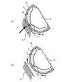
- FIG. 2 is a perspective view showing a core of the golf ball in FIG. 1. It is sectional drawing which shows the state at the time of the hit
- FIG. 6 is a perspective view showing another embodiment of the core of the golf ball according to FIG. 1. It is sectional drawing which shows the other example of the core of FIG. It is sectional drawing which shows the other example of the core of FIG. It is sectional drawing which shows the other example of the core of FIG. It is sectional drawing which shows the other example of the core of FIG. It is sectional drawing which shows the other example of the core of FIG. It is sectional drawing which shows the other example of the core of FIG. It is sectional drawing which shows the other example of the core of FIG. It is a figure which shows an example of the manufacturing method of the golf ball shown in FIG. It is a figure which shows an example of the manufacturing method of the golf ball shown in FIG.
- FIG. 1 is a cross-sectional view of a golf ball according to this embodiment.
- a golf ball 1 is a multi-piece golf ball in which a core 3 is covered with an intermediate layer 5, an inner cover, and an outer cover 15.
- the diameter of the golf ball needs to be 42.67 mm or more according to the rules (see R & A and USGA). However, in consideration of aerodynamic characteristics and the like, it is preferable to make the ball diameter as small as possible, for example, 42.7 to 42.9 mm.
- the core 3 is comprised with the rubber composition, and as shown in FIG. 2, it is comprised from the spherical main-body part 9 and the three ribs (projection) 11 integrally formed in the surface. Each rib 11 is drawn on the surface of the main body portion 9 and extends along a great circle orthogonal to each other, and eight ribs 13 are formed on the surface of the main body portion 9 by these ribs 11.
- the diameter of the main body 9 is preferably 29.5 to 36.7 mm, and more preferably 29.9 to 35.1 mm.
- the height of the rib 11 is preferably 1.0 to 4.0 mm, and more preferably 1.2 to 2.0 mm.
- the core 3 has a surface Shore D hardness of preferably 50 to 60, and more preferably 53 to 57. This is because if the value is less than 50, the rebound is reduced and the feel without a core is obtained. If the value is more than 60, the feel is too hard and the feel is deteriorated.
- each rib 11 is formed in a trapezoidal cross section so that its width increases as it goes to the main body 9 side.
- the width a of the upper end portion on the radially outer side of the rib 11 is preferably 1.5 to 2.5 mm, and the width b of the lower end portion on the radially inner side of the rib 11 is 3.0 to 6.0 mm. It is preferable to do. Although it may be outside this range, by setting the lower limit of each end of the rib 11 in this way, when filling the intermediate layer 5 at the time of manufacture, filling of the intermediate layer 5 resulting from the pressure of mold clamping The rib 11 can be prevented from being deformed by pressure. As a result, the core 9 can be accurately held at the center of the mold.
- the intermediate layer 5 is composed of a rubber composition or an elastomer, covers the surface of the core 3, and has a substantially spherical outer shape. As shown in FIG. 1, the intermediate layer 5 has a layer thickness substantially the same as the height of the ribs 11 and is filled in eight concave portions 13 surrounded by the ribs 11, and the tips of the ribs 11 are exposed from the surface of the intermediate layer 5. is doing.
- the hardness of the intermediate layer 5 needs to be higher than the hardness of the core 3 in order to suppress backspin described later, and the Shore D hardness of the surface of the intermediate layer 5 is preferably 53 to 62, preferably 56 to More preferably, it is 60.
- the mid layer 5 preferably has a Shore D hardness of 1 to 5 higher than the hardness of the core 3.
- the inner cover 7 is made of an elastomer and covers the tip of the rib 11 and the intermediate layer 5.
- the layer thickness of the inner cover 7 is preferably 0.9 to 1.7 mm, and more preferably 0.9 to 1.5 mm. Although it is possible outside this range, the reason is that if the layer thickness of the inner cover 7 is smaller than 0.9 mm, the ball becomes too soft and the resilience performance is lowered and the durability is lowered. On the other hand, if it exceeds 1.7 mm, the hit feeling becomes too hard.
- the hardness of the inner cover 7 is preferably 55 to 70 on the surface of the inner cover 7, more preferably 58 to 68, and particularly preferably 64 to 68.
- the outer cover 15 is made of an elastomer, covers the inner cover 7, and has predetermined dimples (not shown) formed on the surface thereof.
- the layer thickness of the outer cover 15 is preferably 0.8 to 1.3 mm, and more preferably 0.9 to 1.2 mm. Outside this range is possible, but the reason is that when the outer cover 15 has a layer thickness smaller than 0.8 mm, the durability of the outer cover 15 is significantly lowered and molding becomes difficult, while it exceeds 1.3 mm. This is because the rebound is too low and the flight distance cannot be increased.
- the hardness is preferably 54 to 60, and more preferably 56 to 60 on the surface of the golf ball.
- the layer thickness of the outer cover 15 is a value obtained by measuring the distance from an arbitrary point on the outermost side in the radial direction where no dimples are formed to an arbitrary point in contact with the intermediate layer along the normal line.
- the total layer thickness of the inner cover 7 and the outer cover 15 is preferably 1.9 to 3.0 mm, more preferably 2.0 to 2.8 mm. A thickness of 0 to 2.6 mm is particularly preferable. Thereby, preferable resilience performance and durability can be obtained.
- dimples formed on the outer cover 15 will be described.
- the dimple shape a circular shape, various polygonal shapes, an elliptical shape, or the like can be used alone or in combination.
- the diameter can be set to 2.5 to 4.5 mm.
- the number of dimples is 350 to 450, preferably 360 to 410. If the number of dimples is too large, the ball trajectory may be lowered and the flight distance may be reduced. On the other hand, if the number of dimples is too small, the trajectory becomes high and the flight distance may be reduced.
- the area ratio of dimples to the spherical surface of the golf ball is preferably 73% or more, and more preferably 75% or more.
- the core 3 can be manufactured from a known rubber composition containing a base rubber, a cross-linking material, a metal salt of an unsaturated carboxylic acid, a filler, and the like.
- a base rubber natural rubber, polyisobrene rubber, styrene butadiene rubber, EPDM, or the like can be used, but it is particularly preferable to use high cis polybutadiene having 80% or more of cis 1,4 bonds.
- crosslinking agent for example, organic peroxides such as dicumyl peroxide and t-butyl peroxide can be used, and it is particularly preferable to use dicumyl peroxide.
- the amount is 0.3 to 5 parts by weight, preferably 0.5 to 2 parts by weight, based on 100 parts by weight of the base rubber.
- the metal salt of the unsaturated carboxylic acid it is preferable to use a metal salt of a monovalent or divalent unsaturated carboxylic acid having 3 to 8 carbon atoms such as acrylic acid or methacrylic acid, but zinc acrylate is used. Then, the resilience performance of the ball can be improved, which is particularly preferable.
- the blending amount is preferably 10 to 40 parts by weight with respect to 100 parts by weight of the base rubber.
- the filler those usually blended in the core can be used, and for example, zinc oxide, barium sulfate, calcium carbonate, etc. can be used.
- the blending amount is preferably 2 to 50 parts by weight with respect to 100 parts by weight of the base rubber.
- the intermediate layer 5 is composed of a rubber composition or an elastomer as described above, but when composed of a rubber composition, it can be composed of the same components as the core 3 described above. However, in order to raise hardness from the core 3, it is preferable to increase the compounding quantity of unsaturated carboxylic acid.
- the intermediate layer 5 is composed of an elastomer, for example, styrene-butadiene-styrene block copolymer (SBS), styrene-isoprene-styrene block copolymer (SIS), styrene-ethylene-butylene-styrene block copolymer (SEBS), styrene- Styrenic thermoplastic elastomers such as ethylene-propylene-styrene block copolymer (SEPS); olefinic thermoplastic elastomers with polyethylene or polypropylene as hard segments and butadiene rubber, acrylonitrile butadiene rubber, or ethylene / propylene rubber as soft segments; Vinyl chloride with crystalline polyvinyl chloride as the hard segment and amorphous polyvinyl chloride or acrylonitrile butadiene rubber as the soft segment -Based thermoplastic elastomer; polyurethane-based thermoplastic e
- the inner cover 7 and the outer cover 15 are made of a known elastomer, and the same one as the above intermediate layer can be used.
- ionomer resin is more suitable for resilience, durability, moldability, and the like.
- the ionomer resin for example, High Milan 1706, 1605 manufactured by Mitsui DuPont Polychemical Co., Ltd. or Surlyn 9910, 8940, 8150, 8120, 8320 manufactured by DuPont Co., Ltd. can be used.
- the inner cover 7, for example, Duon ionomer HPF1000 or HPF2000 can be suitably used in terms of softness and resilience.
- As the outer cover 15, for example, Ionomer HPC AD1043 manufactured by DuPont can be suitably used in terms of resilience and scratch resistance.
- the elastic resistance of the ball to return to the original state is promoted by the ribs 11, so that backspin can be effectively suppressed.
- the rib 11 has a hardness lower than that of the intermediate layer 5 because the rib 11 has a hardness lower than that of the intermediate layer 5. Deform. Due to this impact, a stress that generates back spin B acts on the ball itself. When the ball leaves the club C, as shown in FIG. 3B, the deformation of the rib 11 having low hardness is restored, so that the force F acts in a direction to cancel back spin B by this restoration. To do.
- the spin is reduced and the jump angle is increased, so that the flight distance can be further extended.
- the rib 11 is not a mere protrusion, but is configured as a wall surrounding the periphery of the intermediate layer 5, so that the force when the rib 11 is restored depends on the entire wall 5. Acts greatly from the surroundings, and this promotes a force F opposite to the backspin B. Therefore, the backspin amount is reduced and the flight distance can be greatly increased. Such an effect becomes prominent particularly when a club aiming at a flight distance such as a driver is used.
- the current state is indicated by a solid line, and the state immediately before that is indicated by a broken line.
- the inner cover 7 is disposed between the intermediate layer 5 and the outer cover 15, the striking force is applied to the intermediate layer 5 and the rib 11 in approach shots where the deformation of the ball is small, such as hitting with an iron. It is possible to suppress transmission. As a result, it is possible to prevent the force that cancels back spin described above from being promoted. Therefore, when the driver hits the ball, the backspin can be reduced and the flight distance can be increased. On the other hand, when the ball is hit by the iron, the backspin can be applied and the ball can be stopped accurately.
- the hardness of the outer cover 15 is lowered, the feel on impact can be softened. Moreover, since the outer cover 15 has a low hardness, it can be easily deformed. That is, since the outer cover 15 which is the outermost layer is easily deformed, the backspin can be exerted greatly when hit with an iron.
- the inner cover 7 can improve the resilience performance even if the outer cover 15 has a soft feel. Thereby, even if the club head speed is low, high resilience performance can be obtained and the flight distance can be extended.
- the rib 11 is formed on the core 3 and the hardness of the mid layer 5 is made higher than the hardness of the rib 11, thereby suppressing the back spin as described above. It has gained.
- Such a backspin suppression effect can be adjusted by the height of the ribs 11 and the height difference between the intermediate layer 5 and the ribs 11, and thus the flight distance can also be adjusted. It is also possible to adjust the flight distance by adjusting the lift of the ball depending on the shape of the dimples. Such ball performance adjustment is performed according to the level of the user and the required performance.
- the lift can be set as follows. For example, immediately after hitting with a driver, for example, the ball speed is 62 m / s, the spin rate is 2400 rpm, and the spin parameter is 0.09. The lift coefficient at this time is preferably 0.13 to 0.17. Immediately after hitting with an iron, for example, the ball speed is 46 m / s, the spin amount is 4700 rpm, and the spin parameter is 0.23. The spin rate is about 2500 rpm. The spin parameter at this time is 0.12. The lift coefficient when the spin parameter is 0.12 is preferably 0.16 to 0.20. As described above, if the lift coefficient is too high, the flight distance decreases due to blowing up.
- the lift coefficient is too small, the trajectory will be low, the falling angle will be low, and the stop will be worse when hitting from a rough with an iron. Therefore, it is preferable to set the lift as described above in the dimple design or the like in view of the structure of the ball described above.
- the force acting on the golf ball is expressed by the following ballistic equation.
- F FL + FD + Mg
- FD Drag (N)
- M Mass of golf ball (kg)
- g Gravitational acceleration (m / s 2 )
- the lift FL and drag FD are expressed by the following formulas, respectively.
- the measurement of spin parameters, lift, etc. can be performed by using a TrackMan manufactured by Interactive Sports Games Co. Ltd. for a ball hit with a golf robot.
- This TrackMan is a device that uses the radar Doppler effect to measure the tracking of a flying ball.
- FIG. 4 is a perspective view of the core in which a notch is formed
- FIG. 5 is a cross-sectional view of FIG.
- the notch 24 is formed to have a bottom surface 24 a extending along a tangential plane H passing through the intersection point P of the great circle. That is, the notch 24 is formed by cutting the rib 11 by the tangential plane H.
- the notches 24 By forming the notches 24 in this way, the four recesses 13 arranged around the intersection point P of the great circle communicate with each other, and as will be described later, the intermediate layer material is passed through the notches 24 as shown in FIG. 13 can be easily distributed.
- the said inclination turns into a draft, for example, when a shaping
- the notch 24 is formed as described above, as shown in FIG. 5, the arc direction of the upper end where the notch 24 is not formed in each arc section S delimited by each intersection P in the rib 11. It is preferable that the length L is 10 mm or more.
- the cutout portion 24 may be formed to have a bottom surface 24 a that passes through the middle in the height direction of the rib 11 and extends along a plane H 2 that is perpendicular to the normal line n.
- the notch 24 is formed by setting the distance D from the upper end of the virtual rib 11 to the bottom surface 24 a to 1.2 mm or more when there is no notch 24. It is preferable to do.
- the length L is preferably 10 mm or more as described above.
- the bottom surface 24a of the notch 24 can be formed along a plane that forms an angle of 91 to 93 ° with the normal line n, thereby forming a draft angle.
- a notch can be provided in the middle of each arc section S of the rib 11. That is, as shown in FIG. 8A, two bottom surfaces 25a extending from one point on the normal line m of the main body 9 passing through the center point Q in the arc direction of the arc section S to the intersection P side on both ends are provided.
- the notch 25 can also be formed. In this case, it is preferable that the bottom surface 25a and the normal line m form 45 to 48 degrees when viewed from the front. If it does in this way, as above-mentioned, the core 3 can be easily extracted from a shaping
- the depth D of the notch 25 is preferably 1.2 mm or more. Although outside this range is possible, by setting the above range, the material for the intermediate layer can be smoothly distributed between the recesses 13.
- the depth D of the notch 25 refers to the distance from the upper end of the virtual rib 11 to the deepest part of the notch 25 when there is no notch 25.
- two planes in which the cutout portion 25 extends from one point on the normal line m of the main body portion 9 passing through the center point Q in the arc direction of the arc section S to the intersection P side on both ends. Can be formed so as to have a side surface 25b along the main body portion 9 and an arc-shaped bottom surface 25c along the main body portion 9.
- the angle formed between the side surface 25b and the normal line m is 45 to 48 ° in plan view in consideration of the draft, as in the case of FIG.
- the bottom surface 25c can also be formed so as to pass through an intermediate portion of the rib 11 in the height direction.
- the depth D of the notch is preferably 1.2 mm or more.
- two or more cutout portions 25 can be provided in the middle portion of the arc section S as long as the shape can be easily removed.
- the arc section S may have both the notch 24 shown in FIG. 5, FIG. 6, or 7 and the notch 25 shown in FIG. 8.
- the layer thickness of the intermediate layer 5 and the height of the rib 11 are the same, but it is not necessarily the same.
- the layer thickness of the intermediate layer 5 is made larger than the height of the rib 11. May be.
- the height is slightly higher than the height of the rib 11, for example, within 0.3 mm.
- FIG. 10 and 11 are views showing a method for manufacturing a four-piece golf ball having the core shown in FIG.
- the core is molded.
- a predetermined amount of unvulcanized rubber composition is placed in a mold. Deploy.
- This rubber composition is obtained by blending the above-described base rubber, a crosslinking agent, a metal salt of an unsaturated carboxylic acid, a filler, and the like, and kneading them with a kneader such as a panbury mixer or a roll. Then, this rubber composition is press-molded at 130 to 180 ° C. to form the core 3 shown in FIG.
- the intermediate layer 5 is formed by press molding.
- the mold for forming the intermediate layer includes an upper mold 43 and a lower mold 45 having a hemispherical recess 41.
- the recesses 41 of the upper mold 43 and the lower mold 45 are finished with a rough surface in the same manner as the core molding die, and a plurality of concave burrs 49 are formed around the recesses 41.
- an unvulcanized rubber composition 61 is inserted into the recess 41 of the lower mold 45, and the rubber composition 61 is disposed on the upper portion of the core 3 formed as described above.
- the core 3 is disposed between the upper mold 43 and the lower mold 45.
- the upper die 43 and the lower die 45 are brought into contact with each other, and the rubber composition 61 is fully vulcanized at 130 to 180 ° C. for 5 to 25 minutes to perform press molding. Layer 5 is formed.
- the rubber composition 61 disposed in the upper part of the core 3 and the concave part 41 of the lower mold 45 is filled into the concave part 13 while being pressed onto the surface of the core 3.
- the adjacent recesses 13 communicate with each other through the notch 24, so that the rubber composition reaches all the recesses and is uniformly filled.
- middle layer 5 can also be shape
- the golf ball according to the present embodiment can be obtained.
- the intermediate layer 5 can be coated on the core 3 by one-step press molding, and as a result, the manufacturing time can be greatly shortened.
- a method for manufacturing a golf ball having an intermediate layer in which a notch is formed has been described.
- a golf ball having no notch can be manufactured by a substantially similar method.
- the golf ball concerning the present invention is not limited to this, and various changes are possible unless it deviates from the meaning.
- three ribs are formed along the great circle of the main body, but the form of the ribs is not particularly limited, and the shape, number, and position thereof can be changed as appropriate. That is, it is only necessary to form a recess filled with the intermediate layer by the rib.
- Tables 3 and 4 show the compositions of the materials constituting the core and the intermediate layer, and the numerical values show parts by weight.
- the materials constituting the inner cover and the outer cover are as follows, and each numerical value in the table indicates the mixing ratio of the materials.
- 1706 indicates HiMilan 1706 manufactured by Mitsui DuPont Polychemical Co., Ltd.
- 1601 indicates HiMilan 1601 manufactured by Mitsui DuPont Polychemical Co., Ltd.
- HPC represents DuPont's ionomer HPC AD 1043
- HPF represents DuPont's ionomer HPF 1000, 8150
- No. 1 wood (1W: MP Craft425 manufactured by Mizuno Co., Ltd., loft angle 9.5 °) by a hitting robot (SHOT ROBO v manufactured by Miyamae Co., Ltd.) , Shaft QUAD 6 Butt Standard Length 45 inches), Shaft Hardness S) and Sand Wedge (SW: Mizuno Corporation MP T Series, 56 ° Chrome Plating, Shaft Dynamic Gold Wedge Flex Length 35.25 inches were used.
- a hit test was conducted to measure the flight distance (carry), where the head speed of No. 1 wood was 45 m / s and the head speed of sand wedge was 35 m / s.
- a wood hit feeling test was conducted, in which the test subject was given a four-step evaluation (1: non- (2: soft, 3: hard, 4: very hard), and the average value was used as the hitting value of each example.
- a durability test was performed. Was fired at 40 m / s, repeatedly hitting an iron plate, and the number of times until it was broken was measured using Example 1. The number of times until breaking was taken as 100, and the relative value of each ball was calculated as the durability index. The results are shown in Table 6 below.
- Comparative Example 4 since the outer cover has a high hardness, the deformation of the outer cover is small, and the back spin when using the sand wedge is small, which is not suitable for the approach. On the other hand, if the hardness of the outer cover is too low as in Comparative Example 5, the backspin becomes large even when the driver is used, and the flight distance does not increase. Further, in Comparative Example 6, since the outer cover has a large layer thickness, the resilience performance is lowered and the flight distance is not extended. In Comparative Example 7, since the inner cover is also soft in addition to the outer cover, the resilience performance is lowered and the flight distance is not extended. Moreover, since the total layer thickness of the inner cover and the outer cover is thin, the comparative example 8 is inferior in durability. In Comparative Example 9, since the cover is a single layer, the ball is hard, the hit feeling is poor, and the back spin when using the sand wedge is small.
- the flight distance can be greatly increased, and an appropriate backspin can be generated in the approach shot.
Priority Applications (3)
| Application Number | Priority Date | Filing Date | Title |
|---|---|---|---|
| JP2011528824A JP5538402B2 (ja) | 2009-08-27 | 2010-08-25 | ゴルフボール |
| EP10811908.2A EP2444129A4 (de) | 2009-08-27 | 2010-08-25 | Golfball |
| CN2010800377830A CN102481470A (zh) | 2009-08-27 | 2010-08-25 | 高尔夫球 |
Applications Claiming Priority (2)
| Application Number | Priority Date | Filing Date | Title |
|---|---|---|---|
| JP2009197278 | 2009-08-27 | ||
| JP2009-197278 | 2009-08-27 |
Publications (1)
| Publication Number | Publication Date |
|---|---|
| WO2011024859A1 true WO2011024859A1 (ja) | 2011-03-03 |
Family
ID=43627959
Family Applications (1)
| Application Number | Title | Priority Date | Filing Date |
|---|---|---|---|
| PCT/JP2010/064385 WO2011024859A1 (ja) | 2009-08-27 | 2010-08-25 | ゴルフボール |
Country Status (6)
| Country | Link |
|---|---|
| US (1) | US20110118059A1 (de) |
| EP (1) | EP2444129A4 (de) |
| JP (1) | JP5538402B2 (de) |
| CN (1) | CN102481470A (de) |
| TW (1) | TW201127452A (de) |
| WO (1) | WO2011024859A1 (de) |
Cited By (2)
| Publication number | Priority date | Publication date | Assignee | Title |
|---|---|---|---|---|
| JP2013063261A (ja) * | 2011-09-02 | 2013-04-11 | Mizuno Corp | ゴルフボール |
| JP2017086155A (ja) * | 2015-11-02 | 2017-05-25 | 美津濃株式会社 | ゴルフボール |
Families Citing this family (11)
| Publication number | Priority date | Publication date | Assignee | Title |
|---|---|---|---|---|
| WO2013191751A1 (en) * | 2012-06-18 | 2013-12-27 | The Pill, Llc | A training golf ball |
| US9126085B2 (en) * | 2013-03-15 | 2015-09-08 | Nike, Inc. | Golf club head structures having split, multi-part heads |
| US9468814B2 (en) | 2013-07-05 | 2016-10-18 | Nike, Inc. | Multi-layer golf ball |
| US9492716B2 (en) | 2013-07-05 | 2016-11-15 | Nike, Inc. | Multi-layer golf ball |
| US9586096B2 (en) | 2013-07-05 | 2017-03-07 | Nike, Inc. | Multi-layer golf ball |
| US10155137B2 (en) | 2013-07-05 | 2018-12-18 | Feng Tay Enterprises Co., Ltd | Golf ball core |
| US9573023B2 (en) | 2013-07-05 | 2017-02-21 | Nike, Inc. | Multi-layer golf ball |
| US9283440B2 (en) | 2013-11-08 | 2016-03-15 | Nike, Inc. | Multi-layer golf ball |
| US9289656B2 (en) | 2013-11-21 | 2016-03-22 | Nike, Inc. | Multi-layer golf ball |
| KR101703045B1 (ko) * | 2015-03-17 | 2017-02-06 | 엑스페론골프 주식회사 | 밸런스 회전 골프공 |
| JP6631224B2 (ja) * | 2015-12-14 | 2020-01-15 | 住友ゴム工業株式会社 | ツーピースゴルフボール |
Citations (2)
| Publication number | Priority date | Publication date | Assignee | Title |
|---|---|---|---|---|
| WO2005089883A1 (ja) | 2004-03-19 | 2005-09-29 | Mizuno Corporation | マルチピースゴルフボール及びその製造方法 |
| JP2009034509A (ja) * | 2007-07-31 | 2009-02-19 | Bridgestone Sports Co Ltd | マルチピースソリッドゴルフボール |
Family Cites Families (14)
| Publication number | Priority date | Publication date | Assignee | Title |
|---|---|---|---|---|
| JP4016228B2 (ja) * | 1998-04-20 | 2007-12-05 | ブリヂストンスポーツ株式会社 | ゴルフボール |
| US6835146B2 (en) * | 1999-11-23 | 2004-12-28 | Acushnet Company | Golf ball with high coefficient of restitution |
| US6485378B1 (en) * | 1999-11-23 | 2002-11-26 | Acushnet Company | Golf ball |
| US6756436B2 (en) * | 2001-06-26 | 2004-06-29 | Acushnet Company | Golf balls comprising highly-neutralized acid polymers |
| US7101292B2 (en) * | 2002-07-12 | 2006-09-05 | Sri Sports Limited | Multi-piece solid golf ball |
| US7108921B2 (en) * | 2002-10-24 | 2006-09-19 | Acushnet Company | Compositions for use in golf balls |
| US6955613B2 (en) * | 2003-01-10 | 2005-10-18 | Mizuno Corporation | Multi-piece golf ball and manufacturing method thereof |
| JP4038671B2 (ja) * | 2003-01-10 | 2008-01-30 | 美津濃株式会社 | マルチピースゴルフボール |
| CN1950130A (zh) * | 2004-03-19 | 2007-04-18 | 美津浓株式会社 | 复合层高尔夫球及其制造方法 |
| US7008334B2 (en) * | 2004-04-14 | 2006-03-07 | Bridgestone Sports Co., Ltd. | Golf ball |
| CN1960782B (zh) * | 2004-06-09 | 2010-05-12 | 美津浓株式会社 | 多层高尔夫球及其制造方法 |
| JP4435640B2 (ja) * | 2004-07-29 | 2010-03-24 | Sriスポーツ株式会社 | ゴルフボール |
| US7273425B2 (en) * | 2005-12-05 | 2007-09-25 | Bridgestone Sports Co., Ltd. | Solid golf ball |
| US7744492B2 (en) * | 2007-07-31 | 2010-06-29 | Bridgestone Sports Co., Ltd. | Multi-piece solid golf ball |
-
2010
- 2010-08-25 CN CN2010800377830A patent/CN102481470A/zh active Pending
- 2010-08-25 EP EP10811908.2A patent/EP2444129A4/de not_active Withdrawn
- 2010-08-25 WO PCT/JP2010/064385 patent/WO2011024859A1/ja active Application Filing
- 2010-08-25 JP JP2011528824A patent/JP5538402B2/ja not_active Expired - Fee Related
- 2010-08-25 US US12/868,120 patent/US20110118059A1/en not_active Abandoned
- 2010-08-26 TW TW099128643A patent/TW201127452A/zh unknown
Patent Citations (2)
| Publication number | Priority date | Publication date | Assignee | Title |
|---|---|---|---|---|
| WO2005089883A1 (ja) | 2004-03-19 | 2005-09-29 | Mizuno Corporation | マルチピースゴルフボール及びその製造方法 |
| JP2009034509A (ja) * | 2007-07-31 | 2009-02-19 | Bridgestone Sports Co Ltd | マルチピースソリッドゴルフボール |
Non-Patent Citations (1)
| Title |
|---|
| See also references of EP2444129A4 |
Cited By (2)
| Publication number | Priority date | Publication date | Assignee | Title |
|---|---|---|---|---|
| JP2013063261A (ja) * | 2011-09-02 | 2013-04-11 | Mizuno Corp | ゴルフボール |
| JP2017086155A (ja) * | 2015-11-02 | 2017-05-25 | 美津濃株式会社 | ゴルフボール |
Also Published As
| Publication number | Publication date |
|---|---|
| TW201127452A (en) | 2011-08-16 |
| CN102481470A (zh) | 2012-05-30 |
| EP2444129A1 (de) | 2012-04-25 |
| JP5538402B2 (ja) | 2014-07-02 |
| JPWO2011024859A1 (ja) | 2013-01-31 |
| US20110118059A1 (en) | 2011-05-19 |
| EP2444129A4 (de) | 2014-12-10 |
Similar Documents
| Publication | Publication Date | Title |
|---|---|---|
| JP5538402B2 (ja) | ゴルフボール | |
| JP4374500B2 (ja) | マルチピースゴルフボール及びその製造方法 | |
| JP5078316B2 (ja) | ゴルフボール及びその製造方法 | |
| JP4419026B2 (ja) | マルチピースゴルフボール及びその製造方法 | |
| JP6675144B2 (ja) | マルチピースソリッドゴルフボール | |
| JP5424990B2 (ja) | ゴルフボール | |
| JP4373189B2 (ja) | ゴルフボール | |
| US7192367B2 (en) | Multi-piece golf ball, manufacturing method thereof and mold for manufacturing the same | |
| JP4916208B2 (ja) | ゴルフボール | |
| JP4398351B2 (ja) | ゴルフボール | |
| JP4693887B2 (ja) | ゴルフボール | |
| JP2012020118A (ja) | ゴルフボール | |
| JP4969348B2 (ja) | ゴルフボール | |
| JP4061508B2 (ja) | ゴルフボール及びそのコアを成形する成形型 | |
| JP5545345B2 (ja) | ゴルフボール | |
| JP4066001B2 (ja) | ゴルフボール及びその製造方法 | |
| JPH11299932A (ja) | ゴルフボール | |
| JP2005168701A (ja) | ゴルフボール | |
| JP4038671B2 (ja) | マルチピースゴルフボール | |
| JP4006549B2 (ja) | ソリッドゴルフボール | |
| JP6596842B2 (ja) | ゴルフボール及びその製造方法 | |
| JPH10248955A (ja) | ソリッドゴルフボール | |
| JP4463695B2 (ja) | ゴルフボール | |
| JP5800756B2 (ja) | ゴルフボール | |
| WO2012111437A1 (ja) | ゴルフボール |
Legal Events
| Date | Code | Title | Description |
|---|---|---|---|
| WWE | Wipo information: entry into national phase |
Ref document number: 201080037783.0 Country of ref document: CN |
|
| 121 | Ep: the epo has been informed by wipo that ep was designated in this application |
Ref document number: 10811908 Country of ref document: EP Kind code of ref document: A1 |
|
| WWE | Wipo information: entry into national phase |
Ref document number: 2011528824 Country of ref document: JP |
|
| WWE | Wipo information: entry into national phase |
Ref document number: 2010811908 Country of ref document: EP |
|
| NENP | Non-entry into the national phase |
Ref country code: DE |