WO2011024859A1 - Golf ball - Google Patents
Golf ball Download PDFInfo
- Publication number
- WO2011024859A1 WO2011024859A1 PCT/JP2010/064385 JP2010064385W WO2011024859A1 WO 2011024859 A1 WO2011024859 A1 WO 2011024859A1 JP 2010064385 W JP2010064385 W JP 2010064385W WO 2011024859 A1 WO2011024859 A1 WO 2011024859A1
- Authority
- WO
- WIPO (PCT)
- Prior art keywords
- golf ball
- intermediate layer
- hardness
- rib
- ball
- Prior art date
Links
Images


Classifications
-
- A—HUMAN NECESSITIES
- A63—SPORTS; GAMES; AMUSEMENTS
- A63B—APPARATUS FOR PHYSICAL TRAINING, GYMNASTICS, SWIMMING, CLIMBING, OR FENCING; BALL GAMES; TRAINING EQUIPMENT
- A63B37/00—Solid balls; Rigid hollow balls; Marbles
- A63B37/0003—Golf balls
- A63B37/0023—Covers
- A63B37/0029—Physical properties
- A63B37/0031—Hardness
-
- A—HUMAN NECESSITIES
- A63—SPORTS; GAMES; AMUSEMENTS
- A63B—APPARATUS FOR PHYSICAL TRAINING, GYMNASTICS, SWIMMING, CLIMBING, OR FENCING; BALL GAMES; TRAINING EQUIPMENT
- A63B37/00—Solid balls; Rigid hollow balls; Marbles
- A63B37/0003—Golf balls
-
- A—HUMAN NECESSITIES
- A63—SPORTS; GAMES; AMUSEMENTS
- A63B—APPARATUS FOR PHYSICAL TRAINING, GYMNASTICS, SWIMMING, CLIMBING, OR FENCING; BALL GAMES; TRAINING EQUIPMENT
- A63B37/00—Solid balls; Rigid hollow balls; Marbles
- A63B37/0003—Golf balls
- A63B37/0023—Covers
- A63B37/0029—Physical properties
- A63B37/0033—Thickness
-
- A—HUMAN NECESSITIES
- A63—SPORTS; GAMES; AMUSEMENTS
- A63B—APPARATUS FOR PHYSICAL TRAINING, GYMNASTICS, SWIMMING, CLIMBING, OR FENCING; BALL GAMES; TRAINING EQUIPMENT
- A63B37/00—Solid balls; Rigid hollow balls; Marbles
- A63B37/0003—Golf balls
- A63B37/0038—Intermediate layers, e.g. inner cover, outer core, mantle
- A63B37/004—Physical properties
- A63B37/0043—Hardness
-
- A—HUMAN NECESSITIES
- A63—SPORTS; GAMES; AMUSEMENTS
- A63B—APPARATUS FOR PHYSICAL TRAINING, GYMNASTICS, SWIMMING, CLIMBING, OR FENCING; BALL GAMES; TRAINING EQUIPMENT
- A63B37/00—Solid balls; Rigid hollow balls; Marbles
- A63B37/0003—Golf balls
- A63B37/0038—Intermediate layers, e.g. inner cover, outer core, mantle
- A63B37/004—Physical properties
- A63B37/0045—Thickness
-
- A—HUMAN NECESSITIES
- A63—SPORTS; GAMES; AMUSEMENTS
- A63B—APPARATUS FOR PHYSICAL TRAINING, GYMNASTICS, SWIMMING, CLIMBING, OR FENCING; BALL GAMES; TRAINING EQUIPMENT
- A63B37/00—Solid balls; Rigid hollow balls; Marbles
- A63B37/0003—Golf balls
- A63B37/007—Characteristics of the ball as a whole
- A63B37/0072—Characteristics of the ball as a whole with a specified number of layers
- A63B37/0076—Multi-piece balls, i.e. having two or more intermediate layers
-
- A—HUMAN NECESSITIES
- A63—SPORTS; GAMES; AMUSEMENTS
- A63B—APPARATUS FOR PHYSICAL TRAINING, GYMNASTICS, SWIMMING, CLIMBING, OR FENCING; BALL GAMES; TRAINING EQUIPMENT
- A63B37/00—Solid balls; Rigid hollow balls; Marbles
- A63B37/0003—Golf balls
- A63B37/007—Characteristics of the ball as a whole
- A63B37/0077—Physical properties
- A63B37/0092—Hardness distribution amongst different ball layers
- A63B37/00922—Hardness distribution amongst different ball layers whereby hardness of the cover is lower than hardness of the intermediate layers
-
- A—HUMAN NECESSITIES
- A63—SPORTS; GAMES; AMUSEMENTS
- A63B—APPARATUS FOR PHYSICAL TRAINING, GYMNASTICS, SWIMMING, CLIMBING, OR FENCING; BALL GAMES; TRAINING EQUIPMENT
- A63B37/00—Solid balls; Rigid hollow balls; Marbles
- A63B37/0003—Golf balls
- A63B37/007—Characteristics of the ball as a whole
- A63B37/0077—Physical properties
- A63B37/0097—Layers interlocking by means of protrusions or inserts, lattices or the like
Definitions
- the present invention relates to a golf ball having a multilayer structure.
- One type of golf balls is a multi-layered golf ball comprising a plurality of layers.
- One example is a golf ball described in Patent Document 1.
- This golf ball is configured by forming a rib around a spherical main body portion and further forming an intermediate layer in a recess surrounded by the rib. And the following effects are produced by making the hardness of an intermediate layer larger than the hardness of a rib. That is, generally, when the golf ball and the golf club come into contact with each other, the ball is twisted in the circumferential direction by friction with the club face surface. The twisted ball is restored to its original state by elastic resistance, and a force opposite to the backspin is applied to the ball. At this time, the greater the deformation of the twisted ball, the more backspin is suppressed and the flight distance can be extended.
- the elastic resistance that the ball tries to return to the original state is promoted by the rib, backspin can be effectively suppressed. That is, in this golf ball, since the hardness of the rib is lower than the hardness of the intermediate layer, the rib deforms more greatly than the intermediate layer by hitting. Since the rib is configured not as a simple protrusion but as a wall surrounding the periphery of the intermediate layer, the force of the entire wall acts greatly from the periphery of the intermediate layer when the rib is restored. Force opposite to the pin is encouraged. As a result, the flight distance can be greatly increased. Such an effect is particularly apparent when hitting with a club aiming at a flight distance such as a driver.
- the golf ball is suitable for hitting by a driver, there is a problem in an approach shot using an iron.
- An object of the present invention is to provide a golf ball that can obtain a flight distance by a driver and can accurately generate backspin even in an approach shot.
- a golf ball according to the present invention includes a spherical main body, a plurality of ribs formed on the surface of the main body, a recess surrounded by the ribs, and an intermediate layer having a hardness higher than that of the ribs, An inner cover that covers the intermediate layer, and an outer cover that covers the inner cover and has a lower hardness than the inner cover.
- the rib is deformed more greatly than the intermediate layer by impact. Since the rib is configured not as a simple protrusion but as a wall surrounding the periphery of the intermediate layer, the force of the entire wall acts greatly from the periphery of the intermediate layer when the rib is restored. Force opposite to the pin is encouraged. As a result, the flight distance can be greatly increased. Such an effect is particularly apparent when hitting with a club aiming at a flight distance such as a driver.
- the inner cover is arranged between the intermediate layer and the outer cover, the hitting force is transmitted to the intermediate layer and the rib in approach shots where the deformation of the ball is small, such as hitting with an iron. Can be suppressed. As a result, it is possible to prevent the force that cancels back spin described above from being promoted. Therefore, according to the golf ball of the present invention, the backspin can be reduced to increase the flight distance when hit by the driver, while the backspin can be applied when hitting by the iron, and the ball is stopped accurately. be able to.
- the hardness of the outer cover is lower than the hardness of the inner cover, it is possible to soften the hit feeling.
- the deformation of the outer cover can be increased, the backspin can be exerted greatly when hit with an iron.
- the hardness of the inner cover is higher than that of the outer cover, even if the outer cover has a soft feel, the inner cover can improve the resilience performance. Therefore, the flight distance can be extended. For example, when the Shore D hardness of the inner cover is 55 to 70, the resilience performance can be improved. Further, when the Shore D hardness of the outer cover is set to 54 to 60, the hit feeling can be softened.
- the hardness of the inner cover can be made higher than the hardness of the intermediate layer. Thereby, the inner hardness in the radial direction is lower than that of the inner cover, and the hardness of the hit feeling by the inner cover can be reduced.
- the total thickness of the inner cover and the outer cover can be 1.9 mm or more. This is because the amount of deformation of the ball due to the hit with the approach using the wedge may be about 2.0 mm. If the total thickness of the inner cover and the outer cover is set to 1.9 mm or more, the wedge is removed. The hit by the approach used is not easily transmitted to the intermediate layer and the rib, and backspin offset by the rib can be reliably reduced. Therefore, the ball can be stopped accurately in the approach shot by the wedge. This layer thickness also improves the durability of the ball.
- the main body and the rib can be integrated, and the hardness of the main body can be made the same as the hardness of the rib. According to this configuration, since the hardness of the intermediate layer is higher than the hardness of the main body portion as well as the hardness of the rib, the spin rate can be suppressed and the flight distance can be improved.
- FIG. 1 is a cross-sectional view showing a first embodiment of a golf ball according to the present invention.
- FIG. 2 is a perspective view showing a core of the golf ball in FIG. 1. It is sectional drawing which shows the state at the time of the hit
- FIG. 6 is a perspective view showing another embodiment of the core of the golf ball according to FIG. 1. It is sectional drawing which shows the other example of the core of FIG. It is sectional drawing which shows the other example of the core of FIG. It is sectional drawing which shows the other example of the core of FIG. It is sectional drawing which shows the other example of the core of FIG. It is sectional drawing which shows the other example of the core of FIG. It is sectional drawing which shows the other example of the core of FIG. It is sectional drawing which shows the other example of the core of FIG. It is a figure which shows an example of the manufacturing method of the golf ball shown in FIG. It is a figure which shows an example of the manufacturing method of the golf ball shown in FIG.
- FIG. 1 is a cross-sectional view of a golf ball according to this embodiment.
- a golf ball 1 is a multi-piece golf ball in which a core 3 is covered with an intermediate layer 5, an inner cover, and an outer cover 15.
- the diameter of the golf ball needs to be 42.67 mm or more according to the rules (see R & A and USGA). However, in consideration of aerodynamic characteristics and the like, it is preferable to make the ball diameter as small as possible, for example, 42.7 to 42.9 mm.
- the core 3 is comprised with the rubber composition, and as shown in FIG. 2, it is comprised from the spherical main-body part 9 and the three ribs (projection) 11 integrally formed in the surface. Each rib 11 is drawn on the surface of the main body portion 9 and extends along a great circle orthogonal to each other, and eight ribs 13 are formed on the surface of the main body portion 9 by these ribs 11.
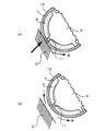
- the diameter of the main body 9 is preferably 29.5 to 36.7 mm, and more preferably 29.9 to 35.1 mm.
- the height of the rib 11 is preferably 1.0 to 4.0 mm, and more preferably 1.2 to 2.0 mm.
- the core 3 has a surface Shore D hardness of preferably 50 to 60, and more preferably 53 to 57. This is because if the value is less than 50, the rebound is reduced and the feel without a core is obtained. If the value is more than 60, the feel is too hard and the feel is deteriorated.
- each rib 11 is formed in a trapezoidal cross section so that its width increases as it goes to the main body 9 side.
- the width a of the upper end portion on the radially outer side of the rib 11 is preferably 1.5 to 2.5 mm, and the width b of the lower end portion on the radially inner side of the rib 11 is 3.0 to 6.0 mm. It is preferable to do. Although it may be outside this range, by setting the lower limit of each end of the rib 11 in this way, when filling the intermediate layer 5 at the time of manufacture, filling of the intermediate layer 5 resulting from the pressure of mold clamping The rib 11 can be prevented from being deformed by pressure. As a result, the core 9 can be accurately held at the center of the mold.
- the intermediate layer 5 is composed of a rubber composition or an elastomer, covers the surface of the core 3, and has a substantially spherical outer shape. As shown in FIG. 1, the intermediate layer 5 has a layer thickness substantially the same as the height of the ribs 11 and is filled in eight concave portions 13 surrounded by the ribs 11, and the tips of the ribs 11 are exposed from the surface of the intermediate layer 5. is doing.
- the hardness of the intermediate layer 5 needs to be higher than the hardness of the core 3 in order to suppress backspin described later, and the Shore D hardness of the surface of the intermediate layer 5 is preferably 53 to 62, preferably 56 to More preferably, it is 60.
- the mid layer 5 preferably has a Shore D hardness of 1 to 5 higher than the hardness of the core 3.
- the inner cover 7 is made of an elastomer and covers the tip of the rib 11 and the intermediate layer 5.
- the layer thickness of the inner cover 7 is preferably 0.9 to 1.7 mm, and more preferably 0.9 to 1.5 mm. Although it is possible outside this range, the reason is that if the layer thickness of the inner cover 7 is smaller than 0.9 mm, the ball becomes too soft and the resilience performance is lowered and the durability is lowered. On the other hand, if it exceeds 1.7 mm, the hit feeling becomes too hard.
- the hardness of the inner cover 7 is preferably 55 to 70 on the surface of the inner cover 7, more preferably 58 to 68, and particularly preferably 64 to 68.
- the outer cover 15 is made of an elastomer, covers the inner cover 7, and has predetermined dimples (not shown) formed on the surface thereof.
- the layer thickness of the outer cover 15 is preferably 0.8 to 1.3 mm, and more preferably 0.9 to 1.2 mm. Outside this range is possible, but the reason is that when the outer cover 15 has a layer thickness smaller than 0.8 mm, the durability of the outer cover 15 is significantly lowered and molding becomes difficult, while it exceeds 1.3 mm. This is because the rebound is too low and the flight distance cannot be increased.
- the hardness is preferably 54 to 60, and more preferably 56 to 60 on the surface of the golf ball.
- the layer thickness of the outer cover 15 is a value obtained by measuring the distance from an arbitrary point on the outermost side in the radial direction where no dimples are formed to an arbitrary point in contact with the intermediate layer along the normal line.
- the total layer thickness of the inner cover 7 and the outer cover 15 is preferably 1.9 to 3.0 mm, more preferably 2.0 to 2.8 mm. A thickness of 0 to 2.6 mm is particularly preferable. Thereby, preferable resilience performance and durability can be obtained.
- dimples formed on the outer cover 15 will be described.
- the dimple shape a circular shape, various polygonal shapes, an elliptical shape, or the like can be used alone or in combination.
- the diameter can be set to 2.5 to 4.5 mm.
- the number of dimples is 350 to 450, preferably 360 to 410. If the number of dimples is too large, the ball trajectory may be lowered and the flight distance may be reduced. On the other hand, if the number of dimples is too small, the trajectory becomes high and the flight distance may be reduced.
- the area ratio of dimples to the spherical surface of the golf ball is preferably 73% or more, and more preferably 75% or more.
- the core 3 can be manufactured from a known rubber composition containing a base rubber, a cross-linking material, a metal salt of an unsaturated carboxylic acid, a filler, and the like.
- a base rubber natural rubber, polyisobrene rubber, styrene butadiene rubber, EPDM, or the like can be used, but it is particularly preferable to use high cis polybutadiene having 80% or more of cis 1,4 bonds.
- crosslinking agent for example, organic peroxides such as dicumyl peroxide and t-butyl peroxide can be used, and it is particularly preferable to use dicumyl peroxide.
- the amount is 0.3 to 5 parts by weight, preferably 0.5 to 2 parts by weight, based on 100 parts by weight of the base rubber.
- the metal salt of the unsaturated carboxylic acid it is preferable to use a metal salt of a monovalent or divalent unsaturated carboxylic acid having 3 to 8 carbon atoms such as acrylic acid or methacrylic acid, but zinc acrylate is used. Then, the resilience performance of the ball can be improved, which is particularly preferable.
- the blending amount is preferably 10 to 40 parts by weight with respect to 100 parts by weight of the base rubber.
- the filler those usually blended in the core can be used, and for example, zinc oxide, barium sulfate, calcium carbonate, etc. can be used.
- the blending amount is preferably 2 to 50 parts by weight with respect to 100 parts by weight of the base rubber.
- the intermediate layer 5 is composed of a rubber composition or an elastomer as described above, but when composed of a rubber composition, it can be composed of the same components as the core 3 described above. However, in order to raise hardness from the core 3, it is preferable to increase the compounding quantity of unsaturated carboxylic acid.
- the intermediate layer 5 is composed of an elastomer, for example, styrene-butadiene-styrene block copolymer (SBS), styrene-isoprene-styrene block copolymer (SIS), styrene-ethylene-butylene-styrene block copolymer (SEBS), styrene- Styrenic thermoplastic elastomers such as ethylene-propylene-styrene block copolymer (SEPS); olefinic thermoplastic elastomers with polyethylene or polypropylene as hard segments and butadiene rubber, acrylonitrile butadiene rubber, or ethylene / propylene rubber as soft segments; Vinyl chloride with crystalline polyvinyl chloride as the hard segment and amorphous polyvinyl chloride or acrylonitrile butadiene rubber as the soft segment -Based thermoplastic elastomer; polyurethane-based thermoplastic e
- the inner cover 7 and the outer cover 15 are made of a known elastomer, and the same one as the above intermediate layer can be used.
- ionomer resin is more suitable for resilience, durability, moldability, and the like.
- the ionomer resin for example, High Milan 1706, 1605 manufactured by Mitsui DuPont Polychemical Co., Ltd. or Surlyn 9910, 8940, 8150, 8120, 8320 manufactured by DuPont Co., Ltd. can be used.
- the inner cover 7, for example, Duon ionomer HPF1000 or HPF2000 can be suitably used in terms of softness and resilience.
- As the outer cover 15, for example, Ionomer HPC AD1043 manufactured by DuPont can be suitably used in terms of resilience and scratch resistance.
- the elastic resistance of the ball to return to the original state is promoted by the ribs 11, so that backspin can be effectively suppressed.
- the rib 11 has a hardness lower than that of the intermediate layer 5 because the rib 11 has a hardness lower than that of the intermediate layer 5. Deform. Due to this impact, a stress that generates back spin B acts on the ball itself. When the ball leaves the club C, as shown in FIG. 3B, the deformation of the rib 11 having low hardness is restored, so that the force F acts in a direction to cancel back spin B by this restoration. To do.
- the spin is reduced and the jump angle is increased, so that the flight distance can be further extended.
- the rib 11 is not a mere protrusion, but is configured as a wall surrounding the periphery of the intermediate layer 5, so that the force when the rib 11 is restored depends on the entire wall 5. Acts greatly from the surroundings, and this promotes a force F opposite to the backspin B. Therefore, the backspin amount is reduced and the flight distance can be greatly increased. Such an effect becomes prominent particularly when a club aiming at a flight distance such as a driver is used.
- the current state is indicated by a solid line, and the state immediately before that is indicated by a broken line.
- the inner cover 7 is disposed between the intermediate layer 5 and the outer cover 15, the striking force is applied to the intermediate layer 5 and the rib 11 in approach shots where the deformation of the ball is small, such as hitting with an iron. It is possible to suppress transmission. As a result, it is possible to prevent the force that cancels back spin described above from being promoted. Therefore, when the driver hits the ball, the backspin can be reduced and the flight distance can be increased. On the other hand, when the ball is hit by the iron, the backspin can be applied and the ball can be stopped accurately.
- the hardness of the outer cover 15 is lowered, the feel on impact can be softened. Moreover, since the outer cover 15 has a low hardness, it can be easily deformed. That is, since the outer cover 15 which is the outermost layer is easily deformed, the backspin can be exerted greatly when hit with an iron.
- the inner cover 7 can improve the resilience performance even if the outer cover 15 has a soft feel. Thereby, even if the club head speed is low, high resilience performance can be obtained and the flight distance can be extended.
- the rib 11 is formed on the core 3 and the hardness of the mid layer 5 is made higher than the hardness of the rib 11, thereby suppressing the back spin as described above. It has gained.
- Such a backspin suppression effect can be adjusted by the height of the ribs 11 and the height difference between the intermediate layer 5 and the ribs 11, and thus the flight distance can also be adjusted. It is also possible to adjust the flight distance by adjusting the lift of the ball depending on the shape of the dimples. Such ball performance adjustment is performed according to the level of the user and the required performance.
- the lift can be set as follows. For example, immediately after hitting with a driver, for example, the ball speed is 62 m / s, the spin rate is 2400 rpm, and the spin parameter is 0.09. The lift coefficient at this time is preferably 0.13 to 0.17. Immediately after hitting with an iron, for example, the ball speed is 46 m / s, the spin amount is 4700 rpm, and the spin parameter is 0.23. The spin rate is about 2500 rpm. The spin parameter at this time is 0.12. The lift coefficient when the spin parameter is 0.12 is preferably 0.16 to 0.20. As described above, if the lift coefficient is too high, the flight distance decreases due to blowing up.
- the lift coefficient is too small, the trajectory will be low, the falling angle will be low, and the stop will be worse when hitting from a rough with an iron. Therefore, it is preferable to set the lift as described above in the dimple design or the like in view of the structure of the ball described above.
- the force acting on the golf ball is expressed by the following ballistic equation.
- F FL + FD + Mg
- FD Drag (N)
- M Mass of golf ball (kg)
- g Gravitational acceleration (m / s 2 )
- the lift FL and drag FD are expressed by the following formulas, respectively.
- the measurement of spin parameters, lift, etc. can be performed by using a TrackMan manufactured by Interactive Sports Games Co. Ltd. for a ball hit with a golf robot.
- This TrackMan is a device that uses the radar Doppler effect to measure the tracking of a flying ball.
- FIG. 4 is a perspective view of the core in which a notch is formed
- FIG. 5 is a cross-sectional view of FIG.
- the notch 24 is formed to have a bottom surface 24 a extending along a tangential plane H passing through the intersection point P of the great circle. That is, the notch 24 is formed by cutting the rib 11 by the tangential plane H.
- the notches 24 By forming the notches 24 in this way, the four recesses 13 arranged around the intersection point P of the great circle communicate with each other, and as will be described later, the intermediate layer material is passed through the notches 24 as shown in FIG. 13 can be easily distributed.
- the said inclination turns into a draft, for example, when a shaping
- the notch 24 is formed as described above, as shown in FIG. 5, the arc direction of the upper end where the notch 24 is not formed in each arc section S delimited by each intersection P in the rib 11. It is preferable that the length L is 10 mm or more.
- the cutout portion 24 may be formed to have a bottom surface 24 a that passes through the middle in the height direction of the rib 11 and extends along a plane H 2 that is perpendicular to the normal line n.
- the notch 24 is formed by setting the distance D from the upper end of the virtual rib 11 to the bottom surface 24 a to 1.2 mm or more when there is no notch 24. It is preferable to do.
- the length L is preferably 10 mm or more as described above.
- the bottom surface 24a of the notch 24 can be formed along a plane that forms an angle of 91 to 93 ° with the normal line n, thereby forming a draft angle.
- a notch can be provided in the middle of each arc section S of the rib 11. That is, as shown in FIG. 8A, two bottom surfaces 25a extending from one point on the normal line m of the main body 9 passing through the center point Q in the arc direction of the arc section S to the intersection P side on both ends are provided.
- the notch 25 can also be formed. In this case, it is preferable that the bottom surface 25a and the normal line m form 45 to 48 degrees when viewed from the front. If it does in this way, as above-mentioned, the core 3 can be easily extracted from a shaping
- the depth D of the notch 25 is preferably 1.2 mm or more. Although outside this range is possible, by setting the above range, the material for the intermediate layer can be smoothly distributed between the recesses 13.
- the depth D of the notch 25 refers to the distance from the upper end of the virtual rib 11 to the deepest part of the notch 25 when there is no notch 25.
- two planes in which the cutout portion 25 extends from one point on the normal line m of the main body portion 9 passing through the center point Q in the arc direction of the arc section S to the intersection P side on both ends. Can be formed so as to have a side surface 25b along the main body portion 9 and an arc-shaped bottom surface 25c along the main body portion 9.
- the angle formed between the side surface 25b and the normal line m is 45 to 48 ° in plan view in consideration of the draft, as in the case of FIG.
- the bottom surface 25c can also be formed so as to pass through an intermediate portion of the rib 11 in the height direction.
- the depth D of the notch is preferably 1.2 mm or more.
- two or more cutout portions 25 can be provided in the middle portion of the arc section S as long as the shape can be easily removed.
- the arc section S may have both the notch 24 shown in FIG. 5, FIG. 6, or 7 and the notch 25 shown in FIG. 8.
- the layer thickness of the intermediate layer 5 and the height of the rib 11 are the same, but it is not necessarily the same.
- the layer thickness of the intermediate layer 5 is made larger than the height of the rib 11. May be.
- the height is slightly higher than the height of the rib 11, for example, within 0.3 mm.
- FIG. 10 and 11 are views showing a method for manufacturing a four-piece golf ball having the core shown in FIG.
- the core is molded.
- a predetermined amount of unvulcanized rubber composition is placed in a mold. Deploy.
- This rubber composition is obtained by blending the above-described base rubber, a crosslinking agent, a metal salt of an unsaturated carboxylic acid, a filler, and the like, and kneading them with a kneader such as a panbury mixer or a roll. Then, this rubber composition is press-molded at 130 to 180 ° C. to form the core 3 shown in FIG.
- the intermediate layer 5 is formed by press molding.
- the mold for forming the intermediate layer includes an upper mold 43 and a lower mold 45 having a hemispherical recess 41.
- the recesses 41 of the upper mold 43 and the lower mold 45 are finished with a rough surface in the same manner as the core molding die, and a plurality of concave burrs 49 are formed around the recesses 41.
- an unvulcanized rubber composition 61 is inserted into the recess 41 of the lower mold 45, and the rubber composition 61 is disposed on the upper portion of the core 3 formed as described above.
- the core 3 is disposed between the upper mold 43 and the lower mold 45.
- the upper die 43 and the lower die 45 are brought into contact with each other, and the rubber composition 61 is fully vulcanized at 130 to 180 ° C. for 5 to 25 minutes to perform press molding. Layer 5 is formed.
- the rubber composition 61 disposed in the upper part of the core 3 and the concave part 41 of the lower mold 45 is filled into the concave part 13 while being pressed onto the surface of the core 3.
- the adjacent recesses 13 communicate with each other through the notch 24, so that the rubber composition reaches all the recesses and is uniformly filled.
- middle layer 5 can also be shape
- the golf ball according to the present embodiment can be obtained.
- the intermediate layer 5 can be coated on the core 3 by one-step press molding, and as a result, the manufacturing time can be greatly shortened.
- a method for manufacturing a golf ball having an intermediate layer in which a notch is formed has been described.
- a golf ball having no notch can be manufactured by a substantially similar method.
- the golf ball concerning the present invention is not limited to this, and various changes are possible unless it deviates from the meaning.
- three ribs are formed along the great circle of the main body, but the form of the ribs is not particularly limited, and the shape, number, and position thereof can be changed as appropriate. That is, it is only necessary to form a recess filled with the intermediate layer by the rib.
- Tables 3 and 4 show the compositions of the materials constituting the core and the intermediate layer, and the numerical values show parts by weight.
- the materials constituting the inner cover and the outer cover are as follows, and each numerical value in the table indicates the mixing ratio of the materials.
- 1706 indicates HiMilan 1706 manufactured by Mitsui DuPont Polychemical Co., Ltd.
- 1601 indicates HiMilan 1601 manufactured by Mitsui DuPont Polychemical Co., Ltd.
- HPC represents DuPont's ionomer HPC AD 1043
- HPF represents DuPont's ionomer HPF 1000, 8150
- No. 1 wood (1W: MP Craft425 manufactured by Mizuno Co., Ltd., loft angle 9.5 °) by a hitting robot (SHOT ROBO v manufactured by Miyamae Co., Ltd.) , Shaft QUAD 6 Butt Standard Length 45 inches), Shaft Hardness S) and Sand Wedge (SW: Mizuno Corporation MP T Series, 56 ° Chrome Plating, Shaft Dynamic Gold Wedge Flex Length 35.25 inches were used.
- a hit test was conducted to measure the flight distance (carry), where the head speed of No. 1 wood was 45 m / s and the head speed of sand wedge was 35 m / s.
- a wood hit feeling test was conducted, in which the test subject was given a four-step evaluation (1: non- (2: soft, 3: hard, 4: very hard), and the average value was used as the hitting value of each example.
- a durability test was performed. Was fired at 40 m / s, repeatedly hitting an iron plate, and the number of times until it was broken was measured using Example 1. The number of times until breaking was taken as 100, and the relative value of each ball was calculated as the durability index. The results are shown in Table 6 below.
- Comparative Example 4 since the outer cover has a high hardness, the deformation of the outer cover is small, and the back spin when using the sand wedge is small, which is not suitable for the approach. On the other hand, if the hardness of the outer cover is too low as in Comparative Example 5, the backspin becomes large even when the driver is used, and the flight distance does not increase. Further, in Comparative Example 6, since the outer cover has a large layer thickness, the resilience performance is lowered and the flight distance is not extended. In Comparative Example 7, since the inner cover is also soft in addition to the outer cover, the resilience performance is lowered and the flight distance is not extended. Moreover, since the total layer thickness of the inner cover and the outer cover is thin, the comparative example 8 is inferior in durability. In Comparative Example 9, since the cover is a single layer, the ball is hard, the hit feeling is poor, and the back spin when using the sand wedge is small.
- the flight distance can be greatly increased, and an appropriate backspin can be generated in the approach shot.
Abstract
Disclosed is a golf ball which is capable of increasing a carry with a driver and is capable of securely causing backspin in an approach shot.
The golf ball is provided with: a spherical body; a plurality of ribs which are formed on the surface of the body; an intermediate layer which is charged into concave portions each surrounded by the ribs and has a hardness higher than that of the ribs; an inner cover which covers the intermediate layer; and an outer cover which covers the inner cover and has a hardness lower than that of the inner cover.
Description
本発明は、多層構造のゴルフボールに関する。
The present invention relates to a golf ball having a multilayer structure.
近年、ゴルフボールは、高い反発性及び打撃時のソフトフィーリングを兼ね備えた種々のものが提案されており、その一種にボールを複数の層で構成する多層構造のゴルフボールがある。その一つとして、特許文献1に記載のゴルフボールがある。このゴルフボールは、球状の本体部の周囲にリブを形成し、さらにリブに囲まれた凹部に中間層を形成することで構成されている。そして、中間層の硬度をリブの硬度よりも大きくすることで、次のような効果を奏している。すなわち、一般的に、ゴルフボールとゴルフクラブとが接触すると、クラブフェース面との摩擦によりボールは周方向にねじれた状態となる。そして、ねじれたボールは弾性抵抗により元の状態に復元しつつバックスピンとは反対向きの力をボールに作用させる。このとき、ねじれたボールの変形が大きいほどバックスピンが抑制され飛距離を伸ばすことが可能になる。
In recent years, various golf balls having high resilience and soft feeling at the time of hitting have been proposed. One type of golf balls is a multi-layered golf ball comprising a plurality of layers. One example is a golf ball described in Patent Document 1. This golf ball is configured by forming a rib around a spherical main body portion and further forming an intermediate layer in a recess surrounded by the rib. And the following effects are produced by making the hardness of an intermediate layer larger than the hardness of a rib. That is, generally, when the golf ball and the golf club come into contact with each other, the ball is twisted in the circumferential direction by friction with the club face surface. The twisted ball is restored to its original state by elastic resistance, and a force opposite to the backspin is applied to the ball. At this time, the greater the deformation of the twisted ball, the more backspin is suppressed and the flight distance can be extended.
ここで、特許文献1のゴルフボールでは、リブによってボールが元の状態に戻ろうとする弾性抵抗が助長されるため、バックスピンを効果的に抑制することができる。すなわち、このゴルフボールでは、リブの硬度が中間層の硬度よりも低いため、打撃によって中間層よりもリブが大きく変形する。そして、リブは単なる突出部ではなく中間層の周囲を囲む壁のように構成されているため、リブが復元する際にこの壁全面の力が中間層の周囲から大きく作用し、これによって、バックスピンと反対向きの力が助長される。その結果、飛距離を大きく伸ばすことができる。このような効果は、特にドライバーのような飛距離を狙ったクラブで打撃したときに現れる。
Here, in the golf ball of Patent Document 1, since the elastic resistance that the ball tries to return to the original state is promoted by the rib, backspin can be effectively suppressed. That is, in this golf ball, since the hardness of the rib is lower than the hardness of the intermediate layer, the rib deforms more greatly than the intermediate layer by hitting. Since the rib is configured not as a simple protrusion but as a wall surrounding the periphery of the intermediate layer, the force of the entire wall acts greatly from the periphery of the intermediate layer when the rib is restored. Force opposite to the pin is encouraged. As a result, the flight distance can be greatly increased. Such an effect is particularly apparent when hitting with a club aiming at a flight distance such as a driver.
ところで、上記ゴルフボールでは、ドライバーによる打撃には適しているものの、アイアンを用いたアプローチショットにおいては、問題がある。すなわち、アプローチショットにおいては、バックスピンを作用させ、ボールを止めることが重要であるため、上記のように、バックスピンと反対向きの力が助長されると、ボールを的確に止めることができなくなるという問題がある。
By the way, although the golf ball is suitable for hitting by a driver, there is a problem in an approach shot using an iron. In other words, in approach shots, it is important to apply a backspin to stop the ball, and as described above, if a force opposite to the backspin is promoted, the ball cannot be stopped accurately. There's a problem.
本発明は、ドライバーにより飛距離を得ることができるとともに、アプローチショットにおいても的確にバックスピンを生じさせることが可能なゴルフボールを提供することを目的とする。
An object of the present invention is to provide a golf ball that can obtain a flight distance by a driver and can accurately generate backspin even in an approach shot.
本発明に係るゴルフボールは、球状の本体部と、前記本体部の表面に形成される複数のリブと、前記リブによって囲まれる凹部に充填され、前記リブよりも硬度の高い中間層と、前記中間層を覆うインナーカバーと、前記インナーカバーを覆い、当該インナーカバーよりも硬度の低いアウターカバーと、を備えている。
A golf ball according to the present invention includes a spherical main body, a plurality of ribs formed on the surface of the main body, a recess surrounded by the ribs, and an intermediate layer having a hardness higher than that of the ribs, An inner cover that covers the intermediate layer, and an outer cover that covers the inner cover and has a lower hardness than the inner cover.
この構成によれば、リブの硬度が中間層の硬度よりも低いため、打撃によって中間層よりもリブが大きく変形する。そして、リブは単なる突出部ではなく中間層の周囲を囲む壁のように構成されているため、リブが復元する際にこの壁全面の力が中間層の周囲から大きく作用し、これによって、バックスピンと反対向きの力が助長される。その結果、飛距離を大きく伸ばすことができる。このような効果は、特にドライバーのような飛距離を狙ったクラブで打撃したときに現れる。
According to this configuration, since the hardness of the rib is lower than the hardness of the intermediate layer, the rib is deformed more greatly than the intermediate layer by impact. Since the rib is configured not as a simple protrusion but as a wall surrounding the periphery of the intermediate layer, the force of the entire wall acts greatly from the periphery of the intermediate layer when the rib is restored. Force opposite to the pin is encouraged. As a result, the flight distance can be greatly increased. Such an effect is particularly apparent when hitting with a club aiming at a flight distance such as a driver.
但し、中間層とアウターカバーとの間にインナーカバーが配置されているため、アイアンによる打撃のように、ボールの変形が小さいアプローチショットにおいては、打撃力が中間層及びリブに伝達されるのを抑制することができる。その結果、上述したバックスピンを相殺する力が助長されるのを防止することができる。したがって、本発明のゴルフボールによれば、ドライバーによる打撃時には、バックスピンを低減して飛距離を伸ばすことができる一方、アイアンによる打撃時には、バックスピンを作用させることができ、ボールを的確に止めることができる。
However, since the inner cover is arranged between the intermediate layer and the outer cover, the hitting force is transmitted to the intermediate layer and the rib in approach shots where the deformation of the ball is small, such as hitting with an iron. Can be suppressed. As a result, it is possible to prevent the force that cancels back spin described above from being promoted. Therefore, according to the golf ball of the present invention, the backspin can be reduced to increase the flight distance when hit by the driver, while the backspin can be applied when hitting by the iron, and the ball is stopped accurately. be able to.
さらに、アウターカバーの硬度をインナーカバーの硬度よりも低くしているため、打感を柔らかくすることができる。しかも、アウターカバーの変形を大きくすることができるため、アイアンによる打撃時にバックスピンを大きく作用させることができる。さらに、インナーカバーの硬度がアウターカバーよりも高いため、アウターカバーの打感が柔らかいとしても、インナーカバーにより反発性能を向上することができる。したがって、飛距離を伸ばすことができる。例えば、インナーカバーのショアD硬度を55~70とすると、反発性能を向上することができる。また、アウターカバーのショアD硬度を54~60とすると、打感を柔らかくすることができる。
Furthermore, since the hardness of the outer cover is lower than the hardness of the inner cover, it is possible to soften the hit feeling. In addition, since the deformation of the outer cover can be increased, the backspin can be exerted greatly when hit with an iron. Furthermore, since the hardness of the inner cover is higher than that of the outer cover, even if the outer cover has a soft feel, the inner cover can improve the resilience performance. Therefore, the flight distance can be extended. For example, when the Shore D hardness of the inner cover is 55 to 70, the resilience performance can be improved. Further, when the Shore D hardness of the outer cover is set to 54 to 60, the hit feeling can be softened.
上記ゴルフボールにおいては、インナーカバーの硬度を、中間層の硬度よりも高くすることができる。これにより、インナーカバーよりも径方向の内側の硬度が低くなり、インナーカバーによる打感の硬さを緩和することができる。
In the golf ball, the hardness of the inner cover can be made higher than the hardness of the intermediate layer. Thereby, the inner hardness in the radial direction is lower than that of the inner cover, and the hardness of the hit feeling by the inner cover can be reduced.
上記ゴルフボールにおいては、インナーカバーとアウターカバーの層厚の合計が、1.9mm以上とすることができる。これは、ウェッジを用いたアプローチによる打撃でのボールの変形量は、2.0mm程度になることもあり、インナーカバーとアウターカバーの層厚の合計を、1.9mm以上としておくと、ウェッジを用いたアプローチによる打撃が中間層及びリブまで伝達されにくくなり、リブによるバックスピンの相殺を確実に低減することができる。したがって、ウェッジによるアプローチショットにおいては、的確にボールを止めることが可能になる。また、この層厚により、ボールの耐久性も向上する。
In the above golf ball, the total thickness of the inner cover and the outer cover can be 1.9 mm or more. This is because the amount of deformation of the ball due to the hit with the approach using the wedge may be about 2.0 mm. If the total thickness of the inner cover and the outer cover is set to 1.9 mm or more, the wedge is removed. The hit by the approach used is not easily transmitted to the intermediate layer and the rib, and backspin offset by the rib can be reliably reduced. Therefore, the ball can be stopped accurately in the approach shot by the wedge. This layer thickness also improves the durability of the ball.
上記ゴルフボールにおいては、本体部とリブとを一体化し、本体部の硬度をリブの硬度と同じにすることができる。この構成によれば、中間層の硬度が、リブの硬度だけでなく本体部の硬度よりも高いため、スピン量を抑制することができ、飛距離の向上を図ることができる。
In the above golf ball, the main body and the rib can be integrated, and the hardness of the main body can be made the same as the hardness of the rib. According to this configuration, since the hardness of the intermediate layer is higher than the hardness of the main body portion as well as the hardness of the rib, the spin rate can be suppressed and the flight distance can be improved.
以下、本発明に係るマルチピースゴルフボールの一実施形態を図面を参照して説明する。図1は本実施形態に係るゴルフボールの断面図である。
Hereinafter, an embodiment of a multi-piece golf ball according to the present invention will be described with reference to the drawings. FIG. 1 is a cross-sectional view of a golf ball according to this embodiment.
図1に示すように、本実施形態に係るゴルフボール1は、コア3を中間層5、インナーカバー及びアウターカバー15で被覆したマルチピースゴルフボールである。ゴルフボールの直径は、規則(R&A、及びUSGA参照)の定めるところにより、42.67mm以上にする必要がある。但し、空力特性等を考慮するとボール径はできるだけ小さくすることが好ましく、例えば42.7~42.9mmとすることができる。コア3は、ゴム組成物で構成され、図2に示すように、球状の本体部9と、その表面に一体形成された3本のリブ(突条)11とから構成されている。各リブ11は、本体部9の表面に描かれ相互に直交する大円に沿って延びており、これらリブ11により本体部9の表面には8個の凹部13が形成されている。
As shown in FIG. 1, a golf ball 1 according to this embodiment is a multi-piece golf ball in which a core 3 is covered with an intermediate layer 5, an inner cover, and an outer cover 15. The diameter of the golf ball needs to be 42.67 mm or more according to the rules (see R & A and USGA). However, in consideration of aerodynamic characteristics and the like, it is preferable to make the ball diameter as small as possible, for example, 42.7 to 42.9 mm. The core 3 is comprised with the rubber composition, and as shown in FIG. 2, it is comprised from the spherical main-body part 9 and the three ribs (projection) 11 integrally formed in the surface. Each rib 11 is drawn on the surface of the main body portion 9 and extends along a great circle orthogonal to each other, and eight ribs 13 are formed on the surface of the main body portion 9 by these ribs 11.
本体部9の直径は、29.5~36.7mmにすることが好ましく、29.9~35.1mmであることがさらに好ましいい。また、リブ11の高さは1.0~4.0mmであることが好ましく、1.2~2.0mmであることがさらに好ましい。また、コア3の硬度は、表面のショアD硬度が50~60であることが好ましく、53~57であることがさらに好ましい。これは、50より小さいと反発が低下し、芯のない打感になるからであり、60より大きいと硬すぎて打感が悪くなるからである。
The diameter of the main body 9 is preferably 29.5 to 36.7 mm, and more preferably 29.9 to 35.1 mm. The height of the rib 11 is preferably 1.0 to 4.0 mm, and more preferably 1.2 to 2.0 mm. The core 3 has a surface Shore D hardness of preferably 50 to 60, and more preferably 53 to 57. This is because if the value is less than 50, the rebound is reduced and the feel without a core is obtained. If the value is more than 60, the feel is too hard and the feel is deteriorated.
図1及び図2に示すように、各リブ11は、本体部9側にいくにしたがってその幅が増大するように断面台形状に形成されている。リブ11の径方向外方の上端部の幅aは1.5~2.5mmにすることが好ましく、またリブ11の径方向内方の下端部の幅bは3.0~6.0mmにすることが好ましい。この範囲外にすることもできるが、このようにリブ11の各端部の下限を設定することにより、製造時に中間層5を充填する際に、金型締めの圧力からくる中間層5の充填圧によってリブ11が変形するのを防止することができる。その結果、コア9を金型の中心に正確に保持することができる。
As shown in FIGS. 1 and 2, each rib 11 is formed in a trapezoidal cross section so that its width increases as it goes to the main body 9 side. The width a of the upper end portion on the radially outer side of the rib 11 is preferably 1.5 to 2.5 mm, and the width b of the lower end portion on the radially inner side of the rib 11 is 3.0 to 6.0 mm. It is preferable to do. Although it may be outside this range, by setting the lower limit of each end of the rib 11 in this way, when filling the intermediate layer 5 at the time of manufacture, filling of the intermediate layer 5 resulting from the pressure of mold clamping The rib 11 can be prevented from being deformed by pressure. As a result, the core 9 can be accurately held at the center of the mold.
中間層5は、ゴム組成物又はエラストマーで構成され、コア3の表面を覆い、その外形が略球状をなしている。図1に示すように、中間層5は、リブ11の高さとほぼ同じ層厚で、リブ11によって囲まれる8つの凹部13に充填されており、中間層5の表面からリブ11の先端が露出している。中間層5の硬度は、後述するバックスピンの抑制のために、コア3の硬度よりも高くする必要があり、中間層5の表面のショアD硬度が53~62であることが好ましく、56~60であることがさらに好ましい。このとき、中間層5の硬度は、コア3の硬度よりもショアD硬度が1~5高いことが好ましい。
The intermediate layer 5 is composed of a rubber composition or an elastomer, covers the surface of the core 3, and has a substantially spherical outer shape. As shown in FIG. 1, the intermediate layer 5 has a layer thickness substantially the same as the height of the ribs 11 and is filled in eight concave portions 13 surrounded by the ribs 11, and the tips of the ribs 11 are exposed from the surface of the intermediate layer 5. is doing. The hardness of the intermediate layer 5 needs to be higher than the hardness of the core 3 in order to suppress backspin described later, and the Shore D hardness of the surface of the intermediate layer 5 is preferably 53 to 62, preferably 56 to More preferably, it is 60. At this time, the mid layer 5 preferably has a Shore D hardness of 1 to 5 higher than the hardness of the core 3.
インナーカバー7は、エラストマーで構成され、リブ11の先端部と中間層5とを覆っている。インナーカバー7の層厚は0.9~1.7mmとするのが好ましく、0.9~1.5mmとするのがさらに好ましい。この範囲外も可能ではあるが、その理由は、インナーカバー7の層厚が0.9mmより小さくなると、ボールが柔らかくなりすぎて、反発性能が低下するとともに、耐久性が低下するからである。一方、1.7mmを越えると打感が硬くなり過ぎる。また、その硬度はインナーカバー7の表面のショアD硬度を55~70とするのが好ましく、58~68であることがさらに好ましく、64~68とすることが特に好ましい。
The inner cover 7 is made of an elastomer and covers the tip of the rib 11 and the intermediate layer 5. The layer thickness of the inner cover 7 is preferably 0.9 to 1.7 mm, and more preferably 0.9 to 1.5 mm. Although it is possible outside this range, the reason is that if the layer thickness of the inner cover 7 is smaller than 0.9 mm, the ball becomes too soft and the resilience performance is lowered and the durability is lowered. On the other hand, if it exceeds 1.7 mm, the hit feeling becomes too hard. The hardness of the inner cover 7 is preferably 55 to 70 on the surface of the inner cover 7, more preferably 58 to 68, and particularly preferably 64 to 68.
アウターカバー15は、エラストマーで構成され、インナーカバー7を覆うとともに、その表面には図示を省略する所定のディンプルが形成されている。アウターカバー15の層厚は0.8~1.3mmとするのが好ましく、0.9~1.2mmとするのがさらに好ましい。この範囲外も可能ではあるが、その理由は、アウターカバー15の層厚が0.8mmより小さくなると、アウターカバー15の耐久性が著しく低下するとともに成形が困難になる一方、1.3mmを越えると反発が低下しすぎて飛距離が伸びなくなるからである。また、その硬度はゴルフボール表面のショアD硬度が54~60とするのが好ましく、56~60であることがさらに好ましい。なお、アウターカバー15の層厚とは、ディンプルが形成されていない径方向の最も外側の任意の一点から、中間層と接する任意の一点までの距離を法線に沿って計測した値である。また、層厚に関しては、インナーカバー7とアウターカバー15との合計の層厚が1.9~3.0mmであることが好ましく、2.0~2.8mmとすることがさらに好ましく、2.0~2.6mmとすることが特に好ましい。これにより、好ましい反発性能と、耐久性を得ることができる。
The outer cover 15 is made of an elastomer, covers the inner cover 7, and has predetermined dimples (not shown) formed on the surface thereof. The layer thickness of the outer cover 15 is preferably 0.8 to 1.3 mm, and more preferably 0.9 to 1.2 mm. Outside this range is possible, but the reason is that when the outer cover 15 has a layer thickness smaller than 0.8 mm, the durability of the outer cover 15 is significantly lowered and molding becomes difficult, while it exceeds 1.3 mm. This is because the rebound is too low and the flight distance cannot be increased. The hardness is preferably 54 to 60, and more preferably 56 to 60 on the surface of the golf ball. The layer thickness of the outer cover 15 is a value obtained by measuring the distance from an arbitrary point on the outermost side in the radial direction where no dimples are formed to an arbitrary point in contact with the intermediate layer along the normal line. Regarding the layer thickness, the total layer thickness of the inner cover 7 and the outer cover 15 is preferably 1.9 to 3.0 mm, more preferably 2.0 to 2.8 mm. A thickness of 0 to 2.6 mm is particularly preferable. Thereby, preferable resilience performance and durability can be obtained.
次に、アウターカバー15に形成されるディンプルについて説明する。ディンプルの形状は、円形や各種多角形や楕円形などを1種類または複数種を組み合わせて使用することができる。例えば、円形ディンプルであれば直径は、2.5~4.5mmとすることができる。また、ディンプル数は、350~450個、好ましくは、360個~410個である。ディンプルの数が多すぎると、ボールの弾道が低くなり飛距離が落ちるおそれがある。一方、ディンプルの数が少なすぎると、弾道が高くなり飛距離が落ちるおそれがある。また、ディンプルがゴルフボールの球面に占める面積率は、73%以上がよく、75%以上がさらに好ましい。
Next, dimples formed on the outer cover 15 will be described. As the dimple shape, a circular shape, various polygonal shapes, an elliptical shape, or the like can be used alone or in combination. For example, in the case of a circular dimple, the diameter can be set to 2.5 to 4.5 mm. The number of dimples is 350 to 450, preferably 360 to 410. If the number of dimples is too large, the ball trajectory may be lowered and the flight distance may be reduced. On the other hand, if the number of dimples is too small, the trajectory becomes high and the flight distance may be reduced. Further, the area ratio of dimples to the spherical surface of the golf ball is preferably 73% or more, and more preferably 75% or more.
続いて、上記ゴルフボールの各部材を構成する材料について詳細に説明する。コア3は、基材ゴム、架橋材、不飽和カルボン酸の金属塩、充填剤等を配合した公知のゴム組成物で製造することができる。基材ゴムとしては、天然ゴム、ポリイソブレンゴム、スチレンブタジエンゴム、EPDM等を使用できるが、シス1,4結合を80%以上を有するハイシスポリブタジエンを使用することが特に好ましい。
Subsequently, materials constituting each member of the golf ball will be described in detail. The core 3 can be manufactured from a known rubber composition containing a base rubber, a cross-linking material, a metal salt of an unsaturated carboxylic acid, a filler, and the like. As the base rubber, natural rubber, polyisobrene rubber, styrene butadiene rubber, EPDM, or the like can be used, but it is particularly preferable to use high cis polybutadiene having 80% or more of cis 1,4 bonds.
架橋剤としては、例えばジクミルパーオキサイドやt-ブチルパーオキサイドのような有機過酸化物を使用することができるが、ジクミルパーオキサイドを使用するのが特に好ましい。配合量は、基材ゴム100重量部に対して0.3~5重量部であり、好ましくは0.5~2重量部である。
As the crosslinking agent, for example, organic peroxides such as dicumyl peroxide and t-butyl peroxide can be used, and it is particularly preferable to use dicumyl peroxide. The amount is 0.3 to 5 parts by weight, preferably 0.5 to 2 parts by weight, based on 100 parts by weight of the base rubber.
不飽和カルボン酸の金属塩としては、アクリル酸又はメタクリル酸のような炭素数3~8の一価又は二価の不飽和カルボン酸の金属塩を使用することが好ましいが、アクリル酸亜鉛を使用するとボールの反発性能を向上することができ、特に好ましい。配合量は、基材ゴム100重量部に対して10~40重量部にするのが好ましい。
As the metal salt of the unsaturated carboxylic acid, it is preferable to use a metal salt of a monovalent or divalent unsaturated carboxylic acid having 3 to 8 carbon atoms such as acrylic acid or methacrylic acid, but zinc acrylate is used. Then, the resilience performance of the ball can be improved, which is particularly preferable. The blending amount is preferably 10 to 40 parts by weight with respect to 100 parts by weight of the base rubber.
充填剤は、コアに通常配合されるものを使用することができ、例えば酸化亜鉛、硫酸バリウム、炭酸カルシウム等を使用することができる。配合量は、基材ゴム100重量部に対して2~50重量部にするのが好ましい。また、必要に応じて老化防止剤、またはしゃく解剤等を配合してもよい。
As the filler, those usually blended in the core can be used, and for example, zinc oxide, barium sulfate, calcium carbonate, etc. can be used. The blending amount is preferably 2 to 50 parts by weight with respect to 100 parts by weight of the base rubber. Moreover, you may mix | blend an anti-aging agent or a peptizer as needed.
中間層5は、上記のようにゴム組成物またはエラストマーで構成されるが、ゴム組成物で構成する場合には、上記したコア3と同様の成分で構成することができる。但し、コア3より硬度を上げるため、不飽和カルボン酸の配合量を多くすることが好ましい。
The intermediate layer 5 is composed of a rubber composition or an elastomer as described above, but when composed of a rubber composition, it can be composed of the same components as the core 3 described above. However, in order to raise hardness from the core 3, it is preferable to increase the compounding quantity of unsaturated carboxylic acid.
中間層5をエラストマーで構成する場合には、例えばスチレン-ブタジエン-スチレンブロックコポリマー(SBS)、スチレン-イソプレン-スチレンブロックコポリマー(SIS)、スチレン-エチレン-ブチレン-スチレンブロックコポリマー(SEBS)、スチレン-エチレン-プロピレン-スチレンブロックコポリマー(SEPS)のようなスチレン系熱可塑性エラストマー;ポリエチレンまたはポリプロピレンをハードセグメントとし、ブタジエンゴム、アクリルニトリルブタジエンゴム、エチレン・プロピレンゴムをソフトセグメントとするオレフィン系熱可塑性エラストマー;結晶ポリ塩化ビニルをハードセグメントとし、非晶ポリ塩化ビニルまたはアクリロニトリル・ブタジエンゴムをソフトセグメントとする塩化ビニル系熱可塑性エラストマー;ポリウレタンをハードセグメントとし、ポリエーテルまたはポリエステルをソフトセグメントとするウレタン系熱可塑性エラストマー;ポリエステルをハードセグメントとし、ポリエーテルまたはポリエステルをソフトセグメントとするポリエステル系熱可塑性エラストマー;ポリアミドをハードセグメントとし、ポリエーテルまたはポリエステルをソフトセグメントとするポリアミド系熱可塑性エラストマー;アイオノマー樹脂などを使用することができる。
When the intermediate layer 5 is composed of an elastomer, for example, styrene-butadiene-styrene block copolymer (SBS), styrene-isoprene-styrene block copolymer (SIS), styrene-ethylene-butylene-styrene block copolymer (SEBS), styrene- Styrenic thermoplastic elastomers such as ethylene-propylene-styrene block copolymer (SEPS); olefinic thermoplastic elastomers with polyethylene or polypropylene as hard segments and butadiene rubber, acrylonitrile butadiene rubber, or ethylene / propylene rubber as soft segments; Vinyl chloride with crystalline polyvinyl chloride as the hard segment and amorphous polyvinyl chloride or acrylonitrile butadiene rubber as the soft segment -Based thermoplastic elastomer; polyurethane-based thermoplastic elastomer with polyurethane as hard segment and polyether or polyester as soft segment; polyester-based thermoplastic elastomer with polyester as hard segment and polyether or polyester as soft segment; polyamide as hard A polyamide-based thermoplastic elastomer having a segment and a polyether or polyester soft segment; an ionomer resin or the like can be used.
インナーカバー7及びアウターカバー15は、公知のエラストマーで構成され、上記中間層と同じものを使用することができるが、アイオノマー樹脂が、反発性、耐久性、成形性などにより好適である。アイオノマー樹脂としては、例えば、三井デュポンポリケミカル社製ハイミラン1706、1605や、デュポン社製サーリン9910,8940,8150,8120,8320を用いることができる。また、インナーカバー7としては、例えば、デュポン社製アイオノマーHPF1000やHPF2000がソフト感と反発性の点で好適に用いることができる。また、アウターカバー15としては、例えば、デュポン社製アイオノマーHPC AD1043が、反発性、耐傷性などの点で、好適に用いることができる。
The inner cover 7 and the outer cover 15 are made of a known elastomer, and the same one as the above intermediate layer can be used. However, ionomer resin is more suitable for resilience, durability, moldability, and the like. As the ionomer resin, for example, High Milan 1706, 1605 manufactured by Mitsui DuPont Polychemical Co., Ltd. or Surlyn 9910, 8940, 8150, 8120, 8320 manufactured by DuPont Co., Ltd. can be used. As the inner cover 7, for example, Duon ionomer HPF1000 or HPF2000 can be suitably used in terms of softness and resilience. As the outer cover 15, for example, Ionomer HPC AD1043 manufactured by DuPont can be suitably used in terms of resilience and scratch resistance.
なお、これらの材料は単体で使うことはもとより、ブレンドして使い、性能を向上させることも可能である。
It should be noted that these materials can be used alone or blended to improve performance.
以上のように、本実施形態によれば、次のような利点がある。一般的に、ゴルフボールとゴルフクラブとが接触すると、クラブフェース面との摩擦によりボールは周方向にねじれた状態となる。そして、ねじれたボールは弾性抵抗により元の状態に復元しつつバックスピンとは反対向きの力をボールに作用させる。このとき、ねじれたボールの変形が大きいほどバックスピンが抑制され飛距離を伸ばすことが可能になる。
As described above, according to this embodiment, there are the following advantages. Generally, when a golf ball and a golf club come into contact with each other, the ball is twisted in the circumferential direction due to friction with the club face surface. The twisted ball is restored to its original state by elastic resistance, and a force opposite to the backspin is applied to the ball. At this time, the greater the deformation of the twisted ball, the more backspin is suppressed and the flight distance can be extended.
ここで、本実施形態に係るゴルフボールでは、リブ11によってボールが元の状態に戻ろうとする弾性抵抗が助長されるため、バックスピンを効果的に抑制することができる。より詳細に説明すると、図3(a)に示すように、このゴルフボールでは、リブ11の硬度が中間層5の硬度よりも低いため、クラブCによる打撃によって中間層5よりもリブ11が大きく変形する。この打撃によりボール自体にはバックスピンBを生じさせる応力が働く。そして、ボールがクラブCから離れる際には、図3(b)に示すように、硬度の低いリブ11の変形が復元されるため、この復元によってバックスピンBを相殺する方向に力Fが作用する。その結果、スピンが減り、飛び出し角度が高くなるため、飛距離をさらに伸ばすことができる。特に、本実施形態では、リブ11が単なる突出部ではなく、中間層5の周囲を囲む壁のように構成されているため、リブ11が復元する際の力は、この壁全面によって中間層5の周囲から大きく作用し、これによって、バックスピンBと反対向きの力Fが助長される。したがって、バックスピン量が減少し、飛距離を大きく伸ばすことが可能となる。このような効果は、特にドライバー等の飛距離を狙ったクラブを使用したときに顕著になる。なお、図3では、現在の状態を実線で表し、その直前の状態を破線で表している。
Here, in the golf ball according to the present embodiment, the elastic resistance of the ball to return to the original state is promoted by the ribs 11, so that backspin can be effectively suppressed. More specifically, as shown in FIG. 3A, in this golf ball, the rib 11 has a hardness lower than that of the intermediate layer 5 because the rib 11 has a hardness lower than that of the intermediate layer 5. Deform. Due to this impact, a stress that generates back spin B acts on the ball itself. When the ball leaves the club C, as shown in FIG. 3B, the deformation of the rib 11 having low hardness is restored, so that the force F acts in a direction to cancel back spin B by this restoration. To do. As a result, the spin is reduced and the jump angle is increased, so that the flight distance can be further extended. In particular, in the present embodiment, the rib 11 is not a mere protrusion, but is configured as a wall surrounding the periphery of the intermediate layer 5, so that the force when the rib 11 is restored depends on the entire wall 5. Acts greatly from the surroundings, and this promotes a force F opposite to the backspin B. Therefore, the backspin amount is reduced and the flight distance can be greatly increased. Such an effect becomes prominent particularly when a club aiming at a flight distance such as a driver is used. In FIG. 3, the current state is indicated by a solid line, and the state immediately before that is indicated by a broken line.
但し、中間層5とアウターカバー15との間にインナーカバー7が配置されているため、アイアンによる打撃のように、ボールの変形が小さいアプローチショットにおいては、打撃力が中間層5及びリブ11に伝達されるのを抑制することができる。その結果、上述したバックスピンを相殺する力が助長されるのを防止することができる。したがって、ドライバーによる打撃時には、バックスピンを低減して飛距離を伸ばすことができる一方、アイアンによる打撃時には、バックスピンを作用させることができ、ボールを的確に止めることができる。
However, since the inner cover 7 is disposed between the intermediate layer 5 and the outer cover 15, the striking force is applied to the intermediate layer 5 and the rib 11 in approach shots where the deformation of the ball is small, such as hitting with an iron. It is possible to suppress transmission. As a result, it is possible to prevent the force that cancels back spin described above from being promoted. Therefore, when the driver hits the ball, the backspin can be reduced and the flight distance can be increased. On the other hand, when the ball is hit by the iron, the backspin can be applied and the ball can be stopped accurately.
さらに、アウターカバー15の硬度を低くしているため、打感を柔らかくすることができる。しかも、アウターカバー15の硬度が低いため、変形させやすい。すなわち、最外層であるアウターカバー15が変形しやすいため、アイアンによる打撃時にバックスピンを大きく作用させることができる。
Furthermore, since the hardness of the outer cover 15 is lowered, the feel on impact can be softened. Moreover, since the outer cover 15 has a low hardness, it can be easily deformed. That is, since the outer cover 15 which is the outermost layer is easily deformed, the backspin can be exerted greatly when hit with an iron.
また、インナーカバー7の硬度を高くしているため、アウターカバー15の打感が柔らかいとしても、インナーカバー7により反発性能を向上することができる。これにより、クラブのヘッドスピードが低くても、高い反発性能を得ることができ、飛距離を伸ばすことができる。
Further, since the hardness of the inner cover 7 is increased, the inner cover 7 can improve the resilience performance even if the outer cover 15 has a soft feel. Thereby, even if the club head speed is low, high resilience performance can be obtained and the flight distance can be extended.
上記のように、本実施形態におけるゴルフボールでは、コア3にリブ11を形成し、中間層5の硬度をリブ11の硬度よりも高くすることで、上述したようにバックスピンを抑制する効果を得ている。このようなバックスピン抑制効果は、リブ11の高さ、中間層5とリブ11との高度差により調整可能であり、これによって、飛距離も調整可能である。また、ディンプルの形状などにより、ボールの揚力を調整することで、飛距離を調整することも可能である。このようなボール性能の調整は、ユーザのレベル、求められる性能によって行われる。例えば、プロなどの上級者用としては、アプローチでボールを止めたい場合には、リブによるバックスピン抑制効果を低減し、ある程度バックスピンを生じやすくしたいという要望がある。しかしながら、アプローチショットに重点をおくと、ドライバー使用時に、ボールが吹き上がりやすくなり、飛距離が伸びない。そこで、例えば、予め、ボールの揚力を低くして吹き上がりを防止するような、ディンプル設計などを施しておけば、ドライバー使用時の飛距離を伸ばすことができる。
As described above, in the golf ball according to the present embodiment, the rib 11 is formed on the core 3 and the hardness of the mid layer 5 is made higher than the hardness of the rib 11, thereby suppressing the back spin as described above. It has gained. Such a backspin suppression effect can be adjusted by the height of the ribs 11 and the height difference between the intermediate layer 5 and the ribs 11, and thus the flight distance can also be adjusted. It is also possible to adjust the flight distance by adjusting the lift of the ball depending on the shape of the dimples. Such ball performance adjustment is performed according to the level of the user and the required performance. For example, for advanced players such as professionals, there is a desire to reduce the backspin suppression effect by the ribs and to make backspin more likely to occur to stop the ball by approach. However, if an emphasis is placed on approach shots, the ball tends to blow up when the driver is used, and the flight distance does not increase. Therefore, for example, if a dimple design or the like is applied in advance to reduce the lift of the ball and prevent it from blowing up, the flight distance when using the driver can be extended.
上記のような要望に対し、次のように、揚力を設定することができる。例えば、ドライバーでの打撃直後は、例えばボール速度62m/s、スピン量2400rpmで、スピンパラメータが0.09である。この時の揚力係数は0.13~0.17が好ましい。また、アイアンでの打撃直後は、例えばボール速度46m/s、スピン量4700rpmとなり、スピンパラメータが0.23であるが、ラフなどから打撃した時は、スピンは通常の打撃時に比べ、大幅に減少し、スピン量が2500rpm程度となる。この時のスピンパラメータは0.12である。このスピンパラ
メータが0.12の時の揚力係数は、0.16~0.20が好ましい。前述の通り、揚力係数が高すぎると吹き上がりなどにより、飛距離が減る。一方、揚力係数が小さすぎると、アイアンでのラフからの打撃時に、弾道が低く、落下角も低くなり、止まりが悪くなる。よって、上述したボールの構造などからして、ディンプル設計などで、揚力を上記のように設定することが好ましい。 In response to the above demand, the lift can be set as follows. For example, immediately after hitting with a driver, for example, the ball speed is 62 m / s, the spin rate is 2400 rpm, and the spin parameter is 0.09. The lift coefficient at this time is preferably 0.13 to 0.17. Immediately after hitting with an iron, for example, the ball speed is 46 m / s, the spin amount is 4700 rpm, and the spin parameter is 0.23. The spin rate is about 2500 rpm. The spin parameter at this time is 0.12. The lift coefficient when the spin parameter is 0.12 is preferably 0.16 to 0.20. As described above, if the lift coefficient is too high, the flight distance decreases due to blowing up. On the other hand, if the lift coefficient is too small, the trajectory will be low, the falling angle will be low, and the stop will be worse when hitting from a rough with an iron. Therefore, it is preferable to set the lift as described above in the dimple design or the like in view of the structure of the ball described above.
メータが0.12の時の揚力係数は、0.16~0.20が好ましい。前述の通り、揚力係数が高すぎると吹き上がりなどにより、飛距離が減る。一方、揚力係数が小さすぎると、アイアンでのラフからの打撃時に、弾道が低く、落下角も低くなり、止まりが悪くなる。よって、上述したボールの構造などからして、ディンプル設計などで、揚力を上記のように設定することが好ましい。 In response to the above demand, the lift can be set as follows. For example, immediately after hitting with a driver, for example, the ball speed is 62 m / s, the spin rate is 2400 rpm, and the spin parameter is 0.09. The lift coefficient at this time is preferably 0.13 to 0.17. Immediately after hitting with an iron, for example, the ball speed is 46 m / s, the spin amount is 4700 rpm, and the spin parameter is 0.23. The spin rate is about 2500 rpm. The spin parameter at this time is 0.12. The lift coefficient when the spin parameter is 0.12 is preferably 0.16 to 0.20. As described above, if the lift coefficient is too high, the flight distance decreases due to blowing up. On the other hand, if the lift coefficient is too small, the trajectory will be low, the falling angle will be low, and the stop will be worse when hitting from a rough with an iron. Therefore, it is preferable to set the lift as described above in the dimple design or the like in view of the structure of the ball described above.
なお、上述した揚力など、ゴルフボールに働く力は、下記弾道方程式で現される。
F=FL+FD+Mg
F:ゴルフボールに働く力
FL:揚力(N)
FD:抗力(N)
M:ゴルフボールの質量(kg)
g:重力加速度(m/s2) The force acting on the golf ball, such as the lift described above, is expressed by the following ballistic equation.
F = FL + FD + Mg
F: Force acting on the golf ball FL: Lift (N)
FD: Drag (N)
M: Mass of golf ball (kg)
g: Gravitational acceleration (m / s 2 )
揚力FL、抗力FDは、それぞれ下記数式で表わされる。
FL=0.5×CL×ρ×A×V2
FD=0.5×CD×ρ×A×V2
CL:揚力係数
CD:抗力係数
ρ:空気の密度(kg/m3)
A:ゴルフボールの断面積(m2)
V:ゴルフボールの速度(m/s) The lift FL and drag FD are expressed by the following formulas, respectively.
FL = 0.5 × CL × ρ × A × V 2
FD = 0.5 × CD × ρ × A × V 2
CL: Lift coefficient CD: Drag coefficient ρ: Air density (kg / m 3 )
A: Golf ball cross-sectional area (m 2 )
V: Golf ball speed (m / s)
また、スピンパラメータSpは、下記数式で表される。
Sp=π×d×N/V
d:ゴルフボール直径(m)
N:ゴルフボールの回転数(rps) The spin parameter Sp is expressed by the following mathematical formula.
Sp = π × d × N / V
d: Golf ball diameter (m)
N: Number of revolutions of golf ball (rps)
Sp=π×d×N/V
d:ゴルフボール直径(m)
N:ゴルフボールの回転数(rps) The spin parameter Sp is expressed by the following mathematical formula.
Sp = π × d × N / V
d: Golf ball diameter (m)
N: Number of revolutions of golf ball (rps)
なお、スピンパラメータ、揚力などの測定は、ゴルフロボットを用いて打撃したボールを、Interactive Sports Games Co.Ltd.社製のTrackManを用いて計測することができる。このTrackManはレーダー・ドップラー効果を用い、飛翔しているボールの追尾計測を目的とした装置である。
In addition, the measurement of spin parameters, lift, etc. can be performed by using a TrackMan manufactured by Interactive Sports Games Co. Ltd. for a ball hit with a golf robot. This TrackMan is a device that uses the radar Doppler effect to measure the tracking of a flying ball.
ところで、上述したリブは、種々の形状にすることができるが、製造時に中間層を効率よく成形する観点からは、次のような切欠部をリブに形成することが好ましい。図4は切欠部が形成されたコアの斜視図、図5は、図4の断面図である。図4及び図5に示すように、切欠部24は、大円の交点Pを通る接平面Hに沿って延びる底面24aを有するように形成されている。すなわち、この接平面Hによってリブ11を切り取ることで切欠部24を形成している。このように切欠部24を形成することにより、大円の交点Pを中心として配置される4つの凹部13が連通し、後述するように、中間層用の材料を切欠部24を介して各凹部13に容易に行き渡らせることができる。この場合、図6に示すように、接平面Hからリブ11の中央側へ1~3°傾斜した平面H1、つまり交点Pを通る本体部9の法線nと平面視において91~93°の角度をなす平面に沿って切欠部24の底面24aを形成するようにしてもよい。このようにすると、上記傾斜が抜き勾配となり、例えば成形型が上型と下型の2つの型から構成されている場合に、コア3を成形型から容易に取り出すことができる。
By the way, although the rib mentioned above can be made into various shapes, it is preferable to form the following notch in the rib from the viewpoint of efficiently forming the intermediate layer at the time of manufacture. FIG. 4 is a perspective view of the core in which a notch is formed, and FIG. 5 is a cross-sectional view of FIG. As shown in FIGS. 4 and 5, the notch 24 is formed to have a bottom surface 24 a extending along a tangential plane H passing through the intersection point P of the great circle. That is, the notch 24 is formed by cutting the rib 11 by the tangential plane H. By forming the notches 24 in this way, the four recesses 13 arranged around the intersection point P of the great circle communicate with each other, and as will be described later, the intermediate layer material is passed through the notches 24 as shown in FIG. 13 can be easily distributed. In this case, as shown in FIG. 6, a plane H 1 inclined by 1 to 3 ° from the tangential plane H toward the center of the rib 11, that is, a normal line n of the main body 9 passing through the intersection P and 91 to 93 ° in plan view. You may make it form the bottom face 24a of the notch part 24 along the plane which makes this angle. If it does in this way, the said inclination turns into a draft, for example, when a shaping | molding die is comprised from 2 type | molds, an upper mold | type and a lower mold | type, the core 3 can be easily taken out from a shaping | molding die.
また、上記のように切欠部24を形成する場合、図5に示すように、リブ11において各交点Pによって区切られた各円弧セクションSでは、切欠部24が形成されていない上端部の円弧方向の長さLを10mm以上にすることが好ましい。
Further, when the notch 24 is formed as described above, as shown in FIG. 5, the arc direction of the upper end where the notch 24 is not formed in each arc section S delimited by each intersection P in the rib 11. It is preferable that the length L is 10 mm or more.
また、図7に示すように、切欠部24が、リブ11の高さ方向の中間を通り、上記法線nに垂直な平面H2に沿う底面24aを有するように形成することもできる。この場合、凹部13間で中間層5をスムーズに流通させるため、切欠部24がない場合の仮想的なリブ11の上端から底面24aまでの距離Dを1.2mm以上にして切欠部24を形成することが好ましい。また、長さLは、上記と同様に10mm以上にすることが好ましい。さらに、この場合も、図6と同様に、法線nと91~93°の角度をなす平面に沿うようにして切欠部24の底面24aを形成し、抜き勾配を形成することもできる。
In addition, as shown in FIG. 7, the cutout portion 24 may be formed to have a bottom surface 24 a that passes through the middle in the height direction of the rib 11 and extends along a plane H 2 that is perpendicular to the normal line n. In this case, in order to smoothly flow the intermediate layer 5 between the recesses 13, the notch 24 is formed by setting the distance D from the upper end of the virtual rib 11 to the bottom surface 24 a to 1.2 mm or more when there is no notch 24. It is preferable to do. Further, the length L is preferably 10 mm or more as described above. Further, in this case as well, similarly to FIG. 6, the bottom surface 24a of the notch 24 can be formed along a plane that forms an angle of 91 to 93 ° with the normal line n, thereby forming a draft angle.
また、リブ11の各円弧セクションSの中間に切欠部を設けることもできる。すなわち、図8(a)に示すように、円弧セクションSの円弧方向の中心点Qを通る本体部9の法線m上の一点から両端の交点P側へ延びる2つの底面25aを有するように切欠部25を形成することもできる。この場合、底面25aと法線mとが正面視で45~48度をなすようにすることが好ましい。このようにすると、上記したように、コア3を成形型から容易に抜き出すことができる。但し、上記角度が48度より大きくなると、上記したリブの円弧方向の長さLが短くなり好ましくない。また、この場合の切欠部25の深さDは、1.2mm以上にすることが好ましい。この範囲外も可能ではあるが、上記範囲にすることで、中間層用の材料を凹部13間でスムーズに流通させることができる。なお、切欠部25の深さDとは、切欠部25がない場合の仮想的なリブ11の上端から切欠部25の最深部までの距離をいう。
Also, a notch can be provided in the middle of each arc section S of the rib 11. That is, as shown in FIG. 8A, two bottom surfaces 25a extending from one point on the normal line m of the main body 9 passing through the center point Q in the arc direction of the arc section S to the intersection P side on both ends are provided. The notch 25 can also be formed. In this case, it is preferable that the bottom surface 25a and the normal line m form 45 to 48 degrees when viewed from the front. If it does in this way, as above-mentioned, the core 3 can be easily extracted from a shaping | molding die. However, if the angle is larger than 48 degrees, the length L of the rib in the arc direction is not preferable. In this case, the depth D of the notch 25 is preferably 1.2 mm or more. Although outside this range is possible, by setting the above range, the material for the intermediate layer can be smoothly distributed between the recesses 13. The depth D of the notch 25 refers to the distance from the upper end of the virtual rib 11 to the deepest part of the notch 25 when there is no notch 25.
或いは、図8(b)に示すように、切欠部25が、円弧セクションSの円弧方向の中心点Qを通る本体部9の法線m上の一点から両端の交点P側へ延びる2つの平面に沿う側面25bと、これら2つの側面25bを結び本体部9に沿う円弧状の底面25cとを有するように形成することもできる。側面25bと、法線mとのなす角は、図8(a)のものと同様に、抜き勾配を考慮して平面視で45~48°である。なお、上記底面25cは、リブ11の高さ方向の中間部を通るように形成することもできる。但し、この場合も切欠部の深さDは、1.2mm以上にすることが好ましい。また、円弧セクションSの中間部には、型抜きが容易に行える形状であれば、2個以上の切欠部25を設けることもできる。
Alternatively, as shown in FIG. 8B, two planes in which the cutout portion 25 extends from one point on the normal line m of the main body portion 9 passing through the center point Q in the arc direction of the arc section S to the intersection P side on both ends. Can be formed so as to have a side surface 25b along the main body portion 9 and an arc-shaped bottom surface 25c along the main body portion 9. The angle formed between the side surface 25b and the normal line m is 45 to 48 ° in plan view in consideration of the draft, as in the case of FIG. The bottom surface 25c can also be formed so as to pass through an intermediate portion of the rib 11 in the height direction. However, also in this case, the depth D of the notch is preferably 1.2 mm or more. In addition, two or more cutout portions 25 can be provided in the middle portion of the arc section S as long as the shape can be easily removed.
また、図9に示すように、円弧セクションSが、図5、図6,または図7に示す切欠部24、及び図8に示す切欠部25の両方を有するようにしてもよい。なお、図8及び図9に示すように、円弧セクションSにおける切欠部が形成されていない部分の長さL(=L1+L2)は、10mm以上にすることが好ましい。
Further, as shown in FIG. 9, the arc section S may have both the notch 24 shown in FIG. 5, FIG. 6, or 7 and the notch 25 shown in FIG. 8. As shown in FIGS. 8 and 9, it is preferable that the length L (= L 1 + L 2 ) of the portion of the arc section S where the notch is not formed be 10 mm or more.
また、上記実施形態では、中間層5の層厚とリブ11の高さとを同一にしているが、必ずしも同一である必要はなく、例えば、中間層5の層厚をリブ11の高さより厚くしてもよい。但し、リブ11の高さより若干高い程度、例えば0.3mm以内とすることが望ましい。
In the above embodiment, the layer thickness of the intermediate layer 5 and the height of the rib 11 are the same, but it is not necessarily the same. For example, the layer thickness of the intermediate layer 5 is made larger than the height of the rib 11. May be. However, it is desirable that the height is slightly higher than the height of the rib 11, for example, within 0.3 mm.
次に、上記のように構成されたゴルフボールの製造方法の一例を図面を参照して説明する。以下においては、中間層をゴム組成物で形成する場合の製造方法について説明する。図10及び図11は、図5に示すコアを有するフォーピースのゴルフボールの製造方法を示す図である。
Next, an example of a method for manufacturing the golf ball configured as described above will be described with reference to the drawings. Below, the manufacturing method in the case of forming an intermediate | middle layer with a rubber composition is demonstrated. 10 and 11 are views showing a method for manufacturing a four-piece golf ball having the core shown in FIG.
まず、コアを成形する。ここでは、所定量の未加硫のゴム組成物を金型に配置する。配置する。このゴム組成物は、上述したような基材ゴム、架橋剤、不飽和カルボン酸の金属塩、及び充填材等を配合し、パンバリーミキサーやロール等の混練機により混練したものである。そして、このゴム組成物を130~180℃でプレス成形し、図4に示すコア3を形成する。
First, the core is molded. Here, a predetermined amount of unvulcanized rubber composition is placed in a mold. Deploy. This rubber composition is obtained by blending the above-described base rubber, a crosslinking agent, a metal salt of an unsaturated carboxylic acid, a filler, and the like, and kneading them with a kneader such as a panbury mixer or a roll. Then, this rubber composition is press-molded at 130 to 180 ° C. to form the core 3 shown in FIG.
次に、図10に示すように、プレス成形により中間層5を成形する。図10(a)に示すように、中間層を成形する金型は、半球状の凹部41を有する上型43及び下型45とから構成されている。上型43及び下型45の凹部41は、コア成形用の金型と同様に表面が粗く仕上げられるとともに、各凹部41の周囲に、複数の凹状のバリを溜める部分49が形成されている。
Next, as shown in FIG. 10, the intermediate layer 5 is formed by press molding. As shown in FIG. 10A, the mold for forming the intermediate layer includes an upper mold 43 and a lower mold 45 having a hemispherical recess 41. The recesses 41 of the upper mold 43 and the lower mold 45 are finished with a rough surface in the same manner as the core molding die, and a plurality of concave burrs 49 are formed around the recesses 41.
そして、図10(a)に示すように、下型45の凹部41に未加硫のゴム組成物61を挿入するとともに、上記のように形成したコア3の上部にゴム組成物61を配置し、このコア3を上型43及び下型45の間に配置する。続いて、図10(b)に示すように、上型43及び下型45を当接させ、ゴム組成物61を130~180℃で5~25分間全加硫してプレス成形を行い、中間層5を形成する。
Then, as shown in FIG. 10A, an unvulcanized rubber composition 61 is inserted into the recess 41 of the lower mold 45, and the rubber composition 61 is disposed on the upper portion of the core 3 formed as described above. The core 3 is disposed between the upper mold 43 and the lower mold 45. Subsequently, as shown in FIG. 10B, the upper die 43 and the lower die 45 are brought into contact with each other, and the rubber composition 61 is fully vulcanized at 130 to 180 ° C. for 5 to 25 minutes to perform press molding. Layer 5 is formed.
このとき、コア3の上部及び下型45の凹部41に配置されたゴム組成物61は、コア3の表面にプレスされながら、凹部13に充填されていく。上記したように隣接する各凹部13は切欠部24を介して連通しているため、ゴム組成物はすべての凹部に行き渡り、均一に充填される。なお、中間層5は、例えば図11に示すような金型を用いて、射出成形により成形することもできる。この場合、切欠部がなければすべての凹部13に対してゲートを設けなければゴム組成物が均一に充填されないが、上記のようにリブ11に切欠部24を設けることにより、金型47,48にコア3を挿入した後、1箇所のゲート50からゴム組成物を注入しても、上記と同様に切欠部24を介して各凹部13にゴム組成物が均一に充填される。
At this time, the rubber composition 61 disposed in the upper part of the core 3 and the concave part 41 of the lower mold 45 is filled into the concave part 13 while being pressed onto the surface of the core 3. As described above, the adjacent recesses 13 communicate with each other through the notch 24, so that the rubber composition reaches all the recesses and is uniformly filled. In addition, the intermediate | middle layer 5 can also be shape | molded by injection molding, for example using a metal mold | die as shown in FIG. In this case, if there is no notch portion, the rubber composition is not uniformly filled unless gates are provided for all the recesses 13, but by providing the notches 24 in the rib 11 as described above, the molds 47 and 48 are provided. Even after the core 3 is inserted into the rubber composition, even if the rubber composition is injected from one gate 50, the rubber composition is uniformly filled into the concave portions 13 through the notches 24 in the same manner as described above.
こうして中間層5の成形が完了すると、中間層5が被覆されたコア3を金型から取り外す。これに続いて、中間層5の表面に、インナーカバー7をプレス成形或いは射出成形する。さらに、インナーカバーの表面に、アウターカバーをプレス成形あるいは射出成形により所定のディンプルを備えた状態に被覆すると本実施形態に係るゴルフボールを得ることができる。
Thus, when the forming of the intermediate layer 5 is completed, the core 3 covered with the intermediate layer 5 is removed from the mold. Subsequently, the inner cover 7 is press-molded or injection-molded on the surface of the intermediate layer 5. Further, when the outer cover is covered on the surface of the inner cover so as to have predetermined dimples by press molding or injection molding, the golf ball according to the present embodiment can be obtained.
このように、リブ11に切欠部24が形成され、隣接する凹部13が切欠部24を介して連通しているため、ゴム組成物61がコア3表面のいずれの位置からプレスされても、すべての凹部13に行き渡って充填される。したがって、1工程のプレス成形で、中間層5をコア3に被覆することができ、その結果、製造時間を大幅に短縮することができる。
Thus, since the notch 24 is formed in the rib 11 and the adjacent recessed part 13 is connected via the notch 24, even if the rubber composition 61 is pressed from any position on the surface of the core 3, all It fills in the recesses 13 of the filler. Therefore, the intermediate layer 5 can be coated on the core 3 by one-step press molding, and as a result, the manufacturing time can be greatly shortened.
なお、上記の説明では、切欠部が形成された中間層を有するゴルフボールの製造方法について説明したが、切欠部がないものもほぼ同様の方法で製造することができる。但し、切欠部がない場合には、各凹部に中間層の材料が充填されるように材料を配置してプレス成形したり、射出成形の場合には各凹部に対応する複数のゲートを設ける必要がある。
In the above description, a method for manufacturing a golf ball having an intermediate layer in which a notch is formed has been described. However, a golf ball having no notch can be manufactured by a substantially similar method. However, when there is no notch, it is necessary to place the material so that each recess is filled with the material of the intermediate layer and press-mold, or in the case of injection molding, it is necessary to provide multiple gates corresponding to each recess There is.
以上、本発明に係るゴルフボールの一実施形態を示したが、本発明に係るゴルフボールは、これに限定されるものではなく、その趣旨を逸脱しない限りにおいて種々の変更が可能である。例えば、上記実施形態では、3つのリブを本体部の大円に沿って形成しているが、リブの形態は特には限定されず、その形状、数、位置も適宜変更可能である。すなわち、リブによって中間層が充填される凹部が形成されればよい。
As mentioned above, although one embodiment of the golf ball concerning the present invention was shown, the golf ball concerning the present invention is not limited to this, and various changes are possible unless it deviates from the meaning. For example, in the above embodiment, three ribs are formed along the great circle of the main body, but the form of the ribs is not particularly limited, and the shape, number, and position thereof can be changed as appropriate. That is, it is only necessary to form a recess filled with the intermediate layer by the rib.
以下、本発明の実施例及びこれと対比する比較例を示す。ここでは、本発明の実施例に係る7種類のゴルフボールと、比較例に係る9種類のゴルフボールとを比較する。この実施例は、上記実施形態に対応するものである。以下の表1は各ゴルフボールの形状を示しており、表2は各部材の硬度を示している。これらのボールは、直径42.7mm、重量45.5gで製造された。
Hereinafter, examples of the present invention and comparative examples for comparison will be shown. Here, seven types of golf balls according to examples of the present invention and nine types of golf balls according to comparative examples are compared. This example corresponds to the above embodiment. Table 1 below shows the shape of each golf ball, and Table 2 shows the hardness of each member. These balls were produced with a diameter of 42.7 mm and a weight of 45.5 g.
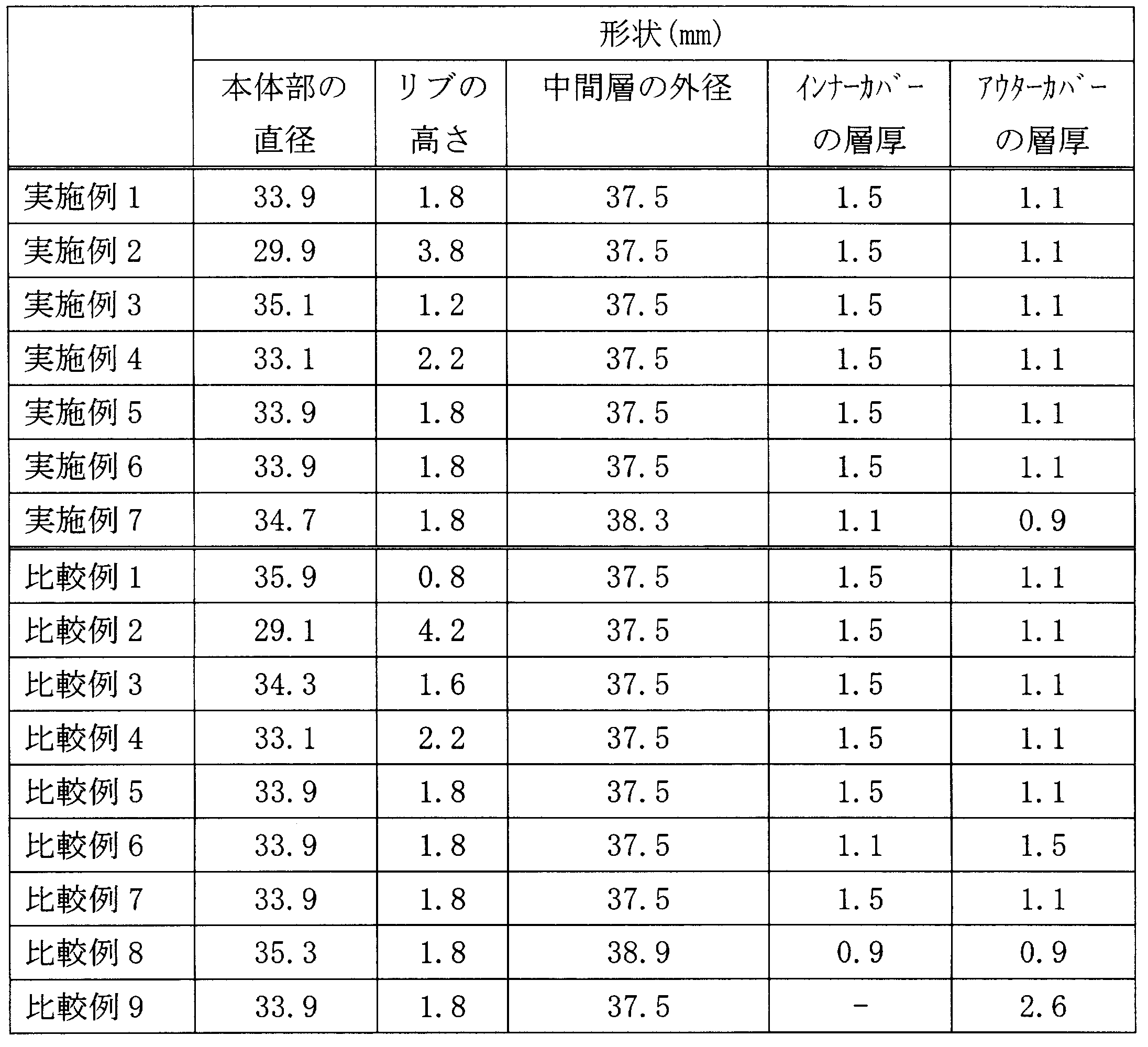

また、表3及び表4は、コアと中間層を構成する材料の組成を示しており、数値は重量部を示している。
Tables 3 and 4 show the compositions of the materials constituting the core and the intermediate layer, and the numerical values show parts by weight.

さらに、インナーカバー及びアウターカバーを構成する材料は以下の通りであり、表中の各数値は、材料の配合比を示している。
Furthermore, the materials constituting the inner cover and the outer cover are as follows, and each numerical value in the table indicates the mixing ratio of the materials.

なお、上記表で、1706は、三井デュポンポリケミカル社製ハイミラン1706を示し、1601は、三井デュポンポリケミカル社製ハイミラン1601を示している。また、HPCは、デュポン社製アイオノマーHPC AD 1043、HPFは、デュポン社製アイオノマーHPF 1000、8150は、デュポン社製アイオノマー サーリン8150を示している。
In the above table, 1706 indicates HiMilan 1706 manufactured by Mitsui DuPont Polychemical Co., Ltd., and 1601 indicates HiMilan 1601 manufactured by Mitsui DuPont Polychemical Co., Ltd. Further, HPC represents DuPont's ionomer HPC AD 1043, HPF represents DuPont's ionomer HPF 1000, 8150, and DuPont's ionomer Surin 8150.
以上のように構成された実施例及び比較例に係るゴルフボールを用い、打撃ロボット(ミヤマエ株式会社製SHOT ROBO v)による1番ウッド(1W:ミズノ株式会社製MP Craft425、ロフト角9.5°、シャフト QUAD 6 Buttスタンダード長さ45インチ)、シャフト硬さS)及びサンドウェッジ(SW:ミズノ株式会社製MP Tシリーズ、56°クロムメッキ、シャフト ダイナミックゴールド Wedgeフレックス 長さ35.25インチを使用した打撃テストを行い飛距離(キャリー)を測定した。ここで、1番ウッドのヘッドスピードは45m/sとし、サンドウェッジのヘッドスピードは35m/sとした。また、アマチュア上級者5人による1番ウッドでの打感テストを行った。この打感テストでは、被験者に4段階評価(1:非常にソフト、2:ソフト、3:硬い、4:非常に硬い)を行ってもらい、その平均値を各例の打感値とした。さらに、耐久試験も行った。試験方法として、エアーガンでボールを40m/sで発射し、鉄板に繰り返しぶつけ、割れるまでの回数を測定した。実施例1を用いてこの試験を行い、割れるまでの回数を100として、各ボールの相対値を耐久指数として算出した。結果は、以下の表6の通りである。
Using the golf balls according to the examples and comparative examples configured as described above, No. 1 wood (1W: MP Craft425 manufactured by Mizuno Co., Ltd., loft angle 9.5 °) by a hitting robot (SHOT ROBO v manufactured by Miyamae Co., Ltd.) , Shaft QUAD 6 Butt Standard Length 45 inches), Shaft Hardness S) and Sand Wedge (SW: Mizuno Corporation MP T Series, 56 ° Chrome Plating, Shaft Dynamic Gold Wedge Flex Length 35.25 inches were used. A hit test was conducted to measure the flight distance (carry), where the head speed of No. 1 wood was 45 m / s and the head speed of sand wedge was 35 m / s. A wood hit feeling test was conducted, in which the test subject was given a four-step evaluation (1: non- (2: soft, 3: hard, 4: very hard), and the average value was used as the hitting value of each example.In addition, a durability test was performed. Was fired at 40 m / s, repeatedly hitting an iron plate, and the number of times until it was broken was measured using Example 1. The number of times until breaking was taken as 100, and the relative value of each ball was calculated as the durability index. The results are shown in Table 6 below.

表6に示す結果から明らかなように、実施例1~7は、いずれも良好な結果が得られている。一方、比較例1では、リブの高さが低すぎるため、バックスピン抑制効果が低くなっている。比較例2では、リブの高さが高すぎるため、また、比較例3は、コアと中間層との高度差が大きすぎてバックスピン抑制効果が大きくなリ過ぎ、飛距離が落ちている。これは、揚力が低下していることも考えられる。
As is apparent from the results shown in Table 6, all of Examples 1 to 7 have good results. On the other hand, in Comparative Example 1, since the rib height is too low, the backspin suppressing effect is low. In Comparative Example 2, the height of the rib is too high. In Comparative Example 3, the difference in altitude between the core and the intermediate layer is too large, and the backspin suppressing effect is too large, and the flight distance is reduced. This may be because the lift is reduced.
比較例4はアウターカバーの硬度が高いため、アウターカバーの変形が小さく、サンドウェッジ使用時のバックスピンが小さくなっており、アプローチには適していない。一方、比較例5のようにアウターカバーの硬度が低すぎると、ドライバー使用時においても、バックスピンが大きくなり、飛距離が伸びない。また、比較例6では、アウターカバーの層厚が大きいため、反発性能が低下し、飛距離が伸びていない。比較例7は、アウターカバーに加え、インナーカバーも柔らかいため、反発性能が低下して飛距離が伸びていない。また、比較例8はインナーカバーとアウターカバーの合計層厚が薄いため、耐久性が劣っている。そして、比較例9はカバーが1層であるため、ボールが硬くなり、打感が悪くなっており、またサンドウェッジ使用時のバックスピンが小さくなっている。
In Comparative Example 4, since the outer cover has a high hardness, the deformation of the outer cover is small, and the back spin when using the sand wedge is small, which is not suitable for the approach. On the other hand, if the hardness of the outer cover is too low as in Comparative Example 5, the backspin becomes large even when the driver is used, and the flight distance does not increase. Further, in Comparative Example 6, since the outer cover has a large layer thickness, the resilience performance is lowered and the flight distance is not extended. In Comparative Example 7, since the inner cover is also soft in addition to the outer cover, the resilience performance is lowered and the flight distance is not extended. Moreover, since the total layer thickness of the inner cover and the outer cover is thin, the comparative example 8 is inferior in durability. In Comparative Example 9, since the cover is a single layer, the ball is hard, the hit feeling is poor, and the back spin when using the sand wedge is small.
以上から明らかなように、本発明に係るゴルフボールによれば、飛距離を大きく伸ばすことができるとともに、アプローチショットにおいては適度なバックスピンを生じさせることができる。
As is clear from the above, according to the golf ball of the present invention, the flight distance can be greatly increased, and an appropriate backspin can be generated in the approach shot.
1 ゴルフボール
3 コア
5 中間層
7 インナーカバー
9 本体部
11 リブ
13 凹部
15 アウターカバー
DESCRIPTION OFSYMBOLS 1 Golf ball 3 Core 5 Mid layer 7 Inner cover 9 Main body part 11 Rib 13 Recessed part 15 Outer cover
3 コア
5 中間層
7 インナーカバー
9 本体部
11 リブ
13 凹部
15 アウターカバー
DESCRIPTION OF
Claims (5)
- 球状の本体部と、
前記本体部の表面に形成される複数のリブと、
前記リブによって囲まれる凹部に充填され、前記リブよりも硬度の高い中間層と、
前記中間層を覆うインナーカバーと、
前記インナーカバーを覆い、当該インナーカバーよりも硬度の低いアウターカバーと、
を備えている、ゴルフボール。 A spherical body,
A plurality of ribs formed on the surface of the main body;
An intermediate layer filled in the recess surrounded by the ribs and having a higher hardness than the ribs;
An inner cover covering the intermediate layer;
Covering the inner cover, an outer cover having a lower hardness than the inner cover;
A golf ball comprising: - 前記インナーカバーの硬度は、前記中間層の硬度よりも高い、請求項1に記載のゴルフボール。 The golf ball according to claim 1, wherein the hardness of the inner cover is higher than the hardness of the intermediate layer.
- 前記インナーカバーとアウターカバーの層厚の合計が1.9mm以上である、請求項1または2に記載のゴルフボール。 The golf ball according to claim 1 or 2, wherein a total thickness of the inner cover and the outer cover is 1.9 mm or more.
- 前記インナーカバーのショアD硬度が55~70である、請求項1から3のいずれかに記載のゴルフボール。 4. The golf ball according to claim 1, wherein the inner cover has a Shore D hardness of 55 to 70.
- 前記アウターカバーのショアD硬度が54~60である、請求項1から4のいずれかに記載のゴルフボール。
The golf ball according to any one of claims 1 to 4, wherein the outer cover has a Shore D hardness of 54 to 60.
Priority Applications (3)
| Application Number | Priority Date | Filing Date | Title |
|---|---|---|---|
| JP2011528824A JP5538402B2 (en) | 2009-08-27 | 2010-08-25 | Golf ball |
| EP10811908.2A EP2444129A4 (en) | 2009-08-27 | 2010-08-25 | Golf ball |
| CN2010800377830A CN102481470A (en) | 2009-08-27 | 2010-08-25 | Golf ball |
Applications Claiming Priority (2)
| Application Number | Priority Date | Filing Date | Title |
|---|---|---|---|
| JP2009197278 | 2009-08-27 | ||
| JP2009-197278 | 2009-08-27 |
Publications (1)
| Publication Number | Publication Date |
|---|---|
| WO2011024859A1 true WO2011024859A1 (en) | 2011-03-03 |
Family
ID=43627959
Family Applications (1)
| Application Number | Title | Priority Date | Filing Date |
|---|---|---|---|
| PCT/JP2010/064385 WO2011024859A1 (en) | 2009-08-27 | 2010-08-25 | Golf ball |
Country Status (6)
| Country | Link |
|---|---|
| US (1) | US20110118059A1 (en) |
| EP (1) | EP2444129A4 (en) |
| JP (1) | JP5538402B2 (en) |
| CN (1) | CN102481470A (en) |
| TW (1) | TW201127452A (en) |
| WO (1) | WO2011024859A1 (en) |
Cited By (2)
| Publication number | Priority date | Publication date | Assignee | Title |
|---|---|---|---|---|
| JP2013063261A (en) * | 2011-09-02 | 2013-04-11 | Mizuno Corp | Golf ball |
| JP2017086155A (en) * | 2015-11-02 | 2017-05-25 | 美津濃株式会社 | Golf ball |
Families Citing this family (11)
| Publication number | Priority date | Publication date | Assignee | Title |
|---|---|---|---|---|
| WO2013191751A1 (en) * | 2012-06-18 | 2013-12-27 | The Pill, Llc | A training golf ball |
| US9126085B2 (en) * | 2013-03-15 | 2015-09-08 | Nike, Inc. | Golf club head structures having split, multi-part heads |
| US9468814B2 (en) | 2013-07-05 | 2016-10-18 | Nike, Inc. | Multi-layer golf ball |
| US9492716B2 (en) | 2013-07-05 | 2016-11-15 | Nike, Inc. | Multi-layer golf ball |
| US9573023B2 (en) | 2013-07-05 | 2017-02-21 | Nike, Inc. | Multi-layer golf ball |
| US10155137B2 (en) | 2013-07-05 | 2018-12-18 | Feng Tay Enterprises Co., Ltd | Golf ball core |
| US9586096B2 (en) | 2013-07-05 | 2017-03-07 | Nike, Inc. | Multi-layer golf ball |
| US9283440B2 (en) | 2013-11-08 | 2016-03-15 | Nike, Inc. | Multi-layer golf ball |
| US9289656B2 (en) | 2013-11-21 | 2016-03-22 | Nike, Inc. | Multi-layer golf ball |
| KR101703045B1 (en) * | 2015-03-17 | 2017-02-06 | 엑스페론골프 주식회사 | Balance rotating golf ball |
| JP6631224B2 (en) * | 2015-12-14 | 2020-01-15 | 住友ゴム工業株式会社 | Two piece golf ball |
Citations (2)
| Publication number | Priority date | Publication date | Assignee | Title |
|---|---|---|---|---|
| WO2005089883A1 (en) | 2004-03-19 | 2005-09-29 | Mizuno Corporation | Multi-piece golf ball and method for manufacturing same |
| JP2009034509A (en) * | 2007-07-31 | 2009-02-19 | Bridgestone Sports Co Ltd | Multi-piece solid golf ball |
Family Cites Families (14)
| Publication number | Priority date | Publication date | Assignee | Title |
|---|---|---|---|---|
| JP4016228B2 (en) * | 1998-04-20 | 2007-12-05 | ブリヂストンスポーツ株式会社 | Golf ball |
| US6835146B2 (en) * | 1999-11-23 | 2004-12-28 | Acushnet Company | Golf ball with high coefficient of restitution |
| US6485378B1 (en) * | 1999-11-23 | 2002-11-26 | Acushnet Company | Golf ball |
| US6756436B2 (en) * | 2001-06-26 | 2004-06-29 | Acushnet Company | Golf balls comprising highly-neutralized acid polymers |
| US7101292B2 (en) * | 2002-07-12 | 2006-09-05 | Sri Sports Limited | Multi-piece solid golf ball |
| US7108921B2 (en) * | 2002-10-24 | 2006-09-19 | Acushnet Company | Compositions for use in golf balls |
| JP4038671B2 (en) * | 2003-01-10 | 2008-01-30 | 美津濃株式会社 | Multi-piece golf ball |
| US6955613B2 (en) * | 2003-01-10 | 2005-10-18 | Mizuno Corporation | Multi-piece golf ball and manufacturing method thereof |
| CN1950130A (en) * | 2004-03-19 | 2007-04-18 | 美津浓株式会社 | Multi-piece golf ball and manufacturing method thereof |
| US7008334B2 (en) * | 2004-04-14 | 2006-03-07 | Bridgestone Sports Co., Ltd. | Golf ball |
| CN1960782B (en) * | 2004-06-09 | 2010-05-12 | 美津浓株式会社 | Multi-layer golf ball and manufacturing method thereof |
| JP4435640B2 (en) * | 2004-07-29 | 2010-03-24 | Sriスポーツ株式会社 | Golf ball |
| US7273425B2 (en) * | 2005-12-05 | 2007-09-25 | Bridgestone Sports Co., Ltd. | Solid golf ball |
| US7744492B2 (en) * | 2007-07-31 | 2010-06-29 | Bridgestone Sports Co., Ltd. | Multi-piece solid golf ball |
-
2010
- 2010-08-25 JP JP2011528824A patent/JP5538402B2/en not_active Expired - Fee Related
- 2010-08-25 US US12/868,120 patent/US20110118059A1/en not_active Abandoned
- 2010-08-25 WO PCT/JP2010/064385 patent/WO2011024859A1/en active Application Filing
- 2010-08-25 CN CN2010800377830A patent/CN102481470A/en active Pending
- 2010-08-25 EP EP10811908.2A patent/EP2444129A4/en not_active Withdrawn
- 2010-08-26 TW TW099128643A patent/TW201127452A/en unknown
Patent Citations (2)
| Publication number | Priority date | Publication date | Assignee | Title |
|---|---|---|---|---|
| WO2005089883A1 (en) | 2004-03-19 | 2005-09-29 | Mizuno Corporation | Multi-piece golf ball and method for manufacturing same |
| JP2009034509A (en) * | 2007-07-31 | 2009-02-19 | Bridgestone Sports Co Ltd | Multi-piece solid golf ball |
Non-Patent Citations (1)
| Title |
|---|
| See also references of EP2444129A4 |
Cited By (2)
| Publication number | Priority date | Publication date | Assignee | Title |
|---|---|---|---|---|
| JP2013063261A (en) * | 2011-09-02 | 2013-04-11 | Mizuno Corp | Golf ball |
| JP2017086155A (en) * | 2015-11-02 | 2017-05-25 | 美津濃株式会社 | Golf ball |
Also Published As
| Publication number | Publication date |
|---|---|
| EP2444129A1 (en) | 2012-04-25 |
| TW201127452A (en) | 2011-08-16 |
| CN102481470A (en) | 2012-05-30 |
| JP5538402B2 (en) | 2014-07-02 |
| US20110118059A1 (en) | 2011-05-19 |
| EP2444129A4 (en) | 2014-12-10 |
| JPWO2011024859A1 (en) | 2013-01-31 |
Similar Documents
| Publication | Publication Date | Title |
|---|---|---|
| JP5538402B2 (en) | Golf ball | |
| JP4374500B2 (en) | Multi-piece golf ball and manufacturing method thereof | |
| JP5078316B2 (en) | Golf ball and manufacturing method thereof | |
| JP4419026B2 (en) | Multi-piece golf ball and manufacturing method thereof | |
| JP6675144B2 (en) | Multi-piece solid golf ball | |
| JP5424990B2 (en) | Golf ball | |
| JP4373189B2 (en) | Golf ball | |
| US7192367B2 (en) | Multi-piece golf ball, manufacturing method thereof and mold for manufacturing the same | |
| JP4916208B2 (en) | Golf ball | |
| JP4398351B2 (en) | Golf ball | |
| JP4693887B2 (en) | Golf ball | |
| JP2012020118A (en) | Golf ball | |
| JP4969348B2 (en) | Golf ball | |
| JP4061508B2 (en) | Mold for molding golf ball and its core | |
| JP5545345B2 (en) | Golf ball | |
| JP4066001B2 (en) | Golf ball and manufacturing method thereof | |
| JPH11299932A (en) | Golf ball | |
| JP2005168701A (en) | Golf ball | |
| JP2002224242A (en) | Golf ball | |
| JP4038671B2 (en) | Multi-piece golf ball | |
| JP4006549B2 (en) | Solid golf balls | |
| JP6596842B2 (en) | Golf ball and manufacturing method thereof | |
| JPH10248955A (en) | Solid golf ball | |
| JP4463695B2 (en) | Golf ball | |
| JP5800756B2 (en) | Golf ball |
Legal Events
| Date | Code | Title | Description |
|---|---|---|---|
| WWE | Wipo information: entry into national phase |
Ref document number: 201080037783.0 Country of ref document: CN |
|
| 121 | Ep: the epo has been informed by wipo that ep was designated in this application |
Ref document number: 10811908 Country of ref document: EP Kind code of ref document: A1 |
|
| WWE | Wipo information: entry into national phase |
Ref document number: 2011528824 Country of ref document: JP |
|
| WWE | Wipo information: entry into national phase |
Ref document number: 2010811908 Country of ref document: EP |
|
| NENP | Non-entry into the national phase |
Ref country code: DE |