WO2010090343A1 - 黒鉛化炭素片分散液およびその製造方法 - Google Patents
黒鉛化炭素片分散液およびその製造方法 Download PDFInfo
- Publication number
- WO2010090343A1 WO2010090343A1 PCT/JP2010/052012 JP2010052012W WO2010090343A1 WO 2010090343 A1 WO2010090343 A1 WO 2010090343A1 JP 2010052012 W JP2010052012 W JP 2010052012W WO 2010090343 A1 WO2010090343 A1 WO 2010090343A1
- Authority
- WO
- WIPO (PCT)
- Prior art keywords
- graphitized carbon
- weight
- average
- parts
- dispersion
- Prior art date
- Legal status (The legal status is an assumption and is not a legal conclusion. Google has not performed a legal analysis and makes no representation as to the accuracy of the status listed.)
- Ceased
Links
Images











Classifications
-
- C—CHEMISTRY; METALLURGY
- C08—ORGANIC MACROMOLECULAR COMPOUNDS; THEIR PREPARATION OR CHEMICAL WORKING-UP; COMPOSITIONS BASED THEREON
- C08J—WORKING-UP; GENERAL PROCESSES OF COMPOUNDING; AFTER-TREATMENT NOT COVERED BY SUBCLASSES C08B, C08C, C08F, C08G or C08H
- C08J5/00—Manufacture of articles or shaped materials containing macromolecular substances
- C08J5/04—Reinforcing macromolecular compounds with loose or coherent fibrous material
- C08J5/0405—Reinforcing macromolecular compounds with loose or coherent fibrous material with inorganic fibres
- C08J5/042—Reinforcing macromolecular compounds with loose or coherent fibrous material with inorganic fibres with carbon fibres
-
- C—CHEMISTRY; METALLURGY
- C01—INORGANIC CHEMISTRY
- C01B—NON-METALLIC ELEMENTS; COMPOUNDS THEREOF; METALLOIDS OR COMPOUNDS THEREOF NOT COVERED BY SUBCLASS C01C
- C01B32/00—Carbon; Compounds thereof
- C01B32/20—Graphite
- C01B32/205—Preparation
-
- C—CHEMISTRY; METALLURGY
- C01—INORGANIC CHEMISTRY
- C01B—NON-METALLIC ELEMENTS; COMPOUNDS THEREOF; METALLOIDS OR COMPOUNDS THEREOF NOT COVERED BY SUBCLASS C01C
- C01B32/00—Carbon; Compounds thereof
- C01B32/20—Graphite
- C01B32/21—After-treatment
Definitions
- the present invention relates to a dispersion of graphitized carbon pieces having a micron-sized thin plate shape and a developed graphite crystal structure, and a method for producing the same.
- various carbon fibers, natural graphite, artificial graphite and the like are applied in a wide range of fields as carbon-based materials.
- the carbon fiber include PAN-based carbon fiber using polyacrylonitrile (PAN) as a raw material, isotropic pitch-based carbon fiber using isotropic pitch as a raw material, and anisotropic pitch-based material using anisotropic pitch as a raw material.
- PAN polyacrylonitrile
- anisotropic pitch-based material using anisotropic pitch as a raw material.
- Examples thereof include carbon fibers, carbon nanotubes produced by vapor deposition, and carbon nanofibers (for example, Non-Patent Documents 1 to 3).
- the PAN-based carbon fiber and the isotropic pitch-based carbon fiber are derived from the fact that the carbon crystal structure content and the crystal growth size are small, so that the thermal conductivity and electrical conductivity of the carbon fiber are so high. It will not be.
- anisotropic pitch-based carbon fibers, vapor-grown carbon nanotubes, vapor-grown carbon nanofibers, etc. can dramatically increase the content and growth size of the carbon crystal structure. Conductivity and conductivity can be obtained.
- vapor phase carbon nanotubes and vapor phase carbon nanofibers are prepared by a vapor phase method, it is difficult to obtain high productivity. Further, since it is nano-sized (several nm to several hundred nm), it often has problems with matrix dispersibility and handling properties.
- anisotropic pitch-based graphitized carbon fiber is considered the most suitable material among carbon fibers.
- Patent Document 1 in the commercial production of general anisotropic pitch-based carbon fibers, a fiber diameter of 3 ⁇ m or less is used from the viewpoint of productivity or production stability because a production process in which melt pitch is discharged from the spinning holes is used for spinning. Is difficult to manufacture, and the cross-sectional shape is almost a perfect circle.
- natural graphite and artificial graphite have a great variety of crystallinity, purity and the like depending on their production conditions or production conditions.
- an object of the present invention is to provide a dispersion containing carbon pieces excellent in thermal conductivity and conductivity, which can fill a matrix at a high concentration and can form a dense network in the matrix, and a method for producing the same. It is to provide.
- Another object of the present invention is to provide a solution composition containing the dispersion and matrix.
- Another object of the present invention is to provide a carbon piece excellent in thermal conductivity and conductivity that can be filled in a matrix at a high concentration and can form a dense network in the matrix.
- this invention is providing the composite material excellent in thermal conductivity and electroconductivity.
- the present inventors diligently studied the graphitized carbon material by paying attention to its shape and size. As a result, the graphitized carbon material is made into a thin plate-like micron-sized graphitized carbon piece, so that the matrix can be filled at a high rate, and the graphitized carbon material network becomes denser and more complex. The present inventors have found that the thermal conductivity and electrical conductivity of the material are greatly improved, and have reached the present invention.
- the present invention is a dispersion containing a graphitized carbon piece and a liquid dispersion medium, the graphitized carbon piece, (1) It has a thin plate shape with an average thickness of 0.02 to 2 ⁇ m, (2) Average long axis length of 1 to 100 ⁇ m, (3) Average minor axis length of 0.1 to 10 ⁇ m, (4) The average aspect ratio of the major axis to the minor axis is 2 to 100, (5) The crystallite size (Lc) derived from the thickness direction of the hexagonal network surface of the graphite crystal is 20 nm or more, Is a dispersion.
- Lc crystallite size
- the present invention is also characterized in that the graphitized carbon material having a crystallite size (Lc) derived from the thickness direction of the hexagonal network surface of the graphite crystal of 20 nm or more is pulverized in the presence of a liquid dispersion medium. It is a manufacturing method of a liquid.
- the present invention also provides a solution composition containing the dispersion and the matrix, wherein the content of the graphitized carbon pieces is 1 to 900 parts by weight with respect to 100 parts by weight of the matrix.
- this invention includes the molded article formed by shape
- the present invention also includes (1) a thin plate shape having an average thickness of 0.02 to 2 ⁇ m (2) Average long axis length of 1 to 100 ⁇ m, (3) Average minor axis length of 0.1 to 10 ⁇ m, (4) The average aspect ratio of the major axis to the minor axis is 2 to 100, (5) The crystallite size (Lc) derived from the thickness direction of the hexagonal network surface of the graphite crystal is 20 nm or more, It is a graphitized carbon piece.
- the present invention also includes 100 parts by weight of matrix and 1 to 900 parts by weight of graphitized carbon pieces, (1) It has a thin plate shape with an average thickness of 0.02 to 2 ⁇ m, (2) Average long axis length of 1 to 100 ⁇ m, (3) Average minor axis length of 0.1 to 10 ⁇ m, (4) The average aspect ratio of the major axis to the minor axis is 2 to 100, (5) The crystallite size (Lc) derived from the thickness direction of the hexagonal network surface of the graphite crystal is 20 nm or more, Is a composite material.
- the present invention includes a molded product obtained by molding the composite material.
- FIG. 1 is a schematic diagram showing an example of a cross-sectional structure of graphitized carbon fiber suitable for the present invention.
- FIG. 2 is an example of an electron micrograph of a cross section of graphitized carbon fiber having a cross-sectional structure represented by the schematic diagram of FIG.
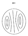
- FIG. 3 is a schematic view showing another example of the cross-sectional structure of graphitized carbon fiber suitable for the present invention.
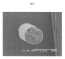
- FIG. 4 is an example of an electron micrograph of a cross section of graphitized carbon fiber having a cross-sectional structure represented by the schematic diagram of FIG.
- FIG. 5 is a schematic view showing another example of the cross-sectional structure of graphitized carbon fiber suitable for the present invention.
- FIG. 6 is an example of an electron micrograph of the cross section of the graphitized carbon fiber having the cross-sectional structure represented by the schematic diagram of FIG. 5, and is an example of an electron micrograph of the graphitized carbon fiber of Example 1.
- FIG. 7 is an example of another cross-sectional structure of graphitized carbon fiber.
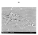
- FIG. 8 is an example of an electron micrograph of the graphitized carbon piece obtained in Example 1.
- FIG. 9 is another example of an electron micrograph of the graphitized carbon piece obtained in Example 1.
- FIG. 10 is another example of an electron micrograph of the graphitized carbon piece obtained in Example 1.
- FIG. 11 is another example of an electron micrograph of the graphitized carbon piece obtained in Example 1.
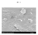
- FIG. 12 is an example of an electron micrograph of the graphitized carbon piece obtained in Example 4.
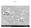
- FIG. 13 is another example of an electron micrograph of the graphitized carbon piece obtained in Example 4.
- FIG. 14 is another example of an electron micrograph of the graphitized carbon piece obtained in Example 4.
- FIG. 15 is another example of an electron micrograph of the graphitized carbon piece obtained in Example 4.
- FIG. 16 is another example of an electron micrograph of the graphitized carbon piece obtained in Example 4.
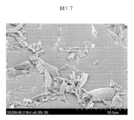
- FIG. 17 is an example of an electron micrograph of the carbon piece obtained in Comparative Example 3.
- FIG. 18 is another example of an electron micrograph of the carbon piece obtained in Comparative Example 3.
- FIG. 19 is another example of an electron micrograph of the carbon piece obtained in Comparative Example 3.
- the dispersion of the present invention is a dispersion containing graphitized carbon pieces and a liquid dispersion medium.
- the graphitized carbon pieces (1) have a thin plate shape with an average thickness of 0.02 to 2 ⁇ m, (2) Average long axis length of 1 to 100 ⁇ m, (3) Average minor axis length of 0.1 to 10 ⁇ m, (4) The average aspect ratio of the major axis to the minor axis is 2 to 100, (5)
- the crystallite size (Lc) derived from the thickness direction of the hexagonal network surface of the graphite crystal is 20 nm or more.
- the average thickness of the graphitized carbon pieces is 0.02 to 2 ⁇ m, preferably 0.05 to 1 ⁇ m, more preferably 0.1 to 0.5 ⁇ m.
- the average major axis length of the graphitized carbon pieces is 1 to 100 ⁇ m, preferably 3 to 70 ⁇ m, more preferably 10 to 50 ⁇ m.
- the average short axis length of the graphitized carbon pieces is 0.1 to 10 ⁇ m, preferably 0.3 to 5 ⁇ m, more preferably 0.5 to 3 ⁇ m.
- the average aspect ratio between the major axis and the minor axis of the graphitized carbon piece is 2 to 100, preferably 5 to 100, more preferably 5 to 50, still more preferably 5 to 30, and particularly preferably 10 to 30.
- the crystallite size (Lc) derived from the thickness direction of the hexagonal network surface of the graphite crystal of the graphitized carbon piece is 20 nm or more, preferably 30 nm or more, more preferably 40 nm or more.
- the graphitized carbon piece has a shape that is considered to be a problem as expressed as a thin plate as illustrated in the microscopic observation photographs in FIGS. 8 to 16, but there are fine irregularities at the end and the surface. It is not a complete plate shape with a pair of parallel planes.
- the graphitized carbon piece of the present invention partially has a surface with some unevenness and curvature, but at least most of the plate has a pair of upper and lower surfaces that are substantially parallel surfaces ( A rectangular parallelepiped, an elliptical plate, etc.). Therefore, the size of the graphitized carbon piece is expressed by the plate thickness, the average major axis length, and the average minor axis length when this is approximated as a complete plate.
- the dispersion may contain a part of the graphitized carbon fragment that is out of the shape. It is preferable to occupy 80% by weight or more of the graphitized carbon pieces.
- the dispersion of the present invention contains a liquid dispersion medium.
- the liquid dispersion medium is preferably water or an organic solvent having a boiling point of 300 ° C. or lower.
- the boiling point of the organic solvent is 300 ° C. or lower, preferably 250 ° C. or lower, more preferably 200 ° C. or lower in consideration of wettability, compatibility with the dispersant described later, and drying.
- the temperature is preferably 100 ° C. or lower.
- Specific examples of the organic solvent include ketones, esters, ethers, alcohols, aromatic solvents, nitrogen-containing solvents, and the like.
- ketones such as diethyl ketone, methyl ethyl ketone, methyl isobutyl ketone, cyclohexanone, and methylcyclohexanone.
- esters such as ethyl acetate, butyl acetate, methyl lactate, ethyl lactate, propyl lactate, butyl lactate, diethyl adipate, dibutyl oxalate, dimethyl malonate, diethyl malonate, dimethyl succinate, diethyl succinate .
- esters such as ethylene glycol monomethyl ether acetate, ethylene glycol monoethyl ether acetate, ethylene glycol monobutyl ether acetate, diethylene glycol monomethyl ether acetate, diethylene glycol monoethyl ether acetate, propylene glycol monomethyl ether acetate, propylene glycol monoethyl ether acetate It is done.
- alcohols such as methanol, ethanol, propanol, isopropanol, butanol, isobutanol, 1-pentanol, 1-heptanol, 2-octanol, 3-methyl-1-butanol, are mentioned.
- the dispersion of the present invention may contain a dispersant as necessary.
- a dispersant a polymer compound containing a linking group having an acid value or an amine value in the molecular chain is preferably used.
- the dispersant is a polymer compound containing a linking group having an amine value in the molecular chain. Is more stable because it is more strongly and persistently adsorbed on the surface of the graphitized carbon piece.
- a dispersant containing a linking group having an amine value in the molecular chain is effective.
- a copolymer of a C1-C10 lower acrylate (or methacrylate) and a monoalkylaminoalkyl acrylate (or methacrylate) such as methyl, ethyl, propyl, butyl, amyl, hexyl, 2-ethylhexyl, methyl, ethyl , Propyl, butyl, amyl, hexyl, 2-ethylhexyl and the like
- urethane type and polyester type having an amine value are also preferred.
- Polymeric dispersants having an amine value are commercially available from BYK Chemie “Disperbyk-160, 161, 162, 163, 164, 165, 166, 169, 182, 183, 184, 185, 2000, 2001, 2020, 2050, 2070, 2150 ", EFKA CHEMICALS” EFKA-4046, 4047, 4048, 4050, 4055, 4400, 4401, 4402 ", Nippon Lubrizol” SOLPERSE24000SC, 24000GR, 31845 ", manufactured by Enomoto Kasei Co., Ltd.
- Preferable examples include DESPARON DA703-50, DA-705, DA-725 “," Ajisper PB711, 821, 822, 824, 827 "manufactured by Ajinomoto Fine Techno Co., Ltd.
- the amine value of these polymer dispersants is preferably 1 to 50 mgKOH / g. Particularly preferred is 1 to 40 mg KOH / g.
- the amine value is the number of mg of KOH equivalent to hydrochloric acid necessary for neutralizing 1 g of resin with a 0.1N hydrochloric acid solution, and can be determined by potentiometric titration.
- a water-soluble resin or a surfactant can be used as the dispersant in the case of an aqueous system.
- the water-soluble resin include styrene-acrylic acid copolymer, styrene-methylstyrene-acrylic acid copolymer, styrene-acrylic acid- (meth) acrylic acid ester (lower alkyl ester of about C1 to C4, hereinafter Similarly) copolymer, methacrylic acid- (meth) acrylic acid ester copolymer, acrylic acid- (meth) acrylic acid ester copolymer, styrene-methacrylic acid copolymer, styrene-maleic acid copolymer, styrene- Methyl styrene-maleic acid copolymer, styrene- (meth) acrylic acid ester-maleic acid copolymer, styrene- (meth) acrylic acid ester-
- the water-soluble resin is characterized by having an acid value, and the acid value is preferably 50 to 320, particularly preferably 55 to 270.
- the acid value is the mg amount of KOH required to neutralize 1 g of the resin.
- the surfactant nonionic, anionic and cationic amphoteric ions are preferred.
- alkylbenzene sulfonate higher alcohol sulfate ester salt, higher fatty acid salt, higher alkyl dicarboxylate, alkyl naphthalene sulfonate, alkyl sulfosuccinate, naphthalene sulfonic acid formalin condensate salt, polyoxyethylene alkyl ether
- Anionic surfactants such as sulfates and polyoxyethylene alkyl phosphates are listed.
- Nonionics such as polyoxyethylene alkyl ether, polyoxyethylene alkyl phenyl ether, fatty acid monoglyceride, sorbitan fatty acid ester, polyoxyethylene sorbitan fatty acid ester, polyoxyethylene fatty acid ester, polyglycerin fatty acid ester, polyoxyethylene-added acetylene glycol Surfactant is mentioned.
- cationic surfactants such as aliphatic amine salts, aliphatic phosphonium salts, and aliphatic sulfonium salts are exemplified.
- a structural formula having a relatively low volatile decomposition point at the time of drying is preferable for physical properties during film formation.
- the polymer dispersant and the water-soluble resin preferably have a weight average molecular weight of 1,000 to 50,000, particularly preferably 2,000 to 30,000, in view of their dispersibility. If it is out of this range, the dispersibility of the graphitized carbon pieces may be deteriorated.
- the average molecular weight can be measured by GPC (gel permeation chromatography).
- the content of graphitized carbon pieces in the dispersion of the present invention is preferably in the range of 3 to 70% by weight, more preferably 10 to 50% by weight, and still more preferably 15 to 30% by weight, based on the total amount of the dispersion. is there. If it is less than 3% by weight, it is inferior in production efficiency and convenience in various applications, and if it exceeds 70% by weight, the viscosity of the dispersion is increased and handling properties are lowered.
- the content of the dispersant in the dispersion of the present invention is preferably 5 to 100 parts by weight, more preferably 10 to 70 parts by weight with respect to 100 parts by weight of the graphitized carbon pieces.
- dispersibility and fluidity may be insufficient when the content of the graphitized carbon piece is large (approximately more than 5% by weight).
- the amount exceeds 100 parts by weight, the dispersion becomes highly viscous.
- the dispersion of the present invention may contain other additives as necessary.
- the dispersion of the present invention is produced by pulverizing a graphitized carbon material having a crystallite size (Lc) of 20 nm or more derived from the thickness direction of the hexagonal network surface of graphite crystals in the presence of a liquid dispersion medium. Can do.
- Lc crystallite size
- the graphitized carbon material to be wet pulverized is a carbon material having a crystallite size (Lc) derived from the thickness direction of the hexagonal network surface of the graphite crystal of 20 nm or more.
- the carbon material one having a high degree of graphitization is preferable.
- the degree of graphitization indicates the degree of growth of the graphite crystal structure, but can be expressed by several physical property values that can be analyzed with an instrument or the like.
- a crystallite size (Lc) derived from at least the thickness direction of the hexagonal network surface of the graphite crystal is preferably 20 nm or more.
- Lc crystallite size
- Lc is less than 20 nm, there is a tendency that efficient wet pulverization becomes difficult. This is probably because graphite crystals are not sufficiently developed, and the residual stress accumulated between the crystal layers is small.
- the value of Lc is preferably 20 nm or more, more preferably 30 nm or more, still more preferably 40 nm or more, and most preferably 50 nm or more. More preferably, the crystallite size (La) derived from the growth direction of the hexagonal network surface is also preferably 30 nm or more, more preferably 50 nm or more, still more preferably 70 nm or more, and most preferably 90 nm or more.
- the plane spacing (d002) of the graphite crystal is preferably 0.3370 nm or less, more preferably 0.3367 nm or less, and further preferably 0.3363 nm or less.
- the crystallite size in the thickness direction of the hexagonal mesh surface and the growth direction of the hexagonal mesh surface, the interplanar spacing of the graphite crystals, and the like can be determined by so-called X-ray diffraction.
- the measurement method is a concentration method, and the Gakushin method is preferably used as an analysis method.
- the crystallite size in the thickness direction of the hexagonal mesh plane is obtained using diffraction lines from the (002) plane, and the crystallite size in the growth direction of the hexagonal mesh plane is obtained using diffraction lines from the (110) plane.
- the true density of the carbon material is 1.90 to 2.25 g / cm. 3 Is preferable, and more preferably 2.00 to 2.25 g / cm. 3 More preferably, 2.10-2.25 g / cm 3 It is.
- the graphitized carbon material is preferably an anisotropic pitch-based graphitized carbon fiber.
- anisotropic pitch-based graphitized carbon fiber spinning is performed using a liquid crystalline pitch, so that a developed graphite crystal having an Lc of 20 nm or more is easily obtained, and the domain orientation of the graphite crystal due to liquid crystallinity is obtained. It has characteristics that are easy to develop.
- the graphitized carbon material is preferably a material in which the domain alignment structure arranged in layers is observed partially or entirely. These domain orientations are possible, for example, by observing the fiber cross section with a scanning electron microscope or the like. Among these, it is preferable that the graphitized carbon material is an anisotropic pitch-based graphitized carbon fiber, and a domain alignment structure extending in the radial direction is observed at the center of the fiber cross section.
- FIGS. 1, 3, and 5 Schematic diagrams of typical three types of fiber cross-sectional structures related to such a structure are illustrated in FIGS. 1, 3, and 5.
- FIG. FIGS. 2, 4, and 6 show examples of photographs of fiber cross-sections observed with a scanning electron microscope corresponding to the structures of FIGS. 1, 3, and 5, respectively.
- FIG. 1 and FIG. 2 are examples of a radial structure in which a plurality of domain groups are arranged radially from the fiber center toward the fiber outer periphery.
- FIG. 3 and FIG. 4 are examples of structures comprising a combination of a radial structure and an elliptical arrangement structure.
- FIG. 5 and FIG. 6 are examples of structures composed of a combination of a radial structure and a semi-elliptical array structure.
- FIG. 7 shows an example of a cross-sectional structure of graphitized carbon fiber in which the development of such a radial structure is small and the domains are oriented almost randomly.
- anisotropic pitch-based graphitized carbon fibers containing a large amount of radial structure large residual stresses and strains are accumulated at the boundaries of each domain forming the radial structure, and the fibers start from these boundaries. This is preferable because vertical cracks are easily generated in the fiber axis direction.
- the radial structure is preferably observed in an area of 10% or more of the total area of the fiber cross section, more preferably 20% or more, and further preferably 30% or more.
- the area ratio of the radial structure is approximately 100% for the carbon fibers illustrated in FIG. 2 and approximately 30% for the carbon fibers illustrated in FIGS. 4 and 6.
- the average fiber diameter of the anisotropic pitch-based graphitized carbon fiber is preferably in the range of 3 to 20 ⁇ m, more preferably 5 to 17 ⁇ m, and still more preferably 7 to 15 ⁇ m, as the average fiber diameter in terms of perfect circle. .
- the dispersion value (CV value) indicating the variation in the fiber diameter is a percentage of the value obtained by dividing the standard deviation of the fiber diameter at the time of measuring the predetermined number by the average value of the fiber diameter, and the CV value is in the range of 3-20. Is more preferable, and the range of 3 to 15 is more preferable.
- the average fiber length is more preferably 15 to 1,000 ⁇ m, still more preferably 20 to 500 ⁇ m, and most preferably 25 to 250 ⁇ m.
- a graphitized carbon material subjected to a wet pulverization treatment, particularly an anisotropic pitch-based graphitized carbon short fiber can be produced by the following method.
- the raw material include condensed polycyclic hydrocarbon compounds such as naphthalene and phenanthrene, condensed heterocyclic compounds such as petroleum pitch and coal pitch. Among these, condensed polycyclic hydrocarbon compounds such as naphthalene and phenanthrene are preferable, and mesophase pitch is particularly preferable.
- the mesophase rate of the mesophase pitch is at least 90% or more, more preferably 95% or more, and further preferably 99% or more.
- the mesophase rate of the mesophase pitch can be confirmed by observing the pitch in the molten state with a polarizing microscope. In addition, you may use a pitch suitably combining 2 or more types as needed.
- the softening point temperature of the pitch is preferably in the range of 230 to 360 ° C.
- the softening point temperature can be determined by, for example, the Mettler method. When the softening point temperature is lower than 230 ° C., the infusibilization process temperature described later is lowered, and therefore, the infusibilization process takes a long time, which is not preferable.
- a more preferable range of the softening point temperature is 250 ° C. or higher and 340 ° C. or lower, and more preferably 260 ° C. or higher and 320 ° C. or lower.
- the spinning method is not particularly limited, but a so-called melt spinning method is preferably used.
- a normal spinning drawing method in which a mesophase pitch discharged from a die is drawn with a winder
- a melt blow method using hot air as an atomizing source a centrifugal spinning method in which mesophase pitch is drawn using centrifugal force, etc. It is done.
- the spinning method of the precursor fiber by the melt blow method will be described in detail.
- the shape of the spinning nozzle is not particularly limited, and a perfect circular shape is usually used. However, there is no problem even if an irregularly shaped nozzle such as an ellipse is used in a timely manner.
- the ratio L / D of the nozzle hole length L to the hole diameter D is preferably about 2 to 30. If L / D is less than 2, it becomes difficult to increase the shearing force at the time of pitch melting. If L / D exceeds 30, it is necessary to increase the spinning pressure, and it is necessary to increase the size of the device, including ensuring the strength of the device. And it is difficult to increase the surface density of the spinning holes and the productivity is lowered.
- a more preferable range of L / D is 3 to 25, more preferably 5 to 20 from the viewpoint of increasing the area ratio of the radial structure.
- the melt viscosity of the pitch when passing through the nozzle holes is preferably in the range of about 1 to 100 Pa ⁇ s. If the melt viscosity of the melt pitch is less than 1 Pa ⁇ s, it is difficult to maintain the fiber shape.
- the melt viscosity exceeds 100 Pa ⁇ s, it is necessary to considerably increase the pressure resistance of the spinning nozzle, which is not desirable in terms of cost performance of the apparatus.
- the melt viscosity is more preferably 3 to 40 Pa ⁇ s, and more preferably 5 to 20 Pa ⁇ s.
- the anisotropic pitch graphitized carbon fiber preferably has a melt viscosity in the range of 3 to 40 (Pa ⁇ s) and the spinning nozzle L / D in the range of 2 to 30.
- the fiber diameter of the precursor fiber can be adjusted by changing the nozzle hole diameter, changing the discharge amount of the raw material pitch from the nozzle, or changing the draft ratio of the precursor fiber by blowing air.
- the draft ratio is changed by blowing a gas having a linear velocity of 100 to 20,000 m / min heated to 100 to 400 ° C. in the vicinity of the thinning point of the spinning pitch discharged from the nozzle.
- a gas having a linear velocity of 100 to 20,000 m / min heated to 100 to 400 ° C. in the vicinity of the thinning point of the spinning pitch discharged from the nozzle.
- Can do There is no particular restriction on the gas to be blown, but air is desirable from the viewpoint of cost performance and safety.
- the fiber diameter of the precursor fiber is preferably in the range of about 5 to 25 ⁇ m as a true circle equivalent average fiber diameter. More preferably, it is 7 to 20 ⁇ m.
- the precursor fiber spun by the melt blow method is collected, for example, in a web-like form on a belt movable wire net or the like.
- the thickness, basis weight, density, etc. of the web can be arbitrarily adjusted by setting the spinning conditions and the belt conveyance speed.
- the basis weight of the web is 150 to 1,000 g / m in consideration of productivity and process stability. 2 Is preferred.
- the web of precursor fibers thus obtained is conveyed by a belt or the like and sent to the infusibilization process.
- the infusibilization treatment can be performed by a known method. For example, it can be carried out in an oxidizing atmosphere using air or a gas obtained by adding ozone, nitrogen dioxide, nitrogen, oxygen, iodine, bromine to air, but in consideration of safety and convenience, it may be carried out in the air. desirable.
- the infusibilization process can be performed by either batch process or continuous process, but continuous process is desirable in consideration of productivity.
- the infusibilization treatment is preferably carried out at a temperature lower than the softening point temperature of the pitch, and can be achieved by applying a heat treatment at a temperature of about 150 to 350 ° C.
- a more preferable temperature range is 160 to 340 ° C.
- the temperature increase rate is preferably 1 to 10 ° C./min. In the case of continuous treatment, the above temperature increase rate can be achieved by sequentially passing through a plurality of reaction chambers set at arbitrary temperatures. A more preferable range of the heating rate is 3 to 9 ° C./min in consideration of productivity and process stability.
- the web that has been infusibilized is conveyed by a belt or the like and sent to the carbonization process. Carbonization can also be performed by a known method. For example, it can be carried out by heating and heat-treating the web at a temperature of about 600 to 2,500 ° C.
- the carbonization process is preferably performed at normal pressure and in a nitrogen atmosphere in consideration of cost.
- the carbonization treatment can be either batch processing or continuous processing, but continuous processing is desirable in consideration of productivity.
- the web that has been carbonized is preferably subjected to a coarse pulverization step.
- the coarse pulverization step is a step of throwing the web into various cutting machines and / or crushing / pulverizing machines, destroying the shape of the web, and cutting the carbon fibers inside the web into short fibers having an appropriate fiber length. .
- the purpose of cutting into an appropriate length of short fiber is to improve productivity, production stability, controllability, etc. in the later-described advanced graphitization process and wet pulverization process.
- the reason for mentioning productivity here is that the advanced graphitization process and wet pulverization process are often performed in batch processing because of the equipment, so it is necessary to increase the amount of carbon fiber that can be input at once in batch processing. This is because it is generally preferable to use short fibers having an appropriate fiber length rather than webs. That is, the main purpose is to increase the bulk density when carbon fibers are filled into batch processing containers and devices, and the bulk density of short fiber-like carbon fibers is at least 0.1 g / cm. 3 Or more, more preferably 0.3 g / cm 3 Or more, more preferably 0.5 g / cm 3 Or more, most preferably 0.7 g / cm 3 It is preferable to perform coarse pulverization to achieve the above.
- the crushing / pulverizing machine includes, for example, a hammer type using an impact action, a pin type, a ball type, a bead type and a rod type, a high-speed rotation type using collision between particles, and a roll type using a compression / tearing action.
- Cone-type and screw-type crushing / pulverizing machines are preferably used. If necessary, cutting and crushing / crushing can be configured by a plurality of machines.
- the classification step is a step of performing a sieving operation, and is a step of efficiently separating a component having a fiber length not less than a predetermined value or less than a predetermined value by sieving.
- the short fiber-like carbon fiber that has undergone the coarse pulverization step is preferably subjected to a process of advanced graphitization treatment in which heat treatment at a higher temperature is performed for the purpose of further growing the graphite crystal structure inside the carbon fiber, if necessary.
- the process of the advanced graphitization treatment is, for example, using an Atchison furnace, an electric furnace, etc., in a vacuum or in a non-oxidizing atmosphere using an inert gas such as nitrogen, argon, krypton, etc. This is a step of performing a heat treatment at around 500 to 3,500 ° C.
- the pulverization in the present invention is a wet pulverization.
- Wet pulverization means that a mixed liquid composed of a graphitized carbon material and a liquid dispersion medium (organic solvent, water, etc.) is subjected to a shearing force or impact force in a wet pulverizing / dispersing device to make the graphitized carbon material finer.
- This method is obtained by finely pulverizing into a simple shape to obtain graphitized carbon pieces and dispersing them in a liquid dispersion medium as they are.
- the graphitized carbon material, the liquid dispersion medium, and the dispersion medium are as described in the section of the dispersion liquid.
- wet pulverization can be performed in a state where the graphitized carbon material is uniformly dispersed in the dispersion medium, and the dispersion of the present invention can be stably produced with high productivity. Specifically, after mixing a graphitized carbon material, a liquid dispersion medium and a dispersant, premixing is performed as necessary, and then performing wet grinding, a dispersion having excellent uniformity can be obtained. .
- a media-medium type disperser or a collision type disperser which are known wet dispersers, are preferably exemplified.
- a media-media type disperser moves small-sized media such as glass, alumina, zirconia, steel, and tungsten as media in a vessel at high speed, and grinds the slurry passing between them with shear force between the media.
- a media medium type disperser include a ball mill, a sand mill, a pearl mill, an agitator mill, a coball mill, an ultra visco mill, a spike mill, an ultra fine mill, and a paint shaker.
- the collision type disperser refers to a type in which a fluid collides with one wall surface at high speed, or fluids collide with each other at high speed to pulverize pigments in the fluid.
- Such a collision type disperser include a nanomizer, a homogenizer, a microfluidizer, and an optimizer.
- a known dispersion machine such as a roll mill such as a two-roll or a three-roll or an ultrasonic disperser can simultaneously obtain a dispersion.
- the control of the size of the graphitized carbon pieces by wet pulverization treatment includes the operating conditions (treatment time, torque, pressure, bead type, etc.) of the wet pulverization and dispersion device, the dispersion concentration of the material to be treated, the concentration of the dispersant, the solvent Adjustments can be made as appropriate depending on the type, viscosity, and the like.
- the pulverization is preferably performed in the presence of 300 to 10,000 parts by weight of a liquid dispersion medium with respect to 100 parts by weight of the graphitized carbon material.
- the amount of the liquid dispersion medium is preferably 400 to 5,000 parts by weight, more preferably 500 to 2,000 parts by weight with respect to 100 parts by weight of the graphitized carbon material.
- a dispersant is used in combination, it is preferably carried out in the presence of 5 to 100 parts by weight of the dispersant, preferably 10 to 70 parts by weight, more preferably 15 to 15 parts by weight per 100 parts by weight of the graphitized carbon material. 50 parts by weight.
- the present invention includes a solution composition containing the dispersion of the present invention and a matrix, wherein the content of graphitized carbon pieces is 1 to 900 parts by weight with respect to 100 parts by weight of the matrix.
- the dispersion and the matrix graphitized carbon pieces are as described above.
- the matrix is preferably a thermosetting resin or a thermoplastic resin.
- the thermosetting resin and the thermoplastic resin are as described above.
- the present invention includes a molded product obtained by molding the solution composition.
- ⁇ Graphitized carbon fragment> A graphitized carbon piece can be obtained by removing liquid components such as a liquid dispersion medium and a dispersant from the dispersion of the present invention.
- Removal of liquid components can be achieved by heating the dispersion liquid while reducing the pressure as necessary, volatilizing the liquid components, filtering methods using a mesh or filter with an appropriate opening, centrifugation, and spray drying. These methods can be combined appropriately.
- the removal of the dispersing agent can be performed by a method of filtering after mixing a solvent capable of completely dissolving the dispersing agent with the dispersion.
- the dispersion can be volatilized and removed by heating. In consideration of stability, it is possible to adopt an ultrafiltration method in which only the free dispersant is removed.
- the shape and physical properties of the graphitized carbon piece obtained as a simple substance are as described above.
- the graphitized carbon piece obtained by itself may be subjected to heat treatment at high temperature, surface activation treatment, or the like, if necessary.
- high-temperature heat treatment treatment at a temperature of about 1,500 to 3,500 ° C. in a vacuum or in a container filled with an inert gas is preferable, and decomposition and volatilization of organic components adsorbed on the surface of the graphitized carbon piece are preferable. Its purpose is to eliminate the reaction active sites such as the graphite crystal edge surface contained in the graphitized carbon piece.
- the present invention includes a composite material containing 100 parts by weight of the matrix and 1 to 900 parts by weight of the graphitized carbon pieces of the present invention.
- the matrix (binder) include thermoplastic resins, thermosetting resins, and rubbers.
- Thermoplastic resins include polyolefins and their copolymers (polyethylene, polypropylene, polymethylpentene, polyvinyl chloride, polyvinylidene chloride, polyvinyl acetate, polyvinyl alcohol, ethylene-vinyl acetate copolymer, ethylene-propylene copolymer).
- Ethylene- ⁇ -olefin copolymers, etc. polymethacrylic acids and copolymers thereof (polymethacrylates such as polymethyl methacrylate), polyacrylic acids and copolymers thereof, polyacetals and copolymers thereof Polymers, fluororesins and their copolymers (polyvinylidene fluoride, polytetrafluoroethylene, etc.), polyesters and their copolymers (polyethylene terephthalate, polybutylene terephthalate, polyethylene 2,6 naphthalate, liquid crystalline Remers, etc.), polystyrenes and copolymers thereof (styrene-acrylonitrile copolymers, ABS resins, etc.), polyacrylonitriles and copolymers thereof, polyphenylene ethers (PPE) and copolymers thereof (modified PPE resins, etc.) ), Aliphatic polyamides and copolymers thereof, aromatic polyamides and copolymers thereof,
- thermosetting resin examples include epoxies, acrylics, urethanes, silicones, phenols, imides, thermosetting modified PPEs, thermosetting PPEs, and modified products thereof.
- thermoplastic resins and thermosetting resins a resin using various elastomer components as a soft segment as a copolymer component is used for the purpose of improving the flexibility, post-processability and handleability of the composite material depending on the application. It is also preferable.
- the rubber examples include natural rubber, butadiene rubber, nitrile butadiene rubber, acrylic rubber, urethane rubber, silicone rubber, and fluorine rubber.
- thermoplastic resins thermosetting resins, and rubbers
- one kind thereof may be used alone, or two or more kinds may be appropriately combined as necessary.
- these matrix materials may be mixed at the time of producing the graphitized carbon piece dispersion of the present invention, and may also serve as a dispersant, a stabilizer and the like of the graphitized carbon piece dispersion.
- the content of graphitized carbon pieces in these composite materials is in the range of 1 to 900 parts by weight of graphitized carbon pieces with respect to 100 parts by weight of the matrix. When the graphitized carbon piece is less than 1 part by weight, the effect of increasing the thermal conductivity and electrical conductivity of the composite material is often insufficient.
- the binding ability becomes insufficient, so that the self-supporting property, mechanical strength and surface property of the composite molded article are deteriorated, and defects such as pores are likely to occur.
- the graphitized carbon pieces are easily detached from the molded body.
- the content of the graphitized carbon piece is preferably 10 to 700 parts by weight, more preferably 20 to 500 parts by weight, with respect to 100 parts by weight of the matrix (binder).
- One of the features of the present invention is that the content ratio of the graphitized carbon pieces to the matrix is increased, that is, a higher filling is possible than the conventional material.
- a composite material in which the graphitized carbon piece is composited in the range of 200 to 900 parts by weight, more preferably in the range of 300 to 900 parts by weight with respect to 100 parts by weight of the matrix is a particularly preferable aspect of the present invention.
- the composite material is preferably mixed with an appropriate amount of fillers, additives and the like other than the graphitized carbon pieces as required for the application. These fillers and additives may be mixed and dispersed in the graphitized carbon piece dispersion of the present invention, or may be mixed and dispersed in advance in the matrix material. Alternatively, a method of adjusting separately from these and mixing with a dispersion or a matrix may be employed.
- Fillers are mixed for the purpose of improving or controlling the thermal conductivity, electrical conductivity, mechanical strength, thermal expansion coefficient, molding shrinkage ratio, magnetic properties, dielectric performance, etc. of the composite material.
- Fillers include metal oxides such as aluminum oxide, magnesium oxide, silicon oxide, and zinc oxide, metal hydroxides such as aluminum hydroxide and magnesium hydroxide, and metal nitride such as boron nitride and aluminum nitride.
- Metal oxynitrides such as carbon nitrides, aluminum oxynitride, metal carbides such as silicon carbide, metals such as gold, silver, copper, aluminum, silicon and alloys thereof, ferrite series, cobalt series, chromium Magnetic materials such as graphite, natural graphite, artificial graphite (including carbon black, ketjen black, etc.), expanded graphite, diamond, carbon nanotubes, carbon nanofibers and other carbon materials, potassium titanate and other inorganic compounds, Wollastonite, zeolite, sericite, kaolin, mica, clay, pyrophyllite , Bentonite, asbestos, talc, alumina silicate and other silicates, calcium carbonate, magnesium carbonate, dolomite and other carbonates, calcium sulfate, barium sulfate and other organic polymers, aramid and other organic polymers , Fillers having forms such as fibrous and whisker-like.
- the additive examples include known dispersibility improvers, mold release agents, flame retardants, emulsifiers, softeners, plasticizers, and surfactants.
- a mixing device or a kneading device such as a kneader, various mixers, a blender, a roll, an extruder, a milling machine, or a self-revolving stirrer is preferably used.
- the present invention includes a molded product obtained by molding the solution composition. When molding these composite materials, injection molding, press molding, calendar molding, roll molding, extrusion molding, powder molding, casting molding, blow molding, vacuum molding, etc. Molding can be performed by various molding methods.
- the dispersion or graphitized carbon piece of the present invention can be used in a wide range of fields such as electric and electronics, automobiles, architecture, space, and energy. More specifically, as a highly functional filler material having high thermal conductivity and / or high electrical conductivity, it is possible to create a composite material excellent in heat dissipation and conductivity, and resin, ceramics, metal, liquid material It is possible to make a composite with various types of matrix or binder materials.
- Composite materials for example, in the form of sheets or films, or in the form of pastes, adhesives, adhesives, paints (including powder paints), inks, fillers, pellets for injection molding, or injection molding It can be widely used in the form of various molded products such as products, vacuum molded products, and press molded products.
- the dispersion or graphitized carbon piece of the present invention is suitably applied as an electrode material (capacitance material) and / or electrode auxiliary material in various battery applications such as lithium ion batteries, electric double layer capacitors, and wet solar cells. be able to.
- the usage as an electrode aid it is suitable for improving the electrical conductivity and mechanical strength of the electrode layer, particularly in the case of setting the thickness of the electrode to be high for the purpose of increasing the capacity density as a battery, etc. Suppresses the increase in internal resistance (electrical resistance) in the electrode layer, increases the mechanical strength of the electrode layer, effectively reduces capacity and causes variations in battery performance due to partial peeling from the current collector interface, etc. It can be suppressed.
- the greatest feature of the graphitized carbon piece of the present invention is that it has a unique shape and size as compared with conventional carbon fiber materials.
- the composite material using the graphitized carbon piece of the present invention can be used for applications that require fine pattern processing, filling / mounting in a very narrow space, or surface smoothness and precision based on the shape and size characteristics. It is possible to use the present invention very suitably for applications that require smooth molding, applications that require thin-leaf / thin-wall molding processing, and the like.
- a preferred application is an electrode.
- Average fiber diameter of carbon fiber The fiber diameter of 60 carbon fibers was measured as an average fiber diameter in terms of a perfect circle under an optical microscope set to a combination of a 100 ⁇ objective lens and a 10 ⁇ eyepiece micrometer, and the average value was obtained.
- the magnification was appropriately adjusted according to the fiber length to be measured.
- the acceleration voltage was 2 kV and the sample tilt angle was 0 to 40 °.
- Average major axis length, average minor axis length, average thickness of graphitized carbon pieces Using a scanning electron microscope (S-5200, manufactured by Hitachi High-Technology Corporation), the major axis length and minor axis length of 50 carbon pieces can be measured at any magnification in the range of about 1,000 to 2,000 times. The average value was taken as the average major axis length and the average minor axis length. In addition, the thickness of 25 carbon pieces was measured at an arbitrary multiple field of view at a magnification of about 50,000 to 200,000 times, and the average value was taken as the average thickness. (7) True density of carbon fiber: Measurements were made using the floatation method.
- a mixed solution of dibromoethane having a specific gravity of 2.17 (g / cm 3 ) and bromoform having a specific gravity of 2.89 (g / cm 3 ) is prepared in a cylinder and controlled at a temperature of 25 ⁇ 0.2 ° C.
- Carbon short fibers are infiltrated into the above mixed solution, held at 1.3 kPa for 3 minutes, and then stirred until the carbon short fibers come to the center of the mixed solution. After 10 minutes, dibromoethane is added if the short carbon fibers emerge, and bromoform is added dropwise if the short fibers appear to sink.
- Crystallite size and plane spacing of graphite crystals Obtained by the X-ray diffraction method, the crystallite size (Lc) derived from the thickness direction of the hexagonal network surface of the graphite crystal and the interplanar spacing (d002) of the graphite crystal were obtained using diffraction lines from the (002) plane.
- the crystallite size (La) derived from the growth direction of the network surface was determined using diffraction lines from the (110) plane.
- Thermal conductivity and electrical resistivity of carbon fiber The carbon fiber was not coarsely pulverized, and the single-fiber carbon fiber was extracted as a sample from the web after the carbonization process or the highly graphitization process, and the measurement was performed as follows. That is, after the fiber extracted as a sample is fixed on a flat surface, a pair of measurement terminals are provided at a predetermined interval on the fiber, and the electrical resistivity between both terminals is measured. The fiber portion to be the terminal portion was coated with a silver paste to reduce the contact resistance, and the electrical resistivity was measured by a four-terminal method.
- K represents the thermal conductivity (unit: W / (m ⁇ K)) of the carbon fiber
- ER represents the electrical specific resistance (unit: ⁇ ⁇ m) of the carbon fiber.
- Example 1 (Creation of graphitized carbon material) A pitch made of a condensed polycyclic hydrocarbon compound was used as a main raw material. The optical anisotropy ratio was 100%, and the softening point was 288 ° C. The pitch melted at 335 ° C. is averaged by a melt-blow method using a mouthpiece with a diameter of 0.2 mm ⁇ , and blowing heated air from the slit at a linear velocity of 10,000 m / min to pull the melt pitch. A carbon fiber precursor having a fiber diameter of about 11.0 ⁇ m was prepared. The spinning nozzle L / D in this spinning was 10.
- the melt viscosity of the pitch at the time of spinning at a temperature of 335 ° C. and a shear rate of 6,000 s ⁇ 1 was 10.5 Pa ⁇ s.
- the obtained carbon fiber precursor was collected on a perforated belt and further adjusted with a cross wrapper so that the basis weight was 350 g / m 2 to obtain a carbon fiber precursor web.
- the carbon fiber precursor web was heated from 170 ° C. to 290 ° C. at an average heating rate of 4 ° C./min for infusibilization, and then carbonized at 800 ° C. in a nitrogen atmosphere. A carbonized fiber web was obtained.
- the carbonized fiber web was coarsely pulverized to obtain a coarsely pulverized product having an average fiber length of about 50 ⁇ m.
- the bulk density of this coarsely pulverized product was 0.45 g / cm 3 .
- the coarsely pulverized product was subjected to a heat treatment at 3,100 ° C. in an electric furnace in a non-oxidizing atmosphere as a highly graphitizing treatment, and the intended graphitized carbon short fiber was prepared.
- the average fiber length of the graphitized carbon short fibers obtained in this way was 8.0 ⁇ m, and the cross-sectional structure was observed with a scanning electron microscope (FIG. 6).
- the true specific gravity of the graphitized carbon short fiber is 2.20 g / cm 3
- the crystallite size (Lc) derived from the thickness direction of the hexagonal network surface of graphite is 44 nm
- the crystallite derived from the growth direction of the hexagonal network surface The size (La) is 106 nm.
- the interplanar spacing (d002) of the graphite crystal was 0.3365 nm.
- the electrical specific resistance of the graphitized carbon short fiber was 1.6 ⁇ ⁇ m, and the thermal conductivity was 750 W / (m ⁇ K).
- 80 parts by weight of the graphitized carbon short fibers, 50 parts by weight of SOLSPERSE 24000GR (manufactured by Nippon Lubrizol Co., Ltd.) and 870 parts by weight of methyl ethyl ketone as a dispersant are mixed for 1 hour, and then glass beads having a diameter of 0.5 mm are used. Then, using a horizontal bead mill disperser filled with 75%, wet pulverization was performed with a residence time of 30 minutes.
- the graphitized carbon fragment dispersion thus obtained was centrifuged to separate and remove MEK from the supernatant. Next, the solvent component remaining in the sediment was dried and volatilized on the Si wafer, and then 2 nm of platinum was sputter coated, and the morphology of the graphitized carbon pieces was observed using a scanning electron microscope.
- the obtained graphitized carbon pieces are in the shape of a thin plate illustrated in FIGS. 8 to 11, and the average thickness is about 0.2 ⁇ m, the average major axis length is 25.1 ⁇ m, the average minor axis length is 3.2 ⁇ m, and the average aspect is It was about 7.8.
- the crystallite size (Lc) derived from the thickness direction of the hexagonal network surface of the graphite crystal was 44 nm.
- Composite material Next, using this graphitized carbon fragment dispersion, a sheet-like composite material was prepared, and its thermal conductivity and electrical conductivity were evaluated. That is, a methyl ethyl ketone solution of urethane elastomer resin and the above graphitized carbon piece dispersion were mixed at a solid content weight ratio of 100: 100, and then coated on a glass plate with a bar coater, and at 180 ° C. for 180 minutes.
- the sheet After performing heat treatment and drying methyl ethyl ketone as a solvent, the sheet was peeled from the glass plate to obtain a composite sheet having a thickness of about 150 ⁇ m and excellent flexibility.
- a polyurethane resin excellent in tensile strength and elongation at break was used as a film characteristic.
- the obtained sheet has a thermal conductivity of 26.2 W / (m ⁇ K) in the sheet in-plane direction, 0.7 W / (m ⁇ K) in the sheet thickness direction, and a surface resistance value of 3.2 ⁇ / ⁇ . Met.
- Example 2 A thermosetting epoxy resin was used as the matrix material.
- bisphenol type epoxy resin (Epicoat 807 manufactured by Yuka Shell Epoxy Co., Ltd.) and 2-ethyl 4-methylimidazole as a curing agent were used in combination.
- This epoxy resin and the graphitized carbon piece dispersion prepared in Example 1 were mixed at a solid weight ratio of 100: 300, and then coated on a polyethylene terephthalate film (separator film) that had been subjected to release treatment with a bar coater. After heat treatment at 80 ° C. for 10 minutes and drying the solvent, the coating film was peeled off from the film, followed by thermosetting at 180 ° C. for 30 minutes to prepare a composite sheet having a thickness of about 100 ⁇ m.
- thermoplastic acrylic resin was used as the matrix material.
- a thermoplastic acrylic resin was obtained by thermally polymerizing 95 parts by weight of butyl acrylate, 5 parts by weight of hydroxyethyl methacrylate, and 0.2 parts by weight of benzoyl peroxide with stirring in a solvent.
- the acrylic resin and the graphitized carbon piece dispersion prepared in Example 1 were mixed at a solid weight ratio of 100: 200, and then coated on a release-treated polyethylene terephthalate film (separator film). After heat-treating for minutes and drying the solvent, the coating film was peeled off from the film to prepare a composite sheet having a thickness of about 100 ⁇ m.
- the obtained sheet has a thermal conductivity of 31.9 W / (m ⁇ K) in the sheet in-plane direction, 1.5 W / (m ⁇ K) in the sheet thickness direction, and a surface resistance value of 2.1 ⁇ / ⁇ . Met.
- Example 4 In Example 1, a graphitized carbon fragment dispersion was prepared in the same manner as in Example 1 except that the residence time in the horizontal bead mill disperser during wet pulverization was 3 hours. Observations were made. As a result, the graphitized carbon pieces are in the shape of a thin plate illustrated in FIGS. 12 to 16, the average thickness is about 0.05 ⁇ m, the average major axis length is 3.2 ⁇ m, the average minor axis length is 1.3 ⁇ m, and the average aspect ratio is Was about 2.5.
- the crystallite size (Lc) derived from the thickness direction of the hexagonal network surface of the graphite crystal was 41 nm.
- Example 5 a sheet in which graphitized carbon pieces were dispersed in a urethane elastomer was prepared in the same manner as in Example 1, and the thermal conductivity of this sheet was 13.6 W / (m ⁇ K) in the sheet in-plane direction, and the sheet thickness.
- the direction resistance was 0.5 W / (m ⁇ K), and the surface resistance value was 7.6 ⁇ / ⁇ .
- Example 5 the blending in the wet pulverization treatment was changed to Example 1 except that 150 parts by weight of graphitized carbon short fibers, 100 parts by weight of carboxymethyl cellulose as a dispersant, and 750 parts by weight of N-methyl-2pyrrolidone were used.
- the carbon fragment was observed with an electron microscope.
- the average thickness was about 0.5 ⁇ m
- the average major axis length was 24.9 ⁇ m
- the average minor axis length was 3.1 ⁇ m
- the average aspect was about 8.0.
- the crystallite size (Lc) derived from the thickness direction of the hexagonal network surface of the graphite crystal was 44 nm.
- Example 6 (Preparation of lithium ion secondary battery and performance evaluation) As a negative electrode, 90 parts by weight of mesophase carbon micro beads (MCMB: manufactured by Osaka Gas Chemical Co., Ltd.), 4 parts by weight of acetylene black (registered trademark Denka Black manufactured by Denki Kagaku Kogyo Co., Ltd.), polyvinylidene fluoride (Kureha Chemical Co., Ltd.) 6 parts by weight and 90 parts by weight of N-methyl-2pyrrolidone were kneaded and then mixed with 30 parts by weight of the graphitized carbon dispersion of Example 5 to prepare a slurry.
- MCMB mesophase carbon micro beads
- acetylene black registered trademark Denka Black manufactured by Denki Kagaku Kogyo Co., Ltd.
- polyvinylidene fluoride Kureha Chemical Co., Ltd.
- the obtained slurry was coated on a copper foil having a thickness of 18 ⁇ m, dried and pressed to obtain a negative electrode having a thickness of about 150 ⁇ m.
- a positive electrode 92 parts by weight of lithium cobalt oxide (LiCoO 2 : manufactured by Nippon Chemical Industry Co., Ltd.), 2 parts by weight of acetylene black (registered trademark Denka Black manufactured by Denki Kagaku Kogyo Co., Ltd.), polyvinylidene fluoride (manufactured by Kureha Chemical Co., Ltd.) 6 parts by weight and 100 parts by weight of N-methyl-pyrrolidone were kneaded and then mixed with 20 parts by weight of the graphitized carbon dispersion of Example 5 to prepare a slurry.
- LiCoO 2 lithium cobalt oxide
- acetylene black registered trademark Denka Black manufactured by Denki Kagaku Kogyo Co., Ltd.
- polyvinylidene fluoride manufactured by Kureha Chemical Co
- the obtained slurry was applied onto an aluminum foil having a thickness of 20 ⁇ m, dried and pressed to obtain a positive electrode having a thickness of 165 ⁇ m.
- these positive and negative electrodes are cut to a predetermined size, they are impregnated with an electrolytic solution in a state of facing through a separator having a thickness of about 18 ⁇ m made of a polyethylene microporous membrane film, and sealed in an exterior made of an aluminum laminate film.
- a lithium ion battery was created.
- the positive electrode area is 2 ⁇ 1.4 cm 2
- the negative electrode area is 2.2 ⁇ 1.6 cm 2
- the electrolyte is 1M LiPF 6 ethylene carbonate / ethyl methyl carbonate (3/7 weight ratio) (manufactured by Kishida Chemical Co., Ltd.).
- 25 batteries having the same configuration and the same size were prepared and evaluated. Of the 25 batteries prepared, the highest 0.2C discharge capacity was 12.7 mAh, the 2C discharge capacity was 8.6 mAh, and the lowest was 0.2C discharge capacity 12.3 mAh, 2C discharge capacity 8.3 mAh. It was.
- the value obtained by dividing the 2C discharge capacity by the 0.2C discharge capacity is approximately in the range of 0.67 to 0.68, which is more than the value in the comparative example described later that does not use the graphitized carbon dispersion of the present invention. The value was significantly higher.
- Comparative Example 1 Using the graphitized carbon short fiber before the wet pulverization treatment of Example 1 and the urethane elastomer resin in the same weight ratio as in Example 1, a composite sheet was prepared. The thermal conductivity of the obtained sheet is 5.9 W / (m ⁇ K) in the in-plane direction of the sheet, 0.5 W / (m ⁇ K) in the sheet thickness direction, and the surface resistance is 6.2 ⁇ / ⁇ . there were.
- Example 2 Comparative Example 2 In Example 2, using the graphitized carbon short fibers before the wet pulverization treatment of Example 1 and mixing with an epoxy resin at the same weight ratio as in Example 2, coating on a polyethylene terephthalate film and drying As a result, the coating film had a remarkably uneven shape, and a sheet having good continuity and self-supporting appearance could not be obtained. From this, it was found that, when the mixing ratio was high as in Example 2, it was difficult to ensure moldability with a normal filler material, that is, the filler was poorly filled.
- Comparative Example 3 A PAN-based carbon short fiber (manufactured by Toho Tenax Co., Ltd., average fiber length 160 ⁇ m) starting from polyacrylonitrile was subjected to wet pulverization in the same manner as in Example 1. About the obtained PAN-based carbon fiber dispersion, after centrifuging, the remaining solvent component was dried and volatilized, and then the morphology of the PAN-based carbon fiber was observed. The carbon pieces having the shapes shown in FIGS. was observed, and almost no carbon pieces having a thin plate shape as in Examples were observed. The crystallite size (Lc) derived from the thickness direction of the hexagonal network surface of the graphite crystal was about 4 nm.
- this PAN-based carbon fiber dispersion and urethane elastomer resin were mixed at the same weight ratio as in Example 1 to prepare a composite sheet, and its thermal conductivity and electrical conductivity were evaluated.
- the thermal conductivity of the obtained sheet was 1.34 W / (m ⁇ K) in the sheet in-plane direction, 0.42 W / (m ⁇ K) in the sheet thickness direction, and the surface resistance was 160 ⁇ / ⁇ . . That is, compared with Example 1, both heat conductivity and electrical conductivity were remarkably inferior.
- Example 6 a lithium ion secondary battery was prepared and evaluated in the same manner as in Example 6 except that the graphitized carbon dispersion liquid of Example 5 was not used for the slurry used for preparation of the negative electrode and the positive electrode. .
- a negative electrode 90 parts by weight of mesophase carbon micro beads (MCMB: manufactured by Osaka Gas Chemical Co., Ltd.), 4 parts by weight of acetylene black (registered trademark Denka Black manufactured by Denki Kagaku Kogyo Co., Ltd.), polyvinylidene fluoride (manufactured by Kureha Chemical Co., Ltd.) ) 6 parts by weight and 90 parts by weight of N-methyl-2pyrrolidone were kneaded to prepare a slurry. The obtained slurry was coated on a copper foil having a thickness of 18 ⁇ m, dried and pressed to obtain a negative electrode having a thickness of about 150 ⁇ m.
- MCMB mesophase carbon micro beads
- acetylene black registered trademark Denka Black manufactured by Denki Kagaku Kogyo Co., Ltd.
- polyvinylidene fluoride manufactured by Kureha Chemical Co., Ltd.
- lithium cobaltate LiCoO 2 : manufactured by Nippon Chemical Industry Co., Ltd.
- acetylene black registered trademark Denka Black manufactured by Denki Kagaku Kogyo Co., Ltd.
- polyvinylidene fluoride Kureha Chemical Co., Ltd. 6 parts by weight
- N-methyl-pyrrolidone 100 parts by weight
- positive and negative electrodes are cut to a predetermined size, they are impregnated with an electrolytic solution in a state of facing through a separator having a thickness of about 18 ⁇ m made of a polyethylene microporous membrane film, and sealed in an exterior made of an aluminum laminate film.
- a lithium ion battery was created.
- the positive electrode area is 2 ⁇ 1.4 cm 2
- the negative electrode area is 2.2 ⁇ 1.6 cm 2
- the electrolyte is 1M LiPF 6 ethylene carbonate / ethyl methyl carbonate (3/7 weight ratio) (manufactured by Kishida Chemical Co., Ltd.).
- 25 batteries having the same configuration and the same size were prepared and evaluated.
- the dispersion of the present invention contains carbon pieces excellent in thermal conductivity and conductivity that can be filled in a matrix at a high concentration and can form a dense network within the matrix.
- the dispersion of the present invention is a composite material or molded material excellent in thermal conductivity and electrical conductivity. Since the graphitized carbon pieces of the present invention have a thin plate shape suitable for stacking and filling without gaps, it is possible to increase the high filling property in the matrix, that is, the mixing ratio, compared with the conventional carbon-based filler. . As a result, a composite material excellent in thermal conductivity and electrical conductivity can be obtained.
- the graphitized carbon piece of the present invention is a submicron to micron sized thin plate, and when added to a composite material highly filled with other fillers, it can efficiently enter the gaps between these fillers. As a result, a high performance improvement effect can be obtained even with a relatively small amount of mixing. Furthermore, the graphitized carbon pieces of the present invention show improved thermal conductivity and electrical conductivity compared to conventional carbon fillers even when the mixing amount is the same. This is probably because the graphitized carbon piece of the present invention is extremely excellent in dispersibility, so that the filler network structure has developed significantly and an efficient heat and electricity transfer path has been formed.
- the graphitized carbon pieces of the present invention are in the form of a thin plate with a fine size
- the micron size is fine by coating with very thin thicknesses such as submicron to micron, thin-leaf molding, ricindi dripping (drawing) or screen printing.
- the suitability for applications such as pattern creation is increased.
- the composite material and molded product of the present invention are excellent in thermal conductivity and electrical conductivity.
- the graphitized carbon piece of the present invention has a wide range of application fields such as electric electronics, automobiles, architecture, space, energy, etc., but particularly as a highly functional filler material with high thermal conductivity and / or high electrical conductivity, It is suitable for producing a composite material having excellent conductivity.
- the graphitized carbon piece of the present invention can be used as a composite material with various matrixes such as resins, ceramics, metals, liquid functional materials, or binder materials. More specifically, it can be used for various molding applications (sheets, films, injection molding, etc.) and high-functional material applications (paste, grease, adhesives, adhesives, paints, inks, fillers, etc.). Furthermore, it can also be applied as electrode materials and / or electrode aids for various batteries such as lithium ion batteries, electric double layer capacitors, and wet solar cells.
Landscapes
- Chemical & Material Sciences (AREA)
- Organic Chemistry (AREA)
- Inorganic Chemistry (AREA)
- Life Sciences & Earth Sciences (AREA)
- General Life Sciences & Earth Sciences (AREA)
- Geology (AREA)
- Materials Engineering (AREA)
- Manufacturing & Machinery (AREA)
- Engineering & Computer Science (AREA)
- Health & Medical Sciences (AREA)
- Chemical Kinetics & Catalysis (AREA)
- Medicinal Chemistry (AREA)
- Polymers & Plastics (AREA)
- Carbon And Carbon Compounds (AREA)
- Inorganic Fibers (AREA)
- Compositions Of Macromolecular Compounds (AREA)
Abstract
本発明の目的は、マトリックスに高濃度で充填でき、またマトリックス内で緻密なネットワークを形成することのできる、熱伝導性および導電性に優れた炭素片を含有する分散液およびその製造方法を提供することにある。本発明は、黒鉛化炭素片および液体分散媒を含有する分散液であって、該黒鉛化炭素片は、 (1)平均厚み0.02~2μmの薄板形状を有し、 (2)平均長軸長1~100μm、 (3)平均短軸長0.1~10μm、 (4)長軸と短軸との平均アスペクト比が2~100、 (5)黒鉛結晶の六角網面の厚み方向に由来する結晶子サイズ(Lc)が20nm以上、 である分散液およびその製造方法である。
Description
本発明は、ミクロンサイズの薄板状形状と発達した黒鉛結晶構造を有する黒鉛化炭素片の分散液とその製造方法に関する。
現在、炭素系材料としては、各種の炭素繊維、天然黒鉛、人工黒鉛等が広い分野で応用されている。炭素繊維としては、例えば、ポリアクリロニトリル(PAN)を原料とするPAN系炭素繊維、等方性ピッチを原料とする等方性ピッチ系炭素繊維、異方性ピッチを原料とする異方性ピッチ系炭素繊維、気相成長法によるカーボンナノチューブ、カーボンナノファイバー等が挙げられる(例えば非特許文献1~3)。
ここでPAN系炭素繊維、等方性ピッチ系炭素繊維は、炭素の結晶構造の含有割合および結晶の成長サイズが小さいことに由来して、炭素繊維の熱伝導性や電気伝導性はさほど高いものにはならない。
一方、異方性ピッチ系炭素繊維、気相法カーボンナノチューブ、気相法カーボンナノファイバー等では、炭素結晶構造の含有割合と成長サイズを飛躍的に高めることが可能で、この結果、優れた熱伝導性や導電性を得ることができる。
但し、気相法カーボンナノチューブ、気相法カーボンナノファイバーは、気相法で作成するため、高い生産性が得られにくい。またナノサイズ(数nm~数100nm前後)であるため、マトリックス分散性やハンドリング性に問題を抱える場合が多い。さらに昨今のナノ材料の人体安全性に関する世界的懸念の発生がある。そのため、熱伝導性や導電性を得る目的において、炭素繊維の中では異方性ピッチ系黒鉛化炭素繊維が最も好適な材料と考えられる。(特許文献1)
尚、一般的な異方性ピッチ系炭素繊維の商業的生産では、紡糸孔から溶融ピッチを吐出して紡糸する製造プロセスを用いる為、生産性もしくは生産安定性の観点より、3μm以下の繊維径のものを製造することは難しく、断面形状もほぼ真円に近い形状である。
一方、天然黒鉛や人工黒鉛はその生成条件もしくは製造条件等により、結晶性や純度等が極めて多様となっているのが実情である。中には結晶の成長サイズが大きく、熱伝導性や電気伝導性フィラーとしての性能ポテンシャルを有しているものもあるが、天然黒鉛や人工黒鉛は、一般的にその形状はほぼ球体近似可能な微粒子状であって、アスペクト比が小さいため、繊維形状に比べ、マトリックス内での伝熱/導電のネットワーク形成能が低く、その結果として、複合材料として高い性能を得ることが難しいとの問題があった。
日本特許第2722270号明細書
Nature,354,56(1991)
炭素,No.168,169(1995)
J.Cryst.Growth,32,335(1976)
ここでPAN系炭素繊維、等方性ピッチ系炭素繊維は、炭素の結晶構造の含有割合および結晶の成長サイズが小さいことに由来して、炭素繊維の熱伝導性や電気伝導性はさほど高いものにはならない。
一方、異方性ピッチ系炭素繊維、気相法カーボンナノチューブ、気相法カーボンナノファイバー等では、炭素結晶構造の含有割合と成長サイズを飛躍的に高めることが可能で、この結果、優れた熱伝導性や導電性を得ることができる。
但し、気相法カーボンナノチューブ、気相法カーボンナノファイバーは、気相法で作成するため、高い生産性が得られにくい。またナノサイズ(数nm~数100nm前後)であるため、マトリックス分散性やハンドリング性に問題を抱える場合が多い。さらに昨今のナノ材料の人体安全性に関する世界的懸念の発生がある。そのため、熱伝導性や導電性を得る目的において、炭素繊維の中では異方性ピッチ系黒鉛化炭素繊維が最も好適な材料と考えられる。(特許文献1)
尚、一般的な異方性ピッチ系炭素繊維の商業的生産では、紡糸孔から溶融ピッチを吐出して紡糸する製造プロセスを用いる為、生産性もしくは生産安定性の観点より、3μm以下の繊維径のものを製造することは難しく、断面形状もほぼ真円に近い形状である。
一方、天然黒鉛や人工黒鉛はその生成条件もしくは製造条件等により、結晶性や純度等が極めて多様となっているのが実情である。中には結晶の成長サイズが大きく、熱伝導性や電気伝導性フィラーとしての性能ポテンシャルを有しているものもあるが、天然黒鉛や人工黒鉛は、一般的にその形状はほぼ球体近似可能な微粒子状であって、アスペクト比が小さいため、繊維形状に比べ、マトリックス内での伝熱/導電のネットワーク形成能が低く、その結果として、複合材料として高い性能を得ることが難しいとの問題があった。
熱伝導性および電気伝導性に優れた複合材料を得るには、先述の通り、黒鉛結晶が大きく成長した黒鉛化炭素材料をフィラーとして用いることが好ましい。しかし、フィラー自体の熱伝導率、電気伝導率が優れていても、複合材料にした場合の熱伝導率、電気伝導率は充分ではなかった。
そこで本発明の目的は、マトリックスに高濃度で充填でき、またマトリックス内で緻密なネットワークを形成することのできる、熱伝導性および導電性に優れた炭素片を含有する分散液およびその製造方法を提供することにある。
また本発明は、該分散液およびマトリックスを含有する溶液組成物を提供することにある。
また本発明は、マトリックスに高濃度で充填でき、またマトリックス内で緻密なネットワークを形成することのできる、熱伝導性および導電性に優れた炭素片を提供することにある。
また本発明は、熱伝導性および導電性に優れた複合材料を提供することにある。
本発明者らは黒鉛化炭素材料について、その形状とサイズに着目して鋭意検討を行った。その結果、黒鉛化炭素材料を薄板状でミクロンサイズの黒鉛化炭素片とすることにより、マトリックスへの高率充填が可能となり、かつ、黒鉛化炭素材料のネットワークがより緻密なものになり、複合材料の熱伝導率、電気伝導率が大きく改善されることを見出し、本発明に至った。
すなわち本発明は、黒鉛化炭素片および液体分散媒を含有する分散液であって、該黒鉛化炭素片は、
(1)平均厚み0.02~2μmの薄板形状を有し、
(2)平均長軸長1~100μm、
(3)平均短軸長0.1~10μm、
(4)長軸と短軸との平均アスペクト比が2~100、
(5)黒鉛結晶の六角網面の厚み方向に由来する結晶子サイズ(Lc)が20nm以上、
である分散液である。
また本発明は、黒鉛結晶の六角網面の厚み方向に由来する結晶子サイズ(Lc)が20nm以上である黒鉛化炭素材料を、液体分散媒の存在下で粉砕することを特徴とする上記分散液の製造方法である。
また本発明は、上記分散液およびマトリックスを含有し、黒鉛化炭素片の含有量がマトリックス100重量部に対し、1~900重量部である溶液組成物である。また本発明は上記溶液組成物を成形してなる成形物を包含する。
また本発明は、(1)平均厚み0.02~2μmの薄板形状を有し、
(2)平均長軸長1~100μm、
(3)平均短軸長0.1~10μm、
(4)長軸と短軸との平均アスペクト比が2~100、
(5)黒鉛結晶の六角網面の厚み方向に由来する結晶子サイズ(Lc)が20nm以上、
である黒鉛化炭素片である。
また本発明は、100重量部のマトリックスおよび1~900重量部の黒鉛化炭素片を含有し、該黒鉛化炭素片は、
(1)平均厚み0.02~2μmの薄板形状を有し、
(2)平均長軸長1~100μm、
(3)平均短軸長0.1~10μm、
(4)長軸と短軸との平均アスペクト比が2~100、
(5)黒鉛結晶の六角網面の厚み方向に由来する結晶子サイズ(Lc)が20nm以上、
である複合材料である。本発明は上記複合材料を成形してなる成形物を包含する。
そこで本発明の目的は、マトリックスに高濃度で充填でき、またマトリックス内で緻密なネットワークを形成することのできる、熱伝導性および導電性に優れた炭素片を含有する分散液およびその製造方法を提供することにある。
また本発明は、該分散液およびマトリックスを含有する溶液組成物を提供することにある。
また本発明は、マトリックスに高濃度で充填でき、またマトリックス内で緻密なネットワークを形成することのできる、熱伝導性および導電性に優れた炭素片を提供することにある。
また本発明は、熱伝導性および導電性に優れた複合材料を提供することにある。
本発明者らは黒鉛化炭素材料について、その形状とサイズに着目して鋭意検討を行った。その結果、黒鉛化炭素材料を薄板状でミクロンサイズの黒鉛化炭素片とすることにより、マトリックスへの高率充填が可能となり、かつ、黒鉛化炭素材料のネットワークがより緻密なものになり、複合材料の熱伝導率、電気伝導率が大きく改善されることを見出し、本発明に至った。
すなわち本発明は、黒鉛化炭素片および液体分散媒を含有する分散液であって、該黒鉛化炭素片は、
(1)平均厚み0.02~2μmの薄板形状を有し、
(2)平均長軸長1~100μm、
(3)平均短軸長0.1~10μm、
(4)長軸と短軸との平均アスペクト比が2~100、
(5)黒鉛結晶の六角網面の厚み方向に由来する結晶子サイズ(Lc)が20nm以上、
である分散液である。
また本発明は、黒鉛結晶の六角網面の厚み方向に由来する結晶子サイズ(Lc)が20nm以上である黒鉛化炭素材料を、液体分散媒の存在下で粉砕することを特徴とする上記分散液の製造方法である。
また本発明は、上記分散液およびマトリックスを含有し、黒鉛化炭素片の含有量がマトリックス100重量部に対し、1~900重量部である溶液組成物である。また本発明は上記溶液組成物を成形してなる成形物を包含する。
また本発明は、(1)平均厚み0.02~2μmの薄板形状を有し、
(2)平均長軸長1~100μm、
(3)平均短軸長0.1~10μm、
(4)長軸と短軸との平均アスペクト比が2~100、
(5)黒鉛結晶の六角網面の厚み方向に由来する結晶子サイズ(Lc)が20nm以上、
である黒鉛化炭素片である。
また本発明は、100重量部のマトリックスおよび1~900重量部の黒鉛化炭素片を含有し、該黒鉛化炭素片は、
(1)平均厚み0.02~2μmの薄板形状を有し、
(2)平均長軸長1~100μm、
(3)平均短軸長0.1~10μm、
(4)長軸と短軸との平均アスペクト比が2~100、
(5)黒鉛結晶の六角網面の厚み方向に由来する結晶子サイズ(Lc)が20nm以上、
である複合材料である。本発明は上記複合材料を成形してなる成形物を包含する。
図1は、本発明において好適な黒鉛化炭素繊維の断面構造の一例を示す模式図である。
図2は、図1の模式図で表される断面構造を有する黒鉛化炭素繊維の断面の電子顕微鏡写真の一例である。
図3は、本発明において好適な黒鉛化炭素繊維の断面構造の他の一例を示す模式図である。
図4は、図3の模式図で表される断面構造を有する黒鉛化炭素繊維の断面の電子顕微鏡写真の一例である。
図5は、本発明において好適な黒鉛化炭素繊維の断面構造の他の一例を示す模式図である。
図6は、図5の模式図で表される断面構造を有する黒鉛化炭素繊維の断面の電子顕微鏡写真の一例であって、実施例1の黒鉛化炭素繊維の電子顕微鏡写真の一例である。
図7は、黒鉛化炭素繊維のその他の断面構造の一例である。
図8は、実施例1で得た黒鉛化炭素片の電子顕微鏡写真の一例である。
図9は、実施例1で得た黒鉛化炭素片の電子顕微鏡写真の他の一例である。
図10は、実施例1で得た黒鉛化炭素片の電子顕微鏡写真の他の一例である。
図11は、実施例1で得た黒鉛化炭素片の電子顕微鏡写真の他の一例である。
図12は、実施例4で得た黒鉛化炭素片の電子顕微鏡写真の一例である。
図13は、実施例4で得た黒鉛化炭素片の電子顕微鏡写真の他の一例である。
図14は、実施例4で得た黒鉛化炭素片の電子顕微鏡写真の他の一例である。
図15は、実施例4で得た黒鉛化炭素片の電子顕微鏡写真の他の一例である。
図16は、実施例4で得た黒鉛化炭素片の電子顕微鏡写真の他の一例である。
図17は、比較例3で得た炭素片の電子顕微鏡写真の一例である。
図18は、比較例3で得た炭素片の電子顕微鏡写真の他の一例である。
図19は、比較例3で得た炭素片の電子顕微鏡写真の他の一例である。
図2は、図1の模式図で表される断面構造を有する黒鉛化炭素繊維の断面の電子顕微鏡写真の一例である。
図3は、本発明において好適な黒鉛化炭素繊維の断面構造の他の一例を示す模式図である。
図4は、図3の模式図で表される断面構造を有する黒鉛化炭素繊維の断面の電子顕微鏡写真の一例である。
図5は、本発明において好適な黒鉛化炭素繊維の断面構造の他の一例を示す模式図である。
図6は、図5の模式図で表される断面構造を有する黒鉛化炭素繊維の断面の電子顕微鏡写真の一例であって、実施例1の黒鉛化炭素繊維の電子顕微鏡写真の一例である。
図7は、黒鉛化炭素繊維のその他の断面構造の一例である。
図8は、実施例1で得た黒鉛化炭素片の電子顕微鏡写真の一例である。
図9は、実施例1で得た黒鉛化炭素片の電子顕微鏡写真の他の一例である。
図10は、実施例1で得た黒鉛化炭素片の電子顕微鏡写真の他の一例である。
図11は、実施例1で得た黒鉛化炭素片の電子顕微鏡写真の他の一例である。
図12は、実施例4で得た黒鉛化炭素片の電子顕微鏡写真の一例である。
図13は、実施例4で得た黒鉛化炭素片の電子顕微鏡写真の他の一例である。
図14は、実施例4で得た黒鉛化炭素片の電子顕微鏡写真の他の一例である。
図15は、実施例4で得た黒鉛化炭素片の電子顕微鏡写真の他の一例である。
図16は、実施例4で得た黒鉛化炭素片の電子顕微鏡写真の他の一例である。
図17は、比較例3で得た炭素片の電子顕微鏡写真の一例である。
図18は、比較例3で得た炭素片の電子顕微鏡写真の他の一例である。
図19は、比較例3で得た炭素片の電子顕微鏡写真の他の一例である。
以下、本発明を詳細に説明する。
〈分散液および黒鉛化炭素片〉
本発明の分散液は、黒鉛化炭素片および液体分散媒を含有する分散液である。黒鉛化炭素片は(1)平均厚み0.02~2μmの薄板形状を有し、
(2)平均長軸長1~100μm、
(3)平均短軸長0.1~10μm、
(4)長軸と短軸との平均アスペクト比が2~100、
(5)黒鉛結晶の六角網面の厚み方向に由来する結晶子サイズ(Lc)が20nm以上である。
黒鉛化炭素片の平均厚みは、0.02~2μm、好ましくは0.05~1μm、より好ましくは0.1~0.5μmである。
黒鉛化炭素片の平均長軸長は、1~100μm、好ましくは3~70μm、更に好ましくは10~50μmである。
黒鉛化炭素片の平均短軸長は0.1~10μm、好ましくは0.3~5μm、より好ましくは0.5~3μmである。
黒鉛化炭素片の長軸と短軸との平均アスペクト比が2~100、好ましくは5~100、より好ましくは5~50、さらに好ましくは5~30、特に好ましくは10~30である。黒鉛化炭素片の黒鉛結晶の六角網面の厚み方向に由来する結晶子サイズ(Lc)は20nm以上、好ましくは30nm以上、より好ましくは40nm以上である。
黒鉛化炭素片は図8~16に顕微鏡観察写真に例示したように薄板状と表現して問題ないと考えられる形状を有しているが、端部や表面には細かい凹凸が存在し、3対の平行面を持った完全な板の形状ではない。即ち、本発明の黒鉛化炭素片は若干の凹凸や曲率を有した面を部分的には有しているが、少なくとも大部分において、上下1対の面がほぼ平行面となっている板(直方体、楕円板等)として認識できるものを指す。
従って、黒鉛化炭素片のサイズについては、これを完全な板として近似した場合の、板の厚み、平均長軸長、平均短軸長で表現する。
尚、黒鉛化炭素片分散液の製造条件等により、分散液中に前記形状を外れた黒鉛化炭素片を一部含む場合があるが、この場合にも前記形状を有する黒鉛化炭素片が全黒鉛化炭素片の80重量%以上を占めることが好ましい。
(液体分散媒)
本発明の分散液は液体分散媒を含有する。液体分散媒は、水または沸点が300℃以下の有機溶媒であることが好ましい。有機溶媒の沸点は、後述する分散剤に対する湿潤性、相溶性、さらには乾燥性を考慮すると、300℃以下、好ましくは250℃以下、より好ましくは200℃以下である。また黒鉛化炭素片分散液を乾固して、炭素片を単体で得る場合には100℃以下である事が好ましい。
有機溶媒の具体例としては、ケトン類、エステル類、エーテル類、アルコール類、芳香族系溶剤、含窒素系溶剤等が挙げられる。具体的には、ジエチルケトン、メチルエチルケトン、メチルイソブチルケトン、シクロヘキサノン、メチルシクロヘキサノンなどのケトン類が挙げられる。また、酢酸エチル、酢酸ブチル、乳酸メチル、乳酸エチル、乳酸プロピル、乳酸ブチル、アジピン酸ジエチル、シュウ酸ジブチル、マロン酸ジメチル、マロン酸ジエチル、コハク酸ジメチル、コハク酸ジエチルなどのエステル類が挙げられる。また、メチルエーテル、エチルエーテル、プロピルエーテル、ジエチルエーテル、イソプロピルエーテル、テトラヒドロフラン、ジオキサン、エチレングリコールジメチルエーテル、エチレングリコールジエチルエーテル、ジエチレングリコールジエチルエーテル、プロピレングリコールモノメチルエーテル、プロピレングリコールモノエチルエーテル、プロピレングリコールn−プロピルエーテル、プロピレングリコールモノブチルエーテルなどのエーテル類が挙げられる。また、エチレングリコールモノメチルエーテルアセテート、エチレングリコールモノエチルエーテルアセテート、エチレングリコールモノブチルエーテルアセテート、ジエチレングリコールモノメチルエーテルアセテート、ジエチレングリコールモノエチルエーテルアセテート、プロピレングリコールモノメチルエーテルアセテート、プロピレングリコールモノエチルエーテルアセテートなどのエステル類が挙げられる。また、メタノール、エタノール、プロパノール、イソプロパノール、ブタノール、イソブタノール、1−ペンタノール、1−ヘプタノール、2−オクタノール、3−メチル−1−ブタノールなどのアルコール類が挙げられる。また、トルエン、キシレン、クメンなどの芳香族系溶剤が挙げられる。また、N,N−ジメチルホルムアミド、N,N−ジメチルアセトアミド、2−ピロリドン、N−メチルピロリドンなどの含窒素系溶剤が挙げられる。
(分散剤)
本発明の分散液は必要に応じ、分散剤を含有しても構わない。分散剤としては、分子鎖中に酸価やアミン価を有する結合基を含有する高分子化合物が好ましく用いられる。分散された黒鉛化炭素片は、水中または有機溶媒中で、酸塩基相互作用により安定化しようとするが、分散剤が分子鎖中にアミン価を有する結合基を含有する高分子化合物である場合には、黒鉛化炭素片表面にさらに強く持続的に吸着するため、より安定化する。
有機溶媒中では、分子鎖中にアミン価を有する結合基を含有する分散剤が有効である。例えば、メチル、エチル、プロピル、ブチル、アミル、ヘキシル、2−エチルヘキシルなどのC1~C10程度の低級アクリレート(またはメタクリレート)とモノアルキルアミノアルキルアクリレート(またはメタクリレート)との共重合体や、メチル、エチル、プロピル、ブチル、アミル、ヘキシル、2−エチルヘキシルなどのC1~C10程度の低級アクリレート(またはメタクリレート)とジアルキルアミノアルキルアクリレート(またはメタクリレート)との共重合体などが挙げられる。さらにはアミン価を有するウレタン系やポリエステル系なども好ましく挙げられる。
アミン価を有する高分子分散剤は、市販の商品としては、BYK Chemie社「Disperbyk−160、161、162、163、164、165、166、169、182、183、184、185、2000、2001、2020、2050、2070、2150」、Efka CHEMICALS社「EFKA−4046、4047、4048、4050,4055、4400、4401、4402」、日本ルブリゾール社「SOLSPERSE24000SC、24000GR、31845」、楠本化成(株)製「デイスパロンDA703−50、DA−705、DA−725」、味の素ファインテクノ(株)製「アジスパーPB711、821、822、824、827」などが好ましく挙げられる。
これら高分子分散剤のアミン価は1~50mgKOH/gであることが好ましい。特に好ましくは1~40mgKOH/gのものがよい。なおここでアミン価とは、樹脂1gを0.1Nの塩酸溶液で中和させるのに必要な塩酸と等価なKOHのmg数であり、電位差滴定法で求めることができる。
水系の場合の分散剤としては、水溶性樹脂または界面活性剤を用いることができる。
水溶性樹脂の具体例としては、スチレン−アクリル酸共重合体、スチレン−メチルスチレン−アクリル酸共重合体、スチレン−アクリル酸−(メタ)アクリル酸エステル(C1~C4程度の低級アルキルエステル、以下同様)共重合体、メタクリル酸−(メタ)アクリル酸エステル共重合体、アクリル酸−(メタ)アクリル酸エステル共重合体、スチレン−メタクリル酸共重合体、スチレン−マレイン酸共重合体、スチレン−メチルスチレン−マレイン酸共重合体、スチレン−(メタ)アクリル酸エステル−マレイン酸共重合体、スチレン−(メタ)アクリル酸エステル−アリルスルホン酸共重合体、ビニルナフタレン−アクリル酸共重合体、ビニルナフタレン−マレイン酸共重合体、またはそれらのナトリウム、カリウム、アンモニウムなどの塩が挙げられる。これらは単独でまたは2種以上を混合してもよい。市販の商品としては、BASF社「JONCRL 52J、57J、60J、62J、70J」、SARTOMER社「SMA1000H、1440H、2000H、3000H、2625H」、東亜合成(株)製「UC−3000、3900、3910、3920」などが挙げられる。また、水溶性樹脂は酸価を有しているのが特徴であり、酸価は好ましくは50~320、特に好ましくは55~270のものがよい。なおここで酸価とは、樹脂1gを中和させるのに必要なKOHのmg量である。
界面活性剤としてはノニオン、アニオン、カチオン両性イオンなどが好ましい。具体的には、アルキルベンゼンスルホン酸塩、高級アルコール硫酸エステル塩、高級脂肪酸塩、高級アルキルジカルボン酸塩、アルキルナフタレンスルホン酸塩、アルキルスルホコハク酸塩、ナフタレンスルホン酸ホルマリン縮合物塩、ポリオキシエチレンアルキルエーテル硫酸塩、ポリオキシエチレンアルキルリン酸エステルなどのアニオン系界面活性剤が挙げられる。また、ポリオキシエチレンアルキルエーテル、ポリオキシエチレンアルキルフェニルエーテル、脂肪酸モノグリセリド、ソルビタン脂肪酸エステル、ポリオキシエチレンソルビタン脂肪酸エステル、ポリオキシエチレン脂肪酸エステル、ポリグリセリン脂肪酸エステル、ポリオキシエチレン付加アセチレングリコールなどのノニオン系界面活性剤が挙げられる。また、脂肪族アミン塩、脂肪族ホスホニウム塩、脂肪族スルホニウム塩などのカチオン系界面活性剤が挙げられる。特に、乾燥時に揮発分解点が比較的低い構造式のものが成膜時の物性には好ましい。市販の商品としては、第一工業製薬(株)製「ソルゲンシリーズ、ノイゲンシリーズ、プライサーフシリーズ、ハイテノールシリーズ」、花王(株)製「ポイズシリーズ、エマルゲンシリーズ、デモールシリーズ、レオドールシリーズ、ペレックスシリーズ」などが好ましく挙げられる。
また、高分子分散剤ならびに水溶性樹脂は、その分散性を考慮すれば、好ましくは重量平均分子量として1,000~50,000、特に好ましくは2,000~30,000である。この範囲から外れると、黒鉛化炭素片の分散性は悪くなることがある。平均分子量はGPC(ゲルパーミエーションクロマトグラフィー)で測定することができる。
本発明の分散液中の黒鉛化炭素片の含有量は分散液の全量に対し、好ましくは3~70重量%、より好ましくは10~50重量%、さらに好ましくは15~30重量%の範囲である。3%重量未満であると、生産効率および各種用途での利便性に劣り、70重量%超であると、分散液の粘度の増大を招き、ハンドリング性が低下する。
分散剤を用いる場合、本発明の分散液中の分散剤の含有量は、黒鉛化炭素片100重量部に対して、好ましくは5~100重量部、より好ましくは10~70重量部である。黒鉛化炭素片100重量部に対し5重量部未満では、黒鉛化炭素片の含有量が多い場合(概ね5重量%超の場合)に分散性、流動性が不十分となる場合がある。一方、100重量部を超えると、分散液は高粘度となる。
黒鉛化炭素片の含有量が少ない場合(概ね5重量%以下の場合)には、分散剤を用いなくても、応用上必要な分散性、流動性を兼ね備えた分散液を得る事も可能である。
本発明の分散液には、必要に応じて、他の添加剤類を含有しても良い。これら添加剤類の例としては、沈降防止剤、酸化防止剤、紫外線吸収剤、赤外線吸収剤、難燃剤、PH調整剤、各種の界面活性剤、増粘剤、流動性向上剤等が挙げられる。
〈分散液の製造方法〉
本発明の分散液は、黒鉛結晶の六角網面の厚み方向に由来する結晶子サイズ(Lc)が20nm以上である黒鉛化炭素材料を、液体分散媒の存在下で粉砕することにより製造することができる。
(黒鉛化炭素材料)
本発明の製造方法において、湿式粉砕する黒鉛化炭素材料は、黒鉛結晶の六角網面の厚み方向に由来する結晶子サイズ(Lc)が20nm以上の炭素材料である。
炭素材料としては、黒鉛化度の高いものが好ましい。黒鉛化度は黒鉛結晶構造の成長度合を示すものであるが、機器等で分析可能な幾つかの物性値により表現することができる。これら物性値としては、例えば、黒鉛結晶の結晶子サイズや面間隔、炭素材料の真密度等の物性値が挙げられるが、本発明に用いる炭素材料としては、それらの物性値を代表して、少なくとも黒鉛結晶の六角網面の厚み方向に由来する結晶子サイズ(Lc)として20nm以上のものを用いることが好ましい。
Lcの値が20nm未満であると、例えば数100W/m・Kを超える熱伝導率や、数μΩ・m未満の体積比抵抗といった高熱伝導、高電気伝導の性能が得られにくく、フィラーとしての利用が制限される。またLcの値が20nm未満であると、効率的な湿式微粉砕が行いにくくなるとの傾向も観られる。この原因はおそらく黒鉛結晶の発達が不十分である為、結晶層間等に蓄積される残留応力が小さい為と推定される。Lcの値は20nm以上であることが好ましく、より好ましくは30nm以上、更に好ましくは40nm以上、最も好ましくは50nm以上である。
さらに好ましくは、六角網面の成長方向に由来する結晶子サイズ(La)についても、30nm以上であることが好ましく、より好ましくは50nm以上、更に好ましくは70nm以上、最も好ましくは90nm以上である。
また黒鉛結晶の面間隔(d002)については0.3370nm以下であることが好ましく、より好ましくは0.3367nm以下、更に好ましくは0.3363nm以下である。
ここで六角網面の厚み方向、および六角網面の成長方向の結晶子サイズ、黒鉛結晶の面間隔等は、いわゆるX線回折法で求めることができる。測定手法は集中法とし、解析手法としては、学振法が好適に用いられる。六角網面の厚み方向の結晶子サイズは、(002)面からの回折線を用いて求め、六角網面の成長方向の結晶子サイズは、(110)面からの回折線を用いてそれぞれ求めることができる。
また炭素材料の真密度は、1.90~2.25g/cm3の範囲とすることが好ましく、より好ましくは2.00~2.25g/cm3、更に好ましくは2.10~2.25g/cm3である。
黒鉛化炭素材料は、異方性ピッチ系黒鉛化炭素繊維であることが好ましい。異方性ピッチ系黒鉛化炭素繊維では、液晶性のピッチを用いて紡糸を行うことから、Lcが20nm以上の発達した黒鉛結晶が得られやすく、かつ液晶性に起因した黒鉛結晶のドメイン配向が発達しやすい特徴を有する。
黒鉛化炭素材料は、層状に配列したドメイン配向構造が部分的もしくは全面に観察される材料であることが好ましい。
これらのドメイン配向は、例えば繊維断面を走査型電子顕微鏡等で観察することで可能である。なかでも黒鉛化炭素材が異方性ピッチ系黒鉛化炭素繊維であり、その繊維断面の中心部に、径方向に横断して伸びるドメイン配向構造が観察されることが好ましい。このようなドメイン配向構造が存在すると、これに沿って、繊維が繊維軸方向に縦割れし易くなり、湿式粉砕をより効率的に行う上で好ましい。
このような構造に係る典型的な3種の繊維断面構造の模式図を、図1、図3、図5に例示する。また図2、図4、図6には、それぞれ図1、図3、図5の構造に対応した走査型電子顕微鏡による繊維断面の観察写真例を例示する。図1と図2は複数のドメイン群が繊維中心部から繊維外周方向に向かって放射状に配列してなるラジアル構造の例である。また図3と図4はラジアル構造と楕円状の配列構造の組み合わせからなる構造の例である。また図5と図6はラジアル構造と半楕円状の配列構造の組み合わせからなる構造の例である。一方これらに対し、こうしたラジアル構造の発達が少なく、ドメインがほぼランダムに配向している黒鉛化炭素繊維の断面構造の例を図7に示す。
ここで、特にラジアル構造を多く含んだ異方性ピッチ系黒鉛化炭素繊維では、ラジアル構造を形成する各ドメインの境界部等に大きな残留応力、歪が蓄積され、これら境界部を起点に繊維が繊維軸方向に縦割れし易くなる為、好ましい。ラジアル構造は、繊維断面の全面積の10%以上の面積に観察されることが好ましく、より好ましくは20%以上、更に好ましくは30%以上である。
このラジアル構造の面積比率については、図2に例示した炭素繊維ではほぼ100%、図4、図6に例示した炭素繊維ではほぼ30%である。この一方、図7に例示した炭素繊維ではほぼ0%である。
また異方性ピッチ系黒鉛化炭素繊維の平均繊維径は、真円換算平均繊維径として、3~20μmの範囲にあることが好ましく、より好ましくは5~17μm、更に好ましくは7~15μmである。
繊維径のバラツキを示す分散値(CV値)は所定本数測定時の繊維径の標準偏差を繊維径の平均値で除した値の百分率であるが、CV値は3~20の範囲にあることが好ましく、より好ましくは3~15の範囲である。
さて本発明で用いる炭素材料として、異方性ピッチ系黒鉛化炭素炭素を用いる場合には、効率的な湿式微粉砕処理を施す上において、あらかじめ短繊維状に切断しておくことが好ましく、平均繊維長としておおよそ10~10,000μmの範囲に切断しておくことが好ましい。平均繊維長はより好ましくは15~1,000μm、更に好ましくは20~500μm、最も好ましくは25~250μmである。
(異方性ピッチ系黒鉛化炭素短繊維の製造)
湿式微粉砕処理に処する黒鉛化炭素材料、なかでも異方性ピッチ系黒鉛化炭素短繊維は、以下の方法で製造することができる。
原料として、ナフタレンやフェナントレンといった縮合多環炭化水素化合物、石油系ピッチや石炭系ピッチといった縮合複素環化合物等が挙げられる。その中でもナフタレンやフェナントレンといった縮合多環炭化水素化合物が好ましく、特にメソフェーズピッチが好ましい。
メソフェーズピッチのメソフェーズ率としては少なくとも90%以上、より好ましくは95%以上、さらに好ましくは99%以上である。なお、メソフェーズピッチのメソフェーズ率は、溶融状態にあるピッチを偏光顕微鏡で観察することで確認できる。尚、ピッチは必要に応じ、二種以上を適宜組み合わせて用いてもよい。
ピッチの軟化点温度は230~360℃の範囲にあることが好ましい。軟化点温度は例えばメトラー法により求めることができる。軟化点温度が230℃より低いと、後述の不融化処理温度が低くなる関係で、不融化工程に長時間を要するため好ましくない。また一方、360℃を超えると、ピッチの熱分解による劣化を引き起こしやすくなり、発生したガスで繊維中に気泡が発生するなどの問題を生じるため好ましくない。軟化点温度のより好ましい範囲は250℃以上340℃以下、更に好ましくは260℃以上320℃以下である。
このメソフェーズピッチを用いて、まず紡糸工程を行い、異方性ピッチ系黒鉛化炭素繊維の前駆体繊維(以下、前駆体繊維という)を得る。
紡糸方法には特に制限はないが、いわゆる溶融紡糸法が好ましく用いられる。より具体的には、例えば、口金から吐出したメソフェーズピッチをワインダーで引き取る通常の紡糸延伸法、熱風をアトマイジング源として用いるメルトブロー法、遠心力を利用してメソフェーズピッチを引き取る遠心紡糸法などが挙げられる。これらの中でも前駆体繊維の形態制御、生産性の高さなどの理由からメルトブロー法を用いることが望ましい。
以下、メルトブロー法による前駆体繊維の紡糸方法について詳述する。紡糸ノズルの形状については特に制約なく、通常真円状のものが使用されるが、適時楕円などの異型形状のノズルを用いても何ら問題ない。
一般にノズル孔の長さLと孔径Dの比L/Dは2~30程度であることが好ましい。L/Dが2未満では、ピッチ溶融時のせん断力を高めることが難しくなり、L/Dが30を超えると紡糸圧力を高める必要が生じ、装置強度の確保を含めて装置のサイズアップが必要になったり、紡糸孔の面密度を上げ難くなり、生産性が低下する等の問題がある。
特に本発明においては、繊維断面の黒鉛結晶構造に関し、ラジアル構造の面積比率を高める観点においてL/Dのより好ましい範囲は3~25、より好ましくは5~20である。
溶融ピッチ紡糸時のノズル温度、ノズル通過時のせん断速度、紡糸ピッチへのブロー風の当て方(風孔の構造、ブローの角度、風量、風温等)等については特に制約はないが、紡糸の安定性を維持するとともに、繊維断面の黒鉛結晶構造を制御する上で好ましい条件を採用する。
一般にメルトブロー法における紡糸安定性を確保する上では、ノズル孔を通過する際のピッチの溶融粘度はおよそ1~100Pa・sの範囲にあることが好ましい。溶融ピッチの溶融粘度が1Pa・s未満であると、繊維形状を維持することが難しくなる。一方、溶融粘度が100Pa・sを超えると、紡糸ノズルの耐圧を相当に高める必要が出てくる為、装置のコストパフォーマンスの上で望ましくない。特に本発明においては、繊維断面の黒鉛結晶構造に関し、ラジアル構造の面積比率を高める観点において、溶融粘度のより好ましい範囲は3~40Pa・s、より好ましくは5~20Pa・sである。
異方性ピッチ系黒鉛化炭素繊維の紡糸時の溶融粘度が3~40(Pa・s)の範囲にあって、紡糸ノズルのL/Dが2~30の範囲にあることが好ましい。
尚、紡糸工程においては、ノズル孔径の変更、ノズルからの原料ピッチの吐出量の変更、あるいはブロー風による前駆体繊維のドラフト比を変更する等の手法により、前駆体繊維の繊維径の調整が可能である。
このうちドラフト比の変更は、100~400℃に加温された毎分100~20,000mの線速度のガスを、ノズルから吐出された紡糸ピッチの細化点近傍に吹き付けることによって達成することができる。吹き付けるガスに特に制限は無いが、コストパフォーマンスと安全性の面から空気が望ましい。
製造時の紡糸安定性、ならびに後述する不融化・炭化工程を含む生産性の観点において、前駆体繊維の繊維径は真円換算平均繊維径として、およそ5~25μmの範囲にあることが好ましく、より好ましくは7~20μmである。
メルトブロー法により紡糸された前駆体繊維は、例えば、ベルト可動の金網等にウェブ状の形態で捕集される。ウェブの厚みや目付量、密度等は紡糸条件とベルト搬送速度の設定により任意に調整できる。また必要に応じ、クロスラップ等の手法によりウェブを積層させることも可能である。ウェブの目付量としては生産性および工程安定性を考慮して、150~1,000g/m2が好ましい。
このようにして得られた前駆体繊維によるウェブは、ベルト等で搬送され、不融化処理の工程に送られる。
不融化処理は公知の方法で行うことができる。例えば、空気、或いはオゾン、二酸化窒素、窒素、酸素、ヨウ素、臭素を空気に添加したガスを用いた酸化性雰囲気下で実施できるが、安全性、利便性を考慮すると空気中で実施することが望ましい。尚、不融化処理は、バッチ処理、連続処理のどちらでも処理可能であるが、生産性を考慮すると連続処理が望ましい。
不融化処理は、ピッチの軟化点温度よりも低温で処理することが好ましく、概ね150~350℃の温度で、一定時間の熱処理を付与することで達成される。より好ましい温度範囲は160~340℃である。
昇温速度は1~10℃/分が好適に用いられ、連続処理の場合は任意の温度に設定した複数の反応室を順次通過させることで、上記昇温速度を達成できる。昇温速度のより好ましい範囲は、生産性および工程安定性を考慮して、3~9℃/分である。
不融化処理の完了したウェブは、ベルト等で搬送され、炭化処理の工程に送られる。炭化処理も公知の方法にて行うことができる。例えば、真空中、或いは窒素、アルゴン、クリプトン等の不活性ガスを用いた非酸化性雰囲気中にて、ウェブを600~2,500℃前後の温度に加熱、熱処理することにより行うことができる。
炭化処理を施した炭素繊維内部では有意に黒鉛結晶構造の発達が見られ、一般には熱処理温度が高いほど、熱処理時間が長いほど、また繊維に与える総熱量が大きいほど、結晶構造は大きく発達する。ただし後述の高度黒鉛化処理の工程を実施する場合には、同工程で黒鉛結晶構造の著しい発達が期待できることから、炭化処理工程の熱処理温度、時間、総熱量等を適宜抑えても構わない。
炭化処理の工程はコスト面を考慮すると常圧かつ窒素雰囲気下で行うことが望ましい。また炭化処理は、バッチ処理、連続処理のどちらでも可能であるが、生産性を考慮すれば連続処理が望ましい。
炭化処理の完了したウェブは、続いて粗粉砕工程を施すことが好ましい。粗粉砕工程とは各種の切断機およびまたは破砕・粉砕機等にウェブを投入し、ウェブの形状を破壊するとともに、ウェブ内部の炭素繊維を適当な繊維長を有する短繊維に切断する工程である。
このように適当な長さの短繊維状に切断する目的は、後述の高度黒鉛化工程や湿式微粉砕工程における生産性、生産安定性、制御性等を高めることにある。ここで生産性を挙げた理由については、高度黒鉛化工程や湿式微粉砕工程が装置の関係上、バッチ処理で行われる場合が多い為、バッチ処理で一度に投入できる炭素繊維の量を増やす必要があり、これには一般にウェブ状であるよりは適当な繊維長の短繊維状である方が好ましいからである。すなわちバッチ処理用の容器や装置類に炭素繊維を充填する際の嵩密度を高めることが主目的であり、短繊維状の炭素繊維の嵩密度が少なくとも0.1g/cm3以上、より好ましくは0.3g/cm3以上、更に好ましくは0.5g/cm3以上、最も好ましくは0.7g/cm3以上となるように粗粉砕を行うことが好ましい。
切断機としては、例えば、ギロチン式、1軸、2軸および多軸回転式等のカッターが好適に使用されることができる。また破砕・粉砕機としては、例えば、衝撃作用を利用したハンマ式、ピン式、ボール式、ビーズ式およびロッド式、粒子同士の衝突を利用した高速回転式、圧縮・引裂き作用を利用したロール式、コーン式およびスクリュー式等の破砕・粉砕機等が好適に使用される。また必要に応じ、切断と破砕・粉砕を多種複数機で構成することも可能である。
短繊維状炭素繊維の嵩密度もしくは繊維長の制御に関しては、目的とする繊維長の範囲に対して好適な装置・機種もしくはその組み合わせ等を選定するとともに、ロータ・回転刃等の回転数、供給量、刃間クリアランス、系内滞留時間等を適宜調整することによって、好ましく制御することができる。
尚、切断機や破砕・粉砕機のみでは繊維長制御が不十分となる場合には、更に分級工程を付け加えることができる。分級工程はすなわち篩い分けの操作を行う工程であり、所定以上もしくは所定以下の繊維長の成分を篩い分けにより効率的に分離する工程であり、振動篩い式、遠心分離式、慣性力式、濾過式等の各種の分級装置を用いて実施される。
粗粉砕工程を経た短繊維状の炭素繊維には、必要に応じ、炭素繊維内部の黒鉛結晶構造を更に大きく成長させる目的で、より高温の熱処理を施す高度黒鉛化処理の工程を行うことが好ましい。高度黒鉛化処理の工程は具体的には、例えば、アチソン炉、電気炉等を用い、真空中、あるいは窒素、アルゴン、クリプトン等の不活性ガスを用いた非酸化性雰囲気下等で、2,500~3,500℃前後で熱処理を施す工程である。
(粉砕)
本発明における粉砕は、湿式粉砕であることを特徴とする。湿式粉砕とは、黒鉛化炭素材料と液体分散媒(有機溶剤、水等)とからなる混合液を、湿式粉砕分散装置内でせん断力や衝撃力を与えることによって、黒鉛化炭素材料をより細かな形状に微粉砕し黒鉛化炭素片とし、そのまま液体分散媒中に分散した状態で得る方法である。
黒鉛化炭素材料、液体分散媒および分散媒は、分散液の項で説明した通りである。
分散剤を併用することにより、黒鉛化炭素材料を分散媒中に均一に分散した状態で湿式粉砕を行うことができ、本発明の分散液を生産性良く安定的に生産することができる。具体的には、黒鉛化炭素材料、液体分散媒および分散剤を混合し、必要に応じてプレミキシングを行った後、湿式粉砕を行うことにより、均一性に優れた分散液を得ることができる。
湿式粉砕分散装置としては、公知の湿式分散装置であるメディア媒体型分散機や衝突型分散機等が好ましく挙げられる。
メディア媒体型分散機とは、ベッセル内で、媒体としてガラス、アルミナ、ジルコニア、スチール、タングステンなどの小径のメディアを高速で運動させ、そのあいだを通過するスラリーをメディア間の剪断力で摩砕させるものをいう。かかるメディア媒体型分散機の具体例としては、例えば、ボールミル、サンドミル、パールミル、アジテータミル、コボールミル、ウルトラビスコミル、スパイクミル、ウルトラファインミル、ペイントシェーカーなどが挙げられる。
また衝突型分散機とは、1つの壁面に流体を高速で衝突させるか、流体同士を高速で衝突させて流体中の顔料などを粉砕させるものをいう。かかる衝突型分散機の具体例としては、例えばナノマイザー、ホモゲナイザー、マイクロフルイダイザー、アルチマイザーなどがあげられる。これら以外にも2本ロールや3本ロールなどのロールミル、超音波分散機などの公知の分散機でも同時に分散液を得ることができる。
また湿式微粉砕処理による黒鉛化炭素片のサイズのコントロールについては、湿式粉砕分散装置の運転条件(処理時間、トルク、圧力、ビーズ種類等)、被処理材料の分散濃度、分散剤の濃度、溶剤種類、粘度等により、適宜調整が可能である。
粉砕は、黒鉛化炭素材料100重量部に対し、300~10,000重量部の液体分散媒の存在下で行うことが好ましい。液体分散媒の量は、黒鉛化炭素材料100重量部に対し、好ましくは400~5,000重量部、より好ましくは500~2,000重量部である。また分散剤を併用する場合には、黒鉛化炭素材料100重量部に対し、5~100重量部の分散剤の存在下で行う事が好ましく、好ましくは10~70重量部、より好ましくは15~50重量部である。
〈溶液組成物〉
本発明は、本発明の分散液およびマトリックスを含有し、黒鉛化炭素片の含有量がマトリックス100重量部に対し、1~900重量部である溶液組成物を包含する。分散液、マトリックス黒鉛化炭素片は、前述の通りである。溶液組成物において、マトリックスが、熱硬化性樹脂または熱可塑性樹脂であることが好ましい。熱硬化性樹脂、熱可塑性樹脂は、前述の通りである。本発明は、上記溶液組成物を成形してなる成形物を包含する。
〈黒鉛化炭素片〉
本発明の分散液から液体分散媒、分散剤等の液体成分を除去することにより、黒鉛化炭素片を得ることができる。
液体成分の除去は、必要に応じて減圧を行いながら、分散液を加熱し、液体成分を揮発させる方法や、適当な開度のメッシュ、フィルター等を用いたフィルタリング方法、遠心分離、噴霧乾燥法等の方法を適宜組み合わせて行うことができる。
また分散剤の除去は、分散剤を完全溶解できる溶媒を分散液に混合した後にフィルタリングする方法等を用いることができる。また先述の揮発分解点が比較的低い分散剤を用いた場合には分散液の加熱による揮発除去が可能になる。安定性を考慮して、フリー分散剤のみを除去する限外ろ過法を採用することも可能である。
これらの処理を通じ、単体として得られる黒鉛化炭素片の形状、物性は、前述のとおりである。
また単体で得られた黒鉛化炭素片は、必要に応じ、高温での熱処理や表面活性化処理等を施しても良い。高温熱処理としては、真空下もしくは不活性ガスを封入した容器内での1,500~3,500℃前後の温度での処理が好ましく、本黒鉛化炭素片の表面に吸着した有機物成分の分解揮発による除去や、本黒鉛化炭素片の含有する黒鉛結晶エッジ面等の反応活性点の活性抑制等がその目的である。表面活性化処理としては、公知のプラズマ処理、オゾン処理、オゾン水処理、酸・アルカリ等による薬液処理等が挙げられる。
この他、用途によっては、本黒鉛化炭素片への表面コーティングも可能であり、熱重合性もしくはプラズマ重合性のモノマー等を用いた本黒鉛化炭素片へのCVDコーティング処理や、その他公知の粉体表面被覆コーティング手法を利用できる。
〈複合材料〉
本発明は、100重量部のマトリックスおよび1~900重量部の本発明の黒鉛化炭素片を含有する複合材料を包含する。
マトリックス(バインダ)として、熱可塑性樹脂、熱硬化性樹脂またはゴムが挙げられる。
熱可塑性樹脂としては、ポリオレフィン類およびその共重合体(ポリエチレン、ポリプロピレン、ポリメチルペンテン、ポリ塩化ビニル、ポリ塩化ビニリデン、ポリ酢酸ビニル、ポリビニルアルコール、エチレン−酢酸ビニル共重合体、エチレン−プロピレン共重合体等のエチレン−α−オレフィン共重合体など)、ポリメタクリル酸類およびその共重合体(ポリメタクリル酸メチル等のポリメタクリル酸エステルなど)、ポリアクリル酸類およびその共重合体、ポリアセタール類およびその共重合体、フッ素樹脂類およびその共重合体(ポリフッ化ビニリデン、ポリテトラフルオロエチレン等)、ポリエステル類およびその共重合体(ポリエチレンテレフタレート、ポリブチレンテレフタレート、ポリエチレン2,6ナフタレート、液晶性ポリマーなど)、ポリスチレン類およびその共重合体(スチレン−アクリロニトリル共重合体、ABS樹脂など)、ポリアクリロニトリル類およびその共重合体、ポリフェニレンエーテル(PPE)類およびその共重合体(変性PPE樹脂なども含む)、脂肪族ポリアミド類およびその共重合体、芳香族ポリアミド類およびその共重合体、ポリイミド類およびその共重合体、ポリアミドイミド類およびその共重合体、ポリカーボネート類およびその共重合体、ポリフェニレンスルフィド類およびその共重合体、ポリサルホン類およびその共重合体、ポリエーテルサルホン類およびその共重合体、ポリエーテルニトリル類およびその共重合体、ポリエーテルケトン類およびその共重合体、ポリエーテルエーテルケトン類およびその共重合体、ポリケトン類およびその共重合体、ポリシリコーン系重合体等が挙げられる。
熱硬化性樹脂としては、エポキシ類、アクリル類、ウレタン類、シリコーン類、フェノール類、イミド類、熱硬化型変性PPE類、および熱硬化型PPE類等、およびそれらの変性体等が挙げられる。
これら熱可塑性樹脂、熱硬化性樹脂に関し、用途に応じ、複合材料の柔軟性、後加工性、取り扱い性を高める目的で、ソフトセグメントとなる各種エラストマー成分等を共重合成分として用いた樹脂を用いることも好ましい。
ゴムとしては、例えば、天然ゴム、ブタジエンゴム、ニトリルブタジエンゴム、その他、アクリル系ゴム、ウレタン系ゴム、シリコーン系ゴム、フッ素系ゴム等が挙げられる。
これら熱可塑性樹脂類、熱硬化性樹脂類、ゴム類においては、その1種を単独で用いても、必要に応じて、2種以上を適宜組み合わせて用いても良い。
尚、これらマトリックス材料は、場合によっては、本発明の黒鉛化炭素片分散液の製造時に混合されても良く、黒鉛化炭素片分散液の分散剤、安定剤等の役割を兼ねても良い。
これら複合材料中の黒鉛化炭素片の含有量はマトリックス100重量部に対し、黒鉛化炭素片が1~900重量部の範囲である。黒鉛化炭素片が1重量部未満であると、複合材料の熱伝導性、電気伝導性を高める効果が不十分な場合が多く、900重量部より大きいと、マトリックスの黒鉛化炭素片の保持・バインディング能力が不十分になって、複合成形物の自立性や機械的強度、表面性の悪化が起こり、ポア等の欠陥も起こりやすくなる。また成形体からの黒鉛化炭素片の脱落が起こりやすくなる。黒鉛化炭素片の含有量は、マトリックス(バインダ)100重量部に対し、好ましくは10~700重量部、より好ましくは20~500重量部である。
尚、本発明の特長の一つとして、マトリックスに対する黒鉛化炭素片の含有割合を高めること、すなわち従来の材料よりも高充填が可能である点が挙げられる。こうした目的においては特に、黒鉛化炭素片は、マトリックス100重量部に対し、200~900重量部の範囲、より好ましくは300~900重量部の範囲で複合した複合材料が本発明の特に好ましい態様の一つとして挙げられる。
さて複合材料には、用途等での必要に応じて、黒鉛化炭素片以外のフィラー類、添加剤等を適当量混合することも好ましく行われる。
これらフィラー類、添加剤は、本発明の黒鉛化炭素片分散液に混合、分散して用いても良いし、マトリックス材料の方にあらかじめ混合、分散して用いても良い。またこれらとは別個に調整しておいて、分散液、マトリックスと混合する方法をとっても良い。
フィラー類は、複合材料の熱伝導性、電気伝導性、機械的強度、熱膨張率、成形収縮率、磁性的性質、誘電的性能等の向上もしくはコントロールの目的で混合され、場合によっては電気化学的エネルギーの貯蔵性に関する目的で混合される。
こうしたフィラー類としては、例えば、酸化アルミニウム、酸化マグネシウム、酸化ケイ素、酸化亜鉛等の金属酸化物類、水酸化アルミニウム、水酸化マグネシウム等の金属水酸化物類、窒化ホウ素、窒化アルミニウムなどの金属窒化物類、窒化炭素類、酸化窒化アルミニウム等の金属酸窒化物類、炭化珪素等の金属炭化物類、金、銀、銅、アルミニウム、珪素等の金属およびその合金類、フェライト系、コバルト系、クロム系等の磁性材料、天然黒鉛、人造黒鉛(カーボンブラック、ケッチェンブラック等も含む)、膨張黒鉛、ダイヤモンド、カーボンナノチューブ、カーボンナノファイバー等の炭素系材料類、チタン酸カリウム等の無機化合物類、ワラステナイト、ゼオライト、セリサイト、カオリン、マイカ、クレー、パイロフィライト、ベントナイト、アスベスト、タルク、アルミナシリケートなどの珪酸塩類、炭酸カルシウム、炭酸マグネシウム、ドロマイトなどの炭酸塩類、硫酸カルシウム、硫酸バリウムなどの硫酸塩類、アラミド等の有機重合体類等による粒子状、不定形状、繊維状、ウイスカ状等の形態を持ったフィラー類が挙げられる。
添加剤としては、公知の分散性向上剤、離型剤、難燃剤、乳化剤、軟化剤、可塑剤、界面活性剤等を挙げることができる。
複合材料の作成においては、ニーダー、各種ミキサー、ブレンダー、ロール、押出機、ミリング機、自公転式の撹拌機などの混合装置または混練装置が好適に用いられる。
本発明は、上記溶液組成物を成形してなる成形物を包含する。またこれら複合材料を成形する際には、射出成形法、プレス成形法、カレンダー成形法、ロール成形法、押出成形法、粉体成形法、注型成形法、ブロー成形法、真空成形法等の各種成形方法にて、成形することが可能である。
〈用途〉
本発明の分散液もしくは黒鉛化炭素片は、電気電子、自動車、建築、宇宙、エネルギー等の幅広い分野に用いることができる。
より具体的には、高熱伝導性およびまたは高電気伝導性等の高機能性フィラー材料として、放熱性や導電性等に優れた複合材料の作成が可能であり、樹脂、セラミックス、金属、液体材料等の各種のマトリックスもしくはバインダ材料との複合化が可能である。
複合材料は、例えばシートやフィルム状に成形した形態で、もしくはペースト、接着剤、粘着剤、塗料(粉体塗料も含む)、インク、充填材、射出成形用ペレット等の形で、もしくは射出成形品、真空成形品、プレス成形品等の各種成形品の形で幅広く用いることができる。
また、本発明の分散液もしくは黒鉛化炭素片は、リチウムイオン電池や電気二重層キャパシタ、湿式太陽電池等々の各種バッテリー用途において、その電極材料(容量材)およびまたは電極助材として好適に応用することができる。尚、電極助材としての使い方に関しては、電極層の導電性向上や機械的強度向上に好適であり、特に電池としての容量密度を高める目的において、電極の厚みを高めに設定する場合等において、電極層内の内部抵抗(電気抵抗)の増加を抑制するとともに、電極層の機械的強度を高め、集電体界面からの部分的剥落等による容量低下および電池性能のバラツキ発生等を効果的に抑制する事ができる。
本発明の黒鉛化炭素片は、従来の炭素繊維材料と比べて、特異な形状とサイズを有していることが最大の特徴である。この特徴によって、黒鉛化炭素片とマトリックス(バインダ)材料を複合した複合材料、もしくは本発明の黒鉛化炭素片と他のフィラーとマトリックス(バインダ)材料とを複合した複合材料において、従来よりも高密度かつ緻密なフィラー分散状態を実現することが可能になる。この結果、複合材料内部はフィラーの相互接触等によるネットワーク構造が発達し、熱や電気の効率的な伝達経路が形成される。
また本発明の黒鉛化炭素片を用いた複合材料では、その形状とサイズの特徴に基づいて、微細パターンの加工が必要な用途や、非常に狭い空間への充填/実装、あるいは表面平滑で精密な成形が必要な用途、薄葉/薄肉の成形加工が必要な用途等に極めて好適に用いることが可能となる。好ましい用途として電極が挙げられる。
〈分散液および黒鉛化炭素片〉
本発明の分散液は、黒鉛化炭素片および液体分散媒を含有する分散液である。黒鉛化炭素片は(1)平均厚み0.02~2μmの薄板形状を有し、
(2)平均長軸長1~100μm、
(3)平均短軸長0.1~10μm、
(4)長軸と短軸との平均アスペクト比が2~100、
(5)黒鉛結晶の六角網面の厚み方向に由来する結晶子サイズ(Lc)が20nm以上である。
黒鉛化炭素片の平均厚みは、0.02~2μm、好ましくは0.05~1μm、より好ましくは0.1~0.5μmである。
黒鉛化炭素片の平均長軸長は、1~100μm、好ましくは3~70μm、更に好ましくは10~50μmである。
黒鉛化炭素片の平均短軸長は0.1~10μm、好ましくは0.3~5μm、より好ましくは0.5~3μmである。
黒鉛化炭素片の長軸と短軸との平均アスペクト比が2~100、好ましくは5~100、より好ましくは5~50、さらに好ましくは5~30、特に好ましくは10~30である。黒鉛化炭素片の黒鉛結晶の六角網面の厚み方向に由来する結晶子サイズ(Lc)は20nm以上、好ましくは30nm以上、より好ましくは40nm以上である。
黒鉛化炭素片は図8~16に顕微鏡観察写真に例示したように薄板状と表現して問題ないと考えられる形状を有しているが、端部や表面には細かい凹凸が存在し、3対の平行面を持った完全な板の形状ではない。即ち、本発明の黒鉛化炭素片は若干の凹凸や曲率を有した面を部分的には有しているが、少なくとも大部分において、上下1対の面がほぼ平行面となっている板(直方体、楕円板等)として認識できるものを指す。
従って、黒鉛化炭素片のサイズについては、これを完全な板として近似した場合の、板の厚み、平均長軸長、平均短軸長で表現する。
尚、黒鉛化炭素片分散液の製造条件等により、分散液中に前記形状を外れた黒鉛化炭素片を一部含む場合があるが、この場合にも前記形状を有する黒鉛化炭素片が全黒鉛化炭素片の80重量%以上を占めることが好ましい。
(液体分散媒)
本発明の分散液は液体分散媒を含有する。液体分散媒は、水または沸点が300℃以下の有機溶媒であることが好ましい。有機溶媒の沸点は、後述する分散剤に対する湿潤性、相溶性、さらには乾燥性を考慮すると、300℃以下、好ましくは250℃以下、より好ましくは200℃以下である。また黒鉛化炭素片分散液を乾固して、炭素片を単体で得る場合には100℃以下である事が好ましい。
有機溶媒の具体例としては、ケトン類、エステル類、エーテル類、アルコール類、芳香族系溶剤、含窒素系溶剤等が挙げられる。具体的には、ジエチルケトン、メチルエチルケトン、メチルイソブチルケトン、シクロヘキサノン、メチルシクロヘキサノンなどのケトン類が挙げられる。また、酢酸エチル、酢酸ブチル、乳酸メチル、乳酸エチル、乳酸プロピル、乳酸ブチル、アジピン酸ジエチル、シュウ酸ジブチル、マロン酸ジメチル、マロン酸ジエチル、コハク酸ジメチル、コハク酸ジエチルなどのエステル類が挙げられる。また、メチルエーテル、エチルエーテル、プロピルエーテル、ジエチルエーテル、イソプロピルエーテル、テトラヒドロフラン、ジオキサン、エチレングリコールジメチルエーテル、エチレングリコールジエチルエーテル、ジエチレングリコールジエチルエーテル、プロピレングリコールモノメチルエーテル、プロピレングリコールモノエチルエーテル、プロピレングリコールn−プロピルエーテル、プロピレングリコールモノブチルエーテルなどのエーテル類が挙げられる。また、エチレングリコールモノメチルエーテルアセテート、エチレングリコールモノエチルエーテルアセテート、エチレングリコールモノブチルエーテルアセテート、ジエチレングリコールモノメチルエーテルアセテート、ジエチレングリコールモノエチルエーテルアセテート、プロピレングリコールモノメチルエーテルアセテート、プロピレングリコールモノエチルエーテルアセテートなどのエステル類が挙げられる。また、メタノール、エタノール、プロパノール、イソプロパノール、ブタノール、イソブタノール、1−ペンタノール、1−ヘプタノール、2−オクタノール、3−メチル−1−ブタノールなどのアルコール類が挙げられる。また、トルエン、キシレン、クメンなどの芳香族系溶剤が挙げられる。また、N,N−ジメチルホルムアミド、N,N−ジメチルアセトアミド、2−ピロリドン、N−メチルピロリドンなどの含窒素系溶剤が挙げられる。
(分散剤)
本発明の分散液は必要に応じ、分散剤を含有しても構わない。分散剤としては、分子鎖中に酸価やアミン価を有する結合基を含有する高分子化合物が好ましく用いられる。分散された黒鉛化炭素片は、水中または有機溶媒中で、酸塩基相互作用により安定化しようとするが、分散剤が分子鎖中にアミン価を有する結合基を含有する高分子化合物である場合には、黒鉛化炭素片表面にさらに強く持続的に吸着するため、より安定化する。
有機溶媒中では、分子鎖中にアミン価を有する結合基を含有する分散剤が有効である。例えば、メチル、エチル、プロピル、ブチル、アミル、ヘキシル、2−エチルヘキシルなどのC1~C10程度の低級アクリレート(またはメタクリレート)とモノアルキルアミノアルキルアクリレート(またはメタクリレート)との共重合体や、メチル、エチル、プロピル、ブチル、アミル、ヘキシル、2−エチルヘキシルなどのC1~C10程度の低級アクリレート(またはメタクリレート)とジアルキルアミノアルキルアクリレート(またはメタクリレート)との共重合体などが挙げられる。さらにはアミン価を有するウレタン系やポリエステル系なども好ましく挙げられる。
アミン価を有する高分子分散剤は、市販の商品としては、BYK Chemie社「Disperbyk−160、161、162、163、164、165、166、169、182、183、184、185、2000、2001、2020、2050、2070、2150」、Efka CHEMICALS社「EFKA−4046、4047、4048、4050,4055、4400、4401、4402」、日本ルブリゾール社「SOLSPERSE24000SC、24000GR、31845」、楠本化成(株)製「デイスパロンDA703−50、DA−705、DA−725」、味の素ファインテクノ(株)製「アジスパーPB711、821、822、824、827」などが好ましく挙げられる。
これら高分子分散剤のアミン価は1~50mgKOH/gであることが好ましい。特に好ましくは1~40mgKOH/gのものがよい。なおここでアミン価とは、樹脂1gを0.1Nの塩酸溶液で中和させるのに必要な塩酸と等価なKOHのmg数であり、電位差滴定法で求めることができる。
水系の場合の分散剤としては、水溶性樹脂または界面活性剤を用いることができる。
水溶性樹脂の具体例としては、スチレン−アクリル酸共重合体、スチレン−メチルスチレン−アクリル酸共重合体、スチレン−アクリル酸−(メタ)アクリル酸エステル(C1~C4程度の低級アルキルエステル、以下同様)共重合体、メタクリル酸−(メタ)アクリル酸エステル共重合体、アクリル酸−(メタ)アクリル酸エステル共重合体、スチレン−メタクリル酸共重合体、スチレン−マレイン酸共重合体、スチレン−メチルスチレン−マレイン酸共重合体、スチレン−(メタ)アクリル酸エステル−マレイン酸共重合体、スチレン−(メタ)アクリル酸エステル−アリルスルホン酸共重合体、ビニルナフタレン−アクリル酸共重合体、ビニルナフタレン−マレイン酸共重合体、またはそれらのナトリウム、カリウム、アンモニウムなどの塩が挙げられる。これらは単独でまたは2種以上を混合してもよい。市販の商品としては、BASF社「JONCRL 52J、57J、60J、62J、70J」、SARTOMER社「SMA1000H、1440H、2000H、3000H、2625H」、東亜合成(株)製「UC−3000、3900、3910、3920」などが挙げられる。また、水溶性樹脂は酸価を有しているのが特徴であり、酸価は好ましくは50~320、特に好ましくは55~270のものがよい。なおここで酸価とは、樹脂1gを中和させるのに必要なKOHのmg量である。
界面活性剤としてはノニオン、アニオン、カチオン両性イオンなどが好ましい。具体的には、アルキルベンゼンスルホン酸塩、高級アルコール硫酸エステル塩、高級脂肪酸塩、高級アルキルジカルボン酸塩、アルキルナフタレンスルホン酸塩、アルキルスルホコハク酸塩、ナフタレンスルホン酸ホルマリン縮合物塩、ポリオキシエチレンアルキルエーテル硫酸塩、ポリオキシエチレンアルキルリン酸エステルなどのアニオン系界面活性剤が挙げられる。また、ポリオキシエチレンアルキルエーテル、ポリオキシエチレンアルキルフェニルエーテル、脂肪酸モノグリセリド、ソルビタン脂肪酸エステル、ポリオキシエチレンソルビタン脂肪酸エステル、ポリオキシエチレン脂肪酸エステル、ポリグリセリン脂肪酸エステル、ポリオキシエチレン付加アセチレングリコールなどのノニオン系界面活性剤が挙げられる。また、脂肪族アミン塩、脂肪族ホスホニウム塩、脂肪族スルホニウム塩などのカチオン系界面活性剤が挙げられる。特に、乾燥時に揮発分解点が比較的低い構造式のものが成膜時の物性には好ましい。市販の商品としては、第一工業製薬(株)製「ソルゲンシリーズ、ノイゲンシリーズ、プライサーフシリーズ、ハイテノールシリーズ」、花王(株)製「ポイズシリーズ、エマルゲンシリーズ、デモールシリーズ、レオドールシリーズ、ペレックスシリーズ」などが好ましく挙げられる。
また、高分子分散剤ならびに水溶性樹脂は、その分散性を考慮すれば、好ましくは重量平均分子量として1,000~50,000、特に好ましくは2,000~30,000である。この範囲から外れると、黒鉛化炭素片の分散性は悪くなることがある。平均分子量はGPC(ゲルパーミエーションクロマトグラフィー)で測定することができる。
本発明の分散液中の黒鉛化炭素片の含有量は分散液の全量に対し、好ましくは3~70重量%、より好ましくは10~50重量%、さらに好ましくは15~30重量%の範囲である。3%重量未満であると、生産効率および各種用途での利便性に劣り、70重量%超であると、分散液の粘度の増大を招き、ハンドリング性が低下する。
分散剤を用いる場合、本発明の分散液中の分散剤の含有量は、黒鉛化炭素片100重量部に対して、好ましくは5~100重量部、より好ましくは10~70重量部である。黒鉛化炭素片100重量部に対し5重量部未満では、黒鉛化炭素片の含有量が多い場合(概ね5重量%超の場合)に分散性、流動性が不十分となる場合がある。一方、100重量部を超えると、分散液は高粘度となる。
黒鉛化炭素片の含有量が少ない場合(概ね5重量%以下の場合)には、分散剤を用いなくても、応用上必要な分散性、流動性を兼ね備えた分散液を得る事も可能である。
本発明の分散液には、必要に応じて、他の添加剤類を含有しても良い。これら添加剤類の例としては、沈降防止剤、酸化防止剤、紫外線吸収剤、赤外線吸収剤、難燃剤、PH調整剤、各種の界面活性剤、増粘剤、流動性向上剤等が挙げられる。
〈分散液の製造方法〉
本発明の分散液は、黒鉛結晶の六角網面の厚み方向に由来する結晶子サイズ(Lc)が20nm以上である黒鉛化炭素材料を、液体分散媒の存在下で粉砕することにより製造することができる。
(黒鉛化炭素材料)
本発明の製造方法において、湿式粉砕する黒鉛化炭素材料は、黒鉛結晶の六角網面の厚み方向に由来する結晶子サイズ(Lc)が20nm以上の炭素材料である。
炭素材料としては、黒鉛化度の高いものが好ましい。黒鉛化度は黒鉛結晶構造の成長度合を示すものであるが、機器等で分析可能な幾つかの物性値により表現することができる。これら物性値としては、例えば、黒鉛結晶の結晶子サイズや面間隔、炭素材料の真密度等の物性値が挙げられるが、本発明に用いる炭素材料としては、それらの物性値を代表して、少なくとも黒鉛結晶の六角網面の厚み方向に由来する結晶子サイズ(Lc)として20nm以上のものを用いることが好ましい。
Lcの値が20nm未満であると、例えば数100W/m・Kを超える熱伝導率や、数μΩ・m未満の体積比抵抗といった高熱伝導、高電気伝導の性能が得られにくく、フィラーとしての利用が制限される。またLcの値が20nm未満であると、効率的な湿式微粉砕が行いにくくなるとの傾向も観られる。この原因はおそらく黒鉛結晶の発達が不十分である為、結晶層間等に蓄積される残留応力が小さい為と推定される。Lcの値は20nm以上であることが好ましく、より好ましくは30nm以上、更に好ましくは40nm以上、最も好ましくは50nm以上である。
さらに好ましくは、六角網面の成長方向に由来する結晶子サイズ(La)についても、30nm以上であることが好ましく、より好ましくは50nm以上、更に好ましくは70nm以上、最も好ましくは90nm以上である。
また黒鉛結晶の面間隔(d002)については0.3370nm以下であることが好ましく、より好ましくは0.3367nm以下、更に好ましくは0.3363nm以下である。
ここで六角網面の厚み方向、および六角網面の成長方向の結晶子サイズ、黒鉛結晶の面間隔等は、いわゆるX線回折法で求めることができる。測定手法は集中法とし、解析手法としては、学振法が好適に用いられる。六角網面の厚み方向の結晶子サイズは、(002)面からの回折線を用いて求め、六角網面の成長方向の結晶子サイズは、(110)面からの回折線を用いてそれぞれ求めることができる。
また炭素材料の真密度は、1.90~2.25g/cm3の範囲とすることが好ましく、より好ましくは2.00~2.25g/cm3、更に好ましくは2.10~2.25g/cm3である。
黒鉛化炭素材料は、異方性ピッチ系黒鉛化炭素繊維であることが好ましい。異方性ピッチ系黒鉛化炭素繊維では、液晶性のピッチを用いて紡糸を行うことから、Lcが20nm以上の発達した黒鉛結晶が得られやすく、かつ液晶性に起因した黒鉛結晶のドメイン配向が発達しやすい特徴を有する。
黒鉛化炭素材料は、層状に配列したドメイン配向構造が部分的もしくは全面に観察される材料であることが好ましい。
これらのドメイン配向は、例えば繊維断面を走査型電子顕微鏡等で観察することで可能である。なかでも黒鉛化炭素材が異方性ピッチ系黒鉛化炭素繊維であり、その繊維断面の中心部に、径方向に横断して伸びるドメイン配向構造が観察されることが好ましい。このようなドメイン配向構造が存在すると、これに沿って、繊維が繊維軸方向に縦割れし易くなり、湿式粉砕をより効率的に行う上で好ましい。
このような構造に係る典型的な3種の繊維断面構造の模式図を、図1、図3、図5に例示する。また図2、図4、図6には、それぞれ図1、図3、図5の構造に対応した走査型電子顕微鏡による繊維断面の観察写真例を例示する。図1と図2は複数のドメイン群が繊維中心部から繊維外周方向に向かって放射状に配列してなるラジアル構造の例である。また図3と図4はラジアル構造と楕円状の配列構造の組み合わせからなる構造の例である。また図5と図6はラジアル構造と半楕円状の配列構造の組み合わせからなる構造の例である。一方これらに対し、こうしたラジアル構造の発達が少なく、ドメインがほぼランダムに配向している黒鉛化炭素繊維の断面構造の例を図7に示す。
ここで、特にラジアル構造を多く含んだ異方性ピッチ系黒鉛化炭素繊維では、ラジアル構造を形成する各ドメインの境界部等に大きな残留応力、歪が蓄積され、これら境界部を起点に繊維が繊維軸方向に縦割れし易くなる為、好ましい。ラジアル構造は、繊維断面の全面積の10%以上の面積に観察されることが好ましく、より好ましくは20%以上、更に好ましくは30%以上である。
このラジアル構造の面積比率については、図2に例示した炭素繊維ではほぼ100%、図4、図6に例示した炭素繊維ではほぼ30%である。この一方、図7に例示した炭素繊維ではほぼ0%である。
また異方性ピッチ系黒鉛化炭素繊維の平均繊維径は、真円換算平均繊維径として、3~20μmの範囲にあることが好ましく、より好ましくは5~17μm、更に好ましくは7~15μmである。
繊維径のバラツキを示す分散値(CV値)は所定本数測定時の繊維径の標準偏差を繊維径の平均値で除した値の百分率であるが、CV値は3~20の範囲にあることが好ましく、より好ましくは3~15の範囲である。
さて本発明で用いる炭素材料として、異方性ピッチ系黒鉛化炭素炭素を用いる場合には、効率的な湿式微粉砕処理を施す上において、あらかじめ短繊維状に切断しておくことが好ましく、平均繊維長としておおよそ10~10,000μmの範囲に切断しておくことが好ましい。平均繊維長はより好ましくは15~1,000μm、更に好ましくは20~500μm、最も好ましくは25~250μmである。
(異方性ピッチ系黒鉛化炭素短繊維の製造)
湿式微粉砕処理に処する黒鉛化炭素材料、なかでも異方性ピッチ系黒鉛化炭素短繊維は、以下の方法で製造することができる。
原料として、ナフタレンやフェナントレンといった縮合多環炭化水素化合物、石油系ピッチや石炭系ピッチといった縮合複素環化合物等が挙げられる。その中でもナフタレンやフェナントレンといった縮合多環炭化水素化合物が好ましく、特にメソフェーズピッチが好ましい。
メソフェーズピッチのメソフェーズ率としては少なくとも90%以上、より好ましくは95%以上、さらに好ましくは99%以上である。なお、メソフェーズピッチのメソフェーズ率は、溶融状態にあるピッチを偏光顕微鏡で観察することで確認できる。尚、ピッチは必要に応じ、二種以上を適宜組み合わせて用いてもよい。
ピッチの軟化点温度は230~360℃の範囲にあることが好ましい。軟化点温度は例えばメトラー法により求めることができる。軟化点温度が230℃より低いと、後述の不融化処理温度が低くなる関係で、不融化工程に長時間を要するため好ましくない。また一方、360℃を超えると、ピッチの熱分解による劣化を引き起こしやすくなり、発生したガスで繊維中に気泡が発生するなどの問題を生じるため好ましくない。軟化点温度のより好ましい範囲は250℃以上340℃以下、更に好ましくは260℃以上320℃以下である。
このメソフェーズピッチを用いて、まず紡糸工程を行い、異方性ピッチ系黒鉛化炭素繊維の前駆体繊維(以下、前駆体繊維という)を得る。
紡糸方法には特に制限はないが、いわゆる溶融紡糸法が好ましく用いられる。より具体的には、例えば、口金から吐出したメソフェーズピッチをワインダーで引き取る通常の紡糸延伸法、熱風をアトマイジング源として用いるメルトブロー法、遠心力を利用してメソフェーズピッチを引き取る遠心紡糸法などが挙げられる。これらの中でも前駆体繊維の形態制御、生産性の高さなどの理由からメルトブロー法を用いることが望ましい。
以下、メルトブロー法による前駆体繊維の紡糸方法について詳述する。紡糸ノズルの形状については特に制約なく、通常真円状のものが使用されるが、適時楕円などの異型形状のノズルを用いても何ら問題ない。
一般にノズル孔の長さLと孔径Dの比L/Dは2~30程度であることが好ましい。L/Dが2未満では、ピッチ溶融時のせん断力を高めることが難しくなり、L/Dが30を超えると紡糸圧力を高める必要が生じ、装置強度の確保を含めて装置のサイズアップが必要になったり、紡糸孔の面密度を上げ難くなり、生産性が低下する等の問題がある。
特に本発明においては、繊維断面の黒鉛結晶構造に関し、ラジアル構造の面積比率を高める観点においてL/Dのより好ましい範囲は3~25、より好ましくは5~20である。
溶融ピッチ紡糸時のノズル温度、ノズル通過時のせん断速度、紡糸ピッチへのブロー風の当て方(風孔の構造、ブローの角度、風量、風温等)等については特に制約はないが、紡糸の安定性を維持するとともに、繊維断面の黒鉛結晶構造を制御する上で好ましい条件を採用する。
一般にメルトブロー法における紡糸安定性を確保する上では、ノズル孔を通過する際のピッチの溶融粘度はおよそ1~100Pa・sの範囲にあることが好ましい。溶融ピッチの溶融粘度が1Pa・s未満であると、繊維形状を維持することが難しくなる。一方、溶融粘度が100Pa・sを超えると、紡糸ノズルの耐圧を相当に高める必要が出てくる為、装置のコストパフォーマンスの上で望ましくない。特に本発明においては、繊維断面の黒鉛結晶構造に関し、ラジアル構造の面積比率を高める観点において、溶融粘度のより好ましい範囲は3~40Pa・s、より好ましくは5~20Pa・sである。
異方性ピッチ系黒鉛化炭素繊維の紡糸時の溶融粘度が3~40(Pa・s)の範囲にあって、紡糸ノズルのL/Dが2~30の範囲にあることが好ましい。
尚、紡糸工程においては、ノズル孔径の変更、ノズルからの原料ピッチの吐出量の変更、あるいはブロー風による前駆体繊維のドラフト比を変更する等の手法により、前駆体繊維の繊維径の調整が可能である。
このうちドラフト比の変更は、100~400℃に加温された毎分100~20,000mの線速度のガスを、ノズルから吐出された紡糸ピッチの細化点近傍に吹き付けることによって達成することができる。吹き付けるガスに特に制限は無いが、コストパフォーマンスと安全性の面から空気が望ましい。
製造時の紡糸安定性、ならびに後述する不融化・炭化工程を含む生産性の観点において、前駆体繊維の繊維径は真円換算平均繊維径として、およそ5~25μmの範囲にあることが好ましく、より好ましくは7~20μmである。
メルトブロー法により紡糸された前駆体繊維は、例えば、ベルト可動の金網等にウェブ状の形態で捕集される。ウェブの厚みや目付量、密度等は紡糸条件とベルト搬送速度の設定により任意に調整できる。また必要に応じ、クロスラップ等の手法によりウェブを積層させることも可能である。ウェブの目付量としては生産性および工程安定性を考慮して、150~1,000g/m2が好ましい。
このようにして得られた前駆体繊維によるウェブは、ベルト等で搬送され、不融化処理の工程に送られる。
不融化処理は公知の方法で行うことができる。例えば、空気、或いはオゾン、二酸化窒素、窒素、酸素、ヨウ素、臭素を空気に添加したガスを用いた酸化性雰囲気下で実施できるが、安全性、利便性を考慮すると空気中で実施することが望ましい。尚、不融化処理は、バッチ処理、連続処理のどちらでも処理可能であるが、生産性を考慮すると連続処理が望ましい。
不融化処理は、ピッチの軟化点温度よりも低温で処理することが好ましく、概ね150~350℃の温度で、一定時間の熱処理を付与することで達成される。より好ましい温度範囲は160~340℃である。
昇温速度は1~10℃/分が好適に用いられ、連続処理の場合は任意の温度に設定した複数の反応室を順次通過させることで、上記昇温速度を達成できる。昇温速度のより好ましい範囲は、生産性および工程安定性を考慮して、3~9℃/分である。
不融化処理の完了したウェブは、ベルト等で搬送され、炭化処理の工程に送られる。炭化処理も公知の方法にて行うことができる。例えば、真空中、或いは窒素、アルゴン、クリプトン等の不活性ガスを用いた非酸化性雰囲気中にて、ウェブを600~2,500℃前後の温度に加熱、熱処理することにより行うことができる。
炭化処理を施した炭素繊維内部では有意に黒鉛結晶構造の発達が見られ、一般には熱処理温度が高いほど、熱処理時間が長いほど、また繊維に与える総熱量が大きいほど、結晶構造は大きく発達する。ただし後述の高度黒鉛化処理の工程を実施する場合には、同工程で黒鉛結晶構造の著しい発達が期待できることから、炭化処理工程の熱処理温度、時間、総熱量等を適宜抑えても構わない。
炭化処理の工程はコスト面を考慮すると常圧かつ窒素雰囲気下で行うことが望ましい。また炭化処理は、バッチ処理、連続処理のどちらでも可能であるが、生産性を考慮すれば連続処理が望ましい。
炭化処理の完了したウェブは、続いて粗粉砕工程を施すことが好ましい。粗粉砕工程とは各種の切断機およびまたは破砕・粉砕機等にウェブを投入し、ウェブの形状を破壊するとともに、ウェブ内部の炭素繊維を適当な繊維長を有する短繊維に切断する工程である。
このように適当な長さの短繊維状に切断する目的は、後述の高度黒鉛化工程や湿式微粉砕工程における生産性、生産安定性、制御性等を高めることにある。ここで生産性を挙げた理由については、高度黒鉛化工程や湿式微粉砕工程が装置の関係上、バッチ処理で行われる場合が多い為、バッチ処理で一度に投入できる炭素繊維の量を増やす必要があり、これには一般にウェブ状であるよりは適当な繊維長の短繊維状である方が好ましいからである。すなわちバッチ処理用の容器や装置類に炭素繊維を充填する際の嵩密度を高めることが主目的であり、短繊維状の炭素繊維の嵩密度が少なくとも0.1g/cm3以上、より好ましくは0.3g/cm3以上、更に好ましくは0.5g/cm3以上、最も好ましくは0.7g/cm3以上となるように粗粉砕を行うことが好ましい。
切断機としては、例えば、ギロチン式、1軸、2軸および多軸回転式等のカッターが好適に使用されることができる。また破砕・粉砕機としては、例えば、衝撃作用を利用したハンマ式、ピン式、ボール式、ビーズ式およびロッド式、粒子同士の衝突を利用した高速回転式、圧縮・引裂き作用を利用したロール式、コーン式およびスクリュー式等の破砕・粉砕機等が好適に使用される。また必要に応じ、切断と破砕・粉砕を多種複数機で構成することも可能である。
短繊維状炭素繊維の嵩密度もしくは繊維長の制御に関しては、目的とする繊維長の範囲に対して好適な装置・機種もしくはその組み合わせ等を選定するとともに、ロータ・回転刃等の回転数、供給量、刃間クリアランス、系内滞留時間等を適宜調整することによって、好ましく制御することができる。
尚、切断機や破砕・粉砕機のみでは繊維長制御が不十分となる場合には、更に分級工程を付け加えることができる。分級工程はすなわち篩い分けの操作を行う工程であり、所定以上もしくは所定以下の繊維長の成分を篩い分けにより効率的に分離する工程であり、振動篩い式、遠心分離式、慣性力式、濾過式等の各種の分級装置を用いて実施される。
粗粉砕工程を経た短繊維状の炭素繊維には、必要に応じ、炭素繊維内部の黒鉛結晶構造を更に大きく成長させる目的で、より高温の熱処理を施す高度黒鉛化処理の工程を行うことが好ましい。高度黒鉛化処理の工程は具体的には、例えば、アチソン炉、電気炉等を用い、真空中、あるいは窒素、アルゴン、クリプトン等の不活性ガスを用いた非酸化性雰囲気下等で、2,500~3,500℃前後で熱処理を施す工程である。
(粉砕)
本発明における粉砕は、湿式粉砕であることを特徴とする。湿式粉砕とは、黒鉛化炭素材料と液体分散媒(有機溶剤、水等)とからなる混合液を、湿式粉砕分散装置内でせん断力や衝撃力を与えることによって、黒鉛化炭素材料をより細かな形状に微粉砕し黒鉛化炭素片とし、そのまま液体分散媒中に分散した状態で得る方法である。
黒鉛化炭素材料、液体分散媒および分散媒は、分散液の項で説明した通りである。
分散剤を併用することにより、黒鉛化炭素材料を分散媒中に均一に分散した状態で湿式粉砕を行うことができ、本発明の分散液を生産性良く安定的に生産することができる。具体的には、黒鉛化炭素材料、液体分散媒および分散剤を混合し、必要に応じてプレミキシングを行った後、湿式粉砕を行うことにより、均一性に優れた分散液を得ることができる。
湿式粉砕分散装置としては、公知の湿式分散装置であるメディア媒体型分散機や衝突型分散機等が好ましく挙げられる。
メディア媒体型分散機とは、ベッセル内で、媒体としてガラス、アルミナ、ジルコニア、スチール、タングステンなどの小径のメディアを高速で運動させ、そのあいだを通過するスラリーをメディア間の剪断力で摩砕させるものをいう。かかるメディア媒体型分散機の具体例としては、例えば、ボールミル、サンドミル、パールミル、アジテータミル、コボールミル、ウルトラビスコミル、スパイクミル、ウルトラファインミル、ペイントシェーカーなどが挙げられる。
また衝突型分散機とは、1つの壁面に流体を高速で衝突させるか、流体同士を高速で衝突させて流体中の顔料などを粉砕させるものをいう。かかる衝突型分散機の具体例としては、例えばナノマイザー、ホモゲナイザー、マイクロフルイダイザー、アルチマイザーなどがあげられる。これら以外にも2本ロールや3本ロールなどのロールミル、超音波分散機などの公知の分散機でも同時に分散液を得ることができる。
また湿式微粉砕処理による黒鉛化炭素片のサイズのコントロールについては、湿式粉砕分散装置の運転条件(処理時間、トルク、圧力、ビーズ種類等)、被処理材料の分散濃度、分散剤の濃度、溶剤種類、粘度等により、適宜調整が可能である。
粉砕は、黒鉛化炭素材料100重量部に対し、300~10,000重量部の液体分散媒の存在下で行うことが好ましい。液体分散媒の量は、黒鉛化炭素材料100重量部に対し、好ましくは400~5,000重量部、より好ましくは500~2,000重量部である。また分散剤を併用する場合には、黒鉛化炭素材料100重量部に対し、5~100重量部の分散剤の存在下で行う事が好ましく、好ましくは10~70重量部、より好ましくは15~50重量部である。
〈溶液組成物〉
本発明は、本発明の分散液およびマトリックスを含有し、黒鉛化炭素片の含有量がマトリックス100重量部に対し、1~900重量部である溶液組成物を包含する。分散液、マトリックス黒鉛化炭素片は、前述の通りである。溶液組成物において、マトリックスが、熱硬化性樹脂または熱可塑性樹脂であることが好ましい。熱硬化性樹脂、熱可塑性樹脂は、前述の通りである。本発明は、上記溶液組成物を成形してなる成形物を包含する。
〈黒鉛化炭素片〉
本発明の分散液から液体分散媒、分散剤等の液体成分を除去することにより、黒鉛化炭素片を得ることができる。
液体成分の除去は、必要に応じて減圧を行いながら、分散液を加熱し、液体成分を揮発させる方法や、適当な開度のメッシュ、フィルター等を用いたフィルタリング方法、遠心分離、噴霧乾燥法等の方法を適宜組み合わせて行うことができる。
また分散剤の除去は、分散剤を完全溶解できる溶媒を分散液に混合した後にフィルタリングする方法等を用いることができる。また先述の揮発分解点が比較的低い分散剤を用いた場合には分散液の加熱による揮発除去が可能になる。安定性を考慮して、フリー分散剤のみを除去する限外ろ過法を採用することも可能である。
これらの処理を通じ、単体として得られる黒鉛化炭素片の形状、物性は、前述のとおりである。
また単体で得られた黒鉛化炭素片は、必要に応じ、高温での熱処理や表面活性化処理等を施しても良い。高温熱処理としては、真空下もしくは不活性ガスを封入した容器内での1,500~3,500℃前後の温度での処理が好ましく、本黒鉛化炭素片の表面に吸着した有機物成分の分解揮発による除去や、本黒鉛化炭素片の含有する黒鉛結晶エッジ面等の反応活性点の活性抑制等がその目的である。表面活性化処理としては、公知のプラズマ処理、オゾン処理、オゾン水処理、酸・アルカリ等による薬液処理等が挙げられる。
この他、用途によっては、本黒鉛化炭素片への表面コーティングも可能であり、熱重合性もしくはプラズマ重合性のモノマー等を用いた本黒鉛化炭素片へのCVDコーティング処理や、その他公知の粉体表面被覆コーティング手法を利用できる。
〈複合材料〉
本発明は、100重量部のマトリックスおよび1~900重量部の本発明の黒鉛化炭素片を含有する複合材料を包含する。
マトリックス(バインダ)として、熱可塑性樹脂、熱硬化性樹脂またはゴムが挙げられる。
熱可塑性樹脂としては、ポリオレフィン類およびその共重合体(ポリエチレン、ポリプロピレン、ポリメチルペンテン、ポリ塩化ビニル、ポリ塩化ビニリデン、ポリ酢酸ビニル、ポリビニルアルコール、エチレン−酢酸ビニル共重合体、エチレン−プロピレン共重合体等のエチレン−α−オレフィン共重合体など)、ポリメタクリル酸類およびその共重合体(ポリメタクリル酸メチル等のポリメタクリル酸エステルなど)、ポリアクリル酸類およびその共重合体、ポリアセタール類およびその共重合体、フッ素樹脂類およびその共重合体(ポリフッ化ビニリデン、ポリテトラフルオロエチレン等)、ポリエステル類およびその共重合体(ポリエチレンテレフタレート、ポリブチレンテレフタレート、ポリエチレン2,6ナフタレート、液晶性ポリマーなど)、ポリスチレン類およびその共重合体(スチレン−アクリロニトリル共重合体、ABS樹脂など)、ポリアクリロニトリル類およびその共重合体、ポリフェニレンエーテル(PPE)類およびその共重合体(変性PPE樹脂なども含む)、脂肪族ポリアミド類およびその共重合体、芳香族ポリアミド類およびその共重合体、ポリイミド類およびその共重合体、ポリアミドイミド類およびその共重合体、ポリカーボネート類およびその共重合体、ポリフェニレンスルフィド類およびその共重合体、ポリサルホン類およびその共重合体、ポリエーテルサルホン類およびその共重合体、ポリエーテルニトリル類およびその共重合体、ポリエーテルケトン類およびその共重合体、ポリエーテルエーテルケトン類およびその共重合体、ポリケトン類およびその共重合体、ポリシリコーン系重合体等が挙げられる。
熱硬化性樹脂としては、エポキシ類、アクリル類、ウレタン類、シリコーン類、フェノール類、イミド類、熱硬化型変性PPE類、および熱硬化型PPE類等、およびそれらの変性体等が挙げられる。
これら熱可塑性樹脂、熱硬化性樹脂に関し、用途に応じ、複合材料の柔軟性、後加工性、取り扱い性を高める目的で、ソフトセグメントとなる各種エラストマー成分等を共重合成分として用いた樹脂を用いることも好ましい。
ゴムとしては、例えば、天然ゴム、ブタジエンゴム、ニトリルブタジエンゴム、その他、アクリル系ゴム、ウレタン系ゴム、シリコーン系ゴム、フッ素系ゴム等が挙げられる。
これら熱可塑性樹脂類、熱硬化性樹脂類、ゴム類においては、その1種を単独で用いても、必要に応じて、2種以上を適宜組み合わせて用いても良い。
尚、これらマトリックス材料は、場合によっては、本発明の黒鉛化炭素片分散液の製造時に混合されても良く、黒鉛化炭素片分散液の分散剤、安定剤等の役割を兼ねても良い。
これら複合材料中の黒鉛化炭素片の含有量はマトリックス100重量部に対し、黒鉛化炭素片が1~900重量部の範囲である。黒鉛化炭素片が1重量部未満であると、複合材料の熱伝導性、電気伝導性を高める効果が不十分な場合が多く、900重量部より大きいと、マトリックスの黒鉛化炭素片の保持・バインディング能力が不十分になって、複合成形物の自立性や機械的強度、表面性の悪化が起こり、ポア等の欠陥も起こりやすくなる。また成形体からの黒鉛化炭素片の脱落が起こりやすくなる。黒鉛化炭素片の含有量は、マトリックス(バインダ)100重量部に対し、好ましくは10~700重量部、より好ましくは20~500重量部である。
尚、本発明の特長の一つとして、マトリックスに対する黒鉛化炭素片の含有割合を高めること、すなわち従来の材料よりも高充填が可能である点が挙げられる。こうした目的においては特に、黒鉛化炭素片は、マトリックス100重量部に対し、200~900重量部の範囲、より好ましくは300~900重量部の範囲で複合した複合材料が本発明の特に好ましい態様の一つとして挙げられる。
さて複合材料には、用途等での必要に応じて、黒鉛化炭素片以外のフィラー類、添加剤等を適当量混合することも好ましく行われる。
これらフィラー類、添加剤は、本発明の黒鉛化炭素片分散液に混合、分散して用いても良いし、マトリックス材料の方にあらかじめ混合、分散して用いても良い。またこれらとは別個に調整しておいて、分散液、マトリックスと混合する方法をとっても良い。
フィラー類は、複合材料の熱伝導性、電気伝導性、機械的強度、熱膨張率、成形収縮率、磁性的性質、誘電的性能等の向上もしくはコントロールの目的で混合され、場合によっては電気化学的エネルギーの貯蔵性に関する目的で混合される。
こうしたフィラー類としては、例えば、酸化アルミニウム、酸化マグネシウム、酸化ケイ素、酸化亜鉛等の金属酸化物類、水酸化アルミニウム、水酸化マグネシウム等の金属水酸化物類、窒化ホウ素、窒化アルミニウムなどの金属窒化物類、窒化炭素類、酸化窒化アルミニウム等の金属酸窒化物類、炭化珪素等の金属炭化物類、金、銀、銅、アルミニウム、珪素等の金属およびその合金類、フェライト系、コバルト系、クロム系等の磁性材料、天然黒鉛、人造黒鉛(カーボンブラック、ケッチェンブラック等も含む)、膨張黒鉛、ダイヤモンド、カーボンナノチューブ、カーボンナノファイバー等の炭素系材料類、チタン酸カリウム等の無機化合物類、ワラステナイト、ゼオライト、セリサイト、カオリン、マイカ、クレー、パイロフィライト、ベントナイト、アスベスト、タルク、アルミナシリケートなどの珪酸塩類、炭酸カルシウム、炭酸マグネシウム、ドロマイトなどの炭酸塩類、硫酸カルシウム、硫酸バリウムなどの硫酸塩類、アラミド等の有機重合体類等による粒子状、不定形状、繊維状、ウイスカ状等の形態を持ったフィラー類が挙げられる。
添加剤としては、公知の分散性向上剤、離型剤、難燃剤、乳化剤、軟化剤、可塑剤、界面活性剤等を挙げることができる。
複合材料の作成においては、ニーダー、各種ミキサー、ブレンダー、ロール、押出機、ミリング機、自公転式の撹拌機などの混合装置または混練装置が好適に用いられる。
本発明は、上記溶液組成物を成形してなる成形物を包含する。またこれら複合材料を成形する際には、射出成形法、プレス成形法、カレンダー成形法、ロール成形法、押出成形法、粉体成形法、注型成形法、ブロー成形法、真空成形法等の各種成形方法にて、成形することが可能である。
〈用途〉
本発明の分散液もしくは黒鉛化炭素片は、電気電子、自動車、建築、宇宙、エネルギー等の幅広い分野に用いることができる。
より具体的には、高熱伝導性およびまたは高電気伝導性等の高機能性フィラー材料として、放熱性や導電性等に優れた複合材料の作成が可能であり、樹脂、セラミックス、金属、液体材料等の各種のマトリックスもしくはバインダ材料との複合化が可能である。
複合材料は、例えばシートやフィルム状に成形した形態で、もしくはペースト、接着剤、粘着剤、塗料(粉体塗料も含む)、インク、充填材、射出成形用ペレット等の形で、もしくは射出成形品、真空成形品、プレス成形品等の各種成形品の形で幅広く用いることができる。
また、本発明の分散液もしくは黒鉛化炭素片は、リチウムイオン電池や電気二重層キャパシタ、湿式太陽電池等々の各種バッテリー用途において、その電極材料(容量材)およびまたは電極助材として好適に応用することができる。尚、電極助材としての使い方に関しては、電極層の導電性向上や機械的強度向上に好適であり、特に電池としての容量密度を高める目的において、電極の厚みを高めに設定する場合等において、電極層内の内部抵抗(電気抵抗)の増加を抑制するとともに、電極層の機械的強度を高め、集電体界面からの部分的剥落等による容量低下および電池性能のバラツキ発生等を効果的に抑制する事ができる。
本発明の黒鉛化炭素片は、従来の炭素繊維材料と比べて、特異な形状とサイズを有していることが最大の特徴である。この特徴によって、黒鉛化炭素片とマトリックス(バインダ)材料を複合した複合材料、もしくは本発明の黒鉛化炭素片と他のフィラーとマトリックス(バインダ)材料とを複合した複合材料において、従来よりも高密度かつ緻密なフィラー分散状態を実現することが可能になる。この結果、複合材料内部はフィラーの相互接触等によるネットワーク構造が発達し、熱や電気の効率的な伝達経路が形成される。
また本発明の黒鉛化炭素片を用いた複合材料では、その形状とサイズの特徴に基づいて、微細パターンの加工が必要な用途や、非常に狭い空間への充填/実装、あるいは表面平滑で精密な成形が必要な用途、薄葉/薄肉の成形加工が必要な用途等に極めて好適に用いることが可能となる。好ましい用途として電極が挙げられる。
以下、実施例を挙げて、本発明を更に具体的に説明する。本発明はこれにより何等限定を受けるものではない。
(1)炭素繊維の平均繊維径:
100倍の対物レンズと10倍の接眼測微計の組合せに設定した光学顕微鏡下で60本の炭素繊維の繊維径を真円換算平均繊維径として測定し、その平均値から求めた。
(2)炭素繊維の繊維径の変動係数(CV値):
前記60本の炭素繊維の繊維径測定値の標準偏差をその平均値で除した値の百分率として求めた。
(3)炭素短繊維の平均繊維長:
光学顕微鏡下、測長器を用いて2,000本の炭素短繊維を測定し(10視野、200本ずつ測定)、その個数平均繊維長として求めた。尚、倍率は測定する繊維長に応じて適宜調整した。
(4)炭素繊維の断面構造の観察
走査型電子顕微鏡(株式会社日立ハイテクノロジー製S−2400)を用いて観察を行った。
(5)黒鉛化炭素片の形態観察
走査型電子顕微鏡(株式会社日立ハイテクノロジー製S−5200)を用いて観察を行った。加速電圧は2kV、試料傾斜角度は0~40°とした。
(6)黒鉛化炭素片の平均長軸長、平均短軸長、平均厚み:
走査型電子顕微鏡(株式会社日立ハイテクノロジー製S−5200)を用い、倍率1,000~2,000倍前後で任意の複数視野にて、50本の炭素片の長軸長、短軸長を測定し、その平均値をもって平均長軸長、平均短軸長とした。また倍率50,000~200,000倍前後で任意の複数視野にて、25本の炭素片の厚みを測定し、その平均値を持って平均厚みとした。
(7)炭素繊維の真密度:
浮沈法を用いて測定した。即ち、シリンダー内に比重2.17(g/cm3)のジブロモエタンと比重2.89(g/cm3)のブロモホルムの混合溶液を作成し、25±0.2℃の温度にコントロールする。上記混合溶液に炭素短繊維を浸析させ、1.3kPaで3分間保持した後、炭素短繊維が混合液の中央に来るまでかき混ぜる。10分後、炭素短繊維が浮上するようであればジブロモエタンを追加し、沈むようであればブロモホルムを滴下する。この操作を炭素短繊維が静止するまで繰り返し、静止の後、その混合液体の密度を比重浮ひょうで測定し、炭素繊維の真密度とした。
(8)黒鉛結晶の結晶子サイズ、面間隔:
X線回折法にて求め、黒鉛結晶の六角網面の厚み方向に由来する結晶子サイズ(Lc)と黒鉛結晶の面間隔(d002)は(002)面からの回折線を用いて求め、六角網面の成長方向に由来する結晶子サイズ(La)は(110)面からの回折線を用いて求めた。
尚、X線回折測定結果からのデータ解析と数値算出方法は学振法に準拠して実施した。
(9)炭素繊維の熱伝導率、電気比抵抗値:
炭素繊維の粗粉砕処理を実施せず、炭化処理工程後もしくは高度黒鉛化処理工程後のウェブから単糸状の炭素繊維をサンプルとして抜き取って、以下の要領で測定を行った。
すなわち前記でサンプルとして抜き取った繊維を平面上に固定した後、繊維上の所定の間隔をもって測定用の一対の端子部を設け、両端子間の電気比抵抗を測定する。尚、端子部となる繊維部分には銀ペーストを塗り、接触抵抗を低減するとともに、電気比抵抗の測定は四端子法をもって行った。
このようにして炭素繊維の繊維軸方向の電気比抵抗率を測定した後、特開平11−117143号公報に開示されている熱伝導率と電気比抵抗との関係を表す下記式より熱伝導率を求めた。
K=1272.4/ER−49.4
ここで、Kは炭素繊維の熱伝導率(単位:W/(m・K))、ERは炭素繊維の電気比抵抗(単位:μΩ・m)を表す。
(10)黒鉛化炭素短繊維の嵩密度の測定
100mLのガラス製容器に山盛りとなるようにサンプルを入れ、直定規でガラス製容器の口とサンプル面が一致するようにかきとりを行い、その後ガラス製容器内のサンプルを秤量することにより、測定を行った。
(11)黒鉛化炭素片の複合成形体サンプルの熱伝導率:
レーザーフラッシュ法(NETZSCH製LFA−457)を用いて、サンプルの厚み方向ならびに面内方向について夫々測定を行った。
(12)黒鉛化炭素片の複合成形体サンプルの電気伝導性(表面抵抗値):
ダイヤインスツルメント製ローレスタEPを用いて、サンプルの表面抵抗値を測定した。
(13)リチウムイオン二次電池の放電特性の評価
実施例で作成したリチウムイオン二次電池(設計容量12.5mAh)について、2.5mA、4.2Vで8時間定電流・定電圧充電(0.2C充電)、2.5mA、2.75V(0.2C放電)で定電流放電の充放電サイクルを10サイクル実施した後、10サイクル目に得られた放電容量(4.2V−2.75Vの範囲)を本電池の0.2C放電容量とした。
次に2.5mA、4.2Vで8時間定電流・定電圧充電、25mA、2.75V(2C放電)で定電流放電を行い、このとき得られた容量を本電池の2C放電容量とした。
また本実施例では、この2C放電容量を0.2C放電容量で割った値を負荷特性の指標として評価した。
実施例1
(黒鉛化炭素材料の作成)
縮合多環炭化水素化合物よりなるピッチを主原料とした。光学的異方性割合は100%、軟化点が288℃であった。335℃で溶融したピッチを、直径0.2mmφの孔の口金を使用し、スリットから加熱空気を毎分10,000mの線速度で噴出させて、溶融ピッチを牽引して、メルトブロー法により、平均繊維径が約11.0μmの炭素繊維前駆体を作製した。
本紡糸における紡糸ノズルのL/Dは10であり、温度335℃、せん断速度6,000s−1における紡糸時のピッチの溶融粘度は10.5Pa・sであった。
得られた炭素繊維前駆体を多孔ベルト上に捕集し、さらにクロスラッパーで目付量が350g/m2となるように調整し、炭素繊維前駆体ウェブを得た。
次に炭素繊維前駆体ウェブを空気中で170℃から290℃まで平均昇温速度4℃/分で昇温して不融化処理を行った後、引き続いて窒素雰囲気中800℃で炭化処理を施し、炭化繊維ウェブを得た。
この後、この炭化繊維ウェブを粗粉砕処理し、平均繊維長約50μmの粗粉砕物を得た。尚、この粗粉砕物の嵩密度は0.45g/cm3であった。
この粗粉砕物について、高度黒鉛化処理として、非酸化性雰囲気とした電気炉内で3,100℃の熱処理を施し、目的とする黒鉛化炭素短繊維を作成した。
このようにして得られた黒鉛化炭素短繊維の平均繊維長は8.0μmであり、走査型電子顕微鏡により、断面構造が観察された(図6)。ここでは繊維断面の中心部に径方向に伸びるドメイン配向構造が明瞭に観察され、また繊維断面の全面積に対し、おおよそ30%の面積にラジアル構造が確認された。
また黒鉛化炭素短繊維の真比重は2.20g/cm3であり、黒鉛の六角網面の厚み方向に由来する結晶子サイズ(Lc)は44nm、六角網面の成長方向に由来する結晶子サイズ(La)は106nm。また黒鉛結晶の面間隔(d002)は0.3365nmであった。
黒鉛化炭素短繊維の電気比抵抗は1.6μΩ・mであり、熱伝導率は750W/(m・K)であった。
(湿式粉砕)
得られた黒鉛化炭素短繊維80重量部、分散剤としてSOLSPERSE24000GR(日本ルブリゾール社製)50重量部、メチルエチルケトン870重量部を混合しプレミキシング1時間おこない、そののち直径0.5mmのガラスビーズを使用して75%充填した横型ビーズミル分散機を用いて滞留時間30分で湿式粉砕処理をおこなった。
このようにして得られた黒鉛化炭素片分散液について、遠心分離を行い、上澄液のMEKを分離除去した。次に沈降物について残存する溶剤成分をSiウエハ上で乾燥、揮発させた後、白金を2nmスパッタコーティングして、走査型電子顕微鏡を用いて黒鉛化炭素片の形態観察を行った。
得られた黒鉛化炭素片は図8~11に例示する薄板状の形状であり、その平均厚みは約0.2μm、平均長軸長25.1μm、平均短軸長3.2μm、平均アスペクトは約7.8であった。また黒鉛結晶の六角網面の厚み方向に由来する結晶子サイズ(Lc)は44nmであった。
(複合材料)
次にこの黒鉛化炭素片分散液を用いて、シート状の複合材料を作成し、その熱伝導率と電気伝導率を評価した。
すなわち、ウレタンエラストマー樹脂のメチルエチルケトン溶解液と、前記の黒鉛化炭素片分散液とを固形分重量比率として、100:100で混合した後、バーコーターでガラス板上にコーティングし、80℃で180分間、熱処理を行い、溶剤分のメチルエチルケトンを乾燥した後、ガラス板からシートを剥離し、厚み約150μmの柔軟性に優れた複合シートを得た。ウレタンエラストマー樹脂としては、膜特性として引張強度や破断伸度に優れたポリウレタン樹脂を用いた。
得られたシートの熱伝導率は、シート面内方向に26.2W/(m・K)、シート厚み方向に0.7W/(m・K)であり、表面抵抗値は3.2Ω/□であった。
実施例2
マトリックス材料として、熱硬化型のエポキシ系樹脂を用いた。すなわちビスフェノール型のエポキシ樹脂(油化シェルエポキシ社製エピコート807)と、硬化剤として2−エチル4−メチルイミダゾールを組み合わせて用いた。このエポキシ樹脂と実施例1で作成した黒鉛化炭素片分散液を固形分重量比率として100:300で混合した後、バーコーターで離型処理されたポリエチレンテレフタレートフィルム(セパレータフィルム)上にコーティングし、80℃で10分間熱処理を行い、溶剤分を乾燥した後、フィルムからコーティング膜を剥離し、続けて180℃で30分間熱硬化を行って、厚み約100μmの複合シートを作成した。
得られたシートの熱伝導率は、シート面内方向に49.1W/(m・K)、シート厚み方向に2.3W/(m・K)であり、表面抵抗値は0.6Ω/□であった。
実施例3
マトリックス材料として、熱可塑性のアクリル系樹脂を用いた。熱可塑性のアクリル系樹脂は、ブチルアクリレート95重量部、ヒドロキシエチルメタアクリレート5重量部、ベンゾイルパーオキサイド0.2重量部を溶媒中で攪拌しながら熱重合することによって得た。
アクリル樹脂と実施例1で作成した黒鉛化炭素片分散液を固形分重量比率として100:200で混合した後、離型処理されたポリエチレンテレフタレートフィルム(セパレータフィルム)上にコーティングし、100℃で15分間熱処理を行い、溶剤分を乾燥した後、フィルムからコーティング膜を剥離し、厚み約100μmの複合シートを作成した。
得られたシートの熱伝導率は、シート面内方向に31.9W/(m・K)、シート厚み方向に1.5W/(m・K)であり、表面抵抗値は2.1Ω/□であった。
実施例4
実施例1において、湿式微粉砕処理での横型ビーズミル分散機内の滞留時間を3時間とした以外は、実施例1と全く同様にして黒鉛化炭素片分散液を作成した後、炭素片の電子顕微鏡観察を行った。
この結果、黒鉛化炭素片は図12~16に例示する薄板状の形状であり、その平均厚みは約0.05μm、平均長軸長3.2μm、平均短軸長1.3μm、平均アスペクト比は約2.5であった。また黒鉛結晶の六角網面の厚み方向に由来する結晶子サイズ(Lc)は41nmであった。
次に実施例1と同じ要領でウレタンエラストマーに黒鉛化炭素片を分散したシートを作成した所、本シートの熱伝導率は、シート面内方向に13.6W/(m・K)、シート厚み方向に0.5W/(m・K)であり、表面抵抗値は7.6Ω/□であった。
実施例5
実施例1において、湿式微粉砕処理での配合を、黒鉛化炭素短繊維150重量部、分散剤としてカルボキシメチルセルロース100重量部、N−メチル−2ピロリドン750重量部とした以外は、実施例1と全く同様にして黒鉛化炭素片分散液を作成した後、炭素片の電子顕微鏡観察を行った。
その平均厚みは約0.5μm、平均長軸長24.9μm、平均短軸長3.1μm、平均アスペクトは約8.0であった。また黒鉛結晶の六角網面の厚み方向に由来する結晶子サイズ(Lc)は44nmであった。
実施例6(リチウムイオン二次電池の作成と性能評価)
負極として、メソフェーズカーボンマイクロビーズ(MCMB:大阪瓦斯化学(株)製)90重量部、アセチレンブラック(電気化学工業(株)製 登録商標デンカブラック)4重量部、ポリフッ化ビニリデン(クレハ化学(株)製)6重量部、N−メチル−2ピロリドン90重量部を混練した後、実施例5の黒鉛化炭素分散液30重量部と混合して、スラリーを作製した。得られたスラリーを厚さが18μmの銅箔上に塗布乾燥後プレスし、厚み約150μmの負極を得た。
正極として、コバルト酸リチウム(LiCoO2:日本化学工業社製)92重量部、アセチレンブラック(電気化学工業(株)製 登録商標デンカブラック)2重量部、ポリフッ化ビニリデン(クレハ化学(株)製)6重量部、N−メチル−ピロリドン100重量部を混練した後、実施例5の黒鉛化炭素分散液20重量部と混合して、スラリーを作製した。得られたスラリーを厚さが20μmのアルミ箔上に塗布乾燥後プレスし、165μmの正極を得た。
これら正極及び負極を所定の大きさにカットした後、ポリエチレン微多孔膜フィルムからなる厚み約18μmのセパレータを介して対向させた状態で、電解液を含浸し、アルミラミネートフィルムからなる外装に封入してリチウムイオン電池を作成した。正極面積は2×1.4cm2、負極面積は2.2×1.6cm2、電解液は1M LiPF6 エチレンカーボネート/エチルメチルカーボネート(3/7重量比)(キシダ化学(株)製)を用いた。尚、ここでは同一構成、同一サイズの電池を25個作成して評価を行った。
25個作成した電池について、0.2C放電容量は最も高いもので12.7mAh、2C放電容量は8.6mAh、最も低いもので0.2C放電容量12.3mAh、2C放電容量8.3mAhであった。負荷特性に関し、2C放電容量を0.2C放電容量で割った値はほぼ0.67~0.68の範囲にあり、本発明の黒鉛化炭素分散液を使用しない後述の比較例における値よりも有意に高い値を示した。
比較例1
実施例1の湿式微粉砕処理を施す前段階の黒鉛化炭素短繊維を用いて、実施例1と同じ重量比率でウレタンエラストマー樹脂と混合し、複合シートを作成した。
得られたシートの熱伝導率はシート面内方向に5.9W/(m・K)、シート厚み方向に0.5W/(m・K)であり、表面抵抗値は6.2Ω/□であった。すなわち実施例1と比べ、電気伝導性は若干の低下であったが、熱伝導性が大きく劣っていた。
比較例2
実施例2において、実施例1の湿式微粉砕処理を施す前段階の黒鉛化炭素短繊維を用いて、実施例2と同じ重量比率でエポキシ系樹脂と混合後、ポリエチレンテレフタレートフィルム上にコーティング、乾燥した所、コーティング膜は著しい凹凸形状を呈し、連続性、自立性のある外観良好なシートを得ることができなかった。
これより、実施例2のような高い混合比率とすると、通常のフィラー材料では成形性の確保が難しいこと、すなわちフィラーの高充填性に劣っていることがわかった。
比較例3
ポリアクリロニトリルを出発原料とするPAN系炭素短繊維(東邦テナックス(株)製、平均繊維長160μm)に、実施例1と同じ要領で湿式微粉砕処理を施した。得られたPAN系炭素繊維分散液について、遠心分離の後、残った溶剤成分を乾燥、揮発させた後、PAN系炭素繊維の形態観察を行った所、図17~19に示す形状の炭素片が観察され、実施例のような薄板状の形状の炭素片は殆ど観られなかった。また黒鉛結晶の六角網面の厚み方向に由来する結晶子サイズ(Lc)は約4nmであった。
続いて、実施例1と同じ重量比率で、このPAN系炭素繊維分散液とウレタンエラストマー樹脂と混合し、複合シートを作成し、その熱伝導率と電気伝導率を評価した。
得られたシートの熱伝導率は、シート面内方向に1.34W/(m・K)、シート厚み方向に0.42W/(m・K)であり、表面抵抗は160Ω/□であった。すなわち実施例1に比べ、熱伝導性、電気伝導性ともに著しく劣っていた。
比較例4(リチウムイオン二次電池の作成と性能評価)
実施例6において、負極、正極の作成に用いたスラリーに実施例5の黒鉛化炭素分散液を用いなかった以外は、実施例6と同様にして、リチウムイオン二次電池を作成して評価した。
すなわち負極として、メソフェーズカーボンマイクロビーズ(MCMB:大阪瓦斯化学(株)製)90重量部、アセチレンブラック(電気化学工業(株)製 登録商標デンカブラック)4重量部、ポリフッ化ビニリデン(クレハ化学社製)6重量部、N−メチル−2ピロリドン90重量部を混練して、スラリーを作製した。得られたスラリーを厚さが18μmの銅箔上に塗布乾燥後プレスし、厚み約150μmの負極を得た。
正極として、コバルト酸リチウム(LiCoO2:日本化学工業(株)製)92重量部、アセチレンブラック(電気化学工業(株)製 登録商標デンカブラック)4重量部、ポリフッ化ビニリデン(クレハ化学(株)製)6重量部、N−メチル−ピロリドン100重量部を混練して、スラリーを作製し、厚さが20μmのアルミ箔上に塗布乾燥後プレスし、厚み165μmの正極を得た。
これら正極及び負極を所定の大きさにカットした後、ポリエチレン微多孔膜フィルムからなる厚み約18μmのセパレータを介して対向させた状態で、電解液を含浸し、アルミラミネートフィルムからなる外装に封入してリチウムイオン電池を作成した。正極面積は2×1.4cm2、負極面積は2.2×1.6cm2、電解液は1M LiPF6 エチレンカーボネート/エチルメチルカーボネート(3/7重量比)(キシダ化学(株)製)を用いた。尚、ここでは同一構成、同一サイズの電池を25個作成して評価を行った。
25個作成した電池について、0.2C放電容量は最も高いもので12.6mAhであり、2C放電容量は7.9mAhであったが、最も低いものは0.2C放電容量10.4mAh、2C放電容量5.9mAhであり、電池間のバラツキが大きかった。負荷特性に関し、2C放電容量を0.2C放電容量で割った値は0.57~0.63の範囲であり、実施例6よりも有意に低く、かつ電池間のバラツキも大きかった。
発明の効果
本発明の分散液は、マトリックスに高濃度で充填でき、またマトリックス内で緻密なネットワークを形成することのできる、熱伝導性および導電性に優れた炭素片を含有する。よって、本発明の分散液から熱伝導性や電気伝導性に優れた複合材料や成形物を製造することができる。
本発明の分散液の製造方法によれば該分散液を効率的に製造することができる。
また本発明の溶液組成物は、熱伝導性や電気伝導性に優れた複合材料や成形物の材料となる。
本発明の黒鉛化炭素片は、積み重ねて隙間無く充填するのに適した薄板状の形状を有するので、従来の炭素系フィラーに比べ、マトリックス中への高充填性すなわち混合割合を高めることができる。その結果、熱伝導性や電気伝導性に優れた複合材料を得ることができる。本発明の黒鉛化炭素片はサブミクロン~ミクロンサイズの薄板状であることにより、他種フィラーで高充填された複合材料に添加した場合に、これらフィラーの間隙に効率良く入り込むことができるとの特長も有しており、この結果、比較的少量の混合でも高い性能向上効果を得ることができる。さらには本発明の黒鉛化炭素片は、混合量が同一である場合にも、従来の炭素系フィラーに比べ、熱伝導性や電気伝導性の性能向上が見られる。これはおそらく、本発明の黒鉛化炭素片が分散性に極めて優れているため、フィラーのネットワーク構造が著しく発達し、熱や電気の効率的な伝達経路が形成されたものと推測される。また本発明の黒鉛化炭素片は微細なサイズの薄板状であることから、サブミクロン~ミクロンといった非常に薄い厚みのコーティングや薄葉成形、リシンジ滴下(描画)やスクリーン印刷法等によるミクロンサイズの微細パターン作成等の用途への適合性が高くなる。
また本発明の複合材料、成形物は、熱伝導性および導電性に優れる。
(1)炭素繊維の平均繊維径:
100倍の対物レンズと10倍の接眼測微計の組合せに設定した光学顕微鏡下で60本の炭素繊維の繊維径を真円換算平均繊維径として測定し、その平均値から求めた。
(2)炭素繊維の繊維径の変動係数(CV値):
前記60本の炭素繊維の繊維径測定値の標準偏差をその平均値で除した値の百分率として求めた。
(3)炭素短繊維の平均繊維長:
光学顕微鏡下、測長器を用いて2,000本の炭素短繊維を測定し(10視野、200本ずつ測定)、その個数平均繊維長として求めた。尚、倍率は測定する繊維長に応じて適宜調整した。
(4)炭素繊維の断面構造の観察
走査型電子顕微鏡(株式会社日立ハイテクノロジー製S−2400)を用いて観察を行った。
(5)黒鉛化炭素片の形態観察
走査型電子顕微鏡(株式会社日立ハイテクノロジー製S−5200)を用いて観察を行った。加速電圧は2kV、試料傾斜角度は0~40°とした。
(6)黒鉛化炭素片の平均長軸長、平均短軸長、平均厚み:
走査型電子顕微鏡(株式会社日立ハイテクノロジー製S−5200)を用い、倍率1,000~2,000倍前後で任意の複数視野にて、50本の炭素片の長軸長、短軸長を測定し、その平均値をもって平均長軸長、平均短軸長とした。また倍率50,000~200,000倍前後で任意の複数視野にて、25本の炭素片の厚みを測定し、その平均値を持って平均厚みとした。
(7)炭素繊維の真密度:
浮沈法を用いて測定した。即ち、シリンダー内に比重2.17(g/cm3)のジブロモエタンと比重2.89(g/cm3)のブロモホルムの混合溶液を作成し、25±0.2℃の温度にコントロールする。上記混合溶液に炭素短繊維を浸析させ、1.3kPaで3分間保持した後、炭素短繊維が混合液の中央に来るまでかき混ぜる。10分後、炭素短繊維が浮上するようであればジブロモエタンを追加し、沈むようであればブロモホルムを滴下する。この操作を炭素短繊維が静止するまで繰り返し、静止の後、その混合液体の密度を比重浮ひょうで測定し、炭素繊維の真密度とした。
(8)黒鉛結晶の結晶子サイズ、面間隔:
X線回折法にて求め、黒鉛結晶の六角網面の厚み方向に由来する結晶子サイズ(Lc)と黒鉛結晶の面間隔(d002)は(002)面からの回折線を用いて求め、六角網面の成長方向に由来する結晶子サイズ(La)は(110)面からの回折線を用いて求めた。
尚、X線回折測定結果からのデータ解析と数値算出方法は学振法に準拠して実施した。
(9)炭素繊維の熱伝導率、電気比抵抗値:
炭素繊維の粗粉砕処理を実施せず、炭化処理工程後もしくは高度黒鉛化処理工程後のウェブから単糸状の炭素繊維をサンプルとして抜き取って、以下の要領で測定を行った。
すなわち前記でサンプルとして抜き取った繊維を平面上に固定した後、繊維上の所定の間隔をもって測定用の一対の端子部を設け、両端子間の電気比抵抗を測定する。尚、端子部となる繊維部分には銀ペーストを塗り、接触抵抗を低減するとともに、電気比抵抗の測定は四端子法をもって行った。
このようにして炭素繊維の繊維軸方向の電気比抵抗率を測定した後、特開平11−117143号公報に開示されている熱伝導率と電気比抵抗との関係を表す下記式より熱伝導率を求めた。
K=1272.4/ER−49.4
ここで、Kは炭素繊維の熱伝導率(単位:W/(m・K))、ERは炭素繊維の電気比抵抗(単位:μΩ・m)を表す。
(10)黒鉛化炭素短繊維の嵩密度の測定
100mLのガラス製容器に山盛りとなるようにサンプルを入れ、直定規でガラス製容器の口とサンプル面が一致するようにかきとりを行い、その後ガラス製容器内のサンプルを秤量することにより、測定を行った。
(11)黒鉛化炭素片の複合成形体サンプルの熱伝導率:
レーザーフラッシュ法(NETZSCH製LFA−457)を用いて、サンプルの厚み方向ならびに面内方向について夫々測定を行った。
(12)黒鉛化炭素片の複合成形体サンプルの電気伝導性(表面抵抗値):
ダイヤインスツルメント製ローレスタEPを用いて、サンプルの表面抵抗値を測定した。
(13)リチウムイオン二次電池の放電特性の評価
実施例で作成したリチウムイオン二次電池(設計容量12.5mAh)について、2.5mA、4.2Vで8時間定電流・定電圧充電(0.2C充電)、2.5mA、2.75V(0.2C放電)で定電流放電の充放電サイクルを10サイクル実施した後、10サイクル目に得られた放電容量(4.2V−2.75Vの範囲)を本電池の0.2C放電容量とした。
次に2.5mA、4.2Vで8時間定電流・定電圧充電、25mA、2.75V(2C放電)で定電流放電を行い、このとき得られた容量を本電池の2C放電容量とした。
また本実施例では、この2C放電容量を0.2C放電容量で割った値を負荷特性の指標として評価した。
実施例1
(黒鉛化炭素材料の作成)
縮合多環炭化水素化合物よりなるピッチを主原料とした。光学的異方性割合は100%、軟化点が288℃であった。335℃で溶融したピッチを、直径0.2mmφの孔の口金を使用し、スリットから加熱空気を毎分10,000mの線速度で噴出させて、溶融ピッチを牽引して、メルトブロー法により、平均繊維径が約11.0μmの炭素繊維前駆体を作製した。
本紡糸における紡糸ノズルのL/Dは10であり、温度335℃、せん断速度6,000s−1における紡糸時のピッチの溶融粘度は10.5Pa・sであった。
得られた炭素繊維前駆体を多孔ベルト上に捕集し、さらにクロスラッパーで目付量が350g/m2となるように調整し、炭素繊維前駆体ウェブを得た。
次に炭素繊維前駆体ウェブを空気中で170℃から290℃まで平均昇温速度4℃/分で昇温して不融化処理を行った後、引き続いて窒素雰囲気中800℃で炭化処理を施し、炭化繊維ウェブを得た。
この後、この炭化繊維ウェブを粗粉砕処理し、平均繊維長約50μmの粗粉砕物を得た。尚、この粗粉砕物の嵩密度は0.45g/cm3であった。
この粗粉砕物について、高度黒鉛化処理として、非酸化性雰囲気とした電気炉内で3,100℃の熱処理を施し、目的とする黒鉛化炭素短繊維を作成した。
このようにして得られた黒鉛化炭素短繊維の平均繊維長は8.0μmであり、走査型電子顕微鏡により、断面構造が観察された(図6)。ここでは繊維断面の中心部に径方向に伸びるドメイン配向構造が明瞭に観察され、また繊維断面の全面積に対し、おおよそ30%の面積にラジアル構造が確認された。
また黒鉛化炭素短繊維の真比重は2.20g/cm3であり、黒鉛の六角網面の厚み方向に由来する結晶子サイズ(Lc)は44nm、六角網面の成長方向に由来する結晶子サイズ(La)は106nm。また黒鉛結晶の面間隔(d002)は0.3365nmであった。
黒鉛化炭素短繊維の電気比抵抗は1.6μΩ・mであり、熱伝導率は750W/(m・K)であった。
(湿式粉砕)
得られた黒鉛化炭素短繊維80重量部、分散剤としてSOLSPERSE24000GR(日本ルブリゾール社製)50重量部、メチルエチルケトン870重量部を混合しプレミキシング1時間おこない、そののち直径0.5mmのガラスビーズを使用して75%充填した横型ビーズミル分散機を用いて滞留時間30分で湿式粉砕処理をおこなった。
このようにして得られた黒鉛化炭素片分散液について、遠心分離を行い、上澄液のMEKを分離除去した。次に沈降物について残存する溶剤成分をSiウエハ上で乾燥、揮発させた後、白金を2nmスパッタコーティングして、走査型電子顕微鏡を用いて黒鉛化炭素片の形態観察を行った。
得られた黒鉛化炭素片は図8~11に例示する薄板状の形状であり、その平均厚みは約0.2μm、平均長軸長25.1μm、平均短軸長3.2μm、平均アスペクトは約7.8であった。また黒鉛結晶の六角網面の厚み方向に由来する結晶子サイズ(Lc)は44nmであった。
(複合材料)
次にこの黒鉛化炭素片分散液を用いて、シート状の複合材料を作成し、その熱伝導率と電気伝導率を評価した。
すなわち、ウレタンエラストマー樹脂のメチルエチルケトン溶解液と、前記の黒鉛化炭素片分散液とを固形分重量比率として、100:100で混合した後、バーコーターでガラス板上にコーティングし、80℃で180分間、熱処理を行い、溶剤分のメチルエチルケトンを乾燥した後、ガラス板からシートを剥離し、厚み約150μmの柔軟性に優れた複合シートを得た。ウレタンエラストマー樹脂としては、膜特性として引張強度や破断伸度に優れたポリウレタン樹脂を用いた。
得られたシートの熱伝導率は、シート面内方向に26.2W/(m・K)、シート厚み方向に0.7W/(m・K)であり、表面抵抗値は3.2Ω/□であった。
実施例2
マトリックス材料として、熱硬化型のエポキシ系樹脂を用いた。すなわちビスフェノール型のエポキシ樹脂(油化シェルエポキシ社製エピコート807)と、硬化剤として2−エチル4−メチルイミダゾールを組み合わせて用いた。このエポキシ樹脂と実施例1で作成した黒鉛化炭素片分散液を固形分重量比率として100:300で混合した後、バーコーターで離型処理されたポリエチレンテレフタレートフィルム(セパレータフィルム)上にコーティングし、80℃で10分間熱処理を行い、溶剤分を乾燥した後、フィルムからコーティング膜を剥離し、続けて180℃で30分間熱硬化を行って、厚み約100μmの複合シートを作成した。
得られたシートの熱伝導率は、シート面内方向に49.1W/(m・K)、シート厚み方向に2.3W/(m・K)であり、表面抵抗値は0.6Ω/□であった。
実施例3
マトリックス材料として、熱可塑性のアクリル系樹脂を用いた。熱可塑性のアクリル系樹脂は、ブチルアクリレート95重量部、ヒドロキシエチルメタアクリレート5重量部、ベンゾイルパーオキサイド0.2重量部を溶媒中で攪拌しながら熱重合することによって得た。
アクリル樹脂と実施例1で作成した黒鉛化炭素片分散液を固形分重量比率として100:200で混合した後、離型処理されたポリエチレンテレフタレートフィルム(セパレータフィルム)上にコーティングし、100℃で15分間熱処理を行い、溶剤分を乾燥した後、フィルムからコーティング膜を剥離し、厚み約100μmの複合シートを作成した。
得られたシートの熱伝導率は、シート面内方向に31.9W/(m・K)、シート厚み方向に1.5W/(m・K)であり、表面抵抗値は2.1Ω/□であった。
実施例4
実施例1において、湿式微粉砕処理での横型ビーズミル分散機内の滞留時間を3時間とした以外は、実施例1と全く同様にして黒鉛化炭素片分散液を作成した後、炭素片の電子顕微鏡観察を行った。
この結果、黒鉛化炭素片は図12~16に例示する薄板状の形状であり、その平均厚みは約0.05μm、平均長軸長3.2μm、平均短軸長1.3μm、平均アスペクト比は約2.5であった。また黒鉛結晶の六角網面の厚み方向に由来する結晶子サイズ(Lc)は41nmであった。
次に実施例1と同じ要領でウレタンエラストマーに黒鉛化炭素片を分散したシートを作成した所、本シートの熱伝導率は、シート面内方向に13.6W/(m・K)、シート厚み方向に0.5W/(m・K)であり、表面抵抗値は7.6Ω/□であった。
実施例5
実施例1において、湿式微粉砕処理での配合を、黒鉛化炭素短繊維150重量部、分散剤としてカルボキシメチルセルロース100重量部、N−メチル−2ピロリドン750重量部とした以外は、実施例1と全く同様にして黒鉛化炭素片分散液を作成した後、炭素片の電子顕微鏡観察を行った。
その平均厚みは約0.5μm、平均長軸長24.9μm、平均短軸長3.1μm、平均アスペクトは約8.0であった。また黒鉛結晶の六角網面の厚み方向に由来する結晶子サイズ(Lc)は44nmであった。
実施例6(リチウムイオン二次電池の作成と性能評価)
負極として、メソフェーズカーボンマイクロビーズ(MCMB:大阪瓦斯化学(株)製)90重量部、アセチレンブラック(電気化学工業(株)製 登録商標デンカブラック)4重量部、ポリフッ化ビニリデン(クレハ化学(株)製)6重量部、N−メチル−2ピロリドン90重量部を混練した後、実施例5の黒鉛化炭素分散液30重量部と混合して、スラリーを作製した。得られたスラリーを厚さが18μmの銅箔上に塗布乾燥後プレスし、厚み約150μmの負極を得た。
正極として、コバルト酸リチウム(LiCoO2:日本化学工業社製)92重量部、アセチレンブラック(電気化学工業(株)製 登録商標デンカブラック)2重量部、ポリフッ化ビニリデン(クレハ化学(株)製)6重量部、N−メチル−ピロリドン100重量部を混練した後、実施例5の黒鉛化炭素分散液20重量部と混合して、スラリーを作製した。得られたスラリーを厚さが20μmのアルミ箔上に塗布乾燥後プレスし、165μmの正極を得た。
これら正極及び負極を所定の大きさにカットした後、ポリエチレン微多孔膜フィルムからなる厚み約18μmのセパレータを介して対向させた状態で、電解液を含浸し、アルミラミネートフィルムからなる外装に封入してリチウムイオン電池を作成した。正極面積は2×1.4cm2、負極面積は2.2×1.6cm2、電解液は1M LiPF6 エチレンカーボネート/エチルメチルカーボネート(3/7重量比)(キシダ化学(株)製)を用いた。尚、ここでは同一構成、同一サイズの電池を25個作成して評価を行った。
25個作成した電池について、0.2C放電容量は最も高いもので12.7mAh、2C放電容量は8.6mAh、最も低いもので0.2C放電容量12.3mAh、2C放電容量8.3mAhであった。負荷特性に関し、2C放電容量を0.2C放電容量で割った値はほぼ0.67~0.68の範囲にあり、本発明の黒鉛化炭素分散液を使用しない後述の比較例における値よりも有意に高い値を示した。
比較例1
実施例1の湿式微粉砕処理を施す前段階の黒鉛化炭素短繊維を用いて、実施例1と同じ重量比率でウレタンエラストマー樹脂と混合し、複合シートを作成した。
得られたシートの熱伝導率はシート面内方向に5.9W/(m・K)、シート厚み方向に0.5W/(m・K)であり、表面抵抗値は6.2Ω/□であった。すなわち実施例1と比べ、電気伝導性は若干の低下であったが、熱伝導性が大きく劣っていた。
比較例2
実施例2において、実施例1の湿式微粉砕処理を施す前段階の黒鉛化炭素短繊維を用いて、実施例2と同じ重量比率でエポキシ系樹脂と混合後、ポリエチレンテレフタレートフィルム上にコーティング、乾燥した所、コーティング膜は著しい凹凸形状を呈し、連続性、自立性のある外観良好なシートを得ることができなかった。
これより、実施例2のような高い混合比率とすると、通常のフィラー材料では成形性の確保が難しいこと、すなわちフィラーの高充填性に劣っていることがわかった。
比較例3
ポリアクリロニトリルを出発原料とするPAN系炭素短繊維(東邦テナックス(株)製、平均繊維長160μm)に、実施例1と同じ要領で湿式微粉砕処理を施した。得られたPAN系炭素繊維分散液について、遠心分離の後、残った溶剤成分を乾燥、揮発させた後、PAN系炭素繊維の形態観察を行った所、図17~19に示す形状の炭素片が観察され、実施例のような薄板状の形状の炭素片は殆ど観られなかった。また黒鉛結晶の六角網面の厚み方向に由来する結晶子サイズ(Lc)は約4nmであった。
続いて、実施例1と同じ重量比率で、このPAN系炭素繊維分散液とウレタンエラストマー樹脂と混合し、複合シートを作成し、その熱伝導率と電気伝導率を評価した。
得られたシートの熱伝導率は、シート面内方向に1.34W/(m・K)、シート厚み方向に0.42W/(m・K)であり、表面抵抗は160Ω/□であった。すなわち実施例1に比べ、熱伝導性、電気伝導性ともに著しく劣っていた。
比較例4(リチウムイオン二次電池の作成と性能評価)
実施例6において、負極、正極の作成に用いたスラリーに実施例5の黒鉛化炭素分散液を用いなかった以外は、実施例6と同様にして、リチウムイオン二次電池を作成して評価した。
すなわち負極として、メソフェーズカーボンマイクロビーズ(MCMB:大阪瓦斯化学(株)製)90重量部、アセチレンブラック(電気化学工業(株)製 登録商標デンカブラック)4重量部、ポリフッ化ビニリデン(クレハ化学社製)6重量部、N−メチル−2ピロリドン90重量部を混練して、スラリーを作製した。得られたスラリーを厚さが18μmの銅箔上に塗布乾燥後プレスし、厚み約150μmの負極を得た。
正極として、コバルト酸リチウム(LiCoO2:日本化学工業(株)製)92重量部、アセチレンブラック(電気化学工業(株)製 登録商標デンカブラック)4重量部、ポリフッ化ビニリデン(クレハ化学(株)製)6重量部、N−メチル−ピロリドン100重量部を混練して、スラリーを作製し、厚さが20μmのアルミ箔上に塗布乾燥後プレスし、厚み165μmの正極を得た。
これら正極及び負極を所定の大きさにカットした後、ポリエチレン微多孔膜フィルムからなる厚み約18μmのセパレータを介して対向させた状態で、電解液を含浸し、アルミラミネートフィルムからなる外装に封入してリチウムイオン電池を作成した。正極面積は2×1.4cm2、負極面積は2.2×1.6cm2、電解液は1M LiPF6 エチレンカーボネート/エチルメチルカーボネート(3/7重量比)(キシダ化学(株)製)を用いた。尚、ここでは同一構成、同一サイズの電池を25個作成して評価を行った。
25個作成した電池について、0.2C放電容量は最も高いもので12.6mAhであり、2C放電容量は7.9mAhであったが、最も低いものは0.2C放電容量10.4mAh、2C放電容量5.9mAhであり、電池間のバラツキが大きかった。負荷特性に関し、2C放電容量を0.2C放電容量で割った値は0.57~0.63の範囲であり、実施例6よりも有意に低く、かつ電池間のバラツキも大きかった。
発明の効果
本発明の分散液は、マトリックスに高濃度で充填でき、またマトリックス内で緻密なネットワークを形成することのできる、熱伝導性および導電性に優れた炭素片を含有する。よって、本発明の分散液から熱伝導性や電気伝導性に優れた複合材料や成形物を製造することができる。
本発明の分散液の製造方法によれば該分散液を効率的に製造することができる。
また本発明の溶液組成物は、熱伝導性や電気伝導性に優れた複合材料や成形物の材料となる。
本発明の黒鉛化炭素片は、積み重ねて隙間無く充填するのに適した薄板状の形状を有するので、従来の炭素系フィラーに比べ、マトリックス中への高充填性すなわち混合割合を高めることができる。その結果、熱伝導性や電気伝導性に優れた複合材料を得ることができる。本発明の黒鉛化炭素片はサブミクロン~ミクロンサイズの薄板状であることにより、他種フィラーで高充填された複合材料に添加した場合に、これらフィラーの間隙に効率良く入り込むことができるとの特長も有しており、この結果、比較的少量の混合でも高い性能向上効果を得ることができる。さらには本発明の黒鉛化炭素片は、混合量が同一である場合にも、従来の炭素系フィラーに比べ、熱伝導性や電気伝導性の性能向上が見られる。これはおそらく、本発明の黒鉛化炭素片が分散性に極めて優れているため、フィラーのネットワーク構造が著しく発達し、熱や電気の効率的な伝達経路が形成されたものと推測される。また本発明の黒鉛化炭素片は微細なサイズの薄板状であることから、サブミクロン~ミクロンといった非常に薄い厚みのコーティングや薄葉成形、リシンジ滴下(描画)やスクリーン印刷法等によるミクロンサイズの微細パターン作成等の用途への適合性が高くなる。
また本発明の複合材料、成形物は、熱伝導性および導電性に優れる。
本発明の黒鉛化炭素片は、電気電子、自動車、建築、宇宙、エネルギー等の広範な応用分野を有するが、特に高熱伝導性およびまたは高電気伝導性の高機能性フィラー材料として、放熱性や導電性に優れた複合材料の作成に好適である。本発明の黒鉛化炭素片は、樹脂、セラミックス、金属、液体機能材料等の各種のマトリックスもしくはバインダ材料との複合材料として用いることができる。
より具体的には、各種成形用途(シート、フィルム、射出成形等)や高機能材用途(ペースト、グリス、接着剤、粘着剤、塗料、インク、充填材等)として用いることができる。
また更には、リチウムイオン電池や電気二重層キャパシタ、湿式太陽電池等々の各種バッテリー用途の電極材料およびまたは電極助材等としても応用することができる。
より具体的には、各種成形用途(シート、フィルム、射出成形等)や高機能材用途(ペースト、グリス、接着剤、粘着剤、塗料、インク、充填材等)として用いることができる。
また更には、リチウムイオン電池や電気二重層キャパシタ、湿式太陽電池等々の各種バッテリー用途の電極材料およびまたは電極助材等としても応用することができる。
Claims (17)
- 黒鉛化炭素片および液体分散媒を含有する分散液であって、該黒鉛化炭素片は、
(1)平均厚み0.02~2μmの薄板形状を有し、
(2)平均長軸長1~100μm、
(3)平均短軸長0.1~10μm、
(4)長軸と短軸との平均アスペクト比が2~100、
(5)黒鉛結晶の六角網面の厚み方向に由来する結晶子サイズ(Lc)が20nm以上、
である分散液。 - 黒鉛化炭素片の含有量は、分散液の全量に対して3~70重量%の範囲である請求項1に記載の分散液。
- 液体分散媒は、水または沸点が200℃以下の有機溶媒である請求項1に記載の分散液。
- 黒鉛化炭素片100重量部に対し、5~100重量部の分散剤を含有する請求項1に記載の分散液。
- 黒鉛結晶の六角網面の厚み方向に由来する結晶子サイズ(Lc)が20nm以上である黒鉛化炭素材料を、液体分散媒の存在下で粉砕することを特徴とする請求項1に記載の分散液の製造方法。
- 黒鉛化炭素材料は、層状に配列したドメイン配向構造が部分的もしくは全面に観察される材料である請求項5に記載の製造方法。
- 黒鉛化炭素材料は、異方性ピッチ系黒鉛化炭素繊維である請求項5に記載の製造方法。
- 異方性ピッチ系黒鉛化炭素繊維の平均繊維径が3~20μmの範囲にある請求項7に記載の製造方法。
- 液体分散媒は、水または沸点が200℃以下の有機溶媒である請求項5に記載の製造方法。
- 黒鉛化炭素材料100重量部に対し、300~10,000重量部の液体分散媒、もしくは、300~10,000重量部の液体分散媒と5~100重量部の分散剤の存在下で粉砕する請求項5に記載の製造方法。
- 請求項1に記載の分散液およびマトリックスを含有し、黒鉛化炭素片の含有量がマトリックス100重量部に対し、1~900重量部である溶液組成物。
- マトリックスが、熱硬化性樹脂または熱可塑性樹脂である請求項11に記載の溶液組成物。
- 請求項11に記載の溶液組成物を成形してなる成形物。
- (1)平均厚み0.02~2μmの薄板形状を有し、
(2)平均長軸長1~100μm、
(3)平均短軸長0.1~10μm、
(4)長軸と短軸との平均アスペクト比が2~100、
(5)黒鉛結晶の六角網面の厚み方向に由来する結晶子サイズ(Lc)が20nm以上、
である黒鉛化炭素片。 - 100重量部のマトリックスおよび1~900重量部の黒鉛化炭素片を含有し、該黒鉛化炭素片は、
(1)平均厚み0.02~2μmの薄板形状を有し、
(2)平均長軸長1~100μm、
(3)平均短軸長0.1~10μm、
(4)長軸と短軸との平均アスペクト比が2~100、
(5)黒鉛結晶の六角網面の厚み方向に由来する結晶子サイズ(Lc)が20nm以上、
である複合材料。 - 請求項15記載の複合材料を成形してなる成形物。
- 電極である請求項16記載の成形物。
Priority Applications (1)
| Application Number | Priority Date | Filing Date | Title |
|---|---|---|---|
| JP2010549548A JPWO2010090343A1 (ja) | 2009-02-05 | 2010-02-04 | 黒鉛化炭素片分散液およびその製造方法 |
Applications Claiming Priority (2)
| Application Number | Priority Date | Filing Date | Title |
|---|---|---|---|
| JP2009024806 | 2009-02-05 | ||
| JP2009-024806 | 2009-02-05 |
Publications (1)
| Publication Number | Publication Date |
|---|---|
| WO2010090343A1 true WO2010090343A1 (ja) | 2010-08-12 |
Family
ID=42542226
Family Applications (1)
| Application Number | Title | Priority Date | Filing Date |
|---|---|---|---|
| PCT/JP2010/052012 Ceased WO2010090343A1 (ja) | 2009-02-05 | 2010-02-04 | 黒鉛化炭素片分散液およびその製造方法 |
Country Status (3)
| Country | Link |
|---|---|
| JP (1) | JPWO2010090343A1 (ja) |
| TW (1) | TW201041799A (ja) |
| WO (1) | WO2010090343A1 (ja) |
Cited By (13)
| Publication number | Priority date | Publication date | Assignee | Title |
|---|---|---|---|---|
| JP2012067202A (ja) * | 2010-09-24 | 2012-04-05 | Sekisui Chem Co Ltd | ポリオレフィン系樹脂組成物 |
| JP2013119490A (ja) * | 2011-12-06 | 2013-06-17 | Toyota Central R&D Labs Inc | 親水化グラファイト材料およびその製造方法 |
| JP2013119491A (ja) * | 2011-12-06 | 2013-06-17 | Toyota Central R&D Labs Inc | 黒鉛薄膜およびその製造方法 |
| JP2015107913A (ja) * | 2013-12-04 | 2015-06-11 | エフ イー アイ カンパニFei Company | ナノ結晶カーボン自立薄膜の製造方法 |
| JP2015155366A (ja) * | 2014-02-20 | 2015-08-27 | 深▲セン▼市貝特瑞新能源材料股▲ふん▼有限公司 | 天然黒鉛のボールミリングによる機械的改質方法及び改質天然黒鉛系負極材料 |
| WO2016204240A1 (ja) * | 2015-06-18 | 2016-12-22 | 帝人株式会社 | 繊維状炭素及びその製造方法、並びに非水電解質二次電池用電極合剤層、並びに非水電解質二次電池用電極、並びに非水電解質二次電池 |
| JP2017063014A (ja) * | 2015-06-18 | 2017-03-30 | 帝人株式会社 | 非水電解質二次電池用電極合剤層、非水電解質二次電池用電極、及び非水電解質二次電池 |
| JPWO2018062352A1 (ja) * | 2016-09-28 | 2019-07-04 | 帝人株式会社 | 放熱シート |
| JPWO2019065018A1 (ja) * | 2017-09-28 | 2019-11-14 | 新日本テクノカーボン株式会社 | 黒鉛材料 |
| WO2020095581A1 (ja) * | 2018-11-05 | 2020-05-14 | 株式会社ダイセル | ナノダイヤモンド分散組成物 |
| JP2020164638A (ja) * | 2019-03-29 | 2020-10-08 | 大阪瓦斯株式会社 | ゴム又は樹脂用添加剤 |
| JP2021158274A (ja) * | 2020-03-27 | 2021-10-07 | 日本ゼオン株式会社 | 熱伝導シートおよびその製造方法 |
| CN115286413A (zh) * | 2022-07-18 | 2022-11-04 | 浙江星辉新材料科技有限公司 | 一种碳碳复合材料坩埚及其制备方法 |
Families Citing this family (4)
| Publication number | Priority date | Publication date | Assignee | Title |
|---|---|---|---|---|
| TW201240805A (en) * | 2011-04-12 | 2012-10-16 | ji-zong Zhuang | Manufacturing method and product of substrate having heat conductive graphite |
| TWI485106B (zh) * | 2012-10-16 | 2015-05-21 | Ritedia Corp | 石墨烯薄片製備方法及其所製備之石墨烯薄片 |
| JP6615446B2 (ja) * | 2014-04-15 | 2019-12-04 | 東洋炭素株式会社 | 放電加工用の黒鉛−銅複合電極材料及びその材料を用いた放電加工用電極 |
| CN112563844B (zh) * | 2020-12-03 | 2022-03-04 | 中国电力科学研究院有限公司 | 一种柔性石墨/连续碳纤维复合导电接地材料及其制备方法 |
Citations (8)
| Publication number | Priority date | Publication date | Assignee | Title |
|---|---|---|---|---|
| JPH087885A (ja) * | 1994-06-15 | 1996-01-12 | Toshiba Corp | リチウム二次電池 |
| JPH09306476A (ja) * | 1996-05-13 | 1997-11-28 | Sony Corp | 非水電解液二次電池用負極材料およびこれを用いた非水電解液二次電池 |
| JPH10236809A (ja) * | 1996-12-26 | 1998-09-08 | Hitachi Chem Co Ltd | 黒鉛粒子及びその製造法、黒鉛粒子を用いた黒鉛ペースト、リチウム二次電池用負極及びその製造法並びにリチウム二次電池 |
| JPH11339771A (ja) * | 1998-05-22 | 1999-12-10 | Fuji Photo Film Co Ltd | 非水二次電池 |
| JP2004256964A (ja) * | 2003-02-27 | 2004-09-16 | Teijin Ltd | 炭素繊維の製造方法 |
| JP2007042620A (ja) * | 2005-07-04 | 2007-02-15 | Showa Denko Kk | リチウム二次電池用負極、負極組成物の製造方法、及びリチウム二次電池 |
| JP2007091487A (ja) * | 2005-09-26 | 2007-04-12 | Muroran Institute Of Technology | 導電性材料の製造方法および導電性弾性体組成物 |
| JP2008169513A (ja) * | 2007-01-12 | 2008-07-24 | Teijin Ltd | 光反射性熱伝導性フィラー、光反射性熱伝導性樹脂組成物、光反射性熱伝導層、光反射性フィルム、電子実装基板、光反射性熱伝導カバーレイフィルム |
-
2010
- 2010-02-04 WO PCT/JP2010/052012 patent/WO2010090343A1/ja not_active Ceased
- 2010-02-04 JP JP2010549548A patent/JPWO2010090343A1/ja active Pending
- 2010-02-05 TW TW099103533A patent/TW201041799A/zh unknown
Patent Citations (8)
| Publication number | Priority date | Publication date | Assignee | Title |
|---|---|---|---|---|
| JPH087885A (ja) * | 1994-06-15 | 1996-01-12 | Toshiba Corp | リチウム二次電池 |
| JPH09306476A (ja) * | 1996-05-13 | 1997-11-28 | Sony Corp | 非水電解液二次電池用負極材料およびこれを用いた非水電解液二次電池 |
| JPH10236809A (ja) * | 1996-12-26 | 1998-09-08 | Hitachi Chem Co Ltd | 黒鉛粒子及びその製造法、黒鉛粒子を用いた黒鉛ペースト、リチウム二次電池用負極及びその製造法並びにリチウム二次電池 |
| JPH11339771A (ja) * | 1998-05-22 | 1999-12-10 | Fuji Photo Film Co Ltd | 非水二次電池 |
| JP2004256964A (ja) * | 2003-02-27 | 2004-09-16 | Teijin Ltd | 炭素繊維の製造方法 |
| JP2007042620A (ja) * | 2005-07-04 | 2007-02-15 | Showa Denko Kk | リチウム二次電池用負極、負極組成物の製造方法、及びリチウム二次電池 |
| JP2007091487A (ja) * | 2005-09-26 | 2007-04-12 | Muroran Institute Of Technology | 導電性材料の製造方法および導電性弾性体組成物 |
| JP2008169513A (ja) * | 2007-01-12 | 2008-07-24 | Teijin Ltd | 光反射性熱伝導性フィラー、光反射性熱伝導性樹脂組成物、光反射性熱伝導層、光反射性フィルム、電子実装基板、光反射性熱伝導カバーレイフィルム |
Cited By (22)
| Publication number | Priority date | Publication date | Assignee | Title |
|---|---|---|---|---|
| JP2012067202A (ja) * | 2010-09-24 | 2012-04-05 | Sekisui Chem Co Ltd | ポリオレフィン系樹脂組成物 |
| JP2013119490A (ja) * | 2011-12-06 | 2013-06-17 | Toyota Central R&D Labs Inc | 親水化グラファイト材料およびその製造方法 |
| JP2013119491A (ja) * | 2011-12-06 | 2013-06-17 | Toyota Central R&D Labs Inc | 黒鉛薄膜およびその製造方法 |
| JP2015107913A (ja) * | 2013-12-04 | 2015-06-11 | エフ イー アイ カンパニFei Company | ナノ結晶カーボン自立薄膜の製造方法 |
| JP2015155366A (ja) * | 2014-02-20 | 2015-08-27 | 深▲セン▼市貝特瑞新能源材料股▲ふん▼有限公司 | 天然黒鉛のボールミリングによる機械的改質方法及び改質天然黒鉛系負極材料 |
| EP3312316A4 (en) * | 2015-06-18 | 2018-07-04 | Teijin Limited | Fibrous carbon, method for manufacturing same, electrode mixture layer for non-aqueous-electrolyte secondary cell, electrode for non-aqueous-electrolyte secondary cell, and non-aqueous-electrolyte secondary cell |
| US11532822B2 (en) | 2015-06-18 | 2022-12-20 | Teijin Limited | Fibrous carbon, method for manufacturing same, electrode mixture layer for non-aqueous-electrolyte secondary cell, electrode for non-aqueous-electrolyte secondary cell, and non-aqueous-electrolyte secondary cell |
| CN107735515A (zh) * | 2015-06-18 | 2018-02-23 | 帝人株式会社 | 纤维状碳和其制造方法、及非水电解质二次电池用电极混合物层、及非水电解质二次电池用电极、及非水电解质二次电池 |
| KR20180019589A (ko) * | 2015-06-18 | 2018-02-26 | 데이진 가부시키가이샤 | 섬유상 탄소 및 그 제조 방법, 및 비수 전해질 이차 전지용 전극 합제층, 및 비수 전해질 이차 전지용 전극, 및 비수 전해질 이차 전지 |
| JPWO2016204240A1 (ja) * | 2015-06-18 | 2018-03-01 | 帝人株式会社 | 繊維状炭素及びその製造方法、並びに非水電解質二次電池用電極合剤層、並びに非水電解質二次電池用電極、並びに非水電解質二次電池 |
| WO2016204240A1 (ja) * | 2015-06-18 | 2016-12-22 | 帝人株式会社 | 繊維状炭素及びその製造方法、並びに非水電解質二次電池用電極合剤層、並びに非水電解質二次電池用電極、並びに非水電解質二次電池 |
| JP2017063014A (ja) * | 2015-06-18 | 2017-03-30 | 帝人株式会社 | 非水電解質二次電池用電極合剤層、非水電解質二次電池用電極、及び非水電解質二次電池 |
| KR102626158B1 (ko) | 2015-06-18 | 2024-01-16 | 데이진 가부시키가이샤 | 섬유상 탄소 및 그 제조 방법, 및 비수 전해질 이차 전지용 전극 합제층, 및 비수 전해질 이차 전지용 전극, 및 비수 전해질 이차 전지 |
| JPWO2018062352A1 (ja) * | 2016-09-28 | 2019-07-04 | 帝人株式会社 | 放熱シート |
| JPWO2019065018A1 (ja) * | 2017-09-28 | 2019-11-14 | 新日本テクノカーボン株式会社 | 黒鉛材料 |
| WO2020095581A1 (ja) * | 2018-11-05 | 2020-05-14 | 株式会社ダイセル | ナノダイヤモンド分散組成物 |
| JP2020164638A (ja) * | 2019-03-29 | 2020-10-08 | 大阪瓦斯株式会社 | ゴム又は樹脂用添加剤 |
| JP7438671B2 (ja) | 2019-03-29 | 2024-02-27 | 大阪瓦斯株式会社 | ゴム又は樹脂用添加剤 |
| JP2021158274A (ja) * | 2020-03-27 | 2021-10-07 | 日本ゼオン株式会社 | 熱伝導シートおよびその製造方法 |
| JP7476612B2 (ja) | 2020-03-27 | 2024-05-01 | 日本ゼオン株式会社 | 熱伝導シートおよびその製造方法 |
| CN115286413A (zh) * | 2022-07-18 | 2022-11-04 | 浙江星辉新材料科技有限公司 | 一种碳碳复合材料坩埚及其制备方法 |
| CN116003151A (zh) * | 2022-07-18 | 2023-04-25 | 浙江星辉新材料科技有限公司 | 一种碳碳复合材料坩埚及其制备方法 |
Also Published As
| Publication number | Publication date |
|---|---|
| JPWO2010090343A1 (ja) | 2012-08-09 |
| TW201041799A (en) | 2010-12-01 |
Similar Documents
| Publication | Publication Date | Title |
|---|---|---|
| JPWO2010090343A1 (ja) | 黒鉛化炭素片分散液およびその製造方法 | |
| US12278374B2 (en) | Carbon nanotube dispersion liquid for nonaqueous electrolyte secondary battery, resin composition using the same, mixture slurry, electrode film, and nonaqueous electrolyte secondary battery | |
| CN111433943B (zh) | 包含碳化硅和碳颗粒的复合物 | |
| KR102184847B1 (ko) | 배터리 전극용 실리콘 입자 | |
| JP5777195B1 (ja) | 複合伝導素材体、蓄電デバイス、導電性分散液、導電デバイス、導電性コンポジット及び熱伝導性コンポジット並びに複合伝導素材の製造方法 | |
| CN100464448C (zh) | 电池电极用的碳材料及其制造方法和用途 | |
| JP6592515B2 (ja) | 繊維状炭素及びその製造方法、並びに非水電解質二次電池用電極合剤層、並びに非水電解質二次電池用電極、並びに非水電解質二次電池 | |
| CN109997261A (zh) | 包含硅颗粒的大型电池组阳极 | |
| JP7683196B2 (ja) | カーボンナノチューブ分散液、およびそれを用いた樹脂組成物、導電膜、合材スラリー、電極、非水電解質二次電池 | |
| EP3226257A1 (en) | Method for manufacturing electroconductive paste, and electroconductive paste | |
| TWI718184B (zh) | 瀝青系極細碳纖維、其製造方法、使用該瀝青系極細碳纖維之非水電解質二次電池用負極及具備該非水電解質二次電池用負極之非水電解質二次電池 | |
| CN111418097A (zh) | 锂离子二次电池用负极材料、其制造方法、负极用糊、负极片和锂离子二次电池 | |
| JP7108372B2 (ja) | 非水電解質二次電池用電極合剤層、非水電解質二次電池用電極及び非水電解質二次電池 | |
| CN105408248A (zh) | 碳材料、电池电极用材料以及电池 | |
| JP7548473B2 (ja) | カーボンナノチューブ分散液、及びそれを用いた樹脂組成物、導電膜、合材スラリー、電極、非水電解質二次電池 | |
| JP6472660B2 (ja) | リチウムイオン二次電池負極用スラリーの製造方法 | |
| US9399719B2 (en) | High carbon nanotube content fluids | |
| US20250286048A1 (en) | Silicon-dominant battery electrodes | |
| CN114631202A (zh) | 石墨烯分散液及正极糊料 | |
| CN104934576A (zh) | 碳-硅复合材料、包括它的锂二次电池阳极和锂二次电池 | |
| WO2017135406A1 (ja) | 炭素繊維集合体及びその製造方法並びに非水電解質二次電池用電極合剤層並びに非水電解質二次電池用電極並びに非水電解質二次電池 | |
| JP2017066546A (ja) | ピッチ系極細炭素繊維、非水電解質二次電池用電極合剤層及び非水電解質二次電池用電極並びに非水電解質二次電池 | |
| JP2017010935A (ja) | 非電解質二次電池用電極合剤層、それを含む非水電解質二次電池用電極及び非水電解質二次電池 | |
| HK40090153A (zh) | 包含硅颗粒的大型电池组阳极 | |
| JP2026510896A (ja) | エネルギー貯蔵デバイス用電極 |
Legal Events
| Date | Code | Title | Description |
|---|---|---|---|
| 121 | Ep: the epo has been informed by wipo that ep was designated in this application |
Ref document number: 10738671 Country of ref document: EP Kind code of ref document: A1 |
|
| ENP | Entry into the national phase |
Ref document number: 2010549548 Country of ref document: JP Kind code of ref document: A |
|
| NENP | Non-entry into the national phase |
Ref country code: DE |
|
| 122 | Ep: pct application non-entry in european phase |
Ref document number: 10738671 Country of ref document: EP Kind code of ref document: A1 |