WO2009157408A1 - 血液ポンプ装置 - Google Patents
血液ポンプ装置 Download PDFInfo
- Publication number
- WO2009157408A1 WO2009157408A1 PCT/JP2009/061318 JP2009061318W WO2009157408A1 WO 2009157408 A1 WO2009157408 A1 WO 2009157408A1 JP 2009061318 W JP2009061318 W JP 2009061318W WO 2009157408 A1 WO2009157408 A1 WO 2009157408A1
- Authority
- WO
- WIPO (PCT)
- Prior art keywords
- impeller
- housing
- pump device
- blood pump
- rotational torque
- Prior art date
Links
Images


Classifications
-
- F—MECHANICAL ENGINEERING; LIGHTING; HEATING; WEAPONS; BLASTING
- F04—POSITIVE - DISPLACEMENT MACHINES FOR LIQUIDS; PUMPS FOR LIQUIDS OR ELASTIC FLUIDS
- F04D—NON-POSITIVE-DISPLACEMENT PUMPS
- F04D13/00—Pumping installations or systems
- F04D13/02—Units comprising pumps and their driving means
- F04D13/021—Units comprising pumps and their driving means containing a coupling
- F04D13/024—Units comprising pumps and their driving means containing a coupling a magnetic coupling
- F04D13/026—Details of the bearings
-
- A—HUMAN NECESSITIES
- A61—MEDICAL OR VETERINARY SCIENCE; HYGIENE
- A61M—DEVICES FOR INTRODUCING MEDIA INTO, OR ONTO, THE BODY; DEVICES FOR TRANSDUCING BODY MEDIA OR FOR TAKING MEDIA FROM THE BODY; DEVICES FOR PRODUCING OR ENDING SLEEP OR STUPOR
- A61M60/00—Blood pumps; Devices for mechanical circulatory actuation; Balloon pumps for circulatory assistance
- A61M60/10—Location thereof with respect to the patient's body
- A61M60/104—Extracorporeal pumps, i.e. the blood being pumped outside the patient's body
-
- A—HUMAN NECESSITIES
- A61—MEDICAL OR VETERINARY SCIENCE; HYGIENE
- A61M—DEVICES FOR INTRODUCING MEDIA INTO, OR ONTO, THE BODY; DEVICES FOR TRANSDUCING BODY MEDIA OR FOR TAKING MEDIA FROM THE BODY; DEVICES FOR PRODUCING OR ENDING SLEEP OR STUPOR
- A61M60/00—Blood pumps; Devices for mechanical circulatory actuation; Balloon pumps for circulatory assistance
- A61M60/20—Type thereof
- A61M60/205—Non-positive displacement blood pumps
- A61M60/216—Non-positive displacement blood pumps including a rotating member acting on the blood, e.g. impeller
-
- A—HUMAN NECESSITIES
- A61—MEDICAL OR VETERINARY SCIENCE; HYGIENE
- A61M—DEVICES FOR INTRODUCING MEDIA INTO, OR ONTO, THE BODY; DEVICES FOR TRANSDUCING BODY MEDIA OR FOR TAKING MEDIA FROM THE BODY; DEVICES FOR PRODUCING OR ENDING SLEEP OR STUPOR
- A61M60/00—Blood pumps; Devices for mechanical circulatory actuation; Balloon pumps for circulatory assistance
- A61M60/40—Details relating to driving
- A61M60/403—Details relating to driving for non-positive displacement blood pumps
- A61M60/419—Details relating to driving for non-positive displacement blood pumps the force acting on the blood contacting member being permanent magnetic, e.g. from a rotating magnetic coupling between driving and driven magnets
-
- A—HUMAN NECESSITIES
- A61—MEDICAL OR VETERINARY SCIENCE; HYGIENE
- A61M—DEVICES FOR INTRODUCING MEDIA INTO, OR ONTO, THE BODY; DEVICES FOR TRANSDUCING BODY MEDIA OR FOR TAKING MEDIA FROM THE BODY; DEVICES FOR PRODUCING OR ENDING SLEEP OR STUPOR
- A61M60/00—Blood pumps; Devices for mechanical circulatory actuation; Balloon pumps for circulatory assistance
- A61M60/40—Details relating to driving
- A61M60/403—Details relating to driving for non-positive displacement blood pumps
- A61M60/422—Details relating to driving for non-positive displacement blood pumps the force acting on the blood contacting member being electromagnetic, e.g. using canned motor pumps
-
- A—HUMAN NECESSITIES
- A61—MEDICAL OR VETERINARY SCIENCE; HYGIENE
- A61M—DEVICES FOR INTRODUCING MEDIA INTO, OR ONTO, THE BODY; DEVICES FOR TRANSDUCING BODY MEDIA OR FOR TAKING MEDIA FROM THE BODY; DEVICES FOR PRODUCING OR ENDING SLEEP OR STUPOR
- A61M60/00—Blood pumps; Devices for mechanical circulatory actuation; Balloon pumps for circulatory assistance
- A61M60/80—Constructional details other than related to driving
- A61M60/802—Constructional details other than related to driving of non-positive displacement blood pumps
- A61M60/818—Bearings
- A61M60/82—Magnetic bearings
- A61M60/822—Magnetic bearings specially adapted for being actively controlled
-
- A—HUMAN NECESSITIES
- A61—MEDICAL OR VETERINARY SCIENCE; HYGIENE
- A61M—DEVICES FOR INTRODUCING MEDIA INTO, OR ONTO, THE BODY; DEVICES FOR TRANSDUCING BODY MEDIA OR FOR TAKING MEDIA FROM THE BODY; DEVICES FOR PRODUCING OR ENDING SLEEP OR STUPOR
- A61M60/00—Blood pumps; Devices for mechanical circulatory actuation; Balloon pumps for circulatory assistance
- A61M60/80—Constructional details other than related to driving
- A61M60/802—Constructional details other than related to driving of non-positive displacement blood pumps
- A61M60/818—Bearings
- A61M60/824—Hydrodynamic or fluid film bearings
-
- F—MECHANICAL ENGINEERING; LIGHTING; HEATING; WEAPONS; BLASTING
- F04—POSITIVE - DISPLACEMENT MACHINES FOR LIQUIDS; PUMPS FOR LIQUIDS OR ELASTIC FLUIDS
- F04D—NON-POSITIVE-DISPLACEMENT PUMPS
- F04D13/00—Pumping installations or systems
- F04D13/02—Units comprising pumps and their driving means
- F04D13/06—Units comprising pumps and their driving means the pump being electrically driven
- F04D13/0666—Units comprising pumps and their driving means the pump being electrically driven the motor being of the plane gap type
-
- F—MECHANICAL ENGINEERING; LIGHTING; HEATING; WEAPONS; BLASTING
- F04—POSITIVE - DISPLACEMENT MACHINES FOR LIQUIDS; PUMPS FOR LIQUIDS OR ELASTIC FLUIDS
- F04D—NON-POSITIVE-DISPLACEMENT PUMPS
- F04D29/00—Details, component parts, or accessories
- F04D29/04—Shafts or bearings, or assemblies thereof
- F04D29/046—Bearings
- F04D29/047—Bearings hydrostatic; hydrodynamic
-
- F—MECHANICAL ENGINEERING; LIGHTING; HEATING; WEAPONS; BLASTING
- F04—POSITIVE - DISPLACEMENT MACHINES FOR LIQUIDS; PUMPS FOR LIQUIDS OR ELASTIC FLUIDS
- F04D—NON-POSITIVE-DISPLACEMENT PUMPS
- F04D29/00—Details, component parts, or accessories
- F04D29/04—Shafts or bearings, or assemblies thereof
- F04D29/046—Bearings
- F04D29/048—Bearings magnetic; electromagnetic
Definitions
- the present invention relates to a blood pump device for feeding blood.
- centrifugal blood pump for extracorporeal blood circulation in a heart assist pump or an artificial heart-lung machine for assisting the function of the heart.
- an implantable pump has been proposed.
- Centrifugal pumps use a system that transmits driving torque from an external motor using magnetic coupling by completely eliminating physical communication between the outside and the blood chamber in the pump and preventing invasion of bacteria.
- Such a centrifugal blood pump has a housing having a blood inflow port and a blood outflow port, and an impeller that rotates in the housing and feeds blood by centrifugal force during rotation.
- the impeller is rotated by a rotational torque generating mechanism that includes a permanent magnet inside and a rotor that includes a magnet for attracting the magnet of the impeller and a motor that rotates the rotor.
- the impeller is also attracted to the opposite side of the rotor and rotates in a non-contact state with respect to the housing.
- a metal material is used as a constituent material of the housing for the purpose of long-term use.
- a plastic material is used as a constituent material of the housing.
- the housing needs to have a certain thickness in order to maintain the strength of the pump device main body, and there is a concern that the rotational magnetic force applied to the impeller by the impeller rotational torque generating unit is reduced.
- the impeller rotational torque generating unit has a sufficient magnetic force of the impeller magnetic body while ensuring a sufficient thickness of the housing.
- the impeller can be sucked and rotated without increasing the size.
- an object of the present invention is to provide a blood pump device that can rotate an impeller satisfactorily and without being in contact with the inner surface of the housing without being affected by the material forming the housing.
- a pump unit comprising a housing having a blood inflow port and a blood outflow port, an impeller having a plurality of magnetic bodies, and rotating in the housing to feed blood, and generating impeller rotational torque for rotating the impeller
- a blood pump device comprising: a housing, wherein the housing is arranged between the impeller and the impeller rotational torque generating portion to transmit a magnetic attraction generated by the impeller rotational torque generating portion to the magnetic body of the impeller.
- the blood pump device includes a non-contact bearing mechanism for rotating the impeller in a non-contact state with the inner surface of the housing when the impeller is rotated by the impeller rotation torque generating unit.
- a blood pump device provided.
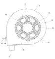
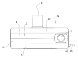
- FIG. 1 is a front view of an embodiment of the blood pump device of the present invention.
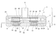
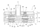
- FIG. 2 is a plan view of the blood pump device of FIG. 3 is a bottom view of the blood pump device of FIG. 4 is a cross-sectional view taken along line AA in FIG.
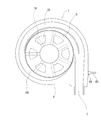
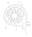
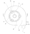
- FIG. 5 is a plan view showing a state where the first housing member of the blood pump device of FIG. 1 is removed.
- FIG. 6 is a plan view of a second housing member of the blood pump device of FIG.
- FIG. 7 is a bottom view of the first housing member of the blood pump device of FIG. 8 is a cross-sectional view taken along line BB in FIG.
- FIG. 9 is a front view of another embodiment of the blood pump device of the present invention.
- FIG. 1 is a front view of an embodiment of the blood pump device of the present invention.
- FIG. 2 is a plan view of the blood pump device of FIG. 3 is a bottom view of the blood pump device of FIG. 4 is a cross-sectional view taken along
- FIG. 10 is a plan view of the blood pump device of FIG. 11 is a cross-sectional view taken along the line CC of FIG.
- FIG. 12 is a front view of another embodiment of the blood pump device of the present invention.
- FIG. 13 is a plan view of the blood pump device of FIG. 14 is a cross-sectional view taken along the line DD of FIG.
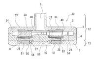
- FIG. 15 is a cross-sectional view of another embodiment of the blood pump device of the present invention.
- FIG. 1 is a front view of an embodiment of the blood pump device of the present invention.
- FIG. 2 is a plan view of the blood pump device of FIG. 3 is a bottom view of the blood pump device of FIG. 4 is a cross-sectional view taken along line AA in FIG.
- FIG. 5 is a plan view showing a state where the first housing member of the blood pump device of FIG. 1 is removed.
- FIG. 6 is a plan view of a second housing member of the blood pump device of FIG.
- FIG. 7 is a bottom view of the first housing member of the blood pump device of FIG. 8 is a cross-sectional view taken along line BB in FIG.
- the blood pump device 1 includes a housing 2 having a blood inflow port 6 and a blood outflow port 7, and a pump unit including a plurality of magnetic bodies 25 and an impeller 8 that rotates in the housing and feeds blood. 12 and an impeller rotational torque generator 13 for rotating the impeller.
- the housing 2 includes a plurality of magnetic members 54 embedded between the impeller 8 and the impeller rotational torque generator 13 in order to transmit the magnetic attractive force generated by the impeller rotational torque generator 13 to the magnetic body 25 of the impeller.
- the blood pump device 1 includes a non-contact bearing mechanism for rotating the impeller in a non-contact state within the housing when the impeller is rotated by the impeller rotational torque generator 13.
- the blood pump device 1 includes a housing 2, a pump unit 12 including an impeller 8 housed in the housing 2, and an impeller rotational torque generating unit 13 for rotating the impeller. Further, in the blood pump device 1 of this embodiment, the impeller rotational torque generating unit 13 is detachable from the pump unit 12. Thus, by making the impeller rotational torque generating unit 13 detachable from the pump unit 12, only the pump unit 12 having the blood circulation unit is disposable, and the impeller rotational torque generating unit having no blood contact portion in use. 13 can be reused.
- the housing 2 includes a first housing member 3 having a recess for storing the blood inlet port 6 and the upper portion of the impeller 8, and a second housing member 4 having a recess for storing the blood outlet port 7 and the lower portion of the impeller 8. And.
- the housing 2 is formed by combining the first housing member 3 and the second housing member 4.
- the housing 2 includes a blood chamber 24 communicating with the blood inflow port 6 and the blood outflow port 7 therein. Further, as shown in FIGS. 1 and 2, the blood inflow port 6 is provided so as to protrude substantially perpendicularly from the vicinity of the center of the upper surface of the housing 2 (first housing member 3).
- the blood inflow port 6 is not limited to such a straight tube, and may be a curved tube or a bent tube. As shown in FIGS. 1 to 7, the blood outflow port 7 is provided so as to protrude in a tangential direction from the side surface of the housing 2 formed in a substantially cylindrical shape. Further, in the housing in this embodiment, the blood outflow path has a double volute structure divided into two, but it may have a single volute structure or a structure without a volute.
- the housing 2 includes a plurality of magnetic members 54 embedded between the impeller 8 and the impeller rotational torque generator 13 in order to transmit the magnetic attractive force generated by the impeller rotational torque generator 13 to the magnetic body 25 of the impeller.
- a plurality of magnetic members 54 are embedded in the second housing member 4 (specifically, in the bottom wall).
- the magnetic member 54 is preferably embedded so as not to be exposed in the blood chamber 24.
- a ferromagnetic material is used as the magnetic member 54.
- the magnetic member 54 is preferably a soft magnetic material.
- soft magnetic materials include electromagnetic steel plates (silicon steel plates), pure iron, carbon steel having a carbon content of 0.3% by mass or less (for example, low carbon steel indicated by S15C in JIS standards), ferritic stainless steel ( Specifically, JIS standard SUSXM27) can be used.
- the housing 2, specifically, the first housing member 3 and the second housing member 4 are made of synthetic resin or metal.
- a material for forming the housing 2 if it is a synthetic resin, polycarbonate, acrylic resin [polyacrylate (eg, polymethyl methacrylate, polymethyl acrylate), polyacrylamide, acrylonitrile-styrene copolymer, acrylonitrile-butadiene-styrene copolymer] Etc.], polyolefin (polyethylene, polypropylene, ethylene-propylene copolymer, ultrahigh molecular weight polyethylene) styrene resin [polystyrene, MS resin (methacrylate-styrene copolymer), MBS resin (methacrylate-butylene-styrene copolymer)], etc.
- the thermoplastic hard synthetic resin can be used.
- polycarbonate, polymethyl acrylate, and ultra high molecular weight polyethylene are preferable.
- titanium, a titanium alloy, and stainless steel can be used.
- titanium or a titanium alloy is preferable.
- the first housing member 3 and the second housing member 4 are provided with a peripheral portion that comes into surface contact. If the housing is made of synthetic resin, high-frequency and ultrasonic waves are generated at the peripheral portion. In the case of a metal housing, it is joined in a liquid-tight manner by welding, screw fixing with a sealant sandwiched between the peripheral portions thereof.
- an impeller 8 is accommodated in the housing 2. Specifically, as shown in FIG. 4, a disc-shaped impeller 8 having a through-hole at the center is housed in a blood chamber 24 formed in the housing 2.
- the impeller 8 includes a donut plate-like member (lower shroud) 27 that forms a lower surface, a donut plate-like member (upper shroud) 28 that is open at the center that forms an upper surface, and a gap between the two.
- a plurality of (for example, seven) vanes 19 are formed.
- a plurality (seven) blood passages partitioned by adjacent vanes 19 are formed between the lower shroud and the upper shroud.
- the blood passage communicates with the central opening of the impeller 8, starts from the central opening of the impeller 8, and extends so that the width gradually increases to the outer peripheral edge.
- the vane 19 is formed between the adjacent blood passages.
- each blood passage and each vane 19 are provided at equal angular intervals and in substantially the same shape.
- the impeller 8 has a plurality of (for example, six) magnetic bodies 25 (permanent magnets, driven magnets) embedded therein.
- the magnetic body 25 is embedded in the lower shroud 27.
- the embedded magnetic body 25 (permanent magnet) is moved to the impeller rotational torque generating unit 13 side by the stator 51 of the impeller rotational torque generating unit 13 through the magnetic member embedded in the housing 2 (second housing member 4). It is provided to be sucked and to receive the rotational torque of the impeller rotational torque generator 13.
- the magnetic body 25 permanent magnet
- a circular shape, a fan shape, and a ring shape an integrated type in which N poles and S poles are alternately magnetized
- the impeller member is made of a metal having high corrosion resistance (titanium, stainless steel SUS316L, etc.) or a synthetic resin.
- a synthetic resin what was demonstrated as a forming material of a housing can be used conveniently.
- the blood pump device 1 of the present invention includes a non-contact bearing mechanism for rotating the impeller in a non-contact state with the inner surface of the housing when the impeller is rotated by the impeller rotational torque generator 13.
- the non-contact bearing mechanism is provided on the inner surface of the housing 2 on the side of the impeller rotational torque generating unit 13 [in other words, the surface of the recess of the second housing member 4 (the bottom wall surface)).
- the dynamic pressure groove 48 is configured.
- the impeller rotates at a rotation speed equal to or higher than a predetermined value, so that the impeller is brought into non-contact due to the hydrodynamic bearing effect by the dynamic pressure generated between the formation surface (dynamic pressure groove forming portion) 42 of the dynamic pressure groove 48 and the impeller 8. Rotate in state.
- the dynamic pressure groove forming portion 42 is formed in a size corresponding to the bottom surface of the impeller 8 (surface on the impeller rotational torque generating portion side).
- each dynamic pressure groove 48 has one end on the periphery (circumference) of a circular portion slightly spaced from the center of the surface of the recess of the second housing member, and is spirally ( In other words, the width gradually extends to the vicinity of the outer edge of the concave surface.
- a plurality of dynamic pressure grooves 48 are provided, and each of the dynamic pressure grooves 48 has substantially the same shape and is disposed at substantially the same interval.
- the dynamic pressure groove 48 is a recess, and the depth is preferably about 0.005 to 0.4 mm.
- About 6 to 36 dynamic pressure grooves 48 are preferably provided.
- twelve dynamic pressure grooves are arranged at an equal angle with respect to the central axis of the impeller.
- the dynamic pressure groove 48 in the pump device of this embodiment has a so-called inward spiral groove shape, and when the impeller rotates in the clockwise direction, the pumping of the fluid by the action of the dynamic pressure groove forming portion 42 is performed in the groove portion. Since the pressure is increased from the outer diameter toward the inner diameter, a force in the opposite direction is obtained between the impeller 8 and the housing 2 forming the dynamic pressure groove forming portion, which becomes the dynamic pressure.
- the impeller 8 is sucked toward the impeller rotational torque generating portion 13 during rotation.
- the impeller 8 is arranged between the dynamic pressure groove forming portion 42 of the housing and the bottom surface of the impeller 8 (or the impeller 8).
- the dynamic pressure bearing effect formed between the dynamic pressure groove forming part and the inner surface of the housing rotates away from the inner surface of the housing and rotates in a non-contact state, ensuring a blood flow path between the lower surface of the impeller and the inner surface of the housing. Prevents blood retention and blood clots arising from it.
- the dynamic pressure groove forming portion exerts a stirring action between the lower surface of the impeller and the inner surface of the housing, thereby preventing partial blood retention between the two.
- the dynamic pressure groove 48 is preferably rounded so that the corner portion has an R of at least 0.05 mm. By doing so, the generation of hemolysis can be reduced.
- the dynamic pressure groove forming portion may be provided not on the housing side but on the surface on the impeller rotational torque generating portion side of the impeller 8. Also in this case, it is preferable to have the same configuration as the above-described dynamic pressure groove forming portion.
- the dynamic pressure groove may be provided on the surface of the impeller 8 on the side of the impeller rotational torque generating unit 13 (in other words, the bottom surface of the impeller 8).
- a plurality of dynamic pressure grooves are also formed on the inner surface of the housing (in other words, the surface of the concave portion of the first housing member 3) opposite to the impeller rotational torque generating portion.
- a dynamic pressure groove forming portion (second dynamic pressure groove forming portion) 32 having a dynamic pressure groove) 33 may be provided.
- the impeller 8 rotates in a non-contact state due to a dynamic pressure bearing effect formed between the dynamic pressure groove forming portion 42 and the impeller 8 generated by rotating at a rotation speed greater than or equal to a predetermined value.
- the second dynamic pressure groove 33 prevents the impeller from sticking to the concave surface of the first housing member when receiving an external impact or when the dynamic pressure by the dynamic pressure groove forming portion 42 becomes excessive.
- the dynamic pressure generated by the dynamic pressure groove forming portion 42 and the dynamic pressure generated by the second dynamic pressure groove forming portion 32 may be different.
- the dynamic pressure groove forming portion 32 is formed in a size corresponding to the upper surface of the impeller 8 (side surface opposite to the impeller rotational torque generating portion).
- each dynamic pressure groove 33 is on the periphery (circumference) of a circular portion slightly spaced from the center of the dynamic pressure groove forming portion 32 (in other words, the center of the inner surface of the concave portion of the first housing member 3).
- One end of the concave portion extends in a spiral shape (in other words, curved or bent) so that the width gradually increases to the vicinity of the outer edge of the concave portion.
- the dynamic pressure groove has a so-called herringbone shape bent halfway.
- a plurality of dynamic pressure grooves 33 are provided, and each of the dynamic pressure grooves 33 has substantially the same shape and is disposed at substantially the same interval.
- the dynamic pressure groove 33 is a recess, and the depth is preferably about 0.005 to 0.4 mm.
- About 6 to 36 dynamic pressure grooves 33 are preferably provided.
- twelve dynamic pressure grooves are arranged at an equal angle with respect to the central axis of the impeller.
- the dynamic pressure groove 33 is preferably rounded so that the corner portion has an R of at least 0.05 mm. By doing so, the generation of hemolysis and the formation of thrombus can be reduced.
- the second dynamic pressure groove forming portion may be provided not on the housing side but on the surface opposite to the impeller rotational torque generating portion of the impeller 8 (in other words, the upper surface of the impeller 8). Also in this case, it is preferable to have the same configuration as the second dynamic pressure groove forming portion described above.
- the blood pump apparatus 1 of this invention has the impeller rotational torque generation part 13 for rotating an impeller. In the blood pump device 1 of this embodiment, the impeller rotational torque generating unit 13 can be attached to and detached from the pump unit 12.
- the impeller rotational torque generating unit 13 is configured by a motor stator 50 including a plurality of stators 51 arranged on the circumference. ing.
- the third housing member 5 includes an annular recess (doughnut-shaped recess), and the plurality of stators 51 are accommodated in the third housing member 5 so as to be annular (doughnut-shaped).
- the stator 51 includes a stator core 53 and a stator coil 52 wound around the stator core 53.
- a motor stator 50 is formed by six stators 51. As the stator coil 52, a multi-layer wound stator coil is used. Then, by switching the direction of the current flowing through the stator coil 52 of each stator 51, a rotating magnetic field is generated, and the impeller is attracted and rotated by this rotating magnetic field.
- the third housing member 5 includes a cable port 66 on the side surface. Specifically, as shown in FIGS. 1 to 3, 5, 6, and 8, a cable port 66 is formed on the side surface of the third housing member 5.
- the cords connected to the stator coil 52 of each stator 51 are bundled, and a cable 65 is formed by winding a reinforcing body around the outer layer.
- the cable 65 extends from the cable port 66 to the outside.
- each magnetic member 54 of the housing 2 (specifically, the second housing member 4) is a stator core of each stator 51 described above. 53 so as to be positioned on the top.
- the stator core 53 of this embodiment has a fan shape as shown in FIG. 8, and the magnetic member 54 has a fan shape so as to correspond to the shape.
- the magnetic member 54 is slightly larger than the stator core 53.
- each magnetic member 54 of the housing 2 (specifically, the second housing member 4) is connected to the stator core 53 of each stator 51. It is in contact. Specifically, in the pump device 1, the upper end portion of the stator core 53 slightly protrudes from the stator coil 52 and the protruding portion is exposed. The magnetic member 54 is embedded in the second housing member 4 so that the lower surface is exposed, and the portion where the lower surface of the magnetic member 54 is exposed is a recess for accommodating the protruding portion of the stator core 53. It has become. For this reason, the magnetic member 54 and the stator core 53 are in contact. By doing so, the magnetic force generated in the stator 51 can be reliably transmitted to the magnetic member 54.
- the pump unit 12 and the impeller rotational torque generating unit 13 are detachable, and both are provided with a coupling mechanism.
- a first engaging portion (specifically, a recess) 45 is formed on the bottom surface of the second housing member of the pump portion 12, and the impeller rotational torque generating portion 13
- the housing 5 is formed with a second engaging portion (specifically, a protruding portion) 55 that engages with the first engaging portion (concave portion) 45. Then, the first engaging portion (concave portion) 45 of the pump portion 12 and the second engaging portion (projecting portion) 55 of the impeller rotational torque generating portion 13 are engaged with each other so that they are connected.
- the 1st engaging part (concave part) 45 and the 2nd engaging part (protrusion part) 55 of the impeller rotational torque generation part 13 are provided with a positioning function, as shown in FIG.
- the first engaging portion (concave portion) 45 and the second engaging portion (convex portion) 55 of the impeller rotational torque generating portion 13 have shapes corresponding to the positioning (specifically, The cross-sectional shape is a polygonal shape, and in a state where both are engaged, each magnetic member 54 of the pump portion 12 is positioned on the stator core 53 of each stator 51, It is in contact.
- the cross-sectional shapes of the first engaging portion (concave portion) 45 and the second engaging portion (convex portion) 55 of the impeller rotational torque generating portion 13 are not limited to polygonal shapes, but are elliptical, It may be a shape.
- the engagement form of the 1st engagement part of the pump part 12 and the 2nd engagement part of the impeller rotational torque generation part 13 is not limited to the above, The embodiment shown in FIG. Like a pump, the 1st engaging part 46 may be a convex part, and the 2nd engaging part 56 may be a (concave part).
- the blood pump device of the present invention may be of a type such as the blood pump device 10 of the embodiment shown in FIGS.
- FIG. 9 is a front view of another embodiment of the blood pump device of the present invention.
- FIG. 10 is a plan view of the blood pump device of FIG. 11 is a cross-sectional view taken along the line CC of FIG.
- the impeller 8 includes the second magnetic body 29, and the blood pump device is on the side opposite to the impeller rotational torque generating unit 13 side.
- Others are the same in that a permanent magnet 61 for attracting the second magnetic body 29 of the impeller 8 is provided in the housing (specifically, in the first housing member 3), see the above description. It shall be.
- the impeller 8 includes a second magnetic body 29 embedded in a donut plate-like member (upper shroud) 28 having an opening at the center forming the upper surface. I have. And as the 2nd magnetic body 29, a flat ring-shaped thing is suitable. Further, the second magnetic body 29 is disposed at a position slightly inside the peripheral edge of the impeller 8.
- the second magnetic body 29 is preferably a permanent magnet or a ferromagnetic body, and particularly preferably a permanent magnet. 10 and 11, a permanent magnet 61 for attracting the second magnetic body 29 of the impeller 8 is provided on the second magnetic body 29 of the impeller 8 in the first housing member 3. It is buried to become. As shown in FIG. 10, the permanent magnet 61 is preferably a ring shape corresponding to the shape of the second magnetic body 29.
- the pump device 10 includes a plurality of dynamic pressure grooves (second dynamic pressure) on the inner surface of the housing opposite to the impeller rotational torque generating portion (in other words, the surface of the concave portion of the first housing member 3).
- a dynamic pressure groove forming portion (second dynamic pressure groove forming portion) 32 having a groove) 33 is provided.
- the impeller 8 has a dynamic pressure formed between the dynamic pressure groove forming portion 32 and the impeller 8 that is generated when the impeller 8 rotates at a rotation speed greater than or equal to a predetermined number of revolutions. By facing this suction force, the impeller 8 is prevented from sticking to the concave surface of the first housing member, and the impeller rotates in a non-contact state with the inner surface of the housing.
- the permanent magnet 61 and the second magnetic body 29 are not limited to the ring-shaped ones described above, and a plurality of permanent magnets and the second magnetic body are arranged at substantially the same angular intervals on the circumference. May be arranged.
- the number of permanent magnets and second magnetic bodies is preferably 2 to 8, particularly 3 to 6.
- suction direction of an impeller rotational torque generation part may be an electromagnet instead of a permanent magnet.
- electromagnets are used, a plurality (specifically, three) of electromagnets are arranged on the circumference at substantially the same angular intervals as in a pump device 20 (see FIG. 13) of an embodiment described later. It is preferable.
- the impeller attracting force (specifically, the attracting force applied to the impeller via the magnetic member 54) when the impeller rotational torque generating unit 13 generates the magnetic force, and the permanent magnet
- the resultant force of the impeller suction force by 61 is preferably balanced near the center of the movable range of the impeller 8 in the housing 2.
- the third housing member 5 includes a cable port 66 on the side surface. Specifically, as shown in FIGS. 9 and 10, a cable port 66 is formed on the side surface of the third housing member 5.
- the cords connected to the stator coil 52 of each stator 51 are bundled, and a cable 65 is formed by winding a reinforcing body around the outer layer. The cable 65 extends from the cable port 66 to the outside.
- the blood pump device of the present invention may be of a type like the blood pump device 20 of the embodiment shown in FIGS.
- FIG. 12 is a front view of another embodiment of the blood pump device of the present invention.
- FIG. 13 is a plan view of the blood pump device of FIG. 14 is a cross-sectional view taken along the line DD of FIG.
- the difference between the pump device 20 of this embodiment and the pump device 10 described above is only a non-contact bearing mechanism.
- the non-contact bearing mechanism (impeller position control unit) 14 includes a plurality of fixed electromagnets for attracting the second magnetic body 29 of the impeller 8, as shown in FIGS. 13 and 14. 63 and a position sensor 65 for detecting the position of the second magnetic body 29 of the impeller 8.
- the impeller position control unit 14 includes a plurality of electromagnets 63 housed in the impeller position control unit housing 22 and a plurality of position sensors 65.
- the plural (three) electromagnets 63 and the plural (three) position sensors 65 of the impeller position control unit are provided at equal angular intervals, and the electromagnet 63 and the position sensor 65 are also provided at equal angular intervals.
- the electromagnet 63 includes a core and a coil. In this embodiment, three electromagnets 63 are provided. The number of electromagnets 63 may be three or more, for example, four.
- Three or more are provided, and these electromagnetic forces are adjusted using the detection result of the position sensor 65, thereby balancing the forces in the direction of the rotation axis (z axis) of the impeller 8 and orthogonal to the rotation axis (z axis).
- the moment about the x and y axes can be controlled. Thereby, the impeller 8 can be rotated without contacting the inner surface of the housing.
- the position sensor 65 detects the gap between the electromagnet 63 and the second magnetic body 29, and this detection output is controlled by a control mechanism (not shown) that controls the current or voltage applied to the coil of the electromagnet 63. Sent to the department.
- the impeller position control unit 14 is detachable from the pump unit 12. And in the 1st housing member 3 of the pump part 12, in order to transmit the magnetic attraction force which the electromagnet 63 generate
- a plurality of magnetic members 64 and a plurality of magnetic bodies 61 are embedded in the first housing member 3.
- the magnetic member 64 and the magnetic body 61 are preferably embedded so as not to be exposed in the blood chamber 24.
- the magnetic member 64 is made of a ferromagnetic material.
- a soft magnetic material is preferable. Examples of soft magnetic materials include electromagnetic steel plates (silicon steel plates), pure iron, carbon steel having a carbon content of 0.3% by mass or less (for example, low carbon steel indicated by S15C in JIS standards), ferritic stainless steel ( Specifically, JIS standard SUSXM27) can be used.
- the core of the electromagnet 63 and the magnetic member 64 embedded in the first housing member 3 may be in contact with each other. In this type of pump device, the first dynamic pressure groove and the second dynamic pressure groove described above may not be provided.
- the third housing member 5 includes a cable port 66 on the side surface. Specifically, as shown in FIGS. 12 and 13, a cable port 66 is formed on the side surface of the third housing member 5.
- the cord 65 connected to the stator coil 52 of each stator 51, the cord connected to the electromagnet, and the cord connected to the position sensor are bundled, and a reinforcing member is wound around the outer layer. Is forming.
- the cable 65 extends from the cable port 66 to the outside.
- the magnetic member 54 embedded in the housing 2 (second housing member 4) does not expose the lower surface as in the pump device 30 of the embodiment shown in FIG. It may not be in contact with.
- the blood pump device of the present invention can be applied to both an in-vivo or extracorporeal circulation pump.
- the blood pump device of the present invention is particularly effective when used as a blood pump device for extracorporeal circulation.
- the blood pump device of the present invention is as follows.
- a pump unit including a housing having a blood inflow port and a blood outflow port, an impeller having a plurality of magnetic bodies and rotating in the housing to feed blood, and an impeller for rotating the impeller
- a blood pump device having a rotational torque generating unit, wherein the housing is configured to transmit the magnetic attraction generated by the impeller rotational torque generating unit to the magnetic body of the impeller, and the impeller and the impeller rotational torque.
- a plurality of magnetic members embedded between the generating portions wherein the blood pump device is non-contact for rotating the impeller in a non-contact state with the inner surface of the housing when the impeller is rotated by the impeller rotational torque generating portion
- a blood pump device comprising a bearing mechanism.
- the housing is separated from the blood chamber and the impeller torque generation, so that the housing can be easily manufactured and assembled and can be reduced in weight.
- the magnetic attractive force generated by the impeller rotational torque generating portion can be reliably transmitted to the magnetic body of the impeller.
- the blood pump device includes a non-contact bearing mechanism for rotating the impeller to the inner surface of the housing in a non-contact state when the impeller is rotated by the impeller rotational torque generating unit, so that the impeller rotates in a non-contact state. It is possible to make it.
- the impeller rotational torque generating unit is a motor stator including a plurality of stators arranged on a circumference, and the stator includes a stator core and a stator coil wound around the stator core, and the plurality of magnetic
- the blood pump device according to (1) wherein the member is disposed so as to be positioned on the stator core of each stator.
- the blood pump device according to any one of (1) to (4), wherein the magnetic member is a soft magnetic material.
- the blood pump device includes a dynamic pressure groove provided on the inner surface of the housing opposite to the impeller rotational torque generating part or on the surface of the impeller opposite to the impeller rotational torque generating part.
- the blood pump device according to any one of (1) to (5) above.
- the impeller includes a second magnetic body, and the blood pump device sucks the second magnetic body of the impeller into the housing opposite to the impeller rotational torque generating unit.
- the blood pump device according to any one of (1) to (6), comprising a permanent magnet or an electromagnet.
- the non-contact bearing mechanism is configured by a dynamic pressure groove provided on the inner surface of the housing on the impeller rotational torque generating unit side or on the surface of the impeller on the impeller rotational torque generating unit side (1) Thru
- the non-contact bearing mechanism is provided in a second magnetic body provided on the impeller and a housing opposite to the impeller rotational torque generating portion, and the second magnetic body of the impeller is The blood pump device according to any one of the above (1) to (7), which includes an electromagnet for suction and a position sensor for detecting the position of the impeller.
Abstract
血液ポンプ装置1は、血液流入ポート6と血液流出ポート7とを有するハウジング2と、ハウジング内で回転するインペラ8とからなるポンプ部12と、インペラ回転トルク発生部13とを有する。ハウジング2は、インペラ回転トルク発生部13が発生する磁気吸引力をインペラの磁性体25に伝達するために、インペラ8とインペラ回転トルク発生部13間に埋設された複数の磁性部材54を備える。ポンプ装置1は、インペラ回転トルク発生部13によるインペラ回転時に、インペラをハウジングの内面に非接触状態にて回転させるための非接触軸受機構を備える。
Description
本発明は、血液を送液するための血液ポンプ装置に関する。
最近では、心臓の働きを補助する心臓補助ポンプや人工心肺装置における体外血液循環に遠心式血液ポンプを使用する例が増加している。また、遠心式血液ポンプとしては、体内埋め込み型のものも提案されている。
遠心ポンプとしては、外部とポンプ内の血液室との物理的な連通を完全に排除し、細菌等の侵入を防止できることにより、外部モータからの駆動トルクを磁気結合を用いて伝達する方式のものがある。そして、このような遠心式血液ポンプは、血液流入ポートと血液流出ポートを有するハウジングと、ハウジング内で回転し、回転時の遠心力によって血液を送液するインペラを有している。また、インペラは、内部に永久磁石を備え、インペラの磁石を吸引するための磁石を備えるロータおよびこのロータを回転させるモータを備えた回転トルク発生機構により回転する。また、インペラはロータと反対側にも吸引されており、ハウジングに対して非接触状態にて回転する。
遠心ポンプとしては、外部とポンプ内の血液室との物理的な連通を完全に排除し、細菌等の侵入を防止できることにより、外部モータからの駆動トルクを磁気結合を用いて伝達する方式のものがある。そして、このような遠心式血液ポンプは、血液流入ポートと血液流出ポートを有するハウジングと、ハウジング内で回転し、回転時の遠心力によって血液を送液するインペラを有している。また、インペラは、内部に永久磁石を備え、インペラの磁石を吸引するための磁石を備えるロータおよびこのロータを回転させるモータを備えた回転トルク発生機構により回転する。また、インペラはロータと反対側にも吸引されており、ハウジングに対して非接触状態にて回転する。
上記特許文献1に示す体内埋め込み型の遠心式血液ポンプ装置では、長時間の使用を目的とするためにハウジングの構成材料に金属材料が使用されている。これに対し、特許文献2に示すような血液ポンプ装置および特許文献3に示すような血液ポンプ装置では、ハウジングの構成材料としてプラスチック材料が使用される。この場合のハウジングは、ポンプ装置本体の強度を保つためにある程度の厚さが必要となり、インペラ回転トルク発生部によるインペラへの回転磁力が低下することが危惧される。
そして、本発明者等が検討したところ、インペラ回転トルク発生部側のハウジング内に磁性材料を備えることでインペラ回転トルク発生部は、ハウジングの厚さを十分確保しながら、インペラ磁性体の磁力、或いはサイズを大きなものとしなくてもインペラを吸引するとともに回転させることができることを知見した。
そして、本発明者等が検討したところ、インペラ回転トルク発生部側のハウジング内に磁性材料を備えることでインペラ回転トルク発生部は、ハウジングの厚さを十分確保しながら、インペラ磁性体の磁力、或いはサイズを大きなものとしなくてもインペラを吸引するとともに回転させることができることを知見した。
そこで、本発明の目的は、ハウジングの形成材料による影響を受けることなく、インペラを良好に、かつ、ハウジング内面に接触しない状態にて回転させることができる血液ポンプ装置を提供するものである。
上記目的を達成するものは、以下のものである。
血液流入ポートと血液流出ポートとを有するハウジングと、複数の磁性体を備え、前記ハウジング内で回転し血液を送液するインペラとからなるポンプ部と、前記インペラを回転させるためのインペラ回転トルク発生部とを有する血液ポンプ装置であって、前記ハウジングは、前記インペラ回転トルク発生部が発生する磁気吸引力を前記インペラの前記磁性体に伝達するために、前記インペラと前記インペラ回転トルク発生部間に埋設された複数の磁性部材を備え、前記血液ポンプ装置は、前記インペラ回転トルク発生部によるインペラ回転時に、前記インペラを前記ハウジングの内面に非接触状態にて回転させるための非接触軸受機構を備える血液ポンプ装置。
血液流入ポートと血液流出ポートとを有するハウジングと、複数の磁性体を備え、前記ハウジング内で回転し血液を送液するインペラとからなるポンプ部と、前記インペラを回転させるためのインペラ回転トルク発生部とを有する血液ポンプ装置であって、前記ハウジングは、前記インペラ回転トルク発生部が発生する磁気吸引力を前記インペラの前記磁性体に伝達するために、前記インペラと前記インペラ回転トルク発生部間に埋設された複数の磁性部材を備え、前記血液ポンプ装置は、前記インペラ回転トルク発生部によるインペラ回転時に、前記インペラを前記ハウジングの内面に非接触状態にて回転させるための非接触軸受機構を備える血液ポンプ装置。
本発明の血液ポンプ装置を図面に示す実施例を用いて説明する。
図1は、本発明の血液ポンプ装置の実施例の正面図である。図2は、図1の血液ポンプ装置の平面図である。図3は、図1の血液ポンプ装置の底面図である。図4は、図2のA-A線断面図である。図5は、図1の血液ポンプ装置の第1ハウジング部材を取り外した状態を示す平面図である。図6は、図1の血液ポンプ装置の第2ハウジング部材の平面図である。図7は、図1の血液ポンプ装置の第1ハウジング部材の底面図である。図8は、図4のB-B線断面図である。
図1は、本発明の血液ポンプ装置の実施例の正面図である。図2は、図1の血液ポンプ装置の平面図である。図3は、図1の血液ポンプ装置の底面図である。図4は、図2のA-A線断面図である。図5は、図1の血液ポンプ装置の第1ハウジング部材を取り外した状態を示す平面図である。図6は、図1の血液ポンプ装置の第2ハウジング部材の平面図である。図7は、図1の血液ポンプ装置の第1ハウジング部材の底面図である。図8は、図4のB-B線断面図である。
本発明の血液ポンプ装置1は、血液流入ポート6と血液流出ポート7とを有するハウジング2と、複数の磁性体25を備え、ハウジング内で回転し血液を送液するインペラ8とからなるポンプ部12と、インペラを回転させるためのインペラ回転トルク発生部13とを有する。ハウジング2は、インペラ回転トルク発生部13が発生する磁気吸引力をインペラの磁性体25に伝達するために、インペラ8とインペラ回転トルク発生部13間に埋設された複数の磁性部材54を備える。血液ポンプ装置1は、インペラ回転トルク発生部13によるインペラ回転時に、インペラをハウジングの内にて非接触状態にて回転させるための非接触軸受機構を備える。
この実施例の血液ポンプ装置1は、ハウジング2と、ハウジング2内に収納されたインペラ8とからなるポンプ部12と、インペラを回転させるためのインペラ回転トルク発生部13とを有する。また、この実施例の血液ポンプ装置1では、インペラ回転トルク発生部13は、ポンプ部12に着脱可能となっている。このようにインペラ回転トルク発生部13をポンプ部12に対して、着脱可能とすることにより、血液流通部を有するポンプ部12のみを使い捨てとし、使用時に血液接触部を持たないインペラ回転トルク発生部13を再使用することができる。
ハウジング2は、血液流入ポート6とインペラ8の上部を収納するための凹部を備える第1ハウジング部材3と、血液流出ポート7とインペラ8の下部を収納するための凹部を備える第2ハウジング部材4とを備えている。そして、第1ハウジング部材3と第2ハウジング部材4を組み合わせることにより、ハウジング2が形成されている。そして、ハウジング2は、血液流入ポート6および血液流出ポート7と連通する血液室24を内部に備えるものとなっている。また、血液流入ポート6は、図1および図2に示すように、ハウジング2(第1ハウジング部材3)の上面の中央付近よりほぼ垂直に突出するように設けられている。なお、血液流入ポート6は、このようなストレート管に限定されるものでなく、湾曲管もしくは屈曲管でもよい。血液流出ポート7は、図1ないし図7に示すように、ほぼ円筒状に形成されたハウジング2の側面より接線方向に突出するように設けられている。また、この実施例におけるハウジングでは、血液流出路は、2つに区分されたダブルボリュート構造となっているが、シングルボリュート構造のもの、またボリュートがない構造のものでもよい。
そして、ハウジング2は、インペラ回転トルク発生部13が発生する磁気吸引力をインペラの磁性体25に伝達するために、インペラ8とインペラ回転トルク発生部13間に埋設された複数の磁性部材54を備えている。具体的には、第2ハウジング部材4内(具体的には、底面壁内)に、複数の磁性部材54が埋設されている。特に、この実施例のポンプ装置1のように、磁性部材54は、血液室24内に露出しないように埋設されていることが好ましい。そして、磁性部材54としては、強磁性体が用いられる。特に、磁性部材54としては、軟質磁性体が好ましい。軟質磁性体としては、電磁鋼板(珪素鋼板)、純鉄、炭素含有率が0.3質量%以下の炭素鋼(例えば、JIS規格でS15Cで標記される低炭素鋼)、フェライト系ステンレス鋼(具体的には、JIS規格のSUSXM27)などが使用できる。
そして、ハウジング2、具体的には、第1ハウジング部材3および第2ハウジング部材4は、合成樹脂あるいは金属により形成されている。ハウジング2の形成材料としては、合成樹脂であればポリカーボネート、アクリル樹脂[ポリアクリレート(例えば、ポリメチルメタクリレート、ポリメチルアクリレート)、ポリアクリルアミド、アクリロニトリル-スチレン共重合体、アクリロニトリル-ブタジエン-スチレン共重合体等]、ポリオレフィン(ポリエチレン、ポリプロピレン、エチレン-プロピレンコポリマー、超高分子ポリエチレン)スチレン系樹脂[ポリスチレン、MS樹脂 (メタクリレート-スチレン共重合体)、MBS樹脂(メタクリレート-ブチレン-スチレン共重合体)]などの熱可塑性の硬質合成樹脂が使用できる。特に、ポリカーボネート、ポリメチルアクリレート、超高分子ポリエチレンが好ましい。金属の場合は、チタン、チタン合金、ステンレスを使用することが可能である。特に、チタンまたはチタン合金が好ましい。
また、第1ハウジング部材3および第2ハウジング部材4は、図4に示すように、面接触する周縁部を備えており、合成樹脂製ハウジングであれば、それら周縁部にて、高周波、超音波などによる熱融着または接着剤などにより、また金属製ハウジングであれば、それら周縁部にて、溶接、シール材を挟んだねじ固定などにより、液密に接合される。
また、第1ハウジング部材3および第2ハウジング部材4は、図4に示すように、面接触する周縁部を備えており、合成樹脂製ハウジングであれば、それら周縁部にて、高周波、超音波などによる熱融着または接着剤などにより、また金属製ハウジングであれば、それら周縁部にて、溶接、シール材を挟んだねじ固定などにより、液密に接合される。
そして、ハウジング2内には、インペラ8が収納されている。具体的には、図4に示すように、ハウジング2内に形成された血液室24内に、中央に貫通口を有する円板状のインペラ8が収納されている。
インペラ8は、図4および図5に示すように、下面を形成するドーナツ板状部材(下部シュラウド)27と、上面を形成する中央が開口したドーナツ板状部材(上部シュラウド)28と、両者間に形成された複数(例えば、7つ)のベーン19を有する。そして、下部シュラウドと上部シュラウドの間には、隣り合うベーン19で仕切られた複数(7つ)の血液通路が形成されている。血液通路は、図5に示すように、インペラ8の中央開口と連通し、インペラ8の中央開口を始端とし、外周縁まで徐々に幅が広がるように延びている。言い換えれば、隣り合う血液通路間にベーン19が形成されている。なお、この実施例では、それぞれの血液通路およびそれぞれのベーン19は、等角度間隔にかつほぼ同じ形状に設けられている。
そして、図4に示すように、インペラ8には、複数(例えば、6個)の磁性体25(永久磁石、従動マグネット)が埋設されている。この実施例では、磁性体25は、下部シュラウド27内に埋設されている。埋設された磁性体25(永久磁石)は、ハウジング2(第2ハウジング部材4)に埋設された磁性部材を介して、インペラ回転トルク発生部13のステータ51により、インペラ回転トルク発生部13側に吸引されるためおよびインペラ回転トルク発生部13の回転トルクを受け取るために設けられている。
また、この実施例のようにある程度の個数の磁性体25を埋設することにより、後述する複数のステータ51との磁気的結合も十分に確保できる。磁性体25(永久磁石)の形状としては、円形、扇型、さらにリング形状(N極とS極が交互に着磁された一体型)などが好ましい。インペラ部材は、耐食性の高い金属(チタン、ステンレスSUS316Lなど)、あるいは合成樹脂により形成されている。合成樹脂としては、ハウジングの形成材料として説明したものが好適に使用できる。
そして、本発明の血液ポンプ装置1は、インペラ回転トルク発生部13によるインペラ回転時に、インペラをハウジングの内面に非接触状態にて回転させるための非接触軸受機構を備えている。
この実施例のポンプ装置1では、上記の非接触軸受機構は、インペラ回転トルク発生部13側のハウジング2内面[言い換えれば、第2ハウジング部材4の凹部の表面(底面壁表面)]に設けられた動圧溝48により構成されている。そして、インペラは、所定以上の回転数にて回転することにより、動圧溝48の形成面(動圧溝形成部)42とインペラ8間に発生する動圧力による動圧軸受効果により、非接触状態にて回転する。動圧溝形成部42は、図6に示すように、インペラ8の底面(インペラ回転トルク発生部側の面)に対応する大きさに形成されている。そして、この実施例のポンプ装置1では、各動圧溝48は、第2ハウジング部材の凹部の表面の中心より若干離間した円形部分の周縁(円周)上に一端を有し、渦状に(言い換えれば、湾曲して)凹部表面の外縁付近まで、幅が徐々に広がるように延びている。また、動圧溝48は複数個設けられており、それぞれの動圧溝48はほぼ同じ形状であり、かつほぼ同じ間隔に配置されている。動圧溝48は、凹部であり、深さとしては、0.005~0.4mm程度が好適である。動圧溝48としては、6~36個程度設けることが好ましい。この実施例では、12個の動圧溝がインペラの中心軸に対して等角度に配置されている。この実施例のポンプ装置における動圧溝48は、いわゆる内向スパイラル溝形状となっており、インペラが時計方向に回転することにより、この動圧溝形成部42の作用による流体のポンピングは、溝部の外径から内径に向け圧力が高められるために、インペラ8とこの動圧溝形成部を形成しているハウジング2間に反対方向の力が得られ、これが動圧力となる。
この実施例のポンプ装置1では、上記の非接触軸受機構は、インペラ回転トルク発生部13側のハウジング2内面[言い換えれば、第2ハウジング部材4の凹部の表面(底面壁表面)]に設けられた動圧溝48により構成されている。そして、インペラは、所定以上の回転数にて回転することにより、動圧溝48の形成面(動圧溝形成部)42とインペラ8間に発生する動圧力による動圧軸受効果により、非接触状態にて回転する。動圧溝形成部42は、図6に示すように、インペラ8の底面(インペラ回転トルク発生部側の面)に対応する大きさに形成されている。そして、この実施例のポンプ装置1では、各動圧溝48は、第2ハウジング部材の凹部の表面の中心より若干離間した円形部分の周縁(円周)上に一端を有し、渦状に(言い換えれば、湾曲して)凹部表面の外縁付近まで、幅が徐々に広がるように延びている。また、動圧溝48は複数個設けられており、それぞれの動圧溝48はほぼ同じ形状であり、かつほぼ同じ間隔に配置されている。動圧溝48は、凹部であり、深さとしては、0.005~0.4mm程度が好適である。動圧溝48としては、6~36個程度設けることが好ましい。この実施例では、12個の動圧溝がインペラの中心軸に対して等角度に配置されている。この実施例のポンプ装置における動圧溝48は、いわゆる内向スパイラル溝形状となっており、インペラが時計方向に回転することにより、この動圧溝形成部42の作用による流体のポンピングは、溝部の外径から内径に向け圧力が高められるために、インペラ8とこの動圧溝形成部を形成しているハウジング2間に反対方向の力が得られ、これが動圧力となる。
インペラ8は、回転時にインペラ回転トルク発生部13側に吸引されるが、このような動圧溝形成部を有することにより、ハウジングの動圧溝形成部42とインペラ8の底面間(もしくはインペラの動圧溝形成部とハウジング内面間)に形成される動圧軸受効果により、ハウジング内面より離れ、非接触状態にて回転し、インペラの下面とハウジング内面間に血液流路を確保し、両者間での血液滞留およびそれに起因する血栓の発生を防止する。さらに、通常状態において、動圧溝形成部が、インペラの下面とハウジング内面間において撹拌作用を発揮するので、両者間における部分的な血液滞留の発生を防止する。
さらに、動圧溝48は、その角となる部分が少なくとも0.05mm以上のRを持つように丸められていることが好ましい。このようにすることにより、溶血の発生をより少ないものとすることができる。
なお、動圧溝形成部は、ハウジング側ではなくインペラ8のインペラ回転トルク発生部側の面に設けてもよい。この場合も上述した動圧溝形成部と同様の構成とすることが好ましい。具体的には、動圧溝は、インペラ8のインペラ回転トルク発生部13側の面(言い換えれば、インペラ8の底面)に設けてもよい。
さらに、動圧溝48は、その角となる部分が少なくとも0.05mm以上のRを持つように丸められていることが好ましい。このようにすることにより、溶血の発生をより少ないものとすることができる。
なお、動圧溝形成部は、ハウジング側ではなくインペラ8のインペラ回転トルク発生部側の面に設けてもよい。この場合も上述した動圧溝形成部と同様の構成とすることが好ましい。具体的には、動圧溝は、インペラ8のインペラ回転トルク発生部13側の面(言い換えれば、インペラ8の底面)に設けてもよい。
そして、この実施例のポンプ装置1のように、インペラ回転トルク発生部側と反対側のハウジング内面(言い換えれば、第1ハウジング部材3の凹部の表面)にも複数の動圧溝(第2の動圧溝)33を有する動圧溝形成部(第2の動圧溝形成部)32を設けてもよい。
インペラ8は、所定以上の回転数により回転することにより発生する動圧溝形成部42とインペラ8間に形成される動圧軸受効果により、非接触状態にて回転する。この第2の動圧溝33は、外的衝撃を受けた時また動圧溝形成部42による動圧力が過剰となった時に、インペラの第1ハウジング部材の凹部表面への密着を防止する。そして、動圧溝形成部42により発生する動圧力と第2の動圧溝形成部32により発生する動圧力は異なるものとなっていてもよい。
インペラ8は、所定以上の回転数により回転することにより発生する動圧溝形成部42とインペラ8間に形成される動圧軸受効果により、非接触状態にて回転する。この第2の動圧溝33は、外的衝撃を受けた時また動圧溝形成部42による動圧力が過剰となった時に、インペラの第1ハウジング部材の凹部表面への密着を防止する。そして、動圧溝形成部42により発生する動圧力と第2の動圧溝形成部32により発生する動圧力は異なるものとなっていてもよい。
具体的には、図4および図7に示すように、動圧溝形成部32は、インペラ8の上面(インペラ回転トルク発生部と反対側面)に対応する大きさに形成されている。図7に示すように、各動圧溝33は、動圧溝形成部32の中心(言い換えれば、第1ハウジング部材3の凹部内面の中心)より若干離間した円形部分の周縁(円周)上に一端を有し、渦状に(言い換えれば、湾曲もしくは屈曲して)凹部の外縁付近まで、幅が徐々に広がるように延びている。特に、この実施例では、動圧溝は、途中で屈曲したいわゆるヘリングボーン形状となっている。また、動圧溝33は複数個設けられており、それぞれの動圧溝33はほぼ同じ形状であり、かつほぼ同じ間隔に配置されている。動圧溝33は、凹部であり、深さとしては、0.005~0.4mm程度が好適である。動圧溝33としては、6~36個程度設けることが好ましい。この実施例では、12個の動圧溝がインペラの中心軸に対して等角度に配置されている。
さらに、動圧溝33は、その角となる部分が少なくとも0.05mm以上のRを持つように丸められていることが好ましい。このようにすることにより、溶血の発生及び血栓形成をより少ないものとすることができる。
なお、第2の動圧溝形成部は、ハウジング側ではなくインペラ8のインペラ回転トルク発生部と反対側の面(言い換えれば、インペラ8の上面)に設けてもよい。この場合も上述した第2の動圧溝形成部と同様の構成とすることが好ましい。 そして、本発明の血液ポンプ装置1は、インペラを回転させるためのインペラ回転トルク発生部13を有している。そして、この実施例の血液ポンプ装置1では、インペラ回転トルク発生部13は、ポンプ部12に着脱可能となっている。
なお、第2の動圧溝形成部は、ハウジング側ではなくインペラ8のインペラ回転トルク発生部と反対側の面(言い換えれば、インペラ8の上面)に設けてもよい。この場合も上述した第2の動圧溝形成部と同様の構成とすることが好ましい。 そして、本発明の血液ポンプ装置1は、インペラを回転させるためのインペラ回転トルク発生部13を有している。そして、この実施例の血液ポンプ装置1では、インペラ回転トルク発生部13は、ポンプ部12に着脱可能となっている。
この実施例の血液ポンプ装置1では、図3,図4および図8に示すように、インペラ回転トルク発生部13は、円周上に配置された複数のステータ51からなるモータステータ50により構成されている。そして、第3ハウジング部材5は、環状凹部(ドーナツ状凹部)を備えており、複数のステータ51は、第3ハウジング部材5内に、環状(ドーナツ状)となるように収納されている。ステータ51は、ステータコア53とステータコア53に巻かれたステータコイル52を備えている。この実施例のポンプ装置1では、6個のステータ51によりモータステータ50が形成されている。また、ステータコイル52としては、多層巻きのステータコイルが用いられる。そして、各ステータ51のステータコイル52に流れる電流の方向を切り換えることにより、回転磁界が発生し、この回転磁界により、インペラは吸引されるとともに回転する。
そして、第3ハウジング部材5は、側面にケーブル用ポート66を備えている。具体的には、図1ないし図3、図5、図6および図8に示すように、第3ハウジング部材5の側面に、ケーブル用ポート66が形成されている。そして、各ステータ51のステータコイル52に接続されたコードは束ねられるととともに、外層に補強体が巻き付けられるなどによりケーブル65を形成している。そして、ケーブル65は、ケーブル用ポート66より外部に延出している。
そして、この実施例の血液ポンプ装置1では、図4、図8に示すように、ハウジング2(具体的には、第2ハウジング部材4)の各磁性部材54は、上述した各ステータ51のステータコア53上に位置するように配置されている。そして、この実施例のステータコア53は、図8に示すように扇状となっており、磁性部材54もその形状に対応するように扇状となっている。また、磁性部材54は、若干ステータコア53より大きいものとなっている。
そして、この実施例の血液ポンプ装置1では、図4、図8に示すように、ハウジング2(具体的には、第2ハウジング部材4)の各磁性部材54は、上述した各ステータ51のステータコア53上に位置するように配置されている。そして、この実施例のステータコア53は、図8に示すように扇状となっており、磁性部材54もその形状に対応するように扇状となっている。また、磁性部材54は、若干ステータコア53より大きいものとなっている。
さらに、この実施例の血液ポンプ装置1では、図4、図8に示すように、ハウジング2(具体的には、第2ハウジング部材4)の各磁性部材54は、各ステータ51のステータコア53と接触するものとなっている。具体的には、このポンプ装置1では、ステータコア53の上端部は、ステータコイル52より若干突出するとともに、突出部が露出するものとなっている。そして、磁性部材54は、下面が露出するように、第2ハウジング部材4に埋設されており、さらに、磁性部材54の下面が露出する部分は、ステータコア53の突出部を収納するための凹部となっている。このため、磁性部材54とステータコア53は接触している。このようにすることにより、ステータ51にて発生した磁力を確実に磁性部材54に伝達することができる。
また、この実施例のポンプ装置1では、ポンプ部12とインペラ回転トルク発生部13は着脱可能となっているとともに、両者は連結機構を備えている。この実施例のポンプ装置1では、ポンプ部12の第2ハウジング部材の底面には、第1の係合部(具体的には、凹部)45が形成されており、インペラ回転トルク発生部13のハウジング5には、第1の係合部(凹部)45と係合する第2の係合部(具体的には、突出部)55が形成されている。そして、ポンプ部12の第1の係合部(凹部)45とインペラ回転トルク発生部13の第2の係合部(突出部)55とが係合することにより、両者は連結される。また、第1の係合部(凹部)45とインペラ回転トルク発生部13の第2の係合部(突出部)55は、図8に示すように位置決め機能を備えることが好ましい。図8に示すものでは、第1の係合部(凹部)45とインペラ回転トルク発生部13の第2の係合部(凸部)55は、位置決め可能に対応する形状(具体的には、断面が多角形状)となっており、両者を係合させた状態にて、ポンプ部12の各磁性部材54が、各ステータ51のステータコア53上に位置するものとなっており、さらに、両者が接触するものとなっている。なお、第1の係合部(凹部)45とインペラ回転トルク発生部13の第2の係合部(凸部)55の断面形状は、多角形状に限定されるものではなく、楕円状、星形などであってもよい。また、ポンプ部12の第1の係合部とインペラ回転トルク発生部13の第2の係合部の係合形態は、上記のものに限定されるものではなく、図15に示す実施例のポンプのように、第1の係合部46が凸部であり、第2の係合部56が(凹部)であってもよい。
また、本発明の血液ポンプ装置としては、図9ないし図11に示す実施例の血液ポンプ装置10のようなタイプのものであってもよい。
図9は、本発明の血液ポンプ装置の他の実施例の正面図である。図10は、図9の血液ポンプ装置の平面図である。図11は、図10のC-C線断面図である。
この実施例の血液ポンプ装置10と上述した実施例の血液ポンプ装置1との相違は、インペラ8が第2の磁性体29を備え、血液ポンプ装置は、インペラ回転トルク発生部13側と反対側のハウジング内(具体的には、第1ハウジング部材3内)に、インペラ8の第2の磁性体29を吸引するための永久磁石61を備える点でその他は同じであり、上述した説明を参照するものとする。
図9は、本発明の血液ポンプ装置の他の実施例の正面図である。図10は、図9の血液ポンプ装置の平面図である。図11は、図10のC-C線断面図である。
この実施例の血液ポンプ装置10と上述した実施例の血液ポンプ装置1との相違は、インペラ8が第2の磁性体29を備え、血液ポンプ装置は、インペラ回転トルク発生部13側と反対側のハウジング内(具体的には、第1ハウジング部材3内)に、インペラ8の第2の磁性体29を吸引するための永久磁石61を備える点でその他は同じであり、上述した説明を参照するものとする。
この実施例の血液ポンプ装置10では、インペラ8は、図11に示すように、上面を形成する中央が開口したドーナツ板状部材(上部シュラウド)28内に埋設された第2の磁性体29を備えている。そして、第2の磁性体29としては、平板リング状のものが好適である。また、第2の磁性体29は、インペラ8の周縁部より若干内側となる位置に配置されている。第2の磁性体29は、永久磁石、強磁性体であることが好ましく、特に、永久磁石であることが好ましい。
そして、図10および図11に示すように、第1ハウジング部材3内には、インペラ8の第2の磁性体29を吸引するための永久磁石61が、インペラ8の第2の磁性体29上となるように埋設されている。永久磁石61としては、図10に示すように、第2の磁性体29の形状に対応したリング状のものであることが好ましい。
そして、図10および図11に示すように、第1ハウジング部材3内には、インペラ8の第2の磁性体29を吸引するための永久磁石61が、インペラ8の第2の磁性体29上となるように埋設されている。永久磁石61としては、図10に示すように、第2の磁性体29の形状に対応したリング状のものであることが好ましい。
そして、この実施例のポンプ装置10は、インペラ回転トルク発生部側と反対側のハウジング内面(言い換えれば、第1ハウジング部材3の凹部の表面)にも複数の動圧溝(第2の動圧溝)33を有する動圧溝形成部(第2の動圧溝形成部)32を備えている。このため、インペラ8は、所定以上の回転数により回転することにより発生する動圧溝形成部32とインペラ8間に形成される動圧力が、インペラ8の第2の磁性体29と永久磁石61の吸引力に対向することにより、インペラ8の第1ハウジング部材の凹部表面への密着を防止し、インペラのハウジング内面への非接触状態での回転を良好なものとする。なお、永久磁石61および第2の磁性体29は、上述したリング状のものに限定されるものではなく、複数個の永久磁石および第2の磁性体が、円周上にほぼ同一角度間隔にて配置されたものであってもよい。この場合、永久磁石および第2の磁性体の数としては、2~8個が好ましく、特に、3~6個が好ましい。また、第2の磁性体29をインペラ回転トルク発生部の吸引方向と反対側に吸引するものは、永久磁石ではなく、電磁石でもよい。電磁石を用いる場合には、後述する実施例のポンプ装置20(図13参照)のように、複数個(具体的には、3個)の電磁石を円周上にほぼ同一角度間隔にて配置することが好ましい。
また、この実施例のポンプ装置10では、インペラ回転トルク発生部13の磁力発生時におけるインペラの吸引力(具体的には、磁性部材54を介してインペラに付与される吸引力)と、永久磁石61によるインペラの吸引力の合力が、ハウジング2内のインペラ8の可動範囲の中央付近にて釣り合うものとなっていることが好ましい。
また、この実施例の血液ポンプ装置10においても、第3ハウジング部材5は、側面にケーブル用ポート66を備えている。具体的には、図9および図10に示すように、第3ハウジング部材5の側面に、ケーブル用ポート66が形成されている。そして、各ステータ51のステータコイル52に接続されたコードは束ねられるととともに、外層に補強体が巻き付けられるなどによりケーブル65を形成している。そして、ケーブル65は、ケーブル用ポート66より外部に延出している。
また、この実施例の血液ポンプ装置10においても、第3ハウジング部材5は、側面にケーブル用ポート66を備えている。具体的には、図9および図10に示すように、第3ハウジング部材5の側面に、ケーブル用ポート66が形成されている。そして、各ステータ51のステータコイル52に接続されたコードは束ねられるととともに、外層に補強体が巻き付けられるなどによりケーブル65を形成している。そして、ケーブル65は、ケーブル用ポート66より外部に延出している。
また、本発明の血液ポンプ装置としては、図12ないし図14に示す実施例の血液ポンプ装置20のようなタイプのものであってもよい。
図12は、本発明の血液ポンプ装置の他の実施例の正面図である。 図13は、図12の血液ポンプ装置の平面図である。図14は、図13のD-D線断面図である。
この実施例のポンプ装置20と上述したポンプ装置10との相違は、非接触式軸受機構のみである。
このポンプ装置20では、非接触式軸受機構(インペラ位置制御部)14は、図13および図14に示すように、インペラ8の第2の磁性体29を吸引するための固定された複数の電磁石63と、インペラ8の第2の磁性体29の位置を検出するための位置センサ65を備えている。具体的には、インペラ位置制御部14は、インペラ位置制御部ハウジング22内に収納された複数の電磁石63と、複数の位置センサ65を有する。インペラ位置制御部の複数(3つ)の電磁石63および複数(3つ)の位置センサ65は、それぞれ等角度間隔にて設けられており、電磁石63と位置センサ65も等角度間隔にて設けられている。電磁石63は、コアとコイルからなる。電磁石63は、この実施例では、3個設けられている。電磁石63は、3個以上、例えば、4つでもよい。3個以上設け、これらの電磁力を位置センサ65の検知結果を用いて調整することにより、インペラ8の回転軸(z軸)方向の力を釣り合わせ、かつ回転軸(z軸)に直交するx軸およびy軸まわりのモーメントを制御することができる。これにより、インペラ8は、ハウジング内面に接触することなく、回転させることができる。
位置センサ65は、電磁石63と第2の磁性体29との隙間の間隔を検知し、この検知出力は、電磁石63のコイルに与えられる電流もしくは電圧を制御する制御機構(図示せず)の制御部に送られる。
そして、この実施例のポンプ装置20では、インペラ位置制御部14は、ポンプ部12に対して、着脱自在となっている。そして、ポンプ部12の第1ハウジング部材3内には、図13および図14に示すように、電磁石63が発生する磁気吸引力をインペラの第2の磁性体29に伝達するために、インペラ8と電磁石63間に埋設された複数の磁性部材64、さらに複数の磁性体61を備えることが好ましい。具体的には、第1ハウジング部材3内に、複数の磁性部材64、及び複数の磁性体61が埋設されている。特に、この実施例のポンプ装置20のように、磁性部材64と磁性体61は、血液室24内に露出しないように埋設されていることが好ましい。そして、磁性部材64は、強磁性体が用いられる。特に、軟質磁性体であることが好ましい。軟質磁性体としては、電磁鋼板(珪素鋼板)、純鉄、炭素含有率が0.3質量%以下の炭素鋼(例えば、JIS規格でS15Cで標記される低炭素鋼)、フェライト系ステンレス鋼(具体的には、JIS規格のSUSXM27)などが使用できる。また、上述したステータと同様に、電磁石63のコアと第1ハウジング部材3内に埋設された磁性部材64は、接触するものであってもよい。そして、このタイプのポンプ装置では、上述した第1の動圧溝および第2の動圧溝を備えないものであってもよい。
そして、この実施例のポンプ装置20では、インペラ位置制御部14は、ポンプ部12に対して、着脱自在となっている。そして、ポンプ部12の第1ハウジング部材3内には、図13および図14に示すように、電磁石63が発生する磁気吸引力をインペラの第2の磁性体29に伝達するために、インペラ8と電磁石63間に埋設された複数の磁性部材64、さらに複数の磁性体61を備えることが好ましい。具体的には、第1ハウジング部材3内に、複数の磁性部材64、及び複数の磁性体61が埋設されている。特に、この実施例のポンプ装置20のように、磁性部材64と磁性体61は、血液室24内に露出しないように埋設されていることが好ましい。そして、磁性部材64は、強磁性体が用いられる。特に、軟質磁性体であることが好ましい。軟質磁性体としては、電磁鋼板(珪素鋼板)、純鉄、炭素含有率が0.3質量%以下の炭素鋼(例えば、JIS規格でS15Cで標記される低炭素鋼)、フェライト系ステンレス鋼(具体的には、JIS規格のSUSXM27)などが使用できる。また、上述したステータと同様に、電磁石63のコアと第1ハウジング部材3内に埋設された磁性部材64は、接触するものであってもよい。そして、このタイプのポンプ装置では、上述した第1の動圧溝および第2の動圧溝を備えないものであってもよい。
また、この実施例の血液ポンプ装置20においても、第3ハウジング部材5は、側面にケーブル用ポート66を備えている。具体的には、図12および図13に示すように、第3ハウジング部材5の側面に、ケーブル用ポート66が形成されている。そして、各ステータ51のステータコイル52に接続されたコード、上記の電磁石に接続されたコードおよび上記の位置センサに接続されたコードは束ねられるととともに、外層に補強体が巻き付けられるなどによりケーブル65を形成している。そして、ケーブル65は、ケーブル用ポート66より外部に延出している。
そして、上述したすべての実施例において、ハウジング2(第2ハウジング部材4)に埋設された磁性部材54は、図15に示す実施例のポンプ装置30のように、下面が露出せず、ステータコア53と接触しないものであってもよい。
本発明の血液ポンプ装置は、体内埋め込み型あるいは体外循環型ポンプどちらにも適用可能である。本発明の血液ポンプ装置は、体外循環用血液ポンプ装置とする場合に特に有効である。
そして、上述したすべての実施例において、ハウジング2(第2ハウジング部材4)に埋設された磁性部材54は、図15に示す実施例のポンプ装置30のように、下面が露出せず、ステータコア53と接触しないものであってもよい。
本発明の血液ポンプ装置は、体内埋め込み型あるいは体外循環型ポンプどちらにも適用可能である。本発明の血液ポンプ装置は、体外循環用血液ポンプ装置とする場合に特に有効である。
本発明の血液ポンプ装置は、以下のものである。
(1)血液流入ポートと血液流出ポートとを有するハウジングと、複数の磁性体を備え、前記ハウジング内で回転し血液を送液するインペラとからなるポンプ部と、前記インペラを回転させるためのインペラ回転トルク発生部とを有する血液ポンプ装置であって、前記ハウジングは、前記インペラ回転トルク発生部が発生する磁気吸引力を前記インペラの前記磁性体に伝達するために、前記インペラと前記インペラ回転トルク発生部間に埋設された複数の磁性部材を備え、前記血液ポンプ装置は、前記インペラ回転トルク発生部によるインペラ回転時に、前記インペラを前記ハウジングの内面に非接触状態にて回転させるための非接触軸受機構を備える血液ポンプ装置。
本発明の血液ポンプ装置では、ハウジングは、血液室とインペラトルク発生が分離されているため、製造、組み立てが容易でありかつ軽量化をはかることができる。そして、埋設された複数の磁性部材を備えることにより、インペラ回転トルク発生部が発生する磁気吸引力を確実にインペラの磁性体に伝達することができる。さらに、血液ポンプ装置は、インペラ回転トルク発生部によるインペラ回転時に、インペラをハウジングの内面に非接触状態にて回転させるための非接触軸受機構を備えているため、インペラを非接触状態にて回転させることが可能となっている。
そして、本発明の実施態様は、以下のものであってもよい。
(2) 前記インペラ回転トルク発生部は、円周上に配置された複数のステータからなるモータステータであり、前記ステータは、ステータコアと該ステータコアに巻かれたステータコイルとを備え、前記複数の磁性部材は、前記各ステータの前記ステータコア上に位置するように配置されている上記(1)に記載の血液ポンプ装置。
(3) 前記ハウジングの前記磁性部材と前記ステータコアは、接触するように配置されている上記(2)に記載の血液ポンプ装置。
(4) 前記インペラ回転トルク発生部は、前記ポンプ部に着脱可能である上記(1)ないし(3)のいずれかに記載の血液ポンプ装置。
(5) 前記磁性部材は、軟質磁性体である上記(1)ないし(4)のいずれかに記載の血液ポンプ装置。
(6) 前記血液ポンプ装置は、前記インペラ回転トルク発生部側と反対側の前記ハウジング内面もしくは前記インペラの前記インペラ回転トルク発生部側と反対側の面に設けられた動圧溝を備えている上記(1)ないし(5)のいずれかに記載の血液ポンプ装置。
(7) 前記インペラは、第2の磁性体を備え、前記血液ポンプ装置は、前記インペラ回転トルク発生部側と反対側の前記ハウジング内に、前記インペラの前記第2の磁性体を吸引するための永久磁石もしくは電磁石を備えている上記(1)ないし(6)のいずれかに記載の血液ポンプ装置。
(8) 前記非接触軸受機構は、前記インペラ回転トルク発生部側の前記ハウジング内面もしくは前記インペラの前記インペラ回転トルク発生部側の面に設けられた動圧溝により構成されている上記(1)ないし(7)のいずれかに記載の血液ポンプ装置。
(9) 前記非接触軸受機構は、前記インペラに設けられた第2の磁性体と、前記インペラ回転トルク発生部側と反対側のハウジング内に設けられ、前記インペラの前記第2の磁性体を吸引するための電磁石と、前記インペラの位置を検出するための位置センサとにより構成されている上記(1)ないし(7)のいずれかに記載の血液ポンプ装置。
(10) 前記ハウジングは、合成樹脂製である上記(1)ないし(9)のいずれかに記載の血液ポンプ装置。
(11) 前記ハウジングは、金属製である上記(1)ないし(9)のいずれかに記載の血液ポンプ装置。
Claims (11)
- 血液流入ポートと血液流出ポートとを有するハウジングと、複数の磁性体を備え、前記ハウジング内で回転し血液を送液するインペラとからなるポンプ部と、前記インペラを回転させるためのインペラ回転トルク発生部とを有する血液ポンプ装置であって、
前記ハウジングは、前記インペラ回転トルク発生部が発生する磁気吸引力を前記インペラの前記磁性体に伝達するために、前記インペラと前記インペラ回転トルク発生部間に埋設された複数の磁性部材を備え、前記血液ポンプ装置は、前記インペラ回転トルク発生部によるインペラ回転時に、前記インペラを前記ハウジングの内面に非接触状態にて回転させるための非接触軸受機構を備えることを特徴とする血液ポンプ装置。 - 前記インペラ回転トルク発生部は、円周上に配置された複数のステータからなるモータステータであり、前記ステータは、ステータコアと該ステータコアに巻かれたステータコイルとを備え、前記複数の磁性部材は、前記各ステータの前記ステータコア上に位置するように配置されている請求項1に記載の血液ポンプ装置。
- 前記ハウジングの前記磁性部材と前記ステータコアは、接触するように配置されている請求項2に記載の血液ポンプ装置。
- 前記インペラ回転トルク発生部は、前記ポンプ部に着脱可能である請求項1ないし3のいずれかに記載の血液ポンプ装置。
- 前記磁性部材は、軟質磁性体である請求項1ないし4のいずれかに記載の血液ポンプ装置。
- 前記血液ポンプ装置は、前記インペラ回転トルク発生部側と反対側の前記ハウジング内面もしくは前記インペラの前記インペラ回転トルク発生部側と反対側の面に設けられた動圧溝を備えている請求項1ないし5のいずれかに記載の血液ポンプ装置。
- 前記インペラは、第2の磁性体を備え、前記血液ポンプ装置は、前記インペラ回転トルク発生部側と反対側の前記ハウジング内に、前記インペラの前記第2の磁性体を吸引するための永久磁石もしくは電磁石を備えている請求項1ないし6のいずれかに記載の血液ポンプ装置。
- 前記非接触軸受機構は、前記インペラ回転トルク発生部側の前記ハウジング内面もしくは前記インペラの前記インペラ回転トルク発生部側の面に設けられた動圧溝により構成されている請求項1ないし7のいずれかに記載の血液ポンプ装置。
- 前記非接触軸受機構は、前記インペラに設けられた第2の磁性体と、前記インペラ回転トルク発生部側と反対側のハウジング内に設けられ、前記インペラの前記第2の磁性体を吸引するための電磁石と、前記インペラの位置を検出するための位置センサとにより構成されている請求項1ないし7のいずれかに記載の血液ポンプ装置。
- 前記ハウジングは、合成樹脂製である請求項1ないし9のいずれかに記載の血液ポンプ装置。
- 前記ハウジングは、金属製である請求項1ないし9のいずれかに記載の血液ポンプ装置。
Priority Applications (4)
| Application Number | Priority Date | Filing Date | Title |
|---|---|---|---|
| JP2010518002A JP5171953B2 (ja) | 2008-06-23 | 2009-06-22 | 血液ポンプ装置 |
| EP09770118.9A EP2292282B1 (en) | 2008-06-23 | 2009-06-22 | Blood pump apparatus |
| US12/975,816 US8827661B2 (en) | 2008-06-23 | 2010-12-22 | Blood pump apparatus |
| US14/456,740 US9109601B2 (en) | 2008-06-23 | 2014-08-11 | Blood pump apparatus |
Applications Claiming Priority (2)
| Application Number | Priority Date | Filing Date | Title |
|---|---|---|---|
| JP2008-163401 | 2008-06-23 | ||
| JP2008163401 | 2008-06-23 |
Related Child Applications (1)
| Application Number | Title | Priority Date | Filing Date |
|---|---|---|---|
| US12/975,816 Continuation US8827661B2 (en) | 2008-06-23 | 2010-12-22 | Blood pump apparatus |
Publications (1)
| Publication Number | Publication Date |
|---|---|
| WO2009157408A1 true WO2009157408A1 (ja) | 2009-12-30 |
Family
ID=41444474
Family Applications (1)
| Application Number | Title | Priority Date | Filing Date |
|---|---|---|---|
| PCT/JP2009/061318 WO2009157408A1 (ja) | 2008-06-23 | 2009-06-22 | 血液ポンプ装置 |
Country Status (4)
| Country | Link |
|---|---|
| US (2) | US8827661B2 (ja) |
| EP (1) | EP2292282B1 (ja) |
| JP (1) | JP5171953B2 (ja) |
| WO (1) | WO2009157408A1 (ja) |
Cited By (18)
| Publication number | Priority date | Publication date | Assignee | Title |
|---|---|---|---|---|
| JP2012189072A (ja) * | 2011-02-24 | 2012-10-04 | Sinfonia Technology Co Ltd | ポンプ |
| EP2594799A1 (en) * | 2010-07-12 | 2013-05-22 | NTN Corporation | Centrifugal pump device |
| US9109601B2 (en) | 2008-06-23 | 2015-08-18 | Thoratec Corporation | Blood pump apparatus |
| US9133854B2 (en) | 2010-03-26 | 2015-09-15 | Thoratec Corporation | Centrifugal blood pump device |
| US9382908B2 (en) | 2010-09-14 | 2016-07-05 | Thoratec Corporation | Centrifugal pump apparatus |
| US9381285B2 (en) | 2009-03-05 | 2016-07-05 | Thoratec Corporation | Centrifugal pump apparatus |
| US9410549B2 (en) | 2009-03-06 | 2016-08-09 | Thoratec Corporation | Centrifugal pump apparatus |
| US9556873B2 (en) | 2013-02-27 | 2017-01-31 | Tc1 Llc | Startup sequence for centrifugal pump with levitated impeller |
| US9623161B2 (en) | 2014-08-26 | 2017-04-18 | Tc1 Llc | Blood pump and method of suction detection |
| US9709061B2 (en) | 2013-01-24 | 2017-07-18 | Tc1 Llc | Impeller position compensation using field oriented control |
| US9713663B2 (en) | 2013-04-30 | 2017-07-25 | Tc1 Llc | Cardiac pump with speed adapted for ventricle unloading |
| US9850906B2 (en) | 2011-03-28 | 2017-12-26 | Tc1 Llc | Rotation drive device and centrifugal pump apparatus employing same |
| US10052420B2 (en) | 2013-04-30 | 2018-08-21 | Tc1 Llc | Heart beat identification and pump speed synchronization |
| US10117983B2 (en) | 2015-11-16 | 2018-11-06 | Tc1 Llc | Pressure/flow characteristic modification of a centrifugal pump in a ventricular assist device |
| US10166318B2 (en) | 2015-02-12 | 2019-01-01 | Tc1 Llc | System and method for controlling the position of a levitated rotor |
| US10245361B2 (en) | 2015-02-13 | 2019-04-02 | Tc1 Llc | Impeller suspension mechanism for heart pump |
| US10371152B2 (en) | 2015-02-12 | 2019-08-06 | Tc1 Llc | Alternating pump gaps |
| US10506935B2 (en) | 2015-02-11 | 2019-12-17 | Tc1 Llc | Heart beat identification and pump speed synchronization |
Families Citing this family (23)
| Publication number | Priority date | Publication date | Assignee | Title |
|---|---|---|---|---|
| US9067005B2 (en) | 2008-12-08 | 2015-06-30 | Thoratec Corporation | Centrifugal pump apparatus |
| JP5443197B2 (ja) | 2010-02-16 | 2014-03-19 | ソラテック コーポレーション | 遠心式ポンプ装置 |
| CN103442760B (zh) * | 2011-04-05 | 2016-10-26 | 瑞思迈有限公司 | 呼吸设备 |
| JP6083929B2 (ja) | 2012-01-18 | 2017-02-22 | ソーラテック コーポレイション | 遠心式ポンプ装置 |
| GB201218768D0 (en) * | 2012-10-18 | 2012-12-05 | Calon Cardio Technology Ltd | Centrifugal pumps |
| US9127680B2 (en) | 2013-04-05 | 2015-09-08 | Thoratec Corporation | Verification of magnetic balance for magnetically levitated impeller |
| JP6512792B2 (ja) * | 2014-11-06 | 2019-05-15 | 株式会社荏原製作所 | 磁気浮上型ポンプ |
| US20170016449A1 (en) * | 2015-07-14 | 2017-01-19 | Hamilton Sundstrand Corporation | Axial-flux induction motor pump |
| EP3135933B1 (en) * | 2015-08-25 | 2019-05-01 | ReinHeart GmbH | Active magnetic bearing |
| AU2018280236A1 (en) | 2017-06-07 | 2020-01-16 | Shifamed Holdings, Llc | Intravascular fluid movement devices, systems, and methods of use |
| CN109420207B (zh) * | 2017-08-29 | 2024-02-20 | 航天泰心科技有限公司 | 血泵装置 |
| EP3710076B1 (en) | 2017-11-13 | 2023-12-27 | Shifamed Holdings, LLC | Intravascular fluid movement devices, systems, and methods of use |
| US10722631B2 (en) | 2018-02-01 | 2020-07-28 | Shifamed Holdings, Llc | Intravascular blood pumps and methods of use and manufacture |
| CN109707633B (zh) * | 2019-01-30 | 2023-10-03 | 深圳市研派科技有限公司 | 一种水泵 |
| US11654275B2 (en) | 2019-07-22 | 2023-05-23 | Shifamed Holdings, Llc | Intravascular blood pumps with struts and methods of use and manufacture |
| US11724089B2 (en) | 2019-09-25 | 2023-08-15 | Shifamed Holdings, Llc | Intravascular blood pump systems and methods of use and control thereof |
| CN114728116A (zh) | 2019-11-12 | 2022-07-08 | 费森尤斯医疗护理德国有限责任公司 | 血液治疗系统 |
| CA3160967A1 (en) | 2019-11-12 | 2021-05-20 | Fresenius Medical Care Deutschland Gmbh | Blood treatment systems |
| EP4058095A1 (en) * | 2019-11-12 | 2022-09-21 | Fresenius Medical Care Deutschland GmbH | Blood treatment systems |
| EP4058079A1 (en) | 2019-11-12 | 2022-09-21 | Fresenius Medical Care Deutschland GmbH | Blood treatment systems |
| EP4058088A1 (en) | 2019-11-12 | 2022-09-21 | Fresenius Medical Care Deutschland GmbH | Blood treatment systems |
| CN113289242B (zh) * | 2020-11-27 | 2022-08-12 | 浙江迪远医疗器械有限公司 | 血液泵 |
| CN117062646A (zh) * | 2021-04-09 | 2023-11-14 | 马里兰大学巴尔的摩 | 改进的离心式血泵 |
Citations (7)
| Publication number | Priority date | Publication date | Assignee | Title |
|---|---|---|---|---|
| JPH0742869U (ja) * | 1993-12-28 | 1995-08-11 | 象印マホービン株式会社 | 遠心ポンプ |
| JPH09122228A (ja) | 1995-10-27 | 1997-05-13 | Terumo Corp | 遠心ポンプ駆動制御装置および体外循環血液回路用送血装置 |
| JPH11244377A (ja) | 1998-03-03 | 1999-09-14 | Terumo Corp | 遠心式血液ポンプ装置 |
| JP2003135592A (ja) | 2001-11-02 | 2003-05-13 | Terumo Corp | 医療器具およびその製造方法ならびに遠心式液体ポンプ |
| JP2004332566A (ja) * | 2003-04-30 | 2004-11-25 | Yamada Seisakusho Co Ltd | マグネットポンプ |
| JP2007089972A (ja) * | 2005-09-30 | 2007-04-12 | Terumo Corp | 遠心式血液ポンプ装置 |
| JP2008132131A (ja) * | 2006-11-28 | 2008-06-12 | Terumo Corp | センサレス磁気軸受型血液ポンプ装置 |
Family Cites Families (265)
| Publication number | Priority date | Publication date | Assignee | Title |
|---|---|---|---|---|
| US1093868A (en) | 1912-03-11 | 1914-04-21 | Henry W Jacobs | Means for forming couplings or joints. |
| US3960468A (en) | 1946-07-16 | 1976-06-01 | The United States Of America As Represented By The United States Energy Research And Development Administration | Fluid lubricated bearing assembly |
| US2684035A (en) | 1947-10-02 | 1954-07-20 | Philip G Kemp | Fluid pump |
| US3510229A (en) | 1968-07-23 | 1970-05-05 | Maytag Co | One-way pump |
| US3932069A (en) | 1974-12-19 | 1976-01-13 | Ford Motor Company | Variable reluctance motor pump |
| LU77252A1 (ja) | 1976-05-06 | 1977-08-22 | ||
| FR2451480A1 (fr) | 1979-03-16 | 1980-10-10 | Belenger Jacques | Pompe centrifuge medicale |
| JPS589535Y2 (ja) | 1979-11-06 | 1983-02-21 | ビツグウエイ株式会社 | カ−トリツジ式化粧品 |
| JPH0247496Y2 (ja) | 1980-05-21 | 1990-12-13 | ||
| US4382199A (en) | 1980-11-06 | 1983-05-03 | Nu-Tech Industries, Inc. | Hydrodynamic bearing system for a brushless DC motor |
| US4688998A (en) | 1981-03-18 | 1987-08-25 | Olsen Don B | Magnetically suspended and rotated impellor pump apparatus and method |
| US5078741A (en) | 1986-10-12 | 1992-01-07 | Life Extenders Corporation | Magnetically suspended and rotated rotor |
| DE3214397C2 (de) | 1982-04-20 | 1984-07-26 | Karl Dr. 6301 Pohlheim Aigner | Perfusions-Doppellumenkatheter |
| US4549860A (en) | 1983-04-04 | 1985-10-29 | Yakich Sam S | Blood pump improvements |
| US4806080A (en) | 1983-07-06 | 1989-02-21 | Ebara Corporation | Pump with shaftless impeller |
| JPS61293146A (ja) | 1984-11-02 | 1986-12-23 | Hitachi Ltd | アキシヤルギヤツプ形電動機 |
| US4686982A (en) | 1985-06-19 | 1987-08-18 | John Nash | Spiral wire bearing for rotating wire drive catheter |
| US4769006A (en) | 1985-05-13 | 1988-09-06 | Kos Medical Technologies, Ltd. | Hydrodynamically propelled pacing catheter |
| US4790843A (en) | 1986-06-16 | 1988-12-13 | Baxter Travenol Laboratories, Inc. | Prosthetic heart valve assembly |
| US4753221A (en) | 1986-10-22 | 1988-06-28 | Intravascular Surgical Instruments, Inc. | Blood pumping catheter and method of use |
| US4902272A (en) | 1987-06-17 | 1990-02-20 | Abiomed Cardiovascular, Inc. | Intra-arterial cardiac support system |
| US4930997A (en) | 1987-08-19 | 1990-06-05 | Bennett Alan N | Portable medical suction device |
| US4817586A (en) | 1987-11-24 | 1989-04-04 | Nimbus Medical, Inc. | Percutaneous bloom pump with mixed-flow output |
| US4846152A (en) | 1987-11-24 | 1989-07-11 | Nimbus Medical, Inc. | Single-stage axial flow blood pump |
| US4895557A (en) | 1987-12-07 | 1990-01-23 | Nimbus Medical, Inc. | Drive mechanism for powering intravascular blood pumps |
| US5092879A (en) | 1988-02-17 | 1992-03-03 | Jarvik Robert K | Intraventricular artificial hearts and methods of their surgical implantation and use |
| US4906229A (en) | 1988-05-03 | 1990-03-06 | Nimbus Medical, Inc. | High-frequency transvalvular axisymmetric blood pump |
| FR2632686B1 (ja) | 1988-06-14 | 1993-07-16 | Thomson Brandt Armements | |
| US4908012A (en) | 1988-08-08 | 1990-03-13 | Nimbus Medical, Inc. | Chronic ventricular assist system |
| US4964864A (en) | 1988-09-27 | 1990-10-23 | American Biomed, Inc. | Heart assist pump |
| US4919647A (en) | 1988-10-13 | 1990-04-24 | Kensey Nash Corporation | Aortically located blood pumping catheter and method of use |
| US4957504A (en) | 1988-12-02 | 1990-09-18 | Chardack William M | Implantable blood pump |
| US4969865A (en) | 1989-01-09 | 1990-11-13 | American Biomed, Inc. | Helifoil pump |
| US4944722A (en) | 1989-02-23 | 1990-07-31 | Nimbus Medical, Inc. | Percutaneous axial flow blood pump |
| US4995857A (en) | 1989-04-07 | 1991-02-26 | Arnold John R | Left ventricular assist device and method for temporary and permanent procedures |
| US5324177A (en) | 1989-05-08 | 1994-06-28 | The Cleveland Clinic Foundation | Sealless rotodynamic pump with radially offset rotor |
| US4985014A (en) | 1989-07-11 | 1991-01-15 | Orejola Wilmo C | Ventricular venting loop |
| US5147186A (en) | 1989-08-04 | 1992-09-15 | Bio Medicus, Inc. | Blood pump drive system |
| JPH03111697A (ja) | 1989-09-22 | 1991-05-13 | Jidosha Denki Kogyo Co Ltd | 小型遠心ポンプ |
| JP3025295B2 (ja) | 1990-10-11 | 2000-03-27 | エヌティエヌ株式会社 | ターボ形ポンプ |
| US5112202A (en) | 1990-01-31 | 1992-05-12 | Ntn Corporation | Turbo pump with magnetically supported impeller |
| US5145333A (en) | 1990-03-01 | 1992-09-08 | The Cleveland Clinic Foundation | Fluid motor driven blood pump |
| FR2659396B1 (fr) | 1990-03-07 | 1992-05-15 | Cit Alcatel | Pompe a vide pour vide moleculaire propre. |
| JPH0636821B2 (ja) | 1990-03-08 | 1994-05-18 | 健二 山崎 | 体内埋設形の補助人工心臓 |
| US5092844A (en) | 1990-04-10 | 1992-03-03 | Mayo Foundation For Medical Education And Research | Intracatheter perfusion pump apparatus and method |
| US5211546A (en) | 1990-05-29 | 1993-05-18 | Nu-Tech Industries, Inc. | Axial flow blood pump with hydrodynamically suspended rotor |
| DE4020120A1 (de) | 1990-06-25 | 1991-01-31 | Klaus Prof Dr Ing Affeld | Medizinische vorrichtung zur erzeugung eines alternierenden volumenstroms fuer den antrieb von implantierbaren blutpumpen |
| CA2022019C (en) | 1990-07-26 | 1992-12-29 | Michael Black | Catheter |
| JP2989233B2 (ja) | 1990-07-31 | 1999-12-13 | エヌティエヌ株式会社 | ターボ形ポンプ |
| US5195877A (en) | 1990-10-05 | 1993-03-23 | Kletschka Harold D | Fluid pump with magnetically levitated impeller |
| US5190528A (en) | 1990-10-19 | 1993-03-02 | Boston University | Percutaneous transseptal left atrial cannulation system |
| DE4111713A1 (de) * | 1991-04-10 | 1993-01-14 | Magnet Motor Gmbh | Fluidpumpe |
| US5106372A (en) | 1991-05-03 | 1992-04-21 | Sherwood Medical Company | Single use syringe |
| JPH0521197U (ja) | 1991-05-17 | 1993-03-19 | 株式会社荏原製作所 | キヤンドモータポンプ |
| US5584803A (en) | 1991-07-16 | 1996-12-17 | Heartport, Inc. | System for cardiac procedures |
| US5290236A (en) | 1991-09-25 | 1994-03-01 | Baxter International Inc. | Low priming volume centrifugal blood pump |
| US5449342A (en) | 1991-09-30 | 1995-09-12 | Nippon Zeon Co., Ltd. | Apparatus for assisting blood circulation |
| US5360445A (en) | 1991-11-06 | 1994-11-01 | International Business Machines Corporation | Blood pump actuator |
| US5350283A (en) | 1991-12-04 | 1994-09-27 | Ntn Corporation | Clean pump |
| US5201679A (en) | 1991-12-13 | 1993-04-13 | Attwood Corporation | Marine propeller with breakaway hub |
| US5306295A (en) | 1992-04-30 | 1994-04-26 | University Of Utah Research Foundation | Electrohydraulic heart with septum mounted pump |
| US5300112A (en) | 1992-07-14 | 1994-04-05 | Aai Corporation | Articulated heart pump |
| US5354331A (en) | 1992-07-15 | 1994-10-11 | Schachar Ronald A | Treatment of presbyopia and other eye disorders |
| JP2564843Y2 (ja) | 1992-07-29 | 1998-03-11 | 日本ビクター株式会社 | すべりスラスト軸受け構造 |
| US5290227A (en) | 1992-08-06 | 1994-03-01 | Pasque Michael K | Method of implanting blood pump in ascending aorta or main pulmonary artery |
| US5312341A (en) | 1992-08-14 | 1994-05-17 | Wayne State University | Retaining apparatus and procedure for transseptal catheterization |
| SE501215C2 (sv) | 1992-09-02 | 1994-12-12 | Oeyvind Reitan | Kateterpump |
| US5376114A (en) | 1992-10-30 | 1994-12-27 | Jarvik; Robert | Cannula pumps for temporary cardiac support and methods of their application and use |
| FR2698560B1 (fr) | 1992-11-30 | 1995-02-03 | Virbac Laboratoires | Principes actifs pulvérulents stabilisés, compositions les contenant, leur procédé d'obtention et leurs applications. |
| JP2583924Y2 (ja) | 1992-12-25 | 1998-10-27 | エヌティエヌ株式会社 | クリーンポンプ |
| US5332374A (en) | 1992-12-30 | 1994-07-26 | Ralph Kricker | Axially coupled flat magnetic pump |
| US5643226A (en) | 1993-02-24 | 1997-07-01 | Minnesota Mining And Manufacturing | Low velocity aortic cannula |
| JPH0670476U (ja) | 1993-03-05 | 1994-09-30 | 東京電気株式会社 | ブラシレスモータ |
| DE4321260C1 (de) | 1993-06-25 | 1995-03-09 | Westphal Dieter Dipl Ing Dipl | Blutpumpe als Zentrifugalpumpe |
| DE69432148T2 (de) | 1993-07-01 | 2003-10-16 | Boston Scient Ltd | Katheter zur bilddarstellung, zur anzeige elektrischer signale und zur ablation |
| JPH0714220U (ja) | 1993-08-18 | 1995-03-10 | アスモ株式会社 | 液中軸受 |
| US5527159A (en) | 1993-11-10 | 1996-06-18 | The United States Of America As Represented By The Administrator Of The National Aeronautics And Space Administration | Rotary blood pump |
| DE29580466U1 (de) | 1994-02-01 | 1996-10-02 | Howmedica | Prothese mit beschichtetem Femurschaft |
| US5597377A (en) | 1994-05-06 | 1997-01-28 | Trustees Of Boston University | Coronary sinus reperfusion catheter |
| US5607407A (en) | 1994-05-09 | 1997-03-04 | Tolkoff; Marc J. | Catheter assembly |
| US5507629A (en) | 1994-06-17 | 1996-04-16 | Jarvik; Robert | Artificial hearts with permanent magnet bearings |
| US5504978A (en) | 1994-07-15 | 1996-04-09 | Meyer, Iii; Harold A. | Locking clamp assembly |
| US5569111A (en) | 1994-10-11 | 1996-10-29 | The United States Of America As Represented By The Secretary Of The Navy | Permanent magnet torque/force transfer apparatus |
| US5613935A (en) | 1994-12-16 | 1997-03-25 | Jarvik; Robert | High reliability cardiac assist system |
| US5725357A (en) | 1995-04-03 | 1998-03-10 | Ntn Corporation | Magnetically suspended type pump |
| JP4076581B2 (ja) | 1995-04-03 | 2008-04-16 | レビトロニクス エルエルシー | 電磁式回転駆動装置を有する回転機器 |
| US5707218A (en) | 1995-04-19 | 1998-01-13 | Nimbus, Inc. | Implantable electric axial-flow blood pump with blood cooled bearing |
| US6206659B1 (en) | 1995-06-01 | 2001-03-27 | Advanced Bionics, Inc. | Magnetically driven rotor for blood pump |
| US5924848A (en) | 1995-06-01 | 1999-07-20 | Advanced Bionics, Inc. | Blood pump having radial vanes with enclosed magnetic drive components |
| US5938412A (en) | 1995-06-01 | 1999-08-17 | Advanced Bionics, Inc. | Blood pump having rotor with internal bore for fluid flow |
| US5793974A (en) | 1995-06-30 | 1998-08-11 | Sun Microsystems, Inc. | Network navigation and viewing system for network management system |
| US6007479A (en) | 1996-07-08 | 1999-12-28 | H.D.S. Systems Ltd. | Heart assist system and method |
| US5575630A (en) | 1995-08-08 | 1996-11-19 | Kyocera Corporation | Blood pump having magnetic attraction |
| US5924975A (en) | 1995-08-30 | 1999-07-20 | International Business Machines Corporation | Linear pump |
| DE19535781C2 (de) | 1995-09-26 | 1999-11-11 | Fraunhofer Ges Forschung | Vorrichtung zur aktiven Strömungsunterstützung von Körperflüssigkeiten |
| US5947703A (en) | 1996-01-31 | 1999-09-07 | Ntn Corporation | Centrifugal blood pump assembly |
| US5695471A (en) | 1996-02-20 | 1997-12-09 | Kriton Medical, Inc. | Sealless rotary blood pump with passive magnetic radial bearings and blood immersed axial bearings |
| US5840070A (en) | 1996-02-20 | 1998-11-24 | Kriton Medical, Inc. | Sealless rotary blood pump |
| DE19613564C1 (de) | 1996-04-04 | 1998-01-08 | Guenter Prof Dr Rau | Intravasale Blutpumpe |
| US5868703A (en) | 1996-04-10 | 1999-02-09 | Endoscopic Technologies, Inc. | Multichannel catheter |
| US5738649A (en) | 1996-04-16 | 1998-04-14 | Cardeon Corporation | Peripheral entry biventricular catheter system for providing access to the heart for cardiopulmonary surgery or for prolonged circulatory support of the heart |
| US5611679A (en) | 1996-04-22 | 1997-03-18 | Eastman Kodak Company | Corrosion-resistant pump |
| US5814011A (en) | 1996-04-25 | 1998-09-29 | Medtronic, Inc. | Active intravascular lung |
| US5746709A (en) | 1996-04-25 | 1998-05-05 | Medtronic, Inc. | Intravascular pump and bypass assembly and method for using the same |
| US6074180A (en) | 1996-05-03 | 2000-06-13 | Medquest Products, Inc. | Hybrid magnetically suspended and rotated centrifugal pumping apparatus and method |
| US6254359B1 (en) | 1996-05-10 | 2001-07-03 | The United States Of America As Represented By The Administrator Of The National Aeronautics And Space Administration | Method for providing a jewel bearing for supporting a pump rotor shaft |
| JPH09313600A (ja) | 1996-05-28 | 1997-12-09 | Terumo Corp | 遠心式液体ポンプ装置 |
| US6244835B1 (en) | 1996-06-26 | 2001-06-12 | James F. Antaki | Blood pump having a magnetically suspended rotor |
| DE19629614A1 (de) | 1996-07-23 | 1998-01-29 | Cardiotools Herzchirurgietechn | Linksherzassistpumpe |
| US5755783A (en) | 1996-07-29 | 1998-05-26 | Stobie; Robert | Suture rings for rotatable artificial heart valves |
| CA2237203C (en) | 1996-09-10 | 2007-09-18 | Sulzer Electronics Ag | Rotary pump and method for operation thereof |
| WO1998010719A1 (en) | 1996-09-13 | 1998-03-19 | Medtronic, Inc. | Prosthetic heart valve with suturing member having non-uniform radial width |
| US5851174A (en) | 1996-09-17 | 1998-12-22 | Robert Jarvik | Cardiac support device |
| US5965089A (en) | 1996-10-04 | 1999-10-12 | United States Surgical Corporation | Circulatory support system |
| US5795074A (en) | 1996-10-08 | 1998-08-18 | Seagate Technology, Inc. | Grooved hydrodynamic thrust bearing |
| US6071093A (en) | 1996-10-18 | 2000-06-06 | Abiomed, Inc. | Bearingless blood pump and electronic drive system |
| US5888242A (en) | 1996-11-01 | 1999-03-30 | Nimbus, Inc. | Speed control system for implanted blood pumps |
| US5776111A (en) | 1996-11-07 | 1998-07-07 | Medical Components, Inc. | Multiple catheter assembly |
| US5807311A (en) | 1996-11-29 | 1998-09-15 | Palestrant; Aubrey M. | Dialysis catheter having rigid and collapsible lumens and related method |
| US6123460A (en) | 1997-02-28 | 2000-09-26 | Sumitomo Electric Industries, Ltd. | Hydrodynamic gas bearing structure and optical deflection scanner comprising the same |
| US5890883A (en) | 1997-03-19 | 1999-04-06 | The Cleveland Clinic Foundation | Rotodynamic pump with non-circular hydrodynamic bearing journal |
| US5964694A (en) | 1997-04-02 | 1999-10-12 | Guidant Corporation | Method and apparatus for cardiac blood flow assistance |
| AUPO902797A0 (en) | 1997-09-05 | 1997-10-02 | Cortronix Pty Ltd | A rotary blood pump with hydrodynamically suspended impeller |
| JPH10331841A (ja) | 1997-05-27 | 1998-12-15 | Sony Corp | 動圧流体軸受装置及び動圧流体軸受装置の製造方法 |
| US6123725A (en) | 1997-07-11 | 2000-09-26 | A-Med Systems, Inc. | Single port cardiac support apparatus |
| US6709418B1 (en) | 1997-07-11 | 2004-03-23 | A-Med Systems, Inc. | Apparatus and methods for entering cavities of the body |
| US6532964B2 (en) | 1997-07-11 | 2003-03-18 | A-Med Systems, Inc. | Pulmonary and circulatory blood flow support devices and methods for heart surgery procedures |
| US6123726A (en) | 1997-07-25 | 2000-09-26 | Seiko Epson Corporation | Portable drive system for artificial heart |
| DE59712591D1 (de) | 1997-08-25 | 2006-05-04 | Levitronix Llc | Magnetgelagerte Rotationsanordnung |
| DE59712162D1 (de) | 1997-09-04 | 2005-02-17 | Levitronix Llc Waltham | Zentrifugalpumpe |
| JP3919896B2 (ja) | 1997-09-05 | 2007-05-30 | テルモ株式会社 | 遠心式液体ポンプ装置 |
| UA56262C2 (uk) | 1997-10-09 | 2003-05-15 | Орквіс Медікел Корпорейшн | Імплантовувана система підтримки серця |
| US6610004B2 (en) | 1997-10-09 | 2003-08-26 | Orqis Medical Corporation | Implantable heart assist system and method of applying same |
| US5928131A (en) | 1997-11-26 | 1999-07-27 | Vascor, Inc. | Magnetically suspended fluid pump and control system |
| US6422990B1 (en) | 1997-11-26 | 2002-07-23 | Vascor, Inc. | Blood pump flow rate control method and apparatus utilizing multiple sensors |
| US6293901B1 (en) | 1997-11-26 | 2001-09-25 | Vascor, Inc. | Magnetically suspended fluid pump and control system |
| DE29804046U1 (de) | 1998-03-07 | 1998-04-30 | Schmitz Rode Thomas Dipl Ing D | Perkutan implantierbare selbstentfaltbare Axialpumpe zur temporären Herzunterstützung |
| US6176822B1 (en) | 1998-03-31 | 2001-01-23 | Impella Cardiotechnik Gmbh | Intracardiac blood pump |
| US6086527A (en) | 1998-04-02 | 2000-07-11 | Scimed Life Systems, Inc. | System for treating congestive heart failure |
| US6508777B1 (en) | 1998-05-08 | 2003-01-21 | Cardeon Corporation | Circulatory support system and method of use for isolated segmental perfusion |
| DE19821307C1 (de) | 1998-05-13 | 1999-10-21 | Impella Cardiotech Gmbh | Intrakardiale Blutpumpe |
| US6042347A (en) | 1998-07-27 | 2000-03-28 | Scholl; Frank G. | Pedia-cadio pump |
| US6135943A (en) | 1998-08-07 | 2000-10-24 | Cardiac Assist Technologies, Inc. | Non-invasive flow indicator for a rotary blood pump |
| US6641558B1 (en) | 1998-09-30 | 2003-11-04 | A-Med Systems, Inc. | Method and apparatus for preventing air embolisms |
| US6149683A (en) | 1998-10-05 | 2000-11-21 | Kriton Medical, Inc. | Power system for an implantable heart pump |
| US6264635B1 (en) | 1998-12-03 | 2001-07-24 | Kriton Medical, Inc. | Active magnetic bearing system for blood pump |
| US6926662B1 (en) | 1998-12-23 | 2005-08-09 | A-Med Systems, Inc. | Left and right side heart support |
| US6158984A (en) | 1998-12-28 | 2000-12-12 | Kriton Medical, Inc. | Rotary blood pump with ceramic members |
| US6749598B1 (en) | 1999-01-11 | 2004-06-15 | Flowmedica, Inc. | Apparatus and methods for treating congestive heart disease |
| US7329236B2 (en) | 1999-01-11 | 2008-02-12 | Flowmedica, Inc. | Intra-aortic renal drug delivery catheter |
| US6123659A (en) | 1999-01-26 | 2000-09-26 | Nimbus Inc. | Blood pump with profiled outflow region |
| US6245007B1 (en) | 1999-01-28 | 2001-06-12 | Terumo Cardiovascular Systems Corporation | Blood pump |
| US6319231B1 (en) | 1999-02-12 | 2001-11-20 | Abiomed, Inc. | Medical connector |
| EP1034808A1 (en) | 1999-03-09 | 2000-09-13 | Paul Frederik Gründeman | A device for transventricular mechanical circulatory support |
| US6295877B1 (en) | 1999-03-30 | 2001-10-02 | A-Med Systems, Inc. | Pressure sensing cannula |
| AUPP995999A0 (en) | 1999-04-23 | 1999-05-20 | University Of Technology, Sydney | Non-contact estimation and control system |
| US6234772B1 (en) | 1999-04-28 | 2001-05-22 | Kriton Medical, Inc. | Rotary blood pump |
| JP4043644B2 (ja) | 1999-05-06 | 2008-02-06 | 日本電産株式会社 | 動圧軸受装置の製造方法 |
| US6146325A (en) | 1999-06-03 | 2000-11-14 | Arrow International, Inc. | Ventricular assist device |
| EP1063753B1 (de) | 1999-06-22 | 2009-07-22 | Levitronix LLC | Elektrischer Drehantrieb mit einem magnetisch gelagerten Rotor |
| US6190304B1 (en) | 1999-07-13 | 2001-02-20 | University Of North Texas Health Science Center At Fort Worth | Enhanced intra-aortic balloon assist device |
| US6247892B1 (en) | 1999-07-26 | 2001-06-19 | Impsa International Inc. | Continuous flow rotary pump |
| US7022100B1 (en) | 1999-09-03 | 2006-04-04 | A-Med Systems, Inc. | Guidable intravascular blood pump and related methods |
| US6227820B1 (en) | 1999-10-05 | 2001-05-08 | Robert Jarvik | Axial force null position magnetic bearing and rotary blood pumps which use them |
| DE29921352U1 (de) | 1999-12-04 | 2001-04-12 | Impella Cardiotech Ag | Intravasale Blutpumpe |
| DE19963662C2 (de) | 1999-12-29 | 2003-10-16 | Guido Brohlburg | Direkt beschiefertes Aufsparren Dämmsystem für Hausdächer |
| US6439845B1 (en) | 2000-03-23 | 2002-08-27 | Kidney Replacement Services, P.C. | Blood pump |
| DE60107401T2 (de) | 2000-03-27 | 2005-11-24 | The Cleveland Clinic Foundation, Cleveland | Chronisches leistungssteuerungssystem für rotodynamische blutpumpe |
| JP2001309628A (ja) | 2000-04-19 | 2001-11-02 | Unisia Jecs Corp | モータポンプ |
| US6547530B2 (en) * | 2000-05-19 | 2003-04-15 | Ntn Corporation | Fluid pump apparatus |
| US6458163B1 (en) | 2000-07-11 | 2002-10-01 | Prosthetic Design, Inc. | Coupling-socket adapter assembly for a prosthetic limb |
| AU2002217770A1 (en) | 2000-11-16 | 2002-05-27 | Geoff Briggs | Automatic suture fixation apparatus and method |
| DE10058669B4 (de) | 2000-11-25 | 2004-05-06 | Impella Cardiotechnik Ag | Mikromotor |
| DE10059714C1 (de) | 2000-12-01 | 2002-05-08 | Impella Cardiotech Ag | Intravasale Pumpe |
| DE10060275A1 (de) | 2000-12-05 | 2002-06-13 | Impella Cardiotech Ag | Verfahren zum Kalibrieren eines Drucksensors oder eines Flussensors an einer Rotationspumpe |
| US20020095210A1 (en) | 2001-01-16 | 2002-07-18 | Finnegan Michael T. | Heart pump graft connector and system |
| DE10108810A1 (de) | 2001-02-16 | 2002-08-29 | Berlin Heart Ag | Vorrichtung zur axialen Förderung von Flüssigkeiten |
| US6547519B2 (en) | 2001-04-13 | 2003-04-15 | Hewlett Packard Development Company, L.P. | Blower impeller apparatus with pivotable blades |
| US6517315B2 (en) | 2001-05-29 | 2003-02-11 | Hewlett-Packard Company | Enhanced performance fan with the use of winglets |
| US20020188167A1 (en) | 2001-06-06 | 2002-12-12 | Anthony Viole | Multilumen catheter for minimizing limb ischemia |
| US20030023302A1 (en) | 2001-07-26 | 2003-01-30 | Riyad Moe | Sewing cuff assembly for heart valves |
| WO2003015609A2 (en) | 2001-08-16 | 2003-02-27 | Apex Medical, Inc. | Physiological heart pump control |
| US6808371B2 (en) | 2001-09-25 | 2004-10-26 | Matsushita Electric Industrial Co., Ltd. | Ultra-thin pump and cooling system including the pump |
| US6942672B2 (en) | 2001-10-23 | 2005-09-13 | Vascor, Inc. | Method and apparatus for attaching a conduit to the heart or a blood vessel |
| US6692318B2 (en) | 2001-10-26 | 2004-02-17 | The Penn State Research Foundation | Mixed flow pump |
| EP1469770B1 (en) | 2002-01-08 | 2010-10-27 | Micromed Technology, Inc. | System for detecting ventricular collapse |
| US6991595B2 (en) | 2002-04-19 | 2006-01-31 | Thoratec Corporation | Adaptive speed control for blood pump |
| US20040024285A1 (en) | 2002-06-21 | 2004-02-05 | Helmut Muckter | Blood pump with impeller |
| US6732501B2 (en) | 2002-06-26 | 2004-05-11 | Heartware, Inc. | Ventricular connector |
| US7241257B1 (en) | 2002-06-28 | 2007-07-10 | Abbott Cardiovascular Systems, Inc. | Devices and methods to perform minimally invasive surgeries |
| US6949188B2 (en) | 2002-07-15 | 2005-09-27 | Geyer's Manufacturing & Design, Inc. | Filter assembly having improved sealing features |
| US7959674B2 (en) | 2002-07-16 | 2011-06-14 | Medtronic, Inc. | Suture locking assembly and method of use |
| US7578843B2 (en) | 2002-07-16 | 2009-08-25 | Medtronic, Inc. | Heart valve prosthesis |
| US6949066B2 (en) | 2002-08-21 | 2005-09-27 | World Heart Corporation | Rotary blood pump diagnostics and cardiac output controller |
| US6817836B2 (en) | 2002-09-10 | 2004-11-16 | Miwatec Incorporated | Methods and apparatus for controlling a continuous flow rotary blood pump |
| JP4186593B2 (ja) | 2002-11-13 | 2008-11-26 | 松下電工株式会社 | Dcブラシレスモータ及びそれを備えたdcポンプ |
| US6860713B2 (en) | 2002-11-27 | 2005-03-01 | Nidec Corporation | Fan with collapsible blades, redundant fan system, and related method |
| US7470246B2 (en) | 2002-12-17 | 2008-12-30 | Terumo Kabushiki Kaisha | Centrifugal blood pump apparatus |
| JP4456857B2 (ja) | 2002-12-17 | 2010-04-28 | テルモ株式会社 | 遠心式血液ポンプ装置 |
| US7048681B2 (en) | 2003-03-28 | 2006-05-23 | Terumo Corporation | Method and apparatus for adjusting a length of the inflow conduit on a ventricular assist device |
| JP2004346925A (ja) | 2003-05-20 | 2004-12-09 | Yoshio Yano | 非接触ポンプの回転部分の非接触を確実にする装置 |
| US7128538B2 (en) | 2003-07-07 | 2006-10-31 | Terumo Corporation | Centrifugal fluid pump apparatus |
| CA2533252C (en) * | 2003-07-24 | 2014-11-04 | Tesma International Inc. | Electric fluid pump |
| JP2005094955A (ja) | 2003-09-18 | 2005-04-07 | Toyota Central Res & Dev Lab Inc | アキシャル型永久磁石モータ |
| US7416525B2 (en) | 2003-09-18 | 2008-08-26 | Myrakelle, Llc | Rotary blood pump |
| ATE406685T1 (de) | 2003-10-03 | 2008-09-15 | Foster Miller Inc | Drehpumpe mit elektromagnetischem lcr-lager |
| JP4767488B2 (ja) | 2003-10-23 | 2011-09-07 | Ntn株式会社 | 磁気浮上型ポンプ |
| JP2005167173A (ja) | 2003-11-14 | 2005-06-23 | Hitachi Chem Co Ltd | 金属上への絶縁樹脂層の形成方法、内層導体回路処理方法、プリント配線板の製造方法及び多層配線板 |
| JP2005245138A (ja) | 2004-02-27 | 2005-09-08 | Japan Servo Co Ltd | モータ |
| DE102004019721A1 (de) | 2004-03-18 | 2005-10-06 | Medos Medizintechnik Ag | Pumpe |
| ATE456963T1 (de) | 2004-03-24 | 2010-02-15 | Terumo Corp | Zentrifugalblutpumpe mit hydrodynamischer lagerung |
| JP4340178B2 (ja) | 2004-03-24 | 2009-10-07 | テルモ株式会社 | 遠心式血液ポンプ装置 |
| JP4233475B2 (ja) | 2004-03-25 | 2009-03-04 | テルモ株式会社 | 遠心式血液ポンプ装置 |
| US7160243B2 (en) | 2004-03-25 | 2007-01-09 | Terumo Corporation | Method and system for controlling blood pump flow |
| JP4340183B2 (ja) | 2004-03-31 | 2009-10-07 | テルモ株式会社 | 遠心式血液ポンプ装置 |
| US7172551B2 (en) | 2004-04-12 | 2007-02-06 | Scimed Life Systems, Inc. | Cyclical pressure coronary assist pump |
| JP2006002937A (ja) | 2004-05-20 | 2006-01-05 | Minebea Co Ltd | 流体動圧軸受装置およびその製造方法、スピンドルモータ、および記録ディスク駆動装置 |
| KR100600758B1 (ko) | 2004-09-15 | 2006-07-19 | 엘지전자 주식회사 | 모터의 스테이터 및 그 제조방법 |
| US7393181B2 (en) | 2004-09-17 | 2008-07-01 | The Penn State Research Foundation | Expandable impeller pump |
| US8419609B2 (en) | 2005-10-05 | 2013-04-16 | Heartware Inc. | Impeller for a rotary ventricular assist device |
| US7699586B2 (en) | 2004-12-03 | 2010-04-20 | Heartware, Inc. | Wide blade, axial flow pump |
| JP4759261B2 (ja) | 2004-12-16 | 2011-08-31 | テルモ株式会社 | 遠心式血液ポンプ装置 |
| JP2006245455A (ja) | 2005-03-07 | 2006-09-14 | Ricoh Co Ltd | 可変インダクタ |
| JP2006254619A (ja) | 2005-03-11 | 2006-09-21 | Daikin Ind Ltd | コアと、電機子、モータ及び圧縮機並びにそれらの製造方法 |
| DE102005017546A1 (de) | 2005-04-16 | 2006-10-19 | Impella Cardiosystems Gmbh | Verfahren zur Steuerung einer Blutpumpe |
| JP2007002885A (ja) | 2005-06-22 | 2007-01-11 | Aisin Takaoka Ltd | 差動装置 |
| JP4758166B2 (ja) | 2005-08-03 | 2011-08-24 | アスモ株式会社 | モータ及びウォータポンプ |
| JP2007088974A (ja) | 2005-09-26 | 2007-04-05 | Toshiba Corp | 通信端末装置 |
| JP4472612B2 (ja) | 2005-09-30 | 2010-06-02 | テルモ株式会社 | 遠心式血液ポンプ装置 |
| US9744279B2 (en) | 2005-12-08 | 2017-08-29 | Heartware, Inc. | Implant connector |
| CN103432637B (zh) * | 2006-01-13 | 2016-12-28 | 哈特威尔公司 | 旋转式血泵 |
| US8672611B2 (en) | 2006-01-13 | 2014-03-18 | Heartware, Inc. | Stabilizing drive for contactless rotary blood pump impeller |
| JP5068951B2 (ja) | 2006-02-08 | 2012-11-07 | 本田技研工業株式会社 | モータ用ロータの製造方法および製造装置 |
| US20070213690A1 (en) | 2006-03-08 | 2007-09-13 | Nickolas Phillips | Blood conduit connector |
| JP2007247489A (ja) | 2006-03-15 | 2007-09-27 | Asmo Co Ltd | 電動ポンプ |
| WO2007112033A2 (en) | 2006-03-23 | 2007-10-04 | The Penn State Research Foundation | Heart assist device with expandable impeller pump |
| JP2009532131A (ja) * | 2006-03-31 | 2009-09-10 | オーキス メディカル コーポレイション | 回転血液ポンプ |
| US7850594B2 (en) | 2006-05-09 | 2010-12-14 | Thoratec Corporation | Pulsatile control system for a rotary blood pump |
| JP4898319B2 (ja) * | 2006-06-23 | 2012-03-14 | テルモ株式会社 | 血液ポンプ装置 |
| JP2008011611A (ja) | 2006-06-28 | 2008-01-17 | Victor Co Of Japan Ltd | モータ |
| JP5217145B2 (ja) | 2006-10-12 | 2013-06-19 | ダイキン工業株式会社 | 界磁子及び電機子用磁心並びに電機子及びモータ |
| JP2008104278A (ja) | 2006-10-18 | 2008-05-01 | Honda Motor Co Ltd | モータ |
| JP4962033B2 (ja) | 2007-02-06 | 2012-06-27 | ダイキン工業株式会社 | アキシャルギャップ型モータ |
| JP4959424B2 (ja) | 2007-05-31 | 2012-06-20 | 勇 青谷 | ポンプ装置 |
| JP2008301634A (ja) | 2007-05-31 | 2008-12-11 | Nidec Sankyo Corp | モータ |
| JP4707696B2 (ja) | 2007-06-26 | 2011-06-22 | 本田技研工業株式会社 | アキシャルギャップ型モータ |
| DE102007043575A1 (de) | 2007-09-13 | 2009-03-26 | Minebea Co., Ltd. | Fluiddynamische Lagerstruktur und fluiddynamisches Lager |
| KR101576447B1 (ko) | 2007-10-29 | 2015-12-10 | 가부시키가이샤 한도오따이 에네루기 켄큐쇼 | 단결정 반도체층의 형성 방법, 결정성 반도체층의 형성 방법, 다결정층의 형성 방법, 및 반도체 장치 제작 방법 |
| US7942805B2 (en) | 2007-12-27 | 2011-05-17 | Heartware, Inc. | VAD connector plug |
| JP5171953B2 (ja) | 2008-06-23 | 2013-03-27 | テルモ株式会社 | 血液ポンプ装置 |
| US9067005B2 (en) | 2008-12-08 | 2015-06-30 | Thoratec Corporation | Centrifugal pump apparatus |
| JP5347171B2 (ja) | 2008-12-11 | 2013-11-20 | ソラテック コーポレーション | 遠心式ポンプ装置 |
| JP5378010B2 (ja) | 2009-03-05 | 2013-12-25 | ソラテック コーポレーション | 遠心式ポンプ装置 |
| CN102341600B (zh) | 2009-03-06 | 2014-12-10 | 胸腔科技有限公司 | 离心式泵装置 |
| WO2011013483A1 (ja) | 2009-07-29 | 2011-02-03 | Ntn株式会社 | 回転駆動装置およびそれを用いた遠心式ポンプ装置 |
| US20110118829A1 (en) | 2009-11-15 | 2011-05-19 | Thoratec Corporation | Attachment device and method |
| US9682180B2 (en) | 2009-11-15 | 2017-06-20 | Thoratec Corporation | Attachment system, device and method |
| JP5443197B2 (ja) | 2010-02-16 | 2014-03-19 | ソラテック コーポレーション | 遠心式ポンプ装置 |
| JP5572832B2 (ja) | 2010-03-26 | 2014-08-20 | ソーラテック コーポレイション | 遠心式血液ポンプ装置 |
| JP5681403B2 (ja) | 2010-07-12 | 2015-03-11 | ソーラテック コーポレイション | 遠心式ポンプ装置 |
| JP5577506B2 (ja) | 2010-09-14 | 2014-08-27 | ソーラテック コーポレイション | 遠心式ポンプ装置 |
| TW201219072A (en) | 2010-09-24 | 2012-05-16 | Thoratec Corp | Generating artificial pulse |
| JP2012200285A (ja) | 2011-03-23 | 2012-10-22 | Toshiba Corp | 画像処理装置、x線ct装置、及び画像処理方法 |
| EP2693609B1 (en) | 2011-03-28 | 2017-05-03 | Thoratec Corporation | Rotation and drive device and centrifugal pump device using same |
| US8579790B2 (en) | 2012-01-05 | 2013-11-12 | Thoratec Corporation | Apical ring for ventricular assist device |
-
2009
- 2009-06-22 JP JP2010518002A patent/JP5171953B2/ja not_active Expired - Fee Related
- 2009-06-22 EP EP09770118.9A patent/EP2292282B1/en not_active Not-in-force
- 2009-06-22 WO PCT/JP2009/061318 patent/WO2009157408A1/ja active Application Filing
-
2010
- 2010-12-22 US US12/975,816 patent/US8827661B2/en not_active Expired - Fee Related
-
2014
- 2014-08-11 US US14/456,740 patent/US9109601B2/en not_active Expired - Fee Related
Patent Citations (7)
| Publication number | Priority date | Publication date | Assignee | Title |
|---|---|---|---|---|
| JPH0742869U (ja) * | 1993-12-28 | 1995-08-11 | 象印マホービン株式会社 | 遠心ポンプ |
| JPH09122228A (ja) | 1995-10-27 | 1997-05-13 | Terumo Corp | 遠心ポンプ駆動制御装置および体外循環血液回路用送血装置 |
| JPH11244377A (ja) | 1998-03-03 | 1999-09-14 | Terumo Corp | 遠心式血液ポンプ装置 |
| JP2003135592A (ja) | 2001-11-02 | 2003-05-13 | Terumo Corp | 医療器具およびその製造方法ならびに遠心式液体ポンプ |
| JP2004332566A (ja) * | 2003-04-30 | 2004-11-25 | Yamada Seisakusho Co Ltd | マグネットポンプ |
| JP2007089972A (ja) * | 2005-09-30 | 2007-04-12 | Terumo Corp | 遠心式血液ポンプ装置 |
| JP2008132131A (ja) * | 2006-11-28 | 2008-06-12 | Terumo Corp | センサレス磁気軸受型血液ポンプ装置 |
Non-Patent Citations (1)
| Title |
|---|
| See also references of EP2292282A4 |
Cited By (31)
| Publication number | Priority date | Publication date | Assignee | Title |
|---|---|---|---|---|
| US9109601B2 (en) | 2008-06-23 | 2015-08-18 | Thoratec Corporation | Blood pump apparatus |
| US9381285B2 (en) | 2009-03-05 | 2016-07-05 | Thoratec Corporation | Centrifugal pump apparatus |
| US9410549B2 (en) | 2009-03-06 | 2016-08-09 | Thoratec Corporation | Centrifugal pump apparatus |
| US9133854B2 (en) | 2010-03-26 | 2015-09-15 | Thoratec Corporation | Centrifugal blood pump device |
| EP2594799A1 (en) * | 2010-07-12 | 2013-05-22 | NTN Corporation | Centrifugal pump device |
| EP2594799A4 (en) * | 2010-07-12 | 2014-11-05 | Thoratec Corp | CENTRIFUGAL PUMP DEVICE |
| US9068572B2 (en) | 2010-07-12 | 2015-06-30 | Thoratec Corporation | Centrifugal pump apparatus |
| US9638202B2 (en) | 2010-09-14 | 2017-05-02 | Tc1 Llc | Centrifugal pump apparatus |
| US9382908B2 (en) | 2010-09-14 | 2016-07-05 | Thoratec Corporation | Centrifugal pump apparatus |
| JP2012189072A (ja) * | 2011-02-24 | 2012-10-04 | Sinfonia Technology Co Ltd | ポンプ |
| US9850906B2 (en) | 2011-03-28 | 2017-12-26 | Tc1 Llc | Rotation drive device and centrifugal pump apparatus employing same |
| US9709061B2 (en) | 2013-01-24 | 2017-07-18 | Tc1 Llc | Impeller position compensation using field oriented control |
| US9556873B2 (en) | 2013-02-27 | 2017-01-31 | Tc1 Llc | Startup sequence for centrifugal pump with levitated impeller |
| US9713663B2 (en) | 2013-04-30 | 2017-07-25 | Tc1 Llc | Cardiac pump with speed adapted for ventricle unloading |
| US10052420B2 (en) | 2013-04-30 | 2018-08-21 | Tc1 Llc | Heart beat identification and pump speed synchronization |
| US10980928B2 (en) | 2013-04-30 | 2021-04-20 | Tc1 Llc | Cardiac pump with speed adapted for ventricle unloading |
| US11724094B2 (en) | 2013-04-30 | 2023-08-15 | Tc1 Llc | Cardiac pump with speed adapted for ventricle unloading |
| US9623161B2 (en) | 2014-08-26 | 2017-04-18 | Tc1 Llc | Blood pump and method of suction detection |
| US10856748B2 (en) | 2015-02-11 | 2020-12-08 | Tc1 Llc | Heart beat identification and pump speed synchronization |
| US11712167B2 (en) | 2015-02-11 | 2023-08-01 | Tc1 Llc | Heart beat identification and pump speed synchronization |
| US10506935B2 (en) | 2015-02-11 | 2019-12-17 | Tc1 Llc | Heart beat identification and pump speed synchronization |
| US10371152B2 (en) | 2015-02-12 | 2019-08-06 | Tc1 Llc | Alternating pump gaps |
| US10874782B2 (en) | 2015-02-12 | 2020-12-29 | Tc1 Llc | System and method for controlling the position of a levitated rotor |
| US11781551B2 (en) | 2015-02-12 | 2023-10-10 | Tc1 Llc | Alternating pump gaps |
| US11015605B2 (en) | 2015-02-12 | 2021-05-25 | Tc1 Llc | Alternating pump gaps |
| US11724097B2 (en) | 2015-02-12 | 2023-08-15 | Tc1 Llc | System and method for controlling the position of a levitated rotor |
| US10166318B2 (en) | 2015-02-12 | 2019-01-01 | Tc1 Llc | System and method for controlling the position of a levitated rotor |
| US10245361B2 (en) | 2015-02-13 | 2019-04-02 | Tc1 Llc | Impeller suspension mechanism for heart pump |
| US10117983B2 (en) | 2015-11-16 | 2018-11-06 | Tc1 Llc | Pressure/flow characteristic modification of a centrifugal pump in a ventricular assist device |
| US11639722B2 (en) | 2015-11-16 | 2023-05-02 | Tc1 Llc | Pressure/flow characteristic modification of a centrifugal pump in a ventricular assist device |
| US10888645B2 (en) | 2015-11-16 | 2021-01-12 | Tc1 Llc | Pressure/flow characteristic modification of a centrifugal pump in a ventricular assist device |
Also Published As
| Publication number | Publication date |
|---|---|
| US20110129373A1 (en) | 2011-06-02 |
| US9109601B2 (en) | 2015-08-18 |
| JPWO2009157408A1 (ja) | 2011-12-15 |
| US8827661B2 (en) | 2014-09-09 |
| EP2292282A1 (en) | 2011-03-09 |
| JP5171953B2 (ja) | 2013-03-27 |
| US20150078936A1 (en) | 2015-03-19 |
| EP2292282B1 (en) | 2017-11-15 |
| EP2292282A4 (en) | 2015-05-06 |
Similar Documents
| Publication | Publication Date | Title |
|---|---|---|
| JP5171953B2 (ja) | 血液ポンプ装置 | |
| JP4472612B2 (ja) | 遠心式血液ポンプ装置 | |
| EP2461465B1 (en) | Rotation drive device and centrifugal pump device | |
| JP4472610B2 (ja) | 遠心式血液ポンプ装置 | |
| EP2145108B1 (en) | Centrifugal rotary blood pump | |
| JP6067606B2 (ja) | 回転式血液ポンプ | |
| JPH11244377A (ja) | 遠心式血液ポンプ装置 | |
| JP4340178B2 (ja) | 遠心式血液ポンプ装置 | |
| EP2554191A1 (en) | Centrifugal blood pump device | |
| US11686318B2 (en) | Centrifugal blood pump device | |
| JP2004209240A (ja) | 遠心式血液ポンプ装置 | |
| JP2005287599A (ja) | 遠心式血液ポンプ装置 | |
| JP6434423B2 (ja) | 遠心ポンプシステム | |
| JP4472611B2 (ja) | 遠心式血液ポンプ装置 | |
| JP5249646B2 (ja) | 血液ポンプ | |
| JP7050534B2 (ja) | ポンプ装置 | |
| JP4340182B2 (ja) | 血液ポンプ装置 | |
| JP5015985B2 (ja) | 遠心式血液ポンプ装置 | |
| JP2019154574A (ja) | ポンプ装置 | |
| JP3247718B2 (ja) | 血液ポンプ | |
| CN115875306A (zh) | 离心泵 | |
| CN115978009A (zh) | 离心泵 | |
| JP3247716B2 (ja) | 血液ポンプ | |
| JP2020133479A (ja) | ポンプ装置 |
Legal Events
| Date | Code | Title | Description |
|---|---|---|---|
| 121 | Ep: the epo has been informed by wipo that ep was designated in this application |
Ref document number: 09770118 Country of ref document: EP Kind code of ref document: A1 |
|
| WWE | Wipo information: entry into national phase |
Ref document number: 2010518002 Country of ref document: JP |
|
| REEP | Request for entry into the european phase |
Ref document number: 2009770118 Country of ref document: EP |
|
| WWE | Wipo information: entry into national phase |
Ref document number: 2009770118 Country of ref document: EP |
|
| NENP | Non-entry into the national phase |
Ref country code: DE |