WO2009119084A1 - 液体供給流路装置及びそれを用いた液体噴射装置 - Google Patents
液体供給流路装置及びそれを用いた液体噴射装置 Download PDFInfo
- Publication number
- WO2009119084A1 WO2009119084A1 PCT/JP2009/001323 JP2009001323W WO2009119084A1 WO 2009119084 A1 WO2009119084 A1 WO 2009119084A1 JP 2009001323 W JP2009001323 W JP 2009001323W WO 2009119084 A1 WO2009119084 A1 WO 2009119084A1
- Authority
- WO
- WIPO (PCT)
- Prior art keywords
- flow path
- liquid
- housing cover
- liquid supply
- channel
- Prior art date
- Legal status (The legal status is an assumption and is not a legal conclusion. Google has not performed a legal analysis and makes no representation as to the accuracy of the status listed.)
- Ceased
Links
Images




Classifications
-
- B—PERFORMING OPERATIONS; TRANSPORTING
- B41—PRINTING; LINING MACHINES; TYPEWRITERS; STAMPS
- B41J—TYPEWRITERS; SELECTIVE PRINTING MECHANISMS, i.e. MECHANISMS PRINTING OTHERWISE THAN FROM A FORME; CORRECTION OF TYPOGRAPHICAL ERRORS
- B41J2/00—Typewriters or selective printing mechanisms characterised by the printing or marking process for which they are designed
- B41J2/005—Typewriters or selective printing mechanisms characterised by the printing or marking process for which they are designed characterised by bringing liquid or particles selectively into contact with a printing material
- B41J2/01—Ink jet
- B41J2/17—Ink jet characterised by ink handling
- B41J2/175—Ink supply systems ; Circuit parts therefor
- B41J2/17503—Ink cartridges
- B41J2/1752—Mounting within the printer
- B41J2/17523—Ink connection
-
- B—PERFORMING OPERATIONS; TRANSPORTING
- B41—PRINTING; LINING MACHINES; TYPEWRITERS; STAMPS
- B41J—TYPEWRITERS; SELECTIVE PRINTING MECHANISMS, i.e. MECHANISMS PRINTING OTHERWISE THAN FROM A FORME; CORRECTION OF TYPOGRAPHICAL ERRORS
- B41J2/00—Typewriters or selective printing mechanisms characterised by the printing or marking process for which they are designed
- B41J2/005—Typewriters or selective printing mechanisms characterised by the printing or marking process for which they are designed characterised by bringing liquid or particles selectively into contact with a printing material
- B41J2/01—Ink jet
- B41J2/135—Nozzles
- B41J2/14—Structure thereof only for on-demand ink jet heads
-
- B—PERFORMING OPERATIONS; TRANSPORTING
- B41—PRINTING; LINING MACHINES; TYPEWRITERS; STAMPS
- B41J—TYPEWRITERS; SELECTIVE PRINTING MECHANISMS, i.e. MECHANISMS PRINTING OTHERWISE THAN FROM A FORME; CORRECTION OF TYPOGRAPHICAL ERRORS
- B41J2/00—Typewriters or selective printing mechanisms characterised by the printing or marking process for which they are designed
- B41J2/005—Typewriters or selective printing mechanisms characterised by the printing or marking process for which they are designed characterised by bringing liquid or particles selectively into contact with a printing material
- B41J2/01—Ink jet
- B41J2/17—Ink jet characterised by ink handling
- B41J2/175—Ink supply systems ; Circuit parts therefor
-
- B—PERFORMING OPERATIONS; TRANSPORTING
- B41—PRINTING; LINING MACHINES; TYPEWRITERS; STAMPS
- B41J—TYPEWRITERS; SELECTIVE PRINTING MECHANISMS, i.e. MECHANISMS PRINTING OTHERWISE THAN FROM A FORME; CORRECTION OF TYPOGRAPHICAL ERRORS
- B41J2/00—Typewriters or selective printing mechanisms characterised by the printing or marking process for which they are designed
- B41J2/005—Typewriters or selective printing mechanisms characterised by the printing or marking process for which they are designed characterised by bringing liquid or particles selectively into contact with a printing material
- B41J2/01—Ink jet
- B41J2/17—Ink jet characterised by ink handling
- B41J2/175—Ink supply systems ; Circuit parts therefor
- B41J2/17503—Ink cartridges
-
- Y—GENERAL TAGGING OF NEW TECHNOLOGICAL DEVELOPMENTS; GENERAL TAGGING OF CROSS-SECTIONAL TECHNOLOGIES SPANNING OVER SEVERAL SECTIONS OF THE IPC; TECHNICAL SUBJECTS COVERED BY FORMER USPC CROSS-REFERENCE ART COLLECTIONS [XRACs] AND DIGESTS
- Y10—TECHNICAL SUBJECTS COVERED BY FORMER USPC
- Y10T—TECHNICAL SUBJECTS COVERED BY FORMER US CLASSIFICATION
- Y10T137/00—Fluid handling
- Y10T137/8593—Systems
Definitions
- the present invention relates to a liquid supply channel device that connects a liquid ejecting apparatus main body such as a printer and an external tank, and a liquid ejecting apparatus using the same.
- Inkjet printers are widely known as liquid ejecting apparatuses that eject liquid onto a target.
- a recording head is mounted on a carriage that reciprocates, and ink (liquid) supplied from an ink cartridge (liquid receptor) is ejected from a nozzle formed on the recording head to serve as a target.
- Printing is performed on the recording medium.
- a printer conventionally, for example, a type in which an ink cartridge is mounted on a carriage as described in Patent Document 1 (so-called on-carriage type) and an ink cartridge in a printer as described in Patent Document 2 are used.
- a printer of a type that is mounted at a fixed position different from the carriage. JP 2004-262092 A JP 2003-320680 A
- the ink capacity of the ink cartridge is small due to the mounting space on the carriage. Therefore, when a relatively large amount of printing is to be executed, the ink cartridge is frequently replaced. It is necessary to do. For this reason, when performing such large-scale printing, there is a problem that not only the replacement work of the ink cartridge is required, but also the running cost increases.
- the frequency of the off-carriage type is not as high as that of the on-carriage type, but when a large amount of printing is to be executed, it is necessary to replace the ink cartridge. In particular, among the off-carriage types, those for home use rather than for business use have a small ink cartridge capacity, so the replacement frequency increases.
- the printer is modified by connecting a large capacity external tank to the printer.
- the ink supply tube is drawn from the outside of the printer to the inside in order to supply ink from the external tank to the inside of the printer.
- the printer was covered with a casing cover for the purpose of soundproofing and design, and there was no other way than forcing the ink supply tube through the gap of the casing cover. If the ink supply tube is forcibly bent, or if the diameter of the ink supply tube is large with respect to the gap, the ink supply tube will be bent or crushed, and the ink supply tube will be blocked, making it impossible to supply ink.
- the ink supply tube may be crushed when the cover is opened and closed, and ink may not be supplied from the external tank.
- the present invention has been made in view of such circumstances, and its purpose is to provide operability, performance, and appearance of the liquid ejecting apparatus even when liquid is supplied from the external tank to the inside of the liquid ejecting apparatus main body.
- An object of the present invention is to provide a liquid supply channel device and a liquid ejecting apparatus using the same that can prevent liquid supply from being interrupted by being crushed by a casing cover without being damaged.
- a liquid supply channel device includes a first channel and a second channel that communicates with one end of the first channel and extends in a direction intersecting the first channel.
- a flow path forming member that defines at least one bent flow path including a flow path and a third flow path that communicates with the other end of the second flow path and extends in a direction intersecting the second flow path
- the flow path forming member has the first casing cover or the gap between the first casing cover and the second casing cover forming the outer surface of the liquid ejecting apparatus main body. The liquid is supplied from the outside to the inside of the liquid ejecting apparatus main body by being arranged along the second casing cover.
- the bent flow path is formed in advance so as to fit in the gap between the first housing cover and the second housing cover of the liquid ejecting apparatus main body, It is possible to prevent the liquid supply from being interrupted by being crushed by the casing cover without impairing the operability, performance and appearance of the apparatus. Further, bubbles can be trapped in a space located in the vertical upper part of the bent flow path formed by the first to third flow paths extending in the crossing direction.
- the flow path forming member is configured such that a flow path disposed in a gap between the first housing cover and the second housing cover has a maximum flow path rather than a flow path width.
- a flat channel having a small height it can have a shape retaining property that maintains the shape of the bent channel.
- the flat flow path can be arranged without difficulty in the gap between the first and second casing covers, and even if the first and second casing covers are relatively opened and closed, the first shape retention is achieved. , It is possible to prevent the flow path forming member from being sandwiched between the second casing covers.
- the flow path forming member includes first, second, and third plate-like members connected to each other, and the first and third plates are formed at both ends of the second plate-like member.
- the plate-shaped member is crossed and connected to the second plate-shaped member, and the second flow path seals the recess formed in the second plate-shaped member and the opening of the recess.
- the first flow path is formed by a through hole that penetrates the first plate member and communicates with the concave portion of the second plate member.
- the flow path may be formed by a through hole that penetrates the third plate member and communicates with the concave portion of the second plate member.
- the first to third plate-like members connected to each other so as to maintain a bent shape can be formed with a flow path simply by providing a through hole and a concave portion. Since it can be sealed with a thin plate member such as an elastomer sheet, it becomes easy to form a flat flow path having a low flow path height.
- the flow path forming member is bent along the first, second, and third flow paths, and each flow path height of the first, second, and third flow paths is First and second thin plate-like members that are spaced apart from each other so as to ensure the thickness, and are bent along the first, second, and third flow paths to form the first and second Two partition members disposed between the opposing thin plate-like members and arranged to face each other so as to ensure the widths of the first, second, and third flow paths. be able to.
- the flow channel height direction can be defined by the first and second thin plate members, and the flow channel width direction can be defined by the partition member.
- both ends in the channel height direction can be partitioned by the first and second thin plate-like members, it is easy to form a flat channel with a low channel height.
- the first and second thin plate-like members are flexible sheets having no shape-retaining properties such as resin films, elastomer sheets, rubber sheets, etc. in addition to those having bent shape-retaining properties such as metal or hard resin. Even so, it is possible to secure a flow path having shape retention by laying along the partition member having shape retention.
- the flow path forming member is formed of a plurality of metal pipes that are bent along the first, second, and third flow paths to define a plurality of flow paths.
- a plurality of metal pipes can be juxtaposed.
- the metal pipe is formed of a thin metal plate, it can be arranged in the gap between the first and second housing covers, and a flow path for plural kinds of liquids can be secured by using the parallel pipe.
- the flow path forming member may include at least one flexible tube, and liquid may be pressurized or supplied by suction into the at least one flexible tube.
- the tube is crushed in a state where there is no pressurization or suction of the liquid, but a flow path having a predetermined cross-sectional area can be secured by pressurization or suction of the liquid.
- the flexible tube itself does not have shape retention, it can be used by inserting the flexible tube through a hollow bent holding case.
- a liquid ejecting apparatus is disposed outside the liquid ejecting apparatus main body, a liquid ejecting apparatus main body having a liquid ejecting nozzle inside at least covered with the first and second casing covers.
- An external tank, and a liquid supply channel device that supplies the liquid in the external tank to the inside of the liquid ejecting apparatus main body.
- the liquid supply channel device includes: a first channel; A second flow path that communicates with one end of the first flow path and extends in a direction intersecting the first flow path, and a second flow path that communicates with the other end of the second flow path.
- a flow path forming member that partitions and forms at least one bent flow path including a third flow path extending in a direction intersecting with the first flow path cover.
- the first housing cover or the second housing cover via a gap between the housing cover Characterized in that it is arranged along.
- the bent flow path is formed in advance so as to fit in the gap between the first housing cover and the second housing cover of the liquid ejecting apparatus main body, Without impairing the operability, performance, and appearance of the spray device, it is possible to prevent the supply of liquid from the external tank from being interrupted due to the flow path being crushed by the housing cover. Further, bubbles can be trapped in a space located in the vertical upper part of the bent flow path formed by the first to third flow paths extending in the crossing direction.
- the liquid ejecting apparatus main body may include a storage unit that stores the liquid supplied by the liquid supply channel device, and the storage unit may have a damper capability. Due to the damper capacity of the reservoir, the flow rate can be adjusted by attenuating the rapid movement of the liquid supplied from the external tank and the fluctuation of the liquid pressure.
- FIG. 1A is an overall view of a liquid ejecting apparatus according to an embodiment of the present invention
- FIG. 1B is a side view showing a state where a scanner cover of the printer main body shown in FIG. 1A is opened
- FIG. FIG. 2C is a side view illustrating a state where the upper housing cover of the printer main body illustrated in FIG.
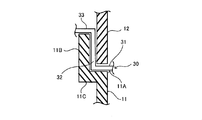
- It is a schematic sectional drawing which shows one attachment form of the liquid supply flow-path apparatus arrange
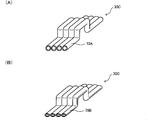
- FIG. 10A and 10B are schematic perspective views of a liquid supply channel device according to the third embodiment.
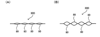
- 11A and 11B are schematic explanatory views of a liquid supply channel device according to the fourth embodiment.
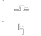
- 12A and 12B are schematic explanatory views of a holding case through which a flexible tube used in the fourth embodiment is inserted. It is a schematic explanatory drawing which shows an example of the attachment state in the liquid injection apparatus main body of a liquid supply flow-path apparatus.
- FIG. 1A is a front view showing the overall configuration of the inkjet printer.
- This printer includes a printer main body 10, an external tank 20 disposed outside the printer main body 10, and an ink supply channel device (liquid supply channel) that supplies ink that is liquid from the external tank 20 to the inside of the printer main body 10.
- Device 30.
- the external tank 20 can pump the ink inside by a water head difference or external pressure. Alternatively, the ink in the external tank 20 may be sucked by a mechanism inside the printer body 10.
- the printer main body 10 includes a platen that supports paper in an interior surrounded by a lower housing cover (first housing cover) 11 and an upper housing cover (second housing cover) 12.
- a carriage that reciprocates along a guide shaft parallel to the platen, a recording head (liquid ejecting head) mounted on the carriage, an ink cartridge that supplies ink to the recording head, and the like are incorporated.
- a scanner cover 13 is disposed on the upper housing cover 12.
- FIG. 1B is a side view showing a state in which the scanner cover 13 is opened.
- the scanner cover 13 is opened, the document is placed on the document table, the scanner cover 13 is closed, and the start button is pressed, scanning of the document is started, and printing is performed by the printer main body 10.
- the printer main body 10 is a multifunction peripheral, and printing on the printer main body 10 is not limited to a document read by a scanner, and for example, information sent from a personal computer can be printed.
- FIG. 1C shows a state where the upper casing cover 12 is opened during maintenance.
- the ink supply channel device 30 is guided from the outside of the printer main body 10 to the inside through a gap between the lower housing cover 11 and the upper housing cover 12.
- a cutout portion 11A in which the upper edge is partially cut is formed on the side surface of the lower housing cover 11. This notch portion 11A is originally provided to secure a gap with the upper housing cover 12 so that a finger can be hooked when the upper housing cover 12 is opened and closed.
- the ink supply channel device 30 is introduced from the outside of the printer main body 10 into the inside through the maximum gap between the lower and upper housing covers 11 and 12 secured in the notch portion 11A. . In this way, by using the gap formed in advance in the printer main body 10, the ink supply channel device 30 can be mounted on the printer main body 10 without impairing the operability, performance, and appearance of the printer main body 10.
- FIG. 2 shows an ink supply channel device, for example, along the lower casing cover 11 through a gap between end faces where the upper end of the lower casing cover 11 and the lower end of the upper casing cover 12 face each other.
- FIG. 3 includes an inner wall cover 11B that is opposed to the inner side of the upper housing cover 12 and a step portion 11C that connects the inner wall / outer wall cover at the upper end of the lower housing cover (outer wall cover) 11. ing.
- the lower housing cover (outer wall cover) 11 is provided via a gap between the lower housing cover (outer wall cover) 11, the stepped portion 11C and the inner wall cover 11B, and the upper housing cover 12.
- the ink supply channel device 30 is disposed along the step portion 11C and the inner wall cover 11B.
- the ink supply flow path device 30 has a channel shape (in order to get over the lower case cover 11 while being held along the lower case cover 11).
- a U-shaped channel is essential.
- the lower housing cover (outer wall cover) 11, the step portion 11C and the inner wall cover 11B are arranged along the lower housing cover (outer wall cover) 11, the step portion 11C and the inner wall cover 11B.
- a crank-shaped channel is essential.
- the ink supply flow path device 30 communicates with the first flow path 31 and one end of the first flow path 31 and intersects the first flow path 31, for example, in a perpendicular direction.
- a flow path (or a plurality of flow paths) may be defined.
- the ink supply flow path device 30 having such a shape is arranged on the lower side through a gap between the lower casing cover 11 and the upper casing cover 12 in both cases of FIGS. Ink is supplied from the outside to the inside of the printer body 10 by being disposed along the housing cover 11 or the upper housing cover 12.
- bubbles having a low specific gravity can be discharged into the space above the ink in the second flow path 32 to remove the bubbles, and the bubble trap can be used. Only ink can be supplied.
- the ink supply flow path device 30 has a flow path (second flow path 32 in the example of FIG. 2) disposed in a gap between the lower housing cover 11 and the upper housing cover 12.
- a flow path forming member having a shape retaining property of a bent flow path bent in a channel shape or a crank shape is included.
- a flat flow path having a low flow path height is necessary to be disposed in the gap between the lower and upper housing covers 11 and 12 shown in FIG. Therefore, the channel width is made larger than the channel height.
- the shape retaining property is a property of maintaining the shape. Due to the shape retaining property, even when the upper housing cover 12 is opened and closed as shown in FIG.
- the flow path forming member forming the ink supply flow path device 30 preferably has a low oxygen or hydrogen permeability coefficient.
- This oxygen / hydrogen permeability coefficient depends on the shape of the flow path, but in a room temperature environment, the oxygen permeability coefficient is 200 [cc ⁇ mm / m2 ⁇ day ⁇ atm] or less, more preferably 100 or less, and the water vapor permeability coefficient is 0.2 [g ⁇ mm / m 2 ⁇ day] or less, more preferably 0.1 or less.
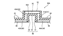
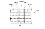
- the flow path forming member of the ink supply flow path device 30A includes a flow path partition forming member 40 and a thin plate member 50.
- the flow path partition forming member 40 is formed of a material having shape retaining properties such as resin, metal, elastomer, rubber and the like.
- the thin plate member 50 can be formed of a resin film, an elastomer sheet, or the like. In order to thermally weld the thin plate member 50 to the flow path partition forming member 40, the flow path partition forming member 40 and the thin plate member 50 can be formed of the same kind of resin or elastomer.
- the flow path partition forming member 40 includes first, second, and third plate-like members 41, 42, and 43 connected to each other to form the channel-shaped flow path shown in FIG. At both ends of the plate-like member 42, the first and third plate-like members 41, 43 are connected to the second plate-like member so as to intersect, for example, orthogonally.
- the second flow path 32 is partitioned by a recess 42A formed in the second plate member 42 and a thin plate member 50 that seals the opening of the recess 42A.
- a recess 42A formed in the second plate member 42
- a thin plate member 50 that seals the opening of the recess 42A.
- four second flow paths 31 are formed on the flow path partition forming member 40, but the number depends on the type of ink to be supplied. Accordingly, it may be set as appropriate, and at least one may be formed.
- the first flow path 31 is formed by a through hole 41A that penetrates the first plate member 41 and communicates with the recess 42A of the second plate member 42.
- the third flow path 33 is formed by a through hole 43 ⁇ / b> A that penetrates the third plate member 43 and communicates with the recess 42 ⁇ / b> A of the second plate member 42.
- the through holes 41A and 43A have a rectangular cross section in FIG. 5 and the same cross section as the second flow path 32. However, a circular cross section may be used in consideration of workability.
- the first and third flow channels 31 and 33 formed by the through holes 41A and 43A are not flat flow channels.
- the paths 31 and 33 are not necessarily arranged in the gap between the lower housing cover 11 and the upper housing cover 12 as shown in FIG.
- the ink supply channel device 30A shown in FIGS. 4 to 6 includes an upstream plate member 44 on the upstream side of the first plate member 41, and a downstream plate member on the downstream side of the second plate member 43. 45 may further be included.
- the upstream plate member 44 has a recess 44A that communicates with the through hole 41A
- the downstream plate member 45 has a recess 45A that communicates with the through hole 43A.
- These concave portions 44A and 45A are also sealed by the thin plate member 50 in the same manner as the concave portion 42A, and the upstream flow path 34 and the downstream flow path 35 are formed.
- the upstream plate member 44 and the downstream plate member 45 are not essential, and an ink supply tube may be connected to the first and third plate members 41 and 43 instead.
- the upstream plate member 44 and the downstream plate member 45 are not arranged in the gap between the lower housing cover 11 and the upper housing cover 12 but are sandwiched between the lower housing cover 11 and the upper housing cover 12. This is because there is no fear.
- the channel cross-sectional area may be made larger than the flat channel of the ink supply channel device 30A. This is because flow resistance is reduced to ensure smooth ink supply.
- the above can be similarly applied to second to fourth embodiments described later.
- the ink supply flow path device 30A according to the first embodiment is disposed in the gap between the lower housing cover 11 and the upper housing cover 12 as shown in FIG.
- the ink supply channel device 30A is held by the recess of the channel-shaped ink supply channel device 30A being inserted into the upper end of the lower housing cover 11.
- the ink supply flow path device 30 ⁇ / b> A is a flat flow path in which the second flow path 32 disposed in the gap between the lower housing cover 11 and the upper housing cover 12 is partitioned by the thin plate member 50 and Has shape retention. For this reason, even if the upper housing cover 12 is opened and closed as shown in FIG. 1C, the flat bent flow path is not sandwiched between the lower housing cover 11 and the upper housing cover 12, and is stable. Ink can be supplied. Therefore, idling with the recording head is prevented, and failure of the printer main body 10 can be reduced. In addition, a bubble trap can be realized in the second flow path 32.
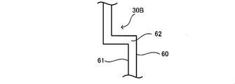
- the ink supply flow path device 30B is formed as a flow path forming member, for example, bent along the first, second, and third flow paths 31, 32, and 3 shown in FIG.
- the first and second thin plate-like members 60 and 61 that are spaced apart from each other so as to ensure the height of each of the three flow paths 31, 32, and 33, and the first, second, and third It is bent along the flow paths 31, 32, 33, arranged between the opposing first and second thin plate members 60, 61, and the first, second, third flow paths 31, 32.
- 33 and at least two partition members 62, 63 that are arranged to face each other so as to ensure the width of each flow path.
- N is an integer of 2 or more
- (N + 1) partition members may be provided.
- first and second thin plate-like members 60 and 61 and the partition members 62 and 63 may be a combination of various materials. There are two main combinations of materials.
- the first type is a case where the first and second thin plate-like members 60, 61 have a shape retaining property that maintains a bent shape
- the second type is a case where the shape retaining property does not exist.
- the first and second thin plate-like members 60 and 61 are formed of metal or hard resin to ensure shape retention.
- the material of the partition members 62 and 63 in the first type may be any material that can be sandwiched between the first and second thin plate-like members 60 and 61 to exhibit the partition function.
- resin, metal, elastomer And rubber for example, resin, metal, elastomer And rubber.
- the materials of the first and second thin plate members 60 and 61 are materials having no shape-retaining property and having flexibility, such as resin films, elastomer sheets, rubber sheets, etc. Can do.
- the first and second thin plate-like members 60, 61 are deformed and bent in accordance with the surfaces of the partition members 62, 63 having shape retention.
- resin, metal, elastomer, rubber or the like can be used as the material of the partition members 62 and 63 in the second type.
- the ink supply flow path device 30B according to the second embodiment is also disposed in the gap between the lower housing cover 11 and the upper housing cover 12 as shown in FIG. In addition, the ink supply flow path device 30 is held by the recess of the channel-shaped ink supply flow path device 30B being inserted into the upper end of the lower housing cover 11.
- the second flow path 32 disposed in the gap between the lower housing cover 11 and the upper housing cover 12 is partitioned by the first and second thin plate members 60 and 61.
- the flow path is flat, and the first and second thin plate-like members 60 and 61 and / or the partition members 62 and 63 have shape retention. For this reason, even if the upper housing cover 12 is opened and closed as shown in FIG. 1C, the flat bent flow path is not sandwiched between the lower housing cover 11 and the upper housing cover 12, and is stable. Ink can be supplied. Therefore, idling with the recording head is prevented, and failure of the printer main body 10 can be reduced. In addition, a bubble trap can be realized in the second flow path 32.
- the ink supply flow path device 30B according to the second embodiment is not limited in the bending direction unlike the first embodiment, for example, even when the crank-shaped flow path shown in FIG. It can be bent as shown in FIG.
- FIG. 10A and 10B show an ink supply channel device 30C according to the third embodiment.
- the ink supply flow path device 30C is bent and formed along the first, second, and third flow paths 31, 32, and 33 shown in FIG. 2 as a flow path forming member to partition and form a plurality of flow paths.
- a plurality of metal pipes 70A or 70B are formed, and the plurality of metal pipes are arranged side by side.
- the metal pipe 70A shown in FIG. 10A is a circular flow path, but the metal pipe 70B in FIG. 10B is used as a flat elliptical flow path whose flow path height is smaller than the flow path width. May be.
- the ink supply flow path device 30C is also disposed in the gap between the lower housing cover 11 and the upper housing cover 12 as shown in FIG.
- the ink supply flow path device 30 is held by inserting the recess of the channel-shaped ink supply flow path device 30 ⁇ / b> C into the upper end of the lower housing cover 11.
- the second channel 32 disposed in the gap between the lower housing cover 11 and the upper housing cover 12 is a flat channel.
- it has shape retention. For this reason, even if the upper housing cover 12 is opened and closed as shown in FIG. 1C, the flat bent flow path is not sandwiched between the lower housing cover 11 and the upper housing cover 12, and is stable. Ink can be supplied. Therefore, idling with the recording head is prevented, and failure of the printer main body 10 can be reduced. In addition, a bubble trap can be realized in the second flow path 32.
- the metal pipe 70A or 70B can be freely bent even in the ink supply flow path device 30C according to the third embodiment, for example, the case of forming a crank-shaped flow path shown in FIG. it can.
- the ink supply flow path device 30D includes at least one, for example, four flexible tubes 80 as flow path forming members.
- the flexible tube 80 is crushed in the state before the ink supply shown in FIG. 11A, but is deformed when the pressurized or sucked ink passes, as shown in FIG. 11B.
- the required flow path cross-sectional area can be secured.
- the flexible tube 80 can be formed by partially bonding two opposing films, an elastomer sheet, a rubber sheet, etc. by heat welding or adhesion.
- the ink supply channel device 30D can be freely deformed into the channel shape of FIG. 2 or the crank shape of FIG. However, since the flexible tube 80 itself does not have shape retention, the flexible tube 80 is inserted into, for example, the channel-shaped holding case 82 or the crank-shaped holding case 84 shown in FIGS.
- the holding cases 82 and 84 hold the shape retaining property and can be arranged between the lower and upper casing covers 11 and 12.
- the second flow path 32 disposed in the gap between the lower housing cover 11 and the upper housing cover 12 shown in FIG. Since it is ensured as a flat flow path, the ink can be stably supplied without being sandwiched between the lower housing cover 11 and the upper housing cover 12. Therefore, idling with the recording head is prevented, and failure of the printer main body 10 can be reduced. Even when bent in a crank shape as shown in FIG. 3, the first to third flow paths 31 to 33 can be secured as flat flow paths. In addition, a bubble trap can be realized in the second flow path 32.
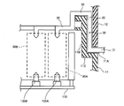
- FIG. 13 shows the inside of the printer main body 10 shown in FIG.
- the printer main body 10 has lower and upper casing covers 11 and 12 of the type shown in FIG.
- the ink supply flow path device 30 is inserted into the printer main body 10 through the cutout portion 11A of the lower casing cover 11 and extends along the gap between the lower and upper casing covers 11 and 12.
- the third channels 31 to 33 are bent in a crank shape.
- the flow path 35 on the downstream side of the third flow path 33 is connected to the ink reservoirs 90A, 90B,... Installed for each ink color.
- the installation positions of the ink reservoirs 90A and 90B are originally locations where off-carriage type ink cartridges are arranged. Since the ink cartridge is not configured to be able to supply ink from the outside, ink storage portions 90A and 90B are provided as a substitute.
- the ink reservoirs 90A and 90B are formed in a bag shape by a flexible film such as a resin film and / or an aluminum thin film, for example, and have a damper capability.
- the ink reservoirs 90A and 90B are connected to the recording head via ink lead-out members (liquid lead-out members) 100A and 100B provided on the printer main body 10 side, and an inner flow path 110 branched for each ink.
- the ink in the external tank 20 can be guided to the recording head.
- the ink storage portions 90 ⁇ / b> A and 90 ⁇ / b> B may be similarly provided.
- the ink supply channel device 30 may be connected to an adapter having a structure that can be connected to the inner tube in the printer main body 10 instead of the ink reservoirs 90a and 90b.
- liquid supply channel device of the present invention is not limited to the ink jet recording apparatus.
- the present invention can be used for various liquid ejecting apparatuses including a liquid ejecting head that ejects a minute amount of liquid droplets.
- a droplet means the state of the liquid discharged from the said liquid ejecting apparatus, and shall also include what pulls a tail in granular shape, tear shape, and thread shape.
- the liquid ejecting apparatus include, for example, an apparatus having a color material ejecting head used for manufacturing a color filter such as a liquid crystal display, an electrode material (conducting material) used for forming an electrode such as an organic EL display and a surface emitting display (FED).
- a color material ejecting head used for manufacturing a color filter such as a liquid crystal display
- an electrode material (conducting material) used for forming an electrode such as an organic EL display and a surface emitting display (FED).
- Examples thereof include an apparatus having a paste) ejection head, an apparatus having a bio-organic matter ejection head used for biochip manufacturing, an apparatus having a sample ejection head as a precision pipette, a textile printing apparatus, and a micro dispenser.
- the liquid may be any material that can be ejected by the liquid ejecting apparatus.
- a typical example of the liquid is ink as described in the above embodiment.
- the ink includes various liquid compositions such as general aquatic ink, oil-based ink, gel ink, and hot melt ink.
- the liquid may be a substance other than a material used for printing characters and images, such as liquid crystal.
- the liquid is not limited to a liquid as one state of a substance, but may be a liquid obtained by mixing a solid substance such as a pigment or metal particles with a liquid as one state of a substance.
Landscapes
- Ink Jet (AREA)
Abstract
Description
図1(A)~図1(C)は、本発明に係る液体噴射装置の一実施形態であるインクジェットプリンタを示している。図1(A)は、インクジェットプリンタの全体構成を示す正面図である。このプリンタは、プリンタ本体10と、プリンタ本体10の外部に配置された外部タンク20と、外部タンク20よりプリンタ本体10の内部まで液体であるインクを供給するインク供給流路装置(液体供給流路装置)30とを有している。外部タンク20は水頭差によりあるいは外部加圧により、内部のインクを圧送することができる。あるいは、プリンタ本体10内部の機構により外部タンク20内のインクを吸引しても良い。
次に、インク供給流路装置(液体供給流路装置)30について説明する。図2及び図3は、図1(A)のA-A断面例を示している。図2は、下側の筐体カバー11の上端と上側の筐体カバー12の下端とが対向する端面間の隙間を介して、例えば下側の筐体カバー11に沿ってインク供給流路装置30が配置される例を示している。図3は、下側の筐体カバー(外壁カバー)11の上端に、上側の筐体カバー12の内側にて対向する内壁カバー11Bと、内壁・外壁カバーを連結する段差部11Cとを有している。この場合も、下側筐体カバー(外壁カバー)11、段差部11C及び内壁カバー11Bと、上側筐体カバー12との間の隙間を介して、例えば下側の筐体カバー(外壁カバー)11、段差部11C及び内壁カバー11Bに沿ってインク供給流路装置30が配置される。
以下、図2に示すチャンネル状の流路を有するインク供給流路装置30の具体例について説明する。図4~図6は、第1実施形態に係るインク供給流路装置30Aを示している。図4及び図6に示すように、このインク供給流路装置30Aの流路形成部材として、流路区画形成部材40と、薄板状部材50とを有している。流路区画形成部材40は、樹脂、金属、エストマ、ゴム等の保形性を有する材料にて形成される。薄板状部材50は、樹脂フィルム、エラストマシート等で形成できる。薄板状部材50を流路区画形成部材40に熱溶着するには、流路区画形成部材40及び薄板状部材50を同種の樹脂またはエラストマにて形成することができる。
図7及び図8は、本発明の第2実施形態に係るインク供給流路装置30Bを示している。このインク供給流路装置30Bは、流路形成部材として、例えば図2に示す第1,第2,第3の流路31,32,3に沿って屈曲形成され、第1,第2,第3の流路31,32,33の各流路高さを確保するように離間して対向配置される第1,第2の薄板状部材60,61と、第1,第2,第3の流路31,32,33に沿って屈曲形成されて、第1,第2の薄板状部材60,61の対向間に配置され、かつ、第1,第2,第3の流路31,32,33の各流路幅を確保するように離間して対向配置される少なくとも2つの仕切り部材62,63とを含む。なお、N(Nは2以上の整数)個の流路を形成するには、仕切り部材を(N+1)個設ければよい。
図10(A)(B)は、第3実施形態に係るインク供給流路装置30Cを示している。このインク供給流路装置30Cは、流路形成部材として、図2に示す第1,第2,第3の流路31,32,33に沿って屈曲形成されて複数の流路を区画形成する複数の金属パイプ70Aまたは70Bで形成され、複数の金属パイプを並設している。図10(A)に示す金属パイプ70Aは円形流路であるが、流路幅に対して流路高さを小さくした扁平な楕円状流路とする図10(B)の金属パイプ70Bを用いても良い。
図11(A)(B)は、第4実施形態に係るインク供給流路装置30Dを示している。このインク供給流路装置30Dは、流路形成部材はとして、少なくとも一つ例えば4つの可撓性チューブ80を含んでいる。この可撓性チューブ80は、図11(A)に示すインク供給前の状態ではつぶれているが、加圧または吸引供給されたインクが通過する際に変形して図11(B)に示すように膨張して、必要な流路断面積を確保できる。
図13は、図1に示すプリンタ本体10の内部を示している。このプリンタ本体10は図3のタイプの下側・上側の筐体カバー11,12を有す。インク供給流路装置30は、下側の筐体カバー11の切欠部11Aよりプリンタ本体10の内部に挿入され、下側・上側の筐体カバー11,12の間の隙間に沿って、第1~第3の流路31~33がクランク状に屈曲形成されている。
Claims (8)
- 第1の流路と、前記第1の流路の一端と連通して前記第1の流路と交差する方向に沿って延びる第2の流路と、前記第2の流路の他端と連通して前記第2の流路と交差する方向に延びる第3の流路を含む少なくとも一つの屈曲流路を区画形成する流路形成部材を有し、
前記流路形成部材が、液体噴射装置本体の外面を形成する第1の筐体カバーと第2の筐体カバーとの間の隙間を介して、前記第1の筐体カバーまたは前記第2の筐体カバーに沿って配置されることで、前記液体噴射装置本体の外部から内部に液体を供給することを特徴とする液体供給流路装置。 - 請求項1において、
前記流路形成部材は、前記第1の筐体カバーと前記第2の筐体カバーとの間の隙間に配置される流路を、流路幅よりも最大流路高さが小さい扁平な流路として、前記少なくとも一つの屈曲流路の形状を保持する保形性を有することを特徴とする液体供給流路装置。 - 請求項2において、
前記流路形成部材は互いに連結された第1,第2,第3の板状部材を含み、前記第2の板状部材の両端にて、前記第1,第3の板状部材が前記第2の板状部材に対して交差して連結され、
前記第2の流路は、前記2の板状部材に形成された凹部と、前記凹部の開口を封止する薄板状部材にて区画され、
前記第1の流路は、前記第1の板状部材に貫通して前記第2の板状部材の前記凹部と連通する貫通孔にて形成され、
前記第3の流路は、前記第3の板状部材に貫通して前記第2の板状部材の前記凹部と連通する貫通孔にて形成されることを特徴とする液体供給流路装置。 - 請求項2において、
前記流路形成部材は、
前記第1,第2,第3の流路に沿って屈曲形成され、前記第1,第2,第3の流路の各流路高さを確保するように離間して対向配置される第1,第2の薄板状部材と、
前記第1,第2,第3の流路に沿って屈曲形成されて、前記第1,第2の薄板状部材の対向間に配置され、かつ、前記第1,第2,第3の流路の各流路幅を確保するように離間して対向配置される少なくとも2つの仕切り部材と、
を含むことを特徴とする液体供給流路装置。 - 請求項1または2において、
前記流路形成部材は、前記第1,第2,第3の流路に沿って屈曲形成されて複数の流路を区画形成する複数の金属パイプで形成され、前記複数の金属パイプを並設したことを特徴とする液体供給流路装置。 - 請求項1または2において、
前記流路形成部材は少なくとも一つの可撓性チューブを含み、前記少なくとも一つの可撓性チューブ内に液体が加圧または吸引供給されることを特徴とする液体供給流路装置。 - 少なくとも第1及び第2の筐体カバーに覆われた内部に液体噴射ノズルを有する液体噴射装置本体と、
前記液体噴射装置本体の外部に配置される外部タンクと、
前記外部タンクの液体を、前記液体噴射装置本体の内部に供給する液体供給流路装置と、
を有し、
前記液体供給流路装置は、第1の流路と、前記第1の流路の一端と連通して前記第1の流路と交差する方向に沿って延びる第2の流路と、前記第2の流路の他端と連通して前記第2の流路と交差する方向に延びる第3の流路を含む少なくとも一つの屈曲流路を区画形成する流路形成部材を有し、
前記流路形成部材が、前記第1の筐体カバーと前記第2の筐体カバーとの間の隙間を介して、前記第1の筐体カバーまたは前記第2の筐体カバーに沿って配置されることを特徴とする液体噴射装置。 - 請求項7において、
前記液体噴射装置本体の内部には、前記液体供給流路装置により供給された液体を貯留する貯留部を含み、前記貯留部はダンパー能力を有することを特徴とする液体噴射装置。
Priority Applications (10)
| Application Number | Priority Date | Filing Date | Title |
|---|---|---|---|
| KR1020127020251A KR101332040B1 (ko) | 2008-03-25 | 2009-03-25 | 기록 장치 |
| KR1020127020250A KR101331380B1 (ko) | 2008-03-25 | 2009-03-25 | 기록 장치 |
| CN200980109854.0A CN101980871B (zh) | 2008-03-25 | 2009-03-25 | 液体供应流路装置以及使用该装置的液体喷射装置 |
| US12/933,697 US20110018947A1 (en) | 2008-03-25 | 2009-03-25 | Liquid Supply Flow Path Device And Liquid Ejecting Apparatus Using The Same |
| JP2010505347A JPWO2009119084A1 (ja) | 2008-03-25 | 2009-03-25 | 液体供給流路装置及びそれを用いた液体噴射装置 |
| US13/668,392 US8657422B2 (en) | 2008-03-25 | 2012-11-05 | Liquid supply flow path device and liquid ejecting apparatus using the same |
| US13/668,390 US8974042B2 (en) | 2008-03-25 | 2012-11-05 | Liquid supply flow path device and liquid ejecting apparatus using the same |
| US14/074,011 US20140055532A1 (en) | 2008-03-25 | 2013-11-07 | Liquid Supply Flow Path Device and Liquid Ejecting Apparatus Using the Same |
| US14/074,012 US20140055533A1 (en) | 2008-03-25 | 2013-11-07 | Liquid Supply Flow Path Device and Liquid Ejecting Apparatus Using the Same |
| US14/548,756 US9555638B2 (en) | 2008-03-25 | 2014-11-20 | Liquid supply flow path device and liquid ejecting apparatus using the same |
Applications Claiming Priority (2)
| Application Number | Priority Date | Filing Date | Title |
|---|---|---|---|
| JP2008-078159 | 2008-03-25 | ||
| JP2008078159 | 2008-03-25 |
Related Child Applications (3)
| Application Number | Title | Priority Date | Filing Date |
|---|---|---|---|
| US12/933,697 A-371-Of-International US20110018947A1 (en) | 2008-03-25 | 2009-03-25 | Liquid Supply Flow Path Device And Liquid Ejecting Apparatus Using The Same |
| US13/668,392 Division US8657422B2 (en) | 2008-03-25 | 2012-11-05 | Liquid supply flow path device and liquid ejecting apparatus using the same |
| US13/668,390 Continuation US8974042B2 (en) | 2008-03-25 | 2012-11-05 | Liquid supply flow path device and liquid ejecting apparatus using the same |
Publications (1)
| Publication Number | Publication Date |
|---|---|
| WO2009119084A1 true WO2009119084A1 (ja) | 2009-10-01 |
Family
ID=41113295
Family Applications (1)
| Application Number | Title | Priority Date | Filing Date |
|---|---|---|---|
| PCT/JP2009/001323 Ceased WO2009119084A1 (ja) | 2008-03-25 | 2009-03-25 | 液体供給流路装置及びそれを用いた液体噴射装置 |
Country Status (5)
| Country | Link |
|---|---|
| US (6) | US20110018947A1 (ja) |
| JP (7) | JPWO2009119084A1 (ja) |
| KR (3) | KR20100124344A (ja) |
| CN (6) | CN102896903B (ja) |
| WO (1) | WO2009119084A1 (ja) |
Cited By (18)
| Publication number | Priority date | Publication date | Assignee | Title |
|---|---|---|---|---|
| JP2012057652A (ja) * | 2010-09-06 | 2012-03-22 | Polyplastics Co | 流路形成構造体及び当該流路形成構造体の製造方法 |
| JP2012162087A (ja) * | 2008-03-25 | 2012-08-30 | Seiko Epson Corp | 液体供給流路装置及びそれを用いた液体噴射装置 |
| JP2013121660A (ja) * | 2011-12-09 | 2013-06-20 | Seiko Epson Corp | 記録装置 |
| JP2013121658A (ja) * | 2011-12-09 | 2013-06-20 | Seiko Epson Corp | 記録装置 |
| JP2013144423A (ja) * | 2012-02-29 | 2013-07-25 | Seiko Epson Corp | 記録装置 |
| JP2013166327A (ja) * | 2012-02-16 | 2013-08-29 | Seiko Epson Corp | インクジェット記録装置 |
| JP2013166302A (ja) * | 2012-02-15 | 2013-08-29 | Seiko Epson Corp | インクジェット記録装置 |
| WO2013128924A1 (ja) * | 2012-02-29 | 2013-09-06 | セイコーエプソン株式会社 | 液体噴射装置 |
| JP2013176945A (ja) * | 2012-02-29 | 2013-09-09 | Seiko Epson Corp | 記録装置 |
| JP2013176946A (ja) * | 2012-02-29 | 2013-09-09 | Seiko Epson Corp | 液体噴射装置 |
| JP2013180397A (ja) * | 2012-02-29 | 2013-09-12 | Seiko Epson Corp | 液体噴射装置 |
| JP2013180396A (ja) * | 2012-02-29 | 2013-09-12 | Seiko Epson Corp | 液体噴射装置 |
| JP2013198992A (ja) * | 2012-03-23 | 2013-10-03 | Seiko Epson Corp | 記録装置 |
| WO2014024391A1 (ja) * | 2012-08-10 | 2014-02-13 | セイコーエプソン株式会社 | 液体噴射装置 |
| JP2014034202A (ja) * | 2012-08-10 | 2014-02-24 | Seiko Epson Corp | 記録装置 |
| JP2014040031A (ja) * | 2012-08-22 | 2014-03-06 | Seiko Epson Corp | 記録装置 |
| JP2014184672A (ja) * | 2013-03-25 | 2014-10-02 | Seiko Epson Corp | 液体収容体 |
| JPWO2013114841A1 (ja) * | 2012-01-30 | 2015-05-11 | セイコーエプソン株式会社 | インクジェット記録装置 |
Families Citing this family (10)
| Publication number | Priority date | Publication date | Assignee | Title |
|---|---|---|---|---|
| JP5974356B2 (ja) * | 2012-02-29 | 2016-08-23 | セイコーエプソン株式会社 | 液体噴射装置 |
| JP5994360B2 (ja) * | 2012-04-26 | 2016-09-21 | セイコーエプソン株式会社 | 記録装置 |
| JP6057058B2 (ja) * | 2012-08-10 | 2017-01-11 | セイコーエプソン株式会社 | 記録装置 |
| JP5983924B2 (ja) * | 2012-08-10 | 2016-09-06 | セイコーエプソン株式会社 | 記録装置 |
| JP6103177B2 (ja) * | 2012-08-10 | 2017-03-29 | セイコーエプソン株式会社 | 液体噴射装置および液体噴射方法 |
| WO2014024392A1 (ja) * | 2012-08-10 | 2014-02-13 | セイコーエプソン株式会社 | 液体噴射装置 |
| JP6315451B2 (ja) * | 2014-04-07 | 2018-04-25 | アンリツ株式会社 | ミリ波帯フィルタ |
| JP6220722B2 (ja) * | 2014-04-17 | 2017-10-25 | アンリツ株式会社 | ミリ波帯用電波ハーフミラーおよびその透過係数平坦化方法 |
| JP6805498B2 (ja) * | 2016-01-29 | 2020-12-23 | セイコーエプソン株式会社 | 複合機 |
| JP7313953B2 (ja) * | 2019-07-29 | 2023-07-25 | キヤノン株式会社 | 画面生成サーバ、制御方法、プログラムおよび商品情報提供システム |
Citations (3)
| Publication number | Priority date | Publication date | Assignee | Title |
|---|---|---|---|---|
| JP2002127450A (ja) * | 2000-10-25 | 2002-05-08 | Canon Inc | 接続装置及びインクジェット方式画像形成装置 |
| JP2006231654A (ja) * | 2005-02-24 | 2006-09-07 | Ricoh Co Ltd | 画像形成装置 |
| JP2006305940A (ja) * | 2005-04-28 | 2006-11-09 | Seiko Epson Corp | 液体流路形成体誘導装置 |
Family Cites Families (40)
| Publication number | Priority date | Publication date | Assignee | Title |
|---|---|---|---|---|
| US7009A (en) * | 1850-01-08 | Machinery for dressing shingles | ||
| US4012A (en) * | 1845-04-26 | Improvement in electrographic printing | ||
| US4234885A (en) * | 1979-09-10 | 1980-11-18 | A. B. Dick Company | Remote ink valve |
| JP3320248B2 (ja) | 1995-04-17 | 2002-09-03 | キヤノン株式会社 | インクジェット装置 |
| JP3572854B2 (ja) | 1996-04-05 | 2004-10-06 | セイコーエプソン株式会社 | インクジェットプリンタ及びダンパ |
| JPH10226084A (ja) | 1997-02-17 | 1998-08-25 | Seiko Epson Corp | インク供給チューブの振れ止め機構 |
| JP2000153619A (ja) * | 1998-11-24 | 2000-06-06 | Seiko Epson Corp | プリンタ並びにそのインクカートリッジ |
| JP2000211162A (ja) | 1999-01-27 | 2000-08-02 | Canon Inc | 液体吐出記録装置 |
| DE60035145T2 (de) * | 1999-04-08 | 2008-02-14 | Seiko Epson Corp. | Tintenstrahlaufzeichnungsgerät und Steuerverfahren für die Reinigung des eingebauten Aufzeichnungskopfes |
| JP4282043B2 (ja) * | 1999-12-06 | 2009-06-17 | キヤノン株式会社 | 記録液体供給通路、記録液体収納容器、およびこれらを備える記録液体供給装置、並びにその表面改質方法 |
| US6338553B1 (en) * | 2000-05-15 | 2002-01-15 | Hewlett-Packard Company Intellectual Property Administration | Ink supply tube guiding system for large format printer |
| JP2002160379A (ja) * | 2000-11-24 | 2002-06-04 | Canon Inc | インクジェット記録装置のインク供給装置 |
| JP2002267052A (ja) | 2001-03-07 | 2002-09-18 | Sumitomo Electric Ind Ltd | 流体移送用チューブおよびその製造方法 |
| US6481838B1 (en) * | 2001-09-05 | 2002-11-19 | Hewlett-Packard Company | Ink tube connection to printhead carriage cover |
| JP3966729B2 (ja) * | 2002-01-22 | 2007-08-29 | シャープ株式会社 | インクジェット記録装置 |
| JP3573151B2 (ja) * | 2002-02-28 | 2004-10-06 | セイコーエプソン株式会社 | 液体噴射装置用液体供給チューブおよび液体噴射装置 |
| JP4470404B2 (ja) | 2003-07-22 | 2010-06-02 | セイコーエプソン株式会社 | 液体導通材及び液体噴射装置 |
| JP3800144B2 (ja) * | 2002-07-26 | 2006-07-26 | ブラザー工業株式会社 | プリンタ |
| US7008051B2 (en) * | 2002-10-10 | 2006-03-07 | Akermalm Per G | Expanded ink supply system for ink jet printers |
| CN100431842C (zh) * | 2003-02-04 | 2008-11-12 | 兄弟工业株式会社 | 喷墨打印机中的气泡去除 |
| DE602004005668T2 (de) * | 2003-02-04 | 2007-12-27 | Brother Kogyo K.K., Nagoya | Luftblasenentfernung bei einem tintenstrahldrucker |
| JP2004262092A (ja) | 2003-02-28 | 2004-09-24 | Seiko Epson Corp | 印刷装置及びその制御方法 |
| JP3935868B2 (ja) * | 2003-07-18 | 2007-06-27 | 株式会社クボタ | 作業車の操作構造 |
| US6913342B2 (en) * | 2003-09-10 | 2005-07-05 | Eastman Kodak Company | Apparatus for securing print cartridge in ink jet printer |
| JP4635426B2 (ja) | 2003-10-22 | 2011-02-23 | ブラザー工業株式会社 | 画像形成装置 |
| JP2005169922A (ja) * | 2003-12-12 | 2005-06-30 | Yoshikazu Yano | プリンター用インク供給パイプ |
| JP4341434B2 (ja) | 2004-03-12 | 2009-10-07 | セイコーエプソン株式会社 | インクチューブ保持機構およびインクジェットプリンタ |
| CN101058263B (zh) * | 2004-04-12 | 2012-01-11 | 精工爱普生株式会社 | 液体输送管的制造方法 |
| JP4252926B2 (ja) | 2004-04-22 | 2009-04-08 | 株式会社ブリヂストン | 液体噴射装置用液体供給チューブおよび液体噴射装置 |
| JP2006035484A (ja) | 2004-07-23 | 2006-02-09 | Seiko Epson Corp | 液体容器および液体残量検出方法 |
| KR100934129B1 (ko) | 2005-02-02 | 2009-12-29 | 세이코 엡슨 가부시키가이샤 | 어태치먼트 및 액체 공급 장치 |
| JP2006255964A (ja) * | 2005-03-15 | 2006-09-28 | Seiko Epson Corp | 液体噴射装置 |
| JP2006305941A (ja) * | 2005-04-28 | 2006-11-09 | Seiko Epson Corp | 液体供給回収装置 |
| JP4760153B2 (ja) | 2005-06-15 | 2011-08-31 | セイコーエプソン株式会社 | 駆動力伝達装置、加圧ポンプ装置、液体噴射装置 |
| JP4679316B2 (ja) * | 2005-09-16 | 2011-04-27 | 株式会社リコー | 画像形成装置 |
| JP4792920B2 (ja) * | 2005-10-31 | 2011-10-12 | ブラザー工業株式会社 | 画像形成装置 |
| JP2007144776A (ja) | 2005-11-28 | 2007-06-14 | Ricoh Co Ltd | インク供給チューブ支持機構及びインクジェット記録装置 |
| JP2007160795A (ja) * | 2005-12-15 | 2007-06-28 | Seiko Epson Corp | 液体噴射付属装置 |
| JP2007245451A (ja) | 2006-03-15 | 2007-09-27 | Konica Minolta Holdings Inc | 液体噴射装置及びインクジェット記録装置 |
| CN102896903B (zh) | 2008-03-25 | 2015-07-01 | 精工爱普生株式会社 | 液体供应流路装置以及使用该装置的液体喷射装置 |
-
2009
- 2009-03-25 CN CN201210353302.8A patent/CN102896903B/zh active Active
- 2009-03-25 JP JP2010505347A patent/JPWO2009119084A1/ja not_active Withdrawn
- 2009-03-25 KR KR1020107023650A patent/KR20100124344A/ko not_active Withdrawn
- 2009-03-25 WO PCT/JP2009/001323 patent/WO2009119084A1/ja not_active Ceased
- 2009-03-25 CN CN201310574215.XA patent/CN103640335B/zh active Active
- 2009-03-25 KR KR1020127020250A patent/KR101331380B1/ko active Active
- 2009-03-25 CN CN201310574214.5A patent/CN103753960A/zh active Pending
- 2009-03-25 CN CN201310225127.9A patent/CN103395294B/zh active Active
- 2009-03-25 KR KR1020127020251A patent/KR101332040B1/ko active Active
- 2009-03-25 CN CN200980109854.0A patent/CN101980871B/zh active Active
- 2009-03-25 CN CN201410166028.2A patent/CN104029490A/zh active Pending
- 2009-03-25 US US12/933,697 patent/US20110018947A1/en not_active Abandoned
-
2012
- 2012-04-25 JP JP2012100179A patent/JP5387722B2/ja active Active
- 2012-04-25 JP JP2012100180A patent/JP5327353B2/ja not_active Expired - Fee Related
- 2012-11-05 US US13/668,392 patent/US8657422B2/en not_active Expired - Fee Related
- 2012-11-05 US US13/668,390 patent/US8974042B2/en active Active
-
2013
- 2013-03-13 JP JP2013050187A patent/JP5565488B2/ja not_active Expired - Fee Related
- 2013-03-13 JP JP2013050210A patent/JP2013107406A/ja not_active Withdrawn
- 2013-06-04 JP JP2013117645A patent/JP5500297B2/ja active Active
- 2013-11-07 US US14/074,011 patent/US20140055532A1/en not_active Abandoned
- 2013-11-07 US US14/074,012 patent/US20140055533A1/en not_active Abandoned
- 2013-12-18 JP JP2013260978A patent/JP5761324B2/ja not_active Expired - Fee Related
-
2014
- 2014-11-20 US US14/548,756 patent/US9555638B2/en active Active
Patent Citations (3)
| Publication number | Priority date | Publication date | Assignee | Title |
|---|---|---|---|---|
| JP2002127450A (ja) * | 2000-10-25 | 2002-05-08 | Canon Inc | 接続装置及びインクジェット方式画像形成装置 |
| JP2006231654A (ja) * | 2005-02-24 | 2006-09-07 | Ricoh Co Ltd | 画像形成装置 |
| JP2006305940A (ja) * | 2005-04-28 | 2006-11-09 | Seiko Epson Corp | 液体流路形成体誘導装置 |
Cited By (25)
| Publication number | Priority date | Publication date | Assignee | Title |
|---|---|---|---|---|
| US8657422B2 (en) | 2008-03-25 | 2014-02-25 | Seiko Epson Corporation | Liquid supply flow path device and liquid ejecting apparatus using the same |
| JP2012162087A (ja) * | 2008-03-25 | 2012-08-30 | Seiko Epson Corp | 液体供給流路装置及びそれを用いた液体噴射装置 |
| US9555638B2 (en) | 2008-03-25 | 2017-01-31 | Seiko Epson Corporation | Liquid supply flow path device and liquid ejecting apparatus using the same |
| US8974042B2 (en) | 2008-03-25 | 2015-03-10 | Seiko Epson Corporation | Liquid supply flow path device and liquid ejecting apparatus using the same |
| JP2012057652A (ja) * | 2010-09-06 | 2012-03-22 | Polyplastics Co | 流路形成構造体及び当該流路形成構造体の製造方法 |
| JP2013121660A (ja) * | 2011-12-09 | 2013-06-20 | Seiko Epson Corp | 記録装置 |
| JP2013121658A (ja) * | 2011-12-09 | 2013-06-20 | Seiko Epson Corp | 記録装置 |
| JP2016144951A (ja) * | 2012-01-30 | 2016-08-12 | セイコーエプソン株式会社 | インクジェット記録装置 |
| US9315031B2 (en) | 2012-01-30 | 2016-04-19 | Seiko Epson Corporation | Ink jet recording apparatus |
| JPWO2013114841A1 (ja) * | 2012-01-30 | 2015-05-11 | セイコーエプソン株式会社 | インクジェット記録装置 |
| JP2013166302A (ja) * | 2012-02-15 | 2013-08-29 | Seiko Epson Corp | インクジェット記録装置 |
| JP2013166327A (ja) * | 2012-02-16 | 2013-08-29 | Seiko Epson Corp | インクジェット記録装置 |
| CN104136222A (zh) * | 2012-02-29 | 2014-11-05 | 精工爱普生株式会社 | 液体喷射装置 |
| JP2013180396A (ja) * | 2012-02-29 | 2013-09-12 | Seiko Epson Corp | 液体噴射装置 |
| JP2013180397A (ja) * | 2012-02-29 | 2013-09-12 | Seiko Epson Corp | 液体噴射装置 |
| JP2013176946A (ja) * | 2012-02-29 | 2013-09-09 | Seiko Epson Corp | 液体噴射装置 |
| JP2013176945A (ja) * | 2012-02-29 | 2013-09-09 | Seiko Epson Corp | 記録装置 |
| WO2013128924A1 (ja) * | 2012-02-29 | 2013-09-06 | セイコーエプソン株式会社 | 液体噴射装置 |
| JP2013144423A (ja) * | 2012-02-29 | 2013-07-25 | Seiko Epson Corp | 記録装置 |
| JP2013198992A (ja) * | 2012-03-23 | 2013-10-03 | Seiko Epson Corp | 記録装置 |
| WO2014024391A1 (ja) * | 2012-08-10 | 2014-02-13 | セイコーエプソン株式会社 | 液体噴射装置 |
| JP2014034202A (ja) * | 2012-08-10 | 2014-02-24 | Seiko Epson Corp | 記録装置 |
| US9180671B2 (en) | 2012-08-10 | 2015-11-10 | Seiko Epson Corporation | Liquid ejecting apparatus including a gap forming member having a locking member |
| JP2014040031A (ja) * | 2012-08-22 | 2014-03-06 | Seiko Epson Corp | 記録装置 |
| JP2014184672A (ja) * | 2013-03-25 | 2014-10-02 | Seiko Epson Corp | 液体収容体 |
Also Published As
Similar Documents
| Publication | Publication Date | Title |
|---|---|---|
| JP5327353B2 (ja) | 記録装置 | |
| EP2681049B1 (en) | Valve systems for managing air in a fluid ejection system | |
| JP2014162063A (ja) | 液体噴射ヘッド及び液体噴射装置 | |
| JP5365170B2 (ja) | 液体供給装置及び液体噴射装置 | |
| CN112440582B (zh) | 液体喷出装置 | |
| JP5946945B1 (ja) | 自重式圧力制御弁を備えたインクジェット式記録装置 | |
| JP2012240292A (ja) | 液体噴射ヘッドユニット及び液体噴射装置 | |
| JP4311225B2 (ja) | 液体噴射装置 | |
| JP2018103491A (ja) | 廃液タンク及び液体吐出装置 | |
| JP2019022969A (ja) | 液体吐出装置 | |
| JP2012131082A (ja) | 液体噴射ヘッド及び液体噴射装置 | |
| JP2013082078A (ja) | 液体カートリッジ | |
| JP2008188895A (ja) | 液体流路形成体および液体噴射装置 |
Legal Events
| Date | Code | Title | Description |
|---|---|---|---|
| WWE | Wipo information: entry into national phase |
Ref document number: 200980109854.0 Country of ref document: CN |
|
| 121 | Ep: the epo has been informed by wipo that ep was designated in this application |
Ref document number: 09725532 Country of ref document: EP Kind code of ref document: A1 |
|
| WWE | Wipo information: entry into national phase |
Ref document number: 12933697 Country of ref document: US |
|
| WWE | Wipo information: entry into national phase |
Ref document number: 2010505347 Country of ref document: JP |
|
| NENP | Non-entry into the national phase |
Ref country code: DE |
|
| ENP | Entry into the national phase |
Ref document number: 20107023650 Country of ref document: KR Kind code of ref document: A |
|
| 122 | Ep: pct application non-entry in european phase |
Ref document number: 09725532 Country of ref document: EP Kind code of ref document: A1 |