WO2008150034A1 - 画像形成方法、磁性トナー及びプロセスユニット - Google Patents

画像形成方法、磁性トナー及びプロセスユニット Download PDF

Info

Publication number
WO2008150034A1
WO2008150034A1 PCT/JP2008/060814 JP2008060814W WO2008150034A1 WO 2008150034 A1 WO2008150034 A1 WO 2008150034A1 JP 2008060814 W JP2008060814 W JP 2008060814W WO 2008150034 A1 WO2008150034 A1 WO 2008150034A1
Authority
WO
WIPO (PCT)
Prior art keywords
toner
magnetic
magnetic toner
carrier
latent image
Prior art date
Application number
PCT/JP2008/060814
Other languages
English (en)
French (fr)
Inventor
Tadashi Dojo
Michihisa Magome
Eriko Yanase
Takashi Matsui
Tomohisa Sano
Akira Sakakibara
Shuichi Hiroko
Original Assignee
Canon Kabushiki Kaisha
Priority date (The priority date is an assumption and is not a legal conclusion. Google has not performed a legal analysis and makes no representation as to the accuracy of the date listed.)
Filing date
Publication date
Application filed by Canon Kabushiki Kaisha filed Critical Canon Kabushiki Kaisha
Priority to CN2008800031055A priority Critical patent/CN101589345B/zh
Priority to JP2009517934A priority patent/JP4771558B2/ja
Priority to KR1020097016249A priority patent/KR101238502B1/ko
Priority to EP08765555A priority patent/EP2071406B1/en
Priority to US12/254,393 priority patent/US8841054B2/en
Publication of WO2008150034A1 publication Critical patent/WO2008150034A1/ja

Links

Classifications

    • GPHYSICS
    • G03PHOTOGRAPHY; CINEMATOGRAPHY; ANALOGOUS TECHNIQUES USING WAVES OTHER THAN OPTICAL WAVES; ELECTROGRAPHY; HOLOGRAPHY
    • G03GELECTROGRAPHY; ELECTROPHOTOGRAPHY; MAGNETOGRAPHY
    • G03G9/00Developers
    • G03G9/08Developers with toner particles
    • GPHYSICS
    • G03PHOTOGRAPHY; CINEMATOGRAPHY; ANALOGOUS TECHNIQUES USING WAVES OTHER THAN OPTICAL WAVES; ELECTROGRAPHY; HOLOGRAPHY
    • G03GELECTROGRAPHY; ELECTROPHOTOGRAPHY; MAGNETOGRAPHY
    • G03G9/00Developers
    • G03G9/08Developers with toner particles
    • G03G9/083Magnetic toner particles
    • GPHYSICS
    • G03PHOTOGRAPHY; CINEMATOGRAPHY; ANALOGOUS TECHNIQUES USING WAVES OTHER THAN OPTICAL WAVES; ELECTROGRAPHY; HOLOGRAPHY
    • G03GELECTROGRAPHY; ELECTROPHOTOGRAPHY; MAGNETOGRAPHY
    • G03G15/00Apparatus for electrographic processes using a charge pattern
    • G03G15/06Apparatus for electrographic processes using a charge pattern for developing
    • G03G15/08Apparatus for electrographic processes using a charge pattern for developing using a solid developer, e.g. powder developer
    • G03G15/0806Apparatus for electrographic processes using a charge pattern for developing using a solid developer, e.g. powder developer on a donor element, e.g. belt, roller
    • G03G15/0813Apparatus for electrographic processes using a charge pattern for developing using a solid developer, e.g. powder developer on a donor element, e.g. belt, roller characterised by means in the developing zone having an interaction with the image carrying member, e.g. distance holders
    • GPHYSICS
    • G03PHOTOGRAPHY; CINEMATOGRAPHY; ANALOGOUS TECHNIQUES USING WAVES OTHER THAN OPTICAL WAVES; ELECTROGRAPHY; HOLOGRAPHY
    • G03GELECTROGRAPHY; ELECTROPHOTOGRAPHY; MAGNETOGRAPHY
    • G03G9/00Developers
    • G03G9/08Developers with toner particles
    • G03G9/0827Developers with toner particles characterised by their shape, e.g. degree of sphericity
    • GPHYSICS
    • G03PHOTOGRAPHY; CINEMATOGRAPHY; ANALOGOUS TECHNIQUES USING WAVES OTHER THAN OPTICAL WAVES; ELECTROGRAPHY; HOLOGRAPHY
    • G03GELECTROGRAPHY; ELECTROPHOTOGRAPHY; MAGNETOGRAPHY
    • G03G9/00Developers
    • G03G9/08Developers with toner particles
    • G03G9/087Binders for toner particles

Definitions

  • the present invention relates to an image forming method used in a recording method using an electrophotographic method, an electrostatic recording method, an electrostatic printing method, or a toner jet recording method.
  • One of the harmful effects of narrowing the development area is a decrease in density due to insufficient toner supply. If various development conditions are changed, such as reducing the magnetic force of the magnet contained in the development sleep in order to maintain such a decrease in density, toner that is not sufficiently charged will also fly and capri and toner scattering will occur. Increase. In addition, shading unevenness (so-called sleeve ghost), etc., easily occurs during the development sleep cycle.
  • the narrowing of the development area further promotes some phenomena seen in the jimbing development method. For example, an edge effect occurs in which magnetic toner concentrates on the edge of the latent image and develops. It becomes easy to cause the transfer omission that occurs when the formed toner image is pressed against the transfer material.
  • an edge effect occurs in which magnetic toner concentrates on the edge of the latent image and develops. It becomes easy to cause the transfer omission that occurs when the formed toner image is pressed against the transfer material.
  • ear chain form
  • the processing agent externally added to the toner particles is likely to cause problems such as so-called toner deterioration such that the toner is buried or detached from the toner particles or the toner particles are missing.
  • toner deterioration progresses, when it is used repeatedly, the charge amount decreases, or the generated fine powder adheres to the developing sleeve or the regulating member, so that an image defect due to poor charging tends to occur.
  • An object of the present invention is to provide an image forming method, a magnetic toner, and a process unit that can solve the above-described problems.
  • the object of the present invention is to provide a stable image density regardless of the use environment even when applied to a developing sleep with a reduced diameter, and image formation that does not cause image defects such as capri, tailing, and transfer omission. It is to provide a method, magnetic toner and process unit.
  • Another object of the present invention is to provide a miniaturized process unit.
  • the toner applied to the toner carrier having a diameter of 5. Omm or more and less than 12.0 mm the present inventors measured the compressibility of the magnetic toner and the total energy measured by the powder flowability measuring device. By optimizing the toner, a magnetic toner and a process unit that achieve stable image density and high image quality and that can be miniaturized have been found, and the present invention has been completed.
  • the present invention is as follows.
  • a latent image carrier and a toner carrier carrying magnetic toner on the surface and having a magnetic field generating means are disposed at a predetermined interval, and the latent image carrier and the toner carrier An image forming method for developing an electrostatic latent image carried on the latent image carrier by applying an alternating electric field therebetween and using a magnetic toner,
  • the outer diameter of the toner carrier is not less than 5. Omm and less than 12.0 mm;
  • the magnetic toner includes magnetic toner particles containing at least a binder resin and magnetic powder, and inorganic fine powder,
  • the magnetic toner has an average circularity of 0.950 or more, a compression ratio obtained from the following formula (1) of 30 or less,
  • Compression rate ⁇ 1 (apparent density Z tap density) ⁇ X 100 (1)
  • T o tal En erg y measured in the toner powder fluidity measuring apparatus satisfies the following formulas (2) and (3):
  • an image forming method magnetic toner, which can be miniaturized, can obtain a stable image density regardless of the use environment, and can obtain a high-quality image free from capri, tailing, and transfer omission. And a process unit was obtained.
  • FIG. 1 is an explanatory diagram of a process unit to which the magnetic toner of the present invention can be applied.
  • FIGS. 2A and 2B are schematic views of a propeller blade of a powder fluidity analyzer used for t o t a l e n e r g y measurement.
  • the diameter of the toner carrier for example, developing sleeve
  • the number of contacts with the regulating member will increase, thereby stabilizing the toner carrying amount and the charge amount on the toner carrier.
  • the flying state of the magnetic toner within a narrow development area greatly affects the image quality.
  • the flying state of the magnetic toner onto the photosensitive drum is greatly influenced by the formation of toner “ears” on the toner carrier and the ease of collapse of the toner “ears” in the development area.
  • the compression ratio of the magnetic toner is defined by the following formula (1).
  • Compression rate ⁇ 1 (apparent density / tap density) ⁇ X I 0 0 (1)
  • This reduction ratio is a value calculated from the apparent density and tap density of the toner, and represents the change rate of the apparent density and the tap density.
  • the stirring state of the magnetic toner and the pressing state of the toner carrier 8 fluctuate in accordance with environmental changes and the remaining amount of toner due to use over time.
  • the surface area of the toner carrier is reduced, so that there is less chance of contact with the magnetic toner.
  • the compression rate of magnetic toner is an index for measuring the stability of toner “ear” formation against such fluctuations.
  • the magnetic toner needs to have a compression ratio of 30 or less.
  • the present invention is characterized in that the total energy measured by the powder flowability measuring device for magnetic toner satisfies the following formulas (2) and (3). Total energy is the total of the force required to push the stirring blade into the powder and the force required to rotate the stirring blade in the powder.
  • TE 10 Total Energy when stirring speed is 10 mm / sec
  • TE 100 Total Energy when stirring speed is 100 mm / sec
  • TE! In the present invention. Is between 60 Om J and 150 Om J. If it exceeds 1500 mJ, the cohesive force between the toners will become too high, so that the “ears” of the toner will not collapse, and the developing area itself will become narrower, and the density will tend to decrease and the image quality will tend to deteriorate. . Further, by setting it to 60 Om J or more, it is possible to apply an appropriate stress to the toner, and even when applied to a toner carrier having a reduced diameter, the toner is quickly and sharply charged.
  • TE 10 / TE 100 is 1.60 or less. When this value exceeds 1.60, the flying state is more likely to change when the “ear” state of the toner on the toner carrier as described above changes. For this reason, it is easy to cause deterioration of image quality such as transfer dropout, capri, and tailing with environmental changes and changes with time.
  • Examples of methods for controlling the toner compression rate and the Tota 1 En erg y in the powder fluidity measuring device include the following methods (A) to (D). These methods may be performed independently or may be achieved by combining a plurality of methods.
  • (A) A method of controlling the packing property by optimizing the particle size distribution of the magnetic toner and optimizing the amount of fine powder and coarse powder.
  • (B) A method of increasing the shape (average circularity) and surface smoothness of magnetic toner and reducing the contact area between toner particles.
  • the average circularity of the toner is 0.950 or more, preferably 0.960 or more. This is partly due to the high average circularity of magnetic toners, which tends to shorten the “ears” of the toner on the developing sleeve. This is thought to be due to the tendency of the collapse of the “ho” within the development area due to the reduced concentration. If the average circularity is within this range, a high-quality image with a high image density can be obtained.
  • the toner of the present invention preferably has a weight average particle diameter (D4) of 4.0 win or more and 9.0 ⁇ m or less.
  • D4 weight average particle size
  • the toner of the present invention preferably has a weight average particle diameter (D4) of 4.0 win or more and 9.0 ⁇ m or less.
  • the weight average particle size (D4) of the toner exceeds 9. ⁇ ⁇ , the reproducibility of the minute dot image decreases.
  • the weight average particle diameter (D 4) of the toner is less than 4.0 ⁇ , the specific surface area of the toner increases and the cohesive force between the toners becomes too high, causing problems such as low density and image defects. Is more likely to occur.
  • the effects such as improvement of charging stability and fluidity appear more remarkably when the weight average particle diameter is 4.0 Aim or more and 9. ⁇ ⁇ or less. From the viewpoint of high image quality, 5.0 ⁇ or more and 8.0 ⁇ m or less is preferable.
  • the effect can be easily obtained by controlling the magnetic characteristics of the magnetic toner.
  • the residual magnetic field when magnetized at a magnetic field of 79.6 kA to 3. OAm 2 / kg or less it is possible to reduce the magnetic cohesion of the toner,
  • the toner flying state is more preferable because it makes it easier for the “ears” to collapse.
  • 100 is a photosensitive drum as a latent image carrier
  • 102 is a developing sleeve as a toner carrier
  • 104 is a magnet roller as magnetic field generating means
  • 140 is a developer container that also serves as a toner container for storing magnetic toner
  • 103 is a toner. It is a developing blade as a regulating member.
  • the photosensitive drum 100 rotates in the direction of the arrow in FIG. 1, and an electrostatic latent image is formed on the surface by a charging unit and a latent image forming exposure unit (not shown).
  • a magnet roller 104 is disposed inside the developing sleeve 102.
  • the magnet roller 104 is provided with a plurality of magnetic poles.
  • the magnetic toner in 40 is carried on the surface of the developing sleeve 10 2.
  • the developing sleeve 10 2 rotates in the direction of the arrow in FIG. 1, and the magnetic toner is regulated by the developing blade 10 3 that is in contact with the surface of the developing sleeve 10 to form a toner layer with a uniform carrying amount.
  • the bus line of the photosensitive drum 100 and the axis of the developing sleeve 10 2 are arranged substantially parallel to each other, and the photosensitive drum 100 and the developing sleeve 100 are closely opposed to each other with a predetermined interval.
  • One of the magnetic poles of the magnet roller 10 4 is installed so as to substantially coincide with the closest position of the photosensitive drum 100 and the developing sleeve 100.
  • the moving speed (peripheral speed) of each surface of the photosensitive drum 100 and the development sleep 1002 is substantially the same, or the peripheral speed of the development sleeve 100 is slightly faster.
  • An alternating electric field is applied between the photosensitive drum 100 and the developing sleeve 100. That is, a DC voltage and an AC voltage are superimposed and applied by the alternating bias voltage applying means and the DC bias voltage applying means.
  • the diameter of the developing sleeve is not less than 5. O mm and less than 12. O mm. If the thickness exceeds 1 O. 2 mm, the process unit cannot be reduced in size sufficiently. If it is less than 5. O mm, the rigidity of the developing sleeve itself is low, and image defects such as uneven pitching due to stagnation are likely to occur, and the contact opportunity between the magnetic toner and the developing sleeve is extremely reduced. It becomes difficult to obtain the charge amount.
  • the diameter of the developing sleeve is more preferably from 6. O mm to 10.0 mm.
  • the magnetic flux density in the direction of the latent image carrier of the magnetic field generating means included in the toner carrier is preferably 60 G or more and 80 G or less on the surface of the toner carrier.
  • the magnetic flux density is within the above range, an appropriate magnetic binding force can be obtained, and the toner can be transferred between the latent image carrier and the toner carrier, and particularly good image formation is possible. Become.
  • the toner carrier used in the present invention preferably has at least a substrate and a resin coating layer formed on the surface thereof.
  • a substrate a cylindrical member, a columnar member, a belt-shaped member, or the like can be used.
  • a rigid cylindrical tube or solid rod such as metal is preferably used as the substrate.
  • Such a substrate can be prepared by molding a non-magnetic metal or alloy such as aluminum, stainless steel, or brass into a cylindrical or columnar shape and polishing or grinding it. These substrates are molded or processed with high precision in order to improve the uniformity of the image.
  • the straightness in the longitudinal direction is preferably 30 ⁇ or less, more preferably 20 / m or less, and even more preferably 10 m or less.
  • the gap between the toner carrier and the latent image carrier for example, the gap between the vertical surface and the vertical surface when the toner carrier is rotated through a uniform spacer. , Preferably 30 ⁇ or less, more preferably 20 m or less, and even more preferably 10 m or less.
  • Aluminum is preferably used because of the material cost.
  • Blasting may be applied to the surface of the substrate in order to improve toner transportability.
  • a plast material such as spherical glass beads (not limited to this)
  • the glass beads are sprayed from the blast nozzle onto the substrate surface at a predetermined pressure for a predetermined time, A number of depressions are formed on the surface of the substrate.
  • the binder resin component contained in the resin coating layer of the toner carrier of the present invention generally known resins can be used.
  • a curable resin or the like can be used.
  • the resin coating layer of the toner carrier contains these resins as binder resin components, a triboelectric charge suitable for the toner as a toner carrier can be imparted. As a result, problems such as image density reduction and image density unevenness can be preferably suppressed.
  • the toner carrier can be further improved in durability. For this reason, even in continuous copying, a developing method that provides uniform charge to the toner on the toner carrier and can obtain a high-quality image with reduced image density and no unevenness of density or capri during durability. It becomes possible to do.
  • the resin coating layer has conductivity.
  • toner is formed using toner with a small particle size or with a high degree of spheroidization, non-uniform charging and charge-up of the initial toner are likely to occur, but the toner carrier is electrically conductive. It is possible to control well by providing a resin coating layer.
  • the volume resistance value of the resin coating layer is preferably 10— ⁇ cm or more and 10 4 ⁇ ⁇ cm or less, more preferably 10— ⁇ cm or more and 10 3 ⁇ ⁇ cm or less. .
  • the toner can be stably charged.
  • Conductive substance that can be used to adjust the volume resistance of the resin coating layer
  • metal powder such as aluminum, copper, nickel, silver, metal oxide powder such as antimony oxide, indium oxide, tin oxide, carbon fiber, carbon black, graphitized carbon black, carbon such as graphite, etc. Things are listed.
  • carbon black, particularly conductive amorphous carbon is particularly suitable because it is excellent in electrical conductivity and can have any degree of conductivity only by controlling its addition amount. Further, it can be added after the polymer material is filled and the conductivity is adjusted.
  • the graphitized carbon black that can be used in the present invention preferably has a primary particle size of 10 nm or more and 100 nm or less, more preferably 10 nm or more and 70 nm or less. .
  • the primary particle size is 10 nm or more, the agglomeration property between the graphitized carbon blacks is lowered, and it is possible to suppress an increase in the viscosity of the coating liquid obtained by dispersing together with the binder resin component and the like. As a result, the dispersibility of the graphitized carbon black in the coating solution is improved and is likely to be uniform.
  • the primary particle size is 10 O nm or less, there is a high density of graphitization bombs in the resin coating layer, and the conductivity is excellent and the conductivity on the surface of the resin coating layer is uniform, so a development bias is applied. When leaked, it is difficult for charge leakage to occur.
  • the addition amount of these conductive substances suitable in the present invention is preferably in the range of 1 part by mass to 100 parts by mass with respect to 100 parts by mass of the binder resin component contained in the resin coating layer. .
  • the unevenness-imparting particles that can be used in the present invention are preferably spherical.
  • spherical irregularity-providing particles By using spherical irregularity-providing particles, a desired surface roughness can be obtained with a smaller amount of addition than irregular-shaped irregularity-imparting particles, and a uniform irregularity surface can be obtained. Furthermore, even when the surface of the resin coating layer is worn, the surface roughness of the resin coating layer changes. Therefore, the toner layer thickness on the toner carrier is hardly changed, so that the toner can be uniformly charged and streak unevenness can be prevented.
  • the volume average particle size of the spherical irregularity-imparting particles used in the present invention is not less than 0. 3
  • the volume average particle size of the spherical irregularity imparting particles is 0.3 / m or more, it is possible to impart a uniform surface roughness to the surface of the resin coating layer, and charge up of the toner due to wear of the resin coating layer. Contamination and fusion of the toner carrier with toner can be prevented. In addition, it is preferable since there is no deterioration of the image due to sleeve ghost and no decrease in image density.
  • the volume average particle diameter of the spherical four-convex imparting particles is 30 or less, the surface roughness of the resin coating layer is within an appropriate range, and the toner transport amount and the toner coat on the toner carrier become uniform. The toner is uniformly charged. Moreover, there is no protrusion of coarse particles, and it is possible to prevent the occurrence of white spots and black spots due to image stripe bias leak. Furthermore, it is preferable without lowering the mechanical strength of the resin coating layer.
  • any conventionally known spherical irregularity imparting particles can be suitably used as long as the volume average particle diameter is 0.3 Aim or more and 30 / iii or less.
  • the irregularity-imparting particles that can be suitably used in the present invention include spherical resin particles, spherical metal oxide particles, and spherical carbonized particles.
  • spherical resin particles when spherical resin particles are added to the resin coating layer, a preferable surface roughness can be obtained with a smaller addition amount, and a uniform surface shape is easily obtained, which is preferable.
  • the spherical resin particles that can be used in the present invention can be easily obtained by, for example, suspension polymerization method, dispersion polymerization method and the like.
  • the resin particles obtained by the powdered stone method may be used after being spheroidized by thermal or physical spheronization treatment.
  • dispersibility in the resin coating layer uniformity of the surface of the resin coating layer to be formed, contamination resistance of the resin coating layer, toner charging performance, wear resistance of the resin coating layer, etc. are improved.
  • Inorganic fine powders that can be used include oxides such as S i 0 2 , S r T i 0 3 , C e 0 2 , C r O, A 1 2 0 3 , Z n O, Mg O, S Examples include nitrides such as i 3 N 4 , carbides such as S i C, and inorganic fine powders such as sulfates and carbonates such as C a S 0 4 , B a S 0 4 , and C a C 0 3. . These inorganic fine powders are preferably treated with a coupling agent.
  • an inorganic fine powder treated with a coupling agent is preferably used for the purpose of improving the adhesion with the binder resin component contained in the resin coating layer or for imparting hydrophobicity to the irregularity imparting particles.
  • a coupling agent is preferably used for the purpose of improving the adhesion with the binder resin component contained in the resin coating layer or for imparting hydrophobicity to the irregularity imparting particles. Can be used.
  • the solid lubricants include, for example, crystalline degenerate graphite, molybdenum disulfide, boron nitride, mica, fluorinated graphite, silver-selenium niobium, calcium chlorite, talc and zinc stearate. Examples include substances composed of fatty acid metal salts. Among them, the crystalline graphite is particularly preferably used because it does not impair the conductivity of the conductive resin coating layer when used in combination with spherical conductive particles having conductivity.
  • This solid lubricant preferably has a volume average particle diameter of 0.2 ⁇ m or more and 20 ⁇ m or less, more preferably 1 tni or more and 15 5 ⁇ or less.
  • the volume average particle size of the solid lubricant is 0.2 ⁇ m or more, sufficient lubricity can be obtained.
  • the volume average particle size is 20 m or less, the influence on the surface roughness is small, the surface roughness is difficult to be changed due to durability, the surface roughness is difficult to change, the surface of the resin coating layer becomes stable, and the toner on the toner carrier It is preferable in that the coating of the toner and the charging of the toner are stabilized.
  • the resin coating A charge control agent may be included in the layer.
  • charge control agent examples include modified products such as niguguchishin and fatty acid metal salts, tributylbenzyl ammonium 2-hydroxy 1-4 naphthosulfonate, tetrabutyl ammonium tetrafluoroborate and the like.
  • Quaternary ammonium salts, and their analogs such as phosphonium salts, and rake salts such as phosphonium salts
  • the rake agents include phosphotungstic acid, phosphomolybdic acid, phosphorus Tannic acid, lauric acid, gallic acid, ferricyanide, ferrocyanide, etc.), metal salts of higher fatty acids; diorganotin oxides such as butyl tin oxide, dioctyl tin oxide, and dixyl hexyl tin oxide; Examples include diorganotin borates such as dibutinores borate, dioctinoles borate, dicyclohexyl tin borate; guanidines, imidazole compounds, and the like.
  • the toner of the present invention can be produced by any known method.
  • a polymerization method for producing a toner in a wet medium such as a dispersion polymerization method, an association aggregation method, or a suspension polymerization method is preferable because the toner shape and surface properties can be easily controlled and the toner physical properties of the present invention can be easily obtained.
  • the suspension polymerization method is particularly preferable.
  • toner production by a suspension polymerization method will be described.
  • components necessary as toners such as magnetic powder (magnetic iron oxide), colorant, release agent, plasticizer, binder, charge control agent, and crosslinking agent are contained in the polymerizable monomer.
  • Other additives such as organic solvents and dispersants added to reduce the viscosity of the polymer produced by the polymerization reaction are added as appropriate, depending on the disperser such as homogenizer, ball mill, colloid mill, ultrasonic disperser, etc. Or uniformly dissolve or disperse.
  • the monomer system (monomer composition) thus obtained is suspended in an aqueous medium containing a dispersion stabilizer.
  • the polymerization initiator may be added at the same time when other additives are added to the polymerizable monomer, or may be mixed immediately before being suspended in the aqueous medium. Also, a polymerization initiator dissolved in a polymerizable monomer or solvent can be added immediately after granulation and before starting the polymerization reaction.
  • stirring may be performed using an ordinary stirrer to such an extent that the particle state is maintained and particle floating and sedimentation are prevented.
  • inorganic dispersants are unlikely to produce harmful ultrafine powders, and because of their steric hindrance, dispersion stability is obtained, so even if the reaction temperature is changed, stability is not easily lost, and cleaning is easy and adversely affects the toner. Since it is difficult, it can be preferably used.
  • inorganic dispersants include: calcium phosphate, magnesium phosphate, aluminum phosphate, phosphate polyvalent metal salts such as zinc phosphate; carbonates such as calcium carbonate and magnesium carbonate; calcium metasuccinate, calcium sulfate, sulfuric acid Inorganic salts such as barium; inorganic acids such as calcium hydroxide, magnesium hydroxide, aluminum hydroxide, silicic power, bentonite, and alumina.
  • the inorganic dispersant particles can be generated in an aqueous medium.
  • a sodium phosphate aqueous solution and a calcium chloride aqueous solution can be mixed with high-speed stirring to produce water-insoluble calcium phosphate, which enables more uniform and fine dispersion.
  • a water-soluble salt or sodium salt is produced as a by-product.
  • a water-soluble salt is present in the aqueous medium, dissolution of the polymerizable monomer in water is suppressed, and the superposition due to emulsion polymerization is suppressed.
  • the inorganic dispersant can be almost completely removed by dissolving with acid or alkali after the polymerization is completed.
  • These inorganic dispersants are preferably used in an amount of from 0.2 parts by weight to 20 parts by weight alone or in combination of two or more with respect to 100 parts by weight of the polymerizable monomer.
  • a surfactant in an amount of not less than 0.001 part by mass and not more than 0.1 part by mass may be used in combination.
  • the surfactant include sodium dodecylbenzene sulfate, sodium tetradecyl sulfate, sodium pentadecyl sulfate, sodium octyl sulfate, sodium oleate, sodium laurate, sodium stearate, and potassium stearate.
  • the release agent to be sealed inside precipitates by phase separation, and the encapsulation becomes more complete.
  • the reaction temperature it is possible to raise the reaction temperature to 90 ° C. or more and 150 ° C. or less.
  • the present invention in order to control the shape and surface smoothness of the magnetic toner, it is preferable to adjust by introducing water vapor into the obtained polymer dispersion containing toner particles.
  • a saturated water vapor having a temperature of 10 ° C. or higher is introduced into the aqueous medium in the container in the latter half of the polymerization or after the completion of the polymerization.
  • Examples of the polymerizable monomer constituting the polymerizable monomer system used in the present invention include the following.
  • Polymerizable monomers include styrene monomers such as styrene, o-methyl styrene, m-methyl styrene, P-methylol styrene, ⁇ -methoxy styrene, p-ethynole styrene; methyl acrylate, ethyl acrylate , N-butyl acrylate, isobutyl acrylate, n-propyl acrylate, n-octyl acrylate, dodecyl acrylate, 2-ethylhexyl acrylate, stearyl acrylate, 2-chloroethyl acrylate, acrylic Acrylic acid esters such as acid phenyl; methyl methacrylate, methacrylic acid ethyl ester, methacrylate methacrylate Mouth pills, n-butyl methacrylate, isobutyl methacrylate, n-
  • polymerizable monomers can be used alone or in combination.
  • styrene or a styrene derivative is preferably used alone or mixed with other polymerizable monomers from the viewpoint of development characteristics and durability of the toner.
  • a polymerization initiator i having a half-life of 0.5 to 30 hours during the polymerization reaction, and 0.5 to 20 mass of the polymerizable monomer. /.
  • the polymerization reaction is carried out using the added amount, a polymer having a maximum molecular weight of 10,000 or more and 10,000 or less can be obtained, and the toner can be provided with desirable strength and suitable melting characteristics.
  • polymerization initiators examples include 2, 2, azobis mono (2,4-dimethylvaleronitrile), 2, 2 'azobisisobutyronitrile, 1, 1, azobis mono (cyclohexane 1 1, 2, azobis--4-methoxy 2, 4 — azo or diazo polymerization initiators such as dimethylpareronitrile and azobisisobutyronitrile; benzoyl peroxide Peroxide-based polymerizations such as oxides, methyl ethyl ketone peroxide, disopropyl peroxide, cumene hydroperoxide, 2,4-dichlorobenzoyl peroxide, lauroyl peroxide Initiators are mentioned.
  • a crosslinking agent may be added, and a preferable addition amount is 0.001 to 15% by mass of the polymerizable monomer.
  • the cross-linking agent a compound having two or more polymerizable double bonds is mainly used, for example, an aromatic divinyl compound such as divinylbenzene, dibutanaphthalene, etc .; Chlorate, ethylene glycol dimethacrylate, 1,3-pentanediol ⁇ / dimethacrylate A carboxylic acid ester having two double bonds such as divinyl phosphide, dibutyl ether, divinyl sulfide, dibul sulfone and the like; and a compound having three or more vinyl groups alone or Used as a mixture.
  • an aromatic divinyl compound such as divinylbenzene, dibutanaphthalene, etc .
  • Chlorate ethylene glycol dimethacrylate, 1,3-pentanediol ⁇ / dimethacrylate
  • a carboxylic acid ester having two double bonds such as divinyl phosphide, dibutyl ether, divinyl s
  • Magnetic materials contained in the magnetic toner include iron oxides such as magnetite, maghemite, and ferrite, and iron oxides including other metal oxides; metals such as Fe, Co, Ni, or these metals A1, Co, Cu, Pb, Mg, Ni, Sn, Zn, Sb, Be, Bi, Cd, Ca, Mn, Se, Ti, W, V Alloys; and mixtures thereof.
  • iron sesquioxide F e 3 0 4
  • iron sesquioxide y_F e 2 0 3
  • iron oxide Z n F e 2 0 4
  • iron yttrium oxide Y 3 F e 5 0 12
  • iron oxide power dominium C dF e 2 0 4
  • iron gadolinium oxide Gd 3 F e s 0 12
  • iron oxide copper CuF e 2 0 4
  • iron oxide lead P b F e 12 0 19
  • nickel oxide N i F e 2 0 4
  • neodymium oxide N d F e 2 0 3
  • iron oxide palium B a F e 12 0 19
  • magnesium oxide Mg F e 2 0 4
  • Manganese oxide MnF e 2 0 4
  • Iron lanthanum oxide L a F e 0 3
  • Iron powder Fe
  • Cobalt powder C o
  • Such magnetic iron oxide preferably has a BET specific surface area by nitrogen adsorption method of 2 m 2 / g or more and 30 m 2 / g or less, particularly 3 2 / g or more and 28 m 2 / g or less, and further has a Mohs hardness. 5 or more and 7 or less are preferable.
  • the shape of magnetic iron oxide includes octahedrons, hexahedrons, spheres, needles, scales, etc., but those with less anisotropy such as octahedrons, hexahedrons, spheres, and irregular shapes have image density. It is preferable for increasing the ratio. Such a shape can be confirmed by SEM.
  • the particle size of magnetic iron oxide the number average particle size is 0.1 to 0.3 / m in the measurement of the particle size of particles having a particle size of 0.03 ⁇ or more, and the force The number of particles of 0.03 to 0.10 m is preferably 40% by number or less.
  • the number of particles of 0.1 to 10 ⁇ m or less of the magnetic iron oxide in the toner exceeds 40% by number, the surface area of the magnetic acid iron iron fine particles increases and the dispersibility decreases.
  • the number is 40 because it tends to cause agglomeration and increases the possibility of impairing the chargeability of the toner and reducing the coloring power. / 0 or less is preferable. Further, it is preferable to make it 30% or less because the tendency becomes smaller.
  • the number of particles of 0.30 / ⁇ or more in the magnetic iron oxide fine particles is preferably 10% by number or less. 1 0 pieces. If it exceeds 0 , the coloring power tends to decrease, and the image density tends to decrease. It is difficult to make the particles contain a uniform number, which is not preferable. More preferably, it should be 5% by number or less.
  • the coercive force is such that the coercive force is 1.5 k AZm or more and 12 k A / m or less, and the saturation magnetization is 30 A m 2 / kg or more 1 20 Am 2 / kg or less (preferably 40 Am 2 / kg or more 8 0 Am 2 / kg or less), residual magnetization 1 Am 2 / kg or more 1 0 Am 2 / kg or less of what is favored arbitrary.
  • the magnetic properties of magnetic materials should be measured using a vibration magnetometer, for example, VSMP-1-10 (Toei Kogyo Co., Ltd.) under the conditions of 25 ° C and an external magnetic field of 79.6 k AZm. Can do.
  • a vibration magnetometer for example, VSMP-1-10 (Toei Kogyo Co., Ltd.) under the conditions of 25 ° C and an external magnetic field of 79.6 k AZm. Can do.
  • the magnetic properties of the magnetic material are set so that the remanence after magnetic magnetization of the magnetic toner of 79.58 kA / m (lk Oersted) is 3.0 Am 2 / kg or less. It is preferable to adjust the addition amount.
  • the magnetic iron oxide fine particles used as the magnetic material have been hydrophobized.
  • the state of magnetic iron oxide in the toner can be precisely controlled.
  • Examples of the coupling agent that can be used for the surface treatment of magnetic iron oxide in the present invention include a silane coupling agent and a titanium coupling agent.
  • a silane coupling agent that is more preferably used is represented by the general formula (A)
  • R represents an alkoxy group
  • m represents an integer of 1 to 3
  • Y represents an alkyl group, a bur group, a methacryl group, a phenyl group, an amino group, an epoxy group, a mercapto group, or a derivative thereof.
  • N represents an integer from 1 to 3. It is shown by.
  • p in the formula represents an integer of 2 to 20 (more preferably, an integer of 3 to 15), and q represents an integer of 1 to 3 (more preferably, an integer of 1 or 2). It is preferred to use an alkoxysilane force pulling agent.
  • the amount of g should be 0.05 to 20 parts by mass, preferably 0.1 to 10 parts by mass with respect to 100 parts by mass of the magnetic iron oxide fine particles before the treatment.
  • examples of a method for controlling the hydrophobicity of magnetic iron oxide include a method of treating with two or more silane coupling agents having different p in the above coupling agent. By appropriately adjusting the type of the coupling agent and the ratio of the treatment amount, It becomes possible to obtain magnetic iron oxide having a distribution in the degree of hydrophobic treatment.
  • a method of stirring an appropriate amount of magnetic iron oxide and a coupling agent in an aqueous medium can be cited as a method for treating with a force coupling agent in an aqueous medium.
  • An aqueous medium is a medium whose main component is water. Specific examples include water itself, water added with a small amount of a surfactant, water added with a pH adjusting agent, and water added with an organic solvent.
  • a surfactant a nonionic surfactant such as polybulal alcohol is preferable.
  • the surfactant is preferably added in an amount of 0.1 to 5% by mass with respect to water.
  • the pH adjusting agent include inorganic acids such as hydrochloric acid.
  • Stirring is performed using a mixer having a stirring blade (specifically, a high shear force mixing device such as an attritor or TK homomixer), and the iron oxide fine particles are sufficiently formed into primary particles in an aqueous medium. Good to do.
  • a stirring blade specifically, a high shear force mixing device such as an attritor or TK homomixer
  • the magnetic iron oxide thus obtained has a uniform hydrophobic surface, the dispersibility in the polymerizable monomer composition is very good, and toner particles having a uniform content of magnetic iron oxide are used. Be able to get.
  • the magnetic iron oxide used in the toner according to the present invention is produced, for example, by the following method.
  • An aqueous solution containing ferrous hydroxide is prepared by adding an alkaline solution such as sodium hydroxide to an iron ferrous salt aqueous solution, such as an aqueous ferrous sulfate solution, in an amount equal to or greater than the iron component. While maintaining the pH of the prepared aqueous solution at pH 7 or higher (preferably pH 8 to 10), air was blown in, and the aqueous solution was heated to 70 ° C or higher to conduct oxidation reaction of ferrous hydroxide. First, a seed crystal that becomes the core of the magnetic iron oxide particles is produced.
  • an alkaline solution such as sodium hydroxide
  • an iron ferrous salt aqueous solution such as an aqueous ferrous sulfate solution
  • an aqueous solution containing about 1 equivalent of ferrous sulfate is added to the slurry-like liquid containing seed crystals based on the amount of alkali added previously.
  • the reaction of ferrous hydroxide proceeds while blowing air, with the seed crystal as the core and magnetic properties.
  • Growing iron oxide particles As the oxidation proceeds, the pH of the liquid moves to the acidic side.
  • the pH of the liquid should not be less than 6. Adjust the pH of the solution at the end of the oxidation reaction and stir well so that the magnetic iron oxide becomes primary particles. Add the coupling agent and mix and stir thoroughly. After stirring, filter, dry, and lightly disintegrate to obtain hydrophobized magnetic iron oxide.
  • the iron oxide obtained by washing and filtering is redispersed in another aqueous medium without drying, and then the pH of the redispersed liquid is adjusted and sufficiently stirred.
  • a coupling treatment may be performed by adding a silane coupling agent.
  • the ferrous salt used in the ferrous salt aqueous solution in the production of magnetic iron oxide fines is generally iron sulfate by-produced in the production of sulfuric acid method titanium, and iron sulfate by-produced by surface cleaning of steel sheets.
  • salt iron can be used.
  • an aqueous ferrous sulfate solution having an iron concentration of 0.5 to 2 m o 1 / liter is generally used in order to prevent an increase in viscosity during the reaction and the solubility of iron sulfate.
  • the concentration of iron sulfate generally tends to be finer as the product becomes thinner.
  • the more air, the lower the reaction temperature the easier it is to form fine particles.
  • the magnetic iron oxide used in the toner according to the present invention is preferably used in an amount of 10 to 200 parts by weight, more preferably 20 to 180 parts by weight, more preferably 100 parts by weight of the binder resin.
  • the amount is preferably 40 to 1600 parts by mass. If it is within the above range, Sufficient coloring power as a toner can be obtained, and good developability and fixability can be obtained.
  • the extracted amount S 3 and S 15 (mass%) of the magnetic material is less than the total magnetic material content at 3 minutes and 15 minutes. It is preferable to satisfy the formula.
  • the present invention by changing the time for extracting the magnetic toner with hydrochloric acid, it is possible to estimate the existence state of the magnetic material from the outermost surface of the toner.
  • the magnetic substance extracted in 5 mo 1/1 hydrochloric acid in 3 minutes is the magnetic substance existing on the outermost surface portion of the toner, and the amount of magnetic substance extracted in 15 minutes exists from the vicinity of the surface toward the toner center. This is considered to represent the abundance of the magnetic substance.
  • the amount of magnetic material (S 3 ) obtained by extracting the magnetic toner with 5 mo 1/1 hydrochloric acid for 3 minutes is 0.5% or more and 1% or less, preferably 5% or less.
  • the effect of moisture absorption by the magnetic material hardly occurs, and as a toner, charging characteristics excellent in environmental stability can be obtained.
  • the magnetic substance is present in the vicinity of the surface moderately, the occurrence of charge up can be suppressed even in a low humidity environment. .
  • the amount of magnetic substance (S 15 , S 3 ) extracted with 5 mo 11 hydrochloric acid for 15 minutes is 40% or more and 80% or less, preferably 45% or more and 75% or less.
  • S 15 corresponds to the amount of magnetic material existing near the surface.
  • S 15 When S 15 is less than 40%, the amount of magnetic material present in the vicinity of the surface is small. As a result, the toner's resistance to stress is reduced and toner deterioration is likely to occur with long-term use. Also, when S 15 exceeds 80%, the magnetic substance concentrates near the surface, so the dispersibility of the magnetic substance and other additives deteriorates, resulting in low density and image defects associated with durability. It becomes easy to do.
  • polymerization may be performed by adding a resin to the polymerizable monomer system.
  • the monomer is water-soluble and cannot be used because it dissolves in an aqueous suspension and causes emulsion polymerization.
  • Hydrophilic groups such as amino groups, carboxylic acid groups, hydroxyl groups, sulfonic acid groups, glycidyl groups, and nitryl groups.
  • a monomer component containing a functional functional group is to be introduced into the toner, a random copolymer, a block copolymer, or a graft copolymer of these and a butyl compound such as styrene or ethylene is used.
  • a polycondensate such as polyester or polyamide, or a polyaddition polymer such as polyether or polyimine.
  • a polycondensate such as polyester or polyamide
  • a polyaddition polymer such as polyether or polyimine.
  • the amount used is preferably 1 to 20 parts by mass with respect to 100 parts by mass of the polymerizable monomer. When the amount used is less than 1 part by mass, the effect of addition is small. On the other hand, when the amount exceeds 20 parts by mass, it is difficult to design various properties of the polymerized toner.
  • the polymer containing these polar functional groups those having an average molecular weight of 300 or more are preferably used. If the molecular weight is less than 300, particularly not more than 200, the present polymer tends to concentrate in the vicinity of the surface, so that adverse effects on developability, blocking resistance, etc. are likely to occur. In addition, if a polymer having a molecular weight different from that of the toner obtained by polymerizing the monomer is dissolved in the monomer and polymerized, a toner having a wide molecular weight distribution and high offset resistance can be obtained. Obtainable.
  • the toner according to the present invention it is preferable to add a polyester resin as a resin to be added to the polymerizable monomer.
  • a polyester resin as a resin to be added to the polymerizable monomer.
  • the binder resin, magnetic material, and other additives as necessary are mixed thoroughly by a mixer such as a Henschel mixer or a ball mill, and then melted, kneaded and kneaded using a thermal kneader such as a kneader or an extruder.
  • a method is preferred in which the toner particles are obtained by mixing the resins with each other and solidifying the melt-kneaded product by cooling, then crushing the solidified product and classifying the powdered product.
  • the toner particles and the external additive can be obtained by sufficiently mixing them as necessary with a mixer such as a Henschel mixer.
  • the classification can be performed at any time after the toner particles are generated. For example, classification may be performed after mixing with the external additive.
  • Table 1 shows an example of a pulverizing device for toner production
  • Table 2 shows an example of a classification device for toner production
  • Table 3 shows an example of a sieving device for toner production
  • Table 4 shows an example of a mixing device for toner production.
  • Table 5 lists examples of kneaders for toner production.
  • the obtained particles are instantaneously put on the toner particle surface.
  • a method in which the shape and the surface of the magnetic toner particles are modified using an apparatus that blows hot hot air and immediately cools the toner particles with cold air is also preferable.
  • the modification of the surface of the magnetic toner particles by the heat treatment of such a method does not apply excessive heat to the toner particles, so that the raw material components are altered. Thus, the surface modification of the toner particles can be performed.
  • the toner particles are instantaneously cooled, the toner particles do not excessively coalesce and do not change significantly from the toner particle size before the surface modification. Easy to control physical properties.
  • An example of such an apparatus is Meteoleinbo (manufactured by Nippon Pneumatic Kogyo Co., Ltd.).
  • the methanol concentration when the transmittance is 50% at the initial stage is 60% by volume or more and 80% by volume or less. It is preferable.
  • the volume is set to 60 vol% or more and 80 vol% or less, the affinity with water becomes appropriate, and it becomes possible to maintain an appropriate charge even in a high humidity environment. It is possible to suppress problems such as deterioration in coat uniformity of the developing sleeve due to the image, thin image density, and toner adhesion to the photosensitive member.
  • the wettability of the toner can be adjusted by controlling the state of the release agent exposed to the toner surface, and controlling the hydrophobicity and addition amount of the inorganic fine powder.
  • the binder resin used in the production by the pulverization method includes a polyester resin, a styrene-acrylic resin, a hybrid resin containing a polyester resin component and a styrene-acrylic resin component, an epoxy resin, and a styrene-butadiene.
  • Resins, polyurethane resins and the like can be mentioned, but there is no particular limitation, and conventionally known resin can be used. Of these, polyester resins and hybrid resins are particularly preferred in terms of fixing properties.
  • polyester resin and the monomer of the polyester resin component used in the present invention include the following.
  • Alcohol components include ethylene glycol, propylene dallicol, 1,3-butanediol, 1,4 monobutanediol, 2,3_butanediol, diethylene glycolol, triethyleneglycolanol, 1,5-pentanedio -Nore, 1, 6-hexanezinore, Neopentinoreglycolone, 2-Ethyl 1,3- Examples include hexanediol, hydrogenated bisphenol A, bisphenol derivatives represented by the formula (a), and diols represented by the following formula (i).
  • R represents an ethylene or propylene group
  • X and y are respectively
  • divalent carboxylic acids containing 50 mo 1% or more of the total acid components include benzene dicarboxylic acids such as phthalic acid, terephthalic acid, isophthalic acid, and phthalic anhydride, or anhydrides thereof; succinic acid, adipic acid, sepasin Acids, alkyl dicarboxylic acids such as azelaic acid, or anhydrides thereof, and succinic acid or anhydrides substituted with alkyl groups having 6 to 18 carbon atoms; fumaric acid, maleic acid, citraconic acid, itaconic acid, etc. And unsaturated dicarboxylic acids or anhydrides thereof.
  • glycerin pentaerythritol, sonorebit, so / lebitan, and polyhydric alcohols such as oxyalkylene ethers of novolac-type phenolic resin; trimellitic acid, pyromellitic acid, benzophenone tetra Examples thereof include polycarboxylic acids such as carboxylic acid and its anhydride.
  • bur monomers for producing styrene-acrylic resins include: Something like that is fisted.
  • Styrene o-methylol styrene, m-methylol styrene, p-methylol styrene, p-phenol / res styrene, p-ethynol styrene, 2,4-dimethylol styrene, p 1 n-butyl styrene, p-tert 1 Puchinolestyrene, p— n — hexinoless styrene, p—n—octino styrene, p— n—nonino styrene, p— n—decino styrene,-n -dodecino styrene, methoxy styrene, p— Styrene and its derivatives such as chronole styrene, 3,4-dichronole styrene,
  • unsaturated dibasic acids such as maleic acid, citraconic acid, itaconic acid, alkenyl succinic acid, fumaric acid, mesaconic acid; maleic anhydride, citraconic anhydride, itaconic anhydride, alkenyl succinic anhydride
  • unsaturated dibasic acid anhydrides such as: maleic acid methyl half ester, maleic acid ethyl half ester, maleic acid butyl half ester, citraconic acid methyl half ester, citraconic acid ethyl half ester, citraconic acid butyl half ester, itacon Half-esters of unsaturated base acids such as methyl half-esterolate, anoleno-nosuccinic acid methinorenoate, -fuestenole, fumaric acid methyl half-ester, mesaconic acid methyl half-ester; unsaturated basic acids such as dimethylmaleic acid and dimethylfumaric acid D Tel; acrylic
  • acrylic acid or methacrylic acid esters such as 2-hydroxylethyl acrylate, 2-hydroxylethylenomethacrylate, 2-hydroxypropyl methacrylate, 4- (1-hydroxyl-1-methylbutyl) ) Styrene, 4- (1-Hydroxy 1-Methylolehexyl) Monomers having a hydroxyl group such as styrene.
  • it may be a polymer crosslinked with a crosslinking monomer as exemplified below.
  • aromatic dibier compounds include dibutene benzene and dibuty naphthalene; examples of diacrylate compounds linked by an alkyl chain include ethylene glycolo-resiphthalate, 1,3-butylene glycodiacrylate, 1,4- Butagnino Regazia Talelate, 1, 5 _Pentangiono Regis Atallate, 1,6 monohexanediol acrylate, neopentinoleglycol acrylate, and acrylates of the above compounds are replaced by metatalates: linked by an alkyl chain containing an ether bond
  • diacrylate compounds include, for example, diethylene dallicol acrylate, triethylene glycol oleoacrylate, tetraethylene glycol / resiate acrylate, polyethylene glycol # 4 0 0 diacrylate, polyethylene glycol # 6 0 0 diacrylate.
  • dipropylene glycol acrylate and those in which the acrylate of the above compound is replaced by metatalylate; diacrylate compounds linked by a chain containing an aromatic group and an ether bond include, for example, polyoxyethylene (2 1 2 2 11 bis (4-hydroxyphenenole) propane diatalylate, polyoxyethylene (4) 1 2, 21 bis (4-hydroxy ferro) propane ditalylate, and acrylates of the above compounds to methacrylate
  • polyester type dichlore cocoons include trade name MAN DA (Nippon Kayaku).
  • Polyfunctional crosslinkers include pentaerythritol triacrylate, trimethylol / reethane triacrylate, trimethylolpropane triacrylate, tetramethylol methane tetraacrylate, oligoester acrylate, and acrylates of the above compounds Is substituted with metatalylate; triallyl cyanurate, triallyl trimellitate;
  • crosslinking agents are used in an amount of from 0.001 to 0.1% based on 100% by mass of other monomer components.
  • cross-linkable monomers those that are preferably used in toner resin for fixing and offset resistance include aromatic dibule compounds (particularly dibulene benzene), chains containing aromatic groups and ether bonds. Examples of the diacrylate compound linked in the above.
  • Polymerization initiator used when producing the styrene-acrylic resin of the present invention For example, 2, 2, azobisisoptyronitrile, 2, 2, azobis (4-methoxy-2,4 dimethylvaleronitrile), 2, 2, azobis (one 2,4-dimethylparero) Nitrile), 2,2'-azobis (1-2-methylbutyronitrile), dimethyl-2,2,1azobissoptyrate, 1,1,1azobis (1-cyclohexane force / reponitrinore), 2—Carbamoinorezo isotope nitrile, 2, 2, azobis (2,4,4-trimethylpentane), 2-phenol azo 2,4-dimethyl-4-methoxy valero nitrile, 2, 2, azo Ketone peroxides such as bis (2-methyl monopropane), methyl ethyl ketone peroxide, acetyl acetylton peroxide, hexanone peroxide, 2, 2-bis (t
  • a hybrid resin composed of a polyester resin component and a styrene-acrylic resin component is synthesized, it is necessary to include a monomer component that can react with both the polyester resin component and the styrene-acrylic resin component described above.
  • the monomers constituting the polyester resin component those that can react with the styrene-acrylic resin component include, for example, unsaturated dicarboxylic acids such as fumaric acid, maleic acid, citraconic acid, and itaconic acid, or anhydrides thereof. Can be mentioned.
  • the monomers constituting the styrene-acrylic resin component those that can react with the polyester resin component include those having a carboxyl group or a hydroxyl group, and acrylic acid or methacrylic acid esters.
  • a polymer containing a monomer component capable of reacting with each of the vinyl resin and the polyester resin listed above is present, and a polymerization reaction of one or both resins is performed.
  • the method obtained by is preferred.
  • a mold release agent can also be contained as needed.
  • the release agent usable in the toner of the present invention include aliphatic hydrocarbon waxes such as low molecular weight polyethylene, low molecular weight polypropylene, microcrystalline wax, and paraffin wax; aliphatic hydrocarbon waxes such as polyethylene oxide wax; Oxides or block copolymers thereof; waxes mainly composed of fatty acid esters such as carnapa wax, sazol wax, and montanic acid ester wax; partially fatty acid esters such as deoxidized carnapa wax Or all deoxidized; saturated straight-chain fatty acids such as palmitic acid, stearic acid, montanic acid; unsaturated fatty acids such as brassic acid, ellostearic acid, valinalic acid; stearinole alcohol, phalal Kill Arconore, Behel-Le Arcor Saturated alcohols such as Nore, carnauvyl alcohol, seryl alcohol, and mesyl alcohol;
  • Examples of the release agent that can be contained in the toner include aliphatic hydrocarbon series.
  • an aliphatic hydrocarbon wax for example, a low molecular weight alkylene polymer obtained by radical polymerization of alkylene at high pressure or polymerization using a Ziegler catalyst at low pressure; a high molecular weight alkylene polymer Polymer obtained by thermally decomposing carbon; synthetic hydrocarbons obtained from the distillation residue of hydrocarbons obtained from the synthesis gas containing carbon monoxide and hydrogen, and synthesis obtained by hydrogenating them
  • Hydrocarbon waxes These aliphatic hydrocarbon waxes separated by the press sweat method, solvent method, vacuum distillation and fractional crystallization method.
  • hydrocarbon as the base of the aliphatic hydrocarbon wax examples include, for example, Synthesized by the reaction of carbon monoxide and hydrogen using a metal oxide catalyst (mostly two or more multi-component systems) (for example, the Gintor method, Hydrocol method (using fluidized catalyst bed)) Hydrocarbon compounds); hydrocarbons with up to a few hundred carbon atoms obtained by the Wager method (using an identified catalyst bed) that yields a large amount of wax-like hydrocarbons; hydrocarbons obtained by polymerizing alkylenes such as ethylene with Ziegler catalysts; Is mentioned.
  • a metal oxide catalyst mostly two or more multi-component systems
  • the Wager method using an identified catalyst bed
  • the hydrocarbon is a straight-chain hydrocarbon having a small number of branches and a long saturation, and particularly a hydrocarbon synthesized by a method not using polymerization of alkylene. Also preferred from the molecular weight distribution.
  • the release agent has a peak temperature of the endothermic main peak in the region of 50 to 90 ° C. in the obtained DSC curve when the toner particles containing the release agent are measured with a differential scanning calorimeter. It is preferable that the toner particles are contained in the toner particles in view of the low-temperature fixability and high-temperature offset resistance of the toner.
  • the peak temperature of the endothermic main peak is within the above range in DSC measurement, in addition to obtaining good fixability, exudation of wax components in the storage environment can be well suppressed, so excellent storage ⁇ Even when toner particles are obtained directly by polymerization in an aqueous medium, good granulation properties can be obtained.
  • the above endothermic peak temperature is measured according to AS TM D 3 4 1 8— 8 2 using a highly accurate internal heat input compensation type differential scanning calorimeter, for example, DSC-7 manufactured by Perkin Elmer.
  • the temperature at which the above peak appears can be adjusted by using a release agent that has been appropriately adjusted for the melting point, glass transition point, degree of polymerization, etc. .
  • the DSC-7 is applicable to the measurement of the temperature indicating the thermal properties of a single particle or toner particle material, such as the glass transition point of the binder resin, the softening point, and the melting point of the wax. can do.
  • the toner according to the present invention may contain a charge control agent in order to stabilize the charging characteristics.
  • a charge control agent known ones can be used, and in particular, a charge control agent that has a fast charge speed and can stably maintain a constant charge amount is preferable.
  • Specific compounds include, as negative charge control agents, metal compounds of aromatic carboxylic acids such as salicylic acid, alkylsalicylic acid, dialkylsalicylic acid, naphthoic acid and dicarboxylic acid, metal salts of azo dyes or azo pigments or metals Examples thereof include a complex, a polymer compound having a sulfonic acid or carboxylic acid group in the side chain, a boron compound, a urine compound, a cadmium compound, and calixarene.
  • positive charge control agents include quaternary ammonium salts, polymer compounds having such quaternary ammonium salts in the side chain, guanidine compounds, niguecin compounds, and imidazole compounds.
  • charge control agents are preferably used in an amount of 0.5 to 10 parts by mass with respect to 100 parts by mass of the binder resin.
  • it is not essential to add a charge control agent, and the toner layer pressure regulating member or the toner carrier is not always included in the toner by actively utilizing frictional charging with the toner carrier. It is not necessary to include a charge control agent.
  • S pilon B lack TR H, T 1 77, T-95 (Hodogaya Chemical Co., Ltd.), BONTRON (registered trademark) S-34, S-44, S-54 , ⁇ — 84, ⁇ — 88, ⁇ — 89 (Oriental Chemistry (For example, TP-3020, TP-4115 (Hodogaya Chemical Co., Ltd.), BONTRON (registered trademark) N-01, N-0, N-).
  • Preferred examples include 07, P-5 1 (Orient Chemical Co.) and Copy Blue PR (Clariant).
  • the magnetic iron oxide fine particles may function as a colorant, but other colorants other than the magnetic iron oxide fine particles may be used in combination.
  • coloring materials that can be used in combination include magnetic or nonmagnetic inorganic compounds, and known dyes and pigments.
  • ferromagnetic metal particles such as cobalt and nickel, or chromium, manganese, copper, zinc, aluminum, alloys added with rare earth elements, hematite, titanium black, egrosin dye / pigment, Examples include carbon black and phthalocyanine. These may also be used by treating the surface.
  • the toner according to the present invention is used by externally adding various materials according to the type of toner to the toner particles described above.
  • the externally added material include a fluidity improver that improves the fluidity of the toner such as inorganic fine powder, and a conductive fine powder that adjusts the chargeability of the toner such as metal oxide fine particles.
  • the fluidity improver include those that can improve the fluidity of the toner by external addition to the toner particles.
  • Such fluidity improvers include, for example, wet-process silica, fine-powder silica such as dry process silica, fine-powder titanium oxide, fine-powder alumina; these can be used with silane coupling agents, titanium force pulling agents, silicone oil, etc. Treated silica, treated titanium oxide, treated alumina; and the like.
  • the fluidity improver preferably has a specific surface area by nitrogen adsorption measured by BET method of 30 m 2 / g or more, more preferably 5 O m 2 // g or more.
  • the fluidity improver varies depending on the type of the fluidity improver, for example, it is preferable to mix 0.001 to 5 parts by mass with respect to 100 parts by mass of the toner particles. It is more preferable to blend 3 parts by mass.
  • a preferred fluidity improver is a fine powder produced by vapor phase oxidation of a silicon halide compound, and is referred to as dry process silica or fumed silica.
  • Such silica utilizes, for example, a thermal decomposition oxidation reaction in oxygen and hydrogen of a tetrachlorosilane gas, and the basic reaction equation is expressed by the following equation (6). is there.
  • silica fine powder used as a fluidity improver in the present invention also includes them.
  • the average primary particle size is preferably in the range of 0.001 to 2 ⁇ , and more preferably in the range of 0.002 to 0.2.
  • silica fine powders produced by vapor phase oxidation of silicon halogen compounds include those sold under the following trade names: AERO SIL (Japan Aerosil) 1 30, 200, 300 380, TT600, ⁇ 1 70, ⁇ 80, COK 84; C a-0-SiL (CABOT Co.) M-5, MS-7, MS-75, HS-5, EH-5; Wa cker HDK N 20 (WACKER-CHEM IE GMBH) VI 5, N2 0E, T30, T40; D—CF ine Sili C a (Dowcoing C ⁇ company); F ranso 1 (F ransi 1 company) ) Etc. are mentioned.
  • the silica fine powder is preferably hydrophobized.
  • the silica fine powder is obtained by treating the silica fine powder so that the degree of hydrophobicity measured by the methanol titration test is in the range of 30 to 80 degrees, which controls the wettability of the toner. This is particularly preferable.
  • the degree of hydrophobicity is determined by adding methanol dropwise to a predetermined amount of fine silica powder that has been stirred in water. Expressed as the percentage of methanol in the liquid mixture of methanol and water at the end.
  • Examples of the method for hydrophobizing the silica fine powder include a method in which the silica fine particles are chemically treated with an organic silicon compound or silicone oil that reacts with the silica fine powder or is physically adsorbed on the silica fine particles. More preferably, it is a hydrophobizing treatment with an organic silicon compound.
  • organic silicon compound hexamethyldisilazane, trimethylsilane, trimethylchlorosilane, 1, limethylethoxysilane, dimethyldichlorosilane, methyltricolsilane, allyldimethylchlorosilane, allyl Phenyl dichlorosilane, benzyl dimethenorechronole silane, bromomethinoresin methinore chronole silane, ⁇ -chloro enore trichlorosilane, ⁇ -chloro ethino chlorosilane, chloromethyl dimethyl chlorosilane, triorganosilyl mercaptan, ⁇ Limethinoresylinoremenole captan, triorganosilylacrylate, bi-dimethyldimethylacetoxysilane, dimethylethoxysilane, dimethyldimethoxysilane, diphenyljetoxysilane,
  • silane coupling agents having a nitrogen atom among the above organic silicon compounds include aminopropyl trimethoxysilane, aminopropyltriethoxysilane, dimethylaminopropyltrimethoxysilane, jetylaminopropyltrimethoxysilane, dipropylaminopropyltrimethoxysilane, Dibutylaminopropyltrimethoxysilane, monobutylaminopropyltrimethoxysilane, dioctylaminopropyldimethoxysilane, diptylaminopropyldimethoxysilane Examples thereof include silane, dibutylaminopropyl monomethoxysilane, dimethylaminophenol tritoxysilane, trimethoxysilyl mono-propylamine, and trimethoxysilyl- ⁇
  • HMD S hexamethyldisilazane
  • the silicone oil preferably used in the hydrophobization treatment of the silica fine powder preferably has a viscosity at 25 ° C. of 0.5 centistokes or more and 100 000 stokes or less, and 1 or more and 10 More preferably, it is at most 0 centistokes, more preferably at least 10 centistokes.
  • Particularly preferred silicone oils include, for example, dimethyl silicone oil, methyl phenyl silicone oil, hypermethyl styrene modified silicone oil, chloro silicone oil, and fluorine modified silicone oil.
  • silica fine powder treated with a silane coupling agent and silicone oil are directly mixed using a mixer such as a Henschel mixer; A method of spraying silicone oil on silica fine powder; a method of dissolving or dispersing silicone oil in a suitable solvent, adding silica fine powder and mixing to remove the solvent;
  • the silica fine powder When the surface of hydrophobized silica fine powder is treated with silicone oil, the silica fine powder is heated to 200 ° C or higher (more preferably 25 ° C or higher) in an inert gas after the silicone oil treatment. However, it is more preferable to stabilize the surface coat.
  • both the silane coupling agent and the silicone oil described above can be used for the surface hydrophobization treatment of the silica fine powder.
  • silica fine powder is preliminarily used with a silane-powered pulling agent. Examples thereof include a method of treating with a silicone oil after the treatment, or a method of treating a silica fine powder with a silane coupling agent and a silicone oil at the same time.
  • an external additive other than the fluidity improver may be added to the toner according to the present invention, if necessary.
  • fine particles having a primary particle size exceeding 3 Onm more preferably inorganic particles or organic fine particles having a primary particle size of 100 nm or more and nearly spherical may be added to the toner particles.
  • inorganic particles or organic fine particles having a primary particle size of 100 nm or more and nearly spherical may be added to the toner particles.
  • spherical silli force particles, spherical polymethylsilsesquioxane particles, and spherical resin particles are preferably used.
  • additives such as lubricant powders such as polyfluorinated titanium powder, zinc stearate powder, polyvinylidene fluoride powder; or abrasives such as cerium oxide powder, silicon carbide powder, strontium titanate powder; anti-caking agent; Can be added in small amounts as a conductivity improver such as carbon black powder, zinc oxide powder and tin oxide powder; and organic fine particles of opposite polarity and inorganic fine particles. These additives can also be used after hydrophobizing the surface.
  • the external additive as described above is used in an amount of 0.1 to 2 parts by mass (preferably 0.1 to 1.5 parts by mass) with respect to 100 parts by mass of the magnetic toner particles in terms of fixing properties and charging characteristics. preferable.
  • the apparent density and tap density of the toner are measured according to JI S K 5101.
  • TE 10 m J
  • TE 1M powder rheometer powder rheometer FT-4 (hereinafter referred to as FT-4). ) To measure.
  • the measurement is performed by the following operation.
  • the FT-4 measurement dedicated 48 mm diameter blade has a rotation axis in the normal direction at the center of the 48 mm x 10 mm blade plate, and the plate plate rotates at both outermost edges (24 mm from the rotation axis) with a force of 70 °.
  • the part 12 mm away from the shaft is smoothly twisted counterclockwise such as 35 ° (material: SUS, model number: C 210).
  • FT 4 measurement dedicated diameter 5 Omm, capacity 160ml cylindrical split container (model number: C 203, height 82mm from container bottom to split part, material: glass) 23 ° C, 50% environment 3 Add 100 g of toner left for more than a day to make a toner powder layer.
  • the rotational speed of the outermost edge of the blade is 60 (mm / sec) circumferential speed in the clockwise direction (the direction in which the powder layer is loosened by the rotation of the blade) with respect to the powder layer surface.
  • the vertical approach speed of the layer is a speed of 5 (deg) between the trajectory drawn by the outermost edge of the moving blade and the powder layer surface (hereinafter sometimes referred to as the formed angle). Entry from the surface of the powder layer to the position 10 mm from the bottom of the toner powder layer.
  • the rotation speed of the blade is 60 (mm / sec) in the clockwise rotation direction with respect to the powder layer surface, and the angle forming the vertical entry speed to the powder layer is 2 (deg).
  • the blade rotation speed is 60 (mm / sec) in the clockwise rotation direction with respect to the powder layer surface.
  • the toner powder layer is ground at the split part of the FT-4 measurement cell described above, and the toner powder layer of the same volume is formed by removing the toner above the powder layer.
  • the rotation speed of the blade is 100 (mm / sec) in the counterclockwise direction (the direction in which the powder layer is pushed by the rotation of the blade), and the direction perpendicular to the powder layer The angle that makes the approach speed is 5 (deg), and it is made to approach 10mm from the bottom of the toner powder layer.
  • the blade rotation speed is 60 (mm / sec) in the clockwise rotation direction with respect to the powder layer surface, and the angle forming the vertical entry speed to the powder layer is 2 (deg).
  • the blade rotation speed is 60 (mm / sec) in the clockwise rotation direction with respect to the powder layer surface. Extraction is performed from the bottom of the powder layer to a position of 100 mm at an angle of 5 (deg) that forms the vertical extraction speed from. When extraction is complete, rotate the blade clockwise and counterclockwise alternately to remove toner adhering to the blade.
  • weight average particle diameter (D4) and number average particle diameter (D 1) of toner are the apertures of l OO ⁇ m.
  • Precise particle size distribution measuring device "Coulter ⁇ Counter Mu 1 tisizer 3" (registered trademark, manufactured by Beckman Coulter, Inc.) equipped with a single tube and attached for measurement condition setting and measurement data analysis Measured with 25,000 channels of effective measurement channels using Beckman's dedicated software “Beckman's Coulter Letter Multisizer 3 Version 3.51” (manufactured by Beckman's Coulter, Inc.) .
  • electrolytic aqueous solution used for the measurement a special grade sodium chloride dissolved in ion-exchanged water to a concentration of about 1% by mass, for example, “ISO TON I I” (manufactured by Beckman Coulter, Inc.) can be used.
  • the bin interval to logarithmic particle size
  • the particle size bin to 256 particle size bin
  • the particle size range from 2 m to 60 m.
  • the specific measurement method is as follows.
  • the average circularity of the toner is measured using a flow type particle image measuring device “FP I A_2100” (manufactured by Sysmex Corporation). Details are as follows.
  • Circularity (perimeter of a circle with the same area as the particle projection area) / (perimeter of the particle projection image)
  • particle projection area is the area of the binarized particle image
  • particle projection The “perimeter of the image” is the length of the contour line obtained by connecting the edge points of the particle image. The measurement uses the perimeter of the particle image when image processing is performed at an image processing resolution of 51 2 X 51 2 (0.3 ⁇ 0.3 ⁇ m pixels).
  • the degree of circularity is an index indicating the degree of unevenness of the particle, and is 1.00 when the particle is a perfect sphere. The more complex the surface shape, the smaller the degree of circularity.
  • the average circularity C which means the average value of the circularity frequency distribution, is calculated from the following equation, where ci is the circularity at the dividing point i of the particle size distribution and m is the number of particles measured.
  • the installation environment of the equipment should be 23 ° C ⁇ 0.5 so that the in-machine temperature of the flow particle image analyzer F PIA — 2 100 is 26-27 ° C. Control to C and perform autofocus using 2 m latex particles at regular intervals, preferably every 2 hours.
  • the flow type particle image measuring device is used, and the concentration of the dispersion is readjusted so that the toner particle concentration at the time of measurement is about 5,000 particles1.
  • concentration of the dispersion is readjusted so that the toner particle concentration at the time of measurement is about 5,000 particles1.
  • After measurement use this data to cut data with an equivalent circle diameter of less than 2 ⁇ to determine the average circularity of the toner.
  • the equivalent circle diameter is a value calculated as follows.
  • the measuring device used in the present invention “FPI ⁇ -2100”, has a thinner sheath flow compared to “FP IA-1 000”, which has been used to observe the shape of conventional toner ( 7 / ⁇ ⁇ 4 ⁇ ) and the magnification of the processed particle image,
  • the processing resolution of the captured image is improved (256 X 256 ⁇ 51 2 X 51 2), and the accuracy of toner shape measurement is improved.
  • the wettability that is, the hydrophobic property of the toner is determined from a methanol dropping transmittance curve obtained as follows.
  • the sample solution for measurement is set in a powder wettability tester “WET-100 P” (manufactured by Les Power Co., Ltd.). Stir the sample solution at a speed of 6.7 s— 1 (400 rpm) using a magnetic stirrer.
  • a spindle type rotor with a length of 25 mm and a maximum barrel diameter of 8 mm coated with fluororesin is used.
  • the transmittance was measured with light having a wavelength of 780 nm while continuously adding methanol into the measurement sample solution at a dropping speed of 1.3 m 1 / min. Create a curve.
  • the amount of magnetic substance dissolved when dispersed in 5mo 1/1 hydrochloric acid is measured as follows.
  • the amount dissolved in 3 minutes and 15 minutes with respect to the total content of magnetic material is sampled at the time of 3 minutes and 15 minutes with respect to the absorbance after standing overnight (the magnetic material is completely dissolved). It is calculated by the ratio of the absorbance of the prepared solution.
  • the degree of toner aggregation was measured as follows.
  • a “Powder Tester” manufactured by Hosokawa Micron Corporation with a digital display vibrometer “Digivibro MODEL 1 3 32 A” (manufactured by Showa Keiki Co., Ltd.) connected to the side of the vibration table was used. From the bottom of the powder tester's vibration table, a sieve with an opening of 3 8 ⁇ (400 mesh), a sieve with an opening of 7 5 ⁇ (200 mesh), an opening of 1 5 0 / m (1 00 mesh) It was set in the order of the sieve. The measurement was performed as follows in a 23 ° C, 60% RH environment.
  • Aggregation degree (%) ⁇ (Sample weight on sieve with 15 ⁇ opening (g)) / 5 (g) ⁇ X 1 00+ ⁇ (Sample weight on 7 5 m sieve (g)) / 5 (g) ⁇ X 1 00 X 0.6 + + (Sample weight on a 38 m sieve (g)) / 5 (g) ⁇ X 1 00 X 0.2 (Example)
  • a ferrous sulfate aqueous solution is mixed with 1.0 to 1.1 equivalents of a caustic soda solution (containing 1 mass% sodium hexametaphosphate in terms of phosphorus with respect to Fe) and water.
  • An aqueous solution containing ferrous oxide was prepared. While maintaining the aqueous solution at pH 9, air was blown in, and an oxidation reaction was performed at 80 to 90 ° C. to prepare a slurry liquid for generating seed crystals.
  • the average particle size of magnetic iron oxide 1 is 0.24 ⁇ m, and saturation and remanent magnetization at a magnetic field of 79.6 kA / m (1000 Oersted) is 68.6 Am 2 / kg (emu Zg), 3.4 Am kg (e mu / g).
  • Magnetic iron oxides 2 to 4 shown in Table 6 were obtained in the same manner except for the above.
  • Magnetic Iron Oxide Production Examples 1 and 4 the magnetic 'I' raw iron oxides 5 and 6 shown in Table 6 were obtained in the same manner except that the surface treatment with the silane coupling agent was not performed.
  • the following formulation was uniformly dispersed and mixed using an attritor (Mitsui Miike Chemical Co., Ltd.).
  • a polymerizable monomer system was obtained by dissolving 6 parts of the initiator dibenzoyl peroxide.
  • the polymerizable monomer system was put into the aqueous medium, and granulated by stirring at 12, OOO rpm for 12 minutes with Claremix (manufactured by M'Technic Co., Ltd.) at 60 ° C and N 2 atmosphere. The mixture was then reacted at 75 ° C for 1 hour while stirring with a paddle stirring blade. Thereafter, stirring was continued for another 6 hours. After completion of the polymerization reaction, heating was stopped, and 75 parts by mass of saturated water vapor (steam pressure 205 kPa: temperature 120 ° C) per hour was directly introduced into the contents. Ten minutes after the introduction of saturated steam, the temperature of the contents in the container reached 100 ° C.
  • the magnetic toner A was prepared by mixing 0.5 parts of the external additive 2 shown and 0.2 parts of the external additive 4 with a hexane mixer (Mitsui Miike Chemical Co., Ltd.). Table 9 shows the physical properties of this magnetic toner A.
  • magnetic toner A After reacting the polymerizable monomer, water vapor is introduced into the system.
  • the magnetic toner B was obtained in the same manner except that the time for entering was changed to 1 hour, and the magnetic toner C was obtained in the same manner except that the time was changed to 5 hours.
  • Table 9 shows the physical properties of these magnetic toners B and C.
  • the weight average particle diameter (D 4) and the weight average particle diameter (D 4) were changed by changing the magnetic substance and external additives as shown in Table 8 and adjusting the classification conditions. / Magnetic toners D to F were obtained in the same manner except that the number average particle diameter (D 1) was changed. Table 9 shows the physical properties of the magnetic toners D to F.
  • the magnetic toners G to I were prepared in the same manner as in the production of magnetic toner A, except that the type of inorganic or organic fine powder added to the magnetic toner particles was changed as shown in Table 8. Obtained. Table 9 shows the physical properties of magnetic toners G to I.
  • Magnetic toner J was obtained in the same manner as in the production of magnetic toner A, except that in the production example of magnetic toner A, the type of magnetic material used was changed to that shown in Table 8.
  • Table 9 shows the physical properties of Magnetic Toner J.
  • the magnetic toner K and L were prepared in the same manner as in the production of magnetic toner A except that the amount of Ca 3 (P 0 4 ) 2 was adjusted and the particle size of the toner was changed. Obtained.
  • Table 9 shows the physical properties of magnetic toners K and L.
  • magnetic toners a to f were prepared in the same manner as in the production of magnetic toner A except that the magnetic iron oxide and the external additive were changed as shown in Table 8 and the toner particle size was changed.
  • Table 9 shows the physical properties of the magnetic toners a to f. (Table 7)
  • a coating solution for the resin coating layer provided on the surface of the developing sleeve was prepared at the following blending ratio.
  • Resol-type phenolic resin using ammonia catalyst, 40% methanol, manufactured by Dainippon Ink & Chemicals, Inc., trade name ⁇ J 3 2 5) 3 5 0 parts
  • Crystalline graphite (Volume average particle size: 5.5 ⁇ m) 90 parts ⁇ Conductive carbon black (manufactured by Columbia Carbon Co., Ltd., product name: C o n d u c te x 9 7 5) 10 parts
  • Isopropyl alcoholone 300 parts The above materials were dispersed in a sand mill using glass beads.
  • the above-mentioned conductive carbon black, crystalline graphite, 100 parts of isopropyl alcohol are added to the above-mentioned resol-type phenol resin solution, and a sand mill using glass beads having a diameter of 1 mm as media particles.
  • the remaining isopropyl alcohol and the above conductive spherical particles were further added thereto, and the sand mill dispersion was further advanced for 30 minutes to obtain a coating solution.
  • a conductive coating layer is formed on a cylindrical tube made of aluminum having an outer diameter of 8 mm, 1 O mm, and 14 mm by spraying using the above coating solution, followed by heating in a hot air drying furnace.
  • the conductive coating layer was cured by heating at 30 ° C. for 30 minutes to produce a developer bearing member a.
  • the reflectance of the white part of the above image and unused paper was measured with a reflection measuring machine REFLECTMETER (Tokyo Denshoku Co., Ltd.), and the difference between the two was used as a capri.
  • Capri (%) reflectance of unused paper, reflectance of the white part of the image after passing through the paper
  • the machine For tailing, the machine is stopped during the development of the image pattern consisting only of horizontal lines with an image area ratio of about 3% at the initial stage and after the printing of 1,500 sheets, and the tailing status of the characters on the photosensitive drum after development is checked. Visual judgment was made according to the following criteria.
  • the voids were evaluated according to the following criteria, using the visual inspection or the magnifying microscope, by printing out an image including lines and letters after initial and 1500-sheet printing.
  • Example 1 as a result of evaluation with the combinations shown in Table 11-1, good results were obtained as shown in Table 12.
  • Example 1 the results shown in Table 12 were obtained as a result of evaluation using combinations as shown in Table 11.
  • Toner No Development device for evaluation No. Magnetic Toner A Cartridge "1 Example 2 Magnetic Toner B Cart!) Sash” 1
  • Example 3 Magnetic Toner C Cartridge "1
  • Example 4 Magnetic Toner D Cartry "1
  • Example 5 Magnetic Toner-E Catholyte
  • Example 6 Magnetic Toner-F Cartridge
  • Example 7 Magnetic Toner-G Cartridge
  • Example 8 Magnetic Toner-H Cartridge 1 Example 9 Magnetic Toner- 1 Example!
  • Magnetic Toner-J Cartridge “1 Example 11 Magnetic Toner-K Vietnamese, 1 Example 12 Magnetic Toner- L Cart!) Comb, '1 Example 13 Magnetic Toner C Cartridge "2 Example 14 Magnetic Toner- C Cartridge” 3 Example 15 Magnetic Toner C Cartridge "4 Comparative Example 1 Magnetic Toner- a Cart!) Cushion” 1 Comparative Example 2 Magnetic Toner- b Cartridge "1 Comparative Example 3 Magnetic Toner-C Cartridge 1 Comparative Example 4 Magnetic Toner-d Cartridge "1 Comparative Example 5 Magnetic Toner-e Catholic, 1 Comparative Example 6 Magnetic Toner-f Cartridge "1 Comparative Example 7 Magnetic Toner-a Cartridge” 3 Comparative Example 8 Magnetic Toner-a Cartridge ', 5 (Table 12)
  • the polyester monomer and esterification catalyst shown above are charged into a four-necked flask and equipped with a decompression device, water separation device, nitrogen gas introduction device, temperature measurement device, and stirring device, and the temperature is raised to 230 ° C under a nitrogen atmosphere.
  • the reaction was carried out warm. After completion of the reaction, the product was taken out of the container, cooled and ground to obtain Resin A having a soft melting point of 143 ° C. next,
  • polyester monomer and esterification catalyst shown above Charge the polyester monomer and esterification catalyst shown above into a four-necked flask, and attach a decompression device, water separation device, nitrogen gas introduction device, temperature measurement device, and stirring device, and rise to 230 ° C in a nitrogen atmosphere. The reaction was carried out warm. After completion of the reaction, the product was taken out of the container, cooled and pulverized to obtain a resin B having a soft point of 98 ° C.
  • Binder Resin 1 50 parts of each of Resins A and B were mixed with a Henschel mixer to obtain Binder Resin 1.
  • This binder resin 1 has a glass transition temperature of 59 ° C, a soft spot of 128 ° C, and gel permeation. It contained 43% of a component having a molecular weight of 10,000 or less in ablation chromatography.
  • the above mixture was premixed with a Henschel mixer, melt-kneaded with a biaxial extruder heated to 110 ° C., and the cooled kneaded product was coarsely powdered with a hammer mill to obtain a coarsely pulverized toner product.
  • the resulting coarse powder frame was coated with a mechanical powder mill turbo mill (Turbo Kogyo Co., Ltd .; the rotor and stator surfaces were coated with a chromium alloy containing chromium carbide (plating thickness 150 ⁇ m, surface (Hardness HV 1 0 5 0) is used to make fine powder by mechanically milling the powder, and the resulting fine powder cake is divided into fine powders by using a fractional classifier (Nippon Mining Co., Ltd. Elpojet classifier). The coarse particles were classified and removed at the same time, and the toner particles thus obtained had a weight average particle diameter (D 4 ) of 7.
  • the original toner particles were subjected to surface modification with Meteorenbo MR-3 type (manufactured by Japan-Eumatic Kogyo Co., Ltd.), a device that modifies the surface of the toner particles by blowing hot air.
  • the conditions for the surface modification were a raw material supply rate of 2 kg / hr, a hot air flow rate of 70 0 0 1 Zm in, and a discharge hot air temperature of 2500 ° C.
  • Magnetic toner M was prepared by mixing external additives 2 and 4 shown in Table 13 with a Henschel mixer (Mitsui Miike Chemical Co., Ltd.). Table 14 shows the physical properties of this magnetic toner M.
  • magnetic toners O and P were obtained in the same manner as in the production of magnetic toner A except that the magnetic iron oxide and the external additive were changed as shown in Table 13.
  • Table 14 shows the physical properties of magnetic toners O and P.
  • magnetic toner g was obtained in the same manner as in the production of magnetic toner M, except that the external additive was changed as shown in Table 13.
  • Table 14 shows the physical properties of the magnetic toner g.
  • magnetic toner M production example surface modification was not performed with Meteole Impo MR-3 type (manufactured by Nippon Pneumatic Industry Co., Ltd.), and the magnetic materials and external additives were changed as shown in Table 13 Otherwise, magnetic toners h and i were obtained in the same manner as in the production of the magnetic toner M.
  • Table 14 shows the physical properties of magnetic toners h and i.
  • Example 1 The following evaluation was carried out using a commercially available laser beam printer L B P-300 and cartridge 1 filled with magnetic toner A.
  • a 100-sheet durability test was conducted in a normal temperature and humidity environment (temperature 23 ° C, humidity 50%) and a high temperature and humidity environment (temperature 30 ° C, humidity 80%).
  • the manuscript used a chart with an image ratio of 5%.
  • the image density before and after the endurance and the image quality were evaluated in the same manner as in Example 1.
  • Example 15 the results of the evaluation as shown in Table 15 were performed. As shown in Table 16, good results were obtained.
  • Example 15 the results shown in Table 16 were obtained as a result of evaluation using combinations as shown in Table 15.

Abstract

小径化された現像スリーブに適用した場合でも使用環境によらず安定した画像濃度が得られ、カブリや尾引き、転写中抜けといった画像欠陥を起こさない画像形成方法を提供する。該画像形成方法においては、潜像担持体と、磁性トナーを表面に担持し内部に磁界発生手段を有するトナー担持体とを一定の間隔で配置し、該潜像担持体と該トナー担持体との間に交番電界を印加して磁性トナーで該潜像担持体に担持される静電潜像の現像を行う。該トナー担持体の外径が5.0mm以上12.0mm未満であり、該磁性トナーの平均円形度が0.950以上であり、下記式(1)から得られる圧縮率が30以下である。圧縮率={1−(見掛け密度/タップ密度)}×100 (1) 該トナーの粉体流動性測定装置において測定されたTotal Energyが特定の値を満足する。

Description

明 細 書 画像形成方法、 磁性トナー及ぴプロセスユニット 技術分野
本発明は、 電子写真法、 静電記録法、 静電印刷法又はトナージ ット方式記 録法を利用した記録方法に用いられる画像形成方法に関する。 背景技術
近年電子写真法、 静電記録法等の画像形成装置はより小型、 軽量、 高速なも のが求められている。 小型化を達成するためには、 画像形成工程における潜像 担持体、 トナー担持体等の径を小さくすることが必須条件となってくる。 潜像 担持体たる感光ドラムやトナー担持体たる現像スリ一ブの径が小さくなるにつ れて曲率が大きくなるため、 現像部においては現像領域が極めて狭くなる。 特 に磁性一成分トナーを使用する乾式現像法の一つであるジヤンビング現像法に おいては、 現像領域が狭くなることでいくつかの弊害が起こる (特開平 6— 1 1 0 3 2 4号公報)。
現像領域が狭くなることによる弊害の一^ 3として、 トナーの供給不足による 濃度の低下が挙げられる。 このような濃度低下を維持するために現像スリープ に内包されるマグネットの磁力を下げる等、 諸々の現像条件を変化させると、 十分に帯電されていないトナーも飛翔するようになりカプリやトナー飛散が増 大する。 また現像スリープ周期での濃淡ムラ (いわゆるスリーブゴース ト) 等 も発生しやすくなる。
また現像領域が狭くなることでジヤンビング現像法において見られるいくつ かの現象に関してもより促進されるようになる。 例えば潜像端部に磁性トナー が集中して現像するエッジ効果が生じ、 接触転写方法の場合等で感光体上に形 成されたトナー像を転写材へ圧接した場合に起こる転写中抜けが起こりやすく なる。 また、 現像時に磁性トナーが鎖状 (「穂」 と呼ばれている) となって現像 されるため、 磁性トナーが画像部から穂の状態のままはみ出す尾引きといった 現象も起こりやすくなる。
更には現像スリーブの小径化に伴い回転数が増大することで、 磁性トナーに 大きなストレスがかかりやすくなる。 このためトナー粒子へ後から外添した処 理剤がトナーに埋没や脱離をしたり、 トナー粒子が欠けたりする等のいわゆる トナー劣化という問題も発生しやすくなる。 このような劣化が進むと、 繰り返 しで使用された場合に、 帯電量が低下したり、 発生した微粉が現像スリーブや 規制部材に固着することで帯電不良に伴う画像欠陥が起こりやすくなる。
このような問題点に対して、 磁性トナーの流動性を制御することで改善する 試みがなされている。 例えば凝集度を調整したもの (特開 2 0 0 3 - 4 3 7 3 8号公報)、 トナーの圧縮率を制御したもの (特開 2 0 0 0— 1 8 1 1 2 8号公 報、 特開 2 0 0 1— 3 5 6 5 1 6号公報) などがあるが、 小径化した現像スリ ーブと組み合わせた場合における画像品質の向上、 及び耐久性の改善には未だ 課題を残している。 発明の開示
本発明は、 上述のごとき問題点を解決することのできる画像形成方法、 磁性 トナー及びプロセスユニットを提供することにある。
即ち、 本発明の目的は、 小径化された現像スリープに適用した場合でも使用 環境によらず安定した画像濃度が得られ、 カプリや尾引き、 転写中抜けといつ た画像欠陥を起こさない画像形成方法、 磁性トナー及びプロセスュニットを提 供することにある。
また、 本発明の目的は、 小型化されたプロセスユニットを提供することにあ る。 本発明者らは、 5. Omm以上 12. 0 mm未満の径を有するトナー担持体 に適用されるトナーにおいて、 該磁性トナーの圧縮率及び粉体流動性測定装置 において測定された T o t a l En e r g yを最適化することで、 安定した 画像濃度と高画質化を達成するとともに、 小型化を可能とする磁性トナー及び プロセスユニットを見出し、 本発明を完成させるに至った。
すなわち本発明は、 以下のとおりである。
潜像担持体と、 磁性トナーを表面に担持し内部に磁界発生手段を有するトナ 一担持体とが一定の間隔を設けて配置されており、 該潜像担持体と該トナー担 持体との間に交番電界を印加して磁性トナ一で該潜像担持体に担持される静電 潜像の現像を行う画像形成方法であって、
該トナー担持体の外径が 5. Omm以上 12. 0 mm未満であり、
該磁性トナーは、 少なくとも結着樹脂及び磁性粉体を含有する磁性トナー粒子 と無機微粉体とを含んでおり、
該磁性トナーは、 平均円形度が 0. 950以上であり、 下記式 (1) から得ら れる圧縮率が 30以下であり、
圧縮率 = { 1一 (見掛け密度 Zタップ密度) } X 100 ( 1 )
該トナーの粉体流動性測定装置において測定された T o t a l En e r g y が下記式 (2) 及び (3) を満足することを特徴とする画像形成方法。
600≤TE10≤ 1500 (2)
TE10/TE100≤ 1. 60 (3)
。:撹拌速度が 1 Omm/s e cの時の To t a 1 En e r g y (m J)、 TEi。。:撹拌速度が 10 OmmZ s e cの時の T o t a 1 En e r g y (m J))
本発明により、 小型化が可能であり、 使用環境によらず安定した画像濃度が 得られ、 更にはカプリ、 尾引き、 転写中抜けのない高画質な画像が得られる画 像形成方法、 磁性トナー及びプロセスュニットが得られた。 図面の簡単な説明
図 1は、 本発明の磁性トナーを適用できるプロセスュニットの説明図である。 図 2 A及び 2 Bは、 t o t a l e n e r g y測定に用いられる粉体流動性 分析装置のプロペラ型ブレードの概略図である。 発明を実施するための最良の形態
以下、 本発明について詳細に説明する。
プロセスユニットの小型ィ匕等に伴いトナー担持体 (例えば、 現像スリーブ) を小径化した場合、 規制部材との接触回数が增加することでトナー担持体上の トナー担持量及び帯電量の安定化には有利である一方、 狭い現像領域内での磁 性トナーの飛翔状態が画像品位を大きく左右する。 磁性トナーの感光ドラムへ の飛翔状態は、 トナー担持体上のトナーの 「穂」 形成、 及び現像領域における トナーの 「穂」 の崩壊し易さに大きく影響される。
本発明者らが鋭意検討した結果、 このトナー担持体上のトナーの 「穂」 形成 と現像領域内でのトナー飛翔状態とが、 磁性トナ一の圧縮率及び粉体流動性測 定装置において測定される T o t a 1 E n e r g yと密接に相関していると の知見を得、 本発明に至った。
まず本発明において、 磁性トナーの圧縮率は下記式 (1 ) で定義される。 圧縮率 = { 1一 (見掛け密度/タップ密度) } X I 0 0 ( 1 )
この 縮率はトナーの見掛け密度及びタップ密度から計算される値であり、 見掛け密度とタップ密度の変化率を表す。 トナー担持体近傍において磁性トナ 一の撹拌状態やトナー担持体八の押圧状態は、 環境変化、 経時使用に伴う トナ 一残量等に対応して変動する。 特にトナー担持体が小径化されると、 その表面 積が小さくなることで磁性トナーとの接触機会が少ないため、 このような変動 に対して 「穂」 形成が不安定となりやすい。 磁性トナーの圧縮率は、 このよう な変動に対してのトナー 「穂」 形成の安定性をはかる指標となるものである。 本発明において、 磁性トナーの圧縮率を 30以下とする必要がある。 圧縮率 が 30より大きくなると、 小径化した場合においてはトナー担持体近傍での押 圧されている状態の変化が大きくなり、 トナー担持体上でのトナーの 「穂」 形 成が不安定化しやすくなる。 具体的にはトナー担持体上の穂長が長くなったり、 穂の密度が高くなりすぎたりすると、 現像領域においてトナーの 「穂」 が崩壊 しづらくなり、 転写中抜けや尾引きといった画像欠陥が起こりやすくなる。 さらに本発明において、 磁性トナーの粉体流動性測定装置において測定され た To t a 1 En e r g yが下記式 (2) 及び (3) を満足することを特徴 とする。 尚、 To t a l En e r g yとは、 粉体中に攪拌羽根を押し込んで いくのに要する力と、 粉体中で攪拌羽根を回転させるのに要する力の合計のこ とである。
600≤TE10≤ 1500 (2)
TE10/TE100≤ 1. 60 (3)
(TE10;撹拌速度が 10 mm/ s e cの時の T o t a l En e r g y, TE 100;撹拌速度が 100 mm/ s e cの時の T o t a l En e r g y)
本測定では、 従来の凝集度などの測定とは異なり、 撹拌速度を変化させたと きの To t a 1 En e r g yを測定することが可能となる。 そして、 本発明 者らが検討した結果、 この " To t a l En e r g yの値及ぴ変化率" と "ト ナー担持体と潜像担持体間でのトナー飛翔状態" とが、 相関があることが見出 された。
撹拌速度を変化させることによって、 粉体の流速変化に対してトナ一間凝集 力がどのように変化しているかを推察することができる。 To t a l En e r g yが低く且つ流速の変動に対する変化率が小さいということは、 トナー間 凝集力が低いレベルで安定化していることに対応する。 特に小径化した現像ス リーブでの狭い現像領域において、 現像スリーブと感光ドラム間でトナーの 「穂」 を崩した状態で安定して飛翔させるためにはこのトナー間凝集力をでき るだけ低減させる必要がある。 そして、 このトナー間凝集力を見積もるには、 粉体流動性測定装置での測定が有効である。
本発明において TE!。は 60 Om J以上 150 Om J以下である。 1500m J超となるとトナー間凝集力が高くなりすぎるために、 トナーの 「穂」 の崩壊 が進まないうえ、 現像領域自体が狭くなることに伴い濃度低下傾向や画像品質 が低下しやすいためである。 また 60 Om J以上とすることで、 トナーに適度 なストレスを与えることが可能となり、 小径化したトナー担持体に適用した場 合でも素早くかつシャープに帯電するようになる。
また TE10/TE100は 1. 60以下である。 この値が 1. 60超となると、 上 述したようなトナー担持体上のトナーの 「穂」 の状態が変化したときに、 飛翔 状態がさらに変化しやすくなる。 このため環境変化、 経時変化に伴い、 転写中 抜けやカプリ、 尾引きといった画像品質の低下を招きやすいものである。
これら、 トナーの圧縮率や、 粉体流動性測定装置での T o t a 1 En e r g yを制御する方法の例としては、 下記の (A) 乃至 (D) の方法が挙げられ る。 これらの方法は、 単独で行ってもよいが、 複数を組み合わせることによつ て達成しても良い。
(A) 磁性トナーの粒度分布を適正化し、 微粉及び粗粉量を適正化してパツキ ング性を制御する方法。
(B) 磁性トナーの形状 (平均円形度) 及び表面平滑性を高め、 トナー粒子間 の接触面積を減少させる方法。
(C) 磁性トナー表面に表面エネルギー Z疎水性/粒径などを適正化した有機 及びまたは無機微粒子層を複数種付着させる方法。
( D ) 磁性トナ一の磁気特性を適正化し、 磁気凝集性を低減させる方法。
本発明では、 トナーの平均円形度が 0. 950以上であり、 好ましくは 0. 960以上である。 これは一つには磁性トナーにおいて、 平均円形度が高いこ とで現像スリーブ上でのトナーの 「穂」 が短くなりやすく、 更にはトナー間凝 集力が低減することで現像領域内での 「穂」 の崩壊が進みやすいためと考えら れる。 そして、 平均円形度がこの範囲内であれば、 高画像濃度で高画質な画像 が得られる。
また、 本発明のトナーは、 重量平均粒径 (D4) が 4. 0 win以上 9. 0 μ m以下であることが好ましい。 トナーの重量平均粒径 (D4) が 9. Ο μπχを 超えるような場合、 微小ドット画像の再現性が低下する。 一方、 トナーの重量 平均粒径 (D 4) が 4. 0 μπιより小さい場合には、 トナーの比表面積が増大 し、 トナー間凝集力が高くなりすぎるために、 濃度薄や画像欠陥等の問題が発 生しやすくなる。 本発明のトナーにおいて帯電安定性や流動性の改善等の効果 がより顕著に現れるのは、 重量平均粒径が 4. 0 Aim以上 9. Ο μπι以下の場 合であり、 さらに、 より一層の高画質化という点では 5. 0 ηι以上 8. 0 μ m以下が好ましい。
本発明において、 更に磁性トナーの磁気特性を制御することで効果を得られ やすくなる。 磁場 79. 6 k Aノ mで着磁したときの残留磁ィ匕を 3. OAm2/ k g以下とすることで、 トナーの磁気凝集性を低下することが可能となり、 現 像領域内でのトナー飛翔状態がより 「穂」 を崩壌させた状態になりやすく、 好 ましいものである。
次に図 1を参照しながら、 本発明の構成について説明する。
図 1において、 100は潜像担持体たる感光ドラム、 102はトナー担持体 たる現像スリーブ、 104は磁界発生手段たるマグネットローラ、 140は磁 性トナーを収容するトナー容器を兼ねる現像容器、 103はトナー規制部材と しての現像ブレードである。
感光ドラム 100は図 1中の矢印方向に回転し、 その表面には不図示の帯電 手段と潜像形成露光手段で静電潜像が形成される。
現像スリーブ 102の内部には、 マグネットローラ 1 04が配置される。 マ グネットローラ 104には複数の磁極が配置され、 この磁力により現像容器 1 4 0の中の磁性トナーが現像スリーブ 1 0 2の表面上に担持される。 現像スリ ーブ 1 0 2は図 1中の矢印方向に回転し、 その表面に当接する現像ブレード 1 0 3によって磁性トナーが規制され、 均一な担持量のトナー層となる。
感光ドラム 1 0 0の母線と現像スリーブ 1 0 2の軸線とは略平行に配置され、 且つ感光ドラム 1 0 0と現像スリーブ 1 0 2は所定の間隔をもつて接近対向し ている。 マグネットローラ 1 0 4の磁極の 1つは感光ドラム 1 0 0と現像スリ ーブ 1 0 2の最近接位置にほぼ合致するように設置される。 感光ドラム 1 0 0 と現像スリープ 1 0 2の各面移動速度 (周速) は略同一であるか、 現像スリー ブ 1 0 2の周速が若干早い。 感光ドラム 1 0 0と現像スリーブ 1 0 2間には交 番電界が印加される。 即ち、 交番バイアス電圧印加手段と直流バイアス電圧印 加手段によって、 直流電圧と交流電圧が重畳印加される。
本発明において、現像スリーブ(トナー担持体) の径は 5 . O mm以上 1 2 . O mm未満である。 1 2 . O mm以上となると、十分なコンパクト化が図れず、 プロセスユニットの小型化が達成できない。 また 5 . O mm未満では、 現像ス リーブ自体の剛性が低くなり、 橈みなどによるピツチムラなどの画像欠陥が起 こりやすくなるとともに、 磁性トナーと現像スリーブの接触機会が極端に低下 し、 適正な帯電量を得ることが難しくなる。 尚、 本発明においては、 現像スリ —ブの径は 6 . O mm以上 1 0 . 0 mm以下であることがより好ましい。
また、 トナー担持体に内包される磁界発生手段の潜像担持体方向への磁束密 度がトナー担持体表面において 6 0 0 G以上 8 0 0 G以下であることが好まし い。 磁束密度が上記の範囲内にある場合には、 適度な磁気的拘束力が得られ、 潜像担持体とトナー担持体との間におけるトナーの行き来が良好となり、 特に 良好な画像形成が可能となる。
次に本発明に用いられるトナー担持体の構成について説明する。 本発明に用 いられるトナー担持体は、 少なくとも基体及びその表面に形成された樹脂被覆 層を有することが好ましい。 基体としては、 円筒状部材、 円柱状部材、 ベルト状部材等を用いることがで きる。 感光ドラムに非接触の現像方法においては、 金属のような剛体の円筒管 もしくは中実棒が基体として好ましく用いられる。 このような基体はアルミ二 ゥム、 ステンレス鋼、 真鍮等の非磁性の金属または合金を円筒状あるいは円柱 状に成型し、 研磨、 研削等を施して調製することができる。 これらの基体は画 像の均一性を良くするために、 高精度に成型あるいは加工される。 例えば長手 方向の真直度は 3 0 μ ΐη以下とするのが好ましく、 2 0 / m以下とするのがよ り好ましく、 1 0 m以下とするのがさらに好ましい。 トナー担持体と潜像担 持体との間隙の振れ、 例えば、 垂直面に対し均一なスぺーサーを介して突き当 て、 トナー担持体を回転きせた場合の垂直面との間隙の振れは、 3 0 μ πι以下 とするのが好ましく、 2 0 m以下とするのがより好ましく、 1 0 m以下と するのがさらに好ましい。 材料コストゃ加工のしゃすさからアルミニウムが好 ましく用いられる。
基体の表面に対しては、 トナーの搬送性を高める為にブラスト処理を行って も良い。 具体的には、 球形ガラスビーズ等のプラスト材 (これに限定されるも のではない。) を用い、 ブラストノズルから上記ガラスビーズを基体表面に所定 の圧力で所定時間吹き付けてブラスト処理を行い、 基体表面に多数の窪みを形 成させる。
次に、 樹脂被覆層について詳細に説明する。
本発明のトナー担持体の樹脂被覆層に含まれる結着樹脂成分として、 一般に 公知の樹脂が使用可能である。 例えば、 ポリエステル樹脂、 フッ素樹脂、 ポリ イミド榭脂、 ポリアミ ド榭脂、 アクリル系樹脂、 スチレン系樹脂、 ビエル系樹 脂、 ポリエーテルスルホン樹脂、 ポリカーボネート樹脂、 ポリフエ二レンォキ サイド樹脂、 繊維素系樹脂等の熱可塑性樹脂、 フエノール樹脂、 ポリウレタン 樹脂、 ポリエステル樹脂、 ポリイミド榭脂、 シリコーン樹脂、 メラミン樹脂、 グアナミン樹脂、 尿素樹脂、 エポキシ樹脂、 アルキッド樹脂等の熱あるいは光 硬化性樹脂等を使用することができる。 なかでもシリコーン樹脂のような離型 性のあるもの、 或いはフエノール榭脂、 ポリウレタン樹脂、 メラミン樹脂、 グ アナミン樹脂、 尿素樹脂、 フッ素樹脂、 ポリイミド樹脂、 ポリエステル樹脂、 アクリル系樹脂、 スチレン系樹脂のような機械的 ·物理的な負荷に対する耐性 に優れたものが好ましい。 上記トナー担持体の樹脂被覆層が結着樹脂成分とし てこれらの樹脂を含むと、 トナー担持体としてトナーに好適な摩擦帯電電荷を 付与することができる。 その結果、 画像濃度低下、 画像濃度ムラ等の問題を好 ましく抑制することが可能となる。
さらに、 樹脂被覆層を、 複数の樹脂を結着樹脂成分として含み、 そのうちの 一つをフエノール樹脂とすると、 トナー担持体を更に高耐久化できる。 このた め、 連続複写においてもトナー担持体上のトナーに均一な帯電を付与し、 耐久 中の画像濃度低下や均一で濃度ムラやカプリのない高品位の画像を得ることの できる現像方法を提供することが可能になる。
また、 本発明においては、 樹脂被覆層を導電性を有するものとすることが好 ましい。 粒径の小さいト^ "一や球形化度の高いトナーを用いて画像形成を行つ た場合には、 初期トナーの不均一な帯電やチャージアップが生じやすいが、 ト ナー担持体に導電性樹脂被覆層を設けることによって、 良好に制御できる。 更 に、 異なる環境下においても安定したトナーへの摩擦帯電付与が可能となり、 また、 画出し枚数を重ねることでトナーのトリボが立ち上がった状態になって も、 トナーのチャージアップが起こることがなく、 終始安定した高品位の画像 を得ることが可能となる。
樹脂被覆層の体積抵抗値としては、 1 0— · c m以上 1 04Ω · c m以下とす ることが好ましく、 1 0— · c m以上 1 03 Ω · c m以下とすることがより好ま しい。 樹脂被覆層の体積抵抗値を 1 04 Ω · c m以下とするとトナーへの帯電付 与を安定して行うことができる。
樹脂被覆層の体積抵抗値を調整するために使用することのできる導電性物質 として、 例えば、 アルミニウム、 銅、 ニッケル、 銀等の金属粉体、 酸化アンチ モン、 酸化インジウム、 酸化スズ等の金属酸化物粉体、 カーボンファイバー、 カーボンブラック、 黒鉛化カーボンブラック、 グラフアイト等の炭素物等が挙 げられる。 これらのうち、 カーボンブラック、 とりわけ導電性のアモルファス カーボンは、 特に電気伝導性に優れ、 その添加量をコントロールするだけで、 ある程度任意の導電度を得ることができるため好適に用いられる。 また、 高分 子材料に充填して導電性を調整した上で添加することもできる。
また本発明に使用できる黒鉛化カーボンブラックは、 一次粒子径が 1 0 n m 以上 1 0 0 n m以下のものを用いることが好ましく、 更には 1 0 n m以上 7 0 n m以下のものを用いることが好ましい。 一次粒子径を 1 0 n m以上とすると 黒鉛化カーボンブラック同士の凝集性が低くなり、 結着樹脂成分等と共に分散 させて得られる塗工液の粘度が高くなるのを抑制することができる。 これによ り、 黒鉛化カーボンブラックの塗工液中での分散性が向上し均一になり易い。 一次粒子径を 1 0 O n m以下とすると、 樹脂被覆層中で黒鉛化力一ボンブラッ クが高い密度で存在し、 導電性が優れ樹脂被覆層表面の導電性が均一となり、 そのため現像バイアスが印加された際にも電荷のリークが生じにくレ、。
本発明において好適なこれらの導電性物質の添加量は、 樹脂被覆層に含まれ る結着樹脂成分 1 0 0質量部に対して 1質量部乃至 1 0 0質量部の範囲とする ことが好ましい。
また、 樹脂被覆層中に表面粗さを均一にし、 且つ適切な表面粗さを維持する ために、 凹凸形成の為の固体粒子 (凹凸付与粒子と表すことがある) を添加す ることにより更に好ましい結果を得ることができる。
本発明に使用することのできる凹凸付与粒子は、 球状のものが好ましい。 球 状の凹凸付与粒子を用いると、 不定形の凹凸付与粒子に比べ、 より少ない添加 量で所望の表面粗さが得られるとともに、 表面形状の均一な凹凸面が得られる。 さらに、 樹脂被覆層表面が摩耗した場合においても樹脂被覆層の表面粗さの変 化が少なく、 トナー担持体上のトナーの層厚の変化が起きにくいことからトナ 一の帯電を均一化し、 スジ'ムラを発生させにくくすることができる。
本発明で使用する球状の凹凸付与粒子の体積平均粒径は、 0 . 以上 3
0 μ πι以下とすることが好ましく、 2 μ πι以上 2 0 μ πι以下とすることがより 好ましい。 球状の凹凸付与粒子の体積平均粒径を 0 . 3 / m以上とすると、 樹 脂被覆層表面に均一な表面粗さを付与することができ、 樹脂被覆層の摩耗によ るトナーのチャージアップ、 トナーによるトナ一担持体の汚染及び融着を防止 することができる。 また、 スリーブゴーストによる画像の悪化や画像濃度の低 下もなく好ましい。 一方、 球状の四凸付与粒子の体積平均粒径を 3 0 以下 とすると、 樹脂被覆層の表面の粗さが適切な範囲となり、 トナーの搬送量、 ト ナー担持体上のトナーコートが均一となり、 トナーの帯電が均一に行われる。 また粗い粒子の突出もなく画像スジゃバイアスリークによる白ポチ ·黒ポチの 発生を防止することができる。 更に、 樹脂被覆層の機械的強度の低下もなく好 ましい。
本発明においては、 体積平均粒径が 0 . 3 Ai m以上 3 0 / iii以下であれば、 従来公知の球状の凹凸付与粒子をいずれも好適に使用することができる。 本発 明において好適に使用することのできる凹凸付与粒子としては、 例えば、 球状 の樹脂粒子、 球状の金属酸化物粒子、 球状の炭素化物粒子等が挙げられる。 こ れらの中でも、 球状の樹脂粒子が、 樹脂被覆層中に添加した場合により少ない 添加量で好適な表面粗さが得られ、 且つ均一な表面形状が得られやすいので好 ましい。 本発明で使用することのできる球状の樹脂粒子は、 例えば、 懸濁重合 法、 分散重合法等によって容易に得られる。 勿論、 粉石法によって得られた樹 脂粒子を、 熱的な或いは物理的な球形化処理を行って球状化して用いてもよい。 また、 樹脂被覆層中 の分散性、 形成される樹脂被覆層の表面の均一性、 樹 脂被覆層の耐汚染性、 トナ一^■の帯電付与性、 樹脂被覆層の耐摩耗性等を向上 させるために、 本発明で使用する球状の凹凸付与粒子として、 その表面に無機 微粉体を付着させたり、 固着させたり、 あるいは内部に分散させたものを使用 してもよレ、。
使用することのできる無機微粉体として、 S i 02、 S r T i 03、 C e 02、 C r O、 A 1 203、 Z n O、 M g Oの如き酸化物、 S i 3N4の如き窒化物、 S i C の如き炭化物、 C a S 04、 B a S 04、 C a C 03の如き硫酸塩や炭酸塩等の無 機微粉末を挙げることができる。 これらの無機微粉末は、 カップリング剤によ つて処理したものを用いることが好ましい。 即ち、 特に、 樹脂被覆層に含まれ る結着榭脂成分との密着性を向上させる目的で、 あるいは凹凸付与粒子に疎水 性を与える等の目的で、 カツプリング剤により処理した無機微粉体を好ましく 用いることができる。
また、 本発明のトナー担持体を構成する榭脂被覆層には、 導電性を有する球 状の凹凸付与粒子と併用して固体潤滑剤を分散させると、 より本発明の効果が 促進されるため好ましい。 この固体潤滑剤としては、 例えば、 結晶十生グラファ ィト、 二硫化モリブデン、 窒化ホウ素、 雲母、 フッ化グラフアイト、 銀ーセレ ン化ニオブ、 塩化カルシウム一グラフアイト、 滑石及びステアリン酸亜鉛の如 き脂肪酸金属塩からなる物質等が挙げられる。 中でも結晶性グラフアイトは、 導電性を有する球状の凹凸付与粒子と併用した場合に導電性樹脂被覆層の導電 性が損なわれないので特に好ましく用いられる。
この固体潤滑剤は、 体積平均粒径が好ましくは 0 . 2 μ m以上 2 0 μ m以下 であり、 より好ましくは 1 t ni以上 1 5 πι以下のものを使用するのがよい。 固体潤滑剤の体積平均粒径を 0 . 2 μ m以上とすると、 十分な潤滑性を得るこ とができる。 体積平均粒径を 2 0 m以下とすると、 表面粗さに対する影響が 小さく、 且つ耐久により削られにくく表面粗さが変化しにくく、 樹脂被覆層表 面が安定となり、 トナー担持体上へのトナーのコーティング、 及ぴトナーの帯 電が安定化されるという点で好ましい。
本発明においては、 トナー担持体の帯電性を調整するために、 上記樹脂被覆 層中に荷電制御剤を含'有させてもよい。
荷電制御剤としては、 例えば、 ニグ口シン及び脂肪酸金属塩などによる変性 物、 トリブチルベンジルァンモ二ゥムー 1ーヒドロキシ一 4一ナフトスノレフォ ン酸塩、 テトラブチルアンモニゥムテトラフルォロボレ一ト等の四級アンモ- ゥム塩、 及ぴこれらの類似体であるホスホニゥム塩等のォ-ゥム塩及ぴこれら のレーキ顔科 (レーキ化剤としては、 燐タングステン酸、 燐モリブデン酸、 燐
Figure imgf000015_0001
タンニン酸、 ラウリン酸、 没食子酸、 フェリシア ン化物、 フエロシアン化物等)、 高級脂肪酸の金属塩;プチルスズオキサイド、 ジォクチルスズォキサイド、 ジシク口へキシルスズォキサイド等のジオルガノ スズオキサイド;ジブチノレスズボレート、 ジォクチノレスズボレート、 ジシクロ へキシルスズボレート等のジオルガノスズボレート類;グァニジン類、 イミダ ゾール化合物等が挙げられる。
次に本発明におけるトナーの製造方法を説明する。
本発明のトナーは、 公知のいずれの方法によっても製造することが可能であ る。 この中で、 分散重合法、 会合凝集法、 懸濁重合法など湿式媒体中でトナー を製造する重合法は、 トナー形状及び表面性を制御しやすく、 本発明のトナー 物性を得やすいため好ましい。 この中で懸濁重合法は特に好ましい。
製造法の一例として懸濁重合法によるトナーの製造について説明する。 懸濁 重合法では重合性単量体中に、 磁性粉体 (磁性酸化鉄)、 着色剤、 離型剤、 可塑 剤、 結着剤、 荷電制御剤、 架橋剤等のトナーとして必要な成分及びその他の添 加剤、 例えば重合反応で生成する重合体の粘度を低下させるために入れる有機 溶媒、 分散剤等を適宜加えて、 ホモジナイザー、 ボールミル、 コロイドミル、 超音波分散機等の分散機に依って均一に溶解または分散させる。 こうして得ら れた単量体系 (単量体組成物) を、 分散安定剤を含有する水系媒体中に懸濁す る。 この時、 高速撹拌機もしくは超音波分散機のような高速分散機を使用して 一気に所望のトナー粒子のサイズとするほうが、 得られるトナー粒子の粒径が シャープになる。 重合開始剤添加の時期としては、 重合性単量体に他の添加剤 を添加する時に同時に加えても良いし、 水系媒体中に懸濁する直前に混合して も良い。 また、 造粒直後、 重合反応を開始する前に重合性単量体あるいは溶媒 に溶解した重合開始剤を加えることもできる。
造粒後は通常の撹拌機を用いて、 粒子状態が維持され且つ粒子の浮遊 ·沈降 が防止される程度の撹拌を行えば良い。
懸濁重合法においては、 分散安定剤として公知の界面活性剤や有機 ·無機分 散剤が使用できる。 中でも無機分散剤が有害な超微粉を生じ難く、 その立体障 害性により分散安定性を得ているので反応温度を変化させても安定性が崩れ難 く、 洗浄も容易でトナーに悪影響を与え難いので、 好ましく使用できる。 こう した無機分散剤の例としては、 燐酸カルシウム、 燐酸マグネシウム、 酸アル ミニゥム、 燐酸亜鉛の如き燐酸多価金属塩;炭酸カルシウム、 炭酸マグネシゥ ムの如き炭酸塩;メタ硅酸カルシウム、 硫酸カルシウム、 硫酸バリゥムの如き 無機塩;水酸化カルシウム、 水酸化マグネシウム、 水酸化アルミニウム、 シリ 力、 ベントナイト、 アルミナの如き無機酸ィヒ物が挙げられる。
これら無機分散剤を用いる場合には、 そのまま使用しても良いが、 より細か い粒子を得るため、 水系媒体中にて該無機分散剤粒子を生成させることができ る。 例えば燐酸カルシウムの場合、 高速撹拌下、 燐酸ナトリウム水溶液と塩化 カルシウム水溶液とを混合して、 水不溶性の燐酸カルシウムを生成させること ができ、 より均一で細かな分散が可能となる。 この時、 同時に水溶性の塩ィ匕ナ トリウム塩が副生するが、 水系媒体中に水溶性塩が存在すると、 重合性単量体 の水への溶解が抑制されて、 乳化重合に依る超微粒トナーが発生し難くなるの で、 より好都合である。 但し、 この塩ィヒナトリウム塩は重合反応終期に残存重 合性単量体を除去する時には障害となることから、 水系媒体を交換するか、 ィ オン交換樹脂で脱塩したほうが良レ、。 無機分散剤は、 重合終了後酸あるいはァ ルカリで溶解して、 ほぼ完全に取り除くことができる。 これらの無機分散剤は、 重合性単量体 1 0 0質量部に対して、 0 . 2質量部 以上 2 0質量部以下を単独でまたは 2種類以上組み合わせて使用することが好 ましい。
また微粒ィヒされたトナーを目的とする場合には、 0 . 0 0 1質量部以上 0 . 1質量部以下の界面活性剤を併用しても良い。 界面活性剤としては、 例えばド デシルベンゼン硫酸ナトリウム、 テトラデシル硫酸ナトリウム、 ペンタデシル 硫酸ナトリウム、 ォクチル硫酸ナトリウム、 ォレイン酸ナトリウム、 ラウリル 酸ナトリゥム、ステアリン酸ナトリゥム、ステアリン酸カリゥムが挙げられる。 前記重合工程においては、重合温度は 4 0 °C以上、一般には 5 0 °C以上 9 0 °C 以下の温度に設定して重合を行うことが好ましい。 この温度範囲で重合を行う と、 内部に封じられるべき離型剤が、 相分離により析出して内包化がより完全 となる。 残存する重合性単量体を消費するために、 重合反応終期ならば、 反応 温度を 9 0 °C以上 1 5 0 °C以下にまで上げることは可能である。
本発明においては、 磁性トナーの形状及び表面平滑性を制御するために、 得 られたトナー粒子を含む重合体分散液に水蒸気を導入することで調整すること が好ましい。.例えば重合後半或いは重合終了後、 該容器内の水系媒体に温度 1 0 o °c以上の飽和水蒸気を導入する等が挙げられる。
本発明に使用される重合性単量体系を構成する重合性単量体としては以下の ものが挙げられる。
重合性単量体としては、 スチレン、 o—メチルスチレン、 m—メチルスチレ ン、 P—メチノレスチレン、 ρ—メ トキシスチレン、 p—ェチノレスチレンの如き スチレン系単量体;アクリル酸メチル、 アクリル酸ェチル、 アクリル酸 n—プ チル、 アクリル酸イソブチル、 アクリル酸 n—プロピル、 アクリル酸 n—ォク チル、 アクリル酸ドデシル、 アクリル酸 2—ェチルへキシル、 アクリル酸ステ ァリル、 アクリル酸 2—クロルェチル、 アクリル酸フエニルの如きアクリル酸 エステル類;メタクリル酸メチル、 メタタリル酸ェチル、 メタクリル酸 n—プ 口ピル、 メタクリル酸 n—ブチル、 メタクリル酸ィソブチル、 メタクリル酸 n —ォクチル、 メタクリル酸ドデシル、 メタクリル酸 2—ェチルへキシル、 メタ クリル酸ステアリル、 メタクリル酸フエ-ル、 メタクリル酸ジメチルァミノエ チル、 メタクリル酸ジェチルァミノェチルの如きメタクリル酸エステル類;ァ タリロニトリル、 メタタリ口-トリル、 アクリルアミ ドが挙げられる。
これらの重合性単量体は単独または混合して使用し得る。 上述の重合性単量 体の中でも、 スチレンまたはスチレン誘導体を単独で、 あるいは他の重合性単 量体と混合して使用することがトナーの現像特性及び耐久性の点から好ましレ、。 本発明のトナーを重合法で製造する際には、 重合反応時に半減期 0 . 5乃至 3 0時間である重合開始剤 i、 重合性単量体の 0 . 5乃至 2 0質量。/。の添加量 で用いて重合反応を行うと、 分子量 1万以上 1 0万以下の間に極大を有する重 合体を得、 トナーに望ましい強度と適当な溶融特性を与えることができる。 重 合開始剤の例としては、 2, 2, ーァゾビス一 (2 , 4—ジメチルバレロニト リル)、 2, 2 ' ーァゾビスィソブチロニトリル、 1 , 1, ーァゾビス (シクロ へキサン一 1一力ルポ二トリル)、 2, 2, ーァゾビス-- 4ーメ トキシー 2 , 4 —ジメチルパレロニトリル、 ァゾビスィソブチロニトリルの如きァゾ系または ジァゾ系重合開始剤;ベンゾィルパーォキサイド、 メチルェチルケトンパーォ キサイ ド、 ジィソプロピルパーォキシカーボネート、 クメンヒ ドロパーォキサ イド、 2, 4ージクロ口ベンゾィルパーォキサイ ド、 ラウロイルパーォキサイ ドの如き過酸ィヒ物系重合開始剤が挙げられる。
本発明では、 架橋剤を添加しても良く、 好ましい添加量としては、 重合性単 量体の 0 . 0 0 1乃至 1 5質量%である。
ここで、 架橋剤としては、 主として 2個以上の重合可能な二重結合を有する 化合物が用いられ、 例えば、 ジビニルベンゼン、 ジビュルナフタレン等のよう な芳香族ジビニル化合物;例えば、 エチレンダリコールジァクリレート、 ェチ レングリコールジメタクリレート、 1 , 3ープタンジオー^/ジメタクリレート 等のような二重結合を 2個有するカルボン酸エステル;ジビニルァ-リン、 ジ ビュルエーテル、 ジビニルスルフィ ド、 ジビュルスルホン等のジビュル化合物; 及び 3個以上のビニル基を有する化合物;が単独もしくは混合物として用いら れる。
本発明のトナーで使用される磁性体としては、 従来公知の磁性材料が用いら れる。磁性トナーに含まれる磁性材料としては、マグネタイト、マグへマイト、 フェライト等の酸化鉄、 及び他の金属酸化物を含む酸化鉄; F e、 C o, N i のような金属あるいはこれらの金属と A 1、 C o、 Cu、 Pb、 Mg、 N i、 Sn、 Zn、 S b、 B e、 B i、 C d、 Ca、 Mn、 S e、 T i、 W、 Vのよ うな金属との合金;及びこれらの混合物等が挙げられる。
具体的には、 四三酸化鉄 (F e34)、 三二酸化鉄 (y_F e203)、 酸化鉄亜 鉛( Z n F e 204)、酸化鉄ィットリウム(Y3F e 5012)、酸化鉄力ドミニゥム(C dF e204)、 酸化鉄ガドリニウム (Gd3F es12)、 酸化鉄銅 (CuF e24)、 酸化鉄鉛(P b F e12019)、酸化鉄ニッケル(N i F e24)、酸化鉄ネオジム(N d F e23)、 酸化鉄パリゥム (B a F e12019)、 酸化鉄マグネシウム (Mg F e 204)、 酸化鉄マンガン (MnF e24)、 酸化鉄ランタン (L a F e〇3)、 鉄粉 (F e)、 コバルト粉 (C o), ニッケル粉 (N i ) 等が挙げられる。 本発明で は磁性材料として、 少なくとも磁性酸化鉄を含有し、 必要に応じて一種又は二 種以上の他の金属を任意に選択して使用することが可能である。
このような磁性酸化鉄は、 窒素吸着法による B E T比表面積が好ましくは 2 m2/ g以上 30 m2/ g以下、 特に 3 2/ g以上 28 m2/ g以下であり、 更に モース硬度が 5以上 7以下のものが好ましい。
また、 磁性酸化鉄の形状としては、 8面体、 6面体、 球状、 針状、 鱗片状な どがあるが、 8面体、 6面体、 球状、 不定形の如き異方性の少ないものが画像 濃度を高める上で好ましい。 こういった形状は、 S EMなどによって確認する ことができる。 磁性酸化鉄の粒度としては、 0 . 0 3 μ πι以上の粒径を有する粒子を対象と した粒度の測定において、 個数平均粒径が 0 . 1 0乃至 0 . 3 0 / mであり、 力、つ 0 . 0 3乃至0 . 1 0 mの粒子が 4 0個数%以下であることが好ましい。 個数平均粒径が 0 . 1 0 μ m未満の磁性酸化鉄を用いた磁性トナーから画像 を得ると、 画像の色味が赤味にシフトし、 画像の黒色度が不足したり、 ハーフ トーン画像ではより赤味が強く感じられる傾向が強くなつたりするなど、 一般 的に好ましいものではない。 また、 磁性酸化鉄の表面積が増大するために分散 性が低下し、 製造時に要するエネルギーが増大し、 効率的ではない。 また、 磁 性酸化鉄の着色剤としての効果が弱くなり、 画像の濃度が不足することもあり、 好ましいものではない。
一方、 磁性酸化鉄の個数平均粒径が 0 . 3 0 mを超えると、 一粒子あたり の質量が大きくなるため、 製造時にパインダ一との比重差の影響でトナー表面 に露出する確率が高まつたり、 製造装置の摩耗などが著しくなる可能性が高ま つたり、 分散物の沈降安定性などが低下するため好ましくない。
またトナー中において、該磁性酸化鉄の 0 . 1 0 μ m以下の粒子が 4 0個数% を超えると、 磁性酸ィヒ鉄微粒子の表面積が増大して分散性が低下し、 トナー中 にて凝集塊を生じやすくなり トナーの帯電性を損なったり、 着色力が低下した りする可能性が高まるため 4 0個数。 /0以下であることが好ましい。 さらに 3 0 個数%以下とすると、 その傾向はより小さくなるため好ましい。
また、 本発明においては、 磁性酸化鉄微粒子中の 0 . 3 0 /ζ πι以上の粒子が 1 0個数%以下であることが好ましい。 1 0個数。 /0を超えると、 着色力が低下 し、 画像濃度が低下する傾向になることに加え、 同じ使用量であっても個数的 に少ないためにトナー粒子表面の近傍まで存在させること及ぴ各トナー粒子に 均一個数を含有させることが確率的に難しくなり、 好ましくない。 より好まし くは 5個数%以下とするのが良い。
これらの磁性酸化鉄の 7 9 . 5 8 k A/m ( 1 kェルステツド) 印加での磁 気特性は、 抗磁力が 1 . 5 k AZm以上 1 2 k A/m以下、 飽和磁化が 3 0 A m2/ k g以上 1 2 0 Am2/ k g以下(好ましくは 4 0 Am2/ k g以上 8 0 Am 2/ k g以下)、 残留磁化が 1 Am2/ k g以上 1 0 Am2/ k g以下のものが好ま しい。 なお磁性体の磁気特性は、 2 5 °C, 外部磁場 7 9 . 6 k AZmの条件下 において振動型磁力計、 例えば V S M P— 1— 1 0 (東英工業社製) を用い て測定することができる。
本発明においては、 磁性トナーの 7 9 . 5 8 k A/m ( l kエルステッド) の磁場で着磁後の残留磁ィ匕が 3 . 0 Am2/ k g以下となるように磁性体の磁気 特性及ぴ添加量を調整することが好ましい。
本発明に係るトナーを重合法に適用する場合には、 磁性体として使用される 磁性酸化鉄微粒子は、 疎水化処理されたものであることが好ましい。 この疎水 化処理を調整することで、 磁性酸化鉄のトナー中での存在状態を厳密にコント ロールできる。
磁性酸化鉄表面を力ップリング剤等で処理する方法としては、 乾式処理と湿 式処理の二つがある。 本発明ではどちらの方法で行っても良いが、 水系媒体中 での湿式処理方法は、 気相中での乾式処理に比べ、 酸化鉄粒子同士の合一が生 じにくい。 また疎水化処理による磁性酸化鉄間の帯電反発作用が働き、 磁性酸 化鉄はほぼ一次粒子の状態で力ップリング剤による表面処理されるようになる ため好ましい。
本発明において磁性酸化鉄の表面処理に使用できるカップリング剤としては、 例えば、 シランカップリング剤、 チタンカツプリング剤が挙げられる。 より好 ましく用いられるのはシランカップリング剤であり、 一般式 (A)
RmS i Yn (A)
[式中、 Rはアルコキシ基を示し、 mは 1以上 3以下の整数を示し、 Yはアル キル基、 ビュル基、 メタクリル基、 フヱニル基、 アミノ基、 エポキシ基、 メル カプト基又はこれらの誘導体を示し、 nは 1以上 3以下の整数を示す。 ] で示されるものである。 例えばビニルトリメ トキシシラン、 ビュルトリエトキ シシラン、 γ —メタタリルォキシプロピルトリメ トキシシラン、 ビエルトリア セトキシシラン、 メチルトリメ トキシシラン、 メチルトリエトキシシラン、 ィ ソブチルトリメ トキシシラン、 ジメチルジメ トキシシラン、 ジメチルジェトキ シシラン、 トリメチルメ トキシシラン、 ヒ ドロキシプロピル'トリメ トキシシラ ン、 フエニルトリメ トキシシラン、 η一へキサデシルトリメ トキシシラン、 η ーォクタデシルトリメ トキシシランを挙げることができる。
特に、 式 (Β )
CpH2p+1— S i― (O CqH2q+1) 3 ( B )
[式中、 pは 2〜2 0の整数を示し、 qは 1〜 3の整数を示す]
で示されるアルキルトリアルコキシシラン力ップリング剤を使用して磁性酸化 鉄表面を疎水化処理するのが好ましい。
上記式における pが 2より小さいと、 疎水化処理は容易となるが、 疎水性を 十分に付与することが困難となることがある。 また pが 2 0より大きいと、 疎 水性は十分になるが、 磁性酸化鉄同士の合一が多くなり、 トナー中へ磁性酸化 鉄を十分に分散させることが困難となることがある。 また、 qが 3より大きい と、 シランカツプリング剤の反応性が低下して疎水化が十分に行われにくくな ることがある。
よって、 式中の pが 2〜2 0の整数 (より好ましくは、 3〜1 5の整数) を 示し、 qが 1〜3の整数 (より好ましくは、 1又は 2の整数) を示すアルキル トリアルコキシシラン力ップリング剤を使用するのが好ましい。 その処] g量は 処理前の磁性酸化鉄微粒子 1 0 0質量部に対して、 0 . 0 5乃至 2 0質量部、 好ましくは 0 . 1乃至 1 0質量部とするのが良い。
本発明において、 磁性酸化鉄の疎水性を制御する方法として、 上記のカップ リング剤の pが異なる 2種類以上のシランカップリング剤で処理する方法が挙 げられる。 このカツプリング剤の種類及び処理量の割合を適宜調整することで、 疎水化処理の程度に分布を有する磁性酸化鉄を得ることが可能となる。
磁性酸化鉄の表面処理として水系媒体中で力ップリング剤により処理するに は、 水系媒体中で適量の磁性酸化鉄及びカツプリング剤を撹拌する方法が挙げ られる。
水系媒体とは、 水を主要成分としている媒体である。 具体的には、 水系媒体 として水そのもの、 水に少量の界面活性剤を添加したもの、 水に p H調整剤を 添加したもの、 水に有機溶剤を添カ卩したものが挙げられる。 界面活性剤として は、 ポリビュルアルコールの如きノンイオン系界面活性剤が好ましい。 界面活 性剤は、 水に対して 0 . 1乃至 5質量%添加するのが良い。 p H調整剤として は、 塩酸の如き無機酸が挙げられる。
撹拌は、 例えば撹拌羽根を有する混合機 (具体的には、 アトライター、 T K ホモミキサーの如き高剪断力混合装置) で、 酸化鉄微粒子が水系媒体中で、 一 次粒子になるように充分に行うのが良い。
こうして得られる磁性酸化鉄は表面が均一に疎水化処理されているため、 重 合性単量体組成物中における分散性が非常に良好であり、 磁性酸化鉄の含有率 が揃ったトナー粒子を得ることができるようになる。
本発明に係るトナーに用いられる磁性酸化鉄は、 例えば下記方法で製造され る。
硫酸第一鉄水溶液などの第一鉄塩水溶液に、 鉄成分に対して当量又は当量以 上の水酸化ナトリゥムの如きアル力リを加え、 水酸化第一鉄を含む水溶液を調 製する。 調製した水溶液の p Hを p H 7以上 (好ましくは p H 8乃至 1 0 ) に 維持しながら空気を吹き込み、 水溶液を 7 0 °C以上に加温しながら水酸化第一 鉄の酸化反応を行い、 磁性酸化鉄粒子の芯となる種晶をまず生成する。
次に、 種晶を含むスラリー状の液に、 前に加えたアルカリの添加量を基準と して約 1当量の硫酸第一鉄を含む水溶液を加える。 液の p Hを 6乃至 1 0に維 持しつつ空気を吹込みながら水酸化第一鉄の反応を進め、 種晶を芯にして磁性 酸化鉄粒子を成長させる。 酸化反応が進むにつれて液の p Hは酸性側に移行し ていく力 液の p Hは 6未満にしない方が好ましい。 酸化反応の終期に液の p Hを調整し、 磁性酸化鉄が一次粒子になるよう十分に撹拌する。 カップリング 剤を添カ卩して十分に混合撹拌し、 撹拌後に濾過し、 乾燥し、 軽く解砕すること で疎水化処理磁性酸化鉄が得られる。 あるいは、 酸化反応終了後、 洗浄、 濾過 して得られた酸化鉄を、 乾操せずに別の水系媒体中に再分散させた後、 再分散 液の p Hを調整し、 十分撹拌しながらシランカップリング剤を添加し、 カップ リング処理を行っても良い。
いずれにせよ、 水溶液中で生成した未処理の磁性酸ィヒ鉄を、 乾燥工程を経る 前の含水スラリーの状態で疎水化することが好ましい。 これは、 未処理の磁性 酸化鉄をそのまま乾燥してしまうと粒子同士の凝集による合一が避けられず、 こういった凝集状態の粉末にたとえ湿式疎水化処理を行つても均一な疎水化処 理が難しいためである。
磁性酸化鉄微の製造の際に第一鉄塩水溶液に用いる第一鉄塩としては、 一般 的に硫酸法チタン製造に副生する硫酸鉄、 鋼板の表面洗浄に伴って副生する硫 酸鉄の利用が可能であり、 硫酸第一鉄以外には更に塩ィヒ鉄等が可能である。 水溶液法による磁性酸化鉄の製造方法では一般に反応時の粘度の上昇を防ぐ こと、 及び、 硫酸鉄の溶解度から鉄濃度 0 . 5乃至 2 m o 1 /リツトルの硫酸 第一鉄水溶液が用いられる。 硫酸鉄の濃度は一般に薄レ、ほど製品の粒度が細か くなる傾向を有する。 また、 反応に際しては、 空気量が多い程、 そして反応温 度が低いほど微粒ィ匕しやすい。
本発明においては、 このようにして製造された疎水性磁性酸化鉄を使用する ことが好ましい。
本発明に係るトナーに用いる磁性酸化鉄は、 結着樹脂 1 0 0質量部に対して、 1 0乃至 2 0 0質量部用いることが好ましく、 より好ましくは 2 0乃至 1 8 0 質量部、更に好ましくは 4 0乃至 1 6 0質量部である。上記の範囲内であれば、 十分なトナーとしての着色力が得られ、 また良好な現像性や定着性が得られる。 本発明においては、 磁性トナーを 5mo 1 / 1塩酸に分散させた際の 3分、 1 5分時点での磁性体総含有量に対する磁性体の抽出量 S3、 S15 (質量%) が下 記式を満足することが好ましい。
0. 5≤ S3≤ 1 0 (4)
40≤ S15≤ 80 (5)
本発明においては磁性トナーを塩酸で抽出する時間を変更することで、 トナ 一の最表面から内部への磁性体の存在状態を推定することが出来る。 このとき 5 mo 1 / 1塩酸 3分で抽出されるのはトナーの最表面部分に存在する磁性体 であり、 1 5分で抽出される磁性体量は表面近傍からトナー中心に向けて存在 する磁性体の存在量を表すものと考えられる。
本発明において、 磁性トナーを 5 mo 1 / 1塩酸で 3分間抽出した磁性体量 (S3) は 0. 5%以上 1◦%以下、 好ましくは 5%以下である。 このように微 量の磁性体のみが最表面近傍に存在する場合には、 磁性体による吸湿の影響が ほとんど生じないために、 トナーとして、 環境安定性に優れた帯電特性を得る ことが出来る。 更には磁性一成分現像方式において現像スリーブと規制部材間 のス トレスを受けた場合でも、 遊離した磁性体の量を軽減することで、 微粉に よるトナー担持体への汚染を抑制することが可能となる。 また、 適度に磁性体 が表面近傍に存在しているため、 低湿環境下であつてもチャージアツプの発生 を抑制することができる。.
本発明において、 5 mo 1 1塩酸で1 5分間抽出した磁性体量 (S15、 S3。) はそれぞれ 40 %以上 80 %以下、 好ましくは 4 5 %以上 75 %以下である。
S15は表面近傍に存在する磁性体量に対応している。本発明においては、磁性体 がトナー表面近傍に偏在化しているように分布させることで、 耐ストレス性を 向上させることが可能となる。
S15が 40%未満となると、表面近傍に存在する磁性体量が少ないことで、 ト ナ一の対ストレス性が低下し、 長期使用により トナー劣化を起こしやすくなる。 また S 15が 8 0 %超になると、表面近傍に磁性体が集中するため、磁性体やその 他の添加剤の分散性が悪化するようになり、 耐久に伴う濃度薄や画像欠陥が発 生しやすくなる。
本発明では、 重合性単量体系に樹脂を添加して重合しても良い。 例えば、 単 量体では水溶性のため水性懸濁液中では溶解して乳化重合を起こすため使用で きないアミノ基、 カルボン酸基、 水酸基、 スルホン酸基、 グリシジル基、 ニト リル基の如き親水性官能基含有の単量体成分をトナー中に導入したい時には、 これらとスチレンあるいはエチレン等ビュル化合物とのランダム共重合体、 プ ロック共重合体、 あるいはグラフト共重合体の如き共重合体の形にして、 ある いはポリエステル、 ポ.リアミ ドの如き重縮合体、 ポリエーテル、 ポリイミンの 如き重付加重合体の形で使用が可能となる。 こうした極性官能基を含む高分子 重合体をトナー中に共存させると、 前述のワックス成分を相分離させ、 より内 包化が強力となり、 耐オフセット性、 耐ブロッキング性、 低温定着性の良好な トナーを得ることができる。 その使用量としては、 重合性単量体 1 0 0質量部 に対して 1乃至 2 0質量部が好ましい。 使用量が 1質量部未満では添加効果が 小さく、 一方 2 0質量部を超えて使用された場合には、 重合トナーの種々の物 性設計が難しくなつてしまう。 またこれら極性官能基を含む高分子重合体とし ては、 平均分子量が 3 0 0 0以上のものが好ましく用いられる。 分子量 3 0 0 0未満、 特に 2 0 0 0以下では、 本重合体が表面付近に集中し易いことから、 現像性、耐ブロッキング性等に悪い影響が起こり易くなり好ましくない。また、 単量体を重合して得られるトナ一の分子量範囲とは異なる分子量の重合体を単 量体中に溶解して重合すれば、 分子量分布の広い、 耐オフセッ ト性の高いトナ 一を得ることができる。
本発明に係るトナーは、 重合性単量体に添加する樹脂としてポリエステル樹 脂を添加することが好ましい。 次に本発明のトナーを粉碎法によって製造する場合について説明する。
結着樹脂、 磁性体、 及び必要に応じて他の添加剤をヘンシェルミキサー、 ボ ールミルの如き混合機により十分混合し、 ニーダー、 ェクストルーダーの如き 熱混練機を用いて溶融、 捏和及び練肉して樹脂類を互いに相溶せしめ、 溶融混 練物を冷却固化し、 その後、 固化物を粉碎し、 粉碎物を分級することにより ト ナー粒子を得る方法が好ましい。 このトナー粒子と外添剤をヘンシェルミキサ 一の如き混合機により必要に応じて十分混合することにより得ることができる。 また本発明のトナーを製造するに当たって、 分級はトナー粒子生成後の任意 の時期に行うことができ、 例えば外添剤との混合後に分級を行つても良い。
以下にトナー製造用装置として一般的に使用できる装置の例を挙げるが、 こ れらに限定されるものではない。 表 1にはトナー製造用粉砕装置の例を、 表 2 にはトナー製造用分級装置の例を、 表 3にはトナー製造用篩装置の例を、 表 4 にはトナー製造用混合装置の例を、 表 5にはトナー製造用混練装置の例を、 そ れぞれ挙げる。
(表 1 )
け -製造朋、難置例
装置名称 製造メ-カ- カウンターシ'エツトミル ホヌ力ヮミクロン ミクロンシエツ卜 *ヌカヮミクロン
IDS型ミル 日本ニュ-マチック工業
PJMシ' ツト粉難 日本ニュマチック工業
クロスン ユタトミル 栗本鉄工所 ゥ ックス 日曹ユン ニアリンク、、
SKシ'、ュット■才-■ミル セイシン企業
クリフ。トロン 川崎重工業
タ-; ミレ タ ホ'、工業
イノマイサ'、 ホソカワミクロン (表 2 )
トナー製翻分級装置例
Figure imgf000028_0001
(表 3 )
卜ナ -製魏篩装置例
装置名称 製造メカ- ウ トラソニック 晃栄産業 レ; ナジ -, 德寿工作所 ハ フ "ラソ ククシステム タ、、ルトン
、ノニクリ-ン 新東工業 シ、'ャィロシフタ- 円形振動篩 メ-カ-多数 ターホ'スクリナ一 タ-ホ、、工業 ミクロシフタ- 槟野産業
(表 4 )
Figure imgf000029_0001
(表 5 )
トナ-製翻混練装置例
Figure imgf000029_0002
本発明においては、 粉砕法で得られたトナーの圧縮率や粉体流動性測定装置 において測定された T o t a 1 E n e r g y制御するためには、 得られた粒 子を瞬間的にトナー粒子表面に高温の熱風を吹き付け、 直後に冷風によってト ナー粒子を冷却する装置を用いて磁性トナー粒子の形状及び表面改質を行う方 法も好ましい。 このような手法の熱処理によって磁性トナー粒子の表面を改質 することは、 トナー粒子に過度の熱を加えることがないので原材料成分の変質 を防ぎつつトナー粒子の表面改質を行うことができる。 また、 瞬時に冷却する のでトナー粒子同士が過度に合一して、 表面改質前のトナー粒径から大きく変 動してしまうことがないので、 トナー生産工程においても表面改質後のトナー の物性を制御しやすい。 このような装置としては、例えばメテオレインボー(日 本ニューマチック工業社製) が挙げられる。
本発明において、 粉砕法で得られた磁性トナーのメタノール/水混合溶媒に 対する濡れ性試験において、 透過率が初期の 5 0 %時のメタノール濃度を 6 0 体積%以上 8 0体積%以下とすることが好ましい。 6 0体積%以上 8 0体積% 以下とすることで、 水との親和性が適度となり、 高湿環境下においても適度な 帯電を保持できるようになり、 また、 低湿環境下においてもチャージアップ現 象による現像スリ一ブのコ一ト均一性の悪化や画像濃度薄、 帯電付与部材ゃ感 光体へのトナー付着といった問題の発生を抑制することができる。 トナーの濡 れ性は、 離型剤のトナー表面露出状態のコントロールや無機微粉体の疎水性や 添加量のコントロールによって調整できる。
本発明において、 粉砕法で製造する場合に使用される結着樹脂としては、 ポ リエステル樹脂、 スチレン一アクリル系樹脂、 ポリェステル樹脂成分とスチレ ンーアクリル系樹脂成分を含むハイプリッド樹脂、 エポキシ樹脂、 スチレン一 ブタジエン樹脂、 ポリウレタン樹脂などが挙げられるが、 特に限定されず従来 公知の榭脂を用いることができる。 このうち特に、 ポリエステル樹脂及びハイ ブリツド樹脂などが定着性などの点で好ましい。
本発明に用いられるポリエステル樹脂、 及びポリエステル樹脂成分のモノマ 一としては以下のものが挙げられる。
アルコール成分としては、エチレングリコール、プロピレンダリコール、 1, 3—ブタンジオール、 1 , 4一ブタンジオール、 2, 3 _ブタンジオール、 ジ エチレングリコーノレ、 トリエチレングリコーノレ、 1, 5—ペンタンジォーノレ、 1 , 6—へキサンジォ一ノレ、 ネオペンチノレグリコーノレ、 2—ェチル一 1, 3― へキサンジオール、 水素化ビスフエノール A、 また (ァ) 式で表されるビスフ ェノール誘導体及び下記 (ィ ) 式で示されるジオール類が挙げられる。
(化 1 )
(ァ)
Figure imgf000031_0001
式中、 Rはエチレン又はプロピレン基を示し、 X及ぴ yはそれぞれ
1以上の整数であり、 かつ X + yの平均値は 2〜 1 0である。
H- OR'- 0 — O-RO— H (ィ)
を示す。
Figure imgf000031_0002
また、 全酸成分中 5 0 m o 1 %以上を含む 2価のカルボン酸としてはフタル 酸、 テレフタル酸、 イソフタル酸、 無水フタル酸等のベンゼンジカルボン酸類 又はその無水物; コハク酸、 アジピン酸、 セパシン酸、 ァゼライン酸等のアル キルジカルボン酸類又はその無水物、 またさらに炭素数 6乃至 1 8のアルキル 基で置換されたコハク酸もしくはその無水物; フマル酸、 マレイン酸、 シトラ コン酸、 ィタコン酸等の不飽和ジカルボン酸またはその無水物などが挙げられ る。
またグリセリン、 ペンタエリスリ トール、 ソノレビット、 ソ /レビタン、 さらに は、 例えばノボラック型フェノ—ル榭脂のォキシアルキレンエーテル等の多価 アルコール類; トリメ リッ ト酸、 ピロメ リ ッ ト酸、 ベンゾフエノンテトラカル ボン酸やその無水物などの多価カルボン酸類等が挙げられる。
スチレンーァクリル系樹脂を生成するためのビュル系モノマーとしては次の ようなものが拳げられる。
スチレン: oーメチノレスチレン、 m—メチノレスチレン、 p—メチノレスチレン、 p—フエ二/レスチレン、 p—ェチノレスチレン、 2 , 4ージメチノレスチレン、 p 一 n—ブチルスチレン、 p - t e r t一プチノレスチレン、 p— n —へキシノレス チレン、 p—n—ォクチノレスチレン、 p— n—ノニノレスチレン、 p— n—デシ ノレスチレン、 - n -ドデシノレスチレン、 ーメ トキシスチレン、 p—クロノレ スチレン、 3 , 4ージクロノレスチレン、 m—二トロスチレン、 o—二トロスチ レン、 p—-トロスチレンの如きスチレン及びその誘導体;エチレン、 プロピ レン、 ブチレン、 ィソブチレンの如きェチレン不飽和モノォレフィン類;ブタ ジェン、 イソプレンの如き不飽和ポリェン類;塩化ビュル、 塩化ビニリデン、 臭化ビュル、 フッ化ビニルの如きハロゲン化ビニル類;酢酸ビュル、 プ口ピオ ン酸ビュル、ベンゾェ酸ビュルの如きビエルエステル類;メタクリル酸メチル、 メタクリル酸ェチル、 メタクリル酸プロピル、 メタクリル酸 n—プチル、 メタ クリル酸ィソブチル、 メタクリノレ酸 n—ォクチル、 メタクリル酸ドデシル、 メ タクリル酸 2—ェチルへキシル、 メタクリル酸ステアリル、 メタクリル酸フエ エル、 メタクリル酸ジメチルァミノェチル、 メタクリル酸ジェチルアミノエチ ルの如き α—メチレン脂肪族モノカルボン酸エステル類;アタリル酸メチル、 アタリル酸ェチル、 アタリル酸プロピル、 アタリル酸 η—ブチル、 ァクリル酸 イソプチル、 ァクリル酸 η—ォクチル、 ァクリル酸ドデシル、 アクリル酸 2— ェチルへキシル、 アクリル酸ステアリル、 アクリル酸 2—クロルェチル、 ァク リル酸フエエルの如きアクリル酸エステル類; ビニルメチルエーテル、 ビニル ェチルエーテル、 ビニルイソブチルエーテルの如きビニルエーテル類: ビニル メチルケトン、 ビュルへキシルケトン、 メチルイソプロぺニルケトンの如きビ ニノレケトン類; Ν—ビニルピロール、 Ν—ビニルカルバゾール、 Ν—ビ二/レイ ンドール、 Ν—ビエルピロリ ドンの如き Ν—ビニル化合物; ビエルナフタリン 類;アクリロニトリル、 メタクリロニトリル、 アタリルァミ ドの如きァクリル 酸もしくはメタクリル酸誘導体等が挙げられる。
さらに、 マレイン酸、 シトラコン酸、 ィタコン酸、 アルケニルコハク酸、 フ マル酸、 メサコン酸の如き不飽和二塩基酸;マレイン酸無水物、 シトラコン酸 無水物、 ィタコン酸無水物、 アルケニルコハク酸無水物の如き不飽和二塩基酸 無水物;マレイン酸メチルハーフエステル、マレイン酸ェチルハーフエステル、 マレイン酸ブチルハーフエステル、 シトラコン酸メチルハーフエステル、 シト ラコン酸ェチルハーフエステル、 シトラコン酸ブチルハーフエステル、 イタコ ン酸メチルハーフエステノレ、 ァノレケ-ノレコハク酸メチノレノ、ーフエステノレ、 フマ ル酸メチルハーフエステル、 メサコン酸メチルハーフエステルの如き不飽和塩 基酸のハーフエステル;ジメチルマレイン酸、 ジメチルフマル酸の如き不飽和 塩基酸エステル;アクリル酸、 メタクリル酸、 クロトン酸、 ケィヒ酸の如き ひ, β一不飽和酸無水物;該 β—不飽和酸と低級脂肪酸との無水物;アルケニ ルマロン酸、 ァルケニルダルタル酸、 アルケニルアジピン酸、 これらの酸無水 物及びこれらのモノエステルの如きカルボキシル基を有するモノマーが挙げら れる。 .
さらに、 2—ヒ ドロキシルェチルアタリレート、 2—ヒ ドロキシルェチノレメ タクリレート、 2—ヒ ドロキシルプロピルメタクリレートなどのァクリル酸ま たはメタクリル酸エステル類、 4一 ( 1—ヒ ドロキシー 1ーメチルブチル) ス チレン、 4一 ( 1—ヒ ドロキシー 1—メチノレへキシル) スチレンの如きヒ ドロ キシル基を有するモノマーが挙げられる。
また必要に応じて以下に例示するような架橋性モノマーで架橋された重合体 であってもよレヽ。
芳香族ジビエル化合物として例えば、 ジビュルベンゼン、 ジビュルナフタレ ンが挙げられ;アルキル鎖で結ばれたジァクリレート化合物類として例えば、 エチレングリコーノレジアタリレート、 1 , 3ーブチレングリコー ジァクリレ ート、 1 , 4—ブタンジォーノレジアタリレート、 1 , 5 _ペンタンジォーノレジ アタリレート、 1 , 6一へキサンジオールジァクリレート、 ネオペンチノレグリ コールジァクリレート、 及び以上の化合物のァクリレートをメタタリレートに 代えたものが挙げられ:エーテル結合を含むアルキル鎖で結ばれたジァクリレ 一ト化合物類としては、 例えばジエチレンダリコールジァクリ レート、 トリエ チレングリコーノレジァクリレート、 テトラエチレングリコー/レジアタリレート、 ポリエチレングリコール # 4 0 0ジァクリレート、 ポリエチレングリコール # 6 0 0ジァクリレート、 ジプロピレンダリコールジァクリレート、 及び以上の 化合物のァクリレートをメタタリレートに代えたものが挙げられ;芳香族基及 びエーテル結合を含む鎖で結ばれたジァクリレート化合物類として例えば、 ポ リォキシエチレン ( 2 ) 一 2, 2一一ビス ( 4ーヒ ドロキシフエ二ノレ) プロパン ジアタリ レート、 ポリオキシエチレン ( 4 ) 一 2, 2一ビス ( 4ーヒ ドロキシ フエエル) プロパンジアタリレート、 及び以上の化合物のァクリレートをメタ クリレートに代えたものが挙げられ;ポリエステル型ジァクリ レー卜類として 例えば、 商品名 MAN D A (日本化薬) が挙げられる。
多官能の架橋剤としては、 ペンタエリスリ トールトリアタリレート、 トリメ チロー/レエタントリアタリ レート、 トリメチロールプロパントリァクリ レート、 テトラメチロールメタンテトラァクリ レート、 オリゴエステルァクリ レート、 及び以上の化合物のァクリレートをメタタリレートに代えたもの; トリアリル シァヌレート、 トリアリルトリメリテート ; が挙げられる。
これらの架橋剤は、 他のモノマー成分 1 0 0質量%に対して、 0 . 0 1乃至
1 0質量% (さらに好ましくは 0 . 0 3乃至5質量%) 用いることができる。 これらの架橋性モノマーのうち、 トナー用榭脂に定着性、 耐オフセット性の 点から好適に用いられるものとして、 芳香族ジビュル化合物 (特にジビュルべ ンゼン)、 芳香族基及ぴエーテル結合を含む鎖で結ばれたジァクリレート化合物 類が挙げられる。
本発明のスチレンーァクリル系樹脂を製造する場合に用いられる重合開始剤 としては、 例えば、 2 , 2, ーァゾビスイソプチロニトリル、 2 , 2, ーァゾ ビス (4—メ トキシー 2, 4ジメチルバレロニトリル)、 2 , 2, ーァゾビス (一 2 , 4ージメチルパレロニトリル)、 2 , 2 ' ーァゾビス (一 2—メチルブチロ 二トリル)、 ジメチルー 2 , 2, 一ァゾビスィソプチレート、 1 , 1, 一ァゾビ ス ( 1ーシクロへキサン力/レポ二トリノレ)、 2—カーバモイノレァゾ一イソプチ口 二トリル、 2, 2, ーァゾビス ( 2, 4, 4ートリメチルペンタン)、 2—フエ 二ルァゾー2, 4ージメチルー 4ーメ トキシバレロ二トリル、 2, 2, ーァゾ ビス ( 2—メチル一プロパン)、 メチルェチルケトンパーォキサイ ド、 ァセチル ァセトンパーォキサイ ド、 シク口へキサノンパーォキサイドの如きケトンパー ォキサイ ド類、 2 , 2—ビス ( t一ブチルパーォキシ) ブタン、 t—ブチルハ イド口パーオキサイド、 クメンハイド口パーオキサイド、 1, 1 , 3 , 3—テ トラメチルブチルハイドロパーォキサイ ド、 ジー t一ブチルパーォキサイド、 t一プチルクミルパーォキサイ ド、 ジークミルパーォキサイ ド、 a , a, ービ ス ( t --プチルパ一ォキシィソプロピル) ベンゼン、 ィソプチノレパーォキサイ ド、 ォクタノィルパ一ォキサイ ド、 デカノィルパーオキサイ ド、 ラウロイルバ 一オキサイド、 3, 5 , 5—トリメチルへキサノィルパーォキサイ ド、 ベンゾ ィルパーォキサイド、 m—トリオイルパーォキサイド、 ジ一^ {ソプロピルパー ォキシジカーボネート、 ジー 2—ェチノレへキシ/レパーォキシジカーボネート、 ジー n—プロビルパーォキシジカーボネ一ト、 ジ一 2ーェトキシェチルバ一才 キシカーボネート、 ジーメ トキシィソプロピルパーォキシジカーボネート、 ジ ( 3—メチル一 3—メ トキシプチル) パーォキシカーボネート、 ァセチルシク 口へキシルスルホニルパーォキサイ ド、 tーブチノレパーォキシァセテ一ト、 t 一プチルパーォキシイソプチレート、 t一ブチルパーォキシネオデカノエイト、 t—ブチルパーォキシ一 2—ェチルへキサノエイ ト、 t一ブチルパーォキシラ ゥレー ト、 t一プチノレパー才キシベンゾエイ ト、 tーブチノレパーォキシィソプ ロピ カーボネート、 ジー t一プチノレパーォキシイソフタレート、 tーブチノレ パーォキシァリルカーボネート、 tーァミルパーォキシ一 2—ェチルへキサノ エイ ト、 ジー t—プチノレノ 一ォキシへキサハイ ドロテレフタレート、 ジー t一 プチルパーォキシァゼレートがあげられる。
ポリェステル樹脂成分及びスチレン一ァクリル系樹脂成分からなるハイブリ ッド樹脂を合成する場合、 上述のポリエステル樹脂成分とスチレン一アクリル 系樹脂成分の両方と反応し得るモノマー成分を含むことが必要である。 ポリエ ステル樹脂成分を構成するモノマーのうちスチレン一アクリル系樹脂成分と反 応し得るものとしては、 例えばフマル酸、 マレイン酸、 シトラコン酸、 イタコ ン酸などの不飽和ジカルボン酸又はその無水物などが挙げられる。 スチレン一 アクリル系樹脂成分を構成するモノマーのうちポリエステル樹脂成分と反応し 得るものとしては、 カルボキシル基又はヒ ドロキシル基を有するものや、 ァク リル酸もしくはメタクリル酸エステル類が挙げられる。
ハイプリッド樹脂を得る方法としては、 先に挙げたビニル系樹脂及びポリェ ステル樹脂のそれぞれと反応しうるモノマー成分を含むポリマーが存在してい るところで、 どちらか一方もしくは両方の樹脂の重合反応をさせることにより 得る方法が好ましい。
さらに本発明においては、 必要に応じて離型剤を含有させることもできる。 本発明のトナーに使用可能な離型剤としては、 例えば低分子量ポリエチレン、 低分子量ポリプロピレン、 マイクロクリスタリンワックス、 パラフィンヮック ス等の脂肪族炭化水素系ワックス ;酸化ポリエチレンワックス等の脂肪族炭化 水素系ワックスの酸化物又はそれらのブロック共重合物;カルナパワックス、 サゾールワックス、 モンタン酸エステルワックス等の、 脂肪酸エステルを主成 分とするワックス類;脱酸カルナパワックス等の、 脂肪酸エステル類を一部又 は全部を脱酸ィ匕したもの;パルミチン酸、 ステアリン酸、 モンタン酸等の飽和 直鎖脂肪酸類;ブラシジン酸、 ェレオステアリン酸、 バリナリン酸等の不飽和 脂肪酸類;ステアリノレアルコール、 ァラルキルアルコーノレ、 ベへ-ルアルコー ノレ、 カルナウビルアルコール、 セリルアルコール、 メ リシルアルコール等の飽 和アルコール類; ソルビトール等の多価アルコール類; リノール酸アミド、 ォ レイン酸アミ ド、 ラウリン酸アミ ド等の脂肪酸アミ ド類; メチレンビスステア リン酸アミ ド、 エチレンビス力プリン酸アミ ド、 エチレンビスラウリン酸アミ ド、 へキサメチレンビスステアリン酸ァミド等の飽和脂肪酸ビスアミド類;ェ チレンビスォレイン酸アミ ド、 へキサメチレンビスォレイン酸アミ ド、 N , N, ージォレイルアジピン酸アミド、 N, N, ージォレイルセバシン酸アミド等の 不飽和脂肪酸アミ ド類; m—キシレンビスステアリン酸アミ ド、 N, N, 一ジ ステアリルイソフタル酸アミド等の芳香族系ビスアミド類;ステアリン酸カル シゥム、 フゥリン酸カルシウム、 ステアリン酸亜鉛、 ステアリン酸マグネシゥ ム等の脂肪族金属塩 (一般に金属石けんといわれているもの) ;脂肪族炭化水素 系ワックスにスチレンゃァク Vル酸等のビュル系モノマーを用いてグラフ H匕 させたワックス類;ベへニン酸モノグリセリ ド等の、 脂肪酸と多価アルコール の部分エステル化物;植物性油脂の水素添加等によって得られる、 ヒドロキシ ル基を有するメチルエステル化合物;炭素数 1 2以上の長鎖アルキルアルコー ル又は長鎖アルキルカルボン酸;等が挙げられる。
トナーに含有させることのできる離型剤としては、 脂肪族炭化水素系ヮック スが挙げられる。 このような脂肪族炭化水素系ワックスとしては、 例えば、 ァ ルキレンを高圧化でラジカル重合し、 又は低圧化でチーグラ一触媒を用レ、て重 合した低分子量のアルキレンポリマー;高分子量のアルキレンポリマーを熱分 解して得られるアルキレンポリマー;一酸化炭素及び水素を含む合成ガスから ァーゲ法により得られる炭化水素の蒸留残分から得られる合成炭化水素ヮック ス及ぴそれを水素添加して得られる合成炭化水素ワックス ;これらの脂肪族炭 化水素系ワックスをプレス発汗法、 溶剤法、 真空蒸留の利用や分別結晶方式に より分別したもの;が挙げられる。
上記脂肪族炭化水素系ワックスの母体としての炭化水素としては、 例えば、 金属酸化物系触媒 (多くは二種以上の多元系) を使用した一酸化炭素と水素の 反応によって合成されるもの (例えばジントール法、 ヒドロコール法 (流動触 媒床を使用) によって合成された炭化水素化合物);ワックス状炭化水素が多く 得られるァーゲ法 (同定触媒床を使用) により得られる炭素数が数百ぐらいま での炭化水素;エチレン等のアルキレンをチーグラー触媒により重合した炭化 水素;が挙げられる。 このような炭化水素の中でも、 本発明では、 分岐が少な くて小さく、 飽和の長い直鎖状炭化水素であることが好ましく、 特にアルキレ ンの重合によらない方法により合成された炭化水素がその分子量分布からも好 ましい。
本発明において離型剤は、 離型剤を含有するトナー粒子を示差走査熱量計で 測定したときに、 得られる D S C曲線において 5 0乃至 9 0 °Cの領域に吸熱メ インピークのピーク温度が現れるようにトナー粒子に含まれていることが、 ト ナ一の低温定着性及び耐高温オフセット性の点で好ましい。 D S C測定におい て吸熱メインピークのピーク温度が上記範囲内である場合には、 良好な定着性 が得られることに加えて、 保存環境におけるワックス成分の染み出しを良好に 抑制できるため、 優れた保存^■生が得られ、 また、 水系媒体中で重合法により直 接トナー粒子を得る場合においても、 良好な造粒性が得られる。
上記吸熱ピーク温度は、 高精度の内熱式入力補償型の示差走査熱量計、 例え ばパーキンエルマ一社製の D S C— 7を用い、 A S TM D 3 4 1 8— 8 2に 準じて測定することができ、 上記のピークが出現する温度は、 融点やガラス転 移点、 及び重合度等を適切に調整された離型剤を用!/、ることによつて調整する ことが可能である。 なお、 上記 D S C— 7は、 上記ピーク温度の他、 結着樹脂 のガラス転移点、 軟化点、 ワックスの融点等の、 ト "一粒子やトナー粒子材料 の熱的物性を示す温度の測定に適用することができる。
本発明において離型剤として使用できるワックスの具体的な例としては、 ビ スコール (登録商標) 3 3 0— P、 5 5 0— P、 6 6 0— P、 T S— 2 0 0 (三 洋化成工業社)、 ハイワックス 400 P、 200 P、 100P、 410 P、 42 0P、 320P、 220 P、 210 P、 1 10 P (三井化学社)、サゾール H 1、 H2、 C 80、 C 105、 C 77 (シユーマン 'サゾ一ル社)、 HNP— 1、 H NP— 3、 HNP— 9、 HNP— 10、 HNP— 1 1、 HNP— 12 (日本精 鱲株式会社)、 ュニリン (登録商標) 350、 425、 550、 700、 ュニシ ッド (登録商標)、ュニシッド (登録商標) 350、 425、 550、 700 (東 洋ペトロライト社)、木ろう、蜜ろう、ライスワックス、 キャンデリラワックス、 カルナバワックス(株式会社セラリカ NOD Aにて入手可能)等が挙げられる。 本発明に係るトナーには、 帯電特性を安定化するために荷電制御剤を配合し ても良い。 荷電制御剤としては、 公知のものが利用できるが、 特に帯電スピー ドが速く、 且つ、 一定の帯電量を安定して維持できる荷電制御剤が好ましい。 具体的な化合物としては、 ネガ系荷電制御剤としてサリチル酸、 アルキルサ リチル酸、 ジアルキルサリチル酸、 ナフトェ酸、 ダイカルボン酸の如き芳香族 カルボン酸の金属化合物、 ァゾ染料もしくはァゾ顔料の金属塩または金属錯体、 スルホン酸又はカルボン酸基を側鎖に持つ高分子型化合物、 ホウ素化合物、 尿 素化合物、 ケィ素化合物、 カリックスァレーンが挙げられる。 ポジ系荷電制御 剤として四級アンモニゥム塩、 その四級アンモ-ゥム塩を側鎖に有する高分子 型化合物、 グァニジン化合物、 ニグ口シン系化合物、 イミダゾール化合物が挙 げられる。 これらの荷電制御剤は、 結着樹脂 100質量部に対して 0. 5乃至 10質量部使用することが好ましい。 しかしながら、 本発明の画像形成方法に 関わるトナーは、 荷電制御剤の添加は必須ではなく、 トナーの層圧規制部材ゃ トナー担持体との摩擦帯電を積極的に利用することでトナ一中に必ずしも荷電 制御剤を含む必要はない。
より具体的には、 負帯電用として、 例えば S p i l o n B l a c k TR H、 T一 77、 T— 95 (保土谷化学社)、 BONTRON (登録商標) S— 3 4、 S— 44、 S— 54、 Ε— 84、 Ε— 88、 Ε— 89 (オリエント化学 社) がより好ましいものとして挙げられ、 正帯電用として、 例えば T P— 3 0 2、 T P— 4 1 5 (保土谷化学社)、 B O N T R O N (登録商標) N— 0 1、 N - 0 , N— 0 7、 P— 5 1 (オリエント化学社)、 コピーブルー P R (クラ リアント社) が好ましいものとして挙げられる。
本発明においては、 磁性酸化鉄微粒子に着色剤としての機能を兼ねさせても 良いが、 磁性酸化鉄微粒子以外の他の着色剤を併用しても良い。 併用し得る着 色材料としては、 磁性あるいは非磁性無機化合物、 公知の染料及び顔料が挙げ られる。 具体的には、 例えば、 コバルト、 ニッケルの如き強磁性金属粒子、 ま たはこれらにクロム、 マンガン、 銅、 亜鉛、 アルミニウム、 希土類元素を加え た合金、 へマタイト、 チタンブラック、 ェグロシン染料/顔料、 カーボンブラ ック、 フタロシアェンが挙げられる。 これらもまた、 表面を処理して用いても 良い。
本発明に係るトナーは、 上述したトナー粒子に、 トナーの種類に応じた種々 の材料を外添して用いられる。 外添される材料としては、 例えば無機微粉体等 のようにトナーの流動性を向上させる流動性向上剤や、 金属酸化物微粒子等の ようにトナーの帯電性を調整するための導電性微粉体等の外添剤が挙げられる。 上記流動性向上剤としては、 トナー粒子に外添することにより トナーの流動 性を向上し得るものが挙げられる。 このような流動性向上剤としては、 例えば 湿式製法シリカ、 乾式製法シリカの如き微粉末シリカ、 微粉末酸化チタン、 微 粉末アルミナ; これらをシランカップリング剤、 チタン力ップリング剤、 シリ コーンオイル等により表面処理を施した処理シリカ、 処理酸化チタン、 処理ァ ルミナ;等が挙げられる。
流動性向上剤は、 B E T法で測定した窒素吸着による比表面積が 3 0 m2/ g 以上であることが好ましく、 5 O m2// g以上であることがより好ましい。 流動 性向上剤は、 流動性向上剤の種類によって異なるが、 例えばトナー粒子 1 0 0 質量部に対して 0 . 0 1乃至 5質量部を配合することが好ましく、 0 . 1乃至 3質量部を配合することがより好ましい。
好ましい流動性向上剤としては、 ケィ素ハロゲン化合物の蒸気相酸化により 生成された微粉体であり、 乾式法シリカ又はヒュームドシリカと称されるもの である。 このようなシリカは、 例えば、 四塩化ケィ素ガスの酸素、 水素中にお ける熱分解酸化反応を利用するもので、 基礎となる反応式は次のような式 (6) で示されるものである。
S i C 14+ 2H2+02→S i 02+4HC 1 (6)
この製造工程において、 例えば塩ィヒアルミニウム又は塩化チタンの如き他の 金属ハ口ゲン化合物をケィ素ハロゲン化合物と共に用いることによってシリカ と他の金属酸化物の複合微粉体を得ることも可能であり、 本発明で流動性向上 剤として利用されるシリカ微粉体はそれらも包含する。 その粒径は、 平均一次 粒径として 0. 001乃至 2 μπιの範囲内であることが好ましく、 特に 0. 0 02乃至0. 2 の範囲内であることがより好ましい。
ケィ素ハロゲン化合物の蒸気相酸化により生成された市販のシリカ微粉体と しては、 例えば以下のような商品名で市販されているもの、 すなわち AERO S I L (日本ァエロジル社) 1 30、 200、 300、 380、 TT600、 ΜΟ 1 70、 ΜΟΧ 80、 COK 84 ; C a -0- S i L (CABOT C o . 社) M— 5、 MS— 7、 MS— 75、 HS— 5、 EH- 5 ; Wa c k e r HDK N 20 (WACKER-CHEM I E GMBH社) VI 5、 N2 0E、 T30、 T40 ; D— C F i n e S i l i C a (ダウコ一-ング C 〇. 社) ; F r a n s o 1 (F r a n s i 1社) 等が挙げられる。
本発明では、 上記シリカ微粉体は、 疎水化処理されていることが好ましい。 また上記シリカ微粉体は、 メタノ一ル滴定試験によつて測定される疎水化度が 30乃至 80度の範囲の値を示すようにシリカ微粉体を処理したものが、 トナ 一の濡れ性を制御する上で特に好ましい。 なお上記疎水化度は、 水中で撹拌さ れている所定量のシリカ微粉体にメタノールを滴下し、 シリカ微粉体の沈降終 了時におけるメタノール及び水の液状混合物中におけるメタノールの百分率と して表される。 シリカ微粉体の疎水化方法としては、 例えばシリカ微粉体と反 応し、 又はシリカ微粒子に物理吸着する有機ケィ素化合物ゃシリコーンオイル でシリカ微粒子を化学的に処理する方法が挙げられる。 より好ましくは、 有機 ケィ素化合物による疎水化処理である。 ここで、 上記有機ケィ素化合物として は、 へキサメチルジシラザン、 トリメチルシラン、 トリメチルクロルシラン、 1、リメチルェトキシシラン、 ジメチルジクロルシラン、 メチルトリク口ルシラ ン、 ァリルジメチルクロルシラン、 ァリルフエニルジクロルシラン、 ベンジル ジメチノレクロノレシラン、 ブロムメチノレジメチノレクロノレシラン、 α—クロノレエチ ノレトリク口ルシラン、 β一クロルェチノレトリクロルシラン、 クロルメチルジメ チルクロルシラン、 トリオルガノシリルメルカプタン、 卜リメチノレシリノレメノレ カプタン、 トリオルガノシリルァクリ レート、 ビエルジメチルァセトキシシラ ン、 ジメチルエトキシシラン、 ジメチルジメ トキシシラン、 ジフエ二ルジェト キシシラン、 へキサメチルジシロキサン、 1 , 3—ジビルテトラメチルジシ口 キサン、 1 , 3—ジフエ二ルテトラメチルジシロキサン、 及び 1分子当り 2か ら 1 2個のシロキサン単位を有し末端に位置する単位において S iに結合する 水酸基を有するジメチルポリシロキサン等が拳げられる。 これらは一種あるい は二種以上の混合物で用いられる。
シリカ微粉体の疎水化処理においては、 上記有機ケィ素化合物の中でもさら に窒素原子を有するシランカツプリング剤の一種又は二種以上を用いることが 可能である。 このような含窒素シランカップリング剤としては、 例えばァミノ プロビルトリメ トキシシラ 'ン、 ァミノプロピルトリエトキシシラン、 ジメチル ァミノプロピルトリメ トキシシラン、 ジェチルァミノプロピルトリメ トキシシ ラン、 ジプロピルァミノプロピルトリメ トキシシラン、 ジブチルァミノプロピ ルトリメ トキシシラン、 モノプチルァミノプロピルトリメ トキシシラン、 ジォ クチルァミノプロピルジメ トキシシラン、 ジプチルァミノプロピルジメ トキシ シラン、 ジブチルァミノプロピルモノメ トキシシラン、 ジメチルァミノフエ二 ノレトリェトキシシラン、 トリメ トキシシリル一 y—プロピルフエ-ルァミン、 トリメ トキシシリルー γ—プロピルベンジルァミン等が挙げられる。
なおにおいて、 好ましいシランカツプリング剤としてはへキサメチルジシラ ザン (HMD S ) が挙げられる。
またシリカ微粉体の疎水化処理で好ましく使用されるシリコーンオイルとし ては、 2 5 °Cにおける粘度が 0 . 5センチストークス以上 1 0 0 0 0センチス トークス以下であることが好ましく、 1以上 1 0 0 0センチストークス以下で あることがより好ましく、 1 0以上 2 0 0センチス トークス以下であることが より一層好ましい。 また、 特に好ましいシリコーンオイルとしては、 例えばジ メチルシリコーンオイル、 メチルフエニルシリコーンオイル、 ひーメチルスチ レン変性シリコーンオイル、 クロルフエ-ルシリコーンオイル、 フッ素変性シ リコーンオイルが挙げられる。
シリコーンオイルを用いるシリカ微粉体の表面疎水化処理の方法としては、 例えばシランカップリング剤で処理されたシリカ微粉体とシリコーンオイルと をヘンシェルミキサ一の如き混合機を用いて直接混合する方法;ベースとなる シリカ微粉体にシリコーンオイルを噴霧する方法;適当な溶剤にシリコーンォ ィルを溶解又は分散せしめた後、 シリカ微粉体を加え混合し溶剤を除去する方 法;が挙げられる。
シリコーンオイルによってシリカ微粉体の表面疎水化処理を行う場合では、 シリコーンオイルの処理後にシリカ微粉体を不活性ガス中で 2 0 0 °C以上 (よ り好ましくは 2 5 0 °C以上) に加熱し、 表面のコートを安定化させることがよ り好ましい。
本発明においては、 シリカ微粉体の表面疎水化処理に、 前述したシランカツ プリング剤及びシリコーンオイルの両方を用いることが可能である。 このよう な表面疎水化処理方法としては、 シリカ微粉体を予めシラン力ップリング剤で 処理した後にシリコーンオイルで処理する方法、 又はシリカ微粉体をシラン力 ップリング剤とシリコ一ンオイルで同時に処理する方法等が挙げられる。
さらに、 本発明に係るトナーには、 必要に応じて流動性向上剤以外の外部添 加剤を添加してもよい。
例えば、圧縮度を調整する等の目的で、一次粒径が 3 Onmを超える微粒子、 より好ましくは一次粒径が 100 nm以上で球状に近い無機微粒子または有機 微粒子をさらにトナー粒子に添加することも好ましい形態の一つである。 例え ば球状のシリ力粒子、 球状のポリメチルシルセスキォキサン粒子、 球状の樹脂 粒子を用いるのが好ましい。
このような粒子を添加することで、 磁性トナ一の圧縮度及び粉体流動性測定 装置で測定される To t a l En e r g yを適正化することが行いやすくな り、 好ましいものである。
更に他の添加剤、 例えばポリフッ化工チレン粉末、 ステアリン酸亜鉛粉末、 ポリフッ化ビニリデン粉末の如き滑剤粉末;または酸化セリウム粉末、 炭化硅 素粉末、 チタン酸ストロンチウム粉末の如き研磨剤;ケーキング防止剤;また は例えばカーボンブラック粉末、 酸化亜鉛粉末、 酸化スズ粉末の如き導電性付 与剤;また、 逆極性の有機微粒子、 及び無機微粒子を現像性向上剤として少量 加えることもできる。 これらの添加剤も、 その表面を疎水化処理して用いるこ とも可能である。
上述の如き外添剤は、 磁性トナー粒子 100質量部に対して 0. 1乃至 2質 量部 (好ましくは 0. 1乃至 1. 5質量部) 使用するのが定着性及び帯電特性 の点で好ましい。
本発明における各物性の測定法を以下に詳述する。
(1) トナーの圧縮率の測定方法
トナーの見掛け密度とタップ密度は J I S K 5101に準拠して測定する。
(2) T E。及び T E の測定方法 本発明における、 TE10 (m J) 及び TE1M (m J) は、 粉体流動性分析装置パ ウダ一レオメータ FT— 4 (F r e ema n Te c hn o l o g y (以 下、 FT— 4と省略) を用いることによって測定する。
具体的には、 以下の操作により測定を行う。 尚、 全ての操作においてプロべ ラ型ブレードは図 2 A及ぴ 2 Bに示すような FT— 4測定専用 48 mm径プレ 一ドを使用する。 FT— 4測定専用 48 mm径ブレードは 48mmX 10mm のブレード板の中心に法線方向に回転軸が存在し、 プレード板は、 両最外縁部 分 (回転軸から 24 mm部分) 力 70° 、 回転軸から 12 mmの部分が 35 ° といったように反時計回りになめらかにねじられたもの (材質; SUS製、 型 番; C 210) である。
FT— 4測定専用の直径 5 Omm、 容積 160mlの円筒状のスプリット容 器(型番: C 203、容器底面からスプリット部分までの高さ 82mm、材質: ガラス) に 23°C, 50%環境に 3日以上放置されたトナーを 100 g入れる ことでトナー粉体層とする。
(1) コンディショニング操作
(a) 粉体層表面に対して時計回り (ブレードの回転により粉体層がほぐさ れる方向) の回転方向に、 ブレードの最外縁部の回転スピードが周速 60 (m m/s e c)、 粉体層への垂直方向の進入速度を、 移動中のブレードの最外縁部 が描く軌跡と粉体層表面とのなす角が 5 (d e g) のスピード (以降、 なす角 と省略する場合がある) で、 粉体層表面からトナー粉体層の底面から 10mm の位置まで進入させる。 その後、 粉体層表面に対して時計回りの回転方向に、 プレードの回転スピードが 60 (mm/ s e c )、 粉体層への垂直方向の進入速 度をなす角が 2 (d e g) のスピードで、 トナー粉体層の底面から 1 mmの位 置まで進入させる操作を行った後、 粉体層表面に対して時計回りの回転方向に、 ブレードの回転スピードが 60 (mm/ s e c), 粉体層からの抜き取り速度を なす角が 5 (d e g) のスピードでトナー粉体層の底面から 100 mmの位置 まで移動させ、抜き取りを行う。抜き取りが完了したら、プレードを時計回り、 反時計回りに交互に小さく回転させることでプレードに付着したトナーを払い 落とす。
(b) 一連の上記 (1) 一 (a) の操作を 5回行うことで、 トナー粉体層中 に巻き込まれている空気を取り除き、 安定したトナー粉体層を作る。
(2) スプリット操作
上述の FT— 4測定専用セルのスプリット部分でトナー粉体層をすり切り、 粉体層上部のトナーを取り除くことで、 同じ体積のトナー粉体層を形成する。
(3) 測定操作
( i ) ΤΕ。。の測定
(a) 上記 1) 一 (a) と同様のコンディショニング操作を一回行う。 次に 粉体層表面に対して反時計回り (ブレードの回転により粉体層が押し込まれる 方向) の回転方向に、 ブレードの回転スピードが 100 (mm/s e c)、 粉体 層への垂直方向の進入速度をなす角が 5 (d e g) のスピードで、 トナー粉体 層の底面から 10mmの位置まで進入させる。 その後、 粉体層表面に対して時 計回りの回転方向に、 ブレードの回転スピードが 60 (mm/ s e c), 粉体層 への垂直方向の進入速度をなす角が 2 (d e g) のスピードで、 粉体層の底面 から 1 mmの位置まで進入させる操作を行った後、 粉体層表面に対して時計回 りの回転方向に、 ブレードの回転スピードが 60 (mm/ s e c)、 粉体層から の垂直方向の抜き取り速度をなす角が 5 (d e g) のスピードで粉体層の底面 から 100mmの位置まで抜き取りを行う。 抜き取りが完了したら、 ブレード を時計回り、 反時計回りに交互に小さく回転させることでブレードに付着した トナーを払い落とす。
(b) 上記、 一連の操作を 7回繰り返し、 7回目にブレードの回転スピード が 100 (mmZs e c) で、 トナー粉体層の底面から 100mmの位置から 測定を開始し、 底面から 10 mmの位置まで進入させた時に得られる、 回転ト ルクと垂直荷重の総和 E tを、 。。とする。
(i i) TE。の測定
(a) TE細の測定を終了したトナー粉体層を用い、 まず上記 3) — ( i) 一 (a) の操作を 1回行う。
(b) 次に、 上記 3) — ( i ) 一 (a) における一連の操作において、 プレ 一ドの回転スピードを 100 (mm/ s e c) でト ^ "一粉体層に進入させてい たところを、 70 (mm s e c) に落として測定を行う。
(c) 引き続き、 3) — ( i i ) - (b) と同様に 40 (mm/s e c), 1 0 (mm/ s e c) に順次回転数を落とした測定を行い、 回転スピードが 10 (mm/s e c) でトナー粉体層の底面から 100 mmの位置から測定を開始 し、 底面から 10mmの位置まで進入させた時に得られる、 回転トルクと垂直 荷重の総和を、 。とする。
(3) トナーの重量平均粒径 (D4)、 個数平均粒径 (D 1) の測定方法 トナーの重量平均粒径 (D4) および個数平均粒径 (D 1) は、 l O O ^mの アパーチャ一チューブを備えた細孔電気抵抗法による精密粒度分布測定装置 「コールター♦カウンター Mu 1 t i s i z e r 3」 (登録商標、 ベックマ ン . コールター社製) と、 測定条件設定及び測定データ解析をするための付属 の専用ソフト 「ベックマン ' コーノレター Mu l t i s i z e r 3 V e r s i o n 3. 51」 (ベックマン ' コールター社製) を用いて、 実効測定チャン ネル数 2万 5千チャンネルで測定し、 測定データの解析を行い、 算出した。 測定に使用する電解水溶液は、 特級塩化ナトリゥムをイオン交換水に溶解し て濃度が約 1質量%となるようにしたもの、例えば、 「 I S O T O N I I」 (ベ ックマン .コールタ一社製) が使用できる。
尚、 測定、 解析を行う前に、 以下のように専用ソフトの設定を行った。
専用ソフトの 「標準測定方法 (SOM) を変更画面」 において、 コントロー ルモードの総カウント数を 50000粒子に設定し、 測定回数を 1回、 K d値 は 「標準粒子 10. 0 μπι」 (ベックマン ' コールター社製) を用いて得られた 値を設定する。 閾値/ノイズレベルの測定ボタンを押すことで、 閾値とノイズ レベルを自動設定する。 また、 カレントを 1600 Αに、 ゲインを 2に、 電 解液を I SOTON I Iに設定し、 測定後のアパーチャ一チューブのフラッ シュにチェックを入れる。
専用ソフトの 「パルスから粒径への変換設定画面」 において、 ビン間隔を対 数粒径に、 粒径ビンを 256粒径ビンに、 粒径範囲を 2 mから 60 mまで "る。
具体的な測定法は以下の通りである。
( i ) Mu 1 t i s i z e r 3専用のガラス製 250 m 1丸底ビーカーに 前記電解水溶液約 200m lを入れ、 サンプルスタンドにセットし、 スターラ 一ロッドの撹拌を反時計回りで 24回転/秒にて行う。 そして、 解析ソフトの 「アパーチャ一のフラッシュ」 機能により、 アパーチャ一チューブ内の汚れと 気泡を除去しておく。
( i i ) ガラス製の 100m l平底ビーカーに前記電解水溶液約 30 m 1を 入れ、 この中に分散剤として 「コンタミノン N」 (非イオン界面活性剤、 陰ィォ ン界面活性剤、 有機ビルダーからなる p H 7の精密測定器洗浄用中性洗剤の 1 0質量%水溶液、 和光純薬工業社製) をイオン交換水で 3質量倍に希釈した希 釈液を約 0. 3ml加える。
(i i i) 発振周波数 50 kHzの発振器 2個を位相を 1 80度ずらした状 態で内蔵し、 電気的出力 1 20Wの超音波分散器 「U 1 t r a s o n i c D i s p e n s i o n S y s t em Te t o r a l 50」 (日科機バイォス社 製) の水槽内に所定量のイオン交換水を入れ、 この水槽中に前記コンタミノン Nを約 2m 1添加する。
( i V) 前記 ( i i ) のビーカーを前記超音波分散器のビーカー固定穴にセ ットし、 超音波分散器を作動させる。 そして、 ビーカー内の電解水溶液の液面 の共振状態が最大となるようにビーカーの高さ位置を調整する。
(v) 前記 (i V) のビーカー内の電解水溶液に超音波を照射した状態で、 トナー約 10 m gを少量ずつ前記電解水溶液に添加し、 分散させる。 そして、 さらに 60秒間超音波分散処理を継続する。 尚、 超音波分散にあたっては、 水 槽の水温が 10°C以上 40°C以下となる様に適宜調節する。
(v i ) サンプルスタンド内に設置した前記 (i) の丸底ビーカーに、 ピぺ ットを用いてトナーを分散した前記 (V) の電解質水溶液を滴下し、 測定濃度 が約 5 %となるように調整する。 そして、 測定粒子数が 50000個になるま で測定を行う。
(v i i ) 測定データを装置付属の前記専用ソフトにて解析を行い、 重量平 均粒径 (D4) および個数平均粒径 (D 1) を算出する。 尚、 専用ソフトでグ ラフ/体積。 /。と設定したときの、 分析/体積統計値 (算術平均) 画面の 「平均 径」 が重量平均粒径 (D 4 ) であり、 専用ソフトでダラフ 個数%と設定した ときの、 分析 Z個数統計値 (算術平均) 画面の 「平均径」 が個数平均粒径 (D 1) である。
(4) トナー平均円形度の測定
トナーの平均円形度は、 フロー式粒子像測定装置 「FP I A_2100」 (シ スメックス社製) を用いて測定する。 詳細は以下の通りである。
先ず、 円形度を次式より算出する。
円形度 = (粒子投影面積と同じ面積の円の周囲長) / (粒子投影像の周囲長) ここで、 「粒子投影面積」 とは二値化された粒子像の面積であり、 「粒子投影 像の周囲長」 とは該粒子像のェッジ点を結んで得られる輪郭線の長さである。 測定は、 51 2 X 51 2の画像処理解像度 (0. 3 ΠΙΧ 0. 3 μ mの画素) で画像処理した時の粒子像の周囲長を用いる。
円形度は粒子の凹凸の度合いを示す指標であり、 粒子が完全な球形の場合に 1. 00を示し、 表面形状が複雑になる程、 円形度は小さな値となる。 また、 円形度頻度分布の平均値を意味する平均円形度 Cは、 粒度分布の分割 点 iでの円形度を c i、 測定粒子数を mとすると、 下記式から算出される。
(数 1)
m
平均円形度 c i /m
i = 1
具体的な測定方法としては、 容器中に予め不純固形物などを除去したイオン 交換水 10m lを用意し、 その中に分散剤として界面活性剤、 好ましくはドデ シルベンゼンスルホン酸ナトリゥム塩を加えた後、 更に測定試料を 0. 02 g 加え、 分散させる。 分散させる手段としては、 発振周波数 50 kHzの発振器 2個を位相を 180度ずらした状態で内蔵し、 電気的出力 120Wの超音波分 散 ¾= 「 U l t r a s o n i c D i s p e n s i o n sy s t em e t o r a 150型」 (日科機バイオス社製) を用い、 2分間分散処理を行い、 測定 用の分散液とする。 その際、 該分散液の温度が 40°C以上とならない様に適宜 冷却する。 また、 円形度のパラツキを抑えるため、 フロー式粒子像分析装置 F P I A— 2 1 00の機内温度が 26〜27°Cになるよう装置の設置環境を 2 3°C±0. 5。Cにコントロールし、 一定時間おきに、 好ましくは 2時間おきに 2 mラテックス粒子を用いて自動焦点調整を行う。
トナー粒子の円形度測定には、 前記フロー式粒子像測定装置を用い、 測定時 のトナー粒子濃度が約 5000個 1となる様に該分散液濃度を再調整して 計測する。 計測後、 このデータを用いて、 円相当径 2 μπι未満のデータをカツ トして、 トナーの平均円形度を求める。 尚、 円相当径は、 以下のようにして算 出される値である。
円相当径= (粒子投影面積 Ζπ) 1/2Χ 2
本発明で用いている測定装置である 「F P I Α— 2100」 は、 従来トナー の形状を観察するために用いられていた 「FP IA— 1 000」 と比較して、 シースフローの薄層化 (7 /ζπι→4 μιη) 及び処理粒子画像の倍率の向上、 さ らに取り込んだ画像の処理解像度を向上 (256 X 256→51 2 X 51 2) させた装置であり、 トナーの形状測定の精度が向上した装置である。
(5) 水/メタノール濡れ性試験方法
本発明においては、 トナーの濡れ性、 即ち疎水特性は、 下記のようにして得 たメタノール滴下透過率曲線から求める。
まず、 メタノール 60体積%と水 40体積%とからなる含水メタノール液 7 0mlを、 直径 5 cm、 厚さ 1. 75 mmの円筒型ガラス容器中に入れ、 その 測定用サンプル中の気泡等を除去するために超音波分散器で 5分間分散を行う。 次いで、 トナーを目開き 1 50 μπιのメッシュで振るい、 メッシュを通った トナー 0. 1 gを精秤して、 上記含水メタノール液が入れられた容器の中に添 加し、 測定用サンプル液を調製する。
そして、 測定用サンプル液を粉体濡れ性試験機 「WET— 100 P」 (レス力 社製) にセットする。 この測定用サンプル液を、 マグネティックスターラーを 用いて、 6. 7 s—1 ( 400 r p m) の速度で攪拌する。 尚、 マグネティック スターラーの回転子として、 フッ素樹脂コーティングされた、 長さ 25 mm、 最大胴径 8 mmの紡錘型回転子を用いる。
次に、 この測定用サンプル液中に、 上記装置を通して、 メタノールを 1. 3 m 1 /m i nの滴下速度で連続的に添加しながら波長 780 n mの光で透過率 を測定し、 メタノール滴下透過率曲線を作成する。
(6) 磁性体抽出量の測定方法
5mo 1/1塩酸に分散させた際の磁性体の溶解量は下記のようにして測定 する。
1) トナー 25mg (4回分) を精秤する。
2) サンプルビンに試料を入れ、 5mo 1 Z 1塩酸 100m 1を加えたもの を 4サンプル準備する。 それぞれをスターラーで撹拌しながらそれぞれ 3分、
15分、 30分、 ー晚溶解させる。 3) 溶解後の溶液をそれぞれサンプル処理フィルター (ポアサイズ 0. 2乃 至 0. 5 μ m、 例えばマイシヨリディスク H— 2 5— 2 (東ソ一社製) が使用 できる。) でろ過した後、 そのろ液を分光光度計により波長 3 38 nmにおける 吸光度を測定する (例えば、 島津製作所 UV— 3 1 00 PC)。 また、 このと き対照セルにはトナーを分散させていない 1 Omo 1 / 1塩酸を入れておく。 なお本発明における吸光度とは、 試料セルに光を入射させたときの入射光の強 さ I。と、透過光の強さ Iの比である透過率 IZI。の逆数の常用対数、すなわち l o g ( 10/ I ) で表される。
•測定条件:スキャン速度 (中速)、 スリット幅 (0. 5 nm)、 サンプリング ピッチ (2 nm), 測定範囲 ( 600以上 250 n m以下)
本発明において、 磁性体総含有量に対する 3分、 1 5分での溶解量は、 一晩 放置後 (磁性体が完全に溶解している) の吸光度に対する、 3分、 1 5分時点 でサンプリングした溶液の吸光度の割合によつて算出される。
(7) トナーの凝集度測定方法
トナーの凝集度は、 以下のようにして測定した。
測定装置としては、 「パウダーテスター」 (ホソカワミクロン社製) の振動台 側面部分に、 デジタル表示式振動計 「デジバイブロ MODEL 1 3 32 A」 (昭和測器社製) を接続したものを用いた。 そして、 パウダーテスターの振動 台上に下から、 目開き 3 8 μπι (400メッシュ) の篩、 目開き 7 5 μΐη (2 00メッシュ) の篩、 目開き 1 5 0 / m (1 00メッシュ) の篩の順に重ねて セットした。 測定は、 23°C、 6 0%RH環境下で、 以下の様にして行った。
( i ) デジタル表示式振動計の変位の値を 0. 6 0 mm (p e a k— t o— p e a k) になるように振動台の振動幅を予め調整した。
( i i ) 予め 2 3°C、 60%RH環境下において 24時間放置したトナー 5 g を精秤し、 最上段の目開き 1 50 μπιの篩上に静かにのせた。
( i i i ) 篩を 1 5秒間振動させた後、 各篩上に残ったトナーの質量を測定し て、 下式にもとづき凝集度を算出した。
凝集度 (%) = { (目開き 15 Ομπιの篩上の試料質量 (g)) /5 (g)} X 1 00+ { (目開き 7 5 mの篩上の試料質量 (g)) /5 (g)} X 1 00 X 0. 6 + {(目開き 38 mの篩上の試料質量 (g)) /5 (g)} X 1 00 X 0. 2 (実施例)
以下、 本発明を製造例及び実施例により具体的に説明するが、 これは本発明 を限定するものではない。 尚、 以下の配合における部数は全て質量部である。 <磁性酸化鉄の製造例 1 >
硫酸第一鉄水溶液中に、 鉄イオンに対して 1. 0乃至 1. 1当量の苛性ソー ダ溶液 (F eに対しリン換算で 1質量%のへキサメタリン酸ナトリウムを含有) を混合し、 水酸化第一鉄を含む水溶液を調製した。 水溶液を pH 9に維持しな がら、 空気を吹き込み、 80乃至 90°Cで酸化反応を行い、 種晶を生成させる スラリー液を調製した。
次いで、 このスラリー液に当初のアルカリ量 (苛性ソーダのナトリゥム成分) に対し 0. 9乃至 1. 2当量となるよう硫酸第一鉄水溶液を加えた後、 スラリ 一液を pH 8に維持して、 空気を吹込みながら酸化反応を進め、 酸化反応の終 期に pHを約 6に調整し、 シランカップリング剤として、 n— C4H9S i (OC H3)3及び n— C8H17S i (OC2H5)3を磁性酸ィヒ鉄 100部に対しそれぞれ 0. 9部 Z0. 6部添加し、 十分撹拌した。 生成した疎水性酸化鉄粒子を常法によ り洗浄、 濾過、 乾燥し、 次いで凝集している粒子を解砕処理し、 磁性酸化鉄 1 を得た。
磁性酸化鉄 1の平均粒径は 0. 24 μ m、 磁場 79. 6 k A/m (1000 エルステッド) における飽和磁化及ぴ残留磁化が 68. 6 Am2/k g (emu Zg)、 3. 4 Am k g (e mu/g) であった。
<磁性酸化鉄の製造例 2〜 4 >
表 6に示すように、 磁性酸化鉄の磁気特性及び処理剤の種類及び添加量を変 更した以外は同様にして、 表 6に示す磁性酸化鉄 2乃至 4を得た。
く磁性酸化鉄の製造例 5〜 6〉
磁性酸化鉄の製造例 1, 4において、 シランカップリング剤での表面処理を 行わなかった以外は同様にして、 表 6に示す磁' I"生酸化鉄 5、 6を得た。
(表 6 )
Figure imgf000054_0002
: rrC4¾Si (0C¾)3
Figure imgf000054_0001
M 3 : n-C8H17Si (0C2¾)3
<磁性トナー Aの製造 >
ィオン交換水 7 0 9部に 0 . 1 m o 1 Zリツトルー N a 3 P〇4水溶液 4 5 1部 を投入し 6 0 °Cに加温した後、 1 . 0 m o 1 Zリットル一 C a C 1 2水溶液 6 7 . 7部を徐々に添加して C a 3 ( P 04) 2を含む水系媒体を得た。
—方、 下記の処方をアトライター (三井三池化工機 (株)) を用いて均一に分 散混合した。
'スチレン 7 6部
• nーブチルァタリレート 2 4部
•飽和ポリエステル樹脂 4部
(モノマー構成; ビスフエノール Aプロピレンォキサイド付加物/テレフタル 酸、 酸価; 12mgKOHZg、 T g = 72°C、 Mn = 3900、 Mw= 10 000)
•負荷電性制御剤 2部
(T-77 (モノァゾ染料系の F e化合物) (保土ケ谷化学工業社製)) •磁性酸化鉄 1 85部
この単量体組成物を 60 °Cに加温し、 そこに日本精鎩社製; HNP-9 (ポリ エチレンワックス、 DSC吸熱メインピーク =78°C) 10部を混合溶解し、 これに重合開始剤ジベンゾィルパーォキサイド 6部を溶解して重合性単量体系 を得た。
前記水系媒体中に上記重合性単体系を投入し、 60°C, N2雰囲気下において クレアミックス (ェム 'テクニック社製) にて 12, O O O r pmで 15分間 撹拌し、 造粒した。 その後パドル撹拌翼で撹拌しつつ、 75°Cで 1時間反応さ せた。 その後更に 6時間撹拌を続けた。 重合反応終了後、 加熱を停止し、 1時 間当り 75質量部の飽和水蒸気 (スチーム圧力 205 k P a :温度 120°C) を内容物中に直接導入した。 飽和水蒸気の導入を開始してから 10分後、 容器 内の内容物の温度は 100°Cに達した。 重合用容器内温度が 100°Cに達した 3時間後、 容器内温度が 100°Cに達してから 3時間経過後に懸濁液を冷却し、 塩酸を加えて Ca3 (P〇4) 2を溶解し、 濾過、 水洗、 乾燥した。 この粉体を風 力分級機にて分級し、 磁性トナー粒子を得た。
この磁性トナー粒子 100部と、 へキサメチルジシラザン処理した後シリコ 一ンオイルで処理し、 処理後の B E T比表面積が 160 m2/ gの疎水性シリ力 微粉体 1. 0部、 表 7に示す外添剤 2を 0. 5部と外添剤 4を 0. 2部とをへ ンシヱルミキサー(三井三池化工機(株))で混合して磁性トナー Aを調製した。 この磁性トナー Aの物性を表 9に示す。
く磁性トナー B、 Cの製造〉
磁性トナー Aの製造例において、 重合性単量体を反応後、 系内に水蒸気を導 入する時間を 1時間に変更した以外は同様にして磁性トナー Bを得、 5時間に 変更した以外は同様にして磁性トナー Cを得た。 この磁性トナー B及び Cの物 性を表 9に示す。
く磁性トナー D乃至 Fの製造 > '
磁性トナー Aの製造例において、表 8に示す通りに磁性体、外添剤を変更し、 更には分級条件を調整することで重量平均粒径 (D 4 ) 及び重量平均粒径 (D 4 ) /個数平均粒径 (D 1 ) を変更した以外は同様にして、 磁性トナー D乃至 Fを得た。 磁性トナー D乃至 Fの物性を表 9に示す。
く磁性トナー G乃至 Iの製造 >
磁性トナー Aの製造例において、 磁性トナー粒子に添加する無機または有機 微粉体の種類を表 8に示す通りに変更した以外は上記磁性トナー Aの製造と同 様にして、 磁性トナー G乃至 Iを得た。 磁性トナー G乃至 Iの物性を表 9に示 す。
<磁性トナー Jの製造 >
磁性トナー Aの製造例において、 使用する磁性体の種類を表 8に示すものに 変更した以外は上記磁性トナー Aの製造と同様にして、 磁性トナー Jを得た。 磁性トナー Jの物性を表 9に示す。
<磁性トナー K、 Lの製造〉
磁性トナー Αの製造例において、 C a 3 ( P 04) 2の添加量を調整しトナーの 粒径を変更した以外は上記磁性トナー Aの製造と同様にして、 磁性トナー K及 ぴ Lを得た。 磁性トナー K及び Lの物性を表 9に示す。
<比較用磁性トナー a乃至 f の製造 >
磁性トナー Aの製造例において、 表 8に示す通りに磁性酸化鉄及び外添剤を 変更し、 更にトナー粒径を変更した以外は上記磁性トナー Aの製造と同様にし て、 磁性トナー a乃至 f を得た。 磁性トナー a乃至 f の物性を表 9に示す。 (表 7)
Figure imgf000057_0001
(表 8)
Figure imgf000058_0001
Figure imgf000059_0001
S)9 
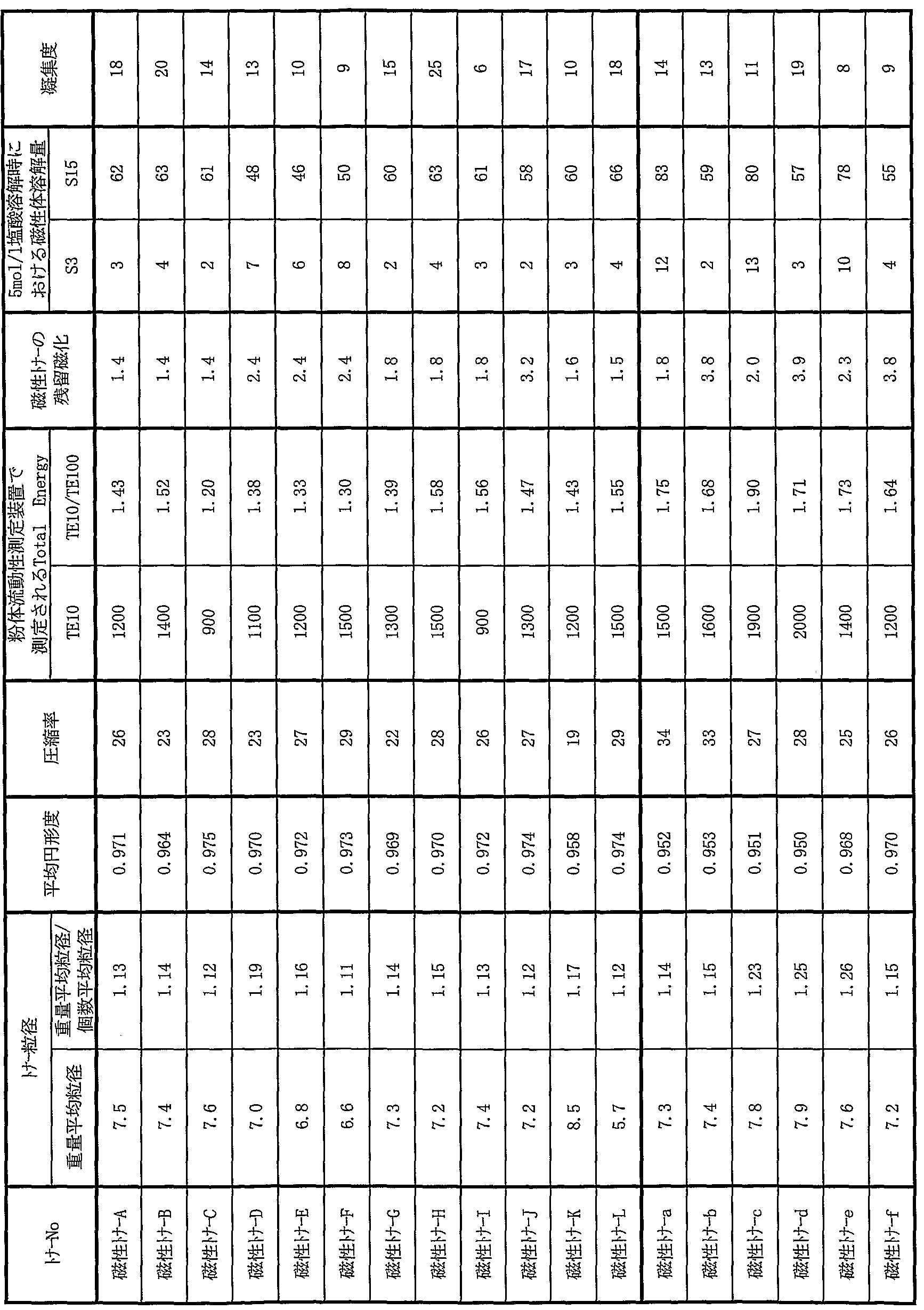
レーザービームプリンター L B P— 3 0 0 0 (キャノン製) のカートリ ッジ において、 現像装置の現像スリ一ブの径及び現像極での磁束密度を表 1 0に示 すように改造したカートリッジ 1乃至 5を作製した。
[トナー担持体の製造方法]
下記に示す配合比にて現像スリーブ表面に設ける樹脂被覆層の塗工液の作製 を行った。
• レゾール型フェノール樹脂 (ァンモニァ触媒使用、 メタノール 4 0 %含有、 大日本インキ化学工業社製、 商品名 ·· J 3 2 5 ) 3 5 0部
•結晶性グラフアイト (体積平均粒径: 5 . 5 μ m) 9 0部 ·導電性カーボンブラック (コロンビアカーボン社製、 商品名 : C o n d u c t e x 9 7 5 ) 1 0部
•導電性球状粒子 (日本カーボン社製、 商品名 :二力ビーズ P C 1 0 2 0 )
3 0部
•ィソプロピルアルコーノレ 3 0 0部 上記材料を、 ガラスビーズを用いてサンドミルにて分散した。 分散方法とし ては、上記レゾール型フエノール樹脂溶液に、上記の導電性カーボンブラック、 結晶性グラフアイ ト、 イソプロピルアルコール 1 0 0部、 を添加し、 直径 l m mのガラスビーズをメディァ粒子として用いたサンドミルにて 2時間分散した, ここに、 更に残りのイソプロピルアルコール及び上記導電性球状粒子を添加し、 更にサンドミル分散を 3 0分進めて塗工液を得た。
上記塗工液を用いてスプレー法により外径 8 mm、 1 O mm, 1 4 mmのァ ルミ二ゥム製円筒管上に導電性被覆層を形成させ、 続いて熱風乾燥炉により 1 6 0 °C、 3 0分間加熱して導電性被覆層を硬化させて現像剤担持体 aを作製し た。 このときの表面粗さ (算術平均粗さ) を測定したところ R a = l . 5 2 μ mであった。 (表 10)
Figure imgf000061_0001
(実施例 1 )
市販のレーザービームプリンター LB P— 3000に、 表 10のカートリ ツ ジ 1に磁性トナー Aを充填したもので下記評価を実施した。 常温常湿環境 (温 度 23°C、 湿度 50%) において、 1 500枚の通紙耐久試験を行った。 原稿 は画像比率 5%のチャートを使用した。 ここで耐久前後での画像濃度、 及び画 質 (カプリ、 尾引き、 転写中抜け) を下記基準により評価した。
(画像評価)
1. 画像濃度
初期及ぴ 1 500枚画だし後に、 印字紙全面にベタ画像部を形成し、 このべ タ画像の画像濃度をマクベス濃度計 (マクベス社製) で SP Iフィルターを使 用して測定した。
2. カプリ
カプリ測定用反射測定機 REFLECTMETER (東京電色 (株)) にて、 上記の画像の白部及び未使用紙の反射率を測定し、 両者の差をカプリとした。 カプリ (%) =未使用紙反射率一通紙後画像白部の反射率
A:カプリ 0. 3%未満
B :力ブ.リ 0. 3 %以上 1. 0 %未満
C :カプリ 1. 0 %以上 2. 0 %未満 D:カプリ 2 . 0 %以上 2 . 5 %未満
E :カプリ 2 . 5 %以上
3 . 尾引き
尾引きは、 初期及び 1 5 0 0枚画だし後に、 画像面積比率約 3 %の横線のみ からなる画像パターンを現像中にマシンを止め、 現像後の感光ドラム上の文字 部の尾引き状況を以下の基準に従い目視で判断した。
A:尾引きは未発生。
B:わずかに尾引きは発生しているものの、 良好な画像。
C:尾引きは発生しているものの、 実用的には問題のない画質。
D :尾引きが顕著に発生。
4 . 中抜け
中抜けは、 初期及び 1 5 0 0枚画だし後に、 ライン及ぴ文字を含む画像をプ リントアウトし、 目視または拡大顕微鏡を使用して、 以下の基準で評価した。
A:文字画像及ぴライン画像ともに、 細部まで忠実に再現している。
B :細部に多少の乱れまたは中抜けが生じているが、 目視では問題ないレベル である。
C: 目視でも乱れや中抜けがわかるレベルである。
D:乱れ、 中抜けが多数発生し、 原稿を再現していない。
その結果、 表 1 2に示すように良好な結果が得られた。
(実施例 2乃至 1 5 )
実施例 1において、 表 1 1に示すような組み合わせで評価を行った結果、 表 1 2に示すように良好な結果が得られた。
(比較例 1〜 8 )
実施例 1において、 表 1 1に示すような組み合わせで評価を行った結果、 表 1 2に示すような結果が得られた。 1 ) トナ No 評価用現像装置 No 実施例 1 磁性トナ- A カートリツシ" 1 実施例 2 磁性トナ- B カート!)ッシ" 1 実施例 3 磁性トナ C カートリッジ" 1 実施例 4 磁性け- D カートリツシ" 1 実施例 5 磁性トナ- E カ トリツシ'、 1 実施例 6 磁性トナ- F カートリツシ" 1 実施例 7 磁性トナ- G カートリッジ" 1 実施例 8 磁性け- H カートリツシ" 1 実施例 9 磁性トナ- 1 カ ト!)クシ" 1 実施例 10 磁性トナ- J カートリツシ" 1 実施例 11 磁性トナ- K カ トリクシ、、 1 実施例 12 磁性トナ- L カート!)クシ、' 1 実施例 13 磁性トナ- C カートリツシ" 2 実施例 14 磁性トナ- C カートリツシ" 3 実施例 15 磁性トナ C カートリツシ" 4 比較例 1 磁性トナ- a カート!)クシ" 1 比較例 2 磁性トナ- b カートリツシ " 1 比較例 3 磁性トナ- c カートリツ 1 比較例 4 磁性トナ- d カートリッジ" 1 比較例 5 磁性トナ- e カ トリツシ、、 1 比較例 6 磁性トナ- f カートリッジ" 1 比較例 7 磁性トナ- a カートリツシ" 3 比較例 8 磁性トナ- a カートリツシ'、 5 (表 12)
Figure imgf000064_0001
く磁性トナー Mの製造 > (結着樹脂の製造例) テレフタル酸 27mo 1 % アジピン酸 5 m o 1 % トリメリット酸 6 m 0 1 % 前記式 (ァ) で示されるビスフエノール誘導体 35mo 1 %
(プロピレンォキサイド 2. 5mo 1付加物)
前記式 (ァ) で示されるビスフヱノール誘導体 17 m o 1 %
(エチレンォキサイド 2· 5mo 1付加物)
上記に示すポリエステルモノマー及びエステル化触媒を 4つ口フラスコに仕 込み、 減圧装置、 水分離装置、 窒素ガス導入装置、 温度測定装置及び撹拌装置 を装着し、 窒素雰囲気下にて 230°Cに昇温して反応を行った。 反応終了後、 生成物を容器から取り出し、 冷却、 粉碎し、 軟ィ匕点 143°Cの樹脂 Aを得た。 次に、
I 24 m o 1 %
16 m o 1 % トリメ リ ッ ト酸 10 m o 1 % 前記式 (ァ) で示されるビスフヱノール誘導体 30 m o 1 %
(プロピレンォキサイド 2. 5 m o 1付加物)
前記式 (ァ) で示されるビスフエノール誘導体 20 m o 1 %
(エチレンォキサイド 2. 5 mo 1付加物)
上記に示すポリエステルモノマー及ぴエステル化触媒を 4口フラスコに仕込 み、 減圧装置、 水分離装置、 窒素ガス導入装置、 温度測定装置及び撹拌装置を 装着し、 窒素雰囲気下にて 230°Cに昇温して反応を行った。 反応終了後、 生 成物を容器から取り出し、 冷却、 粉砕し、 軟ィ匕点 98 °Cの榭脂 Bを得た。
樹脂 A及び Bのそれぞれ 50部をヘンシェルミキサーで混合し、 結着樹脂 1 とした。
この結着樹脂 1のガラス転移温度は 59 °C、 軟ィヒ点は 128°C、 ゲルパーミ エーションクロマトグラフィーにおける分子量 1万以下の成分を 4 3 %含有す るものであった。
•結着樹脂 1
•磁性体 1
•モノァゾ鉄錯体 (T一 7 7 ··保土ケ谷化学社製)
•ポリエチレンワックス (融点 1 0 5。C)
(サゾール社製、 C 1 0 5 )
上記混合物をヘンシェルミキサーで前混合した後、 1 1 0 °Cに加熱された 2 軸ェクストルーダで溶融混練し、 冷却した混練物をハンマーミルで粗粉枠して トナー粗粉砕物を得た。 得られた粗粉枠物を、 機械式粉碎機ターボミル (ター ボ工業社製;回転子および固定子の表面に炭化クロムを含有したクロム合金め つきでコーティング (めっき厚 1 5 0 μ πι、 表面硬さ HV 1 0 5 0 ) を用いて 機械式粉碎させて微粉碎し、 得られた微粉碎物をコアンダ効果を利用した多分 割分級装置 (日鉄鉱業社製エルポジェット分級機) で微粉及び粗粉を同時に分 級除去した。 そこで得られたトナー粒子の重量平均粒径 (D4) は 7 . で あった。
その原科トナー粒子を、 熱風を吹き付けることにより トナー粒子の表面改質 を行う装置であるメテオレインボー MR— 3型 (日本-ユーマチック工業社製) で表面改質を行った。 表面改質時の条件は、 原料供給速度 2 k g / h r、 熱風 流量 7 0 0 1 Zm i n、 吐出熱風温度 2 5 0 °Cで行った。
この磁性トナー粒子 1 0 0部と、 へキサメチルジシラザン処理した後シリコ ーンオイルで処理した、 処理後の B E T比表面積が 1 6 0 2/ gの疎水性シリ カ微粉体 1 · 0部、 及び表 1 3に示す外添剤 2及び 4とをヘンシェルミキサー (三井三池化工機 (株)) で混合して磁性トナー Mを調製した。 この磁性トナー Mの物性を表 1 4に示す。
<磁性トナー Nの製造 > 磁性トナー Mの製造例において、 メテオレインボー MR— 3型 (日本ニュー マチック工業社製) で表面改質を行う条件を、 原料供給速度 2 k g Z h r、 熱 風流量 5 0 0リツトル Zm i n、 吐出熱風温度 2 0 0 °Cで行った以外は同様に 行い、 磁性トナー Nを得た。 磁性トナー Nの物性を表 1 4に示す。
<磁性トナー 0、 Pの製造〉
磁性トナー Mの製造例において、 表 1 3に示す通りに磁性酸化鉄及び外添剤 を変更した以外は上記磁性トナー Aの製造と同様にして、 磁性トナー O及ぴ P を得た。 磁性トナー O及び Pの物性を表 1 4に示す。
<比較用磁性トナー gの製造〉
磁性トナー Mの製造例において、 表 1 3に示す通りに外添剤を変更した以外 は上記磁性トナー Mの製造と同様にして、 磁性トナー gを得た。 磁性トナー g の物性を表 1 4に示す。
く比較用磁性トナー h、 iの製造〉
磁性トナー Mの製造例において、 メテオレインポー MR— 3型 (日本ニュー マチック工業社製) での表面改質を行わず、 更に表 1 3に示す通りに磁性体及 び外添剤を変更した以外は上記磁性トナー Mの製造と同様にして、 磁性トナー h及び iを得た。 磁性トナー h及び iの物性を表 1 4に示す。
(実施例 1 5 )
市販のレーザービームプリンター L B P— 3 0 0 0に、 カートリッジ 1に磁 性トナー Aを充填したもので下記評価を実施した。常温常湿環境(温度 2 3 °C, 湿度 5 0 %) 及び高温高湿環境 (温度 3 0 °C、 湿度 8 0 %) において、 1 0 0 0枚の通紙耐久試験を行つた。 原稿は画像比率 5 %のチャートを使用した。 こ こで耐久前後での画像濃度、 及び画質 (カプリ、 尾引き、 転写中抜け) を実施 例 1と同様にして評価した。
(実施例 1 6〜1 9 )
実施例 1 5において、 表 1 5に示すような組み合わせで評価を行った結果、 表 1 6に示すように良好な結果が得られた。
〔比較例 9〜 1 3〕
実施例 1 5において、 表 1 5に示すような組み合わせで評価を行った結果、 表 1 6に示すような結果が得られた。
(表 1 3 )
Figure imgf000068_0001
(表 1 4 )
Figure imgf000069_0001
(表 15)
Figure imgf000070_0001
(表 16)
Figure imgf000071_0001
この出願は 2 0 0 7年 6月 8日に出願された日本国特許出願第 2 0 0 7 - 1 5 2 2 2 1号からの優先権を主張するものであり、 その内容を引用してこの出 願の一部とするものである。

Claims

請 求 の 範 囲
1. 潜像担持体と、 磁性トナーを表面に担持し内部に磁界発生手段を有する トナー担持体とが一定の間隔を設けて配置されており、 該潜像担持体と該トナ —担持体との間に交番電界を印加して磁性トナーで該潜像担持体に担持される 静電潜像の現像を行う画像形成方法であって、
該トナー担持体の外径が 5. 0 mm以上 12. 0 mm未満であり、
該磁性トナーは、 少なくとも結着樹脂及び磁性粉体を含有する磁性トナー粒子 と無機微粉体とを含んでおり、
該磁性トナーは、 平均円形度が 0. 950以上であり、 下記式 (1) から得ら れる圧縮率が 30以下であり、
圧縮率 = { 1― (見掛け密度 Zタップ密度) } X 100 ( 1 ) 該トナーの粉体流動性測定装置において測定された T o t a 1 En e r g y が下記式 (2) 及び (3) を満足することを特徴とする画像形成方法。
600≤TE10≤ 1 500 (2)
TE10/TE100≤1. 60 (3)
(TEi。:撹拌速度が 1 Omm/s e cの時の T o t a 1 En e r g y (m J) ΤΕ。。:撹拌速度が 10 Omm/ s e cの時の T o t a 1 En e r g y (m J))
2. 該トナー担持体に内包される磁界発生手段の潜像担持体方向八の磁束密 度がトナー担持体表面において 600G以上 800G以下であることを特徴と する請求項 1に記載の画像形成方法。
3 · 該磁性トナーの重量平均粒径 (D 4) 1 4. 0 IX m以上 9. 0 m以 下であることを特徵とする請求項 1又は 2に記載の画像形成方法。
4. 該磁性トナーの磁場 79. 6 kA/mで着磁したときの残留磁化が 3.
0 Am2/k g以下であることを特徴とする請求項 1乃至 3のいずれか 1項に 記載の画像形成方法。
5. 5mo 1 1塩酸中に磁性トナーを分散させた際における、 抽出時間 3 分、 15分時点での磁性体総含有量に対する磁性体抽出量 S 3、 S15 (質量%) が下記式 (4) 及び (5) を満足することを特徴とする請求項 1乃至 4のいず れか 1項に記載の画像形成方法。
0. 5≤ S 3≤ 10 (4)
40≤S 15≤ 80 (5)
6. 該磁性トナー粒子が水系媒体中で製造されたことを特徴とする請求項 1 乃至 5のいずれか 1項に記載の画像形成方法。
7. 該磁性トナーは、 該磁性トナー粒子が懸濁重合法で製造されたことを特 徴とする請求項 6に記載の画像形成方法。
8. 該磁性トナー粒子はさらに離型剤を含有しており、
該磁性トナーは、 メタノール/水混合溶媒に対する濡れ性試験において、 波長 780 n mの光の透過率が 50 %時のメタノール濃度が 60体積0 /0以上 80体 積%以下であることを特徴とする請求項 1乃至 5のいずれか 1項に記載の画像 形成方法。
9. 該磁性トナ一は、 該磁性トナー粒子が熱処理による表面改質工程を含む 粉碎法により製造されたことを特徴とする請求項 8に記載の画像形成方法。
10. 潜像担持体と、 磁性トナーを表面に担持し内部に磁界発生手段を有す るトナー担持体とが一定の間隔を設けて配置されており、 該潜像担持体と該ト ナー担持体との間に交番電界を印加して磁性トナーで該潜像担持体に担持され る静電潜像の現像を行う画像形成方法に用レ、られる磁性トナーであつて、 該トナー担持体の外径が 5. 0 mm以上 1 2. 0 mm未満であり、
該磁性トナーは、 少なくとも結着樹脂及び磁性粉体を含有する磁性トナー粒子 と無機微粉体とを含んでおり、
該磁性トナーは、 平均円形度が 0. 950以上であり、 下記式 (1) から得ら れる圧縮率が 30以下であり、
圧縮率 = { 1一 (見掛け密度/タップ密度) } X 100 ( 1 )
該トナーの粉体流動性測定装置において測定された T o t a 1 En e r g y が下記式 (2) 及び (3) を満足することを特徴とする磁性トナー。
600≤TE10≤ 1 500 (2)
TE10/TE100≤ 1. 60 (3)
(TEi。:撹拌速度が 1 Omm/ s e cの時の T o t a l En e r g y (m J)、 TE100:撹拌速度が 100 mm/ s e cの時の T o t a l En e r g y (m J))
1 1. 潜像担持体と、 磁性トナーを表面に担持し内部に磁界発生手段を有す るトナー担持体とが一定の間隔を設けて配置されており、 該潜像担持体と該ト ナー担持体との間に交番電界を印加して磁性トナーで該潜像担持体に担持され る静電潜像の現像を行うプロセスュニットであって、
該トナー担持体の外径が 5. 0 mm以上 12. 0 mm未満であり、
該磁性トナーは、 少なくとも結着樹脂及ぴ磁性粉体を含有する磁性トナー粒子 と無機微粉体とを含んでおり、
該磁性トナ一は、 平均円形度が 0. 950以上であり、 下記式 ( 1 ) から得ら れる圧縮率が 30以下であり、
圧縮率 = { 1一 (見掛け密度ノタップ密度) } 100 ( 1 )
該トナーの粉体流動性測定装置において測定された T o t a l En e r g y が下記式 (2) 及ぴ (3) を満足することを特徴とするプロセスユニット。
600≤TEl0≤ 1 500 (2)
TE10/TE100≤ 1. 60 (3)
(TEi。:撹拌速度が 1 Omm/s e cの時の To t a 1 En e r g y (mj), TE :撹拌速度が 1 0 OmmZ s e cの時の T o t a 1 En e r g y (m J))
PCT/JP2008/060814 2007-06-08 2008-06-06 画像形成方法、磁性トナー及びプロセスユニット WO2008150034A1 (ja)

Priority Applications (5)

Application Number Priority Date Filing Date Title
CN2008800031055A CN101589345B (zh) 2007-06-08 2008-06-06 图像形成方法、磁性调色剂及处理单元
JP2009517934A JP4771558B2 (ja) 2007-06-08 2008-06-06 画像形成方法、磁性トナー及びプロセスユニット
KR1020097016249A KR101238502B1 (ko) 2007-06-08 2008-06-06 화상 형성 방법, 자성 토너 및 프로세스 유닛
EP08765555A EP2071406B1 (en) 2007-06-08 2008-06-06 Image forming method and process unit
US12/254,393 US8841054B2 (en) 2007-06-08 2008-10-20 Image-forming method, magnetic toner, and process unit

Applications Claiming Priority (2)

Application Number Priority Date Filing Date Title
JP2007152221 2007-06-08
JP2007-152221 2007-06-08

Related Child Applications (1)

Application Number Title Priority Date Filing Date
US12/254,393 Continuation US8841054B2 (en) 2007-06-08 2008-10-20 Image-forming method, magnetic toner, and process unit

Publications (1)

Publication Number Publication Date
WO2008150034A1 true WO2008150034A1 (ja) 2008-12-11

Family

ID=40093830

Family Applications (1)

Application Number Title Priority Date Filing Date
PCT/JP2008/060814 WO2008150034A1 (ja) 2007-06-08 2008-06-06 画像形成方法、磁性トナー及びプロセスユニット

Country Status (6)

Country Link
US (1) US8841054B2 (ja)
EP (1) EP2071406B1 (ja)
JP (1) JP4771558B2 (ja)
KR (1) KR101238502B1 (ja)
CN (1) CN101589345B (ja)
WO (1) WO2008150034A1 (ja)

Cited By (5)

* Cited by examiner, † Cited by third party
Publication number Priority date Publication date Assignee Title
JP2009020231A (ja) * 2007-07-11 2009-01-29 Canon Inc トナー
JP2009036977A (ja) * 2007-08-01 2009-02-19 Canon Inc 現像方法、現像装置及び該現像方法に用いられる現像剤担持体
JP2010160375A (ja) * 2009-01-09 2010-07-22 Canon Inc トナー、画像形成装置及び現像方法
JP2011047989A (ja) * 2009-08-25 2011-03-10 Canon Inc 磁性トナー
JP2011047988A (ja) * 2009-08-25 2011-03-10 Canon Inc トナー

Families Citing this family (46)

* Cited by examiner, † Cited by third party
Publication number Priority date Publication date Assignee Title
JP5284049B2 (ja) * 2007-11-21 2013-09-11 キヤノン株式会社 磁性トナー
JP5473725B2 (ja) * 2009-04-15 2014-04-16 キヤノン株式会社 磁性トナー
JP5630192B2 (ja) * 2009-11-04 2014-11-26 コニカミノルタ株式会社 トナーの製造方法
RU2506620C1 (ru) * 2010-05-31 2014-02-10 Кэнон Кабусики Кайся Магнитный тонер
US8426094B2 (en) 2010-05-31 2013-04-23 Canon Kabushiki Kaisha Magnetic toner
US8544351B2 (en) * 2010-06-02 2013-10-01 Xerox Corporation Method and apparatus for characterizing the flowability of toner particles
US8614044B2 (en) 2010-06-16 2013-12-24 Canon Kabushiki Kaisha Toner
US9551947B2 (en) 2010-08-23 2017-01-24 Canon Kabushiki Kaisha Toner
US8778585B2 (en) 2010-09-16 2014-07-15 Canon Kabushiki Kaisha Toner
JP5569292B2 (ja) * 2010-09-21 2014-08-13 富士ゼロックス株式会社 静電荷像現像用トナー、静電荷像現像用トナーの製造方法、現像剤、及び、画像形成方法
JP5868165B2 (ja) * 2011-12-27 2016-02-24 キヤノン株式会社 現像装置及び現像方法
JP5442046B2 (ja) * 2012-02-01 2014-03-12 キヤノン株式会社 磁性トナー
WO2013146200A1 (ja) * 2012-03-29 2013-10-03 三菱化学株式会社 静電荷像現像用トナー及びそれを収容するトナーカートリッジ
US9575425B2 (en) * 2013-07-31 2017-02-21 Canon Kabushiki Kaisha Toner
US20150037720A1 (en) * 2013-07-31 2015-02-05 Canon Kabushiki Kaisha Magnetic toner
US9575461B2 (en) * 2014-08-07 2017-02-21 Canon Kabushiki Kaisha Process cartridge and image forming method using toner having properties for high image quality
US9804519B2 (en) 2015-12-04 2017-10-31 Canon Kabushiki Kaisha Method for producing toner
JP6762706B2 (ja) 2015-12-04 2020-09-30 キヤノン株式会社 トナー
DE102016116610B4 (de) 2015-12-04 2021-05-20 Canon Kabushiki Kaisha Toner
JP6768423B2 (ja) 2015-12-04 2020-10-14 キヤノン株式会社 トナーの製造方法
JP6991701B2 (ja) 2015-12-04 2022-01-12 キヤノン株式会社 トナー
US10228627B2 (en) 2015-12-04 2019-03-12 Canon Kabushiki Kaisha Toner
JP6910805B2 (ja) 2016-01-28 2021-07-28 キヤノン株式会社 トナー、画像形成装置及び画像形成方法
JP6859141B2 (ja) 2016-03-24 2021-04-14 キヤノン株式会社 トナー粒子の製造方法
JP6873796B2 (ja) 2016-04-21 2021-05-19 キヤノン株式会社 トナー
JP6878133B2 (ja) 2016-05-20 2021-05-26 キヤノン株式会社 トナー
US9946181B2 (en) 2016-05-20 2018-04-17 Canon Kabushiki Kaisha Toner
JP6904801B2 (ja) * 2016-06-30 2021-07-21 キヤノン株式会社 トナー、該トナーを備えた現像装置及び画像形成装置
JP6869819B2 (ja) 2016-06-30 2021-05-12 キヤノン株式会社 トナー、現像装置及び画像形成装置
JP6891051B2 (ja) 2016-06-30 2021-06-18 キヤノン株式会社 トナー、現像装置、及び画像形成装置
US10241430B2 (en) 2017-05-10 2019-03-26 Canon Kabushiki Kaisha Toner, and external additive for toner
US10545420B2 (en) 2017-07-04 2020-01-28 Canon Kabushiki Kaisha Magnetic toner and image-forming method
CN107340697B (zh) * 2017-09-18 2021-01-12 太仓市鑫鹤印刷包装有限公司 一种印刷用环保彩色墨粉
CN110597030B (zh) 2018-06-13 2023-10-24 佳能株式会社 调色剂和双组分显影剂
EP3582014B1 (en) 2018-06-13 2023-08-30 Canon Kabushiki Kaisha Toner and toner manufacturing method
CN110597027B (zh) 2018-06-13 2023-10-20 佳能株式会社 调色剂和调色剂的生产方法
EP3582018B1 (en) 2018-06-13 2024-03-27 Canon Kabushiki Kaisha Positive-charging toner
CN110597032B (zh) 2018-06-13 2024-03-19 佳能株式会社 调色剂
US10656545B2 (en) 2018-06-13 2020-05-19 Canon Kabushiki Kaisha Toner and method for producing toner
EP3582019B1 (en) 2018-06-13 2023-09-06 Canon Kabushiki Kaisha Magnetic toner and method for manufacturing magnetic toner
US10877388B2 (en) 2018-06-13 2020-12-29 Canon Kabushiki Kaisha Toner
EP3582023B1 (en) 2018-06-13 2023-09-06 Canon Kabushiki Kaisha Two-component developer
JP7467219B2 (ja) 2019-05-14 2024-04-15 キヤノン株式会社 トナー
JP7292978B2 (ja) 2019-05-28 2023-06-19 キヤノン株式会社 トナーおよびトナーの製造方法
JP7463086B2 (ja) 2019-12-12 2024-04-08 キヤノン株式会社 トナー
JP2022022127A (ja) 2020-07-22 2022-02-03 キヤノン株式会社 トナー

Citations (11)

* Cited by examiner, † Cited by third party
Publication number Priority date Publication date Assignee Title
JPH0980913A (ja) * 1995-09-11 1997-03-28 Fuji Xerox Co Ltd 画像形成方法
JP2000181128A (ja) 1998-12-17 2000-06-30 Matsushita Electric Ind Co Ltd トナー
JP2001356516A (ja) 2000-06-16 2001-12-26 Minolta Co Ltd 一成分現像用トナー
JP2002091142A (ja) * 2000-09-13 2002-03-27 Canon Inc 現像装置、画像形成方法、及び画像形成用一成分系現像剤
JP2002116576A (ja) * 2000-10-06 2002-04-19 Fuji Xerox Co Ltd 画像形成方法
JP2002278129A (ja) * 2001-03-21 2002-09-27 Canon Inc 画像形成用トナー、画像形成方法及びプロセスカートリッジ
JP2003043738A (ja) 2001-07-30 2003-02-14 Canon Inc 磁性トナー
JP2005049861A (ja) * 2003-07-16 2005-02-24 Canon Inc 静電荷現像用一成分磁性トナー、プロセスカートリッジ、及びプロセスカートリッジの再生産方法
JP2005091437A (ja) * 2003-09-12 2005-04-07 Canon Inc 磁性トナー
JP2007079116A (ja) * 2005-09-14 2007-03-29 Canon Inc トナー、画像形成方法及びプロセスカートリッジ
JP2007152221A (ja) 2005-12-05 2007-06-21 Andes Denki Kk 光触媒材料およびその製造方法

Family Cites Families (20)

* Cited by examiner, † Cited by third party
Publication number Priority date Publication date Assignee Title
DE69322138T2 (de) * 1992-07-29 1999-05-20 Matsushita Electric Ind Co Ltd Elektrophotographischer magnetischer Toner zur Entwicklung eines Bildes und Verfahren zur dessen Herstellung
JP3155835B2 (ja) 1992-09-30 2001-04-16 キヤノン株式会社 画像形成方法及び装置ユニット
JPH07120968A (ja) * 1993-10-27 1995-05-12 Matsushita Electric Ind Co Ltd 磁性トナーおよび画像形成方法
DE69832221T2 (de) * 1997-02-20 2006-07-13 Sharp K.K. Herstellungsverfahren eines elektrophotographischen Toners
US5978634A (en) * 1997-08-21 1999-11-02 Konica Corporation Development method, development device, and image forming apparatus therewith
JP4227309B2 (ja) * 2001-03-21 2009-02-18 キヤノン株式会社 磁性トナー
JP4047137B2 (ja) * 2002-11-08 2008-02-13 キヤノン株式会社 現像装置及びプロセスカートリッジ
JP4018520B2 (ja) * 2002-12-04 2007-12-05 キヤノン株式会社 トナーの製造方法
JP4215492B2 (ja) * 2002-12-10 2009-01-28 株式会社リコー 中間転写体及び画像形成装置
JP3987794B2 (ja) * 2002-12-27 2007-10-10 株式会社リコー 電子写真用トナーとその画像形成装置及び画像形成方法
JP2004301867A (ja) * 2003-03-28 2004-10-28 Canon Inc 画像形成装置
US7323279B2 (en) 2003-07-16 2008-01-29 Canon Kabushiki Kaisha One-component magnetic toner for developing an electrostatic charge image, process cartridge, and method for recycling the process cartridge
US7452649B2 (en) 2003-09-12 2008-11-18 Canon Kabushiki Kaisha Magnetic toner, and image forming method
JP2005331821A (ja) * 2004-05-21 2005-12-02 Canon Inc 磁性トナー
JP4324120B2 (ja) * 2005-02-18 2009-09-02 キヤノン株式会社 磁性トナー
JP4455448B2 (ja) * 2005-04-22 2010-04-21 キヤノン株式会社 磁性トナー
JP2007079117A (ja) * 2005-09-14 2007-03-29 Canon Inc 磁性トナー、画像形成方法およびプロセスカートリッジ
JP5132094B2 (ja) * 2005-09-14 2013-01-30 キヤノン株式会社 画像形成方法及びプロセスカートリッジ
US20070065742A1 (en) * 2005-09-21 2007-03-22 Fuji Xerox Co., Ltd. Single-component magnetic developer, developing method and image-forming method
JP4974511B2 (ja) 2005-11-15 2012-07-11 株式会社沖データ 現像装置及び画像形成装置

Patent Citations (11)

* Cited by examiner, † Cited by third party
Publication number Priority date Publication date Assignee Title
JPH0980913A (ja) * 1995-09-11 1997-03-28 Fuji Xerox Co Ltd 画像形成方法
JP2000181128A (ja) 1998-12-17 2000-06-30 Matsushita Electric Ind Co Ltd トナー
JP2001356516A (ja) 2000-06-16 2001-12-26 Minolta Co Ltd 一成分現像用トナー
JP2002091142A (ja) * 2000-09-13 2002-03-27 Canon Inc 現像装置、画像形成方法、及び画像形成用一成分系現像剤
JP2002116576A (ja) * 2000-10-06 2002-04-19 Fuji Xerox Co Ltd 画像形成方法
JP2002278129A (ja) * 2001-03-21 2002-09-27 Canon Inc 画像形成用トナー、画像形成方法及びプロセスカートリッジ
JP2003043738A (ja) 2001-07-30 2003-02-14 Canon Inc 磁性トナー
JP2005049861A (ja) * 2003-07-16 2005-02-24 Canon Inc 静電荷現像用一成分磁性トナー、プロセスカートリッジ、及びプロセスカートリッジの再生産方法
JP2005091437A (ja) * 2003-09-12 2005-04-07 Canon Inc 磁性トナー
JP2007079116A (ja) * 2005-09-14 2007-03-29 Canon Inc トナー、画像形成方法及びプロセスカートリッジ
JP2007152221A (ja) 2005-12-05 2007-06-21 Andes Denki Kk 光触媒材料およびその製造方法

Non-Patent Citations (1)

* Cited by examiner, † Cited by third party
Title
See also references of EP2071406A4 *

Cited By (5)

* Cited by examiner, † Cited by third party
Publication number Priority date Publication date Assignee Title
JP2009020231A (ja) * 2007-07-11 2009-01-29 Canon Inc トナー
JP2009036977A (ja) * 2007-08-01 2009-02-19 Canon Inc 現像方法、現像装置及び該現像方法に用いられる現像剤担持体
JP2010160375A (ja) * 2009-01-09 2010-07-22 Canon Inc トナー、画像形成装置及び現像方法
JP2011047989A (ja) * 2009-08-25 2011-03-10 Canon Inc 磁性トナー
JP2011047988A (ja) * 2009-08-25 2011-03-10 Canon Inc トナー

Also Published As

Publication number Publication date
US8841054B2 (en) 2014-09-23
CN101589345B (zh) 2012-07-18
EP2071406A1 (en) 2009-06-17
KR101238502B1 (ko) 2013-03-04
KR20090096548A (ko) 2009-09-10
CN101589345A (zh) 2009-11-25
US20090047043A1 (en) 2009-02-19
JPWO2008150034A1 (ja) 2010-08-26
EP2071406A4 (en) 2012-05-16
JP4771558B2 (ja) 2011-09-14
EP2071406B1 (en) 2013-04-03

Similar Documents

Publication Publication Date Title
WO2008150034A1 (ja) 画像形成方法、磁性トナー及びプロセスユニット
JP6910805B2 (ja) トナー、画像形成装置及び画像形成方法
JP4510927B2 (ja) 磁性トナー
JP5284049B2 (ja) 磁性トナー
JP4324120B2 (ja) 磁性トナー
WO2008150028A1 (ja) 磁性トナー
WO2007116537A1 (ja) 現像方法及び現像装置
JP4819646B2 (ja) 非磁性トナー
JP4560462B2 (ja) トナー
JP5230296B2 (ja) 画像形成方法及びプロセスカートリッジ
JP3977159B2 (ja) 磁性トナー
JP2008304747A (ja) トナー
JP2008096827A (ja) 現像装置、プロセスカートリッジ及び画像形成装置
JP4401904B2 (ja) 静電荷現像用トナー及び画像形成方法
JP4086487B2 (ja) 磁性トナー及び画像形成装置
JPH0772654A (ja) 磁性トナー、磁性現像剤及び画像形成方法
JP2001265058A (ja) トナー粒子の製造方法、磁性トナー及び画像形成方法
JP5339778B2 (ja) 画像形成方法および定着方法
JP5451062B2 (ja) トナー粒子の製造方法
JP2009288394A (ja) 画像形成方法、定着方法及び磁性トナー
JP6896545B2 (ja) トナー
JP4072384B2 (ja) 磁性トナー、該トナーを用いた画像形成方法及びプロセスカートリッジ
JP4165822B2 (ja) フルカラートナーキット、プロセスカートリッジ、画像形成方法及び画像形成装置
JP4298614B2 (ja) 磁性トナー
JP2009109827A (ja) 磁性トナー

Legal Events

Date Code Title Description
WWE Wipo information: entry into national phase

Ref document number: 200880003105.5

Country of ref document: CN

121 Ep: the epo has been informed by wipo that ep was designated in this application

Ref document number: 08765555

Country of ref document: EP

Kind code of ref document: A1

WWE Wipo information: entry into national phase

Ref document number: 2008765555

Country of ref document: EP

WWE Wipo information: entry into national phase

Ref document number: 2009517934

Country of ref document: JP

WWE Wipo information: entry into national phase

Ref document number: 1020097016249

Country of ref document: KR

NENP Non-entry into the national phase

Ref country code: DE