WO2007129657A1 - 内燃機関装置および内燃機関の失火判定方法 - Google Patents
内燃機関装置および内燃機関の失火判定方法 Download PDFInfo
- Publication number
- WO2007129657A1 WO2007129657A1 PCT/JP2007/059370 JP2007059370W WO2007129657A1 WO 2007129657 A1 WO2007129657 A1 WO 2007129657A1 JP 2007059370 W JP2007059370 W JP 2007059370W WO 2007129657 A1 WO2007129657 A1 WO 2007129657A1
- Authority
- WO
- WIPO (PCT)
- Prior art keywords
- internal combustion
- combustion engine
- rotation
- fluctuation
- rotational
- Prior art date
Links
Classifications
-
- F—MECHANICAL ENGINEERING; LIGHTING; HEATING; WEAPONS; BLASTING
- F02—COMBUSTION ENGINES; HOT-GAS OR COMBUSTION-PRODUCT ENGINE PLANTS
- F02D—CONTROLLING COMBUSTION ENGINES
- F02D45/00—Electrical control not provided for in groups F02D41/00 - F02D43/00
-
- F—MECHANICAL ENGINEERING; LIGHTING; HEATING; WEAPONS; BLASTING
- F02—COMBUSTION ENGINES; HOT-GAS OR COMBUSTION-PRODUCT ENGINE PLANTS
- F02D—CONTROLLING COMBUSTION ENGINES
- F02D41/00—Electrical control of supply of combustible mixture or its constituents
- F02D41/02—Circuit arrangements for generating control signals
- F02D41/14—Introducing closed-loop corrections
- F02D41/1497—With detection of the mechanical response of the engine
-
- B—PERFORMING OPERATIONS; TRANSPORTING
- B60—VEHICLES IN GENERAL
- B60K—ARRANGEMENT OR MOUNTING OF PROPULSION UNITS OR OF TRANSMISSIONS IN VEHICLES; ARRANGEMENT OR MOUNTING OF PLURAL DIVERSE PRIME-MOVERS IN VEHICLES; AUXILIARY DRIVES FOR VEHICLES; INSTRUMENTATION OR DASHBOARDS FOR VEHICLES; ARRANGEMENTS IN CONNECTION WITH COOLING, AIR INTAKE, GAS EXHAUST OR FUEL SUPPLY OF PROPULSION UNITS IN VEHICLES
- B60K6/00—Arrangement or mounting of plural diverse prime-movers for mutual or common propulsion, e.g. hybrid propulsion systems comprising electric motors and internal combustion engines ; Control systems therefor, i.e. systems controlling two or more prime movers, or controlling one of these prime movers and any of the transmission, drive or drive units Informative references: mechanical gearings with secondary electric drive F16H3/72; arrangements for handling mechanical energy structurally associated with the dynamo-electric machine H02K7/00; machines comprising structurally interrelated motor and generator parts H02K51/00; dynamo-electric machines not otherwise provided for in H02K see H02K99/00
- B60K6/20—Arrangement or mounting of plural diverse prime-movers for mutual or common propulsion, e.g. hybrid propulsion systems comprising electric motors and internal combustion engines ; Control systems therefor, i.e. systems controlling two or more prime movers, or controlling one of these prime movers and any of the transmission, drive or drive units Informative references: mechanical gearings with secondary electric drive F16H3/72; arrangements for handling mechanical energy structurally associated with the dynamo-electric machine H02K7/00; machines comprising structurally interrelated motor and generator parts H02K51/00; dynamo-electric machines not otherwise provided for in H02K see H02K99/00 the prime-movers consisting of electric motors and internal combustion engines, e.g. HEVs
- B60K6/22—Arrangement or mounting of plural diverse prime-movers for mutual or common propulsion, e.g. hybrid propulsion systems comprising electric motors and internal combustion engines ; Control systems therefor, i.e. systems controlling two or more prime movers, or controlling one of these prime movers and any of the transmission, drive or drive units Informative references: mechanical gearings with secondary electric drive F16H3/72; arrangements for handling mechanical energy structurally associated with the dynamo-electric machine H02K7/00; machines comprising structurally interrelated motor and generator parts H02K51/00; dynamo-electric machines not otherwise provided for in H02K see H02K99/00 the prime-movers consisting of electric motors and internal combustion engines, e.g. HEVs characterised by apparatus, components or means specially adapted for HEVs
- B60K6/24—Arrangement or mounting of plural diverse prime-movers for mutual or common propulsion, e.g. hybrid propulsion systems comprising electric motors and internal combustion engines ; Control systems therefor, i.e. systems controlling two or more prime movers, or controlling one of these prime movers and any of the transmission, drive or drive units Informative references: mechanical gearings with secondary electric drive F16H3/72; arrangements for handling mechanical energy structurally associated with the dynamo-electric machine H02K7/00; machines comprising structurally interrelated motor and generator parts H02K51/00; dynamo-electric machines not otherwise provided for in H02K see H02K99/00 the prime-movers consisting of electric motors and internal combustion engines, e.g. HEVs characterised by apparatus, components or means specially adapted for HEVs characterised by the combustion engines
-
- B—PERFORMING OPERATIONS; TRANSPORTING
- B60—VEHICLES IN GENERAL
- B60K—ARRANGEMENT OR MOUNTING OF PROPULSION UNITS OR OF TRANSMISSIONS IN VEHICLES; ARRANGEMENT OR MOUNTING OF PLURAL DIVERSE PRIME-MOVERS IN VEHICLES; AUXILIARY DRIVES FOR VEHICLES; INSTRUMENTATION OR DASHBOARDS FOR VEHICLES; ARRANGEMENTS IN CONNECTION WITH COOLING, AIR INTAKE, GAS EXHAUST OR FUEL SUPPLY OF PROPULSION UNITS IN VEHICLES
- B60K6/00—Arrangement or mounting of plural diverse prime-movers for mutual or common propulsion, e.g. hybrid propulsion systems comprising electric motors and internal combustion engines ; Control systems therefor, i.e. systems controlling two or more prime movers, or controlling one of these prime movers and any of the transmission, drive or drive units Informative references: mechanical gearings with secondary electric drive F16H3/72; arrangements for handling mechanical energy structurally associated with the dynamo-electric machine H02K7/00; machines comprising structurally interrelated motor and generator parts H02K51/00; dynamo-electric machines not otherwise provided for in H02K see H02K99/00
- B60K6/20—Arrangement or mounting of plural diverse prime-movers for mutual or common propulsion, e.g. hybrid propulsion systems comprising electric motors and internal combustion engines ; Control systems therefor, i.e. systems controlling two or more prime movers, or controlling one of these prime movers and any of the transmission, drive or drive units Informative references: mechanical gearings with secondary electric drive F16H3/72; arrangements for handling mechanical energy structurally associated with the dynamo-electric machine H02K7/00; machines comprising structurally interrelated motor and generator parts H02K51/00; dynamo-electric machines not otherwise provided for in H02K see H02K99/00 the prime-movers consisting of electric motors and internal combustion engines, e.g. HEVs
- B60K6/42—Arrangement or mounting of plural diverse prime-movers for mutual or common propulsion, e.g. hybrid propulsion systems comprising electric motors and internal combustion engines ; Control systems therefor, i.e. systems controlling two or more prime movers, or controlling one of these prime movers and any of the transmission, drive or drive units Informative references: mechanical gearings with secondary electric drive F16H3/72; arrangements for handling mechanical energy structurally associated with the dynamo-electric machine H02K7/00; machines comprising structurally interrelated motor and generator parts H02K51/00; dynamo-electric machines not otherwise provided for in H02K see H02K99/00 the prime-movers consisting of electric motors and internal combustion engines, e.g. HEVs characterised by the architecture of the hybrid electric vehicle
- B60K6/44—Series-parallel type
- B60K6/445—Differential gearing distribution type
-
- B—PERFORMING OPERATIONS; TRANSPORTING
- B60—VEHICLES IN GENERAL
- B60K—ARRANGEMENT OR MOUNTING OF PROPULSION UNITS OR OF TRANSMISSIONS IN VEHICLES; ARRANGEMENT OR MOUNTING OF PLURAL DIVERSE PRIME-MOVERS IN VEHICLES; AUXILIARY DRIVES FOR VEHICLES; INSTRUMENTATION OR DASHBOARDS FOR VEHICLES; ARRANGEMENTS IN CONNECTION WITH COOLING, AIR INTAKE, GAS EXHAUST OR FUEL SUPPLY OF PROPULSION UNITS IN VEHICLES
- B60K6/00—Arrangement or mounting of plural diverse prime-movers for mutual or common propulsion, e.g. hybrid propulsion systems comprising electric motors and internal combustion engines ; Control systems therefor, i.e. systems controlling two or more prime movers, or controlling one of these prime movers and any of the transmission, drive or drive units Informative references: mechanical gearings with secondary electric drive F16H3/72; arrangements for handling mechanical energy structurally associated with the dynamo-electric machine H02K7/00; machines comprising structurally interrelated motor and generator parts H02K51/00; dynamo-electric machines not otherwise provided for in H02K see H02K99/00
- B60K6/20—Arrangement or mounting of plural diverse prime-movers for mutual or common propulsion, e.g. hybrid propulsion systems comprising electric motors and internal combustion engines ; Control systems therefor, i.e. systems controlling two or more prime movers, or controlling one of these prime movers and any of the transmission, drive or drive units Informative references: mechanical gearings with secondary electric drive F16H3/72; arrangements for handling mechanical energy structurally associated with the dynamo-electric machine H02K7/00; machines comprising structurally interrelated motor and generator parts H02K51/00; dynamo-electric machines not otherwise provided for in H02K see H02K99/00 the prime-movers consisting of electric motors and internal combustion engines, e.g. HEVs
- B60K6/42—Arrangement or mounting of plural diverse prime-movers for mutual or common propulsion, e.g. hybrid propulsion systems comprising electric motors and internal combustion engines ; Control systems therefor, i.e. systems controlling two or more prime movers, or controlling one of these prime movers and any of the transmission, drive or drive units Informative references: mechanical gearings with secondary electric drive F16H3/72; arrangements for handling mechanical energy structurally associated with the dynamo-electric machine H02K7/00; machines comprising structurally interrelated motor and generator parts H02K51/00; dynamo-electric machines not otherwise provided for in H02K see H02K99/00 the prime-movers consisting of electric motors and internal combustion engines, e.g. HEVs characterised by the architecture of the hybrid electric vehicle
- B60K6/44—Series-parallel type
- B60K6/448—Electrical distribution type
-
- B—PERFORMING OPERATIONS; TRANSPORTING
- B60—VEHICLES IN GENERAL
- B60L—PROPULSION OF ELECTRICALLY-PROPELLED VEHICLES; SUPPLYING ELECTRIC POWER FOR AUXILIARY EQUIPMENT OF ELECTRICALLY-PROPELLED VEHICLES; ELECTRODYNAMIC BRAKE SYSTEMS FOR VEHICLES IN GENERAL; MAGNETIC SUSPENSION OR LEVITATION FOR VEHICLES; MONITORING OPERATING VARIABLES OF ELECTRICALLY-PROPELLED VEHICLES; ELECTRIC SAFETY DEVICES FOR ELECTRICALLY-PROPELLED VEHICLES
- B60L50/00—Electric propulsion with power supplied within the vehicle
- B60L50/10—Electric propulsion with power supplied within the vehicle using propulsion power supplied by engine-driven generators, e.g. generators driven by combustion engines
- B60L50/16—Electric propulsion with power supplied within the vehicle using propulsion power supplied by engine-driven generators, e.g. generators driven by combustion engines with provision for separate direct mechanical propulsion
-
- B—PERFORMING OPERATIONS; TRANSPORTING
- B60—VEHICLES IN GENERAL
- B60L—PROPULSION OF ELECTRICALLY-PROPELLED VEHICLES; SUPPLYING ELECTRIC POWER FOR AUXILIARY EQUIPMENT OF ELECTRICALLY-PROPELLED VEHICLES; ELECTRODYNAMIC BRAKE SYSTEMS FOR VEHICLES IN GENERAL; MAGNETIC SUSPENSION OR LEVITATION FOR VEHICLES; MONITORING OPERATING VARIABLES OF ELECTRICALLY-PROPELLED VEHICLES; ELECTRIC SAFETY DEVICES FOR ELECTRICALLY-PROPELLED VEHICLES
- B60L50/00—Electric propulsion with power supplied within the vehicle
- B60L50/50—Electric propulsion with power supplied within the vehicle using propulsion power supplied by batteries or fuel cells
- B60L50/60—Electric propulsion with power supplied within the vehicle using propulsion power supplied by batteries or fuel cells using power supplied by batteries
- B60L50/61—Electric propulsion with power supplied within the vehicle using propulsion power supplied by batteries or fuel cells using power supplied by batteries by batteries charged by engine-driven generators, e.g. series hybrid electric vehicles
-
- F—MECHANICAL ENGINEERING; LIGHTING; HEATING; WEAPONS; BLASTING
- F02—COMBUSTION ENGINES; HOT-GAS OR COMBUSTION-PRODUCT ENGINE PLANTS
- F02D—CONTROLLING COMBUSTION ENGINES
- F02D29/00—Controlling engines, such controlling being peculiar to the devices driven thereby, the devices being other than parts or accessories essential to engine operation, e.g. controlling of engines by signals external thereto
- F02D29/02—Controlling engines, such controlling being peculiar to the devices driven thereby, the devices being other than parts or accessories essential to engine operation, e.g. controlling of engines by signals external thereto peculiar to engines driving vehicles; peculiar to engines driving variable pitch propellers
-
- F—MECHANICAL ENGINEERING; LIGHTING; HEATING; WEAPONS; BLASTING
- F02—COMBUSTION ENGINES; HOT-GAS OR COMBUSTION-PRODUCT ENGINE PLANTS
- F02D—CONTROLLING COMBUSTION ENGINES
- F02D29/00—Controlling engines, such controlling being peculiar to the devices driven thereby, the devices being other than parts or accessories essential to engine operation, e.g. controlling of engines by signals external thereto
- F02D29/06—Controlling engines, such controlling being peculiar to the devices driven thereby, the devices being other than parts or accessories essential to engine operation, e.g. controlling of engines by signals external thereto peculiar to engines driving electric generators
-
- G—PHYSICS
- G01—MEASURING; TESTING
- G01M—TESTING STATIC OR DYNAMIC BALANCE OF MACHINES OR STRUCTURES; TESTING OF STRUCTURES OR APPARATUS, NOT OTHERWISE PROVIDED FOR
- G01M15/00—Testing of engines
- G01M15/04—Testing internal-combustion engines
- G01M15/11—Testing internal-combustion engines by detecting misfire
-
- B—PERFORMING OPERATIONS; TRANSPORTING
- B60—VEHICLES IN GENERAL
- B60L—PROPULSION OF ELECTRICALLY-PROPELLED VEHICLES; SUPPLYING ELECTRIC POWER FOR AUXILIARY EQUIPMENT OF ELECTRICALLY-PROPELLED VEHICLES; ELECTRODYNAMIC BRAKE SYSTEMS FOR VEHICLES IN GENERAL; MAGNETIC SUSPENSION OR LEVITATION FOR VEHICLES; MONITORING OPERATING VARIABLES OF ELECTRICALLY-PROPELLED VEHICLES; ELECTRIC SAFETY DEVICES FOR ELECTRICALLY-PROPELLED VEHICLES
- B60L2240/00—Control parameters of input or output; Target parameters
- B60L2240/40—Drive Train control parameters
- B60L2240/44—Drive Train control parameters related to combustion engines
- B60L2240/441—Speed
-
- B—PERFORMING OPERATIONS; TRANSPORTING
- B60—VEHICLES IN GENERAL
- B60L—PROPULSION OF ELECTRICALLY-PROPELLED VEHICLES; SUPPLYING ELECTRIC POWER FOR AUXILIARY EQUIPMENT OF ELECTRICALLY-PROPELLED VEHICLES; ELECTRODYNAMIC BRAKE SYSTEMS FOR VEHICLES IN GENERAL; MAGNETIC SUSPENSION OR LEVITATION FOR VEHICLES; MONITORING OPERATING VARIABLES OF ELECTRICALLY-PROPELLED VEHICLES; ELECTRIC SAFETY DEVICES FOR ELECTRICALLY-PROPELLED VEHICLES
- B60L2270/00—Problem solutions or means not otherwise provided for
- B60L2270/10—Emission reduction
- B60L2270/14—Emission reduction of noise
- B60L2270/145—Structure borne vibrations
-
- F—MECHANICAL ENGINEERING; LIGHTING; HEATING; WEAPONS; BLASTING
- F02—COMBUSTION ENGINES; HOT-GAS OR COMBUSTION-PRODUCT ENGINE PLANTS
- F02D—CONTROLLING COMBUSTION ENGINES
- F02D2200/00—Input parameters for engine control
- F02D2200/02—Input parameters for engine control the parameters being related to the engine
- F02D2200/10—Parameters related to the engine output, e.g. engine torque or engine speed
- F02D2200/1015—Engines misfires
-
- F—MECHANICAL ENGINEERING; LIGHTING; HEATING; WEAPONS; BLASTING
- F02—COMBUSTION ENGINES; HOT-GAS OR COMBUSTION-PRODUCT ENGINE PLANTS
- F02D—CONTROLLING COMBUSTION ENGINES
- F02D41/00—Electrical control of supply of combustible mixture or its constituents
- F02D41/02—Circuit arrangements for generating control signals
- F02D41/14—Introducing closed-loop corrections
- F02D41/1497—With detection of the mechanical response of the engine
- F02D41/1498—With detection of the mechanical response of the engine measuring engine roughness
-
- Y—GENERAL TAGGING OF NEW TECHNOLOGICAL DEVELOPMENTS; GENERAL TAGGING OF CROSS-SECTIONAL TECHNOLOGIES SPANNING OVER SEVERAL SECTIONS OF THE IPC; TECHNICAL SUBJECTS COVERED BY FORMER USPC CROSS-REFERENCE ART COLLECTIONS [XRACs] AND DIGESTS
- Y02—TECHNOLOGIES OR APPLICATIONS FOR MITIGATION OR ADAPTATION AGAINST CLIMATE CHANGE
- Y02T—CLIMATE CHANGE MITIGATION TECHNOLOGIES RELATED TO TRANSPORTATION
- Y02T10/00—Road transport of goods or passengers
- Y02T10/60—Other road transportation technologies with climate change mitigation effect
- Y02T10/62—Hybrid vehicles
-
- Y—GENERAL TAGGING OF NEW TECHNOLOGICAL DEVELOPMENTS; GENERAL TAGGING OF CROSS-SECTIONAL TECHNOLOGIES SPANNING OVER SEVERAL SECTIONS OF THE IPC; TECHNICAL SUBJECTS COVERED BY FORMER USPC CROSS-REFERENCE ART COLLECTIONS [XRACs] AND DIGESTS
- Y02—TECHNOLOGIES OR APPLICATIONS FOR MITIGATION OR ADAPTATION AGAINST CLIMATE CHANGE
- Y02T—CLIMATE CHANGE MITIGATION TECHNOLOGIES RELATED TO TRANSPORTATION
- Y02T10/00—Road transport of goods or passengers
- Y02T10/60—Other road transportation technologies with climate change mitigation effect
- Y02T10/70—Energy storage systems for electromobility, e.g. batteries
-
- Y—GENERAL TAGGING OF NEW TECHNOLOGICAL DEVELOPMENTS; GENERAL TAGGING OF CROSS-SECTIONAL TECHNOLOGIES SPANNING OVER SEVERAL SECTIONS OF THE IPC; TECHNICAL SUBJECTS COVERED BY FORMER USPC CROSS-REFERENCE ART COLLECTIONS [XRACs] AND DIGESTS
- Y02—TECHNOLOGIES OR APPLICATIONS FOR MITIGATION OR ADAPTATION AGAINST CLIMATE CHANGE
- Y02T—CLIMATE CHANGE MITIGATION TECHNOLOGIES RELATED TO TRANSPORTATION
- Y02T10/00—Road transport of goods or passengers
- Y02T10/60—Other road transportation technologies with climate change mitigation effect
- Y02T10/7072—Electromobility specific charging systems or methods for batteries, ultracapacitors, supercapacitors or double-layer capacitors
Definitions
- the present invention relates to an internal combustion engine device, a misfire determination method for an internal combustion engine, and a vehicle equipped with the internal combustion engine device, and more specifically, a multi-cylinder internal combustion engine capable of outputting power to a drive shaft via a torsion element.
- the present invention relates to a misfire determination method for a multi-cylinder internal combustion engine capable of outputting power to a drive shaft through a torsion element, and a vehicle equipped with the internal combustion engine device.
- Patent Document 1 Japanese Patent Laid-Open No. 2001-65402
- vibration suppression control is performed by a motor as in the above-described device, it is difficult to determine misfire by the conventional misfire determination method. It is not limited to control.
- the entire transmission including the damper may depend on the operating point of the engine. Resonates, making misfire determination difficult.
- An internal combustion engine device, a misfire determination method for an internal combustion engine, and a vehicle according to the present invention are One of the purposes is to more reliably determine the misfire of a multi-cylinder internal combustion engine that can output power to the drive shaft via any torsion element. Further, the internal combustion engine device, the internal combustion engine misfire determination method, and the vehicle according to the present invention accurately determine misfire of a multi-cylinder internal combustion engine capable of outputting power to the drive shaft via a torsion element such as a damper.
- a torsion element such as a damper
- An internal combustion engine device, a misfire determination method for an internal combustion engine, and a vehicle according to the present invention employ the following means in order to achieve at least a part of the above-described object.
- An internal combustion engine device of the present invention is an internal combustion engine device having a multi-cylinder internal combustion engine capable of outputting power to a drive shaft via a torsion element, wherein the twist element is provided on the output shaft of the internal combustion engine.
- a rotation adjusting means connected to the drive shaft and capable of adjusting the rotation speed and rotation fluctuation of the internal combustion engine, a rotational position detecting means for detecting a rotational position of the output shaft of the internal combustion engine, Rotational fluctuation calculating means for calculating rotational fluctuation of the internal combustion engine based on the detected rotational position, and an influence component on the rotational fluctuation of the internal combustion engine by adjusting the rotational speed and rotational fluctuation of the internal combustion engine by the rotational adjusting means It is determined that one of the cylinders of the internal combustion engine has misfired based on the calculated influence component calculation means, the calculated rotation fluctuation of the internal combustion engine, and the calculated influence component And a misfire determination means.
- the internal combustion engine is calculated by calculating the rotational fluctuation of the internal combustion engine based on the rotational position of the output shaft of the internal combustion engine and adjusting the rotational speed and rotational fluctuation of the internal combustion engine by the rotation adjusting means.
- An influence component affecting the rotation fluctuation is calculated, and it is determined whether any cylinder of the internal combustion engine has misfired based on the calculated rotation fluctuation of the internal combustion engine and the calculated influence component.
- misfire is determined in consideration of an influence component exerted on the rotation fluctuation of the internal combustion engine by the rotation adjusting means. This makes it possible to more reliably and accurately determine misfire of the internal combustion engine that outputs power to the drive shaft via the torsion element.
- the influence component calculation means includes a torque of the rotation adjusting means obtained by solving an equation of motion for a dynamic model including the internal combustion engine, the torsion element, and the rotation adjusting means.
- the rotational variation of the internal combustion engine with respect to the output It is also possible to calculate the influence component based on the transfer function in the influence on the motion and the amplitude and phase of the torque output of the rotation adjusting means.
- the misfire determination means is a rotation fluctuation obtained by subtracting the calculated influence component from the calculated rotation fluctuation of the internal combustion engine. It may be a means for determining misfire based on rotational fluctuation. In this case, the misfire determination means may be a means for determining that a misfire has occurred when the reciprocal of the influence-removed rotation fluctuation is equal to or greater than a threshold value.
- the rotation adjusting means may be means capable of inputting and outputting power to and from the output shaft and the drive shaft with input and output of electric power and power. it can.
- the rotation adjusting means is connected to three shafts of the output shaft of the internal combustion engine, the drive shaft, and the rotation shaft, and based on the power input / output to / from two of the three shafts. It may be a means provided with a three-shaft power input / output means for inputting / outputting power to the remaining shaft and an electric motor capable of inputting / outputting power to / from the rotating shaft.
- a misfire determination method for an internal combustion engine includes a multi-cylinder internal combustion engine, connected to an output shaft of the internal combustion engine via a torsion element, and connected to a drive shaft.
- a misfire determination method for determining misfire of the internal combustion engine in an internal combustion engine device comprising a rotation adjusting means capable of adjusting a rotation fluctuation, wherein the internal combustion engine has a rotation position of the output shaft of the internal combustion engine.
- a rotational fluctuation is calculated, and an influence component on the rotational fluctuation of the internal combustion engine is calculated by adjusting the rotational speed and the rotational fluctuation of the internal combustion engine by the rotation adjusting means, and the calculation is performed from the calculated rotational fluctuation of the internal combustion engine. It is characterized in that it is determined whether any of the cylinders of the internal combustion engine has misfired based on the rotational fluctuation obtained by reducing the influence component.
- the rotational fluctuation of the internal combustion engine is calculated based on the rotational position of the output shaft of the internal combustion engine, and the rotational speed and rotational fluctuation of the internal combustion engine are adjusted by the rotation adjusting means.
- Is used to calculate an influence component affecting the rotation fluctuation of the internal combustion engine, and based on the calculated rotation fluctuation of the internal combustion engine and the calculated influence component it is determined whether or not any cylinder of the internal combustion engine misfires. .
- misfire is determined in consideration of an influence component exerted on the rotation fluctuation of the internal combustion engine by the rotation adjusting means. This allows the screw Thus, it is possible to more reliably and accurately determine misfire of the internal combustion engine that outputs power to the drive shaft via this element.
- misfire determination method for an internal combustion engine of the present invention with respect to the torque output of the rotation adjusting means obtained by solving an equation of motion for a dynamic model including the internal combustion engine, the torsion element, and the rotation adjusting means. And calculating the influence component based on the transfer function in the influence on the rotation fluctuation of the internal combustion engine and the amplitude and phase of the torque output of the rotation adjusting means. .
- the misfire is caused based on the rotational speed fluctuation that has been removed that is a rotational fluctuation obtained by subtracting the calculated influence component from the calculated rotational fluctuation of the internal combustion engine. It can also be a means for judging.
- the vehicle of the present invention includes an internal combustion engine having a multi-cylinder internal combustion engine capable of outputting power to a drive shaft connected to an axle via a torsion element, and an output shaft of the internal combustion engine via the torsion element. And a rotation adjusting means connected to the drive shaft and capable of adjusting the rotation speed and rotation fluctuation of the internal combustion engine, and a rotational position detecting means for detecting the rotational position of the output shaft of the internal combustion engine; A rotation fluctuation calculating means for calculating the rotation fluctuation of the internal combustion engine based on the detected rotation position; and adjusting the rotation speed and the rotation fluctuation of the internal combustion engine by the rotation adjusting means to give the rotation fluctuation of the internal combustion engine. An influence component calculating means for calculating an influence component, and an error that determines that any cylinder of the internal combustion engine has misfired based on the calculated rotation fluctuation of the internal combustion engine and the calculated influence component. Providing a fire determination means.
- the rotational fluctuation of the internal combustion engine is calculated based on the rotational position of the output shaft of the internal combustion engine, and the rotation speed of the internal combustion engine is adjusted by adjusting the rotational speed and the rotational fluctuation of the internal combustion engine by the rotation adjusting means.
- An influence component affecting the fluctuation is calculated, and it is determined based on the calculated rotation fluctuation of the internal combustion engine and the calculated influence component whether or not the power of any cylinder of the internal combustion engine is misfiring. In other words, misfire is determined in consideration of an influence component that affects the rotation fluctuation of the internal combustion engine by the rotation adjusting means.
- FIG. 1 is a configuration diagram showing an outline of the configuration of a hybrid vehicle 20 that is an embodiment of the present invention.
- FIG. 2 is a configuration diagram showing a schematic configuration of an engine 22.
- FIG. 3 is a flowchart showing an example of misfire determination processing executed by an engine ECU 24.
- FIG. 4 is a flowchart showing an example of calculation processing for a required time T30 of 30 degrees.
- FIG. 5 is an explanatory diagram showing an example of a Bode diagram of the frequency characteristics of the effect of the output torque of the motor MG1 on the rotational fluctuation of the crankshaft 26.
- FIG. 6 is an explanatory view showing an example of a dynamic model ignoring the influence of the subsequent stage from the motor MG1.
- FIG. 7 is a configuration diagram showing an outline of a configuration of a hybrid vehicle 120 of a modified example.
- FIG. 8 is a configuration diagram showing an outline of a configuration of a hybrid vehicle 220 of a modified example.
- FIG. 1 is a configuration diagram showing an outline of the configuration of a hybrid vehicle 20 equipped with an internal combustion engine device according to an embodiment of the present invention.
- the hybrid vehicle 20 of the embodiment includes a three-shaft power distribution and integration mechanism 30 connected to an engine 22 and a crankshaft 26 as an output shaft of the engine 22 via a damper 28 as a torsion element 30.
- a motor MG1 capable of generating electricity connected to the power distribution / integration mechanism 30, a reduction gear 35 attached to the ring gear shaft 32a as a drive shaft connected to the power distribution / integration mechanism 30, and the reduction gear 35 It has a connected motor MG2 and a hybrid electronic control unit 70 that controls the entire vehicle.
- the internal combustion engine apparatus of the embodiment mainly includes the engine 22, the power distribution and integration mechanism 30 connected to the engine 22 via the damper 28, the motor MG1, and the engine electronic control unit 24 for controlling the engine 22. To do.
- the engine 22 is configured as a 6-cylinder internal combustion engine that can output power using a hydrocarbon-based fuel such as gasoline or light oil, and is cleaned by an air cleaner 12 2 as shown in FIG.
- Air is sucked through the throttle valve 124 and gasoline is injected from the fuel injection valve 126 provided for each cylinder to mix the sucked air and gasoline.
- This air-fuel mixture is sucked into the fuel chamber via the intake valve 128, and is explosively burned by an electric spark from the spark plug 130.
- the reciprocating motion of the piston 132 which is pushed down by the energy, is converted into the rotational motion of the crankshaft 26. To do.
- the exhaust from the engine 22 is discharged to the outside air through a purification device (three-way catalyst) 134 that purifies harmful components such as carbon monoxide (CO), hydrocarbons (HC), and nitrogen oxides (NOx). .
- CO carbon monoxide
- HC hydrocarbons
- NOx nitrogen oxides
- the engine 22 is controlled by an engine electronic control unit (hereinafter referred to as engine ECU) 24.
- the engine ECU 24 is configured as a microprocessor centered on the CPU 24a.
- the ROM 24b that stores processing programs
- the RAM 24c that temporarily stores data
- input / output ports and communication ports (not shown) are provided. Prepare.
- the engine ECU 24 includes signals from various sensors that detect the state of the engine 22, a crank position sensor 140 that detects the rotational position of the crankshaft 23, and a water temperature sensor that detects the coolant temperature of the engine 22
- the engine ECU 24 also provides various control signals for driving the engine 22, such as a drive signal to the fuel injection valve 126, a drive signal to the throttle motor 136 that adjusts the position of the throttle valve 124, an igniter, A control signal to the integrated idling coil 138, a control signal to the variable valve timing mechanism 150 that can change the opening / closing timing of the intake valve 128, and the like are output via the output port.
- the engine ECU 24 communicates with the hybrid electronic control unit 70, controls the operation of the engine 22 by the control signal from the hybrid electronic control unit 70, and outputs data related to the operating state of the engine 22 as necessary. To do.
- the power distribution and integration mechanism 30 includes an external gear sun gear 31, an internal gear ring gear 32 disposed concentrically with the sun gear 31, and the sun gear 31 and the ring gear 3. 2 and a carrier 34 that holds the plurality of pinion gears 33 so as to rotate and revolve freely, and the sun gear 31, the ring gear 32, and the carrier 34 are used as rotational elements to perform differential action. It is configured as a planetary gear mechanism to perform.
- the crankshaft 26 of the engine 22 is connected to the carrier 34
- the motor MG 1 is connected to the sun gear 31
- the reduction gear 35 is connected to the ring gear 32 via the ring gear shaft 32 a.
- the power from engine 22 input from carrier 34 is distributed according to the gear ratio between sun gear 31 and ring gear 32, and when motor MG1 functions as a motor 34
- the power from the engine 22 input from the engine and the power from the motor MG1 input from the sun gear 31 are combined and output to the ring gear 32 side.
- the power output to the ring gear 32 is finally output from the ring gear shaft 32a to the drive wheels 63a and 63b of the vehicle via the gear mechanism 60 and the differential gear 62.
- Both the motor MG1 and the motor MG2 are configured as well-known synchronous generator motors that can be driven as a generator as well as a generator, and exchange power with the battery 50 via inverters 41 and 42.
- the power line 54 connecting the inverters 41 and 42 and the notch 50 is configured as a positive and negative bus shared by the inverters 41 and 42, and is generated by either the motor MG1 or MG2. Can be consumed by other motors. Therefore, the battery 50 is charged / discharged by electric power generated from one of the motors MG1 and MG2 or insufficient electric power. If the balance of electric power is balanced by motors MG1 and MG2, battery 50 is not charged / discharged.
- the motors MG1 and MG2 are both driven and controlled by a motor electronic control unit (hereinafter referred to as motor ECU) 40.
- the motor ECU 40 includes signals necessary for driving and controlling the motors M Gl and MG2, such as signals from rotational position detection sensors 43 and 44 that detect the rotational positions of the rotors of the motors MG1 and MG2, and current sensors (not shown).
- the phase current applied to the motors MG1 and MG2 detected by the above is input, and a switching control signal to the inverters 41 and 42 is output from the motor ECU 40.
- the motor ECU 40 communicates with the hybrid electronic control unit 70 and drives and controls the motors MG1 and MG2 by the control signal from the electronic control unit 70 for the hybrid. At the same time, data on the operating state of the motors MG 1 and MG 2 is output to the electronic control unit 70 for the hybrid as required.
- the battery 50 is managed by a battery electronic control unit (hereinafter referred to as a battery ECU) 52.
- the notch ECU 52 is connected to a signal necessary for managing the notch 50, for example, a voltage between terminals of a voltage sensor (not shown) installed between the notch 50 terminals, and an output terminal of the notch 50.
- the charging / discharging current from a current sensor (not shown) attached to the power line 54, the battery temperature Tb from the temperature sensor 51 attached to the battery 50, etc. are input, and the state of the battery 50 is Is output to the hybrid electronic control unit 70 by communication.
- the battery ECU 52 also calculates the remaining capacity (SOC) based on the integrated value of the charge / discharge current detected by the current sensor in order to manage the battery 50.
- SOC remaining capacity
- the hybrid electronic control unit 70 is configured as a microprocessor centered on a CPU 72. In addition to the CPU 72, a ROM 74 that stores a processing program, a RAM 76 that temporarily stores data, and an input (not shown). An output port and a communication port are provided.
- the hybrid electronic control unit 70 detects the idling signal from the idling switch 80, the shift position sensor 82 that detects the operating position of the shift lever 81, and the depression amount of the accelerator pedal 83 from the shift position sensor 82. Accelerator pedal position sensor Acc, accelerator pedal position Acc, brake pedal 85 depressing amount brake pedal position sensor 86 brake pedal position BP, vehicle speed sensor 88 vehicle speed V, etc. via the input port Have been entered.
- the hybrid electronic control unit 70 is connected to the engine ECU 24, the motor ECU 40, and the battery ECU 52 via the communication port, and the engine ECU 24, the motor ECU 40, the battery ECU 52, and various control signals and data. We are exchanging.
- the hybrid vehicle 20 of the embodiment configured as described above is a request to be output to the ring gear shaft 32a as the drive shaft based on the accelerator opening Acc and the vehicle speed V corresponding to the depression amount of the accelerator pedal 83 by the driver.
- Torque is calculated, and the engine 22, the motor MG1, and the motor MG2 are controlled so that the required power corresponding to the required torque is output to the ring gear shaft 32a.
- Operation control of engine 22 and motor MG1 and motor MG2 The engine 22 is operated and controlled so that power corresponding to the required power is output from the engine 22, and all of the power output from the engine 22 is torque-converted by the power distribution and integration mechanism 30, the motor MG1, and the motor MG2, and the ring gear.
- the engine 22 outputs power that matches the torque conversion operation mode for driving and controlling the motor MG1 and motor MG2 and the required power and the power required for charging / discharging the battery 50 so that it is output to the shaft 32a.
- the engine 22 is operated and controlled, and all or a part of the power output from the engine 22 with charging / discharging of the notch 50 is accompanied by torque conversion by the power distribution and integration mechanism 30, the motor MG1, and the motor MG2.
- Charge / discharge operation mode that controls the motor MG1 and motor MG2 so that the required power is output to the ring gear shaft 32a.
- Power matching the required power from the motor MG2 is a motor operation mode in which by cormorants operation control to output to the ring gear shaft 32a.
- FIG. 3 is a flowchart showing an example of a misfire determination processing routine executed by the engine ECU 24. This routine is repeatedly executed every predetermined time.
- the CPU 24a of the engine ECU 24 first starts the torque pulsation amplitude P and phase ⁇ in the damping control for suppressing the rotational fluctuation of the rear stage of the damper 28 by the motor MG1 and the crank position.
- Crank angle CA from sensor 140, crank angle CA calculated by the T30 calculation process shown in Fig. 4 is the time required to rotate 30 degrees The time required for 30 degrees T30 and other data necessary for misfire determination Execute the input process (step S100).
- the motor MG1 cancels the rotational fluctuation that is in the opposite phase to the rotational fluctuation of the rear stage of the damper 28 in order to suppress the torque fluctuation for adjusting the rotational speed Ne of the engine 22 by the motor ECU 40 and the rotational fluctuation of the rear stage of the damper 28. Since the torque as the sum of the torque is output, the amplitude P and the phase ⁇ of the torque pulsation in the vibration suppression control by the motor MG1 can be obtained from the fluctuation of the torque command Tml * of the motor MG1 by the motor ECU40.
- the 30-degree required time T30 is the T30 calculation process illustrated in FIG.
- crank angle CA is input every 30 degrees from the reference crank angle (step S200), and the crankshaft 26 is set to 30.
- the crank angle CA is input every 30 degrees from the reference crank angle (step S200)
- the crankshaft 26 is set to 30.
- FIG. 5 shows an example of a Bode diagram of the frequency characteristics of the influence of the output torque of the motor MG1 on the rotation fluctuation of the crankshaft 26 in the hybrid vehicle 20 of the embodiment.
- the frequency characteristics were calculated using the dynamic model shown in FIG. 6 ignoring the influence of the latter stage of the motor MG1.
- Torsion angle per length “ ⁇ inp” is the twist angle per unit length of the input shaft of the power distribution and integration mechanism 30
- Te is the engine torque
- Tmgl is the output torque of the motor MG1
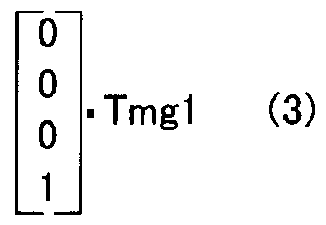
- ⁇ ej And “The dot above ⁇ inpj indicates that ⁇ ej and“ ⁇ inpj are differentiated once. Since we are considering the effect of the motor MG1 on the crankshaft 26, the engine torque Te If 0 is set, Equation (3) is obtained, where “P” is the matrix on the left side of Equation (3), “A” is the matrix on the left side of the first term on the right side, and the matrix on the left side of the second term on the right side.
- Equation (3) is expressed as “Equation (4)”.
- the rotational angular velocity ⁇ e of the crankshaft 26 is expressed using “x” as the left half of Equation (5). If the left-hand side matrix of the left half of Equation (5) is set to “C”, Equation (5 This is the rightmost side of 5). Solving equation (4) using this relationship, we can derive equation (6) as a transfer function G (s) of the effect of output torque Tmg 1 of motor MG 1 on the rotational angular velocity (co e) of crankshaft 26. Can do.
- the transfer function G (s) is obtained by such calculation, and the frequency characteristic is obtained therefrom. Then, this frequency characteristic and the amplitude P and position of torque pulsation in vibration suppression control by the motor MG1
- the influence component that the phase ⁇ and force and the output torque Tmgl of the motor MG1 have on the rotation angular velocity (co e) of the crankshaft 26 is determined as the rotation fluctuation (influence component N30m) every 30 degrees.
- Step S140 and if the required time for determination T30j is greater than the threshold value Trof, it is determined that a misfire has occurred, and the misfired cylinder is identified based on the input crank angle CA (step S). 150), the misfire judgment process is terminated, where the threshold Tref is the standard for the time required for judgment T30j.
- Crank It is set as a value that is larger than the required time for judgment T30j when the cylinder that becomes the combustion stroke at angle CA is not misfiring, and smaller than the required time T30j for when the cylinder is misfied, and is obtained by experiment etc. be able to.
- a cylinder that has misfired can be identified as a cylinder having a combustion stroke at a crank angle CA that is a reference for the determination time T30j that exceeds the threshold Tref.
- the misfire determination is performed using the determination required time T30j from which the influence of the vibration suppression control by the motor MG1 is removed. Further, it is possible to more accurately and accurately determine misfire of the engine 22 that outputs power to the subsequent stage via the damper 28 as a torsion element. Therefore, even if resonance by the damper 28 occurs, misfire of the engine 22 can be determined more reliably and accurately.
- the influence of the output torque of the motor MG1 on the rotation fluctuation of the crankshaft 26 is determined using a dynamic model that ignores the influence of the latter stage of the motor MG1.
- the frequency characteristics are calculated, the frequency characteristics may be calculated using a dynamic model that also takes into account the effects after the motor MG1.
- the misfire of the engine 22 is determined by using the time required for 30 degrees T30 as the time required for the crankshaft 26 to rotate 30 degrees every 30 degrees. Force required to be taken 5 degrees of time required for the crankshaft 26 to rotate 5 degrees every 5 degrees Time required for the rotation of the crankshaft 26 every 10 degrees T5 and 10 degrees It is not enough to judge misfire of engine 22 using various required time such as T10.
- the 30-degree required time calculated using the dynamic model T30-based influence component T30m is subtracted from the 30-degree required time T30, and the determination required time T30j is calculated.
- the time required for judgment is calculated by using T30j. It is assumed that the engine 22 is misfired.
- the time required for 30 degrees is calculated without using the dynamic model.
- the influence component of T30 is subtracted from the time required for 30 degrees T30 and the time required for judgment.
- the engine 22 may be determined to be misfired by calculating the time and calculating the required time for determination.
- the time required for 30 degrees without using a mechanical model For example, the effect of the 30-degree required T30 base on the rotational fluctuation of the crankshaft 26 with respect to the amplitude P and phase ⁇ of torque pulsation in the vibration suppression control by the motor MG1 is obtained in advance by experiments and stored as a map in the ROM 24b. Aside from that, given the amplitude P and phase ⁇ , the map force also corresponds to the 30-degree required time T30-based influence component.
- the power connected to the crankshaft 26 of the engine 22 via the damper 28 as a torsion element and connected to the rotating shaft of the motor MG1 and the ring gear shaft 32a as the drive shaft.
- the engine crankshaft is passed through a damper as a torsion element. Therefore, the motor MG2 is connected to the ring gear shaft 32a as illustrated in the hybrid vehicle 120 of the modified example of FIG. Engine 2 connected to a different axle (axle connected to wheels 64a, 64b in Fig.
- the present invention is not limited to the internal combustion engine device mounted on such a hybrid vehicle, and has an internal combustion engine mounted on a non-moving facility such as an internal combustion engine mounted on a moving body other than a vehicle or a construction facility.
- An internal combustion engine device may be used.
- it is good also as a form of the misfire determination method of an internal combustion engine.
- the present invention can be used in an internal combustion engine device having an internal combustion engine, an automobile manufacturing industry equipped with the internal combustion engine device, and the like.
Landscapes
- Engineering & Computer Science (AREA)
- Mechanical Engineering (AREA)
- Chemical & Material Sciences (AREA)
- Combustion & Propulsion (AREA)
- Transportation (AREA)
- General Engineering & Computer Science (AREA)
- Power Engineering (AREA)
- Sustainable Development (AREA)
- Life Sciences & Earth Sciences (AREA)
- Sustainable Energy (AREA)
- Physics & Mathematics (AREA)
- General Physics & Mathematics (AREA)
- Combined Controls Of Internal Combustion Engines (AREA)
- Control Of Vehicle Engines Or Engines For Specific Uses (AREA)
- Hybrid Electric Vehicles (AREA)
- Electric Propulsion And Braking For Vehicles (AREA)
Abstract
Description


Claims
Priority Applications (3)
| Application Number | Priority Date | Filing Date | Title |
|---|---|---|---|
| US12/226,781 US7765857B2 (en) | 2006-05-09 | 2007-05-02 | Internal combustion engine system and misfire determining method for internal combustion engine |
| EP07742805A EP2017453B1 (en) | 2006-05-09 | 2007-05-02 | Internal combustion engine device, and misfire judging method for internal combustion engine |
| CN2007800166151A CN101438046B (zh) | 2006-05-09 | 2007-05-02 | 内燃机装置和内燃机的失火判定方法 |
Applications Claiming Priority (2)
| Application Number | Priority Date | Filing Date | Title |
|---|---|---|---|
| JP2006130698A JP4702169B2 (ja) | 2006-05-09 | 2006-05-09 | 内燃機関装置およびこれを搭載する車両並びに内燃機関の失火判定方法 |
| JP2006-130698 | 2006-05-09 |
Publications (1)
| Publication Number | Publication Date |
|---|---|
| WO2007129657A1 true WO2007129657A1 (ja) | 2007-11-15 |
Family
ID=38667766
Family Applications (1)
| Application Number | Title | Priority Date | Filing Date |
|---|---|---|---|
| PCT/JP2007/059370 WO2007129657A1 (ja) | 2006-05-09 | 2007-05-02 | 内燃機関装置および内燃機関の失火判定方法 |
Country Status (6)
| Country | Link |
|---|---|
| US (1) | US7765857B2 (ja) |
| EP (1) | EP2017453B1 (ja) |
| JP (1) | JP4702169B2 (ja) |
| KR (1) | KR100986710B1 (ja) |
| CN (1) | CN101438046B (ja) |
| WO (1) | WO2007129657A1 (ja) |
Cited By (1)
| Publication number | Priority date | Publication date | Assignee | Title |
|---|---|---|---|---|
| CN104787032A (zh) * | 2014-01-17 | 2015-07-22 | 福特全球技术公司 | 用于控制混合动力车辆中的牵引电机的方法 |
Families Citing this family (27)
| Publication number | Priority date | Publication date | Assignee | Title |
|---|---|---|---|---|
| JP4458105B2 (ja) * | 2007-03-07 | 2010-04-28 | トヨタ自動車株式会社 | 内燃機関装置およびこれを搭載する車両並びに内燃機関の失火判定方法 |
| JP5044479B2 (ja) * | 2008-05-20 | 2012-10-10 | 株式会社日本自動車部品総合研究所 | 内燃機関の失火判定装置および車両並びに内燃機関の失火判定方法 |
| EP2135785B1 (en) * | 2008-05-26 | 2011-10-12 | C.R.F. Società Consortile per Azioni | Control system for a motor vehicle provided with a semiautomatic gearbox with discrete ratios |
| JP5092988B2 (ja) * | 2008-08-21 | 2012-12-05 | トヨタ自動車株式会社 | 失火判定装置および失火判定方法 |
| JP4858514B2 (ja) * | 2008-08-27 | 2012-01-18 | トヨタ自動車株式会社 | 失火判定装置および失火判定方法 |
| US8346460B2 (en) * | 2009-03-24 | 2013-01-01 | Honda Motor Co., Ltd. | Active vibration isolating support apparatus and method for controlling the same |
| US8027782B2 (en) * | 2009-09-16 | 2011-09-27 | GM Global Technology Operations LLC | Pattern recognition for random misfire |
| US8392057B2 (en) * | 2009-12-21 | 2013-03-05 | Cummins Inc. | Hybrid powertrain diagnostics |
| JP5622050B2 (ja) * | 2011-04-18 | 2014-11-12 | アイシン・エィ・ダブリュ株式会社 | 車両用駆動装置 |
| US9494090B2 (en) | 2013-03-07 | 2016-11-15 | GM Global Technology Operations LLC | System and method for controlling an engine in a bi-fuel vehicle to prevent damage to a catalyst due to engine misfire |
| JP6025640B2 (ja) * | 2013-03-28 | 2016-11-16 | 三菱重工業株式会社 | エンジンの失火時負荷制御方法およびその失火時負荷制御システム |
| US9457789B2 (en) | 2014-05-13 | 2016-10-04 | GM Global Technology Operations LLC | System and method for controlling a multi-fuel engine to reduce engine pumping losses |
| US9581100B2 (en) * | 2014-06-10 | 2017-02-28 | GM Global Technology Operations LLC | Vehicle torque compensation system |
| JP6090291B2 (ja) * | 2014-11-27 | 2017-03-08 | トヨタ自動車株式会社 | 内燃機関の失火判定装置 |
| JP6413827B2 (ja) * | 2015-02-19 | 2018-10-31 | スズキ株式会社 | 異常診断装置 |
| DE102015013541B4 (de) * | 2015-10-19 | 2023-10-05 | Audi Ag | Verfahren zum Betrieb einer Elektromaschine |
| US10005469B2 (en) | 2016-06-08 | 2018-06-26 | Fca Us Llc | Response amplitude modification for hybrid electric vehicle misfire detections |
| JP6624325B1 (ja) * | 2019-03-29 | 2019-12-25 | トヨタ自動車株式会社 | 内燃機関の失火検出装置、内燃機関の失火検出システム、データ解析装置、内燃機関の制御装置、内燃機関の失火検出方法、および受信実行装置 |
| JP6624324B1 (ja) | 2019-03-29 | 2019-12-25 | トヨタ自動車株式会社 | 内燃機関の失火検出装置、内燃機関の失火検出システム、データ解析装置、内燃機関の制御装置、内燃機関の失火検出方法、および受信実行装置 |
| JP6742470B1 (ja) * | 2019-04-23 | 2020-08-19 | 三菱電機株式会社 | 内燃機関の制御装置 |
| CN111157249B (zh) * | 2020-01-08 | 2022-09-02 | 江苏科技大学 | 一种柴油机故障监测预警方法及装置 |
| CN111336011B (zh) * | 2020-03-21 | 2021-04-27 | 东风汽车集团有限公司 | 一种汽油机失火监测方法 |
| JP7363714B2 (ja) * | 2020-08-07 | 2023-10-18 | トヨタ自動車株式会社 | 内燃機関の失火検出装置 |
| JP7327319B2 (ja) * | 2020-08-07 | 2023-08-16 | トヨタ自動車株式会社 | 内燃機関の失火検出装置 |
| JP7322852B2 (ja) * | 2020-10-09 | 2023-08-08 | トヨタ自動車株式会社 | 内燃機関の失火検出装置 |
| JP7392671B2 (ja) * | 2021-01-29 | 2023-12-06 | トヨタ自動車株式会社 | 内燃機関の失火検出装置 |
| JP7392672B2 (ja) * | 2021-01-29 | 2023-12-06 | トヨタ自動車株式会社 | 内燃機関の失火検出装置 |
Citations (4)
| Publication number | Priority date | Publication date | Assignee | Title |
|---|---|---|---|---|
| US5906651A (en) | 1997-05-23 | 1999-05-25 | Toyota Jidosha Kabushiki Kaisha | Misfire detecting device of multicylinder internal combustion engine |
| JP2000032607A (ja) * | 1998-07-09 | 2000-01-28 | Toyota Motor Corp | ハイブリッド車両における駆動系の制振装置 |
| JP2001065402A (ja) * | 1999-08-30 | 2001-03-16 | Denso Corp | ハイブリッド車両の制御装置 |
| JP2004312857A (ja) * | 2003-04-04 | 2004-11-04 | Jatco Ltd | ハイブリッド自動車の制御方法及び制御装置 |
Family Cites Families (14)
| Publication number | Priority date | Publication date | Assignee | Title |
|---|---|---|---|---|
| SE506547C2 (sv) * | 1996-06-20 | 1998-01-12 | Asea Brown Boveri | Förfarande och anordning för att detektera feltändning hos en förbränningsmotor |
| US6199057B1 (en) * | 1996-10-23 | 2001-03-06 | California Institute Of Technology | Bit-serial neuroprocessor architecture |
| DE19939250A1 (de) | 1999-08-19 | 2001-03-22 | Siemens Ag | Verfahren und Vorrichtung zur Dämpfung von Drehschwingungen einer Verbrennungsmaschine |
| JP3614145B2 (ja) * | 2002-03-18 | 2005-01-26 | 日産自動車株式会社 | ハイブリッド車の制御装置 |
| US7110867B2 (en) | 2002-08-26 | 2006-09-19 | Nissan Motor Co., Ltd. | Vibration suppression apparatus and method for hybrid vehicle |
| JP4552687B2 (ja) * | 2005-01-11 | 2010-09-29 | トヨタ自動車株式会社 | 内燃機関の失火判定装置および失火判定方法 |
| JP4525538B2 (ja) * | 2005-02-24 | 2010-08-18 | トヨタ自動車株式会社 | 内燃機関の失火判定装置および失火判定方法 |
| JP4442568B2 (ja) * | 2006-01-27 | 2010-03-31 | トヨタ自動車株式会社 | 内燃機関の失火判定装置および失火判定方法 |
| JP4337829B2 (ja) * | 2006-02-15 | 2009-09-30 | トヨタ自動車株式会社 | 失火判定装置、ハイブリッド自動車及び失火判定方法 |
| JP4702180B2 (ja) * | 2006-05-23 | 2011-06-15 | トヨタ自動車株式会社 | 内燃機関装置および内燃機関の失火判定方法 |
| JP4345847B2 (ja) * | 2006-09-01 | 2009-10-14 | トヨタ自動車株式会社 | 内燃機関の失火判定装置および失火判定方法並びに車両 |
| US7707874B2 (en) * | 2007-12-11 | 2010-05-04 | Toyota Jidosha Kabushiki Kaisha | Misfire determination device and method for internal combustion engine, and vehicle including misfire determination device |
| JP4438858B2 (ja) * | 2007-12-12 | 2010-03-24 | トヨタ自動車株式会社 | 内燃機関の失火判定装置および車両並びにねじれ要素の剛性推定装置,内燃機関の失火判定方法,ねじれ要素の剛性推定方法 |
| JP4623168B2 (ja) * | 2008-08-27 | 2011-02-02 | トヨタ自動車株式会社 | 内燃機関の失火検出装置および失火検出方法 |
-
2006
- 2006-05-09 JP JP2006130698A patent/JP4702169B2/ja not_active Expired - Fee Related
-
2007
- 2007-05-02 US US12/226,781 patent/US7765857B2/en active Active
- 2007-05-02 KR KR1020087027378A patent/KR100986710B1/ko active IP Right Grant
- 2007-05-02 EP EP07742805A patent/EP2017453B1/en not_active Expired - Fee Related
- 2007-05-02 CN CN2007800166151A patent/CN101438046B/zh not_active Expired - Fee Related
- 2007-05-02 WO PCT/JP2007/059370 patent/WO2007129657A1/ja active Search and Examination
Patent Citations (4)
| Publication number | Priority date | Publication date | Assignee | Title |
|---|---|---|---|---|
| US5906651A (en) | 1997-05-23 | 1999-05-25 | Toyota Jidosha Kabushiki Kaisha | Misfire detecting device of multicylinder internal combustion engine |
| JP2000032607A (ja) * | 1998-07-09 | 2000-01-28 | Toyota Motor Corp | ハイブリッド車両における駆動系の制振装置 |
| JP2001065402A (ja) * | 1999-08-30 | 2001-03-16 | Denso Corp | ハイブリッド車両の制御装置 |
| JP2004312857A (ja) * | 2003-04-04 | 2004-11-04 | Jatco Ltd | ハイブリッド自動車の制御方法及び制御装置 |
Non-Patent Citations (1)
| Title |
|---|
| See also references of EP2017453A4 * |
Cited By (1)
| Publication number | Priority date | Publication date | Assignee | Title |
|---|---|---|---|---|
| CN104787032A (zh) * | 2014-01-17 | 2015-07-22 | 福特全球技术公司 | 用于控制混合动力车辆中的牵引电机的方法 |
Also Published As
| Publication number | Publication date |
|---|---|
| EP2017453A1 (en) | 2009-01-21 |
| US20090118990A1 (en) | 2009-05-07 |
| JP4702169B2 (ja) | 2011-06-15 |
| EP2017453B1 (en) | 2011-11-16 |
| EP2017453A4 (en) | 2010-06-02 |
| KR20090025205A (ko) | 2009-03-10 |
| CN101438046B (zh) | 2012-05-09 |
| JP2007303309A (ja) | 2007-11-22 |
| KR100986710B1 (ko) | 2010-10-08 |
| US7765857B2 (en) | 2010-08-03 |
| CN101438046A (zh) | 2009-05-20 |
Similar Documents
| Publication | Publication Date | Title |
|---|---|---|
| JP4702169B2 (ja) | 内燃機関装置およびこれを搭載する車両並びに内燃機関の失火判定方法 | |
| EP2058501B1 (en) | Misfire judging device and misfire judging method for internal combustion engines | |
| EP1965066B1 (en) | Device for judging misfire of internal combustion engine and vehicle mounting it and method for judging misfire | |
| JP4453654B2 (ja) | 内燃機関の失火判定装置およびこれを搭載する車両並びに失火判定方法 | |
| JP4007401B1 (ja) | 内燃機関の失火判定装置および失火判定方法 | |
| JP5011896B2 (ja) | 内燃機関の失火判定装置および車両 | |
| JP4544354B2 (ja) | 内燃機関の失火判定装置および車両 | |
| JP2007170248A (ja) | 内燃機関装置およびこれを搭載する車両並びに内燃機関の失火判定方法 | |
| JP2007303310A (ja) | 内燃機関装置および内燃機関の失火判定方法 | |
| JP2009292362A (ja) | 内燃機関の失火判定装置およびハイブリッド車並びに内燃機関の失火判定方法 | |
| JP2010126064A (ja) | 内燃機関の失火判定装置および内燃機関の失火判定方法 | |
| JP2012215178A (ja) | 内燃機関の失火判定装置 | |
| JP2008095617A (ja) | 内燃機関の失火判定装置および失火判定方法 | |
| JP5108719B2 (ja) | 内燃機関の失火判定装置 | |
| JP2012214224A (ja) | 内燃機関の失火判定装置 | |
| JP4962404B2 (ja) | 内燃機関装置および車両並びに内燃機関装置の制御方法 | |
| JP4605124B2 (ja) | 内燃機関の失火判定装置および失火判定方法並びに車両 | |
| JP2007118755A (ja) | 動力出力装置およびその制御方法並びに車両 | |
| JP2008057491A (ja) | 内燃機関の失火判定装置および失火判定方法並びに車両 | |
| JP2009154714A (ja) | 動力出力装置および車両並びに動力出力装置の制御方法 | |
| JP2013047493A (ja) | エンジンシステム | |
| JP5246152B2 (ja) | 排気温度推定装置および排気温度推定方法 | |
| JP2013071581A (ja) | ハイブリッド車のアイドリング学習装置 | |
| JP2018034712A (ja) | 自動車 | |
| JP2013019310A (ja) | エンジン装置およびハイブリッド自動車 |
Legal Events
| Date | Code | Title | Description |
|---|---|---|---|
| 121 | Ep: the epo has been informed by wipo that ep was designated in this application |
Ref document number: 07742805 Country of ref document: EP Kind code of ref document: A1 |
|
| WWE | Wipo information: entry into national phase |
Ref document number: 12226781 Country of ref document: US |
|
| WWE | Wipo information: entry into national phase |
Ref document number: 2007742805 Country of ref document: EP |
|
| WWE | Wipo information: entry into national phase |
Ref document number: 200780016615.1 Country of ref document: CN Ref document number: 1020087027378 Country of ref document: KR |
|
| NENP | Non-entry into the national phase |
Ref country code: DE |
|
| DPE1 | Request for preliminary examination filed after expiration of 19th month from priority date (pct application filed from 20040101) |