US9321193B2 - Resin product manufacturing system, manufacturing method, resin molding machine and mold - Google Patents
Resin product manufacturing system, manufacturing method, resin molding machine and mold Download PDFInfo
- Publication number
- US9321193B2 US9321193B2 US13/061,349 US200913061349A US9321193B2 US 9321193 B2 US9321193 B2 US 9321193B2 US 200913061349 A US200913061349 A US 200913061349A US 9321193 B2 US9321193 B2 US 9321193B2
- Authority
- US
- United States
- Prior art keywords
- mold
- resin
- intermediate product
- burr
- cavity
- Prior art date
- Legal status (The legal status is an assumption and is not a legal conclusion. Google has not performed a legal analysis and makes no representation as to the accuracy of the status listed.)
- Active, expires
Links
Images


Classifications
-
- B—PERFORMING OPERATIONS; TRANSPORTING
- B29—WORKING OF PLASTICS; WORKING OF SUBSTANCES IN A PLASTIC STATE IN GENERAL
- B29C—SHAPING OR JOINING OF PLASTICS; SHAPING OF MATERIAL IN A PLASTIC STATE, NOT OTHERWISE PROVIDED FOR; AFTER-TREATMENT OF THE SHAPED PRODUCTS, e.g. REPAIRING
- B29C37/00—Component parts, details, accessories or auxiliary operations, not covered by group B29C33/00 or B29C35/00
- B29C37/02—Deburring or deflashing
-
- B—PERFORMING OPERATIONS; TRANSPORTING
- B29—WORKING OF PLASTICS; WORKING OF SUBSTANCES IN A PLASTIC STATE IN GENERAL
- B29C—SHAPING OR JOINING OF PLASTICS; SHAPING OF MATERIAL IN A PLASTIC STATE, NOT OTHERWISE PROVIDED FOR; AFTER-TREATMENT OF THE SHAPED PRODUCTS, e.g. REPAIRING
- B29C33/00—Moulds or cores; Details thereof or accessories therefor
- B29C33/10—Moulds or cores; Details thereof or accessories therefor with incorporated venting means
-
- B—PERFORMING OPERATIONS; TRANSPORTING
- B29—WORKING OF PLASTICS; WORKING OF SUBSTANCES IN A PLASTIC STATE IN GENERAL
- B29C—SHAPING OR JOINING OF PLASTICS; SHAPING OF MATERIAL IN A PLASTIC STATE, NOT OTHERWISE PROVIDED FOR; AFTER-TREATMENT OF THE SHAPED PRODUCTS, e.g. REPAIRING
- B29C43/00—Compression moulding, i.e. applying external pressure to flow the moulding material; Apparatus therefor
- B29C43/32—Component parts, details or accessories; Auxiliary operations
- B29C43/36—Moulds for making articles of definite length, i.e. discrete articles
- B29C43/40—Moulds for making articles of definite length, i.e. discrete articles with means for cutting the article
-
- B—PERFORMING OPERATIONS; TRANSPORTING
- B29—WORKING OF PLASTICS; WORKING OF SUBSTANCES IN A PLASTIC STATE IN GENERAL
- B29C—SHAPING OR JOINING OF PLASTICS; SHAPING OF MATERIAL IN A PLASTIC STATE, NOT OTHERWISE PROVIDED FOR; AFTER-TREATMENT OF THE SHAPED PRODUCTS, e.g. REPAIRING
- B29C45/00—Injection moulding, i.e. forcing the required volume of moulding material through a nozzle into a closed mould; Apparatus therefor
- B29C45/0053—Injection moulding, i.e. forcing the required volume of moulding material through a nozzle into a closed mould; Apparatus therefor combined with a final operation, e.g. shaping
- B29C45/0055—Shaping
-
- B—PERFORMING OPERATIONS; TRANSPORTING
- B29—WORKING OF PLASTICS; WORKING OF SUBSTANCES IN A PLASTIC STATE IN GENERAL
- B29C—SHAPING OR JOINING OF PLASTICS; SHAPING OF MATERIAL IN A PLASTIC STATE, NOT OTHERWISE PROVIDED FOR; AFTER-TREATMENT OF THE SHAPED PRODUCTS, e.g. REPAIRING
- B29C45/00—Injection moulding, i.e. forcing the required volume of moulding material through a nozzle into a closed mould; Apparatus therefor
- B29C45/17—Component parts, details or accessories; Auxiliary operations
- B29C45/26—Moulds
- B29C45/34—Moulds having venting means
-
- B—PERFORMING OPERATIONS; TRANSPORTING
- B29—WORKING OF PLASTICS; WORKING OF SUBSTANCES IN A PLASTIC STATE IN GENERAL
- B29C—SHAPING OR JOINING OF PLASTICS; SHAPING OF MATERIAL IN A PLASTIC STATE, NOT OTHERWISE PROVIDED FOR; AFTER-TREATMENT OF THE SHAPED PRODUCTS, e.g. REPAIRING
- B29C45/00—Injection moulding, i.e. forcing the required volume of moulding material through a nozzle into a closed mould; Apparatus therefor
- B29C45/0053—Injection moulding, i.e. forcing the required volume of moulding material through a nozzle into a closed mould; Apparatus therefor combined with a final operation, e.g. shaping
- B29C2045/0077—Injection moulding, i.e. forcing the required volume of moulding material through a nozzle into a closed mould; Apparatus therefor combined with a final operation, e.g. shaping removing burrs or flashes
-
- B—PERFORMING OPERATIONS; TRANSPORTING
- B29—WORKING OF PLASTICS; WORKING OF SUBSTANCES IN A PLASTIC STATE IN GENERAL
- B29C—SHAPING OR JOINING OF PLASTICS; SHAPING OF MATERIAL IN A PLASTIC STATE, NOT OTHERWISE PROVIDED FOR; AFTER-TREATMENT OF THE SHAPED PRODUCTS, e.g. REPAIRING
- B29C2793/00—Shaping techniques involving a cutting or machining operation
- B29C2793/009—Shaping techniques involving a cutting or machining operation after shaping
Definitions
- the present invention relates to a resin product manufacturing system, a manufacturing method, a resin molding machine and a mold for manufacturing by injection molding, compression molding or the like.
- an injection molding technology for forming a resin molding product by injecting molten resin into a mold at a high pressure. Since the molten resin is injected into the mold at the high pressure in this type of injection molding technology, the mold is, for example, opened by this pressure and a thin burr is readily formed on matching surfaces (parting surfaces) of a fixed mold and a movable mold.
- a deburring device including a cutter blade with a cutting edge portion corresponding to a base end of a burr and a profiling portion corresponding to a surface portion of a product and not constituting a cutting edge and adapted to move the cutter blade along the base end of the burr while vibrating the cutter blade, thereby efficiently removing the burr (see, for example, patent document 2).
- a technology in which an end mill is inserted through a profiling guide member and a burr is cut off by the end mill while the profiling guide member is pressed against a work and moves along the work (see, for example, patent document 3).
- the burr can be efficiently removed when a projecting height of the burr from a product surface is a certain height or higher. If a projecting amount is too little, the burr may not be able to be efficiently removed.
- an object of the present invention is to solve the problems inherent in the prior arts described above and provide a resin product manufacturing system, a manufacturing method, a resin molding machine and a mold capable of easily manufacturing a burr-free finished product in injection mold or the like.
- the present invention is directed to a resin product manufacturing system for forming an intermediate product by a resin molding machine and manufacturing a finished product by deburring the intermediate product by a deburring device, characterized in that the resin molding machine comprises a mold including a storing portion for storing an overflow resin formed at a site corresponding to the entire periphery of an intermediate product in a matching surface and the intermediate product having the overflow resin integrally formed over the entire periphery thereof is formed by the mold, and the deburring device cuts off the overflow resin integrally formed over the entire periphery of the intermediate product together with the burr to manufacture a finished product.
- a product formed by the resin molding machine and having a burr not yet removed is defined to be an intermediate product and a product after deburring is defined to be a finished product.
- the deburring device may include a cutter blade with a cutting edge portion corresponding to the base end of the overflow resin and a profiling portion corresponding to a surface portion of the intermediate product and not constituting a cutting edge, and the overflow resin integral to the intermediate product may be cut off together with the burr by moving the cutter blade along the base end of the overflow resin while vibrating the cutter blade.
- the deburring device Since the formation of the overflow resin is permitted on a parting surface of the intermediate product in these constructions, efficient deburring is performed by the deburring device removing the overflow resin in a later process. In other words, if a burr is formed, it is formed at a tip of the overflow resin. Thus, a burr-free finished product can be easily manufactured by the deburring device cutting off the overflow resin together with the burr.
- the resin molding machine may be a low pressure compression molding machine, a high-pressure compression molding machine, a foam molding machine, a carbon-fiber injection molding machine or the like besides being a general molding machine such as an injection molding machine.
- a foam molding machine is employed, an effect of completely cutting off a burr together with an overflow resin can be obtained by providing an overflow resin at the time of foam injection molding. Further, an effect of completely removing a burr together with an overflow resin, for example, by an ultrasonically vibrated cutter can be obtained by providing the overflow resin in a carbon fiber injection molding machine.
- the structure of the molding machine, a mold used therein and a resin component vary. Particularly, it is difficult to feed an optimal amount of resin into a cavity of the mold and molding becomes unstable if the resin amount is too much or too little.
- the mold is formed with the storing portion for the overflow resin in this invention, a variation in the resin amount is automatically adjusted by the amount of the overflow resin in the storing portion when the resin amount is too much or too little, wherefore the resin amount in the cavity becomes stable to enable stable molding.
- the overflow resin may be integrally formed in a formation direction of a vertical burr extending in an opening direction of the mold.
- the overflow resin may be integrally formed in a formation direction of a horizontal burr extending in a direction orthogonal to the opening direction of the mold.
- Gas may be vented through the storing portion for the overflow resin.
- the overflow resin is integrally formed in the formation direction of the vertical burr or the horizontal burr, it is sufficient for the mold to be formed with the storing portion for storing the overflow resin in the matching surface of the mold, wherefore it becomes easier to fabricate the mold.
- gas is vented through the storing portion for the overflow resin, defects such as burr formation and resin burning caused by degassing concentrate on the overflow resin and a resin product can be manufactured without leaving any defect in the finished product by removing the overflow resin together with the burr.
- the burr formed in the intermediate product is removed by the deburring device, it is desirable to form the burr within the reach of a tool of the deburring device.
- the above burr formed on the intermediate product is set at a predetermined position, e.g. in a range planned to be the entire periphery of a parting line and this burr is removed by the deburring device, wherefore a trace of deburring can be confirmed in the above planned range, for example, with a microscope.
- the present invention may be also directed to a resin product manufacturing method for forming an intermediate product by a resin molding machine and manufacturing a finished product by deburring the intermediate product, comprising a step of forming an intermediate product having an overflow resin integrally formed over the entire periphery thereof by a mold including a storing portion for storing the overflow resin formed at a site corresponding to the entire periphery of the intermediate product in a matching surface; and a step of manufacturing a finished product by cutting off the overflow resin integrally formed on the entire periphery of the intermediate product together with the burr.
- the present invention may be further directed to a resin molding machine for forming an intermediate product including a burr to be removed by a deburring device, comprising a mold including a storing portion for storing an overflow resin formed at a site corresponding to the entire periphery of an intermediate product in a matching surface, wherein the intermediate product having the overflow resin including the burr integrally formed over the entire periphery thereof is formed by the mold.
- the present invention may be furthermore directed to a mold for resin molding machine for forming an intermediate product including a burr to be removed by a deburring device, comprising a storing portion for storing an overflow resin formed at a site corresponding to the entire periphery of an intermediate product in a matching surface, wherein the mold forms the intermediate product having the overflow resin including the burr integrally formed over the entire periphery thereof.
- a deburred surface is finely finished to have a specified outer shape and efficient deburring is performed by the deburring device removing the overflow resin. In other words, if a burr is formed, this is formed at the tip of the overflow resin. Therefore, the burr-free finished product can be easily manufactured by the deburring device cutting off the overflow resin together with the burr.
- FIG. 1 is a perspective view showing one embodiment of a deburring system
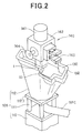
- FIG. 2 is a perspective view showing an operation of deburring a work
- FIG. 3 is a perspective view showing a part of a work receiving jig
- FIG. 4 is a perspective view showing an example of the shape of the work before deburring
- FIG. 5 is a perspective view showing an example of the shape of the work after deburring
- FIG. 6 is a sectional view of a mold
- FIG. 7A is a partial enlarged view of the mold and FIG. 7 B is a sectional view showing an opened state of the mold,
- FIG. 8A is a sectional view of a mold
- FIG. 8B is a partial enlarged view of the mold
- FIG. 8C is a sectional view showing an opened state of the mold
- FIG. 9A is a sectional view of a mold and FIG. 9B is a plan view showing a matching surface of the mold,
- FIG. 10 is a sectional view of a mold according to another embodiment
- FIG. 11 is a front view showing one embodiment of a deburring device
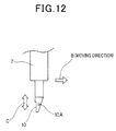
- FIG. 12 is a side view showing a mounted part of a cutter blade
- FIG. 13 is a perspective view enlargedly showing an operation of deburring a work
- FIG. 14 is a sectional view of a leading end part of the cutter blade
- FIG. 15 is a front view showing another embodiment of the deburring device.
- FIG. 16A is a front view
- FIG. 16B is a bottom view
- FIG. 16C is a side view showing another embodiment of the deburring device
- FIG. 17A is a side view and FIGS. 17B and 17C are sectional views showing a profiling head.
- the resin product manufacturing system 100 includes a resin molding machine 101 , an articulated robot 103 having a work holding device and a deburring device at a tip portion of an arm, a work receiving mechanism 105 on which a work 130 (see FIG. 4 ) as an intermediate product before deburring is to be placed, a burr discharge conveyor 107 for discharging a removed burr 132 to the outside of the system, and a finished product discharge conveyor 109 for discharging a work 131 (see FIG. 5 ) as a finished product after deburring to the outside of the system.
- a storage rack for storing finished products may be provided in place of the finished product discharge conveyor 109 .
- the resin molding machine 101 includes, on a base 101 G, a driving mechanism 101 A, a hopper unit 101 B storing a resin material, a screw unit 101 C for feeding the resin and a molding unit 101 F, wherein the molding unit 101 F includes a fixed unit 101 D and a movable unit 101 E. Molten resin fed from the hopper unit 101 B via the screw unit 101 C is molded in the molding unit 101 F to become a resin product (intermediate product to be described in detail later).
- molds not shown
- the molten resin is compressed between the molds by a forward movement of the movable unit 101 E to form an intermediate product.
- the articulated robot 103 includes joints 103 A to 103 F, and a mechanism unit 140 as an integral unit of the work holding device and the deburring device is mounted on an arm tip portion 103 G of a leading joint 103 F.
- this mechanism unit 140 includes a cylindrical base portion 141 to be mounted on the arm tip portion 103 G, a substantially U-shaped holder 142 connected to this base portion 141 , a hand portion 143 for work holding arranged on a first surface of this holder 142 and a suction pad portion 144 for work suction arranged on a second surface of the holder 142 , wherein the suction pad portion 144 is connected to a vacuum source via a connection hose (not shown).
- the hand portion 143 for work holding is operated by an air cylinder (not shown).
- the deburring device 1 is mounted on a third surface (lower surface in FIG. 2 ) of the holder 142 , a cutter blade 10 in the form of a flat blade is fixed to the leading end of the deburring device 1 , and the burr 132 of the work 130 on the work receiving mechanism 105 is removed by the cutter blade 10 .
- the work receiving mechanism 105 includes a mechanism base 110 and a work receiving jig 112 connected to the mechanism base 110 by a plurality of bolts 111 .
- a work placing portion 112 A at the top of the work receiving jig 112 is formed with a receiving groove engageable with, for example, a projection on the work 130 .
- the work 130 is placed on the work placing portion 112 A by being dropped from a solid-line position to an imaginary-line position to engage the projection thereof with the receiving groove.
- the work placing portion 112 A is formed with an inlet 112 B for suction.
- the inlet 112 B is connected to the vacuum source via a connection hose 112 C, whereby the work 130 is fixed by suction when being placed on the work placing portion 112 A.
- the shape of the work placing portion 112 A is determined according to the shape of the projection of the work 130 , the shape of a burr formed on the work and the like, and is at least so set as to enable the removal of the burr formed on the work 130 by the cutter blade 10 , i.e. as not to hinder a deburring operation by the cutter blade 10 .
- the work placing portion 112 A includes a support base 112 D.
- a support base 112 D In the case of changing the shape of works to be molded through the replacement of molds of the resin molding machine 101 , an assembly of the support base 112 D and the parts thereabove is replaced by another work receiving jig 112 including a work placing portion 112 A corresponding to the work shape.
- a setup is changed by replacing the work receiving jig 112 , thereby shortening a setup time.
- FIG. 6 is a sectional view of the resin molding machine 101 .
- FIG. 7A is a partial enlarged view (at the completion of compression) of the work 130 of FIG. 6
- FIG. 7B is a sectional view (at the time of injection) showing an opened state of the mold of FIG. 7A .
- the work in FIGS. 6 and 7 differ from the one shown in FIGS. 1 to 5 in shape, but it is described as the same type below to facilitate the description.
- the resin molding machine 101 described above includes a mold 155 composed of a fixed mold 151 provided in the fixed unit 101 D (see FIG. 1 ) and a movable mold 153 provided in the movable unit 101 E, and the movable mold 153 is moved toward the fixed mold 151 of the fixed unit 101 D to compression-mold the work 130 by driving the movable unit 101 E by a driving mechanism (or a servo motor driving mechanism) having a direct press structure by a hydraulic pressure or a toggle structure.
- a driving mechanism or a servo motor driving mechanism
- the movable mold 153 includes a storing portion 153 B formed in a matching surface 153 A of the mold 153 for storing an overflow resin 130 A corresponding to a so-called vertical burr and extending like a flat plate in a mold opening direction.
- This storing portion 153 B is recessed and formed at a site corresponding to the entire periphery of the work 130 in the matching surface 153 A of the movable mold 153 .
- the storing portion 153 B is formed at a site including the gate and corresponding to the entire periphery of the work 130 .
- a depth T of the storing portion 153 B is 0.05 mm or larger and a length L thereof is 0.05 mm or larger.
- An upper limit value of the length L is, for example, 1 ⁇ 2 of the depth T, preferably 1 ⁇ 3 of the depth T.
- the respective dimensions are appropriately determined according to the property of the resin material, the size of products and the like.
- a parting line P ⁇ L of the movable mold 153 is separated from the fixed mold 151 by a predetermined distance in an opening direction (see FIG. 7B ) and a predetermined amount of the molten resin material is injected into a molding product space (cavity) 135 . Thereafter, the movable mold 153 is moved toward the fixed mold 151 , parting lines P ⁇ L meet, and the fixed mold 151 and the movable mold 153 are clamped (see FIG. 7A ) to compression-mold the work 130 .
- t denotes an opening amount of the mold as shown in FIG. 7B
- a clearance ⁇ resulting from a draft angle ⁇ (see FIG. 7A ) is formed between the fixed mold 151 and the movable mold 153 . Accordingly, in the process of clamping the fixed mold 151 and the movable mold 153 , gas is vented from taper surfaces (matching surfaces) with an inclination ⁇ (e.g. 1° to 3°) of the respective molds.
- the molten resin material may be injected into the molding product space 135 at a low pressure and, thereafter, the fixed mold 151 and the movable mold 153 may be clamped at a low pressure.
- the resin molding machine 101 is not limited to the above construction and may be a usual injection molding apparatus for injecting molten resin into a mold at a high pressure and clamping the mold at a high pressure.
- the overflow resin 130 A formed in the above storing portion 153 B is a part to be cut off in the deburring process to be described later, and the depth T and length L thereof are not limited to the above respective dimensions and set at arbitrary depth T and length L according to the quality of the resin material or the like or suitable for cutting by the deburring device.
- the resin is wasted if the depth T and the length L are too large, and deburring is difficult if they are too small.
- resin molding by the resin molding machine 101 a molding apparatus performance, the mold used, a resin component and the like vary. Particularly, it is difficult to feed an optimal amount of resin into the cavity of the mold and molding becomes unstable if the amount of resin is too much or too little.
- the storing portion 153 B is filled with the overflow resin if a large amount of resin is injected into the mold and a smaller amount of overflow resin enters the storing portion 153 B if a small amount of resin is injected.
- a variation in the resin injection amount is automatically adjusted by the amount of the overflow resin, wherefore the resin amount in the cavity becomes stable to enable stable molding.
- the overflow resin is permitted in this construction, it is not necessary to suppress burr formation at the time of molding and a resin molding product of a higher quality can be manufactured when the molten resin material is injected into the molding product space 135 at a low pressure and, thereafter, the fixed mold 151 and the movable mold 153 are clamped at a low pressure, i.e. when low-pressure compression molding is performed as described above.
- a required mold clamping force thereof can be suppressed to 1 ⁇ 4 to 1 ⁇ 5 of a conventionally required mold clamping force.
- the overflow resin 130 A is equivalent to a conventional so-called burr and synonymous with the burr 132 .
- the burr can be substantially perfectly removed in the subsequent process, the resin molding product is finely finished, and a great difference is brought about for the purpose.
- FIG. 8 show another embodiment of the resin molding machine.
- This resin molding machine 101 includes a mold 155 composed of a fixed mold 159 provided in the fixed unit 101 D (see FIG. 1 ) and movable molds 158 and 157 provided in the movable unit 101 E.
- Denoted by 181 is a shaft of a hydraulic cylinder connected to the movable mold 157 .
- the movable mold 157 is opened or moved in a compression direction via the shaft 181 .
- Denoted by PW is a compression margin.
- a work 150 is a product with a bead 150 B as shown in FIG. 8B (at the completion of compression) and FIG. 8C (at the time of injection), and a storing portion 157 B for storing an overflow resin 150 A corresponding to a vertical burr and extending like a flat plate in a mold opening direction is formed in a matching surface 157 A of the movable mold 157 .
- This storing portion 157 B is recessed and formed at a site corresponding to the entire periphery of the work 150 in the matching surface 157 A of the movable mold 157 .
- a depth T and a length L of the storing portion 157 B are, for example, 0.05 mm or larger and 0.05 mm or larger as in the above embodiment.
- An upper limit value of the length L is, for example, 1 ⁇ 2 of the depth T, preferably 1 ⁇ 3 of the depth T.
- the respective dimensions are appropriately determined according to the property of a resin material, the size of products and the like.
- FIG. 9 show the form of a so-called horizontal burr.
- the same parts as in FIG. 7 are denoted by the same reference numerals and not described.
- a storing portion 151 B for storing an overflow resin 130 A corresponding to a so-called horizontal burr and extending like a flat plate in a direction perpendicular to the mold opening direction is formed in a matching surface 151 A of the fixed mold 151 .
- This storing portion 151 B is recessed and formed at a site corresponding to the entire periphery of the work 130 in the matching surface 151 A of the fixed mold 151 .
- a depth T of the storing portion 151 B is, for example, 0.05 mm or larger and a length L thereof is, for example, 0.05 mm or larger.
- An upper limit value of the length L is, for example, 1 ⁇ 2 of the depth T, preferably 1 ⁇ 3 of the depth T.
- the respective dimensions are appropriately determined according to the property of the resin material, the size of products and the like.
- the overflow resin 130 A formed in the storing portion 151 B is a part to be cut off in the deburring process to be described later, and the depth T and length L thereof are not limited to the above respective dimensions and set at arbitrary depth T and length L suitable for cutting by the deburring device.
- the resin is wasted if the depth T and length L are too large, and deburring is difficult if they are too small.
- a plurality of gas vent holes 160 are so formed in the matching surface 151 A of the fixed mold 151 as to be orthogonal to an extension direction of the storing porting 151 B. These gas vent holes 160 are for discharging gas in the cavity 135 and formed at suitable intervals in a circumferential direction in the entire matching surface 151 A.
- gas is vented through the overflow resin 130 A stored in the storing portion 151 B at the time of resin molding.
- the work 150 may be a product with a bead 150 B as shown in FIG. 10 and a storing portion 153 B for storing an overflow resin 150 A corresponding to a horizontal burr and extending like a flat plate in the direction orthogonal to the mold opening direction may be formed in the matching surface 153 A of the movable mold 153 .
- the fixed mold and the movable mold(s) are clamped at a low or high pressure after the molten resin material is injected into the molding product space (cavity) 135 at a low or high pressure at the time of resin molding.
- an intermediate product having the overflow resin 130 A or 150 A integrally formed on the parting surface of the work 130 or 150 is formed.
- a so-call conventional burr is formed on a peripheral portion of the tip of the overflow resin 130 A or 150 A.
- FIG. 11 shows a deburring device 1 .
- the deburring device 1 is mounted on the third surface (lower surface in FIG. 11 ) of the holder 142 .
- the deburring device 1 includes a supporting body 3 fixed to the third surface, and a slide table device 4 of an air drive type is fixed to the supporting body 3 .
- the slide table device 4 includes a fixing portion 4 a fixed to the supporting body 3 , supporting portions 4 b , 4 c fixed to the opposite ends of the fixing portion 4 a , a shaft 4 d provided between the respective fixing portions 4 b and 4 c and a sliding portion 5 slidable on the shaft 4 d .
- the sliding portion 5 is reciprocally movable in predetermined straight directions (directions of arrows X), and the lower surface of the cutter blade, which is a so-called flat blade, can be pressed against a work in these straight directions.
- Denoted by 4 e are stoppers.
- An air supply port 4 f is formed in one supporting portion 4 b
- an air discharge port 4 g is formed in the other supporting portion 4 c and a pressure regulator (not shown) for regulating the pressure of supplied air is connected to the air supply port 4 f.
- an ultrasonic transducer holder 6 is attached to the sliding portion 5 .
- a half-ring shaped holder portion 6 a is formed at the other end of the ultrasonic transducer holder 6 , a cylindrical portion 7 a of an ultrasonic transducer 7 is sandwiched between this holder portion 6 a and another half-ring shaped holder portion 6 b , and the ultrasonic transducer 7 is attached to the other end of the ultrasonic transducer holder 6 by coupling the respective holder portions 6 a , 6 b by a bolt.
- the cutter blade 10 is fixed to the leading end of the ultrasonic transducer 7 .
- An ultrasonic unit (not shown) is connected to the ultrasonic transducer 7 via a cord 7 b (see FIG. 11 ).
- the ultrasonic transducer 7 is driven by the ultrasonic unit and the cutter blade 10 undergoes ultrasonic vibration in directions (directions of arrows C) substantially orthogonal to a moving direction (direction of arrow B) of the cutter blade 10 according to the vibration of the ultrasonic transducer 7 .
- the sliding portion 5 is constantly biased to right by an air pressure from the air supply port 4 f until coming into contact with the right stopper 4 e in FIG. 11 , the cutter blade 10 comes into contact with the work and, if a reaction force load acts, the sliding portion 5 slides to left in FIG.
- a sliding range is defined by the left stopper 4 e in FIG. 11 .
- the slide table device 4 constitutes a floating mechanism, and the cutter blade 10 at the leading end of the deburring device 1 is movable in the directions of arrows A, i.e. in the floating state with respect to the work (resin molding product) to be described later.
- FIG. 13 shows the cutter blade 10 during a deburring operation.
- FIG. 13 a work 130 shaped differently from the above work 130 (see FIG. 2 ) is shown to facilitate the description.
- the cutter blade 10 includes a cutter blade main body 10 C at a leading end side thereof, and this cutter blade main body 10 C includes a front end surface 10 F and a rear end surface 10 R.
- the rear end surface 10 R extends substantially in parallel with an extension of the ultrasonic transducer 7 , and the front end surface 10 F is swept back at a sweepback angle ⁇ from the extension of the ultrasonic transducer 7 crossing at a right angle to the moving direction B.
- the cutter blade 10 is fixed to the ultrasonic transducer 7 by being brazed or threadably mounted.
- the cutter blade 10 can cut off the overflow resins 130 A, 150 A of the works 130 , 150 formed using the above molds 155 or the like.
- the overflow resin 150 A may be cut off along a cutting line L 1 in FIG. 10
- the overflow resin 130 A may be cut off along a cutting line L 2 in FIG. 7
- the overflow resin 150 A may be cut off along a cutting line L 3 in FIG. 8 .
- the resin molding product that is the work 130 is one of various products such as a nursing bed part, a copier part, a tool box, a thermal resin box, an automotive air spoiler, an automotive visor, an automotive center pillar and an automotive interior seat.
- the cutter blade 10 comes into contact with a base portion (base end) of the overflow resin 130 A (burr 132 ) formed, for example, on a partition line 121 .
- a cutting edge portion 10 A corresponding to the base end of the overflow resin 130 A and, for example, having a width W of about several mm and a curved profiling portion 10 B corresponding to respective surface portions 123 A, 123 B of the work 130 and not constituting a cutting edge are provided on the front end surface 10 F of the cutter blade 10 .
- the width W of the cutting edge portion 10 A is generally about 0.6 to 1 mm, but can be appropriately changed according to the shape of a burr formed on a work.
- FIG. 14 is a sectional view including the cutting edge portion 10 A of the cutter blade.
- a leading end portion of an edge 10 A 1 formed at a tip portion of the cutting edge portion 10 A is terminated at an intersection of a R-surface portion 10 B of the profiling portion 10 B formed on the front end surface 10 F of the cutter blade 10 and the lower surface of the cutter blade main body 10 C.
- the leading end portion of the edge 10 A 1 is swept back in a direction opposite to the moving direction (direction of arrow B) of the cutter blade 10 up to the intersection of the R-surface portion 10 B 1 of the profiling portion 10 B and the lower surface of the cutter blade main body 10 C.
- the leading end portion of the edge 10 A 1 can cut deep into the base end of the overflow resin 130 A (burr 132 ) and remove the overflow resin 130 A (burr 132 ) from the base end thereof.
- the cutter blade 10 does not bite too much into the material, wherefore the occurrence of a trouble such as blade breakage can be suppressed.
- the lower surface of the edge 10 A 1 of the cutting edge portion 10 A extends in alignment with that of the cutter blade main body 10 C and is formed with a leveling portion 10 A 2 .
- the leveling portion 10 A 2 is held in contact with the work 130 at a substantially constant pressure dependent on an air pressure balance in the sliding portion 5 .
- the leveling portion 10 A 2 smoothly levels the vicinity of the partition line 121 of the work 130 by pressing the base portion of the overflow resin 130 A (burr 132 ) left uncut by the cutting edge portion 10 A against the work 130 .
- a lower surface 10 C 1 of the cutter blade main body 10 C formed as apart located more backward than the leveling portion 10 A 2 is separated from the work 130 by a small angle ⁇ , so that the rear end surface 10 R of the cutter blade 10 is completely separated from the work 130 .
- the cutter blade 10 is held in contact with the work 130 only at apart corresponding to the leveling portion 10 A 2 , wherefore the cutting edge portion 10 A and the profiling portion 10 B can be prevented from floating by the contact of other parts.
- an operator When the deburring device 1 is operated, an operator performs, for example, direct teaching by actually moving the arm of the articulated robot 103 once or several times to store path information corresponding to arm movement paths.
- a technique of automatically generating path information utilizing shape information generated by a designing system such as a CAD system or the like is employed utilizing an automatic path generation system.
- the path information obtained by direct teaching or the automatic path generation system does not necessarily indicate correct paths for works 130 in the deburring operation if the respective works 130 to be actually deburred largely vary.
- the deburring device 1 of this construction includes the above floating mechanism and can remove a burr by pressing the cutter blade 10 against a work with a pressing force slightly larger than planned and control profiling.
- a pressing force slightly larger than planned and control profiling is slightly larger than planned and control profiling.
- the articulated robot 103 takes the work (resin molding product) before deburring from the resin molding machine 101 using the hand portion 143 shown in FIG. 2 and transfers the work to the work receiving jig 105 in accordance with direct teaching.
- the overflow resin 130 A (burr 132 ) is permitted on the work 130 as an intermediate product before deburring.
- the articulated robot 103 removes the overflow resin 130 A (burr 132 ) of the work 130 on the work receiving jig 105 using the cutter blade 10 of the deburring device 1 shown in FIG. 2 .
- the work 130 may be, for example, a resin tool box, a resin thermal box, a copier resin part, an automotive resin part, or the like.
- the sliding portion 5 of the arm tip portion 103 G is in a floating state with respect to the work 130 .
- a pressure applied to the air supply port 4 f is controlled and the cutter blade 10 is pressed against the work 130 at a predetermined pressure upon driving the arm tip portion 103 G based on the path information obtained by direct teaching or the like.
- the pressure applied to the air supply port can be automatically switched according to the posture of the cutter blade 10 and is constantly fixed regardless of the posture of the cutter blade 10 .
- the ultrasonic transducer 7 attached to the ultrasonic transducer holder 6 is driven, the profiling portion 10 B is moved along the respective surface portions 123 A, 123 B of the work 130 while the cutter blade 10 is vibrated, for example, at an amplitude of about 30 to 50 ⁇ m, deburring is performed by moving the cutter blade 10 along the base end of the overflow resin 130 A (burr 132 ) formed on the partition line of the work 130 and, simultaneously, the surface after deburring is leveled.
- vibration is not limited to ultrasonic vibration, and vibration with an amplitude of about 10 to 150 ⁇ m may be, for example, given.
- the articulated robot 103 takes the work 131 as a finished product after removal of the overflow resin 130 A (burr 132 ) out from the work receiving jig 105 using the suction pad portion 144 shown in FIG. 2 and transfers it onto the finished product discharge conveyor 109 to discharge it to the outside of the system via the conveyor 109 . Further, the overflow resin 130 A (burr 132 ) removed by the deburring device 1 is discharged onto the burr discharge conveyor 107 via an inclined hopper 133 to be discharged to the outside of the system.
- the finished product 131 completely free from a secondary burr after removal of the overflow resin 130 A (burr 132 ) can be produced in the deburring device 1 .
- the overflow resin 130 A (burr 132 ) is permitted at an intermediate product stage, a so-called burr is formed on the tip of the overflow resin 130 A (burr 132 ), the deburring device 1 includes the cutter blade 10 with the cutting edge portion 10 A corresponding to the base end of the overflow resin 130 A (burr 132 ) and the profiling portion 10 B corresponding to the surface portions of the intermediate product and not constituting the cutting edge, and the overflow resin 130 A (burr 132 ) integral to the intermediate product is cut off together with the burr by moving the cutter blade 10 along the base end of the overflow resin 130 A (burr 132 ) while vibrating the cutter blade 10 . Therefore, the burr-free finished product can be easily manufactured.
- FIG. 15 shows another embodiment of the deburring device 1 .
- a main body 215 of a tool holding unit TH is attached to the arm tip portion 103 G of the articulated robot 103 , and a pressing unit 231 is attached to the main body 215 .
- the pressing unit 231 includes an air slide table 232 , and a tool holder 200 is attached to the leading end of the air slide table 232 .
- the tool holder 200 includes a motor 201 , a supporting member 210 , a spring 212 , a supporting member 209 , guide posts 207 , 208 , a spring 211 and a holder fixing member 206 , and a jaw 205 of the tool holder 204 is fixed to the holder fixing member 206 .
- An end mill 203 penetrates in the tool holder 204 and is fixed to a chuck 202 on an output shaft of the motor 201 .
- a V-shaped opening 204 through which the end mill 203 is exposed, is formed on the outer periphery of the tool holder 204 .
- a product form is taught to the articulated robot 103 and a burr of a work is removed by the end mill 203 facing this opening 204 A while the tool holder 204 is pressed against the work by the operation of the air slide table 232 and the V-shaped opening 204 A of the tool holder 204 profiles a surface of a work as a profiling portion.
- the tool holder 204 is supported to float by the springs 211 , 212 , and a V-shaped wall surface of the opening 204 A of the tool holder 204 functions as the profiling portion.
- an overflow resin 130 A (burr 132 ) integrally formed on a parting surface of an intermediate product as described above can be efficiently cut off by the end mill 203 .
- a cutting tool is not limited to the end mill 203 and may be a rotary bar formed with a multitude of cutting edges on the outer periphery of a bar, or the like.
- FIG. 16 show another embodiment of the deburring device 1 .
- the deburring device 1 is suitable for removing a burr formed on a surface of the intermediate product.
- FIG. 16A denoted by 301 is an arm of an articulated robot.
- a floating mechanism 303 is arranged on a tip 301 A of this arm 301 .
- the floating mechanism 303 includes a base portion 303 A fixed to the tip 301 A of the arm 301 , a slider 307 slidable in both directions of arrows X 1 and X 2 via a linear bearing 305 is supported on this base portion 303 A, and a pair of left and right air cylinders 309 , 309 are coupled to the slider 307 as shown in FIG. 16C .
- the slider 307 is constantly pressed in the direction of arrow X 1 by an air pressure by the operations of the air cylinders 309 , 309 and pushed back, i.e. brought to a floating state when a pressure larger than the air pressure acts in the direction of arrow X 2 .
- a stay 311 is fixed to the slider 307 , and a nozzle main body 313 for water cutting (or laser cutting) is supported at two points vertically spaced apart by a distance ⁇ 1 on the front edge of the stay 311 in FIG. 16A .
- a supporting plate 315 is fixed to the lower edge of the stay 311 in FIG. 16A
- a servo motor 317 is fixed to the supporting plate 315 .
- An output shaft 317 A of this servo motor 317 is coupled to a ball screw 321 via a coupling 319
- a slider 325 is coupled to the ball screw 321 via a screw nut 323 .
- This slider 325 is engaged with a linear bearing 327 fixed to the supporting plate 315 .
- a substantially U-shaped profiling head 331 is swingably supported on the leading end of the slider 325 via a pin 329 , and a pair of profiling rollers (cam followers) 333 A, 333 B which are held in contact with a surface 351 A to be profiled of an intermediate product 351 and make a rolling motion are rotatably supported on opposite end portions of the profiling head 331 while being spaced apart by a predetermined distance ⁇ 2 .
- a nozzle tip 313 A of the nozzle main body 313 is located between the pair of profiling rollers 333 A, 333 B and water (or laser) is output from the nozzle tip 313 A while the surface 351 A to be profiled of the intermediate product 351 is profiled by the profiling rollers 333 A, 333 B, thereby cutting off and removing an overflow resin (burr) 351 B integrally formed over the entire periphery of the intermediate product 351 as described above.
- overflow resin (burr) 351 B integrally formed over the entire periphery of the intermediate product 351 as described above.
- FIG. 17A is a side view of the profiling head and FIGS. 17B and 17C are plan views of the profiling head.
- a receiving base 332 is fixed to the leading end of the slider 325 via a base 330 , and the profiling head 331 is engaged with this receiving base 332 via a bearing 334 and this profiling head 331 is swingably supported via the pin 329 .
- the bearing 334 is formed by a curved surface having a radius of arc R centered on the nozzle tip 313 A of the nozzle main body 313 .
- the function of the servo motor 317 is stopped, the positions of the pair of profiling rollers 333 A, 333 B with respect to the position of the nozzle tip 313 A (dimension W 1 ) are fixed, and water (or laser) is output from the nozzle tip 313 A while the profiling rollers 333 A, 333 B are pressed along the surface 351 A to be profiled of the intermediate product 351 by a propulsive force of the floating mechanism 303 , to cut off the overflow resin 351 B integrally formed over the entire periphery of the intermediate product 351 .
- the profiling head 331 swings about the pin 329 according to this inclination and the pair of profiling rollers 333 A, 333 B profile the inclined straight line portion L 2 .
- water or laser is output from the nozzle tip 313 A while the surface 351 A to be profiled of the intermediate product 351 is profiled by the profiling rollers 333 A, 333 B, thereby cutting off the overflow resin 351 B integrally formed over the entire periphery of the intermediate product 351 .
- This deburring device 1 is not limited to the above embodiments. It goes without saying that an arbitrary deburring device can be applied.
- the cutting tool is supported on the arm tip of the robot and the work is deburred while being fixed in the above embodiments
- the present invention is not limited to this and a work may be, for example, supported on the arm tip of the robot, the robot may be taught, and the work may be deburred as taught with the cutting tool fixed.
- the tool is desirably supported to float.
- the robot supports the work and the tool is provided on apart of a mount and performs a processing as taught by the robot.
Applications Claiming Priority (3)
| Application Number | Priority Date | Filing Date | Title |
|---|---|---|---|
| JP2009-114728 | 2009-05-11 | ||
| JP2009114728A JP4491041B1 (ja) | 2009-05-11 | 2009-05-11 | 樹脂製品製造システム及び製造方法 |
| PCT/JP2009/005917 WO2010131308A1 (ja) | 2009-05-11 | 2009-11-06 | 樹脂製品製造システム、製造方法、樹脂成形装置、及び金型 |
Publications (2)
| Publication Number | Publication Date |
|---|---|
| US20110193258A1 US20110193258A1 (en) | 2011-08-11 |
| US9321193B2 true US9321193B2 (en) | 2016-04-26 |
Family
ID=42351940
Family Applications (1)
| Application Number | Title | Priority Date | Filing Date |
|---|---|---|---|
| US13/061,349 Active 2031-07-03 US9321193B2 (en) | 2009-05-11 | 2009-11-06 | Resin product manufacturing system, manufacturing method, resin molding machine and mold |
Country Status (7)
| Country | Link |
|---|---|
| US (1) | US9321193B2 (ja) |
| EP (1) | EP2322334B1 (ja) |
| JP (1) | JP4491041B1 (ja) |
| KR (1) | KR101311645B1 (ja) |
| CN (1) | CN102066071B (ja) |
| ES (1) | ES2733960T3 (ja) |
| WO (1) | WO2010131308A1 (ja) |
Families Citing this family (13)
| Publication number | Priority date | Publication date | Assignee | Title |
|---|---|---|---|---|
| JP4955823B1 (ja) * | 2011-04-05 | 2012-06-20 | 日本省力機械株式会社 | ワーク取り出し仕上げ装置 |
| EP2869986B1 (fr) * | 2012-07-06 | 2018-09-19 | Compagnie Plastic Omnium | Moule pour former une piece de vehicule automobile en materiau polymere |
| FR2999468B1 (fr) * | 2012-12-14 | 2015-05-29 | Plastic Omnium Cie | Cale pour moule a compression a etancheite amelioree |
| KR101462417B1 (ko) * | 2013-06-04 | 2014-11-17 | 에이테크솔루션(주) | 캐비티 주위에 댐 구조가 구비된 사출성형금형 |
| US10889076B2 (en) | 2016-01-08 | 2021-01-12 | Teijin Limited | Method for producing fiber-reinforced resin shaped product |
| CN106113427B (zh) * | 2016-08-20 | 2018-06-19 | 苏州玖圣塑料科技有限公司 | 一种气阀式热流道模具及利用该模具制造成品的方法 |
| JP6762844B2 (ja) * | 2016-10-28 | 2020-09-30 | タイガースポリマー株式会社 | 管状樹脂成形体の製造方法 |
| CN107685415A (zh) * | 2017-08-02 | 2018-02-13 | 广州蓝圣智能科技有限公司 | 一种用于注塑件三维空间边缘上毛刺去除的自动化系统 |
| JP7045872B2 (ja) * | 2018-02-05 | 2022-04-01 | 川崎重工業株式会社 | 筐体の製作方法 |
| JP7121272B2 (ja) * | 2018-07-31 | 2022-08-18 | キョーラク株式会社 | 構造体の製造方法 |
| JP7117264B2 (ja) * | 2019-04-16 | 2022-08-12 | 株式会社ブリヂストン | ベントホール清掃装置及びベントホール清掃方法 |
| JP2022189011A (ja) * | 2021-06-10 | 2022-12-22 | 株式会社神戸製鋼所 | 金属樹脂複合体を製造するための金型、装置、および方法 |
| CN116100753B (zh) * | 2023-02-13 | 2023-08-22 | 广州市旭胜模具有限公司 | 一种可调节的汽车外壳注塑模具 |
Citations (23)
| Publication number | Priority date | Publication date | Assignee | Title |
|---|---|---|---|---|
| US2148079A (en) * | 1936-07-23 | 1939-02-21 | Goodrich Co B F | Mold for making pliable plastic articles |
| US3957411A (en) * | 1974-08-21 | 1976-05-18 | Schiesser Ag | Mold |
| AT357898B (de) | 1977-02-10 | 1980-08-11 | Semperit Ag | Halbfertigartikel |
| FR2532239A1 (fr) * | 1982-08-30 | 1984-03-02 | Renault | Procede d'ebavurage automatique de pieces en preimpregne polyester |
| DE3444030A1 (de) | 1984-12-03 | 1986-06-05 | Siemens AG, 1000 Berlin und 8000 München | Verfahren und vorrichtung zum fertigen von weitgehend gratfreien formteilen sowie zugehoeriges spritz- oder giessteil |
| JPS62220308A (ja) | 1986-03-22 | 1987-09-28 | Kawasaki Yukou Kk | 油圧プレスによる反応射出成形方法 |
| US5008062A (en) * | 1988-01-20 | 1991-04-16 | Siemens Solar Industries, L.P. | Method of fabricating photovoltaic module |
| JPH04223114A (ja) | 1990-12-25 | 1992-08-13 | Honda Motor Co Ltd | 反応射出成形型 |
| GB2260932A (en) * | 1991-10-22 | 1993-05-05 | Honda Motor Co Ltd | Injection moulding of hollow articles |
| JPH0658349U (ja) | 1993-01-22 | 1994-08-12 | 横浜ゴム株式会社 | 試験用ゴム試料の加硫用金型 |
| JPH07241890A (ja) | 1994-03-07 | 1995-09-19 | Japan Steel Works Ltd:The | 射出圧縮成形方法及び装置 |
| US5564714A (en) | 1993-02-23 | 1996-10-15 | Three Bond Co., Ltd. | Rubber-like molded product with support frame |
| US5676901A (en) * | 1992-06-19 | 1997-10-14 | Matsushita Electric Works, Ltd. | Process for resin-coating of resin moldings, resin-coating apparatus for use in the process |
| JPH1024460A (ja) | 1996-07-11 | 1998-01-27 | Mitsubishi Materials Corp | 薄肉製品の射出成形方法 |
| JP2002239824A (ja) | 2001-02-09 | 2002-08-28 | Nippon Shoryoku Kikai Kk | 自動バリ取り装置およびそれに使用する工具保持装置 |
| DE10122959A1 (de) | 2001-05-11 | 2002-11-21 | West Pharm Serv Drug Res Ltd | Pharmazeutischer Spritzenkolben sowie Verfahren und Vorrichtung zu dessen Herstellung |
| JP2004148773A (ja) | 2002-11-01 | 2004-05-27 | Fujitsu Ltd | 電子機器筐体および該筐体の製造に用いる射出成形装置 |
| JP2005007609A (ja) | 2003-06-16 | 2005-01-13 | Toyo Tire & Rubber Co Ltd | ゴム成形品の製造用金型構造 |
| JP2008030251A (ja) | 2006-07-27 | 2008-02-14 | Nippon Shoryoku Kikai Kk | バリ取り装置およびカッター刃 |
| JP2008238701A (ja) | 2007-03-28 | 2008-10-09 | Toshin Seiko:Kk | 金型、液状樹脂射出成形方法および光学素子 |
| JP2008273212A (ja) | 2008-06-23 | 2008-11-13 | Nippon Shoryoku Kikai Kk | バリ取り装置 |
| US20090115098A1 (en) | 2004-07-29 | 2009-05-07 | Fico B.V. | Mould Part and Method for Encapsulating Electronic Components |
| US20100025869A1 (en) | 2007-02-20 | 2010-02-04 | Mitsunobu Suzuishi | Method of manufacturing molded article formed with thermosetting resin and injection molding apparatus |
Family Cites Families (5)
| Publication number | Priority date | Publication date | Assignee | Title |
|---|---|---|---|---|
| CA2291642A1 (en) * | 1997-05-30 | 1998-12-03 | Christopher A. Leite | Vented mold and method for producing a molded article |
| KR19990016491U (ko) * | 1997-10-28 | 1999-05-25 | 정몽규 | 사출 성형시 공기압이 배출되는 금형 구조 |
| CN1171710C (zh) * | 2002-11-25 | 2004-10-20 | 林齐 | 不饱和聚酯树脂透明铸封方法 |
| CN1504318A (zh) * | 2002-11-29 | 2004-06-16 | 上海纯青实业有限公司 | 一种塑料成型的方法 |
| CN1746081A (zh) * | 2004-09-06 | 2006-03-15 | 上海紫华容器包装有限公司 | 包装用抗菌塑瓶 |
-
2009
- 2009-05-11 JP JP2009114728A patent/JP4491041B1/ja active Active
- 2009-11-06 CN CN200980123531.7A patent/CN102066071B/zh active Active
- 2009-11-06 ES ES09844582T patent/ES2733960T3/es active Active
- 2009-11-06 EP EP09844582.8A patent/EP2322334B1/en active Active
- 2009-11-06 WO PCT/JP2009/005917 patent/WO2010131308A1/ja active Application Filing
- 2009-11-06 KR KR1020117003963A patent/KR101311645B1/ko active IP Right Grant
- 2009-11-06 US US13/061,349 patent/US9321193B2/en active Active
Patent Citations (27)
| Publication number | Priority date | Publication date | Assignee | Title |
|---|---|---|---|---|
| US2148079A (en) * | 1936-07-23 | 1939-02-21 | Goodrich Co B F | Mold for making pliable plastic articles |
| US3957411A (en) * | 1974-08-21 | 1976-05-18 | Schiesser Ag | Mold |
| AT357898B (de) | 1977-02-10 | 1980-08-11 | Semperit Ag | Halbfertigartikel |
| FR2532239A1 (fr) * | 1982-08-30 | 1984-03-02 | Renault | Procede d'ebavurage automatique de pieces en preimpregne polyester |
| DE3444030A1 (de) | 1984-12-03 | 1986-06-05 | Siemens AG, 1000 Berlin und 8000 München | Verfahren und vorrichtung zum fertigen von weitgehend gratfreien formteilen sowie zugehoeriges spritz- oder giessteil |
| JPS62220308A (ja) | 1986-03-22 | 1987-09-28 | Kawasaki Yukou Kk | 油圧プレスによる反応射出成形方法 |
| US5008062A (en) * | 1988-01-20 | 1991-04-16 | Siemens Solar Industries, L.P. | Method of fabricating photovoltaic module |
| JPH04223114A (ja) | 1990-12-25 | 1992-08-13 | Honda Motor Co Ltd | 反応射出成形型 |
| GB2260932A (en) * | 1991-10-22 | 1993-05-05 | Honda Motor Co Ltd | Injection moulding of hollow articles |
| US5676901A (en) * | 1992-06-19 | 1997-10-14 | Matsushita Electric Works, Ltd. | Process for resin-coating of resin moldings, resin-coating apparatus for use in the process |
| JPH0658349U (ja) | 1993-01-22 | 1994-08-12 | 横浜ゴム株式会社 | 試験用ゴム試料の加硫用金型 |
| US5577314A (en) | 1993-02-23 | 1996-11-26 | Three Bond Co., Ltd. | Method of fitting a rubber-like molded Product to a fitted member |
| US5564714A (en) | 1993-02-23 | 1996-10-15 | Three Bond Co., Ltd. | Rubber-like molded product with support frame |
| US5733493A (en) | 1993-02-23 | 1998-03-31 | Three Bond Co., Ltd. | Method of manufacturing an elastic molded product with support frame |
| JPH07241890A (ja) | 1994-03-07 | 1995-09-19 | Japan Steel Works Ltd:The | 射出圧縮成形方法及び装置 |
| JPH1024460A (ja) | 1996-07-11 | 1998-01-27 | Mitsubishi Materials Corp | 薄肉製品の射出成形方法 |
| JP2002239824A (ja) | 2001-02-09 | 2002-08-28 | Nippon Shoryoku Kikai Kk | 自動バリ取り装置およびそれに使用する工具保持装置 |
| US20040099994A1 (en) | 2001-05-11 | 2004-05-27 | West Pharmaceutical Services Deutschland Gmbh & Co. Kg | Pharmaceutical syringe piston and method and device therefor |
| DE10122959A1 (de) | 2001-05-11 | 2002-11-21 | West Pharm Serv Drug Res Ltd | Pharmazeutischer Spritzenkolben sowie Verfahren und Vorrichtung zu dessen Herstellung |
| US20070107204A1 (en) | 2001-05-11 | 2007-05-17 | West Pharmaceutical Services Deutchland GmbH & Co KG | Method and Device for Producing A Pharmaceutical Syringe Piston Stopper |
| JP2004148773A (ja) | 2002-11-01 | 2004-05-27 | Fujitsu Ltd | 電子機器筐体および該筐体の製造に用いる射出成形装置 |
| JP2005007609A (ja) | 2003-06-16 | 2005-01-13 | Toyo Tire & Rubber Co Ltd | ゴム成形品の製造用金型構造 |
| US20090115098A1 (en) | 2004-07-29 | 2009-05-07 | Fico B.V. | Mould Part and Method for Encapsulating Electronic Components |
| JP2008030251A (ja) | 2006-07-27 | 2008-02-14 | Nippon Shoryoku Kikai Kk | バリ取り装置およびカッター刃 |
| US20100025869A1 (en) | 2007-02-20 | 2010-02-04 | Mitsunobu Suzuishi | Method of manufacturing molded article formed with thermosetting resin and injection molding apparatus |
| JP2008238701A (ja) | 2007-03-28 | 2008-10-09 | Toshin Seiko:Kk | 金型、液状樹脂射出成形方法および光学素子 |
| JP2008273212A (ja) | 2008-06-23 | 2008-11-13 | Nippon Shoryoku Kikai Kk | バリ取り装置 |
Non-Patent Citations (8)
| Title |
|---|
| Chinese Office Action dated Apr. 10, 2014, issued in corresponding Chinese Patent Application No. 200980123531.7, w/English translation (19 pages). |
| Extended European Search Report dated Jul. 22, 2015, issued in counterpart application No. 09844582.8 (9 pages). |
| International Search Report of PCT/JP2009/005917, date of mailing Dec. 8, 2009. |
| Japanese Office Action dated Feb. 2, 2010, issued in corresponding JP Patent Application No. 2009-251670 with English translation (7 pages). |
| Japanese Office Action dated Jun. 22, 2010, issued in corresponding JP Patent Application No. 2009-251670 with English translation (6 pages). |
| Notification of Transmittal of Translation of the International Preliminary Report on Patentability (Form PCT/IB/338) of International Application No. PCT/JP20091005917 with Forms PCT/IB/373 and PCT/ISA/237. |
| Translation of Kakimoto et al, JP 2005-007609 A, Jan. 2005. * |
| Translation of Takeda, JP 10-024460 A, Jan. 1998. * |
Also Published As
| Publication number | Publication date |
|---|---|
| CN102066071A (zh) | 2011-05-18 |
| KR20110043706A (ko) | 2011-04-27 |
| JP4491041B1 (ja) | 2010-06-30 |
| JP2010260313A (ja) | 2010-11-18 |
| CN102066071B (zh) | 2015-07-29 |
| EP2322334A4 (en) | 2015-08-19 |
| US20110193258A1 (en) | 2011-08-11 |
| ES2733960T3 (es) | 2019-12-03 |
| KR101311645B1 (ko) | 2013-09-25 |
| EP2322334A1 (en) | 2011-05-18 |
| EP2322334B1 (en) | 2019-04-17 |
| WO2010131308A1 (ja) | 2010-11-18 |
Similar Documents
| Publication | Publication Date | Title |
|---|---|---|
| US9321193B2 (en) | Resin product manufacturing system, manufacturing method, resin molding machine and mold | |
| US8806999B2 (en) | Deburring system, deburring apparatus and cutter blade | |
| EP2695716B1 (en) | Workpiece removal and finishing device | |
| JP5613864B2 (ja) | 加工装置 | |
| CN109128831B (zh) | 一种头枕杆加工用设备 | |
| JP4586105B2 (ja) | 樹脂製品製造システム、製造方法、樹脂成形装置、及び金型 | |
| CN105345857B (zh) | 一种导光板剪切设备 | |
| KR100549829B1 (ko) | 사출 성형품의 게이트 절단장치 및 그 방법 | |
| JP4685976B1 (ja) | スクレイパー式バリ取り装置 | |
| JPH05505344A (ja) | スポット溶接ガン等の電極を整形する方法並びにその装置 | |
| CN215970041U (zh) | 两片式吹塑模具 | |
| KR200353091Y1 (ko) | 게이트 절단장치에 있어서의 성형품 위치정렬장치 | |
| CN210413480U (zh) | 一种全自动高压油管墩头倒角设备 | |
| KR101588301B1 (ko) | 사출금형의 리브 성형장치 | |
| TWI530379B (zh) | 毛邊移除裝置 | |
| TWI426015B (zh) | 毛邊移除系統及毛邊移除裝置 | |
| JP5424844B2 (ja) | インサート位置調整機構を内蔵した金型 | |
| CN214294259U (zh) | 一种面框注塑件及其切水口夹具 | |
| CN113664577B (zh) | 夹具 | |
| KR102105564B1 (ko) | 용접 스터드 볼트 머리 절삭기계 장치 작동방법 | |
| JP2023060968A (ja) | 樹脂成形用成形型の製造方法、樹脂成形用成形型、樹脂成形装置、及び、樹脂成形品の製造方法 | |
| JP2006123273A (ja) | バリ取り方法及び装置 | |
| JPH07299845A (ja) | ゲートカット装置 | |
| JP2024006565A (ja) | 逐次成形方法 | |
| TWI602675B (zh) | 切除器刀刃 |
Legal Events
| Date | Code | Title | Description |
|---|---|---|---|
| AS | Assignment |
Owner name: NIHON SHORYOKU KIKAI CO., LTD., JAPAN Free format text: ASSIGNMENT OF ASSIGNORS INTEREST;ASSIGNORS:TANAKA, NORIO;HORIUCHI, YOSHIYASU;REEL/FRAME:025885/0042 Effective date: 20110221 |
|
| FEPP | Fee payment procedure |
Free format text: PAYOR NUMBER ASSIGNED (ORIGINAL EVENT CODE: ASPN); ENTITY STATUS OF PATENT OWNER: SMALL ENTITY |
|
| STCF | Information on status: patent grant |
Free format text: PATENTED CASE |
|
| MAFP | Maintenance fee payment |
Free format text: PAYMENT OF MAINTENANCE FEE, 4TH YR, SMALL ENTITY (ORIGINAL EVENT CODE: M2551); ENTITY STATUS OF PATENT OWNER: SMALL ENTITY Year of fee payment: 4 |
|
| MAFP | Maintenance fee payment |
Free format text: PAYMENT OF MAINTENANCE FEE, 8TH YR, SMALL ENTITY (ORIGINAL EVENT CODE: M2552); ENTITY STATUS OF PATENT OWNER: SMALL ENTITY Year of fee payment: 8 |