US9320624B2 - Method for manufacturing a stent having superior bending characteristics, and stent manufactured thereby - Google Patents
Method for manufacturing a stent having superior bending characteristics, and stent manufactured thereby Download PDFInfo
- Publication number
- US9320624B2 US9320624B2 US13/978,020 US201213978020A US9320624B2 US 9320624 B2 US9320624 B2 US 9320624B2 US 201213978020 A US201213978020 A US 201213978020A US 9320624 B2 US9320624 B2 US 9320624B2
- Authority
- US
- United States
- Prior art keywords
- bending
- stent
- wire
- bent
- vertexes
- Prior art date
- Legal status (The legal status is an assumption and is not a legal conclusion. Google has not performed a legal analysis and makes no representation as to the accuracy of the status listed.)
- Active, expires
Links
Images


Classifications
-
- B—PERFORMING OPERATIONS; TRANSPORTING
- B21—MECHANICAL METAL-WORKING WITHOUT ESSENTIALLY REMOVING MATERIAL; PUNCHING METAL
- B21F—WORKING OR PROCESSING OF METAL WIRE
- B21F27/00—Making wire network, i.e. wire nets
- B21F27/12—Making special types or portions of network by methods or means specially adapted therefor
-
- A—HUMAN NECESSITIES
- A61—MEDICAL OR VETERINARY SCIENCE; HYGIENE
- A61F—FILTERS IMPLANTABLE INTO BLOOD VESSELS; PROSTHESES; DEVICES PROVIDING PATENCY TO, OR PREVENTING COLLAPSING OF, TUBULAR STRUCTURES OF THE BODY, e.g. STENTS; ORTHOPAEDIC, NURSING OR CONTRACEPTIVE DEVICES; FOMENTATION; TREATMENT OR PROTECTION OF EYES OR EARS; BANDAGES, DRESSINGS OR ABSORBENT PADS; FIRST-AID KITS
- A61F2/00—Filters implantable into blood vessels; Prostheses, i.e. artificial substitutes or replacements for parts of the body; Appliances for connecting them with the body; Devices providing patency to, or preventing collapsing of, tubular structures of the body, e.g. stents
- A61F2/82—Devices providing patency to, or preventing collapsing of, tubular structures of the body, e.g. stents
- A61F2/86—Stents in a form characterised by the wire-like elements; Stents in the form characterised by a net-like or mesh-like structure
- A61F2/90—Stents in a form characterised by the wire-like elements; Stents in the form characterised by a net-like or mesh-like structure characterised by a net-like or mesh-like structure
-
- A—HUMAN NECESSITIES
- A61—MEDICAL OR VETERINARY SCIENCE; HYGIENE
- A61F—FILTERS IMPLANTABLE INTO BLOOD VESSELS; PROSTHESES; DEVICES PROVIDING PATENCY TO, OR PREVENTING COLLAPSING OF, TUBULAR STRUCTURES OF THE BODY, e.g. STENTS; ORTHOPAEDIC, NURSING OR CONTRACEPTIVE DEVICES; FOMENTATION; TREATMENT OR PROTECTION OF EYES OR EARS; BANDAGES, DRESSINGS OR ABSORBENT PADS; FIRST-AID KITS
- A61F2/00—Filters implantable into blood vessels; Prostheses, i.e. artificial substitutes or replacements for parts of the body; Appliances for connecting them with the body; Devices providing patency to, or preventing collapsing of, tubular structures of the body, e.g. stents
- A61F2/82—Devices providing patency to, or preventing collapsing of, tubular structures of the body, e.g. stents
-
- B—PERFORMING OPERATIONS; TRANSPORTING
- B21—MECHANICAL METAL-WORKING WITHOUT ESSENTIALLY REMOVING MATERIAL; PUNCHING METAL
- B21F—WORKING OR PROCESSING OF METAL WIRE
- B21F27/00—Making wire network, i.e. wire nets
- B21F27/12—Making special types or portions of network by methods or means specially adapted therefor
- B21F27/121—Making special types or portions of network by methods or means specially adapted therefor of tubular form, e.g. as reinforcements for pipes or pillars
-
- B—PERFORMING OPERATIONS; TRANSPORTING
- B21—MECHANICAL METAL-WORKING WITHOUT ESSENTIALLY REMOVING MATERIAL; PUNCHING METAL
- B21F—WORKING OR PROCESSING OF METAL WIRE
- B21F45/00—Wire-working in the manufacture of other particular articles
- B21F45/008—Wire-working in the manufacture of other particular articles of medical instruments, e.g. stents, corneal rings
-
- A—HUMAN NECESSITIES
- A61—MEDICAL OR VETERINARY SCIENCE; HYGIENE
- A61F—FILTERS IMPLANTABLE INTO BLOOD VESSELS; PROSTHESES; DEVICES PROVIDING PATENCY TO, OR PREVENTING COLLAPSING OF, TUBULAR STRUCTURES OF THE BODY, e.g. STENTS; ORTHOPAEDIC, NURSING OR CONTRACEPTIVE DEVICES; FOMENTATION; TREATMENT OR PROTECTION OF EYES OR EARS; BANDAGES, DRESSINGS OR ABSORBENT PADS; FIRST-AID KITS
- A61F2240/00—Manufacturing or designing of prostheses classified in groups A61F2/00 - A61F2/26 or A61F2/82 or A61F9/00 or A61F11/00 or subgroups thereof
Definitions
- the present invention relates, in general, to a stent, and more particularly, to a method for manufacturing a stent having a superior bending characteristic, in which the stent is flexibly bent and is prevented from being folded even when sharply bent, and a wire constituting the stent provides a superior bending characteristic and is prevented from being twisted after being coated, and the stent manufactured thereby.
- Such a stent is manufactured by weaving a wire 1 formed of a superelastic shape memory alloy or stainless steel so as to be crossed at different positions and by forming a hollow cylindrical body 3 having a plurality of rhombic spaces (cells) 2 and a predetermined length.
- the interior and exterior of the cylindrical body 3 are coated with polytetrafluoroethylene (PTFE) or silicone that is not harmful to a human body.
- PTFE polytetrafluoroethylene
- This stent is manufactured as shown in FIG. 2 by bending and crossing the wire 1 formed of a superelastic shape memory alloy or stainless steel in directions perpendicular to circumferential and lengthwise directions using a basic jig 10 in which a plurality of projecting pins 11 are uniformly assembled in the circumferential and lengthwise directions so as to have a preset diameter ⁇ and length L, and by forming the rhombic cells 2 so as to be expanded/contracted at intersections in diametrical and lengthwise directions.
- the stent has an elastic force in the diametrical and lengthwise directions so as to be restored in its original state of a cylindrical shape formed by the basic jig 10 as long as the stent is not forcibly pressed by an external force.
- the stent manufactured using this basic jig 10 is disclosed in Korean Unexamined Patent Application Publication Nos. 10-2001-18024 and 10-2001-18026, both of which are the prior applications of the applicant of the present invention.
- the conventional stent is manufactured such that the wire for forming the cells is bent in a right-angled direction. There is no great difficulty in using the stent in a narrowed, smoothly curved blood vessel of the human body.
- the stent has a disadvantage in that it fails to provide a flexible bending characteristic so as to correspond to curvature.
- the bending characteristic is further degraded, and thus the stent exhibits a poor bending characteristic when used in vessels with sharply curved portions.
- the present invention has been made keeping in mind the above problems occurring in the related art, and is intended to provide a method for manufacturing a stent having a superior bending characteristic, in which wires are woven by alternating an obtuse angle and an acute angle so as to repetitively form starry cells in left and right portions and upper and lower portions of the stent, and in which the wires intersecting each other in the starry cells are allowed to freely move to provide the superior bending characteristic caused by flexibility in both the diametrical direction and lengthwise direction thereof, and the stent manufactured thereby.
- the present invention provides a method of manufacturing a stent having a superior bending characteristic, in which a basic jig is used in which projecting pins are assembled at all transition points at which circumference dividing lines and length dividing lines set by equally dividing a circumference and length of a cylinder having the same diameter and length as the stent to be manufactured cross one another, includes a downward wire bending process of moving a strand of wire, which has a predetermined length and is formed of a superelastic shape memory alloy or stainless steel, from an upper starting point to a transition point (projecting pin) at a four-segment diagonal distance to which an upper head is formed in a downward direction and in lengthwise and circumferential directions, bending and moving the wire three times a one-segment diagonal distance at an acute angle and three times a two-segment diagonal distance at an obtuse angle from the transition point (reference point) to another transition point in a zigzag pattern in the lengthwise and circumfer
- a lower head forming process of bending and moving the wire from the transition point located in the downward wire bending process five times the one-segment diagonal distance at the acute angle in the lengthwise and circumferential directions again, bending and moving the wire from the transition point to another transition point two times a four-segment diagonal distance in a zigzag pattern in the lengthwise and circumferential directions, bending and moving the wire from the transition point to another transition point six times the four-segment diagonal distance in a zigzag pattern in the lengthwise and circumferential directions, and forming a lower head having sexangular bending finishing ends;
- the stent manufactured by this manufacturing method is configured so that the cells formed by the crossed wires are formed as repetitive starry cells in which the acute angle bending vertexes bent at the acute angle and the obtuse angle bending vertexes bent at the obtuse angle are joined crosswise and in which the obtuse angle bending vertexes bent at the obtuse angle and the acute angle bending vertexes bent at the acute angle are crossed, and so that the wire bent at the obtuse angle are formed in the starry cell in a simple crossed structure, and provides a flexible bending characteristic by expansion/contraction between the bent vortexes joined crosswise in the event of expansion/contraction or bending in a lengthwise direction and simultaneously by rapid movement of the internal crossed wires.
- a strand of wire is bent from an upper portion to a lower portion at acute and obtuse angles, and from the lower portion to the upper portion at the acute and obtuse angles again.
- the bent wire is joined crosswise with another bent wire at bent vortexes, and moves upward.
- the wires are crossed in opposite directions at the bent vortexes, thereby repetitively forming starry cells.
- a stent having a predetermined size is rapidly manufactured.
- the cells formed at the wire intersections have a unique starry shape without being folded when expanded/contracted and bent. Thereby, the stent is flexibly bent without being folded after being coated, and thus reliability of a product is ensured.
- FIG. 1 is a front configuration view of a conventional stent.
- FIG. 2 is a perspective view and a plan view of a basic jig used to manufacture the stent.
- FIG. 3 is a perspective view and a plan view of a basic jig applied to the present invention.
- FIGS. 4 and 5 are development views for describing a downward wire bending process of the present invention.
- FIGS. 6 to 9 are development views for describing a lower head forming process of the present invention.
- FIGS. 10 to 13 are development views for describing an upward wire bending process of the present invention.
- FIGS. 14 to 18 are development views for describing an upper head forming process of the present invention.
- FIG. 19 is a development view showing an entire wire of a crossed and bent state of the present invention.
- FIG. 20 is a front view of a stent manufactured by a manufacturing method of the present invention.
- FIG. 21 is a sampled enlarged view of FIG. 20 .
- FIGS. 22 to 24 show movement of the wire which is caused by expansion/contraction and bending of the stent of the present invention.
- FIG. 25 is a photograph taken of an actual stent manufactured by the present invention.
- FIG. 26 is a photograph taken of a coated actual stent manufactured by the present invention.
- FIG. 27 is a photograph taken of the actual stent of FIG. 26 in a bent state.
- the present invention provides a stent that has a superior bending characteristic, is flexibly bent, and is prevented from being folded even when sharply bent, and includes a wire that provides a superior bending characteristic and is prevented from being twisted after being coated.
- the characteristic primary gist of the present invention can be specified as ensuring a bending characteristic of a stent and providing a flexible bending characteristic after the stent is coated, preventing the stent from folded even when it is bent sharply.
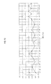
- FIG. 3 a basic jig applied to carry out the present invention is shown.
- This basic jig 10 is used in which projecting pins 11 are assembled at all transition points at which circumference dividing lines a 1 , a 2 , a 3 , . . . , a 13 and length dividing lines b 1 , b 2 , b 3 , . . . , b 17 , which are set by equally dividing a circumference W and length L of a cylinder having the same diameter ⁇ and length L of a stent to be manufactured, cross one another.
- a detailed configuration of the basic jig is disclosed in Korean Unexamined Patent Application Publication Nos. 10-2001-18024 and 10-2001-18026, both of which are the prior applications of the applicant of the present invention.
- the basic jig 10 applied to the present invention is different in that the numbers of circumference dividing lines a 1 , a 2 , a 3 , . . . , a 13 and length dividing lines b 1 , b 2 , b 3 , . . . , b 17 , which are set by equally dividing the circumference-to-diameter ratio W and the length L are increased.
- the manufacturing method of the present invention includes a downward wire bending process, a lower head forming process, an upward wire bending process, an upper head forming process, and a finishing connecting process of connecting a start end and a terminal end of a wire.
- the present invention manufactures a stent 100 using a strand of superelastic shape-memory-alloy or stainless wire (hereinafter referred to as a “wire”) having given standards per centimeter.
- any one of the circumference dividing lines a 1 , a 2 , a 3 , . . . , a 13 of the basic jig 10 is set as an arbitrary reference point a 1 , and a wire 200 extends from the reference point a 1 to the projecting pin 11 located at a transition point a 5 /b 2 that is spaced apart from the reference point by a four-segment diagonal distance (4 l) set in the resultant direction of the length L and the diameter ⁇ .
- This process is a basic process of carrying out the upper head forming process.
- a one-segment length by which the wire 200 moves along a diagonal line of the length L and the diameter ⁇ can be defined as a one-segment diagonal distance (1 l). It is appropriate to understand that, in the following description, the transition point is a point at which the wire is bent at each projecting pin 11 assembled into the basic jig 10 .
- the wire travels three times the one-segment diagonal distance (1 l) from the transition point a 5 /b 2 of the four-segment diagonal distance (4 l) to a transition point a 8 /b 3 in a zigzag pattern at an acute angle, and then travels three times the two-segment diagonal distance (2 l) from the transition point a 8 /b 3 to a transition point a 2 /b 4 in a zigzag pattern at an obtuse angle.
- the wire 200 starts from this transition point located at the projecting pin 11 of the four-segment diagonal distance (4 l) first, and travels three times the one-segment diagonal distance (1 l) to another projecting pin 11 in the zigzag pattern. Then, the wire travels three times the two-segment diagonal distance to another projecting pin 11 in the zigzag pattern again.
- This process is the downward wire bending process (cycle). This downward wire bending process is repeated, so that the wire is bent within a predetermined distance in a downward direction, and is located at a transition point a 11 /b 14 .
- the wire 200 travels five times the one-segment diagonal distance (1 l) from the transition point a 11 /b 14 located in the downward wire bending process wire to a transition point a 4 /b 15 in a zigzag pattern at an acute angle again, and then travels six times the four-segment diagonal distance (4 l) from the transition point a 4 /b 15 to the same transition point a 4 /b 15 in a zigzag pattern. Thereby, three triangular bending finishing ends 210 are formed.
- the wire travels two times the one-segment diagonal distance (1 l) from the transition point a 4 /b 15 to a transition point a 6 /b 15 in a zigzag pattern at an acute angle, and then travels six times the four-segment diagonal distance (4 l) from the transition point a 6 /b 15 to the same transition point a 6 /b 15 .
- sexangular bending finishing ends 210 are formed. This is the lower head forming process having a rhombic cell C 1 .
- the reason the wire 200 travels five times the one-segment diagonal distance (1 l) from the transition point a 11 /b 14 to the transition point a 4 /b 15 in the zigzag pattern again is to, because a route along which the wire 200 is overlapped in order to form the first triangular bending finishing ends 210 is not formed, form the route along which the triangular wire is overlapped to thereby carry out a bending traveling process.
- the reason the wire travels two times the one-segment diagonal distance (1 l) from the transition point a 4 /b 15 to the transition point a 6 /b 15 in the zigzag pattern at the acute angle is to form the route along which the wire 200 is overlapped in order to form the remaining triangular bending finishing ends 210 to thereby carry out the bending traveling process.
- the wire 200 travels seven times the one-segment diagonal distance (1 l) from the transition point a 6 /b 15 located in the lower head forming process to a transition point a 13 /b 14 in a zigzag pattern at an acute angle again, travels three times the two-segment diagonal distance (2 l) from the transition point a 13 /b 14 to a transition point a 7 /b 13 in a zigzag pattern at an obtuse angle, and travels two times the one-segment diagonal distance (1 l) from the transition point a 7 /b 13 to a transition point a 9 /b 13 in a zigzag pattern at an acute angle.
- the wire travels six times the two-segment diagonal distance (2 l) from the transition point a 9 /b 13 to a transition point a 9 /b 13 in a zigzag pattern at an obtuse angle.
- the wire travels seven times the one-segment diagonal distance (1 l) from the transition point located in the lower head forming process to the projecting pin 11 in the zigzag pattern, travels three times the two-segment diagonal distance (2 l) to the projecting pin 11 in the zigzag pattern again, travels two times the one-segment diagonal distance (1 l) to the projecting pin 11 in the zigzag pattern again, and travels six times the two-segment diagonal distance (2 l) to the projecting pin 11 in the zigzag pattern again.
- This upward wire bending process is repeated, so that the wire 200 is bent within a predetermined distance in an upward direction, and is located at a transition point a 3 /b 2 .
- the wire In the upward wire bending process of sequentially bending the wire 200 , the wire is joined crosswise at the transition point (bending vertex) overlapped with the transition point (bending vertex) of the downward wire bending process, and is bent in an upward direction. Thereby, a starry cell C 2 is repetitively formed.
- the wire 200 travels two times the one-segment diagonal distance (1 l) from the transition point a 3 /b 2 located in the upward wire bending process to a transition point a 5 /b 2 in a zigzag pattern at an acute angle again (see FIG. 14 ), and travels six times the four-segment diagonal distance (4 l) from the transition point a 5 /b 2 to a transition point a 5 /b 2 in a zigzag pattern, thereby forming three triangular bending finishing ends 211 (see FIGS. 15 and 16 ).
- the wire 200 travels two times the one-segment diagonal distance (1 l) from the transition point a 5 /b 2 to a transition point a 7 /b 2 in a zigzag pattern at an acute angle, and then travels six times the four-segment diagonal distance (4 l) from the transition point a 7 /b 2 to the same transition point a 7 /b 2 .
- sexangular bending finishing ends 211 are formed.
- This is the upper head forming process having a rhombic cell C 1 (see FIG. 17 ).
- the reason the wire 200 travels two times the one-segment diagonal distance (1 l) from the transition point a 3 /b 2 to the transition point a 5 /b 2 in the zigzag pattern at the acute angle again is to, because a route along which the wire 200 is overlapped in order to form the first triangular bending finishing ends 211 is not formed, form the route along which the triangular wire is overlapped to thereby carry out a bending traveling process.
- the reason the wire travels two times the one-segment diagonal distance (1 l) from the transition point a 2 /b 2 to the transition point a 7 /b 2 in the zigzag pattern at the acute angle is to form the route along which the wire 200 is overlapped in order to form the remaining triangular bending finishing ends 211 to thereby carry out the bending traveling process.
- the wire 200 travels three times the one-segment diagonal distance (1 l) from the transition point a 7 /b 2 located in the upper head forming process to a transition point (projecting pin) a 10 /b 3 in a zigzag pattern at an acute angle, and travels the two-segment diagonal distance (2 l) from the transition point a 10 /b 3 at an obtuse angle.
- the wire 200 is coupled with the wire 200 bent in the downward wire bending process at an overlapped portion by welding 300 . Thereby, the finishing connecting process is completed.
- the projecting pins 11 are separated from the basic jig 10 , and then a cylindrical body is separated and undergoes heat treatment.
- the stent 100 having a middle body in which the starry cells C 2 are formed in the middle thereof as shown in FIG. 10 and upper and lower heads in which the rhombic cells C 1 are formed at upper and lower portions thereof and which have the sexangular bending finishing ends is manufactured as shown in FIG. 20 .
- the stent 100 manufactured in the manufacturing method of the present invention has a structure in which the cells formed by the crossed wire 200 are repetitively formed as the starry cells C 2 by joining acute angle bending vertexes 201 bent at an acute angle and obtuse angle bending vertexes 202 bent at an obtuse angle in a crosswise shape and joining the obtuse angle bending vertexes 202 bent at the obtuse angle and the acute angle bending vertexes 201 bent at the acute angle and in the crosswise shape.
- the wires 200 are woven in such a manner that the acute angle bending vertexes 201 and the obtuse angle bending vertexes 202 , which are bent downward at the acute angle of the one-segment diagonal distance (1 l) and at the obtuse angle of the two-segment diagonal distance (2 l) in a predetermined cycle in the downward wire bending process, and the obtuse angle bending vertexes 202 and the acute angle bending vertexes 201 of the wire 200 , which are bent upward at the obtuse angle of the two-segment diagonal distance (2 l) and at the acute angle of the one-segment diagonal distance (1 l) in a predetermined cycle in the upward wire bending process, are joined crosswise.
- the starry cells C 2 are repetitively formed as shown in FIG. 21 .
- the wires 200 are bent and crossed at an acute angle in the starry cells C 2 in a simple crossed structure, and are rapidly displaced when expansion/contraction between the acute angle bending vertexes 201 and the obtuse angle bending vertexes 202 joined crosswise take place in the event of longitudinal expansion or bending.
- a flexible bending characteristic is provided.
- the expansion/contraction of the stent 100 manufactured in the manufacturing method of the present invention is provided, because the crossed wires 200 are pulled or pushed in such a manner that a distance between each acute angle bending vertex 201 and each obtuse angle bending vertex 202 of the wire 200 is increase or reduced.
- the acute angle bending vertexes 201 and the obtuse angle bending vertexes 202 are contracted in a bending direction, and are pulled in a crossed state in the opposite direction. Thereby, flexible bending movement is provided.
- the acute angle bending vertexes 201 at which the crossing of the wires 200 forming the starry cells C 2 is bent and formed at an acute angle and the obtuse angle bending vertexes 202 at which the crossing of the wires 200 forming the starry cells C 2 is bent and formed at an obtuse angle are joined crosswise, and the wires 200 bent at the obtuse angle are joined crosswise and displaced and supported when the expansion/contraction or the bending takes place.
- the wires provide flexible movement without being folded.
- the coated thin film is not stripped.
- the upper head and the lower head are formed by the wire 200 in which the rhombic cells C 1 are formed in two rows and which is uncomplicatedly crossed, and are not accompanied with great stress, so that they do not exert particular influence on the bending movement or expansion.
- FIG. 25 An actual stent manufactured by the present invention is shown in FIG. 25 through a photograph.
- FIG. 26 is a photograph taken of a coated actual stent manufactured by the present invention.
- FIG. 27 is a photograph showing the actual stent of FIG. 26 in order to show that the real thing is not folded even when is bent in a U shape.
- the stent in a state in which an inner and/or outer surface of the stent of the present invention is coated with a coating material such as silicone or polytetrafluoroethylene (PTFE) as in a typical method, the stent is bent in the U shape, and is not folded. Thus, it can be found that the bending characteristic of the stent is very good.
- a coating material such as silicone or polytetrafluoroethylene (PTFE)
- This coating material is used to prevent lesion cells from penetrating into a lumen after the stent is inserted into the lumen.
Landscapes
- Health & Medical Sciences (AREA)
- Engineering & Computer Science (AREA)
- Biomedical Technology (AREA)
- Vascular Medicine (AREA)
- General Health & Medical Sciences (AREA)
- Heart & Thoracic Surgery (AREA)
- Mechanical Engineering (AREA)
- Cardiology (AREA)
- Life Sciences & Earth Sciences (AREA)
- Animal Behavior & Ethology (AREA)
- Transplantation (AREA)
- Public Health (AREA)
- Veterinary Medicine (AREA)
- Oral & Maxillofacial Surgery (AREA)
- Media Introduction/Drainage Providing Device (AREA)
Applications Claiming Priority (3)
| Application Number | Priority Date | Filing Date | Title |
|---|---|---|---|
| KR10-2011-0004078 | 2011-01-14 | ||
| KR1020110004078A KR101330825B1 (ko) | 2011-01-14 | 2011-01-14 | 굽힘 특성이 양호한 스텐트의 제조방법과 그 스텐트 |
| PCT/KR2012/000238 WO2012096497A2 (ko) | 2011-01-14 | 2012-01-10 | 굽힘 특성이 양호한 스텐트의 제조방법과 그 스텐트 |
Publications (2)
| Publication Number | Publication Date |
|---|---|
| US20130282105A1 US20130282105A1 (en) | 2013-10-24 |
| US9320624B2 true US9320624B2 (en) | 2016-04-26 |
Family
ID=46507563
Family Applications (1)
| Application Number | Title | Priority Date | Filing Date |
|---|---|---|---|
| US13/978,020 Active 2032-10-03 US9320624B2 (en) | 2011-01-14 | 2012-01-10 | Method for manufacturing a stent having superior bending characteristics, and stent manufactured thereby |
Country Status (4)
| Country | Link |
|---|---|
| US (1) | US9320624B2 (ja) |
| JP (1) | JP5777012B2 (ja) |
| KR (1) | KR101330825B1 (ja) |
| WO (1) | WO2012096497A2 (ja) |
Cited By (5)
| Publication number | Priority date | Publication date | Assignee | Title |
|---|---|---|---|---|
| US10349944B2 (en) | 2015-02-04 | 2019-07-16 | M.I. Tech Co., Ltd. | Stent for connecting adjacent tissues and manufacturing method thereof |
| US11382756B2 (en) | 2016-07-28 | 2022-07-12 | Depuy Ireland Unlimited Company | Total knee implant prosthesis assembly and method |
| US11510784B2 (en) | 2019-09-10 | 2022-11-29 | Depuy Ireland Unlimited Company | Orthopaedic knee prosthesis system and methods for using same |
| US11786308B2 (en) | 2019-05-02 | 2023-10-17 | DePuy Synthes Products, Inc. | Orthopaedic implant placement system and method |
| US11865011B2 (en) | 2020-07-10 | 2024-01-09 | Depuy Ireland Unlimited Company | Medial stabilized orthopaedic tibial insert |
Families Citing this family (11)
| Publication number | Priority date | Publication date | Assignee | Title |
|---|---|---|---|---|
| CZ201454A3 (cs) * | 2014-01-23 | 2015-11-04 | Ella- Cs, S.R.O. | Stent |
| JP6045036B2 (ja) * | 2014-01-28 | 2016-12-14 | 日本ライフライン株式会社 | ステント |
| KR101616864B1 (ko) * | 2014-09-01 | 2016-04-29 | 주식회사 엠아이텍 | 스텐트 제조 방법 |
| KR101645629B1 (ko) * | 2014-09-05 | 2016-08-12 | 주식회사 비씨엠 | 스텐트와 그 스텐트 제조방법 |
| KR101631491B1 (ko) * | 2014-10-06 | 2016-06-17 | 주식회사 엠아이텍 | 스텐트 제조방법 |
| KR101713648B1 (ko) * | 2014-12-15 | 2017-03-09 | 주식회사 엠아이텍 | 스텐트 제조방법 |
| JP6177259B2 (ja) * | 2015-01-13 | 2017-08-09 | 日本ライフライン株式会社 | ステントおよびステントグラフト |
| KR101728319B1 (ko) * | 2015-04-15 | 2017-04-19 | 주식회사 엠아이텍 | 스텐트 제조방법 |
| KR102196226B1 (ko) * | 2019-01-28 | 2020-12-29 | 이재희 | 스텐트 및 그 제작 방법 |
| KR102260848B1 (ko) * | 2019-06-14 | 2021-06-03 | 박성욱 | 스텐트 및 그 제조방법 |
| CN114055098B (zh) * | 2021-12-10 | 2023-11-14 | 中国科学院合肥物质科学研究院 | 一种嵌槽钎焊配法的弯曲斜螺线管cct骨架加工方法 |
Citations (15)
| Publication number | Priority date | Publication date | Assignee | Title |
|---|---|---|---|---|
| US6063113A (en) * | 1995-06-13 | 2000-05-16 | William Cook Europe Aps | Device for implantation in a vessel or hollow organ lumen |
| JP2003088591A (ja) | 2001-09-19 | 2003-03-25 | Piolax Medical Device:Kk | ステント及びステント付きグラフト |
| KR100424290B1 (ko) | 2001-04-04 | 2004-03-24 | (주) 태웅메디칼 | 형상기억합금을 이용한 담즙관 확장기구의 제조방법과이에 의해 제조된 확장기구 |
| KR100457629B1 (ko) | 2001-04-04 | 2004-11-18 | (주) 태웅메디칼 | 형상기억합금을 이용한 가변상태 유지형 확장기구의제조방법과 이에 의해 제조된 확장기구 |
| US20050096733A1 (en) * | 2001-12-29 | 2005-05-05 | Kovneristy July K. | Stent and method for the production thereof (variants) |
| KR100826664B1 (ko) | 2006-11-01 | 2008-05-02 | 주식회사 엠아이텍 | 스텐트 및 이 스텐트의 제조방법 |
| US7462192B2 (en) * | 2004-11-10 | 2008-12-09 | Boston Scientific Scimed, Inc. | Atraumatic stent with reduced deployment force, method for making the same and method and apparatus for deploying and positioning the stent |
| KR20090038209A (ko) | 2007-10-15 | 2009-04-20 | 주식회사 스텐다드싸이텍 | 스텐트 |
| US20090306762A1 (en) * | 2002-11-15 | 2009-12-10 | Boston Scientific Scimed, Inc. | Braided stent and method for its manufacture |
| KR20100042478A (ko) | 2008-10-16 | 2010-04-26 | (주) 태웅메디칼 | 굴곡 변형성을 갖는 스텐트의 제조방법과 그 스텐트 |
| US20110029062A1 (en) * | 2008-07-16 | 2011-02-03 | Sung-Gwon Kang | Stent used in blood vessel |
| US20110144739A1 (en) * | 2008-08-05 | 2011-06-16 | Acandis Gmbh & Co. Kg | Medical device and method for producing a device of said kind |
| US20140088688A1 (en) * | 2009-01-26 | 2014-03-27 | Boston Scientific Scimed, Inc. | Atraumatic Stent and Method and Apparatus for making the same |
| US8869670B1 (en) * | 2013-07-29 | 2014-10-28 | Insera Therapeutics, Inc. | Methods of manufacturing variable porosity devices |
| US20150045874A1 (en) * | 2013-08-09 | 2015-02-12 | Boston Scientific Scimed, Inc. | Stent designs and methods of manufacture |
Family Cites Families (4)
| Publication number | Priority date | Publication date | Assignee | Title |
|---|---|---|---|---|
| US5609627A (en) * | 1994-02-09 | 1997-03-11 | Boston Scientific Technology, Inc. | Method for delivering a bifurcated endoluminal prosthesis |
| US6241757B1 (en) * | 1997-02-04 | 2001-06-05 | Solco Surgical Instrument Co., Ltd. | Stent for expanding body's lumen |
| US6652571B1 (en) * | 2000-01-31 | 2003-11-25 | Scimed Life Systems, Inc. | Braided, branched, implantable device and processes for manufacture thereof |
| KR100633020B1 (ko) * | 2005-07-15 | 2006-10-11 | 주식회사 스텐다드싸이텍 | 스텐트 및 그의 제작 방법 |
-
2011
- 2011-01-14 KR KR1020110004078A patent/KR101330825B1/ko active IP Right Grant
-
2012
- 2012-01-10 US US13/978,020 patent/US9320624B2/en active Active
- 2012-01-10 WO PCT/KR2012/000238 patent/WO2012096497A2/ko active Application Filing
- 2012-01-10 JP JP2013548364A patent/JP5777012B2/ja active Active
Patent Citations (15)
| Publication number | Priority date | Publication date | Assignee | Title |
|---|---|---|---|---|
| US6063113A (en) * | 1995-06-13 | 2000-05-16 | William Cook Europe Aps | Device for implantation in a vessel or hollow organ lumen |
| KR100424290B1 (ko) | 2001-04-04 | 2004-03-24 | (주) 태웅메디칼 | 형상기억합금을 이용한 담즙관 확장기구의 제조방법과이에 의해 제조된 확장기구 |
| KR100457629B1 (ko) | 2001-04-04 | 2004-11-18 | (주) 태웅메디칼 | 형상기억합금을 이용한 가변상태 유지형 확장기구의제조방법과 이에 의해 제조된 확장기구 |
| JP2003088591A (ja) | 2001-09-19 | 2003-03-25 | Piolax Medical Device:Kk | ステント及びステント付きグラフト |
| US20050096733A1 (en) * | 2001-12-29 | 2005-05-05 | Kovneristy July K. | Stent and method for the production thereof (variants) |
| US20090306762A1 (en) * | 2002-11-15 | 2009-12-10 | Boston Scientific Scimed, Inc. | Braided stent and method for its manufacture |
| US7462192B2 (en) * | 2004-11-10 | 2008-12-09 | Boston Scientific Scimed, Inc. | Atraumatic stent with reduced deployment force, method for making the same and method and apparatus for deploying and positioning the stent |
| KR100826664B1 (ko) | 2006-11-01 | 2008-05-02 | 주식회사 엠아이텍 | 스텐트 및 이 스텐트의 제조방법 |
| KR20090038209A (ko) | 2007-10-15 | 2009-04-20 | 주식회사 스텐다드싸이텍 | 스텐트 |
| US20110029062A1 (en) * | 2008-07-16 | 2011-02-03 | Sung-Gwon Kang | Stent used in blood vessel |
| US20110144739A1 (en) * | 2008-08-05 | 2011-06-16 | Acandis Gmbh & Co. Kg | Medical device and method for producing a device of said kind |
| KR20100042478A (ko) | 2008-10-16 | 2010-04-26 | (주) 태웅메디칼 | 굴곡 변형성을 갖는 스텐트의 제조방법과 그 스텐트 |
| US20140088688A1 (en) * | 2009-01-26 | 2014-03-27 | Boston Scientific Scimed, Inc. | Atraumatic Stent and Method and Apparatus for making the same |
| US8869670B1 (en) * | 2013-07-29 | 2014-10-28 | Insera Therapeutics, Inc. | Methods of manufacturing variable porosity devices |
| US20150045874A1 (en) * | 2013-08-09 | 2015-02-12 | Boston Scientific Scimed, Inc. | Stent designs and methods of manufacture |
Cited By (8)
| Publication number | Priority date | Publication date | Assignee | Title |
|---|---|---|---|---|
| US10349944B2 (en) | 2015-02-04 | 2019-07-16 | M.I. Tech Co., Ltd. | Stent for connecting adjacent tissues and manufacturing method thereof |
| US10617421B2 (en) | 2015-02-04 | 2020-04-14 | M.I. Tech Co., Ltd. | Stent for connecting adjacent tissues and manufacturing method thereof |
| US11382756B2 (en) | 2016-07-28 | 2022-07-12 | Depuy Ireland Unlimited Company | Total knee implant prosthesis assembly and method |
| US11786308B2 (en) | 2019-05-02 | 2023-10-17 | DePuy Synthes Products, Inc. | Orthopaedic implant placement system and method |
| US11510784B2 (en) | 2019-09-10 | 2022-11-29 | Depuy Ireland Unlimited Company | Orthopaedic knee prosthesis system and methods for using same |
| US11957591B2 (en) | 2019-09-10 | 2024-04-16 | Depuy Ireland Unlimited Company | Orthopaedic knee prosthesis system and methods for using same |
| US11865011B2 (en) | 2020-07-10 | 2024-01-09 | Depuy Ireland Unlimited Company | Medial stabilized orthopaedic tibial insert |
| US11883298B2 (en) | 2020-07-10 | 2024-01-30 | Depuy Ireland Unlimited Company | Medial stabilized orthopaedic knee prosthesis |
Also Published As
| Publication number | Publication date |
|---|---|
| KR101330825B1 (ko) | 2013-11-15 |
| US20130282105A1 (en) | 2013-10-24 |
| JP5777012B2 (ja) | 2015-09-09 |
| WO2012096497A3 (ko) | 2012-11-22 |
| JP2014512195A (ja) | 2014-05-22 |
| WO2012096497A2 (ko) | 2012-07-19 |
| KR20120082662A (ko) | 2012-07-24 |
Similar Documents
| Publication | Publication Date | Title |
|---|---|---|
| US9320624B2 (en) | Method for manufacturing a stent having superior bending characteristics, and stent manufactured thereby | |
| JP7092734B2 (ja) | 減少した短縮および反跳を有するステントデバイスおよびその製造方法 | |
| JP3708923B2 (ja) | 形状記憶合金を用いた可変状態保持型拡張機構およびその製造方法並びに拡張機構製造機 | |
| EP3254643B1 (en) | Linking stent and production method for same | |
| US20080167709A1 (en) | Stent and Method for Manufacturing the Same | |
| WO2023140214A1 (ja) | ステント | |
| KR101796430B1 (ko) | 스텐트 및 스텐트 그래프트 | |
| KR101799713B1 (ko) | 스텐트 | |
| JPWO2020050292A1 (ja) | ステント | |
| WO2015145596A1 (ja) | 柔軟性ステント | |
| KR101602400B1 (ko) | 스텐트 제조 방법 | |
| JP4429833B2 (ja) | ステント及びステントグラフト | |
| JP2003334255A (ja) | ステント及びステントグラフト | |
| KR100548781B1 (ko) | 원통형 스텐트 | |
| KR101109719B1 (ko) | 확장식 스텐트 | |
| KR101777366B1 (ko) | 스텐트 | |
| KR100424290B1 (ko) | 형상기억합금을 이용한 담즙관 확장기구의 제조방법과이에 의해 제조된 확장기구 | |
| US20230190498A1 (en) | Stent with shaped wires | |
| JP4159962B2 (ja) | ステント及びステントグラフト | |
| KR100548782B1 (ko) | 원통형 스텐트 | |
| KR101119621B1 (ko) | 스텐트 | |
| JPWO2020059101A1 (ja) | ステントおよび医療機器 |
Legal Events
| Date | Code | Title | Description |
|---|---|---|---|
| AS | Assignment |
Owner name: TAEWOONG MEDICAL CO., LTD., KOREA, REPUBLIC OF Free format text: ASSIGNMENT OF ASSIGNORS INTEREST;ASSIGNOR:SHIN, KYONG MIN;REEL/FRAME:030728/0320 Effective date: 20130604 Owner name: SHIN, KYONG MIN, KOREA, REPUBLIC OF Free format text: ASSIGNMENT OF ASSIGNORS INTEREST;ASSIGNOR:SHIN, KYONG MIN;REEL/FRAME:030728/0320 Effective date: 20130604 |
|
| STCF | Information on status: patent grant |
Free format text: PATENTED CASE |
|
| MAFP | Maintenance fee payment |
Free format text: PAYMENT OF MAINTENANCE FEE, 4TH YR, SMALL ENTITY (ORIGINAL EVENT CODE: M2551); ENTITY STATUS OF PATENT OWNER: SMALL ENTITY Year of fee payment: 4 |
|
| MAFP | Maintenance fee payment |
Free format text: PAYMENT OF MAINTENANCE FEE, 8TH YR, SMALL ENTITY (ORIGINAL EVENT CODE: M2552); ENTITY STATUS OF PATENT OWNER: SMALL ENTITY Year of fee payment: 8 |
|
| AS | Assignment |
Owner name: TAEWOONG MEDICAL CO., LTD, KOREA, REPUBLIC OF Free format text: ASSIGNMENT OF ASSIGNORS INTEREST;ASSIGNOR:SHIN, KYONG MIN;REEL/FRAME:064560/0293 Effective date: 20230810 |