US7021390B2 - Tubular liner for wellbore casing - Google Patents
Tubular liner for wellbore casing Download PDFInfo
- Publication number
- US7021390B2 US7021390B2 US10/418,687 US41868703A US7021390B2 US 7021390 B2 US7021390 B2 US 7021390B2 US 41868703 A US41868703 A US 41868703A US 7021390 B2 US7021390 B2 US 7021390B2
- Authority
- US
- United States
- Prior art keywords
- tubing
- expandable
- tubular member
- section
- preferred
- Prior art date
- Legal status (The legal status is an assumption and is not a legal conclusion. Google has not performed a legal analysis and makes no representation as to the accuracy of the status listed.)
- Expired - Lifetime, expires
Links
- 238000000034 method Methods 0.000 claims abstract description 187
- 230000008878 coupling Effects 0.000 claims abstract description 10
- 238000010168 coupling process Methods 0.000 claims abstract description 10
- 238000005859 coupling reaction Methods 0.000 claims abstract description 10
- 239000000463 material Substances 0.000 claims description 214
- 238000007789 sealing Methods 0.000 claims description 91
- 229920001971 elastomer Polymers 0.000 claims description 23
- 239000004033 plastic Substances 0.000 claims description 12
- 229920003023 plastic Polymers 0.000 claims description 12
- 230000009467 reduction Effects 0.000 claims description 7
- 230000006835 compression Effects 0.000 claims description 2
- 238000007906 compression Methods 0.000 claims description 2
- 239000000806 elastomer Substances 0.000 claims 2
- 238000004519 manufacturing process Methods 0.000 claims 2
- 239000002184 metal Substances 0.000 claims 2
- 239000004576 sand Substances 0.000 claims 1
- 239000012530 fluid Substances 0.000 description 227
- 230000008569 process Effects 0.000 description 70
- 239000004568 cement Substances 0.000 description 68
- 238000001125 extrusion Methods 0.000 description 67
- 239000003566 sealing material Substances 0.000 description 65
- 238000005553 drilling Methods 0.000 description 39
- 239000000314 lubricant Substances 0.000 description 36
- 229910052782 aluminium Inorganic materials 0.000 description 27
- XAGFODPZIPBFFR-UHFFFAOYSA-N aluminium Chemical compound [Al] XAGFODPZIPBFFR-UHFFFAOYSA-N 0.000 description 27
- 239000004593 Epoxy Substances 0.000 description 24
- 230000015572 biosynthetic process Effects 0.000 description 21
- 239000005060 rubber Substances 0.000 description 21
- 229910000831 Steel Inorganic materials 0.000 description 19
- 239000010959 steel Substances 0.000 description 19
- 239000000203 mixture Substances 0.000 description 17
- -1 for example Substances 0.000 description 16
- 230000035939 shock Effects 0.000 description 16
- 125000006850 spacer group Chemical group 0.000 description 12
- 229910000851 Alloy steel Inorganic materials 0.000 description 10
- 238000002347 injection Methods 0.000 description 10
- 239000007924 injection Substances 0.000 description 10
- 229910001220 stainless steel Inorganic materials 0.000 description 10
- 229910001018 Cast iron Inorganic materials 0.000 description 9
- 125000003700 epoxy group Chemical group 0.000 description 9
- 229920000647 polyepoxide Polymers 0.000 description 9
- 238000004891 communication Methods 0.000 description 8
- 238000004836 empirical method Methods 0.000 description 8
- 238000005086 pumping Methods 0.000 description 8
- 239000006096 absorbing agent Substances 0.000 description 7
- 239000002893 slag Substances 0.000 description 7
- 239000003381 stabilizer Substances 0.000 description 7
- RTAQQCXQSZGOHL-UHFFFAOYSA-N Titanium Chemical compound [Ti] RTAQQCXQSZGOHL-UHFFFAOYSA-N 0.000 description 6
- 239000010936 titanium Substances 0.000 description 6
- 238000003466 welding Methods 0.000 description 6
- 229910001315 Tool steel Inorganic materials 0.000 description 5
- 230000000903 blocking effect Effects 0.000 description 5
- 238000006073 displacement reaction Methods 0.000 description 5
- 230000000694 effects Effects 0.000 description 5
- 239000010935 stainless steel Substances 0.000 description 5
- ZAMOUSCENKQFHK-UHFFFAOYSA-N Chlorine atom Chemical compound [Cl] ZAMOUSCENKQFHK-UHFFFAOYSA-N 0.000 description 4
- 239000004809 Teflon Substances 0.000 description 4
- 229920006362 Teflon® Polymers 0.000 description 4
- 238000005299 abrasion Methods 0.000 description 4
- 229910052801 chlorine Inorganic materials 0.000 description 4
- 239000000460 chlorine Substances 0.000 description 4
- 238000007796 conventional method Methods 0.000 description 4
- 239000011133 lead Substances 0.000 description 4
- 230000001050 lubricating effect Effects 0.000 description 4
- 238000005461 lubrication Methods 0.000 description 4
- 239000007787 solid Substances 0.000 description 4
- 229910052719 titanium Inorganic materials 0.000 description 4
- 230000004888 barrier function Effects 0.000 description 3
- 239000000919 ceramic Substances 0.000 description 3
- 230000000977 initiatory effect Effects 0.000 description 3
- 238000005304 joining Methods 0.000 description 3
- 230000007257 malfunction Effects 0.000 description 3
- 229910001200 Ferrotitanium Inorganic materials 0.000 description 2
- XEEYBQQBJWHFJM-UHFFFAOYSA-N Iron Chemical compound [Fe] XEEYBQQBJWHFJM-UHFFFAOYSA-N 0.000 description 2
- 229910045601 alloy Inorganic materials 0.000 description 2
- 239000000956 alloy Substances 0.000 description 2
- 238000010276 construction Methods 0.000 description 2
- 238000005520 cutting process Methods 0.000 description 2
- 238000003780 insertion Methods 0.000 description 2
- 230000037431 insertion Effects 0.000 description 2
- 230000008439 repair process Effects 0.000 description 2
- 239000011343 solid material Substances 0.000 description 2
- 238000012360 testing method Methods 0.000 description 2
- 229910001369 Brass Inorganic materials 0.000 description 1
- VYZAMTAEIAYCRO-UHFFFAOYSA-N Chromium Chemical compound [Cr] VYZAMTAEIAYCRO-UHFFFAOYSA-N 0.000 description 1
- 230000008901 benefit Effects 0.000 description 1
- 239000010951 brass Substances 0.000 description 1
- 229910052804 chromium Inorganic materials 0.000 description 1
- 239000011651 chromium Substances 0.000 description 1
- 239000002131 composite material Substances 0.000 description 1
- 150000001875 compounds Chemical class 0.000 description 1
- 230000003247 decreasing effect Effects 0.000 description 1
- 238000013461 design Methods 0.000 description 1
- 230000005484 gravity Effects 0.000 description 1
- 229930195733 hydrocarbon Natural products 0.000 description 1
- 150000002430 hydrocarbons Chemical class 0.000 description 1
- 238000009434 installation Methods 0.000 description 1
- 229910052742 iron Inorganic materials 0.000 description 1
- 238000012986 modification Methods 0.000 description 1
- 230000004048 modification Effects 0.000 description 1
- 239000006187 pill Substances 0.000 description 1
- 238000006467 substitution reaction Methods 0.000 description 1
- 238000012546 transfer Methods 0.000 description 1
- XLYOFNOQVPJJNP-UHFFFAOYSA-N water Substances O XLYOFNOQVPJJNP-UHFFFAOYSA-N 0.000 description 1
Images


Classifications
-
- E—FIXED CONSTRUCTIONS
- E21—EARTH OR ROCK DRILLING; MINING
- E21B—EARTH OR ROCK DRILLING; OBTAINING OIL, GAS, WATER, SOLUBLE OR MELTABLE MATERIALS OR A SLURRY OF MINERALS FROM WELLS
- E21B43/00—Methods or apparatus for obtaining oil, gas, water, soluble or meltable materials or a slurry of minerals from wells
- E21B43/02—Subsoil filtering
- E21B43/10—Setting of casings, screens, liners or the like in wells
- E21B43/103—Setting of casings, screens, liners or the like in wells of expandable casings, screens, liners, or the like
- E21B43/106—Couplings or joints therefor
-
- E—FIXED CONSTRUCTIONS
- E21—EARTH OR ROCK DRILLING; MINING
- E21B—EARTH OR ROCK DRILLING; OBTAINING OIL, GAS, WATER, SOLUBLE OR MELTABLE MATERIALS OR A SLURRY OF MINERALS FROM WELLS
- E21B29/00—Cutting or destroying pipes, packers, plugs or wire lines, located in boreholes or wells, e.g. cutting of damaged pipes, of windows; Deforming of pipes in boreholes or wells; Reconditioning of well casings while in the ground
- E21B29/10—Reconditioning of well casings, e.g. straightening
-
- E—FIXED CONSTRUCTIONS
- E21—EARTH OR ROCK DRILLING; MINING
- E21B—EARTH OR ROCK DRILLING; OBTAINING OIL, GAS, WATER, SOLUBLE OR MELTABLE MATERIALS OR A SLURRY OF MINERALS FROM WELLS
- E21B43/00—Methods or apparatus for obtaining oil, gas, water, soluble or meltable materials or a slurry of minerals from wells
- E21B43/02—Subsoil filtering
- E21B43/08—Screens or liners
- E21B43/084—Screens comprising woven materials, e.g. mesh or cloth
-
- E—FIXED CONSTRUCTIONS
- E21—EARTH OR ROCK DRILLING; MINING
- E21B—EARTH OR ROCK DRILLING; OBTAINING OIL, GAS, WATER, SOLUBLE OR MELTABLE MATERIALS OR A SLURRY OF MINERALS FROM WELLS
- E21B43/00—Methods or apparatus for obtaining oil, gas, water, soluble or meltable materials or a slurry of minerals from wells
- E21B43/02—Subsoil filtering
- E21B43/10—Setting of casings, screens, liners or the like in wells
- E21B43/103—Setting of casings, screens, liners or the like in wells of expandable casings, screens, liners, or the like
- E21B43/105—Expanding tools specially adapted therefor
-
- E—FIXED CONSTRUCTIONS
- E21—EARTH OR ROCK DRILLING; MINING
- E21B—EARTH OR ROCK DRILLING; OBTAINING OIL, GAS, WATER, SOLUBLE OR MELTABLE MATERIALS OR A SLURRY OF MINERALS FROM WELLS
- E21B43/00—Methods or apparatus for obtaining oil, gas, water, soluble or meltable materials or a slurry of minerals from wells
- E21B43/14—Obtaining from a multiple-zone well
-
- E—FIXED CONSTRUCTIONS
- E21—EARTH OR ROCK DRILLING; MINING
- E21B—EARTH OR ROCK DRILLING; OBTAINING OIL, GAS, WATER, SOLUBLE OR MELTABLE MATERIALS OR A SLURRY OF MINERALS FROM WELLS
- E21B43/00—Methods or apparatus for obtaining oil, gas, water, soluble or meltable materials or a slurry of minerals from wells
- E21B43/30—Specific pattern of wells, e.g. optimising the spacing of wells
- E21B43/305—Specific pattern of wells, e.g. optimising the spacing of wells comprising at least one inclined or horizontal well
-
- Y—GENERAL TAGGING OF NEW TECHNOLOGICAL DEVELOPMENTS; GENERAL TAGGING OF CROSS-SECTIONAL TECHNOLOGIES SPANNING OVER SEVERAL SECTIONS OF THE IPC; TECHNICAL SUBJECTS COVERED BY FORMER USPC CROSS-REFERENCE ART COLLECTIONS [XRACs] AND DIGESTS
- Y10—TECHNICAL SUBJECTS COVERED BY FORMER USPC
- Y10T—TECHNICAL SUBJECTS COVERED BY FORMER US CLASSIFICATION
- Y10T137/00—Fluid handling
- Y10T137/0318—Processes
- Y10T137/0402—Cleaning, repairing, or assembling
- Y10T137/0441—Repairing, securing, replacing, or servicing pipe joint, valve, or tank
- Y10T137/0447—Including joint or coupling
Definitions
- This invention relates generally to wellbore casings, and in particular to wellbore casings that are formed using expandable tubing.
- a relatively large borehole diameter is required at the upper part of the wellbore.
- Such a large borehole diameter involves increased costs due to heavy casing handling equipment, large drill bits and increased volumes of drilling fluid and drill cuttings.
- increased drilling rig time is involved due to required cement pumping, cement hardening, required equipment changes due to large variations in hole diameters drilled in the course of the well, and the large volume of cuttings drilled and removed.
- the present invention is directed to overcoming one or more of the limitations of the existing procedures for forming new sections of casing in a wellbore.
- a method of forming a wellbore casing includes installing a tubular liner and a mandrel in the borehole, injecting fluidic material into the borehole, and radially expanding the liner in the borehole by extruding the liner off of the mandrel.
- a method of forming a wellbore casing includes drilling out a new section of the borehole adjacent to the already existing casing.
- a tubular liner and a mandrel are then placed into the new section of the borehole with the tubular liner overlapping an already existing casing.
- a hardenable fluidic sealing material is injected into an annular region between the tubular liner and the new section of the borehole.
- the annular region between the tubular liner and the new section of the borehole is then fluidicly isolated from an interior region of the tubular liner below the mandrel.
- a non hardenable fluidic material is then injected into the interior region of the tubular liner below the mandrel.
- the tubular liner is extruded off of the mandrel.
- the overlap between the tubular liner and the already existing casing is sealed.
- the tubular liner is supported by overlap with the already existing casing.
- the mandrel is removed from the borehole.
- the integrity of the seal of the overlap between the tubular liner and the already existing casing is tested.
- At least a portion of the second quantity of the hardenable fluidic sealing material is removed from the interior of the tubular liner.
- the remaining portions of the fluidic hardenable fluidic sealing material are cured.
- At least a portion of cured fluidic hardenable sealing material within the tubular liner is removed.
- an apparatus for expanding a tubular member includes a support member, a mandrel, a tubular member, and a shoe.
- the support member includes a first fluid passage.
- the mandrel is coupled to the support member and includes a second fluid passage.
- the tubular member is coupled to the mandrel.
- the shoe is coupled to the tubular liner and includes a third fluid passage. The first, second and third fluid passages are operably coupled.
- an apparatus for expanding a tubular member includes a support member, an expandable mandrel, a tubular member, a shoe, and at least one sealing member.
- the support member includes a first fluid passage, a second fluid passage, and a flow control valve coupled to the first and second fluid passages.
- the expandable mandrel is coupled to the support member and includes a third fluid passage.
- the tubular member is coupled to the mandrel and includes one or more sealing elements.
- the shoe is coupled to the tubular member and includes a fourth fluid passage.
- the at least one sealing member is adapted to prevent the entry of foreign material into an interior region of the tubular member.
- a method of joining a second tubular member to a first tubular member, the first tubular member having an inner diameter greater than an outer diameter of the second tubular member includes positioning a mandrel within an interior region of the second tubular member. A portion of an interior region of the second tubular member is pressurized and the second tubular member is extruded off of the mandrel into engagement with the first tubular member.
- a tubular liner that includes an annular member having one or more sealing members at an end portion of the annular member, and one or more pressure relief passages at an end portion of the annular member.
- a wellbore casing that includes a tubular liner and an annular body of a cured fluidic sealing material.
- the tubular liner is formed by the process of extruding the tubular liner off of a mandrel.
- a tie-back liner for lining an existing wellbore casing includes a tubular liner and an annular body of cured fluidic sealing material.
- the tubular liner is formed by the process of extruding the tubular liner off of a mandrel.
- the annular body of a cured fluidic sealing material is coupled to the tubular liner.
- an apparatus for expanding a tubular member includes a support member, a mandrel, a tubular member and a shoe.
- the support member includes a first fluid passage.
- the mandrel is coupled to the support member.
- the mandrel includes a second fluid passage operably coupled to the first fluid passage, an interior portion, and an exterior portion.
- the interior portion of the mandrel is drillable.
- the tubular member is coupled to the mandrel.
- the shoe is coupled to the tubular member.
- the shoe includes a third fluid passage operably coupled to the second fluid passage, an interior portion, and an exterior portion. The interior portion of the shoe is drillable.
- FIG. 1 is a fragmentary cross-sectional view illustrating the drilling of a new section of a well borehole.
- FIG. 2 is a fragmentary cross-sectional view illustrating the placement of an embodiment of an apparatus for creating a casing within the new section of the well borehole.
- FIG. 3 is a fragmentary cross-sectional view illustrating the injection of a first quantity of a hardenable fluidic sealing material into the new section of the well borehole.
- FIG. 3 a is another fragmentary cross-sectional view illustrating the injection of a first quantity of a hardenable fluidic sealing material into the new section of the well borehole.
- FIG. 4 is a fragmentary cross-sectional view illustrating the injection of a second quantity of a hardenable fluidic sealing material into the new section of the well borehole.
- FIG. 5 is a fragmentary cross-sectional view illustrating the drilling out of a portion of the cured hardenable fluidic sealing material from the new section of the well borehole.
- FIG. 6 is a cross-sectional view of an embodiment of the overlapping joint between adjacent tubular members.
- FIG. 7 is a fragmentary cross-sectional view of a preferred embodiment of the apparatus for creating a casing within a well borehole.
- FIG. 8 is a fragmentary cross-sectional illustration of the placement of an expanded tubular member within another tubular member.
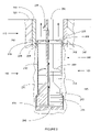
- FIG. 9 is a cross-sectional illustration of a preferred embodiment of an apparatus for forming a casing including a drillable mandrel and shoe.
- FIG. 9 a is another cross-sectional illustration of the apparatus of FIG. 9 .
- FIG. 9 b is another cross-sectional illustration of the apparatus of FIG. 9 .
- FIG. 9 c is another cross-sectional illustration of the apparatus of FIG. 9 .
- FIG. 10 a is a cross-sectional illustration of a wellbore including a pair of adjacent overlapping casings.
- FIG. 10 b is a cross-sectional illustration of an apparatus and method for creating a tie-back liner using an expandable tubular member.
- FIG. 10 c is a cross-sectional illustration of the pumping of a fluidic sealing material into the annular region between the tubular member and the existing casing.
- FIG. 10 d is a cross-sectional illustration of the pressurizing of the interior of the tubular member below the mandrel.
- FIG. 10 e is a cross-sectional illustration of the extrusion of the tubular member off of the mandrel.
- FIG. 10 f is a cross-sectional illustration of the tie-back liner before drilling out the shoe and packer.
- FIG. 10 g is a cross-sectional illustration of the completed tie-back liner created using an expandable tubular member.
- FIG. 11 a is a fragmentary cross-sectional view illustrating the drilling of a new section of a well borehole.
- FIG. 11 b is a fragmentary cross-sectional view illustrating the placement of an embodiment of an apparatus for hanging a tubular liner within the new section of the well borehole.
- FIG. 11 c is a fragmentary cross-sectional view illustrating the injection of a first quantity of a hardenable fluidic sealing material into the new section of the well borehole.
- FIG. 11 d is a fragmentary cross-sectional view illustrating the introduction of a wiper dart into the new section of the well borehole.
- FIG. 11 e is a fragmentary cross-sectional view illustrating the injection of a second quantity of a hardenable fluidic sealing material into the new section of the well borehole.
- FIG. 11 f is a fragmentary cross-sectional view illustrating the completion of the tubular liner.
- An apparatus and method for forming a wellbore casing within a subterranean formation permits a wellbore casing to be formed in a subterranean formation by placing a tubular member and a mandrel in a new section of a wellbore, and then extruding the tubular member off of the mandrel by pressurizing an interior portion of the tubular member.
- the apparatus and method further permits adjacent tubular members in the wellbore to be joined using an overlapping joint that prevents fluid and or gas passage.
- the apparatus and method further permits a new tubular member to be supported by an existing tubular member by expanding the new tubular member into engagement with the existing tubular member.
- the apparatus and method further minimizes the reduction in the hole size of the wellbore casing necessitated by the addition of new sections of wellbore casing.
- An apparatus and method for forming a tie-back liner using an expandable tubular member is also provided.
- the apparatus and method permits a tie-back liner to be created by extruding a tubular member off of a mandrel by pressurizing and interior portion of the tubular member. In this manner, a tie-back liner is produced.
- the apparatus and method further permits adjacent tubular members in the wellbore to be joined using an overlapping joint that prevents fluid and/or gas passage.
- the apparatus and method further permits a new tubular member to be supported by an existing tubular member by expanding the new tubular member into engagement with the existing tubular member.
- An apparatus and method for expanding a tubular member is also provided that includes an expandable tubular member, mandrel and a shoe.
- the interior portions of the apparatus is composed of materials that permit the interior portions to be removed using a conventional drilling apparatus. In this manner, in the event of a malfunction in a downhole region, the apparatus may be easily removed.
- An apparatus and method for hanging an expandable tubular liner in a wellbore is also provided.
- the apparatus and method permit a tubular liner to be attached to an existing section of casing.
- the apparatus and method further have application to the joining of tubular members in general.
- a wellbore 100 is positioned in a subterranean formation 105 .
- the wellbore 100 includes an existing cased section 110 having a tubular casing 115 and an annular outer layer of cement 120 .
- a drill string 125 is used in a well known manner to drill out material from the subterranean formation 105 to form a new section 130 .
- an apparatus 200 for forming a wellbore casing in a subterranean formation is then positioned in the new section 130 of the wellbore 100 .
- the apparatus 200 preferably includes an expandable mandrel or pig 205 , a tubular member 210 , a shoe 215 , a lower cup seal 220 , an upper cup seal 225 , a fluid passage 230 , a fluid passage 235 , a fluid passage 240 , seals 245 , and a support member 250 .
- the expandable mandrel 205 is coupled to and supported by the support member 250 .
- the expandable mandrel 205 is preferably adapted to controllably expand in a radial direction.
- the expandable mandrel 205 may comprise any number of conventional commercially available expandable mandrels modified in accordance with the teachings of the present disclosure.
- the expandable mandrel 205 comprises a hydraulic expansion tool as disclosed in U.S. Pat. No. 5,348,095, the contents of which are incorporated herein by reference, modified in accordance with the teachings of the present disclosure.
- the tubular member 210 is supported by the expandable mandrel 205 .
- the tubular member 210 is expanded in the radial direction and extruded off of the expandable mandrel 205 .
- the tubular member 210 may be fabricated from any number of conventional commercially available materials such as, for example, Oilfield Country Tubular Goods (OCTG), 13 chromium steel tubing/casing, or plastic tubing/casing.
- OCTG Oilfield Country Tubular Goods
- 13 chromium steel tubing/casing or plastic tubing/casing.
- the tubular member 210 is fabricated from OCTG in order to maximize strength after expansion.
- the inner and outer diameters of the tubular member 210 may range, for example, from approximately 0.75 to 47 inches and 1.05 to 48 inches, respectively.
- the inner and outer diameters of the tubular member 210 range from about 3 to 15.5 inches and 3.5 to 16 inches, respectively in order to optimally provide minimal telescoping effect in the most commonly drilled wellbore sizes.
- the tubular member 210 preferably comprises a solid member.
- the end portion 260 of the tubular member 210 is slotted, perforated, or otherwise modified to catch or slow down the mandrel 205 when it completes the extrusion of tubular member 210 .
- the length of the tubular member 210 is limited to minimize the possibility of buckling.
- the length of the tubular member 210 is preferably limited to between about 40 to 20,000 feet in length.
- the shoe 215 is coupled to the expandable mandrel 205 and the tubular member 210 .
- the shoe 215 includes fluid passage 240 .
- the shoe 215 may comprise any number of conventional commercially available shoes such as, for example, Super Seal II float shoe, Super Seal II Down-Jet float shoe or a guide shoe with a sealing sleeve for a latch down plug modified in accordance with the teachings of the present disclosure.
- the shoe 215 comprises an aluminum down-jet guide shoe with a sealing sleeve for a latch-down plug available from Halliburton Energy Services in Dallas, Tex., modified in accordance with the teachings of the present disclosure, in order to optimally guide the tubular member 210 in the wellbore, optimally provide an adequate seal between the interior and exterior diameters of the overlapping joint between the tubular members, and to optimally allow the complete drill out of the shoe and plug after the completion of the cementing and expansion operations.
- the shoe 215 includes one or more through and side outlet ports in fluidic communication with the fluid passage 240 . In this manner, the shoe 215 optimally injects hardenable fluidic sealing material into the region outside the shoe 215 and tubular member 210 .
- the shoe 215 includes the fluid passage 240 having an inlet geometry that can receive a dart and/or a ball sealing member. In this manner, the fluid passage 240 can be optimally sealed off by introducing a plug, dart and/or ball sealing elements into the fluid passage 230 .
- the lower cup seal 220 is coupled to and supported by the support member 250 .
- the lower cup seal 220 prevents foreign materials from entering the interior region of the tubular member 210 adjacent to the expandable mandrel 205 .
- the lower cup seal 220 may comprise any number of conventional commercially available cup seals such as, for example, TP cups, or Selective Injection Packer (SIP) cups modified in accordance with the teachings of the present disclosure.
- the lower cup seal 220 comprises a SIP cup seal, available from Halliburton Energy Services in Dallas, Tex. in order to optimally block foreign material and contain a body of lubricant.
- the upper cup seal 225 is coupled to and supported by the support member 250 .
- the upper cup seal 225 prevents foreign materials from entering the interior region of the tubular member 210 .
- the upper cup seal 225 may comprise any number of conventional commercially available cup seals such as, for example, TP cups or SIP cups modified in accordance with the teachings of the present disclosure.
- the upper cup seal 225 comprises a SIP cup, available from Halliburton Energy Services in Dallas, Tex. in order to optimally block the entry of foreign materials and contain a body of lubricant.
- the fluid passage 230 permits fluidic materials to be transported to and from the interior region of the tubular member 210 below the expandable mandrel 205 .
- the fluid passage 230 is coupled to and positioned within the support member 250 and the expandable mandrel 205 .
- the fluid passage 230 preferably extends from a position adjacent to the surface to the bottom of the expandable mandrel 205 .
- the fluid passage 230 is preferably positioned along a centerline of the apparatus 200 .
- the fluid passage 230 is preferably selected, in the casing running mode of operation, to transport materials such as drilling mud or formation fluids at flow rates and pressures ranging from about 0 to 3,000 gallons/minute and 0 to 9,000 psi in order to minimize drag on the tubular member being run and to minimize surge pressures exerted on the wellbore which could cause a loss of wellbore fluids and lead to hole collapse.
- the fluid passage 235 permits fluidic materials to be released from the fluid passage 230 . In this manner, during placement of the apparatus 200 within the new section 130 of the wellbore 100 , fluidic materials 255 forced up the fluid passage 230 can be released into the wellbore 100 above the tubular member 210 thereby minimizing surge pressures on the wellbore section 130 .
- the fluid passage 235 is coupled to and positioned within the support member 250 .
- the fluid passage is further fluidicly coupled to the fluid passage 230 .
- the fluid passage 235 preferably includes a control valve for controllably opening and closing the fluid passage 235 .
- the control valve is pressure activated in order to controllably minimize surge pressures.
- the fluid passage 235 is preferably positioned substantially orthogonal to the centerline of the apparatus 200 .
- the fluid passage 235 is preferably selected to convey fluidic materials at flow rates and pressures ranging from about 0 to 3,000 gallons/minute and 0 to 9,000 psi in order to reduce the drag on the apparatus 200 during insertion into the new section 130 of the wellbore 100 and to minimize surge pressures on the new wellbore section 130 .
- the fluid passage 240 permits fluidic materials to be transported to and from the region exterior to the tubular member 210 and shoe 215 .
- the fluid passage 240 is coupled to and positioned within the shoe 215 in fluidic communication with the interior region of the tubular member 210 below the expandable mandrel 205 .
- the fluid passage 240 preferably has a cross-sectional shape that permits a plug, or other similar device, to be placed in fluid passage 240 to thereby block further passage of fluidic materials. In this manner, the interior region of the tubular member 210 below the expandable mandrel 205 can be fluidicly isolated from the region exterior to the tubular member 210 . This permits the interior region of the tubular member 210 below the expandable mandrel 205 to be pressurized.
- the fluid passage 240 is preferably positioned substantially along the centerline of the apparatus 200 .
- the fluid passage 240 is preferably selected to convey materials such as cement, drilling mud or epoxies at flow rates and pressures ranging from about 0 to 3,000 gallons/minute and 0 to 9,000 psi in order to optimally fill the annular region between the tubular member 210 and the new section 130 of the wellbore 100 with fluidic materials.
- the fluid passage 240 includes an inlet geometry that can receive a dart and/or a ball sealing member. In this manner, the fluid passage 240 can be sealed off by introducing a plug, dart and/or ball sealing elements into the fluid passage 230 .
- the seals 245 are coupled to and supported by an end portion 260 of the tubular member 210 .
- the seals 245 are further positioned on an outer surface 265 of the end portion 260 of the tubular member 210 .
- the seals 245 permit the overlapping joint between the end portion 270 of the casing 115 and the portion 260 of the tubular member 210 to be fluidicly sealed.
- the seals 245 may comprise any number of conventional commercially available seals such as, for example, lead, rubber, Teflon, or epoxy seals modified in accordance with the teachings of the present disclosure.
- the seals 245 are molded from Stratalock epoxy available from Halliburton Energy Services in Dallas, Tex. in order to optimally provide a load bearing interference fit between the end 260 of the tubular member 210 and the end 270 of the existing casing 115 .
- the seals 245 are selected to optimally provide a sufficient frictional force to support the expanded tubular member 210 from the existing casing 115 .
- the frictional force optimally provided by the seals 245 ranges from about 1,000 to 1,000,000 lbf in order to optimally support the expanded tubular member 210 .
- the support member 250 is coupled to the expandable mandrel 205 , tubular member 210 , shoe 215 , and seals 220 and 225 .
- the support member 250 preferably comprises an annular member having sufficient strength to carry the apparatus 200 into the new section 130 of the wellbore 100 .
- the support member 250 further includes one or more conventional centralizers (not illustrated) to help stabilize the apparatus 200 .
- a quantity of lubricant 275 is provided in the annular region above the expandable mandrel 205 within the interior of the tubular member 210 . In this manner, the extrusion of the tubular member 210 off of the expandable mandrel 205 is facilitated.
- the lubricant 275 may comprise any number of conventional commercially available lubricants such as, for example, Lubriplate, chlorine based lubricants, oil based lubricants or Climax 1500 Antisieze (3100).
- the lubricant 275 comprises Climax 1500 Antisieze (3100) available from Climax Lubricants and Equipment Co. in Houston, Tex. in order to optimally provide optimum lubrication to facilitate the expansion process.
- the support member 250 is thoroughly cleaned prior to assembly to the remaining portions of the apparatus 200 . In this manner, the introduction of foreign material into the apparatus 200 is minimized. This minimizes the possibility of foreign material clogging the various flow passages and valves of the apparatus 200 .
- a couple of wellbore volumes are circulated in order to ensure that no foreign materials are located within the wellbore 100 that might clog up the various flow passages and valves of the apparatus 200 and to ensure that no foreign material interferes with the expansion process.
- the fluid passage 235 is then closed and a hardenable fluidic sealing material 305 is then pumped from a surface location into the fluid passage 230 .
- the material 305 then passes from the fluid passage 230 into the interior region 310 of the tubular member 210 below the expandable mandrel 205 .
- the material 305 then passes from the interior region 310 into the fluid passage 240 .
- the material 305 then exits the apparatus 200 and fills the annular region 315 between the exterior of the tubular member 210 and the interior wall of the new section 130 of the wellbore 100 . Continued pumping of the material 305 causes the material 305 to fill up at least a portion of the annular region 315 .
- the material 305 is preferably pumped into the annular region 315 at pressures and flow rates ranging, for example, from about 0 to 5000 psi and 0 to 1,500 gallons/min, respectively.
- the optimum flow rate and operating pressures vary as a function of the casing and wellbore sizes, wellbore section length, available pumping equipment, and fluid properties of the fluidic material being pumped.
- the optimum flow rate and operating pressure are preferably determined using conventional empirical methods.
- the hardenable fluidic sealing material 305 may comprise any number of conventional commercially available hardenable fluidic sealing materials such as, for example, slag mix, cement or epoxy.
- the hardenable fluidic sealing material 305 comprises a blended cement prepared specifically for the particular well section being drilled from Halliburton Energy Services in Dallas, Tex. in order to provide optimal support for tubular member 210 while also maintaining optimum flow characteristics so as to minimize difficulties during the displacement of cement in the annular region 315 .
- the optimum blend of the blended cement is preferably determined using conventional empirical methods.
- the annular region 315 preferably is filled with the material 305 in sufficient quantities to ensure that, upon radial expansion of the tubular member 210 , the annular region 315 of the new section 130 of the wellbore 100 will be filled with material 305 .
- the wall thickness and/or the outer diameter of the tubular member 210 is reduced in the region adjacent to the mandrel 205 in order optimally permit placement of the apparatus 200 in positions in the wellbore with tight clearances. Furthermore, in this manner, the initiation of the radial expansion of the tubular member 210 during the extrusion process is optimally facilitated.
- a plug 405 is introduced into the fluid passage 240 thereby fluidicly isolating the interior region 310 from the annular region 315 .
- a non-hardenable fluidic material 306 is then pumped into the interior region 310 causing the interior region to pressurize. In this manner, the interior of the expanded tubular member 210 will not contain significant amounts of cured material 305 . This reduces and simplifies the cost of the entire process. Alternatively, the material 305 may be used during this phase of the process.
- the tubular member 210 is extruded off of the expandable mandrel 205 .
- the expandable mandrel 205 may be raised out of the expanded portion of the tubular member 210 .
- the mandrel 205 is raised at approximately the same rate as the tubular member 210 is expanded in order to keep the tubular member 210 stationary relative to the new wellbore section 130 .
- the extrusion process is commenced with the tubular member 210 positioned above the bottom of the new wellbore section 130 , keeping the mandrel 205 stationary, and allowing the tubular member 210 to extrude off of the mandrel 205 and fall down the new wellbore section 130 under the force of gravity.
- the plug 405 is preferably placed into the fluid passage 240 by introducing the plug 405 into the fluid passage 230 at a surface location in a conventional manner.
- the plug 405 preferably acts to fluidicly isolate the hardenable fluidic sealing material 305 from the non hardenable fluidic material 306 .
- the plug 405 may comprise any number of conventional commercially available devices from plugging a fluid passage such as, for example, Multiple Stage Cementer (MSC) latch-down plug, Omega latch-down plug or three-wiper latch-down plug modified in accordance with the teachings of the present disclosure.
- the plug 405 comprises a MSC latch-down plug available from Halliburton Energy Services in Dallas, Tex.
- a non hardenable fluidic material 306 is preferably pumped into the interior region 310 at pressures and flow rates ranging, for example, from approximately 400 to 10,000 psi and 30 to 4,000 gallons/min. In this manner, the amount of hardenable fluidic sealing material within the interior 310 of the tubular member 210 is minimized.
- the non hardenable material 306 is preferably pumped into the interior region 310 at pressures and flow rates ranging from approximately 500 to 9,000 psi and 40 to 3,000 gallons/min in order to maximize the extrusion speed.
- the apparatus 200 is adapted to minimize tensile, burst, and friction effects upon the tubular member 210 during the expansion process. These effects will be depend upon the geometry of the expansion mandrel 205 , the material composition of the tubular member 210 and expansion mandrel 205 , the inner diameter of the tubular member 210 , the wall thickness of the tubular member 210 , the type of lubricant, and the yield strength of the tubular member 210 . In general, the thicker the wall thickness, the smaller the inner diameter, and the greater the yield strength of the tubular member 210 , then the greater the operating pressures required to extrude the tubular member 210 off of the mandrel 205 .
- the extrusion of the tubular member 210 off of the expandable mandrel will begin when the pressure of the interior region 310 reaches, for example, approximately 500 to 9,000 psi.
- the expandable mandrel 205 may be raised out of the expanded portion of the tubular member 210 at rates ranging, for example, from about 0 to 5 ft/sec. In a preferred embodiment, during the extrusion process, the expandable mandrel 205 is raised out of the expanded portion of the tubular member 210 at rates ranging from about 0 to 2 ft/sec in order to minimize the time required for the expansion process while also permitting easy control of the expansion process.
- the outer surface 265 of the end portion 260 of the tubular member 210 will preferably contact the interior surface 410 of the end portion 270 of the casing 115 to form an fluid tight overlapping joint.
- the contact pressure of the overlapping joint may range, for example, from approximately 50 to 20,000 psi. In a preferred embodiment, the contact pressure of the overlapping joint ranges from approximately 400 to 10,000 psi in order to provide optimum pressure to activate the annular sealing members 245 and optimally provide resistance to axial motion to accommodate typical tensile and compressive loads.
- the overlapping joint between the section 410 of the existing casing 115 and the section 265 of the expanded tubular member 210 preferably provides a gaseous and fluidic seal.
- the sealing members 245 optimally provide a fluidic and gaseous seal in the overlapping joint.
- the operating pressure and flow rate of the non hardenable fluidic material 306 is controllably ramped down when the expandable mandrel 205 reaches the end portion 260 of the tubular member 210 . In this manner, the sudden release of pressure caused by the complete extrusion of the tubular member 210 off of the expandable mandrel 205 can be minimized.
- the operating pressure is reduced in a substantially linear fashion from 100% to about 10% during the end of the extrusion process beginning when the mandrel 205 is within about 5 feet from completion of the extrusion process.
- a shock absorber is provided in the support member 250 in order to absorb the shock caused by the sudden release of pressure.
- the shock absorber may comprise, for example, any conventional commercially available shock absorber adapted for use in wellbore operations.
- a mandrel catching structure is provided in the end portion 260 of the tubular member 210 in order to catch or at least decelerate the mandrel 205 .
- the expandable mandrel 205 is removed from the wellbore 100 .
- the integrity of the fluidic seal of the overlapping joint between the upper portion 260 of the tubular member 210 and the lower portion 270 of the casing 115 is tested using conventional methods.
- any uncured portion of the material 305 within the expanded tubular member 210 is then removed in a conventional manner such as, for example, circulating the uncured material out of the interior of the expanded tubular member 210 .
- the mandrel 205 is then pulled out of the wellbore section 130 and a drill bit or mill is used in combination with a conventional drilling assembly 505 to drill out any hardened material 305 within the tubular member 210 .
- the material 305 within the annular region 315 is then allowed to cure.
- any remaining cured material 305 within the interior of the expanded tubular member 210 is then removed in a conventional manner using a conventional drill string 505 .
- the resulting new section of casing 510 includes the expanded tubular member 210 and an outer annular layer 515 of cured material 305 .
- the bottom portion of the apparatus 200 comprising the shoe 215 and dart 405 may then be removed by drilling out the shoe 215 and dart 405 using conventional drilling methods.
- the upper portion 260 of the tubular member 210 includes one or more sealing members 605 and one or more pressure relief holes 610 .
- the overlapping joint between the lower portion 270 of the casing 115 and the upper portion 260 of the tubular member 210 is pressure-tight and the pressure on the interior and exterior surfaces of the tubular member 210 is equalized during the extrusion process.
- the sealing members 605 are seated within recesses 615 formed in the outer surface 265 of the upper portion 260 of the tubular member 210 .
- the sealing members 605 are bonded or molded onto the outer surface 265 of the upper portion 260 of the tubular member 210 .
- the pressure relief holes 610 are preferably positioned in the last few feet of the tubular member 210 . The pressure relief holes reduce the operating pressures required to expand the upper portion 260 of the tubular member 210 . This reduction in required operating pressure in turn reduces the velocity of the mandrel 205 upon the completion of the extrusion process. This reduction in velocity in turn minimizes the mechanical shock to the entire apparatus 200 upon the completion of the extrusion process.
- an apparatus 700 for forming a casing within a wellbore preferably includes an expandable mandrel or pig 705 , an expandable mandrel or pig container 710 , a tubular member 715 , a float shoe 720 , a lower cup seal 725 , an upper cup seal 730 , a fluid passage 735 , a fluid passage 740 , a support member 745 , a body of lubricant 750 , an overshot connection 755 , another support member 760 , and a stabilizer 765 .
- the expandable mandrel 705 is coupled to and supported by the support member 745 .
- the expandable mandrel 705 is further coupled to the expandable mandrel container 710 .
- the expandable mandrel 705 is preferably adapted to controllably expand in a radial direction.
- the expandable mandrel 705 may comprise any number of conventional commercially available expandable mandrels modified in accordance with the teachings of the present disclosure.
- the expandable mandrel 705 comprises a hydraulic expansion tool substantially as disclosed in U.S. Pat. No. 5,348,095, the contents of which are incorporated herein by reference, modified in accordance with the teachings of the present disclosure.
- the expandable mandrel container 710 is coupled to and supported by the support member 745 .
- the expandable mandrel container 710 is further coupled to the expandable mandrel 705 .
- the expandable mandrel container 710 may be constructed from any number of conventional commercially available materials such as, for example, Oilfield Country Tubular Goods, stainless steel, titanium or high strength steels.
- the expandable mandrel container 710 is fabricated from material having a greater strength than the material from which the tubular member 715 is fabricated. In this manner, the container 710 can be fabricated from a tubular material having a thinner wall thickness than the tubular member 210 . This permits the container 710 to pass through tight clearances thereby facilitating its placement within the wellbore.
- the outside diameter of the tubular member 715 is greater than the outside diameter of the container 710 .
- the tubular member 715 is coupled to and supported by the expandable mandrel 705 .
- the tubular member 715 is preferably expanded in the radial direction and extruded off of the expandable mandrel 705 substantially as described above with reference to FIGS. 1–6 .
- the tubular member 715 may be fabricated from any number of materials such as, for example, Oilfield Country Tubular Goods (OCTG), automotive grade steel or plastics. In a preferred embodiment, the tubular member 715 is fabricated from OCTG.
- the tubular member 715 has a substantially annular cross-section. In a particularly preferred embodiment, the tubular member 715 has a substantially circular annular cross-section.
- the tubular member 715 preferably includes an upper section 805 , an intermediate section 810 , and a lower section 815 .
- the upper section 805 of the tubular member 715 preferably is defined by the region beginning in the vicinity of the mandrel container 710 and ending with the top section 820 of the tubular member 715 .
- the intermediate section 810 of the tubular member 715 is preferably defined by the region beginning in the vicinity of the top of the mandrel container 710 and ending with the region in the vicinity of the mandrel 705 .
- the lower section of the tubular member 715 is preferably defined by the region beginning in the vicinity of the mandrel 705 and ending at the bottom 825 of the tubular member 715 .
- the wall thickness of the upper section 805 of the tubular member 715 is greater than the wall thicknesses of the intermediate and lower sections 810 and 815 of the tubular member 715 in order to optimally facilitate the initiation of the extrusion process and optimally permit the apparatus 700 to be positioned in locations in the wellbore having tight clearances.
- the outer diameter and wall thickness of the upper section 805 of the tubular member 715 may range, for example, from about 1.05 to 48 inches and 1 ⁇ 8 to 2 inches, respectively. In a preferred embodiment, the outer diameter and wall thickness of the upper section 805 of the tubular member 715 range from about 3.5 to 16 inches and 3 ⁇ 8 to 1.5 inches, respectively.
- the outer diameter and wall thickness of the intermediate section 810 of the tubular member 715 may range, for example, from about 2.5 to 50 inches and 1/16 to 1.5 inches, respectively. In a preferred embodiment, the outer diameter and wall thickness of the intermediate section 810 of the tubular member 715 range from about 3.5 to 19 inches and 1 ⁇ 8 to 1.25 inches, respectively.
- the outer diameter and wall thickness of the lower section 815 of the tubular member 715 may range, for example, from about 2.5 to 50 inches and 1/16 to 1.25 inches, respectively. In a preferred embodiment, the outer diameter and wall thickness of the lower section 810 of the tubular member 715 range from about 3.5 to 19 inches and 1 ⁇ 8 to 1.25 inches, respectively. In a particularly preferred embodiment, the wall thickness of the lower section 815 of the tubular member 715 is further increased to increase the strength of the shoe 720 when drillable materials such as, for example, aluminum are used.
- the tubular member 715 preferably comprises a solid tubular member.
- the end portion 820 of the tubular member 715 is slotted, perforated, or otherwise modified to catch or slow down the mandrel 705 when it completes the extrusion of tubular member 715 .
- the length of the tubular member 715 is limited to minimize the possibility of buckling.
- the length of the tubular member 715 is preferably limited to between about 40 to 20,000 feet in length.
- the shoe 720 is coupled to the expandable mandrel 705 and the tubular member 715 .
- the shoe 720 includes the fluid passage 740 .
- the shoe 720 further includes an inlet passage 830 , and one or more jet ports 835 .
- the cross-sectional shape of the inlet passage 830 is adapted to receive a latch-down dart, or other similar elements, for blocking the inlet passage 830 .
- the interior of the shoe 720 preferably includes a body of solid material 840 for increasing the strength of the shoe 720 .
- the body of solid material 840 comprises aluminum.
- the shoe 720 may comprise any number of conventional commercially available shoes such as, for example, Super Seal II Down-Jet float shoe, or guide shoe with a sealing sleeve for a latch down plug modified in accordance with the teachings of the present disclosure.
- the shoe 720 comprises an aluminum down-jet guide shoe with a sealing sleeve for a latch-down plug available from Halliburton Energy Services in Dallas, Tex., modified in accordance with the teachings of the present disclosure, in order to optimize guiding the tubular member 715 in the wellbore, optimize the seal between the tubular member 715 and an existing wellbore casing, and to optimally facilitate the removal of the shoe 720 by drilling it out after completion of the extrusion process.
- the lower cup seal 725 is coupled to and supported by the support member 745 .
- the lower cup seal 725 prevents foreign materials from entering the interior region of the tubular member 715 above the expandable mandrel 705 .
- the lower cup seal 725 may comprise any number of conventional commercially available cup seals such as, for example, TP cups or Selective Injection Packer (SIP) cups modified in accordance with the teachings of the present disclosure.
- the lower cup seal 725 comprises a SIP cup, available from Halliburton Energy Services in Dallas, Tex. in order to optimally provide a debris barrier and hold a body of lubricant.
- the upper cup seal 730 is coupled to and supported by the support member 760 .
- the upper cup seal 730 prevents foreign materials from entering the interior region of the tubular member 715 .
- the upper cup seal 730 may comprise any number of conventional commercially available cup seals such as, for example, TP cups or Selective Injection Packer (SIP) cup modified in accordance with the teachings of the present disclosure.
- the upper cup seal 730 comprises a SIP cup available from Halliburton Energy Services in Dallas, Tex. in order to optimally provide a debris barrier and contain a body of lubricant.
- the fluid passage 735 permits fluidic materials to be transported to and from the interior region of the tubular member 715 below the expandable mandrel 705 .
- the fluid passage 735 is fluidicly coupled to the fluid passage 740 .
- the fluid passage 735 is preferably coupled to and positioned within the support member 760 , the support member 745 , the mandrel container 710 , and the expandable mandrel 705 .
- the fluid passage 735 preferably extends from a position adjacent to the surface to the bottom of the expandable mandrel 705 .
- the fluid passage 735 is preferably positioned along a centerline of the apparatus 700 .
- the fluid passage 735 is preferably selected to transport materials such as cement, drilling mud or epoxies at flow rates and pressures ranging from about 40 to 3,000 gallons/minute and 500 to 9,000 psi in order to provide sufficient operating pressures to extrude the tubular member 715 off of the expandable mandrel 705 .
- the apparatus 700 further includes a pressure release passage that is coupled to and positioned within the support member 260 .
- the pressure release passage is further fluidicly coupled to the fluid passage 735 .
- the pressure release passage preferably includes a control valve for controllably opening and closing the fluid passage.
- the control valve is pressure activated in order to controllably minimize surge pressures.
- the pressure release passage is preferably positioned substantially orthogonal to the centerline of the apparatus 700 .
- the pressure release passage is preferably selected to convey materials such as cement, drilling mud or epoxies at flow rates and pressures ranging from about 0 to 500 gallons/minute and 0 to 1,000 psi in order to reduce the drag on the apparatus 700 during insertion into a new section of a wellbore and to minimize surge pressures on the new wellbore section.
- the fluid passage 740 permits fluidic materials to be transported to and from the region exterior to the tubular member 715 .
- the fluid passage 740 is preferably coupled to and positioned within the shoe 720 in fluidic communication with the interior region of the tubular member 715 below the expandable mandrel 705 .
- the fluid passage 740 preferably has a cross-sectional shape that permits a plug, or other similar device, to be placed in the inlet 830 of the fluid passage 740 to thereby block further passage of fluidic materials. In this manner, the interior region of the tubular member 715 below the expandable mandrel 705 can be optimally fluidicly isolated from the region exterior to the tubular member 715 . This permits the interior region of the tubular member 715 below the expandable mandrel 205 to be pressurized.
- the fluid passage 740 is preferably positioned substantially along the centerline of the apparatus 700 .
- the fluid passage 740 is preferably selected to convey materials such as cement, drilling mud or epoxies at flow rates and pressures ranging from about 0 to 3,000 gallons/minute and 0 to 9,000 psi in order to optimally fill an annular region between the tubular member 715 and a new section of a wellbore with fluidic materials.
- the fluid passage 740 includes an inlet passage 830 having a geometry that can receive a dart and/or a ball sealing member. In this manner, the fluid passage 240 can be sealed off by introducing a plug, dart and/or ball sealing elements into the fluid passage 230 .
- the apparatus 700 further includes one or more seals 845 coupled to and supported by the end portion 820 of the tubular member 715 .
- the seals 845 are further positioned on an outer surface of the end portion 820 of the tubular member 715 .
- the seals 845 permit the overlapping joint between an end portion of preexisting casing and the end portion 820 of the tubular member 715 to be fluidicly sealed.
- the seals 845 may comprise any number of conventional commercially available seals such as, for example, lead, rubber, Teflon, or epoxy seals modified in accordance with the teachings of the present disclosure.
- the seals 845 comprise seals molded from StrataLock epoxy available from Halliburton Energy Services in Dallas, Tex. in order to optimally provide a hydraulic seal and a load bearing interference fit in the overlapping joint between the tubular member 715 and an existing casing with optimal load bearing capacity to support the tubular member 715 .
- the seals 845 are selected to provide a sufficient frictional force to support the expanded tubular member 715 from the existing casing. In a preferred embodiment, the frictional force provided by the seals 845 ranges from about 1,000 to 1,000,000 lbf in order to optimally support the expanded tubular member 715 .
- the support member 745 is preferably coupled to the expandable mandrel 705 and the overshot connection 755 .
- the support member 745 preferably comprises an annular member having sufficient strength to carry the apparatus 700 into a new section of a wellbore.
- the support member 745 may comprise any number of conventional commercially available support members such as, for example, steel drill pipe, coiled tubing or other high strength tubular modified in accordance with the teachings of the present disclosure.
- the support member 745 comprises conventional drill pipe available from various steel mills in the United States.
- a body of lubricant 750 is provided in the annular region above the expandable mandrel container 710 within the interior of the tubular member 715 . In this manner, the extrusion of the tubular member 715 off of the expandable mandrel 705 is facilitated.
- the lubricant 705 may comprise any number of conventional commercially available lubricants such as, for example, Lubriplate, chlorine based lubricants, oil based lubricants, or Climax 1500 Antisieze (3100).
- the lubricant 750 comprises Climax 1500 Antisieze (3100) available from Halliburton Energy Services in Houston, Tex. in order to optimally provide lubrication to facilitate the extrusion process.
- the overshot connection 755 is coupled to the support member 745 and the support member 760 .
- the overshot connection 755 preferably permits the support member 745 to be removably coupled to the support member 760 .
- the overshot connection 755 may comprise any number of conventional commercially available overshot connections such as, for example, Innerstring Sealing Adapter, Innerstring Flat-Face Sealing Adapter or EZ Drill Setting Tool Stinger.
- the overshot connection 755 comprises a Innerstring Adapter with an Upper Guide available from Halliburton Energy Services in Dallas, Tex.
- the support member 760 is preferably coupled to the overshot connection 755 and a surface support structure (not illustrated).
- the support member 760 preferably comprises an annular member having sufficient strength to carry the apparatus 700 into a new section of a wellbore.
- the support member 760 may comprise any number of conventional commercially available support members such as, for example, steel drill pipe, coiled tubing or other high strength tubulars modified in accordance with the teachings of the present disclosure.
- the support member 760 comprises a conventional drill pipe available from steel mills in the United States.
- the stabilizer 765 is preferably coupled to the support member 760 .
- the stabilizer 765 also preferably stabilizes the components of the apparatus 700 within the tubular member 715 .
- the stabilizer 765 preferably comprises a spherical member having an outside diameter that is about 80 to 99% of the interior diameter of the tubular member 715 in order to optimally minimize buckling of the tubular member 715 .
- the stabilizer 765 may comprise any number of conventional commercially available stabilizers such as, for example, EZ Drill Star Guides, packer shoes or drag blocks modified in accordance with the teachings of the present disclosure.
- the stabilizer 765 comprises a sealing adapter upper guide available from Halliburton Energy Services in Dallas, Tex.
- the support members 745 and 760 are thoroughly cleaned prior to assembly to the remaining portions of the apparatus 700 . In this manner, the introduction of foreign material into the apparatus 700 is minimized. This minimizes the possibility of foreign material clogging the various flow passages and valves of the apparatus 700 .
- a couple of wellbore volumes are circulated through the various flow passages of the apparatus 700 in order to ensure that no foreign materials are located within the wellbore that might clog up the various flow passages and valves of the apparatus 700 and to ensure that no foreign material interferes with the expansion mandrel 705 during the expansion process.
- the apparatus 700 is operated substantially as described above with reference to FIGS. 1–7 to form a new section of casing within a wellbore.
- the method and apparatus described herein is used to repair an existing wellbore casing 805 by forming a tubular liner 810 inside of the existing wellbore casing 805 .
- an outer annular lining of cement is not provided in the repaired section.
- any number of fluidic materials can be used to expand the tubular liner 810 into intimate contact with the damaged section of the wellbore casing such as, for example, cement, epoxy, slag mix, or drilling mud.
- sealing members 815 are preferably provided at both ends of the tubular member in order to optimally provide a fluidic seal.
- tubular liner 810 is formed within a horizontally positioned pipeline section, such as those used to transport hydrocarbons or water, with the tubular liner 810 placed in an overlapping relationship with the adjacent pipeline section. In this manner, underground pipelines can be repaired without having to dig out and replace the damaged sections.
- the method and apparatus described herein is used to directly line a wellbore with a tubular liner 810 .
- an outer annular lining of cement is not provided between the tubular liner 810 and the wellbore.
- any number of fluidic materials can be used to expand the tubular liner 810 into intimate contact with the wellbore such as, for example, cement, epoxy, slag mix, or drilling mud.
- a preferred embodiment of an apparatus 900 for forming a wellbore casing includes an expandable tubular member 902 , a support member 904 , an expandable mandrel or pig 906 , and a shoe 908 .
- the design and construction of the mandrel 906 and shoe 908 permits easy removal of those elements by drilling them out. In this manner, the assembly 900 can be easily removed from a wellbore using a conventional drilling apparatus and corresponding drilling methods.
- the expandable tubular member 902 preferably includes an upper portion 910 , an intermediate portion 912 and a lower portion 914 .
- the tubular member 902 is preferably extruded off of the mandrel 906 by pressurizing an interior region 966 of the tubular member 902 .
- the tubular member 902 preferably has a substantially annular cross-section.
- an expandable tubular member 915 is coupled to the upper portion 910 of the expandable tubular member 902 .
- the tubular member 915 is preferably extruded off of the mandrel 906 by pressurizing the interior region 966 of the tubular member 902 .
- the tubular member 915 preferably has a substantially annular cross-section.
- the wall thickness of the tubular member 915 is greater than the wall thickness of the tubular member 902 .
- the tubular member 915 may be fabricated from any number of conventional commercially available materials such as, for example, oilfield tubulars, low alloy steels, titanium or stainless steels.
- the tubular member 915 is fabricated from oilfield tubulars in order to optimally provide approximately the same mechanical properties as the tubular member 902 .
- the tubular member 915 has a plastic yield point ranging from about 40,000 to 135,000 psi in order to optimally provide approximately the same yield properties as the tubular member 902 .
- the tubular member 915 may comprise a plurality of tubular members coupled end to end.
- the upper end portion of the tubular member 915 includes one or more sealing members for optimally providing a fluidic and/or gaseous seal with an existing section of wellbore casing.
- the combined length of the tubular members 902 and 915 are limited to minimize the possibility of buckling.
- the combined length of the tubular members 902 and 915 are limited to between about 40 to 20,000 feet in length.
- the lower portion 914 of the tubular member 902 is preferably coupled to the shoe 908 by a threaded connection 968 .
- the intermediate portion 912 of the tubular member 902 preferably is placed in intimate sliding contact with the mandrel 906 .
- the tubular member 902 may be fabricated from any number of conventional commercially available materials such as, for example, oilfield tubulars, low alloy steels, titanium or stainless steels.
- the tubular member 902 is fabricated from oilfield tubulars in order to optimally provide approximately the same mechanical properties as the tubular member 915 .
- the tubular member 902 has a plastic yield point ranging from about 40,000 to 135,000 psi in order to optimally provide approximately the same yield properties as the tubular member 915 .
- the wall thickness of the upper, intermediate, and lower portions, 910 , 912 and 914 of the tubular member 902 may range, for example, from about 1/16 to 1.5 inches. In a preferred embodiment, the wall thickness of the upper, intermediate, and lower portions, 910 , 912 and 914 of the tubular member 902 range from about 1 ⁇ 8 to 1.25 in order to optimally provide wall thickness that are about the same as the tubular member 915 . In a preferred embodiment, the wall thickness of the lower portion 914 is less than or equal to the wall thickness of the upper portion 910 in order to optimally provide a geometry that will fit into tight clearances downhole.
- the outer diameter of the upper, intermediate, and lower portions, 910 , 912 and 914 of the tubular member 902 may range, for example, from about 1.05 to 48 inches. In a preferred embodiment, the outer diameter of the upper, intermediate, and lower portions, 910 , 912 and 914 of the tubular member 902 range from about 31 ⁇ 2 to 19 inches in order to optimally provide the ability to expand the most commonly used oilfield tubulars.
- the length of the tubular member 902 is preferably limited to between about 2 to 5 feet in order to optimally provide enough length to contain the mandrel 906 and a body of lubricant.
- the tubular member 902 may comprise any number of conventional commercially available tubular members modified in accordance with the teachings of the present disclosure.
- the tubular member 902 comprises Oilfield Country Tubular Goods available from various U.S. steel mills.
- the tubular member 915 may comprise any number of conventional commercially available tubular members modified in accordance with the teachings of the present disclosure.
- the tubular member 915 comprises Oilfield Country Tubular Goods available from various U.S. steel mills.
- the various elements of the tubular member 902 may be coupled using any number of conventional process such as, for example, threaded connections, welding or machined from one piece. In a preferred embodiment, the various elements of the tubular member 902 are coupled using welding.
- the tubular member 902 may comprise a plurality of tubular elements that are coupled end to end.
- the various elements of the tubular member 915 may be coupled using any number of conventional process such as, for example, threaded connections, welding or machined from one piece. In a preferred embodiment, the various elements of the tubular member 915 are coupled using welding.
- the tubular member 915 may comprise a plurality of tubular elements that are coupled end to end.
- the tubular members 902 and 915 may be coupled using any number of conventional process such as, for example, threaded connections, welding or machined from one piece.
- the support member 904 preferably includes an innerstring adapter 916 , a fluid passage 918 , an upper guide 920 , and a coupling 922 .
- the support member 904 preferably supports the apparatus 900 during movement of the apparatus 900 within a wellbore.
- the support member 904 preferably has a substantially annular cross-section.
- the support member 904 may be fabricated from any number of conventional commercially available materials such as, for example, oilfield tubulars, low alloy steel, coiled tubing or stainless steel. In a preferred embodiment, the support member 904 is fabricated from low alloy steel in order to optimally provide high yield strength.
- the innerstring adaptor 916 preferably is coupled to and supported by a conventional drill string support from a surface location.
- the innerstring adaptor 916 may be coupled to a conventional drill string support 971 by a threaded connection 970 .
- the fluid passage 918 is preferably used to convey fluids and other materials to and from the apparatus 900 .
- the fluid passage 918 is fluidicly coupled to the fluid passage 952 .
- the fluid passage 918 is used to convey hardenable fluidic sealing materials to and from the apparatus 900 .
- the fluid passage 918 may include one or more pressure relief passages (not illustrated) to release fluid pressure during positioning of the apparatus 900 within a wellbore.
- the fluid passage 918 is positioned along a longitudinal centerline of the apparatus 900 .
- the fluid passage 918 is selected to permit the conveyance of hardenable fluidic materials at operating pressures ranging from about 0 to 9,000 psi.
- the upper guide 920 is coupled to an upper portion of the support member 904 .
- the upper guide 920 preferably is adapted to center the support member 904 within the tubular member 915 .
- the upper guide 920 may comprise any number of conventional guide members modified in accordance with the teachings of the present disclosure.
- the upper guide 920 comprises an innerstring adapter available from Halliburton Energy Services in Dallas, Tex. order to optimally guide the apparatus 900 within the tubular member 915 .
- the coupling 922 couples the support member 904 to the mandrel 906 .
- the coupling 922 preferably comprises a conventional threaded connection.
- the various elements of the support member 904 may be coupled using any number of conventional processes such as, for example, welding, threaded connections or machined from one piece. In a preferred embodiment, the various elements of the support member 904 are coupled using threaded connections.
- the mandrel 906 preferably includes a retainer 924 , a rubber cup 926 , an expansion cone 928 , a lower cone retainer 930 , a body of cement 932 , a lower guide 934 , an extension sleeve 936 , a spacer 938 , a housing 940 , a sealing sleeve 942 , an upper cone retainer 944 , a lubricator mandrel 946 , a lubricator sleeve 948 , a guide 950 , and a fluid passage 952 .
- the retainer 924 is coupled to the lubricator mandrel 946 , lubricator sleeve 948 , and the rubber cup 926 .
- the retainer 924 couples the rubber cup 926 to the lubricator sleeve 948 .
- the retainer 924 preferably has a substantially annular cross-section.
- the retainer 924 may comprise any number of conventional commercially available retainers such as, for example, slotted spring pins or roll pin.
- the rubber cup 926 is coupled to the retainer 924 , the lubricator mandrel 946 , and the lubricator sleeve 948 .
- the rubber cup 926 prevents the entry of foreign materials into the interior region 972 of the tubular member 902 below the rubber cup 926 .
- the rubber cup 926 may comprise any number of conventional commercially available rubber cups such as, for example, TP cups or Selective Injection Packer (SIP) cup.
- the rubber cup 926 comprises a SIP cup available from Halliburton Energy Services in Dallas, Tex. in order to optimally block foreign materials.
- a body of lubricant is further provided in the interior region 972 of the tubular member 902 in order to lubricate the interface between the exterior surface of the mandrel 902 and the interior surface of the tubular members 902 and 915 .
- the lubricant may comprise any number of conventional commercially available lubricants such as, for example, Lubriplate, chlorine based lubricants, oil based lubricants or Climax 1500 Antiseize (3100).
- the lubricant comprises Climax 1500 Antiseize (3100) available from Climax Lubricants and Equipment Co. in Houston, Tex. in order to optimally provide lubrication to facilitate the extrusion process.
- the expansion cone 928 is coupled to the lower cone retainer 930 , the body of cement 932 , the lower guide 934 , the extension sleeve 936 , the housing 940 , and the upper cone retainer 944 .
- the tubular members 902 and 915 are extruded off of the outer surface of the expansion cone 928 .
- axial movement of the expansion cone 928 is prevented by the lower cone retainer 930 , housing 940 and the upper cone retainer 944 .
- Inner radial movement of the expansion cone 928 is prevented by the body of cement 932 , the housing 940 , and the upper cone retainer 944 .
- the expansion cone 928 preferably has a substantially annular cross section.
- the outside diameter of the expansion cone 928 is preferably tapered to provide a cone shape.
- the wall thickness of the expansion cone 928 may range, for example, from about 0.125 to 3 inches. In a preferred embodiment, the wall thickness of the expansion cone 928 ranges from about 0.25 to 0.75 inches in order to optimally provide adequate compressive strength with minimal material.
- the maximum and minimum outside diameters of the expansion cone 928 may range, for example, from about 1 to 47 inches. In a preferred embodiment, the maximum and minimum outside diameters of the expansion cone 928 range from about 3.5 to 19 in order to optimally provide expansion of generally available oilfield tubulars
- the expansion cone 928 may be fabricated from any number of conventional commercially available materials such as, for example, ceramic, tool steel, titanium or low alloy steel. In a preferred embodiment, the expansion cone 928 is fabricated from tool steel in order to optimally provide high strength and abrasion resistance.
- the surface hardness of the outer surface of the expansion cone 928 may range, for example, from about 50 Rockwell C to 70 Rockwell C. In a preferred embodiment, the surface hardness of the outer surface of the expansion cone 928 ranges from about 58 Rockwell C to 62 Rockwell C in order to optimally provide high yield strength.
- the expansion cone 928 is heat treated to optimally provide a hard outer surface and a resilient interior body in order to optimally provide abrasion resistance and fracture toughness.
- the lower cone retainer 930 is coupled to the expansion cone 928 and the housing 940 . In a preferred embodiment, axial movement of the expansion cone 928 is prevented by the lower cone retainer 930 .
- the lower cone retainer 930 has a substantially annular cross-section.
- the lower cone retainer 930 may be fabricated from any number of conventional commercially available materials such as, for example, ceramic, tool steel, titanium or low alloy steel. In a preferred embodiment, the lower cone retainer 930 is fabricated from tool steel in order to optimally provide high strength and abrasion resistance.
- the surface hardness of the outer surface of the lower cone retainer 930 may range, for example, from about 50 Rockwell C to 70 Rockwell C. In a preferred embodiment, the surface hardness of the outer surface of the lower cone retainer 930 ranges from about 58 Rockwell C to 62 Rockwell C in order to optimally provide high yield strength. In a preferred embodiment, the lower cone retainer 930 is heat treated to optimally provide a hard outer surface and a resilient interior body in order to optimally provide abrasion resistance and fracture toughness.
- the lower cone retainer 930 and the expansion cone 928 are formed as an integral one-piece element in order reduce the number of components and increase the overall strength of the apparatus.
- the outer surface of the lower cone retainer 930 preferably mates with the inner surfaces of the tubular members 902 and 915 .
- the body of cement 932 is positioned within the interior of the mandrel 906 .
- the body of cement 932 provides an inner bearing structure for the mandrel 906 .
- the body of cement 932 further may be easily drilled out using a conventional drill device. In this manner, the mandrel 906 may be easily removed using a conventional drilling device.
- the body of cement 932 may comprise any number of conventional commercially available cement compounds. Alternatively, aluminum, cast iron or some other drillable metallic, composite, or aggregate material may be substituted for cement.
- the body of cement 932 preferably has a substantially annular cross-section.
- the lower guide 934 is coupled to the extension sleeve 936 and housing 940 .
- the lower guide 934 preferably helps guide the movement of the mandrel 906 within the tubular member 902 .
- the lower guide 934 preferably has a substantially annular cross-section.
- the lower guide 934 may be fabricated from any number of conventional commercially available materials such as, for example, oilfield tubulars, low alloy steel or stainless steel. In a preferred embodiment, the lower guide 934 is fabricated from low alloy steel in order to optimally provide high yield strength.
- the outer surface of the lower guide 934 preferably mates with the inner surface of the tubular member 902 to provide a sliding fit.
- the extension sleeve 936 is coupled to the lower guide 934 and the housing 940 .
- the extension sleeve 936 preferably helps guide the movement of the mandrel 906 within the tubular member 902 .
- the extension sleeve 936 preferably has a substantially annular cross-section.
- the extension sleeve 936 may be fabricated from any number of conventional commercially available materials such as, for example, oilfield tubulars, low alloy steel or stainless steel. In a preferred embodiment, the extension sleeve 936 is fabricated from low alloy steel in order to optimally provide high yield strength. The outer surface of the extension sleeve 936 preferably mates with the inner surface of the tubular member 902 to provide a sliding fit. In a preferred embodiment, the extension sleeve 936 and the lower guide 934 are formed as an integral one-piece element in order to minimize the number of components and increase the strength of the apparatus.
- the spacer 938 is coupled to the sealing sleeve 942 .
- the spacer 938 preferably includes the fluid passage 952 and is adapted to mate with the extension tube 960 of the shoe 908 . In this manner, a plug or dart can be conveyed from the surface through the fluid passages 918 and 952 into the fluid passage 962 .
- the spacer 938 has a substantially annular cross-section.
- the spacer 938 may be fabricated from any number of conventional commercially available materials such as, for example, steel, aluminum or cast iron. In a preferred embodiment, the spacer 938 is fabricated from aluminum in order to optimally provide drillability. The end of the spacer 938 preferably mates with the end of the extension tube 960 . In a preferred embodiment, the spacer 938 and the sealing sleeve 942 are formed as an integral one-piece element in order to reduce the number of components and increase the strength of the apparatus.
- the housing 940 is coupled to the lower guide 934 , extension sleeve 936 , expansion cone 928 , body of cement 932 , and lower cone retainer 930 .
- the housing 940 preferably prevents inner radial motion of the expansion cone 928 .
- the housing 940 has a substantially annular cross-section.
- the housing 940 may be fabricated from any number of conventional commercially available materials such as, for example, oilfield tubulars, low alloy steel or stainless steel. In a preferred embodiment, the housing 940 is fabricated from low alloy steel in order to optimally provide high yield strength. In a preferred embodiment, the lower guide 934 , extension sleeve 936 and housing 940 are formed as an integral one-piece element in order to minimize the number of components and increase the strength of the apparatus.
- the interior surface of the housing 940 includes one or more protrusions to facilitate the connection between the housing 940 and the body of cement 932 .
- the sealing sleeve 942 is coupled to the support member 904 , the body of cement 932 , the spacer 938 , and the upper cone retainer 944 .
- the sealing sleeve 942 preferably provides support for the mandrel 906 .
- the sealing sleeve 942 is preferably coupled to the support member 904 using the coupling 922 .
- the sealing sleeve 942 has a substantially annular cross-section.
- the sealing sleeve 942 may be fabricated from any number of conventional commercially available materials such as, for example, steel, aluminum or cast iron. In a preferred embodiment, the sealing sleeve 942 is fabricated from aluminum in order to optimally provide drillability of the sealing sleeve 942 .
- the outer surface of the sealing sleeve 942 includes one or more protrusions to facilitate the connection between the sealing sleeve 942 and the body of cement 932 .
- the spacer 938 and the sealing sleeve 942 are integrally formed as a one-piece element in order to minimize the number of components.
- the upper cone retainer 944 is coupled to the expansion cone 928 , the sealing sleeve 942 , and the body of cement 932 .
- the upper cone retainer 944 preferably prevents axial motion of the expansion cone 928 .
- the upper cone retainer 944 has a substantially annular cross-section.
- the upper cone retainer 944 may be fabricated from any number of conventional commercially available materials such as, for example, steel, aluminum or cast iron. In a preferred embodiment, the upper cone retainer 944 is fabricated from aluminum in order to optimally provide drillability of the upper cone retainer 944 .
- the upper cone retainer 944 has a cross-sectional shape designed to provide increased rigidity. In a particularly preferred embodiment, the upper cone retainer 944 has a cross-sectional shape that is substantially I-shaped to provide increased rigidity and minimize the amount of material that would have to be drilled out.
- the lubricator mandrel 946 is coupled to the retainer 924 , the rubber cup 926 , the upper cone retainer 944 , the lubricator sleeve 948 , and the guide 950 .
- the lubricator mandrel 946 preferably contains the body of lubricant in the annular region 972 for lubricating the interface between the mandrel 906 and the tubular member 902 .
- the lubricator mandrel 946 has a substantially annular cross-section.
- the lubricator mandrel 946 may be fabricated from any number of conventional commercially available materials such as, for example, steel, aluminum or cast iron. In a preferred embodiment, the lubricator mandrel 946 is fabricated from aluminum in order to optimally provide drillability of the lubricator mandrel 946 .
- the lubricator sleeve 948 is coupled to the lubricator mandrel 946 , the retainer 924 , the rubber cup 926 , the upper cone retainer 944 , the lubricator sleeve 948 , and the guide 950 .
- the lubricator sleeve 948 preferably supports the rubber cup 926 .
- the lubricator sleeve 948 has a substantially annular cross-section.
- the lubricator sleeve 948 may be fabricated from any number of conventional commercially available materials such as, for example, steel, aluminum or cast iron. In a preferred embodiment, the lubricator sleeve 948 is fabricated from aluminum in order to optimally provide drillability of the lubricator sleeve 948 .
- the lubricator sleeve 948 is supported by the lubricator mandrel 946 .
- the lubricator sleeve 948 in turn supports the rubber cup 926 .
- the retainer 924 couples the rubber cup 926 to the lubricator sleeve 948 .
- seals 949 a and 949 b are provided between the lubricator mandrel 946 , lubricator sleeve 948 , and rubber cup 926 in order to optimally seal off the interior region 972 of the tubular member 902 .
- the guide 950 is coupled to the lubricator mandrel 946 , the retainer 924 , and the lubricator sleeve 948 .
- the guide 950 preferably guides the apparatus on the support member 904 .
- the guide 950 has a substantially annular cross-section.
- the guide 950 may be fabricated from any number of conventional commercially available materials such as, for example, steel, aluminum or cast iron. In a preferred embodiment, the guide 950 is fabricated from aluminum order to optimally provide drillability of the guide 950 .
- the fluid passage 952 is coupled to the mandrel 906 .
- the fluid passage 952 preferably conveys hardenable fluidic materials.
- the fluid passage 952 is positioned about the centerline of the apparatus 900 .
- the fluid passage 952 is adapted to convey hardenable fluidic materials at pressures and flow rate ranging from about 0 to 9,000 psi and 0 to 3,000 gallons/min in order to optimally provide pressures and flow rates to displace and circulate fluids during the installation of the apparatus 900 .
- the various elements of the mandrel 906 may be coupled using any number of conventional process such as, for example, threaded connections, welded connections or cementing. In a preferred embodiment, the various elements of the mandrel 906 are coupled using threaded connections and cementing.
- the shoe 908 preferably includes a housing 954 , a body of cement 956 , a sealing sleeve 958 , an extension tube 960 , a fluid passage 962 , and one or more outlet jets 964 .
- the housing 954 is coupled to the body of cement 956 and the lower portion 914 of the tubular member 902 .
- the housing 954 preferably couples the lower portion of the tubular member 902 to the shoe 908 to facilitate the extrusion and positioning of the tubular member 902 .
- the housing 954 has a substantially annular cross-section.
- the housing 954 may be fabricated from any number of conventional commercially available materials such as, for example, steel or aluminum. In a preferred embodiment, the housing 954 is fabricated from aluminum in order to optimally provide drillability of the housing 954 .
- the interior surface of the housing 954 includes one or more protrusions to facilitate the connection between the body of cement 956 and the housing 954 .
- the body of cement 956 is coupled to the housing 954 , and the sealing sleeve 958 .
- the composition of the body of cement 956 is selected to permit the body of cement to be easily drilled out using conventional drilling machines and processes.
- the composition of the body of cement 956 may include any number of conventional cement compositions.
- a drillable material such as, for example, aluminum or iron may be substituted for the body of cement 956 .
- the sealing sleeve 958 is coupled to the body of cement 956 , the extension tube 960 , the fluid passage 962 , and one or more outlet jets 964 .
- the sealing sleeve 958 preferably is adapted to convey a hardenable fluidic material from the fluid passage 952 into the fluid passage 962 and then into the outlet jets 964 in order to inject the hardenable fluidic material into an annular region external to the tubular member 902 .
- the sealing sleeve 958 further includes an inlet geometry that permits a conventional plug or dart 974 to become lodged in the inlet of the sealing sleeve 958 . In this manner, the fluid passage 962 may be blocked thereby fluidicly isolating the interior region 966 of the tubular member 902 .
- the sealing sleeve 958 has a substantially annular cross-section.
- the sealing sleeve 958 may be fabricated from any number of conventional commercially available materials such as, for example, steel, aluminum or cast iron.
- the sealing sleeve 958 is fabricated from aluminum in order to optimally provide drillability of the sealing sleeve 958 .
- the extension tube 960 is coupled to the sealing sleeve 958 , the fluid passage 962 , and one or more outlet jets 964 .
- the extension tube 960 preferably is adapted to convey a hardenable fluidic material from the fluid passage 952 into the fluid passage 962 and then into the outlet jets 964 in order to inject the hardenable fluidic material into an annular region external to the tubular member 902 .
- the sealing sleeve 960 further includes an inlet geometry that permits a conventional plug or dart 974 to become lodged in the inlet of the sealing sleeve 958 .
- one end of the extension tube 960 mates with one end of the spacer 938 in order to optimally facilitate the transfer of material between the two.
- the extension tube 960 has a substantially annular cross-section.
- the extension tube 960 may be fabricated from any number of conventional commercially available materials such as, for example, steel, aluminum or cast iron.
- the extension tube 960 is fabricated from aluminum in order to optimally provide drillability of the extension tube 960 .
- the fluid passage 962 is coupled to the sealing sleeve 958 , the extension tube 960 , and one or more outlet jets 964 .
- the fluid passage 962 is preferably conveys hardenable fluidic materials.
- the fluid passage 962 is positioned about the centerline of the apparatus 900 .
- the fluid passage 962 is adapted to convey hardenable fluidic materials at pressures and flow rate ranging from about 0 to 9,000 psi and 0 to 3,000 gallons/min in order to optimally provide fluids at operationally efficient rates.
- the outlet jets 964 are coupled to the sealing sleeve 958 , the extension tube 960 , and the fluid passage 962 .
- the outlet jets 964 preferably convey hardenable fluidic material from the fluid passage 962 to the region exterior of the apparatus 900 .
- the shoe 908 includes a plurality of outlet jets 964 .
- the outlet jets 964 comprise passages drilled in the housing 954 and the body of cement 956 in order to simplify the construction of the apparatus 900 .
- the various elements of the shoe 908 may be coupled using any number of conventional process such as, for example, threaded connections, cement or machined from one piece of material. In a preferred embodiment, the various elements of the shoe 908 are coupled using cement.
- the assembly 900 is operated substantially as described above with reference to FIGS. 1–8 to create a new section of casing in a wellbore or to repair a wellbore casing or pipeline.
- a drill string is used in a well known manner to drill out material from the subterranean formation to form a new section.
- the apparatus 900 for forming a wellbore casing in a subterranean formation is then positioned in the new section of the wellbore.
- the apparatus 900 includes the tubular member 915 .
- a hardenable fluidic sealing hardenable fluidic sealing material is then pumped from a surface location into the fluid passage 918 .
- the hardenable fluidic sealing material then passes from the fluid passage 918 into the interior region 966 of the tubular member 902 below the mandrel 906 .
- the hardenable fluidic sealing material then passes from the interior region 966 into the fluid passage 962 .
- the hardenable fluidic sealing material then exits the apparatus 900 via the outlet jets 964 and fills an annular region between the exterior of the tubular member 902 and the interior wall of the new section of the wellbore. Continued pumping of the hardenable fluidic sealing material causes the material to fill up at least a portion of the annular region.
- the hardenable fluidic sealing material is preferably pumped into the annular region at pressures and flow rates ranging, for example, from about 0 to 5,000 psi and 0 to 1,500 gallons/min, respectively.
- the hardenable fluidic sealing material is pumped into the annular region at pressures and flow rates that are designed for the specific wellbore section in order to optimize the displacement of the hardenable fluidic sealing material while not creating high enough circulating pressures such that circulation might be lost and that could cause the wellbore to collapse.
- the optimum pressures and flow rates are preferably determined using conventional empirical methods.
- the hardenable fluidic sealing material may comprise any number of conventional commercially available hardenable fluidic sealing materials such as, for example, slag mix, cement or epoxy.
- the hardenable fluidic sealing material comprises blended cements designed specifically for the well section being lined available from Halliburton Energy Services in Dallas, Tex. in order to optimally provide support for the new tubular member while also maintaining optimal flow characteristics so as to minimize operational difficulties during the displacement of the cement in the annular region.
- the optimum composition of the blended cements is preferably determined using conventional empirical methods.
- the annular region preferably is filled with the hardenable fluidic sealing material in sufficient quantities to ensure that, upon radial expansion of the tubular member 902 , the annular region of the new section of the wellbore will be filled with hardenable material.
- a plug or dart 974 preferably is introduced into the fluid passage 962 thereby fluidicly isolating the interior region 966 of the tubular member 902 from the external annular region.
- a non hardenable fluidic material is then pumped into the interior region 966 causing the interior region 966 to pressurize.
- the plug or dart 974 preferably is introduced into the fluid passage 962 by introducing the plug or dart 974 , or other similar device into the non hardenable fluidic material. In this manner, the amount of cured material within the interior of the tubular members 902 and 915 is minimized.
- the tubular members 902 and 915 are extruded off of the mandrel 906 .
- the mandrel 906 may be fixed or it may be expandable.
- the mandrel 906 is raised out of the expanded portions of the tubular members 902 and 915 using the support member 904 .
- the shoe 908 is preferably substantially stationary.
- the plug or dart 974 is preferably placed into the fluid passage 962 by introducing the plug or dart 974 into the fluid passage 918 at a surface location in a conventional manner.
- the plug or dart 974 may comprise any number of conventional commercially available devices for plugging a fluid passage such as, for example, Multiple Stage Cementer (MSC) latch-down plug, Omega latch-down plug or three-wiper latch down plug modified in accordance with the teachings of the present disclosure.
- the plug or dart 974 comprises a MSC latchdown plug available from Halliburton Energy Services in Dallas, Tex.
- the non hardenable fluidic material is preferably pumped into the interior region 966 at pressures and flow rates ranging from approximately 500 to 9,000 psi and 40 to 3,000 gallons/min in order to optimally extrude the tubular members 902 and 915 off of the mandrel 906 .
- the extrusion of the tubular members 902 and 915 off of the expandable mandrel will begin when the pressure of the interior region 966 reaches approximately 500 to 9,000 psi.
- the extrusion of the tubular members 902 and 915 off of the mandrel 906 begins when the pressure of the interior region 966 reaches approximately 1,200 to 8,500 psi with a flow rate of about 40 to 1250 gallons/minute.
- the mandrel 906 may be raised out of the expanded portions of the tubular members 902 and 915 at rates ranging, for example, from about 0 to 5 ft/sec. In a preferred embodiment, during the extrusion process, the mandrel 906 is raised out of the expanded portions of the tubular members 902 and 915 at rates ranging from about 0 to 2 ft/sec in order to optimally provide pulling speed fast enough to permit efficient operation and permit full expansion of the tubular members 902 and 915 prior to curing of the hardenable fluidic sealing material; but not so fast that timely adjustment of operating parameters during operation is prevented.
- the outer surface of the upper end portion of the tubular member 915 will preferably contact the interior surface of the lower end portion of the existing casing to form an fluid tight overlapping joint.
- the contact pressure of the overlapping joint may range, for example, from approximately 50 to 20,000 psi.
- the contact pressure of the overlapping joint between the upper end of the tubular member 915 and the existing section of wellbore casing ranges from approximately 400 to 10,000 psi in order to optimally provide contact pressure to activate the sealing members and provide optimal resistance such that the tubular member 915 and existing wellbore casing will carry typical tensile and compressive loads.
- the operating pressure and flow rate of the non hardenable fluidic material will be controllably ramped down when the mandrel 906 reaches the upper end portion of the tubular member 915 . In this manner, the sudden release of pressure caused by the complete extrusion of the tubular member 915 off of the expandable mandrel 906 can be minimized.
- the operating pressure is reduced in a substantially linear fashion from 100% to about 10% during the end of the extrusion process beginning when the mandrel 906 has completed approximately all but about the last 5 feet of the extrusion process.
- the operating pressure and/or flow rate of the hardenable fluidic sealing material and/or the non hardenable fluidic material are controlled during all phases of the operation of the apparatus 900 to minimize shock.
- a shock absorber is provided in the support member 904 in order to absorb the shock caused by the sudden release of pressure.
- a mandrel catching structure is provided above the support member 904 in order to catch or at least decelerate the mandrel 906 .
- the mandrel 906 is removed from the wellbore.
- the integrity of the fluidic seal of the overlapping joint between the upper portion of the tubular member 915 and the lower portion of the existing casing is tested using conventional methods. If the fluidic seal of the overlapping joint between the upper portion of the tubular member 915 and the lower portion of the existing casing is satisfactory, then the uncured portion of any of the hardenable fluidic sealing material within the expanded tubular member 915 is then removed in a conventional manner. The hardenable fluidic sealing material within the annular region between the expanded tubular member 915 and the existing casing and new section of wellbore is then allowed to cure.
- any remaining cured hardenable fluidic sealing material within the interior of the expanded tubular members 902 and 915 is then removed in a conventional manner using a conventional drill string.
- the resulting new section of casing preferably includes the expanded tubular members 902 and 915 and an outer annular layer of cured hardenable fluidic sealing material.
- the bottom portion of the apparatus 900 comprising the shoe 908 may then be removed by drilling out the shoe 908 using conventional drilling methods.
- the interior elements of the apparatus 900 are fabricated from materials such as, for example, cement and aluminum, that permit a conventional drill string to be employed to drill out the interior components.
- the composition of the interior sections of the mandrel 906 and shoe 908 including one or more of the body of cement 932 , the spacer 938 , the sealing sleeve 942 , the upper cone retainer 944 , the lubricator mandrel 946 , the lubricator sleeve 948 , the guide 950 , the housing 954 , the body of cement 956 , the sealing sleeve 958 , and the extension tube 960 , are selected to permit at least some of these components to be drilled out using conventional drilling methods and apparatus. In this manner, in the event of a malfunction downhole, the apparatus 900 may be easily removed from the wellbore.
- a wellbore 1000 positioned in a subterranean formation 1002 includes a first casing 1004 and a second casing 1006 .
- the first casing 1004 preferably includes a tubular liner 1008 and a cement annulus 1010 .
- the second casing 1006 preferably includes a tubular liner 1012 and a cement annulus 1014 .
- the second casing 1006 is formed by expanding a tubular member substantially as described above with reference to FIGS. 1–9 c or below with reference to FIGS. 11 a – 11 f.
- an upper portion of the tubular liner 1012 overlaps with a lower portion of the tubular liner 1008 .
- an outer surface of the upper portion of the tubular liner 1012 includes one or more sealing members 1016 for providing a fluidic seal between the tubular liners 1008 and 1012 .
- an apparatus 1100 in order to create a tie-back liner that extends from the overlap between the first and second casings, 1004 and 1006 , an apparatus 1100 is preferably provided that includes an expandable mandrel or pig 1105 , a tubular member 1110 , a shoe 1115 , one or more cup seals 1120 , a fluid passage 1130 , a fluid passage 1135 , one or more fluid passages 1140 , seals 1145 , and a support member 1150 .
- the expandable mandrel or pig 1105 is coupled to and supported by the support member 1150 .
- the expandable mandrel 1105 is preferably adapted to controllably expand in a radial direction.
- the expandable mandrel 1105 may comprise any number of conventional commercially available expandable mandrels modified in accordance with the teachings of the present disclosure.
- the expandable mandrel 1105 comprises a hydraulic expansion tool substantially as disclosed in U.S. Pat. No. 5,348,095, the disclosure of which is incorporated herein by reference, modified in accordance with the teachings of the present disclosure.
- the tubular member 1110 is coupled to and supported by the expandable mandrel 1105 .
- the tubular member 1105 is expanded in the radial direction and extruded off of the expandable mandrel 1105 .
- the tubular member 1110 may be fabricated from any number of materials such as, for example, Oilfield Country Tubular Goods, 13 chromium tubing or plastic piping. In a preferred embodiment, the tubular member 1110 is fabricated from Oilfield Country Tubular Goods.
- the inner and outer diameters of the tubular member 1110 may range, for example, from approximately 0.75 to 47 inches and 1.05 to 48 inches, respectively. In a preferred embodiment, the inner and outer diameters of the tubular member 1110 range from about 3 to 15.5 inches and 3.5 to 16 inches, respectively in order to optimally provide coverage for typical oilfield casing sizes.
- the tubular member 1110 preferably comprises a solid member.
- the upper end portion of the tubular member 1110 is slotted, perforated, or otherwise modified to catch or slow down the mandrel 1105 when it completes the extrusion of tubular member 1110 .
- the length of the tubular member 1110 is limited to minimize the possibility of buckling.
- the length of the tubular member 1110 is preferably limited to between about 40 to 20,000 feet in length.
- the shoe 1115 is coupled to the expandable mandrel 1105 and the tubular member 1110 .
- the shoe 1115 includes the fluid passage 1135 .
- the shoe 1115 may comprise any number of conventional commercially available shoes such as, for example, Super Seal II float shoe, Super Seal II Down-Jet float shoe or a guide shoe with a sealing sleeve for a latch down plug modified in accordance with the teachings of the present disclosure.
- the shoe 1115 comprises an aluminum down-jet guide shoe with a sealing sleeve for a latch-down plug with side ports radiating off of the exit flow port available from Halliburton Energy Services in Dallas, Tex., modified in accordance with the teachings of the present disclosure, in order to optimally guide the tubular member 1100 to the overlap between the tubular member 1100 and the casing 1012 , optimally fluidicly isolate the interior of the tubular member 1100 after the latch down plug has seated, and optimally permit drilling out of the shoe 1115 after completion of the expansion and cementing operations.
- the shoe 1115 includes one or more side outlet ports 1140 in fluidic communication with the fluid passage 1135 . In this manner, the shoe 1115 injects hardenable fluidic sealing material into the region outside the shoe 1115 and tubular member 1110 .
- the shoe 1115 includes one or more of the fluid passages 1140 each having an inlet geometry that can receive a dart and/or a ball sealing member. In this manner, the fluid passages 1140 can be sealed off by introducing a plug, dart and/or ball sealing elements into the fluid passage 1130 .
- the cup seal 1120 is coupled to and supported by the support member 1150 .
- the cup seal 1120 prevents foreign materials from entering the interior region of the tubular member 1110 adjacent to the expandable mandrel 1105 .
- the cup seal 1120 may comprise any number of conventional commercially available cup seals such as, for example, TP cups or Selective Injection Packer (SIP) cups modified in accordance with the teachings of the present disclosure.
- the cup seal 1120 comprises a SIP cup, available from Halliburton Energy Services in Dallas, Tex. in order to optimally provide a barrier to debris and contain a body of lubricant.
- the fluid passage 1130 permits fluidic materials to be transported to and from the interior region of the tubular member 1110 below the expandable mandrel 1105 .
- the fluid passage 1130 is coupled to and positioned within the support member 1150 and the expandable mandrel 1105 .
- the fluid passage 1130 preferably extends from a position adjacent to the surface to the bottom of the expandable mandrel 1105 .
- the fluid passage 1130 is preferably positioned along a centerline of the apparatus 1100 .
- the fluid passage 1130 is preferably selected to transport materials such as cement, drilling mud or epoxies at flow rates and pressures ranging from about 0 to 3,000 gallons/minute and 0 to 9,000 psi in order to optimally provide sufficient operating pressures to circulate fluids at operationally efficient rates.
- the fluid passage 1135 permits fluidic materials to be transmitted from fluid passage 1130 to the interior of the tubular member 1110 below the mandrel 1105 .
- the fluid passages 1140 permits fluidic materials to be transported to and from the region exterior to the tubular member 1110 and shoe 1115 .
- the fluid passages 1140 are coupled to and positioned within the shoe 1115 in fluidic communication with the interior region of the tubular member 1110 below the expandable mandrel 1105 .
- the fluid passages 1140 preferably have a cross-sectional shape that permits a plug, or other similar device, to be placed in the fluid passages 1140 to thereby block further passage of fluidic materials. In this manner, the interior region of the tubular member 1110 below the expandable mandrel 1105 can be fluidicly isolated from the region exterior to the tubular member 1105 . This permits the interior region of the tubular member 1110 below the expandable mandrel 1105 to be pressurized.
- the fluid passages 1140 are preferably positioned along the periphery of the shoe 1115 .
- the fluid passages 1140 are preferably selected to convey materials such as cement, drilling mud or epoxies at flow rates and pressures ranging from about 0 to 3,000 gallons/minute and 0 to 9,000 psi in order to optimally fill the annular region between the tubular member 1110 and the tubular liner 1008 with fluidic materials.
- the fluid passages 1140 include an inlet geometry that can receive a dart and/or a ball sealing member. In this manner, the fluid passages 1140 can be sealed off by introducing a plug, dart and/or ball sealing elements into the fluid passage 1130 .
- the apparatus 1100 includes a plurality of fluid passage 1140 .
- the base of the shoe 1115 includes a single inlet passage coupled to the fluid passages 1140 that is adapted to receive a plug, or other similar device, to permit the interior region of the tubular member 1110 to be fluidicly isolated from the exterior of the tubular member 1110 .
- the seals 1145 are coupled to and supported by a lower end portion of the tubular member 1110 .
- the seals 1145 are further positioned on an outer surface of the lower end portion of the tubular member 1110 .
- the seals 1145 permit the overlapping joint between the upper end portion of the casing 1012 and the lower end portion of the tubular member 1110 to be fluidicly sealed.
- the seals 1145 may comprise any number of conventional commercially available seals such as, for example, lead, rubber, Teflon or epoxy seals modified in accordance with the teachings of the present disclosure.
- the seals 1145 comprise seals molded from Stratalock epoxy available from Halliburton Energy Services in Dallas, Tex. in order to optimally provide a hydraulic seal in the overlapping joint and optimally provide load carrying capacity to withstand the range of typical tensile and compressive loads.
- the seals 1145 are selected to optimally provide a sufficient frictional force to support the expanded tubular member 1110 from the tubular liner 1008 .
- the frictional force provided by the seals 1145 ranges from about 1,000 to 1,000,000 lbf in tension and compression in order to optimally support the expanded tubular member 1110 .
- the support member 1150 is coupled to the expandable mandrel 1105 , tubular member 1110 , shoe 1115 , and seal 1120 .
- the support member 1150 preferably comprises an annular member having sufficient strength to carry the apparatus 1100 into the wellbore 1000 .
- the support member 1150 further includes one or more conventional centralizers (not illustrated) to help stabilize the tubular member 1110 .
- a quantity of lubricant 1150 is provided in the annular region above the expandable mandrel 1105 within the interior of the tubular member 1110 . In this manner, the extrusion of the tubular member 1110 off of the expandable mandrel 1105 is facilitated.
- the lubricant 1150 may comprise any number of conventional commercially available lubricants such as, for example, Lubriplate, chlorine based lubricants or Climax 1500 Antiseize (3100).
- the lubricant 1150 comprises Climax 1500 Antiseize (3100) available from Climax Lubricants and Equipment Co. in Houston, Tex. in order to optimally provide lubrication for the extrusion process.
- the support member 1150 is thoroughly cleaned prior to assembly to the remaining portions of the apparatus 1100 . In this manner, the introduction of foreign material into the apparatus 1100 is minimized. This minimizes the possibility of foreign material clogging the various flow passages and valves of the apparatus 1100 and to ensure that no foreign material interferes with the expansion mandrel 1105 during the extrusion process.
- the apparatus 1100 includes a packer 1155 coupled to the bottom section of the shoe 1115 for fluidicly isolating the region of the wellbore 1000 below the apparatus 1100 .
- the packer 1155 may comprise any number of conventional commercially available packers such as, for example, EZ Drill Packer, EZ SV Packer or a drillable cement retainer.
- the packer 1155 comprises an EZ Drill Packer available from Halliburton Energy Services in Dallas, Tex.
- a high gel strength pill may be set below the tie-back in place of the packer 1155 .
- the packer 1155 may be omitted.
- a couple of wellbore volumes are circulated in order to ensure that no foreign materials are located within the wellbore 1000 that might clog up the various flow passages and valves of the apparatus 1100 and to ensure that no foreign material interferes with the operation of the expansion mandrel 1105 .
- a hardenable fluidic sealing material 1160 is then pumped from a surface location into the fluid passage 1130 .
- the material 1160 then passes from the fluid passage 1130 into the interior region of the tubular member 1110 below the expandable mandrel 1105 .
- the material 1160 then passes from the interior region of the tubular member 1110 into the fluid passages 1140 .
- the material 1160 then exits the apparatus 1100 and fills the annular region between the exterior of the tubular member 1110 and the interior wall of the tubular liner 1008 . Continued pumping of the material 1160 causes the material 1160 to fill up at least a portion of the annular region.
- the material 1160 may be pumped into the annular region at pressures and flow rates ranging, for example, from about 0 to 5,000 psi and 0 to 1,500 gallons/min, respectively.
- the material 1160 is pumped into the annular region at pressures and flow rates specifically designed for the casing sizes being run, the annular spaces being filled, the pumping equipment available, and the properties of the fluid being pumped.
- the optimum flow rates and pressures are preferably calculated using conventional empirical methods.
- the hardenable fluidic sealing material 1160 may comprise any number of conventional commercially available hardenable fluidic sealing materials such as, for example, slag mix, cement or epoxy.
- the hardenable fluidic sealing material 1160 comprises blended cements specifically designed for well section being tied-back, available from Halliburton Energy Services in Dallas, Tex. in order to optimally provide proper support for the tubular member 1110 while maintaining optimum flow characteristics so as to minimize operational difficulties during the displacement of cement in the annular region.
- the optimum blend of the blended cements are preferably determined using conventional empirical methods.
- the annular region may be filled with the material 1160 in sufficient quantities to ensure that, upon radial expansion of the tubular member 1110 , the annular region will be filled with material 1160 .
- one or more plugs 1165 preferably are introduced into the fluid passages 1140 thereby fluidicly isolating the interior region of the tubular member 1110 from the annular region external to the tubular member 1110 .
- a non hardenable fluidic material 1161 is then pumped into the interior region of the tubular member 1110 below the mandrel 1105 causing the interior region to pressurize.
- the one or more plugs 1165 are introduced into the fluid passage 1140 with the introduction of the non hardenable fluidic material. In this manner, the amount of hardenable fluidic material within the interior of the tubular member 1110 is minimized.
- the tubular member 1110 is extruded off of the expandable mandrel 1105 .
- the expandable mandrel 1105 is raised out of the expanded portion of the tubular member 1110 .
- the plugs 1165 are preferably placed into the fluid passages 1140 by introducing the plugs 1165 into the fluid passage 1130 at a surface location in a conventional manner.
- the plugs 1165 may comprise any number of conventional commercially available devices from plugging a fluid passage such as, for example, brass balls, plugs, rubber balls, or darts modified in accordance with the teachings of the present disclosure.
- the plugs 1165 comprise low density rubber balls.
- the plugs 1165 comprise a single latch down dart.
- the non hardenable fluidic material 1161 is preferably pumped into the interior region of the tubular member 1110 below the mandrel 1105 at pressures and flow rates ranging from approximately 500 to 9,000 psi and 40 to 3,000 gallons/min.
- the non hardenable fluidic material 1161 is preferably pumped into the interior region of the tubular member 1110 below the mandrel 1105 at pressures and flow rates ranging from approximately 1200 to 8500 psi and 40 to 1250 gallons/min in order to optimally provide extrusion of typical tubulars.
- the extrusion of the tubular member 1110 off of the expandable mandrel 1105 will begin when the pressure of the interior region of the tubular member 1110 below the mandrel 1105 reaches, for example, approximately 1200 to 8500 psi. In a preferred embodiment, the extrusion of the tubular member 1110 off of the expandable mandrel 1105 begins when the pressure of the interior region of the tubular member 1110 below the mandrel 1105 reaches approximately 1200 to 8500 psi.
- the expandable mandrel 1105 may be raised out of the expanded portion of the tubular member 1110 at rates ranging, for example, from about 0 to 5 ft/sec. In a preferred embodiment, during the extrusion process, the expandable mandrel 1105 is raised out of the expanded portion of the tubular member 1110 at rates ranging from about 0 to 2 ft/sec in order to optimally provide permit adjustment of operational parameters, and optimally ensure that the extrusion process will be completed before the material 1160 cures.
- At least a portion 1180 of the tubular member 1110 has an internal diameter less than the outside diameter of the mandrel 1105 .
- the seal is effected by compressing the seals 1016 between the expanded section 1180 and the wellbore casing 1012 .
- the contact pressure of the joint between the expanded section 1180 of the tubular member 1110 and the casing 1012 ranges from about 500 to 10,000 psi in order to optimally provide pressure to activate the sealing members 1145 and provide optimal resistance to ensure that the joint will withstand typical extremes of tensile and compressive loads.
- substantially all of the entire length of the tubular member 1110 has an internal diameter less than the outside diameter of the mandrel 1105 . In this manner, extrusion of the tubular member 1110 by the mandrel 1105 results in contact between substantially all of the expanded tubular member 1110 and the existing casing 1008 .
- the contact pressure of the joint between the expanded tubular member 1110 and the casings 1008 and 1012 ranges from about 500 to 10,000 psi in order to optimally provide pressure to activate the sealing members 1145 and provide optimal resistance to ensure that the joint will withstand typical extremes of tensile and compressive loads.
- the operating pressure and flow rate of the material 1161 is controllably ramped down when the expandable mandrel 1105 reaches the upper end portion of the tubular member 1110 . In this manner, the sudden release of pressure caused by the complete extrusion of the tubular member 1110 off of the expandable mandrel 1105 can be minimized.
- the operating pressure of the fluidic material 1161 is reduced in a substantially linear fashion from 100% to about 10% during the end of the extrusion process beginning when the mandrel 1105 has completed approximately all but about 5 feet of the extrusion process.
- a shock absorber is provided in the support member 1150 in order to absorb the shock caused by the sudden release of pressure.
- a mandrel catching structure is provided in the upper end portion of the tubular member 1110 in order to catch or at least decelerate the mandrel 1105 .
- the expandable mandrel 1105 is removed from the wellbore 1000 .
- the integrity of the fluidic seal of the joint between the upper portion of the tubular member 1110 and the upper portion of the tubular liner 1108 is tested using conventional methods. If the fluidic seal of the joint between the upper portion of the tubular member 1110 and the upper portion of the tubular liner 1008 is satisfactory, then the uncured portion of the material 1160 within the expanded tubular member 1110 is then removed in a conventional manner. The material 1160 within the annular region between the tubular member 1110 and the tubular liner 1008 is then allowed to cure.
- any remaining cured material 1160 within the interior of the expanded tubular member 1110 is then removed in a conventional manner using a conventional drill string.
- the resulting tie-back liner of casing 1170 includes the expanded tubular member 1110 and an outer annular layer 1175 of cured material 1160 .
- the remaining bottom portion of the apparatus 1100 comprising the shoe 1115 and packer 1155 is then preferably removed by drilling out the shoe 1115 and packer 1155 using conventional drilling methods.
- the apparatus 1100 incorporates the apparatus 900 .
- FIGS. 11 a – 11 f an embodiment of an apparatus and method for hanging a tubular liner off of an existing wellbore casing will now be described.
- a wellbore 1200 is positioned in a subterranean formation 1205 .
- the wellbore 1200 includes an existing cased section 1210 having a tubular casing 1215 and an annular outer layer of cement 1220 .
- a drill string 1225 is used in a well known manner to drill out material from the subterranean formation 1205 to form a new section 1230 .
- an apparatus 1300 for forming a wellbore casing in a subterranean formation is then positioned in the new section 1230 of the wellbore 100 .
- the apparatus 1300 preferably includes an expandable mandrel or pig 1305 , a tubular member 1310 , a shoe 1315 , a fluid passage 1320 , a fluid passage 1330 , a fluid passage 1335 , seals 1340 , a support member 1345 , and a wiper plug 1350 .
- the expandable mandrel 1305 is coupled to and supported by the support member 1345 .
- the expandable mandrel 1305 is preferably adapted to controllably expand in a radial direction.
- the expandable mandrel 1305 may comprise any number of conventional commercially available expandable mandrels modified in accordance with the teachings of the present disclosure.
- the expandable mandrel 1305 comprises a hydraulic expansion tool substantially as disclosed in U.S. Pat. No. 5,348,095, the disclosure of which is incorporated herein by reference, modified in accordance with the teachings of the present disclosure.
- the tubular member 1310 is coupled to and supported by the expandable mandrel 1305 .
- the tubular member 1310 is preferably expanded in the radial direction and extruded off of the expandable mandrel 1305 .
- the tubular member 1310 may be fabricated from any number of materials such as, for example, Oilfield Country Tubular Goods (OCTG), 13 chromium steel tubing/casing or plastic casing. In a preferred embodiment, the tubular member 1310 is fabricated from OCTG.
- the inner and outer diameters of the tubular member 1310 may range, for example, from approximately 0.75 to 47 inches and 1.05 to 48 inches, respectively. In a preferred embodiment, the inner and outer diameters of the tubular member 1310 range from about 3 to 15.5 inches and 3.5 to 16 inches, respectively in order to optimally provide minimal telescoping effect in the most commonly encountered wellbore sizes.
- the tubular member 1310 includes an upper portion 1355 , an intermediate portion 1360 , and a lower portion 1365 .
- the wall thickness and outer diameter of the upper portion 1355 of the tubular member 1310 range from about 3 ⁇ 8 to 11 ⁇ 2 inches and 31 ⁇ 2 to 16 inches, respectively.
- the wall thickness and outer diameter of the intermediate portion 1360 of the tubular member 1310 range from about 0.625 to 0.75 inches and 3 to 19 inches, respectively.
- the wall thickness and outer diameter of the lower portion 1365 of the tubular member 1310 range from about 3 ⁇ 8 to 1.5 inches and 3.5 to 16 inches, respectively.
- the wall thickness of the intermediate section 1360 of the tubular member 1310 is less than or equal to the wall thickness of the upper and lower sections, 1355 and 1365 , of the tubular member 1310 in order to optimally facilitate the initiation of the extrusion process and optimally permit the placement of the apparatus in areas of the wellbore having tight clearances.
- the tubular member 1310 preferably comprises a solid member.
- the upper end portion 1355 of the tubular member 1310 is slotted, perforated, or otherwise modified to catch or slow down the mandrel 1305 when it completes the extrusion of tubular member 1310 .
- the length of the tubular member 1310 is limited to minimize the possibility of buckling.
- the length of the tubular member 1310 is preferably limited to between about 40 to 20,000 feet in length.
- the shoe 1315 is coupled to the tubular member 1310 .
- the shoe 1315 preferably includes fluid passages 1330 and 1335 .
- the shoe 1315 may comprise any number of conventional commercially available shoes such as, for example, Super Seal II float shoe, Super Seal II Down-Jet float shoe or guide shoe with a sealing sleeve for a latch-down plug modified in accordance with the teachings of the present disclosure.
- the shoe 1315 comprises an aluminum down-jet guide shoe with a sealing sleeve for a latch-down plug available from Halliburton Energy Services in Dallas, Tex., modified in accordance with the teachings of the present disclosure, in order to optimally guide the tubular member 1310 into the wellbore 1200 , optimally fluidicly isolate the interior of the tubular member 1310 , and optimally permit the complete drill out of the shoe 1315 upon the completion of the extrusion and cementing operations.
- the shoe 1315 further includes one or more side outlet ports in fluidic communication with the fluid passage 1330 .
- the shoe 1315 preferably injects hardenable fluidic sealing material into the region outside the shoe 1315 and tubular member 1310 .
- the shoe 1315 includes the fluid passage 1330 having an inlet geometry that can receive a fluidic sealing member. In this manner, the fluid passage 1330 can be sealed off by introducing a plug, dart and/or ball sealing elements into the fluid passage 1330 .
- the fluid passage 1320 permits fluidic materials to be transported to and from the interior region of the tubular member 1310 below the expandable mandrel 1305 .
- the fluid passage 1320 is coupled to and positioned within the support member 1345 and the expandable mandrel 1305 .
- the fluid passage 1320 preferably extends from a position adjacent to the surface to the bottom of the expandable mandrel 1305 .
- the fluid passage 1320 is preferably positioned along a centerline of the apparatus 1300 .
- the fluid passage 1320 is preferably selected to transport materials such as cement, drilling mud, or epoxies at flow rates and pressures ranging from about 0 to 3,000 gallons/minute and 0 to 9,000 psi in order to optimally provide sufficient operating pressures to circulate fluids at operationally efficient rates.
- the fluid passage 1330 permits fluidic materials to be transported to and from the region exterior to the tubular member 1310 and shoe 1315 .
- the fluid passage 1330 is coupled to and positioned within the shoe 1315 in fluidic communication with the interior region 1370 of the tubular member 1310 below the expandable mandrel 1305 .
- the fluid passage 1330 preferably has a cross-sectional shape that permits a plug, or other similar device, to be placed in fluid passage 1330 to thereby block further passage of fluidic materials.
- the interior region 1370 of the tubular member 1310 below the expandable mandrel 1305 can be fluidicly isolated from the region exterior to the tubular member 1310 . This permits the interior region 1370 of the tubular member 1310 below the expandable mandrel 1305 to be pressurized.
- the fluid passage 1330 is preferably positioned substantially along the centerline of the apparatus 1300 .
- the fluid passage 1330 is preferably selected to convey materials such as cement, drilling mud or epoxies at flow rates and pressures ranging from about 0 to 3,000 gallons/minute and 0 to 9,000 psi in order to optimally fill the annular region between the tubular member 1310 and the new section 1230 of the wellbore 1200 with fluidic materials.
- the fluid passage 1330 includes an inlet geometry that can receive a dart and/or a ball sealing member. In this manner, the fluid passage 1330 can be sealed off by introducing a plug, dart and/or ball sealing elements into the fluid passage 1320 .
- the fluid passage 1335 permits fluidic materials to be transported to and from the region exterior to the tubular member 1310 and shoe 1315 .
- the fluid passage 1335 is coupled to and positioned within the shoe 1315 in fluidic communication with the fluid passage 1330 .
- the fluid passage 1335 is preferably positioned substantially along the centerline of the apparatus 1300 .
- the fluid passage 1335 is preferably selected to convey materials such as cement, drilling mud or epoxies at flow rates and pressures ranging from about 0 to 3,000 gallons/minute and 0 to 9,000 psi in order to optimally fill the annular region between the tubular member 1310 and the new section 1230 of the wellbore 1200 with fluidic materials.
- the seals 1340 are coupled to and supported by the upper end portion 1355 of the tubular member 1310 .
- the seals 1340 are further positioned on an outer surface of the upper end portion 1355 of the tubular member 1310 .
- the seals 1340 permit the overlapping joint between the lower end portion of the casing 1215 and the upper portion 1355 of the tubular member 1310 to be fluidicly sealed.
- the seals 1340 may comprise any number of conventional commercially available seals such as, for example, lead, rubber, Teflon, or epoxy seals modified in accordance with the teachings of the present disclosure.
- the seals 1340 comprise seals molded from Stratalock epoxy available from Halliburton Energy Services in Dallas, Tex. in order to optimally provide a hydraulic seal in the annulus of the overlapping joint while also creating optimal load bearing capability to withstand typical tensile and compressive loads.
- the seals 1340 are selected to optimally provide a sufficient frictional force to support the expanded tubular member 1310 from the existing casing 1215 .
- the frictional force provided by the seals 1340 ranges from about 1,000 to 1,000,000 lbf in order to optimally support the expanded tubular member 1310 .
- the support member 1345 is coupled to the expandable mandrel 1305 , tubular member 1310 , shoe 1315 , and seals 1340 .
- the support member 1345 preferably comprises an annular member having sufficient strength to carry the apparatus 1300 into the new section 1230 of the wellbore 1200 .
- the support member 1345 further includes one or more conventional centralizers (not illustrated) to help stabilize the tubular member 1310 .
- the support member 1345 is thoroughly cleaned prior to assembly to the remaining portions of the apparatus 1300 . In this manner, the introduction of foreign material into the apparatus 1300 is minimized. This minimizes the possibility of foreign material clogging the various flow passages and valves of the apparatus 1300 and to ensure that no foreign material interferes with the expansion process.
- the wiper plug 1350 is coupled to the mandrel 1305 within the interior region 1370 of the tubular member 1310 .
- the wiper plug 1350 includes a fluid passage 1375 that is coupled to the fluid passage 1320 .
- the wiper plug 1350 may comprise one or more conventional commercially available wiper plugs such as, for example, Multiple Stage Cementer latch-down plugs, Omega latch-down plugs or three-wiper latch-down plug modified in accordance with the teachings of the present disclosure.
- the wiper plug 1350 comprises a Multiple Stage Cementer latch-down plug available from Halliburton Energy Services in Dallas, Tex. modified in a conventional manner for releasable attachment to the expansion mandrel 1305 .
- a couple of wellbore volumes are circulated in order to ensure that no foreign materials are located within the wellbore 1200 that might clog up the various flow passages and valves of the apparatus 1300 and to ensure that no foreign material interferes with the extrusion process.
- a hardenable fluidic sealing material 1380 is then pumped from a surface location into the fluid passage 1320 .
- the material 1380 then passes from the fluid passage 1320 , through the fluid passage 1375 , and into the interior region 1370 of the tubular member 1310 below the expandable mandrel 1305 .
- the material 1380 then passes from the interior region 1370 into the fluid passage 1330 .
- the material 1380 then exits the apparatus 1300 via the fluid passage 1335 and fills the annular region 1390 between the exterior of the tubular member 1310 and the interior wall of the new section 1230 of the wellbore 1200 .
- Continued pumping of the material 1380 causes the material 1380 to fill up at least a portion of the annular region 1390 .
- the material 1380 may be pumped into the annular region 1390 at pressures and flow rates ranging, for example, from about 0 to 5000 psi and 0 to 1,500 gallons/min, respectively.
- the material 1380 is pumped into the annular region 1390 at pressures and flow rates ranging from about 0 to 5000 psi and 0 to 1,500 gallons/min, respectively, in order to optimally fill the annular region between the tubular member 1310 and the new section 1230 of the wellbore 1200 with the hardenable fluidic sealing material 1380 .
- the hardenable fluidic sealing material 1380 may comprise any number of conventional commercially available hardenable fluidic sealing materials such as, for example, slag mix, cement or epoxy.
- the hardenable fluidic sealing material 1380 comprises blended cements designed specifically for the well section being drilled and available from Halliburton Energy Services in order to optimally provide support for the tubular member 1310 during displacement of the material 1380 in the annular region 1390 .
- the optimum blend of the cement is preferably determined using conventional empirical methods.
- the annular region 1390 preferably is filled with the material 1380 in sufficient quantities to ensure that, upon radial expansion of the tubular member 1310 , the annular region 1390 of the new section 1230 of the wellbore 1200 will be filled with material 1380 .
- a wiper dart 1395 is introduced into the fluid passage 1320 .
- the wiper dart 1395 is preferably pumped through the fluid passage 1320 by a non hardenable fluidic material 1381 .
- the wiper dart 1395 then preferably engages the wiper plug 1350 .
- engagement of the wiper dart 1395 with the wiper plug 1350 causes the wiper plug 1350 to decouple from the mandrel 1305 .
- the wiper dart 1395 and wiper plug 1350 then preferably will lodge in the fluid passage 1330 , thereby blocking fluid flow through the fluid passage 1330 , and fluidicly isolating the interior region 1370 of the tubular member 1310 from the annular region 1390 .
- the non hardenable fluidic material 1381 is then pumped into the interior region 1370 causing the interior region 1370 to pressurize.
- the tubular member 1310 is extruded off of the expandable mandrel 1305 .
- the expandable mandrel 1305 is raised out of the expanded portion of the tubular member 1310 by the support member 1345 .
- the wiper dart 1395 is preferably placed into the fluid passage 1320 by introducing the wiper dart 1395 into the fluid passage 1320 at a surface location in a conventional manner.
- the wiper dart 1395 may comprise any number of conventional commercially available devices from plugging a fluid passage such as, for example, Multiple Stage Cementer latch-down plugs, Omega latch-down plugs or three wiper latch-down plug/dart modified in accordance with the teachings of the present disclosure.
- the wiper dart 1395 comprises a three wiper latch-down plug modified to latch and seal in the Multiple Stage Cementer latch down plug 1350 .
- the three wiper latch-down plug is available from Halliburton Energy Services in Dallas, Tex.
- the non hardenable fluidic material 1381 may be pumped into the interior region 1370 at pressures and flow rates ranging, for example, from approximately 0 to 5000 psi and 0 to 1,500 gallons/min in order to optimally extrude the tubular member 1310 off of the mandrel 1305 . In this manner, the amount of hardenable fluidic material within the interior of the tubular member 1310 is minimized.
- the non hardenable fluidic material 1381 is preferably pumped into the interior region 1370 at pressures and flow rates ranging from approximately 500 to 9,000 psi and 40 to 3,000 gallons/min in order to optimally provide operating pressures to maintain the expansion process at rates sufficient to permit adjustments to be made in operating parameters during the extrusion process.
- the extrusion of the tubular member 1310 off of the expandable mandrel 1305 will begin when the pressure of the interior region 1370 reaches, for example, approximately 500 to 9,000 psi.
- the extrusion of the tubular member 1310 off of the expandable mandrel 1305 is a function of the tubular member diameter, wall thickness of the tubular member, geometry of the mandrel, the type of lubricant, the composition of the shoe and tubular member, and the yield strength of the tubular member.
- the optimum flow rate and operating pressures are preferably determined using conventional empirical methods.
- the expandable mandrel 1305 may be raised out of the expanded portion of the tubular member 1310 at rates ranging, for example, from about 0 to 5 ft/sec. In a preferred embodiment, during the extrusion process, the expandable mandrel 1305 may be raised out of the expanded portion of the tubular member 1310 at rates ranging from about 0 to 2 ft/sec in order to optimally provide an efficient process, optimally permit operator adjustment of operation parameters, and ensure optimal completion of the extrusion process before curing of the material 1380 .
- the outer surface of the upper end portion 1355 of the tubular member 1310 will preferably contact the interior surface of the lower end portion of the casing 1215 to form an fluid tight overlapping joint.
- the contact pressure of the overlapping joint may range, for example, from approximately 50 to 20,000 psi. In a preferred embodiment, the contact pressure of the overlapping joint ranges from approximately 400 to 10,000 psi in order to optimally provide contact pressure sufficient to ensure annular sealing and provide enough resistance to withstand typical tensile and compressive loads. In a particularly preferred embodiment, the sealing members 1340 will ensure an adequate fluidic and gaseous seal in the overlapping joint.
- the operating pressure and flow rate of the non hardenable fluidic material 1381 is controllably ramped down when the expandable mandrel 1305 reaches the upper end portion 1355 of the tubular member 1310 . In this manner, the sudden release of pressure caused by the complete extrusion of the tubular member 1310 off of the expandable mandrel 1305 can be minimized.
- the operating pressure is reduced in a substantially linear fashion from 100% to about 10% during the end of the extrusion process beginning when the mandrel 1305 has completed approximately all but about 5 feet of the extrusion process.
- a shock absorber is provided in the support member 1345 in order to absorb the shock caused by the sudden release of pressure.
- a mandrel catching structure is provided in the upper end portion 1355 of the tubular member 1310 in order to catch or at least decelerate the mandrel 1305 .
- the expandable mandrel 1305 is removed from the wellbore 1200 .
- the integrity of the fluidic seal of the overlapping joint between the upper portion 1355 of the tubular member 1310 and the lower portion of the casing 1215 is tested using conventional methods. If the fluidic seal of the overlapping joint between the upper portion 1355 of the tubular member 1310 and the lower portion of the casing 1215 is satisfactory, then the uncured portion of the material 1380 within the expanded tubular member 1310 is then removed in a conventional manner. The material 1380 within the annular region 1390 is then allowed to cure.
- any remaining cured material 1380 within the interior of the expanded tubular member 1310 is then removed in a conventional manner using a conventional drill string.
- the resulting new section of casing 1400 includes the expanded tubular member 1310 and an outer annular layer 1405 of cured material 305 .
- the bottom portion of the apparatus 1300 comprising the shoe 1315 may then be removed by drilling out the shoe 1315 using conventional drilling methods.
- a method of creating a casing in a borehole located in a subterranean formation includes installing a tubular liner and a mandrel in the borehole. A body of fluidic material is then injected into the borehole. The tubular liner is then radially expanded by extruding the liner off of the mandrel.
- the injecting preferably includes injecting a hardenable fluidic sealing material into an annular region located between the borehole and the exterior of the tubular liner; and a non hardenable fluidic material into an interior region of the tubular liner below the mandrel.
- the method preferably includes fluidicly isolating the annular region from the interior region before injecting the second quantity of the non hardenable sealing material into the interior region.
- the injecting the hardenable fluidic sealing material is preferably provided at operating pressures and flow rates ranging from about 0 to 5000 psi and 0 to 1,500 gallons/min.
- the injecting of the non hardenable fluidic material is preferably provided at operating pressures and flow rates ranging from about 500 to 9000 psi and 40 to 3,000 gallons/min.
- the injecting of the non hardenable fluidic material is preferably provided at reduced operating pressures and flow rates during an end portion of the extruding.
- the non hardenable fluidic material is preferably injected below the mandrel.
- the method preferably includes pressurizing a region of the tubular liner below the mandrel.
- the region of the tubular liner below the mandrel is preferably pressurized to pressures ranging from about 500 to 9,000 psi.
- the method preferably includes fluidicly isolating an interior region of the tubular liner from an exterior region of the tubular liner.
- the method further preferably includes curing the hardenable sealing material, and removing at least a portion of the cured sealing material located within the tubular liner.
- the method further preferably includes overlapping the tubular liner with an existing wellbore casing.
- the method further preferably includes sealing the overlap between the tubular liner and the existing wellbore casing.
- the method further preferably includes supporting the extruded tubular liner using the overlap with the existing wellbore casing.
- the method further preferably includes testing the integrity of the seal in the overlap between the tubular liner and the existing wellbore casing.
- the method further preferably includes removing at least a portion of the hardenable fluidic sealing material within the tubular liner before curing.
- the method further preferably includes lubricating the surface of the mandrel.
- the method further preferably includes absorbing shock.
- the method further preferably includes catching the mandrel upon the completion of the extruding.
- An apparatus for creating a casing in a borehole located in a subterranean formation includes a support member, a mandrel, a tubular member, and a shoe.
- the support member includes a first fluid passage.
- the mandrel is coupled to the support member and includes a second fluid passage.
- the tubular member is coupled to the mandrel.
- the shoe is coupled to the tubular liner and includes a third fluid passage.
- the first, second and third fluid passages are operably coupled.
- the support member preferably further includes a pressure relief passage, and a flow control valve coupled to the first fluid passage and the pressure relief passage.
- the support member further preferably includes a shock absorber.
- the support member preferably includes one or more sealing members adapted to prevent foreign material from entering an interior region of the tubular member.
- the mandrel is preferably expandable.
- the tubular member is preferably fabricated from materials selected from the group consisting of Oilfield Country Tubular Goods, 13 chromium steel tubing/casing, and plastic casing.
- the tubular member preferably has inner and outer diameters ranging from about 3 to 15.5 inches and 3.5 to 16 inches, respectively.
- the tubular member preferably has a plastic yield point ranging from about 40,000 to 135,000 psi.
- the tubular member preferably includes one or more sealing members at an end portion.
- the tubular member preferably includes one or more pressure relief holes at an end portion.
- the tubular member preferably includes a catching member at an end portion for slowing down the mandrel.
- the shoe preferably includes an inlet port coupled to the third fluid passage, the inlet port adapted to receive a plug for blocking the inlet port.
- the shoe preferably is drillable.
- a method of joining a second tubular member to a first tubular member, the first tubular member having an inner diameter greater than an outer diameter of the second tubular member has been described that includes positioning a mandrel within an interior region of the second tubular member, positioning the first and second tubular members in an overlapping relationship, pressurizing a portion of the interior region of the second tubular member; and extruding the second tubular member off of the mandrel into engagement with the first tubular member.
- the pressurizing of the portion of the interior region of the second tubular member is preferably provided at operating pressures ranging from about 500 to 9,000 psi.
- the pressurizing of the portion of the interior region of the second tubular member is preferably provided at reduced operating pressures during a latter portion of the extruding.
- the method further preferably includes sealing the overlap between the first and second tubular members.
- the method further preferably includes supporting the extruded first tubular member using the overlap with the second tubular member.
- the method further preferably includes lubricating the surface of the mandrel.
- the method further preferably includes absorbing shock.
- a liner for use in creating a new section of wellbore casing in a subterranean formation adjacent to an already existing section of wellbore casing has been described that includes an annular member.
- the annular member includes one or more sealing members at an end portion of the annular member, and one or more pressure relief passages at an end portion of the annular member.
- a wellbore casing has been described that includes a tubular liner and an annular body of a cured fluidic sealing material.
- the tubular liner is formed by the process of extruding the tubular liner off of a mandrel.
- the tubular liner is preferably formed by the process of placing the tubular liner and mandrel within the wellbore, and pressurizing an interior portion of the tubular liner.
- the annular body of the cured fluidic sealing material is preferably formed by the process of injecting a body of hardenable fluidic sealing material into an annular region external of the tubular liner.
- the interior portion of the tubular liner is preferably fluidicly isolated from an exterior portion of the tubular liner.
- the interior portion of the tubular liner is preferably pressurized to pressures ranging from about 500 to 9,000 psi.
- the tubular liner preferably overlaps with an existing wellbore casing.
- the wellbore casing preferably further includes a seal positioned in the overlap between the tubular liner and the existing wellbore casing.
- Tubular liner is preferably supported the overlap with the existing wellbore casing.
- a method of repairing an existing section of a wellbore casing within a borehole includes installing a tubular liner and a mandrel within the wellbore casing, injecting a body of a fluidic material into the borehole, pressurizing a portion of an interior region of the tubular liner, and radially expanding the liner in the borehole by extruding the liner off of the mandrel.
- the fluidic material is selected from the group consisting of slag mix, cement, drilling mud, and epoxy.
- the method further includes fluidicly isolating an interior region of the tubular liner from an exterior region of the tubular liner.
- the injecting of the body of fluidic material is provided at operating pressures and flow rates ranging from about 500 to 9,000 psi and 40 to 3,000 gallons/min. In a preferred embodiment, the injecting of the body of fluidic material is provided at reduced operating pressures and flow rates during an end portion of the extruding. In a preferred embodiment, the fluidic material is injected below the mandrel. In a preferred embodiment, a region of the tubular liner below the mandrel is pressurized. In a preferred embodiment, the region of the tubular liner below the mandrel is pressurized to pressures ranging from about 500 to 9,000 psi.
- the method further includes overlapping the tubular liner with the existing wellbore casing. In a preferred embodiment, the method further includes sealing the interface between the tubular liner and the existing wellbore casing. In a preferred embodiment, the method further includes supporting the extruded tubular liner using the existing wellbore casing. In a preferred embodiment, the method further includes testing the integrity of the seal in the interface between the tubular liner and the existing wellbore casing. In a preferred embodiment, method further includes lubricating the surface of the mandrel. In a preferred embodiment, the method further includes absorbing shock. In a preferred embodiment, the method further includes catching the mandrel upon the completion of the extruding. In a preferred embodiment, the method further includes expanding the mandrel in a radial direction.
- a tie-back liner for lining an existing wellbore casing includes a tubular liner and an annular body of a cured fluidic sealing material.
- the tubular liner is formed by the process of extruding the tubular liner off of a mandrel.
- the annular body of a cured fluidic sealing material is coupled to the tubular liner.
- the tubular liner is formed by the process of placing the tubular liner and mandrel within the wellbore, and pressurizing an interior portion of the tubular liner.
- the interior portion of the tubular liner is fluidicly isolated from an exterior portion of the tubular liner.
- the interior portion of the tubular liner is pressurized at pressures ranging from about 500 to 9,000 psi.
- the annular body of a cured fluidic sealing material is formed by the process of injecting a body of hardenable fluidic sealing material into an annular region between the existing wellbore casing and the tubular liner.
- the tubular liner overlaps with another existing wellbore casing.
- the tie-back liner further includes a seal positioned in the overlap between the tubular liner and the other existing wellbore casing.
- tubular liner is supported by the overlap with the other existing wellbore casing.
- An apparatus for expanding a tubular member includes a support member, a mandrel, a tubular member, and a shoe.
- the support member includes a first fluid passage.
- the mandrel is coupled to the support member.
- the mandrel includes a second fluid passage operably coupled to the first fluid passage, an interior portion, and an exterior portion.
- the interior portion of the mandrel is drillable.
- the tubular member is coupled to the mandrel.
- the shoe is coupled to the tubular member.
- the shoe includes a third fluid passage operably coupled to the second fluid passage, an interior portion, and an exterior portion.
- the interior portion of the shoe is drillable.
- the interior portion of the mandrel includes a tubular member and a load bearing member.
- the load bearing member comprises a drillable body.
- the interior portion of the shoe includes a tubular member, and a load bearing member.
- the load bearing member comprises a drillable body.
- the exterior portion of the mandrel comprises an expansion cone.
- the expansion cone is fabricated from materials selected from the group consisting of tool steel, titanium, and ceramic.
- the expansion cone has a surface hardness ranging from about 58 to 62 Rockwell C.
- at least a portion of the apparatus is drillable.
Landscapes
- Life Sciences & Earth Sciences (AREA)
- Engineering & Computer Science (AREA)
- Geology (AREA)
- Mining & Mineral Resources (AREA)
- Physics & Mathematics (AREA)
- Environmental & Geological Engineering (AREA)
- Fluid Mechanics (AREA)
- General Life Sciences & Earth Sciences (AREA)
- Geochemistry & Mineralogy (AREA)
- Earth Drilling (AREA)
- Pressure Welding/Diffusion-Bonding (AREA)
- Extrusion Moulding Of Plastics Or The Like (AREA)
- Forging (AREA)
- Physical Or Chemical Processes And Apparatus (AREA)
- Infusion, Injection, And Reservoir Apparatuses (AREA)
- Prostheses (AREA)
- Magnetic Resonance Imaging Apparatus (AREA)
- Control Of Metal Rolling (AREA)
- Joints Allowing Movement (AREA)
- Exhaust-Gas Circulating Devices (AREA)
- Rigid Pipes And Flexible Pipes (AREA)
Abstract
Description
Claims (58)
Priority Applications (6)
| Application Number | Priority Date | Filing Date | Title |
|---|---|---|---|
| US10/491,709 US7234531B2 (en) | 1999-12-03 | 2002-09-19 | Mono-diameter wellbore casing |
| US10/418,687 US7021390B2 (en) | 1998-12-07 | 2003-04-18 | Tubular liner for wellbore casing |
| US10/519,290 US7363984B2 (en) | 1998-12-07 | 2003-05-12 | System for radially expanding a tubular member |
| US10/465,835 US7185710B2 (en) | 1998-12-07 | 2003-06-13 | Mono-diameter wellbore casing |
| US11/084,788 US7419009B2 (en) | 1998-12-07 | 2005-03-18 | Apparatus for radially expanding and plastically deforming a tubular member |
| US11/134,095 US7350564B2 (en) | 1998-12-07 | 2005-05-20 | Mono-diameter wellbore casing |
Applications Claiming Priority (4)
| Application Number | Priority Date | Filing Date | Title |
|---|---|---|---|
| US11129398P | 1998-12-07 | 1998-12-07 | |
| US09/454,139 US6497289B1 (en) | 1998-12-07 | 1999-12-03 | Method of creating a casing in a borehole |
| US09/852,026 US6561227B2 (en) | 1998-12-07 | 2001-05-09 | Wellbore casing |
| US10/418,687 US7021390B2 (en) | 1998-12-07 | 2003-04-18 | Tubular liner for wellbore casing |
Related Parent Applications (1)
| Application Number | Title | Priority Date | Filing Date |
|---|---|---|---|
| US09/852,026 Continuation US6561227B2 (en) | 1998-11-16 | 2001-05-09 | Wellbore casing |
Related Child Applications (5)
| Application Number | Title | Priority Date | Filing Date |
|---|---|---|---|
| PCT/US2002/029856 Continuation-In-Part WO2003029607A1 (en) | 1999-12-03 | 2002-09-19 | Mono-diameter wellbore casing |
| US10465835 Continuation-In-Part | 2002-09-19 | ||
| US10519290 Continuation-In-Part | 2003-05-12 | ||
| US10/465,835 Continuation-In-Part US7185710B2 (en) | 1998-12-07 | 2003-06-13 | Mono-diameter wellbore casing |
| US11/084,788 Continuation-In-Part US7419009B2 (en) | 1998-12-07 | 2005-03-18 | Apparatus for radially expanding and plastically deforming a tubular member |
Publications (2)
| Publication Number | Publication Date |
|---|---|
| US20040045616A1 US20040045616A1 (en) | 2004-03-11 |
| US7021390B2 true US7021390B2 (en) | 2006-04-04 |
Family
ID=22337662
Family Applications (10)
| Application Number | Title | Priority Date | Filing Date |
|---|---|---|---|
| US09/454,139 Expired - Lifetime US6497289B1 (en) | 1998-11-16 | 1999-12-03 | Method of creating a casing in a borehole |
| US09/850,093 Expired - Lifetime US6470966B2 (en) | 1998-12-07 | 2001-05-07 | Apparatus for forming wellbore casing |
| US09/852,027 Expired - Lifetime US6631760B2 (en) | 1998-12-07 | 2001-05-09 | Tie back liner for a well system |
| US09/852,026 Expired - Lifetime US6561227B2 (en) | 1998-11-16 | 2001-05-09 | Wellbore casing |
| US10/199,524 Expired - Lifetime US7159665B2 (en) | 1998-12-07 | 2002-07-19 | Wellbore casing |
| US10/280,356 Expired - Fee Related US7108061B2 (en) | 1998-12-07 | 2002-10-25 | Expander for a tapered liner with a shoe |
| US10/418,687 Expired - Lifetime US7021390B2 (en) | 1998-12-07 | 2003-04-18 | Tubular liner for wellbore casing |
| US11/084,788 Expired - Fee Related US7419009B2 (en) | 1998-12-07 | 2005-03-18 | Apparatus for radially expanding and plastically deforming a tubular member |
| US11/456,587 Abandoned US20070012456A1 (en) | 1998-12-07 | 2006-07-11 | Wellbore Casing |
| US11/456,584 Abandoned US20070017572A1 (en) | 1998-12-07 | 2006-07-11 | Pipeline |
Family Applications Before (6)
| Application Number | Title | Priority Date | Filing Date |
|---|---|---|---|
| US09/454,139 Expired - Lifetime US6497289B1 (en) | 1998-11-16 | 1999-12-03 | Method of creating a casing in a borehole |
| US09/850,093 Expired - Lifetime US6470966B2 (en) | 1998-12-07 | 2001-05-07 | Apparatus for forming wellbore casing |
| US09/852,027 Expired - Lifetime US6631760B2 (en) | 1998-12-07 | 2001-05-09 | Tie back liner for a well system |
| US09/852,026 Expired - Lifetime US6561227B2 (en) | 1998-11-16 | 2001-05-09 | Wellbore casing |
| US10/199,524 Expired - Lifetime US7159665B2 (en) | 1998-12-07 | 2002-07-19 | Wellbore casing |
| US10/280,356 Expired - Fee Related US7108061B2 (en) | 1998-12-07 | 2002-10-25 | Expander for a tapered liner with a shoe |
Family Applications After (3)
| Application Number | Title | Priority Date | Filing Date |
|---|---|---|---|
| US11/084,788 Expired - Fee Related US7419009B2 (en) | 1998-12-07 | 2005-03-18 | Apparatus for radially expanding and plastically deforming a tubular member |
| US11/456,587 Abandoned US20070012456A1 (en) | 1998-12-07 | 2006-07-11 | Wellbore Casing |
| US11/456,584 Abandoned US20070017572A1 (en) | 1998-12-07 | 2006-07-11 | Pipeline |
Country Status (7)
| Country | Link |
|---|---|
| US (10) | US6497289B1 (en) |
| AU (1) | AU767364B2 (en) |
| BR (1) | BR9906143B1 (en) |
| CA (2) | CA2666668A1 (en) |
| DE (1) | DE19958399A1 (en) |
| GB (1) | GB2344606B (en) |
| NO (1) | NO327230B1 (en) |
Cited By (46)
| Publication number | Priority date | Publication date | Assignee | Title |
|---|---|---|---|---|
| US20040244968A1 (en) * | 1998-12-07 | 2004-12-09 | Cook Robert Lance | Expanding a tubular member |
| US20050166387A1 (en) * | 2003-06-13 | 2005-08-04 | Cook Robert L. | Method and apparatus for forming a mono-diameter wellbore casing |
| US20050166388A1 (en) * | 2000-10-02 | 2005-08-04 | Cook Robert L. | Method and apparatus for forming a mono-diameter wellbore casing |
| US20060118192A1 (en) * | 2002-08-30 | 2006-06-08 | Cook Robert L | Method of manufacturing an insulated pipeline |
| US20060162937A1 (en) * | 2002-07-19 | 2006-07-27 | Scott Costa | Protective sleeve for threaded connections for expandable liner hanger |
| US7172021B2 (en) | 2000-09-18 | 2007-02-06 | Shell Oil Company | Liner hanger with sliding sleeve valve |
| US20070131431A1 (en) * | 2002-09-20 | 2007-06-14 | Mark Shuster | Self-Lubricating expansion mandrel for expandable tubular |
| US7231985B2 (en) | 1998-11-16 | 2007-06-19 | Shell Oil Company | Radial expansion of tubular members |
| US7234531B2 (en) | 1999-12-03 | 2007-06-26 | Enventure Global Technology, Llc | Mono-diameter wellbore casing |
| US7240728B2 (en) | 1998-12-07 | 2007-07-10 | Shell Oil Company | Expandable tubulars with a radial passage and wall portions with different wall thicknesses |
| US7246667B2 (en) | 1998-11-16 | 2007-07-24 | Shell Oil Company | Radial expansion of tubular members |
| US7325602B2 (en) | 2000-10-02 | 2008-02-05 | Shell Oil Company | Method and apparatus for forming a mono-diameter wellbore casing |
| US7350563B2 (en) | 1999-07-09 | 2008-04-01 | Enventure Global Technology, L.L.C. | System for lining a wellbore casing |
| US7350564B2 (en) | 1998-12-07 | 2008-04-01 | Enventure Global Technology, L.L.C. | Mono-diameter wellbore casing |
| US7357188B1 (en) | 1998-12-07 | 2008-04-15 | Shell Oil Company | Mono-diameter wellbore casing |
| US7360591B2 (en) | 2002-05-29 | 2008-04-22 | Enventure Global Technology, Llc | System for radially expanding a tubular member |
| US7363984B2 (en) | 1998-12-07 | 2008-04-29 | Enventure Global Technology, Llc | System for radially expanding a tubular member |
| US7377326B2 (en) | 2002-08-23 | 2008-05-27 | Enventure Global Technology, L.L.C. | Magnetic impulse applied sleeve method of forming a wellbore casing |
| US7383889B2 (en) | 2001-11-12 | 2008-06-10 | Enventure Global Technology, Llc | Mono diameter wellbore casing |
| US7398832B2 (en) | 2002-06-10 | 2008-07-15 | Enventure Global Technology, Llc | Mono-diameter wellbore casing |
| US7419009B2 (en) | 1998-12-07 | 2008-09-02 | Shell Oil Company | Apparatus for radially expanding and plastically deforming a tubular member |
| US7424918B2 (en) | 2002-08-23 | 2008-09-16 | Enventure Global Technology, L.L.C. | Interposed joint sealing layer method of forming a wellbore casing |
| US7438133B2 (en) | 2003-02-26 | 2008-10-21 | Enventure Global Technology, Llc | Apparatus and method for radially expanding and plastically deforming a tubular member |
| US7503393B2 (en) | 2003-01-27 | 2009-03-17 | Enventure Global Technology, Inc. | Lubrication system for radially expanding tubular members |
| US7513313B2 (en) | 2002-09-20 | 2009-04-07 | Enventure Global Technology, Llc | Bottom plug for forming a mono diameter wellbore casing |
| US7516790B2 (en) | 1999-12-03 | 2009-04-14 | Enventure Global Technology, Llc | Mono-diameter wellbore casing |
| US20090126945A1 (en) * | 2007-11-20 | 2009-05-21 | Schlumberger Technology Corporation | Anchoring and sealing system for cased hole wells |
| US7552776B2 (en) | 1998-12-07 | 2009-06-30 | Enventure Global Technology, Llc | Anchor hangers |
| US7556092B2 (en) | 1999-02-26 | 2009-07-07 | Enventure Global Technology, Llc | Flow control system for an apparatus for radially expanding tubular members |
| US20100032169A1 (en) * | 2008-08-08 | 2010-02-11 | Adam Mark K | Method and Apparatus for Expanded Liner Extension Using Uphole Expansion |
| US7712522B2 (en) | 2003-09-05 | 2010-05-11 | Enventure Global Technology, Llc | Expansion cone and system |
| US7740076B2 (en) | 2002-04-12 | 2010-06-22 | Enventure Global Technology, L.L.C. | Protective sleeve for threaded connections for expandable liner hanger |
| US7739917B2 (en) | 2002-09-20 | 2010-06-22 | Enventure Global Technology, Llc | Pipe formability evaluation for expandable tubulars |
| US7775290B2 (en) | 2003-04-17 | 2010-08-17 | Enventure Global Technology, Llc | Apparatus for radially expanding and plastically deforming a tubular member |
| US7793721B2 (en) | 2003-03-11 | 2010-09-14 | Eventure Global Technology, Llc | Apparatus for radially expanding and plastically deforming a tubular member |
| US20100252278A1 (en) * | 2009-04-02 | 2010-10-07 | Enhanced Oilfield Technologies. Llc | Anchor assembly |
| US7819185B2 (en) | 2004-08-13 | 2010-10-26 | Enventure Global Technology, Llc | Expandable tubular |
| US7886831B2 (en) | 2003-01-22 | 2011-02-15 | Enventure Global Technology, L.L.C. | Apparatus for radially expanding and plastically deforming a tubular member |
| US7918284B2 (en) | 2002-04-15 | 2011-04-05 | Enventure Global Technology, L.L.C. | Protective sleeve for threaded connections for expandable liner hanger |
| DE102012208792A1 (en) | 2011-08-23 | 2013-02-28 | Baker-Hughes Inc. | Method of expanding an integrated continuous liner |
| US8408317B2 (en) | 2010-01-11 | 2013-04-02 | Tiw Corporation | Tubular expansion tool and method |
| US8443903B2 (en) | 2010-10-08 | 2013-05-21 | Baker Hughes Incorporated | Pump down swage expansion method |
| US8453729B2 (en) | 2009-04-02 | 2013-06-04 | Key Energy Services, Llc | Hydraulic setting assembly |
| US9109435B2 (en) | 2011-10-20 | 2015-08-18 | Baker Hughes Incorporated | Monobore expansion system—anchored liner |
| US9303477B2 (en) | 2009-04-02 | 2016-04-05 | Michael J. Harris | Methods and apparatus for cementing wells |
| US12103100B2 (en) * | 2021-06-11 | 2024-10-01 | Sanjo Machine Works, Ltd. | Method for manufacturing shaft |
Families Citing this family (163)
| Publication number | Priority date | Publication date | Assignee | Title |
|---|---|---|---|---|
| US7040420B2 (en) | 1994-10-14 | 2006-05-09 | Weatherford/Lamb, Inc. | Methods and apparatus for cementing drill strings in place for one pass drilling and completion of oil and gas wells |
| US6865933B1 (en) * | 1998-02-02 | 2005-03-15 | Murray D. Einarson | Multi-level monitoring well |
| US6712154B2 (en) | 1998-11-16 | 2004-03-30 | Enventure Global Technology | Isolation of subterranean zones |
| US6823937B1 (en) | 1998-12-07 | 2004-11-30 | Shell Oil Company | Wellhead |
| US6640903B1 (en) | 1998-12-07 | 2003-11-04 | Shell Oil Company | Forming a wellbore casing while simultaneously drilling a wellbore |
| US6634431B2 (en) | 1998-11-16 | 2003-10-21 | Robert Lance Cook | Isolation of subterranean zones |
| US7121352B2 (en) | 1998-11-16 | 2006-10-17 | Enventure Global Technology | Isolation of subterranean zones |
| US6557640B1 (en) | 1998-12-07 | 2003-05-06 | Shell Oil Company | Lubrication and self-cleaning system for expansion mandrel |
| US6604763B1 (en) | 1998-12-07 | 2003-08-12 | Shell Oil Company | Expandable connector |
| US6575240B1 (en) | 1998-12-07 | 2003-06-10 | Shell Oil Company | System and method for driving pipe |
| US6745845B2 (en) | 1998-11-16 | 2004-06-08 | Shell Oil Company | Isolation of subterranean zones |
| US7195064B2 (en) | 1998-12-07 | 2007-03-27 | Enventure Global Technology | Mono-diameter wellbore casing |
| GB2356651B (en) * | 1998-12-07 | 2004-02-25 | Shell Int Research | Lubrication and self-cleaning system for expansion mandrel |
| AU772327B2 (en) * | 1998-12-22 | 2004-04-22 | Weatherford Technology Holdings, Llc | Procedures and equipment for profiling and jointing of pipes |
| GB2384807B (en) * | 1999-02-25 | 2003-10-01 | Shell Int Research | A method of extracting materials from a wellbore |
| AU770008B2 (en) * | 1999-02-25 | 2004-02-12 | Shell Internationale Research Maatschappij B.V. | Mono-diameter wellbore casing |
| US7311148B2 (en) | 1999-02-25 | 2007-12-25 | Weatherford/Lamb, Inc. | Methods and apparatus for wellbore construction and completion |
| GB2385361B (en) * | 1999-02-26 | 2003-10-08 | Shell Int Research | An annular piston apparatus |
| GB2348223B (en) * | 1999-03-11 | 2003-09-24 | Shell Internat Res Maatschhapp | Method of creating a casing in a borehole |
| US7055608B2 (en) | 1999-03-11 | 2006-06-06 | Shell Oil Company | Forming a wellbore casing while simultaneously drilling a wellbore |
| CA2306656C (en) * | 1999-04-26 | 2006-06-06 | Shell Internationale Research Maatschappij B.V. | Expandable connector for borehole tubes |
| US6598677B1 (en) * | 1999-05-20 | 2003-07-29 | Baker Hughes Incorporated | Hanging liners by pipe expansion |
| GB9920936D0 (en) * | 1999-09-06 | 1999-11-10 | E2 Tech Ltd | Apparatus for and a method of anchoring an expandable conduit |
| GB9920935D0 (en) * | 1999-09-06 | 1999-11-10 | E2 Tech Ltd | Apparatus for and a method of anchoring a first conduit to a second conduit |
| CA2385596C (en) | 1999-10-12 | 2009-12-15 | Enventure Global Technology | Lubricant coating for expandable tubular members |
| US20030107217A1 (en) * | 1999-10-12 | 2003-06-12 | Shell Oil Co. | Sealant for expandable connection |
| GB2374622B (en) * | 1999-11-01 | 2003-12-10 | Shell Oil Co | Wellbore casing repair |
| GC0000211A (en) | 1999-11-15 | 2006-03-29 | Shell Int Research | Expanding a tubular element in a wellbore |
| US7373990B2 (en) * | 1999-12-22 | 2008-05-20 | Weatherford/Lamb, Inc. | Method and apparatus for expanding and separating tubulars in a wellbore |
| US8746028B2 (en) | 2002-07-11 | 2014-06-10 | Weatherford/Lamb, Inc. | Tubing expansion |
| GB2397261B (en) * | 2000-02-18 | 2004-09-15 | Shell Oil Co | Expanding a tubular member |
| US7334650B2 (en) | 2000-04-13 | 2008-02-26 | Weatherford/Lamb, Inc. | Apparatus and methods for drilling a wellbore using casing |
| US6530431B1 (en) | 2000-06-22 | 2003-03-11 | Halliburton Energy Services, Inc. | Screen jacket assembly connection and methods of using same |
| FR2811056B1 (en) | 2000-06-30 | 2003-05-16 | Vallourec Mannesmann Oil & Gas | TUBULAR THREADED JOINT SUITABLE FOR DIAMETRIC EXPANSION |
| US6390201B1 (en) * | 2000-07-05 | 2002-05-21 | Shell Oil Company | Method of creating a downhole sealing and hanging device |
| US6412565B1 (en) | 2000-07-27 | 2002-07-02 | Halliburton Energy Services, Inc. | Expandable screen jacket and methods of using same |
| GB2400624B (en) * | 2000-07-28 | 2005-02-09 | Enventure Global Technology | Coupling an expandable liner to a wellbore casing |
| US7100684B2 (en) | 2000-07-28 | 2006-09-05 | Enventure Global Technology | Liner hanger with standoffs |
| US6494261B1 (en) | 2000-08-16 | 2002-12-17 | Halliburton Energy Services, Inc. | Apparatus and methods for perforating a subterranean formation |
| US6478092B2 (en) | 2000-09-11 | 2002-11-12 | Baker Hughes Incorporated | Well completion method and apparatus |
| CA2391052C (en) * | 2000-09-11 | 2006-12-19 | Baker Hughes Incorporated | Multi-layer screen and downhole completion method |
| GB0023032D0 (en) * | 2000-09-20 | 2000-11-01 | Weatherford Lamb | Downhole apparatus |
| US6564870B1 (en) * | 2000-09-21 | 2003-05-20 | Halliburton Energy Services, Inc. | Method and apparatus for completing wells with expanding packers for casing annulus formation isolation |
| GB2389597B (en) | 2000-10-02 | 2005-05-18 | Shell Oil Co | Plastically deforming and radially expanding a tubular member |
| US20040011534A1 (en) | 2002-07-16 | 2004-01-22 | Simonds Floyd Randolph | Apparatus and method for completing an interval of a wellbore while drilling |
| US6543545B1 (en) | 2000-10-27 | 2003-04-08 | Halliburton Energy Services, Inc. | Expandable sand control device and specialized completion system and method |
| US6568472B1 (en) | 2000-12-22 | 2003-05-27 | Halliburton Energy Services, Inc. | Method and apparatus for washing a borehole ahead of screen expansion |
| US7410000B2 (en) | 2001-01-17 | 2008-08-12 | Enventure Global Technology, Llc. | Mono-diameter wellbore casing |
| JP4399121B2 (en) * | 2001-02-13 | 2010-01-13 | 富士フイルム株式会社 | Imaging system |
| EP1375820B1 (en) | 2001-03-09 | 2005-11-30 | Sumitomo Metal Industries, Ltd. | Steel pipe for use as embedded expanded pipe, and method of embedding oil-well steel pipe |
| US7350585B2 (en) | 2001-04-06 | 2008-04-01 | Weatherford/Lamb, Inc. | Hydraulically assisted tubing expansion |
| GB0108638D0 (en) | 2001-04-06 | 2001-05-30 | Weatherford Lamb | Tubing expansion |
| MY129180A (en) | 2001-04-27 | 2007-03-30 | Shell Int Research | Drilling system with expandable sleeve |
| US6510896B2 (en) * | 2001-05-04 | 2003-01-28 | Weatherford/Lamb, Inc. | Apparatus and methods for utilizing expandable sand screen in wellbores |
| US6550539B2 (en) * | 2001-06-20 | 2003-04-22 | Weatherford/Lamb, Inc. | Tie back and method for use with expandable tubulars |
| AU2002345912A1 (en) | 2001-07-06 | 2003-01-21 | Enventure Global Technology | Liner hanger |
| GB2395506B (en) | 2001-07-06 | 2006-01-18 | Eventure Global Technology | Liner hanger |
| WO2003006788A1 (en) * | 2001-07-13 | 2003-01-23 | Shell Internationale Research Maatschappij B.V. | Method of expanding a tubular element in a wellbore |
| US7258168B2 (en) | 2001-07-27 | 2007-08-21 | Enventure Global Technology L.L.C. | Liner hanger with slip joint sealing members and method of use |
| WO2003016669A2 (en) | 2001-08-20 | 2003-02-27 | Eventure Global Technology | Apparatus for radially expanding tubular members including a segmented expansion cone |
| US7416027B2 (en) | 2001-09-07 | 2008-08-26 | Enventure Global Technology, Llc | Adjustable expansion cone assembly |
| US6585053B2 (en) * | 2001-09-07 | 2003-07-01 | Weatherford/Lamb, Inc. | Method for creating a polished bore receptacle |
| US7546881B2 (en) | 2001-09-07 | 2009-06-16 | Enventure Global Technology, Llc | Apparatus for radially expanding and plastically deforming a tubular member |
| US20030070811A1 (en) | 2001-10-12 | 2003-04-17 | Robison Clark E. | Apparatus and method for perforating a subterranean formation |
| RU2293834C2 (en) * | 2001-10-23 | 2007-02-20 | Шелл Интернэшнл Рисерч Маатсхаппий Б.В. | System for reinforcing a section of well borehole |
| US6722427B2 (en) | 2001-10-23 | 2004-04-20 | Halliburton Energy Services, Inc. | Wear-resistant, variable diameter expansion tool and expansion methods |
| US7066284B2 (en) | 2001-11-14 | 2006-06-27 | Halliburton Energy Services, Inc. | Method and apparatus for a monodiameter wellbore, monodiameter casing, monobore, and/or monowell |
| NL1019368C2 (en) | 2001-11-14 | 2003-05-20 | Nutricia Nv | Preparation for improving receptor performance. |
| WO2003046334A1 (en) * | 2001-11-28 | 2003-06-05 | Shell Internationale Research Maatschappij B.V. | Expandable tubes with overlapping end portions |
| GB0129193D0 (en) * | 2001-12-06 | 2002-01-23 | Weatherford Lamb | Tubing expansion |
| GB0130849D0 (en) | 2001-12-22 | 2002-02-06 | Weatherford Lamb | Bore liner |
| US7290605B2 (en) | 2001-12-27 | 2007-11-06 | Enventure Global Technology | Seal receptacle using expandable liner hanger |
| FR2844331B1 (en) | 2002-01-03 | 2004-11-26 | Vallourec Mannesmann Oil & Gas | PROCESS FOR PRODUCING A SEALED TUBULAR JOINT WITH PLASTIC EXPANSION |
| FR2834325B1 (en) | 2002-01-03 | 2004-03-26 | Vallourec Mannesmann Oil & Gas | TUBULAR THREADED JOINT HAVING SEALING SURFACES |
| FR2834326A1 (en) | 2002-01-03 | 2003-07-04 | Vallourec Mannesmann Oil & Gas | High performance tubular joint, has threaded section of shape ensuring seal after joint has been expanded |
| WO2004027786A2 (en) | 2002-09-20 | 2004-04-01 | Enventure Global Technology | Protective sleeve for expandable tubulars |
| US6681862B2 (en) | 2002-01-30 | 2004-01-27 | Halliburton Energy Services, Inc. | System and method for reducing the pressure drop in fluids produced through production tubing |
| US6854521B2 (en) | 2002-03-19 | 2005-02-15 | Halliburton Energy Services, Inc. | System and method for creating a fluid seal between production tubing and well casing |
| US7017669B2 (en) * | 2002-05-06 | 2006-03-28 | Weatherford/Lamb, Inc. | Methods and apparatus for expanding tubulars |
| US6843322B2 (en) * | 2002-05-31 | 2005-01-18 | Baker Hughes Incorporated | Monobore shoe |
| CA2490786A1 (en) * | 2002-06-26 | 2004-01-08 | Enventure Global Technology | System for radially expanding a tubular member |
| GB0215918D0 (en) * | 2002-07-10 | 2002-08-21 | Weatherford Lamb | Expansion method |
| US6955540B2 (en) | 2002-08-23 | 2005-10-18 | Woodwelding Ag | Preparation for being fastened on a natural tooth part or tooth and corresponding fastening method |
| US7730965B2 (en) * | 2002-12-13 | 2010-06-08 | Weatherford/Lamb, Inc. | Retractable joint and cementing shoe for use in completing a wellbore |
| US6935432B2 (en) | 2002-09-20 | 2005-08-30 | Halliburton Energy Services, Inc. | Method and apparatus for forming an annular barrier in a wellbore |
| US6854522B2 (en) | 2002-09-23 | 2005-02-15 | Halliburton Energy Services, Inc. | Annular isolators for expandable tubulars in wellbores |
| US7303022B2 (en) | 2002-10-11 | 2007-12-04 | Weatherford/Lamb, Inc. | Wired casing |
| US7836946B2 (en) | 2002-10-31 | 2010-11-23 | Weatherford/Lamb, Inc. | Rotating control head radial seal protection and leak detection systems |
| US20040086341A1 (en) * | 2002-11-05 | 2004-05-06 | Conoco Inc. | Metal lined composite risers in offshore applications |
| US7090006B2 (en) * | 2002-11-05 | 2006-08-15 | Conocophillips Company | Replaceable liner for metal lined composite risers in offshore applications |
| US6907937B2 (en) * | 2002-12-23 | 2005-06-21 | Weatherford/Lamb, Inc. | Expandable sealing apparatus |
| US6935430B2 (en) * | 2003-01-31 | 2005-08-30 | Weatherford/Lamb, Inc. | Method and apparatus for expanding a welded connection |
| USRE42877E1 (en) | 2003-02-07 | 2011-11-01 | Weatherford/Lamb, Inc. | Methods and apparatus for wellbore construction and completion |
| WO2004079151A2 (en) | 2003-03-05 | 2004-09-16 | Weatherford/Lamb, Inc. | Drilling with casing latch |
| WO2004079150A2 (en) | 2003-03-05 | 2004-09-16 | Weatherford/Lamb, Inc. | Full bore lined wellbores |
| WO2004083593A2 (en) * | 2003-03-14 | 2004-09-30 | Enventure Global Technology | Radial expansion and milling of expandable tubulars |
| US7195073B2 (en) * | 2003-05-01 | 2007-03-27 | Baker Hughes Incorporated | Expandable tieback |
| GB0412131D0 (en) * | 2004-05-29 | 2004-06-30 | Weatherford Lamb | Coupling and seating tubulars in a bore |
| CN100387804C (en) | 2003-05-05 | 2008-05-14 | 国际壳牌研究有限公司 | Expansion device for expanding pipe |
| US7104322B2 (en) | 2003-05-20 | 2006-09-12 | Weatherford/Lamb, Inc. | Open hole anchor and associated method |
| GB0315997D0 (en) | 2003-07-09 | 2003-08-13 | Weatherford Lamb | Expanding tubing |
| US7036602B2 (en) * | 2003-07-14 | 2006-05-02 | Weatherford/Lamb, Inc. | Retrievable bridge plug |
| WO2005017300A2 (en) * | 2003-07-25 | 2005-02-24 | Exxonmobil Upstream Research Company | Continuous monobore liquid lining system |
| US7264067B2 (en) | 2003-10-03 | 2007-09-04 | Weatherford/Lamb, Inc. | Method of drilling and completing multiple wellbores inside a single caisson |
| US7131498B2 (en) * | 2004-03-08 | 2006-11-07 | Shell Oil Company | Expander for expanding a tubular element |
| US7117940B2 (en) * | 2004-03-08 | 2006-10-10 | Shell Oil Company | Expander for expanding a tubular element |
| US7275598B2 (en) * | 2004-04-30 | 2007-10-02 | Halliburton Energy Services, Inc. | Uncollapsed expandable wellbore junction |
| WO2007145731A2 (en) | 2006-06-07 | 2007-12-21 | Exxonmobil Upstream Research Company | Compressible objects combined with a drilling fluid to form a variable density drilling mud |
| CA2523106C (en) * | 2004-10-12 | 2011-12-06 | Weatherford/Lamb, Inc. | Methods and apparatus for manufacturing of expandable tubular |
| US8826988B2 (en) | 2004-11-23 | 2014-09-09 | Weatherford/Lamb, Inc. | Latch position indicator system and method |
| US7926593B2 (en) | 2004-11-23 | 2011-04-19 | Weatherford/Lamb, Inc. | Rotating control device docking station |
| GB2424432B (en) | 2005-02-28 | 2010-03-17 | Weatherford Lamb | Deep water drilling with casing |
| US7306044B2 (en) * | 2005-03-02 | 2007-12-11 | Halliburton Energy Services, Inc. | Method and system for lining tubulars |
| US7350586B2 (en) * | 2005-05-06 | 2008-04-01 | Guidry Mark L | Casing running tool and method of using same |
| US7119283B1 (en) * | 2005-06-15 | 2006-10-10 | Schlumberger Technology Corp. | Enhanced armor wires for electrical cables |
| BRPI0613612A2 (en) * | 2005-07-22 | 2012-11-06 | Shell Int Research | method for creating and testing an annular barrier |
| CA2555563C (en) | 2005-08-05 | 2009-03-31 | Weatherford/Lamb, Inc. | Apparatus and methods for creation of down hole annular barrier |
| GB2440858A (en) * | 2005-10-13 | 2008-02-13 | Enventure Global Technology | Fluid expansion of liner into contact with existing tubular |
| WO2007079321A2 (en) * | 2005-12-28 | 2007-07-12 | Enventure Global Technology, L.L.C. | Apparatus for radially expanding and plastically deforming a tubular member |
| US7503396B2 (en) * | 2006-02-15 | 2009-03-17 | Weatherford/Lamb | Method and apparatus for expanding tubulars in a wellbore |
| WO2007134255A2 (en) | 2006-05-12 | 2007-11-22 | Weatherford/Lamb, Inc. | Stage cementing methods used in casing while drilling |
| US8276689B2 (en) | 2006-05-22 | 2012-10-02 | Weatherford/Lamb, Inc. | Methods and apparatus for drilling with casing |
| US7533731B2 (en) * | 2006-05-23 | 2009-05-19 | Schlumberger Technology Corporation | Casing apparatus and method for casing or repairing a well, borehole, or conduit |
| EP2035651A4 (en) | 2006-06-07 | 2009-08-05 | Exxonmobil Upstream Res Co | Method for fabricating compressible objects for a variable density drilling mud |
| EP2069389B1 (en) | 2006-08-04 | 2014-10-08 | BP Corporation North America Inc. | Glucanases, nucleic acids encoding them and methods for making and using them |
| ES2620288T3 (en) | 2006-12-21 | 2017-06-28 | Basf Enzymes Llc | Amylases and glucoamylases, nucleic acids that encode them and methods to form and use them |
| US8839870B2 (en) * | 2007-09-18 | 2014-09-23 | Weatherford/Lamb, Inc. | Apparatus and methods for running liners in extended reach wells |
| CA2639426C (en) * | 2007-09-18 | 2012-04-10 | Weatherford/Lamb, Inc. | Apparatus and methods for running liners in extended reach wells |
| US7997345B2 (en) | 2007-10-19 | 2011-08-16 | Weatherford/Lamb, Inc. | Universal marine diverter converter |
| US8286734B2 (en) | 2007-10-23 | 2012-10-16 | Weatherford/Lamb, Inc. | Low profile rotating control device |
| US8844652B2 (en) | 2007-10-23 | 2014-09-30 | Weatherford/Lamb, Inc. | Interlocking low profile rotating control device |
| US9359853B2 (en) | 2009-01-15 | 2016-06-07 | Weatherford Technology Holdings, Llc | Acoustically controlled subsea latching and sealing system and method for an oilfield device |
| US8322432B2 (en) | 2009-01-15 | 2012-12-04 | Weatherford/Lamb, Inc. | Subsea internal riser rotating control device system and method |
| US20090188666A1 (en) * | 2009-04-06 | 2009-07-30 | Rana Khalid Habib | Method And System For Completing A Well |
| US9052051B2 (en) * | 2009-04-20 | 2015-06-09 | Link-Pipe, Inc. | Apparatus and method for internal repair of conduits |
| US8360142B2 (en) * | 2009-06-15 | 2013-01-29 | Enventure Global Technology, Llc | High-ratio tubular expansion |
| US8347983B2 (en) | 2009-07-31 | 2013-01-08 | Weatherford/Lamb, Inc. | Drilling with a high pressure rotating control device |
| US8695698B2 (en) * | 2009-11-20 | 2014-04-15 | Enventure Global Technology, L.L.C. | Expansion system for expandable tubulars |
| WO2011066024A1 (en) | 2009-11-30 | 2011-06-03 | Exxonmobil Upstream Research Company | Systems and methods for forming high performance compressible objects |
| US8261842B2 (en) | 2009-12-08 | 2012-09-11 | Halliburton Energy Services, Inc. | Expandable wellbore liner system |
| FR2956466B1 (en) | 2010-02-17 | 2012-06-08 | Vallourec Mannesmann Oil & Gas | EXPANDABLE THREAD JOINT AND METHOD OF MAKING SAME |
| US8347982B2 (en) | 2010-04-16 | 2013-01-08 | Weatherford/Lamb, Inc. | System and method for managing heave pressure from a floating rig |
| US9551449B2 (en) | 2010-05-26 | 2017-01-24 | Lmk Technologies, Llc | Method for creating a seal between pipe liners |
| US9175542B2 (en) | 2010-06-28 | 2015-11-03 | Weatherford/Lamb, Inc. | Lubricating seal for use with a tubular |
| US20130000924A1 (en) * | 2011-06-29 | 2013-01-03 | Enventure Global Technology, L.L.C. | Expandable liner system |
| US9388662B2 (en) | 2011-11-08 | 2016-07-12 | Magnum Oil Tools International, Ltd. | Settable well tool and method |
| US9243468B2 (en) * | 2012-04-17 | 2016-01-26 | Baker Hughes Incorporated | Expandable annular isolator |
| CN102937008B (en) * | 2012-10-10 | 2015-05-13 | 西安三环科技开发总公司 | Top multistage pressure-bearing expansion pipe expansion construction device |
| US9394760B2 (en) | 2013-08-02 | 2016-07-19 | Halliburton Energy Services, Inc. | Clutch apparatus and method for resisting torque |
| US9453393B2 (en) | 2014-01-22 | 2016-09-27 | Seminole Services, LLC | Apparatus and method for setting a liner |
| CA2953033C (en) | 2014-06-25 | 2023-01-03 | Shell Internationale Research Maatschappij B.V. | System and method for creating a sealing tubular connection in a wellbore |
| GB2540511B (en) | 2014-06-25 | 2020-11-25 | Shell Int Research | Assembly and method for expanding a tubular element |
| WO2016023864A1 (en) | 2014-08-13 | 2016-02-18 | Shell Internationale Research Maatschappij B.V. | Assembly and method for creating an expanded tubular element in a borehole |
| US10858915B2 (en) * | 2016-09-27 | 2020-12-08 | Shell Oil Company | Reducing swab pressure generated behind a well liner expansion cone |
| EA037727B1 (en) | 2016-11-01 | 2021-05-14 | Шелл Интернэшнл Рисерч Маатсхаппий Б.В. | Method for sealing cavities in or adjacent to a cured cement sheath surrounding a well casing |
| EP3721048A1 (en) * | 2017-12-05 | 2020-10-14 | Saudi Arabian Oil Company | Wellbore casing liner printing |
| WO2020016169A1 (en) | 2018-07-20 | 2020-01-23 | Shell Internationale Research Maatschappij B.V. | Method of remediating leaks in a cement sheath surrounding a wellbore tubular |
| US10655414B1 (en) | 2019-01-15 | 2020-05-19 | HanYi Wang | System and method for improving integrity of cased wellbores |
| SG11202105491YA (en) * | 2019-03-11 | 2021-06-29 | Halliburton Energy Services Inc | Minimize trapped fluid impact on expandable liner hangers in geothermal applications |
| CN114635670B (en) * | 2022-02-25 | 2023-02-10 | 中国矿业大学 | Method for preventing fracture of geological casing for underground existing hydrographic drilling |
| US12252961B2 (en) | 2022-05-23 | 2025-03-18 | Halliburton Energy Services, Inc. | Expandable liner hanger assembly having one or more hardened sections |
| US12305480B2 (en) | 2022-05-31 | 2025-05-20 | Saudi Arabian Oil Company | Producing gas through variable bore production tubing |
| US12134956B2 (en) | 2022-10-11 | 2024-11-05 | Halliburton Energy Services, Inc. | Liner hanger system |
Citations (536)
| Publication number | Priority date | Publication date | Assignee | Title |
|---|---|---|---|---|
| US46818A (en) | 1865-03-14 | Improvement in tubes for caves in oil or other wells | ||
| US331940A (en) | 1885-12-08 | Half to ralph bagaley | ||
| US332184A (en) | 1885-12-08 | William a | ||
| US341237A (en) | 1886-05-04 | Bicycle | ||
| US519805A (en) | 1894-05-15 | Charles s | ||
| US802880A (en) | 1905-03-15 | 1905-10-24 | Thomas W Phillips Jr | Oil-well packer. |
| US806156A (en) | 1905-03-28 | 1905-12-05 | Dale Marshall | Lock for nuts and bolts and the like. |
| US958517A (en) | 1909-09-01 | 1910-05-17 | John Charles Mettler | Well-casing-repairing tool. |
| US984449A (en) | 1909-08-10 | 1911-02-14 | John S Stewart | Casing mechanism. |
| US1166040A (en) | 1915-03-28 | 1915-12-28 | William Burlingham | Apparatus for lining tubes. |
| US1233888A (en) | 1916-09-01 | 1917-07-17 | Frank W A Finley | Art of well-producing or earth-boring. |
| US1494128A (en) | 1921-06-11 | 1924-05-13 | Power Specialty Co | Method and apparatus for expanding tubes |
| US1589781A (en) | 1925-11-09 | 1926-06-22 | Joseph M Anderson | Rotary tool joint |
| US1590357A (en) | 1925-01-14 | 1926-06-29 | John F Penrose | Pipe joint |
| US1597212A (en) | 1924-10-13 | 1926-08-24 | Arthur F Spengler | Casing roller |
| US1613461A (en) | 1926-06-01 | 1927-01-04 | Edwin A Johnson | Connection between well-pipe sections of different materials |
| US1756531A (en) | 1928-05-12 | 1930-04-29 | Fyrac Mfg Co | Post light |
| US1880218A (en) | 1930-10-01 | 1932-10-04 | Richard P Simmons | Method of lining oil wells and means therefor |
| US1981525A (en) | 1933-12-05 | 1934-11-20 | Bailey E Price | Method of and apparatus for drilling oil wells |
| US2046870A (en) | 1934-05-08 | 1936-07-07 | Clasen Anthony | Method of repairing wells having corroded sand points |
| US2087185A (en) | 1936-08-24 | 1937-07-13 | Stephen V Dillon | Well string |
| US2122757A (en) | 1935-07-05 | 1938-07-05 | Hughes Tool Co | Drill stem coupling |
| US2160263A (en) | 1937-03-18 | 1939-05-30 | Hughes Tool Co | Pipe joint and method of making same |
| US2187275A (en) | 1937-01-12 | 1940-01-16 | Amos N Mclennan | Means for locating and cementing off leaks in well casings |
| US2204586A (en) | 1938-06-15 | 1940-06-18 | Byron Jackson Co | Safety tool joint |
| US2214226A (en) | 1939-03-29 | 1940-09-10 | English Aaron | Method and apparatus useful in drilling and producing wells |
| US2226804A (en) | 1937-02-05 | 1940-12-31 | Johns Manville | Liner for wells |
| US2273017A (en) | 1939-06-30 | 1942-02-17 | Boynton Alexander | Right and left drill pipe |
| US2301495A (en) | 1939-04-08 | 1942-11-10 | Abegg & Reinhold Co | Method and means of renewing the shoulders of tool joints |
| US2371840A (en) | 1940-12-03 | 1945-03-20 | Herbert C Otis | Well device |
| US2447629A (en) | 1944-05-23 | 1948-08-24 | Richfield Oil Corp | Apparatus for forming a section of casing below casing already in position in a well hole |
| US2500276A (en) | 1945-12-22 | 1950-03-14 | Walter L Church | Safety joint |
| US2583316A (en) | 1947-12-09 | 1952-01-22 | Clyde E Bannister | Method and apparatus for setting a casing structure in a well hole or the like |
| US2627891A (en) | 1950-11-28 | 1953-02-10 | Paul B Clark | Well pipe expander |
| US2734580A (en) | 1956-02-14 | layne | ||
| US2796134A (en) | 1954-07-19 | 1957-06-18 | Exxon Research Engineering Co | Apparatus for preventing lost circulation in well drilling operations |
| US2812025A (en) | 1955-01-24 | 1957-11-05 | James U Teague | Expansible liner |
| US2907589A (en) | 1956-11-05 | 1959-10-06 | Hydril Co | Sealed joint for tubing |
| US2929741A (en) | 1957-11-04 | 1960-03-22 | Morris A Steinberg | Method for coating graphite with metallic carbides |
| GB851096A (en) | 1958-06-13 | 1960-10-12 | Sun Oil Co | Improvements in or relating to production of fluids from a plurality of well formations |
| US3015362A (en) | 1958-12-15 | 1962-01-02 | Johnston Testers Inc | Well apparatus |
| US3015500A (en) | 1959-01-08 | 1962-01-02 | Dresser Ind | Drill string joint |
| US3018547A (en) | 1952-07-30 | 1962-01-30 | Babcock & Wilcox Co | Method of making a pressure-tight mechanical joint for operation at elevated temperatures |
| US3039530A (en) | 1959-08-26 | 1962-06-19 | Elmo L Condra | Combination scraper and tube reforming device and method of using same |
| US3067819A (en) | 1958-06-02 | 1962-12-11 | George L Gore | Casing interliner |
| US3104703A (en) | 1960-08-31 | 1963-09-24 | Jersey Prod Res Co | Borehole lining or casing |
| US3111991A (en) | 1961-05-12 | 1963-11-26 | Pan American Petroleum Corp | Apparatus for repairing well casing |
| GB961750A (en) | 1962-06-12 | 1964-06-24 | David Horace Young | Improvements relating to pumps |
| US3167122A (en) | 1962-05-04 | 1965-01-26 | Pan American Petroleum Corp | Method and apparatus for repairing casing |
| US3175618A (en) | 1961-11-06 | 1965-03-30 | Pan American Petroleum Corp | Apparatus for placing a liner in a vessel |
| US3179168A (en) | 1962-08-09 | 1965-04-20 | Pan American Petroleum Corp | Metallic casing liner |
| US3188816A (en) | 1962-09-17 | 1965-06-15 | Koch & Sons Inc H | Pile forming method |
| US3191680A (en) | 1962-03-14 | 1965-06-29 | Pan American Petroleum Corp | Method of setting metallic liners in wells |
| US3191677A (en) | 1963-04-29 | 1965-06-29 | Myron M Kinley | Method and apparatus for setting liners in tubing |
| US3203483A (en) | 1962-08-09 | 1965-08-31 | Pan American Petroleum Corp | Apparatus for forming metallic casing liner |
| US3203451A (en) | 1962-08-09 | 1965-08-31 | Pan American Petroleum Corp | Corrugated tube for lining wells |
| US3209546A (en) | 1960-09-21 | 1965-10-05 | Lawton Lawrence | Method and apparatus for forming concrete piles |
| US3233315A (en) | 1962-12-04 | 1966-02-08 | Plastic Materials Inc | Pipe aligning and joining apparatus |
| US3245471A (en) | 1963-04-15 | 1966-04-12 | Pan American Petroleum Corp | Setting casing in wells |
| CA736288A (en) | 1966-06-14 | C. Stall Joe | Liner expander | |
| US3270817A (en) | 1964-03-26 | 1966-09-06 | Gulf Research Development Co | Method and apparatus for installing a permeable well liner |
| US3297092A (en) | 1964-07-15 | 1967-01-10 | Pan American Petroleum Corp | Casing patch |
| GB1062610A (en) | 1964-11-19 | 1967-03-22 | Stone Manganese Marine Ltd | Improvements relating to the attachment of components to shafts |
| US3326293A (en) | 1964-06-26 | 1967-06-20 | Wilson Supply Company | Well casing repair |
| CA771462A (en) | 1967-11-14 | Pan American Petroleum Corporation | Metallic casing patch | |
| US3353599A (en) | 1964-08-04 | 1967-11-21 | Gulf Oil Corp | Method and apparatus for stabilizing formations |
| US3354955A (en) | 1964-04-24 | 1967-11-28 | William B Berry | Method and apparatus for closing and sealing openings in a well casing |
| US3371717A (en) | 1965-09-21 | 1968-03-05 | Baker Oil Tools Inc | Multiple zone well production apparatus |
| GB1111536A (en) | 1965-11-12 | 1968-05-01 | Stal Refrigeration Ab | Means for distributing flowing media |
| US3504515A (en) | 1967-09-25 | 1970-04-07 | Daniel R Reardon | Pipe swedging tool |
| US3520049A (en) | 1965-10-14 | 1970-07-14 | Dmitry Nikolaevich Lysenko | Method of pressure welding |
| US3578081A (en) | 1969-05-16 | 1971-05-11 | Albert G Bodine | Sonic method and apparatus for augmenting the flow of oil from oil bearing strata |
| US3579805A (en) | 1968-07-05 | 1971-05-25 | Gen Electric | Method of forming interference fits by heat treatment |
| US3605887A (en) | 1970-05-21 | 1971-09-20 | Shell Oil Co | Apparatus for selectively producing and testing fluids from a multiple zone well |
| US3631926A (en) | 1969-12-31 | 1972-01-04 | Schlumberger Technology Corp | Well packer |
| US3704730A (en) | 1969-06-23 | 1972-12-05 | Sunoco Products Co | Convolute tube and method for making same |
| US3834742A (en) | 1971-02-05 | 1974-09-10 | Parker Hannifin Corp | Tube coupling |
| SU511468A1 (en) | 1973-11-29 | 1976-04-25 | Предприятие П/Я Р-6476 | One-piece flared joint |
| GB1448304A (en) | 1973-06-25 | 1976-09-02 | Petroles Cie Francaise | Bore hole drilling |
| US3989280A (en) | 1972-09-18 | 1976-11-02 | Schwarz Walter | Pipe joint |
| GB1460864A (en) | 1974-03-14 | 1977-01-06 | Sperryn Co Ltd | Pipe unions |
| US4019579A (en) | 1975-05-02 | 1977-04-26 | Fmc Corporation | Apparatus for running, setting and testing a compression-type well packoff |
| SU607950A1 (en) | 1976-04-21 | 1978-05-25 | Татарский Государственный Научно-Исследовательский И Проектный Институт Нефтяной Промышленности | Device for mounting corrugated plug in borehole |
| SU612004A1 (en) | 1976-01-04 | 1978-06-25 | Всесоюзный научно-исследовательский институт по креплению скважин и буровым растворам | Device for fitting metal plug inside pipe |
| SU620582A1 (en) | 1976-01-04 | 1978-08-25 | Всесоюзный научно-исследовательский институт по креплению скважин и буровым растворам | Device for placing metal patch inside pipe |
| SU641070A1 (en) | 1977-08-29 | 1979-01-05 | Всесоюзный научно-исследовательский институт по креплению скважин и буровым растворам | Hydraulic core head |
| GB1542847A (en) | 1976-04-26 | 1979-03-28 | Curran T | Pipe couplings |
| DE2458188C3 (en) | 1973-12-10 | 1979-06-13 | Kubota Ltd., Osaka (Japan) | Pipe connector |
| GB1563740A (en) | 1978-05-05 | 1980-03-26 | No 1 Offshore Services Ltd | Securing of structures to tubular metal piles underwater |
| US4204312A (en) | 1977-02-11 | 1980-05-27 | Serck Industries Limited | Method and apparatus for joining a tubular element to a support |
| WO1981000132A1 (en) | 1979-07-06 | 1981-01-22 | E Iball | Methods and arrangements for casing a borehole |
| GB2058877A (en) | 1979-09-26 | 1981-04-15 | Spun Concrete Ltd | Tunnel Linings |
| SU832049A1 (en) | 1978-05-03 | 1981-05-23 | Всесоюзный Научно-Исследовательскийинститут По Креплению Скважини Буровым Pactbopam | Expander for setting expandale shanks in well |
| SU853089A1 (en) | 1979-11-29 | 1981-08-07 | Всесоюзный Научно-Исследовательс-Кий Институт По Креплению Скважини Буровым Pactbopam | Blank for patch for repairing casings |
| SU874952A1 (en) | 1979-06-29 | 1981-10-23 | Татарский Государственный Научно-Исследовательский И Проектный Институт Нефтяной Промышленности Министерства Нефтяной Промышленности | Expander |
| SU894169A1 (en) | 1979-12-25 | 1981-12-30 | Всесоюзный научно-исследовательский институт по креплению скважин и буровым растворам | Borehole expander |
| SU899850A1 (en) | 1979-08-17 | 1982-01-23 | Всесоюзный научно-исследовательский институт по креплению скважин и буровым растворам | Apparatus for setting expandable tail piece in well |
| SU907220A1 (en) | 1980-05-21 | 1982-02-23 | Татарский Научно-Исследовательский И Проектныий Институт Нефтяной Промышленности | Method of setting a profiled closure in well |
| SU909114A1 (en) | 1979-05-31 | 1982-02-28 | Всесоюзный научно-исследовательский институт по креплению скважин и буровым растворам | Method of repairing casings |
| US4328983A (en) | 1979-06-15 | 1982-05-11 | Gibson Jack Edward | Positive seal steel coupling apparatus and method therefor |
| SU953172A1 (en) | 1967-03-29 | 1982-08-23 | ха вители | Method of consolidpating borehole walls |
| SU959878A1 (en) | 1981-03-05 | 1982-09-23 | Предприятие П/Я М-5057 | Tool for cold expansion of tubes |
| SU976019A1 (en) | 1981-05-13 | 1982-11-23 | Всесоюзный научно-исследовательский институт по креплению скважин и буровым растворам | Method of setting a patch of corrugated pipe length |
| SU976020A1 (en) | 1981-05-27 | 1982-11-23 | Татарский научно-исследовательский и проектный институт нефтяной промышленности | Apparatus for repairing casings within a well |
| SU989038A1 (en) | 1981-08-11 | 1983-01-15 | Всесоюзный научно-исследовательский институт по креплению скважин и буровым растворам | Apparatus for repairing casings |
| SU1002514A1 (en) | 1981-11-09 | 1983-03-07 | Всесоюзный Ордена Трудового Красного Знамени Научно-Исследовательский Институт Буровой Техники | Device for setting plaster in well |
| GB2108228A (en) | 1981-09-21 | 1983-05-11 | Boart Int Ltd | Connection of drill tubes |
| US4384625A (en) | 1980-11-28 | 1983-05-24 | Mobil Oil Corporation | Reduction of the frictional coefficient in a borehole by the use of vibration |
| US4396061A (en) | 1981-01-28 | 1983-08-02 | Otis Engineering Corporation | Locking mandrel for a well flow conductor |
| EP0084940A1 (en) | 1982-01-22 | 1983-08-03 | Haskel, Inc. | Swaging apparatus having elastically deformable members |
| US4401325A (en) | 1980-04-28 | 1983-08-30 | Bridgestone Tire Co., Ltd. | Flexible pipe coupling |
| GB2115860A (en) | 1982-03-01 | 1983-09-14 | Hughes Tool Co | Apparatus and method for cementing a liner in a well bore |
| SU1041671A1 (en) | 1981-06-22 | 1983-09-15 | Татарский Государственный Научно-Исследовательский И Проектный Институт Нефтяной Промышленности | Casing repair apparatus |
| SU1051222A1 (en) | 1982-07-01 | 1983-10-30 | Всесоюзный научно-исследовательский институт по креплению скважин и буровым растворам | Casing repair method |
| US4422317A (en) | 1982-01-25 | 1983-12-27 | Cities Service Company | Apparatus and process for selectively expanding a tube |
| SU1077803A1 (en) | 1982-10-25 | 1984-03-07 | Новосибирское Проектно-Технологическое Бюро "Вниипроектэлектромонтаж" | Apparatus for manufacturing heat-shrinking tubing |
| GB2125876A (en) | 1982-08-26 | 1984-03-14 | Monarch Aluminium | Improvements in or relating to hook locks for sliding doors and windows |
| SU1086118A1 (en) | 1982-11-05 | 1984-04-15 | Татарский государственный научно-исследовательский и проектный институт нефтяной промышленности "ТатНИПИнефть" | Apparatus for repairing a casing |
| US4449713A (en) | 1980-10-17 | 1984-05-22 | Hayakawa Rubber Company Limited | Aqueously-swelling water stopper and a process of stopping water thereby |
| CA1171310A (en) | 1979-10-19 | 1984-07-24 | James C. Swain | Expanding hollow tube rock stabilizer |
| US4467630A (en) * | 1981-12-17 | 1984-08-28 | Haskel, Incorporated | Hydraulic swaging seal construction |
| US4491001A (en) | 1981-12-21 | 1985-01-01 | Kawasaki Jukogyo Kabushiki Kaisha | Apparatus for processing welded joint parts of pipes |
| US4505987A (en) | 1981-11-10 | 1985-03-19 | Oiles Industry Co., Ltd. | Sliding member |
| US4507019A (en) | 1983-02-22 | 1985-03-26 | Expand-A-Line, Incorporated | Method and apparatus for replacing buried pipe |
| SU1158400A1 (en) | 1981-05-15 | 1985-05-30 | Уральское Отделение Всесоюзного Ордена Трудового Красного Знамени Научно-Исследовательского Института Железнодорожного Транспорта | System for power supply of d.c.electric railways |
| US4526836A (en) | 1983-09-16 | 1985-07-02 | Victor Company Of Japan, Ltd. | Magnetic recording media comprising a reaction product of a specific type of fluorine resin and a curing polymer material as a binder in the magnetic layer thereof |
| SU1212575A1 (en) | 1984-04-16 | 1986-02-23 | Львовский Ордена Ленина Политехнический Институт Им.Ленинского Комсомола | Arrangement for expanding pilot borehole |
| US4581817A (en) | 1983-03-18 | 1986-04-15 | Haskel, Inc. | Drawbar swaging apparatus with segmented confinement structure |
| US4590227A (en) | 1984-10-24 | 1986-05-20 | Seitetsu Kagaku Co., Ltd. | Water-swellable elastomer composition |
| US4601343A (en) | 1985-02-04 | 1986-07-22 | Mwl Tool And Supply Company | PBR with latching system for tubing |
| SU1250637A1 (en) | 1984-12-29 | 1986-08-15 | Предприятие П/Я Р-6767 | Arrangement for drilling holes with simultaneous casing-in |
| US4614233A (en) | 1984-10-11 | 1986-09-30 | Milton Menard | Mechanically actuated downhole locking sub |
| US4656779A (en) | 1982-11-11 | 1987-04-14 | Benedetto Fedeli | Block system for doors, windows and the like with blocking members automatically slided from the door frame into the wing |
| US4660863A (en) | 1985-07-24 | 1987-04-28 | A-Z International Tool Company | Casing patch seal |
| US4662446A (en) | 1986-01-16 | 1987-05-05 | Halliburton Company | Liner seal and method of use |
| US4669541A (en) | 1985-10-04 | 1987-06-02 | Dowell Schlumberger Incorporated | Stage cementing apparatus |
| US4674572A (en) | 1984-10-04 | 1987-06-23 | Union Oil Company Of California | Corrosion and erosion-resistant wellhousing |
| SU1324722A1 (en) | 1986-03-26 | 1987-07-23 | Предприятие П/Я А-7844 | Arrangement for expanding round billets |
| US4682797A (en) | 1985-06-29 | 1987-07-28 | Friedrichsfeld Gmbh Keramik-Und Kunststoffwerke | Connecting arrangement with a threaded sleeve |
| US4685834A (en) | 1986-07-02 | 1987-08-11 | Sunohio Company | Splay bottom fluted metal piles |
| US4685191A (en) | 1986-05-12 | 1987-08-11 | Cities Service Oil And Gas Corporation | Apparatus and process for selectively expanding to join one tube into another tube |
| US4693498A (en) | 1986-04-28 | 1987-09-15 | Mobil Oil Corporation | Anti-rotation tubular connection for flowlines or the like |
| US4711474A (en) | 1986-10-21 | 1987-12-08 | Atlantic Richfield Company | Pipe joint seal rings |
| US4714117A (en) | 1987-04-20 | 1987-12-22 | Atlantic Richfield Company | Drainhole well completion |
| US4730851A (en) | 1986-07-07 | 1988-03-15 | Cooper Industries | Downhole expandable casting hanger |
| US4735444A (en) | 1987-04-07 | 1988-04-05 | Claud T. Skipper | Pipe coupling for well casing |
| US4739916A (en) | 1982-09-30 | 1988-04-26 | The Babcock & Wilcox Company | Sleeve repair of degraded nuclear steam generator tubes |
| US4739654A (en) | 1986-10-08 | 1988-04-26 | Conoco Inc. | Method and apparatus for downhole chromatography |
| US4776394A (en) | 1987-02-13 | 1988-10-11 | Tri-State Oil Tool Industries, Inc. | Hydraulic stabilizer for bore hole tool |
| US4793382A (en) | 1984-04-04 | 1988-12-27 | Raychem Corporation | Assembly for repairing a damaged pipe |
| US4796668A (en) | 1984-01-09 | 1989-01-10 | Vallourec | Device for protecting threadings and butt-type joint bearing surfaces of metallic tubes |
| JPS6475715A (en) | 1987-09-18 | 1989-03-22 | Nippon Kokan Kk | Soil cement composite pile |
| US4817716A (en) | 1987-04-30 | 1989-04-04 | Cameron Iron Works Usa, Inc. | Pipe connector and method of applying same |
| US4817710A (en) | 1985-06-03 | 1989-04-04 | Halliburton Company | Apparatus for absorbing shock |
| US4817712A (en) | 1988-03-24 | 1989-04-04 | Bodine Albert G | Rod string sonic stimulator and method for facilitating the flow from petroleum wells |
| US4826347A (en) | 1986-11-03 | 1989-05-02 | Cegedur Societe De Transformation De L'aluminium Pechiney | Force-fitted connection of a circular metal tube in an oval housing |
| US4827594A (en) | 1986-04-30 | 1989-05-09 | Framatome | Process for lining a peripheral tube of a steam generator |
| US4828033A (en) | 1981-06-30 | 1989-05-09 | Dowell Schlumberger Incorporated | Apparatus and method for treatment of wells |
| US4830109A (en) | 1987-10-28 | 1989-05-16 | Cameron Iron Works Usa, Inc. | Casing patch method and apparatus |
| US4832382A (en) | 1987-02-19 | 1989-05-23 | Raychem Corporation | Coupling device |
| US4842082A (en) | 1986-08-21 | 1989-06-27 | Smith International (North Sea) Limited | Variable outside diameter tool for use in pikewells |
| GB2211573A (en) | 1986-06-13 | 1989-07-05 | Usui Kokusai Sangyo Kk | Fixing pipe to flange |
| US4848459A (en) | 1988-04-12 | 1989-07-18 | Dresser Industries, Inc. | Apparatus for installing a liner within a well bore |
| EP0272511A3 (en) | 1986-12-22 | 1989-07-26 | Firma RHYDCON Groten GmbH + Co. KG | Method of making pipe joints for high pressure hydraulic pipelines |
| US4854338A (en) | 1988-06-21 | 1989-08-08 | Dayco Products, Inc. | Breakaway coupling, conduit system utilizing the coupling and methods of making the same |
| US4856592A (en) | 1986-12-18 | 1989-08-15 | Plexus Ocean Systems Limited | Annulus cementing and washout systems for wells |
| US4865127A (en) | 1988-01-15 | 1989-09-12 | Nu-Bore Systems | Method and apparatus for repairing casings and the like |
| US4871199A (en) | 1988-04-25 | 1989-10-03 | Ridenour Ralph Gaylord | Double bead tube fitting |
| US4872253A (en) | 1987-10-07 | 1989-10-10 | Carstensen Kenneth J | Apparatus and method for improving the integrity of coupling sections in high performance tubing and casing |
| GB2216926A (en) | 1988-04-06 | 1989-10-18 | Jumblefierce Limited | Drilling and lining a borehole |
| US4887646A (en) | 1988-02-18 | 1989-12-19 | The Boeing Company | Test fitting |
| US4892337A (en) | 1988-06-16 | 1990-01-09 | Exxon Production Research Company | Fatigue-resistant threaded connector |
| US4893658A (en) | 1987-05-27 | 1990-01-16 | Sumitomo Metal Industries, Ltd. | FRP pipe with threaded ends |
| US4907828A (en) | 1988-02-16 | 1990-03-13 | Western Atlas International, Inc. | Alignable, threaded, sealed connection |
| US4911237A (en) | 1989-03-16 | 1990-03-27 | Baker Hughes Incorporated | Running tool for liner hanger |
| US4913758A (en) | 1989-01-10 | 1990-04-03 | Nu-Bore Systems | Method and apparatus for repairing casings and the like |
| US4915426A (en) | 1989-06-01 | 1990-04-10 | Skipper Claud T | Pipe coupling for well casing |
| US4917409A (en) | 1983-04-29 | 1990-04-17 | Hydril Company | Tubular connection |
| US4919989A (en) | 1989-04-10 | 1990-04-24 | American Colloid Company | Article for sealing well castings in the earth |
| WO1990005598A1 (en) | 1988-11-22 | 1990-05-31 | Tatarsky Gosudarstvenny Nauchno-Issledovatelsky I Proektny Institut Neftyanoi Promyshlennosti | Method and device for making profiled pipes used for well construction |
| US4934312A (en) | 1988-08-15 | 1990-06-19 | Nu-Bore Systems | Resin applicator device |
| US4938291A (en) | 1986-01-06 | 1990-07-03 | Lynde Gerald D | Cutting tool for cutting well casing |
| US4941512A (en) | 1988-11-14 | 1990-07-17 | Cti Industries, Inc. | Method of repairing heat exchanger tube ends |
| US4941532A (en) | 1989-03-31 | 1990-07-17 | Elder Oil Tools | Anchor device |
| US4942925A (en) | 1989-08-21 | 1990-07-24 | Dresser Industries, Inc. | Liner isolation and well completion system |
| US4942926A (en) | 1988-01-29 | 1990-07-24 | Institut Francais Du Petrole | Device and method for carrying out operations and/or manipulations in a well |
| US4958691A (en) | 1989-06-16 | 1990-09-25 | James Hipp | Fluid operated vibratory jar with rotating bit |
| US4968184A (en) | 1989-06-23 | 1990-11-06 | Halliburton Company | Grout packer |
| US4971152A (en) | 1989-08-10 | 1990-11-20 | Nu-Bore Systems | Method and apparatus for repairing well casings and the like |
| US4976322A (en) | 1988-01-21 | 1990-12-11 | Abdrakhmanov Gabrashit S | Method of construction of multiple-string wells |
| US4981250A (en) | 1988-09-06 | 1991-01-01 | Exploweld Ab | Explosion-welded pipe joint |
| US5015017A (en) | 1987-03-19 | 1991-05-14 | Geary George B | Threaded tubular coupling |
| US5014779A (en) | 1988-11-22 | 1991-05-14 | Meling Konstantin V | Device for expanding pipes |
| US5026074A (en) | 1989-06-30 | 1991-06-25 | Cooper Industries, Inc. | Annular metal-to-metal seal |
| US5031699A (en) | 1988-11-22 | 1991-07-16 | Artynov Vadim V | Method of casing off a producing formation in a well |
| US5031370A (en) | 1990-06-11 | 1991-07-16 | Foresight Industries, Inc. | Coupled drive rods for installing ground anchors |
| US5040283A (en) | 1988-08-31 | 1991-08-20 | Shell Oil Company | Method for placing a body of shape memory metal within a tube |
| US5044676A (en) | 1990-01-05 | 1991-09-03 | Abbvetco Gray Inc. | Tubular threaded connector joint with separate interfering locking profile |
| US5052483A (en) | 1990-11-05 | 1991-10-01 | Bestline Liner Systems | Sand control adapter |
| EP0294264B1 (en) | 1987-05-25 | 1991-10-09 | Schlumberger Limited | Locking mechanism for locking a well tool in a well conduit |
| US5059043A (en) | 1989-04-24 | 1991-10-22 | Vermont American Corporation | Blast joint for snubbing unit |
| GB2243191A (en) | 1990-03-19 | 1991-10-23 | Baroid Technology Inc | Fluid economizer control system for blowout preventers |
| NL9001081A (en) | 1990-05-04 | 1991-12-02 | Eijkelkamp Agrisearch Equip Bv | TUBULAR COVER FOR SEALING MATERIAL. |
| US5079837A (en) | 1989-03-03 | 1992-01-14 | Siemes Aktiengesellschaft | Repair lining and method for repairing a heat exchanger tube with the repair lining |
| US5083608A (en) | 1988-11-22 | 1992-01-28 | Abdrakhmanov Gabdrashit S | Arrangement for patching off troublesome zones in a well |
| WO1992001859A1 (en) | 1990-07-17 | 1992-02-06 | Commonwealth Scientific And Industrial Research Organisation | Rock bolt system and method of rock bolting |
| US5093015A (en) | 1990-06-11 | 1992-03-03 | Jet-Lube, Inc. | Thread sealant and anti-seize compound |
| US5095991A (en) | 1990-09-07 | 1992-03-17 | Vetco Gray Inc. | Device for inserting tubular members together |
| US5101653A (en) | 1989-11-24 | 1992-04-07 | Mannesmann Aktiengesellschaft | Mechanical pipe expander |
| US5107221A (en) | 1987-05-26 | 1992-04-21 | Commissariat A L'energie Atomique | Electron accelerator with coaxial cavity |
| US5105888A (en) | 1991-04-10 | 1992-04-21 | Pollock J Roark | Well casing hanger and packoff running and retrieval tool |
| WO1992008875A3 (en) | 1990-11-20 | 1992-07-09 | Framo Dev Ltd | Well completion system |
| US5134891A (en) | 1989-10-30 | 1992-08-04 | Societe Nationale Industrielle Et Aerospatiale | Device to determine the coefficient of the hydric expansion of the elements of a composite structure |
| US5150755A (en) | 1986-01-06 | 1992-09-29 | Baker Hughes Incorporated | Milling tool and method for milling multiple casing strings |
| US5156213A (en) | 1991-05-03 | 1992-10-20 | Halliburton Company | Well completion method and apparatus |
| GB2256910A (en) | 1991-05-24 | 1992-12-23 | Exploweld Ab | Mechanically joining an inner tube to an outer tube |
| GB2257184A (en) | 1991-07-02 | 1993-01-06 | Petroleo Brasileiro Sa | Increasing petroleum recovery |
| US5195583A (en) | 1990-09-27 | 1993-03-23 | Solinst Canada Ltd | Borehole packer |
| EP0553566A1 (en) | 1992-01-30 | 1993-08-04 | Halliburton Company | Horizontal well completion method |
| US5242017A (en) | 1991-12-27 | 1993-09-07 | Hailey Charles D | Cutter blades for rotary tubing tools |
| US5253713A (en) | 1991-03-19 | 1993-10-19 | Belden & Blake Corporation | Gas and oil well interface tool and intelligent controller |
| WO1993025799A1 (en) | 1992-06-09 | 1993-12-23 | Shell Internationale Research Maatschappij B.V. | Method of creating a wellbore in an underground formation |
| WO1993025800A1 (en) | 1992-06-09 | 1993-12-23 | Shell Internationale Research Maatschappij B.V. | Method of completing an uncased section of a borehole |
| US5275242A (en) | 1992-08-31 | 1994-01-04 | Union Oil Company Of California | Repositioned running method for well tubulars |
| US5309621A (en) | 1992-03-26 | 1994-05-10 | Baker Hughes Incorporated | Method of manufacturing a wellbore tubular member by shrink fitting telescoping members |
| US5314014A (en) | 1992-05-04 | 1994-05-24 | Dowell Schlumberger Incorporated | Packer and valve assembly for temporary abandonment of wells |
| US5326137A (en) * | 1991-09-24 | 1994-07-05 | Perfection Corporation | Gas riser apparatus and method |
| RU2016345C1 (en) | 1991-08-27 | 1994-07-15 | Василий Григорьевич Никитченко | Device for applying lubrication to inner surface of longitudinal-corrugated pipe |
| US5330850A (en) | 1990-04-20 | 1994-07-19 | Sumitomo Metal Industries, Ltd. | Corrosion-resistant surface-coated steel sheet |
| US5337827A (en) | 1988-10-27 | 1994-08-16 | Schlumberger Technology Corporation | Pressure-controlled well tester adapted to be selectively retained in a predetermined operating position |
| WO1994021887A1 (en) | 1993-03-25 | 1994-09-29 | Drillflex | Method and device for cementing a well |
| US5360239A (en) | 1989-07-28 | 1994-11-01 | Antares Marketing, S.A. | Threaded tubular connection |
| WO1994025655A1 (en) | 1993-05-03 | 1994-11-10 | Drillflex | Preform or matrix tubular structure for well casing |
| EP0633391A2 (en) | 1993-06-21 | 1995-01-11 | Halliburton Company | Sliding sleeve casing tool |
| WO1995003476A1 (en) | 1993-07-23 | 1995-02-02 | Tatarsky Gosudarstvenny Nauchno-Issledovatelsky I Proektny Institut Neftyanoi Promyshlennosti | Method of finishing wells |
| SU1295799A1 (en) | 1985-07-19 | 1995-02-09 | Татарский Государственный Научно-Исследовательский И Проектный Институт Нефтяной Промышленности | Device for expanding tubes |
| US5400827A (en) | 1990-03-15 | 1995-03-28 | Abb Reaktor Gmbh | Metallic sleeve for bridging a leakage point on a pipe |
| US5413180A (en) | 1991-08-12 | 1995-05-09 | Halliburton Company | One trip backwash/sand control system with extendable washpipe isolation |
| RU2039214C1 (en) | 1992-03-31 | 1995-07-09 | Западно-Сибирский научно-исследовательский и проектно-конструкторский институт технологии глубокого разведочного бурения | Borehole running in method |
| US5431831A (en) | 1993-09-27 | 1995-07-11 | Vincent; Larry W. | Compressible lubricant with memory combined with anaerobic pipe sealant |
| FR2717855A1 (en) | 1994-03-23 | 1995-09-29 | Drifflex | Sealing sheath in well, tubing or piping |
| US5456319A (en) | 1994-07-29 | 1995-10-10 | Atlantic Richfield Company | Apparatus and method for blocking well perforations |
| US5458194A (en) | 1994-01-27 | 1995-10-17 | Ctc International Corporation | Subsea inflatable packer system |
| WO1996001937A1 (en) | 1994-07-07 | 1996-01-25 | Drillflex | Preform, device and method for casing a well |
| US5492173A (en) | 1993-03-10 | 1996-02-20 | Halliburton Company | Plug or lock for use in oil field tubular members and an operating system therefor |
| RU2056201C1 (en) | 1993-07-01 | 1996-03-20 | Татарский Государственный Научно-Исследовательский И Проектный Институт Нефтяной Промышленности | Tube rolling out apparatus |
| WO1996021083A1 (en) | 1994-12-29 | 1996-07-11 | Drillflex | Method and device for casing a well, particularly an oil well bore or a pipe, using an in situ curable flexible tubular preform |
| RU2064357C1 (en) | 1993-08-06 | 1996-07-27 | Татарский Государственный Научно-Исследовательский И Проектный Институт Нефтяной Промышленности | Expander for expanding shaped-tube devices |
| US5540281A (en) | 1995-02-07 | 1996-07-30 | Schlumberger Technology Corporation | Method and apparatus for testing noneruptive wells including a cavity pump and a drill stem test string |
| WO1996026350A1 (en) | 1995-02-14 | 1996-08-29 | Baker Hughes Incorporated | Casing with a laterally extendable tubular member and method for sand control in wells |
| RU2068940C1 (en) | 1990-09-26 | 1996-11-10 | Александр Тарасович Ярыш | Patch for repairing casing strings |
| RU2068943C1 (en) | 1992-02-21 | 1996-11-10 | Татарский Государственный Научно-Исследовательский И Проектный Институт Нефтяной Промышленности | Method for pumping in well |
| WO1996037681A1 (en) | 1995-05-24 | 1996-11-28 | Petroline Wellsystems Limited | Connector assembly for an expandable slotted pipe |
| US5584512A (en) | 1993-10-07 | 1996-12-17 | Carstensen; Kenneth J. | Tubing interconnection system with different size snap ring grooves |
| WO1997006346A1 (en) | 1995-08-04 | 1997-02-20 | Drillflex | Inflatable tubular sleeve for tubing or obturating a well or a pipe |
| WO1997011306A1 (en) | 1995-09-19 | 1997-03-27 | Knudsen Jens Christian Haugaar | Hydraulically actuatable expander |
| GB2305682A (en) | 1995-09-27 | 1997-04-16 | Baker Hughes Inc | Well completion system and method |
| RU2079633C1 (en) | 1994-09-22 | 1997-05-20 | Товарищество с ограниченной ответственностью "ЛОКС" | Method of drilling of additional wellbore from production string |
| FR2741907A1 (en) | 1995-11-30 | 1997-06-06 | Drillflex | Oil drilling method |
| WO1997017524A3 (en) | 1995-11-08 | 1997-06-19 | Shell Int Research | Deformable well screen and method for its installation |
| RU2083798C1 (en) | 1995-01-17 | 1997-07-10 | Товарищество с ограниченной ответственностью "ЛОКС" | Method for separating beds in well by shaped blocking unit |
| WO1997021901A3 (en) | 1995-12-09 | 1997-08-14 | Petroline Wireline Services | Tubing connector |
| WO1997017527A3 (en) | 1995-11-09 | 1997-08-21 | Petroline Wireline Services | Downhole setting tool for an expandable tubing |
| WO1997020130A3 (en) | 1995-11-24 | 1997-08-28 | Petroline Wireline Services | Downhole apparatus and method for expanding a tubing |
| US5662180A (en) | 1995-10-17 | 1997-09-02 | Dresser-Rand Company | Percussion drill assembly |
| WO1997017526A3 (en) | 1995-11-09 | 1997-09-12 | Campbell Alasdair Petroline Wireline Services | Downhole assembly for installing an expandable tubing |
| WO1997035084A1 (en) | 1996-03-15 | 1997-09-25 | Latch Developments Limited | Lock |
| RU2091655C1 (en) | 1994-09-15 | 1997-09-27 | Акционерное общество открытого типа "Уральский научно-исследовательский институт трубной промышленности" | Profiled pipe |
| US5678609A (en) | 1995-03-06 | 1997-10-21 | Arnco Corporation | Aerial duct with ribbed liner |
| RU2095179C1 (en) | 1996-01-05 | 1997-11-10 | Акционерное общество закрытого типа "Элкам-Нефтемаш" | Liner manufacture method |
| US5697449A (en) | 1995-11-22 | 1997-12-16 | Baker Hughes Incorporated | Apparatus and method for temporary subsurface well sealing and equipment anchoring |
| WO1998000626A1 (en) | 1996-07-01 | 1998-01-08 | Shell Internationale Research Maatschappij B.V. | Method for expanding a steel tubing and well with such a tubing |
| RU2105128C1 (en) | 1995-12-01 | 1998-02-20 | Акционерное общество открытого типа "Сибирский научно-исследовательский институт нефтяной промышленности" | Method for restoring tightness of casing strings |
| WO1998007957A1 (en) | 1996-08-16 | 1998-02-26 | Philippe Nobileau | Method for casing a wellbore |
| RU2108445C1 (en) | 1995-12-01 | 1998-04-10 | Акционерное общество открытого типа "Сибирский научно-исследовательский институт нефтяной промышленности" | Method for restoring tightness of casing clearance |
| US5738146A (en) | 1996-02-16 | 1998-04-14 | Sekishin Sangyo Co., Ltd. | Method for rehabilitation of underground piping |
| US5749419A (en) | 1995-11-09 | 1998-05-12 | Baker Hughes Incorporated | Completion apparatus and method |
| US5749585A (en) | 1995-12-18 | 1998-05-12 | Baker Hughes Incorporated | Downhole tool sealing system with cylindrical biasing member with narrow width and wider width openings |
| WO1998022690A1 (en) | 1996-11-22 | 1998-05-28 | Shell Internationale Research Maatschappij B.V. | Connector for an expandable tubing string |
| RO113267B1 (en) | 1994-05-09 | 1998-05-29 | Stan Oprea | Expandable drilling bit |
| WO1998026152A1 (en) | 1996-12-13 | 1998-06-18 | Petroline Wellsystems Limited | Expandable tubing |
| WO1998009053A9 (en) | 1997-08-29 | 1998-07-23 | Method and apparatus for sealing a junction on a multilateral well | |
| GB2322655A (en) | 1996-12-13 | 1998-09-02 | Petroline Wellsystems Ltd | Downhole running tool |
| WO1998042947A1 (en) | 1997-03-21 | 1998-10-01 | Petroline Wellsystems Limited | Expandable slotted tubing string and method for connecting such a tubing string |
| WO1998049423A1 (en) | 1997-04-28 | 1998-11-05 | Shell Internationale Research Maatschappij B.V. | Expandable well screen |
| EP0881359A1 (en) | 1997-05-28 | 1998-12-02 | Herrenknecht GmbH | Method and arrangement for constructing a tunnel by using a driving shield |
| GB2325949A (en) | 1997-05-06 | 1998-12-09 | Baker Hughes Inc | Flow control apparatus and method |
| GB2326896A (en) | 1997-07-01 | 1999-01-06 | Sofitech Nv | An expandable well liner |
| WO1999002818A1 (en) | 1997-07-12 | 1999-01-21 | Petroline Wellsystems Limited | Downhole tubing |
| US5862866A (en) | 1994-05-25 | 1999-01-26 | Roxwell International Limited | Double walled insulated tubing and method of installing same |
| WO1999004135A1 (en) | 1997-07-15 | 1999-01-28 | Marathon Oil Company | Deformed multiple well template and process of use |
| WO1999006670A1 (en) | 1997-08-01 | 1999-02-11 | Shell Internationale Research Maatschappij B.V. | Creating zonal isolation between the interior and exterior of a well system |
| WO1999008828A1 (en) | 1997-08-19 | 1999-02-25 | Shell Internationale Research Maatschappij B.V. | Apparatus for amorphous bonding of tubulars |
| WO1999008827A1 (en) | 1997-08-19 | 1999-02-25 | Shell Internationale Research Maatschappij B.V. | Apparatus for amorphous bonding of tubulars |
| EP0899420A1 (en) | 1997-08-27 | 1999-03-03 | Shell Internationale Researchmaatschappij B.V. | Method for installing a scrolled resilient sheet alongside the inner surface of a fluid conduit |
| GB2329918A (en) | 1997-10-03 | 1999-04-07 | Baker Hughes Inc | Downhole pipe expansion apparatus and method |
| GB2329916A (en) | 1997-10-03 | 1999-04-07 | Baker Hughes Inc | Method for expansion of casings within a wellbore |
| WO1999018328A1 (en) | 1997-10-08 | 1999-04-15 | Formlock, Inc. | Method and apparatus for hanging tubulars in wells |
| US5895079A (en) | 1996-02-21 | 1999-04-20 | Kenneth J. Carstensen | Threaded connections utilizing composite materials |
| WO1999023354A1 (en) | 1997-11-01 | 1999-05-14 | Weatherford/Lamb, Inc. | Expandable downhole tubing |
| WO1999025524A1 (en) | 1997-11-19 | 1999-05-27 | Weatherford/Lamb, Inc. | Method and apparatus for manufacturing an expandable slotted tube |
| WO1999025951A1 (en) | 1997-11-17 | 1999-05-27 | Drillflex | Device for fixing a filtering cover inside a well |
| JPH11169975A (en) | 1997-12-12 | 1999-06-29 | Flowell:Kk | Jig for expanding tube material |
| WO1999035368A1 (en) | 1997-12-31 | 1999-07-15 | Shell Internationale Research Maatschappij B.V. | Method for drilling and completing a hydrocarbon production well |
| US5944108A (en) | 1996-08-29 | 1999-08-31 | Baker Hughes Incorporated | Method for multi-lateral completion and cementing the juncture with lateral wellbores |
| WO1999043923A1 (en) | 1998-02-26 | 1999-09-02 | Shell Internationale Research Maatschappij B.V. | Compositions for use in well construction, repair and/or abandonment |
| GB2336383A (en) | 1998-04-14 | 1999-10-20 | Baker Hughes Inc | Exapandable wellbore screen assembly |
| US5971443A (en) | 1997-03-27 | 1999-10-26 | Vallourec Mannesmann Oil & Gas France | Threaded joint for pipes |
| EP0952305A1 (en) | 1998-04-23 | 1999-10-27 | Shell Internationale Researchmaatschappij B.V. | Deformable tube |
| EP0952306A1 (en) | 1998-04-23 | 1999-10-27 | Shell Internationale Researchmaatschappij B.V. | Foldable tube |
| US5975587A (en) | 1996-04-01 | 1999-11-02 | Continental Industries, Inc. | Plastic pipe repair fitting and connection apparatus |
| EP0823534B1 (en) | 1996-07-30 | 1999-11-10 | Anadrill International, S.A. | Apparatus for establishing branch wells from a parent well |
| RU2144128C1 (en) | 1998-06-09 | 2000-01-10 | Открытое Акционерное общество "Татнефть" Татарский научно-исследовательский и проектный институт нефти | Gear for expanding of pipes |
| US6012521A (en) | 1998-02-09 | 2000-01-11 | Etrema Products, Inc. | Downhole pressure wave generator and method for use thereof |
| WO2000001926A1 (en) | 1998-07-01 | 2000-01-13 | Shell Internationale Research Maatschappij B.V. | Method and tool for fracturing an underground formation |
| US6035954A (en) | 1998-02-12 | 2000-03-14 | Baker Hughes Incorporated | Fluid operated vibratory oil well drilling tool with anti-chatter switch |
| US6047505A (en) | 1997-12-01 | 2000-04-11 | Willow; Robert E. | Expandable base bearing pile and method of bearing pile installation |
| US6047774A (en) | 1997-06-09 | 2000-04-11 | Phillips Petroleum Company | System for drilling and completing multilateral wells |
| US6050346A (en) | 1998-02-12 | 2000-04-18 | Baker Hughes Incorporated | High torque, low speed mud motor for use in drilling oil and gas wells |
| US6056324A (en) | 1998-05-12 | 2000-05-02 | Dril-Quip, Inc. | Threaded connector |
| WO2000026501A1 (en) | 1998-11-04 | 2000-05-11 | Shell Internationale Research Maatschappij B.V. | Wellbore system including a conduit and an expandable device |
| WO2000026502A1 (en) | 1998-10-31 | 2000-05-11 | Weatherford/Lamb, Inc. | Connector for an expandable tubing string |
| WO2000026500A1 (en) | 1998-10-29 | 2000-05-11 | Shell Internationale Research Maatschappij B.V. | Method for transporting and installing an expandable steel tubular |
| US6062324A (en) | 1998-02-12 | 2000-05-16 | Baker Hughes Incorporated | Fluid operated vibratory oil well drilling tool |
| GB2343691A (en) | 1998-11-16 | 2000-05-17 | Shell Int Research | Isolation of subterranean zones |
| WO2000008301A3 (en) | 1998-08-08 | 2000-06-02 | Petroline Wellsystems Ltd | Connector for expandable well screen |
| WO2000031375A1 (en) | 1998-11-25 | 2000-06-02 | Philippe Nobileau | Lateral branch junction for well casing |
| US6074133A (en) | 1998-06-10 | 2000-06-13 | Kelsey; Jim Lacey | Adjustable foundation piering system |
| US6073692A (en) | 1998-03-27 | 2000-06-13 | Baker Hughes Incorporated | Expanding mandrel inflatable packer |
| GB2344606A (en) | 1998-12-07 | 2000-06-14 | Shell Int Research | Wellbore casing with radially expanded liner extruded off a mandrel. |
| US6078031A (en) | 1997-02-04 | 2000-06-20 | Shell Research Limited | Method and device for joining oilfield tubulars |
| US6079495A (en) | 1996-03-11 | 2000-06-27 | Schlumberger Technology Corporation | Method for establishing branch wells at a node of a parent well |
| WO2000037771A1 (en) | 1998-12-22 | 2000-06-29 | Weatherford/Lamb, Inc. | Drilling method |
| WO2000039432A1 (en) | 1998-12-23 | 2000-07-06 | Well Engineering Partners B.V. | Apparatus for completing a subterranean well and method of using same |
| US6085838A (en) * | 1997-05-27 | 2000-07-11 | Schlumberger Technology Corporation | Method and apparatus for cementing a well |
| US6089320A (en) | 1997-10-10 | 2000-07-18 | Halliburton Energy Services, Inc. | Apparatus and method for lateral wellbore completion |
| WO2000004271A9 (en) | 1998-07-15 | 2000-07-27 | Leo D Hudson | Hydraulic equipment for expanding tubular elements in wells |
| GB2346165A (en) | 1999-01-29 | 2000-08-02 | Baker Hughes Inc | Flexible swage assembly |
| WO2000046484A1 (en) | 1999-02-01 | 2000-08-10 | Shell Internationale Research Maatschappij B.V. | Method for creating secondary sidetracks in a well system |
| US6102119A (en) | 1998-11-25 | 2000-08-15 | Exxonmobil Upstream Research Company | Method for installing tubular members axially into an over-pressured region of the earth |
| GB2346632A (en) | 1998-12-22 | 2000-08-16 | Petroline Wellsystems Ltd | A deformable downhole sealing device |
| US6109355A (en) | 1998-07-23 | 2000-08-29 | Pes Limited | Tool string shock absorber |
| WO2000050733A1 (en) | 1999-02-24 | 2000-08-31 | Shell Oil Company | Internal junction reinforcement |
| WO2000050727A1 (en) | 1999-02-23 | 2000-08-31 | Lti Joint Ventures | Horizontal drilling method and apparatus |
| WO2000050732A1 (en) | 1999-02-24 | 2000-08-31 | Shell Internationale Research Maatschappij B.V. | Selective zonal isolation within a slotted liner |
| GB2347950A (en) | 1999-02-11 | 2000-09-20 | Shell Int Research | Method of forming a wellhead |
| GB2347952A (en) | 1999-02-26 | 2000-09-20 | Shell Int Research | Apparatus for coupling a liner to a well casing |
| GB2348223A (en) | 1999-03-11 | 2000-09-27 | Shell Int Research | Forming a casing while simultaneously drilling a wellbore |
| FR2780751B1 (en) | 1998-07-06 | 2000-09-29 | Drillflex | METHOD AND DEVICE FOR TUBING A WELL OR A PIPELINE |
| GB2348657A (en) | 1999-02-25 | 2000-10-11 | Shell Int Research | Mono-diameter wellbore casing |
| US6131265A (en) | 1997-06-13 | 2000-10-17 | M & Fc Holding Company | Method of making a plastic pipe adaptor |
| US6135208A (en) * | 1998-05-28 | 2000-10-24 | Halliburton Energy Services, Inc. | Expandable wellbore junction |
| US6138761A (en) | 1998-02-24 | 2000-10-31 | Halliburton Energy Services, Inc. | Apparatus and methods for completing a wellbore |
| US6158963A (en) | 1998-02-26 | 2000-12-12 | United Technologies Corporation | Coated article and method for inhibiting frictional wear between mating titanium alloy substrates in a gas turbine engine |
| WO2000077431A2 (en) | 1999-04-26 | 2000-12-21 | Shell Internationale Research Maatschappij B.V. | Expandable connector |
| US6167970B1 (en) | 1998-04-30 | 2001-01-02 | B J Services Company | Isolation tool release mechanism |
| WO2001004535A1 (en) | 1999-07-09 | 2001-01-18 | Enventure Global Technology | Two-step radial expansion |
| US6182775B1 (en) | 1998-06-10 | 2001-02-06 | Baker Hughes Incorporated | Downhole jar apparatus for use in oil and gas wells |
| JP2001047161A (en) | 1999-08-12 | 2001-02-20 | Daido Steel Co Ltd | Tube expanding method of metal tube and tube expanding tool |
| US6196336B1 (en) | 1995-10-09 | 2001-03-06 | Baker Hughes Incorporated | Method and apparatus for drilling boreholes in earth formations (drilling liner systems) |
| WO2001018354A1 (en) | 1999-09-06 | 2001-03-15 | E2Tech Limited | Apparatus for and method of anchoring a first conduit to a second conduit |
| WO2001026860A1 (en) | 1999-10-12 | 2001-04-19 | Enventure Global Technology | Lubricant coating for expandable tubular members |
| US6226855B1 (en) | 1996-11-09 | 2001-05-08 | Lattice Intellectual Property Ltd. | Method of joining lined pipes |
| WO2001033037A1 (en) | 1999-11-01 | 2001-05-10 | Shell Oil Company | Wellbore casing repair |
| US6231086B1 (en) | 2000-03-24 | 2001-05-15 | Unisert Multiwall Systems, Inc. | Pipe-in-pipe mechanical bonded joint assembly |
| GB2357099A (en) | 1999-12-08 | 2001-06-13 | Baker Hughes Inc | An expandable liner for a junction in a wellbore and a method for use of said liner |
| US6263966B1 (en) | 1998-11-16 | 2001-07-24 | Halliburton Energy Services, Inc. | Expandable well screen |
| US6267181B1 (en) | 1997-10-29 | 2001-07-31 | Schlumberger Technology Corporation | Method and apparatus for cementing a well |
| GB2350137B (en) | 1999-05-20 | 2001-08-08 | Baker Hughes Inc | Hanging liners by pipe expansion |
| US6275556B1 (en) | 1999-11-19 | 2001-08-14 | Westinghouse Electric Company Llc | Method and apparatus for preventing relative rotation of tube members in a control rod drive mechanism |
| WO2001060545A1 (en) | 2000-02-18 | 2001-08-23 | Shell Oil Company | Expanding a tubular member |
| US6283211B1 (en) | 1998-10-23 | 2001-09-04 | Polybore Services, Inc. | Method of patching downhole casing |
| EP1152120A2 (en) | 2000-05-05 | 2001-11-07 | Halliburton Energy Services, Inc. | Expandable well screen |
| WO2001083943A1 (en) | 2000-05-03 | 2001-11-08 | Schlumberger Technology B.V. (Stbv) | A method and device for regulating the flow rate of formation fluids produced by an oil well |
| US6315043B1 (en) | 1999-07-07 | 2001-11-13 | Schlumberger Technology Corporation | Downhole anchoring tools conveyed by non-rigid carriers |
| US6318457B1 (en) | 1999-02-01 | 2001-11-20 | Shell Oil Company | Multilateral well and electrical transmission system |
| US6318465B1 (en) | 1998-11-03 | 2001-11-20 | Baker Hughes Incorporated | Unconsolidated zonal isolation and control |
| US20010045284A1 (en) | 1999-12-22 | 2001-11-29 | Weatherford/Lamb, Inc. | Apparatus and methods for expanding tubulars in a wellbore |
| US6325148B1 (en) | 1999-12-22 | 2001-12-04 | Weatherford/Lamb, Inc. | Tools and methods for use with expandable tubulars |
| WO2001098623A1 (en) | 1998-11-16 | 2001-12-27 | Shell Oil Company | Radial expansion of tubular members |
| US6334351B1 (en) | 1999-11-08 | 2002-01-01 | Daido Tokushuko Kabushiki Kaisha | Metal pipe expander |
| US6343495B1 (en) | 1999-03-23 | 2002-02-05 | Sonats-Societe Des Nouvelles Applications Des Techniques De Surfaces | Apparatus for surface treatment by impact |
| US6343657B1 (en) | 1997-11-21 | 2002-02-05 | Superior Energy Services, Llc. | Method of injecting tubing down pipelines |
| WO2002010550A1 (en) | 2000-07-28 | 2002-02-07 | Enventure Global Technology | Liner hanger with standoffs |
| WO2002010551A1 (en) | 2000-07-28 | 2002-02-07 | Enventure Global Technology | Liner hanger with slip joint sealing members and method of use |
| US6345431B1 (en) | 1994-03-22 | 2002-02-12 | Lattice Intellectual Property Ltd. | Joining thermoplastic pipe to a coupling |
| US20020020524A1 (en) | 2000-05-04 | 2002-02-21 | Halliburton Energy Services, Inc. | Expandable liner and associated methods of regulating fluid flow in a well |
| US6354373B1 (en) | 1997-11-26 | 2002-03-12 | Schlumberger Technology Corporation | Expandable tubing for a well bore hole and method of expanding |
| US20020033261A1 (en) | 2000-09-20 | 2002-03-21 | Metcalfe Paul David | Downhole apparatus |
| WO2002025059A1 (en) | 2000-09-21 | 2002-03-28 | Halliburton Energy Services, Inc. | Method and apparatus for completing wells with expanding packers for casing annulus and formation isolation |
| GB2359837B (en) | 1999-05-20 | 2002-04-10 | Baker Hughes Inc | Hanging liners by pipe expansion |
| WO2002029199A1 (en) | 2000-10-02 | 2002-04-11 | Shell Oil Company | Method and apparatus for casing expansion |
| GB2367842A (en) | 2000-10-10 | 2002-04-17 | Baker Hughes Inc | An expanding tool for connection between an inner and an outer tubular. |
| US6406063B1 (en) | 1999-07-16 | 2002-06-18 | Fina Research, S.A. | Pipe fittings |
| US6405761B1 (en) | 1998-10-08 | 2002-06-18 | Daido Tokushuko Kabushiki Kaisha | Expandable metal-pipe bonded body and manufacturing method thereof |
| US6409175B1 (en) | 1999-07-13 | 2002-06-25 | Grant Prideco, Inc. | Expandable joint connector |
| GB2370301A (en) | 2000-12-21 | 2002-06-26 | Baker Hughes Inc | A method for well completion using an expandable isolation system |
| US6419033B1 (en) | 1999-12-10 | 2002-07-16 | Baker Hughes Incorporated | Apparatus and method for simultaneous drilling and casing wellbores |
| US6419147B1 (en) | 2000-08-23 | 2002-07-16 | David L. Daniel | Method and apparatus for a combined mechanical and metallurgical connection |
| GB2371064A (en) | 2001-01-16 | 2002-07-17 | Schlumberger Holdings | Packer formed from a tubular having bistable cells |
| GB2371574A (en) | 2001-01-24 | 2002-07-31 | Schlumberger Holdings | Connector for tubulars |
| US6431277B1 (en) | 1999-09-30 | 2002-08-13 | Baker Hughes Incorporated | Liner hanger |
| US20020108756A1 (en) | 2000-10-25 | 2002-08-15 | Harrall Simon John | Downhole tubing |
| WO2002066783A1 (en) | 2001-02-20 | 2002-08-29 | Enventure Global Technology | Mono-diameter wellbore casing |
| WO2002068792A1 (en) | 2001-01-17 | 2002-09-06 | Enventure Global Technology | Mono-diameter wellbore casing |
| WO2002075107A1 (en) | 2001-03-20 | 2002-09-26 | Weatherford/Lamb, Inc. | Tubing seal |
| US6457749B1 (en) | 1999-11-16 | 2002-10-01 | Shell Oil Company | Lock assembly |
| EP0713953B1 (en) | 1994-11-22 | 2002-10-02 | Baker Hughes Incorporated | Method of drilling and completing wells |
| WO2002077411A1 (en) | 2001-03-27 | 2002-10-03 | Weatherford/Lamb, Inc. | Creation of a downhole seal |
| US6460615B1 (en) | 1999-11-29 | 2002-10-08 | Shell Oil Company | Pipe expansion device |
| US6464014B1 (en) | 2000-05-23 | 2002-10-15 | Henry A. Bernat | Downhole coiled tubing recovery apparatus |
| US6464008B1 (en) | 2001-04-25 | 2002-10-15 | Baker Hughes Incorporated | Well completion method and apparatus |
| WO2002081864A2 (en) | 2001-04-04 | 2002-10-17 | Weatherford/Lamb, Inc. | Expandable coaxial tubings |
| WO2002081863A1 (en) | 2001-04-06 | 2002-10-17 | Weatherford/Lamb, Inc. | Downhole apparatus and method for expanding a tubing |
| US6470996B1 (en) | 2000-03-30 | 2002-10-29 | Halliburton Energy Services, Inc. | Wireline acoustic probe and associated methods |
| WO2002086285A1 (en) | 2001-04-20 | 2002-10-31 | E2Tech Limited | Apparatus and methods for radially expanding a tubular member |
| WO2002086286A2 (en) | 2001-04-24 | 2002-10-31 | E2 Tech Limited | Method of and apparatus for casing a borehole |
| US6478092B2 (en) | 2000-09-11 | 2002-11-12 | Baker Hughes Incorporated | Well completion method and apparatus |
| WO2002090713A1 (en) | 2001-05-09 | 2002-11-14 | E2 Tech Limited | Apparatus for and method of radial expansion of a tubular member |
| GB2375560A (en) | 2001-05-18 | 2002-11-20 | Smith International | Downhole fixing device expanded by the insertion of a wedge into a slot |
| WO2002095181A1 (en) | 2001-05-24 | 2002-11-28 | Shell Internationale Research Maatschappij B.V. | Radially expandable tubular with supported end portion |
| US6491108B1 (en) | 2000-06-30 | 2002-12-10 | Bj Services Company | Drillable bridge plug |
| WO2002103150A2 (en) | 2001-06-19 | 2002-12-27 | Weatherford/Lamb, Inc, Csc | Tubing expansion |
| WO2003004819A2 (en) | 2001-07-06 | 2003-01-16 | Enventure Global Technology | Liner hanger |
| WO2003004820A2 (en) | 2001-07-06 | 2003-01-16 | Enventure Global Technology | Liner hanger |
| WO2002053867A3 (en) | 2001-01-03 | 2003-02-06 | Enventure Global Technology | Mono-diameter wellbore casing |
| US20030024708A1 (en) | 1998-12-07 | 2003-02-06 | Shell Oil Co. | Structral support |
| US6517126B1 (en) | 2000-09-22 | 2003-02-11 | General Electric Company | Internal swage fitting |
| WO2003012255A1 (en) | 2001-07-30 | 2003-02-13 | Weatherford/Lamb, Inc. | Completion apparatus and methods for use in wellbores |
| US20030034177A1 (en) | 2001-08-19 | 2003-02-20 | Chitwood James E. | High power umbilicals for subterranean electric drilling machines and remotely operated vehicles |
| WO2003016669A2 (en) | 2001-08-20 | 2003-02-27 | Eventure Global Technology | Apparatus for radially expanding tubular members including a segmented expansion cone |
| US20030047322A1 (en) | 2001-09-10 | 2003-03-13 | Weatherford/Lamb, Inc. | An Expandable hanger and packer |
| US20030047323A1 (en) | 2001-09-10 | 2003-03-13 | Weatherford/Lamb, Inc. | Expandable hanger and packer |
| WO2003023179A2 (en) | 2001-09-06 | 2003-03-20 | Enventure Global Technology | System for lining a wellbore casing |
| WO2003023178A2 (en) | 2001-09-07 | 2003-03-20 | Enventure Global Technology | Adjustable expansion cone assembly |
| GB2380213A (en) | 1998-12-07 | 2003-04-02 | Shell Int Research | Casing and liner assembly |
| GB2380503A (en) | 2001-10-03 | 2003-04-09 | Shell Oil Co | Isolation of subterranean zones |
| US20030067166A1 (en) | 2001-10-09 | 2003-04-10 | Sivley Robert S. | Radially expandable tubular connection |
| WO2003029607A1 (en) | 2001-10-03 | 2003-04-10 | Enventure Global Technlogy | Mono-diameter wellbore casing |
| WO2003029608A1 (en) | 2001-10-02 | 2003-04-10 | Weatherford/Lamb, Inc. | Method and apparatus for expanding and separating tubulars in a wellbore |
| US6550821B2 (en) | 2001-03-19 | 2003-04-22 | Grant Prideco, L.P. | Threaded connection |
| US6550539B2 (en) | 2001-06-20 | 2003-04-22 | Weatherford/Lamb, Inc. | Tie back and method for use with expandable tubulars |
| GB2381019A (en) | 2001-10-18 | 2003-04-23 | Enventure Global Technology | Isolating sections of casings |
| US20030075337A1 (en) | 2001-10-24 | 2003-04-24 | Weatherford/Lamb, Inc. | Method of expanding a tubular member in a wellbore |
| US20030075338A1 (en) | 2001-10-24 | 2003-04-24 | Sivley Robert S. | Apparatus and method to expand casing |
| US20030075339A1 (en) | 2001-10-23 | 2003-04-24 | Gano John C. | Wear-resistant, variable diameter expansion tool and expansion methods |
| US6557640B1 (en) | 1998-12-07 | 2003-05-06 | Shell Oil Company | Lubrication and self-cleaning system for expansion mandrel |
| US6564875B1 (en) | 1999-10-12 | 2003-05-20 | Shell Oil Company | Protective device for threaded portion of tubular member |
| WO2003042486A2 (en) | 2001-11-12 | 2003-05-22 | Enventure Global Technology | Collapsible expansion cone |
| WO2003042489A2 (en) | 2001-11-14 | 2003-05-22 | Halliburton Energy Services, Inc. | Method and apparatus for a monodiameter wellbore, monodiameter casing, monobore, and/or monowell |
| US6568488B2 (en) | 2001-06-13 | 2003-05-27 | Earth Tool Company, L.L.C. | Roller pipe burster |
| US6575240B1 (en) | 1998-12-07 | 2003-06-10 | Shell Oil Company | System and method for driving pipe |
| GB2382828A (en) | 2001-12-10 | 2003-06-11 | Shell Int Research | Zonal isolation apparatus with flow valves controlled in response to sensor outputs |
| WO2003048520A1 (en) | 2001-12-07 | 2003-06-12 | Weatherford/Lamb, Inc. | Method and apparatus for expanding and separating tubulars in a wellbore |
| US20030107217A1 (en) | 1999-10-12 | 2003-06-12 | Shell Oil Co. | Sealant for expandable connection |
| WO2003048521A2 (en) | 2001-12-06 | 2003-06-12 | Weatherford/Lamb, Inc. | Method for joining tubulars by expansion |
| US20030111234A1 (en) | 2001-12-17 | 2003-06-19 | Mcclurkin Joel | Technique for expanding tubular structures |
| US20030116325A1 (en) | 2000-07-28 | 2003-06-26 | Cook Robert Lance | Liner hanger with standoffs |
| US6585053B2 (en) | 2001-09-07 | 2003-07-01 | Weatherford/Lamb, Inc. | Method for creating a polished bore receptacle |
| US20030121655A1 (en) | 2001-12-28 | 2003-07-03 | Weatherford/Lamb, Inc. | Threaded apparatus for selectively translating rotary expander tool downhole |
| WO2003055616A2 (en) | 2001-12-22 | 2003-07-10 | Weatherford/Lamb, Inc. | Tubing expansion |
| WO2003058022A2 (en) | 2001-12-27 | 2003-07-17 | Enventure Global Technology | Seal receptacle using expandable liner hanger |
| WO2003059549A1 (en) | 2002-01-07 | 2003-07-24 | Enventure Global Technology | Protective sleeve for threaded connections for expandable liner hanger |
| US6598678B1 (en) | 1999-12-22 | 2003-07-29 | Weatherford/Lamb, Inc. | Apparatus and methods for separating and joining tubulars in a wellbore |
| WO2003064813A1 (en) | 2002-01-29 | 2003-08-07 | E2Tech Limited | Apparatus and method for expanding tubular members |
| US6604763B1 (en) | 1998-12-07 | 2003-08-12 | Shell Oil Company | Expandable connector |
| WO2003071086A2 (en) | 2002-02-15 | 2003-08-28 | Enventure Global Technology | Mono-diameter wellbore casing |
| US6619696B2 (en) | 2001-12-06 | 2003-09-16 | Baker Hughes Incorporated | Expandable locking thread joint |
| WO2003078785A2 (en) | 2002-03-13 | 2003-09-25 | Eventure Global Technology | Collapsible expansion cone |
| GB2384806B (en) | 1999-02-25 | 2003-10-01 | Shell Int Research | A method of isolating zones in a wellbore |
| GB2385362B (en) | 1999-02-26 | 2003-10-08 | Shell Int Research | A preload assembly for tubular member expansion |
| GB2385619B (en) | 1999-03-11 | 2003-10-08 | Shell Int Research | Forming a wellbore casing while simultaneously drilling a wellbore |
| US20030192705A1 (en) | 1999-03-11 | 2003-10-16 | Shell Oil Co. | Forming a wellbore casing while simultaneously drilling a wellbore |
| WO2003086675A2 (en) | 2002-04-12 | 2003-10-23 | Enventure Global Technology | Protective sleeve for threaded connections for expandable liner hanger |
| WO2003089161A2 (en) | 2002-04-15 | 2003-10-30 | Enventure Global Technlogy | Protective sleeve for threaded connections for expandable liner hanger |
| US6640903B1 (en) | 1998-12-07 | 2003-11-04 | Shell Oil Company | Forming a wellbore casing while simultaneously drilling a wellbore |
| WO2003093623A2 (en) | 2002-05-06 | 2003-11-13 | Enventure Global Technology | Mono diameter wellbore casing |
| US6648075B2 (en) | 2001-07-13 | 2003-11-18 | Weatherford/Lamb, Inc. | Method and apparatus for expandable liner hanger with bypass |
| GB2388860A (en) | 1999-06-07 | 2003-11-26 | Shell Int Research | Inserting a tubular member into a wellbore |
| WO2003102365A1 (en) | 2002-05-29 | 2003-12-11 | Eventure Global Technology | System for radially expanding a tubular member |
| GB2388394B (en) | 1999-04-26 | 2003-12-17 | Shell Int Research | Expandable connector |
| WO2003104601A2 (en) | 2002-06-10 | 2003-12-18 | Enventure Global Technology | Mono-diameter wellbore casing |
| WO2003106130A2 (en) | 2002-06-12 | 2003-12-24 | Eventure Global Technology | Collapsible expansion cone |
| US6668937B1 (en) | 1999-01-11 | 2003-12-30 | Weatherford/Lamb, Inc. | Pipe assembly with a plurality of outlets for use in a wellbore and method for running such a pipe assembly |
| US6672759B2 (en) | 1997-07-11 | 2004-01-06 | International Business Machines Corporation | Method for accounting for clamp expansion in a coefficient of thermal expansion measurement |
| WO2004003337A1 (en) | 2002-06-26 | 2004-01-08 | Enventure Global Technology | System for radially expanding a tubular member |
| US6679328B2 (en) | 1999-07-27 | 2004-01-20 | Baker Hughes Incorporated | Reverse section milling method and apparatus |
| US6681862B2 (en) | 2002-01-30 | 2004-01-27 | Halliburton Energy Services, Inc. | System and method for reducing the pressure drop in fluids produced through production tubing |
| WO2004010039A2 (en) | 2002-07-19 | 2004-01-29 | Enventure Global Technology | Protective sleeve for threaded connections for expandable liner hanger |
| WO2004009950A1 (en) | 2002-07-24 | 2004-01-29 | Enventure Global Technology | Dual well completion system |
| WO2004011776A2 (en) | 2002-07-29 | 2004-02-05 | Enventure Global Technology | Method of forming a mono diameter wellbore casing |
| WO2004018823A2 (en) | 2002-08-23 | 2004-03-04 | Enventure Global Technology | Interposed joint sealing layer method of forming a wellbore casing |
| WO2004018824A2 (en) | 2002-08-23 | 2004-03-04 | Enventure Global Technology | Magnetic impulse applied sleeve method of forming a wellbore casing |
| GB2392686A (en) | 1999-07-09 | 2004-03-10 | Enventure Global Technology | Joining wellbore casings by two-step radial expansion |
| WO2004020895A2 (en) | 2002-08-30 | 2004-03-11 | Enventure Global Technology | Method of manufacturing an insulated pipeline |
| US20040045718A1 (en) | 2000-09-18 | 2004-03-11 | Brisco David Paul | Liner hanger with sliding sleeve valve |
| GB2390628B (en) | 1999-11-01 | 2004-03-17 | Shell Oil Co | Wellbore casing repair |
| WO2004023014A2 (en) | 2002-09-20 | 2004-03-18 | Enventure Global Technlogy | Threaded connection for expandable tubulars |
| GB2391033B (en) | 1999-10-12 | 2004-03-31 | Enventure Global Technology | Apparatus and method for coupling an expandable tubular assembly to a preexisting structure |
| WO2004027205A2 (en) | 2002-09-20 | 2004-04-01 | Enventure Global Technlogy | Mono diameter wellbore casing |
| WO2004027392A1 (en) | 2002-09-20 | 2004-04-01 | Enventure Global Technology | Pipe formability evaluation for expandable tubulars |
| WO2004026500A2 (en) | 2002-09-20 | 2004-04-01 | Enventure Global Technology | Self-lubricating expansion mandrel for expandable tubular |
| WO2004026073A2 (en) | 2002-09-20 | 2004-04-01 | Enventure Global Technlogy | Rotating mandrel for expandable tubular casing |
| WO2004027200A2 (en) | 2002-09-20 | 2004-04-01 | Enventure Global Technlogy | Bottom plug for forming a mono diameter wellbore casing |
| WO2004027204A2 (en) | 2002-09-20 | 2004-04-01 | Enventure Global Technology | Cutter for wellbore casing |
| WO2004026017A2 (en) | 2002-09-20 | 2004-04-01 | Enventure Global Technology | Residual stresses in expandable tubular casing |
| WO2004027786A2 (en) | 2002-09-20 | 2004-04-01 | Enventure Global Technology | Protective sleeve for expandable tubulars |
| US20040065446A1 (en) | 2002-10-08 | 2004-04-08 | Khai Tran | Expander tool for downhole use |
| US6725919B2 (en) | 1998-12-07 | 2004-04-27 | Shell Oil Company | Forming a wellbore casing while simultaneously drilling a wellbore |
| US6725939B2 (en) | 2002-06-18 | 2004-04-27 | Baker Hughes Incorporated | Expandable centralizer for downhole tubulars |
| US20040112606A1 (en) | 2002-10-02 | 2004-06-17 | Baker Hughes Incorporated | Mono-trip cement thru completion |
| US20040112589A1 (en) | 2000-10-02 | 2004-06-17 | Cook Robert Lance | Mono-diameter wellbore casing |
| WO2004053434A2 (en) | 2002-12-05 | 2004-06-24 | Enventure Global Technology | System for radially expanding tubular members |
| US20040118574A1 (en) | 1998-12-07 | 2004-06-24 | Cook Robert Lance | Mono-diameter wellbore casing |
| GB2396641A (en) | 2000-06-19 | 2004-06-30 | Shell Oil Co | Radial expansion of tubular members |
| US20040123988A1 (en) | 1998-12-07 | 2004-07-01 | Shell Oil Co. | Wellhead |
| US20040123983A1 (en) | 1998-11-16 | 2004-07-01 | Enventure Global Technology L.L.C. | Isolation of subterranean zones |
| GB2397261A (en) | 2000-02-18 | 2004-07-21 | Shell Oil Co | Expanding a tubular member |
| WO2004067961A2 (en) | 2003-01-27 | 2004-08-12 | Enventure Global Technology | Lubrication system for radially expanding tubular members |
| GB2398323A (en) | 2001-12-10 | 2004-08-18 | Shell Int Research | Isolation of subterranean zones |
| WO2004074622A2 (en) | 2003-02-18 | 2004-09-02 | Enventure Global Technology | Protective compression and tension sleeves for threaded connections for radially expandable tubular members |
| GB2399120A (en) | 2000-09-18 | 2004-09-08 | Shell Int Research | Forming a wellbore casing |
| GB2399580A (en) | 2001-01-17 | 2004-09-22 | Enventure Global Technology | Mono-diameter wellbore casing |
| US6796380B2 (en) | 2002-08-19 | 2004-09-28 | Baker Hughes Incorporated | High expansion anchor system |
| GB2399848A (en) | 2001-01-03 | 2004-09-29 | Enventure Global Technology | Tubular expansion |
| US20040188099A1 (en) | 1998-12-07 | 2004-09-30 | Shell Oil Co. | Method of creating a casing in a borehole |
| GB2400624A (en) | 2000-07-28 | 2004-10-20 | Enventure Global Technology | Coupling an expandable liner to a wellbore casing |
| WO2004089608A2 (en) | 2003-04-02 | 2004-10-21 | Enventure Global Technology | Apparatus for radially expanding and plastically deforming a tubular member |
| WO2004092527A2 (en) | 2003-04-08 | 2004-10-28 | Enventure Global Technology | Apparatus for radially expanding and plastically deforming a tubular member |
| WO2004092528A2 (en) | 2003-04-07 | 2004-10-28 | Enventure Global Technology | Apparatus for radially expanding and plastically deforming a tubular member |
| WO2004092530A2 (en) | 2003-04-14 | 2004-10-28 | Enventure Global Technology | Radially expanding casing and driling a wellbore |
| WO2004094766A2 (en) | 2003-04-17 | 2004-11-04 | Enventure Global Technology | Apparatus for radially expanding and plastically deforming a tubular member |
| US20040216873A1 (en) | 2003-02-18 | 2004-11-04 | Baker Hughes Incorporated | Radially adjustable downhole devices & methods for same |
| US6814147B2 (en) | 2002-02-13 | 2004-11-09 | Baker Hughes Incorporated | Multilateral junction and method for installing multilateral junctions |
| US20040244968A1 (en) | 1998-12-07 | 2004-12-09 | Cook Robert Lance | Expanding a tubular member |
| US20040262014A1 (en) | 1998-12-07 | 2004-12-30 | Cook Robert Lance | Mono-diameter wellbore casing |
Family Cites Families (479)
| Publication number | Priority date | Publication date | Assignee | Title |
|---|---|---|---|---|
| US2626A (en) | 1842-05-16 | Improvement inplows | ||
| US1494126A (en) * | 1922-10-28 | 1924-05-13 | Linotype Machinery Ltd | Machine for machining curved stereotype printing plates |
| GB232916A (en) | 1924-04-23 | 1926-03-16 | Milk Oil Corp | Improvements in processes of making butter substitutes |
| US2145168A (en) | 1935-10-21 | 1939-01-24 | Flagg Ray | Method of making pipe joint connections |
| US2211173A (en) | 1938-06-06 | 1940-08-13 | Ernest J Shaffer | Pipe coupling |
| US2246038A (en) | 1939-02-23 | 1941-06-17 | Jones & Laughlin Steel Corp | Integral joint drill pipe |
| US2215226A (en) | 1939-04-17 | 1940-09-17 | Gruendler Crusher And Pulveriz | Louver plate screen for mills |
| US2305282A (en) | 1941-03-22 | 1942-12-15 | Guiberson Corp | Swab cup construction and method of making same |
| US2383214A (en) | 1943-05-18 | 1945-08-21 | Bessie Pugsley | Well casing expander |
| US2546295A (en) | 1946-02-08 | 1951-03-27 | Reed Roller Bit Co | Tool joint wear collar |
| US2609258A (en) | 1947-02-06 | 1952-09-02 | Guiberson Corp | Well fluid holding device |
| US2664952A (en) * | 1948-03-15 | 1954-01-05 | Guiberson Corp | Casing packer cup |
| US2477506A (en) * | 1948-10-18 | 1949-07-26 | Allis Chalmers Mfg Co | Internal shield for vapor electric devices |
| US2647847A (en) | 1950-02-28 | 1953-08-04 | Fluid Packed Pump Company | Method for interfitting machined parts |
| US2691418A (en) | 1951-06-23 | 1954-10-12 | John A Connolly | Combination packing cup and slips |
| US2723721A (en) | 1952-07-14 | 1955-11-15 | Seanay Inc | Packer construction |
| US2877822A (en) * | 1953-08-24 | 1959-03-17 | Phillips Petroleum Co | Hydraulically operable reciprocating motor driven swage for restoring collapsed pipe |
| US2919741A (en) * | 1955-09-22 | 1960-01-05 | Blaw Knox Co | Cold pipe expanding apparatus |
| GB788150A (en) | 1956-08-23 | 1957-12-23 | Babcock & Wilcox Dampfkesselwe | Process of and tool for expanding tube ends |
| US3068563A (en) | 1958-11-05 | 1962-12-18 | Westinghouse Electric Corp | Metal joining method |
| US3067801A (en) | 1958-11-13 | 1962-12-11 | Fmc Corp | Method and apparatus for installing a well liner |
| US3115120A (en) | 1960-04-22 | 1963-12-24 | Babcock & Wilcox Co | Apparatus for burning low heat value fuels |
| AT225649B (en) | 1961-07-19 | 1963-01-25 | Schoeller Bleckmann Stahlwerke | Drill pipe connection, especially between drill collars |
| CH388246A (en) | 1962-10-16 | 1964-09-30 | Heberlein & Co Ag | Process for the simultaneous improvement of the wet and dry wrinkle resistance of cellulosic textiles |
| US3162245A (en) | 1963-04-01 | 1964-12-22 | Pan American Petroleum Corp | Apparatus for lining casing |
| US3343252A (en) | 1964-03-03 | 1967-09-26 | Reynolds Metals Co | Conduit system and method for making the same or the like |
| US3364993A (en) | 1964-06-26 | 1968-01-23 | Wilson Supply Company | Method of well casing repair |
| US3210102A (en) | 1964-07-22 | 1965-10-05 | Joslin Alvin Earl | Pipe coupling having a deformed inner lock |
| US3508771A (en) | 1964-09-04 | 1970-04-28 | Vallourec | Joints,particularly for interconnecting pipe sections employed in oil well operations |
| US3358769A (en) | 1965-05-28 | 1967-12-19 | William B Berry | Transporter for well casing interliner or boot |
| US3358760A (en) | 1965-10-14 | 1967-12-19 | Schlumberger Technology Corp | Method and apparatus for lining wells |
| US3389752A (en) | 1965-10-23 | 1968-06-25 | Schlumberger Technology Corp | Zone protection |
| FR1489013A (en) * | 1965-11-05 | 1967-07-21 | Vallourec | Assembly joint for metal pipes |
| US3427707A (en) | 1965-12-16 | 1969-02-18 | Connecticut Research & Mfg Cor | Method of joining a pipe and fitting |
| US3422902A (en) * | 1966-02-21 | 1969-01-21 | Herschede Hall Clock Co The | Well pack-off unit |
| US3397745A (en) | 1966-03-08 | 1968-08-20 | Carl Owens | Vacuum-insulated steam-injection system for oil wells |
| US3412565A (en) | 1966-10-03 | 1968-11-26 | Continental Oil Co | Method of strengthening foundation piling |
| US3498376A (en) | 1966-12-29 | 1970-03-03 | Phillip S Sizer | Well apparatus and setting tool |
| US3424244A (en) | 1967-09-14 | 1969-01-28 | Kinley Co J C | Collapsible support and assembly for casing or tubing liner or patch |
| US3463228A (en) | 1967-12-29 | 1969-08-26 | Halliburton Co | Torque resistant coupling for well tool |
| US3477506A (en) | 1968-07-22 | 1969-11-11 | Lynes Inc | Apparatus relating to fabrication and installation of expanded members |
| US3489220A (en) | 1968-08-02 | 1970-01-13 | J C Kinley | Method and apparatus for repairing pipe in wells |
| US3574357A (en) | 1969-02-27 | 1971-04-13 | Grupul Ind Pentru Foray Si Ext | Thermal insulating tubing |
| US3581817A (en) | 1969-03-13 | 1971-06-01 | Baker Oil Tools Inc | Tensioned well bore liner and tool |
| US3528498A (en) | 1969-04-01 | 1970-09-15 | Wilson Ind Inc | Rotary cam casing swage |
| US3572777A (en) | 1969-05-05 | 1971-03-30 | Armco Steel Corp | Multiple seal, double shoulder joint for tubular products |
| US3532174A (en) | 1969-05-15 | 1970-10-06 | Nick D Diamantides | Vibratory drill apparatus |
| US3568773A (en) | 1969-11-17 | 1971-03-09 | Robert O Chancellor | Apparatus and method for setting liners in well casings |
| US3687196A (en) | 1969-12-12 | 1972-08-29 | Schlumberger Technology Corp | Drillable slip |
| US3665591A (en) | 1970-01-02 | 1972-05-30 | Imp Eastman Corp | Method of making up an expandable insert fitting |
| US3780562A (en) | 1970-01-16 | 1973-12-25 | J Kinley | Device for expanding a tubing liner |
| US3691624A (en) | 1970-01-16 | 1972-09-19 | John C Kinley | Method of expanding a liner |
| US3682256A (en) | 1970-05-15 | 1972-08-08 | Charles A Stuart | Method for eliminating wear failures of well casing |
| US3667547A (en) | 1970-08-26 | 1972-06-06 | Vetco Offshore Ind Inc | Method of cementing a casing string in a well bore and hanging it in a subsea wellhead |
| US3678727A (en) | 1970-08-27 | 1972-07-25 | Robert G Jackson | Stretch-draw tubing process |
| US3693717A (en) | 1970-10-22 | 1972-09-26 | Gulf Research Development Co | Reproducible shot hole |
| US3812912A (en) | 1970-10-22 | 1974-05-28 | Gulf Research Development Co | Reproducible shot hole apparatus |
| US3669190A (en) | 1970-12-21 | 1972-06-13 | Otis Eng Corp | Methods of completing a well |
| US3711123A (en) * | 1971-01-15 | 1973-01-16 | Hydro Tech Services Inc | Apparatus for pressure testing annular seals in an oversliding connector |
| US3709306A (en) | 1971-02-16 | 1973-01-09 | Baker Oil Tools Inc | Threaded connector for impact devices |
| US3785193A (en) | 1971-04-10 | 1974-01-15 | Kinley J | Liner expanding apparatus |
| US3746092A (en) | 1971-06-18 | 1973-07-17 | Cities Service Oil Co | Means for stabilizing wellbores |
| US3712376A (en) | 1971-07-26 | 1973-01-23 | Gearhart Owen Industries | Conduit liner for wellbore and method and apparatus for setting same |
| US3746091A (en) | 1971-07-26 | 1973-07-17 | H Owen | Conduit liner for wellbore |
| US3746068A (en) | 1971-08-27 | 1973-07-17 | Minnesota Mining & Mfg | Fasteners and sealants useful therefor |
| BE788517A (en) | 1971-09-07 | 1973-03-07 | Raychem Corp | VERY LOW TEMPERATURE CHUCK EXPANSION PROCESS |
| US3915763A (en) | 1971-09-08 | 1975-10-28 | Ajax Magnethermic Corp | Method for heat-treating large diameter steel pipe |
| US3779025A (en) | 1971-10-07 | 1973-12-18 | Raymond Int Inc | Pile installation |
| US3764168A (en) | 1971-10-12 | 1973-10-09 | Schlumberger Technology Corp | Drilling expansion joint apparatus |
| US3797259A (en) | 1971-12-13 | 1974-03-19 | Baker Oil Tools Inc | Method for insitu anchoring piling |
| US3848668A (en) | 1971-12-22 | 1974-11-19 | Otis Eng Corp | Apparatus for treating wells |
| US3830295A (en) | 1972-04-13 | 1974-08-20 | Baker Oil Tools Inc | Tubing hanger apparatus |
| US3885298A (en) | 1972-04-26 | 1975-05-27 | Texaco Inc | Method of sealing two telescopic pipes together |
| US3874446A (en) | 1972-07-28 | 1975-04-01 | Baker Oil Tools Inc | Tubing hanger releasing and retrieving tool |
| US3776307A (en) | 1972-08-24 | 1973-12-04 | Gearhart Owen Industries | Apparatus for setting a large bore packer in a well |
| US3830294A (en) | 1972-10-24 | 1974-08-20 | Baker Oil Tools Inc | Pulsing gravel pack tool |
| US3826124A (en) | 1972-10-25 | 1974-07-30 | Zirconium Technology Corp | Manufacture of tubes with improved metallic yield strength and elongation properties |
| US3781966A (en) | 1972-12-04 | 1974-01-01 | Whittaker Corp | Method of explosively expanding sleeves in eroded tubes |
| US3789648A (en) * | 1972-12-27 | 1974-02-05 | Tridan Tool & Machine | Portable tube expander |
| US3818734A (en) | 1973-05-23 | 1974-06-25 | J Bateman | Casing expanding mandrel |
| US3866954A (en) | 1973-06-18 | 1975-02-18 | Bowen Tools Inc | Joint locking device |
| US3942824A (en) | 1973-11-12 | 1976-03-09 | Sable Donald E | Well tool protector |
| US3893718A (en) | 1973-11-23 | 1975-07-08 | Jonathan S Powell | Constricted collar insulated pipe coupling |
| US3898163A (en) | 1974-02-11 | 1975-08-05 | Lambert H Mott | Tube seal joint and method therefor |
| US3887006A (en) | 1974-04-24 | 1975-06-03 | Dow Chemical Co | Fluid retainer setting tool |
| US3948321A (en) | 1974-08-29 | 1976-04-06 | Gearhart-Owen Industries, Inc. | Liner and reinforcing swage for conduit in a wellbore and method and apparatus for setting same |
| US3970336A (en) | 1974-11-25 | 1976-07-20 | Parker-Hannifin Corporation | Tube coupling joint |
| US3915478A (en) * | 1974-12-11 | 1975-10-28 | Dresser Ind | Corrosion resistant pipe joint |
| US3963076A (en) | 1975-03-07 | 1976-06-15 | Baker Oil Tools, Inc. | Method and apparatus for gravel packing well bores |
| US3945444A (en) | 1975-04-01 | 1976-03-23 | The Anaconda Company | Split bit casing drill |
| US4026583A (en) * | 1975-04-28 | 1977-05-31 | Hydril Company | Stainless steel liner in oil well pipe |
| BR7600832A (en) | 1975-05-01 | 1976-11-09 | Caterpillar Tractor Co | PIPE ASSEMBLY JOINT PREPARED FOR AN ADJUSTER AND METHOD FOR MECHANICALLY ADJUSTING AN ADJUSTER TO THE END OF A METAL TUBE LENGTH |
| US3977473A (en) | 1975-07-14 | 1976-08-31 | Page John S Jr | Well tubing anchor with automatic delay and method of installation in a well |
| US4053247A (en) | 1975-07-24 | 1977-10-11 | Marsh Jr Richard O | Double sleeve pipe coupler |
| US4018634A (en) | 1975-12-22 | 1977-04-19 | Grotnes Machine Works, Inc. | Method of producing high strength steel pipe |
| US3999605A (en) | 1976-02-18 | 1976-12-28 | Texas Iron Works, Inc. | Well tool for setting and supporting liners |
| US4152821A (en) | 1976-03-01 | 1979-05-08 | Scott William J | Pipe joining connection process |
| US4069573A (en) | 1976-03-26 | 1978-01-24 | Combustion Engineering, Inc. | Method of securing a sleeve within a tube |
| USRE30802E (en) | 1976-03-26 | 1981-11-24 | Combustion Engineering, Inc. | Method of securing a sleeve within a tube |
| US4011652A (en) | 1976-04-29 | 1977-03-15 | Psi Products, Inc. | Method for making a pipe coupling |
| US4304428A (en) * | 1976-05-03 | 1981-12-08 | Grigorian Samvel S | Tapered screw joint and device for emergency recovery of boring tool from borehole with the use of said joint |
| GB1520552A (en) | 1976-05-28 | 1978-08-09 | Nippon Kokan Kk | Method of manufacturing thick high-strength steel pipe for low temperature service |
| US4257155A (en) | 1976-07-26 | 1981-03-24 | Hunter John J | Method of making pipe coupling joint |
| US4541655A (en) | 1976-07-26 | 1985-09-17 | Hunter John J | Pipe coupling joint |
| US4064941A (en) * | 1976-08-02 | 1977-12-27 | Smith Donald M | Apparatus and method for mixing separated fluids downhole |
| US4138278A (en) | 1976-08-27 | 1979-02-06 | Nippon Steel Corporation | Method for producing a steel sheet having remarkably excellent toughness at low temperatures |
| US4060131A (en) | 1977-01-10 | 1977-11-29 | Baker International Corporation | Mechanically set liner hanger and running tool |
| US4098334A (en) | 1977-02-24 | 1978-07-04 | Baker International Corp. | Dual string tubing hanger |
| US4099563A (en) | 1977-03-31 | 1978-07-11 | Chevron Research Company | Steam injection system for use in a well |
| US4205422A (en) | 1977-06-15 | 1980-06-03 | Yorkshire Imperial Metals Limited | Tube repairs |
| US4125937A (en) | 1977-06-28 | 1978-11-21 | Westinghouse Electric Corp. | Apparatus for hydraulically expanding a tube |
| US4168747A (en) | 1977-09-02 | 1979-09-25 | Dresser Industries, Inc. | Method and apparatus using flexible hose in logging highly deviated or very hot earth boreholes |
| US4550937A (en) | 1978-02-27 | 1985-11-05 | Vallourec S.A. | Joint for steel tubes |
| US4190108A (en) * | 1978-07-19 | 1980-02-26 | Webber Jack C | Swab |
| US4442586A (en) | 1978-10-16 | 1984-04-17 | Ridenour Ralph Gaylord | Tube-to-tube joint method |
| US4379471A (en) * | 1978-11-02 | 1983-04-12 | Rainer Kuenzel | Thread protector apparatus |
| SE427764B (en) | 1979-03-09 | 1983-05-02 | Atlas Copco Ab | MOUNTAIN CULTURAL PROCEDURES REALLY RUCH MOUNTED MOUNTAIN |
| US4274665A (en) | 1979-04-02 | 1981-06-23 | Marsh Jr Richard O | Wedge-tight pipe coupling |
| US4226449A (en) | 1979-05-29 | 1980-10-07 | American Machine & Hydraulics | Pipe clamp |
| US4253687A (en) | 1979-06-11 | 1981-03-03 | Whiting Oilfield Rental, Inc. | Pipe connection |
| EP0021349B1 (en) | 1979-06-29 | 1985-04-17 | Nippon Steel Corporation | High tensile steel and process for producing the same |
| FR2464424A1 (en) | 1979-09-03 | 1981-03-06 | Aerospatiale | METHOD FOR PROVIDING A CANALIZATION OF A CONNECTING TIP AND PIPELINE THUS OBTAINED |
| US4402372A (en) | 1979-09-24 | 1983-09-06 | Reading & Bates Construction Co. | Apparatus for drilling underground arcuate paths and installing production casings, conduits, or flow pipes therein |
| US4603889A (en) | 1979-12-07 | 1986-08-05 | Welsh James W | Differential pitch threaded fastener, and assembly |
| US4305465A (en) | 1980-02-01 | 1981-12-15 | Dresser Industries, Inc. | Subsurface tubing hanger and stinger assembly |
| FR2475949A1 (en) * | 1980-02-15 | 1981-08-21 | Vallourec | DUDGEONING PROCESS, DUDGEON LIKELY TO BE USED FOR THE IMPLEMENTATION OF THIS PROCESS, AND ASSEMBLY OBTAINED USING THE SAME |
| US4359889A (en) | 1980-03-24 | 1982-11-23 | Haskel Engineering & Supply Company | Self-centering seal for use in hydraulically expanding tubes |
| IT1131143B (en) | 1980-05-06 | 1986-06-18 | Nuovo Pignone Spa | PERFECTED METHOD FOR THE SEALING OF A SLEEVE FLANGED TO A PIPE, PARTICULARLY SUITABLE FOR REPAIRING SUBMARINE PIPES INSTALLED AT LARGE DEPTHS |
| US4635333A (en) | 1980-06-05 | 1987-01-13 | The Babcock & Wilcox Company | Tube expanding method |
| US4530231A (en) | 1980-07-03 | 1985-07-23 | Apx Group Inc. | Method and apparatus for expanding tubular members |
| US4423889A (en) | 1980-07-29 | 1984-01-03 | Dresser Industries, Inc. | Well-tubing expansion joint |
| US4355664A (en) | 1980-07-31 | 1982-10-26 | Raychem Corporation | Apparatus for internal pipe protection |
| NO159201C (en) | 1980-09-08 | 1988-12-07 | Atlas Copco Ab | PROCEDURE FOR BOLTING IN MOUNTAIN AND COMBINED EXPANSION BOLT AND INSTALLATION DEVICE FOR SAME. |
| US4368571A (en) | 1980-09-09 | 1983-01-18 | Westinghouse Electric Corp. | Sleeving method |
| US4366971A (en) | 1980-09-17 | 1983-01-04 | Allegheny Ludlum Steel Corporation | Corrosion resistant tube assembly |
| US4391325A (en) | 1980-10-27 | 1983-07-05 | Texas Iron Works, Inc. | Liner and hydraulic liner hanger setting arrangement |
| US4358511A (en) | 1980-10-31 | 1982-11-09 | Huntington Alloys, Inc. | Tube material for sour wells of intermediate depths |
| US4380347A (en) | 1980-10-31 | 1983-04-19 | Sable Donald E | Well tool |
| JPS5952028B2 (en) | 1981-05-19 | 1984-12-17 | 新日本製鐵株式会社 | Impeder for manufacturing ERW pipes |
| US4483399A (en) | 1981-02-12 | 1984-11-20 | Colgate Stirling A | Method of deep drilling |
| US4508129A (en) * | 1981-04-14 | 1985-04-02 | Brown George T | Pipe repair bypass system |
| US4393931A (en) | 1981-04-27 | 1983-07-19 | Baker International Corporation | Combination hydraulically set hanger assembly with expansion joint |
| US4573248A (en) * | 1981-06-04 | 1986-03-04 | Hackett Steven B | Method and means for in situ repair of heat exchanger tubes in nuclear installations or the like |
| US4411435A (en) | 1981-06-15 | 1983-10-25 | Baker International Corporation | Seal assembly with energizing mechanism |
| US4422507A (en) | 1981-09-08 | 1983-12-27 | Dril-Quip, Inc. | Wellhead apparatus |
| US4424865A (en) * | 1981-09-08 | 1984-01-10 | Sperry Corporation | Thermally energized packer cup |
| US4429741A (en) | 1981-10-13 | 1984-02-07 | Christensen, Inc. | Self powered downhole tool anchor |
| AU566422B2 (en) | 1981-10-15 | 1987-10-22 | Thompson, W.H. | A polymerisable fluid |
| SE8106165L (en) | 1981-10-19 | 1983-04-20 | Atlas Copco Ab | PROCEDURE FOR MOUNTAIN AND MOUNTAIN |
| JPS5877528A (en) | 1981-10-31 | 1983-05-10 | Nippon Steel Corp | Manufacturing method for high-strength steel with excellent low-temperature toughness |
| FR2515777B1 (en) | 1981-11-04 | 1986-09-05 | Sumitomo Metal Ind | METALLIC TUBULAR STRUCTURE WITH IMPROVED CRUSHING RESISTANCE, AND MANUFACTURING METHOD THEREOF |
| US4421169A (en) | 1981-12-03 | 1983-12-20 | Atlantic Richfield Company | Protective sheath for high temperature process wells |
| US4420866A (en) | 1982-01-25 | 1983-12-20 | Cities Service Company | Apparatus and process for selectively expanding to join one tube into another tube |
| US4473245A (en) | 1982-04-13 | 1984-09-25 | Otis Engineering Corporation | Pipe joint |
| US4397484A (en) | 1982-04-16 | 1983-08-09 | Mobil Oil Corporation | Locking coupling system |
| US5263748A (en) | 1982-05-19 | 1993-11-23 | Carstensen Kenneth J | Couplings for standard A.P.I. tubings and casings |
| US4413682A (en) | 1982-06-07 | 1983-11-08 | Baker Oil Tools, Inc. | Method and apparatus for installing a cementing float shoe on the bottom of a well casing |
| US4440233A (en) | 1982-07-06 | 1984-04-03 | Hughes Tool Company | Setting tool |
| US4501327A (en) | 1982-07-19 | 1985-02-26 | Philip Retz | Split casing block-off for gas or water in oil drilling |
| US4538442A (en) | 1982-08-31 | 1985-09-03 | The Babcock & Wilcox Company | Method of prestressing a tubular apparatus |
| US4592577A (en) | 1982-09-30 | 1986-06-03 | The Babcock & Wilcox Company | Sleeve type repair of degraded nuclear steam generator tubes |
| US4527815A (en) | 1982-10-21 | 1985-07-09 | Mobil Oil Corporation | Use of electroless nickel coating to prevent galling of threaded tubular joints |
| US4462471A (en) * | 1982-10-27 | 1984-07-31 | James Hipp | Bidirectional fluid operated vibratory jar |
| US4513995A (en) | 1982-12-02 | 1985-04-30 | Mannesmann Aktiengesellschaft | Method for electrolytically tin plating articles |
| US4550782A (en) | 1982-12-06 | 1985-11-05 | Armco Inc. | Method and apparatus for independent support of well pipe hangers |
| US4519456A (en) * | 1982-12-10 | 1985-05-28 | Hughes Tool Company | Continuous flow perforation washing tool and method |
| US4444250A (en) | 1982-12-13 | 1984-04-24 | Hydril Company | Flow diverter |
| US4505017A (en) | 1982-12-15 | 1985-03-19 | Combustion Engineering, Inc. | Method of installing a tube sleeve |
| US4538840A (en) | 1983-01-03 | 1985-09-03 | Delange Richard W | Connector means for use on oil and gas well tubing or the like |
| US4691740A (en) * | 1983-03-15 | 1987-09-08 | Phillips Petroleum Company | Pipeline lining |
| US4485847A (en) | 1983-03-21 | 1984-12-04 | Combustion Engineering, Inc. | Compression sleeve tube repair |
| US4468309A (en) | 1983-04-22 | 1984-08-28 | White Engineering Corporation | Method for resisting galling |
| US4629224A (en) | 1983-04-26 | 1986-12-16 | Hydril Company | Tubular connection |
| US4537429A (en) | 1983-04-26 | 1985-08-27 | Hydril Company | Tubular connection with cylindrical and tapered stepped threads |
| USRE34467E (en) | 1983-04-29 | 1993-12-07 | The Hydril Company | Tubular connection |
| US4531552A (en) | 1983-05-05 | 1985-07-30 | Baker Oil Tools, Inc. | Concentric insulating conduit |
| US4458925A (en) | 1983-05-19 | 1984-07-10 | Otis Engineering Corporation | Pipe joint |
| US4526232A (en) | 1983-07-14 | 1985-07-02 | Shell Offshore Inc. | Method of replacing a corroded well conductor in an offshore platform |
| IL72279A (en) | 1983-07-19 | 1988-11-30 | Pfister Juerg | Pipe coupling device |
| US4508167A (en) | 1983-08-01 | 1985-04-02 | Baker Oil Tools, Inc. | Selective casing bore receptacle |
| GB8323348D0 (en) | 1983-08-31 | 1983-10-05 | Hunting Oilfield Services Ltd | Pipe connectors |
| US4595063A (en) | 1983-09-26 | 1986-06-17 | Fmc Corporation | Subsea casing hanger suspension system |
| US4506432A (en) | 1983-10-03 | 1985-03-26 | Hughes Tool Company | Method of connecting joints of drill pipe |
| US4495073A (en) * | 1983-10-21 | 1985-01-22 | Baker Oil Tools, Inc. | Retrievable screen device for drill pipe and the like |
| US4553776A (en) | 1983-10-25 | 1985-11-19 | Shell Oil Company | Tubing connector |
| US4637436A (en) | 1983-11-15 | 1987-01-20 | Raychem Corporation | Annular tube-like driver |
| US4649492A (en) | 1983-12-30 | 1987-03-10 | Westinghouse Electric Corp. | Tube expansion process |
| US4526839A (en) | 1984-03-01 | 1985-07-02 | Surface Science Corp. | Process for thermally spraying porous metal coatings on substrates |
| JPS60205091A (en) | 1984-03-29 | 1985-10-16 | 住友金属工業株式会社 | Pipe fittings for oil country tubular goods |
| US4605063A (en) | 1984-05-11 | 1986-08-12 | Baker Oil Tools, Inc. | Chemical injection tubing anchor-catcher |
| GB8414203D0 (en) | 1984-06-04 | 1984-07-11 | Hunting Oilfield Services Ltd | Pipe connectors |
| US4576386A (en) | 1985-01-16 | 1986-03-18 | W. S. Shamban & Company | Anti-extrusion back-up ring assembly |
| US4629218A (en) * | 1985-01-29 | 1986-12-16 | Quality Tubing, Incorporated | Oilfield coil tubing |
| US4762344A (en) | 1985-01-30 | 1988-08-09 | Lee E. Perkins | Well casing connection |
| SU1430498A1 (en) | 1985-02-04 | 1988-10-15 | Всесоюзный Научно-Исследовательский Институт Буровой Техники | Arrangement for setting a patch in well |
| US4646787A (en) * | 1985-03-18 | 1987-03-03 | Institute Of Gas Technology | Pneumatic pipe inspection device |
| US4590995A (en) | 1985-03-26 | 1986-05-27 | Halliburton Company | Retrievable straddle packer |
| US4676563A (en) | 1985-05-06 | 1987-06-30 | Innotech Energy Corporation | Apparatus for coupling multi-conduit drill pipes |
| US4683944A (en) | 1985-05-06 | 1987-08-04 | Innotech Energy Corporation | Drill pipes and casings utilizing multi-conduit tubulars |
| US4611662A (en) * | 1985-05-21 | 1986-09-16 | Amoco Corporation | Remotely operable releasable pipe connector |
| US4651831A (en) | 1985-06-07 | 1987-03-24 | Baugh Benton F | Subsea tubing hanger with multiple vertical bores and concentric seals |
| FR2583398B3 (en) | 1985-06-17 | 1988-10-28 | Achard Picard Jean | EXPANDABLE AND RETRACTABLE SHAFT, PARTICULARLY FOR TIGHTENING CHUCKS RECEIVING STRIP MATERIALS |
| US4758025A (en) | 1985-06-18 | 1988-07-19 | Mobil Oil Corporation | Use of electroless metal coating to prevent galling of threaded tubular joints |
| NL8502327A (en) | 1985-08-23 | 1987-03-16 | Wavin Bv | PLASTIC TUBE COMPRISING AN OUTDOOR HOUSING WITH RIDGES AND SMOOTH INTERIOR WALL AND METHOD FOR REPAIRING RESP. IMPROVE A SEWAGE TUBE. |
| US4921045A (en) | 1985-12-06 | 1990-05-01 | Baker Oil Tools, Inc. | Slip retention mechanism for subterranean well packer |
| SU1745873A1 (en) | 1986-01-06 | 1992-07-07 | Всесоюзный научно-исследовательский институт по креплению скважин и буровым растворам | Hydraulic and mechanical mandrel for expanding corrugated patch in casing |
| US4651836A (en) * | 1986-04-01 | 1987-03-24 | Methane Drainage Ventures | Process for recovering methane gas from subterranean coalseams |
| US4751836A (en) * | 1986-07-07 | 1988-06-21 | Vetco Gray Inc. | Pipe end conditioner and method |
| SU1432190A1 (en) | 1986-08-04 | 1988-10-23 | Всесоюзный научно-исследовательский институт по креплению скважин и буровым растворам | Device for setting patch in casing |
| SE460301B (en) | 1986-10-15 | 1989-09-25 | Sandvik Ab | CUTTING ROD FOR STOCKING DRILLING MACHINE |
| US4836278A (en) | 1986-10-23 | 1989-06-06 | Baker Oil Tools, Inc. | Apparatus for isolating a plurality of vertically spaced perforations in a well conduit |
| SU1411434A1 (en) | 1986-11-24 | 1988-07-23 | Татарский Государственный Научно-Исследовательский И Проектный Институт "Татнипинефть" | Method of setting a connection pipe in casing |
| JPS63167108A (en) | 1986-12-26 | 1988-07-11 | 三菱電機株式会社 | Fixing device |
| US4822081A (en) | 1987-03-23 | 1989-04-18 | Xl Systems | Driveable threaded tubular connection |
| US4778088A (en) | 1987-06-15 | 1988-10-18 | Anne Miller | Garment carrier |
| US5097710A (en) | 1987-09-22 | 1992-03-24 | Alexander Palynchuk | Ultrasonic flash gauge |
| US4779445A (en) | 1987-09-24 | 1988-10-25 | Foster Wheeler Energy Corporation | Sleeve to tube expander device |
| US4838349A (en) | 1987-11-16 | 1989-06-13 | Baker Oil Tools, Inc. | Apparatus for testing selected zones of a subterranean bore |
| SU1677248A1 (en) | 1988-03-31 | 1991-09-15 | Всесоюзный научно-исследовательский и проектный институт по креплению скважин и буровым растворам | Method for straightening deformed casing string |
| US4888975A (en) | 1988-04-18 | 1989-12-26 | Soward Milton W | Resilient wedge for core expander tool |
| SU1601330A1 (en) | 1988-04-25 | 1990-10-23 | Всесоюзный Научно-Исследовательский Институт Буровой Техники | Method of setting a patch in unsealed interval of casing |
| US4836579A (en) | 1988-04-27 | 1989-06-06 | Fmc Corporation | Subsea casing hanger suspension system |
| SU1686123A1 (en) | 1988-06-08 | 1991-10-23 | Всесоюзный научно-исследовательский и проектный институт по креплению скважин и буровым растворам | Device for casing repairs |
| DE3825993C1 (en) | 1988-07-28 | 1989-12-21 | Mannesmann Ag, 4000 Duesseldorf, De | |
| SU1627663A1 (en) | 1988-07-29 | 1991-02-15 | Татарский Государственный Научно-Исследовательский И Проектный Институт Нефтяной Промышленности | Casing maintenance device |
| SU1672225A1 (en) | 1988-08-16 | 1991-08-23 | Специальное Конструкторское Бюро Часового И Камневого Станкостроения | Device for volumetric metering out of powders |
| US5664327A (en) | 1988-11-03 | 1997-09-09 | Emitec Gesellschaft Fur Emissionstechnologie Gmbh | Method for producing a hollow composite members |
| SU1659621A1 (en) | 1988-12-26 | 1991-06-30 | Всесоюзный научно-исследовательский и проектно-конструкторский институт геофизических методов исследований, испытания и контроля нефтегазоразведочных скважин | Device for casing repairs |
| US5209600A (en) | 1989-01-10 | 1993-05-11 | Nu-Bore Systems | Method and apparatus for repairing casings and the like |
| SU1686124A1 (en) | 1989-02-24 | 1991-10-23 | Всесоюзный научно-исследовательский и проектный институт по креплению скважин и буровым растворам | Casing repairs method |
| US4930573A (en) | 1989-04-06 | 1990-06-05 | Otis Engineering Corporation | Dual hydraulic set packer |
| SU1698413A1 (en) | 1989-04-11 | 1991-12-15 | Инженерно-строительный кооператив "Магистраль" | Borehole reamer |
| SU1663179A2 (en) | 1989-04-11 | 1991-07-15 | Всесоюзный научно-исследовательский и проектный институт по креплению скважин и буровым растворам | Hydraulic mandrel |
| SU1686125A1 (en) | 1989-05-05 | 1991-10-23 | Всесоюзный научно-исследовательский и проектный институт по креплению скважин и буровым растворам | Device for downhole casing repairs |
| SU1730429A1 (en) | 1989-05-12 | 1992-04-30 | Туркменский Государственный Научно-Исследовательский И Проектный Институт Нефтяной Промышленности "Туркменнипинефть" | Bottomhole design |
| SU1677225A1 (en) | 1989-05-29 | 1991-09-15 | Научно-Исследовательский Горнорудный Институт | Hole reamer |
| US5156223A (en) * | 1989-06-16 | 1992-10-20 | Hipp James E | Fluid operated vibratory jar with rotating bit |
| SU1710694A1 (en) | 1989-06-26 | 1992-02-07 | Всесоюзный научно-исследовательский и проектный институт по креплению скважин и буровым растворам | Method for casing repair |
| SU1747673A1 (en) | 1989-07-05 | 1992-07-15 | Всесоюзный научно-исследовательский и проектный институт по креплению скважин и буровым растворам | Device for application of patch liner to casing pipe |
| US4915177A (en) | 1989-07-19 | 1990-04-10 | Claycomb Jack R | Blast joint for snubbing installation |
| SU1663180A1 (en) | 1989-07-25 | 1991-07-15 | Азербайджанский государственный научно-исследовательский и проектный институт нефтяной промышленности | Casing string straightener |
| US4995464A (en) | 1989-08-25 | 1991-02-26 | Dril-Quip, Inc. | Well apparatus and method |
| MY106026A (en) | 1989-08-31 | 1995-02-28 | Union Oil Company Of California | Well casing flotation device and method |
| US4934038A (en) | 1989-09-15 | 1990-06-19 | Caterpillar Inc. | Method and apparatus for tube expansion |
| US5405171A (en) * | 1989-10-26 | 1995-04-11 | Union Oil Company Of California | Dual gasket lined pipe connector |
| US5156043A (en) | 1990-04-02 | 1992-10-20 | Air-Mo Hydraulics Inc. | Hydraulic chuck |
| CA2083156C (en) | 1990-05-18 | 1996-03-19 | Philippe Nobileau | Preform device and processes for coating and/or lining a cylindrical volume |
| RU1810482C (en) | 1990-06-07 | 1993-04-23 | Cherevatskij Abel S | Method for repair of casing strings |
| RU1818459C (en) | 1990-06-18 | 1993-05-30 | Всесоюзный научно-исследовательский и проектный институт по креплению скважин и буровым растворам | Patch for repair of casing string |
| DE4019599C1 (en) | 1990-06-20 | 1992-01-16 | Abb Reaktor Gmbh, 6800 Mannheim, De | |
| SU1804543A3 (en) | 1990-06-25 | 1993-03-23 | Яpыш Aлekcahдp Tapacobич | Assembly of patches for repair of casings |
| US5425559A (en) | 1990-07-04 | 1995-06-20 | Nobileau; Philippe | Radially deformable pipe |
| SU1749267A1 (en) | 1990-10-22 | 1992-07-23 | Всесоюзный Научно-Исследовательский И Проектный Институт По Креплению Скважин И Буровым Растворам "Бурение" | Method of fabricating corrugated steel patch |
| US5174376A (en) | 1990-12-21 | 1992-12-29 | Fmc Corporation | Metal-to-metal annulus packoff for a subsea wellhead system |
| US5174340A (en) | 1990-12-26 | 1992-12-29 | Shell Oil Company | Apparatus for preventing casing damage due to formation compaction |
| US5306101A (en) | 1990-12-31 | 1994-04-26 | Brooklyn Union Gas | Cutting/expanding tool |
| GB2255781B (en) | 1991-02-15 | 1995-01-18 | Reactive Ind Inc | Adhesive system |
| RU1786241C (en) | 1991-03-27 | 1993-01-07 | Всесоюзный Научно-Исследовательский Институт Буровой Техники | Device for shutting up wells |
| GB9107282D0 (en) | 1991-04-06 | 1991-05-22 | Petroline Wireline Services | Retrievable bridge plug and a running tool therefor |
| US5411301A (en) | 1991-06-28 | 1995-05-02 | Exxon Production Research Company | Tubing connection with eight rounded threads |
| US5197553A (en) | 1991-08-14 | 1993-03-30 | Atlantic Richfield Company | Drilling with casing and retrievable drill bit |
| EP0599964B1 (en) | 1991-08-31 | 1999-04-14 | ZWART, Klaas Johannes | Pack-off tool |
| US5333692A (en) * | 1992-01-29 | 1994-08-02 | Baker Hughes Incorporated | Straight bore metal-to-metal wellbore seal apparatus and method of sealing in a wellbore |
| US5511620A (en) * | 1992-01-29 | 1996-04-30 | Baugh; John L. | Straight Bore metal-to-metal wellbore seal apparatus and method of sealing in a wellbore |
| US5339894A (en) | 1992-04-01 | 1994-08-23 | Stotler William R | Rubber seal adaptor |
| GB2270098B (en) | 1992-04-03 | 1995-11-01 | Tiw Corp | Hydraulically actuated liner hanger arrangement and method |
| US5226492A (en) | 1992-04-03 | 1993-07-13 | Intevep, S.A. | Double seals packers for subterranean wells |
| US5286393A (en) | 1992-04-15 | 1994-02-15 | Jet-Lube, Inc. | Coating and bonding composition |
| US5351752A (en) | 1992-06-30 | 1994-10-04 | Exoko, Incorporated (Wood) | Artificial lifting system |
| US5332038A (en) | 1992-08-06 | 1994-07-26 | Baker Hughes Incorporated | Gravel packing system |
| US5318122A (en) | 1992-08-07 | 1994-06-07 | Baker Hughes, Inc. | Method and apparatus for sealing the juncture between a vertical well and one or more horizontal wells using deformable sealing means |
| US5348093A (en) * | 1992-08-19 | 1994-09-20 | Ctc International | Cementing systems for oil wells |
| US5390735A (en) | 1992-08-24 | 1995-02-21 | Halliburton Company | Full bore lock system |
| US5348087A (en) | 1992-08-24 | 1994-09-20 | Halliburton Company | Full bore lock system |
| US5617918A (en) | 1992-08-24 | 1997-04-08 | Halliburton Company | Wellbore lock system and method of use |
| US5343949A (en) | 1992-09-10 | 1994-09-06 | Halliburton Company | Isolation washpipe for earth well completions and method for use in gravel packing a well |
| US5249628A (en) | 1992-09-29 | 1993-10-05 | Halliburton Company | Horizontal well completions |
| US5361843A (en) | 1992-09-24 | 1994-11-08 | Halliburton Company | Dedicated perforatable nipple with integral isolation sleeve |
| US5396957A (en) | 1992-09-29 | 1995-03-14 | Halliburton Company | Well completions with expandable casing portions |
| US5332049A (en) * | 1992-09-29 | 1994-07-26 | Brunswick Corporation | Composite drill pipe |
| US5325923A (en) | 1992-09-29 | 1994-07-05 | Halliburton Company | Well completions with expandable casing portions |
| US5337808A (en) | 1992-11-20 | 1994-08-16 | Natural Reserves Group, Inc. | Technique and apparatus for selective multi-zone vertical and/or horizontal completions |
| US5462120A (en) | 1993-01-04 | 1995-10-31 | S-Cal Research Corp. | Downhole equipment, tools and assembly procedures for the drilling, tie-in and completion of vertical cased oil wells connected to liner-equipped multiple drainholes |
| US5346007A (en) * | 1993-04-19 | 1994-09-13 | Mobil Oil Corporation | Well completion method and apparatus using a scab casing |
| US5377753A (en) * | 1993-06-24 | 1995-01-03 | Texaco Inc. | Method and apparatus to improve the displacement of drilling fluid by cement slurries during primary and remedial cementing operations, to improve cement bond logs and to reduce or eliminate gas migration problems |
| US5360292A (en) | 1993-07-08 | 1994-11-01 | Flow International Corporation | Method and apparatus for removing mud from around and inside of casings |
| US5370425A (en) | 1993-08-25 | 1994-12-06 | S&H Fabricating And Engineering, Inc. | Tube-to-hose coupling (spin-sert) and method of making same |
| FR2710282B1 (en) * | 1993-09-25 | 1997-01-24 | Behr Gmbh & Co | Method and device for widening metal tubes of oval section by stretching. |
| US5361836A (en) | 1993-09-28 | 1994-11-08 | Dowell Schlumberger Incorporated | Straddle inflatable packer system |
| US5845945A (en) | 1993-10-07 | 1998-12-08 | Carstensen; Kenneth J. | Tubing interconnection system with different size snap ring grooves |
| US5388648A (en) | 1993-10-08 | 1995-02-14 | Baker Hughes Incorporated | Method and apparatus for sealing the juncture between a vertical well and one or more horizontal wells using deformable sealing means |
| US5375661A (en) * | 1993-10-13 | 1994-12-27 | Halliburton Company | Well completion method |
| EP0658395B1 (en) | 1993-12-15 | 2002-05-29 | Elpatronic Ag | Method, apparatus for edge sheet welding |
| US5439320A (en) | 1994-02-01 | 1995-08-08 | Abrams; Sam | Pipe splitting and spreading system |
| DE4406167C2 (en) | 1994-02-25 | 1997-04-24 | Bbc Reaktor Gmbh | Method for achieving a tight connection between a tube and a sleeve |
| US5435395A (en) | 1994-03-22 | 1995-07-25 | Halliburton Company | Method for running downhole tools and devices with coiled tubing |
| US5472243A (en) | 1994-05-17 | 1995-12-05 | Reynolds Metals Company | Fluted tube joint |
| US5443129A (en) | 1994-07-22 | 1995-08-22 | Smith International, Inc. | Apparatus and method for orienting and setting a hydraulically-actuatable tool in a borehole |
| US5613557A (en) | 1994-07-29 | 1997-03-25 | Atlantic Richfield Company | Apparatus and method for sealing perforated well casing |
| US5474334A (en) * | 1994-08-02 | 1995-12-12 | Halliburton Company | Coupling assembly |
| DE4431377C1 (en) | 1994-08-29 | 1996-05-09 | Mannesmann Ag | Pipe connector |
| US5472055A (en) | 1994-08-30 | 1995-12-05 | Smith International, Inc. | Liner hanger setting tool |
| US5667252A (en) | 1994-09-13 | 1997-09-16 | Framatome Technologies, Inc. | Internal sleeve with a plurality of lands and teeth |
| US5755296A (en) * | 1994-09-13 | 1998-05-26 | Nabors Industries, Inc. | Portable top drive |
| US5606792A (en) | 1994-09-13 | 1997-03-04 | B & W Nuclear Technologies | Hydraulic expander assembly and control system for sleeving heat exchanger tubes |
| US5454419A (en) | 1994-09-19 | 1995-10-03 | Polybore, Inc. | Method for lining a casing |
| CN1159851A (en) * | 1994-10-04 | 1997-09-17 | 新日本制铁株式会社 | Steel pipe joint having high galling resistance and surface treatment method thereof |
| US5507343A (en) | 1994-10-05 | 1996-04-16 | Texas Bcc, Inc. | Apparatus for repairing damaged well casing |
| US5624560A (en) * | 1995-04-07 | 1997-04-29 | Baker Hughes Incorporated | Wire mesh filter including a protective jacket |
| US5642781A (en) * | 1994-10-07 | 1997-07-01 | Baker Hughes Incorporated | Multi-passage sand control screen |
| JP3633654B2 (en) * | 1994-10-14 | 2005-03-30 | 株式会社デンソー | Manufacturing method of rotor for electromagnetic clutch and electromagnetic clutch provided with rotor manufactured by the manufacturing method |
| US5497840A (en) | 1994-11-15 | 1996-03-12 | Bestline Liner Systems | Process for completing a well |
| CA2163282C (en) | 1994-11-22 | 2002-08-13 | Miyuki Yamamoto | Threaded joint for oil well pipes |
| US5695009A (en) * | 1995-10-31 | 1997-12-09 | Sonoma Corporation | Downhole oil well tool running and pulling with hydraulic release using deformable ball valving member |
| US5524937A (en) | 1994-12-06 | 1996-06-11 | Camco International Inc. | Internal coiled tubing connector |
| MY121223A (en) | 1995-01-16 | 2006-01-28 | Shell Int Research | Method of creating a casing in a borehole |
| AU677540B2 (en) | 1995-02-03 | 1997-04-24 | Nippon Steel Corporation | High-strength line-pipe steel having low yield ratio and excellent low-temperature toughness |
| US5829520A (en) | 1995-02-14 | 1998-11-03 | Baker Hughes Incorporated | Method and apparatus for testing, completion and/or maintaining wellbores using a sensor device |
| US5566772A (en) | 1995-03-24 | 1996-10-22 | Davis-Lynch, Inc. | Telescoping casing joint for landing a casting string in a well bore |
| US5576485A (en) * | 1995-04-03 | 1996-11-19 | Serata; Shosei | Single fracture method and apparatus for simultaneous measurement of in-situ earthen stress state and material properties |
| US5536422A (en) | 1995-05-01 | 1996-07-16 | Jet-Lube, Inc. | Anti-seize thread compound |
| FR2737534B1 (en) | 1995-08-04 | 1997-10-24 | Drillflex | DEVICE FOR COVERING A BIFURCATION OF A WELL, ESPECIALLY OIL DRILLING, OR A PIPE, AND METHOD FOR IMPLEMENTING SAID DEVICE |
| US5605063A (en) | 1995-08-16 | 1997-02-25 | Taurog; Avraham | Steering wheel restraint |
| FI954309A7 (en) | 1995-09-14 | 1997-03-15 | Rd Trenchless Ltd Oy | Drilling rig and drilling method |
| US5921285A (en) | 1995-09-28 | 1999-07-13 | Fiberspar Spoolable Products, Inc. | Composite spoolable tube |
| US5697442A (en) | 1995-11-13 | 1997-12-16 | Halliburton Company | Apparatus and methods for use in cementing a casing string within a well bore |
| US5611399A (en) * | 1995-11-13 | 1997-03-18 | Baker Hughes Incorporated | Screen and method of manufacturing |
| US5828003A (en) | 1996-01-29 | 1998-10-27 | Dowell -- A Division of Schlumberger Technology Corporation | Composite coiled tubing apparatus and methods |
| US6564867B2 (en) | 1996-03-13 | 2003-05-20 | Schlumberger Technology Corporation | Method and apparatus for cementing branch wells from a parent well |
| GB9605801D0 (en) | 1996-03-20 | 1996-05-22 | Head Philip | A casing and method of installing the casing in a well and apparatus therefore |
| US5775422A (en) | 1996-04-25 | 1998-07-07 | Fmc Corporation | Tree test plug |
| US5685369A (en) | 1996-05-01 | 1997-11-11 | Abb Vetco Gray Inc. | Metal seal well packer |
| US5829524A (en) | 1996-05-07 | 1998-11-03 | Baker Hughes Incorporated | High pressure casing patch |
| AU4330397A (en) | 1996-08-30 | 1998-03-19 | Baker Hughes Incorporated | Method and apparatus for sealing a junction on a multilateral well |
| AU4149397A (en) | 1996-08-30 | 1998-03-19 | Camco International, Inc. | Method and apparatus to seal a junction between a lateral and a main wellbore |
| HRP960524A2 (en) | 1996-11-07 | 1999-02-28 | Januueić Nikola | Lubricant for threaded joints based on solid lubricants and a process for the preparation thereof |
| US5957195A (en) | 1996-11-14 | 1999-09-28 | Weatherford/Lamb, Inc. | Wellbore tool stroke indicator system and tubular patch |
| US5785120A (en) | 1996-11-14 | 1998-07-28 | Weatherford/Lamb, Inc. | Tubular patch |
| US5875851A (en) | 1996-11-21 | 1999-03-02 | Halliburton Energy Services, Inc. | Static wellhead plug and associated methods of plugging wellheads |
| US5833001A (en) | 1996-12-13 | 1998-11-10 | Schlumberger Technology Corporation | Sealing well casings |
| CA2230396C (en) * | 1997-02-25 | 2001-11-20 | Sumitomo Metal Industries, Ltd. | High-toughness, high-tensile-strength steel and method of manufacturing the same |
| US5857524A (en) | 1997-02-27 | 1999-01-12 | Harris; Monty E. | Liner hanging, sealing and cementing tool |
| US6012874A (en) | 1997-03-14 | 2000-01-11 | Dbm Contractors, Inc. | Micropile casing and method |
| US5951207A (en) | 1997-03-26 | 1999-09-14 | Chevron U.S.A. Inc. | Installation of a foundation pile in a subsurface soil |
| US5931511A (en) * | 1997-05-02 | 1999-08-03 | Grant Prideco, Inc. | Threaded connection for enhanced fatigue resistance |
| US5984369A (en) | 1997-06-16 | 1999-11-16 | Cordant Technologies Inc. | Assembly including tubular bodies and mated with a compression loaded adhesive bond |
| US5944100A (en) * | 1997-07-25 | 1999-08-31 | Baker Hughes Incorporated | Junk bailer apparatus for use in retrieving debris from a well bore of an oil and gas well |
| DE19739458C2 (en) | 1997-09-03 | 1999-06-10 | Mannesmann Ag | Pipe connector |
| US5979560A (en) | 1997-09-09 | 1999-11-09 | Nobileau; Philippe | Lateral branch junction for well casing |
| US5992520A (en) | 1997-09-15 | 1999-11-30 | Halliburton Energy Services, Inc. | Annulus pressure operated downhole choke and associated methods |
| WO1999018382A1 (en) | 1997-10-08 | 1999-04-15 | Sumitomo Metal Industries, Ltd. | Screw joint for oil well pipes and method of manufacturing same |
| GB2331103A (en) | 1997-11-05 | 1999-05-12 | Jessop Saville Limited | Non-magnetic corrosion resistant high strength steels |
| US6017168A (en) * | 1997-12-22 | 2000-01-25 | Abb Vetco Gray Inc. | Fluid assist bearing for telescopic joint of a RISER system |
| US6073332A (en) | 1998-03-09 | 2000-06-13 | Turner; William C. | Corrosion resistant tubular system and method of manufacture thereof |
| US6315040B1 (en) | 1998-05-01 | 2001-11-13 | Shell Oil Company | Expandable well screen |
| WO1999064713A1 (en) | 1998-06-11 | 1999-12-16 | Bbl Downhole Tools Ltd. | A drilling tool |
| US6609735B1 (en) | 1998-07-29 | 2003-08-26 | Grant Prideco, L.P. | Threaded and coupled connection for improved fatigue resistance |
| US6158785A (en) | 1998-08-06 | 2000-12-12 | Hydril Company | Multi-start wedge thread for tubular connection |
| US6302211B1 (en) | 1998-08-14 | 2001-10-16 | Abb Vetco Gray Inc. | Apparatus and method for remotely installing shoulder in subsea wellhead |
| US6722440B2 (en) | 1998-08-21 | 2004-04-20 | Bj Services Company | Multi-zone completion strings and methods for multi-zone completions |
| US6216509B1 (en) | 1998-08-25 | 2001-04-17 | R.J. Tower Corporation | Hydroformed tubular member and method of hydroforming tubular members |
| US6009611A (en) * | 1998-09-24 | 2000-01-04 | Oil & Gas Rental Services, Inc. | Method for detecting wear at connections between pin and box joints |
| US7231985B2 (en) | 1998-11-16 | 2007-06-19 | Shell Oil Company | Radial expansion of tubular members |
| US6220306B1 (en) | 1998-11-30 | 2001-04-24 | Sumitomo Metal Ind | Low carbon martensite stainless steel plate |
| US7363984B2 (en) | 1998-12-07 | 2008-04-29 | Enventure Global Technology, Llc | System for radially expanding a tubular member |
| US7552776B2 (en) | 1998-12-07 | 2009-06-30 | Enventure Global Technology, Llc | Anchor hangers |
| CA2497854C (en) | 1998-12-22 | 2006-08-15 | Weatherford/Lamb, Inc. | Cutting a tube by deformation |
| GB2345308B (en) | 1998-12-22 | 2003-08-06 | Petroline Wellsystems Ltd | Tubing anchor |
| US6345373B1 (en) * | 1999-03-29 | 2002-02-05 | The University Of California | System and method for testing high speed VLSI devices using slower testers |
| US6419025B1 (en) | 1999-04-09 | 2002-07-16 | Shell Oil Company | Method of selective plastic expansion of sections of a tubing |
| WO2000061915A1 (en) | 1999-04-09 | 2000-10-19 | Shell Internationale Research Maatschappij B.V. | Method of creating a wellbore in an underground formation |
| US6183013B1 (en) * | 1999-07-26 | 2001-02-06 | General Motors Corporation | Hydroformed side rail for a vehicle frame and method of manufacture |
| AU6009899A (en) | 1999-09-21 | 2001-04-24 | Well Engineering Partners B.V. | Method and device for moving a tube in a borehole in the ground |
| AR020495A1 (en) | 1999-09-21 | 2002-05-15 | Siderca Sa Ind & Com | UNION THREADED HIGH RESISTANCE AND COMPRESSION UNION |
| US6311792B1 (en) | 1999-10-08 | 2001-11-06 | Tesco Corporation | Casing clamp |
| US20050123639A1 (en) | 1999-10-12 | 2005-06-09 | Enventure Global Technology L.L.C. | Lubricant coating for expandable tubular members |
| US6390720B1 (en) | 1999-10-21 | 2002-05-21 | General Electric Company | Method and apparatus for connecting a tube to a machine |
| OA12103A (en) | 1999-11-29 | 2006-05-04 | Shell Int Research | Pipe connecting method. |
| CA2329388C (en) | 1999-12-22 | 2008-03-18 | Smith International, Inc. | Apparatus and method for packing or anchoring an inner tubular within a casing |
| US6698517B2 (en) | 1999-12-22 | 2004-03-02 | Weatherford/Lamb, Inc. | Apparatus, methods, and applications for expanding tubulars in a wellbore |
| US6447025B1 (en) | 2000-05-12 | 2002-09-10 | Grant Prideco, L.P. | Oilfield tubular connection |
| IT1320503B1 (en) * | 2000-06-16 | 2003-12-10 | Iveco Fiat | PROCEDURE FOR THE PRODUCTION OF AXLES FOR INDUSTRIAL VEHICLES. |
| FR2811056B1 (en) | 2000-06-30 | 2003-05-16 | Vallourec Mannesmann Oil & Gas | TUBULAR THREADED JOINT SUITABLE FOR DIAMETRIC EXPANSION |
| US6640895B2 (en) | 2000-07-07 | 2003-11-04 | Baker Hughes Incorporated | Expandable tubing joint and through-tubing multilateral completion method |
| AU782084B2 (en) | 2000-08-15 | 2005-06-30 | Baker Hughes Incorporated | Self lubricating swage |
| NO312478B1 (en) | 2000-09-08 | 2002-05-13 | Freyer Rune | Procedure for sealing annulus in oil production |
| US6648076B2 (en) | 2000-09-08 | 2003-11-18 | Baker Hughes Incorporated | Gravel pack expanding valve |
| CA2391052C (en) | 2000-09-11 | 2006-12-19 | Baker Hughes Incorporated | Multi-layer screen and downhole completion method |
| GB2401631B (en) | 2000-10-02 | 2005-05-18 | Shell Oil Co | Plastically deforming and radially expanding a tubular member |
| US7121351B2 (en) | 2000-10-25 | 2006-10-17 | Weatherford/Lamb, Inc. | Apparatus and method for completing a wellbore |
| US7090025B2 (en) | 2000-10-25 | 2006-08-15 | Weatherford/Lamb, Inc. | Methods and apparatus for reforming and expanding tubulars in a wellbore |
| US6543545B1 (en) | 2000-10-27 | 2003-04-08 | Halliburton Energy Services, Inc. | Expandable sand control device and specialized completion system and method |
| US20040011534A1 (en) | 2002-07-16 | 2004-01-22 | Simonds Floyd Randolph | Apparatus and method for completing an interval of a wellbore while drilling |
| US6454024B1 (en) | 2000-10-27 | 2002-09-24 | Alan L. Nackerud | Replaceable drill bit assembly |
| GB0028041D0 (en) | 2000-11-17 | 2001-01-03 | Weatherford Lamb | Expander |
| US7410000B2 (en) | 2001-01-17 | 2008-08-12 | Enventure Global Technology, Llc. | Mono-diameter wellbore casing |
| GB0102021D0 (en) | 2001-01-26 | 2001-03-14 | E2 Tech Ltd | Apparatus |
| US6516887B2 (en) | 2001-01-26 | 2003-02-11 | Cooper Cameron Corporation | Method and apparatus for tensioning tubular members |
| GB2403972B (en) | 2001-02-20 | 2005-08-24 | Enventure Global Technology | Mono-diameter wellbore casing |
| MY134794A (en) | 2001-03-13 | 2007-12-31 | Shell Int Research | Expander for expanding a tubular element |
| WO2002084162A1 (en) | 2001-04-11 | 2002-10-24 | Sumitomo Metal Industries, Ltd. | Threaded joint for steel pipe |
| US6510896B2 (en) | 2001-05-04 | 2003-01-28 | Weatherford/Lamb, Inc. | Apparatus and methods for utilizing expandable sand screen in wellbores |
| DE10124874A1 (en) * | 2001-05-22 | 2002-11-28 | Voss Fluidtechnik Gmbh & Co Kg | Tube Fitting |
| WO2003006788A1 (en) | 2001-07-13 | 2003-01-23 | Shell Internationale Research Maatschappij B.V. | Method of expanding a tubular element in a wellbore |
| MY135121A (en) | 2001-07-18 | 2008-02-29 | Shell Int Research | Wellbore system with annular seal member |
| US6591905B2 (en) | 2001-08-23 | 2003-07-15 | Weatherford/Lamb, Inc. | Orienting whipstock seat, and method for seating a whipstock |
| US6755447B2 (en) | 2001-08-24 | 2004-06-29 | The Technologies Alliance, Inc. | Production riser connector |
| WO2003021080A1 (en) | 2001-09-05 | 2003-03-13 | Weatherford/Lamb, Inc. | High pressure high temperature packer system and expansion assembly |
| GB2412682B (en) | 2001-09-07 | 2006-01-11 | Enventure Global Technology | Plastically deforming and radially expanding an expandable tubular member |
| WO2004081346A2 (en) | 2003-03-11 | 2004-09-23 | Enventure Global Technology | Apparatus for radially expanding and plastically deforming a tubular member |
| WO2003029609A1 (en) | 2001-10-01 | 2003-04-10 | Baker Hughes Incorporated | Tubular expansion apparatus and method |
| GB2408278B (en) | 2001-10-03 | 2006-02-22 | Enventure Global Technology | Mono-diameter wellbore casing |
| GB2404402B (en) | 2001-10-18 | 2006-04-05 | Enventure Global Technology | Isolation of subterranean zones |
| US6820690B2 (en) | 2001-10-22 | 2004-11-23 | Schlumberger Technology Corp. | Technique utilizing an insertion guide within a wellbore |
| CN1304724C (en) | 2001-10-23 | 2007-03-14 | 国际壳牌研究有限公司 | Device for performing a downhole operation |
| GB2414751B (en) | 2001-11-12 | 2006-06-21 | Enventure Global Technology | Mono diameter wellbore casing |
| GB2410518B (en) | 2001-11-12 | 2005-12-14 | Enventure Global Technology | Collapsible expansion cone |
| US6719064B2 (en) | 2001-11-13 | 2004-04-13 | Schlumberger Technology Corporation | Expandable completion system and method |
| US20030098153A1 (en) | 2001-11-23 | 2003-05-29 | Serafin Witold P. | Composite packer cup |
| WO2003046334A1 (en) | 2001-11-28 | 2003-06-05 | Shell Internationale Research Maatschappij B.V. | Expandable tubes with overlapping end portions |
| US6732806B2 (en) | 2002-01-29 | 2004-05-11 | Weatherford/Lamb, Inc. | One trip expansion method and apparatus for use in a wellbore |
| AU2003210914B2 (en) | 2002-02-11 | 2007-08-23 | Baker Hughes Incorporated | Repair of collapsed or damaged tubulars downhole |
| US20030168222A1 (en) | 2002-03-05 | 2003-09-11 | Maguire Patrick G. | Closed system hydraulic expander |
| GB2415980A (en) | 2002-03-13 | 2006-01-11 | Enventure Global Technology | Tubular expansion using a collapsible expansion cone |
| US6772841B2 (en) | 2002-04-11 | 2004-08-10 | Halliburton Energy Services, Inc. | Expandable float shoe and associated methods |
| US6701598B2 (en) | 2002-04-19 | 2004-03-09 | General Motors Corporation | Joining and forming of tubular members |
| US20050143933A1 (en) * | 2002-04-23 | 2005-06-30 | James Minor | Analyzing and correcting biological assay data using a signal allocation model |
| US6808022B2 (en) | 2002-05-16 | 2004-10-26 | Halliburton Energy Services, Inc. | Latch profile installation in existing casing |
| US6843322B2 (en) | 2002-05-31 | 2005-01-18 | Baker Hughes Incorporated | Monobore shoe |
| WO2004001076A1 (en) | 2002-06-19 | 2003-12-31 | Nippon Steel Corporation | Oil well steel pipe excellent in crushing resistance characteristics after pipe expansion |
| FR2841626B1 (en) | 2002-06-28 | 2004-09-24 | Vallourec Mannesmann Oil & Gas | REINFORCED TUBULAR THREADED JOINT FOR IMPROVED SEALING AFTER PLASTIC EXPANSION |
| GB0217937D0 (en) | 2002-08-02 | 2002-09-11 | Stolt Offshore Sa | Method of and apparatus for interconnecting lined pipes |
| WO2006014333A2 (en) | 2004-07-02 | 2006-02-09 | Enventure Global Technology, Llc | Expandable tubular |
| US6840325B2 (en) | 2002-09-26 | 2005-01-11 | Weatherford/Lamb, Inc. | Expandable connection for use with a swelling elastomer |
| NO318358B1 (en) | 2002-12-10 | 2005-03-07 | Rune Freyer | Device for cable entry in a swelling gasket |
| US6834725B2 (en) | 2002-12-12 | 2004-12-28 | Weatherford/Lamb, Inc. | Reinforced swelling elastomer seal element on expandable tubular |
| US6817633B2 (en) | 2002-12-20 | 2004-11-16 | Lone Star Steel Company | Tubular members and threaded connections for casing drilling and method |
| US6907937B2 (en) | 2002-12-23 | 2005-06-21 | Weatherford/Lamb, Inc. | Expandable sealing apparatus |
| US20040129431A1 (en) | 2003-01-02 | 2004-07-08 | Stephen Jackson | Multi-pressure regulating valve system for expander |
| WO2004076798A2 (en) | 2003-02-26 | 2004-09-10 | Enventure Global Technology | Apparatus for radially expanding and plastically deforming a tubular member |
| US6935430B2 (en) | 2003-01-31 | 2005-08-30 | Weatherford/Lamb, Inc. | Method and apparatus for expanding a welded connection |
| US6935429B2 (en) | 2003-01-31 | 2005-08-30 | Weatherford/Lamb, Inc. | Flash welding process for field joining of tubulars for expandable applications |
| GB2413584B (en) | 2003-02-04 | 2007-03-07 | Baker Hughes Inc | Shoe for expandable liner system |
| US20040174017A1 (en) | 2003-03-06 | 2004-09-09 | Lone Star Steel Company | Tubular goods with expandable threaded connections |
| US6880632B2 (en) | 2003-03-12 | 2005-04-19 | Baker Hughes Incorporated | Calibration assembly for an interactive swage |
| WO2004083593A2 (en) | 2003-03-14 | 2004-09-30 | Enventure Global Technology | Radial expansion and milling of expandable tubulars |
| GB2427886B (en) | 2003-03-14 | 2007-10-10 | Enventure Global Technology | Apparatus and method for radially expanding a wellbore casing using an expansion mandrel and a rotary expansion tool |
| GB2424437B (en) | 2003-03-17 | 2007-10-10 | Enventure Global Technology | Apparatus and method for radially expanding a wellbore casing using an adaptive expansion system |
| GB2416361B (en) | 2003-03-18 | 2007-09-05 | Enventure Global Technology | Apparatus and method for running a radially expandable tubular member |
| CA2522918C (en) | 2003-03-27 | 2009-10-20 | Enventure Global Technology | Apparatus and method for cutting a tubular |
| US6920932B2 (en) | 2003-04-07 | 2005-07-26 | Weatherford/Lamb, Inc. | Joint for use with expandable tubulars |
| US6902652B2 (en) * | 2003-05-09 | 2005-06-07 | Albany International Corp. | Multi-layer papermaker's fabrics with packing yarns |
| US7169239B2 (en) | 2003-05-16 | 2007-01-30 | Lone Star Steel Company, L.P. | Solid expandable tubular members formed from very low carbon steel and method |
| US7025135B2 (en) | 2003-05-22 | 2006-04-11 | Weatherford/Lamb, Inc. | Thread integrity feature for expandable connections |
| US20050166387A1 (en) | 2003-06-13 | 2005-08-04 | Cook Robert L. | Method and apparatus for forming a mono-diameter wellbore casing |
| GB0318573D0 (en) | 2003-08-08 | 2003-09-10 | Weatherford Lamb | Tubing expansion tool |
| US20070163785A1 (en) | 2003-08-14 | 2007-07-19 | Enventure Global Technology | Expandable tubular |
| WO2005021921A2 (en) | 2003-09-02 | 2005-03-10 | Enventure Global Technology | A method of radially expanding and plastically deforming tubular members |
| WO2005021922A2 (en) | 2003-09-02 | 2005-03-10 | Enventure Global Technology, Llc | Threaded connection for expandable tubulars |
| US20070215360A1 (en) | 2003-09-05 | 2007-09-20 | Enventure Global Technology, Llc | Expandable Tubular |
| US20060283603A1 (en) | 2003-09-05 | 2006-12-21 | Enventure Global Technology, Llc | Expandable tubular |
| NZ528128A (en) | 2003-09-09 | 2006-04-28 | Rocktec Ltd | Improved material sorter |
| KR100529933B1 (en) | 2004-01-06 | 2005-11-22 | 엘지전자 주식회사 | Linear compressor |
| GB2430685B (en) | 2004-01-12 | 2008-09-24 | Shell Oil Co | Expandable connection |
| US20050244578A1 (en) | 2004-04-28 | 2005-11-03 | Heerema Marine Contractors Nederland B.V. | System and method for field coating |
| US7182550B2 (en) | 2004-05-26 | 2007-02-27 | Heerema Marine Contractors Nederland B.V. | Abandonment and recovery head apparatus |
| US7172964B2 (en) * | 2004-06-21 | 2007-02-06 | Taiwan Semiconductor Manufacturing Company, Ltd. | Method of preventing photoresist poisoning of a low-dielectric-constant insulator |
| GB0417328D0 (en) * | 2004-08-04 | 2004-09-08 | Read Well Services Ltd | Apparatus and method |
| WO2006020809A2 (en) | 2004-08-11 | 2006-02-23 | Enventure Global Technology, Llc | Expandable tubular member having variable material properties |
| WO2006020960A2 (en) | 2004-08-13 | 2006-02-23 | Enventure Global Technology, Llc | Expandable tubular |
| CA2588377A1 (en) | 2004-11-30 | 2006-06-08 | Enventure Global Technology | Expandable tubular lubrication |
| US7845422B2 (en) | 2005-01-21 | 2010-12-07 | Enventure Global Technology, Llc | Method and apparatus for expanding a tubular member |
| DE102005003441A1 (en) | 2005-01-21 | 2006-09-21 | Carl Zeiss Jena Gmbh | Arrangement and method for compensating the temperature dependence of detectors in spectrometers |
| GB2438554A (en) | 2005-02-14 | 2007-11-28 | Enventure Global Technology | Radial expansion of a wellbore casing against a formation |
| GB2424077A (en) | 2005-03-11 | 2006-09-13 | Enventure Global Technology | Pipe formability evaluation for expandable tubulars |
| WO2006102171A2 (en) | 2005-03-21 | 2006-09-28 | Shell Oil Company | Apparatus and method for radially expanding a wellbore casing using an expansion system |
| WO2006102556A2 (en) | 2005-03-21 | 2006-09-28 | Enventure Global Technology, L.L.C. | Radial expansion system |
| EP1915508A2 (en) * | 2005-07-27 | 2008-04-30 | Enventure Global Technology, L.L.C. | Method and apparatus for coupling expandable tubular members |
| GB2440125A (en) | 2006-07-18 | 2008-01-23 | Dyson Technology Ltd | Cyclonic separating apparatus |
-
1999
- 1999-11-08 GB GB9926449A patent/GB2344606B/en not_active Expired - Lifetime
- 1999-11-10 AU AU59335/99A patent/AU767364B2/en not_active Ceased
- 1999-12-03 CA CA002666668A patent/CA2666668A1/en not_active Abandoned
- 1999-12-03 CA CA002292171A patent/CA2292171C/en not_active Expired - Fee Related
- 1999-12-03 US US09/454,139 patent/US6497289B1/en not_active Expired - Lifetime
- 1999-12-03 DE DE19958399A patent/DE19958399A1/en not_active Withdrawn
- 1999-12-06 BR BRPI9906143-0A patent/BR9906143B1/en not_active IP Right Cessation
- 1999-12-06 NO NO19995991A patent/NO327230B1/en not_active IP Right Cessation
-
2001
- 2001-05-07 US US09/850,093 patent/US6470966B2/en not_active Expired - Lifetime
- 2001-05-09 US US09/852,027 patent/US6631760B2/en not_active Expired - Lifetime
- 2001-05-09 US US09/852,026 patent/US6561227B2/en not_active Expired - Lifetime
-
2002
- 2002-07-19 US US10/199,524 patent/US7159665B2/en not_active Expired - Lifetime
- 2002-10-25 US US10/280,356 patent/US7108061B2/en not_active Expired - Fee Related
-
2003
- 2003-04-18 US US10/418,687 patent/US7021390B2/en not_active Expired - Lifetime
-
2005
- 2005-03-18 US US11/084,788 patent/US7419009B2/en not_active Expired - Fee Related
-
2006
- 2006-07-11 US US11/456,587 patent/US20070012456A1/en not_active Abandoned
- 2006-07-11 US US11/456,584 patent/US20070017572A1/en not_active Abandoned
Patent Citations (732)
| Publication number | Priority date | Publication date | Assignee | Title |
|---|---|---|---|---|
| US2734580A (en) | 1956-02-14 | layne | ||
| US331940A (en) | 1885-12-08 | Half to ralph bagaley | ||
| US332184A (en) | 1885-12-08 | William a | ||
| US341237A (en) | 1886-05-04 | Bicycle | ||
| US519805A (en) | 1894-05-15 | Charles s | ||
| US46818A (en) | 1865-03-14 | Improvement in tubes for caves in oil or other wells | ||
| CA771462A (en) | 1967-11-14 | Pan American Petroleum Corporation | Metallic casing patch | |
| CA736288A (en) | 1966-06-14 | C. Stall Joe | Liner expander | |
| US802880A (en) | 1905-03-15 | 1905-10-24 | Thomas W Phillips Jr | Oil-well packer. |
| US806156A (en) | 1905-03-28 | 1905-12-05 | Dale Marshall | Lock for nuts and bolts and the like. |
| US984449A (en) | 1909-08-10 | 1911-02-14 | John S Stewart | Casing mechanism. |
| US958517A (en) | 1909-09-01 | 1910-05-17 | John Charles Mettler | Well-casing-repairing tool. |
| US1166040A (en) | 1915-03-28 | 1915-12-28 | William Burlingham | Apparatus for lining tubes. |
| US1233888A (en) | 1916-09-01 | 1917-07-17 | Frank W A Finley | Art of well-producing or earth-boring. |
| US1494128A (en) | 1921-06-11 | 1924-05-13 | Power Specialty Co | Method and apparatus for expanding tubes |
| US1597212A (en) | 1924-10-13 | 1926-08-24 | Arthur F Spengler | Casing roller |
| US1590357A (en) | 1925-01-14 | 1926-06-29 | John F Penrose | Pipe joint |
| US1589781A (en) | 1925-11-09 | 1926-06-22 | Joseph M Anderson | Rotary tool joint |
| US1613461A (en) | 1926-06-01 | 1927-01-04 | Edwin A Johnson | Connection between well-pipe sections of different materials |
| US1756531A (en) | 1928-05-12 | 1930-04-29 | Fyrac Mfg Co | Post light |
| US1880218A (en) | 1930-10-01 | 1932-10-04 | Richard P Simmons | Method of lining oil wells and means therefor |
| US1981525A (en) | 1933-12-05 | 1934-11-20 | Bailey E Price | Method of and apparatus for drilling oil wells |
| US2046870A (en) | 1934-05-08 | 1936-07-07 | Clasen Anthony | Method of repairing wells having corroded sand points |
| US2122757A (en) | 1935-07-05 | 1938-07-05 | Hughes Tool Co | Drill stem coupling |
| US2087185A (en) | 1936-08-24 | 1937-07-13 | Stephen V Dillon | Well string |
| US2187275A (en) | 1937-01-12 | 1940-01-16 | Amos N Mclennan | Means for locating and cementing off leaks in well casings |
| US2226804A (en) | 1937-02-05 | 1940-12-31 | Johns Manville | Liner for wells |
| US2160263A (en) | 1937-03-18 | 1939-05-30 | Hughes Tool Co | Pipe joint and method of making same |
| US2204586A (en) | 1938-06-15 | 1940-06-18 | Byron Jackson Co | Safety tool joint |
| US2214226A (en) | 1939-03-29 | 1940-09-10 | English Aaron | Method and apparatus useful in drilling and producing wells |
| US2301495A (en) | 1939-04-08 | 1942-11-10 | Abegg & Reinhold Co | Method and means of renewing the shoulders of tool joints |
| US2273017A (en) | 1939-06-30 | 1942-02-17 | Boynton Alexander | Right and left drill pipe |
| US2371840A (en) | 1940-12-03 | 1945-03-20 | Herbert C Otis | Well device |
| US2447629A (en) | 1944-05-23 | 1948-08-24 | Richfield Oil Corp | Apparatus for forming a section of casing below casing already in position in a well hole |
| US2500276A (en) | 1945-12-22 | 1950-03-14 | Walter L Church | Safety joint |
| US2583316A (en) | 1947-12-09 | 1952-01-22 | Clyde E Bannister | Method and apparatus for setting a casing structure in a well hole or the like |
| US2627891A (en) | 1950-11-28 | 1953-02-10 | Paul B Clark | Well pipe expander |
| US3018547A (en) | 1952-07-30 | 1962-01-30 | Babcock & Wilcox Co | Method of making a pressure-tight mechanical joint for operation at elevated temperatures |
| US2796134A (en) | 1954-07-19 | 1957-06-18 | Exxon Research Engineering Co | Apparatus for preventing lost circulation in well drilling operations |
| US2812025A (en) | 1955-01-24 | 1957-11-05 | James U Teague | Expansible liner |
| US2907589A (en) | 1956-11-05 | 1959-10-06 | Hydril Co | Sealed joint for tubing |
| US2929741A (en) | 1957-11-04 | 1960-03-22 | Morris A Steinberg | Method for coating graphite with metallic carbides |
| US3067819A (en) | 1958-06-02 | 1962-12-11 | George L Gore | Casing interliner |
| GB851096A (en) | 1958-06-13 | 1960-10-12 | Sun Oil Co | Improvements in or relating to production of fluids from a plurality of well formations |
| US3015362A (en) | 1958-12-15 | 1962-01-02 | Johnston Testers Inc | Well apparatus |
| US3015500A (en) | 1959-01-08 | 1962-01-02 | Dresser Ind | Drill string joint |
| US3039530A (en) | 1959-08-26 | 1962-06-19 | Elmo L Condra | Combination scraper and tube reforming device and method of using same |
| US3104703A (en) | 1960-08-31 | 1963-09-24 | Jersey Prod Res Co | Borehole lining or casing |
| US3209546A (en) | 1960-09-21 | 1965-10-05 | Lawton Lawrence | Method and apparatus for forming concrete piles |
| US3111991A (en) | 1961-05-12 | 1963-11-26 | Pan American Petroleum Corp | Apparatus for repairing well casing |
| US3175618A (en) | 1961-11-06 | 1965-03-30 | Pan American Petroleum Corp | Apparatus for placing a liner in a vessel |
| US3191680A (en) | 1962-03-14 | 1965-06-29 | Pan American Petroleum Corp | Method of setting metallic liners in wells |
| US3167122A (en) | 1962-05-04 | 1965-01-26 | Pan American Petroleum Corp | Method and apparatus for repairing casing |
| GB961750A (en) | 1962-06-12 | 1964-06-24 | David Horace Young | Improvements relating to pumps |
| US3179168A (en) | 1962-08-09 | 1965-04-20 | Pan American Petroleum Corp | Metallic casing liner |
| US3203483A (en) | 1962-08-09 | 1965-08-31 | Pan American Petroleum Corp | Apparatus for forming metallic casing liner |
| US3203451A (en) | 1962-08-09 | 1965-08-31 | Pan American Petroleum Corp | Corrugated tube for lining wells |
| US3188816A (en) | 1962-09-17 | 1965-06-15 | Koch & Sons Inc H | Pile forming method |
| US3233315A (en) | 1962-12-04 | 1966-02-08 | Plastic Materials Inc | Pipe aligning and joining apparatus |
| US3245471A (en) | 1963-04-15 | 1966-04-12 | Pan American Petroleum Corp | Setting casing in wells |
| US3191677A (en) | 1963-04-29 | 1965-06-29 | Myron M Kinley | Method and apparatus for setting liners in tubing |
| US3270817A (en) | 1964-03-26 | 1966-09-06 | Gulf Research Development Co | Method and apparatus for installing a permeable well liner |
| US3354955A (en) | 1964-04-24 | 1967-11-28 | William B Berry | Method and apparatus for closing and sealing openings in a well casing |
| US3326293A (en) | 1964-06-26 | 1967-06-20 | Wilson Supply Company | Well casing repair |
| US3297092A (en) | 1964-07-15 | 1967-01-10 | Pan American Petroleum Corp | Casing patch |
| US3353599A (en) | 1964-08-04 | 1967-11-21 | Gulf Oil Corp | Method and apparatus for stabilizing formations |
| GB1062610A (en) | 1964-11-19 | 1967-03-22 | Stone Manganese Marine Ltd | Improvements relating to the attachment of components to shafts |
| US3371717A (en) | 1965-09-21 | 1968-03-05 | Baker Oil Tools Inc | Multiple zone well production apparatus |
| US3520049A (en) | 1965-10-14 | 1970-07-14 | Dmitry Nikolaevich Lysenko | Method of pressure welding |
| GB1111536A (en) | 1965-11-12 | 1968-05-01 | Stal Refrigeration Ab | Means for distributing flowing media |
| SU953172A1 (en) | 1967-03-29 | 1982-08-23 | ха вители | Method of consolidpating borehole walls |
| US3504515A (en) | 1967-09-25 | 1970-04-07 | Daniel R Reardon | Pipe swedging tool |
| US3579805A (en) | 1968-07-05 | 1971-05-25 | Gen Electric | Method of forming interference fits by heat treatment |
| US3578081A (en) | 1969-05-16 | 1971-05-11 | Albert G Bodine | Sonic method and apparatus for augmenting the flow of oil from oil bearing strata |
| US3704730A (en) | 1969-06-23 | 1972-12-05 | Sunoco Products Co | Convolute tube and method for making same |
| US3631926A (en) | 1969-12-31 | 1972-01-04 | Schlumberger Technology Corp | Well packer |
| US3605887A (en) | 1970-05-21 | 1971-09-20 | Shell Oil Co | Apparatus for selectively producing and testing fluids from a multiple zone well |
| US3834742A (en) | 1971-02-05 | 1974-09-10 | Parker Hannifin Corp | Tube coupling |
| US3989280A (en) | 1972-09-18 | 1976-11-02 | Schwarz Walter | Pipe joint |
| GB1448304A (en) | 1973-06-25 | 1976-09-02 | Petroles Cie Francaise | Bore hole drilling |
| SU511468A1 (en) | 1973-11-29 | 1976-04-25 | Предприятие П/Я Р-6476 | One-piece flared joint |
| DE2458188C3 (en) | 1973-12-10 | 1979-06-13 | Kubota Ltd., Osaka (Japan) | Pipe connector |
| GB1460864A (en) | 1974-03-14 | 1977-01-06 | Sperryn Co Ltd | Pipe unions |
| US4019579A (en) | 1975-05-02 | 1977-04-26 | Fmc Corporation | Apparatus for running, setting and testing a compression-type well packoff |
| SU612004A1 (en) | 1976-01-04 | 1978-06-25 | Всесоюзный научно-исследовательский институт по креплению скважин и буровым растворам | Device for fitting metal plug inside pipe |
| SU620582A1 (en) | 1976-01-04 | 1978-08-25 | Всесоюзный научно-исследовательский институт по креплению скважин и буровым растворам | Device for placing metal patch inside pipe |
| SU607950A1 (en) | 1976-04-21 | 1978-05-25 | Татарский Государственный Научно-Исследовательский И Проектный Институт Нефтяной Промышленности | Device for mounting corrugated plug in borehole |
| GB1542847A (en) | 1976-04-26 | 1979-03-28 | Curran T | Pipe couplings |
| US4204312A (en) | 1977-02-11 | 1980-05-27 | Serck Industries Limited | Method and apparatus for joining a tubular element to a support |
| SU641070A1 (en) | 1977-08-29 | 1979-01-05 | Всесоюзный научно-исследовательский институт по креплению скважин и буровым растворам | Hydraulic core head |
| SU832049A1 (en) | 1978-05-03 | 1981-05-23 | Всесоюзный Научно-Исследовательскийинститут По Креплению Скважини Буровым Pactbopam | Expander for setting expandale shanks in well |
| GB1563740A (en) | 1978-05-05 | 1980-03-26 | No 1 Offshore Services Ltd | Securing of structures to tubular metal piles underwater |
| SU909114A1 (en) | 1979-05-31 | 1982-02-28 | Всесоюзный научно-исследовательский институт по креплению скважин и буровым растворам | Method of repairing casings |
| US4328983A (en) | 1979-06-15 | 1982-05-11 | Gibson Jack Edward | Positive seal steel coupling apparatus and method therefor |
| SU874952A1 (en) | 1979-06-29 | 1981-10-23 | Татарский Государственный Научно-Исследовательский И Проектный Институт Нефтяной Промышленности Министерства Нефтяной Промышленности | Expander |
| WO1981000132A1 (en) | 1979-07-06 | 1981-01-22 | E Iball | Methods and arrangements for casing a borehole |
| SU899850A1 (en) | 1979-08-17 | 1982-01-23 | Всесоюзный научно-исследовательский институт по креплению скважин и буровым растворам | Apparatus for setting expandable tail piece in well |
| GB2058877A (en) | 1979-09-26 | 1981-04-15 | Spun Concrete Ltd | Tunnel Linings |
| CA1171310A (en) | 1979-10-19 | 1984-07-24 | James C. Swain | Expanding hollow tube rock stabilizer |
| SU853089A1 (en) | 1979-11-29 | 1981-08-07 | Всесоюзный Научно-Исследовательс-Кий Институт По Креплению Скважини Буровым Pactbopam | Blank for patch for repairing casings |
| SU894169A1 (en) | 1979-12-25 | 1981-12-30 | Всесоюзный научно-исследовательский институт по креплению скважин и буровым растворам | Borehole expander |
| US4401325A (en) | 1980-04-28 | 1983-08-30 | Bridgestone Tire Co., Ltd. | Flexible pipe coupling |
| SU907220A1 (en) | 1980-05-21 | 1982-02-23 | Татарский Научно-Исследовательский И Проектныий Институт Нефтяной Промышленности | Method of setting a profiled closure in well |
| US4449713A (en) | 1980-10-17 | 1984-05-22 | Hayakawa Rubber Company Limited | Aqueously-swelling water stopper and a process of stopping water thereby |
| US4384625A (en) | 1980-11-28 | 1983-05-24 | Mobil Oil Corporation | Reduction of the frictional coefficient in a borehole by the use of vibration |
| US4396061A (en) | 1981-01-28 | 1983-08-02 | Otis Engineering Corporation | Locking mandrel for a well flow conductor |
| SU959878A1 (en) | 1981-03-05 | 1982-09-23 | Предприятие П/Я М-5057 | Tool for cold expansion of tubes |
| SU976019A1 (en) | 1981-05-13 | 1982-11-23 | Всесоюзный научно-исследовательский институт по креплению скважин и буровым растворам | Method of setting a patch of corrugated pipe length |
| SU1158400A1 (en) | 1981-05-15 | 1985-05-30 | Уральское Отделение Всесоюзного Ордена Трудового Красного Знамени Научно-Исследовательского Института Железнодорожного Транспорта | System for power supply of d.c.electric railways |
| SU976020A1 (en) | 1981-05-27 | 1982-11-23 | Татарский научно-исследовательский и проектный институт нефтяной промышленности | Apparatus for repairing casings within a well |
| SU1041671A1 (en) | 1981-06-22 | 1983-09-15 | Татарский Государственный Научно-Исследовательский И Проектный Институт Нефтяной Промышленности | Casing repair apparatus |
| US4828033A (en) | 1981-06-30 | 1989-05-09 | Dowell Schlumberger Incorporated | Apparatus and method for treatment of wells |
| SU989038A1 (en) | 1981-08-11 | 1983-01-15 | Всесоюзный научно-исследовательский институт по креплению скважин и буровым растворам | Apparatus for repairing casings |
| GB2108228A (en) | 1981-09-21 | 1983-05-11 | Boart Int Ltd | Connection of drill tubes |
| SU1002514A1 (en) | 1981-11-09 | 1983-03-07 | Всесоюзный Ордена Трудового Красного Знамени Научно-Исследовательский Институт Буровой Техники | Device for setting plaster in well |
| US4505987A (en) | 1981-11-10 | 1985-03-19 | Oiles Industry Co., Ltd. | Sliding member |
| US4467630A (en) * | 1981-12-17 | 1984-08-28 | Haskel, Incorporated | Hydraulic swaging seal construction |
| US4491001A (en) | 1981-12-21 | 1985-01-01 | Kawasaki Jukogyo Kabushiki Kaisha | Apparatus for processing welded joint parts of pipes |
| EP0084940A1 (en) | 1982-01-22 | 1983-08-03 | Haskel, Inc. | Swaging apparatus having elastically deformable members |
| US4422317A (en) | 1982-01-25 | 1983-12-27 | Cities Service Company | Apparatus and process for selectively expanding a tube |
| GB2115860A (en) | 1982-03-01 | 1983-09-14 | Hughes Tool Co | Apparatus and method for cementing a liner in a well bore |
| SU1051222A1 (en) | 1982-07-01 | 1983-10-30 | Всесоюзный научно-исследовательский институт по креплению скважин и буровым растворам | Casing repair method |
| GB2125876A (en) | 1982-08-26 | 1984-03-14 | Monarch Aluminium | Improvements in or relating to hook locks for sliding doors and windows |
| US4739916A (en) | 1982-09-30 | 1988-04-26 | The Babcock & Wilcox Company | Sleeve repair of degraded nuclear steam generator tubes |
| SU1077803A1 (en) | 1982-10-25 | 1984-03-07 | Новосибирское Проектно-Технологическое Бюро "Вниипроектэлектромонтаж" | Apparatus for manufacturing heat-shrinking tubing |
| SU1086118A1 (en) | 1982-11-05 | 1984-04-15 | Татарский государственный научно-исследовательский и проектный институт нефтяной промышленности "ТатНИПИнефть" | Apparatus for repairing a casing |
| US4656779A (en) | 1982-11-11 | 1987-04-14 | Benedetto Fedeli | Block system for doors, windows and the like with blocking members automatically slided from the door frame into the wing |
| US4507019A (en) | 1983-02-22 | 1985-03-26 | Expand-A-Line, Incorporated | Method and apparatus for replacing buried pipe |
| US4507019B1 (en) | 1983-02-22 | 1987-12-08 | ||
| US4581817A (en) | 1983-03-18 | 1986-04-15 | Haskel, Inc. | Drawbar swaging apparatus with segmented confinement structure |
| US4917409A (en) | 1983-04-29 | 1990-04-17 | Hydril Company | Tubular connection |
| US4526836A (en) | 1983-09-16 | 1985-07-02 | Victor Company Of Japan, Ltd. | Magnetic recording media comprising a reaction product of a specific type of fluorine resin and a curing polymer material as a binder in the magnetic layer thereof |
| US4796668A (en) | 1984-01-09 | 1989-01-10 | Vallourec | Device for protecting threadings and butt-type joint bearing surfaces of metallic tubes |
| US4793382A (en) | 1984-04-04 | 1988-12-27 | Raychem Corporation | Assembly for repairing a damaged pipe |
| SU1212575A1 (en) | 1984-04-16 | 1986-02-23 | Львовский Ордена Ленина Политехнический Институт Им.Ленинского Комсомола | Arrangement for expanding pilot borehole |
| US4674572A (en) | 1984-10-04 | 1987-06-23 | Union Oil Company Of California | Corrosion and erosion-resistant wellhousing |
| US4614233A (en) | 1984-10-11 | 1986-09-30 | Milton Menard | Mechanically actuated downhole locking sub |
| US4590227A (en) | 1984-10-24 | 1986-05-20 | Seitetsu Kagaku Co., Ltd. | Water-swellable elastomer composition |
| SU1250637A1 (en) | 1984-12-29 | 1986-08-15 | Предприятие П/Я Р-6767 | Arrangement for drilling holes with simultaneous casing-in |
| US4601343A (en) | 1985-02-04 | 1986-07-22 | Mwl Tool And Supply Company | PBR with latching system for tubing |
| US4817710A (en) | 1985-06-03 | 1989-04-04 | Halliburton Company | Apparatus for absorbing shock |
| US4682797A (en) | 1985-06-29 | 1987-07-28 | Friedrichsfeld Gmbh Keramik-Und Kunststoffwerke | Connecting arrangement with a threaded sleeve |
| SU1295799A1 (en) | 1985-07-19 | 1995-02-09 | Татарский Государственный Научно-Исследовательский И Проектный Институт Нефтяной Промышленности | Device for expanding tubes |
| US4660863A (en) | 1985-07-24 | 1987-04-28 | A-Z International Tool Company | Casing patch seal |
| US4669541A (en) | 1985-10-04 | 1987-06-02 | Dowell Schlumberger Incorporated | Stage cementing apparatus |
| US4938291A (en) | 1986-01-06 | 1990-07-03 | Lynde Gerald D | Cutting tool for cutting well casing |
| US5150755A (en) | 1986-01-06 | 1992-09-29 | Baker Hughes Incorporated | Milling tool and method for milling multiple casing strings |
| US4662446A (en) | 1986-01-16 | 1987-05-05 | Halliburton Company | Liner seal and method of use |
| SU1324722A1 (en) | 1986-03-26 | 1987-07-23 | Предприятие П/Я А-7844 | Arrangement for expanding round billets |
| US4693498A (en) | 1986-04-28 | 1987-09-15 | Mobil Oil Corporation | Anti-rotation tubular connection for flowlines or the like |
| US4827594A (en) | 1986-04-30 | 1989-05-09 | Framatome | Process for lining a peripheral tube of a steam generator |
| US4685191A (en) | 1986-05-12 | 1987-08-11 | Cities Service Oil And Gas Corporation | Apparatus and process for selectively expanding to join one tube into another tube |
| GB2211573A (en) | 1986-06-13 | 1989-07-05 | Usui Kokusai Sangyo Kk | Fixing pipe to flange |
| US4685834A (en) | 1986-07-02 | 1987-08-11 | Sunohio Company | Splay bottom fluted metal piles |
| US4730851A (en) | 1986-07-07 | 1988-03-15 | Cooper Industries | Downhole expandable casting hanger |
| US4842082A (en) | 1986-08-21 | 1989-06-27 | Smith International (North Sea) Limited | Variable outside diameter tool for use in pikewells |
| US4739654A (en) | 1986-10-08 | 1988-04-26 | Conoco Inc. | Method and apparatus for downhole chromatography |
| US4711474A (en) | 1986-10-21 | 1987-12-08 | Atlantic Richfield Company | Pipe joint seal rings |
| US4826347A (en) | 1986-11-03 | 1989-05-02 | Cegedur Societe De Transformation De L'aluminium Pechiney | Force-fitted connection of a circular metal tube in an oval housing |
| US4856592A (en) | 1986-12-18 | 1989-08-15 | Plexus Ocean Systems Limited | Annulus cementing and washout systems for wells |
| EP0272511A3 (en) | 1986-12-22 | 1989-07-26 | Firma RHYDCON Groten GmbH + Co. KG | Method of making pipe joints for high pressure hydraulic pipelines |
| US4776394A (en) | 1987-02-13 | 1988-10-11 | Tri-State Oil Tool Industries, Inc. | Hydraulic stabilizer for bore hole tool |
| US4832382A (en) | 1987-02-19 | 1989-05-23 | Raychem Corporation | Coupling device |
| US5015017A (en) | 1987-03-19 | 1991-05-14 | Geary George B | Threaded tubular coupling |
| US4735444A (en) | 1987-04-07 | 1988-04-05 | Claud T. Skipper | Pipe coupling for well casing |
| US4714117A (en) | 1987-04-20 | 1987-12-22 | Atlantic Richfield Company | Drainhole well completion |
| US4817716A (en) | 1987-04-30 | 1989-04-04 | Cameron Iron Works Usa, Inc. | Pipe connector and method of applying same |
| EP0294264B1 (en) | 1987-05-25 | 1991-10-09 | Schlumberger Limited | Locking mechanism for locking a well tool in a well conduit |
| US5107221A (en) | 1987-05-26 | 1992-04-21 | Commissariat A L'energie Atomique | Electron accelerator with coaxial cavity |
| US4893658A (en) | 1987-05-27 | 1990-01-16 | Sumitomo Metal Industries, Ltd. | FRP pipe with threaded ends |
| JPS6475715A (en) | 1987-09-18 | 1989-03-22 | Nippon Kokan Kk | Soil cement composite pile |
| US4872253A (en) | 1987-10-07 | 1989-10-10 | Carstensen Kenneth J | Apparatus and method for improving the integrity of coupling sections in high performance tubing and casing |
| US4830109A (en) | 1987-10-28 | 1989-05-16 | Cameron Iron Works Usa, Inc. | Casing patch method and apparatus |
| US4865127A (en) | 1988-01-15 | 1989-09-12 | Nu-Bore Systems | Method and apparatus for repairing casings and the like |
| US4976322A (en) | 1988-01-21 | 1990-12-11 | Abdrakhmanov Gabrashit S | Method of construction of multiple-string wells |
| US4942926A (en) | 1988-01-29 | 1990-07-24 | Institut Francais Du Petrole | Device and method for carrying out operations and/or manipulations in a well |
| US4907828A (en) | 1988-02-16 | 1990-03-13 | Western Atlas International, Inc. | Alignable, threaded, sealed connection |
| US4887646A (en) | 1988-02-18 | 1989-12-19 | The Boeing Company | Test fitting |
| US4817712A (en) | 1988-03-24 | 1989-04-04 | Bodine Albert G | Rod string sonic stimulator and method for facilitating the flow from petroleum wells |
| GB2216926A (en) | 1988-04-06 | 1989-10-18 | Jumblefierce Limited | Drilling and lining a borehole |
| US4848459A (en) | 1988-04-12 | 1989-07-18 | Dresser Industries, Inc. | Apparatus for installing a liner within a well bore |
| US4871199A (en) | 1988-04-25 | 1989-10-03 | Ridenour Ralph Gaylord | Double bead tube fitting |
| US4892337A (en) | 1988-06-16 | 1990-01-09 | Exxon Production Research Company | Fatigue-resistant threaded connector |
| US4854338A (en) | 1988-06-21 | 1989-08-08 | Dayco Products, Inc. | Breakaway coupling, conduit system utilizing the coupling and methods of making the same |
| US4934312A (en) | 1988-08-15 | 1990-06-19 | Nu-Bore Systems | Resin applicator device |
| US5040283A (en) | 1988-08-31 | 1991-08-20 | Shell Oil Company | Method for placing a body of shape memory metal within a tube |
| US4981250A (en) | 1988-09-06 | 1991-01-01 | Exploweld Ab | Explosion-welded pipe joint |
| US5337827A (en) | 1988-10-27 | 1994-08-16 | Schlumberger Technology Corporation | Pressure-controlled well tester adapted to be selectively retained in a predetermined operating position |
| US4941512A (en) | 1988-11-14 | 1990-07-17 | Cti Industries, Inc. | Method of repairing heat exchanger tube ends |
| WO1990005598A1 (en) | 1988-11-22 | 1990-05-31 | Tatarsky Gosudarstvenny Nauchno-Issledovatelsky I Proektny Institut Neftyanoi Promyshlennosti | Method and device for making profiled pipes used for well construction |
| US5083608A (en) | 1988-11-22 | 1992-01-28 | Abdrakhmanov Gabdrashit S | Arrangement for patching off troublesome zones in a well |
| US5014779A (en) | 1988-11-22 | 1991-05-14 | Meling Konstantin V | Device for expanding pipes |
| US5119661A (en) | 1988-11-22 | 1992-06-09 | Abdrakhmanov Gabdrashit S | Apparatus for manufacturing profile pipes used in well construction |
| US5031699A (en) | 1988-11-22 | 1991-07-16 | Artynov Vadim V | Method of casing off a producing formation in a well |
| US4913758A (en) | 1989-01-10 | 1990-04-03 | Nu-Bore Systems | Method and apparatus for repairing casings and the like |
| US5079837A (en) | 1989-03-03 | 1992-01-14 | Siemes Aktiengesellschaft | Repair lining and method for repairing a heat exchanger tube with the repair lining |
| US4911237A (en) | 1989-03-16 | 1990-03-27 | Baker Hughes Incorporated | Running tool for liner hanger |
| US4941532A (en) | 1989-03-31 | 1990-07-17 | Elder Oil Tools | Anchor device |
| US4919989A (en) | 1989-04-10 | 1990-04-24 | American Colloid Company | Article for sealing well castings in the earth |
| US5059043A (en) | 1989-04-24 | 1991-10-22 | Vermont American Corporation | Blast joint for snubbing unit |
| US4915426A (en) | 1989-06-01 | 1990-04-10 | Skipper Claud T | Pipe coupling for well casing |
| US4958691A (en) | 1989-06-16 | 1990-09-25 | James Hipp | Fluid operated vibratory jar with rotating bit |
| US4968184A (en) | 1989-06-23 | 1990-11-06 | Halliburton Company | Grout packer |
| US5026074A (en) | 1989-06-30 | 1991-06-25 | Cooper Industries, Inc. | Annular metal-to-metal seal |
| US5360239A (en) | 1989-07-28 | 1994-11-01 | Antares Marketing, S.A. | Threaded tubular connection |
| US4971152A (en) | 1989-08-10 | 1990-11-20 | Nu-Bore Systems | Method and apparatus for repairing well casings and the like |
| US4942925A (en) | 1989-08-21 | 1990-07-24 | Dresser Industries, Inc. | Liner isolation and well completion system |
| US5134891A (en) | 1989-10-30 | 1992-08-04 | Societe Nationale Industrielle Et Aerospatiale | Device to determine the coefficient of the hydric expansion of the elements of a composite structure |
| US5101653A (en) | 1989-11-24 | 1992-04-07 | Mannesmann Aktiengesellschaft | Mechanical pipe expander |
| US5044676A (en) | 1990-01-05 | 1991-09-03 | Abbvetco Gray Inc. | Tubular threaded connector joint with separate interfering locking profile |
| US5400827A (en) | 1990-03-15 | 1995-03-28 | Abb Reaktor Gmbh | Metallic sleeve for bridging a leakage point on a pipe |
| GB2243191A (en) | 1990-03-19 | 1991-10-23 | Baroid Technology Inc | Fluid economizer control system for blowout preventers |
| US5330850A (en) | 1990-04-20 | 1994-07-19 | Sumitomo Metal Industries, Ltd. | Corrosion-resistant surface-coated steel sheet |
| NL9001081A (en) | 1990-05-04 | 1991-12-02 | Eijkelkamp Agrisearch Equip Bv | TUBULAR COVER FOR SEALING MATERIAL. |
| US5093015A (en) | 1990-06-11 | 1992-03-03 | Jet-Lube, Inc. | Thread sealant and anti-seize compound |
| US5031370A (en) | 1990-06-11 | 1991-07-16 | Foresight Industries, Inc. | Coupled drive rods for installing ground anchors |
| WO1992001859A1 (en) | 1990-07-17 | 1992-02-06 | Commonwealth Scientific And Industrial Research Organisation | Rock bolt system and method of rock bolting |
| US5095991A (en) | 1990-09-07 | 1992-03-17 | Vetco Gray Inc. | Device for inserting tubular members together |
| RU2068940C1 (en) | 1990-09-26 | 1996-11-10 | Александр Тарасович Ярыш | Patch for repairing casing strings |
| US5195583A (en) | 1990-09-27 | 1993-03-23 | Solinst Canada Ltd | Borehole packer |
| US5052483A (en) | 1990-11-05 | 1991-10-01 | Bestline Liner Systems | Sand control adapter |
| WO1992008875A3 (en) | 1990-11-20 | 1992-07-09 | Framo Dev Ltd | Well completion system |
| US5253713A (en) | 1991-03-19 | 1993-10-19 | Belden & Blake Corporation | Gas and oil well interface tool and intelligent controller |
| US5105888A (en) | 1991-04-10 | 1992-04-21 | Pollock J Roark | Well casing hanger and packoff running and retrieval tool |
| US5156213A (en) | 1991-05-03 | 1992-10-20 | Halliburton Company | Well completion method and apparatus |
| GB2256910A (en) | 1991-05-24 | 1992-12-23 | Exploweld Ab | Mechanically joining an inner tube to an outer tube |
| GB2257184A (en) | 1991-07-02 | 1993-01-06 | Petroleo Brasileiro Sa | Increasing petroleum recovery |
| US5282508A (en) | 1991-07-02 | 1994-02-01 | Petroleo Brasilero S.A. - Petrobras | Process to increase petroleum recovery from petroleum reservoirs |
| US5413180A (en) | 1991-08-12 | 1995-05-09 | Halliburton Company | One trip backwash/sand control system with extendable washpipe isolation |
| RU2016345C1 (en) | 1991-08-27 | 1994-07-15 | Василий Григорьевич Никитченко | Device for applying lubrication to inner surface of longitudinal-corrugated pipe |
| US5326137A (en) * | 1991-09-24 | 1994-07-05 | Perfection Corporation | Gas riser apparatus and method |
| US5242017A (en) | 1991-12-27 | 1993-09-07 | Hailey Charles D | Cutter blades for rotary tubing tools |
| EP0553566A1 (en) | 1992-01-30 | 1993-08-04 | Halliburton Company | Horizontal well completion method |
| RU2068943C1 (en) | 1992-02-21 | 1996-11-10 | Татарский Государственный Научно-Исследовательский И Проектный Институт Нефтяной Промышленности | Method for pumping in well |
| US5309621A (en) | 1992-03-26 | 1994-05-10 | Baker Hughes Incorporated | Method of manufacturing a wellbore tubular member by shrink fitting telescoping members |
| US5327964A (en) | 1992-03-26 | 1994-07-12 | Baker Hughes Incorporated | Liner hanger apparatus |
| RU2039214C1 (en) | 1992-03-31 | 1995-07-09 | Западно-Сибирский научно-исследовательский и проектно-конструкторский институт технологии глубокого разведочного бурения | Borehole running in method |
| US5314014A (en) | 1992-05-04 | 1994-05-24 | Dowell Schlumberger Incorporated | Packer and valve assembly for temporary abandonment of wells |
| WO1993025800A1 (en) | 1992-06-09 | 1993-12-23 | Shell Internationale Research Maatschappij B.V. | Method of completing an uncased section of a borehole |
| WO1993025799A1 (en) | 1992-06-09 | 1993-12-23 | Shell Internationale Research Maatschappij B.V. | Method of creating a wellbore in an underground formation |
| US5275242A (en) | 1992-08-31 | 1994-01-04 | Union Oil Company Of California | Repositioned running method for well tubulars |
| US5492173A (en) | 1993-03-10 | 1996-02-20 | Halliburton Company | Plug or lock for use in oil field tubular members and an operating system therefor |
| WO1994021887A1 (en) | 1993-03-25 | 1994-09-29 | Drillflex | Method and device for cementing a well |
| WO1994025655A1 (en) | 1993-05-03 | 1994-11-10 | Drillflex | Preform or matrix tubular structure for well casing |
| EP0633391A2 (en) | 1993-06-21 | 1995-01-11 | Halliburton Company | Sliding sleeve casing tool |
| RU2056201C1 (en) | 1993-07-01 | 1996-03-20 | Татарский Государственный Научно-Исследовательский И Проектный Институт Нефтяной Промышленности | Tube rolling out apparatus |
| WO1995003476A1 (en) | 1993-07-23 | 1995-02-02 | Tatarsky Gosudarstvenny Nauchno-Issledovatelsky I Proektny Institut Neftyanoi Promyshlennosti | Method of finishing wells |
| RU2064357C1 (en) | 1993-08-06 | 1996-07-27 | Татарский Государственный Научно-Исследовательский И Проектный Институт Нефтяной Промышленности | Expander for expanding shaped-tube devices |
| US5431831A (en) | 1993-09-27 | 1995-07-11 | Vincent; Larry W. | Compressible lubricant with memory combined with anaerobic pipe sealant |
| US5584512A (en) | 1993-10-07 | 1996-12-17 | Carstensen; Kenneth J. | Tubing interconnection system with different size snap ring grooves |
| US5458194A (en) | 1994-01-27 | 1995-10-17 | Ctc International Corporation | Subsea inflatable packer system |
| US6345431B1 (en) | 1994-03-22 | 2002-02-12 | Lattice Intellectual Property Ltd. | Joining thermoplastic pipe to a coupling |
| FR2717855A1 (en) | 1994-03-23 | 1995-09-29 | Drifflex | Sealing sheath in well, tubing or piping |
| RO113267B1 (en) | 1994-05-09 | 1998-05-29 | Stan Oprea | Expandable drilling bit |
| US5862866A (en) | 1994-05-25 | 1999-01-26 | Roxwell International Limited | Double walled insulated tubing and method of installing same |
| WO1996001937A1 (en) | 1994-07-07 | 1996-01-25 | Drillflex | Preform, device and method for casing a well |
| US5456319A (en) | 1994-07-29 | 1995-10-10 | Atlantic Richfield Company | Apparatus and method for blocking well perforations |
| RU2091655C1 (en) | 1994-09-15 | 1997-09-27 | Акционерное общество открытого типа "Уральский научно-исследовательский институт трубной промышленности" | Profiled pipe |
| RU2079633C1 (en) | 1994-09-22 | 1997-05-20 | Товарищество с ограниченной ответственностью "ЛОКС" | Method of drilling of additional wellbore from production string |
| EP0713953B1 (en) | 1994-11-22 | 2002-10-02 | Baker Hughes Incorporated | Method of drilling and completing wells |
| WO1996021083A1 (en) | 1994-12-29 | 1996-07-11 | Drillflex | Method and device for casing a well, particularly an oil well bore or a pipe, using an in situ curable flexible tubular preform |
| RU2083798C1 (en) | 1995-01-17 | 1997-07-10 | Товарищество с ограниченной ответственностью "ЛОКС" | Method for separating beds in well by shaped blocking unit |
| US5540281A (en) | 1995-02-07 | 1996-07-30 | Schlumberger Technology Corporation | Method and apparatus for testing noneruptive wells including a cavity pump and a drill stem test string |
| WO1996026350A1 (en) | 1995-02-14 | 1996-08-29 | Baker Hughes Incorporated | Casing with a laterally extendable tubular member and method for sand control in wells |
| US5678609A (en) | 1995-03-06 | 1997-10-21 | Arnco Corporation | Aerial duct with ribbed liner |
| WO1996037681A1 (en) | 1995-05-24 | 1996-11-28 | Petroline Wellsystems Limited | Connector assembly for an expandable slotted pipe |
| US6044906A (en) | 1995-08-04 | 2000-04-04 | Drillflex | Inflatable tubular sleeve for tubing or obturating a well or pipe |
| WO1997006346A1 (en) | 1995-08-04 | 1997-02-20 | Drillflex | Inflatable tubular sleeve for tubing or obturating a well or a pipe |
| WO1997011306A1 (en) | 1995-09-19 | 1997-03-27 | Knudsen Jens Christian Haugaar | Hydraulically actuatable expander |
| US5743335A (en) | 1995-09-27 | 1998-04-28 | Baker Hughes Incorporated | Well completion system and method |
| GB2305682A (en) | 1995-09-27 | 1997-04-16 | Baker Hughes Inc | Well completion system and method |
| US6196336B1 (en) | 1995-10-09 | 2001-03-06 | Baker Hughes Incorporated | Method and apparatus for drilling boreholes in earth formations (drilling liner systems) |
| US5662180A (en) | 1995-10-17 | 1997-09-02 | Dresser-Rand Company | Percussion drill assembly |
| WO1997017524A3 (en) | 1995-11-08 | 1997-06-19 | Shell Int Research | Deformable well screen and method for its installation |
| WO1997017526A3 (en) | 1995-11-09 | 1997-09-12 | Campbell Alasdair Petroline Wireline Services | Downhole assembly for installing an expandable tubing |
| WO1997017527A3 (en) | 1995-11-09 | 1997-08-21 | Petroline Wireline Services | Downhole setting tool for an expandable tubing |
| US5749419A (en) | 1995-11-09 | 1998-05-12 | Baker Hughes Incorporated | Completion apparatus and method |
| US6112818A (en) | 1995-11-09 | 2000-09-05 | Petroline Wellsystems Limited | Downhole setting tool for an expandable tubing |
| US5697449A (en) | 1995-11-22 | 1997-12-16 | Baker Hughes Incorporated | Apparatus and method for temporary subsurface well sealing and equipment anchoring |
| WO1997020130A3 (en) | 1995-11-24 | 1997-08-28 | Petroline Wireline Services | Downhole apparatus and method for expanding a tubing |
| FR2741907A1 (en) | 1995-11-30 | 1997-06-06 | Drillflex | Oil drilling method |
| RU2105128C1 (en) | 1995-12-01 | 1998-02-20 | Акционерное общество открытого типа "Сибирский научно-исследовательский институт нефтяной промышленности" | Method for restoring tightness of casing strings |
| RU2108445C1 (en) | 1995-12-01 | 1998-04-10 | Акционерное общество открытого типа "Сибирский научно-исследовательский институт нефтяной промышленности" | Method for restoring tightness of casing clearance |
| US6322109B1 (en) | 1995-12-09 | 2001-11-27 | Weatherford/Lamb, Inc. | Expandable tubing connector for expandable tubing |
| WO1997021901A3 (en) | 1995-12-09 | 1997-08-14 | Petroline Wireline Services | Tubing connector |
| US5749585A (en) | 1995-12-18 | 1998-05-12 | Baker Hughes Incorporated | Downhole tool sealing system with cylindrical biasing member with narrow width and wider width openings |
| RU2095179C1 (en) | 1996-01-05 | 1997-11-10 | Акционерное общество закрытого типа "Элкам-Нефтемаш" | Liner manufacture method |
| US5738146A (en) | 1996-02-16 | 1998-04-14 | Sekishin Sangyo Co., Ltd. | Method for rehabilitation of underground piping |
| US5895079A (en) | 1996-02-21 | 1999-04-20 | Kenneth J. Carstensen | Threaded connections utilizing composite materials |
| US6056059A (en) | 1996-03-11 | 2000-05-02 | Schlumberger Technology Corporation | Apparatus and method for establishing branch wells from a parent well |
| US6079495A (en) | 1996-03-11 | 2000-06-27 | Schlumberger Technology Corporation | Method for establishing branch wells at a node of a parent well |
| WO1997035084A1 (en) | 1996-03-15 | 1997-09-25 | Latch Developments Limited | Lock |
| US5975587A (en) | 1996-04-01 | 1999-11-02 | Continental Industries, Inc. | Plastic pipe repair fitting and connection apparatus |
| WO1998000626A1 (en) | 1996-07-01 | 1998-01-08 | Shell Internationale Research Maatschappij B.V. | Method for expanding a steel tubing and well with such a tubing |
| EP0823534B1 (en) | 1996-07-30 | 1999-11-10 | Anadrill International, S.A. | Apparatus for establishing branch wells from a parent well |
| WO1998007957A1 (en) | 1996-08-16 | 1998-02-26 | Philippe Nobileau | Method for casing a wellbore |
| US5944108A (en) | 1996-08-29 | 1999-08-31 | Baker Hughes Incorporated | Method for multi-lateral completion and cementing the juncture with lateral wellbores |
| US6226855B1 (en) | 1996-11-09 | 2001-05-08 | Lattice Intellectual Property Ltd. | Method of joining lined pipes |
| US6142230A (en) | 1996-11-14 | 2000-11-07 | Weatherford/Lamb, Inc. | Wellbore tubular patch system |
| WO1998022690A1 (en) | 1996-11-22 | 1998-05-28 | Shell Internationale Research Maatschappij B.V. | Connector for an expandable tubing string |
| US6065500A (en) | 1996-12-13 | 2000-05-23 | Petroline Wellsystems Limited | Expandable tubing |
| US6050341A (en) | 1996-12-13 | 2000-04-18 | Petroline Wellsystems Limited | Downhole running tool |
| GB2322655A (en) | 1996-12-13 | 1998-09-02 | Petroline Wellsystems Ltd | Downhole running tool |
| WO1998026152A1 (en) | 1996-12-13 | 1998-06-18 | Petroline Wellsystems Limited | Expandable tubing |
| US6078031A (en) | 1997-02-04 | 2000-06-20 | Shell Research Limited | Method and device for joining oilfield tubulars |
| WO1998042947A1 (en) | 1997-03-21 | 1998-10-01 | Petroline Wellsystems Limited | Expandable slotted tubing string and method for connecting such a tubing string |
| US5971443A (en) | 1997-03-27 | 1999-10-26 | Vallourec Mannesmann Oil & Gas France | Threaded joint for pipes |
| WO1998049423A1 (en) | 1997-04-28 | 1998-11-05 | Shell Internationale Research Maatschappij B.V. | Expandable well screen |
| GB2325949A (en) | 1997-05-06 | 1998-12-09 | Baker Hughes Inc | Flow control apparatus and method |
| EP0881354B1 (en) | 1997-05-27 | 2003-12-03 | Sofitech N.V. | Method and apparatus for cementing a well |
| US6085838A (en) * | 1997-05-27 | 2000-07-11 | Schlumberger Technology Corporation | Method and apparatus for cementing a well |
| EP0881359A1 (en) | 1997-05-28 | 1998-12-02 | Herrenknecht GmbH | Method and arrangement for constructing a tunnel by using a driving shield |
| US6047774A (en) | 1997-06-09 | 2000-04-11 | Phillips Petroleum Company | System for drilling and completing multilateral wells |
| US6131265A (en) | 1997-06-13 | 2000-10-17 | M & Fc Holding Company | Method of making a plastic pipe adaptor |
| US6250385B1 (en) | 1997-07-01 | 2001-06-26 | Schlumberger Technology Corporation | Method and apparatus for completing a well for producing hydrocarbons or the like |
| GB2326896A (en) | 1997-07-01 | 1999-01-06 | Sofitech Nv | An expandable well liner |
| US6672759B2 (en) | 1997-07-11 | 2004-01-06 | International Business Machines Corporation | Method for accounting for clamp expansion in a coefficient of thermal expansion measurement |
| WO1999002818A1 (en) | 1997-07-12 | 1999-01-21 | Petroline Wellsystems Limited | Downhole tubing |
| GB2347446A (en) | 1997-07-12 | 2000-09-06 | Petroline Wellsystems Ltd | Downhole tubing |
| US6457533B1 (en) | 1997-07-12 | 2002-10-01 | Weatherford/Lamb, Inc. | Downhole tubing |
| WO1999004135A1 (en) | 1997-07-15 | 1999-01-28 | Marathon Oil Company | Deformed multiple well template and process of use |
| US6070671A (en) | 1997-08-01 | 2000-06-06 | Shell Oil Company | Creating zonal isolation between the interior and exterior of a well system |
| WO1999006670A1 (en) | 1997-08-01 | 1999-02-11 | Shell Internationale Research Maatschappij B.V. | Creating zonal isolation between the interior and exterior of a well system |
| WO1999008828A1 (en) | 1997-08-19 | 1999-02-25 | Shell Internationale Research Maatschappij B.V. | Apparatus for amorphous bonding of tubulars |
| WO1999008827A1 (en) | 1997-08-19 | 1999-02-25 | Shell Internationale Research Maatschappij B.V. | Apparatus for amorphous bonding of tubulars |
| EP0899420A1 (en) | 1997-08-27 | 1999-03-03 | Shell Internationale Researchmaatschappij B.V. | Method for installing a scrolled resilient sheet alongside the inner surface of a fluid conduit |
| WO1998009053A9 (en) | 1997-08-29 | 1998-07-23 | Method and apparatus for sealing a junction on a multilateral well | |
| GB2329916A (en) | 1997-10-03 | 1999-04-07 | Baker Hughes Inc | Method for expansion of casings within a wellbore |
| GB2329918A (en) | 1997-10-03 | 1999-04-07 | Baker Hughes Inc | Downhole pipe expansion apparatus and method |
| US6029748A (en) | 1997-10-03 | 2000-02-29 | Baker Hughes Incorporated | Method and apparatus for top to bottom expansion of tubulars |
| WO1999018328A1 (en) | 1997-10-08 | 1999-04-15 | Formlock, Inc. | Method and apparatus for hanging tubulars in wells |
| US6098717A (en) | 1997-10-08 | 2000-08-08 | Formlock, Inc. | Method and apparatus for hanging tubulars in wells |
| US6089320A (en) | 1997-10-10 | 2000-07-18 | Halliburton Energy Services, Inc. | Apparatus and method for lateral wellbore completion |
| US6267181B1 (en) | 1997-10-29 | 2001-07-31 | Schlumberger Technology Corporation | Method and apparatus for cementing a well |
| WO1999023354A1 (en) | 1997-11-01 | 1999-05-14 | Weatherford/Lamb, Inc. | Expandable downhole tubing |
| US6454013B1 (en) | 1997-11-01 | 2002-09-24 | Weatherford/Lamb, Inc. | Expandable downhole tubing |
| FR2771133B1 (en) | 1997-11-17 | 2000-02-04 | Drillflex | DEVICE FOR PLACING A FILTERING ENCLOSURE WITHIN A WELL |
| WO1999025951A1 (en) | 1997-11-17 | 1999-05-27 | Drillflex | Device for fixing a filtering cover inside a well |
| WO1999025524A1 (en) | 1997-11-19 | 1999-05-27 | Weatherford/Lamb, Inc. | Method and apparatus for manufacturing an expandable slotted tube |
| US6343657B1 (en) | 1997-11-21 | 2002-02-05 | Superior Energy Services, Llc. | Method of injecting tubing down pipelines |
| US6354373B1 (en) | 1997-11-26 | 2002-03-12 | Schlumberger Technology Corporation | Expandable tubing for a well bore hole and method of expanding |
| US6047505A (en) | 1997-12-01 | 2000-04-11 | Willow; Robert E. | Expandable base bearing pile and method of bearing pile installation |
| JPH11169975A (en) | 1997-12-12 | 1999-06-29 | Flowell:Kk | Jig for expanding tube material |
| WO1999035368A1 (en) | 1997-12-31 | 1999-07-15 | Shell Internationale Research Maatschappij B.V. | Method for drilling and completing a hydrocarbon production well |
| US6012521A (en) | 1998-02-09 | 2000-01-11 | Etrema Products, Inc. | Downhole pressure wave generator and method for use thereof |
| US6035954A (en) | 1998-02-12 | 2000-03-14 | Baker Hughes Incorporated | Fluid operated vibratory oil well drilling tool with anti-chatter switch |
| US6062324A (en) | 1998-02-12 | 2000-05-16 | Baker Hughes Incorporated | Fluid operated vibratory oil well drilling tool |
| US6050346A (en) | 1998-02-12 | 2000-04-18 | Baker Hughes Incorporated | High torque, low speed mud motor for use in drilling oil and gas wells |
| US6263968B1 (en) | 1998-02-24 | 2001-07-24 | Halliburton Energy Services, Inc. | Apparatus and methods for completing a wellbore |
| EP0937861B1 (en) | 1998-02-24 | 2005-04-13 | Halliburton Energy Services, Inc. | Apparatus and methods for completing a wellbore |
| US6138761A (en) | 1998-02-24 | 2000-10-31 | Halliburton Energy Services, Inc. | Apparatus and methods for completing a wellbore |
| US6158963A (en) | 1998-02-26 | 2000-12-12 | United Technologies Corporation | Coated article and method for inhibiting frictional wear between mating titanium alloy substrates in a gas turbine engine |
| WO1999043923A1 (en) | 1998-02-26 | 1999-09-02 | Shell Internationale Research Maatschappij B.V. | Compositions for use in well construction, repair and/or abandonment |
| US6073692A (en) | 1998-03-27 | 2000-06-13 | Baker Hughes Incorporated | Expanding mandrel inflatable packer |
| GB2336383A (en) | 1998-04-14 | 1999-10-20 | Baker Hughes Inc | Exapandable wellbore screen assembly |
| US6263972B1 (en) | 1998-04-14 | 2001-07-24 | Baker Hughes Incorporated | Coiled tubing screen and method of well completion |
| EP0952306A1 (en) | 1998-04-23 | 1999-10-27 | Shell Internationale Researchmaatschappij B.V. | Foldable tube |
| EP0952305A1 (en) | 1998-04-23 | 1999-10-27 | Shell Internationale Researchmaatschappij B.V. | Deformable tube |
| US6167970B1 (en) | 1998-04-30 | 2001-01-02 | B J Services Company | Isolation tool release mechanism |
| US6056324A (en) | 1998-05-12 | 2000-05-02 | Dril-Quip, Inc. | Threaded connector |
| US6135208A (en) * | 1998-05-28 | 2000-10-24 | Halliburton Energy Services, Inc. | Expandable wellbore junction |
| RU2144128C1 (en) | 1998-06-09 | 2000-01-10 | Открытое Акционерное общество "Татнефть" Татарский научно-исследовательский и проектный институт нефти | Gear for expanding of pipes |
| US6074133A (en) | 1998-06-10 | 2000-06-13 | Kelsey; Jim Lacey | Adjustable foundation piering system |
| US6182775B1 (en) | 1998-06-10 | 2001-02-06 | Baker Hughes Incorporated | Downhole jar apparatus for use in oil and gas wells |
| WO2000001926A1 (en) | 1998-07-01 | 2000-01-13 | Shell Internationale Research Maatschappij B.V. | Method and tool for fracturing an underground formation |
| FR2780751B1 (en) | 1998-07-06 | 2000-09-29 | Drillflex | METHOD AND DEVICE FOR TUBING A WELL OR A PIPELINE |
| WO2000004271A9 (en) | 1998-07-15 | 2000-07-27 | Leo D Hudson | Hydraulic equipment for expanding tubular elements in wells |
| US6109355A (en) | 1998-07-23 | 2000-08-29 | Pes Limited | Tool string shock absorber |
| WO2000008301A3 (en) | 1998-08-08 | 2000-06-02 | Petroline Wellsystems Ltd | Connector for expandable well screen |
| US6405761B1 (en) | 1998-10-08 | 2002-06-18 | Daido Tokushuko Kabushiki Kaisha | Expandable metal-pipe bonded body and manufacturing method thereof |
| US6283211B1 (en) | 1998-10-23 | 2001-09-04 | Polybore Services, Inc. | Method of patching downhole casing |
| WO2000026500A1 (en) | 1998-10-29 | 2000-05-11 | Shell Internationale Research Maatschappij B.V. | Method for transporting and installing an expandable steel tubular |
| WO2000026502A1 (en) | 1998-10-31 | 2000-05-11 | Weatherford/Lamb, Inc. | Connector for an expandable tubing string |
| US6318465B1 (en) | 1998-11-03 | 2001-11-20 | Baker Hughes Incorporated | Unconsolidated zonal isolation and control |
| WO2000026501A1 (en) | 1998-11-04 | 2000-05-11 | Shell Internationale Research Maatschappij B.V. | Wellbore system including a conduit and an expandable device |
| US6712154B2 (en) | 1998-11-16 | 2004-03-30 | Enventure Global Technology | Isolation of subterranean zones |
| WO2001098623A1 (en) | 1998-11-16 | 2001-12-27 | Shell Oil Company | Radial expansion of tubular members |
| GB2343691B (en) | 1998-11-16 | 2003-05-07 | Shell Int Research | Isolation of subterranean zones |
| US20030121558A1 (en) | 1998-11-16 | 2003-07-03 | Cook Robert Lance | Radial expansion of tubular members |
| US6263966B1 (en) | 1998-11-16 | 2001-07-24 | Halliburton Energy Services, Inc. | Expandable well screen |
| GB2384502B (en) | 1998-11-16 | 2004-10-13 | Shell Oil Co | Coupling an expandable tubular member to a preexisting structure |
| GB2343691A (en) | 1998-11-16 | 2000-05-17 | Shell Int Research | Isolation of subterranean zones |
| US20030173090A1 (en) | 1998-11-16 | 2003-09-18 | Shell Oil Co. | Lubrication and self-cleaning system for expansion mandrel |
| US6634431B2 (en) | 1998-11-16 | 2003-10-21 | Robert Lance Cook | Isolation of subterranean zones |
| US20040123983A1 (en) | 1998-11-16 | 2004-07-01 | Enventure Global Technology L.L.C. | Isolation of subterranean zones |
| US6745845B2 (en) | 1998-11-16 | 2004-06-08 | Shell Oil Company | Isolation of subterranean zones |
| US6328113B1 (en) | 1998-11-16 | 2001-12-11 | Shell Oil Company | Isolation of subterranean zones |
| US6102119A (en) | 1998-11-25 | 2000-08-15 | Exxonmobil Upstream Research Company | Method for installing tubular members axially into an over-pressured region of the earth |
| WO2000031375A1 (en) | 1998-11-25 | 2000-06-02 | Philippe Nobileau | Lateral branch junction for well casing |
| US6640903B1 (en) | 1998-12-07 | 2003-11-04 | Shell Oil Company | Forming a wellbore casing while simultaneously drilling a wellbore |
| US20030094277A1 (en) | 1998-12-07 | 2003-05-22 | Shell Oil Co. | Expansion cone for radially expanding tubular members |
| US6470966B2 (en) | 1998-12-07 | 2002-10-29 | Robert Lance Cook | Apparatus for forming wellbore casing |
| GB2344606A (en) | 1998-12-07 | 2000-06-14 | Shell Int Research | Wellbore casing with radially expanded liner extruded off a mandrel. |
| US6739392B2 (en) | 1998-12-07 | 2004-05-25 | Shell Oil Company | Forming a wellbore casing while simultaneously drilling a wellbore |
| US6725919B2 (en) | 1998-12-07 | 2004-04-27 | Shell Oil Company | Forming a wellbore casing while simultaneously drilling a wellbore |
| US6497289B1 (en) | 1998-12-07 | 2002-12-24 | Robert Lance Cook | Method of creating a casing in a borehole |
| US20030024708A1 (en) | 1998-12-07 | 2003-02-06 | Shell Oil Co. | Structral support |
| US20040045616A1 (en) | 1998-12-07 | 2004-03-11 | Shell Oil Co. | Tubular liner for wellbore casing |
| GB2356651B (en) | 1998-12-07 | 2004-02-25 | Shell Int Research | Lubrication and self-cleaning system for expansion mandrel |
| GB2380213A (en) | 1998-12-07 | 2003-04-02 | Shell Int Research | Casing and liner assembly |
| US6557640B1 (en) | 1998-12-07 | 2003-05-06 | Shell Oil Company | Lubrication and self-cleaning system for expansion mandrel |
| US20040262014A1 (en) | 1998-12-07 | 2004-12-30 | Cook Robert Lance | Mono-diameter wellbore casing |
| US6561227B2 (en) | 1998-12-07 | 2003-05-13 | Shell Oil Company | Wellbore casing |
| US20030094279A1 (en) | 1998-12-07 | 2003-05-22 | Shell Oil Co. | Method of selecting tubular members |
| US20050011641A1 (en) | 1998-12-07 | 2005-01-20 | Shell Oil Co. | Wellhead |
| US20010047870A1 (en) | 1998-12-07 | 2001-12-06 | Cook Robert Lance | Apparatus for forming wellbore casing |
| US20040118574A1 (en) | 1998-12-07 | 2004-06-24 | Cook Robert Lance | Mono-diameter wellbore casing |
| US20040123988A1 (en) | 1998-12-07 | 2004-07-01 | Shell Oil Co. | Wellhead |
| AU767364B2 (en) | 1998-12-07 | 2003-11-06 | Shell Internationale Research Maatschappij B.V. | Wellbore casing |
| US20040244968A1 (en) | 1998-12-07 | 2004-12-09 | Cook Robert Lance | Expanding a tubular member |
| US20030094278A1 (en) | 1998-12-07 | 2003-05-22 | Shell Oil Co. | Expansion cone for radially expanding tubular members |
| US20030098154A1 (en) | 1998-12-07 | 2003-05-29 | Shell Oil Co. | Apparatus for radially expanding tubular members |
| US6631760B2 (en) | 1998-12-07 | 2003-10-14 | Shell Oil Company | Tie back liner for a well system |
| US20030098162A1 (en) | 1998-12-07 | 2003-05-29 | Shell Oil Company | Method of inserting a tubular member into a wellbore |
| US6758278B2 (en) | 1998-12-07 | 2004-07-06 | Shell Oil Company | Forming a wellbore casing while simultaneously drilling a wellbore |
| US6575240B1 (en) | 1998-12-07 | 2003-06-10 | Shell Oil Company | System and method for driving pipe |
| US20040188099A1 (en) | 1998-12-07 | 2004-09-30 | Shell Oil Co. | Method of creating a casing in a borehole |
| GB2344606B (en) | 1998-12-07 | 2003-08-13 | Shell Int Research | Forming a wellbore casing by expansion of a tubular member |
| GB2380215B (en) | 1998-12-07 | 2003-08-13 | Shell Int Research | A tubular liner |
| GB2380214B (en) | 1998-12-07 | 2003-08-13 | Shell Int Research | Wellbore casing |
| US6823937B1 (en) | 1998-12-07 | 2004-11-30 | Shell Oil Company | Wellhead |
| GB2380213B (en) | 1998-12-07 | 2003-08-13 | Shell Int Research | Apparatus including a wellbore and wellbore casing |
| US6604763B1 (en) | 1998-12-07 | 2003-08-12 | Shell Oil Company | Expandable connector |
| WO2000037768A1 (en) | 1998-12-22 | 2000-06-29 | Weatherford/Lamb, Inc. | Method and apparatus for expanding a liner patch |
| US6457532B1 (en) | 1998-12-22 | 2002-10-01 | Weatherford/Lamb, Inc. | Procedures and equipment for profiling and jointing of pipes |
| GB2347445A (en) | 1998-12-22 | 2000-09-06 | Petroline Wellsystems Ltd | Bore-drilling bit and bore isolation expander for single trip use. |
| GB2346632A (en) | 1998-12-22 | 2000-08-16 | Petroline Wellsystems Ltd | A deformable downhole sealing device |
| WO2000037767A3 (en) | 1998-12-22 | 2000-10-26 | Weatherford Lamb | Profile formation |
| WO2000037772A1 (en) | 1998-12-22 | 2000-06-29 | Weatherford/Lamb, Inc. | Tubing anchor |
| US6527049B2 (en) | 1998-12-22 | 2003-03-04 | Weatherford/Lamb, Inc. | Apparatus and method for isolating a section of tubing |
| WO2000037771A1 (en) | 1998-12-22 | 2000-06-29 | Weatherford/Lamb, Inc. | Drilling method |
| US6425444B1 (en) | 1998-12-22 | 2002-07-30 | Weatherford/Lamb, Inc. | Method and apparatus for downhole sealing |
| US6543552B1 (en) | 1998-12-22 | 2003-04-08 | Weatherford/Lamb, Inc. | Method and apparatus for drilling and lining a wellbore |
| WO2000039432A1 (en) | 1998-12-23 | 2000-07-06 | Well Engineering Partners B.V. | Apparatus for completing a subterranean well and method of using same |
| US6668937B1 (en) | 1999-01-11 | 2003-12-30 | Weatherford/Lamb, Inc. | Pipe assembly with a plurality of outlets for use in a wellbore and method for running such a pipe assembly |
| US6352112B1 (en) | 1999-01-29 | 2002-03-05 | Baker Hughes Incorporated | Flexible swage |
| GB2346165A (en) | 1999-01-29 | 2000-08-02 | Baker Hughes Inc | Flexible swage assembly |
| US6318457B1 (en) | 1999-02-01 | 2001-11-20 | Shell Oil Company | Multilateral well and electrical transmission system |
| WO2000046484A1 (en) | 1999-02-01 | 2000-08-10 | Shell Internationale Research Maatschappij B.V. | Method for creating secondary sidetracks in a well system |
| GB2347950B (en) | 1999-02-11 | 2003-08-13 | Shell Int Research | Apparatus comprising a plurality of overlapping tubular members |
| GB2347950A (en) | 1999-02-11 | 2000-09-20 | Shell Int Research | Method of forming a wellhead |
| WO2000050727A1 (en) | 1999-02-23 | 2000-08-31 | Lti Joint Ventures | Horizontal drilling method and apparatus |
| WO2000050732A1 (en) | 1999-02-24 | 2000-08-31 | Shell Internationale Research Maatschappij B.V. | Selective zonal isolation within a slotted liner |
| WO2000050733A1 (en) | 1999-02-24 | 2000-08-31 | Shell Oil Company | Internal junction reinforcement |
| GB2348657A (en) | 1999-02-25 | 2000-10-11 | Shell Int Research | Mono-diameter wellbore casing |
| GB2384807B (en) | 1999-02-25 | 2003-10-01 | Shell Int Research | A method of extracting materials from a wellbore |
| GB2384806B (en) | 1999-02-25 | 2003-10-01 | Shell Int Research | A method of isolating zones in a wellbore |
| GB2384805B (en) | 1999-02-25 | 2003-10-01 | Shell Int Research | A method of casing a borehole |
| GB2384802B (en) | 1999-02-25 | 2003-10-01 | Shell Int Research | An apparatus of tubular members |
| GB2384808B (en) | 1999-02-25 | 2003-10-01 | Shell Int Research | A method of joining tubular members |
| GB2384803B (en) | 1999-02-25 | 2003-10-01 | Shell Int Research | Wellbore casing |
| GB2384800B (en) | 1999-02-25 | 2003-10-01 | Shell Int Research | An apparatus of tubular members |
| GB2348657B (en) | 1999-02-25 | 2003-10-01 | Shell Int Research | Wellbore casing |
| GB2384804B (en) | 1999-02-25 | 2003-10-01 | Shell Int Research | Wellbore casing |
| GB2384801B (en) | 1999-02-25 | 2003-10-01 | Shell Int Research | An apparatus for expanding a tubular member |
| GB2385354B (en) | 1999-02-26 | 2003-10-08 | Shell Int Research | A method of controlling a flow of fluidic material |
| US6631769B2 (en) | 1999-02-26 | 2003-10-14 | Shell Oil Company | Method of operating an apparatus for radially expanding a tubular member |
| GB2385357B (en) | 1999-02-26 | 2003-10-08 | Shell Int Research | Apparatus for controlling the flow of fluidic materials |
| GB2385363B (en) | 1999-02-26 | 2003-10-08 | Shell Int Research | An apparatus and method for coupling two elements |
| US6631759B2 (en) | 1999-02-26 | 2003-10-14 | Shell Oil Company | Apparatus for radially expanding a tubular member |
| GB2385353B (en) | 1999-02-26 | 2003-10-08 | Shell Int Research | An expanded tubular member coupled to a pre-existing structure |
| GB2385358B (en) | 1999-02-26 | 2003-10-08 | Shell Int Research | Apparatus for radially expanding a tubular member |
| GB2347952A (en) | 1999-02-26 | 2000-09-20 | Shell Int Research | Apparatus for coupling a liner to a well casing |
| GB2385362B (en) | 1999-02-26 | 2003-10-08 | Shell Int Research | A preload assembly for tubular member expansion |
| GB2385355B (en) | 1999-02-26 | 2003-10-08 | Shell Int Research | A method of coupling a tubular member to a pre-existing structure |
| US6705395B2 (en) | 1999-02-26 | 2004-03-16 | Shell Oil Company | Wellbore casing |
| GB2347952B (en) | 1999-02-26 | 2003-10-08 | Shell Int Research | Apparatus for coupling a tubular member to a pre-existing structure |
| US6568471B1 (en) | 1999-02-26 | 2003-05-27 | Shell Oil Company | Liner hanger |
| GB2385359B (en) | 1999-02-26 | 2003-10-08 | Shell Int Research | An apparatus for coupling a tubular member to a pre-existing structure |
| US6684947B2 (en) | 1999-02-26 | 2004-02-03 | Shell Oil Company | Apparatus for radially expanding a tubular member |
| US20030121669A1 (en) | 1999-02-26 | 2003-07-03 | Shell Oil Co. | Apparatus for releasably coupling two elements |
| GB2385360B (en) | 1999-02-26 | 2003-10-08 | Shell Int Research | A coupling assembly for tubular member expansion |
| GB2385356B (en) | 1999-02-26 | 2003-10-08 | Shell Int Research | A method of applying a force to a piston |
| GB2385361B (en) | 1999-02-26 | 2003-10-08 | Shell Int Research | An annular piston apparatus |
| GB2348223A (en) | 1999-03-11 | 2000-09-27 | Shell Int Research | Forming a casing while simultaneously drilling a wellbore |
| GB2385622B (en) | 1999-03-11 | 2003-10-08 | Shell Int Research | Forming a wellbore casing while simultaneously drilling a wellbore |
| GB2348223B (en) | 1999-03-11 | 2003-09-24 | Shell Internat Res Maatschhapp | Method of creating a casing in a borehole |
| GB2385619B (en) | 1999-03-11 | 2003-10-08 | Shell Int Research | Forming a wellbore casing while simultaneously drilling a wellbore |
| GB2385623B (en) | 1999-03-11 | 2003-10-08 | Shell Int Research | Forming a wellbore casing while simultaneously drilling a wellbore |
| GB2385620B (en) | 1999-03-11 | 2003-10-08 | Shell Int Research | Forming a wellbore casing while simultaneously drilling a wellbore |
| US20030192705A1 (en) | 1999-03-11 | 2003-10-16 | Shell Oil Co. | Forming a wellbore casing while simultaneously drilling a wellbore |
| GB2385621B (en) | 1999-03-11 | 2003-10-08 | Shell Int Research | Forming a wellbore casing while simultaneously drilling a wellbore |
| US6343495B1 (en) | 1999-03-23 | 2002-02-05 | Sonats-Societe Des Nouvelles Applications Des Techniques De Surfaces | Apparatus for surface treatment by impact |
| GB2388395B (en) | 1999-04-26 | 2003-12-17 | Shell Int Research | Expandable connector |
| GB2355738B (en) | 1999-04-26 | 2003-12-24 | Shell Int Research | Method of creating a casing with a deformable tubing |
| GB2388391B (en) | 1999-04-26 | 2003-12-17 | Shell Int Research | A connection for expandable tubulars |
| GB2355738A (en) | 1999-04-26 | 2001-05-02 | Shell Int Research | Wellbore casing with radially expanded liner extruded off of a mandrel |
| GB2388393B (en) | 1999-04-26 | 2003-12-17 | Shell Int Research | Expandable connector |
| GB2388392B (en) | 1999-04-26 | 2003-12-17 | Shell Int Research | Expandable connector |
| GB2388394B (en) | 1999-04-26 | 2003-12-17 | Shell Int Research | Expandable connector |
| GB2361724A (en) | 1999-04-26 | 2001-10-31 | Shell Int Research | Wellbore casing with radially expanded liner extruded off of a mandrel |
| WO2000077431A2 (en) | 1999-04-26 | 2000-12-21 | Shell Internationale Research Maatschappij B.V. | Expandable connector |
| US20030222455A1 (en) | 1999-04-26 | 2003-12-04 | Shell Oil Co. | Expandable connector |
| GB2359837B (en) | 1999-05-20 | 2002-04-10 | Baker Hughes Inc | Hanging liners by pipe expansion |
| US6631765B2 (en) | 1999-05-20 | 2003-10-14 | Baker Hughes Incorporated | Hanging liners by pipe expansion |
| US6598677B1 (en) | 1999-05-20 | 2003-07-29 | Baker Hughes Incorporated | Hanging liners by pipe expansion |
| US6446724B2 (en) | 1999-05-20 | 2002-09-10 | Baker Hughes Incorporated | Hanging liners by pipe expansion |
| GB2350137B (en) | 1999-05-20 | 2001-08-08 | Baker Hughes Inc | Hanging liners by pipe expansion |
| GB2388860B (en) | 1999-06-07 | 2004-02-18 | Shell Int Research | A method of inserting a tubular member into a wellbore |
| GB2388860A (en) | 1999-06-07 | 2003-11-26 | Shell Int Research | Inserting a tubular member into a wellbore |
| GB2388862B (en) | 1999-06-07 | 2004-02-18 | Shell Int Research | A method of selecting a group of tubular members |
| GB2388861B (en) | 1999-06-07 | 2004-02-18 | Shell Int Research | An expandable tubular system |
| US6315043B1 (en) | 1999-07-07 | 2001-11-13 | Schlumberger Technology Corporation | Downhole anchoring tools conveyed by non-rigid carriers |
| GB2392932B (en) | 1999-07-09 | 2004-06-23 | Enventure Global Technology | A Paraboloid expansion cone |
| GB2368865B (en) | 1999-07-09 | 2004-02-11 | Enventure Global Technology | Two-step radial expansion |
| GB2368865A (en) | 1999-07-09 | 2002-05-15 | Enventure Global Technology | Two-step radial expansion |
| GB2392691B (en) | 1999-07-09 | 2004-04-28 | Shell Int Research | Expansion cone |
| GB2392686A (en) | 1999-07-09 | 2004-03-10 | Enventure Global Technology | Joining wellbore casings by two-step radial expansion |
| GB2392686B (en) | 1999-07-09 | 2004-04-28 | Enventure Global Technology | Radial expansion of tubular members |
| WO2001004535A1 (en) | 1999-07-09 | 2001-01-18 | Enventure Global Technology | Two-step radial expansion |
| US6409175B1 (en) | 1999-07-13 | 2002-06-25 | Grant Prideco, Inc. | Expandable joint connector |
| US6406063B1 (en) | 1999-07-16 | 2002-06-18 | Fina Research, S.A. | Pipe fittings |
| US6679328B2 (en) | 1999-07-27 | 2004-01-20 | Baker Hughes Incorporated | Reverse section milling method and apparatus |
| JP2001047161A (en) | 1999-08-12 | 2001-02-20 | Daido Steel Co Ltd | Tube expanding method of metal tube and tube expanding tool |
| WO2001018354A1 (en) | 1999-09-06 | 2001-03-15 | E2Tech Limited | Apparatus for and method of anchoring a first conduit to a second conduit |
| US6431277B1 (en) | 1999-09-30 | 2002-08-13 | Baker Hughes Incorporated | Liner hanger |
| GB2391033B (en) | 1999-10-12 | 2004-03-31 | Enventure Global Technology | Apparatus and method for coupling an expandable tubular assembly to a preexisting structure |
| GB2391575B (en) | 1999-10-12 | 2004-05-19 | Enventure Global Technology | Lubricant coating for expandable tubular members |
| GB2373524B (en) | 1999-10-12 | 2004-04-21 | Enventure Global Technology | Lubricant coating for expandable tubular members |
| US6564875B1 (en) | 1999-10-12 | 2003-05-20 | Shell Oil Company | Protective device for threaded portion of tubular member |
| WO2001026860A1 (en) | 1999-10-12 | 2001-04-19 | Enventure Global Technology | Lubricant coating for expandable tubular members |
| US20030107217A1 (en) | 1999-10-12 | 2003-06-12 | Shell Oil Co. | Sealant for expandable connection |
| US6695012B1 (en) | 1999-10-12 | 2004-02-24 | Shell Oil Company | Lubricant coating for expandable tubular members |
| WO2001033037A1 (en) | 1999-11-01 | 2001-05-10 | Shell Oil Company | Wellbore casing repair |
| GB2390628B (en) | 1999-11-01 | 2004-03-17 | Shell Oil Co | Wellbore casing repair |
| GB2390387B (en) | 1999-11-01 | 2004-04-07 | Shell Oil Co | Wellbore casing repair |
| US6334351B1 (en) | 1999-11-08 | 2002-01-01 | Daido Tokushuko Kabushiki Kaisha | Metal pipe expander |
| US6457749B1 (en) | 1999-11-16 | 2002-10-01 | Shell Oil Company | Lock assembly |
| US6275556B1 (en) | 1999-11-19 | 2001-08-14 | Westinghouse Electric Company Llc | Method and apparatus for preventing relative rotation of tube members in a control rod drive mechanism |
| US6460615B1 (en) | 1999-11-29 | 2002-10-08 | Shell Oil Company | Pipe expansion device |
| GB2357099A (en) | 1999-12-08 | 2001-06-13 | Baker Hughes Inc | An expandable liner for a junction in a wellbore and a method for use of said liner |
| US6561279B2 (en) | 1999-12-08 | 2003-05-13 | Baker Hughes Incorporated | Method and apparatus for completing a wellbore |
| US6419026B1 (en) | 1999-12-08 | 2002-07-16 | Baker Hughes Incorporated | Method and apparatus for completing a wellbore |
| US6419033B1 (en) | 1999-12-10 | 2002-07-16 | Baker Hughes Incorporated | Apparatus and method for simultaneous drilling and casing wellbores |
| US6598678B1 (en) | 1999-12-22 | 2003-07-29 | Weatherford/Lamb, Inc. | Apparatus and methods for separating and joining tubulars in a wellbore |
| US6325148B1 (en) | 1999-12-22 | 2001-12-04 | Weatherford/Lamb, Inc. | Tools and methods for use with expandable tubulars |
| US20010045284A1 (en) | 1999-12-22 | 2001-11-29 | Weatherford/Lamb, Inc. | Apparatus and methods for expanding tubulars in a wellbore |
| US6578630B2 (en) | 1999-12-22 | 2003-06-17 | Weatherford/Lamb, Inc. | Apparatus and methods for expanding tubulars in a wellbore |
| WO2001060545A1 (en) | 2000-02-18 | 2001-08-23 | Shell Oil Company | Expanding a tubular member |
| GB2397263A (en) | 2000-02-18 | 2004-07-21 | Shell Oil Co | Expanding a tubular member |
| GB2397265A (en) | 2000-02-18 | 2004-07-21 | Shell Oil Co | Expanding a tubular member |
| GB2397262A (en) | 2000-02-18 | 2004-07-21 | Shell Oil Co | Expanding a tubular member |
| GB2397263B (en) | 2000-02-18 | 2004-09-15 | Shell Oil Co | Expanding a tubular member |
| GB2397261A (en) | 2000-02-18 | 2004-07-21 | Shell Oil Co | Expanding a tubular member |
| GB2373468B (en) | 2000-02-18 | 2004-07-14 | Shell Oil Co | Expanding a tubular member |
| GB2397262B (en) | 2000-02-18 | 2004-09-15 | Shell Oil Co | Expanding a tubular member |
| GB2397261B (en) | 2000-02-18 | 2004-09-15 | Shell Oil Co | Expanding a tubular member |
| GB2397264B (en) | 2000-02-18 | 2004-09-15 | Shell Oil Co | Expanding a tubular member |
| GB2397264A (en) | 2000-02-18 | 2004-07-21 | Shell Oil Co | Expanding a tubular member |
| GB2397265B (en) | 2000-02-18 | 2004-09-15 | Shell Oil Co | Expanding a tubular member |
| US6231086B1 (en) | 2000-03-24 | 2001-05-15 | Unisert Multiwall Systems, Inc. | Pipe-in-pipe mechanical bonded joint assembly |
| US6470996B1 (en) | 2000-03-30 | 2002-10-29 | Halliburton Energy Services, Inc. | Wireline acoustic probe and associated methods |
| WO2001083943A1 (en) | 2000-05-03 | 2001-11-08 | Schlumberger Technology B.V. (Stbv) | A method and device for regulating the flow rate of formation fluids produced by an oil well |
| US20020020524A1 (en) | 2000-05-04 | 2002-02-21 | Halliburton Energy Services, Inc. | Expandable liner and associated methods of regulating fluid flow in a well |
| EP1152120A2 (en) | 2000-05-05 | 2001-11-07 | Halliburton Energy Services, Inc. | Expandable well screen |
| US6464014B1 (en) | 2000-05-23 | 2002-10-15 | Henry A. Bernat | Downhole coiled tubing recovery apparatus |
| GB2396644A (en) | 2000-06-19 | 2004-06-30 | Shell Oil Co | Coupling an expandable tubular member to a preexisting structure |
| GB2396640A (en) | 2000-06-19 | 2004-06-30 | Shell Oil Co | A system for coupling an expandable tubular member to a preexisting structure |
| GB2401136A (en) | 2000-06-19 | 2004-11-03 | Shell Oil Co | Coupling an expandable tubular member to a preexisting structure |
| GB2396640B (en) | 2000-06-19 | 2004-11-03 | Shell Oil Co | A system for coupling an expandable tubular member to a preexisting structure |
| GB2401137A (en) | 2000-06-19 | 2004-11-03 | Shell Oil Co | Coupling an expandable tubular member to a preexisting structure |
| GB2396642B (en) | 2000-06-19 | 2004-11-17 | Shell Oil Co | A system for coupling a tubular member to a preexisting structure |
| GB2401137B (en) | 2000-06-19 | 2004-12-15 | Shell Oil Co | Coupling a tubular member to a preexisting structure using a radial expansion process |
| GB2396644B (en) | 2000-06-19 | 2004-10-13 | Shell Oil Co | Coupling an expandable tubular member to a preexisting structure |
| GB2396641A (en) | 2000-06-19 | 2004-06-30 | Shell Oil Co | Radial expansion of tubular members |
| GB2401136B (en) | 2000-06-19 | 2004-12-15 | Shell Oil Co | Coupling a tubular member to a preexisting structure using a radial expansion process |
| GB2396642A (en) | 2000-06-19 | 2004-06-30 | Shell Oil Co | System for coupling an expandable tubular member to a preexisting structure |
| GB2396643A (en) | 2000-06-19 | 2004-06-30 | Shell Oil Co | Coupling an expandable tubular member to a preexisting structure |
| GB2401138A (en) | 2000-06-19 | 2004-11-03 | Shell Oil Co | Coupling an expandable tubular member to a preexisting structure |
| GB2396643B (en) | 2000-06-19 | 2004-09-29 | Shell Oil Co | Coupling an expandable tubular member to a preexisting structure |
| US6491108B1 (en) | 2000-06-30 | 2002-12-10 | Bj Services Company | Drillable bridge plug |
| US20030116325A1 (en) | 2000-07-28 | 2003-06-26 | Cook Robert Lance | Liner hanger with standoffs |
| WO2002010550A1 (en) | 2000-07-28 | 2002-02-07 | Enventure Global Technology | Liner hanger with standoffs |
| GB2400624A (en) | 2000-07-28 | 2004-10-20 | Enventure Global Technology | Coupling an expandable liner to a wellbore casing |
| GB2382367B (en) | 2000-07-28 | 2004-09-22 | Enventure Global Technology | Coupling an expandable liner to a wellbore casing |
| GB2382368B (en) | 2000-07-28 | 2004-12-15 | Enventure Global Technology | Liner hanger with slip joint sealing members |
| WO2002010551A1 (en) | 2000-07-28 | 2002-02-07 | Enventure Global Technology | Liner hanger with slip joint sealing members and method of use |
| US6419147B1 (en) | 2000-08-23 | 2002-07-16 | David L. Daniel | Method and apparatus for a combined mechanical and metallurgical connection |
| US6478092B2 (en) | 2000-09-11 | 2002-11-12 | Baker Hughes Incorporated | Well completion method and apparatus |
| GB2399120A (en) | 2000-09-18 | 2004-09-08 | Shell Int Research | Forming a wellbore casing |
| US20040045718A1 (en) | 2000-09-18 | 2004-03-11 | Brisco David Paul | Liner hanger with sliding sleeve valve |
| US20020033261A1 (en) | 2000-09-20 | 2002-03-21 | Metcalfe Paul David | Downhole apparatus |
| WO2002025059A1 (en) | 2000-09-21 | 2002-03-28 | Halliburton Energy Services, Inc. | Method and apparatus for completing wells with expanding packers for casing annulus and formation isolation |
| US6517126B1 (en) | 2000-09-22 | 2003-02-11 | General Electric Company | Internal swage fitting |
| US20040069499A1 (en) | 2000-10-02 | 2004-04-15 | Cook Robert Lance | Mono-diameter wellbore casing |
| US20040112589A1 (en) | 2000-10-02 | 2004-06-17 | Cook Robert Lance | Mono-diameter wellbore casing |
| WO2002029199A1 (en) | 2000-10-02 | 2002-04-11 | Shell Oil Company | Method and apparatus for casing expansion |
| US6450261B1 (en) | 2000-10-10 | 2002-09-17 | Baker Hughes Incorporated | Flexible swedge |
| GB2367842A (en) | 2000-10-10 | 2002-04-17 | Baker Hughes Inc | An expanding tool for connection between an inner and an outer tubular. |
| US20020108756A1 (en) | 2000-10-25 | 2002-08-15 | Harrall Simon John | Downhole tubing |
| GB2370301A (en) | 2000-12-21 | 2002-06-26 | Baker Hughes Inc | A method for well completion using an expandable isolation system |
| US6725934B2 (en) | 2000-12-21 | 2004-04-27 | Baker Hughes Incorporated | Expandable packer isolation system |
| WO2002053867A3 (en) | 2001-01-03 | 2003-02-06 | Enventure Global Technology | Mono-diameter wellbore casing |
| GB2387405A (en) | 2001-01-03 | 2003-10-15 | Enventure Global Technology | Mono-diameter wellbore casing |
| GB2399848A (en) | 2001-01-03 | 2004-09-29 | Enventure Global Technology | Tubular expansion |
| GB2399849A (en) | 2001-01-03 | 2004-09-29 | Enventure Global Technology | Tubular expansion |
| GB2399850A (en) | 2001-01-03 | 2004-09-29 | Enventure Global Technology | Tubular expansion |
| GB2371064A (en) | 2001-01-16 | 2002-07-17 | Schlumberger Holdings | Packer formed from a tubular having bistable cells |
| GB2388134A (en) | 2001-01-17 | 2003-11-05 | Enventure Global Technology | Mono-diameter wellbore casing |
| GB2399580A (en) | 2001-01-17 | 2004-09-22 | Enventure Global Technology | Mono-diameter wellbore casing |
| WO2002068792A1 (en) | 2001-01-17 | 2002-09-06 | Enventure Global Technology | Mono-diameter wellbore casing |
| GB2399579A (en) | 2001-01-17 | 2004-09-22 | Enventure Global Technology | Mono-diameter wellbore casing |
| GB2371574A (en) | 2001-01-24 | 2002-07-31 | Schlumberger Holdings | Connector for tubulars |
| WO2002066783A1 (en) | 2001-02-20 | 2002-08-29 | Enventure Global Technology | Mono-diameter wellbore casing |
| US6550821B2 (en) | 2001-03-19 | 2003-04-22 | Grant Prideco, L.P. | Threaded connection |
| WO2002075107A1 (en) | 2001-03-20 | 2002-09-26 | Weatherford/Lamb, Inc. | Tubing seal |
| WO2002077411A1 (en) | 2001-03-27 | 2002-10-03 | Weatherford/Lamb, Inc. | Creation of a downhole seal |
| WO2002081864A2 (en) | 2001-04-04 | 2002-10-17 | Weatherford/Lamb, Inc. | Expandable coaxial tubings |
| WO2002081863A1 (en) | 2001-04-06 | 2002-10-17 | Weatherford/Lamb, Inc. | Downhole apparatus and method for expanding a tubing |
| WO2002086285A1 (en) | 2001-04-20 | 2002-10-31 | E2Tech Limited | Apparatus and methods for radially expanding a tubular member |
| WO2002086286A2 (en) | 2001-04-24 | 2002-10-31 | E2 Tech Limited | Method of and apparatus for casing a borehole |
| US6464008B1 (en) | 2001-04-25 | 2002-10-15 | Baker Hughes Incorporated | Well completion method and apparatus |
| WO2002090713A1 (en) | 2001-05-09 | 2002-11-14 | E2 Tech Limited | Apparatus for and method of radial expansion of a tubular member |
| GB2375560A (en) | 2001-05-18 | 2002-11-20 | Smith International | Downhole fixing device expanded by the insertion of a wedge into a slot |
| WO2002095181A1 (en) | 2001-05-24 | 2002-11-28 | Shell Internationale Research Maatschappij B.V. | Radially expandable tubular with supported end portion |
| US6568488B2 (en) | 2001-06-13 | 2003-05-27 | Earth Tool Company, L.L.C. | Roller pipe burster |
| WO2002103150A2 (en) | 2001-06-19 | 2002-12-27 | Weatherford/Lamb, Inc, Csc | Tubing expansion |
| US6550539B2 (en) | 2001-06-20 | 2003-04-22 | Weatherford/Lamb, Inc. | Tie back and method for use with expandable tubulars |
| WO2003004820A3 (en) | 2001-07-06 | 2003-12-24 | Enventure Global Technology | Liner hanger |
| GB2394979A (en) | 2001-07-06 | 2004-05-12 | Eventure Global Technology | Liner hanger |
| WO2003004819A2 (en) | 2001-07-06 | 2003-01-16 | Enventure Global Technology | Liner hanger |
| GB2395506A (en) | 2001-07-06 | 2004-05-26 | Eventure Global Technology | Liner hanger |
| WO2003004820A2 (en) | 2001-07-06 | 2003-01-16 | Enventure Global Technology | Liner hanger |
| WO2003004819A3 (en) | 2001-07-06 | 2003-05-22 | Enventure Global Technology | Liner hanger |
| US20040231855A1 (en) | 2001-07-06 | 2004-11-25 | Cook Robert Lance | Liner hanger |
| US20040238181A1 (en) | 2001-07-06 | 2004-12-02 | Cook Robert Lance | Liner hanger |
| US6648075B2 (en) | 2001-07-13 | 2003-11-18 | Weatherford/Lamb, Inc. | Method and apparatus for expandable liner hanger with bypass |
| WO2003012255A1 (en) | 2001-07-30 | 2003-02-13 | Weatherford/Lamb, Inc. | Completion apparatus and methods for use in wellbores |
| US20030034177A1 (en) | 2001-08-19 | 2003-02-20 | Chitwood James E. | High power umbilicals for subterranean electric drilling machines and remotely operated vehicles |
| WO2003016669A2 (en) | 2001-08-20 | 2003-02-27 | Eventure Global Technology | Apparatus for radially expanding tubular members including a segmented expansion cone |
| WO2003016669A3 (en) | 2001-08-20 | 2004-06-10 | Eventure Global Technology | Apparatus for radially expanding tubular members including a segmented expansion cone |
| WO2003023179A2 (en) | 2001-09-06 | 2003-03-20 | Enventure Global Technology | System for lining a wellbore casing |
| WO2003023179A3 (en) | 2001-09-06 | 2004-04-08 | Enventure Global Technology | System for lining a wellbore casing |
| WO2003023178A2 (en) | 2001-09-07 | 2003-03-20 | Enventure Global Technology | Adjustable expansion cone assembly |
| US6585053B2 (en) | 2001-09-07 | 2003-07-01 | Weatherford/Lamb, Inc. | Method for creating a polished bore receptacle |
| WO2003023178A3 (en) | 2001-09-07 | 2004-08-05 | Enventure Global Technology | Adjustable expansion cone assembly |
| US20030047323A1 (en) | 2001-09-10 | 2003-03-13 | Weatherford/Lamb, Inc. | Expandable hanger and packer |
| US20030047322A1 (en) | 2001-09-10 | 2003-03-13 | Weatherford/Lamb, Inc. | An Expandable hanger and packer |
| WO2003029608A1 (en) | 2001-10-02 | 2003-04-10 | Weatherford/Lamb, Inc. | Method and apparatus for expanding and separating tubulars in a wellbore |
| WO2003029607A1 (en) | 2001-10-03 | 2003-04-10 | Enventure Global Technlogy | Mono-diameter wellbore casing |
| GB2380503A (en) | 2001-10-03 | 2003-04-09 | Shell Oil Co | Isolation of subterranean zones |
| US20030067166A1 (en) | 2001-10-09 | 2003-04-10 | Sivley Robert S. | Radially expandable tubular connection |
| US6607220B2 (en) | 2001-10-09 | 2003-08-19 | Hydril Company | Radially expandable tubular connection |
| GB2381019A (en) | 2001-10-18 | 2003-04-23 | Enventure Global Technology | Isolating sections of casings |
| GB2381019B (en) | 2001-10-18 | 2004-12-29 | Enventure Global Technology | Apparatus and method for isolation of subterranean zones |
| US20030075339A1 (en) | 2001-10-23 | 2003-04-24 | Gano John C. | Wear-resistant, variable diameter expansion tool and expansion methods |
| US6722427B2 (en) | 2001-10-23 | 2004-04-20 | Halliburton Energy Services, Inc. | Wear-resistant, variable diameter expansion tool and expansion methods |
| US20030075337A1 (en) | 2001-10-24 | 2003-04-24 | Weatherford/Lamb, Inc. | Method of expanding a tubular member in a wellbore |
| US20030075338A1 (en) | 2001-10-24 | 2003-04-24 | Sivley Robert S. | Apparatus and method to expand casing |
| US6622797B2 (en) | 2001-10-24 | 2003-09-23 | Hydril Company | Apparatus and method to expand casing |
| WO2003042486A2 (en) | 2001-11-12 | 2003-05-22 | Enventure Global Technology | Collapsible expansion cone |
| WO2003042487A2 (en) | 2001-11-12 | 2003-05-22 | Enventure Global Technlogy | Mono diameter wellbore casing |
| WO2003042486A3 (en) | 2001-11-12 | 2003-11-27 | Enventure Global Technology | Collapsible expansion cone |
| WO2003042489A2 (en) | 2001-11-14 | 2003-05-22 | Halliburton Energy Services, Inc. | Method and apparatus for a monodiameter wellbore, monodiameter casing, monobore, and/or monowell |
| US6619696B2 (en) | 2001-12-06 | 2003-09-16 | Baker Hughes Incorporated | Expandable locking thread joint |
| WO2003048521A2 (en) | 2001-12-06 | 2003-06-12 | Weatherford/Lamb, Inc. | Method for joining tubulars by expansion |
| US6629567B2 (en) | 2001-12-07 | 2003-10-07 | Weatherford/Lamb, Inc. | Method and apparatus for expanding and separating tubulars in a wellbore |
| WO2003048520A1 (en) | 2001-12-07 | 2003-06-12 | Weatherford/Lamb, Inc. | Method and apparatus for expanding and separating tubulars in a wellbore |
| GB2398320A (en) | 2001-12-10 | 2004-08-18 | Shell Int Research | Isolation of subterranean zones |
| GB2398323A (en) | 2001-12-10 | 2004-08-18 | Shell Int Research | Isolation of subterranean zones |
| GB2398321A (en) | 2001-12-10 | 2004-08-18 | Shell Int Research | Isolation of subterranean zones |
| GB2382828A (en) | 2001-12-10 | 2003-06-11 | Shell Int Research | Zonal isolation apparatus with flow valves controlled in response to sensor outputs |
| GB2398318A (en) | 2001-12-10 | 2004-08-18 | Shell Int Research | Isolation of subterranean zones |
| GB2398317A (en) | 2001-12-10 | 2004-08-18 | Shell Int Research | Isolation of subterranean zones |
| GB2398319A (en) | 2001-12-10 | 2004-08-18 | Shell Int Research | Isolation of subterranean zones |
| GB2398322A (en) | 2001-12-10 | 2004-08-18 | Shell Int Research | Isolation of subterranean zones |
| US20030111234A1 (en) | 2001-12-17 | 2003-06-19 | Mcclurkin Joel | Technique for expanding tubular structures |
| US6688397B2 (en) | 2001-12-17 | 2004-02-10 | Schlumberger Technology Corporation | Technique for expanding tubular structures |
| WO2003055616A2 (en) | 2001-12-22 | 2003-07-10 | Weatherford/Lamb, Inc. | Tubing expansion |
| US20030140673A1 (en) | 2001-12-22 | 2003-07-31 | Marr Graeme Thomas | Tubing expansion |
| WO2003058022A3 (en) | 2001-12-27 | 2004-07-08 | Enventure Global Technology | Seal receptacle using expandable liner hanger |
| WO2003058022A2 (en) | 2001-12-27 | 2003-07-17 | Enventure Global Technology | Seal receptacle using expandable liner hanger |
| US20030121655A1 (en) | 2001-12-28 | 2003-07-03 | Weatherford/Lamb, Inc. | Threaded apparatus for selectively translating rotary expander tool downhole |
| WO2003059549A1 (en) | 2002-01-07 | 2003-07-24 | Enventure Global Technology | Protective sleeve for threaded connections for expandable liner hanger |
| US20050015963A1 (en) | 2002-01-07 | 2005-01-27 | Scott Costa | Protective sleeve for threaded connections for expandable liner hanger |
| WO2003064813A1 (en) | 2002-01-29 | 2003-08-07 | E2Tech Limited | Apparatus and method for expanding tubular members |
| US6681862B2 (en) | 2002-01-30 | 2004-01-27 | Halliburton Energy Services, Inc. | System and method for reducing the pressure drop in fluids produced through production tubing |
| US6814147B2 (en) | 2002-02-13 | 2004-11-09 | Baker Hughes Incorporated | Multilateral junction and method for installing multilateral junctions |
| WO2003071086A3 (en) | 2002-02-15 | 2004-07-22 | Enventure Global Technology | Mono-diameter wellbore casing |
| WO2003071086A2 (en) | 2002-02-15 | 2003-08-28 | Enventure Global Technology | Mono-diameter wellbore casing |
| WO2003078785A3 (en) | 2002-03-13 | 2004-07-15 | Eventure Global Technology | Collapsible expansion cone |
| WO2003078785A2 (en) | 2002-03-13 | 2003-09-25 | Eventure Global Technology | Collapsible expansion cone |
| WO2003086675A3 (en) | 2002-04-12 | 2004-08-05 | Enventure Global Technology | Protective sleeve for threaded connections for expandable liner hanger |
| WO2003086675A2 (en) | 2002-04-12 | 2003-10-23 | Enventure Global Technology | Protective sleeve for threaded connections for expandable liner hanger |
| WO2003089161A2 (en) | 2002-04-15 | 2003-10-30 | Enventure Global Technlogy | Protective sleeve for threaded connections for expandable liner hanger |
| WO2003089161A3 (en) | 2002-04-15 | 2004-02-26 | Enventure Global Technlogy | Protective sleeve for threaded connections for expandable liner hanger |
| WO2003093623A2 (en) | 2002-05-06 | 2003-11-13 | Enventure Global Technology | Mono diameter wellbore casing |
| WO2003093623A3 (en) | 2002-05-06 | 2004-07-08 | Enventure Global Technology | Mono diameter wellbore casing |
| WO2003102365A1 (en) | 2002-05-29 | 2003-12-11 | Eventure Global Technology | System for radially expanding a tubular member |
| WO2003104601A2 (en) | 2002-06-10 | 2003-12-18 | Enventure Global Technology | Mono-diameter wellbore casing |
| WO2003104601A3 (en) | 2002-06-10 | 2004-07-15 | Enventure Global Technology | Mono-diameter wellbore casing |
| WO2003106130A2 (en) | 2002-06-12 | 2003-12-24 | Eventure Global Technology | Collapsible expansion cone |
| US6725939B2 (en) | 2002-06-18 | 2004-04-27 | Baker Hughes Incorporated | Expandable centralizer for downhole tubulars |
| WO2004003337A1 (en) | 2002-06-26 | 2004-01-08 | Enventure Global Technology | System for radially expanding a tubular member |
| WO2004010039A3 (en) | 2002-07-19 | 2004-07-08 | Enventure Global Technology | Protective sleeve for threaded connections for expandable liner hanger |
| WO2004010039A2 (en) | 2002-07-19 | 2004-01-29 | Enventure Global Technology | Protective sleeve for threaded connections for expandable liner hanger |
| WO2004009950A1 (en) | 2002-07-24 | 2004-01-29 | Enventure Global Technology | Dual well completion system |
| WO2004011776A2 (en) | 2002-07-29 | 2004-02-05 | Enventure Global Technology | Method of forming a mono diameter wellbore casing |
| US6796380B2 (en) | 2002-08-19 | 2004-09-28 | Baker Hughes Incorporated | High expansion anchor system |
| WO2004018824A2 (en) | 2002-08-23 | 2004-03-04 | Enventure Global Technology | Magnetic impulse applied sleeve method of forming a wellbore casing |
| WO2004018823A2 (en) | 2002-08-23 | 2004-03-04 | Enventure Global Technology | Interposed joint sealing layer method of forming a wellbore casing |
| WO2004018823A3 (en) | 2002-08-23 | 2004-08-05 | Enventure Global Technology | Interposed joint sealing layer method of forming a wellbore casing |
| WO2004018824A3 (en) | 2002-08-23 | 2004-07-29 | Enventure Global Technology | Magnetic impulse applied sleeve method of forming a wellbore casing |
| WO2004020895A3 (en) | 2002-08-30 | 2004-04-15 | Enventure Global Technology | Method of manufacturing an insulated pipeline |
| WO2004020895A2 (en) | 2002-08-30 | 2004-03-11 | Enventure Global Technology | Method of manufacturing an insulated pipeline |
| WO2004027200A3 (en) | 2002-09-20 | 2004-07-29 | Enventure Global Technlogy | Bottom plug for forming a mono diameter wellbore casing |
| WO2004023014A2 (en) | 2002-09-20 | 2004-03-18 | Enventure Global Technlogy | Threaded connection for expandable tubulars |
| WO2004027205A2 (en) | 2002-09-20 | 2004-04-01 | Enventure Global Technlogy | Mono diameter wellbore casing |
| WO2004027392A1 (en) | 2002-09-20 | 2004-04-01 | Enventure Global Technology | Pipe formability evaluation for expandable tubulars |
| WO2004026500A2 (en) | 2002-09-20 | 2004-04-01 | Enventure Global Technology | Self-lubricating expansion mandrel for expandable tubular |
| WO2004026073A2 (en) | 2002-09-20 | 2004-04-01 | Enventure Global Technlogy | Rotating mandrel for expandable tubular casing |
| WO2004027200A2 (en) | 2002-09-20 | 2004-04-01 | Enventure Global Technlogy | Bottom plug for forming a mono diameter wellbore casing |
| WO2004027204A2 (en) | 2002-09-20 | 2004-04-01 | Enventure Global Technology | Cutter for wellbore casing |
| WO2004026073A3 (en) | 2002-09-20 | 2004-06-17 | Enventure Global Technlogy | Rotating mandrel for expandable tubular casing |
| WO2004026017A3 (en) | 2002-09-20 | 2004-07-15 | Enventure Global Technology | Residual stresses in expandable tubular casing |
| WO2004027786A3 (en) | 2002-09-20 | 2004-09-10 | Enventure Global Technology | Protective sleeve for expandable tubulars |
| WO2004026017A2 (en) | 2002-09-20 | 2004-04-01 | Enventure Global Technology | Residual stresses in expandable tubular casing |
| WO2004027786A2 (en) | 2002-09-20 | 2004-04-01 | Enventure Global Technology | Protective sleeve for expandable tubulars |
| WO2004027205A3 (en) | 2002-09-20 | 2004-08-05 | Enventure Global Technlogy | Mono diameter wellbore casing |
| WO2004027204A3 (en) | 2002-09-20 | 2004-08-26 | Enventure Global Technology | Cutter for wellbore casing |
| US20040112606A1 (en) | 2002-10-02 | 2004-06-17 | Baker Hughes Incorporated | Mono-trip cement thru completion |
| US20040065446A1 (en) | 2002-10-08 | 2004-04-08 | Khai Tran | Expander tool for downhole use |
| WO2004053434A3 (en) | 2002-12-05 | 2004-08-26 | Enventure Global Technology | System for radially expanding tubular members |
| WO2004053434A2 (en) | 2002-12-05 | 2004-06-24 | Enventure Global Technology | System for radially expanding tubular members |
| WO2004067961A2 (en) | 2003-01-27 | 2004-08-12 | Enventure Global Technology | Lubrication system for radially expanding tubular members |
| WO2004074622A2 (en) | 2003-02-18 | 2004-09-02 | Enventure Global Technology | Protective compression and tension sleeves for threaded connections for radially expandable tubular members |
| US20040216873A1 (en) | 2003-02-18 | 2004-11-04 | Baker Hughes Incorporated | Radially adjustable downhole devices & methods for same |
| WO2004089608A2 (en) | 2003-04-02 | 2004-10-21 | Enventure Global Technology | Apparatus for radially expanding and plastically deforming a tubular member |
| WO2004092528A2 (en) | 2003-04-07 | 2004-10-28 | Enventure Global Technology | Apparatus for radially expanding and plastically deforming a tubular member |
| WO2004092527A2 (en) | 2003-04-08 | 2004-10-28 | Enventure Global Technology | Apparatus for radially expanding and plastically deforming a tubular member |
| WO2004092530A2 (en) | 2003-04-14 | 2004-10-28 | Enventure Global Technology | Radially expanding casing and driling a wellbore |
| WO2004094766A2 (en) | 2003-04-17 | 2004-11-04 | Enventure Global Technology | Apparatus for radially expanding and plastically deforming a tubular member |
Non-Patent Citations (230)
| Title |
|---|
| Baker Hughes Incorporated, "EXPatch Expandable Cladding System" (2002). |
| Baker Hughes Incorporated, "EXPress Expandable Screen System". |
| Baker Hughes Incorporated, "FORMlock Expandable Liner Hangers", undated. |
| Baker Hughes Incorporated, "Technical Overview Production Enhancement Technology" (Mar. 10, 2003) Geir Owe Egge. |
| Combined Search Report and Written Opinion to Application No. PCT/US04/04740 Jan. 19, 2005. |
| Combined Search Report and Written Opinion to Application No. PCT/US04/06246 Jan. 26; 2005. |
| Combined Search Report and Written Opinion to Application No. PCT/US04/08030 Jan. 6, 2005. |
| Combined Search Report and Written Opinion to Application No. PCT/US04/08170 Jan. 13, 2005. |
| Combined Search Report and Written Opinion to Application No. PCT/US04/08171 Feb. 16, 2005. |
| Combined Search Report and Written Opinion to Application No. PCT/US04/11172 Feb. 14, 2005. |
| Examination Report to Application GB 0220872.6, Oct. 29, 2004. |
| Examination Report to Application No. 0416625.2 Jan. 20, 2005. |
| Examination Report to Application No. GB 0013661.4, Nov. 25, 2003. |
| Examination Report to Application No. GB 0208367.3, Jan. 30, 2004. |
| Examination Report to Application No. GB 0208367.3, Nov. 17, 2003. |
| Examination Report to Application No. GB 0208367.3, Nov. 4, 2004. |
| Examination Report to Application No. GB 0216409.3, Feb. 9, 2004. |
| Examination Report to Application No. GB 0225505.7 Feb. 15, 2005. |
| Examination Report to Application No. GB 0225505.7, Oct. 27, 2004. |
| Examination Report to Application No. GB 0300085.8, Nov. 28, 2003. |
| Examination Report to Application No. GB 030086.6, Dec. 1, 2003. |
| Examination Report to Application No. GB 0306046.4, Sep. 10, 2004. |
| Examination Report to Application No. GB 0310836.2, Aug. 7, 2003. |
| Examination Report to Application No. GB 0314846.7, Jul. 15, 2004 (Atty Docket No. 25791.51.05). |
| Examination Report to Application No. GB 0316883.8, Nov. 25, 2003. |
| Examination Report to Application No. GB 0316886.1, Nov. 25, 2003. |
| Examination Report to Application No. GB 0316887.9 Nov. 25, 2003. |
| Examination Report to Application No. GB 0325027.7; Apr. 13, 2004 (Atty Docket No. 25791.36.09). |
| Examination Report to Application No. GB 0325071.9, Feb. 2, 2004 (Atty Docket No. 25791.36.08). |
| Examination Report To Application No. GB 0325072.7, Feb. 5, 2004 (Atty Docket No. 25791.36.09). |
| Examination Report to Application No. GB 0325072.7, Feb. 5, 2004. |
| Examination Report to Application No. GB 0400018.8; Oct. 29, 2004. |
| Examination Report to Application No. GB 0400019.6; Oct. 29, 2004. |
| Examination Report to Application No. GB 0404796.5; May 20, 2004 (Atty Docket No. 25791.59.04). |
| Examination Report to Application No. GB 0404837.7, Jul. 12, 2004 (Atty Docket No. 25791.10.09). |
| Examination Report to Application No. GB 0406257.6, Jan. 25, 2005. |
| Examination Report to Application No. GB 0406257.6, Jun. 28, 2004 (Atty Docket No. 25791.). |
| Examination Report to Application No. GB 0406258.4, May 20, 2004 (Atty Docket No. 25791.58.04). |
| Examination Report to Application No. GB 0406258.4; Jan. 12, 2005. |
| Examination Report to Application No. GB 0408672.4, Jul. 12, 2004 (Atty Docket No. 25791.60.04). |
| Examination Report to Application No. GB 0411698.4, Jan. 24, 2005. |
| Examination Report to Application No. GB 0422419.2 Dec. 8, 2004. |
| Examination Report to Applicaton No. GB 0216409.3, Feb. 9, 2004 (Atty Docket No. 25791.10.08). |
| Examination Report, Applicaton PCT/US03/10144; Jul. 7, 2004 (Atty Docket No. 25791.101.02). |
| Expandable Tubular Technology, "EIS Expandable Isolation Sleeve" (Feb. 2003). |
| High-Tech Wells, "World's First Completion Set Inside Expandable Screen" (2003) Gilmer, J.M., Emerson, A.B. |
| International Examination Report, Application PCT/US02/36267, Jan. 4, 2004. |
| International Examination Report, Application PCT/US02/39418, Feb. 18, 2005. |
| International Examination Report, Application PCT/US03/04837, Dec. 9, 2004. |
| International Examination Report, Application PCT/US03/11765; Dec. 10, 2004. |
| International Examination Report, Application PCT/US03/11765;; Jan. 25, 2005. |
| International Examination Report, Application PCT/US03/29460; Dec. 8, 2004. |
| International Search Report, Application PCT/US02/00677, Feb. 24, 2004 (Atty Docket No. 25791.51.02). |
| International Search Report, Application PCT/US02/20477; Oct. 31, 2003. |
| International Search Report, Application PCT/US02/24399; Feb. 27, 2004 (Atty Docket No. 25791.59.02). |
| International Search Report, Application PCT/US02/24399; Feb. 27, 2004. |
| International Search Report, Application PCT/US02/25727; Feb. 19, 2004 (Atty Docket No. 25791.67.03). |
| International Search Report, Application PCT/US02/25727; Feb. 19, 2004. |
| International Search Report, Application PCT/US02/36157; Apr. 14, 2004 (Atty Docket No. 25791.88.02). |
| International Search Report, Application PCT/US02/36157; Sep. 29, 2003. |
| International Search Report, Application PCT/US02/36267; May 21, 2004 (Atty Docket No. 25791.88.02). |
| International Search Report, Application PCT/US03/00609, May 20, 2004 (Atty Docket No. 25791.71.02). |
| International Search Report, Application PCT/US03/04837, May 28, 2004 (Atty Docket No. 25791.95.02). |
| International Search Report, Application PCT/US03/06544, Jun. 9, 2004 ( Atty Docket No. 25791.93.02). |
| International Search Report, Application PCT/US03/10144; Oct. 31, 2003. |
| International Search Report, Application PCT/US03/11765; Nov. 13, 2003. |
| International Search Report, Application PCT/US03/13787; May 28, 2004 (Atty Docket No. 25791.104.02). |
| International Search Report, Application PCT/US03/14153; May 28, 2004 (Atty Docket No. 25791.104.02). |
| International Search Report, Application PCT/US03/15020; Jul. 30, 2003. |
| International Search Report, Application PCT/US03/18530; Jun. 24, 2994 (Atty Docket No. 25791.108.02). |
| International Search Report, Application PCT/US03/19993; May 24, 2004(Atty Docket No. 25791.106.02). |
| International Search Report, Application PCT/US03/20694; Nov. 12, 2003. |
| International Search Report, Application PCT/US03/20870; May 24, 2004 (Atty Docket No. 25791.111.02). |
| International Search Report, Application PCT/US03/24779; Mar. 3, 2004 (Atty Docket No. 25791.125.02). |
| International Search Report, Application PCT/US03/24779; Mar. 3, 2004. |
| International Search Report, Application PCT/US03/25667; Feb. 26, 2004. |
| International Search Report, Application PCT/US03/25675; May 25, 2004 (Atty Docket No. 25791.121.02). |
| International Search Report, Application PCT/US03/25676, Auug. 17, 2004 (Atty Docket No. 25791.120.02). |
| International Search Report, Application PCT/US03/25676; May 17, 2004 (Atty Docket No. 25791.120.02). |
| International Search Report, Application PCT/US03/25677, Aug. 17, 2004 (Atty Docket No. 25791.119.02). |
| International Search Report, Application PCT/US03/25677; May 21, 2004(Atty Docket No. 25791.119.02). |
| International Search Report, Application PCT/US03/25707; Jun. 23, 2004 (Atty Docket No. 25791.127.02). |
| International Search Report, Application PCT/US03/25715; Apr. 9, 2004 (Atty Docket No. 25791.). |
| International Search Report, Application PCT/US03/25742; Dec. 20, 2004. |
| International Search Report, Application PCT/US03/25742; May 27, 2004(Atty Docket No. 25791.117.02). |
| International Search Report, Application PCT/US03/29460; May 25, 2004 (Atty Docket No. 25791.114.02). |
| International Search Report, Application PCT/US03/29858; Jun. 30, 2003 (Atty Docket No. 25791.102.02). |
| International Search Report, Application PCT/US03/29859, Aug. 16, 2004 (Atty Docket No. 25791.102.02). |
| International Search Report, Application PCT/US03/29859; May 21, 2004 (Atty Docket No. 25791.102.02). |
| International Search Report, Application PCT/US03/38550; Jun. 15, 2004 (Atty Docket No. 25791.157.02). |
| Lubrication Engineering, "Effect of Micro-Surface Texturing on Breakaway Torque and Blister Formation on Carbon-Graphite Faces in a Mechanical Seal" Philip Guichelaar, Karalyn Folkert, Izhak Etsion, Steven Pride (Aug. 2002). |
| Metalforming Online, "Advanced Laser Texturing Tames Tough Tasks" Harvey Arbuckle. |
| Michigan Metrology "3D Surface Finish Roughness Texture Wear WYKO Veeco" C.A. Brown, PHD; Charles, W.A. Johnsen, S. Chester, undated. |
| Oilfield Catalog; "Jet-Lok Product Application Description" (Aug. 8, 2003). |
| Power Ultrasonics, "Design and Optimisation of an Ultrasonic Die System For Form" Chris Cheers (1999, 2000). |
| Proceeding of the International Tribology Conference, "Microtexturing of Functional Surfaces for Improving Their Tribological Performance" Henry Haefke, Yvonne Gerbig, Gabriel Dumitru and Valerio Romano (2002). |
| PT Design, "Scratching the Surface" Todd E. Lizotte (Jun. 1999). |
| Research Area-Sheet Metal Forming-Superposition of Vibra; Fraunhofer IWU (2001). |
| Research Projects;"Analysis of Metal Sheet Formability and It's Factors of Influence" Prof. Dorel Banabic (2003). |
| Sealing Technology, "A laser surface textured hydrostatic mechanical seal" Izhak Etsion and Gregory Halperin (Mar. 2003). |
| Search and Examination Report to Application No. GB 0004282.0, Jun. 3, 2003. |
| Search and Examination Report to Application No. GB 0225505.7, Jul. 1, 2003. |
| Search and Examination Report to Application No. GB 0308290.6, Jun. 2, 2003. |
| Search and Examination Report to Application No. GB 0308293.0, Jul. 14, 2003 (Atty Docket No. 25791.7.13). |
| Search and Examination Report to Application No. GB 0308293.0, Jun. 2, 2003. |
| Search and Examination Report to Application No. GB 0308294.8, Jun. 2, 2003. |
| Search and Examination Report to Application No. GB 0308295.5, Jul. 14, 2003 (Atty Docket No. 25791.7.11). |
| Search and Examination Report to Application No. GB 0308295.5, Jun. 2, 2003. |
| Search and Examination Report to Application No. GB 0308296.3, Jul. 14, 2003 (Atty Docket No. 25791.7.09). |
| Search and Examination Report to Application No. GB 0308296.3, Jun. 2, 2003. |
| Search and Examination Report to Application No. GB 0308297.1, July 2003 (Atty Docket No. 25791.7.10). |
| Search and Examination Report to Application No. GB 0308297.1, Jun. 2, 2003. |
| Search and Examination Report to Application No. GB 0308299.7, Jun. 14, 2003 (Atty Docket No. 25791.7.16). |
| Search and Examination Report to Application No. GB 0308299.7, Jun. 2, 2003. |
| Search and Examination Report to Application No. GB 0308302.9, Jun. 2, 2003. |
| Search and Examination Report to Application No. GB 0308303.7, Jul. 14, 2003 (Atty Docket No. 25791.7.14). |
| Search and Examination Report to Application No. GB 0308303.7, Jun. 2, 2003. |
| Search and Examination Report to Application No. GB 0310090.6, Jun. 24, 2003. |
| Search and Examination Report to Application No. GB 0310099.7, Jun. 24, 2003. |
| Search and Examination Report to Application No. GB 0310101.1, Jun. 24, 2003. |
| Search and Examination Report to Application No. GB 0310104.5, Jun. 24, 2003. |
| Search and Examination Report to Application No. GB 0310118.5, Jun. 24, 2003. |
| Search and Examination Report to Application No. GB 0310757.0, Jun. 12, 2003. |
| Search and Examination Report to Application No. GB 0310759.6, Jun. 12, 2003. |
| Search and Examination Report to Application No. GB 0310770.3, Jun. 12, 2003. |
| Search and Examination Report to Application No. GB 0310772.9, Jun. 12, 2003. |
| Search and Examination Report to Application No. GB 0310785.1, Jun. 12, 2003. |
| Search and Examination Report to Application No. GB 0310795.0, Jun. 12, 2003. |
| Search and Examination Report to Application No. GB 0310797.6, Jun. 12, 2003. |
| Search and Examination Report to Application No. GB 0310799.2, Jun. 12, 2003. |
| Search and Examination Report to Application No. GB 0310801.6, Jun. 12, 2003. |
| Search and Examination Report to Application No. GB 0310833.9, Jun. 12, 2003. |
| Search and Examination Report to Application No. GB 0310836.2, Jun. 12, 2003. |
| Search and Examination Report to Application No. GB 0313406.1, Sep. 3, 2003. |
| Search and Examination Report to Application No. GB 0316883.8, Aug. 14, 2003. |
| Search and Examination Report to Application No. GB 0316886.1, Aug. 14, 2003. |
| Search and Examination Report to Application No. GB 0316887.9, Aug. 14, 2003. |
| Search and Examination Report to Application No. GB 0318545.1, Sep. 3, 2003. |
| Search and Examination Report to Application No. GB 0318547.4; Sep. 3, 2003. |
| Search and Examination Report to Application No. GB 0318549.3; Sep. 3, 2003. |
| Search and Examination Report to Application No. GB 0318550.1, Sep. 3, 2003. |
| Search and Examination Report to Application No. GB 0320579.6, Dec. 16, 2003. |
| Search and Examination Report to Application No. GB 0320580.4, Dec. 17, 2003. |
| Search and Examination Report to Application No. GB 0323891.2, Dec. 19, 2003. |
| Search and Examination Report to Application No. GB 0324172.6, Nov. 4, 2003. |
| Search and Examination Report to Application No. GB 0324174.2, Nov. 4, 2003. |
| Search and Examination Report to Application No. GB 0325071.9, Nov. 18, 2003. |
| Search and Examination Report to Application No. GB 0325072.7; Dec. 3, 2003. |
| Search and Examination Report to Application No. GB 0403891.5, Jun. 9, 2004 (Atty Docket No. 25791.70.09). |
| Search and Examination Report to Application No. GB 0403893.1, Jun. 9, 2004 (Atty Docket No. 25791.70.08). |
| Search and Examination Report to Application No. GB 0403894.9, Jun. 9, 2004 (Atty Docket No. 25791.70.10). |
| Search and Examination Report to Application No. GB 0403897.2, Jun. 9, 2004 (Atty Docket No. 25791.70.07). |
| Search and Examination Report to Application No. GB 040392.0, Jun. 10, 2004 (Atty Docket No. 25791.70.12). |
| Search and Examination Report to Application No. GB 0403920.2, Jun. 10, 2004 (Atty Docket No. 25791.70.11). |
| Search and Examination Report to Application No. GB 0403926.9, Jun. 10, 2004 (Atty Docket No. 25791.70.06). |
| Search and Examination Report to Application No. GB 0404826.0, Apr. 21, 2004 (Atty Docket No. 25791.). |
| Search and Examination Report to Application No. GB 0404828.6, Apr. 21, 2004 (Atty Docket No. 25791.). |
| Search and Examination Report to Application No. GB 0404830.2, Apr. 21, 2004 (Atty Docket No. 25791.). |
| Search and Examination Report to Application No. GB 0404832.8, Apr. 21, 2004 (Atty Docket No. 25791.). |
| Search and Examination Report to Application No. GB 0404833.6, Apr. 21, 2004 (Atty Docket No. 25791.). |
| Search and Examination Report to Application No. GB 0404833.6, Aug. 19, 2004 (Atty Docket No. 25791.38.09). |
| Search and Examination Report to Application No. GB 0404837.7, May 17, 2004 (Atty Docket No. 25791.10.09). |
| Search and Examination Report to Application No. GB 0404839.3, May 14, 2004 (Atty Docket No. 25791.10.11). |
| Search and Examination Report to Application No. GB 0404842.7, May 14, 2004 (Atty Docket No. 25791.10.12). |
| Search and Examination Report to Application No. GB 0404845.0, May 14, 2004 (Atty Docket No. 25791.10.10). |
| Search and Examination Report to Application No. GB 0404849.2, May 17, 2004 (Atty Docket No. 25791.10.13). |
| Search and Examination Report to Application No. GB 0411698.4, Jun. 30, 2004 (Atty Docket No. 25791.47.08). |
| Search and Examination Report to Application No. GB 0411892.3, Jul. 14, 2004 (Atty Docket No. 25791.). |
| Search and Examination Report to Application No. GB 0411893.3, Jul. 14, 2004 (Atty Docket No. 25791.). |
| Search and Examination Report to Application No. GB 0411894.9, Jun. 30, 2004 (Atty Docket No. 25791.). |
| Search and Examination Report to Application No. GB 0412190.1, Jul. 22, 2004 (Atty Docket No. 25791.52.07). |
| Search and Examination Report to Application No. GB 0412191.9, Jul. 22, 2004 (Atty Docket No. 25791.52.08). |
| Search and Examination Report to Application No. GB 0412192.7, Jul. 22, 2004 (Atty Docket No. 25791.52.09). |
| Search and Examination Report to Application No. GB 0416834.0, Aug. 11, 2004 (Atty Docket No. 25791..0). |
| Search and Examination Report to Application No. GB 0416834.0, Nov. 16, 2004. |
| Search and Examination Report to Application No. GB 0417810.9, Aug. 25, 2004 (Atty Docket No. 25791.38.15). |
| Search and Examination Report to Application No. GB 0417810.9, Aug. 25, 2004. |
| Search and Examination Report to Application No. GB 0417811.7, Aug. 25, 2004 (Atty Docket No. 25791.38.14). |
| Search and Examination Report to Application No. GB 0417811.7, Aug. 25, 2004. |
| Search and Examination Report to Application No. GB 0418005.5, Aug. 25, 2004 (Atty Docket No. 25791.38.13). |
| Search and Examination Report to Application No. GB 0418005.5, Aug. 25, 2004. |
| Search and Examination Report to Application No. GB 0418425.5, Sep. 10, 2004. |
| Search and Examination Report to Application No. GB 0418426.3 Sep. 10, 2004. |
| Search and Examination Report to Application No. GB 0418427.1 Sep. 10, 2004. |
| Search and Examination Report to Application No. GB 0418429.7 Sep. 10, 2004. |
| Search and Examination Report to Application No. GB 0418430.5 Sep. 10, 2004. |
| Search and Examination Report to Application No. GB 0418431.3 Sep. 10, 2004. |
| Search and Examination Report to Application No. GB 0418432.1 Sep. 10, 2004. |
| Search and Examination Report to Application No. GB 0418433.9 Sep. 10, 2004. |
| Search and Examination Report to Application No. GB 0418439.6 Sep. 10, 2004. |
| Search and Examination Report to Application No. GB 0418442.0 Sep. 10, 2004. |
| Search and Examination Report to Application No. GB 0422893.8 Nov. 24, 2004. |
| Search and Examination Report to Application No. GB 0423416.7 Nov. 12, 2004. |
| Search and Examination Report to Application No. GB 0423417.5 Nov. 12, 2004. |
| Search and Examination Report to Application No. GB 0423418.3 Nov. 12, 2004. |
| Search Report to Application No. GB 0415835.8, Dec. 2, 2004. |
| Search Report to Application No. Norway 1999 5593, Aug. 20, 2002. |
| Surface Technologies Inc., "Improving Tribological Performance of Mechanical Seals by Laser Surface Texturing" Izhak Etsion. |
| Tribology Transactions "Experimental Investigation of Laser Surface Texturing for Reciprocating Automotive Components" G Ryk, Y Klingerman and I Etsion (2002). |
| Tribology Transactions, "A Laser Surface Textured Parallel Thrust Bearing" V. Brizmer, Y. Klingerman and I. Etsion (Mar. 2003). |
| Tribology Transactions, "Friction-Reducing Surface-Texturing in Reciprocating Automotive Components" Aviram Ronen, and Izhak Etsion (2001). |
| Turcotte and Schubert, Geodynamics (1982) John Wiley & Sons, Inc., pp 9, 432. |
| Weatherford Completion Systems, "Expandable Sand Screens" (2002). |
| Written Opinion to Application No. PCT/US01/19014; Dec. 10, 2002 (Atty Docket No. 25791.38.02). |
| Written Opinion to Application No. PCT/US01/23815; Jul. 25, 2002 (Atty Docket No. 25791.46.02). |
| Written Opinion to Application No. PCT/US01/28960; Dec. 2, 2002 (Atty Docket No. 25791.47.02). |
| Written Opinion to Application No. PCT/US01/30256; Nov. 11, 2002 (Atty Docket No. 25791.48.02). |
| Written Opinion to Application No. PCT/US02/00093; Apr. 21, 2003; (Atty Docket No. 25791.52.02) |
| Written Opinion to Application No. PCT/US02/00677; Apr. 17, 2003 (Atty Docket No. 25791.51.02). |
| Written Opinion to Application No. PCT/US02/04353; Apr. 11, 2003 (Atty Docket No. 25791.50.02). |
| Written Opinion to Application No. PCT/US02/20256; May 9, 2003 (Atty Docket No. 25791.61.02). |
| Written Opinion to Application No. PCT/US02/24399; Apr. 28, 2004 (Atty Docket No. 25791.59.02). |
| Written Opinion to Application No. PCT/US02/25608 Feb. 2, 2005. |
| Written Opinion to Application No. PCT/US02/25608 Sep. 13, 2004 (Atty Docket No. 25791.58.02). |
| Written Opinion to Application No. PCT/US02/25675 Nov. 24, 2004. |
| Written Opinion to Application No. PCT/US02/25727; May 17, 2004 (Atty Docket No. 25791.67.03). |
| Written Opinion to Application No. PCT/US02/39418; Jun. 9, 2004 (Atty Docket No. 25791.92.02). |
| Written Opinion to Application No. PCT/US02/39425; Nov. 22, 2004. |
| Written Opinion to Application No. PCT/US03/06544; Feb. 18, 2005. |
| Written Opinion to Application No. PCT/US03/11765 May 11, 2004 (Atty Docket No. 25791.89.02). |
| Written Opinion to Application No. PCT/US03/13787 Nov. 9, 2004. |
| Written Opinion to Application No. PCT/US03/14153 Nov. 9, 2004. |
| Written Opinion to Application No. PCT/US03/14153 Sep. 9, 2004 (Atty Docket No. 25791.104.02). |
| Written Opinion to Application No. PCT/US03/18530 Sep. 13, 2004 (Atty Docket No. 25791.108.02). |
| Written Opinion to Application No. PCT/US03/19993 Oct. 15, 2004. |
| Written Opinion to Application No. PCT/US03/29858 Jan. 21, 2004. |
| Written Opinion to Application No. PCT/US03/38550 Dec. 10, 2004. |
| www.materialsresources.com, "Low Temperature Bonding of Dissimilar and Hard-to-Bond Materials and Metal-Including.." (2004). |
| www.spurind.com, "Galvanic Protection, Metallurgical Bonds, Custom Fabrication-Spur Industries" (2000). |
| www.tribtech.com. "Trib-gel A Chemical Cold Welding Agent" G R Linzell (Sep. 14, 1999). |
Cited By (68)
| Publication number | Priority date | Publication date | Assignee | Title |
|---|---|---|---|---|
| US7357190B2 (en) | 1998-11-16 | 2008-04-15 | Shell Oil Company | Radial expansion of tubular members |
| US7299881B2 (en) | 1998-11-16 | 2007-11-27 | Shell Oil Company | Radial expansion of tubular members |
| US7275601B2 (en) | 1998-11-16 | 2007-10-02 | Shell Oil Company | Radial expansion of tubular members |
| US7246667B2 (en) | 1998-11-16 | 2007-07-24 | Shell Oil Company | Radial expansion of tubular members |
| US7231985B2 (en) | 1998-11-16 | 2007-06-19 | Shell Oil Company | Radial expansion of tubular members |
| US7665532B2 (en) | 1998-12-07 | 2010-02-23 | Shell Oil Company | Pipeline |
| US7357188B1 (en) | 1998-12-07 | 2008-04-15 | Shell Oil Company | Mono-diameter wellbore casing |
| US7350564B2 (en) | 1998-12-07 | 2008-04-01 | Enventure Global Technology, L.L.C. | Mono-diameter wellbore casing |
| US7419009B2 (en) | 1998-12-07 | 2008-09-02 | Shell Oil Company | Apparatus for radially expanding and plastically deforming a tubular member |
| US7363984B2 (en) | 1998-12-07 | 2008-04-29 | Enventure Global Technology, Llc | System for radially expanding a tubular member |
| US7603758B2 (en) | 1998-12-07 | 2009-10-20 | Shell Oil Company | Method of coupling a tubular member |
| US7434618B2 (en) | 1998-12-07 | 2008-10-14 | Shell Oil Company | Apparatus for expanding a tubular member |
| US7240728B2 (en) | 1998-12-07 | 2007-07-10 | Shell Oil Company | Expandable tubulars with a radial passage and wall portions with different wall thicknesses |
| US20040244968A1 (en) * | 1998-12-07 | 2004-12-09 | Cook Robert Lance | Expanding a tubular member |
| US7552776B2 (en) | 1998-12-07 | 2009-06-30 | Enventure Global Technology, Llc | Anchor hangers |
| US7556092B2 (en) | 1999-02-26 | 2009-07-07 | Enventure Global Technology, Llc | Flow control system for an apparatus for radially expanding tubular members |
| US7350563B2 (en) | 1999-07-09 | 2008-04-01 | Enventure Global Technology, L.L.C. | System for lining a wellbore casing |
| US7234531B2 (en) | 1999-12-03 | 2007-06-26 | Enventure Global Technology, Llc | Mono-diameter wellbore casing |
| US7516790B2 (en) | 1999-12-03 | 2009-04-14 | Enventure Global Technology, Llc | Mono-diameter wellbore casing |
| US7172021B2 (en) | 2000-09-18 | 2007-02-06 | Shell Oil Company | Liner hanger with sliding sleeve valve |
| US7204007B2 (en) | 2000-10-02 | 2007-04-17 | Shell Oil Company | Method and apparatus for forming a mono-diameter wellbore casing |
| US7201223B2 (en) | 2000-10-02 | 2007-04-10 | Shell Oil Company | Method and apparatus for forming a mono-diameter wellbore casing |
| US20050166388A1 (en) * | 2000-10-02 | 2005-08-04 | Cook Robert L. | Method and apparatus for forming a mono-diameter wellbore casing |
| US20050223535A1 (en) * | 2000-10-02 | 2005-10-13 | Cook Robert L | Method and apparatus for forming a mono-diameter wellbore casing |
| US7363690B2 (en) | 2000-10-02 | 2008-04-29 | Shell Oil Company | Method and apparatus for forming a mono-diameter wellbore casing |
| US7363691B2 (en) | 2000-10-02 | 2008-04-29 | Shell Oil Company | Method and apparatus for forming a mono-diameter wellbore casing |
| US7146702B2 (en) * | 2000-10-02 | 2006-12-12 | Shell Oil Company | Method and apparatus for forming a mono-diameter wellbore casing |
| US7325602B2 (en) | 2000-10-02 | 2008-02-05 | Shell Oil Company | Method and apparatus for forming a mono-diameter wellbore casing |
| US7383889B2 (en) | 2001-11-12 | 2008-06-10 | Enventure Global Technology, Llc | Mono diameter wellbore casing |
| US7559365B2 (en) | 2001-11-12 | 2009-07-14 | Enventure Global Technology, Llc | Collapsible expansion cone |
| US7740076B2 (en) | 2002-04-12 | 2010-06-22 | Enventure Global Technology, L.L.C. | Protective sleeve for threaded connections for expandable liner hanger |
| US7918284B2 (en) | 2002-04-15 | 2011-04-05 | Enventure Global Technology, L.L.C. | Protective sleeve for threaded connections for expandable liner hanger |
| US7360591B2 (en) | 2002-05-29 | 2008-04-22 | Enventure Global Technology, Llc | System for radially expanding a tubular member |
| US7398832B2 (en) | 2002-06-10 | 2008-07-15 | Enventure Global Technology, Llc | Mono-diameter wellbore casing |
| US20060162937A1 (en) * | 2002-07-19 | 2006-07-27 | Scott Costa | Protective sleeve for threaded connections for expandable liner hanger |
| US7424918B2 (en) | 2002-08-23 | 2008-09-16 | Enventure Global Technology, L.L.C. | Interposed joint sealing layer method of forming a wellbore casing |
| US7377326B2 (en) | 2002-08-23 | 2008-05-27 | Enventure Global Technology, L.L.C. | Magnetic impulse applied sleeve method of forming a wellbore casing |
| US20060118192A1 (en) * | 2002-08-30 | 2006-06-08 | Cook Robert L | Method of manufacturing an insulated pipeline |
| US7513313B2 (en) | 2002-09-20 | 2009-04-07 | Enventure Global Technology, Llc | Bottom plug for forming a mono diameter wellbore casing |
| US7739917B2 (en) | 2002-09-20 | 2010-06-22 | Enventure Global Technology, Llc | Pipe formability evaluation for expandable tubulars |
| US7571774B2 (en) | 2002-09-20 | 2009-08-11 | Eventure Global Technology | Self-lubricating expansion mandrel for expandable tubular |
| US20070131431A1 (en) * | 2002-09-20 | 2007-06-14 | Mark Shuster | Self-Lubricating expansion mandrel for expandable tubular |
| US7886831B2 (en) | 2003-01-22 | 2011-02-15 | Enventure Global Technology, L.L.C. | Apparatus for radially expanding and plastically deforming a tubular member |
| US7503393B2 (en) | 2003-01-27 | 2009-03-17 | Enventure Global Technology, Inc. | Lubrication system for radially expanding tubular members |
| US7438133B2 (en) | 2003-02-26 | 2008-10-21 | Enventure Global Technology, Llc | Apparatus and method for radially expanding and plastically deforming a tubular member |
| US7793721B2 (en) | 2003-03-11 | 2010-09-14 | Eventure Global Technology, Llc | Apparatus for radially expanding and plastically deforming a tubular member |
| US7775290B2 (en) | 2003-04-17 | 2010-08-17 | Enventure Global Technology, Llc | Apparatus for radially expanding and plastically deforming a tubular member |
| US20050166387A1 (en) * | 2003-06-13 | 2005-08-04 | Cook Robert L. | Method and apparatus for forming a mono-diameter wellbore casing |
| US7712522B2 (en) | 2003-09-05 | 2010-05-11 | Enventure Global Technology, Llc | Expansion cone and system |
| US7819185B2 (en) | 2004-08-13 | 2010-10-26 | Enventure Global Technology, Llc | Expandable tubular |
| US20090126945A1 (en) * | 2007-11-20 | 2009-05-21 | Schlumberger Technology Corporation | Anchoring and sealing system for cased hole wells |
| US7909110B2 (en) * | 2007-11-20 | 2011-03-22 | Schlumberger Technology Corporation | Anchoring and sealing system for cased hole wells |
| US8225878B2 (en) | 2008-08-08 | 2012-07-24 | Baker Hughes Incorporated | Method and apparatus for expanded liner extension using downhole then uphole expansion |
| US20100032167A1 (en) * | 2008-08-08 | 2010-02-11 | Adam Mark K | Method for Making Wellbore that Maintains a Minimum Drift |
| US20100032168A1 (en) * | 2008-08-08 | 2010-02-11 | Adam Mark K | Method and Apparatus for Expanded Liner Extension Using Downhole then Uphole Expansion |
| US20100032169A1 (en) * | 2008-08-08 | 2010-02-11 | Adam Mark K | Method and Apparatus for Expanded Liner Extension Using Uphole Expansion |
| US8215409B2 (en) | 2008-08-08 | 2012-07-10 | Baker Hughes Incorporated | Method and apparatus for expanded liner extension using uphole expansion |
| US8684096B2 (en) | 2009-04-02 | 2014-04-01 | Key Energy Services, Llc | Anchor assembly and method of installing anchors |
| US8453729B2 (en) | 2009-04-02 | 2013-06-04 | Key Energy Services, Llc | Hydraulic setting assembly |
| US20100252278A1 (en) * | 2009-04-02 | 2010-10-07 | Enhanced Oilfield Technologies. Llc | Anchor assembly |
| US9303477B2 (en) | 2009-04-02 | 2016-04-05 | Michael J. Harris | Methods and apparatus for cementing wells |
| US8408317B2 (en) | 2010-01-11 | 2013-04-02 | Tiw Corporation | Tubular expansion tool and method |
| US8443903B2 (en) | 2010-10-08 | 2013-05-21 | Baker Hughes Incorporated | Pump down swage expansion method |
| DE102012208792A1 (en) | 2011-08-23 | 2013-02-28 | Baker-Hughes Inc. | Method of expanding an integrated continuous liner |
| US8826974B2 (en) | 2011-08-23 | 2014-09-09 | Baker Hughes Incorporated | Integrated continuous liner expansion method |
| DE102012208792B4 (en) * | 2011-08-23 | 2025-05-22 | Baker Hughes Holdings Llc | Method for expanding an integrated continuous liner |
| US9109435B2 (en) | 2011-10-20 | 2015-08-18 | Baker Hughes Incorporated | Monobore expansion system—anchored liner |
| US12103100B2 (en) * | 2021-06-11 | 2024-10-01 | Sanjo Machine Works, Ltd. | Method for manufacturing shaft |
Also Published As
| Publication number | Publication date |
|---|---|
| US20030056949A1 (en) | 2003-03-27 |
| US20050161228A1 (en) | 2005-07-28 |
| US20010047866A1 (en) | 2001-12-06 |
| CA2292171C (en) | 2009-08-04 |
| AU767364B2 (en) | 2003-11-06 |
| GB2344606A (en) | 2000-06-14 |
| US7419009B2 (en) | 2008-09-02 |
| US6631760B2 (en) | 2003-10-14 |
| NO995991L (en) | 2000-06-08 |
| CA2666668A1 (en) | 2000-06-07 |
| NO995991D0 (en) | 1999-12-06 |
| NO327230B1 (en) | 2009-05-18 |
| AU5933599A (en) | 2000-06-08 |
| BR9906143A (en) | 2000-09-05 |
| US20070017572A1 (en) | 2007-01-25 |
| US6497289B1 (en) | 2002-12-24 |
| US7108061B2 (en) | 2006-09-19 |
| US7159665B2 (en) | 2007-01-09 |
| US20010047870A1 (en) | 2001-12-06 |
| US20020189816A1 (en) | 2002-12-19 |
| BR9906143B1 (en) | 2009-05-05 |
| CA2292171A1 (en) | 2000-06-07 |
| US20010045289A1 (en) | 2001-11-29 |
| US6561227B2 (en) | 2003-05-13 |
| US6470966B2 (en) | 2002-10-29 |
| GB9926449D0 (en) | 2000-01-12 |
| GB2344606B (en) | 2003-08-13 |
| AU2004200246A1 (en) | 2004-02-19 |
| DE19958399A1 (en) | 2000-07-13 |
| US20040045616A1 (en) | 2004-03-11 |
| US20070012456A1 (en) | 2007-01-18 |
Similar Documents
| Publication | Publication Date | Title |
|---|---|---|
| US7021390B2 (en) | Tubular liner for wellbore casing | |
| US7174964B2 (en) | Wellhead with radially expanded tubulars | |
| US7845422B2 (en) | Method and apparatus for expanding a tubular member | |
| CA2298139C (en) | Wellhead | |
| US7121337B2 (en) | Apparatus for expanding a tubular member | |
| GB2380213A (en) | Casing and liner assembly | |
| US20030192705A1 (en) | Forming a wellbore casing while simultaneously drilling a wellbore | |
| GB2384801A (en) | Apparatus for expanding a tubular | |
| US7967064B2 (en) | Apparatus for radially expanding and plastically deforming a tubular member | |
| AU2003257878A1 (en) | Mono-diameter wellbore casings | |
| AU2004200248B2 (en) | Wellbore Casing |
Legal Events
| Date | Code | Title | Description |
|---|---|---|---|
| AS | Assignment |
Owner name: SHELL OIL COMPANY, TEXAS Free format text: ASSIGNMENT OF ASSIGNORS INTEREST;ASSIGNORS:COOK, ROBERT LANCE;BRISCO, DAVID PAUL;STEWART, R. BRUCE;AND OTHERS;REEL/FRAME:014528/0815;SIGNING DATES FROM 20040114 TO 20040318 |
|
| STCF | Information on status: patent grant |
Free format text: PATENTED CASE |
|
| FEPP | Fee payment procedure |
Free format text: PAYER NUMBER DE-ASSIGNED (ORIGINAL EVENT CODE: RMPN); ENTITY STATUS OF PATENT OWNER: LARGE ENTITY Free format text: PAYOR NUMBER ASSIGNED (ORIGINAL EVENT CODE: ASPN); ENTITY STATUS OF PATENT OWNER: LARGE ENTITY |
|
| FPAY | Fee payment |
Year of fee payment: 4 |
|
| AS | Assignment |
Owner name: ENVENTURE GLOBAL TECHNOLOGY, LLC, TEXAS Free format text: ASSIGNMENT OF ASSIGNORS INTEREST;ASSIGNOR:SHELL OIL COMPANY;REEL/FRAME:024767/0646 Effective date: 20100602 |
|
| FPAY | Fee payment |
Year of fee payment: 8 |
|
| FPAY | Fee payment |
Year of fee payment: 8 |
|
| MAFP | Maintenance fee payment |
Free format text: PAYMENT OF MAINTENANCE FEE, 12TH YEAR, LARGE ENTITY (ORIGINAL EVENT CODE: M1553) Year of fee payment: 12 |