US4581817A - Drawbar swaging apparatus with segmented confinement structure - Google Patents
Drawbar swaging apparatus with segmented confinement structure Download PDFInfo
- Publication number
- US4581817A US4581817A US06/476,492 US47649283A US4581817A US 4581817 A US4581817 A US 4581817A US 47649283 A US47649283 A US 47649283A US 4581817 A US4581817 A US 4581817A
- Authority
- US
- United States
- Prior art keywords
- segments
- drawbar
- pressurizing ring
- ring
- encircling
- Prior art date
- Legal status (The legal status is an assumption and is not a legal conclusion. Google has not performed a legal analysis and makes no representation as to the accuracy of the status listed.)
- Expired - Lifetime
Links
Images

Classifications
-
- B—PERFORMING OPERATIONS; TRANSPORTING
- B21—MECHANICAL METAL-WORKING WITHOUT ESSENTIALLY REMOVING MATERIAL; PUNCHING METAL
- B21D—WORKING OR PROCESSING OF SHEET METAL OR METAL TUBES, RODS OR PROFILES WITHOUT ESSENTIALLY REMOVING MATERIAL; PUNCHING METAL
- B21D39/00—Application of procedures in order to connect objects or parts, e.g. coating with sheet metal otherwise than by plating; Tube expanders
- B21D39/08—Tube expanders
- B21D39/20—Tube expanders with mandrels, e.g. expandable
- B21D39/203—Tube expanders with mandrels, e.g. expandable expandable by fluid or elastic material
- B21D39/206—Tube expanders with mandrels, e.g. expandable expandable by fluid or elastic material by axially compressing the elastic material
-
- Y—GENERAL TAGGING OF NEW TECHNOLOGICAL DEVELOPMENTS; GENERAL TAGGING OF CROSS-SECTIONAL TECHNOLOGIES SPANNING OVER SEVERAL SECTIONS OF THE IPC; TECHNICAL SUBJECTS COVERED BY FORMER USPC CROSS-REFERENCE ART COLLECTIONS [XRACs] AND DIGESTS
- Y10—TECHNICAL SUBJECTS COVERED BY FORMER USPC
- Y10S—TECHNICAL SUBJECTS COVERED BY FORMER USPC CROSS-REFERENCE ART COLLECTIONS [XRACs] AND DIGESTS
- Y10S277/00—Seal for a joint or juncture
- Y10S277/924—Deformation, material removal, or molding for manufacture of seal
-
- Y—GENERAL TAGGING OF NEW TECHNOLOGICAL DEVELOPMENTS; GENERAL TAGGING OF CROSS-SECTIONAL TECHNOLOGIES SPANNING OVER SEVERAL SECTIONS OF THE IPC; TECHNICAL SUBJECTS COVERED BY FORMER USPC CROSS-REFERENCE ART COLLECTIONS [XRACs] AND DIGESTS
- Y10—TECHNICAL SUBJECTS COVERED BY FORMER USPC
- Y10T—TECHNICAL SUBJECTS COVERED BY FORMER US CLASSIFICATION
- Y10T29/00—Metal working
- Y10T29/49—Method of mechanical manufacture
- Y10T29/4935—Heat exchanger or boiler making
- Y10T29/49373—Tube joint and tube plate structure
- Y10T29/49375—Tube joint and tube plate structure including conduit expansion or inflation
-
- Y—GENERAL TAGGING OF NEW TECHNOLOGICAL DEVELOPMENTS; GENERAL TAGGING OF CROSS-SECTIONAL TECHNOLOGIES SPANNING OVER SEVERAL SECTIONS OF THE IPC; TECHNICAL SUBJECTS COVERED BY FORMER USPC CROSS-REFERENCE ART COLLECTIONS [XRACs] AND DIGESTS
- Y10—TECHNICAL SUBJECTS COVERED BY FORMER USPC
- Y10T—TECHNICAL SUBJECTS COVERED BY FORMER US CLASSIFICATION
- Y10T29/00—Metal working
- Y10T29/49—Method of mechanical manufacture
- Y10T29/49826—Assembling or joining
- Y10T29/49908—Joining by deforming
- Y10T29/49938—Radially expanding part in cavity, aperture, or hollow body
- Y10T29/4994—Radially expanding internal tube
-
- Y—GENERAL TAGGING OF NEW TECHNOLOGICAL DEVELOPMENTS; GENERAL TAGGING OF CROSS-SECTIONAL TECHNOLOGIES SPANNING OVER SEVERAL SECTIONS OF THE IPC; TECHNICAL SUBJECTS COVERED BY FORMER USPC CROSS-REFERENCE ART COLLECTIONS [XRACs] AND DIGESTS
- Y10—TECHNICAL SUBJECTS COVERED BY FORMER USPC
- Y10T—TECHNICAL SUBJECTS COVERED BY FORMER US CLASSIFICATION
- Y10T29/00—Metal working
- Y10T29/53—Means to assemble or disassemble
- Y10T29/53113—Heat exchanger
- Y10T29/53122—Heat exchanger including deforming means
Definitions
- the present invention relates to swaging apparatus for causing radial expansion of tubular structures, and, more particularly, to such apparatus in which a drawbar to be inserted in the structure is encircled by elastically deformable pressurization rings by which the pressure is applied.
- One known type of swaging apparatus employs a drawbar encircled by elastically deformable rings, which may be made of polyurethane.
- the drawbar is inserted axially into the structure to be expanded and is then retracted into a head, causing the pressurization rings to be compressed axially and expanded radially.
- Apparatus of this type may be used to perform the entire swaging operation, or it may advantageously be used to perform a preliminary step followed by hydraulic swaging, particularly in high pressure applications.
- the pressurization rings tend to behave as a liquid and deform to fill any available voids.
- a ring adjacent a void will often be extruded into the void.
- the shape and depth of the voids created in a typical swaging situation is such that the elastic limits of the material are exceeded.
- the apparatus can be permanently damaged and it may be difficult to remove the apparatus from the expanded structure.
- An objective of the present invention is to provide an improved drawbar swaging apparatus in which the problem of destructive inelastic extrusion of the pressurization ring or rings is minimized or eliminated.
- a swaging apparatus includes a drawbar to be inserted axially in a tubular structure to be expanded radially.
- the drawbar extends from a head and is encircled by at least one elastically deformable pressurization ring.
- Means are included for retracting the drawbar into the head, whereby the pressurization ring is compressed axially and expanded radially.
- Confinement means that confine the pressurization ring axially to prevent inelastic deformation include a plurality of arcuate segments arranged to form a cylinder encircling the drawbar and cam means for spreading the segments radially in response to an axial force.
- the segments are secured and urged against the drawbar by an encircling resilient band, preferably made of polyurethane.
- the band may be received by an annular groove in the outside of the segments.
- the cam means used to engage and spread the segments is an inelastic ring disposed between the segments on one side and the pressurization ring on the other.
- Conical cam surfaces defined by the segments and the cam ring engage each other to produce an outwardly directed radial force applied to the segments in response to an axial force applied to the drawbar to compress the pressurization rings.
- the cam ring includes an elongated foot that extends axially along the drawbar. Although the cam ring can slide on the drawbar, it cannot move angularly. It, therefore, performs a centering function producing symetrical movement of the segments.
- the foot is received by an annular recess formed by undercut portions of the segments at the ends thereof nearest the pressurization ring.
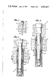
- FIG. 1 is a perspective view of a swaging apparatus constructed in accordance with the invention inserted in a tube in a bore of a tube sheet, only a fragmentary portion of the tube sheet being shown and being broken away to expose the apparatus;
- FIG. 2 is a longitudinal cross-sectional view of the swaging apparatus, tube, and tube sheet of FIG. 1, the apparatus being in position to begin swaging;
- FIG. 3 is another longitudinal cross-sectional view similar to FIG. 2 showing the apparatus, tube, and tube sheet after swaging has taken place and while the swaging pressure is still being applied;
- FIG. 4 is a transverse cross-sectional view of the apparatus, tube, and tube sheet taken along the line 4--4 of FIG. 3;
- FIG. 5 is an enlargement of a fragmentary portion of the structure of FIG. 2 indicated by the arrow 5;
- FIG. 6 is an exploded view of the confinement means of FIG. 2.
- a steel tube sheet 10 of the type used in heat exchangers, such as those that form part of nuclear power plants, has a plurality of bores that extend through it perpendicularly to its primary and secondary surfaces 12 and 14, respectively.
- a plurality of steel tubes 16 are positioned in these bores to be expanded radially by swaging to form leak-proof joints that prevent fluid from migrating from the primary side 14 of the exchanger to the secondary side 12.
- a fragmentary portion of the tube sheet 10 receiving a single tube 16 is shown in FIG. 1.
- the drawbar 20 has a central section 24 that is encircled by three polyurethane pressurization rings 26, 28, and 30, the intended pressure zone of the apparatus 18 being coextensive with these rings. At each end of the pressure zone is a confinement structure 32 or 34 that positions the rings 26, 28 and 30.
- the drawbar 22 includes separately formed annular shoulder members 36 and 38 by which the confinement means are prevented from moving axially toward the ends of the drawbar.
- the drawbar 20 When swaging pressure is to be applied, the drawbar 20 is retracted by a hydraulic piston (not shown) attached to the drawbar in the head 22, the rings 26, 28, and 30 expand outwardly, and the tube 16 is deformed radially outwardly. The bore is then enlarged by deforming the tube 16 and the tube sheet 10.
- the tube 16 exceeds its elastic limits but the tube sheet 10 does not, so that the tube is permanently clamped in place where the swaging pressure is removed and the tube sheet 10 returns to its original shape.
- the pressurization rings 26 and 30 at the ends of the pressure zone could be deformed inelastically and destructively into any void between the drawbar 22 and the tube 16 in the transitional areas where the expanded inside diameter of the tube 16 tapers down to the unexpanded diameter. These potential voids are blocked, however, by the action of the confinement structures 32 and 34.
- the two confinement structures 32 and 34 are alike, only one of these structures 34, best shown in FIG. 5, is described in detail. It is formed by a plurality of separate arcuate segments 40 assembled side by side to form a cylinder that encircles the drawbar 22.
- the segments 40 are first manufactured as a complete integral cylinder which is then cut longitudinally to separate the individual segments (see FIG. 6).
- the segments 40 When the segments 40 are assembled about the drawbar 22, they are secured and urged inwardly by an encircling resilient polyurethane band 42 that is stretched about thirty to fifty percent from its relaxed diameter.
- the band 42 is recieved by a circumferential groove 44 on the outside of the segments 40.
- Adjacent the heel end 46 is the shoulder piece 38 that restrains the confinement structure 34 against axial movement along the drawbar 22.
- each segment 40 At the other end of each segment 40 is an undercut portion 48, all the undercuts collectively defining an annular recess 50 opening toward the pressure zone.
- a conical cam surface 52 At the mouth of the recess 50 is a conical cam surface 52 that is inclined radially outwardly and toward the pressure zone forming a pointed circumferential edge 54 at the end of the confinement structure 34 adjacent the pressurization ring 30.
- a steel cam ring 56 Between the pressurization ring 30 and the segments 40 is a steel cam ring 56 with an elongated cylindrical foot 58 that extends well into the recess 50 and a conical cam surface 60 projecting outwardly from the foot to the edge 54.
- the cam ring 56 is referred to an inelastic since it does not deform under swaging pressure.
- the pressurization rings 26, 28, and 30 are compressed axially and expanded radially. Accordingly, the axial pressure applied by the outermost pressurization ring 30 to the adjacent confinement structure 34 causes the foot 58 of the cam ring 56 to move into the travel space 62.
- the interaction of the cam surfaces 52 and 60 causes the segments 40 to pivot at the heel ends 46 (see FIG. 3), the back surfaces 64 of the segments being angled away from the shoulder piece 38 to permit this pivotal motion.
- the segments 40 move outwardly, giving the confinement structure 34 a slightly conical overall shape, the band 42 is stretched by a small amount.
- the manner in which the confinement structure 34 prevents extrusion of the pressurization ring 30 is best understood with reference to the cross-sectional view of FIG. 4.
- the annular gap that would otherwise be presented to the ring 30 is largely closed by the support segments 40, and only small open areas 68 exist between adjacent segments. Not only is the maximum size of any unsupported areas 68 greatly reduced, but the shape of these small areas is highly advantageous in preventing inelastic deformation or extrusion of the pressurization ring 30.
- the maximum unsupported dimension is merely the diagonal of each small gap 68, which is almost insignificant when compared to the circumference of the drawbar 22.
- the small gaps 68 are each of the same size, and it would be disadvantageous if they were not, since the tendency of the pressurization ring 30 to extrude destructively is determined by the largest gap presented. Uniformity of the gaps 68 is maintained because the segments 40 cannot rotate about the drawbar 22 relative to each other. They are locked in relative position because they are in tight contact with each other at the heel ends 46. The band 42 produces a positive action securing the segments 40 in their relative positions with the heel ends 46 pushed together.
- the cam ring 56 also tends to center the drawbar 22 within the tube 16. This centering effect takes place because the cam ring 56 has a close sliding fit on the drawbar 22 and cannot be cocked angularly because of its substantial length. It therefore forces each segment 40 to move radially by an equal distance, maintaining the symmetry of the confinement structure 34 as that structure assumes a conical shape.
- the apparatus 18 of the present invention can be used repeatedly at high swaging pressures without the need to replace the pressurization rings 26, 28, and 30 or any other components. It is of relatively simple and reliable construction considering the pressures at which it is capable of operating and is capable of being reused repeatedly.
Abstract
Description
Claims (6)
Priority Applications (4)
| Application Number | Priority Date | Filing Date | Title |
|---|---|---|---|
| US06/476,492 US4581817A (en) | 1983-03-18 | 1983-03-18 | Drawbar swaging apparatus with segmented confinement structure |
| DE8484102834T DE3464211D1 (en) | 1983-03-18 | 1984-03-15 | Swaging apparatus |
| EP84102834A EP0121160B1 (en) | 1983-03-18 | 1984-03-15 | Swaging apparatus |
| CA000449737A CA1217415A (en) | 1983-03-18 | 1984-03-16 | Drawbar swaging apparatus with segmented confinement structure |
Applications Claiming Priority (1)
| Application Number | Priority Date | Filing Date | Title |
|---|---|---|---|
| US06/476,492 US4581817A (en) | 1983-03-18 | 1983-03-18 | Drawbar swaging apparatus with segmented confinement structure |
Publications (1)
| Publication Number | Publication Date |
|---|---|
| US4581817A true US4581817A (en) | 1986-04-15 |
Family
ID=23892067
Family Applications (1)
| Application Number | Title | Priority Date | Filing Date |
|---|---|---|---|
| US06/476,492 Expired - Lifetime US4581817A (en) | 1983-03-18 | 1983-03-18 | Drawbar swaging apparatus with segmented confinement structure |
Country Status (4)
| Country | Link |
|---|---|
| US (1) | US4581817A (en) |
| EP (1) | EP0121160B1 (en) |
| CA (1) | CA1217415A (en) |
| DE (1) | DE3464211D1 (en) |
Cited By (33)
| Publication number | Priority date | Publication date | Assignee | Title |
|---|---|---|---|---|
| US4688416A (en) * | 1985-11-12 | 1987-08-25 | Westinghouse Electric Corp. | Fixture and method for rectifying damaged guide thimble insert sleeves in a reconstitutable fuel assembly |
| US4753102A (en) * | 1985-06-07 | 1988-06-28 | L. Schuler Gmbh | Arrangement for coupling and decoupling gripper rail partial sections of a transfer press |
| US4761981A (en) * | 1987-03-23 | 1988-08-09 | Haskel, Inc. | Swaging apparatus for flaring and anchoring tubes |
| US5083363A (en) * | 1990-07-25 | 1992-01-28 | Fatigue Technology, Inc. | Method of installing a grommet in a wall of composite material |
| DE29618272U1 (en) * | 1996-10-22 | 1996-12-05 | Novopress Gmbh | Expanding device for expanding pipe ends |
| US6543636B1 (en) * | 1998-02-26 | 2003-04-08 | Cebal, S.A. | Method for making an aerosol housing with threaded neck |
| US20030066655A1 (en) * | 1999-02-26 | 2003-04-10 | Shell Oil Co. | Apparatus for coupling a tubular member to a preexisting structure |
| US20030094277A1 (en) * | 1998-12-07 | 2003-05-22 | Shell Oil Co. | Expansion cone for radially expanding tubular members |
| US20030098162A1 (en) * | 1998-12-07 | 2003-05-29 | Shell Oil Company | Method of inserting a tubular member into a wellbore |
| US20030107217A1 (en) * | 1999-10-12 | 2003-06-12 | Shell Oil Co. | Sealant for expandable connection |
| US20030192705A1 (en) * | 1999-03-11 | 2003-10-16 | Shell Oil Co. | Forming a wellbore casing while simultaneously drilling a wellbore |
| WO2003102365A1 (en) * | 2002-05-29 | 2003-12-11 | Eventure Global Technology | System for radially expanding a tubular member |
| US20040107754A1 (en) * | 2001-02-08 | 2004-06-10 | Egbert Frenken | Expansion tool for expanding tube ends and pressing device comprising such an expansion tool |
| US20040123988A1 (en) * | 1998-12-07 | 2004-07-01 | Shell Oil Co. | Wellhead |
| US7021390B2 (en) | 1998-12-07 | 2006-04-04 | Shell Oil Company | Tubular liner for wellbore casing |
| US20070296161A1 (en) * | 2006-06-21 | 2007-12-27 | Dudman Richard L | Seal, Sealing System, and Method for Sealing |
| US7665532B2 (en) | 1998-12-07 | 2010-02-23 | Shell Oil Company | Pipeline |
| GB2464275A (en) * | 2008-10-07 | 2010-04-14 | Dynamic Dinosaurs Bv | Apparatus for deforming the shape of tubular elements |
| US7712522B2 (en) | 2003-09-05 | 2010-05-11 | Enventure Global Technology, Llc | Expansion cone and system |
| US7740076B2 (en) | 2002-04-12 | 2010-06-22 | Enventure Global Technology, L.L.C. | Protective sleeve for threaded connections for expandable liner hanger |
| US7739917B2 (en) | 2002-09-20 | 2010-06-22 | Enventure Global Technology, Llc | Pipe formability evaluation for expandable tubulars |
| US7775290B2 (en) | 2003-04-17 | 2010-08-17 | Enventure Global Technology, Llc | Apparatus for radially expanding and plastically deforming a tubular member |
| US7793721B2 (en) | 2003-03-11 | 2010-09-14 | Eventure Global Technology, Llc | Apparatus for radially expanding and plastically deforming a tubular member |
| US7819185B2 (en) | 2004-08-13 | 2010-10-26 | Enventure Global Technology, Llc | Expandable tubular |
| US20110005067A1 (en) * | 2009-07-13 | 2011-01-13 | Lennox Industries Inc. | Rod holder for the assembly of heat exchangers |
| US7886831B2 (en) | 2003-01-22 | 2011-02-15 | Enventure Global Technology, L.L.C. | Apparatus for radially expanding and plastically deforming a tubular member |
| US7918284B2 (en) | 2002-04-15 | 2011-04-05 | Enventure Global Technology, L.L.C. | Protective sleeve for threaded connections for expandable liner hanger |
| US20110226034A1 (en) * | 2010-03-19 | 2011-09-22 | O.N. Industries, Ltd. | Pipe expanding apparatus of thin wall stainless steel pipe |
| CN103433396A (en) * | 2013-09-03 | 2013-12-11 | 西安胜智航空科技有限公司 | Radial stretching expanding pipe for expanding shape memory alloy pipe joint |
| JP2014024096A (en) * | 2012-07-27 | 2014-02-06 | Ihi Corp | Tube expansion apparatus |
| US8833125B2 (en) | 2010-08-26 | 2014-09-16 | Samsung Sdi Co., Ltd. | Swaging apparatus |
| US8967281B2 (en) * | 2008-02-19 | 2015-03-03 | Weatherford/Lamb, Inc. | Expandable packer |
| US9551201B2 (en) | 2008-02-19 | 2017-01-24 | Weatherford Technology Holdings, Llc | Apparatus and method of zonal isolation |
Families Citing this family (2)
| Publication number | Priority date | Publication date | Assignee | Title |
|---|---|---|---|---|
| US6098717A (en) * | 1997-10-08 | 2000-08-08 | Formlock, Inc. | Method and apparatus for hanging tubulars in wells |
| US6415863B1 (en) | 1999-03-04 | 2002-07-09 | Bestline Liner System, Inc. | Apparatus and method for hanging tubulars in wells |
Citations (23)
| Publication number | Priority date | Publication date | Assignee | Title |
|---|---|---|---|---|
| US525588A (en) * | 1894-09-04 | Rod-packing | ||
| US717008A (en) * | 1902-06-02 | 1902-12-30 | Robert C Lochridge | Metallic packing for rods. |
| US724074A (en) * | 1902-05-19 | 1903-03-31 | Hoyt Metal Company | Piston-rod packing. |
| US911228A (en) * | 1908-05-23 | 1909-02-02 | Marcus F Fulford | Metallic packing. |
| US947889A (en) * | 1909-03-15 | 1910-02-01 | Standard Supply And Mfg Company | Rod-packing. |
| US1720563A (en) * | 1926-11-30 | 1929-07-09 | Clarence A Neal | Packing |
| US2118855A (en) * | 1937-05-07 | 1938-05-31 | Miller John | Packing |
| US2460580A (en) * | 1942-03-31 | 1949-02-01 | Sulzer Ag | Method and device for fixing and sealing tubes in a partition wall by use of fluid pressure |
| US2546377A (en) * | 1942-01-20 | 1951-03-27 | Lane Wells Co | Bridging plug |
| DE923964C (en) * | 1942-04-24 | 1955-02-24 | Sulzer Ag | Method and device for fastening and sealing pipes in a wall |
| US3186681A (en) * | 1961-12-18 | 1965-06-01 | Acf Ind Inc | Stem seal for rotary plug valve |
| US3215205A (en) * | 1961-03-31 | 1965-11-02 | Otis Eng Co | Retrievable hydraulic set well packers |
| CH405210A (en) * | 1963-09-13 | 1966-01-15 | Soc Forges Ateliers Creusot | Expansion device |
| US3302736A (en) * | 1963-09-12 | 1967-02-07 | Schlumberger Technology Corp | Well tool seal |
| DE7202510U (en) * | 1972-08-31 | Creusot Loire | Tool for expanding and beading pipe ends | |
| US4186584A (en) * | 1978-05-24 | 1980-02-05 | Thomas C. Wilson, Inc. | Tube expander |
| JPS5524742A (en) * | 1978-08-11 | 1980-02-22 | Hitachi Ltd | Method and device for locating and expanding pipe |
| GB2074914A (en) * | 1980-05-06 | 1981-11-11 | Nuovo Pignone Spa | Method of joining a sleeve to a pipe |
| US4328974A (en) * | 1980-02-19 | 1982-05-11 | White Richard E | Stuffing box packing system and method |
| US4387507A (en) * | 1981-04-20 | 1983-06-14 | Haskel Engineering & Supply Co. | Method and apparatus for radially expanding tubes |
| US4418457A (en) * | 1982-01-21 | 1983-12-06 | Cities Service Company | Apparatus and process for expanding to join a tube into a tube sheet opening |
| US4420866A (en) * | 1982-01-25 | 1983-12-20 | Cities Service Company | Apparatus and process for selectively expanding to join one tube into another tube |
| US4422317A (en) * | 1982-01-25 | 1983-12-27 | Cities Service Company | Apparatus and process for selectively expanding a tube |
Family Cites Families (1)
| Publication number | Priority date | Publication date | Assignee | Title |
|---|---|---|---|---|
| US4502308A (en) * | 1982-01-22 | 1985-03-05 | Haskel, Inc. | Swaging apparatus having elastically deformable members with segmented supports |
-
1983
- 1983-03-18 US US06/476,492 patent/US4581817A/en not_active Expired - Lifetime
-
1984
- 1984-03-15 DE DE8484102834T patent/DE3464211D1/en not_active Expired
- 1984-03-15 EP EP84102834A patent/EP0121160B1/en not_active Expired
- 1984-03-16 CA CA000449737A patent/CA1217415A/en not_active Expired
Patent Citations (24)
| Publication number | Priority date | Publication date | Assignee | Title |
|---|---|---|---|---|
| US525588A (en) * | 1894-09-04 | Rod-packing | ||
| DE7202510U (en) * | 1972-08-31 | Creusot Loire | Tool for expanding and beading pipe ends | |
| US724074A (en) * | 1902-05-19 | 1903-03-31 | Hoyt Metal Company | Piston-rod packing. |
| US717008A (en) * | 1902-06-02 | 1902-12-30 | Robert C Lochridge | Metallic packing for rods. |
| US911228A (en) * | 1908-05-23 | 1909-02-02 | Marcus F Fulford | Metallic packing. |
| US947889A (en) * | 1909-03-15 | 1910-02-01 | Standard Supply And Mfg Company | Rod-packing. |
| US1720563A (en) * | 1926-11-30 | 1929-07-09 | Clarence A Neal | Packing |
| US2118855A (en) * | 1937-05-07 | 1938-05-31 | Miller John | Packing |
| US2546377A (en) * | 1942-01-20 | 1951-03-27 | Lane Wells Co | Bridging plug |
| US2460580A (en) * | 1942-03-31 | 1949-02-01 | Sulzer Ag | Method and device for fixing and sealing tubes in a partition wall by use of fluid pressure |
| DE923964C (en) * | 1942-04-24 | 1955-02-24 | Sulzer Ag | Method and device for fastening and sealing pipes in a wall |
| US3215205A (en) * | 1961-03-31 | 1965-11-02 | Otis Eng Co | Retrievable hydraulic set well packers |
| US3186681A (en) * | 1961-12-18 | 1965-06-01 | Acf Ind Inc | Stem seal for rotary plug valve |
| US3302736A (en) * | 1963-09-12 | 1967-02-07 | Schlumberger Technology Corp | Well tool seal |
| CH405210A (en) * | 1963-09-13 | 1966-01-15 | Soc Forges Ateliers Creusot | Expansion device |
| US4186584A (en) * | 1978-05-24 | 1980-02-05 | Thomas C. Wilson, Inc. | Tube expander |
| JPS5524742A (en) * | 1978-08-11 | 1980-02-22 | Hitachi Ltd | Method and device for locating and expanding pipe |
| US4328974A (en) * | 1980-02-19 | 1982-05-11 | White Richard E | Stuffing box packing system and method |
| GB2074914A (en) * | 1980-05-06 | 1981-11-11 | Nuovo Pignone Spa | Method of joining a sleeve to a pipe |
| US4388752A (en) * | 1980-05-06 | 1983-06-21 | Nuovo Pignone S.P.A. | Method for the sealtight jointing of a flanged sleeve to a pipeline, especially for repairing subsea pipelines laid on very deep sea bottoms |
| US4387507A (en) * | 1981-04-20 | 1983-06-14 | Haskel Engineering & Supply Co. | Method and apparatus for radially expanding tubes |
| US4418457A (en) * | 1982-01-21 | 1983-12-06 | Cities Service Company | Apparatus and process for expanding to join a tube into a tube sheet opening |
| US4420866A (en) * | 1982-01-25 | 1983-12-20 | Cities Service Company | Apparatus and process for selectively expanding to join one tube into another tube |
| US4422317A (en) * | 1982-01-25 | 1983-12-27 | Cities Service Company | Apparatus and process for selectively expanding a tube |
Non-Patent Citations (4)
| Title |
|---|
| "Erickson Expanding Mandrels", Erickson Tool Co., Solon, OH. |
| Bulletin EA 175, Positrol, Inc. (1974). * |
| Bulletin EA-175, Positrol, Inc. (1974). |
| Erickson Expanding Mandrels , Erickson Tool Co., Solon, OH. * |
Cited By (46)
| Publication number | Priority date | Publication date | Assignee | Title |
|---|---|---|---|---|
| US4753102A (en) * | 1985-06-07 | 1988-06-28 | L. Schuler Gmbh | Arrangement for coupling and decoupling gripper rail partial sections of a transfer press |
| US4688416A (en) * | 1985-11-12 | 1987-08-25 | Westinghouse Electric Corp. | Fixture and method for rectifying damaged guide thimble insert sleeves in a reconstitutable fuel assembly |
| US4761981A (en) * | 1987-03-23 | 1988-08-09 | Haskel, Inc. | Swaging apparatus for flaring and anchoring tubes |
| US5083363A (en) * | 1990-07-25 | 1992-01-28 | Fatigue Technology, Inc. | Method of installing a grommet in a wall of composite material |
| DE29618272U1 (en) * | 1996-10-22 | 1996-12-05 | Novopress Gmbh | Expanding device for expanding pipe ends |
| US6543636B1 (en) * | 1998-02-26 | 2003-04-08 | Cebal, S.A. | Method for making an aerosol housing with threaded neck |
| US20030098162A1 (en) * | 1998-12-07 | 2003-05-29 | Shell Oil Company | Method of inserting a tubular member into a wellbore |
| US20030094277A1 (en) * | 1998-12-07 | 2003-05-22 | Shell Oil Co. | Expansion cone for radially expanding tubular members |
| US7665532B2 (en) | 1998-12-07 | 2010-02-23 | Shell Oil Company | Pipeline |
| US20040123988A1 (en) * | 1998-12-07 | 2004-07-01 | Shell Oil Co. | Wellhead |
| US7021390B2 (en) | 1998-12-07 | 2006-04-04 | Shell Oil Company | Tubular liner for wellbore casing |
| US7086475B2 (en) | 1998-12-07 | 2006-08-08 | Shell Oil Company | Method of inserting a tubular member into a wellbore |
| US20030066655A1 (en) * | 1999-02-26 | 2003-04-10 | Shell Oil Co. | Apparatus for coupling a tubular member to a preexisting structure |
| US20030192705A1 (en) * | 1999-03-11 | 2003-10-16 | Shell Oil Co. | Forming a wellbore casing while simultaneously drilling a wellbore |
| US20030107217A1 (en) * | 1999-10-12 | 2003-06-12 | Shell Oil Co. | Sealant for expandable connection |
| US20040107754A1 (en) * | 2001-02-08 | 2004-06-10 | Egbert Frenken | Expansion tool for expanding tube ends and pressing device comprising such an expansion tool |
| US7065995B2 (en) * | 2001-02-08 | 2006-06-27 | Gustav Klauke Gmbh | Expansion tool for expanding tube ends and pressing device comprising such an expansion tool |
| US7740076B2 (en) | 2002-04-12 | 2010-06-22 | Enventure Global Technology, L.L.C. | Protective sleeve for threaded connections for expandable liner hanger |
| US7918284B2 (en) | 2002-04-15 | 2011-04-05 | Enventure Global Technology, L.L.C. | Protective sleeve for threaded connections for expandable liner hanger |
| GB2426993B (en) * | 2002-05-29 | 2007-05-02 | Enventure Global Technology | System for radially expanding a tubular member |
| WO2003102365A1 (en) * | 2002-05-29 | 2003-12-11 | Eventure Global Technology | System for radially expanding a tubular member |
| GB2406125B (en) * | 2002-05-29 | 2006-11-01 | Enventure Global Technology | Radially expanding a tubular member |
| GB2426993A (en) * | 2002-05-29 | 2006-12-13 | Enventure Global Technology | Tubular expander with compressible elastomeric member |
| GB2406125A (en) * | 2002-05-29 | 2005-03-23 | Enventure Global Technology | System for radially expanding a tubular member |
| US7739917B2 (en) | 2002-09-20 | 2010-06-22 | Enventure Global Technology, Llc | Pipe formability evaluation for expandable tubulars |
| US7886831B2 (en) | 2003-01-22 | 2011-02-15 | Enventure Global Technology, L.L.C. | Apparatus for radially expanding and plastically deforming a tubular member |
| US7793721B2 (en) | 2003-03-11 | 2010-09-14 | Eventure Global Technology, Llc | Apparatus for radially expanding and plastically deforming a tubular member |
| US7775290B2 (en) | 2003-04-17 | 2010-08-17 | Enventure Global Technology, Llc | Apparatus for radially expanding and plastically deforming a tubular member |
| US7712522B2 (en) | 2003-09-05 | 2010-05-11 | Enventure Global Technology, Llc | Expansion cone and system |
| US7819185B2 (en) | 2004-08-13 | 2010-10-26 | Enventure Global Technology, Llc | Expandable tubular |
| US20070296161A1 (en) * | 2006-06-21 | 2007-12-27 | Dudman Richard L | Seal, Sealing System, and Method for Sealing |
| US8967281B2 (en) * | 2008-02-19 | 2015-03-03 | Weatherford/Lamb, Inc. | Expandable packer |
| US9903176B2 (en) | 2008-02-19 | 2018-02-27 | Weatherford Technology Holdings, Llc | Expandable packer |
| US9551201B2 (en) | 2008-02-19 | 2017-01-24 | Weatherford Technology Holdings, Llc | Apparatus and method of zonal isolation |
| GB2464275A (en) * | 2008-10-07 | 2010-04-14 | Dynamic Dinosaurs Bv | Apparatus for deforming the shape of tubular elements |
| CN101954431A (en) * | 2009-07-13 | 2011-01-26 | 雷诺士工业股份有限公司 | The bar retainer that is used for the assembling of heat exchanger |
| CN101954431B (en) * | 2009-07-13 | 2014-09-03 | 雷诺士工业股份有限公司 | Rod holder for the assembly of heat exchangers |
| US8429818B2 (en) * | 2009-07-13 | 2013-04-30 | Lennox Industries Inc. | Rod holder for the assembly of heat exchangers |
| AU2010202812B2 (en) * | 2009-07-13 | 2015-04-02 | Lennox Industries Inc. | Rod holder for the assembly of heat exchangers |
| US20110005067A1 (en) * | 2009-07-13 | 2011-01-13 | Lennox Industries Inc. | Rod holder for the assembly of heat exchangers |
| US8528377B2 (en) * | 2010-03-19 | 2013-09-10 | O.N. Industries, Ltd. | Pipe expanding apparatus of thin wall stainless steel pipe |
| US20110226034A1 (en) * | 2010-03-19 | 2011-09-22 | O.N. Industries, Ltd. | Pipe expanding apparatus of thin wall stainless steel pipe |
| US8833125B2 (en) | 2010-08-26 | 2014-09-16 | Samsung Sdi Co., Ltd. | Swaging apparatus |
| JP2014024096A (en) * | 2012-07-27 | 2014-02-06 | Ihi Corp | Tube expansion apparatus |
| CN103433396A (en) * | 2013-09-03 | 2013-12-11 | 西安胜智航空科技有限公司 | Radial stretching expanding pipe for expanding shape memory alloy pipe joint |
| CN103433396B (en) * | 2013-09-03 | 2015-09-09 | 西安胜智航空科技有限公司 | A kind of radial expansion expander expanding for marmem pipe joint |
Also Published As
| Publication number | Publication date |
|---|---|
| EP0121160B1 (en) | 1987-06-16 |
| CA1217415A (en) | 1987-02-03 |
| EP0121160A2 (en) | 1984-10-10 |
| EP0121160A3 (en) | 1985-01-23 |
| DE3464211D1 (en) | 1987-07-23 |
Similar Documents
| Publication | Publication Date | Title |
|---|---|---|
| US4581817A (en) | Drawbar swaging apparatus with segmented confinement structure | |
| EP0084940B1 (en) | Swaging apparatus having elastically deformable members | |
| US4450612A (en) | Swaging apparatus for radially expanding tubes to form joints | |
| US4467630A (en) | Hydraulic swaging seal construction | |
| US2725078A (en) | Flexible liner assembly for a fluid pressure device | |
| US5437310A (en) | Plug assembly | |
| US4195865A (en) | Apparatus for connecting tubular members | |
| US4320568A (en) | Method of expanding tubular members | |
| US4069573A (en) | Method of securing a sleeve within a tube | |
| US4418948A (en) | Elastic coupling for pipes and tubes | |
| US5707087A (en) | Tube fitting | |
| US4371198A (en) | Apparatus for connecting tubular members | |
| US4418457A (en) | Apparatus and process for expanding to join a tube into a tube sheet opening | |
| US6626438B2 (en) | Seal assembly for telescopic hydraulic cylinder | |
| JP2011163523A (en) | Fluid pressure cylinder | |
| US4761981A (en) | Swaging apparatus for flaring and anchoring tubes | |
| US3393917A (en) | Fluid seal | |
| EP1366318B1 (en) | Coupling for connection of a tube or hose by pushing-in | |
| US4043160A (en) | Internal tooling for swaging apparatus | |
| US5085129A (en) | Joint system | |
| JPS64137B2 (en) | ||
| US5907965A (en) | Device for expanding a tube | |
| US20060032369A1 (en) | Piston-piston rod retaining assembly for a hydraulic piston and cylinder unit | |
| US4291890A (en) | Valve seal with O-ring and backup ring | |
| US10393301B1 (en) | Fluid connectors with bellows |
Legal Events
| Date | Code | Title | Description |
|---|---|---|---|
| AS | Assignment |
Owner name: HASKELL ENGINEERING AND SUPPLY CO.; BURBANK, CA. Free format text: ASSIGNMENT OF ASSIGNORS INTEREST.;ASSIGNOR:KELLY, JOHN W.;REEL/FRAME:004110/0015 Effective date: 19830304 |
|
| STCF | Information on status: patent grant |
Free format text: PATENTED CASE |
|
| FEPP | Fee payment procedure |
Free format text: PAYOR NUMBER ASSIGNED (ORIGINAL EVENT CODE: ASPN); ENTITY STATUS OF PATENT OWNER: SMALL ENTITY |
|
| FPAY | Fee payment |
Year of fee payment: 4 |
|
| FPAY | Fee payment |
Year of fee payment: 8 |
|
| FPAY | Fee payment |
Year of fee payment: 12 |
|
| AS | Assignment |
Owner name: HASKEL INTERNATIONAL, INC., CALIFORNIA Free format text: MERGER;ASSIGNOR:HASKEL, INC.;REEL/FRAME:009935/0457 Effective date: 19931214 |
|
| AS | Assignment |
Owner name: CHASE MANHATTAN BANK, AS AGENT, THE, NEW YORK Free format text: SECURITY INTEREST;ASSIGNOR:HASKEL INTERNATIONAL, INC.;REEL/FRAME:010033/0825 Effective date: 19990423 |
|
| AS | Assignment |
Owner name: GENERAL ELECTRIC CAPITAL CORPORATION, AS AGENT, NE Free format text: SECURITY INTEREST;ASSIGNOR:HASKEL INTRNATIONAL, INC.;REEL/FRAME:014845/0311 Effective date: 20031231 |
|
| AS | Assignment |
Owner name: HASKEL INTERNATIONAL, INC., CALIFORNIA Free format text: RELEASE OF ASSIGNMENT OF SECURITY OF PATENTS;ASSIGNOR:JPMORGAN CHASE BANK, AS AGENT;REEL/FRAME:014852/0352 Effective date: 20031231 |