US10892319B2 - Semiconductor device - Google Patents
Semiconductor device Download PDFInfo
- Publication number
- US10892319B2 US10892319B2 US16/316,957 US201716316957A US10892319B2 US 10892319 B2 US10892319 B2 US 10892319B2 US 201716316957 A US201716316957 A US 201716316957A US 10892319 B2 US10892319 B2 US 10892319B2
- Authority
- US
- United States
- Prior art keywords
- region
- semiconductor layer
- conductivity type
- semiconductor device
- back surface
- Prior art date
- Legal status (The legal status is an assumption and is not a legal conclusion. Google has not performed a legal analysis and makes no representation as to the accuracy of the status listed.)
- Active
Links
- 239000004065 semiconductor Substances 0.000 title claims abstract description 381
- 239000010410 layer Substances 0.000 claims description 255
- 230000005684 electric field Effects 0.000 claims description 88
- 230000002093 peripheral effect Effects 0.000 claims description 60
- 239000012535 impurity Substances 0.000 claims description 59
- 210000000746 body region Anatomy 0.000 claims description 24
- 239000011229 interlayer Substances 0.000 claims description 19
- 230000002457 bidirectional effect Effects 0.000 claims description 10
- 230000007547 defect Effects 0.000 claims description 10
- 239000013078 crystal Substances 0.000 claims description 8
- 239000011159 matrix material Substances 0.000 claims description 8
- 239000011347 resin Substances 0.000 claims description 6
- 229920005989 resin Polymers 0.000 claims description 6
- 238000006243 chemical reaction Methods 0.000 claims description 3
- 238000007789 sealing Methods 0.000 claims description 2
- 239000000758 substrate Substances 0.000 description 37
- 238000010586 diagram Methods 0.000 description 28
- 229910052751 metal Inorganic materials 0.000 description 18
- 239000002184 metal Substances 0.000 description 18
- 238000004519 manufacturing process Methods 0.000 description 10
- 230000015572 biosynthetic process Effects 0.000 description 6
- 238000005498 polishing Methods 0.000 description 6
- 230000001681 protective effect Effects 0.000 description 6
- VYPSYNLAJGMNEJ-UHFFFAOYSA-N Silicium dioxide Chemical compound O=[Si]=O VYPSYNLAJGMNEJ-UHFFFAOYSA-N 0.000 description 5
- 238000000137 annealing Methods 0.000 description 5
- 238000000227 grinding Methods 0.000 description 5
- 239000012212 insulator Substances 0.000 description 4
- 150000002500 ions Chemical class 0.000 description 4
- 229910052814 silicon oxide Inorganic materials 0.000 description 4
- 230000012447 hatching Effects 0.000 description 3
- 230000003071 parasitic effect Effects 0.000 description 3
- 238000004544 sputter deposition Methods 0.000 description 3
- 230000007704 transition Effects 0.000 description 3
- 230000004888 barrier function Effects 0.000 description 2
- 238000005530 etching Methods 0.000 description 2
- 230000005669 field effect Effects 0.000 description 2
- 238000005468 ion implantation Methods 0.000 description 2
- 238000005224 laser annealing Methods 0.000 description 2
- 239000000463 material Substances 0.000 description 2
- 239000004642 Polyimide Substances 0.000 description 1
- 229910052782 aluminium Inorganic materials 0.000 description 1
- XAGFODPZIPBFFR-UHFFFAOYSA-N aluminium Chemical compound [Al] XAGFODPZIPBFFR-UHFFFAOYSA-N 0.000 description 1
- 230000000052 comparative effect Effects 0.000 description 1
- -1 for example Substances 0.000 description 1
- 239000007769 metal material Substances 0.000 description 1
- 229910021420 polycrystalline silicon Inorganic materials 0.000 description 1
- 229920001721 polyimide Polymers 0.000 description 1
- 229920005591 polysilicon Polymers 0.000 description 1
- 230000000630 rising effect Effects 0.000 description 1
- 238000005245 sintering Methods 0.000 description 1
Images


Classifications
-
- H—ELECTRICITY
- H01—ELECTRIC ELEMENTS
- H01L—SEMICONDUCTOR DEVICES NOT COVERED BY CLASS H10
- H01L29/00—Semiconductor devices specially adapted for rectifying, amplifying, oscillating or switching and having potential barriers; Capacitors or resistors having potential barriers, e.g. a PN-junction depletion layer or carrier concentration layer; Details of semiconductor bodies or of electrodes thereof ; Multistep manufacturing processes therefor
- H01L29/02—Semiconductor bodies ; Multistep manufacturing processes therefor
- H01L29/06—Semiconductor bodies ; Multistep manufacturing processes therefor characterised by their shape; characterised by the shapes, relative sizes, or dispositions of the semiconductor regions ; characterised by the concentration or distribution of impurities within semiconductor regions
- H01L29/0603—Semiconductor bodies ; Multistep manufacturing processes therefor characterised by their shape; characterised by the shapes, relative sizes, or dispositions of the semiconductor regions ; characterised by the concentration or distribution of impurities within semiconductor regions characterised by particular constructional design considerations, e.g. for preventing surface leakage, for controlling electric field concentration or for internal isolations regions
- H01L29/0607—Semiconductor bodies ; Multistep manufacturing processes therefor characterised by their shape; characterised by the shapes, relative sizes, or dispositions of the semiconductor regions ; characterised by the concentration or distribution of impurities within semiconductor regions characterised by particular constructional design considerations, e.g. for preventing surface leakage, for controlling electric field concentration or for internal isolations regions for preventing surface leakage or controlling electric field concentration
- H01L29/0611—Semiconductor bodies ; Multistep manufacturing processes therefor characterised by their shape; characterised by the shapes, relative sizes, or dispositions of the semiconductor regions ; characterised by the concentration or distribution of impurities within semiconductor regions characterised by particular constructional design considerations, e.g. for preventing surface leakage, for controlling electric field concentration or for internal isolations regions for preventing surface leakage or controlling electric field concentration for increasing or controlling the breakdown voltage of reverse biased devices
- H01L29/0615—Semiconductor bodies ; Multistep manufacturing processes therefor characterised by their shape; characterised by the shapes, relative sizes, or dispositions of the semiconductor regions ; characterised by the concentration or distribution of impurities within semiconductor regions characterised by particular constructional design considerations, e.g. for preventing surface leakage, for controlling electric field concentration or for internal isolations regions for preventing surface leakage or controlling electric field concentration for increasing or controlling the breakdown voltage of reverse biased devices by the doping profile or the shape or the arrangement of the PN junction, or with supplementary regions, e.g. junction termination extension [JTE]
- H01L29/0619—Semiconductor bodies ; Multistep manufacturing processes therefor characterised by their shape; characterised by the shapes, relative sizes, or dispositions of the semiconductor regions ; characterised by the concentration or distribution of impurities within semiconductor regions characterised by particular constructional design considerations, e.g. for preventing surface leakage, for controlling electric field concentration or for internal isolations regions for preventing surface leakage or controlling electric field concentration for increasing or controlling the breakdown voltage of reverse biased devices by the doping profile or the shape or the arrangement of the PN junction, or with supplementary regions, e.g. junction termination extension [JTE] with a supplementary region doped oppositely to or in rectifying contact with the semiconductor containing or contacting region, e.g. guard rings with PN or Schottky junction
- H01L29/0623—Buried supplementary region, e.g. buried guard ring
-
- H—ELECTRICITY
- H01—ELECTRIC ELEMENTS
- H01L—SEMICONDUCTOR DEVICES NOT COVERED BY CLASS H10
- H01L29/00—Semiconductor devices specially adapted for rectifying, amplifying, oscillating or switching and having potential barriers; Capacitors or resistors having potential barriers, e.g. a PN-junction depletion layer or carrier concentration layer; Details of semiconductor bodies or of electrodes thereof ; Multistep manufacturing processes therefor
- H01L29/02—Semiconductor bodies ; Multistep manufacturing processes therefor
- H01L29/06—Semiconductor bodies ; Multistep manufacturing processes therefor characterised by their shape; characterised by the shapes, relative sizes, or dispositions of the semiconductor regions ; characterised by the concentration or distribution of impurities within semiconductor regions
- H01L29/0603—Semiconductor bodies ; Multistep manufacturing processes therefor characterised by their shape; characterised by the shapes, relative sizes, or dispositions of the semiconductor regions ; characterised by the concentration or distribution of impurities within semiconductor regions characterised by particular constructional design considerations, e.g. for preventing surface leakage, for controlling electric field concentration or for internal isolations regions
- H01L29/0607—Semiconductor bodies ; Multistep manufacturing processes therefor characterised by their shape; characterised by the shapes, relative sizes, or dispositions of the semiconductor regions ; characterised by the concentration or distribution of impurities within semiconductor regions characterised by particular constructional design considerations, e.g. for preventing surface leakage, for controlling electric field concentration or for internal isolations regions for preventing surface leakage or controlling electric field concentration
- H01L29/0611—Semiconductor bodies ; Multistep manufacturing processes therefor characterised by their shape; characterised by the shapes, relative sizes, or dispositions of the semiconductor regions ; characterised by the concentration or distribution of impurities within semiconductor regions characterised by particular constructional design considerations, e.g. for preventing surface leakage, for controlling electric field concentration or for internal isolations regions for preventing surface leakage or controlling electric field concentration for increasing or controlling the breakdown voltage of reverse biased devices
- H01L29/0615—Semiconductor bodies ; Multistep manufacturing processes therefor characterised by their shape; characterised by the shapes, relative sizes, or dispositions of the semiconductor regions ; characterised by the concentration or distribution of impurities within semiconductor regions characterised by particular constructional design considerations, e.g. for preventing surface leakage, for controlling electric field concentration or for internal isolations regions for preventing surface leakage or controlling electric field concentration for increasing or controlling the breakdown voltage of reverse biased devices by the doping profile or the shape or the arrangement of the PN junction, or with supplementary regions, e.g. junction termination extension [JTE]
- H01L29/0619—Semiconductor bodies ; Multistep manufacturing processes therefor characterised by their shape; characterised by the shapes, relative sizes, or dispositions of the semiconductor regions ; characterised by the concentration or distribution of impurities within semiconductor regions characterised by particular constructional design considerations, e.g. for preventing surface leakage, for controlling electric field concentration or for internal isolations regions for preventing surface leakage or controlling electric field concentration for increasing or controlling the breakdown voltage of reverse biased devices by the doping profile or the shape or the arrangement of the PN junction, or with supplementary regions, e.g. junction termination extension [JTE] with a supplementary region doped oppositely to or in rectifying contact with the semiconductor containing or contacting region, e.g. guard rings with PN or Schottky junction
-
- H—ELECTRICITY
- H01—ELECTRIC ELEMENTS
- H01L—SEMICONDUCTOR DEVICES NOT COVERED BY CLASS H10
- H01L29/00—Semiconductor devices specially adapted for rectifying, amplifying, oscillating or switching and having potential barriers; Capacitors or resistors having potential barriers, e.g. a PN-junction depletion layer or carrier concentration layer; Details of semiconductor bodies or of electrodes thereof ; Multistep manufacturing processes therefor
- H01L29/02—Semiconductor bodies ; Multistep manufacturing processes therefor
- H01L29/12—Semiconductor bodies ; Multistep manufacturing processes therefor characterised by the materials of which they are formed
- H01L29/16—Semiconductor bodies ; Multistep manufacturing processes therefor characterised by the materials of which they are formed including, apart from doping materials or other impurities, only elements of Group IV of the Periodic Table
- H01L29/1608—Silicon carbide
-
- H—ELECTRICITY
- H01—ELECTRIC ELEMENTS
- H01L—SEMICONDUCTOR DEVICES NOT COVERED BY CLASS H10
- H01L29/00—Semiconductor devices specially adapted for rectifying, amplifying, oscillating or switching and having potential barriers; Capacitors or resistors having potential barriers, e.g. a PN-junction depletion layer or carrier concentration layer; Details of semiconductor bodies or of electrodes thereof ; Multistep manufacturing processes therefor
- H01L29/40—Electrodes ; Multistep manufacturing processes therefor
- H01L29/41—Electrodes ; Multistep manufacturing processes therefor characterised by their shape, relative sizes or dispositions
- H01L29/417—Electrodes ; Multistep manufacturing processes therefor characterised by their shape, relative sizes or dispositions carrying the current to be rectified, amplified or switched
- H01L29/41725—Source or drain electrodes for field effect devices
- H01L29/41766—Source or drain electrodes for field effect devices with at least part of the source or drain electrode having contact below the semiconductor surface, e.g. the source or drain electrode formed at least partially in a groove or with inclusions of conductor inside the semiconductor
-
- H—ELECTRICITY
- H01—ELECTRIC ELEMENTS
- H01L—SEMICONDUCTOR DEVICES NOT COVERED BY CLASS H10
- H01L29/00—Semiconductor devices specially adapted for rectifying, amplifying, oscillating or switching and having potential barriers; Capacitors or resistors having potential barriers, e.g. a PN-junction depletion layer or carrier concentration layer; Details of semiconductor bodies or of electrodes thereof ; Multistep manufacturing processes therefor
- H01L29/40—Electrodes ; Multistep manufacturing processes therefor
- H01L29/43—Electrodes ; Multistep manufacturing processes therefor characterised by the materials of which they are formed
- H01L29/45—Ohmic electrodes
-
- H—ELECTRICITY
- H01—ELECTRIC ELEMENTS
- H01L—SEMICONDUCTOR DEVICES NOT COVERED BY CLASS H10
- H01L29/00—Semiconductor devices specially adapted for rectifying, amplifying, oscillating or switching and having potential barriers; Capacitors or resistors having potential barriers, e.g. a PN-junction depletion layer or carrier concentration layer; Details of semiconductor bodies or of electrodes thereof ; Multistep manufacturing processes therefor
- H01L29/40—Electrodes ; Multistep manufacturing processes therefor
- H01L29/43—Electrodes ; Multistep manufacturing processes therefor characterised by the materials of which they are formed
- H01L29/47—Schottky barrier electrodes
-
- H—ELECTRICITY
- H01—ELECTRIC ELEMENTS
- H01L—SEMICONDUCTOR DEVICES NOT COVERED BY CLASS H10
- H01L29/00—Semiconductor devices specially adapted for rectifying, amplifying, oscillating or switching and having potential barriers; Capacitors or resistors having potential barriers, e.g. a PN-junction depletion layer or carrier concentration layer; Details of semiconductor bodies or of electrodes thereof ; Multistep manufacturing processes therefor
- H01L29/66—Types of semiconductor device ; Multistep manufacturing processes therefor
- H01L29/66007—Multistep manufacturing processes
- H01L29/66053—Multistep manufacturing processes of devices having a semiconductor body comprising crystalline silicon carbide
- H01L29/66068—Multistep manufacturing processes of devices having a semiconductor body comprising crystalline silicon carbide the devices being controllable only by the electric current supplied or the electric potential applied, to an electrode which does not carry the current to be rectified, amplified or switched, e.g. three-terminal devices
-
- H—ELECTRICITY
- H01—ELECTRIC ELEMENTS
- H01L—SEMICONDUCTOR DEVICES NOT COVERED BY CLASS H10
- H01L29/00—Semiconductor devices specially adapted for rectifying, amplifying, oscillating or switching and having potential barriers; Capacitors or resistors having potential barriers, e.g. a PN-junction depletion layer or carrier concentration layer; Details of semiconductor bodies or of electrodes thereof ; Multistep manufacturing processes therefor
- H01L29/66—Types of semiconductor device ; Multistep manufacturing processes therefor
- H01L29/68—Types of semiconductor device ; Multistep manufacturing processes therefor controllable by only the electric current supplied, or only the electric potential applied, to an electrode which does not carry the current to be rectified, amplified or switched
- H01L29/70—Bipolar devices
- H01L29/72—Transistor-type devices, i.e. able to continuously respond to applied control signals
- H01L29/739—Transistor-type devices, i.e. able to continuously respond to applied control signals controlled by field-effect, e.g. bipolar static induction transistors [BSIT]
- H01L29/7393—Insulated gate bipolar mode transistors, i.e. IGBT; IGT; COMFET
- H01L29/7395—Vertical transistors, e.g. vertical IGBT
-
- H—ELECTRICITY
- H01—ELECTRIC ELEMENTS
- H01L—SEMICONDUCTOR DEVICES NOT COVERED BY CLASS H10
- H01L29/00—Semiconductor devices specially adapted for rectifying, amplifying, oscillating or switching and having potential barriers; Capacitors or resistors having potential barriers, e.g. a PN-junction depletion layer or carrier concentration layer; Details of semiconductor bodies or of electrodes thereof ; Multistep manufacturing processes therefor
- H01L29/66—Types of semiconductor device ; Multistep manufacturing processes therefor
- H01L29/68—Types of semiconductor device ; Multistep manufacturing processes therefor controllable by only the electric current supplied, or only the electric potential applied, to an electrode which does not carry the current to be rectified, amplified or switched
- H01L29/76—Unipolar devices, e.g. field effect transistors
- H01L29/772—Field effect transistors
- H01L29/78—Field effect transistors with field effect produced by an insulated gate
- H01L29/7801—DMOS transistors, i.e. MISFETs with a channel accommodating body or base region adjoining a drain drift region
- H01L29/7802—Vertical DMOS transistors, i.e. VDMOS transistors
- H01L29/7803—Vertical DMOS transistors, i.e. VDMOS transistors structurally associated with at least one other device
- H01L29/7806—Vertical DMOS transistors, i.e. VDMOS transistors structurally associated with at least one other device the other device being a Schottky barrier diode
-
- H—ELECTRICITY
- H01—ELECTRIC ELEMENTS
- H01L—SEMICONDUCTOR DEVICES NOT COVERED BY CLASS H10
- H01L29/00—Semiconductor devices specially adapted for rectifying, amplifying, oscillating or switching and having potential barriers; Capacitors or resistors having potential barriers, e.g. a PN-junction depletion layer or carrier concentration layer; Details of semiconductor bodies or of electrodes thereof ; Multistep manufacturing processes therefor
- H01L29/66—Types of semiconductor device ; Multistep manufacturing processes therefor
- H01L29/68—Types of semiconductor device ; Multistep manufacturing processes therefor controllable by only the electric current supplied, or only the electric potential applied, to an electrode which does not carry the current to be rectified, amplified or switched
- H01L29/76—Unipolar devices, e.g. field effect transistors
- H01L29/772—Field effect transistors
- H01L29/78—Field effect transistors with field effect produced by an insulated gate
- H01L29/7801—DMOS transistors, i.e. MISFETs with a channel accommodating body or base region adjoining a drain drift region
- H01L29/7802—Vertical DMOS transistors, i.e. VDMOS transistors
- H01L29/7811—Vertical DMOS transistors, i.e. VDMOS transistors with an edge termination structure
-
- H—ELECTRICITY
- H01—ELECTRIC ELEMENTS
- H01L—SEMICONDUCTOR DEVICES NOT COVERED BY CLASS H10
- H01L29/00—Semiconductor devices specially adapted for rectifying, amplifying, oscillating or switching and having potential barriers; Capacitors or resistors having potential barriers, e.g. a PN-junction depletion layer or carrier concentration layer; Details of semiconductor bodies or of electrodes thereof ; Multistep manufacturing processes therefor
- H01L29/66—Types of semiconductor device ; Multistep manufacturing processes therefor
- H01L29/68—Types of semiconductor device ; Multistep manufacturing processes therefor controllable by only the electric current supplied, or only the electric potential applied, to an electrode which does not carry the current to be rectified, amplified or switched
- H01L29/76—Unipolar devices, e.g. field effect transistors
- H01L29/772—Field effect transistors
- H01L29/78—Field effect transistors with field effect produced by an insulated gate
- H01L29/7801—DMOS transistors, i.e. MISFETs with a channel accommodating body or base region adjoining a drain drift region
- H01L29/7802—Vertical DMOS transistors, i.e. VDMOS transistors
- H01L29/7813—Vertical DMOS transistors, i.e. VDMOS transistors with trench gate electrode, e.g. UMOS transistors
-
- H—ELECTRICITY
- H01—ELECTRIC ELEMENTS
- H01L—SEMICONDUCTOR DEVICES NOT COVERED BY CLASS H10
- H01L29/00—Semiconductor devices specially adapted for rectifying, amplifying, oscillating or switching and having potential barriers; Capacitors or resistors having potential barriers, e.g. a PN-junction depletion layer or carrier concentration layer; Details of semiconductor bodies or of electrodes thereof ; Multistep manufacturing processes therefor
- H01L29/66—Types of semiconductor device ; Multistep manufacturing processes therefor
- H01L29/86—Types of semiconductor device ; Multistep manufacturing processes therefor controllable only by variation of the electric current supplied, or only the electric potential applied, to one or more of the electrodes carrying the current to be rectified, amplified, oscillated or switched
- H01L29/861—Diodes
- H01L29/872—Schottky diodes
-
- H—ELECTRICITY
- H01—ELECTRIC ELEMENTS
- H01L—SEMICONDUCTOR DEVICES NOT COVERED BY CLASS H10
- H01L2224/00—Indexing scheme for arrangements for connecting or disconnecting semiconductor or solid-state bodies and methods related thereto as covered by H01L24/00
- H01L2224/01—Means for bonding being attached to, or being formed on, the surface to be connected, e.g. chip-to-package, die-attach, "first-level" interconnects; Manufacturing methods related thereto
- H01L2224/02—Bonding areas; Manufacturing methods related thereto
- H01L2224/04—Structure, shape, material or disposition of the bonding areas prior to the connecting process
- H01L2224/06—Structure, shape, material or disposition of the bonding areas prior to the connecting process of a plurality of bonding areas
- H01L2224/0601—Structure
- H01L2224/0603—Bonding areas having different sizes, e.g. different heights or widths
-
- H—ELECTRICITY
- H01—ELECTRIC ELEMENTS
- H01L—SEMICONDUCTOR DEVICES NOT COVERED BY CLASS H10
- H01L2224/00—Indexing scheme for arrangements for connecting or disconnecting semiconductor or solid-state bodies and methods related thereto as covered by H01L24/00
- H01L2224/01—Means for bonding being attached to, or being formed on, the surface to be connected, e.g. chip-to-package, die-attach, "first-level" interconnects; Manufacturing methods related thereto
- H01L2224/26—Layer connectors, e.g. plate connectors, solder or adhesive layers; Manufacturing methods related thereto
- H01L2224/31—Structure, shape, material or disposition of the layer connectors after the connecting process
- H01L2224/32—Structure, shape, material or disposition of the layer connectors after the connecting process of an individual layer connector
- H01L2224/321—Disposition
- H01L2224/32151—Disposition the layer connector connecting between a semiconductor or solid-state body and an item not being a semiconductor or solid-state body, e.g. chip-to-substrate, chip-to-passive
- H01L2224/32221—Disposition the layer connector connecting between a semiconductor or solid-state body and an item not being a semiconductor or solid-state body, e.g. chip-to-substrate, chip-to-passive the body and the item being stacked
- H01L2224/32245—Disposition the layer connector connecting between a semiconductor or solid-state body and an item not being a semiconductor or solid-state body, e.g. chip-to-substrate, chip-to-passive the body and the item being stacked the item being metallic
-
- H—ELECTRICITY
- H01—ELECTRIC ELEMENTS
- H01L—SEMICONDUCTOR DEVICES NOT COVERED BY CLASS H10
- H01L2224/00—Indexing scheme for arrangements for connecting or disconnecting semiconductor or solid-state bodies and methods related thereto as covered by H01L24/00
- H01L2224/01—Means for bonding being attached to, or being formed on, the surface to be connected, e.g. chip-to-package, die-attach, "first-level" interconnects; Manufacturing methods related thereto
- H01L2224/42—Wire connectors; Manufacturing methods related thereto
- H01L2224/47—Structure, shape, material or disposition of the wire connectors after the connecting process
- H01L2224/48—Structure, shape, material or disposition of the wire connectors after the connecting process of an individual wire connector
- H01L2224/481—Disposition
- H01L2224/48151—Connecting between a semiconductor or solid-state body and an item not being a semiconductor or solid-state body, e.g. chip-to-substrate, chip-to-passive
- H01L2224/48221—Connecting between a semiconductor or solid-state body and an item not being a semiconductor or solid-state body, e.g. chip-to-substrate, chip-to-passive the body and the item being stacked
- H01L2224/48245—Connecting between a semiconductor or solid-state body and an item not being a semiconductor or solid-state body, e.g. chip-to-substrate, chip-to-passive the body and the item being stacked the item being metallic
- H01L2224/48247—Connecting between a semiconductor or solid-state body and an item not being a semiconductor or solid-state body, e.g. chip-to-substrate, chip-to-passive the body and the item being stacked the item being metallic connecting the wire to a bond pad of the item
-
- H—ELECTRICITY
- H01—ELECTRIC ELEMENTS
- H01L—SEMICONDUCTOR DEVICES NOT COVERED BY CLASS H10
- H01L2224/00—Indexing scheme for arrangements for connecting or disconnecting semiconductor or solid-state bodies and methods related thereto as covered by H01L24/00
- H01L2224/01—Means for bonding being attached to, or being formed on, the surface to be connected, e.g. chip-to-package, die-attach, "first-level" interconnects; Manufacturing methods related thereto
- H01L2224/42—Wire connectors; Manufacturing methods related thereto
- H01L2224/47—Structure, shape, material or disposition of the wire connectors after the connecting process
- H01L2224/48—Structure, shape, material or disposition of the wire connectors after the connecting process of an individual wire connector
- H01L2224/481—Disposition
- H01L2224/48151—Connecting between a semiconductor or solid-state body and an item not being a semiconductor or solid-state body, e.g. chip-to-substrate, chip-to-passive
- H01L2224/48221—Connecting between a semiconductor or solid-state body and an item not being a semiconductor or solid-state body, e.g. chip-to-substrate, chip-to-passive the body and the item being stacked
- H01L2224/48245—Connecting between a semiconductor or solid-state body and an item not being a semiconductor or solid-state body, e.g. chip-to-substrate, chip-to-passive the body and the item being stacked the item being metallic
- H01L2224/48257—Connecting between a semiconductor or solid-state body and an item not being a semiconductor or solid-state body, e.g. chip-to-substrate, chip-to-passive the body and the item being stacked the item being metallic connecting the wire to a die pad of the item
-
- H—ELECTRICITY
- H01—ELECTRIC ELEMENTS
- H01L—SEMICONDUCTOR DEVICES NOT COVERED BY CLASS H10
- H01L2224/00—Indexing scheme for arrangements for connecting or disconnecting semiconductor or solid-state bodies and methods related thereto as covered by H01L24/00
- H01L2224/73—Means for bonding being of different types provided for in two or more of groups H01L2224/10, H01L2224/18, H01L2224/26, H01L2224/34, H01L2224/42, H01L2224/50, H01L2224/63, H01L2224/71
- H01L2224/732—Location after the connecting process
- H01L2224/73251—Location after the connecting process on different surfaces
- H01L2224/73265—Layer and wire connectors
Definitions
- the present invention relates to a semiconductor device.
- Patent Literature 1 Japanese Patent Application Publication No. 2013-110373
- Patent Literature 2 WO 2015/159953
- Patent Literatures 1 and 2 due to the hybrid function of the MOSFET and the IGBT, in both the small current region and in the large current region, satisfactory switching characteristics can be achieved.
- An object of the present invention is to provide a semiconductor device which can achieve not only satisfactory switching characteristics in both a small current region and a large current region but also a satisfactory reverse withstand voltage.
- a semiconductor device includes a semiconductor layer having a front surface, a back surface on a side opposite thereto, and an end surface, an MIS transistor structure which is formed on a front surface portion of the semiconductor layer, a first conductivity type portion and a second conductivity type portion which are formed adjacent to each other on the side of the back surface of the semiconductor layer, and a first electrode which is formed on the back surface of the semiconductor layer, which forms a Schottky junction with the first conductivity type portion and which is in ohmic contact with the second conductivity type portion.
- the first conductivity type portion and the second conductivity type portion respectively form the drain region of a MISFET (Metal Insulator Semiconductor Field Effect Transistor) and the collector region of an IGBT (Insulated Gate Bipolar Semiconductor). That is, for the common MIS transistor structure, by providing mutually different conductivity type electrode contact portions on the side of the back surface, the semiconductor device has a Hybrid-MIS (Hybrid-Metal Insulator Semiconductor) structure in which the MISFET and the IGBT are integrated into the same semiconductor layer.
- MISFET Metal Insulator Semiconductor Field Effect Transistor
- IGBT Insulated Gate Bipolar Semiconductor
- the MISFET is effective as an element which is mainly used in a low withstand voltage region (for example, 5 kV or less).
- a drain current rises from when a drain voltage is 0V, and then linearly increases with an increase in the drain voltage. Therefore, in the MISFET, satisfactory small current region characteristics can be achieved.
- the drain current linearly increases with an increase in the drain voltage, in a case where the MISFET is used in a large current region, the area of the semiconductor layer needs to be increased according to an increase in the drain voltage applied.
- the IGBT is effective as an element which is mainly used in a high withstand voltage region (for example, 10 kV or more).
- a high withstand voltage region for example, 10 kV or more.
- the conductivity modulation characteristics of a bipolar transistor are provided, and thus large-current control can be performed with high withstand voltage. Therefore, in the IGBT, satisfactory large current region characteristics can be achieved without increasing the area of the semiconductor layer.
- the MISFET and the IGBT into the same semiconductor layer, it is possible to realize a wide operating range from the low withstand voltage region to the high withstand voltage region. That is, it is possible to provide the semiconductor device in which, while it is useable as a high withstand voltage element, in the small current region, the MISFET (bipolar) operation can be realized, and in the large current region, the IGBT (bipolar) operation can be realized. Consequently, it is possible to achieve satisfactory switching characteristics in both the small current region and the large current region.
- the semiconductor device for example, when a reverse voltage is applied to the MISFET structure, a current flows in the direction of thickness within the semiconductor layer via a body diode (parasitic diode) formed with a pn junction within the MIS transistor structure.
- a body diode parasitic diode
- the current can be prevented by a Schottky barrier formed between the first conductivity type portion and the first electrode. Consequently, it is possible to ensure a satisfactory reverse withstand voltage.
- the semiconductor layer may include a first conductivity type semiconductor layer
- the first conductivity type portion may include a back surface portion of the first conductivity type semiconductor layer
- the second conductivity type portion may include a second conductivity type impurity region which is selectively formed on the back surface portion of the first conductivity type semiconductor layer.
- the semiconductor layer may include a first conductivity type first semiconductor layer and a second conductivity type second semiconductor layer which is formed on the side of a back surface of the first semiconductor layer, in the second conductivity type layer, a trench having a bottom portion that reaches the first conductivity type layer may be selectively formed, the first conductivity type portion may include aback surface portion of the first conductivity type layer which is exposed to the bottom portion of the trench, and the second conductivity type portion may be formed with the second conductivity type layer.
- the MIS transistor structure may include a second conductivity type body region, a first conductivity type source region which is formed on a front surface portion of the body region, a gate insulating film which is formed such that the gate insulating film is in contact with at least part of the body region and the source region, agate electrode which faces the body region across the gate insulating film, an interlayer insulating film which is formed such that the interlayer insulating film covers an upper portion and a side portion of the gate electrode, and a source electrode which is connected to the source region and formed over the interlayer insulating film, a first conductivity type drift region is arranged on the side of the back surface of the semiconductor layer with respect to the body region in the semiconductor layer, and the drift region may include a drain region at a region which is connected to the first electrode.
- the semiconductor layer may include an electric field relaxation region which is selectively formed on the side of aback surface of the first conductivity type portion in an active region where the MIS transistor structure is formed and which is formed with a high resistance region having a resistance higher than the drift region or the second conductivity type impurity region.
- the electric field relaxation region may include the high resistance region which has a crystal defect concentration of 1 ⁇ 10 14 cm ⁇ 3 to 1 ⁇ 10 22 cm ⁇ 3 or may include the second conductivity type impurity region which has an impurity concentration of 1 ⁇ 10 16 cm ⁇ 3 to 1 ⁇ 10 19 cm ⁇ 3 .
- the first conductivity type portion may include a flat portion which is substantially uniform on the side of the back surface of the semiconductor layer and the electric field relaxation region may be formed in the flat portion.
- the first conductivity type portion may selectively include the trench on the side of the back surface of the semiconductor layer, and the electric field relaxation region may be formed along an inner surface of the trench.
- the semiconductor device may further include a first conductivity type field stop region which is formed on at least the side of the front surface and the side of the back surface of the semiconductor layer and which has an impurity concentration higher than the drift region.
- the field stop region may be arranged at a depth position away from the front surface or the back surface of the semiconductor layer or may be formed such that the field stop region reaches the front surface or the back surface of the semiconductor layer.
- the first conductivity type portion may have an impurity concentration of 1 ⁇ 10 14 cm ⁇ 3 to 1 ⁇ 10 17 cm ⁇ 3
- the first electrode may be formed of Ti, Ni, Mo, or Au.
- the semiconductor layer may further include a front surface terminal structure which is formed in a surrounding region of the active region where the MIS transistor structure is formed.
- the first electrode may include a peripheral edge in a position separated inward from the end surface of the semiconductor layer, and the semiconductor layer may further include a back surface terminal structure which is formed on the side of the back surface of the semiconductor layer in the surrounding region of the active region where the MIS transistor structure is formed and which is arranged such that the back surface terminal structure overlaps a peripheral edge portion of the first electrode.
- the back surface terminal structure overlaps the peripheral edge portion of the first electrode, when the reverse voltage is applied, it is possible to prevent the depletion layer from reaching the end surface (chip end surface) of the semiconductor layer. Accordingly, even when a defect region is present on the end surface of the semiconductor layer due to dicing, it is also possible to prevent the flow of a leakage current caused by the generation of electron-hole pairs.
- the back surface terminal structure may include an inner peripheral edge which is on an inner side with respect to the peripheral edge of the first electrode and an outer peripheral edge which is on an outer side with respect to the peripheral edge of the first electrode and which is in a position separated inward from the end surface of the semiconductor layer.
- the back surface terminal structure may be formed with a plurality of parts which include at least one part that overlaps the peripheral edge portion of the first electrode or may be formed such that the back surface terminal structure reaches the end surface of the semiconductor layer.
- the semiconductor layer may further include a surrounding electric field relaxation region which is formed such that the surrounding electric field relaxation region reaches the back surface from the front surface of the semiconductor layer in the surrounding region of the active region where the MIS transistor structure is formed and which is formed with a high resistance region having a resistance higher than the semiconductor layer or the second conductivity type impurity region.
- the surrounding electric field relaxation region is formed around the MIS transistor structure, even when the depletion layer is extended toward the end surface (chip end surface) of the semiconductor layer at the time of application of the reverse voltage, the depletion layer can be stopped in the surrounding electric field relaxation region, with the result that it is possible to prevent the depletion layer from reaching the end surface. Consequently, it is possible to relax the intensity of the electric field near the end surface of the semiconductor layer. Therefore, even when a defect region is present on the end surface of the semiconductor layer due to dicing, it is also possible to prevent the flow of a leakage current caused by the generation of electron-hole pairs.
- the surrounding electric field relaxation region may include the high resistance region which has a crystal defect concentration of 1 ⁇ 10 14 cm ⁇ 3 to 1 ⁇ 10 22 cm ⁇ 3 or may include the second conductivity type impurity region which has an impurity concentration of 1 ⁇ 10 18 cm ⁇ 3 to 1 ⁇ 10 22 cm ⁇ 3 .
- the surrounding electric field relaxation region may be formed such that the surrounding electric field relaxation region is spaced inward from the end surface of the semiconductor layer and to surround the active region.
- the semiconductor layer may include a first conductivity type surrounding impurity region between the surrounding electric field relaxation region and the end surface of the semiconductor layer, the first electrode may be in contact with the surrounding impurity region on the back surface of the semiconductor layer, and the semiconductor device may include an auxiliary electrode which is in contact with the surrounding impurity region on the front surface of the semiconductor layer and which is electrically connected to the first electrode.
- the potential of the surrounding impurity region is fixed to the same potential from the front surface to the back surface of the semiconductor layer. Accordingly, it is possible to make it difficult to extend the electric field to the surrounding electric impurity region, and thus it is possible to further relax the intensity of the electric field near the semiconductor layer.
- the auxiliary electrode may be formed such that the auxiliary electrode straddles a boundary portion between the surrounding electric field relaxation region and the surrounding impurity region, and may be in contact with both the surrounding electric field relaxation region and the surrounding impurity region.
- the surrounding electric field relaxation region may be formed such that the surrounding electric field relaxation region reaches the end surface of the semiconductor layer.
- the second conductivity type portion may have a minimum width W min which is equal to or more than one cell width in the MIS transistor structure or may have the minimum width W min which is twice or more of the thickness of the semiconductor layer.
- a plurality of the second conductivity type portions may be arranged in the shape of stripes in plan view, or the plurality of the second conductivity type portions may be respectively formed in the shape of a polygon or in the shape of a circle in plan view and arranged discretely.
- a semiconductor package includes the semiconductor device, a lead frame on which the semiconductor device is mounted, and a sealing resin which seals at least part of the semiconductor device and the lead frame.
- the semiconductor device is used as a bidirectional switch, and for example, the bidirectional switch is used as a switch circuit of a matrix converter circuit which converts from a polyphase input to a polyphase output.
- FIG. 1 is a schematic plan view of a semiconductor device according to a preferred embodiment of the present invention.
- FIG. 2 is a schematic bottom view of the semiconductor device according to the preferred embodiment of the present invention.
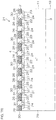
- FIG. 3 is a cross-sectional view presented when the semiconductor device is cut along line III-III in FIG. 1 .
- FIG. 4 is a cross-sectional view presented when the semiconductor device is cut along line IV-IV in FIG. 1 .
- FIG. 5A to FIG. 5C are diagrams showing arrangement patterns of p + type regions.
- FIG. 6A to FIG. 6C are diagrams showing I-V curves in the semiconductor device according to the preferred embodiment of the present invention and in a semiconductor device according to a comparative example.
- FIG. 7A is a diagram showing part of a manufacturing process of the semiconductor device in FIG. 1 to FIG. 4 .
- FIG. 7B is a diagram showing a step subsequent to FIG. 7A .
- FIG. 7C is a diagram showing a step subsequent to FIG. 7B .
- FIG. 7D is a diagram showing a step subsequent to FIG. 7C .
- FIG. 7E is a diagram showing a step subsequent to FIG. 7D .
- FIG. 8A is a diagram showing another form of the manufacturing process of the semiconductor device in FIG. 1 to FIG. 4 .
- FIG. 8B is a diagram showing a step subsequent to FIG. 8A .
- FIG. 8C is a diagram showing a step subsequent to FIG. 8B .
- FIG. 8D is a diagram showing a step subsequent to FIG. 8C .
- FIG. 8E is a diagram showing a step subsequent to FIG. 8D .
- FIG. 8F is a diagram showing a step subsequent to FIG. 8E .
- FIG. 9 is a diagram for illustrating electric field relaxation regions formed in a Schottky interface of the semiconductor device.
- FIG. 10 is an enlarged view of the electric field relaxation regions.
- FIG. 11 is an enlarged view of the electric field relaxation regions.
- FIG. 12 is a schematic cross-sectional view of a semiconductor device which includes n type field stop regions.
- FIG. 13 is a schematic cross-sectional view of the semiconductor device which includes the n type field stop regions.
- FIG. 14 is a cross-sectional view showing another form of the semiconductor device.
- FIG. 15A is a diagram showing part of a manufacturing process of the semiconductor device in FIG. 14 .
- FIG. 15B is a diagram showing a step subsequent to FIG. 15A .
- FIG. 15C is a diagram showing a step subsequent to FIG. 15B .
- FIG. 15D is a diagram showing a step subsequent to FIG. 15C .
- FIG. 16 is a diagram for illustrating electric field relaxation regions formed in a Schottky interface of the semiconductor device in FIG. 14 .
- FIG. 17 is a schematic cross-sectional view of a semiconductor device which includes n type field stop regions.
- FIG. 18 is a schematic cross-sectional view of the semiconductor device which includes the n type field stop regions.
- FIG. 19 is a diagram showing another form of a back surface terminal structure in FIG. 4 .
- FIG. 20 is a diagram showing another form of the back surface terminal structure in FIG. 4 .
- FIG. 21 is a schematic cross-sectional view of a semiconductor device which includes a surrounding electric field relaxation region.
- FIG. 22 is a schematic cross-sectional view of the semiconductor device which includes the surrounding electric field relaxation region.
- FIG. 23 is a schematic cross-sectional view of the semiconductor device which includes the surrounding electric field relaxation region.
- FIG. 24 is a schematic perspective view of a semiconductor package according to a preferred embodiment of the present invention.
- FIG. 25 is a matrix converter circuit diagram in which the semiconductor device according to the preferred embodiment of the present invention is incorporated as a bidirectional switch.
- FIG. 26 is a cross-sectional view showing another form of the semiconductor device.
- FIG. 1 and FIG. 2 are respectively a plan view and a bottom view of a semiconductor device 1 according to the preferred embodiment of the present invention.
- the semiconductor device 1 includes a source electrode 4 and a gate pad 5 on the side of the front surface 2 thereof, and also includes a drain electrode 6 as an example of a first electrode in the present invention on the side of a back surface 3 .
- the source electrode 4 is formed substantially in the shape of a quadrangle over a substantially entire region of a front surface 2 , and includes a peripheral edge 9 in a position separated inward from an end surface 7 of the semiconductor device 1 .
- a front surface terminal structure such as a guard ring, etc.
- a semiconductor region 8 is exposed around the source electrode 4 .
- the semiconductor region 8 surrounding the source electrode 4 is exposed.
- the gate pad 5 is provided in one corner portion of the source electrode 4 such that the gate pad 5 is spaced from the source electrode 4 , and is connected to a gate electrode 26 in each of MIS transistor structures 22 which will be described later.
- the drain electrode 6 is formed substantially in the shape of a quadrangle over a substantially entire region of the back surface 3 , and includes a peripheral edge 10 in a position separated inward from the end surface 7 of the semiconductor device 1 . Accordingly, on the back surface 3 of the semiconductor device 1 , a semiconductor region 45 is exposed around the drain electrode 6 . In this preferred embodiment, the semiconductor region 45 surrounding the drain electrode 6 is exposed.
- FIG. 3 and FIG. 4 are respectively cross-sectional views presented when the semiconductor device 1 is cut along line III-III and line IV-IV in FIG. 1 .
- FIG. 5A to FIG. 5C are diagrams showing arrangement patterns of p + type regions 18 when seen from the side of the back surface.
- the semiconductor device 1 includes a semiconductor layer 11 formed of type SiC.
- the semiconductor layer 11 includes the front surface 2 which is the Si surface of the SiC, the back surface 3 which is the C surface of the SiC on the side opposite thereto, and the end surface 7 which is extended in a direction intersecting the front surface 2 (in FIG. 3 and FIG. 4 , which is extended in a vertical direction).
- the front surface 2 may be a surface other than the Si surface of the SiC
- the back surface 3 may be a surface other than the C surface of the SiC.
- the semiconductor layer 11 has, for example, a thickness of 10 ⁇ m to 250 ⁇ m.
- the semiconductor device 1 generally has a substantially uniform n type impurity concentration, and has, for example, an impurity concentration of 1 ⁇ 10 14 cm ⁇ 3 to 1 ⁇ 10 17 cm ⁇ 3 .
- “having a substantially uniform impurity concentration” means that the semiconductor layer 11 does not have, on aback surface portion (for example, a region which is extended a certain distance from the back surface 3 in the direction of thickness), an n type part (for example, an n + type part) of a relatively high impurity concentration.
- the p + type regions 18 serving as an example of second conductivity type portions in the present invention are selectively formed.
- the regions other than the p + type regions 18 are exposed from the back surface 3 as n + type regions 14 serving as an example of first conductivity type portions in the present invention.
- the p + type regions 18 are formed over a substantially entire semiconductor layer 11 (that is, in both an active region 21 and an outer peripheral region 20 which will be described later).
- the p + type regions 18 can be formed into various patterns. For example, as indicated by hatching in FIG. 5A , a plurality of the p + type regions 18 may be arranged in plan view (bottom view) in the shape of stripes. As indicated by hatching in FIG. 5B , the plurality of the p + type regions 18 may be respectively formed in the shape of polygons (in FIG. 5B , in the shape of regular hexagons) in plan view and may be arranged discretely. Although in FIG. 5B , the plurality of the p + type regions 18 are arranged in a staggered configuration, they may be arranged in a matrix configuration. As indicated by hatching in FIG.
- the plurality of the p + type regions 18 may be respectively formed in the shape of circles (in FIG. 5C , in the shape of regular circles) in plan view and may be arranged discretely. As a matter of course, the arrangement pattern of FIG. 5C may have a matrix configuration as in the case of FIG. 5B . It is noted that, although in FIG. 5A to FIG. 5C , the plurality of the p + type regions 18 are unified having the same shape, they may differ in shape and size.
- the semiconductor device 1 includes the outer peripheral region 20 which is set in a peripheral edge portion (part near the end surface 7 ) and the active region 21 which is surrounded by the outer peripheral region 20 .
- the MIS transistor structure 22 includes a p type body region 23 , an n + type source region 24 , a gate insulating film 25 , the gate electrode 26 , and a p + type body contact region 27 .
- a plurality of the p type body regions 23 are formed on the front surface portion of the semiconductor layer 11 .
- the respective p type body regions 23 form the minimum units (unit cells) through which a current flows in the active region 21 .
- the n + type source region 24 is formed in the inner region of each of the p type body region 23 .
- the n + type source region 24 is exposed to the front surface 2 of the semiconductor layer 11 .
- the outer region of the n + type source region 24 (region surrounding the n + type source region 24 ) defines a channel region 28 .
- the gate electrode 26 straddles adjacent unit cells, and faces the channel region 28 via the gate insulating film 25 .
- the p + type body contact region 27 penetrates through the n + type source region 24 .
- the p + type body contact region 27 is electrically connected to the p type body region 23 .
- the impurity concentration of the p type body region 23 is, for example, 1 ⁇ 10 16 cm ⁇ 3 to 1 ⁇ 10 19 cm ⁇ 3
- the impurity concentration of the n + type source region 24 is, for example, 1 ⁇ 10 19 cm ⁇ 3 to 1 ⁇ 10 21 cm ⁇ 3
- the impurity concentration of the p + type body contact region 27 is, for example, 1 ⁇ 10 19 cm ⁇ 3 to 1 ⁇ 10 21 cm ⁇ 3
- the gate insulating film 25 is formed of, for example, silicon oxide (SiO 2 ), and the thickness thereof is 20 nm to 100 nm.
- the gate electrode 26 is formed of, for example, polysilicon.
- a width Wp of each of the p + type regions 18 in FIG. 5A to FIG. 5C is preferably equal to or more than the cell width Wc.
- the width Wp of each of the p + type regions 18 may be twice or more of the thickness Td. Accordingly, positive holes are efficiently injected from the respective p + type regions 18 , and thus it is possible to make a transition to an IGBT mode at a low drain voltage. It is noted that, as shown in FIG. 5A to FIG. 5C , as the width Wp, it suffices to measure the narrowest part of each of the p + type regions 18 .
- an n + type region on the side of the back surface 3 with respect to the MIS transistor structure 22 is an n + type drift region 29 , and parts thereof are exposed to the back surface 3 as the above-described n type regions 14 .
- an interlayer insulating film 30 which straddles both the active region 21 and the outer peripheral region 20 is formed.
- the interlayer insulating film 30 is formed of, for example, silicon oxide (SiO 2 ), and the thickness thereof is 0.5 ⁇ m to 3.0 ⁇ m.
- a contact hole 31 is formed through which the n + type source region 24 and the p + type body contact region 27 in each unit cell are exposed.
- the source electrode 4 is formed on the interlayer insulating films 30 .
- the source electrode 4 enters the respective contact holes 31 such that the source electrode 4 is in ohmic contact with the n + type source regions 24 and the p + type body contact regions 27 .
- the source electrode 4 is extended from the active region 21 to the outer peripheral region 20 , and includes, in the outer peripheral region 20 , an overlap portion 32 which rides on the interlayer insulating film 30 .
- a front surface terminal structure 33 is formed on the front surface portion of the semiconductor layer 11 in the outer peripheral region 20 .
- the front surface terminal structure 33 may be formed with a plurality of parts which include at least one part that overlaps the peripheral edge portion of the source electrode 4 (peripheral edge portion of a junction portion to the semiconductor layer 11 ).
- an innermost resurf layer 34 (RESURF: Reduced Surface Field) and a plurality of guard ring layers 35 which surround the resurf layer 34 are included.
- the resurf layer 34 is formed such that the resurf layer 34 straddles the interior and the exterior of an opening 36 of the interlayer insulating film 30 , and is brought into contact with the peripheral edge portion of the source electrode 4 within the opening 36 .
- a plurality of the guard ring layers 35 are spaced from each other.
- the resurf layer 34 and the guard ring layers 35 shown in FIG. 4 are formed with a p type impurity region, they may be formed with a high resistance region. In a case of the high resistance region, the resurf layer 34 and the guard ring layers 35 may have a crystal defect concentration of 1 ⁇ 10 14 cm ⁇ 3 to 1 ⁇ 10 22 cm ⁇ 3 .
- the drain electrode 6 is formed on the back surface 3 of the semiconductor layer 11 .
- the drain electrode 6 is an electrode which is common to a plurality of unit cells.
- the drain electrode 6 forms a Schottky junction with the n ⁇ type regions 14 (the n ⁇ type drift region 29 ), and is in ohmic contact with the p + type regions 18 .
- the drain electrode 6 is formed of a metal (for example, Ti, Ni Mo, or Au, etc.) which can form a Schottky junction with the n ⁇ type regions 14 and which can be in ohmic contact with the p + type regions 18 .
- the drain electrode 6 has the peripheral edge 10 in a position separated inward from the end surface 7 of the semiconductor layer 11 . Accordingly, the semiconductor region 45 is exposed to the back surface 3 of the semiconductor layer 11 around the drain electrode 6 . In this preferred embodiment, the semiconductor region 45 which surrounds the drain electrode 6 is exposed.
- the peripheral edge portion of the drain electrode 6 faces the peripheral edge portion of the source electrode 4 across the semiconductor layer 11 . More specifically, the drain electrode 6 is extended from the active region 21 to the outer peripheral region 20 and includes the peripheral edge portion arranged directly below the front surface terminal structure 33 (in this preferred embodiment, the resurf layer 34 ) in the outer peripheral region 20 . As shown in FIG. 4 , the drain electrode 6 may have the same size as the source electrode 4 .
- a back surface terminal structure 12 is formed on the back surface portion of the semiconductor layer 11 in the outer peripheral region 20 .
- the back surface terminal structure 12 includes an inner side peripheral edge 15 which is on an inner side with respect to the peripheral edge 10 of the drain electrode 6 and an outer side peripheral edge 16 which is on an outer side with respect to the peripheral edge 10 of the drain electrode 6 and which is in a position separated inward from the end surface 7 of the semiconductor layer 11 .
- the formation range of the back surface terminal structure 12 is substantially the same as that of the front surface terminal structure 33 . Therefore, the outer side peripheral edge 16 of the back surface terminal structure 12 may coincide with the outer side peripheral edge 17 of the outermost guard ring layer 35 in plan view.
- the back surface terminal structure 12 may be a high resistance region which has a resistance higher than the n ⁇ type drift region 29 or may be a p type impurity region.
- the back surface terminal structure 12 may have a crystal defect concentration of 1 ⁇ 10 14 cm ⁇ 3 to 1 ⁇ 10 22 cm ⁇ 3 .
- the back surface terminal structure 12 may have an impurity concentration of 1 ⁇ 10 16 cm ⁇ 3 to 1 ⁇ 10 19 cm ⁇ 3 .
- the n ⁇ type region 14 (the n ⁇ type drift region 29 ) and the p + type region 18 are exposed to the side of the back surface 3 of the semiconductor layer 11 , and the drain electrode 6 which is the common electrode is in contact with both thereof. Therefore, for the MIS transistor structure 22 , the n ⁇ type drift region 29 and the p + type region 18 respectively form the drain region of a MISFET (Metal Insulator Semiconductor Field Effect Transistor) and the collector region of an IGBT (Insulated Gate Bipolar Semiconductor).
- MISFET Metal Insulator Semiconductor Field Effect Transistor
- IGBT Insulated Gate Bipolar Semiconductor
- the semiconductor device 1 has a Hybrid-MIS (Hybrid-Metal Insulator Semiconductor) structure in which the MISFET and the IGBT are integrated into the same semiconductor layer.
- Hybrid-MIS Hybrid-Metal Insulator Semiconductor
- the MISFET is effective as an element which is mainly used in a low withstand voltage region (for example, 5 kV or less). Therefore, in the semiconductor device 1 , when a voltage is applied between the source and the drain, and a voltage which is equal to or more than a threshold voltage is applied to the gate electrode 26 , the MISFET is first turned on, and thus electrical continuity is established between the source electrode 4 and the drain electrode 6 via the n ⁇ type region 14 of the semiconductor layer 11 (MISFET mode). For example, as shown in FIG. 6A , a drain current Id linearly increases with an increase in a drain voltage Vd until the drain voltage Id rises from when a source-drain voltage Vd is 0V and then pinch-off occurs.
- a drain current Id linearly increases with an increase in a drain voltage Vd until the drain voltage Id rises from when a source-drain voltage Vd is 0V and then pinch-off occurs.
- the drain voltage Vd increases with an increase in the drain current Id
- a current-carrying loss in the MISFET which is determined by the product of the drain voltage Vd and the drain current Id is increased. It is noted that, by increasing the area of the semiconductor layer, the drain voltage Vd necessary for the flow of a large current can be reduced and consequently, the current-carrying loss in the MISFET can be reduced.
- the manufacturing cost is significantly increased.
- the IGBT is effective as an element which is mainly used in a high withstand voltage region (for example, 10 kV or more).
- a high withstand voltage region for example, 10 kV or more.
- the semiconductor device 1 after electrical continuity is established between the source and the drain in the MISFET mode, when, as shown in FIG. 6A , the source-drain voltage becomes equal to or more than a rising voltage Vpn of a parasitic diode (pn diode) formed with the pn junction of the p type body region 23 and the n ⁇ type drift region 29 , the semiconductor device 1 transitions to the large current region. In the large current region, electrons flow into the n ⁇ type drift region 29 .
- pn diode parasitic diode
- the electrons act as a base current for a pnp transistor which is formed with the p type body region 23 , the n ⁇ type drift region 29 , and the p + type region 18 (collector region), and thus electrical continuity is established in the pnp transistor. Since electrons are supplied from the n + type source region 24 (emitter region), and positive holes are injected from the p + type region 18 , electrons and positive holes are excessively accumulated in the n ⁇ type drift region 29 . Accordingly, conductivity modulation occurs in the n ⁇ type drift region 29 , and thus the n ⁇ type drift region 29 transitions to a high conductivity state and the IGBT is turned on.
- the MISFET and the IGBT into the same semiconductor layer, it is possible to realize a wide operating range from the low withstand voltage region to the high withstand voltage region. That is, it is possible to provide the semiconductor device in which, while it is useable as a high withstand voltage element, in the small current region, the MISFET (bipolar) operation can be realized, and in the large current region, the IGBT (bipolar) operation can be realized. Consequently, in the semiconductor device 1 , satisfactory switching characteristics can be achieved in both the small current region and the large current region.
- a reverse voltage in FIG. 6A , the region of Vd ⁇ 0
- a current flows in the direction of thickness within the semiconductor device 1 via a body diode (parasitic diode) formed with the pn junction within the MIS transistor structure 22 .
- a Schottky barrier formed between the n ⁇ type region 14 and the drain electrode 6 , it is possible to prevent the drain current Id from flowing. Consequently, it is possible to ensure a satisfactory reverse withstand voltage.
- a method of manufacturing the semiconductor device 1 will then be described with reference to FIG. 7A to FIG. 7E .
- FIG. 7A to FIG. 7E are diagrams showing a manufacturing process of the semiconductor device 1 shown in FIG. 1 to FIG. 4 in order of steps.
- the semiconductor device 1 In order to manufacture the semiconductor device 1 , as shown in FIG. 7A , first, on a base substrate 19 in a state of a wafer which is formed of an n + type SiC (for example, an impurity concentration is 1 ⁇ 10 18 cm ⁇ 3 to 1 ⁇ 10 20 cm ⁇ 3 ), by epitaxial growth, the semiconductor layer 11 which has a concentration lower than the base substrate 19 is formed.
- the thickness of the base substrate 19 may be, for example, 150 ⁇ m to 450 ⁇ m.
- the above-described MIS transistor structures 22 are formed on the front surface portion of the semiconductor layer 11 .
- the step thereof can be reduced.
- the front surface terminal structure may be formed in a separate step. Thereafter, the interlayer insulating films 30 and the source electrode 4 are formed.
- the entire back surface 3 of the semiconductor layer 11 is exposed.
- This step may be performed by removing the base substrate 19 almost completely by grinding from the side of the back surface 3 and thereafter polishing (for example, CMP) may be performed for finishing.
- polishing for example, CMP
- the semiconductor layer 11 which is exposed after being ground may be further thinned.
- the base substrate 19 having a thickness of 350 ⁇ m may be removed by back surface grinding, and thereafter the semiconductor layer 11 having a thickness of 50 ⁇ m may be polished so as to have a thickness of 40 ⁇ m.
- a resist film (not shown) which selectively covers the back surface 3 of the semiconductor layer 11 is formed, and, via the resist film, p type impurity (for example, aluminum (Al)) ions are implanted into the back surface 3 of the semiconductor layer 11 . Thereafter, by performing laser annealing, the p type impurity is activated, and thus the p + type regions 18 are formed.
- the back surface terminal structure 12 is formed by the ion implantation step for the formation of the p + type region 18 , the step thereof can be reduced. However, the back surface terminal structure 12 may be formed in a separate step.
- a metal film is formed over the entire back surface 3 of the semiconductor layer 11 , and the metal film is selectively removed (etched). Accordingly, the drain electrode 6 is formed. Then, the semiconductor layer 11 is cut along a dicing line which is set at a position away from the peripheral edge 10 (not shown in FIG. 7E ) of the drain electrode 6 . Accordingly, as shown in FIG. 7E , the semiconductor device 1 which is individualized can be obtained.
- the semiconductor device 1 can also be manufactured, for example, in steps 8 A to 8 F instead of steps 7 A to 7 E.
- an n type first semiconductor layer 46 whose concentration is lower than that of the base substrate 19 is formed.
- the thickness of the first semiconductor layer 46 is, for example, 0.5 ⁇ m to 5 ⁇ m.
- the p + type regions 18 are formed in the first semiconductor layer 46 .
- p type impurity ions are selectively implanted into the front surface of the first semiconductor layer 46 .
- the p + type regions 18 do not need to be formed up to the back surface of the first semiconductor layer 46 (interface with the base substrate 19 ), as the p type impurity ions, for example, Al is used.
- the p + type regions 18 are formed.
- the annealing processing is performed, in both the base substrate 19 and the first semiconductor layer 46 , elements which are sensitive to high temperature are not yet formed, and thus the annealing processing can be performed at a relatively high temperature (for example, 1500° C. to 1800° C.).
- an n ⁇ type second semiconductor layer 47 is formed on the first semiconductor layer 46 .
- the thickness of the second semiconductor layer 47 is, for example, 5 ⁇ m to 300 ⁇ m. Accordingly, the semiconductor layer 11 formed with the first semiconductor layer 46 and the second semiconductor layer 47 is formed.
- the p + type regions 18 formed on the front surface portion of the first semiconductor layer 46 are brought into a state where they are embedded in a bottom portion of the semiconductor layer 11 .
- the impurity regions of the MIS transistor structure 22 and the front surface terminal structure 33 are formed. Specifically, the p type body regions 23 , the n + type source regions 24 , the p + type body contact regions 27 , the resurf layer 34 , and the guard ring layers 35 are formed. It is noted that, in the step of FIG.
- the annealing processing for forming the impurity regions (such as the p type body regions 23 , etc.) of the MIS transistor structures 22 may be utilized so as to simultaneously activate the p + type regions 18 .
- the gate insulating films 25 and the gate electrodes 26 which are the remaining elements of the MIS transistor structures 22 are formed. Thereafter, the interlayer insulating films 30 and the source electrode 4 are formed.
- a metal film is formed over the entire back surface 3 of the semiconductor layer 11 , and the metal film is selectively removed (etched). Accordingly, the drain electrode 6 is formed. Then, the semiconductor layer 11 is cut along a dicing line which is set at a position away from the peripheral edge 10 (not shown in FIG. 8F ) of the drain electrode 6 . Accordingly, as shown in FIG. 8F , the semiconductor device 1 which is individualized can be obtained.
- FIG. 9 is a diagram for illustrating electric field relaxation regions 44 formed in a Schottky interface of the back surface 3 of a semiconductor layer 11 . Also, FIG. 10 and FIG. 11 are enlarged views of the electric field relaxation regions 44 .
- the semiconductor device 1 may include the electric field relaxation regions 44 which are formed on the back surface portion of the semiconductor layer 11 in the active region 21 and which are in contact with the drain electrode 6 . More specifically, in the n ⁇ type regions 14 (n type drift region 29 ) exposed from the back surface 3 of the semiconductor layer 11 , the electric field relaxation regions 44 are selectively formed.
- the electric field relaxation regions 44 By forming the electric field relaxation regions 44 , an electric field in the Schottky interface between the n ⁇ type drift region 29 and the drain electrode 6 can be relaxed. Accordingly, a reverse leakage current can be reduced even when a metal whose work function is relatively small is used as the drain electrode 6 , therefore, by using the metal, a low on-resistance can be ensured. More specifically, although the reverse leakage current can also be reduced at the expense of the low on-resistance, since in this configuration, the reverse leakage current can be reduced by the electric field relaxation regions 44 , by using a metal whose work function is lower than a metal used in a case where the electric field relaxation regions 44 are not provided, it is possible to achieve the low on-resistance.
- the electric field relaxation region 44 may be a high resistance region which has a resistance higher than the n ⁇ type drift region 29 or may be a p type impurity region.
- the electric field relaxation region 44 may have a crystal defect concentration of 1 ⁇ 10 14 cm ⁇ 3 to 1 ⁇ 10 22 cm ⁇ 3 .
- the back surface terminal structure 12 may have an impurity concentration of 1 ⁇ 10 16 cm ⁇ 3 to 1 ⁇ 10 19 cm ⁇ 3 .
- the electric field relaxation regions 44 may be formed on the flat portion 37 .
- the electric field relaxation regions 44 may be formed within the n ⁇ type drift region 29 along the inner surfaces of the trenches 38 .
- the drain electrode 6 may be embedded in the trenches 38 and be connected to the electric field relaxation regions 44 within the trenches 38 .
- FIG. 12 and FIG. 13 are schematic cross-sectional views of a semiconductor device 1 which includes n type field stop regions 42 and 43 .
- n type field stop regions 42 and 43 when a voltage is applied between the source and the drain, it is possible to prevent a depletion layer extending from a low voltage side from reaching a conductive pattern (for example, the MIS transistor structures 22 ) on a high voltage side. Accordingly, it is possible to prevent a leakage current caused by a punch-through phenomenon.
- the n type field stop regions 42 and 43 suffice to be an n type field stop region which is formed on at least one of the side of the front surface 2 and the side of the back surface 3 of the semiconductor layer 11 and which has an impurity concentration higher than the n ⁇ type drift region 29 .
- FIG. 12 and FIG. 13 both the front surface side n type field stop region 42 and the back surface side n type field stop region 43 are shown.
- the n type field stop regions 42 and 43 may be arranged at depth positions away from the front surface 2 and the back surface 3 (the Schottky interface) of the semiconductor layer 11 .
- the front surface side n type field stop layer 42 may be disposed below the MIS transistor structure 22 separated toward the side of the back surface 3 from the p type body regions 23 .
- the back surface side n type field stop layer 43 may be disposed at an upper side separated toward the side of the surface 2 from the p + type regions 18 .
- the n type field stop regions 42 and 43 may reach the front surface 2 and the back surface 3 of the semiconductor layer 11 .
- Impurity concentrations of the n type field stop layers 42 and 43 may have profiles uniform in the depth direction of the semiconductor layer 11 , or may have profiles having peaks at predetermined depth positions. In a case where the impurity concentration has a peak, it suffices that a concentration at this peak is higher than a concentration of the n ⁇ type drift region 29 .
- the n type field stop regions 42 and 43 in FIG. 12 and FIG. 13 may be combined as necessary.
- the front surface side n type field stop region 42 may be arranged in a position away from the front surface 2 of the semiconductor layer 11 whereas the back surface side n type field stop region 43 may reach the back surface 3 of the semiconductor layer 11 .
- FIG. 14 is a schematic cross-sectional view showing another form of the semiconductor device 1 .
- the p + type regions 18 are formed with the impurity regions selectively formed on the back surface 3 of the n + type semiconductor layer 11 , in FIG. 14 , the p + type regions 18 are formed with parts of a p + type substrate 39 .
- the semiconductor layer 11 includes the p + type substrate 39 which serves as an example of a second semiconductor layer in the present invention and an n ⁇ type semiconductor layer 40 which serves as an example of a first semiconductor layer in the present invention on the p + type substrate 39 .
- the p + type substrate 39 has, for example, a thickness of 100 ⁇ m to 400 ⁇ m. Also, the p + type substrate 39 has, for example, an impurity concentration of 1 ⁇ 10 17 cm ⁇ 3 to 5 ⁇ 10 19 cm ⁇ 3 .
- trenches 41 are selectively formed.
- the respective trenches 41 reach the n ⁇ type semiconductor layer 40 from the back surface of the p + type substrate 39 (the back surface 3 of the semiconductor layer 11 ) and are formed at a greater depth such that the respective trenches 41 form concave portions 49 in the n type semiconductor layer 40 .
- steps are formed between the formation positions (first parts 51 ) of the trenches 41 and the other positions (second parts 52 ).
- the bottom portion of the trench 41 is formed only with the n ⁇ type semiconductor layer 40 whereas the side portions of the trench 41 are formed with the n ⁇ type semiconductor layer 40 and the p + type substrate 39 .
- the drain electrode 6 is formed along the back surface 3 of the p + type substrate 39 and the inner surfaces of the trenches 41 . Accordingly, a distance (the thickness of the drain electrode 6 ) between one surface which is in contact with the back surface 3 of the p + type substrate 39 of the drain electrode 6 and the inner surface of the trench 41 and the other surface on the side opposite thereto are constant.
- the drain electrode 6 makes a Schottky junction with the n ⁇ type drift region 29 at the bottom portion (the back surface 50 ) and part of the side portions (side surfaces 53 ) of the trench 41 , and is in ohmic contact with the p + type substrate 39 at part of the side portion (the side surface 53 ) of the trench 41 and the back surface 3 of the p + type substrate 39 .
- FIG. 15A to FIG. 15D are diagrams showing a manufacturing process of the semiconductor device 1 shown in FIG. 14 in order of steps.
- the n ⁇ type semiconductor layer 40 is formed by epitaxial growth.
- the MIS transistor structures 22 are formed on the front surface portion of the n ⁇ type semiconductor layer 40 . Thereafter, the interlayer insulating films 30 and the source electrode 4 are formed.
- a step of thinning the p + type substrate 39 may be performed prior to the formation of the trenches 41 .
- This thinning step may be performed, for example, by thinning the p + type substrate 39 by grinding from the side of the back surface 3 (for example, grinding by about 50 ⁇ m to 300 ⁇ m) and thereafter polishing (for example, CMP) may be performed for finishing.
- polishing for example, CMP
- the p + type substrate 39 remaining after the grinding may be further thinned.
- a metal film is formed over the entire back surface 3 of the p + type substrate 39 .
- the metal film is deposited not only on the back surface 3 of the p + type substrate 39 but also on the inner surfaces of the trenches 41 (the back surface 50 of the n ⁇ type semiconductor layer 40 and the side surfaces 53 of the trenches 41 ). Accordingly, the drain electrode 6 is formed. After the formation of the drain electrode 6 , sintering processing may be performed on the drain electrode 6 by laser annealing.
- the semiconductor layer 11 is cut along a dicing line which is set in a predetermined position. Accordingly, the semiconductor device 1 which is individualized can be obtained.
- the electric field relaxation regions 44 and the n type field stop regions 42 and 43 described above may be provided.
- FIG. 16 is a diagram for illustrating the electric field relaxation regions 44 which are formed on the Schottky interface on the back surface 50 of the semiconductor device 1 of FIG. 14 .
- the electric field relaxation regions 44 are selectively formed on the first parts 51 of the n ⁇ type semiconductor layer 40 which are exposed to the trenches 41 .
- FIG. 17 and FIG. 18 are schematic cross-sectional views of the semiconductor device which includes the n type field stop regions 42 and 43 .
- the n type field stop regions 42 and 43 may be arranged at depth positions away from the front surface 2 and the back surface 3 (the Schottky interface) of the n ⁇ type semiconductor layer 40 , or, as shown in FIG. 18 , the n type field stop regions 42 and 43 may reach the front surface 2 and the back surface 3 (the Schottky interface) of the n ⁇ type semiconductor layer 40 .
- FIG. 19 and FIG. 20 are diagrams showing another form of the back surface terminal structure 12 in FIG. 4 .
- the back surface terminal structure 12 may be formed with a plurality of parts which include at least one part that overlaps the peripheral edge portion of the drain electrode 6 .
- an innermost resurf layer 54 (RESURF: Reduced Surface Field) and a plurality of guard ring layers 55 which surround the resurf layer 54 are included.
- the resurf layer 54 is formed such that the resurf layer 54 straddles the interior and the exterior of the drain electrode 6 , and is brought into contact with the peripheral edge portion of the drain electrode 6 .
- the plurality of the guard ring layers 55 are spaced from each other.
- the resurf layer 54 and the guard ring layers 55 may be formed such that the resurf layer 54 and the guard ring layers 55 respectively face the resurf layer 34 and the guard ring layers 35 on the front surface terminal structure 33 in a one-to-one relationship.
- the back surface terminal structure 12 may reach the end surface 7 of the semiconductor layer 11 from the peripheral edge portion of the drain electrode 6 . That is, the outer side peripheral edge 16 of the back surface terminal structure 12 may coincide with the end surface 7 of the semiconductor layer 11 .
- FIG. 21 is a schematic cross-sectional view of a semiconductor device which includes a surrounding electric field relaxation region 56 .
- the surrounding electric field relaxation region 56 may be formed.
- the surrounding electric field relaxation region 56 is formed on the outer side of the front surface terminal structure 33 in the outer peripheral region 20 .
- the surrounding electric field relaxation region 56 is formed with either the high resistance region which has a resistance higher than the semiconductor layer 11 (n ⁇ type drift region 29 ) or a p type semiconductor region.
- the high resistance region has a crystal defect concentration of 1 ⁇ 10 14 cm ⁇ 3 to 1 ⁇ 10 22 cm ⁇ 3 .
- the p type semiconductor region has an impurity concentration of 1 ⁇ 10 18 cm ⁇ 3 to 1 ⁇ 10 22 cm ⁇ 3 .
- the surrounding electric field relaxation region 56 is a constant region which reaches the back surface 3 from the front surface 2 of the semiconductor layer 11 .
- the surrounding electric field relaxation region 56 is formed such that when it is seen in cross section as shown in FIG. 21 , an inner side surface 57 close to the active region 21 and an outer side surface 58 on a side opposite thereto are perpendicular to the front surface 2 and the back surface 3 . Accordingly, a width W 1 of the surrounding electric field relaxation region 56 is substantially constant from the front surface 2 to the back surface 3 of the semiconductor layer 11 .
- the surrounding electric field relaxation region 56 is spaced inward from the end surface 7 of the semiconductor layer 11 , and accordingly, on the outer side of the surrounding electric field relaxation region 56 (between the surrounding electric field relaxation region 56 and the end surface 7 of the semiconductor layer 11 ), an n ⁇ type surrounding region 59 is formed which is formed with part of the semiconductor layer 11 and which serves as an example of a surrounding impurity region in the present invention.
- the surrounding electric field relaxation region 56 which is annular in plan view surrounds the n ⁇ type drift region 29 into a closed space, and the annular region up to the end surface 7 on the outer side thereof is formed as the n ⁇ type surrounding region 59 .
- the surrounding electric field relaxation region 56 of FIG. 21 is spaced inward from the end surface 7 of the semiconductor layer 11 , as shown in FIG. 22 , the surrounding electric field relaxation region 56 may reach the end surface 7 of the semiconductor layer 11 . Accordingly, the outer side surface 58 of the surrounding electric field relaxation region 56 is the surface which coincides with the end surface 7 of the semiconductor layer 11 .
- the semiconductor device 1 may include a second drain electrode 60 which is formed on the side of the front surface 2 of the semiconductor layer 11 and which serves as an example of an auxiliary electrode in the present invention that is set to have the same potential as the drain electrode 6 .
- a contact hole 61 is formed through which the n ⁇ type surrounding region 59 and the surrounding electric field relaxation region 56 are exposed at an end portion of the semiconductor layer 11 .
- the contact hole 61 includes an annular inner peripheral edge 62 which surrounds the n ⁇ type drift region 29 . It is noted that, although in FIG.
- the contact hole 61 is formed up to the end surface 7 of the semiconductor layer 11 such that the interlayer insulating film 30 is not left near the end surface 7 of the semiconductor layer 11 , the contact hole 61 may have an outer peripheral edge in a position separated inward from the end surface 7 such that part of the interlayer insulating film 30 is left near the end surface 7 .
- the second drain electrode 60 enters the contact hole 61 , straddles a boundary portion between the n ⁇ type surrounding region 59 and the surrounding electric field relaxation region 56 within the contact hole 61 , and makes contact with both the regions 56 and 59 . As described with reference to FIG. 22 , in a case where the surrounding electric field relaxation region 56 reaches the end surface 7 of the semiconductor layer 11 , the second drain electrode 60 may make contact only with the surrounding electric field relaxation region 56 within the contact hole 61 .
- the second drain electrode 60 is electrically connected to the drain electrode 6 (see FIG. 24 for the form of connection of the drain electrode 6 and the second drain electrode 60 ). Accordingly, the potentials of the n ⁇ type surrounding region 59 and the surrounding electric field relaxation region 56 are fixed to the same potential from the front surface 2 of the semiconductor layer 11 in contact with the second drain electrode 60 to the back surface 3 in contact with the drain electrode 6 . Consequently, it is possible to make it difficult to extend the electric field to the n ⁇ type surrounding region 59 and the surrounding electric field relaxation region 56 , and thus it is possible to further relax the intensity of the electric field near the end surface 7 of the semiconductor layer 11 .
- FIG. 24 is a schematic perspective view of a semiconductor package 71 according to a preferred embodiment of the present invention.
- the same elements as the components in FIG. 1 to FIG. 23 are identified with the same reference signs, and the description thereof will be omitted.
- the interior of a resin package 74 is shown by showing the resin package 74 transparent.
- the semiconductor package 71 includes a semiconductor chip 72 , a substrate terminal 73 which serves as an example of a lead frame in the present invention, and the resin package 74 .
- the semiconductor chip 72 may have the same configuration as the semiconductor device 1 shown in FIG. 1 to FIG. 23 .
- the substrate terminal 73 is, for example, a plate (metal substrate) which is formed of a metal material, for example, Cu, etc., and includes a drain terminal 77 , a source terminal 78 , and a gate terminal 79 .
- the drain terminal 77 includes an island portion 80 which is formed, in plan view, in the shape of a quadrangle and a linear terminal portion 81 which is extended from one side of the island portion 80 .
- the source terminal 78 and the gate terminal 79 are formed linearly and parallel to the terminal portion 81 of the drain terminal 77 , and are respectively arranged on the right side and the left side of the paper surface such that the source terminal 78 and the gate terminal 79 sandwich the drain terminal 77 in the center (terminal portion 81 ) from both sides in the width direction.
- the island portion 80 is provided in order to support the semiconductor chip 72 and has an area larger than the semiconductor chip 72 . Accordingly, in a state where the semiconductor chip 72 is mounted, the island portion 80 includes an outer peripheral portion 88 which is part on the outer side of the semiconductor chip 72 and which surrounds the semiconductor chip 72 .
- the drain electrode (the drain electrode 6 of FIG. 3 ) of the semiconductor chip 72 is electrically connected to the island portion 80 by die bonding.
- the source electrode 4 and the gate pad 5 of the semiconductor chip 72 are respectively electrically connected, via bonding wires 85 and 86 , to the source terminal 78 and the gate terminal 79 .
- the semiconductor chip 72 includes the second drain electrode 60 shown in FIG. 23
- the second drain electrode 60 is connected to the drain electrode 6 via a bonding wire 82 and the drain terminal 77 (island portion 80 ). Accordingly, the drain electrode 6 and the second drain electrode 60 can be made to have the same potential.
- the semiconductor device 1 described above can be incorporated into a matrix converter circuit 100 shown in FIG. 25 as a bidirectional switch.
- the matrix converter circuit 100 includes a three-phase input portion 103 , a three-phase output portion 104 , a circuit main body portion 105 , and a filter circuit 106 .
- the semiconductor device 1 is introduced as a bidirectional switch 101 in each of switch portions 107 in the circuit main body portion 105 .
- the bidirectional switch 101 can be arranged by a combination of two transistors (semiconductor device 1 ) 102 A and 102 B and two diodes 108 A and 108 B.
- the semiconductor device 1 described above may include protective films 83 and 84 which are formed at least in the outer peripheral region 20 of the semiconductor layer 11 and which cover a portion from the peripheral edge portions of the source electrode 4 and the drain electrode 6 to the end surface 7 of the semiconductor layer 11 . Only either one of the protective films 83 and 84 may be formed or both thereof may be formed. The terminals of the protective films 83 and 84 do not need to be the end surface 7 of the semiconductor layer 11 .
- the protective films 83 and 84 may be formed of, for example, polyimide. It is noted that, although only the case where the protective films 83 and 84 are applied to the form of FIG. 4 is shown, the protective films 83 and 84 can be, as a matter of course, applied to the forms of FIG. 9 , FIG. 12 , FIG. 13 and FIG. 14 , and FIG. 16 to FIG. 23 .
- the material of the semiconductor layer 11 may be another material which is referred to as a wide band gap type such as GaN, etc., or the semiconductor layer 11 may be formed of Si.
- the semiconductor device of the preferred embodiments in the present invention is used as a bidirectional switch for a power supply device, it is possible to easily obtain a power supply device in which the reliability of withstand voltage is enhanced and in which an on-loss is low.
Landscapes
- Engineering & Computer Science (AREA)
- Microelectronics & Electronic Packaging (AREA)
- Power Engineering (AREA)
- Condensed Matter Physics & Semiconductors (AREA)
- General Physics & Mathematics (AREA)
- Physics & Mathematics (AREA)
- Ceramic Engineering (AREA)
- Computer Hardware Design (AREA)
- Chemical & Material Sciences (AREA)
- Crystallography & Structural Chemistry (AREA)
- Manufacturing & Machinery (AREA)
- Electrodes Of Semiconductors (AREA)
- Metal-Oxide And Bipolar Metal-Oxide Semiconductor Integrated Circuits (AREA)
Applications Claiming Priority (3)
| Application Number | Priority Date | Filing Date | Title |
|---|---|---|---|
| JP2016161486 | 2016-08-19 | ||
| JP2016-161486 | 2016-08-19 | ||
| PCT/JP2017/027320 WO2018034127A1 (ja) | 2016-08-19 | 2017-07-27 | 半導体装置 |
Publications (2)
| Publication Number | Publication Date |
|---|---|
| US20200020765A1 US20200020765A1 (en) | 2020-01-16 |
| US10892319B2 true US10892319B2 (en) | 2021-01-12 |
Family
ID=61197461
Family Applications (1)
| Application Number | Title | Priority Date | Filing Date |
|---|---|---|---|
| US16/316,957 Active US10892319B2 (en) | 2016-08-19 | 2017-07-27 | Semiconductor device |
Country Status (6)
| Country | Link |
|---|---|
| US (1) | US10892319B2 (ja) |
| JP (1) | JP7018394B2 (ja) |
| KR (1) | KR102185158B1 (ja) |
| CN (1) | CN109643728B (ja) |
| DE (1) | DE112017004153T5 (ja) |
| WO (1) | WO2018034127A1 (ja) |
Families Citing this family (7)
| Publication number | Priority date | Publication date | Assignee | Title |
|---|---|---|---|---|
| WO2017099122A1 (ja) * | 2015-12-11 | 2017-06-15 | ローム株式会社 | 半導体装置 |
| CN109643728B (zh) | 2016-08-19 | 2022-04-29 | 罗姆股份有限公司 | 半导体装置 |
| DE102018112109A1 (de) * | 2018-05-18 | 2019-11-21 | Infineon Technologies Ag | Siliziumcarbid halbleiterbauelement |
| JP7369601B2 (ja) * | 2019-11-21 | 2023-10-26 | ルネサスエレクトロニクス株式会社 | 半導体装置およびその製造方法 |
| CN112271208A (zh) * | 2020-10-23 | 2021-01-26 | 重庆大学 | 碳化硅单栅极双沟道晶闸管输运igbt及制造方法 |
| CN112736134A (zh) * | 2020-10-23 | 2021-04-30 | 重庆大学 | 碳化硅pnpn晶闸管注入型igbt器件 |
| JP2022169322A (ja) * | 2021-04-27 | 2022-11-09 | 株式会社デンソー | 半導体装置 |
Citations (43)
| Publication number | Priority date | Publication date | Assignee | Title |
|---|---|---|---|---|
| JPS5465477A (en) | 1977-11-04 | 1979-05-26 | Mitsubishi Electric Corp | Resin-sealed semiconductor device |
| JPH0523547A (ja) | 1991-07-19 | 1993-02-02 | Nissin Electric Co Ltd | 溶液濃縮装置 |
| JPH05315490A (ja) | 1992-05-07 | 1993-11-26 | Fuji Electric Co Ltd | 半導体素子 |
| JPH06236990A (ja) | 1992-11-28 | 1994-08-23 | Asea Brown Boveri Ag | Mos制御ダイオード |
| JPH11265976A (ja) | 1998-03-18 | 1999-09-28 | Mitsubishi Electric Corp | パワー半導体モジュールおよびその製造方法 |
| JP2003197831A (ja) | 2001-12-25 | 2003-07-11 | Nippon Inter Electronics Corp | アキシャルリード型半導体装置 |
| JP2004095572A (ja) | 2002-08-29 | 2004-03-25 | Hitachi Ltd | 半導体装置およびその製造方法 |
| JP2005183891A (ja) | 2003-12-19 | 2005-07-07 | Success International Kk | 双方向ブロック型プレーナデバイスの構造と製法 |
| US20070235768A1 (en) | 2006-04-10 | 2007-10-11 | Kazushi Nakazawa | Semiconductor device |
| JP2008041708A (ja) | 2006-08-01 | 2008-02-21 | Nissan Motor Co Ltd | 半導体装置及びその製造方法 |
| US20080315248A1 (en) * | 2006-03-22 | 2008-12-25 | Denso Corporation | Semiconductor Device Having Igbt Cell and Diode Cell and Method for Designing the Same |
| JP2009094433A (ja) | 2007-10-12 | 2009-04-30 | National Institute Of Advanced Industrial & Technology | 炭化珪素装置 |
| US20090134405A1 (en) | 2007-11-27 | 2009-05-28 | Kabushiki Kaisha Toshiba | Semiconductor substrate and semiconductor device |
| JP2009123914A (ja) | 2007-11-15 | 2009-06-04 | Fuji Electric Device Technology Co Ltd | 逆耐圧を有するスイッチング用半導体装置 |
| US20090236697A1 (en) * | 2008-03-24 | 2009-09-24 | Kabushiki Kaisha Toshiba | Semiconductor device and method of manufacturing the same |
| US7989910B2 (en) * | 2007-10-22 | 2011-08-02 | Kabushiki Kaisha Toshiba | Semiconductor device including a resurf region with forward tapered teeth |
| US20120211768A1 (en) | 2011-02-21 | 2012-08-23 | Fuji Electric Co., Ltd. | Wide-band-gap reverse-blocking mos-type semiconductor device |
| US20120211762A1 (en) | 2011-02-23 | 2012-08-23 | Fujitsu Limited | Semiconductor device, method of manufacturing semiconductor device and electronic circuit |
| WO2012124190A1 (ja) | 2011-03-14 | 2012-09-20 | 富士電機株式会社 | 半導体装置の製造方法および半導体装置 |
| JP2012256662A (ja) | 2011-06-08 | 2012-12-27 | Yoshitaka Sugawara | 半導体素子および半導体装置 |
| WO2013018760A1 (ja) | 2011-08-02 | 2013-02-07 | ローム株式会社 | 半導体装置およびその製造方法 |
| US8395162B2 (en) * | 2009-07-21 | 2013-03-12 | Rohm Co., Ltd. | Semiconductor device with multi-layer gate electrode |
| WO2013141221A1 (ja) | 2012-03-19 | 2013-09-26 | 富士電機株式会社 | 半導体装置の製造方法 |
| JP2013219194A (ja) | 2012-04-09 | 2013-10-24 | Sansha Electric Mfg Co Ltd | 半導体装置 |
| WO2014041652A1 (ja) | 2012-09-13 | 2014-03-20 | 富士電機株式会社 | 半導体装置および半導体装置の製造方法 |
| WO2014087601A1 (ja) | 2012-12-03 | 2014-06-12 | パナソニック株式会社 | 半導体装置およびその製造方法 |
| WO2014091961A1 (ja) | 2012-12-10 | 2014-06-19 | ローム株式会社 | 半導体装置および半導体装置の製造方法 |
| US8860039B2 (en) * | 2010-04-26 | 2014-10-14 | Mitsubishi Electric Corporation | Semiconductor device |
| WO2014210072A1 (en) | 2013-06-24 | 2014-12-31 | Ideal Power Inc. | Systems, circuits, devices, and methods with bidirectional bipolar transistors |
| US20150021657A1 (en) | 2013-07-18 | 2015-01-22 | Kabushiki Kaisha Toshiba | Semiconductor device |
| JP2015032789A (ja) | 2013-08-06 | 2015-02-16 | 住友電気工業株式会社 | 炭化珪素半導体基板およびその製造方法、ならびに炭化珪素半導体装置の製造方法 |
| US20150060884A1 (en) | 2013-09-03 | 2015-03-05 | Kabushiki Kaisha Toshiba | Semiconductor device |
| JP2015099932A (ja) | 2002-08-30 | 2015-05-28 | ノーステル エービー | 半導体装置 |
| US20150221731A1 (en) * | 2014-02-04 | 2015-08-06 | Maxpower Semiconductor, Inc. | Vertical power mosfet having planar channel and its method of fabrication |
| US20150228717A1 (en) | 2014-02-10 | 2015-08-13 | Toyota Jidosha Kabushiki Kaisha | Method for manufacturing semiconductor device and semiconductor device |
| WO2015159953A1 (ja) | 2014-04-17 | 2015-10-22 | ローム株式会社 | 半導体装置 |
| WO2015166608A1 (ja) | 2014-04-30 | 2015-11-05 | 三菱電機株式会社 | 炭化珪素半導体装置 |
| US20150340443A1 (en) | 2014-05-21 | 2015-11-26 | Sumitomo Electric Industries, Ltd. | Silicon carbide semiconductor device |
| JP2015220437A (ja) | 2014-05-21 | 2015-12-07 | 住友電気工業株式会社 | 炭化珪素半導体装置 |
| US20160192495A1 (en) | 2014-12-25 | 2016-06-30 | Fuji Electric Co., Ltd. | Semiconductor device |
| US20170054017A1 (en) * | 2014-06-27 | 2017-02-23 | Mitsubishi Electric Corporation | Silicon carbide semiconductor device |
| US20190311917A1 (en) | 2015-12-11 | 2019-10-10 | Rohm Co., Ltd. | Semiconductor device |
| US20200020765A1 (en) | 2016-08-19 | 2020-01-16 | Rohm Co., Ltd. | Semiconductor device |
Family Cites Families (2)
| Publication number | Priority date | Publication date | Assignee | Title |
|---|---|---|---|---|
| JP4198251B2 (ja) * | 1999-01-07 | 2008-12-17 | 三菱電機株式会社 | 電力用半導体装置およびその製造方法 |
| JP6535185B2 (ja) | 2015-03-04 | 2019-06-26 | エイブリック株式会社 | 湿度センサ |
-
2017
- 2017-07-27 CN CN201780050601.5A patent/CN109643728B/zh active Active
- 2017-07-27 WO PCT/JP2017/027320 patent/WO2018034127A1/ja active Application Filing
- 2017-07-27 KR KR1020197006876A patent/KR102185158B1/ko active IP Right Grant
- 2017-07-27 US US16/316,957 patent/US10892319B2/en active Active
- 2017-07-27 DE DE112017004153.8T patent/DE112017004153T5/de active Pending
- 2017-07-27 JP JP2018534318A patent/JP7018394B2/ja active Active
Patent Citations (65)
| Publication number | Priority date | Publication date | Assignee | Title |
|---|---|---|---|---|
| JPS5465477A (en) | 1977-11-04 | 1979-05-26 | Mitsubishi Electric Corp | Resin-sealed semiconductor device |
| JPH0523547A (ja) | 1991-07-19 | 1993-02-02 | Nissin Electric Co Ltd | 溶液濃縮装置 |
| JPH05315490A (ja) | 1992-05-07 | 1993-11-26 | Fuji Electric Co Ltd | 半導体素子 |
| JPH06236990A (ja) | 1992-11-28 | 1994-08-23 | Asea Brown Boveri Ag | Mos制御ダイオード |
| JPH11265976A (ja) | 1998-03-18 | 1999-09-28 | Mitsubishi Electric Corp | パワー半導体モジュールおよびその製造方法 |
| JP2003197831A (ja) | 2001-12-25 | 2003-07-11 | Nippon Inter Electronics Corp | アキシャルリード型半導体装置 |
| JP2004095572A (ja) | 2002-08-29 | 2004-03-25 | Hitachi Ltd | 半導体装置およびその製造方法 |
| JP2015099932A (ja) | 2002-08-30 | 2015-05-28 | ノーステル エービー | 半導体装置 |
| JP2005183891A (ja) | 2003-12-19 | 2005-07-07 | Success International Kk | 双方向ブロック型プレーナデバイスの構造と製法 |
| US20080315248A1 (en) * | 2006-03-22 | 2008-12-25 | Denso Corporation | Semiconductor Device Having Igbt Cell and Diode Cell and Method for Designing the Same |
| US20070235768A1 (en) | 2006-04-10 | 2007-10-11 | Kazushi Nakazawa | Semiconductor device |
| JP2007305609A (ja) | 2006-04-10 | 2007-11-22 | Matsushita Electric Ind Co Ltd | 半導体装置 |
| JP2008041708A (ja) | 2006-08-01 | 2008-02-21 | Nissan Motor Co Ltd | 半導体装置及びその製造方法 |
| JP2009094433A (ja) | 2007-10-12 | 2009-04-30 | National Institute Of Advanced Industrial & Technology | 炭化珪素装置 |
| US7989910B2 (en) * | 2007-10-22 | 2011-08-02 | Kabushiki Kaisha Toshiba | Semiconductor device including a resurf region with forward tapered teeth |
| JP2009123914A (ja) | 2007-11-15 | 2009-06-04 | Fuji Electric Device Technology Co Ltd | 逆耐圧を有するスイッチング用半導体装置 |
| JP2009130266A (ja) | 2007-11-27 | 2009-06-11 | Toshiba Corp | 半導体基板および半導体装置、半導体装置の製造方法 |
| US20090134405A1 (en) | 2007-11-27 | 2009-05-28 | Kabushiki Kaisha Toshiba | Semiconductor substrate and semiconductor device |
| US20090236697A1 (en) * | 2008-03-24 | 2009-09-24 | Kabushiki Kaisha Toshiba | Semiconductor device and method of manufacturing the same |
| US8395162B2 (en) * | 2009-07-21 | 2013-03-12 | Rohm Co., Ltd. | Semiconductor device with multi-layer gate electrode |
| US8860039B2 (en) * | 2010-04-26 | 2014-10-14 | Mitsubishi Electric Corporation | Semiconductor device |
| US20120211768A1 (en) | 2011-02-21 | 2012-08-23 | Fuji Electric Co., Ltd. | Wide-band-gap reverse-blocking mos-type semiconductor device |
| JP2012174831A (ja) | 2011-02-21 | 2012-09-10 | Fuji Electric Co Ltd | ワイドバンドギャップ逆阻止mos型半導体装置 |
| US20120211762A1 (en) | 2011-02-23 | 2012-08-23 | Fujitsu Limited | Semiconductor device, method of manufacturing semiconductor device and electronic circuit |
| WO2012124190A1 (ja) | 2011-03-14 | 2012-09-20 | 富士電機株式会社 | 半導体装置の製造方法および半導体装置 |
| US20150179784A1 (en) | 2011-03-14 | 2015-06-25 | Fuji Electric Co., Ltd. | Semiconductor device having schottky junction between substrate and drain electrode |
| US20140001487A1 (en) | 2011-03-14 | 2014-01-02 | Fuji Electric Co., Ltd. | Semiconductor device manufacturing method and semiconductor device |
| JP2012256662A (ja) | 2011-06-08 | 2012-12-27 | Yoshitaka Sugawara | 半導体素子および半導体装置 |
| US20140225126A1 (en) * | 2011-08-02 | 2014-08-14 | Rohm Co., Ltd. | Semiconductor device, and manufacturing method for same |
| US20170162564A1 (en) | 2011-08-02 | 2017-06-08 | Rohm Co., Ltd. | Method of manufacturing a semiconductor device |
| WO2013018760A1 (ja) | 2011-08-02 | 2013-02-07 | ローム株式会社 | 半導体装置およびその製造方法 |
| JP2013110373A (ja) | 2011-08-02 | 2013-06-06 | Rohm Co Ltd | 半導体装置およびその製造方法 |
| US20160343803A1 (en) | 2011-08-02 | 2016-11-24 | Rohm Co., Ltd. | Semiconductor device |
| WO2013141221A1 (ja) | 2012-03-19 | 2013-09-26 | 富士電機株式会社 | 半導体装置の製造方法 |
| US20140357026A1 (en) | 2012-03-19 | 2014-12-04 | Fuji Electric Co., Ltd. | Production method for semiconductor device |
| JP2013219194A (ja) | 2012-04-09 | 2013-10-24 | Sansha Electric Mfg Co Ltd | 半導体装置 |
| US20150060938A1 (en) | 2012-09-13 | 2015-03-05 | Fuji Electric Co., Ltd. | Semiconductor device and semiconductor device manufacturing method |
| WO2014041652A1 (ja) | 2012-09-13 | 2014-03-20 | 富士電機株式会社 | 半導体装置および半導体装置の製造方法 |
| US20140374774A1 (en) | 2012-12-03 | 2014-12-25 | Panasonic Corporation | Semiconductor device and method for manufacturing same |
| WO2014087601A1 (ja) | 2012-12-03 | 2014-06-12 | パナソニック株式会社 | 半導体装置およびその製造方法 |
| WO2014091961A1 (ja) | 2012-12-10 | 2014-06-19 | ローム株式会社 | 半導体装置および半導体装置の製造方法 |
| US20150333190A1 (en) | 2012-12-10 | 2015-11-19 | Rohm Co., Ltd. | Semiconductor device and semiconductor device manufacturing method |
| WO2014210072A1 (en) | 2013-06-24 | 2014-12-31 | Ideal Power Inc. | Systems, circuits, devices, and methods with bidirectional bipolar transistors |
| US20150021657A1 (en) | 2013-07-18 | 2015-01-22 | Kabushiki Kaisha Toshiba | Semiconductor device |
| JP2015023118A (ja) | 2013-07-18 | 2015-02-02 | 株式会社東芝 | 半導体装置 |
| US20150228726A1 (en) | 2013-07-18 | 2015-08-13 | Kabushiki Kaisha Toshiba | Semiconductor device |
| US20160189955A1 (en) | 2013-08-06 | 2016-06-30 | Sumitomo Electric Industries, Ltd. | Silicon carbide semiconductor substrate, method for manufacturing silicon carbide semiconductor substrate, and method for manufacturing silicon carbide semiconductor device |
| JP2015032789A (ja) | 2013-08-06 | 2015-02-16 | 住友電気工業株式会社 | 炭化珪素半導体基板およびその製造方法、ならびに炭化珪素半導体装置の製造方法 |
| JP2015050394A (ja) | 2013-09-03 | 2015-03-16 | 株式会社東芝 | 半導体装置 |
| US20150060884A1 (en) | 2013-09-03 | 2015-03-05 | Kabushiki Kaisha Toshiba | Semiconductor device |
| US20150221731A1 (en) * | 2014-02-04 | 2015-08-06 | Maxpower Semiconductor, Inc. | Vertical power mosfet having planar channel and its method of fabrication |
| JP2015153784A (ja) | 2014-02-10 | 2015-08-24 | トヨタ自動車株式会社 | 半導体装置の製造方法及び半導体装置 |
| US20150228717A1 (en) | 2014-02-10 | 2015-08-13 | Toyota Jidosha Kabushiki Kaisha | Method for manufacturing semiconductor device and semiconductor device |
| WO2015159953A1 (ja) | 2014-04-17 | 2015-10-22 | ローム株式会社 | 半導体装置 |
| US20170040420A1 (en) * | 2014-04-17 | 2017-02-09 | Rohm Co., Ltd. | Semiconductor device |
| US20180158915A1 (en) * | 2014-04-17 | 2018-06-07 | Rohm Co., Ltd. | Semiconductor device |
| WO2015166608A1 (ja) | 2014-04-30 | 2015-11-05 | 三菱電機株式会社 | 炭化珪素半導体装置 |
| US20160079349A1 (en) | 2014-05-21 | 2016-03-17 | Sumitomo Electric Industries, Ltd. | Silicon carbide semiconductor device |
| JP2015220437A (ja) | 2014-05-21 | 2015-12-07 | 住友電気工業株式会社 | 炭化珪素半導体装置 |
| US20150340443A1 (en) | 2014-05-21 | 2015-11-26 | Sumitomo Electric Industries, Ltd. | Silicon carbide semiconductor device |
| US20170054017A1 (en) * | 2014-06-27 | 2017-02-23 | Mitsubishi Electric Corporation | Silicon carbide semiconductor device |
| US20160192495A1 (en) | 2014-12-25 | 2016-06-30 | Fuji Electric Co., Ltd. | Semiconductor device |
| US10123443B2 (en) | 2014-12-25 | 2018-11-06 | Fuji Electric Co., Ltd. | Semiconductor device |
| US20190311917A1 (en) | 2015-12-11 | 2019-10-10 | Rohm Co., Ltd. | Semiconductor device |
| US20200020765A1 (en) | 2016-08-19 | 2020-01-16 | Rohm Co., Ltd. | Semiconductor device |
Non-Patent Citations (4)
| Title |
|---|
| International Preliminary Report on Patentability issued for International Patent Application No. PCT/JP2016/086369, dated Jun. 21, 2018, 42 pages including English translation. |
| International Preliminary Report on Patentability issued for International Patent Application No. PCT/JP2017/027320, dated Feb. 28, 2019, 22 pages including English translation. |
| International Search Report issued for International Patent Application No. PCT/JP2016/086369, dated Mar. 7, 2017, 7 pages including English translation. |
| International Search Report issued for International Patent Application No. PCT/JP2017/027320, dated Oct. 10, 2017, 7 pages including English translation. |
Also Published As
| Publication number | Publication date |
|---|---|
| DE112017004153T5 (de) | 2019-05-02 |
| JPWO2018034127A1 (ja) | 2019-06-13 |
| KR102185158B1 (ko) | 2020-12-01 |
| US20200020765A1 (en) | 2020-01-16 |
| JP7018394B2 (ja) | 2022-02-10 |
| CN109643728B (zh) | 2022-04-29 |
| KR20190039217A (ko) | 2019-04-10 |
| CN109643728A (zh) | 2019-04-16 |
| WO2018034127A1 (ja) | 2018-02-22 |
Similar Documents
| Publication | Publication Date | Title |
|---|---|---|
| US10832922B2 (en) | Semiconductor device | |
| US10892319B2 (en) | Semiconductor device | |
| US10847621B2 (en) | Semiconductor device with a well region | |
| JP5995435B2 (ja) | 半導体装置およびその製造方法 | |
| JP6617292B2 (ja) | 炭化珪素半導体装置 | |
| US10672878B2 (en) | Silicon carbide semiconductor device | |
| US7791135B2 (en) | Insulated gate silicon carbide semiconductor device and method for manufacturing the same | |
| JP6415749B2 (ja) | 炭化珪素半導体装置 | |
| JP6650431B2 (ja) | 半導体装置およびその製造方法 | |
| US20210151555A1 (en) | Semiconductor device, and method for manufacturing semiconductor device | |
| JP4177229B2 (ja) | 半導体装置とその製造方法 | |
| US20190355840A1 (en) | Semiconductor device and method for manufacturing semicondcutor device | |
| JP2022180233A (ja) | 炭化珪素半導体装置 |
Legal Events
| Date | Code | Title | Description |
|---|---|---|---|
| FEPP | Fee payment procedure |
Free format text: ENTITY STATUS SET TO UNDISCOUNTED (ORIGINAL EVENT CODE: BIG.); ENTITY STATUS OF PATENT OWNER: LARGE ENTITY |
|
| AS | Assignment |
Owner name: ROHM CO., LTD., JAPAN Free format text: ASSIGNMENT OF ASSIGNORS INTEREST;ASSIGNORS:MORI, SEIGO;AKETA, MASATOSHI;SIGNING DATES FROM 20181121 TO 20181122;REEL/FRAME:047969/0324 |
|
| STPP | Information on status: patent application and granting procedure in general |
Free format text: NON FINAL ACTION MAILED |
|
| STPP | Information on status: patent application and granting procedure in general |
Free format text: RESPONSE TO NON-FINAL OFFICE ACTION ENTERED AND FORWARDED TO EXAMINER |
|
| STPP | Information on status: patent application and granting procedure in general |
Free format text: RESPONSE AFTER FINAL ACTION FORWARDED TO EXAMINER |
|
| STPP | Information on status: patent application and granting procedure in general |
Free format text: PUBLICATIONS -- ISSUE FEE PAYMENT VERIFIED |
|
| STCF | Information on status: patent grant |
Free format text: PATENTED CASE |