JP4752473B2 - Exposure apparatus, exposure method, and device manufacturing method - Google Patents
Exposure apparatus, exposure method, and device manufacturing method Download PDFInfo
- Publication number
- JP4752473B2 JP4752473B2 JP2005350685A JP2005350685A JP4752473B2 JP 4752473 B2 JP4752473 B2 JP 4752473B2 JP 2005350685 A JP2005350685 A JP 2005350685A JP 2005350685 A JP2005350685 A JP 2005350685A JP 4752473 B2 JP4752473 B2 JP 4752473B2
- Authority
- JP
- Japan
- Prior art keywords
- liquid
- substrate
- measurement
- exposure
- exposure apparatus
- Prior art date
- Legal status (The legal status is an assumption and is not a legal conclusion. Google has not performed a legal analysis and makes no representation as to the accuracy of the status listed.)
- Expired - Fee Related
Links
Images


Classifications
-
- G—PHYSICS
- G03—PHOTOGRAPHY; CINEMATOGRAPHY; ANALOGOUS TECHNIQUES USING WAVES OTHER THAN OPTICAL WAVES; ELECTROGRAPHY; HOLOGRAPHY
- G03F—PHOTOMECHANICAL PRODUCTION OF TEXTURED OR PATTERNED SURFACES, e.g. FOR PRINTING, FOR PROCESSING OF SEMICONDUCTOR DEVICES; MATERIALS THEREFOR; ORIGINALS THEREFOR; APPARATUS SPECIALLY ADAPTED THEREFOR
- G03F7/00—Photomechanical, e.g. photolithographic, production of textured or patterned surfaces, e.g. printing surfaces; Materials therefor, e.g. comprising photoresists; Apparatus specially adapted therefor
- G03F7/70—Microphotolithographic exposure; Apparatus therefor
- G03F7/708—Construction of apparatus, e.g. environment aspects, hygiene aspects or materials
- G03F7/70908—Hygiene, e.g. preventing apparatus pollution, mitigating effect of pollution or removing pollutants from apparatus
- G03F7/70925—Cleaning, i.e. actively freeing apparatus from pollutants, e.g. using plasma cleaning
-
- G—PHYSICS
- G03—PHOTOGRAPHY; CINEMATOGRAPHY; ANALOGOUS TECHNIQUES USING WAVES OTHER THAN OPTICAL WAVES; ELECTROGRAPHY; HOLOGRAPHY
- G03F—PHOTOMECHANICAL PRODUCTION OF TEXTURED OR PATTERNED SURFACES, e.g. FOR PRINTING, FOR PROCESSING OF SEMICONDUCTOR DEVICES; MATERIALS THEREFOR; ORIGINALS THEREFOR; APPARATUS SPECIALLY ADAPTED THEREFOR
- G03F7/00—Photomechanical, e.g. photolithographic, production of textured or patterned surfaces, e.g. printing surfaces; Materials therefor, e.g. comprising photoresists; Apparatus specially adapted therefor
- G03F7/20—Exposure; Apparatus therefor
- G03F7/2041—Exposure; Apparatus therefor in the presence of a fluid, e.g. immersion; using fluid cooling means
-
- G—PHYSICS
- G03—PHOTOGRAPHY; CINEMATOGRAPHY; ANALOGOUS TECHNIQUES USING WAVES OTHER THAN OPTICAL WAVES; ELECTROGRAPHY; HOLOGRAPHY
- G03F—PHOTOMECHANICAL PRODUCTION OF TEXTURED OR PATTERNED SURFACES, e.g. FOR PRINTING, FOR PROCESSING OF SEMICONDUCTOR DEVICES; MATERIALS THEREFOR; ORIGINALS THEREFOR; APPARATUS SPECIALLY ADAPTED THEREFOR
- G03F7/00—Photomechanical, e.g. photolithographic, production of textured or patterned surfaces, e.g. printing surfaces; Materials therefor, e.g. comprising photoresists; Apparatus specially adapted therefor
- G03F7/70—Microphotolithographic exposure; Apparatus therefor
- G03F7/70216—Mask projection systems
- G03F7/70341—Details of immersion lithography aspects, e.g. exposure media or control of immersion liquid supply
-
- G—PHYSICS
- G03—PHOTOGRAPHY; CINEMATOGRAPHY; ANALOGOUS TECHNIQUES USING WAVES OTHER THAN OPTICAL WAVES; ELECTROGRAPHY; HOLOGRAPHY
- G03F—PHOTOMECHANICAL PRODUCTION OF TEXTURED OR PATTERNED SURFACES, e.g. FOR PRINTING, FOR PROCESSING OF SEMICONDUCTOR DEVICES; MATERIALS THEREFOR; ORIGINALS THEREFOR; APPARATUS SPECIALLY ADAPTED THEREFOR
- G03F7/00—Photomechanical, e.g. photolithographic, production of textured or patterned surfaces, e.g. printing surfaces; Materials therefor, e.g. comprising photoresists; Apparatus specially adapted therefor
- G03F7/70—Microphotolithographic exposure; Apparatus therefor
- G03F7/708—Construction of apparatus, e.g. environment aspects, hygiene aspects or materials
- G03F7/7085—Detection arrangement, e.g. detectors of apparatus alignment possibly mounted on wafers, exposure dose, photo-cleaning flux, stray light, thermal load
-
- G—PHYSICS
- G03—PHOTOGRAPHY; CINEMATOGRAPHY; ANALOGOUS TECHNIQUES USING WAVES OTHER THAN OPTICAL WAVES; ELECTROGRAPHY; HOLOGRAPHY
- G03F—PHOTOMECHANICAL PRODUCTION OF TEXTURED OR PATTERNED SURFACES, e.g. FOR PRINTING, FOR PROCESSING OF SEMICONDUCTOR DEVICES; MATERIALS THEREFOR; ORIGINALS THEREFOR; APPARATUS SPECIALLY ADAPTED THEREFOR
- G03F7/00—Photomechanical, e.g. photolithographic, production of textured or patterned surfaces, e.g. printing surfaces; Materials therefor, e.g. comprising photoresists; Apparatus specially adapted therefor
- G03F7/70—Microphotolithographic exposure; Apparatus therefor
- G03F7/708—Construction of apparatus, e.g. environment aspects, hygiene aspects or materials
- G03F7/70908—Hygiene, e.g. preventing apparatus pollution, mitigating effect of pollution or removing pollutants from apparatus
- G03F7/70916—Pollution mitigation, i.e. mitigating effect of contamination or debris, e.g. foil traps
-
- G—PHYSICS
- G03—PHOTOGRAPHY; CINEMATOGRAPHY; ANALOGOUS TECHNIQUES USING WAVES OTHER THAN OPTICAL WAVES; ELECTROGRAPHY; HOLOGRAPHY
- G03F—PHOTOMECHANICAL PRODUCTION OF TEXTURED OR PATTERNED SURFACES, e.g. FOR PRINTING, FOR PROCESSING OF SEMICONDUCTOR DEVICES; MATERIALS THEREFOR; ORIGINALS THEREFOR; APPARATUS SPECIALLY ADAPTED THEREFOR
- G03F7/00—Photomechanical, e.g. photolithographic, production of textured or patterned surfaces, e.g. printing surfaces; Materials therefor, e.g. comprising photoresists; Apparatus specially adapted therefor
- G03F7/70—Microphotolithographic exposure; Apparatus therefor
- G03F7/708—Construction of apparatus, e.g. environment aspects, hygiene aspects or materials
- G03F7/70975—Assembly, maintenance, transport or storage of apparatus
Description
本発明は、液体を介して基板を露光する露光装置、露光方法及びデバイス製造方法に関するものである。 The present invention relates to an exposure apparatus that exposes a substrate through a liquid, an exposure method, and a device manufacturing method.
半導体デバイスや液晶表示デバイス等のマイクロデバイスの製造工程の一つであるフォトリソグラフィ工程では、マスク上に形成されたパターンを感光性の基板上に投影露光する露光装置が用いられる。この露光装置は、マスクを支持するマスクステージと基板を支持する基板ステージとを有し、マスクステージ及び基板ステージを逐次移動しながらマスクのパターンを投影光学系を介して基板に投影露光するものである。マイクロデバイスの製造においては、デバイスの高密度化のために、基板上に形成されるパターンの微細化が要求されている。この要求に応えるために露光装置の更なる高解像度化が望まれている。その高解像度化を実現するための手段の一つとして、下記特許文献1に開示されているような、投影光学系と基板との間の露光光の光路空間を液体で満たし、液体を介して露光処理を行う液浸露光装置が案出されている。
液浸露光装置においては、液体を介した露光処理及び計測処理を行うため、その液体が汚染されたり、劣化してしまうと、露光処理や計測処理の結果に影響を及ぼす虞がある。そのため、液体の状態を把握し、適切な処置を行うことが重要である。 In the immersion exposure apparatus, since exposure processing and measurement processing are performed via a liquid, if the liquid is contaminated or deteriorated, the result of the exposure processing or measurement processing may be affected. Therefore, it is important to grasp the state of the liquid and take appropriate measures.
本発明はこのような事情に鑑みてなされたものであって、液体の状態(性質、成分など)を精度良く把握することができる露光装置、露光方法及びデバイス製造方法を提供することを目的とする。 The present invention has been made in view of such circumstances, and an object thereof is to provide an exposure apparatus, an exposure method, and a device manufacturing method capable of accurately grasping a liquid state (properties, components, etc.). To do.
上記の課題を解決するため、本発明は実施の形態に示す図1〜図13に対応付けした以下の構成を採用している。但し、各要素に付した括弧付き符号はその要素の例示に過ぎず、各要素を限定するものではない。 In order to solve the above-described problems, the present invention adopts the following configuration corresponding to FIGS. 1 to 13 shown in the embodiment. However, the reference numerals with parentheses attached to each element are merely examples of the element and do not limit each element.
本発明の第1の態様に従えば、光学部材(LS1)を介して基板(P)に露光光(EL)を照射して基板(P)を露光する露光装置において、光学部材(LS1)の光射出面側に配置される基板(P)とは異なる物体(ST1、ST2、DP等)と、光学部材(LS1)と物体(ST1、ST2、DP等)との間の光路空間(K1)を液体(LQ)で満たすための液浸機構(1)と、前記基板(P)とは異なる物体(ST1、ST2、DP等)上に液浸領域(LR)を形成した状態で液体(LQ)の性質及び成分のうち少なくとも一方を計測する計測装置(60)とを備えた露光装置(EX)が提供される。 According to the first aspect of the present invention, in the exposure apparatus that exposes the substrate (P) by irradiating the substrate (P) with the exposure light (EL) through the optical member (LS1), the optical member (LS1) An object (ST1, ST2, DP, etc.) different from the substrate (P) arranged on the light emission surface side, and an optical path space (K1) between the optical member (LS1) and the object (ST1, ST2, DP, etc.) The liquid immersion mechanism (1) for filling the liquid (LQ) with the liquid (LQ) in a state where the liquid immersion area (LR) is formed on an object (ST1, ST2, DP, etc.) different from the substrate (P). ) And an exposure apparatus (EX) provided with a measurement apparatus (60) that measures at least one of the properties and components.
本発明の第1の態様によれば、露光用の基板との接触無しに、液体の状態を把握できるため、液体を所望状態にするための処置を行うことができ、液体を介した露光処理及び計測処理を精度良く行うことができる。 According to the first aspect of the present invention, since the state of the liquid can be grasped without contact with the substrate for exposure, a treatment for bringing the liquid into a desired state can be performed, and exposure processing via the liquid In addition, the measurement process can be performed with high accuracy.
本発明の第2の態様に従えば、基板(P)を液体(LQ)を介して露光する露光方法であって、基板(P)とは異なる物体(ST1、ST2、DP等)上に液浸領域(LR)を形成する第1工程(SA1)と、基板(P)とは異なる物体(ST1、ST2、DP等)上に液浸領域(LR)を形成した状態で液体(LQ)の状態を検査する第2工程(SA2,SA3)と、検査結果に基いて露光条件を調整する第3工程(SA15)と、前記調整した露光条件の下、前記基板(P)上に形成した液浸領域(LR)の液体(LQ)を介して前記基板(P)に露光光(EL)を照射して前記基板を露光する第4工程(SA7)とを含む露光方法が提供される。 According to the second aspect of the present invention, there is provided an exposure method in which a substrate (P) is exposed through a liquid (LQ), and a liquid is applied on an object (ST1, ST2, DP, etc.) different from the substrate (P). The first step (SA1) for forming the immersion region (LR) and the liquid (LQ) in a state where the immersion region (LR) is formed on an object (ST1, ST2, DP, etc.) different from the substrate (P). A second step (SA2, SA3) for inspecting the state, a third step (SA15) for adjusting the exposure condition based on the inspection result, and a liquid formed on the substrate (P) under the adjusted exposure condition. There is provided an exposure method including a fourth step (SA7) of exposing the substrate by irradiating the substrate (P) with exposure light (EL) through the liquid (LQ) in the immersion region (LR).
本発明の第2の態様の露光方法によれば、予め基板とは異なる物体を用いて液浸領域を形成し、液浸露光に使用される液体の状態を把握して液体の状態を含む最適な露光条件を設定することができるために、露光処理及び計測処理を精度よく行うことができる。 According to the exposure method of the second aspect of the present invention, the liquid immersion region is previously formed using an object different from the substrate, the state of the liquid used for the liquid immersion exposure is grasped, and the optimal state including the liquid state Therefore, exposure processing and measurement processing can be performed with high accuracy.
本発明の第3の態様に従えば、上記態様の露光装置(EX)を用いるデバイス製造方法が提供される。 According to the third aspect of the present invention, a device manufacturing method using the exposure apparatus (EX) of the above aspect is provided.
本発明の第3の態様によれば、液体を介した露光処理及び計測処理を精度良く行うことができる露光装置を使ってデバイスを製造することができる。 According to the 3rd aspect of this invention, a device can be manufactured using the exposure apparatus which can perform the exposure process and measurement process via a liquid accurately.
本発明の第4の態様に従えば、上記露光方法により基板を露光する工程を含むデバイスの製造方法が提供される。 According to the 4th aspect of this invention, the manufacturing method of the device including the process of exposing a board | substrate by the said exposure method is provided.
本発明の第4の態様によれば、液体を介した露光処理及び計測処理を精度良く行うことができる露光方法を使ってデバイスを製造することができる。
According to the 4th aspect of this invention, a device can be manufactured using the exposure method which can perform the exposure process and measurement process via a liquid accurately.
本発明によれば、液体を介した露光処理及び計測処理を精度良く行うことができる。 According to the present invention, it is possible to accurately perform exposure processing and measurement processing via a liquid.
以下、本発明の実施形態について図面を参照しながら説明するが、本発明はこれに限定されない。 Hereinafter, embodiments of the present invention will be described with reference to the drawings, but the present invention is not limited thereto.
<第1実施形態>
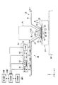
図1は、第1実施形態に係る露光装置を示す概略構成図である。図1において、露光装置EXは、マスクMを保持して移動可能なマスクステージMSTと、基板Pを保持する基板ホルダPHを有し、基板ホルダPHに基板Pを保持して移動可能な基板ステージST1と、露光処理に関する計測を光学的に行う光計測器を搭載し、基板ステージST1とは独立して移動可能な計測ステージST2と、マスクステージMSTに保持されているマスクMを露光光ELで照明する照明光学系ILと、露光光ELで照明されたマスクMのパターンの像を基板ステージST1に保持されている基板Pに投影露光する投影光学系PLと、露光装置EX全体の動作を統括制御する制御装置CONTとを備えている。制御装置CONTには、露光処理に関する情報を報知する報知装置INFが接続されている。報知装置INFは、ディスプレイ装置(表示装置)、音又は光を使って警報(警告)を発する警報装置等を含んで構成されている。更に、制御装置CONTには、露光処理に関する情報を記憶する記憶装置MRYが接続されている。
<First Embodiment>
FIG. 1 is a schematic block diagram that shows an exposure apparatus according to the first embodiment. In FIG. 1, an exposure apparatus EX has a mask stage MST that can move while holding a mask M, and a substrate holder PH that holds a substrate P, and a substrate stage that can move while holding the substrate P in the substrate holder PH. ST1 and an optical measuring instrument that optically measures the exposure process are mounted, and the measurement stage ST2 that can move independently of the substrate stage ST1 and the mask M held on the mask stage MST are exposed to the exposure light EL. General operation of the illumination optical system IL for illuminating, the projection optical system PL for projecting and exposing the pattern image of the mask M illuminated by the exposure light EL onto the substrate P held on the substrate stage ST1, and the entire exposure apparatus EX. And a control device CONT for controlling. The control device CONT is connected to a notification device INF that notifies information related to exposure processing. The notification device INF includes a display device (display device), an alarm device that issues an alarm (warning) using sound or light, and the like. Further, a storage device MRY that stores information related to the exposure process is connected to the control device CONT.
本実施形態の露光装置EXは、露光波長を実質的に短くして解像度を向上するとともに焦点深度を実質的に広くするために液浸法を適用した液浸露光装置であって、投影光学系PLの像面側における露光光ELの光路空間K1を液体LQで満たすための液浸機構1を備えている。液浸機構1は、投影光学系PLの像面側近傍に設けられ、液体LQを供給する供給口12及び液体LQを回収する回収口22を有するノズル部材70と、ノズル部材70に設けられた供給口12を介して投影光学系PLの像面側に液体LQを供給する液体供給機構10と、ノズル部材70に設けられた回収口22を介して投影光学系PLの像面側の液体LQを回収する液体回収機構20とを備えている。ノズル部材70は、投影光学系PLを構成する複数の光学素子のうち、投影光学系PLの像面に最も近い第1光学素子LS1を囲むように環状に形成されている。
The exposure apparatus EX of the present embodiment is an immersion exposure apparatus to which an immersion method is applied in order to substantially shorten the exposure wavelength to improve the resolution and substantially widen the depth of focus. A
露光装置EXは、少なくともマスクMのパターンの像を基板P上に転写している間、液体供給機構10から供給した液体LQにより投影光学系PLの投影領域ARを含む基板P上の一部に、投影領域ARよりも大きく且つ基板Pよりも小さい液体LQの液浸領域LRを局所的に形成する局所液浸方式を採用している。具体的には、露光装置EXは、投影光学系PLの像面に最も近い第1光学素子LS1の下面LSAと、投影光学系PLの像面側に配置された基板P上面との間の光路空間K1を液体LQで満たし、この投影光学系PL(第1光学素子LS1)と基板Pとの間の液体LQ、及び投影光学系PL(第1光学素子LS1)を介してマスクMを通過した露光光ELを基板Pに照射することによってマスクMのパターンの像を基板Pに投影露光する。制御装置CONTは、液体供給機構10を使って基板P上に液体LQを所定量供給するとともに、液体回収機構20を使って基板P上の液体LQを所定量回収することで、基板P上に液体LQの液浸領域LRを局所的に形成する。
The exposure apparatus EX transfers at least a part of the pattern on the mask M onto the substrate P including the projection area AR of the projection optical system PL by the liquid LQ supplied from the
また、露光装置EXは、液浸領域LRを形成する液体LQの性質及び成分のうち少なくとも一方(液体の状態)を計測する計測装置60を備えている。計測装置60は、投影光学系PLと投影光学系PLの像面側に配置される物体との間に満たされた液体LQの性質及び成分のうち少なくとも一方を計測する。本実施形態においては、計測装置60は、液体回収機構20により回収される液体LQを計測する。
Further, the exposure apparatus EX includes a
また液浸機構1のうち、液体供給機構10は、液浸領域LRを形成するための液体LQとは別の所定の機能を有する機能液を供給可能な機能液供給装置120を含んで構成されている。
Of the
本実施形態では、露光装置EXとしてマスクMと基板Pとを走査方向における互いに異なる向き(逆方向)に同期移動しつつマスクMに形成されたパターンを基板Pに露光する走査型露光装置(所謂スキャニングステッパ)を使用する場合を例にして説明する。以下の説明において、水平面内においてマスクMと基板Pとの同期移動方向(走査方向)をX軸方向、水平面内においてX軸方向と直交する方向をY軸方向(非走査方向)、X軸及びY軸方向に垂直で投影光学系PLの光軸AXと一致する方向をZ軸方向とする。また、X軸、Y軸、及びZ軸まわりの回転(傾斜)方向をそれぞれ、θX、θY、及びθZ方向とする。なお、ここでいう「基板」は半導体ウエハ等の基材上に感光材(レジスト)を塗布したものを含み、「マスク」は基板上に縮小投影されるデバイスパターンを形成されたレチクルを含む。 In the present embodiment, the exposure apparatus EX is a scanning exposure apparatus (so-called so-called exposure apparatus EX) that exposes the pattern formed on the mask M onto the substrate P while synchronously moving the mask M and the substrate P in different directions (reverse directions) in the scanning direction. A case where a scanning stepper) is used will be described as an example. In the following description, the synchronous movement direction (scanning direction) of the mask M and the substrate P in the horizontal plane is the X-axis direction, the direction orthogonal to the X-axis direction in the horizontal plane is the Y-axis direction (non-scanning direction), the X-axis, and A direction perpendicular to the Y-axis direction and coincident with the optical axis AX of the projection optical system PL is defined as a Z-axis direction. Further, the rotation (inclination) directions around the X axis, Y axis, and Z axis are the θX, θY, and θZ directions, respectively. Here, the “substrate” includes a substrate in which a photosensitive material (resist) is coated on a base material such as a semiconductor wafer, and the “mask” includes a reticle on which a device pattern to be reduced and projected on the substrate is formed.
照明光学系ILは、露光用光源、露光用光源から射出された光束の照度を均一化するオプティカルインテグレータ、オプティカルインテグレータからの露光光ELを集光するコンデンサレンズ、リレーレンズ系、及び露光光ELによるマスクM上の照明領域を設定する視野絞り等を有している。マスクM上の所定の照明領域は照明光学系ILにより均一な照度分布の露光光ELで照明される。照明光学系ILから射出される露光光ELとしては、例えば水銀ランプから射出される輝線(g線、h線、i線)及びKrFエキシマレーザ光(波長248nm)等の遠紫外光(DUV光)や、ArFエキシマレーザ光(波長193nm)及びF2レーザ光(波長157nm)等の真空紫外光(VUV光)などが用いられる。本実施形態においてはArFエキシマレーザ光が用いられる。 The illumination optical system IL includes an exposure light source, an optical integrator that equalizes the illuminance of a light beam emitted from the exposure light source, a condenser lens that collects the exposure light EL from the optical integrator, a relay lens system, and the exposure light EL. A field stop for setting an illumination area on the mask M is provided. A predetermined illumination area on the mask M is illuminated with the exposure light EL having a uniform illuminance distribution by the illumination optical system IL. The exposure light EL emitted from the illumination optical system IL is, for example, far ultraviolet light (DUV light) such as bright lines (g line, h line, i line) and KrF excimer laser light (wavelength 248 nm) emitted from a mercury lamp. Alternatively, vacuum ultraviolet light (VUV light) such as ArF excimer laser light (wavelength 193 nm) and F 2 laser light (wavelength 157 nm) is used. In this embodiment, ArF excimer laser light is used.
本実施形態においては、液浸領域LRを形成する液体LQとして純水が用いられている。純水は、ArFエキシマレーザ光のみならず、例えば、水銀ランプから射出される輝線(g線、h線、i線)及びKrFエキシマレーザ光(波長248nm)等の遠紫外光(DUV光)も透過可能である。 In the present embodiment, pure water is used as the liquid LQ that forms the immersion region LR. Pure water includes not only ArF excimer laser light but also, for example, far ultraviolet light (DUV light) such as emission lines (g-line, h-line, i-line) emitted from mercury lamps and KrF excimer laser light (wavelength 248 nm). It can be transmitted.
マスクステージMSTは、マスクMを保持して移動可能である。マスクステージMSTは、マスクMを真空吸着(又は静電吸着)により保持する。マスクステージMSTは、制御装置CONTにより制御されるリニアモータ等を含むマスクステージ駆動装置MSTDの駆動により、マスクMを保持した状態で、投影光学系PLの光軸AXに垂直な平面内、すなわちXY平面内で2次元移動可能及びθZ方向に微少回転可能である。マスクステージMST上には移動鏡91が設けられている。また、移動鏡91に対向する位置にはレーザ干渉計92が設けられている。マスクステージMST上のマスクMの2次元方向の位置、及びθZ方向の回転角(場合によってはθX、θY方向の回転角も含む)はレーザ干渉計92によりリアルタイムで計測される。レーザ干渉計92の計測結果は制御装置CONTに出力される。制御装置CONTは、レーザ干渉計92の計測結果に基づいてマスクステージ駆動装置MSTDを駆動し、マスクステージMSTに保持されているマスクMの位置制御を行う。
Mask stage MST is movable while holding mask M. Mask stage MST holds mask M by vacuum suction (or electrostatic suction). The mask stage MST is in a plane perpendicular to the optical axis AX of the projection optical system PL in a state where the mask M is held by driving a mask stage driving device MSTD including a linear motor controlled by the control device CONT, that is, XY. It can move two-dimensionally in the plane and can rotate slightly in the θZ direction. A
投影光学系PLは、マスクMのパターンを所定の投影倍率βで基板Pに投影露光するものであって、複数の光学素子で構成されており、それら光学素子は鏡筒PKで保持されている。本実施形態において、投影光学系PLは、投影倍率βが例えば1/4、1/5、あるいは1/8の縮小系である。なお、投影光学系PLは等倍系及び拡大系のいずれでもよい。また、投影光学系PLは、反射光学素子を含まない屈折系、屈折光学素子を含まない反射系、反射光学素子と屈折光学素子とを含む反射屈折系のいずれであってもよい。投影光学系PLを構成する複数の光学素子のうち、投影光学系PLの像面に最も近い第1光学素子LS1は、鏡筒PKより露出している。 The projection optical system PL projects and exposes the pattern of the mask M onto the substrate P at a predetermined projection magnification β, and is composed of a plurality of optical elements, which are held by a lens barrel PK. . In the present embodiment, the projection optical system PL is a reduction system having a projection magnification β of, for example, 1/4, 1/5, or 1/8. Note that the projection optical system PL may be either an equal magnification system or an enlargement system. The projection optical system PL may be any of a refractive system that does not include a reflective optical element, a reflective system that does not include a refractive optical element, and a catadioptric system that includes a reflective optical element and a refractive optical element. Of the plurality of optical elements constituting the projection optical system PL, the first optical element LS1 closest to the image plane of the projection optical system PL is exposed from the lens barrel PK.
基板ステージST1は、基板Pを保持する基板ホルダPHを有している。基板ステージST1は、投影光学系PLの像面側に配置されており、その投影光学系PLの像面側において、ベース部材BP上で移動可能である。基板ホルダPHは、例えば真空吸着等により基板Pを保持する。基板ステージST1上には凹部96が設けられており、基板Pを保持するための基板ホルダPHは凹部96に配置されている。そして、基板ステージST1のうち凹部96以外の上面95は、基板ホルダPHに保持された基板Pの上面とほぼ同じ高さ(面一)になるような平坦面(平坦部)となっている。
The substrate stage ST1 has a substrate holder PH that holds the substrate P. The substrate stage ST1 is disposed on the image plane side of the projection optical system PL, and is movable on the base member BP on the image plane side of the projection optical system PL. The substrate holder PH holds the substrate P by, for example, vacuum suction. A
基板ステージST1は、制御装置CONTにより制御されるリニアモータ等を含む基板ステージ駆動装置SD1の駆動により、基板Pを基板ホルダPHを介して保持した状態で、ベース部材BP上でXY平面内で2次元移動可能及びθZ方向に微小回転可能である。更に基板ステージST1は、Z軸方向、θX方向、及びθY方向にも移動可能である。したがって、基板ステージST1に支持された基板Pの上面は、X軸、Y軸、Z軸、θX、θY、及びθZ方向の6自由度の方向に移動可能である。基板ステージST1の側面には移動鏡93が設けられている。また、移動鏡93に対向する位置にはレーザ干渉計94が設けられている。基板ステージST1上の基板Pの2次元方向の位置、及び回転角はレーザ干渉計94によりリアルタイムで計測される。また、露光装置EXは、例えば特開平8−37149号公報に開示されているような、基板ステージST1に支持されている基板Pの上面の面位置情報を検出する斜入射方式のフォーカス・レベリング検出系(不図示)を備えている。フォーカス・レベリング検出系は、基板Pの上面の面位置情報(Z軸方向の位置情報、及び基板PのθX及びθY方向の傾斜情報)を検出する。なお、フォーカス・レベリング検出系は、液浸領域LRの液体LQを介して基板Pの面位置情報を検出するものであってもよいし、液浸領域LRの外側で液体LQを介さずに基板Pの面位置情報を検出ものであってもよいし、液体LQを介して基板Pの面位置情報を検出するものと液体LQを介さずに基板Pの面位置情報を検出するものとを併用したものであってもよい。また、フォーカス・レベリング検出系は、静電容量型センサを使った方式のものを採用してもよい。レーザ干渉計94の計測結果は制御装置CONTに出力される。フォーカス・レベリング検出系の検出結果も制御装置CONTに出力される。制御装置CONTは、フォーカス・レベリング検出系の検出結果に基づいて、基板ステージ駆動装置SD1を駆動し、基板Pのフォーカス位置(Z位置)及び傾斜角(θX、θY)を制御して基板Pの上面を投影光学系PLの像面に合わせ込むとともに、レーザ干渉計94の計測結果に基づいて、基板PのX軸方向、Y軸方向、及びθZ方向における位置制御を行う。
The substrate stage ST1 is driven in the XY plane on the base member BP in a state where the substrate P is held via the substrate holder PH by driving the substrate stage driving device SD1 including a linear motor controlled by the control device CONT. Dimensional movement is possible, and minute rotation is possible in the θZ direction. Furthermore, the substrate stage ST1 is also movable in the Z-axis direction, the θX direction, and the θY direction. Therefore, the upper surface of the substrate P supported by the substrate stage ST1 can move in directions of six degrees of freedom in the X axis, Y axis, Z axis, θX, θY, and θZ directions. A
計測ステージST2は、露光処理に関する計測を光学的に行う各種光計測器(計測用部材を含む)を搭載している。計測ステージST2は、投影光学系PLの像面側に配置されており、その投影光学系PLの像面側において、ベース部材BP上で移動可能である。計測ステージST2は、制御装置CONTにより制御されるリニアモータ等を含む計測ステージ駆動装置SD2の駆動により、光計測器を搭載した状態で、ベース部材BP上でXY平面内で2次元移動可能及びθZ方向に微小回転可能である。更に計測ステージST2は、Z軸方向、θX方向、及びθY方向にも移動可能である。したがって、計測ステージST2は、基板ステージST1と同様、X軸、Y軸、Z軸、θX、θY、及びθZ方向の6自由度の方向に移動可能である。計測ステージST2の側面には移動鏡98が設けられている。また、移動鏡98に対向する位置にはレーザ干渉計99が設けられている。計測ステージST2の2次元方向の位置、及び回転角はレーザ干渉計99よりリアルタイムで計測され、制御装置CONTはレーザ干渉計99の計測結果に基づいて、計測ステージST2の位置を制御する。
The measurement stage ST2 is equipped with various optical measuring instruments (including measurement members) that optically measure the exposure process. The measurement stage ST2 is disposed on the image plane side of the projection optical system PL, and is movable on the base member BP on the image plane side of the projection optical system PL. The measurement stage ST2 can be moved two-dimensionally in the XY plane on the base member BP by driving the measurement stage driving device SD2 including a linear motor and the like controlled by the control device CONT. It can be rotated slightly in the direction. Furthermore, the measurement stage ST2 can move in the Z-axis direction, the θX direction, and the θY direction. Accordingly, the measurement stage ST2 can move in the directions of six degrees of freedom in the X-axis, Y-axis, Z-axis, θX, θY, and θZ directions, like the substrate stage ST1. A
制御装置CONTは、ステージ駆動装置SD1、SD2のそれぞれを使って、基板ステージST1及び計測ステージST2のそれぞれをベースBP上で互いに独立して移動可能である。制御装置CONTは、基板ステージST1を投影光学系PLの下に移動することによって、基板ステージST1の上面95又はその基板ステージST1に保持されている基板Pの上面と投影光学系PLの下面LSAとを対向させることができる。同様に制御装置CONTは、計測ステージST2を投影光学系PLの下に移動することによって、計測ステージST2の上面97と投影光学系PLの下面LSAとを対向させることができる。
The control device CONT can move the substrate stage ST1 and the measurement stage ST2 independently of each other on the base BP by using the stage driving devices SD1 and SD2. The control device CONT moves the substrate stage ST1 below the projection optical system PL, whereby the
また、基板ステージST1と計測ステージST2とは互いに並んだ位置に設けられており、基板Pの上面を含む基板ステージST1の上面95と計測ステージST2の上面97とはほぼ同じ高さ位置となるように設けられている。
Further, the substrate stage ST1 and the measurement stage ST2 are provided at positions aligned with each other, and the
図2は、基板ステージST1及び計測ステージST2を上方から見た平面図である。図2において、計測ステージST2の上面97には、光計測器(計測用部材)として、基準部材300が設けられている。基準部材300は、投影光学系PLを介したマスクMのパターンの像に対する基板Pのアライメント位置を規定するために、パターンの像の投影位置と基板アライメント系(不図示)の検出基準とのXY平面内での位置関係(ベースライン量)を計測するときに用いられる。基準部材300の上面301には、第1基準マークMFMと第2基準マークPFMとが所定の位置関係で形成されている。第1基準マークMFMは、例えば特開平7−176468号公報に開示されているようなVRA(ビジュアル・レチクル・アライメント)方式のマスクアライメント系により検出される。VRA方式のマスクアライメント系は、マークに対して光を照射し、CCDカメラ等で撮像したマークの画像データを画像処理してマークの位置を計測する。また、第2基準マークPFMは、例えば特開平4−65603号公報に開示されているようなFIA(フィールド・イメージ・アライメント)方式の基板アライメント系により検出される。FIA方式の基板アライメント系は、基板P上の感光材を感光させないブロードバンドな検出光束を対象マークに照射し、その対象マークからの反射光により受光面に結像された対象マークの像と不図示の指標(基板アライメント系内に設けられた指標板上の指標パターン)の像とを撮像素子(CCD等)を用いて撮像し、それらの撮像信号を画像処理することでマークの位置を計測する。
FIG. 2 is a plan view of the substrate stage ST1 and the measurement stage ST2 as viewed from above. In FIG. 2, a
また、計測ステージST2の上面97には、光計測器として、例えば特開昭57−117238号公報に開示されているように照度ムラを計測したり、特開2001−267239号公報に開示されているように投影光学系PLの露光光ELの透過率の変動量を計測したりするためのムラセンサ400の一部を構成する上板、特開2002−14005号公報に開示されているような空間像計測センサ500の一部を構成する上板、及び特開平11−16816号公報に開示されているような照射量センサ(照度センサ)600の一部を構成する上板が設けられている。計測ステージST2の上面97には、それらセンサ400、500、600の上板の上面401、501、601が配置されている。
Further, on the
本実施形態においては、各光計測器300、400、500、600の各上面301、401、501、601を含む計測ステージST2の上面97はほぼ平坦面となっており、計測ステージST2の上面97と各光計測器300、400、500、600の上面301、401、501、601とはほぼ面一となっている。
In the present embodiment, the
本実施形態においては、基準部材300上に形成された第1基準マークMFMは、投影光学系PL及び液体LQを介してマスクアライメント系によって検出され、第2基準マークPFMは、投影光学系PL及び液体LQを介さずに基板アライメント系によって検出される。また本実施形態においては、投影光学系PLと液体LQとを介して基板Pに露光光ELを照射して基板Pを露光する液浸露光処理が行われるため、露光光ELを使った計測処理を行うムラセンサ400、空間像計測センサ500、照射量センサ600等は、液浸露光処理に対応して、投影光学系PL及び液体LQを介して露光光ELを受光するようになっている。
In the present embodiment, the first reference mark MFM formed on the
このように、計測ステージST2は、露光処理に関する計測処理を行うための専用のステージであって、基板Pを保持しない構成となっており、基板ステージST1は、露光処理に関する計測を行う光計測器を搭載していない構成となっている。なお、計測ステージST2については、例えば特開平11−135400号公報等においてより詳細に開示されている。 As described above, the measurement stage ST2 is a dedicated stage for performing the measurement process related to the exposure process, and is configured not to hold the substrate P. The substrate stage ST1 is an optical measuring instrument that performs the measurement related to the exposure process. It has a configuration that is not installed. The measurement stage ST2 is disclosed in more detail in, for example, Japanese Patent Application Laid-Open No. 11-135400.
なお、各センサ400、500、600は、例えば光学系の一部だけが計測ステージST2に搭載されていてもよいし、センサ全体が計測ステージST2に搭載されていてもよい。また、計測ステージST2に搭載される光計測器としては、上述の各センサ400、500、600や基準部材300に限られず、露光処理に関する計測処理を行う光計測器(計測用部材)であれば、任意のものを計測ステージST2に搭載することができる。また、上述の各センサ400、500、600や基準部材300などの一部を基板ステージST1に設けてもよい。
In addition, for each
また、投影光学系PLの像面側に配置されている計測ステージST2は、液体LQを汚染しないように形成された所定領域100を有している。所定領域100は、計測ステージST2の上面97の一部の領域に設定されている。本実施形態においては、所定領域100は、計測ステージST2の上面97のうち、上記光計測器300、400、500、600が設けられている以外の領域であって、計測ステージST2の上面97のほぼ中央部に設定されている。所定領域100の大きさは、液浸領域LRよりも大きくなるように設定されている。また、所定領域100は、各光計測器300、400、500、600の上面301、401、501、601とほぼ面一となっている。本実施形態においては、計測ステージST2の上面97は、所定領域100の上面、及び各光計測器300、400、500、600の各上面301、401、501、601を含むものとする。
Further, the measurement stage ST2 arranged on the image plane side of the projection optical system PL has a predetermined
計測ステージST2の上面97の一部の領域には所定の処理が施されており、その所定の処理によって、液体LQを汚染しない所定領域100が形成されている。ここで、「液体LQを汚染しない」とは、所定領域100上に液体LQが配置された際、所定領域100の表面から液体LQ中に異物を含む汚染物質(金属、有機イオン、無機イオン等)が溶出(混入)することが所定の許容量以下に抑制された状態を意味する。換言すれば、所定領域100は、液体LQと接触したときに液体LQ中に汚染物質を実質的に発生しない材料から形成されているということができる。そのため、液体LQと所定領域100とが接触しても、液体LQの汚染は防止されている。そして、所定領域100の大きさは液浸領域LRよりも大きいため、所定領域100を含む計測ステージST2の上面97上に液体LQの液浸領域LRを形成する場合、液浸領域LRを所定領域100の内側に形成することにより、液体LQの汚染を抑制することができる。
A predetermined process is performed on a part of the
本実施形態においては、計測ステージST2の上面97を形成する基材にはセラミックスが用いられており、液体LQを汚染しないための処理として、上面97を形成する基材(セラミックス)上に、PFA(四フッ化エチレン(C2F4)とパーフルオロアルコキシエチレンとの共重合体)を被覆する処理(表面処理)が施されている。以下の説明においては、PFAを被覆する処理を適宜、「PFA処理」と称する。
In the present embodiment, ceramics are used for the base material that forms the
本実施形態においては、計測ステージST2の上面97の一部の領域にPFA処理を施して所定領域100を形成したので、所定領域100から液体LQ中に異物を含む汚染物質(金属、有機イオン、無機イオン等)が溶出(混入)することを抑制することができる。したがって、所定領域100と液体LQとが接触しても、液体LQの汚染が防止され、液体LQに与える影響が低減されている。
In the present embodiment, since the
またPFAは、液体(水)LQに対して撥液性(撥水性)を有しており、液浸領域LRを所定領域100上に形成した場合でも、液浸機構1を使って液浸領域LRの形状や大きさ等を所望状態に維持することができる。また、所定領域100上から液体LQを除去(回収)する動作を行った場合、所定領域100上に液体LQが残留することを防止できる。
The PFA has liquid repellency (water repellency) with respect to the liquid (water) LQ, and even when the liquid immersion area LR is formed on the
なおここでは、計測ステージST2の上面97の一部の領域に、液体LQを汚染しないような処理が施されているが、光計測器300、400、500、600の各上面301、401、501、601を含む計測ステージST2の上面97の全ての領域に、液体LQを汚染しないような処理を施してもよい。この場合、計測ステージST2の上面97のうち、光計測器300、400、500、600が設けられている以外の領域に対する処理と、光計測器300、400、500、600の上面301、401、501、601に対する処理とが異なっていてもよい。例えば、計測ステージST2の上面97のうち、光計測器300、400、500、600が設けられている以外の領域に対してはPFA処理を施し、光計測器300、400、500、600の上面301、401、501、601に対してはPFA以外の材料を被覆する処理を施すようにしてもよい。光計測器300、400、500、600の上面301、401、501、601を被覆する材料としては、液体LQを汚染しないとともに、液体LQに対して撥液性を有し、且つ光透過性を有する材料を用いることが好ましい。このような材料としては、例えば、旭硝子社製「サイトップ(登録商標)」が挙げられる。こうすることにより、計測ステージST2の上面97のうち、所定領域100以外の領域に液浸領域LRが配置された場合でも、液体LQの汚染を抑制することができ、液浸領域LRの形状や大きさ等を所望状態に維持することができる。また、計測ステージST2の上面97から液体LQを除去する動作を行った場合、上面97に液体LQが残留することを防止できる。なお、光計測器の上面(例えば301)が汚染防止処理されている場合には、その上面の少なくとも一部を所定領域100とすることもできる。
In this example, a part of the
また、所定領域100(上面97)の表面処理に用いる材料としては、PFAに限られず、液体LQを汚染しないものであれば任意のものを用いることができ、計測ステージST2の上面97を形成する基材や、使用する液体LQの物性(種類)に応じて適宜選択することができる。またここでは、計測ステージST2の上面97の一部の領域に表面処理を施すことによって所定領域100を形成しているが、例えば計測ステージST2の上面97の一部に開口部(凹部)を形成し、その凹部の内側にPFA等からなる板状部材を配置し、その板状部材の上面を所定領域100としてもよい。計測ステージST2の上面97の凹部に板状部材を配置した場合においても、板状部材の上面は平坦面であることが好ましく、板状部材の上面と、各光計測器の各上面301、401、501、601を含む計測ステージST2の上面97とはほぼ面一であることが望ましい。
The material used for the surface treatment of the predetermined region 100 (upper surface 97) is not limited to PFA, and any material that does not contaminate the liquid LQ can be used, and the
図3は、液体LQの液浸領域LRが基板ステージST1上と計測ステージST2上との間で移動している様子を示す図である。図3に示すように、投影光学系PLの像面側(第1光学素子LS1の下)に形成された液浸領域LRは、基板ステージST1上と計測ステージST2上との間で移動可能となっている。液浸領域LRを移動する際には、制御装置CONTは、ステージ駆動装置SD1、SD2を使って、基板ステージST1と計測ステージST2とを近接又は接触した状態で、投影光学系PLの直下の位置を含む領域内で基板ステージST1と計測ステージST2とをXY平面内で一緒に移動する。制御装置CONTは、基板ステージST1と計測ステージST2とを一緒に移動することによって、投影光学系PLと基板ステージST1の上面95及び計測ステージST2の上面97のうち少なくとも一方との間に液体LQを保持した状態で、液浸領域LRを基板ステージST1の上面95と計測ステージST2の上面97との間で移動することができる。こうすることにより、基板ステージST1と計測ステージST2との隙間(ギャップ)からの液体LQの流出を抑えつつ、投影光学系PLの像面側の光路空間K1を液体LQで満たした状態で、基板ステージST1上と計測ステージST2上との間で液浸領域LRを移動することができる。
FIG. 3 is a diagram illustrating a state in which the liquid LQ immersion region LR is moving between the substrate stage ST1 and the measurement stage ST2. As shown in FIG. 3, the liquid immersion area LR formed on the image plane side of the projection optical system PL (below the first optical element LS1) is movable between the substrate stage ST1 and the measurement stage ST2. It has become. When moving the immersion area LR, the control device CONT uses the stage drive devices SD1 and SD2 to bring the substrate stage ST1 and the measurement stage ST2 into close proximity or contact with each other, and a position immediately below the projection optical system PL. The substrate stage ST1 and the measurement stage ST2 are moved together in the XY plane within the region including The control device CONT moves the substrate stage ST1 and the measurement stage ST2 together, thereby supplying the liquid LQ between the projection optical system PL and at least one of the
これにより、液体LQの全回収、再度の供給といった工程を経ることなく、液体LQの液浸領域LRを基板ステージST1の上面95と計測ステージST2の上面97との間で移動することができるので、基板ステージST1におけるある基板Pの露光動作の終了から次の基板Pの露光動作の開始までの時間を短縮して、スループットの向上を図ることができる。また、投影光学系PLの像面側には、液体LQが常に存在するので、液体LQの付着跡(所謂ウォーターマーク)が発生することを効果的に防止できる。
As a result, the liquid immersion area LR of the liquid LQ can be moved between the
次に、図1を参照しながら、液浸機構1の液体供給機構10及び液体回収機構20について説明する。液体供給機構10は、液体LQを投影光学系PLの像面側に供給するためのものであって、液体LQを送出可能な液体供給部11と、液体供給部11にその一端部を接続する供給管13とを備えている。供給管13の途中には、この供給管13の流路を開閉するバルブ13Bが設けられている。バルブ13Bの動作は制御装置CONTにより制御される。供給管13の他端部はノズル部材70に接続されている。ノズル部材70の内部には、供給管13の他端部と供給口12とを接続する内部流路(供給流路)が形成されている。本実施形態においては、液体供給機構10は純水を供給するものであって、液体供給部11は、純水製造装置16、及び供給する液体(純水)LQの温度を調整する温調装置17等を備えている。更に、液体供給部11は、液体LQを収容するタンク、加圧ポンプ、及び液体LQ中の異物を取り除くフィルタユニット等も備えている。液体供給部11の液体供給動作は制御装置CONTにより制御される。なお純水製造装置として、露光装置EXに純水製造装置を設けずに、露光装置EXが配置される工場の純水製造装置を用いるようにしてもよい。また、液体供給機構10のタンク、加圧ポンプ、フィルタユニット等は、その全てを露光装置本体EXが備えている必要はなく、露光装置本体EXが設置される工場等の設備を代用してもよい。
Next, the
なお本実施形態においては、供給管13に設けられるバルブ13Bは、例えば停電等により露光装置EX(制御装置CONT)の駆動源(電源)が停止した場合に供給管13の流路を機械的に閉塞する所謂ノーマルクローズ方式となっている。これにより、停電等の異常が発生した場合でも、供給口12から液体LQが漏出することを防止できる。
In this embodiment, the
液体回収機構20は、投影光学系PLの像面側の液体LQを回収するためのものであって、液体LQを回収可能な液体回収部21と、液体回収部21にその一端部を接続する回収管23とを備えている。回収管23の途中には、この回収管23の流路を開閉するバルブ23Bが設けられている。バルブ23Bの動作は制御装置CONTにより制御される。回収管23の他端部はノズル部材70に接続されている。ノズル部材70の内部には、回収管23の他端部と回収口22とを接続する内部流路(回収流路)が形成されている。液体回収部21は例えば真空ポンプ等の真空系(吸引装置)、回収された液体LQと気体とを分離する気液分離器、及び回収した液体LQを収容するタンク等を備えている。なお、液体回収機構20の真空系、気液分離器、タンク等は、その全てを露光装置本体EXが備えている必要はなく、露光装置本体EXが設置される工場等の設備を代用してもよい。
The
液体LQを供給する供給口12及び液体LQを回収する回収口22はノズル部材70の下面70Aに形成されている。ノズル部材70の下面70Aは、基板Pの上面、基板ステージST1の上面95、及び計測ステージST2の上面97と対向可能な位置に設けられている。ノズル部材70は、第1光学素子LS1の側面を囲むように設けられた環状部材であって、供給口12は、ノズル部材70の下面70Aにおいて、投影光学系PLの第1光学素子LS1(投影光学系PLの光軸AX)を囲むように複数設けられている。また、回収口22は、ノズル部材70の下面70Aにおいて、第1光学素子LS1に対して供給口12よりも外側に離れて設けられており、第1光学素子LS1及び供給口12を囲むように設けられている。
The
そして、制御装置CONTは、液体供給機構10を使って基板P上に液体LQを所定量供給するとともに、液体回収機構20を使って基板P上の液体LQを所定量回収することで、基板P上に液体LQの液浸領域LRを局所的に形成する。液体LQの液浸領域LRを形成する際、制御装置CONTは、液体供給部11及び液体回収部21のそれぞれを駆動する。制御装置CONTの制御のもとで液体供給部11から液体LQが送出されると、その液体供給部11から送出された液体LQは、供給管13を流れた後、ノズル部材70の供給流路を介して、供給口12より投影光学系PLの像面側に供給される。また、制御装置CONTのもとで液体回収部21が駆動されると、投影光学系PLの像面側の液体LQは回収口22を介してノズル部材70の回収流路に流入し、回収管23を流れた後、液体回収部21に回収される。
The control device CONT supplies a predetermined amount of the liquid LQ onto the substrate P using the
本実施形態においては、液体回収機構20で回収された液体LQは、液体供給機構10の液体供給部11に戻されるようになっている。すなわち本実施形態の露光装置EXは、液体供給機構10と液体回収機構20との間で液体LQを循環する循環系を備えた構成となっている。液体供給機構10の液体供給部11に戻された液体LQは、純水製造装置16で精製された後、再び投影光学系PLの像面側(基板P上)に供給される。なお、液体回収機構20で回収された液体LQの全部が液体供給機構10に戻されてもよいし、その一部が戻されてもよい。あるいは、液体回収機構20で回収した液体LQを液体供給機構10に戻さずに、別の供給源より供給された液体LQ、あるいは水道水を純水製造装置16で精製した後、投影光学系PLの像面側に供給するようにしてもよい。なお、ノズル部材70などの液浸機構1の構造は、上述の構造に限られず、例えば、欧州特許公開第1420298号公報、国際公開第2004/055803号公報、国際公開第2004/057589号公報、国際公開第2004/057590号公報、国際公開第2005/029559号公報に記載されているものも用いることができる。
In the present embodiment, the liquid LQ recovered by the
次に、図4を参照しながら液体供給部11について説明する。図4は、液体供給部11の構成を詳細に示す図である。液体供給部11は、純水製造装置16と、純水製造装置16で製造された液体LQの温度を調整する温調装置17とを備えている。純水製造装置16は、例えば浮遊物や不純物を含む水を精製して所定の純度の純水を製造する純水製造器161と、純水製造器161で製造された純水から更に不純物を除いて高純度な純水(超純水)を製造する超純水製造器162とを備えている。純水製造器161(あるいは超純水製造器162)は、イオン交換膜やパーティクルフィルタ等の液体改質部材、及び紫外光照射装置(UVランプ)等の液体改質装置を備えており、これら液体改質部材及び液体改質装置により、液体の比抵抗値、異物(微粒子、気泡)の量、全有機体炭素、及び生菌の量等を所望値に調整する。
Next, the
また、上述したように、液体回収機構20で回収された液体LQは、液体供給機構10の液体供給部11に戻されるようになっている。具体的には、液体回収機構20で回収された液体LQは、戻し管18を介して、液体供給部11の純水製造装置16(純水製造器161)に供給される。戻し管18には、その戻し管18の流路を開閉する第1バルブ18Bが設けられている。純水製造装置16は、戻し管18を介して戻された液体LQを上記液体改質部材及び液体改質装置等を使って精製した後、温調装置17に供給する。また、液体供給部11の純水製造装置16(純水製造器161)には、供給管19を介して機能液供給装置120が接続されている。機能液供給装置120は、液浸領域LRを形成するための液体LQとは別の所定の機能を有する機能液LKを供給可能である。本実施形態においては、機能液供給装置120は、洗浄作用あるいは殺菌作用、あるいはその両方の作用を有する機能液LKを供給する。機能液LKとして、例えば、オゾン水や、界面活性剤、抗菌剤、殺菌、滅菌剤などを含む水溶液または水溶性有機溶剤を用いることができる。本実施形態においては、機能液LKとして過酸化水素水が用いられる。供給管19には、その供給管19の流路を開閉する第2バルブ19Bが設けられている。制御装置CONTは、第1バルブ18Bを作動して戻し管18の流路を開けて液体LQを供給しているとき、第2バルブ19Bを作動して供給管19の流路を閉じて機能液LKの供給を停止する。一方、制御装置CONTは、第2バルブ19Bを作動して供給管19の流路を開けて機能液LKを供給しているとき、第1バルブ18Bを作動して戻し管18の流路を閉じて液体LQの供給を停止する。
Further, as described above, the liquid LQ recovered by the
温調装置17は、純水製造装置16で製造され、供給管13に供給される液体(純水)LQの温度調整を行うものであって、その一端部を純水製造装置16(超純水製造器162)に接続し、他端部を供給管13に接続しており、純水製造装置16で製造された液体LQの温度調整を行った後、その温度調整された液体LQを供給管13に送出する。温調装置17は、純水製造装置16の超純水製造器162から供給された液体LQの温度を粗く調整するラフ温調器171と、ラフ温調器171の流路下流側(供給管13側)に設けられ、供給管13側に流す液体LQの単位時間あたりの量を制御するマスフローコントローラと呼ばれる流量制御器172と、流量制御器172を通過した液体LQ中の溶存気体濃度(溶存酸素濃度、溶存窒素濃度)を低下させるための脱気装置173と、脱気装置173で脱気された液体LQ中の異物(微粒子、気泡)を取り除くフィルタ174と、フィルタ174を通過した液体LQの温度の微調整を行うファイン温調器175とを備えている。
The
ラフ温調器171は、超純水製造器162から送出された液体LQの温度を目標温度(例えば23℃)に対して例えば±0.1℃程度の粗い精度で温度調整するものである。流量制御器172は、ラフ温調器171と脱気装置173との間に配置されており、ラフ温調器171で温度調整された液体LQの脱気装置173側に対する単位時間あたりの流量を制御する。
The
脱気装置173は、ラフ温調器171とファイン温調器175との間、具体的には流量制御器172とフィルタ174との間に配置されており、流量制御器172から送出された液体LQを脱気して、液体LQ中の溶存気体濃度(溶存酸素濃度、溶存窒素濃度を含む)を低下させる。脱気装置173としては、供給された液体LQを減圧することによって脱気する減圧装置など公知の脱気装置を用いることができる。また、中空糸膜フィルタ等のフィルタを用いて液体LQを気液分離し、分離された気体成分を真空系を使って除く脱気フィルタを含む装置や、液体LQを遠心力を使って気液分離し、分離された気体成分を真空系を使って除く脱気ポンプを含む装置などを用いることもできる。脱気装置173は、上記脱気フィルタを含む液体改質部材や上記脱気ポンプを含む液体改質装置によって、溶存気体濃度を所望値に調整する。
The
フィルタ174は、ラフ温調器171とファイン温調器175との間、具体的には脱気装置173とファイン温調器175との間に配置されており、脱気装置173から送出された液体LQ中の異物を取り除くものである。流量制御器172や脱気装置173を通過するときに、液体LQ中に僅かに異物(particle)が混入する可能性が考えられるが、流量制御器172や脱気装置173の下流側(供給管13側)にフィルタ174を設けたことにより、そのフィルタ174によって異物を取り除くことができる。フィルタ174としては、中空糸膜フィルタやパーティクルフィルタなど公知のフィルタを用いることができる。上記パーティクルフィルタ等の液体改質部材を含むフィルタ174は、液体中の異物(微粒子、気泡)の量を許容値以下に調整する。
The
ファイン温調器175は、ラフ温調器171と供給管13との間、具体的にはフィルタ174と供給管13との間に配置されており、高精度に液体LQの温度調整を行う。例えばファイン温調器175は、フィルタ174から送出された液体LQの温度(温度安定性、温度均一性)を目標温度に対して±0.01℃〜±0.001℃程度の高い精度で微調整する。本実施形態においては、温調装置17を構成する複数の機器のうち、ファイン温調器175が液体LQの供給対象である基板Pに最も近い位置に配置されているので、高精度に温度調整された液体LQを基板P上に供給することができる。
The
なお、フィルタ174は温調装置17内でラフ温調器171とファイン温調器175との間に配置されているのが好ましいが、温調装置17内の異なる場所に配置されていてもよいし、温調装置17の外に配置されるようにしてもよい。
The
上述したように、純水製造器161、超純水製造器162、脱気装置173、及びフィルタ174等は、液体改質部材及び液体改質装置をそれぞれ備えており、液体LQの性質及び成分のうち少なくとも一方を調整するための調整装置として機能する。これら各装置161、162、173、174は、液体供給機構10のうち液体LQが流れる流路の所定位置に設けられた構成となっている。なお、本実施形態においては、1台の露光装置EXに対して液体供給部11を1台配置している(図1参照)がこれに限られず、1台の液体供給部11を複数台の露光装置EXで共用しても構わない。このようにすれば、液体供給部11が占有する面積(フットプリント)を節減することができる。あるいは、液体供給部11を構成する純水製造装置16と温調装置17とを分割して、純水製造装置16を複数の露光装置EXで共用し、温調装置17は露光装置EX毎に配置しても構わない。このようにすれば、フットプリントを節減できるとともに、露光装置毎の温度管理が可能である。更に上記の場合において、複数の露光装置EXで共用する液体供給部11または純水製造装置16を、露光装置EXが設置された床とは異なる床(たとえば、床下)に配置すれば、露光装置EXが設置されるクリーンルームの空間をより有効に用いることができる。
As described above, the deionized
次に、図5を参照しながら計測装置60について説明する。計測装置60は、投影光学系PLと投影光学系PLの像面側に配置される物体との間に満たされた液体LQの性質及び成分のうち少なくとも一方を計測するものである。上述のように、本実施形態における液体LQは水であるため、以下の説明においては、液体LQの性質及び成分のうち少なくとも一方を適宜、「水質」と称する。
Next, the measuring
計測装置60は、回収管23の途中に設けられており、液体回収機構20により回収される液体LQを計測する。液体回収機構20は、投影光学系PLと物体との間に満たされている液体LQをノズル部材70の回収口22を介して回収するため、計測装置60は、ノズル部材70の回収口22より回収され、回収管23を流れる液体LQ、すなわち投影光学系PLと物体との間に満たされている液体LQの水質(性質及び成分のうち少なくとも一方)を計測する。
The measuring
図3を参照して説明したように、液体LQの液浸領域LRは、基板ステージST1上と計測ステージST2上との間で移動可能である。計測装置60を使って液体LQの水質を計測するとき、制御装置CONTは、投影光学系PLと計測ステージST2とを対向させた状態で、液浸機構1を使って液体LQの供給及び回収を行い、投影光学系PLと計測ステージST2との間の光路空間K1を液体LQで満たす。より具体的には、計測装置60を使って液体LQの水質を計測するとき、制御装置CONTは、投影光学系PLと計測ステージST2の上面97の所定領域100との間に液体LQを満たす。計測装置60は、投影光学系PLと計測ステージST2の所定領域100との間に満たされた液体LQの水質を計測する。
As described with reference to FIG. 3, the liquid immersion region LR of the liquid LQ is movable between the substrate stage ST1 and the measurement stage ST2. When measuring the water quality of the liquid LQ using the measuring
上述のように、計測ステージST2の所定領域100は液体LQを汚染しないように形成されている。したがって、計測装置60は、投影光学系PLと所定領域100との間に満たされた、汚染が防止された液体LQを計測する。したがって、計測装置60は、投影光学系PLの像面側の光路空間K1に満たされる液体LQ(光路空間K1に供給された液体LQ)の真の水質を精確に計測することができる。計測装置60の計測結果は、制御装置CONTに出力される。制御装置CONTは、計測装置60の計測結果に基づいて、投影光学系PLと計測ステージST2の所定領域100との間に満たされた液体LQの状態(水質)が所望状態か否かを判別することができる。
As described above, the
例えば、投影光学系PLと汚染物質を発生する可能性のある部材との間に液体LQが満たされ、計測装置60がその液体LQを計測する場合について考える。なお、汚染物質を発生する可能性のある部材としては、上述のような表面処理(PFA処理等)を施されていない部材(ステージ上面)、あるいは感光材が被覆されている基板P等が挙げられる。その場合において、計測装置60の計測結果に基づいて液体LQが汚染していると判断された場合であっても、その液体LQの汚染(不具合)の原因を特定することは困難である。すなわちこの場合、液体LQの汚染(不具合)の原因としては、例えば液体供給部11の純水製造装置161の不具合によるものと、上記部材から発生した汚染物質の影響によるものとの少なくとも2つが考えられる。この場合、計測装置60の計測結果に基づいて液体LQの汚染(不具合)の原因を特定することは困難である。液体LQの汚染(不具合)の原因を特定できない場合、その不具合を解消するための対策や、液体LQを所望状態(清浄な状態)にするための処置を講じることが困難となる。本実施形態においては、液体LQを汚染しないように形成された所定領域100上に液体LQの液浸領域LRを形成して液体LQを計測するため、制御装置CONTは、計測装置60の計測結果に基づいて、液体LQの真の状態(水質)を精確に求めることができ、計測した液体LQが汚染していると判断した場合には、汚染の原因が例えば液体供給部11の純水製造装置161の不具合によるものであると判断することができる。したがって、例えば純水製造装置161をメンテナンスする等、液体LQを所望状態にするための適切な処置(対策)を講じることができる。
For example, consider a case where the liquid LQ is filled between the projection optical system PL and a member that may generate a contaminant, and the measuring
また、本実施形態のように回収管23の途中に計測位置を設定する代わりに、例えば供給管13の途中に、液体LQを計測するための計測位置を設け、計測装置60がその計測位置で液体LQの水質を計測する場合について考える。供給管13の途中に設けられた計測位置で液体LQを計測することにより、上述のような汚染物質を発生する可能性のある部材の影響を受けること無く、液体LQを計測することができる。ところが、供給管13の途中に設けられた計測位置とノズル部材70の供給口12との間の所定区間の流路が何らかの原因で汚染している場合、その所定区間の流路を流れることにより、供給口12を介して光路空間K1に供給される液体LQが汚染する可能性があるが、上記計測位置は、所定区間よりも上流側に設けられているため、計測装置60は、その液体LQの汚染を計測することができない。すると、実際には光路空間K1に汚染した液体LQが供給されているにもかかわらず、計測装置60は光路空間K1に供給される液体LQの汚染を把握(計測)できないといった不都合が生じる。その場合、液体LQを所望状態に維持するための処置(対策)を講ずることができなくなるばかりでなく、露光精度及び計測精度の劣化の原因を特定することも困難となる。そして、汚染した液体LQを介して光計測器300、400、500、600による計測処理や、基板Pの露光処理が行われることとなるので、液体LQを介した計測精度や露光精度が劣化する。本実施形態においては、光路空間K1よりも下流側、具体的には回収管23の途中に計測位置を設定したので、上述のような不都合を防止することもできる。
Further, instead of setting the measurement position in the middle of the
なお本実施形態では、液体LQとして水が用いられているため、所定領域100にはPFA処理が施されているが、液体LQが水以外の別の液体からなる場合には、所定領域100から液体LQ中に異物が溶出(混入)するなどの不具合が発生する可能性も考えられる。そのような場合には、上述のように、使用する液体の物性(種類)に応じて、その液体を汚染しないような処理を計測ステージST2に施しておけばよい。
In this embodiment, since water is used as the liquid LQ, the
計測装置60で計測する液体LQの性質・成分(水質または液質、あるいは液体の状態)に関する項目は、露光装置EXの露光精度及び計測精度に与える影響、あるいは露光装置EX自体に与える影響を考慮して決定する。表1は、液体LQの性質・成分(水質)に関する項目と、それが露光装置EXの露光精度あるいは露光装置EX自体に与える影響との一例を示した表である。表1に示す通り、液体LQの性質・成分の項目としては、比抵抗、金属イオン、全有機体炭素(TOC:total organic carbon)、パーティクル・バブル、生菌のような含有物(異物または汚染物)、溶存酸素(DO:dissolved oxygen)、溶存窒素(DN:dissolved nitrogen)のような溶存ガスなどがある。一方、露光装置EXの露光精度あるいは露光装置EX自体に与える影響に関する項目としては、レンズ(特に光学素子LS1)の曇り、ウォーターマーク(液体LQが蒸発することにより、液体中の不純物が固化して残留する付着物)の発生、屈折率変化や光の散乱による光学性能の劣化、レジストプロセス(レジストパターン形成)への影響、各部材等の錆の発生などがある。表1はこれらについて、どの性質・成分の項目が、どの性能にどの程度の影響を与えるかをまとめたものであり、懸念される影響があると予想されるものに「○」を付してある。計測装置60によって計測すべき液体LQの性質・成分の項目は、露光装置EXの露光精度及び計測精度、あるいは露光装置EX自体に与える影響に基づいて、表1の中から必要に応じて選択される。もちろん、全ての項目について計測しても構わないし、表1には示されていない性質・成分に関する項目であっても構わない。
Items related to the properties and components (water quality or liquid quality or liquid state) of the liquid LQ measured by the measuring

上記観点により選択された項目を計測するために、計測装置60は複数の計測器を有している。例えば、計測装置60は、計測器として、比抵抗値を計測するための比抵抗計、全有機体炭素を計測するためのTOC計、微粒子及び気泡を含む異物を計測するためのパーティクルカウンタ、溶存酸素(溶存酸素濃度)を計測するためのDO計、溶存窒素(溶存窒素濃度)を計測するためのDN計、シリカ濃度を計測するためのシリカ計、及び生菌の種類や量を分析可能な分析器等を備えることができる。本実施形態では一例として、全有機体炭素、パーティクル・バブル、溶存酸素、比抵抗値を計測項目として選択し、図5に示すように、計測装置60は、全有機炭素を計測するためのTOC計61、微粒子及び気泡を含む異物を計測するためのパーティクルカウンタ62、溶存酸素を計測するための溶存酸素計(DO計)63、及び比抵抗計64を含んで構成されている。
In order to measure the item selected from the above viewpoint, the measuring
図5に示すように、TOC計61は、回収口22に接続する回収管(回収流路)23の途中から分岐する分岐管(分岐流路)61Kに接続されている。回収管23には回収口22を介して回収された液体LQが流れる。回収管23を流れる液体LQは、投影光学系PLと計測ステージST2の所定領域100との間に満たされた液体である。回収管23を流れる液体LQのうち一部の液体LQは液体回収部21に回収され、残りの一部は分岐管61Kを流れてTOC計61に流入する。TOC計61は、分岐管61Kによって形成された分岐流路を流れる液体LQの全有機体炭素(TOC)を計測する。同様に、パーティクルカウンタ62、溶存酸素計63、及び比抵抗計64は、回収管23の途中から分岐する分岐管62K、63K、64Kのそれぞれに接続されており、それら分岐管62K、63K、64Kによって形成された分岐流路を流れる液体LQ中の異物(微粒子又は気泡)、溶存酸素、比抵抗値を計測する。なお、上記シリカ計や生菌分析器も、回収管23の途中から分岐する分岐管に接続可能である。
As shown in FIG. 5, the
なお、上述したように計測装置60の計測項目は、必要に応じて選択することができるので、計測装置60は、計測器61〜64のいずれか一つ、あるいは複数を備えることができる。
In addition, since the measurement item of the measuring
本実施形態においては、分岐管61K〜64Kはそれぞれ独立した分岐流路を形成しており、それら互いに独立した分岐流路のそれぞれに、各計測器61〜64が接続されている。すなわち、複数の計測器61〜64は、回収管23に対して分岐管61K〜64Kを介して並列に接続されている。なお、計測器の構成によっては、回収管23から分岐させた液体LQを第1の計測器で計測し、その第1の計測器を通過した液体LQを第2の計測器で計測するといったように、回収管23に対して複数の計測器を直列に接続するようにしてもよい。なお、分岐管(分岐箇所)の数や位置によっては、異物(微粒子)が発生する可能性が高まるため、異物発生の可能性を考慮して、分岐管の数や位置を設定するとよい。
In the present embodiment, the
なお、回収管23の途中に液体LQの一部をサンプリングするサンプリング位置を設定してもよい。例えば、液体LQ中に含まれる金属イオンの種類を特定するために、液体LQをサンプリングして、露光装置EXとは別に設けられた分析装置を使って、前記金属イオンの種類を特定することができる。これにより、特定された金属イオンに応じた適切な処置を施すことができる。また、液体LQ中に含まれる不純物を計量するために、液体LQをサンプリングして、露光装置EXとは別に設けられた全蒸発残渣計により液体LQ中の全蒸発残渣量を計測するようにしてもよい。
Note that a sampling position for sampling a part of the liquid LQ may be set in the
本実施形態においては、計測装置60は、回収管23によって形成された回収流路の途中から分岐する分岐流路を流れる液体LQの水質を計測するようになっている。これにより、計測装置60には液体LQが常時供給されるため、制御装置CONTは、液浸露光動作時と同様の動作、すなわち供給口12を介した液体供給動作及び回収口22を介した液体回収動作を行うことで、特別な動作を実行すること無く、液体LQの水質を良好に計測することができる。
In the present embodiment, the measuring
次に、上述した構成を有する露光装置EXを用いてマスクMのパターンの像を基板Pに露光する方法について、図6のフローチャート図を参照しながら説明する。本実施形態においては、複数の基板Pが順次露光されるものとする。より具体的には、複数の基板Pはロット毎に管理され、露光装置EXは、複数のロットのそれぞれについて順次処理を行うものとする。 Next, a method for exposing the image of the pattern of the mask M onto the substrate P using the exposure apparatus EX having the above-described configuration will be described with reference to the flowchart of FIG. In the present embodiment, a plurality of substrates P are sequentially exposed. More specifically, the plurality of substrates P are managed for each lot, and the exposure apparatus EX sequentially performs processing for each of the plurality of lots.
制御装置CONTは、基板ステージ駆動装置SD1を使って基板ステージST1を所定の基板交換位置に移動する。基板交換位置では、不図示の搬送系によって露光後の基板Pを基板ステージST1より搬出(アンロード)するとともに露光前の基板Pを搬入(ロード)する動作が行われる。なお、基板ステージST1上に露光後の基板Pが無い場合には当然のことながら基板Pの搬出は行われず、露光前の基板Pの搬入のみが行われる。また、基板交換位置において露光後の基板Pの搬出のみを行い、露光前の基板Pの搬入を行わない場合もある。以下の説明においては、基板ステージST1に対する露光前の基板Pの搬入及び露光後の基板Pの搬出の少なくとも一方を行う動作を適宜、「基板交換動作」と称する。 The control device CONT moves the substrate stage ST1 to a predetermined substrate exchange position using the substrate stage driving device SD1. At the substrate exchange position, an operation of unloading the substrate P after exposure from the substrate stage ST1 and unloading (loading) the substrate P before exposure is performed by a transport system (not shown). In addition, when there is no substrate P after exposure on the substrate stage ST1, the substrate P is naturally not carried out, and only the substrate P before exposure is carried in. In some cases, only the substrate P after exposure is carried out at the substrate exchange position, and the substrate P before exposure is not carried in. In the following description, the operation of performing at least one of carrying in the substrate P before exposure to the substrate stage ST1 and carrying out the substrate P after exposure is appropriately referred to as “substrate exchange operation”.
本実施形態においては、基板ステージST1に対する基板交換動作が行われている間、計測ステージST2を使った計測処理が行われる。制御装置CONTは、基板ステージST1に対する基板交換動作の少なくとも一部と並行して、計測ステージST2を使った所定の計測処理を開始する(ステップSA1)。 In the present embodiment, measurement processing using the measurement stage ST2 is performed while the substrate exchange operation for the substrate stage ST1 is performed. The control device CONT starts a predetermined measurement process using the measurement stage ST2 in parallel with at least a part of the substrate exchange operation for the substrate stage ST1 (step SA1).
制御装置CONTは、投影光学系PLの下面LSAと計測ステージST2の上面97の所定領域100とを対向させた状態で、すなわち、基板Pが露光のために設置される位置に所定領域100を配置させて、液浸機構1を使って液体LQの供給及び回収を行い、投影光学系PLと計測ステージST2の所定領域100との間を液体LQで満たす。そして、制御装置CONTは、計測装置60を使って、投影光学系PLと計測ステージST2の所定領域100との間の液体LQの水質の計測を行う。上述のように、計測装置60は、汚染が抑制された液体LQを計測することとなる。計測装置60の計測結果は制御装置CONTに出力される。制御装置CONTは、計測装置60の計測結果を記憶装置MRYに記憶する(ステップSA2)。
The control device CONT arranges the
本実施形態においては、制御装置CONTは、所定領域100上に配置された液体LQに対する計測装置60による計測結果を時間経過に対応付けて記憶装置MRYに記憶する。例えば、バルブ13Bが供給管13の流路を閉じているか否かを検知可能なバルブ用センサを設けるとともに、制御装置CONTにタイマー機能を設けておくことにより、制御装置CONTは、バルブ用センサの検知結果に基づいて、バルブ13Bが供給管13の流路を開けたことを検知したときからの経過時間、すなわち、液体供給機構10による液体LQの供給が開始されてからの経過時間を計測することができる。これにより、制御装置CONTは、液体供給機構10による投影光学系PLの像面側に対する液体LQの供給が開始されたときを計測開始時点(基準)として、計測装置60による計測結果を時間経過に対応付けて記憶装置MRYに記憶することができる。なお、制御装置CONTは、バルブ13Bが流路13の流路を閉じたことを検知したとき、すなわち液体供給機構10による投影光学系PLの像面側に対する液体LQの供給が停止されたときを計測開始時点(基準)とすることもできる。以下の説明においては、投影光学系PLと計測ステージST2の所定領域100との間に満たされた液体LQの水質に関する計測装置60の計測結果を時間経過に対応付けて記憶した情報を適宜、「第1ログ情報」と称する。
In the present embodiment, the control device CONT stores the measurement result by the
また、本実施形態においては複数の基板Pが順次露光された後に、基板ステージST1に対する基板交換動作が行われている間、計測ステージST2上の所定領域100上に液体LQの液浸領域LRが形成され、液体LQに対する計測装置60による計測動作が行われる。計測装置60による液体LQに対する計測処理は、基板ステージST1に対する基板Pの交換毎、あるいは所定枚数の基板Pを露光処理する毎、あるいは基板Pのロット毎に実行される。制御装置CONTは、複数の基板Pが順次露光されるとき、計測装置60の計測結果を基板Pに対応付けて記憶装置MRYに記憶する。以下の説明においては、複数の基板Pを順次露光するとき、投影光学系PLと計測ステージST2の所定領域100との間に満たされた液体LQの水質に関する計測装置60の計測結果を基板Pに対応付けて記憶した情報を適宜、「第2ログ情報」と称する。
In the present embodiment, the liquid immersion region LR of the liquid LQ is formed on the
また、制御装置CONTは、計測装置60の計測結果を、表示装置を含んで構成されている報知装置INFで表示(報知)することができる。
Moreover, the control apparatus CONT can display (notify | report) the measurement result of the measuring
制御装置CONTは、計測装置60の計測結果が異常か否かを判別する(ステップSA3)。制御装置CONTは、前記判別結果に基づいて、露光装置EXの動作を制御する。
The control device CONT determines whether or not the measurement result of the
計測装置60の計測結果が異常であるとは、液体LQの状態(水質)が所望状態でなく異常であり、計測装置60で計測される各項目(TOC、異物、溶存気体濃度、シリカ濃度、生菌、比抵抗値など)の計測値が予め設定されている許容値以上となり、液体LQを介した露光処理及び計測処理を所望状態で行うことができない状況である場合を含む。
The measurement result of the measuring
ここで、以下の説明においては、投影光学系PLと所定領域100との間に満たされた液体LQの水質に関する許容値を適宜、「第1許容値」と称する。第1許容値は、投影光学系PLの像面側に配置される物体(ここでは所定領域100)からの影響をほぼ受けていない液体LQの水質の関する許容値を意味する。
Here, in the following description, an allowable value related to the water quality of the liquid LQ filled between the projection optical system PL and the
第1許容値は、例えば予め実験あるいはシミュレーションなどによって求めることができる。液体LQの水質に関する計測値が第1許容値以下であれば、液体LQを介した露光処理及び計測処理を所望状態で行うことができる。 The first allowable value can be obtained in advance through experiments or simulations, for example. If the measurement value regarding the water quality of the liquid LQ is equal to or less than the first allowable value, the exposure process and the measurement process via the liquid LQ can be performed in a desired state.
例えば、液体LQ中の全有機体炭素の値が第1許容値(一例として、1.0ppb)よりも大きい場合(異常である場合)、液体LQの透過率が低下している可能性がある。その場合、液体LQを介した光計測器300、400、500、600による計測精度が劣化する。あるいは、液体LQを介した基板Pの露光精度が劣化する。
For example, when the value of the total organic carbon in the liquid LQ is larger than the first allowable value (for example, 1.0 ppb) (when abnormal), there is a possibility that the transmittance of the liquid LQ is lowered. . In that case, the measurement accuracy by the optical measuring
また、液体LQ中の微粒子又は気泡を含む異物の量が第1許容値よりも多い場合(異常である場合)、液体LQを介した光計測器300、400、500、600による計測精度が劣化したり、液体LQを介して基板P上に転写されるパターンに欠陥が生じる可能性が高くなる。
In addition, when the amount of foreign matter including fine particles or bubbles in the liquid LQ is larger than the first allowable value (abnormal), the measurement accuracy by the optical measuring
また、液体LQ中の溶存酸素及び溶存窒素を含む溶存気体(溶存気体濃度)の値が第1許容値よりも大きい場合(異常である場合)、例えば供給口12を介して基板P上に供給された液体LQが大気開放されたときに、液体LQ中の溶存気体によって液体LQ中に気泡が生成される可能性が高くなる。液体LQ中に気泡が生成されると、上述同様、光計測器300、400、500、600による計測精度が劣化したり、基板P上に転写されるパターンに欠陥が生じる可能性が高くなる。
Further, when the value of the dissolved gas (dissolved gas concentration) containing dissolved oxygen and dissolved nitrogen in the liquid LQ is larger than the first allowable value (when abnormal), for example, supplied onto the substrate P via the
また、生菌の量が多い場合(異常である場合)、液体LQが汚染されて透過率が劣化する。更に、生菌の量が多い場合、液体LQに接触する部材(ノズル部材70、光学素子LS1、計測ステージST2、基板ステージST1、供給管13、回収管23等)が汚染し、汚染が拡大する不都合が生じる。
In addition, when the amount of viable bacteria is large (when abnormal), the liquid LQ is contaminated and the transmittance is deteriorated. Further, when the amount of viable bacteria is large, the members (
また、液体LQの比抵抗値が第1許容値(一例として、25℃において18.2MΩ・cm)よりも小さい場合(異常である場合)、液体LQ中にナトリウムイオン等の金属イオンが多く含まれている可能性がある。その金属イオンを多く含んだ液体LQで基板P上に液浸領域LRを形成すると、液体LQの金属イオンが基板P上の感光材を浸透して、その感光材の下に既に形成されているデバイスパターン(配線パターン)に付着し、デバイスの動作不良を引き起こす等の不都合が生じる可能性がある。 Further, when the specific resistance value of the liquid LQ is smaller than the first allowable value (for example, 18.2 MΩ · cm at 25 ° C.) (when abnormal), the liquid LQ contains a lot of metal ions such as sodium ions. There is a possibility that When the immersion region LR is formed on the substrate P with the liquid LQ containing a large amount of the metal ions, the metal ions of the liquid LQ permeate the photosensitive material on the substrate P and are already formed under the photosensitive material. There is a possibility that inconveniences such as sticking to a device pattern (wiring pattern) and causing device malfunction will occur.
制御装置CONTは、液体LQの水質に関して予め設定されている第1許容値と、計測装置60の計測結果とに基づいて、露光装置EXの動作を制御する。
The control device CONT controls the operation of the exposure apparatus EX based on the first allowable value set in advance with respect to the water quality of the liquid LQ and the measurement result of the
ステップSA3において、計測装置60の計測結果が異常でない、すなわち液体LQの水質が異常でないと判断したとき、制御装置CONTは、液浸機構1を使って投影光学系PLの第1光学素子LS1と計測ステージST2の上面97との間に液体LQを満たし、光計測器300、400、500、600のうちの少なくとも一つを使った計測動作を行う(ステップSA4)。投影光学系PLと光計測器300、400、500、600の上面301、401、501、601との間に満たされている液体LQは、ステップSA3において、水質に異常が無く、所望状態であると判断(確認)された液体LQである。したがって、その所望状態の液体LQを介した光計測器による計測処理を良好に行うことができる。
In step SA3, when it is determined that the measurement result of the
光計測器による計測動作としては、ベースライン計測が一例として挙げられる。具体的には、制御装置CONTは、計測ステージST2上に設けられた基準部材300上の第1基準マークMFMとそれに対応するマスクM上のマスクアライメントマークとを上述のマスクアライメント系を用いて同時に検出し、第1基準マークMFMとそれに対応するマスクアライメントマークとの位置関係を検出する。これと同時に、あるいはその前後に、制御装置CONTは、基準部材300上の第2基準マークPFMを基板アライメント系で検出することで、基板アライメント系の検出基準位置と第2基準マークPFMとの位置関係を検出する。なお上述のように、第1基準マークMFMを計測するときには、第1基準マークMFM上に液浸領域LRが形成され、液体LQを介した計測処理が実行される。一方、第2基準マークPFMを計測するときには、第2基準マークPFM上には液浸領域LRは形成されず、液体LQを介さない計測処理が実行される。そして、制御装置CONTは、第1基準マークMFMとそれに対応するマスクアライメントマークとの位置関係と、基板アライメント系の検出基準位置と第2基準マークPFMとの位置関係と、既知の第1基準マークMFMと第2基準マークPFMとの位置関係とに基づいて、投影光学系PLによるマスクMのパターンの投影位置と基板アライメント系の検出基準位置との距離、すなわち、基板アライメント系のベースライン情報を求める。
An example of the measuring operation by the optical measuring instrument is baseline measurement. Specifically, the control device CONT simultaneously uses the above-described mask alignment system to simultaneously transmit the first reference mark MFM on the
なお、光計測器による計測動作として、上述のベースライン計測に限らず、計測ステージST2に搭載された光計測器400、500、600を使った照度ムラ計測、空間像計測、照度計測などの少なくとも一つを実行できる。制御装置CONTは、それら光計測器400、500、600の計測結果に基づいて、例えば投影光学系PLのキャリブレーション処理等の各種補正処理を行う等、その後に行われる基板Pの露光処理に反映させる。光計測器400、500、600を使った計測処理を行う場合には、制御装置CONTは、投影光学系PLの第1光学素子LS1と計測ステージST2の上面97との間に液体LQを満たし、液体LQを介した計測処理を行う。
Note that the measurement operation by the optical measuring instrument is not limited to the above-described baseline measurement, and at least the illuminance unevenness measurement, the aerial image measurement, the illuminance measurement, and the like using the optical measuring
一方、ステップSA3において、計測装置60の計測結果が異常である、すなわち液体LQの水質が異常であると判断したとき、制御装置CONTは、光計測器による計測動作を実行せず、計測装置60の計測結果を、報知装置INFで報知する(ステップSA14)。例えば制御装置CONTは、液体LQ中に含まれているTOCや溶存気体濃度の時間経過に伴う変動量に関する情報を、表示装置をを備えた報知装置INFで表示することができる。また、計測装置60の計測結果が異常であると判断したとき、制御装置CONTは、報知装置INFで警報(警告)を発するなど、計測結果が異常である旨を報知装置INFで報知することができる。また、計測装置60の計測結果が異常であると判断したとき、制御装置CONTは、液体供給機構10による液体LQの供給を停止することもできる。また、計測ステージST2上に残留した液体LQをノズル部材70を含む液体回収機構20を使って回収してもよい。
On the other hand, when it is determined in step SA3 that the measurement result of the
また、上述したように、液体供給部11は、液体改質部材及び液体改質装置をそれぞれ有し、液体LQの水質を調整するための複数の調整装置(純水製造器161、超純水製造器162、脱気装置173、フィルタ174等)を備えている。制御装置CONTは、計測装置60の計測結果に基づいて、複数の調整装置のうちから少なくとも一つの調整装置を特定し、その特定された調整装置に関する情報を報知装置INFで報知することができる。例えば、計測装置60のうちDO計又はDN計の計測結果に基づいて、溶存気体濃度が異常であると判断した場合、制御装置CONTは、複数の調整装置のうち例えば脱気装置173の脱気フィルタや脱気ポンプのメンテナンス(点検・交換)を促す内容の表示を報知装置INFで表示(報知)する。また、計測装置60のうち比抵抗計の計測結果に基づいて、液体LQの比抵抗値が異常であると判断した場合、制御装置CONTは、複数の調整装置のうち例えば純水製造装置のイオン交換膜のメンテナンス(点検・交換)を促す内容の表示を報知装置INFで表示(報知)する。また、計測装置60のうち比抵抗計の計測結果に基づいて、液体LQの比抵抗値が異常であると判断した場合、制御装置CONTは、複数の調整装置のうち例えば純水製造装置16のイオン交換膜のメンテナンス(点検・交換)を促す内容の表示を報知装置INFで表示(報知)する。また、計測装置60のうちTOC計の計測結果に基づいて、液体LQの全有機体炭素が異常であると判断した場合、制御装置CONTは、複数の調整装置のうち例えば純水製造装置16のUVランプのメンテナンス(点検・交換)を促す内容の表示を報知装置INFで表示(報知)する。また、計測装置60のうちパーティクルカウンタの計測結果に基づいて、液体LQ中の異物(微粒子、気泡)の量が異常であると判断した場合、制御装置CONTは、複数の調整装置のうち例えばフィルタ174あるいは純水製造装置16のパーティクルフィルタのメンテナンス(点検・交換)を促す内容の表示を報知装置INFで表示(報知)する。また、計測装置60のうち生菌分析器の分析結果に基づいて、液体LQ中の生菌の量が異常であると判断した場合、制御装置CONTは、複数の調整装置のうち例えば純水製造装置16のUVランプのメンテナンス(点検・交換)を促す内容の表示を報知装置INFで表示(報知)する。また、計測装置60のうちシリカ計の計測結果に基づいて、液体LQ中のシリカ濃度が異常であると判断した場合、制御装置CONTは、複数の調整装置のうち例えば純水製造装置16のシリカ除去用フィルタのメンテナンス(点検・交換)を促す内容の表示を報知装置INFで表示(報知)する。
Further, as described above, the
そして、報知装置INFの報知情報に基づいて、上述のメンテナンス処理等を含む、液体LQの水質を所望状態にするための処置が行われる(ステップSA15)。その処置が行われた後、制御装置CONTは、計測装置60を使った液体LQの水質の計測動作を再び実行する(ステップSA2)。そして、計測装置60の計測結果が異常でないと判断されるまで、液体LQを所望状態にするための処置が行われる。
Then, based on the notification information of the notification device INF, a treatment for bringing the water quality of the liquid LQ into a desired state, including the above-described maintenance process, is performed (step SA15). After the treatment is performed, the control device CONT performs again the measurement operation of the water quality of the liquid LQ using the measurement device 60 (step SA2). Then, until it is determined that the measurement result of the measuring
ステップSA4の光計測器300、400、500、600の少なくとも1つを使った計測動作が完了することにより、計測ステージST2を使った計測動作が終了する(ステップSA5)。次いで、制御装置CONTは、基板Pの液浸露光処理の開始を指令する(ステップSA6)。
When the measurement operation using at least one of the optical measuring
このとき、基板交換位置においては基板交換動作が完了しており、基板ステージST1には露光前の基板Pが保持されている。制御装置CONTは、例えば計測ステージST2と基板ステージST1とを接触(又は近接)させ、その相対的な位置関係を維持した状態で、XY平面内で移動し、露光前の基板Pに対してアライメント処理を行う。ここで、基板P上には複数のショット領域が設けられており、それら複数のショット領域のそれぞれに対応してアライメントマークが設けられている。制御装置CONTは、基板アライメント系によって露光前の基板P上のアライメントマークの検出を行い、基板P上に設けられ
た複数のショット領域それぞれの基板アライメント系の検出基準位置に対する位置座標を算出する。
At this time, the substrate exchange operation is completed at the substrate exchange position, and the substrate P before exposure is held on the substrate stage ST1. The control device CONT moves, for example, in the XY plane while bringing the measurement stage ST2 and the substrate stage ST1 into contact (or close proximity) and maintaining the relative positional relationship, and aligns with the substrate P before exposure. Process. Here, a plurality of shot areas are provided on the substrate P, and an alignment mark is provided corresponding to each of the plurality of shot areas. The control device CONT detects the alignment mark on the substrate P before exposure using the substrate alignment system, and calculates position coordinates with respect to the detection reference position of the substrate alignment system for each of the plurality of shot areas provided on the substrate P.
制御装置CONTは、基板ステージST1と計測ステージST2とのY軸方向における相対的な位置関係を維持しつつ、ステージ駆動装置SD1、SD2を使って、基板ステージST1と計測ステージST2とを−Y方向に同時に移動する。図3を参照して説明したように、制御装置CONTは、基板ステージST1と計測ステージST2とを接触(又は近接)した状態で、投影光学系PLの直下の位置を含む領域内で、−Y方向に一緒に移動する。制御装置CONTは、基板ステージST1と計測ステージST2とを一緒に移動することによって、投影光学系PLの第1光学素子LS1と計測ステージST2の上面97との間に保持されている液体LQを、計測ステージST2の上面97から基板ステージST1の上面95へ移動する。投影光学系PLの第1光学素子LS1と計測ステージST2との間に満たされていた液体LQの液浸領域LRは、計測ステージST2及び基板ステージST1の−Y方向への移動に伴って、計測ステージST2の上面97、基板ステージST1の上面95、基板Pの上面の順に移動する。基板ステージST1及び計測ステージST2が一緒に−Y方向に所定距離移動すると、投影光学系PLの第1光学素子LS1と基板Pとの間に液体LQが満たされた状態となる。すなわち、液体LQの液浸領域LRが基板ステージST1の基板P上に配置される。基板ステージST1(基板P)を投影光学系PLの下方に移動した後、制御装置CONTは、計測ステージST2を基板ステージST1と衝突しない所定の位置に退避させる。
The control device CONT uses the stage drive devices SD1 and SD2 to move the substrate stage ST1 and the measurement stage ST2 in the −Y direction while maintaining the relative positional relationship between the substrate stage ST1 and the measurement stage ST2 in the Y-axis direction. Move at the same time. As described with reference to FIG. 3, the control device CONT is in a region including the position immediately below the projection optical system PL in a state where the substrate stage ST1 and the measurement stage ST2 are in contact (or close to each other). Move together in the direction. The control apparatus CONT moves the substrate stage ST1 and the measurement stage ST2 together, thereby liquid LQ held between the first optical element LS1 of the projection optical system PL and the
そして、制御装置CONTは、基板ステージST1と計測ステージST2とを離した状態で、基板ステージST1に支持されている基板Pに対するステップ・アンド・スキャン方式の液浸露光を行う。基板Pの液浸露光を行うとき、制御装置CONTは、液浸機構1によって投影光学系PLと基板Pとの間の露光光ELの光路空間K1を液体LQで満たして基板P上に液体LQの液浸領域LRを形成し、投影光学系PLと液体LQとを介して基板P上に露光光ELを照射することによって、基板Pを露光する(ステップSA7)。投影光学系PLと基板Pとの間の光路空間K1に満たされている液体LQは、ステップSA3において、水質に異常が無く、所望状態であると判断(確認)された液体LQである。したがって、その所望状態の液体LQを介して基板Pを良好に露光することができる。
Then, the control device CONT performs step-and-scan immersion exposure on the substrate P supported by the substrate stage ST1 in a state where the substrate stage ST1 and the measurement stage ST2 are separated from each other. When performing immersion exposure of the substrate P, the controller CONT fills the optical path space K1 of the exposure light EL between the projection optical system PL and the substrate P with the liquid LQ by the
制御装置CONTは、基板Pに対してステップ・アンド・スキャン方式の液浸露光動作を実行し、基板P上の複数のショット領域のそれぞれにマスクMのパターンを順次転写する。なお、基板P上の各ショット領域の露光のための基板ステージST1の移動は、上述の基板アライメントの結果得られた基板P上の複数のショット領域の位置座標とベースライン情報とに基づいて行われる。 The control device CONT performs a step-and-scan immersion exposure operation on the substrate P, and sequentially transfers the pattern of the mask M to each of a plurality of shot regions on the substrate P. The movement of the substrate stage ST1 for exposure of each shot area on the substrate P is performed based on the position coordinates and the baseline information of the plurality of shot areas on the substrate P obtained as a result of the above-described substrate alignment. Is called.
図7は、基板Pを液浸露光している状態を示す図である。液浸露光中において、液浸領域LRの液体LQは基板Pに接触しており、液体回収機構20により基板P上から回収された液体LQの水質に関する情報は、計測装置60により常時計測(モニタ)されている。計測装置60の計測結果は制御装置CONTに出力される。制御装置CONTは、計測装置60の計測結果(モニタ情報)を記憶装置MRYに記憶する(ステップSA8)。
FIG. 7 is a diagram showing a state in which the substrate P is subjected to immersion exposure. During the immersion exposure, the liquid LQ in the immersion area LR is in contact with the substrate P, and information on the water quality of the liquid LQ recovered from the substrate P by the
制御装置CONTは、基板P上に配置された液体LQの計測装置60による計測結果を時間経過に対応付けて記憶装置MRYに記憶する。例えば、制御装置CONTは、レーザ干渉計94の計測結果に基づいて、液浸領域LRが計測ステージST2上から基板ステージST1上(基板P上)に移動したときを時間経過の計測開始時点(基準)として、計測装置60による計測結果を時間経過に対応付けて記憶装置MRYに記憶することができる。以下の説明においては、投影光学系PLと基板ステージST1上の基板Pとの間に満たされた液体LQの水質に関する計測装置60の計測結果を時間経過に対応付けて記憶した情報を適宜、「第3ログ情報」と称する。
The control device CONT stores the measurement result of the liquid LQ arranged on the substrate P by the
また、本実施形態においては複数の基板Pが順次露光される。複数の基板Pが順次露光されるとき、制御装置CONTは、計測装置60の計測結果を基板Pに対応付けて記憶装置MRYに記憶する。以下の説明においては、複数の基板Pを順次露光するとき、投影光学系PLと基板ステージST1上の基板Pとの間に満たされた液体LQの水質に関する計測装置60の計測結果を基板Pに対応付けて記憶した情報を適宜、「第4ログ情報」と称する。
In the present embodiment, a plurality of substrates P are sequentially exposed. When the plurality of substrates P are sequentially exposed, the control device CONT stores the measurement result of the
また、制御装置CONTは、計測装置60の計測結果を、露光されるショット領域に対応付けて記憶装置MRYに記憶する。制御装置CONTは、例えば基板ステージST1の位置計測を行うレーザ干渉計94の出力に基づいて、レーザ干渉計94によって規定される座標系でのショット領域の位置情報を求め、位置情報を求められたショット領域を露光しているときの計測装置60の計測結果を、ショット領域に対応付けて記憶装置MRYに記憶することができる。なお、計測装置60で液体LQを計測する時点と、その計測された液体LQが基板P上(ショット領域上)に配置されている時点とでは、計測装置60のサンプリングポート(分岐管)と回収口22との距離に応じた時間的なずれが生じるため、前記距離を考慮して、記憶装置MRYに記憶する情報を補正すればよい。以下の説明においては、計測装置60の計測結果をショット領域に対応付けて記憶した情報を適宜、「第5ログ情報」と称する。
Further, the control device CONT stores the measurement result of the
制御装置CONTは、ステップSA2において投影光学系PLと計測ステージST2の所定領域100との間に満たされた液体LQを計測装置60で計測したときの計測結果と、ステップSA8において投影光学系PLと基板Pとの間に満たされた液体LQを計測装置60で計測したときの計測結果とに基づいて、基板Pに関する情報を求める(ステップSA9)。
The control device CONT uses the
図8は、基板Pの一例を示す図である。図8において、基板Pは、基材2と、その基材2の上面2Aの一部に被覆された感光材3とを有している。基材2は、例えばシリコンウエハ(半導体ウエハ)を含むものである。感光材3は、基材2の上面2Aの中央部の殆どを占める領域に、所定の厚み(例えば200nm程度)で被覆されている。一方、基材2の上面2Aの周縁部2Asには感光材3は被覆されておらず、その上面2Aの周縁部2Asにおいては、基材2が露出している。なお、基材2の側面2Cや下面(裏面)2Bにも感光材3は被覆されていないが、側面2Cや下面2B、あるいは周縁部2Asに感光材3が被覆されていてもよい。本実施形態においては、感光材3として化学増幅型レジストが用いられている。
FIG. 8 is a diagram illustrating an example of the substrate P. In FIG. 8, the substrate P has a
基板Pと液浸領域LRの液体LQとが接触すると、基板Pの一部の成分が液体LQへ溶出する。上述したように、本実施形態の感光材3は、化学増幅型レジストであって、その化学増幅型レジストは、ベース樹脂、ベース樹脂中に含まれる光酸発生剤(PAG:Photo Acid Generator)、及びクエンチャーと呼ばれるアミン系物質を含んで構成されている。そのような感光材3が液体LQに接触すると、感光材3の一部の成分、具体的にはPAGやアミン系物質等が液体LQ中に溶出する。また、基材2の周縁部2Asと液体LQとが接触した場合にも、基材2を構成する物質によっては、基材2の一部の成分(シリコン)が液体LQ中に溶出する可能性がある。以下の説明においては、基板Pから液体LQへ溶出した物質(PAG、アミン系物質、シリコン等)を適宜、「溶出物質」と称する。
When the substrate P and the liquid LQ in the liquid immersion area LR come into contact with each other, some components of the substrate P are eluted into the liquid LQ. As described above, the
ステップSA8において計測装置60で計測される液体LQは、投影光学系PLと基板Pとの間に満たされた液体LQであって、基板Pに接触した後の液体LQである。したがって、計測装置60で計測される液体LQ中には、基板Pから液体LQへ溶出した溶出物質が含まれている。一方、ステップSA2において計測装置60で計測される液体LQは、汚染が抑制された液体LQ、換言すれば溶出物質を含まない液体LQである。したがって、ステップSA2で計測した計測結果と、ステップSA8で計測した計測結果とを比較することにより、制御装置CONTは、基板Pから液体LQへ溶出した溶出物質に関する情報を、基板Pに関する情報として求めることができる。そして、上述の第3、第4、第5ログ情報は、基板Pから液体LQへ溶出した溶出物質に関する情報を含んでいる。
The liquid LQ measured by the measuring
基板Pから液体LQへ溶出した溶出物質に関する情報とは、溶出物質の溶出量や物性(種類)などの各種情報を含む。制御装置CONTは、ステップSA2において計測装置60で計測した水質に関する計測結果と、ステップSA8において計測装置60で計測した水質に関する計測結果とに基づいて、基板Pから液体LQへ溶出した溶出物質の溶出量を求めることができる。
The information on the eluted substance eluted from the substrate P to the liquid LQ includes various information such as the eluted amount and physical properties (type) of the eluted substance. The control device CONT elutes the eluted substance eluted from the substrate P to the liquid LQ based on the measurement result related to the water quality measured by the
例えば制御装置CONTは、計測装置60のうちTOC計61の計測結果に基づいて、基板Pから溶出した溶出物質のうち、特に感光材3から溶出した溶出物質の溶出量を求めることができる。あるいは、計測装置60として、液体LQ中の溶出物質の濃度を計測可能な計測器を設けておくことにより、溶出物質の溶出量(液体LQ中の溶出物質の濃度)を計測することができる。したがって、制御装置CONTは、ステップSA2で計測した溶出物質の溶出量とステップSA8で計測した溶出物質の溶出量との差に基づいて、基板Pから液体LQへ溶出した溶出物質の溶出量を求めることができる。
For example, the control device CONT can obtain the elution amount of the elution substance eluted from the
また計測装置60として、基板Pから溶出した溶出物質(感光材3、PAG等)の種類を計測可能な計測器を設けておくことにより、溶出物質の種類を特定することもできる。
In addition, by providing a measuring
このように、制御装置CONTは、計測装置60の計測結果に基づいて、溶出物質の溶出量や感光材3の種類など、基板Pに関する情報を求めることができる。
As described above, the control device CONT can obtain information on the substrate P such as the elution amount of the eluted substance and the type of the
また、本実施形態においては、基板条件と液体LQへの溶出物質の溶出量との関係が予め求められており、その関係は記憶装置MRYに予め記憶されている。ここで基板条件とは、感光材3の種類(物性)など感光材3に関する条件、あるいは基材2の物性(種類)や周縁部2Asが形成されているか(基材2と液体LQとが接触するか否か)など基材2に関する条件を含む。また、基板条件としては、感光材3の膜厚など、感光材3を基材2に塗布するときの塗布条件も含む。
In the present embodiment, the relationship between the substrate conditions and the amount of the eluted substance eluted into the liquid LQ is obtained in advance, and the relationship is stored in advance in the storage device MRY. Here, the substrate conditions are conditions relating to the
本実施形態においては、互いに異なる基板条件を有する複数の基板P(ロット)が順次露光されるようになっており、記憶装置MRYには、複数の基板P(ロット)に応じた溶出物質の溶出量に関する情報が記憶されている。液体LQへの溶出物質の溶出量は、基板条件(感光材3の物性や膜厚など)に応じて変化するため、例えば実験やシミュレーション等によって、基板条件と液体LQへの溶出物質の溶出量との関係を予め求めることができる。 In the present embodiment, a plurality of substrates P (lots) having different substrate conditions are sequentially exposed, and the storage device MRY has an elution substance eluted according to the plurality of substrates P (lots). Information about the quantity is stored. Since the elution amount of the elution substance into the liquid LQ varies depending on the substrate conditions (physical properties, film thickness, etc. of the photosensitive material 3), the elution amount of the elution substance into the liquid condition and the substrate condition is determined by, for example, experiments or simulations. Can be obtained in advance.
したがって、所定の基板条件の基板Pを液浸露光しているときの計測装置60の計測値(溶出物質の溶出量)が、記憶装置MRYに記憶されている前記所定の基板条件に応じた溶出物質の溶出量に対して大きく異なる場合(計測装置60の計測結果が異常である場合)には、制御装置CONTは、基板Pが異常であると判断し、露光動作を制御することができる。
Therefore, the measurement value (elution amount of the elution substance) of the
また、基板ステージST1上に保持されている基板Pに関する情報が未知である場合には、計測装置60(例えばTOC計61)の計測結果と、記憶装置MRYの記憶情報(基板条件と液体LQへの溶出物質の溶出量との関係)とに基づいて、計測対象である基板P上の感光材3の種類や塗布条件など、基板Pに関する情報を予測することができる。
In addition, when the information regarding the substrate P held on the substrate stage ST1 is unknown, the measurement result of the measurement device 60 (for example, the TOC meter 61) and the storage information of the storage device MRY (to the substrate condition and the liquid LQ). Information on the substrate P, such as the type of
また、図9に示すように、感光材3が薄膜4で被覆されている場合には、計測装置60で計測される溶出物質の量が少なくなる。ここで、感光材3を覆う薄膜4は、反射防止膜(top ARC)やトップコート膜(保護膜)等である。また薄膜4は、感光材3上に形成された反射防止膜を覆っているトップコート膜の場合もある。トップコート膜は、液体LQから感光材3を保護するものであって、例えばフッ素系の撥液性材料で形成されている。薄膜4を設けることにより、基板Pと液体LQとが接触しても、感光材3から液体LQに溶出物質が溶出することが抑制されている。したがって、感光材3が薄膜4で被覆されている場合には、ステップSA2での計測結果(溶出物質の溶出量)と、ステップSA8での計測結果(溶出物質の溶出量)との差が、感光材3が薄膜4で被覆されていない場合に比べて小さくなる。したがって、制御装置CONTは、計測装置60の計測結果に基づいて、感光材3が薄膜4で被覆されているか否かを判別することもできる。このように、制御装置CONTは、計測装置60の計測結果に基づいて、基板Pに関する情報として薄膜4の有無を求めることもできる。
As shown in FIG. 9, when the
なお、薄膜4を構成する物質によっては、感光材3の所定物質が薄膜4を介して液体中へ溶出したり、薄膜4を形成する材料の物質が液体中に溶出する可能性もある。したがって、計測装置60の計測結果に基づいて求められる基板Pに関する情報としては、感光材3上の薄膜4の有無に加えて、薄膜4の材料(物質)などの情報も含まれる。
Depending on the substance constituting the thin film 4, the predetermined substance of the
また、本実施形態においては、基板Pから液体LQへ溶出する溶出物質の溶出量(液体LQ中の溶出物質の濃度)が、予め求められている許容値以下となるように、基板条件及び露光条件が最適に設定されている。ここで露光条件とは、液体LQの条件を含み、液体LQの物性(種類)、液体LQの単位時間あたりの供給量、液体LQの温度、基板P上での液体LQの流れの速度、基板Pと液体LQとが接触している接液時間等などを含む。液体LQへ溶出した溶出物質の溶出量(液体LQ中の溶出物質の濃度)が前記許容値以下であれば、基板Pを良好に露光することができるようになっている。 In the present embodiment, the substrate conditions and exposure are set such that the elution amount of the elution substance eluted from the substrate P to the liquid LQ (concentration of the elution substance in the liquid LQ) is equal to or less than a predetermined allowable value. Conditions are set optimally. Here, the exposure conditions include the conditions of the liquid LQ, the physical properties (type) of the liquid LQ, the supply amount of the liquid LQ per unit time, the temperature of the liquid LQ, the flow speed of the liquid LQ on the substrate P, the substrate It includes the liquid contact time during which P and the liquid LQ are in contact. If the elution amount of the elution substance eluted into the liquid LQ (concentration of the elution substance in the liquid LQ) is equal to or less than the allowable value, the substrate P can be exposed satisfactorily.
ここで、以下の説明においては、投影光学系PLと基板Pとの間に満たされた液体LQの水質に関する許容値を適宜、「第2許容値」と称する。第2許容値は、投影光学系PLの像面側に配置される物体(ここでは基板P)からの影響を受けている液体LQの水質の関する許容値を意味する。 Here, in the following description, an allowable value related to the water quality of the liquid LQ filled between the projection optical system PL and the substrate P is appropriately referred to as a “second allowable value”. The second permissible value means a permissible value relating to the water quality of the liquid LQ that is affected by an object (here, the substrate P) arranged on the image plane side of the projection optical system PL.
溶出量に関する第2許容値に関する情報は、例えば実験あるいはシミュレーションによって予め求めることができる。基板Pから液体LQへ溶出した溶出物質の溶出量が第2許容値以上である場合、液体LQ中の溶出物質の濃度が高くなって液体LQの透過率が低下し、液体LQを介して基板P上まで露光光ELが良好に到達できなくなるなど、液体LQを介した露光精度が劣化する可能性がある。また、基板Pから液体LQへ溶出した溶出物質の溶出量が第2許容値以上である場合、その液体LQに接触する部材(ノズル部材70、回収管23、第1光学素子LS1等)が汚染したり、基板P上に溶出物質が再び付着して異物として作用したり、付着跡(ウォーターマーク)が形成される可能性がある。本実施形態においては、基板Pから液体LQへ溶出した溶出物質の溶出量を第2許容値以下にすることにより、上述の不都合の発生を抑制している。
Information on the second allowable value relating to the elution amount can be obtained in advance by, for example, experiments or simulations. When the elution amount of the elution substance eluted from the substrate P to the liquid LQ is equal to or greater than the second allowable value, the concentration of the elution substance in the liquid LQ increases and the transmittance of the liquid LQ decreases, and the substrate passes through the liquid LQ. There is a possibility that the exposure accuracy via the liquid LQ deteriorates, such as the exposure light EL cannot reach well on P. Further, when the elution amount of the elution substance eluted from the substrate P to the liquid LQ is equal to or greater than the second allowable value, the members (
また、本実施形態においては、互いに異なる基板条件の基板P(ロット)が順次露光されるようになっており、記憶装置MRYには、複数の基板P(ロット)に応じた複数の第2許容値に関する情報が予め記憶されている。換言すれば、第2許容値に関する情報が基板P毎(ロット毎)に記憶装置MRYに予め記憶されている。例えば、互いに異なる物性を有する第1の感光材及び第2の感光材のそれぞれを有する基板P(ロット)を順次露光する際、第1の感光材からの液体LQへの溶出物質の溶出量(濃度)と、第2の感光材からの液体LQへの溶出物質の溶出量(濃度)とが同じであっても、それら溶出物質の物性(吸光係数など)によって、例えば第1の感光材からの溶出物質を含む液体は所望の透過率を有するものの、第2の感光材からの溶出物質を含む液体は所望の透過率を有さない状況が発生する可能性がある。したがって、本実施形態においては、複数の基板P(ロット)のそれぞれに応じた第2許容値が予め求められており、その第2許容値に関する情報が記憶装置MRYに予め記憶されている。このように、本実施形態においては、各基板毎(各ロット毎)に、溶出物質の溶出量に関する第2許容値が別々に予め求められており、記憶装置MRYに記憶されている。 In the present embodiment, the substrates P (lots) having different substrate conditions are sequentially exposed, and the storage device MRY has a plurality of second tolerances corresponding to the plurality of substrates P (lots). Information about values is stored in advance. In other words, the information regarding the second allowable value is stored in advance in the storage device MRY for each substrate P (for each lot). For example, when the substrate P (lot) having each of the first photosensitive material and the second photosensitive material having different physical properties is sequentially exposed, the elution amount of the eluted material from the first photosensitive material to the liquid LQ ( (Concentration) and the elution amount (concentration) of the eluted substance from the second photosensitive material to the liquid LQ are the same, for example, from the first photosensitive material, depending on the physical properties (such as extinction coefficient) of the eluted substance. Although the liquid containing the elution substance has a desired transmittance, the liquid containing the elution substance from the second photosensitive material may not have the desired transmittance. Therefore, in the present embodiment, the second tolerance value corresponding to each of the plurality of substrates P (lots) is obtained in advance, and information regarding the second tolerance value is stored in advance in the storage device MRY. As described above, in the present embodiment, the second permissible value relating to the elution amount of the elution substance is separately determined in advance for each substrate (each lot) and stored in the storage device MRY.
なお、基板Pから液体LQへ溶出する溶出物質の溶出量(液体LQ中の溶出物質の濃度)を予め求められている第2許容値以下とするために、基板P上に液浸領域LRを形成する前に、例えば液浸領域LRを形成しない液体LQで基板Pを浸漬処理するなど、基板Pから液浸領域LRの液体LQへの溶出物質の溶出量を抑えるための所定の処理を予め行ってもよい。あるいは、図9に示したような薄膜4を設けることにより、感光材3から液体LQへの溶出物質の溶出を抑制することができるので、基板Pへの異物の付着や付着跡の形成、あるいは液体LQに接触する部材(ノズル部材70、回収管23等)の汚染を抑制することができる。
In order to set the elution amount of the elution substance eluted from the substrate P to the liquid LQ (concentration of the elution substance in the liquid LQ) to be equal to or less than the second allowable value obtained in advance, the immersion region LR is formed on the substrate P. Before forming, for example, a predetermined process for suppressing the elution amount of the eluted substance from the substrate P to the liquid LQ in the immersion region LR is performed in advance, for example, the substrate P is immersed in the liquid LQ that does not form the immersion region LR. You may go. Alternatively, by providing the thin film 4 as shown in FIG. 9, the elution of the eluted substance from the
制御装置CONTは、計測装置60の計測結果が異常か否かを判別する(ステップSA10)。すなわち、制御装置CONTは、予め求められている溶出物質に関する第2許容値と、計測装置60の計測結果とに基づいて、計測装置60の計測値(溶出物質の溶出量)が第2許容値以上であるか否かを判別する。そして、制御装置CONTは、前記判別結果に基づいて、露光動作を制御する。
The control device CONT determines whether or not the measurement result of the
ステップSA10において、計測装置60の計測結果が異常でないと判断したとき、すなわち、計測装置60の計測結果(溶出物質の溶出量)が、予め求められている溶出物質に関する第2許容値以下であるとき、制御装置CONTは、液浸露光動作を継続する(ステップSA11)。このとき、制御装置CONTは、計測装置60の計測結果(モニタ情報)を、報知装置INFで報知することができる。
In step SA10, when it is determined that the measurement result of the
制御装置CONTは、基板ステージST1上の基板Pに対する液浸露光を終了した後(ステップSA12)、計測ステージ駆動装置ST2を使って計測ステージST2を移動し、基板ステージST1に対して計測ステージST2を接触(又は近接)させる。そして、基板ステージST1の上面95から計測ステージST2の上面97へ液体LQの液浸領域LRを移動する。液体LQの液浸領域LRを計測ステージST2上に移動した後、基板ステージST1を基板交換位置まで移動する。基板交換位置では、露光後の基板Pが基板ステージST1からアンロードされるとともに、露光前の基板Pが基板ステージST1にロードされる。そして、この露光前の基板Pに対する露光処理が行われる。
After finishing immersion exposure on the substrate P on the substrate stage ST1 (step SA12), the control device CONT moves the measurement stage ST2 using the measurement stage drive device ST2, and moves the measurement stage ST2 to the substrate stage ST1. Make contact (or proximity). Then, the liquid immersion region LR of the liquid LQ is moved from the
そして、制御装置CONTは、上述のシーケンスを繰り返し、複数の基板Pを順次露光する。記憶装置MRYには、上述した第1、第2、第3、第4、第5ログ情報が蓄積及び保存される。これらログ情報を用いて、露光不良(エラー)の解析を行うことができる(ステップSA13)。 Then, the control device CONT repeats the above sequence to sequentially expose the plurality of substrates P. The storage device MRY stores and stores the first, second, third, fourth, and fifth log information described above. Using these log information, an exposure failure (error) can be analyzed (step SA13).
一方、ステップSA10において、計測装置60の計測結果が異常であると判断したとき、すなわち、計測装置60の計測結果(溶出物質の溶出量)が、予め求められている溶出物質に関する第2許容値以上であるとき、制御装置CONTは、露光動作を停止する(ステップSA16)。このとき、制御装置CONTは、例えば供給管13に設けられているバルブ13Bを駆動して供給管13の流路を閉じ、液体LQの供給を停止することもできる。また、露光動作を停止した後、基板P上の残留した液体LQをノズル部材70、液体回収機構20を用いて回収してもよい。更に、基板P上に残留した液体LQを回収した後、基板Pを基板ステージST1より搬出(アンロード)してもよい。こうすることにより、異常な状態で露光処理を継続してしまうことに起因して不良ショット(不良基板)が多量に形成されてしまう等の不都合を防止することができる。
On the other hand, when it is determined in step SA10 that the measurement result of the
また、制御装置CONTは、計測装置60の計測結果(モニタ情報)を、報知装置INFで報知する(ステップSA17)。例えば液体LQ中に含まれている感光材3に起因する溶出物質の溶出量に関する情報や、その溶出物質の時間経過に伴う変動量に関する情報や、複数のショット領域のうちある特定のショット領域を露光しているときの液体LQ中に含まれている溶出物質の溶出量(液体LQ中の溶出物質の濃度)に関する情報を、表示装置を含んで構成されている報知装置INFで表示することができる。また、計測装置60の計測結果が異常であると判断したとき、制御装置CONTは、報知装置INFで警報(警告)を発するなど、計測結果が異常である旨を報知装置INFで報知することができる。そして、第2許容値以上の溶出物質の溶出量を計測した場合には、基板条件(例えば感光材3の塗布条件)の見直しを促す旨を報知装置INFで報知することができる。あるいは、その基板Pに関して、第2許容値以上の溶出物質の溶出量を計測した場合には、露光条件(例えば液体LQの単位時間あたりの供給量など)の見直しを促す旨を報知装置INFで報知することができる。
In addition, the control device CONT notifies the measurement result (monitor information) of the
また、その基板P(ロット)に使用されている感光材3に含まれていないはずの物質を計測した場合には、その旨を報知装置INFで報知することができる。また、その基板P(ロット)に使用されている感光材3に含まれていないはずの物質を計測した場合には、感光材3の検査を促す旨を報知装置INFで報知することができる。また、薄膜4が被覆されているはずなのに、溶出物質の溶出量が許容値以上であった場合には、薄膜4が被覆されているか否か、被覆されている場合には良好に被覆されているか否かの検査を促す旨を報知装置INFで報知することができる。
Further, when a substance that should not be included in the
あるいは、基板Pの露光中において、液体LQ中に含まれているTOCや溶存気体濃度の時間経過に伴う変動量に関する情報や、複数のショット領域のうちある特定のショット領域を露光しているときの液体LQ中に含まれているTOCや溶存気体濃度に関する情報を、表示装置を含んで構成されている報知装置INFで表示することができる。 Alternatively, during exposure of the substrate P, when information on the amount of fluctuation of the TOC and dissolved gas concentration contained in the liquid LQ with the passage of time, or a specific shot area among a plurality of shot areas is exposed. Information relating to the TOC and dissolved gas concentration contained in the liquid LQ can be displayed by the notification device INF configured to include the display device.
なおステップSA10において、液体LQの異常が生じたと判断した場合でも、制御装置CONTは、露光動作を継続することができる。そして、例えばある特定のショット領域を露光しているときの、計測装置60のTOC計61の計測結果が異常であると判断したとき、制御装置CONTは、そのショット領域に対応付けて、TOCの計測結果が異常であった旨を、第5ログ情報として記憶装置MRYに記憶する。そして、全てのショット領域を露光した後、記憶装置MRYで記憶した第5ログ情報に基づいて、制御装置CONTは、計測結果の異常(溶出物質の溶出量が許容値以上であること)に起因してパターン転写精度が劣化している可能性のあるショット領域を、取り除いたり、あるいは次の重ね合わせ露光のときは露光しないようにする等の処置を施すことができる。また、そのショット領域を検査し、形成されたパターンに異常がない場合には、ショット領域を取り除くことなく、そのショット領域を使ったデバイス形成を継続する。あるいは、制御装置CONTは、そのショット領域に対応付けて、TOC計61の計測結果が異常であった旨を報知装置INFで報知するようにしてもよい。このように、制御装置CONTは、計測装置60の計測結果をモニタ情報としてリアルタイムに報知装置INFで表示する構成の他に、ログ情報を報知装置INFで表示することも可能である。
Even if it is determined in step SA10 that an abnormality of the liquid LQ has occurred, the control device CONT can continue the exposure operation. For example, when it is determined that the measurement result of the
ところで、本実施形態においては、ステップSA3において、計測装置60で計測される各項目の計測値(水質)が予め設定されている第1許容値以上であるとき、制御装置CONTは、計測装置60の計測結果が異常(水質が異常)であると判断している。水質に関する第1許容値は、計測装置60による計測動作の後に実行される露光プロセスに応じて適宜決定することができる。例えば、計測装置60による計測動作(ステップSA2)の後に、光計測器300、400、500、600を使った計測動作(ステップSA4)が実行されるが、その光計測器300、400、500、600の目標計測精度に応じて、液体LQの水質に関する第1許容値を適宜設定することができる。具体的には、複数のロット(基板P)を露光する場合において、そのロット(基板P)を露光する前に光計測器300、400、500、600を使った光計測動作を行う場合、第1のロット(第1の基板)に関して高い計測精度が要求されている場合には、その第1のロット(第1の基板)に関して液体LQを介して計測するときの液体LQの水質に関する第1許容値を厳しく設定する。また、第1のロット(第1の基板)とは別の第2のロット(第2の基板)に関して比較的ラフな計測精度が許容される場合には、その第2のロット(第2の基板)に関して液体LQを介して計測するときの液体LQの水質に関する第1許容値を比較的緩く設定することができる。
By the way, in this embodiment, when the measured value (water quality) of each item measured by the measuring
あるいは、基板Pの目標露光精度(目標パターン転写精度)に応じて、液体LQの水質に関する第2許容値を適宜設定することができる。具体的には、複数のロット(基板P)を露光する際、第1のロット(第1の基板)に関して高い露光精度(パターン転写精度)が要求されている場合には、その第1のロット(第1の基板)を液体LQを介して露光するときの液体LQの水質に関する第2許容値を厳しく設定する。また、第1のロット(第1の基板)とは別の第2のロット(第2の基板)に関して比較的ラフな露光精度(パターン転写精度)が許容される場合には、その第2のロット(第2の基板)を液体LQを介して露光するときの液体LQの水質に関する第2許容値を比較的緩く設定することができる。 Or according to the target exposure precision (target pattern transfer precision) of the board | substrate P, the 2nd tolerance regarding the water quality of the liquid LQ can be set suitably. Specifically, when high exposure accuracy (pattern transfer accuracy) is required for the first lot (first substrate) when exposing a plurality of lots (substrate P), the first lot is used. The second allowable value regarding the water quality of the liquid LQ when the (first substrate) is exposed through the liquid LQ is strictly set. If a relatively rough exposure accuracy (pattern transfer accuracy) is allowed for a second lot (second substrate) different from the first lot (first substrate), the second lot (second substrate) is allowed. The second permissible value regarding the water quality of the liquid LQ when the lot (second substrate) is exposed through the liquid LQ can be set relatively loosely.
こうすることにより、第1、第2のロット(第1、第2の基板)のそれぞれにおいて所望の露光精度及び計測精度を得ることができるとともに、露光装置EXの稼動率の低下を防止することもできる。すなわち、第1のロットに関する水質の第1、第2許容値と、第2のロットに関する水質の第1、第2許容値とを同じ値に設定した場合、第2のロットについては必要以上の水質を要求されることになる。すると、第2のロットについては所望の水質が得られているにもかかわらず、計測装置60の計測結果が第1許容値以上あるいは第2許容値以上である場合には、上述のように、計測動作あるいは露光動作が停止されることになる。このように、所望の水質が得られているにもかかわらず、露光装置EXの動作が停止することになるため、露光装置EXの稼動率の低下を招くが、上述のように、目標露光精度等に応じて液体LQの水質に関する許容値を適宜設定することで、露光装置EXの稼動率の低下などといった不都合を防止できる。
By doing so, it is possible to obtain desired exposure accuracy and measurement accuracy in each of the first and second lots (first and second substrates), and to prevent a reduction in the operating rate of the exposure apparatus EX. You can also. That is, when the first and second tolerance values of the water quality related to the first lot and the first and second tolerance values of the water quality related to the second lot are set to the same value, the second lot is more than necessary. Water quality is required. Then, although the desired water quality is obtained for the second lot, when the measurement result of the measuring
以上説明したように、投影光学系PLと計測ステージST2の所定領域100との間に満たされた液体LQの性質及び成分のうち少なくとも一方を計測する計測装置60を設けたことにより、その計測結果に基づいて、光路空間K1に満たされる液体LQが所望状態であるか否か(異常か否か)を精確に判別することができる。そして、計測装置60の計測結果が異常である場合には、液体LQを所望状態にするための適切な処置を施すことで、液体LQを介した基板Pの露光精度、及び液体LQを介した光計測器による計測精度の劣化を防止することができる。
As described above, by providing the
また本実施形態においては、所定領域100上に配置された液体LQの計測装置60による計測結果が第1、第2ログ情報として記憶装置MRYに記憶されるとともに、基板P上に配置された液体LQの計測結果60による計測結果が第3、第4、第5ログ情報として記憶装置MRYに記憶されている。例えば、第1、第2ログ情報に基づいて、液体供給部11を構成する各調整装置(液体改質部材及び液体改質装置)を最適なタイミングでメンテナンス(点検・交換)することができる。また、第1、第2ログ情報に基づいて、各調整装置に応じた点検・交換の頻度を最適に設定できる。例えば、第1ログ情報より、パーティクルカウンタの計測値(異物の量)が時間経過に伴って悪化している場合、時間経過に伴う計測値の変化の度合いに基づいて、パーティクルフィルタの最適な交換時期(交換頻度)を予測し設定することができる。また、第1、第2ログ情報より、使用するパーティクルフィルタの性能を最適に設定することができる。例えば、パーティクルカウンタの計測値が時間経過に伴って急速に悪化している場合には、高性能なパーティクルフィルタを使用し、大きく変動しない場合には、比較的低性能な(安価な)パーティクルフィルタを使用してコストダウンを図ることができる。このように、第1、第2ログ情報に基づいて露光装置EXを管理することで、過剰に(不必要に)メンテナンスを行って露光装置の稼働率を低下させてしまったり、逆にメンテナンスを怠って所望状態の液体LQを供給できなくなってしまうといった不都合の発生を防止することができる。
In the present embodiment, the measurement result of the liquid LQ disposed on the
また、第1ログ情報は、時間経過に対応付けた水質情報であるため、どの時点から水質が悪化したかを特定することができる。したがって、露光不良の発生原因を時間経過に対応付けて解析することができる。同様に、第2ログ情報を用いることによっても、露光不良等の不具合(エラー)の原因の解析を行うことができる。基板Pを露光後、その後工程である検査工程で基板Pを検査したとき、検査結果と第1、第2ログ情報とを照合・解析することで、不具合原因の解析及び特定を行うことができる。 Further, since the first log information is water quality information associated with the passage of time, it is possible to specify from which time point the water quality has deteriorated. Therefore, the cause of the exposure failure can be analyzed in association with the passage of time. Similarly, by using the second log information, it is possible to analyze the cause of a defect (error) such as an exposure failure. After the substrate P is exposed, when the substrate P is inspected in an inspection process that is a subsequent process, the inspection result and the first and second log information are collated and analyzed, so that the cause of the failure can be analyzed and specified. .
なお、第1ログ情報及び第2ログ情報は、必ずしも両方取得する必要はなく、いずれか一方を取得するようにしてもよい。 Note that it is not always necessary to acquire both the first log information and the second log information, and either one may be acquired.
また、第3ログ情報は、時間経過に対応付けした水質情報であるため、第3ログ情報に基づいて、時間経過に伴う溶出物質の変動量を求めることができる。そして、その変動量が時間経過に伴って著しく増大している場合には、感光材3が液体LQに対して可溶性であると判断することができる。また、特定ロットあるいは特定ショット領域に露光不良(パターン欠陥)が多く発生している場合において、第4ログ情報(あるいは第5ログ情報)を参照し、そのロット(あるいはショット領域)を露光しているときのTOC計の計測値が異常値を示している場合には、パターン欠陥の原因が溶出物質であると解析することができる。また、例えば第4ログ情報に基づいて、露光終了後に、例えば計測装置60の計測結果が異常なときに露光された基板Pを重点的に検査するなどの処置を講ずることができる。また、第5ログ情報に基づいて、特定ショット領域を露光中に、液体LQが異常であると判断した場合には、制御装置CONTは、その特定ショット領域を取り除いたり、次の重ね合わせ露光のときは露光しないようにする等の処置を施すことができる。あるいは、制御装置CONTは、検査工程を行う検査装置に、前記特定ショット領域の検査を、通常時よりも詳細に行う旨の指示を発することもできる。このように、そして、第3、第4、第5ログ情報に基づいて、パターン欠陥と溶出物質との相関関係を解析することで、不具合(パターン欠陥)の原因を特定することができる。そして、その解析結果に基づいて、パターン欠陥を発生させないように、基板条件や露光条件を見直す等の処置を講ずることができる。
In addition, since the third log information is water quality information associated with the passage of time, it is possible to obtain the amount of change in the eluted substance with the passage of time based on the third log information. If the amount of variation increases remarkably with time, it can be determined that the
なお、第3、第4、第5ログ情報は、必ずしもその全てを取得する必要はなく、第3、第4、第5ログ情報のうちの一つ、または複数の情報を省くこともできる。 Note that it is not always necessary to acquire all of the third, fourth, and fifth log information, and one or more of the third, fourth, and fifth log information can be omitted.
また、制御装置CONTは、計測装置60の計測結果に基づいて、露光動作及び計測動作を制御することができる。例えば、上述したように、基板Pの露光前において、露光光ELの照射量(照度)が光計測器600を使って計測され(ステップSA4)、その計測結果に基づいて露光光ELの照射量(照度)が最適に設定(補正)された後、露光動作が開始されるが、例えば、基板Pの露光中に、液体LQ中のTOCが変動することに起因して、液体LQの光透過率が変動する可能性がある。液体LQの光透過率が変動すると、基板P上での露光量(積算露光量)に変動が生じ、その結果、ショット領域に形成されるデバイスパターンの露光線幅にばらつきが生じる等の不都合が生じる可能性がある。そこで、液体LQ中のTOCとそのときの液体LQの透過率との関係を予め求めて記憶装置MRYに記憶しておき、制御装置CONTは、前記記憶情報と、計測装置60(TOC計61)の計測結果とに基づいて、露光量を制御することで、上記不都合を防止できる。すなわち、制御装置CONTは、液体LQ中のTOCの変動に応じた透過率を前記記憶情報に基づいて導出し、基板Pに到達する露光量を一定にするように制御する。TOC計61で計測されるTOCの変化に応じて、基板P上での露光量を制御することで、基板内(ショット間)、あるいは基板間での露光量が一定となり、露光線幅のばらつきを抑制することができる。なお、TOCと液体LQの光透過率との関係は、光計測器600を使った液体LQを介した計測処理により求めることができる。本実施形態においては、露光光ELの光源としてレーザを用いているため、1パルスあたりのエネルギー(光量)を制御する、あるいはパルス数を制御する等の方法を用いて、基板P上での露光量を制御することができる。あるいは、基板Pの走査速度を制御することで、基板P上での露光量を制御することもできる。
Further, the control device CONT can control the exposure operation and the measurement operation based on the measurement result of the
また、制御装置CONTは、第1ログ情報に基づいて、露光動作及び計測動作を制御することができる。例えば、第1ログ情報に基づいて、TOCの値が時間経過に伴って除々に悪化していると判断した場合、露光装置EXは、第1ログ情報として記憶されているTOCの時間経過に応じた値(変化量)に基づいて、露光量を時間経過に応じて制御することで、基板P間での露光量を一定にし、露光線幅のばらつきを低減することができる。 Further, the control device CONT can control the exposure operation and the measurement operation based on the first log information. For example, if it is determined based on the first log information that the TOC value gradually deteriorates with the passage of time, the exposure apparatus EX responds to the passage of time of the TOC stored as the first log information. By controlling the exposure amount according to the passage of time based on the obtained value (change amount), the exposure amount between the substrates P can be made constant, and variations in the exposure line width can be reduced.
ところで、図1に示したように、露光装置EXのうち、液体供給機構10は、機能液供給装置120を備えている。制御装置CONTは、液浸領域LRを形成する液体LQに接触する各部材に対して、第1ログ情報または計測装置60の計測結果に基づいて、液体供給機構10の機能液供給装置120より機能液LKを供給し、それら部材を洗浄することができる。例えば液体LQ中に生菌の量が多く含まれている等、液体LQが所望状態ではなく汚染していると、その液体LQに接触する各部材、具体的には、ノズル部材70の下面70A、ノズル部材70の内部流路、ノズル部材70に接続する供給管13、回収管23、第1光学素子LS1の下面LSA、基板ステージST1の上面95、計測ステージST2の上面97(光計測器300、400、500、600の各上面、及び所定領域100を含む)等が汚染する可能性がある。そして、前記各部材が汚染すると、液体供給部11より清浄な液体LQを供給したとしても、その部材に接触することで液体LQは汚染され、その汚染された液体LQで液浸領域LRが形成されると、液体LQを介した露光精度及び計測精度の劣化を招く。
By the way, as shown in FIG. 1, the
また、基板P上に液体LQの液浸領域LRを形成した場合、液体LQ中には、基板Pから溶出したPAG等の溶出物質が含まれる。したがって、その溶出物質を含んだ液体LQに接触するノズル部材70は、溶出物質に起因する汚染物質が付着し易く、特にノズル部材70の回収口22近傍においては汚染物質が付着しやすい。また、回収口22に多孔体が設けられている場合、その多孔体にも汚染物質が付着することとなる。そして、その汚染物質が付着した状態を放置しておくと、光路空間K1に清浄な液体LQが供給されたとしても、汚染しているノズル部材70等に接触することで、供給された液体LQが汚染されてしまう。
Further, when the liquid immersion region LR of the liquid LQ is formed on the substrate P, the liquid LQ contains an elution substance such as PAG eluted from the substrate P. Accordingly, the
そこで、制御装置CONTは、計測装置60の計測結果に応じて、液体LQに接触する部材を洗浄するか否かを判断する。すなわち、ステップSA3において、計測装置60の計測結果に基づいて、計測値が第1許容値(あるいは第2許容値、あるいは洗浄用の許容値)よりも大きいと判断した場合、制御装置CONTは、洗浄作用(あるいは殺菌作用)を有する機能液LKを、液体供給機構10の一部を構成する機能液供給装置(洗浄装置)120より前記各部材に対して供給することで、前記各部材を洗浄する。
Therefore, the control device CONT determines whether or not to wash the member that comes into contact with the liquid LQ according to the measurement result of the
機能液供給装置120から機能液LKを供給するとき、制御装置CONTは、投影光学系PLの下面LSAと計測ステージST2の上面97あるいは基板ステージST1の上面95とを対向させる。あるいは、後述するようなダミー基板DPを基板ステージST1に保持し、投影光学系PLの下面LSAと基板ステージST1のダミー基板DPとを対向させてもよい。
When supplying the functional liquid LK from the functional
制御装置CONTは、前記各部材を洗浄するとき、機能液供給装置120と液体供給部11とを接続する供給管19に設けられた第2バルブ19Bを駆動して供給管19の流路を開けるとともに、戻し管18の流路を第1バルブ18Bによって閉じる。こうすることにより、機能液供給装置120から液体供給部11に対して機能液LKが供給される。機能液供給装置120から供給された機能液LKは、液体供給部11を流れた後、供給管13を流れ、ノズル部材70の内部流路(供給流路)を流れた後、供給口12より投影光学系PLの像面側に供給される。また、機能液供給装置120が機能液LKを供給しているとき、液浸露光動作時と同様、液体回収機構20は液体回収動作を行っている。したがって、投影光学系PLの像面側に満たされた機能液LKは、回収口22を介して回収され、回収管23を流れた後、液体回収部21に回収される。機能液LKは、液浸機構1の流路(供給管13、回収管23、ノズル部材70等)を流れることにより、それら流路を洗浄する。
When the control device CONT cleans each member, the control valve CONT drives the
また、投影光学系PLの像面側に満たされた機能液LKは、第1光学素子LS1の下面(液体接触面)LSAやノズル部材70の下面(液体接触面)70Aにも接触するため、それら下面LSA、70Aを洗浄することができる。また、機能液LKの液浸領域を形成した状態で、計測ステージST2(又は基板ステージST1)を機能液LKの液浸領域に対してXY方向に2次元移動することで、計測ステージST2の上面97、あるいは基板ステージPT1の上面95の広い領域を洗浄することができる。このように、液浸露光動作時と同様の手順で、機能液LKの液浸領域形成動作を行うことで、上記各部材を同時に効率良く洗浄することができる。
Further, the functional liquid LK filled on the image plane side of the projection optical system PL also contacts the lower surface (liquid contact surface) LSA of the first optical element LS1 and the lower surface (liquid contact surface) 70A of the
機能液LKを使った洗浄処理の手順としては、機能液供給装置120より機能液LKを供給した後、液浸露光動作時と同様の手順で機能液LKの供給及び回収動作を所定時間継続して投影光学系PLの像面側に機能液LKの液浸領域を形成する。なお、機能液LKを加熱した後、液体供給機構10及び液体回収機構20の流路に流すようにしてもよい。そして、所定時間経過後、機能液LKの供給及び回収動作を停止する。この状態では、投影光学系PLの像面側に機能液LKが保持されており、浸漬状態となっている。そして、浸漬状態を所定時間維持した後、制御装置CONTは、液体供給機構10及び液体回収機構20によって純水の供給及び回収動作を所定時間行い、純水の液浸領域を投影光学系PLの像面側に形成する。これにより、液体供給機構10及び液体回収機構20のそれぞれの流路に純水が流れることとなり、その純水によって前記流路が洗浄される。また、純水の液浸領域によって、第1光学素子LS1の下面LSAや、ノズル部材70の下面70Aも洗浄される。
As a procedure of the cleaning process using the functional liquid LK, after supplying the functional liquid LK from the functional
また、洗浄処理が完了した後、制御装置CONTは、液浸機構1を使って投影光学系PLと計測ステージST2の所定領域100との間を液体LQで満たし、その液体LQを計測装置60を使って計測することで、洗浄処理が良好に行われたか否か、すなわち液体LQが所望状態であるか否かを確認することができる。
After the cleaning process is completed, the control device CONT uses the
機能液LKは、前記各部材に対して影響を与えない材料によって構成されていることが好ましい。本実施形態においては、機能液LKとして過酸化水素水が使用される。なお、前記各部材のうち、機能液LKに対して耐性の無い材料で形成されている部材については、機能液LKによる洗浄処理を行う前に、その部材を取り除いておけばよい。 The functional liquid LK is preferably made of a material that does not affect the respective members. In the present embodiment, hydrogen peroxide is used as the functional liquid LK. Of the members, members formed of a material that is not resistant to the functional liquid LK may be removed before the cleaning process using the functional liquid LK.
本実施形態においては、計測装置60の計測結果に基づいて、機能液供給装置120を含む液体供給機構10の動作を制御して洗浄処理を行うように説明したが、計測装置60の計測結果によらずに、例えば所定時間間隔毎(例えば1ヶ月毎、1年毎)に、洗浄処理を行う構成とすることももちろん可能である。また、液体LQに接触する上記部材(ノズル部材70や第1光学素子LS1等)を汚染する汚染源としては、汚染された液体LQや基板Pからの溶出物質のみならず、例えば空中を浮遊する不純物が前記部材に付着することによっても、前記部材が汚染する可能性もある。そのような場合においても、計測装置60の計測結果によらずに所定時間間隔毎に洗浄処理を行うことで、部材の汚染、ひいてはその部材に接触する液体LQの汚染を防止することができる。
In the present embodiment, it has been described that the cleaning process is performed by controlling the operation of the
なお、上述の第1実施形態において、基板P上に液浸領域を形成しているときの水質計測を省略してもよい。すなわち、図6のフローチャートにおいて、ステップSA9〜SA11、SA16及びSA17を省略してもよい。 In the first embodiment described above, water quality measurement when the liquid immersion area is formed on the substrate P may be omitted. That is, steps SA9 to SA11, SA16, and SA17 may be omitted in the flowchart of FIG.
<第2実施形態>
次に、第2実施形態について説明する。ここで、以下の説明において、上述した第1実施形態と同一又は同等の構成部分については同一の符号を付し、その説明を簡略若しくは省略する。
Second Embodiment
Next, a second embodiment will be described. Here, in the following description, the same or equivalent components as those in the first embodiment described above are denoted by the same reference numerals, and the description thereof is simplified or omitted.
上述の第1実施形態においては、投影光学系PLと計測ステージST2の所定領域100との間を液体LQで満たし、その状態で液体LQの水質を計測し(ステップSA2)、その計測結果に基づいて、液体LQの水質に異常が無いと判断した場合(ステップSA3)、光計測器300、400、500、600のうち少なくとも1つを使った計測動作が行われる構成である。本実施形態においては、図10に示すように、制御装置CONTは、投影光学系PLと計測ステージST2上の光計測器(ここでは一例としてセンサ400)との間に液体LQを満たした状態でセンサ400による計測動作を行い、センサ400による計測動作と、計測装置60による水質計測動作の少なくとも一部とを並行して行う。すなわち、制御装置CONTは、投影光学系PLと計測ステージST2に搭載されているセンサ400の上面401とを対向させた状態で、液浸機構1による液体LQの供給及び回収を行う。これにより、投影光学系PLとセンサ400との間の光路空間K1に液体LQが満たされて、センサ400は液体LQを介した計測処理を行うことができるとともに、計測装置60は、液体回収機構20で回収された液体LQの水質を計測処理を行うことができる。上述のように、センサ400の上面401には例えば「サイトップ(登録商標)」が被覆されており、液体LQを汚染しないように形成されている。したがって、計測装置60は、汚染が抑制された液体LQを計測することができる。なおここでは、センサ400による計測動作と計測装置60による計測動作とを並行して行う場合を例にして説明したが、もちろん、基準部材300、センサ500、600による計測動作と計測装置60による計測動作とを並行して行うことができる。
In the first embodiment described above, the space between the projection optical system PL and the
このように、光計測器による液体LQを介した計測動作と、計測装置60による水質計測動作とを並行して行うことにより、計測ステージST2を使った計測処理時間を短くすることができ、スループット向上を図ることができる。
In this way, by performing the measurement operation via the liquid LQ by the optical measuring instrument and the water quality measurement operation by the
<第3実施形態>
次に、第3実施形態について説明する。上述の実施形態においては、計測装置60を使って液体LQの水質を計測するとき、制御装置CONTは、投影光学系PLと計測ステージST2とを対向させた状態で、液浸機構1による液体LQの供給及び回収を行っているが、図11に示すように、投影光学系PLと、基板ステージST1に保持されたダミー基板DPとを対向させた状態で、液浸機構1による液体LQの供給及び回収を行い、ダミー基板DPに接触した液体LQを計測装置60で計測するようにしてもよい。ダミー基板DPは、デバイス製造のための基板Pとは別の部材であって、基板Pとほぼ同じ大きさ及び形状を有している。そして、ダミー基板DPの上面のうち、少なくとも液体LQと接触する領域は、液体LQを汚染しないように形成されている。本実施形態においては、ダミー基板DPの上面には、第1実施形態同様、PFA処理が施されている。なお、ダミー基板DPがPFAで形成されていてもよい。こうすることによっても、計測装置60は、投影光学系PLの像面側に配置された物体(この場合ダミー基板DP)の影響を受けることなく、液体LQの水質を精確に計測することができる。
<Third Embodiment>
Next, a third embodiment will be described. In the above-described embodiment, when measuring the water quality of the liquid LQ using the measuring
あるいは、基板ステージST1の上面95の一部の領域(又は全部の領域)を、例えばPFA処理することによって液体LQを汚染しないように形成し、計測装置60を使って液体LQの水質を計測するとき、投影光学系PLと基板ステージST1の上面95とを対向させた状態で、液浸機構1による液体LQの供給及び回収を行い、計測装置60による水質計測を行うようにしてもよい。
Alternatively, a partial region (or all region) of the
あるいは、基板ステージST1及び計測ステージST2以外の所定部材と投影光学系PLとを対向させた状態で、液浸機構1による液体LQの供給及び回収を行い、計測装置60による水質計測を行うようにしてもよい。この場合、この所定部材は液体LQを汚染しないように形成された所定領域を有している。また、この所定部材を投影光学系PLの像面側で、アクチュエータを含む駆動装置で移動可能に設けてもよい。
Alternatively, the liquid LQ is supplied and recovered by the
また、計測装置60を計測ステージST2に設けるようにしてもよい。この場合、計測装置60は、計測ステージST2に埋設された計測器(TOC計、パーティクルカウンタなど)と、計測ステージST2の上面97に設けられたサンプリングポート(孔)とを備えている。計測器で液体LQを計測する際には、投影光学系PLの像面側に液体LQの液浸領域LRを形成し、液浸領域LRと計測ステージST2とを相対移動し、液浸領域LRをサンプリングポート上に配置し、サンプリングポートに液体LQを流入させる。計測器は、サンプリングポートを介して取得した液体LQを計測する。ここで、計測ステージST2の上面97にはPFA処理等が施されており、液体LQを汚染しないように形成されている。このような構成によっても、計測装置60は、液体LQの水質を精確に計測することができる。同様に、計測装置60を基板ステージST1に設けるようにしてもよい。
Further, the
<第4実施形態>
次に、第4実施形態について、図12を参照しながら説明する。本実施形態の特徴的な部分は、計測装置60(60A、60B)が、液浸機構1の流路のうち、複数(ここでは2つ)の計測位置のそれぞれにおいて液体LQの水質を計測する点にある。
<Fourth embodiment>
Next, a fourth embodiment will be described with reference to FIG. A characteristic part of the present embodiment is that the measurement device 60 (60A, 60B) measures the water quality of the liquid LQ at each of a plurality of (here, two) measurement positions in the flow path of the
図12において、液浸機構1は、液体LQを供給するための供給管13と、液体LQを回収するための回収管23とを備えている。また、計測装置60は、供給管13の所定位置(第1位置)C1における液体LQの水質を計測するための第1計測装置60Aと、回収管23の所定位置(第2位置)C2における液体LQの水質を計測するための第2計測装置60Bとを備えている。第1、第2計測装置60A、60Bは、図5を参照して説明した第1実施形態の計測装置60とほぼ同等の構成を有している。計測装置60は、第1、第2計測装置60A、60Bを使って、液浸機構1を構成する流路のうち、第1位置C1及び第2位置C2のそれぞれにおける液体LQの水質を計測する。第1、第2計測装置60A、60Bの計測結果は制御装置CONTに出力されるようになっている。
In FIG. 12, the
制御装置CONTは、第1計測装置60Aの計測結果、すなわち第1位置C1における液体LQの水質の計測結果と、第2計測装置60Bの計測結果、すなわち第2位置C2における液体LQの水質の計測結果とに基づいて、液浸機構1を構成する流路のうち、第1位置C1と第2位置C2との間における流路の状態を求めることができる。本実施形態においては、液浸機構1を構成する流路のうち第1位置C1と第2位置C2との間にはノズル部材70が設けられている。したがって、制御装置CONTは、第1、第2計測装置60A、60Bの計測結果に基づいて、ノズル部材70の状態を求めることができる。具体的には、制御装置CONTは、第1、第2計測装置60A、60Bの計測結果に基づいて、ノズル部材70を含む第1位置C1と第2位置C2との間の流路の汚染状態を求めることができる。
The control device CONT measures the measurement result of the
制御装置CONTは、第1、第2計測装置60A、60Bを使って、第1位置C1と第2位置C2との間の流路の汚染状態を求めるとき、投影光学系PLの下面LSA(ノズル部材70の下面70A)と計測ステージST2の上面97の所定領域100との対向させた状態で、液浸機構1による液体LQの供給及び回収を行い、投影光学系PLと所定領域100との間を液体LQで満たす。これにより、計測装置60(第2計測装置60B)は、投影光学系PLの像面側に配置される物体の影響を受けることなく、液体LQの水質を計測することができ、第1位置C1と第2位置C2との間における流路の状態を精確に計測することができる。
When determining the contamination state of the flow path between the first position C1 and the second position C2 using the first and
第1位置C1と第2位置C2との間の流路が汚染している場合には、第1計測装置60Aの計測結果と第2計測装置60Bの計測結果とに差が生じるため、制御装置CONTは、第1、第2計測装置60A、60Bの計測結果に基づいて、ノズル部材70を含む第1位置C1と第2位置C2との間の流路の汚染状態を求めることができる。第1位置C1と第2位置C2との間の流路が汚染している場合、例えば回収管23の内側やノズル部材70の回収流路(内部流路)の内側に有機物が存在している場合、第1計測装置60AのTOC計の計測値に比べて、第2計測装置60BのTOC計の計測値は大きくなる。したがって、制御装置CONTは、第1、第2計測装置60A、60Bの計測結果に基づいて、第1位置C1と第2位置C2との間の流路の汚染状態を求めることができる。
When the flow path between the first position C1 and the second position C2 is contaminated, there is a difference between the measurement result of the
第1位置C1と第2位置C2との間には、光路空間K1に液体LQを供給するための供給口12及び光路空間K1の液体LQを回収するための回収口22を有するノズル部材70が配置されており、第1位置C1と第2位置C2との間の流路が汚染していると、その流路を通過することによって液体LQが汚染され、その汚染した液体LQが光路空間K1を満たしてしまうこととなる。
Between the first position C1 and the second position C2, a
そこで、制御装置CONTは、計測装置60の計測結果に応じて、液浸機構1を構成する流路のうち、特に第1位置C1と第2位置C2との間の流路のメンテナンスを行うか否かを判断する。具体的には、制御装置CONTは、計測装置60の計測結果(第1計測装置60Aの計測値と第2計測装置60Bの計測値との差)が異常か否かを判別し、その判別結果に基づいて、メンテナンスを行うか否かを判断する。
Therefore, according to the measurement result of the measuring
ここで、計測装置60の計測結果が異常とは、第1計測装置60Aの計測値と第2計測値60Bの計測値との差が予め定められている許容値以上となり、第1位置C1と第2位置C2との間の流路を流れることによって液体LQの状態(水質)が所望状態でなくなり、その液体LQが光路空間K1を満たした際、液体LQを介した露光処理及び計測処理を所望状態で行うことができない状況である場合を含む。この許容値に関する情報は、例えば実験あるいはシミュレーションによって予め求めることができる。
Here, the measurement result of the
上述のように、ノズル部材70は、基板Pから溶出した溶出物質を含んだ液体LQに接触するため、汚染しやすい。ノズル部材70の汚染を放置しておくと、光路空間K1に清浄な液体LQが供給されたとしても、汚染しているノズル部材70等に接触することで、供給された液体LQが汚染されてしまう。本実施形態においては、第1位置C1と第2位置C2との間にノズル部材70を配置することで、制御装置CONTは、第1、第2計測装置60A、60Bの計測結果に基づいて、ノズル部材70の汚染状態を精確に求めることができる。そして、ノズル部材70が汚染している場合には、ノズル部材70を清浄にするための適切な処置を行うことで、光路空間K1に満たされる液体LQを所望状態に維持することができる。
As described above, since the
制御装置CONTは、計測装置60(第1、第2計測装置60A、60B)の計測結果に応じて、すなわち、計測装置60の計測結果(第1計測装置60Aの計測値と第2計測装置60Bの計測値との差)が異常か否かを判別したときの判別結果に応じて、メンテナンスを行うか否かを判断する。第1位置C1と第2位置C2との間の流路のメンテナンスを行うと判断した場合、所定のメンテナンス作業を行う。メンテナンス作業としては、第1実施形態同様、機能液供給装置120より洗浄機能を有する機能液LKを、第1位置C1と第2位置C2との間を含む液浸機構1の流路中に流し、その流路を洗浄する作業が挙げられる。あるいはメンテナンス作業として、ノズル部材70と供給管13及び回収管23とを分離し、すなわちノズル部材70を露光装置EXより取り外し、露光装置EXとは別の所定の洗浄装置で、ノズル部材70を洗浄する作業が挙げられる。あるいはメンテナンス作業として、ノズル部材70を新たなもの(清浄なもの)と交換する作業や、オペレータによる洗浄作業などが挙げられる。
The control device CONT responds to the measurement result of the measurement device 60 (first and
また、メンテナンス作業が行われた後、制御装置CONTは、液浸機構1による液体LQの供給及び回収を行い、第1、第2位置C1、C2における液体LQの水質を計測し、ノズル部材70を含む流路が清浄になったか否かを確認することができる。
Further, after the maintenance work is performed, the controller CONT supplies and recovers the liquid LQ by the
本実施形態においては、ノズル部材70を含む第1位置C1と第2位置C2との間の流路の状態を計測しているが、もちろん、液浸機構1の流路のうち、ノズル部材70を含まない任意の計測位置どうしの間の流路の状態を求めることもできる。例えば、供給管13のうち、液体供給部11との接続位置近傍を第1位置C1とし、ノズル部材70との接続位置近傍を第2位置C2とすることにより、供給管13の状態を求めることができる。そして、計測装置の計測結果に基づいて、例えば供給管13に機能液LKを流したり、供給管13を露光装置EXから取り外して洗浄装置で洗浄したり、供給管13を新たな(清浄な)ものと交換するなどの処置を講ずることができる。
In the present embodiment, the state of the flow path between the first position C1 and the second position C2 including the
また、本実施形態においては、計測装置60は、液浸機構1の流路の第1、第2位置C1、C2の2箇所のそれぞれにおける液体LQの水質を計測しているが、もちろん、液浸機構1の流路の3箇所以上の任意の複数位置における液体LQの水質を計測することができる。この場合、液浸機構1の流路の複数の所定位置に計測装置を設定し、制御装置CONTは、それら複数の計測位置のそれぞれにおける液体LQの水質に関する計測結果に基づいて、各計測位置どうし間での流路の状態を求めることができる。
In the present embodiment, the measuring
このように、制御装置CONTは、計測装置60を使って、液浸機構1の流路のうち、液体LQの流れ方向に沿った複数の計測位置における液体LQの水質を計測し、それら各計測位置における水質の計測結果に基づいて、各計測位置どうしの間における流路の状態を求めることができる。こうすることにより、液浸機構1を構成する流路のうち、どの位置で液体LQの水質が変化するかを特定することができ、変化の原因を容易に究明することができる。また制御装置CONTは、各計測装置の計測結果に基づいて、どの区間で異常が発生しているかを特定することができる。そして、ある区間で異常が発生している旨を報知装置INFで報知することで、その区間の調査を促すことができ、不具合からの早期回復を図ることができる。
As described above, the control device CONT uses the
<その他の実施形態>
なお、上述の第1〜第4実施形態における計測装置60は露光装置EXに常設されているが、例えば露光装置EXのメンテナンス時や予め定められたタイミングで、計測装置60を露光装置EX(供給管13又は回収管23)に接続し、液体LQの水質計測を定期的あるいは不定期的に行う構成であってもよい。
<Other embodiments>
Although the
上述の第1〜第4実施形態においては、計測装置60は複数の計測器(61、62、63、64)を有し、複数の分岐管のそれぞれを介して回収管23(又は供給管13)に接続されているが、例えば回収管23(又は供給管13)に分岐管(ポート)を1つ設け、その2つのポートに対して複数の計測器(61、62、63、64)を交換しながら順次接続し、液体LQの水質計測を行うようにしてもよい。また、上述の第2実施形態においては、供給管13に分岐管を介して第1計測装置60Aが接続され、回収管23に分岐管を介して第2計測装置60Bが接続されているが、1つの計測装置と供給管13の第1位置C1及び回収管23の第2位置C2とを接続し、バルブなどを使って流路を切り替えることにより、第1位置C1(第2位置C2)における液体LQの水質を計測した後、第2位置C2(第1位置C1)における液体LQの水質を計測するようにしてもよい。
In the above-described first to fourth embodiments, the measuring
上述の第1〜第4実施形態において、液体LQ中の生菌の成分を計測したい場合には、供給される液体LQを所定のタイミングでサンプリングし、露光装置EXとは別に設けられた計測装置(分析装置)を使って、液体LQを計測(分析)してもよい。また、微粒子や気泡、溶存酸素などを計測する場合にも、インライン方式とせずに、液体LQを所定のタイミングでサンプリングし、露光装置EXとは別に設けられた計測装置で計測するようにしてもよい。あるいは、例えば分岐管61K〜64Kにバルブを設けておき、バルブを操作することで供給管13を流れる液体LQを所定のタイミングで計測装置60に流入させ、液体LQを間欠的に計測するようにしてもよい。一方、供給管13を流れる液体LQを計測装置60に常時供給して連続的に計測することで、計測装置60による計測の安定化を図ることができる。
In the above-described first to fourth embodiments, when it is desired to measure the components of viable bacteria in the liquid LQ, the supplied liquid LQ is sampled at a predetermined timing, and is provided separately from the exposure apparatus EX. The liquid LQ may be measured (analyzed) using (analyzer). Also, when measuring fine particles, bubbles, dissolved oxygen, etc., the liquid LQ is sampled at a predetermined timing without using the in-line method, and is measured by a measuring device provided separately from the exposure device EX. Good. Alternatively, for example, a valve is provided in each of the
上述の第1〜第4実施形態において、分岐管61K、62K、63K、64Kは、液体回収部21とノズル部材70との間の回収管23に接続されており、計測装置60は、回収管23から分岐した液体LQを計測する構成であるが、その場合、分岐管を可能な限りノズル部材70の近傍(回収口22の近傍)に設けることが好ましい。
In the first to fourth embodiments described above, the
上述の第1〜第4実施形態においては、分岐管61K、62K、63K、64Kは、回収管23を流れる液体LQをサンプリングするサンプリングポートとして機能し、計測装置60は、ノズル部材70と液体回収部21の間の回収管23の途中から分岐流路によってサンプリングされた液体LQを計測しているが、ノズル部材70の例えば回収口22近傍にサンプリングポートを取り付け、計測装置60は回収口22近傍を流れる液体LQを計測するようにしてもよい。
In the first to fourth embodiments described above, the
上述したように、本実施形態における液体LQは純水である。純水は、半導体製造工場等で容易に大量に入手できるとともに、基板P上のフォトレジストや光学素子(レンズ)等に対する悪影響がない利点がある。また、純水は環境に対する悪影響がないとともに、不純物の含有量が極めて低いため、基板Pの表面、及び投影光学系PLの先端面に設けられている光学素子の表面を洗浄する作用も期待できる。なお工場等から供給される純水の純度が低い場合には、露光装置が超純水製造器を持つようにしてもよい。 As described above, the liquid LQ in this embodiment is pure water. Pure water has an advantage that it can be easily obtained in large quantities at a semiconductor manufacturing factory or the like, and has no adverse effect on the photoresist, optical element (lens), etc. on the substrate P. In addition, pure water has no adverse effects on the environment, and since the impurity content is extremely low, it can be expected to clean the surface of the substrate P and the surface of the optical element provided on the front end surface of the projection optical system PL. . When the purity of pure water supplied from a factory or the like is low, the exposure apparatus may have an ultrapure water production device.
そして、波長が193nm程度の露光光ELに対する純水(水)の屈折率nはほぼ1.44程度と言われており、露光光ELの光源としてArFエキシマレーザ光(波長193nm)を用いた場合、基板P上では1/n、すなわち約134nmに短波長化されて高い解像度が得られる。更に、焦点深度は空気中に比べて約n倍、すなわち約1.44倍に拡大されるため、空気中で使用する場合と同程度の焦点深度が確保できればよい場合には、投影光学系PLの開口数をより増加させることができ、この点でも解像度が向上する。 The refractive index n of pure water (water) with respect to the exposure light EL having a wavelength of about 193 nm is said to be about 1.44, and when ArF excimer laser light (wavelength 193 nm) is used as the light source of the exposure light EL On the substrate P, the wavelength is shortened to 1 / n, that is, about 134 nm, and a high resolution is obtained. Furthermore, since the depth of focus is enlarged by about n times, that is, about 1.44 times compared with that in the air, the projection optical system PL can be used when it is sufficient to ensure the same depth of focus as that in the air. The numerical aperture can be further increased, and the resolution is improved in this respect as well.
本実施形態では、投影光学系PLの先端に光学素子LS1が取り付けられており、このレンズにより投影光学系PLの光学特性、例えば収差(球面収差、コマ収差等)の調整を行うことができる。なお、投影光学系PLの先端に取り付ける光学素子としては、投影光学系PLの光学特性の調整に用いる光学プレートであってもよい。あるいは露光光ELを透過可能な平行平面板であってもよい。 In the present embodiment, the optical element LS1 is attached to the tip of the projection optical system PL, and the optical characteristics of the projection optical system PL, for example, aberration (spherical aberration, coma aberration, etc.) can be adjusted by this lens. The optical element attached to the tip of the projection optical system PL may be an optical plate used for adjusting the optical characteristics of the projection optical system PL. Alternatively, it may be a plane parallel plate that can transmit the exposure light EL.
なお、液体LQの流れによって生じる投影光学系PLの先端の光学素子と基板Pとの間の圧力が大きい場合には、その光学素子を交換可能とするのではなく、その圧力によって光学素子が動かないように堅固に固定してもよい。 When the pressure between the optical element at the tip of the projection optical system PL generated by the flow of the liquid LQ and the substrate P is large, the optical element is not exchangeable but the optical element is moved by the pressure. It may be fixed firmly so that there is no.
なお、本実施形態では、投影光学系PLと基板P表面との間は液体LQで満たされている構成であるが、例えば基板Pの表面に平行平面板からなるカバーガラスを取り付けた状態で液体LQを満たす構成であってもよい。 In the present embodiment, the space between the projection optical system PL and the surface of the substrate P is filled with the liquid LQ. The structure which satisfy | fills LQ may be sufficient.
また、上述の実施形態の投影光学系は、先端の光学素子の像面側の光路空間を液体で満たしているが、国際公開第2004/019128号パンフレットに開示されているように、先端の光学素子のマスク側の光路空間も液体で満たす投影光学系を採用することもできる。 In the projection optical system of the above-described embodiment, the optical path space on the image plane side of the optical element at the tip is filled with liquid, but as disclosed in International Publication No. 2004/019128, the optical at the tip is used. It is also possible to employ a projection optical system in which the optical path space on the mask side of the element is filled with liquid.
なお、本実施形態の液体LQは水であるが、水以外の液体であってもよい、例えば、露光光ELの光源がF2レーザである場合、このF2レーザ光は水を透過しないので、液体LQとしてはF2レーザ光を透過可能な例えば、過フッ化ポリエーテル(PFPE)やフッ素系オイル等のフッ素系流体であってもよい。この場合、液体LQと接触する部分には、例えばフッ素を含む極性の小さい分子構造の物質で薄膜を形成することで親液化処理する。また、液体LQとしては、その他にも、露光光ELに対する透過性があってできるだけ屈折率が高く、投影光学系PLや基板P表面に塗布されているフォトレジストに対して安定なもの(例えばセダー油)を用いることも可能である。この場合も表面処理は用いる液体LQの極性に応じて行われる。 The liquid LQ of the present embodiment is water, but may be a liquid other than water. For example, when the light source of the exposure light EL is an F 2 laser, the F 2 laser light does not pass through water. The liquid LQ may be, for example, a fluorinated fluid such as perfluorinated polyether (PFPE) or fluorinated oil that can transmit F 2 laser light. In this case, the lyophilic treatment is performed by forming a thin film with a substance having a molecular structure having a small polarity including fluorine, for example, at a portion in contact with the liquid LQ. In addition, as the liquid LQ, the liquid LQ is transmissive to the exposure light EL, has a refractive index as high as possible, and is stable with respect to the photoresist applied to the projection optical system PL and the surface of the substrate P (for example, Cedar). Oil) can also be used. Also in this case, the surface treatment is performed according to the polarity of the liquid LQ to be used.
なお、上記各実施形態の基板Pとしては、半導体デバイス製造用の半導体ウエハのみならず、ディスプレイデバイス用のガラス基板や、薄膜磁気ヘッド用のセラミックウエハ、あるいは露光装置で用いられるマスクまたはレチクルの原版(合成石英、シリコンウエハ)等が適用される。 The substrate P in each of the above embodiments is not only a semiconductor wafer for manufacturing a semiconductor device, but also a glass substrate for a display device, a ceramic wafer for a thin film magnetic head, or an original mask or reticle used in an exposure apparatus. (Synthetic quartz, silicon wafer) or the like is applied.
露光装置EXとしては、マスクMと基板Pとを同期移動してマスクMのパターンを走査露光するステップ・アンド・スキャン方式の走査型露光装置(スキャニングステッパ)の他に、マスクMと基板Pとを静止した状態でマスクMのパターンを一括露光し、基板Pを順次ステップ移動させるステップ・アンド・リピート方式の投影露光装置(ステッパ)にも適用することができる。 As the exposure apparatus EX, in addition to the step-and-scan type scanning exposure apparatus (scanning stepper) that scans and exposes the pattern of the mask M by moving the mask M and the substrate P synchronously, the mask M and the substrate P Can be applied to a step-and-repeat type projection exposure apparatus (stepper) in which the pattern of the mask M is collectively exposed while the substrate P is stationary and the substrate P is sequentially moved stepwise.
また、露光装置EXとしては、第1パターンと基板Pとをほぼ静止した状態で第1パターンの縮小像を投影光学系(例えば1/8縮小倍率で反射素子を含まない屈折型投影光学系)を用いて基板P上に一括露光する方式の露光装置にも適用できる。この場合、更にその後に、第2パターンと基板Pとをほぼ静止した状態で第2パターンの縮小像をその投影光学系を用いて、第1パターンと部分的に重ねて基板P上に一括露光するスティッチ方式の一括露光装置にも適用できる。また、スティッチ方式の露光装置としては、基板P上で少なくとも2つのパターンを部分的に重ねて転写し、基板Pを順次移動させるステップ・アンド・スティッチ方式の露光装置にも適用できる。 Further, as the exposure apparatus EX, a reduced image of the first pattern is projected with the first pattern and the substrate P being substantially stationary (for example, a refraction type projection optical system that does not include a reflecting element at 1/8 reduction magnification). The present invention can also be applied to an exposure apparatus that performs batch exposure on the substrate P using the above. In this case, after that, with the second pattern and the substrate P substantially stationary, a reduced image of the second pattern is collectively exposed onto the substrate P by partially overlapping the first pattern using the projection optical system. It can also be applied to a stitch type batch exposure apparatus. Further, the stitch type exposure apparatus can be applied to a step-and-stitch type exposure apparatus in which at least two patterns are partially transferred on the substrate P, and the substrate P is sequentially moved.
上述の実施形態においては、光透過性の基板上に所定の遮光パターン(又は位相パターン・減光パターン)を形成した光透過型マスク(レチクル)を用いたが、このマスクに代えて、例えば米国特許第6,778,257号公報に開示されているように、露光すべきパターンの電子データに基づいて、透過パターン又は反射パターン、あるいは発光パターンを形成する電子マスクを用いても良い。 In the above-described embodiment, a light transmissive mask (reticle) in which a predetermined light shielding pattern (or phase pattern / dimming pattern) is formed on a light transmissive substrate is used. As disclosed in Japanese Patent No. 6,778,257, an electronic mask that forms a transmission pattern, a reflection pattern, or a light emission pattern based on electronic data of a pattern to be exposed may be used.
また、国際公開第2001/035168号パンフレットに開示されているように、干渉縞をウエハW上に形成することによって、ウエハW上にライン・アンド・スペースパターンを形成する露光装置(リソグラフィシステム)にも本発明を適用することができる。 Further, as disclosed in International Publication No. 2001/035168, an exposure apparatus (lithography system) that forms a line and space pattern on a wafer W by forming interference fringes on the wafer W. The present invention can also be applied.
また、本発明は、計測ステージST2を省略して、基板Pを保持する基板ステージST1だけを備えた露光装置にも適用できる。この場合、液体LQを汚染しないように形成された所定領域100を基板ステージST1に設けてもよいし、上述したようなダミー基板DPを基板ステージST1上に保持して、所定領域として使用してもよい。また、上記実施形態では投影光学系PLを備えた露光装置を例に挙げて説明してきたが、投影光学系PLを用いない露光装置及び露光方法に本発明を適用することができる。このように投影光学系PLを用いない場合であっても、露光光はレンズなどの光学部材を介して基板に照射され、そのような光学部材と基板との間の所定空間に液浸領域が形成される。
The present invention can also be applied to an exposure apparatus that includes only the substrate stage ST1 that holds the substrate P, omitting the measurement stage ST2. In this case, the
また、本発明は、特開平10−163099号公報、特開平10−214783号公報、特表2000−505958号公報などに開示されているツインステージ型の露光装置にも適用できる。ツインステージ型の露光装置においては、基板を保持する2つのステージのうち少なくとも一方のステージの上面に、液体LQを汚染しないように形成された所定領域を形成しておけばよい。 The present invention can also be applied to a twin stage type exposure apparatus disclosed in Japanese Patent Application Laid-Open No. 10-163099, Japanese Patent Application Laid-Open No. 10-214783, and Japanese Translation of PCT International Publication No. 2000-505958. In a twin stage type exposure apparatus, a predetermined region formed so as not to contaminate the liquid LQ may be formed on the upper surface of at least one of the two stages holding the substrate.
また、上述の実施形態においては、投影光学系PLと基板Pとの間に局所的に液体を満たす露光装置を採用しているが、本発明は、特開平6−124873号公報、特開平10−303114号公報、米国特許第5,825,043号などに開示されているような露光対象の基板の表面全体が液体中に浸かっている状態で露光を行う液浸露光装置にも適用可能である。 In the above-described embodiment, an exposure apparatus that locally fills the liquid between the projection optical system PL and the substrate P is employed. However, the present invention is disclosed in JP-A-6-124873 and JP-A-10. -303114, US Pat. No. 5,825,043, etc., and can be applied to an immersion exposure apparatus that performs exposure in a state where the entire surface of the substrate to be exposed is immersed in the liquid. is there.
露光装置EXの種類としては、基板Pに半導体素子パターンを露光する半導体素子製造用の露光装置に限られず、液晶表示素子製造用又はディスプレイ製造用の露光装置や、薄膜磁気ヘッド、撮像素子(CCD)あるいはレチクル又はマスクなどを製造するための露光装置などにも広く適用できる。 The type of the exposure apparatus EX is not limited to an exposure apparatus for manufacturing a semiconductor element that exposes a semiconductor element pattern on the substrate P, but an exposure apparatus for manufacturing a liquid crystal display element or a display, a thin film magnetic head, an image sensor (CCD). ) Or an exposure apparatus for manufacturing reticles or masks.
基板ステージST1やマスクステージMSTにリニアモータ(USP5,623,853またはUSP5,528,118参照)を用いる場合は、エアベアリングを用いたエア浮上型およびローレンツ力またはリアクタンス力を用いた磁気浮上型のどちらを用いてもよい。また、各ステージST1、ST2、MSTは、ガイドに沿って移動するタイプでもよく、ガイドを設けないガイドレスタイプであってもよい。 When a linear motor (see USP5,623,853 or USP5,528,118) is used for the substrate stage ST1 and the mask stage MST, either an air levitation type using air bearings or a magnetic levitation type using Lorentz force or reactance force is used. Also good. Each of the stages ST1, ST2, and MST may be a type that moves along a guide, or may be a guideless type that does not provide a guide.
各ステージST1、ST2、MSTの駆動機構としては、二次元に磁石を配置した磁石ユニットと、二次元にコイルを配置した電機子ユニットとを対向させ電磁力により各ステージST1、ST2、MSTを駆動する平面モータを用いてもよい。この場合、磁石ユニットと電機子ユニットとのいずれか一方をステージST1、ST2、MSTに接続し、磁石ユニットと電機子ユニットとの他方をステージST1、ST2、MSTの移動面側に設ければよい。 As a drive mechanism for each stage ST1, ST2, MST, a magnet unit having a two-dimensionally arranged magnet and an armature unit having a two-dimensionally arranged coil are opposed to drive each stage ST1, ST2, MST by electromagnetic force. A planar motor may be used. In this case, either one of the magnet unit and the armature unit may be connected to the stages ST1, ST2, and MST, and the other of the magnet unit and the armature unit may be provided on the moving surface side of the stages ST1, ST2, and MST. .
ステージST1、ST2の移動により発生する反力は、投影光学系PLに伝わらないように、特開平8−166475号公報(USP5,528,118)に記載されているように、フレーム部材を用いて機械的に床(大地)に逃がしてもよい。 As described in JP-A-8-166475 (USP 5,528,118), the reaction force generated by the movement of the stages ST1 and ST2 is not mechanically transmitted to the projection optical system PL using a frame member. You may escape to the floor (ground).
マスクステージMSTの移動により発生する反力は、投影光学系PLに伝わらないように、特開平8−330224号公報(USP5,874,820)に記載されているように、フレーム部材を用いて機械的に床(大地)に逃がしてもよい。 As described in JP-A-8-330224 (USP 5,874,820), the reaction force generated by the movement of the mask stage MST is not transmitted to the projection optical system PL, but mechanically using a frame member. You may escape to the floor (ground).
以上のように、本願実施形態の露光装置EXは、本願特許請求の範囲に挙げられた各構成要素を含む各種サブシステムを、所定の機械的精度、電気的精度、光学的精度を保つように、組み立てることで製造される。これら各種精度を確保するために、この組み立ての前後には、各種光学系については光学的精度を達成するための調整、各種機械系については機械的精度を達成するための調整、各種電気系については電気的精度を達成するための調整が行われる。各種サブシステムから露光装置への組み立て工程は、各種サブシステム相互の、機械的接続、電気回路の配線接続、気圧回路の配管接続等が含まれる。この各種サブシステムから露光装置への組み立て工程の前に、各サブシステム個々の組み立て工程があることはいうまでもない。各種サブシステムの露光装置への組み立て工程が終了したら、総合調整が行われ、露光装置全体としての各種精度が確保される。なお、露光装置の製造は温度およびクリーン度等が管理されたクリーンルームで行うことが望ましい。 As described above, the exposure apparatus EX according to the present embodiment maintains various mechanical subsystems including the respective constituent elements recited in the claims of the present application so as to maintain predetermined mechanical accuracy, electrical accuracy, and optical accuracy. Manufactured by assembling. In order to ensure these various accuracies, before and after assembly, various optical systems are adjusted to achieve optical accuracy, various mechanical systems are adjusted to achieve mechanical accuracy, and various electrical systems are Adjustments are made to achieve electrical accuracy. The assembly process from the various subsystems to the exposure apparatus includes mechanical connection, electrical circuit wiring connection, pneumatic circuit piping connection and the like between the various subsystems. Needless to say, there is an assembly process for each subsystem before the assembly process from the various subsystems to the exposure apparatus. When the assembly process of the various subsystems to the exposure apparatus is completed, comprehensive adjustment is performed to ensure various accuracies as the entire exposure apparatus. The exposure apparatus is preferably manufactured in a clean room where the temperature, cleanliness, etc. are controlled.
半導体デバイス等のマイクロデバイスは、図13に示すように、マイクロデバイスの機能・性能設計を行うステップ201、この設計ステップに基づいたマスク(レチクル)を製作するステップ202、デバイスの基材である基板を製造するステップ203、前述した実施形態の露光装置EXによりマスクのパターンを基板に露光する露光処理を含む基板処理ステップ204、デバイス組み立てステップ(ダイシング工程、ボンディング工程、パッケージ工程を含む)205、検査ステップ206等を経て製造される。
As shown in FIG. 13, a microdevice such as a semiconductor device includes a
1…液浸機構、2…基材、3…感光材、10…液体供給機構、11…液体供給部、12…供給口、13…供給管、20…液体回収機構、21…液体回収部、22…回収口、23…回収管、60…計測装置、61〜64…計測器、61K〜64K…分岐管、70…ノズル部材、95…上面、97…上面、100…所定領域、300…基準部材、120…機能液供給装置、161…純水製造器、162…超純水製造器、173…脱気装置、174…フィルタ、400、500、600…センサ、AR…投影領域、C1…第1位置、C2…第2位置、CONT…制御装置、DP…ダミー基板、EL…露光光、EX…露光装置、INF…報知装置、K1…光路空間、LK…機能液、LR…液浸領域、LQ…液体、MRY…記憶装置、P…基板、PL…投影光学系、ST1…基板ステージ、ST2…計測ステージ
DESCRIPTION OF
Claims (37)
前記光学部材の光射出面側に配置される前記基板とは異なる物体と、
前記光学部材と前記物体との間の光路空間を液体で満たすための液浸機構と、
前記基板とは異なる物体上に液浸領域を形成した状態で液体の性質及び成分のうち少なくとも一方を計測する計測装置とを備えた露光装置。 In an exposure apparatus for exposing the substrate by irradiating the substrate with exposure light through an optical member,
An object different from the substrate disposed on the light exit surface side of the optical member;
An immersion mechanism for filling an optical path space between the optical member and the object with a liquid;
An exposure apparatus comprising: a measurement device that measures at least one of a property and a component of a liquid in a state where an immersion region is formed on an object different from the substrate.
前記液浸機構は、前記光学部材と前記物体上の前記所定領域との間に液体を満たす請求項1又は2記載の露光装置。 The object has a predetermined area formed so as not to contaminate the liquid;
The exposure apparatus according to claim 1, wherein the liquid immersion mechanism fills a liquid between the optical member and the predetermined area on the object.
前記計測装置は、前記液体回収機構により回収される液体を計測する請求項1〜3のいずれか一項記載の露光装置。 The liquid immersion mechanism includes a liquid recovery mechanism for recovering a liquid,
The exposure apparatus according to claim 1, wherein the measuring device measures the liquid recovered by the liquid recovery mechanism.
前記計測装置は、前記分岐流路を流れる液体を計測する請求項4記載の露光装置。 The liquid recovery mechanism includes a recovery channel through which the recovered liquid flows, and a branch channel that branches from the middle of the recovery channel,
The exposure apparatus according to claim 4, wherein the measurement apparatus measures the liquid flowing through the branch flow path.
前記制御装置は、前記計測結果が異常であるとき、前記報知装置で警告を発する請求項11〜14のいずれか一項記載の露光装置。 A notification device for notifying the measurement result of the measurement device;
The exposure apparatus according to any one of claims 11 to 14, wherein the control device issues a warning by the notification device when the measurement result is abnormal.
前記液浸機構の流路の所定位置に設けられ、前記液体の性質及び成分のうち少なくとも一方を調整可能な複数の調整装置を備え、
前記制御装置は、前記計測装置の計測結果に基づいて、前記複数の調整装置のうちから少なくとも一つの調整装置を特定する請求項11〜15のいずれか一項記載の露光装置。 The liquid immersion mechanism has a flow path through which liquid flows,
A plurality of adjusting devices provided at predetermined positions of the flow path of the liquid immersion mechanism and capable of adjusting at least one of the properties and components of the liquid;
The exposure apparatus according to claim 11, wherein the control device specifies at least one adjustment device from the plurality of adjustment devices based on a measurement result of the measurement device.
前記基板に関する情報は、前記感光材に関する情報を含む請求項17〜19のいずれか一項記載の露光装置。 The substrate has a base material and a photosensitive material coated on the base material,
The exposure apparatus according to claim 17, wherein the information about the substrate includes information about the photosensitive material.
前記計測装置は、前記液浸機構の供給流路のうち第1位置の液体と、前記液浸機構の回収流路のうち第2位置の液体とをそれぞれ計測し、
前記制御装置は、前記第1位置の液体の計測結果と前記第2位置の液体の計測結果とに基づいて、前記第1位置と前記第2位置との間の流路の状態を求める請求項1〜20のいずれか一項記載の露光装置。 The liquid immersion mechanism includes a supply channel for supplying a liquid and a recovery channel for recovering the liquid,
The measuring device measures the liquid at the first position in the supply flow path of the liquid immersion mechanism and the liquid at the second position of the recovery flow path of the liquid immersion mechanism;
The said control apparatus calculates | requires the state of the flow path between the said 1st position and the said 2nd position based on the measurement result of the liquid of the said 1st position, and the measurement result of the liquid of the said 2nd position. The exposure apparatus according to any one of 1 to 20.
前記ノズル部材は、前記第1位置と前記第2位置との間に設けられている請求項21記載の露光装置。 The liquid immersion mechanism has a nozzle member having at least one of a supply port for supplying a liquid and a recovery port for recovering the liquid,
The exposure apparatus according to claim 21, wherein the nozzle member is provided between the first position and the second position.
前記記憶装置は、前記計測装置の計測結果を前記基板に対応付けて記憶する請求項24又は25記載の露光装置。 Multiple substrates are exposed sequentially,
The exposure apparatus according to claim 24 or 25, wherein the storage device stores a measurement result of the measurement device in association with the substrate.
前記光学部材と前記液体とを介して前記基板上に露光光を照射することによって、前記基板を露光する請求項1〜26のいずれか一項記載の露光装置。 The optical path space of the exposure light between the optical member and the substrate is filled with liquid by the liquid immersion mechanism,
The exposure apparatus according to any one of claims 1 to 26, wherein the substrate is exposed by irradiating exposure light onto the substrate through the optical member and the liquid.
前記基板とは異なる物体上に液浸領域を形成する第1工程と、
前記基板とは異なる物体上に液浸領域を形成した状態で液体の状態を検査する第2工程と、
前記検査の結果に基いて露光条件を調整する第3工程と、
前記調整した露光条件の下、前記基板上に形成した液浸領域の液体を介して前記基板に露光光を照射して前記基板を露光する第4工程とを含む露光方法。 An exposure method for exposing a substrate through a liquid,
A first step of forming an immersion region on an object different from the substrate;
A second step of inspecting a liquid state in a state where an immersion region is formed on an object different from the substrate;
A third step of adjusting exposure conditions based on the result of the inspection;
And a fourth step of exposing the substrate by irradiating the substrate with exposure light through a liquid in an immersion region formed on the substrate under the adjusted exposure conditions.
Priority Applications (7)
| Application Number | Priority Date | Filing Date | Title |
|---|---|---|---|
| JP2005350685A JP4752473B2 (en) | 2004-12-09 | 2005-12-05 | Exposure apparatus, exposure method, and device manufacturing method |
| CN2005800355949A CN101044593B (en) | 2004-12-09 | 2005-12-09 | Exposure apparatus, exposure method, and component producing method |
| PCT/JP2005/022634 WO2006062188A1 (en) | 2004-12-09 | 2005-12-09 | Exposure apparatus, exposure method and device manufacturing method |
| EP05814747A EP1821338A4 (en) | 2004-12-09 | 2005-12-09 | Exposure apparatus, exposure method and device manufacturing method |
| US11/660,921 US8035799B2 (en) | 2004-12-09 | 2005-12-09 | Exposure apparatus, exposure method, and device producing method |
| KR1020077001616A KR101281951B1 (en) | 2004-12-09 | 2005-12-09 | Exposure apparatus, exposure method and device manufacturing method |
| US13/137,692 US8913224B2 (en) | 2004-12-09 | 2011-09-02 | Exposure apparatus, exposure method, and device producing method |
Applications Claiming Priority (3)
| Application Number | Priority Date | Filing Date | Title |
|---|---|---|---|
| JP2004356535 | 2004-12-09 | ||
| JP2004356535 | 2004-12-09 | ||
| JP2005350685A JP4752473B2 (en) | 2004-12-09 | 2005-12-05 | Exposure apparatus, exposure method, and device manufacturing method |
Publications (3)
| Publication Number | Publication Date |
|---|---|
| JP2006190997A JP2006190997A (en) | 2006-07-20 |
| JP2006190997A5 JP2006190997A5 (en) | 2009-01-22 |
| JP4752473B2 true JP4752473B2 (en) | 2011-08-17 |
Family
ID=36578008
Family Applications (1)
| Application Number | Title | Priority Date | Filing Date |
|---|---|---|---|
| JP2005350685A Expired - Fee Related JP4752473B2 (en) | 2004-12-09 | 2005-12-05 | Exposure apparatus, exposure method, and device manufacturing method |
Country Status (6)
| Country | Link |
|---|---|
| US (2) | US8035799B2 (en) |
| EP (1) | EP1821338A4 (en) |
| JP (1) | JP4752473B2 (en) |
| KR (1) | KR101281951B1 (en) |
| CN (1) | CN101044593B (en) |
| WO (1) | WO2006062188A1 (en) |
Families Citing this family (28)
| Publication number | Priority date | Publication date | Assignee | Title |
|---|---|---|---|---|
| WO2004093130A2 (en) | 2003-04-11 | 2004-10-28 | Nikon Corporation | Cleanup method for optics in immersion lithography |
| TW201806001A (en) | 2003-05-23 | 2018-02-16 | 尼康股份有限公司 | Exposure device and device manufacturing method |
| TWI245163B (en) | 2003-08-29 | 2005-12-11 | Asml Netherlands Bv | Lithographic apparatus and device manufacturing method |
| CN103605262B (en) | 2004-06-09 | 2016-06-29 | 株式会社尼康 | Exposure device and maintaining method thereof and manufacturing method |
| JP4752473B2 (en) | 2004-12-09 | 2011-08-17 | 株式会社ニコン | Exposure apparatus, exposure method, and device manufacturing method |
| WO2007001045A1 (en) * | 2005-06-29 | 2007-01-04 | Nikon Corporation | Exposure apparatus, substrate processing method, and device producing method |
| KR20080114691A (en) * | 2006-03-13 | 2008-12-31 | 가부시키가이샤 니콘 | Exposure apparatus, maintenance method, exposure method and device manufacturing method |
| US7602471B2 (en) * | 2006-05-17 | 2009-10-13 | Taiwan Semiconductor Manufacturing Company, Ltd. | Apparatus and method for particle monitoring in immersion lithography |
| CN102298274A (en) * | 2006-05-18 | 2011-12-28 | 株式会社尼康 | Exposure method and apparatus, maintenance method and device manufacturing method |
| TW200818256A (en) * | 2006-05-22 | 2008-04-16 | Nikon Corp | Exposure method and apparatus, maintenance method, and device manufacturing method |
| US8570484B2 (en) | 2006-08-30 | 2013-10-29 | Nikon Corporation | Immersion exposure apparatus, device manufacturing method, cleaning method, and cleaning member to remove foreign substance using liquid |
| US7826030B2 (en) | 2006-09-07 | 2010-11-02 | Asml Netherlands B.V. | Lithographic apparatus and device manufacturing method |
| JP2008135723A (en) | 2006-10-27 | 2008-06-12 | Toshiba Corp | Immersion lithography apparatus and exposure method |
| US20080156356A1 (en) | 2006-12-05 | 2008-07-03 | Nikon Corporation | Cleaning liquid, cleaning method, liquid generating apparatus, exposure apparatus, and device fabricating method |
| KR100830586B1 (en) * | 2006-12-12 | 2008-05-21 | 삼성전자주식회사 | Apparatus and method for exposing substrate |
| JP2008198820A (en) * | 2007-02-14 | 2008-08-28 | Tokyo Electron Ltd | Substrate processing method and substrate processing apparatus |
| US8435593B2 (en) * | 2007-05-22 | 2013-05-07 | Asml Netherlands B.V. | Method of inspecting a substrate and method of preparing a substrate for lithography |
| JP2009071193A (en) * | 2007-09-14 | 2009-04-02 | Canon Inc | Exposure apparatus, and method for manufacturing device |
| SG151198A1 (en) | 2007-09-27 | 2009-04-30 | Asml Netherlands Bv | Methods relating to immersion lithography and an immersion lithographic apparatus |
| JP2009094254A (en) * | 2007-10-05 | 2009-04-30 | Canon Inc | Immersion exposure apparatus and device manufacturing method |
| JP5453878B2 (en) * | 2009-03-31 | 2014-03-26 | 栗田工業株式会社 | Ultrapure water production facility and ultrapure water monitoring method |
| US20120019804A1 (en) * | 2010-07-23 | 2012-01-26 | Nikon Corporation | Cleaning method, cleaning apparatus, device fabricating method, program, and storage medium |
| JP5437968B2 (en) * | 2010-10-14 | 2014-03-12 | 本田技研工業株式会社 | Water electrolysis system |
| JP6122252B2 (en) * | 2012-05-01 | 2017-04-26 | キヤノン株式会社 | Exposure apparatus and device manufacturing method |
| JP6114151B2 (en) * | 2013-09-20 | 2017-04-12 | 株式会社Screenホールディングス | Drawing apparatus, substrate processing system, and drawing method |
| CN104035288A (en) * | 2014-06-05 | 2014-09-10 | 浙江大学 | Continuous gas-liquid separation device used for immersion type photoetching machine under negative-pressure environment |
| JP6562707B2 (en) * | 2015-05-13 | 2019-08-21 | キヤノン株式会社 | Imprint apparatus, imprint method, and article manufacturing method |
| JP6207671B1 (en) * | 2016-06-01 | 2017-10-04 | キヤノン株式会社 | Pattern forming apparatus, substrate arranging method, and article manufacturing method |
Family Cites Families (82)
| Publication number | Priority date | Publication date | Assignee | Title |
|---|---|---|---|---|
| US4346164A (en) * | 1980-10-06 | 1982-08-24 | Werner Tabarelli | Photolithographic method for the manufacture of integrated circuits |
| JPS57117238A (en) | 1981-01-14 | 1982-07-21 | Nippon Kogaku Kk <Nikon> | Exposing and baking device for manufacturing integrated circuit with illuminometer |
| JPS57153433A (en) * | 1981-03-18 | 1982-09-22 | Hitachi Ltd | Manufacturing device for semiconductor |
| JPS58202448A (en) | 1982-05-21 | 1983-11-25 | Hitachi Ltd | Exposing device |
| JPS5919912A (en) | 1982-07-26 | 1984-02-01 | Hitachi Ltd | Immersion distance holding device |
| DD221563A1 (en) | 1983-09-14 | 1985-04-24 | Mikroelektronik Zt Forsch Tech | IMMERSIONS OBJECTIVE FOR THE STEP-BY-STEP PROJECTION IMAGING OF A MASK STRUCTURE |
| DE3340079A1 (en) * | 1983-11-05 | 1985-05-15 | Brown, Boveri & Cie Ag, 6800 Mannheim | STORAGE CELL CONNECTION |
| DD224448A1 (en) | 1984-03-01 | 1985-07-03 | Zeiss Jena Veb Carl | DEVICE FOR PHOTOLITHOGRAPHIC STRUCTURAL TRANSMISSION |
| JPS6265326A (en) | 1985-09-18 | 1987-03-24 | Hitachi Ltd | Exposure device |
| JPS63157419A (en) | 1986-12-22 | 1988-06-30 | Toshiba Corp | Fine pattern transfer apparatus |
| JP2897355B2 (en) * | 1990-07-05 | 1999-05-31 | 株式会社ニコン | Alignment method, exposure apparatus, and position detection method and apparatus |
| JPH04305915A (en) | 1991-04-02 | 1992-10-28 | Nikon Corp | Adhesion type exposure device |
| JPH04305917A (en) | 1991-04-02 | 1992-10-28 | Nikon Corp | Adhesion type exposure device |
| JPH0562877A (en) | 1991-09-02 | 1993-03-12 | Yasuko Shinohara | Optical system for lsi manufacturing contraction projection aligner by light |
| US5309198A (en) * | 1992-02-25 | 1994-05-03 | Nikon Corporation | Light exposure system |
| US5329336A (en) * | 1992-07-06 | 1994-07-12 | Nikon Corporation | Exposure method and apparatus |
| JPH06124873A (en) | 1992-10-09 | 1994-05-06 | Canon Inc | Liquid-soaking type projection exposure apparatus |
| JP2753930B2 (en) * | 1992-11-27 | 1998-05-20 | キヤノン株式会社 | Immersion type projection exposure equipment |
| JP3412704B2 (en) * | 1993-02-26 | 2003-06-03 | 株式会社ニコン | Projection exposure method and apparatus, and exposure apparatus |
| JPH07220990A (en) | 1994-01-28 | 1995-08-18 | Hitachi Ltd | Pattern forming method and exposure apparatus therefor |
| US5874820A (en) * | 1995-04-04 | 1999-02-23 | Nikon Corporation | Window frame-guided stage mechanism |
| US5528118A (en) * | 1994-04-01 | 1996-06-18 | Nikon Precision, Inc. | Guideless stage with isolated reaction stage |
| US5696441A (en) * | 1994-05-13 | 1997-12-09 | Distribution Control Systems, Inc. | Linear alternating current interface for electronic meters |
| JP3555230B2 (en) * | 1994-05-18 | 2004-08-18 | 株式会社ニコン | Projection exposure equipment |
| US5623853A (en) * | 1994-10-19 | 1997-04-29 | Nikon Precision Inc. | Precision motion stage with single guide beam and follower stage |
| JPH08316124A (en) * | 1995-05-19 | 1996-11-29 | Hitachi Ltd | Method and apparatus for projection exposing |
| JPH08316125A (en) | 1995-05-19 | 1996-11-29 | Hitachi Ltd | Method and apparatus for projection exposing |
| US5825043A (en) * | 1996-10-07 | 1998-10-20 | Nikon Precision Inc. | Focusing and tilting adjustment system for lithography aligner, manufacturing apparatus or inspection apparatus |
| JP4029182B2 (en) | 1996-11-28 | 2008-01-09 | 株式会社ニコン | Exposure method |
| JP4029183B2 (en) | 1996-11-28 | 2008-01-09 | 株式会社ニコン | Projection exposure apparatus and projection exposure method |
| EP0951054B1 (en) * | 1996-11-28 | 2008-08-13 | Nikon Corporation | Aligner and method for exposure |
| WO1998028665A1 (en) | 1996-12-24 | 1998-07-02 | Koninklijke Philips Electronics N.V. | Two-dimensionally balanced positioning device with two object holders, and lithographic device provided with such a positioning device |
| JP3747566B2 (en) | 1997-04-23 | 2006-02-22 | 株式会社ニコン | Immersion exposure equipment |
| JP3817836B2 (en) | 1997-06-10 | 2006-09-06 | 株式会社ニコン | EXPOSURE APPARATUS, ITS MANUFACTURING METHOD, EXPOSURE METHOD, AND DEVICE MANUFACTURING METHOD |
| JPH1116816A (en) | 1997-06-25 | 1999-01-22 | Nikon Corp | Projection aligner, method for exposure with the device, and method for manufacturing circuit device using the device |
| JP4210871B2 (en) | 1997-10-31 | 2009-01-21 | 株式会社ニコン | Exposure equipment |
| JPH11176727A (en) | 1997-12-11 | 1999-07-02 | Nikon Corp | Projection aligner |
| EP1041357A4 (en) | 1997-12-18 | 2005-06-15 | Nikon Corp | Stage device and exposure apparatus |
| US6208407B1 (en) * | 1997-12-22 | 2001-03-27 | Asm Lithography B.V. | Method and apparatus for repetitively projecting a mask pattern on a substrate, using a time-saving height measurement |
| WO1999049504A1 (en) | 1998-03-26 | 1999-09-30 | Nikon Corporation | Projection exposure method and system |
| JP2000058436A (en) | 1998-08-11 | 2000-02-25 | Nikon Corp | Projection aligner and exposure method |
| WO2001035168A1 (en) | 1999-11-10 | 2001-05-17 | Massachusetts Institute Of Technology | Interference lithography utilizing phase-locked scanning beams |
| JP2001267239A (en) | 2000-01-14 | 2001-09-28 | Nikon Corp | Exposure method, exposure device and manufacturing method of device |
| JP2002014005A (en) | 2000-04-25 | 2002-01-18 | Nikon Corp | Measuring method of spatial image, measuring method of imaging characteristic, measuring device for spatial image, and exposuring device |
| US20020041377A1 (en) * | 2000-04-25 | 2002-04-11 | Nikon Corporation | Aerial image measurement method and unit, optical properties measurement method and unit, adjustment method of projection optical system, exposure method and apparatus, making method of exposure apparatus, and device manufacturing method |
| SG103303A1 (en) * | 2000-07-07 | 2004-04-29 | Nikon Corp | Exposure apparatus, surface position adjustment unit, mask, and device manufacturing method |
| TW529172B (en) * | 2001-07-24 | 2003-04-21 | Asml Netherlands Bv | Imaging apparatus |
| WO2004019128A2 (en) | 2002-08-23 | 2004-03-04 | Nikon Corporation | Projection optical system and method for photolithography and exposure apparatus and method using same |
| CN101424881B (en) * | 2002-11-12 | 2011-11-30 | Asml荷兰有限公司 | Lithography projection apparatus |
| EP1420298B1 (en) | 2002-11-12 | 2013-02-20 | ASML Netherlands B.V. | Lithographic apparatus |
| JP3977324B2 (en) * | 2002-11-12 | 2007-09-19 | エーエスエムエル ネザーランズ ビー.ブイ. | Lithographic apparatus |
| KR20050085236A (en) | 2002-12-10 | 2005-08-29 | 가부시키가이샤 니콘 | Exposure apparatus and method for manufacturing device |
| US7948604B2 (en) * | 2002-12-10 | 2011-05-24 | Nikon Corporation | Exposure apparatus and method for producing device |
| JP4645027B2 (en) | 2002-12-10 | 2011-03-09 | 株式会社ニコン | Exposure apparatus, exposure method, and device manufacturing method |
| JP4352874B2 (en) | 2002-12-10 | 2009-10-28 | 株式会社ニコン | Exposure apparatus and device manufacturing method |
| CN101872135B (en) * | 2002-12-10 | 2013-07-31 | 株式会社尼康 | Exposure system and device producing method |
| JP4608876B2 (en) * | 2002-12-10 | 2011-01-12 | 株式会社ニコン | Exposure apparatus and device manufacturing method |
| WO2004055803A1 (en) | 2002-12-13 | 2004-07-01 | Koninklijke Philips Electronics N.V. | Liquid removal in a method and device for irradiating spots on a layer |
| DE60314668T2 (en) | 2002-12-19 | 2008-03-06 | Koninklijke Philips Electronics N.V. | METHOD AND ARRANGEMENT FOR IRRADIATING A LAYER THROUGH A LIGHT POINT |
| AU2003283717A1 (en) | 2002-12-19 | 2004-07-14 | Koninklijke Philips Electronics N.V. | Method and device for irradiating spots on a layer |
| JP2004281697A (en) * | 2003-03-14 | 2004-10-07 | Canon Inc | Aligner and method for correcting aberration |
| KR101533206B1 (en) | 2003-04-11 | 2015-07-01 | 가부시키가이샤 니콘 | Apparatus and method for maintaining immersion fluid in the gap under the projection lens during wafer exchange in an immersion lithography machine |
| TW201806001A (en) | 2003-05-23 | 2018-02-16 | 尼康股份有限公司 | Exposure device and device manufacturing method |
| KR20180122033A (en) | 2003-05-28 | 2018-11-09 | 가부시키가이샤 니콘 | Exposure method, exposure device, and device manufacturing method |
| JP2004356356A (en) * | 2003-05-29 | 2004-12-16 | Oki Electric Ind Co Ltd | Method for judging completion of cleaning and cleaning apparatus |
| EP1482372B1 (en) * | 2003-05-30 | 2014-10-08 | ASML Netherlands B.V. | Lithographic apparatus and device manufacturing method |
| JP2005005317A (en) * | 2003-06-09 | 2005-01-06 | Sumitomo Mitsubishi Silicon Corp | Method and apparatus for polishing semiconductor wafer |
| EP2261742A3 (en) | 2003-06-11 | 2011-05-25 | ASML Netherlands BV | Lithographic apparatus and device manufacturing method. |
| US7317504B2 (en) * | 2004-04-08 | 2008-01-08 | Asml Netherlands B.V. | Lithographic apparatus and device manufacturing method |
| TWI245163B (en) * | 2003-08-29 | 2005-12-11 | Asml Netherlands Bv | Lithographic apparatus and device manufacturing method |
| KR101874724B1 (en) | 2003-08-29 | 2018-07-04 | 가부시키가이샤 니콘 | Liquid recovery apparatus, exposure apparatus, exposure method, and device production method |
| JP4305095B2 (en) | 2003-08-29 | 2009-07-29 | 株式会社ニコン | Immersion projection exposure apparatus equipped with an optical component cleaning mechanism and immersion optical component cleaning method |
| JP4444920B2 (en) * | 2003-09-19 | 2010-03-31 | 株式会社ニコン | Exposure apparatus and device manufacturing method |
| JP2005136374A (en) * | 2003-10-06 | 2005-05-26 | Matsushita Electric Ind Co Ltd | Semiconductor manufacturing apparatus and pattern formation method using the same |
| EP1524558A1 (en) * | 2003-10-15 | 2005-04-20 | ASML Netherlands B.V. | Lithographic apparatus and device manufacturing method |
| JP4323946B2 (en) | 2003-12-19 | 2009-09-02 | キヤノン株式会社 | Exposure equipment |
| GB2409362B (en) | 2003-12-19 | 2006-07-19 | Nokia Corp | A GPS device |
| JP2005209705A (en) * | 2004-01-20 | 2005-08-04 | Nikon Corp | Exposure device and manufacturing method for device |
| CN103605262B (en) | 2004-06-09 | 2016-06-29 | 株式会社尼康 | Exposure device and maintaining method thereof and manufacturing method |
| WO2006029824A2 (en) * | 2004-09-16 | 2006-03-23 | Carl Zeiss Smt Ag | Monitoring element for lithographic projection systems |
| KR20070068343A (en) * | 2004-10-13 | 2007-06-29 | 가부시키가이샤 니콘 | Exposure apparatus, exposure method and device manufacturing method |
| JP4752473B2 (en) | 2004-12-09 | 2011-08-17 | 株式会社ニコン | Exposure apparatus, exposure method, and device manufacturing method |
-
2005
- 2005-12-05 JP JP2005350685A patent/JP4752473B2/en not_active Expired - Fee Related
- 2005-12-09 CN CN2005800355949A patent/CN101044593B/en not_active Expired - Fee Related
- 2005-12-09 KR KR1020077001616A patent/KR101281951B1/en active IP Right Grant
- 2005-12-09 US US11/660,921 patent/US8035799B2/en not_active Expired - Fee Related
- 2005-12-09 EP EP05814747A patent/EP1821338A4/en not_active Withdrawn
- 2005-12-09 WO PCT/JP2005/022634 patent/WO2006062188A1/en active Application Filing
-
2011
- 2011-09-02 US US13/137,692 patent/US8913224B2/en not_active Expired - Fee Related
Also Published As
| Publication number | Publication date |
|---|---|
| WO2006062188A1 (en) | 2006-06-15 |
| KR20070088458A (en) | 2007-08-29 |
| EP1821338A4 (en) | 2011-03-09 |
| JP2006190997A (en) | 2006-07-20 |
| EP1821338A1 (en) | 2007-08-22 |
| CN101044593A (en) | 2007-09-26 |
| KR101281951B1 (en) | 2013-07-03 |
| US8913224B2 (en) | 2014-12-16 |
| US20120026475A1 (en) | 2012-02-02 |
| US8035799B2 (en) | 2011-10-11 |
| US20070252960A1 (en) | 2007-11-01 |
| CN101044593B (en) | 2010-05-05 |
Similar Documents
| Publication | Publication Date | Title |
|---|---|---|
| JP4752473B2 (en) | Exposure apparatus, exposure method, and device manufacturing method | |
| JP6308316B2 (en) | Exposure apparatus, device manufacturing method, and exposure method | |
| JP4548341B2 (en) | Exposure apparatus, device manufacturing method, maintenance method, and exposure method | |
| TWI416266B (en) | An exposure apparatus, an exposure method, an element manufacturing method, and a maintenance method |
Legal Events
| Date | Code | Title | Description |
|---|---|---|---|
| A521 | Written amendment |
Free format text: JAPANESE INTERMEDIATE CODE: A523 Effective date: 20081201 |
|
| A621 | Written request for application examination |
Free format text: JAPANESE INTERMEDIATE CODE: A621 Effective date: 20081202 |
|
| TRDD | Decision of grant or rejection written | ||
| A01 | Written decision to grant a patent or to grant a registration (utility model) |
Free format text: JAPANESE INTERMEDIATE CODE: A01 Effective date: 20110426 |
|
| A61 | First payment of annual fees (during grant procedure) |
Free format text: JAPANESE INTERMEDIATE CODE: A61 Effective date: 20110509 |
|
| FPAY | Renewal fee payment (event date is renewal date of database) |
Free format text: PAYMENT UNTIL: 20140603 Year of fee payment: 3 |
|
| R150 | Certificate of patent or registration of utility model |
Ref document number: 4752473 Country of ref document: JP Free format text: JAPANESE INTERMEDIATE CODE: R150 Free format text: JAPANESE INTERMEDIATE CODE: R150 |
|
| FPAY | Renewal fee payment (event date is renewal date of database) |
Free format text: PAYMENT UNTIL: 20140603 Year of fee payment: 3 |
|
| R250 | Receipt of annual fees |
Free format text: JAPANESE INTERMEDIATE CODE: R250 |
|
| R250 | Receipt of annual fees |
Free format text: JAPANESE INTERMEDIATE CODE: R250 |
|
| R250 | Receipt of annual fees |
Free format text: JAPANESE INTERMEDIATE CODE: R250 |
|
| R250 | Receipt of annual fees |
Free format text: JAPANESE INTERMEDIATE CODE: R250 |
|
| R250 | Receipt of annual fees |
Free format text: JAPANESE INTERMEDIATE CODE: R250 |
|
| R250 | Receipt of annual fees |
Free format text: JAPANESE INTERMEDIATE CODE: R250 |
|
| LAPS | Cancellation because of no payment of annual fees |