JP4515385B2 - Exposure apparatus, exposure method, and device manufacturing method - Google Patents
Exposure apparatus, exposure method, and device manufacturing method Download PDFInfo
- Publication number
- JP4515385B2 JP4515385B2 JP2005511580A JP2005511580A JP4515385B2 JP 4515385 B2 JP4515385 B2 JP 4515385B2 JP 2005511580 A JP2005511580 A JP 2005511580A JP 2005511580 A JP2005511580 A JP 2005511580A JP 4515385 B2 JP4515385 B2 JP 4515385B2
- Authority
- JP
- Japan
- Prior art keywords
- liquid
- substrate
- flow path
- supply
- recovery
- Prior art date
- Legal status (The legal status is an assumption and is not a legal conclusion. Google has not performed a legal analysis and makes no representation as to the accuracy of the status listed.)
- Expired - Fee Related
Links
Images


Classifications
-
- G—PHYSICS
- G03—PHOTOGRAPHY; CINEMATOGRAPHY; ANALOGOUS TECHNIQUES USING WAVES OTHER THAN OPTICAL WAVES; ELECTROGRAPHY; HOLOGRAPHY
- G03F—PHOTOMECHANICAL PRODUCTION OF TEXTURED OR PATTERNED SURFACES, e.g. FOR PRINTING, FOR PROCESSING OF SEMICONDUCTOR DEVICES; MATERIALS THEREFOR; ORIGINALS THEREFOR; APPARATUS SPECIALLY ADAPTED THEREFOR
- G03F7/00—Photomechanical, e.g. photolithographic, production of textured or patterned surfaces, e.g. printing surfaces; Materials therefor, e.g. comprising photoresists; Apparatus specially adapted therefor
- G03F7/70—Microphotolithographic exposure; Apparatus therefor
- G03F7/708—Construction of apparatus, e.g. environment aspects, hygiene aspects or materials
- G03F7/70858—Environment aspects, e.g. pressure of beam-path gas, temperature
- G03F7/70883—Environment aspects, e.g. pressure of beam-path gas, temperature of optical system
-
- G—PHYSICS
- G03—PHOTOGRAPHY; CINEMATOGRAPHY; ANALOGOUS TECHNIQUES USING WAVES OTHER THAN OPTICAL WAVES; ELECTROGRAPHY; HOLOGRAPHY
- G03F—PHOTOMECHANICAL PRODUCTION OF TEXTURED OR PATTERNED SURFACES, e.g. FOR PRINTING, FOR PROCESSING OF SEMICONDUCTOR DEVICES; MATERIALS THEREFOR; ORIGINALS THEREFOR; APPARATUS SPECIALLY ADAPTED THEREFOR
- G03F7/00—Photomechanical, e.g. photolithographic, production of textured or patterned surfaces, e.g. printing surfaces; Materials therefor, e.g. comprising photoresists; Apparatus specially adapted therefor
- G03F7/70—Microphotolithographic exposure; Apparatus therefor
- G03F7/70216—Mask projection systems
- G03F7/70341—Details of immersion lithography aspects, e.g. exposure media or control of immersion liquid supply
Abstract
Description
本発明は、投影光学系と液体とを介して基板にパターンを露光する露光装置、露光方法、及びデバイス製造方法に関する。
本願は、2003年7月9日に出願された特願2003−272617号に対し優先権を主張し、その内容をここに援用する。
The present invention relates to an exposure apparatus , an exposure method, and a device manufacturing method that expose a pattern on a substrate via a projection optical system and a liquid.
This application claims priority to Japanese Patent Application No. 2003-272617 filed on July 9, 2003, the contents of which are incorporated herein by reference.
半導体デバイスや液晶表示デバイスは、マスク上に形成されたパターンを感光性の基板上に転写する、いわゆるフォトリソグラフィの手法により製造される。このフォトリソグラフィ工程で使用される露光装置は、マスクを支持するマスクステージと基板を支持する基板ステージとを有し、マスクステージ及び基板ステージを逐次移動しながらマスクのパターンを投影光学系を介して基板に転写するものである。近年、デバイスパターンのより一層の高集積化に対応するために投影光学系の更なる高解像度化が望まれている。投影光学系の解像度は、使用する露光波長が短いほど、また、投影光学系の開口数が大きいほど高くなる。そのため、露光装置で使用される露光波長は年々短波長化しており、投影光学系の開口数も増大している。そして、現在主流の露光波長は、KrFエキシマレーザの248nmであるが、更に短波長のArFエキシマレーザの193nmも実用化されつつある。 Semiconductor devices and liquid crystal display devices are manufactured by a so-called photolithography technique in which a pattern formed on a mask is transferred onto a photosensitive substrate. An exposure apparatus used in this photolithography process has a mask stage for supporting a mask and a substrate stage for supporting a substrate, and a mask pattern is transferred via a projection optical system while sequentially moving the mask stage and the substrate stage. It is transferred to the substrate. In recent years, in order to cope with higher integration of device patterns, higher resolution of the projection optical system is desired. The resolution of the projection optical system becomes higher as the exposure wavelength used is shorter and as the numerical aperture of the projection optical system is larger. Therefore, the exposure wavelength used in the exposure apparatus is shortened year by year, and the numerical aperture of the projection optical system is also increasing. The mainstream exposure wavelength is 248 nm of the KrF excimer laser, but the 193 nm of the shorter wavelength ArF excimer laser is also being put into practical use.
また、露光を行う際には、解像度と同様に焦点深度(DOF)も重要となる。解像度R、及び焦点深度δは、それぞれ以下の式で表される。
R=k1・λ/NA … (1)
δ=±k2・λ/NA2 … (2)
ここで、λは露光波長、NAは投影光学系の開口数、k1、k2はプロセス係数である。(1)式、(2)式より、解像度Rを高めるために、露光波長λを短くして、開口数NAを大きくすると、焦点深度δが狭くなることが分かる。
Also, when performing exposure, the depth of focus (DOF) is important as well as the resolution. The resolution R and the depth of focus δ are each expressed by the following equations.
R = k 1 · λ / NA (1)
δ = ± k 2 · λ / NA 2 (2)
Here, λ is the exposure wavelength, NA is the numerical aperture of the projection optical system, and k 1 and k 2 are process coefficients. From the equations (1) and (2), it can be seen that the depth of focus δ becomes narrower when the exposure wavelength λ is shortened and the numerical aperture NA is increased in order to increase the resolution R.
焦点深度δが狭くなり過ぎると、投影光学系の像面に対して基板表面を合致させることが困難となり、露光動作時のフォーカスマージンが不足するおそれがある。そこで、実質的に露光波長を短くして、且つ焦点深度を広くする方法として、例えば、国際公開第99/49504号パンフレットに開示されている液浸法が提案されている。この液浸法は、投影光学系の下面と基板表面との間を水や有機溶媒等の液体で満たして液浸領域を形成し、液体中での露光光の波長が空気中の1/n(nは液体の屈折率で通常1.2〜1.6程度)になることを利用して解像度を向上するとともに、焦点深度を約n倍に拡大するというものである。なお、本国際出願で指定または選択された国の法令で許容される限りにおいて、国際公開第99/49504号パンフレットの記載内容を援用して本文の記載の一部とする。
ところで、液浸領域を形成するために基板上に液体を供給する際、液体供給機構の供給口からの液体の供給が不均一であると例えば液浸領域の形成が不十分になる等の不都合が生じ、基板上に露光されるパターン像の劣化を招く可能性がある。そのため、液体供給機構の供給口から均一に(一様に)液体を供給することが要求される。また、基板に露光されるパターン像の劣化を防止するために液浸領域への気泡等の不純物の混在を防止することも要求される。 By the way, when supplying the liquid onto the substrate to form the liquid immersion area, if the liquid supply from the supply port of the liquid supply mechanism is not uniform, for example, the liquid immersion area is not sufficiently formed. May occur, and the pattern image exposed on the substrate may be deteriorated. Therefore, it is required to supply the liquid uniformly (uniformly) from the supply port of the liquid supply mechanism. Further, in order to prevent the pattern image exposed on the substrate from being deteriorated, it is also required to prevent mixing of impurities such as bubbles in the liquid immersion region.
更に、基板上の液体を良好に回収することも重要である。液体を十分に回収できないと、例えば基板上に残存した液体が乾燥して、そこに水紋(ウォーターマーク)が生じたり、残存した液体が基板の搬出の際などに周辺の機械部品に飛散して錆を生じさせる不都合も生じる。また、液体が残存したり飛散すると、基板がおかれている環境(湿度等)の変動をもたらし、ステージ位置計測に用いる光干渉計の検出光の光路上の屈折率の変化を引き起こす等、露光処理に関する種々の計測動作に影響を与える可能性があり、露光精度を低下させる。 It is also important to recover the liquid on the substrate well. If the liquid cannot be recovered sufficiently, for example, the liquid remaining on the substrate dries and a water mark (watermark) is generated there, or the remaining liquid scatters to surrounding mechanical parts when the substrate is unloaded. Inconvenience that causes rust. Also, if the liquid remains or scatters, the environment (humidity, etc.) where the substrate is placed will change, causing a change in the refractive index on the optical path of the detection light of the optical interferometer used for stage position measurement, etc. There is a possibility of affecting various measurement operations related to the processing, thereby reducing the exposure accuracy.
本発明は、このような事情に鑑みてなされたものであって、投影光学系と液体とを介してパターンを基板に露光する際、パターン像の劣化を防止して精度良く露光処理できる露光装置、及びデバイス製造方法を提供することを目的とする。 The present invention has been made in view of such circumstances, and when exposing a pattern to a substrate via a projection optical system and a liquid, an exposure apparatus capable of preventing exposure of the pattern image and accurately performing exposure processing. And a device manufacturing method.
上記の課題を解決するため、本発明は、実施の形態に示す図1〜図18に対応付けした以下の構成を採用している。但し、各要素に付した括弧付き符号は、その要素の例示に過ぎず、各要素を限定するものではない。 In order to solve the above-described problems, the present invention adopts the following configuration corresponding to FIGS. 1 to 18 shown in the embodiment. However, the reference numerals with parentheses attached to each element are merely examples of the element and do not limit each element.
本発明の第1の態様は、基板(P)上の一部に液浸領域(AR2)を形成し、該液浸領域(AR2)を形成する液体(1)と投影光学系(PL)とを介してパターンの像を基板(P)上に投影することによって基板(P)を露光する露光装置(EX)であって、基板(P)表面に対向するように配置された供給口(13、14)を有する液体供給機構(10)を備え、液体供給機構(10)の流路(82)にはバッファ空間(90)が形成されており、バッファ空間(90)に所定量以上の液体(1)を貯めてから供給口(13、14)への液体供給が開始される。 In the first aspect of the present invention, a liquid immersion area (AR2) is formed on a part of the substrate (P), and the liquid (1) and the projection optical system (PL) that form the liquid immersion area (AR2) are provided. An exposure apparatus (EX) that exposes a substrate (P) by projecting an image of a pattern onto the substrate (P) via a supply port (13) disposed so as to face the surface of the substrate (P). , 14), a buffer space (90) is formed in the flow path (82) of the liquid supply mechanism (10), and a predetermined amount or more of liquid is contained in the buffer space (90). After storing (1), liquid supply to the supply ports (13, 14) is started.
本態様によれば、基板表面に対向する供給口から液体を供給する際、液体をバッファ空間に所定量以上貯めてから供給することにより、供給口に対する液体の流量分布や流速分布を均一化できる。したがって、供給口から基板上に液体を均一に供給できる。 According to this aspect, when supplying the liquid from the supply port facing the substrate surface, the liquid flow rate distribution and flow velocity distribution with respect to the supply port can be made uniform by supplying the liquid after storing a predetermined amount or more in the buffer space. . Therefore, the liquid can be uniformly supplied from the supply port onto the substrate.
本発明の第2の態様は、基板(P)上の一部に液浸領域(AR2)を形成し、該液浸領域(AR2)を形成する液体(1)と投影光学系(PL)とを介してパターンの像を基板(P)上に投影することによって基板(P)を露光する露光装置(EX)であって、基板(P)表面に対向するように配置された供給口(13、14)を有する液体供給機構(10)を備え、液体供給機構(10)の供給口(13、14)へ接続された流路(82)は曲がり角(92)を有し、その曲がり角(92)近傍の流路(91)は、その手前よりも狭められる。 In the second aspect of the present invention, the liquid immersion area (AR2) is formed in a part on the substrate (P), the liquid (1) forming the liquid immersion area (AR2), the projection optical system (PL), An exposure apparatus (EX) that exposes a substrate (P) by projecting an image of a pattern onto the substrate (P) via a supply port (13) disposed so as to face the surface of the substrate (P). , 14), the flow path (82) connected to the supply ports (13, 14) of the liquid supply mechanism (10) has a bend (92), and the bend (92 ) The flow path (91) in the vicinity is narrower than the near side.
本態様によれば、流路の曲がり角近傍には気泡が残存しやすいが、この曲がり角近傍の流路を狭まることで液体の流速を高速化し、その高速化された液体の流れにより気泡を供給口を介して外部に排出できる。そして、流路から気泡を排出した後、液浸露光動作を実行することにより、液浸領域に対する流路からの気泡の混入を防止でき、液浸領域に気泡が存在しない状態で露光処理できる。 According to this aspect, bubbles are likely to remain in the vicinity of the corner of the flow path, but by narrowing the flow path in the vicinity of the corner, the flow rate of the liquid is increased, and the bubble is supplied by the increased flow of the liquid. Can be discharged to the outside. Then, after the bubbles are discharged from the flow path, the immersion exposure operation is executed, so that the bubbles can be prevented from being mixed into the liquid immersion area, and the exposure process can be performed in a state where no bubbles exist in the liquid immersion area.
本発明の第3の態様は、投影光学系(PL)と液体(1)とを介してパターンの像を基板(P)上に投影することによって基板(P)を露光する露光装置(EX)であって、投影光学系(PL)の終端近傍に配置され、液体(1)を供給する液体供給機構(10、30)を備え、液体供給機構(10、30)の側面(30T)と投影光学系(PL)の液体(1)と接する終端の光学部材(2)の側面(2T)との間には微小間隙(100)が形成されており、液体供給機構(10、30)の側面(30T)と終端の光学部材(2)の側面(2T)とのうち少なくとも一方が撥液処理される。 A third aspect of the present invention is an exposure apparatus (EX) that exposes a substrate (P) by projecting an image of a pattern onto the substrate (P) via a projection optical system (PL) and a liquid (1). The liquid supply mechanism (10, 30) is disposed near the end of the projection optical system (PL) and supplies the liquid (1), and is projected on the side surface (30T) of the liquid supply mechanism (10, 30). A minute gap (100) is formed between the side surface (2T) of the terminal optical member (2) in contact with the liquid (1) of the optical system (PL), and the side surface of the liquid supply mechanism (10, 30). At least one of (30T) and the side surface (2T) of the terminal optical member (2) is subjected to a liquid repellent treatment.
本態様によれば、液体供給機構と投影光学系との間に形成された微小間隙により、液体供給機構で生じた振動は投影光学系に伝達されないので、基板を良好に露光できる。そして、この微小間隙を形成する液体供給機構の側面と終端の光学部材の側面とのうち少なくとも一方を撥液処理することにより、微小間隙に対する液体の浸入を防止できる。微小間隙に液体が浸入した場合、浸入した液体は淀んだ状態となるため清浄度が低下し、例えば液浸露光中にその清浄度の低下した微小間隙の液体が液浸領域に混入してしまう不都合が生じる可能性がある。しかしながら、撥液処理することで微小間隙に対する液体の浸入を防止できるので、上記不都合の発生を防止することができる。 According to this aspect, since the vibration generated in the liquid supply mechanism is not transmitted to the projection optical system due to the minute gap formed between the liquid supply mechanism and the projection optical system, the substrate can be exposed satisfactorily. Then, liquid infiltration into the minute gap can be prevented by performing a liquid repellent treatment on at least one of the side surface of the liquid supply mechanism forming the minute gap and the side surface of the terminal optical member. When the liquid enters the minute gap, the entered liquid becomes stagnant and the cleanliness is lowered. For example, the liquid in the minute gap with the lowered purity is mixed into the immersion area during the immersion exposure. Inconvenience may occur. However, the liquid repellent treatment can prevent liquid from entering the minute gaps, thereby preventing the above-described inconvenience.
本発明の第4の態様は、投影光学系(PL)と液体(1)とを介してパターンの像を基板(P)上に投影することによって基板(P)を露光する露光装置(EX)であって、投影光学系(PL)の終端近傍に配置され、液体(1)を回収する液体回収機構(20、30)を備え、液体回収機構(20、30)の側面(30T)と投影光学系(PL)の液体(1)と接する終端の光学部材(2)の側面(2T)との間には微小間隙(100)が形成されており、液体回収機構(20、30)の側面(30T)と終端の光学部材(2)の側面(2T)とのうち少なくとも一方が撥液処理される。 According to a fourth aspect of the present invention, there is provided an exposure apparatus (EX) for exposing a substrate (P) by projecting an image of a pattern onto the substrate (P) through a projection optical system (PL) and a liquid (1). The liquid recovery mechanism (20, 30) is disposed near the end of the projection optical system (PL) and recovers the liquid (1), and is projected onto the side surface (30T) of the liquid recovery mechanism (20, 30). A minute gap (100) is formed between the side surface (2T) of the terminal optical member (2) in contact with the liquid (1) of the optical system (PL), and the side surface of the liquid recovery mechanism (20, 30). At least one of (30T) and the side surface (2T) of the terminal optical member (2) is subjected to a liquid repellent treatment.
すなわち、投影光学系の終端近傍に配置されるものは液体供給機構に限定されず液体回収機構であってもよく、この場合においても、微小間隙を形成する液体回収機構の側面と終端の光学部材の側面とのうち少なくとも一方を撥液処理することで、微小間隙に対する液体の浸入を防止できる。 That is, what is arranged in the vicinity of the end of the projection optical system is not limited to the liquid supply mechanism, and may be a liquid recovery mechanism. In this case as well, the side surface of the liquid recovery mechanism that forms a minute gap and the optical member at the end The liquid can be prevented from entering the minute gap by subjecting at least one of the side surfaces to the liquid repellent treatment.
本発明の第5の態様は、投影光学系(PL)と液体(1)とを介してパターンの像を基板(P)上に投影することによって基板(P)を露光する露光装置(EX)であって、基板(P)上の液体(1)をその周囲の気体とともに回収する液体回収機構(20)を備え、該液体回収機構(20)は、回収した液体(1)と気体とを分離する分離器(60)を備える。 According to a fifth aspect of the present invention, an exposure apparatus (EX) that exposes a substrate (P) by projecting an image of a pattern onto the substrate (P) via a projection optical system (PL) and a liquid (1). The liquid recovery mechanism (20) recovers the liquid (1) on the substrate (P) together with the surrounding gas, and the liquid recovery mechanism (20) collects the recovered liquid (1) and gas. A separator (60) for separation is provided.
本態様によれば、例えば液体回収機構が真空系により基板上の液体をその周囲の気体とともに吸い込むようにして回収する場合、その液体回収機構に、回収した液体と気体とを分離する分離器を設けたことにより、真空ポンプ等の真空系に対する液体の侵入を防止することができる。したがって、真空系の故障等といった不都合の発生を防止しつつ液体回収機構による回収動作を長時間良好に維持することができ、基板上の液体の残存等に起因するパターンの像の劣化を防止することができる。 According to this aspect, for example, when the liquid recovery mechanism recovers the liquid on the substrate together with the surrounding gas by a vacuum system, the separator for separating the recovered liquid and the gas is provided in the liquid recovery mechanism. By providing, it is possible to prevent liquid from entering the vacuum system such as a vacuum pump. Therefore, the recovery operation by the liquid recovery mechanism can be maintained well for a long time while preventing the occurrence of inconvenience such as a vacuum system failure, and the deterioration of the pattern image due to the remaining liquid on the substrate is prevented. be able to.
本発明の第6の態様は、液体(1)を介してパターンの像を基板(P)上に投影することによって基板(P)を露光する露光装置(EX)であって、液体(1)を介して基板(P)上にパターンの像を投影するための投影光学系(PL)と、投影光学系(PL)を構成する複数の光学部材のうち液体と接する光学部材(2)の側面(2T)とそれに対向する物体(30)の表面(30T)との間に形成され、液体(1)の浸入が抑制された間隙(100)とを備える。 A sixth aspect of the present invention is an exposure apparatus (EX) that exposes a substrate (P) by projecting an image of a pattern onto the substrate (P) through the liquid (1), and the liquid (1). A projection optical system (PL) for projecting an image of a pattern onto the substrate (P) via the substrate, and a side surface of the optical member (2) in contact with the liquid among a plurality of optical members constituting the projection optical system (PL) (2T) and a surface (30T) of the object (30) facing the surface (30T), and a gap (100) in which infiltration of the liquid (1) is suppressed.
本態様によれば、光学部材の側面に浸入した液体が滞留して、その液体の清浄度が低下し、その清浄度の低下した液体が、例えば基板上に液浸領域を形成するに液体中に混入するなどの不都合を防止することができる。 According to this aspect, the liquid that has entered the side surface of the optical member stays and the cleanliness of the liquid decreases, and the liquid with the decreased cleanliness is, for example, in the liquid to form an immersion area on the substrate. It is possible to prevent inconveniences such as being mixed in.
本発明の第7の態様は、デバイス製造方法であって、上記記載の露光装置(EX)を用いる。本態様によれば、良好なパターン精度で形成されたパターンを有し、所望の性能を発揮できるデバイスを提供できる。 A seventh aspect of the present invention is a device manufacturing method that uses the above-described exposure apparatus (EX). According to this aspect, it is possible to provide a device that has a pattern formed with good pattern accuracy and can exhibit desired performance.
以下、本発明の露光装置について図面を参照しながら説明する。但し、本発明は、以下の各実施形態に限定されるものではなく、例えばこれら実施形態の構成要素同士を適宜組み合わせてもよい。 The exposure apparatus of the present invention will be described below with reference to the drawings. However, the present invention is not limited to the following embodiments, and for example, the constituent elements of these embodiments may be appropriately combined.
図1は、本発明の露光装置の一実施形態を示す概略構成図である。 FIG. 1 is a schematic block diagram showing an embodiment of the exposure apparatus of the present invention.
図1において、露光装置EXは、マスクMを支持するマスクステージMSTと、基板Pを支持する基板ステージPSTと、マスクステージMSTに支持されているマスクMを露光光ELで照明する照明光学系ILと、露光光ELで照明されたマスクMのパターン像を基板ステージPSTに支持されている基板Pに投影露光する投影光学系PLと、露光装置EX全体の動作を統括制御する制御装置CONTとを備えている。 In FIG. 1, an exposure apparatus EX includes a mask stage MST that supports a mask M, a substrate stage PST that supports a substrate P, and an illumination optical system IL that illuminates the mask M supported by the mask stage MST with exposure light EL. A projection optical system PL that projects and exposes the pattern image of the mask M illuminated by the exposure light EL onto the substrate P supported by the substrate stage PST, and a control device CONT that controls the overall operation of the exposure apparatus EX. I have.
本実施形態の露光装置EXは、露光波長を実質的に短くして解像度を向上するとともに焦点深度を実質的に広くするために液浸法を適用した液浸露光装置であって、基板P上に液体1を供給する液体供給機構10と、基板P上の液体1を回収する液体回収機構20とを備えている。露光装置EXは、少なくともマスクMのパターン像を基板P上に転写している間、液体供給機構10から供給した液体1により、投影光学系PLの像面側の光路空間を液体1で満たして、投影光学系PLの投影領域AR1を含む基板P上の一部に液浸領域AR2を形成する。具体的には、露光装置EXは、投影光学系PLの終端部の光学素子(光学部材)2と基板Pの表面との間に液体1を満たし、この投影光学系PLと基板Pとの間の液体1及び投影光学系PLを介してマスクMのパターン像を基板P上に投影することによって基板Pを露光する。
The exposure apparatus EX of the present embodiment is an immersion exposure apparatus to which an immersion method is applied in order to improve the resolution by substantially shortening the exposure wavelength and substantially increase the depth of focus. A
ここで、本実施形態では、露光装置EXとしてマスクMと基板Pとを走査方向における互いに異なる向き(逆方向)に同期移動しつつマスクMに形成されたパターンを基板Pに露光する走査型露光装置(所謂スキャニングステッパ)を使用する場合を例にして説明する。以下の説明において、投影光学系PLの光軸AXと一致する方向をZ軸方向、Z軸方向に垂直な平面内でマスクMと基板Pとの同期移動方向(走査方向)をX軸方向、Z軸方向及びX軸方向に垂直な方向(非走査方向)をY軸方向とする。また、X軸、Y軸、及びZ軸まわりの回転(傾斜)方向をそれぞれ、θX、θY、及びθZ方向とする。なお、ここでいう「基板」は半導体ウエハ上に感光性材料であるフォトレジストを塗布したものを含み、「マスク」は基板上に縮小投影されるデバイスパターンを形成されたレチクルを含む。 Here, in the present embodiment, as the exposure apparatus EX, scanning exposure is performed in which the pattern formed on the mask M is exposed to the substrate P while the mask M and the substrate P are synchronously moved in different directions (reverse directions) in the scanning direction. A case where an apparatus (so-called scanning stepper) is used will be described as an example. In the following description, the direction that coincides with the optical axis AX of the projection optical system PL is the Z-axis direction, the synchronous movement direction (scanning direction) between the mask M and the substrate P in the plane perpendicular to the Z-axis direction is the X-axis direction, A direction (non-scanning direction) perpendicular to the Z-axis direction and the X-axis direction is defined as a Y-axis direction. In addition, the rotation (inclination) directions around the X axis, the Y axis, and the Z axis are the θX, θY, and θZ directions, respectively. Here, the “substrate” includes a semiconductor wafer coated with a photoresist, which is a photosensitive material, and the “mask” includes a reticle on which a device pattern to be reduced and projected on the substrate is formed.
照明光学系ILは、マスクステージMSTに支持されているマスクMを露光光ELで照明するものであり、露光用光源、露光用光源から射出された光束の照度を均一化するオプティカルインテグレータ、オプティカルインテグレータからの露光光ELを集光するコンデンサレンズ、リレーレンズ系、露光光ELによるマスクM上の照明領域をスリット状に設定する可変視野絞り等を有している。マスクM上の所定の照明領域は照明光学系ILにより均一な照度分布の露光光ELで照明される。照明光学系ILから射出される露光光ELとしては、例えば水銀ランプから射出される紫外域の輝線(g線、h線、i線)及びKrFエキシマレーザ光(波長248nm)等の遠紫外光(DUV光)や、ArFエキシマレーザ光(波長193nm)及びF2レーザ光(波長157nm)等の真空紫外光(VUV光)などが用いられる。本実施形態においてはArFエキシマレーザ光が用いられる。 The illumination optical system IL illuminates the mask M supported by the mask stage MST with the exposure light EL, and the exposure light source, and an optical integrator and an optical integrator for uniformizing the illuminance of the light beam emitted from the exposure light source A condenser lens that collects the exposure light EL from the light source, a relay lens system, a variable field stop that sets the illumination area on the mask M by the exposure light EL in a slit shape, and the like. A predetermined illumination area on the mask M is illuminated with the exposure light EL having a uniform illuminance distribution by the illumination optical system IL. As the exposure light EL emitted from the illumination optical system IL, for example, far ultraviolet light (g-line, h-line, i-line) and KrF excimer laser light (wavelength 248 nm) emitted from a mercury lamp (e.g. DUV light), vacuum ultraviolet light (VUV light) such as ArF excimer laser light (wavelength 193 nm) and F 2 laser light (wavelength 157 nm), or the like is used. In this embodiment, ArF excimer laser light is used.
マスクステージMSTは、マスクMを支持するものであって、投影光学系PLの光軸AXに垂直な平面内、すなわちXY平面内で2次元移動可能及びθZ方向に微小回転可能である。マスクステージMSTはリニアモータ等のマスクステージ駆動装置MSTDにより駆動される。マスクステージ駆動装置MSTDは制御装置CONTにより制御される。マスクステージMST上には移動鏡50が設けられている。また、移動鏡50に対向する位置にはレーザ干渉計51が設けられている。マスクステージMST上のマスクMの2次元方向の位置、及び回転角はレーザ干渉計51によりリアルタイムで計測され、計測結果は制御装置CONTに出力される。制御装置CONTはレーザ干渉計51の計測結果に基づいてマスクステージ駆動装置MSTDを駆動することでマスクステージMSTに支持されているマスクMの位置決めを行う。
The mask stage MST supports the mask M, and can move two-dimensionally in a plane perpendicular to the optical axis AX of the projection optical system PL, that is, in the XY plane, and can be slightly rotated in the θZ direction. The mask stage MST is driven by a mask stage driving device MSTD such as a linear motor. The mask stage driving device MSTD is controlled by the control device CONT. A
投影光学系PLは、マスクMのパターンを所定の投影倍率βで基板Pに投影露光するものであって、基板P側の終端部に設けられた光学素子(レンズ)2を含む複数の光学素子で構成されており、これら光学素子は鏡筒PKで支持されている。本実施形態において、投影光学系PLは、投影倍率βが例えば1/4あるいは1/5の縮小系である。なお、投影光学系PLは等倍系及び拡大系のいずれでもよい。また、本実施形態の投影光学系PLの先端部の光学素子(レンズ)2は鏡筒PKに対して着脱(交換)可能に設けられており、光学素子2には液浸領域AR2の液体1が接触する。
The projection optical system PL projects and exposes the pattern of the mask M onto the substrate P at a predetermined projection magnification β, and includes a plurality of optical elements including an optical element (lens) 2 provided at the terminal portion on the substrate P side. These optical elements are supported by a lens barrel PK. In the present embodiment, the projection optical system PL is a reduction system having a projection magnification β of, for example, 1/4 or 1/5. Note that the projection optical system PL may be either an equal magnification system or an enlargement system. Further, the optical element (lens) 2 at the tip of the projection optical system PL of the present embodiment is provided so as to be detachable (replaceable) with respect to the lens barrel PK, and the liquid 1 in the liquid immersion area AR2 is provided in the
本実施形態において、液体1には純水が用いられる。純水は、ArFエキシマレーザ光のみならず、例えば水銀ランプから射出される紫外域の輝線(g線、h線、i線)及びKrFエキシマレーザ光(波長248nm)等の遠紫外光(DUV光)も透過可能である。
In the present embodiment, pure water is used as the
光学素子2は、螢石で形成されている。螢石は、水との親和性が高いので、光学素子2の液体接触面2aのほぼ全面に液体1を密着させることができる。すなわち、本実施形態においては光学素子2の液体接触面2aとの親和性が高い液体(水)1を供給するようにしているので、光学素子2の液体接触面2aと液体1との密着性が高く、光学素子2と基板Pとの間の光路を液体1で確実に満たすことができる。なお、光学素子2は、水との親和性が高い石英であってもよい。また、光学素子2の液体接触面2aに親水(親液)処理を施して、液体1との親和性をより高めるようにしてもよい。
The
基板ステージPSTは、基板Pを支持するものであって、基板Pを基板ホルダを介して保持するZステージ52と、Zステージ52を支持するXYステージ53と、XYステージ53を支持するベース54とを備えている。基板ステージPSTは、リニアモータ等の基板ステージ駆動装置PSTDにより駆動される。基板ステージ駆動装置PSTDは、制御装置CONTにより制御される。Zステージ52を駆動することにより、Zステージ52に保持されている基板PのZ軸方向における位置(フォーカス位置)、及びθX、θY方向における位置が制御される。また、XYステージ53を駆動することにより、基板PのXY方向における位置(投影光学系PLの像面と実質的に平行な方向の位置)が制御される。すなわち、Zステージ52は、基板Pのフォーカス位置及び傾斜角を制御して基板Pの表面をオートフォーカス方式、及びオートレベリング方式で投影光学系PLの像面に合わせ込み、XYステージ53は、基板PのX軸方向及びY軸方向における位置決めを行う。なお、ZステージとXYステージとを一体的に設けてよいことは言うまでもない。
The substrate stage PST supports the substrate P and includes a
基板ステージPST(Zステージ52)上には移動鏡55が設けられている。また、移動鏡55に対向する位置にはレーザ干渉計56が設けられている。基板ステージPST上の基板Pの2次元方向の位置、及び回転角は、レーザ干渉計56によりリアルタイムで計測され、計測結果は制御装置CONTに出力される。制御装置CONTは、レーザ干渉計56の計測結果に基づいて基板ステージ駆動装置PSTDを駆動することで基板ステージPSTに支持されている基板Pの位置決めを行う。
A
また、基板ステージPST(Zステージ52)上には、基板Pを囲むように補助プレート57が設けられている。補助プレート57は、基板ホルダに保持された基板Pの表面とほぼ同じ高さの平面を有している。ここで、基板Pのエッジと補助プレート57との間には0.1〜2mm程度の隙間があるが、液体1の表面張力によりその隙間に液体1が流れ込むことはほとんどなく、基板Pの周縁近傍を露光する場合にも、補助プレート57により投影光学系PLの下に液体1を保持することができる。
An
液体供給機構10は、所定の液体1を基板P上に供給するものであって、液体1を送出可能な第1液体供給部11及び第2液体供給部12と、第1、第2液体供給部11、12のそれぞれにその一端部を接続する第1、第2供給管11A、12Aとを備えている。第1、第2液体供給部11、12のそれぞれは、液体1を収容するタンク、及び加圧ポンプ等を備えている。
The
液体回収機構20は、基板P上の液体1を回収するものであって、液体1を回収可能な液体回収部21と、液体回収部21にその一端部を接続する回収管22(第1〜第4回収管22A〜22D)とを備えている。液体回収部21は、例えば真空ポンプ等の吸引装置(真空系)、及び回収した液体1を収容するタンク等を備えている。
The
投影光学系PLの終端部の光学素子2の近傍には流路形成部材30が配置されている。
A flow
流路形成部材30は、光学素子2のまわりを囲むように設けられた環状部材であり、基板P表面に対向するように配置された第1供給口13と第2供給口14とを備えている。また、流路形成部材30は、その内部に供給流路82(82A、82B)を有している。供給流路82Aの一端部は第1供給口13に接続し、他端部は第1供給管11Aを介して第1液体供給部11に接続している。供給流路82Bの一端部は第2供給口14に接続し、他端部は第2供給管12Aを介して第2液体供給部12に接続している。更に、流路形成部材30は、基板P表面に対向するように配置された回収口23を備えている。本実施形態において、流路形成部材30は4つの回収口23A〜23Dを有している。また、流路形成部材30は、その内部に回収口23(23A〜23D)に対応した回収流路84(84A〜84D)を有している。回収流路84A〜84Dの一端部は回収口23A〜23Dにそれぞれ接続し、他端部は回収管22A〜22Dを介して液体回収部21にそれぞれ接続している。本実施形態において、流路形成部材30は液体供給機構10及び液体回収機構20それぞれの一部を構成している。
The flow
なお、本実施形態において、第1〜第4回収管22A〜22Dは、1つの液体回収部21に接続されているが、回収管の数に対応した液体回収部21を複数(ここでは4つ)設け、第1〜第4回収管22A〜22Dのそれぞれを前記複数の液体回収部21のそれぞれに接続するようにしてもよい。
In the present embodiment, the first to
第1、第2液体供給部11、12の液体供給動作は、制御装置CONTにより制御される。制御装置CONTは、第1、第2液体供給部11、12による基板P上に対する単位時間あたりの液体供給量をそれぞれ独立して制御可能である。第1、第2液体供給部11、12から送出された液体1は、供給管11A、12A、及び流路形成部材30の供給流路82A、82Bを介して供給口13、14より基板P上に供給される。また、液体回収部21の液体回収動作は、制御装置CONTにより制御される。制御装置CONTは、液体回収部21による単位時間あたりの液体回収量を制御可能である。回収口23から回収された基板P上の液体1は、流路形成部材30の回収流路84及び回収管22を介して液体回収部21に回収される。
The liquid supply operations of the first and second
流路形成部材30のうち回収口23より投影光学系PLに対して外側の下面(基板P側を向く面)には、回収口23で回収しきれなかった液体1を捕捉する所定長さの液体トラップ面70が形成されている。トラップ面70は、XY平面に対して傾斜した面であり、投影領域AR1(液浸領域AR2)に対して外側に向かうにつれて基板Pの表面に対して離れるように(上に向かうように)傾斜している。トラップ面70は、親液処理を施されている。基板Pの表面に塗布されている膜(レジスト、反射防止膜等)は、通常撥水性なので、回収口23の外側に流出した液体1は、トラップ面70で捕捉され、最終的には回収口23に回収される。なお、本実施形態における液体1は、極性の大きい水であるため、トラップ面70に対する親液処理(親水処理)として、例えばアルコールなど極性の大きい分子構造の物質で薄膜を形成することで、このトラップ面70に対して親水性を付与する。
The flow
すなわち、液体1として水を用いる場合にはトラップ面70にOH基など極性の大きい分子構造を持ったものを表面に配置させる処理が望ましい。
That is, when water is used as the
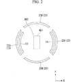
図2は、流路形成部材30に形成された第1、第2供給口13、14及び第1〜第4回収口23A〜23Dと、投影光学系PLの投影領域AR1との位置関係を示す平面図である。
FIG. 2 shows the positional relationship between the first and
図2において、投影光学系PLの投影領域AR1はY軸方向(非走査方向)を長手方向とする矩形状に設定されており、液体1が満たされた液浸領域AR2は投影領域AR1を含むように実質的に4つの回収口で囲まれた領域内であって、且つ基板P上の一部に形成される。第1供給口13は、投影領域AR1に対して走査方向一方側(−X側)に設けられ、第2供給口14は、他方側(+X側)に設けられている。つまり、第1、第2供給口13、14は、走査方向(X方向)に関して投影領域AR1を挟むようにその両側に配置されている。第1、第2供給口13、14のそれぞれは、所定の長さを有する平面視略円弧状のスリット状に形成されている。第1、第2供給口13、14のY軸方向における長さは、少なくとも投影領域AR1のY軸方向における長さより長くなっている。液体供給機構10は、第1、第2供給口13、14より、投影領域AR1の両側で液体1を同時に供給可能である。
In FIG. 2, the projection area AR1 of the projection optical system PL is set in a rectangular shape whose longitudinal direction is the Y-axis direction (non-scanning direction), and the liquid immersion area AR2 filled with the
第1〜第4回収口23A〜23Dは、供給口13、14、及び投影領域AR1を取り囲むように配置されている。複数(4つ)の回収口23A〜23Dのうち、第1回収口23Aと第3回収口23CとがX軸方向に関して投影領域AR1を挟んでその両側に配置されており、第2回収口23Bと第4回収口23DとがY軸方向に関して投影領域AR1を挟んでその両側に配置されている。供給口13、14は、投影領域AR1と回収口23A、23Cとの間に配置された構成となっている。回収口23A〜23Dのそれぞれは、平面視略円弧状の所定の長さを有するスリット状に形成されている。回収口23A、23CのY軸方向における長さは、供給口13、14のY軸方向における長さより長くなっている。回収口23B、23Dのそれぞれも、回収口23A、23Cとほぼ同じ長さに形成されている。第1〜第4回収口23A〜23Dは、第1〜第4回収管22A〜22Dのそれぞれを介して液体回収部21に接続されている。
The first to
なお、本実施形態において、複数の回収口23A〜23Dのそれぞれは、ほぼ同じ大きさ(長さ)に形成されているが、互いに異なる大きさであってもよい。また、回収口23の数は4つに限られず、投影領域AR1及び供給口13、14を取り囲むように配置されていれば、任意の複数設けることができる。
In the present embodiment, each of the plurality of
図3は、流路形成部材30の概略斜視図である。
FIG. 3 is a schematic perspective view of the flow
図3に示すように、流路形成部材30は投影光学系PLの先端部の光学素子2のまわりを囲むように設けられた環状部材であって、第1部材31と、第1部材31の上部に配置される第2部材32と、第2部材32の上部に配置される第3部材33とを備えている。流路形成部材30を構成する第1〜第3部材31〜33のそれぞれは、板状部材であってその中央部に投影光学系PL(光学素子2)を配置可能な穴部31A〜33Aを有している。第1、第2供給管11A、12Aの一端部は、第1、第2液体供給部11、12のそれぞれに接続されており、他端部は流路形成部材30の内部に形成された供給流路82に接続されている。第1〜第4回収管22A〜22Dの一端部は、液体回収部21に接続されており、他端部は、流路形成部材30の内部に形成された回収流路84に接続されている。
As shown in FIG. 3, the flow
図4は、第1〜第3部材のうち最下段に配置される第1部材31を示す斜視図である。
FIG. 4 is a perspective view showing the
第1部材31は、投影光学系PLの−X側に形成され、基板Pに液体1を供給する第1供給口13と、投影光学系PLの+X側に形成され、基板P上に液体を供給する第2供給口14とを備えている。第1供給口13及び第2供給口14のそれぞれは第1部材31を貫通する貫通穴であって、平面視略円弧状に形成されている。更に、第1部材31は、投影光学系PLの−X側に形成され、基板P上の液体を回収する第1回収口23Aと、投影光学系PLの−Y側に形成され、基板P上の液体を回収する第2回収口23Bと、投影光学系PLの+X側に形成され、基板P上の液体を回収する第3回収口23Cと、投影光学系PLの+Y側に形成され、基板P上の液体を回収する第4回収口23Dとを備えている。
The
第1〜第4回収口23A〜23Dのそれぞれも、第1部材31を貫通する貫通穴であって、平面視略円弧状に形成されており、投影光学系PLの周囲に沿って略等間隔に設けられている。また、回収口23A〜23Dのそれぞれは、供給口13、14より投影光学系PLに対して外側に設けられている。供給口13、14の基板Pとの離間距離と、回収口23A〜23Dの基板Pとの離間距離とは、ほぼ同じに設けられている。つまり、供給口13、14の高さ位置と、回収口23A〜23Dの高さ位置とは、ほぼ同じに設けられている。
Each of the first to
図5A及び図5Bは、第1〜第3部材のうち中段に配置される第2部材32を示す斜視図であって、図5Aは、上側から見た斜視図、図5Bは、下側から見上げた斜視図である。
5A and 5B are perspective views showing the
第1、第2供給管11A、12Aの他端部、及び第1〜第4回収管22A〜22Dの他端部は、第2部材32に継手80、81を介して接続される。第2部材32は、投影光学系PLの−X側に形成され、第1部材31の第1供給口13に接続される第1供給穴部15と、投影光学系PLの+X側に形成され、第1部材31の第2供給口14に接続される第2供給穴部16とを備えている。第1、第2供給穴部15、16は貫通穴であって、平面視における形状及び大きさは、第1、第2供給口13、14に対応している。つまり、第1、第2供給穴部15、16は平面視円弧状のスリット状流路となっている。
The other ends of the first and
また、第2部材32の上面32Sのうち、投影光学系PLの−X側には、管状の接続穴41Aを介して第1供給管11Aと接続するテーパ状溝部17が形成されている。テーパ状溝部17は、第1供給管11A(接続穴41A)との接続部から投影光学系PL側(第1供給穴部15側)に向かって水平方向に漸次拡がるように形成されており、その幅広部のY軸方向に関する長さと第1供給穴部15の長さとは、ほぼ同じである。そして、テーパ状溝部17と第1供給穴部15との間には堤防部43が設けられている。堤防部43は、第2部材32の上面32Sより低く且つテーパ状溝部17より高い凸部であって、そのY軸方向における長さは第1供給穴部15(第1供給口13)の長さとほぼ同じである。同様に、第2部材32の上面のうち投影光学系PLの+X側には、接続穴41Bを介して第2供給管12Aと接続するテーパ状溝部18が形成されている。テーパ状溝部18は、第2供給管12A(接続穴41B)との接続部から投影光学系PL側(第2供給穴部16側)に向かって水平方向に漸次拡がるように形成されており、その幅広部のY軸方向に関する長さと第2供給穴部16の長さとはほぼ同じである。そして、テーパ状溝部18と第2供給穴部16との間には堤防部44が設けられている。堤防部44は、第2部材32の上面32Sより低く且つテーパ状溝部18より高い凸部であって、そのY軸方向における長さは、第2供給穴部16(第2供給口14)の長さとほぼ同じである。第1部材31と第2部材32とを接続することにより、第1部材31に形成されている第1、第2供給口13、14と、第2部材32に形成されている第1、第2供給穴部15、16とのそれぞれが接続される。
In addition, on the −X side of the projection optical system PL in the upper surface 32S of the
第2部材32の下面32Dのうち、投影光学系PLの−X側には、管状の接続穴42Aを介して第1回収管22Aと接続するテーパ状溝部45が形成されている。テーパ状溝部45は、第1回収管22Aとの接続部から投影光学系PL側に向かって水平方向に漸次拡がるように形成されており、その幅広部のY軸方向に関する長さと第1部材31の第1回収口23Aの長さとはほぼ同じである。そして、第1部材31と第2部材32とを接続したとき、テーパ状溝部45の幅広部と第1回収口23Aとが接続されるようになっている。投影光学系PLの−Y側には、接続穴42Bを介して第2回収管22Bと接続するテーパ状溝部46が形成されており、第2回収管22Bとの接続部から投影光学系PL側に向かって水平方向に漸次拡がるように形成されている。そして、テーパ状溝部46の幅広部と第1部材31の第2回収口23Bとが接続されるようになっている。同様に、投影光学系PLの+X側及び+Y側のそれぞれには、接続穴42C、42Dを介して第3、第4回収管22C、22Dと接続するテーパ状溝部47、48が形成されており、第3、第4回収管22C、22Dとの接続部から投影光学系PL側に向かって水平方向に漸次拡がるように形成されている。そして、テーパ状溝部47、48の幅広部と第1部材31の第3、第4回収口23C、23Dとが接続されるようになっている。
Of the
図6は、第3部材33を示す図である。
FIG. 6 is a view showing the
第3部材33の下面は平坦面となっており、第2部材32と第3部材33とを接続したとき、第2部材32の上面32Sと第3部材33の下面とが接する。このとき、堤防部43、44は上面32Sより低いので、第3部材33の下面と接しない。
The lower surface of the
なお、本実施形態においては、流路形成部材30を3つの部材を使って形成しているが、部材の数はこれに限るものではない。また、供給口13、14への流路と、回収口23A、23B、23C、23Dへの流路とを各々別の部材に形成してもよいし、各口毎に別々の部材に流路を形成してもよい。
In addition, in this embodiment, although the flow-
図7は、図3のA−A断面矢視図、図8は、図3のB−B断面矢視図である。 7 is a cross-sectional view taken along the line AA in FIG. 3, and FIG. 8 is a cross-sectional view taken along the line BB in FIG.
なお、以下の説明では、流路形成部材30のうち投影光学系PLの+X側に設けられた供給流路82B(82)及び回収流路84C(84)について説明するが、投影光学系PLの−X側に設けられた供給流路82A、投影光学系PLの−X側の回収流路82A、−Y側の回収流路82B、及び+Y側の回収流路82Dも同等の構成を有する。
In the following description, the
図7において、供給流路82Bは、その一端部を継手80を介して供給管12Aに接続し、他端部をテーパ状溝部18に接続した接続穴41Bと、テーパ状溝部18と第3部材33との間に形成されたバッファ空間部90と、堤防部44と第3部材33との間に形成され、バッファ空間部90より狭い狭流路部91と、その上端部を狭流路部91に接続し、下端部を供給口14に接続した供給穴部16とを備えている。バッファ空間90は、比較的広い流路を形成している。バッファ空間部90及び狭流路部91において、液体1は、ほぼ水平方向(XY平面方向)に流れ、供給穴部16において、液体1は、ほぼ鉛直方向(−Z方向)に流れる。つまり、供給流路82Bは、その途中に曲がり角部92を有しており、狭流路部91は、その曲がり角部92近傍(直前)に設けられた構成となっている。
In FIG. 7, the
狭流路部91は、バッファ空間部90よりも流路下流側に設けられている。つまり、曲がり角部92近傍の狭流路部91は、その流路手前であるバッファ空間部90よりも狭められた構成となっている。本実施形態において、狭流路部91は、第2部材32より上方に突出した堤防部44と第3部材33との間に形成されており、バッファ空間部90に対して鉛直方向に狭められている。
The
液体供給部12から送出された液体1は、供給管12Aを介して供給流路82Bのうち接続穴41Bに流入する。流入した液体1は、バッファ空間部90をほぼ水平方向に流れ、狭流路部91を流れた後、曲がり角部92において基板P側に向きを変えられ、供給穴部16を介して供給口14より基板P上に供給される。
The liquid 1 delivered from the
一方、回収流路84Cは、その一端部を回収口23Cに接続し、他端部を接続穴42Cに接続したバッファ空間部94を有している。真空ポンプを有する液体回収部21の駆動により、基板P上の液体1は、回収流路84Cに回収口23Cを介して鉛直上向き(+Z方向)に流入する。このとき、回収口23Cからは、基板P上の液体1とともにその周囲の気体(空気)も流入(回収)する。回収流路84Cに流入した液体1は、バッファ空間部94の一端部側で水平方向にその流れの向きを変えられ、バッファ空間部94をほぼ水平方向に流れる。その後、接続穴42Cを流れ、回収管22Cを介して液体回収部21に送られる。
On the other hand, the
第1〜第3部材31〜33は、例えばステンレススチールやチタン、アルミニウム、あるいはこれらを含む合金等の金属により形成されており、各部材31〜33の穴部や溝部は、例えば放電加工により形成される。放電加工により各部材31〜33に対して加工した後、これら各部材31〜33を接着剤あるいは締結部材等を用いて接合することにより、流路形成部材30が形成される。なお、各部材31〜33の接液面は、電解研磨あるいは不導体酸化膜処理、あるいはその両方を施しておくとよい。各部材31〜33を接合することで、バッファ空間部90及び狭流路部91を含む供給流路82B(82)、及びバッファ空間部94を含む回収流路84C(84)が形成される。なお、流路形成部材30を含む液体供給機構10及び液体回収機構20を構成する各部材は、例えばポリ四フッ化エチレン等の合成樹脂により形成されていてもよい。
The 1st-3rd members 31-33 are formed, for example by metals, such as stainless steel, titanium, aluminum, or an alloy containing these, and the hole part and groove part of each member 31-33 are formed by electric discharge machining, for example Is done. After processing each
液体供給機構10及び液体回収機構20の一部を構成する流路形成部材30の内側面30Tと、投影光学系PLのうち液体1と接する終端部の光学素子2の側面2Tとの間には微小間隙100が形成されている。微小間隙100は、投影光学系PLの光学素子2と流路形成部材30とを振動的に分離するために設けられたものであり、これにより、液体回収機構10や液体回収機構20で発生した振動が、投影光学系PLに伝達することを防ぐことができる。微小間隙100は、投影領域AR1と供給口14とを極力近づけるために、液体1の浸透現象を引き起こす程度に小さく形成されており、流路形成部材30の周囲の気体空間と接続されている。流路形成部材30を含む液体供給機構10及び液体回収機構20のそれぞれは、投影光学系PL及びこの投影光学系PLを支持する支持部材以外の支持部材で支持されている。
Between the
微小間隙100を形成する流路形成部材30の内側面30Tと光学素子2の側面2Tとの双方には、撥液(撥水)処理が施されている。撥液処理が施された撥液処理部101A、101Bは、液体1と接触する微小間隙100の下端部から離れた部分に設けられている。流路形成部材30の内側面30T及び光学素子2の側面2Tのうち微小間隙100の下端部と撥液処理部101A、101Bとの間の未撥液処理部102A、102Bの大きさ(Z軸方向の距離)は、例えば投影光学系PLと基板Pとの間の距離(所謂ワーキングディスタンス)とほぼ同じに設定されている。なお、図7及び図8に示す例では、撥液処理部101Aは、光学素子2の側面2Tのうち微小間隙100の下端部近傍を除いたほぼ全面に設けられているが、その一部に設けられた構成であってもよいし、不連続に(島状に)設けられた構成であってもよい。同様に、撥液処理部101Bは、流路形成部材30の内側面30Tのうち微小間隙100の下端部近傍を除いたほぼ全面に設けられる構成の他に、その一部に設けられた構成であってもよい。
Both the
撥液処理としては、例えば撥液性を有する材料を使ったコーティング処理が挙げられる。撥液性を有する材料としては、例えばフッ素系化合物やシリコン化合物、あるいはポリエチレン等の合成樹脂が挙げられる。また、表面処理のための薄膜は単層膜であってもよいし複数の層からなる膜であってもよい。 Examples of the liquid repellent treatment include a coating treatment using a material having liquid repellency. Examples of the material having liquid repellency include fluorine compounds, silicon compounds, and synthetic resins such as polyethylene. Further, the thin film for surface treatment may be a single layer film or a film composed of a plurality of layers.
なお、流路形成部材30の内側面30T及び光学素子2の側面2Tの撥液面における液体1の接触角は、70度以上、好ましくは90度以上とである。
The contact angle of the
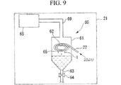
図9は、液体回収部21の要部拡大図である。
FIG. 9 is an enlarged view of a main part of the
液体回収部21には、回収管22に接続された気液分離器60と、その気液分離器60に排気管69を介して接続され、マスフローコントローラや真空ポンプ等を有する真空系68とが設けられている。ここで、上述したように、回収口23からは基板P上の液体1とともにその周囲の気体も回収される。気液分離器60は、回収口23より回収した液体と気体とを分離する。気液分離器60は、タンク61と、タンク61内部に設けられ、回収管22と接続する分離管62とを備えている。タンク61の上部は真空系68に接続されており、タンク61の下部には排出用管部63が設けられている。排出用管部63にはこの排出用管部63の流路を開閉するバルブ64が設けられている。
The
なお、分離器60は、複数の第1〜第4回収管22A〜22Dのそれぞれに設けられてもよいし、複数の第1〜第4回収管22A〜22Dを一旦集合した後、この集合管に設けられてもよい。
The
図10は、分離管62を下方から見た拡大図である。
FIG. 10 is an enlarged view of the
図10に示すように、分離管62は、渦巻き状(螺旋状)に曲げられており、その下面には複数のスリット状の穴部65が所定間隔で形成されている。したがって、真空系68が駆動されると、タンク61及び回収管22が負圧となって、回収口23を介して基板P上の液体1がその周囲の気体とともに回収される。回収口23より回収された液体及び気体は回収管22を通ってタンク61内に設けられた分離管62を流れる。分離管62を流れることで、重力作用によって液体1は、穴部65を介して落下し、タンク61下部に溜まる。なお、バルブ64を作動して排出用管部63を開放することにより、タンク61内に溜まった液体1を外部に排出することができる。一方、気体はタンク61上に接続された排気管69を介して真空系68に吸引される。このように、気液分離器60によって回収した液体と気体とを分離することにより、真空ポンプ等を有する真空系68に液体1が流入しないので、その真空ポンプの故障等の不都合を防止することができる。なお、真空系68に真空ポンプを設けずに、露光装置EXが配置される工場の真空系を用いるようにしてもよい。
As shown in FIG. 10, the
次に、上述した露光装置EXを用いてマスクMのパターン像を基板Pに露光する方法について説明する。 Next, a method for exposing the pattern image of the mask M onto the substrate P using the above-described exposure apparatus EX will be described.
ここで、本実施形態における露光装置EXは、マスクMと基板PとをX軸方向(走査方向)に移動しながらマスクMのパターン像を基板Pに投影露光するものであって、走査露光時には、投影光学系PLの先端部直下の矩形状の投影領域AR1にマスクMの一部のパターン像が投影され、投影光学系PLに対して、マスクMが−X方向(又は+X方向)に速度Vで移動するのに同期して、XYステージ53を介して基板Pが+X方向(又は−X方向)に速度β・V(βは投影倍率)で移動する。基板P上には複数のショット領域が設定されており、1つのショット領域への露光終了後に、基板Pのステッピング移動によって次のショット領域が走査開始位置に移動し、以下、ステップ・アンド・スキャン方式で基板Pを移動しながら各ショット領域に対する走査露光処理が順次行われる。
Here, the exposure apparatus EX in the present embodiment projects and exposes the pattern image of the mask M onto the substrate P while moving the mask M and the substrate P in the X-axis direction (scanning direction). Then, a part of the pattern image of the mask M is projected onto the rectangular projection area AR1 directly under the tip of the projection optical system PL, and the mask M moves in the −X direction (or + X direction) with respect to the projection optical system PL. In synchronization with the movement at V, the substrate P moves through the
走査露光処理を行うに際し、制御装置CONTは、液体供給機構10を駆動し、基板P上に対する液体供給動作を開始する。液体供給機構10の第1、第2液体供給部11、12のそれぞれから送出された液体1は、供給管11A、12Aを流通した後、流路形成部材30内部に形成された供給流路82A、82Bを介して基板P上に供給される。
When performing the scanning exposure process, the control device CONT drives the
例えば、第2液体供給部12から送出された液体1は、第2供給管12Aを流通した後、水平方向に漸次広がるように形成されたバッファ空間部90を流通することで水平方向(Y軸方向)に拡がる。ここで、バッファ空間部90の流路下流側には、堤防部44が形成されているため、第2液体供給部12から送出された液体1は、バッファ空間部90に一旦貯められる。液体1は、バッファ空間部90に所定量以上貯まった後(液体1の水位が堤防部44の高さ以上になった後)、狭流路部91を介して供給穴部16に流れる。こうして、液体1の供給口14への供給が開始される。これにより、バッファ空間部90から流れ出た液体1は、Y軸方向を長手方向とするスリット状の供給口14からほぼ均一に基板P上に供給される。つまり、狭流路部91(堤防部44)が形成されていないと、テーパ状溝部18を流れる液体1の流量は、テーパ状溝部18の幅方向中央部のほうが端部より多くなるため、Y軸方向を長手方向とする供給口14の各位置において基板P上に対する液体供給量が不均一となる場合がある。しかしながら、所定量以上の液体1を貯めてから供給口14への液体供給が開始されるように狭流路部91を設けることによってバッファ空間部90を形成したことにより、液体1は、Y軸方向を長手方向とする略円弧状の供給口14の各位置においてほぼ均一な液体供給量で基板P上に供給される。同様に、第1液体供給部11から送出された液体1も、バッファ空間部90に所定量以上貯められてから供給口13への供給が開始されるので、スリット状の供給口13から基板P上にほぼ均一に供給される。また、供給口13,14からの供給を開始した後も、バッファ空間90を介して供給口13,14へ液体1が流れ続けるので、供給口13,14の各位置において均一な量で基板P上への液体供給を続けることができる。
For example, the
ここで、供給流路82B(82A)の曲がり角部92近傍には例えば供給開始時などに気泡が残存しやすいが、この曲がり角部92近傍の供給流路82Bを狭めて狭流路部91を形成したことにより、狭流路部91を流れる液体1の流速を高速化でき、その高速化された液体1の流れにより気泡を供給口14を介して供給流路82B外部に排出できる。そして、気泡を排出した後、液浸露光動作を実行することにより、液浸領域AR2に気泡がない状態で露光処理できる。
Here, air bubbles are likely to remain in the vicinity of the
本実施形態において、液体供給機構10は、供給口13、14より投影領域AR1の両側から基板P上への液体1の供給を同時に行う。これにより、供給口13、14から基板P上に供給された液体1は、投影光学系PLの終端部の光学素子2の下端面と基板Pとの間に良好に濡れ拡がり、液浸領域AR2を少なくとも投影領域AR1より広い範囲で形成する。
In the present embodiment, the
また、制御装置CONTは、液体回収機構20の液体回収部21を駆動し、液体供給機構10による液体1の供給動作と並行して、基板P上の液体回収動作を行う。これにより、供給口13、14より投影領域AR1に対して外側に流れる基板P上の液体1は、回収口23A〜23Dより回収される。回収流路84(84A〜84D)の一部も、その一端部が回収口23(23A〜23D)のY軸方向とほぼ同じ長さを有し、回収管22に向かって漸次縮小するテーパ状に形成されたバッファ空間部94となっているため、回収口23の各位置においてほぼ均一な液体回収量で基板P上の液体1を回収することができる。
Further, the control device CONT drives the
制御装置CONTは、液体供給機構10及び液体回収機構20により基板Pの表面に対する液体1の供給と並行して基板P上の液体1の回収を行いつつ、基板Pを支持する基板ステージPSTをX軸方向(走査方向)に移動しながら、マスクMのパターン像を投影光学系PLと基板Pとの間の液体1及び投影光学系PLを介して基板P上に投影露光する。
The control device CONT performs the recovery of the
このとき、液体供給機構10は走査方向に関して投影領域AR1の両側から供給口13、14を介して液体1の供給を同時に行っているので、液浸領域AR2は均一且つ良好に形成されている。また、液体回収機構20は、投影領域AR1を囲む複数の回収口23A〜23Dを介して投影領域AR1の走査方向両側を含む投影領域AR1周囲の複数の位置において液体1の回収を同時に行っているため、液体1の基板P周囲への流出や飛散を防止している。
At this time, since the
なお、本実施形態では、投影領域AR1の走査方向両側から基板Pに対して液体1を供給する際、制御装置CONTは、液体供給機構10の第1、第2液体供給部11、12の液体供給動作を制御し、走査方向に関して、投影領域AR1の手前から供給する単位時間あたりの液体供給量を、その反対側で供給する液体供給量よりも多く設定する。例えば、基板Pを+X方向に移動しつつ露光処理する場合、制御装置CONTは、投影領域AR1に対して−X側(すなわち供給口13)からの液体量を、+X側(すなわち供給口14)からの液体量より多くし、一方、基板Pを−X方向に移動しつつ露光処理する場合、投影領域AR1に対して+X側からの液体量を、−X側からの液体量より多くする。ここで、例えば基板Pが+X方向に移動することにより、投影領域AR1に対して+X側に移動する液体量が増し、+X側に液体回収位置を設けられている回収口23Cが液体1を全て回収しきれない場合がある。ところが、+X側の回収口23Cで回収しきれなかった液体1はこの液体回収位置より+X側に設けられているトラップ面70で捕捉されるため、基板Pの周囲等に流出したり飛散したりすることがない。
In the present embodiment, when supplying the
また、上述したように、流路形成部材30と光学素子2との間には微小間隙100が設けられており、これにより液体供給機構10や液体回収機構20で生じた振動が投影光学系PLに伝達する不都合を防止しているが、この間隙が大きすぎると装置全体の大型化を招く。また、液体1の供給口及び回収口が投影領域AR1より離れた位置に設けられることになるため、投影領域AR1を含むように良好に液浸領域AR2を形成できない可能性が生じるとともに、液体使用量が増すという不都合も生じる。また、その大きな間隙より液浸領域AR2に気体(気泡)が混入する可能性も生じる。そこで、本実施形態では、液体1の浸透現象を引き起こす程度の大きさに微小間隙100が設けられている。これにより、装置の大型化を防ぎつつ、間隙から液浸領域AR2に気体が入り込んでしまう不都合を防止することができる。一方で、微小間隙100に液体1が浸入した場合、浸入した液体1は淀んだ状態となるため清浄度が低下し、例えば液浸露光中にその清浄度の低下した微小間隙100の液体1が液浸領域AR2に混入してしまう不都合が生じる可能性がある。そこで、微小間隙100を形成する流路形成部材30の内側面30T及び光学素子2の側面2Tのそれぞれに撥液処理を施すことで微小間隙100に対する液体1の浸入を防止できる。
Further, as described above, the
図11は、微小間隙100の拡大図である。
FIG. 11 is an enlarged view of the
図11に示すように、流路形成部材30の内側面30T及び光学素子2の側面2Tに撥液処理が施されているため、液浸領域AR2の液体1の上昇現象はおこらず、撥液処理部101A、101Bの間に液浸領域AR2の液体1は、入り込まない。一方、微小間隙100のうち未撥液処理部102A、102Bの間には浸透現象により液体1が入り込む。この入り込んだ液体1により、撥液処理部101A、101Bの間に存在する気体が液浸領域AR2に混入する不都合が抑制されている。つまり、図12に示すように、微小間隙100を形成する流路形成部材30の内側面30T及び光学素子2の側面2Tの下端部まで撥液処理を施した場合、微小間隙100の下端部にまで気体(空気)が満たされることになり、液浸走査露光中に液浸領域AR2にその微小間隙100の気体(気泡)が入り込む不都合が生じる可能性がある。したがって、微小間隙100への液体1の浸透防止という点では、図12のように下端部まで撥液処理してもよいが、本実施形態のように、液浸領域AR2の液体1と接触する微小間隙100の下端部近傍の所定領域を未撥液処理部102A、102Bとし、浸透現象により液体1を微小間隙100の下端部近傍に配置可能とすることで、微小間隙100に存在する気体が液浸領域AR2に入り込む不都合も防止できる。なお、図11において、この未撥液処理部102A、102Bの間に入り込んだ液体1の量は僅かであって淀むことがないので、液浸露光中に清浄度の低下した液体1が液浸領域AR2に混入することはない。
As shown in FIG. 11, since the liquid repellent treatment is performed on the
なお、本実施形態において、微小間隙100を形成する流路形成部材30の内側面30Tと光学素子2の側面2Tとの双方に撥液処理が施されているが、少なくともいずれか一方の面に撥液処理を施すことによって、微小間隙100に液体1が入り込む不都合を回避できる。
In this embodiment, both the
以上説明したように、液体1をバッファ空間部90に所定量以上貯めてから供給することにより、供給口13、14に対する液体1の流量分布や流速分布を均一化できる。したがって、供給口13、14から基板P上に液体1を均一に供給できる。
As described above, by supplying the
また、装置スペースの都合等により、供給流路82の一部に曲がり角部92を形成する必要がある場合、この曲がり角部92近傍には気泡が残存しやすくなるが、曲がり角部92近傍の流路を狭まることで液体1の流速を高速化し、その高速化された液体1の流れにより気泡を供給口13、14を介して外部に排出できる。そして、気泡を排出した後、液浸露光動作を実行することにより、液浸領域AR2に対する供給流路82からの気泡の混入を防止でき、液浸領域AR2に気泡が存在しない状態で露光処理できる。特に、本実施形態のように、供給流路82の一部を堤防部44(43)により鉛直方向に狭めることにより、バッファ空間部90をほぼ水平に流れてきた液体1の流速を高速化して曲がり角部92に当てることができ、曲がり角部92近傍に存在する気泡を良好に除去することができる。
In addition, when it is necessary to form a
流路形成部材30は、板状部材である第1〜第3部材31〜33を組み合わせて形成したブロック状部材であり、例えば液体回収の際に空気をかみこんで液体1を吸引した際に発生する振動を、流路形成部材30で吸収することができる。また、複数の板状部材31〜33のそれぞれに対して放電加工等の加工を施して流路の一部を形成し、これらを組み合わせることで液体1の流路を形成するようにしたので、供給流路82及び回収流路84のそれぞれを容易に形成することができる。
The flow
なお、本実施形態において、流路形成部材30を形成する部材31〜33は、四角形の板状部材であるが、円形の板状部材であってもよいし、X軸方向に長い楕円状の板状部材であってもよい。
In addition, in this embodiment, although the members 31-33 which form the flow
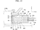
なお、本実施形態において、堤防部44(43)は、断面視矩形状であるが、図13に示すように、断面視円弧状(曲面状)であってもよい。あるいは、断面視三角形や五角形などの多角形状でもよい。また、バッファ空間部の効果は薄れてしまうが、図14に示すように、堤防部44を第3部材33の下面に設け、その堤防部44とテーパ状溝部18との間に狭流路部91を形成するようにしてもよい。
In the present embodiment, the bank portion 44 (43) has a rectangular shape in cross section, but may have an arc shape (curved surface) in cross section as shown in FIG. Or polygonal shapes, such as a cross-sectional view triangle and a pentagon, may be sufficient. Further, although the effect of the buffer space portion is diminished, as shown in FIG. 14, the
本実施形態において、堤防部44は供給流路82の曲がり角部92近傍に設けられているが、図15に示すように、曲がり角部92に対して僅かに離れた位置に設けられてもよい。図15に示す例では、堤防部44は曲がり角部92より流路上流側に設けられている。こうすることによっても、堤防部44の流路上流側にバッファ空間部90を形成することができ、供給口14(13)からの液体1の供給を均一化できる。一方、堤防部44を曲がり角部92に近づけた方が、この曲がり角部92における液体1の流速を高速化できるので、曲がり角部92での気泡の残存を防止することができる。
In the present embodiment, the
本実施形態において、堤防部44(43)はその長手方向において一様の高さを有しているが、図16に示すように、高さ分布があってもよい。図16に示す堤防部44は、その幅方向中央部の高さが両端部より高くなっている。テーパ状溝部18では、幅方向中央部における液体1の流量のほうが端部における流量より多いため、堤防部44の幅方向中央部を高くして狭流路部91の幅方向中央部を両端部より狭めることにより、液体1を供給口14を介してより均一に基板P上に供給できる。
In the present embodiment, the bank portion 44 (43) has a uniform height in the longitudinal direction, but may have a height distribution as shown in FIG. The height of the central part in the width direction of the
なお、堤防部44(43)は、供給流路82の幅方向全域に亘って設けられていることが好ましいが、その一部に設けられていてもよい。あるいは、複数の分割された堤防部が不連続に(島状に)配置されている構成でもよい。こうすることによっても流路が狭まるので液体1の流速を高速化でき、供給流路82に存在する気泡を外部に排出することができる。
In addition, although it is preferable that the embankment part 44 (43) is provided over the width direction whole region of the
なお、堤防部(狭流路部)は、基板P上の液体1を回収する回収流路84に形成されていてもよい。これにより、スリット状の回収口23から基板P上の液体1を均一に回収できる。
Note that the bank portion (narrow channel portion) may be formed in the
なお、本実施形態において、液体供給機構10の一部を構成する供給流路82及び液体回収機構20の一部を構成する回収流路84のそれぞれは、流路形成部材30内部に一体で設けられているが、図17に示すように、供給流路82と回収流路84とは互いに異なる部材により形成されていてもよい。図17において、投影光学系PL(光学素子2)の−X側には供給流路82Aを形成する第1供給部材120が設けられ、+X側には供給流路82Bを形成する第2供給部材121が設けられている。第1、第2供給部材120、121それぞれは、テーパ状溝部17、18、及び堤防部43、44を有しており、平面視略円弧状の供給口13、14より基板P上に液体1を供給する。また、投影光学系PLの−X側及び+X側のそれぞれには回収流路84A、84Cを形成する第1、第3回収部材122、124が設けられ、−Y側及び+Y側のそれぞれには回収流路84B、84Dを形成する第2、第4回収部材123、125がそれぞれ設けられている。第1〜第4回収部材122〜125のそれぞれは平面視略円弧状の回収口23A〜23Dより基板P上の液体1を回収する。この場合においても、液体供給機構を構成する第1、第2供給部材120、121の内側面120T、121Tと光学素子2の側面2Tとの間に微小間隙100が形成されているとともに、液体回収機構を構成する第2、第4回収部材123、125の内側面123T、125Tと光学素子2の側面2Tとの間にも微小間隙100が形成されている。そして、内側面120T、121T、123T、125T、及び側面2Tのそれぞれに撥液処理が施されている。
In the present embodiment, each of the
なお、本実施形態において、基板Pに対向するように配置された供給口13、14及びそれに接続する供給穴部15、16は、基板Pの表面に対してほぼ垂直に設けられ、液体1を基板Pに対して垂直方向から供給しているが、基板Pに対して液体1を斜め方向から供給するように供給口14及び供給穴部16が形成されていてもよい。換言すれば、曲がり角部92はバッファ空間部90を水平方向に流れてきた流体1の向きを垂直方向に変える構成の他に、基板Pに向かって斜め方向に向きを変える構成であってもよい。この場合においても、バッファ空間部90で液体1を所定量貯めた後、狭流路部91を介して基板Pに液体1を供給することで、気泡の発生を抑えつつスリット状の供給口14から液体1をほぼ均一に基板P上に供給することができる。
In this embodiment, the
なお、流路形成部材30は、投影光学系PLの終端部の光学素子2の近傍に微小間隙100を介して設けられているが、光学素子2の先端側面が光学素子2を保持する部材で覆われている場合には、その部材の側面と流路形成部材30の側面30Tとの少なくとも一方を撥液処理すればよい。
The flow
また、上述の実施形態においては、流路形成部材30の側面30Tが光学素子2の側面2Tと対向するように配置されているが、別の部材が光学素子2の側面2Tと対向している場合にも、光学素子2の側面2Tとそれに対する部材の表面(側面)との少なくとも一方を撥液処理(撥液性)にすればよい。
In the above-described embodiment, the
また、上述の実施形態においては、投影光学系PLの終端の光学素子2の側面2Tとそれに対向する部材の側面の少なくとも一方を撥液処理(撥液性)にしているが、例えば国際公開第2004/019128号に開示されているように、投影光学系PLの終端の光学素子のマスクM側の光路空間も液体で満たされている場合には、投影光学系PLを構成する複数の光学素子のうち終端の光学素子に対してマスクM側に配置された光学素子の側面とそれに対向する部材の表面(側面)の少なくとも一方を撥液処理することによって、その隙間への液体の浸入やその隙間での液体の滞留を防止することができる。なお、本国際出願で指定または選択された国の法令で許容される限りにおいて、国際公開第2004/019128号パンフレットの記載内容を援用して本文の記載の一部とする。
In the above-described embodiment, at least one of the
なお、本実施形態において、供給口は、所定の長さを有するスリット状に形成されているが、例えば複数の仕切部材により複数に分割された分割供給口としてもよいし、あるいは直管部を複数並べた構成としてもよいし、直管部とスリット状供給口とを組み合わせた構成であってもよい。また、供給口にスポンジ状部材等の多孔質体を設けてもよい。同様に、回収口に仕切部材を設けてもよいし複数の直管部で形成してもよい。また、多孔質体や仕切部材、あるいは直管部は、流路形成部材30の供給流路82の流路途中に設けられてもよい。
In the present embodiment, the supply port is formed in a slit shape having a predetermined length. For example, the supply port may be divided into a plurality of divided supply ports by a plurality of partition members, or a straight pipe portion may be used. It is good also as a structure arranged in multiple numbers, and the structure which combined the straight pipe | tube part and the slit-shaped supply port may be sufficient. Further, a porous body such as a sponge-like member may be provided at the supply port. Similarly, a partition member may be provided at the recovery port, or a plurality of straight pipe portions may be formed. Further, the porous body, the partition member, or the straight pipe portion may be provided in the middle of the flow path of the
なお、本実施形態では、液体供給機構10の供給口13、14は、投影領域AR1に対して走査方向(X軸方向)両側に設けられている構成であるが、非走査方向(Y軸方向)両側に別の供給口を設け、これら複数の供給口を組み合わせて液体供給を行うようにしてもよい。あるいは、供給口は投影領域AR1の周りを全て囲むように環状に設けられてもよい。
In the present embodiment, the
なお、本実施形態では、トラップ面70は、第1部材31の下面において投影領域AR1の走査方向両側のみに設けられている構成であるが、投影領域AR1に対して非走査方向に設けられた構成とすることも可能である。一方、液体1が流出しやすいのは走査方向両側であるため、投影領域AR1の走査方向両側のみにトラップ面70を設ける構成であっても、流出しようとする液体1を良好に捕捉できる。また、トラップ面70はフラット面である必要は無く、例えば複数の平面を組み合わせた形状であってもよい。あるいは、トラップ面70は、曲面状であってもよく、表面積拡大処理、具体的には粗面処理を施されていてもよい。
In the present embodiment, the
なお、上記実施形態において、液体供給機構10や液体回収機構20のうち液体1が流れる流路の表面に対して親液処理を施すことができる。特に、液体回収機構20の回収口23を含む回収流路84に親液処理を施しておくことにより、液体回収を円滑に行うことができる。また、液体供給機構10の供給口及び供給流路にも親液処理を施すことができる。
In the above embodiment, the lyophilic process can be performed on the surface of the flow path through which the
上記実施形態において、液体1は、純水により構成されている。純水は、半導体製造工場等で容易に大量に入手できるとともに、基板P上のフォトレジストや光学素子(レンズ)等に対する悪影響がない利点がある。また、純水は、環境に対する悪影響がないとともに、不純物の含有量が極めて低いため、基板Pの表面、及び投影光学系PLの先端面に設けられている光学素子の表面を洗浄する作用も期待できる。
In the said embodiment, the
そして、波長が193nm程度の露光光ELに対する純水(水)の屈折率nは、ほぼ1.44であるため、露光光ELの光源としてArFエキシマレーザ光(波長193nm)を用いた場合、基板P上では1/n、すなわち約134nmに短波長化されて高い解像度が得られる。更に、焦点深度は、空気中に比べて約n倍、すなわち約1.44倍に拡大されるため、空気中で使用する場合と同程度の焦点深度が確保できればよい場合には、投影光学系PLの開口数をより増加させることができ、この点でも解像度が向上する。 Since the refractive index n of pure water (water) with respect to the exposure light EL having a wavelength of about 193 nm is approximately 1.44, when ArF excimer laser light (wavelength 193 nm) is used as the light source of the exposure light EL, the substrate On P, the wavelength is shortened to 1 / n, that is, about 134 nm, and high resolution is obtained. Further, since the depth of focus is enlarged by about n times, that is, about 1.44 times compared with that in the air, the projection optical system can be used if it is sufficient to ensure the same depth of focus as that used in the air. The numerical aperture of PL can be further increased, and the resolution is improved also in this respect.
本実施形態では、投影光学系PLの先端に光学素子2が取り付けられており、このレンズにより投影光学系PLの光学特性、例えば収差(球面収差、コマ収差等)の調整を行うことができる。なお、投影光学系PLの先端に取り付ける光学素子としては、投影光学系PLの光学特性の調整に用いる光学プレートであってもよい。あるいは露光光ELを透過可能な平行平面板であってもよい。
In the present embodiment, the
なお、液体1の流れによって生じる投影光学系PLの先端の光学素子と基板Pとの間の圧力が大きい場合には、その光学素子を交換可能とするのではなく、その圧力によって光学素子が動かないように堅固に固定してもよい。
When the pressure between the optical element at the tip of the projection optical system PL generated by the flow of the
なお、本実施形態では、投影光学系PLと基板P表面との間は液体1で満たされている構成であるが、例えば基板Pの表面に平行平面板からなるカバーガラスを取り付けた状態で液体1を満たす構成であってもよい。
In the present embodiment, the space between the projection optical system PL and the surface of the substrate P is filled with the
なお、本実施形態の液体1は水であるが水以外の液体であってもよい。例えば露光光ELの光源がF2レーザである場合、このF2レーザ光は、水を透過しないので、液体1としてはF2レーザ光を透過可能な例えばフッ素系オイルや過フッ化ポリエーテル(PFPE)のフッ素系流体であってもよい。また、液体1としては、その他にも、露光光ELに対する透過性があってできるだけ屈折率が高く、投影光学系PLや基板P表面に塗布されているフォトレジストに対して安定なもの(例えばセダー油)を用いることも可能である。
In addition, although the
この場合も、表面処理は、用いる液体1の極性に応じて行われる。 Also in this case, the surface treatment is performed according to the polarity of the liquid 1 to be used.
なお、上記各実施形態の基板Pとしては、半導体デバイス製造用の半導体ウエハのみならず、ディスプレイデバイス用のガラス基板や、薄膜磁気ヘッド用のセラミックウエハ、あるいは露光装置で用いられるマスクまたはレチクルの原版(合成石英、シリコンウエハ)等が適用される。 The substrate P in each of the above embodiments is not only a semiconductor wafer for manufacturing a semiconductor device, but also a glass substrate for a display device, a ceramic wafer for a thin film magnetic head, or an original mask or reticle used in an exposure apparatus. (Synthetic quartz, silicon wafer) or the like is applied.
露光装置EXとしては、マスクMと基板Pとを同期移動してマスクMのパターンを走査露光するステップ・アンド・スキャン方式の走査型露光装置(スキャニングステッパ)の他に、マスクMと基板Pとを静止した状態でマスクMのパターンを一括露光し、基板Pを順次ステップ移動させるステップ・アンド・リピート方式の投影露光装置(ステッパ)にも適用することができる。また、本発明は基板P上で少なくとも2つのパターンを部分的に重ねて転写するステップ・アンド・スティッチ方式の露光装置にも適用できる。 As the exposure apparatus EX, in addition to the step-and-scan type scanning exposure apparatus (scanning stepper) that scans and exposes the pattern of the mask M by moving the mask M and the substrate P synchronously, the mask M and the substrate P Can be applied to a step-and-repeat type projection exposure apparatus (stepper) in which the pattern of the mask M is collectively exposed while the substrate P is stationary and the substrate P is sequentially moved stepwise. The present invention can also be applied to a step-and-stitch type exposure apparatus that partially transfers at least two patterns on the substrate P.
また、本発明は、ウエハ等の被処理基板を別々に載置してXY方向に独立に移動可能な2つのステージを備えたツインステージ型の露光装置にも適用できる。ツインステージ型の露光装置の構造及び露光動作は、例えば特開平10−163099号及び特開平10−214783号(対応米国特許6,341,007、6,400,441、6,549,269及び6,590,634)、特表2000−505958号(対応米国特許5,969,441)あるいは米国特許6,208,407に開示されており、本国際出願で指定または選択された国の法令で許容される限りにおいて、それらの開示を援用して本文の記載の一部とする。 The present invention can also be applied to a twin stage type exposure apparatus having two stages on which a substrate to be processed such as a wafer is separately placed and can be moved independently in the XY directions. The structure and exposure operation of a twin stage type exposure apparatus are disclosed in, for example, Japanese Patent Laid-Open Nos. 10-163099 and 10-214783 (corresponding US Pat. Nos. 6,341,007, 6,400,441, 6,549,269 and 6). , 590, 634), JP 2000-505958 (corresponding US Pat. No. 5,969,441) or US Pat. No. 6,208,407, which is permitted by the laws of the country designated or selected in this international application. Insofar as possible, those disclosures are incorporated herein by reference.
露光装置EXの種類としては、基板Pに半導体素子パターンを露光する半導体素子製造用の露光装置に限られず、液晶表示素子製造用又はディスプレイ製造用の露光装置や、薄膜磁気ヘッド、撮像素子(CCD)あるいはレチクル又はマスクなどを製造するための露光装置などにも広く適用できる。 The type of the exposure apparatus EX is not limited to an exposure apparatus for manufacturing a semiconductor element that exposes a semiconductor element pattern on the substrate P, but an exposure apparatus for manufacturing a liquid crystal display element or a display, a thin film magnetic head, an image sensor (CCD). ) Or an exposure apparatus for manufacturing reticles or masks.
基板ステージPSTやマスクステージMSTにリニアモータを用いる場合は、エアベアリングを用いたエア浮上型およびローレンツ力またはリアクタンス力を用いた磁気浮上型のどちらを用いてもよい。また、各ステージPST、MSTは、ガイドに沿って移動するタイプでもよく、ガイドを設けないガイドレスタイプであってもよい。ステージにリニアモータを用いた例は、米国特許5,623,853及び5,528,118に開示されており、それぞれ本国際出願で指定または選択された国の法令で許容される限りにおいて、これらの文献の記載内容を援用して本文の記載の一部とする。 When a linear motor is used for the substrate stage PST and the mask stage MST, either an air levitation type using an air bearing or a magnetic levitation type using a Lorentz force or a reactance force may be used. Each stage PST, MST may be a type that moves along a guide, or may be a guideless type that does not have a guide. Examples using linear motors for the stages are disclosed in US Pat. Nos. 5,623,853 and 5,528,118, respectively, as long as permitted by national legislation designated or selected in this international application. The contents of the document are incorporated into the text.
各ステージPST、MSTの駆動機構としては、二次元に磁石を配置した磁石ユニットと、二次元にコイルを配置した電機子ユニットとを対向させ電磁力により各ステージPST、MSTを駆動する平面モータを用いてもよい。この場合、磁石ユニットと電機子ユニットとのいずれか一方をステージPST、MSTに接続し、磁石ユニットと電機子ユニットとの他方をステージPST、MSTの移動面側に設ければよい。 As a driving mechanism for each stage PST, MST, a planar motor that drives each stage PST, MST by electromagnetic force with a magnet unit having a two-dimensionally arranged magnet and an armature unit having a two-dimensionally arranged coil facing each other is provided. It may be used. In this case, either one of the magnet unit and the armature unit may be connected to the stages PST and MST, and the other of the magnet unit and the armature unit may be provided on the moving surface side of the stages PST and MST.
基板ステージPSTの移動により発生する反力は、投影光学系PLに伝わらないように、フレーム部材を用いて機械的に床(大地)に逃がしてもよい。この反力の処理方法は、例えば、米国特許5,528,118(特開平8−166475号公報)に詳細に開示されており、本国際出願で指定または選択された国の法令で許容される限りにおいて、この文献の記載内容を援用して本文の記載の一部とする。 The reaction force generated by the movement of the substrate stage PST may be released mechanically to the floor (ground) using a frame member so as not to be transmitted to the projection optical system PL. This reaction force processing method is disclosed in detail, for example, in US Pat. No. 5,528,118 (Japanese Patent Laid-Open No. Hei 8-166475), and allowed by the laws of the country designated or selected in this international application. As far as this is concerned, the contents of this document are incorporated into the text.
マスクステージMSTの移動により発生する反力は、投影光学系PLに伝わらないように、フレーム部材を用いて機械的に床(大地)に逃がしてもよい。この反力の処理方法は、例えば、米国特許第5,874,820(特開平8−330224号公報)に詳細に開示されており、本国際出願で指定または選択された国の法令で許容される限りにおいて、この文献の開示を援用して本文の記載の一部とする。 The reaction force generated by the movement of the mask stage MST may be released mechanically to the floor (ground) using a frame member so as not to be transmitted to the projection optical system PL. This reaction force processing method is disclosed in detail, for example, in US Pat. No. 5,874,820 (Japanese Patent Laid-Open No. 8-330224), and is allowed by the laws of the country designated or selected in this international application. As far as possible, the disclosure of this document is incorporated into the text.
本実施形態の露光装置EXは、本願特許請求の範囲に挙げられた各構成要素を含む各種サブシステムを、所定の機械的精度、電気的精度、光学的精度を保つように、組み立てることで製造される。これら各種精度を確保するために、この組み立ての前後には、各種光学系については光学的精度を達成するための調整、各種機械系については機械的精度を達成するための調整、各種電気系については電気的精度を達成するための調整が行われる。 The exposure apparatus EX of the present embodiment is manufactured by assembling various subsystems including the constituent elements recited in the claims of the present application so as to maintain predetermined mechanical accuracy, electrical accuracy, and optical accuracy. Is done. In order to ensure these various accuracies, before and after assembly, various optical systems are adjusted to achieve optical accuracy, various mechanical systems are adjusted to achieve mechanical accuracy, and various electrical systems are Adjustments are made to achieve electrical accuracy.
各種サブシステムから露光装置への組み立て工程は、各種サブシステム相互の、機械的接続、電気回路の配線接続、気圧回路の配管接続等が含まれる。この各種サブシステムから露光装置への組み立て工程の前に、各サブシステム個々の組み立て工程があることはいうまでもない。各種サブシステムの露光装置への組み立て工程が終了したら、総合調整が行われ、露光装置全体としての各種精度が確保される。なお、露光装置の製造は温度およびクリーン度等が管理されたクリーンルームで行うことが望ましい。 The assembly process from the various subsystems to the exposure apparatus includes mechanical connection, electrical circuit wiring connection, pneumatic circuit piping connection and the like between the various subsystems. Needless to say, there is an assembly process for each subsystem before the assembly process from the various subsystems to the exposure apparatus. When the assembly process of the various subsystems to the exposure apparatus is completed, comprehensive adjustment is performed to ensure various accuracies as the entire exposure apparatus. The exposure apparatus is preferably manufactured in a clean room where the temperature, cleanliness, etc. are controlled.
半導体デバイス等のマイクロデバイスは、図18に示すように、マイクロデバイスの機能・性能設計を行うステップ201、この設計ステップに基づいたマスク(レチクル)を製作するステップ202、デバイスの基材である基板を製造するステップ203、前述した実施形態の露光装置EXによりマスクのパターンを基板に露光する基板処理ステップ204、デバイス組み立てステップ(ダイシング工程、ボンディング工程、パッケージ工程を含む)205、検査ステップ206等を経て製造される。
As shown in FIG. 18, a microdevice such as a semiconductor device includes a
本発明は、基板上の一部に液浸領域を形成し、該液浸領域を形成する液体と投影光学系とを介してパターンの像を基板上に投影することによって前記基板を露光する露光装置であって、前記基板表面に対向するように配置された供給口を有する液体供給機構を備え、前記液体供給機構の流路にはバッファ空間が形成されており、前記バッファ空間に所定量以上の液体を貯めてから前記供給口への液体供給が開始されるので、気泡や不純物の混入を防止しつつ基板上に液体を均一に供給できるので、パターン像の劣化を防止して精度良く露光できる。 The present invention provides an exposure for exposing a substrate by forming an immersion region on a part of the substrate and projecting an image of a pattern onto the substrate via the liquid forming the immersion region and a projection optical system. The apparatus includes a liquid supply mechanism having a supply port arranged to face the substrate surface, and a buffer space is formed in a flow path of the liquid supply mechanism, and the buffer space has a predetermined amount or more. Since the liquid supply to the supply port is started after the liquid is stored, the liquid can be uniformly supplied onto the substrate while preventing the introduction of bubbles and impurities, so that the pattern image is prevented from being deteriorated and exposed accurately. it can.
1…液体、2…光学素子(光学部材)、10…液体供給機構、11…第1液体供給部、12…第2液体供給部、13、14…供給口、20…液体回収機構、21…液体回収部、23A〜23D…回収口、30…流路形成部材(液体供給機構、液体回収機構)、43、44…堤防部、60…分離器、90…バッファ空間部、91…狭流路部、92…曲がり角部、100…微小間隙、101A、101B…撥液処理部、102A、102B…未撥液処理部、AR1…投影領域、AR2…液浸領域、CONT…制御装置、EX…露光装置、M…マスク、P…基板、PL…投影光学系
DESCRIPTION OF
Claims (15)
前記基板表面に対向するように配置された供給口が形成され、前記投影光学系の終端部の光学素子を囲むように配置された流路形成部材を有する液体供給機構を備え、
前記液体供給機構の前記流路形成部材の流路にはバッファ空間が形成されており、
前記バッファ空間に所定量以上の液体を貯めてから前記供給口への液体供給が行われる。An exposure apparatus that exposes the substrate by forming an immersion area on a part of the substrate and projecting an image of a pattern onto the substrate via the liquid forming the immersion area and a projection optical system. ,
Wherein arranged feed opening so as to face the substrate surface is formed, comprising a liquid supply mechanism having arranged the flow path forming member to surround the optical element of the end portion of the projection optical system,
A buffer space is formed in the flow path of the flow path forming member of the liquid supply mechanism,
After a predetermined amount or more of liquid is stored in the buffer space, the liquid is supplied to the supply port.
前記供給口は、所定長さのスリット状に形成されており、
前記バッファ空間から流れ出た液体は、前記スリット状の供給口からほぼ均一に供給される。The exposure apparatus according to claim 1,
The supply port is formed in a slit shape having a predetermined length,
The liquid flowing out of the buffer space is supplied almost uniformly from the slit-like supply port.
前記液体供給機構の前記流路形成部材は、前記所定量以上の液体を貯めてから前記供給口への液体供給が行われるように液体の流路を狭めることによって前記バッファ空間を形成する。The exposure apparatus according to claim 1,
The flow path forming member of the liquid supply mechanism forms the buffer space by narrowing the liquid flow path so that the liquid is supplied to the supply port after storing a predetermined amount or more of liquid.
前記流路を狭める部分は、前記流路の曲がり角の直前であって、前記バッファ空間の下流側に設けられる。An exposure apparatus according to claim 3, wherein
The portion that narrows the flow path is provided immediately before the turning corner of the flow path and on the downstream side of the buffer space .
前記流路を狭める部分は、その手前よりも鉛直方向に狭められる。The exposure apparatus according to claim 4,
Portion for narrowing the flow path is narrowed in the vertical direction than its front.
前記曲がり角において、ほぼ水平に流れてきた液体が前記基板へ向きを変える。The exposure apparatus according to claim 4,
At the corner, the liquid that has flowed substantially horizontally turns to the substrate.
前記液体供給機構の前記流路形成部材は、前記バッファ空間よりも鉛直方向に狭められた狭流路部を前記バッファ空間の下流に形成するための堤防部を有する。The exposure apparatus according to any one of claims 1 to 3,
The flow path forming member of the liquid supply mechanism has a bank portion for forming a narrow flow path portion narrowed in a vertical direction with respect to the buffer space downstream of the buffer space.
前記堤防部の水平方向の長さは、前記狭流路部と前記供給口との間の流路の水平方向の長さとほぼ同じである。The exposure apparatus according to claim 7, wherein
The horizontal length of the bank portion is substantially the same as the horizontal length of the flow channel between the narrow flow channel portion and the supply port.
前記バッファ空間の液体の水位が前記堤防部の高さ以上になった後に、前記供給口への前記液体の供給が開始される。In the exposure apparatus according to claim 7 or 8,
After the water level of the liquid in the buffer space becomes equal to or higher than the height of the bank portion, the supply of the liquid to the supply port is started.
前記バッファ空間において、前記液体は水平方向に流れる。In the exposure apparatus according to any one of claims 7 to 9,
In the buffer space, the liquid flows in a horizontal direction.
前記バッファ空間は、水平方向に漸次広がるように形成されている。In the exposure apparatus according to any one of claims 7 to 10,
The buffer space is formed so as to gradually expand in the horizontal direction.
前記狭流路部は、前記流路の曲がり角の直前であって、前記バッファ空間の下流側に設けられる。An exposure apparatus according to any one of claims 7 to 11,
The narrow channel portion is provided immediately before the turning corner of the channel and on the downstream side of the buffer space .
請求項1〜12のいずれか一項記載の露光装置を用いる。A device manufacturing method comprising:
An exposure apparatus according to any one of claims 1 to 12 is used.
前記投影光学系の終端部の光学素子を囲むように配置された流路形成部材の供給口と対向するように前記基板を配置することと、
前記流路形成部材の流路に形成されたバッファ空間に所定量以上の液体を貯めてから前記供給口への液体供給を開始することと、を含む露光方法。An exposure method that exposes the substrate by forming an immersion area on a part of the substrate and projecting an image of a pattern onto the substrate via the liquid forming the immersion area and a projection optical system. ,
Disposing the substrate so as to face the supply port of the flow path forming member disposed so as to surround the optical element at the terminal end of the projection optical system;
An exposure method comprising: storing a predetermined amount or more of liquid in a buffer space formed in the flow path of the flow path forming member, and then starting liquid supply to the supply port.
前記流路形成部材は、前記バッファ空間の下流に、前記バッファ空間よりも鉛直方向に狭められた狭流路部を形成する堤防部を有し、
前記バッファ空間の液体の水位が前記堤防部の高さ以上になった後に、前記供給口への前記液体の供給が開始される。The exposure method according to claim 14, wherein
The flow path forming member has a dike section that forms a narrow flow path section that is narrower in the vertical direction than the buffer space downstream of the buffer space,
After the water level of the liquid in the buffer space becomes equal to or higher than the height of the bank portion, the supply of the liquid to the supply port is started.
Applications Claiming Priority (3)
| Application Number | Priority Date | Filing Date | Title |
|---|---|---|---|
| JP2003272617 | 2003-07-09 | ||
| JP2003272617 | 2003-07-09 | ||
| PCT/JP2004/010057 WO2005006415A1 (en) | 2003-07-09 | 2004-07-08 | Exposure apparatus and method for manufacturing device |
Related Child Applications (2)
| Application Number | Title | Priority Date | Filing Date |
|---|---|---|---|
| JP2009013528A Division JP4786724B2 (en) | 2003-07-09 | 2009-01-23 | Exposure apparatus, liquid recovery apparatus, exposure method, and device manufacturing method |
| JP2009013527A Division JP4717933B2 (en) | 2003-07-09 | 2009-01-23 | Exposure apparatus and device manufacturing method |
Publications (2)
| Publication Number | Publication Date |
|---|---|
| JPWO2005006415A1 JPWO2005006415A1 (en) | 2006-09-28 |
| JP4515385B2 true JP4515385B2 (en) | 2010-07-28 |
Family
ID=34055983
Family Applications (11)
| Application Number | Title | Priority Date | Filing Date |
|---|---|---|---|
| JP2005511580A Expired - Fee Related JP4515385B2 (en) | 2003-07-09 | 2004-07-08 | Exposure apparatus, exposure method, and device manufacturing method |
| JP2009013527A Active JP4717933B2 (en) | 2003-07-09 | 2009-01-23 | Exposure apparatus and device manufacturing method |
| JP2009013528A Expired - Fee Related JP4786724B2 (en) | 2003-07-09 | 2009-01-23 | Exposure apparatus, liquid recovery apparatus, exposure method, and device manufacturing method |
| JP2010255406A Expired - Fee Related JP5545868B2 (en) | 2003-07-09 | 2010-11-15 | Exposure apparatus and device manufacturing method |
| JP2012015912A Active JP5722809B2 (en) | 2003-07-09 | 2012-01-27 | Exposure apparatus and device manufacturing method |
| JP2013226196A Expired - Fee Related JP5770814B2 (en) | 2003-07-09 | 2013-10-31 | Exposure apparatus and device manufacturing method |
| JP2013257535A Expired - Fee Related JP5937054B2 (en) | 2003-07-09 | 2013-12-13 | Exposure apparatus and device manufacturing method |
| JP2014246464A Expired - Fee Related JP5917667B2 (en) | 2003-07-09 | 2014-12-05 | Exposure apparatus and device manufacturing method |
| JP2015231233A Expired - Fee Related JP6234982B2 (en) | 2003-07-09 | 2015-11-27 | Exposure apparatus and device manufacturing method |
| JP2016219762A Expired - Fee Related JP6466894B2 (en) | 2003-07-09 | 2016-11-10 | Exposure method and device manufacturing method |
| JP2018001628A Pending JP2018063451A (en) | 2003-07-09 | 2018-01-10 | Exposure apparatus and manufacturing method of device |
Family Applications After (10)
| Application Number | Title | Priority Date | Filing Date |
|---|---|---|---|
| JP2009013527A Active JP4717933B2 (en) | 2003-07-09 | 2009-01-23 | Exposure apparatus and device manufacturing method |
| JP2009013528A Expired - Fee Related JP4786724B2 (en) | 2003-07-09 | 2009-01-23 | Exposure apparatus, liquid recovery apparatus, exposure method, and device manufacturing method |
| JP2010255406A Expired - Fee Related JP5545868B2 (en) | 2003-07-09 | 2010-11-15 | Exposure apparatus and device manufacturing method |
| JP2012015912A Active JP5722809B2 (en) | 2003-07-09 | 2012-01-27 | Exposure apparatus and device manufacturing method |
| JP2013226196A Expired - Fee Related JP5770814B2 (en) | 2003-07-09 | 2013-10-31 | Exposure apparatus and device manufacturing method |
| JP2013257535A Expired - Fee Related JP5937054B2 (en) | 2003-07-09 | 2013-12-13 | Exposure apparatus and device manufacturing method |
| JP2014246464A Expired - Fee Related JP5917667B2 (en) | 2003-07-09 | 2014-12-05 | Exposure apparatus and device manufacturing method |
| JP2015231233A Expired - Fee Related JP6234982B2 (en) | 2003-07-09 | 2015-11-27 | Exposure apparatus and device manufacturing method |
| JP2016219762A Expired - Fee Related JP6466894B2 (en) | 2003-07-09 | 2016-11-10 | Exposure method and device manufacturing method |
| JP2018001628A Pending JP2018063451A (en) | 2003-07-09 | 2018-01-10 | Exposure apparatus and manufacturing method of device |
Country Status (5)
| Country | Link |
|---|---|
| US (7) | US7508490B2 (en) |
| EP (3) | EP1646075B1 (en) |
| JP (11) | JP4515385B2 (en) |
| AT (1) | ATE513309T1 (en) |
| WO (1) | WO2005006415A1 (en) |
Cited By (1)
| Publication number | Priority date | Publication date | Assignee | Title |
|---|---|---|---|---|
| JP2011061233A (en) * | 2003-07-09 | 2011-03-24 | Nikon Corp | Exposure apparatus and device manufacturing method |
Families Citing this family (59)
| Publication number | Priority date | Publication date | Assignee | Title |
|---|---|---|---|---|
| KR20180126102A (en) | 2003-02-26 | 2018-11-26 | 가부시키가이샤 니콘 | Exposure apparatus and method, and method of producing apparatus |
| KR101484435B1 (en) | 2003-04-09 | 2015-01-19 | 가부시키가이샤 니콘 | Exposure method and apparatus, and device manufacturing method |
| DE60308161T2 (en) | 2003-06-27 | 2007-08-09 | Asml Netherlands B.V. | Lithographic apparatus and method for making an article |
| TWI245163B (en) | 2003-08-29 | 2005-12-11 | Asml Netherlands Bv | Lithographic apparatus and device manufacturing method |
| EP3223074A1 (en) | 2003-09-03 | 2017-09-27 | Nikon Corporation | Apparatus and method for immersion lithography for recovering fluid |
| ATE490548T1 (en) * | 2003-10-22 | 2010-12-15 | Nikon Corp | EXPOSURE DEVICE, EXPOSURE METHOD AND METHOD FOR PRODUCING COMPONENTS |
| TWI569308B (en) | 2003-10-28 | 2017-02-01 | 尼康股份有限公司 | Optical illumination device, exposure device, exposure method and device manufacturing method |
| JP4295712B2 (en) | 2003-11-14 | 2009-07-15 | エーエスエムエル ネザーランズ ビー.ブイ. | Lithographic apparatus and apparatus manufacturing method |
| TWI612338B (en) | 2003-11-20 | 2018-01-21 | 尼康股份有限公司 | Optical illuminating apparatus, exposure device, exposure method, and device manufacturing method |
| TWI360837B (en) | 2004-02-06 | 2012-03-21 | Nikon Corp | Polarization changing device, optical illumination |
| WO2005111722A2 (en) | 2004-05-04 | 2005-11-24 | Nikon Corporation | Apparatus and method for providing fluid for immersion lithography |
| JP4517341B2 (en) * | 2004-06-04 | 2010-08-04 | 株式会社ニコン | Exposure apparatus, nozzle member, and device manufacturing method |
| US20070103661A1 (en) * | 2004-06-04 | 2007-05-10 | Nikon Corporation | Exposure apparatus, exposure method, and method for producing device |
| EP1768169B9 (en) * | 2004-06-04 | 2013-03-06 | Nikon Corporation | Exposure apparatus, exposure method, and device producing method |
| CN101685269B (en) | 2004-06-10 | 2011-09-14 | 尼康股份有限公司 | Exposure apparatus and device producing method |
| US8373843B2 (en) | 2004-06-10 | 2013-02-12 | Nikon Corporation | Exposure apparatus, exposure method, and method for producing device |
| US8508713B2 (en) | 2004-06-10 | 2013-08-13 | Nikon Corporation | Exposure apparatus, exposure method, and method for producing device |
| US20070222959A1 (en) * | 2004-06-10 | 2007-09-27 | Nikon Corporation | Exposure apparatus, exposure method, and method for producing device |
| US8717533B2 (en) | 2004-06-10 | 2014-05-06 | Nikon Corporation | Exposure apparatus, exposure method, and method for producing device |
| EP2624282B1 (en) | 2004-06-10 | 2017-02-08 | Nikon Corporation | Immersion exposure apparatus and method, and methods for producing a device |
| US20070139628A1 (en) * | 2004-06-10 | 2007-06-21 | Nikon Corporation | Exposure apparatus, exposure method, and method for producing device |
| US7481867B2 (en) | 2004-06-16 | 2009-01-27 | Edwards Limited | Vacuum system for immersion photolithography |
| WO2005124835A1 (en) * | 2004-06-21 | 2005-12-29 | Nikon Corporation | Exposure equipment and device manufacturing method |
| US7379155B2 (en) | 2004-10-18 | 2008-05-27 | Asml Netherlands B.V. | Lithographic apparatus and device manufacturing method |
| US7903233B2 (en) | 2005-01-21 | 2011-03-08 | Nikon Corporation | Offset partial ring seal in immersion lithographic system |
| US7324185B2 (en) | 2005-03-04 | 2008-01-29 | Asml Netherlands B.V. | Lithographic apparatus and device manufacturing method |
| US7944628B2 (en) * | 2005-03-09 | 2011-05-17 | Carl Zeiss Smt Gmbh | Optical element unit |
| JP2007019463A (en) * | 2005-03-31 | 2007-01-25 | Nikon Corp | Exposure device, exposure method, and method of manufacturing device |
| KR20070115857A (en) * | 2005-03-31 | 2007-12-06 | 가부시키가이샤 니콘 | Exposure apparatus, exposure method, and device production method |
| US8248577B2 (en) | 2005-05-03 | 2012-08-21 | Asml Netherlands B.V. | Lithographic apparatus and device manufacturing method |
| KR101544336B1 (en) | 2005-05-12 | 2015-08-12 | 가부시키가이샤 니콘 | Projection optical system, exposure apparatus and exposure method |
| JP2007012954A (en) * | 2005-07-01 | 2007-01-18 | Canon Inc | Exposure device |
| US7812926B2 (en) | 2005-08-31 | 2010-10-12 | Nikon Corporation | Optical element, exposure apparatus based on the use of the same, exposure method, and method for producing microdevice |
| JP2007096254A (en) * | 2005-08-31 | 2007-04-12 | Nikon Corp | Exposing apparatus and micro device manufacturing method |
| US7411658B2 (en) * | 2005-10-06 | 2008-08-12 | Asml Netherlands B.V. | Lithographic apparatus and device manufacturing method |
| JP2007133077A (en) * | 2005-11-09 | 2007-05-31 | Nikon Corp | Immersion objective lens-barrel and liquid immersion microscope |
| US7773195B2 (en) * | 2005-11-29 | 2010-08-10 | Asml Holding N.V. | System and method to increase surface tension and contact angle in immersion lithography |
| WO2008031576A1 (en) * | 2006-09-12 | 2008-03-20 | Carl Zeiss Smt Ag | Optical arrangement for immersion lithography with a hydrophobic coating and projection exposure apparatus comprising the same |
| US20090122282A1 (en) * | 2007-05-21 | 2009-05-14 | Nikon Corporation | Exposure apparatus, liquid immersion system, exposing method, and device fabricating method |
| NL1035757A1 (en) * | 2007-08-02 | 2009-02-03 | Asml Netherlands Bv | Lithographic apparatus and device manufacturing method. |
| US7924404B2 (en) * | 2007-08-16 | 2011-04-12 | Asml Netherlands B.V. | Lithographic apparatus and device manufacturing method |
| US8681308B2 (en) * | 2007-09-13 | 2014-03-25 | Asml Netherlands B.V. | Lithographic apparatus and device manufacturing method |
| US8451427B2 (en) | 2007-09-14 | 2013-05-28 | Nikon Corporation | Illumination optical system, exposure apparatus, optical element and manufacturing method thereof, and device manufacturing method |
| NL1035908A1 (en) | 2007-09-25 | 2009-03-26 | Asml Netherlands Bv | Lithographic apparatus and device manufacturing method. |
| JP5267029B2 (en) | 2007-10-12 | 2013-08-21 | 株式会社ニコン | Illumination optical apparatus, exposure apparatus, and device manufacturing method |
| SG185313A1 (en) | 2007-10-16 | 2012-11-29 | Nikon Corp | Illumination optical system, exposure apparatus, and device manufacturing method |
| CN101681123B (en) | 2007-10-16 | 2013-06-12 | 株式会社尼康 | Illumination optical system, exposure apparatus, and device manufacturing method |
| US8379187B2 (en) | 2007-10-24 | 2013-02-19 | Nikon Corporation | Optical unit, illumination optical apparatus, exposure apparatus, and device manufacturing method |
| US9116346B2 (en) | 2007-11-06 | 2015-08-25 | Nikon Corporation | Illumination apparatus, illumination method, exposure apparatus, and device manufacturing method |
| NL1036194A1 (en) * | 2007-12-03 | 2009-06-04 | Asml Netherlands Bv | Lithographic apparatus and device manufacturing method. |
| US8289497B2 (en) * | 2008-03-18 | 2012-10-16 | Nikon Corporation | Apparatus and methods for recovering fluid in immersion lithography |
| WO2009145048A1 (en) | 2008-05-28 | 2009-12-03 | 株式会社ニコン | Inspection device and inspecting method for spatial light modulator, illuminating optical system, method for adjusting the illuminating optical system, exposure device, and device manufacturing method |
| NL2003392A (en) | 2008-09-17 | 2010-03-18 | Asml Netherlands Bv | Lithographic apparatus and a method of operating the apparatus. |
| JP5001343B2 (en) | 2008-12-11 | 2012-08-15 | エーエスエムエル ネザーランズ ビー.ブイ. | Fluid extraction system, immersion lithographic apparatus, and method for reducing pressure fluctuations of an immersion liquid used in an immersion lithographic apparatus |
| US8896806B2 (en) | 2008-12-29 | 2014-11-25 | Nikon Corporation | Exposure apparatus, exposure method, and device manufacturing method |
| NL2006389A (en) * | 2010-04-15 | 2011-10-18 | Asml Netherlands Bv | Fluid handling structure, lithographic apparatus and a device manufacturing method. |
| US9158207B2 (en) | 2011-08-09 | 2015-10-13 | Carl Zeiss Smt Gmbh | Optical component comprising radiation protective layer |
| US20140071511A1 (en) * | 2012-09-13 | 2014-03-13 | Sumitomo Electric Industries, Ltd. | Wavelength selective switch |
| TWI567788B (en) * | 2013-02-20 | 2017-01-21 | 國立大學法人大阪大學 | Resist pattern forming method, resist latent image forming apparatus, resist pattern forming apparatus, and resist material |
Citations (3)
| Publication number | Priority date | Publication date | Assignee | Title |
|---|---|---|---|---|
| JP2005005713A (en) * | 2003-06-11 | 2005-01-06 | Asml Netherlands Bv | Lithography apparatus and method of manufacturing device |
| JP2005019615A (en) * | 2003-06-25 | 2005-01-20 | Canon Inc | Immersion type exposure apparatus |
| JP2005019616A (en) * | 2003-06-25 | 2005-01-20 | Canon Inc | Immersion type exposure apparatus |
Family Cites Families (193)
| Publication number | Priority date | Publication date | Assignee | Title |
|---|---|---|---|---|
| DE221563C (en) | ||||
| DE224448C (en) | ||||
| GB1242527A (en) * | 1967-10-20 | 1971-08-11 | Kodak Ltd | Optical instruments |
| JPS5919912Y2 (en) | 1978-08-21 | 1984-06-08 | 清水建設株式会社 | composite heat exchanger |
| US4346164A (en) | 1980-10-06 | 1982-08-24 | Werner Tabarelli | Photolithographic method for the manufacture of integrated circuits |
| US4509852A (en) * | 1980-10-06 | 1985-04-09 | Werner Tabarelli | Apparatus for the photolithographic manufacture of integrated circuit elements |
| JPS57153433A (en) | 1981-03-18 | 1982-09-22 | Hitachi Ltd | Manufacturing device for semiconductor |
| JPS58202448A (en) | 1982-05-21 | 1983-11-25 | Hitachi Ltd | Exposing device |
| JPS5919912A (en) * | 1982-07-26 | 1984-02-01 | Hitachi Ltd | Immersion distance holding device |
| DD221563A1 (en) * | 1983-09-14 | 1985-04-24 | Mikroelektronik Zt Forsch Tech | IMMERSIONS OBJECTIVE FOR THE STEP-BY-STEP PROJECTION IMAGING OF A MASK STRUCTURE |
| DD224448A1 (en) | 1984-03-01 | 1985-07-03 | Zeiss Jena Veb Carl | DEVICE FOR PHOTOLITHOGRAPHIC STRUCTURAL TRANSMISSION |
| FI73950C (en) * | 1985-02-15 | 1987-12-10 | Hackman Ab Oy | Method and apparatus for pumping and volume measurement of food liquids |
| JPS6265326A (en) | 1985-09-18 | 1987-03-24 | Hitachi Ltd | Exposure device |
| JPS6265326U (en) | 1985-10-16 | 1987-04-23 | ||
| JPS63157419A (en) | 1986-12-22 | 1988-06-30 | Toshiba Corp | Fine pattern transfer apparatus |
| JPS63157419U (en) | 1987-03-31 | 1988-10-14 | ||
| JPH04305915A (en) | 1991-04-02 | 1992-10-28 | Nikon Corp | Adhesion type exposure device |
| JPH04305917A (en) | 1991-04-02 | 1992-10-28 | Nikon Corp | Adhesion type exposure device |
| JPH0562877A (en) | 1991-09-02 | 1993-03-12 | Yasuko Shinohara | Optical system for lsi manufacturing contraction projection aligner by light |
| JPH06124873A (en) * | 1992-10-09 | 1994-05-06 | Canon Inc | Liquid-soaking type projection exposure apparatus |
| JP2753930B2 (en) * | 1992-11-27 | 1998-05-20 | キヤノン株式会社 | Immersion type projection exposure equipment |
| US5312552A (en) * | 1993-02-02 | 1994-05-17 | Norman J M | Method and apparatus for removing BTX-type gases from a liquid |
| JPH07220990A (en) | 1994-01-28 | 1995-08-18 | Hitachi Ltd | Pattern forming method and exposure apparatus therefor |
| US5528118A (en) | 1994-04-01 | 1996-06-18 | Nikon Precision, Inc. | Guideless stage with isolated reaction stage |
| US5874820A (en) | 1995-04-04 | 1999-02-23 | Nikon Corporation | Window frame-guided stage mechanism |
| JPH08905A (en) * | 1994-06-20 | 1996-01-09 | Fujitsu Ltd | Washing apparatus and method having defoaming function |
| US5623853A (en) | 1994-10-19 | 1997-04-29 | Nikon Precision Inc. | Precision motion stage with single guide beam and follower stage |
| JPH08316125A (en) | 1995-05-19 | 1996-11-29 | Hitachi Ltd | Method and apparatus for projection exposing |
| JPH08316124A (en) | 1995-05-19 | 1996-11-29 | Hitachi Ltd | Method and apparatus for projection exposing |
| US5825043A (en) | 1996-10-07 | 1998-10-20 | Nikon Precision Inc. | Focusing and tilting adjustment system for lithography aligner, manufacturing apparatus or inspection apparatus |
| WO1998024115A1 (en) | 1996-11-28 | 1998-06-04 | Nikon Corporation | Aligner and method for exposure |
| JP4029182B2 (en) | 1996-11-28 | 2008-01-09 | 株式会社ニコン | Exposure method |
| JP4029183B2 (en) | 1996-11-28 | 2008-01-09 | 株式会社ニコン | Projection exposure apparatus and projection exposure method |
| JP2000505958A (en) | 1996-12-24 | 2000-05-16 | コーニンクレッカ フィリップス エレクトロニクス エヌ ヴィ | Two-dimensional balance positioning device having two article holders and lithographic device having this positioning device |
| JPH10255319A (en) * | 1997-03-12 | 1998-09-25 | Hitachi Maxell Ltd | Master disk exposure device and method therefor |
| JP3747566B2 (en) * | 1997-04-23 | 2006-02-22 | 株式会社ニコン | Immersion exposure equipment |
| JPH10314503A (en) * | 1997-05-15 | 1998-12-02 | Sony Corp | Apparatus fordegassing fluid |
| JP3817836B2 (en) * | 1997-06-10 | 2006-09-06 | 株式会社ニコン | EXPOSURE APPARATUS, ITS MANUFACTURING METHOD, EXPOSURE METHOD, AND DEVICE MANUFACTURING METHOD |
| US5938922A (en) * | 1997-08-19 | 1999-08-17 | Celgard Llc | Contactor for degassing liquids |
| JPH11176727A (en) | 1997-12-11 | 1999-07-02 | Nikon Corp | Projection aligner |
| US6208407B1 (en) | 1997-12-22 | 2001-03-27 | Asm Lithography B.V. | Method and apparatus for repetitively projecting a mask pattern on a substrate, using a time-saving height measurement |
| US6400411B1 (en) * | 1998-01-13 | 2002-06-04 | Avid Technology, Inc. | System and process for maintaining consistent video levels when digitizing video signals using different video capture devices |
| WO1999049504A1 (en) | 1998-03-26 | 1999-09-30 | Nikon Corporation | Projection exposure method and system |
| JP2000058436A (en) | 1998-08-11 | 2000-02-25 | Nikon Corp | Projection aligner and exposure method |
| US6612619B2 (en) * | 1999-01-05 | 2003-09-02 | Martin H. Wieder | Quick coupler retention clip and method |
| US6940582B1 (en) | 1999-09-20 | 2005-09-06 | Nikon Corporation | Parallel link mechanism, exposure system and method of manufacturing the same, and method of manufacturing devices |
| JP2001179252A (en) * | 1999-12-22 | 2001-07-03 | Japan Organo Co Ltd | Method and apparatus for making pure water reduced in content of oxidizing substance |
| JP3548976B2 (en) * | 1999-12-28 | 2004-08-04 | 柏田 昌男 | Method and apparatus for etching semiconductor wafer utilizing reduced pressure |
| US7187503B2 (en) | 1999-12-29 | 2007-03-06 | Carl Zeiss Smt Ag | Refractive projection objective for immersion lithography |
| US6995930B2 (en) | 1999-12-29 | 2006-02-07 | Carl Zeiss Smt Ag | Catadioptric projection objective with geometric beam splitting |
| JP4504537B2 (en) * | 2000-08-29 | 2010-07-14 | 芝浦メカトロニクス株式会社 | Spin processing equipment |
| KR100866818B1 (en) | 2000-12-11 | 2008-11-04 | 가부시키가이샤 니콘 | Projection optical system and exposure apparatus comprising the same |
| WO2002091078A1 (en) | 2001-05-07 | 2002-11-14 | Massachusetts Institute Of Technology | Methods and apparatus employing an index matching medium |
| JP2003086486A (en) * | 2001-09-11 | 2003-03-20 | Canon Inc | Aligner |
| DE60232568D1 (en) | 2001-07-09 | 2009-07-23 | Canon Kk | exposure apparatus |
| US6700688B2 (en) * | 2001-08-24 | 2004-03-02 | Megasense, Inc. | Rolling mirror apparatus and method of use |
| JP3956671B2 (en) * | 2001-11-02 | 2007-08-08 | 栗田工業株式会社 | Pure water manufacturing equipment for semiconductor product manufacturing process |
| DE10210899A1 (en) | 2002-03-08 | 2003-09-18 | Zeiss Carl Smt Ag | Refractive projection lens for immersion lithography |
| DE10229818A1 (en) | 2002-06-28 | 2004-01-15 | Carl Zeiss Smt Ag | Focus detection method and imaging system with focus detection system |
| US7092069B2 (en) | 2002-03-08 | 2006-08-15 | Carl Zeiss Smt Ag | Projection exposure method and projection exposure system |
| TWI242691B (en) | 2002-08-23 | 2005-11-01 | Nikon Corp | Projection optical system and method for photolithography and exposure apparatus and method using same |
| US6988326B2 (en) | 2002-09-30 | 2006-01-24 | Lam Research Corporation | Phobic barrier meniscus separation and containment |
| US7367345B1 (en) | 2002-09-30 | 2008-05-06 | Lam Research Corporation | Apparatus and method for providing a confined liquid for immersion lithography |
| US6954993B1 (en) | 2002-09-30 | 2005-10-18 | Lam Research Corporation | Concentric proximity processing head |
| US7383843B2 (en) | 2002-09-30 | 2008-06-10 | Lam Research Corporation | Method and apparatus for processing wafer surfaces using thin, high velocity fluid layer |
| US7093375B2 (en) | 2002-09-30 | 2006-08-22 | Lam Research Corporation | Apparatus and method for utilizing a meniscus in substrate processing |
| US6788477B2 (en) | 2002-10-22 | 2004-09-07 | Taiwan Semiconductor Manufacturing Co., Ltd. | Apparatus for method for immersion lithography |
| SG121818A1 (en) | 2002-11-12 | 2006-05-26 | Asml Netherlands Bv | Lithographic apparatus and device manufacturing method |
| SG121822A1 (en) | 2002-11-12 | 2006-05-26 | Asml Netherlands Bv | Lithographic apparatus and device manufacturing method |
| US7110081B2 (en) | 2002-11-12 | 2006-09-19 | Asml Netherlands B.V. | Lithographic apparatus and device manufacturing method |
| CN101713932B (en) | 2002-11-12 | 2012-09-26 | Asml荷兰有限公司 | Lithographic apparatus and device manufacturing method |
| DE60335595D1 (en) | 2002-11-12 | 2011-02-17 | Asml Netherlands Bv | Immersion lithographic apparatus and method of making a device |
| CN101470360B (en) | 2002-11-12 | 2013-07-24 | Asml荷兰有限公司 | Immersion lithographic apparatus and device manufacturing method |
| DE10253679A1 (en) | 2002-11-18 | 2004-06-03 | Infineon Technologies Ag | Optical arrangement used in the production of semiconductor components comprises a lens system arranged behind a mask, and a medium having a specified refractive index lying between the mask and the lens system |
| SG131766A1 (en) | 2002-11-18 | 2007-05-28 | Asml Netherlands Bv | Lithographic apparatus and device manufacturing method |
| DE10258718A1 (en) | 2002-12-09 | 2004-06-24 | Carl Zeiss Smt Ag | Projection lens, in particular for microlithography, and method for tuning a projection lens |
| US7948604B2 (en) * | 2002-12-10 | 2011-05-24 | Nikon Corporation | Exposure apparatus and method for producing device |
| JP4529433B2 (en) * | 2002-12-10 | 2010-08-25 | 株式会社ニコン | Exposure apparatus, exposure method, and device manufacturing method |
| WO2004053953A1 (en) * | 2002-12-10 | 2004-06-24 | Nikon Corporation | Exposure apparatus and method for manufacturing device |
| US6992750B2 (en) | 2002-12-10 | 2006-01-31 | Canon Kabushiki Kaisha | Exposure apparatus and method |
| JP4608876B2 (en) * | 2002-12-10 | 2011-01-12 | 株式会社ニコン | Exposure apparatus and device manufacturing method |
| EP1571701A4 (en) * | 2002-12-10 | 2008-04-09 | Nikon Corp | Exposure apparatus and method for manufacturing device |
| KR101101737B1 (en) | 2002-12-10 | 2012-01-05 | 가부시키가이샤 니콘 | Exposure apparatus, exposure method and method for manufacturing device |
| CN100370533C (en) | 2002-12-13 | 2008-02-20 | 皇家飞利浦电子股份有限公司 | Liquid removal in a method and device for irradiating spots on a layer |
| ES2268450T3 (en) | 2002-12-19 | 2007-03-16 | Koninklijke Philips Electronics N.V. | METHOD AND DEVICE FOR IRRADIATING POINTS IN A LAYER. |
| WO2004057589A1 (en) | 2002-12-19 | 2004-07-08 | Koninklijke Philips Electronics N.V. | Method and device for irradiating spots on a layer |
| US7010958B2 (en) | 2002-12-19 | 2006-03-14 | Asml Holding N.V. | High-resolution gas gauge proximity sensor |
| US6781670B2 (en) | 2002-12-30 | 2004-08-24 | Intel Corporation | Immersion lithography |
| US7090964B2 (en) | 2003-02-21 | 2006-08-15 | Asml Holding N.V. | Lithographic printing with polarized light |
| KR20180126102A (en) * | 2003-02-26 | 2018-11-26 | 가부시키가이샤 니콘 | Exposure apparatus and method, and method of producing apparatus |
| US6943941B2 (en) | 2003-02-27 | 2005-09-13 | Asml Netherlands B.V. | Stationary and dynamic radial transverse electric polarizer for high numerical aperture systems |
| US7206059B2 (en) | 2003-02-27 | 2007-04-17 | Asml Netherlands B.V. | Stationary and dynamic radial transverse electric polarizer for high numerical aperture systems |
| US7029832B2 (en) | 2003-03-11 | 2006-04-18 | Samsung Electronics Co., Ltd. | Immersion lithography methods using carbon dioxide |
| US20050164522A1 (en) | 2003-03-24 | 2005-07-28 | Kunz Roderick R. | Optical fluids, and systems and methods of making and using the same |
| JP4347105B2 (en) * | 2003-04-03 | 2009-10-21 | 富士フイルム株式会社 | Image processing method and apparatus, database and program |
| DE602004020200D1 (en) * | 2003-04-07 | 2009-05-07 | Nippon Kogaku Kk | EXPOSURE DEVICE AND METHOD FOR PRODUCING A DEVICE |
| KR101177331B1 (en) | 2003-04-09 | 2012-08-30 | 가부시키가이샤 니콘 | Immersion lithography fluid control system |
| WO2004090634A2 (en) * | 2003-04-10 | 2004-10-21 | Nikon Corporation | Environmental system including vaccum scavange for an immersion lithography apparatus |
| JP4650413B2 (en) | 2003-04-10 | 2011-03-16 | 株式会社ニコン | Environmental system including a transfer area for an immersion lithography apparatus |
| CN1771463A (en) | 2003-04-10 | 2006-05-10 | 株式会社尼康 | Run-off path to collect liquid for an immersion lithography apparatus |
| JP4656057B2 (en) | 2003-04-10 | 2011-03-23 | 株式会社ニコン | Electro-osmotic element for immersion lithography equipment |
| JP4837556B2 (en) | 2003-04-11 | 2011-12-14 | 株式会社ニコン | Optical element cleaning method in immersion lithography |
| JP4582089B2 (en) | 2003-04-11 | 2010-11-17 | 株式会社ニコン | Liquid jet recovery system for immersion lithography |
| EP2613193B1 (en) | 2003-04-11 | 2016-01-13 | Nikon Corporation | Apparatus and method for maintaining immersion fluid in the gap under the projection lens during wafer exchange in an immersion lithography machine |
| SG152078A1 (en) | 2003-04-17 | 2009-05-29 | Nikon Corp | Optical arrangement of autofocus elements for use with immersion lithography |
| JP4025683B2 (en) | 2003-05-09 | 2007-12-26 | 松下電器産業株式会社 | Pattern forming method and exposure apparatus |
| JP4146755B2 (en) | 2003-05-09 | 2008-09-10 | 松下電器産業株式会社 | Pattern formation method |
| TWI295414B (en) | 2003-05-13 | 2008-04-01 | Asml Netherlands Bv | Lithographic apparatus and device manufacturing method |
| US6995833B2 (en) | 2003-05-23 | 2006-02-07 | Canon Kabushiki Kaisha | Projection optical system, exposure apparatus, and device manufacturing method |
| JP2004349645A (en) * | 2003-05-26 | 2004-12-09 | Sony Corp | Liquid-immersed differential liquid-drainage static-pressure floating pad, master-disk exposure apparatus, and method of exposure using liquid-immersed differential liquid-drainage |
| TWI347741B (en) | 2003-05-30 | 2011-08-21 | Asml Netherlands Bv | Lithographic apparatus and device manufacturing method |
| US7213963B2 (en) | 2003-06-09 | 2007-05-08 | Asml Netherlands B.V. | Lithographic apparatus and device manufacturing method |
| US7317504B2 (en) * | 2004-04-08 | 2008-01-08 | Asml Netherlands B.V. | Lithographic apparatus and device manufacturing method |
| JP4054285B2 (en) | 2003-06-12 | 2008-02-27 | 松下電器産業株式会社 | Pattern formation method |
| JP4084710B2 (en) | 2003-06-12 | 2008-04-30 | 松下電器産業株式会社 | Pattern formation method |
| TW201445617A (en) * | 2003-06-13 | 2014-12-01 | 尼康股份有限公司 | Exposure method, substrate stage, exposure apparatus and method for manufacturing device |
| US6867844B2 (en) | 2003-06-19 | 2005-03-15 | Asml Holding N.V. | Immersion photolithography system and method using microchannel nozzles |
| JP4084712B2 (en) | 2003-06-23 | 2008-04-30 | 松下電器産業株式会社 | Pattern formation method |
| JP4029064B2 (en) | 2003-06-23 | 2008-01-09 | 松下電器産業株式会社 | Pattern formation method |
| DE60308161T2 (en) | 2003-06-27 | 2007-08-09 | Asml Netherlands B.V. | Lithographic apparatus and method for making an article |
| US6809794B1 (en) | 2003-06-27 | 2004-10-26 | Asml Holding N.V. | Immersion photolithography system and method using inverted wafer-projection optics interface |
| EP1498778A1 (en) | 2003-06-27 | 2005-01-19 | ASML Netherlands B.V. | Lithographic apparatus and device manufacturing method |
| JP3862678B2 (en) | 2003-06-27 | 2006-12-27 | キヤノン株式会社 | Exposure apparatus and device manufacturing method |
| EP1494074A1 (en) | 2003-06-30 | 2005-01-05 | ASML Netherlands B.V. | Lithographic apparatus and device manufacturing method |
| EP1639391A4 (en) | 2003-07-01 | 2009-04-29 | Nikon Corp | Using isotopically specified fluids as optical elements |
| ATE513309T1 (en) * | 2003-07-09 | 2011-07-15 | Nikon Corp | EXPOSURE DEVICE AND METHOD FOR PRODUCING COMPONENTS |
| US7384149B2 (en) | 2003-07-21 | 2008-06-10 | Asml Netherlands B.V. | Lithographic projection apparatus, gas purging method and device manufacturing method and purge gas supply system |
| US7006209B2 (en) | 2003-07-25 | 2006-02-28 | Advanced Micro Devices, Inc. | Method and apparatus for monitoring and controlling imaging in immersion lithography systems |
| US7175968B2 (en) | 2003-07-28 | 2007-02-13 | Asml Netherlands B.V. | Lithographic apparatus, device manufacturing method and a substrate |
| US7326522B2 (en) | 2004-02-11 | 2008-02-05 | Asml Netherlands B.V. | Device manufacturing method and a substrate |
| EP1503244A1 (en) | 2003-07-28 | 2005-02-02 | ASML Netherlands B.V. | Lithographic projection apparatus and device manufacturing method |
| US7061578B2 (en) | 2003-08-11 | 2006-06-13 | Advanced Micro Devices, Inc. | Method and apparatus for monitoring and controlling imaging in immersion lithography systems |
| US7700267B2 (en) | 2003-08-11 | 2010-04-20 | Taiwan Semiconductor Manufacturing Company, Ltd. | Immersion fluid for immersion lithography, and method of performing immersion lithography |
| US7579135B2 (en) | 2003-08-11 | 2009-08-25 | Taiwan Semiconductor Manufacturing Company, Ltd. | Lithography apparatus for manufacture of integrated circuits |
| US7085075B2 (en) | 2003-08-12 | 2006-08-01 | Carl Zeiss Smt Ag | Projection objectives including a plurality of mirrors with lenses ahead of mirror M3 |
| US6844206B1 (en) | 2003-08-21 | 2005-01-18 | Advanced Micro Devices, Llp | Refractive index system monitor and control for immersion lithography |
| US7070915B2 (en) | 2003-08-29 | 2006-07-04 | Tokyo Electron Limited | Method and system for drying a substrate |
| US6954256B2 (en) | 2003-08-29 | 2005-10-11 | Asml Netherlands B.V. | Gradient immersion lithography |
| US7014966B2 (en) | 2003-09-02 | 2006-03-21 | Advanced Micro Devices, Inc. | Method and apparatus for elimination of bubbles in immersion medium in immersion lithography systems |
| EP3223074A1 (en) | 2003-09-03 | 2017-09-27 | Nikon Corporation | Apparatus and method for immersion lithography for recovering fluid |
| US6961186B2 (en) | 2003-09-26 | 2005-11-01 | Takumi Technology Corp. | Contact printing using a magnified mask image |
| US7369217B2 (en) | 2003-10-03 | 2008-05-06 | Micronic Laser Systems Ab | Method and device for immersion lithography |
| US7678527B2 (en) | 2003-10-16 | 2010-03-16 | Intel Corporation | Methods and compositions for providing photoresist with improved properties for contacting liquids |
| US20070105050A1 (en) | 2003-11-05 | 2007-05-10 | Dsm Ip Assets B.V. | Method and apparatus for producing microchips |
| US7924397B2 (en) | 2003-11-06 | 2011-04-12 | Taiwan Semiconductor Manufacturing Company, Ltd. | Anti-corrosion layer on objective lens for liquid immersion lithography applications |
| US7545481B2 (en) | 2003-11-24 | 2009-06-09 | Asml Netherlands B.V. | Lithographic apparatus and device manufacturing method |
| JP4747263B2 (en) | 2003-11-24 | 2011-08-17 | カール・ツァイス・エスエムティー・ゲーエムベーハー | Holding device for optical elements in an objective |
| US7125652B2 (en) | 2003-12-03 | 2006-10-24 | Advanced Micro Devices, Inc. | Immersion lithographic process using a conforming immersion medium |
| EP1700163A1 (en) | 2003-12-15 | 2006-09-13 | Carl Zeiss SMT AG | Objective as a microlithography projection objective with at least one liquid lens |
| WO2005106589A1 (en) | 2004-05-04 | 2005-11-10 | Carl Zeiss Smt Ag | Microlithographic projection exposure apparatus and immersion liquid therefore |
| KR101200654B1 (en) | 2003-12-15 | 2012-11-12 | 칼 짜이스 에스엠티 게엠베하 | Projection objective having a high aperture and a planar end surface |
| WO2005059645A2 (en) | 2003-12-19 | 2005-06-30 | Carl Zeiss Smt Ag | Microlithography projection objective with crystal elements |
| US20050185269A1 (en) | 2003-12-19 | 2005-08-25 | Carl Zeiss Smt Ag | Catadioptric projection objective with geometric beam splitting |
| US7460206B2 (en) | 2003-12-19 | 2008-12-02 | Carl Zeiss Smt Ag | Projection objective for immersion lithography |
| US7589818B2 (en) | 2003-12-23 | 2009-09-15 | Asml Netherlands B.V. | Lithographic apparatus, alignment apparatus, device manufacturing method, and a method of converting an apparatus |
| US7394521B2 (en) | 2003-12-23 | 2008-07-01 | Asml Netherlands B.V. | Lithographic apparatus and device manufacturing method |
| US7119884B2 (en) | 2003-12-24 | 2006-10-10 | Asml Netherlands B.V. | Lithographic apparatus and device manufacturing method |
| US20050147920A1 (en) | 2003-12-30 | 2005-07-07 | Chia-Hui Lin | Method and system for immersion lithography |
| US7088422B2 (en) | 2003-12-31 | 2006-08-08 | International Business Machines Corporation | Moving lens for immersion optical lithography |
| JP4371822B2 (en) | 2004-01-06 | 2009-11-25 | キヤノン株式会社 | Exposure equipment |
| JP4429023B2 (en) | 2004-01-07 | 2010-03-10 | キヤノン株式会社 | Exposure apparatus and device manufacturing method |
| US20050153424A1 (en) | 2004-01-08 | 2005-07-14 | Derek Coon | Fluid barrier with transparent areas for immersion lithography |
| KR101407204B1 (en) | 2004-01-14 | 2014-06-13 | 칼 짜이스 에스엠티 게엠베하 | Projection objective |
| EP1716457B9 (en) | 2004-01-16 | 2012-04-04 | Carl Zeiss SMT GmbH | Projection system with a polarization-modulating element having a variable thickness profile |
| WO2005069078A1 (en) | 2004-01-19 | 2005-07-28 | Carl Zeiss Smt Ag | Microlithographic projection exposure apparatus with immersion projection lens |
| DE602005019689D1 (en) | 2004-01-20 | 2010-04-15 | Zeiss Carl Smt Ag | EXPOSURE DEVICE AND MEASURING DEVICE FOR A PROJECTION SECTOR |
| US7026259B2 (en) | 2004-01-21 | 2006-04-11 | International Business Machines Corporation | Liquid-filled balloons for immersion lithography |
| US7391501B2 (en) | 2004-01-22 | 2008-06-24 | Intel Corporation | Immersion liquids with siloxane polymer for immersion lithography |
| WO2005074606A2 (en) | 2004-02-03 | 2005-08-18 | Rochester Institute Of Technology | Method of photolithography using a fluid and a system thereof |
| WO2005076084A1 (en) | 2004-02-09 | 2005-08-18 | Carl Zeiss Smt Ag | Projection objective for a microlithographic projection exposure apparatus |
| US7050146B2 (en) | 2004-02-09 | 2006-05-23 | Asml Netherlands B.V. | Lithographic apparatus and device manufacturing method |
| KR101115111B1 (en) | 2004-02-13 | 2012-04-16 | 칼 짜이스 에스엠티 게엠베하 | Projection objective for amicrolithographic projection exposure apparatus |
| JP2007523383A (en) | 2004-02-18 | 2007-08-16 | コーニング インコーポレイテッド | Catadioptric imaging optics for large numerical aperture imaging with deep ultraviolet light |
| US20050205108A1 (en) | 2004-03-16 | 2005-09-22 | Taiwan Semiconductor Manufacturing Co., Ltd. | Method and system for immersion lithography lens cleaning |
| US7027125B2 (en) | 2004-03-25 | 2006-04-11 | International Business Machines Corporation | System and apparatus for photolithography |
| US7084960B2 (en) | 2004-03-29 | 2006-08-01 | Intel Corporation | Lithography using controlled polarization |
| US7227619B2 (en) | 2004-04-01 | 2007-06-05 | Asml Netherlands B.V. | Lithographic apparatus and device manufacturing method |
| US7034917B2 (en) | 2004-04-01 | 2006-04-25 | Asml Netherlands B.V. | Lithographic apparatus, device manufacturing method and device manufactured thereby |
| US7295283B2 (en) | 2004-04-02 | 2007-11-13 | Asml Netherlands B.V. | Lithographic apparatus and device manufacturing method |
| WO2005098504A1 (en) | 2004-04-08 | 2005-10-20 | Carl Zeiss Smt Ag | Imaging system with mirror group |
| US7898642B2 (en) | 2004-04-14 | 2011-03-01 | Asml Netherlands B.V. | Lithographic apparatus and device manufacturing method |
| US7271878B2 (en) * | 2004-04-22 | 2007-09-18 | International Business Machines Corporation | Wafer cell for immersion lithography |
| US7244665B2 (en) * | 2004-04-29 | 2007-07-17 | Micron Technology, Inc. | Wafer edge ring structures and methods of formation |
| US7379159B2 (en) * | 2004-05-03 | 2008-05-27 | Asml Netherlands B.V. | Lithographic apparatus and device manufacturing method |
| WO2005111722A2 (en) | 2004-05-04 | 2005-11-24 | Nikon Corporation | Apparatus and method for providing fluid for immersion lithography |
| US7091502B2 (en) * | 2004-05-12 | 2006-08-15 | Taiwan Semiconductor Manufacturing, Co., Ltd. | Apparatus and method for immersion lithography |
| KR20180078354A (en) | 2004-05-17 | 2018-07-09 | 칼 짜이스 에스엠티 게엠베하 | Catadioptric projection objective with intermediate images |
| US7616383B2 (en) * | 2004-05-18 | 2009-11-10 | Asml Netherlands B.V. | Lithographic apparatus and device manufacturing method |
| US7486381B2 (en) * | 2004-05-21 | 2009-02-03 | Asml Netherlands B.V. | Lithographic apparatus and device manufacturing method |
| WO2005119369A1 (en) | 2004-06-04 | 2005-12-15 | Carl Zeiss Smt Ag | Projection system with compensation of intensity variatons and compensation element therefor |
| CN101833247B (en) | 2004-06-04 | 2013-11-06 | 卡尔蔡司Smt有限责任公司 | Measuring system for the optical measurement of projecting object lens of micro-lithography projection exposure system |
| US7481867B2 (en) | 2004-06-16 | 2009-01-27 | Edwards Limited | Vacuum system for immersion photolithography |
| US7379155B2 (en) * | 2004-10-18 | 2008-05-27 | Asml Netherlands B.V. | Lithographic apparatus and device manufacturing method |
-
2004
- 2004-07-08 AT AT04747523T patent/ATE513309T1/en not_active IP Right Cessation
- 2004-07-08 WO PCT/JP2004/010057 patent/WO2005006415A1/en active Application Filing
- 2004-07-08 EP EP04747523A patent/EP1646075B1/en not_active Not-in-force
- 2004-07-08 EP EP10183482A patent/EP2264532B1/en not_active Not-in-force
- 2004-07-08 EP EP10183476A patent/EP2264531B1/en active Active
- 2004-07-08 JP JP2005511580A patent/JP4515385B2/en not_active Expired - Fee Related
-
2006
- 2006-01-05 US US11/325,474 patent/US7508490B2/en not_active Expired - Fee Related
-
2009
- 2009-01-23 JP JP2009013527A patent/JP4717933B2/en active Active
- 2009-01-23 JP JP2009013528A patent/JP4786724B2/en not_active Expired - Fee Related
- 2009-02-04 US US12/320,771 patent/US8218127B2/en not_active Expired - Fee Related
-
2010
- 2010-11-15 JP JP2010255406A patent/JP5545868B2/en not_active Expired - Fee Related
-
2012
- 2012-01-27 JP JP2012015912A patent/JP5722809B2/en active Active
- 2012-04-17 US US13/449,041 patent/US8797505B2/en active Active
-
2013
- 2013-10-31 JP JP2013226196A patent/JP5770814B2/en not_active Expired - Fee Related
- 2013-12-13 JP JP2013257535A patent/JP5937054B2/en not_active Expired - Fee Related
-
2014
- 2014-06-23 US US14/311,918 patent/US9097988B2/en not_active Expired - Fee Related
- 2014-12-05 JP JP2014246464A patent/JP5917667B2/en not_active Expired - Fee Related
-
2015
- 2015-07-29 US US14/812,366 patent/US9500959B2/en not_active Expired - Fee Related
- 2015-11-27 JP JP2015231233A patent/JP6234982B2/en not_active Expired - Fee Related
-
2016
- 2016-11-10 JP JP2016219762A patent/JP6466894B2/en not_active Expired - Fee Related
- 2016-11-17 US US15/354,396 patent/US9977352B2/en not_active Expired - Fee Related
-
2018
- 2018-01-10 JP JP2018001628A patent/JP2018063451A/en active Pending
- 2018-04-18 US US15/956,000 patent/US20180239266A1/en not_active Abandoned
Patent Citations (3)
| Publication number | Priority date | Publication date | Assignee | Title |
|---|---|---|---|---|
| JP2005005713A (en) * | 2003-06-11 | 2005-01-06 | Asml Netherlands Bv | Lithography apparatus and method of manufacturing device |
| JP2005019615A (en) * | 2003-06-25 | 2005-01-20 | Canon Inc | Immersion type exposure apparatus |
| JP2005019616A (en) * | 2003-06-25 | 2005-01-20 | Canon Inc | Immersion type exposure apparatus |
Cited By (4)
| Publication number | Priority date | Publication date | Assignee | Title |
|---|---|---|---|---|
| JP2011061233A (en) * | 2003-07-09 | 2011-03-24 | Nikon Corp | Exposure apparatus and device manufacturing method |
| JP2012080149A (en) * | 2003-07-09 | 2012-04-19 | Nikon Corp | Exposure apparatus and device manufacturing method |
| JP2014090189A (en) * | 2003-07-09 | 2014-05-15 | Nikon Corp | Exposure device and device manufacturing method |
| JP2016053734A (en) * | 2003-07-09 | 2016-04-14 | 株式会社ニコン | Exposure device and method for producing device |
Also Published As
Similar Documents
| Publication | Publication Date | Title |
|---|---|---|
| JP6466894B2 (en) | Exposure method and device manufacturing method | |
| JP6319410B2 (en) | Exposure apparatus and device manufacturing method | |
| JP6187614B2 (en) | Exposure apparatus, exposure method, and device manufacturing method | |
| JP4444920B2 (en) | Exposure apparatus and device manufacturing method | |
| JP4352930B2 (en) | Exposure apparatus, exposure method, and device manufacturing method |
Legal Events
| Date | Code | Title | Description |
|---|---|---|---|
| A521 | Request for written amendment filed |
Free format text: JAPANESE INTERMEDIATE CODE: A523 Effective date: 20060605 |
|
| A621 | Written request for application examination |
Free format text: JAPANESE INTERMEDIATE CODE: A621 Effective date: 20070517 |
|
| A131 | Notification of reasons for refusal |
Free format text: JAPANESE INTERMEDIATE CODE: A131 Effective date: 20081125 |
|
| A521 | Request for written amendment filed |
Free format text: JAPANESE INTERMEDIATE CODE: A523 Effective date: 20090123 |
|
| A131 | Notification of reasons for refusal |
Free format text: JAPANESE INTERMEDIATE CODE: A131 Effective date: 20090519 |
|
| A521 | Request for written amendment filed |
Free format text: JAPANESE INTERMEDIATE CODE: A523 Effective date: 20090717 |
|
| TRDD | Decision of grant or rejection written | ||
| A01 | Written decision to grant a patent or to grant a registration (utility model) |
Free format text: JAPANESE INTERMEDIATE CODE: A01 Effective date: 20100506 |
|
| A01 | Written decision to grant a patent or to grant a registration (utility model) |
Free format text: JAPANESE INTERMEDIATE CODE: A01 |
|
| A61 | First payment of annual fees (during grant procedure) |
Free format text: JAPANESE INTERMEDIATE CODE: A61 Effective date: 20100512 |
|
| R150 | Certificate of patent or registration of utility model |
Ref document number: 4515385 Country of ref document: JP Free format text: JAPANESE INTERMEDIATE CODE: R150 Free format text: JAPANESE INTERMEDIATE CODE: R150 |
|
| FPAY | Renewal fee payment (event date is renewal date of database) |
Free format text: PAYMENT UNTIL: 20130521 Year of fee payment: 3 |
|
| FPAY | Renewal fee payment (event date is renewal date of database) |
Free format text: PAYMENT UNTIL: 20160521 Year of fee payment: 6 |
|
| R250 | Receipt of annual fees |
Free format text: JAPANESE INTERMEDIATE CODE: R250 |
|
| LAPS | Cancellation because of no payment of annual fees |