KR100866818B1 - Projection optical system and exposure apparatus comprising the same - Google Patents
Projection optical system and exposure apparatus comprising the same Download PDFInfo
- Publication number
- KR100866818B1 KR100866818B1 KR1020010075318A KR20010075318A KR100866818B1 KR 100866818 B1 KR100866818 B1 KR 100866818B1 KR 1020010075318 A KR1020010075318 A KR 1020010075318A KR 20010075318 A KR20010075318 A KR 20010075318A KR 100866818 B1 KR100866818 B1 KR 100866818B1
- Authority
- KR
- South Korea
- Prior art keywords
- lens group
- optical system
- projection optical
- mask
- lens
- Prior art date
Links
- 230000003287 optical effect Effects 0.000 title claims abstract description 148
- 239000000758 substrate Substances 0.000 claims description 29
- 238000000034 method Methods 0.000 claims description 22
- 238000005286 illumination Methods 0.000 claims description 11
- 239000007788 liquid Substances 0.000 claims description 8
- 230000002265 prevention Effects 0.000 claims description 2
- 230000005499 meniscus Effects 0.000 description 51
- 235000012431 wafers Nutrition 0.000 description 49
- 230000004075 alteration Effects 0.000 description 32
- 230000014509 gene expression Effects 0.000 description 20
- 238000010586 diagram Methods 0.000 description 15
- 239000004973 liquid crystal related substance Substances 0.000 description 14
- 238000004519 manufacturing process Methods 0.000 description 10
- 239000004065 semiconductor Substances 0.000 description 9
- 206010010071 Coma Diseases 0.000 description 7
- XLYOFNOQVPJJNP-UHFFFAOYSA-N water Substances O XLYOFNOQVPJJNP-UHFFFAOYSA-N 0.000 description 5
- 238000000206 photolithography Methods 0.000 description 4
- 206010073261 Ovarian theca cell tumour Diseases 0.000 description 3
- 210000004027 cell Anatomy 0.000 description 3
- 210000002858 crystal cell Anatomy 0.000 description 3
- 208000001644 thecoma Diseases 0.000 description 3
- 230000018109 developmental process Effects 0.000 description 2
- 238000005530 etching Methods 0.000 description 2
- 239000010408 film Substances 0.000 description 2
- 239000011521 glass Substances 0.000 description 2
- 238000007654 immersion Methods 0.000 description 2
- 239000000463 material Substances 0.000 description 2
- 239000002184 metal Substances 0.000 description 2
- 229920002120 photoresistant polymer Polymers 0.000 description 2
- 230000015572 biosynthetic process Effects 0.000 description 1
- 230000006866 deterioration Effects 0.000 description 1
- 230000000694 effects Effects 0.000 description 1
- 230000005484 gravity Effects 0.000 description 1
- 238000003384 imaging method Methods 0.000 description 1
- 230000010354 integration Effects 0.000 description 1
- 239000011159 matrix material Substances 0.000 description 1
- 125000000956 methoxy group Chemical group [H]C([H])([H])O* 0.000 description 1
- 230000010355 oscillation Effects 0.000 description 1
- 239000010453 quartz Substances 0.000 description 1
- 230000007261 regionalization Effects 0.000 description 1
- 239000011347 resin Substances 0.000 description 1
- 229920005989 resin Polymers 0.000 description 1
- VYPSYNLAJGMNEJ-UHFFFAOYSA-N silicon dioxide Inorganic materials O=[Si]=O VYPSYNLAJGMNEJ-UHFFFAOYSA-N 0.000 description 1
- 239000008400 supply water Substances 0.000 description 1
- 239000010409 thin film Substances 0.000 description 1
- 238000002834 transmittance Methods 0.000 description 1
- 239000002966 varnish Substances 0.000 description 1
- 230000004304 visual acuity Effects 0.000 description 1
Images


Classifications
-
- G—PHYSICS
- G03—PHOTOGRAPHY; CINEMATOGRAPHY; ANALOGOUS TECHNIQUES USING WAVES OTHER THAN OPTICAL WAVES; ELECTROGRAPHY; HOLOGRAPHY
- G03F—PHOTOMECHANICAL PRODUCTION OF TEXTURED OR PATTERNED SURFACES, e.g. FOR PRINTING, FOR PROCESSING OF SEMICONDUCTOR DEVICES; MATERIALS THEREFOR; ORIGINALS THEREFOR; APPARATUS SPECIALLY ADAPTED THEREFOR
- G03F7/00—Photomechanical, e.g. photolithographic, production of textured or patterned surfaces, e.g. printing surfaces; Materials therefor, e.g. comprising photoresists; Apparatus specially adapted therefor
- G03F7/70—Microphotolithographic exposure; Apparatus therefor
- G03F7/70216—Mask projection systems
- G03F7/70241—Optical aspects of refractive lens systems, i.e. comprising only refractive elements
-
- G—PHYSICS
- G02—OPTICS
- G02B—OPTICAL ELEMENTS, SYSTEMS OR APPARATUS
- G02B13/00—Optical objectives specially designed for the purposes specified below
- G02B13/14—Optical objectives specially designed for the purposes specified below for use with infrared or ultraviolet radiation
- G02B13/143—Optical objectives specially designed for the purposes specified below for use with infrared or ultraviolet radiation for use with ultraviolet radiation
-
- G—PHYSICS
- G02—OPTICS
- G02B—OPTICAL ELEMENTS, SYSTEMS OR APPARATUS
- G02B27/00—Optical systems or apparatus not provided for by any of the groups G02B1/00 - G02B26/00, G02B30/00
- G02B27/18—Optical systems or apparatus not provided for by any of the groups G02B1/00 - G02B26/00, G02B30/00 for optical projection, e.g. combination of mirror and condenser and objective
-
- G—PHYSICS
- G03—PHOTOGRAPHY; CINEMATOGRAPHY; ANALOGOUS TECHNIQUES USING WAVES OTHER THAN OPTICAL WAVES; ELECTROGRAPHY; HOLOGRAPHY
- G03F—PHOTOMECHANICAL PRODUCTION OF TEXTURED OR PATTERNED SURFACES, e.g. FOR PRINTING, FOR PROCESSING OF SEMICONDUCTOR DEVICES; MATERIALS THEREFOR; ORIGINALS THEREFOR; APPARATUS SPECIALLY ADAPTED THEREFOR
- G03F7/00—Photomechanical, e.g. photolithographic, production of textured or patterned surfaces, e.g. printing surfaces; Materials therefor, e.g. comprising photoresists; Apparatus specially adapted therefor
- G03F7/70—Microphotolithographic exposure; Apparatus therefor
- G03F7/70216—Mask projection systems
- G03F7/70341—Details of immersion lithography aspects, e.g. exposure media or control of immersion liquid supply
Abstract
렌즈 외경의 대형화를 억제하면서 높은 이미지측 개구수를 확보할 수 있는 고해상의 투영광학계.
0.75 이상의 이미지측 개구수를 가지며 300 ㎚ 이하의 파장을 갖는 소정 광에 의거하여 제 1 물체 (3) 의 이미지를 제 2 물체 상에 형성하는 투영광학계. 제 1 물체측으로부터 순서대로 양의 굴절력을 갖는 제 1 렌즈군 (G1), 음의 굴절력을 갖는 제 2 렌즈군 (G2), 양의 굴절력을 갖는 제 3 렌즈군 (G3) 및 양의 굴절력을 갖는 제 4 렌즈군 (G4) 을 구비하고 있다. 제 4 렌즈군 (G4) 의 제 2 물체측에 가장 가까운 광학면과 제 2 물체와의 사이의 광축을 따른 거리 D(㎜) 는 0.1 < D < 5 의 조건을 만족시킨다.

투영광학계
A high-resolution projection optical system capable of securing a high numerical aperture on the image side while suppressing enlargement of lens outer diameter.
A projection optical system for forming an image of a first object (3) on a second object based on a predetermined light having an image side numerical aperture of 0.75 or more and a wavelength of 300 nm or less. A first lens group G1 having a positive refracting power, a second lens group G2 having a negative refracting power, a third lens group G3 having a positive refracting power and a positive refracting power And a fourth lens group G4. The distance D (mm) along the optical axis between the optical surface closest to the second object side of the fourth lens group G4 and the second object satisfies the condition 0.1 <D <5.
Projection optical system
Description
도 1 은 본 발명의 실시형태에 관한 투영광학계를 구비한 노광장치의 구성을 개략적으로 나타내는 도면이다.BRIEF DESCRIPTION OF DRAWINGS FIG. 1 is a view schematically showing a configuration of an exposure apparatus provided with a projection optical system according to an embodiment of the present invention; FIG.
도 2 는 제 1 실시예에 관한 투영광학계의 렌즈 구성을 나타내는 도면이다.2 is a diagram showing the lens configuration of the projection optical system according to the first embodiment.
도 3 은 제 1 실시예에 관한 투영광학계의 코마 수차를 나타내는 도면이다.3 is a diagram showing a coma aberration of the projection optical system according to the first embodiment.
도 4 는 제 2 실시예에 관한 투영광학계의 렌즈 구성을 나타내는 도면이다.4 is a diagram showing the lens configuration of the projection optical system according to the second embodiment.
도 5 는 제 2 실시예에 관한 투영광학계의 코마 수차를 나타내는 도면이다.5 is a diagram showing a coma aberration of the projection optical system according to the second embodiment.
도 6 은 제 3 실시예에 관한 투영광학계의 렌즈 구성을 나타내는 도면이다.6 is a diagram showing the lens configuration of the projection optical system according to the third embodiment.
도 7 은 제 3 실시예에 관한 투영광학계의 코마 수차를 나타내는 도면이다.7 is a diagram showing a coma aberration of the projection optical system according to the third embodiment.
도 8 은 마이크로 디바이스로서의 반도체 디바이스를 얻을 때의 수법의 흐름도이다.8 is a flowchart of a method for obtaining a semiconductor device as a microdevice.
도 9 는 마이크로 디바이스로서의 액정표시소자를 얻을 때의 수법의 흐름도이다.9 is a flowchart of a method for obtaining a liquid crystal display element as a microdevice.
* 도면의 주요부분에 대한 부호의 설명 *Description of the Related Art [0002]
1 : 광원 2 : 조명광학계1: light source 2: illumination optical system
3 : 마스크 6 : 투영광학계 3: mask 6: projection optical system
7 : 웨이퍼 10 : 공급부7: wafer 10:
G1 : 제 1 렌즈군 G2 : 제 2 렌즈군G1: first lens group G2: second lens group
G3 : 제 3 렌즈군 G4 : 제 4 렌즈군G3: third lens group G4: fourth lens group
본 발명은 투영광학계 및 이 투영광학계를 구비한 노광장치에 관한 것으로, 특히 반도체소자나 액정표시소자 등을 포토리소그래피 공정에서 제조할 때에 사용되는 노광장치에 가장 적합한 투영광학계에 관한 것이다.BACKGROUND OF THE
반도체소자 등을 제조하기 위한 포토리소그래피 공정에서 투영광학계를 통해 마스크의 패턴 이미지를 웨이퍼와 같은 감광성 기판에 투영 노광하기 위한 노광장치가 사용되고 있다. 이런 종류의 노광장치에서는 반도체소자 등의 집적도가 향상됨에 따라 투영광학계에 요구되는 해상력 (해상도) 이 높아진다. 그래서, 투영광학계의 해상력에 대한 요구를 만족시키기 위해서, 조명광 (노광광) 의 파장을 짧게 함과 동시에 투영광학계의 이미지측 개구수 (NA) 를 최대한 높일 필요성이 요청되고 있다.There has been used an exposure apparatus for projecting and exposing a pattern image of a mask onto a photosensitive substrate such as a wafer through a projection optical system in a photolithography process for manufacturing a semiconductor element or the like. In this type of exposure apparatus, as the degree of integration of semiconductor elements and the like is improved, the resolution (resolution) required of the projection optical system is increased. Thus, in order to satisfy the requirement for the resolving power of the projection optical system, it is required to shorten the wavelength of the illumination light (exposure light) and maximize the image side numerical aperture (NA) of the projection optical system.
그러나, 투영광학계의 개구수를 많게 하면, 개구수 크기에 비례하여 렌즈 외경 (外徑) 이 커진다. 그 결과, 렌즈를 제조하기 위한 광학재료 블럭의 외경 (초재 직경) 도 커져, 균질성이 양호한 광학재료 블럭을 얻는 것이, 나아가서는 성능이 양호한 광학계를 제조하는 것이 어려워진다. 또한, 렌즈 외경이 커지면 중력에 의한 렌즈의 휨이나 변형의 영향을 쉽게 받아, 성능이 양호한 광학계를 제조하는 것이 어려워진다.However, when the numerical aperture of the projection optical system is increased, the outer diameter of the lens becomes larger in proportion to the numerical aperture size. As a result, the outer diameter (inherent diameter) of the optical material block for manufacturing the lens becomes large, and it becomes difficult to obtain an optical material block having good homogeneity, and furthermore, to manufacture an optical system with good performance. In addition, when the outer diameter of the lens becomes large, the effect of warping or deformation of the lens due to gravity is easily taken, and it becomes difficult to manufacture an optical system having a good performance.
본 발명은 상술한 과제를 감안하여 이루어진 것으로, 렌즈 외경의 대형화를 억제하면서 높은 이미지측 개구수를 확보할 수 있는, 고해상의 투영광학계 및 이 투영광학계를 구비한 노광장치를 제공하는 것을 목적으로 한다. 또한, 높은 이미지측 개구수를 갖는 고해상의 투영광학계를 구비한 본 발명의 노광장치를 사용하여, 고정밀도이며 양호한 마이크로 디바이스를 제조할 수 있는 마이크로 디바이스 제조방법을 제공하는 것을 목적으로 한다.SUMMARY OF THE INVENTION It is an object of the present invention to provide a high-resolution projection optical system capable of securing a high image-side numerical aperture while suppressing enlargement of the lens outer diameter, and an exposure apparatus provided with the projection optical system . It is another object of the present invention to provide a microdevice manufacturing method capable of manufacturing a high-precision and good microdevice by using the exposure apparatus of the present invention provided with a high-resolution projection optical system having a high image-side numerical aperture.
과제를 해결하기 위한 수단Means for solving the problem
상기 과제를 해결하기 위해서, 본 발명에서는 0.75 이상의 이미지측 개구수를 가지며 300 ㎚ 이하의 파장을 갖는 소정의 광에 의거하여 제 1 물체의 이미지를 제 2 물체 상에 형성하는 투영광학계에 있어서, In order to solve the above problems, the present invention provides a projection optical system for forming an image of a first object on a second object based on predetermined light having an image side numerical aperture of 0.75 or more and a wavelength of 300 nm or less,
제 1 물체측으로부터 순서대로 양의 굴절력을 갖는 제 1 렌즈군 (G1), 음의 굴절력을 갖는 제 2 렌즈군 (G2), 양의 굴절력을 갖는 제 3 렌즈군 (G3) 및 양의 굴절력을 갖는 제 4 렌즈군 (G4) 을 구비하고,A first lens group G1 having a positive refracting power, a second lens group G2 having a negative refracting power, a third lens group G3 having a positive refracting power and a positive refracting power And a fourth lens group G4 having a positive refractive power,
상기 제 4 렌즈군 (G4) 의 제 2 물체측에 가장 가까운 광학면과 제 2 물체와의 사이의 광축을 따른 거리 D(㎜) 는, The distance D (mm) along the optical axis between the optical surface closest to the second object side of the fourth lens group G4 and the second object,
0.1 < D < 5 (1) 0.1 < D < 5 (1)
의 조건을 만족시키는 것을 특징으로 하는 투영광학계를 제공한다.The projection optical system satisfying the following conditions:
본 발명의 바람직한 양태에 따르면, 상기 투영광학계는 0.8 이상의 이미지측 개구수를 갖는다. 또, 상기 제 4 렌즈군 (G4) 을 구성하는 각 광학부재의 광축을 따른 두께의 합계를 T 로 하고, 상기 제 4 렌즈군 (G4) 의 제 2 물체측에 가장 가까운 광학면과 상기 제 2 물체와의 사이의 광축을 따른 거리를 D 로 하였을 때,According to a preferred embodiment of the present invention, the projection optical system has an image side numerical aperture of 0.8 or more. The total thickness of the optical members constituting the fourth lens group G4 along the optical axis is T, the optical surface closest to the second object side of the fourth lens group G4, When the distance along the optical axis between the object and the object is D,
0.001 < D/T < 0.2 (2)0.001 < D / T < 0.2 (2)
의 조건을 만족시키는 것이 바람직하다.Is satisfied.
또한, 본 발명의 바람직한 양태에 따르면, 상기 제 4 렌즈군 (G4) 을 구성하는 각 광학부재의 광축을 따른 두께의 합계를 T 로 하고, 상기 제 1 물체와 상기 제 2 물체와의 사이의 광축을 따른 거리를 L 로 하였을 때,Further, according to a preferred embodiment of the present invention, the total thickness of the respective optical members constituting the fourth lens group G4 along the optical axis is T, and the sum of the thicknesses along the optical axis between the first object and the second object L is the distance along the line,
0.02 < T/L (3)0.02 < T / L (3)
의 조건을 만족시킨다.Lt; / RTI >
본 발명의 다른 양태에 따르면, 상기 제 1 물체로서의 마스크를 조명하기 위한 조명계, 상기 마스크에 형성된 패턴의 이미지를 상기 제 2 물체로서의 감광성 기판 상에 형성하기 위한 본 발명의 투영광학계 및 상기 감광성 기판으로부터 발생되는 가스가 상기 제 4 렌즈군 (G4) 의 제 2 물체측에 가장 가까운 광학면에 부착되는 것을 방지하기 위한 방지수단을 구비하는 것을 특징으로 하는 노광장치를 제공한다. 이 경우, 상기 방지수단은 상기 제 4 렌즈군 (G4) 의 제 2 물체측에 가장 가까운 광학면과 상기 감광성 기판과의 사이의 광로에서 소정의 기체 또는 액체의 흐름을 형성하기 위한 흐름형성수단을 갖는 것이 바람직하다.According to another aspect of the present invention, there is provided a projection exposure apparatus comprising an illumination system for illuminating a mask as the first object, a projection optical system of the present invention for forming an image of a pattern formed on the mask on the photosensitive substrate as the second object, And a preventing means for preventing the generated gas from adhering to the optical surface closest to the second object side of the fourth lens group G4. In this case, the prevention means may include a flow forming means for forming a predetermined gas or liquid flow in the optical path between the optical surface closest to the second object side of the fourth lens group G4 and the photosensitive substrate .
또, 본 발명의 다른 양태에 따르면, 상기 제 1 물체로서의 마스크를 조명하는 조명공정 및 본 발명의 투영광학계를 통해 상기 마스크에 형성된 패턴을 상기 제 2 물체로서의 감광성 기판 상에 노광하는 노광공정을 포함하고, 상기 노광공정은 상기 감광성 기판으로부터 발생되는 가스가 상기 제 4 렌즈군 (G4) 의 제 2 물체측에 가장 가까운 광학면에 부착되는 것을 방지하기 위해서 상기 제 4 렌즈군 (G4) 의 제 2 물체측에 가장 가까운 광학면과 상기 감광성 기판과의 사이의 광로에서 소정의 기체 또는 액체의 흐름을 형성하는 흐름형성공정을 포함하는 것을 특징으로 하는 노광방법을 제공한다.According to another aspect of the present invention, there is provided an exposure method comprising: an illumination step of illuminating a mask as the first object; and an exposure step of exposing a pattern formed on the mask through the projection optical system of the present invention onto the photosensitive substrate as the second object , And the exposure process is performed such that the gas generated from the photosensitive substrate is prevented from adhering to the optical surface closest to the second object side of the fourth lens group G4, And a flow forming step of forming a predetermined gas or liquid flow in the optical path between the optical surface closest to the object side and the photosensitive substrate.
또한, 본 발명의 다른 양태에 따르면, 본 발명의 노광장치 또는 노광방법을 이용하여 상기 마스크의 패턴을 상기 감광성 기판 상에 노광하는 노광공정 및 상기 노광공정에 의해 노광된 상기 감광성 기판을 현상하는 현상공정을 포함하는 것을 특징으로 하는 마이크로 디바이스의 제조방법을 제공한다.According to another aspect of the present invention, there is provided an exposure method for exposing a pattern of a mask onto a photosensitive substrate using an exposure apparatus or an exposure method of the present invention, and a developing process for developing the photosensitive substrate exposed by the exposure process The present invention also provides a method of manufacturing a micro device.
발명의 실시형태Embodiments of the Invention
일반적으로 노광장치에 탑재된 투영광학계에 있어서, 이미지측 (웨이퍼측) 에 가장 가까운 렌즈면과 웨이퍼와의 거리, 즉 작동거리를 일정하게 유지한 상태로 이미지측 개구수를 크게 하면, 이미지측 개구수의 크기에 비례하여 렌즈 외경도 커진다. 그 원인의 하나로서, 음의 고차 구면 수차의 발생을 들 수 있다. 이하, 이 점에 대해서 설명한다.Generally, in the projection optical system mounted on the exposure apparatus, when the image side numerical aperture is increased while maintaining the distance between the lens surface closest to the image side (wafer side) and the wafer, i.e., the working distance, The outer diameter of the lens is also increased in proportion to the size of the number. One of the causes is the generation of negative higher order spherical aberration. This point will be described below.
투영광학계의 이미지면측에 가장 가까운 렌즈면은 곡률이 작은 평면에 가까운 형상으로 형성되는 것이 많다. 이 경우, 웨이퍼를 향하여 광이 큰 개구수로 투영광학계로부터 사출 (射出) 될 때, 평면에 가까운 형상으로 형성된 이미지면측에 가장 가까운 렌즈면에 있어서 큰 굴절작용을 받아, 고차 구면 수차가 크게 발생하게 된다. 여기에서, 고차 구면 수차의 발생량은 상술한 작동거리 (D) 에 거의 비례한다. 따라서, 작동거리 (D) 를 작게 설정하면, 고차 구면 수차의 발생을 작게 억제할 수 있으며, 이미지측 개구수를 크게 해도 렌즈 외경을 비교적 작게 억제할 수 있다.The lens surface closest to the image plane side of the projection optical system is often formed in a shape close to a plane with a small curvature. In this case, when the light is projected from the projection optical system with a large numerical aperture toward the wafer, the lens surface nearest to the image plane formed in a shape close to the plane is subjected to a large refracting action, do. Here, the amount of generation of the higher order spherical aberration is approximately proportional to the above-described working distance D. Therefore, when the working distance D is set to be small, the generation of the high order spherical aberration can be suppressed to be small, and the lens outer diameter can be suppressed to be relatively small even if the numerical aperture on the image side is increased.
그래서, 본 발명에서는 물체측 (마스크측) 으로부터 순서대로, 양의 굴절력의 제 1 렌즈군 (G1), 음의 굴절력의 제 2 렌즈군 (G2), 양의 굴절력의 제 3 렌즈군 (G3) 및 양의 굴절력의 제 4 렌즈군 (G4) 을 구비한 기본 구성에 있어서, 조건식 (1) 에 따라 작동거리 (D) 를 소정 범위내에서 작게 설정하고 있다. 그 결과, 본 발명에서는 렌즈 외경의 대형화를 억제하면서 높은 이미지측 개구수를 확보할 수 있다. 이하, 본 발명의 각 조건식을 참조하여 본 발명의 구성을 더 상세하게 설명한다.Therefore, in the present invention, the first lens group G1 of positive refractive power, the second lens group G2 of negative refractive power, and the third lens group G3 of positive refractive power are arranged in this order from the object side (mask side) And the fourth lens group G4 having positive refractive power, the working distance D is set to be small within a predetermined range according to the conditional expression (1). As a result, in the present invention, it is possible to secure a high numerical aperture on the image side while suppressing enlargement of the outer diameter of the lens. Hereinafter, the configuration of the present invention will be described in more detail with reference to each conditional expression of the present invention.
본 발명에서는, 제 4 렌즈군 (G4) 의 제 2 물체측에 가장 가까운 (이미지측에 가장 가까운 : 노광장치의 경우에는 웨이퍼측에 가장 가까운) 광학면과 제 2 물체 (노광장치의 경우에는 웨이퍼) 와의 사이의 광축을 따른 작동거리 D(㎜) 가 다음 조건식 (1) 을 만족시킨다.In the present invention, the optical surface closest to the second object side of the fourth lens group G4 (closest to the image side: closest to the wafer side in the case of the exposure apparatus) and the second object (in the case of the exposure apparatus, ) Along the optical axis satisfies the following condition (1): " (1) "
0.1 < D <5 (1)0.1 < D < 5 (1)
조건식 (1) 의 상한값을 상회하면, 작동거리 (D) 가 너무 커지고, 고차 구면 수차의 발생이 커져, 이 고차 구면 수차를 이미지면측에 가장 가까운 렌즈보다도 물체측에 배치된 렌즈에 의해 미리 보정할 필요성이 생긴다. 그 결과, 광학계의 구성이 복잡해짐과 동시에 렌즈 외경이 커져 현실적인 크기의 광학계를 실현하는 것이 어려워진다.If the upper limit of the conditional expression (1) is exceeded, the working distance D becomes too large, the generation of the high order spherical aberration becomes large, and the higher order spherical aberration is corrected in advance by the lens disposed on the object side of the lens closest to the image plane side There is a need. As a result, the configuration of the optical system becomes complicated, and at the same time, the outer diameter of the lens becomes large, and it becomes difficult to realize an optical system of a realistic size.
한편, 조건식 (1) 의 하한값을 하회하면, 작동거리 (D) 가 너무 작아져 광학계의 조작성 등이 현저히 악화된다. 특히, 노광장치의 경우, 광 조사에 의해 웨이퍼에 도포된 레지스트로부터 발생하는 가스 (이하「아웃 가스」라고 함) 가 이미지면측에 가장 가까운 렌즈면에 부착되는 것을 방지하는 것이 어려워진다. 또, 웨이퍼면의 오토포커스가 어려워짐과 동시에 웨이퍼 교환시에 투영광학계와 웨이퍼가 접촉될 위험성이 높아진다.On the other hand, if the lower limit value of the conditional expression (1) is not satisfied, the working distance D becomes too small, and the operability of the optical system is remarkably deteriorated. In particular, in the case of an exposure apparatus, it is difficult to prevent gas (hereinafter referred to as " outgas ") generated from the resist applied to the wafer by light irradiation from adhering to the lens surface closest to the image plane side. In addition, autofocusing of the wafer surface becomes difficult, and the risk that the projection optical system and the wafer come into contact with each other during wafer exchange increases.
또, 본 발명에서는 다음 조건식 (2) 를 만족시키는 것이 바람직하다.In the present invention, it is preferable that the following conditional expression (2) is satisfied.
0.001 < D/T < 0.2 (2)0.001 < D / T < 0.2 (2)
여기에서, T 는 제 4 렌즈군 (G4) 을 구성하는 각 광학부재의 광축을 따른 두께의 합계, 즉, 제 4 렌즈군 (G4) 의 렌즈 총두께이다. 또한, 상술한 바와 같이 D 는 작동거리이다.Here, T is the total thickness along the optical axis of each optical member constituting the fourth lens group G4, that is, the total lens thickness of the fourth lens group G4. Further, as described above, D is the working distance.
조건식 (2) 의 상한값을 상회하면, 조건식 (1) 의 경우와 마찬가지로, 작동거리 (D) 가 너무 커지고, 고차 구면 수차의 발생이 커져, 광학계의 구성이 복잡해짐과 동시에 렌즈 외경이 커져 바람직하지 않다. 또한, 조건식 (2) 의 하한값을 하회하면, 조건식 (1) 의 경우와 마찬가지로, 작동거리 (D) 가 너무 작아져 아웃 가스의 부착 방지 및 웨이퍼면의 오토포커스가 어려워짐과 동시에 투영광학계와 웨이퍼가 접촉될 위험성이 높아져 바람직하지 않다.When the upper limit of the conditional expression (2) is exceeded, as in the case of the conditional expression (1), the working distance D becomes too large, the generation of the high order spherical aberration becomes large, the configuration of the optical system becomes complicated, not. When the lower limit value of the conditional expression (2) is not satisfied, the working distance D becomes too small as in the case of the conditional expression (1) to prevent the adhesion of the outgas and the autofocusing of the wafer surface, So that the risk of contact with the contact surface is increased.
또, 본 발명에서는 다음 조건식 (3) 을 만족시키는 것이 바람직하다. In the present invention, it is preferable that the following conditional expression (3) is satisfied.
0.02 < T/L (3)0.02 < T / L (3)
여기에서, L 은 제 1 물체 (노광장치의 경우에는 마스크) 와 제 2 물체와의 사이의 광축을 따른 거리, 즉 물상점간(物像点間) 거리이다. 또한, 상술한 바와 같이, T 는 제 4 렌즈군 (G4) 의 렌즈 총두께이다.Here, L is the distance along the optical axis between the first object (mask in the case of the exposure apparatus) and the second object, that is, the distance between the object points. Further, as described above, T is the total lens thickness of the fourth lens group G4.
조건식 (3) 은 구면 수차 및 코마 수차를 양호하게 보정하기 위한 조건식이다. 즉, 제 4 렌즈군 (G4) 의 렌즈 총두께 (T) 가 충분히 큰 경우, 구면 수차 및 코마 수차의 발생이 작아서 그 보정은 용이하다. 그러나, 조건식 (3) 의 하한값을 하회하면, 제 4 렌즈군 (G4) 의 렌즈 총두께 (T) 가 너무 작아져, 일정한 양의 굴절력을 유지한 채로 구면 수차 및 코마 수차를 양호하게 보정하는 것이 어려워져 결상 성능이 악화되어 바람직하지 않다.The conditional expression (3) is a conditional expression for satisfactorily correcting the spherical aberration and the coma. That is, when the total lens thickness T of the fourth lens group G4 is sufficiently large, the generation of the spherical aberration and the coma aberration is small and correction thereof is easy. However, if the lower limit value of the condition (3) is exceeded, the lens total thickness T of the fourth lens group G4 becomes too small, and spherical aberration and coma aberration are corrected well while maintaining a constant positive refractive power So that the image forming performance deteriorates.
또, 본 발명에서는 투영광학계의 물상점간 거리 L(㎜) 이 다음 조건식 (4) 를 만족시키는 것이 바람직하다.In the present invention, it is preferable that the distance L (mm) between water points of the projection optical system satisfies the following condition (4).
800 < L < 1600 (4)800 <L <1600 (4)
조건식 (4) 는 넓은 투영시야 (노광장치의 경우에는 넓은 노광영역) 를 확보하면서 모든 수차를 양호하게 보정하기 위한 조건식이다. 조건식 (4) 의 상한값을 상회하면, 물상점간 거리 (L) 가 너무 커져 광학계가 대형화되므로 바람직하지 않다. 특히, 노광장치의 경우에는 장치가 너무 비싸져 노광장치로서 수지가 맞지 않으므로 바람직하지 않다. 반대로 조건식 (4) 의 하한값을 하회하면, 코마 수차를 양호하게 보정하는 것이 어려워 결상 성능의 악화를 가져와 바람직하지 않다. The conditional expression (4) is a conditional expression for satisfactorily correcting all aberrations while ensuring a wide projection field (a wide exposure area in the case of an exposure apparatus). If the upper limit value of the condition (4) is exceeded, the distance L between water points becomes too large to enlarge the optical system, which is not preferable. Particularly, in the case of an exposure apparatus, the apparatus is too expensive, which is not preferable because the resin does not fit as an exposure apparatus. On the other hand, if the lower limit of the conditional expression (4) is not satisfied, it is difficult to correct the coma aberration satisfactorily, resulting in deterioration of image forming performance.
그런데, 상술한 조건식 (1) 및 (2) 를 만족시킴으로써 고차 구면 수차의 발생은 작아지지만, 그 발생량을 완전히 0 으로 억제할 수는 없다. 따라서, 본 발명에서는 광학계를 구성하는 복수개의 광학면 중 하나 이상의 광학면을 비구면 형상으로 형성함으로써, 즉 광학계에 비구면을 도입함으로써 고차 구면 수차를 거의 완전히 보정하는 것이 바람직하다.By satisfying the above-described conditional expressions (1) and (2), the generation of the higher order spherical aberration becomes smaller, but the amount of generation thereof can not be completely suppressed to zero. Therefore, in the present invention, it is preferable to substantially correct the high order spherical aberration by forming at least one optical surface of a plurality of optical surfaces constituting the optical system into an aspherical shape, that is, introducing an aspherical surface into the optical system.
또한, 본 발명에서는 다음 조건식 (5) 를 만족시키는 것이 바람직하다.In the present invention, it is preferable that the following conditional expression (5) is satisfied.
0.01 < |F2|/L < 0.15 (5)0.01 < F2 / L < 0.15 (5)
여기에서, F2 는 제 2 렌즈군 (G2) 의 초점거리이다. 또, 상술한 바와 같이 L 은 물상점간 거리이다.Here, F2 is the focal length of the second lens group G2. Further, as described above, L is the distance between water stores.
조건식 (5) 는 이미지면의 평탄성을 얻기 위한 페츠벌 (Petzval) 합의 보정에 관한 조건식이다. 조건식 (5) 의 상한값을 상회하면, 페츠벌 합의 보정이 불충분해지고 이미지면의 평탄성이 상실되어 바람직하지 않다. 한편, 조건식 (5) 의 하한값을 하회하면, 양의 구면 수차가 현저히 발생되어 비구면을 사용해도 이 수차를 양호하게 보정하는 것이 어려워지고 결상 성능의 악화를 가져와 바람직하지 않다.The conditional expression (5) is a conditional expression for correcting the Petzval sum to obtain the flatness of the image plane. If the upper limit of the condition (5) is exceeded, correction of the Petzval sum becomes insufficient and the flatness of the image plane is lost, which is not preferable. On the other hand, when the lower limit value of the condition (5) is exceeded, positive spherical aberration is remarkably generated, which makes it difficult to correct this aberration well and the image forming performance deteriorates.
또, 상술한 바와 같이 노광장치에 있어서 작동거리 (D) 가 비교적 작은 경우, 레지스트로부터의 아웃 가스가 이미지면측에 가장 가까운 렌즈면에 부착되기 쉽다. 그 결과 이미지측에 가장 가까운 렌즈의 투과율이 저하되고 나아가서는 투영광학계의 광학성능이 악화된다. 그래서, 본 발명에서는 제 4 렌즈군 (G4) 의 이미지면측에 가장 가까운 광학면과 웨이퍼와의 사이의 광로에 있어서 소정의 기체 또는 액체의 흐름을 형성함으로써 아웃 가스가 광학면에 부착되는 것을 방지하는 것이 바람직하다.In addition, as described above, when the working distance D in the exposure apparatus is relatively small, the out gas from the resist tends to adhere to the lens surface closest to the image plane side. As a result, the transmittance of the lens closest to the image side is lowered, and further the optical performance of the projection optical system deteriorates. Therefore, in the present invention, a predetermined gas or liquid flow is formed in the optical path between the optical surface closest to the image plane side of the fourth lens group G4 and the wafer, thereby preventing the outgas from adhering to the optical surface .
본 발명의 실시형태를 첨부한 도면에 따라 설명한다.DESCRIPTION OF THE PREFERRED EMBODIMENTS An embodiment of the present invention will be described with reference to the accompanying drawings.
도 1 은 본 발명의 실시형태에 관한 투영광학계를 구비한 노광장치의 구성을 개략적으로 나타내는 도면이다. 또, 도 1 에서 투영광학계 (6) 의 광축 (AX) 에 평행하게 Z 축을, 광축 (AX) 에 수직인 면내에서 도 1 의 지면에 평행하게 Y 축을, 지면에 수직으로 X 축을 설정하고 있다.BRIEF DESCRIPTION OF DRAWINGS FIG. 1 is a view schematically showing a configuration of an exposure apparatus provided with a projection optical system according to an embodiment of the present invention; FIG. In Fig. 1, the Z axis is set parallel to the optical axis AX of the projection
도시된 노광장치는 조명광을 공급하기 위한 광원으로서 KrF 엑시머레이저 광원 (발진 중심파장 248.40㎚ : 1) 을 구비하고 있다. 광원 (1) 에서 사출된 광은 조명광학계 (2) 를 통해 소정 패턴이 형성된 마스크 (레티클 : 3) 를 조명한다. 마스크 (3) 는 마스크홀더 (4) 를 통해 마스크 스테이지 (5) 상에서 XY 평면에 평행하게 유지되어 있다. 또, 마스크 스테이지 (5) 는 도시를 생략한 구동계의 작용에 의해 마스크면 (즉, XY 평면) 을 따라 이동할 수 있으며, 그 위치좌표는 마스크 간섭계 (도시 생략) 에 의해 계측되고 또한 위치 제어되도록 구성되어 있다.The illustrated exposure apparatus has a KrF excimer laser light source (oscillation center wavelength: 248.40 nm: 1) as a light source for supplying illumination light. Light emitted from the
마스크 (3) 에 형성된 패턴으로부터의 광은 투영광학계 (6) 를 통해 감광성 기판인 웨이퍼 (7) 상에 마스크 패턴 이미지를 형성한다. 웨이퍼 (7) 는 웨이퍼테이블 (웨이퍼홀더 : 8) 을 통해 웨이퍼 스테이지 (9) 상에 있어서 XY 평면에 평행하게 유지되고 있다. 또한, 웨이퍼 스테이지 (9) 는 도시를 생략한 구동계의 작용에 의해 웨이퍼면 (즉, XY 평면) 을 따라 이동할 수 있고, 그 위치좌표는 웨이퍼 간섭계 (도시 생략) 에 의해 계측되고 위치 제어되도록 구성되어 있다. 이렇게 해서, 투영광학계 (6) 의 광축 (AX) 과 직교하는 평면 (XY 평면) 내에서 웨이퍼 (7) 를 2차원적으로 구동제어하면서 일괄 노광 또는 스캔 노광을 실시함으로써 웨이퍼 (7) 의 각 노광영역에는 마스크 (3) 의 패턴이 순차적으로 노광된다.Light from the pattern formed on the
또한, 도시된 노광장치에는, 투영광학계 (6) 과 웨이퍼 (7) 와의 사이의 좁은 광로에서 소정의 기체 또는 액체의 흐름을 형성하기 위해서 기체 또는 액체를 공급하기 위한 공급부 (10) 가 설치되어 있다. 즉, 공급부 (10) 는 웨이퍼 (7) 에 도포된 레지스트로부터의 아웃 가스가 투영광학계 (6) 의 웨이퍼측에 가장 가까운 렌즈면에 부착되는 것을 방지하기 위한 방지수단을 구성하고 있다. 또, 공급부 (10) 가 공기와 같은 기체를 공급하는 경우, 아웃 가스를 광로로부터 확실히 제거하기 위해서, 아웃 가스를 포함하는 기체를 흡인하기 위한 흡인부 (11) 를 부설하는 것이 바람직하다.The illustrated exposure apparatus is provided with a
또, 후술하는 각 실시예에 있어서, 본 발명의 투영광학계 (6) 는 마스크측으로부터 순서대로, 양의 굴절력을 갖는 제 1 렌즈군 (G1), 음의 굴절력을 갖는 제 2 렌즈군 (G2), 양의 굴절력을 갖는 제 3 렌즈군 (G3) 및 양의 굴절력을 갖는 제 4 렌즈군 (G4) 으로 구성되어 있다. 또한, 각 실시예에 있어서, 투영광학계 (6) 를 구성하는 모든 광학부재에는 중심파장 248.40㎚ 에 대하여 1.50839 의 굴절률을 갖는 석영을 사용하고 있다.In each of the embodiments described below, the projection
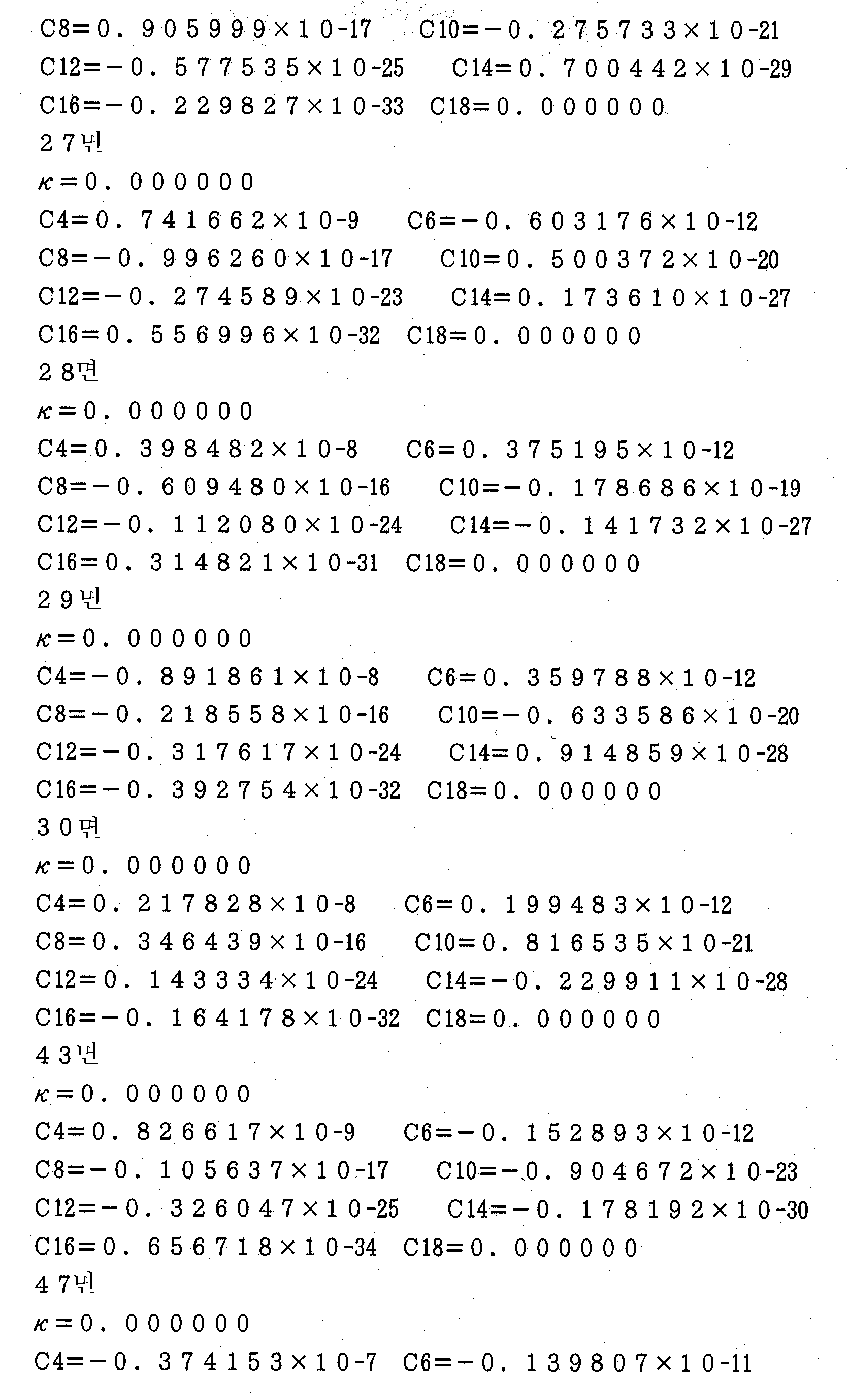
또한, 각 실시예에 있어서, 비구면은 광축에 수직한 방향의 높이를 y 로 하고, 비구면의 정상점에서의 접평면 (接平面) 으로부터 높이 (y) 에서의 비구면 상의 위치까지의 광축을 따른 거리 (새그량) 를 z 로 하고, 정상점 곡률 반경 (기준 곡률 반경) 을 r 로 하고, 원추 계수를 κ 로 하며, n 차의 비구면 계수를 Cn 으로 한 경우, 다음과 같은 수학식 (a) 로 표시된다. 또, 각 실시예에 있어서, 비구면 형상으로 형성된 렌즈면에는 면 번호의 우측에 * 표시를 한다.In each of the embodiments, the aspheric surface has a height in the direction perpendicular to the optical axis, and a distance along the optical axis from the tangential plane (tangential plane) at the normal point of the aspheric surface to the position on the aspheric surface at the height (y) When the cone coefficient is represented by k and the n-th order aspherical surface coefficient is represented by Cn, the following equation (a) is obtained. do. In each of the embodiments, the lens surface formed as an aspherical shape is marked with an asterisk on the right of the surface number.
[수학식 (a)][Mathematical expression (a)]

[제 1 실시예][First Embodiment]
도 2 는 제 1 실시예에 관한 투영광학계의 렌즈 구성을 나타내는 도면이다. 도 2 의 투영광학계에 있어서, 제 1 렌즈군 (G1) 은 마스크측으로부터 순서대로 평행평면판 (P1), 마스크측으로 오목면을 향한 양의 메니스커스 렌즈 (L11), 마스크측으로 오목면을 향한 양의 메니스커스 렌즈 (L12), 양면 볼록렌즈 (L13), 양면 볼록렌즈 (L14), 양면 오목렌즈 (L15), 양면 오목렌즈 (L16), 양면 오목렌즈 (L17), 마스크측의 면이 비구면 형상으로 형성된 양면 오목렌즈 (L18), 마스크측으로 오목면을 향한 음의 메니스커스 렌즈 (L19), 마스크측으로 비구면 형상으로 형성된 오목면을 향한 양의 메니스커스 렌즈 (L110), 마스크측으로 오목면을 향한 양의 메니스커스 렌즈 (L111), 마스크측으로 오목면을 향한 양의 메니스커스 렌즈 (L112), 마스크측으로 볼록면을 향한 양의 메니스커스 렌즈 (L113), 마스크측으로 볼록면을 향한 양의 메니스커스 렌즈 (L114) 및 마스크측으로 볼록면을 향한 양의 메니스커스 렌즈 (L115) 로 구성되어 있다.2 is a diagram showing the lens configuration of the projection optical system according to the first embodiment. In the projection optical system of Fig. 2, the first lens group G1 includes, in order from the mask side, a parallel flat plate P1, a positive meniscus lens L11 facing the concave surface toward the mask side, The positive meniscus lens L12, the double-convex convex lens L13, the double-convex convex lens L14, the double-side concave lens L15, the double-side concave lens L16, the double-side concave lens L17, A double-side concave lens L18 formed in an aspherical shape, a negative meniscus lens L19 facing the concave surface toward the mask side, a positive meniscus lens L110 facing the concave surface formed in an aspheric shape on the mask side, A positive meniscus lens L112 facing the concave surface toward the mask side, a positive meniscus lens L113 facing the convex surface toward the mask side, and a positive meniscus lens L111 facing the mask side. The positive meniscus lens L114 and the positive meniscus lens L114 for the Amount of methoxy varnish toward the convex surface side is composed of coarse lens (L115).
또, 제 2 렌즈군 (G2) 은 마스크측으로부터 순서대로, 웨이퍼측으로 비구면 형상으로 형성된 오목면을 향한 음의 메니스커스 렌즈 (L21), 마스크측의 면 및 웨이퍼측의 면이 모두 비구면 형상으로 형성된 양면 오목렌즈 (L22), 마스크측의 면이 비구면 형상으로 형성된 양면 오목렌즈 (L23) 및 웨이퍼측으로 비구면 형상으로 형성된 볼록면을 향한 음의 메니스커스 렌즈 (L24) 로 구성되어 있다.The second lens group G2 includes, in order from the mask side, a negative meniscus lens L21 facing the concave surface formed as an aspheric surface on the wafer side, a mask side surface and a wafer side surface all having an aspherical shape A double-side concave lens L22 formed on the mask side, a double-side concave lens L23 formed on the mask side in an aspherical shape, and a negative meniscus lens L24 facing the convex surface formed aspheric on the wafer side.
또한, 제 3 렌즈군 (G3) 은 마스크측으로부터 순서대로, 마스크측으로 오목면을 향한 양의 메니스커스 렌즈 (L31), 마스크측으로 오목면을 향한 양의 메니스커스 렌즈 (L32), 마스크측의 면이 비구면 형상으로 형성된 양면 볼록렌즈 (L33), 양면 볼록렌즈 (34), 마스크측으로 오목면을 향한 음의 메니스커스 렌즈 (L35), 마스크측으로 볼록면을 향한 양의 메니스커스 렌즈 (L36), 마스크측으로 볼록면을 향한 양의 메니스커스 렌즈 (L37) 및 마스크측으로 볼록면을 향한 양의 메니스커스 렌즈 (L38) 로 구성되어 있다.The third lens group G3 includes, in order from the mask side, a positive meniscus lens L31 facing the concave surface toward the mask side, a positive meniscus lens L32 facing the concave surface toward the mask side, Side convex lens 34, a negative meniscus lens L35 facing the concave surface toward the mask side, and a positive meniscus lens L34 facing the convex surface toward the mask side L36, a positive meniscus lens L37 facing the convex surface toward the mask side, and a positive meniscus lens L38 facing the convex surface toward the mask side.
그리고, 제 4 렌즈군 (G4) 은 마스크측으로부터 순서대로, 마스크측으로 볼록면을 향한 양의 메니스커스 렌즈 (L41), 마스크측으로 볼록면을 향한 음의 메니스커스 렌즈 (L42), 마스크측으로 볼록면을 향한 양의 메니스커스 렌즈 (L43) 로 구성되어 있다. 제 1 실시예에서는 공급부 (10) 가 물 (중심파장 248.40 ㎚ 에 대하여 1.38 의 굴절률을 갖는다) 을 공급하도록 구성되고, 투영광학계 (6) 과 웨이퍼 (7) 와의 사이의 좁은 광로를 충전 (充塡) 하도록 물의 흐름이 형성된다. 즉, 제 1 실시예의 투영광학계는 수침계 (水浸系) 의 광학계를 구성하고 있다.The fourth lens group G4 includes, in order from the mask side, a positive meniscus lens L41 with a convex surface facing the mask side, a negative meniscus lens L42 with a convex surface facing the mask side, And a positive meniscus lens L43 facing the convex surface. In the first embodiment, the
다음 표 1 에, 제 1 실시예에 관한 투영광학계의 제원 (諸元) 의 값을 게재한다. 표 1 의 주요 제원에 있어서, λ는 노광광의 중심파장을, β는 투영배율을, Ym 은 최대 이미지 높이를, NA 는 이미지측 개구수를, D 는 작동거리를 각각 나타내고 있다. 또한, 표 1 은 웨이퍼측으로부터 순서대로 광학부재 제원를 나타내고, 제 1 칼럼의 면 번호는 웨이퍼측으로부터의 면 순서를, 제 2 칼럼의 r 은 각 면의 곡률 반경 (비구면의 경우에는 정상점 곡률 반경 : ㎜) 을, 제 3 칼럼의 d 는 각 면의 축상 간격, 즉, 면 간격 (㎜) 을, 제 4 칼럼의 n 은 중심파장 (λ) 에 대한 굴절률을 각각 나타내고 있다. 또, 곡률 반경 (r) 은 웨이퍼측을 향한 볼록면의 곡률 반경을 양으로 하고, 웨이퍼측을 향한 오목면의 곡률 반경을 음으로 한다.Table 1 shows the values of the specifications of the projection optical system according to the first embodiment. In the main specifications of Table 1,? Represents the central wavelength of the exposure light,? Represents the projection magnification, Ym represents the maximum image height, NA represents the image side numerical aperture, and D represents the working distance. Table 1 shows the order of the optical members in order from the wafer side, the surface numbers of the first columns are the order of the wafer from the wafer side, the r in the second column is the radius of curvature of each surface (in the case of an aspheric surface, (Mm) in the fourth column, and n is the refractive index with respect to the central wavelength (?), Respectively. The radius of curvature r is positive in the radius of curvature of the convex surface facing the wafer side and negative in the radius of curvature of the concave surface facing the wafer side.


도 3 은 제 1 실시예에 관한 투영광학계의 코마 수차를 나타내는 도면이다. 수차는 레티클측의 스케일로 표시되어 있다. 수차 도면에서 알 수 있듯이, 제 1 실시예에서는 0.89 로 매우 높은 이미지측 개구수를 실현하고 있음에도 불구하고 수차가 양호하게 보정되어 있음을 알 수 있다.3 is a diagram showing a coma aberration of the projection optical system according to the first embodiment. The aberration is indicated by the scale on the reticle side. As can be seen from the aberration diagram, it can be seen that the aberration is corrected well, although the image-side numerical aperture is very high at 0.89 in the first embodiment.
[제 2 실시예][Second Embodiment]
도 4 는 제 2 실시예에 관한 투영광학계의 렌즈 구성을 나타내는 도면이다. 도 4 의 투영광학계에 있어서, 제 1 렌즈군 (G1) 은 마스크측으로부터 순서대로, 평행평면판 (P1), 양면 볼록렌즈 (L11), 양면 볼록렌즈 (L12), 양면 볼록렌즈 (L13), 양면 볼록렌즈 (L14), 마스크측으로 볼록면을 향한 음의 메니스커스 렌즈 (L15), 양면 오목렌즈 (L16), 양면 오목렌즈 (L17), 양면 오목렌즈 (L18), 마스크측으로 오목면을 향한 음의 메니스커스 렌즈 (L19), 마스크측으로 오목면을 향한 양의 메니스커스 렌즈 (L110), 마스크측으로 오목면을 향한 양의 메니스커스 렌즈 (L111), 양면 볼록렌즈 (L112), 양면 볼록렌즈 (L113), 마스크측으로 볼록면을 향한 양의 메니스커스 렌즈 (L114) 및 마스크측으로 볼록면을 향한 양의 메니스커스 렌즈 (L115) 로 구성되어 있다.4 is a diagram showing the lens configuration of the projection optical system according to the second embodiment. 4, the first lens group G1 includes, in order from the mask side, a parallel flat plate P1, a double-side convex lens L11, a double-side convex lens L12, a double-side convex lens L13, A negative meniscus lens L15 with a convex surface facing the mask side, a double-side concave lens L16, a double-side concave lens L17, a double-side concave lens L18, A positive meniscus lens L19 directed toward the mask side, a positive meniscus lens L111 directed toward the concave surface toward the mask side, a double-side convex lens L112, A convex lens L113, a positive meniscus lens L114 facing the convex surface toward the mask side, and a positive meniscus lens L115 facing the convex surface toward the mask side.
또, 제 2 렌즈군 (G2) 은 마스크측으로부터 순서대로, 마스크측으로 볼록면을 향한 음의 메니스커스 렌즈 (L21), 웨이퍼측으로 비구면 형상으로 형성된 오목면을 향한 음의 메니스커스 렌즈 (L22), 마스크측의 면이 비구면 형상으로 형성된 양면 오목렌즈 (L23) 및 웨이퍼측으로 비구면 형상으로 형성된 볼록면을 향한 음의 메니스커스 렌즈 (L24) 로 구성되어 있다.The second lens group G2 includes, in order from the mask side, a negative meniscus lens L21 with a convex surface facing the mask side, a negative meniscus lens L22 with a concave surface facing the wafer side, A double-sided concave lens L23 having a mask-side surface formed in an aspherical shape, and a negative meniscus lens L24 facing the convex surface formed in an aspheric shape on the wafer side.
또한, 제 3 렌즈군 (G3) 은 마스크측으로부터 순서대로, 마스크측으로 오목면을 향한 양의 메니스커스 렌즈 (L31), 양면 볼록렌즈 (L32), 양면 볼록렌즈 (L33), 양면 볼록렌즈 (L34), 마스크측으로 비구면 형상으로 형성된 오목면을 향한 음의 메니스커스 렌즈 (L35), 마스크측으로 볼록면을 향한 양의 메니스커스 렌즈 (L36), 마스크측으로 볼록면을 향한 양의 메니스커스 렌즈 (L37) 및 마스크측으로 볼록면을 향한 양의 메니스커스 렌즈 (L38) 로 구성되어 있다.The third lens group G3 includes, in order from the mask side, a positive meniscus lens L31, a double-side convex lens L32, a double-side convex lens L33, and a double-side convex lens L31 A negative meniscus lens L35 facing the concave surface formed as an aspheric surface on the mask side, a positive meniscus lens L36 facing the convex surface toward the mask side, a positive meniscus lens L36 facing the convex surface toward the mask side, A lens L37 and a positive meniscus lens L38 whose convex surface faces the mask side.
그리고, 제 4 렌즈군 (G4) 은 마스크측으로부터 순서대로, 마스크측으로 볼록면을 향한 양의 메니스커스 렌즈 (L41), 마스크측으로 볼록면을 향한 음의 메니스커스 렌즈 (L42), 마스크측으로 볼록면을 향한 양의 메니스커스 렌즈 (L43) 로 구성되어 있다. 제 2 실시예에서는 공급부 (10) 가 공기를 공급하도록 구성되어, 투영광학계 (6) 와 웨이퍼 (7) 와의 사이의 좁은 광로에 있어서 공기의 흐름이 형성된다. 또, 공기의 굴절률은 1.0 이고, 표 (1) 및 표 (2) 에서 그 표시를 생략하고 있다.The fourth lens group G4 includes, in order from the mask side, a positive meniscus lens L41 with a convex surface facing the mask side, a negative meniscus lens L42 with a convex surface facing the mask side, And a positive meniscus lens L43 facing the convex surface. In the second embodiment, the
다음 표 (2) 에 제 2 실시예에 관한 투영광학계의 제원의 값을 게재한다. 표 (2) 의 주요 제원에 있어서, λ는 노광광의 중심파장을, β는 투영배율을, Ym 은 최대 이미지 높이를, NA 는 이미지측 개구수를, D 는 작동거리를 각각 나타내고 있다. 또한, 표 (2) 의 광학부재 제원에서 제 1 칼럼의 면 번호는 웨이퍼측으로부터의 면 순서를, 제 2 칼럼의 r 은 각 면의 곡률 반경 (비구면의 경우에는 정상점 곡률 반경 : ㎜) 을, 제 3 칼럼의 d 는 각 면의 축상 간격, 즉 면 간격 (㎜) 을, 제 4 칼럼의 n 은 중심파장 (λ) 에 대한 굴절률을 각각 나타내고 있다. 또, 곡률 반경 (r) 은 웨이퍼측을 향하여 볼록면의 곡률 반경을 양으로 하고, 웨이퍼측을 향하여 오목면의 곡률 반경을 음으로 한다.The value of the specification of the projection optical system according to the second embodiment is placed in the following table (2). In the main specifications of Table 2,? Represents the center wavelength of the exposure light,? Represents the projection magnification, Ym represents the maximum image height, NA represents the image side numerical aperture, and D represents the working distance. In the specification of the optical member in Table 2, the surface number of the first column is the order of the surface from the wafer side, and r of the second column is the radius of curvature of each surface (in the case of an aspheric surface, normal point radius of curvature: mm) D in the third column is an axial interval of each surface, that is, a surface interval (mm), and n in the fourth column is a refractive index with respect to the central wavelength (?). In addition, the radius of curvature r is positive toward the wafer side, and the radius of curvature of the concave surface toward the wafer side is negative.


도 5 는 제 2 실시예에 관한 투영광학계의 코마 수차를 나타내는 도면이다. 수차는 레티클측의 스케일로 표시되어 있다. 수차 도면에서 알 수 있듯이 제 2 실시예에서도 0.88 로 매우 높은 이미지측 개구수를 실현하고 있음에도 불구하고 수차가 양호하게 보정되어 있음을 알 수 있다.5 is a diagram showing a coma aberration of the projection optical system according to the second embodiment. The aberration is indicated by the scale on the reticle side. As can be seen from the aberration diagram, the aberration is corrected well in spite of the fact that the second embodiment also achieves a very high image side numerical aperture of 0.88.
[제 3 실시예][Third Embodiment]
도 6 은 제 3 실시예에 관한 투영광학계의 렌즈 구성을 나타내는 도면이다. 도 6 의 투영광학계에 있어서, 제 1 렌즈군 (G1) 은 마스크측으로부터 순서대로, 양면 오목렌즈 (L11), 양면 볼록렌즈 (L12), 양면 볼록렌즈 (L13), 마스크측으로 볼록면을 향한 양의 메니스커스 렌즈 (L14), 마스크측으로 볼록면을 향한 음의 메 니스커스 렌즈 (L15), 양면 오목렌즈 (L16), 양면 오목렌즈 (L17), 마스크측으로 오목면을 향한 양의 메니스커스 렌즈 (L18), 양면 볼록렌즈 (L19), 양면 볼록렌즈 (L20), 마스크측으로 볼록면을 향한 양의 메니스커스 렌즈 (L21) 및 마스크측으로 볼록면을 향한 양의 메니스커스 렌즈 (L22) 로 구성되어 있다.6 is a diagram showing the lens configuration of the projection optical system according to the third embodiment. In the projection optical system of Fig. 6, the first lens group G1 is composed of a double-side concave lens L11, a double-side convex lens L12, a double-side convex lens L13, A negative meniscus lens L15 with a convex surface facing the mask side, a double-side concave lens L16, a double-side concave lens L17, and a positive meniscus lens L17 facing the concave surface toward the mask side. A positive meniscus lens L21 having a convex surface directed toward the mask side and a positive meniscus lens L22 having a convex surface directed toward the mask side are provided on the lens L18, the double-convex lens L19, the double-convex lens L20, .
또, 제 2 렌즈군 (G2) 은 마스크측으로부터 순서대로, 마스크측으로 볼록면을 향한 음의 메니스커스 렌즈 (L23), 마스크측으로 볼록면을 향한 음의 메니스커스 렌즈 (L24), 양면 오목렌즈 (L25) 및 마스크측으로 오목면을 향한 음의 메니스커스 렌즈 (L26) 로 구성되어 있다.The second lens group G2 includes, in order from the mask side, a negative meniscus lens L23 with a convex surface facing the mask side, a negative meniscus lens L24 with a convex surface facing the mask side, A lens L25 and a negative meniscus lens L26 with the concave surface facing the mask side.
또한, 제 3 렌즈군 (G3) 은 마스크측으로부터 순서대로, 마스크측으로 오목면을 향한 양의 메니스커스 렌즈 (L27), 양면 볼록렌즈 (L28), 양면 볼록렌즈 (L29), 마스크측으로 볼록면을 향한 음의 메니스커스 렌즈 (L30), 양면 볼록렌즈 (L31) 및 마스크측으로 볼록면을 향한 양의 메니스커스 렌즈 (L32) 로 구성되어 있다.The third lens group G3 includes, in order from the mask side, a positive meniscus lens L27, a double-side convex lens L28, a double-side convex lens L29, and a positive meniscus lens L27 facing the concave surface toward the mask side, A positive meniscus lens L30 directed toward the positive meniscus lens L31, and a positive meniscus lens L32 directed toward the mask side toward the mask.
그리고, 제 4 렌즈군 (G4) 은 마스크측으로부터 순서대로, 마스크측으로 볼록면을 향한 양의 메니스커스 렌즈 (L33), 마스크측으로 볼록면을 향한 양의 메니스커스 렌즈 (L34), 마스크측으로 볼록면을 향한 양의 메니스커스 렌즈 (L35) 및 평행평면판 (P1) 으로 구성되어 있다.The fourth lens group G4 includes, in order from the mask side, a positive meniscus lens L33 facing the convex surface toward the mask side, a positive meniscus lens L34 facing the convex surface toward the mask side, A positive meniscus lens L35 facing the convex surface, and a parallel flat plate P1.
다음 표 (3) 에 제 3 실시예에 관한 투영광학계의 제원의 값을 게재한다. 표 (3) 의 주요 제원에 있어서, λ는 노광광의 중심파장을, β는 투영배율을, Ym 은 최대 이미지 높이를, NA 는 이미지측 개구수를, D 는 작동거리를 각각 나타내고 있다. 또한, 표 (3) 의 광학부재 제원에서 제 1 칼럼의 면 번호는 웨이퍼측으로부터의 면 순서를, 제 2 칼럼의 r 은 각 면의 곡률 반경 (비구면의 경우에는 정상점 곡률 반경 : ㎜) 을, 제 3 칼럼의 d 는 각 면의 축상 간격, 즉, 면 간격 (㎜) 을, 제 4 칼럼의 n 은 중심파장에 대한 굴절률을 각각 나타내고 있다. 또, 곡률 반경 (r) 은 웨이퍼측을 향한 볼록면의 곡률 반경을 양으로 하고, 웨이퍼측을 향한 오목면의 곡률 반경을 음으로 한다.The value of the specification of the projection optical system according to the third embodiment is placed in the following table (3). In the main specifications of Table 3,? Represents the central wavelength of the exposure light,? Represents the projection magnification, Ym represents the maximum image height, NA represents the image side numerical aperture, and D represents the working distance. In the specifications of the optical member in Table 3, the surface number of the first column is the surface order from the wafer side, and r in the second column is the radius of curvature of each surface (in the case of an aspheric surface, normal point radius of curvature: mm) D in the third column is the axial distance between the respective surfaces, that is, the surface interval (mm), and n in the fourth column is the refractive index with respect to the central wavelength. The radius of curvature r is positive in the radius of curvature of the convex surface facing the wafer side and negative in the radius of curvature of the concave surface facing the wafer side.


도 7 은 제 3 실시예에 관한 투영광학계의 코마 수차를 나타내는 도면이다. 수차는 레티클측의 스케일로 표시되어 있다. 수차 도면에서 알 수 있듯이 제 3 실시예에서도 0.85 라는 높은 이미지측 개구수를 실현하고 있음에도 불구하고 수차가 양호하게 보정되어 있음을 알 수 있다.7 is a diagram showing a coma aberration of the projection optical system according to the third embodiment. The aberration is indicated by the scale on the reticle side. As can be seen from the aberration diagram, it can be seen that even in the third embodiment, a high image side numerical aperture of 0.85 is realized, the aberration is well corrected.
이상과 같이, 상술한 각 실시예에 관한 투영광학계에서는 렌즈 외경의 대형화를 억제하면서 매우 높은 이미지측 개구수를 확보할 수 있다. 따라서, 실시예 1, 2 의 실시형태에 관한 노광장치에서는, KrF 엑시머레이저광에 의거하여, 고해상의 투영광학계를 사용하여 고정밀도의 투영노광을 실시할 수 있다. 또, 실시예 3 의 실시형태에 관한 노광장치에서는, ArF 엑시머레이저광에 의거하여, 고해상의 투영광학계를 사용하여 고정밀도의 투영노광을 실행할 수 있다.As described above, in the projection optical system according to each of the embodiments described above, it is possible to secure a very high image-side numerical aperture while suppressing enlargement of the outer diameter of the lens. Therefore, in the exposure apparatus according to the
상술한 실시형태에 관한 노광장치에서는, 조명광학계를 통해 마스크 (레티클) 를 조명하고 (조명공정), 투영광학계를 사용하여 마스크에 형성된 전사용 패턴을 감광성 기판에 노광 (노광공정) 함으로써, 마이크로 디바이스 (반도체소자, 촬상소자, 액정표시소자, 박막자기헤드 등) 를 제조할 수 있다. 이하, 상술한 실 시형태의 노광장치를 사용하여 감광성 기판으로서의 웨이퍼 등에 소정의 회로패턴을 형성함으로써 마이크로 디바이스로서의 반도체 디바이스를 얻을 때의 수법의 일례에 대하여 도 8 의 흐름도를 참조하여 설명한다.In the exposure apparatus according to the above-described embodiment, the mask (reticle) is illuminated through the illumination optical system (illumination step), and the transfer pattern formed on the mask is exposed to light using the projection optical system (exposure step) (Semiconductor element, imaging element, liquid crystal display element, thin film magnetic head, etc.). Hereinafter, an example of a method for obtaining a semiconductor device as a microdevice by forming a predetermined circuit pattern on a wafer or the like as a photosensitive substrate using the above-described actual-type exposure apparatus will be described with reference to the flowchart of FIG.
먼저, 도 8 의 단계 301 에서, 1 로트의 웨이퍼 상에 금속막이 증착된다. 다음 단계 302 에서, 1 로트의 웨이퍼 상의 금속막 상에 포토레지스트가 도포된다. 그 후, 단계 303 에서, 상술한 실시형태의 노광장치를 사용하여, 마스크상의 패턴의 이미지가 투영광학계를 통해 1 로트의 웨이퍼 상의 각 쇼트영역에 순차적으로 노광 전사된다. 그 후, 단계 304 에서, 1 로트의 웨이퍼 상의 포토레지스트의 현상이 실행된 후, 단계 305 에서, 1 로트의 웨이퍼 상에서 레지스트패턴을 마스크로 하여 에칭함으로써, 마스크상의 패턴에 대응하는 회로패턴이 각 웨이퍼 상의 각 쇼트영역에 형성된다. 그 후, 추가로 위의 레이어의 회로패턴을 형성함으로써 반도체소자 등의 디바이스가 제조된다. 상술한 반도체 디바이스 제조방법에 따르면, 매우 미세한 회로패턴을 갖는 스루풋이 양호한 반도체 디바이스를 얻을 수 있다.First, in step 301 of FIG. 8, a metal film is deposited on one lot of wafers. In the next step 302, photoresist is applied on the metal film on one lot of wafers. Then, in step 303, using the exposure apparatus of the above-described embodiment, the image of the pattern on the mask is successively exposed and transferred to each shot area on one lot of wafers through the projection optical system. Thereafter, in step 304, the development of the photoresist on the wafer of one lot is performed, and in step 305, etching is performed on the wafer of one lot with the resist pattern as a mask, whereby a circuit pattern corresponding to the pattern on the mask is formed on each wafer Is formed in each of the shot areas. Thereafter, a device such as a semiconductor device is manufactured by further forming a circuit pattern of the upper layer. According to the above-described semiconductor device manufacturing method, a semiconductor device having a very fine circuit pattern and good throughput can be obtained.
또, 상술한 실시형태의 노광장치에서는, 플레이트 (글래스 기판) 상에 소정의 패턴 (회로 패턴, 전극 패턴 등) 을 형성함으로써, 마이크로 디바이스로서의 액정표시소자를 얻을 수도 있다. 이하, 도 9 의 흐름도를 참조하여, 이 때의 수법의 일례에 대하여 설명한다. 도 9 에서, 패턴형성공정 401 에서는, 각 실시형태의 노광장치를 사용하여 마스크의 패턴을 감광성 기판 (레지스트가 도포된 유리기판 등) 에 전사 노광하는, 소위 광리소그래피 공정이 실행된다. 이 광리소 그래피 공정에 의해 감광성 기판 상에는 다수의 전극 등을 포함하는 소정 패턴이 형성된다. 그 후, 노광된 기판은 현상공정, 에칭공정, 레지스트 박리공정 등과 같은 각 공정을 거침으로써 기판 상에 소정 패턴이 형성되고, 다음 컬러 필터 형성공정 402 로 이행된다.In the exposure apparatus of the above-described embodiment, a liquid crystal display device as a microdevice can be obtained by forming a predetermined pattern (circuit pattern, electrode pattern, etc.) on a plate (glass substrate). Hereinafter, an example of the method at this time will be described with reference to the flowchart of Fig. 9, in the pattern formation step 401, a so-called photolithography process is performed in which the pattern of the mask is transferred and exposed to a photosensitive substrate (e.g., a glass substrate coated with a resist) using the exposure apparatus of each embodiment. A predetermined pattern including a plurality of electrodes and the like is formed on the photosensitive substrate by the photolithography process. Thereafter, the exposed substrate is subjected to various steps such as a development step, an etching step, a resist stripping step, and the like to form a predetermined pattern on the substrate, and the process proceeds to the next color filter formation step 402.
이어서, 컬러 필터 형성공정 402 에서는, R (Red), G (Green), B (Blue) 에 대응한 3 개의 도트 세트가 매트릭스 형상으로 다수 배열되거나, 또는 R, G, B 의 3 개의 스트라이프 필터 세트를 복수개 수평주사선 방향으로 배열한 컬러 필터를 형성한다. 그리고, 컬러 필터 형성공정 402 이후에, 셀 조립공정 403 이 실행된다. 셀 조립공정 403 에서는, 패턴형성공정 401 에서 얻은 소정 패턴을 갖는 기판 및 컬러 필터 형성공정 402 에서 얻은 컬러 필터 등을 사용하여 액정 패널 (액정 셀) 을 조립한다. 셀 조립공정 403 에서는, 예컨대 패턴형성공정 401 에서 얻은 소정 패턴을 갖는 기판과 컬러 필터 형성공정 402 에서 얻은 컬러 필터와의 사이에 액정을 주입하여 액정 패널 (액정 셀) 을 제조한다.Subsequently, in the color filter forming step 402, a plurality of three dot sets corresponding to R (Red), G (Green) and B (Blue) are arrayed in a matrix form, or three stripe filter sets R, Are arranged in the horizontal scanning line direction. After the color filter forming step 402, the cell assembling step 403 is executed. In the cell assembling step 403, the liquid crystal panel (liquid crystal cell) is assembled by using the substrate having the predetermined pattern obtained in the pattern forming step 401 and the color filter obtained in the color filter forming step 402. In the cell assembling step 403, for example, liquid crystal is injected between a substrate having a predetermined pattern obtained in the pattern forming step 401 and a color filter obtained in the color filter forming step 402 to produce a liquid crystal panel (liquid crystal cell).
그 후, 모듈조립공정 404 에서, 조립된 액정 패널 (액정 셀) 의 표시동작을 실행하게 하는 전기회로, 백라이트 등의 각 부품을 장착하여 액정표시소자로서 완성시킨다. 상술한 액정표시소자의 제조방법에 따르면, 매우 미세한 회로패턴을 갖는 스루풋이 양호한 액정표시소자를 얻을 수 있다.Thereafter, in the module assembling step 404, each component such as an electric circuit for performing a display operation of the assembled liquid crystal panel (liquid crystal cell), a backlight and the like are mounted to complete the liquid crystal display device. According to the method for manufacturing a liquid crystal display element described above, a liquid crystal display element having a very fine circuit pattern and good throughput can be obtained.
그리고, 상술한 실시형태에서는, 광원으로서 KrF 엑시머레이저 광원을 사용하고 있는데, 이것에 한정되지 않고, 예컨대 ArF 엑시머레이저 광원 (파장 193 ㎚) 을 포함하는 다른 적당한 광원을 사용할 수도 있다. In the above-described embodiment, a KrF excimer laser light source is used as the light source. However, the present invention is not limited thereto. For example, another suitable light source including an ArF excimer laser light source (wavelength: 193 nm) may be used.
또, 상술한 실시형태에서는, 노광장치에 탑재되는 투영광학계를 예로 들어 본 발명을 설명했지만, 제 1 물체의 이미지를 제 2 물체 상에 형성하기 위한 일반적인 투영광학계에 본 발명을 적용할 수 있는 것은 명확하다.Although the present invention has been described with reference to a projection optical system mounted on an exposure apparatus in the above-described embodiment, the present invention can be applied to a general projection optical system for forming an image of a first object on a second object It is clear.
이상 설명한 바와 같이, 본 발명에서는, 렌즈 외경의 대형화를 억제하면서 매우 높은 이미지측 개구수를 확보할 수 있는, 고해상의 투영광학계를 실현할 수 있다. 따라서, 높은 이미지측 개구수를 갖는 고해상의 투영광학계를 구비한 본 발명의 노광장치를 사용하여, 고정밀도로 양호한 마이크로 디바이스를 제조할 수 있다.As described above, in the present invention, it is possible to realize a high-resolution projection optical system capable of securing a very high image-side numerical aperture while suppressing enlargement of the lens outer diameter. Therefore, by using the exposure apparatus of the present invention having a high-resolution projection optical system having a high image-side numerical aperture, it is possible to manufacture a good micro device with high precision.
Claims (13)
Applications Claiming Priority (2)
| Application Number | Priority Date | Filing Date | Title |
|---|---|---|---|
| JPJP-P-2000-00375992 | 2000-12-11 | ||
| JP2000375992 | 2000-12-11 |
Publications (2)
| Publication Number | Publication Date |
|---|---|
| KR20020046155A KR20020046155A (en) | 2002-06-20 |
| KR100866818B1 true KR100866818B1 (en) | 2008-11-04 |
Family
ID=18844916
Family Applications (1)
| Application Number | Title | Priority Date | Filing Date |
|---|---|---|---|
| KR1020010075318A KR100866818B1 (en) | 2000-12-11 | 2001-11-30 | Projection optical system and exposure apparatus comprising the same |
Country Status (3)
| Country | Link |
|---|---|
| US (3) | US6633365B2 (en) |
| KR (1) | KR100866818B1 (en) |
| TW (1) | TW512237B (en) |
Families Citing this family (180)
| Publication number | Priority date | Publication date | Assignee | Title |
|---|---|---|---|---|
| DE10064685A1 (en) * | 2000-12-22 | 2002-07-04 | Zeiss Carl | Lithography lens with a first lens group consisting exclusively of lenses with positive refractive power |
| DE10210899A1 (en) * | 2002-03-08 | 2003-09-18 | Zeiss Carl Smt Ag | Refractive projection lens for immersion lithography |
| US7362508B2 (en) * | 2002-08-23 | 2008-04-22 | Nikon Corporation | Projection optical system and method for photolithography and exposure apparatus and method using same |
| SG121822A1 (en) * | 2002-11-12 | 2006-05-26 | Asml Netherlands Bv | Lithographic apparatus and device manufacturing method |
| CN101382738B (en) | 2002-11-12 | 2011-01-12 | Asml荷兰有限公司 | Lithographic projection apparatus |
| US7110081B2 (en) | 2002-11-12 | 2006-09-19 | Asml Netherlands B.V. | Lithographic apparatus and device manufacturing method |
| US9482966B2 (en) | 2002-11-12 | 2016-11-01 | Asml Netherlands B.V. | Lithographic apparatus and device manufacturing method |
| KR100588124B1 (en) | 2002-11-12 | 2006-06-09 | 에이에스엠엘 네델란즈 비.브이. | Lithographic Apparatus and Device Manufacturing Method |
| US7372541B2 (en) * | 2002-11-12 | 2008-05-13 | Asml Netherlands B.V. | Lithographic apparatus and device manufacturing method |
| DE60335595D1 (en) | 2002-11-12 | 2011-02-17 | Asml Netherlands Bv | Immersion lithographic apparatus and method of making a device |
| CN100470367C (en) | 2002-11-12 | 2009-03-18 | Asml荷兰有限公司 | Lithographic apparatus and device manufacturing method |
| US10503084B2 (en) | 2002-11-12 | 2019-12-10 | Asml Netherlands B.V. | Lithographic apparatus and device manufacturing method |
| SG131766A1 (en) * | 2002-11-18 | 2007-05-28 | Asml Netherlands Bv | Lithographic apparatus and device manufacturing method |
| SG121829A1 (en) * | 2002-11-29 | 2006-05-26 | Asml Netherlands Bv | Lithographic apparatus and device manufacturing method |
| US7242455B2 (en) | 2002-12-10 | 2007-07-10 | Nikon Corporation | Exposure apparatus and method for producing device |
| SG2011031200A (en) * | 2002-12-10 | 2014-09-26 | Nippon Kogaku Kk | Exposure apparatus and device manufacturing method |
| EP1571698A4 (en) * | 2002-12-10 | 2006-06-21 | Nikon Corp | Exposure apparatus, exposure method and method for manufacturing device |
| SG150388A1 (en) * | 2002-12-10 | 2009-03-30 | Nikon Corp | Exposure apparatus and method for producing device |
| JP4352874B2 (en) * | 2002-12-10 | 2009-10-28 | 株式会社ニコン | Exposure apparatus and device manufacturing method |
| AU2003289007A1 (en) * | 2002-12-10 | 2004-06-30 | Nikon Corporation | Optical device and projection exposure apparatus using such optical device |
| US7948604B2 (en) * | 2002-12-10 | 2011-05-24 | Nikon Corporation | Exposure apparatus and method for producing device |
| WO2004053952A1 (en) * | 2002-12-10 | 2004-06-24 | Nikon Corporation | Exposure apparatus and method for manufacturing device |
| DE10261775A1 (en) * | 2002-12-20 | 2004-07-01 | Carl Zeiss Smt Ag | Device for the optical measurement of an imaging system |
| TWI621923B (en) * | 2003-02-26 | 2018-04-21 | Nikon Corp | Exposure apparatus, exposure method, and component manufacturing method |
| KR20050110004A (en) * | 2003-03-17 | 2005-11-22 | 가부시키가이샤 니콘 | Projection optical system, exposure system, and exposure method |
| EP1610361B1 (en) | 2003-03-25 | 2014-05-21 | Nikon Corporation | Exposure system and device production method |
| KR101176817B1 (en) * | 2003-04-07 | 2012-08-24 | 가부시키가이샤 니콘 | Exposure apparatus and method for manufacturing device |
| JP4488004B2 (en) * | 2003-04-09 | 2010-06-23 | 株式会社ニコン | Immersion lithography fluid control system |
| KR101886027B1 (en) | 2003-04-10 | 2018-09-06 | 가부시키가이샤 니콘 | Environmental system including vaccum scavange for an immersion lithography apparatus |
| JP4656057B2 (en) * | 2003-04-10 | 2011-03-23 | 株式会社ニコン | Electro-osmotic element for immersion lithography equipment |
| EP3352010A1 (en) * | 2003-04-10 | 2018-07-25 | Nikon Corporation | Run-off path to collect liquid for an immersion lithography apparatus |
| KR101238142B1 (en) * | 2003-04-10 | 2013-02-28 | 가부시키가이샤 니콘 | Environmental system including a transport region for an immersion lithography apparatus |
| JP4837556B2 (en) * | 2003-04-11 | 2011-12-14 | 株式会社ニコン | Optical element cleaning method in immersion lithography |
| WO2004092830A2 (en) * | 2003-04-11 | 2004-10-28 | Nikon Corporation | Liquid jet and recovery system for immersion lithography |
| KR101697896B1 (en) | 2003-04-11 | 2017-01-18 | 가부시키가이샤 니콘 | Apparatus and method for maintaining immersion fluid in the gap under the projection lens during wafer exchange in an immersion lithography machine |
| WO2004095135A2 (en) * | 2003-04-17 | 2004-11-04 | Nikon Corporation | Optical arrangement of autofocus elements for use with immersion lithography |
| SG10201405231YA (en) | 2003-05-06 | 2014-09-26 | Nippon Kogaku Kk | Projection optical system, exposure apparatus, and exposure method |
| US7348575B2 (en) * | 2003-05-06 | 2008-03-25 | Nikon Corporation | Projection optical system, exposure apparatus, and exposure method |
| TWI295414B (en) * | 2003-05-13 | 2008-04-01 | Asml Netherlands Bv | Lithographic apparatus and device manufacturing method |
| EP1624481A4 (en) * | 2003-05-15 | 2008-01-30 | Nikon Corp | Exposure apparatus and method for manufacturing device |
| TW201806001A (en) * | 2003-05-23 | 2018-02-16 | 尼康股份有限公司 | Exposure device and device manufacturing method |
| TWI463533B (en) * | 2003-05-23 | 2014-12-01 | 尼康股份有限公司 | An exposure method, an exposure apparatus, and an element manufacturing method |
| KR101618419B1 (en) * | 2003-05-28 | 2016-05-04 | 가부시키가이샤 니콘 | Exposure method, exposure device, and device manufacturing method |
| TWI442694B (en) * | 2003-05-30 | 2014-06-21 | Asml Netherlands Bv | Lithographic apparatus and device manufacturing method |
| US7213963B2 (en) | 2003-06-09 | 2007-05-08 | Asml Netherlands B.V. | Lithographic apparatus and device manufacturing method |
| US7684008B2 (en) * | 2003-06-11 | 2010-03-23 | Asml Netherlands B.V. | Lithographic apparatus and device manufacturing method |
| US7317504B2 (en) | 2004-04-08 | 2008-01-08 | Asml Netherlands B.V. | Lithographic apparatus and device manufacturing method |
| EP3104396B1 (en) * | 2003-06-13 | 2018-03-21 | Nikon Corporation | Exposure method, substrate stage, exposure apparatus, and device manufacturing method |
| TWI540612B (en) | 2003-06-19 | 2016-07-01 | 尼康股份有限公司 | An exposure apparatus, an exposure method, and an element manufacturing method |
| US6867844B2 (en) | 2003-06-19 | 2005-03-15 | Asml Holding N.V. | Immersion photolithography system and method using microchannel nozzles |
| EP1498778A1 (en) * | 2003-06-27 | 2005-01-19 | ASML Netherlands B.V. | Lithographic apparatus and device manufacturing method |
| EP1491956B1 (en) | 2003-06-27 | 2006-09-06 | ASML Netherlands B.V. | Lithographic apparatus and device manufacturing method |
| US6809794B1 (en) * | 2003-06-27 | 2004-10-26 | Asml Holding N.V. | Immersion photolithography system and method using inverted wafer-projection optics interface |
| EP1494075B1 (en) * | 2003-06-30 | 2008-06-25 | ASML Netherlands B.V. | Lithographic projection apparatus and device manufacturing method |
| EP1494074A1 (en) * | 2003-06-30 | 2005-01-05 | ASML Netherlands B.V. | Lithographic apparatus and device manufacturing method |
| EP1639391A4 (en) * | 2003-07-01 | 2009-04-29 | Nikon Corp | Using isotopically specified fluids as optical elements |
| EP2466383B1 (en) * | 2003-07-08 | 2014-11-19 | Nikon Corporation | Wafer table for immersion lithography |
| WO2005006418A1 (en) * | 2003-07-09 | 2005-01-20 | Nikon Corporation | Exposure apparatus and method for manufacturing device |
| EP2264531B1 (en) | 2003-07-09 | 2013-01-16 | Nikon Corporation | Exposure apparatus and device manufacturing method |
| DE602004030247D1 (en) * | 2003-07-09 | 2011-01-05 | Nippon Kogaku Kk | EXPOSURE DEVICE AND METHOD FOR MANUFACTURING THE CONSTRUCTION |
| US7738074B2 (en) | 2003-07-16 | 2010-06-15 | Asml Netherlands B.V. | Lithographic apparatus and device manufacturing method |
| EP1500982A1 (en) | 2003-07-24 | 2005-01-26 | ASML Netherlands B.V. | Lithographic apparatus and device manufacturing method |
| JP4524669B2 (en) | 2003-07-25 | 2010-08-18 | 株式会社ニコン | Projection optical system inspection method and inspection apparatus |
| US7175968B2 (en) * | 2003-07-28 | 2007-02-13 | Asml Netherlands B.V. | Lithographic apparatus, device manufacturing method and a substrate |
| US7326522B2 (en) * | 2004-02-11 | 2008-02-05 | Asml Netherlands B.V. | Device manufacturing method and a substrate |
| EP1503244A1 (en) * | 2003-07-28 | 2005-02-02 | ASML Netherlands B.V. | Lithographic projection apparatus and device manufacturing method |
| KR101343720B1 (en) | 2003-07-28 | 2013-12-20 | 가부시키가이샤 니콘 | Exposure apparatus device producing method and exposure apparatus controlling method |
| US7779781B2 (en) | 2003-07-31 | 2010-08-24 | Asml Netherlands B.V. | Lithographic apparatus and device manufacturing method |
| US8149381B2 (en) | 2003-08-26 | 2012-04-03 | Nikon Corporation | Optical element and exposure apparatus |
| TWI536121B (en) * | 2003-08-26 | 2016-06-01 | 尼康股份有限公司 | Exposure apparatus and exposure method |
| TWI263859B (en) * | 2003-08-29 | 2006-10-11 | Asml Netherlands Bv | Lithographic apparatus and device manufacturing method |
| EP2261740B1 (en) | 2003-08-29 | 2014-07-09 | ASML Netherlands BV | Lithographic apparatus |
| US6954256B2 (en) * | 2003-08-29 | 2005-10-11 | Asml Netherlands B.V. | Gradient immersion lithography |
| JP4325622B2 (en) * | 2003-08-29 | 2009-09-02 | 株式会社ニコン | Exposure apparatus and device manufacturing method |
| TWI245163B (en) | 2003-08-29 | 2005-12-11 | Asml Netherlands Bv | Lithographic apparatus and device manufacturing method |
| KR101238114B1 (en) | 2003-09-03 | 2013-02-27 | 가부시키가이샤 니콘 | Apparatus and method for providing fluid for immersion lithography |
| WO2005033800A1 (en) * | 2003-09-09 | 2005-04-14 | Carl Zeiss Smt Ag | Lithography lens system and projection exposure system provided with at least one lithography lens system of this type |
| WO2005029559A1 (en) * | 2003-09-19 | 2005-03-31 | Nikon Corporation | Exposure apparatus and device producing method |
| US8208198B2 (en) | 2004-01-14 | 2012-06-26 | Carl Zeiss Smt Gmbh | Catadioptric projection objective |
| EP1519230A1 (en) * | 2003-09-29 | 2005-03-30 | ASML Netherlands B.V. | Lithographic apparatus and device manufacturing method |
| DE60302897T2 (en) * | 2003-09-29 | 2006-08-03 | Asml Netherlands B.V. | Lithographic apparatus and method of making a device |
| TWI525660B (en) | 2003-09-29 | 2016-03-11 | 尼康股份有限公司 | An exposure apparatus and an exposure method, and an element manufacturing method |
| US7158211B2 (en) * | 2003-09-29 | 2007-01-02 | Asml Netherlands B.V. | Lithographic apparatus and device manufacturing method |
| US7369217B2 (en) * | 2003-10-03 | 2008-05-06 | Micronic Laser Systems Ab | Method and device for immersion lithography |
| JP4335213B2 (en) | 2003-10-08 | 2009-09-30 | 株式会社蔵王ニコン | Substrate transport apparatus, exposure apparatus, and device manufacturing method |
| WO2005036621A1 (en) | 2003-10-08 | 2005-04-21 | Zao Nikon Co., Ltd. | Substrate carrying apparatus, substrate carrying method, exposure apparatus, exposure method, and method for producing device |
| JP2005136364A (en) * | 2003-10-08 | 2005-05-26 | Zao Nikon Co Ltd | Substrate carrying device, exposure device and device manufacturing method |
| TWI553701B (en) * | 2003-10-09 | 2016-10-11 | 尼康股份有限公司 | Exposure apparatus and exposure method, component manufacturing method |
| EP1524557A1 (en) * | 2003-10-15 | 2005-04-20 | ASML Netherlands B.V. | Lithographic apparatus and device manufacturing method |
| EP1524558A1 (en) | 2003-10-15 | 2005-04-20 | ASML Netherlands B.V. | Lithographic apparatus and device manufacturing method |
| KR101129946B1 (en) | 2003-10-22 | 2012-03-27 | 칼 짜이스 에스엠티 게엠베하 | Refractive projection objective for immersion lithography |
| US7352433B2 (en) * | 2003-10-28 | 2008-04-01 | Asml Netherlands B.V. | Lithographic apparatus and device manufacturing method |
| US7411653B2 (en) | 2003-10-28 | 2008-08-12 | Asml Netherlands B.V. | Lithographic apparatus |
| US7113259B2 (en) * | 2003-10-31 | 2006-09-26 | Asml Netherlands B.V. | Lithographic apparatus and device manufacturing method |
| JP4295712B2 (en) | 2003-11-14 | 2009-07-15 | エーエスエムエル ネザーランズ ビー.ブイ. | Lithographic apparatus and apparatus manufacturing method |
| US7545481B2 (en) * | 2003-11-24 | 2009-06-09 | Asml Netherlands B.V. | Lithographic apparatus and device manufacturing method |
| EP1690139B1 (en) * | 2003-12-02 | 2009-01-14 | Carl Zeiss SMT AG | Projection optical system |
| CN102163004B (en) * | 2003-12-03 | 2014-04-09 | 株式会社尼康 | Exposure apparatus, exposure method and device producing method |
| KR101681852B1 (en) * | 2003-12-15 | 2016-12-01 | 가부시키가이샤 니콘 | Stage system, exposure apparatus and exposure method |
| US20070081133A1 (en) * | 2004-12-14 | 2007-04-12 | Niikon Corporation | Projection exposure apparatus and stage unit, and exposure method |
| JPWO2005057635A1 (en) * | 2003-12-15 | 2007-07-05 | 株式会社ニコン | Projection exposure apparatus, stage apparatus, and exposure method |
| US7460206B2 (en) * | 2003-12-19 | 2008-12-02 | Carl Zeiss Smt Ag | Projection objective for immersion lithography |
| US7589818B2 (en) * | 2003-12-23 | 2009-09-15 | Asml Netherlands B.V. | Lithographic apparatus, alignment apparatus, device manufacturing method, and a method of converting an apparatus |
| US7394521B2 (en) * | 2003-12-23 | 2008-07-01 | Asml Netherlands B.V. | Lithographic apparatus and device manufacturing method |
| US20080151364A1 (en) | 2004-01-14 | 2008-06-26 | Carl Zeiss Smt Ag | Catadioptric projection objective |
| KR101204157B1 (en) * | 2004-01-20 | 2012-11-22 | 칼 짜이스 에스엠테 게엠베하 | Microlithographic projection exposure apparatus and measuring device for a projection lens |
| US7589822B2 (en) | 2004-02-02 | 2009-09-15 | Nikon Corporation | Stage drive method and stage unit, exposure apparatus, and device manufacturing method |
| US7990516B2 (en) | 2004-02-03 | 2011-08-02 | Nikon Corporation | Immersion exposure apparatus and device manufacturing method with liquid detection apparatus |
| US7050146B2 (en) | 2004-02-09 | 2006-05-23 | Asml Netherlands B.V. | Lithographic apparatus and device manufacturing method |
| CN101727021A (en) * | 2004-02-13 | 2010-06-09 | 卡尔蔡司Smt股份公司 | Projection objective for a microlithographic projection exposure apparatus |
| TW201816844A (en) | 2004-03-25 | 2018-05-01 | 日商尼康股份有限公司 | Exposure apparatus, exposure method, and device manufacturing method |
| US7034917B2 (en) * | 2004-04-01 | 2006-04-25 | Asml Netherlands B.V. | Lithographic apparatus, device manufacturing method and device manufactured thereby |
| US7227619B2 (en) * | 2004-04-01 | 2007-06-05 | Asml Netherlands B.V. | Lithographic apparatus and device manufacturing method |
| US7295283B2 (en) * | 2004-04-02 | 2007-11-13 | Asml Netherlands B.V. | Lithographic apparatus and device manufacturing method |
| US7898642B2 (en) | 2004-04-14 | 2011-03-01 | Asml Netherlands B.V. | Lithographic apparatus and device manufacturing method |
| US7379159B2 (en) * | 2004-05-03 | 2008-05-27 | Asml Netherlands B.V. | Lithographic apparatus and device manufacturing method |
| EP1747499A2 (en) | 2004-05-04 | 2007-01-31 | Nikon Corporation | Apparatus and method for providing fluid for immersion lithography |
| WO2005111689A2 (en) | 2004-05-17 | 2005-11-24 | Carl Zeiss Smt Ag | Catadioptric projection objective with intermediate images |
| US7616383B2 (en) | 2004-05-18 | 2009-11-10 | Asml Netherlands B.V. | Lithographic apparatus and device manufacturing method |
| US7486381B2 (en) * | 2004-05-21 | 2009-02-03 | Asml Netherlands B.V. | Lithographic apparatus and device manufacturing method |
| TWI257553B (en) * | 2004-06-04 | 2006-07-01 | Asustek Comp Inc | Multiple over-clocking main board and control method thereof |
| KR101257960B1 (en) | 2004-06-04 | 2013-04-24 | 칼 짜이스 에스엠테 게엠베하 | System for measuring the image quality of an optical imaging system |
| WO2005122218A1 (en) * | 2004-06-09 | 2005-12-22 | Nikon Corporation | Exposure system and device production method |
| KR20120026639A (en) * | 2004-06-10 | 2012-03-19 | 가부시키가이샤 니콘 | Exposure apparatus, exposure method, and device producing method |
| US7481867B2 (en) | 2004-06-16 | 2009-01-27 | Edwards Limited | Vacuum system for immersion photolithography |
| JP4608253B2 (en) * | 2004-07-06 | 2011-01-12 | オリンパス株式会社 | Immersion objective optical system |
| US7463330B2 (en) | 2004-07-07 | 2008-12-09 | Asml Netherlands B.V. | Lithographic apparatus and device manufacturing method |
| ATE441937T1 (en) * | 2004-07-12 | 2009-09-15 | Nikon Corp | EXPOSURE DEVICE AND COMPONENT PRODUCTION METHOD |
| US7161663B2 (en) * | 2004-07-22 | 2007-01-09 | Asml Netherlands B.V. | Lithographic apparatus |
| JP4621451B2 (en) * | 2004-08-11 | 2011-01-26 | 富士フイルム株式会社 | Protective film forming composition for immersion exposure and pattern forming method using the same |
| US7304715B2 (en) * | 2004-08-13 | 2007-12-04 | Asml Netherlands B.V. | Lithographic apparatus and device manufacturing method |
| WO2006019124A1 (en) * | 2004-08-18 | 2006-02-23 | Nikon Corporation | Exposure apparatus and device manufacturing method |
| US7701550B2 (en) | 2004-08-19 | 2010-04-20 | Asml Netherlands B.V. | Lithographic apparatus and device manufacturing method |
| US20060044533A1 (en) * | 2004-08-27 | 2006-03-02 | Asmlholding N.V. | System and method for reducing disturbances caused by movement in an immersion lithography system |
| US7133114B2 (en) * | 2004-09-20 | 2006-11-07 | Asml Netherlands B.V. | Lithographic apparatus and device manufacturing method |
| US20060060653A1 (en) * | 2004-09-23 | 2006-03-23 | Carl Wittenberg | Scanner system and method for simultaneously acquiring data images from multiple object planes |
| US7522261B2 (en) * | 2004-09-24 | 2009-04-21 | Asml Netherlands B.V. | Lithographic apparatus and device manufacturing method |
| US7355674B2 (en) * | 2004-09-28 | 2008-04-08 | Asml Netherlands B.V. | Lithographic apparatus, device manufacturing method and computer program product |
| US7894040B2 (en) | 2004-10-05 | 2011-02-22 | Asml Netherlands B.V. | Lithographic apparatus and device manufacturing method |
| US7209213B2 (en) * | 2004-10-07 | 2007-04-24 | Asml Netherlands B.V. | Lithographic apparatus and device manufacturing method |
| US7119876B2 (en) * | 2004-10-18 | 2006-10-10 | Asml Netherlands B.V. | Lithographic apparatus and device manufacturing method |
| US7379155B2 (en) | 2004-10-18 | 2008-05-27 | Asml Netherlands B.V. | Lithographic apparatus and device manufacturing method |
| US7423720B2 (en) | 2004-11-12 | 2008-09-09 | Asml Netherlands B.V. | Lithographic apparatus and device manufacturing method |
| US7583357B2 (en) * | 2004-11-12 | 2009-09-01 | Asml Netherlands B.V. | Lithographic apparatus and device manufacturing method |
| US7251013B2 (en) | 2004-11-12 | 2007-07-31 | Asml Netherlands B.V. | Lithographic apparatus and device manufacturing method |
| US7414699B2 (en) * | 2004-11-12 | 2008-08-19 | Asml Netherlands B.V. | Lithographic apparatus and device manufacturing method |
| US7145630B2 (en) * | 2004-11-23 | 2006-12-05 | Asml Netherlands B.V. | Lithographic apparatus and device manufacturing method |
| US7161654B2 (en) * | 2004-12-02 | 2007-01-09 | Asml Netherlands B.V. | Lithographic apparatus and device manufacturing method |
| US7397533B2 (en) * | 2004-12-07 | 2008-07-08 | Asml Netherlands B.V. | Lithographic apparatus and device manufacturing method |
| US20060119811A1 (en) * | 2004-12-07 | 2006-06-08 | Asml Netherlands B.V. | Radiation exposure apparatus comprising a gas flushing system |
| US7248334B2 (en) * | 2004-12-07 | 2007-07-24 | Asml Netherlands B.V. | Sensor shield |
| US7365827B2 (en) * | 2004-12-08 | 2008-04-29 | Asml Netherlands B.V. | Lithographic apparatus and device manufacturing method |
| US7403261B2 (en) * | 2004-12-15 | 2008-07-22 | Asml Netherlands B.V. | Lithographic apparatus and device manufacturing method |
| US7880860B2 (en) | 2004-12-20 | 2011-02-01 | Asml Netherlands B.V. | Lithographic apparatus and device manufacturing method |
| EP1839092A2 (en) * | 2004-12-30 | 2007-10-03 | Carl Zeiss SMT AG | Projection optical system |
| SG124351A1 (en) * | 2005-01-14 | 2006-08-30 | Asml Netherlands Bv | Lithographic apparatus and device manufacturing method |
| EP1681597B1 (en) | 2005-01-14 | 2010-03-10 | ASML Netherlands B.V. | Lithographic apparatus and device manufacturing method |
| WO2006080516A1 (en) | 2005-01-31 | 2006-08-03 | Nikon Corporation | Exposure apparatus and method for manufacturing device |
| US8692973B2 (en) | 2005-01-31 | 2014-04-08 | Nikon Corporation | Exposure apparatus and method for producing device |
| US7282701B2 (en) * | 2005-02-28 | 2007-10-16 | Asml Netherlands B.V. | Sensor for use in a lithographic apparatus |
| USRE43576E1 (en) | 2005-04-08 | 2012-08-14 | Asml Netherlands B.V. | Dual stage lithographic apparatus and device manufacturing method |
| US20060232753A1 (en) * | 2005-04-19 | 2006-10-19 | Asml Holding N.V. | Liquid immersion lithography system with tilted liquid flow |
| US7535644B2 (en) * | 2005-08-12 | 2009-05-19 | Asml Netherlands B.V. | Lens element, lithographic apparatus, device manufacturing method, and device manufactured thereby |
| US7357768B2 (en) * | 2005-09-22 | 2008-04-15 | William Marshall | Recliner exerciser |
| US7773195B2 (en) * | 2005-11-29 | 2010-08-10 | Asml Holding N.V. | System and method to increase surface tension and contact angle in immersion lithography |
| US20070124987A1 (en) * | 2005-12-05 | 2007-06-07 | Brown Jeffrey K | Electronic pest control apparatus |
| KR100768849B1 (en) * | 2005-12-06 | 2007-10-22 | 엘지전자 주식회사 | Power supply apparatus and method for line conection type fuel cell system |
| WO2007071569A1 (en) * | 2005-12-23 | 2007-06-28 | Carl Zeiss Smt Ag | Projection objective of a microlithographic projection exposure apparatus |
| US7649611B2 (en) | 2005-12-30 | 2010-01-19 | Asml Netherlands B.V. | Lithographic apparatus and device manufacturing method |
| DE102006021797A1 (en) | 2006-05-09 | 2007-11-15 | Carl Zeiss Smt Ag | Optical imaging device with thermal damping |
| US8654305B2 (en) | 2007-02-15 | 2014-02-18 | Asml Holding N.V. | Systems and methods for insitu lens cleaning in immersion lithography |
| US8817226B2 (en) | 2007-02-15 | 2014-08-26 | Asml Holding N.V. | Systems and methods for insitu lens cleaning using ozone in immersion lithography |
| US8237911B2 (en) | 2007-03-15 | 2012-08-07 | Nikon Corporation | Apparatus and methods for keeping immersion fluid adjacent to an optical assembly during wafer exchange in an immersion lithography machine |
| TWI389551B (en) * | 2007-08-09 | 2013-03-11 | Mstar Semiconductor Inc | Gamma correction apparatus |
| KR101448152B1 (en) * | 2008-03-26 | 2014-10-07 | 삼성전자주식회사 | Distance measuring sensor having vertical photogate and three dimensional color image sensor having the same |
| JP5097166B2 (en) | 2008-05-28 | 2012-12-12 | エーエスエムエル ネザーランズ ビー.ブイ. | Lithographic apparatus and method of operating the apparatus |
| MX2012007581A (en) * | 2009-12-28 | 2012-07-30 | Pioneer Hi Bred Int | Sorghum fertility restorer genotypes and methods of marker-assisted selection. |
| EP2381310B1 (en) | 2010-04-22 | 2015-05-06 | ASML Netherlands BV | Fluid handling structure and lithographic apparatus |
| CN103278912B (en) * | 2013-06-19 | 2015-07-08 | 中国科学院光电技术研究所 | Reflective type ultra-violet lithography objective lens |
| RU177949U1 (en) * | 2017-05-31 | 2018-03-16 | федеральное государственное автономное образовательное учреждение высшего образования "Санкт-Петербургский национальный исследовательский университет информационных технологий, механики и оптики" (Университет ИТМО) | PHOTOLITOGRAPHIC PROJECTION LENS |
Citations (3)
| Publication number | Priority date | Publication date | Assignee | Title |
|---|---|---|---|---|
| KR960029823A (en) * | 1995-01-06 | 1996-08-17 | 오노 시게오 | Projection optical system and exposure apparatus using the same |
| KR970022570A (en) * | 1995-10-12 | 1997-05-30 | 오노 시게오 | Projection optics and exposure apparatus |
| KR970071147A (en) * | 1996-04-25 | 1997-11-07 | 오노 시게오 | Projection optics and exposure apparatus |
Family Cites Families (16)
| Publication number | Priority date | Publication date | Assignee | Title |
|---|---|---|---|---|
| US4509852A (en) * | 1980-10-06 | 1985-04-09 | Werner Tabarelli | Apparatus for the photolithographic manufacture of integrated circuit elements |
| JPS57153433A (en) * | 1981-03-18 | 1982-09-22 | Hitachi Ltd | Manufacturing device for semiconductor |
| US5121256A (en) * | 1991-03-14 | 1992-06-09 | The Board Of Trustees Of The Leland Stanford Junior University | Lithography system employing a solid immersion lens |
| JP3747566B2 (en) | 1997-04-23 | 2006-02-22 | 株式会社ニコン | Immersion exposure equipment |
| JPH116957A (en) * | 1997-04-25 | 1999-01-12 | Nikon Corp | Projection optical system, projection exposure system and projection exposure method |
| US5973764A (en) * | 1997-06-19 | 1999-10-26 | Svg Lithography Systems, Inc. | Vacuum assisted debris removal system |
| US5856884A (en) * | 1997-09-05 | 1999-01-05 | Nikon Corporation | Projection lens systems |
| US6252662B1 (en) * | 1997-10-14 | 2001-06-26 | Canon Kabushiki Kaisha | Projection exposure apparatus and device manufacturing method using the same |
| JPH11214293A (en) | 1998-01-22 | 1999-08-06 | Nikon Corp | Projection optical system and aligner therewith, and device manufacture |
| AU2747999A (en) | 1998-03-26 | 1999-10-18 | Nikon Corporation | Projection exposure method and system |
| JP2000121934A (en) | 1998-10-16 | 2000-04-28 | Nikon Corp | Projection optical system |
| JP2000356741A (en) * | 1999-06-14 | 2000-12-26 | Canon Inc | Projection optical system |
| WO2001023933A1 (en) * | 1999-09-29 | 2001-04-05 | Nikon Corporation | Projection optical system |
| EP1139138A4 (en) * | 1999-09-29 | 2006-03-08 | Nikon Corp | Projection exposure method and apparatus and projection optical system |
| US20020163629A1 (en) * | 2001-05-07 | 2002-11-07 | Michael Switkes | Methods and apparatus employing an index matching medium |
| DE10210899A1 (en) * | 2002-03-08 | 2003-09-18 | Zeiss Carl Smt Ag | Refractive projection lens for immersion lithography |
-
2001
- 2001-11-30 KR KR1020010075318A patent/KR100866818B1/en active IP Right Grant
- 2001-12-10 US US10/006,667 patent/US6633365B2/en not_active Expired - Lifetime
- 2001-12-11 TW TW090130608A patent/TW512237B/en not_active IP Right Cessation
-
2003
- 2003-07-30 US US10/628,744 patent/US6844919B2/en not_active Expired - Fee Related
-
2004
- 2004-08-26 US US10/925,965 patent/US20050024617A1/en not_active Abandoned
Patent Citations (3)
| Publication number | Priority date | Publication date | Assignee | Title |
|---|---|---|---|---|
| KR960029823A (en) * | 1995-01-06 | 1996-08-17 | 오노 시게오 | Projection optical system and exposure apparatus using the same |
| KR970022570A (en) * | 1995-10-12 | 1997-05-30 | 오노 시게오 | Projection optics and exposure apparatus |
| KR970071147A (en) * | 1996-04-25 | 1997-11-07 | 오노 시게오 | Projection optics and exposure apparatus |
Also Published As
| Publication number | Publication date |
|---|---|
| US6633365B2 (en) | 2003-10-14 |
| US20040021844A1 (en) | 2004-02-05 |
| TW512237B (en) | 2002-12-01 |
| KR20020046155A (en) | 2002-06-20 |
| US20030030916A1 (en) | 2003-02-13 |
| US6844919B2 (en) | 2005-01-18 |
| US20050024617A1 (en) | 2005-02-03 |
Similar Documents
| Publication | Publication Date | Title |
|---|---|---|
| KR100866818B1 (en) | Projection optical system and exposure apparatus comprising the same | |
| KR100799418B1 (en) | Catadioptric system and exposure device having this system | |
| KR20030082452A (en) | Projective optical system, exposure apparatus and exposure method | |
| EP1816502B1 (en) | Projection optical system, exposure equipment and exposure method | |
| US20090161087A1 (en) | Projection optical system, aligner, and method for fabricating device | |
| JP2006086141A (en) | Projection optical system, aligner, and method of exposure | |
| JP4706171B2 (en) | Catadioptric projection optical system, exposure apparatus and exposure method | |
| JP2005257740A (en) | Projection optical system, exposing device, and exposure method | |
| JP2005003982A (en) | Projection optical system, and device and method of exposure | |
| JP2002244035A (en) | Projection optical system and exposure device provided with it | |
| US6856377B2 (en) | Relay image optical system, and illuminating optical device and exposure system provided with the optical system | |
| JP2005115127A (en) | Catadioptric projection optical system, exposure device and exposing method | |
| KR100989606B1 (en) | Projection optical system, exposure apparatus, and method of manufacturing a device | |
| JP2005017734A (en) | Projecting optical system, exposure unit, and device manufacturing method | |
| JPWO2004084281A1 (en) | Projection optical system, exposure apparatus, and exposure method | |
| JP4868209B2 (en) | Projection optical system, exposure apparatus, and exposure method | |
| JP4328940B2 (en) | Projection optical system, exposure apparatus, and exposure method | |
| JP2004219501A (en) | Projection optical system, exposure device and exposure method | |
| JP2002365538A (en) | Projection optical system and exposure device provided with the same | |
| JP2004086110A (en) | Projection optical system, aligner, and exposure method | |
| JP2004004415A (en) | Projection optical system, exposure device, and exposure method | |
| JP2004354555A (en) | Reflection refraction type projection optical system, exposing device and exposing method | |
| JP2007180103A (en) | Imaging optical system, exposure apparatus, method of adjusting imaging optical system, method of adjusting exposure apparatus, and method of manufacturing device | |
| JP2019091057A (en) | Exposure apparatus and device manufacturing method | |
| JP2007109926A (en) | Object optical system, aberration measuring device, and aligner |
Legal Events
| Date | Code | Title | Description |
|---|---|---|---|
| A201 | Request for examination | ||
| E902 | Notification of reason for refusal | ||
| E701 | Decision to grant or registration of patent right | ||
| GRNT | Written decision to grant | ||
| FPAY | Annual fee payment |
Payment date: 20121002 Year of fee payment: 5 |
|
| FPAY | Annual fee payment |
Payment date: 20131001 Year of fee payment: 6 |
|
| FPAY | Annual fee payment |
Payment date: 20141007 Year of fee payment: 7 |
|
| FPAY | Annual fee payment |
Payment date: 20151001 Year of fee payment: 8 |
|
| FPAY | Annual fee payment |
Payment date: 20191016 Year of fee payment: 12 |