EP3957232A1 - Collection and analysis of data for diagnostic purposes - Google Patents
Collection and analysis of data for diagnostic purposes Download PDFInfo
- Publication number
- EP3957232A1 EP3957232A1 EP21187101.7A EP21187101A EP3957232A1 EP 3957232 A1 EP3957232 A1 EP 3957232A1 EP 21187101 A EP21187101 A EP 21187101A EP 3957232 A1 EP3957232 A1 EP 3957232A1
- Authority
- EP
- European Patent Office
- Prior art keywords
- wound
- fluorescence
- imaging
- image
- red
- Prior art date
- Legal status (The legal status is an assumption and is not a legal conclusion. Google has not performed a legal analysis and makes no representation as to the accuracy of the status listed.)
- Pending
Links
Images


Classifications
-
- G—PHYSICS
- G06—COMPUTING OR CALCULATING; COUNTING
- G06T—IMAGE DATA PROCESSING OR GENERATION, IN GENERAL
- G06T7/00—Image analysis
- G06T7/0002—Inspection of images, e.g. flaw detection
- G06T7/0012—Biomedical image inspection
- G06T7/0014—Biomedical image inspection using an image reference approach
- G06T7/0016—Biomedical image inspection using an image reference approach involving temporal comparison
-
- A—HUMAN NECESSITIES
- A61—MEDICAL OR VETERINARY SCIENCE; HYGIENE
- A61B—DIAGNOSIS; SURGERY; IDENTIFICATION
- A61B5/00—Measuring for diagnostic purposes; Identification of persons
- A61B5/0059—Measuring for diagnostic purposes; Identification of persons using light, e.g. diagnosis by transillumination, diascopy, fluorescence
- A61B5/0071—Measuring for diagnostic purposes; Identification of persons using light, e.g. diagnosis by transillumination, diascopy, fluorescence by measuring fluorescence emission
-
- A—HUMAN NECESSITIES
- A61—MEDICAL OR VETERINARY SCIENCE; HYGIENE
- A61B—DIAGNOSIS; SURGERY; IDENTIFICATION
- A61B5/00—Measuring for diagnostic purposes; Identification of persons
- A61B5/0059—Measuring for diagnostic purposes; Identification of persons using light, e.g. diagnosis by transillumination, diascopy, fluorescence
- A61B5/0077—Devices for viewing the surface of the body, e.g. camera, magnifying lens
-
- A—HUMAN NECESSITIES
- A61—MEDICAL OR VETERINARY SCIENCE; HYGIENE
- A61B—DIAGNOSIS; SURGERY; IDENTIFICATION
- A61B5/00—Measuring for diagnostic purposes; Identification of persons
- A61B5/44—Detecting, measuring or recording for evaluating the integumentary system, e.g. skin, hair or nails
- A61B5/441—Skin evaluation, e.g. for skin disorder diagnosis
- A61B5/445—Evaluating skin irritation or skin trauma, e.g. rash, eczema, wound, bed sore
-
- G—PHYSICS
- G01—MEASURING; TESTING
- G01N—INVESTIGATING OR ANALYSING MATERIALS BY DETERMINING THEIR CHEMICAL OR PHYSICAL PROPERTIES
- G01N21/00—Investigating or analysing materials by the use of optical means, i.e. using sub-millimetre waves, infrared, visible or ultraviolet light
- G01N21/62—Systems in which the material investigated is excited whereby it emits light or causes a change in wavelength of the incident light
- G01N21/63—Systems in which the material investigated is excited whereby it emits light or causes a change in wavelength of the incident light optically excited
- G01N21/64—Fluorescence; Phosphorescence
- G01N21/6486—Measuring fluorescence of biological material, e.g. DNA, RNA, cells
-
- G—PHYSICS
- G06—COMPUTING OR CALCULATING; COUNTING
- G06T—IMAGE DATA PROCESSING OR GENERATION, IN GENERAL
- G06T2207/00—Indexing scheme for image analysis or image enhancement
- G06T2207/10—Image acquisition modality
- G06T2207/10016—Video; Image sequence
-
- G—PHYSICS
- G06—COMPUTING OR CALCULATING; COUNTING
- G06T—IMAGE DATA PROCESSING OR GENERATION, IN GENERAL
- G06T2207/00—Indexing scheme for image analysis or image enhancement
- G06T2207/10—Image acquisition modality
- G06T2207/10024—Color image
-
- G—PHYSICS
- G06—COMPUTING OR CALCULATING; COUNTING
- G06T—IMAGE DATA PROCESSING OR GENERATION, IN GENERAL
- G06T2207/00—Indexing scheme for image analysis or image enhancement
- G06T2207/10—Image acquisition modality
- G06T2207/10048—Infrared image
-
- G—PHYSICS
- G06—COMPUTING OR CALCULATING; COUNTING
- G06T—IMAGE DATA PROCESSING OR GENERATION, IN GENERAL
- G06T2207/00—Indexing scheme for image analysis or image enhancement
- G06T2207/10—Image acquisition modality
- G06T2207/10064—Fluorescence image
-
- G—PHYSICS
- G06—COMPUTING OR CALCULATING; COUNTING
- G06T—IMAGE DATA PROCESSING OR GENERATION, IN GENERAL
- G06T2207/00—Indexing scheme for image analysis or image enhancement
- G06T2207/30—Subject of image; Context of image processing
- G06T2207/30004—Biomedical image processing
- G06T2207/30088—Skin; Dermal
-
- G—PHYSICS
- G06—COMPUTING OR CALCULATING; COUNTING
- G06T—IMAGE DATA PROCESSING OR GENERATION, IN GENERAL
- G06T2207/00—Indexing scheme for image analysis or image enhancement
- G06T2207/30—Subject of image; Context of image processing
- G06T2207/30004—Biomedical image processing
- G06T2207/30096—Tumor; Lesion
-
- Y—GENERAL TAGGING OF NEW TECHNOLOGICAL DEVELOPMENTS; GENERAL TAGGING OF CROSS-SECTIONAL TECHNOLOGIES SPANNING OVER SEVERAL SECTIONS OF THE IPC; TECHNICAL SUBJECTS COVERED BY FORMER USPC CROSS-REFERENCE ART COLLECTIONS [XRACs] AND DIGESTS
- Y02—TECHNOLOGIES OR APPLICATIONS FOR MITIGATION OR ADAPTATION AGAINST CLIMATE CHANGE
- Y02A—TECHNOLOGIES FOR ADAPTATION TO CLIMATE CHANGE
- Y02A90/00—Technologies having an indirect contribution to adaptation to climate change
- Y02A90/10—Information and communication technologies [ICT] supporting adaptation to climate change, e.g. for weather forecasting or climate simulation
Definitions
- Devices and methods for collecting data for diagnostic purposes are disclosed.
- the devices and methods of the present application may be suitable for evaluating and tracking bacterial load in a wound over time.
- Wound care is a major clinical challenge.
- Healing and chronic non-healing wounds are associated with a number of biological tissue changes including inflammation, proliferation, remodeling of connective tissues and, a common major concern, bacterial infection.
- a proportion of wound infections are not clinically apparent and contribute to the growing economic burden associated with wound care, especially in aging populations.
- the gold-standard wound assessment includes direct visual inspection of the wound site under white light combined with indiscriminate collection of bacterial swabs and tissue biopsies resulting in delayed, costly and often insensitive bacteriological results. This may affect the timing and effectiveness of treatment.
- Qualitative and subjective visual assessment only provides a gross view of the wound site, but does not provide information about underlying biological and molecular changes that are occurring at the tissue and cellular level.
- a relatively simple and complementary method that collects and analyzes 'biological and molecular' information in real-time to provide early identification of such occult change and guidance regarding treatment of the same is desirable in clinical wound management.
- Early recognition of high-risk wounds may guide therapeutic intervention and provide response monitoring over time, thus greatly reducing both morbidity and mortality due especially to chronic wounds.
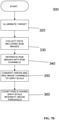
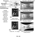
- a method of determining bacterial load of a target from fluorescent image data of the target comprises identifying a region of interest in a fluorescent image of a target, separating RGB images into individual channels, converting individual green and red image channels from the RGB image to gray scale, and counting pixels whose gray scale intensity was above a given threshold.
- a method of obtaining diagnostic data regarding a target comprises directly illuminating at least a portion of a target with a homogeneous field of excitation light emitted by at least one light source connected to a housing of a handheld device, the housing including an enclosure for receiving a wireless communication device having a digital camera.
- the at least one light source emits at least one wavelength or wavelength band causing at least one biomarker in the illuminated portion of the target to fluoresce.
- the method further comprises collecting bacterial autofluorescence data regarding the illuminated portion of the target with an image sensor of the digital camera of the wireless communication device.
- the wireless communication device is secured in the housing.
- the method also comprises analyzing the collected bacterial autofluorescence data using pixel intensity to determine bacterial load of the illuminated portion of the target.
- a system for acquiring data regarding a wound in tissue comprises at least one light source configured to directly illuminate a target surface with a homogeneous field of excitation light.
- the target surface includes at least a portion of a wound and an area around the wound.
- An optical sensor is configured to detect signals responsive to illumination of the illuminated portion of the wound and the area around the wound. Each detected signal is indicative of at least one of endogenous fluorescence, exogenous fluorescence, absorbance, and reflectance in the illuminated portion of the wound and the area around the wound.
- a processor is configured to receive the detected signals and to analyze the detected signal data using pixel intensity and to output data regarding the bacterial load of the illuminated portion of the wound and area around the wound.
- the system further comprises a display for displaying the output data regarding the illuminated portion of the wound and the area around the wound output by the processor.
- a portable, handheld device for imaging and collection of data relating to a wound in tissue.
- the device comprises a housing comprising an enclosure configured to receive a mobile communication device and at least one light source coupled to the housing and configured to directly illuminate at least a portion of a wound and an area around the wound with a homogeneous field of light.
- a mobile communication device is secured in the enclosure of the housing, the mobile communication device comprising an embedded digital camera and having a touchscreen display disposed on a first side of the device and a lens of the camera disposed on a second side of the device opposite the first side.
- the mobile communication device is received in the housing such that an image sensor of the digital camera is positioned to detect optical signals responsive to illumination of the portion of the wound and the area around the wound with the homogeneous field of light, each of the optical signals being indicative of at least one of endogenous fluorescence, exogenous fluorescence, reflectance, and absorbance in the illuminated portion of the wound and the area around the wound.
- an image sensor of the digital camera is positioned to detect optical signals responsive to illumination of the portion of the wound and the area around the wound with the homogeneous field of light, each of the optical signals being indicative of at least one of endogenous fluorescence, exogenous fluorescence, reflectance, and absorbance in the illuminated portion of the wound and the area around the wound.
- a method of obtaining diagnostic data regarding a target comprises directly illuminating at least a portion of a target and an area around the target with a homogeneous field of excitation light emitted by at least one light source connected to a housing of a handheld device.
- the housing includes an enclosure for receiving a wireless communication device having a digital camera.
- the at least one light source emits at least one wavelength or wavelength band causing at least one biomarker in the illuminated portion of the target and area around the target to fluoresce.
- the method further comprises collecting bacterial autofluorescence data regarding the illuminated portion of the target and the area around the target with an image sensor of the digital camera of the wireless communication device.
- the wireless communication device is secured in the housing.
- the method further comprises analyzing the collected bacterial autofluorescence data to determine bacterial load of the illuminated portion of the target and area around the target, and tracking changes in bacterial load of the target over time.
- Bacterial swabs are collected at the time of wound examination and have the noted advantage of providing identification of specific bacterial/microbial species.
- multiple swabs and/or biopsies often are collected randomly from the wound site, and some swabbing techniques may in fact spread the microorganisms around with the wound during the collection process thus affecting patient healing time and morbidity. This may be a problem especially with large chronic (non-healing) wounds where the detection yield for bacterial presence using current swabbing and biopsy protocols is suboptimal (diagnostically insensitive), despite many swabs being collected.
- wound healing involves a complex and dynamic interaction of biological processes divided into four overlapping phases— haemostasis, inflammation, cellular proliferation, and maturation or remodeling of connective tissues - which affect the pathophysiology of wound healing.
- a common major complication arising during the wound healing process which can range from days to months, is infection caused by bacteria and other microorganisms. This can result in a serious impediment to the healing process and lead to significant complications.
- All wounds contain bacteria at levels ranging from contamination, through colonization, critical colonization to infection, and diagnosis of bacterial infection is based on clinical symptoms and signs (e.g., visual and odorous cues).
- wound infection refers to the presence of bacteria within a wound without any host reaction
- wound colonisation refers to the presence of bacteria within the wound which do multiply or initiate a host reaction
- critical colonisation refers to multiplication of bacteria causing a delay in wound healing, usually associated with an exacerbation of pain not previously reported but still with no overt host reaction.
- Wound infection refers to the deposition and multiplication of bacteria in tissue with an associated host reaction.
- critical colonisation can be used to describe wounds that are considered to be moving from colonisation to local infection.
- wound pathogens can be categorised into different groups, such as, bacteria, fungi, spores, protozoa and viruses depending on their structure and metabolic capabilities. Although viruses do not generally cause wound infections, bacteria can infect skin lesions formed during the course of certain viral diseases. Such infections can occur in several settings including in health-care settings (hospitals, clinics) and at home or chronic care facilities. The control of wound infections is increasingly complicated, yet treatment is not always guided by microbiological diagnosis.
- Direct visual assessment of wound health status using white light relies on detection of color and topographical/textural changes in and around the wound, and thus may be incapable and unreliable in detecting subtle changes in tissue remodeling. More importantly, direct visual assessment of wounds often fails to detect the presence of bacterial infection, since bacteria are occult under white light illumination. Infection is diagnosed clinically with microbiological tests used to identify organisms and their antibiotic susceptibility. Although the physical indications of bacterial infection can be readily observed in most wounds using white light (e.g., purulent exudate, crusting, swelling, erythema), this is often significantly delayed and the patient is already at increased risk of morbidity (and other complications associated with infection) and mortality. Therefore, standard white light direct visualization fails to detect the early presence of the bacteria themselves or identify the types of bacteria within the wound.
- white light e.g., purulent exudate, crusting, swelling, erythema
- the National Pressure Ulcer Advisory Panel (NPUAP) developed the Pressure Ulcer Scale for Healing (PUSH) tool that outlines a five-step method of characterizing pressure ulcers. This tool uses three parameters to determine a quantitative score that is then used to monitor the pressure ulcer over time.
- the qualitative parameters include wound dimensions, tissue type, and the amount of exudate or discharge, and thermal readings present after the dressing is removed.
- a wound can be further characterized by its odor and color.
- Such an assessment of wounds currently does not include critical biological and molecular information about the wound. Therefore, all descriptions of wounds are somewhat subjective and noted by hand by either the attending physician or the nurse.
- What is desirable is a robust, cost-effective non-invasive and rapid imaging-based method or device for collecting wound data and providing an analysis in real-time.
- the data and analysis can be used to objectively assess wounds for changes at the biological, biochemical and cellular levels and to rapidly, sensitively and non-invasively detecting the earliest presence of bacteria/microorganisms within wounds.
- Such a method or device for detection of critical biological tissue changes in wounds may serve an adjunctive role with conventional clinical wound management methods in order to guide key clinico-pathological decisions in patient care.
- Such a device may be compact, portable and capable of real-time non-invasive and/or non-contact interrogation of wounds in a safe and convenient manner, which may allow it to fit seamlessly into routine wound management practice and user friendly to the clinician, nurse and wound specialist. This may also include use of this device in the home-care environment (including self-use by a patient), as well as in military battlefield environments.
- image-based device may provide an ability to monitor wound treatment response and healing in real-time by incorporating valuable 'biologically-informed' image-guidance into the clinical wound assessment process. This may ultimately lead to potential new diagnosis, treatment planning, treatment response monitoring and thus 'adaptive' intervention strategies which may permit enhancement of wound-healing response at the individual patient level. Precise identification of the systemic, local, and molecular factors underlying the wound healing problem in individual patients may allow better tailored treatment.
- Tissue autofluorescence imaging provides a unique means of obtaining biologically relevant information of normal and diseased tissues in real-time, thus allowing differentiation between normal and diseased tissue states. This is based, in part, on the inherently different light-tissue interactions (e.g., abosption and scattering of light) that occur at the bulk tissue and cellular levels, changes in the tissue morphology and alterations in the blood content of the tissues.
- tissue blood is a major light absorbing tissue component (i.e., a chromophore).
- This type of technology is suited for imaging disease in hollow organs (e.g., GI tract, oral cavity, lungs, bladder) or exposed tissue surfaces (e.g., skin).
- An autofluorescence imaging device in accordance with the presnet teachings may collect wound data that provides/allows rapid, non-invasive and non-contact real-time analysis of wounds and their composition and components, to detect and exploit the rich biological information of the wound to improve clinical care and management.
- a device in accordance with the present disclosure 1) provides image-guidance for tissue sampling, detecting clinically-significant levels of pathogenic bacteria and wound infection otherwise overlooked by conventional sampling and 2) provides image-guidance for wound treatment, accelerating wound closure compared with conventional therapies and quantitatively tracking long-term changes in bacterial bioburden and distribution in wounds.
- a handheld portable device to examine skin and wounds in real-time is provided.
- the device instantly detects, visualizes, and analyzes bacteria and tissue composition.
- the device is a compact, hand-held, device for noncontact and noninvasive imaging. It captures both white light (WL) and autofluorescence (AF) signals produced by tissue components and bacteria without the use of contrast agents.
- WL white light
- AF autofluorescence
- the devices disclosed herein can be used with contrast agents if desired.
- the device also may capture thermal data from the imaged area.
- the device may be further configured to analyze the white light, fluorescence, and thermal data, correlate such data, and provide an output based on the correlation of the data, such as, for example, an indication of wound status, wound healing, wound infection, bacterial load, or other diagnostic information upon which an intervention strategy may be based.
- the device may be configured to create and/or display composite images including green AF, produced by endogenous connective tissues (e.g., collagen, elastin) in skin, and red AF, produced by endogenous porphyrins in clinically relevant bacteria such as Staphylococcus aureus. Siderophores/pyoverdins in other species such as Pseudomonas aeruginosa appear blue-green in color with in vivo AF imaging.
- the device may provide visualization of bacterial presence, types, distribution, amounts in and around a wound as well as key information surrounding tissue composition (collagen, tissue viability, blood oxygen saturation). For example, the device may provide imaging of collagen composition in and around skin in real-time (via AF imaging).
- the device may be configured to accurately detect and measure bacterial load in wounds in real-time, guide treatment decisions, and track wound healing over the course of antibacterial treatment.
- bioluminescence imaging may be used to correlate absolute bacterial load with FL signals obtained using the handheld device.
- the device may be independent and self-contained. It may interface with computers, printers and EMR systems.
- the device is configured to image bacteria in real-time (via, for example, fluorescence imaging), permitting ready identification of bacteria types, their location, distribution and quantity in accepted units of measurement and allowing identification of and distinction between several different species of bacteria.
- fluorescence imaging may be used to visualize and differentiate Pseudomonas aruginosa (which fluoresces a greenish-blue colour when excited by 405 nm light from the device) from other bacteria (e.g., Staphylococcus aureus) that predominantly fluoresce a red/orange colour under the same excitation wavelength.
- the device's camera sensor and built in fluorescence multiband pass emission filter produce fluorescence images of bacteria (in wounds or normal skin) and Pseudomonas aruginosa appear greenish-blue in colour while other bacteria emit a red/orange colour.
- the device detects differences in the autofluorescence emission of different endogenous molecules (called fluorophores) between the different bacteria.
- the device is configured to identify or provide an indication of tissue viability in real-time (via fluorescence imaging). For example, blood preferentially absorbs 405 nm light compared with other visible wavelengths. Tissues which are perfused by blood are considered viable, and can be differentiated from devitalized (poorly perfused) tissues using fluorescence imaging.
- the device can be configured with a multiband pass emission filter to detect the amount of 405 nm light that is absorbed or reflected from the tissues.
- Viable tissue contains blood that highly absorbs 405 nm light resulting in an image with low levels of 405 nm light, whereas nonviable (or devitalized) tissues do not contain sufficient blood and 405 nm is less absorbed.
- viable tissues from nonviable tissues
- the user will recognize viable tissues (from nonviable tissues) based on the relative amount of 405 nm light in the image, the viable tissues appearing darker compared with the nonviable tissues.
- viable tissues will appear less green fluorescent compared with nonviable tissues because viable tissues will preferentially absorb more of the 405 nm excitation light due to more blood being present, compared with nonviable tissues.
- viable tissue will have less 405 nm excitation light to stimulate the connective tissue autofluorescence than nonviable tissues. The result is that viable tissues will have less green connective tissue fluorescence than non-viable tissues in the same image. The user will appreciate this difference visually during imaging with the device.
- the device is configured to capture and generate images and videos that provide a map or other visual display of user selected parameters.
- maps or displays may correlate, overlay, co-register or otherwise coordinate data generated by the device based on input from one or more device sensors.
- sensors may include, for example, camera sensors configured to detect white light and/or fluorescent images and thermal sensors configured to detect heat signatures of a target.
- the device may be configured to display color images, image maps, or other maps of user selected parameters such as, for example, bacteria location and/or biodistribution, collagen location, location and differentiation between live tissues and dead tissues, differentiation between bacterial species, location and extent of blood, bone, exudate, temperature and wound area/size.
- These maps or displays may be output by the device based on the received signals and may be produced on a single image with or without quantification displays.
- the user-selected parameters shown on the map may be correlated with one or more wound parameters, such as shape, size, topography, volume, depth, and area of the wound.
- wound parameters such as shape, size, topography, volume, depth, and area of the wound.
- This may be accomplished by, for example, using a pixel-by-pixel coloring based on the relative amount of 405 nm light in the Blue channel of the resultant RGB image, green connective tissue fluorescence in the Green channel, and red bacteria fluorescence in Red channel., Additionally and/or alternatively, this may be accomplished by displaying the number of pixels in a given image for each of the blue, green and red channels which would represent amount of blood in tissue, amount of connective tissues, and amount of bacteria, respectively.
- the device may be configured to create and output reports regarding the collected data.
- the device user can generate a wound status report, which may include, for example, date/time, patient ID, images, etc.
- the user can export or print images, to a selected network, computer, printer when connected to cradle, and/or via USB to computer.
- the reports may be generated by the handheld device, by exporting data to a computer for processing and generation of reports, or by a combination of the two. Further, such reports, or the data contained therein, may form the basis of recommended intervention or treatment strategies.
- Reports may include, for example, medical reports, digital reports, reports that encompass handwritten input from clinicians (e.g., via tablet input, etc.).
- the reports may include various types of data including, for example, the identification of wound parameters and the tracking of these parameters over time.
- the reports may identify and track changes in wound size, wound shape, wound topography, wound volume, wound area, bacterial load of the wound, location of bacteria within the wound, presence of exposed bone, blood, connective and other tissues, wound temperature, location of the wound on the patient, number of wounds on the patient, date of wound examination, patient identification, medications administered to the patient, interventional strategies and therapies as administered and as changed over time in response to changing wound parameters, etc.
- the device may generate a report that tracks a patient's wound and skin status changes, including for example, wound size and bacterial burden over time.
- the data collected may be used to generate a database that provides clinical data regarding wound parameters and the efficacy of various wound intervention/treatment strategies.
- the device may be configured to integrate collected data/images/videos into the reports and, alternatively or additionally, include such reports and data/images/videos into a patient's electronic medical record (EMR). This process may be wirelessly, via the use of transfer cables, and the system also may be configured to upload the reports automatically.
- EMR electronic medical record
- the device has a memory sufficient to store several images/videos.
- the device may include a Micro SD card interface for additional storage and firmware development.
- the device can inform the user of low memory capacity.
- the device may also include a data safeguard that will prompt a user to export files in the case of low memory availability.
- a method and device for fluorescence-based imaging and monitoring is disclosed.
- One exemplary embodiment of the device is a portable optical digital imaging device.
- the device may utilize a combination of white light, tissue fluorescence and reflectance imaging, and thermal imaging, and may provide real-time wound imaging, assessment, recordation/documentation, monitoring and/or care management.
- the device may be hand-held, compact and/or light-weight. This device and method may be suitable for monitoring of wounds in humans and animals.
- the device may generally comprise: i) one or more excitation/illumination light sources and ii) a detector device (e.g., a digital imaging detector device), which may be combined with one or more optical emission filters, or spectral filtering mechanisms, and which may have a view/control screen (e.g., a touch-sensitive screen), image capture and zoom controls.
- a detector device e.g., a digital imaging detector device
- the device may also have: iii) a wired and/or wireless data transfer port/module, iv) an electrical power source and power/control switches, and/or v) an enclosure, which may be compact and/or light weight, and which may have a mechanism for attachment of the detector device and/or a handle grip.
- the excitation/illumination light sources may be LED arrays emitting light at about 405 nm (e.g., +/- 5 nm), and may be coupled with additional band-pass filters centered at about 405 nm to remove/minimize the side spectral bands of light from the LED array output so as not to cause light leakage into the imaging detector with its own optical filters.
- the digital imaging detector device may be a digital camera, for example having at least an ISO800 sensitivity, but more preferably an ISO3200 sensitivity, and may be combined with one or more optical emission filters, or other equally effective (e.g., miniaturized) mechanized spectral filtering mechanisms (e.g., acousto-optical tunable filter or liquid crystal tunable filter).
- the digital imaging detector device may have a touch-sensitive viewing and/or control screen, image capture and zoom controls.
- the enclosure may be an outer hard plastic or polymer shell, enclosing the digital imaging detector device, with buttons such that all necessary device controls may be accessed easily and manipulated by the user.
- Miniature heat sinks or small mechanical fans, or other heat dissipating devices may be embedded in the device to allow excess heat to be removed from the excitation light sources if required.
- the complete device, including all its embedded accessories and attachments, may be powered using standard AC/DC power and/or by rechargeable battery pack.
- the complete device may also be attached or mounted to an external mechanical apparatus (e.g., tripod, or movable stand with pivoting arm) allowing mobility of the device within a clinical room with hands-free operation of the device.
- an external mechanical apparatus e.g., tripod, or movable stand with pivoting arm
- the device may be provided with a mobile frame such that it is portable.
- the device may be cleaned using moist gauze wet with water, while the handle may be cleansed with moist gauze wet with alcohol. Additional appropriate cleaning methods will be apparent to those of ordinary skill in the art.
- the device may include software allowing a user to control the device, including control of imaging parameters, visualization of images, storage of image data and user information, transfer of images and/or associated data, and/or relevant image analysis (e.g., diagnostic algorithms).
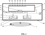
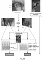
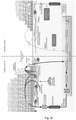
- FIG. 1 A schematic diagram of an example of the device is shown in FIG. 1 .
- the device is shown positioned to image a target object 10 or target surface.
- the device has a digital image acquisition device 1, such as digital camera, video recorder, camcorder, cellular telephone with built-in digital camera, 'Smart' phone with a digital camera, personal digital assistant (PDA), laptop/PC with a digital camera, or a webcam.
- the digital image acquisition device 1 has a lens 2, which may be aligned to point at the target object 10 and may detect the optical signal that emanates from the object 10 or surface.
- the device has an optical filter holder 3 which may accommodate one or more optical filters 4. Each optical filter 4 may have different discrete spectral bandwidths and may be band-pass filters.
- optical filters 4 may be selected and moved in from of the digital camera lens to selectively detect specific optical signals based on the wavelength of light.
- the device may include light sources 5 that produce excitation light to illuminate the object 10 in order to elicit an optical signal (e.g., fluorescence) to be imaged with, for example, blue light (e.g., 400-450 nm), or any other combination of single or multiple wavelengths (e.g., wavelengths in the ultraviolet/visible/near infrared/infrared ranges).
- the light source 5 may comprise a LED array, laser diode and/or filtered lights arranged in a variety of geometries.
- the device may include a method or apparatus 6 (e.g., a heatsink or a cooling fan) to dissipate heat and cool the illumination light sources 5.
- the device may include a method or apparatus 7 (e.g., an optical band-pass filter) to remove any undesirable wavelengths of light from the light sources 5 used to illuminate the object 10 being imaged.
- the device may include a method or apparatus 8 to use an optical means (e.g., use of compact miniature laser diodes that emit a collimated light beam) to measure and determine the distance between the imaging device and the object 10.
- the device may use two light sources, such as two laser diodes, as part of a triangulation apparatus to maintain a constant distance between the device and the object 10. Other light sources may be possible.
- the device may also use ultrasound, or a physical measure, such as a ruler, to determine a constant distance to maintain.
- the device may use a rangefinder to determine the appropriate position of the device relative to the wound to be imaged.
- the device may also include a method or apparatus 9 (e.g., a pivot) to permit the manipulation and orientation of the excitation light sources 5, 8 so as to manoeuvre these sources 5,8 to change the illumination angle of the light striking the object 10 for varying distances.
- the target object 10 may be marked with a mark 11 to allow for multiple images to be taken of the object and then being co-registered for analysis.
- the mark 11 may involve, for example, the use of exogenous fluorescence dyes of different colours which may produce multiple distinct optical signals when illuminated by the light sources 5 and be detectable within the image of the object 10 and thus may permit orientation of multiple images (e.g., taken over time) of the same region of interest by co-registering the different colours and the distances between them.
- the digital image acquisition device 1 may include one or more of: an interface 12 for a head-mounted display; an interface 13 for an external printer; an interface 14 for a tablet computer, laptop computer, desk top computer or other computer device; an interface 15 for the device to permit wired or wireless transfer of imaging data to a remote site or another device; an interface 16 for a global positioning system (GPS) device; an interface 17 for a device allowing the use of extra memory; and an interface 18 for a microphone.
- GPS global positioning system
- the device may include a power supply 19 such as an AC/DC power supply, a compact battery bank, or a rechargeable battery pack. Alternatively, the device may be adapted for connecting to an external power supply.
- the device may have a housing 20 that houses all the components in one entity.
- the housing 20 may be equipped with a means of securing any digital imaging device within it.
- the housing 20 may be designed to be hand-held, compact, and/or portable.
- the housing 20 may be one or more enclosures.
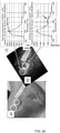
- FIG. 2 shows an example of the device in a typical wound care facility.
- Inset a) shows a typical clinical wound care facility, showing the examination chair and accessory table.
- Insets b-c) show an example of the device in its hard-case container. The device may be integrated into the routine wound care practice allowing real-time imaging of the patient.
- Inset d) shows an example of the device (arrow) placed on the "wound care cart" to illustrate the size of the device.
- Inset e) The device may be used to image under white light illumination, while inset f) shows the device being used to take fluorescence images of a wound under dimmed room lights.
- the device may be used in telemedicine/telehealth infrastructures, for example fluorescence images of a patient's wounds may be sent by email to a wound care specialist via a wireless communication device, such as a Smartphone at another hospital using a wireless/WiFi internet connection.
- a wireless communication device such as a Smartphone at another hospital using a wireless/WiFi internet connection.
- high-resolution fluorescence images may be sent as email attachments to wound care specialists from remote wound care sites for immediate consultation with clinical experts, microbiologists, etc. at specialized clinical wound care and management centers.
- the devices uses two violet/blue light (e.g., 405 nm +/-10 nm emission, narrow emission spectrum) LED arrays (Opto Diode Corporation, Newbury Park, California), each situated on either side of the imaging detector assembly as the excitation or illumination light sources. These arrays have an output power of approximately 1 Watt each, emanating from a 2.5 ⁇ 2.5 cm 2 , with a 70-degree illuminating beam angle.
- the LED arrays may be used to illuminate the tissue surface from a distance of about 10 cm, which means that the total optical power density on the skin surface is about 0.08 W/cm 2 . At such low powers, there is no known potential harm to either the target wound or skin surface, or the eyes from the excitation light.
- the one or more light sources may be articulated (e.g., manually) to vary the illumination angle and spot size on the imaged surface, for example by using a built in pivot, and are powered for example through an electrical connection to a wall outlet and/or a separate portable rechargeable battery pack.
- Excitation/illumination light may be produced by sources including, but not limited to, individual or multiple light-emitting diodes (LEDs) in any arrangement including in ring or array formats, wavelength-filtered light bulbs, or lasers.
- LEDs light-emitting diodes
- Selected single and multiple excitation/illumination light sources with specific wavelength characteristics in the ultraviolet (UV), visible (VIS), far-red, near infrared (NIR) and infrared (IR) ranges may also be used, and may be composed of a LED array, organic LED, laser diode, or filtered lights arranged in a variety of geometries. Excitation/illumination light sources may be 'tuned' to allow the light intensity emanating from the device to be adjusted while imaging. The light intensity may be variable.
- the LED arrays may be attached to individual cooling fans or heat sinks to dissipate heat produced during their operation.
- the LED arrays may emit narrow 405 nm light, which may be spectrally filtered using a commercially available band-pass filter (Chroma Technology Corp, Rockingham, VT, USA) to reduce potential 'leakage' of emitted light into the detector optics.
- the illuminating light sources may shine a narrow-bandwidth or broad-bandwidth violet/blue wavelength or other wavelength or wavelength band of light onto the tissue/wound surface thereby producing a flat and homogeneous field within the region-of-interest.
- the light may also illuminate or excite the tissue down to a certain shallow depth. This excitation/illumination light interacts with the normal and diseased tissues and may cause an optical signal (e.g., absorption, fluorescence and/or reflectance) to be generated within the tissue.
- the imaging device may interrogate tissue components (e.g., connective tissues and bacteria in a wound) at the surface and at certain depths within the tissue (e.g., a wound). For example, by changing from violet/blue (-400-500 nm) to green (-500-540 nm) wavelength light, excitation of deeper tissue/bacterial fluorescent sources may be achieved, for example in a wound. Similarly, by detecting longer wavelengths, fluorescence emission from tissue and/or bacterial sources deeper in the tissue may be detected at the tissue surface.
- tissue components e.g., connective tissues and bacteria in a wound
- the imaging device may interrogate tissue components (e.g., connective tissues and bacteria in a wound) at the surface and at certain depths within the tissue (e.g., a wound). For example, by changing from violet/blue (-400-500 nm) to green (-500-540 nm) wavelength light, excitation of deeper tissue/bacterial fluorescent sources may be achieved, for example in a wound.
- inset c) shows the detection of bacteria below the skin surface (i.e., at depth) after wound cleaning. This use of the device for detecting bacteria at the surface and at depth within a wound and surrounding tissue may be assessed in the context of other clinical signs and symptoms used conventionally in wound care centers.
- Example embodiments of the device are shown in FIG. 4 .
- the device may be used with any standard compact digital imaging device (e.g., a charge-coupled device (CCD) or complementary metal-oxide-semiconductor (CMOS) sensors) as the image acquisition device.
- CCD charge-coupled device
- CMOS complementary metal-oxide-semiconductor
- the example device shown in a) has an external electrical power source, the two LED arrays for illuminating the object/surface to be imaged, and a commercially available digital camera securely fixed to light-weight metal frame equipped with a convenient handle for imaging.
- a multi-band filter is held in front of the digital camera to allow wavelength filtering of the detected optical signal emanating from the object/surface being imaged.
- the camera's video/USB output cables allow transfer of imaging data to a computer for storage and subsequent analysis.
- This example uses a commercially-available 8.1-megapixel Sony digital camera (Sony Cybershot DSC-T200 Digital Camera, Sony Corporation, North America).
- This camera may be suitable because of i) its slim vertical design which may be easily integrated into the enclosure frame, ii) its large 3.5-inch widescreen touch-panel LCD for ease of control, iii) its Carl Zeiss 5x optical zoom lens, and iv) its use in low light (e.g., ISO 3200).
- the device may have a built-in flash which allows for standard white light imaging (e.g., high-definition still or video with sound recording output).
- Camera interface ports may support both wired (e.g., USB) or wireless (e.g., Bluetooth, WiFi, and similar modalities) data transfer or 3 rd party add-on modules to a variety of external devices, such as: a head-mounted display, an external printer, a tablet computer, laptop computer, personal desk top computer, a wireless device to permit transfer of imaging data to a remote site/other device, a global positioning system (GPS) device, a device allowing the use of extra memory, and a microphone.
- the digital camera is powered by rechargeable batteries, or AC/DC powered supply.
- the digital imaging device may include, but is not limited to, digital cameras, webcams, digital SLR cameras, camcorders/video recorders, cellular telephones with embedded digital cameras, Smartphones TM , personal digital assistants (PDAs), and laptop computers/tablet PCs, or personal desk-top computers, all of which contain/or are connected to a digital imaging detector/sensor.
- This light signal produced by the excitation/illumination light sources may be detected by the imaging device using optical filter(s) (e.g., those available from Chroma Technology Corp, Rockingham, VT, USA) that reject the excitation light but allow selected wavelengths of emitted light from the tissue to be detected, thus forming an image on the display.
- optical filter(s) e.g., those available from Chroma Technology Corp, Rockingham, VT, USA
- There is an optical filter holder attached to the enclosure frame in from of the digital camera lens which may accommodate one or more optical filters with different discrete spectral bandwidths, as shown insets b) and c) of FIG. 4 .
- Inset b) shows the device with the LED arrays turned on to emit bright violet/blue light, with a single emission filter in place.
- Inset c) shows the device using a multiple-optical filter holder used to select the appropriate filter for desired wavelength-specific imaging.
- Inset d) shows the device being held in one hand while imaging the
- band-pass filters may be selected and aligned in front of the digital camera lens to selectively detect specific optical signals from the tissue/wound surface based on the wavelength of light desired.
- Spectral filtering of the detected optical signal e.g., absorption, fluorescence, reflectance
- LCTF liquid crystal tunable filter
- AOTF acousto-optic tunable filter
- Spectral filtering may also involve the use of continuous variable filters, and/or manual band-pass optical filters.
- These devices may be placed in front of the imaging detector to produce multispectral, hyperspectral, and/or wavelength-selective imaging of tissues.
- the device may be modified by using optical or variably oriented polarization filters (e.g., linear or circular combined with the use of optical wave plates) attached in a reasonable manner to the excitation/illumination light sources and the imaging detector device.
- optical or variably oriented polarization filters e.g., linear or circular combined with the use of optical wave plates
- the device may be used to image the tissue surface with polarized light illumination and non-polarized light detection or vice versa, or polarized light illumination and polarized light detection, with either white light reflectance and/or fluorescence imaging.
- This may permit imaging of wounds with minimized specular reflections (e.g., glare from white light imaging), as well as enable imaging of fluorescence polarization and/or anisotropy-dependent changes in connective tissues (e.g., collagens and elastin) within the wound and surrounding normal tissues. This may yield useful information about the spatial orientation and organization of connective tissue fibers associated with wound remodeling during healing.
- connective tissues e.g., collagens and elastin
- All components of the imaging device may be integrated into a single structure, such as an ergonomically designed enclosed structure with a handle, allowing it to be comfortably held with one or both hands.
- the device may also be provided without any handle.
- the device may be light weight, portable, and may enable real-time digital imaging (e.g., still and/or video) of any target surface (for example, the skin and/or oral cavity, which is also accessible) using white light, fluorescence and/or reflectance imaging modes.
- the device may be scanned across the body surface for imaging by holding it at variable distances from the surface, and may be used in a lit environment/room to image white light reflectance/fluorescence.
- the device may be used in a dim or dark environment/room to optimize the tissue fluorescence signals, and minimize background signals from room lights.
- the device may be used for direct (e.g., with the unaided eye) or indirect (e.g., via the viewing screen of the digital imaging device) visualization of wounds and surrounding normal tissues.
- the device may also be embodied as not being hand-held or portable, for example as being attached to a mounting mechanism (e.g., a tripod or stand) for use as a relatively stationary optical imaging device for white light, fluorescence and reflectance imaging of objects, materials, and surfaces (e.g., a body). This may allow the device to be used on a desk or table or for 'assembly line' imaging of objects, materials and surfaces.
- a mounting mechanism may be mobile.
- insets e) and f) of FIG. 4 show an embodiment of the device where the image acquisition device is a mobile communication device such as a cellular telephone.
- the cellular telephone used in this example is a Samsung Model A-900, which is equipped with a 1.3 megapixel digital camera. The telephone is fitted into the holding frame for convenient imaging.
- Inset e) shows the use of the device to image a piece of paper with fluorescent ink showing the word "Wound”.
- Inset f) shows imaging of fluorescent ink stained fingers, and detection of the common skin bacteria P.
- the images from the cellular telephone may be sent wirelessly to another cellular telephone, or wirelessly (e.g., via Bluetooth connectivity) to a personal computer for image storage and analysis.
- This demonstrates the capability of the device to perform real-time hand-held fluorescence imaging and wireless transmission to a remote site/person as part of a telemedicine/E-health wound care infrastructure.
- white light reflectance and fluorescence images/movies captured with the device were imported into Adobe Photoshop for image analysis.
- image analysis software was designed using MatLab TM (Mathworks) to allow a variety of image-based spectral algorithms (e.g., red-to-green fluorescence ratios, etc.) to be used to extract pertinent image data (e.g., spatial and spectral data) for quantitative detection/diagnostic value.
- Image post-processing also included mathematical manipulation of the images.
- a handheld device for collection of data from a wound includes a low-cost, consumer-grade, Super HAD TM charge-coupled device (CCD) sensor-based camera (Model DSC-T900, Sony Corp., Japan), with a 35 to 140 mm equivalent 4 ⁇ zoom lens housed in a plastic body and powered by rechargeable batteries ( FIG. 5 ).
- CCD charge-coupled device
- FIG. 5 A prototype of the handheld imaging device is shown in FIG. 5 .
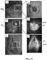
- Inset (a) is a front view of the prototype showing wound fluorescence (FL) image displayed in real time on the liquid-crystal display screen in high definition.
- Inset (b) is a back view of the prototype showing white light (WL) and 405-nm LED arrays providing illumination of the wound, while the FL emission filter is placed in front of the CCD sensor.
- the device is configured to collect high-resolution 12.1 Mpixels color WL and AF images (or videos) in real time ( ⁇ 1 s), which are displayed in red-green-blue (RGB) format on a 3.5-in. touch-sensitive color liquid-crystal display (LCD) screen of the device ( FIG. 5 ).
- the device includes broadband white light-emitting diodes (LEDs), electrically powered by a standard AC 125V source, configured to provide illumination during WL imaging.
- LEDs broadband white light-emitting diodes
- the device includes an emission filter configured to spectrally separate tissue and bacteria AF.
- the device is configured to display the spectrally separated tissue and bacterial AF as a composite RGB image without image processing or color-correction, thus allowing the user to see the bacteria distribution within the anatomical context of the wound and body site.
- the CCD image sensor is sensitive across ultraviolet ( ⁇ 400 nm), visible (400 to 700 nm), and near-infrared (700 to 900 nm) wavelengths to AF of tissues and bacteria, in the absence of exogenous contrast agents.
- the handheld device is configured to take both white light images and fluorescent images incorporates a mobile communication device, such as a smartphone, mobile phone, iPod, iPhone, or other such device having existing image-capturing capabilities such as the CCD sensor.
- a mobile communication device such as a smartphone, mobile phone, iPod, iPhone, or other such device having existing image-capturing capabilities such as the CCD sensor.
- the device incorporates an iPhone 4S.
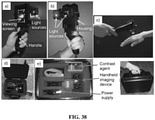
- a mobile imaging device prototype. is shown in FIG. 6A .
- Inset (a) shows a front view of the device, showing the optical components and battery holder of the accessory adaptor, which is mounted onto a standard iPhone 4S smart phone.
- Inset (b) shows a back view of the device, showing the on/off switch and the LCS viewing screen on which the WL and FL images are viewed by the user.
- White light imaging allows the user to capture an image of a patient wound and the fluorescence allows user to capture a corresponding image highlighting the presence of bacteria on the image.
- the display screen may range between about 4-inches (diagonal) and about 7 -inches (diagonal) widescreen display with Multi-Touch IPS technology. Other size displays may be used based on user needs.
- the display quality settings are 1136x640-pixel resolution at 326 pixels per inch; 800:1 contrast ratio; and 500 cd/m2 max brightness.
- the display may have a fingerprint-resistant oleophobic coating.
- the resolution of the camera may be about 5 Megapixels and may have resolutions higher than 5 Megapixels, such as up to about 24 Megapixels, depending upon availability, amount of storage available, etc.
- the selection of the lens design allows the production of high quality images, specifically in the red and green spectra.
- a five-element lens is used (as iPod touch design).
- the user can tap to focus video and/or still images.
- the camera has optimal performance in the dark.
- the camera has an LED flash and shutter speeds are high.
- the exemplary embodiment of the handheld device integrates a consumer grade mobile phone camera with a custom optical platform.
- the image acquisition occurs on the mobile phone camera and functions independently of the device housing, electronics and optics.
- the images are displayed on the phone's LCD touch screen and are stored on the phone itself.
- the customized optical design includes one violet 405nm LED positioned at a 45-degree angle to a dichroic mirror, which is fixed in front of the camera sensor.
- the dichroic mirror reflects violet light while transmitting all greater wavelengths to produce fluorescence excitation illumination that is coaxial to the camera sensor.
- a macro lens is situated in front of the camera sensor to allow for focused close up imaging of wounds ( ⁇ 10cm).
- the violet LED is powered by a standard 9V battery, which is triggered by the user through an external power switch.
- a heat sink is attached to the back for the LED printed circuit board with thermal paste to effectively transfer and dissipate the heat generated by the 5W violet LED.
- the device housing may be made by 3D printing. Other types of suitable structures are disclosed herein, and variations thereof will be understood by those of ordinary skill in the art based on the present teachings.
- the housing provides a means aligning the optical components with consumer grade camera and encasing both the electrical components used to drive the LED and the thermal solution while creating a user friendly and lightweight hand-held design.
- the adaptor is designed to slide onto the top of the iPhone 4s and fit snuggly around the phone to remain fixed in place during imaging.
- the adaptor is removable from the phone for white light imaging.
- the adaptor may be permanently affixed to the mobile communication device, such as the iPhone 4s.
- a movable filter may be provided for switching between white light imaging and fluorescent imaging, in a manner similar to that described with regard to embodiments of the handheld device discussed in FIGS. 1 and 2 .
- the user switches on the violet LED using the toggle switch on the back of the device ( FIG. 6A ).
- the 9V battery sends power to the LED drive, which modulates the current to drive the violet LED.
- the violet broad band LED which is situated perpendicularly to the iPhone camera sensor, emits 405nm light at the 45 degree dichroic mirror.
- the dichroic mirror reflects almost 100% of the light at the 405nm wavelength directly to the target.
- the tissues and bacteria absorb the 405nm photons from the violet LED and photons of a longer wavelength are then emitted by the bacteria and tissue to create fluorescence.
- a specific emission filter is placed in front of the iPhone camera sensor to control the wavelengths of photons that are able to reach the camera sensor and effectively block the excitation light.
- the iPhone camera sensor captures an RGB image of the emitted photons where bacteria is displayed as red (e.g. S. aureus) or very bright bluish-green (e.g. Pseudomonas aruginosa) and healthy connective tissues from skin or wound are captured by a green fluorescence signal.
- the user then utilizes the fluorescence image (or video) stored on the mobile communication device, such as an iPhone, to determine where bacteria are located within and around a wound.
- a study using the handheld device described herein tracked patient wounds over time.
- high resolution WL PRODIGI images were taken of every wound at each visit.
- a disposable length calibration scale (sticker) was placed near the wound during WL and FL imaging to track patient ID and date.
- a clinician marked the locations of suspected clinically significant bacterial load on printed WL images.
- no swab was taken until completion of subsequent FL imaging. This process took 1-2 min per wound, and subsequent FL imaging took 1-2 min per wound.
- the location(s) of positive red and/or green AF were marked on printed images.
- the clinician swabbed each suspicious marked area using the Levine sampling method and swabs were sent for blinded microbiology testing.
- WL and FL imaging were performed and swabs were collected, with clinician blinding to the FL results during treatment delivery.
- clinicians understood and could remember the meaning and characteristics of the red and green fluorescence signals, respectively, blinding them during treatment delivery in the control periods was possible because the fluorescence results for each wound examination and each patient were different.
- previous knowledge of fluorescence characteristics did not substantively influence the treatment decisions during the control periods.
- WL and FL images were also taken after each treatment to analyze wound area.
- WL and AF images were transferred to a laptop.
- Regions of interest ROIs
- RGB images were separated into individual channels.
- the green and red channels of the RGB image were representative of the true tissue and bacterial AF signals detected in vivo.
- image processing procedures were used. Briefly, individual green and red image channels from each RGB image were converted to greyscale (the blue channel was not used) and pixels whose greyscale intensity was above a given histogram threshold (selected to reduce the background noise of the raw image) were counted.
- a red color mask for red FL bacteria was created by finding the local maxima in the color range 100-255 greyscale.
- Tissue AF produced by endogenous collagen or elastin in the skin appeared as green FL, and clinically-relevant bacterial colonies (e.g. Staphylococcus aureus) appeared as red FL (caused by endogenous porphyrins .
- Some bacteria e.g. Pseudomonus aeruginosa
- produced a blue-green signal due to siderophores/pyoverdins, which was differentiated spectrally and texturally from dermis AF using image analysis software.
- the CCD image sensor was sensitive across a broad wavelength range of -300-800 nm.
- PRODIGI integrated easily into the routine clinical work flow.
- tissue FL By combining tissue FL with bacterial FL in a single composite image, the clinician instantly visualized the distribution and extent of the bacterial load within the anatomical context of the wound and body site.
- FL imaging added approximately 1-3 minutes/patient to the wound assessment routine, depending on the number of wounds and the duration of FL-guided swabbing.
- AF imaging detected clinically significant bacterial load in 85% of wound peripheries missed by conventional methods.
- the Levine method for swabbing only the wound bed may be insufficient, possibly resulting in antibacterial treatment being inappropriately withheld.
- modifying standard sampling practices to include swabbing of the wound periphery of all wounds would be impractical and costly.
- AF imaging could help clinicians decide if and where wound margins require sampling.
- the handheld imaging device also identified clinically significant bioburden in surrounding locations close to wounds, which represent sites of potential re-infection, where traditional methods do not examine or swab.
- Identifying and quantitating wound bacterial burden is an important determinant of infection and healing.
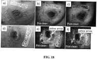
- Data on the visualization and quantitative tracking of bacterial load led to the identification of a new, simple method for image-guided debridement and topical application of antibiotic and antiseptic, which minimizes unnecessary trauma to the wound boundary and maximizes the contribution of debridement to reducing bacterial burden.
- Every wound has the potential for infection, but distinguishing true infection from critical colonization by best practice methods remains challenging and arbitrary, and can lead to over- and under-treatment.
- Critically colonized wounds can be difficult to diagnose because they do not always display classical signs of infection or clearly elevated levels of bioburden. Indeed, the clinical relevance of differentiating critically colonized wounds from infected wounds remains controversial. Identifying a high bacterial load in asymptomatic patients before infection occurs using AF imaging may help prevent infections by prompting aggressive treatment. If a bacterial infection is suspected, antibiotic selection could be guided by the established clinical principles and by AF identification of heavy bacterial burden and differentiation between Gram negative P. aeruginosa and Gram positive S. aureus.
- image analysis may be carried out on the handheld device or WL and FL images may be transferred to a laptop for image processing.
- Image analysis and processing of image data may be performed using a processor of the handheld device, and the results of such analyses may be displayed on the display of the handheld device.
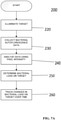
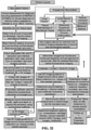
- the following two programs may be used for image processing (for example, analysis of the data collected by the exemplary device using the Super HAD TM charge-coupled device (CCD) sensor-based camera (Model DSC-T900)) and portions of these processes are illustrated in FIGS. 7A and 7B : MATLAB software (Version 7.9.0, The MathWorks, Massachusetts) using a custom-written program and ImageJ Software (Version 1.45n).
- MATLAB software (Version 7.9.0, The MathWorks, Massachusetts) using a custom-written program and ImageJ Software (Version 1.45n).
- ROIs regions of interests
- RGB images are separated into individual channels.
- Green (500 to 550 nm emission) and red AF (>590 nm) from tissue components and bacteria, respectively, detected by the CCD sensor are naturally aligned spectrally with the red and green filters on the Sony CCD image sensor.
- the green and red channels of the RGB image displayed on the handheld device's LCD screen are representative of the true tissue and bacterial AF signals detected in vivo.
- image processing procedures may be used. Briefly, individual green and red image channels from each RGB image are converted to gray scale (the blue channel is not used) and pixels whose gray scale intensity is above a given histogram threshold (selected to reduce the background noise of the raw image) are counted.
- the blue channel would be used, for example, when imaging the amount of 405 nm excitation light that is absorbed by tissues/blood when imaging tissue vascularity/perfusion.
- a red color mask for red FL bacteria is created by finding the local maxima in the color range 100 to 255 gray scale. Then, an inverted green color mask is used to remove the green FL. All pixels with red FL (above the histogram threshold) are binarized and the sum of all "1" pixels is calculated. This is repeated for the green channel of each image. These data give an estimate of the amount of red bacteria in each image.
- the number of FL pixels is converted into a more useful pixel area measure (cm2) by applying a ruler on the pixel image, thereby providing the total amount of fluorescent bacteria as an area measurement (cm2).
- the sizes of the wounds may be traced and measured similarly by converting pixel areas to cm2 of the circled wound area on the WL images.
- the resolution of the FL images is sufficient to localize bacteria based on regions of FL.
- ImageJ software may be used to separate FL images into red, green, and blue channels using the built-in batch processing function "Split Channels" located within the image menu and color submenu of the camera. Each resulting channel is displayed and saved in gray scale. For further analysis, an ROI may be identified in each corresponding red, green, and blue channel image. Under the built-in analysis menu, the "Set Measurement” function may be used to select and measure the following measurement parameters for each color channel image: pixel area, min. and max. gray scale intensity values, and mean gray intensity values. The average red channel intensity value may be determined as (bacterial) FL intensity per square pixel in each red channel image and then used for data analysis and comparison.
- CCD charge-coupled device
- the wounds were monitored for a total of 10 days (see FIG. 8 ), after which the mice were sacrificed. Bacterial amounts from FL images and wound size from WL images were quantified using the MATLAB program described above, and compared over time to determine the wound healing status.
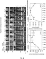
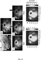
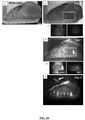
- FIG. 8 shows representative WL and FL images for a single mouse tracked over 10 days.
- Inset (a) provides images taken with the prototype device and showing the two equal-sized wounds on both sides of the spine. The right wound was inoculated with S. aureus in PBS and the left wound was inoculated with PBS only (control). The top row shows WL images, the middle row shows FL images, and the bottom row shows MATLAB quantified images, corresponding to bacterial areas and intensities.
- the FL imaging data demonstrated a significant increase in bacterial FL intensity in the wound inoculated with S. aureus, compared with the control wound, peaking on day 6. Mupirocin (day 7, red arrow) significantly decreased bacterial FL on day 8 to almost zero, indicating treatment effect. Bacteria increased again on days 9 and 10.
- Inset (b) provides a graph showing quantitative changes in bacterial load from FL images obtained in inset (a).
- BLI can be used to measure the absolute amount of bacteria in vivo, because it is one of the most sensitive and reliable screening tools for determining bacterial load.
- BLI collects the light emitted from the enzymatic reaction of luciferase and luciferin and therefore does not require excitation light.
- the bacterial BLI signal did not contribute to the FL signal detected by the handheld device's consumer grade-CCD camera.
- Gram-positive bioluminescent S. aureus-Xen8.1 from the parental strain S.
- aureus 8325-4 (Caliper) was grown to mid-exponential phase the day before pathogen inoculation. Bacteria with the BLI cassette produce the luciferase enzyme and its substrate (luciferin), thereby emitting a 440 to 490 nm bioluminescent signal when metabolically active ( FIG. 9 ).
- BLI images of the wound were acquired before, immediately after, and 1, 2, 3, 4, 5, 6, and 7 days postinoculation inside the dark chamber of the Xenogen IVIS Spectrum Imaging System 100 (Caliper, Massachusetts), using an exposure time of 10 s.
- BLI images were captured using Living Image In Vivo Imaging software (Caliper, Massachusetts). ROIs were digitally circumscribed over the wound and the total luminescence intensity counts were measured within the ROIs for each time point imaged. The absolute amount of bacteria measured from the BLI signals was tested for correlation with the corresponding FL signals on the FL images taken over time of the same wound using the handheld device (as described above).
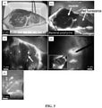
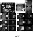
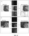
- FIG. 9 provides preclinical data which show that pathogenic bacterial autofluorescence (AF) intensity correlates with bacterial load in vivo.
- Inset (a) shows a time course prototype device mobile images of skin wounds in a mouse prior to and after inoculation with bioluminescent S. aureus-Xen8.1 (10 10 CFU in 30 ⁇ L PBS). Representative WL (top row), AF (middle row), and bioluminescence (bottom row) images are shown for each time point to 7 days after inoculation in a wounded mouse. BLI imaging gives absolute bacterial amount in vivo. Red arrows show when the tegaderm bandage was exchanged, causing some bacteria to be removed from the surface. Inset (b) shows average red FL from S.
- the imaging device may be useful for imaging and/or monitoring in clinical microbiology laboratories.
- the device may be used for quantitative imaging of bacterial colonies and quantifying colony growth in common microbiology assays. Fluorescence imaging of bacterial colonies may be used to determine growth kinetics. Software may be used to provide automatic counting of bacterial colonies.
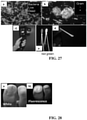
- Bacterial species included streptococcus pyogenes, serratia marcescens, staphylococcus aureus, staphylococcus epidermidis, escherichia coli, and pseudomonas aeruginosa (American Type Culture Collection, ATCC). These were grown and maintained under standard incubation conditions at 37 °C and used for experimentation when during 'exponential growth phase'. Once colonies were detected in the plates (-24 h after inoculation), the device was used to image agar plates containing individual bacterial species in a darkened room.
- the device Using violet/blue (about 405 nm) excitation light, the device was used to image both combined green and red autofluorescence (about 490-550 nm and about 610-640 nm emission) and only red autofluorescence (about 635 +/- 10 nm, the peak emission wavelength for fluorescent endogenous porphyrins) of each agar plate. Fluorescence images were taken of each bacterial species over time for comparison and to monitor colony growth.
- Inset a) shows the device being used to image live bacterial cultures growing on sheep's blood agar plates to detect bacterial autofluorescence.
- Inset b) shows the image of autofluorescence emitted by pseudomonas aruginosa.
- the device may also be used to detect, quantify and/or monitor bacterial colony growth over time using fluorescence, as demonstrated in inset c) with fluorescence imaging of the growth of autofluorescent staphylococcus aureus on an agar plate 24 hours after innoculation. Note the presence of distinct single bacterial colonies in the lower image.
- the device was used to detect both combined green and red (e.g., 490-550 nm + 610-640 nm) and only red (e.g., 635 +/- 10 nm, the peak emission wavelength for fluorescent endogenous porphyrins) emission autofluorescence from several live bacterial species including streptococcus pyogenes, shown in inset d); serratia marcescens, shown in inset e); staphylococcus aureus, shown in inset f); staphylococcus epidermidis, shown inset g); escherichia coli, shown inset h); and Pseudomonas aeruginosa, shown in inset i).
- streptococcus pyogenes shown in inset d
- serratia marcescens shown in inset e
- staphylococcus aureus shown in inset f
- staphylococcus epidermidis shown in inset g
- the autofluorescence images obtained by the device of the bacterial colonies may provide useful image contrast for simple longitudinal quantitative measurements of bacterial colonization and growth kinetics, as well as a means of potentially monitoring response to therapeutic intervention, with antibiotics, photodynamic therapy (PDT), low level light therapy, hyperbaric oxygen therapy (HOT), or advanced wound care products, as examples.
- PDT photodynamic therapy
- HAT hyperbaric oxygen therapy
- advanced wound care products as examples.
- the device provided a portable and sensitive means of imaging individual bacterial colonies growing in standard agar plates. This provided a means to quantify and monitor bacterial colony growth kinetics, as seen in inset c), as well as potentially monitoring response to therapeutic intervention, with antibiotics or photodynamic therapy (PDT) as examples, over time using fluorescence. Therefore, the device may serve as a useful tool in the microbiology laboratory.
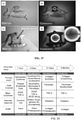
- FIG. 11 shows an example of the use of the imaging device in inset a) standard bacteriology laboratory practice.
- Inset b) fluorescence imaging of a Petri dish containing Staphylococcus aureus combined with custom proprietary image analysis software allows bacterial colonies to be counted rapidly, and here the fluorescence image of the culture dish shows -182 (+/-3) colonies (bright bluish-green spots) growing on agar at 37 °C. (about 405 nm excitation, about 500-550 nm emission (green), about >600 nm emission (red)).
- the device may be used for differentiating the presence and/or location of different bacterial species (e.g., Staphylococcus aureus or Pseudomonas aeguginosa), for example in wounds and surrounding tissues.
- different bacterial species e.g., Staphylococcus aureus or Pseudomonas aeguginosa
- This may be based on the different autofluorescence emission signatures of different bacterial species, including those within the 490-550 nm and 610-640 nm emission wavelength bands when excited by violet/blue light, such as light around 405 nm. Other combinations of wavelengths may be used to distinguish between other species on the images. This information may be used to select appropriate treatment, such as choice of antibiotic.
- Such imaging of bacteriology samples may be applicable to monitoring of wound care.
- the device may be scanned above any wound (e.g., on the body surface) such that the excitation light may illuminate the wound area.
- the wound may then be inspected using the device such that the operator may view the wound in real-time, for example, via a viewer on the imaging device or via an external display device (e.g., heads-up display, a television display, a computer monitor, LCD projector or a head-mounted display).
- an external display device e.g., heads-up display, a television display, a computer monitor, LCD projector or a head-mounted display.
- It may also be possible to transmit the images obtained from the device in real-time (e.g., via wireless communication) to a remote viewing site, for example for telemedicine purposes, or send the images directly to a printer or a computer memory storage. Imaging may be performed within the routine clinical assessment of patient with a wound.
- fiduciary markers e.g., using an indelible fluorescent ink pen
- fiduciary markers may be placed on the surface of the skin near the wound edges or perimeter.
- four spots each of a different fluorescent ink color from separate indelible fluorescent ink pens, which may be provided as a kit to the clinical operator, may be placed near the wound margin or boundary on the normal skin surface.
- These colors may be imaged by the device using the excitation light and a multispectral band filter that matches the emission wavelength of the four ink spots.
- Image analysis may then be performed, by co-registering the fiduciary markers for inter-image alignment.
- the user may not have to align the imaging device between different imaging sessions.
- This technique may facilitate longitudinal (i.e., over time) imaging of wounds, and the clinical operator may therefore be able to image a wound over time without need for aligning the imaging device during every image acquisition.
- a disposable simple fluorescent standard 'strip' may be placed into the field of view during wound imaging (e.g., by using a mild adhesive that sticks the strip to the skin temporarily).
- the strip may be impregnated with one or several different fluorescent dyes of varying concentrations which may produce pre-determined and calibrated fluorescence intensities when illuminated by the excitation light source, which may have single (e.g., 405 nm) or multiple fluorescence emission wavelengths or wavelength bands for image intensity calibration.
- the disposable strip may also have the four spots as described above (e.g., each of different diameters or sizes and each of a different fluorescent ink color with a unique black dot placed next to it) from separate indelible fluorescent ink pens.
- the device With the strip placed near the wound margin or boundary on the normal skin surface, the device may be used to take white light and fluorescence images.
- the strip may offer a convenient way to take multiple images over time of a given wound and then align the images using image analysis.
- the fluorescent 'intensity calibration' strip may also contain an added linear measuring apparatus, such as a ruler of fixed length to aid in spatial distance measurements of the wounds.
- Such a strip may be an example of a calibration target which may be used with the device to aid in calibration or measuring of image parameters (e.g., wound size, fluorescence intensity, etc.), and other similar calibration target may be used.
- the device may have two light sources, such as low power laser beams, which may be used to triangulate individual beams onto the surface of the skin in order to determine a fixed or variable distance between the device and the wound surface. This may be done using a simply geometric arrangement between the laser light sources, and may permit the clinical operator to easily visualize the laser targeting spots on the skin surface and adjust the distance of the device from the wound during multiple imaging sessions.
- Other methods of maintaining a constant distance may include the use of ultrasound, or the use of a physical measure, such as a ruler, or a range finder mechanism.
- the device may be used to take white light images of the total wound with normal surrounding normal tissues using a measuring apparatus (e.g., a ruler) placed within the imaging field of view. This may allow visual assessment of the wound and calculation/determination of quantitative parameters such as the wound area, circumference, diameter, and topographic profile.
- This quantitative information about the wound may be used to track and monitor changes in the wound appearance over time, in order to evaluate and determine the degree of wound healing caused by natural means or by any therapeutic intervention.
- This data may be stored electronically in the health record of the patient for future reference.
- White light imaging may be performed during the initial clinical assessment of the patient by the operator.
- the device may be designed to detect all or a majority of tissue autofluorescence (AF). For example, using a multi-spectral band filter, the device may image tissue autofluorescence emanating from the following tissue biomolecules, as well as blood-associated optical absorption, for example under 405 nm excitation: collagen (Types I, II, III, IV, V and others) which appear green, elastin which appears greenish-yellow-orange, reduced nicotinamide adenine dinucleotide (NADH), flavin adenine dinucleotide (FAD), which emit a blue-green autofluorescence signal, and bacteria/microorganisms, most of which appear to have a broad (e.g., green and red) autofluorescence emission.
- collagen Types I, II, III, IV, V and others
- NADH reduced nicotinamide adenine dinucleotide
- FAD flavin adenine dinucleotide
- Image analysis may include calculating a ratio of red-to-green AF in the image. Intensity calculations may be obtained from regions of interest within the wound images. Pseudo-coloured images may be mapped onto the white light images of the wound.
- the device was tested in a model of wounds contaminated with bacteria.
- pig meat with skin, was purchased from a butcher.
- a scalpel was used to make incisions, ranging in size from 1.5 cm 2 to 4 cm 2 in the skin, and deep enough to see the muscle layer.
- the device was used to image some meat samples without (exogenous) addition of bacteria to the simulated wounds.
- the meat sample was left at room temperature for 24 h in order for bacteria on the meat to grow, and then imaging was performed with the device using both white light reflectance and autofluorescence, for comparison.
- a sample of pig meat with simulated wounds was prepared by applying six bacterial species to each of six small 1.5 cm 2 wound incision sites on the skin surface: streptococcus pyogenes, serratia marcescens, staphylococcus aureus, staphylococcus epidermidis, escherichia coli, and pseudomonas aeruginosa.
- streptococcus pyogenes serratia marcescens
- staphylococcus aureus staphylococcus epidermidis
- escherichia coli staphylococcus epidermidis
- pseudomonas aeruginosa pseudomonas aeruginosa
- the device was used to image the bacteria-laden meat sample using white light reflectance and violet/blue light-induced tissue autofluorescence emission, using both a dual emission band (450-505 nm and 590-650 nm) emission filter and a single band (635 +/- 10 nm) emission filter, on the left and a single band filter over the course of three days, at 24 h time intervals, during which the meat sample was maintained at 37 °C. Imaging was also performed on the styrofoam container on which the meat sample was stored during the three days.
- FIG. 12 shows the results of the device being used for non-invasive autofluorescence detection of bacteria in a simulated animal wound model.
- bacteria were occult within the wound site, as shown in inset a) and magnified in inset b).
- the device was capable of allowing identification of the presence of bacteria within the wound site based on the dramatic increase in red fluorescence from bacterial porphyrins against a bright green fluorescence background from connective tissue (e.g., collagen and elastins) as seen in inset c) and magnified in inset d).
- connective tissue e.g., collagen and elastins
- inset b) and inset d) show a dramatic increase in red fluorescence from bacterial porphyrins against a bright green fluorescence background from connective tissue (e.g., collagen and elastins). It was noted that with autofluorescence, bacterial colonies were also detected on the skin surface based on their green fluorescence emission causing individual colonies to appear as punctuate green spots on the skin. These were not seen under white light examination. Fluorescence imaging of connective tissues aided in determining the wound margins as seen in inset e) and inset f), and some areas of the skin (marked ' ⁇ ' in c) appeared more red fluorescent than other areas, potentially indicating subcutaneous infection of porphyrin-producing bacteria. Insets e) and f) also show the device detecting red fluorescent bacteria within the surgical wound, which are occult under white light imaging.
- connective tissue e.g., collagen and elastins
- the device mapped biodistribution of bacteria within the wound site and on the surrounding skin and thus may aid in targeting specific tissue areas requiring swabbing or biopsy for microbiological testing. Furthermore, using the imaging device may permit the monitoring of the response of the bacterially-infected tissues to a variety of medical treatments, including the use of antibiotics and other therapies, such as antibiotics, wound debridement, wound cleaning, photodynamic therapy (PDT), hyperbaric oxygen therapy (HOT), low level light therapy, or anti-matrix metalloproteinase (MMP).
- PDT photodynamic therapy
- HET hyperbaric oxygen therapy
- MMP anti-matrix metalloproteinase
- the device may be useful for visualization of bacterial biodistribution at the surface as well as within the tissue depth of the wound, and also for surrounding normal tissues. The device may thus be useful for indicating the spatial distribution of an infection.
- the imaging device may be used clinically to determine the healing status of a chronic wound and the success of wound debridement.
- a typical foot ulcer in a person with diabetes is shown in the figure, with (i) the nonhealing edge (i.e., callus) containing ulcerogenic cells with molecular markers indicative of healing impairment and (ii) phenotypically normal but physiologically impaired cells, which can be stimulated to heal.
- the nonhealing edge i.e., callus
- phenotypically normal but physiologically impaired cells which can be stimulated to heal.
- a wound's appearance after debridement it may not be healing and may need to be evaluated for the presence of specific molecular markers of inhibition and/or hyperkeratotic tissue (e.g., c-myc and ⁇ -catenin).
- the clinician may be able to determine the in situ expression of molecular biomarkers.
- fluorescence imaging of the wound area and image analyses may allow biopsy targeting for subsequent immunohistochemistry and this may determine whether the extent of debridement was sufficient. If the extent of debridement was insufficient, as shown in the lower left diagram, cells positive for c-myc (which appears green) and nuclear ⁇ -catenin (which appears purple) may be found based on their fluorescence, indicating the presence of ulcerogenic cells, which may prevent the wound from healing properly and indicate that additional debridement is necessary.
- Lack of healing may also be demarcated by a thicker epidermis, thicker cornified layer, and presence of nuclei in the cornified layer. If the debridement was successful, as in the lower right lower diagram, no staining for c-myc or ⁇ -catenin may be found, indicating an absence of ulcerogenic cells and successful debridement. These markers of inhibition may be useful, but the goal is actual healing as defined by the appearance of new epithelium, decreased area of the wound, and no drainage. This information may be collected using the fluorescence imaging device and stored electronically in the patient's medical record, which may provide an objective analysis coupled with pathology and microbiology reports. By comparing expected healing time with actual healing (i.e., healing progress) time using the imaging device, adaptive treatment strategies may be implemented on a per-patient basis.
- FIG. 14 shows an example of the use of the device for imaging wound healing of a pressure ulcer.
- Inset a) White light image taken with the device of the right foot of a diabetic patient with a pressure ulcer is shown.
- Inset b) Corresponding fluorescence image shows the bright red fluorescence of bacteria (bacteriology results confirmed presence of heavy growth of Staphylococcus aureus) which are invisible under standard white light examination (yellow arrows). Note the heavy growth of Staphylococcus aureus bacteria around the periphery of the non-healing wound (long yellow arrow).
- Insets c-d) Show the spectrally-separated (unmixed) red-green-blue images of the raw fluorescence image in inset b), which are used to produce spectrally-encoded image maps of the green (e.g. collagen) and red (e.g. bacteria) fluorescence intensities calculated using mathematical algorithms and displayed in false color with color scale.
- Insets f-g) show examples of image-processing methods used enhance the contrast of the endogenous bacterial autofluorescence signal by calculating the red/green fluorescence intensity ratio to reveal the presence and biodistribution of bacteria (red-orange-yellow) within and around the open wound.
- FIG. 15 shows an example of the use of the device for imaging a chronic non-healing wound.
- Inset a) White light image taken with the device of the left breast of a female patient with Pyoderma gangrenosum, shows a chronic non-healing wound (blue arrow) and a healed wound (red arrow). Bacteria typically cannot be visualized by standard white light visualization used in conventional clinical examination of the wounds.
- non-healed wound appears dark colored under fluorescence (mainly due to blood absorption of the excitation and fluorescence emission light), while bacteria appear as punctuate bright red spots in the healed wound (red arrow).
- fluorescence normal surrounding skin appears cyan-green due to endogenous collagen fluorescence (405 nm excitation).
- the non-healed wound blue arrow appears to have a band of very bright red fluorescence around the wound border, confirmed with swab cultures (bacteriology) to contain a heavy growth of Staphylococcus aureus (with few Gram positive bacilli and rare Gram positive cocci, confirmed by microscopy).
- Inset c White light image of the healed wound in insets a, b) and d) corresponding fluorescence image showing bright red fluorescence from bacteria (pink arrows), which are occult under white light.
- Inset e White light and inset f) corresponding fluorescence images of the non-healed breast wound.
- bacteria Staphylococcus aureus
- X the wound
- FIG. 16 further illustrates imaging of a chronic non-healing wound using an example of the imaging device.
- Inset a) White light image taken with the device of left breast of female patient with Pyoderma gangrenosum, showing chronic non-healing wound (blue arrow) and healed wound (blue arrow). Bacteria cannot be visualized by standard white light visualization used in clinical examination of the wounds.
- Inset b) Corresponding fluorescence image of the same wounds (405 nm excitation, 500-550 nm emission (green), >600 nm emission (red)). While the nipple appears to be normal under white without obvious contamination of bacteria, fluorescence imaging shows the presence of bacteria emanating from the nipple ducts. Swabs of the nipple showed bacteria were Staphylococcus epidermidis (Occasional growth found on culture). (Scale bar in cm)
- FIG. 17 shows a central area and border of a chronic non-healing wound imaged using the imaging device.
- bacteria Staphylococcus aureus; shown by bacterial swabbing
- X the wound
- FIG. 18 shows further images of a chronic non-healing wound using the imaging device.
- Inset a) White light image taken with the device of left breast of female patient with Pyoderma gangrenosum, showing chronic non-healing wound. Bacteria cannot be visualized by standard white light visualization used in clinical examination of the wounds.
- Inset b) Corresponding fluorescence image of the same wound (405 nm excitation, 500-550 nm emission (green), >600 nm emission (red)). Fluorescence imaging shows the presence of bacteria around the wound edge/border pre- cleaning inset (b) and post-cleaning inset (c).
- cleaning involved the use of standard gauze and phosphate buffered saline to wipe the surface the wound (within and without) for 5 minutes.
- the red fluorescence of the bacteria is appreciably decreased indicating that some of the red fluorescent bacteria may reside below the tissue surface around the edge of the wound.
- Small amounts of bacteria (red fluorescent) remained within the wound center after cleaning.
- inset d) shows a white light image of a chronic non-healing wound in the same patient located on the left calf.
- Inset e) Shows the corresponding fluorescence images pre-cleaning inset (e) and post-cleaning inset (f).
- Swabbing of the central area of the wound revealed the occasional growth of Staphylococcus aureus, with a heavy growth of Staphylococcus aureus at the edge (yellow arrow).
- Cleaning resulted in a reduction of the fluorescent bacteria (Staphylococcus aureus) on the wound surface as determined using the handheld optical imaging device.
- the use of the imaging device resulted in the real-time detection of white light-occult bacteria and this allowed an alteration in the way the patient was treated such that, following fluorescence imaging, wounds and surrounding (bacteria contaminated) were either re-cleaned thoroughly or cleaned for the first time because of de novo detection of bacteria.
- a disposable adhesive measurement-calibration 'strip' for aiding in imaging-focusing and this "strip" may be adhered to any part of the body surface (e.g., near a wound) to allow wound spatial measurements.
- the calibration strip may also be distinctly fluorescent and may be used to add patient-specific information to the images, including the use of multiple exogenous fluorescent dyes for "barcoding" purposes - the information of which can be integrated directly into the fluorescence images of wounds. (Scale bar in cm).
- FIG. 19 illustrates use of the imaging device for monitoring wound healing over time.
- the imaging device is used for tracking changes in the healing status and bacterial biodistribution (e.g. contamination) of a non-healing chronic wound from the left breast of female patient with Pyoderma gangrenosum.
- White light images see column showing insets a-m
- corresponding fluorescence images of the healed wound see column showing insets b-n
- of the chronic non-healing wound see column showing insets co
- 405 nm excitation, 500-550 nm emission (green), >600 nm emission (red) taken using the imaging device under both white light and fluorescence modes.
- FIG. 20 shows another example of the use of the device for monitoring wound status over time.
- the imaging device is used tracking changes in the healing status and bacterial biodistribution (e.g. contamination) of a wound from the left calf of 21 year old female patient with Pyoderma gangrenosum.
- White light images see column of insets a-i
- corresponding fluorescence images see column of insets b-j
- HOT hyperbaric oxygen therapy
- Inset b) shows a distinct green band of fluorescence at the immediate boundary of the wound (yellow arrow; shown to be contaminated heavy growth of Staphylococcus aureus), and this band changes over time as the wound heals. Red fluorescence bacteria are also seen further away from the wound (orange arrow), and their biodistribution changes over time (see column of insets b-j).
- the wound-to-periwound-to-normal tissue boundaries can be seen clearly by fluorescence in image inset j).
- Connective tissue in this example, collagens
- connective tissue remodeling during wound healing can be monitored over time, during various wound treatments including, as is the case here, hyperbaric oxygen therapy of chronic wounds.
- FIG. 21 illustrates use of the imaging device for targeting bacterial swabs during routine wound assessment in the clinic.
- the swab can be directed or targeted to specific areas of bacterial contamination/infection using fluorescence image-guidance in real-time. This may decrease the potential for contamination of non-infected tissues by reducing the spread of bacteria during routine swabbing procedures, which may be a problem in conventional wound swabbing methods.
- Swab results from this sample were determined to be Staphylococcus aureus (with few Gram positive bacilli and rare Gram positive cocci, confirmed by microscopy).
- FIG. 22 shows an example of the co-registration of a) white light and b) corresponding fluorescence images made with the imaging device in a patient with diabetes-associated non-healing foot ulcers.
- a non-contact temperature measuring probe inset in a
- cross-laser sighting direct temperature measurements were made on normal skin (yellow "3 and 4") and within the foot ulcers (yellow "1 and 2") (infected with Pseudomonas aeruginosa, as confirmed by bacteriological culture), indicating the ability to add temperature-based information to the wound assessment during the clinical examination.
- Infected wounds have elevated temperatures, as seen by the average 34.45 °C in the infected wounds compared with the 30.75 °C on the normal skin surface, and these data illustrate the possibility of multimodality measurements which include white light, fluorescence and thermal information for wound health/infectious assessment in real-time.
- both non-healing wounds on this patient's right foot contained heavy growth of Pseudomonas aeruginosa (in addition to Gram positive cocci and Gram negative bacilli), which in this example appear as bright green fluorescent areas within the wound (inset b).
- FIG. 23 shows an example of the use of the imaging device for monitoring a pressure ulcer.
- Inset a) White light image taken with the imaging device of the right foot of a Caucasian diabetic patient with a pressure ulcer is shown.
- Inset b) Corresponding fluorescence image shows the bright red fluorescence of bacteria (bacteriology results confirmed presence of heavy growth of Staphylococcus aureus) which are invisible under standard white light examination (yellow arrows). Dead skin appears as a white/pale light green color (white arrows). Note the heavy growth of Staphylococcus aureus bacteria around the periphery of the non-healing open wounds (yellow arrows).
- Inset c) Shows the fluorescence imaging of a topically applied silver antimicrobial dressing.
- the imaging device may be used to detect the endogenous fluorescence signal from advanced wound care products (e.g., hydrogels, wound dressings, etc.) or the fluorescence signals from such products which have been prepared with a fluorescent dye with an emission wavelength within the detection sensitivity of the imaging detector on the device.
- the device may be used for image-guided delivery/application of advanced wound care treatment products and to subsequently monitor their distribution and clearance over time.
- FIG. 24 shows an example of the use of the device for monitoring a pressure ulcer.
- Inset a) White light image taken with the device of the right foot of a Caucasian diabetic patient with a pressure ulcer.
- Inset b) Corresponding fluorescence image shows the bright red fluorescent area of bacteria (bacteriology results confirmed presence of heavy growth of Staphylococcus aureus, SA) at the wound edge and bright green fluorescent bacteria (bacteriology results confirmed presence of heavy growth of Pseudomonas aeruginosa, PA) which are both invisible under standard white light examination.
- SA Staphylococcus aureus
- PA Pseudomonas aeruginosa
- Inset c Fluorescence spectroscopy taken of the wound revealed unique spectral differences between these two bacterial species: SA has a characteristic red (about 630 nm) autofluorescence emission peak, while PA lacks the red fluorescence but has a strong green autofluorescence peak at around 480 nm.
- the handheld device spectrally distinguishes bacteria from connective tissues and blood in vivo.
- the device detects AF signals of S. aureus, Staphylococcus epidermidis, P. aeruginosa, Candida, Serratia marcescens, Viridans streptococci (a-hemolytic streptococci), Streptococcus pyogenes ( ⁇ -hemolytic streptococci), Corynebacterium diphtheriae, Enterobacter, Enterococcus, and methicillin-resistant S.
- MRSA microbiological swab cultures
- S. aureus S. epidermidis, Candida, S. marcescens, Viridans streptococci, Corynebacterium diphtheriae, S. pyogenes, Enterobacter, and Enterococcus produced red FL (from porphyrin) while P. aeruginosa produced a bluish-green FL (from pyoverdin) detected by the handheld device.
- These spectral characteristics differ significantly from connective tissues (collagen, elastin) and blood, which appear green and dark red, respectively.
- a representative image of these spectral characteristics is shown in FIG. 24 .
- FIG. 25 shows an example of the use of the device for monitoring a chronic non-healing wound.
- Inset a White light image taken with the imaging device of chronic non-healing wounds in 44 year old black male patient with Type II diabetes is shown. Bacteria cannot be visualized by standard white light visualization (see column of insets a-g) used in conventional clinical examination of the wounds. Column of insets b-h) Corresponding fluorescence image of the same wounds (405 nm excitation, 500-550 nm emission (green), >600 nm emission (red)). This patient presented with multiple open non-healing wounds.
- Swab cultures taken from each wound area using the fluorescence image-guidance revealed the heavy growths of Pseudomonas aruginosa (yellow arrow) which appear bright green fluorescent, and Serratia marcescens (circles) which appear red fluorescent. (Scale bar in cm).
- FIG. 26 is a schematic diagram illustrating an example of a use of "calibration" targets, which may be custom-designed, multi-purpose, and/or disposable, for use during wound imaging with the imaging device.
- the strip which in this example is adhesive, may contain a combination of one or more of: spatial measurement tools (e.g., length scale), information barcode for integrating patient-specific medical information, and impregnated concentration-gradients of fluorescent dyes for real-time fluorescence image calibration during imaging.
- multiple concentrations of various exogenous fluorescent dyes or other fluorescence agents may be used for multiplexed fluorescence intensity calibration, for example when more than one exogenous fluorescently-labeled probe is used for tissue/cell/molecular-targeted molecular imaging of wounds in vivo.
- FIG. 27 shows an example of the use of an embodiment of the imaging device for monitoring bacteria, for example for monitoring a treatment response.
- live (green) and dead (red) bacteria inset (e) may be distinguished in real-time ex vivo (e.g., on the swab or tissue biopsy) following bacterial swabbing of a wound, or other body surface, for example, in the swabbing of the oral buccal cheek, as in inset d).
- This real-time bacterial Gram staining or live/dead image-based assessment may be useful for real-time or relatively rapid bacteriology results that may be used for refining treatments, such as antibiotic or other disinfective treatments, or for monitoring treatment response.
- FIG. 28 shows an example of the use of the device used for imaging of toe nail infection.
- Inset a) White light and inset b) corresponding autofluorescence of the right toe of a subject demonstrating the enhanced contrast of the infection that fluorescence imaging provides compared to white light visualization (405 nm excitation, 500-550 nm emission (green), >600 nm emission (red)).
- FIG. 29 shows an example of the device being used for non-invasive autofluorescence detection of collagen and varies bacterial species on the skin surface of a pig meat sample.
- autofluorescence imaging was able to detect the presence of several bacterial species 24 h after they were topically applied to small incisions made in the skin (i.e., streptococcus pyogenes, serratia marcescens, staphylococcus aureus, staphylococcus epidermidis, escherichia coli, and pseudomonas aeruginosa).
- Inset a) shows white light images of pig meat used for testing.
- the device was also able to detect spreading of the bacteria over the surface of the meat over time.
- Inset d) shows an image at Day 1
- inset f) shows an image at Day 3, as the meat sample was maintained at 37 °C.
- Red fluorescence can be seen in some of the wound sites (5, 6) in inset c).
- the device detects a dramatic increase in bacterial autofluorescence from wound site 5) escherichia coli and 6) pseudomonas aeruginosa, with the latter producing significant green and red autofluorescence.
- Insets c) and e) show the device detecting fluorescence using a dual band (450-505 nm green and 590-650 nm) on the left and a single band filter (635 +/-10 nm) on the right, of the wound surface.
- the device detects the significant increase in bacterial autofluorescence (in green and red) from the other wound sites, as well as the bacterial contamination (indicated by the arrow in inset f) on the styrofoam container in which the meat sample was kept.
- the device was also able to detect spreading of the bacteria over the surface of the meat.
- the device may provide critical information on the biodistribution of the bacteria on the wound surface which may be useful for targeting bacterial swabbing and tissue biopsies. Note, in insets d) and f), the intense green fluorescence signal from endogenous collagen at the edge of the pig meat sample.
- This example demonstrates the use of the device for real-time detection of biological changes in connective tissue and bacterial growth based on autofluorescence alone, suggesting a practical capability of the device to provide longitudinal monitoring of bacterial growth in wounds.
- the images show examples of the device used for autofluorescence detection of connective tissues (e.g., collagen, elastin) and bacteria on the muscle surface of a pig meat sample.
- Inset a) shows that white light image of pig meat used for testing shows no obvious signs of bacterial/microbial contamination or spoilage.
- inset b) imaging of the same area with the device under blue/violet light excitation revealed a bright red fluorescent area of the muscle indicating the potential for bacterial contamination compared with the adjacent side of muscle.
- Extremely bright green autofluorescence of collagen can also be seen at the edge of the skin.
- inset c the device was used to surgically interrogate suspicious red fluorescence further to provide a targeted biopsy for subsequent pathology or bacteriology. Note also the capability of the device to detect by fluorescence the contamination (arrow) of the surgical instrument (e.g., forceps) during surgery.
- the device was used to target the collection of fluorescence spectroscopy using a fibre optic probe of an area suspected to be infected by bacteria (inset shows the device being used to target the spectroscopy probe in the same area of red fluorescent muscle in insets b), c).
- e) show an example of the device being used to detect contamination by various thin films of bacteria on the surface of the Styrofoam container on which the meat sample was kept.
- the device is capable of detecting bacteria on non-biological surfaces where they are occult under standard white light viewing (as in inset a).
- the device was also able to identify suspicious areas of muscle tissue, which may then be interrogated further by surgery or targeted biopsy for pathological verification, or by other optical means such as fluorescence spectroscopy using a fiber optic probe. Also, it detected contamination by various bacteria on the surface of the Styrofoam container on which the meat sample was kept. Autofluorescence of the bacteria appears as streaks of green and red fluorescence under violet/blue excitation light from the various bacterial species previously applied to the meat.
- hyperspectral/multispectral fluorescence imaging was used to quantitatively measure the fluorescence intensity spectra from the bacteria under violet/blue light excitation.
- FIG. 30 the device was used to detect fluorescence from bacteria growing in agar plates and on the surface of a simulated wound on pig meat, as discussed above for FIGS. 12 and 29 .
- Bacterial autofluorescence was detected in the green and red wavelength ranges using the device in the culture inset (a) and meat samples inset (d).
- Hyperspectral/multispectral imaging was used to image the bacteria (E.
- Coli in culture inset (b) and to measure the quantitative fluorescence intensity spectra from the bacteria (red line - porphyrins, green - cytoplasm, blue - agar background) inset (c).
- the red arrow shows the 635 nm peak of porphyrin fluorescence detected in the bacteria.
- Hyperspectral/multispectral imaging also confirmed the strong green fluorescence ( ⁇ , right square in inset d) from P. aruginosa (with little porphyrin fluorescence, yellow line in inset f) compared to E. coli (left square in inset d) where significant porphyrin red fluorescence was detected.
- Insets e )and g) show the color-coded hyperspectral/multispectral images corresponding to P. aeruginosa and E. coli, respectively, from the meat surface after 2 days of growth (incubated at 37 °C); and insets f) and h) show the corresponding color-coded fluorescence spectroscopy.
- inset i) excitation-emission matrices (EEM) were also measured for the various bacterial species in solution, demonstrating the ability to select the optimum excitation and emission wavelength bandwidths for use with optical filters in the imaging device.
- EEM excitation-emission matrices
- the EEM for E. coli shows strong green fluorescence as well as significant red fluorescence from endogenous bacterial porphyrins (arrow).
- Spectral information derived from excitation-emission matrices may aid in optimizing the selection of excitation and emission wavelength bandwidths for use with optical filters in the imaging device to permit inter-bacterial species differentiating ex vivo and in vivo.
- the device may be used to detect subtle changes in the presence and amount of endogenous connective tissues (e.g. collagens and elastins) as well as bacteria and/or other microorganisms, such as yeast, fungus and mold within wounds and surrounding normal tissues, based on unique autofluorescence signatures of these biological components.
- endogenous connective tissues e.g. collagens and elastins
- bacteria and/or other microorganisms such as yeast, fungus and mold within wounds and surrounding normal tissues, based on unique autofluorescence signatures of these biological components.
- This device may be used as an imaging and/or monitoring device in clinical microbiology laboratories.
- the device may be used for quantitative imaging of bacterial colonies and quantifying colony growth in common microbiology assays. Fluorescence imaging of bacterial colonies may be used to determine growth kinetics.
- Angiogenesis the growth of new blood vessels, is an important natural process required for healing wounds and for restoring blood flow to tissues after injury or insult.
- Angiogenesis therapies which are designed to "turn on" new capillary growth, are revolutionizing medicine by providing a unified approach for treating crippling and life-threatening conditions.
- Angiogenesis is a physiological process required for wound healing. Immediately following injury, angiogenesis is initiated by multiple molecular signals, including hemostatic factors, inflammation, cytokine growth factors, and cell-matrix interactions. New capillaries proliferate via a cascade of biological events to form granulation tissue in the wound bed.
- This process may be sustained until the terminal stages of healing, when angiogenesis is halted by diminished levels of growth factors, resolution of inflammation, stabilized tissue matrix, and endogenous inhibitors of angiogenesis. Defects in the angiogenesis pathway impair granulation and delay healing, and these are evident in chronic wounds.
- selected narrow wavelength bands e.g., blue, green and red components
- the device may also be used to image the presence of blood and microvascular networks within and around the wound, including the surrounding normal tissue, thus also revealing areas of erythema and inflammation.
- the device may use individual optical filters (e.g., 405 nm, 546 nm, 600 nm, +/- 25 nm each) in order to demonstrate the possibility of imaging blood and microvasculature in wounds.
- White light images of a wound may be collected with the device and then the device, equipped with a triple band-pass filter (e.g., 405 nm, 546 nm, 600 nm, +/- 25 nm each), placed in front of the imaging detector may image the separate narrow bandwidths of blue (B), green (G), and red (R) reflected light components from the wound.
- a triple band-pass filter e.g., 405 nm, 546 nm, 600 nm, +/- 25 nm each
- These wavelength bands may be selected based on the peak absorption wavelengths of blood, containing both oxygenated and deoxygenated hemoglobin, in the visible light wavelength range.
- the resulting images may yield the relative absorption, and thus reflectance, of visible light by blood in the field of view.
- the resulting 'blood absorption' image yields a high contrast image of the presence of blood and/or microvascular networks in the wound and surrounding normal tissues.
- the clinician may select the appropriate optical filter set for use with the device to obtain images of blood and/or microvascular distribution within the wound and the combine this information with one or both of autofluorescence imaging and imaging with exogenous contrast agents. This may provide a comprehensive information set of the wound and surrounding normal tissues at the morphological, topographical, anatomical, physiological, biological and molecular levels, which currently may not be possible within conventional wound care practice.
- FIG. 31 shows examples of the device used for imaging of blood and microvasculature in wounds.
- the device was used to image a piece of filter paper stained with blood inset (a) and the ear of a mouse during surgery inset (b).
- White light images were collected of each specimen using the imaging device, in non-fluorescence mode, and then the device was equipped with a triple band-pass filter placed in front of the imaging detector (405 nm, 546 nm, 600 nm, +/- 25 nm each) to image the separate narrow bandwidths of blue (B), green (G), and red (R) reflected light components from the specimens.
- B blue
- G green
- R red
- These wavelength bands were selected based on the peak absorption wavelengths of blood in the visible light wavelength range (inset in a) shows the absorption spectral profile for oxy- and deoxygenated hemoglobin in blood. This shows that using a simple multiband transmission filter, it is possible to combine the three B, G, R images into a single 'white light equivalent' image that measures the relative absorption of light by blood in the field of view. The resulting 'blood absorption' image yields a high contrast image of the presence of blood containing both oxy- and deoxygenated hemoglobin.
- the device may be used with narrower bandwidth filters to yield higher contrast images of blood absorption in wounds, for example.
- the device may be used to image and/or monitor targets such as a skin target, an oral target, an ear-nose-throat target, an ocular target, a genital target, an anal target, and any other suitable targets on a subject.
- targets such as a skin target, an oral target, an ear-nose-throat target, an ocular target, a genital target, an anal target, and any other suitable targets on a subject.
- the present device may provide biologically-relevant information about wounds and may exploit the emerging telemedicine (e.g., E-health) infrastructure to provide a solution for mobile wound care technology and may greatly impact wound health care treatment.
- Wound care accounts for a large percentage of home visits conducted by nurses and health care workers. Despite best practices some wounds do not heal as expected and require the services of a clinical specialist.
- the device described here may enable access to specialized clinical resources to help treat wounds from the convenience of the patient's home or chronic care facility, which decreases travel time for clients, increases availability to clinical wound specialists, and may reduce costs to the health care system.
- the device may be used to detect and monitor changes in connective tissues (e.g., collagen, elastin) and blood/vascular supply during the wound healing process, monitor tissue necrosis and exudate in wounds based on fluorescence, detect and diagnose wound infections including potentially indicating critical 'clinically significant' categories of the presence of bacteria or micro-organisms (e.g., for detecting contamination, colonization, critical colonization and infection) at the surface and deep within wounds, provide topographic information of the wound, and identify wound margins and surrounding normal tissues.
- connective tissues e.g., collagen, elastin
- blood/vascular supply e.g., vascular supply during the wound healing process
- tissue necrosis and exudate in wounds based on fluorescence
- detect and diagnose wound infections including potentially indicating critical 'clinically significant' categories of the presence of bacteria or micro-organisms (e.g., for detecting contamination, colonization, critical colonization and infection) at the surface and deep within wounds, provide topographic information of
- Tissue fluorescence and reflectance imaging data may be 'mapped' onto the white light images of the wound thereby permitting visualization within the wound and the surrounding normal tissues of essential wound biochemical and photobiological (e.g., fluorescence) information, which has not been possible to date.
- Real-time imaging of wounds may be performed over time to monitoring changes in wound healing, and to potentially monitor the effectiveness of treatments by providing useful information about underlying biological changes that are occurring at the tissue/cellular level (e.g., matrix remodeling, inflammation, infection and necrosis). This may provide quantitative and objective wound information for detection, diagnosis and treatment monitoring in patients.
- the device may be used to monitor and/or track the effectiveness of therapy at a biological level (e.g., on a bacterial level), which may provide more information than monitoring only the macroscopic/morphological appearance using white light.
- the device may provide real-time non-invasive image-guided biopsy targeting, clinical procedural guidance, tissue characterization, and may enable image-guided treatment using conventional and emerging modalities (e.g., PDT).
- use of the imaging device may be used to correlate critical biological and molecular wound information obtained by fluorescence (e.g., endogenous tissue autofluorescence and/or administration of exogenous molecular-biomarker targeted fluorescence contrast agents) with existing and emerging clinical wound care assessment and treatment guides, such as the NERDS and STONES guidelines proposed by Sibbald et al. ( Sibbald et al. Increased Bacterial Burden and Infection: The Story of NERDS and STONES.
- fluorescence e.g., endogenous tissue autofluorescence and/or administration of exogenous molecular-biomarker targeted fluorescence contrast agents
- existing and emerging clinical wound care assessment and treatment guides such as the NERDS and STONES guidelines proposed by Sibbald et al. ( Sibbald
- the fluorescence imaging data obtained with the device may be used to characterize, spatially and spectrally, bacterial balance and burden at the superficial and deep levels of wounds.
- the device may provide real-time non-invasive image-guided biopsy targeting, clinical procedural guidance, tissue characterization, and may enable image-guided treatment using conventional and emerging treatment modalities (e.g., photodynamic therapy, PDT).
- the device may be used within the clinical setting and integrated into conventional clinical wound care regimens, and may have a distinct role in areas of infectious diseases. It should be noted as well that this device may also be used for real-time analysis, monitoring and care for chronic and acute wounds in animals and pets, via conventional veterinary care.
- This device may allow real-time wound healing assessment for a large patient cohort base.
- elderly people, diabetics, immuno-suppressed and immobilized individuals have an increased incidence of chronic wounds and other dermal afflictions that result from poor circulation and immobility, e.g. pressure ulcers such as bed sores, venous stasis ulcers, and diabetic ulcers.
- pressure ulcers such as bed sores, venous stasis ulcers, and diabetic ulcers.
- These chronic conditions greatly increase the cost of care and reduce the patient's quality of life.
- these groups are growing in number, the need for advanced wound care products will increase.
- This device may impact patient care by allowing a cost-effective means of monitoring chronic and acute wounds in a number of settings, including hospitals, ambulatory clinics, chronic care facilities, in-home-visit health care, emergency rooms and other critical areas in health care facilities. Further, such a 'hand-held' and portable imaging device may be easily carried and used by nursing and ambulance staff. Early identification of scarring, which is related to connective tissue production and re-modeling of the wound, and bacterial infections may be detected and treated appropriately, something that is currently difficult.
- wound-care products including multiple dressing types (e.g., film, hydrocolloid, foam, anti-microbial, alginate, non-adherent, impregnated), hydrogels, wound cleansers and debriding agents, tissue engineered products (e.g., skin replacements, substitutes, and tissue-engineered products such as synthetic polymer-based biological tissue and growth factors), wound cleansers, pharmacological products, and physical therapies may also benefit from the device developed here as it may allow image-based longitudinal monitoring of the effectiveness of such treatments.
- Physical therapies may include hydrotherapy, electrical stimulation, electromagnetic stimulation devices, ultraviolet therapy, hyperbaric oxygen therapy, ultrasound devices, laser/light emitting diode (LED) devices, and wound imaging/documentation. Additional therapies may include, for example, antibiotics, wound debridement, application of wound dressings, and wound cleaning.
- Wound tissue analysis is typically required for the assessment of the healing of skin wounds. Percentage of the granulation tissue, fibrin and necrosis in the wound, and their change during treatment may provide useful information that may guide wound treatment.
- Image analysis may include advanced statistical pattern recognition and classification algorithms to identify individual pixels within the fluorescence wound images collected with the device based on the optical information of the wound and surrounding normal tissue. Thus, image analysis may allow wound images to be mapped into various components of the wound, including total wound area, epithelialization, granulation, slough, necrotic, hypergranulation, infected, undermining, and surrounding tissue margins. This has an added advantage of providing relatively rapid determination of wound healing rates, as well as informing guide patient management decisions.
- FIG. 32 illustrates the projected management workflow for the imaging device in a clinical wound care setting.
- the device may be easily integrated into routine wound assessment, diagnosis, treatment and longitudinal monitoring of response, and may provide critical biological and molecular information of the wound in real-time for rapid decision-making during adaptive interventions.
- This device may be easily integrated into existing health-care computer infrastructures (e.g., desktop and pocket PCs used by a growing number of physicians or other health care professionals) for longitudinal image cataloguing for patient wound management within the conventional clinical environment.
- the wireless receiving and transmission of data capabilities of the device may allow monitoring of wound care and healing remotely through existing and future wireless telemedicine infrastructure.
- the device may be used to transfer essential medical data (e.g., wound health status) via the internet or over wireless services, such as cellular telephone, PDA or Smartphone services, to remote sites which may permit remote medical interventions, with a further utility in military medical applications for battlefield wound management.
- the device may allow real-time surface imaging of wound sites and may be easily carried by point-of-care personnel in clinical settings.
- the device may offer image-based documentation of wound healing and tracking of treatment effectiveness. Also, this technology may be adapted to also function in 'wireless' mode to permit remote medical interventions by potentially adapting it for use with high-resolution digital cameras embedded in commercially-available cellular telephones.
- the imaging device may be integrated into a 'store-and-forward' concept of wound assessment systems.
- a system may present a comprehensive set of clinical data that meet the recommendations of clinical practice guidelines.
- the presently-disclosed device may integrate into a computer-based wound assessment system (e.g., with image analysis software) to be used by a health care facility to enhance existing clinical databases and support the implementation of evidence-- based practice guidelines.
- a computer-based wound assessment system e.g., with image analysis software
- Such an integrated telemedicine infrastructure may be used for monitoring patients at home or in long-term-care facilities, who may benefit from routine monitoring by qualified clinicians but currently do not have access to this care.
- This device may be further developed into a portable handheld point-of-care diagnostic system, which may represent a major advance in detecting, monitoring, treating, and preventing infectious disease spread in the developed and developing worlds. This knowledge may significantly improve the diagnostic tools available to practitioners who treat chronic wounds in settings where quantitative cultures are inaccessible.
- the device may allow digital imaging with optical and digital zooming capabilities (e.g., those embedded in commonly available digital imaging devices). Still or video image quality may be in 'high-definition' format to achieve high spatial resolution imaging of the tissue surface. Images may be recorded as still/freeze frame and/or in video/movie format and printed using standard imaging printing protocols which do (e.g., connected via USB) or do not (e.g., PictBridge) require a personal computer. The images/video data may be transferred to a personal computer for data archival storage and/or image viewing and/or analysis/manipulation. The device may also transfer data to a printer or personal computer using wired or wireless capabilities (e.g., Bluetooth).
- wired or wireless capabilities e.g., Bluetooth
- Visualization may be performed on the hand-held device screen and/or in addition to simultaneous viewing on a video screen/monitor (e.g., head-mounted displays and glasses) using standard output video cables.
- This device may display, in combination or separately, optical wavelength and fluorescence/reflectance intensity information with spatial dimensions of the imaged scene to allow quantitative measurements of distances (e.g., monitoring changes tissue morphology/topography) over time.
- the device may also allow digital image/video storage/cataloguing of images and related patient medical data, for example using dedicated software with imaging analysis capabilities and/or diagnostic algorithms.
- Image analysis may be used together with the device to quantitatively measure fluorescence intensities and relative changes in multiple fluorescence spectra (e.g., multiplexed imaging) of the exogenous optical molecular targeting probes in the wound and surrounding normal tissues.
- the biodistributions of the fluorescent probes may be determined based on the fluorescence images collected and these may be monitored over time between individual clinical wound imaging sessions for change.
- the clinical operator may determine in real-time or near real-time the health and/or healing status and response to treatment over time of a given wound, for example by using a look-up table in which specific tissue, cellular and molecular signals are displayed in correlation to wound health, healing and response status, an example of which is shown in FIG. 33 .
- This may permit the clinician to determine whether a wound is healing based on biological and molecular information which may not be possible otherwise with existing technologies.
- the presence and abundance of bacteria/microorganisms and their response to treatment may offer a means to adapt the therapy in real-time instead of incurring delays in response assessment with conventional bacteriological testing of wound cultures.
- Image analysis techniques may be used to calibrate the initial or first images of the wound using a portable fluorescent standard placed within the field of view during imaging with the device.
- the image analysis may also permit false or pseudo color display on a monitor for differentiating different biological (e.g., tissue, cellular, and molecular) components of the wound and surrounding normal tissues including those biomarkers identified by autofluorescence and those identified by the use of exogenous targeted or untargeted fluorescence/absorption contrast agents.
- FIG. 34 Examples of such biomarkers are listed in FIG. 34 and illustrated in FIG. 35 .
- FIG. 35 the diagram shows mechanisms of wound healing in healthy people versus people with diabetic wounds.
- the acute wound healing process is guided and maintained through integration of multiple molecular signals (e.g., in the form of cytokines and chemokines) released by keratinocytes, fibroblasts, endothelial cells, macrophages, and platelets.
- molecular signals e.g., in the form of cytokines and chemokines
- VEGF vascular endothelial growth factor
- SDF-1 ⁇ expression is decreased in epithelial cells and myofibroblasts in the diabetic wound, which prevents EPC homing to wounds and therefore limits wound healing. It has been shown that establishing hyperoxia in wound tissue (e.g., via HBO therapy) activated many NOS isoforms, increased NO levels, and enhanced EPC mobilization to the circulation. However, local administration of SDF-1 ⁇ was required to trigger homing of these cells to the wound site. These results suggest that HBO therapy combined with SDF-1 ⁇ administration may be a potential therapeutic option to accelerate diabetic wound healing alone or in combination with existing clinical protocols.
- Pre-assigned color maps may be used to display simultaneously the biological components of the wound and surrounding normal tissues including connective tissues, blood, microvascularity, bacteria, microorganisms, etc. as well as fluorescently labeled drugs/pharmacological agents. This may permit visualization in real-time or near real-time (e.g., less than 1 minute) of the health, healing and infectious status of the wound area.
- the image analysis algorithms may provide one or more of the following features:
- image analysis algorithm techniques, or software have been described, this description also extends to a computing device, a system, and a method for carrying out this image analysis.
- the device may also be useful for providing fluorescent image-guidance, for example in surgical procedures, even without the use of dyes or markers.
- Certain tissues and/or organs may have different fluorescent spectra (e.g., endogenous fluorescence) when viewed using the imaging device, or example under certain excitation light conditions.
- FIG. 36 demonstrates the usefulness of the device for fluorescence imaging-assisted surgery.
- different organs of a mouse model may be more clearly distinguishable than under white light.
- Insets b, c and g show the mouse model under white light.
- Insets a, d-f and h-j show the mouse model as imaged with the device.
- FIG. 37 shows an example of the use of the device for imaging small animal models.
- the mouse dorsal skin-fold window chamber is imaged under white light (insets a, c) and fluorescence (insets b, d).
- the feet and face appear bright red fluorescent due to endogenous autofluorescence from the cage bedding and food dust materials. (405 nm excitation; 490-550 nm and >600 nm emission channels).
- Bioengineered skin products or skin equivalents have become available commercially for the treatment of acute and chronic wounds, as well as burn wounds. These have been developed and tested in human wounds.
- Skin equivalents may contain living cells, such as fibroblasts or keratinocytes, or both, while others are made of acellular materials or extracts of living cells. The clinical effect of these constructs is 15-20% better than conventional 'control' therapy, but there is debate over what constitutes an appropriate control.
- Bioengineered skin may work by delivering living cells which are known as a 'smart material' because they are capable of adapting to their environment. There is evidence that some of these living constructs are able to release growth factors and cytokines.
- Exogenous fluorescent molecular agents may be used in conjunction with such skin substitutes to determine completeness of engraftment as well as biological response of the wound to the therapy.
- the healing of full-thickness skin defects may require extensive synthesis and remodeling of dermal and epidermal components. Fibroblasts play an important role in this process and are being incorporated in the latest generation of artificial dermal substitutes.
- the imaging device described here may be used to determine the fate of fibroblasts seeded in skin substitute and the influence of the seeded fibroblasts on cell migration and dermal substitute degradation after transplantation to wound site can be determined.
- Wounds may be treated with either dermal substitutes seeded with autologous fibroblasts or acellular substitutes. Seeded fibroblasts, labeled with a fluorescent cell marker, may then be detected in the wounds with fluorescence imaging device and then quantitatively assessed using image analysis, for example as described above.
- Rimon Therapeutics produces Theramers TM (www.rimontherapeutics.com) which are medical polymers that have biological activity in and of themselves, without the use of drugs. Rimon Therapeutics produces the following wound care products, which can be made to be uniquely fluorescent, when excited by 405 nm excitation light: Angiogenic Theramer TM , which induces new blood vessel development (i.e., angiogenesis) in wounds or other ischemic tissue; MI Theramer TM , which inhibits the activity of matrix metalloproteases (MMPs), a ubiquitous group of enzymes that are implicated in many conditions in which tissue is weakened or destroyed; AM Theramer TM , a thermoplastic that kills gram positive and gram negative bacteria without harming mammalian cells; and ThermaGel TM , a polymer that changes from a liquid to a strong gel reversibly around body temperature. These can each be made to be fluorescent
- the application of such fluorescent polymer agents may be guided by fluorescent imaging in real-time. This may permit the Theramer agent to be accurately delivered/applied (e.g., topically) to the wound site. Following application of the agent to the wound, the fluorescent imaging device may then be used to quantitatively determine the therapeutic effects of the Theramers on the wound as well as track the biodistribution of these in the wound over time, in vivo and non-invasively. It may also be possible to add a molecular beacon, possibly having another fluorescent emission wavelength, to the MI Theramer TM that can fluoresce in the presence of wound enzymes (e.g., MMPs), and this may indicate in real-time the response of the wound to the MI Theramer TM .
- a molecular beacon possibly having another fluorescent emission wavelength
- Fluorescent agents may be added to other products to allow for imaging using the device. In some cases, the products may already be luminescent and may not require the addition of fluorescent agents.
- the device may be used also to monitor the effects of such treatments over time.
- the imaging device may be provided in a kit, for example including the device and a fluorescing contrast agent.
- the contrast agent may be any one or more of those described above.
- the contrast agent may be for labeling a biomarker in a wound, where the kit is for wound monitoring applications.
- FIG. 38 shows an example of a kit including the imaging device.
- Inset a) shows the handle and the touch-sensitive viewing screen
- inset b) shows external housing and excitation light sources.
- the imaging device may be used to scan the body surface of both human and veterinary patients for image-based wound assessment, or for non-wound imaging applications.
- the device and any accessories e.g., electrical/battery power supplies), potential exogenous fluorescence contrast agents, etc.
- the imaging device may be used in white light and fluorescence modes to improve the administration of these treatments as well as monitor their effectiveness over time non-invasively and quantitatively.
- the device may be used in combination with other imaging modalities, for example thermal imaging methods, among others.
- the use of a fluorescent imaging device in such environments is disclosed in U.S. Patent No. 9,042,967 B2 to DaCosta et al., entitled “Device and Method for Wound Imaging and Monitoring,” and issued on May 26, 2015 , which is incorporated by reference herein.
- the device may be used for detecting and imaging of the presence of bacteria or microbes and other pathogens on a variety of surfaces, materials, instruments (e.g., surgical instruments) in hospitals, chronic care facilities, old age homes, and other health care settings where contamination may be the leading source of infection.
- the device may be used in conjunction with standard detection, identification and enumeration of indicator organisms and pathogens strategies.
Landscapes
- Health & Medical Sciences (AREA)
- Life Sciences & Earth Sciences (AREA)
- Engineering & Computer Science (AREA)
- Medical Informatics (AREA)
- Physics & Mathematics (AREA)
- General Health & Medical Sciences (AREA)
- Veterinary Medicine (AREA)
- Heart & Thoracic Surgery (AREA)
- Biomedical Technology (AREA)
- Molecular Biology (AREA)
- Surgery (AREA)
- Animal Behavior & Ethology (AREA)
- Pathology (AREA)
- Public Health (AREA)
- Biophysics (AREA)
- Quality & Reliability (AREA)
- Radiology & Medical Imaging (AREA)
- Nuclear Medicine, Radiotherapy & Molecular Imaging (AREA)
- Computer Vision & Pattern Recognition (AREA)
- General Physics & Mathematics (AREA)
- Theoretical Computer Science (AREA)
- Dermatology (AREA)
- Investigating, Analyzing Materials By Fluorescence Or Luminescence (AREA)
- Investigating Or Analysing Materials By Optical Means (AREA)
- Radiation Pyrometers (AREA)
- Measuring And Recording Apparatus For Diagnosis (AREA)
- Investigating Or Analysing Biological Materials (AREA)
- Measuring Or Testing Involving Enzymes Or Micro-Organisms (AREA)
Applications Claiming Priority (3)
| Application Number | Priority Date | Filing Date | Title |
|---|---|---|---|
| US201462028386P | 2014-07-24 | 2014-07-24 | |
| PCT/CA2015/000444 WO2016011534A1 (en) | 2014-07-24 | 2015-07-24 | Collection and analysis of data for diagnostic purposes |
| EP15824466.5A EP3171765B1 (en) | 2014-07-24 | 2015-07-24 | Collection and analysis of data for diagnostic purposes |
Related Parent Applications (2)
| Application Number | Title | Priority Date | Filing Date |
|---|---|---|---|
| EP15824466.5A Division-Into EP3171765B1 (en) | 2014-07-24 | 2015-07-24 | Collection and analysis of data for diagnostic purposes |
| EP15824466.5A Division EP3171765B1 (en) | 2014-07-24 | 2015-07-24 | Collection and analysis of data for diagnostic purposes |
Publications (1)
| Publication Number | Publication Date |
|---|---|
| EP3957232A1 true EP3957232A1 (en) | 2022-02-23 |
Family
ID=55162353
Family Applications (2)
| Application Number | Title | Priority Date | Filing Date |
|---|---|---|---|
| EP21187101.7A Pending EP3957232A1 (en) | 2014-07-24 | 2015-07-24 | Collection and analysis of data for diagnostic purposes |
| EP15824466.5A Active EP3171765B1 (en) | 2014-07-24 | 2015-07-24 | Collection and analysis of data for diagnostic purposes |
Family Applications After (1)
| Application Number | Title | Priority Date | Filing Date |
|---|---|---|---|
| EP15824466.5A Active EP3171765B1 (en) | 2014-07-24 | 2015-07-24 | Collection and analysis of data for diagnostic purposes |
Country Status (10)
Families Citing this family (114)
| Publication number | Priority date | Publication date | Assignee | Title |
|---|---|---|---|---|
| CA3162577C (en) | 2008-05-20 | 2023-09-26 | University Health Network | Device and method for fluorescence-based imaging and monitoring |
| US11985075B1 (en) * | 2013-02-04 | 2024-05-14 | C/Hca, Inc. | Data stream processing for dynamic resource scheduling |
| US10628180B1 (en) | 2018-08-20 | 2020-04-21 | C/Hca, Inc. | Disparate data aggregation for user interface customization |
| WO2015114121A1 (en) | 2014-01-30 | 2015-08-06 | Bd Kiestra B.V | A system and method for image acquisition using supervised high quality imaging |
| CN115919256A (zh) | 2014-07-24 | 2023-04-07 | 大学健康网络 | 用于诊断目的的数据的收集和分析 |
| US10524647B2 (en) * | 2014-07-31 | 2020-01-07 | The University Of Akron | Smartphone endoscope system |
| KR102585730B1 (ko) | 2014-08-08 | 2023-10-10 | 퀀텀-에스아이 인코포레이티드 | 수신된 광자들의 시간 비닝을 위한 집적 디바이스 |
| JP6845221B2 (ja) | 2015-04-23 | 2021-03-17 | ビーデー キーストラ ビー.ヴィー. | プレート培地上にストリークされた試料からの自動化された微生物コロニーカウントのための方法及びシステム |
| KR20240069819A (ko) | 2015-04-23 | 2024-05-20 | 비디 키에스트라 비.브이. | 콜로니 콘트라스트 수집 |
| US10209242B2 (en) * | 2015-05-21 | 2019-02-19 | Emit Imaging, Inc. | Fluorescence histo-tomography (FHT) systems and methods |
| US11013467B2 (en) * | 2015-10-22 | 2021-05-25 | Tyto Care Ltd | System, method and computer program product for physiological monitoring |
| CN108471945A (zh) * | 2015-11-13 | 2018-08-31 | 耶斯生物技术公司 | 有关病毒性和非病毒性感染之间原位分化的装置和系统以及方法 |
| US20170232185A1 (en) * | 2016-02-17 | 2017-08-17 | Acist Medical Systems, Inc. | Sterilization of fluid paths in injection system |
| AU2017219894B2 (en) * | 2016-02-17 | 2021-12-09 | Tesseract Health, Inc. | Sensor and device for lifetime imaging and detection applications |
| WO2017158428A1 (en) * | 2016-03-14 | 2017-09-21 | Smith & Nephew Plc | Wound dressing apparatus with flexible display |
| JP7299292B2 (ja) * | 2016-04-19 | 2023-06-27 | マクセル株式会社 | 作業支援装置 |
| CN106092908B (zh) * | 2016-05-26 | 2019-01-18 | 北京化工大学 | 一种基于两个颜色传感器动态白平衡的真菌霉素的快速检测方法 |
| GB201610988D0 (en) * | 2016-06-23 | 2016-08-10 | Inspection Tech Ltd | Apparatus and method for extracting low intensity photonic signals |
| JP7024713B2 (ja) | 2016-08-04 | 2022-02-24 | ソニーグループ株式会社 | 画像処理装置、及び画像処理方法 |
| WO2018039624A1 (en) | 2016-08-26 | 2018-03-01 | The Texas A&M University System | Hand-held synchronous scan spectrometer for in situ detection of pathogens and mineral deficiency in blood |
| WO2018064077A2 (en) | 2016-09-29 | 2018-04-05 | Smith & Nephew, Inc. | Construction and protection of components in negative pressure wound therapy systems |
| US20180093107A1 (en) * | 2016-09-30 | 2018-04-05 | Gliese 623B, LLC | System and Method For Healing and/or Disinfecting Wounds and Burns |
| US20190290176A1 (en) * | 2016-10-19 | 2019-09-26 | The Regents Of The University Of Colorado, A Body Corporate | Systems And Methods For Determining Physiological Information With A Computing Device |
| US11002678B2 (en) * | 2016-12-22 | 2021-05-11 | University Of Tsukuba | Data creation method and data use method |
| WO2018119347A1 (en) | 2016-12-22 | 2018-06-28 | Quantum-Si Incorporated | Integrated photodetector with direct binning pixel |
| AU2016433865B2 (en) * | 2016-12-30 | 2022-05-26 | Barco Nv | System and method for 3D reconstruction |
| FR3061849B1 (fr) * | 2017-01-17 | 2025-03-21 | Fluoptics | Procede et dispositif de mesure de la fluorescence emise a la surface d'un tissu biologique |
| CN116794819A (zh) * | 2017-02-08 | 2023-09-22 | Essenlix 公司 | 用于测定的光学器件、装置和系统 |
| US12120407B2 (en) | 2017-02-08 | 2024-10-15 | Essenlix Corporation | Image-based assay using mark-assisted machine learning |
| US20200029887A1 (en) * | 2017-02-21 | 2020-01-30 | Envue Imaging Inc. | Method of assessing wound contamination and infection |
| US11974903B2 (en) * | 2017-03-07 | 2024-05-07 | Smith & Nephew, Inc. | Reduced pressure therapy systems and methods including an antenna |
| US10803988B2 (en) * | 2017-03-20 | 2020-10-13 | SK Commercial Construction, Inc. | Color analysis and control using a transparent display screen on a mobile device with non-transparent, bendable display screen or multiple display screen with 3D sensor for telemedicine diagnosis and treatment |
| US20200138295A1 (en) * | 2017-05-09 | 2020-05-07 | Yes Biotechology Inc | Devices, systems and methods relating to thermometer housings for attachment to hand-held thermometers for in situ differentiation between viral and non-viral infections |
| JP2020520690A (ja) * | 2017-05-09 | 2020-07-16 | イエス バイオテクノロジー,インク. | ウィルス性病原菌と非ウィルス性病原菌の間のイン・サイチュ差別化のためのハンドヘルド式通信装置に関する装置、システム、および方法 |
| WO2018213752A1 (en) * | 2017-05-19 | 2018-11-22 | Fundación Deusto | Method and system for monitoring and evaluation of pressure ulcer severity |
| US10376149B2 (en) * | 2017-07-11 | 2019-08-13 | Colgate-Palmolive Company | Oral care evaluation system and process |
| CN109452944B (zh) * | 2017-09-06 | 2023-08-15 | 东北大学 | 基于荧光脉搏波的血液荧光物质无创检测系统 |
| US11160491B2 (en) | 2017-09-12 | 2021-11-02 | Hill-Rom Services, Inc. | Devices, systems, and methods for monitoring wounds |
| GB201718859D0 (en) | 2017-11-15 | 2017-12-27 | Smith & Nephew | Sensor positioning for sensor enabled wound therapy dressings and systems |
| WO2019092509A1 (en) * | 2017-11-10 | 2019-05-16 | Galderma Research & Development | Uv device for evaluation of skin conditions |
| EP3714459A4 (en) * | 2017-11-20 | 2021-12-22 | Nano Global Corp. | COLLECTION AND ANALYSIS OF DATA BASED ON THE DETECTION OF BIOLOGICAL CELLS OR BIOLOGICAL SUBSTANCES |
| FR3075824B1 (fr) * | 2017-12-21 | 2022-01-14 | Biomerieux Sa | Procede d'identification d'une levure ou d'une bacterie |
| FR3075825B1 (fr) * | 2017-12-21 | 2022-01-21 | Biomerieux Sa | Procede et systeme d'identificationdu type de gram d'une bacterie |
| CA3089345A1 (en) * | 2018-02-02 | 2019-08-08 | Moleculight Inc. | Wound imaging and analysis |
| DE102018203646A1 (de) * | 2018-03-12 | 2019-09-12 | Robert Bosch Gmbh | Verfahren und Kamerasystem zur Überwachung eines Verpackungsvorgangs |
| JP7445599B2 (ja) * | 2018-03-13 | 2024-03-07 | トラスト バイオソニックス インク | 高感度分子解析のための組成及び方法 |
| EP3540494B1 (en) * | 2018-03-16 | 2022-11-23 | Leica Instruments (Singapore) Pte. Ltd. | Augmented reality surgical microscope and microscopy method |
| DE102018107621A1 (de) * | 2018-03-29 | 2019-10-02 | Imedos Systems GmbH | Vorrichtung und Verfahren zur Untersuchung der metabolischen Autoregulation |
| CN112534241A (zh) * | 2018-06-01 | 2021-03-19 | 奥布Xyz股份有限公司 | 检测介质中的分析物 |
| EP3801211A1 (en) * | 2018-06-08 | 2021-04-14 | East Carolina University | Determining peripheral oxygen saturation (spo2) and hemoglobin concentration using multi-spectral laser imaging (msli) methods and systems |
| CA3106578A1 (en) * | 2018-07-16 | 2020-01-23 | Swift Medical Inc. | Apparatus for visualization of tissue |
| US11938236B2 (en) * | 2018-08-17 | 2024-03-26 | Seoul Viosys Co., Ltd. | Medical dressing |
| US11908573B1 (en) | 2020-02-18 | 2024-02-20 | C/Hca, Inc. | Predictive resource management |
| EP3649919B1 (de) * | 2018-11-12 | 2025-01-01 | Ivoclar Vivadent AG | Dentales bildaufnahmesystem |
| US20200146555A1 (en) * | 2018-11-13 | 2020-05-14 | Atlantic Health System, Inc. | Devices, systems, and methods for controlling distance between an imaging device and a wound |
| BR112021011132A2 (pt) * | 2018-12-14 | 2021-08-31 | Spectral Md, Inc. | Sistemas de aprendizado por máquina e métodos para avaliação, predição de cicatrização e tratamento de feridas |
| CN113260835B (zh) | 2018-12-14 | 2025-04-08 | 光谱Md公司 | 用于高精度多孔径光谱成像的系统和方法 |
| USD908161S1 (en) | 2019-01-15 | 2021-01-19 | Moleculight, Inc. | Handheld imaging device |
| USD910182S1 (en) | 2019-01-17 | 2021-02-09 | Sbi Alapharma Canada, Inc. | Handheld multi-modal imaging device |
| EP3911940A4 (en) * | 2019-01-17 | 2022-10-26 | Moleculight Inc. | MODULAR MULTIMODAL IMAGING AND ANALYSIS SYSTEM |
| USD908881S1 (en) | 2019-01-17 | 2021-01-26 | Sbi Alapharma Canada, Inc. | Handheld endoscopic imaging device |
| JP7664162B2 (ja) * | 2019-01-17 | 2025-04-17 | エス・ビィ・アイ・アラファーマ・カナダ・インコーポレイテッド | 腫瘍の視覚化および除去のためのデバイス、システムおよび方法 |
| US10996169B2 (en) | 2019-02-27 | 2021-05-04 | Microsoft Technology Licensing, Llc | Multi-spectral fluorescent imaging |
| EP3931344B1 (en) * | 2019-03-01 | 2024-09-04 | Agricam Aktiebolag | Method and system for detection of micro organisms |
| WO2020198315A1 (en) | 2019-03-26 | 2020-10-01 | East Carolina University | Near-infrared fluorescence imaging for blood flow and perfusion visualization and related systems and computer program products |
| JP7361346B2 (ja) * | 2019-04-24 | 2023-10-16 | パナソニックIpマネジメント株式会社 | 発光装置並びにそれを用いた医療システム、電子機器及び検査方法 |
| US11157822B2 (en) | 2019-04-29 | 2021-10-26 | Kpn Innovatons Llc | Methods and systems for classification using expert data |
| WO2020223713A1 (en) * | 2019-05-02 | 2020-11-05 | Duke University | Devices and methods for imaging microarray chips |
| CN110236694B (zh) * | 2019-06-04 | 2021-09-10 | 广东欧谱曼迪科技有限公司 | 基于光谱响应特性的同屏近红外双谱荧光成像方法及系统 |
| WO2020264423A1 (en) * | 2019-06-28 | 2020-12-30 | Resmed Inc. | Systems and methods for image monitoring |
| EP4046023A4 (en) * | 2019-10-16 | 2024-02-14 | Purdue Research Foundation | IMAGE PROCESSING AND AUTHENTICATION OF NON-CLONABLE FUNCTIONS |
| US12253533B2 (en) * | 2019-10-31 | 2025-03-18 | Siemens Healthcare Diagnostics Inc. | Methods and apparatus providing calibration of background illumination for sample and/or sample container characterization |
| US11961608B2 (en) | 2019-11-11 | 2024-04-16 | Healthy.Io Ltd. | Image processing systems and methods for caring for skin features |
| US20220400956A1 (en) * | 2019-11-15 | 2022-12-22 | Bruin Biometrics, Llc | Spectral Imaging |
| CN110786833A (zh) * | 2019-12-03 | 2020-02-14 | 南昌航空大学 | 一种激光散斑对表皮组织创伤检测并实时投影的装置 |
| US10986321B1 (en) * | 2019-12-10 | 2021-04-20 | Arthrex, Inc. | Method and device for color correction of two or more self-illuminated camera systems |
| CN120000324A (zh) * | 2019-12-23 | 2025-05-16 | 阿瓦瓦公司 | 使用电磁辐射治疗设备对患者进行反馈分析和/或治疗的系统、方法和计算机可访问介质 |
| CN111122855B (zh) * | 2020-01-10 | 2023-04-11 | 上海泰辉生物科技有限公司 | 荧光免疫层析试纸条即时检测系统 |
| US20210220665A1 (en) * | 2020-01-21 | 2021-07-22 | Trustees Of Dartmouth College | System and method for quantitative dosimetry of photodynamic therapy in skin |
| US20240389931A1 (en) * | 2020-01-23 | 2024-11-28 | Precision Healing LLC | Wound care diagnosis with fluorescence signatures |
| US20210231566A1 (en) * | 2020-01-23 | 2021-07-29 | Precision Healing, Inc. | Exudate analysis using optical signatures |
| US20220120676A1 (en) * | 2020-01-23 | 2022-04-21 | Precision Healing, Inc. | Multispectral sample analysis using absorption signatures |
| US20220117491A1 (en) * | 2020-01-23 | 2022-04-21 | Precision Healing, Inc. | Multispectral sample analysis using fluorescence signatures |
| US20240245346A1 (en) * | 2020-01-23 | 2024-07-25 | Precision Healing, Inc. | Image analysis using skin wound factors |
| WO2021204788A1 (en) * | 2020-04-10 | 2021-10-14 | Humanitas Mirasole S.P.A. | Skinfold chamber |
| EP3900574A1 (en) * | 2020-04-21 | 2021-10-27 | Koninklijke Philips N.V. | Personal care devices |
| WO2021262895A1 (en) * | 2020-06-23 | 2021-12-30 | Woundtech | Multi-modal mobile thermal imaging system |
| US11275936B2 (en) | 2020-06-25 | 2022-03-15 | Kpn Innovations, Llc. | Systems and methods for classification of scholastic works |
| PL3964822T3 (pl) * | 2020-09-03 | 2024-04-08 | Erbe Elektromedizin Gmbh | Urządzenie i sposób analizy tkanek |
| KR102442299B1 (ko) * | 2020-09-04 | 2022-09-22 | 에스디서비스코리아 주식회사 | 미생물 모니터링 시스템, 미생물 모니터링 방법 및 미생물 처리 시스템 |
| FR3115602B1 (fr) * | 2020-10-22 | 2024-10-25 | Oreal | Procede et appareil de detection d’ecran solaire sur de la peau ayant diverses couches de produit cosmetique |
| KR20230048426A (ko) * | 2020-09-29 | 2023-04-11 | 로레알 | 다양한 화장품층을 갖는 피부 상의 선스크린을 검출하기 위한 방법 및 장치 |
| US12070194B2 (en) | 2020-11-02 | 2024-08-27 | Presley M. Mock | Remote medical examination |
| WO2022147064A1 (en) * | 2020-12-31 | 2022-07-07 | Precision Healing, Inc. | Multispectral sample analysis using fluorescence signatures |
| CN114764769A (zh) * | 2020-12-31 | 2022-07-19 | 佛山市顺德区美的电热电器制造有限公司 | 家用设备的运行控制方法、家用设备和可读存储介质 |
| WO2022170350A1 (en) * | 2021-02-08 | 2022-08-11 | Exa Health, Inc. | Monitoring sample collection from an orifice |
| US11836922B2 (en) | 2021-05-19 | 2023-12-05 | Zerigo Health, Inc. | System and method for evaluating effectiveness of a skin treatment |
| WO2023018469A1 (en) * | 2021-08-12 | 2023-02-16 | Talal Ali Ahmad | Systems and methods for evaluating health outcomes |
| US11758263B2 (en) * | 2021-08-24 | 2023-09-12 | Moleculight, Inc. | Systems, devices, and methods for imaging and measurement using a stereoscopic camera system |
| WO2023064627A1 (en) * | 2021-10-16 | 2023-04-20 | Safetyspect Inc | System and method for assessing biological tissue |
| US11928804B2 (en) | 2021-10-25 | 2024-03-12 | Kyndryl, Inc. | Dynamic device configuration |
| JP7507935B2 (ja) * | 2021-11-04 | 2024-06-28 | マクセル株式会社 | 作業支援方法 |
| FR3129406A1 (fr) * | 2021-11-24 | 2023-05-26 | Biomerieux | Procédé de détermination de la susceptibilité d’un microorganisme à un agent antimicrobien |
| US20250049383A1 (en) * | 2021-12-20 | 2025-02-13 | Koninklijke Philips N.V. | Contactless wound monitoring |
| US12390155B2 (en) | 2021-12-27 | 2025-08-19 | Matrixcare, Inc. | Predicting wound management treatment resources using machine learning |
| CN114209284B (zh) * | 2021-12-30 | 2023-07-28 | 山东大学 | 烧伤创面表层组织活性检测系统 |
| FI131516B1 (fi) * | 2022-06-22 | 2025-06-03 | Danvantar Biophotonics Oy | Ihotutkimuslaite |
| DE102022115683A1 (de) * | 2022-06-23 | 2023-12-28 | FotoFinder Systems GmbH | Vorrichtung und System zur Bilderfassung eines Körperbereiches eines Patienten |
| KR102573520B1 (ko) * | 2023-03-14 | 2023-09-04 | (주) 비엔에프코리아 | 이미지 분석 기반의 균 계수 장치 및 방법 |
| US12322109B2 (en) * | 2023-06-22 | 2025-06-03 | Wound Pros Technology, Inc. | Methods and systems for improving wound healing |
| CN117243642B (zh) * | 2023-11-16 | 2024-01-26 | 山东皇圣堂药业有限公司 | 一种基于机器视觉的智能咽拭子采样设备控制系统 |
| WO2025170957A1 (en) * | 2024-02-06 | 2025-08-14 | Precision Healing LLC | Wound care image analysis using a smartphone |
| CN119214593B (zh) * | 2024-08-27 | 2025-08-19 | 中国人民解放军95666部队医院 | 创面监测系统 |
| CN119323786B (zh) * | 2024-10-14 | 2025-05-23 | 西安工业大学 | 创面细菌自体荧光检测系统及方法 |
Citations (6)
| Publication number | Priority date | Publication date | Assignee | Title |
|---|---|---|---|---|
| WO2004025556A2 (en) * | 2002-09-12 | 2004-03-25 | Baylor College Of Medecine | System and method for image segmentation |
| WO2009140757A1 (en) * | 2008-05-20 | 2009-11-26 | University Health Network | Device and method for fluorescence-based imaging and monitoring |
| US20110015591A1 (en) * | 2009-07-14 | 2011-01-20 | Southwest Research Institute | Wound Healing Sensor Techniques |
| WO2012075028A1 (en) * | 2010-11-29 | 2012-06-07 | Dako Denmark A/S | Methods and systems for analyzing images of specimens processed by a programmable quantitative assay |
| WO2012083349A1 (en) * | 2010-12-19 | 2012-06-28 | Darling Matthew Ross | System for integrated wound analysis |
| US8280471B2 (en) * | 2007-12-12 | 2012-10-02 | Kimberly-Clark Worldwide, Inc. | Fiber optic based detection of autofluorescent bacterial pathogens |
Family Cites Families (624)
| Publication number | Priority date | Publication date | Assignee | Title |
|---|---|---|---|---|
| JPS5337142A (en) | 1977-09-30 | 1978-04-06 | Tipton Mfg Co | Bumper mounting magazine |
| JPS5940830A (ja) | 1982-08-31 | 1984-03-06 | 浜松ホトニクス株式会社 | レ−ザ光パルスを用いた癌の診断装置 |
| US6128516A (en) | 1994-05-09 | 2000-10-03 | Chromatics Color Sciences International Inc. | Method and apparatus for detecting and measuring conditions affecting color |
| US4740459A (en) | 1984-08-06 | 1988-04-26 | Washington Research Foundation | Fluorescence assay for microbial beta-lactamase |
| US4859063A (en) | 1986-02-11 | 1989-08-22 | University Of Massachusetts Medical Center | Imaging microspectrofluorimeter |
| US5552134A (en) | 1988-01-11 | 1996-09-03 | University Of Toledo | Uses of benzochlorins, verdins and porphyrin derivatives and of compositions containing such benzochlorins, verdins and porphyrin derivatives |
| US5873821A (en) | 1992-05-18 | 1999-02-23 | Non-Invasive Technology, Inc. | Lateralization spectrophotometer |
| ATE133545T1 (de) | 1988-12-21 | 1996-02-15 | Massachusetts Inst Technology | Verfahren für laserinduzierte fluoreszenz von gewebe |
| US5353799A (en) | 1991-01-22 | 1994-10-11 | Non Invasive Technology, Inc. | Examination of subjects using photon migration with high directionality techniques |
| JPH02195235A (ja) | 1989-01-24 | 1990-08-01 | Aloka Co Ltd | 蛍光測定装置 |
| US5421337A (en) | 1989-04-14 | 1995-06-06 | Massachusetts Institute Of Technology | Spectral diagnosis of diseased tissue |
| US5845639A (en) | 1990-08-10 | 1998-12-08 | Board Of Regents Of The University Of Washington | Optical imaging methods |
| JPH04127039A (ja) | 1990-09-19 | 1992-04-28 | Hitachi Ltd | 蛍光スペクトルによる物質の同定方法 |
| US5687730A (en) | 1991-01-22 | 1997-11-18 | Pdt Systems, Inc. | Apparatus for detecting the presence of abnormal tissue within a target tissue beneath the skin of a patient |
| US6690966B1 (en) | 1991-02-26 | 2004-02-10 | Massachusetts Institute Of Technology | Methods of molecular spectroscopy to provide for the diagnosis of tissue |
| CA2042075C (en) | 1991-05-08 | 2001-01-23 | Branko Palcic | Endoscopic imaging system |
| US5769792A (en) | 1991-07-03 | 1998-06-23 | Xillix Technologies Corp. | Endoscopic imaging system for diseased tissue |
| US5533508A (en) | 1991-10-31 | 1996-07-09 | Pdt Systems, Inc. | Vivo dosimeter for photodynamic therapy |
| US6129664A (en) | 1992-01-07 | 2000-10-10 | Chromatics Color Sciences International, Inc. | Method and apparatus for detecting and measuring conditions affecting color |
| DE4200741C2 (de) | 1992-01-14 | 2000-06-15 | Kaltenbach & Voigt | Einrichtung zum Erkennen von Karies an Zähnen |
| US5482041A (en) | 1992-06-05 | 1996-01-09 | Wilk; Peter J. | Medical investigation system and related method |
| US5849595A (en) | 1992-10-05 | 1998-12-15 | Alfano; Robert R. | Method for monitoring the effects of chemotherapeutic agents on neoplasmic media |
| WO1994021816A1 (en) | 1993-03-25 | 1994-09-29 | Envirocon International Incorporated | Test kits and methods for rapidly testing for contamination by microorganisms |
| US5341805A (en) | 1993-04-06 | 1994-08-30 | Cedars-Sinai Medical Center | Glucose fluorescence monitor and method |
| AU6666894A (en) | 1993-04-22 | 1994-11-08 | Pixsys, Inc. | System for locating relative positions of objects |
| US5588428A (en) | 1993-04-28 | 1996-12-31 | The University Of Akron | Method and apparatus for non-invasive volume and texture analysis |
| US5421339A (en) | 1993-05-12 | 1995-06-06 | Board Of Regents, The University Of Texas System | Diagnosis of dysplasia using laser induced fluoroescence |
| US5820558A (en) | 1994-12-02 | 1998-10-13 | Non-Invasive Technology, Inc. | Optical techniques for examination of biological tissue |
| US6058324A (en) | 1993-06-17 | 2000-05-02 | Non-Invasive Technology, Inc. | Examination and imaging of biological tissue |
| US5569911A (en) | 1993-07-19 | 1996-10-29 | General Electric Company | Fiber optic system for remote fluorescent sensing using excitation and return fibers |
| US5474910A (en) | 1993-10-15 | 1995-12-12 | Alfano; Robert R. | Method and device for detecting biological molecules and/or microorganisms within a desired area or space |
| US5492118A (en) | 1993-12-16 | 1996-02-20 | Board Of Trustees Of The University Of Illinois | Determining material concentrations in tissues |
| US5590660A (en) | 1994-03-28 | 1997-01-07 | Xillix Technologies Corp. | Apparatus and method for imaging diseased tissue using integrated autofluorescence |
| US5456260A (en) | 1994-04-05 | 1995-10-10 | The General Hospital Corporation | Fluorescence detection of cell proliferation |
| US5515864A (en) | 1994-04-21 | 1996-05-14 | Zuckerman; Ralph | Method and apparatus for the in vivo measurement of oxygen concentration levels by the indirect determination of fluoescence lifetime |
| DE4417639A1 (de) | 1994-05-19 | 1995-11-23 | Boehringer Mannheim Gmbh | Verfahren zur Bestimmung eines Analyten in einer biologischen Probe |
| US5605152A (en) | 1994-07-18 | 1997-02-25 | Minimed Inc. | Optical glucose sensor |
| JPH0838460A (ja) | 1994-08-03 | 1996-02-13 | Mitsubishi Electric Corp | 脳活動計測装置 |
| US5522868A (en) | 1994-08-23 | 1996-06-04 | Sisters Of Providence In Oregon | Method and apparatus for determination of psoralen concentrations in biological tissues |
| US5599717A (en) | 1994-09-02 | 1997-02-04 | Martin Marietta Energy Systems, Inc. | Advanced synchronous luminescence system |
| US5701902A (en) | 1994-09-14 | 1997-12-30 | Cedars-Sinai Medical Center | Spectroscopic burn injury evaluation apparatus and method |
| US5572996A (en) | 1994-09-19 | 1996-11-12 | Pdt Systems, Inc. | In vivo pharmacokinetics of photosensitive drugs and method |
| US5579773A (en) | 1994-09-30 | 1996-12-03 | Martin Marietta Energy Systems, Inc. | Laser-induced differential normalized fluorescence method for cancer diagnosis |
| US6542772B1 (en) | 1994-12-02 | 2003-04-01 | Non-Invasive Technology, Inc. | Examination and imaging of biological tissue |
| EP0808124B1 (en) | 1995-01-03 | 2003-04-16 | Non-Invasive Technology, Inc. | Optical coupler for in vivo examination of biological tissue |
| US6258576B1 (en) | 1996-06-19 | 2001-07-10 | Board Of Regents, The University Of Texas System | Diagnostic method and apparatus for cervical squamous intraepithelial lesions in vitro and in vivo using fluorescence spectroscopy |
| US5697373A (en) | 1995-03-14 | 1997-12-16 | Board Of Regents, The University Of Texas System | Optical method and apparatus for the diagnosis of cervical precancers using raman and fluorescence spectroscopies |
| US7236815B2 (en) | 1995-03-14 | 2007-06-26 | The Board Of Regents Of The University Of Texas System | Method for probabilistically classifying tissue in vitro and in vivo using fluorescence spectroscopy |
| JP3200607B2 (ja) | 1995-03-17 | 2001-08-20 | 財団法人神奈川科学技術アカデミー | 細胞診断用標識剤及びそれを用いた細胞診断システム |
| US5612540A (en) | 1995-03-31 | 1997-03-18 | Board Of Regents, The University Of Texas Systems | Optical method for the detection of cervical neoplasias using fluorescence spectroscopy |
| US5628310A (en) | 1995-05-19 | 1997-05-13 | Joseph R. Lakowicz | Method and apparatus to perform trans-cutaneous analyte monitoring |
| US5995860A (en) | 1995-07-06 | 1999-11-30 | Thomas Jefferson University | Implantable sensor and system for measurement and control of blood constituent levels |
| IT1275571B (it) | 1995-07-19 | 1997-08-07 | Consiglio Nazionale Ricerche | Substrati fluorogenici suscettibili di fotoattivazione previa trasformazione per via enzimatica atti alla diagnosi ed alla terapia fotodinamica dei tumori |
| US6104945A (en) | 1995-08-01 | 2000-08-15 | Medispectra, Inc. | Spectral volume microprobe arrays |
| US5813987A (en) | 1995-08-01 | 1998-09-29 | Medispectra, Inc. | Spectral volume microprobe for analysis of materials |
| US6212424B1 (en) | 1998-10-29 | 2001-04-03 | Rio Grande Medical Technologies, Inc. | Apparatus and method for determination of the adequacy of dialysis by non-invasive near-infrared spectroscopy |
| US7016713B2 (en) | 1995-08-09 | 2006-03-21 | Inlight Solutions, Inc. | Non-invasive determination of direction and rate of change of an analyte |
| US6152876A (en) | 1997-04-18 | 2000-11-28 | Rio Grande Medical Technologies, Inc. | Method for non-invasive blood analyte measurement with improved optical interface |
| CA2230228C (en) | 1995-08-24 | 2006-11-14 | Purdue Research Foundation | Fluorescence lifetime-based imaging and spectroscopy in tissues and other random media |
| AU709432B2 (en) | 1995-09-20 | 1999-08-26 | California Institute Of Technology | Detecting thermal discrepancies in vessel walls |
| WO1997011636A2 (de) | 1995-09-26 | 1997-04-03 | Karl Storz Gmbh & Co. | Vorrichtung zur photodynamischen diagnose |
| BR9611136A (pt) | 1995-10-23 | 1999-09-14 | Cytometrics Inc | Processo e aparelho para análise de imagem refletida |
| GB9521784D0 (en) | 1995-10-24 | 1996-01-03 | Rosslyn Medical Ltd | Diagnostic apparatus |
| US6873716B1 (en) | 1995-11-14 | 2005-03-29 | ARETé ASSOCIATES | Confocal-reflection streak lidar apparatus with strip-shaped photocathode, for applications at a wide range of scales |
| GB2307295B (en) | 1995-11-17 | 1997-10-29 | Pierre Robert Graves | Transcutaneous measurement of substance in body tissues or fluid |
| ZA967500B (en) | 1995-12-21 | 1998-03-05 | Unilever Plc | Device for the identification of acne, microcomedones, and bacteria on human skin. |
| US5981958A (en) | 1996-01-16 | 1999-11-09 | Li; Ning | Method and apparatus for detecting pathological and physiological change in plants |
| US5647368A (en) | 1996-02-28 | 1997-07-15 | Xillix Technologies Corp. | Imaging system for detecting diseased tissue using native fluorsecence in the gastrointestinal and respiratory tract |
| US6571119B2 (en) | 1996-03-06 | 2003-05-27 | Fuji Photo Film Co., Ltd. | Fluorescence detecting apparatus |
| DE19612536A1 (de) | 1996-03-29 | 1997-10-02 | Freitag Lutz Dr | Anordnung und Verfahren zur Diagnose von malignem Gewebe durch Fluoreszenzbetrachtung |
| US5690417A (en) | 1996-05-13 | 1997-11-25 | Optical Gaging Products, Inc. | Surface illuminator with means for adjusting orientation and inclination of incident illumination |
| US5879294A (en) | 1996-06-28 | 1999-03-09 | Hutchinson Technology Inc. | Tissue chromophore measurement system |
| US5851181A (en) | 1996-08-30 | 1998-12-22 | Esc Medical Systems Ltd. | Apparatus for simultaneously viewing and spectrally analyzing a portion of skin |
| JP3844815B2 (ja) | 1996-08-30 | 2006-11-15 | 浜松ホトニクス株式会社 | 散乱体の吸収情報計測方法及び装置 |
| DE19638809C2 (de) | 1996-09-20 | 2000-05-18 | Storz Karl Gmbh & Co Kg | Vorrichtung zur Prüfung eines PDD- oder PDT-Systems und/oder zur Schulung an einem derartigen System |
| US6119031A (en) | 1996-11-21 | 2000-09-12 | Boston Scientific Corporation | Miniature spectrometer |
| US6135965A (en) | 1996-12-02 | 2000-10-24 | Board Of Regents, The University Of Texas System | Spectroscopic detection of cervical pre-cancer using radial basis function networks |
| US8182473B2 (en) | 1999-01-08 | 2012-05-22 | Palomar Medical Technologies | Cooling system for a photocosmetic device |
| CA2192036A1 (en) | 1996-12-04 | 1998-06-04 | Harvey Lui | Fluorescence scope system for dermatologic diagnosis |
| US6826422B1 (en) | 1997-01-13 | 2004-11-30 | Medispectra, Inc. | Spectral volume microprobe arrays |
| US5952664A (en) | 1997-01-17 | 1999-09-14 | Imaging Diagnostic Systems, Inc. | Laser imaging apparatus using biomedical markers that bind to cancer cells |
| US6122042A (en) | 1997-02-07 | 2000-09-19 | Wunderman; Irwin | Devices and methods for optically identifying characteristics of material objects |
| JP3654325B2 (ja) | 1997-02-13 | 2005-06-02 | 富士写真フイルム株式会社 | 蛍光検出装置 |
| JP3771344B2 (ja) | 1997-02-13 | 2006-04-26 | 富士写真フイルム株式会社 | 蛍光電子内視鏡 |
| US6081612A (en) | 1997-02-28 | 2000-06-27 | Electro Optical Sciences Inc. | Systems and methods for the multispectral imaging and characterization of skin tissue |
| WO1998037811A1 (en) | 1997-02-28 | 1998-09-03 | Electro-Optical Sciences, Inc. | Systems and methods for the multispectral imaging and characterization of skin tissue |
| US6914250B2 (en) | 1997-03-07 | 2005-07-05 | Clare Chemical Research, Inc. | Fluorometric detection using visible light |
| GB2323166B (en) | 1997-03-12 | 2001-04-11 | Johnson & Johnson Medical | Method and apparatus for mapping the condition of a wound |
| WO1998041158A1 (en) | 1997-03-19 | 1998-09-24 | Lucid Technologies, Inc. | Cellular surgery utilizing confocal microscopy |
| US6640131B1 (en) | 1997-04-02 | 2003-10-28 | Karl Storz Gmbh & Co. Kg | Device for photodynamic diagnosis or treatment |
| US6229856B1 (en) | 1997-04-14 | 2001-05-08 | Masimo Corporation | Method and apparatus for demodulating signals in a pulse oximetry system |
| US6008889A (en) | 1997-04-16 | 1999-12-28 | Zeng; Haishan | Spectrometer system for diagnosis of skin disease |
| US6317624B1 (en) | 1997-05-05 | 2001-11-13 | The General Hospital Corporation | Apparatus and method for demarcating tumors |
| JPH10328129A (ja) | 1997-06-02 | 1998-12-15 | Olympus Optical Co Ltd | 蛍光観察装置 |
| US7890158B2 (en) | 2001-06-05 | 2011-02-15 | Lumidigm, Inc. | Apparatus and method of biometric determination using specialized optical spectroscopy systems |
| US6280386B1 (en) | 1997-06-16 | 2001-08-28 | The Research Foundation Of The City University Of New York | Apparatus for enhancing the visibility of a luminous object inside tissue and methods for same |
| US5986271A (en) | 1997-07-03 | 1999-11-16 | Lazarev; Victor | Fluorescence imaging system |
| US6124597A (en) | 1997-07-07 | 2000-09-26 | Cedars-Sinai Medical Center | Method and devices for laser induced fluorescence attenuation spectroscopy |
| US6238348B1 (en) | 1997-07-22 | 2001-05-29 | Scimed Life Systems, Inc. | Miniature spectrometer system and method |
| US6128525A (en) | 1997-07-29 | 2000-10-03 | Zeng; Haishan | Apparatus and method to monitor photodynamic therapy (PDT) |
| US6393315B1 (en) | 1997-09-12 | 2002-05-21 | Communaute Europeenne | Detecting and mapping of inflamed zones in a living tissue |
| US6422994B1 (en) | 1997-09-24 | 2002-07-23 | Olympus Optical Co., Ltd. | Fluorescent diagnostic system and method providing color discrimination enhancement |
| EP1719541A1 (en) | 1997-10-08 | 2006-11-08 | The General Hospital Corporation | Phototherapy systems |
| US6289236B1 (en) | 1997-10-10 | 2001-09-11 | The General Hospital Corporation | Methods and apparatus for distinguishing inflamed and tumorous bladder tissue |
| US6091984A (en) | 1997-10-10 | 2000-07-18 | Massachusetts Institute Of Technology | Measuring tissue morphology |
| JPH1096697A (ja) | 1997-10-20 | 1998-04-14 | Olympus Optical Co Ltd | 蛍光顕微鏡装置 |
| JP2001520393A (ja) | 1997-10-20 | 2001-10-30 | ボード オブ リージェンツ, ザ ユニバーシティ オブ テキサス システム | 蛍光分光法におけるシグナル増強造影剤としての酢酸 |
| US6134010A (en) | 1997-11-07 | 2000-10-17 | Lucid, Inc. | Imaging system using polarization effects to enhance image quality |
| US6055451A (en) | 1997-12-12 | 2000-04-25 | Spectrx, Inc. | Apparatus and method for determining tissue characteristics |
| US20030135122A1 (en) | 1997-12-12 | 2003-07-17 | Spectrx, Inc. | Multi-modal optical tissue diagnostic system |
| US6830731B1 (en) | 1998-01-05 | 2004-12-14 | Biosite, Inc. | Immunoassay fluorometer |
| DE19800312A1 (de) | 1998-01-07 | 1999-07-08 | Wolf Gmbh Richard | Diagnosegerät zur bildgebenden Aufnahme fluoreszierender biologischer Gewebebereiche |
| US6091985A (en) | 1998-01-23 | 2000-07-18 | Research Foundation Of City College Of New York | Detection of cancer and precancerous conditions in tissues and/or cells using native fluorescence excitation spectroscopy |
| US6014204A (en) | 1998-01-23 | 2000-01-11 | Providence Health System | Multiple diameter fiber optic device and process of using the same |
| US6364829B1 (en) | 1999-01-26 | 2002-04-02 | Newton Laboratories, Inc. | Autofluorescence imaging system for endoscopy |
| US6640124B2 (en) | 1998-01-30 | 2003-10-28 | The Schepens Eye Research Institute | Imaging apparatus and methods for near simultaneous observation of directly scattered light and multiply scattered light |
| DE19804797A1 (de) | 1998-02-07 | 1999-08-12 | Storz Karl Gmbh & Co | Vorrichtung zur endoskopischen Fluoreszenzdiagnose von Gewebe |
| JP4733264B2 (ja) | 1998-02-11 | 2011-07-27 | ノン−インヴェイシヴ テクノロジイ,インク. | 胸部腫瘍の検出、画像形成および特徴表示 |
| WO1999040841A1 (en) | 1998-02-11 | 1999-08-19 | Non-Invasive Technology, Inc. | Imaging and characterization of brain tissue |
| US6078833A (en) | 1998-03-25 | 2000-06-20 | I.S.S. (Usa) Inc. | Self referencing photosensor |
| US20020091324A1 (en) | 1998-04-06 | 2002-07-11 | Nikiforos Kollias | Non-invasive tissue glucose level monitoring |
| US7899518B2 (en) | 1998-04-06 | 2011-03-01 | Masimo Laboratories, Inc. | Non-invasive tissue glucose level monitoring |
| US6721582B2 (en) | 1999-04-06 | 2004-04-13 | Argose, Inc. | Non-invasive tissue glucose level monitoring |
| US6064899A (en) | 1998-04-23 | 2000-05-16 | Nellcor Puritan Bennett Incorporated | Fiber optic oximeter connector with element indicating wavelength shift |
| US6223071B1 (en) | 1998-05-01 | 2001-04-24 | Dusa Pharmaceuticals Inc. | Illuminator for photodynamic therapy and diagnosis which produces substantially uniform intensity visible light |
| EP1080361A4 (en) | 1998-05-19 | 2005-08-10 | Spectrx Inc | APPARATUS AND METHOD FOR DETERMINING THE CHARACTERISTICS OF FABRICS |
| US6081739A (en) | 1998-05-21 | 2000-06-27 | Lemchen; Marc S. | Scanning device or methodology to produce an image incorporating correlated superficial, three dimensional surface and x-ray images and measurements of an object |
| US6064897A (en) | 1998-06-01 | 2000-05-16 | Abbott Laboratories | Sensor utilizing Raman spectroscopy for non-invasive monitoring of analytes in biological fluid and method of use |
| US6549801B1 (en) | 1998-06-11 | 2003-04-15 | The Regents Of The University Of California | Phase-resolved optical coherence tomography and optical doppler tomography for imaging fluid flow in tissue with fast scanning speed and high velocity sensitivity |
| US6405070B1 (en) | 1998-06-16 | 2002-06-11 | Bhaskar Banerjee | Detection of cancer using cellular autofluorescence |
| US6922576B2 (en) | 1998-06-19 | 2005-07-26 | Becton, Dickinson And Company | Micro optical sensor device |
| US6304766B1 (en) | 1998-08-26 | 2001-10-16 | Sensors For Medicine And Science | Optical-based sensing devices, especially for in-situ sensing in humans |
| CN102226766B (zh) | 1998-08-26 | 2017-03-01 | 医药及科学传感器公司 | 基于光学的感测装置 |
| US6142629A (en) | 1998-08-30 | 2000-11-07 | Applied Spectral Imaging Ltd. | Spectral imaging using illumination of preselected spectral content |
| US6806089B1 (en) | 1998-09-08 | 2004-10-19 | University Of Maryland, Baltimore | Low frequency modulation sensors using nanosecond fluorophores |
| IL141864A0 (en) | 1998-09-11 | 2002-03-10 | Spectrx Inc | Multi-modal optical tissue diagnostic system |
| US6256530B1 (en) | 1998-09-15 | 2001-07-03 | Denvu, L.L.C. | Optical instrument and technique for cancer diagnosis using in-vivo fluorescence emission of test tissue |
| EP1115328A4 (en) | 1998-09-24 | 2004-11-10 | Super Dimension Ltd | SYSTEM AND METHOD FOR LOCATING A CATHETER DURING AN ENDOCORPOREAL MEDICAL EXAMINATION |
| US6652836B2 (en) | 1998-10-15 | 2003-11-25 | Fluoroprobe, Inc. | Method for viewing tumor tissue located within a body cavity |
| US6219575B1 (en) | 1998-10-23 | 2001-04-17 | Babak Nemati | Method and apparatus to enhance optical transparency of biological tissues |
| UA66892C2 (uk) | 1998-10-28 | 2004-06-15 | Дойчез Центрум Фюр Люфт-Унд Раумфарт Е.В. | Система детектування флуоресценції для визначення значущих параметрів рослинності |
| JP2000155090A (ja) | 1998-11-20 | 2000-06-06 | Fuji Photo Film Co Ltd | 血管の画像化装置 |
| CA2356623C (en) | 1998-12-23 | 2005-10-18 | Medispectra, Inc. | Systems and methods for optical examination of samples |
| JP2002532181A (ja) | 1998-12-23 | 2002-10-02 | メディスペクトラ, インコーポレイテッド | 頚部のスクリーニングのための光学的方法およびシステム |
| US6454789B1 (en) | 1999-01-15 | 2002-09-24 | Light Science Corporation | Patient portable device for photodynamic therapy |
| US6272376B1 (en) | 1999-01-22 | 2001-08-07 | Cedars-Sinai Medical Center | Time-resolved, laser-induced fluorescence for the characterization of organic material |
| AU3349200A (en) | 1999-01-26 | 2000-08-07 | Newton Laboratories, Inc. | Autofluorescence imaging system for endoscopy |
| US6665556B1 (en) | 1999-01-29 | 2003-12-16 | Robert R. Alfano | Method and apparatus for examining a tissue using the spectral wing emission therefrom induced by visible to infrared photoexcitation |
| EP1161924B1 (en) | 1999-02-12 | 2006-12-20 | Alexei Ivanovich Trushin | Method for diagnosing proliferation regions and device for realising the same |
| US7914442B1 (en) | 1999-03-01 | 2011-03-29 | Gazdzinski Robert F | Endoscopic smart probe and method |
| US6088606A (en) | 1999-03-22 | 2000-07-11 | Spectrx, Inc. | Method and apparatus for determining a duration of a medical condition |
| US6577391B1 (en) | 1999-03-25 | 2003-06-10 | Spectrx, Inc. | Apparatus and method for determining tissue characteristics |
| US20040147843A1 (en) | 1999-11-05 | 2004-07-29 | Shabbir Bambot | System and method for determining tissue characteristics |
| US7107116B2 (en) | 1999-03-29 | 2006-09-12 | Genex Technologies, Inc. | Diffuse optical tomography system and method of use |
| DE19917713A1 (de) | 1999-04-09 | 2000-10-19 | Diagnostikforschung Inst | Kurzkettige Peptid-Farbstoffkonjugate als Konstrastmittel für die optische Diagnostik |
| US6236881B1 (en) | 1999-04-26 | 2001-05-22 | Contec Medical Ltd. | Method and apparatus for differentiating and processing images of normal benign and pre-cancerous and cancerous lesioned tissues using mixed reflected and autofluoresced light |
| US6167297A (en) | 1999-05-05 | 2000-12-26 | Benaron; David A. | Detecting, localizing, and targeting internal sites in vivo using optical contrast agents |
| US6667803B1 (en) | 1999-06-03 | 2003-12-23 | Hutchinson Technology, Inc. | Calibration mode recognition and calibration algorithm for spectrophotometric instrument |
| GB2367125B (en) | 1999-06-04 | 2004-07-14 | Astron Clinica Ltd | Method of and apparatus for investigating tissue histology |
| US6563105B2 (en) | 1999-06-08 | 2003-05-13 | University Of Washington | Image acquisition with depth enhancement |
| US6205354B1 (en) | 1999-06-18 | 2001-03-20 | University Of Utah | Method and apparatus for noninvasive measurement of carotenoids and related chemical substances in biological tissue |
| US6697666B1 (en) | 1999-06-22 | 2004-02-24 | Board Of Regents, The University Of Texas System | Apparatus for the characterization of tissue of epithelial lined viscus |
| JP4849755B2 (ja) | 1999-07-02 | 2012-01-11 | ハイパースペクトラル・イメージング・インコーポレイテツド | イメージング装置および試料分析方法 |
| JP2001078175A (ja) | 1999-07-07 | 2001-03-23 | Fuji Photo Film Co Ltd | 蛍光観察装置 |
| US6219566B1 (en) | 1999-07-13 | 2001-04-17 | Photonics Research Ontario | Method of measuring concentration of luminescent materials in turbid media |
| WO2001011343A1 (en) | 1999-08-06 | 2001-02-15 | Cambridge Research & Instrumentation Inc. | Spectral imaging system |
| US6750964B2 (en) | 1999-08-06 | 2004-06-15 | Cambridge Research And Instrumentation, Inc. | Spectral imaging methods and systems |
| DE60016533T2 (de) | 1999-09-29 | 2005-12-15 | Fuji Photo Film Co. Ltd., Minamiashigara | Vorrichtung zur Erfassung eines Fluoreszenzbildes |
| DE69940787D1 (de) | 1999-09-30 | 2009-06-04 | Diagnoptics Holding B V | Verfahren und gerät zur bestimmung der autofluoreszenz von hautgewebe |
| US7317938B2 (en) | 1999-10-08 | 2008-01-08 | Sensys Medical, Inc. | Method of adapting in-vitro models to aid in noninvasive glucose determination |
| US6701168B1 (en) | 1999-10-14 | 2004-03-02 | Trustees Of The University Of Pennsylvania | Apparatus for measuring an oxygen concentration gradient and method of use thereof |
| EP1097670B1 (en) | 1999-11-02 | 2010-10-27 | FUJIFILM Corporation | Apparatus for displaying fluorescence information |
| WO2001033201A1 (en) | 1999-11-03 | 2001-05-10 | Argose, Inc. | Asynchronous fluorescence scan |
| JP3983947B2 (ja) | 1999-11-16 | 2007-09-26 | 富士フイルム株式会社 | 蛍光画像表示方法および装置 |
| JP2001157658A (ja) | 1999-12-02 | 2001-06-12 | Fuji Photo Film Co Ltd | 蛍光画像表示装置 |
| AT409451B (de) | 1999-12-14 | 2002-08-26 | Hoffmann La Roche | Vorrichtung zur bestimmung der örtlichen verteilung einer messgrösse |
| US20020007122A1 (en) | 1999-12-15 | 2002-01-17 | Howard Kaufman | Methods of diagnosing disease |
| DE60014702T2 (de) | 1999-12-22 | 2006-02-02 | Xillix Technologies Corp., Richmond | Tragbares system zur ermittlung von hautanomalien |
| US6603552B1 (en) | 1999-12-22 | 2003-08-05 | Xillix Technologies Corp. | Portable system for detecting skin abnormalities based on characteristic autofluorescence |
| JP2001178672A (ja) | 1999-12-24 | 2001-07-03 | Fuji Photo Film Co Ltd | 蛍光画像表示装置 |
| US20020138008A1 (en) | 2000-01-13 | 2002-09-26 | Kazuhiro Tsujita | Method and apparatus for displaying fluorescence images and method and apparatus for acquiring endoscope images |
| JP4433347B2 (ja) | 2000-01-17 | 2010-03-17 | 富士フイルム株式会社 | 蛍光撮像装置 |
| US7689014B2 (en) | 2000-01-18 | 2010-03-30 | Z-Kat Inc | Apparatus and method for measuring anatomical objects using coordinated fluoroscopy |
| US8078263B2 (en) | 2000-01-19 | 2011-12-13 | Christie Medical Holdings, Inc. | Projection of subsurface structure onto an object's surface |
| US6631289B2 (en) | 2000-01-20 | 2003-10-07 | Research Foundation Of Cuny | System and method of fluorescence spectroscopic imaging for characterization and monitoring of tissue damage |
| US20010047136A1 (en) | 2000-01-21 | 2001-11-29 | Domanik Richard A. | In-vivo tissue inspection and sampling |
| US6577884B1 (en) | 2000-06-19 | 2003-06-10 | The General Hospital Corporation | Detection of stroke events using diffuse optical tomagraphy |
| US7860554B2 (en) | 2000-01-27 | 2010-12-28 | National Research Council Of Canada | Visible-near infrared spectroscopy in burn injury assessment |
| AU779659B2 (en) | 2000-02-08 | 2005-02-03 | Cornell Research Foundation Inc. | Multiphoton excitation through optical fibers for fluorescence spectroscopy |
| US20010034477A1 (en) | 2000-02-18 | 2001-10-25 | James Mansfield | Multivariate analysis of green to ultraviolet spectra of cell and tissue samples |
| US6597932B2 (en) | 2000-02-18 | 2003-07-22 | Argose, Inc. | Generation of spatially-averaged excitation-emission map in heterogeneous tissue |
| US6751490B2 (en) | 2000-03-01 | 2004-06-15 | The Board Of Regents Of The University Of Texas System | Continuous optoacoustic monitoring of hemoglobin concentration and hematocrit |
| US7109315B2 (en) | 2000-03-15 | 2006-09-19 | Bruce J. Bryan | Renilla reniformis fluorescent proteins, nucleic acids encoding the fluorescent proteins and the use thereof in diagnostics, high throughput screening and novelty items |
| US7389132B2 (en) | 2000-03-17 | 2008-06-17 | Wei-Kung Wang | Mold-in method and apparatus |
| CA2404600A1 (en) | 2000-03-28 | 2001-10-04 | Board Of Regents, The University Of Texas System | Methods and apparatus for diagnostic multispectral digital imaging |
| GR1004180B (el) | 2000-03-28 | 2003-03-11 | ����������� ����� ��������� (����) | Μεθοδος και συστημα χαρακτηρισμου και χαρτογραφησης αλλοιωσεων των ιστων |
| US6778846B1 (en) | 2000-03-30 | 2004-08-17 | Medtronic, Inc. | Method of guiding a medical device and system regarding same |
| AU2001259435A1 (en) | 2000-05-03 | 2001-11-12 | Stephen T Flock | Optical imaging of subsurface anatomical structures and biomolecules |
| DE50013812D1 (de) | 2000-05-19 | 2007-01-11 | Coherent Gmbh | Vorrichtung und Verfahren zur Erkennung von tumorösem Gewebe |
| DE10027100C2 (de) | 2000-05-31 | 2002-08-08 | Klaus Mueller-Dethlefs | Verfahren und Vorrichtung zum Nachweisen von Substanzen in Körperflüssigkeiten |
| DE60144202D1 (de) | 2000-06-06 | 2011-04-21 | Fujifilm Corp | Fluorezentlicht Bilddarstellungsverfahren und Gerät dafür |
| AU2001255518A1 (en) | 2000-06-07 | 2001-12-17 | Baylor College Of Medicine | Compositions and methods for array-based nucleic acid hybridization |
| US6748259B1 (en) | 2000-06-15 | 2004-06-08 | Spectros Corporation | Optical imaging of induced signals in vivo under ambient light conditions |
| US6975898B2 (en) | 2000-06-19 | 2005-12-13 | University Of Washington | Medical imaging, diagnosis, and therapy using a scanning single optical fiber system |
| WO2002007585A2 (en) | 2000-07-13 | 2002-01-31 | Virginia Commonwealth University | Tissue interrogation spectroscopy |
| JP4133319B2 (ja) | 2000-07-14 | 2008-08-13 | ノバダック テクノロジーズ インコーポレイテッド | コンパクトな蛍光内視鏡映像システム |
| US7359748B1 (en) | 2000-07-26 | 2008-04-15 | Rhett Drugge | Apparatus for total immersion photography |
| US6582363B2 (en) | 2000-08-25 | 2003-06-24 | Pentax Corporation | Video endoscope system and illumination optical system |
| US6487428B1 (en) | 2000-08-31 | 2002-11-26 | Trustees Of The University Of Pennsylvania | Extravasation detection apparatus and method based on optical sensing |
| US6738659B2 (en) | 2000-08-31 | 2004-05-18 | Hsu Pei-Feng | Optical imaging using the temporal direct reflective signal from a minimized pulse width laser |
| US6678398B2 (en) * | 2000-09-18 | 2004-01-13 | Sti Medical Systems, Inc. | Dual mode real-time screening and rapid full-area, selective-spectral, remote imaging and analysis device and process |
| IL138683A0 (en) | 2000-09-25 | 2001-10-31 | Vital Medical Ltd | Apparatus and method for monitoring tissue vitality parameters |
| ATE441110T1 (de) | 2000-11-09 | 2009-09-15 | Sicel Technologies Inc | In-vivo detektion von biomolekülekonzentrationen mittels fluoreszenzmarker |
| US9295391B1 (en) | 2000-11-10 | 2016-03-29 | The General Hospital Corporation | Spectrally encoded miniature endoscopic imaging probe |
| US20020058864A1 (en) | 2000-11-13 | 2002-05-16 | Mansfield James R. | Reduction of spectral site to site variation |
| US6615063B1 (en) | 2000-11-27 | 2003-09-02 | The General Hospital Corporation | Fluorescence-mediated molecular tomography |
| DE10059070C1 (de) | 2000-11-28 | 2002-02-14 | Pulsion Medical Sys Ag | Vorrichtung zur Bestimmung von Gewebeperfusion und intraoperative Verwendung |
| US6826424B1 (en) | 2000-12-19 | 2004-11-30 | Haishan Zeng | Methods and apparatus for fluorescence and reflectance imaging and spectroscopy and for contemporaneous measurements of electromagnetic radiation with multiple measuring devices |
| JP2002197506A (ja) | 2000-12-26 | 2002-07-12 | Glory Ltd | Uv・蛍光検出装置及びそのセンシング方法 |
| US20030123056A1 (en) | 2001-01-08 | 2003-07-03 | Barnes Donald Michael | Apparatus having precision hyperspectral imaging array with active photonic excitation targeting capabilities and associated methods |
| DE10100581B4 (de) | 2001-01-09 | 2007-11-15 | Ursula Schies | Verfahren und Vorrichtung zum Nachweis von Mikroorganismen auf Oberflächen |
| US6697652B2 (en) | 2001-01-19 | 2004-02-24 | Massachusetts Institute Of Technology | Fluorescence, reflectance and light scattering spectroscopy for measuring tissue |
| US20020146160A1 (en) | 2001-01-19 | 2002-10-10 | Parker Mary F. | Method and apparatus for generating two-dimensional images of cervical tissue from three-dimensional hyperspectral cubes |
| AU2002227838A1 (en) | 2001-01-31 | 2002-08-12 | Eva F. Dickson | Method and hand-held device for fluorescence detection |
| EP1372483A2 (en) | 2001-03-01 | 2004-01-02 | Trustees of Dartmouth College | Fluorescence lifetime spectrometer (fls) and methods of detecting diseased tissues |
| NO325061B1 (no) | 2001-03-06 | 2008-01-28 | Photosense As | Fremgangsmate og arrangement for bestemmelse av den optiske egenskap av et multisjiktvev |
| US6600947B2 (en) | 2001-03-16 | 2003-07-29 | Nymox Corporation | Method of detecting amyloid-containing lesions by autofluorescence |
| US20110313296A9 (en) | 2001-04-11 | 2011-12-22 | Johnson Robert D | Method and Apparatus for Determination of a Measure of a Glycation End-Product or Disease State Using Tissue Fluorescence |
| US20070276199A1 (en) | 2002-04-04 | 2007-11-29 | Ediger Marwood N | Determination of a Measure of a Glycation End-Product or Disease State Using Tissue Fluorescence |
| US6694158B2 (en) | 2001-04-11 | 2004-02-17 | Motorola, Inc. | System using a portable detection device for detection of an analyte through body tissue |
| US7139598B2 (en) | 2002-04-04 | 2006-11-21 | Veralight, Inc. | Determination of a measure of a glycation end-product or disease state using tissue fluorescence |
| DK1385423T3 (da) | 2001-04-27 | 2008-03-25 | Eyesense Ag | Udstyr til måling af glukosekoncentrationer i blod |
| US20020182112A1 (en) | 2001-04-30 | 2002-12-05 | Unilever Home & Personal Care Usa, Division Of Conopco, Inc. | In vivo method for measuring binding of chemical actives to skin or specific constituents of skin |
| AT503309B1 (de) | 2001-05-01 | 2011-08-15 | Gen Hospital Corp | Vorrichtung zur bestimmung von atherosklerotischem belag durch messung von optischen gewebeeigenschaften |
| JP3731814B2 (ja) | 2001-05-07 | 2006-01-05 | 富士写真フイルム株式会社 | 蛍光画像表示装置 |
| US7403812B2 (en) | 2001-05-17 | 2008-07-22 | Xenogen Corporation | Method and apparatus for determining target depth, brightness and size within a body region |
| US6757554B2 (en) | 2001-05-22 | 2004-06-29 | Alfred E. Mann Institute For Biomedical Engineering At The University Of Southern California | Measurement of cardiac output and blood volume by non-invasive detection of indicator dilution |
| JP2002345733A (ja) | 2001-05-29 | 2002-12-03 | Fuji Photo Film Co Ltd | 撮像装置 |
| WO2002096266A2 (en) | 2001-05-30 | 2002-12-05 | Ischemia Technology, Inc. | Method and system for optically performing an assay to determine a medical condition |
| ATE359806T1 (de) | 2001-06-04 | 2007-05-15 | Gen Hospital Corp | Nachweis und therapie von empfindlichem plaque mit photodynamischen verbindungen |
| GB0113899D0 (en) | 2001-06-07 | 2001-08-01 | Photocure Asa | Photodynamic therapy lamp |
| EP1395338B1 (en) | 2001-06-15 | 2010-12-22 | Uv-Solutions, Llc | Method for determining the transmissivity of a bandage |
| DE10129754A1 (de) | 2001-06-20 | 2003-01-02 | Holger Jungmann | Verfahren und Vorrichtung zur Erfassung von Stoffen in vitalem Gewebe |
| JP3862582B2 (ja) | 2001-06-29 | 2006-12-27 | 富士フイルムホールディングス株式会社 | 蛍光画像取得方法および装置並びにプログラム |
| FR2826857B1 (fr) | 2001-07-09 | 2004-03-12 | Oreal | Instrument pour observer la peau ou les cheveux |
| US6930773B2 (en) | 2001-08-23 | 2005-08-16 | Cambridge Research And Instrumentation, Inc. | Spectral imaging |
| JP2003070722A (ja) | 2001-09-06 | 2003-03-11 | Pentax Corp | プローブ及び蛍光診断システム |
| FR2830325B1 (fr) | 2001-09-28 | 2003-12-26 | Centre Nat Rech Scient | Dispositif de mesure des caracteristiques d'absorption lumineuse d'un echantillon de tissu biologique, procede de mesure associe, et applications dans le domaine de l'analyse vegetale et le domaine medical |
| GB2381452B (en) | 2001-11-05 | 2005-08-10 | Johnson & Johnson Medical Ltd | Wound monitoring |
| US6922523B2 (en) | 2001-11-08 | 2005-07-26 | Johnson & Johnson Consumer Companies, Inc. | Method of promoting skin care products |
| US7738032B2 (en) | 2001-11-08 | 2010-06-15 | Johnson & Johnson Consumer Companies, Inc. | Apparatus for and method of taking and viewing images of the skin |
| US7317818B2 (en) | 2001-11-26 | 2008-01-08 | L'ORéAL S.A. | Method of enabling an analysis of an external body portion |
| US20030109787A1 (en) | 2001-12-12 | 2003-06-12 | Michael Black | Multiple laser diagnostics |
| US20030113934A1 (en) | 2001-12-17 | 2003-06-19 | Sung-Yun Kwon | Diagnostic sensing apparatus |
| US7202947B2 (en) | 2001-12-19 | 2007-04-10 | Wisconsin Alumni Research Foundation | Depth-resolved fluorescence instrument with angled excitation |
| AU2002367319B8 (en) | 2001-12-31 | 2008-03-06 | Anticancer, Inc. | System for monitoring bacterial tumor treatment |
| US7057721B2 (en) | 2002-01-10 | 2006-06-06 | Chemimage Corporation | Wide field method for detecting pathogenic microorganisms |
| US20060241496A1 (en) | 2002-01-15 | 2006-10-26 | Xillix Technologies Corp. | Filter for use with imaging endoscopes |
| US6899675B2 (en) | 2002-01-15 | 2005-05-31 | Xillix Technologies Corp. | Fluorescence endoscopy video systems with no moving parts in the camera |
| US7747315B2 (en) | 2002-01-15 | 2010-06-29 | Board Of Regents, The University Of Texas System | Methods and compositions to reduce scattering of light during therapeutic and diagnostic imaging procedures |
| US7404929B2 (en) | 2002-01-18 | 2008-07-29 | Newton Laboratories, Inc. | Spectroscopic diagnostic methods and system based on scattering of polarized light |
| AU2003212897B2 (en) | 2002-01-31 | 2007-08-02 | Expressive Constructs, Inc. | Method for detecting microorganisms |
| US20030160182A1 (en) | 2002-02-25 | 2003-08-28 | Emerge Interactive, Inc. | Apparatus and method for detecting fecal and ingesta contamination using a hand held illumination and imaging device |
| US20070149868A1 (en) | 2002-03-08 | 2007-06-28 | Blank Thomas B | Method and Apparatus for Photostimulation Enhanced Analyte Property Estimation |
| US7697966B2 (en) | 2002-03-08 | 2010-04-13 | Sensys Medical, Inc. | Noninvasive targeting system method and apparatus |
| WO2003077749A2 (en) | 2002-03-12 | 2003-09-25 | Beth Israel Deaconess Medical Center | Medical imaging systems |
| US8620410B2 (en) | 2002-03-12 | 2013-12-31 | Beth Israel Deaconess Medical Center | Multi-channel medical imaging system |
| US20030216626A1 (en) | 2002-03-28 | 2003-11-20 | Fuji Photo Film Co., Ltd. | Fluorescence judging method and apparatus |
| JP3678416B2 (ja) | 2002-03-29 | 2005-08-03 | 富士写真フイルム株式会社 | 撮影装置 |
| JP4615865B2 (ja) | 2002-04-02 | 2011-01-19 | エダ リサーチ アンド ディベロップメント カンパニー リミティド | 静止したバックグラウンド中の移動物質の特徴づけ |
| US8140147B2 (en) | 2002-04-04 | 2012-03-20 | Veralight, Inc. | Determination of a measure of a glycation end-product or disease state using a flexible probe to determine tissue fluorescence of various sites |
| US8131332B2 (en) | 2002-04-04 | 2012-03-06 | Veralight, Inc. | Determination of a measure of a glycation end-product or disease state using tissue fluorescence of various sites |
| US8676283B2 (en) | 2002-04-04 | 2014-03-18 | Veralight, Inc. | Method and apparatus to compensate for melanin and hemoglobin variation in determination of a measure of a glycation end-product or disease state using tissue fluorescence |
| US20120078075A1 (en) | 2002-04-04 | 2012-03-29 | Maynard John D | Determination of a measure of a glycation end-product or disease state using tissue fluorescence in combination with one or more other tests |
| US8238993B2 (en) | 2002-04-04 | 2012-08-07 | Veralight, Inc. | Determination of a measure of a glycation end-product or disease state using tissue fluorescence lifetime |
| US20040073120A1 (en) | 2002-04-05 | 2004-04-15 | Massachusetts Institute Of Technology | Systems and methods for spectroscopy of biological tissue |
| US6711426B2 (en) | 2002-04-09 | 2004-03-23 | Spectros Corporation | Spectroscopy illuminator with improved delivery efficiency for high optical density and reduced thermal load |
| US7197355B2 (en) | 2002-04-19 | 2007-03-27 | Visiongate, Inc. | Variable-motion optical tomography of small objects |
| DE60315970T2 (de) | 2002-05-06 | 2008-05-21 | Covidien Ag | Blutdetektor zur kontrolle einer elektrochirurgischen einheit |
| AUPS219002A0 (en) | 2002-05-08 | 2002-06-06 | Lion Eye Institute, The | Digital hand-held imaging device |
| GB0211068D0 (en) * | 2002-05-14 | 2002-06-26 | Amersham Biosciences Uk Ltd | Method for assessing biofilms |
| US7135033B2 (en) | 2002-05-23 | 2006-11-14 | Palomar Medical Technologies, Inc. | Phototreatment device for use with coolants and topical substances |
| JP4311607B2 (ja) | 2002-05-27 | 2009-08-12 | 富士フイルム株式会社 | 蛍光診断情報生成方法および装置 |
| GB2390157B (en) | 2002-06-25 | 2005-09-28 | Johnson & Johnson Medical Ltd | Wound fluid collecting and indicating device |
| US7016717B2 (en) | 2002-07-05 | 2006-03-21 | The Regents Of The University Of California | Near-infrared spectroscopic tissue imaging for medical applications |
| US20040077951A1 (en) | 2002-07-05 | 2004-04-22 | Wei-Chiang Lin | Apparatus and methods of detection of radiation injury using optical spectroscopy |
| US8285015B2 (en) | 2002-07-05 | 2012-10-09 | Lawrence Livermore Natioonal Security, LLC | Simultaneous acquisition of differing image types |
| US20050119548A1 (en) | 2002-07-05 | 2005-06-02 | Vanderbilt University | Method and apparatus for optical spectroscopic detection of cell and tissue death |
| US7257437B2 (en) | 2002-07-05 | 2007-08-14 | The Regents Of The University Of California | Autofluorescence detection and imaging of bladder cancer realized through a cystoscope |
| US6933154B2 (en) | 2002-07-09 | 2005-08-23 | Medispectra, Inc. | Optimal windows for obtaining optical data for characterization of tissue samples |
| US7282723B2 (en) | 2002-07-09 | 2007-10-16 | Medispectra, Inc. | Methods and apparatus for processing spectral data for use in tissue characterization |
| US6818903B2 (en) | 2002-07-09 | 2004-11-16 | Medispectra, Inc. | Method and apparatus for identifying spectral artifacts |
| US7103401B2 (en) | 2002-07-10 | 2006-09-05 | Medispectra, Inc. | Colonic polyp discrimination by tissue fluorescence and fiberoptic probe |
| US6768918B2 (en) | 2002-07-10 | 2004-07-27 | Medispectra, Inc. | Fluorescent fiberoptic probe for tissue health discrimination and method of use thereof |
| US6865407B2 (en) | 2002-07-11 | 2005-03-08 | Optical Sensors, Inc. | Calibration technique for non-invasive medical devices |
| US7599731B2 (en) | 2002-07-16 | 2009-10-06 | Xenogen Corporation | Fluorescent light tomography |
| WO2004017374A2 (en) | 2002-08-16 | 2004-02-26 | Clinical Microarrays, Inc. | Reading of fluorescent arrays |
| DE10237682A1 (de) | 2002-08-16 | 2004-03-11 | Sartorius Ag | Messsystem mit mindestens einem austauschbaren Sensor |
| DE10362401B3 (de) | 2002-08-28 | 2022-03-10 | Carl Zeiss Meditec Ag | Mikroskopiesystem und Mikroskopieverfahren |
| US20040064053A1 (en) | 2002-09-30 | 2004-04-01 | Chang Sung K. | Diagnostic fluorescence and reflectance |
| JP2004127039A (ja) | 2002-10-03 | 2004-04-22 | Seiko Epson Corp | タスク排他制御方法及びタスク排他制御装置 |
| CN1493250A (zh) | 2002-10-31 | 2004-05-05 | ƽ | 内窥镜诊断癌前病变的装置 |
| EP1617761B1 (en) | 2002-11-07 | 2012-01-11 | Johnson & Johnson Consumer Products, Inc. | Method for assessing the efficacy of skin care products |
| US6992762B2 (en) | 2002-11-11 | 2006-01-31 | Art Advanced Research Technologies Inc. | Method and apparatus for time resolved optical imaging of biological tissues as part of animals |
| US20040101860A1 (en) | 2002-11-27 | 2004-05-27 | Jones Alison M. | Predicting animal performance |
| US7365844B2 (en) | 2002-12-10 | 2008-04-29 | Board Of Regents, The University Of Texas System | Vision enhancement system for improved detection of epithelial neoplasia and other conditions |
| AU2003288491A1 (en) | 2002-12-13 | 2004-07-09 | Image Enhancement Technologies, Llc | Optical examination method and apparatus particularly useful for real-time discrimination of tumors from normal tissues during surgery |
| US7505809B2 (en) | 2003-01-13 | 2009-03-17 | Mediguide Ltd. | Method and system for registering a first image with a second image relative to the body of a patient |
| JP4475923B2 (ja) | 2003-01-14 | 2010-06-09 | 株式会社モリタ製作所 | 診断用撮影器 |
| DE102004001856B4 (de) | 2003-01-14 | 2019-05-23 | J. Morita Mfg. Corp. | Bilderstellungsgerät für Diagnosezwecke |
| US20090075391A1 (en) | 2003-01-17 | 2009-03-19 | Newton Laboratories, Inc. | Spectroscopic diagnostic method and system based on scattering of polarized light |
| US20040143190A1 (en) | 2003-01-22 | 2004-07-22 | Schnitzer Mark J. | Mapping neural and muscular electrical activity |
| EP1593095B1 (en) | 2003-02-05 | 2019-04-17 | The General Hospital Corporation | Method and system for free space optical tomography of diffuse media |
| EP1594551A2 (en) | 2003-02-19 | 2005-11-16 | Sicel Technologies, Inc. | In vivo fluorescence sensors, systems, and related methods operating in conjunction with fluorescent analytes |
| US7006223B2 (en) | 2003-03-07 | 2006-02-28 | 3Gen, Llc. | Dermoscopy epiluminescence device employing cross and parallel polarization |
| US8090431B2 (en) | 2003-03-10 | 2012-01-03 | University Of Iowa Research Foundation | Systems and methods for bioluminescent computed tomographic reconstruction |
| US7324608B1 (en) | 2003-03-14 | 2008-01-29 | Ralink Technology, Inc. | Efficient subcarrier weighting to enhance receiver performance |
| US6821289B2 (en) | 2003-03-25 | 2004-11-23 | Ceramoptec Industries, Inc. | Efficacy and safety of photodynamic therapy by multiple application protocols with photosensitizers that show extended tumor retention |
| US7633621B2 (en) | 2003-04-11 | 2009-12-15 | Thornton Robert L | Method for measurement of analyte concentrations and semiconductor laser-pumped, small-cavity fiber lasers for such measurements and other applications |
| US20060013454A1 (en) | 2003-04-18 | 2006-01-19 | Medispectra, Inc. | Systems for identifying, displaying, marking, and treating suspect regions of tissue |
| US7151270B2 (en) | 2003-05-02 | 2006-12-19 | Leica Microsystems Cms Gmbh | Method for classifying object image regions of an object to be detected using a scanning microscope |
| US20040225222A1 (en) | 2003-05-08 | 2004-11-11 | Haishan Zeng | Real-time contemporaneous multimodal imaging and spectroscopy uses thereof |
| EP1624796B1 (en) | 2003-05-14 | 2012-02-29 | SpectraCure AB | System for therapy and diagnosis comprising in combination non-mechanical and mechanical distributors for distribution of radiation |
| SE527164C2 (sv) | 2003-05-14 | 2006-01-10 | Spectracure Ab | Anordning och metod för terapi och diagnostik innefattande optiska komponenter för distribution av strålning |
| US7697975B2 (en) | 2003-06-03 | 2010-04-13 | British Colombia Cancer Agency | Methods and apparatus for fluorescence imaging using multiple excitation-emission pairs and simultaneous multi-channel image detection |
| US7353055B2 (en) | 2003-06-18 | 2008-04-01 | Hogan Josh N | Non-invasive analysis system |
| WO2004113889A1 (en) | 2003-06-20 | 2004-12-29 | The Texas A & M University System | Method and system for near-infrared fluorescence contrast-enhanced imaging with area illumination and area detection |
| WO2004112567A2 (en) | 2003-06-26 | 2004-12-29 | Given Imaging Ltd. | Methods, device and system for in vivo detection |
| JP4388318B2 (ja) | 2003-06-27 | 2009-12-24 | オリンパス株式会社 | 画像処理装置 |
| DE10329915A1 (de) | 2003-07-02 | 2005-03-17 | Manfred Holtkamp Elektronik Gmbh | Vorrichtungen und Verfahren für die Bestimmung einer zulässigen Bestrahlung der menschlichen Haut mit UV-Strahlung |
| US8213005B2 (en) | 2003-07-22 | 2012-07-03 | King Saud University | Method for discriminating between benign and malignant prostate tumors |
| FR2858205B1 (fr) | 2003-07-28 | 2005-09-16 | Sopro Soc | Appareil de detection et de caracterisation des tissus biologiques |
| EP1664854B1 (en) | 2003-08-19 | 2015-07-22 | Cornell Research Foundation, Inc. | Optical fiber delivery and collection system for biological applications |
| US7539530B2 (en) | 2003-08-22 | 2009-05-26 | Infraredx, Inc. | Method and system for spectral examination of vascular walls through blood during cardiac motion |
| DK1675501T3 (da) | 2003-09-12 | 2013-11-18 | Or Nim Medical Ltd | Ikke-invasiv optisk monitorering af et område af interesse |
| US7935055B2 (en) | 2003-09-19 | 2011-05-03 | Siemens Medical Solutions Usa, Inc. | System and method of measuring disease severity of a patient before, during and after treatment |
| EP1670347A4 (en) | 2003-09-19 | 2011-05-18 | Gen Hospital Corp | FLUORESCENCE POLARIZATION DISPLAY DEVICES AND METHOD |
| US8133177B2 (en) | 2003-09-23 | 2012-03-13 | Vasamed, Inc. | System and method for assessing capillary vitality |
| US7321791B2 (en) | 2003-09-23 | 2008-01-22 | Cambridge Research And Instrumentation, Inc. | Spectral imaging of deep tissue |
| US8634607B2 (en) | 2003-09-23 | 2014-01-21 | Cambridge Research & Instrumentation, Inc. | Spectral imaging of biological samples |
| US7519411B2 (en) | 2003-09-26 | 2009-04-14 | Institut National D'optique | Method for elucidating reaction dynamics of photoreactive compounds from optical signals affected by an external magnetic field |
| AU2004277760B2 (en) | 2003-10-03 | 2011-09-29 | Academisch Medisch Centrum | System and method for imaging the reflectance of a substrate |
| US7224468B2 (en) | 2003-10-20 | 2007-05-29 | Agilent Technologies, Inc. | En-face functional imaging using multiple wavelengths |
| EP1678329A4 (en) | 2003-10-30 | 2008-07-02 | Tufts New England Medical Ct | PRENATAL DIAGNOSIS USING CELL-FREE FEDERAL DNA IN FRUIT WATER |
| US7960707B2 (en) | 2003-10-31 | 2011-06-14 | New Art Advanced Research Technologies, Inc. | Time-domain method and apparatus for determining the depth and concentration of a fluorophore in a turbid medium |
| CN1902494B (zh) | 2003-11-03 | 2010-10-27 | 伊西康公司 | 用于检测广谱细菌的方法、肽和生物传感器 |
| GB2408209A (en) | 2003-11-18 | 2005-05-25 | Qinetiq Ltd | Flexible medical light source |
| CN100443042C (zh) | 2003-11-20 | 2008-12-17 | 浜松光子学株式会社 | 淋巴结检测装置 |
| US7155274B1 (en) | 2003-11-21 | 2006-12-26 | Imaging Diagnostic Systems, Inc. | Optical computed tomography scanner for small laboratory animals |
| US7496392B2 (en) | 2003-11-26 | 2009-02-24 | Becton, Dickinson And Company | Fiber optic device for sensing analytes |
| WO2005052558A1 (en) | 2003-11-28 | 2005-06-09 | Bc Cancer Agency | Multimodal detection of tissue abnormalities based on raman and background fluorescence spectroscopy |
| DE10357184A1 (de) | 2003-12-08 | 2005-07-07 | Siemens Ag | Verfahren zur fusionierten Bilddarstellung |
| US8620411B2 (en) | 2003-12-12 | 2013-12-31 | Johnson & Johnson Consumer Companies, Inc. | Method of assessing skin and overall health of an individual |
| US9750449B2 (en) | 2003-12-12 | 2017-09-05 | Johnson & Johnson Consumer Inc. | Method of assessing skin |
| US7587236B2 (en) | 2004-01-08 | 2009-09-08 | Lawrence Livermore National Security, Llc | Optical spectroscopy for the detection of ischemic tissue injury |
| WO2005069887A2 (en) | 2004-01-16 | 2005-08-04 | The City College Of The University Of New York | Micro-scale compact device for in vivo medical diagnosis combining optical imaging and point fluorescence spectroscopy |
| CN1652012A (zh) | 2004-02-06 | 2005-08-10 | 上海乐金广电电子有限公司 | 可切换滤波器的板状相机 |
| US7570359B2 (en) | 2004-02-09 | 2009-08-04 | John S. Fox | Illuminating and panoramically viewing a macroscopically-sized specimen along a single viewing axis at a single time |
| JP2005233636A (ja) | 2004-02-17 | 2005-09-02 | Shimadzu Corp | 食肉の脂肪交雑検査方法及び装置 |
| US7591980B2 (en) | 2004-03-01 | 2009-09-22 | Mesosystems Technology, Inc. | Biological alarm |
| US20050234526A1 (en) * | 2004-04-14 | 2005-10-20 | Gilhuly Terence J | Systems and methods for detection of disease including oral scopes and ambient light management systems (ALMS) |
| KR101122029B1 (ko) | 2004-04-15 | 2012-03-09 | 가부시키가이샤 모리텍스 | 안면 촬상 장치 |
| US20060253261A1 (en) | 2004-05-05 | 2006-11-09 | Chem Image Corporation | Digitizing biology |
| JP4536060B2 (ja) | 2004-05-06 | 2010-09-01 | 日本電信電話株式会社 | 成分濃度測定装置及び成分濃度測定装置制御方法 |
| DE102004024494B4 (de) | 2004-05-16 | 2019-10-17 | Dürr Dental SE | Medizinische Kamera |
| JP2005331889A (ja) | 2004-05-21 | 2005-12-02 | Keyence Corp | 蛍光顕微鏡及び蛍光観察方法 |
| US8730047B2 (en) | 2004-05-24 | 2014-05-20 | Trutouch Technologies, Inc. | System for noninvasive determination of analytes in tissue |
| CA2570035C (en) | 2004-06-14 | 2013-08-13 | Eyesense Ag | Combined apparatus for measuring the blood glucose level from an ocular fluid |
| WO2006009910A2 (en) | 2004-06-17 | 2006-01-26 | The Regents Of The University Of California | Time-resolved optometric fluorescence detection for skin diagnostics |
| WO2006009906A2 (en) | 2004-06-17 | 2006-01-26 | The Regents Of The University Of California | Time-resolved non-invasive autofluorescence device for detecting diabetes |
| US7209773B2 (en) | 2004-06-18 | 2007-04-24 | In Technology Holdings Llc | Method and apparatus for performing in-vivo blood analysis using raman spectrum |
| ATE441459T1 (de) | 2004-06-30 | 2009-09-15 | Univ Rochester | Fotodynamische therapie mit räumlich aufgelíster dualspektroskopieüberwachung |
| US20060008866A1 (en) | 2004-07-09 | 2006-01-12 | Emerge Interactive, Inc. | Apparatus and method for detecting human fecal contamination on hands and other objects using an illumination imaging device |
| CA2475191A1 (en) | 2004-07-20 | 2006-01-20 | Biophys, Inc. | System and method for rapid reading of macro and micro matrices |
| US7277210B2 (en) | 2005-07-21 | 2007-10-02 | C8 Medisensors Inc. | Measuring spectral lines from an analyte using multiplexed holograms and polarization manipulation |
| US7526329B2 (en) | 2004-08-19 | 2009-04-28 | Hogan Josh N | Multiple reference non-invasive analysis system |
| US8135449B2 (en) | 2004-08-26 | 2012-03-13 | Oxygen Enterprises, Ltd. | Imaging of oxygen by phosphorescence quenching |
| US20060082768A1 (en) | 2004-08-31 | 2006-04-20 | Wilson Denise M | Miniaturized fluorescence analysis system |
| WO2006026666A2 (en) | 2004-08-31 | 2006-03-09 | Synergeyes, Inc. | Multipurpose optical imaging devices |
| US7218822B2 (en) | 2004-09-03 | 2007-05-15 | Chemimage Corporation | Method and apparatus for fiberscope |
| JP2006081842A (ja) | 2004-09-17 | 2006-03-30 | Morita Mfg Co Ltd | 撮影用補助装置 |
| US7734325B2 (en) | 2004-09-21 | 2010-06-08 | Carestream Health, Inc. | Apparatus and method for multi-modal imaging |
| US7798955B2 (en) | 2004-10-26 | 2010-09-21 | Olympus Corporation | Image generating device for generating a fluorescence image |
| US7376451B2 (en) | 2004-10-27 | 2008-05-20 | General Electric Company | Measurement and treatment system and method |
| JP2006122335A (ja) | 2004-10-28 | 2006-05-18 | Morita Mfg Co Ltd | カメラ装置 |
| US8026942B2 (en) | 2004-10-29 | 2011-09-27 | Johnson & Johnson Consumer Companies, Inc. | Skin imaging system with probe |
| FR2878424B1 (fr) | 2004-11-26 | 2008-02-01 | Oreal | Procede d'observation d'un tissu biologique, notamment de la peau humaine |
| WO2006056965A1 (en) | 2004-11-26 | 2006-06-01 | L'oreal | A method of observing biological tissue, in particular human skin |
| EP1827238A4 (en) | 2004-12-06 | 2009-04-22 | Cambridge Res & Instrmnt Inc | SYSTEMS AND METHOD FOR THE OPTICAL IMAGE DISPLAY AND MEASUREMENT IN VIVO |
| US20060135869A1 (en) | 2004-12-07 | 2006-06-22 | Farina James D | System and method for measuring arterial vessels using near infrared spectroscopy at simultaneous multiple wavelengths |
| US7826878B2 (en) | 2004-12-07 | 2010-11-02 | Research Foundation Of City University Of New York | Optical tomography using independent component analysis for detection and localization of targets in turbid media |
| WO2006063246A1 (en) | 2004-12-08 | 2006-06-15 | The General Hospital Corporation | System and method for normalized fluorescence or bioluminescence imaging |
| JP5028008B2 (ja) | 2004-12-08 | 2012-09-19 | オリンパス株式会社 | 蛍光内視鏡装置 |
| GB0426993D0 (en) | 2004-12-09 | 2005-01-12 | Council Cent Lab Res Councils | Apparatus for depth-selective raman spectroscopy |
| US7603031B1 (en) | 2004-12-15 | 2009-10-13 | Canfield Scientific, Incorporated | Programmable, multi-spectral, image-capture environment |
| US7286224B2 (en) | 2004-12-21 | 2007-10-23 | Palo Alto Research Center Incorporated | Time-multiplexed scanning light source for multi-probe, multi-laser fluorescence detection systems |
| CN101237817B (zh) | 2004-12-28 | 2013-01-23 | 超级医药成像有限公司 | 在全身生理学和休克的判定、评估和监测中的超光谱/多光谱成像 |
| US8190242B2 (en) | 2005-01-08 | 2012-05-29 | Lawrence Livermore National Security, Llc | Portable laser synthesizer for high-speed multi-dimensional spectroscopy |
| CA2595213C (en) | 2005-01-21 | 2014-10-28 | Perceptronix Medical Inc. | Method and apparatus for measuring cancerous changes from reflectance spectral measurements obtained during endoscopic imaging |
| EP2237189B1 (en) | 2005-01-27 | 2018-08-01 | Cambridge Research & Instrumentation, Inc. | Classifying image features |
| JP4546274B2 (ja) | 2005-02-09 | 2010-09-15 | 株式会社スペクトラテック | 生体情報計測装置およびその制御方法 |
| US20110184260A1 (en) | 2005-02-09 | 2011-07-28 | Robinson M Ries | Methods and Apparatuses for Noninvasive Determinations of Analytes |
| US20060200070A1 (en) | 2005-02-14 | 2006-09-07 | Callicoat David N | Method and apparatus for calibrating an analyte detection system with a calibration sample |
| DE202005003411U1 (de) | 2005-02-24 | 2006-07-06 | Karl Storz Gmbh & Co. Kg | Multifunktionales Fluoreszenzdiagnosesystem |
| US20060188389A1 (en) | 2005-02-24 | 2006-08-24 | Motorola, Inc. | Method and system for reducing microbes on a portable electronic device |
| US8157807B2 (en) | 2005-06-02 | 2012-04-17 | The Invention Science Fund I, Llc | Skin treatment including patterned light |
| DE102005013045B4 (de) | 2005-03-18 | 2013-03-14 | Siemens Aktiengesellschaft | Fluoreszenz-Scanner für molekulare Signaturen |
| US20060241495A1 (en) | 2005-03-23 | 2006-10-26 | Eastman Kodak Company | Wound healing monitoring and treatment |
| JP2006263044A (ja) | 2005-03-23 | 2006-10-05 | Fuji Photo Film Co Ltd | 蛍光検出システム |
| WO2006100685A2 (en) | 2005-03-25 | 2006-09-28 | Cnoga Holdings Ltd | Optical sensor device and image processing unit for measuring chemical concentrations, chemical saturations and biophysical parameters |
| US7308292B2 (en) | 2005-04-15 | 2007-12-11 | Sensors For Medicine And Science, Inc. | Optical-based sensing devices |
| US20100228183A1 (en) * | 2005-04-20 | 2010-09-09 | Sunnen Gerard V | Method and apparatus for the deactivation of bacterial and fungal toxins in wounds, and for the disruption of wound biofilms |
| US8351026B2 (en) | 2005-04-22 | 2013-01-08 | Affymetrix, Inc. | Methods and devices for reading microarrays |
| US7962198B2 (en) | 2005-04-27 | 2011-06-14 | The Trustees Of Dartmouth College | System and method for spectral-encoded high-rate hemodynamic tomography |
| US20060270919A1 (en) | 2005-05-11 | 2006-11-30 | Mytek, Llc | Biomarkers sensing |
| KR100953773B1 (ko) | 2005-05-11 | 2010-04-21 | 올림푸스 메디칼 시스템즈 가부시키가이샤 | 생체 관측 장치용 신호 처리 장치 |
| US20070093700A1 (en) | 2005-05-31 | 2007-04-26 | Ge Wang | Computational optical biopsy |
| US20070038124A1 (en) | 2005-06-02 | 2007-02-15 | Newton Laboratories, Inc. | Optical probe for arterial tissue analysis |
| WO2007002323A2 (en) | 2005-06-23 | 2007-01-04 | Epoc, Inc. | System and method for monitoring of end organ oxygenation by measurement of in vivo cellular energy status |
| US7785277B2 (en) | 2005-06-23 | 2010-08-31 | Celleration, Inc. | Removable applicator nozzle for ultrasound wound therapy device |
| US20070004972A1 (en) | 2005-06-29 | 2007-01-04 | Johnson & Johnson Consumer Companies, Inc. | Handheld device for determining skin age, proliferation status and photodamage level |
| EP1903930A2 (en) | 2005-07-05 | 2008-04-02 | The Board of Regents of The University of Texas System | Depth-resolved spectroscopy method and apparatus |
| US9103793B2 (en) | 2005-07-22 | 2015-08-11 | Massachusetts Institute Of Technology | Intrinsic Raman spectroscopy |
| US20070167836A1 (en) | 2005-07-25 | 2007-07-19 | Massachusetts Institute Of Technology | Multi modal spectroscopy |
| US7899624B2 (en) * | 2005-07-25 | 2011-03-01 | Hernani Del Mundo Cualing | Virtual flow cytometry on immunostained tissue-tissue cytometer |
| US20120302892A1 (en) | 2005-07-25 | 2012-11-29 | Niyom Lue | Portable optical fiber probe-based spectroscopic scanner for rapid cancer diagnosis |
| MX2008002201A (es) | 2005-08-16 | 2008-10-21 | Skin Cancer Scanning Ltd | Tecnologias infrarrojas pasivas y visuales-opticas combinadas y el sistema correspondiente para la deteccion e identificacion de precursores de cancer de piel, lunares y tumores para el diagnostico temprano. |
| US7729749B2 (en) | 2005-09-01 | 2010-06-01 | The Regents Of The University Of Michigan | Method and apparatus for evaluating connective tissue conditions |
| US8050735B2 (en) | 2005-09-08 | 2011-11-01 | Carestream Health, Inc. | Apparatus and method for multi-modal imaging |
| US8504140B2 (en) | 2008-04-08 | 2013-08-06 | Bruker Biospin Corporation | Apparatus and method for fluorescence imaging and tomography using spatially structured illumination |
| US7454046B2 (en) | 2005-09-20 | 2008-11-18 | Brightex Bio-Photonics, Llc | Method and system for analyzing skin conditions using digital images |
| EP1938245A2 (en) | 2005-09-20 | 2008-07-02 | Brightex Bio-Photonics, Llc | Systems and methods for analyzing skin conditions of people using digital images |
| JP4662831B2 (ja) | 2005-09-20 | 2011-03-30 | 富士フイルム株式会社 | 試料分析装置 |
| JP4647447B2 (ja) | 2005-09-20 | 2011-03-09 | 富士フイルム株式会社 | 試料分析装置 |
| US8218143B2 (en) | 2005-09-26 | 2012-07-10 | The United States Of America As Represented By The Secretary Of The Army | Noninvasive detection of elements and/or chemicals in biological matter |
| DK1937137T3 (da) | 2005-09-29 | 2022-08-29 | Massachusetts Gen Hospital | Fremgangsmåde og indretning til optisk billeddannelse via spektral kodning |
| US7558619B2 (en) | 2005-10-04 | 2009-07-07 | Nu Skin International, Inc. | Raman instrument for measuring weak signals in the presence of strong background fluorescence |
| FR2891924B1 (fr) | 2005-10-10 | 2007-12-28 | Biospace Mesures | Dispositif et procede d'imagerie en luminescence |
| JP4855755B2 (ja) | 2005-10-12 | 2012-01-18 | オリンパスメディカルシステムズ株式会社 | 生体診断装置 |
| US7889348B2 (en) | 2005-10-14 | 2011-02-15 | The General Hospital Corporation | Arrangements and methods for facilitating photoluminescence imaging |
| JP2009512539A (ja) | 2005-10-24 | 2009-03-26 | スペクトラサイエンス,インコーポレーテッド | 病変組織の非内視鏡的光バイオプシー検出のためのシステムおよび方法 |
| US20070129615A1 (en) | 2005-10-27 | 2007-06-07 | Northwestern University | Apparatus for recognizing abnormal tissue using the detection of early increase in microvascular blood content |
| EP1948008A2 (en) | 2005-11-10 | 2008-07-30 | Philips Intellectual Property & Standards GmbH | Absorption and scattering map reconstruction for optical fluorescence tomography |
| US20070167838A1 (en) | 2005-11-10 | 2007-07-19 | Hubble Hugh W | System and method for a Raman and/or fluorescence colposcope |
| US20070161876A1 (en) * | 2005-11-18 | 2007-07-12 | Spectrx, Inc. | Method and apparatus for rapid detection and diagnosis of tissue abnormalities |
| US7366365B2 (en) | 2005-11-23 | 2008-04-29 | Princeton Lightwave, Inc. | Tissue scanning apparatus and method |
| US7945077B2 (en) | 2005-11-30 | 2011-05-17 | Lawrence Livermore National Security, Llc | Hyperspectral microscope for in vivo imaging of microstructures and cells in tissues |
| US8320650B2 (en) | 2005-11-30 | 2012-11-27 | Lawrence Livermore National Security, Llc | In vivo spectral micro-imaging of tissue |
| JP4576325B2 (ja) | 2005-12-05 | 2010-11-04 | 株式会社モリタ製作所 | 口腔観察器 |
| WO2007067952A2 (en) | 2005-12-07 | 2007-06-14 | The Board Of Trustees Of The University Of Illinois | Optical microprobe for blood clot detection |
| DE102005060311A1 (de) | 2005-12-16 | 2007-06-21 | Siemens Ag | Einrichtung zur Visualisierung von Objekteigenschaften |
| US8676302B2 (en) | 2006-01-03 | 2014-03-18 | University Of Iowa Research Foundation | Systems and methods for multi-spectral bioluminescence tomography |
| US8255040B2 (en) | 2006-06-29 | 2012-08-28 | Accuvein, Llc | Micro vein enhancer |
| FR2895897B1 (fr) | 2006-01-12 | 2008-10-17 | Commissariat Energie Atomique | Procede et dispositif de reconstruction d'image de tomographie optique de fluorescence par double mesure |
| US20070213618A1 (en) | 2006-01-17 | 2007-09-13 | University Of Washington | Scanning fiber-optic nonlinear optical imaging and spectroscopy endoscope |
| JP3992064B2 (ja) | 2006-01-20 | 2007-10-17 | 住友電気工業株式会社 | 光学分析装置 |
| JP4679375B2 (ja) | 2006-01-25 | 2011-04-27 | 株式会社日立ハイテクノロジーズ | キャピラリ電気泳動装置 |
| DE102006004583A1 (de) | 2006-02-01 | 2007-08-09 | Siemens Ag | Optische Abtasteinrichtung |
| US20140158541A1 (en) * | 2006-02-13 | 2014-06-12 | Life Technologies Israel Ltd. | Transilluminator Base and Scanner for Imaging Fluorescent Gels |
| US20070239031A1 (en) | 2006-02-15 | 2007-10-11 | Kye-Sung Lee | Systems and methods for performing simultaneous tomography and spectroscopy |
| DE102006022056A1 (de) | 2006-02-20 | 2007-08-30 | Fraunhofer-Gesellschaft zur Förderung der angewandten Forschung e.V. | Spektralanalyse zur zuverlässigeren Bestimmung von Vitalparametern |
| JP4826586B2 (ja) | 2006-02-23 | 2011-11-30 | 株式会社ニコン | スペクトル画像処理方法、コンピュータ実行可能なスペクトル画像処理プログラム、スペクトルイメージングシステム |
| WO2007097171A1 (ja) | 2006-02-23 | 2007-08-30 | Nikon Corporation | スペクトル画像処理方法、スペクトル画像処理プログラム、及びスペクトルイメージングシステム |
| JP4951256B2 (ja) | 2006-03-16 | 2012-06-13 | オリンパスメディカルシステムズ株式会社 | 生体観測装置 |
| US7641815B2 (en) | 2006-03-21 | 2010-01-05 | Ultradots, Inc. | Luminescent materials that emit light in the visible range or the near infrared range |
| JP4643481B2 (ja) | 2006-03-23 | 2011-03-02 | オリンパスメディカルシステムズ株式会社 | 画像処理装置 |
| WO2007115406A1 (en) | 2006-04-10 | 2007-10-18 | Led Medical Diagnostics, Inc. | Multipurpose diseased tissue detection devices, systems and methods |
| US8936629B2 (en) * | 2006-04-12 | 2015-01-20 | Invention Science Fund I Llc | Autofluorescent imaging and target ablation |
| US8129105B2 (en) | 2006-04-13 | 2012-03-06 | Ralph Zuckerman | Method and apparatus for the non-invasive measurement of tissue function and metabolism by determination of steady-state fluorescence anisotropy |
| US8543180B2 (en) | 2006-05-03 | 2013-09-24 | Covidien Lp | Method and apparatus for total hemoglobin measurement |
| JP4845590B2 (ja) | 2006-05-22 | 2011-12-28 | オリンパス株式会社 | 内視鏡システム |
| JP2007313169A (ja) | 2006-05-29 | 2007-12-06 | Olympus Corp | 病変抽出装置および病変抽出方法 |
| KR101431227B1 (ko) | 2006-06-12 | 2014-08-21 | 코닌클리케 필립스 엔.브이. | 신체 감시 디바이스, 신체 데이터 획득 방법 및 상처의 존재, 위치 및/또는 단계를 결정하는 방법 |
| US8246611B2 (en) | 2006-06-14 | 2012-08-21 | Candela Corporation | Treatment of skin by spatial modulation of thermal heating |
| US7536213B2 (en) | 2006-06-16 | 2009-05-19 | C8 Medisensors Inc. | Reduction in scattering from a turbid medium by photo-bleaching |
| DE102006029809B3 (de) | 2006-06-28 | 2007-11-08 | Ltb Lasertechnik Berlin Gmbh | Ortsaufgelöstes Messverfahren für die Detektion von Melanin in Fluorophorgemischen in einer Festkörperprobe |
| US8244333B2 (en) | 2006-06-29 | 2012-08-14 | Accuvein, Llc | Scanned laser vein contrast enhancer |
| US8045263B2 (en) | 2006-06-30 | 2011-10-25 | The General Hospital Corporation | Device and method for wide-field and high resolution imaging of tissue |
| US8644911B1 (en) | 2006-06-30 | 2014-02-04 | Hypermed Imaging, Inc. | OxyVu-1 hyperspectral tissue oxygenation (HTO) measurement system |
| US20080154102A1 (en) | 2006-07-03 | 2008-06-26 | Frangioni John V | Intraoperative imaging methods |
| CN101484067B (zh) | 2006-07-07 | 2011-07-06 | 皇家飞利浦电子股份有限公司 | 光学成像系统和方法 |
| US8078264B2 (en) | 2006-07-11 | 2011-12-13 | Case Western Reserve University | Intra-operative molecular imaging |
| US8078265B2 (en) | 2006-07-11 | 2011-12-13 | The General Hospital Corporation | Systems and methods for generating fluorescent light images |
| RU2009107179A (ru) | 2006-07-31 | 2010-09-10 | Конинклейке Филипс Электроникс Н.В. (Nl) | Устройство для быстрого формирования флуоресцентных изображений для диффузной оптической томографии |
| FR2904691B1 (fr) | 2006-08-02 | 2009-03-06 | Commissariat Energie Atomique | Procede et dispositif de reconstruction 3d de la distribution d'elements fluorescents. |
| US8540393B2 (en) * | 2006-08-09 | 2013-09-24 | Olympus Medical Systems Corp. | First and second light-emitting elements having identical peak emission intensities |
| US8942775B2 (en) | 2006-08-14 | 2015-01-27 | Tcms Transparent Beauty Llc | Handheld apparatus and method for the automated application of cosmetics and other substances |
| US7603151B2 (en) | 2006-08-22 | 2009-10-13 | Bayer Healthcare Llc | Non-invasive methods of using spectral information in determining analyte concentrations |
| US10335038B2 (en) | 2006-08-24 | 2019-07-02 | Xenogen Corporation | Spectral unmixing for in-vivo imaging |
| US20110042580A1 (en) | 2006-09-06 | 2011-02-24 | University Health Network | Fluorescence quantification and image acquisition in highly turbid media |
| US8447087B2 (en) * | 2006-09-12 | 2013-05-21 | Carestream Health, Inc. | Apparatus and method for caries detection |
| US8270689B2 (en) | 2006-09-12 | 2012-09-18 | Carestream Health, Inc. | Apparatus for caries detection |
| US8000777B2 (en) | 2006-09-19 | 2011-08-16 | Kci Licensing, Inc. | System and method for tracking healing progress of tissue |
| US20080103375A1 (en) | 2006-09-22 | 2008-05-01 | Kiani Massi E | Patient monitor user interface |
| EP2099354A2 (en) | 2006-09-27 | 2009-09-16 | Georgia Tech Research Corporation | Systems and methods for the measurement of surfaces |
| WO2008039988A2 (en) | 2006-09-28 | 2008-04-03 | The Florida International University Board Of Trustees | Hand-held optical probe based imaging system with 3d tracking facilities |
| WO2009089372A2 (en) | 2008-01-08 | 2009-07-16 | Cornova, Inc. | Systems and methods for analysis and treatment of a body lumen |
| CA2664691A1 (en) | 2006-09-29 | 2008-04-03 | Ottawa Health Research Institute | Correlation technique for analysis of clinical condition |
| US8107696B2 (en) | 2006-10-02 | 2012-01-31 | Johnson & Johnson Consumer Companies, Inc. | Calibration apparatus and method for fluorescent imaging |
| US8189887B2 (en) | 2006-10-02 | 2012-05-29 | Johnson & Johnson Consumer Companies, Inc. | Imaging standard apparatus and method |
| US7764303B2 (en) | 2006-10-02 | 2010-07-27 | Johnson & Johnson Consumer Companies, Inc. | Imaging apparatus and methods for capturing and analyzing digital images of the skin |
| KR100867977B1 (ko) | 2006-10-11 | 2008-11-10 | 한국과학기술원 | 인도시아닌 그린 혈중 농도 역학을 이용한 조직 관류 분석장치 및 그를 이용한 조직 관류 분석방법 |
| EP1912059A1 (en) | 2006-10-11 | 2008-04-16 | Basf Se | Mobile device for fluorescence detection and its use |
| US8838213B2 (en) | 2006-10-19 | 2014-09-16 | The General Hospital Corporation | Apparatus and method for obtaining and providing imaging information associated with at least one portion of a sample, and effecting such portion(s) |
| WO2008057781A2 (en) | 2006-10-27 | 2008-05-15 | Montecito Bio-Sciences, Ltd. | Portable apparatus for improved sample analysis |
| DE102006050886B4 (de) | 2006-10-27 | 2016-12-22 | Siemens Healthcare Gmbh | Medizinisches Instrument und Einrichtung zur Erzeugung von Gewebeschnittbildern |
| US20080119832A1 (en) | 2006-11-16 | 2008-05-22 | Molten Labs, Inc. | Multi-Modal Scanning Confocal Adaptive-Optic Macroscope System and Associated Methods |
| US20080118886A1 (en) | 2006-11-21 | 2008-05-22 | Rongguang Liang | Apparatus for dental oct imaging |
| US8039816B2 (en) | 2006-11-24 | 2011-10-18 | Olympus Corporation | Fluorescence observation apparatus |
| ES2572187T3 (es) | 2006-12-01 | 2016-05-30 | Mobeam Inc | Sistema, método y aparato para comunicar información desde un dispositivo electrónico personal |
| WO2008074019A2 (en) | 2006-12-13 | 2008-06-19 | Georgia Tech Research Corporation | Systems and methods for real time multispectral imaging |
| KR100853655B1 (ko) | 2006-12-15 | 2008-08-25 | 한국전기연구원 | 피부 질환의 광학 진단 및 치료를 위한 장치, 광원 시스템 및 장치의 이용방법 |
| US8652040B2 (en) | 2006-12-19 | 2014-02-18 | Valencell, Inc. | Telemetric apparatus for health and environmental monitoring |
| WO2008080083A2 (en) | 2006-12-22 | 2008-07-03 | Washington University | High performance imaging system for diffuse optical tomography and associated method of use |
| SG10201914077TA (en) | 2007-01-05 | 2020-03-30 | Myskin Inc | System, device and method for dermal imaging |
| CN100512752C (zh) | 2007-01-12 | 2009-07-15 | 天津市先石光学技术有限公司 | 光程可选择的无创人体成分检测方法及检测装置 |
| US20080177140A1 (en) | 2007-01-23 | 2008-07-24 | Xillix Technologies Corp. | Cameras for fluorescence and reflectance imaging |
| JP5396004B2 (ja) | 2007-01-31 | 2014-01-22 | オリンパス株式会社 | 蛍光観察装置および蛍光観察装置の作動方法 |
| US7751863B2 (en) | 2007-02-06 | 2010-07-06 | Glumetrics, Inc. | Optical determination of ph and glucose |
| US7973925B2 (en) | 2007-02-06 | 2011-07-05 | C8 Medisensors Inc. | Apparatus for stabilizing mechanical, thermal, and optical properties and for reducing the fluorescence of biological samples for optical evaluation |
| US20080221416A1 (en) | 2007-03-09 | 2008-09-11 | Nellcor Puritan Bennett Llc | System and method for detection of macular degeneration using spectrophotometry |
| US7672702B2 (en) | 2007-03-13 | 2010-03-02 | Samsung Electronics Co., Ltd. | Noninvasive in vivo measuring system and noninvasive in vivo measuring method by correcting influence of Hemoglobin |
| US20120059254A1 (en) | 2007-03-14 | 2012-03-08 | Wang Lifan | Apparatus and method for phase-space reduction for imaging of fluorescing, scattering and/or absorbing structures |
| US7996068B2 (en) | 2007-03-14 | 2011-08-09 | The Board Of Trustees Of The Leland Stanford Junior University | Surgical method and apparatus for identification of fluorescence |
| JP2008229024A (ja) | 2007-03-20 | 2008-10-02 | Olympus Corp | 蛍光観察装置 |
| US20100217129A1 (en) | 2007-03-23 | 2010-08-26 | El-Deiry Wafik S | Angiogenesis monitoring using in vivo hyperspectral radiometric imaging |
| US8626271B2 (en) | 2007-04-13 | 2014-01-07 | Ethicon Endo-Surgery, Inc. | System and method using fluorescence to examine within a patient's anatomy |
| US8494227B2 (en) * | 2007-04-17 | 2013-07-23 | Francine J. Prokoski | System and method for using three dimensional infrared imaging to identify individuals |
| US7706646B2 (en) | 2007-04-24 | 2010-04-27 | Tomophase Corporation | Delivering light via optical waveguide and multi-view optical probe head |
| US8224427B2 (en) | 2007-04-25 | 2012-07-17 | Ruder Boscovic Institute | Method for real time tumour visualisation and demarcation by means of photodynamic diagnosis |
| CA2686065A1 (en) | 2007-05-10 | 2008-11-20 | Glumetrics, Inc. | Equilibrium non-consuming fluorescence sensor for real time intravascular glucose measurement |
| JP4739363B2 (ja) | 2007-05-15 | 2011-08-03 | キヤノン株式会社 | 生体情報イメージング装置、生体情報の解析方法、及び生体情報のイメージング方法 |
| US7909253B2 (en) | 2007-05-24 | 2011-03-22 | Northrop Grumman Systems Corporation | Image detection system and methods |
| JP2008304298A (ja) * | 2007-06-07 | 2008-12-18 | Panasonic Corp | 細菌判別装置および細菌判別方法 |
| US7812945B2 (en) | 2007-06-15 | 2010-10-12 | Art Advanced Research Technologies Inc. | Fluorescence tomography using line-by-line forward model |
| WO2009005748A1 (en) | 2007-06-29 | 2009-01-08 | The Trustees Of Columbia University In The City Ofnew York | Optical imaging or spectroscopy systems and methods |
| US7508524B2 (en) | 2007-07-20 | 2009-03-24 | Vanderbilt University | Combined raman spectroscopy-optical coherence tomography (RS-OCT) system and applications of the same |
| JP2009034224A (ja) | 2007-07-31 | 2009-02-19 | Olympus Medical Systems Corp | 医療装置 |
| EP2187830A1 (en) | 2007-08-14 | 2010-05-26 | Hansen Medical, Inc. | Robotic instrument systems and methods utilizing optical fiber sensor |
| US8366652B2 (en) | 2007-08-17 | 2013-02-05 | The Invention Science Fund I, Llc | Systems, devices, and methods including infection-fighting and monitoring shunts |
| US20090062662A1 (en) | 2007-08-27 | 2009-03-05 | Remicalm, Llc | Optical spectroscopic device for the identification of cervical cancer |
| US7925333B2 (en) | 2007-08-28 | 2011-04-12 | Ethicon Endo-Surgery, Inc. | Medical device including scanned beam unit with operational control features |
| WO2009032880A1 (en) | 2007-09-04 | 2009-03-12 | Electro-Optical Sciences, Inc. | Dermatology information |
| US20090073439A1 (en) | 2007-09-15 | 2009-03-19 | The General Hospital Corporation | Apparatus, computer-accessible medium and method for measuring chemical and/or molecular compositions of coronary atherosclerotic plaques in anatomical structures |
| US8538195B2 (en) | 2007-09-17 | 2013-09-17 | Raytheon Company | Hyperspectral image dimension reduction system and method |
| GB0718291D0 (en) | 2007-09-19 | 2007-10-31 | King S College London | Imaging apparatus and method |
| US10028722B2 (en) | 2007-09-25 | 2018-07-24 | Hospital For Special Surgery | Methods and apparatus for assisting cartilage diagnostic and therapeutic procedures |
| US8644663B2 (en) | 2007-10-11 | 2014-02-04 | Mauna Kea Technologies | Modular imaging system, modules for this system and method implemented using this system |
| US20090099460A1 (en) | 2007-10-16 | 2009-04-16 | Remicalm Llc | Method and device for the optical spectroscopic identification of cervical cancer |
| US8330087B2 (en) | 2007-10-16 | 2012-12-11 | Cambridge Research & Instrumentation, Inc. | Spectral imaging system with dynamic optical correction |
| US20090118600A1 (en) | 2007-11-02 | 2009-05-07 | Ortiz Joseph L | Method and apparatus for skin documentation and analysis |
| WO2009059412A1 (en) | 2007-11-05 | 2009-05-14 | The University Of British Columbia | Monitoring urodynamics by trans-vaginal nirs |
| US8509879B2 (en) | 2007-11-06 | 2013-08-13 | The Regents Of The University Of California | Apparatus and method for widefield functional imaging (WiFI) using integrated structured illumination and laser speckle imaging |
| US20090124854A1 (en) | 2007-11-09 | 2009-05-14 | Fujifilm Corporation | Image capturing device and image capturing system |
| EP2063309B1 (de) | 2007-11-13 | 2012-09-26 | TRUMPF Medizin Systeme GmbH + Co. KG | Verfahren zum Ausleuchten einer Operationsstelle |
| US20090131800A1 (en) | 2007-11-15 | 2009-05-21 | Carestream Health, Inc. | Multimodal imaging system for tissue imaging |
| US8849380B2 (en) | 2007-11-26 | 2014-09-30 | Canfield Scientific Inc. | Multi-spectral tissue imaging |
| JP4954858B2 (ja) | 2007-11-30 | 2012-06-20 | オリンパス株式会社 | 蛍光観察装置および内視鏡装置 |
| US8031924B2 (en) | 2007-11-30 | 2011-10-04 | General Electric Company | Methods and systems for removing autofluorescence from images |
| WO2009072177A1 (ja) | 2007-12-03 | 2009-06-11 | Olympus Corporation | 分光観察装置、内視鏡システムおよびカプセル内視鏡システム |
| EP2067432A3 (en) | 2007-12-05 | 2012-12-26 | FUJIFILM Corporation | Image processing system, image processing method, and program |
| FR2924808B1 (fr) | 2007-12-11 | 2010-09-03 | Commissariat Energie Atomique | Systeme d'analyse par fluorescence d'un champ dans une zone eclairee |
| US8180421B2 (en) | 2007-12-12 | 2012-05-15 | Kimberly-Clark Worldwide, Inc. | Resonance energy transfer based detection of nosocomial infection |
| US8619257B2 (en) | 2007-12-13 | 2013-12-31 | Kimberley-Clark Worldwide, Inc. | Recombinant bacteriophage for detection of nosocomial infection |
| WO2009077947A2 (en) | 2007-12-17 | 2009-06-25 | Koninklijke Philips Electronics N.V. | Method for detecting the presence of inhomogeneities in an interior of a turbid medium and device for imaging the interior of turbid media |
| JP5246643B2 (ja) | 2007-12-19 | 2013-07-24 | 富士フイルム株式会社 | 撮像システムおよびプログラム |
| US8403862B2 (en) | 2007-12-20 | 2013-03-26 | Yeda Research And Development Co. Ltd. | Time-based imaging |
| EP2242516A1 (en) | 2008-01-11 | 2010-10-27 | Genelux Corporation | Methods and compositions for detection of bacteria and treatment of diseases and disorders |
| US7609814B2 (en) | 2008-01-15 | 2009-10-27 | Siemens Medical Solutions Usa, Inc. | Adaptive medical image and mask data processing system |
| US9072445B2 (en) | 2008-01-24 | 2015-07-07 | Lifeguard Surgical Systems Inc. | Common bile duct surgical imaging system |
| US8406860B2 (en) | 2008-01-25 | 2013-03-26 | Novadaq Technologies Inc. | Method for evaluating blush in myocardial tissue |
| WO2009105250A2 (en) | 2008-02-20 | 2009-08-27 | Alpha Orthopaedics, Inc. | Optical methods for real time monitoring of tissue treatment |
| US9192304B2 (en) | 2008-02-21 | 2015-11-24 | Timothy P. Barber | Apparatus and method for orthogonalizing signals detecting blood oxygenation and blood volume |
| US8118206B2 (en) | 2008-03-15 | 2012-02-21 | Surgisense Corporation | Sensing adjunct for surgical staplers |
| RU2510235C2 (ru) | 2008-03-18 | 2014-03-27 | Новадак Текнолоджиз Инк. | Система визуализации для получения комбинированного изображения из полноцветного изображения в отраженном свете и изображение в ближней инфракрасной области |
| US20090236541A1 (en) | 2008-03-24 | 2009-09-24 | General Electric Company | System and Methods for Optical Imaging |
| WO2009120964A2 (en) | 2008-03-27 | 2009-10-01 | The General Hospital Corporation | In vivo flow cytometry based on cellular autofluorescence |
| JP5267143B2 (ja) | 2008-03-27 | 2013-08-21 | 富士フイルム株式会社 | 撮像装置およびプログラム |
| US8593513B2 (en) | 2008-04-02 | 2013-11-26 | Fujifilm Corporation | Image capturing apparatus having first and second light reception sections, image capturing method, and computer-readable medium |
| US20100210931A1 (en) * | 2008-04-04 | 2010-08-19 | Modulate Imaging Inc. | Method for performing qualitative and quantitative analysis of wounds using spatially structured illumination |
| US8467857B2 (en) | 2008-04-11 | 2013-06-18 | Seoul National University R & Db Foundation | Hypodermic vein detection imaging apparatus based on infrared optical system |
| US8591865B2 (en) | 2008-04-18 | 2013-11-26 | Pharmacophotonics, Inc. | Renal function analysis method and apparatus |
| US8491120B2 (en) | 2008-04-22 | 2013-07-23 | Annidis Health Systems Corp. | Retinal fundus surveillance method and apparatus |
| GB0807611D0 (en) | 2008-04-25 | 2008-06-04 | Univ Manchester | Dental imaging and apparatus thereof |
| US8169468B2 (en) | 2008-04-26 | 2012-05-01 | Intuitive Surgical Operations, Inc. | Augmented stereoscopic visualization for a surgical robot |
| US9883833B2 (en) | 2008-05-13 | 2018-02-06 | Spectral Image, Inc. | Systems and methods for hyperspectral medical imaging using real-time projection of spectral information |
| US8227766B2 (en) | 2008-05-15 | 2012-07-24 | Navidea Biopharmaceuticals, Inc. | Hand-held probe for intra-operative detection of fluorescence labeled compounds and antibodies |
| US20090289200A1 (en) | 2008-05-22 | 2009-11-26 | Fujifilm Corporation | Fluorescent image obtainment method and apparatus, fluorescence endoscope, and excitation-light unit |
| US8983581B2 (en) | 2008-05-27 | 2015-03-17 | Massachusetts Institute Of Technology | System and method for large field of view, single cell analysis |
| WO2010016911A2 (en) * | 2008-08-06 | 2010-02-11 | The Texas A & M University System | Use of bacterial beta-lactamase for in vitro diagnostics and in vivo imaging, diagnostics and therapeutics |
| US20100041998A1 (en) | 2008-08-18 | 2010-02-18 | Postel Olivier B | Method for Detecting and/or Monitoring a Wound Using Infrared Thermal Imaging |
| JP5421568B2 (ja) | 2008-10-20 | 2014-02-19 | アズビル株式会社 | 物理量センサおよび物理量計測方法 |
| WO2010120769A2 (en) | 2009-04-14 | 2010-10-21 | The General Hospital Corporation | Method and apparatus for multimodal imaging of biological tissue |
| DE102009040017A1 (de) * | 2009-09-04 | 2011-03-24 | Rene Beaujean | System und Verfahren zur Detektion einer Temperatur auf einer Oberfläche eines Körpers |
| US8908936B2 (en) | 2009-10-14 | 2014-12-09 | Carestream Health, Inc. | Method for extracting a carious lesion area |
| US9211058B2 (en) | 2010-07-02 | 2015-12-15 | Intuitive Surgical Operations, Inc. | Method and system for fluorescent imaging with background surgical image composed of selective illumination spectra |
| US20120004508A1 (en) | 2010-07-02 | 2012-01-05 | Mcdowall Ian | Surgical illuminator with dual spectrum fluorescence |
| JP5707758B2 (ja) | 2010-07-13 | 2015-04-30 | ソニー株式会社 | 撮像装置、撮像システム、手術用ナビゲーションシステム、及び撮像方法 |
| CN101943661B (zh) | 2010-08-23 | 2014-04-09 | 北京工商大学 | 一种基于近红外光谱及显微菌斑面积数据融合的猪肉新鲜度无损检测技术 |
| KR20120140324A (ko) * | 2011-06-21 | 2012-12-31 | 정하철 | 홍채 전안부 촬영장치 |
| JP5450527B2 (ja) * | 2011-08-10 | 2014-03-26 | 富士フイルム株式会社 | 内視鏡装置 |
| WO2013059599A1 (en) | 2011-10-19 | 2013-04-25 | The Regents Of The University Of California | Image-based measurement tools |
| US9322769B2 (en) | 2011-12-19 | 2016-04-26 | Robert R. Alfano | Method and apparatus for detecting degree of spoilage of food |
| CN102586092B (zh) * | 2012-02-10 | 2013-07-31 | 浙江大学 | 动态监测伤口愈合的细胞阻抗成像系统及方法 |
| DE102012105291A1 (de) * | 2012-06-18 | 2013-12-19 | Fraunhofer-Gesellschaft zur Förderung der angewandten Forschung e.V. | Verfahren, Vorrichtung und tragbares Messgerät zur Detektion biologischer Moleküle in Schichten eines Schichtsystems |
| CN104519801B (zh) * | 2012-09-28 | 2016-11-02 | 株式会社日立制作所 | 便携式超声波拍摄装置 |
| US20140221843A1 (en) | 2013-02-02 | 2014-08-07 | The Regents Of The University Of California | Near-infrared imaging for diagnosis of sinusitis |
| EP2959291A4 (en) | 2013-02-19 | 2016-08-31 | Wayne John Cancer Inst | METHOD FOR THE DIAGNOSIS AND TREATMENT OF CANCER BY DETECTION AND MANIPULATION OF MICROBES IN TUMORS |
| US9661200B2 (en) | 2013-08-07 | 2017-05-23 | Olloclip, Llc | Auxiliary optical components for mobile devices |
| CN103815875B (zh) * | 2013-10-28 | 2015-06-03 | 重庆西南医院 | 一种用于烧伤皮肤坏死深度和面积诊断的近红外光谱成像系统 |
| CA2931529C (en) | 2013-11-27 | 2022-08-23 | Children's National Medical Center | 3d corrected imaging |
| WO2015114121A1 (en) * | 2014-01-30 | 2015-08-06 | Bd Kiestra B.V | A system and method for image acquisition using supervised high quality imaging |
| WO2015120348A1 (en) * | 2014-02-06 | 2015-08-13 | Dentsply International Inc. | Inspection of dental roots and the endodontic cavity space therein |
| JP2017526907A (ja) * | 2014-07-10 | 2017-09-14 | スミス アンド ネフュー ピーエルシーSmith & Nephew Public Limited Company | デバイスにおける及びそれに関する改善 |
| CN115919256A (zh) | 2014-07-24 | 2023-04-07 | 大学健康网络 | 用于诊断目的的数据的收集和分析 |
| GB2543728B (en) * | 2014-08-12 | 2019-04-17 | Nextgen Jane Inc | Medical kit and method for processing a biological sample |
| US10113910B2 (en) | 2014-08-26 | 2018-10-30 | Digimarc Corporation | Sensor-synchronized spectrally-structured-light imaging |
| WO2016161022A2 (en) * | 2015-03-30 | 2016-10-06 | Accerlate Diagnostics, Inc. | Instrument and system for rapid microorganism identification and antimicrobial agent susceptibility testing |
| US10253355B2 (en) * | 2015-03-30 | 2019-04-09 | Accelerate Diagnostics, Inc. | Instrument and system for rapid microorganism identification and antimicrobial agent susceptibility testing |
| JP6743137B2 (ja) | 2015-11-13 | 2020-08-19 | ノバダック テクノロジーズ ユーエルシー | ターゲットの照明およびイメージングのためのシステムおよび方法 |
| WO2018035612A1 (en) | 2016-08-24 | 2018-03-01 | Mimosa Diagnostics Inc. | Multispectral mobile tissue assessment |
| US10215632B2 (en) | 2016-09-19 | 2019-02-26 | Zycor Labs Inc. | Method and apparatus for spectral reflectance imaging using digital cameras |
| WO2019092509A1 (en) | 2017-11-10 | 2019-05-16 | Galderma Research & Development | Uv device for evaluation of skin conditions |
| CA3106578A1 (en) | 2018-07-16 | 2020-01-23 | Swift Medical Inc. | Apparatus for visualization of tissue |
-
2015
- 2015-07-24 CN CN202211481571.2A patent/CN115919256A/zh active Pending
- 2015-07-24 US US15/328,214 patent/US10438356B2/en active Active
- 2015-07-24 DK DK15824466.5T patent/DK3171765T3/da active
- 2015-07-24 CN CN201580051827.8A patent/CN106714670A/zh active Pending
- 2015-07-24 JP JP2017503917A patent/JP6769949B2/ja active Active
- 2015-07-24 PL PL15824466T patent/PL3171765T3/pl unknown
- 2015-07-24 WO PCT/CA2015/000444 patent/WO2016011534A1/en active Application Filing
- 2015-07-24 CA CA2955976A patent/CA2955976A1/en active Pending
- 2015-07-24 EP EP21187101.7A patent/EP3957232A1/en active Pending
- 2015-07-24 ES ES15824466T patent/ES2894912T3/es active Active
- 2015-07-24 CN CN202211481570.8A patent/CN115844328A/zh active Pending
- 2015-07-24 CN CN202211482954.1A patent/CN115989999A/zh active Pending
- 2015-07-24 PT PT15824466T patent/PT3171765T/pt unknown
- 2015-07-24 EP EP15824466.5A patent/EP3171765B1/en active Active
-
2019
- 2019-10-04 US US16/593,174 patent/US11676276B2/en active Active
-
2020
- 2020-09-24 JP JP2020159809A patent/JP7482732B2/ja active Active
-
2022
- 2022-12-30 US US18/148,861 patent/US11954861B2/en active Active
-
2023
- 2023-06-13 US US18/334,123 patent/US11961236B2/en active Active
- 2023-06-13 US US18/334,133 patent/US12169935B2/en active Active
- 2023-11-22 JP JP2023198373A patent/JP2024037187A/ja active Pending
-
2024
- 2024-04-08 US US18/629,603 patent/US12387335B2/en active Active
- 2024-04-15 US US18/635,677 patent/US20240346659A1/en active Pending
-
2025
- 2025-01-17 US US19/028,076 patent/US20250166201A1/en active Pending
- 2025-01-17 US US19/027,884 patent/US20250166199A1/en active Pending
- 2025-01-17 US US19/027,847 patent/US20250166198A1/en active Pending
- 2025-01-17 US US19/027,928 patent/US20250166200A1/en active Pending
Patent Citations (7)
| Publication number | Priority date | Publication date | Assignee | Title |
|---|---|---|---|---|
| WO2004025556A2 (en) * | 2002-09-12 | 2004-03-25 | Baylor College Of Medecine | System and method for image segmentation |
| US8280471B2 (en) * | 2007-12-12 | 2012-10-02 | Kimberly-Clark Worldwide, Inc. | Fiber optic based detection of autofluorescent bacterial pathogens |
| WO2009140757A1 (en) * | 2008-05-20 | 2009-11-26 | University Health Network | Device and method for fluorescence-based imaging and monitoring |
| US9042967B2 (en) | 2008-05-20 | 2015-05-26 | University Health Network | Device and method for wound imaging and monitoring |
| US20110015591A1 (en) * | 2009-07-14 | 2011-01-20 | Southwest Research Institute | Wound Healing Sensor Techniques |
| WO2012075028A1 (en) * | 2010-11-29 | 2012-06-07 | Dako Denmark A/S | Methods and systems for analyzing images of specimens processed by a programmable quantitative assay |
| WO2012083349A1 (en) * | 2010-12-19 | 2012-06-28 | Darling Matthew Ross | System for integrated wound analysis |
Non-Patent Citations (2)
| Title |
|---|
| SIBBALD ET AL.: "Increased Bacterial Burden and Infection: The Story of NERDS and STONES", ADV SKIN WOUND CARE, vol. 19, 2006, pages 447 - 61 |
| TREUILLET S ET AL: "Three-Dimensional Assessment of Skin Wounds Using a Standard Digital Camera", IEEE TRANSACTIONS ON MEDICAL IMAGING, IEEE SERVICE CENTER, PISCATAWAY, NJ, US, vol. 28, no. 5, May 2009 (2009-05-01), pages 752 - 762, XP011249911, ISSN: 0278-0062 * |
Also Published As
Similar Documents
| Publication | Publication Date | Title |
|---|---|---|
| US11961236B2 (en) | Collection and analysis of data for diagnostic purposes | |
| US12251191B2 (en) | Diagnostic method and system with optical and temperature sensors for imaging and mapping fluorescence intensities of tissue | |
| HK40069119A (en) | Collection and analysis of data for diagnostic purposes | |
| HK1238515A1 (en) | Collection and analysis of data for diagnostic purposes | |
| HK1238515B (en) | Collection and analysis of data for diagnostic purposes |
Legal Events
| Date | Code | Title | Description |
|---|---|---|---|
| PUAI | Public reference made under article 153(3) epc to a published international application that has entered the european phase |
Free format text: ORIGINAL CODE: 0009012 |
|
| STAA | Information on the status of an ep patent application or granted ep patent |
Free format text: STATUS: THE APPLICATION HAS BEEN PUBLISHED |
|
| AC | Divisional application: reference to earlier application |
Ref document number: 3171765 Country of ref document: EP Kind code of ref document: P |
|
| AK | Designated contracting states |
Kind code of ref document: A1 Designated state(s): AL AT BE BG CH CY CZ DE DK EE ES FI FR GB GR HR HU IE IS IT LI LT LU LV MC MK MT NL NO PL PT RO RS SE SI SK SM TR |
|
| STAA | Information on the status of an ep patent application or granted ep patent |
Free format text: STATUS: REQUEST FOR EXAMINATION WAS MADE |
|
| 17P | Request for examination filed |
Effective date: 20220819 |
|
| RBV | Designated contracting states (corrected) |
Designated state(s): AL AT BE BG CH CY CZ DE DK EE ES FI FR GB GR HR HU IE IS IT LI LT LU LV MC MK MT NL NO PL PT RO RS SE SI SK SM TR |
|
| REG | Reference to a national code |
Ref country code: HK Ref legal event code: DE Ref document number: 40069119 Country of ref document: HK |
|
| STAA | Information on the status of an ep patent application or granted ep patent |
Free format text: STATUS: EXAMINATION IS IN PROGRESS |
|
| 17Q | First examination report despatched |
Effective date: 20241212 |
|
| GRAP | Despatch of communication of intention to grant a patent |
Free format text: ORIGINAL CODE: EPIDOSNIGR1 |
|
| STAA | Information on the status of an ep patent application or granted ep patent |
Free format text: STATUS: GRANT OF PATENT IS INTENDED |
|
| INTG | Intention to grant announced |
Effective date: 20250804 |