EP3871708A2 - Tragbares medikamentenverabreichungssystem mit vorgefüllter kartusche - Google Patents
Tragbares medikamentenverabreichungssystem mit vorgefüllter kartusche Download PDFInfo
- Publication number
- EP3871708A2 EP3871708A2 EP21169430.2A EP21169430A EP3871708A2 EP 3871708 A2 EP3871708 A2 EP 3871708A2 EP 21169430 A EP21169430 A EP 21169430A EP 3871708 A2 EP3871708 A2 EP 3871708A2
- Authority
- EP
- European Patent Office
- Prior art keywords
- drug delivery
- drug
- delivery device
- patient
- plunger
- Prior art date
- Legal status (The legal status is an assumption and is not a legal conclusion. Google has not performed a legal analysis and makes no representation as to the accuracy of the status listed.)
- Granted
Links
Images


















Classifications
-
- A—HUMAN NECESSITIES
- A61—MEDICAL OR VETERINARY SCIENCE; HYGIENE
- A61M—DEVICES FOR INTRODUCING MEDIA INTO, OR ONTO, THE BODY; DEVICES FOR TRANSDUCING BODY MEDIA OR FOR TAKING MEDIA FROM THE BODY; DEVICES FOR PRODUCING OR ENDING SLEEP OR STUPOR
- A61M5/00—Devices for bringing media into the body in a subcutaneous, intra-vascular or intramuscular way; Accessories therefor, e.g. filling or cleaning devices, arm-rests
- A61M5/14—Infusion devices, e.g. infusing by gravity; Blood infusion; Accessories therefor
- A61M5/142—Pressure infusion, e.g. using pumps
- A61M5/145—Pressure infusion, e.g. using pumps using pressurised reservoirs, e.g. pressurised by means of pistons
- A61M5/1452—Pressure infusion, e.g. using pumps using pressurised reservoirs, e.g. pressurised by means of pistons pressurised by means of pistons
- A61M5/1454—Pressure infusion, e.g. using pumps using pressurised reservoirs, e.g. pressurised by means of pistons pressurised by means of pistons spring-actuated, e.g. by a clockwork
-
- A—HUMAN NECESSITIES
- A61—MEDICAL OR VETERINARY SCIENCE; HYGIENE
- A61M—DEVICES FOR INTRODUCING MEDIA INTO, OR ONTO, THE BODY; DEVICES FOR TRANSDUCING BODY MEDIA OR FOR TAKING MEDIA FROM THE BODY; DEVICES FOR PRODUCING OR ENDING SLEEP OR STUPOR
- A61M5/00—Devices for bringing media into the body in a subcutaneous, intra-vascular or intramuscular way; Accessories therefor, e.g. filling or cleaning devices, arm-rests
- A61M5/178—Syringes
- A61M5/31—Details
- A61M5/315—Pistons; Piston-rods; Guiding, blocking or restricting the movement of the rod or piston; Appliances on the rod for facilitating dosing ; Dosing mechanisms
- A61M5/31565—Administration mechanisms, i.e. constructional features, modes of administering a dose
- A61M5/3159—Dose expelling manners
- A61M5/31593—Multi-dose, i.e. individually set dose repeatedly administered from the same medicament reservoir
-
- A—HUMAN NECESSITIES
- A61—MEDICAL OR VETERINARY SCIENCE; HYGIENE
- A61M—DEVICES FOR INTRODUCING MEDIA INTO, OR ONTO, THE BODY; DEVICES FOR TRANSDUCING BODY MEDIA OR FOR TAKING MEDIA FROM THE BODY; DEVICES FOR PRODUCING OR ENDING SLEEP OR STUPOR
- A61M5/00—Devices for bringing media into the body in a subcutaneous, intra-vascular or intramuscular way; Accessories therefor, e.g. filling or cleaning devices, arm-rests
- A61M5/14—Infusion devices, e.g. infusing by gravity; Blood infusion; Accessories therefor
- A61M5/142—Pressure infusion, e.g. using pumps
- A61M5/14244—Pressure infusion, e.g. using pumps adapted to be carried by the patient, e.g. portable on the body
- A61M5/14248—Pressure infusion, e.g. using pumps adapted to be carried by the patient, e.g. portable on the body of the skin patch type
-
- A—HUMAN NECESSITIES
- A61—MEDICAL OR VETERINARY SCIENCE; HYGIENE
- A61M—DEVICES FOR INTRODUCING MEDIA INTO, OR ONTO, THE BODY; DEVICES FOR TRANSDUCING BODY MEDIA OR FOR TAKING MEDIA FROM THE BODY; DEVICES FOR PRODUCING OR ENDING SLEEP OR STUPOR
- A61M5/00—Devices for bringing media into the body in a subcutaneous, intra-vascular or intramuscular way; Accessories therefor, e.g. filling or cleaning devices, arm-rests
- A61M5/178—Syringes
- A61M5/28—Syringe ampoules or carpules, i.e. ampoules or carpules provided with a needle
-
- A—HUMAN NECESSITIES
- A61—MEDICAL OR VETERINARY SCIENCE; HYGIENE
- A61M—DEVICES FOR INTRODUCING MEDIA INTO, OR ONTO, THE BODY; DEVICES FOR TRANSDUCING BODY MEDIA OR FOR TAKING MEDIA FROM THE BODY; DEVICES FOR PRODUCING OR ENDING SLEEP OR STUPOR
- A61M5/00—Devices for bringing media into the body in a subcutaneous, intra-vascular or intramuscular way; Accessories therefor, e.g. filling or cleaning devices, arm-rests
- A61M5/178—Syringes
- A61M5/31—Details
- A61M5/315—Pistons; Piston-rods; Guiding, blocking or restricting the movement of the rod or piston; Appliances on the rod for facilitating dosing ; Dosing mechanisms
- A61M5/31525—Dosing
- A61M5/31531—Microsyringes, e.g. having piston bore diameter close or equal to needle shaft diameter
-
- A—HUMAN NECESSITIES
- A61—MEDICAL OR VETERINARY SCIENCE; HYGIENE
- A61M—DEVICES FOR INTRODUCING MEDIA INTO, OR ONTO, THE BODY; DEVICES FOR TRANSDUCING BODY MEDIA OR FOR TAKING MEDIA FROM THE BODY; DEVICES FOR PRODUCING OR ENDING SLEEP OR STUPOR
- A61M5/00—Devices for bringing media into the body in a subcutaneous, intra-vascular or intramuscular way; Accessories therefor, e.g. filling or cleaning devices, arm-rests
- A61M5/178—Syringes
- A61M5/31—Details
- A61M5/32—Needles; Details of needles pertaining to their connection with syringe or hub; Accessories for bringing the needle into, or holding the needle on, the body; Devices for protection of needles
-
- A—HUMAN NECESSITIES
- A61—MEDICAL OR VETERINARY SCIENCE; HYGIENE
- A61M—DEVICES FOR INTRODUCING MEDIA INTO, OR ONTO, THE BODY; DEVICES FOR TRANSDUCING BODY MEDIA OR FOR TAKING MEDIA FROM THE BODY; DEVICES FOR PRODUCING OR ENDING SLEEP OR STUPOR
- A61M5/00—Devices for bringing media into the body in a subcutaneous, intra-vascular or intramuscular way; Accessories therefor, e.g. filling or cleaning devices, arm-rests
- A61M5/178—Syringes
- A61M5/24—Ampoule syringes, i.e. syringes with needle for use in combination with replaceable ampoules or carpules, e.g. automatic
- A61M5/2455—Ampoule syringes, i.e. syringes with needle for use in combination with replaceable ampoules or carpules, e.g. automatic with sealing means to be broken or opened
- A61M5/2466—Ampoule syringes, i.e. syringes with needle for use in combination with replaceable ampoules or carpules, e.g. automatic with sealing means to be broken or opened by piercing without internal pressure increase
- A61M2005/2474—Ampoule syringes, i.e. syringes with needle for use in combination with replaceable ampoules or carpules, e.g. automatic with sealing means to be broken or opened by piercing without internal pressure increase with movable piercing means, e.g. ampoule remains fixed or steady
-
- A—HUMAN NECESSITIES
- A61—MEDICAL OR VETERINARY SCIENCE; HYGIENE
- A61M—DEVICES FOR INTRODUCING MEDIA INTO, OR ONTO, THE BODY; DEVICES FOR TRANSDUCING BODY MEDIA OR FOR TAKING MEDIA FROM THE BODY; DEVICES FOR PRODUCING OR ENDING SLEEP OR STUPOR
- A61M5/00—Devices for bringing media into the body in a subcutaneous, intra-vascular or intramuscular way; Accessories therefor, e.g. filling or cleaning devices, arm-rests
- A61M5/178—Syringes
- A61M5/31—Details
- A61M5/3129—Syringe barrels
- A61M2005/3142—Modular constructions, e.g. supplied in separate pieces to be assembled by end-user
-
- A—HUMAN NECESSITIES
- A61—MEDICAL OR VETERINARY SCIENCE; HYGIENE
- A61M—DEVICES FOR INTRODUCING MEDIA INTO, OR ONTO, THE BODY; DEVICES FOR TRANSDUCING BODY MEDIA OR FOR TAKING MEDIA FROM THE BODY; DEVICES FOR PRODUCING OR ENDING SLEEP OR STUPOR
- A61M5/00—Devices for bringing media into the body in a subcutaneous, intra-vascular or intramuscular way; Accessories therefor, e.g. filling or cleaning devices, arm-rests
- A61M5/178—Syringes
- A61M5/31—Details
- A61M5/315—Pistons; Piston-rods; Guiding, blocking or restricting the movement of the rod or piston; Appliances on the rod for facilitating dosing ; Dosing mechanisms
- A61M5/31511—Piston or piston-rod constructions, e.g. connection of piston with piston-rod
- A61M2005/31518—Piston or piston-rod constructions, e.g. connection of piston with piston-rod designed to reduce the overall size of an injection device, e.g. using flexible or pivotally connected chain-like rod members
-
- A—HUMAN NECESSITIES
- A61—MEDICAL OR VETERINARY SCIENCE; HYGIENE
- A61M—DEVICES FOR INTRODUCING MEDIA INTO, OR ONTO, THE BODY; DEVICES FOR TRANSDUCING BODY MEDIA OR FOR TAKING MEDIA FROM THE BODY; DEVICES FOR PRODUCING OR ENDING SLEEP OR STUPOR
- A61M37/00—Other apparatus for introducing media into the body; Percutany, i.e. introducing medicines into the body by diffusion through the skin
-
- A—HUMAN NECESSITIES
- A61—MEDICAL OR VETERINARY SCIENCE; HYGIENE
- A61M—DEVICES FOR INTRODUCING MEDIA INTO, OR ONTO, THE BODY; DEVICES FOR TRANSDUCING BODY MEDIA OR FOR TAKING MEDIA FROM THE BODY; DEVICES FOR PRODUCING OR ENDING SLEEP OR STUPOR
- A61M5/00—Devices for bringing media into the body in a subcutaneous, intra-vascular or intramuscular way; Accessories therefor, e.g. filling or cleaning devices, arm-rests
- A61M5/14—Infusion devices, e.g. infusing by gravity; Blood infusion; Accessories therefor
- A61M5/142—Pressure infusion, e.g. using pumps
- A61M5/145—Pressure infusion, e.g. using pumps using pressurised reservoirs, e.g. pressurised by means of pistons
- A61M5/1452—Pressure infusion, e.g. using pumps using pressurised reservoirs, e.g. pressurised by means of pistons pressurised by means of pistons
- A61M5/14566—Pressure infusion, e.g. using pumps using pressurised reservoirs, e.g. pressurised by means of pistons pressurised by means of pistons with a replaceable reservoir for receiving a piston rod of the pump
-
- A—HUMAN NECESSITIES
- A61—MEDICAL OR VETERINARY SCIENCE; HYGIENE
- A61M—DEVICES FOR INTRODUCING MEDIA INTO, OR ONTO, THE BODY; DEVICES FOR TRANSDUCING BODY MEDIA OR FOR TAKING MEDIA FROM THE BODY; DEVICES FOR PRODUCING OR ENDING SLEEP OR STUPOR
- A61M5/00—Devices for bringing media into the body in a subcutaneous, intra-vascular or intramuscular way; Accessories therefor, e.g. filling or cleaning devices, arm-rests
- A61M5/42—Devices for bringing media into the body in a subcutaneous, intra-vascular or intramuscular way; Accessories therefor, e.g. filling or cleaning devices, arm-rests having means for desensitising skin, for protruding skin to facilitate piercing, or for locating point where body is to be pierced
Definitions
- Embodiments generally relate to medication delivery. More particularly, embodiments relate to wearable drug delivery devices.
- a wearable drug delivery device that can deliver a liquid drug stored in a container to a patient or user.
- the container can be a prefilled cartridge that can be loaded into the drug delivery device by the patient or that can be preloaded within the drug delivery device when provided to the patient.
- a sealed end of the container can be pierced to couple the stored liquid drug to a needle conduit.
- the needle conduit can be coupled to a needle insertion component that provides access to the patient.
- a drive system of the drug delivery device can expel the liquid drug from the container to the patient through the needle conduit.
- the drive system can be controlled to provide the liquid drug to the patient in a single dose or over multiple doses.
- the drive system can include an energy storage component and an energy transfer component to enable the drug delivery device to maintain a small form factor. As a result, the patient's comfort when using the drug delivery device is improved.
- Other embodiments are disclosed and described.
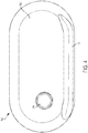
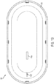
- FIG. 1 illustrates a first exemplary embodiment of a drug delivery device 100.
- the drug delivery device 100 can include a top portion or cover 102 and a lower portion or base 104.
- the top portion 102 and the lower portion 104 can together form a housing of the drug delivery device 100.
- the top portion 102 and the lower portion 104 can be coupled together to form an outside of the drug delivery device 100.
- the top portion 102 and the lower portion 104 can be formed from any material including, for example, plastic, metal, rubber, or any combination thereof.
- the drug delivery device 100 can be used to deliver a therapeutic agent (e.g., a drug) drug to a patient or user.
- the drug delivery device 100 can include a container for retaining a liquid drug.
- the drug delivery device 100 can be used to deliver the liquid drug from the container to the patient. Any type of liquid drug can be stored by the drug delivery device 100 and delivered to a patient.
- the container can contain any therapeutic agent such as, for example, a drug, a subcutaneous injectable, a medicine, or a biologic.
- a patient receiving a drug or other medicine (or any liquid) from the drug delivery device 100 can also be referred to as a user.
- the drug delivery device 100 can maintain the liquid drug within a primary drug container.
- the primary drug container can be a cartridge.
- the cartridge can be an International Organization for Standardization (ISO) standardized cartridge.
- the drug delivery device 100 can be provided to the patient with a preloaded and prefilled cartridge.
- the drug delivery device 100 can include a slot or opening for a patient to load a prefilled cartridge into the drug delivery device 100.
- the drug delivery device 100 can be designed and/or intended for a single use such that after the liquid drug is delivered to the patient, the drug delivery device 100 can be discarded.
- the primary drug container can be filled or refilled by a patient such that the drug delivery device 100 can be reused.
- the drug delivery device 100 can include a port for accessing and filling the primary drug container.
- the drug delivery device 100 can be a wearable drug delivery device 100.
- the drug delivery device 100 can be an on-body delivery system (OBDS).
- OBDS on-body delivery system
- the drug delivery device 100 can be coupled to a patient in a number of ways.
- the lower portion 104 of the drug delivery device 100 can include an adhesive for attaching to a patient.
- the drug delivery device 100 can be attached to a secondary device attached or worn by the patient such that the drug delivery device 100 fits onto or can be coupled to the secondary device.
- the drug delivery device 100 can operate as a mechanical device.
- the drug delivery device 100 can include only mechanical components and/or can provide only mechanical functionality and operation.
- the drug delivery device 100 can operate as an electromechanical device
- the drug delivery device 100 can include one or more controllers associated memory for controlling various components of the drug delivery device 100.
- the drug delivery device 100 can include other electrical and/or electromechanical components such as, for example, sensors, user interfaces, and communication interfaces.
- a first portion of the drug delivery device 100 can be a mechanical based system (e.g., a drive system for expelling a drug from a container for delivery to the user) while a second portion of the drug delivery device 100 can be an electromechanical based system (e.g., components for measuring and recoding dosage amounts). Operation of the drug delivery device 100 can be entirely patient-based, automated, and/or semi-autonomous.
- a mechanical based system e.g., a drive system for expelling a drug from a container for delivery to the user
- an electromechanical based system e.g., components for measuring and recoding dosage amounts
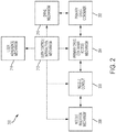
- FIG. 2 illustrates an exemplary embodiment 200 of various functional components of the drive delivery device 100.
- FIG. 2 can represent the various functional components of the drug delivery device 100 when implemented as a mechanical device (e.g., including the function and operation of the constituent components of the drug delivery device 100 depicted in FIG. 2 ).
- the functional components depicted in FIG. 2 can be contained or positioned within the drug delivery device 100 (e.g., contained within the top portion 102 and the lower portion 104).
- the mechanical implementation of the drug delivery device 100 can include a primary drug container 202, a primary drug container access mechanism or component 204, a needle conduit 206, a needle insertion mechanism or component 208, a drive mechanism or component 210, a user control and/or interaction mechanism or component 212, and a patient (or user) adherence or coupling mechanism component 214.
- the primary drug container 202 can store any type of liquid drug.
- the primary drug container 202 can be a cartridge including, for example, an ISO standardized cartridge.
- the primary drug container 202 can be provided as preloaded into the drug delivery device 100 and prefilled with the stored liquid drug.
- the patient can load a prefilled cartridge into the drug delivery device 100.
- the primary drug container 202 can be accessible for filling or refilling through a port provided on the drug delivery device 100.
- the primary drug container 202 Prior to activation of the drug delivery device 100, the primary drug container 202 can maintain the stored liquid drug. That is, the liquid drug can be sealed or contained within the primary drug container 202. Once the drug delivery device 100 is activated, the liquid drug stored in the primary drug container 202 can be accessed to provide the stored liquid drug to the patient.
- the needle conduit 206 can include tubing or other fluid delivery mechanisms for transferring the stored liquid drug retained in the primary drug container 202 to the needle insertion mechanism 208.
- the needle conduit 206 can be routed around any internal portion of the drug delivery device 100.
- the needle conduit 206 can be formed, for example, from plastic tubing, metal tubing (e.g., stainless steel tubing), or a combination thereof. In general, the needle conduit 206 can provide a fluid path for the liquid drug when expelled from the primary drug container 202.
- FIG. 3 illustrates a second exemplary embodiment 300 of the various functional components of the drug delivery device 100.
- FIG. 3 can represent the various functional components of the drug delivery device 100 when implemented as an electromechanical device (e.g., including the function and operation of the constituent components of the drug delivery device 100).
- the functional components depicted in FIG. 3 can be contained or positioned within the drug delivery device 100 (e.g., contained within the top portion 102 and the lower portion 104).
- the memory 304 can be coupled to the controller 302.
- the controller 302 can include one or more processors.
- the controller 302 can implement any software, code, or instructions stored in the memory 304.
- the sensor 306 can be any type of sensor.
- the sensor 306 can include any type of sensor for monitoring a condition of the patient or for monitoring operation of the drug delivery device 100.
- the sensor 306 can be flow sensor, a viscosity sensor, a sensor for determining a positioning of a plunger of the drug delivery device 100, a sensor for determining an amount of liquid drug delivered to the user, a sensor for determining how much liquid drug remains in the drug delivery device 100, a Hall effect sensor, and or a photogate.
- the sensor 306 can also be a temperature sensor, an electrocardiography (ECG) sensor, a blood pressure sensor, a blood glucose sensor, or any other type of patient biometric sensor.
- ECG electrocardiography
- Each of the individual components shown in FIG. 3 - the primary drug container 202, the primary drug container access mechanism 204, the needle conduit 206, the needle insertion mechanism 208, the drive mechanism 210, the user control and/or interaction mechanism 212, and the patient adherence or coupling mechanism 214 - can function and operate as described in relation to FIG. 2 and/or can include electrical and/or electromechanical features and can enable control by the controller 302.
- FIG. 5 illustrates a first side view of the drug delivery device 100.
- the drug delivery device 100 can include a protrusion 502.
- the protrusion 502 can extend from the bottom portion 104 of the drug delivery device 100.
- the protrusion 502 can extend from along any portion of the bottom portion 104 of the drug delivery device 100.
- the protrusion 502 can be of any length and can extend below the bottom portion 104 by any amount.
- the protrusion 502 can be a portion of the needle insertion mechanism 208 depicted in FIGs. 2 and 3 .
- the protrusion 502 can be a soft needle or cannula that extends from the drug delivery device 100 into the patient once a hard needle of the needle insertion mechanism 208 has been retracted back inside the drug delivery device 100.
- the protrusion 502 can extend below the bottom portion 104 when attached to a patient and when delivering a liquid drug to the patient.
- the bottom portion 104 of the drug delivery device 100 can include a port or opening allowing for extension of the hard and soft needle and retraction of the hard needle of the needle insertion mechanism 208.
- the protrusion 502, as a soft needle can remain extended outside of the drug delivery device 100 after activation.
- the operation of the drug delivery device 100 can be controlled as desired to start, stop, and restart delivery of the liquid drug to the patient as desired.
- the patient can stop operation of the drug delivery device 100 after a first dose of the liquid drug has been delivered to the patient and can then restart operation of the drug delivery device 100 to provide a subsequent dose of the liquid drug to the patient.
- Operation of the drive mechanism 210 can control the dosing of the liquid drug to the patient as described in relation to 810.
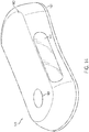
- FIG. 9 illustrates a second exemplary embodiment of a drug delivery device 900.
- the drug delivery device 900 can operate and provide substantially the same functionality as the drug device 100.
- the drug delivery device 900 can include a top or upper portion 902 and a lower portion or base 904.
- the top portion 902 and the lower portion 904 can together form a housing of the drug delivery device 900.
- the top portion 902 and the lower portion 904 can be coupled together to form an outside of the drug delivery device 900.
- the drug delivery device 900 can represent another design or form factor of the drug delivery device 100.
- the on-body interlock device 1104 can be required to be depressed (e.g., passively) before the drug delivery device 900 can be activated. For example, when the drug delivery device 900 is coupled to a patient, the on-body interlock device 1104 can be passively depressed. Once depressed, the patient interaction element 108 can subsequently be used to activate the drug delivery device 900. Prior to the on-body interlock 1104 being depressed, the patient interaction element 108 can be disengaged such that manipulation of the patient interaction element 108 does not activate the drug delivery device 900.
- the opening 906 can be positioned a side of the upper portion 906.
- the opening 906 can be of any size and/or shape.
- the opening 906 can have any width or height.
- the drug delivery device 1400 can include an opening or window 1406 that can expose a portion of a primary drug container and/or cartridge positioned within the drug delivery device 1400.
- the opening 1406 can correspond to the opening 906.
- the top portion 1402 can also include a patient interaction element or component 1408.
- the patient interaction element 1408 can be a push button.
- the patient interaction element 912 can correspond to the patient interaction element 108 and/or the patient interaction element 908.
- the drug delivery device 1400 can also include an on-body interlock positioned on an underside of the bottom portion 1404 (not shown in FIG. 14 ).
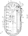
- the liquid drug 1510 can be forced out of the primary drug container 1502 through the plunger 1508 on to the needle conduit 1514. Accordingly, in various embodiments, the liquid drug 1510 can be expelled from the primary drug container 1502 in a direction that is approximately opposite to a direction of movement of the plunger 1508 as the plunger 1508 is moved toward the first end 1504.
- the drive spring 1518 can be any type of spring.
- the drive spring 1518 can have any desired spring constant value, k.
- the drive spring 1518 is not limited to a single spring and can include one or more springs.
- the drive spring 1518 can include one or more compression springs and/or torsion springs.
- the drive spring 1518 can include one or more linear compression springs arranged in a parallel arrangement, a series arrangement, an arrangement of nested springs in series, or any combination thereof.
- the drive spring 1518 can be implemented as double series springs.
- a dead bolt 1522 or other fixed element can be positioned at one end of the drive spring 1518.
- the dead bolt 1522 can provide a stable reference for the drive spring 1518 (e.g., a push off point).
- the dead bolt 1522 can be considered a thrust point for the drive spring 1518 (e.g., a force reactionary "thrust point").
- the dead bolt 1522 can be considered to be or can represented a fixed component that can be coupled to the inner top surface of the lower portion 104.
- the fixed component 1522 can be positioned at an end of the drive spring 1518.
- the track 1524 can form any shape and can be arranged to take on any shape to guide the spheres 1520 from the drive spring 1518 to the cartridge 1502.
- a first end of the track 1524 can be positioned adjacent to the dead bolt 1522 and a second end of the track 1524 can be positioned approximately adjacent to the second end 1506 of the cartridge.
- the first end of the track 1524 can be closed while the second end of the track 1524 can be open, to allow the spheres 1520 to exit the track 1524 and to enter the primary drug container 1502 as shown in FIG. 15 .
- the track 1520 can provide a support or guide for the drive spring 1518. This can increase the efficiency of the drug delivery device 100 as the drive spring 1518 can be prevented from buckling or deforming during expansion (e.g., when the drug delivery device 100 is in motion due to movement of the patient).
- the spheres 1520 can be arranged between the drive spring 1518 and the primary drug container 1502. In various embodiments, the spheres 1520 can be positioned adjacent to the primary drug container 1502, the primary drug container access mechanism 1512, and/or the plunger 1508. The spheres 1520 can be arranged to follow any path or route (e.g., as determined by the track 1524). The spheres 1520 can be considered as forming a ball chain.
- the drive mechanism 210 of a drug delivery device described herein can include chains, linkages, or other flexible or semi-flexible elements or components for translating a force form a source (e.g., the drive spring 1518) to the plunger 1508. In various embodiments, one or more rigid elements can be used transfer a force to the plunger 1508. In general, any combination of spheres 1520, flexible, semi-flexible, and/or rigid elements can be used to transfer a force to the plunger 1508.
- the primary drug container 1502 can be drained of its contents and delivered to a patient.
- the liquid drug 1510 contained in the primary drug container 1502 can be drained at any desired rate over any amount of time over one or more doses.
- the liquid drug 1510 can be expelled from the primary drug container 1502 at one time (e.g., for a single dose delivery) or can be expelled over a series of start and stop intervals (e.g., for multiple dose delivery).
- the spheres 1520 and track 1524 can be used to transfer energy stored by the drive spring 1518 to the plunger 1508.
- the drive spring 1518 can be considered to be an energy storage mechanism or component and the spheres 1520 can be considered to be an energy transfer mechanism or component.
- the drive mechanism of the drug delivery device 100 can therefore be considered to include both an energy storage mechanism or component and an energy transfer mechanism or component. Any number of spheres 1520 can be used between the drive spring 1518 and the primary drug container 1502.
- the drive spring 1518 and the spheres 1520 can be selected and adjusted to help regulate a flow of the liquid drug 1510 from the primary drug container 1502 to the needle insertion mechanism 1516 based on a variety factors including the viscosity of the liquid drug 1510.
- the needle conduit 1514 can be arranged as shown in FIG. 15 to provide a service loop that allows flexing to improve delivery and flow of the liquid drug 1510 to the patient.
- the drug delivery devices described herein can operates as follows.
- the plunger 1508 can be moved toward the first end 1504 of the primary drug container 1502 to expel the liquid drug 1510 from the primary drug container 1502.
- the liquid drug 1510 expelled from the primary drug container 1502 can be provided to a needle conduit 1514.
- the needle conduit 1514 can be coupled to a needle insertion mechanism 1516 that can provide an access point to the patient.
- the needle conduit 1514 can be coupled to the plunger 1518 or can be coupled to a septum of the primary drug container 1502.
- the flow (e.g., speed) of the liquid drug 1510 can be determined by a variety of factors including a viscosity of the liquid drug 1510, a length and size (e.g., internal diameter) of the needle conduit 1514 and any fluid path portion of the needle mechanism 1516, and the force provided by the drive spring 1518. Given a viscosity of for a particular liquid drug 1510, the force provided by the drive spring 1518 as well as parameters of the fluid path (e.g., length and width of the provided fluid path through the needle conduit 1514) can be tuned or adjusted to provide a desired flow rate. In particular, a desired flow rate of the liquid drug 1510. In this way, a particular liquid drug 1510 can be delivered to the patient over a desired amount of time.
- the drive spring 1518 can be maintained in a compressed state prior to activation. Once activated, the drive spring 1518 can be allowed to expand and apply a force to the one or more spheres 1520. An initial force provided by the drive spring 1518 can cause the primary drug container access mechanism 1512 to access the primary drug container 1502. Specifically, the primary drug container access mechanism 1512 can couple the liquid drug 1510 to the needle conduit - for example, by forcing a needle of the needle conduit 1514 to pierce the plunger 1518.
- the drive spring 1518 can be allowed to expand fully in substantially one motion over a desired period of time. In doing so, the liquid drug 1510 can be expelled from the primary drug container 1502 substantially continuously.
- application of the force from the drive spring 1518 to the plunger 1508 can be interrupted.
- the drive spring 1518 can be prevented from expanding and/or the spheres 1520 can be held back from advancing.
- the liquid drug 1510 can be delivered to the patient in multiple discrete amounts, thereby providing multiple doses of the liquid drug 1510 to the patient over time.
- the needle insertion mechanism 1516 and/or the needle conduit 1514 can also block the flow of the liquid drug 1510 when desired to enable the liquid drug 1510 to be delivered to the patient over multiple doses.
- the spheres 1520 can provide efficient energy transfer from the drive spring 1518 to the plunger 1508 due in part to the spheres 1520 providing point to point contact to one another. This point to point contact can introduce less friction into a drive system than a drive system that relies on line to line contact between elements for transferring energy. Further, the drive mechanism of the drug delivery device 100 enables energy to be transferred in a different direction than the energy is initially provided. For example, as shown in FIG. 15 , the energy stored by the drive spring 1518 can be transferred around a tight radius of curvature by the spheres 1520 (e.g., around a corner or 180 degrees from the where the energy is first directed as shown by the exemplary arrangement of the track 1524). This enables the drug delivery device 100 to remain small and compact.
- a force can be provided by the drive spring 1518 when it is allowed to expand.
- the force provided by the drive spring 1518 can be applied in a direction 1530 toward the spheres 1520.
- the direction 1530 can correspond to a direction in which the drive spring 1518 is allowed to expand, based on a positioning of the dead bolt 1522, which can provide a thrust point for the drive spring 1518.
- the direction 1530 of the force provided by the drive spring 1518 can be from the dead bolt 1522 to the spheres 1520.
- the spheres 1520 can translate or transfer the force from the drive spring 1518 to the plunger 1508.
- the liquid drug 1510 can be expelled from either end of the primary drug container 1502. This enables the components of the drug delivery device 100 (as shown in FIG. 15 ) to be arranged in a close and tight manner, allowing the drug delivery device 100 to remain small and compact. In turn, the drug delivery device 100 can be more comfortable to wear and less cumbersome to the patient.
- the needle conduit 1514 can be a needle formed from plastic or metal, or a combination thereof. As shown in FIG. 15 , an end of the need conduit 1514 that can be coupled to the liquid drug 1510 can be a hard end of the needle conduit 1514 while the portion of the needle conduit 1514 routed toward the needle mechanism 1516 can be a soft portion of the needle conduit 1514.
- FIG. 16 illustrates a second exemplary arrangement of internal components of the drug delivery device 100.
- FIG. 16 shows various internal components of the drug delivery device 100 when the top portion 102 of the drug delivery device 100 is removed.
- the internal components shown in FIG. 16 can be substantially the same as and/or representative of the internal components of any other drug delivery devices disclosed herein including the drug delivery device 900 and the drug delivery device 1400.
- the arrangement and positioning of the internal components is not limited to that shown in FIG. 16 .
- the guide 1502 can include a first region 1604 and a second region 1606.
- the first region 1604 can be driven forward and can begin to collapse.
- the second region 1606 can begin to expand as the plunger 1508 is moved forward toward the first end 1504 of the primary drug container 1502. Accordingly, portions of the guide 1602 can be allowed to expand or compress as appropriate based on its positioning relative to the drive spring 1518 and the plunger 1508 and based on the expanded state of the drive spring 1518.
- FIGs. 15 and 16 show the liquid drug 1510 of the primary drug container 1502 as accessible through the plunger 1508.
- the liquid drug 1510 of the primary drug container 1502 can be accessed through the first end 1504 of the primary drug container 1502, which may include or may be referred to as the "septum" (e.g., as depicted and described in relation to FIG. 41 ).
- the primary drug container access mechanism 1512 can be positioned at or near the first end 1504 of the primary drug container 1502.
- the primary drug container access mechanism 1512 can access the liquid drug 1510 through a septum positioned at or near the first end 1504 of the primary drug container 1502.
- the primary drug container 1502 can be held in a stationary position and the primary drug container access mechanism 1512 can be moved relative to the primary drug container 1502 to pierce the septum.
- the primary drug container access mechanism 1512 can be held in a stationary position and the primary drug container 1504 can be moved relative to the primary drug container access mechanism 1512 to pierce the septum.
- a force provided by the drive spring 1518 can cause the septum to be pierced, thereby coupling the liquid drug 1510 to the needle conduit 1514.
- the drive spring 1518 is shown with the fixed component or plate positioned at an end of the drive spring 1518 and directly coupled to the spheres 1520.
- the drive spring 1518 as illustrated can be used as the drive spring 1518 depicted in FIG. 15 .
- the various internal components of the drug delivery device 100 depicted in FIGs. 15 and 16 can be mechanically operated and controlled or can be electromechanically operated and controlled. In various embodiments, the internal components of the drug delivery device 100 depicted in FIGs. 15 and 16 can be operated to deliver the liquid drug 1510 to the patient in a single dose. In various embodiments, the internal components of the drug delivery device 100 depicted in FIGs. 15 and 16 can be operated to deliver the liquid drug 1510 to the patient in two or more doses (e.g., in multiple doses).
- the flow of the liquid drug 1510 can be stopped or interrupted such that it does not flow out of the primary drug container 1502, through the needle conduit 1514, and/or through the needle insertion mechanism 1516.
- multiple doses can be provided by interrupting the flow of the liquid drug 1510 from the primary drug container 1520.
- the flow of the liquid drug 1510 can be interrupted by removing the force applied to the plunger 1508 that can push the liquid drug 1510 out of the primary drug container 1502.
- the force applied to the plunger 1508 can be interrupted by retaining the drive spring 1518 and/or by retaining the spheres 1520 from applying any translated force from the drive spring 1518 to the plunger 1508.
- the drug delivery device 100 can provide the liquid drug 1510 to the patient over multiple doses.
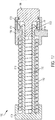
- FIG. 17 illustrates an exemplary drive spring release mechanism or component 1700.
- the drive spring release mechanism 1700 can include a drive spring 1702, a tension member 1704, a spring retainer 1706, and a release cam 1708.
- the drive spring 102 can correspond to or represent the drive spring 1518 depicted, for example, in FIGs. 15 and 16 .
- FIG. 17 illustrates a cross-sectional view of the drive spring release mechanism 1700.
- the drive spring release mechanism 1700 can be a component of the drive mechanism 210 depicted in FIGs. 2 and 3 .
- FIG. 17 shows the drive spring release mechanism 1700 in a first state or locked state with the drive spring 1702 in a compressed state.
- the tension member 1704 and the spring retainer 1706 can prevent the drive spring 1702 from extending in a direction towards the tension member 1704 relative to a positioning of the spring retainer 1706.
- the tension member 1704 can include a first arm or extension 1710 and a second arm or extension 1712.
- the first and second extensions 1710 and 1712 can extend from a first end or base end of the tension member 1704 through a center portion of the drive spring 1702.
- the first and second extensions 1710 and 1712 can extend beyond an end of the drive spring 1702.
- a first end 1720 of the first extension 1710 can be retained in place as shown by the spring retainer 1706.
- a second end 1722 of the second extension 1712 can also be retained in place as shown by the spring retainer 1706.
- the spring retainer 1706 can include a first portion 1714 positioned between the end of the drive spring 1702 (e.g., a top or first end) and the end 1720 of the first extension 1710.
- the spring retainer 1706 can include a second portion 1716 positioned between the end of the drive spring 1702 (e.g., a bottom or second end) and the end 1722 of the second extensions 1712.
- the first end 1720 and the second end 1722 can be considered to be lips or traverse extensions of the first and second extensions 1710 and 1712, respectively.
- the end 1720 of the first extension 1710 can be thicker or wider than the portion of the first extension 1710 that is positioned in a center or middle of the drive spring 1702 (e.g., to form a lip or traverse extension as described above).
- the first portion 1714 of the spring retainer 1706 and the first portion 1718 of the release cam 1708 can retain the first portion 1714 of the spring retainer 1706 as shown.
- the end 1722 of the second extension 1712 can be thicker or wider than the portion of the second extension 1712 that is positioned in a center or middle of the drive spring 1702 such that the second portion 1716 of the spring retainer 1706 and the first portion 1718 of the release cam 1708 can retain the second portion 1712 of the spring retainer 1706.
- the drive spring release mechanism 1700 can maintain the drive spring 1702 in a compressed or locked state as shown in FIG. 17 until activated - for example, by a patient input.
- FIG. 18 illustrates the drive spring release mechanism 1700 in a second state or released state (also in cross-section).
- the release cam 1708 can be rotated.
- the release cam 1708 can be rotated about an axis that is approximately parallel and/or coaxial to an axis of the drive spring 1702.
- the first portion 1718 of the release cam 1708 can have a variable width such that the first portion 1718 has a narrower width when the release cam 1708 is rotated to release the drive spring 1702. As shown in FIG.
- the tension member 1704 can be coupled to the spheres 1520 illustrated in FIGs. 15 and 16 .
- the movement of the tension member 1704 and the drive spring 1702 can apply a force to the spheres 1520, thereby causing the plunger 1508 to advance into the primary drug container 1502 to expel the liquid drug 1510.
- the plunger 1508 can be pierceable.
- the plunger 1508 can be pierceable by a hard needle 1902 coupled to the needle conduit 1514.
- the hard needle 1902 can be coupled to an end of the needle conduit 1514.
- An initial force provide by the drive spring 1518 when the drive spring 1518 is initially released can provide a force to enable the hard needle 1902 to pierce the plunger 1508 and extend into the primary drug container 1502.
- the hard needle 1902 can extend into the primary drug container 1502 through an inlet or opening 1904 formed when the hard needle 1902 is pressed against the plunger 1508.
- the plunger 1508 may seal the primary drug container 1502 to contain the liquid drug 1510. Further, prior to the plunger 1508 being pierced, the plunger 1508 may seal the liquid drug 1510 off from the needle conduit 1514 (e.g., decouple or separate the liquid drug 1510 from the needle conduit 1514) such that the liquid drug 1510 cannot be supplied to the patient.
- the plunger 1508 can be designed to facilitate removal of the liquid drug 1510 from the primary drug container 1502.
- an end of the plunger 1508 that is adjacent to the portion of the primary drug container 1502 that holds the liquid drug 1510 can include one or more channels 1906.
- the channels 1906 can be arranged and positioned in any manner. As shown in FIG. 19 , the channels 1906 can form a cross-like pattern or shape.
- the channels 1906 can help force or funnel the liquid drug 1510 towards the needle 1902 and needle inlet 1904. As a result, more of the liquid drug 1510 can be expelled from the primary drug container 1502 by reducing the amount of the liquid drug 1510 trapped or retained inside of the primary drug container 1502.
- the needle 1902 and opening 1904 are positioned away from a center of the plunger 1508.
- the needle 1902 and opening 1904 are positioned towards an outer diameter of the spheres 1520 and can be positioned outside of the guide coil 1602.
- the needle 1902 and opening 1904 can be positioned at or near an approximate center of the plunger 1508 with the channels 1906 arranged and positioned to guide the liquid drug toward the center of the plunger 1508.
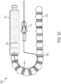
- the drive system 2000 can include a release mechanism - for example, a gate or lynch pin - that can control advancement of the spheres 1520 and the springs 2002 toward the plunger 1508.
- a gate or lynch pin can be positioned between the plunger 1508 and the first sphere 1520 positioned adjacent to the plunger 1508. The gate or lynch pin can prevent advancement of the spheres 1520 and can therefore prevent a force from being applied to the plunger 1508.
- a force from the spheres 1520 and the springs 2002 can be applied to the plunger 1508. Removal of the gate or lynch pin can initiate activation of the drug delivery device incorporating the drive system 2000.
- Other release mechanism can include a spring release mechanism that can restrict or allow movement (e.g., expansion) of one or more of the springs 2002.
- the drive system 2000 can include a release mechanism that can maintain the springs 2002 in a compressed state and can allow the springs 2002 to expand when desired.
- the springs 2002 can be released at substantially the same time (e.g., to provide the liquid drug 1510 to the patient in a single dose). Alternatively, the springs 2002 can be released at different times (e.g., to provide the liquid drug 1510 to the patient over multiple doses).
- a track or housing or other guide can surround or partial enclose or contain the spheres 1520 and the springs 2002 to guide the movement of the spheres 1520 and the springs 2002.
- the last sphere 1520 of the drive system 2000 e.g., the sphere 1520 positioned furthest from the plunger 1508 can be positioned against a solid element (not shown in FIG. 7 ) which can provide a push point for the drive system 2002.
- an assistor spring can be placed at the end of the depicted spheres 1520 and springs 2002.
- the drive spring 1518 can be used as an assister spring.
- An assistor spring can be used to provide additional force to the plunger 1508.
- an assistor spring can be similar to the previously mentioned drive spring 1518.
- an assistor spring can be similar to the drive spring 1518 but may have a lower spring constant, k, since the springs 2002 can each provide a component of the overall provided driving force.
- the assistor spring can be a coil spring, an elastomeric element, or any other appropriate device (e.g., one or more compression springs arranged in any manner or configuration) for providing a desired actuation assisting force to the spheres 1520.
- the springs 2002 can be arranges in series, which can result in a lower total or equivalent spring constant that can provide a more even force over time as the springs 2002 expand.
- the drive system 2000 can provide tunability for adjusting how quickly the liquid drug of the primary drug container 1502 can be expelled.
- the springs 2002 can be added or removed to speed up or slow down the rate of drug delivery, respectively, for a given liquid drug. More springs 2002 may be used for liquid drugs having a relatively higher viscosity while fewer springs 2002 may be used for liquid drugs having a relatively lower viscosity. Further, more springs 2002 can be used to increase a stroke of the plunger 1508. The introduction of the springs 2002 can provide a more constant force over time and distance such that the liquid drug 1510 can be delivered at a more constant rate throughout the delivery of the drug (e.g., as compared to drive system arrangements employing only a single drive spring). Further, each spring 2002 can be tailored to provide a desired spring constant and/or desired amount of force.
- the drive system 2000 can provide an approximately constant spring force (e.g., a change of less than 5% of force over a stroke).
- the force provided by the series coupled springs 2002 can be largely constant, thereby ensuring precise drug delivery over a long period of time.
- the drive system 2000 is also space efficient as the air space between the spheres is largely consumed.
- the drive system 2000 provides an easily tunable load (e.g., to provide a variable drive force). Specifically, the load pushing on the plunger 1508 can be adjusted by adding or removing springs 2002 between the spheres 1520. This can allow for tuning of the delivery rate for drugs of different viscosities without needing to change the base design or introduce new parts.
- Differently sized primary drug containers 1502 can also be accommodated by adding or removing springs 2002 and spheres 1520.
- Any of the drive systems described herein can include one or more intermediate springs 2002.
- the drive systems depicted in FIGs. 15 and 16 can be modified to include one or more springs 2002 as shown in FIG. 20 .
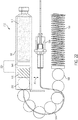
- FIG. 21 illustrates an exemplary alternative drive system 2100 for delivering a liquid drug to a patient.
- the drive system 2100 can be used with any of the drug delivery devices described herein (e.g., the drug delivery device 100).
- the drive system 2100 can be used to advance the movement of spheres 1520 as desired to provide delivery of the liquid drug 1510 over multiple doses.
- the drive system 2100 can correspond to the drive mechanism 210 described in relation to FIGs. 2 and 3 .
- the drive system can include any or all features of the drive systems described in relation to FIGs. 15 , 16 and/or 20.
- the drive system 2100 can include a gate 2102.
- the gate 2102 can be positioned in front of the primary drug container 1502.
- the gate 2102 can be controlled to regulate the advancement of the spheres 1520 and application of a force against the plunger 1508.
- the drive system 2100 can be considered as providing a metered ball or sphere drive system.
- FIG. 21 shows the drive system 2100 in an initial or first state.
- the gate 2102 is positioned between the first sphere 1520 and the primary drug container 1502.
- the spheres 1520 cannot advance further toward the plunger 1508.
- the liquid drug 1510 is not expelled from the primary drug container 1502.
- the gate 2102 can move in the directions 2104 to allow advancement of the spheres 1520 and to prevent advancement of the spheres 1520.
- the primary drug container access mechanism 1512 can be positioned adjacent to the plunger 1508.
- One or more individual components of the primary drug container access mechanism 1512 are not shown in FIG. 21 for simplicity.
- the spheres 1520 can advance the plunger 1508 by applying a force to the primary drug container access mechanism 1512, which, in turn, can apply the force to the plunger 1508.
- the spheres 1520 can directly apply a force on the plunger 1508 (e.g., the primary drug container access mechanism 1512 can be removed).
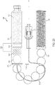
- FIG. 22 illustrates the drive system 2100 in a second or subsequent state of operation.
- FIG. 22 shows the gate 2102 in an open state.
- the gate 2102 no longer interrupts the advancement of the spheres 1520. That is, the gate 2102 is moved to a different position positon that does not block the spheres 1520 from advancing toward the plunger 1508.
- the spheres 1520 can apply a force on the plunger 1508 to advance it forward, thereby expelling the liquid drug 1510 from the primary drug container 1502.
- a first sphere 2202 has advanced past the gate 2102 toward the plunger 1508. Consequently, the plunger 1508 has been advanced by an amount or distance 2204 relative to a starting point of the plunger 1508 as shown in FIG. 21 .
- the amount 2204 that the plunger 1508 has advanced can correspond to approximately a diameter of the first sphere 2202.
- the diameter of the first sphere 2202 (as well as the diameters of all the spheres 1520) can correspond to one stroke of delivery of the liquid drug 1510.
- an amount of the liquid drug 1510 corresponding to a size of each of the spheres 1520 can be pushed out from the primary drug container 1502.
- the drive spring 1518 can expand to apply the force to the spheres 1520, driving the spheres 1520 toward the plunger 1508.
- the gate 2102 can control the amount of the liquid drug 1510 provided to the patient.
- the number of spheres 1520 that advance past the gate 2102 can determine the amount of the liquid drug 1520 provided to the patient.
- the gate 2102 can allow the same number of spheres 1520 to advance each time the gate 2102 is opened or can allow different numbers of spheres 1520 to advance.
- the drive system 2100 can provide multiple doses of approximately the same amount or volume of the liquid drug 1510 to the patient.
- the drive system 2100 can provide multiple doses of different amounts or volumes of the liquid drug 1510 to the patient.
- the gate 2102 can be controlled by a mechanical or electromechanical mechanism and can be automatically controlled or patient controlled. Overall, the gate 2102 can be controlled to provide a single dose to the patient or multiple doses to the patient at any desired time over any desired amount of time.
- FIG. 23 illustrates the drive system 2100 in a third or subsequent state of operation.
- the gate 2102 is in a closed position and the first sphere 2202 is positioned between the gate 2102 and the plunger 1508. With the gate 2102 in the closed position, the gate 2102 can impede further advancement of the remaining spheres 1520. As a result, a dose of the liquid drug 1510 corresponding the diameter of the first sphere 2202 has been provided to the patient.
- regulating the location or position of the gate 2102 can in turn regulate delivery of the liquid drug 1510 to a patient.
- a desired dosage of the liquid drug 1510 can be delivered to a patient over a desired amount of time in this manner.
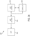
- FIG. 24 illustrate an exemplary gate control mechanism 2400.
- the gate control mechanism 2400 can be used to control operation and movement of the gate 2102.
- the gate control mechanism 2400 can include a gate 2402, a gate actuator 2404, a patient control component 2406, and a controller 2408.
- the gate 2402 can correspond to the gate 2102.
- the gate actuator 2404 can be any device capable of moving the gate 2402 between at least a first positon (e.g., a closed positon as described in relation to FIG. 23 ) and a second position (e.g., an open positioning as described in relation to FIG. 23 ) responsive to the patient control component 2406 or the controller 2408.
- the patient control component 2406 can be any component or feature for receiving input from a patient.
- the patient control component 2406 can include one or more buttons or switches.
- the patient control component 2406 can be used to specify when the gate 2402 is to be in an open positon or a closed position.
- the gate actuator 2404 can be responsive to the patient control component 2406 such that the gate 2402 opens and closes responsive to a patient.
- the patient control component 2406 can correspond to any of the patient interaction elements or components described herein (e.g., the patient interaction component 108 of the drug delivery device 100).
- FIG. 26 illustrates a top view of the drug delivery device 2500. As shown in FIG. 26 , the first and second buttons 2506 and 2508 are positioned on opposite sides of the drug delivery device 2500.
- FIG. 27 illustrates an activation mechanism of the drug delivery device 2500.
- the activation mechanism of the drug delivery device 2500 can be based on operation of the first and second buttons 2506 and 2508.
- the depicted activation mechanism can be included or used with any of the drug delivery devices described herein.
- the activation mechanism of FIG. 27 may provide a "double lockout" feature that can prevent inadvertent or premature activation of the drug delivery device 2500.
- the drug delivery device 2500 may not deliver a liquid drug to the patient until both the first and second buttons 2506 and 2508 have been activated, either in series or simultaneously, as will be described herein.
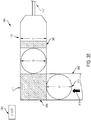
- a first sphere 2702 is positioned adjacent to the primary drug container 1502.
- the first sphere 2702 is blocked from advancing toward the primary drug container 1502 by a first ball 2704 and a set of balls 2706.
- the first ball 2704 can be positioned on a first side of the first sphere 2702 and the set of balls 2706 can be positioned on a second, opposite side of the first sphere 2702.
- the set of balls 2706 can include any number of balls.
- the set of balls 2706 can be positioned on a track or tray 2708 that guides the movement of the balls 2706.
- two or more balls can be used in place of the single first ball 2704.
- a rod can be used as an alternative to the set of balls 2706.
- the rod can have a length that is approximately the same as the length of the set of balls 2706 together.
- the rod can have rounded ends.
- the first sphere 2702, and the remaining spheres 1520, can be allowed to advance toward the primary drug container 1502 when the first ball 2704 and the set of balls 2706 are moved away from the first sphere 2702. Movement of the first ball 2704 can be determined based on operation of the second button 2508. Movement of the set of balls 2706 can be determined based on operation of the first button 2506. In various embodiments, the movement of the first ball 2704 can be determined based on operation of the first button 2506 and movement of the set of balls 2706 can be determined based on operation of the second button 2508.
- the set of balls 2706 may be coupled indirectly to the first button 2506. Movement of the set of balls 2706 can be restricted by an arm 2710.
- the arm 2710 can be positioned across the track 2708 to restrict or prevent movement of the set of balls 2706 along the track away from the first sphere 2702. Movement of the arm 2710 can be controlled by the first button 2506. Specifically, when the button 2506 is engaged, a pin 2712 coupled to the button 2506 can be moved in a direction (e.g., downwards and/or sideways) through an opening 2714 in the arm 2710. When the pin 2712 is moved through the opening 2714, the arm 2710 can be released, and thereby allowed to move in a direction 2716 away from the set of balls 2706, as shown in FIG. 27 .
- Movement of the arm 2710 in the direction 2716 can allow the set of balls 2706 to move in a direction 2726 (e.g., away from the first sphere 2702).
- the set of balls 2706 can move in the direction 2726 along the track 2708.
- the set of balls 2706 can be positioned away from the first sphere 2702 and can no longer restrict movement of the spheres 1502.
- the set of balls 2706 may naturally move along the track 2708 (e.g., under the force of gravity), or they may be forced to move along the track 2708 in the direction 2726 due to the force of the sphere 2702.
- the latch 2720 can prevent the first ball 2704 from moving in the direction 2722.
- the latch 2720 can be removed from restricting movement of the first ball 2704.
- the first ball 2704 can be allowed to move in the direction 2722, thereby no longer blocking movement of the spheres 1520 from advancing in the direction 2802.
- the latch 2720 can include a hole or opening through which the first ball 2704 can be forced through by the spheres 1520.
- the opening of the latch 2720 can be positioned adjacent to the first ball 2704 when the latch is moved by the button 2508. Prior to manipulation of the button 2508, the opening can be positioned so as not to be adjacent to the first ball 2704.
- the movement of the spheres 1520 in the direction 2802 can cause the first ball 2704 through the opening and away from the spheres 1520.
- the activation mechanism depicted in FIGs. 27 and 28 can be part of a drive mechanism or drug container access mechanism of a drug delivery device described herein (e.g., corresponding to a portion of the drive mechanism 210 and/or a portion of the primary drug container access mechanism 204 described in relation to FIGs. 2 and 3 ).
- FIG. 29 illustrates an exemplary implementation of a primary drug container access mechanism or component 2900.
- the primary drug container access mechanism 2900 can be an implementation of the primary drug container access mechanism 1512 depicted in FIG. 15 .
- the primary drug container access mechanism 2900 can be used with any of the drug delivery devices described herein.
- FIG. 29 depicts the primary drug container access mechanism 2900 relative to a cross section of the drug delivery device 100 for purposes of describing the components and operation of the primary drug container access mechanism 2900.
- the primary drug container access mechanism 2900 can correspond to the primary drug container access mechanism 204 described in relation to FIG. 2 and 3
- the needle pilot component 2902 can be spaced apart from the pusher plate component 2906 by a distance 2908.
- the pusher plate component 2906 can also be spaced apart from the first sphere 1520.
- the spacer spring 2904 can be positioned within an internal opening formed between the needle pilot component 2902 and the pusher plate component 2906.
- the needle conduit 1514 can be routed over a top of the sphere 1520 and into the pusher plate component 2906.
- the pusher plate component 2906 can include an opening for the needle conduit 1514. Specifically, the needle conduit 1514 can be routed approximately vertically through the pusher plate component 2906 and then routed approximately horizontally through the pusher plate component 2906 in an approximate center of the pusher plate component 2906.
- the needle conduit 1514 can be routed in any manner through the pusher plate component 2906.
- the needle conduit 1514 can then further extend across the distance 2908 separating the needle pilot component 2902 and the pusher plate component 2906.
- the needle conduit 1514 can be routed through a center of the spacer spring 2904 and through an approximate center of the needle pilot component 2902 as shown.
- the needle conduit 1514 can be positioned through a portion of the plunger 1508 but does not make contact with the liquid drug 1510. When positioned through a portion of the plunger 1508, the needle conduit 1514 can be considered to be partially embedded within the plunger 1508. In various other embodiments, the needle conduit 1514 can be initially positioned outside of the plunger 1508 (e.g., adjacent to the plunger 1508). When positioned outside or adjacent the plunger 1508, the needle conduit 1514 can be considered to be fully separated from the plunger 1508.
- the primary drug container access mechanism 2900 can be used to advance an end of the needle conduit 1514 fully through the plunger 1508 when activated with the needle conduit 1514 either initially partially embedded within the plunger 1508 or fully separated from the plunger 1508 as described herein.
- the sphere 1520 can be restricted from moving forward in a direction 2910 (and/or no force can be applied to the sphere 1520). Subsequent to the initial state, when the drug delivery device of which the primary drug container access mechanism 2900 can be a part is activated, the sphere 1520 can be allowed to move in the direction 2910 toward the pusher plate component 2906. When the sphere 1520 makes contact with the pusher plate component 2906, the force from the sphere 1520 can cause the pusher plate component 2906 to move forward toward the plunger 1508.
- the pusher plate component 2906 can cause the spacer spring 2904 to compress and the pusher plate component 2906 can make contact with the needle pilot component 2902, moving the needle pilot component 2902 toward the plunger 1508.
- a needle 2912 or end component of the needle conduit 1514 can be pushed through the plunger 1508 into the liquid drug 1510.
- the end of the needle conduit 1514 (which can include the needle 2912), can be driven forward through the plunger 1508, thereby coupling the needle conduit 1514 to the liquid drug 1510.
- the needle pilot component 2902 can help maintain the needle conduit 1514 centered along the plunger 1508 to facilitate efficient removal of the liquid drug 1510.
- the spacer spring 2904 can keep the needle pilot component 2902 and the pusher plate component 2906 separated and taught prior to activation/insertion of the tip 2912 of the needle conduit 1514 into the liquid drug 1510.
- the pusher plate component 2906, the spacer spring 2904, and the needle pilot component 2904 can all move in a direction 2914 to push the plunger 1508 in the direction 2914 to expel the liquid drug 1510 through the needle conduit 1514 as the spheres 1520 push on the pusher plate component 2906.
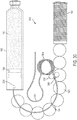
- FIG. 30 illustrates an exemplary alternative drive system 3000 for delivering a liquid drug to a patient.
- the drive system 3000 can be used with any of the drug delivery devices described herein (e.g., the drug delivery device 100).
- the drive system 3000 can be used to advance the movement of spheres 1520 as desired to provide delivery of the liquid drug 1510 over multiple doses.
- the drive system 3000 can correspond to the drive mechanism 210 described in relation to FIGs. 2 and 3 .
- the drive system 3000 can include any feature of any of the other drive systems described herein.
- the drive system 3000 can include a first wheel or roller 3002 and a second wheel or roller 3004.
- the rollers 3002 and 3004 can be positioned above the path of the spheres 1520.
- the rollers 3002 and 3004 can regulate forward movement of the needle conduit 1514 toward the plunger 1508.
- a portion of the needle conduit 1514 can be routed between the rollers 3002 and 3004.
- An end portion of the needle conduit 1514 can include a hard needle 3006.
- the hard needle area 3006 can be advanced forward by the force of the spheres 1520.
- the rollers 3002 and 3004 can function as a brake or as a metering system for regulating the amount of the needle conduit 1514 that can be moved toward the plunger 1508.
- the rollers 3002 and 3004 can determine when the plunger 1508 can be advanced by allowing or preventing the needle conduit 1514 - and in turn the hard needle area 3006 - from moving forward (e.g., as a result of the force applied by the drive spring 1518).
- a portion of the needle conduit 1514 can form a coil 3008.
- the coil 3008 of the needle conduit 1514 can be held in place so that it can be paid out for translation to the rollers 3002 and 3004.
- a back portion 3010 of the needle conduit 1514 can form a loop or be otherwise shaped to provide a service loop for the needle insertion mechanism 1516.
- the rollers 3002 and 3004 can be considered to be a clutch that regulates movement of the plunger 1508 and can therefore meter out advancement of the needle conduit 1514 and the spheres 1520, thereby allowing the drive system 3000 to be controlled for delivery of the liquid drug 1510 over multiple doses.
- the rollers 3002 and 3004 can be mechanically and/or electromechanically controlled. By incrementally allowing the rollers 3002 and 3004 to move or turn, incremental doses of the liquid drug 1510 to the patient.
- the drive system 3000 can provide for any incremental advancement of the plunger 1508.
- the plunger 1508 can be advanced by an amount equal to less than the diameter of the spheres 1520, allowing for fine control of the amount of the liquid drug 1510 delivered to the patient.
- the drive system 3000 can be considered to be a clutched needle drive system.
- FIG. 31 illustrates an exemplary alternative drive system 3100 for delivering a liquid drug to a patient.
- the drive system 3100 can be used with any of the drug delivery devices described herein (e.g., the drug delivery device 100).
- the drive system 3100 can be used to advance the movement of spheres 1520 as desired to provide delivery of the liquid drug 1510 over multiple doses.
- the drive system 3100 can correspond to the drive mechanism 210 described in relation to FIGs. 2 and 3 .
- the drive system 3100 can include any feature of any of the other drive systems described herein.
- the drive system 3100 can include a dosing wheel 3102.
- the dosing wheel 3102 can include a number of arms or spokes 3104 that radially extend from a hub.
- the dosing wheel 3012 can have any number of arms 3104.
- One or more of the arms 3104 can be positioned between adjacent spheres 1520.
- the dosing wheel 3102 can rotate in a direction 3106 as shown about an axis of the dosing wheel 3102 to move the spheres 1520 forward toward the primary drug container 1502.
- the drive spring 1518 can provide the force to move the spheres 1520 as regulated by the dosing wheel 3102. That is, the dosing wheel 3102 can impede forward movement of the spheres 1520 until the dosing wheel 3102 rotates a desired amount in the direction 3106.
- the arms 3104 can be flexing arms or flexible arms allowing the arms 3104 to fold out of the way when passing the primary drug container 1502. Further, as the arms 3104 rotate, the arms 3104 can engage a next sphere 1520 being pushed forward by the drive spring 1518.
- the arms 3104 can include a hinge to enable the arms 3104 to fold or bend about the hinge such that the arms 3104 can be folded to prevent interference with the primary drug container 1502.
- the drive system 3200 can include a rotatable arm 3202.
- the rotatable arm 3202 can be controlled to apply a force to the spheres 1520 which can translate the force to the plunger 1508.
- the drive system 3200 can be implemented without a drive spring (e.g., the drive spring 1518 as described in relation to FIG. 15 ).
- the rotatable arm 3202 can rotate about a point or axis 3404.
- the rotatable arm 3202 can be controlled mechanically or electromechanically.
- the rotatable arm 3202 can be controlled to rotate any amount relative to an axis 3404, thereby providing the ability to provide the liquid drug 1520 to the patient over multiple doses.
- the rotatable arm 3210 can be part of a transmission or gear reduction transmission for delivering the drug contained in the container 3202. As shown in FIG. 32 , the rotatable arm 3202 can rotate in a clockwise manner to move the spheres 1520 against the plunger 1508.
- Movement of the rotatable arm 3202 can be actuated by a power source such as a motor (e.g., an electrical motor).
- a power source such as a motor (e.g., an electrical motor).
- Various mechanical, electrical, and/or electromechanical mechanisms can be used to rotate or move the rotatable arm 3202.
- a constant force spring, a torsion spring, or a spiral torsional spring can be used to provide a force that causes the rotatable arm 3202 to move.
- the use of a constant force spring may be particularly advantageous as a constant force spring may not decay in the same manner as a linear spring.
- FIG. 39 illustrates an exemplary alternative drive system 3900 for delivering a liquid drug to a patient.
- the drive system 3900 can be used with any of the drug delivery devices described herein (e.g., the drug delivery device 100).
- the drive system 3900 can be used to advance the movement of spheres 1520 as desired to provide delivery of the liquid drug 1510 over multiple doses.
- the drive system 3900 can correspond to the drive mechanism 210 described in relation to FIGs. 2 and 3 .
- the drive system 3900 can represent a particular implementation of the drive system 3200 depicted in FIG. 32 .
- the drive system 3900 can include any feature of any of the other drive systems described herein.
- FIG. 39 shows a top or overhead view of the drive system 3900.
- the drive system 3900 can include any of the features and components of the drive systems and/or drug delivery devices described herein. Many features of the drive system 3900 such as, for example, a plunger, a sphere track, and a needle conduit are not shown in FIG. 39 for simplicity.
- the drive system 3900 can include a torsion spring 3902.
- the torsion spring 3902 can be coiled as shown to include an extending arm 3904.
- the arm 3904 can be positioned behind a set of spheres 1520.
- the torsion spring 3902 can be centered about an axis or center point 3906.
- the axis or center 3906 can be approximately positioned in a center of the torsion spring 3902.
- the torsion spring 3902 can be a double-bodied torsion spring.
- the torsion spring 3902 can be held or maintained in a coiled or compressed state. After activation, the torsion spring 3902 can be released and allowed to uncoil or expand. During release, the arm 3904 can rotate (e.g., in a clockwise direction) to advance the spheres 1520 toward the primary drug container 1502.
- the center 3906 of the torsion spring 3902 can be offset from a center of a sphere track radius, which can improve angles of incidence for more efficient energy transfer from the torsion spring 3902 to the spheres 1520.
- the torsion spring 3902 can rotate about the center point 3906.
- the tines or tongue of the torsion spring 3902 (e.g., as a double-bodied torsion spring) can be used to advance the spheres 1520.
- the torsion spring 3902 can be positioned adjacent to a track 3908.
- the track 3908 can correspond to or be an implementation of the track 1524 and/or the track 3802.
- the track 3908 can guide the spheres 1520 toward the plunger 1508.
- the track can include an open section or cutout to allow the arm 3904 to move inside of the track 3908 to advance the spheres 1520.
- the arm 3904 can be retained by to activation by a number of mechanism such as, for example, a pin, rod, or other mechanical component. Once activated, the arm 3904 can be allowed to rotate (e.g., in a clockwise direction relative to FIG. 39 ).
- An inhibitor component 3910 can be used to prevent rotation and/or movement of the other portion of the torsion spring 3910.
- the inhibitor component 3910 can be a mechanical device such as, for example, a pin or rod restricting movement of the torsion spring 3902.
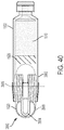
- FIG. 40 illustrates a side view of the drive system 3900 depicted in FIG. 39 .
- the torsion spring 3902 can be positioned adjacent to the primary drug container 1502 to allow the arm 3904 to make contact with the spheres 1520.
- FIG. 40 shows the axis or center 3906 of the torsion spring 3902 about which the arm 3904 can rotate.
- the drive system 3900 can occupy less area than other drive systems described herein, enabling a drug delivery device that includes the drive system 3900 to be provided in a smaller form factor or size.
- the drive system 3300 can include a flexible drive element 3302 and a rotatable nut 3304.
- the flexible drive element 3302 can be a helical compression spring (e.g., a flexible lead screw).
- the flexible drive 3302 can be coupled to the rotatable nut 3304.
- the rotatable nut 3304 can be positioned at an end of the primary drug container 1502.
- the flexible drive element 3302 can be coupled to the rotatable nut 3304.
- the flexible drive element 3304 can pass through a center of the rotatable nut 3304.
- the rotatable nut 3304 can remain in a fixed positioned, coupled to the end 1506 of the primary drug container 1502.
- the rotatable nut 3304 can drive movement of the flexible drive element 3302. That is, the rotatable nut 3302 can include threads coupled to the flexible drive element 3302 to enable movement of the flexible drive element 3302 based on movement of the rotatable nut 3304. For example, rotating the rotatable nut 3304 in a first direction 3306 can move the flexible drive element 3302 in a direction toward the plunger 1508. Rotating the rotatable nut 3304 in a second, opposite direction can move the flexible drive element 3302 away from the plunger 1508. The rotatable nut 3304 can rotate perpendicularly to a vertical axis positioned in approximately a center of the primary drug container 1502. The flexible drive element 3302 can be arranged to pass through the rotatable nut 3304 to contact the plunger 1508.
- the rotatable nut 3304 can be controlled mechanically or electromechanically.
- the rotatable nut 3304 can be driven by a gear system or other mechanism such as, for example, a spring or motor.
- the drive system 3300 enables a force to be applied to the plunger 1508 in a tight and compact space without using a drive spring or spheres.
- the drive system 3300 can operate without applying any force to the flexible drive element 3302 behind the rotatable nut 3304.
- the flexible drive element 3302 can be routed as desired within a drug delivery device.
- the flexible drive element 3302 can be a round wire or a rectangular wire.
- FIG. 34 illustrates an exemplary alternative drive system 3400 for delivering a liquid drug to a patient.
- the drive system 3400 can be used with any of the drug delivery devices described herein (e.g., the drug delivery device 100).
- the drive system 3400 can be used to advance the movement of a plunger as desired to provide delivery of the liquid drug over multiple doses.
- the drive system 3400 can correspond to the drive mechanism 210 described in relation to FIGs. 2 and 3 .
- the drive system 3400 can include any feature of any of the other drive systems described herein.
- FIG. 34 illustrates the drive system 3400 in a first position or operating state.
- the drive system 3400 can include a drug container 3402 (e.g., corresponding to the primary drug container 1502).
- the container 3402 can contain a liquid drug or medicine (e.g., corresponding to the liquid drug 1510).
- the container 3402 can be a prefilled cartridge.
- a plunger 3404 e.g., corresponding to the plunger 1508
- a fluid exit path 3406 can be positioned in proximity to a second, opposite end of the container 3402.
- the fluid exit path 3406 can include tubing, a needle, and/or a cannula for transferring a fluid from one location to another.
- the plunger 3404 can be moved in a direction towards the second end of the container 3402 (towards the needle conduit 3406) by one or more spheres 3408 (e.g., corresponding to the spheres 1520).
- the spheres 3408 can be positioned within and can travel within a sphere path 3410.
- the positioning of the spheres 3408 can be maintained by a wall stop 3412 and an actuated stop 3414. Specifically, the wall stop 3412, the actuated stop 3414, and the sphere path 3410 can maintain one or more spheres adjacent to the plunger 3404.
- the actuated stop 3414 can be moved by a drive system.
- the drive system can be an electromechanical drive system.
- the actuated stop 3414 can move left and right (relative to the orientation shown in FIG. 34 ) to open and close a space between the actuated stop 3414 and the plunger 3404.
- the actuated stop 3404 can be considered to be in an open position such that one or more spheres 3408 can be positioned between the actuated stop 3414 and the plunger 3404.
- the container 3402 can generally be cylindrical in shape but is not so limited and can have a diameter of D1 as indicated in FIG. 34 .
- the spheres 3408 can generally be spherical in shape but are not so limited and can have a diameter of D2 as shown in FIG. 34 .
- the diameter D2 of the spheres 3408 can be slightly smaller than the diameter D1 of the container 3402.
- the actuated stop 3414 can be moved by a mechanical, electrical, and/or electromechanical drive system.
- the actuated stop 3414 can be coupled to a linear induction motor that enables the actuated stop 3414 to move forward and backwards.
- a space can open up between the actuated stop 3414 and the plunger 3404.
- one or more spheres 3408 can move upwards from the sphere path 3410 to occupy the open space.
- a single sphere 3408 is positioned adjacent to the wall stop 3412 and between the actuated stop 3414 and the plunger 3404.
- the actuated stop 3414 can be moved to the right (towards the plunger 3404). Movement of the actuated top 3414 towards the plunger 3404 can cause the sphere 3048 to push against the plunger 3404. The force of the sphere 3408 against the plunger 3404 can cause the plunger 3404 to move to the right (towards the needle conduit 3046). Movement of the plunger 3404 towards the needle conduit 3406 can cause the liquid drug stored in the container 3402 to be forced out of the container 3402 and into the fluid exit path 3406. Accordingly, the movement of the actuated stop 3414 can cause a portion of the liquid drug from the container 3402 to be delivered to a patient.
- the amount of drug delivered to the patient can be determined based on the amount of movement of the actuated stop 3414 and/or the diameter D2 of the spheres 3408.
- a single dose of a drug can correspond to the amount of drug expelled from the container 3402 when the plunger 3404 is moved by an amount corresponding to the diameter D2 of a single sphere 3408.
- the actuated stop 3414 can be moved to allow more than one sphere 3408 to push the plunger 3404 forward during each actuation of the actuated stop 3414.
- the actuated stop 3414 can be moved to allow the plunger 3404 to move a distance that is less than a diameter of the sphere 3408.
- any size dosage can be provided by the drive system 3400 (e.g., any dosage corresponding to any distance the plunger moves 3404 corresponding to any portion of the diameter of a sphere 3408 or more than one sphere 3408).
- a force 3418 can be provided to positon the spheres 3408 towards the wall stop 3412.
- the force 3418 can be provided by any mechanical and/or electromechanical mechanism such as, for example, a spring or motor.
- FIG. 35 illustrates the drive system 3400 in a second position or operating state.
- the actuated stop 3414 has been moved to the right towards the plunger 3404.
- the first sphere 3408 has been moved forward towards the plunger 3404 causing the plunger to move towards the fluid exit path 3406.
- the movement of the plunger 3404 by being pushed by the sphere 3408 causes a portion of the liquid drug of the container 3402 to be pushed out through the fluid exit path 3406.
- the plunger 3404 has been moved by a distance approximately equal to the diameter D2 of the sphere 3408.
- This amount of plunger 3404 movement can correspond to one dosage of the liquid drug stored in the container but is not so limited.
- the diameter D2 of the spheres 3408 can set the dosage amount per sphere 3408 with the amount of dosage of the drug being equal to the number of sphere 3408 diameters or fractions thereof which correspond to the amount of plunger 3404 movement.
- the drive system 3400 can be used to push the spheres 3408 and the plunger 3404 in a controlled manner.
- the speed at which these components are pushed can determine the speed of delivery of the drug and can be adjusted or varied.
- the operation of the drive system 3400 can toggle between the two states shown in FIGs. 34 and 35 .
- the actuated stop 3414 can be moved back away from the plunger 3404 to open up a space for a next sphere 3408.
- two spheres 3408 can be positioned adjacent to one another in line with the actuated stop 3414 and the plunger 3404.
- a next amount of drug can be delivered to the patient when the actuated stop 3414 moves forward again towards to the plunger 3404 to push both spheres 3408 against the plunger 3404.
- a sensor 3416 as shown in FIGs. 34 and 35 can be used to detect the position of the actuated stop 3414 and/or the positons of the spheres 3408.
- the sensor 3416 can provide an indication of positon of these components to a drive system and/or controller for moving the actuated stop 3414.
- the sensor 3416 can be a Hall effect sensor.
- the sensor 3416 can be coupled to a controller or other logic that can maintain a count of how many spheres have been moved into the positon to move the plunger 3404. In doing so, a measure of the number and size of doses can be tracked.
- the wall stop 3412 can be fixed or can be moveable. In various embodiments, the wall stop 3412 can be moved back and forth (e.g., up and down relative to the orientation shown in FIGs. 34 and 35 ) to enable spheres 3408 to be moved up near the container 3402.
- the needle insertion mechanism 3700 can include a first component 3702 and a second component 3704.
- the first and second components 3702 and 3704 can be coupled to a track 3710.
- the first and second components 3702 and 3704 can be positioned on top of the track 3710 and can slide back and forth along the track 3710.
- the first and second components 3702 and 3704 can be coupled to a needle or tubing 3706.
- the needle 3706 can be a portion of the needle conduit 206.
- the needle 3706 can be routed through the first and second components 3702 and 3704.
- a second needle or cannula 3708 can be coupled to the first component 3702.
- the second needle or cannula 3708 can also be a part of the needle conduit 206.
- the second needle or cannula 3708 can be a soft needle or cannula and can be formed from a soft plastic material.
- the needle 3706 can be positioned within the cannula 3708. Together, the needle 3706 and the cannula 3708 can represent or be referred to as a transcutaneous access component.
- the track 3710 can be coupled to an interior portion of a bottom portion of a drug delivery device (e.g., the lower portion 104 of the drug delivery device 100).
- the end of the cannula 3708 can correspond to the protrusion 502 and/or the protrusion 1102.
- the end of the cannula 3708 can remain inside of the drug delivery device prior to activation.
- the hard needle 3706 can be retracted back inside of the drug delivery device after providing access to the patient.
- the portion of the hard needle 3706 that extends from the second component 3704 can be relatively softer than a portion of the needle 3706 extending from the first component 3702.
- the hard needle 3706 and the cannula 3708 can be part of the needle conduit 1514.
- the track 3802 can be circular.
- a sphere 3804 (also shown in cross-section) can be positioned inside of the track 3802.
- the sphere 3804 can represent a sphere 1520.
- the track 3802 can have an inner diameter that is slightly larger than a diameter of the sphere 3804, thereby allowing the sphere 3804 to move through the track 3804.
- a gap or distance 3806 shows a difference in the diameters of the track 3802 (e.g., inner diameter) and the sphere 3804.
- the sphere 3804 is shown centered within the interior of the track 3802. During operation (e.g., movement of the sphere 3804 within the track 3802), the sphere 3804 can make contact with a portion of an inner surface of the track 3802.
- the track 3802 can provide more efficient movement of the sphere 3804 than a conventional square-shaped track (i.e., a track having a square cross-sectional shape or profile).
- the track 3802 can enable the sphere 3804 to move through the track with less friction force to overcome than a square shaped track.
- the efficiency of a drive system that uses the track 3802 can be more efficient, as less force can be used to overcome frictional forces when moving the sphere 3804.
- the split line 3810 can split the track 3802 at an approximately 60/40 split such that approximately 60% of the track 3802 is positioned below the split line 3810 and approximately 40% of the track is positioned above the split line 3810.
- the split line 3810 can represent the positioning of where the upper and lower sections of the track 3802 are joined or put together to form the circular cross-section of the track 3802 as shown in FIG. 38 .
- Forming the track 3802 along the split line 3810 can improve the efficiency of the track 3802 compared to forming the track along the split line 3808.
- the split line 3808 can introduce relatively larger frictional forces that may be required to be overcome when moving the sphere 3804 as compared to the relatively lower frictional forces introduced by forming the track 3802 along the split line 3810.
- the efficiency of a drive system that uses the track 3802 having the track joined at the split line 3810 can be more efficient, as less force can be used to overcome frictional forces when moving the sphere 3804.
- the efficiency of the track 3802 can also be improved when the track 3802 is formed from relatively harder materials.
- the track 3802 may experience less deformation than when formed of relatively softer materials.
- the track 3802 can be formed of relatively harder materials such as stainless steel or hard plastics to reduce deformation.
- the efficiency of the track 3802 (or a drive system using the track 3802) can be improved by using spheres that are lubricious. Materials such as acetyl (e.g., Delrin) or similar plastics blended with a lubricant (such as Teflon or PTFE) can be used to form the spheres and/or track 3802.
- the track 3802 can be formed from a single or unitary piece of material.
- the track 3802 can be formed from a plastic material as a single element without joining two or more pieces at a split line.
- the track 3802 can be a plastic pipe or tube having a desired shape and curvature.
- the track 3802 can be formed and provided without a split line.
- the track 3802 can include one or more openings. The openings can accommodate portions of the drive systems for any of the drug delivery devices described herein.
- FIG. 41 illustrates an exemplary embodiment 4100 of an alternative routing of the needle conduit 1514.
- the needle conduit 1514 depicted in FIG. 41 can be used with any of the drug delivery devices described herein (e.g., the drug delivery device 100).
- the needle conduit 1514 can be routed along any path relative to the other components depicted in FIG. 41 .
- the routing of the needle conduit 1514 as shown in FIG. 41 can be implemented or used with any of the drug delivery devices and/or drive systems described herein.
- any of the drug delivery devices described herein can use any type of springs and any type of spring combinations for a drive spring.
- the drive springs of the drug delivery devices described herein including any intermediate or interstitial springs or assister springs, can be compression springs, torsion springs, or double-bodied torsion springs, or any combination thereof, and can be arranged in series, parallel, or in a combination thereof. Any of the springs described herein can be considered to be or referred to as drive springs.
- Any of the drug delivery devices described herein can include any of the drive mechanisms described herein. Any of the drive mechanisms described herein can be operated to provide a stored liquid drug to a patient in a single dose or over multiple doses.
- Each of the drug delivery devices and drive systems described herein can include or be implemented using a track - such as, for example the track 1524 depicted in FIG. 15 - to provide a pathway or guide for the spheres. In various illustrated embodiments the track has been omitted for simplicity only.
- Each of the drug delivery devices and drive systems described herein can expel a stored liquid drug through the plunger sealing a first end of drug cartridge or through a septum sealing a second end of the drug cartridge as described herein.
- the needle conduit can be coupled to and/or can pierce the plunger of the drug cartridge or the septum of the drug cartridge.
Landscapes
- Health & Medical Sciences (AREA)
- Vascular Medicine (AREA)
- Engineering & Computer Science (AREA)
- Anesthesiology (AREA)
- Biomedical Technology (AREA)
- Heart & Thoracic Surgery (AREA)
- Hematology (AREA)
- Life Sciences & Earth Sciences (AREA)
- Animal Behavior & Ethology (AREA)
- General Health & Medical Sciences (AREA)
- Public Health (AREA)
- Veterinary Medicine (AREA)
- Dermatology (AREA)
- Infusion, Injection, And Reservoir Apparatuses (AREA)
Priority Applications (1)
| Application Number | Priority Date | Filing Date | Title |
|---|---|---|---|
| EP26161399.6A EP4725520A2 (de) | 2016-05-26 | 2017-05-26 | Tragbares medikamentenverabreichungssystem mit vorgefüllter kartusche |
Applications Claiming Priority (10)
| Application Number | Priority Date | Filing Date | Title |
|---|---|---|---|
| US201662341898P | 2016-05-26 | 2016-05-26 | |
| US201662374394P | 2016-08-12 | 2016-08-12 | |
| US201662374881P | 2016-08-14 | 2016-08-14 | |
| US201662375026P | 2016-08-15 | 2016-08-15 | |
| US201662385749P | 2016-09-09 | 2016-09-09 | |
| US201762449845P | 2017-01-24 | 2017-01-24 | |
| US201762449849P | 2017-01-24 | 2017-01-24 | |
| PCT/US2017/034811 WO2017205816A1 (en) | 2016-05-26 | 2017-05-26 | Single dose drug delivery device |
| EP17729299.2A EP3463510B1 (de) | 2016-05-26 | 2017-05-26 | Gerät zur verabreichung einer einzigen dosis |
| EP19206333.7A EP3646905B1 (de) | 2016-05-26 | 2017-05-26 | Vorrichtung zur abgabe von arzneimitteln in einzeldosis |
Related Parent Applications (3)
| Application Number | Title | Priority Date | Filing Date |
|---|---|---|---|
| EP19206333.7A Division EP3646905B1 (de) | 2016-05-26 | 2017-05-26 | Vorrichtung zur abgabe von arzneimitteln in einzeldosis |
| EP19206333.7A Division-Into EP3646905B1 (de) | 2016-05-26 | 2017-05-26 | Vorrichtung zur abgabe von arzneimitteln in einzeldosis |
| EP17729299.2A Division EP3463510B1 (de) | 2016-05-26 | 2017-05-26 | Gerät zur verabreichung einer einzigen dosis |
Related Child Applications (1)
| Application Number | Title | Priority Date | Filing Date |
|---|---|---|---|
| EP26161399.6A Division EP4725520A2 (de) | 2016-05-26 | 2017-05-26 | Tragbares medikamentenverabreichungssystem mit vorgefüllter kartusche |
Publications (3)
| Publication Number | Publication Date |
|---|---|
| EP3871708A2 true EP3871708A2 (de) | 2021-09-01 |
| EP3871708A3 EP3871708A3 (de) | 2022-01-19 |
| EP3871708B1 EP3871708B1 (de) | 2026-03-11 |
Family
ID=59034917
Family Applications (4)
| Application Number | Title | Priority Date | Filing Date |
|---|---|---|---|
| EP17729299.2A Active EP3463510B1 (de) | 2016-05-26 | 2017-05-26 | Gerät zur verabreichung einer einzigen dosis |
| EP21169430.2A Active EP3871708B1 (de) | 2016-05-26 | 2017-05-26 | Tragbares medikamentenverabreichungssystem mit vorgefüllter kartusche |
| EP26161399.6A Pending EP4725520A2 (de) | 2016-05-26 | 2017-05-26 | Tragbares medikamentenverabreichungssystem mit vorgefüllter kartusche |
| EP19206333.7A Active EP3646905B1 (de) | 2016-05-26 | 2017-05-26 | Vorrichtung zur abgabe von arzneimitteln in einzeldosis |
Family Applications Before (1)
| Application Number | Title | Priority Date | Filing Date |
|---|---|---|---|
| EP17729299.2A Active EP3463510B1 (de) | 2016-05-26 | 2017-05-26 | Gerät zur verabreichung einer einzigen dosis |
Family Applications After (2)
| Application Number | Title | Priority Date | Filing Date |
|---|---|---|---|
| EP26161399.6A Pending EP4725520A2 (de) | 2016-05-26 | 2017-05-26 | Tragbares medikamentenverabreichungssystem mit vorgefüllter kartusche |
| EP19206333.7A Active EP3646905B1 (de) | 2016-05-26 | 2017-05-26 | Vorrichtung zur abgabe von arzneimitteln in einzeldosis |
Country Status (3)
| Country | Link |
|---|---|
| US (5) | US10363374B2 (de) |
| EP (4) | EP3463510B1 (de) |
| WO (2) | WO2017205816A1 (de) |
Cited By (1)
| Publication number | Priority date | Publication date | Assignee | Title |
|---|---|---|---|---|
| US12527912B2 (en) | 2018-07-25 | 2026-01-20 | Quasuras, Inc. | Subcutaneous access hub with multiple cannula ports |
Families Citing this family (128)
| Publication number | Priority date | Publication date | Assignee | Title |
|---|---|---|---|---|
| ATE480278T1 (de) | 2005-09-12 | 2010-09-15 | Unomedical As | Einfürungssystem für ein infusionsset mit einem ersten und zweiten federeinheit |
| US8417311B2 (en) | 2008-09-12 | 2013-04-09 | Optiscan Biomedical Corporation | Fluid component analysis system and method for glucose monitoring and control |
| CA2702116C (en) | 2007-10-10 | 2021-01-05 | Optiscan Biomedical Corporation | Fluid component analysis system and method for glucose monitoring and control |
| USD994111S1 (en) | 2008-05-12 | 2023-08-01 | Kaleo, Inc. | Medicament delivery device cover |
| US7959598B2 (en) | 2008-08-20 | 2011-06-14 | Asante Solutions, Inc. | Infusion pump systems and methods |
| CA2792138A1 (en) | 2010-03-30 | 2011-10-06 | Unomedical A/S | Medical device |
| US9084849B2 (en) | 2011-01-26 | 2015-07-21 | Kaleo, Inc. | Medicament delivery devices for administration of a medicament within a prefilled syringe |
| US10194938B2 (en) | 2011-03-14 | 2019-02-05 | UnoMedical, AS | Inserter system with transport protection |
| EP2583715A1 (de) | 2011-10-19 | 2013-04-24 | Unomedical A/S | Infusionsschlauchsystem und Herstellungsverfahren |
| RS65875B1 (sr) | 2012-03-30 | 2024-09-30 | Insulet Corp | Sredstvo za isporučivanje tečnosti sa alatom za transkutani pristup, mehanizmom za inserciju i praćenje nivoa glukoze u krvi za istovremenu upotrebu |
| US9561324B2 (en) | 2013-07-19 | 2017-02-07 | Bigfoot Biomedical, Inc. | Infusion pump system and method |
| GB2523989B (en) | 2014-01-30 | 2020-07-29 | Insulet Netherlands B V | Therapeutic product delivery system and method of pairing |
| US10441717B2 (en) | 2014-04-15 | 2019-10-15 | Insulet Corporation | Monitoring a physiological parameter associated with tissue of a host to confirm delivery of medication |
| US10773028B2 (en) * | 2014-10-07 | 2020-09-15 | Silgan Dispensing Systems Corporation | Indexing dose dispensing device |
| CN111905188B (zh) | 2015-02-18 | 2022-07-22 | 英赛罗公司 | 流体输送和输注装置及其使用方法 |
| CN107635527B (zh) | 2015-03-10 | 2021-04-23 | 里珍纳龙药品有限公司 | 无菌刺穿系统和方法 |
| US10576206B2 (en) | 2015-06-30 | 2020-03-03 | Kaleo, Inc. | Auto-injectors for administration of a medicament within a prefilled syringe |
| US10576207B2 (en) | 2015-10-09 | 2020-03-03 | West Pharma. Services IL, Ltd. | Angled syringe patch injector |
| US11806502B2 (en) | 2015-11-20 | 2023-11-07 | Tandem Diabetes Care Switzerland Sarl | Micropump |
| WO2017091584A1 (en) | 2015-11-25 | 2017-06-01 | Insulet Corporation | Wearable medication delivery device |
| WO2017123525A1 (en) | 2016-01-13 | 2017-07-20 | Bigfoot Biomedical, Inc. | User interface for diabetes management system |
| US10806859B2 (en) | 2016-01-14 | 2020-10-20 | Bigfoot Biomedical, Inc. | Adjusting insulin delivery rates |
| HK1256995A1 (zh) | 2016-01-14 | 2019-10-11 | Bigfoot Biomedical, Inc. | 药物输送设备、系统和方法中的阻塞解决方案 |
| WO2017125817A1 (en) | 2016-01-19 | 2017-07-27 | Unomedical A/S | Cannula and infusion devices |
| CN113041432B (zh) | 2016-01-21 | 2023-04-07 | 西医药服务以色列有限公司 | 包括视觉指示物的药剂输送装置 |
| US10363342B2 (en) | 2016-02-04 | 2019-07-30 | Insulet Corporation | Anti-inflammatory cannula |
| US12383166B2 (en) | 2016-05-23 | 2025-08-12 | Insulet Corporation | Insulin delivery system and methods with risk-based set points |
| US10363374B2 (en) * | 2016-05-26 | 2019-07-30 | Insulet Corporation | Multi-dose drug delivery device |
| WO2018034784A1 (en) * | 2016-08-17 | 2018-02-22 | Amgen Inc. | Drug delivery device with placement detection |
| US10765807B2 (en) | 2016-09-23 | 2020-09-08 | Insulet Corporation | Fluid delivery device with sensor |
| USD878557S1 (en) * | 2016-10-26 | 2020-03-17 | West Pharmaceutical Services, Inc. | Injector device |
| USD878555S1 (en) * | 2016-10-26 | 2020-03-17 | West Pharmaceutical Services, Inc. | Injector device |
| USD878556S1 (en) * | 2016-10-26 | 2020-03-17 | West Pharmaceutical Services, Inc. | Injector device |
| USD882765S1 (en) * | 2016-10-26 | 2020-04-28 | West Pharmaceutical Services, Inc. | Injector device |
| US10245377B2 (en) | 2016-11-11 | 2019-04-02 | Insulet Corporation | Drug delivery systems with sealed and sterile fluid paths and methods of providing the same |
| ES2985905T3 (es) | 2016-11-22 | 2024-11-07 | Lts Device Tech Ltd | Aparato para suministrar una sustancia terapéutica |
| US11096624B2 (en) | 2016-12-12 | 2021-08-24 | Bigfoot Biomedical, Inc. | Alarms and alerts for medication delivery devices and systems |
| US10500334B2 (en) | 2017-01-13 | 2019-12-10 | Bigfoot Biomedical, Inc. | System and method for adjusting insulin delivery |
| US11033682B2 (en) | 2017-01-13 | 2021-06-15 | Bigfoot Biomedical, Inc. | Insulin delivery methods, systems and devices |
| US10758675B2 (en) | 2017-01-13 | 2020-09-01 | Bigfoot Biomedical, Inc. | System and method for adjusting insulin delivery |
| US10583250B2 (en) | 2017-01-13 | 2020-03-10 | Bigfoot Biomedical, Inc. | System and method for adjusting insulin delivery |
| US10881792B2 (en) | 2017-01-13 | 2021-01-05 | Bigfoot Biomedical, Inc. | System and method for adjusting insulin delivery |
| EP3568860B1 (de) | 2017-01-13 | 2025-12-10 | Insulet Corporation | Insulinverabreichungsverfahren, -systeme und -vorrichtungen |
| WO2018156548A1 (en) * | 2017-02-22 | 2018-08-30 | Insulet Corporation | Needle insertion mechanisms for drug containers |
| IL308643B2 (en) | 2017-05-05 | 2025-02-01 | Regeneron Pharma | Auto-injector |
| CN115779186A (zh) | 2017-06-20 | 2023-03-14 | 曼金德公司 | 药剂输送装置以及操作药剂输送装置的方法 |
| US10722640B2 (en) | 2017-08-03 | 2020-07-28 | Insulet Corporation | Devices, systems, and methods of packaging for a pre-filled drug delivery device |
| US10973939B2 (en) | 2017-08-03 | 2021-04-13 | Insulet Corporation | System and method for aseptic packaging of a drug delivery device components |
| WO2019060839A1 (en) * | 2017-09-25 | 2019-03-28 | Insulet Corporation | DRUG DELIVERY DEVICE WITH PRE-FILLED CARTRIDGE |
| US10898656B2 (en) | 2017-09-26 | 2021-01-26 | Insulet Corporation | Needle mechanism module for drug delivery device |
| USD895109S1 (en) * | 2017-10-18 | 2020-09-01 | Roche Diabetes Care, Inc. | Inserter for an infusion set |
| US11147931B2 (en) | 2017-11-17 | 2021-10-19 | Insulet Corporation | Drug delivery device with air and backflow elimination |
| CN111432860B (zh) * | 2017-12-08 | 2023-08-08 | 坦德姆糖尿病护理瑞士有限责任公司 | 给药装置 |
| US11766519B2 (en) | 2018-01-17 | 2023-09-26 | Amgen Inc. | Drug delivery mechanism |
| USD928199S1 (en) | 2018-04-02 | 2021-08-17 | Bigfoot Biomedical, Inc. | Medication delivery device with icons |
| US11565043B2 (en) | 2018-05-04 | 2023-01-31 | Insulet Corporation | Safety constraints for a control algorithm based drug delivery system |
| US12562251B1 (en) | 2018-05-09 | 2026-02-24 | Bigfoot Biomedical, Inc. | Computing architecture for assuring the provenance of medication therapy related parameters, and related systems, methods and devices |
| USD882760S1 (en) * | 2018-07-22 | 2020-04-28 | Sorrel Medical Ltd. | Medical drug delivery device |
| EP3603700A1 (de) * | 2018-07-30 | 2020-02-05 | Tecpharma Licensing AG | Nadeleinführ- und retraktionsmechanismus |
| US11241532B2 (en) | 2018-08-29 | 2022-02-08 | Insulet Corporation | Drug delivery system with sensor having optimized communication and infusion site |
| AU2019347755B2 (en) | 2018-09-28 | 2023-02-02 | Insulet Corporation | Activity mode for artificial pancreas system |
| EP3632487B1 (de) | 2018-10-05 | 2024-06-12 | LTS Device Technologies Ltd | Auslösesequenz |
| EP3864668A1 (de) | 2018-10-11 | 2021-08-18 | Insulet Corporation | Ereignisdetektion für ein arzneimittelabgabesystem |
| EP3902584A4 (de) | 2018-12-29 | 2022-09-07 | Kaleo, Inc. | Vorrichtungen und verfahren zur abgabe von substanzen in einer vorgefüllten spritze |
| USD920343S1 (en) | 2019-01-09 | 2021-05-25 | Bigfoot Biomedical, Inc. | Display screen or portion thereof with graphical user interface associated with insulin delivery |
| JP7256294B2 (ja) * | 2019-04-22 | 2023-04-11 | エスエイチエル・メディカル・アーゲー | オンボディ薬剤送達デバイスのための起動機構 |
| CA3141608A1 (en) | 2019-05-20 | 2020-11-26 | Unomedical A/S | Rotatable infusion device and methods thereof |
| CA3145580A1 (en) | 2019-08-09 | 2021-02-18 | Kaleo, Inc. | Devices and methods for delivery of substances within a prefilled syringe |
| US11801344B2 (en) | 2019-09-13 | 2023-10-31 | Insulet Corporation | Blood glucose rate of change modulation of meal and correction insulin bolus quantity |
| US11935637B2 (en) | 2019-09-27 | 2024-03-19 | Insulet Corporation | Onboarding and total daily insulin adaptivity |
| EP4069082B1 (de) | 2019-12-06 | 2024-06-05 | Insulet Corporation | Techniken und vorrichtungen zum bereitstellen von adaptivität und personalisierung bei der behandlung von diabetes |
| US11833329B2 (en) | 2019-12-20 | 2023-12-05 | Insulet Corporation | Techniques for improved automatic drug delivery performance using delivery tendencies from past delivery history and use patterns |
| JP7512395B2 (ja) | 2020-01-06 | 2024-07-08 | インスレット コーポレイション | 持続する残差に基づく食事および/または運動行為の予測 |
| EP4100958A1 (de) | 2020-02-03 | 2022-12-14 | Insulet Corporation | Einsatz von fuzzy-logik beim vorhersagen von benutzerverhalten, das die blutzuckerkonzentration beeinflusst |
| US11551802B2 (en) | 2020-02-11 | 2023-01-10 | Insulet Corporation | Early meal detection and calorie intake detection |
| US11547800B2 (en) | 2020-02-12 | 2023-01-10 | Insulet Corporation | User parameter dependent cost function for personalized reduction of hypoglycemia and/or hyperglycemia in a closed loop artificial pancreas system |
| US11986630B2 (en) | 2020-02-12 | 2024-05-21 | Insulet Corporation | Dual hormone delivery system for reducing impending hypoglycemia and/or hyperglycemia risk |
| US11324889B2 (en) | 2020-02-14 | 2022-05-10 | Insulet Corporation | Compensation for missing readings from a glucose monitor in an automated insulin delivery system |
| US12495994B2 (en) | 2020-02-20 | 2025-12-16 | Insulet Corporation | Meal bolus subcategories in model based insulin therapy |
| US11607493B2 (en) | 2020-04-06 | 2023-03-21 | Insulet Corporation | Initial total daily insulin setting for user onboarding |
| CN111514411B (zh) * | 2020-04-26 | 2022-09-06 | 沈阳工程学院 | 一种可穿戴式智能医疗注射装置 |
| US12121700B2 (en) | 2020-07-22 | 2024-10-22 | Insulet Corporation | Open-loop insulin delivery basal parameters based on insulin delivery records |
| US11684716B2 (en) | 2020-07-31 | 2023-06-27 | Insulet Corporation | Techniques to reduce risk of occlusions in drug delivery systems |
| US12569619B2 (en) | 2020-09-21 | 2026-03-10 | Insulet Corporation | Techniques for determining automated insulin delivery dosages |
| EP4696344A3 (de) | 2020-09-30 | 2026-04-15 | Insulet Corporation | Arzneimittelabgabevorrichtung mit integriertem optischen glucosemonitor |
| US12115351B2 (en) | 2020-09-30 | 2024-10-15 | Insulet Corporation | Secure wireless communications between a glucose monitor and other devices |
| US12458751B2 (en) | 2020-10-02 | 2025-11-04 | Insulet Corporation | Fluid delivery device having multiple penetrating elements |
| US11241530B1 (en) | 2020-11-23 | 2022-02-08 | Amf Medical Sa | Insulin patch pump having photoplethysmography module |
| US12433512B2 (en) | 2020-12-18 | 2025-10-07 | Insulet Corporation | Adhesive pad with a metallic coil for securing an on-body medical device |
| US11160925B1 (en) | 2021-01-29 | 2021-11-02 | Insulet Corporation | Automatic drug delivery system for delivery of a GLP-1 therapeutic |
| US12268847B1 (en) | 2021-02-10 | 2025-04-08 | Kaleo, Inc. | Devices and methods for delivery of substances within a medicament container |
| US11872369B1 (en) | 2021-02-18 | 2024-01-16 | Fresenius Kabi Deutschland Gmbh | Wearable medicament delivery device with leakage and skin contact sensing and method of use thereof |
| US11311666B1 (en) | 2021-02-18 | 2022-04-26 | Fresenius Kabi Deutschland Gmbh | Modular wearable medicament delivery device and method of use thereof |
| US11464902B1 (en) | 2021-02-18 | 2022-10-11 | Fresenius Kabi Deutschland Gmbh | Wearable medicament delivery device with compressible reservoir and method of use thereof |
| US11406755B1 (en) | 2021-02-19 | 2022-08-09 | Fresenius Kabi Deutschland Gmbh | Sensing fluid flow irregularities in an on-body injector |
| US11497847B1 (en) | 2021-02-19 | 2022-11-15 | Fresenius Kabi Deutschland Gmbh | Wearable injector with adhesive substrate |
| US11607505B1 (en) | 2021-02-19 | 2023-03-21 | Fresenius Kabi Deutschland Gmbh | Wearable injector with sterility sensors |
| US11344682B1 (en) | 2021-02-19 | 2022-05-31 | Fresenius Kabi Deutschland Gmbh | Drug supply cartridge with visual use indicator and delivery devices that use the same |
| US11426523B1 (en) | 2021-02-19 | 2022-08-30 | Fresenius Kabi Deutschland Gmbh | Drug delivery assembly including a removable cartridge |
| US11413394B1 (en) | 2021-02-19 | 2022-08-16 | Fresenius Kabi Deutschland Gmbh | Display for wearable drug delivery device |
| US11633537B1 (en) | 2021-02-19 | 2023-04-25 | Fresenius Kabi Deutschland Gmbh | Drug delivery assembly including a pre-filled cartridge |
| EP4305636A1 (de) | 2021-03-10 | 2024-01-17 | Insulet Corporation | Medikamentenabgabevorrichtung mit einstellbarer und stückweiser analytniveau-kostenkomponente zur adressierung persistenter positiver analytniveauabweichungen |
| US11904140B2 (en) | 2021-03-10 | 2024-02-20 | Insulet Corporation | Adaptable asymmetric medicament cost component in a control system for medicament delivery |
| CA3216453A1 (en) | 2021-04-23 | 2022-10-27 | Unomedical A/S | Miniaturized patch pump system |
| US12592306B2 (en) | 2021-04-28 | 2026-03-31 | Insulet Corporation | Devices and methods for initialization of drug delivery devices using measured analyte sensor information |
| US11419976B1 (en) | 2021-04-30 | 2022-08-23 | Fresenius Kabi Deutschland Gmbh | Wearable drug delivery device with pressurized fluid dispensing |
| US11529459B1 (en) | 2021-04-30 | 2022-12-20 | Fresenius Kabi Deutschland Gmbh | Wearable injector with adhesive module |
| US11351300B1 (en) | 2021-04-30 | 2022-06-07 | Fresenius Kabl Deutschland GmbH | Drug dispensing system with replaceable drug supply cartridges |
| US11504470B1 (en) | 2021-04-30 | 2022-11-22 | Fresenius Kabi Deutschland Gmbh | Deformable drug reservoir for wearable drug delivery device |
| US11717608B1 (en) | 2021-05-03 | 2023-08-08 | Fresenius Kabi Deutschland Gmbh | Drug delivery assembly including an adhesive pad |
| US11484646B1 (en) | 2021-05-04 | 2022-11-01 | Fresenius Kabi Deutschland Gmbh | Sealing systems for a reservoir of an on-body injector |
| WO2022251642A1 (en) | 2021-05-28 | 2022-12-01 | Insulet Corporation | Spring-based status sensors |
| US12496398B2 (en) | 2021-05-28 | 2025-12-16 | Insulet Corporation | Threshold based automatic glucose control response |
| US12594377B2 (en) | 2021-06-01 | 2026-04-07 | Tandem Diabetes Care Switzerland Sàrl | Systems and methods for delivering microdoses of medication |
| US11529464B1 (en) | 2021-06-01 | 2022-12-20 | Amf Medical Sa | Systems and methods for monitoring delivery of microdoses of medication |
| US11679199B2 (en) | 2021-06-01 | 2023-06-20 | Amf Medical Sa | Systems and methods for delivering microdoses of medication |
| US11857757B2 (en) | 2021-06-01 | 2024-01-02 | Tandem Diabetes Care Switzerland Sàrl | Systems and methods for delivering microdoses of medication |
| EP4101482A1 (de) | 2021-06-07 | 2022-12-14 | Insulet Corporation | Übungssicherheitsvorhersage basierend auf physiologischen bedingungen |
| US12514980B2 (en) | 2021-06-30 | 2026-01-06 | Insulet Corporation | Adjustment of medicament delivery by a medicament delivery device based on menstrual cycle phase |
| US12521486B2 (en) | 2021-07-16 | 2026-01-13 | Insulet Corporation | Method for modification of insulin delivery during pregnancy in automatic insulin delivery systems |
| WO2023049900A1 (en) | 2021-09-27 | 2023-03-30 | Insulet Corporation | Techniques enabling adaptation of parameters in aid systems by user input |
| US12478738B2 (en) | 2021-11-04 | 2025-11-25 | Insulet Corporation | Methods and systems for sterilizing sealed components of a drug delivery device |
| USD1007676S1 (en) | 2021-11-16 | 2023-12-12 | Regeneron Pharmaceuticals, Inc. | Wearable autoinjector |
| US11439754B1 (en) | 2021-12-01 | 2022-09-13 | Insulet Corporation | Optimizing embedded formulations for drug delivery |
| EP4243030A1 (de) | 2022-03-09 | 2023-09-13 | Insulet Corporation | Anpassung von medikamentenverabreichungsparametern in einem offenen regelkreis der medikamentenverabreichung |
| KR20250044385A (ko) | 2022-08-04 | 2025-03-31 | 인슐렛 코포레이션 | 이중 저장조 및 고정 유체 포트를 갖는 펌프 기구 |
| EP4646726A1 (de) | 2023-01-06 | 2025-11-12 | Insulet Corporation | Automatisch oder manuell initiierte mahlzeitbolusabgabe mit anschliessender automatischer sicherheitseinschränkungsrelaxation |
| WO2025171324A1 (en) * | 2024-02-08 | 2025-08-14 | Desai Nick | Methods and systems for automated medicine dispensing |
Citations (3)
| Publication number | Priority date | Publication date | Assignee | Title |
|---|---|---|---|---|
| US4313439A (en) * | 1980-03-24 | 1982-02-02 | Biotek, Inc. | Automated, spring-powered medicament infusion system |
| US20040069044A1 (en) * | 1999-04-29 | 2004-04-15 | Gilad Lavi | Device for measuring a volume of drug |
| WO2011133823A1 (en) * | 2010-04-21 | 2011-10-27 | Abbott Biotechnology Ltd. | Wearable automatic injection device for controlled delivery of therapeutic agents |
Family Cites Families (533)
| Publication number | Priority date | Publication date | Assignee | Title |
|---|---|---|---|---|
| US445545A (en) | 1891-02-03 | Non-interference signal-box | ||
| CA606281A (en) | 1960-10-04 | Dann Morris | Cartridge for metering syringe | |
| US588583A (en) | 1897-08-24 | Plow-clevis | ||
| US1441508A (en) | 1921-12-06 | 1923-01-09 | Jensen Anton Marius | Cylindrical slide valve |
| GB310488A (en) | 1928-04-26 | 1930-07-24 | Ceska Zbrojovka Akciova Spolec | Fore-stock for guns, particularly self-loading guns |
| GB357139A (de) | 1929-06-14 | 1931-09-14 | Paul Von Vago | |
| US2198666A (en) | 1936-09-30 | 1940-04-30 | Lakeland Foundation | Syringe |
| US2283925A (en) | 1937-04-30 | 1942-05-26 | Rca Corp | High frequency core and shield and method of making the same |
| FR1078911A (fr) | 1949-08-17 | 1954-11-24 | Seringue hypodermique automatique et son ampoule | |
| GB730703A (en) | 1952-07-31 | 1955-05-25 | Centre Nat Rech Scient | Magnetic materials and methods of manufacturing such materials |
| GB810488A (en) | 1955-03-01 | 1959-03-18 | Eduard Woydt | Liquid pressure piston-engine or reciprocating pump |
| GB875034A (en) | 1957-07-01 | 1961-08-16 | Renault | Improvements in or relating to valves for fluids under pressure |
| US3176712A (en) | 1961-10-03 | 1965-04-06 | Ramsden Clement | Non-return valve |
| US3297260A (en) | 1964-09-21 | 1967-01-10 | Conrad R Barlow | Nozzle and valve assembly |
| DE1200595B (de) | 1964-11-28 | 1965-09-09 | Stoll Walter Dipl Ing | Schnellkupplung fuer an die Lenker der Dreipunktankopplungsvorrichtung eines Schleppers anzukuppelnde Iandwirtschaftliche Geraete |
| US3413573A (en) | 1965-06-18 | 1968-11-26 | Westinghouse Electric Corp | Microelectronic frequency selective apparatus with vibratory member and means responsive thereto |
| US3464359A (en) | 1967-11-13 | 1969-09-02 | Medimeter Corp The | Apparatus for moving fluid from one system to a second system |
| US3505809A (en) | 1968-05-20 | 1970-04-14 | Thermal Hydraulics Corp | Thermal motor |
| US3574114A (en) | 1968-08-05 | 1971-04-06 | Bell Telephone Labor Inc | Fine grain ceramic ferrites |
| US3614554A (en) | 1968-10-24 | 1971-10-19 | Texas Instruments Inc | Miniaturized thin film inductors for use in integrated circuits |
| DE7121836U (de) | 1970-06-13 | 1972-01-27 | Ismatec Sa | Dosier-kolbenpumpe |
| US3946732A (en) | 1973-08-08 | 1976-03-30 | Ampoules, Inc. | Two-chamber mixing syringe |
| US3885662A (en) | 1973-12-26 | 1975-05-27 | Ibm | Steerable follower selection mechanism |
| US3947692A (en) | 1974-08-05 | 1976-03-30 | Viron E. Payne, Inc. | Digital transducers |
| IL46017A (en) | 1974-11-07 | 1977-11-30 | Ampoules Inc | Two-chamber mixing syringe |
| US3993061A (en) | 1975-02-28 | 1976-11-23 | Ivac Corporation | Syringe pump drive system and disposable syringe cartridge |
| US3983077A (en) | 1975-05-02 | 1976-09-28 | Texas Instruments Incorporated | Process for making ceramic resistor materials |
| FR2348709A1 (fr) | 1976-04-23 | 1977-11-18 | Pistor Michel | Procede de traitement mesotherapique et dispositif d'injection,formant micro-injecteur automatique,en comportant application |
| US4210173A (en) | 1976-12-06 | 1980-07-01 | American Hospital Supply Corporation | Syringe pumping system with valves |
| US4152098A (en) | 1977-01-03 | 1979-05-01 | Clark Ivan P | Micropump |
| DE2749251C3 (de) | 1977-11-03 | 1981-10-08 | Danfoss A/S, 6430 Nordborg | Regelbare Heizvorrichtung für kleine Massen, insbesondere das Ausdehnungsmittel in Wärmestellvorrichtungen |
| FR2455269A1 (fr) | 1978-01-17 | 1980-11-21 | Marceau Serge | Systeme de dosage dynamique a cylindres pneumatiques |
| US4221219A (en) | 1978-07-31 | 1980-09-09 | Metal Bellows Corporation | Implantable infusion apparatus and method |
| US4265601A (en) | 1978-09-05 | 1981-05-05 | Harold Mandroian | Three valve precision pump apparatus with head pressure flowthrough protection |
| US4257324A (en) | 1978-10-30 | 1981-03-24 | Bell & Howell Company | Position monitoring methods and apparatus |
| US4277226A (en) | 1979-03-09 | 1981-07-07 | Avi, Inc. | IV Pump with empty supply reservoir and occlusion detector |
| GB2076658B (en) | 1979-12-13 | 1984-03-28 | Cepuritis Talivaldis | Wearable insulin infusion system having a tubular reservoir and a positive displacement metering means |
| US4268150A (en) | 1980-01-28 | 1981-05-19 | Laurence Chen | Disposable camera with simplified film advance and indicator |
| CA1169323A (en) | 1980-06-03 | 1984-06-19 | Anthony M. Albisser | Insulin infusion device |
| US4371790A (en) | 1980-09-19 | 1983-02-01 | Rmr Systems, Inc. | Fluid measuring system |
| US4424720A (en) | 1980-12-15 | 1984-01-10 | Ivac Corporation | Mechanism for screw drive and syringe plunger engagement/disengagement |
| IN155982B (de) | 1980-12-31 | 1985-04-20 | Choi Soo Bong | |
| JPS57163309A (en) | 1981-04-01 | 1982-10-07 | Olympus Optical Co Ltd | Capsule apparatus for medical use |
| FR2507637B1 (fr) | 1981-06-16 | 1986-09-26 | Libero Elettrotecnica | Dispositif d'actionnement thermoelectrique, notamment pour activer des distributeurs de detergents et/ou d'agents de brillantage dans des machines a laver |
| US4400683A (en) | 1981-09-18 | 1983-08-23 | Matsushita Electric Industrial Co., Ltd. | Voltage-dependent resistor |
| US4435173A (en) | 1982-03-05 | 1984-03-06 | Delta Medical Industries | Variable rate syringe pump for insulin delivery |
| US4498843A (en) | 1982-08-02 | 1985-02-12 | Schneider Philip H | Insulin infusion pump |
| US4551134A (en) | 1982-08-06 | 1985-11-05 | Nuvatec, Inc. | Intravenous set |
| US4475905A (en) | 1982-09-30 | 1984-10-09 | Himmelstrup Anders B | Injection device |
| US4523170A (en) | 1982-11-05 | 1985-06-11 | Spang & Company | Adjustable air gap ferrite structures and methods of manufacture |
| GB2261117B (en) | 1983-05-09 | 1993-10-06 | Secr Defence | Mixer circuit |
| DE3468173D1 (en) | 1983-09-07 | 1988-02-04 | Disetronic Ag | Portable infusion apparatus |
| NL8303908A (nl) | 1983-11-15 | 1985-06-03 | Unilever Nv | Werkwijze en inrichting voor het volumetrisch doseren van viskeuze produkten. |
| US4685903A (en) | 1984-01-06 | 1987-08-11 | Pacesetter Infusion, Ltd. | External infusion pump apparatus |
| US4562751A (en) | 1984-01-06 | 1986-01-07 | Nason Clyde K | Solenoid drive apparatus for an external infusion pump |
| US4678408A (en) | 1984-01-06 | 1987-07-07 | Pacesetter Infusion, Ltd. | Solenoid drive apparatus for an external infusion pump |
| US4684368A (en) | 1984-06-01 | 1987-08-04 | Parker Hannifin Corporation | Inverted pump |
| US4634427A (en) | 1984-09-04 | 1987-01-06 | American Hospital Supply Company | Implantable demand medication delivery assembly |
| EP0177802A3 (de) | 1984-09-27 | 1988-12-21 | Siemens Aktiengesellschaft | Ladungssensoranordnung |
| US4567549A (en) | 1985-02-21 | 1986-01-28 | Blazer International Corp. | Automatic takeup and overload protection device for shape memory metal actuator |
| US4846797A (en) | 1985-05-14 | 1989-07-11 | Intelligent Medicine, Inc. | Syringe positioning device for enhancing fluid flow control |
| US4908017A (en) | 1985-05-14 | 1990-03-13 | Ivion Corporation | Failsafe apparatus and method for effecting syringe drive |
| DK160633C (da) | 1985-05-15 | 1991-09-02 | Henning Munk Ejlersen | Slangepumpe, isaer til avendelse som insulinpumpe |
| US4689042A (en) | 1985-05-20 | 1987-08-25 | Survival Technology, Inc. | Automatic medicament ingredient mixing and injecting apparatus |
| WO1987005055A1 (en) | 1986-02-24 | 1987-08-27 | Hughes Aircraft Company | Process for forming an environmentally stable optical coating and structures formed thereby |
| US5349852A (en) | 1986-03-04 | 1994-09-27 | Deka Products Limited Partnership | Pump controller using acoustic spectral analysis |
| US4778451A (en) | 1986-03-04 | 1988-10-18 | Kamen Dean L | Flow control system using boyle's law |
| US4646038A (en) | 1986-04-07 | 1987-02-24 | Motorola, Inc. | Ceramic resonator filter with electromagnetic shielding |
| US4759120A (en) | 1986-05-30 | 1988-07-26 | Bel Fuse Inc. | Method for surface mounting a coil |
| US4766889A (en) | 1986-06-26 | 1988-08-30 | Medical Engineering Corporation | Infusion erectile system |
| GB8701731D0 (en) | 1987-01-27 | 1987-03-04 | Patcentre Benelux Nv Sa | Pumps |
| US4880770A (en) | 1987-05-04 | 1989-11-14 | Eastman Kodak Company | Metalorganic deposition process for preparing superconducting oxide films |
| WO1988009187A1 (fr) | 1987-05-18 | 1988-12-01 | Disetronic Ag | Appareil pour faire des perfusions |
| US4898579A (en) | 1987-06-26 | 1990-02-06 | Pump Controller Corporation | Infusion pump |
| US4858619A (en) | 1987-06-29 | 1989-08-22 | Toth Marie A | Intracranial pressure monitoring system |
| US5217754A (en) | 1987-07-27 | 1993-06-08 | Trustees Of The University Of Pennsylvania | Organometallic precursors in conjunction with rapid thermal annealing for synthesis of thin film ceramics |
| ATA228987A (de) | 1987-09-09 | 1993-07-15 | Pickhard Ewald | Injektionsvorrichtung mit einer verformbaren ampulle |
| US5189609A (en) | 1987-10-09 | 1993-02-23 | Hewlett-Packard Company | Medical monitoring system with softkey control |
| US4967201A (en) | 1987-10-22 | 1990-10-30 | Westinghouse Electric Corp. | Multi-layer single substrate microwave transmit/receive module |
| US4898578A (en) | 1988-01-26 | 1990-02-06 | Baxter International Inc. | Drug infusion system with calculator |
| US4898582A (en) * | 1988-08-09 | 1990-02-06 | Pharmetrix Corporation | Portable infusion device assembly |
| US5062841A (en) | 1988-08-12 | 1991-11-05 | The Regents Of The University Of California | Implantable, self-regulating mechanochemical insulin pump |
| US5084749A (en) | 1988-08-25 | 1992-01-28 | Eastman Kodak Company | Image sensing device with reduced smear |
| US5456945A (en) | 1988-12-27 | 1995-10-10 | Symetrix Corporation | Method and apparatus for material deposition |
| US5614252A (en) | 1988-12-27 | 1997-03-25 | Symetrix Corporation | Method of fabricating barium strontium titanate |
| US5222362A (en) | 1989-01-10 | 1993-06-29 | Maus Daryl D | Heat-activated drug delivery system and thermal actuators therefor |
| US5205819A (en) | 1989-05-11 | 1993-04-27 | Bespak Plc | Pump apparatus for biomedical use |
| US4991743A (en) | 1989-11-06 | 1991-02-12 | Cobe Laboratories, Inc. | Controlled flow accumulator |
| JPH03179805A (ja) | 1989-12-07 | 1991-08-05 | Murata Mfg Co Ltd | 誘電体レンズアンテナ用複合材料 |
| US5020325A (en) | 1990-02-13 | 1991-06-04 | Procedes Vernet | Heat motor |
| US5139999A (en) | 1990-03-08 | 1992-08-18 | President And Fellows Of Harvard College | Chemical vapor deposition process where an alkaline earth metal organic precursor material is volatilized in the presence of an amine or ammonia and deposited onto a substrate |
| US5097122A (en) | 1990-04-16 | 1992-03-17 | Pacesetter Infusion, Ltd. | Medication infusion system having optical motion sensor to detect drive mechanism malfunction |
| US5007458A (en) | 1990-04-23 | 1991-04-16 | Parker Hannifin Corporation | Poppet diaphragm valve |
| JPH0451966A (ja) | 1990-06-19 | 1992-02-20 | Toichi Ishikawa | 薬液連続注入器 |
| GB9019571D0 (en) | 1990-09-07 | 1990-10-24 | Electrotech Instr Ltd | Power transformers and coupled inductors with optimally interleaved windings |
| JP2847573B2 (ja) | 1990-09-10 | 1999-01-20 | 富士通株式会社 | 電圧制御発振器 |
| US5527288A (en) * | 1990-12-13 | 1996-06-18 | Elan Medical Technologies Limited | Intradermal drug delivery device and method for intradermal delivery of drugs |
| GB9027859D0 (en) | 1990-12-21 | 1991-02-13 | Cmb Foodcan Plc | Metering apparatus |
| US5759923A (en) | 1991-02-25 | 1998-06-02 | Symetrix Corporation | Method and apparatus for fabricating silicon dioxide and silicon glass layers in integrated circuits |
| US5236416A (en) | 1991-05-23 | 1993-08-17 | Ivac Corporation | Syringe plunger position detection and alarm generation |
| US5213483A (en) | 1991-06-19 | 1993-05-25 | Strato Medical Corporation | Peristaltic infusion pump with removable cassette and mechanically keyed tube set |
| DE4129271C1 (de) | 1991-09-03 | 1992-09-17 | Fresenius Ag, 6380 Bad Homburg, De | |
| US5263198A (en) | 1991-11-05 | 1993-11-16 | Honeywell Inc. | Resonant loop resistive FET mixer |
| DE4200595C2 (de) | 1992-01-13 | 1994-10-13 | Michail Efune | Baugruppe zum Infusion-Set für eine Insulinpumpe |
| US5198824A (en) | 1992-01-17 | 1993-03-30 | Texas Instruments Incorporated | High temperature co-fired ceramic integrated phased array packaging |
| US5219377A (en) | 1992-01-17 | 1993-06-15 | Texas Instruments Incorporated | High temperature co-fired ceramic integrated phased array package |
| US5911716A (en) | 1992-01-24 | 1999-06-15 | I-Flow Corporation | Platen pump |
| US5272485A (en) | 1992-02-04 | 1993-12-21 | Trimble Navigation Limited | Microstrip antenna with integral low-noise amplifier for use in global positioning system (GPS) receivers |
| US5267956A (en) | 1992-02-05 | 1993-12-07 | Alcon Surgical, Inc. | Surgical cassette |
| DK47992D0 (da) | 1992-04-10 | 1992-04-10 | Novo Nordisk As | Apparat |
| US5261884A (en) | 1992-04-29 | 1993-11-16 | Becton, Dickinson And Company | Syringe pump control system |
| US5346476A (en) | 1992-04-29 | 1994-09-13 | Edward E. Elson | Fluid delivery system |
| JPH0663133A (ja) | 1992-06-18 | 1994-03-08 | Raifu Technol Kenkyusho | 携帯用自動薬液注入装置 |
| US5254096A (en) | 1992-09-23 | 1993-10-19 | Becton, Dickinson And Company | Syringe pump with graphical display or error conditions |
| US6068615A (en) | 1994-07-22 | 2000-05-30 | Health Hero Network, Inc. | Inductance-based dose measurement in syringes |
| DE4241943C2 (de) | 1992-12-11 | 1994-12-01 | Busak & Luyken Gmbh & Co | Verschlußmittel und Dichtungsventil für Behälteröffnungen |
| CH685461B5 (fr) | 1993-01-05 | 1996-01-31 | Jean Claude Berney | Dispositif portable de perfusion de substances therapeutiques liquides et ensembles comprenant un tel dispositif. |
| JP2764513B2 (ja) | 1993-01-21 | 1998-06-11 | ティーディーケイ株式会社 | 耐還元性誘電体磁器組成物 |
| US5433710A (en) | 1993-03-16 | 1995-07-18 | Minimed, Inc. | Medication infusion pump with fluoropolymer valve seat |
| GB2282270B (en) | 1993-03-31 | 1996-12-04 | Motorola Inc | Switch circuit and method therefor |
| DE4310808C2 (de) | 1993-04-02 | 1995-06-22 | Boehringer Mannheim Gmbh | System zur Dosierung von Flüssigkeiten |
| JP3381301B2 (ja) | 1993-04-14 | 2003-02-24 | 株式会社ジェイ・エム・エス | シリンジポンプ |
| US5261882A (en) * | 1993-04-26 | 1993-11-16 | Sealfon Andrew I | Negator spring-powered syringe |
| US5312790A (en) | 1993-06-09 | 1994-05-17 | The United States Of America As Represented By The Secretary Of The Army | Ceramic ferroelectric material |
| DE69410536T2 (de) | 1993-06-24 | 1998-11-26 | Canon K.K., Tokio/Tokyo | Solarmodul mit warm-verschweisstem Teil zur Verbesserung der Feuchtigkeitsbeständigkeit |
| WO1995009987A1 (en) | 1993-10-04 | 1995-04-13 | Research International, Inc. | Micromachined fluid flow regulators |
| DE4336694A1 (de) | 1993-10-27 | 1995-05-04 | Inst Neue Mat Gemein Gmbh | Verfahren zur Herstellung von Metall- und Keramiksinterkörpern und -schichten |
| US5807075A (en) | 1993-11-23 | 1998-09-15 | Sarcos, Inc. | Disposable ambulatory microprocessor controlled volumetric pump |
| US6027826A (en) | 1994-06-16 | 2000-02-22 | The United States Of America As Represented By The Secretary Of The Air Force | Method for making ceramic-metal composites and the resulting composites |
| GB2290913B (en) | 1994-06-30 | 1998-03-11 | Plessey Semiconductors Ltd | Multi-chip module inductor structure |
| US5582593A (en) | 1994-07-21 | 1996-12-10 | Hultman; Barry W. | Ambulatory medication delivery system |
| US5520661A (en) | 1994-07-25 | 1996-05-28 | Baxter International Inc. | Fluid flow regulator |
| CA2154937A1 (en) | 1994-07-29 | 1996-01-30 | John C. Tanner | System for administration of a liquid agent to a patient with a syringe pump |
| JPH0858897A (ja) | 1994-08-12 | 1996-03-05 | Japan Storage Battery Co Ltd | 流体供給装置 |
| GB9417450D0 (en) | 1994-08-25 | 1994-10-19 | Symmetricom Inc | An antenna |
| CA2130985A1 (en) | 1994-08-26 | 1996-02-27 | Florent Boudreau | Pill bottle opener |
| US5478610A (en) | 1994-09-02 | 1995-12-26 | Ceram Incorporated | Metalorganic chemical vapor deposition of layered structure oxides |
| US6208535B1 (en) | 1994-10-31 | 2001-03-27 | Texas Instruments Incorporated | Resonant gate driver |
| US5637095A (en) | 1995-01-13 | 1997-06-10 | Minimed Inc. | Medication infusion pump with flexible drive plunger |
| US5665070A (en) | 1995-01-19 | 1997-09-09 | I-Flow Corporation | Infusion pump with magnetic bag compression |
| DE19503119A1 (de) | 1995-02-01 | 1996-08-08 | Hoechst Ag | Verfahren zur Herstellung von aromatischen Olefinen unter Katalyse von Palladacyclen |
| JP2697663B2 (ja) | 1995-03-04 | 1998-01-14 | 株式会社ニッショー | 複数薬液混注具 |
| FR2731475B1 (fr) | 1995-03-07 | 1997-05-30 | Thomson Dauphinoise | Dispositif de montage d'un composant electrique de chauffage et/ou de refroidissement sur un verin thermique |
| US5625365A (en) | 1995-03-10 | 1997-04-29 | Trimble Navigation Limited | Dual-frequency microwave radio antenna system |
| US5503628A (en) | 1995-03-15 | 1996-04-02 | Jettek, Inc. | Patient-fillable hypodermic jet injector |
| US5889459A (en) | 1995-03-28 | 1999-03-30 | Matsushita Electric Industrial Co., Ltd. | Metal oxide film resistor |
| EP1920718A1 (de) | 1995-04-20 | 2008-05-14 | ACIST Medical Systems, Inc. | Injektor für Röntgenkontrastmittel |
| US5618269A (en) | 1995-05-04 | 1997-04-08 | Sarcos, Inc. | Pressure-driven attachable topical fluid delivery system |
| EP0789146B1 (de) | 1995-07-27 | 2002-04-10 | Seiko Epson Corporation | Mikroventil und methode zu dessen herstellung, mikropumpe die dieses mikroventil benutzt und methode zu ihrer herstellung, sowie vorrichtung, die diese mikropumpe verwendet |
| US5584053A (en) | 1995-08-04 | 1996-12-10 | Motorola, Inc. | Commonly coupled high frequency transmitting/receiving switching module |
| US6222489B1 (en) | 1995-08-07 | 2001-04-24 | Murata Manufacturing Co., Ltd. | Antenna device |
| US5635433A (en) | 1995-09-11 | 1997-06-03 | The United States Of America As Represented By The Secretary Of The Army | Ceramic ferroelectric composite material-BSTO-ZnO |
| DE19535962C1 (de) | 1995-09-27 | 1997-02-13 | Siemens Ag | Dopplerradarmodul |
| US5779676A (en) | 1995-10-11 | 1998-07-14 | Science Incorporated | Fluid delivery device with bolus injection site |
| US5776103A (en) | 1995-10-11 | 1998-07-07 | Science Incorporated | Fluid delivery device with bolus injection site |
| US6050457A (en) | 1995-12-06 | 2000-04-18 | The Procter & Gamble Company | High pressure manually-actuated spray pump |
| ZA9610374B (en) * | 1995-12-11 | 1997-06-23 | Elan Med Tech | Cartridge-based drug delivery device |
| GB9601250D0 (en) | 1996-01-23 | 1996-03-27 | Symmetricom Inc | An antenna |
| US5628309A (en) | 1996-01-25 | 1997-05-13 | Raya Systems, Inc. | Meter for electrically measuring and recording injection syringe doses |
| GB9603914D0 (en) | 1996-02-23 | 1996-04-24 | Symmetricom Inc | An antenna |
| US6413883B1 (en) | 1996-03-04 | 2002-07-02 | Symetrix Corporation | Method of liquid deposition by selection of liquid viscosity and other precursor properties |
| GB9606829D0 (en) | 1996-03-30 | 1996-06-05 | Jeffrey Peter | Supplying materials etc |
| JPH09275316A (ja) | 1996-04-05 | 1997-10-21 | Murata Mfg Co Ltd | チップアンテナ |
| US5976109A (en) | 1996-04-30 | 1999-11-02 | Medtronic, Inc. | Apparatus for drug infusion implanted within a living body |
| US5785688A (en) | 1996-05-07 | 1998-07-28 | Ceramatec, Inc. | Fluid delivery apparatus and method |
| IL118689A (en) | 1996-06-20 | 2000-10-31 | Gadot Amir | Intravenous infusion apparatus |
| US5707715A (en) | 1996-08-29 | 1998-01-13 | L. Pierre deRochemont | Metal ceramic composites with improved interfacial properties and methods to make such composites |
| US5771567A (en) | 1996-08-29 | 1998-06-30 | Raytheon Company | Methods of fabricating continuous transverse stub radiating structures and antennas |
| US6323549B1 (en) | 1996-08-29 | 2001-11-27 | L. Pierre deRochemont | Ceramic composite wiring structures for semiconductor devices and method of manufacture |
| US6143432A (en) | 1998-01-09 | 2000-11-07 | L. Pierre deRochemont | Ceramic composites with improved interfacial properties and methods to make such composites |
| JPH10126307A (ja) | 1996-10-21 | 1998-05-15 | Murata Mfg Co Ltd | 高周波複合部品 |
| US5748827A (en) | 1996-10-23 | 1998-05-05 | University Of Washington | Two-stage kinematic mount |
| US6883778B1 (en) | 1996-11-18 | 2005-04-26 | Nypro Inc. | Apparatus for reducing fluid drawback through a medical valve |
| KR0138353Y1 (ko) | 1996-12-13 | 1999-04-01 | 주식회사부윤테크 | 일회용 주사기 |
| US5858239A (en) | 1997-02-14 | 1999-01-12 | Aksys, Ltd. | Methods and apparatus for adjustment of blood drip chamber of dialysis machines using touchscreen interface |
| US6052040A (en) | 1997-03-03 | 2000-04-18 | Ngk Spark Plug Co., Ltd. | Dielectric duplexer with different capacitive coupling between antenna pad and transmitting and receiving sections |
| CH692240A5 (de) | 1997-03-26 | 2002-04-15 | Disetronic Licensing Ag | Kathetersystem für Hautdurchlassvorrichtungen. |
| US20010048969A1 (en) | 1997-05-05 | 2001-12-06 | Constantino Stephen A. | Dispersible, metal oxide-coated, barium titanate materials |
| CN1179983A (zh) | 1997-06-03 | 1998-04-29 | 王坤山 | 由弹性活门式瓶塞和穿刺针组成的医用装置 |
| DE19723648C1 (de) | 1997-06-05 | 1998-08-27 | Disetronic Licensing Ag | Vorrichtung zur dosierten Verabreichung einer Medikamentflüssigkeit |
| US5954643A (en) | 1997-06-09 | 1999-09-21 | Minimid Inc. | Insertion set for a transcutaneous sensor |
| US5957890A (en) | 1997-06-09 | 1999-09-28 | Minimed Inc. | Constant flow medication infusion pump |
| US6046707A (en) | 1997-07-02 | 2000-04-04 | Kyocera America, Inc. | Ceramic multilayer helical antenna for portable radio or microwave communication apparatus |
| US5965848A (en) | 1997-07-22 | 1999-10-12 | Randice-Lisa Altschul | Disposable portable electronic devices and method of making |
| US6200293B1 (en) | 1997-08-27 | 2001-03-13 | Science Incorporated | Fluid delivery device with temperature controlled energy source |
| US6485462B1 (en) | 1997-08-27 | 2002-11-26 | Science Incorporated | Fluid delivery device with heat activated energy source |
| US6527744B1 (en) | 1997-08-27 | 2003-03-04 | Science Incorporated | Fluid delivery device with light activated energy source |
| US5961492A (en) | 1997-08-27 | 1999-10-05 | Science Incorporated | Fluid delivery device with temperature controlled energy source |
| US6569115B1 (en) | 1997-08-28 | 2003-05-27 | Mdc Investment Holdings, Inc. | Pre-filled retractable needle injection device |
| WO1999010049A1 (en) | 1997-08-29 | 1999-03-04 | Cycle-Ops Products, Inc. | Exercise resistance device |
| US6019747A (en) | 1997-10-21 | 2000-02-01 | I-Flow Corporation | Spring-actuated infusion syringe |
| FR2771843B1 (fr) | 1997-11-28 | 2000-02-11 | Sgs Thomson Microelectronics | Transformateur en circuit integre |
| JP3296276B2 (ja) | 1997-12-11 | 2002-06-24 | 株式会社村田製作所 | チップアンテナ |
| US5897530A (en) | 1997-12-24 | 1999-04-27 | Baxter International Inc. | Enclosed ambulatory pump |
| US6159188A (en) | 1998-01-14 | 2000-12-12 | Robert L. Rogers | Apparatus and method for delivery of micro and submicro quantities of materials |
| US6539286B1 (en) | 1998-01-26 | 2003-03-25 | Micron Technology, Inc. | Fluid level sensor |
| AU2570999A (en) | 1998-02-02 | 1999-08-16 | Medtronic, Inc. | Implantable drug infusion device having a safety valve |
| JP3738577B2 (ja) | 1998-02-13 | 2006-01-25 | 株式会社村田製作所 | アンテナ装置及び移動体通信機器 |
| JPH11251829A (ja) | 1998-02-27 | 1999-09-17 | Kyocera Corp | スロットアンテナ及びそれを具備する配線基板 |
| WO1999048546A1 (en) | 1998-03-23 | 1999-09-30 | Elan Corporation, Plc | Drug delivery device |
| US5933121A (en) | 1998-04-07 | 1999-08-03 | Harris Corporation | Antenna array for sensing signals on conductors |
| US5919167A (en) | 1998-04-08 | 1999-07-06 | Ferring Pharmaceuticals | Disposable micropump |
| US6126637A (en) * | 1998-04-15 | 2000-10-03 | Science Incorporated | Fluid delivery device with collapsible needle cover |
| US6040805A (en) | 1998-05-08 | 2000-03-21 | Antcom Corp. | Low profile ceramic choke |
| CA2334174A1 (en) | 1998-06-04 | 1999-12-09 | Izrail Tsals | Gas driven drug delivery device |
| US5906597A (en) | 1998-06-09 | 1999-05-25 | I-Flow Corporation | Patient-controlled drug administration device |
| US6023251A (en) | 1998-06-12 | 2000-02-08 | Korea Electronics Technology Institute | Ceramic chip antenna |
| GB9813002D0 (en) | 1998-06-16 | 1998-08-12 | Symmetricom Inc | An antenna |
| US6154176A (en) | 1998-08-07 | 2000-11-28 | Sarnoff Corporation | Antennas formed using multilayer ceramic substrates |
| US5993423A (en) | 1998-08-18 | 1999-11-30 | Choi; Soo Bong | Portable automatic syringe device and injection needle unit thereof |
| US20030148024A1 (en) | 2001-10-05 | 2003-08-07 | Kodas Toivo T. | Low viscosity precursor compositons and methods for the depositon of conductive electronic features |
| KR100467569B1 (ko) | 1998-09-11 | 2005-03-16 | 삼성전자주식회사 | 송수신일체형마이크로스트립패치안테나 |
| US6204203B1 (en) | 1998-10-14 | 2001-03-20 | Applied Materials, Inc. | Post deposition treatment of dielectric films for interface control |
| KR20010081028A (ko) | 1998-11-18 | 2001-08-25 | 추후제출 | 제어 또는 프로그래밍을 위한 데이터의 무선 전송으로약제를 이동식으로 공급하는 휴대용 장치 및 방법 |
| GB9828768D0 (en) | 1998-12-29 | 1999-02-17 | Symmetricom Inc | An antenna |
| US6540260B1 (en) | 1999-01-20 | 2003-04-01 | Whang Kwee Tan | Photograph album page, spine and system |
| US20040158193A1 (en) | 1999-02-10 | 2004-08-12 | Baxter International Inc. | Medical apparatus using selective graphical interface |
| US6375638B2 (en) | 1999-02-12 | 2002-04-23 | Medtronic Minimed, Inc. | Incremental motion pump mechanisms powered by shape memory alloy wire or the like |
| US6208843B1 (en) | 1999-06-03 | 2001-03-27 | Cirocomm Technology Corp. | Radio frequency and microwave module for simultaneously transmitting data and audio signal |
| CA2370623C (en) | 1999-06-08 | 2004-07-20 | Medical Research Group, Inc. | Method and apparatus for infusing liquids using a chemical reaction in an implanted infusion device |
| JP3389886B2 (ja) | 1999-06-09 | 2003-03-24 | 株式会社村田製作所 | 高周波回路装置及び通信機装置 |
| US7601270B1 (en) | 1999-06-28 | 2009-10-13 | California Institute Of Technology | Microfabricated elastomeric valve and pump systems |
| US6300894B1 (en) | 1999-07-09 | 2001-10-09 | Harris Corporation | Antenna having electrically controllable radar cross-section |
| US6562001B2 (en) | 2000-01-21 | 2003-05-13 | Medtronic Minimed, Inc. | Microprocessor controlled ambulatory medical apparatus with hand held communication device |
| US6871396B2 (en) | 2000-02-09 | 2005-03-29 | Matsushita Electric Industrial Co., Ltd. | Transfer material for wiring substrate |
| US7003336B2 (en) | 2000-02-10 | 2006-02-21 | Medtronic Minimed, Inc. | Analyte sensor method of making the same |
| US6531945B1 (en) | 2000-03-10 | 2003-03-11 | Micron Technology, Inc. | Integrated circuit inductor with a magnetic core |
| EP1265659A4 (de) | 2000-03-22 | 2006-12-13 | Docusys Inc | System zur überwachung und zur abgabe von wirkstoffen |
| JP3371887B2 (ja) | 2000-03-23 | 2003-01-27 | 株式会社村田製作所 | 移動体通信装置及びそれに用いる高周波複合部品 |
| TW523415B (en) | 2000-03-24 | 2003-03-11 | Novo Nordisk As | A flexible piston rod |
| US6541820B1 (en) | 2000-03-28 | 2003-04-01 | International Rectifier Corporation | Low voltage planar power MOSFET with serpentine gate pattern |
| US6485461B1 (en) | 2000-04-04 | 2002-11-26 | Insulet, Inc. | Disposable infusion device |
| US6585699B2 (en) | 2000-04-13 | 2003-07-01 | Nna/S | Drug delivery device provided with a one-way mechanism |
| US6596343B1 (en) | 2000-04-21 | 2003-07-22 | Applied Materials, Inc. | Method and apparatus for processing semiconductor substrates with hydroxyl radicals |
| WO2001081292A1 (en) | 2000-04-24 | 2001-11-01 | Toho Titanium Co., Ltd. | Phthalic diester derivatives and electron donors |
| CN1256735C (zh) | 2000-04-26 | 2006-05-17 | 古河电气工业株式会社 | 介电陶瓷、树脂-陶瓷复合材料、电气部件和天线及其制造方法 |
| KR100533097B1 (ko) | 2000-04-27 | 2005-12-02 | 티디케이가부시기가이샤 | 복합자성재료와 이것을 이용한 자성성형재료, 압분 자성분말성형재료, 자성도료, 복합 유전체재료와 이것을이용한 성형재료, 압분성형 분말재료, 도료, 프리프레그및 기판, 전자부품 |
| KR100365295B1 (ko) | 2000-05-03 | 2002-12-18 | 한국과학기술연구원 | 저온소결 저손실 고주파 유전체 세라믹스 조성물 및 그 제조방법 |
| US6919119B2 (en) | 2000-05-30 | 2005-07-19 | The Penn State Research Foundation | Electronic and opto-electronic devices fabricated from nanostructured high surface to volume ratio thin films |
| US6494433B2 (en) | 2000-06-06 | 2002-12-17 | The Regents Of The University Of Michigan | Thermally activated polymer device |
| US6266020B1 (en) | 2000-07-24 | 2001-07-24 | Auden Technology Mfg. Co. Ltd. | Hidden antenna device of a mobile phone |
| US6589229B1 (en) | 2000-07-31 | 2003-07-08 | Becton, Dickinson And Company | Wearable, self-contained drug infusion device |
| US6611419B1 (en) | 2000-07-31 | 2003-08-26 | Intel Corporation | Electronic assembly comprising substrate with embedded capacitors |
| JP2004506912A (ja) | 2000-08-16 | 2004-03-04 | レイセオン・カンパニー | 高集積単一基板mmwマルチビーム・センサ |
| US6492949B1 (en) | 2000-08-16 | 2002-12-10 | Raytheon Company | Slot antenna element for an array antenna |
| US6740059B2 (en) | 2000-09-08 | 2004-05-25 | Insulet Corporation | Devices, systems and methods for patient infusion |
| WO2002023105A1 (en) | 2000-09-15 | 2002-03-21 | Mile High Equipment Company | Quiet ice making apparatus |
| JP2002100902A (ja) | 2000-09-25 | 2002-04-05 | Tdk Corp | 高周波帯域通過フィルタ |
| DE10049844A1 (de) | 2000-10-09 | 2002-04-11 | Philips Corp Intellectual Pty | Miniaturisierte Mikrowellenantenne |
| AU2001296724A1 (en) | 2000-10-10 | 2002-04-22 | Primarion, Inc. | Microelectronic magnetic structure, device including the structure, and methods of forming the structure and device |
| JP2002118417A (ja) | 2000-10-10 | 2002-04-19 | Alps Electric Co Ltd | 平面パッチアンテナ |
| US6363609B1 (en) | 2000-10-20 | 2002-04-02 | Short Block Technologies, Inc. | Method and apparatus for aligning crankshaft sections |
| JP3726017B2 (ja) | 2000-10-31 | 2005-12-14 | Tdk株式会社 | 磁性材料およびインダクタ |
| US6559735B1 (en) | 2000-10-31 | 2003-05-06 | Cts Corporation | Duplexer filter with an alternative signal path |
| EP1334279A1 (de) | 2000-11-06 | 2003-08-13 | Nanostream, Inc. | Unidirektional-durchfluss-mikrofluidkomponenten |
| EP1702635B1 (de) | 2000-11-09 | 2008-01-16 | Insulet Corporation | Gerät zur transkutanen Abgabe von Medikamenten |
| WO2002046864A2 (en) | 2000-12-07 | 2002-06-13 | Emcore Corporation | Automated wafer handling with graphic user interface |
| US6537249B2 (en) | 2000-12-18 | 2003-03-25 | Science, Incorporated | Multiple canopy |
| EP1364125A1 (de) | 2001-01-17 | 2003-11-26 | M 2 Medical A/S | Stellglied aus formgedächtnislegierung |
| US6496149B1 (en) | 2001-02-01 | 2002-12-17 | Apple Computer, Inc. | Recessed aperture-coupled patch antenna with multiple dielectrics for wireless applications |
| GB0107601D0 (en) | 2001-03-27 | 2001-05-16 | Dca Design Int Ltd | Improvements in and relating to and injection device |
| EP1413004A4 (de) | 2001-05-17 | 2004-07-21 | Cypress Semiconductor Corp | Ballgitter-antennenanordnung |
| EP1815879A3 (de) * | 2001-05-18 | 2007-11-14 | Deka Products Limited Partnership | Infusionsset für eine Flüssigkeitspumpe |
| KR100426219B1 (ko) | 2001-05-18 | 2004-04-06 | 홍국선 | 유전체 세라믹 조성물 및 이를 이용한 적층부품의 제조방법 |
| WO2002102584A1 (en) | 2001-05-23 | 2002-12-27 | The Regents Of The University Of California | Composite material having low electromagnetic reflection and refraction |
| EP1286932A1 (de) | 2001-06-01 | 2003-03-05 | Paratek Microwave, Inc. | Abstimmbare dielektrische zusammensetzungen mit verlustarmem glasanteil |
| EP1409574A4 (de) | 2001-06-08 | 2006-02-15 | Eikos Inc | Nanoverbundwerkstoff-dielektrika |
| KR100414765B1 (ko) | 2001-06-15 | 2004-01-13 | 한국과학기술연구원 | 세라믹 칩 안테나 |
| WO2002103846A1 (en) | 2001-06-15 | 2002-12-27 | E-Tenna Corporation | Aperture antenna having a high-impedance backing |
| US20030034124A1 (en) | 2001-06-19 | 2003-02-20 | Yasuhiro Sugaya | Dielectric resonator, dielectric filter and method of producing the same, filter device combined to a transmit-receive antenna and communication apparatus using the same |
| US7235063B2 (en) | 2001-08-21 | 2007-06-26 | D'antonio Consultants International, Inc. | Hypodermic injection system |
| US20040094733A1 (en) | 2001-08-31 | 2004-05-20 | Hower Robert W. | Micro-fluidic system |
| DE10143168A1 (de) | 2001-09-04 | 2003-03-20 | Philips Corp Intellectual Pty | Schaltungsplatine und SMD-Antenne hierfür |
| JP3734731B2 (ja) | 2001-09-06 | 2006-01-11 | 株式会社ノリタケカンパニーリミテド | セラミック電子部品及びその製造方法 |
| US6808954B2 (en) | 2001-09-07 | 2004-10-26 | Intel Corporation | Vacuum-cavity MEMS resonator |
| US20030055380A1 (en) | 2001-09-19 | 2003-03-20 | Flaherty J. Christopher | Plunger for patient infusion device |
| NL1019126C1 (nl) | 2001-10-05 | 2003-04-08 | Fondse Valves B V | Doseerpomp. |
| US6733890B2 (en) | 2001-10-23 | 2004-05-11 | Fujitsu Limited | Integrated ceramic module and microwave dielectric composition |
| US6787181B2 (en) | 2001-10-26 | 2004-09-07 | Symetrix Corporation | Chemical vapor deposition method of making layered superlattice materials using trimethylbismuth |
| US7553512B2 (en) | 2001-11-02 | 2009-06-30 | Cabot Corporation | Method for fabricating an inorganic resistor |
| US20040078028A1 (en) | 2001-11-09 | 2004-04-22 | Flaherty J. Christopher | Plunger assembly for patient infusion device |
| US6635958B2 (en) | 2001-12-03 | 2003-10-21 | Dover Capital Formation Group | Surface mount ceramic package |
| US20030109827A1 (en) | 2001-12-07 | 2003-06-12 | Elan Pharma International Limited | Drug delivery system and method |
| DE10161743B4 (de) | 2001-12-15 | 2004-08-05 | Hüttinger Elektronik GmbH & Co. KG | Hochfrequenzanregungsanordnung |
| EP1323682A3 (de) | 2001-12-25 | 2004-01-21 | Ngk Spark Plug Co., Ltd | Dielektrisches Material und dielektrischer, gesinterter Körper, und Leiterplatte |
| US6864848B2 (en) | 2001-12-27 | 2005-03-08 | Hrl Laboratories, Llc | RF MEMs-tuned slot antenna and a method of making same |
| TW535176B (en) | 2001-12-28 | 2003-06-01 | Winbond Electronics Corp | Inductor structure applied on a silicon substrate and the manufacturing method thereof |
| US6878136B2 (en) | 2002-02-28 | 2005-04-12 | Medical Product Specialists | Huber needle with anti-rebound safety mechanism |
| JP4350525B2 (ja) | 2002-03-18 | 2009-10-21 | イーライ リリー アンド カンパニー | 機械的利点を与えるギヤーセット付き薬剤分与装置 |
| CN1375338A (zh) | 2002-03-22 | 2002-10-23 | 张�浩 | 加热式输液器 |
| US7104275B2 (en) | 2002-04-01 | 2006-09-12 | Emerson Electric Co. | Pinch valve |
| US7052251B2 (en) | 2002-04-22 | 2006-05-30 | Medtronic Minimed, Inc. | Shape memory alloy wire driven positive displacement micropump with pulsatile output |
| US20040153032A1 (en) | 2002-04-23 | 2004-08-05 | Garribotto John T. | Dispenser for patient infusion device |
| US6656158B2 (en) | 2002-04-23 | 2003-12-02 | Insulet Corporation | Dispenser for patient infusion device |
| US6960192B1 (en) | 2002-04-23 | 2005-11-01 | Insulet Corporation | Transcutaneous fluid delivery system |
| US20050238507A1 (en) | 2002-04-23 | 2005-10-27 | Insulet Corporation | Fluid delivery device |
| US6656159B2 (en) | 2002-04-23 | 2003-12-02 | Insulet Corporation | Dispenser for patient infusion device |
| GB0211294D0 (en) | 2002-05-17 | 2002-06-26 | Owen Mumford Ltd | Improvements relating to injection devices |
| US7160272B1 (en) | 2002-05-31 | 2007-01-09 | Elcam Plastic | Y-site medical valve |
| AUPS274002A0 (en) | 2002-06-03 | 2002-06-20 | University Of Wollongong, The | Control method and system for metal arc welding |
| US6723072B2 (en) | 2002-06-06 | 2004-04-20 | Insulet Corporation | Plunger assembly for patient infusion device |
| US7291782B2 (en) | 2002-06-22 | 2007-11-06 | Nanosolar, Inc. | Optoelectronic device and fabrication method |
| US6750820B2 (en) | 2002-06-27 | 2004-06-15 | Harris Corporation | High efficiency antennas of reduced size on dielectric substrate |
| US6741148B2 (en) | 2002-06-27 | 2004-05-25 | Harris Corporation | High efficiency coupled line filters |
| US6753745B2 (en) | 2002-06-27 | 2004-06-22 | Harris Corporation | High efficiency four port circuit |
| US6753814B2 (en) | 2002-06-27 | 2004-06-22 | Harris Corporation | Dipole arrangements using dielectric substrates of meta-materials |
| US6720926B2 (en) | 2002-06-27 | 2004-04-13 | Harris Corporation | System for improved matching and broadband performance of microwave antennas |
| US6750740B2 (en) | 2002-06-27 | 2004-06-15 | Harris Corporation | High efficiency interdigital filters |
| US6727785B2 (en) | 2002-06-27 | 2004-04-27 | Harris Corporation | High efficiency single port resonant line |
| US6963259B2 (en) | 2002-06-27 | 2005-11-08 | Harris Corporation | High efficiency resonant line |
| US6731244B2 (en) | 2002-06-27 | 2004-05-04 | Harris Corporation | High efficiency directional coupler |
| US6731248B2 (en) | 2002-06-27 | 2004-05-04 | Harris Corporation | High efficiency printed circuit array of log-periodic dipole arrays |
| US20040010207A1 (en) | 2002-07-15 | 2004-01-15 | Flaherty J. Christopher | Self-contained, automatic transcutaneous physiologic sensing system |
| US7018360B2 (en) | 2002-07-16 | 2006-03-28 | Insulet Corporation | Flow restriction system and method for patient infusion device |
| KR100442699B1 (ko) | 2002-07-19 | 2004-08-02 | 삼성전자주식회사 | 인접 수동소자 칩이 전기적으로 연결된 웨이퍼, 수동소자및 이를 이용한 반도체 패키지 |
| JP2004079701A (ja) | 2002-08-14 | 2004-03-11 | Sony Corp | 半導体装置及びその製造方法 |
| US6749407B2 (en) | 2002-08-22 | 2004-06-15 | Motorola, Inc. | Method of installing valves in a micro-pump |
| WO2004020186A2 (en) | 2002-08-29 | 2004-03-11 | The Regents Of The University Of California | Indefinite materials |
| JP2005538573A (ja) | 2002-09-05 | 2005-12-15 | ナノシス・インク. | ナノ構造及びナノ複合材をベースとする組成物 |
| EP1403519A1 (de) | 2002-09-27 | 2004-03-31 | Novo Nordisk A/S | Membranpumpe mit dehnbarer Pumpenmembran |
| US7144384B2 (en) | 2002-09-30 | 2006-12-05 | Insulet Corporation | Dispenser components and methods for patient infusion device |
| US7128727B2 (en) | 2002-09-30 | 2006-10-31 | Flaherty J Christopher | Components and methods for patient infusion device |
| US20040068224A1 (en) | 2002-10-02 | 2004-04-08 | Couvillon Lucien Alfred | Electroactive polymer actuated medication infusion pumps |
| US7399401B2 (en) | 2002-10-09 | 2008-07-15 | Abbott Diabetes Care, Inc. | Methods for use in assessing a flow condition of a fluid |
| CA2501825C (en) | 2002-10-09 | 2009-12-01 | Therasense, Inc. | Fluid delivery device, system and method |
| WO2004056412A2 (en) | 2002-12-23 | 2004-07-08 | M2 Medical A/S | A disposable, wearable insulin dispensing device, a combination of such a device and a programming controller and a method of controlling the operation of such a device |
| JP2004159221A (ja) | 2002-11-08 | 2004-06-03 | Renesas Technology Corp | 通信用半導体集積回路および無線通信システム |
| US7230316B2 (en) | 2002-12-27 | 2007-06-12 | Semiconductor Energy Laboratory Co., Ltd. | Semiconductor device having transferred integrated circuit |
| JP2004247271A (ja) | 2003-02-12 | 2004-09-02 | Bimetal Japan Kk | 電圧感知スイッチ. |
| JP2004274719A (ja) | 2003-02-18 | 2004-09-30 | Fujitsu Hitachi Plasma Display Ltd | プリドライブ回路、容量性負荷駆動回路及びプラズマディスプレイ装置 |
| US6943731B2 (en) | 2003-03-31 | 2005-09-13 | Harris Corporation | Arangements of microstrip antennas having dielectric substrates including meta-materials |
| US6791496B1 (en) | 2003-03-31 | 2004-09-14 | Harris Corporation | High efficiency slot fed microstrip antenna having an improved stub |
| WO2004093648A2 (en) | 2003-04-18 | 2004-11-04 | Insulet Corporation | User interface for infusion pump remote controller and method of using the same |
| US20050182366A1 (en) | 2003-04-18 | 2005-08-18 | Insulet Corporation | Method For Visual Output Verification |
| US20050020980A1 (en) | 2003-06-09 | 2005-01-27 | Yoshio Inoue | Coupling system for an infusion pump |
| WO2005019967A2 (en) | 2003-06-10 | 2005-03-03 | Yu George W | Mapping assessment program |
| RU2236068C1 (ru) | 2003-06-10 | 2004-09-10 | Мятиев Ата Атаевич | Электрод-электролитная пара на основе двуокиси циркония (варианты), способ ее изготовления (варианты) и органогель |
| DE10327254B4 (de) | 2003-06-17 | 2010-01-28 | Disetronic Licensing Ag | Modulare Infusionspumpe |
| US7137694B2 (en) | 2003-09-29 | 2006-11-21 | Hewlett-Packard Development Company, L.P. | Ink drying system for printer |
| US20050262451A1 (en) | 2003-10-09 | 2005-11-24 | Jesse Remignanti | Graphical user interface for changing parameters |
| JP4047803B2 (ja) | 2003-12-25 | 2008-02-13 | 日機装株式会社 | ダイアフラムポンプ |
| US20070166453A1 (en) | 2004-02-19 | 2007-07-19 | Nanosolar, Inc. | High-throughput printing of chalcogen layer |
| HUE025052T2 (en) | 2004-03-08 | 2016-01-28 | Ichor Medical Systems Inc | A sharpened device for electrically mediated delivery of medical substances |
| JP4273036B2 (ja) | 2004-05-12 | 2009-06-03 | 中 奥村 | 投薬支援プログラム、投薬支援装置、投薬支援プログラムを記録した記録媒体及び投薬支援システム |
| US20060086994A1 (en) | 2004-05-14 | 2006-04-27 | Susanne Viefers | Nanoelectromechanical components |
| US7220245B2 (en) | 2004-05-26 | 2007-05-22 | Kriesel Marshall S | Infusion apparatus |
| US7564887B2 (en) | 2004-06-30 | 2009-07-21 | Finisar Corporation | Long wavelength vertical cavity surface emitting lasers |
| US20060064053A1 (en) | 2004-09-17 | 2006-03-23 | Bollish Stephen J | Multichannel coordinated infusion system |
| JP4843611B2 (ja) | 2004-10-01 | 2011-12-21 | デ,ロシェモント,エル.,ピエール | セラミックアンテナモジュール及びその製造方法 |
| US7507221B2 (en) | 2004-10-13 | 2009-03-24 | Mallinckrodt Inc. | Powerhead of a power injection system |
| JP2006159228A (ja) | 2004-12-06 | 2006-06-22 | Mitsubishi Heavy Ind Ltd | 熱交換器のロウ付け方法、ロウ付け予熱装置 |
| US7470237B2 (en) | 2005-01-10 | 2008-12-30 | Ethicon Endo-Surgery, Inc. | Biopsy instrument with improved needle penetration |
| US20060173439A1 (en) | 2005-01-18 | 2006-08-03 | Thorne Gale H Jr | Syringe drive system |
| US7714794B2 (en) | 2005-01-19 | 2010-05-11 | Behzad Tavassoli Hozouri | RFID antenna |
| US20060178633A1 (en) | 2005-02-03 | 2006-08-10 | Insulet Corporation | Chassis for fluid delivery device |
| JP4997708B2 (ja) | 2005-03-08 | 2012-08-08 | Dic株式会社 | フッ素化アルキル基含有オリゴマーの製造方法 |
| EP2896419A1 (de) | 2005-03-28 | 2015-07-22 | Insulet Corporation | Flüssigkeitsabgabevorrichtung |
| WO2006105794A1 (en) | 2005-04-06 | 2006-10-12 | M 2 Medical A/S | An actuator |
| EP1877116A1 (de) | 2005-04-13 | 2008-01-16 | Novo Nordisk A/S | Medizinische auf der haut befestigbare vorrichtung und system |
| US20060253085A1 (en) | 2005-05-06 | 2006-11-09 | Medtronic Minimed, Inc. | Dual insertion set |
| US7691086B2 (en) | 2005-06-14 | 2010-04-06 | Tengiz Tkebuchava | Catheter for introduction of medications to the tissues of a heart or other organ |
| CN101213638B (zh) | 2005-06-30 | 2011-07-06 | L·皮尔·德罗什蒙 | 电子元件及制造方法 |
| US8350657B2 (en) | 2005-06-30 | 2013-01-08 | Derochemont L Pierre | Power management module and method of manufacture |
| DE102005040344A1 (de) | 2005-08-25 | 2007-03-01 | Fresenius Kabi Deutschland Gmbh | Pumpe |
| US8105279B2 (en) | 2005-09-26 | 2012-01-31 | M2 Group Holdings, Inc. | Dispensing fluid from an infusion pump system |
| US20070088271A1 (en) | 2005-10-18 | 2007-04-19 | Richards Cynthia C | Medication device |
| US7941316B2 (en) | 2005-10-28 | 2011-05-10 | Microsoft Corporation | Combined speech and alternate input modality to a mobile device |
| ATE466614T1 (de) | 2005-11-02 | 2010-05-15 | Injectica Ag | Implantierbares infusionsgerät mit vorschiebbarer und zurückziehbarer nadel |
| EP1952099A1 (de) | 2005-11-14 | 2008-08-06 | Mydata Automation AB | Jetting-vorrichtung und verfahren zum verbessern der leistungsfähigkeit einer jetting-vorrichtung |
| GB2433032A (en) | 2005-12-08 | 2007-06-13 | Owen Mumford Ltd | Syringe with dose adjustment means |
| US8069690B2 (en) | 2005-12-16 | 2011-12-06 | Ofs Fitel, Llc | Apparatus and method for fabricating glass bodies using an aerosol delivery system |
| US7763917B2 (en) | 2006-01-24 | 2010-07-27 | De Rochemont L Pierre | Photovoltaic devices with silicon dioxide encapsulation layer and method to make same |
| US8354294B2 (en) | 2006-01-24 | 2013-01-15 | De Rochemont L Pierre | Liquid chemical deposition apparatus and process and products therefrom |
| CN104162200B (zh) | 2006-02-09 | 2018-03-27 | 德卡产品有限公司 | 外围系统 |
| KR101361376B1 (ko) | 2006-03-30 | 2014-02-10 | 발레리타스 인코포레이티드 | 복합-카트리지 유체 전달 장치 |
| US20070259768A1 (en) | 2006-05-03 | 2007-11-08 | Kear Bernard H | Nanocomposite ceramic and method for producing the same |
| US8632508B2 (en) | 2006-05-29 | 2014-01-21 | Novo Nordisk A/S | Mechanism for injection device |
| US20070282269A1 (en) | 2006-05-31 | 2007-12-06 | Seattle Medical Technologies | Cannula delivery apparatus and method for a disposable infusion device |
| US9119582B2 (en) | 2006-06-30 | 2015-09-01 | Abbott Diabetes Care, Inc. | Integrated analyte sensor and infusion device and methods therefor |
| US20080160492A1 (en) | 2006-08-08 | 2008-07-03 | Insulet Corporation | Interactive training system and method |
| US7789857B2 (en) | 2006-08-23 | 2010-09-07 | Medtronic Minimed, Inc. | Infusion medium delivery system, device and method with needle inserter and needle inserter device and method |
| US20080172028A1 (en) | 2006-10-17 | 2008-07-17 | Blomquist Michael L | Insulin pump having selectable insulin absorption models |
| GB2456681B (en) | 2006-10-26 | 2009-11-11 | Starbridge Systems Ltd | Pump |
| ITPD20060419A1 (it) | 2006-11-13 | 2008-05-14 | Federico Nalesso | Dispositivo per il trattamento manutentivo di cateteri venosi centrali |
| US7595623B2 (en) | 2006-11-20 | 2009-09-29 | Freescale Semiconductor, Inc. | Methods and apparatus for a spread spectrum switching regulator |
| US8172799B2 (en) | 2007-01-10 | 2012-05-08 | Acist Medical Systems, Inc. | Volumetric pump |
| US8798284B2 (en) | 2007-04-02 | 2014-08-05 | Baxter International Inc. | User selectable masking sounds for medical instruments |
| DE102007018868A1 (de) | 2007-04-19 | 2008-10-23 | Lts Lohmann Therapie-Systeme Ag | Einweginjektor mit mindestens einem Zughaken und einem Schiebekeilgetriebe zum entsichernden Lösen eines Sperrelements |
| EP2146760B1 (de) | 2007-04-30 | 2018-10-10 | Medtronic MiniMed, Inc. | Reservoir-füllung, blasenkontrolle und infusionsmedium-abgabesysteme und verfahren dafür |
| WO2008133702A1 (en) | 2007-04-30 | 2008-11-06 | Medtronic Minimed, Inc. | Needle inserting and fluid flow connection for infusion medium delivery system |
| US8066805B2 (en) | 2007-05-30 | 2011-11-29 | Kovio, Inc. | Metal inks, methods of making the same, and methods for printing and/or forming metal films |
| US8211059B2 (en) | 2007-06-25 | 2012-07-03 | Kriesel Marshall S | Fluid dispenser with additive sub-system |
| CN101801438B (zh) * | 2007-07-20 | 2013-08-07 | 梅丁格有限公司 | 可手动操作的便携式输注设备 |
| US9968742B2 (en) | 2007-08-29 | 2018-05-15 | Medtronic Minimed, Inc. | Combined sensor and infusion set using separated sites |
| WO2009039203A2 (en) | 2007-09-17 | 2009-03-26 | Satish Sundar | High precision infusion pump controller |
| US7771391B2 (en) * | 2007-09-28 | 2010-08-10 | Calibra Medical, Inc. | Disposable infusion device with snap action actuation |
| US8702405B2 (en) | 2007-11-17 | 2014-04-22 | Brian Leonard Verrilli | Twisting translational displacement pump cartridge |
| US7771392B2 (en) | 2007-11-29 | 2010-08-10 | Roche Diagnostics Operations, Inc. | Lead screw delivery device using reusable shape memory actuator drive |
| EP2232576A2 (de) | 2007-12-06 | 2010-09-29 | Craig Leidholm | Verfahren und einrichtungen zum verarbeiten einer vorläuferschicht in einer gruppe über umwelt |
| US8206353B2 (en) * | 2008-04-11 | 2012-06-26 | Medtronic Minimed, Inc. | Reservoir barrier layer systems and methods |
| US7812774B2 (en) | 2008-05-08 | 2010-10-12 | Ethertronics, Inc. | Active tuned loop-coupled antenna |
| WO2009141005A1 (de) | 2008-05-20 | 2009-11-26 | Tecpharma Licensing Ag | Vorrichtung zur verabreichung eines injizierbaren produkts mit restmengenanzeige |
| US8231577B2 (en) * | 2008-06-26 | 2012-07-31 | Calibra Medical, Inc. | Disposable infusion device with automatically releasable cannula driver |
| US8140275B2 (en) | 2008-07-18 | 2012-03-20 | Insulet Corporation | Calculating insulin on board for extended bolus being delivered by an insulin delivery device |
| DE102008038751B3 (de) | 2008-08-12 | 2010-04-15 | Fresenius Medical Care Deutschland Gmbh | Umkehrosmoseanlage mit einer Vorrichtung zur Geräuschminderung sowie Verfahren zur Geräuschminderung einer Umkehrosmoseanlage |
| JP5646479B2 (ja) * | 2008-08-18 | 2014-12-24 | カリブラ メディカル,インク. | 再使用可能な部品及び使い捨て部品を備える薬注入システム |
| US8452953B2 (en) | 2008-09-05 | 2013-05-28 | Roche Diagnostics Operations, Inc. | Insulin pump programming software for selectively modifying configuration data |
| US8237715B2 (en) | 2008-09-05 | 2012-08-07 | Roche Diagnostics Operations, Inc. | Method and system for manipulating groups of data representations of a graphical display |
| AU2009290976B2 (en) * | 2008-09-10 | 2015-05-28 | F. Hoffmann-La Roche Ag | Delivery device for use with a therapeutic drug |
| WO2015048803A2 (en) * | 2013-09-30 | 2015-04-02 | Medimop Medical Projects Ltd. | Stabilized pen injector |
| ES2927372T3 (es) * | 2008-12-09 | 2022-11-04 | Becton Dickinson Co | Mecanismo de bombeo de suministro de carrera múltiple para un dispositivo de administración de medicamentos para inyecciones de alta presión |
| RU2515486C2 (ru) | 2008-12-12 | 2014-05-10 | Санофи-Авентис Дойчланд Гмбх | Механизм привода с установкой в исходное состояние для устройства подачи лекарственного средства и устройство подачи лекарственного средства |
| WO2010071027A1 (ja) | 2008-12-15 | 2010-06-24 | 株式会社村田製作所 | 高周波結合器及び通信装置 |
| US9370621B2 (en) | 2008-12-16 | 2016-06-21 | Medtronic Minimed, Inc. | Needle insertion systems and methods |
| WO2010085567A2 (en) | 2009-01-22 | 2010-07-29 | Medtronic, Inc. | User interface that displays pending and selected programming for an implantable medical device |
| AR075234A1 (es) | 2009-02-05 | 2011-03-16 | Sanofi Aventis Deutschland | Dispositivos de administracion de medicamentos. |
| EP2437816B1 (de) | 2009-06-04 | 2013-04-24 | Novo Nordisk Health Care AG | Mischvorrichtung mit kolben-/kolbenstangenblockierung |
| CN102498292B (zh) | 2009-07-23 | 2015-07-08 | 斯维斯诺弗产品责任有限公司 | 包括流体泵送装置和驱动系统的流体输送系统 |
| US8926561B2 (en) | 2009-07-30 | 2015-01-06 | Tandem Diabetes Care, Inc. | Infusion pump system with disposable cartridge having pressure venting and pressure feedback |
| US20110049394A1 (en) | 2009-09-01 | 2011-03-03 | De Rochemont L Pierre | Ionizing disinfectant surface |
| US8900190B2 (en) | 2009-09-02 | 2014-12-02 | Medtronic Minimed, Inc. | Insertion device systems and methods |
| EP2475356B1 (de) | 2009-09-08 | 2019-04-10 | Roche Diabetes Care GmbH | Vorrichtungen, systeme und verfahren zur einstellung von flüssigkeitsausgabeparametern |
| US10071196B2 (en) * | 2012-05-15 | 2018-09-11 | West Pharma. Services IL, Ltd. | Method for selectively powering a battery-operated drug-delivery device and device therefor |
| US8157769B2 (en) * | 2009-09-15 | 2012-04-17 | Medimop Medical Projects Ltd. | Cartridge insertion assembly for drug delivery system |
| CA2779793C (en) | 2009-11-03 | 2014-04-08 | F. Hoffmann-La Roche Ag | Device for almost germ-free provision of a fluid medium |
| US9230292B2 (en) | 2012-11-08 | 2016-01-05 | Uber Technologies, Inc. | Providing on-demand services through use of portable computing devices |
| CA2779284A1 (en) | 2009-12-07 | 2011-06-16 | Sanofi-Aventis Deutschland Gmbh | Drive assembly for a drug delivery device and drug delivery device |
| WO2011075042A1 (en) | 2009-12-14 | 2011-06-23 | Shl Group Ab | Medicament delivery device |
| ES2565405T3 (es) * | 2009-12-16 | 2016-04-04 | Becton Dickinson And Company | Dispositivo de autoinyección |
| US9677555B2 (en) | 2011-12-21 | 2017-06-13 | Deka Products Limited Partnership | System, method, and apparatus for infusing fluid |
| WO2011114285A2 (en) | 2010-03-17 | 2011-09-22 | Sensile Pat Ag | Micropump |
| IL211800A (en) | 2010-03-21 | 2014-03-31 | Isaac Zukier | Liquid or clot injection device |
| EP2560703A2 (de) | 2010-04-20 | 2013-02-27 | MiniPumps, LLC | Elektrolytisch angetriebene wirkstoffpumpenvorrichtungen |
| SG186094A1 (en) * | 2010-06-07 | 2013-01-30 | Amgen Inc | Drug delivery device |
| EP2397181B1 (de) | 2010-06-18 | 2014-01-15 | F. Hoffmann-La Roche AG | Einführvorrichtung mit einer permanent verschließenden sich drehenden Nadelabdeckung |
| EP2611478B1 (de) * | 2010-09-02 | 2022-08-17 | Becton, Dickinson and Company | Selbstinjektionsvorrichtung mit nadelschutz mit aktivierungsverhinderung |
| EP2635328A1 (de) | 2010-11-03 | 2013-09-11 | Sanofi-Aventis Deutschland GmbH | Nadelanordnung zur verabreichung von mindestens zwei arzneimitteln |
| CN102467326A (zh) | 2010-11-16 | 2012-05-23 | 富泰华工业(深圳)有限公司 | 菜单显示装置及其显示控制方法 |
| GB201020472D0 (en) | 2010-12-02 | 2011-01-19 | Oval Medical Technologies Ltd | A drive assembly for an autoinjector |
| US20120150446A1 (en) | 2010-12-10 | 2012-06-14 | Google Inc. | Interactive User Interface for Weather Data |
| EP2468338A1 (de) | 2010-12-21 | 2012-06-27 | Sanofi-Aventis Deutschland GmbH | Automatischer Injektor |
| JP6159262B2 (ja) | 2011-03-16 | 2017-07-05 | サノフィ−アベンティス・ドイチュラント・ゲゼルシャフト・ミット・ベシュレンクテル・ハフツング | 薬物送達デバイス用の駆動機構及び薬物送達デバイス |
| JP5791142B2 (ja) | 2011-03-17 | 2015-10-07 | 株式会社 美粒 | 乳化分散液製造システム |
| BR112013024811A2 (pt) | 2011-03-31 | 2016-12-20 | Sanofi Aventis Deutschland | mecanismo de dosagem e dispositivo de injeção |
| ES2605817T3 (es) | 2011-04-21 | 2017-03-16 | Abbvie Inc. | Dispositivo de inyección automático portátil |
| JP5853289B2 (ja) | 2011-04-26 | 2016-02-09 | 大成化工株式会社 | プレフィルドシリンジ用弾性シール体 |
| US8499913B2 (en) | 2011-05-20 | 2013-08-06 | The Boeing Company | Shape memory alloy actuator system and method |
| BR112014004530A2 (pt) | 2011-09-02 | 2017-03-28 | Unitract Syringe Pty Ltd | mecanismo de acionamento para bombas de administração de fármaco com indicação de estado integrada |
| JP5861341B2 (ja) | 2011-09-12 | 2016-02-16 | 頴 小西 | ポンプ装置 |
| MX352613B (es) * | 2011-09-13 | 2017-12-01 | Unitract Syringe Pty Ltd | Conexión estéril de vía de fluido para contenedores de fármacos para bombas de suministro de fármacos. |
| EP2572740A1 (de) | 2011-09-20 | 2013-03-27 | Roche Diagnostics GmbH | Arzneimittelinjektionsvorrichtungen und Systeme mit einer Analytenmessung |
| CN103957961B (zh) | 2011-10-07 | 2016-08-17 | 诺沃—诺迪斯克有限公司 | 用于基于三轴磁性传感器确定元件位置的系统 |
| US8382703B1 (en) | 2011-10-18 | 2013-02-26 | King Saud University | Piezoelectric dual-syringe insulin pump |
| US9136939B2 (en) | 2011-12-29 | 2015-09-15 | Roche Diabetes Care, Inc. | Graphical user interface pertaining to a bolus calculator residing on a handheld diabetes management device |
| EP2626097A1 (de) | 2012-02-09 | 2013-08-14 | Arte Corporation | Vorrichtung zur Aufnahme eines gefriergetrockneten pharmazeutischen Produkts und Verfahren zur Herstellung eines abgedichteten Behälters zur Aufnahme eines gefriergetrockneten pharmazeutischen Produkts |
| US9623173B2 (en) | 2012-03-05 | 2017-04-18 | Becton, Dickinson And Company | Wireless communication for on-body medical devices |
| JP6006509B2 (ja) | 2012-03-08 | 2016-10-12 | 武蔵エンジニアリング株式会社 | 液体定量吐出装置および塗布装置 |
| RU2608908C2 (ru) | 2012-03-15 | 2017-01-26 | Бектон, Дикинсон Энд Компани | Одноразовая шприц-ручка на несколько доз |
| DE102012102274B4 (de) | 2012-03-19 | 2018-05-24 | B. Braun Melsungen Ag | Kolbenpumpe |
| US9072827B2 (en) * | 2012-03-26 | 2015-07-07 | Medimop Medical Projects Ltd. | Fail safe point protector for needle safety flap |
| RS65875B1 (sr) | 2012-03-30 | 2024-09-30 | Insulet Corp | Sredstvo za isporučivanje tečnosti sa alatom za transkutani pristup, mehanizmom za inserciju i praćenje nivoa glukoze u krvi za istovremenu upotrebu |
| US20130298080A1 (en) | 2012-05-07 | 2013-11-07 | Research In Motion Limited | Mobile electronic device for selecting elements from a list |
| US10489035B2 (en) | 2012-06-03 | 2019-11-26 | Maquet Critical Care Ab | System with breathing apparatus and touch screen |
| US9715327B2 (en) | 2012-06-07 | 2017-07-25 | Tandem Diabetes Care, Inc. | Preventing inadvertent changes in ambulatory medical devices |
| US20130346858A1 (en) | 2012-06-25 | 2013-12-26 | Neyrinck Llc | Remote Control of Audio Application and Associated Sub-Windows |
| US8706691B2 (en) | 2012-07-24 | 2014-04-22 | Roche Diagnostics Operations, Inc. | System for managing insulin dosage data |
| WO2014029416A1 (en) * | 2012-08-20 | 2014-02-27 | Roche Diagnostics Gmbh | Therapeutic system with an adaptor for an infusion set |
| US20150202386A1 (en) | 2012-08-28 | 2015-07-23 | Osprey Medical, Inc. | Volume monitoring device utilizing hall sensor-based systems |
| KR101630761B1 (ko) | 2012-09-24 | 2016-06-15 | 삼성전자주식회사 | 초음파 장치 및 초음파 장치의 정보 제공 방법 |
| JP6098988B2 (ja) | 2012-09-28 | 2017-03-22 | 味の素株式会社 | 支持体含有プレポリマーシート |
| US20140108046A1 (en) | 2012-10-12 | 2014-04-17 | Ruben Gerardo Echeverria Cabrera | Sharing healthcare information on private collaborative networks |
| EP2928522B1 (de) | 2012-12-10 | 2020-06-03 | Sanofi-Aventis Deutschland GmbH | Medizinische pumpe und betriebsverfahren dafür |
| DE102012024371A1 (de) | 2012-12-13 | 2014-06-18 | Schott Ag | Vorrichtung zur Aufbewahrung Lagerung von flüssigen Medien, insbesondere Arzneimitteln und Verfahren zum Ausbringen von flüssigen Medien |
| US9925331B2 (en) | 2013-03-11 | 2018-03-27 | Boston Scientific Limited | Double action infusion system |
| WO2014139916A1 (en) | 2013-03-13 | 2014-09-18 | Sanofi-Aventis Deutschland Gmbh | Assembly for a drug delivery device comprising a feedback feature |
| WO2014149357A1 (en) | 2013-03-22 | 2014-09-25 | Amgen Inc. | Injector and method of assembly |
| MX381853B (es) * | 2013-05-03 | 2025-03-13 | Becton Dickinson Co | Subconjunto de trayectoria de flujo. |
| CN103279352A (zh) | 2013-05-31 | 2013-09-04 | 北京小米科技有限责任公司 | 多级进度条、进度控制的方法和装置 |
| KR102274902B1 (ko) | 2013-05-31 | 2021-07-07 | 쓰리엠 이노베이티브 프로퍼티즈 컴파니 | 마이크로니들 주사 및 주입 장치 및 그의 사용 방법 |
| JP6297794B2 (ja) | 2013-06-12 | 2018-03-20 | 株式会社ダイセル | 注射器 |
| AU2014308659B2 (en) | 2013-08-23 | 2018-11-01 | Unl Holdings Llc | Integrated pierceable seal fluid pathway connection and drug containers for drug delivery pumps |
| JP6567522B2 (ja) | 2013-09-03 | 2019-08-28 | サノフイSanofi | 薬物送達デバイス用の機構および機構を含む薬物送達デバイス |
| FR3010624B1 (fr) | 2013-09-13 | 2015-09-25 | Ct Hospitalier Universitaire De Poitiers | Procede et systeme de cartographie, procede et systeme d'evaluation de l'efficacite d'une stimulation medullaire |
| US8979799B1 (en) * | 2013-10-14 | 2015-03-17 | Medtronic Minimed, Inc. | Electronic injector |
| US20150134353A1 (en) | 2013-11-12 | 2015-05-14 | Karen Elaine Ferrell | Health care services optimization platform, strategic purchasing & method related thereof |
| JP6400097B2 (ja) | 2013-11-15 | 2018-10-03 | アイヴェニクス インクIvenix, Inc. | 流量レギュレータアセンブリ |
| CA2931949C (en) | 2013-12-01 | 2020-01-14 | Becton, Dickinson And Company | Medicament device |
| US20150205509A1 (en) | 2013-12-02 | 2015-07-23 | Daydials, Inc. | User interface using graphical dials to represent user activity |
| DK2881128T3 (en) | 2013-12-04 | 2019-01-28 | Hoffmann La Roche | Ambulatory infusion system comprising a step switch mechanism for valve control |
| US20150205511A1 (en) | 2014-01-17 | 2015-07-23 | Apple Inc. | Systems And Methods For An Animated Graphical User Interface |
| WO2015117854A1 (en) | 2014-02-06 | 2015-08-13 | Novo Nordisk A/S | A cartridge and needle assembly in combination |
| WO2015157174A1 (en) | 2014-04-07 | 2015-10-15 | Becton, Dickinson And Company | Rotational metering pump for insulin patch |
| US10004845B2 (en) | 2014-04-18 | 2018-06-26 | Becton, Dickinson And Company | Split piston metering pump |
| CN206518749U (zh) | 2014-04-24 | 2017-09-26 | 贝克顿·迪金森公司 | 导管插入装置 |
| WO2015164647A1 (en) | 2014-04-24 | 2015-10-29 | Becton, Dickinson And Company | Cannula insertion and retraction device for infusion device |
| KR101524678B1 (ko) * | 2014-04-29 | 2015-06-03 | 최규동 | 길이단축형 주사기 구동장치 |
| US20150331995A1 (en) | 2014-05-14 | 2015-11-19 | Tiecheng Zhao | Evolving contextual clinical data engine for medical data processing |
| CA2947795A1 (en) | 2014-05-19 | 2015-11-26 | Medicom Innovation Partner A/S | A medical cartridge comprising a one way valve |
| US20150356250A1 (en) | 2014-06-04 | 2015-12-10 | Polimeni Medical Infromation Technologies, Llc | Method for an Interactive, Patient Controlled Medical Information System in a Digital, Real Time Manner which Features a Single Point of Entry for Patients, Physicians, all other Health Care Providers, Health Care Payers, Researchers and Pharmaceutical Companies |
| US9416775B2 (en) | 2014-07-02 | 2016-08-16 | Becton, Dickinson And Company | Internal cam metering pump |
| CA2955194A1 (en) | 2014-07-15 | 2016-01-21 | T6 Health Systems Llc | Healthcare information analysis and graphical display presentation system |
| CN106573111B (zh) | 2014-08-18 | 2020-03-31 | 温德加普医疗股份有限公司 | 便携式药物混合和递送装置及相关方法 |
| CA2900913C (en) | 2014-08-20 | 2023-03-21 | Dreamwell, Ltd. | Smart pillows and processes for providing active noise cancellation and biofeedback |
| WO2016040423A1 (en) | 2014-09-10 | 2016-03-17 | Becton, Dickinson And Company | Activation system and method for on-body medical devices |
| WO2016041875A1 (en) | 2014-09-15 | 2016-03-24 | Sanofi | Triggering injection status information display on a mobile device via tapping the housing of a skin-attachable drug injection device |
| WO2016048878A1 (en) | 2014-09-22 | 2016-03-31 | Becton, Dickinson And Company | Plate with integral fluid path channels |
| EP3848072A1 (de) * | 2014-12-19 | 2021-07-14 | Amgen Inc. | Medikamentenabgabevorrichtung mit näherungssensor |
| US11357916B2 (en) * | 2014-12-19 | 2022-06-14 | Amgen Inc. | Drug delivery device with live button or user interface field |
| US20160209072A1 (en) | 2015-01-19 | 2016-07-21 | Lennox Industries Inc. | Programmable smart thermostat |
| DK3050585T3 (da) | 2015-01-27 | 2019-07-08 | Idorsia Pharmaceuticals Ltd | Doseringsindretning til afgivelse af en fluid under aseptiske betingelser |
| US20160259889A1 (en) | 2015-03-02 | 2016-09-08 | Lifespeed, Inc. | Visual database for managing medical images and methods of use |
| KR102491543B1 (ko) | 2015-11-06 | 2023-01-26 | 삼성전자주식회사 | 전자 장치의 날짜 및 시간 설정 방법 및 그 전자 장치 |
| WO2017091584A1 (en) | 2015-11-25 | 2017-06-01 | Insulet Corporation | Wearable medication delivery device |
| GB201600232D0 (en) | 2016-01-06 | 2016-02-17 | Vicentra B V | Fluid delivery system |
| GB201600234D0 (en) | 2016-01-06 | 2016-02-17 | Vicentra B V | Shape memory actuator |
| EP4335471A3 (de) | 2016-01-28 | 2024-08-21 | DEKA Products Limited Partnership | Vorrichtung zur überwachung, regelung oder steuerung eines fluidstroms |
| WO2017148855A1 (en) | 2016-03-01 | 2017-09-08 | Novo Nordisk A/S | Switch arrangement for drug delivery device with data capture |
| WO2017176374A1 (en) | 2016-04-06 | 2017-10-12 | Flextronics Ap, Llc | Automatic injection device having a drive system with a shape memory spring |
| GB2549750A (en) | 2016-04-27 | 2017-11-01 | Owen Mumford Ltd | Medicament delivery device |
| US10363374B2 (en) * | 2016-05-26 | 2019-07-30 | Insulet Corporation | Multi-dose drug delivery device |
| WO2017207495A1 (en) | 2016-05-30 | 2017-12-07 | Novo Nordisk A/S | Mounting feature for accessory device |
| US10709845B2 (en) | 2016-07-21 | 2020-07-14 | Amgen Inc. | Drug delivery device with a rotatable drive mechanism |
| JP2019524302A (ja) * | 2016-08-08 | 2019-09-05 | ユーエヌエル ホールディングス エルエルシーUNL Holdings LLC | 薬剤送達デバイスおよび流体流路を接続するための方法 |
| WO2018035051A1 (en) | 2016-08-14 | 2018-02-22 | Insulet Corporation | Drug delivery device with detection of position of the plunger |
| EP3354303B1 (de) | 2017-01-31 | 2020-01-08 | Société Industrielle de Sonceboz S.A. | Wirkstofffreisetzungssystem |
| FR3063015B1 (fr) | 2017-02-20 | 2021-10-01 | Aptar France Sas | Dispositif d'injection automatique de produit fluide. |
| US10792425B2 (en) | 2017-03-03 | 2020-10-06 | Jerry Joseph | Treatment system with automated cannula and sensor inserter, fluid delivery device, and drive mechanism for use therewith |
| US10695485B2 (en) | 2017-03-07 | 2020-06-30 | Insulet Corporation | Very high volume user filled drug delivery device |
| CN107096091A (zh) | 2017-06-08 | 2017-08-29 | 广州欧浦瑞医疗科技有限公司 | 一种新型机械式输液加压装置及加压方法 |
| US20190095052A1 (en) | 2017-09-27 | 2019-03-28 | Fomtech Limited | User Interface Elements for Compact Menu |
| AU2019347755B2 (en) | 2018-09-28 | 2023-02-02 | Insulet Corporation | Activity mode for artificial pancreas system |
| EP3864668A1 (de) | 2018-10-11 | 2021-08-18 | Insulet Corporation | Ereignisdetektion für ein arzneimittelabgabesystem |
| JP7684275B2 (ja) | 2019-07-25 | 2025-05-27 | ベクトン・ディキンソン・アンド・カンパニー | インスリンパッチのための回転計量ポンプ |
-
2017
- 2017-05-26 US US15/607,182 patent/US10363374B2/en active Active
- 2017-05-26 WO PCT/US2017/034811 patent/WO2017205816A1/en not_active Ceased
- 2017-05-26 WO PCT/US2017/034814 patent/WO2017205819A1/en not_active Ceased
- 2017-05-26 EP EP17729299.2A patent/EP3463510B1/de active Active
- 2017-05-26 US US15/607,169 patent/US10342926B2/en active Active
- 2017-05-26 EP EP21169430.2A patent/EP3871708B1/de active Active
- 2017-05-26 EP EP26161399.6A patent/EP4725520A2/de active Pending
- 2017-05-26 EP EP19206333.7A patent/EP3646905B1/de active Active
-
2018
- 2018-05-15 US US15/980,469 patent/US11129943B2/en active Active
-
2021
- 2021-08-23 US US17/408,523 patent/US12318594B2/en active Active
-
2025
- 2025-05-19 US US19/211,805 patent/US20250367388A1/en active Pending
Patent Citations (3)
| Publication number | Priority date | Publication date | Assignee | Title |
|---|---|---|---|---|
| US4313439A (en) * | 1980-03-24 | 1982-02-02 | Biotek, Inc. | Automated, spring-powered medicament infusion system |
| US20040069044A1 (en) * | 1999-04-29 | 2004-04-15 | Gilad Lavi | Device for measuring a volume of drug |
| WO2011133823A1 (en) * | 2010-04-21 | 2011-10-27 | Abbott Biotechnology Ltd. | Wearable automatic injection device for controlled delivery of therapeutic agents |
Cited By (1)
| Publication number | Priority date | Publication date | Assignee | Title |
|---|---|---|---|---|
| US12527912B2 (en) | 2018-07-25 | 2026-01-20 | Quasuras, Inc. | Subcutaneous access hub with multiple cannula ports |
Also Published As
| Publication number | Publication date |
|---|---|
| EP3463510B1 (de) | 2019-11-13 |
| EP3646905A1 (de) | 2020-05-06 |
| WO2017205819A1 (en) | 2017-11-30 |
| EP3646905B1 (de) | 2021-06-23 |
| US10363374B2 (en) | 2019-07-30 |
| US20210379293A1 (en) | 2021-12-09 |
| US11129943B2 (en) | 2021-09-28 |
| EP3871708B1 (de) | 2026-03-11 |
| US20170340827A1 (en) | 2017-11-30 |
| EP3463510A1 (de) | 2019-04-10 |
| US12318594B2 (en) | 2025-06-03 |
| EP3871708A3 (de) | 2022-01-19 |
| US10342926B2 (en) | 2019-07-09 |
| US20250367388A1 (en) | 2025-12-04 |
| US20180256823A1 (en) | 2018-09-13 |
| EP4725520A2 (de) | 2026-04-15 |
| US20170340837A1 (en) | 2017-11-30 |
| WO2017205816A1 (en) | 2017-11-30 |
Similar Documents
| Publication | Publication Date | Title |
|---|---|---|
| US12318594B2 (en) | On-body interlock for drug delivery device | |
| US9114212B2 (en) | Auto-priming injection device | |
| US11260176B2 (en) | Autoinjector having needle shield triggering | |
| CN103025370B (zh) | 流体输送装置针收回机构、筒及可扩张液压流体密封件 | |
| EP2379135B1 (de) | Motormechanismus für eine arzneiabgabevorrichtung und arzneiabgabevorrichtung | |
| EP4262930B1 (de) | Flüssigkeitszufuhrsystem mit nadeleinheit | |
| CN205460432U (zh) | 用药笔 | |
| CN107921200B (zh) | 药剂输送装置 | |
| KR102881398B1 (ko) | 바늘 조립체가 있는 유체 전달 시스템 | |
| RU2750676C1 (ru) | Способ и устройства для введения инсулина | |
| EA036104B1 (ru) | Приводные механизмы для помп подачи лекарства | |
| EP3595738A1 (de) | Injektorvorrichtung | |
| US20250262373A1 (en) | Drug delivery device cassette | |
| JP2020517393A (ja) | 自動流体注入装置 | |
| KR20260026541A (ko) | 바늘 조립체 및 바늘 조립체를 갖는 유체 전달 시스템 |
Legal Events
| Date | Code | Title | Description |
|---|---|---|---|
| PUAI | Public reference made under article 153(3) epc to a published international application that has entered the european phase |
Free format text: ORIGINAL CODE: 0009012 |
|
| STAA | Information on the status of an ep patent application or granted ep patent |
Free format text: STATUS: REQUEST FOR EXAMINATION WAS MADE |
|
| 17P | Request for examination filed |
Effective date: 20210420 |
|
| AC | Divisional application: reference to earlier application |
Ref document number: 3646905 Country of ref document: EP Kind code of ref document: P Ref document number: 3463510 Country of ref document: EP Kind code of ref document: P |
|
| AK | Designated contracting states |
Kind code of ref document: A2 Designated state(s): AL AT BE BG CH CY CZ DE DK EE ES FI FR GB GR HR HU IE IS IT LI LT LU LV MC MK MT NL NO PL PT RO RS SE SI SK SM TR |
|
| PUAL | Search report despatched |
Free format text: ORIGINAL CODE: 0009013 |
|
| STAA | Information on the status of an ep patent application or granted ep patent |
Free format text: STATUS: EXAMINATION IS IN PROGRESS |
|
| AK | Designated contracting states |
Kind code of ref document: A3 Designated state(s): AL AT BE BG CH CY CZ DE DK EE ES FI FR GB GR HR HU IE IS IT LI LT LU LV MC MK MT NL NO PL PT RO RS SE SI SK SM TR |
|
| RIC1 | Information provided on ipc code assigned before grant |
Ipc: A61M 5/142 20060101ALI20211214BHEP Ipc: A61M 5/145 20060101AFI20211214BHEP |
|
| 17Q | First examination report despatched |
Effective date: 20220110 |
|
| GRAP | Despatch of communication of intention to grant a patent |
Free format text: ORIGINAL CODE: EPIDOSNIGR1 |
|
| STAA | Information on the status of an ep patent application or granted ep patent |
Free format text: STATUS: GRANT OF PATENT IS INTENDED |
|
| INTG | Intention to grant announced |
Effective date: 20251001 |
|
| GRAS | Grant fee paid |
Free format text: ORIGINAL CODE: EPIDOSNIGR3 |
|
| GRAA | (expected) grant |
Free format text: ORIGINAL CODE: 0009210 |
|
| STAA | Information on the status of an ep patent application or granted ep patent |
Free format text: STATUS: THE PATENT HAS BEEN GRANTED |
|
| AC | Divisional application: reference to earlier application |
Ref document number: 3646905 Country of ref document: EP Kind code of ref document: P Ref document number: 3463510 Country of ref document: EP Kind code of ref document: P |
|
| AK | Designated contracting states |
Kind code of ref document: B1 Designated state(s): AL AT BE BG CH CY CZ DE DK EE ES FI FR GB GR HR HU IE IS IT LI LT LU LV MC MK MT NL NO PL PT RO RS SE SI SK SM TR |
|
| REG | Reference to a national code |
Ref country code: CH Ref legal event code: F10 Free format text: ST27 STATUS EVENT CODE: U-0-0-F10-F00 (AS PROVIDED BY THE NATIONAL OFFICE) Effective date: 20260311 Ref country code: GB Ref legal event code: FG4D |
|
| REG | Reference to a national code |
Ref country code: DE Ref legal event code: R096 Ref document number: 602017094311 Country of ref document: DE |
|
| REG | Reference to a national code |
Ref country code: IE Ref legal event code: FG4D |