EP3845167A2 - Asymmetric segmented ultrasonic support pad for cooperative engagement with a movable rf electrode - Google Patents
Asymmetric segmented ultrasonic support pad for cooperative engagement with a movable rf electrode Download PDFInfo
- Publication number
- EP3845167A2 EP3845167A2 EP20217632.7A EP20217632A EP3845167A2 EP 3845167 A2 EP3845167 A2 EP 3845167A2 EP 20217632 A EP20217632 A EP 20217632A EP 3845167 A2 EP3845167 A2 EP 3845167A2
- Authority
- EP
- European Patent Office
- Prior art keywords
- clamp arm
- electrode
- pad
- effector
- clamp
- Prior art date
- Legal status (The legal status is an assumption and is not a legal conclusion. Google has not performed a legal analysis and makes no representation as to the accuracy of the status listed.)
- Pending
Links
- HGCIXCUEYOPUTN-UHFFFAOYSA-N C1CC=CCC1 Chemical compound C1CC=CCC1 HGCIXCUEYOPUTN-UHFFFAOYSA-N 0.000 description 1
- 0 C[C@]1C(C*)CCCC1 Chemical compound C[C@]1C(C*)CCCC1 0.000 description 1
Images


Classifications
-
- A—HUMAN NECESSITIES
- A61—MEDICAL OR VETERINARY SCIENCE; HYGIENE
- A61B—DIAGNOSIS; SURGERY; IDENTIFICATION
- A61B18/00—Surgical instruments, devices or methods for transferring non-mechanical forms of energy to or from the body
-
- A—HUMAN NECESSITIES
- A61—MEDICAL OR VETERINARY SCIENCE; HYGIENE
- A61B—DIAGNOSIS; SURGERY; IDENTIFICATION
- A61B17/00—Surgical instruments, devices or methods, e.g. tourniquets
- A61B17/32—Surgical cutting instruments
- A61B17/320068—Surgical cutting instruments using mechanical vibrations, e.g. ultrasonic
- A61B17/320092—Surgical cutting instruments using mechanical vibrations, e.g. ultrasonic with additional movable means for clamping or cutting tissue, e.g. with a pivoting jaw
-
- A—HUMAN NECESSITIES
- A61—MEDICAL OR VETERINARY SCIENCE; HYGIENE
- A61B—DIAGNOSIS; SURGERY; IDENTIFICATION
- A61B18/00—Surgical instruments, devices or methods for transferring non-mechanical forms of energy to or from the body
- A61B18/04—Surgical instruments, devices or methods for transferring non-mechanical forms of energy to or from the body by heating
- A61B18/12—Surgical instruments, devices or methods for transferring non-mechanical forms of energy to or from the body by heating by passing a current through the tissue to be heated, e.g. high-frequency current
- A61B18/14—Probes or electrodes therefor
- A61B18/1442—Probes having pivoting end effectors, e.g. forceps
- A61B18/1445—Probes having pivoting end effectors, e.g. forceps at the distal end of a shaft, e.g. forceps or scissors at the end of a rigid rod
-
- A—HUMAN NECESSITIES
- A61—MEDICAL OR VETERINARY SCIENCE; HYGIENE
- A61B—DIAGNOSIS; SURGERY; IDENTIFICATION
- A61B18/00—Surgical instruments, devices or methods for transferring non-mechanical forms of energy to or from the body
- A61B18/04—Surgical instruments, devices or methods for transferring non-mechanical forms of energy to or from the body by heating
- A61B18/12—Surgical instruments, devices or methods for transferring non-mechanical forms of energy to or from the body by heating by passing a current through the tissue to be heated, e.g. high-frequency current
- A61B18/14—Probes or electrodes therefor
- A61B18/16—Indifferent or passive electrodes for grounding
-
- A—HUMAN NECESSITIES
- A61—MEDICAL OR VETERINARY SCIENCE; HYGIENE
- A61B—DIAGNOSIS; SURGERY; IDENTIFICATION
- A61B17/00—Surgical instruments, devices or methods, e.g. tourniquets
- A61B17/32—Surgical cutting instruments
- A61B17/320068—Surgical cutting instruments using mechanical vibrations, e.g. ultrasonic
- A61B2017/320072—Working tips with special features, e.g. extending parts
- A61B2017/320074—Working tips with special features, e.g. extending parts blade
- A61B2017/320075—Working tips with special features, e.g. extending parts blade single edge blade, e.g. for cutting
-
- A—HUMAN NECESSITIES
- A61—MEDICAL OR VETERINARY SCIENCE; HYGIENE
- A61B—DIAGNOSIS; SURGERY; IDENTIFICATION
- A61B17/00—Surgical instruments, devices or methods, e.g. tourniquets
- A61B17/32—Surgical cutting instruments
- A61B17/320068—Surgical cutting instruments using mechanical vibrations, e.g. ultrasonic
- A61B17/320092—Surgical cutting instruments using mechanical vibrations, e.g. ultrasonic with additional movable means for clamping or cutting tissue, e.g. with a pivoting jaw
- A61B2017/320094—Surgical cutting instruments using mechanical vibrations, e.g. ultrasonic with additional movable means for clamping or cutting tissue, e.g. with a pivoting jaw additional movable means performing clamping operation
-
- A—HUMAN NECESSITIES
- A61—MEDICAL OR VETERINARY SCIENCE; HYGIENE
- A61B—DIAGNOSIS; SURGERY; IDENTIFICATION
- A61B17/00—Surgical instruments, devices or methods, e.g. tourniquets
- A61B17/32—Surgical cutting instruments
- A61B17/320068—Surgical cutting instruments using mechanical vibrations, e.g. ultrasonic
- A61B17/320092—Surgical cutting instruments using mechanical vibrations, e.g. ultrasonic with additional movable means for clamping or cutting tissue, e.g. with a pivoting jaw
- A61B2017/320095—Surgical cutting instruments using mechanical vibrations, e.g. ultrasonic with additional movable means for clamping or cutting tissue, e.g. with a pivoting jaw with sealing or cauterizing means
-
- A—HUMAN NECESSITIES
- A61—MEDICAL OR VETERINARY SCIENCE; HYGIENE
- A61B—DIAGNOSIS; SURGERY; IDENTIFICATION
- A61B18/00—Surgical instruments, devices or methods for transferring non-mechanical forms of energy to or from the body
- A61B2018/00315—Surgical instruments, devices or methods for transferring non-mechanical forms of energy to or from the body for treatment of particular body parts
- A61B2018/00345—Vascular system
- A61B2018/00404—Blood vessels other than those in or around the heart
-
- A—HUMAN NECESSITIES
- A61—MEDICAL OR VETERINARY SCIENCE; HYGIENE
- A61B—DIAGNOSIS; SURGERY; IDENTIFICATION
- A61B18/00—Surgical instruments, devices or methods for transferring non-mechanical forms of energy to or from the body
- A61B2018/00571—Surgical instruments, devices or methods for transferring non-mechanical forms of energy to or from the body for achieving a particular surgical effect
- A61B2018/00601—Cutting
-
- A—HUMAN NECESSITIES
- A61—MEDICAL OR VETERINARY SCIENCE; HYGIENE
- A61B—DIAGNOSIS; SURGERY; IDENTIFICATION
- A61B18/00—Surgical instruments, devices or methods for transferring non-mechanical forms of energy to or from the body
- A61B2018/00571—Surgical instruments, devices or methods for transferring non-mechanical forms of energy to or from the body for achieving a particular surgical effect
- A61B2018/00607—Coagulation and cutting with the same instrument
-
- A—HUMAN NECESSITIES
- A61—MEDICAL OR VETERINARY SCIENCE; HYGIENE
- A61B—DIAGNOSIS; SURGERY; IDENTIFICATION
- A61B18/00—Surgical instruments, devices or methods for transferring non-mechanical forms of energy to or from the body
- A61B2018/00571—Surgical instruments, devices or methods for transferring non-mechanical forms of energy to or from the body for achieving a particular surgical effect
- A61B2018/0063—Sealing
-
- A—HUMAN NECESSITIES
- A61—MEDICAL OR VETERINARY SCIENCE; HYGIENE
- A61B—DIAGNOSIS; SURGERY; IDENTIFICATION
- A61B18/00—Surgical instruments, devices or methods for transferring non-mechanical forms of energy to or from the body
- A61B2018/00636—Sensing and controlling the application of energy
- A61B2018/00773—Sensed parameters
- A61B2018/00875—Resistance or impedance
-
- A—HUMAN NECESSITIES
- A61—MEDICAL OR VETERINARY SCIENCE; HYGIENE
- A61B—DIAGNOSIS; SURGERY; IDENTIFICATION
- A61B18/00—Surgical instruments, devices or methods for transferring non-mechanical forms of energy to or from the body
- A61B2018/00994—Surgical instruments, devices or methods for transferring non-mechanical forms of energy to or from the body combining two or more different kinds of non-mechanical energy or combining one or more non-mechanical energies with ultrasound
-
- A—HUMAN NECESSITIES
- A61—MEDICAL OR VETERINARY SCIENCE; HYGIENE
- A61B—DIAGNOSIS; SURGERY; IDENTIFICATION
- A61B18/00—Surgical instruments, devices or methods for transferring non-mechanical forms of energy to or from the body
- A61B18/04—Surgical instruments, devices or methods for transferring non-mechanical forms of energy to or from the body by heating
- A61B18/12—Surgical instruments, devices or methods for transferring non-mechanical forms of energy to or from the body by heating by passing a current through the tissue to be heated, e.g. high-frequency current
- A61B18/1206—Generators therefor
- A61B2018/1246—Generators therefor characterised by the output polarity
- A61B2018/126—Generators therefor characterised by the output polarity bipolar
-
- A—HUMAN NECESSITIES
- A61—MEDICAL OR VETERINARY SCIENCE; HYGIENE
- A61B—DIAGNOSIS; SURGERY; IDENTIFICATION
- A61B18/00—Surgical instruments, devices or methods for transferring non-mechanical forms of energy to or from the body
- A61B18/04—Surgical instruments, devices or methods for transferring non-mechanical forms of energy to or from the body by heating
- A61B18/12—Surgical instruments, devices or methods for transferring non-mechanical forms of energy to or from the body by heating by passing a current through the tissue to be heated, e.g. high-frequency current
- A61B18/14—Probes or electrodes therefor
- A61B18/1442—Probes having pivoting end effectors, e.g. forceps
- A61B2018/1452—Probes having pivoting end effectors, e.g. forceps including means for cutting
-
- A—HUMAN NECESSITIES
- A61—MEDICAL OR VETERINARY SCIENCE; HYGIENE
- A61B—DIAGNOSIS; SURGERY; IDENTIFICATION
- A61B18/00—Surgical instruments, devices or methods for transferring non-mechanical forms of energy to or from the body
- A61B18/04—Surgical instruments, devices or methods for transferring non-mechanical forms of energy to or from the body by heating
- A61B18/12—Surgical instruments, devices or methods for transferring non-mechanical forms of energy to or from the body by heating by passing a current through the tissue to be heated, e.g. high-frequency current
- A61B18/14—Probes or electrodes therefor
- A61B2018/1465—Deformable electrodes
-
- A—HUMAN NECESSITIES
- A61—MEDICAL OR VETERINARY SCIENCE; HYGIENE
- A61B—DIAGNOSIS; SURGERY; IDENTIFICATION
- A61B34/00—Computer-aided surgery; Manipulators or robots specially adapted for use in surgery
- A61B34/30—Surgical robots
- A61B2034/302—Surgical robots specifically adapted for manipulations within body cavities, e.g. within abdominal or thoracic cavities
-
- A—HUMAN NECESSITIES
- A61—MEDICAL OR VETERINARY SCIENCE; HYGIENE
- A61B—DIAGNOSIS; SURGERY; IDENTIFICATION
- A61B90/00—Instruments, implements or accessories specially adapted for surgery or diagnosis and not covered by any of the groups A61B1/00 - A61B50/00, e.g. for luxation treatment or for protecting wound edges
- A61B90/03—Automatic limiting or abutting means, e.g. for safety
- A61B2090/033—Abutting means, stops, e.g. abutting on tissue or skin
- A61B2090/034—Abutting means, stops, e.g. abutting on tissue or skin abutting on parts of the device itself
- A61B2090/035—Abutting means, stops, e.g. abutting on tissue or skin abutting on parts of the device itself preventing further rotation
Definitions
- the present disclosure generally relates to end-effectors adapted and configured to operate with multiple energy modalities to enable tissue sealing and cutting employing simultaneously, independently, or sequentially applied energy modalities. More particularly, the present disclosure relates to end-effectors adapted and configured to operate with surgical instruments that employ combined ultrasonic and electrosurgical systems, such as monopolar or bipolar radio frequency (RF), to enable tissue sealing and cutting employing simultaneously, independently, or sequentially applied ultrasonic and electrosurgical energy modalities.
- the energy modalities may be applied based on tissue parameters or other algorithms.
- the end-effectors may be adapted and configured to couple to hand held or robotic surgical systems.
- Ultrasonic surgical instruments employing ultrasonic energy modalities are finding increasingly widespread applications in surgical procedures by virtue of the unique performance characteristics of such instruments.
- ultrasonic surgical instruments can provide substantially simultaneous cutting of tissue and hemostasis by coagulation, desirably minimizing patient trauma.
- the cutting action is typically realized by an end-effector, ultrasonic blade, or ultrasonic blade tip, at the distal end of the instrument, which transmits ultrasonic energy to tissue brought into contact with the end-effector.
- An ultrasonic end-effector may comprise an ultrasonic blade, a clamp arm, and a pad, among other components.
- Ultrasonic energy cuts and coagulates by vibrating a blade in contact with tissue. Vibrating at high frequencies (e.g., 55,500 times per second), the ultrasonic blade denatures protein in the tissue to form a sticky coagulum. Pressure exerted on tissue with the blade surface collapses blood vessels and allows the coagulum to form a hemostatic seal.
- the precision of cutting and coagulation is controlled by the surgeon's technique and adjusting the power level, blade edge, tissue traction, and blade pressure.
- Electrosurgical instruments for applying electrical energy modalities to tissue to treat, seal, cut, and / or destroy tissue also are finding increasingly widespread applications in surgical procedures.
- An electrosurgical instrument typically includes an instrument having a distally-mounted end-effector comprising one or more than one electrode. The end-effector can be positioned against the tissue such that electrical current is introduced into the tissue.
- Electrosurgical instruments can be configured for bipolar or monopolar operation. During bipolar operation, current is introduced though a first electrode (e.g., active electrode) into the tissue and returned from the tissue through a second electrode (e.g., return electrode).
- a first electrode e.g., active electrode
- a second electrode e.g., return electrode
- Electrosurgical end-effectors may be adapted and configured to couple to hand held instruments as well as robotic instruments.
- RF energy is a form of electrical energy that may be in the frequency range of 200 kilohertz (kHz) to 1 megahertz (MHz).
- kHz kilohertz
- MHz megahertz
- an electrosurgical instrument can transmit low frequency RF energy through tissue, which causes ionic agitation, or friction, in effect resistive heating, thereby increasing the temperature of the tissue. Because a sharp boundary is created between the affected tissue and the surrounding tissue, surgeons can operate with a high level of precision and control, without sacrificing untargeted adjacent tissue. The low operating temperatures of RF energy is useful for removing, shrinking, or sculpting soft tissue while simultaneously sealing blood vessels. RF energy works particularly well on connective tissue, which is primarily comprised of collagen and shrinks when contacted by heat.
- the RF energy may be in a frequency range described in EN 60601-2-2:2009+A11:2011, Definition 201.3.218-HIGH FREQUENCY.
- the frequency in monopolar RF applications may be typically restricted to less than 5 MHz.
- the frequency in bipolar RF energy applications can be almost anything. Frequencies above 200 kHz can be typically used for monopolar applications in order to avoid the unwanted stimulation of nerves and muscles that would result from the use of low frequency current. Lower frequencies may be used for bipolar applications if the risk analysis shows the possibility of neuromuscular stimulation has been mitigated to an acceptable level. Normally, frequencies above 5 MHz are not used in order to minimize the problems associated with high frequency leakage currents. Higher frequencies may, however, be used in the case of bipolar applications. It is generally recognized that 10 mA is the lower threshold of thermal effects on tissue.
- Ultrasonic surgical instruments and electrosurgical instruments of the nature described herein can be configured for open surgical procedures, minimally invasive surgical procedures, or non-invasive surgical procedures.
- Minimally invasive surgical procedures involve the use of a camera and instruments inserted through small incisions in order to visualize and treat conditions within joints or body cavities.
- Minimally invasive procedures may be performed entirely within the body or, in some circumstances, can be used together with a smaller open approach.
- These combined approaches known as "arthroscopic, laparoscopic or thoracoscopic-assisted surgery," for example.
- the surgical instruments described herein also can be used in non-invasive procedures such as endoscopic surgical procedures, for example.
- the instruments may be controlled by a surgeon using a hand held instrument or a robot.
- a challenge of utilizing these surgical instruments is the inability to control and customize single or multiple energy modalities depending on the type of tissue being treated. It would be desirable to provide end-effectors that overcome some of the deficiencies of current surgical instruments and improve the quality of tissue treatment, sealing, or cutting or combinations thereof.
- the combination energy modality end-effectors described herein overcome those deficiencies and improve the quality of tissue treatment, sealing, or cutting or combinations thereof.
- an apparatus for dissecting and coagulating tissue.
- the apparatus comprises a surgical instrument comprising an end-effector adapted and configured to deliver a plurality of energy modalities to tissue at a distal end thereof.
- the energy modalities may be applied simultaneously, independently, or sequentially.
- a generator is electrically coupled to the surgical instrument and is configured to supply a plurality of energy modalities to the end-effector.
- the generator is configured to supply electrosurgical energy (e.g., monopolar or bipolar radio frequency (RF) energy) and ultrasonic energy to the end-effector to allow the end-effector to interact with the tissue.
- the energy modalities may be supplied to the end-effector by a single generator or multiple generators.
- the present disclosure provides a surgical instrument configured to deliver at least two energy types (e.g., ultrasonic, monopolar RF, bipolar RF, microwave, or irreversible electroporation [IRE]) to tissue.
- the surgical instrument includes a first activation button for activating energy, a second button for selecting an energy mode for the activation button.
- the second button is connected to a circuit that uses at least one input parameter to define the energy mode.
- the input parameter can be modified remotely through connection to a generator or through a software update.
- the present disclosure provides a combination ultrasonic / bipolar RF energy surgical device.
- the combination ultrasonic / bipolar RF energy surgical device comprises an end-effector.
- the end-effector comprises a clamp arm and an ultrasonic blade.
- the clamp arm comprises a movable clamp jaw, a compliant polymeric pad, and at least one bipolar RF electrode.
- the at least one electrode is coupled to a positive pole of an RF generator and the ultrasonic blade is coupled to the negative pole of the RF generator.
- the ultrasonic blade is acoustically coupled to an ultrasonic transducer stack that is driven by an ultrasonic generator.
- the at least one electrode acts a deflectable support with respect to an opposing ultrasonic blade.
- the at least one electrode crosses over the ultrasonic blade and is configured to be deflectable with respect to the clamp arm having features to change the mechanical properties of the tissue compression under the at least one electrode.
- the at least one electrode includes a feature to prevent inadvertent contact between the electrode and the ultrasonic blade.
- the present disclosure provides a combination ultrasonic / bipolar RF energy surgical device.
- the combination ultrasonic / bipolar RF energy surgical device comprises an end-effector.
- the end-effector comprises a clamp arm and an ultrasonic blade.
- the clamp arm comprises a movable clamp jaw, a compliant polymeric pad, and at least one bipolar RF electrode.
- the at least one electrode is coupled to a positive pole of an RF generator and the ultrasonic blade is coupled to the negative pole of the RF generator.
- the ultrasonic blade is acoustically coupled to an ultrasonic transducer stack that is driven by an ultrasonic generator.
- the movable clamp jaw comprises at least one non-biased deflectable electrode to minimize contact between the ultrasonic blade and the RF electrode.
- the ultrasonic blade pad contains a feature for securing the electrode to the pad. As the pad height wears or is cut through, the height of the electrode with respect to the clamp jaw is progressively adjusted. Once the clamp jaw is moved away from the ultrasonic blade, the electrode remains in its new position.
- the present disclosure provides a combination ultrasonic / bipolar RF energy surgical device.
- the combination ultrasonic / bipolar RF energy surgical device comprises an end-effector.
- the end-effector comprises a clamp arm and an ultrasonic blade.
- the clamp arm comprises a movable clamp jaw, a compliant polymeric pad, and at least one bipolar RF electrode.
- the at least one electrode is coupled to a positive pole of an RF generator and the ultrasonic blade is coupled to the negative pole of the RF generator.
- the ultrasonic blade is acoustically coupled to an ultrasonic transducer stack that is driven by an ultrasonic generator.
- the at least one bipolar RF electrode is deflectable and has a higher distal bias than proximal bias.
- the bipolar RF electrode is deflectable with respect to the clamp jaw.
- the end-effector is configured to change the mechanical properties of the tissue compression proximal to distal end to create a more uniform or differing pattern of pressure than due
- the present disclosure provides a combination ultrasonic / bipolar RF energy surgical device.
- the combination ultrasonic / bipolar RF energy surgical device comprises an end-effector.
- the end-effector comprises a clamp arm and an ultrasonic blade.
- the clamp arm comprises a movable clamp jaw, a compliant polymeric pad, and at least one bipolar RF electrode.
- the at least one electrode is coupled to a positive pole of an RF generator and the ultrasonic blade is coupled to the negative pole of the RF generator.
- the ultrasonic blade is acoustically coupled to an ultrasonic transducer stack that is driven by an ultrasonic generator.
- the bipolar RF electrode is deflectable and the end-effector provides variable compression / bias along the length of the deflectable electrode.
- the end-effector is configured to change the mechanical properties of the tissue compression under the electrodes based on clamp jaw closure or clamping amount.
- the present disclosure provides a combination ultrasonic / bipolar RF energy surgical device.
- the combination ultrasonic / bipolar RF energy surgical device comprises an end-effector.
- the end-effector comprises a clamp arm and an ultrasonic blade.
- the clamp arm comprises a movable clamp jaw, a compliant polymeric pad, and at least one bipolar RF electrode.
- the at least one electrode is coupled to a positive pole of an RF generator and the ultrasonic blade is coupled to the negative pole of the RF generator.
- the ultrasonic blade is acoustically coupled to an ultrasonic transducer stack that is driven by an ultrasonic generator.
- the pad includes asymmetric segments to provide support for the ultrasonic blade support and the electrode is movable.
- the asymmetric segmented pad is configured for cooperative engagement with the movable bipolar RF electrode.
- the segmented ultrasonic support pad extends at least partially through the bipolar RF electrode.
- At least one pad element is significantly taller than a second pad element.
- the first pad element extends entirely through the bipolar RF electrode and the second pad element extends partially through the bipolar RF electrode.
- the first pad element and the second pad element are made of dissimilar materials.
- the present disclosure provides a combination ultrasonic / bipolar RF energy surgical device.
- the combination ultrasonic / bipolar RF energy surgical device comprises an end-effector.
- the end-effector comprises a clamp arm and an ultrasonic blade.
- the clamp arm comprises a movable clamp jaw, a compliant polymeric pad, and at least one bipolar RF electrode.
- the at least one electrode is coupled to a positive pole of an RF generator and the ultrasonic blade is coupled to the negative pole of the RF generator.
- the ultrasonic blade is acoustically coupled to an ultrasonic transducer stack that is driven by an ultrasonic generator.
- variations in the physical parameters of the electrode in combination with a deflectable electrode are employed to change the energy density delivered to the tissue and the tissue interactions.
- the physical aspects of the electrode vary along its length in order to change the contact area and / or the energy density of the electrode to tissue as the electrode also deflects.
- the present disclosure provides a combination ultrasonic / bipolar RF energy surgical device.
- the combination ultrasonic / bipolar RF energy surgical device comprises an end-effector.
- the end-effector comprises a clamp arm and an ultrasonic blade.
- the clamp arm comprises a movable clamp jaw, a compliant polymeric pad, and at least one bipolar RF electrode.
- the at least one electrode is coupled to a positive pole of an RF generator and the ultrasonic blade is coupled to the negative pole of the RF generator.
- the ultrasonic blade is acoustically coupled to an ultrasonic transducer stack that is driven by an ultrasonic generator.
- an ultrasonic transducer control algorithm is provided to reduce the power delivered by the ultrasonic or RF generator when a short circuit of contact between the ultrasonic blade and the electrode is detected to prevent damage to the ultrasonic blade.
- the ultrasonic blade control algorithm monitors for electrical shorting or ultrasonic blade to electrode contact. This detection is used to adjust the power / amplitude level of the ultrasonic transducer when the electrical threshold minimum is exceeded and adjusts the transducer power / amplitude threshold to a level below the minimum threshold that would cause damage to the ultrasonic blade, ultrasonic generator, bipolar RF electrode, or bipolar RF generator.
- the monitored electrical parameter could be tissue impedance (Z) or electrical continuity.
- the power adjustment could be to shut off the ultrasonic generator, bipolar RF generator, of the surgical device or it could be a proportionate response to either the electrical parameter, pressure, or time or any combination of these parameters.
- the present disclosure provides a combination ultrasonic / bipolar RF energy surgical device.
- the combination ultrasonic / bipolar RF energy surgical device comprises an end-effector.
- the end-effector comprises a clamp arm and an ultrasonic blade.
- the clamp arm comprises a movable clamp jaw, a compliant polymeric pad, and at least one bipolar RF electrode.
- the at least one electrode is coupled to a positive pole of an RF generator and the ultrasonic blade is coupled to the negative pole of the RF generator.
- the ultrasonic blade is acoustically coupled to an ultrasonic transducer stack that is driven by an ultrasonic generator.
- the clamp jaw features or aspects are provided in the clamp ram to minimize tissue sticking and improve tissue control.
- the clamp arm tissue path or clamp area includes features configured to adjust the tissue path relative to the clamp arm / ultrasonic blade to create a predefined location of contact to reduce tissue sticking and charring.
- the present disclosure provides a combination ultrasonic / bipolar RF energy surgical device.
- the combination ultrasonic / bipolar RF energy surgical device comprises an end-effector.
- the end-effector comprises a clamp arm and an ultrasonic blade.
- the clamp arm comprises a movable clamp jaw, a compliant polymeric pad, and at least one bipolar RF electrode.
- the at least one electrode is coupled to a positive pole of an RF generator and the ultrasonic blade is coupled to the negative pole of the RF generator.
- the ultrasonic blade is acoustically coupled to an ultrasonic transducer stack that is driven by an ultrasonic generator.
- a partially conductive clamp arm pad is provided to enable electrode wear through and minimize electrical shorting between the ultrasonic blade and the bipolar RF electrode.
- the clamp arm pad includes electrically conductive and non-conductive portions allowing it to act as one of the bipolar RF electrodes while also acting as the wearable support structure for the ultrasonic blade.
- the electrically conductive portions of the clamp ram pad are positioned around the perimeter of the pad and not positioned directly below the ultrasonic blade contact area.
- the electrically conductive portion is configured to degrade or wear to prevent any contact with the ultrasonic blade from interrupting the electrical conductivity of the remaining electrically conductive pad.
- related systems include but are not limited to circuitry and / or programming for effecting herein-referenced method aspects; the circuitry and / or programming can be virtually any combination of hardware, software, and / or firmware configured to affect the herein-referenced method aspects depending upon the design choices of the system designer.
- circuitry and / or programming can be virtually any combination of hardware, software, and / or firmware configured to affect the herein-referenced method aspects depending upon the design choices of the system designer.
- various other method and / or system aspects are set forth and described in the teachings such as text (e.g., claims and / or detailed description) and / or drawings of the present disclosure.
- a combined ultrasonic and electrosurgical instrument may be configured for use in open surgical procedures, but has applications in other types of surgery, such as minimally invasive laparoscopic, orthoscopic, or thoracoscopic procedures, for example, non-invasive endoscopic procedures, either in hand held or and robotic-assisted procedures.
- Versatility is achieved by selective application of multiple energy modalities simultaneously, independently, sequentially, or combinations thereof.
- versatility may be achieved by selective use of ultrasonic and electrosurgical energy (e.g., monopolar or bipolar RF energy) either simultaneously, independently, sequentially, or combinations thereof.
- the present disclosure provides an ultrasonic surgical clamp apparatus comprising an ultrasonic blade and a deflectable RF electrode such that the ultrasonic blade and deflectable RF electrode cooperate to effect sealing, cutting, and clamping of tissue by cooperation of a clamping mechanism of the apparatus comprising the RF electrode with an associated ultrasonic blade.
- the clamping mechanism includes a pivotal clamp arm which cooperates with the ultrasonic blade for gripping tissue therebetween.
- the clamp arm is preferably provided with a clamp tissue pad (also known as “clamp arm pad”) having a plurality of axially spaced gripping teeth, segments, elements, or individual units which cooperate with the ultrasonic blade of the end-effector to achieve the desired sealing and cutting effects on tissue, while facilitating grasping and gripping of tissue during surgical procedures.
- a clamp tissue pad also known as “clamp arm pad”
- clamp arm pad having a plurality of axially spaced gripping teeth, segments, elements, or individual units which cooperate with the ultrasonic blade of the end-effector to achieve the desired sealing and cutting effects on tissue, while facilitating grasping and gripping of tissue during surgical procedures.
- the end-effectors described herein comprise an electrode.
- the end-effectors described herein comprise alternatives to the electrode to provide a compliant coupling of RF energy to tissue, accommodate pad wear / thinning, minimize generation of excess heat (low coefficient of friction, pressure), minimize generation of sparks, minimize interruptions due to electrical shorting, or combinations thereof.
- the electrode is fixed to the clamp jaw at the proximal end and is free to deflect at the distal end. Accordingly, throughout this disclosure the electrode may be referred to as a cantilever beam electrode or as a deflectable electrode.
- the end-effectors described herein comprise a clamp arm mechanism configured to apply high pressure between a pad and an ultrasonic blade to grasp and seal tissue, maximize probability that the clamp arm electrode contacts tissue in limiting or difficult scenarios, such as, for example, thin tissue, tissue under lateral tension, tissue tenting / vertical tension especially tenting tissue away from clamp arm.
- the end-effectors described herein are configured to balance match of surface area / current densities between electrodes, balance and minimize thermal conduction from tissue interface, such as, for example, impacts lesion formation and symmetry, cycle time, residual thermal energy.
- the end-effectors described herein are configured to minimize sticking, tissue adherence (minimize anchor points) and may comprise small polyimide pads.
- the present disclosure provides a combination ultrasonic / bipolar RF energy surgical device.
- the combination ultrasonic / bipolar RF energy surgical device comprises an end-effector.
- the end-effector comprises a clamp arm and an ultrasonic blade.
- the clamp arm comprises a movable clamp jaw, a compliant polymeric pad, and at least one bipolar RF electrode.
- the at least one electrode is coupled to a positive pole of an RF generator and the ultrasonic blade is coupled to the negative pole of the RF generator.
- the ultrasonic blade is acoustically coupled to an ultrasonic transducer stack that is driven by an ultrasonic generator.
- the end-effector comprises electrode biasing mechanisms.
- the present disclosure is directed to a method for using a surgical device comprising a combination of ultrasonic and advanced bipolar RF energy with a movable RF electrode on at least one jaw of an end-effector.
- the movable RF electrode having a variable biasing force from a proximal end to a distal end of the movable RF electrode.
- the movable RF electrode being segmented into discrete portions than can be put in electrical communication or isolated from each other.
- the movable RF electrode being made of a conductive or partially conductive material. It will be appreciated that any of the end effectors described in this disclosure may be configured with an electrode biasing mechanism.
- the present disclosure provides a limiting electrode biasing mechanism to prevent ultrasonic blade to electrode damage.
- the present disclosure provides an end-effector for use with a ultrasonic / RF combination device, where the end-effector comprises an electrode.
- the combination ultrasonic / bipolar RF energy surgical device comprises an electrode biasing mechanism.
- the limiting electrode biasing mechanism is configured to prevent or minimize ultrasonic blade to electrode damage.
- the electrode is fixed to the clamp jaw at the proximal end and is free to deflect at the distal end. Accordingly, throughout this disclosure the electrode may be referred to as a cantilever beam electrode or as a deflectable electrode.
- the present disclosure provides an electrode cantilever beam fixated at only one end comprising a biasing threshold mechanism.
- the deflectable cantilever electrode is configured for combination ultrasonic / bipolar RF energy surgical devices.
- the combination ultrasonic / RF energy surgical device comprises an ultrasonic blade, a clamp arm, and at least one electrode which crosses over the ultrasonic blade.
- the electrode is configured to be deflectable with respect to the clamp arm and includes features to change the mechanical properties of the tissue under compression between the electrode and the ultrasonic blade.
- the electrode includes a feature to prevent inadvertent contact between the electrode and the ultrasonic blade to prevent or minimize ultrasonic blade to electrode damage.
- the electrode comprises a metallic spring element attached at a proximal end of the clamp jaw of the end-effector.
- the metallic spring element defines openings for receives therethrough one or more clamp arm pads (also known as “tissue pads” or “clamp tissue pads”) and comprises integrated minimum gap elements.
- This configuration of the electrode provides a method of preventing tissue from accumulating around the biasing mechanism that can impact the performance of the electrode. This configuration also minimizes the binding between the wear pads and the biasing spring, increases the strength of the electrode to clamp arm connection, minimizes inadvertent release of the clamp arm pads by attaching the polyimide pads to the electrode, and balance matches the surface area / current densities between electrodes.
- the electrode is fixed to the clamp jaw at the proximal end and is free to deflect at the distal end. Accordingly, throughout this disclosure the electrode is deflectable and may be referred to as a cantilever beam electrode or deflectable electrode.
- FIGS. 1-9 illustrate one aspect of an end-effector comprising a deflectable / cantilever electrode configured for use with a combination ultrasonic / bipolar RF energy device, according to at least one aspect of the present disclosure.
- FIG. 1 is a perspective view of a clamp arm 1000 portion of an end-effector for use with a combined ultrasonic / RF device, according to at least one aspect of the present disclosure.
- the ultrasonic blade which functions as the other clamp arm of the end-effector is not shown.
- the end-effector is configured such that the ultrasonic blade is one pole of the bipolar RF circuit and the clamp arm 1000 is the opposite pole.
- a consistent RF electrode gap is maintained between the clamp arm 1000 and the ultrasonic blade to prevent the ultrasonic blade from contacting the electrode resulting in blade breakage or a short circuit.
- Tissue under treatment is clamped and compressed between the clamp arm 1000 and the ultrasonic blade.
- the clamp arm 1000 includes a frame 1002, an electrode 1004, at least one small electrically nonconductive gap pad 1006, at least one large electrically nonconductive gap pad 1008, at least one electrically nonconductive clamp arm pad 1010.
- the small and large gap pads 1006, 1008 are configured to set a gap between the electrode 1004 and the ultrasonic blade.
- the clamp arm pad 1010 is configured to grasp tissue between the clamp arm 1000 and the ultrasonic blade to assist with sealing and cutting of the tissue.
- the small and large nonconductive gap pads may be swapped.
- the nonconductive gap pads are simply sized differently regardless of the relative size difference between the nonconductive gap pads.
- Pivotal movement of the clamp arm 1000 with respect to the end-effector is effected by the provision of at least one, and preferably a pair of, lever portions 1012 of the clamp arm 1000 frame 1002 at a proximal end 1014 thereof.
- the lever portions 1012 are positioned on respective opposite sides of an ultrasonic waveguide and end-effector, and are in operative engagement with a drive portion of a reciprocable actuating member. Reciprocable movement of the actuating member, relative to an outer tubular sheath and the ultrasonic waveguide, thereby effects pivotal movement of the clamp arm 1000 relative to the end-effector about pivot points 1016.
- the lever portions 1012 can be respectively positioned in a pair of openings defined by the drive portion, or otherwise suitably mechanically coupled therewith, whereby reciprocable movement of the actuating member acts through the drive portion and lever portions 1012 to pivot the clamp arm 1000.
- FIG. 2 is an exploded view of the clamp arm 1000 shown in FIG. 1 , according to at least one aspect of the present disclosure.
- the electrode 1004 is made of a metallic spring material attached at a proximal end 1014 of the frame 1002 of the clamp arm 1000 such that the electrode 1004 can deflect.
- the metallic spring electrode 1004 defines openings 1018 for receiving therethrough elements of the clamp arm pad 1010 and defines additional openings 1020, 1021 for receiving the gap pads 1006, 1008 to set a minimum gap between the electrode 1004 and the ultrasonic blade.
- At least one of the gap pads 1006 is disposed on a distal end 1022 of the electrode 1004.
- the gap pads 1006, 1008 are thus integrated with the electrode 1004.
- the electrode 1004 prevents tissue from accumulating around the biasing mechanism, e.g., cantilevered spring, that can impact the performance of the electrode 1004.
- This configuration also minimizes the binding between the wearable clamp arm pads 1010 and the biasing spring electrode 1004, increases the strength of the electrode 1004 to the clamp arm connection, minimizes inadvertent release of the clamp arm pads1018 by attaching the gap pads 1006, 1008 to the electrode 1004, and balance matches the surface area / current densities between electrodes.
- the electrode 1004 is attached to the frame 1002 by two protrusions 1024.
- the electrode protrusions 1024 are attached to the proximal end 1014 of the frame 1002 as shown in FIGS. 3 and 4 .
- FIGS. 3 and 4 are perspective views of the frame 1002, according to at least one aspect of the present disclosure. These views illustrate the connection surfaces 1026 on the proximal end 1014 of the fame 1002 for attaching the proximal end of the electrode 1004 to the frame 1002.
- the electrode protrusions 1024 are welded to the connection surfaces 1026 of the frame 1002 such that the electrode 1004 behaves in a deflectable manner.
- FIG. 5 is a perspective view of the electrode 1004, according to at least one aspect of the present disclosure. This view illustrates the bias in the electrode 1004 made of spring material as indicated by the curvature of the electrode 1004 along a longitudinal length.
- the electrode 1004 has a thickness "d" of 0.010" and may be selected within a range of thicknesses of 0.005" to 0.015", for example.
- the openings 1020 are sized and configured to receive a protrusion 1036 defined on a bottom portion of the gap pads 1006.
- FIG. 6 is a perspective view of the clamp arm pad 1010, according to at least one aspect of the present disclosure.
- the clamp arm pad 1010 comprises a plurality of clamp arm elements 1032 protruding from a backbone 1030. Throughout this disclosure, the clamp arm elements 1032 also are referred to as "teeth.”
- the clamp arm pad 1010 defines apertures 1028 in a position where the gap pads 1006 are located on the electrode 1004. With reference also to FIGS. 8 and 9 , the apertures 1028 defined by the clamp arm pad 1010 are sized and configured to receive the protrusion 1036 defined on a bottom portion of the gap pads 1006.
- the clamp arm pad 1010 material is softer than the gap pad 1006, 1008 material.
- the clamp arm pad 1010 is made of a non-stick lubricious material such as polytetrafluoroethylene (PTFE) or similar synthetic fluoropolymers of tetrafluoroethylene.
- PTFE polytetrafluoroethylene
- PTFE is a hydrophobic, non-wetting, high density and resistant to high temperatures, and versatile material and non-stick properties.
- the gap pads 1006, 1008 are made of a polyimide material, and in one aspect, is made of a durable high-performance polyimide-based plastic known under the tradename VESPEL and manufactured by DuPont or other suitable polyimide, polyimide polymer alloy, or PET (Polyethylene Terephthalate), PEEK (Polyether Ether Ketone), PEKK (Poly Ether Ketone Ketone) polymer alloy, for example.
- VESPEL durable high-performance polyimide-based plastic known under the tradename VESPEL and manufactured by DuPont or other suitable polyimide, polyimide polymer alloy, or PET (Polyethylene Terephthalate), PEEK (Polyether Ether Ketone), PEKK (Poly Ether Ketone Ketone) polymer alloy, for example.
- PET Polyethylene Terephthalate
- PEEK Polyether Ether Ketone
- PEKK Poly Ether Ketone Ketone
- FIG. 7 is a perspective top view of the large gap pad 1008, according to at least one aspect of the present disclosure.
- the large gap pad 1008 comprises a protrusion 1034 sized and configured to fit within the opening 1021 at the proximal end 1014 of the electrode 1004.
- FIG. 8 is a perspective top view of the small gap pad 1006, according to at least one aspect of the present disclosure.
- FIG. 9 is a perspective bottom view of the small gap pad 1006 shown in FIG. 8 .
- the small gap pads 1006 include a protrusion 1036 at the bottom portion sized and configured to be received within the openings 1020 defined by the electrode 1004 and the apertures 1028 defined by the clamp arm pad 1010.
- the small and large gap pads 1006, 1008 are made of a polyimide material, and in one aspect, is made of a durable high-performance polyimide-based plastic known under the tradename VESPEL and manufactured by DuPont.
- VESPEL durable high-performance polyimide-based plastic
- the durability of the polyimide material ensures that the electrode gap remains relatively constant under normal wear and tear.
- the present disclosure also provides additional end-effector configurations for combination ultrasonic and bipolar RF energy devices.
- This portion of the disclosure provides end-effector configurations for use in combination ultrasonic and bipolar RF energy devices.
- the end-effector maintains a consistent gap between the RF electrode gap and the ultrasonic blade, which functions as one pole of the bipolar RF circuit, and the clamp arm, which functions as the opposite pole of the bipolar RF circuit.
- the electrode gap is set by a soft PTFE clamp arm pad which may be subject to wear during surgery. When the clamp arm pad wears through, the ultrasonic blade can contact the electrode resulting in blade breakage or an electrical short circuit, both of which are undesirable.
- various aspects of the present disclosure incorporate a deflectable RF electrode in combination with a clamp arm pad comprising a non-stick lubricious compliant (e.g., PTFE) pad fixed to the clamp arm.
- the RF electrode contains wear-resistant, electrically nonconductive pads which contact the blade to set the blade-to-electrode gap.
- the compliant clamp arm pad extends through openings defined by the electrode and reacts to the clamping force from the ultrasonic blade. As the compliant clamp arm pad wears, the electrode deflects to maintain a constant gap between the blade and the electrode.
- Such configuration provides a consistent gap between the electrode and the ultrasonic blade throughout the life of the device, prevents shorting and ultrasonic blade breakage, which can occur when the ultrasonic blade touches the electrode, and enables the electrode material to be positioned directly on the side that is opposite the ultrasonic blade to improve sealing performance.
- the electrode is fixed to the clamp jaw at the proximal end and is free to deflect at the distal end. Accordingly, throughout this disclosure the electrode may be referred to as a cantilever beam electrode or deflectable electrode.
- the present disclosure provides asymmetric cooperation of the clamp arm / electrode / pad to effect the ultrasonic blade-RF electrode interaction.
- the present disclosure provides a shortened clamp arm.
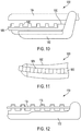
- FIGS. 10-12 illustrate an effector comprising a shortened clamp arm for deflectable / cantilever electrode applications, according to various aspects of the present disclosure.
- the end-effector is configured for asymmetric cooperation of the clamp arm, electrode, and clamp arm pad to effect the ultrasonic blade / RF electrode interaction.
- the electrode is adapted and configured for use with a combination ultrasonic / bipolar RF energy surgical device and is deflectable under load, where the electrode is one pole of the bipolar RF circuit and the ultrasonic blade is the opposite pole of the bipolar RF circuit.
- a distal end of the clamp arm is shortened and a length of the clamp arm pad is kept the same length such that a distal end of the clamp arm pad extends beyond the distal end of the clamp arm.
- This configuration also can eliminate the use of the distal and middle gap setting clamp arm pads, previously referred to herein, for example, as wear resistant clamp arm pads for setting and maintaining a gap between the electrode and the ultrasonic blade.
- FIG. 10 is a side view of an end-effector 1680 comprising a shortened clamp arm 1682, an ultrasonic blade 1684, an electrode 1686, and a clamp arm pad 1688, according to at least one aspect of the present disclosure.
- FIG. 11 is a top view of the end-effector 1680. As shown in FIGS. 10-11 , the ultrasonic blade 1684 and the electrode 1686 are substantially the same length.
- the clamp arm 1682 is shortened to allow the electrode 1686 to overextend to prevent an electrical short circuit.
- a gap setting pad 1690 is provided at a proximal end 1692 of the end-effector 1680.
- FIG. 12 illustrates a clamp arm 1700 comprising a clamp jaw 1702, an electrode 1704, and a clamp arm pad 1706, according to at least one aspect of the present disclosure.
- the clamp arm 1700 is configured for use with an end-effector comprising an ultrasonic blade as disclosed in other sections herein. This configuration frees up space distally 1708 on the clamp jaw 1702.
- the clamp arm pad 1706 e.g., PTFE
- PTFE PTFE
- the present disclosure provides an end-effector that employs the thermal behavior of the pad to deflect the electrode.
- the length of the clamp arm pad may be the same length as the ultrasonic blade and as the clamp arm pad expands or changes shape due to pressure or heat, the thermal expansion properties of the clamp arm pad material (e.g., PTFE) can be used to deflect the electrode out of the path of the ultrasonic blade.
- a non-biased electrode and pad are provided.
- the non-biased but deflectable pad varies in position with respect to the clamp arm as the pad wears.
- the non-biased electrode is configured to minimize contact between the ultrasonic blade and the RF electrode.
- the clamp arm pad comprises a feature for securing the electrode to the clamp arm pad.
- the height of the clamp arm pad wears or is cut through, the height of the electrode with respect to the clamp arm is progressively adjusted.
- the electrode once the clamp arm is moved away from the ultrasonic blade the electrode remains in its new position.
- the electrode is fixed to the clamp arm at the proximal end and is free to deflect at the distal end. Accordingly, throughout this disclosure the electrode may be referred to as a cantilever beam electrode or as a deflectable electrode.
- Configurations of end-effectors comprising a deflectable / cantilever electrode described hereinabove with respect to FIGS. 1-12 may be combined with a biased electrode as described hereinbelow with respect to FIGS. 13-18 .
- the present disclosure provides an end-effector for a combination ultrasonic / bipolar RF energy surgical device that employs pressure or clamp jaw compression to adjust the height of the electrode as the clamp arm pad wears.
- the clamp arm pad follows the clamp arm biased electrode with wearable stops.
- the clamp arm pad contains a feature for securing the electrode to the pad. As the pad height wears or is cut through, the electrode height with respect to the clamp arm is progressively adjusted. Once the clamp arm is moved away from the ultrasonic blade, the electrode stays in its new position.
- the electrode is adapted and configured for use with a combination ultrasonic / bipolar RF energy surgical device and is deflectable under load, where the electrode is one pole of the bipolar RF circuit and the ultrasonic blade is the opposite pole of the bipolar RF circuit.
- the existing (seed) electrode is a flat electrode, which is practically horizontal or parallel to the clamp arm in the free state (no load).
- the electrode is fixed to the clamp arm at the proximal end and is free to deflect at the distal end. Accordingly, throughout this disclosure the electrode may be referred to as a cantilever beam electrode or as a deflectable / cantilever electrode. When clamped on tissue, the tissue loads the electrode, causing it to deflect toward the clamp arm.
- the electrode "follows" the pad as it wears.
- the electrode is biased toward the clamp arm in the free state (whether by being a formed / curved electrode, or by attaching / welding the electrode non-parallel to the clamp arm) using any suitable fastening technique such as welding, laser welding, brazing, soldering, pressing, among other fastening techniques.
- Wearable stop features (on the pad or elsewhere) keep the electrode away from the clamp arm, until said stop features are worn away during use. Once worn away, the electrode is able to approach the clamp arm. These features could be tooth or ratchet shaped, a vertical taper, or other.
- the present disclosure provides a deflectable / cantilever electrode, wherein in a free state, the electrode is biased toward clamp arm and may attached at an angle and made of a preformed curve using any suitable fastening technique such as welding, laser welding, brazing, soldering, pressing, among other fastening techniques.
- the present disclosure provides an end-effector with a deflectable / cantilever electrode comprising wearable stop features to prevent the electrode from reaching or contacting the clamp arm.
- the stop features wear, the electrode moves toward the clamp arm until it reaches the next stop.
- the stop features wear simultaneously with the clamp arm pad to maintain the appropriate gap between the clamp arm pad and the electrode.
- the features may be entirely separate from the clamp arm pad.
- the features can be configured to withstand clamping loads, but wear away due to heat (melting / flowing) or abrasion. Possible examples include teeth on one or more clamp arm pads (PTFE, polyimide, or other) and tapered profile on one or more clamp arm pads (PTFE, polyimide, or other).
- FIG. 13 illustrates an end-effector clamp arm 1710 comprising a clamp jaw 1712, an electrode 1714, and a clamp arm pad 1716, according to at least one aspect of the present disclosure.
- the clamp arm 1710 is configured for use with an end-effector comprising an ultrasonic blade (not shown) as described throughout this disclosure.
- the clamp arm 1710 also comprises a wear resistant gap pad 1717 to set a gap between the electrode 1714 and the ultrasonic blade.
- the electrode 1714 is biased in a level or horizontal 1718 orientation.
- the electrode 1714 is fixed to the clamp jaw 1712 at the proximal end and is free to deflect at the distal end. Accordingly, throughout this disclosure the electrode 1714 may be referred to as a cantilever beam electrode or as a deflectable electrode.
- FIG. 14 illustrates an end-effector clamp arm 1720 comprising a clamp jaw 1722, an electrode 1724, and a clamp arm pad 1726, according to at least one aspect of the present disclosure.
- the clamp arm 1720 is configured for use with an end-effector comprising an ultrasonic blade (not shown) as described throughout this disclosure.
- the clamp arm 1720 also comprises a wear resistant gap pad 1727 to set a gap between the electrode 1724 and the ultrasonic blade.
- the electrode 1724 in the free state, the electrode 1724 is configured pre-formed, bent, or is otherwise biased toward the clamp jaw 1722 along line 1728 away from the horizontal 1718 orientation.
- the electrode 1724 is fixed to the clamp arm 1720 at the proximal end and is free to deflect at the distal end.
- the electrode 1724 may be referred to as a cantilever beam electrode or as a deflectable electrode.
- the clamp arm 1720 further comprises a retainer to prevent the biased electrode 1724 from bending toward the clamp jaw 1722 and maintaining the biased electrode 1724 in a substantially flat configuration (e.g., parallel, level, or horizontal) relative to the ultrasonic blade. Examples of retainers such as a retainer tooth 1738 and a retainer wall 1760 with a tapered profile are described below in FIGS. 15-18 .
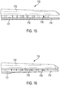
- FIG. 15 illustrates an end-effector clamp arm 1730 comprising a clamp jaw 1732, an electrode 1734, and a clamp arm pad 1736, according to at least one aspect of the present disclosure.
- the clamp arm 1730 is configured for use with an end-effector comprising an ultrasonic blade (not shown) as described throughout this disclosure.
- the clamp arm 1730 also comprises a wear resistant gap pad 1737 to set a gap between the electrode 1744 and the ultrasonic blade.
- the electrode 1734 is configured pre-formed curved, bent, or otherwise biased toward the clamp jaw 1732.
- a retainer tooth 1738 is provided on the clamp arm pad 1736 to prevent the electrode 1734 from springing in toward the clamp jaw 1732.
- FIG. 15 illustrates an end-effector clamp arm 1730 comprising a clamp jaw 1732, an electrode 1734, and a clamp arm pad 1736, according to at least one aspect of the present disclosure.
- the clamp arm 1730 is configured for use with an end-effector comprising an ultrasonic blade (not shown
- the electrode 1734 when the bottom retainer tooth 1738 is worn away, the electrode 1734 can move toward the clamp jaw 1732 due to the pre-formed curve, according to at least one aspect of the present disclosure.
- the electrode 1734 is fixed to the clamp arm 1730 at the proximal end and is free to deflect at the distal end. Accordingly, throughout this disclosure the electrode 1734 may be referred to as a cantilever beam electrode or as a deflectable electrode.
- FIG. 17 illustrates an end-effector clamp arm 1750 comprising a clamp jaw 1752, an electrode 1754, and a clamp arm pad 1756, according to at least one aspect of the present disclosure.
- the clamp arm 1750 is configured for use with an end-effector comprising an ultrasonic blade (not shown) as described throughout this disclosure.
- the clamp arm 1750 also comprises a wear resistant gap pad 1757 to set a gap between the electrode 1754 and the ultrasonic blade.
- the electrode 1754 In the free state, the electrode 1754 is configured pre-formed with a curve, bent, or otherwise biased toward 1758 the clamp jaw 1752.
- a retainer wall 1760 having a tapered profile, or similar feature, is provided on the clamp arm pad 1756 to prevent the electrode 1754 from springing in toward the clamp jaw 1752.
- the electrode 1754 is fixed to the clamp jaw 1752 at the proximal end and is free to deflect at the distal end. Accordingly, throughout this disclosure the electrode 1754 may be referred to as a cantilever beam electrode or as a deflectable electrode.
- the present disclosure provides an end-effector for a combination ultrasonic / bipolar RF energy surgical device that employs a constant pressure distribution biasing mechanism.
- the end-effector includes an elastic compressible support for mounting and insulating a deflectable electrode.
- a hollow honeycomb or chambered elastomer support attachment cushion can be employed to allow all or part of the electrode attached to it to deflect but be biased towards the ultrasonic blade. This configuration could provide the added benefit of thermally insulating the electrode from the rest of the metallic clamp jaw. This would also provide an elastomer "curtain" around the electrode to minimize tissue accumulation behind the electrode.
- a non-strut deflectable geometry for the elastomer cells will enable the deflection force to be held constant over a predefined range of deflections.
- the electrode is adapted and configured for use with a combination ultrasonic / bipolar RF energy surgical device and is deflectable under load, where the electrode is one pole of the bipolar RF circuit and the ultrasonic blade is the opposite pole of the bipolar RF circuit.
- the above configuration prevents lateral skew of the electrode under compression to prevent shorting. Further, the deflectable electrode is affixed to the elastomer and the elastomer is affixed to the metallic clamp arm. The solid height of the spring is limited from driving allowable compression while maintaining as much metallic clamp arm as possible. Thermal conduction from tissue interface is balanced and minimizes - impacts lesion formation and symmetry, cycle time, and residual thermal energy.
- Configurations of end-effectors comprising a deflectable / cantilever electrode described hereinabove with respect to FIGS. 1-12 may be combined with a flexible electrode disposed above a lattice cushion and a plurality of hard spacers to set a gap between the flexible electrode and the ultrasonic blade as described hereinbelow with respect to FIGS. 19-21 .
- Configurations of a biased electrode as described hereinabove with respect to FIGS. 13-18 may be combined with a flexible electrode disposed above a lattice cushion and a plurality of hard spacers to set a gap between the flexible electrode and the ultrasonic blade as described hereinbelow with respect to FIGS. 19-21 .
- Configurations of end-effectors comprising a deflectable / cantilever electrode described hereinabove with respect to FIGS. 1-12 in combination with a biased electrode as described hereinabove with respect to FIGS. 13-18 may be combined with a flexible electrode disposed above a lattice cushion and a plurality of hard spacers to set a gap between the flexible electrode and the ultrasonic blade as described hereinbelow with respect to FIGS. 19-21 .
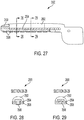
- FIGS. 19-20 illustrate an end-effector 1810 comprising a clamp arm 1812, an ultrasonic blade 1814, a lattice cushion 1816, a flexible electrode 1818 disposed above the lattice cushion 1816, and a plurality of hard spacers 1820 to set a gap between the flexible electrode 1818 and the ultrasonic blade 1814, according to at least one aspect of the present disclosure.
- FIG. 21 is an exploded view of the end-effector 1810 shown in FIGS. 19-20 .
- a clamp arm pad 1822 is disposed inside a slot 1825 formed within the lattice cushion 1816.
- the lattice cushion 1816 acts as a spring-like element.
- the hard spacers 1820 are used to set a gap between the flexible electrode 1818 and the ultrasonic blade 1814.
- the clamp arm 1812 is open and tissue 1824 of non-uniform thickness (T 1a , T 2a , T 3a ) is disposed over the flexible electrode 1818.
- the clamp arm 1812 is closed to compress the tissue 1824.
- the present disclosure provides an end-effector for a combination ultrasonic / bipolar RF energy surgical device with means for insuring distal tip contact with bias using a zero gap bipolar RF energy system.
- the present disclosure provides a deflectable electrode for a combination ultrasonic / bipolar RF energy surgical device with a higher distal bias than proximal bias.
- the present disclosure provides a combination energy device comprising a bipolar electrode that is deflectable with respect to the clamp arm. The combination energy device comprises features to change the mechanical properties of the tissue compression proximal to distal to create a more uniform or differing pattern of pressure than due to the clamping forces alone.
- the present disclosure provides a non-linear distal distributing mechanism and in another aspect the present disclosure provides electrical non-linear distribution of energy density.
- the electrode is adapted and configured for use with a combination ultrasonic / bipolar RF energy surgical device and is deflectable under load, where the electrode is one pole of the bipolar RF circuit and the ultrasonic blade is the opposite pole of the bipolar RF circuit.
- Configurations of end-effectors comprising a deflectable / cantilever electrode described hereinabove with respect to FIGS. 1-12 may be combined with a conductive polymer clamp arm pad as described hereinbelow with respect to FIGS. 22-36 .
- Configurations of a biased electrode as described hereinabove with respect to FIGS. 13-18 may be combined with a conductive polymer clamp arm pad as described hereinbelow with respect to FIGS. 22-36 .
- Configurations of a flexible electrode disposed above a lattice cushion and a plurality of hard spacers to set a gap between the flexible electrode and the ultrasonic blade as described hereinabove with respect to FIGS. 19-21 may be combined with a conductive polymer clamp arm pad as described hereinbelow with respect to FIGS. 22-36 .
- Configurations of a biased electrode as described hereinabove with respect to FIGS. 13-18 may be combined with a flexible electrode disposed above a lattice cushion and a plurality of hard spacers to set a gap between the flexible electrode and the ultrasonic blade as described hereinabove with respect to FIGS. 19-21 may be combined with a conductive polymer clamp arm pad as described hereinbelow with respect to FIGS. 22-36 .
- Configurations of a biased electrode as described hereinabove with respect to FIGS. 13-18 may be combined with a flexible electrode disposed above a lattice cushion and a plurality of hard spacers to set a gap between the flexible electrode and the ultrasonic blade as described hereinabove with respect to FIGS. 19-21 may be combined with a conductive polymer clamp arm pad as described hereinbelow with respect to FIGS. 22-36 .
- Configurations of end-effectors comprising a deflectable / cantilever electrode described hereinabove with respect to FIGS. 1-12 in combination with a biased electrode as described hereinabove with respect to FIGS. 13-18 may be combined with a conductive polymer clamp arm pad as described hereinbelow with respect to FIGS. 22-36 .
- Configurations of end-effectors comprising a deflectable / cantilever electrode described hereinabove with respect to FIGS. 1-12 in combination with a biased electrode as described hereinabove with respect to FIGS. 13-18 may be combined with a flexible electrode disposed above a lattice cushion and a plurality of hard spacers to set a gap between the flexible electrode and the ultrasonic blade as described hereinabove with respect to FIGS. 19-21 may be combined with a conductive polymer clamp arm pad as described hereinbelow with respect to FIGS. 22-36 .
- the present disclosure provides a combination ultrasonic / bipolar RF energy surgical device comprising an ultrasonic pad with partially or fully electrically conductive portions such that the pad behaves as both the blade support / wear pad and the bipolar RF electrode.
- the present disclosure provides a partially conductive clamp arm pad to enable electrode wear and minimize short circuiting in a combination bipolar RF and ultrasonic energy device where the clamp arm pad has conductive and non-conductive portions allowing it to act as one of the RF electrodes while also acting as a wearable support structure for the ultrasonic blade.
- the present disclosure provides conductive portions around the perimeter of the clamp arm pad and not positioned directly on the side that is opposite the ultrasonic blade contact area.
- a portion of the conductive clamp arm pad is degradable or wearable preventing contact from the ultrasonic blade from interrupting the conductivity of the remaining portions of the conductive clamp arm pad.
- the present disclosure provides an end-effector for a combination ultrasonic / bipolar RF energy surgical device comprising a conductive polymer ultrasonic clamp arm pad.
- the end-effector comprises a clamp arm pad doped with tin oxide.
- FIG. 22 is a section view of a conductive polymer clamp arm pad 2440, according to at least one aspect of the present disclosure.
- the conductive polymer clamp arm pad 2440 comprises tin oxide 2442 (SnO 2 ) embedded in a polymer material 2444, such as Teflon (PTFE), to make the clamp arm pad 2440 electrically conductive.
- the doping may be achieved using a cold spray process.
- the conductive polymer clamp arm pad 2440 can achieve traditional ultrasonic tissue clamp arm pad functions such as, for example, contacting the ultrasonic blade, absorbing heat from the ultrasonic blade, and assisting in tissue grasping and clamping.
- the tin oxide doped clamp arm pad 2440 functions as one of the two electrodes or poles of the bipolar RF circuit to deliver RF energy to tissue grasped between the ultrasonic blade and the clamp arm pad 2440.
- the tin oxide doped clamp arm pad 2440 is biocompatible, electrically conductive, thermally conductive, enables a large portion of the clamp arm pad 2440 to be used to improve wear resistance of the clamp arm pad 2440, and is white in color.
- the electrode is adapted and configured for use with a combination ultrasonic / bipolar RF energy surgical device and is deflectable under load, where the electrode is one pole of the bipolar RF circuit and the ultrasonic blade is the opposite pole of the bipolar RF circuit.
- the present disclosure provides a conductive polymer ultrasonic clamp arm pad as an electrode replacement.
- the present disclosure provides an electrode that is improved, easier to make, and less costly to make.
- the present disclosure provides a clamp arm pad comprising hard polyimide polymer layers and electrically conductive layers to allow the clamp arm pad to achieve traditional functions as well as carry bipolar electricity to eliminate the need for a separate electrode in the clamp arm of a combined energy end-effector. In this manner, the clamp jaw can be me manufactured in a manner similar to the ultrasonic-only clamp jaw with the new clamp arm pad material swapped for the traditional ultrasonic-only clamp arm pad.
- the electrode is adapted and configured for use with a combination ultrasonic / bipolar RF energy surgical device and is deflectable under load, where the electrode is one pole of the bipolar RF circuit and the ultrasonic blade is the opposite pole of the bipolar RF circuit.
- Benefits include improved ultrasonic performance, including clamp arm pad wear, similar to current ultrasonic-only instruments because there are no electrode gaps between elements "squares" of polymer.
- the cost of the improved clamp jaw will be similar to current ultrasonic-only clamp jaws because of the need for a separate electrode component is eliminated and provides multiple small polymer square elements.
- the manufacturing steps needed to make the clamp jaw are the same as the manufacturing steps required for making current ultrasonic-only clamp jaws. Manufacturing the improved clamp jaw requires only the substitution of the clamp arm pad and does require the production of an additional electrode component to add to the clamp jaw and eliminates assembly steps.
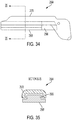
- FIG. 23 is a perspective view of a clamp arm pad 2450 configured to replace a conventional electrode, according to at least one aspect of the present disclosure.
- the clamp arm pad 2450 comprises electrically non-conductive layers 2452 and electrically conductive layers 2454 in a sandwich-like configuration. This configuration eliminates the need for a spring loaded electrode plate.
- the electrically non-conductive layers 2452 can be made of polymer, polyimide, Teflon (PTFE) and similar electrically non-conductive materials.
- the conductive layers 2454 may be made of thin electrically conductive polymer, metal foil, or carbon loaded material.
- the clamp arm pad 2450 may be manufactured such that the majority of the material contacting the ultrasonic blade are the electrically non-conductive layers 2452.
- the electrically conductive layers 2452 will still have available surface area to conduct RF electricity through the tissue and return electrode (e.g., ultrasonic blade).
- FIG. 24 illustrates a clamp arm 2460 comprising the clamp arm pad 2450 described in FIG. 23 , according to at least one aspect of the present disclosure.
- the non-conductive layers 2452 have a large surface area compared to the conductive layers 2454, which appear as thin layers or foils.
- FIG. 25 illustrates clamp arm pads configured as described in FIGS 23-24 , according to at least one aspect of the present disclosure.
- the first clamp arm pad 2470 is new and comprises teeth 2472 formed integrally therewith.
- the second clamp arm pad 2476 is new and without teeth.
- the third clamp arm pad 2478 worn and may be representative of either the first clamp arm pad 2470 or the second clamp arm pad 2476.
- FIG. 26 is a section view of a clamp arm 2480 comprising a composite clamp arm pad 2482 in contact with tissue 2484, according to at least one aspect of the present disclosure.
- the end-effector 2480 comprises an upper clamp jaw 2486 and an adhesive 2488 to fixedly attach the composite clamp arm pad 2482 to the upper clamp jaw 2486.
- the composite clamp arm pad 2482 comprises thin electrically non-conductive layers 2490 (e.g., PTFE) and thin electrically conductive layers 2492 (e.g., thin stainless steel foils).
- the electrically conductive layers 2492 form the electrode portion of the composite clamp arm pad 2482.
- the electrically conductive layers 2492 deform as the electrically non-conductive layers 2490 (e.g., PTFE) wear-away.
- the thickness of the electrically conductive layers 2492 enables the electrode portion of the composite clamp arm pad 2482 to deform as the electrically non-conductive layers 2490 wear-away.
- the electrically conductive layers 2492 conduct some of the heat away from the electrically non-conductive layers 2490 to keep the composite clamp arm pad 2482 cooler.
- the composite clamp arm pad 2482 is fixed to the upper clamp jaw 2486 by an adhesive 2488.
- the adhesive 2488 may be filled with carbon to make it electrically conductive and connect the electrode portions of the composite clamp arm pad 2482 to the upper clamp jaw 2486.
- the electrode is adapted and configured for use with a combination ultrasonic / bipolar RF energy surgical device and is deflectable under load, where the electrode is one pole of the bipolar RF circuit and the ultrasonic blade is the opposite pole of the bipolar RF circuit.
- the clamp arm pad comprises cooperative conductive and insulative portions.
- the present disclosure provides a combination ultrasonic / bipolar RF energy surgical device where the clamp arm pad has conductive and non-conductive portions allowing it to act as one of the RF electrodes while also acting as the wearable support structure for the ultrasonic blade.
- the conductive portions of the clamp arm pad are disposed around the perimeter of the pad and are not positioned directly on the side that is opposite the ultrasonic blade contact area.
- the conductive portion of the clamp arm pad is degradable or wearable to prevent contact with the ultrasonic blade from interrupting the conductivity of the remaining conductive portions of the clamp arm pad.
- the present disclosure provides a clamp arm pad for use with combination ultrasonic / bipolar RF energy devices where portions of the clamp arm pad include electrically conductive material and other portions include electrically non-conductive material.
- the electrode is adapted and configured for use with a combination ultrasonic / RF energy device and is deflectable under load, where the electrode is one pole of the bipolar RF circuit and the ultrasonic blade is the opposite pole of the bipolar RF circuit.
- the clamp arm pad may be manufactured using a variety of techniques.
- One technique comprises a two shot process of molding conductive and non-conductive materials in the same compression mold. This process effectively creates a single clamp arm pad with portions that can act as a bipolar RF electrode and others that will act as electrical insulators.
- Another technique comprises a super sonic cold spray embedding of metallic elements into a polymeric (e.g., Teflon, PTFE) pad or matrix.
- Another technique comprises 3D printing of multiple materials (e.g., Teflon, PTFE, and doped conductive polymer), printing / transfer printing conductive or functional inks onto clamp arm pad.
- Another technique comprises metals and conductive materials (e.g., graphite / carbon) may be applied to the clamp arm pad using chemical vapor deposition, physical vapor deposition, sputter deposition, vacuum deposition, vacuum metalizing, or thermal spray.
- conductive / loaded clamp arm pad electrodes provide continuity through the pad with micro randomly oriented and positioned particles or macro oriented structures (e.g., fabric, woven, long constrained fibers.
- Another technique comprises making the surface of the clamp arm pad conductive, providing wear-through electrodes, 3D printing, thermal spraying, cold spraying, coatings / paints / epoxies, sheet / foil / wire / film wrapping or laminating, vacuum metalizing, printing / transferring, among other techniques.
- polymer electrodes filled with conductive material may be applied to the clamp arm pad using chemical vapor deposition, physical vapor deposition, sputter deposition, vacuum deposition, vacuum metalizing, or thermal spray.
- conductive / loaded clamp arm pad electrodes provide
- the end-effector clamp arm comprises a fixed polymer electrode.
- FIG. 27 illustrates a clamp arm 2500 comprising a clamp jaw 2502 to support a carrier 2504 or stamping attached to the clamp jaw 2502 and a clamp arm pad 2506, according to at least one aspect of the present disclosure.
- the clamp arm pad 2506 comprises an electrically conductive pad 2508 and an electrically non-conductive pad 2510.
- the electrically conductive pad 2508 is made of an electrically conductive polymer and acts as one of the electrodes of the bipolar RF circuit.
- the clamp jaw 2502 and the carrier 2504 may be made of stainless steel and attached using any suitable fastening technique such as welding, laser welding, brazing, soldering, pressing, among other fastening techniques, for example.
- the electrically conductive pad 2508 may comprise a polymer such as, for example, silicone, fluorosilicone, PTFE, and similar materials.
- the electrically conductive pad 2508 is overmolded onto the carrier 2504 using PTFE, silicone, fluorosilicone filled with silver particles, silver over aluminum, silver over copper, copper, nickel, graphite, carbon (amorphous, chopped fiber), gold, platinum, stainless steel, iron, or zinc, or combinations thereof.
- FIG. 28 is a section view taken at section 28-28 in FIG. 27 and FIG. 29 is a section view taken at section 29-29 in FIG. 27 .
- the sections views 28-28 and 29-29 show the clamp arm 2500 comprising the clamp jaw 2502, the support carrier 2504, the electrically conductive pad 2508, and the electrically non-conductive pad 2510.
- FIG. 30 is a section view of an alternative implementation of a clamp arm 2520 comprising a clamp jaw 2522, an electrically conductive pad 2524, and an electrically non-conductive pad 2526, according to at least one aspect of the present disclosure.
- the electrically conductive pad 2524 is made of an electrically conductive polymer and acts as one of the electrodes in the bipolar RF circuit.
- FIG. 31 is a section view of an alternative implementation of a clamp arm 2530 comprising a clamp jaw 2532, a carrier 2534 or stamping welded to the clamp jaw 2532, an electrically conductive pad 2536, and an electrically non-conductive pad 2538, according to at least one aspect of the present disclosure.
- the electrically conductive pad 2536 is made of an electrically conductive polymer and acts as one of the electrodes in the bipolar RF circuit.
- the electrically conductive pad 2536 is overmolded over the carrier 2534 or stamping.
- the end-effector clamp arm comprises a film over metal insert molded electrode assembly.
- a film may be provided over a metal (e.g., stainless steel) insert molded electrode assembly.
- a film over metal such as stainless steel can be insert molded to form an electrode assembly.
- the film on the insert molded electrode may be etched to form micro-holes, slots, honeycomb, among other patterns, to enable conduction of RF energy as well as to cut the periphery of the component.
- the film may be formed onto or bond onto a stainless steel electrode using IML / FIM (In-Mold Labeling / Film Insert Molding) processes described hereinbelow.
- the charged film electrode may be placed into a polymer injection mold tool to mold a polymer to the back of the electrode and film.
- the electrode is adapted and configured for use with a combination ultrasonic / bipolar RF energy surgical device and is deflectable under load, where the electrode is one pole of the bipolar RF circuit and the ultrasonic blade is the opposite pole of the bipolar RF circuit.
- FIG. 32 illustrates insert molded electrodes 2540, according to at least one aspect of the present disclosure.
- the insert molded electrode 2540 comprises an electrically conductive element 2546, a molded polymer pad 2548, and a film 2542 coating.
- Features 2550 such as micro-holes, slots, honeycomb, or similar features, are formed in the film 2542 to allow the passage of RF energy.
- Retention features 2552 also are formed on the film 2542.
- the side walls 2558 of the film 2542 extend below the bottom of the polymer pad 2548 may be folded around the bottom of the polymer pad 2548 and over molded with retention posts.
- the retention features 2552 are molded into the holes 2554 defined by the film 2542.
- the conductive element 2546 may be made of an electrically conductive metal such as stainless steel or similar conductive material.
- the conductive element 2546 can be about 0.010" thick and may be selected within a range of thicknesses of 0.005" to 0.015" and can be formed by tamping or machining.
- the film 2544 can be about 0.001" to 0.002" thick and may be made of polyimide, polyester, or similar materials. Alternatively to mechanical retention, such as posts, the film 2544 can be directly bonded to the conductive element 2546.
- One example includes DuPont Pyralux HXC Kapton film with epoxy adhesive backing having a thickness of 0.002".
- the non-stick surface prevents tissue from sticking to the insert molded electrode 2540.
- the non-stick surface eliminates short circuiting of opposing electrodes by setting a gap within the range of 0.002" to 0.004" along the entire length of the insert molded electrode 2540.
- the non-stick surface minimizes lateral spread of RF energy due to coverage of side walls 2558 of the insert molded electrode 2540.
- the insert molded electrode 2540 exhibits structural soundness and provides an easier more robust electrical connection than a multi-layer flexible circuit.
- the end-effector comprises a conductive clamp arm and pad constructs for combination ultrasonic / bipolar RF energy surgical devices.
- the present disclosure provides a clamp arm assembly comprising a conductive or selectively conductive thin film, foil, or laminate that is applied to, around or on the clamp arm assembly to serve as a durable "pole" in a combination ultrasonic / bipolar RF energy surgical device.
- an algorithm, software, or logic is provided to manage conditions of electrical short circuiting.
- the electrode is adapted and configured for use with a combination ultrasonic / bipolar RF energy surgical device and is deflectable under load, where the electrode is one pole of the bipolar RF circuit and the ultrasonic blade is the opposite pole of the bipolar RF circuit.
- FIG. 33 illustrates an end-effector 2560 comprising an ultrasonic blade 2562, a clamp arm 2564, and a clamp arm pad 2566 comprising an electrically conductive film 2568, according to at least one aspect of the present disclosure.
- FIG. 34 illustrates the clamp arm 2564 shown in FIG. 33 .
- the clamp arm 2564 comprising a clamp jaw 2570 to support the clamp arm pad 2566.
- a thin electrically conductive film 2568 is disposed over the clamp arm pad 2566 to form an electrode of one of the poles of the bipolar RF circuit.
- FIG. 35 is a section view of the clamp arm 2564 taken along section 35-35 in FIG. 34 .
- the clamp jaw 2570 can be made of metal such as stainless steel.
- the clamp arm pad 2566 can be made of an electrically non-conductive complaint material such as PTFE, silicone, high temperature polymer, or similar materials.
- the electrically conductive film 2568 or foil can be made of an electrically conductive material such as titanium, silver, gold, aluminum, zinc, and any alloys thereof including stainless steel.
- FIG. 36 illustrates a clamp arm 2580 comprising a partially electrically conductive clamp arm pad 2582, according to at least one aspect of the resent disclosure.
- An electrically conductive foil 2584 covers a portion of an electrically non-conductive pad 2586.
- the electrically non-conductive pad 2588 at the proximal end 2590 sets a gap between the clamp arm pad 2582 and the ultrasonic blade.
- Elements of the electrically conductive film 2568, foil, or laminate may include, for example, a single layer of thin conductive material such as metals (titanium, silver, gold, zinc, aluminum, magnesium, iron, etc. and their alloys or stainless steels), plated metals (nickel and then gold over copper, for example) or polymers filled heavily with conductive materials such as metal powder, or filings.
- a biocompatible metal foil such as titanium, silver, gold, zinc, or stainless steel selected from a thickness within the range of 0.001" to 0.008" (0.025 mm - 0.20 mm).
- the film 2568, foil, or laminate may include a thin polymer coating, film or layer covering the thin conductive material described above.
- This coating, film or layer is highly resistive, that is, it is not an effective conductor of bipolar RF energy to adjacent tissue.
- the coating may be perforated to allow for energy delivery from the electrode to tissue.
- the conductive material may be perforated or contain holes or windows through the full thickness of the conductive material to minimize the thermal capacitance of this layer (testing has shown that long and / or thick foils result in longer transection times due to thermal energy being removed from the treatment sight. These perforations, holes or windows also may allow for retention of the foil to other parts or layers. These perforations, holes or windows may be patterned across the entire foil sheet or may be localized at the treatment site or away from the treatment site such as, for example, on the sides of the clamp arm only.
- the thin polymer coating, film or layer may be perforated or contain full thickness holes or windows such that the conductive film, foil or laminate is in direct communication with tissue for delivery of bipolar radiofrequency energy to the tissue.
- these holes or windows may be formed by selective coating or coating removal.
- the conductive film 2568, foil, or laminate is in direct contact with the clamp arm structure that is typically fabricated from stainless steel.
- the resulting conductive path then allows for simplicity of construction in that the path is formed by necessary structural component, namely a support tube or actuator that connects directly to the clamp arm and then the conductive film, foil or laminate.
- the conductive film 2568, foil, or laminate is backed by a relatively soft, high temperature, low wear polymer or elastomer pad made from materials such as PTFE, silicone, polyimide, high temperature thermoplastics, among other materials.
- a relatively soft, high temperature, low wear polymer or elastomer pad made from materials such as PTFE, silicone, polyimide, high temperature thermoplastics, among other materials.
- the compliance of this relatively soft pad allows for a wide range of component tolerances to obtain a zero or near zero gap between the jaw and the ultrasonic blade along its full tissue effecting length when the jaw is fully closed, thus allowing tissue to be sealed and cut along this length.
- the compliance also eliminates or greatly dampens any audible vibration of the conductive layer that may occur when the ultrasonic blade is closed against the conductive layer.
- the conductive film 2568, foil, or laminate may include a rigid to semi-rigid polymer on its backside / back surface (that is the surface away from the tissue and toward the clamp arm). This part is made from injection moldable polymers or polymer alloys and adhered to the film, foil or laminate by way of Film Insert Molding (FIM) or In-Mold Labeling (IML).
- FIM Film Insert Molding
- IML In-Mold Labeling
- thin stainless steel, copper, or aluminum foils are quiet in operation (no "screeching" or emitting of obtuse squeals).
- the thin stainless steel, copper, or aluminum foils provide a robust surface against which the ultrasonic blade can act. Robust enough that materials such as silicone rubber that would otherwise tear and serve as a poor pad material are usable and do not easily tear or split.
- the proximal portion of the jaw clamping surface may not include the conductive film, foil or laminate because this area of the jaw contacts the blade first and will be more likely result in shunting of power / shorting in this area.
- the present disclosure provides a short circuit mitigation algorithm for activating an output including bipolar RF energy.
- a short alert is not given to the user if it occurs after the energy delivered for the activation exceeds a threshold amount (thereby indicating that the tissue thinned but has likely received an adequate dose of bipolar RF energy for the sealing, coagulation of tissue), or an activation time threshold has been exceeded (again, thereby indicating that the tissue has thinned but has likely received and adequate dose), or both energy and activation time thresholds have been exceeded.
- a process of making a film over stainless steel insert molded electrode assembly comprises etching the film and forming apertures (micro-holes, slots, or honeycomb) for passing RF energy; cutting periphery of the electrode component; forming a film onto / bond onto stainless steel electrode if needed; placing the charged film and electrode into a polymer injection mold tool; molding the polymer to the back of the electrode and film.
- apertures micro-holes, slots, or honeycomb
- the present disclosure provides a combination ultrasonic / bipolar RF energy surgical device comprising an ultrasonic pad configuration.
- the end-effector comprises a compression element to limit heat generation in the end-effector or any of its components.
- the present disclosure provides an asymmetric segmented ultrasonic support clamp arm pad for cooperative engagement with a movable RF electrode configured for use with a combination ultrasonic / RF energy device.
- the asymmetric segmented ultrasonic support clamp arm pad extends at least partially through the RF electrode.
- at least one element of the clamp arm pad is significantly taller than a second element of the clamp arm pad.
- a first clamp arm pad extends entirely through and a second clamp arm pad extends only partially through the electrode.
- the first element of the clamp arm pad and the second element of the clamp arm pad are made of dissimilar materials. Additional background material can be found in US Patent Application Publication No. 2017/0164997 , which is incorporated herein by reference in its entirety.
- the end-effector comprises a deflectable electrode configuration.
- the present disclosure provides a segmented ultrasonic support clamp arm pad which extends at least partially through an RF electrode.
- at least one pad element is significantly taller than a second element.
- the first pad element extends entirely through the electrode and the second pad element extends partially through the electrode.
- the first pad element and the second pad element are made of dissimilar materials.
- the present disclosure provides an electrode comprising destructive and non-destructive portions.
- the description of FIGS. 1-9 is herein incorporated by reference.
- the clamp arm pad 1010 shown in connection with FIGS. 1-9 provides larger resilient (e.g., PTFE) pad areas while still allowing the electrode 1004 to deflect.
- the electrode is fixed to the clamp jaw at the proximal end and is free to deflect at the distal end. Accordingly, throughout this disclosure the electrode may be referred to as a cantilever beam electrode or as a deflectable electrode.
- the electrode is adapted and configured for use with a combination ultrasonic / bipolar RF energy surgical device and is deflectable under load, where the electrode is one pole of the bipolar RF circuit and the ultrasonic blade is the opposite pole of the bipolar RF circuit.
- the end-effector comprises a clamp arm pad in an I-beam configuration.
- the I-beam shaped clamp arm pad e.g., Teflon or PTFE
- the top portion of the clamp arm pad may be shaped in a modified cobblestone fashion to increase electrode surface area on the side that is opposite the ultrasonic blade. This configuration simultaneously provides a pad at the midline and flanges on the clamp arm pad over the electrode to prevent the clamp arm pad from delaminating from the clamp arm.
- the proximal hard (e.g., polyimide) gap setting pad slides in from the back (proximal end) to provide gap setting structure and a "plug" to hold the clamp arm pad in place.
- FIGS. 37-39 illustrate a clamp arm 1990 comprising an I-beam shaped clamp arm pad 1992 configured for use with an end-effector comprising a clamp jaw 1994, an ultrasonic blade (not shown), and an electrode 1996, according to at least one aspect of the present disclosure.
- the clamp arm pad 1992 has an I-beam configuration comprising top and bottom lateral portions 1998, 2000 separated by a mesial portion 2002 to define a cross-sectional shape of an "I".
- the electrode 1996 is disposed between the top and bottom lateral portions 1998, 2000 of the I-beam shaped clamp arm pad 1992.
- the electrode 1996 is fixed to the clamp jaw 1994 at the proximal end and is free to deflect at the distal end.
- the electrode 1996 may be referred to as a cantilever beam electrode or as a deflectable electrode.
- the clamp jaw 1994 defines a longitudinal slot 2010 to slidably receive the bottom lateral portions 1998, 2000 and a portion of the mesial portion 2002 of the I-beam shaped clamp arm pad 1992 therethrough.
- FIG. 38 is a top view of the clamp arm 1990 showing the clamp arm pad 1992 as viewed from above the electrode 1996.
- FIG. 39 is a top view of the electrode 1996 showing a longitudinal slot 2010 to slidably receive the clamp arm pad 1992 therein.
- the top portions 1998 of the I-beam segments of the clamp arm pad 1992 referred to as the flanges, are positioned above the electrode 1996 to prevent the clamp arm pad 1992 from delaminating from the clamp jaw 1994.
- a hard wear resistant gap setting pad 2004 to set a gap between the electrode 1996 and the ultrasonic blade (not shown).
- the deflectable electrode 1996 is fixedly attached to the clamp jaw 1994 by welding the proximal end 2006 of the electrode 1996 to the clamp jaw 1994 by welding at weld points 2008.
- Other attachment techniques may employed such as laser welding, brazing, soldering, pressing, among other fastening techniques.
- FIGS. 40A-40C illustrate a method of assembling the clamp arm 1990 shown in FIGS. 37-39 , according to at least one aspect of the present disclosure.
- the electrode 1996 is welded to the proximal end 2006 of the clamp jaw 1994 at weld points 2008.
- the clamp arm pad 1992 is slidably inserted into the longitudinal slot 2010.
- the hard wear resistant gap setting pad 2004 to set the gap is slidably inserted into the clamp jaw 1994.
- the clamp arm 1990 described in connection with FIGS. 37-40C provides an electrode 1996 that deflects when clamped on tissue. Tissue accumulation points between the clamp arm pad 1992 segments is eliminated and the electrode 1996 delamination is minimized.
- the clamp arm 1990 also eliminates small gap setting pads and easy to manufacture.
- the end-effector comprises interactive electrode recesses and ultrasonic blade support features.
- FIGS. 41-43 illustrate an end-effector 2020 comprising an electrode 2026 defining recesses 2030 in overlapping locations with an ultrasonic blade 2024 to minimize impact between the ultrasonic blade 2024 and the electrode 2026, according to at least one aspect of the present disclosure.
- FIG. 41 is a section view of an end-effector 2020 comprising a clamp arm 2022, an ultrasonic blade 2024, an electrode 2026, and a heavy polymer support pad 2028 (e.g., polyamide pad), according to at least one aspect of the present disclosure.
- FIG. 41 is a section view of an end-effector 2020 comprising a clamp arm 2022, an ultrasonic blade 2024, an electrode 2026, and a heavy polymer support pad 2028 (e.g., polyamide pad), according to at least one aspect of the present disclosure.
- FIG. 42 is a section view of the end-effector 2020 with a worn down heavy polymer support pad 2028 and tissue 2032 clamped between the clamp arm 2022 and the ultrasonic blade 2024. In the clamped state, the electrode 2026 is substantially flush with the ultrasonic blade 2024.
- FIG. 43 is a magnified view of the end-effector 2020. In the fully clamped state, the electrode 2026 is substantially flush with the ultrasonic blade 2024.
- a plane 2034 defined by the top of the electrode 2026 is substantially flush or even with a plane 2036 defined by the bottom of the ultrasonic blade 2024 as it rests within the recess 2030 defined by the heavier polymer support pad 2028.
- the electrode 2026 defines a recess 2029 and the heavy polymer support pad 2028 defines an integrated recess 2030 that corresponds to the location of the ultrasonic blade 2024 to minimize interaction on the electrode 2026 and the ultrasonic blade 2024.
- the location of these recesses 2030 may coincide with the location of the heavier polymer support pad 2028 that is not subjected to damage by contact with the ultrasonic blade 2024. In this way the electrode 2026 may be substantially flush with the ultrasonic blade 2024 when clamped in the fully clamped state and yet not in metallic contact with the ultrasonic blade 2024.
- the electrode is adapted and configured for use with a combination ultrasonic / RF energy device and is deflectable under load, where the electrode is one pole of the bipolar RF circuit and the ultrasonic blade is the opposite pole of the bipolar RF circuit.
- the end-effector comprises a polyimide front pad.
- FIGS. 44-45 illustrates a clamp arm 2040 comprising a clamp jaw 2042, a stationary gap setting pad 2044 in combination with movable floating gap setting pads 2046, according to at least one aspect of the present disclosure.
- This configuration provides a composite arrangement to both create ultrasonic blade pressure while also setting a minimum gap between an electrode 2048 and the ultrasonic blade.
- the electrode 2048 is adapted and configured for use with a combination ultrasonic / RF energy device and is deflectable under load, where the electrode is one pole of the bipolar RF circuit and the ultrasonic blade is the opposite pole of the bipolar RF circuit.
- FIG. 44 is a top view of a clamp arm 2040 showing the stationary gap setting pad 2044 and the movable floating gap setting pads 2046.
- FIG. 45 is a side view of the clamp arm 2040 showing the clamp jaw 2042, the stationary gap setting pad 2044, the movable floating gap setting pads 2046, the electrode 2048, and a clamp arm pad 2050.
- the most distal 2052 stationary pad 2044 is attached to the clamp jaw 2042 in a similar fashion as the clamp arm pad 2050.
- the most distal 2052 stationary gap setting pad 2044 will improve tip pressure / grasping and decreases the likelihood of short circuiting the electrode 2048 to the ultrasonic blade due to burn through of the stationary gap setting pad 2044.
- FIGS. 46-47 show an alternative clamp arm 2060 comprising a clamp jaw 2074, a stationary gap setting pad 2064 at a distal end 2062, a stationary clamp arm pad 2066, and a movable floating gap setting pad 2070 at a proximal end 2068, according to at least one aspect of the present disclosure.
- the clamp arm 2060 also comprises an electrode 2072.
- the end-effector comprises a deflectable / cantilever electrode with teeth.
- Tissue retention in an ultrasonic device can be difficult due to the smooth nature of the ultrasonic blade. Additional gripping features can be added to increase the tissue gripping force.
- the electrode element of the device is adapted and configured for use with a combination ultrasonic / bipolar RF energy surgical device and is deflectable under load, where the electrode is one pole of the bipolar RF circuit and the ultrasonic blade is the opposite pole of the bipolar RF circuit.
- FIGS. 48-49 illustrate a combination ultrasonic / bipolar RF energy surgical device that employs an electrode comprising small teeth, according to at least one aspect of the present disclosure.
- the electrode teeth can add to the tissue retention. Teeth that pass through the electrode can be added to the clamp jaw. This configuration is relatively easy to implement and provides better tissue retention in an ultrasonic device.
- the present disclosure provides a surgical device comprising an ultrasonic blade and an RF electrode for cutting and sealing tissue where the RF electrode is implemented as a flexible member and where the flexible electrode comprises a plurality of teeth for facilitating the tissue grasping function.
- the present disclosure provides a surgical device comprising an ultrasonic blade and an RF electrode for cutting and sealing tissue where the RF electrode is implemented as a flexible member and where the rigid movable jaw comprises a plurality of teeth protruding through the flexible electrode for facilitating the tissue grasping function.
- FIG. 48 illustrates an end-effector 2080 comprising a clamp arm 2082, an ultrasonic blade 2084, an electrode 2086 comprising a plurality of teeth 2088, a pliable clamp arm pad 2090, and hard gap setting pads 2092, 2093 according to at least one aspect of the present disclosure.
- the clamp arm 2082 comprises a clamp jaw 2094 that is pivotally movable about a pivot point 2096.
- the electrode 2086 is fixed to the clamp jaw 2094 at the proximal end and is free to deflect at the distal end. Accordingly, throughout this disclosure the electrode 2086 may be referred to as a cantilever beam electrode or as a deflectable electrode.
- the electrode 2086 is adapted and configured for use with a combination ultrasonic / bipolar RF energy surgical device and is deflectable under load, where the electrode 2086 is one pole of the bipolar RF circuit and the ultrasonic blade 2084 is the opposite pole of the bipolar RF circuit.
- FIG. 49 illustrates an end-effector 2100 comprising a clamp arm 2102, an ultrasonic blade 2104, an electrode 2106, a pliable clamp arm pad 2110, and hard gap setting pads 2112, 2113 according to at least one aspect of the present disclosure.
- the clamp arm 2102 comprises a clamp jaw 2114 comprising teeth 2108 that extend through the electrode 2106.
- the clamp jaw 2114 is pivotally movable about a pivot point.
- the electrode 2106 is fixed to the clamp jaw 2114 at the proximal end and is free to deflect at the distal end. Accordingly, throughout this disclosure the electrode 2106 may be referred to as a cantilever beam electrode or as a deflectable electrode.
- the end-effector comprises an ultrasonic reloadable electrode subassembly.
- FIGS. 50-57 illustrate a clamp arm 2120 comprising a reloadable electrode 2122 that incorporates a clamp arm pad 2126 comprising teeth 2123, according to at least one aspect of the present disclosure.
- the reloadable electrode 2122 provides an advantageous solution to challenges typically encountered with electrodes such as wear, tissue accumulation, and manufacturing difficulties.
- the clamp arm 2120 includes a pivot point 2121 that enables the clamp arm 2120 to pivotally open and close.
- the electrode 2122 is adapted and configured for use with a combination ultrasonic / bipolar RF energy surgical device and is deflectable under load, where the electrode 2122 is one pole of the bipolar RF circuit and the ultrasonic blade is the opposite pole of the bipolar RF circuit.
- FIG. 50 illustrates a reloadable electrode 2122 and a clamp arm pad 2126, according to at least one aspect of the present disclosure.
- FIG. 51 illustrates a clamp arm 2120 comprising the reloadable electrode 2122 and clamp arm pad 2126 located within a clamp jaw 2127.
- Hard wear resistant gap pads 2125, 2129 are disposed on or adjacent to the reloadable electrode 2122 to set a gap between the reloadable electrode 2122 and an ultrasonic blade (not shown).
- the reloadable electrode 2122 includes an arm 2124 formed of an extended piece of sheet metal bent into a spring that can be reloaded into the clamp arm 2120 of the end-effector.
- the clamp arm pad 2126 (Teflon, PTFE) can be trapped in a spring form 2128 of the arm 2124 and retained until loaded into the clamp arm 2120.
- the sides 2130 of the reloadable electrode 2122 are curved inwards to prevent tissue from accumulating between the clamp arm 2120 and the arm 2124.
- the reloadable electrode 2122 is fixed to the clamp jaw 2127 at the proximal end and is free to deflect at the distal end. Accordingly, throughout this disclosure the reloadable electrode 2122 may be referred to as a cantilever beam electrode or as a deflectable electrode.
- FIG. 52 is a side view and FIG. 53 is a top view of the reloadable electrode 2122 and clamp arm pad 2126 in the process of being slidably inserted into the clamp jaw 2127 from the front (distal end) of the clamp jaw 2127.
- the arm 2124 is assembled from the front of the clamp arm 2120 and is retained by a bent tab 2132 that locates a slot 2134 in the clamp jaw 2127.
- the tab 2132 can be depressed to replace the reloadable electrode 2122 and the clamp jaw 2127 during the procedure.
- the reloadable electrode 2122 comprises retention legs 2136 that interface with pockets 2138 in the clamp arm 2120.
- the retention legs 2136 locate and keep the clamp arm 2120 from releasing during operation.
- a slot 2135 defined by the clamp jaw 2127 receives the reloadable electrode 2122.
- the assembly process costs less than welding and allows for reclamation of components if defects are found.
- Alternative aspects include the direction in which the reloadable electrode 2122 and clamp arm pad 2126 are loaded or reloaded into the clamp jaw 2127, the shape and number of pads of the clamp arm pad 2126, the configuration of the proximal pad, and the configuration of the electrode retention legs 2136.
- the reloadable electrode 2122 is depicted as being loaded from the front (distal end) of the clamp jaw 2127, alternatively, the reloadable electrode 2122 could be loaded from the back (proximal end), sides, or top of the clamp jaw 2127.
- the shape of the clamp arm pad 2126 and the number of pads can vary to accommodate a particular clinical task.
- the proximal clamp arm pad 2126 is located on the clamp arm 2120.
- the proximal clamp arm pad 2126 could be incorporated onto the reload side.
- the number and size of the electrode retention legs 2136 can vary. Another retention feature besides the electrode retention legs 2136 can be used.
- FIG. 54 is a section view of the electrode legs 2136 inserted in the clamp jaw 2127 pockets 2138 and the bent tab 2132 located in the slot 2134 defined by the clamp jaw 2127 and FIG. 55 is a detailed view of the clamp arm pocket 2138.
- FIG. 56 shows how the arm 2124 can be released by pressing down the bent tab 2132.
- FIG. 57 is a detailed view of the reloadable electrode 2122 and arm 2124 formed as a stamped component showing the extended piece of sheet metal and apertures 2142 sized and configured to receive the teeth 2123 protruding from the clamp arm pad 2126, apertures 2144 sized and configured to receive the hard wear resistant gap pads 2125, and an aperture 2146 sized and configured to receive the hard wear resistant gap pad 2129.
- the reloadable electrode 2122 provides several advantageous and benefits including preventing short circuiting of the reloadable electrode 2122 to the ultrasonic blade 2104, overcoming the application of insufficient tissue pressure due to wear of the polymeric (e.g., Teflon PTFE) clamp arm pad 2126, improving tip grasping, reducing tissue snagging and tissue sticking, reducing tissue accumulation between the replaceable electrode 2124 and the clamp arm 2120, preventing the replaceable electrode 2124 from delaminating from the clamp arm 2120, improved manufacturability, and / or improved reliability / mission life.
- the polymeric (e.g., Teflon PTFE) clamp arm pad 2126 improve tip grasping, reducing tissue snagging and tissue sticking, reducing tissue accumulation between the replaceable electrode 2124 and the clamp arm 2120, preventing the replaceable electrode 2124 from delaminating from the clamp arm 2120, improved manufacturability, and / or improved reliability / mission life.
- the end-effector comprises a replenishing pad configuration.
- the present disclosure provides an end-effector configured for use with combination ultrasonic / bipolar (RF) electrosurgical instruments.
- the end-effector maintains a consistent gap between the bipolar RF electrode and the ultrasonic blade in combination ultrasonic / Bipolar RF energy devices where the ultrasonic blade is one pole of the bipolar RF circuit and the clamp arm is the opposite pole of the bipolar RF circuit.
- the gap between the bipolar RF electrode and the ultrasonic blade is set by a soft polymeric (e.g., PTFE) clamp arm pad, which is subject to wear during a surgical procedure.
- a soft polymeric (e.g., PTFE) clamp arm pad which is subject to wear during a surgical procedure.
- the electrode is adapted and configured for use with a combination ultrasonic / bipolar RF energy surgical device and is deflectable under load, where the electrode is one pole of the bipolar RF circuit and the ultrasonic blade is the opposite pole of the bipolar RF circuit.
- the present disclosure provides an end-effector that incorporates an RF electrode fixed to the clamp arm.
- the electrode comprises wear-resistant, non-conductive pads, which contact the ultrasonic blade to set the blade-to-electrode gap. These wear-resistant gap setting pads also react to the clamp force applied to the ultrasonic blade.
- the electrode defines a series of holes through which a compliant polymeric (TEFLON / PTFE) clamp arm pad protrudes and contacts the ultrasonic blade when in the clamped position.
- the compliant polymeric clamp arm pad is supported by a spring element positioned between the clamp arm pad and the clamp arm. The spring element maintains consistent contact between the clamp arm pad and the ultrasonic blade.
- the spring may be a compression spring, leaf spring, or an elastomer, among other types of springs.
- FIGS. 58-60 illustrate an end-effector 2150 comprising an ultrasonic blade 2152 and a clamp arm 2154 comprising a spring-loaded clamp arm pad 2156, according to at least one aspect of the present disclosure.
- FIG. 58 is a perspective view of the end-effector
- FIG. 59 is a section view of the end-effector 2150
- FIG. 60 is an exploded view of the end-effector 2150.
- the clamp arm 2154 further comprises a clamp jaw 2158 defining an aperture 2160 sized and configured to receive therein an electrode 2162 and a clamp arm pad teeth 2155 assembly.
- the electrode 2162 further defines apertures 2164 sized and configured to receive the clamp arm pad teeth 2155 therethrough.
- a plurality of springs 2168 are located in corresponding bosses 2170.
- a backing plate 2172 is locked to the clamp jaw 2158 and compresses the springs 2168 to apply a load to the clamp arm pad 2155.
- the load applied to the clamp arm pad 2155 causes the spring-loaded clamp arm pad 2156 to remain in contact with the ultrasonic blade 2152 as the spring-loaded clamp arm pad 2156 wears during use.
- the electrode 2162 is adapted and configured for use with a combination ultrasonic / bipolar RF energy surgical device and is deflectable under load, where the electrode 2162 is one pole of the bipolar RF circuit and the ultrasonic blade 2152 is the opposite pole of the bipolar RF circuit.
- FIG. 61 illustrates a spring-loaded clamp arm pad 2180, according to at least one aspect of the present disclosure.
- the clamp arm pad 2180 comprises a clamp jaw 2182, and electrode 2184, a compliant clamp arm pad 2186 (e.g., PTFE), and a hard gap setting pad 2188 (e.g., polyimide).
- a spring force is applied to the clamp arm pad 2186 to move the clamp arm pad 2186 relative to the electrode 2184, while the electrode 2184 remains fixed.
- FIG. 62 illustrates a clamp arm 2190 comprising a spring-loaded clamp arm pad 2192, according to at least one aspect of the present disclosure.
- the clamp arm 2190 further comprises a backing plate 2194 and a plurality of springs 2196 located between a clamp jaw 2198 and a backing plate 2200.
- the base of the clamp arm pad 2192 is fixed to the backing plate 2194 and projections 2202 (e.g., teeth) of the clamp arm pad 2192 extend through apertures 2204 defined by an electrode 2206.
- the clamp arm 2190 further comprises a plurality of gap setting pads 2208 made of a hard wear resistant material to set a gap between the electrode 2206 and an ultrasonic blade (not shown).
- the spring-loaded clamp arm pad 2192 is made of a lubricous, non-stick, compliant material such as PTFE and the gap setting pads 2208 are made of a harder wear resistant material such as polyimide.
- FIG. 63 illustrates a clamp arm 2210 comprising a spring-loaded clamp arm pad 2212, an electrode 2214, and gap setting pads 2216, according to at least one aspect of the present disclosure.
- Cuts 2218 in the clamp arm pad 2212 define projections 2215 that act as spring elements.
- the base of the clamp arm pad 2212 is fixed to the back of the electrode 2214 and projections 2211 (e.g., teeth) of the clamp arm pad 2212 extend through apertures 2213 defined by the electrode 2214.
- the spring-loaded clamp arm pad 2212 is made of a lubricous, non-stick, compliant material such as PTFE and the gap setting pads 2216 are made of a harder wear resistant material such as polyimide.
- FIG. 64 illustrates a clamp arm 2220 comprising a spring-loaded clamp arm pad 2222 that is uniformly raised by an elastomeric spring 2224, according to at least one aspect of the present disclosure.
- the elastomeric spring 2224 may be formed of rubber, foam, or other resilient material.
- the elastomeric spring 2224 is positioned over a hard plastic gap setting pad 2226.
- the spring-loaded clamp arm pad 2222 is made of a lubricous, non-stick, compliant material such as PTFE and the gap setting pads 2226 are made of a harder wear resistant material such as polyimide.
- FIG. 65 illustrates a clamp arm 2230 comprising a spring-loaded clamp arm pad 2232, according to at least one aspect of the present disclosure.
- a spring 2234 applies a load to the clamp arm pad 2232 such that clamp arm pad 2232 maintains intimate contact with the ultrasonic blade during a surgical procedure.
- the end-effector comprises a floating clamp arm pad.
- FIGS. 66-82 illustrate two configurations of an end-effector 2240 comprising first and second configurations of floating clamp arms 2242, 2244 combined with an ultrasonic blade 2246, according to at least one aspect of the present disclosure.
- the end-effector 2240 configurations comprise clamp arm pad units 2248, 2250 supported by an elastic / hyper elastic block 2252, 2254 and an electrode 2255 for use in combination with the ultrasonic blade 2246 to reduce wear of the clamp arm pad units 2248, 2250 and increase cutting speed where tissue volume is high.
- the elastic / hyper elastic block 2252, 2254 may be formed as a single piece or multiple individual pieces 2250.
- the individual clamp arm pad units 2248, 2250 may be biased against the elastic / hyper elastic block 2254 to accommodate a high pressure area between the floating clamp arm 2244 and the ultrasonic blade 2246.
- the electrode 2255 is adapted and configured for use with a combination ultrasonic / bipolar RF energy surgical device and is deflectable under load, where the electrode 2255 is one pole of the bipolar RF circuit and the ultrasonic blade 2246 is the opposite pole of the bipolar RF circuit.
- the floating clamp arms 2242, 2244 include multiple individual clamp arm pad units 2248, 2250 where each of the individual clamp arm pad units 2248, 2250 seats against a single piece block 2252 or multi-piece block 2254 attached to the floating clamp arms 2242, 2244.
- Each of the individual clamp arm pad units 2248, 2250 comprise collars 2264 to constrain movement of the individual clamp arm pad units 2248, 2250 along electrode 2255 channels and between the clamp jaw 2260 and the electrode 2255.
- the single piece block 2252 or multi-piece block 2254 is made of an elastic or hyper elastic material to provide spring-like characteristics for balancing pressure between the sides of the floating clamp arms 2242, 2244 and the side of the ultrasonic blade 2246.
- the material may be porosint, rubber, or similar electrically insulative materials.
- the compressible blocks 2252, 2254 enable the individual clamp arm pad units 2248, 2250 to float.
- the blocks 2252, 2254 are pushed to compression by the individual clamp arm pad units 2248, 2250 where tissue volume is high, thus causing higher pressure on tissue to increase cutting speed in that area, and increasing hemostasis.
- the compressed block 2252, 2254 will continue to push the individual clamp arm pad units 2248, 2250 back against the tissue until the tissue is fully cut.
- FIG. 67 is an exploded view of a clamp jaw 2260, electrode 2255, and ultrasonic blade 2246 components that are generic to the either one of the first or second configurations of the floating clamp arms 2242, 2244.
- FIG. 68 illustrates the clamp arm pad units 2248 and single piece elastic / hyper elastic block 2252 components of a first configuration of floating clamp arm 2242.
- the single piece elastic / hyper elastic block 2252 supports the clamp arm pad units 2248 and may be made of porosint, rubber, or similar electrically insulative materials.
- FIG. 69 illustrates the clamp arm pad unit 2250 and multi-piece elastic / hyper elastic block 2254 components of a second configuration floating clamp arm 2244.
- Each of the multi-piece elastic / hyper elastic blocks 2254 supports each of the clamp arm pad units 2250 and may be made of porosint, rubber, or similar electrically insulative materials.
- Each of the multi-piece elastic / hyper elastic blocks 2254 is bound to the each individual clamp arm pad units 2250. Each of these configurations will be described in more detail hereinbelow.
- FIG. 70 illustrates the clamp arm pad units 2250 layout protruding through apertures 2262 defined by the electrode 2255 without contacting each other, according to at least one aspect of the present disclosure.
- FIG. 71 illustrates the apertures 2262 defined by the electrode 2255 sized and configured to receive either one of the clamp arm pad units 2248, 2250.
- the apertures 2262 define channels 2266 to guide movement of the individual clamp arm pad units 2248, 2250.
- the collars 2264 on the individual clamp arm pad units 2248, 2250 constrict movement of the individual clamp arm pad units 2248, 2250 between the floating clamp arm 2242, 2244 and the electrode 2255 and prevents the individual clamp arm pad units 2248, 2250 from escaping out of the electrode 2255.
- FIG. 72 is an assembly view of the first configuration clamp arm 2248 comprising the single piece elastic / hyper elastic block 2252.
- FIG. 73 is a section view of a first configuration of an end-effector 2270 comprising a floating clamp arm 2242 and an ultrasonic blade 2246, according to at least one aspect of the present disclosure.
- the floating clamp arm 2242 comprises a clamp jaw 2260, a plurality of individual clamp arm pad units 2248 located through apertures 2262 defined by the electrode 2255 and supported by the single piece elastic / hyper elastic block 2252.
- the plurality of individual clamp arm pad units 2248 engages tissue 2268 located between the ultrasonic blade 2246 and the electrode 2255.
- FIG. 74 is a section view of a second configuration of an end-effector 2280 comprising a floating clamp arm 2244 and an ultrasonic blade 2246, according to at least one aspect of the present disclosure.
- the floating clamp arm 2244 comprises a clamp jaw 2261, a plurality of individual clamp arm pad units 2250 located through apertures 2262 defined by the electrode 2255 and supported by the multi-piece elastic / hyper elastic block 2254.
- the plurality of individual clamp arm pad units 2250 engage tissue 2268 located between the ultrasonic blade 2246 and the electrode 2255.
- FIG. 75 illustrates a method 2290 of assembling a first configuration end-effector 2292 comprising a floating clamp arm 2242 and an ultrasonic blade 2246, according to at least one aspect of the present disclosure.
- a first subassembly 2296 comprises the individual clamp arm pad units 2248 assembled to the electrode 2255.
- a second subassembly 2298 comprises the single piece elastic / hyper elastic block 2252 assembled to the clamp jaw 2260 by welding or screws.
- a third subassembly 2300 comprises the first subassembly 2296 assembled to the second subassembly 2298 to produce a fully assembled floating clamp arm 2242.
- the end-effector 2292 is completed by adding the ultrasonic blade 2246 to the third-subassembly 2300.
- FIG. 76 illustrates the end-effector 2292 assembled in accordance with FIG. 75 .
- the single piece elastic / hyper elastic block 2252 is compressed by the individual clamp arm pad units 2248 in locations where the volume of tissue 2268 is high, thus causing higher pressure on the tissue 2268 to increase cutting speed in that area, possibly increasing hemostasis.
- the compressed single piece elastic / hyper elastic block 2252 will continue to push on the individual clamp arm pad units 2248 against the tissue 2268 until the tissue 2268 is fully cut and the individual clamp arm pad units 2248 will restore to their original position.
- FIG. 78 shows a location 2249 where pressure between the ultrasonic blade 2246 and the individual clamp arm pad units 2248 can be balanced by the single piece elastic / hyper elastic block 2252 when the ultrasonic blade 2246 contacts the individual clamp arm pad units 2248 directly, thus reducing wear of the individual clamp arm pad units 2248.
- FIG. 79 illustrates a method 2310 for assembling a second configuration end-effector 2312 comprising a floating clamp arm 2244 and an ultrasonic blade 2246, according to at least one aspect of the present disclosure.
- a first subassembly 2316 comprises the individual clamp arm pad units 2250 and multi-piece elastic / hyper elastic block 2254 assembled to the electrode 2255.
- a second subassembly 2318 comprises the first subassembly 2316 assembled to the clamp jaw 2260 by any suitable fastening technique such as welding, laser welding, brazing, soldering, pressing, among other fastening techniques such as screws.
- the end-effector 2312 is completed by adding the ultrasonic blade 2246 to the second-subassembly 2318.
- FIG. 80 illustrates the end-effector 2312 assembled in accordance with FIG. 79 .
- the multi-piece elastic / hyper elastic block 2254 is pushed to compression by the individual clamp arm pad units 2250 in locations where the tissue 2268 volume is high, thus causing higher pressure on the tissue 2268 to increase cutting speed in that area, possibly increasing hemostasis.
- the compressed multi-piece elastic / hyper elastic block 2254 will continue to push on the individual clamp arm pad units 2250 against the tissue 2268 until the tissue 2268 is fully cut and the individual clamp arm pad units 2250 will restore to their original position.
- FIG. 82 shows a location 2251 where pressure between the ultrasonic blade 2246 and the individual clamp arm pad units 2250 can be balanced by the multi-piece elastic / hyper elastic block 2254 when the ultrasonic blade 2246 contacts the individual clamp arm pad units 2250 directly, thus reducing wear of the individual clamp arm pad units 2250.
- the end-effector comprises selectively deployable teeth.
- the ultrasonic pad teeth provide increased surface area contact between tissue and electrodes and would be ideal for applying a single RF energy modality for sealing tissue.
- the ultrasonic pad teeth provide low risk of metal-to-metal contact between the ultrasonic blade and the electrode and would be ideal for tissue manipulation and applying a single ultrasonic energy modality.
- the ultrasonic pad teeth are well suited for application of both ultrasonic and RF energy modalities simultaneously.
- the electrode is adapted and configured for use with a combination ultrasonic / bipolar RF energy surgical device and is deflectable under load, where the electrode is one pole of the bipolar RF circuit and the ultrasonic blade is the opposite pole of the bipolar RF circuit.
- FIG. 83 illustrates a clamp arm 2320 comprising selectively deployable pad teeth 2330, according to at least one aspect of the present disclosure.
- the clamp arm 2320 comprises a clamp jaw 2322, an electrode 2324, a plurality of apertures 2326 defined by the electrode 2324, and a driver tab 2328.
- the plurality of apertures 2326 defined by the electrode 2324 include deployable pad teeth 2330.
- the driver tab 2328 is used to deploy or retract the deployable pad teeth 2330 such that the deployable pad teeth 2330 are retracted when the driver tab 2328 is retracted and the deployable pad teeth 2330 are deployed when the driver tab 2328 is advanced.
- this configuration may be reversed such that the deployable pad teeth 2330 are deployed when the driver tab 2328 is retracted and the deployable pad teeth 2330 are retracted when the driver tab 2328 is advanced.
- the pad tooth plugs 2330 are made of lubricious compliant polymeric materials such as Teflon / PTFE.
- the clamp arm 2320 subassembly is formed by nesting the driver tab 2328 into a channel of the clamp jaw 2322.
- Selectively deployable pad teeth 2330 are placed on a driver 2332 ( FIGS. 84-85 ) and are in the subassembly through interference with the electrode 2324.
- the electrode 2324 can be fixedly attached to the clamp jaw 2322 using any suitable fastening technique such as welding, laser welding, brazing, soldering, pressing, among other fastening techniques.
- Translating the driver 2332 within the clamp jaw 2322 causes the selectively deployable pad teeth 2330 to raise or lower relative to the surface of the electrode 2324.
- FIG. 84 is a section view of the clamp arm 2320 shown in FIG. 83 comprising selectively deployable pad teeth 2330 located within the apertures 2236 in a retracted configuration, according to at least one aspect of the present disclosure.
- the driver 2332 is retracted proximally 2334, as shown, the selectively deployable pad teeth 2330 retract below the electrode 2324.
- FIG. 85 is a section view of the clamp arm 2320 shown in FIG. 83 comprising selectively deployable pad teeth 2330 in a deployed configuration, according to at least one aspect of the present disclosure.
- the driver 2332 is advanced distally 2336, as shown, the selectively deployable pad teeth 2330 deploy above the electrode 2324.
- FIG. 86 is a detail section view of the clamp arm 2320 shown in FIG. 83 comprising selectively deployable pad teeth 2330 in a retracted configuration, according to at least one aspect of the present disclosure.
- Each of the selectively deployable pad teeth 2330 have a shoulder 2338 that is greater than the apertures 2326 defined by the electrode 2324 to retain the selectively deployable pad teeth 2330 within the clamp jaw 2322.
- the selectively deployable pad teeth 2330 geometry 2340 is sized and configured to deploy through the apertures 2326.
- Interference geometry 2342 can be round (as shown), angled, or a combination thereof to optimize a desired force profile for deployment of the selectively deployable pad teeth 2330.
- Additional handle mechanisms push / pull rod, additional tube drive
- already known in the art may be employed to actuate the driver 2332.
- the end-effector comprises a clamp arm pad with a heat sink cooling mechanism.
- the clamp arm pad comprises a heat sink block to protect the clamp arm pad of an ultrasonic device by reducing heat accumulation on the clamp arm pad. Reducing heat accumulation on the clamp arm pad may be achieved in a variety of techniques.
- the electrode is adapted and configured for use with a combination ultrasonic / bipolar RF energy surgical device and is deflectable under load, where the electrode is one pole of the bipolar RF circuit and the ultrasonic blade is the opposite pole of the bipolar RF circuit.
- FIG. 87A illustrates an end-effector 2350 configured to receive heat sink material block 2356 as shown in FIGS. 87B-87C , according to at least one aspect of the present disclosure.
- the end-effector 2350 comprises a clamp jaw 2352 and an ultrasonic blade 2354.
- FIG. 87B illustrates one example of the end-effector 2350 shown in FIG. 87A with a heat sink material block 2356 added or otherwise fixedly attached to a clamp arm pad 2358, supported by the metal clamp jaw 2352.
- FIG. 87C shows the heat sink material block 2356 with a worn out clamp arm pad 2359.
- the heat sink material block 2356 reduces heat accumulation and will protect the clamp arm pad 2359 from excessive heating due to contact with ultrasonic blade 2354.
- FIG. 88A illustrates an end-effector 2360 comprising a metal clamp jaw 2362 and an ultrasonic blade 2364 where at least some portions of the metal clamp jaw is made of a heat sink material, according to at least one aspect of the present disclosure.
- the entire metal clamp jaw 2362 is made of heat sink material and is closely fixed to a clamp arm pad 2366, shown in FIG. 88B , and an alternate clamp arm pad 2368, shown in FIG. 88C .
- the heat sink material may comprise either one or both of a material with high heat conductivity property and high specific heat and create large surface area feature to increase heat diffusion as heat builds up in the clamp arm pad 2366, 2368 due to contact with the ultrasonic blade 2364.
- the heat sink material should have high heat conductivity performance such as, for example, aluminum, copper, and alloys thereof, or other similar materials.
- the heat sink material creates a big surface area on the heat sink component to accelerate heat diffusion or dissipation.
- the most common heat sink materials are aluminum alloys.
- Aluminum alloy 1050 has one of the higher thermal conductivity values at 229 W/m•K but is mechanically soft.
- Aluminum alloys 6060 (low stress), 6061, 6063 can be used, with thermal conductivity values of 166 and 201 W/m•K, respectively.
- FIG. 89 shows the components of the end effector 2350, 2360 described in FIGS. 87A-87C and 88A-88C .
- FIG. 90 shows one heat sink structure 2367 comprising fins 2369 for increasing the surface area of the heat sink component, according to at least one aspect of the present disclosure.
- FIG. 91 shows another heat sink structure 2370 comprising pores 2372 for increasing the surface area of the heat sink component, according to at least one aspect of the present disclosure.
- the present disclosure provides combination ultrasonic / bipolar RF energy surgical devices and systems.
- Various forms are directed to user interfaces for surgical instruments with ultrasonic and / or electrosurgical (RF) end-effectors configured for effecting tissue treating, dissecting, cutting, and/or coagulation during surgical procedures.
- RF electrosurgical
- a user interface is provided for a combined ultrasonic and electrosurgical instrument that may be configured for use in open surgical procedures, but has applications in other types of surgery, such as minimally invasive laparoscopic procedures, for example, non-invasive endoscopic procedures, either in hand held or and robotic-assisted procedures.
- Versatility is achieved by selective application of multiple energy modalities simultaneously, independently, sequentially, or combinations thereof.
- versatility may be achieved by selective use of ultrasonic and electrosurgical energy (e.g., monopolar or bipolar RF energy) either simultaneously, independently, sequentially, or combinations thereof.
- the present disclosure provides a user interface for an apparatus comprising an ultrasonic blade and clamp arm with a deflectable RF electrode such that the ultrasonic blade and deflectable RF electrode cooperate to effect sealing, cutting, and clamping of tissue by cooperation of a clamping mechanism of the apparatus comprising the RF electrode with an associated ultrasonic blade.
- the clamping mechanism includes a pivotal clamp arm which cooperates with the ultrasonic blade for gripping tissue therebetween.
- the clamp arm is preferably provided with a clamp tissue pad (also known as “clamp arm pad”) having a plurality of axially spaced gripping teeth, segments, elements, or individual units which cooperate with the ultrasonic blade of the end-effector to achieve the desired sealing and cutting effects on tissue, while facilitating grasping and gripping of tissue during surgical procedures.
- a clamp tissue pad also known as “clamp arm pad”
- clamp arm pad having a plurality of axially spaced gripping teeth, segments, elements, or individual units which cooperate with the ultrasonic blade of the end-effector to achieve the desired sealing and cutting effects on tissue, while facilitating grasping and gripping of tissue during surgical procedures.
- the end-effectors described herein comprise an electrode.
- the end-effectors described herein comprise alternatives to the electrode to provide a compliant coupling of RF energy to tissue, accommodate pad wear / thinning, minimize generation of excess heat (low coefficient of friction, pressure), minimize generation of sparks, minimize interruptions due to electrical shorting, or combinations thereof.
- the electrode is fixed to the clamp jaw at the proximal end and is free to deflect at the distal end. Accordingly, throughout this disclosure the electrode may be referred to as a cantilever beam electrode or as a deflectable electrode.
- the end-effectors described herein comprise a clamp arm mechanism configured to high pressure between a pad and an ultrasonic blade to grasp and seal tissue, maximize probability that the clamp arm electrode contacts tissue in limiting or difficult scenarios, such as, for example, thin tissue, tissue under lateral tension, tissue tenting / vertical tension especially tenting tissue away from clamp arm.
- the end-effectors described herein are configured to balance match of surface area / current densities between electrodes, balance and minimize thermal conduction from tissue interface, such as , for example, impacts lesion formation and symmetry, cycle time, residual thermal energy.
- the end-effectors described herein are configured to minimize sticking, tissue adherence (minimize anchor points) and may comprise small polyimide pads.
- the present disclosure provides a surgical device configured to deliver at least two energy types (e.g., ultrasonic, monopolar RF, bipolar RF, microwave, or irreversible electroporation [IRE]) to tissue.
- the surgical device includes a first activation button switch for activating energy, a second button switch for selecting an energy mode for the activation button switch.
- the second button switch is connected to a circuit that uses at least one input parameter to define the energy mode.
- the input parameter can be modified remotely through connection to a generator or through a software update.
- At least one of the energy modes is a simultaneous blend of RF and ultrasonic energy
- the input parameter represents a duty cycle of the RF and ultrasonic energy
- the second button switch is configurable to select from a list of predefined modes and the number of modes in the list is defined by a second input parameter defined by a user.
- the input parameter is either duty cycle, voltage, frequency, pulse width, or current.
- the device also includes a visual indicator of the selected energy mode within the portion of device in the surgical field
- the second button switch is a separate control from the end effector closure trigger.
- the second button switch is configured to be activated second stage of the closure trigger.
- the first stage of the closure trigger in the closing direction is to actuate the end effector.
- At least one of the energy modes is selected from ultrasonic, RF bipolar, RF monopolar, microwave, or IRE.
- At least one of the energy modes is selected from ultrasonic, RF bipolar, RF monopolar, microwave, or IRE and is configured to be applied in a predefined duty cycle or pulsed algorithm.
- At least one of the energy modes is selected from a sequential application of two or more of the following types of energy: ultrasonic, RF bipolar, RF monopolar, microwave, or IRE.
- At least one of the energy modes is a simultaneous blend of two or more of the following types of energy: ultrasonic, RF bipolar, RF monopolar, microwave, and IRE.
- At least one of the energy modes is a simultaneous blend of two or more of the following types of energy: ultrasonic, RF bipolar, RF monopolar, microwave, and IRE followed sequentially by one or more of the aforementioned energies.
- At least one of the energy modes is one off the following types of energy: Ultrasonic, RF bipolar, RF monopolar, microwave, and IRE followed sequentially by a simultaneous blend of two or more of the aforementioned energies.
- At least one of the energy modes is procedure or tissue specific predefined algorithm.
- At least one of the energy modes is compiled from learned surgical behaviors or activities.
- the input parameter is at least one of: energy type, duty cycle, voltage, frequency, pulse width, current, impedance limit, activation time, or blend of energy.
- the second button switch is configurable to select from a list of predefined modes and the number of modes in the list is either predefined or defined by a second input parameter defined by a user.
- the aforementioned energy modes are made available to the user through software updates to the generator.
- the aforementioned energy modes are made available to the user through software updates to the device.
- the preferred selections by the user are made available to multiple generators through either networking, the cloud, or manual transfer.
- the device also includes a visual indicator of the selected energy mode within the portion of device in the surgical field.
- a button switch can be a manually, mechanically, or electrically operated electromechanical device with one or more sets of electrical contacts, which are connected to external circuits.
- Each set of electrical contacts can be in one of two states: either “closed” meaning the contacts are touching and electricity can flow between them, or “open”, meaning the contacts are separated and the switch is electrically non-conducting.
- the mechanism actuating the transition between these two states (open or closed) can be either an "alternate action” (flip the switch for continuous “on” or “off') or “momentary” (push for "on” and release for "off') type.
- the present disclosure provides a combination ultrasonic / bipolar RF energy surgical device comprising on device mode selection and visual feedback.
- _As surgical devices evolve and become more capable, the number of specialized modes in which they can be operated increases. Adding extra button switches on a device to accommodate these new additional modes would complicate the user interface and make the device more difficult to use.
- the present disclosure provides techniques for assigning different modes to a single physical button switch, which enables a wider selection of modes without adding complexity to the housing design (e.g., adding more and more button switches).
- the housing is in the form of a handle or pistol grip.
- FIG. 92 illustrates a surgical device 100 comprising a mode selection button switch 130 on the device 100, according to at least one aspect of the present disclosure.
- the surgical device 100 comprises a housing 102 defining a handle 104 in the form of a pistol grip.
- the housing 102 comprises a trigger 106 which when squeezed is received into the internal space defined by the handle 104.
- the trigger 106 is used to operate a clamp arm 111 portion of an end-effector 110.
- a clamp jaw 112 is pivotally movable about pivot point 114.
- the housing 102 is coupled to the end-effector 110 through a shaft 108, which is rotatable by a knob 122.
- the end-effector 110 comprises a clamp arm 111 and an ultrasonic blade 116.
- the clamp arm 111 comprises a clamp jaw 112, an electrode 118, and a clamp arm pad 120.
- the clamp arm pad 120 is made of a non-stick lubricious material such as PTFE or similar synthetic fluoropolymers of tetrafluoroethylene. PTFE is a hydrophobic, non-wetting, high density and resistant to high temperatures, and versatile material and non-stick properties.
- the clamp arm pad 120 is electrically non-conductive.
- the electrode 118 is made of an electrically conductive material to deliver electrical energy such as monopolar RF, bipolar RF, microwave, or irreversible electroporation (IRE), for example.
- the electrode 118 may comprises gap setting pads made of a polyimide material, and in one aspect, is made of a durable high-performance polyimide-based plastic known under the tradename VESPEL and manufactured by DuPont or other suitable polyimide, polyimide polymer alloy, or PET (Polyethylene Terephthalate), PEEK (Polyether Ether Ketone), PEKK (Poly Ether Ketone Ketone) polymer alloy, for example. Unless otherwise noted hereinbelow, the clamp arm pads and gap pads described hereinbelow are made of the materials described in this paragraph.
- the electrode 118 and the ultrasonic blade 116 are coupled to the generator 133.
- the generator 133 is configured to drive RF, microwave, or IRE energy to the electrode 118.
- the generator 133 also is configured to drive an ultrasonic transducer acoustically coupled to the ultrasonic blade 116.
- the electrode 118 is one pole of an electrical circuit and the ultrasonic blade 116 is the opposite pole of the electrical circuit.
- the housing 102 includes a switch 124 to activate the ultrasonic blade 116.
- the circuit may be contained in the housing 102 or may reside in the generator 133.
- the surgical device 100 is coupled to the generator 133 via a cable 131.
- the cable 131 conducts signals for the electrosurgical functions and the ultrasonic transducer.
- the surgical device 100 is configured to deliver at least two energy types (e.g., ultrasonic, monopolar RF, bipolar RF, microwave, or irreversible electroporation [IRE]) to tissue located in the end-effector 110 between the clamp arm 111 and the ultrasonic blade 116.
- the housing 102 of the surgical device 100 includes a first activation button switch 126 for activating energy and a second "mode" button switch 130 for selecting an energy mode for the activation button switch.
- the second button switch 130 is connected to a circuit that uses at least one input parameter to define the energy mode.
- the input parameter can be modified remotely through connection to a generator or through a software update.
- the energy mode is displayed on a user interface 128.
- the surgical instrument 100 provides mode switching through the on device directional selector "mode" button switch 130.
- the user can press the mode button switch 130 to toggle through different modes and the colored light on the user interface 128 indicates the selected mode.
- different modes of operation can be assigned to the surgical device by pressing the "mode" button switch 130, where each time the mode button switch 130 is pressed, or pushed and held, the surgical device 100 toggles through the available modes, which are displayed on the user interface 128. Once a mode is selected, the generator 133 will provide the appropriate generator tone and the surgical device 100 will have a lighted indicator on the user interface 128 to indicate which mode was selected.
- the "mode" selection button switch 130 is placed symmetrically on both sides of the housing 102. This enables both a right and left handed surgeon to select/toggle through modes without using a second hand.
- the "mode" selection button switch 130 can toggle in many different directions, which enables the surgeon to select from a list of options and navigate more complex selections remotely from the sterile field without having to ask a circulator to make adjustments at the generator 133.
- the lighted indicator on the user interface 128 of the surgical device 100 in addition to generator 133 tones, gives the surgeon feedback on which mode is selected.
- FIGS. 93A-93C illustrate three options for selecting the various operating modes of the surgical device 100, according to at least one aspect of the present disclosure.
- feedback for mode selection is audible and / or visible through the generator 133 interface where the generator 133 announces the selected mode verbally and / or shows a description of the selected mode on a screen of the generator 133.
- FIG. 93A shows a first mode selection option 132A where the button switch 130 can be pressed forward 136 or backward 134 to cycle the surgical instrument 100 through the various modes.
- FIG. 93B shows a second mode selection option 132B where the button switch 130 is pressed up 140 or down 138 to cycle the surgical instrument 100 through the various modes.
- FIG. 93C shows a third mode selection option 132C where the button switch 130 is pressed forward 136, backward 134, up 149, or down 138 to cycle the surgical instrument 100 through the various modes.
- FIG. 94 illustrates a surgical device 150 comprising a mode selection button switch 180 on the back of the device 150, according to at least one aspect of the present disclosure.
- the surgical device 150 comprises a housing 152 defining a handle 154 in the form of a pistol grip.
- the housing 152 comprises a trigger 156 which when squeezed is received into the internal space defined by the handle 154.
- the trigger 156 is used to operate a clamp arm 161 portion of an end-effector 160.
- a clamp jaw 162 is pivotally movable about pivot point 164.
- the housing 152 is coupled to the end-effector 160 through a shaft 158, which is rotatable by a knob 172.
- the end-effector 160 comprises a clamp arm 161 and an ultrasonic blade 166.
- the clamp arm 161 comprises a clamp jaw 162, an electrode 168, and a clamp arm pad 170.
- the clamp arm pad 170 is made of a non-stick lubricious material such as PTFE or similar synthetic fluoropolymers of tetrafluoroethylene. PTFE is a hydrophobic, non-wetting, high density and resistant to high temperatures, and versatile material and non-stick properties.
- the clamp arm pad 170 is electrically non-conductive.
- the electrode 168 is made of an electrically conductive material to deliver electrical energy such as monopolar RF, bipolar RF, microwave, or irreversible electroporation (IRE), for example.
- the electrode 168 may comprises gap setting pads made of a polyimide material, and in one aspect, is made of a durable high-performance polyimide-based plastic known under the tradename VESPEL and manufactured by DuPont or other suitable polyimide, polyimide polymer alloy, or or PET (Polyethylene Terephthalate), PEEK (Polyether Ether Ketone), PEKK (Poly Ether Ketone Ketone) polymer alloy, for example. Unless otherwise noted hereinbelow, the clamp arm pads and gap pads described hereinbelow are made of the materials described in this paragraph.
- the electrode 168 and the ultrasonic blade 166 are coupled to the generator 133.
- the generator 133 is configured to drive RF, microwave, or IRE energy to the electrode 168.
- the generator 133 also is configured to drive an ultrasonic transducer acoustically coupled to the ultrasonic blade 166.
- the electrode 168 is one pole of an electrical circuit and the ultrasonic blade 166 is the opposite pole of the electrical circuit.
- the housing 152 includes a switch 174 to activate the ultrasonic blade 166.
- the circuit may be contained in the housing 152 or may reside in the generator 133.
- the surgical device 150 is coupled to the generator 133 via a cable 181.
- the cable 181 conducts signals for the electrosurgical functions and the ultrasonic transducer.
- the surgical device 100 is configured to deliver at least two energy types (e.g., ultrasonic, monopolar RF, bipolar RF, microwave, or irreversible electroporation [IRE]) to tissue located in the end-effector 110 between the clamp arm 111 and the ultrasonic blade 116.
- the housing 102 of the surgical device 100 includes a first activation button switch 126 for activating energy and a second "mode" button switch 130 for selecting an energy mode for the activation button switch.
- the second button switch 130 is connected to a circuit that uses at least one input parameter to define the energy mode.
- the input parameter can be modified remotely through connection to a generator or through a software update.
- the energy mode is displayed on a user interface 128.
- the surgical instrument 150 provides mode switching through the on device directional selector "mode" button switch 180.
- the user can press the mode button switch 180 to toggle through different modes and the colored light on the user interface 178 indicates the selected mode.
- different modes of operation can be assigned to the surgical device by pressing the "mode" button switch 180, where each time the mode button switch 180 is pressed, or pushed and held, the surgical device 150 toggles through the available modes, which are displayed on the user interface 178. Once a mode is selected, the generator 133 will provide the appropriate generator tone and the surgical device 150 will have a lighted indicator on the user interface 178 to indicate which mode was selected.
- the "mode" selection button switch 180 is placed on the back of the surgical device 150.
- the location of the "mode” selection button switch 180 is out of the reach of the surgeon's hand holding the surgical device 150 so a second hand is required to change modes. This is intended to prevent inadvertent activation.
- a surgeon In order to change modes, a surgeon must use her second hand to intentionally press the mode button switch 180.
- the lighted indicator on the user interface 178 of the surgical device 150 in addition to generator tones gives the surgeon feedback on which mode is selected.
- FIG. 95A shows a first mode selection option where as the mode button switch 180 is pressed to toggled through various modes, colored light indicates the selected mode on the user interface 178.
- FIG. 95B shows a second mode selection option where as the mode button switch 180 is pressed to toggle through various modes a screen 182 indicates the selected mode (e.g., LCD, e-ink).
- the mode button switch 180 is pressed to toggle through various modes a screen 182 indicates the selected mode (e.g., LCD, e-ink).
- FIG. 95C shows a third mode selection option where as the mode button switch 180 is pressed to toggle through various modes, labelled lights 184 indicate the selected mode.
- FIG. 95D shows a fourth mode selection option where as a labeled button switch 186 is pressed to select a mode, when a labeled button switch 180 is selected, it is illuminated to indicate mode selected
- the present disclosure provides a combination ultrasonic / bipolar RF energy surgical device comprising energy activation with trigger closure.
- additional button switches or controls are added to the surgical devices.
- the additional button switches or controls make these advanced energy surgical devices complicated and difficult to use. Additionally, when using an advanced energy surgical device to control bleeding, difficult to use user interfaces or difficult to access capability will cost critical time and attention during a surgical procedure.
- monopolar RF energy or advanced bipolar RF energy is activated by closing the trigger by squeezing the trigger past a first closure click to a second activation click and holding closed until energy delivery is ceased by the power source in the generator.
- Energy also can be immediately reapplied by slightly releasing and re-squeezing the trigger as many times as desired.
- FIG. 96 illustrates a surgical device 190 comprising a trigger 196 activation mechanism, according to at least one aspect of the present disclosure.
- the surgical device 190 comprises a housing 192 defining a handle 194 in the form of a pistol grip.
- the housing 192 comprises a trigger 196 which when squeezed is received into the internal space defined by the handle 194.
- the housing 192 is coupled to an end-effector through a shaft 198, which is rotatable by a knob 202.
- the surgical device 190 is coupled to a generator 206 via a cable 204.
- the cable 204 conducts signals for the electrosurgical functions and the ultrasonic transducer.
- the trigger 196 is configured to operate a clamp arm portion of an end-effector and to trigger electrosurgical energy, thus eliminating the activation button switch 126, 176 shown in FIGS. 92 and 94 .
- the trigger 196 closes to a first audible and tactile click to close the jaws for grasping tissue and further closes to a second audible and tactile click to activate electrosurgical energy such as monopolar or bipolar RF. Microwave, or IRE energy.
- the full sequence is completed by activating the front button switch which cuts using ultrasonic energy.
- Procedure for operating the surgical device 190 squeeze the trigger 196 to a first audible and tactile click; verify targeted tissue in jaws; activate RF energy by further squeezing the trigger 196 to a second audible and tactile click until end tone is heard; cut by pressing ultrasonic front switch 200 until tissue divides.
- Modified procedure for operating the surgical instrument 190 for additional capability activate RF energy with the trigger 196 and hold while simultaneously activation the front button switch 200 to activate the ultrasonic transducer, which will result in simultaneous application of electrosurgical and ultrasonic energy modalities being delivered to the tissue at the same time.
- the front button switch 200 for activating ultrasonic energy may be toggled to different speeds via a mode selector on the surgical device 190 or on the power source generator 206.
- the surgical instruments 100, 150, 190 and associated algorithms described above in connection with FIGS. 92-96 comprising the end-effectors described in FIGS. 1-91 may be implemented in the following surgical hub system in conjunction with the following generator and modular energy system, for example.
- FIG. 97 illustrates an alternative clamp arm comprising a metal clamp jaw, an electrode, a plurality of clamp arm pads, and gap pads, according to at least one aspect of the present disclosure.
- FIG. 97 illustrates an alternative clamp arm 2900 comprising a metal clamp jaw 2904, an electrode 2906, a plurality of clamp arm pads 2920 extend through holes in the electrode 2906, a gap pad 2930, and a gap pad 2910, according to at least one aspect of the present disclosure.
- the electrode 2906 is attached to the metal jaw 2906 at weld locations 2908.
- the electrode 2906 wraps around the metal clamp jaw 2904 and electrode 2906 can deflect.
- the gap pad 2910 has a top PI layer 2912 and a bottom elastomer layer 2914 for pressure control that is attached directly to the metal clamp jaw 2904.
- the clamp arm pads 2920 are attached directly to the metal clamp jaw 2904 and are composite pads with a high pressure center zone 2922 made of PTFE for reduced heat and an outer zone 2924 made of PI for electrode 2906 deflection.
- FIG. 98 is a surgical system 3102 comprising a surgical hub 3106 paired with a visualization system 3108, a robotic system 3110, and an intelligent instrument 3112, in accordance with at least one aspect of the present disclosure.
- the hub 3106 is depicted in communication with a visualization system 3108, a robotic system 3110, and a handheld intelligent surgical instrument 3112 configured in a similar manner to the surgical instruments 100, 150, 190 as described in FIGS. 92-97 .
- the hub 3106 includes a hub display 3135, an imaging module 3138, a generator module 3140, a communication module 3130, a processor module 3132, and a storage array 3134. In certain aspects, as illustrated in FIG. 98 , the hub 3106 further includes a smoke evacuation module 3126 and/or a suction / irrigation module 3128.
- the hub modular enclosure 3136 offers a unified environment for managing the power, data, and fluid lines, which reduces the frequency of entanglement between such lines.
- the surgical hub for use in a surgical procedure that involves energy application to tissue at a surgical site.
- the surgical hub includes a hub enclosure and a combo generator module slidably receivable in a docking station of the hub enclosure.
- the docking station includes data and power contacts.
- the combo generator module includes two or more of an ultrasonic energy generator component, a bipolar RF energy generator component, and a monopolar RF energy generator component that are housed in a single unit.
- the combo generator module also includes a smoke evacuation component, at least one energy delivery cable for connecting the combo generator module to a surgical instrument, at least one smoke evacuation component configured to evacuate smoke, fluid, and/or particulates generated by the application of therapeutic energy to the tissue, and a fluid line extending from the remote surgical site to the smoke evacuation component.
- the fluid line is a first fluid line and a second fluid line extends from the remote surgical site to a suction and irrigation module slidably received in the hub enclosure.
- the hub enclosure comprises a fluid interface.
- Certain surgical procedures may require the application of more than one energy type to the tissue.
- One energy type may be more beneficial for cutting the tissue, while another different energy type may be more beneficial for sealing the tissue.
- a bipolar generator can be used to seal the tissue while an ultrasonic generator can be used to cut the sealed tissue.
- the modular surgical enclosure includes a first energy-generator module, configured to generate a first energy for application to the tissue, and a first docking station comprising a first docking port that includes first data and power contacts, wherein the first energy-generator module is slidably movable into an electrical engagement with the power and data contacts and wherein the first energy-generator module is slidably movable out of the electrical engagement with the first power and data contacts,
- the modular surgical enclosure also includes a second energy-generator module configured to generate a second energy, different than the first energy, for application to the tissue, and a second docking station comprising a second docking port that includes second data and power contacts, wherein the second energy-generator module is slidably movable into an electrical engagement with the power and data contacts, and wherein the second energy-generator module is slidably movable out of the electrical engagement with the second power and data contacts.
- a second energy-generator module configured to generate a second energy, different than the first energy, for application to the tissue
- a second docking station comprising a second docking port that includes second data and power contacts
- the modular surgical enclosure also includes a communication bus between the first docking port and the second docking port, configured to facilitate communication between the first energy-generator module and the second energy-generator module.
- FIG. 99 illustrates an example of a generator 3900, in accordance with at least one aspect of the present disclosure.
- the generator 3900 is one form of a generator configured to couple to a surgical instrument 100, 150, 190 as described in FIGS. 92-97 , and further configured to execute adaptive ultrasonic and electrosurgical control algorithms in a surgical data network comprising a modular communication hub as shown in FIG. 98 .
- the generator 3900 is configured to deliver multiple energy modalities to a surgical instrument.
- the generator 3900 provides RF and ultrasonic signals for delivering energy to a surgical instrument either independently or simultaneously.
- the RF and ultrasonic signals may be provided alone or in combination and may be provided simultaneously.
- at least one generator output can deliver multiple energy modalities (e.g., ultrasonic, bipolar or monopolar RF, irreversible and/or reversible electroporation, and/or microwave energy, among others) through a single port, and these signals can be delivered separately or simultaneously to the end effector to treat tissue.
- the generator 3900 comprises a processor 3902 coupled to a waveform generator 3904.
- the processor 3902 and waveform generator 3904 are configured to generate a variety of signal waveforms based on information stored in a memory coupled to the processor 3902, not shown for clarity of disclosure.
- the digital information associated with a waveform is provided to the waveform generator 3904 which includes one or more DAC circuits to convert the digital input into an analog output.
- the analog output is fed to an amplifier 3906 for signal conditioning and amplification.
- the conditioned and amplified output of the amplifier 3906 is coupled to a power transformer 3908.
- the signals are coupled across the power transformer 3908 to the secondary side, which is in the patient isolation side.
- a first signal of a first energy modality is provided to the surgical instrument between the terminals labeled ENERGY1 and RETURN.
- a second signal of a second energy modality is coupled across a capacitor 3910 and is provided to the surgical instrument between the terminals labeled ENERGY2 and RETURN.
- n may be used to designate that up to n ENERGYn terminals may be provided, where n is a positive integer greater than 1. It also will be appreciated that up to "n” return paths RETURNn may be provided without departing from the scope of the present disclosure.
- a first voltage sensing circuit 3912 is coupled across the terminals labeled ENERGY1 and the RETURN path to measure the output voltage therebetween.
- a second voltage sensing circuit 3924 is coupled across the terminals labeled ENERGY2 and the RETURN path to measure the output voltage therebetween.
- a current sensing circuit 3914 is disposed in series with the RETURN leg of the secondary side of the power transformer 3908 as shown to measure the output current for either energy modality. If different return paths are provided for each energy modality, then a separate current sensing circuit should be provided in each return leg.
- the outputs of the first and second voltage sensing circuits 3912, 3924 are provided to respective isolation transformers 3916, 3922 and the output of the current sensing circuit 3914 is provided to another isolation transformer 3918.
- the outputs of the isolation transformers 3916, 3928, 3922 in the on the primary side of the power transformer 3908 (non-patient isolated side) are provided to a one or more ADC circuit 3926.
- the digitized output of the ADC circuit 3926 is provided to the processor 3902 for further processing and computation.
- the output voltages and output current feedback information can be employed to adjust the output voltage and current provided to the surgical instrument and to compute output impedance, among other parameters.
- Input/output communications between the processor 3902 and patient isolated circuits is provided through an interface circuit 3920. Sensors also may be in electrical communication with the processor 3902 by way of the interface circuit 3920.
- the impedance may be determined by the processor 3902 by dividing the output of either the first voltage sensing circuit 3912 coupled across the terminals labeled ENERGY1/RETURN or the second voltage sensing circuit 3924 coupled across the terminals labeled ENERGY2/RETURN by the output of the current sensing circuit 3914 disposed in series with the RETURN leg of the secondary side of the power transformer 3908.
- the outputs of the first and second voltage sensing circuits 3912, 3924 are provided to separate isolations transformers 3916, 3922 and the output of the current sensing circuit 3914 is provided to another isolation transformer 3916.
- the digitized voltage and current sensing measurements from the ADC circuit 3926 are provided the processor 3902 for computing impedance.
- the first energy modality ENERGY1 may be ultrasonic energy and the second energy modality ENERGY2 may be RF energy.
- other energy modalities include irreversible and/or reversible electroporation and/or microwave energy, among others.
- FIG. 99 shows a single return path RETURN may be provided for two or more energy modalities, in other aspects, multiple return paths RETURNn may be provided for each energy modality ENERGYn.
- the ultrasonic transducer impedance may be measured by dividing the output of the first voltage sensing circuit 3912 by the current sensing circuit 3914 and the tissue impedance may be measured by dividing the output of the second voltage sensing circuit 3924 by the current sensing circuit 3914.
- the generator 3900 comprising at least one output port can include a power transformer 3908 with a single output and with multiple taps to provide power in the form of one or more energy modalities, such as ultrasonic, bipolar or monopolar RF, irreversible and/or reversible electroporation, and/or microwave energy, among others, for example, to the end effector depending on the type of treatment of tissue being performed.
- the generator 3900 can deliver energy with higher voltage and lower current to drive an ultrasonic transducer, with lower voltage and higher current to drive RF electrodes for sealing tissue, or with a coagulation waveform for spot coagulation using either monopolar or bipolar RF electrosurgical electrodes.
- the output waveform from the generator 3900 can be steered, switched, or filtered to provide the frequency to the end effector of the surgical instrument.
- the connection of an ultrasonic transducer to the generator 3900 output would be preferably located between the output labeled ENERGY1 and RETURN as shown in FIG. 98 .
- a connection of RF bipolar electrodes to the generator 3900 output would be preferably located between the output labeled ENERGY2 and RETURN.
- the preferred connections would be active electrode (e.g., pencil or other probe) to the ENERGY2 output and a suitable return pad connected to the RETURN output.
- FIG. 100 is a diagram of various modules and other components that are combinable to customize modular energy systems, in accordance with at least one aspect of the present disclosure.
- FIG. 101A is a first illustrative modular energy system configuration including a header module and a display screen that renders a graphical user interface (GUI) for relaying information regarding modules connected to the header module, in accordance with at least one aspect of the present disclosure.
- FIG. 101A is the modular energy system shown in FIG. 101B mounted to a cart, in accordance with at least one aspect of the present disclosure.
- GUI graphical user interface
- ORs everywhere in the world are a tangled web of cords, devices, and people due to the amount of equipment required to perform surgical procedures.
- Surgical capital equipment tends to be a major contributor to this issue because most surgical capital equipment performs a single, specialized task. Due to their specialized nature and the surgeons' needs to utilize multiple different types of devices during the course of a single surgical procedure, an OR may be forced to be stocked with two or even more pieces of surgical capital equipment, such as energy generators. Each of these pieces of surgical capital equipment must be individually plugged into a power source and may be connected to one or more other devices that are being passed between OR personnel, creating a tangle of cords that must be navigated.
- a surgical hub can be configured to interchangeably receive a variety of modules, which can in turn interface with surgical devices (e.g., a surgical instrument or a smoke evacuator) or provide various other functions (e.g., communications).
- a surgical hub can be embodied as a modular energy system 4000, which is illustrated in connection with FIGS. 100-101B .
- the modular energy system 4000 can include a variety of different modules 4001 that are connectable together in a stacked configuration.
- the modules 4001 can be both physically and communicably coupled together when stacked or otherwise connected together into a singular assembly. Further, the modules 4001 can be interchangeably connectable together in different combinations or arrangements.
- each of the modules 4001 can include a consistent or universal array of connectors disposed along their upper and lower surfaces, thereby allowing any module 4001 to be connected to another module 4001 in any arrangement (except that, in some aspects, a particular module type, such as the header module 4002, can be configured to serve as the uppermost module within the stack, for example).
- the modular energy system 4000 can include a housing that is configured to receive and retain the modules 4001, as is shown in FIG. 98 .
- the modular energy system 4000 can also include a variety of different components or accessories that are also connectable to or otherwise associatable with the modules 4001.
- the modular energy system 4000 can be embodied as a generator module 3140, 3900 ( FIGS.
- the modular energy system 4000 can be a distinct system from a surgical hub 3106.
- the modular energy system 4000 can be communicably couplable to a surgical hub 3106 for transmitting and/or receiving data therebetween.
- the modular energy system 4000 can be assembled from a variety of different modules 4001, some examples of which are illustrated in FIG. 100 .
- Each of the different types of modules 4001 can provide different functionality, thereby allowing the modular energy system 4000 to be assembled into different configurations to customize the functions and capabilities of the modular energy system 4000 by customizing the modules 4001 that are included in each modular energy system 4000.
- the modules 4001 of the modular energy system 4000 can include, for example, a header module 4002 (which can include a display screen 4006), an energy module 4004, a technology module 4040, and a visualization module 4042.
- the header module 4002 is configured to serve as the top or uppermost module within the modular energy system stack and can thus lack connectors along its top surface.
- the header module 4002 can be configured to be positioned at the bottom or the lowermost module within the modular energy system stack and can thus lack connectors along its bottom surface. In yet another aspect, the header module 4002 can be configured to be positioned at an intermediate position within the modular energy system stack and can thus include connectors along both its bottom and top surfaces.
- the header module 4002 can be configured to control the system-wide settings of each module 4001 and component connected thereto through physical controls 4011 thereon and/or a graphical user interface (GUI) 4008 rendered on the display screen 4006.
- GUI graphical user interface
- Such settings could include the activation of the modular energy system 4000, the volume of alerts, the footswitch settings, the settings icons, the appearance or configuration of the user interface, the surgeon profile logged into the modular energy system 4000, and/or the type of surgical procedure being performed.
- the header module 4002 can also be configured to provide communications, processing, and/or power for the modules 4001 that are connected to the header module 4002.
- the energy module 4004 which can also be referred to as a generator module 3140, 3900 ( FIGS. 98-99 ), can be configured to generate one or multiple energy modalities for driving electrosurgical and/or ultrasonic surgical instruments connected thereto, such as is described above in connection with the generator 3900 illustrated in FIG. 99 .
- the technology module 4040 can be configured to provide additional or expanded control algorithms (e.g., electrosurgical or ultrasonic control algorithms for controlling the energy output of the energy module 4004).
- the visualization module 4042 can be configured to interface with visualization devices (i.e., scopes) and accordingly provide increased visualization capabilities.
- the modular energy system 4000 can further include a variety of accessories 4029 that are connectable to the modules 4001 for controlling the functions thereof or that are otherwise configured to work on conjunction with the modular energy system 4000.
- the accessories 4029 can include, for example, a single-pedal footswitch 4032, a dual-pedal footswitch 4034, and a cart 4030 for supporting the modular energy system 4000 thereon.
- the footswitches 4032, 4034 can be configured to control the activation or function of particular energy modalities output by the energy module 4004, for example.
- the depicted modular energy system 4000 provides a surgical platform that grows with the availability of technology and is customizable to the needs of the facility and/or surgeons. Further, the modular energy system 4000 supports combo devices (e.g., dual electrosurgical and ultrasonic energy generators) and supports software-driven algorithms for customized tissue effects. Still further, the surgical system architecture reduces the capital footprint by combining multiple technologies critical for surgery into a single system.
- the various modular components utilizable in connection with the modular energy system 4000 can include monopolar energy generators, bipolar energy generators, dual electrosurgical/ultrasonic energy generators, display screens, and various other modules and/or other components, some of which are also described above in connection with FIGS. 1-97 .
- the header module 4002 can, in some aspects, include a display screen 4006 that renders a GUI 4008 for relaying information regarding the modules 4001 connected to the header module 4002.
- the GUI 4008 of the display screen 4006 can provide a consolidated point of control of all of the modules 4001 making up the particular configuration of the modular energy system 4000.
- the header module 4002 can lack the display screen 4006 or the display screen 4006 can be detachably connected to the housing 4010 of the header module 4002.
- the header module 4002 can be communicably couplable to an external system that is configured to display the information generated by the modules 4001 of the modular energy system 4000.
- the modular energy system 4000 can be communicably couplable to a robotic cart or robotic control console, which is configured to display the information generated by the modular energy system 4000 to the operator of the robotic surgical system.
- the modular energy system 4000 can be communicably couplable to a mobile display that can be carried or secured to a surgical staff member for viewing thereby.
- the modular energy system 4000 can be communicably couplable to a surgical hub 4100 or another computer system that can include a display 4104.
- the user interface can be wirelessly connectable with the modular energy system 4000 as a whole or one or more modules 4001 thereof such that the user interface can display information from the connected modules 4001 thereon.
- the energy module 4004 can include a port assembly 4012 including a number of different ports configured to deliver different energy modalities to corresponding surgical instruments that are connectable thereto.
- the port assembly 4012 includes a bipolar port 4014, a first monopolar port 4016a, a second monopolar port 4018b, a neutral electrode port 4018 (to which a monopolar return pad is connectable), and a combination energy port 4020.
- this particular combination of ports is simply provided for illustrative purposes and alternative combinations of ports and/or energy modalities may be possible for the port assembly 4012.
- FIGS. 101A-101B illustrate a first illustrative configuration of the modular energy system 4000 including a header module 4002 (including a display screen 4006) and an energy module 4004 connected together.
- a header module 4002 including a display screen 4006
- an energy module 4004 connected together.
- Such a configuration can be suitable for laparoscopic and open surgical procedures, for example.
- FIGS. 49-53 illustrate an example surgical system 10 with ultrasonic and electrosurgical features including any one of the end-effectors, surgical instruments, and generators described herein.
- FIG. 49 depicts a surgical system 10 including a generator 12 and a surgical instrument 14.
- the surgical instrument 14 is operatively coupled with the generator 12 via a power cable 16.
- the generator 12 is operable to power the surgical instrument 14 to deliver ultrasonic energy for cutting tissue, and electrosurgical bipolar RF energy (i.e., therapeutic levels of RF energy) for sealing tissue.
- the generator 12 is configured to power the surgical instrument 14 to deliver ultrasonic energy and electrosurgical bipolar RF energy simultaneously or independently.
- the surgical instrument 14 of the present example comprises a handle assembly 18, a shaft assembly 20 extending distally from the handle assembly 18, and an end effector 22 arranged at a distal end of the shaft assembly 20.
- the handle assembly 18 comprises a body 24 including a pistol grip 26 and energy control buttons 28, 30 configured to be manipulated by a surgeon.
- a trigger 32 is coupled to a lower portion of the body 24 and is pivotable toward and away from the pistol grip 26 to selectively actuate the end effector 22, as described in greater detail below.
- the handle assembly 18 may comprise a scissor grip configuration, for example.
- An ultrasonic transducer 34 is housed internally within and supported by the body 24. In other configurations, the ultrasonic transducer 34 may be provided externally of the body 24.
- the end effector 22 includes an ultrasonic blade 36 and a clamp arm 38 configured to selectively pivot toward and away from the ultrasonic blade 36, for clamping tissue therebetween.
- the ultrasonic blade 36 is acoustically coupled with the ultrasonic transducer 34, which is configured to drive (i.e., vibrate) the ultrasonic blade 36 at ultrasonic frequencies for cutting and / or sealing tissue positioned in contact with the ultrasonic blade 36.
- the clamp arm 38 is operatively coupled with the trigger 32 such that the clamp arm 38 is configured to pivot toward the ultrasonic blade 36, to a closed position, in response to pivoting of the trigger 32 toward the pistol grip 26.
- clamp arm 38 is configured to pivot away from the ultrasonic blade 36, to an open position (see e.g., FIGS. 49-51 ), in response to pivoting of the trigger 32 away from the pistol grip 26.
- the clamp arm 38 may be coupled with the trigger 32 will be apparent to those of ordinary skill in the art in view of the teachings provided herein.
- one or more resilient members may be incorporated to bias the clamp arm 38 and / or the trigger 32 toward the open position.
- a clamp pad 40 is secured to and extends distally along a clamping side of the clamp arm 38, facing the ultrasonic blade 36.
- the clamp pad 40 is configured to engage and clamp tissue against a corresponding tissue treatment portion of the ultrasonic blade 36 when the clamp arm 38 is actuated to its closed position.
- At least a clamping-side of the clamp arm 38 provides a first electrode 42, referred to herein as clamp arm electrode 42.
- at least a clamping-side of the ultrasonic blade 36 provides a second electrode 44, referred to herein as a blade electrode 44.
- the electrodes 42, 44 are configured to apply electrosurgical bipolar RF energy, provided by the generator 12, to tissue electrically coupled with the electrodes 42, 44.
- the clamp arm electrode 42 may serve as an active electrode while the blade electrode 44 serves as a return electrode, or vice-versa.
- the surgical instrument 14 may be configured to apply the electrosurgical bipolar RF energy through the electrodes 42, 44 while vibrating the ultrasonic blade 36 at an ultrasonic frequency, before vibrating the ultrasonic blade 36 at an ultrasonic frequency, and / or after vibrating the ultrasonic blade 36 at an ultrasonic frequency.
- the shaft assembly 20 extends along a longitudinal axis and includes an outer tube 46, an inner tube 48 received within the outer tube 46, and an ultrasonic waveguide 50 supported within the inner tube 48.
- the clamp arm 38 is coupled to distal ends of the inner and outer tubes 46, 48.
- the clamp arm 38 includes a pair of proximally extending clevis arms 52 that receive therebetween and pivotably couple to a distal end 54 of the inner tube 48 with a pivot pin 56 received through bores formed in the clevis arms 52 and the distal end 54 of the inner tube 48.
- each clevis finger 58 depend downwardly from the clevis arms 52 and pivotably couple to a distal end 60 of the outer tube 46.
- each clevis finger 58 includes a protrusion 62 that is rotatably received within a corresponding opening 64 formed in a sidewall of the distal end 60 of the outer tube 46.
- the inner tube 48 is longitudinally fixed relative to the handle assembly 18, and the outer tube 46 is configured to translate relative to the inner tube 48 and the handle assembly 18, along the longitudinal axis of the shaft assembly 20.
- the clamp arm 38 pivots about the pivot pin 56 toward its open position.
- the clamp arm 38 pivots in an opposite direction toward its closed position.
- a proximal end of the outer tube 46 is operatively coupled with the trigger 32, for example via a linkage assembly, such that actuation of the trigger 32 causes translation of the outer tube 46 relative to the inner tube 48, thereby opening or closing the clamp arm 38.
- the outer tube 46 may be longitudinally fixed and the inner tube 48 may be configured to translate for moving the clamp arm 38 between its open and closed positions.
- the shaft assembly 20 and the end effector 22 are configured to rotate together about the longitudinal axis, relative to the handle assembly 18.
- a retaining pin 66 shown in FIG. 52 , extends transversely through the proximal portions of the outer tube 46, the inner tube 48, and the waveguide 50 to thereby couple these components rotationally relative to one another.
- a rotation knob 68 is provided at a proximal end portion of the shaft assembly 20 to facilitate rotation of the shaft assembly 20, and the end effector 22, relative to the handle assembly 18.
- the rotation knob 68 is secured rotationally to the shaft assembly 20 with the retaining pin 66, which extends through a proximal collar of the rotation knob 68. It will be appreciated that in other suitable configurations, the rotation knob 68 may be omitted or substituted with alternative rotational actuation structures.
- the ultrasonic waveguide 50 is acoustically coupled at its proximal end with the ultrasonic transducer 34, for example by a threaded connection, and at its distal end with the ultrasonic blade 36, as shown in FIG. 53 .
- the ultrasonic blade 36 is shown formed integrally with the waveguide 50 such that the blade 36 extends distally, directly from the distal end of the waveguide 50.
- the waveguide 50 acoustically couples the ultrasonic transducer 34 with the ultrasonic blade 36, and functions to communicate ultrasonic mechanical vibrations from the transducer 34 to the blade 36. Accordingly, the ultrasonic transducer 34, the waveguide 50, and the ultrasonic blade 36 together define an acoustic assembly.
- the ultrasonic blade 36 may be positioned in direct contact with tissue, with or without assistive clamping force provided by the clamp arm 38, to impart ultrasonic vibrational energy to the tissue and thereby cut and / or seal the tissue.
- the blade 36 may cut through tissue clamped between the clamp arm 38 and a first treatment side of the blade 36, or the blade 36 may cut through tissue positioned in contact with an oppositely disposed second treatment side of the blade 36, for example during a "back-cutting" movement.
- the waveguide 50 may amplify the ultrasonic vibrations delivered to the blade 36.
- the waveguide 50 may include various features operable to control the gain of the vibrations, and/or features suitable to tune the waveguide 50 to a selected resonant frequency. Additional features of the ultrasonic blade 36 and the waveguide 50 are described in greater detail below.
- the waveguide 50 is supported within the inner tube 48 by a plurality of nodal support elements 70 positioned along a length of the waveguide 50, as shown in FIGS. 52-53 .
- the nodal support elements 70 are positioned longitudinally along the waveguide 50 at locations corresponding to acoustic nodes defined by the resonant ultrasonic vibrations communicated through the waveguide 50.
- the nodal support elements 70 may provide structural support to the waveguide 50, and acoustic isolation between the waveguide 50 and the inner and outer tubes 46, 48 of the shaft assembly 20.
- the nodal support elements 70 may comprise o-rings.
- the waveguide 50 is supported at its distal-most acoustic node by a nodal support element in the form of an overmold member 72, shown in FIG. 53 .
- the waveguide 50 is secured longitudinally and rotationally within the shaft assembly 20 by the retaining pin 66, which passes through a transverse through-bore 74 formed at a proximally arranged acoustic node of the waveguide 50, such as the proximal-most acoustic node, for example.
- a distal tip 76 of the ultrasonic blade 36 is located at a position corresponding to an anti-node associated with the resonant ultrasonic vibrations communicated through the waveguide 50.
- the distal tip 76 of the blade 36 is caused to oscillate longitudinally in the range of approximately 20 to 120 microns peak-to-peak, for example, and in some instances in the range of approximately 20 to 50 microns, at a predetermined vibratory frequency f o of approximately 50 kHz, for example.
- the ultrasonic oscillation of the blade 36 may simultaneously sever the tissue and denature the proteins in adjacent tissue cells, thereby providing a coagulative effect with minimal thermal spread.
- An aspect of the end-effector or surgical instrument may include any one or more than one, and any combination of, the examples described below:
- a machine-readable medium may include any mechanism for storing or transmitting information in a form readable by a machine (e.g., a computer), but is not limited to, floppy diskettes, optical disks, compact disc, read-only memory (CD-ROMs), and magneto-optical disks, read-only memory (ROMs), random access memory (RAM), erasable programmable read-only memory (EPROM), electrically erasable programmable read-only memory (EEPROM), magnetic or optical cards, flash memory, or a tangible, machine-readable storage used in the transmission of information over the Internet via electrical, optical, acoustical or other forms of propagated signals (e.g., carrier waves, infrared signals, digital signals, etc.). Accordingly, the non-
- control circuit may refer to, for example, hardwired circuitry, programmable circuitry (e.g., a computer processor including one or more individual instruction processing cores, processing unit, processor, microcontroller, microcontroller unit, controller, digital signal processor (DSP), programmable logic device (PLD), programmable logic array (PLA), or field programmable gate array (FPGA)), state machine circuitry, firmware that stores instructions executed by programmable circuitry, and any combination thereof.
- programmable circuitry e.g., a computer processor including one or more individual instruction processing cores, processing unit, processor, microcontroller, microcontroller unit, controller, digital signal processor (DSP), programmable logic device (PLD), programmable logic array (PLA), or field programmable gate array (FPGA)
- state machine circuitry firmware that stores instructions executed by programmable circuitry, and any combination thereof.
- control circuit may, collectively or individually, be embodied as circuitry that forms part of a larger system, for example, an integrated circuit (IC), an application-specific integrated circuit (ASIC), a system on-chip (SoC), desktop computers, laptop computers, tablet computers, servers, smart phones, etc.
- control circuit includes, but is not limited to, electrical circuitry having at least one discrete electrical circuit, electrical circuitry having at least one integrated circuit, electrical circuitry having at least one application specific integrated circuit, electrical circuitry forming a general purpose computing device configured by a computer program (e.g., a general purpose computer configured by a computer
- logic may refer to an app, software, firmware and/or circuitry configured to perform any of the aforementioned operations.
- Software may be embodied as a software package, code, instructions, instruction sets and/or data recorded on non-transitory computer readable storage medium.
- Firmware may be embodied as code, instructions or instruction sets and/or data that are hard-coded (e.g., nonvolatile) in memory devices.
- the terms "component,” “system,” “module” and the like can refer to a computer-related entity, either hardware, a combination of hardware and software, software, or software in execution.
- an “algorithm” refers to a self-consistent sequence of steps leading to a desired result, where a “step” refers to a manipulation of physical quantities and/or logic states which may, though need not necessarily, take the form of electrical or magnetic signals capable of being stored, transferred, combined, compared, and otherwise manipulated. It is common usage to refer to these signals as bits, values, elements, symbols, characters, terms, numbers, or the like. These and similar terms may be associated with the appropriate physical quantities and are merely convenient labels applied to these quantities and/or states.
- a network may include a packet switched network.
- the communication devices may be capable of communicating with each other using a selected packet switched network communications protocol.
- One example communications protocol may include an Ethernet communications protocol which may be capable permitting communication using a Transmission Control Protocol/Internet Protocol (TCP/IP).
- TCP/IP Transmission Control Protocol/Internet Protocol
- the Ethernet protocol may comply or be compatible with the Ethernet standard published by the Institute of Electrical and Electronics Engineers (IEEE) titled "IEEE 802.3 Standard", published in December, 2008 and/or later versions of this standard.
- the communication devices may be capable of communicating with each other using an X.25 communications protocol.
- the X.25 communications protocol may comply or be compatible with a standard promulgated by the International Telecommunication Union-Telecommunication Standardization Sector (ITU-T).
- the communication devices may be capable of communicating with each other using a frame relay communications protocol.
- the frame relay communications protocol may comply or be compatible with a standard promulgated by Consultative Committee for International Circuit and Telephone (CCITT) and/or the American National Standards Institute (ANSI).
- the transceivers may be capable of communicating with each other using an Asynchronous Transfer Mode (ATM) communications protocol.
- ATM Asynchronous Transfer Mode
- the ATM communications protocol may comply or be compatible with an ATM standard published by the ATM Forum titled "ATM-MPLS Network Interworking 2.0" published August 2001, and/or later versions of this standard.
- ATM-MPLS Network Interworking 2.0 published August 2001
- One or more components may be referred to herein as “configured to,” “configurable to,” “operable/operative to,” “adapted/adaptable,” “able to,” “conformable/conformed to,” etc.
- “configured to” can generally encompass active-state components and/or inactive-state components and/or standby-state components, unless context requires otherwise.
- proximal and distal are used herein with reference to a clinician manipulating the handle portion of the surgical instrument.
- proximal refers to the portion closest to the clinician and the term “distal” refers to the portion located away from the clinician.
- distal refers to the portion located away from the clinician.
- spatial terms such as “vertical”, “horizontal”, “up”, and “down” may be used herein with respect to the drawings.
- surgical instruments are used in many orientations and positions, and these terms are not intended to be limiting and/or absolute.
- any reference to “one aspect,” “an aspect,” “an exemplification,” “one exemplification,” and the like means that a particular feature, structure, or characteristic described in connection with the aspect is included in at least one aspect.
- appearances of the phrases “in one aspect,” “in an aspect,” “in an exemplification,” and “in one exemplification” in various places throughout the specification are not necessarily all referring to the same aspect.
- the particular features, structures or characteristics may be combined in any suitable manner in one or more aspects.
Landscapes
- Health & Medical Sciences (AREA)
- Surgery (AREA)
- Life Sciences & Earth Sciences (AREA)
- Engineering & Computer Science (AREA)
- Molecular Biology (AREA)
- Public Health (AREA)
- Veterinary Medicine (AREA)
- Biomedical Technology (AREA)
- Heart & Thoracic Surgery (AREA)
- Medical Informatics (AREA)
- Nuclear Medicine, Radiotherapy & Molecular Imaging (AREA)
- Animal Behavior & Ethology (AREA)
- General Health & Medical Sciences (AREA)
- Otolaryngology (AREA)
- Physics & Mathematics (AREA)
- Plasma & Fusion (AREA)
- Dentistry (AREA)
- Mechanical Engineering (AREA)
- Surgical Instruments (AREA)
- General Electrical Machinery Utilizing Piezoelectricity, Electrostriction Or Magnetostriction (AREA)
- Manipulator (AREA)
Abstract
Description
- The present application claims priority under 35 U.S.C. §119(e) to
U.S. Provisional Patent Application Serial No. 62/955,292 - The present disclosure generally relates to end-effectors adapted and configured to operate with multiple energy modalities to enable tissue sealing and cutting employing simultaneously, independently, or sequentially applied energy modalities. More particularly, the present disclosure relates to end-effectors adapted and configured to operate with surgical instruments that employ combined ultrasonic and electrosurgical systems, such as monopolar or bipolar radio frequency (RF), to enable tissue sealing and cutting employing simultaneously, independently, or sequentially applied ultrasonic and electrosurgical energy modalities. The energy modalities may be applied based on tissue parameters or other algorithms. The end-effectors may be adapted and configured to couple to hand held or robotic surgical systems.
- Ultrasonic surgical instruments employing ultrasonic energy modalities are finding increasingly widespread applications in surgical procedures by virtue of the unique performance characteristics of such instruments. Depending upon specific instrument configurations and operational parameters, ultrasonic surgical instruments can provide substantially simultaneous cutting of tissue and hemostasis by coagulation, desirably minimizing patient trauma. The cutting action is typically realized by an end-effector, ultrasonic blade, or ultrasonic blade tip, at the distal end of the instrument, which transmits ultrasonic energy to tissue brought into contact with the end-effector. An ultrasonic end-effector may comprise an ultrasonic blade, a clamp arm, and a pad, among other components.
- Some surgical instruments utilize ultrasonic energy for both precise cutting and controlled coagulation. Ultrasonic energy cuts and coagulates by vibrating a blade in contact with tissue. Vibrating at high frequencies (e.g., 55,500 times per second), the ultrasonic blade denatures protein in the tissue to form a sticky coagulum. Pressure exerted on tissue with the blade surface collapses blood vessels and allows the coagulum to form a hemostatic seal. The precision of cutting and coagulation is controlled by the surgeon's technique and adjusting the power level, blade edge, tissue traction, and blade pressure.
- Electrosurgical instruments for applying electrical energy modalities to tissue to treat, seal, cut, and / or destroy tissue also are finding increasingly widespread applications in surgical procedures. An electrosurgical instrument typically includes an instrument having a distally-mounted end-effector comprising one or more than one electrode. The end-effector can be positioned against the tissue such that electrical current is introduced into the tissue. Electrosurgical instruments can be configured for bipolar or monopolar operation. During bipolar operation, current is introduced though a first electrode (e.g., active electrode) into the tissue and returned from the tissue through a second electrode (e.g., return electrode). During monopolar operation, current is introduced into the tissue by an active electrode of the end-effector and returned through a return electrode such as a grounding pad, for example, separately coupled to the body of a patient. Heat generated by the current flowing through the tissue may form hemostatic seals within the tissue and/or between tissues and thus may be particularly useful for sealing blood vessels, for example. The end-effector of an electrosurgical instrument also may include a cutting member that is movable relative to the tissue and the electrodes to transect the tissue. Electrosurgical end-effectors may be adapted and configured to couple to hand held instruments as well as robotic instruments.
- Electrical energy applied by an electrosurgical instrument can be transmitted to the instrument by a generator in communication with the hand piece. The electrical energy may be in the form of radio frequency ("RF") energy. RF energy is a form of electrical energy that may be in the frequency range of 200 kilohertz (kHz) to 1 megahertz (MHz). In application, an electrosurgical instrument can transmit low frequency RF energy through tissue, which causes ionic agitation, or friction, in effect resistive heating, thereby increasing the temperature of the tissue. Because a sharp boundary is created between the affected tissue and the surrounding tissue, surgeons can operate with a high level of precision and control, without sacrificing untargeted adjacent tissue. The low operating temperatures of RF energy is useful for removing, shrinking, or sculpting soft tissue while simultaneously sealing blood vessels. RF energy works particularly well on connective tissue, which is primarily comprised of collagen and shrinks when contacted by heat.
- The RF energy may be in a frequency range described in EN 60601-2-2:2009+A11:2011, Definition 201.3.218-HIGH FREQUENCY. For example, the frequency in monopolar RF applications may be typically restricted to less than 5 MHz. However, in bipolar RF energy applications, the frequency can be almost anything. Frequencies above 200 kHz can be typically used for monopolar applications in order to avoid the unwanted stimulation of nerves and muscles that would result from the use of low frequency current. Lower frequencies may be used for bipolar applications if the risk analysis shows the possibility of neuromuscular stimulation has been mitigated to an acceptable level. Normally, frequencies above 5 MHz are not used in order to minimize the problems associated with high frequency leakage currents. Higher frequencies may, however, be used in the case of bipolar applications. It is generally recognized that 10 mA is the lower threshold of thermal effects on tissue.
- Ultrasonic surgical instruments and electrosurgical instruments of the nature described herein can be configured for open surgical procedures, minimally invasive surgical procedures, or non-invasive surgical procedures. Minimally invasive surgical procedures involve the use of a camera and instruments inserted through small incisions in order to visualize and treat conditions within joints or body cavities. Minimally invasive procedures may be performed entirely within the body or, in some circumstances, can be used together with a smaller open approach. These combined approaches, known as "arthroscopic, laparoscopic or thoracoscopic-assisted surgery," for example. The surgical instruments described herein also can be used in non-invasive procedures such as endoscopic surgical procedures, for example. The instruments may be controlled by a surgeon using a hand held instrument or a robot.
- A challenge of utilizing these surgical instruments is the inability to control and customize single or multiple energy modalities depending on the type of tissue being treated. It would be desirable to provide end-effectors that overcome some of the deficiencies of current surgical instruments and improve the quality of tissue treatment, sealing, or cutting or combinations thereof. The combination energy modality end-effectors described herein overcome those deficiencies and improve the quality of tissue treatment, sealing, or cutting or combinations thereof.
- In one aspect, an apparatus is provided for dissecting and coagulating tissue. The apparatus comprises a surgical instrument comprising an end-effector adapted and configured to deliver a plurality of energy modalities to tissue at a distal end thereof. The energy modalities may be applied simultaneously, independently, or sequentially. A generator is electrically coupled to the surgical instrument and is configured to supply a plurality of energy modalities to the end-effector. In one aspect, the generator is configured to supply electrosurgical energy (e.g., monopolar or bipolar radio frequency (RF) energy) and ultrasonic energy to the end-effector to allow the end-effector to interact with the tissue. The energy modalities may be supplied to the end-effector by a single generator or multiple generators.
- In various aspects, the present disclosure provides a surgical instrument configured to deliver at least two energy types (e.g., ultrasonic, monopolar RF, bipolar RF, microwave, or irreversible electroporation [IRE]) to tissue. The surgical instrument includes a first activation button for activating energy, a second button for selecting an energy mode for the activation button. The second button is connected to a circuit that uses at least one input parameter to define the energy mode. The input parameter can be modified remotely through connection to a generator or through a software update.
- In one aspect, the present disclosure provides a combination ultrasonic / bipolar RF energy surgical device. The combination ultrasonic / bipolar RF energy surgical device comprises an end-effector. The end-effector comprises a clamp arm and an ultrasonic blade. The clamp arm comprises a movable clamp jaw, a compliant polymeric pad, and at least one bipolar RF electrode. The at least one electrode is coupled to a positive pole of an RF generator and the ultrasonic blade is coupled to the negative pole of the RF generator. The ultrasonic blade is acoustically coupled to an ultrasonic transducer stack that is driven by an ultrasonic generator. In one aspect, the at least one electrode acts a deflectable support with respect to an opposing ultrasonic blade. The at least one electrode crosses over the ultrasonic blade and is configured to be deflectable with respect to the clamp arm having features to change the mechanical properties of the tissue compression under the at least one electrode. The at least one electrode includes a feature to prevent inadvertent contact between the electrode and the ultrasonic blade.
- In another aspect, the present disclosure provides a combination ultrasonic / bipolar RF energy surgical device. The combination ultrasonic / bipolar RF energy surgical device comprises an end-effector. The end-effector comprises a clamp arm and an ultrasonic blade. The clamp arm comprises a movable clamp jaw, a compliant polymeric pad, and at least one bipolar RF electrode. The at least one electrode is coupled to a positive pole of an RF generator and the ultrasonic blade is coupled to the negative pole of the RF generator. The ultrasonic blade is acoustically coupled to an ultrasonic transducer stack that is driven by an ultrasonic generator. In one aspect, the movable clamp jaw comprises at least one non-biased deflectable electrode to minimize contact between the ultrasonic blade and the RF electrode. The ultrasonic blade pad contains a feature for securing the electrode to the pad. As the pad height wears or is cut through, the height of the electrode with respect to the clamp jaw is progressively adjusted. Once the clamp jaw is moved away from the ultrasonic blade, the electrode remains in its new position.
- In another aspect, the present disclosure provides a combination ultrasonic / bipolar RF energy surgical device. The combination ultrasonic / bipolar RF energy surgical device comprises an end-effector. The end-effector comprises a clamp arm and an ultrasonic blade. The clamp arm comprises a movable clamp jaw, a compliant polymeric pad, and at least one bipolar RF electrode. The at least one electrode is coupled to a positive pole of an RF generator and the ultrasonic blade is coupled to the negative pole of the RF generator. The ultrasonic blade is acoustically coupled to an ultrasonic transducer stack that is driven by an ultrasonic generator. In one aspect, the at least one bipolar RF electrode is deflectable and has a higher distal bias than proximal bias. The bipolar RF electrode is deflectable with respect to the clamp jaw. The end-effector is configured to change the mechanical properties of the tissue compression proximal to distal end to create a more uniform or differing pattern of pressure than due to the clamping alone.
- In another aspect, the present disclosure provides a combination ultrasonic / bipolar RF energy surgical device. The combination ultrasonic / bipolar RF energy surgical device comprises an end-effector. The end-effector comprises a clamp arm and an ultrasonic blade. The clamp arm comprises a movable clamp jaw, a compliant polymeric pad, and at least one bipolar RF electrode. The at least one electrode is coupled to a positive pole of an RF generator and the ultrasonic blade is coupled to the negative pole of the RF generator. The ultrasonic blade is acoustically coupled to an ultrasonic transducer stack that is driven by an ultrasonic generator. In one aspect, the bipolar RF electrode is deflectable and the end-effector provides variable compression / bias along the length of the deflectable electrode. The end-effector is configured to change the mechanical properties of the tissue compression under the electrodes based on clamp jaw closure or clamping amount.
- In another aspect, the present disclosure provides a combination ultrasonic / bipolar RF energy surgical device. The combination ultrasonic / bipolar RF energy surgical device comprises an end-effector. The end-effector comprises a clamp arm and an ultrasonic blade. The clamp arm comprises a movable clamp jaw, a compliant polymeric pad, and at least one bipolar RF electrode. The at least one electrode is coupled to a positive pole of an RF generator and the ultrasonic blade is coupled to the negative pole of the RF generator. The ultrasonic blade is acoustically coupled to an ultrasonic transducer stack that is driven by an ultrasonic generator. The one aspect, the pad includes asymmetric segments to provide support for the ultrasonic blade support and the electrode is movable. The asymmetric segmented pad is configured for cooperative engagement with the movable bipolar RF electrode. The segmented ultrasonic support pad extends at least partially through the bipolar RF electrode. At least one pad element is significantly taller than a second pad element. The first pad element extends entirely through the bipolar RF electrode and the second pad element extends partially through the bipolar RF electrode. The first pad element and the second pad element are made of dissimilar materials.
- In another aspect, the present disclosure provides a combination ultrasonic / bipolar RF energy surgical device. The combination ultrasonic / bipolar RF energy surgical device comprises an end-effector. The end-effector comprises a clamp arm and an ultrasonic blade. The clamp arm comprises a movable clamp jaw, a compliant polymeric pad, and at least one bipolar RF electrode. The at least one electrode is coupled to a positive pole of an RF generator and the ultrasonic blade is coupled to the negative pole of the RF generator. The ultrasonic blade is acoustically coupled to an ultrasonic transducer stack that is driven by an ultrasonic generator. In one aspect, variations in the physical parameters of the electrode in combination with a deflectable electrode are employed to change the energy density delivered to the tissue and the tissue interactions. The physical aspects of the electrode vary along its length in order to change the contact area and / or the energy density of the electrode to tissue as the electrode also deflects.
- In another aspect, the present disclosure provides a combination ultrasonic / bipolar RF energy surgical device. The combination ultrasonic / bipolar RF energy surgical device comprises an end-effector. The end-effector comprises a clamp arm and an ultrasonic blade. The clamp arm comprises a movable clamp jaw, a compliant polymeric pad, and at least one bipolar RF electrode. The at least one electrode is coupled to a positive pole of an RF generator and the ultrasonic blade is coupled to the negative pole of the RF generator. The ultrasonic blade is acoustically coupled to an ultrasonic transducer stack that is driven by an ultrasonic generator. In one aspect, an ultrasonic transducer control algorithm is provided to reduce the power delivered by the ultrasonic or RF generator when a short circuit of contact between the ultrasonic blade and the electrode is detected to prevent damage to the ultrasonic blade. The ultrasonic blade control algorithm monitors for electrical shorting or ultrasonic blade to electrode contact. This detection is used to adjust the power / amplitude level of the ultrasonic transducer when the electrical threshold minimum is exceeded and adjusts the transducer power / amplitude threshold to a level below the minimum threshold that would cause damage to the ultrasonic blade, ultrasonic generator, bipolar RF electrode, or bipolar RF generator. The monitored electrical parameter could be tissue impedance (Z) or electrical continuity. The power adjustment could be to shut off the ultrasonic generator, bipolar RF generator, of the surgical device or it could be a proportionate response to either the electrical parameter, pressure, or time or any combination of these parameters.
- In another aspect, the present disclosure provides a combination ultrasonic / bipolar RF energy surgical device. The combination ultrasonic / bipolar RF energy surgical device comprises an end-effector. The end-effector comprises a clamp arm and an ultrasonic blade. The clamp arm comprises a movable clamp jaw, a compliant polymeric pad, and at least one bipolar RF electrode. The at least one electrode is coupled to a positive pole of an RF generator and the ultrasonic blade is coupled to the negative pole of the RF generator. The ultrasonic blade is acoustically coupled to an ultrasonic transducer stack that is driven by an ultrasonic generator. In one aspect, the clamp jaw features or aspects are provided in the clamp ram to minimize tissue sticking and improve tissue control. The clamp arm tissue path or clamp area includes features configured to adjust the tissue path relative to the clamp arm / ultrasonic blade to create a predefined location of contact to reduce tissue sticking and charring.
- In another aspect, the present disclosure provides a combination ultrasonic / bipolar RF energy surgical device. The combination ultrasonic / bipolar RF energy surgical device comprises an end-effector. The end-effector comprises a clamp arm and an ultrasonic blade. The clamp arm comprises a movable clamp jaw, a compliant polymeric pad, and at least one bipolar RF electrode. The at least one electrode is coupled to a positive pole of an RF generator and the ultrasonic blade is coupled to the negative pole of the RF generator. The ultrasonic blade is acoustically coupled to an ultrasonic transducer stack that is driven by an ultrasonic generator. In one aspect, a partially conductive clamp arm pad is provided to enable electrode wear through and minimize electrical shorting between the ultrasonic blade and the bipolar RF electrode. The clamp arm pad includes electrically conductive and non-conductive portions allowing it to act as one of the bipolar RF electrodes while also acting as the wearable support structure for the ultrasonic blade. The electrically conductive portions of the clamp ram pad are positioned around the perimeter of the pad and not positioned directly below the ultrasonic blade contact area. The electrically conductive portion is configured to degrade or wear to prevent any contact with the ultrasonic blade from interrupting the electrical conductivity of the remaining electrically conductive pad.
- In addition to the foregoing, various other method and / or system and / or program product aspects are set forth and described in the teachings such as text (e.g., claims and / or detailed description) and / or drawings of the present disclosure.
- The foregoing is a summary and thus may contain simplifications, generalizations, inclusions, and / or omissions of detail; consequently, those skilled in the art will appreciate that the summary is illustrative only and is NOT intended to be in any way limiting. Other aspects, features, and advantages of the devices and / or processes and / or other subject matter described herein will become apparent in the teachings set forth herein.
- In one or more various aspects, related systems include but are not limited to circuitry and / or programming for effecting herein-referenced method aspects; the circuitry and / or programming can be virtually any combination of hardware, software, and / or firmware configured to affect the herein-referenced method aspects depending upon the design choices of the system designer. In addition to the foregoing, various other method and / or system aspects are set forth and described in the teachings such as text (e.g., claims and / or detailed description) and / or drawings of the present disclosure.
- Further, it is understood that any one or more of the following-described forms, expressions of forms, examples, can be combined with any one or more of the other following-described forms, expressions of forms, and examples.
- The foregoing summary is illustrative only and is not intended to be in any way limiting. In addition to the illustrative aspects, embodiments, and features described above, further aspects, embodiments, and features will become apparent by reference to the drawings and the following detailed description.
- The novel features of the described forms are set forth with particularity in the appended claims. The described forms, however, both as to organization and methods of operation, may be best understood by reference to the following description, taken in conjunction with the accompanying drawings in which:
-
FIG. 1 is a perspective view of a clamp arm portion of an end-effector for use with a combined ultrasonic / RF device, according to at least one aspect of the present disclosure. -
FIG. 2 is an exploded view of the clamp arm shown inFIG. 1 , according to at least one aspect of the present disclosure. -
FIGS. 3 and 4 are perspective views of the frame, according to at least one aspect of the present disclosure. -
FIG. 5 is a perspective view of the electrode, according to at least one aspect of the present disclosure. -
FIG. 6 is a perspective view of the clamp arm pad, according to at least one aspect of the present disclosure. -
FIG. 7 is a perspective top view of the large gap pad, according to at least one aspect of the present disclosure. -
FIG. 8 is a perspective top view of the small gap pad, according to at least one aspect of the present disclosure. -
FIG. 9 is a perspective bottom view of the small gap pad shown inFIG. 8 . -
FIGS. 10-12 illustrate an effector comprising a shortened clamp arm for deflectable / cantilever electrode applications, according to various aspects of the present disclosure, where: -
FIG. 10 is a side view of an end-effector comprising a shortened clamp arm, an ultrasonic blade, an electrode, and a clamp arm pad, according to at least one aspect of the present disclosure; -
FIG. 11 is a top view of the end-effector, according to at least one aspect of the present disclosure; and -
FIG. 12 illustrates a clamp arm comprising a clamp jaw, an electrode, and a clamp arm pad, according to at least one aspect of the present disclosure. -
FIG. 13 illustrates an end-effector clamp arm comprising a clamp jaw, an electrode, and a clamp arm pad, according to at least one aspect of the present disclosure. -
FIG. 14 illustrates an end-effector clamp arm comprising a clamp jaw, an electrode, and a clamp arm pad, according to at least one aspect of the present disclosure. -
FIG. 15 illustrates an end-effector clamp arm comprising a clamp jaw, an electrode, and a clamp arm pad, according to at least one aspect of the present disclosure. -
FIG. 16 illustrates bottom retainer tooth that is worn away such that the electrode can move toward the clamp jaw due to the pre-formed curve, according to at least one aspect of the present disclosure. -
FIG. 17 illustrates an end-effector clamp arm comprising a clamp jaw, an electrode, and a clamp arm pad, according to at least one aspect of the present disclosure. -
FIG. 18 illustrates a retainer wall with a tapered profile worn away such that there is sufficient melting / flowing away from the retainer wall with the tapered profile region to allow the electrode to move toward the clamp jaw due to the pre-formed curve, according to at least one aspect of the present disclosure. -
FIGS. 19-21 illustrate an end-effector comprising a clamp arm, an ultrasonic blade, a lattice cushion, a flexible electrode disposed above the lattice cushion, and a plurality of hard spacers to set a gap between the flexible electrode and the ultrasonic blade, according to at least one aspect of the present disclosure, where: -
FIG. 19 illustrates the clamp arm open and tissue of non-uniform thickness (T1a, T2a, T3a) is disposed over the flexible electrode; -
FIG. 20 the clamp arm is closed to compress the tissue; and -
FIG. 21 is an exploded view of the end-effector shown inFIGS. 19-20 . -
FIG. 22 is a section view of a conductive polymer clamp arm pad, according to at least one aspect of the present disclosure. -
FIG. 23 is a perspective view of a clamp arm pad configured to replace a conventional electrode, according to at least one aspect of the present disclosure. -
FIG. 24 illustrates a clamp arm comprising the clamp arm pad described inFIG. 23 , according to at least one aspect of the present disclosure. -
FIG. 25 illustrates clamp arm pads configured as described inFIGS. 23-24 , according to at least one aspect of the present disclosure. -
FIG. 26 is a section view of a clamp arm comprising a composite clamp arm pad in contact with tissue, according to at least one aspect of the present disclosure. -
FIG. 27 illustrates a clamp arm comprising a clamp jaw to support a carrier or stamping attached to the clamp jaw and a clamp arm pad, according to at least one aspect of the present disclosure. -
FIG. 28 is a section view taken at section 28-28 inFIG. 27 . -
FIG. 29 is a section view taken at section 29-29 inFIG. 27 . -
FIG. 30 is a section view of an alternative implementation of a clamp arm comprising a clamp jaw, an electrically conductive pad, and an electrically non-conductive pad, according to at least one aspect of the present disclosure. -
FIG. 31 is a section view of an alternative implementation of a clamp arm comprising a clamp jaw, a carrier or stamping welded to the clamp jaw, an electrically conductive pad, and an electrically non-conductive pad, according to at least one aspect of the present disclosure. -
FIG. 32 illustrates insert molded electrodes, according to at least one aspect of the present disclosure. -
FIG. 33 illustrates an end-effector comprising an ultrasonic blade, a clamp arm, and a clamp arm pad comprising an electrically conductive film, according to at least one aspect of the present disclosure. -
FIG. 34 illustrates the clamp arm shown inFIG. 33 . -
FIG. 35 is a section view of the clamp arm taken along section 35-35 inFIG. 34 . -
FIG. 36 illustrates a clamp arm comprising a partially electrically conductive clamp arm pad, according to at least one aspect of the resent disclosure. -
FIGS. 37-39 illustrate a clamp arm comprising an I-beam shaped clamp arm pad configured for use with an end-effector comprising a clamp jaw, an ultrasonic blade (not shown), and an electrode, according to at least one aspect of the present disclosure, where: -
FIG. 38 is a top view of the clamp arm showing the clamp arm pad as viewed from above the electrode; and -
FIG. 39 is a top view of the electrode showing a longitudinal slot to slidably receive the clamp arm pad therein. -
FIGS. 40A-40C illustrate a method of assembling the clamp arm shown inFIGS. 37-39 , according to at least one aspect of the present disclosure, where: -
FIG. 40A illustrates the electrode welded to the proximal end of the clamp jaw at weld points; -
FIG. 40B illustrates the clamp arm pad slidably inserted into the longitudinal slot; and -
FIG. 40C illustrates the hard wear resistant gap setting pad to set the gap is slidably inserted into the clamp jaw. -
FIGS. 41-43 illustrate an end-effector with recesses provided within an electrode in locations of overlap with an ultrasonic blade to minimize impact between the ultrasonic blade and the electrode, according to at least one aspect of the present disclosure, where: -
FIG. 41 is a section view of an end-effector comprising a clamp arm, an ultrasonic blade, an electrode, and a heavy polymer support pad, according to at least one aspect of the present disclosure; -
FIG. 42 is a section view of the end-effector with a worn down heavy polymer support pad and tissue clamped between the clamp arm and the ultrasonic blade; and -
FIG. 43 is a magnified view of the end-effector. -
FIGS. 44-45 illustrates a clamp arm comprising a clamp jaw, a stationary gap setting pad in combination with movable floating gap setting pads, according to at least one aspect of the present disclosure, where: -
FIG. 44 is a top view of a clamp arm showing the stationary gap setting pad and the movable floating gap setting pads; and -
FIG. 45 is a side view of the clamp arm showing the clamp jaw, the stationary gap setting pad, the movable floating gap setting pads, the electrode, and a clamp arm pad. -
FIG. 46 shows an alternative clamp arm comprising a clamp jaw, a stationary gap setting pad at a distal end, a stationary clamp arm pad, and a movable floating gap setting pad at a proximal end, according to at least one aspect of the present disclosure. -
FIG. 47 shows an alternative clamp arm comprising a clamp jaw, a stationary gap setting pad at a distal end, a stationary clamp arm pad, and a movable floating gap setting pad at a proximal end, according to at least one aspect of the present disclosure. -
FIGS. 48-49 illustrate a combination ultrasonic / bipolar RF energy surgical device that employs an electrode comprising small teeth, according to at least one aspect of the present disclosure, where: -
FIG. 48 illustrates an end-effector comprising a clamp arm, an ultrasonic blade, an electrode comprising a plurality of teeth, a pliable clamp arm pad, and hard gap setting pads according to at least one aspect of the present disclosure; and -
FIG. 49 illustrates an end-effector comprising a clamp arm, an ultrasonic blade, an electrode, a pliable clamp arm pad, and hard gap setting pads according to at least one aspect of the present disclosure. -
FIGS. 50-57 illustrate a clamp arm comprising a reloadable electrode that incorporates a clamp arm pad comprising teeth, according to at least one aspect of the present disclosure, where: -
FIG. 50 illustrates a reloadable electrode and a clamp arm pad, according to at least one aspect of the present disclosure; -
FIG. 51 illustrates a clamp arm comprising the reloadable electrode and clamp arm pad located within a clamp jaw; -
FIG. 52 is a side view of the reloadable electrode and clamp arm pad being slidably inserted into the clamp jaw from the front of the clamp jaw; -
FIG. 53 is a top view of the reloadable electrode and clamp arm pad being slidably inserted into the clamp jaw from the front of the clamp jaw; -
FIG. 54 is a section view of the electrode legs inserted in the clamp jaw pockets and the bent tab located in the slot in the clamp jaw; -
FIG. 55 is a detailed view of the clamp arm pocket; -
FIG. 56 illustrates the arm released by pressing the bent tab; and -
FIG. 57 is a detailed view of the reloadable electrode and arm as a stamped component showing the extended piece of sheet metal and apertures to receive the teeth of the clamp arm pad, apertures to receive the hard wear resistant gap pads, and an aperture to receive the hard wear resistant gap pad. -
FIGS. 58-60 illustrate an end-effector comprising an ultrasonic blade and a clamp arm comprising a spring-loaded clamp arm pad, according to at least one aspect of the present disclosure, where: -
FIG. 58 is a perspective view of the end-effector; -
FIG. 59 is a section view of the end-effector; and -
FIG. 60 is an exploded view of the end-effector. -
FIG. 61 illustrates a spring-loaded clamp arm pad, according to at least one aspect of the present disclosure. -
FIG. 62 illustrates a clamp arm comprising a spring-loaded clamp arm pad, according to at least one aspect of the present disclosure. -
FIG. 63 illustrates a clamp arm comprising a spring-loaded clamp arm pad, an electrode, and gap setting pads, according to at least one aspect of the present disclosure. -
FIG. 64 illustrates a clamp arm comprising a spring-loaded clamp arm pad that is uniformly raised by an elastomeric spring, according to at least one aspect of the present disclosure. -
FIG. 65 illustrates a clamp arm comprising a spring-loaded clamp arm pad, according to at least one aspect of the present disclosure. -
FIGS. 66-82 illustrate two configurations of an end-effector comprising first and second configurations of floating clamp arms combined with an ultrasonic blade, according to at least one aspect of the present disclosure, where: -
FIG. 66 illustrates two configurations of the end-effector; -
FIG. 67 is an exploded view of a clamp jaw, electrode, and an ultrasonic blade components that are generic to the either one of the first or second configurations of the floating clamp arms; -
FIG. 68 illustrates the clamp arm pad units and single piece elastic / hyper elastic block components of a first configuration of floating clamp arm; -
FIG. 69 illustrates the clamp arm pad unit and multi-piece elastic / hyper elastic block components of a second configuration floating clamp arm; -
FIG. 70 illustrates the clamp arm pad units layout protruding through apertures formed in the electrode without contacting each other, according to at least one aspect of the present disclosure; -
FIG. 71 illustrates the apertures defined by the electrode sized and configured to receive either one of the clamp arm pad units; -
FIG. 72 is an assembly view of the first configuration clamp arm comprising the single piece elastic / hyper elastic block; -
FIG. 73 is a section view of a first configuration of an end-effector comprising a floating clamp arm and an ultrasonic blade, according to at least one aspect of the present disclosure; -
FIG. 74 is a section view of a second configuration of an end-effector comprising a floating clamp arm and an ultrasonic blade, according to at least one aspect of the present disclosure; -
FIG. 75 illustrates a method for assembling a first configuration end-effector comprising a floating clamp arm and an ultrasonic blade, according to at least one aspect of the present disclosure; -
FIG. 76 illustrates the end-effector assembled in accordance withFIG. 75 ; -
FIG. 77 illustrates a single piece elastic / hyper elastic block pushed to compression; -
FIG. 78 shows a location where pressure between the ultrasonic blade and the individual clamp arm pad units can be balanced by the single piece elastic / hyper elastic block; -
FIG. 79 illustrates a method for assembling a second configuration end-effector comprising a floating clamp arm and an ultrasonic blade, according to at least one aspect of the present disclosure; -
FIG. 80 illustrates the end-effector assembled in accordance withFIG. 79 ; -
FIG. 81 illustrates the multi-piece elastic / hyper elastic block pushed to compression by the individual clamp arm pad units in locations where the tissue volume is high; and -
FIG. 82 shows a location where pressure between the ultrasonic blade and the individual clamp arm pad units can be balanced by the multi-piece elastic / hyper elastic block. -
FIG. 83 illustrates a clamp arm comprising selectively deployable pad teeth, according to at least one aspect of the present disclosure. -
FIG. 84 is a section view of the clamp arm shown inFIG. 83 comprising selectively deployable pad teeth located within the apertures in a retracted configuration, according to at least one aspect of the present disclosure. -
FIG. 85 is a section view of the clamp arm shown inFIG. 83 comprising selectively deployable pad teeth in a deployed configuration, according to at least one aspect of the present disclosure. -
FIG. 86 is a detail section view of the clamp arm shown inFIG. 83 comprising selectively deployable pad teeth in a retracted configuration, according to at least one aspect of the present disclosure. -
FIGS. 87A illustrates an end-effector configured to receive heat sink material block as shown inFIGS. 87B-87C , according to at least one aspect of the present disclosure. -
FIG. 87B illustrates one example of the end-effector shown inFIG. 87A with a heat sink material block added or otherwise fixedly attached to a clamp arm pad, supported by the metal clamp jaw. -
FIG. 87C shows the heat sink material block with a worn out clamp arm pad. -
FIG. 88A illustrates an end-effector comprising a metal clamp jaw and an ultrasonic blade where at least some portions of the metal clamp jaw is made of a heat sink material, according to at least one aspect of the present disclosure. -
FIG. 88B illustrates an alternate clamp arm pad. -
FIG. 88C illustrates the heat sink material comprising either one or both of a material with high heat conductivity property and high specific heat and create large surface area feature to increase heat diffusion as heat builds up in the clamp arm pad. -
FIG. 89 shows the components of the end effector described inFIGS. 87A-87C and 88A-88C. -
FIG. 90 shows one heat sink structure comprising fins for increasing the surface area of the heat sink component, according to at least one aspect of the present disclosure. -
FIG. 91 shows another heat sink structure comprising pores for increasing the surface area of the heat sink component, according to at least one aspect of the present disclosure. -
FIG. 92 illustrates a surgical device comprising a mode selection button switch on the device, according to at least one aspect of the present disclosure. -
FIGS. 93A-93C illustrate three options for selecting the various operating modes of the surgical device, according to at least one aspect of the present disclosure, where: -
FIG. 93A shows a first mode selection option where the button switch can be pressed forward or backward to cycle the surgical instrument through the various modes; -
FIG. 93B shows a second mode selection option where the button switch is pressed up or down to cycle the surgical instrument through the various modes; and -
FIG. 93C shows a third mode selection option where the button switch is pressed forward, backward, up, or down to cycle the surgical instrument through the various modes. -
FIG. 94 illustrates a surgical device comprising a mode selection button switch on the back of the device, according to at least one aspect of the present disclosure. -
FIG. 95A shows a first mode selection option where as the mode button switch is pressed to toggled through various modes, colored light indicates the selected mode on the user interface. -
FIG. 95B shows a second mode selection option where as the mode button switch is pressed to toggle through various modes a screen indicates the selected mode (e.g., LCD, e-ink). -
FIG. 95C shows a third mode selection option where as the mode button switch is pressed to toggle through various modes, labelled lights indicate the selected mode. -
FIG. 95D shows a fourth mode selection option where as a labeled button switch is pressed to select a mode, when a labeled button switch is selected, it is illuminated to indicate mode selected. -
FIG. 96 illustrates a surgical device comprising a trigger activation mechanism, according to at least one aspect of the present disclosure. -
FIG. 97 illustrates an alternative clamp arm comprising a metal clamp jaw, an electrode, a plurality of clamp arm pads, and gap pads, according to at least one aspect of the present disclosure. -
FIG. 98 is a surgical system comprising a surgical hub paired with a visualization system, a robotic system, and an intelligent instrument, in accordance with at least one aspect of the present disclosure. -
FIG. 99 illustrates an example of a generator, in accordance with at least one aspect of the present disclosure. -
FIG. 100 is a diagram of various modules and other components that are combinable to customize modular energy systems, in accordance with at least one aspect of the present disclosure. -
FIG. 101A is a first illustrative modular energy system configuration including a header module and a display screen that renders a graphical user interface (GUI) for relaying information regarding modules connected to the header module, in accordance with at least one aspect of the present disclosure. -
FIG. 101B is the modular energy system shown inFIG. 101A mounted to a cart, in accordance with at least one aspect of the present disclosure. -
FIG. 102 depicts a perspective view of an exemplary surgical system having a generator and a surgical instrument operable to treat tissue with ultrasonic energy and bipolar RF energy, in accordance with at least one aspect of the present disclosure. -
FIG. 103 depicts a top perspective view of an end effector of the surgical instrument ofFIG. 102 , having a clamp arm that provides a first electrode and an ultrasonic blade that provides a second electrode, in accordance with at least one aspect of the present disclosure. -
FIG. 104 depicts a bottom perspective view of the end effector ofFIG. 103 , in accordance with at least one aspect of the present disclosure. -
FIG. 105 depicts a partially exploded perspective view of the surgical instrument ofFIG. 102 , in accordance with at least one aspect of the present disclosure. -
FIG. 106 depicts an enlarged exploded perspective view of a distal portion of the shaft assembly and the end effector of the surgical instrument ofFIG. 102 , in accordance with at least one aspect of the present disclosure. - Applicant of the present application owns the following U.S. Provisional Patent Applications, filed on December 30, 2019, the disclosure of each of which is herein incorporated by reference in its respective entirety:
-
U.S. Provisional Patent Application Serial No. 62/955,294 -
U.S. Provisional Patent Application Serial No. 62/955,299 -
U.S. Provisional Patent Application Serial No. 62/955,306 - Applicant of the present application owns the following U.S. Patent Applications that were filed on even date herewith, and which are each herein incorporated by reference in their respective entireties:
- Attorney Docket No. END9232USNP1/190715-1, entitled USER INTERFACE FOR SURGICAL INSTRUMENT WITH COMBINATION ENERGY MODALITY END-EFFECTOR;
- Attorney Docket No. END9233USNP1/190716-1M, entitled METHOD OF OPERATING A COMBINATION ULTRASONIC / BIPOLAR RF SURGICAL DEVICE WITH A COMBINATION ENERGY MODALITY END-EFFECTOR;
- Attorney Docket No. END9233USNP2/190716-2, entitled DEFLECTABLE SUPPORT OF RF ENERGY ELECTRODE WITH RESPECT TO OPPOSING ULTRASONIC BLADE;
- Attorney Docket No. END9233USNP3/190716-3, entitled NON-BIASED DEFLECTABLE ELECTRODE TO MINIMIZE CONTACT BETWEEN ULTRASONIC BLADE AND ELECTRODE;
- Attorney Docket No. END9233USNP4/190716-4, entitled DEFLECTABLE ELECTRODE WITH HIGHER DISTAL BIAS RELATIVE TO PROXIMAL BIAS;
- Attorney Docket No. END9233USNP5/190716-5, entitled DEFLECTABLE ELECTRODE WITH VARIABLE COMPRESSION BIAS ALONG THE LENGTH OF THE DEFLECTABLE ELECTRODE;
- Attorney Docket No. END9233USNP7/190716-7, entitled VARIATION IN ELECTRODE PARAMETERS AND DEFLECTABLE ELECTRODE TO MODIFY ENERGY DENSITY AND TISSUE INTERACTION;
- Attorney Docket No. END9233USNP8/190716-8, entitled TECHNIQUES FOR DETECTING ULTRASONIC BLADE TO ELECTRODE CONTACT AND REDUCING POWER TO ULTRASONIC BLADE;
- Attorney Docket No. END9233USNP9/190716-9, entitled CLAMP ARM JAW TO MINIMIZE TISSUE STICKING AND IMPROVE TISSUE CONTROL; and
- Attorney Docket No. END9233USNP10/190716-10, entitled PARTIALLY CONDUCTIVE CLAMP ARM PAD TO ENABLE ELECTRODE WEAR THROUGH AND MINIMIZE SHORT CIRCUITING.
- Applicant of the present application owns the following U.S. Patent Applications that were filed on May 28, 2020, and which are each herein incorporated by reference in their respective entireties:
-
U.S. Patent Application Serial No. 16/885,813 , entitled METHOD FOR AN ELECTROSURGICAL PROCEDURE; -
U.S. Patent Application Serial No. 16/885,820 , entitled ARTICULATABLE SURGICAL INSTRUMENT; -
U.S. Patent Application Serial No. 16/885,823 , entitled SURGICAL INSTRUMENT WITH JAW ALIGNMENT FEATURES; -
U.S. Patent Application Serial No. 16/885,826 , entitled SURGICAL INSTRUMENT WITH ROTATABLE AND ARTICULATABLE SURGICAL END EFFECTOR; -
U.S. Patent Application Serial No. 16/885,838 , entitled ELECTROSURGICAL INSTRUMENT WITH ASYNCHRONOUS ENERGIZING ELECTRODES; -
U.S. Patent Application Serial No. 16/885,851 , entitled ELECTROSURGICAL INSTRUMENT WITH ELECTRODES BIASING SUPPORT; -
U.S. Patent Application Serial No. 16/885,860 , entitled ELECTROSURGICAL INSTRUMENT WITH FLEXIBLE WIRING ASSEMBLIES; -
U.S. Patent Application Serial No. 16/885,866 , entitled ELECTROSURGICAL INSTRUMENT WITH VARIABLE CONTROL MECHANISMS; -
U.S. Patent Application Serial No. 16/885,870 , entitled ELECTROSURGICAL SYSTEMS WITH INTEGRATED AND EXTERNAL POWER SOURCES; -
U.S. Patent Application Serial No. 16/885,873 , entitled ELECTROSURGICAL INSTRUMENTS WITH ELECTRODES HAVING ENERGY FOCUSING FEATURES; -
U.S. Patent Application Serial No. 16/885,879 , entitled ELECTROSURGICAL INSTRUMENTS WITH ELECTRODES HAVING VARIABLE ENERGY DENSITIES; -
U.S. Patent Application Serial No. 16/885,881 , entitled ELECTROSURGICAL INSTRUMENT WITH MONOPOLAR AND BIPOLAR ENERGY CAPABILITIES; -
U.S. Patent Application Serial No. 16/885,888 , entitled ELECTROSURGICAL END EFFECTORS WITH THERMALLY INSULATIVE AND THERMALLY CONDUCTIVE PORTIONS; -
U.S. Patent Application Serial No. 16/885,893 , entitled ELECTROSURGICAL INSTRUMENT WITH ELECTRODES OPERABLE IN BIPOLAR AND MONOPOLAR MODES; -
U.S. Patent Application Serial No. 16/885,900 , entitled ELECTROSURGICAL INSTRUMENT FOR DELIVERING BLENDED ENERGY MODALITIES TO TISSUE; -
U.S. Patent Application Serial No. 16/885,917 , entitled CONTROL PROGRAM ADAPTATION BASED ON DEVICE STATUS AND USER INPUT; -
U.S. Patent Application Serial No. 16/885,923 , entitled CONTROL PROGRAM FOR MODULAR COMBINATION ENERGY DEVICE; and -
U.S. Patent Application Serial No. 16/885,931 , entitled SURGICAL SYSTEM COMMUNICATION PATHWAYS. - Before explaining various forms of surgical instruments in detail, it should be noted that the illustrative forms are not limited in application or use to the details of construction and arrangement of parts illustrated in the accompanying drawings and description. The illustrative forms may be implemented or incorporated in other forms, variations and modifications, and may be practiced or carried out in various ways. Further, unless otherwise indicated, the terms and expressions utilized herein have been chosen for the purpose of describing the illustrative forms for the convenience of the reader and are not for the purpose of limitation thereof.
- Further, it is understood that any one or more of the following-described forms, expressions of forms, examples, can be combined with any one or more of the other following-described forms, expressions of forms, and examples.
- Various forms are directed to improved ultrasonic and / or electrosurgical (RF) instruments configured for effecting tissue treating, dissecting, cutting, and / or coagulation during surgical procedures. In one form, a combined ultrasonic and electrosurgical instrument may be configured for use in open surgical procedures, but has applications in other types of surgery, such as minimally invasive laparoscopic, orthoscopic, or thoracoscopic procedures, for example, non-invasive endoscopic procedures, either in hand held or and robotic-assisted procedures. Versatility is achieved by selective application of multiple energy modalities simultaneously, independently, sequentially, or combinations thereof. For example, versatility may be achieved by selective use of ultrasonic and electrosurgical energy (e.g., monopolar or bipolar RF energy) either simultaneously, independently, sequentially, or combinations thereof.
- In one aspect, the present disclosure provides an ultrasonic surgical clamp apparatus comprising an ultrasonic blade and a deflectable RF electrode such that the ultrasonic blade and deflectable RF electrode cooperate to effect sealing, cutting, and clamping of tissue by cooperation of a clamping mechanism of the apparatus comprising the RF electrode with an associated ultrasonic blade. The clamping mechanism includes a pivotal clamp arm which cooperates with the ultrasonic blade for gripping tissue therebetween. The clamp arm is preferably provided with a clamp tissue pad (also known as "clamp arm pad") having a plurality of axially spaced gripping teeth, segments, elements, or individual units which cooperate with the ultrasonic blade of the end-effector to achieve the desired sealing and cutting effects on tissue, while facilitating grasping and gripping of tissue during surgical procedures.
- In one aspect, the end-effectors described herein comprise an electrode. In other aspects, the end-effectors described herein comprise alternatives to the electrode to provide a compliant coupling of RF energy to tissue, accommodate pad wear / thinning, minimize generation of excess heat (low coefficient of friction, pressure), minimize generation of sparks, minimize interruptions due to electrical shorting, or combinations thereof. The electrode is fixed to the clamp jaw at the proximal end and is free to deflect at the distal end. Accordingly, throughout this disclosure the electrode may be referred to as a cantilever beam electrode or as a deflectable electrode.
- In other aspects, the end-effectors described herein comprise a clamp arm mechanism configured to apply high pressure between a pad and an ultrasonic blade to grasp and seal tissue, maximize probability that the clamp arm electrode contacts tissue in limiting or difficult scenarios, such as, for example, thin tissue, tissue under lateral tension, tissue tenting / vertical tension especially tenting tissue away from clamp arm.
- In other aspects, the end-effectors described herein are configured to balance match of surface area / current densities between electrodes, balance and minimize thermal conduction from tissue interface, such as, for example, impacts lesion formation and symmetry, cycle time, residual thermal energy.
- In other aspects, the end-effectors described herein are configured to minimize sticking, tissue adherence (minimize anchor points) and may comprise small polyimide pads.
- In various aspects, the present disclosure provides a combination ultrasonic / bipolar RF energy surgical device. The combination ultrasonic / bipolar RF energy surgical device comprises an end-effector. The end-effector comprises a clamp arm and an ultrasonic blade. The clamp arm comprises a movable clamp jaw, a compliant polymeric pad, and at least one bipolar RF electrode. The at least one electrode is coupled to a positive pole of an RF generator and the ultrasonic blade is coupled to the negative pole of the RF generator. The ultrasonic blade is acoustically coupled to an ultrasonic transducer stack that is driven by an ultrasonic generator. In various aspects, the end-effector comprises electrode biasing mechanisms.
- In one general aspect, the present disclosure is directed to a method for using a surgical device comprising a combination of ultrasonic and advanced bipolar RF energy with a movable RF electrode on at least one jaw of an end-effector. The movable RF electrode having a variable biasing force from a proximal end to a distal end of the movable RF electrode. The movable RF electrode being segmented into discrete portions than can be put in electrical communication or isolated from each other. The movable RF electrode being made of a conductive or partially conductive material. It will be appreciated that any of the end effectors described in this disclosure may be configured with an electrode biasing mechanism.
- In one aspect, the present disclosure provides a limiting electrode biasing mechanism to prevent ultrasonic blade to electrode damage. Generally, in various aspects, the present disclosure provides an end-effector for use with a ultrasonic / RF combination device, where the end-effector comprises an electrode. In one aspect, the combination ultrasonic / bipolar RF energy surgical device comprises an electrode biasing mechanism. In one aspect, the limiting electrode biasing mechanism is configured to prevent or minimize ultrasonic blade to electrode damage. The electrode is fixed to the clamp jaw at the proximal end and is free to deflect at the distal end. Accordingly, throughout this disclosure the electrode may be referred to as a cantilever beam electrode or as a deflectable electrode.
- In various aspects, the present disclosure provides an electrode cantilever beam fixated at only one end comprising a biasing threshold mechanism. In one aspect, the deflectable cantilever electrode is configured for combination ultrasonic / bipolar RF energy surgical devices.
- In one aspect, the combination ultrasonic / RF energy surgical device comprises an ultrasonic blade, a clamp arm, and at least one electrode which crosses over the ultrasonic blade. In one aspect, the electrode is configured to be deflectable with respect to the clamp arm and includes features to change the mechanical properties of the tissue under compression between the electrode and the ultrasonic blade. In another aspect, the electrode includes a feature to prevent inadvertent contact between the electrode and the ultrasonic blade to prevent or minimize ultrasonic blade to electrode damage.
- In various aspects, the electrode comprises a metallic spring element attached at a proximal end of the clamp jaw of the end-effector. The metallic spring element defines openings for receives therethrough one or more clamp arm pads (also known as "tissue pads" or "clamp tissue pads") and comprises integrated minimum gap elements. This configuration of the electrode provides a method of preventing tissue from accumulating around the biasing mechanism that can impact the performance of the electrode. This configuration also minimizes the binding between the wear pads and the biasing spring, increases the strength of the electrode to clamp arm connection, minimizes inadvertent release of the clamp arm pads by attaching the polyimide pads to the electrode, and balance matches the surface area / current densities between electrodes. The electrode is fixed to the clamp jaw at the proximal end and is free to deflect at the distal end. Accordingly, throughout this disclosure the electrode is deflectable and may be referred to as a cantilever beam electrode or deflectable electrode.
-
FIGS. 1-9 illustrate one aspect of an end-effector comprising a deflectable / cantilever electrode configured for use with a combination ultrasonic / bipolar RF energy device, according to at least one aspect of the present disclosure.FIG. 1 is a perspective view of aclamp arm 1000 portion of an end-effector for use with a combined ultrasonic / RF device, according to at least one aspect of the present disclosure. For conciseness and clarity of disclosure, the ultrasonic blade, which functions as the other clamp arm of the end-effector is not shown. The end-effector is configured such that the ultrasonic blade is one pole of the bipolar RF circuit and theclamp arm 1000 is the opposite pole. A consistent RF electrode gap is maintained between theclamp arm 1000 and the ultrasonic blade to prevent the ultrasonic blade from contacting the electrode resulting in blade breakage or a short circuit. Tissue under treatment is clamped and compressed between theclamp arm 1000 and the ultrasonic blade. - The
clamp arm 1000 includes aframe 1002, anelectrode 1004, at least one small electricallynonconductive gap pad 1006, at least one large electricallynonconductive gap pad 1008, at least one electrically nonconductiveclamp arm pad 1010. In one aspect, the small andlarge gap pads electrode 1004 and the ultrasonic blade. Theclamp arm pad 1010 is configured to grasp tissue between theclamp arm 1000 and the ultrasonic blade to assist with sealing and cutting of the tissue. In other aspects, the small and large nonconductive gap pads may be swapped. In other aspects, the nonconductive gap pads are simply sized differently regardless of the relative size difference between the nonconductive gap pads. - Pivotal movement of the
clamp arm 1000 with respect to the end-effector is effected by the provision of at least one, and preferably a pair of,lever portions 1012 of theclamp arm 1000frame 1002 at aproximal end 1014 thereof. Thelever portions 1012 are positioned on respective opposite sides of an ultrasonic waveguide and end-effector, and are in operative engagement with a drive portion of a reciprocable actuating member. Reciprocable movement of the actuating member, relative to an outer tubular sheath and the ultrasonic waveguide, thereby effects pivotal movement of theclamp arm 1000 relative to the end-effector about pivot points 1016. Thelever portions 1012 can be respectively positioned in a pair of openings defined by the drive portion, or otherwise suitably mechanically coupled therewith, whereby reciprocable movement of the actuating member acts through the drive portion andlever portions 1012 to pivot theclamp arm 1000. -
FIG. 2 is an exploded view of theclamp arm 1000 shown inFIG. 1 , according to at least one aspect of the present disclosure. In various aspects, theelectrode 1004 is made of a metallic spring material attached at aproximal end 1014 of theframe 1002 of theclamp arm 1000 such that theelectrode 1004 can deflect. Themetallic spring electrode 1004 definesopenings 1018 for receiving therethrough elements of theclamp arm pad 1010 and definesadditional openings gap pads electrode 1004 and the ultrasonic blade. At least one of thegap pads 1006 is disposed on adistal end 1022 of theelectrode 1004. Thegap pads electrode 1004. In this configuration, theelectrode 1004 prevents tissue from accumulating around the biasing mechanism, e.g., cantilevered spring, that can impact the performance of theelectrode 1004. This configuration also minimizes the binding between the wearableclamp arm pads 1010 and the biasingspring electrode 1004, increases the strength of theelectrode 1004 to the clamp arm connection, minimizes inadvertent release of the clamp arm pads1018 by attaching thegap pads electrode 1004, and balance matches the surface area / current densities between electrodes. Theelectrode 1004 is attached to theframe 1002 by twoprotrusions 1024. Theelectrode protrusions 1024 are attached to theproximal end 1014 of theframe 1002 as shown inFIGS. 3 and 4 . -
FIGS. 3 and 4 are perspective views of theframe 1002, according to at least one aspect of the present disclosure. These views illustrate the connection surfaces 1026 on theproximal end 1014 of thefame 1002 for attaching the proximal end of theelectrode 1004 to theframe 1002. In one aspect, theelectrode protrusions 1024 are welded to the connection surfaces 1026 of theframe 1002 such that theelectrode 1004 behaves in a deflectable manner. -
FIG. 5 is a perspective view of theelectrode 1004, according to at least one aspect of the present disclosure. This view illustrates the bias in theelectrode 1004 made of spring material as indicated by the curvature of theelectrode 1004 along a longitudinal length. Theopenings gap pads clamp arm pads 1010. In one aspect, theelectrode 1004 has a thickness "d" of 0.010" and may be selected within a range of thicknesses of 0.005" to 0.015", for example. With reference also toFIGS. 8 and 9 , theopenings 1020 are sized and configured to receive aprotrusion 1036 defined on a bottom portion of thegap pads 1006. -
FIG. 6 is a perspective view of theclamp arm pad 1010, according to at least one aspect of the present disclosure. Theclamp arm pad 1010 comprises a plurality ofclamp arm elements 1032 protruding from abackbone 1030. Throughout this disclosure, theclamp arm elements 1032 also are referred to as "teeth." In one aspect, theclamp arm pad 1010 definesapertures 1028 in a position where thegap pads 1006 are located on theelectrode 1004. With reference also toFIGS. 8 and 9 , theapertures 1028 defined by theclamp arm pad 1010 are sized and configured to receive theprotrusion 1036 defined on a bottom portion of thegap pads 1006. In one aspect, theclamp arm pad 1010 material is softer than thegap pad clamp arm pad 1010 is made of a non-stick lubricious material such as polytetrafluoroethylene (PTFE) or similar synthetic fluoropolymers of tetrafluoroethylene. PTFE is a hydrophobic, non-wetting, high density and resistant to high temperatures, and versatile material and non-stick properties. In contrast, thegap pads -
FIG. 7 is a perspective top view of thelarge gap pad 1008, according to at least one aspect of the present disclosure. Thelarge gap pad 1008 comprises aprotrusion 1034 sized and configured to fit within theopening 1021 at theproximal end 1014 of theelectrode 1004.FIG. 8 is a perspective top view of thesmall gap pad 1006, according to at least one aspect of the present disclosure.FIG. 9 is a perspective bottom view of thesmall gap pad 1006 shown inFIG. 8 . As shown inFIGS. 8 and 9 , thesmall gap pads 1006 include aprotrusion 1036 at the bottom portion sized and configured to be received within theopenings 1020 defined by theelectrode 1004 and theapertures 1028 defined by theclamp arm pad 1010. The small andlarge gap pads - In one aspect, the present disclosure also provides additional end-effector configurations for combination ultrasonic and bipolar RF energy devices. This portion of the disclosure provides end-effector configurations for use in combination ultrasonic and bipolar RF energy devices. In these configurations, the end-effector maintains a consistent gap between the RF electrode gap and the ultrasonic blade, which functions as one pole of the bipolar RF circuit, and the clamp arm, which functions as the opposite pole of the bipolar RF circuit. In conventional end-effector configurations, the electrode gap is set by a soft PTFE clamp arm pad which may be subject to wear during surgery. When the clamp arm pad wears through, the ultrasonic blade can contact the electrode resulting in blade breakage or an electrical short circuit, both of which are undesirable.
- To overcome these and other limitations, various aspects of the present disclosure incorporate a deflectable RF electrode in combination with a clamp arm pad comprising a non-stick lubricious compliant (e.g., PTFE) pad fixed to the clamp arm. The RF electrode contains wear-resistant, electrically nonconductive pads which contact the blade to set the blade-to-electrode gap. The compliant clamp arm pad extends through openings defined by the electrode and reacts to the clamping force from the ultrasonic blade. As the compliant clamp arm pad wears, the electrode deflects to maintain a constant gap between the blade and the electrode. Such configuration provides a consistent gap between the electrode and the ultrasonic blade throughout the life of the device, prevents shorting and ultrasonic blade breakage, which can occur when the ultrasonic blade touches the electrode, and enables the electrode material to be positioned directly on the side that is opposite the ultrasonic blade to improve sealing performance. The electrode is fixed to the clamp jaw at the proximal end and is free to deflect at the distal end. Accordingly, throughout this disclosure the electrode may be referred to as a cantilever beam electrode or deflectable electrode.
- In one aspect, the present disclosure provides asymmetric cooperation of the clamp arm / electrode / pad to effect the ultrasonic blade-RF electrode interaction. In one aspect, the present disclosure provides a shortened clamp arm.
FIGS. 10-12 illustrate an effector comprising a shortened clamp arm for deflectable / cantilever electrode applications, according to various aspects of the present disclosure. In one aspect, the end-effector is configured for asymmetric cooperation of the clamp arm, electrode, and clamp arm pad to effect the ultrasonic blade / RF electrode interaction. The electrode is adapted and configured for use with a combination ultrasonic / bipolar RF energy surgical device and is deflectable under load, where the electrode is one pole of the bipolar RF circuit and the ultrasonic blade is the opposite pole of the bipolar RF circuit. - In one aspect, a distal end of the clamp arm is shortened and a length of the clamp arm pad is kept the same length such that a distal end of the clamp arm pad extends beyond the distal end of the clamp arm. This would allow the electrode to hyper-extend to minimize potential for electrically shorting the distal end of the clamp arm. It also may have the benefit of extending the life of the clamp arm pad because of the additional exposed clamp arm pad material to be worn through. This configuration also can eliminate the use of the distal and middle gap setting clamp arm pads, previously referred to herein, for example, as wear resistant clamp arm pads for setting and maintaining a gap between the electrode and the ultrasonic blade.
-
FIG. 10 is a side view of an end-effector 1680 comprising a shortenedclamp arm 1682, anultrasonic blade 1684, anelectrode 1686, and aclamp arm pad 1688, according to at least one aspect of the present disclosure.FIG. 11 is a top view of the end-effector 1680. As shown inFIGS. 10-11 , theultrasonic blade 1684 and theelectrode 1686 are substantially the same length. Theclamp arm 1682 is shortened to allow theelectrode 1686 to overextend to prevent an electrical short circuit. In one aspect, agap setting pad 1690 is provided at a proximal end 1692 of the end-effector 1680. -
FIG. 12 illustrates aclamp arm 1700 comprising aclamp jaw 1702, anelectrode 1704, and aclamp arm pad 1706, according to at least one aspect of the present disclosure. Free up space distally on clamp arm. Theclamp arm 1700 is configured for use with an end-effector comprising an ultrasonic blade as disclosed in other sections herein. This configuration frees up space distally 1708 on theclamp jaw 1702. The clamp arm pad 1706 (e.g., PTFE) is fully supported underneath, but space is freed in the t-slot region and on the side walls to allow for moreclamp arm pad 1706 burn through and further deflection of theelectrode 1704 away from the ultrasonic blade (not shown). - In one aspect, the present disclosure provides an end-effector that employs the thermal behavior of the pad to deflect the electrode. In one aspect, the length of the clamp arm pad may be the same length as the ultrasonic blade and as the clamp arm pad expands or changes shape due to pressure or heat, the thermal expansion properties of the clamp arm pad material (e.g., PTFE) can be used to deflect the electrode out of the path of the ultrasonic blade.
- In one aspect, a non-biased electrode and pad are provided. The non-biased but deflectable pad varies in position with respect to the clamp arm as the pad wears. The non-biased electrode is configured to minimize contact between the ultrasonic blade and the RF electrode. The clamp arm pad comprises a feature for securing the electrode to the clamp arm pad. In one aspect, as the height of the clamp arm pad wears or is cut through, the height of the electrode with respect to the clamp arm is progressively adjusted. In another aspect, once the clamp arm is moved away from the ultrasonic blade the electrode remains in its new position. The electrode is fixed to the clamp arm at the proximal end and is free to deflect at the distal end. Accordingly, throughout this disclosure the electrode may be referred to as a cantilever beam electrode or as a deflectable electrode.
- Configurations of end-effectors comprising a deflectable / cantilever electrode described hereinabove with respect to
FIGS. 1-12 may be combined with a biased electrode as described hereinbelow with respect toFIGS. 13-18 . - In one aspect, the present disclosure provides an end-effector for a combination ultrasonic / bipolar RF energy surgical device that employs pressure or clamp jaw compression to adjust the height of the electrode as the clamp arm pad wears. In one aspect, the clamp arm pad follows the clamp arm biased electrode with wearable stops. In one aspect, the clamp arm pad contains a feature for securing the electrode to the pad. As the pad height wears or is cut through, the electrode height with respect to the clamp arm is progressively adjusted. Once the clamp arm is moved away from the ultrasonic blade, the electrode stays in its new position.
- Achieving sufficient clamp arm pad life on a combination ultrasonic / bipolar RF energy surgical device requires maintaining a sufficiently small yet non-zero clamp arm pad-to-electrode gap throughout the life of the instrument to provide desirable ultrasonic and bipolar RF tissue effects. The electrode is adapted and configured for use with a combination ultrasonic / bipolar RF energy surgical device and is deflectable under load, where the electrode is one pole of the bipolar RF circuit and the ultrasonic blade is the opposite pole of the bipolar RF circuit.
- The existing (seed) electrode is a flat electrode, which is practically horizontal or parallel to the clamp arm in the free state (no load). The electrode is fixed to the clamp arm at the proximal end and is free to deflect at the distal end. Accordingly, throughout this disclosure the electrode may be referred to as a cantilever beam electrode or as a deflectable / cantilever electrode. When clamped on tissue, the tissue loads the electrode, causing it to deflect toward the clamp arm.
- In one aspect, the electrode "follows" the pad as it wears. In this aspect, the electrode is biased toward the clamp arm in the free state (whether by being a formed / curved electrode, or by attaching / welding the electrode non-parallel to the clamp arm) using any suitable fastening technique such as welding, laser welding, brazing, soldering, pressing, among other fastening techniques. Wearable stop features (on the pad or elsewhere) keep the electrode away from the clamp arm, until said stop features are worn away during use. Once worn away, the electrode is able to approach the clamp arm. These features could be tooth or ratchet shaped, a vertical taper, or other.
- In one aspect, the present disclosure provides a deflectable / cantilever electrode, wherein in a free state, the electrode is biased toward clamp arm and may attached at an angle and made of a preformed curve using any suitable fastening technique such as welding, laser welding, brazing, soldering, pressing, among other fastening techniques.
- In one aspect, the present disclosure provides an end-effector with a deflectable / cantilever electrode comprising wearable stop features to prevent the electrode from reaching or contacting the clamp arm. As the stop features wear, the electrode moves toward the clamp arm until it reaches the next stop. In one aspect, the stop features wear simultaneously with the clamp arm pad to maintain the appropriate gap between the clamp arm pad and the electrode. The features may be entirely separate from the clamp arm pad. The features can be configured to withstand clamping loads, but wear away due to heat (melting / flowing) or abrasion. Possible examples include teeth on one or more clamp arm pads (PTFE, polyimide, or other) and tapered profile on one or more clamp arm pads (PTFE, polyimide, or other).
-
FIG. 13 illustrates an end-effector clamp arm 1710 comprising aclamp jaw 1712, anelectrode 1714, and aclamp arm pad 1716, according to at least one aspect of the present disclosure. Theclamp arm 1710 is configured for use with an end-effector comprising an ultrasonic blade (not shown) as described throughout this disclosure. Theclamp arm 1710 also comprises a wearresistant gap pad 1717 to set a gap between theelectrode 1714 and the ultrasonic blade. As shown, in the free state, theelectrode 1714 is biased in a level or horizontal 1718 orientation. Theelectrode 1714 is fixed to theclamp jaw 1712 at the proximal end and is free to deflect at the distal end. Accordingly, throughout this disclosure theelectrode 1714 may be referred to as a cantilever beam electrode or as a deflectable electrode. -
FIG. 14 illustrates an end-effector clamp arm 1720 comprising aclamp jaw 1722, anelectrode 1724, and aclamp arm pad 1726, according to at least one aspect of the present disclosure. Theclamp arm 1720 is configured for use with an end-effector comprising an ultrasonic blade (not shown) as described throughout this disclosure. Theclamp arm 1720 also comprises a wearresistant gap pad 1727 to set a gap between theelectrode 1724 and the ultrasonic blade. As shown, in the free state, theelectrode 1724 is configured pre-formed, bent, or is otherwise biased toward theclamp jaw 1722 alongline 1728 away from the horizontal 1718 orientation. Theelectrode 1724 is fixed to theclamp arm 1720 at the proximal end and is free to deflect at the distal end. Accordingly, throughout this disclosure theelectrode 1724 may be referred to as a cantilever beam electrode or as a deflectable electrode. To prevent thebiased electrode 1724 from bending toward theclamp jaw 1722 under the biasing force, theclamp arm 1720 further comprises a retainer to prevent thebiased electrode 1724 from bending toward theclamp jaw 1722 and maintaining thebiased electrode 1724 in a substantially flat configuration (e.g., parallel, level, or horizontal) relative to the ultrasonic blade. Examples of retainers such as aretainer tooth 1738 and a retainer wall 1760 with a tapered profile are described below inFIGS. 15-18 . -
FIG. 15 illustrates an end-effector clamp arm 1730 comprising aclamp jaw 1732, anelectrode 1734, and aclamp arm pad 1736, according to at least one aspect of the present disclosure. Theclamp arm 1730 is configured for use with an end-effector comprising an ultrasonic blade (not shown) as described throughout this disclosure. Theclamp arm 1730 also comprises a wearresistant gap pad 1737 to set a gap between the electrode 1744 and the ultrasonic blade. In the free state, theelectrode 1734 is configured pre-formed curved, bent, or otherwise biased toward theclamp jaw 1732. However, aretainer tooth 1738, or similar feature, is provided on theclamp arm pad 1736 to prevent theelectrode 1734 from springing in toward theclamp jaw 1732. InFIG. 16 , when thebottom retainer tooth 1738 is worn away, theelectrode 1734 can move toward theclamp jaw 1732 due to the pre-formed curve, according to at least one aspect of the present disclosure. Theelectrode 1734 is fixed to theclamp arm 1730 at the proximal end and is free to deflect at the distal end. Accordingly, throughout this disclosure theelectrode 1734 may be referred to as a cantilever beam electrode or as a deflectable electrode. -
FIG. 17 illustrates an end-effector clamp arm 1750 comprising aclamp jaw 1752, anelectrode 1754, and aclamp arm pad 1756, according to at least one aspect of the present disclosure. Theclamp arm 1750 is configured for use with an end-effector comprising an ultrasonic blade (not shown) as described throughout this disclosure. Theclamp arm 1750 also comprises a wearresistant gap pad 1757 to set a gap between theelectrode 1754 and the ultrasonic blade. In the free state, theelectrode 1754 is configured pre-formed with a curve, bent, or otherwise biased toward 1758 theclamp jaw 1752. However, a retainer wall 1760 having a tapered profile, or similar feature, is provided on theclamp arm pad 1756 to prevent theelectrode 1754 from springing in toward theclamp jaw 1752. - In
FIG. 17 , when the tapered profile retainer wall 1760 is worn away, there is sufficient melting / flowing away from the tapered profile retainer wall 1760 region to allow theelectrode 1754 to move toward theclamp jaw 1752 due to the pre-formed curve, according to at least one aspect of the present disclosure. Theelectrode 1754 is fixed to theclamp jaw 1752 at the proximal end and is free to deflect at the distal end. Accordingly, throughout this disclosure theelectrode 1754 may be referred to as a cantilever beam electrode or as a deflectable electrode. - In one aspect, the present disclosure provides an end-effector for a combination ultrasonic / bipolar RF energy surgical device that employs a constant pressure distribution biasing mechanism. In one aspect, the end-effector includes an elastic compressible support for mounting and insulating a deflectable electrode. In one aspect, a hollow honeycomb or chambered elastomer support attachment cushion can be employed to allow all or part of the electrode attached to it to deflect but be biased towards the ultrasonic blade. This configuration could provide the added benefit of thermally insulating the electrode from the rest of the metallic clamp jaw. This would also provide an elastomer "curtain" around the electrode to minimize tissue accumulation behind the electrode. In one aspect, a non-strut deflectable geometry for the elastomer cells will enable the deflection force to be held constant over a predefined range of deflections. The electrode is adapted and configured for use with a combination ultrasonic / bipolar RF energy surgical device and is deflectable under load, where the electrode is one pole of the bipolar RF circuit and the ultrasonic blade is the opposite pole of the bipolar RF circuit.
- The above configuration prevents lateral skew of the electrode under compression to prevent shorting. Further, the deflectable electrode is affixed to the elastomer and the elastomer is affixed to the metallic clamp arm. The solid height of the spring is limited from driving allowable compression while maintaining as much metallic clamp arm as possible. Thermal conduction from tissue interface is balanced and minimizes - impacts lesion formation and symmetry, cycle time, and residual thermal energy.
- Configurations of end-effectors comprising a deflectable / cantilever electrode described hereinabove with respect to
FIGS. 1-12 may be combined with a flexible electrode disposed above a lattice cushion and a plurality of hard spacers to set a gap between the flexible electrode and the ultrasonic blade as described hereinbelow with respect toFIGS. 19-21 . - Configurations of a biased electrode as described hereinabove with respect to
FIGS. 13-18 may be combined with a flexible electrode disposed above a lattice cushion and a plurality of hard spacers to set a gap between the flexible electrode and the ultrasonic blade as described hereinbelow with respect toFIGS. 19-21 . - Configurations of end-effectors comprising a deflectable / cantilever electrode described hereinabove with respect to
FIGS. 1-12 in combination with a biased electrode as described hereinabove with respect toFIGS. 13-18 may be combined with a flexible electrode disposed above a lattice cushion and a plurality of hard spacers to set a gap between the flexible electrode and the ultrasonic blade as described hereinbelow with respect toFIGS. 19-21 . -
FIGS. 19-20 illustrate an end-effector 1810 comprising aclamp arm 1812, anultrasonic blade 1814, alattice cushion 1816, aflexible electrode 1818 disposed above thelattice cushion 1816, and a plurality ofhard spacers 1820 to set a gap between theflexible electrode 1818 and theultrasonic blade 1814, according to at least one aspect of the present disclosure.FIG. 21 is an exploded view of the end-effector 1810 shown inFIGS. 19-20 . Aclamp arm pad 1822 is disposed inside aslot 1825 formed within thelattice cushion 1816. Thelattice cushion 1816 acts as a spring-like element. Thehard spacers 1820 are used to set a gap between theflexible electrode 1818 and theultrasonic blade 1814. - In
FIG. 19 theclamp arm 1812 is open andtissue 1824 of non-uniform thickness (T1a, T2a, T3a) is disposed over theflexible electrode 1818. InFIG. 20 theclamp arm 1812 is closed to compress thetissue 1824. Thelattice cushion 1816 on theclamp arm 1812 results in consistent tissue 1824 (T1b, T2b, T3b) compression across variable thickness tissue 1824 (T1a, T2a, T3a), such that:
- Additional background disclosure may be found in
EP3378427 ,WO2019/006068 , which are herein incorporated by reference in their entirety. - In one aspect, the present disclosure provides an end-effector for a combination ultrasonic / bipolar RF energy surgical device with means for insuring distal tip contact with bias using a zero gap bipolar RF energy system. In various aspects, the present disclosure provides a deflectable electrode for a combination ultrasonic / bipolar RF energy surgical device with a higher distal bias than proximal bias. In one aspect, the present disclosure provides a combination energy device comprising a bipolar electrode that is deflectable with respect to the clamp arm. The combination energy device comprises features to change the mechanical properties of the tissue compression proximal to distal to create a more uniform or differing pattern of pressure than due to the clamping forces alone. In one aspect, the present disclosure provides a non-linear distal distributing mechanism and in another aspect the present disclosure provides electrical non-linear distribution of energy density. The electrode is adapted and configured for use with a combination ultrasonic / bipolar RF energy surgical device and is deflectable under load, where the electrode is one pole of the bipolar RF circuit and the ultrasonic blade is the opposite pole of the bipolar RF circuit.
- Configurations of end-effectors comprising a deflectable / cantilever electrode described hereinabove with respect to
FIGS. 1-12 may be combined with a conductive polymer clamp arm pad as described hereinbelow with respect toFIGS. 22-36 . - Configurations of a biased electrode as described hereinabove with respect to
FIGS. 13-18 may be combined with a conductive polymer clamp arm pad as described hereinbelow with respect toFIGS. 22-36 . - Configurations of a flexible electrode disposed above a lattice cushion and a plurality of hard spacers to set a gap between the flexible electrode and the ultrasonic blade as described hereinabove with respect to
FIGS. 19-21 may be combined with a conductive polymer clamp arm pad as described hereinbelow with respect toFIGS. 22-36 . - Configurations of a biased electrode as described hereinabove with respect to
FIGS. 13-18 may be combined with a flexible electrode disposed above a lattice cushion and a plurality of hard spacers to set a gap between the flexible electrode and the ultrasonic blade as described hereinabove with respect toFIGS. 19-21 may be combined with a conductive polymer clamp arm pad as described hereinbelow with respect toFIGS. 22-36 . - Configurations of a biased electrode as described hereinabove with respect to
FIGS. 13-18 may be combined with a flexible electrode disposed above a lattice cushion and a plurality of hard spacers to set a gap between the flexible electrode and the ultrasonic blade as described hereinabove with respect toFIGS. 19-21 may be combined with a conductive polymer clamp arm pad as described hereinbelow with respect toFIGS. 22-36 . - Configurations of end-effectors comprising a deflectable / cantilever electrode described hereinabove with respect to
FIGS. 1-12 in combination with a biased electrode as described hereinabove with respect toFIGS. 13-18 may be combined with a conductive polymer clamp arm pad as described hereinbelow with respect toFIGS. 22-36 . - Configurations of end-effectors comprising a deflectable / cantilever electrode described hereinabove with respect to
FIGS. 1-12 in combination with a biased electrode as described hereinabove with respect toFIGS. 13-18 may be combined with a flexible electrode disposed above a lattice cushion and a plurality of hard spacers to set a gap between the flexible electrode and the ultrasonic blade as described hereinabove with respect toFIGS. 19-21 may be combined with a conductive polymer clamp arm pad as described hereinbelow with respect toFIGS. 22-36 . - In various aspects, the present disclosure provides a combination ultrasonic / bipolar RF energy surgical device comprising an ultrasonic pad with partially or fully electrically conductive portions such that the pad behaves as both the blade support / wear pad and the bipolar RF electrode. In one aspect, the present disclosure provides a partially conductive clamp arm pad to enable electrode wear and minimize short circuiting in a combination bipolar RF and ultrasonic energy device where the clamp arm pad has conductive and non-conductive portions allowing it to act as one of the RF electrodes while also acting as a wearable support structure for the ultrasonic blade. In another aspect, the present disclosure provides conductive portions around the perimeter of the clamp arm pad and not positioned directly on the side that is opposite the ultrasonic blade contact area. In another aspect, a portion of the conductive clamp arm pad is degradable or wearable preventing contact from the ultrasonic blade from interrupting the conductivity of the remaining portions of the conductive clamp arm pad.
- In one aspect, the present disclosure provides an end-effector for a combination ultrasonic / bipolar RF energy surgical device comprising a conductive polymer ultrasonic clamp arm pad. In one aspect, the end-effector comprises a clamp arm pad doped with tin oxide.
FIG. 22 is a section view of a conductive polymerclamp arm pad 2440, according to at least one aspect of the present disclosure. The conductive polymerclamp arm pad 2440 comprises tin oxide 2442 (SnO2) embedded in apolymer material 2444, such as Teflon (PTFE), to make theclamp arm pad 2440 electrically conductive. The doping may be achieved using a cold spray process. Once doped, the conductive polymerclamp arm pad 2440 can achieve traditional ultrasonic tissue clamp arm pad functions such as, for example, contacting the ultrasonic blade, absorbing heat from the ultrasonic blade, and assisting in tissue grasping and clamping. The tin oxide dopedclamp arm pad 2440 functions as one of the two electrodes or poles of the bipolar RF circuit to deliver RF energy to tissue grasped between the ultrasonic blade and theclamp arm pad 2440. The tin oxide dopedclamp arm pad 2440 is biocompatible, electrically conductive, thermally conductive, enables a large portion of theclamp arm pad 2440 to be used to improve wear resistance of theclamp arm pad 2440, and is white in color. The electrode is adapted and configured for use with a combination ultrasonic / bipolar RF energy surgical device and is deflectable under load, where the electrode is one pole of the bipolar RF circuit and the ultrasonic blade is the opposite pole of the bipolar RF circuit. - In one aspect, the present disclosure provides a conductive polymer ultrasonic clamp arm pad as an electrode replacement. To improve the life of the ultrasonic clamp arm pad and improve the RF tissue effects, the present disclosure provides an electrode that is improved, easier to make, and less costly to make. In one aspect, the present disclosure provides a clamp arm pad comprising hard polyimide polymer layers and electrically conductive layers to allow the clamp arm pad to achieve traditional functions as well as carry bipolar electricity to eliminate the need for a separate electrode in the clamp arm of a combined energy end-effector. In this manner, the clamp jaw can be me manufactured in a manner similar to the ultrasonic-only clamp jaw with the new clamp arm pad material swapped for the traditional ultrasonic-only clamp arm pad. The electrode is adapted and configured for use with a combination ultrasonic / bipolar RF energy surgical device and is deflectable under load, where the electrode is one pole of the bipolar RF circuit and the ultrasonic blade is the opposite pole of the bipolar RF circuit.
- Benefits include improved ultrasonic performance, including clamp arm pad wear, similar to current ultrasonic-only instruments because there are no electrode gaps between elements "squares" of polymer. The cost of the improved clamp jaw will be similar to current ultrasonic-only clamp jaws because of the need for a separate electrode component is eliminated and provides multiple small polymer square elements. In addition, the manufacturing steps needed to make the clamp jaw are the same as the manufacturing steps required for making current ultrasonic-only clamp jaws. Manufacturing the improved clamp jaw requires only the substitution of the clamp arm pad and does require the production of an additional electrode component to add to the clamp jaw and eliminates assembly steps.
-
FIG. 23 is a perspective view of aclamp arm pad 2450 configured to replace a conventional electrode, according to at least one aspect of the present disclosure. Theclamp arm pad 2450 comprises electricallynon-conductive layers 2452 and electricallyconductive layers 2454 in a sandwich-like configuration. This configuration eliminates the need for a spring loaded electrode plate. The electricallynon-conductive layers 2452 can be made of polymer, polyimide, Teflon (PTFE) and similar electrically non-conductive materials. Theconductive layers 2454 may be made of thin electrically conductive polymer, metal foil, or carbon loaded material. Theclamp arm pad 2450 may be manufactured such that the majority of the material contacting the ultrasonic blade are the electricallynon-conductive layers 2452. In one aspect, 75% of the material contacting the ultrasonic blade is electrically non-conductive material such as PTFE. In another aspect, 85% of the material contacting the ultrasonic blade is electrically non-conductive material such as PTFE. In another aspect, 95% of the material contacting the ultrasonic blade is electrically non-conductive material such as PTFE. Additionally, as theclamp arm pad 2450 wears, the electricallyconductive layers 2452 will still have available surface area to conduct RF electricity through the tissue and return electrode (e.g., ultrasonic blade). -
FIG. 24 illustrates aclamp arm 2460 comprising theclamp arm pad 2450 described inFIG. 23 , according to at least one aspect of the present disclosure. In the illustratedclamp arm 2460, thenon-conductive layers 2452 have a large surface area compared to theconductive layers 2454, which appear as thin layers or foils. -
FIG. 25 illustrates clamp arm pads configured as described inFIGS 23-24 , according to at least one aspect of the present disclosure. The firstclamp arm pad 2470 is new and comprisesteeth 2472 formed integrally therewith. The secondclamp arm pad 2476 is new and without teeth. The thirdclamp arm pad 2478 worn and may be representative of either the firstclamp arm pad 2470 or the secondclamp arm pad 2476. - In one aspect, the present disclosure provides a composite clamp arm pad for a combination ultrasonic / bipolar RF energy surgical device.
FIG. 26 is a section view of aclamp arm 2480 comprising a compositeclamp arm pad 2482 in contact withtissue 2484, according to at least one aspect of the present disclosure. The end-effector 2480 comprises anupper clamp jaw 2486 and an adhesive 2488 to fixedly attach the compositeclamp arm pad 2482 to theupper clamp jaw 2486. The compositeclamp arm pad 2482 comprises thin electrically non-conductive layers 2490 (e.g., PTFE) and thin electrically conductive layers 2492 (e.g., thin stainless steel foils). The electricallyconductive layers 2492 form the electrode portion of the compositeclamp arm pad 2482. The electrically conductive layers 2492 (e.g., thin stainless steel foils) deform as the electrically non-conductive layers 2490 (e.g., PTFE) wear-away. The thickness of the electricallyconductive layers 2492 enables the electrode portion of the compositeclamp arm pad 2482 to deform as the electricallynon-conductive layers 2490 wear-away. Advantageously, the electricallyconductive layers 2492 conduct some of the heat away from the electricallynon-conductive layers 2490 to keep the compositeclamp arm pad 2482 cooler. As described above, the compositeclamp arm pad 2482 is fixed to theupper clamp jaw 2486 by an adhesive 2488. The adhesive 2488 may be filled with carbon to make it electrically conductive and connect the electrode portions of the compositeclamp arm pad 2482 to theupper clamp jaw 2486. The electrode is adapted and configured for use with a combination ultrasonic / bipolar RF energy surgical device and is deflectable under load, where the electrode is one pole of the bipolar RF circuit and the ultrasonic blade is the opposite pole of the bipolar RF circuit. - In one aspect, the clamp arm pad comprises cooperative conductive and insulative portions._In one aspect, the present disclosure provides a combination ultrasonic / bipolar RF energy surgical device where the clamp arm pad has conductive and non-conductive portions allowing it to act as one of the RF electrodes while also acting as the wearable support structure for the ultrasonic blade. In another aspect, the conductive portions of the clamp arm pad are disposed around the perimeter of the pad and are not positioned directly on the side that is opposite the ultrasonic blade contact area. In another aspect, the conductive portion of the clamp arm pad is degradable or wearable to prevent contact with the ultrasonic blade from interrupting the conductivity of the remaining conductive portions of the clamp arm pad.
- In one aspect, the present disclosure provides a clamp arm pad for use with combination ultrasonic / bipolar RF energy devices where portions of the clamp arm pad include electrically conductive material and other portions include electrically non-conductive material. The electrode is adapted and configured for use with a combination ultrasonic / RF energy device and is deflectable under load, where the electrode is one pole of the bipolar RF circuit and the ultrasonic blade is the opposite pole of the bipolar RF circuit.
- In various aspects, the clamp arm pad may be manufactured using a variety of techniques. One technique comprises a two shot process of molding conductive and non-conductive materials in the same compression mold. This process effectively creates a single clamp arm pad with portions that can act as a bipolar RF electrode and others that will act as electrical insulators. Another technique comprises a super sonic cold spray embedding of metallic elements into a polymeric (e.g., Teflon, PTFE) pad or matrix. Another technique comprises 3D printing of multiple materials (e.g., Teflon, PTFE, and doped conductive polymer), printing / transfer printing conductive or functional inks onto clamp arm pad. Another technique comprises metals and conductive materials (e.g., graphite / carbon) may be applied to the clamp arm pad using chemical vapor deposition, physical vapor deposition, sputter deposition, vacuum deposition, vacuum metalizing, or thermal spray. Another technique comprises conductive / loaded clamp arm pad electrodes provide continuity through the pad with micro randomly oriented and positioned particles or macro oriented structures (e.g., fabric, woven, long constrained fibers. Another technique comprises making the surface of the clamp arm pad conductive, providing wear-through electrodes, 3D printing, thermal spraying, cold spraying, coatings / paints / epoxies, sheet / foil / wire / film wrapping or laminating, vacuum metalizing, printing / transferring, among other techniques. In another technique, polymer electrodes filled with conductive material.
- In one aspect, the end-effector clamp arm comprises a fixed polymer electrode.
FIG. 27 illustrates aclamp arm 2500 comprising aclamp jaw 2502 to support acarrier 2504 or stamping attached to theclamp jaw 2502 and aclamp arm pad 2506, according to at least one aspect of the present disclosure. Theclamp arm pad 2506 comprises an electricallyconductive pad 2508 and an electrically non-conductive pad 2510. The electricallyconductive pad 2508 is made of an electrically conductive polymer and acts as one of the electrodes of the bipolar RF circuit. Theclamp jaw 2502 and thecarrier 2504 may be made of stainless steel and attached using any suitable fastening technique such as welding, laser welding, brazing, soldering, pressing, among other fastening techniques, for example. The electricallyconductive pad 2508 may comprise a polymer such as, for example, silicone, fluorosilicone, PTFE, and similar materials. The electricallyconductive pad 2508 is overmolded onto thecarrier 2504 using PTFE, silicone, fluorosilicone filled with silver particles, silver over aluminum, silver over copper, copper, nickel, graphite, carbon (amorphous, chopped fiber), gold, platinum, stainless steel, iron, or zinc, or combinations thereof. -
FIG. 28 is a section view taken at section 28-28 inFIG. 27 and FIG. 29 is a section view taken at section 29-29 inFIG. 27 . The sections views 28-28 and 29-29 show theclamp arm 2500 comprising theclamp jaw 2502, thesupport carrier 2504, the electricallyconductive pad 2508, and the electrically non-conductive pad 2510. -
FIG. 30 is a section view of an alternative implementation of aclamp arm 2520 comprising aclamp jaw 2522, an electricallyconductive pad 2524, and an electricallynon-conductive pad 2526, according to at least one aspect of the present disclosure. The electricallyconductive pad 2524 is made of an electrically conductive polymer and acts as one of the electrodes in the bipolar RF circuit. -
FIG. 31 is a section view of an alternative implementation of aclamp arm 2530 comprising aclamp jaw 2532, acarrier 2534 or stamping welded to theclamp jaw 2532, an electricallyconductive pad 2536, and an electricallynon-conductive pad 2538, according to at least one aspect of the present disclosure. The electricallyconductive pad 2536 is made of an electrically conductive polymer and acts as one of the electrodes in the bipolar RF circuit. The electricallyconductive pad 2536 is overmolded over thecarrier 2534 or stamping. - In one aspect, the end-effector clamp arm comprises a film over metal insert molded electrode assembly. In one aspect, a film may be provided over a metal (e.g., stainless steel) insert molded electrode assembly. A film over metal such as stainless steel can be insert molded to form an electrode assembly. The film on the insert molded electrode may be etched to form micro-holes, slots, honeycomb, among other patterns, to enable conduction of RF energy as well as to cut the periphery of the component. The film may be formed onto or bond onto a stainless steel electrode using IML / FIM (In-Mold Labeling / Film Insert Molding) processes described hereinbelow. The charged film electrode may be placed into a polymer injection mold tool to mold a polymer to the back of the electrode and film. The electrode is adapted and configured for use with a combination ultrasonic / bipolar RF energy surgical device and is deflectable under load, where the electrode is one pole of the bipolar RF circuit and the ultrasonic blade is the opposite pole of the bipolar RF circuit.
-
FIG. 32 illustrates insert moldedelectrodes 2540, according to at least one aspect of the present disclosure. The insert moldedelectrode 2540 comprises an electricallyconductive element 2546, a moldedpolymer pad 2548, and afilm 2542 coating.Features 2550 such as micro-holes, slots, honeycomb, or similar features, are formed in thefilm 2542 to allow the passage of RF energy. Retention features 2552 also are formed on thefilm 2542. Theside walls 2558 of thefilm 2542 extend below the bottom of thepolymer pad 2548 may be folded around the bottom of thepolymer pad 2548 and over molded with retention posts. The retention features 2552 are molded into theholes 2554 defined by thefilm 2542. Although the two insert moldedelectrodes 2540 are shown with a gap between them, in actuality, the two insert moldedelectrodes 2540 are fit line-to-line 2556 via mold pressure. - The
conductive element 2546 may be made of an electrically conductive metal such as stainless steel or similar conductive material. Theconductive element 2546 can be about 0.010" thick and may be selected within a range of thicknesses of 0.005" to 0.015" and can be formed by tamping or machining. The film 2544 can be about 0.001" to 0.002" thick and may be made of polyimide, polyester, or similar materials. Alternatively to mechanical retention, such as posts, the film 2544 can be directly bonded to theconductive element 2546. One example includes DuPont Pyralux HXC Kapton film with epoxy adhesive backing having a thickness of 0.002". - Advantageously, the non-stick surface prevents tissue from sticking to the insert molded
electrode 2540. The non-stick surface eliminates short circuiting of opposing electrodes by setting a gap within the range of 0.002" to 0.004" along the entire length of the insert moldedelectrode 2540. The non-stick surface minimizes lateral spread of RF energy due to coverage ofside walls 2558 of the insert moldedelectrode 2540. Also, the insert moldedelectrode 2540 exhibits structural soundness and provides an easier more robust electrical connection than a multi-layer flexible circuit. - In one aspect, the end-effector comprises a conductive clamp arm and pad constructs for combination ultrasonic / bipolar RF energy surgical devices. In one aspect, the present disclosure provides a clamp arm assembly comprising a conductive or selectively conductive thin film, foil, or laminate that is applied to, around or on the clamp arm assembly to serve as a durable "pole" in a combination ultrasonic / bipolar RF energy surgical device. Further, an algorithm, software, or logic is provided to manage conditions of electrical short circuiting. The electrode is adapted and configured for use with a combination ultrasonic / bipolar RF energy surgical device and is deflectable under load, where the electrode is one pole of the bipolar RF circuit and the ultrasonic blade is the opposite pole of the bipolar RF circuit.
-
FIG. 33 illustrates an end-effector 2560 comprising anultrasonic blade 2562, aclamp arm 2564, and aclamp arm pad 2566 comprising an electricallyconductive film 2568, according to at least one aspect of the present disclosure. -
FIG. 34 illustrates theclamp arm 2564 shown inFIG. 33 . Theclamp arm 2564 comprising aclamp jaw 2570 to support theclamp arm pad 2566. A thin electricallyconductive film 2568 is disposed over theclamp arm pad 2566 to form an electrode of one of the poles of the bipolar RF circuit. -
FIG. 35 is a section view of theclamp arm 2564 taken along section 35-35 inFIG. 34 . Theclamp jaw 2570 can be made of metal such as stainless steel. Theclamp arm pad 2566 can be made of an electrically non-conductive complaint material such as PTFE, silicone, high temperature polymer, or similar materials. The electricallyconductive film 2568 or foil can be made of an electrically conductive material such as titanium, silver, gold, aluminum, zinc, and any alloys thereof including stainless steel. -
FIG. 36 illustrates aclamp arm 2580 comprising a partially electrically conductiveclamp arm pad 2582, according to at least one aspect of the resent disclosure. An electricallyconductive foil 2584 covers a portion of an electricallynon-conductive pad 2586. Theelectrically non-conductive pad 2588 at theproximal end 2590 sets a gap between theclamp arm pad 2582 and the ultrasonic blade. - Elements of the electrically
conductive film 2568, foil, or laminate may include, for example, a single layer of thin conductive material such as metals (titanium, silver, gold, zinc, aluminum, magnesium, iron, etc. and their alloys or stainless steels), plated metals (nickel and then gold over copper, for example) or polymers filled heavily with conductive materials such as metal powder, or filings. Preferably, it is a biocompatible metal foil such as titanium, silver, gold, zinc, or stainless steel selected from a thickness within the range of 0.001" to 0.008" (0.025 mm - 0.20 mm). - The
film 2568, foil, or laminate may include a thin polymer coating, film or layer covering the thin conductive material described above. This coating, film or layer is highly resistive, that is, it is not an effective conductor of bipolar RF energy to adjacent tissue. The coating may be perforated to allow for energy delivery from the electrode to tissue. - The conductive material may be perforated or contain holes or windows through the full thickness of the conductive material to minimize the thermal capacitance of this layer (testing has shown that long and / or thick foils result in longer transection times due to thermal energy being removed from the treatment sight. These perforations, holes or windows also may allow for retention of the foil to other parts or layers. These perforations, holes or windows may be patterned across the entire foil sheet or may be localized at the treatment site or away from the treatment site such as, for example, on the sides of the clamp arm only.
- If present, the thin polymer coating, film or layer may be perforated or contain full thickness holes or windows such that the conductive film, foil or laminate is in direct communication with tissue for delivery of bipolar radiofrequency energy to the tissue. For coatings, these holes or windows may be formed by selective coating or coating removal.
- Ideally, the
conductive film 2568, foil, or laminate is in direct contact with the clamp arm structure that is typically fabricated from stainless steel. The resulting conductive path then allows for simplicity of construction in that the path is formed by necessary structural component, namely a support tube or actuator that connects directly to the clamp arm and then the conductive film, foil or laminate. - In one aspect, the
conductive film 2568, foil, or laminate is backed by a relatively soft, high temperature, low wear polymer or elastomer pad made from materials such as PTFE, silicone, polyimide, high temperature thermoplastics, among other materials. The compliance of this relatively soft pad allows for a wide range of component tolerances to obtain a zero or near zero gap between the jaw and the ultrasonic blade along its full tissue effecting length when the jaw is fully closed, thus allowing tissue to be sealed and cut along this length. The compliance also eliminates or greatly dampens any audible vibration of the conductive layer that may occur when the ultrasonic blade is closed against the conductive layer. - The
conductive film 2568, foil, or laminate may include a rigid to semi-rigid polymer on its backside / back surface (that is the surface away from the tissue and toward the clamp arm). This part is made from injection moldable polymers or polymer alloys and adhered to the film, foil or laminate by way of Film Insert Molding (FIM) or In-Mold Labeling (IML). - In testing, thin stainless steel, copper, or aluminum foils are quiet in operation (no "screeching" or emitting of obtuse squeals). The thin stainless steel, copper, or aluminum foils provide a robust surface against which the ultrasonic blade can act. Robust enough that materials such as silicone rubber that would otherwise tear and serve as a poor pad material are usable and do not easily tear or split.
- The proximal portion of the jaw clamping surface may not include the conductive film, foil or laminate because this area of the jaw contacts the blade first and will be more likely result in shunting of power / shorting in this area.
- In one aspect, the present disclosure provides a short circuit mitigation algorithm for activating an output including bipolar RF energy.
- A short alert is not given to the user if it occurs after the energy delivered for the activation exceeds a threshold amount (thereby indicating that the tissue thinned but has likely received an adequate dose of bipolar RF energy for the sealing, coagulation of tissue), or an activation time threshold has been exceeded (again, thereby indicating that the tissue has thinned but has likely received and adequate dose), or both energy and activation time thresholds have been exceeded.
- A process of making a film over stainless steel insert molded electrode assembly comprises etching the film and forming apertures (micro-holes, slots, or honeycomb) for passing RF energy; cutting periphery of the electrode component; forming a film onto / bond onto stainless steel electrode if needed; placing the charged film and electrode into a polymer injection mold tool; molding the polymer to the back of the electrode and film.
- In various aspects, the present disclosure provides a combination ultrasonic / bipolar RF energy surgical device comprising an ultrasonic pad configuration. The end-effector comprises a compression element to limit heat generation in the end-effector or any of its components. In one aspect, the present disclosure provides an asymmetric segmented ultrasonic support clamp arm pad for cooperative engagement with a movable RF electrode configured for use with a combination ultrasonic / RF energy device. In another aspect, the asymmetric segmented ultrasonic support clamp arm pad extends at least partially through the RF electrode. In another aspect, at least one element of the clamp arm pad is significantly taller than a second element of the clamp arm pad. In another aspect, a first clamp arm pad extends entirely through and a second clamp arm pad extends only partially through the electrode. In another aspect, the first element of the clamp arm pad and the second element of the clamp arm pad are made of dissimilar materials. Additional background material can be found in
US Patent Application Publication No. 2017/0164997 , which is incorporated herein by reference in its entirety. - In one aspect, the end-effector comprises a deflectable electrode configuration. In one aspect the present disclosure provides a segmented ultrasonic support clamp arm pad which extends at least partially through an RF electrode. In another aspect, at least one pad element is significantly taller than a second element. In another aspect, the first pad element extends entirely through the electrode and the second pad element extends partially through the electrode. In another aspect, the first pad element and the second pad element are made of dissimilar materials.
- In one aspect, the present disclosure provides an electrode comprising destructive and non-destructive portions. The description of
FIGS. 1-9 is herein incorporated by reference. Theclamp arm pad 1010 shown in connection withFIGS. 1-9 provides larger resilient (e.g., PTFE) pad areas while still allowing theelectrode 1004 to deflect. The electrode is fixed to the clamp jaw at the proximal end and is free to deflect at the distal end. Accordingly, throughout this disclosure the electrode may be referred to as a cantilever beam electrode or as a deflectable electrode. The electrode is adapted and configured for use with a combination ultrasonic / bipolar RF energy surgical device and is deflectable under load, where the electrode is one pole of the bipolar RF circuit and the ultrasonic blade is the opposite pole of the bipolar RF circuit. - In one aspect, the end-effector comprises a clamp arm pad in an I-beam configuration. The I-beam shaped clamp arm pad (e.g., Teflon or PTFE) is provided such that the bottom of the clamp arm pad slides into the clamp arm, and the top of the clamp arm pad slides above the electrode. The top portion of the clamp arm pad may be shaped in a modified cobblestone fashion to increase electrode surface area on the side that is opposite the ultrasonic blade. This configuration simultaneously provides a pad at the midline and flanges on the clamp arm pad over the electrode to prevent the clamp arm pad from delaminating from the clamp arm. The proximal hard (e.g., polyimide) gap setting pad slides in from the back (proximal end) to provide gap setting structure and a "plug" to hold the clamp arm pad in place.
-
FIGS. 37-39 illustrate aclamp arm 1990 comprising an I-beam shapedclamp arm pad 1992 configured for use with an end-effector comprising aclamp jaw 1994, an ultrasonic blade (not shown), and anelectrode 1996, according to at least one aspect of the present disclosure. Theclamp arm pad 1992 has an I-beam configuration comprising top andbottom lateral portions mesial portion 2002 to define a cross-sectional shape of an "I". Theelectrode 1996 is disposed between the top andbottom lateral portions clamp arm pad 1992. Theelectrode 1996 is fixed to theclamp jaw 1994 at the proximal end and is free to deflect at the distal end. Accordingly, throughout this disclosure theelectrode 1996 may be referred to as a cantilever beam electrode or as a deflectable electrode. Theclamp jaw 1994 defines alongitudinal slot 2010 to slidably receive thebottom lateral portions mesial portion 2002 of the I-beam shapedclamp arm pad 1992 therethrough. -
FIG. 38 is a top view of theclamp arm 1990 showing theclamp arm pad 1992 as viewed from above theelectrode 1996.FIG. 39 is a top view of theelectrode 1996 showing alongitudinal slot 2010 to slidably receive theclamp arm pad 1992 therein. With reference toFIGS. 38-39 , thetop portions 1998 of the I-beam segments of theclamp arm pad 1992, referred to as the flanges, are positioned above theelectrode 1996 to prevent theclamp arm pad 1992 from delaminating from theclamp jaw 1994. Also shown in this view is a hard wear resistantgap setting pad 2004 to set a gap between theelectrode 1996 and the ultrasonic blade (not shown). Thedeflectable electrode 1996 is fixedly attached to theclamp jaw 1994 by welding theproximal end 2006 of theelectrode 1996 to theclamp jaw 1994 by welding at weld points 2008. Other attachment techniques may employed such as laser welding, brazing, soldering, pressing, among other fastening techniques. -
FIGS. 40A-40C illustrate a method of assembling theclamp arm 1990 shown inFIGS. 37-39 , according to at least one aspect of the present disclosure. InFIG. 40A theelectrode 1996 is welded to theproximal end 2006 of theclamp jaw 1994 at weld points 2008. InFIG. 40B theclamp arm pad 1992 is slidably inserted into thelongitudinal slot 2010. InFIG. 40C the hard wear resistantgap setting pad 2004 to set the gap is slidably inserted into theclamp jaw 1994. - The
clamp arm 1990 described in connection withFIGS. 37-40C provides anelectrode 1996 that deflects when clamped on tissue. Tissue accumulation points between theclamp arm pad 1992 segments is eliminated and theelectrode 1996 delamination is minimized. Theclamp arm 1990 also eliminates small gap setting pads and easy to manufacture. - In one aspect, the end-effector comprises interactive electrode recesses and ultrasonic blade support features.
FIGS. 41-43 illustrate an end-effector 2020 comprising anelectrode 2026 definingrecesses 2030 in overlapping locations with anultrasonic blade 2024 to minimize impact between theultrasonic blade 2024 and theelectrode 2026, according to at least one aspect of the present disclosure.FIG. 41 is a section view of an end-effector 2020 comprising aclamp arm 2022, anultrasonic blade 2024, anelectrode 2026, and a heavy polymer support pad 2028 (e.g., polyamide pad), according to at least one aspect of the present disclosure.FIG. 42 is a section view of the end-effector 2020 with a worn down heavypolymer support pad 2028 andtissue 2032 clamped between theclamp arm 2022 and theultrasonic blade 2024. In the clamped state, theelectrode 2026 is substantially flush with theultrasonic blade 2024.FIG. 43 is a magnified view of the end-effector 2020. In the fully clamped state, theelectrode 2026 is substantially flush with theultrasonic blade 2024. As theultrasonic blade 2024 rests in therecess 2030 defined by the heavy polymer support pad 2028 aplane 2034 defined by the top of theelectrode 2026 is substantially flush or even with aplane 2036 defined by the bottom of theultrasonic blade 2024 as it rests within therecess 2030 defined by the heavierpolymer support pad 2028. - With reference now to
FIGS. 41-43 , along the centerline (CL) of theelectrode 2026, theelectrode 2026 defines arecess 2029 and the heavypolymer support pad 2028 defines anintegrated recess 2030 that corresponds to the location of theultrasonic blade 2024 to minimize interaction on theelectrode 2026 and theultrasonic blade 2024. The location of theserecesses 2030 may coincide with the location of the heavierpolymer support pad 2028 that is not subjected to damage by contact with theultrasonic blade 2024. In this way theelectrode 2026 may be substantially flush with theultrasonic blade 2024 when clamped in the fully clamped state and yet not in metallic contact with theultrasonic blade 2024. An additional hole defined within the recessed area could be used to heat stake or fix the heavypolymer support pad 2028 to theelectrode recess 2030. The electrode is adapted and configured for use with a combination ultrasonic / RF energy device and is deflectable under load, where the electrode is one pole of the bipolar RF circuit and the ultrasonic blade is the opposite pole of the bipolar RF circuit. - In one aspect, the end-effector comprises a polyimide front pad.
FIGS. 44-45 illustrates aclamp arm 2040 comprising aclamp jaw 2042, a stationarygap setting pad 2044 in combination with movable floatinggap setting pads 2046, according to at least one aspect of the present disclosure. This configuration provides a composite arrangement to both create ultrasonic blade pressure while also setting a minimum gap between anelectrode 2048 and the ultrasonic blade. Theelectrode 2048 is adapted and configured for use with a combination ultrasonic / RF energy device and is deflectable under load, where the electrode is one pole of the bipolar RF circuit and the ultrasonic blade is the opposite pole of the bipolar RF circuit. -
FIG. 44 is a top view of aclamp arm 2040 showing the stationarygap setting pad 2044 and the movable floatinggap setting pads 2046.FIG. 45 is a side view of theclamp arm 2040 showing theclamp jaw 2042, the stationarygap setting pad 2044, the movable floatinggap setting pads 2046, theelectrode 2048, and aclamp arm pad 2050. The most distal 2052stationary pad 2044 is attached to theclamp jaw 2042 in a similar fashion as theclamp arm pad 2050. The most distal 2052 stationarygap setting pad 2044 will improve tip pressure / grasping and decreases the likelihood of short circuiting theelectrode 2048 to the ultrasonic blade due to burn through of the stationarygap setting pad 2044. -
FIGS. 46-47 show analternative clamp arm 2060 comprising aclamp jaw 2074, a stationarygap setting pad 2064 at adistal end 2062, a stationaryclamp arm pad 2066, and a movable floatinggap setting pad 2070 at aproximal end 2068, according to at least one aspect of the present disclosure. Theclamp arm 2060 also comprises anelectrode 2072. - In one aspect, the end-effector comprises a deflectable / cantilever electrode with teeth. Tissue retention in an ultrasonic device can be difficult due to the smooth nature of the ultrasonic blade. Additional gripping features can be added to increase the tissue gripping force. The electrode element of the device is adapted and configured for use with a combination ultrasonic / bipolar RF energy surgical device and is deflectable under load, where the electrode is one pole of the bipolar RF circuit and the ultrasonic blade is the opposite pole of the bipolar RF circuit.
-
FIGS. 48-49 illustrate a combination ultrasonic / bipolar RF energy surgical device that employs an electrode comprising small teeth, according to at least one aspect of the present disclosure. The electrode teeth can add to the tissue retention. Teeth that pass through the electrode can be added to the clamp jaw. This configuration is relatively easy to implement and provides better tissue retention in an ultrasonic device. In one aspect, the present disclosure provides a surgical device comprising an ultrasonic blade and an RF electrode for cutting and sealing tissue where the RF electrode is implemented as a flexible member and where the flexible electrode comprises a plurality of teeth for facilitating the tissue grasping function. In another aspect, the present disclosure provides a surgical device comprising an ultrasonic blade and an RF electrode for cutting and sealing tissue where the RF electrode is implemented as a flexible member and where the rigid movable jaw comprises a plurality of teeth protruding through the flexible electrode for facilitating the tissue grasping function. -
FIG. 48 illustrates an end-effector 2080 comprising aclamp arm 2082, anultrasonic blade 2084, anelectrode 2086 comprising a plurality ofteeth 2088, a pliableclamp arm pad 2090, and hardgap setting pads clamp arm 2082 comprises aclamp jaw 2094 that is pivotally movable about apivot point 2096. Theelectrode 2086 is fixed to theclamp jaw 2094 at the proximal end and is free to deflect at the distal end. Accordingly, throughout this disclosure theelectrode 2086 may be referred to as a cantilever beam electrode or as a deflectable electrode. Theelectrode 2086 is adapted and configured for use with a combination ultrasonic / bipolar RF energy surgical device and is deflectable under load, where theelectrode 2086 is one pole of the bipolar RF circuit and theultrasonic blade 2084 is the opposite pole of the bipolar RF circuit. -
FIG. 49 illustrates an end-effector 2100 comprising aclamp arm 2102, anultrasonic blade 2104, anelectrode 2106, a pliableclamp arm pad 2110, and hardgap setting pads clamp arm 2102 comprises aclamp jaw 2114 comprisingteeth 2108 that extend through theelectrode 2106. Theclamp jaw 2114 is pivotally movable about a pivot point. Theelectrode 2106 is fixed to theclamp jaw 2114 at the proximal end and is free to deflect at the distal end. Accordingly, throughout this disclosure theelectrode 2106 may be referred to as a cantilever beam electrode or as a deflectable electrode. - In one aspect, the end-effector comprises an ultrasonic reloadable electrode subassembly.
FIGS. 50-57 illustrate aclamp arm 2120 comprising areloadable electrode 2122 that incorporates aclamp arm pad 2126 comprisingteeth 2123, according to at least one aspect of the present disclosure. Thereloadable electrode 2122 provides an advantageous solution to challenges typically encountered with electrodes such as wear, tissue accumulation, and manufacturing difficulties. Theclamp arm 2120 includes apivot point 2121 that enables theclamp arm 2120 to pivotally open and close. Theelectrode 2122 is adapted and configured for use with a combination ultrasonic / bipolar RF energy surgical device and is deflectable under load, where theelectrode 2122 is one pole of the bipolar RF circuit and the ultrasonic blade is the opposite pole of the bipolar RF circuit. -
FIG. 50 illustrates areloadable electrode 2122 and aclamp arm pad 2126, according to at least one aspect of the present disclosure.FIG. 51 illustrates aclamp arm 2120 comprising thereloadable electrode 2122 and clamparm pad 2126 located within aclamp jaw 2127. Hard wearresistant gap pads reloadable electrode 2122 to set a gap between thereloadable electrode 2122 and an ultrasonic blade (not shown). Thereloadable electrode 2122 includes anarm 2124 formed of an extended piece of sheet metal bent into a spring that can be reloaded into theclamp arm 2120 of the end-effector. The clamp arm pad 2126 (Teflon, PTFE) can be trapped in aspring form 2128 of thearm 2124 and retained until loaded into theclamp arm 2120. Thesides 2130 of thereloadable electrode 2122 are curved inwards to prevent tissue from accumulating between theclamp arm 2120 and thearm 2124. Thereloadable electrode 2122 is fixed to theclamp jaw 2127 at the proximal end and is free to deflect at the distal end. Accordingly, throughout this disclosure thereloadable electrode 2122 may be referred to as a cantilever beam electrode or as a deflectable electrode. -
FIG. 52 is a side view andFIG. 53 is a top view of thereloadable electrode 2122 and clamparm pad 2126 in the process of being slidably inserted into theclamp jaw 2127 from the front (distal end) of theclamp jaw 2127. Thearm 2124 is assembled from the front of theclamp arm 2120 and is retained by abent tab 2132 that locates aslot 2134 in theclamp jaw 2127. Thetab 2132 can be depressed to replace thereloadable electrode 2122 and theclamp jaw 2127 during the procedure. Thereloadable electrode 2122 comprisesretention legs 2136 that interface withpockets 2138 in theclamp arm 2120. Theretention legs 2136 locate and keep theclamp arm 2120 from releasing during operation. Aslot 2135 defined by theclamp jaw 2127 receives thereloadable electrode 2122. The assembly process costs less than welding and allows for reclamation of components if defects are found. Alternative aspects include the direction in which thereloadable electrode 2122 and clamparm pad 2126 are loaded or reloaded into theclamp jaw 2127, the shape and number of pads of theclamp arm pad 2126, the configuration of the proximal pad, and the configuration of theelectrode retention legs 2136. - Although the
reloadable electrode 2122 is depicted as being loaded from the front (distal end) of theclamp jaw 2127, alternatively, thereloadable electrode 2122 could be loaded from the back (proximal end), sides, or top of theclamp jaw 2127. The shape of theclamp arm pad 2126 and the number of pads can vary to accommodate a particular clinical task. In this aspect, the proximalclamp arm pad 2126 is located on theclamp arm 2120. In a replaceable aspect, the proximalclamp arm pad 2126 could be incorporated onto the reload side. The number and size of theelectrode retention legs 2136 can vary. Another retention feature besides theelectrode retention legs 2136 can be used. -
FIG. 54 is a section view of theelectrode legs 2136 inserted in theclamp jaw 2127pockets 2138 and thebent tab 2132 located in theslot 2134 defined by theclamp jaw 2127 andFIG. 55 is a detailed view of theclamp arm pocket 2138.FIG. 56 shows how thearm 2124 can be released by pressing down thebent tab 2132.FIG. 57 is a detailed view of thereloadable electrode 2122 andarm 2124 formed as a stamped component showing the extended piece of sheet metal andapertures 2142 sized and configured to receive theteeth 2123 protruding from theclamp arm pad 2126,apertures 2144 sized and configured to receive the hard wearresistant gap pads 2125, and an aperture 2146 sized and configured to receive the hard wearresistant gap pad 2129. - The
reloadable electrode 2122 provides several advantageous and benefits including preventing short circuiting of thereloadable electrode 2122 to theultrasonic blade 2104, overcoming the application of insufficient tissue pressure due to wear of the polymeric (e.g., Teflon PTFE)clamp arm pad 2126, improving tip grasping, reducing tissue snagging and tissue sticking, reducing tissue accumulation between thereplaceable electrode 2124 and theclamp arm 2120, preventing thereplaceable electrode 2124 from delaminating from theclamp arm 2120, improved manufacturability, and / or improved reliability / mission life. - In one aspect, the end-effector comprises a replenishing pad configuration. The present disclosure provides an end-effector configured for use with combination ultrasonic / bipolar (RF) electrosurgical instruments. The end-effector maintains a consistent gap between the bipolar RF electrode and the ultrasonic blade in combination ultrasonic / Bipolar RF energy devices where the ultrasonic blade is one pole of the bipolar RF circuit and the clamp arm is the opposite pole of the bipolar RF circuit. In conventional end-effector configurations, the gap between the bipolar RF electrode and the ultrasonic blade is set by a soft polymeric (e.g., PTFE) clamp arm pad, which is subject to wear during a surgical procedure. When the polymeric pad wears through, there's the peril that the ultrasonic blade can contact the electrode resulting in breakage of the ultrasonic or an electrode to ultrasonic blade short circuit. The electrode is adapted and configured for use with a combination ultrasonic / bipolar RF energy surgical device and is deflectable under load, where the electrode is one pole of the bipolar RF circuit and the ultrasonic blade is the opposite pole of the bipolar RF circuit.
- In one aspect, the present disclosure provides an end-effector that incorporates an RF electrode fixed to the clamp arm. The electrode comprises wear-resistant, non-conductive pads, which contact the ultrasonic blade to set the blade-to-electrode gap. These wear-resistant gap setting pads also react to the clamp force applied to the ultrasonic blade. The electrode defines a series of holes through which a compliant polymeric (TEFLON / PTFE) clamp arm pad protrudes and contacts the ultrasonic blade when in the clamped position. The compliant polymeric clamp arm pad is supported by a spring element positioned between the clamp arm pad and the clamp arm. The spring element maintains consistent contact between the clamp arm pad and the ultrasonic blade. As the compliant polymeric clamp arm pad wears, additional material is pushed through the electrode by the spring to maintain clamp arm pad to ultrasonic blade contact throughout the life of the combination ultrasonic / bipolar RF energy device. The spring may be a compression spring, leaf spring, or an elastomer, among other types of springs.
-
FIGS. 58-60 illustrate an end-effector 2150 comprising anultrasonic blade 2152 and aclamp arm 2154 comprising a spring-loadedclamp arm pad 2156, according to at least one aspect of the present disclosure.FIG. 58 is a perspective view of the end-effector,FIG. 59 is a section view of the end-effector 2150, andFIG. 60 is an exploded view of the end-effector 2150. Theclamp arm 2154 further comprises aclamp jaw 2158 defining anaperture 2160 sized and configured to receive therein anelectrode 2162 and a clamparm pad teeth 2155 assembly. Theelectrode 2162 further definesapertures 2164 sized and configured to receive the clamparm pad teeth 2155 therethrough. A plurality ofsprings 2168 are located in correspondingbosses 2170. Abacking plate 2172 is locked to theclamp jaw 2158 and compresses thesprings 2168 to apply a load to theclamp arm pad 2155. The load applied to theclamp arm pad 2155 causes the spring-loadedclamp arm pad 2156 to remain in contact with theultrasonic blade 2152 as the spring-loadedclamp arm pad 2156 wears during use. Theelectrode 2162 is adapted and configured for use with a combination ultrasonic / bipolar RF energy surgical device and is deflectable under load, where theelectrode 2162 is one pole of the bipolar RF circuit and theultrasonic blade 2152 is the opposite pole of the bipolar RF circuit. -
FIG. 61 illustrates a spring-loadedclamp arm pad 2180, according to at least one aspect of the present disclosure. Theclamp arm pad 2180 comprises aclamp jaw 2182, andelectrode 2184, a compliant clamp arm pad 2186 (e.g., PTFE), and a hard gap setting pad 2188 (e.g., polyimide). A spring force is applied to theclamp arm pad 2186 to move theclamp arm pad 2186 relative to theelectrode 2184, while theelectrode 2184 remains fixed. -
FIG. 62 illustrates aclamp arm 2190 comprising a spring-loadedclamp arm pad 2192, according to at least one aspect of the present disclosure. Theclamp arm 2190 further comprises abacking plate 2194 and a plurality ofsprings 2196 located between aclamp jaw 2198 and a backing plate 2200. The base of theclamp arm pad 2192 is fixed to thebacking plate 2194 and projections 2202 (e.g., teeth) of theclamp arm pad 2192 extend throughapertures 2204 defined by anelectrode 2206. In one aspect, theclamp arm 2190 further comprises a plurality ofgap setting pads 2208 made of a hard wear resistant material to set a gap between theelectrode 2206 and an ultrasonic blade (not shown). In one aspect, the spring-loadedclamp arm pad 2192 is made of a lubricous, non-stick, compliant material such as PTFE and thegap setting pads 2208 are made of a harder wear resistant material such as polyimide. -
FIG. 63 illustrates aclamp arm 2210 comprising a spring-loadedclamp arm pad 2212, anelectrode 2214, andgap setting pads 2216, according to at least one aspect of the present disclosure. Cuts 2218 in theclamp arm pad 2212 defineprojections 2215 that act as spring elements. The base of theclamp arm pad 2212 is fixed to the back of theelectrode 2214 and projections 2211 (e.g., teeth) of theclamp arm pad 2212 extend throughapertures 2213 defined by theelectrode 2214. In one aspect, the spring-loadedclamp arm pad 2212 is made of a lubricous, non-stick, compliant material such as PTFE and thegap setting pads 2216 are made of a harder wear resistant material such as polyimide. -
FIG. 64 illustrates aclamp arm 2220 comprising a spring-loadedclamp arm pad 2222 that is uniformly raised by anelastomeric spring 2224, according to at least one aspect of the present disclosure. Theelastomeric spring 2224 may be formed of rubber, foam, or other resilient material. Theelastomeric spring 2224 is positioned over a hard plasticgap setting pad 2226. In one aspect, the spring-loadedclamp arm pad 2222 is made of a lubricous, non-stick, compliant material such as PTFE and thegap setting pads 2226 are made of a harder wear resistant material such as polyimide. -
FIG. 65 illustrates aclamp arm 2230 comprising a spring-loadedclamp arm pad 2232, according to at least one aspect of the present disclosure. Aspring 2234 applies a load to theclamp arm pad 2232 such thatclamp arm pad 2232 maintains intimate contact with the ultrasonic blade during a surgical procedure. - In one aspect, the end-effector comprises a floating clamp arm pad.
FIGS. 66-82 illustrate two configurations of an end-effector 2240 comprising first and second configurations of floatingclamp arms ultrasonic blade 2246, according to at least one aspect of the present disclosure. The end-effector 2240 configurations comprise clamparm pad units elastic block electrode 2255 for use in combination with theultrasonic blade 2246 to reduce wear of the clamparm pad units elastic block individual pieces 2250. The individual clamparm pad units elastic block 2254 to accommodate a high pressure area between the floatingclamp arm 2244 and theultrasonic blade 2246. Theelectrode 2255 is adapted and configured for use with a combination ultrasonic / bipolar RF energy surgical device and is deflectable under load, where theelectrode 2255 is one pole of the bipolar RF circuit and theultrasonic blade 2246 is the opposite pole of the bipolar RF circuit. - In one aspect, the floating
clamp arms arm pad units arm pad units single piece block 2252 ormulti-piece block 2254 attached to the floatingclamp arms arm pad units arm pad units electrode 2255 channels and between theclamp jaw 2260 and theelectrode 2255. Thesingle piece block 2252 ormulti-piece block 2254 is made of an elastic or hyper elastic material to provide spring-like characteristics for balancing pressure between the sides of the floatingclamp arms ultrasonic blade 2246. The material may be porosint, rubber, or similar electrically insulative materials. The compressible blocks 2252, 2254 enable the individual clamparm pad units blocks arm pad units compressed block arm pad units -
FIG. 67 is an exploded view of aclamp jaw 2260,electrode 2255, andultrasonic blade 2246 components that are generic to the either one of the first or second configurations of the floatingclamp arms -
FIG. 68 illustrates the clamparm pad units 2248 and single piece elastic / hyperelastic block 2252 components of a first configuration of floatingclamp arm 2242. The single piece elastic / hyperelastic block 2252 supports the clamparm pad units 2248 and may be made of porosint, rubber, or similar electrically insulative materials. -
FIG. 69 illustrates the clamparm pad unit 2250 and multi-piece elastic / hyperelastic block 2254 components of a second configuration floatingclamp arm 2244. Each of the multi-piece elastic / hyperelastic blocks 2254 supports each of the clamparm pad units 2250 and may be made of porosint, rubber, or similar electrically insulative materials. Each of the multi-piece elastic / hyperelastic blocks 2254 is bound to the each individual clamparm pad units 2250. Each of these configurations will be described in more detail hereinbelow. -
FIG. 70 illustrates the clamparm pad units 2250 layout protruding throughapertures 2262 defined by theelectrode 2255 without contacting each other, according to at least one aspect of the present disclosure. -
FIG. 71 illustrates theapertures 2262 defined by theelectrode 2255 sized and configured to receive either one of the clamparm pad units apertures 2262 define channels 2266 to guide movement of the individual clamparm pad units arm pad units arm pad units clamp arm electrode 2255 and prevents the individual clamparm pad units electrode 2255. -
FIG. 72 is an assembly view of the firstconfiguration clamp arm 2248 comprising the single piece elastic / hyperelastic block 2252.FIG. 73 is a section view of a first configuration of an end-effector 2270 comprising a floatingclamp arm 2242 and anultrasonic blade 2246, according to at least one aspect of the present disclosure. The floatingclamp arm 2242 comprises aclamp jaw 2260, a plurality of individual clamparm pad units 2248 located throughapertures 2262 defined by theelectrode 2255 and supported by the single piece elastic / hyperelastic block 2252. The plurality of individual clamparm pad units 2248 engagestissue 2268 located between theultrasonic blade 2246 and theelectrode 2255. -
FIG. 74 is a section view of a second configuration of an end-effector 2280 comprising a floatingclamp arm 2244 and anultrasonic blade 2246, according to at least one aspect of the present disclosure. The floatingclamp arm 2244 comprises aclamp jaw 2261, a plurality of individual clamparm pad units 2250 located throughapertures 2262 defined by theelectrode 2255 and supported by the multi-piece elastic / hyperelastic block 2254. The plurality of individual clamparm pad units 2250 engagetissue 2268 located between theultrasonic blade 2246 and theelectrode 2255. -
FIG. 75 illustrates amethod 2290 of assembling a first configuration end-effector 2292 comprising a floatingclamp arm 2242 and anultrasonic blade 2246, according to at least one aspect of the present disclosure. Afirst subassembly 2296 comprises the individual clamparm pad units 2248 assembled to theelectrode 2255. Asecond subassembly 2298 comprises the single piece elastic / hyperelastic block 2252 assembled to theclamp jaw 2260 by welding or screws. Athird subassembly 2300 comprises thefirst subassembly 2296 assembled to thesecond subassembly 2298 to produce a fully assembled floatingclamp arm 2242. The end-effector 2292 is completed by adding theultrasonic blade 2246 to the third-subassembly 2300. -
FIG. 76 illustrates the end-effector 2292 assembled in accordance withFIG. 75 . As shown inFIG. 77 the single piece elastic / hyperelastic block 2252 is compressed by the individual clamparm pad units 2248 in locations where the volume oftissue 2268 is high, thus causing higher pressure on thetissue 2268 to increase cutting speed in that area, possibly increasing hemostasis. The compressed single piece elastic / hyperelastic block 2252 will continue to push on the individual clamparm pad units 2248 against thetissue 2268 until thetissue 2268 is fully cut and the individual clamparm pad units 2248 will restore to their original position. -
FIG. 78 shows alocation 2249 where pressure between theultrasonic blade 2246 and the individual clamparm pad units 2248 can be balanced by the single piece elastic / hyperelastic block 2252 when theultrasonic blade 2246 contacts the individual clamparm pad units 2248 directly, thus reducing wear of the individual clamparm pad units 2248. -
FIG. 79 illustrates amethod 2310 for assembling a second configuration end-effector 2312 comprising a floatingclamp arm 2244 and anultrasonic blade 2246, according to at least one aspect of the present disclosure. Afirst subassembly 2316 comprises the individual clamparm pad units 2250 and multi-piece elastic / hyperelastic block 2254 assembled to theelectrode 2255. A second subassembly 2318 comprises thefirst subassembly 2316 assembled to theclamp jaw 2260 by any suitable fastening technique such as welding, laser welding, brazing, soldering, pressing, among other fastening techniques such as screws. The end-effector 2312 is completed by adding theultrasonic blade 2246 to the second-subassembly 2318. -
FIG. 80 illustrates the end-effector 2312 assembled in accordance withFIG. 79 . As shown inFIG. 81 the multi-piece elastic / hyperelastic block 2254 is pushed to compression by the individual clamparm pad units 2250 in locations where thetissue 2268 volume is high, thus causing higher pressure on thetissue 2268 to increase cutting speed in that area, possibly increasing hemostasis. The compressed multi-piece elastic / hyperelastic block 2254 will continue to push on the individual clamparm pad units 2250 against thetissue 2268 until thetissue 2268 is fully cut and the individual clamparm pad units 2250 will restore to their original position. -
FIG. 82 shows a location 2251 where pressure between theultrasonic blade 2246 and the individual clamparm pad units 2250 can be balanced by the multi-piece elastic / hyperelastic block 2254 when theultrasonic blade 2246 contacts the individual clamparm pad units 2250 directly, thus reducing wear of the individual clamparm pad units 2250. - In one aspect, the end-effector comprises selectively deployable teeth. In combination ultrasonic / bipolar RF energy devices it may be desirable to have selectively deployable teeth to facilitate different energy modalities. This enables multi-functionality without making significant configuration trade-offs to. In a retracted configuration, the ultrasonic pad teeth provide increased surface area contact between tissue and electrodes and would be ideal for applying a single RF energy modality for sealing tissue. In a fully deployed configuration, the ultrasonic pad teeth provide low risk of metal-to-metal contact between the ultrasonic blade and the electrode and would be ideal for tissue manipulation and applying a single ultrasonic energy modality. In a partially deployed configuration, the ultrasonic pad teeth are well suited for application of both ultrasonic and RF energy modalities simultaneously. The electrode is adapted and configured for use with a combination ultrasonic / bipolar RF energy surgical device and is deflectable under load, where the electrode is one pole of the bipolar RF circuit and the ultrasonic blade is the opposite pole of the bipolar RF circuit.
-
FIG. 83 illustrates aclamp arm 2320 comprising selectivelydeployable pad teeth 2330, according to at least one aspect of the present disclosure. Theclamp arm 2320 comprises aclamp jaw 2322, anelectrode 2324, a plurality ofapertures 2326 defined by theelectrode 2324, and adriver tab 2328. The plurality ofapertures 2326 defined by theelectrode 2324 includedeployable pad teeth 2330. Thedriver tab 2328 is used to deploy or retract thedeployable pad teeth 2330 such that thedeployable pad teeth 2330 are retracted when thedriver tab 2328 is retracted and thedeployable pad teeth 2330 are deployed when thedriver tab 2328 is advanced. In another aspect, this configuration may be reversed such that thedeployable pad teeth 2330 are deployed when thedriver tab 2328 is retracted and thedeployable pad teeth 2330 are retracted when thedriver tab 2328 is advanced. In one aspect, the pad tooth plugs 2330 are made of lubricious compliant polymeric materials such as Teflon / PTFE. - Similar to a staple cartridge, the
clamp arm 2320 subassembly is formed by nesting thedriver tab 2328 into a channel of theclamp jaw 2322. Selectivelydeployable pad teeth 2330 are placed on a driver 2332 (FIGS. 84-85 ) and are in the subassembly through interference with theelectrode 2324. To complete the subassembly, theelectrode 2324 can be fixedly attached to theclamp jaw 2322 using any suitable fastening technique such as welding, laser welding, brazing, soldering, pressing, among other fastening techniques. Translating thedriver 2332 within theclamp jaw 2322 causes the selectivelydeployable pad teeth 2330 to raise or lower relative to the surface of theelectrode 2324. -
FIG. 84 is a section view of theclamp arm 2320 shown inFIG. 83 comprising selectivelydeployable pad teeth 2330 located within the apertures 2236 in a retracted configuration, according to at least one aspect of the present disclosure. When thedriver 2332 is retracted proximally 2334, as shown, the selectivelydeployable pad teeth 2330 retract below theelectrode 2324. -
FIG. 85 is a section view of theclamp arm 2320 shown inFIG. 83 comprising selectivelydeployable pad teeth 2330 in a deployed configuration, according to at least one aspect of the present disclosure. When thedriver 2332 is advanced distally 2336, as shown, the selectivelydeployable pad teeth 2330 deploy above theelectrode 2324. -
FIG. 86 is a detail section view of theclamp arm 2320 shown inFIG. 83 comprising selectivelydeployable pad teeth 2330 in a retracted configuration, according to at least one aspect of the present disclosure. Each of the selectivelydeployable pad teeth 2330 have ashoulder 2338 that is greater than theapertures 2326 defined by theelectrode 2324 to retain the selectivelydeployable pad teeth 2330 within theclamp jaw 2322. The selectivelydeployable pad teeth 2330geometry 2340 is sized and configured to deploy through theapertures 2326.Interference geometry 2342 can be round (as shown), angled, or a combination thereof to optimize a desired force profile for deployment of the selectivelydeployable pad teeth 2330. Additional handle mechanisms (push / pull rod, additional tube drive) already known in the art may be employed to actuate thedriver 2332. - In one aspect, the end-effector comprises a clamp arm pad with a heat sink cooling mechanism. In one aspect, the clamp arm pad comprises a heat sink block to protect the clamp arm pad of an ultrasonic device by reducing heat accumulation on the clamp arm pad. Reducing heat accumulation on the clamp arm pad may be achieved in a variety of techniques. The electrode is adapted and configured for use with a combination ultrasonic / bipolar RF energy surgical device and is deflectable under load, where the electrode is one pole of the bipolar RF circuit and the ultrasonic blade is the opposite pole of the bipolar RF circuit.
-
FIG. 87A illustrates an end-effector 2350 configured to receive heatsink material block 2356 as shown inFIGS. 87B-87C , according to at least one aspect of the present disclosure. The end-effector 2350 comprises aclamp jaw 2352 and anultrasonic blade 2354.FIG. 87B illustrates one example of the end-effector 2350 shown inFIG. 87A with a heatsink material block 2356 added or otherwise fixedly attached to aclamp arm pad 2358, supported by themetal clamp jaw 2352.FIG. 87C shows the heatsink material block 2356 with a worn outclamp arm pad 2359. The heatsink material block 2356 reduces heat accumulation and will protect theclamp arm pad 2359 from excessive heating due to contact withultrasonic blade 2354. -
FIG. 88A illustrates an end-effector 2360 comprising ametal clamp jaw 2362 and anultrasonic blade 2364 where at least some portions of the metal clamp jaw is made of a heat sink material, according to at least one aspect of the present disclosure. In one aspect, the entiremetal clamp jaw 2362 is made of heat sink material and is closely fixed to aclamp arm pad 2366, shown inFIG. 88B , and an alternateclamp arm pad 2368, shown inFIG. 88C . The heat sink material may comprise either one or both of a material with high heat conductivity property and high specific heat and create large surface area feature to increase heat diffusion as heat builds up in theclamp arm pad ultrasonic blade 2364. - In connection with
FIGS. 87A-87C and88A-88C , the heat sink material should have high heat conductivity performance such as, for example, aluminum, copper, and alloys thereof, or other similar materials. In addition, the heat sink material creates a big surface area on the heat sink component to accelerate heat diffusion or dissipation. The most common heat sink materials are aluminum alloys. Aluminum alloy 1050 has one of the higher thermal conductivity values at 229 W/m•K but is mechanically soft. Aluminum alloys 6060 (low stress), 6061, 6063 can be used, with thermal conductivity values of 166 and 201 W/m•K, respectively. -
FIG. 89 shows the components of theend effector FIGS. 87A-87C and88A-88C . -
FIG. 90 shows oneheat sink structure 2367 comprisingfins 2369 for increasing the surface area of the heat sink component, according to at least one aspect of the present disclosure. -
FIG. 91 shows anotherheat sink structure 2370 comprisingpores 2372 for increasing the surface area of the heat sink component, according to at least one aspect of the present disclosure. - In various aspects, the present disclosure provides combination ultrasonic / bipolar RF energy surgical devices and systems. Various forms are directed to user interfaces for surgical instruments with ultrasonic and / or electrosurgical (RF) end-effectors configured for effecting tissue treating, dissecting, cutting, and/or coagulation during surgical procedures. In one form, a user interface is provided for a combined ultrasonic and electrosurgical instrument that may be configured for use in open surgical procedures, but has applications in other types of surgery, such as minimally invasive laparoscopic procedures, for example, non-invasive endoscopic procedures, either in hand held or and robotic-assisted procedures. Versatility is achieved by selective application of multiple energy modalities simultaneously, independently, sequentially, or combinations thereof. For example, versatility may be achieved by selective use of ultrasonic and electrosurgical energy (e.g., monopolar or bipolar RF energy) either simultaneously, independently, sequentially, or combinations thereof.
- In one aspect, the present disclosure provides a user interface for an apparatus comprising an ultrasonic blade and clamp arm with a deflectable RF electrode such that the ultrasonic blade and deflectable RF electrode cooperate to effect sealing, cutting, and clamping of tissue by cooperation of a clamping mechanism of the apparatus comprising the RF electrode with an associated ultrasonic blade. The clamping mechanism includes a pivotal clamp arm which cooperates with the ultrasonic blade for gripping tissue therebetween. The clamp arm is preferably provided with a clamp tissue pad (also known as "clamp arm pad") having a plurality of axially spaced gripping teeth, segments, elements, or individual units which cooperate with the ultrasonic blade of the end-effector to achieve the desired sealing and cutting effects on tissue, while facilitating grasping and gripping of tissue during surgical procedures.
- In one aspect, the end-effectors described herein comprise an electrode. In other aspects, the end-effectors described herein comprise alternatives to the electrode to provide a compliant coupling of RF energy to tissue, accommodate pad wear / thinning, minimize generation of excess heat (low coefficient of friction, pressure), minimize generation of sparks, minimize interruptions due to electrical shorting, or combinations thereof. The electrode is fixed to the clamp jaw at the proximal end and is free to deflect at the distal end. Accordingly, throughout this disclosure the electrode may be referred to as a cantilever beam electrode or as a deflectable electrode.
- In other aspects, the end-effectors described herein comprise a clamp arm mechanism configured to high pressure between a pad and an ultrasonic blade to grasp and seal tissue, maximize probability that the clamp arm electrode contacts tissue in limiting or difficult scenarios, such as, for example, thin tissue, tissue under lateral tension, tissue tenting / vertical tension especially tenting tissue away from clamp arm.
- In other aspects, the end-effectors described herein are configured to balance match of surface area / current densities between electrodes, balance and minimize thermal conduction from tissue interface, such as , for example, impacts lesion formation and symmetry, cycle time, residual thermal energy. In other aspects, the end-effectors described herein are configured to minimize sticking, tissue adherence (minimize anchor points) and may comprise small polyimide pads.
- In various aspects, the present disclosure provides a surgical device configured to deliver at least two energy types (e.g., ultrasonic, monopolar RF, bipolar RF, microwave, or irreversible electroporation [IRE]) to tissue. The surgical device includes a first activation button switch for activating energy, a second button switch for selecting an energy mode for the activation button switch. The second button switch is connected to a circuit that uses at least one input parameter to define the energy mode. The input parameter can be modified remotely through connection to a generator or through a software update.
- In one aspect, at least one of the energy modes is a simultaneous blend of RF and ultrasonic energy, and the input parameter represents a duty cycle of the RF and ultrasonic energy.
- In one aspect, the second button switch is configurable to select from a list of predefined modes and the number of modes in the list is defined by a second input parameter defined by a user.
- In one aspect, the input parameter is either duty cycle, voltage, frequency, pulse width, or current.
- In one aspect, the device also includes a visual indicator of the selected energy mode within the portion of device in the surgical field
- In one aspect, the second button switch is a separate control from the end effector closure trigger.
- In one aspect, the second button switch is configured to be activated second stage of the closure trigger. The first stage of the closure trigger in the closing direction is to actuate the end effector.
- In one aspect, at least one of the energy modes is selected from ultrasonic, RF bipolar, RF monopolar, microwave, or IRE.
- In one aspect, at least one of the energy modes is selected from ultrasonic, RF bipolar, RF monopolar, microwave, or IRE and is configured to be applied in a predefined duty cycle or pulsed algorithm.
- In one aspect, at least one of the energy modes is selected from a sequential application of two or more of the following types of energy: ultrasonic, RF bipolar, RF monopolar, microwave, or IRE.
- In one aspect, at least one of the energy modes is a simultaneous blend of two or more of the following types of energy: ultrasonic, RF bipolar, RF monopolar, microwave, and IRE.
- In one aspect, at least one of the energy modes is a simultaneous blend of two or more of the following types of energy: ultrasonic, RF bipolar, RF monopolar, microwave, and IRE followed sequentially by one or more of the aforementioned energies.
- In one aspect, at least one of the energy modes is one off the following types of energy: Ultrasonic, RF bipolar, RF monopolar, microwave, and IRE followed sequentially by a simultaneous blend of two or more of the aforementioned energies.
- In one aspect, at least one of the energy modes is procedure or tissue specific predefined algorithm.
- In one aspect, at least one of the energy modes is compiled from learned surgical behaviors or activities.
- In one aspect, the input parameter is at least one of: energy type, duty cycle, voltage, frequency, pulse width, current, impedance limit, activation time, or blend of energy.
- In one aspect, the second button switch is configurable to select from a list of predefined modes and the number of modes in the list is either predefined or defined by a second input parameter defined by a user.
- In one aspect, the aforementioned energy modes are made available to the user through software updates to the generator.
- In one aspect, the aforementioned energy modes are made available to the user through software updates to the device.
- In one aspect, the preferred selections by the user are made available to multiple generators through either networking, the cloud, or manual transfer.
- In one aspect, the device also includes a visual indicator of the selected energy mode within the portion of device in the surgical field.
- As used herein a button switch can be a manually, mechanically, or electrically operated electromechanical device with one or more sets of electrical contacts, which are connected to external circuits. Each set of electrical contacts can be in one of two states: either "closed" meaning the contacts are touching and electricity can flow between them, or "open", meaning the contacts are separated and the switch is electrically non-conducting. The mechanism actuating the transition between these two states (open or closed) can be either an "alternate action" (flip the switch for continuous "on" or "off') or "momentary" (push for "on" and release for "off') type.
- In one aspect, the present disclosure provides a combination ultrasonic / bipolar RF energy surgical device comprising on device mode selection and visual feedback._As surgical devices evolve and become more capable, the number of specialized modes in which they can be operated increases. Adding extra button switches on a device to accommodate these new additional modes would complicate the user interface and make the device more difficult to use. Accordingly, the present disclosure provides techniques for assigning different modes to a single physical button switch, which enables a wider selection of modes without adding complexity to the housing design (e.g., adding more and more button switches). In one aspect, the housing is in the form of a handle or pistol grip.
- As more specialized modes become available, there is a need to provide multiple modes to a surgeon using the surgical device without creating a complex user interface. Surgeons want to be able to control the mode selection from the sterile field rather than relying on a circulating nurse at the generator. Surgeon want real time feedback so they are confident they know which mode is selected.
-
FIG. 92 illustrates asurgical device 100 comprising a modeselection button switch 130 on thedevice 100, according to at least one aspect of the present disclosure. Thesurgical device 100 comprises ahousing 102 defining ahandle 104 in the form of a pistol grip. Thehousing 102 comprises atrigger 106 which when squeezed is received into the internal space defined by thehandle 104. Thetrigger 106 is used to operate aclamp arm 111 portion of an end-effector 110. Aclamp jaw 112 is pivotally movable aboutpivot point 114. Thehousing 102 is coupled to the end-effector 110 through ashaft 108, which is rotatable by aknob 122. - The end-
effector 110 comprises aclamp arm 111 and anultrasonic blade 116. Theclamp arm 111 comprises aclamp jaw 112, anelectrode 118, and aclamp arm pad 120. In one aspect, theclamp arm pad 120 is made of a non-stick lubricious material such as PTFE or similar synthetic fluoropolymers of tetrafluoroethylene. PTFE is a hydrophobic, non-wetting, high density and resistant to high temperatures, and versatile material and non-stick properties. Theclamp arm pad 120 is electrically non-conductive. In contrast, theelectrode 118 is made of an electrically conductive material to deliver electrical energy such as monopolar RF, bipolar RF, microwave, or irreversible electroporation (IRE), for example. Theelectrode 118 may comprises gap setting pads made of a polyimide material, and in one aspect, is made of a durable high-performance polyimide-based plastic known under the tradename VESPEL and manufactured by DuPont or other suitable polyimide, polyimide polymer alloy, or PET (Polyethylene Terephthalate), PEEK (Polyether Ether Ketone), PEKK (Poly Ether Ketone Ketone) polymer alloy, for example. Unless otherwise noted hereinbelow, the clamp arm pads and gap pads described hereinbelow are made of the materials described in this paragraph. - The
electrode 118 and theultrasonic blade 116 are coupled to thegenerator 133. Thegenerator 133 is configured to drive RF, microwave, or IRE energy to theelectrode 118. Thegenerator 133 also is configured to drive an ultrasonic transducer acoustically coupled to theultrasonic blade 116. In certain implementations, theelectrode 118 is one pole of an electrical circuit and theultrasonic blade 116 is the opposite pole of the electrical circuit. Thehousing 102 includes aswitch 124 to activate theultrasonic blade 116. The circuit may be contained in thehousing 102 or may reside in thegenerator 133. Thesurgical device 100 is coupled to thegenerator 133 via acable 131. Thecable 131 conducts signals for the electrosurgical functions and the ultrasonic transducer. - In various aspects, the
surgical device 100 is configured to deliver at least two energy types (e.g., ultrasonic, monopolar RF, bipolar RF, microwave, or irreversible electroporation [IRE]) to tissue located in the end-effector 110 between theclamp arm 111 and theultrasonic blade 116. Thehousing 102 of thesurgical device 100 includes a firstactivation button switch 126 for activating energy and a second "mode"button switch 130 for selecting an energy mode for the activation button switch. Thesecond button switch 130 is connected to a circuit that uses at least one input parameter to define the energy mode. The input parameter can be modified remotely through connection to a generator or through a software update. The energy mode is displayed on auser interface 128. - In one aspect, the
surgical instrument 100 provides mode switching through the on device directional selector "mode"button switch 130. The user can press themode button switch 130 to toggle through different modes and the colored light on theuser interface 128 indicates the selected mode. - According to various aspects of the present disclosure, different modes of operation can be assigned to the surgical device by pressing the "mode"
button switch 130, where each time themode button switch 130 is pressed, or pushed and held, thesurgical device 100 toggles through the available modes, which are displayed on theuser interface 128. Once a mode is selected, thegenerator 133 will provide the appropriate generator tone and thesurgical device 100 will have a lighted indicator on theuser interface 128 to indicate which mode was selected. - In the example illustrated in
FIG. 92 , the "mode"selection button switch 130 is placed symmetrically on both sides of thehousing 102. This enables both a right and left handed surgeon to select/toggle through modes without using a second hand. In this aspect, the "mode"selection button switch 130 can toggle in many different directions, which enables the surgeon to select from a list of options and navigate more complex selections remotely from the sterile field without having to ask a circulator to make adjustments at thegenerator 133. The lighted indicator on theuser interface 128 of thesurgical device 100, in addition togenerator 133 tones, gives the surgeon feedback on which mode is selected. -
FIGS. 93A-93C illustrate three options for selecting the various operating modes of thesurgical device 100, according to at least one aspect of the present disclosure. In addition to the coloredlight user interface 128 on thehousing 102 of thesurgical device 100, feedback for mode selection is audible and / or visible through thegenerator 133 interface where thegenerator 133 announces the selected mode verbally and / or shows a description of the selected mode on a screen of thegenerator 133. -
FIG. 93A shows a firstmode selection option 132A where thebutton switch 130 can be pressed forward 136 or backward 134 to cycle thesurgical instrument 100 through the various modes. -
FIG. 93B shows a secondmode selection option 132B where thebutton switch 130 is pressed up 140 or down 138 to cycle thesurgical instrument 100 through the various modes. -
FIG. 93C shows a thirdmode selection option 132C where thebutton switch 130 is pressed forward 136, backward 134, up 149, or down 138 to cycle thesurgical instrument 100 through the various modes. -
FIG. 94 illustrates asurgical device 150 comprising a modeselection button switch 180 on the back of thedevice 150, according to at least one aspect of the present disclosure. Thesurgical device 150 comprises ahousing 152 defining ahandle 154 in the form of a pistol grip. Thehousing 152 comprises atrigger 156 which when squeezed is received into the internal space defined by thehandle 154. Thetrigger 156 is used to operate aclamp arm 161 portion of an end-effector 160. Aclamp jaw 162 is pivotally movable aboutpivot point 164. Thehousing 152 is coupled to the end-effector 160 through ashaft 158, which is rotatable by aknob 172. - The end-
effector 160 comprises aclamp arm 161 and anultrasonic blade 166. Theclamp arm 161 comprises aclamp jaw 162, anelectrode 168, and aclamp arm pad 170. In one aspect, theclamp arm pad 170 is made of a non-stick lubricious material such as PTFE or similar synthetic fluoropolymers of tetrafluoroethylene. PTFE is a hydrophobic, non-wetting, high density and resistant to high temperatures, and versatile material and non-stick properties. Theclamp arm pad 170 is electrically non-conductive. In contrast, theelectrode 168 is made of an electrically conductive material to deliver electrical energy such as monopolar RF, bipolar RF, microwave, or irreversible electroporation (IRE), for example. Theelectrode 168 may comprises gap setting pads made of a polyimide material, and in one aspect, is made of a durable high-performance polyimide-based plastic known under the tradename VESPEL and manufactured by DuPont or other suitable polyimide, polyimide polymer alloy, or or PET (Polyethylene Terephthalate), PEEK (Polyether Ether Ketone), PEKK (Poly Ether Ketone Ketone) polymer alloy, for example. Unless otherwise noted hereinbelow, the clamp arm pads and gap pads described hereinbelow are made of the materials described in this paragraph. - The
electrode 168 and theultrasonic blade 166 are coupled to thegenerator 133. Thegenerator 133 is configured to drive RF, microwave, or IRE energy to theelectrode 168. Thegenerator 133 also is configured to drive an ultrasonic transducer acoustically coupled to theultrasonic blade 166. In certain implementations, theelectrode 168 is one pole of an electrical circuit and theultrasonic blade 166 is the opposite pole of the electrical circuit. Thehousing 152 includes aswitch 174 to activate theultrasonic blade 166. The circuit may be contained in thehousing 152 or may reside in thegenerator 133. Thesurgical device 150 is coupled to thegenerator 133 via acable 181. Thecable 181 conducts signals for the electrosurgical functions and the ultrasonic transducer. - In various aspects, the
surgical device 100 is configured to deliver at least two energy types (e.g., ultrasonic, monopolar RF, bipolar RF, microwave, or irreversible electroporation [IRE]) to tissue located in the end-effector 110 between theclamp arm 111 and theultrasonic blade 116. Thehousing 102 of thesurgical device 100 includes a firstactivation button switch 126 for activating energy and a second "mode"button switch 130 for selecting an energy mode for the activation button switch. Thesecond button switch 130 is connected to a circuit that uses at least one input parameter to define the energy mode. The input parameter can be modified remotely through connection to a generator or through a software update. The energy mode is displayed on auser interface 128. - In one aspect, the
surgical instrument 150 provides mode switching through the on device directional selector "mode"button switch 180. The user can press themode button switch 180 to toggle through different modes and the colored light on theuser interface 178 indicates the selected mode. - According to various aspects of the present disclosure, different modes of operation can be assigned to the surgical device by pressing the "mode"
button switch 180, where each time themode button switch 180 is pressed, or pushed and held, thesurgical device 150 toggles through the available modes, which are displayed on theuser interface 178. Once a mode is selected, thegenerator 133 will provide the appropriate generator tone and thesurgical device 150 will have a lighted indicator on theuser interface 178 to indicate which mode was selected. - In the example illustrated in
FIG. 94 , the "mode"selection button switch 180 is placed on the back of thesurgical device 150. The location of the "mode"selection button switch 180 is out of the reach of the surgeon's hand holding thesurgical device 150 so a second hand is required to change modes. This is intended to prevent inadvertent activation. In order to change modes, a surgeon must use her second hand to intentionally press themode button switch 180. The lighted indicator on theuser interface 178 of thesurgical device 150, in addition to generator tones gives the surgeon feedback on which mode is selected. -
FIG. 95A shows a first mode selection option where as themode button switch 180 is pressed to toggled through various modes, colored light indicates the selected mode on theuser interface 178. -
FIG. 95B shows a second mode selection option where as themode button switch 180 is pressed to toggle through various modes ascreen 182 indicates the selected mode (e.g., LCD, e-ink). -
FIG. 95C shows a third mode selection option where as themode button switch 180 is pressed to toggle through various modes, labelledlights 184 indicate the selected mode. -
FIG. 95D shows a fourth mode selection option where as a labeledbutton switch 186 is pressed to select a mode, when a labeledbutton switch 180 is selected, it is illuminated to indicate mode selected - In one aspect, the present disclosure provides a combination ultrasonic / bipolar RF energy surgical device comprising energy activation with trigger closure. As more functionality is added to advanced energy surgical devices additional button switches or controls are added to the surgical devices. The additional button switches or controls make these advanced energy surgical devices complicated and difficult to use. Additionally, when using an advanced energy surgical device to control bleeding, difficult to use user interfaces or difficult to access capability will cost critical time and attention during a surgical procedure.
- According to the present disclosure, monopolar RF energy or advanced bipolar RF energy is activated by closing the trigger by squeezing the trigger past a first closure click to a second activation click and holding closed until energy delivery is ceased by the power source in the generator. Energy also can be immediately reapplied by slightly releasing and re-squeezing the trigger as many times as desired.
-
FIG. 96 illustrates asurgical device 190 comprising atrigger 196 activation mechanism, according to at least one aspect of the present disclosure. Thesurgical device 190 comprises ahousing 192 defining ahandle 194 in the form of a pistol grip. Thehousing 192 comprises atrigger 196 which when squeezed is received into the internal space defined by thehandle 194. Thehousing 192 is coupled to an end-effector through ashaft 198, which is rotatable by aknob 202. Thesurgical device 190 is coupled to agenerator 206 via acable 204. Thecable 204 conducts signals for the electrosurgical functions and the ultrasonic transducer. - The
trigger 196 is configured to operate a clamp arm portion of an end-effector and to trigger electrosurgical energy, thus eliminating theactivation button switch FIGS. 92 and94 . Thetrigger 196 closes to a first audible and tactile click to close the jaws for grasping tissue and further closes to a second audible and tactile click to activate electrosurgical energy such as monopolar or bipolar RF. Microwave, or IRE energy. The full sequence is completed by activating the front button switch which cuts using ultrasonic energy. - Procedure for operating the surgical device 190: squeeze the
trigger 196 to a first audible and tactile click; verify targeted tissue in jaws; activate RF energy by further squeezing thetrigger 196 to a second audible and tactile click until end tone is heard; cut by pressing ultrasonicfront switch 200 until tissue divides. - Modified procedure for operating the
surgical instrument 190 for additional capability: activate RF energy with thetrigger 196 and hold while simultaneously activation thefront button switch 200 to activate the ultrasonic transducer, which will result in simultaneous application of electrosurgical and ultrasonic energy modalities being delivered to the tissue at the same time. - In an alternative implementation, the
front button switch 200 for activating ultrasonic energy may be toggled to different speeds via a mode selector on thesurgical device 190 or on thepower source generator 206. - The
surgical instruments FIGS. 92-96 comprising the end-effectors described inFIGS. 1-91 may be implemented in the following surgical hub system in conjunction with the following generator and modular energy system, for example. -
FIG. 97 illustrates an alternative clamp arm comprising a metal clamp jaw, an electrode, a plurality of clamp arm pads, and gap pads, according to at least one aspect of the present disclosure.FIG. 97 illustrates analternative clamp arm 2900 comprising ametal clamp jaw 2904, anelectrode 2906, a plurality ofclamp arm pads 2920 extend through holes in theelectrode 2906, agap pad 2930, and agap pad 2910, according to at least one aspect of the present disclosure. Theelectrode 2906 is attached to themetal jaw 2906 atweld locations 2908. Theelectrode 2906 wraps around themetal clamp jaw 2904 andelectrode 2906 can deflect. Thegap pad 2910 has atop PI layer 2912 and abottom elastomer layer 2914 for pressure control that is attached directly to themetal clamp jaw 2904. Theclamp arm pads 2920 are attached directly to themetal clamp jaw 2904 and are composite pads with a highpressure center zone 2922 made of PTFE for reduced heat and anouter zone 2924 made of PI forelectrode 2906 deflection. - In one aspect, the combination ultrasonic / bipolar RF energy surgical device is configured to operate within a surgical hub system.
FIG. 98 is asurgical system 3102 comprising asurgical hub 3106 paired with avisualization system 3108, arobotic system 3110, and anintelligent instrument 3112, in accordance with at least one aspect of the present disclosure. Referring now toFIG. 98 , thehub 3106 is depicted in communication with avisualization system 3108, arobotic system 3110, and a handheld intelligentsurgical instrument 3112 configured in a similar manner to thesurgical instruments FIGS. 92-97 . Thehub 3106 includes ahub display 3135, animaging module 3138, agenerator module 3140, acommunication module 3130, aprocessor module 3132, and astorage array 3134. In certain aspects, as illustrated inFIG. 98 , thehub 3106 further includes asmoke evacuation module 3126 and/or a suction /irrigation module 3128. - During a surgical procedure, energy application to tissue, for sealing and/or cutting, is generally associated with smoke evacuation, suction of excess fluid, and/or irrigation of the tissue. Fluid, power, and/or data lines from different sources are often entangled during the surgical procedure. Valuable time can be lost addressing this issue during a surgical procedure. Detangling the lines may necessitate disconnecting the lines from their respective modules, which may require resetting the modules. The hub
modular enclosure 3136 offers a unified environment for managing the power, data, and fluid lines, which reduces the frequency of entanglement between such lines. - Aspects of the present disclosure present a surgical hub for use in a surgical procedure that involves energy application to tissue at a surgical site. The surgical hub includes a hub enclosure and a combo generator module slidably receivable in a docking station of the hub enclosure. The docking station includes data and power contacts. The combo generator module includes two or more of an ultrasonic energy generator component, a bipolar RF energy generator component, and a monopolar RF energy generator component that are housed in a single unit. In one aspect, the combo generator module also includes a smoke evacuation component, at least one energy delivery cable for connecting the combo generator module to a surgical instrument, at least one smoke evacuation component configured to evacuate smoke, fluid, and/or particulates generated by the application of therapeutic energy to the tissue, and a fluid line extending from the remote surgical site to the smoke evacuation component.
- In one aspect, the fluid line is a first fluid line and a second fluid line extends from the remote surgical site to a suction and irrigation module slidably received in the hub enclosure. In one aspect, the hub enclosure comprises a fluid interface.
- Certain surgical procedures may require the application of more than one energy type to the tissue. One energy type may be more beneficial for cutting the tissue, while another different energy type may be more beneficial for sealing the tissue. For example, a bipolar generator can be used to seal the tissue while an ultrasonic generator can be used to cut the sealed tissue. Aspects of the present disclosure present a solution where a hub
modular enclosure 136 is configured to accommodate different generators, and facilitate an interactive communication therebetween. One of the advantages of the hubmodular enclosure 136 is enabling the quick removal and/or replacement of various modules. - Aspects of the present disclosure present a modular surgical enclosure for use in a surgical procedure that involves energy application to tissue. The modular surgical enclosure includes a first energy-generator module, configured to generate a first energy for application to the tissue, and a first docking station comprising a first docking port that includes first data and power contacts, wherein the first energy-generator module is slidably movable into an electrical engagement with the power and data contacts and wherein the first energy-generator module is slidably movable out of the electrical engagement with the first power and data contacts,
- Further to the above, the modular surgical enclosure also includes a second energy-generator module configured to generate a second energy, different than the first energy, for application to the tissue, and a second docking station comprising a second docking port that includes second data and power contacts, wherein the second energy-generator module is slidably movable into an electrical engagement with the power and data contacts, and wherein the second energy-generator module is slidably movable out of the electrical engagement with the second power and data contacts.
- In addition, the modular surgical enclosure also includes a communication bus between the first docking port and the second docking port, configured to facilitate communication between the first energy-generator module and the second energy-generator module.
- In one aspect, the present disclosure provides a generator configured to drive the combination ultrasonic / bipolar RF energy surgical device.
FIG. 99 illustrates an example of agenerator 3900, in accordance with at least one aspect of the present disclosure. As shown inFIG. 99 , thegenerator 3900 is one form of a generator configured to couple to asurgical instrument FIGS. 92-97 , and further configured to execute adaptive ultrasonic and electrosurgical control algorithms in a surgical data network comprising a modular communication hub as shown inFIG. 98 . Thegenerator 3900 is configured to deliver multiple energy modalities to a surgical instrument. Thegenerator 3900 provides RF and ultrasonic signals for delivering energy to a surgical instrument either independently or simultaneously. The RF and ultrasonic signals may be provided alone or in combination and may be provided simultaneously. As noted above, at least one generator output can deliver multiple energy modalities (e.g., ultrasonic, bipolar or monopolar RF, irreversible and/or reversible electroporation, and/or microwave energy, among others) through a single port, and these signals can be delivered separately or simultaneously to the end effector to treat tissue. Thegenerator 3900 comprises aprocessor 3902 coupled to awaveform generator 3904. Theprocessor 3902 andwaveform generator 3904 are configured to generate a variety of signal waveforms based on information stored in a memory coupled to theprocessor 3902, not shown for clarity of disclosure. The digital information associated with a waveform is provided to thewaveform generator 3904 which includes one or more DAC circuits to convert the digital input into an analog output. The analog output is fed to anamplifier 3906 for signal conditioning and amplification. The conditioned and amplified output of theamplifier 3906 is coupled to apower transformer 3908. The signals are coupled across thepower transformer 3908 to the secondary side, which is in the patient isolation side. A first signal of a first energy modality is provided to the surgical instrument between the terminals labeled ENERGY1 and RETURN. A second signal of a second energy modality is coupled across acapacitor 3910 and is provided to the surgical instrument between the terminals labeled ENERGY2 and RETURN. It will be appreciated that more than two energy modalities may be output and thus the subscript "n" may be used to designate that up to n ENERGYn terminals may be provided, where n is a positive integer greater than 1. It also will be appreciated that up to "n" return paths RETURNn may be provided without departing from the scope of the present disclosure. - A first
voltage sensing circuit 3912 is coupled across the terminals labeled ENERGY1 and the RETURN path to measure the output voltage therebetween. A second voltage sensing circuit 3924 is coupled across the terminals labeled ENERGY2 and the RETURN path to measure the output voltage therebetween. Acurrent sensing circuit 3914 is disposed in series with the RETURN leg of the secondary side of thepower transformer 3908 as shown to measure the output current for either energy modality. If different return paths are provided for each energy modality, then a separate current sensing circuit should be provided in each return leg. The outputs of the first and secondvoltage sensing circuits 3912, 3924 are provided torespective isolation transformers current sensing circuit 3914 is provided to another isolation transformer 3918. The outputs of theisolation transformers more ADC circuit 3926. The digitized output of theADC circuit 3926 is provided to theprocessor 3902 for further processing and computation. The output voltages and output current feedback information can be employed to adjust the output voltage and current provided to the surgical instrument and to compute output impedance, among other parameters. Input/output communications between theprocessor 3902 and patient isolated circuits is provided through aninterface circuit 3920. Sensors also may be in electrical communication with theprocessor 3902 by way of theinterface circuit 3920. - In one aspect, the impedance may be determined by the
processor 3902 by dividing the output of either the firstvoltage sensing circuit 3912 coupled across the terminals labeled ENERGY1/RETURN or the second voltage sensing circuit 3924 coupled across the terminals labeled ENERGY2/RETURN by the output of thecurrent sensing circuit 3914 disposed in series with the RETURN leg of the secondary side of thepower transformer 3908. The outputs of the first and secondvoltage sensing circuits 3912, 3924 are provided to separateisolations transformers current sensing circuit 3914 is provided to anotherisolation transformer 3916. The digitized voltage and current sensing measurements from theADC circuit 3926 are provided theprocessor 3902 for computing impedance. As an example, the first energy modality ENERGY1 may be ultrasonic energy and the second energy modality ENERGY2 may be RF energy. Nevertheless, in addition to ultrasonic and bipolar or monopolar RF energy modalities, other energy modalities include irreversible and/or reversible electroporation and/or microwave energy, among others. Also, although the example illustrated inFIG. 99 shows a single return path RETURN may be provided for two or more energy modalities, in other aspects, multiple return paths RETURNn may be provided for each energy modality ENERGYn. Thus, as described herein, the ultrasonic transducer impedance may be measured by dividing the output of the firstvoltage sensing circuit 3912 by thecurrent sensing circuit 3914 and the tissue impedance may be measured by dividing the output of the second voltage sensing circuit 3924 by thecurrent sensing circuit 3914. - As shown in
FIG. 99 , thegenerator 3900 comprising at least one output port can include apower transformer 3908 with a single output and with multiple taps to provide power in the form of one or more energy modalities, such as ultrasonic, bipolar or monopolar RF, irreversible and/or reversible electroporation, and/or microwave energy, among others, for example, to the end effector depending on the type of treatment of tissue being performed. For example, thegenerator 3900 can deliver energy with higher voltage and lower current to drive an ultrasonic transducer, with lower voltage and higher current to drive RF electrodes for sealing tissue, or with a coagulation waveform for spot coagulation using either monopolar or bipolar RF electrosurgical electrodes. The output waveform from thegenerator 3900 can be steered, switched, or filtered to provide the frequency to the end effector of the surgical instrument. The connection of an ultrasonic transducer to thegenerator 3900 output would be preferably located between the output labeled ENERGY1 and RETURN as shown inFIG. 98 . In one example, a connection of RF bipolar electrodes to thegenerator 3900 output would be preferably located between the output labeled ENERGY2 and RETURN. In the case of monopolar output, the preferred connections would be active electrode (e.g., pencil or other probe) to the ENERGY2 output and a suitable return pad connected to the RETURN output. - Additional details are disclosed in
U.S. Patent Application Publication No. 2017/0086914 , titled TECHNIQUES FOR OPERATING GENERATOR FOR DIGITALLY GENERATING ELECTRICAL SIGNAL WAVEFORMS AND SURGICAL INSTRUMENTS, which published on March 30, 2017, which is herein incorporated by reference in its entirety. - In one aspect, the present disclosure provides a modular energy system configured to drive the combination ultrasonic / bipolar RF energy surgical device.
FIG. 100 is a diagram of various modules and other components that are combinable to customize modular energy systems, in accordance with at least one aspect of the present disclosure.FIG. 101A is a first illustrative modular energy system configuration including a header module and a display screen that renders a graphical user interface (GUI) for relaying information regarding modules connected to the header module, in accordance with at least one aspect of the present disclosure.FIG. 101A is the modular energy system shown inFIG. 101B mounted to a cart, in accordance with at least one aspect of the present disclosure. - With reference now to
FIGS. 99-101B , ORs everywhere in the world are a tangled web of cords, devices, and people due to the amount of equipment required to perform surgical procedures. Surgical capital equipment tends to be a major contributor to this issue because most surgical capital equipment performs a single, specialized task. Due to their specialized nature and the surgeons' needs to utilize multiple different types of devices during the course of a single surgical procedure, an OR may be forced to be stocked with two or even more pieces of surgical capital equipment, such as energy generators. Each of these pieces of surgical capital equipment must be individually plugged into a power source and may be connected to one or more other devices that are being passed between OR personnel, creating a tangle of cords that must be navigated. Another issue faced in modern ORs is that each of these specialized pieces of surgical capital equipment has its own user interface and must be independently controlled from the other pieces of equipment within the OR. This creates complexity in properly controlling multiple different devices in connection with each other and forces users to be trained on and memorize different types of user interfaces (which may further change based upon the task or surgical procedure being performed, in addition to changing between each piece of capital equipment). This cumbersome, complex process can necessitate the need for even more individuals to be present within the OR and can create danger if multiple devices are not properly controlled in tandem with each other. Therefore, consolidating surgical capital equipment technology into singular systems that are able to flexibly address surgeons' needs to reduce the footprint of surgical capital equipment within ORs would simplify the user experience, reduce the amount of clutter in ORs, and prevent difficulties and dangers associated with simultaneously controlling multiple pieces of capital equipment. Further, making such systems expandable or customizable would allow for new technology to be conveniently incorporated into existing surgical systems, obviating the need to replace entire surgical systems or for OR personnel to learn new user interfaces or equipment controls with each new technology. - A surgical hub can be configured to interchangeably receive a variety of modules, which can in turn interface with surgical devices (e.g., a surgical instrument or a smoke evacuator) or provide various other functions (e.g., communications). In one aspect, a surgical hub can be embodied as a
modular energy system 4000, which is illustrated in connection withFIGS. 100-101B . Themodular energy system 4000 can include a variety ofdifferent modules 4001 that are connectable together in a stacked configuration. In one aspect, themodules 4001 can be both physically and communicably coupled together when stacked or otherwise connected together into a singular assembly. Further, themodules 4001 can be interchangeably connectable together in different combinations or arrangements. In one aspect, each of themodules 4001 can include a consistent or universal array of connectors disposed along their upper and lower surfaces, thereby allowing anymodule 4001 to be connected to anothermodule 4001 in any arrangement (except that, in some aspects, a particular module type, such as theheader module 4002, can be configured to serve as the uppermost module within the stack, for example). In an alternative aspect, themodular energy system 4000 can include a housing that is configured to receive and retain themodules 4001, as is shown inFIG. 98 . Themodular energy system 4000 can also include a variety of different components or accessories that are also connectable to or otherwise associatable with themodules 4001. In another aspect, themodular energy system 4000 can be embodied as agenerator module 3140, 3900 (FIGS. 98-99 ) of asurgical hub 3106. In yet another aspect, themodular energy system 4000 can be a distinct system from asurgical hub 3106. In such aspects, themodular energy system 4000 can be communicably couplable to asurgical hub 3106 for transmitting and/or receiving data therebetween. - The
modular energy system 4000 can be assembled from a variety ofdifferent modules 4001, some examples of which are illustrated inFIG. 100 . Each of the different types ofmodules 4001 can provide different functionality, thereby allowing themodular energy system 4000 to be assembled into different configurations to customize the functions and capabilities of themodular energy system 4000 by customizing themodules 4001 that are included in eachmodular energy system 4000. Themodules 4001 of themodular energy system 4000 can include, for example, a header module 4002 (which can include a display screen 4006), anenergy module 4004, atechnology module 4040, and avisualization module 4042. In the depicted aspect, theheader module 4002 is configured to serve as the top or uppermost module within the modular energy system stack and can thus lack connectors along its top surface. In another aspect, theheader module 4002 can be configured to be positioned at the bottom or the lowermost module within the modular energy system stack and can thus lack connectors along its bottom surface. In yet another aspect, theheader module 4002 can be configured to be positioned at an intermediate position within the modular energy system stack and can thus include connectors along both its bottom and top surfaces. Theheader module 4002 can be configured to control the system-wide settings of eachmodule 4001 and component connected thereto throughphysical controls 4011 thereon and/or a graphical user interface (GUI) 4008 rendered on thedisplay screen 4006. Such settings could include the activation of themodular energy system 4000, the volume of alerts, the footswitch settings, the settings icons, the appearance or configuration of the user interface, the surgeon profile logged into themodular energy system 4000, and/or the type of surgical procedure being performed. Theheader module 4002 can also be configured to provide communications, processing, and/or power for themodules 4001 that are connected to theheader module 4002. Theenergy module 4004, which can also be referred to as agenerator module 3140, 3900 (FIGS. 98-99 ), can be configured to generate one or multiple energy modalities for driving electrosurgical and/or ultrasonic surgical instruments connected thereto, such as is described above in connection with thegenerator 3900 illustrated inFIG. 99 . Thetechnology module 4040 can be configured to provide additional or expanded control algorithms (e.g., electrosurgical or ultrasonic control algorithms for controlling the energy output of the energy module 4004). Thevisualization module 4042 can be configured to interface with visualization devices (i.e., scopes) and accordingly provide increased visualization capabilities. - The
modular energy system 4000 can further include a variety ofaccessories 4029 that are connectable to themodules 4001 for controlling the functions thereof or that are otherwise configured to work on conjunction with themodular energy system 4000. Theaccessories 4029 can include, for example, a single-pedal footswitch 4032, a dual-pedal footswitch 4034, and acart 4030 for supporting themodular energy system 4000 thereon. Thefootswitches energy module 4004, for example. - By utilizing modular components, the depicted
modular energy system 4000 provides a surgical platform that grows with the availability of technology and is customizable to the needs of the facility and/or surgeons. Further, themodular energy system 4000 supports combo devices (e.g., dual electrosurgical and ultrasonic energy generators) and supports software-driven algorithms for customized tissue effects. Still further, the surgical system architecture reduces the capital footprint by combining multiple technologies critical for surgery into a single system. - The various modular components utilizable in connection with the
modular energy system 4000 can include monopolar energy generators, bipolar energy generators, dual electrosurgical/ultrasonic energy generators, display screens, and various other modules and/or other components, some of which are also described above in connection withFIGS. 1-97 . - Referring now to
FIG. 101A , theheader module 4002 can, in some aspects, include adisplay screen 4006 that renders aGUI 4008 for relaying information regarding themodules 4001 connected to theheader module 4002. In some aspects, theGUI 4008 of thedisplay screen 4006 can provide a consolidated point of control of all of themodules 4001 making up the particular configuration of themodular energy system 4000. In alternative aspects, theheader module 4002 can lack thedisplay screen 4006 or thedisplay screen 4006 can be detachably connected to thehousing 4010 of theheader module 4002. In such aspects, theheader module 4002 can be communicably couplable to an external system that is configured to display the information generated by themodules 4001 of themodular energy system 4000. For example, in robotic surgical applications, themodular energy system 4000 can be communicably couplable to a robotic cart or robotic control console, which is configured to display the information generated by themodular energy system 4000 to the operator of the robotic surgical system. As another example, themodular energy system 4000 can be communicably couplable to a mobile display that can be carried or secured to a surgical staff member for viewing thereby. In yet another example, themodular energy system 4000 can be communicably couplable to a surgical hub 4100 or another computer system that can include a display 4104. In aspects utilizing a user interface that is separate from or otherwise distinct from themodular energy system 4000, the user interface can be wirelessly connectable with themodular energy system 4000 as a whole or one ormore modules 4001 thereof such that the user interface can display information from theconnected modules 4001 thereon. - Referring still to
FIG. 101A , theenergy module 4004 can include aport assembly 4012 including a number of different ports configured to deliver different energy modalities to corresponding surgical instruments that are connectable thereto. In the particular aspect illustrated inFIGS. 100-101B , theport assembly 4012 includes abipolar port 4014, a firstmonopolar port 4016a, a second monopolar port 4018b, a neutral electrode port 4018 (to which a monopolar return pad is connectable), and acombination energy port 4020. However, this particular combination of ports is simply provided for illustrative purposes and alternative combinations of ports and/or energy modalities may be possible for theport assembly 4012. - As noted above, the
modular energy system 4000 can be assembled into different configurations. Further, the different configurations of themodular energy system 4000 can also be utilizable for different surgical procedure types and/or different tasks. For example,FIGS. 101A-101B illustrate a first illustrative configuration of themodular energy system 4000 including a header module 4002 (including a display screen 4006) and anenergy module 4004 connected together. Such a configuration can be suitable for laparoscopic and open surgical procedures, for example. -
FIGS. 49-53 illustrate an examplesurgical system 10 with ultrasonic and electrosurgical features including any one of the end-effectors, surgical instruments, and generators described herein.FIG. 49 depicts asurgical system 10 including agenerator 12 and asurgical instrument 14. Thesurgical instrument 14 is operatively coupled with thegenerator 12 via apower cable 16. Thegenerator 12 is operable to power thesurgical instrument 14 to deliver ultrasonic energy for cutting tissue, and electrosurgical bipolar RF energy (i.e., therapeutic levels of RF energy) for sealing tissue. In one aspect, thegenerator 12 is configured to power thesurgical instrument 14 to deliver ultrasonic energy and electrosurgical bipolar RF energy simultaneously or independently. - The
surgical instrument 14 of the present example comprises ahandle assembly 18, ashaft assembly 20 extending distally from thehandle assembly 18, and anend effector 22 arranged at a distal end of theshaft assembly 20. Thehandle assembly 18 comprises abody 24 including apistol grip 26 andenergy control buttons trigger 32 is coupled to a lower portion of thebody 24 and is pivotable toward and away from thepistol grip 26 to selectively actuate theend effector 22, as described in greater detail below. In other suitable variations of thesurgical instrument 14, thehandle assembly 18 may comprise a scissor grip configuration, for example. Anultrasonic transducer 34 is housed internally within and supported by thebody 24. In other configurations, theultrasonic transducer 34 may be provided externally of thebody 24. - As shown in
FIGS. 50 and 51 , theend effector 22 includes anultrasonic blade 36 and aclamp arm 38 configured to selectively pivot toward and away from theultrasonic blade 36, for clamping tissue therebetween. Theultrasonic blade 36 is acoustically coupled with theultrasonic transducer 34, which is configured to drive (i.e., vibrate) theultrasonic blade 36 at ultrasonic frequencies for cutting and / or sealing tissue positioned in contact with theultrasonic blade 36. Theclamp arm 38 is operatively coupled with thetrigger 32 such that theclamp arm 38 is configured to pivot toward theultrasonic blade 36, to a closed position, in response to pivoting of thetrigger 32 toward thepistol grip 26. Further, theclamp arm 38 is configured to pivot away from theultrasonic blade 36, to an open position (see e.g.,FIGS. 49-51 ), in response to pivoting of thetrigger 32 away from thepistol grip 26. Various suitable ways in which theclamp arm 38 may be coupled with thetrigger 32 will be apparent to those of ordinary skill in the art in view of the teachings provided herein. In some versions, one or more resilient members may be incorporated to bias theclamp arm 38 and / or thetrigger 32 toward the open position. - A
clamp pad 40 is secured to and extends distally along a clamping side of theclamp arm 38, facing theultrasonic blade 36. Theclamp pad 40 is configured to engage and clamp tissue against a corresponding tissue treatment portion of theultrasonic blade 36 when theclamp arm 38 is actuated to its closed position. At least a clamping-side of theclamp arm 38 provides afirst electrode 42, referred to herein asclamp arm electrode 42. Additionally, at least a clamping-side of theultrasonic blade 36 provides asecond electrode 44, referred to herein as ablade electrode 44. Theelectrodes generator 12, to tissue electrically coupled with theelectrodes clamp arm electrode 42 may serve as an active electrode while theblade electrode 44 serves as a return electrode, or vice-versa. Thesurgical instrument 14 may be configured to apply the electrosurgical bipolar RF energy through theelectrodes ultrasonic blade 36 at an ultrasonic frequency, before vibrating theultrasonic blade 36 at an ultrasonic frequency, and / or after vibrating theultrasonic blade 36 at an ultrasonic frequency. - As shown in
FIGS. 49-53 , theshaft assembly 20 extends along a longitudinal axis and includes anouter tube 46, aninner tube 48 received within theouter tube 46, and anultrasonic waveguide 50 supported within theinner tube 48. As seen best inFIGS. 50-53 , theclamp arm 38 is coupled to distal ends of the inner andouter tubes clamp arm 38 includes a pair of proximally extending clevisarms 52 that receive therebetween and pivotably couple to adistal end 54 of theinner tube 48 with apivot pin 56 received through bores formed in theclevis arms 52 and thedistal end 54 of theinner tube 48. The first andsecond clevis fingers 58 depend downwardly from theclevis arms 52 and pivotably couple to adistal end 60 of theouter tube 46. Specifically, eachclevis finger 58 includes aprotrusion 62 that is rotatably received within acorresponding opening 64 formed in a sidewall of thedistal end 60 of theouter tube 46. - In the present example, the
inner tube 48 is longitudinally fixed relative to thehandle assembly 18, and theouter tube 46 is configured to translate relative to theinner tube 48 and thehandle assembly 18, along the longitudinal axis of theshaft assembly 20. As theouter tube 46 translates distally, theclamp arm 38 pivots about thepivot pin 56 toward its open position. As theouter tube 46 translates proximally, theclamp arm 38 pivots in an opposite direction toward its closed position. A proximal end of theouter tube 46 is operatively coupled with thetrigger 32, for example via a linkage assembly, such that actuation of thetrigger 32 causes translation of theouter tube 46 relative to theinner tube 48, thereby opening or closing theclamp arm 38. In other suitable configurations not shown herein, theouter tube 46 may be longitudinally fixed and theinner tube 48 may be configured to translate for moving theclamp arm 38 between its open and closed positions. - The
shaft assembly 20 and theend effector 22 are configured to rotate together about the longitudinal axis, relative to thehandle assembly 18. A retainingpin 66, shown inFIG. 52 , extends transversely through the proximal portions of theouter tube 46, theinner tube 48, and thewaveguide 50 to thereby couple these components rotationally relative to one another. In the present example, arotation knob 68 is provided at a proximal end portion of theshaft assembly 20 to facilitate rotation of theshaft assembly 20, and theend effector 22, relative to thehandle assembly 18. Therotation knob 68 is secured rotationally to theshaft assembly 20 with the retainingpin 66, which extends through a proximal collar of therotation knob 68. It will be appreciated that in other suitable configurations, therotation knob 68 may be omitted or substituted with alternative rotational actuation structures. - The
ultrasonic waveguide 50 is acoustically coupled at its proximal end with theultrasonic transducer 34, for example by a threaded connection, and at its distal end with theultrasonic blade 36, as shown inFIG. 53 . Theultrasonic blade 36 is shown formed integrally with thewaveguide 50 such that theblade 36 extends distally, directly from the distal end of thewaveguide 50. In this manner, thewaveguide 50 acoustically couples theultrasonic transducer 34 with theultrasonic blade 36, and functions to communicate ultrasonic mechanical vibrations from thetransducer 34 to theblade 36. Accordingly, theultrasonic transducer 34, thewaveguide 50, and theultrasonic blade 36 together define an acoustic assembly. During use, theultrasonic blade 36 may be positioned in direct contact with tissue, with or without assistive clamping force provided by theclamp arm 38, to impart ultrasonic vibrational energy to the tissue and thereby cut and / or seal the tissue. For example, theblade 36 may cut through tissue clamped between theclamp arm 38 and a first treatment side of theblade 36, or theblade 36 may cut through tissue positioned in contact with an oppositely disposed second treatment side of theblade 36, for example during a "back-cutting" movement. In some variations, thewaveguide 50 may amplify the ultrasonic vibrations delivered to theblade 36. Further, thewaveguide 50 may include various features operable to control the gain of the vibrations, and/or features suitable to tune thewaveguide 50 to a selected resonant frequency. Additional features of theultrasonic blade 36 and thewaveguide 50 are described in greater detail below. - The
waveguide 50 is supported within theinner tube 48 by a plurality ofnodal support elements 70 positioned along a length of thewaveguide 50, as shown inFIGS. 52-53 . Specifically, thenodal support elements 70 are positioned longitudinally along thewaveguide 50 at locations corresponding to acoustic nodes defined by the resonant ultrasonic vibrations communicated through thewaveguide 50. Thenodal support elements 70 may provide structural support to thewaveguide 50, and acoustic isolation between thewaveguide 50 and the inner andouter tubes shaft assembly 20. In variations, thenodal support elements 70 may comprise o-rings. Thewaveguide 50 is supported at its distal-most acoustic node by a nodal support element in the form of anovermold member 72, shown inFIG. 53 . Thewaveguide 50 is secured longitudinally and rotationally within theshaft assembly 20 by the retainingpin 66, which passes through a transverse through-bore 74 formed at a proximally arranged acoustic node of thewaveguide 50, such as the proximal-most acoustic node, for example. - In the present example, a
distal tip 76 of theultrasonic blade 36 is located at a position corresponding to an anti-node associated with the resonant ultrasonic vibrations communicated through thewaveguide 50. Such a configuration enables the acoustic assembly of theinstrument 14 to be tuned to a preferred resonant frequency fo when theultrasonic blade 36 is not loaded by tissue. When theultrasonic transducer 34 is energized by thegenerator 12 to transmit mechanical vibrations through thewaveguide 50 to theblade 36, thedistal tip 76 of theblade 36 is caused to oscillate longitudinally in the range of approximately 20 to 120 microns peak-to-peak, for example, and in some instances in the range of approximately 20 to 50 microns, at a predetermined vibratory frequency fo of approximately 50 kHz, for example. When theultrasonic blade 36 is positioned in contact with tissue, the ultrasonic oscillation of theblade 36 may simultaneously sever the tissue and denature the proteins in adjacent tissue cells, thereby providing a coagulative effect with minimal thermal spread. - Examples of various aspects of end-effectors and surgical instruments of the present disclosure are provided below. An aspect of the end-effector or surgical instrument may include any one or more than one, and any combination of, the examples described below:
- Example 1. An end-effector, comprising: a clamp arm; and an ultrasonic blade configured to couple to an ultrasonic transducer and to a pole of an electrical generator; wherein the clamp arm comprises: a clamp jaw; a cantilever electrode configured to couple to an opposite pole of the electrical generator, wherein the cantilever electrode is fixed to the clamp jaw at a proximal end and free to deflect at a distal end; and an I-beam shaped clamp arm pad, wherein the clamp arm pad defines top and bottom lateral portions separated by a mesial portion to define the shape of an "I", wherein the cantilever electrode is disposed between the top and bottom lateral portions of the I-beam shaped clamp arm pad.
- Example 2. The end-effector of Example 1, further comprising a hard wear resistant gap setting pad disposed at the proximal end of the cantilever electrode to set a gap between the cantilever electrode and the ultrasonic blade.
- Example 3. The end-effector of any one of Examples 1-2, wherein the cantilever electrode defines a slot open an proximal end to slidably receive the mesial portion of the I-beam shaped clamp arm pad.
- Example 4. The end-effector of any one of Examples 1-3 wherein the clamp jaw defines a longitudinal slot to slidably receive the bottom lateral portions and a portion of the mesial portion of the I-beam shaped clamp arm pad therethrough.
- Example 5. An end-effector, comprising: a clamp arm; and an ultrasonic blade configured to couple to an ultrasonic transducer and to a pole of an electrical generator; wherein the clamp arm comprises: a clamp jaw; a cantilever electrode configured to couple to an opposite pole of the electrical generator, wherein the cantilever electrode is fixed to the clamp jaw at a proximal end and free to deflect at a distal end; and a clamp arm pad; wherein the clamp jaw, the cantilever electrode, and the clamp arm pad define recesses along a longitudinal length that coincides with the ultrasonic blade.
- Example 6. The end-effector of Example 5, wherein the cantilever electrode is substantially flush with the ultrasonic blade in the full clamped state and but not in metallic contact with the ultrasonic blade, wherein the clamp arm pad includes a heavy polymer support pad.
- Example 7. The end-effector of Example 6, further comprising an aperture defined within the defined recesses to heat stake or fix the heavy polymer support pad to the cantilever electrode recess.
- Example 8. An end-effector, comprising: a clamp arm; and an ultrasonic blade configured to couple to an ultrasonic transducer and to a pole of an electrical generator; wherein the clamp arm comprises: a clamp jaw having a proximal end and a distal end, the proximal end pivotally movable about a pivot point; a cantilever electrode configured to couple to an opposite pole of the electrical generator, wherein the cantilever electrode comprises a proximal end fixed to the proximal end of the clamp jaw and a distal end that is free to deflect, and the cantilever electrode defining a surface configured to contact tissue and apply electrical energy to the tissue in contact therewith; and a clamp arm pad fixed to the clamp jaw and having at least a portion disposed between the clamp jaw and the cantilever electrode and another portion extending beyond the surface of the cantilever electrode to contact tissue.
- Example 9. The end-effector of Example 8, further comprising at least one gap pad fixed to the cantilever electrode to set a gap between the ultrasonic blade and the cantilever electrode.
- Example 10. The end-effector of Example 9, wherein the gap pad is located at a proximal end of the cantilever electrode.
- Example 11. The end-effector of any one of Examples 9-10, wherein the gap pad is made of a material having a hardness that is greater than a hardness of the clamp arm pad such that the gap pad has longer wear life than the clamp arm pad, wherein the gap pad material is made of non-compliant and the clamp arm pad material is compliant, and wherein the clamp arm pad is made of a compliant material.
- Example 12. The end-effector of any one of Examples 9-11, wherein the cantilever electrode defines a gap pad at a proximal end of the cantilever electrode, a gap pad at a distal end of the cantilever electrode, and a gap pad located between the proximal end and the distal end.
- Example 13. The end-effector of any one of Examples 8-12, wherein the clamp arm pad comprises a base portion fixedly attached to the clamp jaw and a plurality of teeth extending from the base in a direction toward the cantilever electrode.
- Example 14. The end-effector of any one of Examples 8-13, further comprising: at least one gap pad fixed the cantilever electrode to set a gap between the ultrasonic blade and the cantilever electrode; wherein the clamp arm pad comprises a base portion fixedly attached to the clamp jaw and a plurality of teeth extending from the base in a direction toward the cantilever electrode; and wherein the cantilever electrode defines a plurality of apertures sized and configured to receive the at least one gap pad and the plurality of teeth therethrough; wherein the cantilever electrode defines at least one an aperture at the proximal defining an open end to slidably receive one of the gap pads; and a gap pad located at the distal end of the cantilever electrode and a gap pad located between the distal and the proximal end of the cantilever electrode, wherein the proximal gap pad is sized larger than the distal and the medial gap pads.
- Example 15. An end-effector, comprising: a clamp arm; and an ultrasonic blade configured to couple to an ultrasonic transducer and to a pole of an electrical generator; wherein the clamp arm comprises: a clamp jaw; a cantilever electrode configured to couple to an opposite pole of the electrical generator, wherein the cantilever electrode is fixed to the clamp jaw at a proximal end and free to deflect at a distal end; a stationary gap setting pad located at a distal end of the clamp arm; and movable floating gap setting pads to create a composite arrangement to both create ultrasonic blade pressure while also setting a minimum gap between the cantilever electrode and the ultrasonic blade.
- Example 16. The end-effector of Example 15, wherein the clamp arm further comprises a clamp arm pad attached to clamp jaw.
- Example 17. The end-effector of any one of Examples 15-16, wherein the stationary gap setting pad is attached to the clamp jaw.
- Example 18. The end-effector of any one of Examples 15-17, wherein the stationary gap setting pad is configured to apply tip pressure and assist tissue grasping and prevent short circuiting the cantilever electrode to the ultrasonic blade.
- Example 19. The end-effector of any one of Examples 15-18, further comprising a stationary clamp arm pad, wherein the movable floating gap setting pads create a composite arrangement to apply pressure to the ultrasonic blade and set a minimum gap between the cantilever electrode and the ultrasonic blade.
- While several forms have been illustrated and described, it is not the intention of Applicant to restrict or limit the scope of the appended claims to such detail. Numerous modifications, variations, changes, substitutions, combinations, and equivalents to those forms may be implemented and will occur to those skilled in the art without departing from the scope of the present disclosure. Moreover, the structure of each element associated with the described forms can be alternatively described as a means for providing the function performed by the element. Also, where materials are disclosed for certain components, other materials may be used. It is therefore to be understood that the foregoing description and the appended claims are intended to cover all such modifications, combinations, and variations as falling within the scope of the disclosed forms. The appended claims are intended to cover all such modifications, variations, changes, substitutions, modifications, and equivalents.
- The foregoing detailed description has set forth various forms of the devices and/or processes via the use of block diagrams, flowcharts, and/or examples. Insofar as such block diagrams, flowcharts, and/or examples contain one or more functions and/or operations, it will be understood by those within the art that each function and/or operation within such block diagrams, flowcharts, and/or examples can be implemented, individually and/or collectively, by a wide range of hardware, software, firmware, or virtually any combination thereof. Those skilled in the art will recognize that some aspects of the forms disclosed herein, in whole or in part, can be equivalently implemented in integrated circuits, as one or more computer programs running on one or more computers (e.g., as one or more programs running on one or more computer systems), as one or more programs running on one or more processors (e.g., as one or more programs running on one or more microprocessors), as firmware, or as virtually any combination thereof, and that designing the circuitry and/or writing the code for the software and or firmware would be well within the skill of one of skill in the art in light of this disclosure. In addition, those skilled in the art will appreciate that the mechanisms of the subject matter described herein are capable of being distributed as one or more program products in a variety of forms, and that an illustrative form of the subject matter described herein applies regardless of the particular type of signal bearing medium used to actually carry out the distribution.
- Instructions used to program logic to perform various disclosed aspects can be stored within a memory in the system, such as dynamic random access memory (DRAM), cache, flash memory, or other storage. Furthermore, the instructions can be distributed via a network or by way of other computer readable media. Thus a machine-readable medium may include any mechanism for storing or transmitting information in a form readable by a machine (e.g., a computer), but is not limited to, floppy diskettes, optical disks, compact disc, read-only memory (CD-ROMs), and magneto-optical disks, read-only memory (ROMs), random access memory (RAM), erasable programmable read-only memory (EPROM), electrically erasable programmable read-only memory (EEPROM), magnetic or optical cards, flash memory, or a tangible, machine-readable storage used in the transmission of information over the Internet via electrical, optical, acoustical or other forms of propagated signals (e.g., carrier waves, infrared signals, digital signals, etc.). Accordingly, the non-transitory computer-readable medium includes any type of tangible machine-readable medium suitable for storing or transmitting electronic instructions or information in a form readable by a machine (e.g., a computer).
- As used in any aspect herein, the term "control circuit" may refer to, for example, hardwired circuitry, programmable circuitry (e.g., a computer processor including one or more individual instruction processing cores, processing unit, processor, microcontroller, microcontroller unit, controller, digital signal processor (DSP), programmable logic device (PLD), programmable logic array (PLA), or field programmable gate array (FPGA)), state machine circuitry, firmware that stores instructions executed by programmable circuitry, and any combination thereof. The control circuit may, collectively or individually, be embodied as circuitry that forms part of a larger system, for example, an integrated circuit (IC), an application-specific integrated circuit (ASIC), a system on-chip (SoC), desktop computers, laptop computers, tablet computers, servers, smart phones, etc. Accordingly, as used herein "control circuit" includes, but is not limited to, electrical circuitry having at least one discrete electrical circuit, electrical circuitry having at least one integrated circuit, electrical circuitry having at least one application specific integrated circuit, electrical circuitry forming a general purpose computing device configured by a computer program (e.g., a general purpose computer configured by a computer
- program which at least partially carries out processes and/or devices described herein, or a microprocessor configured by a computer program which at least partially carries out processes and/or devices described herein), electrical circuitry forming a memory device (e.g., forms of random access memory), and/or electrical circuitry forming a communications device (e.g., a modem, communications switch, or optical-electrical equipment). Those having skill in the art will recognize that the subject matter described herein may be implemented in an analog or digital fashion or some combination thereof.
- As used in any aspect herein, the term "logic" may refer to an app, software, firmware and/or circuitry configured to perform any of the aforementioned operations. Software may be embodied as a software package, code, instructions, instruction sets and/or data recorded on non-transitory computer readable storage medium. Firmware may be embodied as code, instructions or instruction sets and/or data that are hard-coded (e.g., nonvolatile) in memory devices.
- As used in any aspect herein, the terms "component," "system," "module" and the like can refer to a computer-related entity, either hardware, a combination of hardware and software, software, or software in execution.
- As used in any aspect herein, an "algorithm" refers to a self-consistent sequence of steps leading to a desired result, where a "step" refers to a manipulation of physical quantities and/or logic states which may, though need not necessarily, take the form of electrical or magnetic signals capable of being stored, transferred, combined, compared, and otherwise manipulated. It is common usage to refer to these signals as bits, values, elements, symbols, characters, terms, numbers, or the like. These and similar terms may be associated with the appropriate physical quantities and are merely convenient labels applied to these quantities and/or states.
- A network may include a packet switched network. The communication devices may be capable of communicating with each other using a selected packet switched network communications protocol. One example communications protocol may include an Ethernet communications protocol which may be capable permitting communication using a Transmission Control Protocol/Internet Protocol (TCP/IP). The Ethernet protocol may comply or be compatible with the Ethernet standard published by the Institute of Electrical and Electronics Engineers (IEEE) titled "IEEE 802.3 Standard", published in December, 2008 and/or later versions of this standard. Alternatively or additionally, the communication devices may be capable of communicating with each other using an X.25 communications protocol. The X.25 communications protocol may comply or be compatible with a standard promulgated by the International Telecommunication Union-Telecommunication Standardization Sector (ITU-T). Alternatively or additionally, the communication devices may be capable of communicating with each other using a frame relay communications protocol. The frame relay communications protocol may comply or be compatible with a standard promulgated by Consultative Committee for International Telegraph and Telephone (CCITT) and/or the American National Standards Institute (ANSI). Alternatively or additionally, the transceivers may be capable of communicating with each other using an Asynchronous Transfer Mode (ATM) communications protocol. The ATM communications protocol may comply or be compatible with an ATM standard published by the ATM Forum titled "ATM-MPLS Network Interworking 2.0" published August 2001, and/or later versions of this standard. Of course, different and/or after-developed connection-oriented network communication protocols are equally contemplated herein.
- Unless specifically stated otherwise as apparent from the foregoing disclosure, it is appreciated that, throughout the foregoing disclosure, discussions using terms such as "processing," "computing," "calculating," "determining," "displaying," or the like, refer to the action and processes of a computer system, or similar electronic computing device, that manipulates and transforms data represented as physical (electronic) quantities within the computer system's registers and memories into other data similarly represented as physical quantities within the computer system memories or registers or other such information storage, transmission or display devices.
- One or more components may be referred to herein as "configured to," "configurable to," "operable/operative to," "adapted/adaptable," "able to," "conformable/conformed to," etc. Those skilled in the art will recognize that "configured to" can generally encompass active-state components and/or inactive-state components and/or standby-state components, unless context requires otherwise.
- The terms "proximal" and "distal" are used herein with reference to a clinician manipulating the handle portion of the surgical instrument. The term "proximal" refers to the portion closest to the clinician and the term "distal" refers to the portion located away from the clinician. It will be further appreciated that, for convenience and clarity, spatial terms such as "vertical", "horizontal", "up", and "down" may be used herein with respect to the drawings. However, surgical instruments are used in many orientations and positions, and these terms are not intended to be limiting and/or absolute.
- Those skilled in the art will recognize that, in general, terms used herein, and especially in the appended claims (e.g., bodies of the appended claims) are generally intended as "open" terms (e.g., the term "including" should be interpreted as "including but not limited to," the term "having" should be interpreted as "having at least," the term "includes" should be interpreted as "includes but is not limited to," etc.). It will be further understood by those within the art that if a specific number of an introduced claim recitation is intended, such an intent will be explicitly recited in the claim, and in the absence of such recitation no such intent is present. For example, as an aid to understanding, the following appended claims may contain usage of the introductory phrases "at least one" and "one or more" to introduce claim recitations. However, the use of such phrases should not be construed to imply that the introduction of a claim recitation by the indefinite articles "a" or "an" limits any particular claim containing such introduced claim recitation to claims containing only one such recitation, even when the same claim includes the introductory phrases "one or more" or "at least one" and indefinite articles such as "a" or "an" (e.g., "a" and/or "an" should typically be interpreted to mean "at least one" or "one or more"); the same holds true for the use of definite articles used to introduce claim recitations.
- In addition, even if a specific number of an introduced claim recitation is explicitly recited, those skilled in the art will recognize that such recitation should typically be interpreted to mean at least the recited number (e.g., the bare recitation of "two recitations," without other modifiers, typically means at least two recitations, or two or more recitations). Furthermore, in those instances where a convention analogous to "at least one of A, B, and C, etc." is used, in general such a construction is intended in the sense one having skill in the art would understand the convention (e.g., "a system having at least one of A, B, and C" would include but not be limited to systems that have A alone, B alone, C alone, A and B together, A and C together, B and C together, and/or A, B, and C together, etc.). In those instances where a convention analogous to "at least one of A, B, or C, etc." is used, in general such a construction is intended in the sense one having skill in the art would understand the convention (e.g., "a system having at least one of A, B, or C" would include but not be limited to systems that have A alone, B alone, C alone, A and B together, A and C together, B and C together, and/or A, B, and C together, etc.). It will be further understood by those within the art that typically a disjunctive word and/or phrase presenting two or more alternative terms, whether in the description, claims, or drawings, should be understood to contemplate the possibilities of including one of the terms, either of the terms, or both terms unless context dictates otherwise. For example, the phrase "A or B" will be typically understood to include the possibilities of "A" or "B" or "A and B."
- With respect to the appended claims, those skilled in the art will appreciate that recited operations therein may generally be performed in any order. Also, although various operational flow diagrams are presented in a sequence(s), it should be understood that the various operations may be performed in other orders than those which are illustrated, or may be performed concurrently. Examples of such alternate orderings may include overlapping, interleaved, interrupted, reordered, incremental, preparatory, supplemental, simultaneous, reverse, or other variant orderings, unless context dictates otherwise. Furthermore, terms like "responsive to," "related to," or other past-tense adjectives are generally not intended to exclude such variants, unless context dictates otherwise.
- It is worthy to note that any reference to "one aspect," "an aspect," "an exemplification," "one exemplification," and the like means that a particular feature, structure, or characteristic described in connection with the aspect is included in at least one aspect. Thus, appearances of the phrases "in one aspect," "in an aspect," "in an exemplification," and "in one exemplification" in various places throughout the specification are not necessarily all referring to the same aspect. Furthermore, the particular features, structures or characteristics may be combined in any suitable manner in one or more aspects.
- Any patent application, patent, non-patent publication, or other disclosure material referred to in this specification and/or listed in any Application Data Sheet is incorporated by reference herein, to the extent that the incorporated materials is not inconsistent herewith. As such, and to the extent necessary, the disclosure as explicitly set forth herein supersedes any conflicting material incorporated herein by reference. Any material, or portion thereof, that is said to be incorporated by reference herein, but which conflicts with existing definitions, statements, or other disclosure material set forth herein will only be incorporated to the extent that no conflict arises between that incorporated material and the existing disclosure material.
- In summary, numerous benefits have been described which result from employing the concepts described herein. The foregoing description of the one or more forms has been presented for purposes of illustration and description. It is not intended to be exhaustive or limiting to the precise form disclosed. Modifications or variations are possible in light of the above teachings. The one or more forms were chosen and described in order to illustrate principles and practical application to thereby enable one of ordinary skill in the art to utilize the various forms and with various modifications as are suited to the particular use contemplated. It is intended that the claims submitted herewith define the overall scope.
Claims (18)
- An end-effector, comprising:a clamp arm; andan ultrasonic blade configured to acoustically couple to an ultrasonic transducer and to electrically couple a pole of an electrical generator;wherein the clamp arm comprises:a clamp jaw;a cantilever electrode configured to electrically couple to an opposite pole of the electrical generator, wherein the cantilever electrode is fixed to the clamp jaw at a proximal end and free to deflect at a distal end; andan I-beam shaped clamp arm pad, wherein the clamp arm pad defines top and bottom lateral portions separated by a mesial portion to define the shape of an "I", wherein the cantilever electrode is disposed between the top and bottom lateral portions of the I-beam shaped clamp arm pad.
- The end-effector of claim 1, further comprising a hard wear resistant gap setting pad disposed at the proximal end of the cantilever electrode to set a gap between the cantilever electrode and the ultrasonic blade.
- The end-effector of claim 1 or claim 2, wherein the cantilever electrode defines a slot open an proximal end to slidably receive the mesial portion of the I-beam shaped clamp arm pad.
- The end-effector of any preceding claim, wherein the clamp jaw defines a longitudinal slot to slidably receive the bottom lateral portions and a portion of the mesial portion of the I-beam shaped clamp arm pad therethrough.
- An end-effector, comprising:a clamp arm; andan ultrasonic blade configured to acoustically couple to an ultrasonic transducer and to electrically couple a pole of an electrical generator;wherein the clamp arm comprises:a clamp jaw;a cantilever electrode configured to electrically couple to an opposite pole of the electrical generator, wherein the cantilever electrode is fixed to the clamp jaw at a proximal end and free to deflect at a distal end; anda clamp arm pad;wherein the clamp jaw, the cantilever electrode, and the clamp arm pad define recesses along a longitudinal length that coincides with the ultrasonic blade.
- The end-effector of claim 5, wherein the cantilever electrode is substantially flush with the ultrasonic blade in the full clamped state and but not in metallic contact with the ultrasonic blade, wherein the clamp arm pad includes a heavy polymer support pad, preferably further comprising an aperture defined within the defined recesses to heat stake or fix the heavy polymer support pad to the cantilever electrode recess.
- An end-effector, comprising:a clamp arm; andan ultrasonic blade configured to acoustically coupled to an ultrasonic transducer and to electrically couple to a pole of an electrical generator;wherein the clamp arm comprises:a clamp jaw having a proximal end and a distal end, the proximal end pivotally movable about a pivot point;a cantilever electrode configured to couple to an opposite pole of the electrical generator, wherein the cantilever electrode comprises a proximal end fixed to the proximal end of the clamp jaw and a distal end that is free to deflect, and the cantilever electrode defining a surface configured to contact tissue and apply electrical energy to the tissue in contact therewith; anda clamp arm pad fixed to the clamp jaw and having at least a portion disposed between the clamp jaw and the cantilever electrode and another portion extending beyond the surface of the cantilever electrode to contact tissue.
- The end-effector of claim 7, further comprising at least one gap pad fixed to the cantilever electrode to set a gap between the ultrasonic blade and the cantilever electrode.
- The end-effector of claim 8, wherein the gap pad is located at a proximal end of the cantilever electrode.
- The end-effector of claim 8 or claim 9, wherein the gap pad is made of a material having a hardness that is greater than a hardness of the clamp arm pad such that the gap pad has longer wear life than the clamp arm pad, wherein the gap pad material is made of non-compliant and the clamp arm pad material is compliant, and wherein the clamp arm pad is made of a compliant material.
- The end-effector of any one of claims 8 to 10, wherein the cantilever electrode defines a gap pad at a proximal end of the cantilever electrode, a gap pad at a distal end of the cantilever electrode, and a gap pad located between the proximal end and the distal end.
- The end-effector of any one of claims 8 to 11, wherein the clamp arm pad comprises a base portion fixedly attached to the clamp jaw and a plurality of teeth extending from the base in a direction toward the cantilever electrode.
- The end-effector of any one of claims 8 to 12, further comprising:at least one gap pad fixed the cantilever electrode to set a gap between the ultrasonic blade and the cantilever electrode;wherein the clamp arm pad comprises a base portion fixedly attached to the clamp jaw and a plurality of teeth extending from the base in a direction toward the cantilever electrode; andwherein the cantilever electrode defines a plurality of apertures sized and configured to receive the at least one gap pad and the plurality of teeth therethrough;wherein the cantilever electrode defines at least one an aperture at the proximal defining an open end to slidably receive one of the gap pads; anda gap pad located at the distal end of the cantilever electrode and a gap pad located between the distal and the proximal end of the cantilever electrode, wherein the proximal gap pad is sized larger than the distal and the medial gap pads.
- An end-effector, comprising:a clamp arm; andan ultrasonic blade configured to acoustically couple to an ultrasonic transducer and to electrically couple to a pole of an electrical generator;wherein the clamp arm comprises:a clamp jaw;a cantilever electrode configured to electrically couple to an opposite pole of the electrical generator, wherein the cantilever electrode is fixed to the clamp jaw at a proximal end and free to deflect at a distal end;a stationary gap setting pad located at a distal end of the clamp arm; andmovable floating gap setting pads to create a composite arrangement to both create ultrasonic blade pressure while also setting a minimum gap between the cantilever electrode and the ultrasonic blade.
- The end-effector of claim 14, wherein the clamp arm further comprises a clamp arm pad attached to the clamp jaw.
- The end-effector of claim 14 or claim 15, wherein the stationary gap setting pad is attached to the clamp jaw.
- The end-effector of any one of claims 14 to 16, wherein the stationary gap setting pad is configured to apply tip pressure and assist tissue grasping and prevent short circuiting the cantilever electrode to the ultrasonic blade.
- The end-effector of any one of claims 14 to 17, further comprising a stationary clamp arm pad, wherein the movable floating gap setting pads create a composite arrangement to apply pressure to the ultrasonic blade and set a minimum gap between the cantilever electrode and the ultrasonic blade.
Applications Claiming Priority (2)
| Application Number | Priority Date | Filing Date | Title |
|---|---|---|---|
| US201962955292P | 2019-12-30 | 2019-12-30 | |
| US16/887,554 US11944366B2 (en) | 2019-12-30 | 2020-05-29 | Asymmetric segmented ultrasonic support pad for cooperative engagement with a movable RF electrode |
Publications (2)
| Publication Number | Publication Date |
|---|---|
| EP3845167A2 true EP3845167A2 (en) | 2021-07-07 |
| EP3845167A3 EP3845167A3 (en) | 2021-11-03 |
Family
ID=73344114
Family Applications (1)
| Application Number | Title | Priority Date | Filing Date |
|---|---|---|---|
| EP20217632.7A Pending EP3845167A3 (en) | 2019-12-30 | 2020-12-29 | Asymmetric segmented ultrasonic support pad for cooperative engagement with a movable rf electrode |
Country Status (6)
| Country | Link |
|---|---|
| US (1) | US11944366B2 (en) |
| EP (1) | EP3845167A3 (en) |
| JP (1) | JP2023509428A (en) |
| CN (1) | CN115190780A (en) |
| BR (1) | BR112022012875A2 (en) |
| WO (1) | WO2021137009A1 (en) |
Families Citing this family (41)
| Publication number | Priority date | Publication date | Assignee | Title |
|---|---|---|---|---|
| US9089360B2 (en) | 2008-08-06 | 2015-07-28 | Ethicon Endo-Surgery, Inc. | Devices and techniques for cutting and coagulating tissue |
| US8663220B2 (en) | 2009-07-15 | 2014-03-04 | Ethicon Endo-Surgery, Inc. | Ultrasonic surgical instruments |
| US11090104B2 (en) | 2009-10-09 | 2021-08-17 | Cilag Gmbh International | Surgical generator for ultrasonic and electrosurgical devices |
| US8469981B2 (en) | 2010-02-11 | 2013-06-25 | Ethicon Endo-Surgery, Inc. | Rotatable cutting implement arrangements for ultrasonic surgical instruments |
| US9439668B2 (en) | 2012-04-09 | 2016-09-13 | Ethicon Endo-Surgery, Llc | Switch arrangements for ultrasonic surgical instruments |
| US20140005705A1 (en) | 2012-06-29 | 2014-01-02 | Ethicon Endo-Surgery, Inc. | Surgical instruments with articulating shafts |
| US9351754B2 (en) | 2012-06-29 | 2016-05-31 | Ethicon Endo-Surgery, Llc | Ultrasonic surgical instruments with distally positioned jaw assemblies |
| US9408622B2 (en) | 2012-06-29 | 2016-08-09 | Ethicon Endo-Surgery, Llc | Surgical instruments with articulating shafts |
| US9393037B2 (en) | 2012-06-29 | 2016-07-19 | Ethicon Endo-Surgery, Llc | Surgical instruments with articulating shafts |
| US20140135804A1 (en) | 2012-11-15 | 2014-05-15 | Ethicon Endo-Surgery, Inc. | Ultrasonic and electrosurgical devices |
| US9737355B2 (en) | 2014-03-31 | 2017-08-22 | Ethicon Llc | Controlling impedance rise in electrosurgical medical devices |
| US9913680B2 (en) | 2014-04-15 | 2018-03-13 | Ethicon Llc | Software algorithms for electrosurgical instruments |
| US11141213B2 (en) | 2015-06-30 | 2021-10-12 | Cilag Gmbh International | Surgical instrument with user adaptable techniques |
| US10194973B2 (en) | 2015-09-30 | 2019-02-05 | Ethicon Llc | Generator for digitally generating electrical signal waveforms for electrosurgical and ultrasonic surgical instruments |
| US10595930B2 (en) | 2015-10-16 | 2020-03-24 | Ethicon Llc | Electrode wiping surgical device |
| US10779849B2 (en) | 2016-01-15 | 2020-09-22 | Ethicon Llc | Modular battery powered handheld surgical instrument with voltage sag resistant battery pack |
| US11229471B2 (en) | 2016-01-15 | 2022-01-25 | Cilag Gmbh International | Modular battery powered handheld surgical instrument with selective application of energy based on tissue characterization |
| US10456193B2 (en) | 2016-05-03 | 2019-10-29 | Ethicon Llc | Medical device with a bilateral jaw configuration for nerve stimulation |
| US10376305B2 (en) | 2016-08-05 | 2019-08-13 | Ethicon Llc | Methods and systems for advanced harmonic energy |
| US11266430B2 (en) | 2016-11-29 | 2022-03-08 | Cilag Gmbh International | End effector control and calibration |
| US11452525B2 (en) | 2019-12-30 | 2022-09-27 | Cilag Gmbh International | Surgical instrument comprising an adjustment system |
| US11660089B2 (en) | 2019-12-30 | 2023-05-30 | Cilag Gmbh International | Surgical instrument comprising a sensing system |
| US12064109B2 (en) | 2019-12-30 | 2024-08-20 | Cilag Gmbh International | Surgical instrument comprising a feedback control circuit |
| US11759251B2 (en) | 2019-12-30 | 2023-09-19 | Cilag Gmbh International | Control program adaptation based on device status and user input |
| US11786291B2 (en) | 2019-12-30 | 2023-10-17 | Cilag Gmbh International | Deflectable support of RF energy electrode with respect to opposing ultrasonic blade |
| US12023086B2 (en) | 2019-12-30 | 2024-07-02 | Cilag Gmbh International | Electrosurgical instrument for delivering blended energy modalities to tissue |
| US11779329B2 (en) | 2019-12-30 | 2023-10-10 | Cilag Gmbh International | Surgical instrument comprising a flex circuit including a sensor system |
| US11937863B2 (en) | 2019-12-30 | 2024-03-26 | Cilag Gmbh International | Deflectable electrode with variable compression bias along the length of the deflectable electrode |
| US11986201B2 (en) | 2019-12-30 | 2024-05-21 | Cilag Gmbh International | Method for operating a surgical instrument |
| US12082808B2 (en) | 2019-12-30 | 2024-09-10 | Cilag Gmbh International | Surgical instrument comprising a control system responsive to software configurations |
| US12076006B2 (en) | 2019-12-30 | 2024-09-03 | Cilag Gmbh International | Surgical instrument comprising an orientation detection system |
| US20210196359A1 (en) | 2019-12-30 | 2021-07-01 | Ethicon Llc | Electrosurgical instruments with electrodes having energy focusing features |
| US11684412B2 (en) | 2019-12-30 | 2023-06-27 | Cilag Gmbh International | Surgical instrument with rotatable and articulatable surgical end effector |
| US11950797B2 (en) | 2019-12-30 | 2024-04-09 | Cilag Gmbh International | Deflectable electrode with higher distal bias relative to proximal bias |
| US11812957B2 (en) | 2019-12-30 | 2023-11-14 | Cilag Gmbh International | Surgical instrument comprising a signal interference resolution system |
| US11696776B2 (en) | 2019-12-30 | 2023-07-11 | Cilag Gmbh International | Articulatable surgical instrument |
| US11937866B2 (en) | 2019-12-30 | 2024-03-26 | Cilag Gmbh International | Method for an electrosurgical procedure |
| US12053224B2 (en) | 2019-12-30 | 2024-08-06 | Cilag Gmbh International | Variation in electrode parameters and deflectable electrode to modify energy density and tissue interaction |
| US11779387B2 (en) | 2019-12-30 | 2023-10-10 | Cilag Gmbh International | Clamp arm jaw to minimize tissue sticking and improve tissue control |
| US11911063B2 (en) | 2019-12-30 | 2024-02-27 | Cilag Gmbh International | Techniques for detecting ultrasonic blade to electrode contact and reducing power to ultrasonic blade |
| US20210196357A1 (en) | 2019-12-30 | 2021-07-01 | Ethicon Llc | Electrosurgical instrument with asynchronous energizing electrodes |
Citations (4)
| Publication number | Priority date | Publication date | Assignee | Title |
|---|---|---|---|---|
| US20170086914A1 (en) | 2015-09-30 | 2017-03-30 | Ethicon Endo-Surgery, Llc | Techniques for operating generator for digitally generating electrical signal waveforms and surgical instruments |
| US20170164997A1 (en) | 2015-12-10 | 2017-06-15 | Ethicon Endo-Surgery, Llc | Method of treating tissue using end effector with ultrasonic and electrosurgical features |
| EP3378427A2 (en) | 2017-03-24 | 2018-09-26 | Biosense Webster (Israel) Ltd. | Catheter with deformable distal electrode |
| WO2019006068A1 (en) | 2017-06-30 | 2019-01-03 | Intuitive Surgical Operations, Inc. | Electrosurgical instrument with compliant elastomeric electrode |
Family Cites Families (2789)
| Publication number | Priority date | Publication date | Assignee | Title |
|---|---|---|---|---|
| US1570025A (en) | 1926-01-19 | John van doiten yottng | ||
| USRE25033E (en) | 1961-08-29 | Vibratory machine tool and vibratory abrasion method | ||
| US969528A (en) | 1909-12-23 | 1910-09-06 | Reuben B Disbrow | Butter-spade. |
| US1813902A (en) | 1928-01-18 | 1931-07-14 | Liebel Flarsheim Co | Electrosurgical apparatus |
| US2188497A (en) | 1936-09-24 | 1940-01-30 | Waldorf Paper Prod Co | Container and method of making the same |
| US2366274A (en) | 1942-06-03 | 1945-01-02 | Brunswick Balke Collender Co | Plastic fastening means and method of applying the same |
| US2510693A (en) | 1944-03-29 | 1950-06-06 | Lee B Green | Fastening member |
| US2425245A (en) | 1945-03-30 | 1947-08-05 | Conrad B Johnson | Cushion grip for air hammers and the like |
| US2458152A (en) | 1945-04-03 | 1949-01-04 | Us Rubber Co | Plastic rivet and method of making same |
| US2442966A (en) | 1946-09-07 | 1948-06-08 | American Cystoscope Makers Inc | Electrosurgical resecting instrument |
| US2597564A (en) | 1948-01-31 | 1952-05-20 | Kenly C Bugg | Stitch and seam opener |
| US2704333A (en) | 1951-03-15 | 1955-03-15 | Raytheon Mfg Co | Ultrasonic vibratory devices |
| US2748967A (en) | 1952-03-19 | 1956-06-05 | William B Roach | Bottle closure |
| US2849788A (en) | 1952-08-02 | 1958-09-02 | A V Roe Canada Ltd | Method and apparatus for making hollow blades |
| US3033407A (en) | 1953-07-03 | 1962-05-08 | Union Carbide Corp | Bottle closures |
| US2736960A (en) | 1954-01-29 | 1956-03-06 | James A Armstrong | Razor blade knife |
| US2874470A (en) | 1954-05-28 | 1959-02-24 | James R Richards | High frequency dental tool |
| DE1008144B (en) | 1955-02-26 | 1957-05-09 | Artur Haerter K G | Electric dry shaver |
| NL106732C (en) | 1955-03-08 | |||
| US2845072A (en) | 1955-06-21 | 1958-07-29 | William A Shafer | Surgical knife |
| US3053124A (en) | 1959-11-16 | 1962-09-11 | Cavitron Ultrasonics Inc | Ultrasonic welding |
| US3015961A (en) | 1960-05-02 | 1962-01-09 | Sheffield Corp | Machine component |
| US3166971A (en) | 1960-11-23 | 1965-01-26 | Air Reduction | Riveting by electric discharge |
| US3082805A (en) | 1960-12-21 | 1963-03-26 | John H Royce | Tissue macerator |
| US3433226A (en) | 1965-07-21 | 1969-03-18 | Aeroprojects Inc | Vibratory catheterization apparatus and method of using |
| US3322403A (en) | 1965-11-15 | 1967-05-30 | Gray Company Inc | Agitator |
| US3616375A (en) | 1966-03-03 | 1971-10-26 | Inoue K | Method employing wave energy for the extraction of sulfur from petroleum and the like |
| US3525912A (en) | 1966-03-28 | 1970-08-25 | Scovill Manufacturing Co | Selectable power source for a motor driven appliance |
| US3432691A (en) | 1966-09-15 | 1969-03-11 | Branson Instr | Oscillatory circuit for electro-acoustic converter |
| US3526219A (en) | 1967-07-21 | 1970-09-01 | Ultrasonic Systems | Method and apparatus for ultrasonically removing tissue from a biological organism |
| US3554198A (en) | 1967-08-04 | 1971-01-12 | Cardiac Electronics Inc | Patient-isolating circuitry for cardiac facing device |
| US3636943A (en) | 1967-10-27 | 1972-01-25 | Ultrasonic Systems | Ultrasonic cauterization |
| US3514856A (en) | 1967-10-30 | 1970-06-02 | Corning Glass Works | Razor blade configuration |
| US3606682A (en) | 1967-10-30 | 1971-09-21 | Corning Glass Works | Razor blades |
| US3513848A (en) | 1967-12-11 | 1970-05-26 | Ultrasonic Systems | Ultrasonic suturing |
| US3489930A (en) | 1968-07-29 | 1970-01-13 | Branson Instr | Apparatus for controlling the power supplied to an ultrasonic transducer |
| US3580841A (en) | 1969-07-31 | 1971-05-25 | Us Interior | Ultrathin semipermeable membrane |
| US3629726A (en) | 1969-08-29 | 1971-12-21 | Surgical Design Corp | Oscillator and oscillator control circuit |
| US3614484A (en) | 1970-03-25 | 1971-10-19 | Branson Instr | Ultrasonic motion adapter for a machine tool |
| US3668486A (en) | 1971-01-08 | 1972-06-06 | Crest Ultrasonics Corp | Load-sensitive generator for driving piezo-electric transducers |
| US3809977A (en) | 1971-02-26 | 1974-05-07 | Ultrasonic Systems | Ultrasonic kits and motor systems |
| US3924335A (en) | 1971-02-26 | 1975-12-09 | Ultrasonic Systems | Ultrasonic dental and other instrument means and methods |
| US3703651A (en) | 1971-07-12 | 1972-11-21 | Kollmorgen Corp | Temperature-controlled integrated circuits |
| US3776238A (en) | 1971-08-24 | 1973-12-04 | Univ California | Ophthalmic instrument |
| US3777760A (en) | 1971-09-09 | 1973-12-11 | H Essner | Surgical stick |
| US3702948A (en) | 1972-01-07 | 1972-11-14 | Ultrasonic Systems | Ultrasonic motors and scissors |
| US3885438A (en) | 1972-02-04 | 1975-05-27 | Sr Rano J Harris | Automatic fluid injector |
| US3805787A (en) | 1972-06-16 | 1974-04-23 | Surgical Design Corp | Ultrasonic surgical instrument |
| US3830098A (en) | 1973-03-22 | 1974-08-20 | Blackstone Corp | Output monitored electromechanical devices |
| US3900823A (en) | 1973-03-28 | 1975-08-19 | Nathan O Sokal | Amplifying and processing apparatus for modulated carrier signals |
| US5172344A (en) | 1973-06-29 | 1992-12-15 | Raytheon Company | Deep submergence transducer |
| US4058126A (en) | 1973-08-02 | 1977-11-15 | Leveen Harry H | Device for the fracture of the blood vessel lining |
| DE2339827B2 (en) | 1973-08-06 | 1977-02-24 | A6 In 3-02 | DENTAL EQUIPMENT |
| US3918442A (en) | 1973-10-10 | 1975-11-11 | Georgy Alexandrovich Nikolaev | Surgical instrument for ultrasonic joining of biological tissue |
| US3875945A (en) | 1973-11-02 | 1975-04-08 | Demetron Corp | Electrosurgery instrument |
| JPS50100891A (en) | 1973-12-21 | 1975-08-09 | ||
| US3854737A (en) | 1974-01-21 | 1974-12-17 | Chemprene | Combination rotary and reciprocating unitary sealing mechanism |
| US4012647A (en) | 1974-01-31 | 1977-03-15 | Ultrasonic Systems, Inc. | Ultrasonic motors and converters |
| US3956826A (en) | 1974-03-19 | 1976-05-18 | Cavitron Corporation | Ultrasonic device and method |
| US3946738A (en) | 1974-10-24 | 1976-03-30 | Newton David W | Leakage current cancelling circuit for use with electrosurgical instrument |
| US3955859A (en) | 1975-03-25 | 1976-05-11 | The Torrington Company | Bearing with multiple lip seal |
| US4005714A (en) | 1975-05-03 | 1977-02-01 | Richard Wolf Gmbh | Bipolar coagulation forceps |
| US4074719A (en) | 1975-07-12 | 1978-02-21 | Kurt Semm | Method of and device for causing blood coagulation |
| US4034762A (en) | 1975-08-04 | 1977-07-12 | Electro Medical Systems, Inc. | Vas cautery apparatus |
| DE2646229A1 (en) | 1976-10-13 | 1978-04-20 | Erbe Elektromedizin | HIGH FREQUENCY SURGICAL EQUIPMENT |
| DE2656278B2 (en) | 1976-12-11 | 1979-03-15 | Kurt Prof. Dr.Med. 2300 Kiel Semm | Electrocoagulation instrument and |
| US4203430A (en) | 1976-12-16 | 1980-05-20 | Nagashige Takahashi | Device for controlling curvature of an end section in an endoscope |
| US4180074A (en) | 1977-03-15 | 1979-12-25 | Fibra-Sonics, Inc. | Device and method for applying precise irrigation, aspiration, medication, ultrasonic power and dwell time to biotissue for surgery and treatment |
| US4167944A (en) | 1977-06-27 | 1979-09-18 | Surgical Design Corp. | Rotatable surgical cutting instrument with improved cutter blade wear |
| US4300083A (en) | 1977-07-05 | 1981-11-10 | Automation Devices, Inc. | Constant amplitude controller and method |
| US4200106A (en) | 1977-10-11 | 1980-04-29 | Dinkelkamp Henry T | Fixed arc cyclic ophthalmic surgical instrument |
| US4203444A (en) | 1977-11-07 | 1980-05-20 | Dyonics, Inc. | Surgical instrument suitable for closed surgery such as of the knee |
| US4188927A (en) | 1978-01-12 | 1980-02-19 | Valleylab, Inc. | Multiple source electrosurgical generator |
| US4304987A (en) | 1978-09-18 | 1981-12-08 | Raychem Corporation | Electrical devices comprising conductive polymer compositions |
| GB2032221A (en) | 1978-10-23 | 1980-04-30 | Keeler Instr Ltd | Hand Held Ultrasonic Transducer Instrument |
| US4237441A (en) | 1978-12-01 | 1980-12-02 | Raychem Corporation | Low resistivity PTC compositions |
| JPS5590195A (en) | 1978-12-28 | 1980-07-08 | Ootake Seisakusho:Kk | Ultrasonic oscillator with output meter |
| SU850068A1 (en) | 1979-06-01 | 1981-07-30 | Всесоюзный Научно-Исследовательскийинститут Медицинского Приборостроения | Device for ultrasonic surgery |
| US4461304A (en) | 1979-11-05 | 1984-07-24 | Massachusetts Institute Of Technology | Microelectrode and assembly for parallel recording of neurol groups |
| US4314559A (en) | 1979-12-12 | 1982-02-09 | Corning Glass Works | Nonstick conductive coating |
| US4281785A (en) | 1979-12-21 | 1981-08-04 | Dayco Corporation | Stapling apparatus and method and thermoplastic stables used therewith |
| US4545926A (en) | 1980-04-21 | 1985-10-08 | Raychem Corporation | Conductive polymer compositions and devices |
| WO1981003271A1 (en) | 1980-05-13 | 1981-11-26 | American Hospital Supply Corp | A multipolar electrosurgical device |
| US4306570A (en) | 1980-08-20 | 1981-12-22 | Matthews Larry S | Counter rotating biopsy needle |
| US4353371A (en) | 1980-09-24 | 1982-10-12 | Cosman Eric R | Longitudinally, side-biting, bipolar coagulating, surgical instrument |
| US4562838A (en) | 1981-01-23 | 1986-01-07 | Walker William S | Electrosurgery instrument |
| US5026370A (en) | 1981-03-11 | 1991-06-25 | Lottick Edward A | Electrocautery instrument |
| US4409981A (en) | 1981-07-20 | 1983-10-18 | Minnesota Mining And Manufacturing Company | Medical electrode |
| US4463759A (en) | 1982-01-13 | 1984-08-07 | Garito Jon C | Universal finger/foot switch adaptor for tube-type electrosurgical instrument |
| US4535773A (en) | 1982-03-26 | 1985-08-20 | Inbae Yoon | Safety puncturing instrument and method |
| GB2119102B (en) | 1982-04-01 | 1985-09-04 | Victor Company Of Japan | Load impedance detector for audio power amplifiers |
| US4512344A (en) | 1982-05-12 | 1985-04-23 | Barber Forest C | Arthroscopic surgery dissecting apparatus |
| US4445063A (en) | 1982-07-26 | 1984-04-24 | Solid State Systems, Corporation | Energizing circuit for ultrasonic transducer |
| US4491132A (en) | 1982-08-06 | 1985-01-01 | Zimmer, Inc. | Sheath and retractable surgical tool combination |
| US4545374A (en) | 1982-09-03 | 1985-10-08 | Jacobson Robert E | Method and instruments for performing a percutaneous lumbar diskectomy |
| US4492231A (en) | 1982-09-17 | 1985-01-08 | Auth David C | Non-sticking electrocautery system and forceps |
| US4553544A (en) | 1982-09-20 | 1985-11-19 | Janome Sewing Machine Co. Ltd. | Suturing instrument for surgical operation |
| US4504264A (en) | 1982-09-24 | 1985-03-12 | Kelman Charles D | Apparatus for and method of removal of material using ultrasonic vibraton |
| US4526571A (en) | 1982-10-15 | 1985-07-02 | Cooper Lasersonics, Inc. | Curved ultrasonic surgical aspirator |
| DE3374522D1 (en) | 1982-10-26 | 1987-12-23 | University Of Aberdeen | |
| JPS5968513U (en) | 1982-10-28 | 1984-05-09 | 持田製薬株式会社 | Horn for ultrasonic scalpel |
| DE3301890C2 (en) | 1983-01-21 | 1986-04-10 | W.C. Heraeus Gmbh, 6450 Hanau | Retractor |
| US4593691A (en) | 1983-07-13 | 1986-06-10 | Concept, Inc. | Electrosurgery electrode |
| JPS6045668A (en) | 1983-08-23 | 1985-03-12 | 廣瀬 徳三 | Sewing method and apparatus using resin needle achieving stitch yarn effect |
| DE3480462D1 (en) | 1983-09-13 | 1989-12-21 | Valleylab Inc | Electrosurgical generator |
| US4550870A (en) | 1983-10-13 | 1985-11-05 | Alchemia Ltd. Partnership | Stapling device |
| US4808154A (en) | 1983-10-26 | 1989-02-28 | Freeman Jerre M | Phacoemulsification/irrigation and aspiration sleeve apparatus |
| US4878493A (en) | 1983-10-28 | 1989-11-07 | Ninetronix Venture I | Hand-held diathermy apparatus |
| US4494759A (en) | 1983-10-31 | 1985-01-22 | Kieffer Robert A | Seal for relatively rotatable parts |
| JPS60104872A (en) | 1983-11-09 | 1985-06-10 | Nippon Pillar Packing Co Ltd | Shaft seal device for emergency use |
| US4574615A (en) | 1983-12-19 | 1986-03-11 | The Babcock & Wilcox Company | Sonic apparatus and method for detecting the presence of a gaseous substance in a closed space |
| US4617927A (en) | 1984-02-29 | 1986-10-21 | Aspen Laboratories, Inc. | Electrosurgical unit |
| US4633119A (en) | 1984-07-02 | 1986-12-30 | Gould Inc. | Broadband multi-resonant longitudinal vibrator transducer |
| US4641053A (en) | 1984-08-14 | 1987-02-03 | Matsushita Seiko Co., Ltd. | Ultrasonic liquid atomizer with an improved soft start circuit |
| EP0171967A3 (en) | 1984-08-15 | 1987-11-04 | Valleylab, Inc. | Electrosurgical generator |
| US4608981A (en) | 1984-10-19 | 1986-09-02 | Senmed, Inc. | Surgical stapling instrument with staple height adjusting mechanism |
| US4633874A (en) | 1984-10-19 | 1987-01-06 | Senmed, Inc. | Surgical stapling instrument with jaw latching mechanism and disposable staple cartridge |
| US4634420A (en) | 1984-10-31 | 1987-01-06 | United Sonics Incorporated | Apparatus and method for removing tissue mass from an organism |
| US4649919A (en) | 1985-01-23 | 1987-03-17 | Precision Surgical Instruments, Inc. | Surgical instrument |
| US4739759A (en) | 1985-02-26 | 1988-04-26 | Concept, Inc. | Microprocessor controlled electrosurgical generator |
| US4640279A (en) | 1985-08-08 | 1987-02-03 | Oximetrix, Inc. | Combination surgical scalpel and electrosurgical instrument |
| US4750488A (en) | 1986-05-19 | 1988-06-14 | Sonomed Technology, Inc. | Vibration apparatus preferably for endoscopic ultrasonic aspirator |
| US4922902A (en) | 1986-05-19 | 1990-05-08 | Valleylab, Inc. | Method for removing cellular material with endoscopic ultrasonic aspirator |
| US4712722A (en) | 1985-09-04 | 1987-12-15 | Eg&G, Inc. | Concurrent ultrasonic weld evaluation system |
| JPS6266848A (en) | 1985-09-20 | 1987-03-26 | 住友ベークライト株式会社 | Surgical operation appliance |
| US4674502A (en) | 1985-09-27 | 1987-06-23 | Coopervision, Inc. | Intraocular surgical instrument |
| US4708127A (en) | 1985-10-24 | 1987-11-24 | The Birtcher Corporation | Ultrasonic generating system with feedback control |
| US4662068A (en) | 1985-11-14 | 1987-05-05 | Eli Polonsky | Suture fusing and cutting apparatus |
| US4646738A (en) | 1985-12-05 | 1987-03-03 | Concept, Inc. | Rotary surgical tool |
| JPH0796017B2 (en) | 1986-03-20 | 1995-10-18 | オリンパス光学工業株式会社 | Biopsy device |
| JPH0767460B2 (en) | 1986-03-28 | 1995-07-26 | オリンパス光学工業株式会社 | Ultrasonic treatment device |
| US4827911A (en) | 1986-04-02 | 1989-05-09 | Cooper Lasersonics, Inc. | Method and apparatus for ultrasonic surgical fragmentation and removal of tissue |
| US4694835A (en) | 1986-05-21 | 1987-09-22 | Minnesota Mining And Manufacturing Company | Biomedical electrode |
| JPS62292153A (en) | 1986-06-13 | 1987-12-18 | オリンパス光学工業株式会社 | Ultrasonic living body tissue cutting probe |
| JPS62292154A (en) | 1986-06-13 | 1987-12-18 | オリンパス光学工業株式会社 | Ultrasonic living body tissue cutting probe |
| EP0253012B1 (en) | 1986-07-17 | 1992-01-22 | Erbe Elektromedizin GmbH. | High-frequency surgical apparatus for thermally coagulating biological tissues |
| US4735603A (en) | 1986-09-10 | 1988-04-05 | James H. Goodson | Laser smoke evacuation system and method |
| JPH0777161B2 (en) | 1986-10-24 | 1995-08-16 | 日本メクトロン株式会社 | PTC composition, method for producing the same and PTC element |
| JPS63109386A (en) | 1986-10-28 | 1988-05-14 | Honda Denshi Giken:Kk | Method for compensating temperature of ultrasonic sensor |
| US4954960A (en) | 1986-11-07 | 1990-09-04 | Alcon Laboratories | Linear power control for ultrasonic probe with tuned reactance |
| EP0270819A3 (en) | 1986-11-07 | 1989-01-11 | Alcon Laboratories, Inc. | Linear power control for ultrasonic probe with tuned reactance |
| US4852578A (en) | 1986-11-13 | 1989-08-01 | The United State Of America As Represented By The Administrator Of The National Aeronautics And Space Administration | Rapidly quantifying the relative distention of a human bladder |
| US4761871A (en) | 1986-11-21 | 1988-08-09 | Phillips Petroleum Company | Method of joining two thermoplastic articles |
| US4836186A (en) | 1987-01-16 | 1989-06-06 | Scholz Francis J | Body compression device for patients under fluoroscopic examination |
| US4838853A (en) | 1987-02-05 | 1989-06-13 | Interventional Technologies Inc. | Apparatus for trimming meniscus |
| DE8702446U1 (en) | 1987-02-18 | 1987-10-08 | Kothe, Lutz, 7760 Radolfzell | Medical device |
| DE3807004A1 (en) | 1987-03-02 | 1988-09-15 | Olympus Optical Co | ULTRASONIC TREATMENT DEVICE |
| US5001649A (en) | 1987-04-06 | 1991-03-19 | Alcon Laboratories, Inc. | Linear power control for ultrasonic probe with tuned reactance |
| IL82163A (en) | 1987-04-10 | 1990-07-26 | Laser Ind Ltd | Optical-fiber type power transmission device |
| US4936842A (en) | 1987-05-08 | 1990-06-26 | Circon Corporation | Electrosurgical probe apparatus |
| US5106538A (en) | 1987-07-21 | 1992-04-21 | Raychem Corporation | Conductive polymer composition |
| JP2568564B2 (en) | 1987-07-21 | 1997-01-08 | 松下電器産業株式会社 | Lining material and ultrasonic drive motor using the lining material |
| US4867157A (en) | 1987-08-13 | 1989-09-19 | Baxter Travenol Laboratories, Inc. | Surgical cutting instrument |
| US4850354A (en) | 1987-08-13 | 1989-07-25 | Baxter Travenol Laboratories, Inc. | Surgical cutting instrument |
| US4819635A (en) | 1987-09-18 | 1989-04-11 | Henry Shapiro | Tubular microsurgery cutting apparatus |
| US5015227A (en) | 1987-09-30 | 1991-05-14 | Valleylab Inc. | Apparatus for providing enhanced tissue fragmentation and/or hemostasis |
| US4844064A (en) | 1987-09-30 | 1989-07-04 | Baxter Travenol Laboratories, Inc. | Surgical cutting instrument with end and side openings |
| US4915643A (en) | 1987-10-28 | 1990-04-10 | Yazaki Corporation | Connector |
| US5035695A (en) | 1987-11-30 | 1991-07-30 | Jaroy Weber, Jr. | Extendable electrocautery surgery apparatus and method |
| JPH01151452A (en) | 1987-12-09 | 1989-06-14 | Olympus Optical Co Ltd | Ultrasonic suction apparatus |
| JPH01198540A (en) | 1987-12-24 | 1989-08-10 | Sumitomo Bakelite Co Ltd | Excretory treatment apparatus |
| EP0325456B1 (en) | 1988-01-20 | 1995-12-27 | G2 Design Limited | Diathermy unit |
| US5163421A (en) | 1988-01-22 | 1992-11-17 | Angiosonics, Inc. | In vivo ultrasonic system with angioplasty and ultrasonic contrast imaging |
| US4926860A (en) | 1988-02-05 | 1990-05-22 | Flexmedics Corporation | ARthroscopic instrumentation and method |
| US4862890A (en) | 1988-02-29 | 1989-09-05 | Everest Medical Corporation | Electrosurgical spatula blade with ceramic substrate |
| EP0336742A3 (en) | 1988-04-08 | 1990-05-16 | Bristol-Myers Company | Method and apparatus for the calibration of electrosurgical apparatus |
| JPH0532094Y2 (en) | 1988-05-17 | 1993-08-18 | ||
| US4880015A (en) | 1988-06-03 | 1989-11-14 | Nierman David M | Biopsy forceps |
| US4910389A (en) | 1988-06-03 | 1990-03-20 | Raychem Corporation | Conductive polymer compositions |
| US4965532A (en) | 1988-06-17 | 1990-10-23 | Olympus Optical Co., Ltd. | Circuit for driving ultrasonic transducer |
| US4896009A (en) | 1988-07-11 | 1990-01-23 | James River Corporation | Gas permeable microwave reactive package |
| US4865159A (en) | 1988-07-18 | 1989-09-12 | Jamison Michael V | Acoustic horn and attachment device |
| JP3088004B2 (en) | 1989-04-28 | 2000-09-18 | 株式会社東芝 | Operation command device |
| US4920978A (en) | 1988-08-31 | 1990-05-01 | Triangle Research And Development Corporation | Method and apparatus for the endoscopic treatment of deep tumors using RF hyperthermia |
| US4903696A (en) | 1988-10-06 | 1990-02-27 | Everest Medical Corporation | Electrosurgical generator |
| JPH0529698Y2 (en) | 1988-10-27 | 1993-07-29 | ||
| GB2226245A (en) | 1988-11-18 | 1990-06-27 | Alan Crockard | Endoscope, remote actuator and aneurysm clip applicator. |
| US5318570A (en) | 1989-01-31 | 1994-06-07 | Advanced Osseous Technologies, Inc. | Ultrasonic tool |
| US5061269A (en) | 1989-02-07 | 1991-10-29 | Joseph J. Berke | Surgical rongeur power grip structure and method |
| US5084052A (en) | 1989-02-09 | 1992-01-28 | Baxter International Inc. | Surgical cutting instrument with plurality of openings |
| DE3904558C2 (en) | 1989-02-15 | 1997-09-18 | Lindenmeier Heinz | Automatically power-controlled high-frequency generator for high-frequency surgery |
| US4981756A (en) | 1989-03-21 | 1991-01-01 | Vac-Tec Systems, Inc. | Method for coated surgical instruments and tools |
| US5009661A (en) | 1989-04-24 | 1991-04-23 | Michelson Gary K | Protective mechanism for surgical rongeurs |
| US6129740A (en) | 1989-04-24 | 2000-10-10 | Michelson; Gary Karlin | Instrument handle design |
| US5451227A (en) | 1989-04-24 | 1995-09-19 | Michaelson; Gary K. | Thin foot plate multi bite rongeur |
| US5653713A (en) | 1989-04-24 | 1997-08-05 | Michelson; Gary Karlin | Surgical rongeur |
| JPH02286149A (en) | 1989-04-27 | 1990-11-26 | Sumitomo Bakelite Co Ltd | Surgery operating device |
| CA2007210C (en) | 1989-05-10 | 1996-07-09 | Stephen D. Kuslich | Intervertebral reamer |
| US5226910A (en) | 1989-07-05 | 1993-07-13 | Kabushiki Kaisha Topcon | Surgical cutter |
| JP2829864B2 (en) | 1989-07-05 | 1998-12-02 | 株式会社トプコン | Surgical cutter |
| DE3923851C1 (en) | 1989-07-19 | 1990-08-16 | Richard Wolf Gmbh, 7134 Knittlingen, De | |
| US5123903A (en) | 1989-08-10 | 1992-06-23 | Medical Products Development, Inc. | Disposable aspiration sleeve for ultrasonic lipectomy |
| US5226909A (en) | 1989-09-12 | 1993-07-13 | Devices For Vascular Intervention, Inc. | Atherectomy device having helical blade and blade guide |
| EP0422887B1 (en) | 1989-10-13 | 1996-12-11 | Kabushiki Kaisha Machida Seisakusho | Bending device |
| EP0424685B1 (en) | 1989-10-27 | 1995-05-10 | Storz Instrument Company | Method for driving an ultrasonic transducer |
| US5105117A (en) | 1989-10-31 | 1992-04-14 | Brother Kogyo Kabushiki Kaisha | Ultrasonic motor |
| US5176677A (en) | 1989-11-17 | 1993-01-05 | Sonokinetics Group | Endoscopic ultrasonic rotary electro-cauterizing aspirator |
| US5167619A (en) | 1989-11-17 | 1992-12-01 | Sonokineticss Group | Apparatus and method for removal of cement from bone cavities |
| US5797958A (en) | 1989-12-05 | 1998-08-25 | Yoon; Inbae | Endoscopic grasping instrument with scissors |
| US5984938A (en) | 1989-12-05 | 1999-11-16 | Yoon; Inbae | Surgical instrument with jaws and movable internal scissors and method for use thereof |
| US5665100A (en) | 1989-12-05 | 1997-09-09 | Yoon; Inbae | Multifunctional instrument with interchangeable operating units for performing endoscopic procedures |
| US6099550A (en) | 1989-12-05 | 2000-08-08 | Yoon; Inbae | Surgical instrument having jaws and an operating channel and method for use thereof |
| US5108383A (en) | 1989-12-08 | 1992-04-28 | Allied-Signal Inc. | Membranes for absorbent packets |
| IL93141A0 (en) | 1990-01-23 | 1990-11-05 | Urcan Medical Ltd | Ultrasonic recanalization system |
| US5391144A (en) | 1990-02-02 | 1995-02-21 | Olympus Optical Co., Ltd. | Ultrasonic treatment apparatus |
| US5126618A (en) | 1990-03-06 | 1992-06-30 | Brother Kogyo Kabushiki Kaisha | Longitudinal-effect type laminar piezoelectric/electrostrictive driver, and printing actuator using the driver |
| US5026387A (en) | 1990-03-12 | 1991-06-25 | Ultracision Inc. | Method and apparatus for ultrasonic surgical cutting and hemostatis |
| US5167725A (en) | 1990-08-01 | 1992-12-01 | Ultracision, Inc. | Titanium alloy blade coupler coated with nickel-chrome for ultrasonic scalpel |
| US5263957A (en) | 1990-03-12 | 1993-11-23 | Ultracision Inc. | Ultrasonic scalpel blade and methods of application |
| US5112300A (en) | 1990-04-03 | 1992-05-12 | Alcon Surgical, Inc. | Method and apparatus for controlling ultrasonic fragmentation of body tissue |
| US5075839A (en) | 1990-04-05 | 1991-12-24 | General Electric Company | Inductor shunt, output voltage regulation system for a power supply |
| JPH03296308A (en) | 1990-04-13 | 1991-12-27 | Advantest Corp | Waveform generator |
| US5156633A (en) | 1990-05-10 | 1992-10-20 | Symbiosis Corporation | Maryland dissector laparoscopic instrument |
| US5507297A (en) | 1991-04-04 | 1996-04-16 | Symbiosis Corporation | Endoscopic instruments having detachable proximal handle and distal portions |
| US5241968A (en) | 1990-05-10 | 1993-09-07 | Symbiosis Corporation | Single acting endoscopic instruments |
| AU630294B2 (en) | 1990-05-11 | 1992-10-22 | Sumitomo Bakelite Company Limited | Surgical ultrasonic horn |
| JPH0546429Y2 (en) | 1990-06-21 | 1993-12-06 | ||
| US5205817A (en) | 1990-05-17 | 1993-04-27 | Sumitomo Bakelite Company Limited | Surgical instrument |
| USD327872S (en) | 1990-06-06 | 1992-07-14 | Raychem Corporation | Coaxial cable connector |
| US5275609A (en) | 1990-06-22 | 1994-01-04 | Vance Products Incorporated | Surgical cutting instrument |
| US5269785A (en) | 1990-06-28 | 1993-12-14 | Bonutti Peter M | Apparatus and method for tissue removal |
| JP2863280B2 (en) | 1990-07-04 | 1999-03-03 | アスモ株式会社 | Driving method of ultrasonic motor |
| JPH0621450Y2 (en) | 1990-07-05 | 1994-06-08 | アロカ株式会社 | Ultrasonic surgical instrument |
| JP2987175B2 (en) | 1990-07-05 | 1999-12-06 | オリンパス光学工業株式会社 | Ultrasound therapy equipment |
| US5911699A (en) | 1990-07-17 | 1999-06-15 | Aziz Yehia Anis | Removal of tissue |
| US5218529A (en) | 1990-07-30 | 1993-06-08 | University Of Georgia Research Foundation, Inc. | Neural network system and methods for analysis of organic materials and structures using spectral data |
| USD332660S (en) | 1990-09-17 | 1993-01-19 | United States Surgical Corporation | Surgical clip applier |
| US5725529A (en) | 1990-09-25 | 1998-03-10 | Innovasive Devices, Inc. | Bone fastener |
| US5104025A (en) | 1990-09-28 | 1992-04-14 | Ethicon, Inc. | Intraluminal anastomotic surgical stapler with detached anvil |
| US5509922A (en) | 1990-10-05 | 1996-04-23 | United States Surgical Corporation | Endoscopic surgical instrument |
| US5486189A (en) | 1990-10-05 | 1996-01-23 | United States Surgical Corporation | Endoscopic surgical instrument |
| JPH04150847A (en) | 1990-10-12 | 1992-05-25 | Katsuya Takasu | Armpit smell surgical apparatus and chip for operation |
| US5042707A (en) | 1990-10-16 | 1991-08-27 | Taheri Syde A | Intravascular stapler, and method of operating same |
| JP2960954B2 (en) | 1990-10-17 | 1999-10-12 | オリンパス光学工業株式会社 | Ultrasound therapy equipment |
| US5190541A (en) | 1990-10-17 | 1993-03-02 | Boston Scientific Corporation | Surgical instrument and method |
| US5242460A (en) | 1990-10-25 | 1993-09-07 | Devices For Vascular Intervention, Inc. | Atherectomy catheter having axially-disposed cutting edge |
| US5152762A (en) | 1990-11-16 | 1992-10-06 | Birtcher Medical Systems, Inc. | Current leakage control for electrosurgical generator |
| US5162044A (en) | 1990-12-10 | 1992-11-10 | Storz Instrument Company | Phacoemulsification transducer with rotatable handle |
| US5052145A (en) | 1990-12-26 | 1991-10-01 | Wang Wen Chang | Electric fishing float |
| US5368557A (en) | 1991-01-11 | 1994-11-29 | Baxter International Inc. | Ultrasonic ablation catheter device having multiple ultrasound transmission members |
| US5304115A (en) | 1991-01-11 | 1994-04-19 | Baxter International Inc. | Ultrasonic angioplasty device incorporating improved transmission member and ablation probe |
| US5222937A (en) | 1991-01-11 | 1993-06-29 | Olympus Optical Co., Ltd. | Ultrasonic treatment apparatus |
| US5957882A (en) | 1991-01-11 | 1999-09-28 | Advanced Cardiovascular Systems, Inc. | Ultrasound devices for ablating and removing obstructive matter from anatomical passageways and blood vessels |
| US5447509A (en) | 1991-01-11 | 1995-09-05 | Baxter International Inc. | Ultrasound catheter system having modulated output with feedback control |
| US5184605A (en) | 1991-01-31 | 1993-02-09 | Excel Tech Ltd. | Therapeutic ultrasound generator with radiation dose control |
| WO1992014514A1 (en) | 1991-02-13 | 1992-09-03 | Applied Medical Resources, Inc. | Surgical trocar |
| US5231989A (en) | 1991-02-15 | 1993-08-03 | Raychem Corporation | Steerable cannula |
| GB9103777D0 (en) | 1991-02-22 | 1991-04-10 | B & W Loudspeakers | Analogue and digital convertors |
| US5438997A (en) | 1991-03-13 | 1995-08-08 | Sieben; Wayne | Intravascular imaging apparatus and methods for use and manufacture |
| US5217460A (en) | 1991-03-22 | 1993-06-08 | Knoepfler Dennis J | Multiple purpose forceps |
| US5109819A (en) | 1991-03-29 | 1992-05-05 | Cummins Electronics Company, Inc. | Accelerator control system for a motor vehicle |
| JP3064458B2 (en) | 1991-04-02 | 2000-07-12 | 日本電気株式会社 | Thickness longitudinal vibration piezoelectric transformer and its driving method |
| US5258004A (en) | 1991-04-04 | 1993-11-02 | Symbiosis Corporation | Double acting, dual pivot thoracoscopic surgical lung clamps |
| US5396900A (en) | 1991-04-04 | 1995-03-14 | Symbiosis Corporation | Endoscopic end effectors constructed from a combination of conductive and non-conductive materials and useful for selective endoscopic cautery |
| US5163537A (en) | 1991-04-29 | 1992-11-17 | Simmons-Rand Company | Battery changing system for electric battery-powered vehicles |
| US5160334A (en) | 1991-04-30 | 1992-11-03 | Utah Medical Products, Inc. | Electrosurgical generator and suction apparatus |
| US5221282A (en) | 1991-05-29 | 1993-06-22 | Sonokinetics Group | Tapered tip ultrasonic aspirator |
| US5190517A (en) | 1991-06-06 | 1993-03-02 | Valleylab Inc. | Electrosurgical and ultrasonic surgical system |
| US5330471A (en) | 1991-06-07 | 1994-07-19 | Hemostatic Surgery Corporation | Bi-polar electrosurgical endoscopic instruments and methods of use |
| US5484436A (en) | 1991-06-07 | 1996-01-16 | Hemostatic Surgery Corporation | Bi-polar electrosurgical instruments and methods of making |
| US5196007A (en) | 1991-06-07 | 1993-03-23 | Alan Ellman | Electrosurgical handpiece with activator |
| US5472443A (en) | 1991-06-07 | 1995-12-05 | Hemostatic Surgery Corporation | Electrosurgical apparatus employing constant voltage and methods of use |
| US5234428A (en) | 1991-06-11 | 1993-08-10 | Kaufman David I | Disposable electrocautery/cutting instrument with integral continuous smoke evacuation |
| US5383917A (en) | 1991-07-05 | 1995-01-24 | Jawahar M. Desai | Device and method for multi-phase radio-frequency ablation |
| US5176695A (en) | 1991-07-08 | 1993-01-05 | Davinci Medical, Inc. | Surgical cutting means |
| USD334173S (en) | 1991-07-17 | 1993-03-23 | Pan-International Industrial Corp. | Plastic outer shell for a computer connector |
| US5257988A (en) | 1991-07-19 | 1993-11-02 | L'esperance Medical Technologies, Inc. | Apparatus for phacoemulsifying cataractous-lens tissue within a protected environment |
| JP3197310B2 (en) | 1991-07-24 | 2001-08-13 | オリンパス光学工業株式会社 | Treatment device |
| JPH0541716A (en) | 1991-08-05 | 1993-02-19 | Matsushita Electric Ind Co Ltd | Digital transmission system |
| US5383888A (en) | 1992-02-12 | 1995-01-24 | United States Surgical Corporation | Articulating endoscopic surgical apparatus |
| US5387207A (en) | 1991-08-12 | 1995-02-07 | The Procter & Gamble Company | Thin-unit-wet absorbent foam materials for aqueous body fluids and process for making same |
| GR920100358A (en) | 1991-08-23 | 1993-06-07 | Ethicon Inc | Surgical anastomosis stapling instrument. |
| US5246003A (en) | 1991-08-28 | 1993-09-21 | Nellcor Incorporated | Disposable pulse oximeter sensor |
| US5285795A (en) | 1991-09-12 | 1994-02-15 | Surgical Dynamics, Inc. | Percutaneous discectomy system having a bendable discectomy probe and a steerable cannula |
| US5275607A (en) | 1991-09-23 | 1994-01-04 | Visionary Medical, Inc. | Intraocular surgical scissors |
| US5476479A (en) | 1991-09-26 | 1995-12-19 | United States Surgical Corporation | Handle for endoscopic surgical instruments and jaw structure |
| JPH0595955A (en) | 1991-10-07 | 1993-04-20 | Olympus Optical Co Ltd | Ultrasonic therapeutic apparatus |
| CA2535467C (en) | 1991-10-09 | 2008-04-01 | Ethicon, Inc. | Electrosurgical device |
| USD347474S (en) | 1991-10-11 | 1994-05-31 | Ethicon, Inc. | Endoscopic stapler |
| US5242339A (en) | 1991-10-15 | 1993-09-07 | The United States Of America As Represented By The Administrator Of The National Aeronautics And Space Adminstration | Apparatus and method for measuring subject work rate on an exercise device |
| US5478003A (en) | 1991-10-18 | 1995-12-26 | United States Surgical Corporation | Surgical apparatus |
| US5395312A (en) | 1991-10-18 | 1995-03-07 | Desai; Ashvin | Surgical tool |
| US6250532B1 (en) | 1991-10-18 | 2001-06-26 | United States Surgical Corporation | Surgical stapling apparatus |
| US5562703A (en) | 1994-06-14 | 1996-10-08 | Desai; Ashvin H. | Endoscopic surgical instrument |
| US5163945A (en) | 1991-10-18 | 1992-11-17 | Ethicon, Inc. | Surgical clip applier |
| US5307976A (en) | 1991-10-18 | 1994-05-03 | Ethicon, Inc. | Linear stapling mechanism with cutting means |
| US5326013A (en) | 1991-10-18 | 1994-07-05 | United States Surgical Corporation | Self contained gas powered surgical apparatus |
| US5312023A (en) | 1991-10-18 | 1994-05-17 | United States Surgical Corporation | Self contained gas powered surgical apparatus |
| US5711472A (en) | 1991-10-18 | 1998-01-27 | United States Surgical Corporation | Self contained gas powered surgical apparatus |
| JPH05115490A (en) | 1991-10-25 | 1993-05-14 | Olympus Optical Co Ltd | Ultrasonic treatment device |
| US5713896A (en) | 1991-11-01 | 1998-02-03 | Medical Scientific, Inc. | Impedance feedback electrosurgical system |
| US5665085A (en) | 1991-11-01 | 1997-09-09 | Medical Scientific, Inc. | Electrosurgical cutting tool |
| US5531744A (en) | 1991-11-01 | 1996-07-02 | Medical Scientific, Inc. | Alternative current pathways for bipolar surgical cutting tool |
| US5383874A (en) | 1991-11-08 | 1995-01-24 | Ep Technologies, Inc. | Systems for identifying catheters and monitoring their use |
| JPH07500757A (en) | 1991-11-08 | 1995-01-26 | イーピー テクノロジーズ,インコーポレイテッド | System and method for ablating tissue while monitoring tissue impedance |
| US5197964A (en) | 1991-11-12 | 1993-03-30 | Everest Medical Corporation | Bipolar instrument utilizing one stationary electrode and one movable electrode |
| US5254129A (en) | 1991-11-22 | 1993-10-19 | Alexander Chris B | Arthroscopic resector |
| US5433725A (en) | 1991-12-13 | 1995-07-18 | Unisurge, Inc. | Hand-held surgical device and tools for use therewith, assembly and method |
| US6210402B1 (en) | 1995-11-22 | 2001-04-03 | Arthrocare Corporation | Methods for electrosurgical dermatological treatment |
| WO1993014708A1 (en) | 1992-02-03 | 1993-08-05 | Ultracision Inc. | Laparoscopic surgical apparatus and methods using ultrasonic energy |
| US5324299A (en) | 1992-02-03 | 1994-06-28 | Ultracision, Inc. | Ultrasonic scalpel blade and methods of application |
| DE69220814T2 (en) | 1992-02-07 | 1998-02-05 | Valleylab Inc | SURGICAL ULTRASONIC DEVICE |
| US5387215A (en) | 1992-02-12 | 1995-02-07 | Sierra Surgical Inc. | Surgical instrument for cutting hard tissue and method of use |
| US5626595A (en) | 1992-02-14 | 1997-05-06 | Automated Medical Instruments, Inc. | Automated surgical instrument |
| US5645075A (en) | 1992-02-18 | 1997-07-08 | Symbiosis Corporation | Jaw assembly for an endoscopic instrument |
| US5428504A (en) | 1992-02-18 | 1995-06-27 | Motorola, Inc. | Cooling cover for RF power devices |
| US5261922A (en) | 1992-02-20 | 1993-11-16 | Hood Larry L | Improved ultrasonic knife |
| US5695510A (en) | 1992-02-20 | 1997-12-09 | Hood; Larry L. | Ultrasonic knife |
| US5269297A (en) | 1992-02-27 | 1993-12-14 | Angiosonics Inc. | Ultrasonic transmission apparatus |
| US5213569A (en) | 1992-03-31 | 1993-05-25 | Davis Peter L | Tip for a tissue phacoemulsification device |
| US5411481A (en) | 1992-04-08 | 1995-05-02 | American Cyanamid Co. | Surgical purse string suturing instrument and method |
| US5318525A (en) | 1992-04-10 | 1994-06-07 | Medtronic Cardiorhythm | Steerable electrode catheter |
| US5540681A (en) | 1992-04-10 | 1996-07-30 | Medtronic Cardiorhythm | Method and system for radiofrequency ablation of tissue |
| US5573533A (en) | 1992-04-10 | 1996-11-12 | Medtronic Cardiorhythm | Method and system for radiofrequency ablation of cardiac tissue |
| US5318589A (en) | 1992-04-15 | 1994-06-07 | Microsurge, Inc. | Surgical instrument for endoscopic surgery |
| US5620459A (en) | 1992-04-15 | 1997-04-15 | Microsurge, Inc. | Surgical instrument |
| US5300068A (en) | 1992-04-21 | 1994-04-05 | St. Jude Medical, Inc. | Electrosurgical apparatus |
| US5318564A (en) | 1992-05-01 | 1994-06-07 | Hemostatic Surgery Corporation | Bipolar surgical snare and methods of use |
| US5443463A (en) | 1992-05-01 | 1995-08-22 | Vesta Medical, Inc. | Coagulating forceps |
| US5353474A (en) | 1992-05-01 | 1994-10-11 | Good Wayne T | Transferrable personalized grip for a handle assembly and method for making same |
| US5293863A (en) | 1992-05-08 | 1994-03-15 | Loma Linda University Medical Center | Bladed endoscopic retractor |
| US5389098A (en) | 1992-05-19 | 1995-02-14 | Olympus Optical Co., Ltd. | Surgical device for stapling and/or fastening body tissues |
| JP3069819B2 (en) | 1992-05-28 | 2000-07-24 | 富士通株式会社 | Heat sink, heat sink fixture used for the heat sink, and portable electronic device using the heat sink |
| US5906625A (en) | 1992-06-04 | 1999-05-25 | Olympus Optical Co., Ltd. | Tissue-fixing surgical instrument, tissue-fixing device, and method of fixing tissue |
| US5658300A (en) | 1992-06-04 | 1997-08-19 | Olympus Optical Co., Ltd. | Tissue fixing surgical instrument, tissue-fixing device, and method of fixing tissues |
| US5318563A (en) | 1992-06-04 | 1994-06-07 | Valley Forge Scientific Corporation | Bipolar RF generator |
| JP3098858B2 (en) | 1992-06-08 | 2000-10-16 | オリンパス光学工業株式会社 | Ultrasonic motor |
| WO1994000059A1 (en) | 1992-06-24 | 1994-01-06 | Microsurge, Inc. | Reusable endoscopic surgical instrument |
| US5264925A (en) | 1992-06-26 | 1993-11-23 | Life Surgery, Inc. | Single sensor video imaging system and method using sequential color object illumination |
| US6449006B1 (en) | 1992-06-26 | 2002-09-10 | Apollo Camera, Llc | LED illumination system for endoscopic cameras |
| JP3386517B2 (en) | 1992-06-26 | 2003-03-17 | オリンパス光学工業株式会社 | Ultrasonic treatment equipment |
| US5394187A (en) | 1992-06-26 | 1995-02-28 | Apollo Camera, L.L.C. | Video imaging systems and method using a single interline progressive scanning sensor and sequential color object illumination |
| US5408268A (en) | 1992-06-26 | 1995-04-18 | Apollo Camera, L.L.C. | Video imaging system and method using a single full frame sensor and sequential color object illumination |
| US5366466A (en) | 1992-07-09 | 1994-11-22 | Unisurge, Inc. | Surgical scissors |
| DE9210327U1 (en) | 1992-07-16 | 1992-11-26 | Kothe, Lutz, 7760 Radolfzell | Forceps handle for medical equipment |
| US5657429A (en) | 1992-08-10 | 1997-08-12 | Computer Motion, Inc. | Automated endoscope system optimal positioning |
| US5542916A (en) | 1992-08-12 | 1996-08-06 | Vidamed, Inc. | Dual-channel RF power delivery system |
| US5258006A (en) | 1992-08-21 | 1993-11-02 | Everest Medical Corporation | Bipolar electrosurgical forceps |
| US5282817A (en) | 1992-09-08 | 1994-02-01 | Hoogeboom Thomas J | Actuating handle for multipurpose surgical instrument |
| US5562659A (en) | 1992-09-09 | 1996-10-08 | Materials Conversion Corp. | Electro-surgical instrument and method of fabrication |
| JPH06104503A (en) | 1992-09-18 | 1994-04-15 | Sharp Corp | Bimorph piezoelectric actuator |
| US5282800A (en) | 1992-09-18 | 1994-02-01 | Edward Weck, Inc. | Surgical instrument |
| US5601224A (en) | 1992-10-09 | 1997-02-11 | Ethicon, Inc. | Surgical instrument |
| US5334198A (en) | 1992-10-09 | 1994-08-02 | Innovasive Devices, Inc. | Surgical instrument |
| US5330502A (en) | 1992-10-09 | 1994-07-19 | Ethicon, Inc. | Rotational endoscopic mechanism with jointed drive mechanism |
| US5662662A (en) | 1992-10-09 | 1997-09-02 | Ethicon Endo-Surgery, Inc. | Surgical instrument and method |
| US5520704A (en) | 1992-10-09 | 1996-05-28 | United States Surgical Corporation | Everting forceps with locking mechanism |
| US5626587A (en) | 1992-10-09 | 1997-05-06 | Ethicon Endo-Surgery, Inc. | Method for operating a surgical instrument |
| US5374813A (en) | 1992-10-15 | 1994-12-20 | Life Surgery, Inc. | Surgical instrument recycling and tracking system |
| US5309927A (en) | 1992-10-22 | 1994-05-10 | Ethicon, Inc. | Circular stapler tissue retention spring method |
| KR100285388B1 (en) | 1992-11-02 | 2001-03-15 | 이마이 기요스케 | Ultrasonic device |
| US5275166A (en) | 1992-11-16 | 1994-01-04 | Ethicon, Inc. | Method and apparatus for performing ultrasonic assisted surgical procedures |
| US5395364A (en) | 1993-06-10 | 1995-03-07 | Symbiosis Corporation | Endoscopic instrument incorporating an elastomeric fluid seal |
| AU672227B2 (en) | 1992-11-30 | 1996-09-26 | Sherwood Services Ag | An ultrasonic surgical handpiece and an energy initiator to maintain the vibration and linear dynamics |
| US5342356A (en) | 1992-12-02 | 1994-08-30 | Ellman Alan G | Electrical coupling unit for electrosurgery |
| US5400267A (en) | 1992-12-08 | 1995-03-21 | Hemostatix Corporation | Local in-device memory feature for electrically powered medical equipment |
| US5403312A (en) | 1993-07-22 | 1995-04-04 | Ethicon, Inc. | Electrosurgical hemostatic device |
| US5807393A (en) | 1992-12-22 | 1998-09-15 | Ethicon Endo-Surgery, Inc. | Surgical tissue treating device with locking mechanism |
| US5558671A (en) | 1993-07-22 | 1996-09-24 | Yates; David C. | Impedance feedback monitor for electrosurgical instrument |
| DE4300307C2 (en) | 1993-01-08 | 1996-09-19 | Aesculap Ag | Surgical instrument |
| JPH06217988A (en) | 1993-01-26 | 1994-08-09 | Terumo Corp | Blood vessel sticking instrument |
| US5322055B1 (en) | 1993-01-27 | 1997-10-14 | Ultracision Inc | Clamp coagulator/cutting system for ultrasonic surgical instruments |
| ATE164992T1 (en) | 1993-01-29 | 1998-05-15 | Smith & Nephew Inc | SWIVELING CURVED INSTRUMENT |
| US5620447A (en) | 1993-01-29 | 1997-04-15 | Smith & Nephew Dyonics Inc. | Surgical instrument |
| US5342359A (en) | 1993-02-05 | 1994-08-30 | Everest Medical Corporation | Bipolar coagulation device |
| US5357423A (en) | 1993-02-22 | 1994-10-18 | Kulicke And Soffa Investments, Inc. | Apparatus and method for automatically adjusting power output of an ultrasonic generator |
| KR940019363A (en) | 1993-02-22 | 1994-09-14 | 요시히데 시바노 | Oscillator Oscillation Method in Ultrasonic Cleaning |
| US5445638B1 (en) | 1993-03-08 | 1998-05-05 | Everest Medical Corp | Bipolar coagulation and cutting forceps |
| US5381067A (en) | 1993-03-10 | 1995-01-10 | Hewlett-Packard Company | Electrical impedance normalization for an ultrasonic transducer array |
| EP0642321A4 (en) | 1993-03-22 | 1995-11-02 | Aziz Yehia Anis | Removal of tissue. |
| US5346502A (en) | 1993-04-15 | 1994-09-13 | Ultracision, Inc. | Laparoscopic ultrasonic surgical instrument and methods for manufacturing the instruments |
| US5370645A (en) | 1993-04-19 | 1994-12-06 | Valleylab Inc. | Electrosurgical processor and method of use |
| US5540375A (en) | 1993-04-20 | 1996-07-30 | United States Surgical Corporation | Endoscopic stapler |
| DE69432050T2 (en) | 1993-04-30 | 2003-10-30 | Medical Scientific, Inc. | ELECTROSURGICAL IMPEDANCE FEEDBACK SYSTEM |
| GB9309142D0 (en) | 1993-05-04 | 1993-06-16 | Gyrus Medical Ltd | Laparoscopic instrument |
| CA2121194A1 (en) | 1993-05-06 | 1994-11-07 | Corbett Stone | Bipolar electrosurgical instruments |
| US5449370A (en) | 1993-05-12 | 1995-09-12 | Ethicon, Inc. | Blunt tipped ultrasonic trocar |
| EP0699053B1 (en) | 1993-05-14 | 1999-03-17 | Sri International | Surgical apparatus |
| CA2124109A1 (en) | 1993-05-24 | 1994-11-25 | Mark T. Byrne | Endoscopic surgical instrument with electromagnetic sensor |
| US5396266A (en) | 1993-06-08 | 1995-03-07 | Technical Research Associates, Inc. | Kinesthetic feedback apparatus and method |
| US5500216A (en) | 1993-06-18 | 1996-03-19 | Julian; Jorge V. | Topical hydrophobic composition and method |
| USD354564S (en) | 1993-06-25 | 1995-01-17 | Richard-Allan Medical Industries, Inc. | Surgical clip applier |
| US5395363A (en) | 1993-06-29 | 1995-03-07 | Utah Medical Products | Diathermy coagulation and ablation apparatus and method |
| US5715817A (en) | 1993-06-29 | 1998-02-10 | C.R. Bard, Inc. | Bidirectional steering catheter |
| DE4323585A1 (en) | 1993-07-14 | 1995-01-19 | Delma Elektro Med App | Bipolar high-frequency surgical instrument |
| US5501654A (en) | 1993-07-15 | 1996-03-26 | Ethicon, Inc. | Endoscopic instrument having articulating element |
| US5805140A (en) | 1993-07-16 | 1998-09-08 | Immersion Corporation | High bandwidth force feedback interface using voice coils and flexures |
| US5731804A (en) | 1995-01-18 | 1998-03-24 | Immersion Human Interface Corp. | Method and apparatus for providing high bandwidth, low noise mechanical I/O for computer systems |
| CA2167367A1 (en) | 1993-07-21 | 1995-02-02 | Charles H. Klieman | Surgical instrument for endoscopic and general surgery |
| US5792165A (en) | 1993-07-21 | 1998-08-11 | Charles H. Klieman | Endoscopic instrument with detachable end effector |
| US5827323A (en) | 1993-07-21 | 1998-10-27 | Charles H. Klieman | Surgical instrument for endoscopic and general surgery |
| US5693051A (en) | 1993-07-22 | 1997-12-02 | Ethicon Endo-Surgery, Inc. | Electrosurgical hemostatic device with adaptive electrodes |
| US5688270A (en) | 1993-07-22 | 1997-11-18 | Ethicon Endo-Surgery,Inc. | Electrosurgical hemostatic device with recessed and/or offset electrodes |
| US5810811A (en) | 1993-07-22 | 1998-09-22 | Ethicon Endo-Surgery, Inc. | Electrosurgical hemostatic device |
| GR940100335A (en) | 1993-07-22 | 1996-05-22 | Ethicon Inc. | Electrosurgical device for placing staples. |
| US5817093A (en) | 1993-07-22 | 1998-10-06 | Ethicon Endo-Surgery, Inc. | Impedance feedback monitor with query electrode for electrosurgical instrument |
| US5709680A (en) | 1993-07-22 | 1998-01-20 | Ethicon Endo-Surgery, Inc. | Electrosurgical hemostatic device |
| CA2145314C (en) | 1993-07-26 | 2005-05-03 | Rickey D. Hart | Suture grasping device |
| US5678568A (en) | 1993-07-27 | 1997-10-21 | Olympus Optical Co., Ltd. | System control apparatus, medical system control apparatus and image-plane display method of medical system control apparatus |
| US5419761A (en) | 1993-08-03 | 1995-05-30 | Misonix, Inc. | Liposuction apparatus and associated method |
| US5451161A (en) | 1993-08-24 | 1995-09-19 | Parkell Products, Inc. | Oscillating circuit for ultrasonic dental scaler |
| JPH08504120A (en) | 1993-08-25 | 1996-05-07 | アポロ キャメラ,リミテッド ライアビリティー カンパニー | Surgical ligation clip |
| US5858018A (en) | 1993-08-25 | 1999-01-12 | Apollo Camera, Llc | Low profile tool for applying spring action ligation clips |
| US5483501A (en) | 1993-09-14 | 1996-01-09 | The Whitaker Corporation | Short distance ultrasonic distance meter |
| US5397333A (en) | 1993-09-24 | 1995-03-14 | Nusurg Medical, Inc. | Surgical hook knife |
| DE4333257C2 (en) | 1993-09-27 | 1997-09-04 | Siemens Ag | Method of obtaining an error flag signal |
| US5371429A (en) | 1993-09-28 | 1994-12-06 | Misonix, Inc. | Electromechanical transducer device |
| US5361583A (en) | 1993-09-30 | 1994-11-08 | Ethicon, Inc. | Pressurized fluid actuation system with variable force and stroke output for use in a surgical instrument |
| US5339723A (en) | 1993-09-30 | 1994-08-23 | Ethicon, Inc. | Pressurized fluid actuation system for amplifying operator input force in a surgical instrument |
| US6210403B1 (en) | 1993-10-07 | 2001-04-03 | Sherwood Services Ag | Automatic control for energy from an electrosurgical generator |
| US5607436A (en) | 1993-10-08 | 1997-03-04 | United States Surgical Corporation | Apparatus for applying surgical clips |
| US5456689A (en) | 1993-10-13 | 1995-10-10 | Arnold J. Kresch | Method and device for tissue resection |
| US5600526A (en) | 1993-10-15 | 1997-02-04 | The Texas A & M University System | Load analysis system for fault detection |
| WO1995010978A1 (en) | 1993-10-19 | 1995-04-27 | Ep Technologies, Inc. | Segmented electrode assemblies for ablation of tissue |
| US5423844A (en) | 1993-10-22 | 1995-06-13 | Promex, Inc. | Rotary surgical cutting instrument |
| US5536267A (en) | 1993-11-08 | 1996-07-16 | Zomed International | Multiple electrode ablation apparatus |
| US6632221B1 (en) | 1993-11-08 | 2003-10-14 | Rita Medical Systems, Inc. | Method of creating a lesion in tissue with infusion |
| US5472005A (en) | 1993-11-16 | 1995-12-05 | Campbell; Keith S. | Ultrasonic cleaning apparatus for cleaning chandeliers |
| DE4340056A1 (en) | 1993-11-24 | 1995-06-01 | Delma Elektro Med App | Laparoscopic surgical device |
| USD358887S (en) | 1993-12-02 | 1995-05-30 | Cobot Medical Corporation | Combined cutting and coagulating forceps |
| US5458598A (en) | 1993-12-02 | 1995-10-17 | Cabot Technology Corporation | Cutting and coagulating forceps |
| US5490860A (en) | 1993-12-08 | 1996-02-13 | Sofamor Danek Properties, Inc. | Portable power cutting tool |
| US5471988A (en) | 1993-12-24 | 1995-12-05 | Olympus Optical Co., Ltd. | Ultrasonic diagnosis and therapy system in which focusing point of therapeutic ultrasonic wave is locked at predetermined position within observation ultrasonic scanning range |
| US5359994A (en) | 1994-01-24 | 1994-11-01 | Welch Allyn, Inc. | Proximal steering cable adjustment |
| US5638827A (en) | 1994-02-01 | 1997-06-17 | Symbiosis Corporation | Super-elastic flexible jaws assembly for an endoscopic multiple sample bioptome |
| US5465895A (en) | 1994-02-03 | 1995-11-14 | Ethicon Endo-Surgery, Inc. | Surgical stapler instrument |
| DE4405656C2 (en) | 1994-02-22 | 1998-12-10 | Ferton Holding | Body stone removal device |
| US5429131A (en) | 1994-02-25 | 1995-07-04 | The Regents Of The University Of California | Magnetized electrode tip catheter |
| DE4447698B4 (en) | 1994-02-27 | 2005-04-14 | Hahn, Rainer, Dr.Med.Dent. | Medical tool |
| EP0677275B1 (en) | 1994-03-17 | 2004-01-28 | Terumo Kabushiki Kaisha | Surgical instrument |
| US5649547A (en) | 1994-03-24 | 1997-07-22 | Biopsys Medical, Inc. | Methods and devices for automated biopsy and collection of soft tissue |
| US6500112B1 (en) | 1994-03-30 | 2002-12-31 | Brava, Llc | Vacuum dome with supporting rim and rim cushion |
| US5584830A (en) | 1994-03-30 | 1996-12-17 | Medtronic Cardiorhythm | Method and system for radiofrequency ablation of cardiac tissue |
| US5511556A (en) | 1994-04-11 | 1996-04-30 | Desantis; Stephen A. | Needle core biopsy instrument |
| US5817033A (en) | 1994-04-11 | 1998-10-06 | Desantis; Stephen A. | Needle core biopsy device |
| US5417709A (en) | 1994-04-12 | 1995-05-23 | Symbiosis Corporation | Endoscopic instrument with end effectors forming suction and/or irrigation lumens |
| US5529235A (en) | 1994-04-28 | 1996-06-25 | Ethicon Endo-Surgery, Inc. | Identification device for surgical instrument |
| US5480409A (en) | 1994-05-10 | 1996-01-02 | Riza; Erol D. | Laparoscopic surgical instrument |
| US5553675A (en) | 1994-06-10 | 1996-09-10 | Minnesota Mining And Manufacturing Company | Orthopedic surgical device |
| US6464689B1 (en) | 1999-09-08 | 2002-10-15 | Curon Medical, Inc. | Graphical user interface for monitoring and controlling use of medical devices |
| US5823197A (en) | 1994-06-24 | 1998-10-20 | Somnus Medical Technologies, Inc. | Method for internal ablation of turbinates |
| JPH0824266A (en) | 1994-07-20 | 1996-01-30 | Sumitomo Bakelite Co Ltd | Horn for ultrasonic operation apparatus |
| AU694225B2 (en) | 1994-08-02 | 1998-07-16 | Ethicon Endo-Surgery, Inc. | Ultrasonic hemostatic and cutting instrument |
| US5507738A (en) | 1994-08-05 | 1996-04-16 | Microsonic Engineering Devices Company, Inc. | Ultrasonic vascular surgical system |
| US5779130A (en) | 1994-08-05 | 1998-07-14 | United States Surgical Corporation | Self-contained powered surgical apparatus |
| US5451220A (en) | 1994-08-15 | 1995-09-19 | Microsonic Engineering Devices Company, Inc. | Battery operated multifunction ultrasonic wire for angioplasty |
| TW266267B (en) | 1994-08-23 | 1995-12-21 | Ciba Geigy | Process for sterilizing articles and providing sterile storage environments |
| US5456684A (en) | 1994-09-08 | 1995-10-10 | Hutchinson Technology Incorporated | Multifunctional minimally invasive surgical instrument |
| US5522839A (en) | 1994-09-09 | 1996-06-04 | Pilling Weck Incorporated | Dissecting forceps |
| US5451053A (en) | 1994-09-09 | 1995-09-19 | Garrido; Fernando P. | Reconfigurable video game controller |
| US5694936A (en) | 1994-09-17 | 1997-12-09 | Kabushiki Kaisha Toshiba | Ultrasonic apparatus for thermotherapy with variable frequency for suppressing cavitation |
| US5674219A (en) | 1994-10-06 | 1997-10-07 | Donaldson Company, Inc. | Electrosurgical smoke evacuator |
| EP0705571A1 (en) | 1994-10-07 | 1996-04-10 | United States Surgical Corporation | Self-contained powered surgical apparatus |
| US5562610A (en) | 1994-10-07 | 1996-10-08 | Fibrasonics Inc. | Needle for ultrasonic surgical probe |
| US6142994A (en) | 1994-10-07 | 2000-11-07 | Ep Technologies, Inc. | Surgical method and apparatus for positioning a diagnostic a therapeutic element within the body |
| US5562609A (en) | 1994-10-07 | 1996-10-08 | Fibrasonics, Inc. | Ultrasonic surgical probe |
| US5632717A (en) | 1994-10-07 | 1997-05-27 | Yoon; Inbae | Penetrating endoscope |
| US5720742A (en) | 1994-10-11 | 1998-02-24 | Zacharias; Jaime | Controller and actuating system for surgical instrument |
| JP2638750B2 (en) | 1994-10-13 | 1997-08-06 | リョービ株式会社 | Power tool handle structure |
| US5752973A (en) | 1994-10-18 | 1998-05-19 | Archimedes Surgical, Inc. | Endoscopic surgical gripping instrument with universal joint jaw coupler |
| USD381077S (en) | 1994-10-25 | 1997-07-15 | Ethicon Endo-Surgery | Multifunctional surgical stapling instrument |
| US5549637A (en) | 1994-11-10 | 1996-08-27 | Crainich; Lawrence | Articulated medical instrument |
| US5717306A (en) | 1994-11-18 | 1998-02-10 | Shipp; John I. | Battery identification and power interrupt system |
| JPH08153914A (en) | 1994-11-25 | 1996-06-11 | Philips Japan Ltd | Piezoelectric ceramic transformer |
| DE4444853B4 (en) | 1994-12-16 | 2006-09-28 | Hilti Ag | Hand tool for material-removing machining with an electro-acoustic transducer for the generation of ultrasonic vibrations |
| US5632432A (en) | 1994-12-19 | 1997-05-27 | Ethicon Endo-Surgery, Inc. | Surgical instrument |
| US5704534A (en) | 1994-12-19 | 1998-01-06 | Ethicon Endo-Surgery, Inc. | Articulation assembly for surgical instruments |
| US5836957A (en) | 1994-12-22 | 1998-11-17 | Devices For Vascular Intervention, Inc. | Large volume atherectomy device |
| AU701320B2 (en) | 1994-12-22 | 1999-01-28 | Ethicon Endo-Surgery, Inc. | Impedance feedback monitor with query electrode for electrosurgical instrument |
| US5505693A (en) | 1994-12-30 | 1996-04-09 | Mackool; Richard J. | Method and apparatus for reducing friction and heat generation by an ultrasonic device during surgery |
| US5563179A (en) | 1995-01-10 | 1996-10-08 | The Proctor & Gamble Company | Absorbent foams made from high internal phase emulsions useful for acquiring and distributing aqueous fluids |
| US5486162A (en) | 1995-01-11 | 1996-01-23 | Fibrasonics, Inc. | Bubble control device for an ultrasonic surgical probe |
| US5603711A (en) | 1995-01-20 | 1997-02-18 | Everest Medical Corp. | Endoscopic bipolar biopsy forceps |
| CA2168404C (en) | 1995-02-01 | 2007-07-10 | Dale Schulze | Surgical instrument with expandable cutting element |
| US5573424A (en) | 1995-02-09 | 1996-11-12 | Everest Medical Corporation | Apparatus for interfacing a bipolar electrosurgical instrument to a monopolar generator |
| US6409722B1 (en) | 1998-07-07 | 2002-06-25 | Medtronic, Inc. | Apparatus and method for creating, maintaining, and controlling a virtual electrode used for the ablation of tissue |
| US6503248B1 (en) | 2000-10-30 | 2003-01-07 | Seedling Enterprises, Llc | Cooled, non-sticking electrosurgical devices |
| US5647871A (en) | 1995-03-10 | 1997-07-15 | Microsurge, Inc. | Electrosurgery with cooled electrodes |
| US6544264B2 (en) | 1995-03-10 | 2003-04-08 | Seedling Enterprises, Llc | Electrosurgery with cooled electrodes |
| US5571121A (en) | 1995-03-28 | 1996-11-05 | Heifetz; Milton D. | Atraumatic clamp for temporary occlusion of blood vessels |
| ES2174056T3 (en) | 1995-03-28 | 2002-11-01 | Straub Medical Ag | CATHETER TO UNLOCK ABNORMAL INCRUSTATIONS IN HUMAN BLOOD VESSELS. |
| US5882206A (en) | 1995-03-29 | 1999-03-16 | Gillio; Robert G. | Virtual surgery system |
| US5655100A (en) | 1995-03-31 | 1997-08-05 | Sun Microsystems, Inc. | Transaction activation processor for controlling memory transaction execution in a packet switched cache coherent multiprocessor system |
| US5618307A (en) | 1995-04-03 | 1997-04-08 | Heartport, Inc. | Clamp assembly and method of use |
| US5599350A (en) | 1995-04-03 | 1997-02-04 | Ethicon Endo-Surgery, Inc. | Electrosurgical clamping device with coagulation feedback |
| JP3686117B2 (en) | 1995-04-06 | 2005-08-24 | オリンパス株式会社 | Ultrasonic incision coagulator |
| JP3571414B2 (en) | 1995-05-11 | 2004-09-29 | オリンパス株式会社 | Ultrasonic incision coagulation equipment |
| US6669690B1 (en) | 1995-04-06 | 2003-12-30 | Olympus Optical Co., Ltd. | Ultrasound treatment system |
| US6056735A (en) | 1996-04-04 | 2000-05-02 | Olympus Optical Co., Ltd. | Ultrasound treatment system |
| US5624452A (en) | 1995-04-07 | 1997-04-29 | Ethicon Endo-Surgery, Inc. | Hemostatic surgical cutting or stapling instrument |
| US6264650B1 (en) | 1995-06-07 | 2001-07-24 | Arthrocare Corporation | Methods for electrosurgical treatment of intervertebral discs |
| US5707369A (en) | 1995-04-24 | 1998-01-13 | Ethicon Endo-Surgery, Inc. | Temperature feedback monitor for hemostatic surgical instrument |
| US5779701A (en) | 1995-04-27 | 1998-07-14 | Symbiosis Corporation | Bipolar endoscopic surgical scissor blades and instrument incorporating the same |
| US5800432A (en) | 1995-05-01 | 1998-09-01 | Ep Technologies, Inc. | Systems and methods for actively cooling ablation electrodes using diodes |
| US6575969B1 (en) | 1995-05-04 | 2003-06-10 | Sherwood Services Ag | Cool-tip radiofrequency thermosurgery electrode system for tumor ablation |
| US6461378B1 (en) | 1995-05-05 | 2002-10-08 | Thermage, Inc. | Apparatus for smoothing contour irregularities of skin surface |
| US5674235A (en) | 1995-05-10 | 1997-10-07 | Ultralase Technologies International | Ultrasonic surgical cutting instrument |
| DE69630188T2 (en) | 1995-06-02 | 2004-08-12 | Surgical Design Corp. | PHACOEMULSIFICATION HANDPIECE, CUFF AND LACE |
| WO1996039086A1 (en) | 1995-06-06 | 1996-12-12 | Valleylab Inc. | Power control for an electrosurgical generator |
| US5720744A (en) | 1995-06-06 | 1998-02-24 | Valleylab Inc | Control system for neurosurgery |
| US6293943B1 (en) | 1995-06-07 | 2001-09-25 | Ep Technologies, Inc. | Tissue heating and ablation systems and methods which predict maximum tissue temperature |
| US7090672B2 (en) | 1995-06-07 | 2006-08-15 | Arthrocare Corporation | Method for treating obstructive sleep disorder includes removing tissue from the base of tongue |
| US6149620A (en) | 1995-11-22 | 2000-11-21 | Arthrocare Corporation | System and methods for electrosurgical tissue treatment in the presence of electrically conductive fluid |
| US6210337B1 (en) | 1995-06-07 | 2001-04-03 | Atl Ultrasound Inc. | Ultrasonic endoscopic probe |
| US6837887B2 (en) | 1995-06-07 | 2005-01-04 | Arthrocare Corporation | Articulated electrosurgical probe and methods |
| JP4219418B2 (en) | 1995-06-13 | 2009-02-04 | 株式会社ミワテック | Ultrasonic surgical device |
| US6293942B1 (en) | 1995-06-23 | 2001-09-25 | Gyrus Medical Limited | Electrosurgical generator method |
| US5591187A (en) | 1995-07-14 | 1997-01-07 | Dekel; Moshe | Laparoscopic tissue retrieval device and method |
| US5762256A (en) | 1995-08-28 | 1998-06-09 | United States Surgical Corporation | Surgical stapler |
| US5782396A (en) | 1995-08-28 | 1998-07-21 | United States Surgical Corporation | Surgical stapler |
| JP3760959B2 (en) | 1995-09-06 | 2006-03-29 | 株式会社デンソー | Generator |
| US5662667A (en) | 1995-09-19 | 1997-09-02 | Ethicon Endo-Surgery, Inc. | Surgical clamping mechanism |
| US5827271A (en) | 1995-09-19 | 1998-10-27 | Valleylab | Energy delivery system for vessel sealing |
| US5776130A (en) | 1995-09-19 | 1998-07-07 | Valleylab, Inc. | Vascular tissue sealing pressure control |
| US5797959A (en) | 1995-09-21 | 1998-08-25 | United States Surgical Corporation | Surgical apparatus with articulating jaw structure |
| US5772659A (en) | 1995-09-26 | 1998-06-30 | Valleylab Inc. | Electrosurgical generator power control circuit and method |
| US6059997A (en) | 1995-09-29 | 2000-05-09 | Littlelfuse, Inc. | Polymeric PTC compositions |
| US5630420A (en) | 1995-09-29 | 1997-05-20 | Ethicon Endo-Surgery, Inc. | Ultrasonic instrument for surgical applications |
| US5883615A (en) | 1995-09-29 | 1999-03-16 | Liebel-Flarsheim Company | Foot-operated control system for a multi-function |
| US5674220A (en) | 1995-09-29 | 1997-10-07 | Ethicon Endo-Surgery, Inc. | Bipolar electrosurgical clamping device |
| US5796188A (en) | 1995-10-05 | 1998-08-18 | Xomed Surgical Products, Inc. | Battery-powered medical instrument with power booster |
| AU7255896A (en) | 1995-10-06 | 1997-04-28 | Brian S. Kelleher | Steerable, flexible forceps device |
| US6428538B1 (en) | 1995-10-20 | 2002-08-06 | United States Surgical Corporation | Apparatus and method for thermal treatment of body tissue |
| GB9521772D0 (en) | 1995-10-24 | 1996-01-03 | Gyrus Medical Ltd | An electrosurgical instrument |
| JPH09130655A (en) | 1995-10-30 | 1997-05-16 | Sharp Corp | Image pickup device |
| JPH09140722A (en) | 1995-11-29 | 1997-06-03 | Olympus Optical Co Ltd | Ultrasonic therapy instrument |
| US5658281A (en) | 1995-12-04 | 1997-08-19 | Valleylab Inc | Bipolar electrosurgical scissors and method of manufacture |
| US5755717A (en) | 1996-01-16 | 1998-05-26 | Ethicon Endo-Surgery, Inc. | Electrosurgical clamping device with improved coagulation feedback |
| US5916229A (en) | 1996-02-07 | 1999-06-29 | Evans; Donald | Rotating needle biopsy device and method |
| US5669922A (en) | 1996-02-20 | 1997-09-23 | Hood; Larry | Ultrasonically driven blade with a radial hook that defines a circular recess |
| US5762255A (en) | 1996-02-20 | 1998-06-09 | Richard-Allan Medical Industries, Inc. | Surgical instrument with improvement safety lockout mechanisms |
| US5792138A (en) | 1996-02-22 | 1998-08-11 | Apollo Camera, Llc | Cordless bipolar electrocautery unit with automatic power control |
| US6682501B1 (en) | 1996-02-23 | 2004-01-27 | Gyrus Ent, L.L.C. | Submucosal tonsillectomy apparatus and method |
| US5609573A (en) | 1996-02-28 | 1997-03-11 | Conmed Corporation | Electrosurgical suction/irrigation instrument |
| DE19608716C1 (en) | 1996-03-06 | 1997-04-17 | Aesculap Ag | Bipolar surgical holding instrument |
| US6036707A (en) | 1996-03-07 | 2000-03-14 | Devices For Vascular Intervention | Catheter device having a selectively flexible housing |
| US5702390A (en) | 1996-03-12 | 1997-12-30 | Ethicon Endo-Surgery, Inc. | Bioplar cutting and coagulation instrument |
| US6325795B1 (en) | 1996-03-12 | 2001-12-04 | Sherwood Services Ag | Replaceable accessory cord and handswitch |
| US5830224A (en) | 1996-03-15 | 1998-11-03 | Beth Israel Deaconess Medical Center | Catheter apparatus and methodology for generating a fistula on-demand between closely associated blood vessels at a pre-chosen anatomic site in-vivo |
| US5728130A (en) | 1996-03-22 | 1998-03-17 | Olympus Optical Co., Ltd. | Ultrasonic trocar system |
| DE19613012C1 (en) | 1996-03-25 | 1997-08-14 | Siemens Ag | Generation of fault classification signals by trained neural net |
| FR2746995B1 (en) | 1996-03-28 | 1998-05-15 | Sgs Thomson Microelectronics | TRANSMISSION ENCODING METHOD AND DEVICE AND USE OF THE METHOD |
| US5700261A (en) | 1996-03-29 | 1997-12-23 | Ethicon Endo-Surgery, Inc. | Bipolar Scissors |
| US5626608A (en) | 1996-03-29 | 1997-05-06 | United States Surgical Corporation | Surgical instrument having locking handle |
| US5766164A (en) | 1996-07-03 | 1998-06-16 | Eclipse Surgical Technologies, Inc. | Contiguous, branched transmyocardial revascularization (TMR) channel, method and device |
| US5723970A (en) | 1996-04-05 | 1998-03-03 | Linear Technology Corporation | Battery charging circuitry having supply current regulation |
| USD416089S (en) | 1996-04-08 | 1999-11-02 | Richard-Allan Medical Industries, Inc. | Endoscopic linear stapling and dividing surgical instrument |
| US5792135A (en) | 1996-05-20 | 1998-08-11 | Intuitive Surgical, Inc. | Articulated surgical instrument for performing minimally invasive surgery with enhanced dexterity and sensitivity |
| US5843109A (en) | 1996-05-29 | 1998-12-01 | Allergan | Ultrasonic handpiece with multiple piezoelectric elements and heat dissipator |
| US5746756A (en) | 1996-06-03 | 1998-05-05 | Ethicon Endo-Surgery, Inc. | Internal ultrasonic tip amplifier |
| JPH10127654A (en) | 1996-11-05 | 1998-05-19 | Olympus Optical Co Ltd | Ultrasonic treatment tool |
| US6887252B1 (en) | 1996-06-21 | 2005-05-03 | Olympus Corporation | Ultrasonic treatment appliance |
| JP3274826B2 (en) | 1997-10-15 | 2002-04-15 | オリンパス光学工業株式会社 | Ultrasonic treatment tool |
| JPH11128238A (en) | 1997-10-28 | 1999-05-18 | Olympus Optical Co Ltd | Ultrasonic therapy device |
| US6129735A (en) | 1996-06-21 | 2000-10-10 | Olympus Optical Co., Ltd. | Ultrasonic treatment appliance |
| US5906628A (en) | 1996-06-26 | 1999-05-25 | Olympus Optical Co., Ltd. | Ultrasonic treatment instrument |
| JPH105237A (en) | 1996-06-26 | 1998-01-13 | Olympus Optical Co Ltd | Ultrasonic processor |
| ATE349955T1 (en) | 1996-07-01 | 2007-01-15 | Univ Massachusetts | FINGERTIP-ATTACHED INSTRUMENT FOR MINIMALLY INVASIVE SURGERY |
| US6113594A (en) | 1996-07-02 | 2000-09-05 | Ethicon, Inc. | Systems, methods and apparatus for performing resection/ablation in a conductive medium |
| US6358264B2 (en) | 1996-07-24 | 2002-03-19 | Surgical Design Corporation | Surgical instruments with movable member |
| US5800448A (en) | 1996-07-24 | 1998-09-01 | Surgical Design Corporation | Ultrasonic surgical instrument |
| US5826576A (en) | 1996-08-08 | 1998-10-27 | Medtronic, Inc. | Electrophysiology catheter with multifunction wire and method for making |
| US6031526A (en) | 1996-08-08 | 2000-02-29 | Apollo Camera, Llc | Voice controlled medical text and image reporting system |
| US6017354A (en) | 1996-08-15 | 2000-01-25 | Stryker Corporation | Integrated system for powered surgical tools |
| US6544260B1 (en) | 1996-08-20 | 2003-04-08 | Oratec Interventions, Inc. | Method for treating tissue in arthroscopic environment using precooling and apparatus for same |
| US5836943A (en) | 1996-08-23 | 1998-11-17 | Team Medical, L.L.C. | Electrosurgical generator |
| US5993972A (en) | 1996-08-26 | 1999-11-30 | Tyndale Plains-Hunter, Ltd. | Hydrophilic and hydrophobic polyether polyurethanes and uses therefor |
| US6364888B1 (en) | 1996-09-09 | 2002-04-02 | Intuitive Surgical, Inc. | Alignment of master and slave in a minimally invasive surgical apparatus |
| US5836909A (en) | 1996-09-13 | 1998-11-17 | Cosmescu; Ioan | Automatic fluid control system for use in open and laparoscopic laser surgery and electrosurgery and method therefor |
| DE29623113U1 (en) | 1996-09-18 | 1997-10-30 | Winter & Ibe Olympus | Axial handle for surgical, especially endoscopic, instruments |
| US20050143769A1 (en) | 2002-08-19 | 2005-06-30 | White Jeffrey S. | Ultrasonic dissector |
| CA2213948C (en) | 1996-09-19 | 2006-06-06 | United States Surgical Corporation | Ultrasonic dissector |
| GB2317566B (en) | 1996-09-27 | 2000-08-09 | Smiths Industries Plc | Electrosurgery apparatus |
| US6847336B1 (en) | 1996-10-02 | 2005-01-25 | Jerome H. Lemelson | Selectively controllable heads-up display system |
| US5833696A (en) | 1996-10-03 | 1998-11-10 | United States Surgical Corporation | Apparatus for applying surgical clips |
| EP1698289B1 (en) | 1996-10-04 | 2008-04-30 | United States Surgical Corporation | Instrument for cutting tissue |
| US6109500A (en) | 1996-10-04 | 2000-08-29 | United States Surgical Corporation | Lockout mechanism for a surgical stapler |
| US6036667A (en) | 1996-10-04 | 2000-03-14 | United States Surgical Corporation | Ultrasonic dissection and coagulation system |
| EP1946708B1 (en) | 1996-10-04 | 2011-06-22 | Tyco Healthcare Group LP | Instrument for cutting tissue |
| US5989274A (en) | 1996-10-17 | 1999-11-23 | Ethicon Endo-Surgery, Inc. | Methods and devices for improving blood flow to a heart of a patient |
| US5730752A (en) | 1996-10-29 | 1998-03-24 | Femrx, Inc. | Tubular surgical cutters having aspiration flow control ports |
| US6126676A (en) | 1996-10-30 | 2000-10-03 | Ethicon, Inc. | Surgical tipping apparatus |
| US6238366B1 (en) | 1996-10-31 | 2001-05-29 | Ethicon, Inc. | System for fluid retention management |
| US6292700B1 (en) | 1999-09-10 | 2001-09-18 | Surx, Inc. | Endopelvic fascia treatment for incontinence |
| US6091995A (en) | 1996-11-08 | 2000-07-18 | Surx, Inc. | Devices, methods, and systems for shrinking tissues |
| US5891142A (en) | 1996-12-06 | 1999-04-06 | Eggers & Associates, Inc. | Electrosurgical forceps |
| DE19651362C1 (en) | 1996-12-10 | 1998-06-10 | Endress Hauser Gmbh Co | Device for monitoring a predetermined level in a container |
| US6331181B1 (en) | 1998-12-08 | 2001-12-18 | Intuitive Surgical, Inc. | Surgical robotic tools, data architecture, and use |
| US6132368A (en) | 1996-12-12 | 2000-10-17 | Intuitive Surgical, Inc. | Multi-component telepresence system and method |
| US5808396A (en) | 1996-12-18 | 1998-09-15 | Alcon Laboratories, Inc. | System and method for tuning and controlling an ultrasonic handpiece |
| US5910129A (en) | 1996-12-19 | 1999-06-08 | Ep Technologies, Inc. | Catheter distal assembly with pull wires |
| US6063098A (en) | 1996-12-23 | 2000-05-16 | Houser; Kevin | Articulable ultrasonic surgical apparatus |
| US6051010A (en) | 1996-12-23 | 2000-04-18 | Ethicon Endo-Surgery, Inc. | Methods and devices for joining transmission components |
| US5776155A (en) | 1996-12-23 | 1998-07-07 | Ethicon Endo-Surgery, Inc. | Methods and devices for attaching and detaching transmission components |
| DE19700402C2 (en) | 1997-01-08 | 1999-12-30 | Ferdinand Peer | Instrument to compensate for hand tremors when manipulating fine structures |
| SE508289C2 (en) | 1997-01-28 | 1998-09-21 | Ericsson Telefon Ab L M | Method and apparatus for monitoring and controlling oscillator signal |
| US6156389A (en) | 1997-02-03 | 2000-12-05 | Cytonix Corporation | Hydrophobic coating compositions, articles coated with said compositions, and processes for manufacturing same |
| US5916213A (en) | 1997-02-04 | 1999-06-29 | Medtronic, Inc. | Systems and methods for tissue mapping and ablation |
| US5904681A (en) | 1997-02-10 | 1999-05-18 | Hugh S. West, Jr. | Endoscopic surgical instrument with ability to selectively remove different tissue with mechanical and electrical energy |
| US5810828A (en) | 1997-02-13 | 1998-09-22 | Mednext, Inc. | Adjustable depth drill guide |
| US5944737A (en) | 1997-10-10 | 1999-08-31 | Ethicon Endo-Surgery, Inc. | Ultrasonic clamp coagulator apparatus having improved waveguide support member |
| US5968060A (en) | 1997-02-28 | 1999-10-19 | Ethicon Endo-Surgery, Inc. | Ultrasonic interlock and method of using the same |
| US5989275A (en) | 1997-02-28 | 1999-11-23 | Ethicon Endo-Surgery, Inc. | Damping ultrasonic transmission components |
| US6206844B1 (en) | 1997-02-28 | 2001-03-27 | Ethicon Endo-Surgery, Inc. | Reusable ultrasonic surgical instrument with removable outer sheath |
| US5810859A (en) | 1997-02-28 | 1998-09-22 | Ethicon Endo-Surgery, Inc. | Apparatus for applying torque to an ultrasonic transmission component |
| US6508825B1 (en) | 1997-02-28 | 2003-01-21 | Lumend, Inc. | Apparatus for treating vascular occlusions |
| US5957943A (en) | 1997-03-05 | 1999-09-28 | Ethicon Endo-Surgery, Inc. | Method and devices for increasing ultrasonic effects |
| US7083613B2 (en) | 1997-03-05 | 2006-08-01 | The Trustees Of Columbia University In The City Of New York | Ringed forceps |
| US6626901B1 (en) | 1997-03-05 | 2003-09-30 | The Trustees Of Columbia University In The City Of New York | Electrothermal instrument for sealing and joining or cutting tissue |
| WO1998040020A1 (en) | 1997-03-10 | 1998-09-17 | Applied Medical Resources Corporation | Surgical clips and clamps |
| US5800449A (en) | 1997-03-11 | 1998-09-01 | Ethicon Endo-Surgery, Inc. | Knife shield for surgical instruments |
| WO1998040015A2 (en) | 1997-03-13 | 1998-09-17 | Biomax Technologies, Inc. | Catheters and endoscopes comprising optical probes and bioptomes and methods of using the same |
| JP3832075B2 (en) | 1997-03-25 | 2006-10-11 | セイコーエプソン株式会社 | Inkjet recording head, method for manufacturing the same, and piezoelectric element |
| US6033399A (en) | 1997-04-09 | 2000-03-07 | Valleylab, Inc. | Electrosurgical generator with adaptive power control |
| US5897569A (en) | 1997-04-16 | 1999-04-27 | Ethicon Endo-Surgery, Inc. | Ultrasonic generator with supervisory control circuitry |
| GB9708268D0 (en) | 1997-04-24 | 1997-06-18 | Gyrus Medical Ltd | An electrosurgical instrument |
| JPH10295700A (en) | 1997-04-25 | 1998-11-10 | Sumitomo Bakelite Co Ltd | Surgical operation appliance |
| AU6357298A (en) | 1997-04-28 | 1998-10-29 | Ethicon Endo-Surgery, Inc. | Methods and devices for controlling the vibration of ultrasonic transmission components |
| US5968007A (en) | 1997-05-01 | 1999-10-19 | Sonics & Materials, Inc. | Power-limit control for ultrasonic surgical instrument |
| USH1904H (en) | 1997-05-14 | 2000-10-03 | Ethicon Endo-Surgery, Inc. | Electrosurgical hemostatic method and device |
| USH2037H1 (en) | 1997-05-14 | 2002-07-02 | David C. Yates | Electrosurgical hemostatic device including an anvil |
| WO1998052792A1 (en) | 1997-05-21 | 1998-11-26 | Siemens Aktiengesellschaft | Method and device for transmitting digital data from a measuring station in a motor vehicle occupant protection system to an air bag control device |
| US6152902A (en) | 1997-06-03 | 2000-11-28 | Ethicon, Inc. | Method and apparatus for collecting surgical fluids |
| FR2764516B1 (en) | 1997-06-11 | 1999-09-03 | Inst Nat Sante Rech Med | ULTRASONIC INTRATISSULAIRE APPLICATOR FOR HYPERTHERMIA |
| US5851212A (en) | 1997-06-11 | 1998-12-22 | Endius Incorporated | Surgical instrument |
| WO1998057588A1 (en) | 1997-06-17 | 1998-12-23 | Cool Laser Optics, Inc. | Method and apparatus for temperature control of biologic tissue with simultaneous irradiation |
| US6231565B1 (en) | 1997-06-18 | 2001-05-15 | United States Surgical Corporation | Robotic arm DLUs for performing surgical tasks |
| US20030109778A1 (en) | 1997-06-20 | 2003-06-12 | Cardiac Assist Devices, Inc. | Electrophysiology/ablation catheter and remote actuator therefor |
| JPH1112222A (en) | 1997-06-25 | 1999-01-19 | Nippon Shokubai Co Ltd | Recovery of acrylic acid |
| US6144402A (en) | 1997-07-08 | 2000-11-07 | Microtune, Inc. | Internet transaction acceleration |
| US5938633A (en) | 1997-07-09 | 1999-08-17 | Ethicon Endo-Surgery, Inc. | Ultrasonic surgical devices |
| US5913823A (en) | 1997-07-15 | 1999-06-22 | Acuson Corporation | Ultrasound imaging method and system for transmit signal generation for an ultrasonic imaging system capable of harmonic imaging |
| JP2001510067A (en) | 1997-07-18 | 2001-07-31 | ガイラス・メディカル・リミテッド | Electrosurgical instrument |
| US6096037A (en) | 1997-07-29 | 2000-08-01 | Medtronic, Inc. | Tissue sealing electrosurgery device and methods of sealing tissue |
| DE69829921T2 (en) | 1997-08-04 | 2006-05-04 | Ethicon, Inc. | Device for the treatment of body tissue |
| US6024750A (en) | 1997-08-14 | 2000-02-15 | United States Surgical | Ultrasonic curved blade |
| US6024744A (en) | 1997-08-27 | 2000-02-15 | Ethicon, Inc. | Combined bipolar scissor and grasper |
| US6013052A (en) | 1997-09-04 | 2000-01-11 | Ep Technologies, Inc. | Catheter and piston-type actuation device for use with same |
| US6267761B1 (en) | 1997-09-09 | 2001-07-31 | Sherwood Services Ag | Apparatus and method for sealing and cutting tissue |
| WO1999012483A1 (en) | 1997-09-11 | 1999-03-18 | Genzyme Corporation | Articulating endoscopic implant rotator surgical apparatus and method for using same |
| US5836990A (en) | 1997-09-19 | 1998-11-17 | Medtronic, Inc. | Method and apparatus for determining electrode/tissue contact |
| US5865361A (en) | 1997-09-23 | 1999-02-02 | United States Surgical Corporation | Surgical stapling apparatus |
| US5921956A (en) | 1997-09-24 | 1999-07-13 | Smith & Nephew, Inc. | Surgical instrument |
| US6358246B1 (en) | 1999-06-25 | 2002-03-19 | Radiotherapeutics Corporation | Method and system for heating solid tissue |
| US5954717A (en) | 1997-09-25 | 1999-09-21 | Radiotherapeutics Corporation | Method and system for heating solid tissue |
| US6436116B1 (en) | 1997-10-06 | 2002-08-20 | Smith & Nephew, Inc. | Methods and apparatus for removing veins |
| US6048224A (en) | 1997-10-09 | 2000-04-11 | Tekonsha Engineering Company | Sealed multiple-contact electrical connector |
| US5954746A (en) | 1997-10-09 | 1999-09-21 | Ethicon Endo-Surgery, Inc. | Dual cam trigger for a surgical instrument |
| SE510713C2 (en) | 1997-10-10 | 1999-06-14 | Ericsson Telefon Ab L M | Phase locking circuit and method for controlling voltage controlled oscillator |
| US6068647A (en) | 1997-10-10 | 2000-05-30 | Ethicon Endo-Surgery, Inc. | Ultrasonic clamp coagulator apparatus having improved clamp arm tissue pad |
| US5947984A (en) | 1997-10-10 | 1999-09-07 | Ethicon Endo-Surger, Inc. | Ultrasonic clamp coagulator apparatus having force limiting clamping mechanism |
| US5980510A (en) | 1997-10-10 | 1999-11-09 | Ethicon Endo-Surgery, Inc. | Ultrasonic clamp coagulator apparatus having improved clamp arm pivot mount |
| US5873873A (en) | 1997-10-10 | 1999-02-23 | Ethicon Endo-Surgery, Inc. | Ultrasonic clamp coagulator apparatus having improved clamp mechanism |
| US5893835A (en) | 1997-10-10 | 1999-04-13 | Ethicon Endo-Surgery, Inc. | Ultrasonic clamp coagulator apparatus having dual rotational positioning |
| US5954736A (en) | 1997-10-10 | 1999-09-21 | Ethicon Endo-Surgery, Inc. | Coagulator apparatus having indexed rotational positioning |
| US6050943A (en) | 1997-10-14 | 2000-04-18 | Guided Therapy Systems, Inc. | Imaging, therapy, and temperature monitoring ultrasonic system |
| WO1999020341A1 (en) | 1997-10-16 | 1999-04-29 | Electrologic Of America, Inc. | Electrical stimulation therapy method and apparatus |
| US6176857B1 (en) | 1997-10-22 | 2001-01-23 | Oratec Interventions, Inc. | Method and apparatus for applying thermal energy to tissue asymmetrically |
| AU1112499A (en) | 1997-10-23 | 1999-05-10 | Arthrocare Corporation | Power supply and methods for electrosurgery in conductive fluid |
| WO1999023960A1 (en) | 1997-11-12 | 1999-05-20 | Isothermix Inc | Methods and apparatus for welding blood vessels |
| US6050996A (en) | 1997-11-12 | 2000-04-18 | Sherwood Services Ag | Bipolar electrosurgical instrument with replaceable electrodes |
| US6187003B1 (en) | 1997-11-12 | 2001-02-13 | Sherwood Services Ag | Bipolar electrosurgical instrument for sealing vessels |
| US6156029A (en) | 1997-11-25 | 2000-12-05 | Eclipse Surgical Technologies, Inc. | Selective treatment of endocardial/myocardial boundary |
| US6068627A (en) | 1997-12-10 | 2000-05-30 | Valleylab, Inc. | Smart recognition apparatus and method |
| JPH11169381A (en) | 1997-12-15 | 1999-06-29 | Olympus Optical Co Ltd | High frequency treating device |
| US6126629A (en) | 1997-12-18 | 2000-10-03 | Bausch & Lomb Surgical, Inc. | Multiple port phaco needle |
| US6033375A (en) | 1997-12-23 | 2000-03-07 | Fibrasonics Inc. | Ultrasonic probe with isolated and teflon coated outer cannula |
| JPH11178833A (en) | 1997-12-24 | 1999-07-06 | Olympus Optical Co Ltd | Ultrasonic treatment implement |
| US6165150A (en) | 1997-12-29 | 2000-12-26 | Surgical Design Corporation | Tips for ultrasonic handpiece |
| US6388657B1 (en) | 1997-12-31 | 2002-05-14 | Anthony James Francis Natoli | Virtual reality keyboard system and method |
| US6080149A (en) | 1998-01-09 | 2000-06-27 | Radiotherapeutics, Corporation | Method and apparatus for monitoring solid tissue heating |
| EP1049411B1 (en) | 1998-01-19 | 2006-03-22 | Michael John Radley Young | Ultrasonic cutting tool |
| US6736813B2 (en) | 1998-01-23 | 2004-05-18 | Olympus Optical Co., Ltd. | High-frequency treatment tool |
| DE19803439A1 (en) | 1998-01-29 | 1999-08-05 | Sachse Hans E | Bone removal appliance of hollow cylinder with inner dia. deviating from circular cross section |
| US6296640B1 (en) | 1998-02-06 | 2001-10-02 | Ethicon Endo-Surgery, Inc. | RF bipolar end effector for use in electrosurgical instruments |
| US6562037B2 (en) | 1998-02-12 | 2003-05-13 | Boris E. Paton | Bonding of soft biological tissues by passing high frequency electric current therethrough |
| JPH11225951A (en) | 1998-02-17 | 1999-08-24 | Olympus Optical Co Ltd | Treatment tool for endoscope |
| US6132429A (en) | 1998-02-17 | 2000-10-17 | Baker; James A. | Radiofrequency medical instrument and methods for luminal welding |
| US6113598A (en) | 1998-02-17 | 2000-09-05 | Baker; James A. | Radiofrequency medical instrument and methods for vessel welding |
| DE19806718A1 (en) | 1998-02-18 | 1999-08-26 | Storz Endoskop Gmbh | System for treating of body tissue using ultrasound with generator and unit transmitting ultrasound on tissue and hollow probe |
| US6126658A (en) | 1998-02-19 | 2000-10-03 | Baker; James A. | Radiofrequency medical instrument and methods for vessel welding |
| US7775972B2 (en) | 1998-02-24 | 2010-08-17 | Hansen Medical, Inc. | Flexible instrument |
| US6860878B2 (en) | 1998-02-24 | 2005-03-01 | Endovia Medical Inc. | Interchangeable instrument |
| US8303576B2 (en) | 1998-02-24 | 2012-11-06 | Hansen Medical, Inc. | Interchangeable surgical instrument |
| US6810281B2 (en) | 2000-12-21 | 2004-10-26 | Endovia Medical, Inc. | Medical mapping system |
| US20060074442A1 (en) | 2000-04-06 | 2006-04-06 | Revascular Therapeutics, Inc. | Guidewire for crossing occlusions or stenoses |
| AUPP229398A0 (en) | 1998-03-11 | 1998-04-09 | Ampcontrol Pty Ltd | Two wire communicaton system |
| US6159160A (en) | 1998-03-26 | 2000-12-12 | Ethicon, Inc. | System and method for controlled infusion and pressure monitoring |
| US5935144A (en) | 1998-04-09 | 1999-08-10 | Ethicon Endo-Surgery, Inc. | Double sealed acoustic isolation members for ultrasonic |
| US6454782B1 (en) | 1998-04-13 | 2002-09-24 | Ethicon Endo-Surgery, Inc. | Actuation mechanism for surgical instruments |
| US6589200B1 (en) | 1999-02-22 | 2003-07-08 | Ethicon Endo-Surgery, Inc. | Articulating ultrasonic surgical shears |
| US5897523A (en) | 1998-04-13 | 1999-04-27 | Ethicon Endo-Surgery, Inc. | Articulating ultrasonic surgical instrument |
| US5980546A (en) | 1998-04-13 | 1999-11-09 | Nexus Medical System, Inc. Llc | Guillotine cutter used with medical procedures |
| JP3686765B2 (en) | 1998-04-16 | 2005-08-24 | オリンパス株式会社 | Ultrasonic treatment device |
| AU754594B2 (en) | 1998-04-24 | 2002-11-21 | Indigo Medical, Incorporated | Energy application system with ancillary information exchange capability, energy applicator, and methods associated therewith |
| US6003517A (en) | 1998-04-30 | 1999-12-21 | Ethicon Endo-Surgery, Inc. | Method for using an electrosurgical device on lung tissue |
| US6270831B2 (en) | 1998-04-30 | 2001-08-07 | Medquest Products, Inc. | Method and apparatus for providing a conductive, amorphous non-stick coating |
| US6514252B2 (en) | 1998-05-01 | 2003-02-04 | Perfect Surgical Techniques, Inc. | Bipolar surgical instruments having focused electrical fields |
| US5994855A (en) | 1998-05-07 | 1999-11-30 | Optiva Corporation | Automatic power adjustment system for introductory use of a vibrating device on a human body |
| US6193709B1 (en) | 1998-05-13 | 2001-02-27 | Olympus Optical Co., Ltd. | Ultrasonic treatment apparatus |
| US6740082B2 (en) | 1998-12-29 | 2004-05-25 | John H. Shadduck | Surgical instruments for treating gastro-esophageal reflux |
| US6162194A (en) | 1998-05-20 | 2000-12-19 | Apollo Camera, Llc | Surgical irrigation apparatus and methods for use |
| US6974450B2 (en) | 1999-12-30 | 2005-12-13 | Pearl Technology Holdings, Llc | Face-lifting device |
| US7198635B2 (en) | 2000-10-17 | 2007-04-03 | Asthmatx, Inc. | Modification of airways by application of energy |
| US6132448A (en) | 1998-06-19 | 2000-10-17 | Stryker Corporation | Endoscopic irrigated bur |
| US6679882B1 (en) | 1998-06-22 | 2004-01-20 | Lina Medical Aps | Electrosurgical device for coagulating and for making incisions, a method of severing blood vessels and a method of coagulating and for making incisions in or severing tissue |
| US6390973B1 (en) | 1998-06-25 | 2002-05-21 | Asahi Kogaku Kogyo Kabushiki Kaisha | Endoscope for ultrasonic examination and surgical treatment associated thereto |
| US6660017B2 (en) | 1998-06-29 | 2003-12-09 | Ethicon Endo-Surgery, Inc. | Balanced ultrasonic blade including a singular balance asymmetry |
| CA2276316C (en) | 1998-06-29 | 2008-02-12 | Ethicon Endo-Surgery, Inc. | Method of balancing asymmetric ultrasonic surgical blades |
| CA2276313C (en) | 1998-06-29 | 2008-01-29 | Ethicon Endo-Surgery, Inc. | Balanced ultrasonic blade including a plurality of balance asymmetries |
| US6309400B2 (en) | 1998-06-29 | 2001-10-30 | Ethicon Endo-Surgery, Inc. | Curved ultrasonic blade having a trapezoidal cross section |
| US6077285A (en) | 1998-06-29 | 2000-06-20 | Alcon Laboratories, Inc. | Torsional ultrasound handpiece |
| US6066132A (en) | 1998-06-30 | 2000-05-23 | Ethicon, Inc. | Articulating endometrial ablation device |
| US6537272B2 (en) | 1998-07-07 | 2003-03-25 | Medtronic, Inc. | Apparatus and method for creating, maintaining, and controlling a virtual electrode used for the ablation of tissue |
| US6096033A (en) | 1998-07-20 | 2000-08-01 | Tu; Hosheng | Medical device having ultrasonic ablation capability |
| US6572639B1 (en) | 1998-07-31 | 2003-06-03 | Surx, Inc. | Interspersed heating/cooling to shrink tissues for incontinence |
| US7534243B1 (en) | 1998-08-12 | 2009-05-19 | Maquet Cardiovascular Llc | Dissection and welding of tissue |
| US6794027B1 (en) | 1998-08-24 | 2004-09-21 | Daikin Industries, Ltd. | Thin coating film comprising fluorine-containing polymer and method of forming same |
| DE19839826A1 (en) | 1998-09-01 | 2000-03-02 | Karl Fastenmeier | High-frequency device for generating a plasma arc for the treatment of human tissue |
| US6833865B1 (en) | 1998-09-01 | 2004-12-21 | Virage, Inc. | Embedded metadata engines in digital capture devices |
| US6440147B1 (en) | 1998-09-03 | 2002-08-27 | Rubicor Medical, Inc. | Excisional biopsy devices and methods |
| US6022362A (en) | 1998-09-03 | 2000-02-08 | Rubicor Medical, Inc. | Excisional biopsy devices and methods |
| US6086584A (en) | 1998-09-10 | 2000-07-11 | Ethicon, Inc. | Cellular sublimation probe and methods |
| US6245065B1 (en) | 1998-09-10 | 2001-06-12 | Scimed Life Systems, Inc. | Systems and methods for controlling power in an electrosurgical probe |
| US6123702A (en) | 1998-09-10 | 2000-09-26 | Scimed Life Systems, Inc. | Systems and methods for controlling power in an electrosurgical probe |
| US6391026B1 (en) | 1998-09-18 | 2002-05-21 | Pro Duct Health, Inc. | Methods and systems for treating breast tissue |
| US6132427A (en) | 1998-09-21 | 2000-10-17 | Medicor Corporation | Electrosurgical instruments |
| US6402748B1 (en) | 1998-09-23 | 2002-06-11 | Sherwood Services Ag | Electrosurgical device having a dielectrical seal |
| US6929602B2 (en) | 1998-09-28 | 2005-08-16 | Kabushiki Kaisha Toshiba | Endoscope apparatus |
| JP4136118B2 (en) | 1998-09-30 | 2008-08-20 | オリンパス株式会社 | Electrosurgical equipment |
| US20040167508A1 (en) | 2002-02-11 | 2004-08-26 | Robert Wham | Vessel sealing system |
| US7582087B2 (en) | 1998-10-23 | 2009-09-01 | Covidien Ag | Vessel sealing instrument |
| US7137980B2 (en) | 1998-10-23 | 2006-11-21 | Sherwood Services Ag | Method and system for controlling output of RF medical generator |
| US7267677B2 (en) | 1998-10-23 | 2007-09-11 | Sherwood Services Ag | Vessel sealing instrument |
| US20100042093A9 (en) | 1998-10-23 | 2010-02-18 | Wham Robert H | System and method for terminating treatment in impedance feedback algorithm |
| US6511480B1 (en) | 1998-10-23 | 2003-01-28 | Sherwood Services Ag | Open vessel sealing forceps with disposable electrodes |
| US6585735B1 (en) | 1998-10-23 | 2003-07-01 | Sherwood Services Ag | Endoscopic bipolar electrosurgical forceps |
| US7364577B2 (en) | 2002-02-11 | 2008-04-29 | Sherwood Services Ag | Vessel sealing system |
| EP1123058B1 (en) | 1998-10-23 | 2005-12-28 | Sherwood Services AG | Open vessel sealing forceps with stop member |
| US6398779B1 (en) | 1998-10-23 | 2002-06-04 | Sherwood Services Ag | Vessel sealing system |
| US6277117B1 (en) | 1998-10-23 | 2001-08-21 | Sherwood Services Ag | Open vessel sealing forceps with disposable electrodes |
| JP4164235B2 (en) | 1998-10-23 | 2008-10-15 | コビディエン アクチェンゲゼルシャフト | Endoscopic bipolar electrosurgical forceps |
| US7901400B2 (en) | 1998-10-23 | 2011-03-08 | Covidien Ag | Method and system for controlling output of RF medical generator |
| US7118570B2 (en) | 2001-04-06 | 2006-10-10 | Sherwood Services Ag | Vessel sealing forceps with disposable electrodes |
| US6796981B2 (en) | 1999-09-30 | 2004-09-28 | Sherwood Services Ag | Vessel sealing system |
| US20040249374A1 (en) | 1998-10-23 | 2004-12-09 | Tetzlaff Philip M. | Vessel sealing instrument |
| US6174311B1 (en) | 1998-10-28 | 2001-01-16 | Sdgi Holdings, Inc. | Interbody fusion grafts and instrumentation |
| JP2000210299A (en) | 1999-01-20 | 2000-08-02 | Olympus Optical Co Ltd | Surgical operation instrument |
| DE19850068C1 (en) | 1998-10-30 | 2000-06-08 | Storz Karl Gmbh & Co Kg | Medical instrument for tissue preparation |
| US6459926B1 (en) | 1998-11-20 | 2002-10-01 | Intuitive Surgical, Inc. | Repositioning and reorientation of master/slave relationship in minimally invasive telesurgery |
| CA2357028C (en) | 1998-12-30 | 2008-09-02 | Wedeco Ag | Device for the uv irradiation, in particular for the disinfection, of flowing liquids having reduced uv transmission |
| US20030171747A1 (en) | 1999-01-25 | 2003-09-11 | Olympus Optical Co., Ltd. | Medical treatment instrument |
| US7189206B2 (en) | 2003-02-24 | 2007-03-13 | Senorx, Inc. | Biopsy device with inner cutter |
| US6174309B1 (en) | 1999-02-11 | 2001-01-16 | Medical Scientific, Inc. | Seal & cut electrosurgical instrument |
| US6332891B1 (en) | 1999-02-16 | 2001-12-25 | Stryker Corporation | System and method for performing image guided surgery |
| US6290575B1 (en) | 1999-03-01 | 2001-09-18 | John I. Shipp | Surgical ligation clip with increased ligating force |
| DE19908721A1 (en) | 1999-03-01 | 2000-09-28 | Storz Karl Gmbh & Co Kg | Instrument for cutting biological and especially human tissue |
| US6350269B1 (en) | 1999-03-01 | 2002-02-26 | Apollo Camera, L.L.C. | Ligation clip and clip applier |
| US6027515A (en) | 1999-03-02 | 2000-02-22 | Sound Surgical Technologies Llc | Pulsed ultrasonic device and method |
| US7550216B2 (en) | 1999-03-03 | 2009-06-23 | Foster-Miller, Inc. | Composite solid polymer electrolyte membranes |
| US6582427B1 (en) | 1999-03-05 | 2003-06-24 | Gyrus Medical Limited | Electrosurgery system |
| US6666875B1 (en) | 1999-03-05 | 2003-12-23 | Olympus Optical Co., Ltd. | Surgical apparatus permitting recharge of battery-driven surgical instrument in noncontact state |
| JP2000271142A (en) | 1999-03-24 | 2000-10-03 | Olympus Optical Co Ltd | Electric-driven medical implement |
| US20020022836A1 (en) | 1999-03-05 | 2002-02-21 | Gyrus Medical Limited | Electrosurgery system |
| US6311783B1 (en) | 1999-03-08 | 2001-11-06 | William Harpell | Gardening tool |
| US6190386B1 (en) | 1999-03-09 | 2001-02-20 | Everest Medical Corporation | Electrosurgical forceps with needle electrodes |
| US6582451B1 (en) | 1999-03-16 | 2003-06-24 | The University Of Sydney | Device for use in surgery |
| JP2000271145A (en) | 1999-03-24 | 2000-10-03 | Olympus Optical Co Ltd | Device and system for treatment |
| US6287344B1 (en) | 1999-03-31 | 2001-09-11 | Ethicon Endo-Surgery, Inc. | Method for repairing tissue defects using an ultrasonic device |
| US6416486B1 (en) | 1999-03-31 | 2002-07-09 | Ethicon Endo-Surgery, Inc. | Ultrasonic surgical device having an embedding surface and a coagulating surface |
| US6251110B1 (en) | 1999-03-31 | 2001-06-26 | Ethicon Endo-Surgery, Inc. | Combined radio frequency and ultrasonic surgical device |
| US6257241B1 (en) | 1999-03-31 | 2001-07-10 | Ethicon Endo-Surgery, Inc. | Method for repairing tissue defects using ultrasonic radio frequency energy |
| JP2000287987A (en) | 1999-04-01 | 2000-10-17 | Olympus Optical Co Ltd | Chargeable battery type medical treatment apparatus |
| US6594552B1 (en) | 1999-04-07 | 2003-07-15 | Intuitive Surgical, Inc. | Grip strength with tactile feedback for robotic surgery |
| US6278218B1 (en) | 1999-04-15 | 2001-08-21 | Ethicon Endo-Surgery, Inc. | Apparatus and method for tuning ultrasonic transducers |
| CA2370076C (en) | 1999-04-15 | 2007-11-13 | Ethicon Endo-Surgery, Inc. | Ultrasonic transducer with improved compressive loading |
| AU4420100A (en) | 1999-04-21 | 2000-11-10 | Michael John Radley Young | Improved waveguide output configurations |
| CA2368246A1 (en) | 1999-04-23 | 2000-11-02 | United States Surgical Corporation | Second generation coil fastener applier with memory ring |
| US6152923A (en) | 1999-04-28 | 2000-11-28 | Sherwood Services Ag | Multi-contact forceps and method of sealing, coagulating, cauterizing and/or cutting vessels and tissue |
| US6689146B1 (en) | 1999-04-29 | 2004-02-10 | Stryker Corporation | Powered surgical handpiece with integrated irrigator and suction application |
| EP1115338B1 (en) | 1999-05-07 | 2006-08-16 | Aesculap AG & Co. KG | Rotating surgical instrument |
| US6233476B1 (en) | 1999-05-18 | 2001-05-15 | Mediguide Ltd. | Medical positioning system |
| US20030130693A1 (en) | 1999-05-18 | 2003-07-10 | Levin John M. | Laparoscopic/thorascopic insertion caps |
| US6174310B1 (en) | 1999-05-24 | 2001-01-16 | Kirwan Surgical Products, Inc. | Bipolar coaxial coagulator having offset connector pin |
| US6454781B1 (en) | 1999-05-26 | 2002-09-24 | Ethicon Endo-Surgery, Inc. | Feedback control in an ultrasonic surgical instrument for improved tissue effects |
| US20030181898A1 (en) | 1999-05-28 | 2003-09-25 | Bowers William J. | RF filter for an electrosurgical generator |
| US6517565B1 (en) | 1999-06-02 | 2003-02-11 | Power Medical Interventions, Inc. | Carriage assembly for controlling a steering wire steering mechanism within a flexible shaft |
| US8025199B2 (en) | 2004-02-23 | 2011-09-27 | Tyco Healthcare Group Lp | Surgical cutting and stapling device |
| US7695485B2 (en) | 2001-11-30 | 2010-04-13 | Power Medical Interventions, Llc | Surgical device |
| US6793652B1 (en) | 1999-06-02 | 2004-09-21 | Power Medical Interventions, Inc. | Electro-mechanical surgical device |
| KR100660771B1 (en) | 1999-06-03 | 2006-12-26 | 아스린 에스.아. | Security device comprising a stop member for drilling instrument used in particular in dental surgery and device pre-calibrating and storing drilling depth |
| US6273852B1 (en) | 1999-06-09 | 2001-08-14 | Ethicon, Inc. | Surgical instrument and method for treating female urinary incontinence |
| US6117152A (en) | 1999-06-18 | 2000-09-12 | Ethicon Endo-Surgery, Inc. | Multi-function ultrasonic surgical instrument |
| US6214023B1 (en) | 1999-06-21 | 2001-04-10 | Ethicon Endo-Surgery, Inc. | Ultrasonic surgical instrument with removable clamp arm |
| US7128708B2 (en) | 2002-06-13 | 2006-10-31 | Usgi Medical Inc. | Shape lockable apparatus and method for advancing an instrument through unsupported anatomy |
| US6811842B1 (en) | 1999-06-29 | 2004-11-02 | The Procter & Gamble Company | Liquid transport member for high flux rates between two port regions |
| US6488196B1 (en) | 1999-06-30 | 2002-12-03 | Axya Medical, Inc. | Surgical stapler and method of applying plastic staples to body tissue |
| US6254623B1 (en) | 1999-06-30 | 2001-07-03 | Ethicon Endo-Surgery, Inc. | Ultrasonic clamp coagulator surgical instrument with improved blade geometry |
| US20010031950A1 (en) | 1999-07-16 | 2001-10-18 | Samantha Bell | Surgical blade coatings |
| JP2001029353A (en) | 1999-07-21 | 2001-02-06 | Olympus Optical Co Ltd | Ultrasonic treating device |
| US6423073B2 (en) | 1999-07-23 | 2002-07-23 | Ethicon, Inc. | Instrument for inserting graft fixation device |
| US6258034B1 (en) | 1999-08-04 | 2001-07-10 | Acuson Corporation | Apodization methods and apparatus for acoustic phased array aperture for diagnostic medical ultrasound transducer |
| US6590733B1 (en) | 1999-08-20 | 2003-07-08 | Agere Systems Inc. | Digital processing of pilot-tone amplitudes |
| TW449185U (en) | 1999-08-20 | 2001-08-01 | Chroma Ate Inc | Charge/discharge control circuit for battery |
| US6666860B1 (en) | 1999-08-24 | 2003-12-23 | Olympus Optical Co., Ltd. | Electric treatment system |
| US20020087155A1 (en) | 1999-08-30 | 2002-07-04 | Underwood Ronald A. | Systems and methods for intradermal collagen stimulation |
| US6419675B1 (en) | 1999-09-03 | 2002-07-16 | Conmed Corporation | Electrosurgical coagulating and cutting instrument |
| US6611793B1 (en) | 1999-09-07 | 2003-08-26 | Scimed Life Systems, Inc. | Systems and methods to identify and disable re-use single use devices based on detecting environmental changes |
| US6651669B1 (en) | 1999-09-07 | 2003-11-25 | Scimed Life Systems, Inc. | Systems and methods to identify and disable re-used single use devices based on cataloging catheter usage |
| US7077039B2 (en) | 2001-11-13 | 2006-07-18 | Sd3, Llc | Detection system for power equipment |
| US20030036705A1 (en) | 1999-10-05 | 2003-02-20 | Omnisonics Medical Technologies, Inc. | Ultrasonic probe device having an impedance mismatch with rapid attachment and detachment means |
| US6432118B1 (en) | 1999-10-05 | 2002-08-13 | Ethicon Endo-Surgery, Inc. | Multifunctional curved blade for use with an ultrasonic surgical instrument |
| US20020077550A1 (en) | 1999-10-05 | 2002-06-20 | Rabiner Robert A. | Apparatus and method for treating gynecological diseases using an ultrasonic medical device operating in a transverse mode |
| US6379350B1 (en) | 1999-10-05 | 2002-04-30 | Oratec Interventions, Inc. | Surgical instrument for ablation and aspiration |
| US20040097996A1 (en) | 1999-10-05 | 2004-05-20 | Omnisonics Medical Technologies, Inc. | Apparatus and method of removing occlusions using an ultrasonic medical device operating in a transverse mode |
| US6524251B2 (en) | 1999-10-05 | 2003-02-25 | Omnisonics Medical Technologies, Inc. | Ultrasonic device for tissue ablation and sheath for use therewith |
| US6458142B1 (en) | 1999-10-05 | 2002-10-01 | Ethicon Endo-Surgery, Inc. | Force limiting mechanism for an ultrasonic surgical instrument |
| US6551337B1 (en) | 1999-10-05 | 2003-04-22 | Omnisonics Medical Technologies, Inc. | Ultrasonic medical device operating in a transverse mode |
| US6325811B1 (en) | 1999-10-05 | 2001-12-04 | Ethicon Endo-Surgery, Inc. | Blades with functional balance asymmetries for use with ultrasonic surgical instruments |
| JP4233742B2 (en) | 1999-10-05 | 2009-03-04 | エシコン・エンド−サージェリィ・インコーポレイテッド | Connecting curved clamp arms and tissue pads used with ultrasonic surgical instruments |
| US6204592B1 (en) | 1999-10-12 | 2001-03-20 | Ben Hur | Ultrasonic nailing and drilling apparatus |
| WO2001028444A1 (en) | 1999-10-15 | 2001-04-26 | Lina Medical Aps | An electrosurgical device for coagulating and for making incisions, a method of severing blood vessels and a method of coagulating and for making incisions in or severing tissue |
| US6356224B1 (en) | 1999-10-21 | 2002-03-12 | Credence Systems Corporation | Arbitrary waveform generator having programmably configurable architecture |
| US6340878B1 (en) | 1999-10-22 | 2002-01-22 | Motorola, Inc. | Silicon equivalent PTC circuit |
| US20030109875A1 (en) | 1999-10-22 | 2003-06-12 | Tetzlaff Philip M. | Open vessel sealing forceps with disposable electrodes |
| US6716215B1 (en) | 1999-10-29 | 2004-04-06 | Image-Guided Neurologics | Cranial drill with sterile barrier |
| US6440062B1 (en) | 1999-11-10 | 2002-08-27 | Asahi Kogaku Kogyo Kabushiki Kaisha | Control wire driving mechanism for use in endoscope |
| US6443969B1 (en) | 2000-08-15 | 2002-09-03 | Misonix, Inc. | Ultrasonic cutting blade with cooling |
| JP2001149374A (en) | 1999-11-29 | 2001-06-05 | Asahi Optical Co Ltd | Tissue-collection instrument for endoscope |
| RU2154437C1 (en) | 1999-11-30 | 2000-08-20 | Зао "Вниимп-Вита" | Electrosurgical apparatus |
| US7153312B1 (en) | 1999-12-02 | 2006-12-26 | Smith & Nephew Inc. | Closure device and method for tissue repair |
| US6635057B2 (en) | 1999-12-02 | 2003-10-21 | Olympus Optical Co. Ltd. | Electric operation apparatus |
| US6352532B1 (en) | 1999-12-14 | 2002-03-05 | Ethicon Endo-Surgery, Inc. | Active load control of ultrasonic surgical instruments |
| US6743245B2 (en) | 1999-12-20 | 2004-06-01 | Alcon Universal Ltd. | Asynchronous method of operating microsurgical instruments |
| DK176336B1 (en) | 1999-12-22 | 2007-08-20 | Asahi Optical Co Ltd | Endoscopic tissue collection instrument |
| US6884252B1 (en) | 2000-04-04 | 2005-04-26 | Circuit Tree Medical, Inc. | Low frequency cataract fragmenting device |
| US6511493B1 (en) | 2000-01-10 | 2003-01-28 | Hydrocision, Inc. | Liquid jet-powered surgical instruments |
| US6702821B2 (en) | 2000-01-14 | 2004-03-09 | The Bonutti 2003 Trust A | Instrumentation for minimally invasive joint replacement and methods for using same |
| US6416469B1 (en) | 2000-01-26 | 2002-07-09 | Genzyme Corporation | Suture organizing and retaining device and base member for surgical retractor |
| AU2001234681A1 (en) | 2000-02-01 | 2001-08-14 | Sound Surgical Technologies Llc | Aluminum ultrasonic surgical applicator and method of making such an applicator |
| US6589239B2 (en) | 2000-02-01 | 2003-07-08 | Ashok C. Khandkar | Electrosurgical knife |
| SE0000344D0 (en) | 2000-02-02 | 2000-02-02 | Sudhir Chowdhury | Disinfection of water |
| JP2002186901A (en) | 2000-12-21 | 2002-07-02 | Olympus Optical Co Ltd | Ultrasonic surgical equipment |
| RU2201169C2 (en) | 2000-02-08 | 2003-03-27 | Санкт-Петербургская медицинская академия последипломного образования | Ultrasonic device for carrying out neurosurgical treatment |
| US6564806B1 (en) | 2000-02-18 | 2003-05-20 | Thomas J. Fogarty | Device for accurately marking tissue |
| US6723091B2 (en) | 2000-02-22 | 2004-04-20 | Gyrus Medical Limited | Tissue resurfacing |
| US6629974B2 (en) | 2000-02-22 | 2003-10-07 | Gyrus Medical Limited | Tissue treatment method |
| US20010025183A1 (en) | 2000-02-25 | 2001-09-27 | Ramin Shahidi | Methods and apparatuses for maintaining a trajectory in sterotaxi for tracking a target inside a body |
| US6558385B1 (en) | 2000-09-22 | 2003-05-06 | Tissuelink Medical, Inc. | Fluid-assisted medical device |
| US8048070B2 (en) | 2000-03-06 | 2011-11-01 | Salient Surgical Technologies, Inc. | Fluid-assisted medical devices, systems and methods |
| US6953461B2 (en) | 2002-05-16 | 2005-10-11 | Tissuelink Medical, Inc. | Fluid-assisted medical devices, systems and methods |
| US6506208B2 (en) | 2000-03-06 | 2003-01-14 | Robert B. Hunt | Surgical instrument |
| US6428539B1 (en) | 2000-03-09 | 2002-08-06 | Origin Medsystems, Inc. | Apparatus and method for minimally invasive surgery using rotational cutting tool |
| WO2001067970A1 (en) | 2000-03-15 | 2001-09-20 | Bioaccess, Inc. | Orthopedic medical device |
| DE20004812U1 (en) | 2000-03-16 | 2000-09-28 | Knop, Christian, Dr., 30163 Hannover | Endoscopic expanding pliers |
| US6926712B2 (en) | 2000-03-24 | 2005-08-09 | Boston Scientific Scimed, Inc. | Clamp having at least one malleable clamp member and surgical method employing the same |
| AR028271A1 (en) | 2000-03-24 | 2003-04-30 | Kimberly Clark Co | A SYSTEM FOR A HYGIENIC PRODUCT AND A PAD FOR WOMEN'S HYGIENE THAT UNDERSTANDS THIS SYSTEM |
| US6423082B1 (en) | 2000-03-31 | 2002-07-23 | Ethicon Endo-Surgery, Inc. | Ultrasonic surgical blade with improved cutting and coagulation features |
| US6623501B2 (en) | 2000-04-05 | 2003-09-23 | Therasense, Inc. | Reusable ceramic skin-piercing device |
| US6984220B2 (en) | 2000-04-12 | 2006-01-10 | Wuchinich David G | Longitudinal-torsional ultrasonic tissue dissection |
| FR2807827B1 (en) | 2000-04-12 | 2002-07-05 | Technomed Medical Systems | FLUID HANDLING SYSTEM FOR THERAPY APPARATUS |
| US20020107514A1 (en) | 2000-04-27 | 2002-08-08 | Hooven Michael D. | Transmural ablation device with parallel jaws |
| AU2001249874A1 (en) | 2000-04-27 | 2001-11-12 | Medtronic, Inc. | System and method for assessing transmurality of ablation lesions |
| AU2001253654A1 (en) | 2000-04-27 | 2001-11-12 | Medtronic, Inc. | Vibration sensitive ablation apparatus and method |
| ATE378009T1 (en) | 2000-05-16 | 2007-11-15 | Atrionix Inc | DEVICE WITH AN ULTRASONIC TRANSDUCER ON A FEEDER |
| DE10025352B4 (en) | 2000-05-23 | 2007-09-20 | Hilti Ag | Tool device with an ultrasonic adapter |
| USD445764S1 (en) | 2000-05-24 | 2001-07-31 | Aten International Co., Ltd. | Computer-cord-connector |
| USD445092S1 (en) | 2000-05-24 | 2001-07-17 | Aten International Co., Ltd. | Computer-cord-connector |
| US6602262B2 (en) | 2000-06-02 | 2003-08-05 | Scimed Life Systems, Inc. | Medical device having linear to rotation control |
| US20030204188A1 (en) | 2001-11-07 | 2003-10-30 | Artemis Medical, Inc. | Tissue separating and localizing catheter assembly |
| DE10028319A1 (en) | 2000-06-07 | 2001-12-13 | Endress Hauser Gmbh Co | Electromechanical transducer has piezoelectric elements in stack with intermediate contact electrodes in form of flat connecting vanes fed out of flexible circuit board |
| AU2001270943A1 (en) | 2000-06-14 | 2001-12-24 | Harmonia Medical Technologies, INC | Surgical instrument and method of using the same |
| US6511478B1 (en) | 2000-06-30 | 2003-01-28 | Scimed Life Systems, Inc. | Medical probe with reduced number of temperature sensor wires |
| US20020002380A1 (en) | 2000-06-30 | 2002-01-03 | Bishop Gregory D. | Ultrasonic clamp and coagulation apparatus with tissue support surface |
| US6558376B2 (en) | 2000-06-30 | 2003-05-06 | Gregory D. Bishop | Method of use of an ultrasonic clamp and coagulation apparatus with tissue support surface |
| US7235073B2 (en) | 2000-07-06 | 2007-06-26 | Ethicon Endo-Surgery, Inc. | Cooled electrosurgical forceps |
| US6746443B1 (en) | 2000-07-27 | 2004-06-08 | Intuitive Surgical Inc. | Roll-pitch-roll surgical tool |
| JP2003000612A (en) | 2001-06-18 | 2003-01-07 | Olympus Optical Co Ltd | Energy treating system |
| US6761698B2 (en) | 2000-07-28 | 2004-07-13 | Olympus Corporation | Ultrasonic operation system |
| US6773443B2 (en) | 2000-07-31 | 2004-08-10 | Regents Of The University Of Minnesota | Method and apparatus for taking a biopsy |
| DE20013827U1 (en) | 2000-08-10 | 2001-12-20 | Kaltenbach & Voigt GmbH & Co., 88400 Biberach | Medical or dental treatment instrument with a tool holder in the form of a vibrating rod |
| JP2002059380A (en) | 2000-08-22 | 2002-02-26 | Olympus Optical Co Ltd | Master-slave device |
| US6730080B2 (en) | 2000-08-23 | 2004-05-04 | Olympus Corporation | Electric operation apparatus |
| DE10042606A1 (en) | 2000-08-30 | 2001-08-16 | Siemens Ag | Medical instrument has two interfitting cannulas with curvature altered by twisting by means of cog wheels, or drive mechanism. |
| US6551309B1 (en) | 2000-09-14 | 2003-04-22 | Cryoflex, Inc. | Dual action cryoprobe and methods of using the same |
| IT1318881B1 (en) | 2000-09-19 | 2003-09-10 | St Microelectronics Srl | HIGH EFFICIENCY PILOTING CIRCUIT FOR CAPACITIVE LOADS. |
| US20020082621A1 (en) | 2000-09-22 | 2002-06-27 | Schurr Marc O. | Methods and devices for folding and securing tissue |
| US6475215B1 (en) | 2000-10-12 | 2002-11-05 | Naim Erturk Tanrisever | Quantum energy surgical device and method |
| GB0025427D0 (en) | 2000-10-17 | 2000-11-29 | Young Michael J R | Ultrasonic tool mechanism |
| US6537291B2 (en) | 2000-10-20 | 2003-03-25 | Ethicon Endo-Surgery, Inc. | Method for detecting a loose blade in a hand piece connected to an ultrasonic surgical system |
| US6678621B2 (en) | 2000-10-20 | 2004-01-13 | Ethicon Endo-Surgery, Inc. | Output displacement control using phase margin in an ultrasonic surgical hand piece |
| US6338657B1 (en) | 2000-10-20 | 2002-01-15 | Ethicon Endo-Surgery | Hand piece connector |
| US20020049551A1 (en) | 2000-10-20 | 2002-04-25 | Ethicon Endo-Surgery, Inc. | Method for differentiating between burdened and cracked ultrasonically tuned blades |
| JP4248781B2 (en) | 2000-10-20 | 2009-04-02 | エシコン・エンド−サージェリィ・インコーポレイテッド | Detection circuit for surgical handpiece system |
| US6626926B2 (en) | 2000-10-20 | 2003-09-30 | Ethicon Endo-Surgery, Inc. | Method for driving an ultrasonic system to improve acquisition of blade resonance frequency at startup |
| US7077853B2 (en) | 2000-10-20 | 2006-07-18 | Ethicon Endo-Surgery, Inc. | Method for calculating transducer capacitance to determine transducer temperature |
| US6633234B2 (en) | 2000-10-20 | 2003-10-14 | Ethicon Endo-Surgery, Inc. | Method for detecting blade breakage using rate and/or impedance information |
| US6480796B2 (en) | 2000-10-20 | 2002-11-12 | Ethicon Endo-Surgery, Inc. | Method for improving the start up of an ultrasonic system under zero load conditions |
| US6679899B2 (en) | 2000-10-20 | 2004-01-20 | Ethicon Endo-Surgery, Inc. | Method for detecting transverse vibrations in an ultrasonic hand piece |
| US6809508B2 (en) | 2000-10-20 | 2004-10-26 | Ethicon Endo-Surgery, Inc. | Detection circuitry for surgical handpiece system |
| JP4156231B2 (en) | 2000-10-20 | 2008-09-24 | エシコン・エンド−サージェリィ・インコーポレイテッド | Method for detecting transverse vibrations in an ultrasonic hand piece |
| US6908472B2 (en) | 2000-10-20 | 2005-06-21 | Ethicon Endo-Surgery, Inc. | Apparatus and method for altering generator functions in an ultrasonic surgical system |
| US6623500B1 (en) | 2000-10-20 | 2003-09-23 | Ethicon Endo-Surgery, Inc. | Ring contact for rotatable connection of switch assembly for use in a surgical system |
| CA2359281C (en) | 2000-10-20 | 2010-12-14 | Ethicon Endo-Surgery, Inc. | Detection circuitry for surgical handpiece system |
| US6662127B2 (en) | 2000-10-20 | 2003-12-09 | Ethicon Endo-Surgery, Inc. | Method for detecting presence of a blade in an ultrasonic system |
| US7273483B2 (en) | 2000-10-20 | 2007-09-25 | Ethicon Endo-Surgery, Inc. | Apparatus and method for alerting generator functions in an ultrasonic surgical system |
| US6945981B2 (en) | 2000-10-20 | 2005-09-20 | Ethicon-Endo Surgery, Inc. | Finger operated switch for controlling a surgical handpiece |
| USD511145S1 (en) | 2000-10-20 | 2005-11-01 | Ethicon Endo-Surgery, Inc. | Hand piece switch adapter |
| US6500176B1 (en) | 2000-10-23 | 2002-12-31 | Csaba Truckai | Electrosurgical systems and techniques for sealing tissue |
| US6656177B2 (en) | 2000-10-23 | 2003-12-02 | Csaba Truckai | Electrosurgical systems and techniques for sealing tissue |
| US6527736B1 (en) | 2000-10-23 | 2003-03-04 | Grieshaber & Co. Ag Schaffhausen | Device for use in ophthalmologic procedures |
| JP2002132917A (en) | 2000-10-26 | 2002-05-10 | Fujitsu Ltd | Printing service method and system, and printer |
| US20030139741A1 (en) | 2000-10-31 | 2003-07-24 | Gyrus Medical Limited | Surgical instrument |
| US6893435B2 (en) | 2000-10-31 | 2005-05-17 | Gyrus Medical Limited | Electrosurgical system |
| US6843789B2 (en) | 2000-10-31 | 2005-01-18 | Gyrus Medical Limited | Electrosurgical system |
| JP2002143177A (en) | 2000-11-07 | 2002-05-21 | Miwatec:Kk | Ultrasonic hand piece and ultrasonic horn used therefor |
| US7267685B2 (en) | 2000-11-16 | 2007-09-11 | Cordis Corporation | Bilateral extension prosthesis and method of delivery |
| US6733506B1 (en) | 2000-11-16 | 2004-05-11 | Ethicon, Inc. | Apparatus and method for attaching soft tissue to bone |
| CN2460047Y (en) | 2000-11-16 | 2001-11-21 | 黄健平 | Computer virtual B ultrasonic diagnostic apparatus |
| US6543452B1 (en) | 2000-11-16 | 2003-04-08 | Medilyfe, Inc. | Nasal intubation device and system for intubation |
| US6558380B2 (en) | 2000-12-08 | 2003-05-06 | Gfd Gesellschaft Fur Diamantprodukte Mbh | Instrument for surgical purposes and method of cleaning same |
| IT249046Y1 (en) | 2000-12-11 | 2003-03-25 | Optikon 2000 Spa | EMULSIFIED TIP FOR OCULISTIC SURGERY, IN PARTICULAR FOR THE PHACOEMULSIFICATION OF CATARACT. |
| WO2002049690A2 (en) | 2000-12-20 | 2002-06-27 | Fox Hollow Technologies, Inc. | Debulking catheter |
| JP3561234B2 (en) | 2000-12-21 | 2004-09-02 | アイシン機工株式会社 | Ultrasonic generation transmission device |
| DE20021619U1 (en) | 2000-12-21 | 2001-03-08 | Neumann, Anne-Kathrin, 26605 Aurich | Surgical hand tool, in particular ultrasound scalpel |
| US6690960B2 (en) | 2000-12-21 | 2004-02-10 | David T. Chen | Video-based surgical targeting system |
| US8133218B2 (en) | 2000-12-28 | 2012-03-13 | Senorx, Inc. | Electrosurgical medical system and method |
| US6840938B1 (en) | 2000-12-29 | 2005-01-11 | Intuitive Surgical, Inc. | Bipolar cauterizing instrument |
| US7530986B2 (en) | 2001-01-08 | 2009-05-12 | Ethicon Endo-Surgery, Inc. | Laminated ultrasonic end effector |
| AU2002245243B2 (en) | 2001-01-11 | 2007-03-22 | Angiodynamics, Inc. | Bone-treatment instrument and method |
| US20040138621A1 (en) | 2003-01-14 | 2004-07-15 | Jahns Scott E. | Devices and methods for interstitial injection of biologic agents into tissue |
| US6620161B2 (en) | 2001-01-24 | 2003-09-16 | Ethicon, Inc. | Electrosurgical instrument with an operational sequencing element |
| US6464702B2 (en) | 2001-01-24 | 2002-10-15 | Ethicon, Inc. | Electrosurgical instrument with closing tube for conducting RF energy and moving jaws |
| US6458128B1 (en) | 2001-01-24 | 2002-10-01 | Ethicon, Inc. | Electrosurgical instrument with a longitudinal element for conducting RF energy and moving a cutting element |
| US6554829B2 (en) | 2001-01-24 | 2003-04-29 | Ethicon, Inc. | Electrosurgical instrument with minimally invasive jaws |
| US20020107517A1 (en) | 2001-01-26 | 2002-08-08 | Witt David A. | Electrosurgical instrument for coagulation and cutting |
| US6500188B2 (en) | 2001-01-29 | 2002-12-31 | Ethicon Endo-Surgery, Inc. | Ultrasonic surgical instrument with finger actuator |
| US6561983B2 (en) | 2001-01-31 | 2003-05-13 | Ethicon Endo-Surgery, Inc. | Attachments of components of ultrasonic blades or waveguides |
| US6752815B2 (en) | 2001-01-31 | 2004-06-22 | Ethicon Endo-Surgery, Inc. | Method and waveguides for changing the direction of longitudinal vibrations |
| USD444365S1 (en) | 2001-01-31 | 2001-07-03 | Campbell Hausfeld/Scott Fetzer Company | Handheld power tool housing and handle |
| AU2002242071B2 (en) | 2001-01-31 | 2006-10-19 | Rex Medical, Inc. | Apparatus and method for stapling and resectioning gastro-esophageal tissue |
| EP2221011B8 (en) | 2001-02-08 | 2012-02-29 | Tyco Healthcare Group LP | Ultrasonic surgical instrument |
| US20080214967A1 (en) | 2004-02-17 | 2008-09-04 | Ernest Aranyi | Ultrasonic surgical instrument |
| US20040054364A1 (en) | 2002-02-08 | 2004-03-18 | Ernest Aranyi | Ultrasonic surgical instrument |
| US20040097911A1 (en) | 2001-02-13 | 2004-05-20 | Olympus Optical Co., Ltd. | Ultrasonic operating apparartus and tool for changing tip thereof |
| JP2002238919A (en) | 2001-02-20 | 2002-08-27 | Olympus Optical Co Ltd | Control apparatus for medical care system and medical care system |
| US6533784B2 (en) | 2001-02-24 | 2003-03-18 | Csaba Truckai | Electrosurgical working end for transecting and sealing tissue |
| US6775575B2 (en) | 2001-02-26 | 2004-08-10 | D. Bommi Bommannan | System and method for reducing post-surgical complications |
| US6383194B1 (en) | 2001-02-26 | 2002-05-07 | Viswanadham Pothula | Flexible ultrasonic surgical snare |
| US6719776B2 (en) | 2001-03-01 | 2004-04-13 | Ethicon Endo-Surgery, Inc. | Thumb pad actuator for an ultrasonic surgical instrument |
| JP2002263579A (en) | 2001-03-07 | 2002-09-17 | Olympus Optical Co Ltd | Ultrasonic transducer drive unit |
| US6682527B2 (en) | 2001-03-13 | 2004-01-27 | Perfect Surgical Techniques, Inc. | Method and system for heating tissue with a bipolar instrument |
| US6514267B2 (en) | 2001-03-26 | 2003-02-04 | Iep Pharmaceutical Devices Inc. | Ultrasonic scalpel |
| US20030014087A1 (en) | 2001-03-30 | 2003-01-16 | Neurocontrol Corporation | Systems and methods for performing prosthetic or therapeutic neuromuscular stimulation using a programmable universal external controller |
| US6626848B2 (en) | 2001-03-30 | 2003-09-30 | Eric M. Neuenfeldt | Method and device to reduce needle insertion force |
| US8348880B2 (en) | 2001-04-04 | 2013-01-08 | Ethicon Endo-Surgery, Inc. | Ultrasonic surgical instrument incorporating fluid management |
| US7101371B2 (en) | 2001-04-06 | 2006-09-05 | Dycus Sean T | Vessel sealer and divider |
| WO2002080798A1 (en) | 2001-04-06 | 2002-10-17 | Sherwood Services Ag | Molded insulating hinge for bipolar instruments |
| EP1377227B1 (en) | 2001-04-06 | 2005-11-23 | Sherwood Services AG | Vessel sealing instrument |
| US20030229344A1 (en) | 2002-01-22 | 2003-12-11 | Dycus Sean T. | Vessel sealer and divider and method of manufacturing same |
| USD457958S1 (en) | 2001-04-06 | 2002-05-28 | Sherwood Services Ag | Vessel sealer and divider |
| US7083618B2 (en) | 2001-04-06 | 2006-08-01 | Sherwood Services Ag | Vessel sealer and divider |
| EP1372507B1 (en) | 2001-04-06 | 2006-06-28 | Sherwood Services AG | Vessel sealer and divider with non-conductive stop members |
| US7101372B2 (en) | 2001-04-06 | 2006-09-05 | Sherwood Sevices Ag | Vessel sealer and divider |
| US7118587B2 (en) | 2001-04-06 | 2006-10-10 | Sherwood Services Ag | Vessel sealer and divider |
| US7101373B2 (en) | 2001-04-06 | 2006-09-05 | Sherwood Services Ag | Vessel sealer and divider |
| EP1372508B1 (en) | 2001-04-06 | 2005-12-21 | Sherwood Services AG | Vessel sealing forceps with disposable electrodes |
| US20020151837A1 (en) | 2001-04-16 | 2002-10-17 | Surgicon Inc. | Surgical irrigation apparatus and methods for use |
| JP2002306504A (en) | 2001-04-18 | 2002-10-22 | Olympus Optical Co Ltd | Surgical system |
| US6562035B1 (en) | 2001-04-19 | 2003-05-13 | Levin John M | Insulated surgical scissors including cauterizing tip |
| US6994708B2 (en) | 2001-04-19 | 2006-02-07 | Intuitive Surgical | Robotic tool with monopolar electro-surgical scissors |
| US7824401B2 (en) | 2004-10-08 | 2010-11-02 | Intuitive Surgical Operations, Inc. | Robotic tool with wristed monopolar electrosurgical end effectors |
| US6783524B2 (en) | 2001-04-19 | 2004-08-31 | Intuitive Surgical, Inc. | Robotic surgical tool with ultrasound cauterizing and cutting instrument |
| EP1381321B1 (en) | 2001-04-20 | 2012-04-04 | Tyco Healthcare Group LP | Bipolar or ultrasonic surgical device |
| US7959626B2 (en) | 2001-04-26 | 2011-06-14 | Medtronic, Inc. | Transmural ablation systems and methods |
| US6699240B2 (en) | 2001-04-26 | 2004-03-02 | Medtronic, Inc. | Method and apparatus for tissue ablation |
| US6807968B2 (en) | 2001-04-26 | 2004-10-26 | Medtronic, Inc. | Method and system for treatment of atrial tachyarrhythmias |
| US6913579B2 (en) | 2001-05-01 | 2005-07-05 | Surgrx, Inc. | Electrosurgical working end and method for obtaining tissue samples for biopsy |
| US6531846B1 (en) | 2001-05-03 | 2003-03-11 | National Semiconductor Corporation | Final discharge of a cell activated by a circuit that senses when a charging fault has occurred |
| US20020165577A1 (en) | 2001-05-04 | 2002-11-07 | Ethicon Endo-Surgery, Inc. | Easily detachable ultrasonic clamping device |
| WO2002089686A1 (en) | 2001-05-10 | 2002-11-14 | Rita Medical Systems, Inc. | Rf tissue ablation apparatus and method |
| US6588277B2 (en) | 2001-05-21 | 2003-07-08 | Ethicon Endo-Surgery | Method for detecting transverse mode vibrations in an ultrasonic hand piece/blade |
| US7182604B2 (en) | 2001-06-01 | 2007-02-27 | Sherwood Services Ag | Return pad cable connector |
| US6656198B2 (en) | 2001-06-01 | 2003-12-02 | Ethicon-Endo Surgery, Inc. | Trocar with reinforced obturator shaft |
| US8052672B2 (en) | 2001-06-06 | 2011-11-08 | LENR Solutions, Inc. | Fat removal and nerve protection device and method |
| US10835307B2 (en) | 2001-06-12 | 2020-11-17 | Ethicon Llc | Modular battery powered handheld surgical instrument containing elongated multi-layered shaft |
| JP2003010201A (en) | 2001-06-27 | 2003-01-14 | Pentax Corp | Ultrasonic therapeutic instrument |
| US20030055443A1 (en) | 2001-06-29 | 2003-03-20 | Spotnitz Henry M. | Tripod knife for venous access |
| US6817974B2 (en) | 2001-06-29 | 2004-11-16 | Intuitive Surgical, Inc. | Surgical tool having positively positionable tendon-actuated multi-disk wrist joint |
| JP4347043B2 (en) | 2001-06-29 | 2009-10-21 | イントゥイティブ・サージカル・インコーポレーテッド | Platform joint wrist |
| US20040243147A1 (en) | 2001-07-03 | 2004-12-02 | Lipow Kenneth I. | Surgical robot and robotic controller |
| US6923804B2 (en) | 2001-07-12 | 2005-08-02 | Neothermia Corporation | Electrosurgical generator |
| US6740079B1 (en) | 2001-07-12 | 2004-05-25 | Neothermia Corporation | Electrosurgical generator |
| US7037255B2 (en) | 2001-07-27 | 2006-05-02 | Ams Research Corporation | Surgical instruments for addressing pelvic disorders |
| IL144638A (en) | 2001-07-30 | 2005-12-18 | Nano Size Ltd | High power ultrasound reactor for the production of nano-powder materials |
| US6778023B2 (en) | 2001-07-31 | 2004-08-17 | Nokia Corporation | Tunable filter and method of tuning a filter |
| WO2003013374A1 (en) | 2001-08-06 | 2003-02-20 | Penn State Research Foundation | Multifunctional tool and method for minimally invasive surgery |
| US20030040758A1 (en) | 2001-08-21 | 2003-02-27 | Yulun Wang | Robotically controlled surgical instrument, visual force-feedback |
| US6808525B2 (en) | 2001-08-27 | 2004-10-26 | Gyrus Medical, Inc. | Bipolar electrosurgical hook probe for cutting and coagulating tissue |
| US7282048B2 (en) | 2001-08-27 | 2007-10-16 | Gyrus Medical Limited | Electrosurgical generator and system |
| DE60239778D1 (en) | 2001-08-27 | 2011-06-01 | Gyrus Medical Ltd | Electrosurgical device |
| WO2004078051A2 (en) | 2001-08-27 | 2004-09-16 | Gyrus Medial Limited | Electrosurgical system |
| US6994709B2 (en) | 2001-08-30 | 2006-02-07 | Olympus Corporation | Treatment device for tissue from living tissues |
| NL1018874C2 (en) | 2001-09-03 | 2003-03-05 | Michel Petronella Hub Vleugels | Surgical instrument. |
| US7229455B2 (en) | 2001-09-03 | 2007-06-12 | Olympus Corporation | Ultrasonic calculus treatment apparatus |
| AU2002339884A1 (en) | 2001-09-05 | 2003-03-18 | Tissuelink Medical, Inc. | Fluid assisted medical devices, fluid delivery systems and controllers for such devices, and methods |
| US20030050572A1 (en) | 2001-09-07 | 2003-03-13 | Brautigam Robert T. | Specimen retrieving needle |
| US6802843B2 (en) | 2001-09-13 | 2004-10-12 | Csaba Truckai | Electrosurgical working end with resistive gradient electrodes |
| US6773434B2 (en) | 2001-09-18 | 2004-08-10 | Ethicon, Inc. | Combination bipolar forceps and scissors instrument |
| US6773409B2 (en) | 2001-09-19 | 2004-08-10 | Surgrx Llc | Surgical system for applying ultrasonic energy to tissue |
| GB2379878B (en) | 2001-09-21 | 2004-11-10 | Gyrus Medical Ltd | Electrosurgical system and method |
| ATE320767T1 (en) | 2001-09-28 | 2006-04-15 | Rita Medical Systems Inc | IMPEDANCE CONTROLLED DEVICE FOR TISSUE ABLATION |
| US6616661B2 (en) | 2001-09-28 | 2003-09-09 | Ethicon, Inc. | Surgical device for clamping, ligating, and severing tissue |
| US7166103B2 (en) | 2001-10-01 | 2007-01-23 | Electrosurgery Associates, Llc | High efficiency electrosurgical ablator with electrode subjected to oscillatory or other repetitive motion |
| CN1267059C (en) | 2001-10-04 | 2006-08-02 | 吉本斯集团有限责任公司 | Device and method for propelling thread |
| EP1432357B1 (en) | 2001-10-05 | 2017-07-26 | Covidien LP | Surgical stapling apparatus and method |
| US7796969B2 (en) | 2001-10-10 | 2010-09-14 | Peregrine Semiconductor Corporation | Symmetrically and asymmetrically stacked transistor group RF switch |
| ES2327907T3 (en) | 2001-10-11 | 2009-11-05 | Tyco Healthcare Group Lp | LONG ILTRASONIC CUTTING BLADE SHAPED BY SMALLER STRATIFIED BLADES. |
| JP2003126110A (en) | 2001-10-24 | 2003-05-07 | Olympus Optical Co Ltd | Ultrasonic treatment equipment |
| US20050267464A1 (en) | 2001-10-18 | 2005-12-01 | Surgrx, Inc. | Electrosurgical instrument and method of use |
| US7070597B2 (en) | 2001-10-18 | 2006-07-04 | Surgrx, Inc. | Electrosurgical working end for controlled energy delivery |
| US6929644B2 (en) | 2001-10-22 | 2005-08-16 | Surgrx Inc. | Electrosurgical jaw structure for controlled energy delivery |
| US6685703B2 (en) | 2001-10-19 | 2004-02-03 | Scimed Life Systems, Inc. | Generator and probe adapter |
| US6926716B2 (en) | 2001-11-09 | 2005-08-09 | Surgrx Inc. | Electrosurgical instrument |
| US7125409B2 (en) | 2001-10-22 | 2006-10-24 | Surgrx, Inc. | Electrosurgical working end for controlled energy delivery |
| US7041102B2 (en) | 2001-10-22 | 2006-05-09 | Surgrx, Inc. | Electrosurgical working end with replaceable cartridges |
| US7354440B2 (en) | 2001-10-22 | 2008-04-08 | Surgrx, Inc. | Electrosurgical instrument and method of use |
| US7083619B2 (en) | 2001-10-22 | 2006-08-01 | Surgrx, Inc. | Electrosurgical instrument and method of use |
| US7517349B2 (en) | 2001-10-22 | 2009-04-14 | Vnus Medical Technologies, Inc. | Electrosurgical instrument and method |
| US7011657B2 (en) | 2001-10-22 | 2006-03-14 | Surgrx, Inc. | Jaw structure for electrosurgical instrument and method of use |
| US6770072B1 (en) | 2001-10-22 | 2004-08-03 | Surgrx, Inc. | Electrosurgical jaw structure for controlled energy delivery |
| US7189233B2 (en) | 2001-10-22 | 2007-03-13 | Surgrx, Inc. | Electrosurgical instrument |
| US20060293656A1 (en) | 2001-10-22 | 2006-12-28 | Shadduck John H | Electrosurgical instrument and method of use |
| US8075558B2 (en) | 2002-04-30 | 2011-12-13 | Surgrx, Inc. | Electrosurgical instrument and method |
| US20040098010A1 (en) | 2001-10-22 | 2004-05-20 | Glenn Davison | Confuser crown skin pricker |
| US7311709B2 (en) | 2001-10-22 | 2007-12-25 | Surgrx, Inc. | Electrosurgical instrument and method of use |
| US6905497B2 (en) | 2001-10-22 | 2005-06-14 | Surgrx, Inc. | Jaw structure for electrosurgical instrument |
| JP2003126104A (en) | 2001-10-23 | 2003-05-07 | Olympus Optical Co Ltd | Ultrasonic incision apparatus |
| JP2006507015A (en) | 2001-10-24 | 2006-03-02 | スティーブン, エル.,エム.,ディー. ティリム, | Handle / grip and how to design it |
| CA2466031C (en) | 2001-11-07 | 2012-04-10 | Ethicon Endo-Surgery, Inc. | An ultrasonic clamp coagulator apparatus having an improved clamping end-effector |
| JP3676997B2 (en) | 2001-11-07 | 2005-07-27 | 株式会社岳将 | Spindle structure of ultrasonic processing machine and support horn used therefor |
| US9412314B2 (en) | 2001-11-20 | 2016-08-09 | E Ink Corporation | Methods for driving electro-optic displays |
| US6719765B2 (en) | 2001-12-03 | 2004-04-13 | Bonutti 2003 Trust-A | Magnetic suturing system and method |
| US7686770B2 (en) | 2005-10-14 | 2010-03-30 | Microfabrica Inc. | Discrete or continuous tissue capture device and method for making |
| US7226448B2 (en) | 2001-12-04 | 2007-06-05 | Estech, Inc. (Endoscopic Technologies, Inc.) | Cardiac treatment devices and methods |
| CN100522096C (en) | 2001-12-04 | 2009-08-05 | 能量医学介入公司 | System and method for calibrating a surgical instrument |
| US7753908B2 (en) | 2002-02-19 | 2010-07-13 | Endoscopic Technologies, Inc. (Estech) | Apparatus for securing an electrophysiology probe to a clamp |
| RU22035U1 (en) | 2001-12-06 | 2002-03-10 | Общество с ограниченной ответственностью "Научно-производственное объединение "Каскад-НТЛ" | DEVICE FOR COAGULATION AND RESECTION OF BIOLOGICAL TISSUES |
| US7052496B2 (en) | 2001-12-11 | 2006-05-30 | Olympus Optical Co., Ltd. | Instrument for high-frequency treatment and method of high-frequency treatment |
| US20030114851A1 (en) | 2001-12-13 | 2003-06-19 | Csaba Truckai | Electrosurgical jaws for controlled application of clamping pressure |
| US6602252B2 (en) | 2002-01-03 | 2003-08-05 | Starion Instruments Corporation | Combined dissecting, cauterizing, and stapling device |
| DE10201569B4 (en) | 2002-01-11 | 2008-12-24 | Aesculap Ag | Surgical instrument |
| CA2733138C (en) | 2002-01-22 | 2012-10-09 | Csaba Truckai | Electrosurgical instrument and method of use |
| US20030144680A1 (en) | 2002-01-22 | 2003-07-31 | Sontra Medical, Inc. | Portable ultrasonic scalpel/cautery device |
| US6676660B2 (en) | 2002-01-23 | 2004-01-13 | Ethicon Endo-Surgery, Inc. | Feedback light apparatus and method for use with an electrosurgical instrument |
| US6887209B2 (en) | 2002-01-25 | 2005-05-03 | Advanced Medical Optics | Pulsed vacuum and/or flow method and apparatus for tissue removal |
| DE10204487B4 (en) | 2002-01-30 | 2004-03-04 | Infineon Technologies Ag | temperature sensor |
| DE10203630A1 (en) | 2002-01-30 | 2003-08-14 | Fraunhofer Ges Forschung | Sample holder for cryopreservation of biological samples |
| WO2003068046A2 (en) | 2002-02-13 | 2003-08-21 | Applied Medical Resources Corporation | Tissue fusion/welder apparatus corporation |
| US20080177268A1 (en) | 2002-02-14 | 2008-07-24 | Wolfgang Daum | Minimally-Invasive Approach to Bone-Obstructed Soft Tissue |
| US6733498B2 (en) | 2002-02-19 | 2004-05-11 | Live Tissue Connect, Inc. | System and method for control of tissue welding |
| US20030158548A1 (en) | 2002-02-19 | 2003-08-21 | Phan Huy D. | Surgical system including clamp and apparatus for securing an energy transmission device to the clamp and method of converting a clamp into an electrophysiology device |
| US6610059B1 (en) | 2002-02-25 | 2003-08-26 | Hs West Investments Llc | Endoscopic instruments and methods for improved bubble aspiration at a surgical site |
| US7041083B2 (en) | 2002-02-26 | 2006-05-09 | Scimed Life Systems, Inc. | Medical catheter assembly including a removable inner sleeve and method of using the same |
| US6819027B2 (en) | 2002-03-04 | 2004-11-16 | Cepheid | Method and apparatus for controlling ultrasonic transducer |
| US20060259026A1 (en) | 2005-05-05 | 2006-11-16 | Baylis Medical Company Inc. | Electrosurgical treatment method and device |
| US7285117B2 (en) | 2002-03-15 | 2007-10-23 | Boston Scientific Scimed, Inc. | Medical device control systems |
| US7247161B2 (en) | 2002-03-22 | 2007-07-24 | Gyrus Ent L.L.C. | Powered surgical apparatus, method of manufacturing powered surgical apparatus, and method of using powered surgical apparatus |
| GB2387782B (en) | 2002-03-28 | 2004-04-07 | Michael John Radley Young | Improved surgical tool mechanism |
| AU2003223580A1 (en) | 2002-04-12 | 2003-10-27 | San Diego Swiss Machining, Inc. | Ultrasonic microtube dental instruments and methods of using same |
| US7258688B1 (en) | 2002-04-16 | 2007-08-21 | Baylis Medical Company Inc. | Computerized electrical signal generator |
| JP2003305050A (en) | 2002-04-17 | 2003-10-28 | Olympus Optical Co Ltd | Ultrasonic operation apparatus |
| US20040030330A1 (en) | 2002-04-18 | 2004-02-12 | Brassell James L. | Electrosurgery systems |
| WO2003090630A2 (en) | 2002-04-25 | 2003-11-06 | Tyco Healthcare Group, Lp | Surgical instruments including micro-electromechanical systems (mems) |
| US20030204199A1 (en) | 2002-04-30 | 2003-10-30 | Novak Theodore A. D. | Device and method for ultrasonic tissue excision with tissue selectivity |
| US6969385B2 (en) | 2002-05-01 | 2005-11-29 | Manuel Ricardo Moreyra | Wrist with decoupled motion transmission |
| EP1503674B1 (en) | 2002-05-10 | 2006-08-23 | Tyco Healthcare Group Lp | Electrosurgical stapling apparatus |
| US20030212392A1 (en) | 2002-05-13 | 2003-11-13 | Paul Fenton | Ultrasonic soft tissue cutting and coagulation systems having a curvilinear blade member and clamp |
| US20030212332A1 (en) | 2002-05-13 | 2003-11-13 | Paul Fenton | Disposable ultrasonic soft tissue cutting and coagulation systems |
| US20030212422A1 (en) | 2002-05-13 | 2003-11-13 | Paul Fenton | Ultrasonic soft tissue cutting and coagulation systems with movable vibrating probe and fixed receiving clamp |
| EP1511536A4 (en) | 2002-05-13 | 2010-04-21 | Axya Medical Inc | Ultrasonic soft tissue cutting and coagulation systems |
| GB2388741B (en) | 2002-05-17 | 2004-06-30 | Morgan Crucible Co | Transducer assembly |
| US6814731B2 (en) | 2002-05-20 | 2004-11-09 | Scimed Life Systems, Inc. | Methods for RF ablation using jet injection of conductive fluid |
| JP2004000336A (en) | 2002-05-31 | 2004-01-08 | Olympus Corp | Ultrasonic treatment apparatus |
| US6543456B1 (en) | 2002-05-31 | 2003-04-08 | Ethicon Endo-Surgery, Inc. | Method for minimally invasive surgery in the digestive system |
| US20060159731A1 (en) | 2002-06-03 | 2006-07-20 | Yissum Research Development Company Of The Hebrew University Of Jerusalem | Multi-layer collagenic article useful for wounds healing and a method for its production thereof |
| AU2003237398B2 (en) | 2002-06-04 | 2009-07-09 | Sound Surgical Technologies, Llc | Ultrasonic device and method for tissue coagulation |
| AU2003240512B2 (en) | 2002-06-04 | 2009-11-05 | The Board Of Trustees Of The Leland Stanford Junior University | Device and method for rapid aspiration and collection of body tissue from within an enclosed body space |
| US6855140B2 (en) | 2002-06-06 | 2005-02-15 | Thomas E. Albrecht | Method of tissue lesion removal |
| US7066893B2 (en) | 2002-06-06 | 2006-06-27 | Ethicon Endo-Surgery, Inc. | Biopsy method |
| US7153315B2 (en) | 2002-06-11 | 2006-12-26 | Boston Scientific Scimed, Inc. | Catheter balloon with ultrasonic microscalpel blades |
| WO2003105702A2 (en) | 2002-06-14 | 2003-12-24 | Power Medical Interventions, Inc. | Surgical device |
| RU2284160C2 (en) | 2002-06-24 | 2006-09-27 | Аркадий Вениаминович Дубровский | Device for rotating remote control instrument |
| AUPS322702A0 (en) | 2002-06-28 | 2002-07-18 | Cochlear Limited | Cochlear implant electrode array |
| US7033356B2 (en) | 2002-07-02 | 2006-04-25 | Gyrus Medical, Inc. | Bipolar electrosurgical instrument for cutting desiccating and sealing tissue |
| US7331410B2 (en) | 2002-07-03 | 2008-02-19 | Smith International, Inc. | Drill bit arcuate-shaped inserts with cutting edges and method of manufacture |
| EP1534152A1 (en) | 2002-07-13 | 2005-06-01 | Stryker Corporation | System and method for performing irrigated nose and throat surgery |
| US6958071B2 (en) | 2002-07-13 | 2005-10-25 | Stryker Corporation | Surgical tool system |
| US6929622B2 (en) | 2002-07-15 | 2005-08-16 | Lai-Wen Chian | Safety syringe cylinder |
| US20040047485A1 (en) | 2002-07-16 | 2004-03-11 | Stewart Sherrit | Folded horns for vibration actuators |
| US7060075B2 (en) | 2002-07-18 | 2006-06-13 | Biosense, Inc. | Distal targeting of locking screws in intramedullary nails |
| JP2004057588A (en) | 2002-07-30 | 2004-02-26 | Olympus Corp | Surgical treatment instrument |
| US8579937B2 (en) | 2002-07-31 | 2013-11-12 | Covidien Lp | Tool member cover and cover deployment device |
| WO2004012615A1 (en) | 2002-08-02 | 2004-02-12 | Olympus Corporation | Ultrasonic treatment apparatus |
| US20040030254A1 (en) | 2002-08-07 | 2004-02-12 | Eilaz Babaev | Device and method for ultrasound wound debridement |
| CA2633137C (en) | 2002-08-13 | 2012-10-23 | The Governors Of The University Of Calgary | Microsurgical robot system |
| US20040176751A1 (en) | 2002-08-14 | 2004-09-09 | Endovia Medical, Inc. | Robotic medical instrument system |
| US20040132383A1 (en) | 2002-08-14 | 2004-07-08 | Langford Mark A. | Fluid jet cutting system |
| JP2004073582A (en) | 2002-08-20 | 2004-03-11 | Olympus Corp | Vital tissue abscise tool |
| US8986297B2 (en) | 2002-08-21 | 2015-03-24 | Resect Medical, Inc. | Thermal hemostasis and/or coagulation of tissue |
| US6942677B2 (en) | 2003-02-26 | 2005-09-13 | Flowcardia, Inc. | Ultrasound catheter apparatus |
| DE10241702A1 (en) | 2002-09-09 | 2004-03-18 | Berchtold Holding Gmbh | ultrasonic instrument |
| USD490059S1 (en) | 2002-09-09 | 2004-05-18 | Thermal Dynamics Corporation | Connector adapter |
| US20040064151A1 (en) | 2002-09-27 | 2004-04-01 | Starion Instruments Corporation | Ultrasonic forceps |
| US7087054B2 (en) | 2002-10-01 | 2006-08-08 | Surgrx, Inc. | Electrosurgical instrument and method of use |
| EP1498082B1 (en) | 2002-10-02 | 2008-12-10 | Olympus Corporation | Operating system having a plurality of medical devices and a plurality of remote control devices |
| US7931649B2 (en) | 2002-10-04 | 2011-04-26 | Tyco Healthcare Group Lp | Vessel sealing instrument with electrical cutting mechanism |
| EP2241266B1 (en) | 2002-10-04 | 2013-05-29 | Covidien LP | Tool assembly for a surgical stapling device |
| EP1759641B1 (en) | 2002-10-04 | 2011-04-13 | Tyco Healthcare Group LP | Surgical stapler with universal articulation and tissue pre-clamp |
| DE60315846T2 (en) | 2002-10-04 | 2008-05-21 | Tyco Healthcare Group Lp, Norwalk | ASSEMBLY OF SURGICAL CLIP TOOL |
| USD477408S1 (en) | 2002-10-04 | 2003-07-15 | Conmed Corporation | Electrosurgical generator |
| JP2004129871A (en) | 2002-10-10 | 2004-04-30 | Olympus Corp | Ultrasonic operating device |
| US7041088B2 (en) | 2002-10-11 | 2006-05-09 | Ethicon, Inc. | Medical devices having durable and lubricious polymeric coating |
| US7682366B2 (en) | 2002-10-16 | 2010-03-23 | Olympus Corporation | Calculus manipulation apparatus |
| US20040147934A1 (en) | 2002-10-18 | 2004-07-29 | Kiester P. Douglas | Oscillating, steerable, surgical burring tool and method of using the same |
| US20040092921A1 (en) | 2002-10-21 | 2004-05-13 | Kadziauskas Kenneth E. | System and method for pulsed ultrasonic power delivery employing cavitation effects |
| JP2003116870A (en) | 2002-10-23 | 2003-04-22 | Miwatec:Kk | Ultrasonic hand piece and ultrasonic horn used for this |
| US20040092992A1 (en) | 2002-10-23 | 2004-05-13 | Kenneth Adams | Disposable battery powered rotary tissue cutting instruments and methods therefor |
| US8162966B2 (en) | 2002-10-25 | 2012-04-24 | Hydrocision, Inc. | Surgical devices incorporating liquid jet assisted tissue manipulation and methods for their use |
| AU2003301525A1 (en) | 2002-10-25 | 2004-05-13 | Hydrocision, Inc. | Surgical devices incorporating liquid jet assisted tissue manipulation and methods for their use |
| JP4086621B2 (en) | 2002-10-28 | 2008-05-14 | 株式会社トップ | Surgical instrument handle structure |
| US7083620B2 (en) | 2002-10-30 | 2006-08-01 | Medtronic, Inc. | Electrosurgical hemostat |
| US7678125B2 (en) | 2002-11-12 | 2010-03-16 | Apollo Camera, L.L.C. | Surgical ligation clip |
| US6786383B2 (en) | 2002-11-14 | 2004-09-07 | Kimberly-Clark Worldwide, Inc. | Ultrasonic horn assembly with fused stack components |
| US7799026B2 (en) | 2002-11-14 | 2010-09-21 | Covidien Ag | Compressible jaw configuration with bipolar RF output electrodes for soft tissue fusion |
| US20040097912A1 (en) | 2002-11-18 | 2004-05-20 | Gonnering Wayne J. | Electrosurgical generator and method with removable front panel having replaceable electrical connection sockets and illuminated receptacles |
| US6835082B2 (en) | 2002-11-18 | 2004-12-28 | Conmed Corporation | Monopolar electrosurgical multi-plug connector device and method which accepts multiple different connector plugs |
| US6942660B2 (en) | 2002-11-19 | 2005-09-13 | Conmed Corporation | Electrosurgical generator and method with multiple semi-autonomously executable functions |
| US6948503B2 (en) | 2002-11-19 | 2005-09-27 | Conmed Corporation | Electrosurgical generator and method for cross-checking output power |
| US6905499B1 (en) | 2002-11-26 | 2005-06-14 | Thermal Corp. | Heat pipe for cautery surgical Instrument |
| US7390317B2 (en) | 2002-12-02 | 2008-06-24 | Applied Medical Resources Corporation | Universal access seal |
| JP4095919B2 (en) | 2002-12-09 | 2008-06-04 | ジンマー株式会社 | Measuring device for total knee replacement surgery |
| US7217128B2 (en) | 2002-12-12 | 2007-05-15 | Discus Dental Impressions, Inc. | Ultrasonic dental insert having interchangeable plastic and metal tips |
| US8057468B2 (en) | 2002-12-17 | 2011-11-15 | Bovie Medical Corporation | Method to generate a plasma stream for performing electrosurgery |
| US20040176686A1 (en) | 2002-12-23 | 2004-09-09 | Omnisonics Medical Technologies, Inc. | Apparatus and method for ultrasonic medical device with improved visibility in imaging procedures |
| US8454639B2 (en) | 2002-12-30 | 2013-06-04 | Cybersonics, Inc. | Dual probe with floating inner probe |
| US6875220B2 (en) | 2002-12-30 | 2005-04-05 | Cybersonics, Inc. | Dual probe |
| US6926717B1 (en) | 2003-01-14 | 2005-08-09 | Jon C. Garito | Electrosurgical breast electrode |
| US7287682B1 (en) | 2003-01-20 | 2007-10-30 | Hazem Ezzat | Surgical device and method |
| US20040142667A1 (en) | 2003-01-21 | 2004-07-22 | Lochhead Donald Laird | Method of correcting distortion in a power amplifier |
| US6899685B2 (en) | 2003-01-24 | 2005-05-31 | Acueity, Inc. | Biopsy device |
| US20040158237A1 (en) | 2003-02-11 | 2004-08-12 | Marwan Abboud | Multi-energy ablation station |
| JP2004248368A (en) | 2003-02-12 | 2004-09-02 | Asmo Co Ltd | Ultrasonic motor and manufacturing method thereof |
| JP4920407B2 (en) | 2003-02-14 | 2012-04-18 | ボード オブ トラスティーズ オブ ザ レランド スタンフォード ジュニア ユニバーシティ | An electrosurgical system that generates a uniform electric field with minimal disruption of surrounding tissue |
| US7169146B2 (en) | 2003-02-14 | 2007-01-30 | Surgrx, Inc. | Electrosurgical probe and method of use |
| US7104834B2 (en) | 2003-02-20 | 2006-09-12 | Sherwood Services Ag | System and method for connecting an electrosurgical instrument to a generator |
| BRPI0407847A (en) | 2003-02-25 | 2006-02-14 | Ethicon Endo Surgery Inc | variable speed cutter feed biopsy device |
| US7252641B2 (en) | 2003-02-25 | 2007-08-07 | Ethicon Endo-Surgery, Inc. | Method of operating a biopsy device |
| US7476237B2 (en) | 2003-02-27 | 2009-01-13 | Olympus Corporation | Surgical instrument |
| WO2004080278A2 (en) | 2003-03-06 | 2004-09-23 | Tissuelink Medical, Inc. | Fluid -assisted medical devices, systems and methods |
| US7077845B2 (en) | 2003-03-11 | 2006-07-18 | Arthrex, Inc. | Surgical abrader with suction port proximal to bearing |
| US20040181242A1 (en) | 2003-03-12 | 2004-09-16 | Stack Richard S. | Articulated suturing system |
| WO2004080291A2 (en) | 2003-03-12 | 2004-09-23 | Color Kinetics Incorporated | Methods and systems for medical lighting |
| US20060064086A1 (en) | 2003-03-13 | 2006-03-23 | Darren Odom | Bipolar forceps with multiple electrode array end effector assembly |
| JP4395078B2 (en) | 2003-03-13 | 2010-01-06 | コヴィディエン アクチェンゲゼルシャフト | Bipolar coaxial electrode assembly for soft tissue fusion |
| WO2004083797A2 (en) | 2003-03-14 | 2004-09-30 | Thermosurgery Technologies, Inc. | Hyperthermia treatment system |
| US20040199192A1 (en) | 2003-04-04 | 2004-10-07 | Takayuki Akahoshi | Phacoemulsification needle |
| JP3840194B2 (en) | 2003-04-07 | 2006-11-01 | キヤノン株式会社 | Vibrating knife |
| US7566318B2 (en) | 2003-04-11 | 2009-07-28 | Cardiac Pacemakers, Inc. | Ultrasonic subcutaneous dissection tool incorporating fluid delivery |
| WO2004098426A1 (en) | 2003-04-15 | 2004-11-18 | Omnisonics Medical Technologies, Inc. | Apparatus and method for preshaped ultrasonic probe |
| US20040215132A1 (en) | 2003-04-22 | 2004-10-28 | Inbae Yoon | Spot coagulating & occluding instrument and method of use |
| CA2523675C (en) | 2003-05-01 | 2016-04-26 | Sherwood Services Ag | Electrosurgical instrument which reduces thermal damage to adjacent tissue |
| EP1617776B1 (en) | 2003-05-01 | 2015-09-02 | Covidien AG | System for programing and controlling an electrosurgical generator system |
| US8128624B2 (en) | 2003-05-01 | 2012-03-06 | Covidien Ag | Electrosurgical instrument that directs energy delivery and protects adjacent tissue |
| US7160299B2 (en) | 2003-05-01 | 2007-01-09 | Sherwood Services Ag | Method of fusing biomaterials with radiofrequency energy |
| USD496997S1 (en) | 2003-05-15 | 2004-10-05 | Sherwood Services Ag | Vessel sealer and divider |
| JP5137230B2 (en) | 2003-05-15 | 2013-02-06 | コヴィディエン・アクチェンゲゼルシャフト | Tissue sealer with non-conductive variable stop member and method for sealing tissue |
| US7615005B2 (en) | 2003-05-16 | 2009-11-10 | Ethicon Endo-Surgery, Inc. | Medical apparatus for use with an endoscope |
| US6978921B2 (en) | 2003-05-20 | 2005-12-27 | Ethicon Endo-Surgery, Inc. | Surgical stapling instrument incorporating an E-beam firing mechanism |
| US7380695B2 (en) | 2003-05-20 | 2008-06-03 | Ethicon Endo-Surgery, Inc. | Surgical stapling instrument having a single lockout mechanism for prevention of firing |
| US9060770B2 (en) | 2003-05-20 | 2015-06-23 | Ethicon Endo-Surgery, Inc. | Robotically-driven surgical instrument with E-beam driver |
| ATE422525T1 (en) | 2003-05-20 | 2009-02-15 | Dsm Ip Assets Bv | METHOD FOR PRODUCING NANOSTRUCTURED SURFACE COATINGS, THEIR COATINGS AND OBJECTS CONTAINING THE COATING |
| US6988649B2 (en) | 2003-05-20 | 2006-01-24 | Ethicon Endo-Surgery, Inc. | Surgical stapling instrument having a spent cartridge lockout |
| US7380696B2 (en) | 2003-05-20 | 2008-06-03 | Ethicon Endo-Surgery, Inc. | Articulating surgical stapling instrument incorporating a two-piece E-beam firing mechanism |
| US7090637B2 (en) | 2003-05-23 | 2006-08-15 | Novare Surgical Systems, Inc. | Articulating mechanism for remote manipulation of a surgical or diagnostic tool |
| USD491666S1 (en) | 2003-06-03 | 2004-06-15 | Megadyne Medical Products, Inc. | Electrosurgical generator |
| ITVI20030111A1 (en) | 2003-06-06 | 2004-12-07 | Telea Electronic Eng Srl | ELECTRONIC SCALPEL FOR COAGULATION. |
| US8172870B2 (en) | 2003-06-09 | 2012-05-08 | Microline Surgical, Inc. | Ligation clip applier |
| JP4079266B2 (en) | 2003-06-11 | 2008-04-23 | 株式会社リコー | Toner adhesion measuring apparatus and measuring method |
| US7156846B2 (en) | 2003-06-13 | 2007-01-02 | Sherwood Services Ag | Vessel sealer and divider for use with small trocars and cannulas |
| US7597693B2 (en) | 2003-06-13 | 2009-10-06 | Covidien Ag | Vessel sealer and divider for use with small trocars and cannulas |
| US7150749B2 (en) | 2003-06-13 | 2006-12-19 | Sherwood Services Ag | Vessel sealer and divider having elongated knife stroke and safety cutting mechanism |
| EP2298197B1 (en) | 2003-06-17 | 2021-01-27 | Ethicon LLC | Hand activated ultrasonic instrument |
| CA2724284C (en) | 2003-06-17 | 2013-02-26 | Tyco Healthcare Group Lp | Surgical stapling device |
| US20040260273A1 (en) | 2003-06-18 | 2004-12-23 | Wan Elaine Y. | Magnetic surgical instrument system |
| US20040260300A1 (en) | 2003-06-20 | 2004-12-23 | Bogomir Gorensek | Method of delivering an implant through an annular defect in an intervertebral disc |
| EP1648553A4 (en) | 2003-06-24 | 2017-05-31 | MedRelief Inc. | Apparatus and method for bioelectric stimulation, healing acceleration, pain relief, or pathogen devitalization |
| US9035741B2 (en) | 2003-06-27 | 2015-05-19 | Stryker Corporation | Foot-operated control console for wirelessly controlling medical devices |
| US7128720B2 (en) | 2003-06-30 | 2006-10-31 | Ethicon, Inc. | Ultrasonic finger probe |
| US7037306B2 (en) | 2003-06-30 | 2006-05-02 | Ethicon, Inc. | System for creating linear lesions for the treatment of atrial fibrillation |
| US9002518B2 (en) | 2003-06-30 | 2015-04-07 | Intuitive Surgical Operations, Inc. | Maximum torque driving of robotic surgical tools in robotic surgical systems |
| US7074218B2 (en) | 2003-06-30 | 2006-07-11 | Ethicon, Inc. | Multi-modality ablation device |
| US7412008B2 (en) | 2003-06-30 | 2008-08-12 | Freescale Semiconductor, Inc. | Programmable phase mapping and phase rotation modulator and method |
| US7066895B2 (en) | 2003-06-30 | 2006-06-27 | Ethicon, Inc. | Ultrasonic radial focused transducer for pulmonary vein ablation |
| JP4206843B2 (en) | 2003-07-02 | 2009-01-14 | アイシン・エィ・ダブリュ株式会社 | Navigation device |
| JP2005027907A (en) | 2003-07-07 | 2005-02-03 | Olympus Corp | Ultrasonic surgery system and probe |
| US7055731B2 (en) | 2003-07-09 | 2006-06-06 | Ethicon Endo-Surgery Inc. | Surgical stapling instrument incorporating a tapered firing bar for increased flexibility around the articulation joint |
| US6981628B2 (en) | 2003-07-09 | 2006-01-03 | Ethicon Endo-Surgery, Inc. | Surgical instrument with a lateral-moving articulation control |
| US6786382B1 (en) | 2003-07-09 | 2004-09-07 | Ethicon Endo-Surgery, Inc. | Surgical stapling instrument incorporating an articulation joint for a firing bar track |
| US7111769B2 (en) | 2003-07-09 | 2006-09-26 | Ethicon Endo-Surgery, Inc. | Surgical instrument incorporating an articulation mechanism having rotation about the longitudinal axis |
| JP3895709B2 (en) | 2003-07-10 | 2007-03-22 | オリンパス株式会社 | Ultrasonic coagulation / cutting device and control method of ultrasonic coagulation / cutting device |
| JP4130385B2 (en) | 2003-07-23 | 2008-08-06 | 独立行政法人科学技術振興機構 | Method for producing single-walled carbon nanotube containing guest molecule |
| JP2005040222A (en) | 2003-07-24 | 2005-02-17 | Olympus Corp | Ultrasonic treatment apparatus |
| US7144403B2 (en) | 2003-07-29 | 2006-12-05 | Alcon, Inc. | Surgical knife |
| JP4128496B2 (en) | 2003-07-30 | 2008-07-30 | オリンパス株式会社 | Ultrasonic treatment device |
| JP4472395B2 (en) | 2003-08-07 | 2010-06-02 | オリンパス株式会社 | Ultrasonic surgery system |
| US6915623B2 (en) | 2003-08-14 | 2005-07-12 | Ethicon, Inc. | Method for assembling a package for sutures |
| US7951165B2 (en) | 2003-08-18 | 2011-05-31 | Boston Scientific Scimed, Inc. | Endoscopic medical instrument and related methods of use |
| JP2005058616A (en) | 2003-08-19 | 2005-03-10 | Olympus Corp | Control device for medical system and method of control for medical system |
| JP4612545B2 (en) | 2003-08-19 | 2011-01-12 | 有限会社リバー精工 | Bipolar high frequency treatment tool |
| JP4217134B2 (en) | 2003-08-28 | 2009-01-28 | オリンパス株式会社 | Switch control device |
| JP3999715B2 (en) | 2003-08-28 | 2007-10-31 | オリンパス株式会社 | Ultrasonic treatment device |
| JP2005074088A (en) | 2003-09-02 | 2005-03-24 | Olympus Corp | Ultrasonic treating instrument |
| US7578820B2 (en) | 2003-09-02 | 2009-08-25 | Moore Jeffrey D | Devices and techniques for a minimally invasive disc space preparation and implant insertion |
| EP1514518A1 (en) | 2003-09-11 | 2005-03-16 | SDGI Holdings, Inc. | Impulsive percussion instruments for endplate preparation |
| US9168085B2 (en) | 2006-09-29 | 2015-10-27 | Baylis Medical Company Inc. | Monitoring and controlling energy delivery of an electrosurgical device |
| JP4129217B2 (en) | 2003-09-29 | 2008-08-06 | オリンパス株式会社 | Ultrasonic surgery system, abnormality detection method and abnormality detection program thereof |
| US7083075B2 (en) | 2003-09-29 | 2006-08-01 | Ethicon Endo-Surgery, Inc. | Multi-stroke mechanism with automatic end of stroke retraction |
| US7135018B2 (en) | 2003-09-30 | 2006-11-14 | Ethicon, Inc. | Electrosurgical instrument and method for transecting an organ |
| US6746284B1 (en) | 2003-10-02 | 2004-06-08 | Hon Hai Precision Ind. Co., Ltd. | Electrical connector assembly having signal and power terminals |
| JP4391788B2 (en) | 2003-10-03 | 2009-12-24 | オリンパス株式会社 | Medical system control device |
| US8357103B2 (en) | 2003-10-14 | 2013-01-22 | Suros Surgical Systems, Inc. | Vacuum assisted biopsy needle set |
| US20090090763A1 (en) | 2007-10-05 | 2009-04-09 | Tyco Healthcare Group Lp | Powered surgical stapling device |
| WO2005037329A2 (en) | 2003-10-17 | 2005-04-28 | Tyco Healthcare Group, Lp | Surgical stapling device with independent tip rotation |
| USD509589S1 (en) | 2003-10-17 | 2005-09-13 | Tyco Healthcare Group, Lp | Handle for surgical instrument |
| US9055943B2 (en) | 2007-09-21 | 2015-06-16 | Covidien Lp | Hand held surgical handle assembly, surgical adapters for use between surgical handle assembly and surgical end effectors, and methods of use |
| US10041822B2 (en) | 2007-10-05 | 2018-08-07 | Covidien Lp | Methods to shorten calibration times for powered devices |
| US10105140B2 (en) | 2009-11-20 | 2018-10-23 | Covidien Lp | Surgical console and hand-held surgical device |
| US7572266B2 (en) | 2003-10-21 | 2009-08-11 | Young Wayne P | Clip applier tool having a discharge configuration |
| US20050090817A1 (en) | 2003-10-22 | 2005-04-28 | Scimed Life Systems, Inc. | Bendable endoscopic bipolar device |
| US20070275348A1 (en) | 2003-10-23 | 2007-11-29 | Lemon Ronald R | Sonic and Ultrasonic Surgical Tips |
| KR20050040451A (en) | 2003-10-28 | 2005-05-03 | 삼성전자주식회사 | Mobile terminal equipment having radio frequency identification function and programming method thereof |
| US7217269B2 (en) | 2003-10-28 | 2007-05-15 | Uab Research Foundation | Electrosurgical control system |
| US7686826B2 (en) | 2003-10-30 | 2010-03-30 | Cambridge Endoscopic Devices, Inc. | Surgical instrument |
| US20050096683A1 (en) | 2003-11-01 | 2005-05-05 | Medtronic, Inc. | Using thinner laminations to reduce operating temperature in a high speed hand-held surgical power tool |
| US6979332B2 (en) | 2003-11-04 | 2005-12-27 | Medtronic, Inc. | Surgical micro-resecting instrument with electrocautery and continuous aspiration features |
| US7163548B2 (en) | 2003-11-05 | 2007-01-16 | Ethicon Endo-Surgery, Inc | Ultrasonic surgical blade and instrument having a gain step |
| EP2889011B1 (en) | 2003-11-12 | 2017-01-04 | Applied Medical Resources Corporation | Overmolded grasper jaw |
| US20050107777A1 (en) | 2003-11-13 | 2005-05-19 | West Hugh S.Jr. | Parallel wire ablator |
| US7232440B2 (en) | 2003-11-17 | 2007-06-19 | Sherwood Services Ag | Bipolar forceps having monopolar extension |
| US7367976B2 (en) | 2003-11-17 | 2008-05-06 | Sherwood Services Ag | Bipolar forceps having monopolar extension |
| US7131970B2 (en) | 2003-11-19 | 2006-11-07 | Sherwood Services Ag | Open vessel sealing instrument with cutting mechanism |
| WO2005052959A2 (en) | 2003-11-19 | 2005-06-09 | Surgrx, Inc. | Polymer compositions exhibiting a ptc property and method of fabrication |
| US7252667B2 (en) | 2003-11-19 | 2007-08-07 | Sherwood Services Ag | Open vessel sealing instrument with cutting mechanism and distal lockout |
| US7241294B2 (en) | 2003-11-19 | 2007-07-10 | Sherwood Services Ag | Pistol grip electrosurgical pencil with manual aspirator/irrigator and methods of using the same |
| US7811283B2 (en) | 2003-11-19 | 2010-10-12 | Covidien Ag | Open vessel sealing instrument with hourglass cutting mechanism and over-ratchet safety |
| US7879033B2 (en) | 2003-11-20 | 2011-02-01 | Covidien Ag | Electrosurgical pencil with advanced ES controls |
| US7442193B2 (en) | 2003-11-20 | 2008-10-28 | Covidien Ag | Electrically conductive/insulative over-shoe for tissue fusion |
| US7131860B2 (en) | 2003-11-20 | 2006-11-07 | Sherwood Services Ag | Connector systems for electrosurgical generator |
| US7300435B2 (en) | 2003-11-21 | 2007-11-27 | Sherwood Services Ag | Automatic control system for an electrosurgical generator |
| US7431720B2 (en) | 2003-11-25 | 2008-10-07 | Ethicon, Inc. | Multi-function clamping device with stapler and ablation heads |
| US7118564B2 (en) | 2003-11-26 | 2006-10-10 | Ethicon Endo-Surgery, Inc. | Medical treatment system with energy delivery device for limiting reuse |
| US8002770B2 (en) | 2003-12-02 | 2011-08-23 | Endoscopic Technologies, Inc. (Estech) | Clamp based methods and apparatus for forming lesions in tissue and confirming whether a therapeutic lesion has been formed |
| US7317955B2 (en) | 2003-12-12 | 2008-01-08 | Conmed Corporation | Virtual operating room integration |
| US20050149108A1 (en) | 2003-12-17 | 2005-07-07 | Microvention, Inc. | Implant delivery and detachment system and method |
| US7326236B2 (en) | 2003-12-23 | 2008-02-05 | Xtent, Inc. | Devices and methods for controlling and indicating the length of an interventional element |
| CN1634601A (en) | 2003-12-26 | 2005-07-06 | 吉林省中立实业有限公司 | Method for sterilizing medical appliance |
| US8337407B2 (en) | 2003-12-30 | 2012-12-25 | Liposonix, Inc. | Articulating arm for medical procedures |
| US7210881B2 (en) | 2003-12-30 | 2007-05-01 | Greenberg Alex M | Sleeved stop for a drill bit |
| JP4262631B2 (en) | 2004-01-13 | 2009-05-13 | オリンパス株式会社 | Ultrasonic treatment device |
| US7632269B2 (en) | 2004-01-16 | 2009-12-15 | Ethicon Endo-Surgery, Inc. | Electrosurgical instrument with replaceable cartridge |
| US20050165429A1 (en) | 2004-01-23 | 2005-07-28 | Peter Douglas | Surgical clamp possessing a combined parallel and scissor style clamp head |
| US20050171522A1 (en) | 2004-01-30 | 2005-08-04 | Christopherson Mark A. | Transurethral needle ablation system with needle position indicator |
| US7251531B2 (en) | 2004-01-30 | 2007-07-31 | Ams Research Corporation | Heating method for tissue contraction |
| US7204835B2 (en) | 2004-02-02 | 2007-04-17 | Gyrus Medical, Inc. | Surgical instrument |
| US20050177184A1 (en) | 2004-02-09 | 2005-08-11 | Easley James C. | Torsional dissection tip |
| US7488322B2 (en) | 2004-02-11 | 2009-02-10 | Medtronic, Inc. | High speed surgical cutting instrument |
| US20060264995A1 (en) | 2004-02-18 | 2006-11-23 | Fanton Gary S | Apparatus and methods for clearing obstructions from surgical cutting instruments |
| US7124932B2 (en) | 2004-02-25 | 2006-10-24 | Megadyne Medical Products, Inc. | Electrosurgical counter and lockout mechanism |
| CN1922563A (en) | 2004-02-25 | 2007-02-28 | 玛格戴恩医疗产品公司 | Electrosurgical counter and lockout mechanism |
| US20050188743A1 (en) | 2004-02-26 | 2005-09-01 | H. P. Intellectual Corp. | Automatic ultrasonic frequency calibration scheme |
| US7235071B2 (en) | 2004-02-27 | 2007-06-26 | Conmed Corporation | Gas-assisted electrosurgical accessory connector and method with improved gas sealing and biasing for maintaining a gas tight seal |
| US20050192611A1 (en) | 2004-02-27 | 2005-09-01 | Houser Kevin L. | Ultrasonic surgical instrument, shears and tissue pad, method for sealing a blood vessel and method for transecting patient tissue |
| US8182501B2 (en) | 2004-02-27 | 2012-05-22 | Ethicon Endo-Surgery, Inc. | Ultrasonic surgical shears and method for sealing a blood vessel using same |
| US20050192610A1 (en) | 2004-02-27 | 2005-09-01 | Houser Kevin L. | Ultrasonic surgical shears and tissue pad for same |
| US20050234484A1 (en) | 2004-02-27 | 2005-10-20 | Houser Kevin L | Ultrasonic surgical blade having transverse and longitudinal vibration |
| US7703459B2 (en) | 2004-03-09 | 2010-04-27 | Usgi Medical, Inc. | Apparatus and methods for mapping out endoluminal gastrointestinal surgery |
| US7179254B2 (en) | 2004-03-09 | 2007-02-20 | Ethicon, Inc. | High intensity ablation device |
| US7955331B2 (en) | 2004-03-12 | 2011-06-07 | Ethicon Endo-Surgery, Inc. | Electrosurgical instrument and method of use |
| US8181840B2 (en) | 2004-03-19 | 2012-05-22 | Tyco Healthcare Group Lp | Tissue tensioner assembly and approximation mechanism for surgical stapling device |
| US7625388B2 (en) | 2004-03-22 | 2009-12-01 | Alcon, Inc. | Method of controlling a surgical system based on a load on the cutting tip of a handpiece |
| US20050249667A1 (en) | 2004-03-24 | 2005-11-10 | Tuszynski Jack A | Process for treating a biological organism |
| JP4282523B2 (en) | 2004-03-30 | 2009-06-24 | オリンパス株式会社 | Ultrasonic treatment device |
| US20050222598A1 (en) | 2004-04-05 | 2005-10-06 | Manoa Medical, Inc., A Delaware Corporation | Tissue cutting device |
| ES2776878T3 (en) | 2004-04-05 | 2020-08-03 | Massachusetts Gen Hospital | Device for tissue treatment |
| JP2005296412A (en) | 2004-04-13 | 2005-10-27 | Olympus Corp | Endoscopic treatment apparatus |
| US7220951B2 (en) | 2004-04-19 | 2007-05-22 | Surgrx, Inc. | Surgical sealing surfaces and methods of use |
| JP4291202B2 (en) | 2004-04-20 | 2009-07-08 | オリンパス株式会社 | Ultrasonic treatment device |
| AU2005244221B2 (en) | 2004-05-03 | 2011-02-10 | Ams Research Corporation | Surgical implants and related methods |
| JP4819037B2 (en) | 2004-05-04 | 2011-11-16 | オーツー マイクロ, インコーポレーテッド | Cordless power tool with tool identification circuit |
| US8333764B2 (en) | 2004-05-12 | 2012-12-18 | Medtronic, Inc. | Device and method for determining tissue thickness and creating cardiac ablation lesions |
| US20050256405A1 (en) | 2004-05-17 | 2005-11-17 | Makin Inder Raj S | Ultrasound-based procedure for uterine medical treatment |
| JP4554431B2 (en) | 2004-05-18 | 2010-09-29 | ローム株式会社 | DTMF signal generation circuit, sound signal generation circuit, and communication apparatus |
| US7951095B2 (en) | 2004-05-20 | 2011-05-31 | Ethicon Endo-Surgery, Inc. | Ultrasound medical system |
| US7708751B2 (en) | 2004-05-21 | 2010-05-04 | Ethicon Endo-Surgery, Inc. | MRI biopsy device |
| US9638770B2 (en) | 2004-05-21 | 2017-05-02 | Devicor Medical Products, Inc. | MRI biopsy apparatus incorporating an imageable penetrating portion |
| US20050261588A1 (en) | 2004-05-21 | 2005-11-24 | Makin Inder Raj S | Ultrasound medical system |
| JP4304486B2 (en) | 2004-05-27 | 2009-07-29 | マツダ株式会社 | Engine fuel piping structure |
| US7066936B2 (en) | 2004-06-07 | 2006-06-27 | Ethicon, Inc. | Surgical cutting and tissue vaporizing instrument |
| CA2569582A1 (en) | 2004-06-07 | 2005-12-22 | Edwards Lifesciences Corporation | Methods and devices for delivering ablative energy |
| JP4727575B2 (en) | 2004-06-15 | 2011-07-20 | オリンパス株式会社 | Energy treatment tool |
| JP4343778B2 (en) | 2004-06-16 | 2009-10-14 | オリンパス株式会社 | Ultrasonic surgical device |
| JP2006006410A (en) | 2004-06-22 | 2006-01-12 | Olympus Corp | Ultrasonic surgery apparatus |
| US7226447B2 (en) | 2004-06-23 | 2007-06-05 | Smith & Nephew, Inc. | Electrosurgical generator |
| DE102004031141A1 (en) | 2004-06-28 | 2006-01-26 | Erbe Elektromedizin Gmbh | Electrosurgical instrument |
| CN100357150C (en) | 2004-07-12 | 2007-12-26 | 曹海洋 | Enclosed type two-wheeled motorcycle with movable floor |
| US7535233B2 (en) | 2004-07-15 | 2009-05-19 | Cooper Technologies Company | Traveling wave based relay protection |
| USD536093S1 (en) | 2004-07-15 | 2007-01-30 | Olympus Corporation | Treatment apparatus for endoscope |
| US7601136B2 (en) | 2004-07-20 | 2009-10-13 | Takayuki Akahoshi | Infusion sleeve |
| US8357155B2 (en) | 2004-07-20 | 2013-01-22 | Microline Surgical, Inc. | Multielectrode electrosurgical blade |
| CA2577985A1 (en) | 2004-07-20 | 2006-03-23 | Surginetics, Inc. | Multielectrode electrosurgical instrument |
| US7143925B2 (en) | 2004-07-28 | 2006-12-05 | Ethicon Endo-Surgery, Inc. | Surgical instrument incorporating EAP blocking lockout mechanism |
| US7506790B2 (en) | 2004-07-28 | 2009-03-24 | Ethicon Endo-Surgery, Inc. | Surgical instrument incorporating an electrically actuated articulation mechanism |
| US7407077B2 (en) | 2004-07-28 | 2008-08-05 | Ethicon Endo-Surgery, Inc. | Electroactive polymer-based actuation mechanism for linear surgical stapler |
| US7879070B2 (en) | 2004-07-28 | 2011-02-01 | Ethicon Endo-Surgery, Inc. | Electroactive polymer-based actuation mechanism for grasper |
| US7147138B2 (en) | 2004-07-28 | 2006-12-12 | Ethicon Endo-Surgery, Inc. | Surgical stapling instrument having an electroactive polymer actuated buttress deployment mechanism |
| US9072535B2 (en) | 2011-05-27 | 2015-07-07 | Ethicon Endo-Surgery, Inc. | Surgical stapling instruments with rotatable staple deployment arrangements |
| US7896879B2 (en) | 2004-07-29 | 2011-03-01 | Vertos Medical, Inc. | Spinal ligament modification |
| CN100394897C (en) | 2004-08-03 | 2008-06-18 | 张毓笠 | Compound vibrated ultrasonic bone surgery apparatus |
| US8911438B2 (en) | 2004-08-10 | 2014-12-16 | Medtronic, Inc. | Tuna device with integrated saline reservoir |
| DE102004055669B4 (en) | 2004-08-11 | 2009-09-24 | Erbe Elektromedizin Gmbh | Electrosurgical instrument |
| DE102004040959B4 (en) | 2004-08-24 | 2008-12-24 | Erbe Elektromedizin Gmbh | Surgical instrument |
| JP2006068396A (en) | 2004-09-03 | 2006-03-16 | Olympus Corp | Medical system and control method for the same |
| US7195631B2 (en) | 2004-09-09 | 2007-03-27 | Sherwood Services Ag | Forceps with spring loaded end effector assembly |
| JP4300169B2 (en) | 2004-09-10 | 2009-07-22 | アロカ株式会社 | Ultrasound surgical device |
| JP4481313B2 (en) | 2004-09-14 | 2010-06-16 | オリンパス株式会社 | Ultrasonic treatment instrument, probe for ultrasonic treatment instrument, treatment part, and large diameter part |
| JP2006081664A (en) | 2004-09-15 | 2006-03-30 | Olympus Corp | Medical system and method for controlling medical system |
| WO2006034281A1 (en) | 2004-09-21 | 2006-03-30 | Discus Dental Impressions | Dental instruments having durable coatings |
| US7540872B2 (en) | 2004-09-21 | 2009-06-02 | Covidien Ag | Articulating bipolar electrosurgical instrument |
| AU2005289828A1 (en) | 2004-09-24 | 2006-04-06 | The Board Of Trustees Of The Leland Stanford Junior University | Methods and devices for the non-thermal, electrically-induced closure of blood vessels |
| JP4727964B2 (en) | 2004-09-24 | 2011-07-20 | 株式会社日立製作所 | Semiconductor device |
| JP4755106B2 (en) | 2004-09-27 | 2011-08-24 | オリンパス株式会社 | Ultrasonic surgery system |
| US7422582B2 (en) | 2004-09-29 | 2008-09-09 | Stryker Corporation | Control console to which powered surgical handpieces are connected, the console configured to simultaneously energize more than one and less than all of the handpieces |
| US7740594B2 (en) | 2004-09-29 | 2010-06-22 | Ethicon Endo-Surgery, Inc. | Cutter for biopsy device |
| US10646292B2 (en) | 2004-09-30 | 2020-05-12 | Intuitive Surgical Operations, Inc. | Electro-mechanical strap stack in robotic arms |
| USD531311S1 (en) | 2004-10-06 | 2006-10-31 | Sherwood Services Ag | Pistol grip style elongated dissecting and dividing instrument |
| USD541418S1 (en) | 2004-10-06 | 2007-04-24 | Sherwood Services Ag | Lung sealing device |
| US20060079879A1 (en) | 2004-10-08 | 2006-04-13 | Faller Craig N | Actuation mechanism for use with an ultrasonic surgical instrument |
| US7628792B2 (en) | 2004-10-08 | 2009-12-08 | Covidien Ag | Bilateral foot jaws |
| US7553309B2 (en) | 2004-10-08 | 2009-06-30 | Covidien Ag | Electrosurgical system employing multiple electrodes and method thereof |
| JP2006114072A (en) | 2004-10-12 | 2006-04-27 | Matsushita Electric Ind Co Ltd | Control of disk data, virtual disk creation apparatus, method, program, and medium |
| US7738969B2 (en) | 2004-10-15 | 2010-06-15 | Baxano, Inc. | Devices and methods for selective surgical removal of tissue |
| JP2006115631A (en) | 2004-10-15 | 2006-04-27 | Konica Minolta Holdings Inc | Piezoelectric driving device |
| JP4589399B2 (en) | 2004-10-18 | 2010-12-01 | ブラック アンド デッカー インク | Cordless power supply system |
| US7582086B2 (en) | 2004-10-20 | 2009-09-01 | Atricure, Inc. | Surgical clamp |
| JP4287354B2 (en) | 2004-10-25 | 2009-07-01 | 株式会社日立製作所 | Surgical instruments |
| US7337010B2 (en) | 2004-10-29 | 2008-02-26 | Medtronic, Inc. | Medical device having lithium-ion battery |
| US20060095045A1 (en) | 2004-11-01 | 2006-05-04 | Sdgi Holdings, Inc. | Methods for explantation of intervertebral disc implants |
| EP1813218B1 (en) | 2004-11-04 | 2013-04-17 | Olympus Medical Systems Corp. | Ultrasonic treating device |
| US7479148B2 (en) | 2004-11-08 | 2009-01-20 | Crescendo Technologies, Llc | Ultrasonic shear with asymmetrical motion |
| US8617152B2 (en) | 2004-11-15 | 2013-12-31 | Medtronic Ablation Frontiers Llc | Ablation system with feedback |
| US7641671B2 (en) | 2004-11-22 | 2010-01-05 | Design Standards Corporation | Closing assemblies for clamping device |
| US20060109061A1 (en) | 2004-11-22 | 2006-05-25 | Masterwave, Inc. | System and method for narrow bandwidth amplitude modulation |
| US7156189B1 (en) | 2004-12-01 | 2007-01-02 | The United States Of America As Represented By The Administrator Of The National Aeronautics And Space Administration | Self mountable and extractable ultrasonic/sonic anchor |
| GB0426503D0 (en) | 2004-12-02 | 2005-01-05 | Orthosonics Ltd | Improved osteotome |
| JP2006158525A (en) | 2004-12-03 | 2006-06-22 | Olympus Medical Systems Corp | Ultrasonic surgical apparatus, and method of driving ultrasonic treatment instrument |
| US7803168B2 (en) | 2004-12-09 | 2010-09-28 | The Foundry, Llc | Aortic valve repair |
| DE602005021249D1 (en) | 2004-12-09 | 2010-06-24 | Stryker Corp | WIRELESS SYSTEM FOR THE PROVISION OF INSTRUMENT AND IMPLANT DATA TO A SURGICAL NAVIGATION DEVICE |
| US7371227B2 (en) | 2004-12-17 | 2008-05-13 | Ethicon Endo-Surgery, Inc. | Trocar seal assembly |
| US7513025B2 (en) | 2004-12-28 | 2009-04-07 | The Boeing Company | Magnetic field concentrator for electromagnetic forming |
| US7691095B2 (en) | 2004-12-28 | 2010-04-06 | St. Jude Medical, Atrial Fibrillation Division, Inc. | Bi-directional steerable catheter control handle |
| US7862561B2 (en) | 2005-01-08 | 2011-01-04 | Boston Scientific Scimed, Inc. | Clamp based lesion formation apparatus with variable spacing structures |
| US20160038228A1 (en) | 2005-01-18 | 2016-02-11 | Steven A. Daniel | Thermal hemostasis and/or coagulation of tissue |
| JP2006217716A (en) | 2005-02-02 | 2006-08-17 | Olympus Corp | Ultrasonic actuator driving unit and ultrasonic actuator driving method |
| US20060195106A1 (en) | 2005-02-02 | 2006-08-31 | Jones Bryan S | Ultrasonic cutting device |
| US7559450B2 (en) | 2005-02-18 | 2009-07-14 | Ethicon Endo-Surgery, Inc. | Surgical instrument incorporating a fluid transfer controlled articulation mechanism |
| US7559452B2 (en) | 2005-02-18 | 2009-07-14 | Ethicon Endo-Surgery, Inc. | Surgical instrument having fluid actuated opposing jaws |
| US7784662B2 (en) | 2005-02-18 | 2010-08-31 | Ethicon Endo-Surgery, Inc. | Surgical instrument with articulating shaft with single pivot closure and double pivot frame ground |
| US7654431B2 (en) | 2005-02-18 | 2010-02-02 | Ethicon Endo-Surgery, Inc. | Surgical instrument with guided laterally moving articulation member |
| US7780054B2 (en) | 2005-02-18 | 2010-08-24 | Ethicon Endo-Surgery, Inc. | Surgical instrument with laterally moved shaft actuator coupled to pivoting articulation joint |
| EP1871267B1 (en) | 2005-02-22 | 2018-09-12 | Mako Surgical Corp. | Haptic guidance system |
| WO2006096169A1 (en) | 2005-03-03 | 2006-09-14 | Granit Medical Innovations, Llc | Needle biopsy forceps with integral sample ejector |
| GB2423931B (en) | 2005-03-03 | 2009-08-26 | Michael John Radley Young | Ultrasonic cutting tool |
| WO2006092021A1 (en) | 2005-03-04 | 2006-09-08 | Intervention Technology Pty Ltd | A minimal device and method for effecting hyperthermia derived anaesthesia |
| US7674263B2 (en) | 2005-03-04 | 2010-03-09 | Gyrus Ent, L.L.C. | Surgical instrument and method |
| US7699846B2 (en) | 2005-03-04 | 2010-04-20 | Gyrus Ent L.L.C. | Surgical instrument and method |
| US20060200041A1 (en) | 2005-03-04 | 2006-09-07 | Ethicon Endo-Surgery, Inc. | Biopsy device incorporating an adjustable probe sleeve |
| US20060217729A1 (en) | 2005-03-09 | 2006-09-28 | Brasseler Usa Medical Llc | Surgical apparatus and tools for same |
| US20060206100A1 (en) | 2005-03-09 | 2006-09-14 | Brasseler Usa Medical Llc | Surgical apparatus and power module for same, and a method of preparing a surgical apparatus |
| USD552241S1 (en) | 2005-03-10 | 2007-10-02 | Conmed Corporation | Electrosurgical generator |
| US20060211943A1 (en) | 2005-03-15 | 2006-09-21 | Crescendo Technologies, Llc | Ultrasonic blade with terminal end balance features |
| US7285895B2 (en) | 2005-03-15 | 2007-10-23 | Crescendo Technologies, Llc | Ultrasonic medical device and method |
| US7784663B2 (en) | 2005-03-17 | 2010-08-31 | Ethicon Endo-Surgery, Inc. | Surgical stapling instrument having load sensing control circuitry |
| US7931611B2 (en) | 2005-03-23 | 2011-04-26 | Misonix, Incorporated | Ultrasonic wound debrider probe and method of use |
| US8197472B2 (en) | 2005-03-25 | 2012-06-12 | Maquet Cardiovascular, Llc | Tissue welding and cutting apparatus and method |
| US7918848B2 (en) | 2005-03-25 | 2011-04-05 | Maquet Cardiovascular, Llc | Tissue welding and cutting apparatus and method |
| US7674261B2 (en) | 2005-03-28 | 2010-03-09 | Elliquence, Llc | Electrosurgical instrument with enhanced capability |
| US7335997B2 (en) | 2005-03-31 | 2008-02-26 | Ethicon Endo-Surgery, Inc. | System for controlling ultrasonic clamping and cutting instruments |
| US20090204114A1 (en) | 2005-03-31 | 2009-08-13 | Covidien Ag | Electrosurgical Forceps with Slow Closure Sealing Plates and Method of Sealing Tissue |
| US7491202B2 (en) | 2005-03-31 | 2009-02-17 | Covidien Ag | Electrosurgical forceps with slow closure sealing plates and method of sealing tissue |
| US20060224160A1 (en) | 2005-04-01 | 2006-10-05 | Trieu Hai H | Instruments and methods for aggressive yet continuous tissue removal |
| JP2006288431A (en) | 2005-04-05 | 2006-10-26 | Olympus Medical Systems Corp | Ultrasonic surgical system |
| CA2599310C (en) | 2005-04-11 | 2013-12-10 | Cierra, Inc. | Methods and apparatus to achieve a closure of a layered tissue defect |
| US20060264809A1 (en) | 2005-04-12 | 2006-11-23 | Hansmann Douglas R | Ultrasound catheter with cavitation promoting surface |
| US7297149B2 (en) | 2005-04-14 | 2007-11-20 | Ethicon Endo-Surgery, Inc. | Surgical clip applier methods |
| US8523882B2 (en) | 2005-04-14 | 2013-09-03 | Ethicon Endo-Surgery, Inc. | Clip advancer mechanism with alignment features |
| US8092475B2 (en) | 2005-04-15 | 2012-01-10 | Integra Lifesciences (Ireland) Ltd. | Ultrasonic horn for removal of hard tissue |
| WO2006116198A2 (en) | 2005-04-21 | 2006-11-02 | Asthmatx, Inc. | Control methods and devices for energy delivery |
| WO2006114736A2 (en) | 2005-04-25 | 2006-11-02 | Koninklijke Philips Electronics, N.V. | Ultrasound transducer assembly having improved thermal management |
| ATE526890T1 (en) | 2005-04-29 | 2011-10-15 | Bovie Medical Corp | FORCEPS FOR PERFORMING ENDOSCOPIC OR ARTHROSCOPIC OPERATION |
| US20070011836A1 (en) | 2005-05-03 | 2007-01-18 | Second Act Partners, Inc. | Oral hygiene devices employing an acoustic waveguide |
| US7320687B2 (en) | 2005-05-04 | 2008-01-22 | Lee Thomas H | Tendon stripper |
| US8597193B2 (en) | 2005-05-06 | 2013-12-03 | Vasonova, Inc. | Apparatus and method for endovascular device guiding and positioning using physiological parameters |
| US9339323B2 (en) | 2005-05-12 | 2016-05-17 | Aesculap Ag | Electrocautery method and apparatus |
| US7803156B2 (en) | 2006-03-08 | 2010-09-28 | Aragon Surgical, Inc. | Method and apparatus for surgical electrocautery |
| JP4481922B2 (en) | 2005-05-13 | 2010-06-16 | オリンパスメディカルシステムズ株式会社 | Medical treatment tool |
| US20060264832A1 (en) | 2005-05-20 | 2006-11-23 | Medtronic, Inc. | User interface for a portable therapy delivery device |
| JP4398406B2 (en) | 2005-06-01 | 2010-01-13 | オリンパスメディカルシステムズ株式会社 | Surgical instruments |
| US7717312B2 (en) | 2005-06-03 | 2010-05-18 | Tyco Healthcare Group Lp | Surgical instruments employing sensors |
| EP2289452A3 (en) | 2005-06-06 | 2015-12-30 | Intuitive Surgical Operations, Inc. | Laparoscopic ultrasound robotic surgical system |
| CN1877756A (en) | 2005-06-10 | 2006-12-13 | 富准精密工业(深圳)有限公司 | Magnetic powder |
| US20080147058A1 (en) | 2005-06-13 | 2008-06-19 | Horrell Robin S | Electrocautery system, provided with safe lighting during operational use |
| US7727177B2 (en) | 2005-06-21 | 2010-06-01 | Inasurgica, Llc | Four function surgical instrument |
| EP1898775B1 (en) | 2005-06-21 | 2013-02-13 | Philips Electronics LTD | System and apparatus for navigated therapy and diagnosis |
| US7655003B2 (en) | 2005-06-22 | 2010-02-02 | Smith & Nephew, Inc. | Electrosurgical power control |
| JP2007000427A (en) | 2005-06-24 | 2007-01-11 | Olympus Medical Systems Corp | Endoscope |
| US8241271B2 (en) | 2005-06-30 | 2012-08-14 | Intuitive Surgical Operations, Inc. | Robotic surgical instruments with a fluid flow control system for irrigation, aspiration, and blowing |
| JP2007007810A (en) | 2005-07-01 | 2007-01-18 | Bosch Corp | Spindle for ultrasonic machining |
| US7632267B2 (en) | 2005-07-06 | 2009-12-15 | Arthrocare Corporation | Fuse-electrode electrosurgical apparatus |
| US20100034605A1 (en) | 2005-07-08 | 2010-02-11 | Huckins Sean C | Apparatus and method thereof for drilling holes in discrete controlled increments |
| US20070060935A1 (en) | 2005-07-11 | 2007-03-15 | Schwardt Jeffrey D | Apparatus and methods of tissue removal within a spine |
| WO2007008710A2 (en) | 2005-07-11 | 2007-01-18 | Kyphon Inc. | Apparatus and methods of tissue removal within a spine |
| US20070016236A1 (en) | 2005-07-18 | 2007-01-18 | Crescendo Technologies, Llc | Balanced ultrasonic curved blade |
| WO2007014215A2 (en) | 2005-07-22 | 2007-02-01 | Berg Howard K | Ultrasonic scalpel device |
| US7554343B2 (en) | 2005-07-25 | 2009-06-30 | Piezoinnovations | Ultrasonic transducer control method and system |
| EP1908130A2 (en) | 2005-07-25 | 2008-04-09 | Piezoinnovations | Ultrasonic transducer devices and methods of manufacture |
| US7959050B2 (en) | 2005-07-26 | 2011-06-14 | Ethicon Endo-Surgery, Inc | Electrically self-powered surgical instrument with manual release |
| US8038046B2 (en) | 2006-05-19 | 2011-10-18 | Ethicon Endo-Surgery, Inc. | Electrical surgical instrument with optimized power supply and drive |
| US8579176B2 (en) | 2005-07-26 | 2013-11-12 | Ethicon Endo-Surgery, Inc. | Surgical stapling and cutting device and method for using the device |
| US8097012B2 (en) | 2005-07-27 | 2012-01-17 | The Spectranetics Corporation | Endocardial lead removing apparatus |
| DE602005017139D1 (en) | 2005-07-28 | 2009-11-26 | Covidien Ag | Electrode arrangement with electrode heat sink for an electrosurgical device |
| JP4734058B2 (en) | 2005-07-29 | 2011-07-27 | オリンパスメディカルシステムズ株式会社 | Medical treatment device |
| US20070027468A1 (en) | 2005-08-01 | 2007-02-01 | Wales Kenneth S | Surgical instrument with an articulating shaft locking mechanism |
| US7659833B2 (en) | 2005-08-02 | 2010-02-09 | Warner Thomas P | System and method for remotely controlling devices |
| EP1749479A1 (en) | 2005-08-02 | 2007-02-07 | Marco Gandini | Retractor instrument |
| US7540871B2 (en) | 2005-08-03 | 2009-06-02 | Conmed Corporation | Integrated three-port receptacle and method for connecting hand and foot switched electrosurgical accessories |
| JP5124920B2 (en) | 2005-08-16 | 2013-01-23 | コニカミノルタアドバンストレイヤー株式会社 | Drive device |
| JP4402629B2 (en) | 2005-08-19 | 2010-01-20 | オリンパスメディカルシステムズ株式会社 | Ultrasonic coagulation and incision device |
| US7628791B2 (en) | 2005-08-19 | 2009-12-08 | Covidien Ag | Single action tissue sealer |
| US7751115B2 (en) | 2005-08-26 | 2010-07-06 | Lg Electronics Inc. | Electronic paper display device, manufacturing method and driving method thereof |
| US8800838B2 (en) | 2005-08-31 | 2014-08-12 | Ethicon Endo-Surgery, Inc. | Robotically-controlled cable-based surgical end effectors |
| US20070056596A1 (en) | 2005-08-31 | 2007-03-15 | Alcon, Inc. | Pulse manipulation for controlling a phacoemulsification surgical system |
| US9237891B2 (en) | 2005-08-31 | 2016-01-19 | Ethicon Endo-Surgery, Inc. | Robotically-controlled surgical stapling devices that produce formed staples having different lengths |
| EP1931237A2 (en) | 2005-09-14 | 2008-06-18 | Neoguide Systems, Inc. | Methods and apparatus for performing transluminal and other procedures |
| US8852184B2 (en) | 2005-09-15 | 2014-10-07 | Cannuflow, Inc. | Arthroscopic surgical temperature control system |
| US7678105B2 (en) | 2005-09-16 | 2010-03-16 | Conmed Corporation | Method and apparatus for precursively controlling energy during coaptive tissue fusion |
| US20070067123A1 (en) | 2005-09-19 | 2007-03-22 | Jungerman Roger L | Advanced arbitrary waveform generator |
| US20070066971A1 (en) | 2005-09-21 | 2007-03-22 | Podhajsky Ronald J | Method and system for treating pain during an electrosurgical procedure |
| US7472815B2 (en) | 2005-09-21 | 2009-01-06 | Ethicon Endo-Surgery, Inc. | Surgical stapling instruments with collapsible features for controlling staple height |
| EP1767164B1 (en) | 2005-09-22 | 2013-01-09 | Covidien AG | Electrode assembly for tissue fusion |
| US9445784B2 (en) | 2005-09-22 | 2016-09-20 | Boston Scientific Scimed, Inc | Intravascular ultrasound catheter |
| US7311526B2 (en) | 2005-09-26 | 2007-12-25 | Apple Inc. | Magnetic connector for electronic device |
| US7451904B2 (en) | 2005-09-26 | 2008-11-18 | Ethicon Endo-Surgery, Inc. | Surgical stapling instrument having end effector gripping surfaces |
| AU2006294745B2 (en) | 2005-09-27 | 2012-04-19 | Allegiance Corporation | Medical suction and irrigation device |
| US7357287B2 (en) | 2005-09-29 | 2008-04-15 | Ethicon Endo-Surgery, Inc. | Surgical stapling instrument having preloaded firing assistance mechanism |
| CA2561034C (en) | 2005-09-30 | 2014-12-09 | Sherwood Services Ag | Flexible endoscopic catheter with an end effector for coagulating and transfecting tissue |
| US7879035B2 (en) | 2005-09-30 | 2011-02-01 | Covidien Ag | Insulating boot for electrosurgical forceps |
| US7722607B2 (en) | 2005-09-30 | 2010-05-25 | Covidien Ag | In-line vessel sealer and divider |
| CN100467087C (en) | 2005-09-30 | 2009-03-11 | 东北大学 | Cranial nerve electrostimulating device capable of remotely controlling exercise behevior |
| US7846161B2 (en) | 2005-09-30 | 2010-12-07 | Covidien Ag | Insulating boot for electrosurgical forceps |
| US20070074584A1 (en) | 2005-10-03 | 2007-04-05 | Joseph Talarico | Gentle touch surgical instrument and method of using same |
| US8096459B2 (en) | 2005-10-11 | 2012-01-17 | Ethicon Endo-Surgery, Inc. | Surgical stapler with an end effector support |
| US7572268B2 (en) | 2005-10-13 | 2009-08-11 | Bacoustics, Llc | Apparatus and methods for the selective removal of tissue using combinations of ultrasonic energy and cryogenic energy |
| US8152825B2 (en) | 2005-10-14 | 2012-04-10 | Ethicon Endo-Surgery, Inc. | Medical ultrasound system and handpiece and methods for making and tuning |
| US20070191713A1 (en) | 2005-10-14 | 2007-08-16 | Eichmann Stephen E | Ultrasonic device for cutting and coagulating |
| US20080051812A1 (en) | 2006-08-01 | 2008-02-28 | Baxano, Inc. | Multi-Wire Tissue Cutter |
| US20080033465A1 (en) | 2006-08-01 | 2008-02-07 | Baxano, Inc. | Multi-Wire Tissue Cutter |
| US8734438B2 (en) | 2005-10-21 | 2014-05-27 | Covidien Ag | Circuit and method for reducing stored energy in an electrosurgical generator |
| CN2868227Y (en) | 2005-10-24 | 2007-02-14 | 钟李宽 | Five-in-one cutting knife |
| US7607557B2 (en) | 2005-11-04 | 2009-10-27 | Ethicon Endo-Surgery, Inc. | Surgical stapling instruments structured for pump-assisted delivery of medical agents |
| EP1955239A4 (en) | 2005-11-08 | 2011-06-22 | Univ Boston | Manipulators employing multiple deformable elongate members |
| US20070106317A1 (en) | 2005-11-09 | 2007-05-10 | Shelton Frederick E Iv | Hydraulically and electrically actuated articulation joints for surgical instruments |
| US20070118115A1 (en) | 2005-11-22 | 2007-05-24 | Sherwood Services Ag | Bipolar electrosurgical sealing instrument having an improved tissue gripping device |
| US7997278B2 (en) | 2005-11-23 | 2011-08-16 | Barrx Medical, Inc. | Precision ablating method |
| US8246642B2 (en) | 2005-12-01 | 2012-08-21 | Ethicon Endo-Surgery, Inc. | Ultrasonic medical instrument and medical instrument connection assembly |
| EP1956992B1 (en) | 2005-12-02 | 2013-03-06 | Koninklijke Philips Electronics N.V. | Automating the ablation procedure to minimize the need for manual intervention |
| US20070130771A1 (en) | 2005-12-12 | 2007-06-14 | Kimberly-Clark Worldwide, Inc. | Methods for producing ultrasonic waveguides having improved amplification |
| US8033173B2 (en) | 2005-12-12 | 2011-10-11 | Kimberly-Clark Worldwide, Inc. | Amplifying ultrasonic waveguides |
| JP2007165707A (en) | 2005-12-15 | 2007-06-28 | Nitto Denko Corp | Flexible wiring circuit board |
| US20070149881A1 (en) | 2005-12-22 | 2007-06-28 | Rabin Barry H | Ultrasonically Powered Medical Devices and Systems, and Methods and Uses Thereof |
| US7879029B2 (en) | 2005-12-30 | 2011-02-01 | Biosense Webster, Inc. | System and method for selectively energizing catheter electrodes |
| US7525309B2 (en) | 2005-12-30 | 2009-04-28 | Depuy Products, Inc. | Magnetic sensor array |
| US7930065B2 (en) | 2005-12-30 | 2011-04-19 | Intuitive Surgical Operations, Inc. | Robotic surgery system including position sensors using fiber bragg gratings |
| US8382748B2 (en) | 2006-01-03 | 2013-02-26 | Donald J. Geisel | High efficiency, precision electrosurgical apparatus and method |
| US7670334B2 (en) | 2006-01-10 | 2010-03-02 | Ethicon Endo-Surgery, Inc. | Surgical instrument having an articulating end effector |
| US7871392B2 (en) | 2006-01-12 | 2011-01-18 | Integra Lifesciences (Ireland) Ltd. | Endoscopic ultrasonic surgical aspirator for use in fluid filled cavities |
| US8721657B2 (en) | 2006-01-13 | 2014-05-13 | Olympus Medical Systems Corp. | Medical instrument |
| CN100463660C (en) | 2006-01-18 | 2009-02-25 | 重庆海扶(Hifu)技术有限公司 | Ultrasonic therapeutic pincers |
| US20070166663A1 (en) | 2006-01-18 | 2007-07-19 | Telles Heidi A | Cordless ultrasonic dental scaler |
| US7621930B2 (en) | 2006-01-20 | 2009-11-24 | Ethicon Endo-Surgery, Inc. | Ultrasound medical instrument having a medical ultrasonic blade |
| US20070173872A1 (en) | 2006-01-23 | 2007-07-26 | Ethicon Endo-Surgery, Inc. | Surgical instrument for cutting and coagulating patient tissue |
| US20070173813A1 (en) | 2006-01-24 | 2007-07-26 | Sherwood Services Ag | System and method for tissue sealing |
| EP3210557B1 (en) | 2006-01-24 | 2018-10-17 | Covidien AG | System for tissue sealing |
| US8298232B2 (en) | 2006-01-24 | 2012-10-30 | Tyco Healthcare Group Lp | Endoscopic vessel sealer and divider for large tissue structures |
| US8882766B2 (en) | 2006-01-24 | 2014-11-11 | Covidien Ag | Method and system for controlling delivery of energy to divide tissue |
| US20160045248A1 (en) | 2006-01-24 | 2016-02-18 | Covidien Lp | System and method for tissue sealing |
| US8147485B2 (en) | 2006-01-24 | 2012-04-03 | Covidien Ag | System and method for tissue sealing |
| US8734443B2 (en) | 2006-01-24 | 2014-05-27 | Covidien Lp | Vessel sealer and divider for large tissue structures |
| US7766910B2 (en) | 2006-01-24 | 2010-08-03 | Tyco Healthcare Group Lp | Vessel sealer and divider for large tissue structures |
| CN101371434B (en) | 2006-01-24 | 2011-04-20 | D2音频有限公司 | Systems and methods for improving performance in a digital amplifier by adding an ultrasonic signal to an input audio signal |
| US8241282B2 (en) | 2006-01-24 | 2012-08-14 | Tyco Healthcare Group Lp | Vessel sealing cutting assemblies |
| CA2574935A1 (en) | 2006-01-24 | 2007-07-24 | Sherwood Services Ag | A method and system for controlling an output of a radio-frequency medical generator having an impedance based control algorithm |
| US8685016B2 (en) | 2006-01-24 | 2014-04-01 | Covidien Ag | System and method for tissue sealing |
| US7815641B2 (en) | 2006-01-25 | 2010-10-19 | The Regents Of The University Of Michigan | Surgical instrument and method for use thereof |
| US20070203483A1 (en) | 2006-01-27 | 2007-08-30 | David Kim | Ablation device with lockout feature |
| TWI344558B (en) | 2006-01-27 | 2011-07-01 | Mstar Semiconductor Inc | Measurement device for measuring gray-to-gray response time |
| US7464846B2 (en) | 2006-01-31 | 2008-12-16 | Ethicon Endo-Surgery, Inc. | Surgical instrument having a removable battery |
| US20110295295A1 (en) | 2006-01-31 | 2011-12-01 | Ethicon Endo-Surgery, Inc. | Robotically-controlled surgical instrument having recording capabilities |
| US7753904B2 (en) | 2006-01-31 | 2010-07-13 | Ethicon Endo-Surgery, Inc. | Endoscopic surgical instrument with a handle that can articulate with respect to the shaft |
| US7416101B2 (en) | 2006-01-31 | 2008-08-26 | Ethicon Endo-Surgery, Inc. | Motor-driven surgical cutting and fastening instrument with loading force feedback |
| US8708213B2 (en) | 2006-01-31 | 2014-04-29 | Ethicon Endo-Surgery, Inc. | Surgical instrument having a feedback system |
| US7770775B2 (en) | 2006-01-31 | 2010-08-10 | Ethicon Endo-Surgery, Inc. | Motor-driven surgical cutting and fastening instrument with adaptive user feedback |
| US20070175955A1 (en) | 2006-01-31 | 2007-08-02 | Shelton Frederick E Iv | Surgical cutting and fastening instrument with closure trigger locking mechanism |
| US7845537B2 (en) | 2006-01-31 | 2010-12-07 | Ethicon Endo-Surgery, Inc. | Surgical instrument having recording capabilities |
| WO2007089761A2 (en) | 2006-01-31 | 2007-08-09 | Angiotech Biocoatings Corp. | Lubricious echogenic coatings |
| US7766210B2 (en) | 2006-01-31 | 2010-08-03 | Ethicon Endo-Surgery, Inc. | Motor-driven surgical cutting and fastening instrument with user feedback system |
| US8161977B2 (en) | 2006-01-31 | 2012-04-24 | Ethicon Endo-Surgery, Inc. | Accessing data stored in a memory of a surgical instrument |
| US7568603B2 (en) | 2006-01-31 | 2009-08-04 | Ethicon Endo-Surgery, Inc. | Motor-driven surgical cutting and fastening instrument with articulatable end effector |
| US7464849B2 (en) | 2006-01-31 | 2008-12-16 | Ethicon Endo-Surgery, Inc. | Electro-mechanical surgical instrument with closure system and anvil alignment components |
| US7422139B2 (en) | 2006-01-31 | 2008-09-09 | Ethicon Endo-Surgery, Inc. | Motor-driven surgical cutting fastening instrument with tactile position feedback |
| US7644848B2 (en) | 2006-01-31 | 2010-01-12 | Ethicon Endo-Surgery, Inc. | Electronic lockouts and surgical instrument including same |
| EP1815950A1 (en) | 2006-02-03 | 2007-08-08 | The European Atomic Energy Community (EURATOM), represented by the European Commission | Robotic surgical system for performing minimally invasive medical procedures |
| US7503893B2 (en) | 2006-02-03 | 2009-03-17 | Cannuflow, Inc. | Anti-extravasation sheath and method |
| WO2007092805A2 (en) | 2006-02-07 | 2007-08-16 | Ams Research Corporation | Laparoscopic laser device and method |
| US7936203B2 (en) | 2006-02-08 | 2011-05-03 | Micron Technology, Inc. | Temperature compensation via power supply modification to produce a temperature-independent delay in an integrated circuit |
| AR059339A1 (en) | 2006-02-09 | 2008-03-26 | Chugai Pharmaceutical Co Ltd | CUMARINE DERIVATIVES FOR PROLIFERATIVE DISORDERS OF CELLS, PHARMACEUTICAL COMPOSITION AND THERAPEUTIC AGENT CONTAINING THEM |
| US7662151B2 (en) | 2006-02-15 | 2010-02-16 | Boston Scientific Scimed, Inc. | Contact sensitive probes |
| US20070191712A1 (en) | 2006-02-15 | 2007-08-16 | Ethicon Endo-Surgery, Inc. | Method for sealing a blood vessel, a medical system and a medical instrument |
| US7854735B2 (en) | 2006-02-16 | 2010-12-21 | Ethicon Endo-Surgery, Inc. | Energy-based medical treatment system and method |
| US20070239101A1 (en) | 2006-02-21 | 2007-10-11 | David Kellogg | Method for applying serum to a person's skin |
| US7645278B2 (en) | 2006-02-22 | 2010-01-12 | Olympus Corporation | Coagulating cutter |
| US9820771B2 (en) | 2006-03-03 | 2017-11-21 | Axcess Instruments Inc. | Apparatus and method for minimally invasive surgery |
| US20070219481A1 (en) | 2006-03-16 | 2007-09-20 | Eilaz Babaev | Apparatus and methods for the treatment of avian influenza with ultrasound |
| US7648499B2 (en) | 2006-03-21 | 2010-01-19 | Covidien Ag | System and method for generating radio frequency energy |
| US8394115B2 (en) | 2006-03-22 | 2013-03-12 | Ethicon Endo-Surgery, Inc. | Composite end effector for an ultrasonic surgical instrument |
| US8992422B2 (en) | 2006-03-23 | 2015-03-31 | Ethicon Endo-Surgery, Inc. | Robotically-controlled endoscopic accessory channel |
| US9675375B2 (en) | 2006-03-29 | 2017-06-13 | Ethicon Llc | Ultrasonic surgical system and method |
| US20070236213A1 (en) | 2006-03-30 | 2007-10-11 | Paden Bradley E | Telemetry method and apparatus using magnetically-driven mems resonant structure |
| US8430811B2 (en) | 2008-09-30 | 2013-04-30 | Ethicon Endo-Surgery, Inc. | Multiple port surgical access device |
| US8485970B2 (en) | 2008-09-30 | 2013-07-16 | Ethicon Endo-Surgery, Inc. | Surgical access device |
| US20100081883A1 (en) | 2008-09-30 | 2010-04-01 | Ethicon Endo-Surgery, Inc. | Methods and devices for performing gastroplasties using a multiple port access device |
| US8425410B2 (en) | 2008-09-30 | 2013-04-23 | Ethicon Endo-Surgery, Inc. | Surgical access device with protective element |
| US20100081864A1 (en) | 2008-09-30 | 2010-04-01 | Ethicon Endo-Surgery, Inc. | Methods and devices for performing gastrectomies and gastroplasties |
| CN101420914B (en) | 2006-04-11 | 2011-06-29 | 爱尔伯电子医疗设备公司 | Multi-function device for endoscopic surgery |
| US20070249941A1 (en) | 2006-04-21 | 2007-10-25 | Alcon, Inc. | Method for driving an ultrasonic handpiece with a class D amplifier |
| US20070265560A1 (en) | 2006-04-24 | 2007-11-15 | Ekos Corporation | Ultrasound Therapy System |
| US7601119B2 (en) | 2006-04-25 | 2009-10-13 | Hrayr Kamig Shahinian | Remote manipulator with eyeballs |
| US7867228B2 (en) | 2006-04-28 | 2011-01-11 | Ethicon Endo-Surgery, Inc. | Apparatus and method for performing an endoscopic mucosal resection |
| US9339326B2 (en) | 2006-05-03 | 2016-05-17 | Boston Scientific Scimed, Inc. | Diamond-like carbon electrode coating |
| US7641653B2 (en) | 2006-05-04 | 2010-01-05 | Covidien Ag | Open vessel sealing forceps disposable handswitch |
| US7351095B2 (en) | 2006-05-10 | 2008-04-01 | Craig Olsen | Disposable surgical connector |
| US20070265613A1 (en) | 2006-05-10 | 2007-11-15 | Edelstein Peter Seth | Method and apparatus for sealing tissue |
| US20070265616A1 (en) | 2006-05-10 | 2007-11-15 | Sherwood Services Ag | Vessel sealing instrument with optimized power density |
| DE202006020056U1 (en) | 2006-05-15 | 2007-09-20 | Olympus Winter & Ibe Gmbh | Forceps for vessel coagulation |
| US7586289B2 (en) | 2006-05-23 | 2009-09-08 | Ultralife Corporation | Complete discharge device |
| JP2008001876A (en) | 2006-05-23 | 2008-01-10 | Asahi Kasei Corp | Polyesterimide and method for producing the same |
| US20080039746A1 (en) | 2006-05-25 | 2008-02-14 | Medtronic, Inc. | Methods of using high intensity focused ultrasound to form an ablated tissue area containing a plurality of lesions |
| US8114104B2 (en) | 2006-06-01 | 2012-02-14 | Ethicon Endo-Surgery, Inc. | Mechanism for assembly of ultrasonic instrument |
| EP1862133A1 (en) | 2006-06-02 | 2007-12-05 | Olympus Medical Systems Corp. | Ultrasonic surgical apparatus and method of driving ultrasonic treatment device |
| JP2009539498A (en) | 2006-06-05 | 2009-11-19 | ブロンカス テクノロジーズ, インコーポレイテッド | Device for forming passages and detecting blood vessels |
| US7431704B2 (en) | 2006-06-07 | 2008-10-07 | Bacoustics, Llc | Apparatus and method for the treatment of tissue with ultrasound energy by direct contact |
| US20070287933A1 (en) | 2006-06-08 | 2007-12-13 | Chris Phan | Tissue debulking device and method of using the same |
| US20070299895A1 (en) | 2006-06-09 | 2007-12-27 | Johnson Scot L | System and method of generating electrical stimulation waveforms as a therapeutic modality |
| JP4504332B2 (en) | 2006-06-12 | 2010-07-14 | オリンパスメディカルシステムズ株式会社 | Surgical system and system operation information notification method |
| US8814870B2 (en) | 2006-06-14 | 2014-08-26 | Misonix, Incorporated | Hook shaped ultrasonic cutting blade |
| US20080097501A1 (en) | 2006-06-22 | 2008-04-24 | Tyco Healthcare Group Lp | Ultrasonic probe deflection sensor |
| ATE494040T1 (en) | 2006-06-28 | 2011-01-15 | Ardian Inc | SYSTEMS FOR HEAT-INDUCED RENAL NEUROMODULATION |
| IL176652A0 (en) | 2006-06-29 | 2007-08-19 | Elisra Electronic Systems Ltd | Phase-coherent signal generator |
| DE102006030889B4 (en) | 2006-07-04 | 2010-07-08 | Infineon Technologies Ag | Concept for generating radar signals |
| JP4157574B2 (en) * | 2006-07-04 | 2008-10-01 | オリンパスメディカルシステムズ株式会社 | Surgical instrument |
| US7488319B2 (en) | 2006-07-06 | 2009-02-10 | Yates Leroy L | Resecting device |
| US7776037B2 (en) | 2006-07-07 | 2010-08-17 | Covidien Ag | System and method for controlling electrode gap during tissue sealing |
| GB0613662D0 (en) | 2006-07-10 | 2006-08-16 | Rotork Controls | Improvements to valve actuators |
| US7717914B2 (en) | 2006-07-11 | 2010-05-18 | Olympus Medical Systems Corporation | Treatment device |
| US20100063437A1 (en) | 2006-07-12 | 2010-03-11 | Nelson Drew V | Multifunctional surgical instrument |
| US7502234B2 (en) | 2006-07-12 | 2009-03-10 | Aaron Medical Industries, Inc. | Planar transformer power supply |
| WO2008008457A2 (en) | 2006-07-13 | 2008-01-17 | Bovie Medical | Surgical sealing and cutting apparatus |
| US20080013809A1 (en) | 2006-07-14 | 2008-01-17 | Bracco Imaging, Spa | Methods and apparatuses for registration in image guided surgery |
| US20080015575A1 (en) | 2006-07-14 | 2008-01-17 | Sherwood Services Ag | Vessel sealing instrument with pre-heated electrodes |
| US7744615B2 (en) | 2006-07-18 | 2010-06-29 | Covidien Ag | Apparatus and method for transecting tissue on a bipolar vessel sealing instrument |
| WO2008011575A1 (en) | 2006-07-20 | 2008-01-24 | Medtronic, Inc. | Transmural ablation systems and methods |
| US7419490B2 (en) | 2006-07-27 | 2008-09-02 | Applied Medical Resources Corporation | Bipolar electrosurgical scissors |
| US7587536B2 (en) | 2006-07-28 | 2009-09-08 | Icron Technologies Corporation | Method and apparatus for distributing USB hub functions across a network |
| JP2008033644A (en) | 2006-07-28 | 2008-02-14 | Takao Oishi | Application service providing system and application service providing method |
| US20080029575A1 (en) | 2006-08-02 | 2008-02-07 | Shelton Frederick E | Surgical cutting and fastening instrument with distally mounted pneumatically powered rotary drive member |
| US7731717B2 (en) | 2006-08-08 | 2010-06-08 | Covidien Ag | System and method for controlling RF output during tissue sealing |
| US8034049B2 (en) | 2006-08-08 | 2011-10-11 | Covidien Ag | System and method for measuring initial tissue impedance |
| US9757142B2 (en) | 2006-08-09 | 2017-09-12 | Olympus Corporation | Relay device and ultrasonic-surgical and electrosurgical system |
| US20080125768A1 (en) | 2006-08-09 | 2008-05-29 | Olympus Medical Systems Corp. | Relay device and ultrasonic-surgical and electrosurgical system |
| US7708758B2 (en) | 2006-08-16 | 2010-05-04 | Cambridge Endoscopic Devices, Inc. | Surgical instrument |
| US7919184B2 (en) | 2006-08-21 | 2011-04-05 | Mohapatra Satish C | Hybrid nanoparticles |
| US8926620B2 (en) | 2006-08-25 | 2015-01-06 | Kyphon Sarl | Apparatus and methods for use of expandable members in surgical applications |
| JP2010501287A (en) | 2006-08-25 | 2010-01-21 | ババエヴ,エイラズ | Portable ultrasound device for wound treatment |
| US8025672B2 (en) | 2006-08-29 | 2011-09-27 | Misonix, Incorporated | Ultrasonic wound treatment method and apparatus |
| US8430897B2 (en) | 2006-08-29 | 2013-04-30 | Misonix Incorporated | Ultrasonic wound debrider probe and method of use |
| US20080058775A1 (en) | 2006-08-29 | 2008-03-06 | Darian Alexander L | Ultrasonic debrider probe and method of use |
| US20080071269A1 (en) | 2006-09-18 | 2008-03-20 | Cytyc Corporation | Curved Endoscopic Medical Device |
| US20080077145A1 (en) | 2006-09-22 | 2008-03-27 | Searete Llc, A Limited Liability Corporation Of The State Of Delaware | Sterilizing cutting system |
| US7780663B2 (en) | 2006-09-22 | 2010-08-24 | Ethicon Endo-Surgery, Inc. | End effector coatings for electrosurgical instruments |
| US20080082039A1 (en) | 2006-09-29 | 2008-04-03 | Eilaz Babaev | Ultrasound Liquid Delivery Device |
| US8348131B2 (en) | 2006-09-29 | 2013-01-08 | Ethicon Endo-Surgery, Inc. | Surgical stapling instrument with mechanical indicator to show levels of tissue compression |
| US20080082098A1 (en) | 2006-09-29 | 2008-04-03 | Kazue Tanaka | Electric processing system |
| US20110087276A1 (en) | 2009-10-09 | 2011-04-14 | Ethicon Endo-Surgery, Inc. | Method for forming a staple |
| US7799020B2 (en) | 2006-10-02 | 2010-09-21 | Conmed Corporation | Near-instantaneous responsive closed loop control electrosurgical generator and method |
| US8460275B2 (en) | 2006-10-05 | 2013-06-11 | Covidien Lp | Flexible endoscopic stitching devices |
| DE102006047204B4 (en) | 2006-10-05 | 2015-04-23 | Erbe Elektromedizin Gmbh | Tubular shaft instrument |
| ATE544412T1 (en) | 2006-10-05 | 2012-02-15 | Erbe Elektromedizin | TUBE SHAFT INSTRUMENT |
| US8733614B2 (en) | 2006-10-06 | 2014-05-27 | Covidien Lp | End effector identification by mechanical features |
| DE602006012054D1 (en) | 2006-10-06 | 2010-03-18 | Ethicon Endo Surgery Inc | Anastomosenapplikator |
| CA2664111C (en) | 2006-10-06 | 2016-02-16 | Tyco Healthcare Group Lp | Endoscopic vessel sealer and divider having a flexible articulating shaft |
| US7637410B2 (en) | 2006-10-06 | 2009-12-29 | Tyco Healthcare Group Lp | Surgical instrument including a locking assembly |
| US8807414B2 (en) | 2006-10-06 | 2014-08-19 | Covidien Lp | System and method for non-contact electronic articulation sensing |
| US20090082716A1 (en) | 2006-10-13 | 2009-03-26 | Takayuki Akahoshi Akahoshi | Linear to Torsional Converter for Phaco Handpieces |
| EP2455036B1 (en) | 2006-10-18 | 2015-07-15 | Vessix Vascular, Inc. | Tuned RF energy and electrical tissue characterization for selective treatment of target tissues |
| CA2666663C (en) | 2006-10-18 | 2016-02-09 | Minnow Medical, Inc. | System for inducing desirable temperature effects on body tissue |
| US20080147092A1 (en) | 2006-10-23 | 2008-06-19 | Michael Rogge | Hybrid energy instrument combined with clip application capability |
| US20090131885A1 (en) | 2006-11-08 | 2009-05-21 | Takayuki Akahoshi | Curved Irrigation/Aspiration Needle |
| EP2086441A4 (en) | 2006-11-09 | 2012-04-25 | Ncontact Surgical Inc | Vacuum coagulation probes |
| JP2008119250A (en) | 2006-11-13 | 2008-05-29 | Miwatec:Kk | Handpiece for ultrasonic surgical instrument, and horn |
| US20080114364A1 (en) | 2006-11-15 | 2008-05-15 | Aoi Medical, Inc. | Tissue cavitation device and method |
| US7714481B2 (en) | 2006-11-30 | 2010-05-11 | Olympus Medical Systems Corp. | Ultrasonic treatment apparatus |
| US8715270B2 (en) | 2006-12-01 | 2014-05-06 | Boston Scientific Scimed, Inc. | Multi-part instrument systems and methods |
| CA2670969C (en) | 2006-12-06 | 2016-01-19 | Boston Scientific Limited | Tissue ablation using pulse modulated radio frequency energy |
| DE102006058867A1 (en) | 2006-12-07 | 2008-06-12 | Aesculap Ag & Co. Kg | Surgical switching power supply and surgical DC power tool |
| US7846160B2 (en) | 2006-12-21 | 2010-12-07 | Cytyc Corporation | Method and apparatus for sterilization |
| DE602006014291D1 (en) | 2006-12-29 | 2010-06-24 | Ultrazonix Dnt Ab | Manufacturing process for a membrane and article provided with such a membrane |
| US8444637B2 (en) | 2006-12-29 | 2013-05-21 | St. Jude Medical, Atrial Filbrillation Division, Inc. | Steerable ablation device |
| CN201029899Y (en) | 2007-01-05 | 2008-03-05 | 苏州天臣国际医疗科技有限公司 | Micro-wound surgery side stitching apparatus |
| US8652120B2 (en) | 2007-01-10 | 2014-02-18 | Ethicon Endo-Surgery, Inc. | Surgical instrument with wireless communication between control unit and sensor transponders |
| US7954682B2 (en) | 2007-01-10 | 2011-06-07 | Ethicon Endo-Surgery, Inc. | Surgical instrument with elements to communicate between control unit and end effector |
| US7721936B2 (en) | 2007-01-10 | 2010-05-25 | Ethicon Endo-Surgery, Inc. | Interlock and surgical instrument including same |
| US8684253B2 (en) | 2007-01-10 | 2014-04-01 | Ethicon Endo-Surgery, Inc. | Surgical instrument with wireless communication between a control unit of a robotic system and remote sensor |
| US7434717B2 (en) | 2007-01-11 | 2008-10-14 | Ethicon Endo-Surgery, Inc. | Apparatus for closing a curved anvil of a surgical stapling device |
| US20080171938A1 (en) | 2007-01-15 | 2008-07-17 | Shinya Masuda | Ultrasonic operating apparatus |
| US8529565B2 (en) | 2007-01-15 | 2013-09-10 | Olympus Medical Systems Corp. | Ultrasonic operating apparatus |
| JP5165696B2 (en) | 2007-01-16 | 2013-03-21 | エシコン・エンド−サージェリィ・インコーポレイテッド | Ultrasonic device for cutting and coagulation |
| JP4933911B2 (en) | 2007-02-02 | 2012-05-16 | 学校法人日本医科大学 | Ultrasound surgical device |
| US20110125149A1 (en) | 2007-02-06 | 2011-05-26 | Rizk El-Galley | Universal surgical function control system |
| EP1972264A1 (en) | 2007-02-07 | 2008-09-24 | CODMAN & SHURTLEFF, INC. | Endoscopic instrument holder |
| TWM318226U (en) | 2007-02-09 | 2007-09-01 | Guo-An Guo | Structure for fast connection of waterproof cable connector |
| US7935114B2 (en) | 2007-02-14 | 2011-05-03 | Olympus Medical Systems Corp. | Curative treatment system, curative treatment device, and treatment method for living tissue using energy |
| US7789883B2 (en) | 2007-02-14 | 2010-09-07 | Olympus Medical Systems Corp. | Curative treatment system, curative treatment device, and treatment method for living tissue using energy |
| EP2653128B1 (en) | 2007-02-25 | 2016-10-19 | Avent, Inc. | Control of energy delivery to multiple energy delivery devices |
| US20080208108A1 (en) | 2007-02-28 | 2008-08-28 | Kenichi Kimura | Treatment apparatus for operation |
| US8848808B2 (en) | 2007-03-01 | 2014-09-30 | Lightfleet Corporation | Time domain symbols |
| WO2008109125A1 (en) | 2007-03-06 | 2008-09-12 | Tyco Healthcare Group Lp | Surgical stapling apparatus |
| US7669747B2 (en) | 2007-03-15 | 2010-03-02 | Ethicon Endo-Surgery, Inc. | Washer for use with a surgical stapling instrument |
| US8057498B2 (en) | 2007-11-30 | 2011-11-15 | Ethicon Endo-Surgery, Inc. | Ultrasonic surgical instrument blades |
| ES2547487T3 (en) | 2007-03-22 | 2015-10-06 | Ethicon Endo-Surgery, Inc. | Ultrasonic surgical instrument blades |
| US8226675B2 (en) | 2007-03-22 | 2012-07-24 | Ethicon Endo-Surgery, Inc. | Surgical instruments |
| US20080234709A1 (en) | 2007-03-22 | 2008-09-25 | Houser Kevin L | Ultrasonic surgical instrument and cartilage and bone shaping blades therefor |
| US8142461B2 (en) | 2007-03-22 | 2012-03-27 | Ethicon Endo-Surgery, Inc. | Surgical instruments |
| US8911460B2 (en) | 2007-03-22 | 2014-12-16 | Ethicon Endo-Surgery, Inc. | Ultrasonic surgical instruments |
| US7862560B2 (en) | 2007-03-23 | 2011-01-04 | Arthrocare Corporation | Ablation apparatus having reduced nerve stimulation and related methods |
| US8608745B2 (en) | 2007-03-26 | 2013-12-17 | DePuy Synthes Products, LLC | System, apparatus, and method for cutting bone during an orthopaedic surgical procedure |
| US8056787B2 (en) | 2007-03-28 | 2011-11-15 | Ethicon Endo-Surgery, Inc. | Surgical stapling and cutting instrument with travel-indicating retraction member |
| JP5197980B2 (en) | 2007-03-29 | 2013-05-15 | オリンパスメディカルシステムズ株式会社 | Multi-joint bending mechanism and medical device with multi-joint bending mechanism |
| JP5074069B2 (en) | 2007-03-29 | 2012-11-14 | オリンパスメディカルシステムズ株式会社 | Multi-joint bending mechanism and medical device with multi-joint bending mechanism |
| US8377044B2 (en) | 2007-03-30 | 2013-02-19 | Ethicon Endo-Surgery, Inc. | Detachable end effectors |
| US20080243162A1 (en) | 2007-04-02 | 2008-10-02 | Norikiyo Shibata | Trocar |
| US8267935B2 (en) | 2007-04-04 | 2012-09-18 | Tyco Healthcare Group Lp | Electrosurgical instrument reducing current densities at an insulator conductor junction |
| US8187267B2 (en) | 2007-05-23 | 2012-05-29 | St. Jude Medical, Atrial Fibrillation Division, Inc. | Ablation catheter with flexible tip and methods of making the same |
| US8574253B2 (en) | 2007-04-06 | 2013-11-05 | Hologic, Inc. | Method, system and device for tissue removal |
| US9259233B2 (en) | 2007-04-06 | 2016-02-16 | Hologic, Inc. | Method and device for distending a gynecological cavity |
| US20090270895A1 (en) | 2007-04-06 | 2009-10-29 | Interlace Medical, Inc. | Low advance ratio, high reciprocation rate tissue removal device |
| US20080255413A1 (en) | 2007-04-13 | 2008-10-16 | Michael Zemlok | Powered surgical instrument |
| US9050123B2 (en) | 2007-04-16 | 2015-06-09 | Smith & Nephew, Inc. | Powered surgical system |
| WO2008130793A1 (en) | 2007-04-17 | 2008-10-30 | Tyco Healthcare Group Lp | Electrical connector adapter |
| US8814856B2 (en) | 2007-04-30 | 2014-08-26 | Medtronic, Inc. | Extension and retraction mechanism for a hand-held device |
| US20080275440A1 (en) | 2007-05-03 | 2008-11-06 | Medtronic, Inc. | Post-ablation verification of lesion size |
| US20090327715A1 (en) | 2007-05-04 | 2009-12-31 | Smith Kevin W | System and Method for Cryptographic Identification of Interchangeable Parts |
| GB0708783D0 (en) | 2007-05-04 | 2007-06-13 | Gyrus Medical Ltd | Electrosurgical system |
| US20080281200A1 (en) | 2007-05-10 | 2008-11-13 | Misonix, Incorporated | Elevated coupling liquid temperature during HIFU treatment method and hardware |
| US8641704B2 (en) | 2007-05-11 | 2014-02-04 | Medtronic Ablation Frontiers Llc | Ablation therapy system and method for treating continuous atrial fibrillation |
| US20090157064A1 (en) | 2007-05-11 | 2009-06-18 | Hodel Michael R | RFID System and Method Therefor |
| EP3025636B1 (en) | 2007-05-11 | 2017-11-01 | Intuitive Surgical Operations, Inc. | Visual electrode ablation systems |
| US7832611B2 (en) | 2007-05-16 | 2010-11-16 | The Invention Science Fund I, Llc | Steerable surgical stapler |
| JP5019108B2 (en) | 2007-05-22 | 2012-09-05 | オリンパス株式会社 | Treatment tool |
| GB0709994D0 (en) | 2007-05-24 | 2007-07-04 | Gyrus Medical Ltd | Electrosurgical generator |
| US8409234B2 (en) | 2007-05-25 | 2013-04-02 | Hansen Medical, Inc. | Rotational apparatus system and method for a robotic instrument system |
| US7798386B2 (en) | 2007-05-30 | 2010-09-21 | Ethicon Endo-Surgery, Inc. | Surgical instrument articulation joint cover |
| US7810693B2 (en) | 2007-05-30 | 2010-10-12 | Ethicon Endo-Surgery, Inc. | Surgical stapling and cutting instrument with articulatable end effector |
| US7549564B2 (en) | 2007-06-22 | 2009-06-23 | Ethicon Endo-Surgery, Inc. | Surgical stapling instrument with an articulating end effector |
| US8157145B2 (en) | 2007-05-31 | 2012-04-17 | Ethicon Endo-Surgery, Inc. | Pneumatically powered surgical cutting and fastening instrument with electrical feedback |
| US20080296346A1 (en) | 2007-05-31 | 2008-12-04 | Shelton Iv Frederick E | Pneumatically powered surgical cutting and fastening instrument with electrical control and recording mechanisms |
| US7819299B2 (en) | 2007-06-04 | 2010-10-26 | Ethicon Endo-Surgery, Inc. | Surgical instrument having a common trigger for actuating an end effector closing system and a staple firing system |
| US7832408B2 (en) | 2007-06-04 | 2010-11-16 | Ethicon Endo-Surgery, Inc. | Surgical instrument having a directional switching mechanism |
| US8931682B2 (en) | 2007-06-04 | 2015-01-13 | Ethicon Endo-Surgery, Inc. | Robotically-controlled shaft based rotary drive systems for surgical instruments |
| US8659208B1 (en) | 2007-06-14 | 2014-02-25 | Misonix, Inc. | Waveform generator for driving electromechanical device |
| US20090023985A1 (en) | 2007-06-14 | 2009-01-22 | Usgi Medical, Inc. | Endoluminal instrument management system |
| US8845630B2 (en) | 2007-06-15 | 2014-09-30 | Syneron Medical Ltd | Devices and methods for percutaneous energy delivery |
| US7510107B2 (en) | 2007-06-18 | 2009-03-31 | Ethicon Endo-Surgery, Inc. | Cable driven surgical stapling and cutting instrument with apparatus for preventing inadvertent cable disengagement |
| GB2450679A (en) | 2007-06-19 | 2009-01-07 | Gyrus Medical Ltd | Electrosurgical System with status indicators on instruments |
| GB2456533A (en) | 2008-01-16 | 2009-07-22 | Gyrus Medical Ltd | Selection method for multi-instrument electrosurgical system |
| USD578645S1 (en) | 2007-06-20 | 2008-10-14 | Abbott Laboratories | Medical device delivery handle |
| USD578643S1 (en) | 2007-06-20 | 2008-10-14 | Abbott Laboratories | Medical device delivery handle |
| USD578644S1 (en) | 2007-06-20 | 2008-10-14 | Abbott Laboratories | Medical device delivery handle |
| USD576725S1 (en) | 2007-06-20 | 2008-09-09 | Abbot Laboratories, Inc. | Medical device delivery handle |
| US7604150B2 (en) | 2007-06-22 | 2009-10-20 | Ethicon Endo-Surgery, Inc. | Surgical stapling instrument with an anti-back up mechanism |
| US8308040B2 (en) | 2007-06-22 | 2012-11-13 | Ethicon Endo-Surgery, Inc. | Surgical stapling instrument with an articulatable end effector |
| US7753245B2 (en) | 2007-06-22 | 2010-07-13 | Ethicon Endo-Surgery, Inc. | Surgical stapling instruments |
| US7658311B2 (en) | 2007-06-22 | 2010-02-09 | Ethicon Endo-Surgery, Inc. | Surgical stapling instrument with a geared return mechanism |
| JP5336481B2 (en) | 2007-06-29 | 2013-11-06 | コヴィディエン リミテッド パートナーシップ | Method and system for monitoring tissue during an electrosurgical procedure |
| US8328738B2 (en) | 2007-06-29 | 2012-12-11 | Actuated Medical, Inc. | Medical tool for reduced penetration force with feedback means |
| US8105230B2 (en) | 2007-07-09 | 2012-01-31 | Olympus Medical Systems Corp. | Medical system |
| US7834484B2 (en) | 2007-07-16 | 2010-11-16 | Tyco Healthcare Group Lp | Connection cable and method for activating a voltage-controlled generator |
| DE102007034271A1 (en) | 2007-07-19 | 2009-01-22 | Celon Ag Medical Instruments | High-frequency surgical device and method for its operation |
| US8808319B2 (en) | 2007-07-27 | 2014-08-19 | Ethicon Endo-Surgery, Inc. | Surgical instruments |
| US8882791B2 (en) | 2007-07-27 | 2014-11-11 | Ethicon Endo-Surgery, Inc. | Ultrasonic surgical instruments |
| US8702609B2 (en) | 2007-07-27 | 2014-04-22 | Meridian Cardiovascular Systems, Inc. | Image-guided intravascular therapy catheters |
| US8523889B2 (en) | 2007-07-27 | 2013-09-03 | Ethicon Endo-Surgery, Inc. | Ultrasonic end effectors with increased active length |
| US8257377B2 (en) | 2007-07-27 | 2012-09-04 | Ethicon Endo-Surgery, Inc. | Multiple end effectors ultrasonic surgical instruments |
| US8348967B2 (en) | 2007-07-27 | 2013-01-08 | Ethicon Endo-Surgery, Inc. | Ultrasonic surgical instruments |
| US8430898B2 (en) | 2007-07-31 | 2013-04-30 | Ethicon Endo-Surgery, Inc. | Ultrasonic surgical instruments |
| US9044261B2 (en) | 2007-07-31 | 2015-06-02 | Ethicon Endo-Surgery, Inc. | Temperature controlled ultrasonic surgical instruments |
| US8512365B2 (en) | 2007-07-31 | 2013-08-20 | Ethicon Endo-Surgery, Inc. | Surgical instruments |
| US8252012B2 (en) | 2007-07-31 | 2012-08-28 | Ethicon Endo-Surgery, Inc. | Ultrasonic surgical instrument with modulator |
| JP2010535595A (en) | 2007-08-10 | 2010-11-25 | エレメ メディカル インコーポレイテッド | Multi-module skin or body treatment system and use thereof |
| US20090048589A1 (en) | 2007-08-14 | 2009-02-19 | Tomoyuki Takashino | Treatment device and treatment method for living tissue |
| US20090054894A1 (en) | 2007-08-24 | 2009-02-26 | Chie Yachi | Surgical operating apparatus |
| US20090054886A1 (en) | 2007-08-24 | 2009-02-26 | Chie Yachi | Surgical operating apparatus |
| GB0716590D0 (en) | 2007-08-24 | 2007-10-03 | Gyrus Medical Ltd | Electrosurgical system |
| DE102007040358A1 (en) | 2007-08-27 | 2009-03-05 | Technische Universität München | Trocar tube, trocar, obturator or rectoscope for transluminal endoscopic surgery over natural orifices |
| US8998891B2 (en) | 2007-08-30 | 2015-04-07 | Ellman International, Inc. | Tri-frequency electrosurgical instrument |
| US8579897B2 (en) | 2007-11-21 | 2013-11-12 | Ethicon Endo-Surgery, Inc. | Bipolar forceps |
| US8070036B1 (en) | 2007-09-06 | 2011-12-06 | Cardica, Inc | True multi-fire surgical stapler configured to fire staples of different sizes |
| US7876030B2 (en) | 2007-09-11 | 2011-01-25 | Ngk Spark Plug Co., Ltd. | Ultrasonic transducer which is either crimped or welded during assembly |
| US20090065565A1 (en) | 2007-09-12 | 2009-03-12 | Vascular Technologies, Inc. | System, method and apparatus for preventing reuse of medical instruments |
| JP4104648B1 (en) | 2007-09-13 | 2008-06-18 | 和征 榊原 | Battery pack |
| US20090076506A1 (en) | 2007-09-18 | 2009-03-19 | Surgrx, Inc. | Electrosurgical instrument and method |
| DE102007044790A1 (en) | 2007-09-19 | 2009-04-02 | Dieter Mann | One-hand device for eye surgery |
| US7877852B2 (en) | 2007-09-20 | 2011-02-01 | Tyco Healthcare Group Lp | Method of manufacturing an end effector assembly for sealing tissue |
| US20090082766A1 (en) | 2007-09-20 | 2009-03-26 | Tyco Healthcare Group Lp | Tissue Sealer and End Effector Assembly and Method of Manufacturing Same |
| EP3111854B1 (en) | 2007-09-21 | 2021-01-20 | Covidien LP | Surgical device |
| DE102007047243A1 (en) | 2007-09-25 | 2009-04-02 | Karl Storz Gmbh & Co. Kg | Bipolar medical instrument |
| AU2008221509B2 (en) | 2007-09-28 | 2013-10-10 | Covidien Lp | Dual durometer insulating boot for electrosurgical forceps |
| US20090088745A1 (en) | 2007-09-28 | 2009-04-02 | Tyco Healthcare Group Lp | Tapered Insulating Boot for Electrosurgical Forceps |
| US7703653B2 (en) | 2007-09-28 | 2010-04-27 | Tyco Healthcare Group Lp | Articulation mechanism for surgical instrument |
| US20090088785A1 (en) | 2007-09-28 | 2009-04-02 | Shinya Masuda | Surgical operating apparatus |
| USD594983S1 (en) | 2007-10-05 | 2009-06-23 | Ethicon Endo-Surgery, Inc. | Handle assembly for surgical instrument |
| US8960520B2 (en) | 2007-10-05 | 2015-02-24 | Covidien Lp | Method and apparatus for determining parameters of linear motion in a surgical instrument |
| US20110022032A1 (en) | 2007-10-05 | 2011-01-27 | Tyco Healthcare Group Lp | Battery ejection design for a surgical device |
| US8967443B2 (en) | 2007-10-05 | 2015-03-03 | Covidien Lp | Method and apparatus for determining parameters of linear motion in a surgical instrument |
| AU2008308606B2 (en) | 2007-10-05 | 2014-12-18 | Ethicon Endo-Surgery, Inc. | Ergonomic surgical instruments |
| US20130214025A1 (en) | 2007-10-05 | 2013-08-22 | Covidien Lp | Powered surgical stapling device |
| US7909220B2 (en) | 2007-10-05 | 2011-03-22 | Tyco Healthcare Group Lp | Surgical stapler having an articulation mechanism |
| US8535308B2 (en) | 2007-10-08 | 2013-09-17 | Biosense Webster (Israel), Ltd. | High-sensitivity pressure-sensing probe |
| WO2009049016A1 (en) | 2007-10-10 | 2009-04-16 | Ethicon Endo-Surgery, Inc | Ultrasonic device for cutting and coagulating |
| WO2009088550A2 (en) | 2007-10-19 | 2009-07-16 | Lockheed Martin Corporation | System and method for conditioning animal tissue using laser light |
| US8070762B2 (en) | 2007-10-22 | 2011-12-06 | Atheromed Inc. | Atherectomy devices and methods |
| US8460284B2 (en) | 2007-10-26 | 2013-06-11 | Encision, Inc. | Multiple parameter fault detection in electrosurgical instrument shields |
| JP5364255B2 (en) | 2007-10-31 | 2013-12-11 | テルモ株式会社 | Medical manipulator |
| CN101848680B (en) | 2007-11-05 | 2012-05-30 | 爱尔博电子医疗仪器股份有限公司 | Surgical instrument for sealing blood vessels |
| US8372064B2 (en) | 2007-11-08 | 2013-02-12 | Angiodynamics, Inc. | Articulatable device for delivering therapeutic energy to tissue |
| EP2211744A1 (en) | 2007-11-13 | 2010-08-04 | Boston Scientific Scimed, Inc. | Apparatus system and method for coagulating and cutting tissue |
| EP2060238B1 (en) | 2007-11-15 | 2012-02-15 | Ewald Hensler | Coagulation instrument |
| WO2009079155A2 (en) | 2007-11-20 | 2009-06-25 | The Cleveland Clinic Foundation | Method and apparatus for tissue sampling |
| US9050098B2 (en) | 2007-11-28 | 2015-06-09 | Covidien Ag | Cordless medical cauterization and cutting device |
| US8377059B2 (en) | 2007-11-28 | 2013-02-19 | Covidien Ag | Cordless medical cauterization and cutting device |
| US8758342B2 (en) | 2007-11-28 | 2014-06-24 | Covidien Ag | Cordless power-assisted medical cauterization and cutting device |
| US10010339B2 (en) | 2007-11-30 | 2018-07-03 | Ethicon Llc | Ultrasonic surgical blades |
| US7901423B2 (en) | 2007-11-30 | 2011-03-08 | Ethicon Endo-Surgery, Inc. | Folded ultrasonic end effectors with increased active length |
| US8338726B2 (en) | 2009-08-26 | 2012-12-25 | Covidien Ag | Two-stage switch for cordless hand-held ultrasonic cautery cutting device |
| US8403948B2 (en) | 2007-12-03 | 2013-03-26 | Covidien Ag | Cordless hand-held ultrasonic cautery cutting device |
| US8663262B2 (en) | 2007-12-03 | 2014-03-04 | Covidien Ag | Battery assembly for battery-powered surgical instruments |
| US9314261B2 (en) | 2007-12-03 | 2016-04-19 | Covidien Ag | Battery-powered hand-held ultrasonic surgical cautery cutting device |
| US8435257B2 (en) | 2007-12-03 | 2013-05-07 | Covidien Ag | Cordless hand-held ultrasonic cautery cutting device and method |
| US9017355B2 (en) | 2007-12-03 | 2015-04-28 | Covidien Ag | Battery-powered hand-held ultrasonic surgical cautery cutting device |
| US8061014B2 (en) | 2007-12-03 | 2011-11-22 | Covidien Ag | Method of assembling a cordless hand-held ultrasonic cautery cutting device |
| US9107690B2 (en) | 2007-12-03 | 2015-08-18 | Covidien Ag | Battery-powered hand-held ultrasonic surgical cautery cutting device |
| JP2011505919A (en) | 2007-12-07 | 2011-03-03 | ゼヴェクス・インコーポレーテッド | Method for inducing lateral motion in Langevin type vibrators using split electrodes of ceramic elements |
| CN101951849B (en) | 2007-12-18 | 2013-05-22 | 博维医药公司 | Surgical apparatus with removable tool cartridge |
| US20090163807A1 (en) | 2007-12-21 | 2009-06-25 | Sliwa John W | Finger-mounted or robot-mounted transducer device |
| US9043018B2 (en) | 2007-12-27 | 2015-05-26 | Intuitive Surgical Operations, Inc. | Medical device with orientable tip for robotically directed laser cutting and biomaterial application |
| US8562600B2 (en) | 2007-12-27 | 2013-10-22 | St. Jude Medical, Atrial Fibrillation Division, Inc. | Integration of control software with a medical device and system |
| US8147488B2 (en) | 2007-12-28 | 2012-04-03 | Olympus Medical Systems Corp. | Surgical operating apparatus |
| US8186877B2 (en) | 2007-12-30 | 2012-05-29 | St. Jude Medical, Atrial Fibrillation Division, Inc. | Method and system for using common subchannel to assess the operating characteristics of transducers |
| US20090177119A1 (en) | 2008-01-03 | 2009-07-09 | Boston Scientific Scimed, Inc. | Articulating intracorporeal medical device |
| US20090182331A1 (en) | 2008-01-11 | 2009-07-16 | Live Tissue Connect, Inc. | Bipolar modular forceps cover assembly |
| US20090182322A1 (en) | 2008-01-11 | 2009-07-16 | Live Tissue Connect, Inc. | Bipolar modular forceps modular arms |
| US20090182332A1 (en) | 2008-01-15 | 2009-07-16 | Ethicon Endo-Surgery, Inc. | In-line electrosurgical forceps |
| US8489172B2 (en) | 2008-01-25 | 2013-07-16 | Kardium Inc. | Liposuction system |
| US20090198272A1 (en) | 2008-02-06 | 2009-08-06 | Lawrence Kerver | Method and apparatus for articulating the wrist of a laparoscopic grasping instrument |
| US8221418B2 (en) | 2008-02-07 | 2012-07-17 | Tyco Healthcare Group Lp | Endoscopic instrument for tissue identification |
| US7905381B2 (en) | 2008-09-19 | 2011-03-15 | Ethicon Endo-Surgery, Inc. | Surgical stapling instrument with cutting member arrangement |
| US8561870B2 (en) | 2008-02-13 | 2013-10-22 | Ethicon Endo-Surgery, Inc. | Surgical stapling instrument |
| US9179912B2 (en) | 2008-02-14 | 2015-11-10 | Ethicon Endo-Surgery, Inc. | Robotically-controlled motorized surgical cutting and fastening instrument |
| US8622274B2 (en) | 2008-02-14 | 2014-01-07 | Ethicon Endo-Surgery, Inc. | Motorized cutting and fastening instrument having control circuit for optimizing battery usage |
| US7819298B2 (en) | 2008-02-14 | 2010-10-26 | Ethicon Endo-Surgery, Inc. | Surgical stapling apparatus with control features operable with one hand |
| US8758391B2 (en) | 2008-02-14 | 2014-06-24 | Ethicon Endo-Surgery, Inc. | Interchangeable tools for surgical instruments |
| US8636736B2 (en) | 2008-02-14 | 2014-01-28 | Ethicon Endo-Surgery, Inc. | Motorized surgical cutting and fastening instrument |
| US8573465B2 (en) | 2008-02-14 | 2013-11-05 | Ethicon Endo-Surgery, Inc. | Robotically-controlled surgical end effector system with rotary actuated closure systems |
| US8657174B2 (en) | 2008-02-14 | 2014-02-25 | Ethicon Endo-Surgery, Inc. | Motorized surgical cutting and fastening instrument having handle based power source |
| US8459525B2 (en) | 2008-02-14 | 2013-06-11 | Ethicon Endo-Sugery, Inc. | Motorized surgical cutting and fastening instrument having a magnetic drive train torque limiting device |
| US8382792B2 (en) | 2008-02-14 | 2013-02-26 | Covidien Lp | End effector assembly for electrosurgical device |
| RU2493788C2 (en) | 2008-02-14 | 2013-09-27 | Этикон Эндо-Серджери, Инк. | Surgical cutting and fixing instrument, which has radio-frequency electrodes |
| US8752749B2 (en) | 2008-02-14 | 2014-06-17 | Ethicon Endo-Surgery, Inc. | Robotically-controlled disposable motor-driven loading unit |
| US7861906B2 (en) | 2008-02-14 | 2011-01-04 | Ethicon Endo-Surgery, Inc. | Surgical stapling apparatus with articulatable components |
| US7980443B2 (en) | 2008-02-15 | 2011-07-19 | Ethicon Endo-Surgery, Inc. | End effectors for a surgical cutting and stapling instrument |
| US8608044B2 (en) | 2008-02-15 | 2013-12-17 | Ethicon Endo-Surgery, Inc. | Feedback and lockout mechanism for surgical instrument |
| DE102008009623A1 (en) | 2008-02-18 | 2009-08-20 | Kaltenbach & Voigt Gmbh | Device for operating an electrically operated medical instrument |
| US8388646B2 (en) | 2008-02-22 | 2013-03-05 | Covidien Lp | Monocoque jaw design |
| US20090216157A1 (en) | 2008-02-22 | 2009-08-27 | Norihiro Yamada | Ultrasonic operating apparatus |
| US8246575B2 (en) | 2008-02-26 | 2012-08-21 | Tyco Healthcare Group Lp | Flexible hollow spine with locking feature and manipulation structure |
| GB2460392B (en) | 2008-02-29 | 2012-08-01 | Surgical Innovations Ltd | Handle |
| EP2252955A1 (en) | 2008-03-03 | 2010-11-24 | Nike International Ltd. | Interactive athletic equipment system |
| DE102008013590A1 (en) | 2008-03-11 | 2009-09-24 | Epcos Ag | Method for operating a piezoelectric element |
| US8328802B2 (en) | 2008-03-19 | 2012-12-11 | Covidien Ag | Cordless medical cauterization and cutting device |
| US20090240244A1 (en) | 2008-03-19 | 2009-09-24 | Synergetics Usa, Inc. | Electrosurgical Generator Having Boost Mode Control Based on Impedance |
| US8641663B2 (en) | 2008-03-27 | 2014-02-04 | St. Jude Medical, Atrial Fibrillation Division, Inc. | Robotic catheter system input device |
| US9241768B2 (en) | 2008-03-27 | 2016-01-26 | St. Jude Medical, Atrial Fibrillation Division, Inc. | Intelligent input device controller for a robotic catheter system |
| US8048074B2 (en) | 2008-03-28 | 2011-11-01 | Olympus Medical Systems Corp. | Surgical operating apparatus |
| US8484833B2 (en) | 2008-03-31 | 2013-07-16 | Covidien Lp | Automated assembly device to tolerate blade variation |
| ES2535200T3 (en) | 2008-03-31 | 2015-05-06 | Applied Medical Resources Corporation | Electrosurgical system with means to measure the permissiveness and conductivity of a tissue |
| US20090248021A1 (en) | 2008-03-31 | 2009-10-01 | Tyco Healthcare Group Lp | End Effector Assembly for Electrosurgical Devices and System for Using the Same |
| US9642669B2 (en) | 2008-04-01 | 2017-05-09 | Olympus Corporation | Treatment system, and treatment method for living tissue using energy |
| US8226665B2 (en) | 2008-04-04 | 2012-07-24 | Tyco Healthcare Group Lp | Ultrasonic needle driver |
| US20090254080A1 (en) | 2008-04-07 | 2009-10-08 | Satoshi Honda | Surgical operation apparatus |
| US20090254077A1 (en) | 2008-04-08 | 2009-10-08 | Tyco Healthcare Group Lp | Arc Generation in a Fluid Medium |
| US20090259149A1 (en) | 2008-04-15 | 2009-10-15 | Naoko Tahara | Power supply apparatus for operation |
| DE102008019380B4 (en) | 2008-04-17 | 2012-11-22 | Erbe Elektromedizin Gmbh | Bipolar clamp for HF surgery |
| US20090270891A1 (en) | 2008-04-18 | 2009-10-29 | Jean Michael Beaupre | Balanced ultrasonic curved blade |
| US20090264909A1 (en) | 2008-04-18 | 2009-10-22 | Jean Michael Beaupre | Ultrasonic shears stop pad |
| US8357158B2 (en) | 2008-04-22 | 2013-01-22 | Covidien Lp | Jaw closure detection system |
| US8348947B2 (en) | 2008-04-25 | 2013-01-08 | Olympus Medical Systems Corp. | Treatment system, and treatment method for living tissue using energy |
| CA2722566A1 (en) | 2008-04-25 | 2009-10-29 | Downey, Earl, C. | Laparoscopic surgical instrument |
| US20090270853A1 (en) | 2008-04-28 | 2009-10-29 | Chie Yachi | Surgical operating apparatus |
| WO2009137421A1 (en) | 2008-05-05 | 2009-11-12 | Stryker Corporation | Surgical tool system including a tool and a console, the console capable of reading data from a memory integral with the tool over the conductors over which power is sourced to the tool |
| JP5380705B2 (en) | 2008-05-15 | 2014-01-08 | 株式会社リバーセイコー | Endoscopic high frequency hemostatic forceps |
| US20090287205A1 (en) | 2008-05-16 | 2009-11-19 | Boston Scientific Scimed, Inc. | Systems and methods for preventing tissue popping caused by bubble expansion during tissue ablation |
| US7922061B2 (en) | 2008-05-21 | 2011-04-12 | Ethicon Endo-Surgery, Inc. | Surgical instrument with automatically reconfigurable articulating end effector |
| GB0809243D0 (en) | 2008-05-21 | 2008-06-25 | Sra Dev Ltd | Improved torsional mode tissue dissector |
| GB0809461D0 (en) | 2008-05-23 | 2008-07-02 | Gyrus Medical Ltd | An electrosurgical generator and system |
| US9402680B2 (en) | 2008-05-27 | 2016-08-02 | Maquet Cardiovasular, Llc | Surgical instrument and method |
| US8357149B2 (en) | 2008-06-05 | 2013-01-22 | Biosense Webster, Inc. | Filter for simultaneous pacing and ablation |
| US8403926B2 (en) | 2008-06-05 | 2013-03-26 | Ethicon Endo-Surgery, Inc. | Manually articulating devices |
| US20090306639A1 (en) | 2008-06-06 | 2009-12-10 | Galil Medical Ltd. | Cryoprobe incorporating electronic module, and system utilizing same |
| US8437832B2 (en) | 2008-06-06 | 2013-05-07 | Biosense Webster, Inc. | Catheter with bendable tip |
| CN102014759B (en) | 2008-06-11 | 2012-12-26 | 韩商未来股份有限公司 | Instrument of surgical robot arm |
| JP5430161B2 (en) | 2008-06-19 | 2014-02-26 | オリンパスメディカルシステムズ株式会社 | Ultrasonic surgical device |
| JP5379501B2 (en) | 2008-06-19 | 2013-12-25 | オリンパスメディカルシステムズ株式会社 | Ultrasonic treatment device |
| US7543730B1 (en) | 2008-06-24 | 2009-06-09 | Tyco Healthcare Group Lp | Segmented drive member for surgical instruments |
| JP2010009686A (en) | 2008-06-27 | 2010-01-14 | Pioneer Electronic Corp | Optical disk reading apparatus, its management information providing method, management information providing program, computer readable recording medium-recorded management information providing program, and optical disk reproduction system |
| US9265567B2 (en) | 2008-06-30 | 2016-02-23 | Intuitive Surgical Operations, Inc. | Vessel sealing instrument with stepped jaw |
| US8340726B1 (en) | 2008-06-30 | 2012-12-25 | Iwao Fujisaki | Communication device |
| DE102008038314A1 (en) | 2008-06-30 | 2010-01-07 | Erbe Elektromedizin Gmbh | An electrosurgical generator for treating a biological tissue, a method for controlling an output voltage of an electrosurgical generator, and corresponding use of the ESR |
| JP2011527611A (en) | 2008-07-08 | 2011-11-04 | パワー メディカル インターベンションズ, エルエルシー | Surgical attachment for use with robotic surgical systems |
| US8262563B2 (en) | 2008-07-14 | 2012-09-11 | Ethicon Endo-Surgery, Inc. | Endoscopic translumenal articulatable steerable overtube |
| US9204923B2 (en) | 2008-07-16 | 2015-12-08 | Intuitive Surgical Operations, Inc. | Medical instrument electronically energized using drive cables |
| US8771270B2 (en) | 2008-07-16 | 2014-07-08 | Intuitive Surgical Operations, Inc. | Bipolar cautery instrument |
| JP4267055B1 (en) | 2008-07-18 | 2009-05-27 | 規方 田熊 | Suction catheter and suction catheter system |
| FR2934390B1 (en) | 2008-07-22 | 2010-08-13 | St Microelectronics Rousset | MULTICANAL TRANSMISSION ON A UNIFIL BUS |
| KR101076785B1 (en) | 2008-07-24 | 2011-10-25 | 박영석 | Injection molding method using powder |
| JP5384869B2 (en) | 2008-07-24 | 2014-01-08 | オリンパスメディカルシステムズ株式会社 | Endoscopic treatment system |
| US9247953B2 (en) | 2008-08-01 | 2016-02-02 | Syntheon, Llc | Medical ultrasonic cauterization and cutting device and method |
| US8968355B2 (en) | 2008-08-04 | 2015-03-03 | Covidien Lp | Articulating surgical device |
| US8801752B2 (en) | 2008-08-04 | 2014-08-12 | Covidien Lp | Articulating surgical device |
| US8529437B2 (en) | 2008-08-06 | 2013-09-10 | Encision, Inc. | Multifunctional surgical instrument with flexible end effector tools |
| US9089360B2 (en) | 2008-08-06 | 2015-07-28 | Ethicon Endo-Surgery, Inc. | Devices and techniques for cutting and coagulating tissue |
| US8058771B2 (en) | 2008-08-06 | 2011-11-15 | Ethicon Endo-Surgery, Inc. | Ultrasonic device for cutting and coagulating with stepped output |
| US20100036370A1 (en) | 2008-08-07 | 2010-02-11 | Al Mirel | Electrosurgical instrument jaw structure with cutting tip |
| US8172836B2 (en) | 2008-08-11 | 2012-05-08 | Tyco Healthcare Group Lp | Electrosurgical system having a sensor for monitoring smoke or aerosols |
| US8454599B2 (en) | 2008-08-13 | 2013-06-04 | Olympus Medical Systems Corp. | Treatment apparatus and electro-surgical device |
| US8257387B2 (en) | 2008-08-15 | 2012-09-04 | Tyco Healthcare Group Lp | Method of transferring pressure in an articulating surgical instrument |
| US20100057081A1 (en) | 2008-08-28 | 2010-03-04 | Tyco Healthcare Group Lp | Tissue Fusion Jaw Angle Improvement |
| US8795274B2 (en) | 2008-08-28 | 2014-08-05 | Covidien Lp | Tissue fusion jaw angle improvement |
| US8361569B2 (en) | 2008-08-28 | 2013-01-29 | Jnc Corporation | Liquid crystal composition and liquid crystal display device |
| US8974477B2 (en) | 2008-08-29 | 2015-03-10 | Olympus Medical Systems Corp. | Ultrasonic operating apparatus |
| US20100057118A1 (en) | 2008-09-03 | 2010-03-04 | Dietz Timothy G | Ultrasonic surgical blade |
| US20100063528A1 (en) | 2008-09-05 | 2010-03-11 | Beaupre Jean Michael | Ultrasonic shears actuating mechanism |
| US20100063526A1 (en) | 2008-09-05 | 2010-03-11 | Jean Michael Beaupre | Jaw |
| KR101644842B1 (en) | 2008-09-08 | 2016-08-12 | 후지필름 가부시키가이샤 | Endoscope system, method of using the same, assisting tool and adapter |
| AU2009291688A1 (en) | 2008-09-12 | 2010-03-18 | Ethicon Endo-Surgery, Inc. | Ultrasonic device for fingertip control |
| US20100069903A1 (en) | 2008-09-18 | 2010-03-18 | Tyco Healthcare Group Lp | Vessel Sealing Instrument With Cutting Mechanism |
| US8210411B2 (en) | 2008-09-23 | 2012-07-03 | Ethicon Endo-Surgery, Inc. | Motor-driven surgical cutting instrument |
| US9386983B2 (en) | 2008-09-23 | 2016-07-12 | Ethicon Endo-Surgery, Llc | Robotically-controlled motorized surgical instrument |
| US9050083B2 (en) | 2008-09-23 | 2015-06-09 | Ethicon Endo-Surgery, Inc. | Motorized surgical instrument |
| US8328761B2 (en) | 2008-09-30 | 2012-12-11 | Ethicon Endo-Surgery, Inc. | Variable surgical access device |
| US7967602B2 (en) | 2008-10-07 | 2011-06-28 | John Theodore Lindquist | Pliers for forming orthodontic wires |
| US8608045B2 (en) | 2008-10-10 | 2013-12-17 | Ethicon Endo-Sugery, Inc. | Powered surgical cutting and stapling apparatus with manually retractable firing system |
| US8020743B2 (en) | 2008-10-15 | 2011-09-20 | Ethicon Endo-Surgery, Inc. | Powered articulatable surgical cutting and fastening instrument with flexible drive member |
| US20100106173A1 (en) | 2008-10-23 | 2010-04-29 | Hideto Yoshimine | Ultrasonic surgical device |
| CN102204077B (en) | 2008-11-05 | 2014-05-28 | 株式会社日立医疗器械 | Phase shift inverter, x-ray high-voltage device using same, x-ray ct device, and x-ray imaging device |
| CA2743140A1 (en) | 2008-11-11 | 2010-05-20 | Shifamed, Llc | Low profile electrode assembly |
| EP2355699A4 (en) | 2008-11-11 | 2012-08-01 | Univ Texas | Medical devices, apparatuses, systems, and methods |
| JP5271050B2 (en) | 2008-11-20 | 2013-08-21 | アズビル株式会社 | Hume food management system and management method |
| US8197479B2 (en) | 2008-12-10 | 2012-06-12 | Tyco Healthcare Group Lp | Vessel sealer and divider |
| WO2010068783A1 (en) | 2008-12-12 | 2010-06-17 | Corindus Inc. | Remote catheter procedure system |
| US20100168741A1 (en) | 2008-12-29 | 2010-07-01 | Hideo Sanai | Surgical operation apparatus |
| CN101474081A (en) | 2008-12-30 | 2009-07-08 | 深圳市蓝韵实业有限公司 | Device for producing orthogonal local oscillation signal in continuous Doppler ultrasound imaging system |
| WO2010078428A1 (en) | 2008-12-30 | 2010-07-08 | Optimyst Systems, Inc. | Ophthalmic fluid delivery system |
| US8303579B2 (en) | 2008-12-31 | 2012-11-06 | Olympus Medical Systems Corp. | Surgical operation system and surgical operation method |
| US8864757B2 (en) | 2008-12-31 | 2014-10-21 | St. Jude Medical, Atrial Fibrillation Division, Inc. | System and method for measuring force and torque applied to a catheter electrode tip |
| WO2010078344A1 (en) | 2008-12-31 | 2010-07-08 | St. Jude Medical, Atrial Fibrillation Division, Inc. | Robotic catheter system input device |
| JP5569818B2 (en) | 2009-01-07 | 2014-08-13 | エンライテン テクノロジーズ, インコーポレイテッド | Tissue removal device, system and method |
| US8361066B2 (en) | 2009-01-12 | 2013-01-29 | Ethicon Endo-Surgery, Inc. | Electrical ablation devices |
| US8211100B2 (en) | 2009-01-12 | 2012-07-03 | Tyco Healthcare Group Lp | Energy delivery algorithm for medical devices based on maintaining a fixed position on a tissue electrical conductivity v. temperature curve |
| US8602031B2 (en) | 2009-01-12 | 2013-12-10 | Hansen Medical, Inc. | Modular interfaces and drive actuation through barrier |
| US8235917B2 (en) | 2009-01-13 | 2012-08-07 | Tyco Healthcare Group Lp | Wireless electrosurgical controller |
| JP5829526B2 (en) | 2009-01-14 | 2015-12-09 | コーニンクレッカ フィリップス エヌ ヴェKoninklijke Philips N.V. | Monitoring device to monitor ablation treatment |
| US20100187283A1 (en) | 2009-01-26 | 2010-07-29 | Lawrence Crainich | Method For Feeding Staples In a Low Profile Surgical Stapler |
| US8287485B2 (en) | 2009-01-28 | 2012-10-16 | Olympus Medical Systems Corp. | Treatment system for surgery and control method of treatment system for surgery |
| US20110278343A1 (en) | 2009-01-29 | 2011-11-17 | Cardica, Inc. | Clamping of Hybrid Surgical Instrument |
| US8989855B2 (en) | 2009-01-30 | 2015-03-24 | Medtronic Xomed, Inc. | Nerve monitoring during electrosurgery |
| US20100193566A1 (en) | 2009-02-05 | 2010-08-05 | Ethicon Endo-Surgery, Inc. | Surgical stapling instrument |
| US8414577B2 (en) | 2009-02-05 | 2013-04-09 | Ethicon Endo-Surgery, Inc. | Surgical instruments and components for use in sterile environments |
| US8485413B2 (en) | 2009-02-05 | 2013-07-16 | Ethicon Endo-Surgery, Inc. | Surgical stapling instrument comprising an articulation joint |
| US8397971B2 (en) | 2009-02-05 | 2013-03-19 | Ethicon Endo-Surgery, Inc. | Sterilizable surgical instrument |
| US8517239B2 (en) | 2009-02-05 | 2013-08-27 | Ethicon Endo-Surgery, Inc. | Surgical stapling instrument comprising a magnetic element driver |
| US8444036B2 (en) | 2009-02-06 | 2013-05-21 | Ethicon Endo-Surgery, Inc. | Motor driven surgical fastener device with mechanisms for adjusting a tissue gap within the end effector |
| US8696917B2 (en) | 2009-02-09 | 2014-04-15 | Edwards Lifesciences Corporation | Analyte sensor and fabrication methods |
| DE102009010101A1 (en) | 2009-02-24 | 2010-08-26 | Karl Storz Gmbh & Co. Kg | Medical instrument for grasping surgical sutures |
| JP5567602B2 (en) | 2009-02-26 | 2014-08-06 | ストライカー コーポレイション | Surgical instrument device having a handpiece that can be used with a surgical instrument |
| WO2010104755A1 (en) | 2009-03-05 | 2010-09-16 | Tyco Healthcare Group Lp | Endoscopic vessel sealer and divider having a flexible articulating shaft |
| US8858547B2 (en) | 2009-03-05 | 2014-10-14 | Intuitive Surgical Operations, Inc. | Cut and seal instrument |
| US20100228250A1 (en) | 2009-03-05 | 2010-09-09 | Intuitive Surgical Operations, Inc. | Cut and seal instrument |
| US8120301B2 (en) | 2009-03-09 | 2012-02-21 | Intuitive Surgical Operations, Inc. | Ergonomic surgeon control console in robotic surgical systems |
| US8423182B2 (en) | 2009-03-09 | 2013-04-16 | Intuitive Surgical Operations, Inc. | Adaptable integrated energy control system for electrosurgical tools in robotic surgical systems |
| US8418073B2 (en) | 2009-03-09 | 2013-04-09 | Intuitive Surgical Operations, Inc. | User interfaces for electrosurgical tools in robotic surgical systems |
| US8055208B2 (en) | 2009-03-09 | 2011-11-08 | Mettler-Toledo, Inc. | Low energy data communication circuit for hazardous or nonhazardous environments |
| US20120053597A1 (en) | 2009-03-10 | 2012-03-01 | Mcmaster University | Mobile robotic surgical system |
| DE102009012600B3 (en) | 2009-03-11 | 2010-10-28 | Erbe Elektromedizin Gmbh | High-frequency surgical generator |
| WO2010105197A2 (en) | 2009-03-12 | 2010-09-16 | The General Hospital Corporation | Non-contact optical system, computer-accessible medium and method for measuring at least one mechanical property of tissue using coherent speckle techniques(s) |
| US20100234906A1 (en) | 2009-03-16 | 2010-09-16 | Pacesetter, Inc. | System and method for controlling rate-adaptive pacing based on a cardiac force-frequency relation detected by an implantable medical device |
| US8597287B2 (en) | 2009-03-17 | 2013-12-03 | Stryker Corporation | Method and system for varying output intensity of energy applied to an electrosurgical probe |
| US8298225B2 (en) | 2009-03-19 | 2012-10-30 | Tyco Healthcare Group Lp | System and method for return electrode monitoring |
| US8066167B2 (en) | 2009-03-23 | 2011-11-29 | Ethicon Endo-Surgery, Inc. | Circular surgical stapling instrument with anvil locking system |
| JP4601727B2 (en) | 2009-03-24 | 2010-12-22 | オリンパスメディカルシステムズ株式会社 | Endoscopy robot system |
| US9277969B2 (en) | 2009-04-01 | 2016-03-08 | Covidien Lp | Microwave ablation system with user-controlled ablation size and method of use |
| US8251994B2 (en) | 2009-04-07 | 2012-08-28 | Tyco Healthcare Group Lp | Vessel sealer and divider with blade deployment alarm |
| US8287532B2 (en) | 2009-04-13 | 2012-10-16 | Biosense Webster, Inc. | Epicardial mapping and ablation catheter |
| US10045819B2 (en) | 2009-04-14 | 2018-08-14 | Covidien Lp | Frequency identification for microwave ablation probes |
| US8292879B2 (en) | 2009-04-17 | 2012-10-23 | Domain Surgical, Inc. | Method of treatment with adjustable ferromagnetic coated conductor thermal surgical tool |
| US20100274278A1 (en) | 2009-04-22 | 2010-10-28 | Pare Surgical, Inc. | Endoscopic tissue grasping apparatus and method |
| US20100274160A1 (en) | 2009-04-22 | 2010-10-28 | Chie Yachi | Switching structure and surgical equipment |
| US8277446B2 (en) | 2009-04-24 | 2012-10-02 | Tyco Healthcare Group Lp | Electrosurgical tissue sealer and cutter |
| USD621503S1 (en) | 2009-04-28 | 2010-08-10 | Tyco Healthcare Group Ip | Pistol grip laparoscopic sealing and dissection device |
| US8738110B2 (en) | 2009-05-01 | 2014-05-27 | Livermore National Security, Llc | Rigid spine reinforced polymer microelectrode array probe and method of fabrication |
| RU2405603C1 (en) | 2009-05-04 | 2010-12-10 | Валерий Викторович Педдер | High-amplitude acoustic system for ultrasonic surgery and therapy |
| WO2014143014A1 (en) | 2013-03-15 | 2014-09-18 | Triagenics, Llc | Therapeutic tooth bud ablation |
| US8246615B2 (en) | 2009-05-19 | 2012-08-21 | Vivant Medical, Inc. | Tissue impedance measurement using a secondary frequency |
| US9700339B2 (en) | 2009-05-20 | 2017-07-11 | Ethicon Endo-Surgery, Inc. | Coupling arrangements and methods for attaching tools to ultrasonic surgical instruments |
| US20100298743A1 (en) | 2009-05-20 | 2010-11-25 | Ethicon Endo-Surgery, Inc. | Thermally-activated coupling arrangements and methods for attaching tools to ultrasonic surgical instruments |
| US8056720B2 (en) | 2009-05-28 | 2011-11-15 | Symmetry Medical Manufacturing, Inc. | Method and system for medical instrument sterilization containers |
| CN104605929B (en) | 2009-06-02 | 2017-04-12 | 博维医药公司 | Surgical jaws for sealing tissue |
| JP5462530B2 (en) | 2009-06-03 | 2014-04-02 | 国立大学法人 東京医科歯科大学 | Heat generating apparatus and biological tissue bonding apparatus |
| US8845537B2 (en) | 2009-06-03 | 2014-09-30 | Olympus Medical Systems Corp. | Ultrasound operation apparatus, ultrasound operation system, and cavitation utilization method |
| US8650728B2 (en) | 2009-06-24 | 2014-02-18 | Ethicon Endo-Surgery, Inc. | Method of assembling a transducer for a surgical instrument |
| US20100331742A1 (en) | 2009-06-26 | 2010-12-30 | Shinya Masuda | Surgical operating apparatus |
| US8623040B2 (en) | 2009-07-01 | 2014-01-07 | Alcon Research, Ltd. | Phacoemulsification hook tip |
| JP5253576B2 (en) | 2009-07-06 | 2013-07-31 | オリンパスメディカルシステムズ株式会社 | Ultrasonic surgical device |
| US8246618B2 (en) | 2009-07-08 | 2012-08-21 | Tyco Healthcare Group Lp | Electrosurgical jaws with offset knife |
| US9017326B2 (en) | 2009-07-15 | 2015-04-28 | Ethicon Endo-Surgery, Inc. | Impedance monitoring apparatus, system, and method for ultrasonic surgical instruments |
| CA2768129C (en) | 2009-07-15 | 2017-11-28 | Ethicon Endo-Surgery, Inc. | Electrosurgery generator for ultrasonic surgical instruments |
| US8663220B2 (en) | 2009-07-15 | 2014-03-04 | Ethicon Endo-Surgery, Inc. | Ultrasonic surgical instruments |
| US8461744B2 (en) | 2009-07-15 | 2013-06-11 | Ethicon Endo-Surgery, Inc. | Rotating transducer mount for ultrasonic surgical instruments |
| GB2472216A (en) | 2009-07-28 | 2011-02-02 | Gyrus Medical Ltd | Bipolar electrosurgical instrument with four electrodes |
| US8932282B2 (en) | 2009-08-03 | 2015-01-13 | Covidien Lp | Power level transitioning in a surgical instrument |
| US8647350B2 (en) | 2009-08-11 | 2014-02-11 | Raptor Ridge, Llc | Delivery device and method for compliant tissue fasteners |
| US8360299B2 (en) | 2009-08-11 | 2013-01-29 | Covidien Lp | Surgical stapling apparatus |
| US8276801B2 (en) | 2011-02-01 | 2012-10-02 | Tyco Healthcare Group Lp | Surgical stapling apparatus |
| US7956620B2 (en) | 2009-08-12 | 2011-06-07 | Tyco Healthcare Group Lp | System and method for augmented impedance sensing |
| US8430876B2 (en) | 2009-08-27 | 2013-04-30 | Tyco Healthcare Group Lp | Vessel sealer and divider with knife lockout |
| US8747351B2 (en) | 2009-08-28 | 2014-06-10 | Biosense Webster, Inc. | Catheter with multi-functional control handle having linear mechanism |
| WO2011024200A1 (en) | 2009-08-31 | 2011-03-03 | Indian Institute Of Science | Laparoscopic apparatus |
| US8568412B2 (en) | 2009-09-09 | 2013-10-29 | Covidien Lp | Apparatus and method of controlling cutting blade travel through the use of etched features |
| US8974932B2 (en) | 2009-09-14 | 2015-03-10 | Warsaw Orthopedic, Inc. | Battery powered surgical tool with guide wire |
| CN102470002B (en) | 2009-09-15 | 2014-07-30 | 奥林巴斯医疗株式会社 | Treatment instrument for endoscope |
| DE102009041329A1 (en) | 2009-09-15 | 2011-03-24 | Celon Ag Medical Instruments | Combined Ultrasonic and HF Surgical System |
| US8207651B2 (en) | 2009-09-16 | 2012-06-26 | Tyco Healthcare Group Lp | Low energy or minimum disturbance method for measuring frequency response functions of ultrasonic surgical devices in determining optimum operating point |
| DE102009042411A1 (en) | 2009-09-21 | 2011-03-31 | Richard Wolf Gmbh | Medical instrument |
| US8568400B2 (en) | 2009-09-23 | 2013-10-29 | Covidien Lp | Methods and apparatus for smart handset design in surgical instruments |
| US20110071523A1 (en) | 2009-09-23 | 2011-03-24 | Tyco Healthcare Group Lp | Vessel Sealer with Self-Aligning Jaws |
| US9820806B2 (en) | 2009-09-29 | 2017-11-21 | Covidien Lp | Switch assembly for electrosurgical instrument |
| US8323310B2 (en) | 2009-09-29 | 2012-12-04 | Covidien Lp | Vessel sealing jaw with offset sealing surface |
| US8292886B2 (en) | 2009-10-06 | 2012-10-23 | Tyco Healthcare Group Lp | Apparatus, system, and method for performing an electrosurgical procedure |
| US8512371B2 (en) | 2009-10-06 | 2013-08-20 | Covidien Lp | Jaw, blade and gap manufacturing for surgical instruments with small jaws |
| US11090104B2 (en) | 2009-10-09 | 2021-08-17 | Cilag Gmbh International | Surgical generator for ultrasonic and electrosurgical devices |
| AU2010303390B2 (en) | 2009-10-09 | 2015-05-14 | Ethicon Endo-Surgery, Inc. | Surgical instrument |
| US10441345B2 (en) | 2009-10-09 | 2019-10-15 | Ethicon Llc | Surgical generator for ultrasonic and electrosurgical devices |
| US9168054B2 (en) | 2009-10-09 | 2015-10-27 | Ethicon Endo-Surgery, Inc. | Surgical generator for ultrasonic and electrosurgical devices |
| USRE47996E1 (en) | 2009-10-09 | 2020-05-19 | Ethicon Llc | Surgical generator for ultrasonic and electrosurgical devices |
| US8747404B2 (en) | 2009-10-09 | 2014-06-10 | Ethicon Endo-Surgery, Inc. | Surgical instrument for transmitting energy to tissue comprising non-conductive grasping portions |
| US10172669B2 (en) | 2009-10-09 | 2019-01-08 | Ethicon Llc | Surgical instrument comprising an energy trigger lockout |
| US8906016B2 (en) | 2009-10-09 | 2014-12-09 | Ethicon Endo-Surgery, Inc. | Surgical instrument for transmitting energy to tissue comprising steam control paths |
| US8623011B2 (en) | 2009-10-09 | 2014-01-07 | Ethicon Endo-Surgery, Inc. | Magnetic surgical sled with locking arm |
| US8574231B2 (en) | 2009-10-09 | 2013-11-05 | Ethicon Endo-Surgery, Inc. | Surgical instrument for transmitting energy to tissue comprising a movable electrode or insulator |
| US8956349B2 (en) | 2009-10-09 | 2015-02-17 | Ethicon Endo-Surgery, Inc. | Surgical generator for ultrasonic and electrosurgical devices |
| US8939974B2 (en) | 2009-10-09 | 2015-01-27 | Ethicon Endo-Surgery, Inc. | Surgical instrument comprising first and second drive systems actuatable by a common trigger mechanism |
| US8038693B2 (en) | 2009-10-21 | 2011-10-18 | Tyco Healthcare Group Ip | Methods for ultrasonic tissue sensing and feedback |
| WO2011052939A2 (en) | 2009-10-26 | 2011-05-05 | 주식회사 이턴 | Surgical instrument and adapter for single port surgery |
| US8460288B2 (en) | 2009-10-28 | 2013-06-11 | Olympus Corporation | Biological-tissue joining apparatus |
| EP2468203B1 (en) | 2009-10-28 | 2013-12-25 | Olympus Medical Systems Corp. | Medical device |
| WO2011052391A1 (en) | 2009-10-28 | 2011-05-05 | オリンパスメディカルシステムズ株式会社 | Medical device |
| US8388647B2 (en) | 2009-10-28 | 2013-03-05 | Covidien Lp | Apparatus for tissue sealing |
| CN102378601B (en) | 2009-10-28 | 2014-04-30 | 奥林巴斯医疗株式会社 | High-frequency surgery device and medical device control method |
| US20110112400A1 (en) | 2009-11-06 | 2011-05-12 | Ardian, Inc. | High intensity focused ultrasound catheter apparatuses, systems, and methods for renal neuromodulation |
| DE102009046561A1 (en) | 2009-11-10 | 2011-05-12 | Robert Bosch Gmbh | Method for operating at least one ultrasonic transducer |
| BR112012011435B1 (en) | 2009-11-13 | 2020-06-23 | Intuitive Surgical Operations, Inc. | Surgical instrument mechanism, robotic surgical instrument set and robotic surgical instrument system |
| EP2467073B1 (en) | 2009-11-13 | 2017-01-11 | Intuitive Surgical Operations, Inc. | Curved cannula and robotic manipulator |
| US8521331B2 (en) | 2009-11-13 | 2013-08-27 | Intuitive Surgical Operations, Inc. | Patient-side surgeon interface for a minimally invasive, teleoperated surgical instrument |
| US8610501B2 (en) | 2009-11-16 | 2013-12-17 | Covidien Lp | Class resonant-H electrosurgical generators |
| US20110125151A1 (en) | 2009-11-24 | 2011-05-26 | Strauss Timo | High frequency surgical device |
| US9241730B2 (en) | 2009-11-25 | 2016-01-26 | Eliaz Babaev | Ultrasound surgical saw |
| EP2491880A4 (en) | 2009-11-27 | 2014-04-23 | Olympus Medical Systems Corp | Instrument for therapeutic treatment, device for therapeutic treatment and method for therapeutic treatment |
| US8070711B2 (en) | 2009-12-09 | 2011-12-06 | Alcon Research, Ltd. | Thermal management algorithm for phacoemulsification system |
| US8136712B2 (en) | 2009-12-10 | 2012-03-20 | Ethicon Endo-Surgery, Inc. | Surgical stapler with discrete staple height adjustment and tactile feedback |
| JP5293586B2 (en) | 2009-12-15 | 2013-09-18 | 富士通株式会社 | Non-contact IC card system |
| US10039588B2 (en) | 2009-12-16 | 2018-08-07 | Covidien Lp | System and method for tissue sealing |
| CN102100582A (en) | 2009-12-16 | 2011-06-22 | 余姚市柳叶刀医疗器械科技有限公司 | Rotatable wrist minimally-invasive electrode |
| USD627066S1 (en) | 2009-12-18 | 2010-11-09 | Tyco Healthcare Group Lp | Surgical instrument handle |
| US8591459B2 (en) | 2009-12-21 | 2013-11-26 | Ethicon Endo-Surgery, Inc. | Use of biomarkers and therapeutic agents with surgical devices |
| DK2515770T3 (en) | 2009-12-22 | 2019-02-25 | Cook Medical Technologies Llc | MEDICAL DEVICES WITH REMOVABLE THREADABLE BUYERS |
| US8220688B2 (en) | 2009-12-24 | 2012-07-17 | Ethicon Endo-Surgery, Inc. | Motor-driven surgical cutting instrument with electric actuator directional control assembly |
| US8851354B2 (en) | 2009-12-24 | 2014-10-07 | Ethicon Endo-Surgery, Inc. | Surgical cutting instrument that analyzes tissue thickness |
| US8267300B2 (en) | 2009-12-30 | 2012-09-18 | Ethicon Endo-Surgery, Inc. | Dampening device for endoscopic surgical stapler |
| CN102596079B (en) | 2010-01-21 | 2014-08-13 | 奥林巴斯医疗株式会社 | Surgical treatment device |
| US8374670B2 (en) | 2010-01-22 | 2013-02-12 | Biosense Webster, Inc. | Catheter having a force sensing distal tip |
| WO2011089717A1 (en) | 2010-01-22 | 2011-07-28 | オリンパスメディカルシステムズ株式会社 | Treatment tool, treatment device, and treatment method |
| US8556929B2 (en) | 2010-01-29 | 2013-10-15 | Covidien Lp | Surgical forceps capable of adjusting seal plate width based on vessel size |
| KR101638393B1 (en) | 2010-01-29 | 2016-07-11 | 삼성전자주식회사 | Apparatus and method for displaying capacity and charging/discharging state of battery in poertable device |
| US8328061B2 (en) | 2010-02-02 | 2012-12-11 | Covidien Lp | Surgical instrument for joining tissue |
| DE102010015899B4 (en) | 2010-02-04 | 2022-07-28 | Erbe Elektromedizin Gmbh | Electrosurgical assembly and electrosurgical instrument |
| US8961547B2 (en) | 2010-02-11 | 2015-02-24 | Ethicon Endo-Surgery, Inc. | Ultrasonic surgical instruments with moving cutting implement |
| US8469981B2 (en) | 2010-02-11 | 2013-06-25 | Ethicon Endo-Surgery, Inc. | Rotatable cutting implement arrangements for ultrasonic surgical instruments |
| US8419759B2 (en) | 2010-02-11 | 2013-04-16 | Ethicon Endo-Surgery, Inc. | Ultrasonic surgical instrument with comb-like tissue trimming device |
| US8382782B2 (en) | 2010-02-11 | 2013-02-26 | Ethicon Endo-Surgery, Inc. | Ultrasonic surgical instruments with partially rotating blade and fixed pad arrangement |
| US8531064B2 (en) | 2010-02-11 | 2013-09-10 | Ethicon Endo-Surgery, Inc. | Ultrasonically powered surgical instruments with rotating cutting implement |
| US8486096B2 (en) | 2010-02-11 | 2013-07-16 | Ethicon Endo-Surgery, Inc. | Dual purpose surgical instrument for cutting and coagulating tissue |
| US8323302B2 (en) | 2010-02-11 | 2012-12-04 | Ethicon Endo-Surgery, Inc. | Methods of using ultrasonically powered surgical instruments with rotatable cutting implements |
| US8579928B2 (en) | 2010-02-11 | 2013-11-12 | Ethicon Endo-Surgery, Inc. | Outer sheath and blade arrangements for ultrasonic surgical instruments |
| US8951272B2 (en) | 2010-02-11 | 2015-02-10 | Ethicon Endo-Surgery, Inc. | Seal arrangements for ultrasonically powered surgical instruments |
| US9259234B2 (en) | 2010-02-11 | 2016-02-16 | Ethicon Endo-Surgery, Llc | Ultrasonic surgical instruments with rotatable blade and hollow sheath arrangements |
| WO2011099571A1 (en) | 2010-02-12 | 2011-08-18 | オリンパスメディカルシステムズ株式会社 | Ultrasonic treatment device |
| US8585727B2 (en) | 2010-02-14 | 2013-11-19 | Oscar R. Polo | Tissue severing devices and methods |
| USD631155S1 (en) | 2010-02-23 | 2011-01-18 | Cambridge Endoscopic Devices, Inc. | Medical instrument |
| US8403945B2 (en) | 2010-02-25 | 2013-03-26 | Covidien Lp | Articulating endoscopic surgical clip applier |
| US8439912B2 (en) | 2010-02-26 | 2013-05-14 | Covidien Lp | De-tensioning mechanism for articulation drive cables |
| US9107684B2 (en) | 2010-03-05 | 2015-08-18 | Covidien Lp | System and method for transferring power to intrabody instruments |
| US8864761B2 (en) | 2010-03-10 | 2014-10-21 | Covidien Lp | System and method for determining proximity relative to a critical structure |
| WO2011110966A2 (en) | 2010-03-11 | 2011-09-15 | Koninklijke Philips Electronics N.V. | Method and system for characterizing and visualizing electromagnetic tracking errors |
| WO2011116332A2 (en) | 2010-03-18 | 2011-09-22 | SPI Surgical, Inc. | Surgical cockpit comprising multisensory and multimodal interfaces for robotic surgery and methods related thereto |
| US8419727B2 (en) | 2010-03-26 | 2013-04-16 | Aesculap Ag | Impedance mediated power delivery for electrosurgery |
| US8827992B2 (en) | 2010-03-26 | 2014-09-09 | Aesculap Ag | Impedance mediated control of power delivery for electrosurgery |
| US8696665B2 (en) | 2010-03-26 | 2014-04-15 | Ethicon Endo-Surgery, Inc. | Surgical cutting and sealing instrument with reduced firing force |
| JP4856290B2 (en) | 2010-03-31 | 2012-01-18 | オリンパスメディカルシステムズ株式会社 | Medical equipment |
| USD638540S1 (en) | 2010-04-08 | 2011-05-24 | Terumo Kabushiki Kaisha | Manipulator system operating handle for medical use |
| US8834518B2 (en) | 2010-04-12 | 2014-09-16 | Ethicon Endo-Surgery, Inc. | Electrosurgical cutting and sealing instruments with cam-actuated jaws |
| US8623044B2 (en) | 2010-04-12 | 2014-01-07 | Ethicon Endo-Surgery, Inc. | Cable actuated end-effector for a surgical instrument |
| US8709035B2 (en) | 2010-04-12 | 2014-04-29 | Ethicon Endo-Surgery, Inc. | Electrosurgical cutting and sealing instruments with jaws having a parallel closure motion |
| US8496682B2 (en) | 2010-04-12 | 2013-07-30 | Ethicon Endo-Surgery, Inc. | Electrosurgical cutting and sealing instruments with cam-actuated jaws |
| ES2387255T3 (en) | 2010-04-14 | 2012-09-19 | Tuebingen Scientific Medical Gmbh | Surgical instrument with elastically movable instrument head |
| US8535311B2 (en) | 2010-04-22 | 2013-09-17 | Ethicon Endo-Surgery, Inc. | Electrosurgical instrument comprising closing and firing systems |
| EP2382923B1 (en) | 2010-04-28 | 2016-12-14 | Sanovas, Inc. | Pressure/vaccum actuated biopsy device |
| US8568397B2 (en) | 2010-04-28 | 2013-10-29 | Covidien Lp | Induction sealing |
| US10265118B2 (en) | 2010-05-04 | 2019-04-23 | Covidien Lp | Pinion blade drive mechanism for a laparoscopic vessel dissector |
| US8562592B2 (en) | 2010-05-07 | 2013-10-22 | Ethicon Endo-Surgery, Inc. | Compound angle laparoscopic methods and devices |
| US9023070B2 (en) | 2010-05-13 | 2015-05-05 | Rex Medical, L.P. | Rotational thrombectomy wire coupler |
| US8685020B2 (en) | 2010-05-17 | 2014-04-01 | Ethicon Endo-Surgery, Inc. | Surgical instruments and end effectors therefor |
| JP5059231B2 (en) | 2010-05-18 | 2012-10-24 | オリンパスメディカルシステムズ株式会社 | Medical equipment |
| US20110284014A1 (en) | 2010-05-19 | 2011-11-24 | The Board Of Regents Of The University Of Texas System | Medical Devices That Include Removable Magnet Units and Related Methods |
| US9044256B2 (en) | 2010-05-19 | 2015-06-02 | Board Of Regents, The University Of Texas System | Medical devices, apparatuses, systems, and methods |
| USD669992S1 (en) | 2010-05-20 | 2012-10-30 | Sound Surgical Technologies, Llc | Ultrasonic amplifier |
| WO2011146809A1 (en) | 2010-05-20 | 2011-11-24 | Mclawhorn Tyler E | Lead system for electrical devices used in medical procedures |
| GB2480498A (en) | 2010-05-21 | 2011-11-23 | Ethicon Endo Surgery Inc | Medical device comprising RF circuitry |
| JP4933684B2 (en) | 2010-05-31 | 2012-05-16 | オリンパスメディカルシステムズ株式会社 | Endoscopic treatment tool |
| US8638428B2 (en) | 2010-06-01 | 2014-01-28 | Joe Denton Brown | Method and apparatus for using optical feedback to detect fiber breakdown during surgical laser procedures |
| US8430877B2 (en) | 2010-06-02 | 2013-04-30 | Covidien Lp | Apparatus for performing an electrosurgical procedure |
| US8491625B2 (en) | 2010-06-02 | 2013-07-23 | Covidien Lp | Apparatus for performing an electrosurgical procedure |
| US8790342B2 (en) | 2010-06-09 | 2014-07-29 | Ethicon Endo-Surgery, Inc. | Electrosurgical instrument employing pressure-variation electrodes |
| US8926607B2 (en) | 2010-06-09 | 2015-01-06 | Ethicon Endo-Surgery, Inc. | Electrosurgical instrument employing multiple positive temperature coefficient electrodes |
| US8888776B2 (en) | 2010-06-09 | 2014-11-18 | Ethicon Endo-Surgery, Inc. | Electrosurgical instrument employing an electrode |
| US8795276B2 (en) | 2010-06-09 | 2014-08-05 | Ethicon Endo-Surgery, Inc. | Electrosurgical instrument employing a plurality of electrodes |
| US20110306967A1 (en) | 2010-06-10 | 2011-12-15 | Payne Gwendolyn P | Cooling configurations for electrosurgical instruments |
| US8753338B2 (en) | 2010-06-10 | 2014-06-17 | Ethicon Endo-Surgery, Inc. | Electrosurgical instrument employing a thermal management system |
| US8764747B2 (en) | 2010-06-10 | 2014-07-01 | Ethicon Endo-Surgery, Inc. | Electrosurgical instrument comprising sequentially activated electrodes |
| US9005199B2 (en) | 2010-06-10 | 2015-04-14 | Ethicon Endo-Surgery, Inc. | Heat management configurations for controlling heat dissipation from electrosurgical instruments |
| JP5006475B2 (en) | 2010-06-17 | 2012-08-22 | オリンパスメディカルシステムズ株式会社 | Ultrasonic treatment system and method for operating ultrasonic treatment system |
| WO2011160008A1 (en) | 2010-06-18 | 2011-12-22 | Howmedica Osteonics Corp. | Patient-specific total hip arthroplasty |
| DE102010025298B4 (en) | 2010-06-28 | 2023-06-15 | Celon Ag Medical Instruments | High frequency surgical device |
| US8657489B2 (en) | 2010-06-28 | 2014-02-25 | Infineon Technologies Ag | Power switch temperature control device and method |
| US20120004655A1 (en) | 2010-06-30 | 2012-01-05 | Harrison Jay Kim | Bipolar Connector System |
| US8226580B2 (en) | 2010-06-30 | 2012-07-24 | Biosense Webster (Israel), Ltd. | Pressure sensing for a multi-arm catheter |
| US9204891B2 (en) | 2010-07-07 | 2015-12-08 | Carevature Medical Ltd. | Flexible surgical device for tissue removal |
| US8512336B2 (en) | 2010-07-08 | 2013-08-20 | Covidien Lp | Optimal geometries for creating current densities in a bipolar electrode configuration |
| US8834466B2 (en) | 2010-07-08 | 2014-09-16 | Ethicon Endo-Surgery, Inc. | Surgical instrument comprising an articulatable end effector |
| US9149324B2 (en) | 2010-07-08 | 2015-10-06 | Ethicon Endo-Surgery, Inc. | Surgical instrument comprising an articulatable end effector |
| US8613383B2 (en) | 2010-07-14 | 2013-12-24 | Ethicon Endo-Surgery, Inc. | Surgical instruments with electrodes |
| US8453906B2 (en) | 2010-07-14 | 2013-06-04 | Ethicon Endo-Surgery, Inc. | Surgical instruments with electrodes |
| US8795327B2 (en) | 2010-07-22 | 2014-08-05 | Ethicon Endo-Surgery, Inc. | Electrosurgical instrument with separate closure and cutting members |
| US20120022519A1 (en) | 2010-07-22 | 2012-01-26 | Ethicon Endo-Surgery, Inc. | Surgical cutting and sealing instrument with controlled energy delivery |
| US8979843B2 (en) | 2010-07-23 | 2015-03-17 | Ethicon Endo-Surgery, Inc. | Electrosurgical cutting and sealing instrument |
| US8702704B2 (en) | 2010-07-23 | 2014-04-22 | Ethicon Endo-Surgery, Inc. | Electrosurgical cutting and sealing instrument |
| US9192431B2 (en) | 2010-07-23 | 2015-11-24 | Ethicon Endo-Surgery, Inc. | Electrosurgical cutting and sealing instrument |
| US8979844B2 (en) | 2010-07-23 | 2015-03-17 | Ethicon Endo-Surgery, Inc. | Electrosurgical cutting and sealing instrument |
| US20120022583A1 (en) | 2010-07-23 | 2012-01-26 | Eric Sugalski | Surgical Tool with Crossbar Lever |
| US20120022526A1 (en) | 2010-07-23 | 2012-01-26 | Ethicon Endo-Surgery, Inc. | Electrosurgical cutting and sealing instrument |
| USD637288S1 (en) | 2010-07-23 | 2011-05-03 | Conmed Corporation | Surgical handpiece |
| US9011437B2 (en) | 2010-07-23 | 2015-04-21 | Ethicon Endo-Surgery, Inc. | Electrosurgical cutting and sealing instrument |
| US8298233B2 (en) | 2010-08-20 | 2012-10-30 | Tyco Healthcare Group Lp | Surgical instrument configured for use with interchangeable hand grips |
| CA2750482C (en) | 2010-08-25 | 2016-11-01 | Syntheon, Llc | Battery-powered hand-held ultrasonic surgical cautery cutting device |
| US8663222B2 (en) | 2010-09-07 | 2014-03-04 | Covidien Lp | Dynamic and static bipolar electrical sealing and cutting device |
| EP2613724A1 (en) | 2010-09-07 | 2013-07-17 | Boston Scientific Scimed, Inc. | Self-powered ablation catheter for renal denervation |
| US10258505B2 (en) | 2010-09-17 | 2019-04-16 | Alcon Research, Ltd. | Balanced phacoemulsification tip |
| KR20120030174A (en) | 2010-09-17 | 2012-03-28 | 삼성전자주식회사 | Surgery robot system and surgery apparatus and method for providing tactile feedback |
| GB201015998D0 (en) | 2010-09-22 | 2010-11-03 | Orthosonics Ltd | Improved femoral implant revision tool |
| US9545253B2 (en) | 2010-09-24 | 2017-01-17 | Ethicon Endo-Surgery, Llc | Surgical instrument with contained dual helix actuator assembly |
| US9089327B2 (en) | 2010-09-24 | 2015-07-28 | Ethicon Endo-Surgery, Inc. | Surgical instrument with multi-phase trigger bias |
| US9877720B2 (en) | 2010-09-24 | 2018-01-30 | Ethicon Llc | Control features for articulating surgical device |
| US9402682B2 (en) | 2010-09-24 | 2016-08-02 | Ethicon Endo-Surgery, Llc | Articulation joint features for articulating surgical device |
| USD669993S1 (en) | 2010-09-29 | 2012-10-30 | Sound Surgical Technologies, Llc | Console for use in power assisted lipoplasty |
| US8733613B2 (en) | 2010-09-29 | 2014-05-27 | Ethicon Endo-Surgery, Inc. | Staple cartridge |
| US9044228B2 (en) | 2010-09-30 | 2015-06-02 | Ethicon Endo-Surgery, Inc. | Fastener system comprising a plurality of fastener cartridges |
| JP5917527B2 (en) | 2010-09-30 | 2016-05-18 | エシコン・エンド−サージェリィ・インコーポレイテッドEthicon Endo−Surgery,Inc. | Surgical cutting and fastening instrument having separate and separate fastener deployment and tissue cutting systems |
| US8695866B2 (en) | 2010-10-01 | 2014-04-15 | Ethicon Endo-Surgery, Inc. | Surgical instrument having a power control circuit |
| US8888809B2 (en) | 2010-10-01 | 2014-11-18 | Ethicon Endo-Surgery, Inc. | Surgical instrument with jaw member |
| US8979890B2 (en) | 2010-10-01 | 2015-03-17 | Ethicon Endo-Surgery, Inc. | Surgical instrument with jaw member |
| CA2813389C (en) | 2010-10-01 | 2020-01-14 | Ethicon Endo-Surgery, Inc. | Surgical instrument with jaw member |
| EP3991678A3 (en) | 2010-10-01 | 2022-06-22 | Applied Medical Resources Corporation | Electrosurgical instruments and connections thereto |
| US9017372B2 (en) | 2010-10-01 | 2015-04-28 | Covidien Lp | Blade deployment mechanisms for surgical forceps |
| USD696631S1 (en) | 2011-05-17 | 2013-12-31 | Ethicon Endo-Surgery, Inc. | Electrical connector |
| US9345534B2 (en) | 2010-10-04 | 2016-05-24 | Covidien Lp | Vessel sealing instrument |
| GB201017968D0 (en) | 2010-10-23 | 2010-12-08 | Sra Dev Ltd | Ergonomic handpiece for laparoscopic and open surgery |
| JP6046041B2 (en) | 2010-10-25 | 2016-12-14 | メドトロニック アーディアン ルクセンブルク ソシエテ ア レスポンサビリテ リミテ | Devices, systems, and methods for neuromodulation therapy evaluation and feedback |
| US8628529B2 (en) | 2010-10-26 | 2014-01-14 | Ethicon Endo-Surgery, Inc. | Surgical instrument with magnetic clamping force |
| US20120109186A1 (en) | 2010-10-29 | 2012-05-03 | Parrott David A | Articulating laparoscopic surgical instruments |
| US9451967B2 (en) | 2010-11-01 | 2016-09-27 | Boston Scientific Scimed, Inc. | Tissue closure |
| US9782214B2 (en) | 2010-11-05 | 2017-10-10 | Ethicon Llc | Surgical instrument with sensor and powered control |
| WO2012061720A1 (en) | 2010-11-05 | 2012-05-10 | Ethicon Endo- Surgery, Inc. | Surgical instrument with modular end effector and detection feature |
| US20120116265A1 (en) | 2010-11-05 | 2012-05-10 | Houser Kevin L | Surgical instrument with charging devices |
| US9161803B2 (en) | 2010-11-05 | 2015-10-20 | Ethicon Endo-Surgery, Inc. | Motor driven electrosurgical device with mechanical and electrical feedback |
| US10085792B2 (en) | 2010-11-05 | 2018-10-02 | Ethicon Llc | Surgical instrument with motorized attachment feature |
| US9011471B2 (en) | 2010-11-05 | 2015-04-21 | Ethicon Endo-Surgery, Inc. | Surgical instrument with pivoting coupling to modular shaft and end effector |
| CN103298424A (en) | 2010-11-05 | 2013-09-11 | 伊西康内外科公司 | User feedback through handpiece of surgical instrument |
| US9510895B2 (en) | 2010-11-05 | 2016-12-06 | Ethicon Endo-Surgery, Llc | Surgical instrument with modular shaft and end effector |
| US20120116381A1 (en) | 2010-11-05 | 2012-05-10 | Houser Kevin L | Surgical instrument with charging station and wireless communication |
| US9597143B2 (en) | 2010-11-05 | 2017-03-21 | Ethicon Endo-Surgery, Llc | Sterile medical instrument charging device |
| US9072523B2 (en) | 2010-11-05 | 2015-07-07 | Ethicon Endo-Surgery, Inc. | Medical device with feature for sterile acceptance of non-sterile reusable component |
| US9144453B2 (en) | 2010-11-08 | 2015-09-29 | Bovie Medical Corporation | Multi-mode electrosurgical apparatus |
| US9095333B2 (en) | 2012-07-02 | 2015-08-04 | Bovie Medical Corporation | Systems and methods of discriminating between argon and helium gases for enhanced safety of medical devices |
| US9770285B2 (en) | 2010-11-08 | 2017-09-26 | Bovie Medical Corporation | System and method for identifying and controlling an electrosurgical apparatus |
| EP2901960B1 (en) | 2010-11-15 | 2017-01-25 | Intuitive Surgical Operations, Inc. | Decoupling instrument shaft roll and end effector actuation in a surgical instrument |
| US8480703B2 (en) | 2010-11-19 | 2013-07-09 | Covidien Lp | Surgical device |
| US8920421B2 (en) | 2010-11-29 | 2014-12-30 | Covidien Lp | System and method for tissue sealing |
| US8784418B2 (en) | 2010-11-29 | 2014-07-22 | Covidien Lp | Endoscopic surgical forceps |
| JP5734631B2 (en) | 2010-12-02 | 2015-06-17 | オリンパス株式会社 | Surgery support system |
| US8801710B2 (en) | 2010-12-07 | 2014-08-12 | Immersion Corporation | Electrosurgical sealing tool having haptic feedback |
| US8523043B2 (en) | 2010-12-07 | 2013-09-03 | Immersion Corporation | Surgical stapler having haptic feedback |
| US8715277B2 (en) | 2010-12-08 | 2014-05-06 | Ethicon Endo-Surgery, Inc. | Control of jaw compression in surgical instrument having end effector with opposing jaw members |
| US20120150169A1 (en) | 2010-12-09 | 2012-06-14 | Medtronic, Inc. | Impedance measurement to monitor organ perfusion or hemodynamic status |
| GB201021032D0 (en) | 2010-12-10 | 2011-01-26 | Creo Medical Ltd | Electrosurgical apparatus |
| CN111110314A (en) | 2010-12-21 | 2020-05-08 | 史赛克公司 | Control module for powered surgical tool including active seal |
| WO2012088471A1 (en) | 2010-12-22 | 2012-06-28 | Veebot, Llc | Systems and methods for autonomous intravenous needle insertion |
| EP3918989B1 (en) | 2010-12-23 | 2024-09-18 | Bard Access Systems, Inc. | Systems and methods for guiding a medical instrument |
| EP2654594A1 (en) | 2010-12-23 | 2013-10-30 | Straumann Holding AG | Cassette for storage of medical instruments |
| US8862955B2 (en) | 2010-12-29 | 2014-10-14 | Stmicroelectronics S.R.L. | Apparatus for at-speed testing, in inter-domain mode, of a multi-clock-domain digital integrated circuit according to BIST or SCAN techniques |
| US8936614B2 (en) | 2010-12-30 | 2015-01-20 | Covidien Lp | Combined unilateral/bilateral jaws on a surgical instrument |
| US9044245B2 (en) | 2011-01-05 | 2015-06-02 | Medtronic Ablation Frontiers Llc | Multipolarity epicardial radiofrequency ablation |
| US9028481B2 (en) | 2011-01-05 | 2015-05-12 | Covidien Lp | System and method for measuring current of an electrosurgical generator |
| CN102595386A (en) | 2011-01-06 | 2012-07-18 | 北京三星通信技术研究有限公司 | Method for supporting mobility of user equipment (UE) |
| US9113940B2 (en) | 2011-01-14 | 2015-08-25 | Covidien Lp | Trigger lockout and kickback mechanism for surgical instruments |
| US8603089B2 (en) | 2011-01-19 | 2013-12-10 | Covidien Lp | Surgical instrument including inductively coupled accessory |
| US20120191091A1 (en) | 2011-01-24 | 2012-07-26 | Tyco Healthcare Group Lp | Reusable Medical Device with Advanced Counting Capability |
| US9028476B2 (en) | 2011-02-03 | 2015-05-12 | Covidien Lp | Dual antenna microwave resection and ablation device, system and method of use |
| US9326787B2 (en) | 2011-02-07 | 2016-05-03 | Olympus Corporation | Energy treatment instrument |
| CA2827044A1 (en) | 2011-02-10 | 2012-08-16 | Actuated Medical, Inc. | Medical tool with electromechanical control and feedback |
| WO2012108295A1 (en) | 2011-02-10 | 2012-08-16 | オリンパスメディカルシステムズ株式会社 | High frequency surgical device and surgical device |
| US8986287B2 (en) | 2011-02-14 | 2015-03-24 | Adrian E. Park | Adjustable laparoscopic instrument handle |
| KR102359695B1 (en) | 2011-02-15 | 2022-02-09 | 인튜어티브 서지컬 오퍼레이션즈 인코포레이티드 | Systems for detecting clamping or firing failure |
| JP6424003B2 (en) | 2011-02-15 | 2018-11-14 | インテュイティブ サージカル オペレーションズ, インコーポレイテッド | System for displaying tightening predictions |
| WO2012112705A1 (en) | 2011-02-15 | 2012-08-23 | Intuitive Surgical Operations, Inc. | Seals and sealing methods for a surgical instrument having an articulated end effector actuated by a drive shaft |
| RU2596718C2 (en) | 2011-02-15 | 2016-09-10 | Смит Энд Нефью, Инк. | Device for arthroscopic resection |
| US8767970B2 (en) | 2011-02-16 | 2014-07-01 | Apple Inc. | Audio panning with multi-channel surround sound decoding |
| US9017370B2 (en) | 2011-02-17 | 2015-04-28 | Covidien Lp | Vessel sealer and divider with captured cutting element |
| EP3300678A1 (en) | 2011-02-18 | 2018-04-04 | Intuitive Surgical Operations Inc. | Fusing and cutting surgical instrument and related methods |
| US20120211542A1 (en) | 2011-02-23 | 2012-08-23 | Tyco Healthcare Group I.P | Controlled tissue compression systems and methods |
| JP2012171088A (en) | 2011-02-24 | 2012-09-10 | Olympus Corp | Master operation input device, and master-slave manipulator |
| CN103354736B (en) | 2011-03-09 | 2015-08-19 | 奥林巴斯医疗株式会社 | bipolar treatment device |
| US8857693B2 (en) | 2011-03-15 | 2014-10-14 | Ethicon Endo-Surgery, Inc. | Surgical instruments with lockable articulating end effector |
| CN103108600B (en) | 2011-03-24 | 2015-07-22 | 奥林巴斯医疗株式会社 | Surgical gripping device |
| CN103747752B (en) | 2011-03-24 | 2017-04-26 | 伊西康内外科公司 | Energy-based scissors device |
| CN202027624U (en) | 2011-03-25 | 2011-11-09 | 薛新汶 | Ultrasonic tool used for surgery |
| EP2691036B1 (en) | 2011-03-30 | 2016-08-10 | Covidien LP | Ultrasonic surgical instruments |
| WO2012135705A1 (en) | 2011-03-30 | 2012-10-04 | Tyco Healthcare Group Lp | Ultrasonic surgical instruments |
| US8974479B2 (en) | 2011-03-30 | 2015-03-10 | Covidien Lp | Ultrasonic surgical instruments |
| US20120253328A1 (en) | 2011-03-30 | 2012-10-04 | Tyco Healthcare Group Lp | Combined presentation unit for reposable battery operated surgical system |
| US20120265241A1 (en) | 2011-04-12 | 2012-10-18 | Tyco Healthcare Group Lp | Surgical Forceps and Method of Manufacturing Thereof |
| CA3022254C (en) | 2011-04-15 | 2020-04-28 | Covidien Ag | Battery powered hand-held ultrasonic surgical cautery cutting device |
| ITTO20110394A1 (en) | 2011-05-05 | 2012-11-06 | Univ Pisa | CATHETER EQUIPPED WITH ELECTROMAGNETIC POSITION SENSORS, AND LOCALIZATION SYSTEM FOR CATHETER AND WIRE GUIDES |
| JP5763407B2 (en) | 2011-05-09 | 2015-08-12 | 株式会社ダイヘン | Abnormality detection device and power generation system provided with the abnormality detection device |
| US8444664B2 (en) | 2011-05-16 | 2013-05-21 | Covidien Lp | Medical ultrasound instrument with articulated jaws |
| US20120296371A1 (en) | 2011-05-17 | 2012-11-22 | Tyco Healthcare Group Lp | Modular Shaft for Endoscopic Vessel Sealer and Divider |
| US8968283B2 (en) | 2011-05-19 | 2015-03-03 | Covidien Lp | Ultrasound device for precise tissue sealing and blade-less cutting |
| US9358065B2 (en) | 2011-06-23 | 2016-06-07 | Covidien Lp | Shaped electrode bipolar resection apparatus, system and methods of use |
| US9636167B2 (en) | 2011-05-31 | 2017-05-02 | Covidien Lp | Surgical device with DC power connection |
| KR101828354B1 (en) | 2011-06-03 | 2018-02-12 | 삼성전자주식회사 | surgical device |
| KR101298237B1 (en) | 2011-06-09 | 2013-08-22 | 국립암센터 | Surgical devices |
| US9615877B2 (en) | 2011-06-17 | 2017-04-11 | Covidien Lp | Tissue sealing forceps |
| JP5342041B2 (en) | 2011-07-11 | 2013-11-13 | キヤノン株式会社 | Assembly adjustment method and manufacturing method of multi-beam scanning optical apparatus |
| US9844384B2 (en) | 2011-07-11 | 2017-12-19 | Covidien Lp | Stand alone energy-based tissue clips |
| US8568390B2 (en) | 2011-07-20 | 2013-10-29 | Covidien Lp | Articulating surgical apparatus |
| US9028478B2 (en) | 2011-07-20 | 2015-05-12 | Covidien Lp | Articulating surgical apparatus |
| US20130023925A1 (en) | 2011-07-20 | 2013-01-24 | Tyco Healthcare Group Lp | Articulating Surgical Apparatus |
| US9259265B2 (en) | 2011-07-22 | 2016-02-16 | Ethicon Endo-Surgery, Llc | Surgical instruments for tensioning tissue |
| US10004526B2 (en) | 2011-07-25 | 2018-06-26 | Covidien Lp | Ultrasonic dissection system |
| US9314301B2 (en) | 2011-08-01 | 2016-04-19 | Miramar Labs, Inc. | Applicator and tissue interface module for dermatological device |
| PL2554132T3 (en) | 2011-08-01 | 2016-06-30 | Erbe Elektromedizin | Tissue fusion instrument |
| CN103717169B (en) | 2011-08-04 | 2016-11-16 | 奥林巴斯株式会社 | Medical manipulator and control method thereof |
| JP5936914B2 (en) | 2011-08-04 | 2016-06-22 | オリンパス株式会社 | Operation input device and manipulator system including the same |
| US8968317B2 (en) | 2011-08-18 | 2015-03-03 | Covidien Lp | Surgical forceps |
| EP2747689A2 (en) | 2011-08-23 | 2014-07-02 | Aesculap AG | Electrosurgical device and methods of manufacture and use |
| WO2013026922A1 (en) | 2011-08-25 | 2013-02-28 | Endocontrol | Actuating knob for a surgical instrument |
| US9033973B2 (en) | 2011-08-30 | 2015-05-19 | Covidien Lp | System and method for DC tissue impedance sensing |
| US9044243B2 (en) | 2011-08-30 | 2015-06-02 | Ethcon Endo-Surgery, Inc. | Surgical cutting and fastening device with descendible second trigger arrangement |
| DE102011082102A1 (en) | 2011-09-02 | 2013-03-07 | Celon Ag Medical Instruments | Electrode arrangement and electronic gripping instrument |
| DE102011082307A1 (en) | 2011-09-07 | 2013-03-07 | Celon Ag Medical Instruments | Electrosurgical instrument, electrosurgical device and related methods |
| US9099863B2 (en) | 2011-09-09 | 2015-08-04 | Covidien Lp | Surgical generator and related method for mitigating overcurrent conditions |
| US9039692B2 (en) | 2011-09-20 | 2015-05-26 | Covidien Lp | Handheld medical devices including microwave amplifier unit at device handle |
| US9204918B2 (en) | 2011-09-28 | 2015-12-08 | RELIGN Corporation | Medical ablation system and method of use |
| US8961515B2 (en) | 2011-09-28 | 2015-02-24 | Covidien Lp | Electrosurgical instrument |
| US9668806B2 (en) | 2011-09-29 | 2017-06-06 | Covidien Lp | Surgical forceps including a removable stop member |
| US20130085510A1 (en) | 2011-09-30 | 2013-04-04 | Ethicon Endo-Surgery, Inc. | Robot-mounted surgical tables |
| US9004071B2 (en) | 2011-10-18 | 2015-04-14 | Ian Joseph Alexander | Nasal guide and method of use thereof |
| PL2768418T3 (en) | 2011-10-19 | 2017-12-29 | Ethicon Endo-Surgery, Inc. | Clip applier adapted for use with a surgical robot |
| US8968308B2 (en) | 2011-10-20 | 2015-03-03 | Covidien Lp | Multi-circuit seal plates |
| US9492221B2 (en) | 2011-10-20 | 2016-11-15 | Covidien Lp | Dissection scissors on surgical device |
| US10085762B2 (en) | 2011-10-21 | 2018-10-02 | Ethicon Llc | Ultrasonic device for cutting and coagulating |
| USD687549S1 (en) | 2011-10-24 | 2013-08-06 | Ethicon Endo-Surgery, Inc. | Surgical instrument |
| WO2013062978A2 (en) | 2011-10-24 | 2013-05-02 | Ethicon Endo-Surgery, Inc. | Medical instrument |
| US9492146B2 (en) | 2011-10-25 | 2016-11-15 | Covidien Lp | Apparatus for endoscopic procedures |
| US8899462B2 (en) | 2011-10-25 | 2014-12-02 | Covidien Lp | Apparatus for endoscopic procedures |
| CN103945783B (en) | 2011-11-15 | 2016-10-26 | 直观外科手术操作公司 | There is the operating theater instruments of the blade packed up |
| US8968312B2 (en) | 2011-11-16 | 2015-03-03 | Covidien Lp | Surgical device with powered articulation wrist rotation |
| US8876726B2 (en) | 2011-12-08 | 2014-11-04 | Biosense Webster (Israel) Ltd. | Prevention of incorrect catheter rotation |
| US9266310B2 (en) | 2011-12-16 | 2016-02-23 | Apple Inc. | Methods of joining device structures with adhesive |
| US20130158660A1 (en) | 2011-12-20 | 2013-06-20 | Richard A. Bergs | Medical Devices, Apparatuses, Systems, and Methods with Magnetic Shielding |
| US20130158659A1 (en) | 2011-12-20 | 2013-06-20 | Richard A. Bergs | Medical Devices, Apparatuses, Systems, and Methods With Configurations for Shaping Magnetic-Fields and Interactions |
| CA2861622C (en) | 2011-12-23 | 2020-10-27 | Vessix Vascular, Inc. | Methods and apparatuses for remodeling tissue of or adjacent to a body passage |
| DE102012100040A1 (en) | 2012-01-04 | 2013-07-04 | Aesculap Ag | Electrosurgical instrument and jaw part for this |
| US9023035B2 (en) | 2012-01-06 | 2015-05-05 | Covidien Lp | Monopolar pencil with integrated bipolar/ligasure tweezers |
| US8382775B1 (en) | 2012-01-08 | 2013-02-26 | Vibrynt, Inc. | Methods, instruments and devices for extragastric reduction of stomach volume |
| JP5192591B2 (en) | 2012-01-16 | 2013-05-08 | 富士フイルム株式会社 | Capsule endoscope and operation control method of capsule endoscope |
| US8961513B2 (en) | 2012-01-25 | 2015-02-24 | Covidien Lp | Surgical tissue sealer |
| WO2013119545A1 (en) | 2012-02-10 | 2013-08-15 | Ethicon-Endo Surgery, Inc. | Robotically controlled surgical instrument |
| US9044230B2 (en) | 2012-02-13 | 2015-06-02 | Ethicon Endo-Surgery, Inc. | Surgical cutting and fastening instrument with apparatus for determining cartridge and firing motion status |
| US8752264B2 (en) | 2012-03-06 | 2014-06-17 | Covidien Lp | Surgical tissue sealer |
| US11399898B2 (en) | 2012-03-06 | 2022-08-02 | Briteseed, Llc | User interface for a system used to determine tissue or artifact characteristics |
| US20130253256A1 (en) | 2012-03-20 | 2013-09-26 | David B. Griffith | Apparatuses, systems, and methods for use and transport of magnetic medical devices with transport fixtures or safety cages |
| US20130253480A1 (en) | 2012-03-22 | 2013-09-26 | Cory G. Kimball | Surgical instrument usage data management |
| TWM438061U (en) | 2012-04-03 | 2012-09-21 | Inhon Internat Co Ltd | Connector module and a male connector and the female connector |
| US9724118B2 (en) | 2012-04-09 | 2017-08-08 | Ethicon Endo-Surgery, Llc | Techniques for cutting and coagulating tissue for ultrasonic surgical instruments |
| US9226766B2 (en) | 2012-04-09 | 2016-01-05 | Ethicon Endo-Surgery, Inc. | Serial communication protocol for medical device |
| US9439668B2 (en) | 2012-04-09 | 2016-09-13 | Ethicon Endo-Surgery, Llc | Switch arrangements for ultrasonic surgical instruments |
| US9241731B2 (en) | 2012-04-09 | 2016-01-26 | Ethicon Endo-Surgery, Inc. | Rotatable electrical connection for ultrasonic surgical instruments |
| US20130267874A1 (en) | 2012-04-09 | 2013-10-10 | Amy L. Marcotte | Surgical instrument with nerve detection feature |
| US9237921B2 (en) | 2012-04-09 | 2016-01-19 | Ethicon Endo-Surgery, Inc. | Devices and techniques for cutting and coagulating tissue |
| US9044238B2 (en) | 2012-04-10 | 2015-06-02 | Covidien Lp | Electrosurgical monopolar apparatus with arc energy vascular coagulation control |
| JP5883343B2 (en) | 2012-04-12 | 2016-03-15 | 株式会社スズキプレシオン | Medical manipulator |
| JP5940864B2 (en) | 2012-04-12 | 2016-06-29 | カール シュトルツ ゲゼルシャフト ミット ベシュレンクテル ハフツング ウント コンパニー コマンディートゲゼルシャフト | Medical manipulator |
| US8968294B2 (en) | 2012-04-17 | 2015-03-03 | Covidien Lp | Single or limited use device designs |
| EP2838439A4 (en) | 2012-04-18 | 2015-11-25 | Cardica Inc | Safety lockout for surgical stapler |
| US9788851B2 (en) | 2012-04-18 | 2017-10-17 | Ethicon Llc | Surgical instrument with tissue density sensing |
| CN104135955B (en) | 2012-04-20 | 2016-10-19 | 奥林巴斯株式会社 | Operation device |
| DE102012103503A1 (en) | 2012-04-20 | 2013-10-24 | Aesculap Ag | Medical TFT instrument with pivotable electrode bearing |
| US9393070B2 (en) | 2012-04-24 | 2016-07-19 | Cibiem, Inc. | Endovascular catheters and methods for carotid body ablation |
| EP2796105B1 (en) | 2012-04-26 | 2017-11-01 | Olympus Corporation | Surgical system |
| US9216050B2 (en) | 2012-05-01 | 2015-12-22 | Medtronic Ablation Frontiers Llc | Detection of microbubble formation during catheter ablation |
| US9060778B2 (en) | 2012-04-26 | 2015-06-23 | Medtronic Ablation Frontiers Llc | Intermittent short circuit detection on a multi-electrode catheter |
| EP2844172B1 (en) | 2012-05-02 | 2017-10-04 | Ethicon LLC | Electrosurgical device for cutting and coagulating |
| EP2844164B1 (en) | 2012-05-04 | 2016-06-29 | Agile Endosurgery, Inc. | Surgical tool |
| US9039731B2 (en) | 2012-05-08 | 2015-05-26 | Covidien Lp | Surgical forceps including blade safety mechanism |
| US11871901B2 (en) | 2012-05-20 | 2024-01-16 | Cilag Gmbh International | Method for situational awareness for surgical network or surgical network connected device capable of adjusting function based on a sensed situation or usage |
| DE102012208605A1 (en) | 2012-05-23 | 2013-11-28 | Karl Storz Gmbh & Co. Kg | Medical instrument with a shaft with a flexible section and a controlled bendable section |
| EP2668922B1 (en) | 2012-05-30 | 2016-10-26 | Covidien AG | System for tissue sealing |
| US9572592B2 (en) | 2012-05-31 | 2017-02-21 | Ethicon Endo-Surgery, Llc | Surgical instrument with orientation sensing |
| US9681884B2 (en) | 2012-05-31 | 2017-06-20 | Ethicon Endo-Surgery, Llc | Surgical instrument with stress sensor |
| JP5625135B2 (en) | 2012-06-01 | 2014-11-12 | オリンパスメディカルシステムズ株式会社 | Treatment tool using energy |
| US20130321425A1 (en) | 2012-06-05 | 2013-12-05 | Dexcom, Inc. | Reporting modules |
| JP5572780B2 (en) | 2012-06-06 | 2014-08-13 | オリンパスメディカルシステムズ株式会社 | Ultrasonic probe and method for manufacturing ultrasonic probe |
| US10677764B2 (en) | 2012-06-11 | 2020-06-09 | Covidien Lp | Temperature estimation and tissue detection of an ultrasonic dissector from frequency response monitoring |
| JP2014003731A (en) | 2012-06-15 | 2014-01-09 | Canon Inc | Drive unit of vibration type actuator and medical system using the same |
| US9101358B2 (en) | 2012-06-15 | 2015-08-11 | Ethicon Endo-Surgery, Inc. | Articulatable surgical instrument comprising a firing drive |
| CA3201083A1 (en) | 2012-06-20 | 2013-12-27 | Stryker Corporation | Systems and methods for off-axis tissue manipulation |
| US8968296B2 (en) | 2012-06-26 | 2015-03-03 | Covidien Lp | Energy-harvesting system, apparatus and methods |
| US9510891B2 (en) | 2012-06-26 | 2016-12-06 | Covidien Lp | Surgical instruments with structures to provide access for cleaning |
| US20140005640A1 (en) | 2012-06-28 | 2014-01-02 | Ethicon Endo-Surgery, Inc. | Surgical end effector jaw and electrode configurations |
| US20140005705A1 (en) | 2012-06-29 | 2014-01-02 | Ethicon Endo-Surgery, Inc. | Surgical instruments with articulating shafts |
| US9119657B2 (en) | 2012-06-28 | 2015-09-01 | Ethicon Endo-Surgery, Inc. | Rotary actuatable closure arrangement for surgical end effector |
| US9125662B2 (en) | 2012-06-28 | 2015-09-08 | Ethicon Endo-Surgery, Inc. | Multi-axis articulating and rotating surgical tools |
| US9101385B2 (en) | 2012-06-28 | 2015-08-11 | Ethicon Endo-Surgery, Inc. | Electrode connections for rotary driven surgical tools |
| US9289256B2 (en) | 2012-06-28 | 2016-03-22 | Ethicon Endo-Surgery, Llc | Surgical end effectors having angled tissue-contacting surfaces |
| US8747238B2 (en) | 2012-06-28 | 2014-06-10 | Ethicon Endo-Surgery, Inc. | Rotary drive shaft assemblies for surgical instruments with articulatable end effectors |
| JP5931604B2 (en) | 2012-06-28 | 2016-06-08 | オリンパス株式会社 | Therapeutic treatment device |
| US9072536B2 (en) | 2012-06-28 | 2015-07-07 | Ethicon Endo-Surgery, Inc. | Differential locking arrangements for rotary powered surgical instruments |
| US9282974B2 (en) | 2012-06-28 | 2016-03-15 | Ethicon Endo-Surgery, Llc | Empty clip cartridge lockout |
| US20140001234A1 (en) | 2012-06-28 | 2014-01-02 | Ethicon Endo-Surgery, Inc. | Coupling arrangements for attaching surgical end effectors to drive systems therefor |
| US9028494B2 (en) | 2012-06-28 | 2015-05-12 | Ethicon Endo-Surgery, Inc. | Interchangeable end effector coupling arrangement |
| US20140001231A1 (en) | 2012-06-28 | 2014-01-02 | Ethicon Endo-Surgery, Inc. | Firing system lockout arrangements for surgical instruments |
| US9561038B2 (en) | 2012-06-28 | 2017-02-07 | Ethicon Endo-Surgery, Llc | Interchangeable clip applier |
| US20140005718A1 (en) | 2012-06-28 | 2014-01-02 | Ethicon Endo-Surgery, Inc. | Multi-functional powered surgical device with external dissection features |
| US9072524B2 (en) | 2012-06-29 | 2015-07-07 | Covidien Lp | Surgical forceps |
| US9351754B2 (en) | 2012-06-29 | 2016-05-31 | Ethicon Endo-Surgery, Llc | Ultrasonic surgical instruments with distally positioned jaw assemblies |
| US9198714B2 (en) | 2012-06-29 | 2015-12-01 | Ethicon Endo-Surgery, Inc. | Haptic feedback devices for surgical robot |
| US20140005702A1 (en) | 2012-06-29 | 2014-01-02 | Ethicon Endo-Surgery, Inc. | Ultrasonic surgical instruments with distally positioned transducers |
| US9226767B2 (en) | 2012-06-29 | 2016-01-05 | Ethicon Endo-Surgery, Inc. | Closed feedback control for electrosurgical device |
| US9408622B2 (en) | 2012-06-29 | 2016-08-09 | Ethicon Endo-Surgery, Llc | Surgical instruments with articulating shafts |
| US9393037B2 (en) | 2012-06-29 | 2016-07-19 | Ethicon Endo-Surgery, Llc | Surgical instruments with articulating shafts |
| US9326788B2 (en) | 2012-06-29 | 2016-05-03 | Ethicon Endo-Surgery, Llc | Lockout mechanism for use with robotic electrosurgical device |
| US9283045B2 (en) | 2012-06-29 | 2016-03-15 | Ethicon Endo-Surgery, Llc | Surgical instruments with fluid management system |
| US9039691B2 (en) | 2012-06-29 | 2015-05-26 | Covidien Lp | Surgical forceps |
| US10028786B2 (en) | 2012-06-29 | 2018-07-24 | Covidien Lp | Helical connector assembly |
| US9820768B2 (en) | 2012-06-29 | 2017-11-21 | Ethicon Llc | Ultrasonic surgical instruments with control mechanisms |
| US10194907B2 (en) | 2012-07-18 | 2019-02-05 | Covidien Lp | Multi-fire stapler with electronic counter, lockout, and visual indicator |
| US9301798B2 (en) | 2012-07-19 | 2016-04-05 | Covidien Lp | Surgical forceps including reposable end effector assemblies |
| US9192421B2 (en) | 2012-07-24 | 2015-11-24 | Covidien Lp | Blade lockout mechanism for surgical forceps |
| US9700310B2 (en) | 2013-08-23 | 2017-07-11 | Ethicon Llc | Firing member retraction devices for powered surgical instruments |
| US9305497B2 (en) | 2012-08-31 | 2016-04-05 | Qualcomm Mems Technologies, Inc. | Systems, devices, and methods for driving an analog interferometric modulator |
| DE102012109037B4 (en) | 2012-09-25 | 2020-11-26 | Adolf Würth Gmbh & Co Kg | Ultrasonic generator with low pass on the output side for a hand-held device |
| US9147965B2 (en) | 2012-09-26 | 2015-09-29 | Kc Magcon, Inc. | Magnetic-enabled connector device |
| GB2506377A (en) | 2012-09-27 | 2014-04-02 | Creo Medical Ltd | Electrosurgical apparatus comprising an RF generator, microwave generator, combining circuit and waveguide isolator |
| BR112015007010B1 (en) | 2012-09-28 | 2022-05-31 | Ethicon Endo-Surgery, Inc | end actuator |
| US9687290B2 (en) | 2012-10-02 | 2017-06-27 | Covidien Lp | Energy-based medical devices |
| US8702702B1 (en) | 2012-10-05 | 2014-04-22 | Gyrus Acmi, Inc. | Surgical cutting instrument with electromechanical cutting |
| US9526564B2 (en) | 2012-10-08 | 2016-12-27 | Covidien Lp | Electric stapler device |
| US9421014B2 (en) | 2012-10-18 | 2016-08-23 | Covidien Lp | Loading unit velocity and position feedback |
| US10478182B2 (en) | 2012-10-18 | 2019-11-19 | Covidien Lp | Surgical device identification |
| US9095367B2 (en) | 2012-10-22 | 2015-08-04 | Ethicon Endo-Surgery, Inc. | Flexible harmonic waveguides/blades for surgical instruments |
| US10201365B2 (en) | 2012-10-22 | 2019-02-12 | Ethicon Llc | Surgeon feedback sensing and display methods |
| US20140121569A1 (en) | 2012-10-25 | 2014-05-01 | Solta Medical, Inc. | Ultrasonically heated probe |
| US20140135804A1 (en) | 2012-11-15 | 2014-05-15 | Ethicon Endo-Surgery, Inc. | Ultrasonic and electrosurgical devices |
| US9572622B2 (en) | 2012-12-10 | 2017-02-21 | Ethicon Endo-Surgery, Llc | Bipolar electrosurgical features for targeted hemostasis |
| US9050100B2 (en) | 2012-12-10 | 2015-06-09 | Ethicon Endo-Surgery, Inc. | Surgical instrument with feedback at end effector |
| US8874220B2 (en) | 2012-12-13 | 2014-10-28 | Nuraleve Inc. | Neurostimulation system, device, and method |
| JP5750670B2 (en) | 2012-12-13 | 2015-07-22 | オリンパス株式会社 | Treatment equipment |
| US9468498B2 (en) | 2012-12-20 | 2016-10-18 | Cook Medical Technologies Llc | Magnetic activation of monopolar and bipolar devices |
| US20140194875A1 (en) | 2013-01-10 | 2014-07-10 | Covidien Lp | Surgical forceps |
| US20140194874A1 (en) | 2013-01-10 | 2014-07-10 | Ethicon Endo-Surgery, Inc. | Electrosurgical end effector with independent closure feature and blade |
| GB201300490D0 (en) | 2013-01-11 | 2013-02-27 | Univ Leuven Kath | An apparatus and method for generating motion around a remote centre of motion |
| US20140207124A1 (en) | 2013-01-23 | 2014-07-24 | Ethicon Endo-Surgery, Inc. | Surgical instrument with selectable integral or external power source |
| US9149325B2 (en) | 2013-01-25 | 2015-10-06 | Ethicon Endo-Surgery, Inc. | End effector with compliant clamping jaw |
| US9610114B2 (en) | 2013-01-29 | 2017-04-04 | Ethicon Endo-Surgery, Llc | Bipolar electrosurgical hand shears |
| US9375256B2 (en) | 2013-02-05 | 2016-06-28 | Covidien Lp | Electrosurgical forceps |
| US20140221994A1 (en) | 2013-02-05 | 2014-08-07 | Covidien Lp | Electrosurgical instrument |
| US9560995B2 (en) | 2013-02-25 | 2017-02-07 | Covidien Lp | Methods and systems for determining a probe-off condition in a medical device |
| US9700309B2 (en) | 2013-03-01 | 2017-07-11 | Ethicon Llc | Articulatable surgical instruments with conductive pathways for signal communication |
| US10070916B2 (en) | 2013-03-11 | 2018-09-11 | Covidien Lp | Surgical instrument with system and method for springing open jaw members |
| US9456863B2 (en) | 2013-03-11 | 2016-10-04 | Covidien Lp | Surgical instrument with switch activation control |
| EP2967754B1 (en) | 2013-03-12 | 2020-08-19 | Biolase, Inc. | Dental laser unit with communication link to assistance center |
| US9345481B2 (en) | 2013-03-13 | 2016-05-24 | Ethicon Endo-Surgery, Llc | Staple cartridge tissue thickness sensor system |
| US9629629B2 (en) | 2013-03-14 | 2017-04-25 | Ethicon Endo-Surgey, LLC | Control systems for surgical instruments |
| US9888919B2 (en) | 2013-03-14 | 2018-02-13 | Ethicon Llc | Method and system for operating a surgical instrument |
| US10226273B2 (en) | 2013-03-14 | 2019-03-12 | Ethicon Llc | Mechanical fasteners for use with surgical energy devices |
| US9877782B2 (en) | 2013-03-14 | 2018-01-30 | Ethicon Llc | Electrosurgical instrument end effector with compliant electrode |
| US9592056B2 (en) | 2013-03-14 | 2017-03-14 | Covidien Lp | Powered stapling apparatus |
| US9498275B2 (en) | 2013-03-14 | 2016-11-22 | Covidien Lp | Systems and methods for arc detection and drag adjustment |
| US9241728B2 (en) | 2013-03-15 | 2016-01-26 | Ethicon Endo-Surgery, Inc. | Surgical instrument with multiple clamping mechanisms |
| CN105380711B (en) | 2013-03-15 | 2018-01-02 | 捷锐士阿希迈公司(以奥林巴斯美国外科技术名义) | Combine electrosurgery device |
| US9763730B2 (en) | 2013-03-15 | 2017-09-19 | Gyrus Acmi, Inc. | Electrosurgical instrument |
| WO2014150774A1 (en) | 2013-03-15 | 2014-09-25 | GYRUS ACMI, INC. (d/b/a OLYMPUS SURGICAL TECHNOLOGIES AMERICA) | Combination electrosurgical device |
| US9510906B2 (en) | 2013-03-15 | 2016-12-06 | Ethicon Endo-Surgery, Llc | Tissue clamping features of surgical instrument end effector |
| US10842563B2 (en) | 2013-03-15 | 2020-11-24 | Covidien Lp | System and method for power control of electrosurgical resonant inverters |
| WO2014145148A2 (en) | 2013-03-15 | 2014-09-18 | Ellman International, Inc. | Surgical instruments and systems with multimodes of treatments and electrosurgical operation |
| PL2777583T3 (en) | 2013-03-15 | 2020-11-16 | Erbe Elektromedizin Gmbh | Instrument for vessel fusion and separation |
| US9993289B2 (en) | 2013-03-18 | 2018-06-12 | Olympus Corporation | Treatment device |
| GB201305987D0 (en) | 2013-04-03 | 2013-05-15 | Gyrus Medical Ltd | Electrosurgical system |
| ES2677574T3 (en) | 2013-04-08 | 2018-08-03 | Boston Scientific Scimed, Inc. | Medical systems |
| US9649110B2 (en) | 2013-04-16 | 2017-05-16 | Ethicon Llc | Surgical instrument comprising a closing drive and a firing drive operated from the same rotatable output |
| JP5678242B1 (en) | 2013-05-02 | 2015-02-25 | オリンパスメディカルシステムズ株式会社 | Ultrasound treatment system |
| EP2999414B1 (en) | 2013-05-21 | 2018-08-08 | Camplex, Inc. | Surgical visualization systems |
| US9574644B2 (en) | 2013-05-30 | 2017-02-21 | Ethicon Endo-Surgery, Llc | Power module for use with a surgical instrument |
| US11020016B2 (en) | 2013-05-30 | 2021-06-01 | Auris Health, Inc. | System and method for displaying anatomy and devices on a movable display |
| CN203468630U (en) | 2013-05-31 | 2014-03-12 | 瑞奇外科器械(中国)有限公司 | Ultrasonic surgery system |
| US9385831B2 (en) | 2013-06-05 | 2016-07-05 | Raytheon Company | Circuits and method to enable efficient generation of direct digital synthesizer based waveforms of arbitrary bandwidth |
| US9504520B2 (en) | 2013-06-06 | 2016-11-29 | Ethicon Endo-Surgery, Llc | Surgical instrument with modular motor |
| US20140373003A1 (en) | 2013-06-13 | 2014-12-18 | L'oreal | Appliance-based firmware upgrade system |
| EP3010684B1 (en) | 2013-06-17 | 2023-06-14 | ABB Schweiz AG | A rotary joint of a robot and the robot including the same |
| US9629633B2 (en) | 2013-07-09 | 2017-04-25 | Covidien Lp | Surgical device, surgical adapters for use between surgical handle assembly and surgical loading units, and methods of use |
| US9554845B2 (en) | 2013-07-18 | 2017-01-31 | Covidien Lp | Surgical forceps for treating and cutting tissue |
| US9655670B2 (en) | 2013-07-29 | 2017-05-23 | Covidien Lp | Systems and methods for measuring tissue impedance through an electrosurgical cable |
| US10285750B2 (en) | 2013-07-29 | 2019-05-14 | Covidien Lp | Systems and methods for operating an electrosurgical generator |
| CN104434298B (en) | 2013-08-07 | 2017-11-03 | 柯惠有限合伙公司 | Bipolar surgical instrument with tissue locating part |
| JP5847356B2 (en) | 2013-08-07 | 2016-01-20 | オリンパス株式会社 | Ultrasonic treatment device |
| WO2015021359A1 (en) | 2013-08-09 | 2015-02-12 | Chamberlain Lisa | Magnetic shields |
| US9636112B2 (en) | 2013-08-16 | 2017-05-02 | Covidien Lp | Chip assembly for reusable surgical instruments |
| JP6416260B2 (en) | 2013-08-23 | 2018-10-31 | エシコン エルエルシー | Firing member retractor for a powered surgical instrument |
| US9554465B1 (en) | 2013-08-27 | 2017-01-24 | Flextronics Ap, Llc | Stretchable conductor design and methods of making |
| US9674949B1 (en) | 2013-08-27 | 2017-06-06 | Flextronics Ap, Llc | Method of making stretchable interconnect using magnet wires |
| CN105246423B (en) | 2013-08-29 | 2017-11-14 | 奥林巴斯株式会社 | Hold processing unit and holding unit |
| US9295514B2 (en) | 2013-08-30 | 2016-03-29 | Ethicon Endo-Surgery, Llc | Surgical devices with close quarter articulation features |
| US9597141B2 (en) | 2013-09-03 | 2017-03-21 | Covidien Lp | Switch assemblies for multi-function surgical instruments and surgical instruments incorporating the same |
| US9814514B2 (en) | 2013-09-13 | 2017-11-14 | Ethicon Llc | Electrosurgical (RF) medical instruments for cutting and coagulating tissue |
| US20150080876A1 (en) | 2013-09-16 | 2015-03-19 | Ethoicon Endo-Surgery, Inc | Integrated systems for electrosurgical steam or smoke control |
| US9861428B2 (en) | 2013-09-16 | 2018-01-09 | Ethicon Llc | Integrated systems for electrosurgical steam or smoke control |
| US10271840B2 (en) | 2013-09-18 | 2019-04-30 | Covidien Lp | Apparatus and method for differentiating between tissue and mechanical obstruction in a surgical instrument |
| US10231747B2 (en) | 2013-09-20 | 2019-03-19 | Ethicon Llc | Transducer features for ultrasonic surgical instrument |
| US9717548B2 (en) | 2013-09-24 | 2017-08-01 | Covidien Lp | Electrode for use in a bipolar electrosurgical instrument |
| US10695119B2 (en) | 2013-09-24 | 2020-06-30 | Covidien Lp | Power and bi directional data interface assembly and surgical system including the same |
| US10610289B2 (en) | 2013-09-25 | 2020-04-07 | Covidien Lp | Devices, systems, and methods for grasping, treating, and dividing tissue |
| US10130412B2 (en) | 2013-09-26 | 2018-11-20 | Covidien Lp | Systems and methods for estimating tissue parameters using surgical devices |
| US9867651B2 (en) | 2013-09-26 | 2018-01-16 | Covidien Lp | Systems and methods for estimating tissue parameters using surgical devices |
| US10448986B2 (en) | 2013-09-27 | 2019-10-22 | Covidien Lp | Electrosurgical medical device with power modulation |
| US20150112335A1 (en) | 2013-10-18 | 2015-04-23 | Ethicon Endo-Surgery, Inc. | Electrosurgical devices with fluid flow control |
| US9265926B2 (en) | 2013-11-08 | 2016-02-23 | Ethicon Endo-Surgery, Llc | Electrosurgical devices |
| US9526565B2 (en) | 2013-11-08 | 2016-12-27 | Ethicon Endo-Surgery, Llc | Electrosurgical devices |
| US9861381B2 (en) | 2013-11-12 | 2018-01-09 | Ethicon Llc | Removable battery casing for surgical instrument |
| US9949785B2 (en) | 2013-11-21 | 2018-04-24 | Ethicon Llc | Ultrasonic surgical instrument with electrosurgical feature |
| BR112016011680B1 (en) | 2013-11-26 | 2022-02-15 | Ethicon Endo-Surgery, Llc | DEVICE |
| GB201321710D0 (en) | 2013-12-09 | 2014-01-22 | Creo Medical Ltd | Electrosurgical apparatus |
| GB2521228A (en) | 2013-12-16 | 2015-06-17 | Ethicon Endo Surgery Inc | Medical device |
| US9743946B2 (en) | 2013-12-17 | 2017-08-29 | Ethicon Llc | Rotation features for ultrasonic surgical instrument |
| US9724120B2 (en) | 2013-12-17 | 2017-08-08 | Ethicon Endo-Surgery, Llc | Clamp arm features for ultrasonic surgical instrument |
| GB201322844D0 (en) | 2013-12-23 | 2014-02-12 | Creo Medical Ltd | Electrosurgical device |
| US9795436B2 (en) | 2014-01-07 | 2017-10-24 | Ethicon Llc | Harvesting energy from a surgical generator |
| US9408660B2 (en) | 2014-01-17 | 2016-08-09 | Ethicon Endo-Surgery, Llc | Device trigger dampening mechanism |
| US9802033B2 (en) | 2014-01-28 | 2017-10-31 | Ethicon Llc | Surgical devices having controlled tissue cutting and sealing |
| EP3103407B1 (en) | 2014-02-06 | 2018-11-21 | Olympus Corporation | Ultrasonic probe and ultrasonic treatment apparatus |
| US10420607B2 (en) | 2014-02-14 | 2019-09-24 | Arthrocare Corporation | Methods and systems related to an electrosurgical controller |
| US9974541B2 (en) | 2014-02-14 | 2018-05-22 | Covidien Lp | End stop detection |
| US20150238260A1 (en) | 2014-02-26 | 2015-08-27 | Covidien Lp | Surgical instruments including nerve stimulator apparatus for use in the detection of nerves in tissue and methods of directing energy to tissue using same |
| WO2015138708A1 (en) | 2014-03-12 | 2015-09-17 | Proximed, Llc | Surgical guidance systems, devices, and methods |
| JP5989275B2 (en) | 2014-03-14 | 2016-09-07 | オリンパス株式会社 | Grip unit and bipolar treatment instrument |
| US9554854B2 (en) | 2014-03-18 | 2017-01-31 | Ethicon Endo-Surgery, Llc | Detecting short circuits in electrosurgical medical devices |
| US9675374B2 (en) | 2014-03-24 | 2017-06-13 | Ethicon Llc | Ultrasonic forceps |
| US9913642B2 (en) | 2014-03-26 | 2018-03-13 | Ethicon Llc | Surgical instrument comprising a sensor system |
| US10028761B2 (en) | 2014-03-26 | 2018-07-24 | Ethicon Llc | Feedback algorithms for manual bailout systems for surgical instruments |
| US9826977B2 (en) | 2014-03-26 | 2017-11-28 | Ethicon Llc | Sterilization verification circuit |
| US20150272557A1 (en) | 2014-03-26 | 2015-10-01 | Ethicon Endo-Surgery, Inc. | Modular surgical instrument system |
| US20180132850A1 (en) | 2014-03-26 | 2018-05-17 | Ethicon Llc | Surgical instrument comprising a sensor system |
| US20150272659A1 (en) | 2014-03-27 | 2015-10-01 | Ethicon Endo-Surgery, Inc. | Two stage trigger, clamp and cut bipolar vessel sealer |
| US10463421B2 (en) | 2014-03-27 | 2019-11-05 | Ethicon Llc | Two stage trigger, clamp and cut bipolar vessel sealer |
| US10092310B2 (en) | 2014-03-27 | 2018-10-09 | Ethicon Llc | Electrosurgical devices |
| US9737355B2 (en) | 2014-03-31 | 2017-08-22 | Ethicon Llc | Controlling impedance rise in electrosurgical medical devices |
| CN110755155B (en) | 2014-03-31 | 2022-11-15 | 直观外科手术操作公司 | Surgical instrument with switchable transmission |
| US10058377B2 (en) | 2014-04-02 | 2018-08-28 | Covidien Lp | Electrosurgical devices including transverse electrode configurations |
| US20150282879A1 (en) | 2014-04-03 | 2015-10-08 | Medtronic Minimed, Inc. | Precise insertion site locator |
| EP2928271A1 (en) | 2014-04-04 | 2015-10-07 | Clothing Plus MBU Oy | Stretchable device for transmitting signal |
| US9918730B2 (en) | 2014-04-08 | 2018-03-20 | Ethicon Llc | Methods and devices for controlling motorized surgical devices |
| US9913680B2 (en) | 2014-04-15 | 2018-03-13 | Ethicon Llc | Software algorithms for electrosurgical instruments |
| US9895160B2 (en) | 2014-04-16 | 2018-02-20 | Gyrus Acmi Inc. | Surgical operating apparatus with temperature control |
| US9757186B2 (en) | 2014-04-17 | 2017-09-12 | Ethicon Llc | Device status feedback for bipolar tissue spacer |
| US20150317899A1 (en) | 2014-05-01 | 2015-11-05 | Covidien Lp | System and method for using rfid tags to determine sterilization of devices |
| US20150313667A1 (en) | 2014-05-02 | 2015-11-05 | Covidien Lp | Electrosurgical instruments including end-effector assembly configured to provide mechanical cutting action on tissue |
| US9872722B2 (en) | 2014-05-05 | 2018-01-23 | Covidien Lp | Wake-up system and method for powered surgical instruments |
| US10639098B2 (en) | 2014-05-06 | 2020-05-05 | Cosman Instruments, Llc | Electrosurgical generator |
| US10251725B2 (en) | 2014-06-09 | 2019-04-09 | Covidien Lp | Authentication and information system for reusable surgical instruments |
| CN104001276A (en) | 2014-06-11 | 2014-08-27 | 郭锐 | Method capable of identifying and recognizing ultrasonic probe and ultrasonic treatment device |
| CN104013444A (en) | 2014-06-23 | 2014-09-03 | 南京广慈医疗科技有限公司 | Phased array high-intensity focused ultrasonic ablation system |
| PL2959854T3 (en) | 2014-06-25 | 2018-07-31 | Erbe Elektromedizin Gmbh | Surgical instrument |
| DE102014108914A1 (en) | 2014-06-25 | 2015-12-31 | Aesculap Ag | Electrosurgical instrument and jaw part for this |
| EP3170463A4 (en) | 2014-07-15 | 2018-03-28 | Olympus Corporation | Instrument |
| US10348941B2 (en) | 2014-07-30 | 2019-07-09 | Karl Storz Endovision, Inc. | Durable flexible circuit assembly |
| US10285724B2 (en) | 2014-07-31 | 2019-05-14 | Ethicon Llc | Actuation mechanisms and load adjustment assemblies for surgical instruments |
| US9707028B2 (en) | 2014-08-20 | 2017-07-18 | Gyrus Acmi, Inc. | Multi-mode combination electrosurgical device |
| US20160051316A1 (en) | 2014-08-25 | 2016-02-25 | Ethicon Endo-Surgery, Inc. | Electrosurgical electrode mechanism |
| US9877776B2 (en) | 2014-08-25 | 2018-01-30 | Ethicon Llc | Simultaneous I-beam and spring driven cam jaw closure mechanism |
| US10194976B2 (en) | 2014-08-25 | 2019-02-05 | Ethicon Llc | Lockout disabling mechanism |
| US10194972B2 (en) | 2014-08-26 | 2019-02-05 | Ethicon Llc | Managing tissue treatment |
| US10016199B2 (en) | 2014-09-05 | 2018-07-10 | Ethicon Llc | Polarity of hall magnet to identify cartridge type |
| US10172666B2 (en) | 2014-09-18 | 2019-01-08 | Covidien Lp | System and method for controlling operation of an electrosurgical system |
| US10426546B2 (en) | 2014-09-18 | 2019-10-01 | Omniguide, Inc. | Laparoscopic handpiece for waveguides |
| US9974539B2 (en) | 2014-10-15 | 2018-05-22 | Ethicon Llc | Surgical instrument battery pack with voltage polling |
| KR20170078616A (en) | 2014-10-29 | 2017-07-07 | 스미또모 베이크라이트 가부시키가이샤 | Endoscope scissors and endoscopic high-frequency treatment tool |
| US10136938B2 (en) | 2014-10-29 | 2018-11-27 | Ethicon Llc | Electrosurgical instrument with sensor |
| CN106999236A (en) | 2014-12-08 | 2017-08-01 | 奥林匹斯冬季和Ibe有限公司 | Combined ultrasonic ripple and HF surgery systems and its control device and method |
| US10639092B2 (en) | 2014-12-08 | 2020-05-05 | Ethicon Llc | Electrode configurations for surgical instruments |
| US10010366B2 (en) | 2014-12-17 | 2018-07-03 | Ethicon Llc | Surgical devices and methods for tissue cutting and sealing |
| US9844375B2 (en) | 2014-12-18 | 2017-12-19 | Ethicon Llc | Drive arrangements for articulatable surgical instruments |
| US9987000B2 (en) | 2014-12-18 | 2018-06-05 | Ethicon Llc | Surgical instrument assembly comprising a flexible articulation system |
| US10085748B2 (en) | 2014-12-18 | 2018-10-02 | Ethicon Llc | Locking arrangements for detachable shaft assemblies with articulatable surgical end effectors |
| US10117649B2 (en) | 2014-12-18 | 2018-11-06 | Ethicon Llc | Surgical instrument assembly comprising a lockable articulation system |
| US10188385B2 (en) | 2014-12-18 | 2019-01-29 | Ethicon Llc | Surgical instrument system comprising lockable systems |
| US9968355B2 (en) | 2014-12-18 | 2018-05-15 | Ethicon Llc | Surgical instruments with articulatable end effectors and improved firing beam support arrangements |
| US9844374B2 (en) | 2014-12-18 | 2017-12-19 | Ethicon Llc | Surgical instrument systems comprising an articulatable end effector and means for adjusting the firing stroke of a firing member |
| GB2533411B (en) | 2014-12-19 | 2020-08-05 | Gyrus Medical Ltd | Electrosurgical system |
| US20160175029A1 (en) | 2014-12-22 | 2016-06-23 | Ethicon Endo-Surgery, Inc. | Tissue sealing and cutting instrument with locking features |
| US10092348B2 (en) | 2014-12-22 | 2018-10-09 | Ethicon Llc | RF tissue sealer, shear grip, trigger lock mechanism and energy activation |
| US9848937B2 (en) | 2014-12-22 | 2017-12-26 | Ethicon Llc | End effector with detectable configurations |
| US10159524B2 (en) | 2014-12-22 | 2018-12-25 | Ethicon Llc | High power battery powered RF amplifier topology |
| US10111699B2 (en) | 2014-12-22 | 2018-10-30 | Ethicon Llc | RF tissue sealer, shear grip, trigger lock mechanism and energy activation |
| JP6076574B2 (en) | 2014-12-24 | 2017-02-08 | オリンパス株式会社 | Grasping treatment unit and grasping treatment instrument |
| GB2535627B (en) | 2015-01-14 | 2017-06-28 | Gyrus Medical Ltd | Electrosurgical system |
| GB2535003B (en) | 2015-01-14 | 2018-12-12 | Gyrus Medical Ltd | Electrosurgical instrument |
| US9113912B1 (en) | 2015-01-21 | 2015-08-25 | Serene Medical, Inc. | Systems and devices to identify and limit nerve conduction |
| US10245095B2 (en) | 2015-02-06 | 2019-04-02 | Ethicon Llc | Electrosurgical instrument with rotation and articulation mechanisms |
| WO2016130844A1 (en) | 2015-02-13 | 2016-08-18 | Trice Medical, Inc. | Tissue visualization and modification devices and methods |
| US10130367B2 (en) | 2015-02-26 | 2018-11-20 | Covidien Lp | Surgical apparatus |
| US10182816B2 (en) | 2015-02-27 | 2019-01-22 | Ethicon Llc | Charging system that enables emergency resolutions for charging a battery |
| US10180463B2 (en) | 2015-02-27 | 2019-01-15 | Ethicon Llc | Surgical apparatus configured to assess whether a performance parameter of the surgical apparatus is within an acceptable performance band |
| US10226250B2 (en) | 2015-02-27 | 2019-03-12 | Ethicon Llc | Modular stapling assembly |
| US9924961B2 (en) | 2015-03-06 | 2018-03-27 | Ethicon Endo-Surgery, Llc | Interactive feedback system for powered surgical instruments |
| US9993248B2 (en) | 2015-03-06 | 2018-06-12 | Ethicon Endo-Surgery, Llc | Smart sensors with local signal processing |
| US9895148B2 (en) | 2015-03-06 | 2018-02-20 | Ethicon Endo-Surgery, Llc | Monitoring speed control and precision incrementing of motor for powered surgical instruments |
| US9808246B2 (en) | 2015-03-06 | 2017-11-07 | Ethicon Endo-Surgery, Llc | Method of operating a powered surgical instrument |
| US10687806B2 (en) | 2015-03-06 | 2020-06-23 | Ethicon Llc | Adaptive tissue compression techniques to adjust closure rates for multiple tissue types |
| US10245033B2 (en) | 2015-03-06 | 2019-04-02 | Ethicon Llc | Surgical instrument comprising a lockable battery housing |
| US10045776B2 (en) | 2015-03-06 | 2018-08-14 | Ethicon Llc | Control techniques and sub-processor contained within modular shaft with select control processing from handle |
| US10617412B2 (en) | 2015-03-06 | 2020-04-14 | Ethicon Llc | System for detecting the mis-insertion of a staple cartridge into a surgical stapler |
| US10052044B2 (en) | 2015-03-06 | 2018-08-21 | Ethicon Llc | Time dependent evaluation of sensor data to determine stability, creep, and viscoelastic elements of measures |
| US9901342B2 (en) | 2015-03-06 | 2018-02-27 | Ethicon Endo-Surgery, Llc | Signal and power communication system positioned on a rotatable shaft |
| US10441279B2 (en) | 2015-03-06 | 2019-10-15 | Ethicon Llc | Multiple level thresholds to modify operation of powered surgical instruments |
| US20160262786A1 (en) | 2015-03-10 | 2016-09-15 | Ethicon Endo-Surgery, Llc | Surgical blades with fatigue resistant properties |
| US10342602B2 (en) | 2015-03-17 | 2019-07-09 | Ethicon Llc | Managing tissue treatment |
| US10321950B2 (en) | 2015-03-17 | 2019-06-18 | Ethicon Llc | Managing tissue treatment |
| US20160270842A1 (en) | 2015-03-20 | 2016-09-22 | Ethicon Endo-Surgery, Llc | Electrosurgical device having controllable current paths |
| US10595929B2 (en) | 2015-03-24 | 2020-03-24 | Ethicon Llc | Surgical instruments with firing system overload protection mechanisms |
| US10363084B2 (en) | 2015-04-01 | 2019-07-30 | Covidien Lp | Interdigitation of waveforms for dual-output electrosurgical generators |
| US10314638B2 (en) | 2015-04-07 | 2019-06-11 | Ethicon Llc | Articulating radio frequency (RF) tissue seal with articulating state sensing |
| JP6472538B2 (en) | 2015-04-10 | 2019-02-20 | ジャイラス エーシーエムアイ インク | Medical forceps with offset teeth |
| US20160296270A1 (en) | 2015-04-10 | 2016-10-13 | Ethicon Endo-Surgery, Llc | Devices and methods for providing additional power to surgical devices |
| US10117702B2 (en) | 2015-04-10 | 2018-11-06 | Ethicon Llc | Surgical generator systems and related methods |
| CN107427313B (en) | 2015-04-10 | 2021-05-18 | 奥林巴斯株式会社 | Medical device |
| US10130410B2 (en) | 2015-04-17 | 2018-11-20 | Ethicon Llc | Electrosurgical instrument including a cutting member decouplable from a cutting member trigger |
| US9872725B2 (en) | 2015-04-29 | 2018-01-23 | Ethicon Llc | RF tissue sealer with mode selection |
| CN112353490A (en) | 2015-05-15 | 2021-02-12 | 直观外科手术操作公司 | Systems and methods for minimally invasive cutting instrument manipulation |
| US10064270B2 (en) | 2015-06-05 | 2018-08-28 | North Carolina State University | Flexible interconnects, systems, and uses thereof |
| US10034684B2 (en) | 2015-06-15 | 2018-07-31 | Ethicon Llc | Apparatus and method for dissecting and coagulating tissue |
| US11020140B2 (en) | 2015-06-17 | 2021-06-01 | Cilag Gmbh International | Ultrasonic surgical blade for use with ultrasonic surgical instruments |
| US10335149B2 (en) | 2015-06-18 | 2019-07-02 | Ethicon Llc | Articulatable surgical instruments with composite firing beam structures with center firing support member for articulation support |
| US11129669B2 (en) | 2015-06-30 | 2021-09-28 | Cilag Gmbh International | Surgical system with user adaptable techniques based on tissue type |
| US11051873B2 (en) | 2015-06-30 | 2021-07-06 | Cilag Gmbh International | Surgical system with user adaptable techniques employing multiple energy modalities based on tissue parameters |
| US10898256B2 (en) | 2015-06-30 | 2021-01-26 | Ethicon Llc | Surgical system with user adaptable techniques based on tissue impedance |
| US10357303B2 (en) | 2015-06-30 | 2019-07-23 | Ethicon Llc | Translatable outer tube for sealing using shielded lap chole dissector |
| US10034704B2 (en) | 2015-06-30 | 2018-07-31 | Ethicon Llc | Surgical instrument with user adaptable algorithms |
| US11141213B2 (en) | 2015-06-30 | 2021-10-12 | Cilag Gmbh International | Surgical instrument with user adaptable techniques |
| US10154852B2 (en) | 2015-07-01 | 2018-12-18 | Ethicon Llc | Ultrasonic surgical blade with improved cutting and coagulation features |
| WO2017015563A1 (en) | 2015-07-22 | 2017-01-26 | Carnegie Mellon University | Flexible and stretchable sensor using soft optical waveguides |
| US10507033B2 (en) | 2015-08-26 | 2019-12-17 | Ethicon Llc | Ultrasonic surgical instrument with replaceable clamp pad |
| WO2017031712A1 (en) | 2015-08-26 | 2017-03-02 | Covidien Lp | Electrosurgical end effector assemblies and electrosurgical forceps configured to reduce thermal spread |
| EP3138522B1 (en) | 2015-09-03 | 2020-11-04 | Erbe Elektromedizin GmbH | Instrument for mounting, separating and/or coagulation of biological tissue |
| EP4252674A3 (en) | 2015-09-25 | 2024-03-20 | Covidien LP | Robotic surgical assemblies and instrument drive connectors thereof |
| EP3359054A4 (en) | 2015-10-05 | 2019-08-14 | Flexdex, Inc. | Medical devices having smoothly articulating multi-cluster joints |
| EP3359062A4 (en) | 2015-10-07 | 2019-08-14 | Bioaccess, Inc. | Surgical power tool |
| US10548655B2 (en) | 2015-10-16 | 2020-02-04 | Ethicon Llc | Control and electrical connections for electrode endocutter device |
| US10595930B2 (en) | 2015-10-16 | 2020-03-24 | Ethicon Llc | Electrode wiping surgical device |
| US11020200B2 (en) | 2015-10-19 | 2021-06-01 | Ethicon Llc | Surgical instrument with dual mode end effector and compound lever with detents |
| WO2017083126A1 (en) | 2015-11-13 | 2017-05-18 | Intuitive Surgical Operations, Inc. | Staple pusher with lost motion between ramps |
| US10973517B2 (en) | 2015-11-13 | 2021-04-13 | Intuitive Surgical Operations, Inc. | Stapler with composite cardan and screw drive |
| CN108136599B (en) | 2015-12-01 | 2021-04-09 | Abb瑞士股份有限公司 | Robot joint and robot including robot joint |
| US20170164972A1 (en) | 2015-12-10 | 2017-06-15 | Ethicon Endo-Surgery, Llc | End effector for instrument with ultrasonic and electrosurgical features |
| US10265068B2 (en) | 2015-12-30 | 2019-04-23 | Ethicon Llc | Surgical instruments with separable motors and motor control circuits |
| US10368865B2 (en) | 2015-12-30 | 2019-08-06 | Ethicon Llc | Mechanisms for compensating for drivetrain failure in powered surgical instruments |
| US10179022B2 (en) | 2015-12-30 | 2019-01-15 | Ethicon Llc | Jaw position impedance limiter for electrosurgical instrument |
| US10292704B2 (en) | 2015-12-30 | 2019-05-21 | Ethicon Llc | Mechanisms for compensating for battery pack failure in powered surgical instruments |
| US10575892B2 (en) | 2015-12-31 | 2020-03-03 | Ethicon Llc | Adapter for electrical surgical instruments |
| US20170189095A1 (en) | 2015-12-31 | 2017-07-06 | Ethicon Endo-Surgery, Llc | Multiple port electrical isolation technique for surgical instruments |
| US10314579B2 (en) | 2016-01-07 | 2019-06-11 | Covidien Lp | Adapter assemblies for interconnecting surgical loading units and handle assemblies |
| US20170202595A1 (en) | 2016-01-15 | 2017-07-20 | Ethicon Endo-Surgery, Llc | Modular battery powered handheld surgical instrument with a plurality of control programs |
| US10716615B2 (en) | 2016-01-15 | 2020-07-21 | Ethicon Llc | Modular battery powered handheld surgical instrument with curved end effectors having asymmetric engagement between jaw and blade |
| US10779849B2 (en) | 2016-01-15 | 2020-09-22 | Ethicon Llc | Modular battery powered handheld surgical instrument with voltage sag resistant battery pack |
| US11229471B2 (en) | 2016-01-15 | 2022-01-25 | Cilag Gmbh International | Modular battery powered handheld surgical instrument with selective application of energy based on tissue characterization |
| US11129670B2 (en) | 2016-01-15 | 2021-09-28 | Cilag Gmbh International | Modular battery powered handheld surgical instrument with selective application of energy based on button displacement, intensity, or local tissue characterization |
| CN108463184B (en) | 2016-01-19 | 2021-08-13 | 提坦医疗公司 | Graphical user interface for robotic surgical system |
| WO2017130214A1 (en) | 2016-01-25 | 2017-08-03 | K-Nine Writing Systems Pvt. Ltd. | Tissue/vessel sealer and/or cutter with variable shapes of jaw assembly with partial dlc coating |
| US11213293B2 (en) | 2016-02-09 | 2022-01-04 | Cilag Gmbh International | Articulatable surgical instruments with single articulation link arrangements |
| US10470764B2 (en) | 2016-02-09 | 2019-11-12 | Ethicon Llc | Surgical instruments with closure stroke reduction arrangements |
| US10398439B2 (en) | 2016-02-10 | 2019-09-03 | Covidien Lp | Adapter, extension, and connector assemblies for surgical devices |
| US10448948B2 (en) | 2016-02-12 | 2019-10-22 | Ethicon Llc | Mechanisms for compensating for drivetrain failure in powered surgical instruments |
| US11224426B2 (en) | 2016-02-12 | 2022-01-18 | Cilag Gmbh International | Mechanisms for compensating for drivetrain failure in powered surgical instruments |
| US10258331B2 (en) | 2016-02-12 | 2019-04-16 | Ethicon Llc | Mechanisms for compensating for drivetrain failure in powered surgical instruments |
| US20170231628A1 (en) | 2016-02-12 | 2017-08-17 | Ethicon Endo-Surgery, Llc | Mechanisms for compensating for drivetrain failure in powered surgical instruments |
| US10555769B2 (en) | 2016-02-22 | 2020-02-11 | Ethicon Llc | Flexible circuits for electrosurgical instrument |
| US10350016B2 (en) | 2016-03-17 | 2019-07-16 | Intuitive Surgical Operations, Inc. | Stapler with cable-driven advanceable clamping element and dual distal pulleys |
| US10631858B2 (en) | 2016-03-17 | 2020-04-28 | Intuitive Surgical Operations, Inc. | Stapler with cable-driven advanceable clamping element and distal pulley |
| US10682136B2 (en) | 2016-04-01 | 2020-06-16 | Ethicon Llc | Circular stapling system comprising load control |
| US10485542B2 (en) | 2016-04-01 | 2019-11-26 | Ethicon Llc | Surgical stapling instrument comprising multiple lockouts |
| US10307159B2 (en) | 2016-04-01 | 2019-06-04 | Ethicon Llc | Surgical instrument handle assembly with reconfigurable grip portion |
| US11284890B2 (en) | 2016-04-01 | 2022-03-29 | Cilag Gmbh International | Circular stapling system comprising an incisable tissue support |
| US10722233B2 (en) | 2016-04-07 | 2020-07-28 | Intuitive Surgical Operations, Inc. | Stapling cartridge |
| US10357247B2 (en) | 2016-04-15 | 2019-07-23 | Ethicon Llc | Surgical instrument with multiple program responses during a firing motion |
| US10828028B2 (en) | 2016-04-15 | 2020-11-10 | Ethicon Llc | Surgical instrument with multiple program responses during a firing motion |
| US11179150B2 (en) | 2016-04-15 | 2021-11-23 | Cilag Gmbh International | Systems and methods for controlling a surgical stapling and cutting instrument |
| US10405859B2 (en) | 2016-04-15 | 2019-09-10 | Ethicon Llc | Surgical instrument with adjustable stop/start control during a firing motion |
| US10856934B2 (en) | 2016-04-29 | 2020-12-08 | Ethicon Llc | Electrosurgical instrument with electrically conductive gap setting and tissue engaging members |
| US10646269B2 (en) | 2016-04-29 | 2020-05-12 | Ethicon Llc | Non-linear jaw gap for electrosurgical instruments |
| US10987156B2 (en) | 2016-04-29 | 2021-04-27 | Ethicon Llc | Electrosurgical instrument with electrically conductive gap setting member and electrically insulative tissue engaging members |
| US10702329B2 (en) | 2016-04-29 | 2020-07-07 | Ethicon Llc | Jaw structure with distal post for electrosurgical instruments |
| US10485607B2 (en) | 2016-04-29 | 2019-11-26 | Ethicon Llc | Jaw structure with distal closure for electrosurgical instruments |
| US20170312018A1 (en) | 2016-04-29 | 2017-11-02 | Ethicon Endo-Surgery, Llc | Electrosurgical instrument with conductive gap setting member and insulative tissue engaging member having variable dimensions and stiffness |
| US10456193B2 (en) | 2016-05-03 | 2019-10-29 | Ethicon Llc | Medical device with a bilateral jaw configuration for nerve stimulation |
| US10624667B2 (en) | 2016-05-20 | 2020-04-21 | Ethicon Llc | System and method to track usage of surgical instrument |
| JP6307669B1 (en) | 2016-05-25 | 2018-04-04 | オリンパス株式会社 | High frequency treatment tool |
| US11076908B2 (en) | 2016-06-02 | 2021-08-03 | Gyrus Acmi, Inc. | Two-stage electrosurgical device for vessel sealing |
| US11464561B2 (en) | 2016-06-02 | 2022-10-11 | Gyrus Acmi, Inc. | Two-stage electrosurgical device for vessel sealing |
| USD822206S1 (en) | 2016-06-24 | 2018-07-03 | Ethicon Llc | Surgical fastener |
| US10675024B2 (en) | 2016-06-24 | 2020-06-09 | Ethicon Llc | Staple cartridge comprising overdriven staples |
| USD847989S1 (en) | 2016-06-24 | 2019-05-07 | Ethicon Llc | Surgical fastener cartridge |
| USD826405S1 (en) | 2016-06-24 | 2018-08-21 | Ethicon Llc | Surgical fastener |
| USD850617S1 (en) | 2016-06-24 | 2019-06-04 | Ethicon Llc | Surgical fastener cartridge |
| US10893883B2 (en) | 2016-07-13 | 2021-01-19 | Ethicon Llc | Ultrasonic assembly for use with ultrasonic surgical instruments |
| US20180014872A1 (en) | 2016-07-15 | 2018-01-18 | Ethicon Endo-Surgery, Llc | Paired device and generator codes |
| US10376305B2 (en) | 2016-08-05 | 2019-08-13 | Ethicon Llc | Methods and systems for advanced harmonic energy |
| CN109788978B (en) | 2016-09-28 | 2022-03-01 | 奥林巴斯株式会社 | Treatment tool |
| JP6701365B2 (en) | 2016-10-07 | 2020-05-27 | オリンパス株式会社 | Surgical instrument |
| CN116327376A (en) | 2016-11-11 | 2023-06-27 | 直观外科手术操作公司 | Teleoperated surgical system with scan-based positioning |
| US11266430B2 (en) | 2016-11-29 | 2022-03-08 | Cilag Gmbh International | End effector control and calibration |
| US10517596B2 (en) | 2016-12-21 | 2019-12-31 | Ethicon Llc | Articulatable surgical instruments with articulation stroke amplification features |
| US10537325B2 (en) | 2016-12-21 | 2020-01-21 | Ethicon Llc | Staple forming pocket arrangement to accommodate different types of staples |
| US20180168609A1 (en) | 2016-12-21 | 2018-06-21 | Ethicon Endo-Surgery, Llc | Firing assembly comprising a fuse |
| US10667810B2 (en) | 2016-12-21 | 2020-06-02 | Ethicon Llc | Closure members with cam surface arrangements for surgical instruments with separate and distinct closure and firing systems |
| US10856868B2 (en) | 2016-12-21 | 2020-12-08 | Ethicon Llc | Firing member pin configurations |
| US10667811B2 (en) | 2016-12-21 | 2020-06-02 | Ethicon Llc | Surgical stapling instruments and staple-forming anvils |
| US10624635B2 (en) | 2016-12-21 | 2020-04-21 | Ethicon Llc | Firing members with non-parallel jaw engagement features for surgical end effectors |
| US11134942B2 (en) | 2016-12-21 | 2021-10-05 | Cilag Gmbh International | Surgical stapling instruments and staple-forming anvils |
| US10758230B2 (en) | 2016-12-21 | 2020-09-01 | Ethicon Llc | Surgical instrument with primary and safety processors |
| US10993715B2 (en) | 2016-12-21 | 2021-05-04 | Ethicon Llc | Staple cartridge comprising staples with different clamping breadths |
| US10610224B2 (en) | 2016-12-21 | 2020-04-07 | Ethicon Llc | Lockout arrangements for surgical end effectors and replaceable tool assemblies |
| US20180168615A1 (en) | 2016-12-21 | 2018-06-21 | Ethicon Endo-Surgery, Llc | Method of deforming staples from two different types of staple cartridges with the same surgical stapling instrument |
| US10758229B2 (en) | 2016-12-21 | 2020-09-01 | Ethicon Llc | Surgical instrument comprising improved jaw control |
| US10682138B2 (en) | 2016-12-21 | 2020-06-16 | Ethicon Llc | Bilaterally asymmetric staple forming pocket pairs |
| US10945727B2 (en) | 2016-12-21 | 2021-03-16 | Ethicon Llc | Staple cartridge with deformable driver retention features |
| US10426471B2 (en) | 2016-12-21 | 2019-10-01 | Ethicon Llc | Surgical instrument with multiple failure response modes |
| US11419606B2 (en) | 2016-12-21 | 2022-08-23 | Cilag Gmbh International | Shaft assembly comprising a clutch configured to adapt the output of a rotary firing member to two different systems |
| US10542982B2 (en) | 2016-12-21 | 2020-01-28 | Ethicon Llc | Shaft assembly comprising first and second articulation lockouts |
| US20180168648A1 (en) | 2016-12-21 | 2018-06-21 | Ethicon Endo-Surgery, Llc | Durability features for end effectors and firing assemblies of surgical stapling instruments |
| US10687810B2 (en) | 2016-12-21 | 2020-06-23 | Ethicon Llc | Stepped staple cartridge with tissue retention and gap setting features |
| US10758298B2 (en) | 2017-01-20 | 2020-09-01 | Ethicon Llc | Articulating electrosurgical tools |
| US20180289432A1 (en) | 2017-04-05 | 2018-10-11 | Kb Medical, Sa | Robotic surgical systems for preparing holes in bone tissue and methods of their use |
| CN110267777A (en) | 2017-04-28 | 2019-09-20 | Abb瑞士股份有限公司 | Core of a cable management module and robot |
| US10881409B2 (en) | 2017-05-02 | 2021-01-05 | Covidien Lp | Rotation assembly for a surgical device |
| US11311295B2 (en) | 2017-05-15 | 2022-04-26 | Covidien Lp | Adaptive powered stapling algorithm with calibration factor |
| US11129661B2 (en) | 2017-05-22 | 2021-09-28 | Cilag Gmbh International | Combination ultrasonic and electrosurgical system having EEPROM and ASIC components |
| US10390841B2 (en) | 2017-06-20 | 2019-08-27 | Ethicon Llc | Control of motor velocity of a surgical stapling and cutting instrument based on angle of articulation |
| US10881399B2 (en) | 2017-06-20 | 2021-01-05 | Ethicon Llc | Techniques for adaptive control of motor velocity of a surgical stapling and cutting instrument |
| US10993716B2 (en) | 2017-06-27 | 2021-05-04 | Ethicon Llc | Surgical anvil arrangements |
| US11266405B2 (en) | 2017-06-27 | 2022-03-08 | Cilag Gmbh International | Surgical anvil manufacturing methods |
| US20180368844A1 (en) | 2017-06-27 | 2018-12-27 | Ethicon Llc | Staple forming pocket arrangements |
| US11324503B2 (en) | 2017-06-27 | 2022-05-10 | Cilag Gmbh International | Surgical firing member arrangements |
| US10856869B2 (en) | 2017-06-27 | 2020-12-08 | Ethicon Llc | Surgical anvil arrangements |
| US10772629B2 (en) | 2017-06-27 | 2020-09-15 | Ethicon Llc | Surgical anvil arrangements |
| USD908216S1 (en) | 2017-06-28 | 2021-01-19 | Ethicon Llc | Surgical instrument |
| US10779824B2 (en) | 2017-06-28 | 2020-09-22 | Ethicon Llc | Surgical instrument comprising an articulation system lockable by a closure system |
| US11259805B2 (en) | 2017-06-28 | 2022-03-01 | Cilag Gmbh International | Surgical instrument comprising firing member supports |
| US11478242B2 (en) | 2017-06-28 | 2022-10-25 | Cilag Gmbh International | Jaw retainer arrangement for retaining a pivotable surgical instrument jaw in pivotable retaining engagement with a second surgical instrument jaw |
| USD865175S1 (en) | 2017-06-28 | 2019-10-29 | Ethicon Llc | Staple cartridge for surgical instrument |
| US10765427B2 (en) | 2017-06-28 | 2020-09-08 | Ethicon Llc | Method for articulating a surgical instrument |
| USD906355S1 (en) | 2017-06-28 | 2020-12-29 | Ethicon Llc | Display screen or portion thereof with a graphical user interface for a surgical instrument |
| US11246592B2 (en) | 2017-06-28 | 2022-02-15 | Cilag Gmbh International | Surgical instrument comprising an articulation system lockable to a frame |
| USD893717S1 (en) | 2017-06-28 | 2020-08-18 | Ethicon Llc | Staple cartridge for surgical instrument |
| USD869655S1 (en) | 2017-06-28 | 2019-12-10 | Ethicon Llc | Surgical fastener cartridge |
| US11065048B2 (en) | 2017-06-28 | 2021-07-20 | Cilag Gmbh International | Flexible circuit arrangement for surgical fastening instruments |
| US11129666B2 (en) | 2017-06-28 | 2021-09-28 | Cilag Gmbh International | Shaft module circuitry arrangements |
| USD851762S1 (en) | 2017-06-28 | 2019-06-18 | Ethicon Llc | Anvil |
| USD854151S1 (en) | 2017-06-28 | 2019-07-16 | Ethicon Llc | Surgical instrument shaft |
| CN107374752B (en) | 2017-07-31 | 2023-12-26 | 中国人民解放军第二军医大学第二附属医院 | Vertebra support distance measuring device |
| US11304695B2 (en) | 2017-08-03 | 2022-04-19 | Cilag Gmbh International | Surgical system shaft interconnection |
| US11471155B2 (en) | 2017-08-03 | 2022-10-18 | Cilag Gmbh International | Surgical system bailout |
| US11974742B2 (en) | 2017-08-03 | 2024-05-07 | Cilag Gmbh International | Surgical system comprising an articulation bailout |
| US10485566B2 (en) | 2017-08-17 | 2019-11-26 | Gyrus Acmi, Inc. | Forceps with tissue stop |
| GB2567480A (en) | 2017-10-13 | 2019-04-17 | Creo Medical Ltd | Electrosurgical resector tool |
| EP3932343A1 (en) | 2017-10-30 | 2022-01-05 | Ethicon LLC | Surgical instrument comprising an adaptive electrical system |
| EP3476302A3 (en) | 2017-10-30 | 2019-07-31 | Ethicon LLC | Surgical suturing instrument comprising a non-circular needle |
| US11129634B2 (en) | 2017-10-30 | 2021-09-28 | Cilag Gmbh International | Surgical instrument with rotary drive selectively actuating multiple end effector functions |
| US11311342B2 (en) | 2017-10-30 | 2022-04-26 | Cilag Gmbh International | Method for communicating with surgical instrument systems |
| US11759224B2 (en) | 2017-10-30 | 2023-09-19 | Cilag Gmbh International | Surgical instrument systems comprising handle arrangements |
| US10779825B2 (en) | 2017-12-15 | 2020-09-22 | Ethicon Llc | Adapters with end effector position sensing and control arrangements for use in connection with electromechanical surgical instruments |
| US10716565B2 (en) | 2017-12-19 | 2020-07-21 | Ethicon Llc | Surgical instruments with dual articulation drivers |
| JP7322030B2 (en) | 2017-12-28 | 2023-08-07 | エシコン エルエルシー | Variable output cartridge sensor assembly |
| BR112020012556A2 (en) | 2017-12-28 | 2020-11-24 | Ethicon Llc | surgical instrument that has a flexible electrode |
| US11389164B2 (en) | 2017-12-28 | 2022-07-19 | Cilag Gmbh International | Method of using reinforced flexible circuits with multiple sensors to optimize performance of radio frequency devices |
| US20190200987A1 (en) | 2017-12-28 | 2019-07-04 | Ethicon Llc | Variable output cartridge sensor assembly |
| US11969142B2 (en) | 2017-12-28 | 2024-04-30 | Cilag Gmbh International | Method of compressing tissue within a stapling device and simultaneously displaying the location of the tissue within the jaws |
| US11576677B2 (en) | 2017-12-28 | 2023-02-14 | Cilag Gmbh International | Method of hub communication, processing, display, and cloud analytics |
| US20190206564A1 (en) | 2017-12-28 | 2019-07-04 | Ethicon Llc | Method for facility data collection and interpretation |
| US11857152B2 (en) | 2017-12-28 | 2024-01-02 | Cilag Gmbh International | Surgical hub spatial awareness to determine devices in operating theater |
| US20190201045A1 (en) | 2017-12-28 | 2019-07-04 | Ethicon Llc | Method for smoke evacuation for surgical hub |
| US11304699B2 (en) | 2017-12-28 | 2022-04-19 | Cilag Gmbh International | Method for adaptive control schemes for surgical network control and interaction |
| US20190206569A1 (en) | 2017-12-28 | 2019-07-04 | Ethicon Llc | Method of cloud based data analytics for use with the hub |
| US11559307B2 (en) | 2017-12-28 | 2023-01-24 | Cilag Gmbh International | Method of robotic hub communication, detection, and control |
| US11998193B2 (en) | 2017-12-28 | 2024-06-04 | Cilag Gmbh International | Method for usage of the shroud as an aspect of sensing or controlling a powered surgical device, and a control algorithm to adjust its default operation |
| US11937769B2 (en) | 2017-12-28 | 2024-03-26 | Cilag Gmbh International | Method of hub communication, processing, storage and display |
| US11559308B2 (en) | 2017-12-28 | 2023-01-24 | Cilag Gmbh International | Method for smart energy device infrastructure |
| US11109866B2 (en) | 2017-12-28 | 2021-09-07 | Cilag Gmbh International | Method for circular stapler control algorithm adjustment based on situational awareness |
| US11424027B2 (en) | 2017-12-28 | 2022-08-23 | Cilag Gmbh International | Method for operating surgical instrument systems |
| US11589888B2 (en) | 2017-12-28 | 2023-02-28 | Cilag Gmbh International | Method for controlling smart energy devices |
| US11659023B2 (en) | 2017-12-28 | 2023-05-23 | Cilag Gmbh International | Method of hub communication |
| US11903601B2 (en) | 2017-12-28 | 2024-02-20 | Cilag Gmbh International | Surgical instrument comprising a plurality of drive systems |
| US11311306B2 (en) | 2017-12-28 | 2022-04-26 | Cilag Gmbh International | Surgical systems for detecting end effector tissue distribution irregularities |
| US11324557B2 (en) | 2017-12-28 | 2022-05-10 | Cilag Gmbh International | Surgical instrument with a sensing array |
| JP7047106B2 (en) | 2018-01-19 | 2022-04-04 | ボストン サイエンティフィック サイムド,インコーポレイテッド | Medical device delivery system with feedback loop |
| US11278280B2 (en) | 2018-03-28 | 2022-03-22 | Cilag Gmbh International | Surgical instrument comprising a jaw closure lockout |
| US11207067B2 (en) | 2018-03-28 | 2021-12-28 | Cilag Gmbh International | Surgical stapling device with separate rotary driven closure and firing systems and firing member that engages both jaws while firing |
| US11096688B2 (en) | 2018-03-28 | 2021-08-24 | Cilag Gmbh International | Rotary driven firing members with different anvil and channel engagement features |
| US11219453B2 (en) | 2018-03-28 | 2022-01-11 | Cilag Gmbh International | Surgical stapling devices with cartridge compatible closure and firing lockout arrangements |
| US20190298353A1 (en) | 2018-03-28 | 2019-10-03 | Ethicon Llc | Surgical stapling devices with asymmetric closure features |
| US11259806B2 (en) | 2018-03-28 | 2022-03-01 | Cilag Gmbh International | Surgical stapling devices with features for blocking advancement of a camming assembly of an incompatible cartridge installed therein |
| US11471156B2 (en) | 2018-03-28 | 2022-10-18 | Cilag Gmbh International | Surgical stapling devices with improved rotary driven closure systems |
| US10973520B2 (en) | 2018-03-28 | 2021-04-13 | Ethicon Llc | Surgical staple cartridge with firing member driven camming assembly that has an onboard tissue cutting feature |
| US11406382B2 (en) | 2018-03-28 | 2022-08-09 | Cilag Gmbh International | Staple cartridge comprising a lockout key configured to lift a firing member |
| US20190388091A1 (en) | 2018-06-21 | 2019-12-26 | Covidien Lp | Powered surgical devices including strain gauges incorporated into flex circuits |
| USD914878S1 (en) | 2018-08-20 | 2021-03-30 | Ethicon Llc | Surgical instrument anvil |
| US20200054321A1 (en) | 2018-08-20 | 2020-02-20 | Ethicon Llc | Surgical instruments with progressive jaw closure arrangements |
| US11045192B2 (en) | 2018-08-20 | 2021-06-29 | Cilag Gmbh International | Fabricating techniques for surgical stapler anvils |
| US11253256B2 (en) | 2018-08-20 | 2022-02-22 | Cilag Gmbh International | Articulatable motor powered surgical instruments with dedicated articulation motor arrangements |
| US10856870B2 (en) | 2018-08-20 | 2020-12-08 | Ethicon Llc | Switching arrangements for motor powered articulatable surgical instruments |
| US10842492B2 (en) | 2018-08-20 | 2020-11-24 | Ethicon Llc | Powered articulatable surgical instruments with clutching and locking arrangements for linking an articulation drive system to a firing drive system |
| US11083458B2 (en) | 2018-08-20 | 2021-08-10 | Cilag Gmbh International | Powered surgical instruments with clutching arrangements to convert linear drive motions to rotary drive motions |
| US11039834B2 (en) | 2018-08-20 | 2021-06-22 | Cilag Gmbh International | Surgical stapler anvils with staple directing protrusions and tissue stability features |
| US10779821B2 (en) | 2018-08-20 | 2020-09-22 | Ethicon Llc | Surgical stapler anvils with tissue stop features configured to avoid tissue pinch |
| US11207065B2 (en) | 2018-08-20 | 2021-12-28 | Cilag Gmbh International | Method for fabricating surgical stapler anvils |
| US10912559B2 (en) | 2018-08-20 | 2021-02-09 | Ethicon Llc | Reinforced deformable anvil tip for surgical stapler anvil |
| US11291440B2 (en) | 2018-08-20 | 2022-04-05 | Cilag Gmbh International | Method for operating a powered articulatable surgical instrument |
| US10350025B1 (en) | 2018-09-06 | 2019-07-16 | Gyrus Acmi, Inc. | System and method for preventing reuse of medical device |
| US11350978B2 (en) | 2018-09-07 | 2022-06-07 | Cilag Gmbh International | Flexible neutral electrode |
| US11197734B2 (en) | 2018-10-30 | 2021-12-14 | Covidien Lp | Load sensing devices for use in surgical instruments |
| CN111546552A (en) | 2019-02-08 | 2020-08-18 | 柯惠Lp公司 | Fully encapsulated electronic device and printed circuit board |
| US11291445B2 (en) | 2019-02-19 | 2022-04-05 | Cilag Gmbh International | Surgical staple cartridges with integral authentication keys |
| US11357503B2 (en) | 2019-02-19 | 2022-06-14 | Cilag Gmbh International | Staple cartridge retainers with frangible retention features and methods of using same |
| US11751872B2 (en) | 2019-02-19 | 2023-09-12 | Cilag Gmbh International | Insertable deactivator element for surgical stapler lockouts |
| US11317915B2 (en) | 2019-02-19 | 2022-05-03 | Cilag Gmbh International | Universal cartridge based key feature that unlocks multiple lockout arrangements in different surgical staplers |
| US11369377B2 (en) | 2019-02-19 | 2022-06-28 | Cilag Gmbh International | Surgical stapling assembly with cartridge based retainer configured to unlock a firing lockout |
| US11172929B2 (en) | 2019-03-25 | 2021-11-16 | Cilag Gmbh International | Articulation drive arrangements for surgical systems |
| US11147551B2 (en) | 2019-03-25 | 2021-10-19 | Cilag Gmbh International | Firing drive arrangements for surgical systems |
| US11696761B2 (en) | 2019-03-25 | 2023-07-11 | Cilag Gmbh International | Firing drive arrangements for surgical systems |
| US11147553B2 (en) | 2019-03-25 | 2021-10-19 | Cilag Gmbh International | Firing drive arrangements for surgical systems |
| US11819285B2 (en) | 2019-04-05 | 2023-11-21 | Covidien Lp | Magnetic interference detection systems and methods |
| US11534164B2 (en) | 2019-04-05 | 2022-12-27 | Covidien Lp | Strain gauge stabilization in a surgical device |
| USD950728S1 (en) | 2019-06-25 | 2022-05-03 | Cilag Gmbh International | Surgical staple cartridge |
| USD952144S1 (en) | 2019-06-25 | 2022-05-17 | Cilag Gmbh International | Surgical staple cartridge retainer with firing system authentication key |
| US11298127B2 (en) | 2019-06-28 | 2022-04-12 | Cilag GmbH Interational | Surgical stapling system having a lockout mechanism for an incompatible cartridge |
| US11224497B2 (en) | 2019-06-28 | 2022-01-18 | Cilag Gmbh International | Surgical systems with multiple RFID tags |
| US11684434B2 (en) | 2019-06-28 | 2023-06-27 | Cilag Gmbh International | Surgical RFID assemblies for instrument operational setting control |
| US11638587B2 (en) | 2019-06-28 | 2023-05-02 | Cilag Gmbh International | RFID identification systems for surgical instruments |
| US11291451B2 (en) | 2019-06-28 | 2022-04-05 | Cilag Gmbh International | Surgical instrument with battery compatibility verification functionality |
| US11259803B2 (en) | 2019-06-28 | 2022-03-01 | Cilag Gmbh International | Surgical stapling system having an information encryption protocol |
| US11426167B2 (en) | 2019-06-28 | 2022-08-30 | Cilag Gmbh International | Mechanisms for proper anvil attachment surgical stapling head assembly |
| US11229437B2 (en) | 2019-06-28 | 2022-01-25 | Cilag Gmbh International | Method for authenticating the compatibility of a staple cartridge with a surgical instrument |
| US11464601B2 (en) | 2019-06-28 | 2022-10-11 | Cilag Gmbh International | Surgical instrument comprising an RFID system for tracking a movable component |
| US12004740B2 (en) | 2019-06-28 | 2024-06-11 | Cilag Gmbh International | Surgical stapling system having an information decryption protocol |
| US11553971B2 (en) | 2019-06-28 | 2023-01-17 | Cilag Gmbh International | Surgical RFID assemblies for display and communication |
| US11399837B2 (en) | 2019-06-28 | 2022-08-02 | Cilag Gmbh International | Mechanisms for motor control adjustments of a motorized surgical instrument |
| US11771419B2 (en) | 2019-06-28 | 2023-10-03 | Cilag Gmbh International | Packaging for a replaceable component of a surgical stapling system |
| US11376098B2 (en) | 2019-06-28 | 2022-07-05 | Cilag Gmbh International | Surgical instrument system comprising an RFID system |
| US11246678B2 (en) | 2019-06-28 | 2022-02-15 | Cilag Gmbh International | Surgical stapling system having a frangible RFID tag |
| US11853835B2 (en) | 2019-06-28 | 2023-12-26 | Cilag Gmbh International | RFID identification systems for surgical instruments |
| US11660163B2 (en) | 2019-06-28 | 2023-05-30 | Cilag Gmbh International | Surgical system with RFID tags for updating motor assembly parameters |
| US11361176B2 (en) | 2019-06-28 | 2022-06-14 | Cilag Gmbh International | Surgical RFID assemblies for compatibility detection |
| US11576672B2 (en) | 2019-12-19 | 2023-02-14 | Cilag Gmbh International | Surgical instrument comprising a closure system including a closure member and an opening member driven by a drive screw |
| US11844520B2 (en) | 2019-12-19 | 2023-12-19 | Cilag Gmbh International | Staple cartridge comprising driver retention members |
| US11529139B2 (en) | 2019-12-19 | 2022-12-20 | Cilag Gmbh International | Motor driven surgical instrument |
| US11931033B2 (en) | 2019-12-19 | 2024-03-19 | Cilag Gmbh International | Staple cartridge comprising a latch lockout |
| US11446029B2 (en) | 2019-12-19 | 2022-09-20 | Cilag Gmbh International | Staple cartridge comprising projections extending from a curved deck surface |
| US11291447B2 (en) | 2019-12-19 | 2022-04-05 | Cilag Gmbh International | Stapling instrument comprising independent jaw closing and staple firing systems |
| US11607219B2 (en) | 2019-12-19 | 2023-03-21 | Cilag Gmbh International | Staple cartridge comprising a detachable tissue cutting knife |
| US11234698B2 (en) | 2019-12-19 | 2022-02-01 | Cilag Gmbh International | Stapling system comprising a clamp lockout and a firing lockout |
| US11504122B2 (en) | 2019-12-19 | 2022-11-22 | Cilag Gmbh International | Surgical instrument comprising a nested firing member |
| US11304696B2 (en) | 2019-12-19 | 2022-04-19 | Cilag Gmbh International | Surgical instrument comprising a powered articulation system |
| US11559304B2 (en) | 2019-12-19 | 2023-01-24 | Cilag Gmbh International | Surgical instrument comprising a rapid closure mechanism |
| US11911032B2 (en) | 2019-12-19 | 2024-02-27 | Cilag Gmbh International | Staple cartridge comprising a seating cam |
| US11529137B2 (en) | 2019-12-19 | 2022-12-20 | Cilag Gmbh International | Staple cartridge comprising driver retention members |
| US11464512B2 (en) | 2019-12-19 | 2022-10-11 | Cilag Gmbh International | Staple cartridge comprising a curved deck surface |
| US12035913B2 (en) | 2019-12-19 | 2024-07-16 | Cilag Gmbh International | Staple cartridge comprising a deployable knife |
| US11701111B2 (en) | 2019-12-19 | 2023-07-18 | Cilag Gmbh International | Method for operating a surgical stapling instrument |
| US11779329B2 (en) | 2019-12-30 | 2023-10-10 | Cilag Gmbh International | Surgical instrument comprising a flex circuit including a sensor system |
| US20210196306A1 (en) | 2019-12-30 | 2021-07-01 | Ethicon Llc | Non-biased deflectable electrode to minimize contact between ultrasonic blade and electrode |
| US11684412B2 (en) | 2019-12-30 | 2023-06-27 | Cilag Gmbh International | Surgical instrument with rotatable and articulatable surgical end effector |
| US12023086B2 (en) | 2019-12-30 | 2024-07-02 | Cilag Gmbh International | Electrosurgical instrument for delivering blended energy modalities to tissue |
| US12053224B2 (en) | 2019-12-30 | 2024-08-06 | Cilag Gmbh International | Variation in electrode parameters and deflectable electrode to modify energy density and tissue interaction |
| US20210196270A1 (en) | 2019-12-30 | 2021-07-01 | Ethicon Llc | Surgical instrument comprising a flex circuit |
| US11950797B2 (en) | 2019-12-30 | 2024-04-09 | Cilag Gmbh International | Deflectable electrode with higher distal bias relative to proximal bias |
| US12082808B2 (en) | 2019-12-30 | 2024-09-10 | Cilag Gmbh International | Surgical instrument comprising a control system responsive to software configurations |
| US11786291B2 (en) | 2019-12-30 | 2023-10-17 | Cilag Gmbh International | Deflectable support of RF energy electrode with respect to opposing ultrasonic blade |
| US11911063B2 (en) | 2019-12-30 | 2024-02-27 | Cilag Gmbh International | Techniques for detecting ultrasonic blade to electrode contact and reducing power to ultrasonic blade |
| US20210196353A1 (en) | 2019-12-30 | 2021-07-01 | Ethicon Llc | Multi-layer clamp arm pad for enhanced versatility and performance of a surgical device |
| US11937863B2 (en) | 2019-12-30 | 2024-03-26 | Cilag Gmbh International | Deflectable electrode with variable compression bias along the length of the deflectable electrode |
| US12064109B2 (en) | 2019-12-30 | 2024-08-20 | Cilag Gmbh International | Surgical instrument comprising a feedback control circuit |
| US11986201B2 (en) | 2019-12-30 | 2024-05-21 | Cilag Gmbh International | Method for operating a surgical instrument |
| US11937866B2 (en) | 2019-12-30 | 2024-03-26 | Cilag Gmbh International | Method for an electrosurgical procedure |
| US11452525B2 (en) | 2019-12-30 | 2022-09-27 | Cilag Gmbh International | Surgical instrument comprising an adjustment system |
| US11779387B2 (en) | 2019-12-30 | 2023-10-10 | Cilag Gmbh International | Clamp arm jaw to minimize tissue sticking and improve tissue control |
| US20210196352A1 (en) | 2019-12-30 | 2021-07-01 | Ethicon Llc | Partially conductive clamp arm pad to enable electrode wear through and minimize short circuiting |
| US20210196357A1 (en) | 2019-12-30 | 2021-07-01 | Ethicon Llc | Electrosurgical instrument with asynchronous energizing electrodes |
| US20210196345A1 (en) | 2019-12-30 | 2021-07-01 | Ethicon Llc | User interface for surgical instrument with combination energy modality end-effector |
| US11696776B2 (en) | 2019-12-30 | 2023-07-11 | Cilag Gmbh International | Articulatable surgical instrument |
| US11660089B2 (en) | 2019-12-30 | 2023-05-30 | Cilag Gmbh International | Surgical instrument comprising a sensing system |
| US20210196359A1 (en) | 2019-12-30 | 2021-07-01 | Ethicon Llc | Electrosurgical instruments with electrodes having energy focusing features |
| US20210196334A1 (en) | 2019-12-30 | 2021-07-01 | Ethicon Llc | Method of operating a combination ultrasonic / bipolar rf surgical device with a combination energy modality end-effector |
| US12076006B2 (en) | 2019-12-30 | 2024-09-03 | Cilag Gmbh International | Surgical instrument comprising an orientation detection system |
| US11812957B2 (en) | 2019-12-30 | 2023-11-14 | Cilag Gmbh International | Surgical instrument comprising a signal interference resolution system |
| US11759251B2 (en) | 2019-12-30 | 2023-09-19 | Cilag Gmbh International | Control program adaptation based on device status and user input |
-
2020
- 2020-05-29 US US16/887,554 patent/US11944366B2/en active Active
- 2020-11-04 JP JP2022540381A patent/JP2023509428A/en active Pending
- 2020-11-04 CN CN202080091913.2A patent/CN115190780A/en active Pending
- 2020-11-04 BR BR112022012875A patent/BR112022012875A2/en unknown
- 2020-11-04 WO PCT/IB2020/060388 patent/WO2021137009A1/en active Application Filing
- 2020-12-29 EP EP20217632.7A patent/EP3845167A3/en active Pending
Patent Citations (4)
| Publication number | Priority date | Publication date | Assignee | Title |
|---|---|---|---|---|
| US20170086914A1 (en) | 2015-09-30 | 2017-03-30 | Ethicon Endo-Surgery, Llc | Techniques for operating generator for digitally generating electrical signal waveforms and surgical instruments |
| US20170164997A1 (en) | 2015-12-10 | 2017-06-15 | Ethicon Endo-Surgery, Llc | Method of treating tissue using end effector with ultrasonic and electrosurgical features |
| EP3378427A2 (en) | 2017-03-24 | 2018-09-26 | Biosense Webster (Israel) Ltd. | Catheter with deformable distal electrode |
| WO2019006068A1 (en) | 2017-06-30 | 2019-01-03 | Intuitive Surgical Operations, Inc. | Electrosurgical instrument with compliant elastomeric electrode |
Also Published As
| Publication number | Publication date |
|---|---|
| CN115190780A (en) | 2022-10-14 |
| BR112022012875A2 (en) | 2022-09-06 |
| WO2021137009A1 (en) | 2021-07-08 |
| JP2023509428A (en) | 2023-03-08 |
| US20210196336A1 (en) | 2021-07-01 |
| EP3845167A3 (en) | 2021-11-03 |
| US11944366B2 (en) | 2024-04-02 |
Similar Documents
| Publication | Publication Date | Title |
|---|---|---|
| EP3845167A2 (en) | Asymmetric segmented ultrasonic support pad for cooperative engagement with a movable rf electrode | |
| EP3845184B1 (en) | Deflectable electrode with higher distal bias relative to proximal bias | |
| US11937863B2 (en) | Deflectable electrode with variable compression bias along the length of the deflectable electrode | |
| EP3845170A2 (en) | Partially conductive clamp arm pad to enable electrode wear through and minimize short circuiting | |
| EP3845182B1 (en) | Biased deflectable electrode to minimize contact between ultrasonic blade and electrode | |
| US11786291B2 (en) | Deflectable support of RF energy electrode with respect to opposing ultrasonic blade | |
| US12053224B2 (en) | Variation in electrode parameters and deflectable electrode to modify energy density and tissue interaction | |
| EP3845180A1 (en) | Clamp arm jaw to minimize tissue sticking and improve tissue control | |
| US11911063B2 (en) | Techniques for detecting ultrasonic blade to electrode contact and reducing power to ultrasonic blade | |
| EP3845186A1 (en) | Multi-layer clamp arm pad for enhanced versatility and performance of a surgical device | |
| US20210196334A1 (en) | Method of operating a combination ultrasonic / bipolar rf surgical device with a combination energy modality end-effector |
Legal Events
| Date | Code | Title | Description |
|---|---|---|---|
| PUAI | Public reference made under article 153(3) epc to a published international application that has entered the european phase |
Free format text: ORIGINAL CODE: 0009012 |
|
| STAA | Information on the status of an ep patent application or granted ep patent |
Free format text: STATUS: THE APPLICATION HAS BEEN PUBLISHED |
|
| AK | Designated contracting states |
Kind code of ref document: A2 Designated state(s): AL AT BE BG CH CY CZ DE DK EE ES FI FR GB GR HR HU IE IS IT LI LT LU LV MC MK MT NL NO PL PT RO RS SE SI SK SM TR |
|
| PUAL | Search report despatched |
Free format text: ORIGINAL CODE: 0009013 |
|
| AK | Designated contracting states |
Kind code of ref document: A3 Designated state(s): AL AT BE BG CH CY CZ DE DK EE ES FI FR GB GR HR HU IE IS IT LI LT LU LV MC MK MT NL NO PL PT RO RS SE SI SK SM TR |
|
| RIC1 | Information provided on ipc code assigned before grant |
Ipc: A61B 18/14 20060101ALI20210927BHEP Ipc: A61B 17/32 20060101AFI20210927BHEP |
|
| STAA | Information on the status of an ep patent application or granted ep patent |
Free format text: STATUS: REQUEST FOR EXAMINATION WAS MADE |
|
| 17P | Request for examination filed |
Effective date: 20220429 |
|
| RBV | Designated contracting states (corrected) |
Designated state(s): AL AT BE BG CH CY CZ DE DK EE ES FI FR GB GR HR HU IE IS IT LI LT LU LV MC MK MT NL NO PL PT RO RS SE SI SK SM TR |