JP5569818B2 - Tissue removal device, system and method - Google Patents
Tissue removal device, system and method Download PDFInfo
- Publication number
- JP5569818B2 JP5569818B2 JP2011544687A JP2011544687A JP5569818B2 JP 5569818 B2 JP5569818 B2 JP 5569818B2 JP 2011544687 A JP2011544687 A JP 2011544687A JP 2011544687 A JP2011544687 A JP 2011544687A JP 5569818 B2 JP5569818 B2 JP 5569818B2
- Authority
- JP
- Japan
- Prior art keywords
- vacuum
- cannula
- tissue removal
- tissue
- pulse
- Prior art date
- Legal status (The legal status is an assumption and is not a legal conclusion. Google has not performed a legal analysis and makes no representation as to the accuracy of the status listed.)
- Active
Links
Images


Classifications
-
- A—HUMAN NECESSITIES
- A61—MEDICAL OR VETERINARY SCIENCE; HYGIENE
- A61F—FILTERS IMPLANTABLE INTO BLOOD VESSELS; PROSTHESES; DEVICES PROVIDING PATENCY TO, OR PREVENTING COLLAPSING OF, TUBULAR STRUCTURES OF THE BODY, e.g. STENTS; ORTHOPAEDIC, NURSING OR CONTRACEPTIVE DEVICES; FOMENTATION; TREATMENT OR PROTECTION OF EYES OR EARS; BANDAGES, DRESSINGS OR ABSORBENT PADS; FIRST-AID KITS
- A61F9/00—Methods or devices for treatment of the eyes; Devices for putting-in contact lenses; Devices to correct squinting; Apparatus to guide the blind; Protective devices for the eyes, carried on the body or in the hand
- A61F9/007—Methods or devices for eye surgery
- A61F9/00736—Instruments for removal of intra-ocular material or intra-ocular injection, e.g. cataract instruments
-
- A—HUMAN NECESSITIES
- A61—MEDICAL OR VETERINARY SCIENCE; HYGIENE
- A61M—DEVICES FOR INTRODUCING MEDIA INTO, OR ONTO, THE BODY; DEVICES FOR TRANSDUCING BODY MEDIA OR FOR TAKING MEDIA FROM THE BODY; DEVICES FOR PRODUCING OR ENDING SLEEP OR STUPOR
- A61M1/00—Suction or pumping devices for medical purposes; Devices for carrying-off, for treatment of, or for carrying-over, body-liquids; Drainage systems
- A61M1/71—Suction drainage systems
- A61M1/74—Suction control
- A61M1/741—Suction control with means for varying suction manually
- A61M1/7413—Suction control with means for varying suction manually by changing the cross-section of the line
- A61M1/7415—Suction control with means for varying suction manually by changing the cross-section of the line by deformation of the fluid passage
-
- A—HUMAN NECESSITIES
- A61—MEDICAL OR VETERINARY SCIENCE; HYGIENE
- A61M—DEVICES FOR INTRODUCING MEDIA INTO, OR ONTO, THE BODY; DEVICES FOR TRANSDUCING BODY MEDIA OR FOR TAKING MEDIA FROM THE BODY; DEVICES FOR PRODUCING OR ENDING SLEEP OR STUPOR
- A61M1/00—Suction or pumping devices for medical purposes; Devices for carrying-off, for treatment of, or for carrying-over, body-liquids; Drainage systems
- A61M1/71—Suction drainage systems
- A61M1/74—Suction control
- A61M1/75—Intermittent or pulsating suction
-
- A—HUMAN NECESSITIES
- A61—MEDICAL OR VETERINARY SCIENCE; HYGIENE
- A61M—DEVICES FOR INTRODUCING MEDIA INTO, OR ONTO, THE BODY; DEVICES FOR TRANSDUCING BODY MEDIA OR FOR TAKING MEDIA FROM THE BODY; DEVICES FOR PRODUCING OR ENDING SLEEP OR STUPOR
- A61M1/00—Suction or pumping devices for medical purposes; Devices for carrying-off, for treatment of, or for carrying-over, body-liquids; Drainage systems
- A61M1/84—Drainage tubes; Aspiration tips
-
- A—HUMAN NECESSITIES
- A61—MEDICAL OR VETERINARY SCIENCE; HYGIENE
- A61B—DIAGNOSIS; SURGERY; IDENTIFICATION
- A61B18/00—Surgical instruments, devices or methods for transferring non-mechanical forms of energy to or from the body
- A61B18/04—Surgical instruments, devices or methods for transferring non-mechanical forms of energy to or from the body by heating
- A61B18/08—Surgical instruments, devices or methods for transferring non-mechanical forms of energy to or from the body by heating by means of electrically-heated probes
- A61B18/082—Probes or electrodes therefor
-
- A—HUMAN NECESSITIES
- A61—MEDICAL OR VETERINARY SCIENCE; HYGIENE
- A61M—DEVICES FOR INTRODUCING MEDIA INTO, OR ONTO, THE BODY; DEVICES FOR TRANSDUCING BODY MEDIA OR FOR TAKING MEDIA FROM THE BODY; DEVICES FOR PRODUCING OR ENDING SLEEP OR STUPOR
- A61M39/00—Tubes, tube connectors, tube couplings, valves, access sites or the like, specially adapted for medical use
- A61M39/22—Valves or arrangement of valves
- A61M39/24—Check- or non-return valves
- A61M2039/2473—Valve comprising a non-deformable, movable element, e.g. ball-valve, valve with movable stopper or reciprocating element
- A61M2039/2486—Guided stem, e.g. reciprocating stopper
-
- A—HUMAN NECESSITIES
- A61—MEDICAL OR VETERINARY SCIENCE; HYGIENE
- A61M—DEVICES FOR INTRODUCING MEDIA INTO, OR ONTO, THE BODY; DEVICES FOR TRANSDUCING BODY MEDIA OR FOR TAKING MEDIA FROM THE BODY; DEVICES FOR PRODUCING OR ENDING SLEEP OR STUPOR
- A61M2205/00—General characteristics of the apparatus
- A61M2205/36—General characteristics of the apparatus related to heating or cooling
- A61M2205/3653—General characteristics of the apparatus related to heating or cooling by Joule effect, i.e. electric resistance
-
- A—HUMAN NECESSITIES
- A61—MEDICAL OR VETERINARY SCIENCE; HYGIENE
- A61M—DEVICES FOR INTRODUCING MEDIA INTO, OR ONTO, THE BODY; DEVICES FOR TRANSDUCING BODY MEDIA OR FOR TAKING MEDIA FROM THE BODY; DEVICES FOR PRODUCING OR ENDING SLEEP OR STUPOR
- A61M2210/00—Anatomical parts of the body
- A61M2210/06—Head
- A61M2210/0612—Eyes
Description
(関連出願の相互参照)
本願は、米国仮特許出願第61/143,010号(名称「TISSUE REMOVAL DEVICES,SYSTEMS AND METHODS」、2009年1月7日出願)の利益を主張し、この出願の内容は、その全体が本明細書に参考として援用される。
(Cross-reference of related applications)
This application claims the benefit of US Provisional Patent Application No. 61 / 143,010 (named “TISSUE REMOVAL DEVICES, SYSTEMS AND METHODS”, filed Jan. 7, 2009). Incorporated herein by reference.
(発明の分野)
本発明は、概して、組織の除去に関し、その非限定的な実施例は、患者の眼からの白内障物質の除去である。本発明はまた、除去される組織を断片化および/または分解するために真空パルスおよび/または熱エネルギーを利用することにも関する。
(Field of Invention)
The present invention generally relates to tissue removal, a non-limiting example of which is removal of cataract material from a patient's eye. The invention also relates to the use of vacuum pulses and / or thermal energy to fragment and / or break down the tissue to be removed.
多くの外科的手技は、種々の種類の眼科手技を含む、手術部位からの組織の除去を伴う。頻繁に行われている手技の一実施例は、白内障手術である。白内障を除去するための最適な器具は、水晶体超音波乳化吸引術(「フェイコ」)デバイスとなっている。フェイコ技術は、白内障を断片化して除去するために、エネルギーモダリティとして超音波を利用する。具体的には、フェイコ技術は、白内障物質を断片化する小さいチタン針を振動させるために、機械的超音波エネルギーを使用する。眼から白内障物質を除去するために、吸引がチタン針を介して印加される。同軸スリーブが、手技中に眼に洗浄流体を供給して、振動針によって生成される大量の熱を中和することに役立つ。 Many surgical procedures involve the removal of tissue from the surgical site, including various types of ophthalmic procedures. One example of a frequently performed procedure is cataract surgery. The best instrument for removing cataracts is the phacoemulsification (“Feco”) device. Feco technology uses ultrasound as an energy modality to fragment and remove cataracts. Specifically, phaco technology uses mechanical ultrasonic energy to vibrate a small titanium needle that fragments cataract material. Suction is applied through a titanium needle to remove cataract material from the eye. A coaxial sleeve serves to supply irrigation fluid to the eye during the procedure to neutralize the large amount of heat generated by the vibrating needle.
フェイコ技術には、多くの欠点がある。利用される高い超音波エネルギーは、切開部位における眼組織への熱損傷をもたらす場合がある。また、フェイコ技術は高価であり、フェイコ手技は複雑で習得に時間がかかることが知られている。発展途上国は、何年もフェイコ技術を採用しようとしてきたが、フェイコ技術の高い費用、およびフェイコ手術方法を習得する際に外科医が体験する困難のため、これらの国の多くでは進歩が遅くなっている。また、フェイコ手技中に切開部位で生じる外科的に誘発された乱視を低減するために、現在の3.0mm標準よりも小さい切開を加えるという、外科医側の所望もある。フェイコ技法には、切開がフェイコ先端およびそのシリコーン洗浄スリーブの周囲において過度にぴったり適合している場合に、切開部位に熱傷を引き起こす傾向がある。ぴったり適合した状態の程度にかかわらず、採用される高レベルの超音波エネルギーは、切開における熱傷または角膜熱傷を引き起こす場合がある。また、開発されている新しい折畳み式眼内レンズ(IOL)のうちのいくつかは、2.5mmの切開を通して眼に挿入することができる。外科医がこのサイズの切開を通して白内障を除去しようとする場合、超音波チタン先端およびシリコーン洗浄スリーブから生じる摩擦に起因する熱的効果を経験し得る可能性が高い。この熱的効果は、組織収縮をもたらし、誘発された乱視を引き起こし得る。 There are a number of drawbacks to phaco technology. The high ultrasonic energy utilized may result in thermal damage to the ocular tissue at the incision site. It is known that the phaco technique is expensive and the phaco technique is complicated and takes time to learn. Developing countries have been trying to adopt phaco technology for many years, but many of these countries have made slow progress due to the high cost of phaco technology and the difficulties that surgeons experience when learning phaco surgery methods. ing. There is also a desire on the part of the surgeon to make an incision that is smaller than the current 3.0 mm standard to reduce the surgically induced astigmatism that occurs at the incision site during the phaco procedure. The phaco technique tends to cause burns at the incision site when the incision is too tightly fitted around the phaco tip and its silicone cleaning sleeve. Regardless of the degree of close fit, the high level of ultrasonic energy employed can cause burns at the incision or corneal burns. Also, some of the new foldable intraocular lenses (IOLs) that have been developed can be inserted into the eye through a 2.5 mm incision. If a surgeon attempts to remove a cataract through an incision of this size, it is likely that he can experience the thermal effects due to friction arising from the ultrasonic titanium tip and the silicone cleaning sleeve. This thermal effect can lead to tissue contraction and trigger induced astigmatism.
また、フェイコデバイスのチタン先端を通して送達される機械的超音波エネルギーは、先端の機械的移動とともに、白内障物質を断片化することを目的としているキャビテーション場を生じるが、手術中に接触する虹彩または眼組織あるいは構造を損傷する場合がある。外科医は、眼の内側において超音波エネルギーを活性化する時に非常に慎重でなければならない。超音波エネルギーを制御する困難により、外科医はしばしば、比較的高い流量を介してチタン先端に白内障粒子を引き寄せようとする。大抵の外科医は、高い流量および超音波エネルギー場がフェイコ先端自体をはるかに越えて到達するため、眼の中のフェイコ先端の移動を最小化しようとする。超音波の広い伝搬およびキャビテーションは、フェイコ技術の避けられない副産物であり、両方とも潜在的に有害であり、現在は従来の水晶体超音波乳化吸引術の制限である。 Also, the mechanical ultrasonic energy delivered through the titanium tip of the phaco device, along with the mechanical movement of the tip, creates a cavitation field intended to fragment the cataract material, but does not come into contact with the iris or May damage eye tissue or structure. The surgeon must be very careful when activating ultrasonic energy inside the eye. Due to the difficulty in controlling ultrasound energy, surgeons often try to attract cataract particles to the titanium tip via a relatively high flow rate. Most surgeons attempt to minimize the movement of the phaco tip in the eye because the high flow rate and ultrasonic energy field reach far beyond the phaco tip itself. Wide propagation of ultrasound and cavitation are inevitable by-products of phaco technology, both potentially harmful and are currently limitations of conventional phacoemulsification.
加えて、超音波エネルギーには、特に高いレベルで、角膜浮腫を引き起こす傾向がある。多くの外科医は、角膜を保護するように、眼の前嚢にフェイコ先端を挿入する前に眼に粘弾性材料を注入する。一部の外科医は、IOLが眼に挿入される白内障手技の段階中に、粘弾性材料を使用する。粘弾性材料は高価であるため、その使用の低減が白内障手技の費用を削減する。 In addition, ultrasonic energy tends to cause corneal edema, especially at high levels. Many surgeons inject viscoelastic materials into the eye before inserting the phaco tip into the anterior capsule of the eye to protect the cornea. Some surgeons use viscoelastic materials during the stage of a cataract procedure where an IOL is inserted into the eye. Since viscoelastic materials are expensive, reducing their use reduces the cost of cataract procedures.
また、フェイコデバイスによって生じた超音波エネルギーは、角膜の内層上に位置する内皮細胞を損傷することも知られている。これらの細胞は、視覚の質にとって重要である。白内障が硬くなるほど、白内障を乳化するために必要とされる、より高いレベルの超音波による内皮細胞損失が大きくなる。フェイコ技術の使用において、1プラスから3プラス硬度である白内障で13.74%(1.5から46.66%)の平均内皮細胞損失があることが報告されている。また、フェイコで4プラス硬度の白内障を除去する時に、26.06%(6.81から58.33%)の平均内皮細胞損失があることも報告されている。 It is also known that ultrasonic energy generated by a phaco device damages endothelial cells located on the inner layer of the cornea. These cells are important for visual quality. The harder the cataract, the greater the endothelial cell loss due to the higher level of ultrasound required to emulsify the cataract. In the use of phaco technology, it has been reported that there is an average endothelial cell loss of 13.74% (1.5 to 46.66%) in cataracts that are 1 plus 3 plus hardness. It has also been reported that there is an average endothelial cell loss of 26.06% (6.81 to 58.33%) when removing 4 plus hardness cataracts with Feiko.
白内障手術で利用される流体の量は、術後の角膜の透明度、および外科的手技の全体的有効性に有意な影響を及ぼし得る。現在のフェイコデバイスは、熱的懸念によって、部分的閉鎖フェイコ切開で動作する。この切開は、手術中に眼から有意量の流体流出を生じる。補償するために、多くのシステムは、レンズ材料をチタン針に引き付けるようにより高い吸引流量を使用しなければならない。より高い流量と組み合わせて、より高い乱流を生成し、全体的な眼房の安定性を損なう傾向がある。したがって、完全閉鎖切開とともに動作できることがより有利となり、それにより、外向きの流動は、抽出カニューレのみを通して方向付けられる。代わりに閉塞原理で動作する、本開示で教示されるデバイス等の非超音波デバイスでは、流体使用が最小であってもよく、手術性能が削減した手術時間で向上させられてもよい。 The amount of fluid utilized in cataract surgery can have a significant impact on post-operative corneal transparency and the overall effectiveness of the surgical procedure. Current phaco devices operate with partially closed phacotomy due to thermal concerns. This incision produces a significant amount of fluid outflow from the eye during surgery. To compensate, many systems must use higher suction flow rates to attract the lens material to the titanium needle. In combination with higher flow rates, it tends to create higher turbulence and compromise overall chamber stability. Thus, it would be more advantageous to be able to operate with a fully closed incision so that outward flow is directed only through the extraction cannula. Alternatively, in non-ultrasonic devices, such as the devices taught in this disclosure, that operate on the occlusion principle, fluid usage may be minimal and surgical performance may be improved with reduced surgical time.
また、将来、いくつかのIOL製造業者によって開発されている注入可能なIOLを収容するように嚢内白内障除去を行うために、より小さい切開(約1mm)が必要とされるであろう。現在のフェイコ技術は、機械的超音波によって引き起こされる熱を管理する際の制限により、嚢内手技を行うことができない。 Also, in the future, smaller incisions (about 1 mm) will be required to perform intracapsular cataract removal to accommodate injectable IOLs developed by several IOL manufacturers. Current Feco technology cannot perform endocapsular procedures due to limitations in managing the heat caused by mechanical ultrasound.
先述の内容を考慮して、より費用効果的であり、超音波熱エネルギーを低減または排除することを含んで、損傷のリスクを低減し、患者の眼等の手術部位の周辺組織への損傷をあまり引き起こさない、術後合併症のリスクを低減する、手技を単純化して時間を削減する、ならびに、現在開発中の新しい眼内レンズ(IOL)技術に適応することを含んで、所与の手技に必要な切開部位のサイズを縮小する、組織除去のための装置および方法の継続的必要性がある。 In view of the foregoing, it is more cost effective and includes reducing or eliminating ultrasonic thermal energy to reduce the risk of damage and reduce damage to the surrounding tissue at the surgical site, such as the patient's eye. Reduce the risk of post-operative complications, simplify procedures and reduce time, and adapt to new intraocular lens (IOL) technology currently under development There is a continuing need for an apparatus and method for tissue removal that reduces the size of the incision site required for surgery.
全体的または部分的に、先述の問題、および/または当業者によって観察され得る他の問題に対処するために、本開示は、以下で説明される実装で一例として説明されるような方法、過程、システム、装置、器具、および/またはデバイスを提供する。 To address, in whole or in part, the aforementioned problems, and / or other problems that may be observed by one of ordinary skill in the art, the present disclosure is a method, process as described by way of example in an implementation described below. A system, apparatus, instrument, and / or device.
1つの実装によれば、組織除去デバイスは、組織を吸引することができるカニューレと、吸引される組織に局所化された熱を印加することができる、カニューレの先端に位置する熱素子とを含む。 According to one implementation, a tissue removal device includes a cannula capable of aspirating tissue and a thermal element located at the tip of the cannula that can apply localized heat to the aspirated tissue. .
いくつかの実装では、組織除去デバイスはまた、カニューレの中で真空を印加するためのデバイスを含んでもよい。いくつかの実装では、真空を印加するためのデバイスは、制御されたパルス率および真空レベルに従って真空パルスを印加するために構成されてもよい。いくつかの実装では、組織除去デバイスはまた、制御可能なパルス率および電力レベルに従って先端で熱を印加するためのデバイスを含んでもよい。 In some implementations, the tissue removal device may also include a device for applying a vacuum within the cannula. In some implementations, the device for applying a vacuum may be configured to apply a vacuum pulse according to a controlled pulse rate and vacuum level. In some implementations, the tissue removal device may also include a device for applying heat at the tip according to a controllable pulse rate and power level.
別の実装によれば、組織を除去するための方法は、カニューレの先端から組織に局所化された熱を印加するステップと、カニューレを通して加熱した組織を吸引するステップとを含む。 According to another implementation, a method for removing tissue includes applying localized heat to the tissue from the tip of the cannula and aspirating the heated tissue through the cannula.
いくつかの実装では、熱は、連続的に、またはパルスで印加されてもよい。いくつかの実装では、組織は、真空パルスを印加することによって吸引されてもよい。いくつかの実装では、真空パルスはまた、組織を破壊するために利用されてもよい。 In some implementations, heat may be applied continuously or in pulses. In some implementations, tissue may be aspirated by applying a vacuum pulse. In some implementations, vacuum pulses may also be utilized to disrupt tissue.
別の実装によれば、組織変性デバイスは、開放遠位端と、遠位端で終端する内側通路であって、真空源と流体的に連絡するように構成される内側通路とを含む、カニューレと、熱伝導性かつ導電性材料から構築される環状先端部分を含む、発熱遠位要素と、環状先端部分を通して電流を流すための電気エネルギー源と電気的に連絡するように構成される、第1の電気接触領域および第2の電気接触領域とを含み、環状先端部分は、遠位端に配置され、内側通路と流体的に連絡し、組織変性デバイスは、組織変性デバイスの外側の環境から環状先端部分および内側通路を通る組織吸引経路を確立する。 According to another implementation, a tissue degeneration device includes a cannula including an open distal end and an inner passage terminating in the distal end, the inner passage configured to be in fluid communication with a vacuum source. And a heat generating distal element including an annular tip portion constructed from a thermally conductive and conductive material, and a first configured to be in electrical communication with an electrical energy source for flowing current through the annular tip portion. An annular tip portion disposed at the distal end and in fluid communication with the inner passage, wherein the tissue degeneration device is from an environment outside the tissue degeneration device. A tissue aspiration path is established through the annular tip portion and the inner passage.
別の実装によれば、組織を変性させるための方法は、周辺組織から除去される標的組織に向かって組織変性デバイスの遠位区画を移動させるステップであって、遠位区画は、カニューレと、発熱遠位要素とを含み、カニューレは、開放遠位端と、遠位端で終端する内側通路とを含み、遠位要素は、遠位端に配置される環状先端部分を含み、内側通路と流体的に連絡する先端開口部を画定する、ステップと、内側通路の中で真空を生成することによって、標的組織を先端開口部の中へ移動させて閉塞させるステップと、標的組織に熱を伝達するために、遠位要素を発熱させるステップと、先端開口部および内側通路を通して加熱した組織を吸引するために、内側通路に生成された真空を利用するステップとを含む。 According to another implementation, a method for denaturing tissue includes moving a distal section of a tissue modification device toward a target tissue that is removed from surrounding tissue, the distal section comprising a cannula, And a cannula including an open distal end and an inner passage terminating in the distal end, the distal element including an annular tip portion disposed at the distal end, Defining a tip opening in fluid communication; generating a vacuum in the inner passage to move the target tissue into the tip opening to occlude; and transferring heat to the target tissue To heat the distal element and to utilize the vacuum created in the inner passage to aspirate the heated tissue through the tip opening and the inner passage.
別の実装によれば、組織除去デバイスは、ハンドピース内部を封入し、近位ハンドピース開口部および遠位ハンドピース開口部を有する、ハンドピースと、近位ハンドピース開口部からハンドピース内部および遠位ハンドピース開口部を通って延在し、遠位ハンドピース開口部から距離を置いてハンドピースの外側に配置される開放遠位導管端で終端する、真空導管と、真空導管と連絡し、真空導管の中の真空圧を制御するように構成される、弁機構とを備え、真空導管は、弁機構から遠位導管端まで延在する、剛性導管区画を含む。 According to another implementation, the tissue removal device encloses the interior of the handpiece and has a proximal handpiece opening and a distal handpiece opening, and the proximal handpiece opening to the handpiece interior and Communicating with the vacuum conduit and the vacuum conduit extending through the distal handpiece opening and terminating at an open distal conduit end disposed at a distance from the distal handpiece opening and disposed outside the handpiece A valve mechanism configured to control vacuum pressure in the vacuum conduit, the vacuum conduit including a rigid conduit section extending from the valve mechanism to the distal conduit end.
いくつかの実装では、弁機構は、真空導管の中で移動可能なプランジャを含んでもよい。いくつかの実装では、プランジャは、組織を切断するように構成される、鋭い刃を含んでもよい。 In some implementations, the valve mechanism may include a plunger that is movable within the vacuum conduit. In some implementations, the plunger may include a sharp blade configured to cut tissue.
いくつかの実装では、組織除去デバイスは、それによってハンドピースが真空導管に取り外し可能に固定される係止要素を含んでもよく、係止要素は、ハンドピースに取り外し可能に固定され、近位ハンドピース開口部および真空導管の周りに同軸に配置される。いくつかの実装では、組織除去デバイスは、近位ハンドピース開口部の中に配置され、係止要素と真空導管との間で同軸に間置されるハブを含んでもよい。
いくつかの実装では、組織除去デバイスは、真空制御デバイスを含み得、真空制御デバイスは、弁機構と電気的に連絡し、開放状態と閉鎖状態との間で弁機構を作動させ、制御可能なパルス率において真空導管の中に真空パルスを誘発するように構成されるパルス率制御回路を含む。
いくつかの実装では、パルス率制御回路は、パルス率コントローラを含み、パルス率コントローラは、ハンドピースから遠隔に配置され、ユーザ操作コンソール入力およびユーザ操作フットスイッチから成る群より選択される。
いくつかの実装では、真空制御デバイスは、真空モード切替え回路をさらに含み、真空モード切替え回路は、連続真空モードとパルス真空モードとの間で弁機構を切り替えるように構成される。いくつかの実装では、真空モード切替え回路は、スイッチを含み、スイッチは、ハンドピースから遠隔に配置され、ユーザ操作コンソールスイッチおよびユーザ操作フットスイッチから成る群より選択される。
いくつかの実装では、真空制御デバイスは、真空モード切換え回路をさらに含み、真空モード切替え回路は、単一パルス真空モードとパルス列真空モードとの間で弁機構を切り替えるように構成される。いくつかの実装では、真空モード切替え回路は、スイッチを含み、スイッチは、ハンドピースから遠隔に配置され、ユーザ操作コンソールスイッチおよびユーザ操作フットスイッチから成る群より選択される。
いくつかの実装では、弁機構の少なくとも一部分は、ハンドピースの中に封入される。
In some implementations, the tissue removal device may include a locking element by which the handpiece is removably secured to the vacuum conduit, the locking element being removably secured to the handpiece and the proximal hand It is arranged coaxially around the piece opening and the vacuum conduit. In some implementations, the tissue removal device may include a hub disposed within the proximal handpiece opening and coaxially interposed between the locking element and the vacuum conduit.
In some implementations, the tissue removal device can include a vacuum control device that is in electrical communication with the valve mechanism to operate and control the valve mechanism between an open state and a closed state. A pulse rate control circuit configured to induce a vacuum pulse in the vacuum conduit at a pulse rate is included.
In some implementations, the pulse rate control circuit includes a pulse rate controller, wherein the pulse rate controller is located remotely from the handpiece and is selected from the group consisting of a user operated console input and a user operated foot switch.
In some implementations, the vacuum control device further includes a vacuum mode switching circuit that is configured to switch the valve mechanism between a continuous vacuum mode and a pulsed vacuum mode. In some implementations, the vacuum mode switching circuit includes a switch, the switch being remotely located from the handpiece and selected from the group consisting of a user operated console switch and a user operated foot switch.
In some implementations, the vacuum control device further includes a vacuum mode switching circuit, wherein the vacuum mode switching circuit is configured to switch the valve mechanism between a single pulse vacuum mode and a pulse train vacuum mode. In some implementations, the vacuum mode switching circuit includes a switch, the switch being remotely located from the handpiece and selected from the group consisting of a user operated console switch and a user operated foot switch.
In some implementations, at least a portion of the valve mechanism is encapsulated within the handpiece.
いくつかの実装では、組織除去デバイスは、真空導管の中の真空レベルを測定するように構成される、真空トランスデューサと、真空トランスデューサと連絡する真空制御回路とを含んでもよく、真空制御回路は、真空トランスデューサから受信される真空レベル測定信号に応じて、複数の異なる真空制御モード間で弁機構を切り替えるように構成される。真空制御モードは、例えば、連続真空モード、パルス真空モード、単一パルスモード、低減真空レベルモード、および真空オフモードのうちの1つ以上を含み得る。
いくつかの実装では、組織除去デバイスは、真空制御デバイスを含み得、真空制御デバイスは、弁機構と連絡し、真空導管の中の真空レベルおよび真空導管の中の真空パルス率を制御するように構成され、真空レベルとパルス率とが一緒に調整される第1の制御モードと、真空レベルとパルス率とが独立して調整される第2の制御モードとの間で切り替えられるように構成される。
In some implementations, the tissue removal device may include a vacuum transducer configured to measure a vacuum level in the vacuum conduit and a vacuum control circuit in communication with the vacuum transducer, the vacuum control circuit comprising: The valve mechanism is configured to switch between a plurality of different vacuum control modes in response to a vacuum level measurement signal received from the vacuum transducer . The vacuum control mode can include, for example, one or more of a continuous vacuum mode, a pulsed vacuum mode, a single pulse mode, a reduced vacuum level mode, and a vacuum off mode.
In some implementations, the tissue removal device can include a vacuum control device that communicates with the valve mechanism to control the vacuum level in the vacuum conduit and the vacuum pulse rate in the vacuum conduit. And is configured to be switched between a first control mode in which the vacuum level and pulse rate are adjusted together and a second control mode in which the vacuum level and pulse rate are adjusted independently. The
いくつかの実装では、組織除去デバイスは、ハンドピースから遠隔に配置される、同じまたは異なる種類の2つ以上の真空ポンプと、各真空ポンプ出口および弁機構と連絡する流体経路切替えデバイスとを含んでもよく、流体経路切替えデバイスは、真空ポンプと弁機構との間の流体的に連絡を制御する、2つ以上のそれぞれの流体経路位置の間で切替え可能である。 In some implementations, the tissue removal device includes two or more vacuum pumps of the same or different types disposed remotely from the handpiece and a fluid path switching device in communication with each vacuum pump outlet and valve mechanism. Alternatively, the fluid path switching device is switchable between two or more respective fluid path positions that control fluid communication between the vacuum pump and the valve mechanism.
別の実装によれば、眼から組織を除去するための方法は、眼に形成された切開を通して、眼の内部に組織除去デバイスの真空導管の遠位先端を挿入するステップと、空導管を介して組織に一連の真空パルスを印加することによって、内部の組織を破壊するステップであって、真空パルスを印加するステップは、開放状態と閉鎖状態との間で交互に真空導管の剛性区画と連絡する弁機構を作動させるステップを含み、剛性区画は、弁機構から遠位先端まで延在する、ステップと、真空導管を通して、組織除去デバイスから遠隔に配置される受容部位まで、破壊した組織を吸引するステップとを含む。 According to another implementation, a method for removing tissue from an eye includes inserting a distal tip of a vacuum conduit of a tissue removal device into the eye through an incision formed in the eye, and via an empty conduit. Destroying the internal tissue by applying a series of vacuum pulses to the tissue, the step of applying the vacuum pulses communicating with the rigid compartment of the vacuum conduit alternately between open and closed states The rigid section extends from the valve mechanism to the distal tip, and sucks the destroyed tissue through a vacuum conduit to a receiving site remotely located from the tissue removal device. Including the step of.
いくつかの実装では、内部は、眼の前嚢の内部であり、組織は、白内障物質を含む。 In some implementations, the interior is the interior of the anterior capsule of the eye and the tissue includes a cataract material.
いくつかの実装では、方法は、組織を破壊する前に、真空導管の中で連続真空圧を印加するステップと、連続真空圧を印加しながら、前嚢の外部に対して遠位端を配置するステップと、連続真空圧を印加することから単一真空パルスを印加することに切り替えることによって、前嚢の中への入口を作成するステップと、前嚢に遠位先端を挿入するステップとを含む。いくつかの実装では、前嚢に遠位先端を挿入するステップは、真空導管と入口を画定する前嚢の部分との間に周辺界面を確立し、方法は、周辺界面において、真空導管と前嚢との間に実質的に流体密封のシールを維持するステップを含む。 In some implementations, the method applies a continuous vacuum pressure in the vacuum conduit prior to disrupting the tissue and positions the distal end relative to the exterior of the anterior capsule while applying the continuous vacuum pressure. Creating an entrance into the anterior capsule by switching from applying a continuous vacuum pressure to applying a single vacuum pulse, and inserting a distal tip into the anterior capsule Including. In some implementations, the step of inserting the distal tip into the anterior capsule establishes a peripheral interface between the vacuum conduit and the portion of the anterior capsule that defines the inlet, and the method includes: Maintaining a substantially fluid tight seal with the sac.
いくつかの実装では、切開は、2.5mm以下の最大幅を有する。いくつかの実装では、最大幅は、約1mmである。 In some implementations, the incision has a maximum width of 2.5 mm or less. In some implementations, the maximum width is about 1 mm.
いくつかの実装では、方法は、遠位先端から遠隔にある真空導管内の場所で、破壊した組織を切断するステップを含む。いくつかの実装では、切断するステップは、弁機構のプランジャを操作するステップを含む。 In some implementations, the method includes cutting the disrupted tissue at a location in the vacuum conduit that is remote from the distal tip. In some implementations, the cutting step includes manipulating a plunger of the valve mechanism.
いくつかの実装では、真空パルスを印加するステップは、フットスイッチに係合するステップと、フットスイッチとの係合を維持するステップとを含み、さらに、フットスイッチを解放することによって弁機構を自動的に閉鎖するステップを含む。
いくつかの実装では、組織を破壊する前に、真空導管の中に連続真空圧を印加しながら、眼の構造に対して遠位端が配置され、構造を通して切開を形成するために、連続真空圧を印加することから構造に単一真空パルスを印加することに切り替えられ、構造を通して遠位先端が挿入される。
いくつかの実装では、弁機構と連絡し、それから遠隔に配置される制御機器を操作することによって、真空パルスのパルス率が調整される。制御機器は、例えば、ユーザ操作コンソール入力および/またはユーザ操作フットスイッチであり得る。
いくつかの実装では、弁機構と連絡し、それから遠隔に配置される制御機器を操作することによって、パルス真空モードと連続真空モードとの間で組織除去デバイスの動作が切り替えられる。制御機器は、例えば、ユーザ操作コンソール入力および/またはユーザ操作フットスイッチであり得る。
いくつかの実装では、真空パルスの周波数を調整することによって、真空導管を通る破壊された組織の流量が制御される。
In some implementations, applying the vacuum pulse includes engaging the foot switch and maintaining engagement with the foot switch, and further automatically releasing the foot switch to release the valve mechanism. A step of automatically closing.
In some implementations, the distal end is placed against the ocular structure while applying a continuous vacuum pressure in the vacuum conduit prior to disrupting the tissue, and a continuous vacuum is formed to form an incision through the structure. Switching from applying pressure to applying a single vacuum pulse to the structure inserts the distal tip through the structure.
In some implementations, the pulse rate of the vacuum pulse is adjusted by communicating with a valve mechanism and then operating a remotely located control device. The control device may be, for example, a user operation console input and / or a user operation foot switch.
In some implementations, the operation of the tissue removal device is switched between a pulsed vacuum mode and a continuous vacuum mode by communicating with a valve mechanism and then operating a remotely located control device. The control device may be, for example, a user operation console input and / or a user operation foot switch.
In some implementations, the flow of disrupted tissue through the vacuum conduit is controlled by adjusting the frequency of the vacuum pulse.
別の実装によれば、眼の手術を行うための方法は、眼に形成された切開を通して、眼の前嚢に手持ち式手術デバイスのカニューレの遠位先端を挿入するステップと、カニューレを介して白内障物質に一連の真空パルスを印加することによって、前嚢の中の白内障物質を破壊するステップであって、真空パルスを印加するステップは、真空導管がカニューレと流体的に連絡している間に、開放状態と閉鎖状態との間で交互に真空導管と連絡する弁機構を作動させるステップを含む、ステップと、カニューレを通して、手持ち式手術デバイスから遠隔に配置される受容部位まで、破壊した組織を吸引するステップと、カニューレが真空導管と連絡する第1の位置から、カニューレが物質注入穴と流体的に連絡する第2の位置まで、手持ち式手術デバイスのセレクタを移動させるステップと、注入穴およびカニューレを介して前嚢に材料を注入するステップとを含む。
いくつかの実装では、注入される材料は、白内障物質を変性させるために効果的な材料、または人工水晶体に利用される屈折性材料である。
いくつかの実装では、切開を通して切開シールを挿入することによって、切開が密閉され、切開シールの拡張可能な部分は、前嚢の内面上で拡張する。
According to another implementation, a method for performing eye surgery includes inserting a distal tip of a cannula of a hand-held surgical device into an anterior capsule of an eye through an incision formed in the eye, and via the cannula Destroying the cataract material in the anterior capsule by applying a series of vacuum pulses to the cataract material, the step of applying the vacuum pulse while the vacuum conduit is in fluid communication with the cannula Actuating a valve mechanism that communicates with the vacuum conduit alternately between an open state and a closed state, and through the cannula to the receiving site that is remotely located from the hand-held surgical device From the first position where the cannula is in communication with the vacuum conduit to the second position where the cannula is in fluid communication with the substance injection hole. Comprising a step of moving the chair selector, and a step of injecting the material into the anterior capsule through the injection aperture and the cannula.
In some implementations, the injected material is a material that is effective to denature cataract substances, or a refractive material that is utilized in an artificial lens.
In some implementations, the incision is sealed by inserting an incision seal through the incision and the expandable portion of the incision seal expands on the inner surface of the anterior capsule.
別の実装によれば、組織除去デバイスは、遠位ハンドピース開口部を有するハンドピースと、ハンドピースの中に配置される真空導管と、真空導管から延在し、遠位ハンドピース開口部から距離を置いてハンドピースの外側に配置される開放遠位端で終端する、カニューレであって、第1のカニューレ壁と、第1のカニューレ壁の反対側の第2のカニューレ壁と、第1のカニューレ壁と第2のカニューレ壁との間に間置される第1のシールと、第1のシールの反対側で第1のカニューレ壁と第2のカニューレ壁との間に間置される第2のシールとを含む、カニューレであって、第1のカニューレ壁および第2のカニューレ壁は、導電性材料から構築され、第1のシールおよび第2のシールは、電気絶縁材料から構築され、カニューレは、遠位先端から真空導管までの真空気密経路を確立するように真空導管に取り付けられる、カニューレと、第1のカニューレ壁から加熱素子を通って第2のカニューレ壁までの電気伝導経路を確立するように、第1のカニューレ壁および第2のカニューレ壁に取り付けられる、抵抗加熱素子とを含む。 According to another implementation, the tissue removal device includes a handpiece having a distal handpiece opening, a vacuum conduit disposed in the handpiece, and extending from the vacuum conduit and from the distal handpiece opening. A cannula terminating in an open distal end disposed at a distance from the handpiece, the first cannula wall; a second cannula wall opposite the first cannula wall; A first seal interposed between the cannula wall and the second cannula wall, and between the first cannula wall and the second cannula wall opposite the first seal A cannula including a second seal, wherein the first cannula wall and the second cannula wall are constructed from an electrically conductive material, and the first seal and the second seal are constructed from an electrically insulating material. The cannula is distal A cannula attached to the vacuum conduit to establish a vacuum tight path from the end to the vacuum conduit, and an electrical conduction path from the first cannula wall through the heating element to the second cannula wall, And a resistive heating element attached to the first and second cannula walls.
いくつかの実装では、カニューレの遠位先端は、縦軸の周りに同軸に配置され、抵抗加熱素子は、縦軸の周りに同軸に配置され、縦軸を少なくとも部分的に囲むループ区画を含み、流体経路は、真空導管までループ区画および遠位先端を通過する。いくつかの実装では、ループ区画は、鋭い刃で終端する。
いくつかの実装では、カニューレは、遠位端で終端する先細り区画を含み、遠位端は、先細り区画に隣接するカニューレの部分の内側断面積よりも小さい内側断面積を有する。
いくつかの実装では、組織除去デバイスは、カニューレを通って移動可能なプランジャと、プランジャの遠位プランジャ端に取り付けられた可撓性密閉要素とをさらに含む。
いくつかの実装では、抵抗加熱素子は、こびり付き防止材料で被覆される。
いくつかの実装では、組織除去デバイスは、カニューレを介して抵抗加熱素子と電気的に連絡している電流制御デバイスを含み、電流制御デバイスは、電流が連続的に該抵抗加熱素子を通って流れる第1の設定と、電流がパルス状で該抵抗加熱素子を通って流れる第2の設定との間で切替え可能である。いくつかの実装では、電流制御デバイスは、第1の設定と第2の設定との間で電流制御デバイスを切り替えるように構成されるユーザ操作切替えデバイスを含み、ユーザ操作切替えデバイスは、コンソール入力およびフットスイッチから成る群より選択される。
いくつかの実装では、組織除去デバイスは、弁機構をさらに含み、弁機構は、真空導管と連絡し、真空導管の中の真空圧を制御するように構成される。いくつかの実装では、組織除去デバイスは、制御デバイスをさらに含み、制御デバイスは、抵抗加熱素子および弁機構と連絡し、抵抗加熱素子を通る電流レベルおよび真空導管の中の真空パルスを制御するように構成され、電流レベルおよび真空パルスが一緒に調整される第1の制御モードと、電流レベルおよび真空パルスが独立して調整される第2の制御モードとの間で切り替えられるように構成される。
In some implementations, the distal tip of the cannula is coaxially disposed about the longitudinal axis and the resistive heating element is disposed coaxially about the longitudinal axis and includes a loop section that at least partially surrounds the longitudinal axis. The fluid path passes through the loop section and the distal tip to the vacuum conduit. In some implementations, the loop section terminates with a sharp blade.
In some implementations, the cannula includes a tapered section that terminates at the distal end, and the distal end has an inner cross-sectional area that is smaller than the inner cross-sectional area of the portion of the cannula adjacent to the tapered section.
In some implementations, the tissue removal device further includes a plunger movable through the cannula and a flexible sealing element attached to the distal plunger end of the plunger.
In some implementations, the resistive heating element is coated with an anti-stick material.
In some implementations, the tissue removal device includes a current control device that is in electrical communication with the resistive heating element via a cannula, wherein the current control device allows current to flow continuously through the resistive heating element. It is possible to switch between a first setting and a second setting in which the current flows in pulses through the resistance heating element. In some implementations, the current control device includes a user operation switching device configured to switch the current control device between a first setting and a second setting, the user operation switching device comprising console input and Selected from the group consisting of footswitches.
In some implementations, the tissue removal device further includes a valve mechanism that is configured to communicate with the vacuum conduit and to control the vacuum pressure in the vacuum conduit. In some implementations, the tissue removal device further includes a control device that communicates with the resistive heating element and the valve mechanism to control the current level through the resistive heating element and the vacuum pulse in the vacuum conduit. Configured to be switched between a first control mode in which the current level and vacuum pulse are adjusted together and a second control mode in which the current level and vacuum pulse are adjusted independently .
いくつかの実装では、抵抗加熱素子は、先細り区画の内側断面積に及ぶワイヤを含む。いくつかの実装では、ワイヤは、十字形またはS字形構成を有する。いくつかの実装では、組織除去デバイスは、ワイヤに接続され、ワイヤが遠位先端に設置される延長位置と、ワイヤが遠位先端から距離を置いて先細り区画内に設置される後退位置との間でワイヤを移動させるように構成される、ワイヤ後退デバイスを含む。 In some implementations, the resistive heating element includes a wire that spans the inner cross-sectional area of the tapered section. In some implementations, the wire has a cross-shaped or S-shaped configuration. In some implementations, the tissue removal device is connected to a wire and has an extended position in which the wire is placed at the distal tip and a retracted position in which the wire is placed in the tapered section at a distance from the distal tip. A wire retraction device configured to move the wire between them.
いくつかの実装では、遠位先端を含むカニューレの少なくとも遠位端領域は、弾性材料から成り、それにより、遠位先端の開口部は、それに対して遠位先端が配置される表面に一致する。 In some implementations, at least the distal end region of the cannula, including the distal tip, is made of an elastic material so that the opening of the distal tip coincides with the surface on which the distal tip is disposed .
別の実装によれば、眼から組織を除去するための方法は、眼に形成された切開を通して、眼の内部に組織除去デバイスの中空遠位先端を挿入するステップと、ハンドピースの内部を通して、伝導性の第1のカニューレ壁を通して遠位先端に位置する抵抗加熱素子まで、抵抗加熱素子を通して伝導性の第2のカニューレ壁まで、および第2のカニューレ壁から再びハンドピース内部を通して、電流を流すことによって、組織を破壊するように、遠位先端に近接する眼の内部の組織に熱エネルギーを伝達するステップであって、第1のカニューレ壁および第2のカニューレ壁は、ハンドピースから延在し、遠位端で終端するカニューレを形成し、電流を流すことによって生成される熱エネルギーの大部分は、抵抗加熱素子において生成される、ステップと、遠位端において真空を印加することによって、カニューレを通して、カニューレに接続され、ハンドピースの中に配置される真空導管を通して、ハンドピースから遠隔に配置される受容部位まで、破壊した組織を吸引するステップとを含む。
いくつかの実装では、真空を印加するステップは、真空パルスを印加するステップを含む。
According to another implementation, a method for removing tissue from an eye includes inserting a hollow distal tip of a tissue removal device into the eye through an incision formed in the eye, and through the interior of the handpiece. Current is passed through the conductive first cannula wall to the resistive heating element located at the distal tip, through the resistive heating element to the conductive second cannula wall, and again from the second cannula wall through the interior of the handpiece. Transferring thermal energy to tissue inside the eye proximate to the distal tip so as to destroy the tissue, wherein the first cannula wall and the second cannula wall extend from the handpiece The cannula terminating at the distal end and most of the thermal energy generated by passing the current is generated in the resistive heating element. And applying a vacuum at the distal end through the cannula, through the vacuum conduit connected to the cannula and placed in the handpiece, to the receiving site remotely located from the handpiece Aspirating.
In some implementations, applying the vacuum includes applying a vacuum pulse.
別の実装によれば、眼から組織を除去するための方法は、眼に形成された切開を通して、眼の内部に組織除去デバイスの真空導管の遠位先端を挿入するステップと、真空導管を介して組織に一連の真空パルスを印加することによって、内部の組織を破壊するステップであって、真空パルスを印加するステップは、開放状態と閉鎖状態との間で交互に真空導管の剛性区画と連絡する弁機構を作動させるステップを含み、剛性区画は、弁機構から遠位先端まで延在する、ステップと、真空導管を通して、組織除去デバイスから遠隔に配置される受容部位まで、破壊した組織を吸引するステップとを含む。
いくつかの実装では、真空導管は、遠位先端で終端するカニューレを含む。組織を破壊することは、ハンドピースの内部を通して、カニューレの伝導性の第1のカニューレ壁を通して遠位先端に位置する抵抗加熱素子まで、抵抗加熱素子を通してカニューレの伝導性の第2のカニューレ壁まで、および第2のカニューレ壁から再びハンドピース内部を通して、電流を流すことによって、眼の内部の組織に熱エネルギーを伝達することをさらに含み、電流を流すことによって放散される熱エネルギーの大部分は、抵抗加熱素子から放散される。
別の実装によれば、手持ち式手術器具は、遠位端と、近位端とを含む筐体と、
遠位端から延在するカニューレと、近位端に配置され、複数のユーザ選択可能なポートを含む回転可能なハブであって、回転可能なハブは、複数のハブ位置まで回転可能であり、各ハブ位置において、ポートのうちの1つは、カニューレと流体的に連絡している、回転可能なハブとを備える。
別の実装によれば、切開シールは、遠位端と、手術器具への取外し可能な取付のために構成された近位端とを含むシャフトと、遠位端に取り付けられ、遠位端から半径方向に延在する複数のセグメントを含む拡張可能な部分であって、拡張可能な部分は、セグメントがシャフトに対して第1の角度で配向される後退位置から、セグメントが第1の角度よりも大きいシャフトに対する第2の角度で配置される拡張位置まで移動可能である、拡張可能な部分とを備える。
According to another implementation, a method for removing tissue from an eye includes inserting a distal tip of a vacuum conduit of a tissue removal device into the eye through an incision formed in the eye; Destroying the internal tissue by applying a series of vacuum pulses to the tissue, the step of applying the vacuum pulses communicating with the rigid compartment of the vacuum conduit alternately between open and closed states The rigid section extends from the valve mechanism to the distal tip, and sucks the destroyed tissue through a vacuum conduit to a receiving site remotely located from the tissue removal device. Including the step of.
In some implementations, the vacuum conduit includes a cannula that terminates at a distal tip. Disrupting the tissue is through the interior of the handpiece through the cannula conductive first cannula wall to the resistive heating element located at the distal tip and through the resistive heating element to the conductive cannula second cannula wall. And transferring the thermal energy from the second cannula wall through the handpiece again through the interior of the handpiece to the tissue inside the eye, the majority of the thermal energy dissipated by passing the current is , Dissipated from the resistance heating element.
According to another implementation, a hand-held surgical instrument includes a housing that includes a distal end and a proximal end;
A rotatable hub disposed at the proximal end and including a plurality of user-selectable ports, the rotatable hub being rotatable to a plurality of hub positions; At each hub position, one of the ports includes a rotatable hub that is in fluid communication with the cannula.
According to another implementation, the incision seal is attached to the distal end from the distal end and a shaft including a distal end and a proximal end configured for removable attachment to the surgical instrument. An expandable portion that includes a plurality of radially extending segments, wherein the expandable portion is from a retracted position in which the segments are oriented at a first angle with respect to the shaft, the segments from the first angle. And an expandable portion that is movable to an expanded position that is disposed at a second angle relative to the larger shaft.
以下の図および詳細な説明を検討すると、本発明の他のデバイス、装置、システム、方法、特徴、および利点が、当業者にとって明白となるであろう。全てのそのような付加的なシステム、方法、特徴、および利点は、本説明内に含まれ、本発明の範囲内にあり、添付の請求項によって保護されることが意図される。
本発明は、例えば、以下の手段を提供する。
(項目1)
組織除去デバイスであって、
組織を吸引するカニューレと、
該カニューレの先端に位置する熱素子であって、該先端において局所化された熱を吸引されるべき該組織に印加する熱素子と
を備える、デバイス。
(項目2)
上記カニューレの中に真空を印加するデバイスをさらに備える、項目1に記載の組織除去デバイス。
(項目3)
上記真空を印加する上記デバイスは、制御可能なパルス率および真空レベルに従って真空パルスを印加するように構成される、項目2に記載の組織除去デバイス。
(項目4)
制御可能なパルス率および出力レベルに従って上記先端において熱を印加するデバイスをさらに備える、項目1に記載の組織除去デバイス。
(項目5)
局所化された熱をカニューレの先端から組織に印加することと、
該カニューレを通して該加熱された組織を吸引することと
を含む、組織を除去する方法。
(項目6)
上記熱は、パルスで印加される、項目5に記載の方法。
(項目7)
上記組織は、真空パルスを印加することによって吸引される、項目5に記載の方法。
(項目8)
開放遠位端と、該遠位端で終端する内側通路とを含むカニューレであって、該内側通路は、真空源と流体的に連絡するように構成される、カニューレと、
熱伝導性かつ導電性の材料から構築される環状先端部分と、該環状先端部分を通して電流を流す電気エネルギー源と電気的に連絡するように構成される第1の電気接触領域および第2の電気接触領域とを含む発熱遠位要素であって、該環状先端部分は、該遠位端に配置され、該内側通路と流体的に連絡している、発熱遠位要素と
を備える組織変性デバイスであって、該組織変性デバイスは、該組織変性デバイスの外側の環境から該環状先端部分および該内側通路を通る組織吸引経路を確立する、組織変性デバイス。
(項目9)
組織を変性させる方法であって、
周辺組織から除去されるべき標的組織に向かって組織変性デバイスの遠位区画を移動させることであって、該遠位区画は、カニューレと、発熱遠位要素とを含み、該カニューレは、開放遠位端と、該遠位端で終端する内側通路とを含み、該遠位要素は、該遠位端に配置された環状先端部分を含み、該内側通路と流体的に連絡する先端開口部を画定する、ことと、
該内側通路の中に真空を生成することによって、該標的組織を該先端開口部の中へ移動させて閉塞させることと、
該標的組織に熱を伝達するために、該遠位要素に発熱させることと、
該先端開口部および該内側通路を通して該加熱された組織を吸引するために、該内側通路の中に生成された該真空を利用することと
を含む、方法。
(項目10)
ハンドピースであって、該ハンドピースは、ハンドピース内部を封入し、近位ハンドピース開口部および遠位ハンドピース開口部を有するハンドピースと、 真空導管であって、該近位ハンドピース開口部から該ハンドピース内部および該遠位ハンドピース開口部を通って延在し、該遠位ハンドピース開口部から距離を置いて該ハンドピースの外側に配置される開放遠位導管端で終端する真空導管と、
弁機構であって、該真空導管と連絡し、該真空導管の中の真空圧を制御するように構成される弁機構と
を備え、該真空導管は、該弁機構から該遠位導管端まで延在する剛性導管区画を含む、組織除去デバイス。
(項目11)
真空制御デバイスをさらに含み、該真空制御デバイスは、上記弁機構と電気的に連絡し、開放状態と閉鎖状態との間で該弁機構を作動させ、制御可能なパルス率において該真空導管の中に真空パルスを誘発するように構成されるパルス率制御回路を含む、項目10に記載の組織除去デバイス。
(項目12)
上記パルス率制御回路は、パルス率コントローラを含み、該パルス率コントローラは、上記ハンドピースから遠隔に配置され、ユーザ操作コンソール入力およびユーザ操作フットスイッチから成る群より選択される、項目11に記載の組織除去デバイス。
(項目13)
上記真空制御デバイスは、真空モード切替え回路をさらに含み、該真空モード切替え回路は、連続真空モードとパルス真空モードとの間で上記弁機構を切り替えるように構成される、項目11に記載の組織除去デバイス。
(項目14)
上記真空モード切替え回路は、スイッチを含み、該スイッチは、上記ハンドピースから遠隔に配置され、ユーザ操作コンソールスイッチおよびユーザ操作フットスイッチから成る群より選択される、項目13に記載の組織除去デバイス。
(項目15)
上記真空制御デバイスは、真空モード切換え回路をさらに含み、該真空モード切替え回路は、単一パルス真空モードとパルス列真空モードとの間で上記弁機構を切り替えるように構成される、項目11に記載の組織除去デバイス。
(項目16)
上記真空モード切替え回路は、スイッチを含み、該スイッチは、上記ハンドピースから遠隔に配置され、ユーザ操作コンソールスイッチおよびユーザ操作フットスイッチから成る群より選択される、項目15に記載の組織除去デバイス。
(項目17)
上記弁機構の少なくとも一部分は、上記ハンドピースの中に封入される、項目10に記載の組織除去デバイス。
(項目18)
上記真空導管の中の真空レベルを測定するように構成される真空トランスデューサと、該真空トランスデューサと連絡する真空制御回路とをさらに含み、該真空制御回路は、該真空トランスデューサから受信される真空レベル測定信号に応じて、複数の異なる真空制御モード間で該弁機構を切り替えるように構成される、項目10に記載の組織除去デバイス。
(項目19)
真空制御デバイスをさらに含み、該真空制御デバイスは、上記弁機構と連絡し、上記真空導管の中の真空レベルおよび該真空導管の中の真空パルス率を制御するように構成され、真空レベルとパルス率とが一緒に調整される第1の制御モードと、真空レベルとパルス率とが独立して調整される第2の制御モードとの間で切り替えられるように構成される、項目10に記載の組織除去デバイス。
(項目20)
眼から組織を除去する方法であって、該方法は、
該眼に形成された切開を通して、該眼の内部に組織除去デバイスの真空導管の遠位先端を挿入することと、
該真空導管を介して組織に一連の真空パルスを印加することによって、該内部の該組織を破壊することであって、該真空パルスを印加することは、開放状態と閉鎖状態との間で交互に該真空導管の剛性区画と連絡する弁機構を作動させることを含み、該剛性区画は、該弁機構から該遠位先端まで延在する、ことと、
該真空導管を通して、該組織除去デバイスから遠隔に配置される受容部位まで、該破壊された組織を吸引することと
を含む、方法。
(項目21)
組織を破壊する前に、上記真空導管の中に連続真空圧を印加しながら、上記眼の構造に対して上記遠位端を配置することと、該構造を通して切開を形成するために、該連続真空圧を印加することから該構造に単一真空パルスを印加することに切り替えることと、該構造を通して該遠位先端を挿入することとをさらに含む、項目20に記載の方法。
(項目22)
上記弁機構と連絡し、それから遠隔に配置される制御機器を操作することによって、上記真空パルスのパルス率を調整することをさらに含み、該制御機器は、ユーザ操作コンソール入力およびユーザ操作フットスイッチから成る群より選択される、項目20に記載の方法。
(項目23)
上記弁機構と連絡し、それから遠隔に配置される制御機器を操作することによって、パルス真空モードと連続真空モードとの間で上記組織除去デバイスの動作を切り替えることをさらに含み、該制御機器は、ユーザ操作コンソール入力およびユーザ操作フットスイッチから成る群より選択される、項目20に記載の方法。
(項目24)
上記真空パルスの周波数を調整することによって、上記真空導管を通る破壊された組織の流量を制御することをさらに含む、項目20に記載の方法。
(項目25)
遠位ハンドピース開口部を有するハンドピースと、
該ハンドピースの中に配置される真空導管と、
該真空導管から延在し、該遠位ハンドピース開口部から距離を置いて該ハンドピースの外側に配置される開放遠位先端で終端するカニューレであって、該カニューレは、第1のカニューレ壁と、該第1のカニューレ壁の反対側の第2のカニューレ壁と、該第1のカニューレ壁と該第2のカニューレ壁との間に間置される第1のシールと、該第1のシールの反対側で該第1のカニューレ壁と該第2のカニューレ壁との間に間置される第2のシールとを含み、該第1のカニューレ壁および該第2のカニューレ壁は、導電性材料から構築され、該第1のシールおよび該第2のシールは、電気絶縁材料から構築され、該カニューレは、該遠位先端から該真空導管までの真空気密経路を確立するために、該真空導管に取り付けられる、カニューレと、
抵抗加熱素子であって、該第1のカニューレ壁から該加熱素子を通って該第2のカニューレ壁までの電気伝導経路を確立するために、該第1のカニューレ壁および該第2のカニューレ壁に取り付けられる抵抗加熱素子と
を備える、組織除去デバイス。
(項目26)
上記カニューレの上記遠位先端は、縦軸の周りに同軸に配置され、上記抵抗加熱素子は、該縦軸の周りに同軸に配置され、該縦軸を少なくとも部分的に囲むループ区画を含み、上記流体経路は、上記真空導管まで該ループ区画および該遠位先端を通過する、項目25に記載の組織除去デバイス。
(項目27)
上記ループ区画は、鋭い刃で終端する、項目26に記載の組織除去デバイス。
(項目28)
上記カニューレは、上記遠位端で終端する先細り区画を含み、該遠位端は、該先細り区画に隣接する該カニューレの部分の内側断面積よりも小さい内側断面積を有する、項目25に記載の組織除去デバイス。
(項目29)
上記カニューレを通って移動可能なプランジャと、該プランジャの遠位プランジャ端に取り付けられた可撓性密閉要素とをさらに含む、項目25に記載の組織除去デバイス。
(項目30)
上記抵抗加熱素子は、こびり付き防止材料で被覆される、項目25に記載の組織除去デバイス。
(項目31)
上記カニューレを介して上記抵抗加熱素子と電気的に連絡している電流制御デバイスをさらに含み、該電流制御デバイスは、電流が連続的に該抵抗加熱素子を通って流れる第1の設定と、電流がパルス状で該抵抗加熱素子を通って流れる第2の設定との間で切替え可能である、項目25に記載の組織除去デバイス。
(項目32)
上記電流制御デバイスは、上記第1の設定と上記第2の設定との間で該電流制御デバイスを切り替えるように構成されるユーザ操作切替えデバイスを含み、該ユーザ操作切替えデバイスは、コンソール入力およびフットスイッチから成る群より選択される、項目31に記載の組織除去デバイス。
(項目33)
弁機構をさらに含み、該弁機構は、上記真空導管と連絡し、該真空導管の中の真空圧を制御するように構成される、項目25に記載の組織除去デバイス。
(項目34)
制御デバイスをさらに含み、該制御デバイスは、上記抵抗加熱素子および上記弁機構と連絡し、該抵抗加熱素子を通る電流レベルおよび上記真空導管の中の真空パルスを制御するように構成され、電流レベルおよび真空パルスが一緒に調整される第1の制御モードと、電流レベルおよび真空パルスが独立して調整される第2の制御モードとの間で切り替えられるように構成される、項目33に記載の組織除去デバイス。
(項目35)
眼から組織を除去する方法であって、
該眼に形成された切開を通して、該眼の内部に組織除去デバイスの中空遠位先端を挿入することと、
ハンドピースの内部を通して、伝導性の第1のカニューレ壁を通して該遠位先端に位置する抵抗加熱素子まで、該抵抗加熱素子を通して伝導性の第2のカニューレ壁まで、および該第2のカニューレ壁から再び該ハンドピース内部を通して電流を流すことによって、該遠位先端近傍の該眼の内部の組織に熱エネルギーを伝達することであって、該第1のカニューレ壁および該第2のカニューレ壁は、該ハンドピースから延在し、該遠位先端で終端するカニューレを形成し、該電流を流すことによって生成される該熱エネルギーの大部分は、該抵抗加熱素子において生成される、ことと、
該遠位先端において真空を印加することによって、該カニューレを通して、該カニューレに接続され、該ハンドピースの中に配置される真空導管を通して、該ハンドピースから遠隔に配置される受容部位まで破壊された組織を吸引することと
を含む、方法。
(項目36)
真空を印加するステップは、真空パルスを印加するステップを含む、項目35に記載の方法。
(項目37)
眼から組織を除去する方法であって、
該眼に形成された切開を通して、該眼の内部に組織除去デバイスの真空導管の遠位先端を挿入することと、
該真空導管を介して該組織に一連の真空パルスを印加することによって、該内部の該組織を破壊することであって、該真空パルスを印加することは、開放状態と閉鎖状態との間で交互に該真空導管の剛性区画と連絡する弁機構を作動させることを含み、該剛性区画は、該弁機構から該遠位先端まで延在する、ことと、
該真空導管を通して、該組織除去デバイスから遠隔に配置される受容部位まで、該破壊された組織を吸引することと
を含む、方法。
(項目38)
上記真空導管は、上記遠位先端で終端するカニューレを含み、組織を破壊することは、上記ハンドピースの内部を通して、該カニューレの伝導性の第1のカニューレ壁を通して該遠位先端に位置する抵抗加熱素子まで、該抵抗加熱素子を通して該カニューレの伝導性の第2のカニューレ壁まで、および該第2のカニューレ壁から再び該ハンドピース内部を通して、電流を流すことによって、該眼の内部の該組織に熱エネルギーを伝達することを含み、該電流を流すことによって放散される該熱エネルギーの大部分は、該抵抗加熱素子から放散される、項目37に記載の方法。
(項目39)
眼の手術を行う方法であって、該方法は、
該眼に形成された切開を通して、該眼の前嚢に手持ち式手術デバイスのカニューレの遠位先端を挿入することと、
該カニューレを介して白内障物質に一連の真空パルスを印加することによって、該前嚢の中の該白内障物質を破壊することであって、該真空パルスを印加することは、真空導管が該カニューレと流体的に連絡している間に、開放状態と閉鎖状態との間で交互に該真空導管と連絡する弁機構を作動させることを含む、ことと、
該カニューレを通して、該手持ち式手術デバイスから遠隔に配置された受容部位まで、該破壊された組織を吸引することと、
該カニューレが該真空導管と連絡する第1の位置から、該カニューレが物質注入穴と流体的に連絡する第2の位置まで、該手持ち式手術デバイスのセレクタを移動させることと、
該注入穴および該カニューレを介して、該前嚢に材料を注入することと
を含む、方法。
(項目40)
上記注入される材料は、白内障物質を変性させるために効果的な材料、および人工水晶体に利用される屈折性材料から成る群より選択される、項目39に記載の方法。
(項目41)
上記切開を通して切開シールを挿入することによって、該切開を密閉することをさらに含み、該切開シールの拡張可能な部分は、上記前嚢の内面上で拡張する、項目39に記載の方法。
(項目42)
遠位端と、近位端とを含む筐体と、
該遠位端から延在するカニューレと、
該近位端に配置され、複数のユーザ選択可能なポートを含む回転可能なハブであって、該回転可能なハブは、複数のハブ位置まで回転可能であり、各ハブ位置において、該ポートのうちの1つは、該カニューレと流体的に連絡している、回転可能なハブと
を備える、手持ち式手術器具。
(項目43)
遠位端と、手術器具への取外し可能な取付のために構成された近位端とを含むシャフトと、
該遠位端に取り付けられ、該遠位端から半径方向に延在する複数のセグメントを含む拡張可能な部分であって、該拡張可能な部分は、該セグメントが該シャフトに対して第1の角度で配向される後退位置から、該セグメントが該第1の角度よりも大きい該シャフトに対する第2の角度で配置される拡張位置まで移動可能である、拡張可能な部分と
を備える、切開シール。
Other devices, apparatus, systems, methods, features, and advantages of the present invention will be apparent to those skilled in the art upon review of the following figures and detailed description. It is intended that all such additional systems, methods, features, and advantages be included within this description, be within the scope of the invention, and be protected by the accompanying claims.
For example, the present invention provides the following means.
(Item 1)
A tissue removal device,
A cannula for aspirating tissue;
A thermal element located at the tip of the cannula, wherein the thermal element applies heat localized at the tip to the tissue to be aspirated;
A device comprising:
(Item 2)
The tissue removal device of item 1, further comprising a device for applying a vacuum in the cannula.
(Item 3)
The tissue removal device of item 2, wherein the device for applying the vacuum is configured to apply a vacuum pulse according to a controllable pulse rate and vacuum level.
(Item 4)
The tissue removal device of item 1, further comprising a device that applies heat at the tip according to a controllable pulse rate and power level.
(Item 5)
Applying localized heat to the tissue from the tip of the cannula;
Aspirating the heated tissue through the cannula;
A method of removing tissue, including:
(Item 6)
Item 6. The method according to Item 5, wherein the heat is applied in pulses.
(Item 7)
6. The method of item 5, wherein the tissue is aspirated by applying a vacuum pulse.
(Item 8)
A cannula including an open distal end and an inner passage terminating in the distal end, the inner passage configured to be in fluid communication with a vacuum source;
A first electrical contact region and a second electricity configured to be in electrical communication with an annular tip portion constructed from a thermally conductive and conductive material and an electrical energy source that conducts current through the annular tip portion A heat generating distal element including a contact region, wherein the annular tip portion is disposed at the distal end and is in fluid communication with the inner passage;
A tissue degeneration device comprising: a tissue degeneration device that establishes a tissue aspiration path through the annular tip portion and the inner passage from an environment outside the tissue degeneration device.
(Item 9)
A method of degenerating tissue,
Moving a distal section of a tissue modification device toward a target tissue to be removed from surrounding tissue, the distal section including a cannula and a pyrogenic distal element, the cannula being open A distal end and an inner passage terminating at the distal end, the distal element including an annular tip portion disposed at the distal end and having a tip opening in fluid communication with the inner passage Defining, and
Moving the target tissue into the tip opening to occlude by creating a vacuum in the inner passage;
Heating the distal element to transfer heat to the target tissue;
Utilizing the vacuum created in the inner passage to aspirate the heated tissue through the tip opening and the inner passage;
Including a method.
(Item 10)
A handpiece enclosing the interior of the handpiece, having a proximal handpiece opening and a distal handpiece opening; and a vacuum conduit, the proximal handpiece opening A vacuum extending from the interior of the handpiece and through the distal handpiece opening and terminating at an open distal conduit end disposed outside the handpiece at a distance from the distal handpiece opening A conduit;
A valve mechanism in communication with the vacuum conduit and configured to control a vacuum pressure in the vacuum conduit;
And the vacuum conduit includes a rigid conduit segment extending from the valve mechanism to the distal conduit end.
(Item 11)
A vacuum control device that is in electrical communication with the valve mechanism, operates the valve mechanism between an open state and a closed state, and has a controllable pulse rate in the vacuum conduit; 11. The tissue removal device of
(Item 12)
12. The pulse rate control circuit includes a pulse rate controller, wherein the pulse rate controller is remotely located from the handpiece and is selected from the group consisting of a user operation console input and a user operation foot switch. Tissue removal device.
(Item 13)
12. The tissue removal of item 11, wherein the vacuum control device further includes a vacuum mode switching circuit, the vacuum mode switching circuit configured to switch the valve mechanism between a continuous vacuum mode and a pulsed vacuum mode. device.
(Item 14)
14. The tissue removal device of item 13, wherein the vacuum mode switching circuit includes a switch, the switch being remotely located from the handpiece and selected from the group consisting of a user operated console switch and a user operated foot switch.
(Item 15)
12. The vacuum control device further includes a vacuum mode switching circuit, wherein the vacuum mode switching circuit is configured to switch the valve mechanism between a single pulse vacuum mode and a pulse train vacuum mode. Tissue removal device.
(Item 16)
16. The tissue removal device of item 15, wherein the vacuum mode switching circuit includes a switch, the switch being remotely located from the handpiece and selected from the group consisting of a user operated console switch and a user operated foot switch.
(Item 17)
The tissue removal device of
(Item 18)
A vacuum transducer configured to measure a vacuum level in the vacuum conduit; and a vacuum control circuit in communication with the vacuum transducer, the vacuum control circuit receiving a vacuum level measurement received from the vacuum transducer 11. The tissue removal device of
(Item 19)
A vacuum control device, wherein the vacuum control device is in communication with the valve mechanism and is configured to control a vacuum level in the vacuum conduit and a vacuum pulse rate in the vacuum conduit; Item 11. The
(Item 20)
A method of removing tissue from an eye, the method comprising:
Inserting a distal tip of a vacuum conduit of a tissue removal device into the eye through an incision formed in the eye;
Destroying the internal tissue by applying a series of vacuum pulses to the tissue via the vacuum conduit, wherein applying the vacuum pulse alternates between an open state and a closed state; Activating a valve mechanism in communication with the rigid section of the vacuum conduit, the rigid section extending from the valve mechanism to the distal tip;
Aspirating the destroyed tissue through the vacuum conduit to a receiving site remotely located from the tissue removal device;
Including a method.
(Item 21)
Place the distal end relative to the eye structure and apply an incision through the structure while applying continuous vacuum pressure into the vacuum conduit prior to disrupting the tissue. 21. The method of item 20, further comprising switching from applying a vacuum pressure to applying a single vacuum pulse to the structure and inserting the distal tip through the structure.
(Item 22)
Adjusting the pulse rate of the vacuum pulse by communicating with the valve mechanism and then remotely operating a control device, the control device from a user operation console input and a user operation foot switch 21. A method according to item 20, wherein the method is selected from the group consisting of:
(Item 23)
Further comprising switching the operation of the tissue removal device between a pulsed vacuum mode and a continuous vacuum mode by communicating with the valve mechanism and then operating a remotely located control device, the control device comprising: 21. The method of item 20, wherein the method is selected from the group consisting of a user operated console input and a user operated foot switch.
(Item 24)
21. The method of item 20, further comprising controlling the flow rate of the disrupted tissue through the vacuum conduit by adjusting the frequency of the vacuum pulse.
(Item 25)
A handpiece having a distal handpiece opening;
A vacuum conduit disposed in the handpiece;
A cannula extending from the vacuum conduit and terminating at an open distal tip disposed at a distance from the distal handpiece opening and disposed outside the handpiece, the cannula comprising a first cannula wall A second cannula wall opposite the first cannula wall, a first seal interposed between the first cannula wall and the second cannula wall, and the first cannula A second seal interposed between the first cannula wall and the second cannula wall on the opposite side of the seal, the first cannula wall and the second cannula wall being electrically conductive The first seal and the second seal are constructed from an electrically insulating material, and the cannula is configured to establish a vacuum tight path from the distal tip to the vacuum conduit. A cannula attached to a vacuum conduit;
A resistive heating element, the first cannula wall and the second cannula wall for establishing an electrical conduction path from the first cannula wall through the heating element to the second cannula wall With resistance heating element attached to
A tissue removal device comprising:
(Item 26)
The distal tip of the cannula is coaxially disposed about a longitudinal axis, and the resistive heating element is disposed coaxially about the longitudinal axis and includes a loop section at least partially surrounding the longitudinal axis; 26. The tissue removal device of item 25, wherein the fluid path passes through the loop section and the distal tip to the vacuum conduit.
(Item 27)
27. The tissue removal device of item 26, wherein the loop section terminates with a sharp blade.
(Item 28)
26. The item of claim 25, wherein the cannula includes a tapered section that terminates at the distal end, the distal end having an inner cross-sectional area that is smaller than an inner cross-sectional area of a portion of the cannula adjacent to the tapered section. Tissue removal device.
(Item 29)
26. The tissue removal device of item 25, further comprising a plunger movable through the cannula and a flexible sealing element attached to a distal plunger end of the plunger.
(Item 30)
26. The tissue removal device according to item 25, wherein the resistance heating element is coated with an anti-stick material.
(Item 31)
A current control device in electrical communication with the resistive heating element via the cannula, the current control device comprising: a first setting wherein current flows continuously through the resistive heating element; 26. The tissue removal device of item 25, wherein the device is switchable between a second setting that flows in pulses through the resistive heating element.
(Item 32)
The current control device includes a user operation switching device configured to switch the current control device between the first setting and the second setting, the user operation switching device including a console input and a foot 32. The tissue removal device of item 31, wherein the device is selected from the group consisting of switches.
(Item 33)
26. The tissue removal device of item 25, further comprising a valve mechanism, wherein the valve mechanism is configured to communicate with the vacuum conduit and to control the vacuum pressure in the vacuum conduit.
(Item 34)
And further comprising a control device configured to communicate with the resistive heating element and the valve mechanism to control a current level through the resistive heating element and a vacuum pulse in the vacuum conduit; 34. The item 33, configured to be switched between a first control mode in which the vacuum pulse is adjusted together and a second control mode in which the current level and the vacuum pulse are adjusted independently. Tissue removal device.
(Item 35)
A method of removing tissue from the eye,
Inserting a hollow distal tip of a tissue removal device into the eye through an incision formed in the eye;
Through the interior of the handpiece, through a conductive first cannula wall to a resistive heating element located at the distal tip, through the resistive heating element to a conductive second cannula wall, and from the second cannula wall Transferring thermal energy to tissue inside the eye near the distal tip by passing a current through the handpiece again, the first cannula wall and the second cannula wall comprising: Forming a cannula extending from the handpiece and terminating at the distal tip, and most of the thermal energy generated by passing the current is generated in the resistive heating element;
By applying a vacuum at the distal tip, it was broken through the cannula, connected to the cannula and through a vacuum conduit located in the handpiece to a receiving site located remotely from the handpiece. Aspirating tissue and
Including a method.
(Item 36)
36. The method of item 35, wherein applying a vacuum comprises applying a vacuum pulse.
(Item 37)
A method of removing tissue from the eye,
Inserting a distal tip of a vacuum conduit of a tissue removal device into the eye through an incision formed in the eye;
Destroying the internal tissue by applying a series of vacuum pulses to the tissue through the vacuum conduit, the applying the vacuum pulse between an open state and a closed state; Alternately activating a valve mechanism in communication with the rigid section of the vacuum conduit, the rigid section extending from the valve mechanism to the distal tip;
Aspirating the destroyed tissue through the vacuum conduit to a receiving site remotely located from the tissue removal device;
Including a method.
(Item 38)
The vacuum conduit includes a cannula that terminates at the distal tip, and disrupting tissue is a resistance located at the distal tip through the interior of the handpiece and through the conductive first cannula wall of the cannula. The tissue inside the eye by flowing an electric current to the heating element, through the resistive heating element to the conductive second cannula wall of the cannula, and again from the second cannula wall through the handpiece interior. 38. A method according to item 37, comprising transferring thermal energy to the power source, wherein most of the thermal energy dissipated by passing the current is dissipated from the resistive heating element.
(Item 39)
A method of performing eye surgery, the method comprising:
Inserting the distal tip of the cannula of a hand-held surgical device into the anterior capsule of the eye through an incision formed in the eye;
Destroying the cataract material in the anterior capsule by applying a series of vacuum pulses to the cataract material through the cannula, wherein applying the vacuum pulse causes the vacuum conduit to Activating a valve mechanism that communicates with the vacuum conduit alternately between an open state and a closed state while in fluid communication; and
Aspirating the destroyed tissue through the cannula from the hand-held surgical device to a remotely located receiving site;
Moving the selector of the handheld surgical device from a first position where the cannula communicates with the vacuum conduit to a second position where the cannula fluidly communicates with the substance injection hole;
Injecting material into the anterior capsule through the injection hole and the cannula;
Including a method.
(Item 40)
40. The method of item 39, wherein the injected material is selected from the group consisting of a material effective to denature a cataract material and a refractive material utilized in an artificial lens.
(Item 41)
40. The method of item 39, further comprising sealing the incision by inserting an incision seal through the incision, wherein the expandable portion of the incision seal expands on the inner surface of the anterior capsule.
(Item 42)
A housing including a distal end and a proximal end;
A cannula extending from the distal end;
A rotatable hub disposed at the proximal end and including a plurality of user-selectable ports, wherein the rotatable hub is rotatable to a plurality of hub positions, wherein at each hub position, the port's One of which is a rotatable hub in fluid communication with the cannula;
A hand-held surgical instrument.
(Item 43)
A shaft including a distal end and a proximal end configured for removable attachment to a surgical instrument;
An expandable portion attached to the distal end and including a plurality of segments extending radially from the distal end, the expandable portion having a first segment with respect to the shaft An expandable portion that is movable from a retracted position that is oriented at an angle to an expanded position at which the segment is disposed at a second angle relative to the shaft that is greater than the first angle;
An incision seal.
本発明は、以下の図を参照することによって、より良く理解することができる。図中の構成要素は、必ずしも一定の縮尺ではなく、代わりに本発明の原則を例証することが強調されている。図中、類似参照数字は、異なる図の全体を通して対応する部品を指定する。
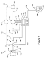
図1は、本明細書において開示される実装に従う組織除去システム100の実施例を図示するブロック図である。組織除去システム100は、概して、組織除去デバイス104と、真空ポンプ108と、制御コンソール112および足踏み制御デバイス116等の1つ以上のシステム制御デバイスとを含む。典型的な実装では、組織除去デバイス104は、ユーザによって快適に手で持たれるように体系化およびサイズ決定され、したがって、ハンドピース、手持ち式器具、または手持ち式デバイスと呼ばれ得る。組織除去システム100の他の構成要素は、固定型または携帯型であり、組織除去システム100が利用される特定の手技に望ましいか、または適切であってもよい。組織除去デバイス104および種々の他の構成要素は、組織除去システム100を完成するために迅速かつ容易に相互接続されるように適合される、滅菌したあらかじめ組み立てられた形態で外科医に提供されてもよい。組織除去デバイス104および種々の他の構成要素は、使い捨て材料で構築されてもよい。
FIG. 1 is a block diagram illustrating an example of a
概して、組織除去システム100は、組織除去デバイス104の遠位先端における真空または真空と熱エネルギーとの両方の制御された印加を介して、外科部位124から標的組織120を除去するために、外科医(または他の種類のユーザ)による利用に対して適合される。本状況では、標的組織120は、外科部位124から除去されることが所望される組織を包含する。実施例として、標的組織120は、患者の眼から除去される白内障物質であってもよい。真空は、外科部位124から標的組織120を吸引するためだけでなく、標的組織120を破壊するためのモダリティとしても利用されてもよい。熱エネルギーもまた、標的組織120を破壊することを支援するために利用されてもよい。組織除去システム100はまた、滅菌方式で吸引した組織の収集および廃棄を可能にするために、出口線130を介して真空ポンプ108と連絡する任意の好適なレセプタクル、容器、または同等物によって具現化され得るような組織収集部位128を含んでもよい。特定の用途に応じて、組織除去システム100はまた、組織除去デバイス104を介して外科部位124にある種類の材料を添加するように構成されてもよい。例えば、組織除去システム100は、外科部位124に洗浄流体を塗布するように適合されてもよく、またはそのような機能が別個の器具によって果たされてもよい。他の実施例として、組織除去デバイス104は、皮質材料を吸収する材料、またはゲル、あるいはヒト水晶体、流動性があるIOL材料等に取って代わる他の屈折性材料を注入するように構成されてもよい。
In general, the
組織除去デバイス104は、概して、外科部位124に設置され、操作されるように適合される開放遠位端132と、反対側の近位端136とを含む。組織除去デバイス104はまた、種々の構成要素を封入する筐体140を含む。上述のように、筐体140は、外科医の手で持たれるように構成(サイズ決定、成形等)されてもよい。有利な実装では、筐体140は、外科医を保護するために、電気的および熱的の両方において絶縁性である材料で構築され、その非限定的実施例は、種々の熱可塑性物質および他のポリマー組成物である。組織除去デバイス104の1つ以上の構成要素(導管、管類、チャンバ等)は、筐体140を通って、概して開放遠位端132から近位端136まで、または少なくともそれに向かって伝わる内部真空(または吸引)線144を提供する。内部吸引線144の一部は、短い距離にわたって筐体140の遠位開口部から延在し、組織除去デバイス104の開放遠位端132に対応する開放遠位先端で終端してもよい、カニューレ148によって確立される。典型的には、近位端136(すなわち、筐体140の近位開口部)またはその付近に位置する、組織除去デバイス104の適切な付属品(図示せず)を介して、内部吸引線144は、任意の好適な長さの外部吸引線152との接続を介して真空ポンプ108と流体的に連絡して、配置されてもよい。
The
組織除去デバイス104はまた、内部吸引線144と動作連絡している、筐体140内に位置する真空パルスデバイス156を含んでもよい。制御されたレベルの真空を確立する真空ポンプ108を用いて、真空パルスデバイス156は、制御された周波数および持続時間の真空パルスを生成するように操作されてもよい。この目的で、真空パルスバイス156は、真空パルス制御信号線160を介して制御コンソール112と電気連絡して、配置されてもよい。真空パルスデバイス156は、真空パルスを生成するために好適な任意の方式で構成されてもよく、そのいくつかの実施例を以下で説明する。真空パルスの効果を最適化するために、真空パルスデバイス156と開放遠位端132との間の内部吸引線144の一部は、生成されたままのパルスエネルギーが遠位端132に移送される際に保存されるように、剛性となるべきである。つまり、軟質導管材料(例えば、可撓性管類)は、パルスエネルギーに望ましくない減衰効果を提供する場合があるため、内部吸引線144のこの部分では、そのような材料が回避されるべきである。したがって、カニューレ148は、剛性材料から構築されるべきである。組織除去デバイス104の設計に応じて、図示したカニューレ148は、その遠位先端から真空パルスデバイス156まで、すなわち、剛性となるべきである内部吸引線144の全体部分にわたって、延在してもよい。代替として、1つ以上の他の明確に異なる導管が、カニューレ148と真空パルスデバイス156との間に提供されてもよく、その場合、そのような他の導管は、同様に剛性となるべきである。
The
動作中、真空ポンプ108は、組織除去デバイス104に対する基準レベルの真空を提供する。この真空レベルは、組織を吸引するために、外科医によって必要に応じて制御および調整されてもよい。組織除去手技中の任意の所与の期間にわたって、外科医は、真空のレベルを一定に設定してもよく、または真空レベルを変化させてもよい。真空パルスデバイス156は、真空ポンプ108によって生成される真空をパルスにするように操作されてもよい。真空パルスは、任意の数の目的で行われてもよく、その実施例は、その吸引前に標的組織120を破壊することである。1つの特定の実施例では、パルス真空エネルギーが、白内障物質を破壊するために利用される。真空パルスの全体的持続時間(すなわち、真空パルスデバイス156が動作中である時間)、ならびにパルスパラメータ(例えば、パルスの大きさおよび持続時間/周波数)は、外科医によって判定されてもよい。実施例として、外科医は、種々の側面の中から、(所定の、事前にプログラムされた等の)真空パルスプログラムを選択することが可能になってもよく、および/またはリアルタイムで(オンザフライで)真空パルスパラメータを調整することが可能になってもよい。外科医は、制御コンソール112および/または足踏み制御デバイス116を利用することによって、真空ポンプ108および真空パルスデバイス156の動作パラメータを制御してもよい。
In operation, the
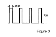
真空パルスデバイス156によって実装されてもよい、真空パルスプログラム(またはプロファイル)のいくつかの実施例が、図2および3に図示されている。具体的には、図2は、比較的高い周波数のパルスおよび中程度の真空レベルによって特徴付けられる、パルス真空信号の実施例である。図3は、比較的低い周波数のパルスおよび高い真空レベルによって特徴付けられる、パルス真空信号の実施例である。有利な実装では、パルス列は、真空レベルが高い値と低い値(ゼロ真空または非常に低い真空に対応してもよい)との間で突然切り替わる、図2および3に示されるような階段状プロファイルを有する(すなわち、階段関数または方形波である)。つまり、高い値と低い値との間の遷移は、傾斜または曲線関数によって改善されない。この方式によって、パルスは事実上、標的組織120を破壊するために効果的である、一連の離散影響を構成する。
Some examples of vacuum pulse programs (or profiles) that may be implemented by the
ある種類の組織の破壊等の、真空パルスのある具体的な目的で、真空パルスの大きさは、真空ポンプ108によって提供される基準真空の大きさよりも有意に高いことが望ましいか、または必要であってもよい。よって、真空パルスデバイス156の動作は、真空ポンプ108の動作と協調させられてもよく、それは制御コンソール112によって自動的に行われてもよい。例えば、制御コンソール112は、真空パルスデバイス156の起動時に真空ポンプ108によって生成される真空レベルを漸増し、同様に、真空パルスデバイス156の起動時に真空レベルを漸減するように構成されてもよい。また、安全特徴として、制御コンソール112は、真空パルスデバイス156の動作停止時に、または真空パルスデバイス156の故障を感知すると、真空ポンプ108をシャットダウンするように構成されてもよい。この種類の協調は、白内障除去および他の眼科手技等の、ある種類の組織除去手技に特に有用である。そのような動作環境で、真空パルスが動作する、より高い真空レベルは、パルスがない場合に、潜在的に有害な高流量状態を生成し得る。つまり、組織除去デバイス104の遠位先端が、患者の眼等の流体環境内に位置する時に、真空ポンプ108の動作によって確立される真空は、カニューレ148および吸引線を備える全ての他の流体導管を通して、流体環境から真空ポンプ108に向かった方向に流体流動を確立する。真空パルスデバイス156が操作されていない時に、流量は主に、真空ポンプ108によって印加される真空のレベルに依存する。組織除去システム100は、付近の組織または他の構造を損傷する、または別様に悪影響を及ぼすことなく、標的組織120を吸引するために効果的と判定される一連の大きさ以内で真空を印加するよう、真空ポンプ108を操作するように構成される。一方で、真空パルスデバイス156も動作中である時、真空パルス、すなわち、遠位先端で印加される真空の周期的断絶および回復は、流体流量に有意な影響を及ぼす。概して、真空パルス率が高くなるほど、流体流量が低くなり、真空パルス率が低くなるほど、流体流量が高くなる。したがって、結果として生じた流体流量が安全範囲内にとどまるため、安全な方式で標的組織120を非常に効果的に破壊するように、高周波数真空パルスが比較的大きい強度で印加されてもよい。しかしながら、真空パルスデバイス156の動作停止または故障により、パルスが停止した後に、真空がその高い大きさにとどまった場合には、流体流量は、安全ではないレベルまで急速に増加する場合がある。患者の眼等の、ある重要な外科部位については、この流量の急上昇および/または連続的に印加された(非パルス)高い大きさの真空への突然の遷移は、急速な流体損失および患者への損傷を引き起こし得る。したがって、損傷のリスクを排除するために、真空ポンプ108および真空パルスデバイス156のそれぞれの動作を協調させることが有利である。
For certain purposes of vacuum pulses, such as the destruction of certain types of tissue, it is desirable or necessary that the magnitude of the vacuum pulse is significantly higher than the magnitude of the reference vacuum provided by the
既述のように、より高い真空パルス率は、より低い流体流量をもたらし、より低い真空パルス率は、より高い流体流量をもたらす。したがって、組織除去デバイス104が真空パルスモードで動作している間に、外科医は、真空パルスデバイス156によって供給されている真空パルスの周波数を変化させることによって、流体流量、したがって、組織除去デバイス104を通して吸引されている破壊した組織の流量を制御することができる。真空パルス周波数は、例えば、制御コンソール112または足踏み制御デバイス116の上に位置する適切な調整ノブを操作することによって、変化させられてもよい。説明されたものと同様の安全特徴として、制御コンソール112または足踏み制御デバイス116に提供される回路は、真空パルス周波数の所定の低い閾値に達しているかどうかを検出し、もしそうであれば、印加した真空の大きさを自動的に低下させて、危険なほど高い流量を回避することによって応答するように構成されてもよい。別の安全特徴として、足踏み制御デバイス116は、真空パルスモードが動作中のままであるために、足踏み制御デバイス116のフットスイッチが押下されたままであることを要求するよう構成されてもよい。この構成によって、外科医が意図的または偶然にフットスイッチから足を外した場合、組織除去システム100が、低い真空レベルを伴う連続真空モードに自動的に切り替えられ、または真空ポンプ108が自動的に遮断され、または真空パルスデバイス156の弁機構が、カニューレ148の遠位先端への真空の印加を中断するよう、吸引線144を自動的に閉鎖する、等である。
As already mentioned, a higher vacuum pulse rate results in a lower fluid flow rate and a lower vacuum pulse rate results in a higher fluid flow rate. Thus, while the
図1でさらに示されるように、いくつかの実装では、組織除去システム100は、低真空線と、別個の高真空線とを含んでもよい。上記の第1の吸引線152は、低真空線として利用され、第2の吸引線164は、高真空線として利用される。第1の吸引線152および第1の真空ポンプ108は、外科医が一連の比較的低い真空レベル以内で真空レベルを変化させてもよい、連続または定常状態真空モード中に動作中である。高真空線164は、真空パルスデバイス156と、真空パルスモードと関連付けられる比較的高いレベルの真空を印加するために構成される、第2の真空ポンプ168の流体入口とを相互接続する。第1の真空ポンプ108と同様に、第2の真空ポンプ168は、適切な電気信号線(図示せず)を介して、制御コンソール112または足踏み制御デバイス116によって制御される。第1の真空ポンプ108および第2の真空ポンプ168は、同じ種類のポンプまたは異なる種類のポンプであってもよい。制御コンソール112または足踏み制御デバイス116は、連続真空モードまたは真空パルスモードの外科医の選択に従って、または本開示の他の場所で説明されるようなある事象に応じて自動的に、第1の真空ポンプ108および第2の真空ポンプ168を操作することを切り替えるように構成される。真空パルスデバイス156は、選択されたモードに応じて、カニューレ148から第1の吸引線152または第2の吸引線164の中への流体経路を切り替えるように構成されてもよい。したがって、流体および除去された組織は、第1の吸引線152または第2の吸引線164を通って流れる。出口線172は、第2の真空ポンプ168の流体出口と、組織収集部位128とを相互接続してもよい。
As further shown in FIG. 1, in some implementations, the
組織除去デバイス104はまた、カニューレ148の遠位先端に位置する熱素子176を含んでもよい。熱素子176は、標的組織120に局所化された熱エネルギーを印加するように適合される。熱エネルギーは、標的組織120を分解する効果を有する。本状況では、「分解する」とは、概して、標的組織120が、その元の状態とは異なる状態に転換され、異なる状態が、外科部位124からの標的組織の除去および/または組織除去デバイス104を通した吸引を容易にすることを意味する。分解の正確な機構は、標的組織120の性質または組成に依存する。いくつかの非限定的実施例として、分解は、標的組織120をより小さい破片に破壊すること、標的組織120を変性させること、標的組織120を解重合すること、標的組織120を融解させることを伴ってもよい。いくつかの実装では、熱素子176は、DC電流に応答する電気抵抗加熱素子である。熱素子176は、組織除去デバイス104の1つ以上の導電性構成要素を通して熱素子176へ所望の大きさのDC電流を渡す加熱信号線180を介して、制御コンソール112によって制御されてもよい。1つの非限定的な実施例として、制御コンソール112は、熱素子176の温度が約40〜70℃の範囲内で変化させられることを可能にする電流範囲にわたって、熱素子176を活性化するように構成されてもよい。制御コンソール112はまた、熱素子176にパルス熱エネルギーを印加させるために、加熱信号線180上でパルスDC電流を伝送するように構成されてもよい。加熱信号線180は、熱素子176の2つの端子または接点とそれぞれ連絡し、それにより、電流が一方の送電線を通過し、熱素子176を通過し、他方の送電線を通過する回路を確立する、2つの送電線を表してもよい。代替として、または加えて、熱素子176の1つ以上の動作パラメータは、以下でさらに説明されるように、足踏み制御デバイス116によって制御されてもよい。
熱素子176は、概して、任意の導電性であるが電気抵抗性の材料、すなわち、それを通過する電気エネルギーの大部分を熱エネルギーに変換するために効果的な材料で構築されてもよい。したがって、種々の金属および金属合金が利用されてもよい。好ましくは、熱素子176は、電流によく反応する材料、すなわち、極めて抵抗性の(または伝導性が低い)材料、または別の言い方をすれば、電流に応じて熱を容易に放散する材料から成る。1つの非限定的実施例は、ニクロムである。いくつかの実装では、熱素子176は、熱素子176への標的組織120の付着または保持を防止するために、熱素子176にこびり付き防止特性を与える材料によって被覆されてもよい。好適なこびり付き防止被覆の非限定的実施例は、パリレン族の種々のポリマー組成物ならびにその化学的誘導体および相対物を含む。
The
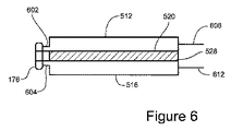
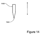
図4は、組織除去デバイス104の遠位領域の実施例の断面図である。より具体的には、図4は、カニューレ148の遠位領域およびカニューレ148の遠位先端402に設置される熱素子176を断面図で図示する。カニューレ148の内面406は、カニューレ148の内部を封入する。内面406の内径は、カニューレ148を通る断面流動面積を決定付ける。この実施例では、熱素子176およびカニューレ148は、縦軸410の周りに同軸に配設される。縦軸410と同一線上にある矢印は、概して、印加された真空によって確立される圧力勾配の方向、したがって、流体流動および組織吸引の方向を図示する。この実施例では、熱素子176は、カニューレ148の中への流体入口414としての役割を果たし、したがって、組織除去デバイス104の開放遠位端132(図1)に対応する、開口部を画定するワイヤループの形態で提供される。したがって、熱素子176は、環状であり、吸引された流体および組織の流路を同軸に包囲する。流体入口414のサイズ(内径)は、カニューレ176の中への流動面積を決定付ける。これは、外側視点からの熱素子176およびカニューレ148の端面図である、図5にも図示されている。熱素子176の内径は、カニューレ148の内径と同じ、または実質的に同じであってもよく、その場合、流動面積は、カニューレ148の軸長に沿って保存される。図4および5で図示されるような他の実装では、熱素子176の内径は、カニューレ148の内径よりも小さくてもよく、直径の遷移は、カニューレ148の先細り(円錐)区画418によって提供される。小径熱素子176によって画定される流体入口414を横断するのに十分小さい組織には、カニューレ148によって画定されるより大きい断面流動面積を塞ぐリスクがほとんどないため、この構成は、カニューレ148が詰まることを防止するために有用であってもよい。図5に示されるように、熱素子176は、間隙508によって分離される2つの末端502、504を有するという点で、C字形であってもよい。この構成では、熱素子176にDC電流を通過させるための回路を完成するように、それぞれの導線が取り付けられるか、または別様に2つの末端502、504と電気接触して配置されてもよい。導線は、次に、図1で図式的に図示された加熱信号線180を介して制御コンソール112と連絡してもよい。
FIG. 4 is a cross-sectional view of an example of a distal region of
組織除去デバイス104は、切開を介して外科部位にカニューレ148を挿入することを伴う、種々の手技で利用されてもよい。例えば、種々の眼科手技では、切開が患者の眼の膜を通して加えられてもよい。切開は、例えば、レーザ手技等の種々の技法によって加えられてもよい。眼への損傷を最小化し、術後の回復および治癒期間を最小化するために、切開は、可能な限り小さくなるべきである。したがって、カニューレ148は、実践可能な限り小さくなるべきである。本明細書で開示されるカニューレ148および熱素子176の設計は、それらの機能に悪影響を及ぼすことなく、これらの構成要素のサイズが最小化されることを可能にする。いくつかの実装では、カニューレ148の外径は、約1.0〜3.0mmに及ぶ。いくつかの実施例では、カニューレ148の外径は、約3.0mm、2.5mm、2.0mm、1.5mm、または1.0mmである。他の場所で記述されるように、熱素子176の外径は、カニューレ148の外径とほぼ同じ、またはそれより小さくてもよい。いくつかの実施例では、熱素子176の外径は、約1.7mm以下である。カニューレ148のサイズは、部分的には、組織除去デバイス104自体が、外科部位に洗浄流体を供給するための手段を提供することを要求されないため、最小化することができる。本明細書で開示される真空パルス効果および熱的効果の利用は、従来技術の組織除去技法とほぼ同量の洗浄流体を必要としない。外科部位に添加される必要がある任意の洗浄流体は、別個の手持ち式デバイスによって供給されてもよい。これは、外科医が一方の手で組織除去デバイス104を、必要に応じて他方の手で洗浄デバイスを扱う、両手技法と呼ばれてもよい。代替として、組織除去デバイス104は、カニューレ148と同軸にある環状スリーブ(図示せず)を通して、洗浄流体が組織除去デバイス104によって供給される、同軸技法を行うために構成されてもよい。この後者の代替案は、より大きい切開を必要とするが、切開は3.0mm未満であってもよい。
The
図4はまた、熱素子176によって実装される熱的効果の実施例も図示する。この実施例では、標的組織120(例えば、白内障または白内障の一部分等)が、印加された真空の影響下で流体入口414に引き寄せられている。しかしながら、標的組織120は、流体入口414よりも大きく、したがって、最初に熱素子176と接触し、流体入口414を閉塞させる。いくつかの状況では、印加された真空は、標的組織120が流体入口414を通って横断し、カニューレ148を通って組織除去デバイス104から流出し、関連吸引線を通って所望の目的地(例えば、図1に図示された収集部位128)まで流れることを可能にするほどに、標的組織120を変形させることに十分であってもよい。他の状況では、標的組織120は、大きすぎるか、および/または印加された真空の影響下のみで吸引されように十分変形可能ではない場合があり、および/または真空パルス効果の実装は、標的組織120を破壊するほど効果的ではない場合がある。これら後者の状況では、熱素子176は、標的組織120に熱エネルギーを印加し、それにより、流体入口414およびカニューレ148を通してより容易に輸送される、より小さい断片422に標的組織120を破壊するように活性化されてもよい。
FIG. 4 also illustrates an example of a thermal effect implemented by the
加えて、組織除去システム100は、閉塞の発生を検出し、熱素子176を自動的に起動するように構成されてもよい。閉塞事象を検出するために、種々のアプローチがとられてもよい。1つの非限定的実施例として、組織除去システム100は、圧力フィードバック信号線188を介して制御コンソール112に連続的または断続的な圧力フィードバック信号を提供する、その適切な場所で吸引線152と動作可能にインターフェース接続される、圧力トランスデューサ184(図1)を提供してもよい。吸引線152の中の圧力(または真空)レベルの急変の検出は、流体入口414(図4)における閉塞事象の発生として解釈され、熱素子176の起動を自動的に誘起してもよい。同様に、組織除去システム100が連続真空モードで動作している時に、閉塞事象の検出が、真空パルスモードの起動を誘起してもよい。制御コンソール112は、閉塞の検出時における組織除去デバイス104の動作の現在の状態に応じて、真空パルスモードおよび/または熱印加を自動的に誘起するかどうか、および同時または連続的に両方のモードを起動するかどうかを決定するように構成されてもよい。後に、閉塞が失われたことが検出されると、制御コンソール112は、真空パルスデバイス156および/または熱素子176を動作停止させるように構成されてもよく、および/または真空ポンプ108、168をシャットダウンするか、または別様に遠位先端402で真空を遮断させてもよい。閉塞を検出する目的で、圧力トランスデューサ184は、内部吸引線144の何らかの部分と動作連絡している、組織除去デバイス104の筐体140(図1)の中に設置されてもよい。代替として、図1に示されるように、圧力トランスデューサ184は、外部吸引線152または164と動作連絡して、あるいは真空ポンプ108または168の筐体内に設置されてもよい。
In addition, the
熱的効果の有効性は、全ての状況において標的組織120と熱素子176との間の実際の接触を必要とするわけではないことに留意されるであろう。例えば、外科部位にカニューレ148の遠位先端402を挿入すると、熱素子176は、標的組織120から短い距離を置いて位置してもよい。次いで、熱素子176は、標的組織120に近接しているが接触していない間に起動されてもよい。熱素子176からの熱エネルギーは、空気または流体(例えば、眼科手技の場合は眼液、および/または種々の外科的手技で適用されてもよいような洗浄流体)等の、熱素子176と標的組織120との間に存在する流体媒体のほんの一部分を介して標的組織120に移送されてもよい。標的組織120が、熱素子176によって包囲される流体入口414に引き寄せられる前に、標的組織120を破壊し始めさせるように、十分な量の熱エネルギーが流体媒体を通して移送されてもよい。代替として、または加えて、標的組織120は、熱素子176からの熱の移送によって、流体入口414に向かう輸送中に破壊し始めてもよい。
It will be noted that the effectiveness of the thermal effect does not require actual contact between the
全てのそのような状況において、熱的効果は極めて局所的であることが明白である。熱素子176は、流体入口414の中へ直接放出された熱エネルギーを濃縮する外面領域、および流体入口414の直接近傍を提示するよう成形される。熱的効果は、標的組織120が存在する流体容量の大部分が、相当な程度まで加熱される必要がないほど、効果的かつ急速である。熱的効果はまた、非常に短い期間にわたって熱エネルギーが印加される必要しかないほど効果的かつ急速である。この期間は、周囲の非標的組織が印加された熱エネルギーによる悪影響を受けるには不十分である。これは、洗浄流体が熱素子176によって堆積された過剰な熱エネルギーを吸収するので、外科部位を通る洗浄流体の循環を伴う手技において、特にそのようである。熱活性化の期間はまた、パルス熱的効果が熱の一定の印加よりも効果的であることが分かっている手技において、上述のように熱エネルギーのパルスを印加することによって最小化されてもよい。また、熱素子176は、外科部位が熱素子176の最小表面積に曝露されるように、設置され、サイズ決定され、成形される。実施例として、熱素子176がカニューレ148の遠位先端402から軸方向外向きに延在する距離は、約2mm以下であってもよい。他の実装では、熱素子176が、カニューレ148の遠位先端418内に部分的または完全に引っ込んでいるように設置されてもよい。
In all such situations, it is clear that the thermal effect is very local. The
図4および5は、加えて、カニューレ148自体の構造が熱素子176にDC電流を伝導するために利用される実装を図示する。この実装は、図4および5に図示された熱素子176およびカニューレ148の上面図である、図6でも図示されている。この場合、カニューレ148は、カニューレ148が、縦軸410に沿って延在する2つのC字形または半円形の導電性構造部材512、516を含む分割構造設計を有する。構造部材512、516は、任意の好適な伝導性材料から成ってもよい。有利な実装では、構造部材512、516は、非常に良好な導体、すなわち、非常に効率的に電気を伝導し、したがって、過度の量の抵抗熱を生成することがない材料から成る。このようにして、熱素子176によって付与される熱的効果は、カニューレ148の遠位先端402に局在したままであり、カニューレ148によってほとんど熱が放出されない。このことは、膜または他の組織を通して切開が形成されて、したがって、この切開を通って延在するカニューレ148の外周と直接接触し得る、これらの膜または他の組織への熱損傷を回避するために特に有用である。カニューレ部材512、516に好適な材料の非限定的な実施例は、アルミニウム、銅、ニッケル、および種々の貴金属(例えば、金、銀、プラチナ)を含む。
4 and 5 additionally illustrate an implementation in which the structure of the
図5の透視図から、カニューレ148の構造部材512、516は、上部間隙520および直径に沿って反対側の下部間隙524によって相互から分離される。図6に示されるように、間隙520、524は、軸方向に細長く、カニューレ148の軸方向距離全体に沿って続く。この構成によって、2つの部材512、516は、相互から電気的に隔離され、したがって、熱素子176にDC電流を渡すための電線用導管として利用されてもよい。この目的で、2つの部材512、516は、熱素子176の末端502、504と電気的に接触している、それぞれの延長部602、604(または突起、タブ、または同等物)を含んでもよい。カニューレ148の全ての他の伝導性部分は、熱素子176から物理的に分離されている。図6で図式的に図示されるように、2つの部材512、516は、図1に示された加熱信号線180の一部と連絡するか、またはそれを形成してもよい、組織除去デバイス104の中に提供されてもよい、2つの他の導電体608、612とそれぞれ連絡してもよい。
From the perspective view of FIG. 5, the
カニューレ148によって囲まれる流体容量を完全に封入し、吸引線のこの部分を密閉するために、軸方向に細長いシール528、532が、カニューレ部材512、516の間の間隙520、524をそれぞれ充填するよう設置されてもよい。軸方向シール528、532は、任意の好適な電気絶縁材料から成ってもよい。他の実装では、シール528、532は、カニューレ148の2つの部材512、516を部分的または完全に包囲するシリンダ等の、カニューレ148の外部にある組織除去デバイス104の構造から延在する半径方向突起であってもよい。シール528、532はまた、組織除去デバイス104の筐体140の内部から延在するか、またはそれによって支持されてもよい。
To fully enclose the fluid volume enclosed by the
図7、8、および9は、カニューレ148の遠位部分、およびどのように熱素子が体系化されてもよいかという斜視図である。これらの図のそれぞれにおいて、カニューレ148は、2つの湾曲部材512、516が相互から電気的に隔離されている上記の分割設計を有する。図示を簡単にするために、部材512、516の間に間置されるシールは示されていない。また、これらの実施例では、カニューレ148は、一定の直径を有する。図7は、上記で説明され、図4、5、および6において図示されたものと同様である間隙508を有するリング状の熱素子776を図示している。図8は、同様に間隙508を有するリング状の熱素子876を図示する。図7と比較して、図8の熱素子876は、より大きい軸方向寸法を有する。これは、特定の目的のために熱素子876を成形することを容易にする。例えば、図8に示されるように、熱素子876の最遠位部分802は、鋭い刃806へと先細りになってもよく、それは、熱素子876と接触させられた大きい標的組織を破壊することに役立ち、および/または鋭い刃806でさらに局所的な熱的効果を提供してもよい。加えて、最遠位部分802の内径は、図4、5、および6に図示されたカニューレ148の先細り区画418と同様に、詰まりを防止するためにカニューレ148の内径から先細りになってもよい。図9は、カニューレ148の長さの少なくとも一部分に沿って軸方向に延在する2つの軸方向脚部902、906を含む、熱素子976を図示する。軸方向脚部902、906は、例えば、カニューレ148の分割部材512、516の間の間隙のうちの1つの中に設置されてもよい。軸方向脚部902、906は、カニューレ148の遠位領域の所望の長さにわたって熱的効果を拡張させるために提供され得る。
7, 8 and 9 are perspective views of the distal portion of the
熱素子776、876、976の位置は、任意の好適な方式で、それぞれのカニューレ148に対して固定されてもよい。例えば、図7において、熱素子776の末端は、溶接、はんだ付け、または導電性接着剤によって、それぞれのカニューレ延長部602、604と電気的に連絡して配置されてもよい。図8では、熱素子876は、同様にそのカニューレ148に取り付けられてもよい。図9では、熱素子976の軸方向脚部902、906(末端としての機能を果たす)は、同様に、そのカニューレ148のそれぞれの内縁に取り付けられてもよい。代替として、図9では、軸方向脚部902、906は、カニューレ148に沿って及ぶそれぞれの絶縁ワイヤ(図示せず)に取り付けられ、ヒータ信号線180(図1)と連絡してもよい。この後者の場合、カニューレ148の構造部材512、516は、伝導性材料の代わりに電気絶縁材料から成る。
The location of the
ここまで説明された種々のカニューレ148は、真っ直ぐな軸に沿って配向されるが、これは本教示の限定ではない。いくつかの実装では、組織除去デバイス104に提供されるカニューレ148は、曲線状であるか、または角度を成してもよい。他の実装では、カニューレ148の曲率半径または角度は、調整可能であってもよい。つまり、外科医は、直線状カニューレ148を利用することを選択するか、または、所望の湾曲あるいは角度付き形状に一致するようにカニューレ148を屈曲させることが可能であってもよい。カニューレ148のこの調整機能は、順応性のある(しかし真空パルスを減衰させないように依然として剛性である)材料を選択すること、相互に対して移動可能である一連のセグメントの形態のカニューレ148を提供すること等によって、種々の方法で実装されてもよい。調整可能なカニューレ148は、アクセスしにくい、真っ直ぐな境界がない、または予測不可能な境界を有する、外科部位において有用であり得る。いくつかの実施例は、血管、種々の生物学的管、および種々の解剖学的空洞を含む。
The
図10および11は、その内部吸引線144を形成する、組織除去デバイス104の構造の実施例の断面図である。図10が開放位置で吸引線144を示す一方で、図11は閉鎖位置で吸引線144を示す。構造は、カニューレ148、カニューレ148と流体的に連絡している管1002等の別の好適な流体導管、および吸引管1002と動作連絡している真空パルスデバイス1056を含む。カニューレ148は、本明細書で説明される実装のうちのいずれかに従って体系化されてもよい。上述のように、カニューレ148、および真空パルスデバイス1056とカニューレ148との間の吸引管1002の少なくともその部分は、真空パルス効果を最適化するよう剛性となるべきである。真空パルスデバイス1056は、吸引管1002を通る流体経路を交互に閉鎖および開放し、したがって、真空を交互に断絶および回復するために好適な任意の設計を有してもよい。この目的で、いくつかの実装では、真空パルスデバイス1056は、交互に流体経路の中へ延在し、そこから後退するように作動させられてもよい、可動部材1006を含む。可動部材1006は、その延長位置と後退位置との間の可動部材1006の循環運動が真空パルスを生成するように、その中に延長させられると、流体経路の全体または一部を塞ぐように構成されてもよい。上述のように、真空パルス効果は、標的組織を破壊するために利用されてもよい。真空パルス効果は、代替として、または熱的効果と併せて実装されてもよい。また、真空パルス効果および熱的効果は、順に、または同時に実装されてもよい。順に実装されると、真空パルス効果は、熱的効果に続いてもよく、または逆も同様である。2つの効果の連鎖は、1つ以上の交互サイクルにわたって繰り返されてもよい。したがって、所与の組織除去手技では、外科医は、真空パルス効果のみ、または熱的効果のみ、または所望の順序に従って両方の効果、または相乗効果を達成するように同時に両方の効果を活性化することを選択してもよい。
10 and 11 are cross-sectional views of an example of the structure of the
図10および11において具体的に図示された実施例では、真空パルスデバイス1056は、ソレノイドアクチュエータ1010を含む、ソレノイドベースのデバイスである。可動部材1006は、アクチュエータ1010によって平行移動させられるプランジャとしての機能を果たす。可動部材1006は、吸引管1002の開口部1014を通って平行移動する。吸引管1002を流体密封状態に維持するために、任意の好適な設計のシールが、必要に応じて可動部材1006と管開口部1014との間の物理的界面に提供されてもよい。1つの非限定的実施例として、シールは、管開口部1014を覆う弾性材料であってもよい。可動部材1006が管開口部1014を通って吸引管1002の中へと平行移動するにつれて、シールは、伸張し、可動部材1006の周囲で変形し、それにより、可動部材1006ならびに管開口部1014を覆い、吸引管1002の内部と外部との間の流体隔離を維持する。
In the embodiment specifically illustrated in FIGS. 10 and 11, the
図12および13は、ソレノイドベースの真空パルスデバイス1256の別の実施例の断面図である。真空パルスデバイス1256は、ソレノイドアクチュエータ1210と、アクチュエータ1210によって組織除去デバイス104の吸引管1202の流路の中へ、およびそこから外へ往復運動させられる可動部材1206とを含む。図12は、その後退位置で可動部材1206を図示し、図13は、その延長位置で可動部材1206を図示する。この実施例では、可動部材1206は、吸引管1202の断面積と実質的に等しい断面積を有する遠位区画1218を含む。この構成によって、真空パルスデバイス1256の効果は、可動部材1206が完全延長位置にあるときに吸引管1202を通る流体の閉塞を完成するか、またはほぼ完成する。
12 and 13 are cross-sectional views of another embodiment of a solenoid-based
図14は、吸引管の中の流体流動の方向に対して直角な視点からの可動部材1406の側面図である。可動部材1406は、図10および11または図12および13と併せて上記で説明されるようなソレノイドベースの真空パルスデバイスに提供されてもよい。この実施例では、可動部材1406は、鋭い刃1422まで先細りになる。この構成によって、可動部材1406が吸引管の中へ循環させられている間に、可動部材1406は、吸引管を通って流れる組織をさらに破壊するために利用されてもよい。
FIG. 14 is a side view of the
図15および16は、ソレノイドベースの真空パルスデバイス1556の別の実施例の断面図である。真空パルスデバイス1556は、ソレノイドアクチュエータ1510と、アクチュエータ1510によって組織除去デバイス104の吸引管1502の流路に向かい、およびそこから離れるように往復運動させられる可動部材1506とを含む。図15は、その後退位置における可動部材1506を図示し、図16は、その延長位置における可動部材1506を図示する。この実施例では、真空パルスデバイス1556は、ピンチ弁として設計されている。可動部材1506は、丸みを帯びた端を有する遠位区画1518を含む。可動部材1506の直下にある吸引管1502の区画1526は、変形可能な材料(例えば、可撓性管類)から構築される。可動部材1506がその完全延長位置まで平行移動させられるにつれて、可動部材1506は、可撓性区画1526の外面と接触し、可撓性区画1526の内壁の対向する領域が相互と接触し、それにより、吸引管1502を通る流路をくびれさせるまで、可撓性区画1526を変形させる。
15 and 16 are cross-sectional views of another embodiment of a solenoid-based
図1を再び参照すると、真空ポンプ108は、概して、筐体と、流体入口と、流体出口と、真空生成構成要素(図示せず)とを含む。流体入口は、(第1の)外部吸引線152を介して組織除去デバイス104と流体的に連絡して配置され得る。流体出口は、出口線130を介して組織収集場128と流体的に連絡して配置されてもよい。外部吸引線152、130、164、172は、任意の好適な流体伝導構造(例えば、管類)を有してもよく、任意の好適な長さであってもよく、および剛性または可撓性であってもよい。真空ポンプ108は、組織除去デバイス104の遠位端132で制御されたレベルの真空を生成するための任意の好適なポンプであってもよい。真空の大きさ(またはレベル)は、標的組織120が、カニューレ148、内部吸引線144、第1の外部吸引線152、真空ポンプ108、出口線130を通って、組織収集場128まで吸引されることを可能にする程度に高く設定されてもよい。
Referring again to FIG. 1, the
いくつかの実装では、真空ポンプ108は、一対の電動式シリンジ型ポンプユニットが筐体の中に配置される二重シリンダ構成を有する。この場合、真空生成構成要素は、一対のシリンダと、それぞれのシリンダの中で往復運動する一対のピストンと、それぞれのピストンの往復移動を制御する一対のモータとを含んでもよい。真空ポンプ108の内部通路は、第1の吸引線152およびそれぞれのシリンダを相互接続する一対の入口通路と、それぞれのシリンダおよび出口線130を相互接続する一対の出口通路とを含んでもよい。能動制御弁が、各入口通路および出口通路に提供されてもよい。ピストンは、180度、または約180度相互に位相がずれて往復運動させられる。したがって、一方のピストンが吸引ストロークを実行している一方で、他方のピストンは放出ストロークを実行している。その結果として、第1の吸引線152からの流体が1つのシリンダの中へ引き込まれている一方で、他方のシリンダの中に以前に引き込まれていた流体は出口線130の中へ放出される。加えて、一対の圧力トランスデューサが、各シリンダの中の真空を測定するために、それぞれのシリンダと流体的に連絡して配置されてもよい。この種類の二重シリンダポンプの実施例は、その全体が参照することにより本明細書に組み込まれる米国特許出願公開第2005/0234394号において説明されている。
In some implementations, the
この実施例を続けると、真空ポンプ108のモータは、モータ制御信号線190を介して制御コンソール112と信号連絡している。弁は、弁制御信号線192を介して制御コンソール112と信号連絡している。圧力トランスデューサは、圧力フィードバック信号線194を介して制御コンソール112と信号連絡している。この構成によって、制御コンソール112は、ピストンのそれぞれの速度およびそれらの相対的位置(すなわち、相対的タイミングまたは位相整合)を監視して調整するオンおよびオフ位置の間と、おそらくオンとオフ位置との間の中間位置との間で弁の位置を切り替え、ならびに測定された真空レベルに基づいて制御決定を行うように各シリンダの中の真空レベルを監視することが可能である。この構成によって、制御コンソール112は、モータおよび弁のそれぞれの動作を同期化して、吸引線152の中に一定の真空レベルを維持することが可能である。真空レベルは、制御コンソール112または足踏み制御デバイス116上の制御機器を操作することによって、外科医によって選択されてもよい。この構成はまた、真空レベルを変化させることによって引き起こされる真空レベルの一過性の不安定性を最小化しながら、真空ポンプ108が外科医によって行われる真空レベルのリアルタイム調整に迅速に反応することも可能にする。
Continuing with this embodiment, the motor of
図1で図式的に図示されるように、制御コンソール112は、外科医に情報を出力するためのディスプレイ114を含んでもよい。制御コンソール112はまた、外科医が情報を入力し、組織除去システム100(例えば、真空ポンプ108および168、真空パルスデバイス156、熱素子176等)の種々の動作パラメータを設定して調整し、足踏み制御デバイス116によって提供される制御機構をプログラムまたは調整することを可能にするための種々の制御機器または入力機構118(スイッチ、ノブ、キーパッド等)を含んでもよい。制御コンソール112はまた、電子ハードウェア(回路)と、ソフトウェアを記憶するためのメモリとを含む。回路は、ディスプレイ114および入力機構118のそれぞれの動作を可能にするため、および足踏み制御デバイス116とインターフェース接続するためのインターフェース回路を含む。回路およびソフトウェアは、組織除去システム100の種々の機能を支援するために構成される。実施例として、回路は、真空ポンプ108および168、真空パルスデバイス156、および熱素子176の動作を監視し、これらの構成要素に適切な制御信号を送信するために構成されてもよい。ソフトウェアは、行われる特定の組織除去手技に適切な方式で、これらの構成要素を制御するための回路をプログラムするために提供されてもよい。いくつかの実装では、一方または両方の真空ポンプ108および168は、制御コンソール112に、またはその内側に載置されてもよい。他の実装では、一方または両方の真空ポンプ108および168は、足踏み制御デバイス116に、またはその内側に載置されてもよい。
As schematically illustrated in FIG. 1, the
制御コンソール112の入力機構を利用することによって、外科医は、実施例として、真空ポンプ108および168をオンまたはオフに切り替えること、真空ポンプ108および168によって生成される真空レベルを設定して変化させること、真空パルスデバイス156をオンまたはオフに切り替えること、真空パルスデバイス156のパルス周波数を設定して変化させる(それにより、吸引された組織の流量も制御する)こと、真空パルスの大きさを設定して変化させること、熱素子176をオンまたはオフに切り替えること、熱素子176に供給される電流の量を設定して変化させる(それにより、熱素子176の動作温度を制御すること)こと、連続加熱モードとパルス加熱モードとの間で熱素子176を切り替えること、印加された熱エネルギーのパルスの周波数および強度を設定して変化させること等を行ってもよい。制御コンソール112はまた、単一の調整を行うことによって、外科医が真空パルス率および真空パルス強度(または熱パルス率および熱パルス強度)を単一の動作パラメータとして一緒に制御することができるモードと、2つの別個の入力機構を操作することによって、外科医が真空パルス率および真空パルス強度(または熱パルス率および熱パルス強度)を独立して制御することができるモードとの間で、外科医が切り替えることを可能にするように構成されてもよい。同様に、制御コンソール112は、外科医が真空パルスデバイス156の1つ以上のパラメータによって熱素子176の1つ以上の動作パラメータを制御することができるモードと、外科医が真空パルスデバイス156の動作パラメータとは無関係に熱素子176の動作パラメータを制御することができるモードとの間で、外科医が切り替えることを可能にするように構成されてもよい。
By utilizing the input mechanism of the
制御コンソール112はまた、所定の真空パルスの大きさで単一パルスを印加するように、外科医が、瞬間的にのみ真空パルスデバイス156を起動する単一パルスモードに真空パルスデバイス156を切り替えることを可能にするように構成されてもよい。単一パルスモードは、例えば、患者の眼の前嚢の中への入口を作成することを要求する眼科手技において有用であり得る。この実施例では、標的組織を破壊する前に、カニューレ148の遠位先端は、前嚢の外部と接触して配置されてもよい。この時間の間に、組織除去デバイス104は、遠位先端を前嚢と接触させることを支援するために、連続真空モードにおいて操作されてもよい。次いで、真空パルスデバイス156は、単一パルスモードに切り替えられ、それにより、単一パルスによって付与される影響は、その外部構造の厚さを通して前嚢の中への入口を作成することに十分である。次いで、遠位先端が入口を通して挿入されてもよく、その時に、組織除去手技が行われてもよい。この技法は、カニューレ148のサイズおよび形状に正確に一致するサイズおよび形状を有する、入口の作成を可能にし、それにより、前嚢とカニューレ148との間に上部シールを提供する。
The
足踏み制御デバイス116は、説明されたようなもの等の、制御コンソール112によって制御可能な同じ機能のうちの1つ以上を制御するために構成されてもよい。したがって、足踏み制御デバイス116は、調整可能なノブ122および押下可能なフットペダル126等の1つ以上の入力機構を含んでもよい。フットペダル126は、フットスイッチおよび/またはピボット式フットペダルを含んでもよい。フットスイッチは、組織除去システム100の構成要素をオンおよびオフ状態の間で切り替えるように、または動作パラメータの増分調整をクリックスルーする(例えば、印加された真空または電気エネルギーの高、中、または低設定を選択する)ために、操作されてもよい。ピボット式フットペダルは、最小値と最大値との間で動作パラメータを変化させるために利用されてもよい。足踏み制御デバイス116の上の調整可能なノブ122または制御コンソール112の上のノブは、外科医が、旋回式フットペダルの最小値および最大値、および/またはフットペダルの旋回進行に応じて動作パラメータが変化する速度(例えば、線形または指数関数)を設定することを可能にするように構成されてもよい。実施例として、その基準位置からその中間位置までフットペダルを前方に旋回することは、関連動作パラメータを、事前設定された最大値の正確に50%である値に適応させてもよい。別の実施例として、その基準位置からその中間位置までフットペダルを前方に旋回することは、関連動作パラメータを、事前設定された最大値の75%である値に適応させてもよく、その場合、最大値まで残りの25%を超えて動作パラメータを適応さえることは、ペダルの進行の残りの部分を通して、中間位置からフットペダルを前方に旋回することを必要とする。制御コンソール112および/または足踏み制御デバイス116は、どの機能および動作が制御コンソール112によって制御されるか、およびどの機能および動作が足踏み制御デバイス116によって制御されるかを外科医が選択することを可能にするように構成されてもよい。簡潔にするために、足踏み制御デバイス116は、有線または無線通信リンク196上で制御コンソール112と通信するものとして、図1で図式的に図示されている。しかしながら、足踏み制御デバイス116によって制御可能な機能に応じて、種々の電気信号線が、制御コンソール112と通信するものに代わって、またはそれらに加えて、足踏み制御デバイス116まで直接及んでもよいことが理解されるであろう。
The
図17は、別の実装による、組織除去システム1700の実施例を図示するブロック図である。簡単にするために、制御コンソール112および足踏み制御デバイス116(図1)は、図17で図示されていない。組織除去システム1700は、連続真空モード中に第1の吸引線152上で調整可能な真空を提供する第1の真空ポンプ1708と、パルス真空モード中に第2の吸引線164上で比較的高いレベルにおいて調整可能な真空を提供する第2の真空ポンプ1768とを含む。前述のように、真空パルスデバイス156または組織除去デバイス104の他の構成要素は、選択された真空モードに従って、第1の吸引線152と第2の吸引線164との間でカニューレ148からの吸引経路を切り替えるために構成されてもよい。この実施例では、真空ポンプ1708、1768は、本開示で以前に説明された液体ポンプの代わりに、気体(例えば、空気)ポンプとして構成される。組織収集デバイス128は、吸引線152、164およびそれぞれの出口線1742、1746を介して、組織除去デバイス104と真空ポンプ1708、1768との間で相互接続される。組織収集デバイス128は、気体のみが出口線1742、1746を通して送られるように、吸引された流体および組織を除去するための従来の方式で構成されてもよい。代替として、別個の組織収集デバイスが、2つの吸引線152、164に提供されてもよい。典型的には、真空を構築することを支援するように、真空貯留部1754、1758が、それぞれの真空ポンプ1708、1768の上流に提供される。代替として、両方の真空ポンプ1708、1768が、単一の貯留部と連絡してもよい。任意の好適な設計の1つ以上の圧力調節器1762、1766が、必要に応じて、それぞれの真空ポンプ1708、1768と流体的に連絡して提供されてもよい。圧力調節器1762、1766は、制御コンソール112または足踏み制御デバイス116によって制御することができる種類であってもよい。前述の構成要素(真空ポンプ1708、1768、真空貯留部1754、1758、圧力調節器1762、1766、組織収集デバイス128)のうちの1つ以上は、制御コンソール112または足踏み制御デバイス116に、あるいはその内側に載置されてもよい。図17に図示された組織除去システム1700は、図1に図示された組織除去システム100について上記で説明されるものと同様に動作してもよい。
FIG. 17 is a block diagram illustrating an example of a
図18、19、および20は、別の実装による組織除去デバイス1804の実施例を図示する。具体的には、図18は、組織除去デバイス1804の斜視図であり、図19は、組織除去デバイス1804の上面図であり、図20は、図19の線B−Bに沿って得られた組織除去デバイス1804の断面図である。この実施例では、以前に説明されたように、組織除去デバイス1804は、一方の吸引線152が連続真空モード中に利用され、他方の吸引線164がパルス真空モード中に利用される、筐体140の近位開口部から延在する、2つの吸引線152、164とともに動作するために構成される。代替として、組織除去デバイス1804は、単一の吸引線のみとともに動作するために構成されてもよい。この実施例では、カニューレ148は、筐体140内の内部吸引管2002に接続される。カニューレ148は、カニューレ148の構造の半分が、筐体140を通って加熱信号線180としての機能を果たすそれぞれのアウトバウンドワイヤまで及ぶ、それぞれの絶縁ワイヤに接続された状態で、本開示で以前に説明された分割設計を有してもよい。カニューレ148は、組織除去デバイス1804の迅速な組立および分解を可能にするように、内部ハブ2074および同軸上のネジ式係止機構1878によって形成される、筐体140の遠位開口部から外向きに延在してもよい。
18, 19, and 20 illustrate an example of a
また、図18、19、および20に図示された実施例では、組織除去デバイス1804は、ソレノイドベースの真空パルスデバイス1856を含む。真空パルスデバイス1856は、筐体140の近位端に取り付けられるソレノイドブロック1810と、ソレノイドアクチュエータ1806とを含む。ソレノイドブロック1810は、内部吸引管2002と流体的に連絡している共通ポート2054と、第1の吸引線152と流体的に連絡している低真空ポート2062と、第2の吸引線164と流体的に連絡している高真空ポート2066とを含む。アクチュエータ1806は、スプール弁の形態で提供されてもよく、その一般動作は当業者に公知である。この場合、アクチュエータ1806によって作動される可動部材は、ソレノイドブロック1810に対して前後に平行移動するスプールである。スプールの位置は、スプール位置に応じて動作中または非動作中である相互接続通路またはチャネル2068を用いて、共通ポート2054が低真空ポート2062と流体的に連絡しているか、高真空ポート2066と流体的に連絡しているかを判定する。したがって、スプールは、連続真空モードとパルス真空モードとの間で組織除去デバイス1804を切り替えるために利用される。連続真空モードでは、共通ポート2054は、真空ポート2062と流体的に連絡しており、吸引された物質が、第1の真空ポンプの影響下でカニューレ148から第1の吸引線152まで送られる。パルス真空モードでは、共通ポート2054は、高真空ポート2066と流体的に連絡しており、吸引された物質が、第2の真空ポンプの影響下でカニューレ148から第2の吸引線164まで送られる。この実施例では、真空パルスデバイス1856は、共通ポート2054と高真空ポート2066との間の流体経路を交互に開放および閉鎖するように、急速にスプールを前後に平行移動させることによって、真空パルスを生成するように構成されてもよい。
Also, in the example illustrated in FIGS. 18, 19, and 20,
図21は、別の実装による、手持ち式手術器具2100の実施例の斜視図である。手術器具2100は、組織吸引に加えた1つ以上の機能が外科医によって選択されてもよい多機能器具として構成される。この目的で、手術器具2100は、その近位端に位置する回転可能なハブ2106を含む。回転可能なハブ2106は、手術器具2100によって支持される枢軸2110の周囲で外科医によって回転させられてもよい。回転可能なハブ2106は、真空管類152に接続可能な真空ポートまたは穴2112と、対応する付加的な管類2116に接続可能な1つ以上の付加的なポートまたは穴2114とを含む。付加的なポート2114は、手術器具2100および組織吸引に利用される同じカニューレを通して特定の種類の材料を流すことによって、本開示で前述したように、そのような材料を外科部位に添加するための注入穴として利用されてもよい。回転可能なハブ2106と手術器具2100との間の界面は、増分回転が、所望のポート2112または2114を、真空の印加ならびに流体および組織流動に通常は採用される手術器具2100の内部通路と流体的に連絡して係止するように構成される。1つの実装では、付加的なポート2114および管類2116は、嚢内手技の一部として液体IOL材料を注入するために利用される。真空ポート2112が白内障を除去するために採用された後、外科医は、IOL材料源に接続される付加的なポート2114を切り替えるために、ハブ2106を回転させる。次いで、外科医は、IOL材料供給線としての機能を果たす管類2116を介して、眼の嚢部に液体IOL材料を注入するために、手術器具2100を利用する。この構成は、眼から真空カニューレを除去し、後に、液体IOL材料を注入する目的で、以前に作成された小さい前嚢切開を通して別の別個のカニューレを挿入するように外科医に要求することを回避する。これは、嚢内手技を行うために、前嚢に加えられた切開が、利用されているカニューレに完璧に合致しなければならないので、有利である。カニューレの任意の移動が、切開を引き裂くか、または損傷する場合があり、それは切開を傷つけ、切開を密閉して液体IOL材料が嚢部から漏出することを防止しにくくする。
FIG. 21 is a perspective view of an example of a hand-held
図22および23は、嚢内手技または他の種類の手技中に切開を密閉するために利用され得る拡張可能な切開シール2200の実施例の斜視図である。図22は、拡張位置にある切開シール2200を示し、図23は、後退位置にある切開シール2200を示す。切開シール2200は、切開によって画定される開口部に嵌入し、それを完全に充填するようにサイズ決定されるシャフト2204を含む。シャフト2204は、遠位端2208と、近位端2212とを含む。切開シール2200はまた、遠位端2208に隣接する拡張可能部分2216も含む。拡張可能部分2216は、傘の方式で構成される。したがって、拡張可能部分2216は、隣接するセグメント2220が放射状の折り目2224において接合されている状態で、遠位端2208から半径方向外向きに延在する、複数の放射状セグメントまたはパネル2220を含む。拡張可能部分2216は、セグメント2220がシャフト2204に対して第1の角度で配向される、図23に示された後退位置から、セグメント2220が第1の角度よりも大きいシャフト2204に対する第2の角度で配置される、図22に示された拡張位置まで、移動可能である。シールとして機能することに加えて、切開シール2200は、組織除去デバイスまたは他の手術器具(例えば、図21に示された手術器具2100)を通して外科部位の中へ粘着性材料を押し込むために、プランジャとして利用されてもよい。
22 and 23 are perspective views of an example of an
IOL手技の実施例では、切開シール2200は、最初に、その近位端2212において別個の器具の細長い棒またはワイヤに軽く(または緩く等)取り付けられてもよい。近位端2212は、この取付を達成するように、任意の好適な手段によって構成されてもよい。IOL材料線2116(図21)が手術器具2100のカニューレと流体的に連絡するように設定された手術器具2100を用いて、外科医は、IOL材料線2116にIOL材料を注入する。次いで、別個の器具の棒に取り付けられた切開シール2200のシャフト2204を用いて、外科医は、IOL材料線2116に切開シール2200を挿入し、別個の器具の棒を押すことによって、それを通して切開シール2200を押し進めてもよい。切開シール2200は、図23に示された後退位置においてIOL材料線2116を通って容易に進行する。IOL材料は、極めて粘着性であってもよく、切開を通して嚢部に挿入される際に支援を必要としてもよい。したがって、遠位端2208は、IOL材料線2116を通してIOL材料を押し進めるために利用されてもよい。外科医は、手術器具2100のカニューレを通して切開の中へ切開シール2200を押し込んでもよい。外科医は、拡張可能部分2216が切開を通過し、完全に嚢部の中に配置されるほど遠くへ、切開を通して切開シール2200を押し進めてもよい。この時に、切開シール2200のシャフト2204は、切開を通って延在し、切開を画定する組織境界は、シャフト2204の周囲で緊密に嵌合する。次いで、外科医は、別個の器具の棒を引っ張ってもよく、それにより、シャフト2204が切開から後退し始める。この引張は、切開シール2200の拡張可能部分2216を、図22に示された拡張位置まで外向きに拡張させる。拡張位置では、拡張可能部分2216は、切開を包囲する近傍で前嚢の後面に対して隣接する。したがって、シャフト2204および拡張可能部分2216は、切開の中および周囲で流体密封シールを形成する。また、ここで拡張可能部分2216がその拡張位置にあり、切開の内側に位置するため、拡張可能部分2216を前嚢から除去することができず、その結果として、拡張可能部分2216がシャフト2204に固着されたままであるので、シャフト2204を切開から完全に後退させることができない。しかしながら、上述のように、別個の器具の棒は、シャフト2204に軽く取り付けられるにすぎない。したがって、外科医が棒を引き戻すと、棒は、シャフト2204から着脱され、次いで、切開シール2200が前述の方式で切開の中に適正に設置された後、手術器具2100のカニューレを通した後退を介して、外科部位から容易に除去されてもよい。
In an example of an IOL procedure, the
拡張可能な切開シール2200は、図22および23と併せて上記で説明された機能および動作を可能にするために好適な任意の材料から構築されてもよい。
The
一般に、「連絡する」および「〜と・・・連絡している」(例えば、第1の構成要素が第2の構成要素と「連絡する」または「連絡している」)等の用語は、2つ以上の構成要素または要素との間の構造、機能、機械、電気、信号、光学、磁気、電磁気、イオン、または流体関係を示すために本明細書で使用される。そのようなものとして、1つの構成要素が第2の構成要素と連絡とするといわれる事実は、付加的な構成要素が、第1と第2の構成要素との間に存在する、および/または第1および第2の構成要素と関連付けられるか、あるいは係合される場合があるという可能性を除外することを目的としない。 In general, terms such as “contact” and “in contact with” (eg, the first component “contacts” or “contacts” the second component) are: As used herein to denote a structural, functional, mechanical, electrical, signal, optical, magnetic, electromagnetic, ionic, or fluid relationship between two or more components or elements. As such, the fact that one component is said to be in communication with the second component is that an additional component exists between the first and second components, and / or It is not intended to exclude the possibility that it may be associated with or engaged with the first and second components.
本発明の種々の側面または詳細は、本発明の範囲から逸脱することなく変更されてもよいことが理解されるであろう。さらに、前述の説明は、限定の目的ではなく、例示の目的のためにすぎず、本発明は請求項によって定義される。
It will be understood that various aspects or details of the invention may be changed without departing from the scope of the invention. Furthermore, the foregoing description is for purposes of illustration and not limitation, and the present invention is defined by the claims.
Claims (10)
該近位ハンドピース開口部から該ハンドピース内部および該遠位ハンドピース開口部を通って延在し、該遠位ハンドピース開口部から距離を置いて該ハンドピースの外側に配置された開放遠位導管端で終端する真空導管と、
該真空導管と連絡し、該真空導管の中の真空圧を制御するように構成された弁機構と、
該弁機構と連絡し、開放状態と閉鎖状態との間で該弁機構を作動させるよう構成されたパルス率制御回路を具備してなる真空制御デバイスであって、該弁機構が制御可能なパルス率において該真空導管の中に真空パルスを誘発するようにしたものと、
を備えてなる組織除去デバイスであって、
該真空導管が、該弁機構から該開放遠位導管端まで延在すると共に流路を画成する剛性導管区画を含み、該弁機構がアクチュエータと可動部材とを具備してなり、該剛性導管区画内に真空パルスを発生させるため、該可動部材が該アクチュエータによって該流路内への導入、該流路からの導出を交互に駆動されるようになっている、
ことを特徴とする組織除去デバイス。
A handpiece surrounding the interior of the handpiece and having a proximal handpiece opening and a distal handpiece opening;
Extending through the handpiece interior and distal handpiece opening from the proximal handpiece opening, far opened disposed outside of the handpiece at a distance from the distal handpiece opening A vacuum conduit terminating at the end of the position conduit;
Communication with the vacuum conduit and configured valve mechanism to control the vacuum pressure in the vacuum conduit,
A vacuum control device comprising a pulse rate control circuit in communication with the valve mechanism and configured to operate the valve mechanism between an open state and a closed state, the pulse being controllable by the valve mechanism Inducing a vacuum pulse in the vacuum conduit at a rate ;
A tissue removal device comprising:
Vacuum conduit comprises a rigid conduit section defining a flow path with extends from the valve mechanism to the open distal conduit end, the valve mechanism is to comprise an actuator and a movable member, rigid conduit In order to generate a vacuum pulse in the compartment, the movable member is alternately driven to be introduced into the flow path and led out from the flow path by the actuator.
A tissue removal device characterized by that .
Pulse rate control circuit includes a pulse rate controller, the pulse rate controller, wherein arranged from the handpiece to a remote, according to claim 1 selected from the group consisting of a user operation console input and user operation footswitch Tissue removal device.
The tissue removal of claim 1 , wherein the vacuum control device further comprises a vacuum mode switching circuit, the vacuum mode switching circuit configured to switch the valve mechanism between a continuous vacuum mode and a pulsed vacuum mode. device.
Said vacuum mode switching circuit includes a switch, said switch, said remotely located from the handpiece, the tissue removal device of claim 3 selected from the group ing from the user operation console switches and user operation footswitch .
The vacuum control device further includes a vacuum mode SWITCHING example circuit, the vacuum mode switching circuit in claim 1 configured to switch the valve mechanism between a single pulse vacuum mode and the pulse train vacuum mode The tissue removal device described.
6. The tissue removal device of claim 5 , wherein the vacuum mode switching circuit includes a switch, the switch being remotely located from the handpiece and selected from the group consisting of a user operation console switch and a user operation foot switch.
The tissue removal device of claim 1, wherein at least a portion of the valve mechanism is enclosed within the handpiece.
A vacuum transducer configured to measure a vacuum level in the vacuum conduit; and a vacuum control circuit in communication with the vacuum transducer, the vacuum control circuit receiving a vacuum level measurement received from the vacuum transducer in response to the signal, the tissue removal device of claim 1 configured to switch the valve mechanism between a plurality of different vacuum control modes.
The vacuum control device is configured to control a vacuum level in the vacuum conduit and has a first control mode in which the vacuum level and the pulse rate are adjusted together; the vacuum level and the pulse rate; There the tissue removal device of claim 1 adapted to be switched between a second control mode to be adjusted independently.
Applications Claiming Priority (3)
| Application Number | Priority Date | Filing Date | Title |
|---|---|---|---|
| US14301009P | 2009-01-07 | 2009-01-07 | |
| US61/143,010 | 2009-01-07 | ||
| PCT/US2010/020348 WO2010080894A2 (en) | 2009-01-07 | 2010-01-07 | Tissue removal devices, systems and methods |
Publications (3)
| Publication Number | Publication Date |
|---|---|
| JP2012514502A JP2012514502A (en) | 2012-06-28 |
| JP2012514502A5 JP2012514502A5 (en) | 2012-10-18 |
| JP5569818B2 true JP5569818B2 (en) | 2014-08-13 |
Family
ID=42317131
Family Applications (1)
| Application Number | Title | Priority Date | Filing Date |
|---|---|---|---|
| JP2011544687A Active JP5569818B2 (en) | 2009-01-07 | 2010-01-07 | Tissue removal device, system and method |
Country Status (7)
| Country | Link |
|---|---|
| US (1) | US9370611B2 (en) |
| EP (1) | EP2385815B1 (en) |
| JP (1) | JP5569818B2 (en) |
| AU (1) | AU2010203588B2 (en) |
| CA (1) | CA2750407C (en) |
| ES (1) | ES2887354T3 (en) |
| WO (1) | WO2010080894A2 (en) |
Families Citing this family (175)
| Publication number | Priority date | Publication date | Assignee | Title |
|---|---|---|---|---|
| US11229472B2 (en) | 2001-06-12 | 2022-01-25 | Cilag Gmbh International | Modular battery powered handheld surgical instrument with multiple magnetic position sensors |
| US8182501B2 (en) | 2004-02-27 | 2012-05-22 | Ethicon Endo-Surgery, Inc. | Ultrasonic surgical shears and method for sealing a blood vessel using same |
| MX2007004151A (en) | 2004-10-08 | 2007-09-11 | Johnson & Johnson | Ultrasonic surgical instrument. |
| US20070191713A1 (en) | 2005-10-14 | 2007-08-16 | Eichmann Stephen E | Ultrasonic device for cutting and coagulating |
| US7621930B2 (en) | 2006-01-20 | 2009-11-24 | Ethicon Endo-Surgery, Inc. | Ultrasound medical instrument having a medical ultrasonic blade |
| WO2008097993A2 (en) | 2007-02-05 | 2008-08-14 | Boston Scientific Limited | Thrombectomy apparatus and method |
| US8057498B2 (en) | 2007-11-30 | 2011-11-15 | Ethicon Endo-Surgery, Inc. | Ultrasonic surgical instrument blades |
| US8142461B2 (en) | 2007-03-22 | 2012-03-27 | Ethicon Endo-Surgery, Inc. | Surgical instruments |
| US8911460B2 (en) | 2007-03-22 | 2014-12-16 | Ethicon Endo-Surgery, Inc. | Ultrasonic surgical instruments |
| US8523889B2 (en) | 2007-07-27 | 2013-09-03 | Ethicon Endo-Surgery, Inc. | Ultrasonic end effectors with increased active length |
| US8808319B2 (en) | 2007-07-27 | 2014-08-19 | Ethicon Endo-Surgery, Inc. | Surgical instruments |
| US8512365B2 (en) | 2007-07-31 | 2013-08-20 | Ethicon Endo-Surgery, Inc. | Surgical instruments |
| US8430898B2 (en) | 2007-07-31 | 2013-04-30 | Ethicon Endo-Surgery, Inc. | Ultrasonic surgical instruments |
| US9044261B2 (en) | 2007-07-31 | 2015-06-02 | Ethicon Endo-Surgery, Inc. | Temperature controlled ultrasonic surgical instruments |
| US8623027B2 (en) | 2007-10-05 | 2014-01-07 | Ethicon Endo-Surgery, Inc. | Ergonomic surgical instruments |
| EP3354243A1 (en) | 2007-11-21 | 2018-08-01 | Smith & Nephew PLC | Wound dressing |
| US10010339B2 (en) | 2007-11-30 | 2018-07-03 | Ethicon Llc | Ultrasonic surgical blades |
| KR101572634B1 (en) | 2008-04-04 | 2015-12-01 | 포사이트 비젼4, 인크. | Therapeutic device for pain management and vision |
| US9089360B2 (en) | 2008-08-06 | 2015-07-28 | Ethicon Endo-Surgery, Inc. | Devices and techniques for cutting and coagulating tissue |
| US8827983B2 (en) | 2008-08-21 | 2014-09-09 | Smith & Nephew, Inc. | Sensor with electrical contact protection for use in fluid collection canister and negative pressure wound therapy systems including same |
| US9510854B2 (en) | 2008-10-13 | 2016-12-06 | Boston Scientific Scimed, Inc. | Thrombectomy catheter with control box having pressure/vacuum valve for synchronous aspiration and fluid irrigation |
| US9999710B2 (en) | 2009-01-07 | 2018-06-19 | Med-Logics, Inc. | Tissue removal devices, systems and methods |
| US9370611B2 (en) | 2009-01-07 | 2016-06-21 | Med-Logics, Inc. | Tissue removal devices, systems and methods |
| US20120089080A1 (en) * | 2009-01-07 | 2012-04-12 | Enlighten Technologies, Inc. | Tissue removal devices, systems and methods |
| US9700339B2 (en) | 2009-05-20 | 2017-07-11 | Ethicon Endo-Surgery, Inc. | Coupling arrangements and methods for attaching tools to ultrasonic surgical instruments |
| US8663220B2 (en) | 2009-07-15 | 2014-03-04 | Ethicon Endo-Surgery, Inc. | Ultrasonic surgical instruments |
| US10441345B2 (en) | 2009-10-09 | 2019-10-15 | Ethicon Llc | Surgical generator for ultrasonic and electrosurgical devices |
| US11090104B2 (en) | 2009-10-09 | 2021-08-17 | Cilag Gmbh International | Surgical generator for ultrasonic and electrosurgical devices |
| US8986302B2 (en) | 2009-10-09 | 2015-03-24 | Ethicon Endo-Surgery, Inc. | Surgical generator for ultrasonic and electrosurgical devices |
| WO2011050365A1 (en) | 2009-10-23 | 2011-04-28 | Forsight Labs, Llc | Conformable therapeutic shield for vision and pain |
| NO2490635T3 (en) * | 2009-10-23 | 2018-02-03 | ||
| US20110137231A1 (en) * | 2009-12-08 | 2011-06-09 | Alcon Research, Ltd. | Phacoemulsification Hand Piece With Integrated Aspiration Pump |
| US20110144567A1 (en) * | 2009-12-15 | 2011-06-16 | Alcon Research, Ltd. | Phacoemulsification Hand Piece With Integrated Aspiration Pump and Cartridge |
| US8951272B2 (en) | 2010-02-11 | 2015-02-10 | Ethicon Endo-Surgery, Inc. | Seal arrangements for ultrasonically powered surgical instruments |
| US8469981B2 (en) | 2010-02-11 | 2013-06-25 | Ethicon Endo-Surgery, Inc. | Rotatable cutting implement arrangements for ultrasonic surgical instruments |
| US8486096B2 (en) | 2010-02-11 | 2013-07-16 | Ethicon Endo-Surgery, Inc. | Dual purpose surgical instrument for cutting and coagulating tissue |
| US8795327B2 (en) | 2010-07-22 | 2014-08-05 | Ethicon Endo-Surgery, Inc. | Electrosurgical instrument with separate closure and cutting members |
| US9192431B2 (en) | 2010-07-23 | 2015-11-24 | Ethicon Endo-Surgery, Inc. | Electrosurgical cutting and sealing instrument |
| GB201015656D0 (en) | 2010-09-20 | 2010-10-27 | Smith & Nephew | Pressure control apparatus |
| CA3089920C (en) | 2010-10-12 | 2024-01-09 | Smith & Nephew, Inc. | A medical device configured to communicate with a remote computer system |
| AU2012221758B2 (en) | 2011-02-24 | 2017-05-04 | Eximo Medical Ltd. | Hybrid catheter for tissue resection |
| US9259265B2 (en) | 2011-07-22 | 2016-02-16 | Ethicon Endo-Surgery, Llc | Surgical instruments for tensioning tissue |
| US9084845B2 (en) | 2011-11-02 | 2015-07-21 | Smith & Nephew Plc | Reduced pressure therapy apparatuses and methods of using same |
| EP2811932B1 (en) | 2012-02-10 | 2019-06-26 | Ethicon LLC | Robotically controlled surgical instrument |
| US9901664B2 (en) | 2012-03-20 | 2018-02-27 | Smith & Nephew Plc | Controlling operation of a reduced pressure therapy system based on dynamic duty cycle threshold determination |
| US9439668B2 (en) | 2012-04-09 | 2016-09-13 | Ethicon Endo-Surgery, Llc | Switch arrangements for ultrasonic surgical instruments |
| US9427505B2 (en) | 2012-05-15 | 2016-08-30 | Smith & Nephew Plc | Negative pressure wound therapy apparatus |
| AU2013266899B2 (en) * | 2012-05-25 | 2018-04-26 | Johnson & Johnson Surgical Vision, Inc. | Surgical handpiece having directional fluid control capabilities |
| US20140005705A1 (en) | 2012-06-29 | 2014-01-02 | Ethicon Endo-Surgery, Inc. | Surgical instruments with articulating shafts |
| US9408622B2 (en) | 2012-06-29 | 2016-08-09 | Ethicon Endo-Surgery, Llc | Surgical instruments with articulating shafts |
| US9351754B2 (en) | 2012-06-29 | 2016-05-31 | Ethicon Endo-Surgery, Llc | Ultrasonic surgical instruments with distally positioned jaw assemblies |
| US9198714B2 (en) | 2012-06-29 | 2015-12-01 | Ethicon Endo-Surgery, Inc. | Haptic feedback devices for surgical robot |
| US9226767B2 (en) | 2012-06-29 | 2016-01-05 | Ethicon Endo-Surgery, Inc. | Closed feedback control for electrosurgical device |
| US9326788B2 (en) | 2012-06-29 | 2016-05-03 | Ethicon Endo-Surgery, Llc | Lockout mechanism for use with robotic electrosurgical device |
| US9820768B2 (en) | 2012-06-29 | 2017-11-21 | Ethicon Llc | Ultrasonic surgical instruments with control mechanisms |
| US20140005702A1 (en) | 2012-06-29 | 2014-01-02 | Ethicon Endo-Surgery, Inc. | Ultrasonic surgical instruments with distally positioned transducers |
| US9393037B2 (en) | 2012-06-29 | 2016-07-19 | Ethicon Endo-Surgery, Llc | Surgical instruments with articulating shafts |
| CA2884039C (en) * | 2012-09-04 | 2020-09-29 | Med-Logics, Inc. | Tissue removal devices, systems and methods |
| JP6275727B2 (en) | 2012-09-28 | 2018-02-07 | エシコン・エンド−サージェリィ・インコーポレイテッドEthicon Endo−Surgery,Inc. | Multifunctional bipolar forceps |
| US9095367B2 (en) | 2012-10-22 | 2015-08-04 | Ethicon Endo-Surgery, Inc. | Flexible harmonic waveguides/blades for surgical instruments |
| US20140135804A1 (en) | 2012-11-15 | 2014-05-15 | Ethicon Endo-Surgery, Inc. | Ultrasonic and electrosurgical devices |
| EP2874583B1 (en) | 2012-12-11 | 2017-09-06 | Alcon Research, Ltd. | Phacoemulsification hand piece with integrated aspiration and irrigation pump |
| US9962288B2 (en) | 2013-03-07 | 2018-05-08 | Novartis Ag | Active acoustic streaming in hand piece for occlusion surge mitigation |
| US9283040B2 (en) | 2013-03-13 | 2016-03-15 | The Spectranetics Corporation | Device and method of ablative cutting with helical tip |
| US9456872B2 (en) | 2013-03-13 | 2016-10-04 | The Spectranetics Corporation | Laser ablation catheter |
| US10383691B2 (en) * | 2013-03-13 | 2019-08-20 | The Spectranetics Corporation | Last catheter with helical internal lumen |
| US9883885B2 (en) * | 2013-03-13 | 2018-02-06 | The Spectranetics Corporation | System and method of ablative cutting and pulsed vacuum aspiration |
| US9737649B2 (en) | 2013-03-14 | 2017-08-22 | Smith & Nephew, Inc. | Systems and methods for applying reduced pressure therapy |
| US10226273B2 (en) | 2013-03-14 | 2019-03-12 | Ethicon Llc | Mechanical fasteners for use with surgical energy devices |
| EP4159253A1 (en) | 2013-03-14 | 2023-04-05 | Smith & Nephew, Inc | Systems and methods for applying reduced pressure therapy |
| US9126219B2 (en) | 2013-03-15 | 2015-09-08 | Alcon Research, Ltd. | Acoustic streaming fluid ejector |
| US9693896B2 (en) | 2013-03-15 | 2017-07-04 | Novartis Ag | Systems and methods for ocular surgery |
| US9915274B2 (en) | 2013-03-15 | 2018-03-13 | Novartis Ag | Acoustic pumps and systems |
| US9545337B2 (en) | 2013-03-15 | 2017-01-17 | Novartis Ag | Acoustic streaming glaucoma drainage device |
| US9750638B2 (en) | 2013-03-15 | 2017-09-05 | Novartis Ag | Systems and methods for ocular surgery |
| CN109730806B (en) * | 2013-03-15 | 2023-01-24 | 伊瑟拉医疗公司 | Vascular treatment device and method |
| EP2988711B1 (en) | 2013-04-26 | 2018-11-07 | Med-Logics, Inc. | Tissue removal device |
| JP6310072B2 (en) | 2013-06-26 | 2018-04-11 | ネクシスビジョン, インコーポレイテッド | Contact lenses for refractive correction |
| WO2017142874A2 (en) * | 2016-02-16 | 2017-08-24 | Insera Therapeutics, Inc. | Aspiration devices and anchored flow diverting devices |
| AU2014306876B2 (en) | 2013-08-13 | 2019-05-02 | Smith & Nephew, Inc. | Systems and methods for applying reduced pressure therapy |
| US9814514B2 (en) | 2013-09-13 | 2017-11-14 | Ethicon Llc | Electrosurgical (RF) medical instruments for cutting and coagulating tissue |
| US9861428B2 (en) * | 2013-09-16 | 2018-01-09 | Ethicon Llc | Integrated systems for electrosurgical steam or smoke control |
| EP3007660B1 (en) * | 2013-10-31 | 2017-05-03 | Novartis AG | Cyclic aperture flow regulator system |
| US9265926B2 (en) | 2013-11-08 | 2016-02-23 | Ethicon Endo-Surgery, Llc | Electrosurgical devices |
| GB2521229A (en) | 2013-12-16 | 2015-06-17 | Ethicon Endo Surgery Inc | Medical device |
| GB2521228A (en) | 2013-12-16 | 2015-06-17 | Ethicon Endo Surgery Inc | Medical device |
| US10022268B2 (en) * | 2013-12-17 | 2018-07-17 | Medical Instrument Development Laboratories, Inc. | Diaphragm-position-controlled, multi-mode ocular fluid management system and method |
| US9795436B2 (en) | 2014-01-07 | 2017-10-24 | Ethicon Llc | Harvesting energy from a surgical generator |
| US9554854B2 (en) | 2014-03-18 | 2017-01-31 | Ethicon Endo-Surgery, Llc | Detecting short circuits in electrosurgical medical devices |
| US10463421B2 (en) | 2014-03-27 | 2019-11-05 | Ethicon Llc | Two stage trigger, clamp and cut bipolar vessel sealer |
| US10092310B2 (en) | 2014-03-27 | 2018-10-09 | Ethicon Llc | Electrosurgical devices |
| US9737355B2 (en) | 2014-03-31 | 2017-08-22 | Ethicon Llc | Controlling impedance rise in electrosurgical medical devices |
| US9913680B2 (en) | 2014-04-15 | 2018-03-13 | Ethicon Llc | Software algorithms for electrosurgical instruments |
| EP3552571A3 (en) | 2014-05-18 | 2019-11-27 | Eximo Medical Ltd. | System for tissue ablation using pulsed laser |
| US9883877B2 (en) | 2014-05-19 | 2018-02-06 | Walk Vascular, Llc | Systems and methods for removal of blood and thrombotic material |
| US10405924B2 (en) | 2014-05-30 | 2019-09-10 | The Spectranetics Corporation | System and method of ablative cutting and vacuum aspiration through primary orifice and auxiliary side port |
| US10285724B2 (en) | 2014-07-31 | 2019-05-14 | Ethicon Llc | Actuation mechanisms and load adjustment assemblies for surgical instruments |
| CA2956572C (en) | 2014-07-31 | 2023-06-27 | Smith & Nephew, Inc. | Systems and methods for applying reduced pressure therapy |
| US10111777B2 (en) * | 2014-11-20 | 2018-10-30 | Novartis Ag | Traction-limiting vitrecetomy probe |
| US10639092B2 (en) | 2014-12-08 | 2020-05-05 | Ethicon Llc | Electrode configurations for surgical instruments |
| US9931447B2 (en) | 2014-12-16 | 2018-04-03 | Novartis Ag | Quick-opening vent valve for phaco fluidics aspiration system |
| US10737002B2 (en) | 2014-12-22 | 2020-08-11 | Smith & Nephew Plc | Pressure sampling systems and methods for negative pressure wound therapy |
| US10549016B2 (en) | 2014-12-30 | 2020-02-04 | Smith & Nephew, Inc. | Blockage detection in reduced pressure therapy |
| US10245095B2 (en) | 2015-02-06 | 2019-04-02 | Ethicon Llc | Electrosurgical instrument with rotation and articulation mechanisms |
| US10342602B2 (en) | 2015-03-17 | 2019-07-09 | Ethicon Llc | Managing tissue treatment |
| US10321950B2 (en) | 2015-03-17 | 2019-06-18 | Ethicon Llc | Managing tissue treatment |
| US10595929B2 (en) | 2015-03-24 | 2020-03-24 | Ethicon Llc | Surgical instruments with firing system overload protection mechanisms |
| US11020140B2 (en) | 2015-06-17 | 2021-06-01 | Cilag Gmbh International | Ultrasonic surgical blade for use with ultrasonic surgical instruments |
| US11051873B2 (en) | 2015-06-30 | 2021-07-06 | Cilag Gmbh International | Surgical system with user adaptable techniques employing multiple energy modalities based on tissue parameters |
| US10898256B2 (en) | 2015-06-30 | 2021-01-26 | Ethicon Llc | Surgical system with user adaptable techniques based on tissue impedance |
| US10357303B2 (en) | 2015-06-30 | 2019-07-23 | Ethicon Llc | Translatable outer tube for sealing using shielded lap chole dissector |
| US11141213B2 (en) | 2015-06-30 | 2021-10-12 | Cilag Gmbh International | Surgical instrument with user adaptable techniques |
| US10034704B2 (en) | 2015-06-30 | 2018-07-31 | Ethicon Llc | Surgical instrument with user adaptable algorithms |
| US11129669B2 (en) | 2015-06-30 | 2021-09-28 | Cilag Gmbh International | Surgical system with user adaptable techniques based on tissue type |
| US10154852B2 (en) | 2015-07-01 | 2018-12-18 | Ethicon Llc | Ultrasonic surgical blade with improved cutting and coagulation features |
| US10561440B2 (en) | 2015-09-03 | 2020-02-18 | Vesatek, Llc | Systems and methods for manipulating medical devices |
| US10194973B2 (en) | 2015-09-30 | 2019-02-05 | Ethicon Llc | Generator for digitally generating electrical signal waveforms for electrosurgical and ultrasonic surgical instruments |
| US10595930B2 (en) | 2015-10-16 | 2020-03-24 | Ethicon Llc | Electrode wiping surgical device |
| EP3383249A1 (en) * | 2015-12-03 | 2018-10-10 | Smith & Nephew, Inc | Method and system of fluid management in surgical procedures |
| US10179022B2 (en) | 2015-12-30 | 2019-01-15 | Ethicon Llc | Jaw position impedance limiter for electrosurgical instrument |
| US10575892B2 (en) | 2015-12-31 | 2020-03-03 | Ethicon Llc | Adapter for electrical surgical instruments |
| US11229471B2 (en) | 2016-01-15 | 2022-01-25 | Cilag Gmbh International | Modular battery powered handheld surgical instrument with selective application of energy based on tissue characterization |
| US11129670B2 (en) | 2016-01-15 | 2021-09-28 | Cilag Gmbh International | Modular battery powered handheld surgical instrument with selective application of energy based on button displacement, intensity, or local tissue characterization |
| US10716615B2 (en) | 2016-01-15 | 2020-07-21 | Ethicon Llc | Modular battery powered handheld surgical instrument with curved end effectors having asymmetric engagement between jaw and blade |
| US11229450B2 (en) | 2016-01-15 | 2022-01-25 | Cilag Gmbh International | Modular battery powered handheld surgical instrument with motor drive |
| US10624785B2 (en) | 2016-01-30 | 2020-04-21 | Carl Zeiss Meditec Cataract Technology Inc. | Devices and methods for ocular surgery |
| AU2017218439B2 (en) | 2016-02-12 | 2022-07-28 | Smith & Nephew, Inc. | Systems and methods for detecting operational conditions of reduced pressure therapy |
| US10555769B2 (en) | 2016-02-22 | 2020-02-11 | Ethicon Llc | Flexible circuits for electrosurgical instrument |
| US10492805B2 (en) | 2016-04-06 | 2019-12-03 | Walk Vascular, Llc | Systems and methods for thrombolysis and delivery of an agent |
| US10646269B2 (en) | 2016-04-29 | 2020-05-12 | Ethicon Llc | Non-linear jaw gap for electrosurgical instruments |
| US10702329B2 (en) | 2016-04-29 | 2020-07-07 | Ethicon Llc | Jaw structure with distal post for electrosurgical instruments |
| US10485607B2 (en) | 2016-04-29 | 2019-11-26 | Ethicon Llc | Jaw structure with distal closure for electrosurgical instruments |
| US10456193B2 (en) | 2016-05-03 | 2019-10-29 | Ethicon Llc | Medical device with a bilateral jaw configuration for nerve stimulation |
| CN109414292A (en) | 2016-05-05 | 2019-03-01 | 爱克斯莫医疗有限公司 | Device and method for cutting off and/or melting unwanted tissue |
| US10245064B2 (en) | 2016-07-12 | 2019-04-02 | Ethicon Llc | Ultrasonic surgical instrument with piezoelectric central lumen transducer |
| US10893883B2 (en) | 2016-07-13 | 2021-01-19 | Ethicon Llc | Ultrasonic assembly for use with ultrasonic surgical instruments |
| US10842522B2 (en) | 2016-07-15 | 2020-11-24 | Ethicon Llc | Ultrasonic surgical instruments having offset blades |
| US10376305B2 (en) | 2016-08-05 | 2019-08-13 | Ethicon Llc | Methods and systems for advanced harmonic energy |
| US10285723B2 (en) | 2016-08-09 | 2019-05-14 | Ethicon Llc | Ultrasonic surgical blade with improved heel portion |
| USD847990S1 (en) | 2016-08-16 | 2019-05-07 | Ethicon Llc | Surgical instrument |
| US10420580B2 (en) | 2016-08-25 | 2019-09-24 | Ethicon Llc | Ultrasonic transducer for surgical instrument |
| US10952759B2 (en) | 2016-08-25 | 2021-03-23 | Ethicon Llc | Tissue loading of a surgical instrument |
| US10603064B2 (en) | 2016-11-28 | 2020-03-31 | Ethicon Llc | Ultrasonic transducer |
| US11266430B2 (en) | 2016-11-29 | 2022-03-08 | Cilag Gmbh International | End effector control and calibration |
| US20180207397A1 (en) * | 2017-01-23 | 2018-07-26 | Walk Vascular, Llc | Systems and methods for removal of blood and thrombotic material |
| WO2018204699A1 (en) | 2017-05-04 | 2018-11-08 | Iantech, Inc. | Devices and methods for ocular surgery |
| US10820920B2 (en) | 2017-07-05 | 2020-11-03 | Ethicon Llc | Reusable ultrasonic medical devices and methods of their use |
| EP3687463A4 (en) | 2017-09-26 | 2021-07-07 | William F. Wiley | Self-contained ocular surgery instrument |
| AU2018375222A1 (en) * | 2017-12-01 | 2020-07-16 | Smith & Nephew, Inc. | Slotted canulla for arthroscopic surgery |
| USD847864S1 (en) | 2018-01-22 | 2019-05-07 | Insera Therapeutics, Inc. | Pump |
| DE102018107439A1 (en) * | 2018-03-28 | 2019-10-02 | Karl Storz Se & Co. Kg | Medical instrument |
| CA3102347A1 (en) | 2018-06-05 | 2019-12-12 | Carl Zeiss Meditec Cataract Technology Inc. | Ophthalmic microsurgical tools, systems, and methods of use |
| US10716880B2 (en) | 2018-06-15 | 2020-07-21 | Incuvate, Llc | Systems and methods for aspiration and monitoring |
| US11678905B2 (en) | 2018-07-19 | 2023-06-20 | Walk Vascular, Llc | Systems and methods for removal of blood and thrombotic material |
| US10531883B1 (en) | 2018-07-20 | 2020-01-14 | Syntheon 2.0, LLC | Aspiration thrombectomy system and methods for thrombus removal with aspiration catheter |
| EP3917468B1 (en) | 2019-02-01 | 2023-11-15 | Carl Zeiss Meditec Cataract Technology Inc. | Ophthalmic cutting instruments having integrated aspiration pump |
| WO2020236593A1 (en) | 2019-05-17 | 2020-11-26 | Carl Zeiss Meditec Cataract Technology Inc. | Ophthalmic cutting instruments having integrated aspiration pump |
| AU2020288110A1 (en) | 2019-06-07 | 2022-01-27 | Carl Zeiss Meditec Cataract Technology Inc. | Multi-stage trigger for ophthalmology cutting tool |
| CA3149443A1 (en) | 2019-10-08 | 2021-04-15 | John Morgan Bourne | Aspiration systems and methods with multiple pumps and pressure sensor |
| US11779387B2 (en) | 2019-12-30 | 2023-10-10 | Cilag Gmbh International | Clamp arm jaw to minimize tissue sticking and improve tissue control |
| US11779329B2 (en) | 2019-12-30 | 2023-10-10 | Cilag Gmbh International | Surgical instrument comprising a flex circuit including a sensor system |
| US11937866B2 (en) | 2019-12-30 | 2024-03-26 | Cilag Gmbh International | Method for an electrosurgical procedure |
| US20210196361A1 (en) | 2019-12-30 | 2021-07-01 | Ethicon Llc | Electrosurgical instrument with monopolar and bipolar energy capabilities |
| US11786291B2 (en) | 2019-12-30 | 2023-10-17 | Cilag Gmbh International | Deflectable support of RF energy electrode with respect to opposing ultrasonic blade |
| US11944366B2 (en) | 2019-12-30 | 2024-04-02 | Cilag Gmbh International | Asymmetric segmented ultrasonic support pad for cooperative engagement with a movable RF electrode |
| US11950797B2 (en) | 2019-12-30 | 2024-04-09 | Cilag Gmbh International | Deflectable electrode with higher distal bias relative to proximal bias |
| US11911063B2 (en) | 2019-12-30 | 2024-02-27 | Cilag Gmbh International | Techniques for detecting ultrasonic blade to electrode contact and reducing power to ultrasonic blade |
| US11452525B2 (en) | 2019-12-30 | 2022-09-27 | Cilag Gmbh International | Surgical instrument comprising an adjustment system |
| US11812957B2 (en) | 2019-12-30 | 2023-11-14 | Cilag Gmbh International | Surgical instrument comprising a signal interference resolution system |
| US11660089B2 (en) | 2019-12-30 | 2023-05-30 | Cilag Gmbh International | Surgical instrument comprising a sensing system |
| US20210196358A1 (en) | 2019-12-30 | 2021-07-01 | Ethicon Llc | Electrosurgical instrument with electrodes biasing support |
| US11759251B2 (en) | 2019-12-30 | 2023-09-19 | Cilag Gmbh International | Control program adaptation based on device status and user input |
| US11684412B2 (en) | 2019-12-30 | 2023-06-27 | Cilag Gmbh International | Surgical instrument with rotatable and articulatable surgical end effector |
| US11696776B2 (en) | 2019-12-30 | 2023-07-11 | Cilag Gmbh International | Articulatable surgical instrument |
| US11937863B2 (en) | 2019-12-30 | 2024-03-26 | Cilag Gmbh International | Deflectable electrode with variable compression bias along the length of the deflectable electrode |
Family Cites Families (60)
| Publication number | Priority date | Publication date | Assignee | Title |
|---|---|---|---|---|
| FR1575563A (en) * | 1968-01-26 | 1969-07-25 | ||
| US3595239A (en) * | 1969-04-04 | 1971-07-27 | Roy A Petersen | Catheter with electrical cutting means |
| US3882872A (en) * | 1970-01-05 | 1975-05-13 | Nicholas G Douvas | Method and apparatus for cataract surgery |
| US3693613A (en) * | 1970-12-09 | 1972-09-26 | Cavitron Corp | Surgical handpiece and flow control system for use therewith |
| US4191176A (en) * | 1976-02-24 | 1980-03-04 | Novo Laboratories, Inc. | Intralenticular cataract surgery |
| US4078564A (en) * | 1976-02-24 | 1978-03-14 | Novo Enzyme Corporation | Intralenticular cataract surgery |
| US4273261A (en) * | 1979-04-04 | 1981-06-16 | Krueger Wallace F | Metering apparatus |
| US4314560A (en) * | 1979-11-28 | 1982-02-09 | Helfgott Maxwell A | Powered handpiece for endophthalmic surgery |
| US4674499A (en) * | 1980-12-08 | 1987-06-23 | Pao David S C | Coaxial bipolar probe |
| JPS59205009A (en) * | 1983-05-07 | 1984-11-20 | Kuroda Precision Ind Ltd | Air pressure pulse generator |
| US4597388A (en) | 1983-12-15 | 1986-07-01 | Trutek Research, Inc. | Apparatus for removing cataracts |
| SE445188B (en) * | 1984-05-21 | 1986-06-09 | Larssons Ind Mek Verkstad | RING SURFACE GRINDING DEVICE, PREFERRED A VALVE SEALING SURFACE |
| US4744360A (en) * | 1986-12-18 | 1988-05-17 | Bath Patricia E | Apparatus for ablating and removing cataract lenses |
| US4767403A (en) * | 1987-02-09 | 1988-08-30 | The Boc Group, Inc. | Positive pulse device and system |
| US4925450A (en) * | 1987-03-20 | 1990-05-15 | The Cooper Companies, Inc. | Surgical aspirator cannula |
| US5022413A (en) * | 1988-04-21 | 1991-06-11 | Spina Jr Joseph | Intralenticular cataract surgical procedure |
| JPH03173874A (en) * | 1989-09-29 | 1991-07-29 | Mitsubishi Kasei Corp | New heterocyclic compound |
| EP0448857A1 (en) * | 1990-03-27 | 1991-10-02 | Jong-Khing Huang | An apparatus of a spinning type of resectoscope for prostatectomy |
| US5312401A (en) * | 1991-07-10 | 1994-05-17 | Electroscope, Inc. | Electrosurgical apparatus for laparoscopic and like procedures |
| US5217459A (en) * | 1991-08-27 | 1993-06-08 | William Kamerling | Method and instrument for performing eye surgery |
| US5697281A (en) * | 1991-10-09 | 1997-12-16 | Arthrocare Corporation | System and method for electrosurgical cutting and ablation |
| JPH0547653U (en) * | 1991-12-04 | 1993-06-25 | エヌオーケー株式会社 | solenoid valve |
| WO1993015703A1 (en) * | 1992-02-05 | 1993-08-19 | Inventive Systems, Inc. | Improved phacoemulsification handpiece |
| US5308673A (en) * | 1992-05-07 | 1994-05-03 | Minnesota Mining And Manufacturing Company | Stitchbonded absorbent articles and method of making same |
| US5322504A (en) * | 1992-05-07 | 1994-06-21 | United States Surgical Corporation | Method and apparatus for tissue excision and removal by fluid jet |
| US5637112A (en) * | 1992-06-08 | 1997-06-10 | Orthopedic Systems, Inc. | Apparatus for attaching suture to bone |
| US5300069A (en) * | 1992-08-12 | 1994-04-05 | Daniel Hunsberger | Electrosurgical apparatus for laparoscopic procedures and method of use |
| US5423330A (en) * | 1993-03-10 | 1995-06-13 | The University Of Miami | Capsule suction punch instrument and method of use |
| US6832996B2 (en) * | 1995-06-07 | 2004-12-21 | Arthrocare Corporation | Electrosurgical systems and methods for treating tissue |
| US5533999A (en) * | 1993-08-23 | 1996-07-09 | Refractec, Inc. | Method and apparatus for modifications of visual acuity by thermal means |
| US6213997B1 (en) * | 1993-08-23 | 2001-04-10 | Refractec, Inc. | Apparatus for modifications of visual acuity by thermal means |
| US5616120A (en) * | 1995-02-06 | 1997-04-01 | Andrew; Mark S. | Method and apparatus for lenticular liquefaction and aspiration |
| US6264650B1 (en) * | 1995-06-07 | 2001-07-24 | Arthrocare Corporation | Methods for electrosurgical treatment of intervertebral discs |
| US6669685B1 (en) * | 1997-11-06 | 2003-12-30 | Biolase Technology, Inc. | Tissue remover and method |
| US5651783A (en) * | 1995-12-20 | 1997-07-29 | Reynard; Michael | Fiber optic sleeve for surgical instruments |
| US5885243A (en) * | 1996-12-11 | 1999-03-23 | Alcon Laboratories, Inc. | Liquefaction handpiece |
| US5817050A (en) * | 1997-05-29 | 1998-10-06 | Klein; Jeffrey A. | Liposuction cannula |
| US6017316A (en) * | 1997-06-18 | 2000-01-25 | Biopsys Medical | Vacuum control system and method for automated biopsy device |
| US6511454B1 (en) * | 1998-05-29 | 2003-01-28 | Nidek Co., Ltd. | Irrigation/aspiration apparatus and irrigation/aspiration cassette therefore |
| US6676628B2 (en) * | 1998-06-04 | 2004-01-13 | Alcon Manufacturing, Ltd. | Pumping chamber for a liquefracture handpiece |
| US6112123A (en) * | 1998-07-28 | 2000-08-29 | Endonetics, Inc. | Device and method for ablation of tissue |
| IL129790A0 (en) | 1999-03-09 | 2000-02-29 | Orsense Ltd | A device for enhancement of blood-related signals |
| US6375672B1 (en) * | 1999-03-22 | 2002-04-23 | Board Of Trustees Of Michigan State University | Method for controlling the chemical and heat induced responses of collagenous materials |
| US6599271B1 (en) * | 1999-04-13 | 2003-07-29 | Syntec, Inc. | Ophthalmic flow converter |
| AU4666900A (en) * | 1999-04-28 | 2000-11-10 | Georgia Tech Research Corporation | Instrument and method for phacoemulsification by direct thermal irradiation |
| US6454763B1 (en) * | 1999-08-05 | 2002-09-24 | Paradigm Medical Industries Inc. | Laser surgical handpiece with photon trap |
| US6428508B1 (en) * | 2000-02-01 | 2002-08-06 | Enlighten Technologies, Inc. | Pulsed vacuum cataract removal system |
| US6520929B2 (en) * | 2000-04-20 | 2003-02-18 | Advanced Medical Optics | Infusion sleeve for ophthalmic surgery |
| US7172601B2 (en) * | 2000-05-22 | 2007-02-06 | Itos International Ltd. | Cataract surgery devices and methods for using same |
| US6887209B2 (en) * | 2002-01-25 | 2005-05-03 | Advanced Medical Optics | Pulsed vacuum and/or flow method and apparatus for tissue removal |
| US7572257B2 (en) * | 2002-06-14 | 2009-08-11 | Ncontact Surgical, Inc. | Vacuum coagulation and dissection probes |
| US7278836B2 (en) * | 2002-10-01 | 2007-10-09 | Hammonds Technical Services, Inc. | Metering pump |
| US7846126B2 (en) * | 2003-07-14 | 2010-12-07 | Abbott Medical Optics, Inc. | System and method for modulated surgical procedure irrigation and aspiration |
| US20050234394A1 (en) * | 2004-03-26 | 2005-10-20 | Rod Ross | Dual cylinder vacuum pump for medical aspiration system |
| GB2427142B (en) * | 2005-06-13 | 2010-10-20 | Single Use Surgical Ltd | Multi lumen suction irrigator |
| EP2164435B1 (en) * | 2007-06-19 | 2012-08-01 | Alcon Research, Ltd. | Post-occlusion chamber collapse canceling system for a surgical apparatus |
| US8721594B2 (en) * | 2007-06-19 | 2014-05-13 | Alcon Research, Ltd. | Post-occlusion chamber collapse canceling system for a surgical apparatus and method of use |
| CA2941763C (en) * | 2008-11-07 | 2018-10-30 | Abbott Medical Optics Inc. | Automatically pulsing different aspiration levels to an ocular probe |
| US20100152762A1 (en) | 2008-12-16 | 2010-06-17 | Mark Joseph L | Tissue removal system with multi-directional foot actuator assembly for neurosurgical and spinal surgery applications |
| US9370611B2 (en) | 2009-01-07 | 2016-06-21 | Med-Logics, Inc. | Tissue removal devices, systems and methods |
-
2010
- 2010-01-07 US US12/683,893 patent/US9370611B2/en active Active
- 2010-01-07 JP JP2011544687A patent/JP5569818B2/en active Active
- 2010-01-07 AU AU2010203588A patent/AU2010203588B2/en active Active
- 2010-01-07 WO PCT/US2010/020348 patent/WO2010080894A2/en active Application Filing
- 2010-01-07 EP EP10729502.4A patent/EP2385815B1/en active Active
- 2010-01-07 ES ES10729502T patent/ES2887354T3/en active Active
- 2010-01-07 CA CA2750407A patent/CA2750407C/en active Active
Also Published As
| Publication number | Publication date |
|---|---|
| AU2010203588B2 (en) | 2014-01-16 |
| EP2385815A2 (en) | 2011-11-16 |
| AU2010203588A1 (en) | 2011-07-21 |
| EP2385815B1 (en) | 2021-06-23 |
| WO2010080894A3 (en) | 2011-03-31 |
| CA2750407C (en) | 2018-12-04 |
| CA2750407A1 (en) | 2010-07-15 |
| WO2010080894A2 (en) | 2010-07-15 |
| ES2887354T3 (en) | 2021-12-22 |
| US9370611B2 (en) | 2016-06-21 |
| US20100191178A1 (en) | 2010-07-29 |
| AU2010203588A2 (en) | 2011-07-28 |
| JP2012514502A (en) | 2012-06-28 |
| EP2385815A4 (en) | 2017-04-26 |
Similar Documents
| Publication | Publication Date | Title |
|---|---|---|
| JP5569818B2 (en) | Tissue removal device, system and method | |
| JP2012514502A5 (en) | ||
| US11896524B2 (en) | Tissue removal devices, systems and methods | |
| US9999710B2 (en) | Tissue removal devices, systems and methods | |
| US9561129B2 (en) | Tissue removal devices, systems and methods | |
| KR101948297B1 (en) | Tissue Removal Devices Having A Movable Inner Cannula In Communication With A Vacuum Source | |
| CA2884039C (en) | Tissue removal devices, systems and methods | |
| JP6284939B6 (en) | Tissue removal device, system and method |
Legal Events
| Date | Code | Title | Description |
|---|---|---|---|
| A521 | Request for written amendment filed |
Free format text: JAPANESE INTERMEDIATE CODE: A523 Effective date: 20120831 |
|
| A621 | Written request for application examination |
Free format text: JAPANESE INTERMEDIATE CODE: A621 Effective date: 20120831 |
|
| A131 | Notification of reasons for refusal |
Free format text: JAPANESE INTERMEDIATE CODE: A131 Effective date: 20130925 |
|
| A977 | Report on retrieval |
Free format text: JAPANESE INTERMEDIATE CODE: A971007 Effective date: 20130925 |
|
| A601 | Written request for extension of time |
Free format text: JAPANESE INTERMEDIATE CODE: A601 Effective date: 20131224 |
|
| RD02 | Notification of acceptance of power of attorney |
Free format text: JAPANESE INTERMEDIATE CODE: A7422 Effective date: 20131224 |
|
| A521 | Request for written amendment filed |
Free format text: JAPANESE INTERMEDIATE CODE: A523 Effective date: 20140204 |
|
| A602 | Written permission of extension of time |
Free format text: JAPANESE INTERMEDIATE CODE: A602 Effective date: 20140212 |
|
| A521 | Request for written amendment filed |
Free format text: JAPANESE INTERMEDIATE CODE: A523 Effective date: 20140324 |
|
| TRDD | Decision of grant or rejection written | ||
| A01 | Written decision to grant a patent or to grant a registration (utility model) |
Free format text: JAPANESE INTERMEDIATE CODE: A01 Effective date: 20140513 |
|
| A61 | First payment of annual fees (during grant procedure) |
Free format text: JAPANESE INTERMEDIATE CODE: A61 Effective date: 20140612 |
|
| R150 | Certificate of patent or registration of utility model |
Ref document number: 5569818 Country of ref document: JP Free format text: JAPANESE INTERMEDIATE CODE: R150 |
|
| R250 | Receipt of annual fees |
Free format text: JAPANESE INTERMEDIATE CODE: R250 |
|
| S533 | Written request for registration of change of name |
Free format text: JAPANESE INTERMEDIATE CODE: R313533 |
|
| R250 | Receipt of annual fees |
Free format text: JAPANESE INTERMEDIATE CODE: R250 |
|
| R350 | Written notification of registration of transfer |
Free format text: JAPANESE INTERMEDIATE CODE: R350 |
|
| R250 | Receipt of annual fees |
Free format text: JAPANESE INTERMEDIATE CODE: R250 |
|
| R250 | Receipt of annual fees |
Free format text: JAPANESE INTERMEDIATE CODE: R250 |
|
| R250 | Receipt of annual fees |
Free format text: JAPANESE INTERMEDIATE CODE: R250 |
|
| R250 | Receipt of annual fees |
Free format text: JAPANESE INTERMEDIATE CODE: R250 |
|
| S111 | Request for change of ownership or part of ownership |
Free format text: JAPANESE INTERMEDIATE CODE: R313113 |
|
| R350 | Written notification of registration of transfer |
Free format text: JAPANESE INTERMEDIATE CODE: R350 |
|
| R250 | Receipt of annual fees |
Free format text: JAPANESE INTERMEDIATE CODE: R250 |