BR112012011435B1 - Surgical instrument mechanism, robotic surgical instrument set and robotic surgical instrument system - Google Patents
Surgical instrument mechanism, robotic surgical instrument set and robotic surgical instrument system Download PDFInfo
- Publication number
- BR112012011435B1 BR112012011435B1 BR112012011435-2A BR112012011435A BR112012011435B1 BR 112012011435 B1 BR112012011435 B1 BR 112012011435B1 BR 112012011435 A BR112012011435 A BR 112012011435A BR 112012011435 B1 BR112012011435 B1 BR 112012011435B1
- Authority
- BR
- Brazil
- Prior art keywords
- surgical instrument
- axis
- transmission
- main axis
- shaft
- Prior art date
Links
Images


Classifications
-
- A—HUMAN NECESSITIES
- A61—MEDICAL OR VETERINARY SCIENCE; HYGIENE
- A61B—DIAGNOSIS; SURGERY; IDENTIFICATION
- A61B34/00—Computer-aided surgery; Manipulators or robots specially adapted for use in surgery
- A61B34/70—Manipulators specially adapted for use in surgery
- A61B34/71—Manipulators operated by drive cable mechanisms
-
- A—HUMAN NECESSITIES
- A61—MEDICAL OR VETERINARY SCIENCE; HYGIENE
- A61B—DIAGNOSIS; SURGERY; IDENTIFICATION
- A61B17/00—Surgical instruments, devices or methods, e.g. tourniquets
- A61B17/068—Surgical staplers, e.g. containing multiple staples or clamps
- A61B17/072—Surgical staplers, e.g. containing multiple staples or clamps for applying a row of staples in a single action, e.g. the staples being applied simultaneously
- A61B17/07207—Surgical staplers, e.g. containing multiple staples or clamps for applying a row of staples in a single action, e.g. the staples being applied simultaneously the staples being applied sequentially
-
- A—HUMAN NECESSITIES
- A61—MEDICAL OR VETERINARY SCIENCE; HYGIENE
- A61B—DIAGNOSIS; SURGERY; IDENTIFICATION
- A61B17/00—Surgical instruments, devices or methods, e.g. tourniquets
- A61B17/068—Surgical staplers, e.g. containing multiple staples or clamps
-
- A—HUMAN NECESSITIES
- A61—MEDICAL OR VETERINARY SCIENCE; HYGIENE
- A61B—DIAGNOSIS; SURGERY; IDENTIFICATION
- A61B17/00—Surgical instruments, devices or methods, e.g. tourniquets
- A61B17/068—Surgical staplers, e.g. containing multiple staples or clamps
- A61B17/072—Surgical staplers, e.g. containing multiple staples or clamps for applying a row of staples in a single action, e.g. the staples being applied simultaneously
-
- A—HUMAN NECESSITIES
- A61—MEDICAL OR VETERINARY SCIENCE; HYGIENE
- A61B—DIAGNOSIS; SURGERY; IDENTIFICATION
- A61B17/00—Surgical instruments, devices or methods, e.g. tourniquets
- A61B17/11—Surgical instruments, devices or methods, e.g. tourniquets for performing anastomosis; Buttons for anastomosis
- A61B17/115—Staplers for performing anastomosis in a single operation
-
- A—HUMAN NECESSITIES
- A61—MEDICAL OR VETERINARY SCIENCE; HYGIENE
- A61B—DIAGNOSIS; SURGERY; IDENTIFICATION
- A61B17/00—Surgical instruments, devices or methods, e.g. tourniquets
- A61B2017/00477—Coupling
-
- A—HUMAN NECESSITIES
- A61—MEDICAL OR VETERINARY SCIENCE; HYGIENE
- A61B—DIAGNOSIS; SURGERY; IDENTIFICATION
- A61B17/00—Surgical instruments, devices or methods, e.g. tourniquets
- A61B17/068—Surgical staplers, e.g. containing multiple staples or clamps
- A61B17/072—Surgical staplers, e.g. containing multiple staples or clamps for applying a row of staples in a single action, e.g. the staples being applied simultaneously
- A61B2017/07214—Stapler heads
-
- A—HUMAN NECESSITIES
- A61—MEDICAL OR VETERINARY SCIENCE; HYGIENE
- A61B—DIAGNOSIS; SURGERY; IDENTIFICATION
- A61B17/00—Surgical instruments, devices or methods, e.g. tourniquets
- A61B17/28—Surgical forceps
- A61B17/29—Forceps for use in minimally invasive surgery
- A61B2017/2901—Details of shaft
- A61B2017/2902—Details of shaft characterized by features of the actuating rod
-
- A—HUMAN NECESSITIES
- A61—MEDICAL OR VETERINARY SCIENCE; HYGIENE
- A61B—DIAGNOSIS; SURGERY; IDENTIFICATION
- A61B17/00—Surgical instruments, devices or methods, e.g. tourniquets
- A61B17/28—Surgical forceps
- A61B17/29—Forceps for use in minimally invasive surgery
- A61B2017/2926—Details of heads or jaws
- A61B2017/2927—Details of heads or jaws the angular position of the head being adjustable with respect to the shaft
-
- A—HUMAN NECESSITIES
- A61—MEDICAL OR VETERINARY SCIENCE; HYGIENE
- A61B—DIAGNOSIS; SURGERY; IDENTIFICATION
- A61B34/00—Computer-aided surgery; Manipulators or robots specially adapted for use in surgery
- A61B34/30—Surgical robots
- A61B2034/302—Surgical robots specifically adapted for manipulations within body cavities, e.g. within abdominal or thoracic cavities
-
- A—HUMAN NECESSITIES
- A61—MEDICAL OR VETERINARY SCIENCE; HYGIENE
- A61B—DIAGNOSIS; SURGERY; IDENTIFICATION
- A61B34/00—Computer-aided surgery; Manipulators or robots specially adapted for use in surgery
- A61B34/30—Surgical robots
- A61B2034/304—Surgical robots including a freely orientable platform, e.g. so called 'Stewart platforms'
-
- A—HUMAN NECESSITIES
- A61—MEDICAL OR VETERINARY SCIENCE; HYGIENE
- A61B—DIAGNOSIS; SURGERY; IDENTIFICATION
- A61B34/00—Computer-aided surgery; Manipulators or robots specially adapted for use in surgery
- A61B34/30—Surgical robots
-
- H—ELECTRICITY
- H04—ELECTRIC COMMUNICATION TECHNIQUE
- H04W—WIRELESS COMMUNICATION NETWORKS
- H04W84/00—Network topologies
- H04W84/02—Hierarchically pre-organised networks, e.g. paging networks, cellular networks, WLAN [Wireless Local Area Network] or WLL [Wireless Local Loop]
- H04W84/10—Small scale networks; Flat hierarchical networks
- H04W84/12—WLAN [Wireless Local Area Networks]
Abstract
A presente invenção refere-se a mecanismos, conjuntos, sistemas, ferramentas e métodos que incorporam o uso de um eixo de transmissão deslocado dentro de um membro independentemente giratório. Um mecanismo de exemplo inclui uma base e um eixo principal montado para girar em relação à base, um primeiro eixo de transmissão montado no interior do eixo principal e um primeiro recurso de transmissão encaixado com o primeiro eixo de transmissão. O eixo principal inclui uma extremidade proximal, uma extremidade distal e um eixo geométrico rotacional de eixo principal definido entre eles. O primeiro eixo de transmissão é deslocado do eixo geométrico rotacional de eixo principal. Um eixo geométrico rotacionak de primeiro recurso de transmissão é definido para o primeiro recurso de transmissão e é fixo em relação â base à medida que o eixo principal gira. O primeiro recurso de transmissão gira o primeiro eixo de transmissãoThe present invention relates to mechanisms, assemblies, systems, tools and methods that incorporate the use of a shifted drive shaft within an independently rotating member. An example mechanism includes a base and a main shaft mounted to rotate with respect to the base, a first drive shaft mounted inside the main shaft and a first drive feature fitted with the first drive shaft. The main axis includes a proximal end, a distal end and a rotational geometric axis of the main axis defined between them. The first drive axis is offset from the main axis rotational axis. A rotational geometry axis of the first transmission resource is defined for the first transmission resource and is fixed relative to the base as the main axis rotates. The first drive feature rotates the first drive shaft
Description
[001] O presente pedido reivindica o benefício segundo 35 U.S.C. § 119(e) do Pedido de Patente dos Estados Unidos N° 61/260.919 (depositado em 13 de novembro de 2009, intitulado "Motor Interface For Parallel Drive Shafts Within An Independent Rotating Member"), que é aqui incorporado através de referência. Esse pedido também está relacionado com o Pedido de Patente dos Estados Unidos N° xx/xxx. xxx (simultaneamente depositado, intitulado "Wrist Articulation By Linked Pull Rods") [Pasta do Procurador No. ISRG 02320/US], Pedido de Patente dos Estados Unidos No. xx/xxx, xxx (simultaneamente depositado; intitulado "Double Universal Joint") [Pasta do Procurador No. ISRG 02340/US], Pedido de Patente dos Estados Unidos No. xx/xxx, xxx (simultaneamente depositado, intitulado "Surgical Tool Containing Two Degree of Freedom Wrist") [Pasta do Procurador No. ISRG 02350/US], e Pedido de Patente dos Estados Unidos No. xx/xxx,xxx (simultaneamente depositado, intitulado "End Effector With Redundant Closing Mechanisms") [Attorney Docket No. ISRG 02330/US], todos os quais são aqui incorporados através de referência.[001] The present application claims the benefit under 35 USC § 119 (e) of United States Patent Application No. 61 / 260,919 (filed on November 13, 2009, entitled "Motor Interface For Parallel Drive Shafts Within An Independent Rotating Member "), which is incorporated here by reference. This application is also related to United States Patent Application No. xx / xxx. xxx (simultaneously filed, entitled "Wrist Articulation By Linked Pull Rods") [Attorney's File No. ISRG 02320 / US], United States Patent Application No. xx / xxx, xxx (simultaneously filed; entitled "Double Universal Joint" ) [Attorney File No. ISRG 02340 / US], United States Patent Application No. xx / xxx, xxx (simultaneously filed, entitled "Surgical Tool Containing Two Degree of Freedom Wrist") [Attorney File No. ISRG 02350 / US], and United States Patent Application No. xx / xxx, xxx (simultaneously filed, entitled "End Effector With Redundant Closing Mechanisms") [Attorney Docket No. ISRG 02330 / US], all of which are incorporated herein through of reference.
[002] Técnicas cirúrgicas minimamente invasivas são objetivadas na redução da quantidade de tecido estranho que é danificado durante procedimentos de diagnóstico ou cirúrgicos, assim, reduzindo o tempo de recuperação do paciente, o desconforto e os efeitos colaterais prejudiciais. Como uma consequência, a duração média de uma internação hospitalar para cirurgia padrão pode ser encurtada significativa- mente, usando técnicas cirúrgicas minimamente invasivas. Também, tempos de recuperação do paciente, o desconforto do paciente, os efeitos colaterais cirúrgicos e tempo longe do trabalho também podem ser reduzidos com cirurgia minimamente invasiva.[002] Minimally invasive surgical techniques are aimed at reducing the amount of foreign tissue that is damaged during diagnostic or surgical procedures, thus reducing the patient's recovery time, discomfort and harmful side effects. As a consequence, the average length of hospital stay for standard surgery can be significantly shortened, using minimally invasive surgical techniques. Also, patient recovery times, patient discomfort, surgical side effects and time away from work can also be reduced with minimally invasive surgery.
[003] Uma forma comum de cirurgia minimamente invasiva é a endoscopia e uma forma comum de endoscopia é a laparoscopia, que é a inspeção e a cirurgia minimamente invasivas no interior da cavidade abdominal. Em cirurgia laparoscópica padrão, o abdômen de um paciente é insuflado com gás e luvas de cânula são passadas através de pequenas incisões (aproximadamente, meia polegada ou menos) para proporcionar orifícios de entrada para instrumentos laparoscópi- cos.[003] A common form of minimally invasive surgery is endoscopy and a common form of endoscopy is laparoscopy, which is inspection and minimally invasive surgery inside the abdominal cavity. In standard laparoscopic surgery, a patient's abdomen is insufflated with gas and cannula gloves are passed through small incisions (approximately half an inch or less) to provide entry holes for laparoscopic instruments.
[004] Instrumentos cirúrgicos laparoscópicos, em geral, incluem um endoscópio (por exemplo, laparoscópio) para visualização do campo cirúrgico e instrumentos para trabalhar no local cirúrgico. Os instrumentos de trabalho, tipicamente, são similares àqueles usados em cirurgia convencional (aberta), exceto que a extremidade de trabalho ou efetor de extremidade de cada instrumento é separado de seu cabo por um tubo de extensão (também conhecido como, por exemplo, um eixo de instrumento ou um eixo principal). O efetor de extremidade pode incluir, por exemplo, um grampo, pinça, tesoura, grampeador, instrumento de cautério, cortador linear ou suporte de agulha.[004] Laparoscopic surgical instruments, in general, include an endoscope (for example, laparoscope) for viewing the surgical field and instruments for working in the surgical site. Work instruments are typically similar to those used in conventional (open) surgery, except that the working end or end effector of each instrument is separated from its handle by an extension tube (also known as, for example, a instrument axis or a main axis). The end effector can include, for example, a clamp, tweezers, scissors, stapler, precautionary instrument, linear cutter or needle holder.
[005] Para realizar procedimentos cirúrgicos, o cirurgião passa instrumentos de trabalho através de luvas de cânula até um local cirúrgico interno e os manipula do lado de fora do abdômen. O cirurgião vê o procedimento a partir de um monitor que mostra uma imagem do local cirúrgico tomada do endoscópio. Técnicas endoscópicas similares são empregadas, por exemplo, em artroscopia, retroperitoneosco- pia, pelviscopia, nefroscopia, cistoscopia, cisternoscopia, sinoscopia, histeroscopia, uretroscopia e semelhantes.[005] To perform surgical procedures, the surgeon passes work instruments through cannula gloves to an internal surgical site and manipulates them on the outside of the abdomen. The surgeon sees the procedure from a monitor that shows an image of the surgical site taken from the endoscope. Similar endoscopic techniques are employed, for example, in arthroscopy, retroperitoneal microscope, pelviscopy, nephroscopy, cystoscopy, cisternoscopy, synoscopy, hysteroscopy, urethroscopy and the like.
[006] Sistemas robóticos telecirúrgicos , minimamente invasivos, estão sendo desenvolvidos para aumentar a dextreza de um cirurgião , quando trabalhando em um local cirúrgico interno, bem como para permitir a um cirurgião operar um paciente a partir de uma localização remota (fora do campo estéril). Em um sistema de telecirurgia, ao cirurgião, frequentemente, é proporcionada uma imagem do local cirúrgico em um console de controle. Enquanto vê uma imagem tridimensional do local cirúrgico em um visor ou tela adequado, o cirurgião realiza os procedimentos cirúrgicos no paciente através da manipulação de dispositivos mestre de entrada ou de controle do console de controle. Cada um dos dispositivos mestre de entrada controla o movimento de um instrumento cirúrgico servomecanicamente atuado/ articulado. Durante o procedimento cirúrgico, o sistema telecirúrgico pode proporcionar atuação mecânica e controle de uma variedade de instrumentos ou ferramentas cirúrgicas tendo efetores de extremidade que desempenham diversas funções para o cirurgião, por exemplo, sustentação ou acionamento de uma agulha, agarramento de um vaso sanguíneo, dessecando tecido ou semelhante em resposta à manipulação dos dispositivos mestre de entrada.[006] Minimally invasive, telesurgical robotic systems are being developed to increase a surgeon's dexterity when working in an internal surgical location, as well as to allow a surgeon to operate on a patient from a remote location (outside the sterile field) ). In a tele-surgery system, the surgeon is often provided with an image of the surgical site on a control console. While viewing a three-dimensional image of the surgical site on a suitable viewfinder or screen, the surgeon performs the surgical procedures on the patient by manipulating master input or control devices from the control console. Each of the master input devices controls the movement of a servomechanically operated / articulated surgical instrument. During the surgical procedure, the telesurgical system can provide mechanical actuation and control of a variety of surgical instruments or tools having end effectors that perform different functions for the surgeon, for example, holding or triggering a needle, grasping a blood vessel, drying tissue or the like in response to manipulation of the master input devices.
[007] A manipulação e o controle desses efetores de extremidade é um aspecto particularmente benéfico dos sistemas cirúrgicos robóticos. Por essa razão, é desejável proporcionar instrumentos cirúrgicos que incluem mecanismos que proporcionam três graus de movimento rotacional de um efetor de extremidade para imitar a ação natural do pulso de um cirurgião. Esses mecanismos serão apropriadamente dimensionados para uso em um procedimento minimamente invasivo e relativamente simples em desenho para reduzir possíveis pontos de falha. Além disso, esses mecanismos proporcionarão uma faixa adequada de movimento para permitr que o efetor de extremidade seja manipulado em uma ampla variedade de posições.[007] The manipulation and control of these end effectors is a particularly beneficial aspect of robotic surgical systems. For this reason, it is desirable to provide surgical instruments that include mechanisms that provide three degrees of rotational movement of an end effector to mimic the natural action of a surgeon's wrist. These mechanisms will be appropriately sized for use in a minimally invasive procedure and relatively simple in design to reduce possible points of failure. In addition, these mechanisms will provide an adequate range of motion to allow the end effector to be manipulated in a wide variety of positions.
[008] Dispositivos lineares, não robóticos, de agarramento, corte e grampeamento têm sido empregados em muitos procedimentos cirúrgicos diferentes. Por exemplo, esse dispositivo pode ser usado para ressecar um tecido canceroso ou anômalo de um trato gastrointestinal. Infelizmente, muitos dispositivos cirúrgicos conhecidos, incluindo dispositivos lineares de agarramento, corte e grampeamento, frequentemente, têm garras opostas que podem ser difíceis de manobrar dentro de um paciente. Para dispositivos conhecidos tendo garras opostas que são manobráveis dentro de um paciente, esses dispositivos podem não gerar força de aperto suficiente para algumas aplicações cirúrgicas (por exemplo, aperto de tecido, grampeamento de tecido, corte de tecido, etc.), que pode reduzir a eficácia do dispositivo cirúrgico.[008] Linear, non-robotic, grasping, cutting and stapling devices have been used in many different surgical procedures. For example, this device can be used to resect cancerous or abnormal tissue in the gastrointestinal tract. Unfortunately, many known surgical devices, including linear grasping, cutting and stapling devices, often have opposite claws that can be difficult to maneuver within a patient. For known devices having opposite grips that are maneuverable within a patient, these devices may not generate sufficient clamping force for some surgical applications (eg, tissue tightening, tissue stapling, tissue cutting, etc.), which can reduce the effectiveness of the surgical device.
[009] Desse modo, acredita-se ser uma necessidade de um aperfeiçoamento na capacidade de manobra de efetores de extremidade cirúrgicos, particularmente com relação à cirurgia minimamente invasi- va. Além disso, acredita-se haver uma necessidade de efetores de extremidade cirúrgicos com alta força de atuação, por exemplo, força elevada de agarramento.[009] Thus, it is believed that there is a need for an improvement in the maneuverability of surgical end effectors, particularly with regard to minimally invasive surgery. In addition, it is believed that there is a need for surgical end effectors with high actuation force, for example, high gripping force.
[0010] Mecanismos, conjuntos, sistemas, instrumentos e métodos são proporcionados, muitos dos quais incorporam o uso de um eixo de transmissão deslocado dentro de um membro independentemente giratório. Esses mecanismos, conjuntos, sistemas, instrumentos e métodos podem ser particularmente benéficos para uso em cirurgia, por exemplo, em cirurgia minimamente invasiva, em cirurgia robótica minimamente invasiva, bem como outros tipos de cirurgia. A combinação de um eixo de transmissão deslocado montado para rotação dentro de um eixo de instrumento girável independentemente permite que energia de atuação significativa seja transferida para um efetor de extremidade enquanto deixa uma região central do eixo de instrumento disponível para roteamento de outros componentes, por exemplo, cabos de controle, fios de controle, cateteres ou outros desses componentes. A atuação de eixo de transmissão pode ser usada para articular e/ ou orientar um efetor de extremidade , por exemplo, de modo a proporcionar uma força de aperto relativamente alta desejada, tal como para corte ou grampeamento, opcionalmente, com uma taxa de resposta limitada. A atuação de cabo pode ser usada para articulação e/ ou orientação de força relativamente menor do efetor de extremidade , quando uma taxa de resposta maior é desejada, tal como quando agarrando e manipulando tecidos, telecirurgicamente. Sistemas híbridos, atuados por cabo/ eixo exemplificativos podem atuar, seletivamente, uma única junta de garras de agarramento/ tratamento, usando uma transmissão de eixo de grande força ou uma transmissão por cabo de grande resposta. Embora as várias modalidades aqui divulgadas sejam descritas, principalmente, com relação às aplicações cirúrgicas, mecanismos, conjuntos, sistemas, instrumentos e métodos podem encontrar uso em uma ampla variedade de aplicações, dentro e fora do corpo humano, bem como em aplicações não cirúrgicas.[0010] Mechanisms, assemblies, systems, instruments and methods are provided, many of which incorporate the use of a displaced transmission shaft within an independently rotating member. These mechanisms, sets, systems, instruments and methods can be particularly beneficial for use in surgery, for example, in minimally invasive surgery, in minimally invasive robotic surgery, as well as other types of surgery. The combination of a displaced drive shaft mounted for rotation within an independently rotatable instrument axis allows significant actuation energy to be transferred to an end effector while leaving a central region of the instrument axis available for routing other components, for example , control cables, control wires, catheters or other such components. The drive shaft actuation can be used to articulate and / or orient an end effector, for example, in order to provide a desired relatively high clamping force, such as for cutting or stapling, optionally with a limited response rate . The cable actuation can be used for relatively lower articulation and / or force orientation of the end effector, when a higher response rate is desired, such as when grasping and manipulating tissues, telecirurgically. Exemplary cable / shaft actuated hybrid systems can selectively act on a single gripping / treatment jaw joint, using either a high-strength shaft transmission or a high-response cable transmission. Although the various modalities disclosed here are described mainly in relation to surgical applications, mechanisms, assemblies, systems, instruments and methods can find use in a wide variety of applications, inside and outside the human body, as well as in non-surgical applications.
[0011] Em um primeiro aspecto, um mecanismo incluindo um eixo de transmissão deslocado montado dentro de um eixo principal rotativo é proporcionado. O mecanismo inclui uma base, um eixo principal e um primeiro recurso de transmissão encaixado com o primeiro eixo de transmissão. O eixo principal inclui uma extremidade proximal, uma extremidade distai e um eixo geométrico rotacional de eixo principal. O eixo geométrico rotacional de primeiro recurso de transmissão é definido para o primeiro recurso de transmissão e é fixo em relação à base à medida que o eixo principal gira. O primeiro recurso de transmissão gira o primeiro eixo de transmissão.[0011] In a first aspect, a mechanism including a displaced transmission shaft mounted within a rotating main axis is provided. The mechanism includes a base, a main shaft and a first transmission feature fitted with the first transmission shaft. The main axis includes a proximal end, a distal end and a rotational geometric axis of the main axis. The rotational geometry axis of the first transmission feature is defined for the first transmission feature and is fixed relative to the base as the main axis rotates. The first drive feature rotates the first drive shaft.
[0012] Várias abordagens podem ser usadas para girar o primeiro eixo de transmissão via o primeiro recurso de transmissão. Por exem- pio, o eixo geométrico rotacional de eixo principal e o eixo geométrico rotacional de primeiro recurso de transmissão podem ser coincidentes. O encaixe entre o primeiro recurso de transmissão e o primeiro eixo de transmissão pode permitir um movimento axial do primeiro eixo de transmissão em relação à base. O primeiro recurso de transmissão pode ser encaixado com o primeiro eixo de transmissão através de uma abertura no eixo principal. O primeiro eixo de transmissão pode incluir um segundo recurso de transmissão que se projeta através da abertura do eixo principal e encaixa o primeiro recurso de transmissão. O segundo recurso de transmissão pode incluir dentes de engrenagem externa. O primeiro recurso de transmissão pode incluir uma engrenagem de anel interno.[0012] Several approaches can be used to rotate the first drive shaft via the first drive feature. For example, the rotational geometry axis of the main axis and the rotational geometry axis of the first transmission feature can be coincident. The fit between the first drive feature and the first drive shaft can allow axial movement of the first drive shaft in relation to the base. The first drive feature can be fitted with the first drive shaft through an opening in the main shaft. The first drive shaft can include a second drive feature that projects through the opening of the main shaft and fits the first drive feature. The second transmission feature may include external gear teeth. The first transmission feature may include an inner ring gear.
[0013] Em muitas modalidades, o mecanismo inclui um terceiro recurso de transmissão para girar o eixo principal. Por exemplo, um terceiro recurso de transmissão, tendo um eixo geométrico rotacional de terceiro recurso de transmissão pode encaixar o eixo principal. O eixo geométrico rotacional de terceiro recurso de transmissão pode ser fixado em relação à base 20, à medida que o terceiro recurso de transmissão gira o eixo principal.[0013] In many embodiments, the mechanism includes a third transmission feature to rotate the main shaft. For example, a third transmission feature, having a rotational geometry axis of the third transmission feature, can fit the main axis. The rotational geometry axis of the third transmission resource can be fixed in relation to the
[0014] Em muitas modalidades, um segundo eixo de transmissão é montado no interior do eixo principal e deslocado do eixo geométrico rotacional do eixo principal. Um quarto recurso de transmissão, tendo um eixo geométrico rotacional de quarto recurso de transmissão, pode ser encaixado com o segundo eixo de transmissão. Um eixo geométrico rotacional de quarto recurso de transmissão pode ser fixo em relação à base à medida que o eixo principal gira. O quarto recurso de transmissão pode girar o segundo eixo de transmissão pode ser encaixado com o segundo eixo de transmissão através de uma abertura no eixo principal.[0014] In many embodiments, a second drive shaft is mounted inside the main axis and displaced from the rotational geometric axis of the main axis. A fourth drive feature, having a rotational geometric axis of the fourth drive feature, can be fitted with the second drive shaft. A rotational geometry axis of the fourth transmission feature can be fixed relative to the base as the main axis rotates. The fourth drive feature can rotate the second drive shaft can be engaged with the second drive shaft through an opening in the main shaft.
[0015] Em muitas modalidades, o suporte do primeiro eixo de transmissão é integrado no eixo principal. Por exemplo, o eixo principal pode incluir uma reentrância configurada para interface com um mancai suportando o primeiro eixo de transmissão e o mecanismo ainda pode incluir o mancai que suporta o primeiro eixo de transmissão. O mecanismo ainda pode incluir um anel de retenção para reter o mancai que suporta o primeiro eixo de transmissão.[0015] In many modalities, the support of the first transmission axis is integrated into the main axis. For example, the main shaft may include a recess configured to interface with a bearing supporting the first transmission shaft and the mechanism may also include the bearing that supports the first transmission shaft. The mechanism may also include a retaining ring to retain the bearing that supports the first transmission shaft.
[0016] Em muitas modalidades, um efetor de extremidade é acoplado com a extremidade distal do eixo principal. O efetor de extremidade pode ser acoplado com o primeiro eixo de transmissão e/ ou com o segundo eixo de transmissão. O efetor de extremidade pode ser girado através de uma rotação do eixo principal. Uma rotação do primeiro eixo de transmissão e/ ou do segundo eixo de transmissão pode atuar o efetor de extremidade.[0016] In many embodiments, an end effector is coupled with the distal end of the main axis. The end effector can be coupled with the first drive shaft and / or the second drive shaft. The end effector can be rotated by rotating the main shaft. A rotation of the first drive shaft and / or the second drive shaft can actuate the end effector.
[0017] Em muitas modalidades, o mecanismo ainda compreende um recurso de transmissão de cabo de controle e um cabo de controle encaixado com o recurso de transmissão de cabo de controle. O cabo de controle pode ser roteado dentro do eixo principal entre as extremidades proximal e distal do eixo principal. O mecanismo ainda pode compreender um efetor de extremidade acoplado com o cabo de controle. Um movimento do cabo de controle pode atuar o efetor de extremidade.[0017] In many modalities, the mechanism still comprises a control cable transmission feature and a control cable fitted with the control cable transmission feature. The control cable can be routed within the main axis between the proximal and distal ends of the main axis. The mechanism may further comprise an end effector coupled with the control cable. A movement of the control cable can actuate the end effector.
[0018] Em outro aspecto, um conjunto robótico, incluindo um eixo de transmissão deslocado, montado dentro de um eixo principal giratório, é proporcionado. O conjunto robótico inclui uma base; um eixo principal montado para girar em relação à base; um eixo de transmissão montado no interior do eixo principal ; um conjunto de atuação acoplado com o eixo principal e o eixo de transmissão; e um efetor de extremidade acoplado com o eixo principal. O eixo principal inclui uma extremidade proximal , uma extremidade distai e um eixo geométrico rotacional de eixo principal definido entre elas. O eixo de transmissão é deslocado do eixo geométrico rotacional do eixo principal. O conjunto de atuação é operável para girar, independentemente, o eixo principal em relação à base e girar o eixo de transmissão em relação ao eixo principal. O efetor de extremidade inclui um mecanismo de eixo acionado acoplado com o eixo de transmissão.[0018] In another aspect, a robotic assembly, including a displaced transmission shaft, mounted within a rotating main shaft, is provided. The robotic set includes a base; a main shaft mounted to rotate with respect to the base; a drive shaft mounted inside the main shaft; an actuation set coupled with the main shaft and the transmission shaft; and an end effector coupled with the main shaft. The main axis includes a proximal end, a distal end and a rotational geometric axis of the main axis defined between them. The drive shaft is offset from the rotational axis of the main axis. The actuation set is operable to independently rotate the main axis in relation to the base and to rotate the transmission axis in relation to the main axis. The end effector includes a driven shaft mechanism coupled with the drive shaft.
[0019] Em muitas modalidades, o conjunto robótico ainda compreende um segundo eixo de transmissão montado no interior do eixo principal e deslocado do eixo geométrico rotacional de eixo principal. O conjunto de atuação ainda pode ser operável para girar, independentemente, o segundo eixo de transmissão em relação ao eixo principal. O efetor de extremidade pode ainda compreender um mecanismo de atuação de segundo eixo acionado, acoplado operativamente com o segundo eixo de transmissão.[0019] In many modalities, the robotic set still comprises a second transmission shaft mounted inside the main axis and displaced from the main axis rotational axis. The actuation set can still be operable to independently rotate the second drive axis in relation to the main axis. The end effector can further comprise a second actuated actuation mechanism, operatively coupled with the second transmission axis.
[0020] Em muitas modalidades, o conjunto robótico ainda compreende um cabo de controle acoplado com o efetor de extremidade. O cabo de controle pode ser roteado dentro do eixo principal entre as extremidades proximal e distal do eixo principal. Um movimento do cabo de controle pode atuar o efetor de extremidade.[0020] In many modalities, the robotic assembly still comprises a control cable coupled with the end effector. The control cable can be routed within the main axis between the proximal and distal ends of the main axis. A movement of the control cable can actuate the end effector.
[0021] Em outro aspecto, um conjunto robótico incluindo um eixo de transmissão deslocado montado dentro do eixo principal giratório é proporcionado. O sistema robótico inclui uma base; um eixo principal montado para girar em relação à base; um primeiro eixo de transmissão montado no interior do eixo principal ; um segundo eixo de transmissão montado no interior do eixo principal ; um conjunto de atuação acoplado com o eixo principal , o primeiro eixo de transmissão e o segundo eixo de transmissão; um controlador; e um efetor de extremidade acoplado com o eixo principal de modo que o efetor de extremidade é girado através de rotação do eixo principal. O eixo principal inclui uma extremidade proximal , uma extremidade distai e um eixo geométrico rotacional de eixo principal definido entre elas. O primeiro eixo de transmissão e o segundo eixo de transmissão são deslocados do eixo geométrico rotacional de eixo principal. O controlador inclui uma entrada e uma saída.A entrada é acoplada com um dispositivo de entrada para receber pelo menos um sinal de entrada do dispositivo de entrada. A saída é acoplada com o conjunto de atuação para enviar pelo menos um sinal de controle para o conjunto de atuação. O controlador inclui um processador e um meio tangível contendo instruções que, quando executadas fazem o processador gerar pelo um sinal de controle em resposta ao pelo menos um sinal de entrada, de modo que o dispositivo de entrada pode ser usado por um usuário para girar, independentemente, o eixo principal em relação à base, girar o primeiro eixo de transmissão em relação ao eixo principal e girar o segundo eixo de transmissão em relação ao eixo principal. O efetor de extremidade inclui um mecanismo acionado pelo primeiro eixo acoplado com o primeiro eixo de transmissão e um mecanismo de atuação acionado pelo segundo eixo, acoplado com o segundo eixo de transmissão.[0021] In another aspect, a robotic assembly including a displaced transmission shaft mounted within the rotating main axis is provided. The robotic system includes a base; a main shaft mounted to rotate with respect to the base; a first drive shaft mounted inside the main shaft; a second drive shaft mounted inside the main shaft; an actuation set coupled with the main shaft, the first transmission shaft and the second transmission shaft; a controller; and an end effector coupled to the main shaft so that the end effector is rotated by rotating the main shaft. The main axis includes a proximal end, a distal end and a rotational geometric axis of the main axis defined between them. The first drive shaft and the second drive shaft are offset from the rotational axis of the main shaft. The controller includes an input and an output. The input is coupled with an input device to receive at least one input signal from the input device. The output is coupled with the actuation set to send at least one control signal to the actuation set. The controller includes a processor and a tangible medium containing instructions that, when executed, cause the processor to generate at the control signal in response to at least one input signal, so that the input device can be used by a user to rotate, independently the main axis in relation to the base, rotate the first transmission axis in relation to the main axis and rotate the second transmission axis in relation to the main axis. The end effector includes a mechanism driven by the first axis coupled with the first drive shaft and an actuation mechanism driven by the second axis, coupled with the second drive shaft.
[0022] Em muitas modalidades, o conjunto de atuação compreende componentes adicionais. Por exemplo, o conjunto de atuação pode incluir um primeiro motor acoplado com o primeiro eixo de transmissão e o controlador. O conjunto de atuação pode incluir um segundo motor acoplado com o segundo eixo de transmissão e o controlador. O conjunto de atuação pode incluir um motor de eixo principal acoplado com o eixo principal e o controlador. O conjunto de atuação pode incluir um primeiro codificador acoplado com o primeiro motor e o controlador. O primeiro codificador pode enviar um sinal de posição de primeiro motor para o controlador em resposta a uma posição do primeiro motor. O conjunto de atuação pode incluir um segundo codificador acoplado com o segundo motor e o controlador. O segundo codificador pode enviar um sinal de posição de segundo motor para o controlador em resposta a uma posição do segundo motor. O conjunto de atuação pode incluir um codificador de eixo principal acoplado com o motor de eixo principal e o controlador. O codificador de eixo principal pode enviar um sinal de posição de eixo principal para o controlador, em resposta a uma posição do motor de eixo principal.[0022] In many modalities, the performance set comprises additional components. For example, the actuation set can include a first motor coupled with the first drive shaft and the controller. The actuation set can include a second motor coupled with the second drive shaft and the controller. The actuation set can include a main shaft motor coupled with the main shaft and the controller. The actuation set can include a first encoder coupled with the first motor and the controller. The first encoder can send a first engine position signal to the controller in response to a first engine position. The actuation set can include a second encoder coupled with the second motor and the controller. The second encoder can send a second engine position signal to the controller in response to a second engine position. The actuation set can include a main shaft encoder coupled with the main shaft motor and the controller. The main axis encoder can send a main axis position signal to the controller in response to a main axis motor position.
[0023] Em muitas modalidades, o sistema robótico ainda compreende um cabo de controle acoplado com o efetor de extremidade. O cabo de controle pode ser roteado dentro do eixo principal entre as extremidades proximal e distal do eixo principal. Um movimento do cabo de controle pode atuar o efetor de extremidade.[0023] In many modalities, the robotic system still comprises a control cable coupled with the end effector. The control cable can be routed within the main axis between the proximal and distal ends of the main axis. A movement of the control cable can actuate the end effector.
[0024] Em outro aspecto, um instrumento robótico, incluindo um eixo de transmissão deslocado, montado dentro do eixo principal giratório, é proporcionado. O instrumento robótico é configurado para montagem em um manipulador tendo uma interface de instrumento com primeiro, segundo e terceiro recursos de transmissão. O instrumento robótico inclui um chassi de instrumento proximal montável, liberavel- mente, na interface de instrumento, um efetor de extremidade distai, tendo um grau distai de liberdade e um mecanismo de atuação acionado por eixo; um eixo principal tendo uma extremidade proximal adjacente ao chassi, uma extremidade distai adjacente ao efetor de extremidade , um furo que se estende entre eles e uma abertura lateral distalmente da extremidade proximal ; e um sistema híbrido de trans-missão de cabo/ eixo acoplando operativamente os recursos de transmissão da interface de instrumento ao efetor de extremidade, quando o chassi é montado na interface de instrumento. A atuação do primeiro recurso de transmissão gira o eixo principal e o efetor de extremidade em relação ao chassi em torno de um eixo geométrico rotational de eixo principal. Cabos que se estendem do chassi distalmente dentro do furo do eixo principal acoplam o grau distai de liberada do efetor de extremidade ao segundo recurso de transmissão. O primeiro eixo de transmissão acopla o mecanismo de atuação acionado por ei- xo do efetor de extremidade ao terceiro recurso de transmissão através da abertura lateral no eixo principal. O primeiro eixo de transmissão é deslocado do eixo geométrico rotacional de eixo principal.[0024] In another aspect, a robotic instrument, including a displaced transmission shaft, mounted within the rotating main shaft, is provided. The robotic instrument is configured for mounting on a manipulator having an instrument interface with first, second and third transmission capabilities. The robotic instrument includes a freely mountable proximal instrument chassis, at the instrument interface, a distal end effector, having a distal degree of freedom and an actuation mechanism driven by an axis; a main axis having a proximal end adjacent to the chassis, a distal end adjacent to the end effector, a hole extending between them and a lateral opening distally from the proximal end; and a hybrid cable / axis transmission system operatively coupling the transmission capabilities of the instrument interface to the end effector when the chassis is mounted on the instrument interface. The actuation of the first transmission feature rotates the main shaft and the end effector in relation to the chassis around a rotational geometric axis of the main shaft. Cables extending from the chassis distally into the main shaft hole couple the distal degree of release from the end effector to the second transmission feature. The first transmission shaft couples the actuation mechanism driven by the end effector shaft to the third transmission resource through the lateral opening on the main shaft. The first drive axis is offset from the main axis rotational axis.
[0025] Em outro aspecto, um método para a transmissão de torque através de um eixo de transmissão deslocado, roteado dentro de um eixo principal girável, é proporcionado. O método inclui o suporte de um eixo principal para girar em relação a uma base, de modo que o eixo principal gira em torno de um eixo geométrico rotacional de eixo principal, suportando um eixo de transmissão para girar em relação ao eixo principal ,. De modo que o eixo de transmissão gira em torno de um eixo geométrico rotacional de eixo de transmissão, que é deslocado do eixo geométrico rotacional de eixo principal , encaixando o eixo de transmissão com um recurso de transmissão, tendo um eixo geométrico rotacional de recurso de transmissão que é fixo em relação à base, à medida que o eixo principal gira, girando o eixo principal em relação à base e girando o recurso de transmissão em relação ao eixo principal , de modo a girar o eixo de transmissão em relação ao eixo principal. Em muitas modalidades, o eixo principal gira em relação à base e o eixo de transmissão gira em relação ao eixo principal , simultaneamente.[0025] In another aspect, a method for transmitting torque through a displaced transmission shaft, routed within a rotatable main shaft, is provided. The method includes supporting a main axis to rotate in relation to a base, so that the main axis rotates around a rotational geometry axis of the main axis, supporting a transmission axis to rotate in relation to the main axis,. In such a way that the transmission axis rotates around a rotational axis of the transmission axis, which is displaced from the rotational axis of the main axis, fitting the transmission axis with a transmission resource, having a rotational geometric axis of transmission resource. transmission that is fixed in relation to the base, as the main axis rotates, rotating the main axis in relation to the base and rotating the transmission feature in relation to the main axis, in order to rotate the transmission axis in relation to the main axis . In many embodiments, the main axis rotates relative to the base and the drive axis rotates relative to the main axis, simultaneously.
[0026] Em outro aspecto, um método cirúrgico, minimamente inva- sivo, é proporcionado. O método inclui a introdução de um efetor de extremidade em um local cirúrgico interno dentro de um paciente através de uma abertura minimamente invasiva ou orifício natural por meio da manipulação de uma base, girando o efetor de extremidade em relação à base e realizando uma tarefa cirúrgica de modo que o primeiro eixo de transmissão atua o efetor de extremidade. No método, o efetor de extremidade é suportado em relação à base por um eixo de instrumento alongado, o efetor de extremidade é girado em relação à base pela rotação do eixo de instrumento em relação à base em torno de um eixo geométrico rotacional de transmissão de instrumento e o eixo geométrico rotacional de primeiro eixo de transmissão que é desloca-do do eixo geométrico rotacional de eixo de instrumento. Em muitas modalidades, o método ainda compreende a atuação do efetor de ex-tremidade por meio da rotação de um segundo eixo de transmissão em relação ao eixo de instrumento, o segundo eixo de transmissão girando em torno de um eixo geométrico rotacional de segundo eixo de transmissão, que é deslocado do eixo geométrico rotacional de eixo de instrumento.[0026] In another aspect, a minimally invasive surgical method is provided. The method includes introducing an end effector into an internal surgical site within a patient through a minimally invasive opening or natural orifice by manipulating a base, rotating the end effector in relation to the base and performing a surgical task so that the first transmission shaft acts on the end effector. In the method, the end effector is supported in relation to the base by an elongated instrument axis, the end effector is rotated in relation to the base by the rotation of the instrument axis in relation to the base around a rotational geometric axis of transmission of instrument and the rotational geometric axis of the first transmission axis which is displaced from the rotational geometric axis of the instrument axis. In many modalities, the method still comprises the action of the ex-tremor effector through the rotation of a second transmission axis in relation to the instrument axis, the second transmission axis rotating around a rotational geometric axis of the second axis of transmission, which is offset from the rotational geometric axis of the instrument axis.
[0027] Para uma melhor compreensão da natureza e das vantagens da presente invenção, referência será feita à descrição detalhada e seguir e dos desenhos anexos. Outros aspectos, objetivos e vantagens da invenção se tornarão evidentes dos desenhos e da descrição detalhada que segue.[0027] For a better understanding of the nature and advantages of the present invention, reference will be made to the detailed and following description and the attached drawings. Other aspects, objectives and advantages of the invention will become evident from the drawings and the detailed description that follows.
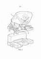
[0028] A figura 1 é uma vista de plano de um sistema cirúrgico ro- bótico minimamente invasivo sendo usado para realizar uma cirurgia, de acordo com muitas modalidades.[0028] Figure 1 is a plan view of a minimally invasive robotic surgical system being used to perform surgery, according to many modalities.
[0029] A figura 2 é uma vista em perspectiva de um console de controle de cirurgião para um sistema de cirurgia robótico, de acordo com muitas modalidades.[0029] Figure 2 is a perspective view of a surgeon control console for a robotic surgery system, according to many modalities.
[0030] A figura 3 é uma vista em perspectiva de um carrinho eletrônico para um sistema cirúrgico robótico, de acordo com muitas modalidades.[0030] Figure 3 is a perspective view of an electronic cart for a robotic surgical system, according to many modalities.
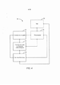
[0031] A figura 4 ilustra, diagramaticamente, um sistema cirúrgico robótico, de acordo com muitas modalidades.[0031] Figure 4 illustrates, diagrammatically, a robotic surgical system, according to many modalities.
[0032] A figura 5A é uma vista frontal de um carrinho do lado do paciente (robô cirúrgico) de um sistema cirúrgico robótico, de acordo com muitas modalidades.[0032] Figure 5A is a front view of a trolley on the patient's side (surgical robot) of a robotic surgical system, according to many modalities.
[0033] A figura 5B é uma vista frontal de um instrumento cirúrgicorobótico.[0033] Figure 5B is a front view of a surgical instrument.
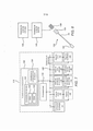
[0034] A figura 6 ilustra, diagramaticamente, um conjunto robótico tendo dois eixos de transmissão deslocados dentro de um eixo principal girável, de acordo com muitas modalidades.[0034] Figure 6 illustrates, diagrammatically, a robotic assembly having two transmission axes displaced within a rotatable main axis, according to many modalities.
[0035] A figura 7 ilustra diagramaticamente a integração de componentes do conjunto robótico da figura 6 com um controlador, de acordo com muitas modalidades.[0035] Figure 7 illustrates diagrammatically the integration of components of the robotic set of figure 6 with a controller, according to many modalities.
[0036] A figura 8 ilustra diagramaticamente um instrumento robótico e um sistema robótico associado, de acordo com muitas modalidades.[0036] Figure 8 illustrates diagrammatically a robotic instrument and an associated robotic system, according to many modalities.
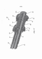
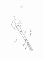
[0037] A figura 9 é uma vista em perspectiva de um instrumento robótico que é montável liberavelmente em um manipulador de instrumento robótico, de acordo com muitas modalidades.[0037] Figure 9 is a perspective view of a robotic instrument that can be releasably mounted on a robotic instrument manipulator, according to many modalities.
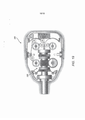
[0038] A figura 10 é uma vista em perspectiva da extremidade proximal de um instrumento robótico da figura 9, mostrando um conjunto de atuação, de acordo com muitas modalidades.[0038] Figure 10 is a perspective view of the proximal end of a robotic instrument in Figure 9, showing a set of actions, according to many modalities.
[0039] A figura 11 é uma vista em perspectiva de uma seção transversal do conjunto de atuação da figura 10, ilustrando componentes usados para atuar um primeiro eixo de transmissão deslocado interno, de acordo com muitas modalidades.[0039] Figure 11 is a perspective view of a cross section of the actuation set of figure 10, illustrating components used to act on a first displaced internal transmission shaft, according to many modalities.
[0040] A figura 12 é uma vista em perspectiva ilustrando componentes do conjunto de atuação da figura 10 que são usados para atuar um segundo eixo de transmissão deslocado interno, de acordo com muitas modalidades.[0040] Figure 12 is a perspective view illustrating components of the actuation set of figure 10 that are used to act a second internal displaced transmission axis, according to many modalities.
[0041] A figura 13 é uma vista em perspectiva de uma seção transversal do conjunto de atuação da figura 10, ilustrando vários componentes e o roteamento de cabos de controle de efetor de extremidade , de acordo com muitas modalidades.[0041] Figure 13 is a perspective view of a cross section of the actuation set of figure 10, illustrating various components and the routing of end effector control cables, according to many modalities.
[0042] A figura 14 é uma vista seccional transversal do conjunto de atuação da figura 10, ilustrando vários componentes e o roteamento dos cabos de controle de efetor de extremidade , de acordo com muitas modalidades.[0042] Figure 14 is a cross-sectional view of the actuation set of figure 10, illustrating various components and the routing of the end effector control cables, according to many modalities.
[0043] A figura 15A é uma vista em perspectiva de uma montagem de acoplamento de eixo principal usada para acoplar um eixo principal girável com um chassi de instrumento proximal, mostrando aberturas através das quais eixos de transmissão deslocados, montados internamente, são acionados e dentes de engrenagem externa que são usados para girar o eixo principal , de acordo com muitas modalidades.[0043] Figure 15A is a perspective view of a main shaft coupling assembly used to couple a rotatable main shaft with a proximal instrument chassis, showing openings through which displaced, internally mounted transmission shafts are driven and teeth. of external gear that are used to rotate the main shaft, according to many modalities.
[0044] A figura 15B é uma vista em perspectiva de um subconjunto interno que inclui dois eixos de transmissão deslocados internos e montagens de suporte associadas, de acordo com muitas modalidades.[0044] Figure 15B is a perspective view of an internal subset that includes two internal displaced transmission shafts and associated support assemblies, according to many modalities.
[0045] A figura 15C é uma vista em perspectiva mostrando a combinação dos componentes das figuras 15A e 15B, de acordo com muitas modalidades.[0045] Figure 15C is a perspective view showing the combination of the components of figures 15A and 15B, according to many modalities.
[0046] A figura 16 é uma vista em perspectiva de um conjunto de atuação tendo uma configuração de contagem de parte reduzida, de acordo com muitas modalidades.[0046] Figure 16 is a perspective view of an actuation set having a reduced part count configuration, according to many modalities.
[0047] A figura 17 é uma vista seccional transversal em perspectiva do conjunto de atuação da figura 16.[0047] Figure 17 is a cross-sectional perspective view of the set of action in Figure 16.
[0048] As figuras 18A e 18B são vistas de extremidades proximal e distai, respectivamente, do conjunto de atuação da figura 16.[0048] Figures 18A and 18B are seen from proximal and distal ends, respectively, from the action set of figure 16.
[0049] A figura 19 é uma ilustração em vista de plano da integração do conjunto de atuação da figura 16 dentro de um chassi de instrumento proximal, de acordo com muitas modalidades.[0049] Figure 19 is an illustration in plan view of the integration of the set of action of figure 16 within a chassis of proximal instrument, according to many modalities.
[0050] A figura 20 é uma ilustração diagramática simplificada de um conjunto cirúrgico, de acordo com muitas modalidades.[0050] Figure 20 is a simplified diagrammatic illustration of a surgical set, according to many modalities.
[0051] A figura 21 é um fluxograma de um método para transmissão de torque através de um eixo de transmissão deslocado roteado dentro de um eixo principal girável, de acordo com muitas modalidades.[0051] Figure 21 is a flow chart of a method for transmitting torque through a displaced transmission shaft routed within a rotatable main shaft, according to many modalities.
[0052] A figura 22 é um fluxograma de um método cirúrgico minimamente invasivo, de acordo com muitas modalidades.[0052] Figure 22 is a flow chart of a minimally invasive surgical method, according to many modalities.
[0053] Mecanismos, conjuntos, sistemas, instrumentos e métodos incorporando o uso de um eixo de transmissão deslocado dentro de um membro independentemente giratório são proporcionados. Esses mecanismos, conjuntos, sistemas, instrumentos e métodos podem ser particularmente benéficos para uso em cirurgia, por exemplo, em cirurgia minimamente invasiva, cirurgia robótica minimamente invasiva, bem como outros tipos de cirurgia. Embora as várias modalidades aqui divulgadas serem descritas principalmente com relação às aplicações cirúrgicas, mecanismos, conjuntos, sistemas, instrumentos e métodos podem ser usados em uma ampla variedade de aplicações, no interior e fora do corpo humano, bem como em aplicações não cirúrgicas.[0053] Mechanisms, assemblies, systems, instruments and methods incorporating the use of a displaced transmission shaft within an independently rotating member are provided. These mechanisms, sets, systems, instruments and methods can be particularly beneficial for use in surgery, for example, in minimally invasive surgery, minimally invasive robotic surgery, as well as other types of surgery. Although the various modalities disclosed here are described mainly in relation to surgical applications, mechanisms, assemblies, systems, instruments and methods can be used in a wide variety of applications, inside and outside the human body, as well as in non-surgical applications.
[0054] Fazendo referência agora aos desenhos, em que numerais de referência semelhantes representam partes semelhantes por todas as diversas vistas, a figura 1 é uma ilustração em vista de plano de um sistema Cirúrgico Robótico Minimamente Invasivo (MIRS) 10, tipicamente usado para realização de um procedimento diagnóstico ou cirúrgico minimamente invasivo em um Paciente 12, que está deitado sobre uma mesa de operação 14. O sistema pode incluir um Console de Cirurgião 16 para uso por um cirurgião 18 durante o procedimento. Um ou mais Assistentes 20 também podem participar no procedimento. O sistema de MIRS 10 pode ainda incluir um Carrinho do Lado do Paciente 22 (robô cirúrgico) e um Carrinho Eletrônico 24. O Carrinho do Lado do Paciente pode manipular pelo menos um conjunto de instrumento acoplado removivelmente 26 (daqui em diante referido, sim- plesmente, como "instrumento") através de uma incisão minimamente invasiva no corpo de paciente 12, enquanto o cirurgião 18 vê o local cirúrgico através do console 16. Uma imagem do local cirúrgico pode ser obtida por um endoscópio 28, tal como um endoscópio estereoscópico , que pode ser manipulado pelo Carrinho do Lado do Paciente 22, de modo a orientar o endoscópio 28. O Carrinho Eletrônico 24 pode ser usado para processar as imagens do local cirúrgico para exposição subsequente para o Cirurgião 18 através do Console de Cirurgião 16. O número de instrumentos cirúrgicos 26 usados de uma vez, em geral, dependerá do procedimento diagnóstico ou cirúrgico e as restrições do espaço dentro da sala de operações entre outros fatores. Se for necessário mudar um ou mais dos instrumentos 26 que estão sendo usados durante um procedimento, um Assistente 20 pode remover o instrumento 26 do Carrinho do Lado do Paciente 22 e substi- tuí-lo por outro instrumento 26 de uma bandeja 30 na sala de operações.[0054] Referring now to the drawings, in which similar reference numerals represent similar parts from all the different views, figure 1 is an illustration in plan view of a Minimally Invasive Robotic Surgical system (MIRS) 10, typically used for realization of a minimally invasive diagnostic or surgical procedure on a
[0055] A figura 2 é uma vista em perspectiva do Console de Cirurgião 16. O Console de Cirurgião 16 inclui um visor para o olho esquerdo 32 e um visor para o olho direito 34 para apresentar o Cirurgião 18 com uma visão estéreo coordenada do local cirúrgico , que permite percepção de profundidade. O console 16 ainda um ou mais dispositivos de controle de entrada 36, que, por sua vez, faz o Carrinho do Lado do Paciente 22 (mostrado na figura 1) para manipular um ou mais instrumentos. Os dispositivos de controle de entrada 36 proporcionarão os mesmos grãos de liberdade que seus instrumentos associados 26 (mostrados na figura 1) de modo a proporcionar ao Cirurgião tele- presença ou a percepção de que os dispositivos de controle de entrada 36 são integrais com os instrumentos 26, de modo que o Cirurgião tem um forte sendo de controle direto dos instrumentos 26. Com essa finalidade, sensores de posição, força e realimentação tátil (não mos- trados) podem ser empregados para transmitir posição, força e sensações táteis dos instrumentos 26 de volta para as mãos do Cirurgião através dos dispositivos de controle de entrada 36.[0055] Figure 2 is a perspective view of the
[0056] O Console de Cirurgião 16, usualmente, está localizado na mesma sala que o paciente, de modo que o Cirurgião pode monitorar, diretamente, o procedimento, estar presente fisicamente, se necessário, e falar para um Assistente diretamente, em lugar de através do telefone ou outro meio de comunicação. Contudo, o Cirurgião pode estar localizado em uma sala diferente, um prédio completamente diferente ou outra localização remota do Paciente, permitindo procedimentos cirúrgicos remotos (isto é, operando do lado de fora do campo estéril).[0056] The
[0057] A figura 3 é uma vista em perspectiva do Carrinho Eletrônico 24. O Carrinho Eletrônico 24 pode ser acoplado com o endoscópio 28 e pode incluir um processador para processar imagens capturadas para subsequente visualização, tal como para um Cirurgião no Console de Cirurgião ou em outra tela adequada localizada localmente e/ ou remotamente. Por exemplo, onde um endoscópio estereoscópico é usado, o Carrinho Eletrônico 24 pode processar as imagens capturadas de modo a apresentar ao Cirurgião imagens estéreos coordenadas do local cirúrgico. Essa coordenação pode inclui alinhamento entre as imagens opostas e pode incluir o ajusta da distância de trabalho estéreo do endoscópio estereoscópico. Como outro exemplo, o processamento de imagem pode incluir o uso de parâmetros de calibra- ção de câmera previamente determinados de modo a compensar erros de formação de imagens do dispositivo de captura de imagens, tais como aberrações ópticas.[0057] Figure 3 is a perspective view of the
[0058] A figura 4 ilustra diagramaticamente um sistema cirúrgico robótico 50 (tal como o sistema Ml RS 10 da figura 1). Como discutido acima, um Console de Cirurgião 52 (tal como o Console de Cirurgião 16 na figura 1) pode ser usado por um Cirurgião para controlar um Carrinho do Lado do Paciente (robô cirúrgico) 54 (tal como um Carrinho do Lado do Paciente 22 na figura 1), durante um procedimento minimamente invasivo. O Carrinho do Lado do Paciente 54 pode usar um dispositivo de formação de imagens, tal como um endoscópio estereoscópico, para capturar imagens do local do procedimento e enviar as imagens capturadas para um Carrinho Eletrônico 56 (tal como o Carrinho Eletrônico 24 na figura 1). Como discutido acima, o Carrinho Eletrônico 56 pode processar as imagens capturadas em uma variedade de maneiras antes de qualquer visualização subsequente. Por exemplo, o Carrinho Eletrônico 56 pode sobrepor as imagens capturadas com uma interface de controle virtual antes da exposição das imagens combinadas ao Cirurgião via o Console de Cirurgião 52. O Carrinho do Lado do Paciente 54 pode enviar as imagens capturadas para processamento do lado de fora do Carrinho Eletrônico 56. Por exemplo, o Carrinho do Lado do Paciente 54 pode enviar as imagens capturadas para um processador 58, que pode ser usado para processar as imagens capturadas. As imagens também podem ser processadas através de uma combinação do Carrinho Eletrônico 56 e do processador 58, que podem ser acoplados juntos de modo a processar as imagens capturadas conjuntamente, sequencialmente e/ ou outras combinações dos mesmos. Uma ou mais telas separadas 60 também podem ser acopladas com o processador 58 e/ ou o Carrinho Eletrônico 56 para visualização local e/ ou remota de imagens, tais como imagens do local do procedimento ou outras imagens relacionadas.[0058] Figure 4 diagrammatically illustrates a robotic surgical system 50 (such as the
[0059] As figuras 5A e 5B mostram um Carrinho do Lado do Paciente 22 e um instrumento cirúrgico 62, respectivamente. O instrumento cirúrgico 62 é um exemplo dos instrumentos cirúrgicos 26. O Carrinho do Lado do Paciente 22 mostrado proporciona a manipulação de três instrumentos cirúrgicos 26 e um dispositivo de formação de imagens 28, tal como um endoscópio estereoscópico usado para a captura de imagens do local do procedimento. A manipulação é proporcionada por mecanismos robóticos tendo um número de juntas robóticas. O dispositivo de formação de imagens 28 e os instrumentos cirúrgicos 26 podem ser posicionados e manipulados através de incisões no paciente, de modo que um centro remoto cinemático é mantido na incisão, de modo a minimizar o tamanho da incisão. Imagens do local cirúrgico podem incluir imagens das extremidades distais dos instrumentos cirúrgicos 26, quando são posicionados dentro do campo de visão do dispositivo de formação de imagens 28.[0059] Figures 5A and 5B show a
[0060] A figura 6 ilustra diagramaticamente um conjunto robótico 70 tendo dois eixos de transmissão deslocados dentro de um eixo principal girável, de acordo com muitas modalidades. O conjunto robótico 70 inclui um efetor de extremidade 72 que é acoplado com a extremidade distal de um eixo principal girável 74 e um conjunto de atuação 76 acoplado com o eixo principal 74 e o efetor de extremidade 72.[0060] Figure 6 diagrammatically illustrates a
[0061] O efetor de extremidade 72 inclui uma base de efetor de extremidade, um primeiro mecanismo de atuação 78, um segundo mecanismo de atuação 80 e mecanismo(s) de cabo de controle 82. A base de endoscópio estereoscópico é acoplada articuladamente ao eixo principal girável 74. O primeiro mecanismo de atuação 78 e o segundo mecanismo de atuação 80 são eixos acionados e podem ser usados para atuar e/ ou articular uma variedade de recursos e/ ou dispositivos de efetor de extremidade , por exemplo, um recurso de aperto, um recurso de corte móvel, um dispositivo de corte e grampeamento ou ou-tro recurso e/ ou dispositivo de efetor de extremidade adequado que pode ser atuado e/ ou articulado com um mecanismo acionado por eixo. O(s) mecanismo(s) de cabo de controle 82 também pode(m) ser usado(s) para atuar e/ ou articular uma variedade de recursos e/ ou dispositivos de efetor de extremidade, particularmente aqueles onde uma resposta rápida é desejada, por exemplo, um recurso de aperto, um eixo principal para o pulso de base de efetor de extremidade que é usado para articular a base do efetor de extremidade em relação ao eixo principal ou outro recurso e/ ou dispositivo adequado que pode ser atuado e/ ou articulado via um ou mais cabos de controle.[0061] The
[0062] A base do efetor de extremidade é acoplada com o eixo principal girável 74, de modo que uma rotação do eixo principal 74 em torno de um eixo geométrico rotacional de eixo principal produz uma rotação correspondente da base de efetor de extremidade. Conforme discutido acima, a capacidade de girar independentemente o eixo principal 74 proporciona capacidade aumentada de manobra do efetor de extremidade em relação a um eixo principal não giratório, o que pode ser benéfico durante certos procedimentos cirúrgicos, por exemplo, durante certos procedimentos cirúrgicos minimamente invasivos. A base de efetor de extremidade também pode ser acoplada com o eixo principal girável 74 com um mecanismo de pulso adequado 84 que proporciona capacidade de manobra de efetor de extremidade adicional.[0062] The base of the end effector is coupled with the rotatable
[0063] Dois eixos de transmissão são usados para acionar os mecanismos de atuação acionados por eixo de efetor de extremidade. Um primeiro eixo de transmissão 86 é montado para rotação em torno de um eixo geométrico rotacional de primeiro eixo de transmissão, que é deslocado do eixo geométrico rotacional do eixo principal. O primeiro eixo de transmissão 86 é acoplado operativamente com o primeiro mecanismo de atuação 78. Igualmente , um segundo eixo de transmissão 88 é montado para rotação em torno de um eixo geométrico rotacional de segundo eixo de transmissão, que é deslocado do eixo geométrico rotacional do eixo principal. O segundo eixo de transmissão 88 é acoplado operativamente com o segundo mecanismo de atuação 80.[0063] Two transmission shafts are used to drive the actuation mechanisms driven by the end effector shaft. A
[0064] O conjunto de atuação 76 é acoplado com o eixo principal girável 74, o primeiro eixo de transmissão 86, o segundo eixo de transmissão 88 e o(s) mecanismo(s) de cabo de controle 82. O eixo principal girável 74 é montado para rotação em relação a uma base do conjunto de atuação 76. O conjunto de atuação 76 é operável para produzir a rotação do eixo principal girável 74 em relação à base. O conjunto de atuação 76 também é operável para gerar qualquer combinação de rotação do eixo principal girável 74 em relação à base, rotação do primeiro eixo de transmissão 86 em relação ao eixo principal girável 74 e rotação do segundo eixo de transmissão 88 em relação ao eixo principal girável 74.[0064] The actuation set 76 is coupled with the rotatable
[0065] O conjunto de atuação 76 é configurado para proporcionar a funcionalidade descrita acima em que o primeiro eixo de transmissão 86 e o segundo eixo de transmissão 88 pode ser girados independentemente em relação ao eixo principal girável 74, mesmo durante a rotação do eixo principal girável 74 em relação à base. O conjunto de atuação 76 inclui um motor de eixo principal 90 acoplado com um codificador de eixo principal 92 e uma interface de eixo principal 94, um primeiro motor 96 acoplado com um primeiro codificador 98 e uma primeira interface 100, um segundo motor 102 acoplado com um segundo codificador 104 e uma segunda interface 106 e um (nos) motor (es) de cabo de controle 108 acoplado com um(ns) codificador(es) de cabo de controle 110 e uma(s) interface(s) de cabo de controle 112. A interface de eixo principal 94 é acoplada com o eixo principal girável 74 de modo a transferir movimento rotacional do motor de eixo princi-pal 90 para o eixo principal girável 74. O motor de eixo principal 90 pode ser acoplado fixamente com a base de modo que o movimento rotacional transferido resulta na rotação do eixo principal girável 74 em relação à base. O codificador de eixo principal 92 mede a orientação do motor de eixo principal 90, a interface de eixo principal 94 e/ ou o eixo principal girável 74 e pode ser acoplado com um controlador (não mostrado na figura 6) de modo a proporcionar ao controlador a orientação medida. A primeira interface 100 é acoplada com o primeiro eixo de transmissão 86 de modo a ser operável para transferir movimento rotacional do primeiro motor 96 para o primeiro eixo de transmissão 86 durante qualquer orientação e/ ou movimento rotacional do eixo principal girável 74. O primeiro codificador 98 mede a orientação do primeiro motor 96, a primeira interface 100 e/ ou o primeiro eixo de transmissão 86 e pode ser acoplado com o controlador de modo a proporcionar ao controlador a orientação medida. A segunda interface 106 é acoplada com o segundo eixo de transmissão 88 de modo a ser operável para transferir movimento rotacional do segundo motor 102 para o segundo eixo de transmissão 88 durante qualquer orientação e/ ou movimento rotacional do eixo principal girável 74. O segundo codificador 104 mede a orientação do segundo motor 102, da segunda interface 106 e/ ou do segundo eixo de transmissão 88 e pode ser acoplado com o controlador de modo a proporcionar ao controlador a orientação medida. A(s) interface(s) de cabo de controle 112 é acoplada com o(s) cabo(s) de controle 114 que são acoplados operativamente com o(s) mecanismo^) de cabo de controle 82. O(s) cabo de controle 114 podem ser roteados de modo a tolerar uma faixa de orientações rotacionais do eixo principal girável 74, por exemplo, ao serem roteados nas proximidades do eixo geométrico rotacional do eixo principal para minimizar mudanças no comprimento do cabo de controle devido à rotação do eixo principal girável 74. e por serem configurados para tolerar qualquer torção de cabo(s) de controle e/ ou torção entre cabos de controle que podem resultar para algumas orientações rotacionais do eixo principal 74 (por exemplo, tendo uma construção que tolera atrito de cabo com cabo). O(s) codificador(es) de cabos de controle 110 mede a orientação do(s) motor(es) de cabo(s) de controle 108 e/ ou a(s) interfa- ce(s) de cabo de controle 112 e pode ser acoplado com o controlador de modo a proporcionar ao controlador a orientação medida.[0065] The actuation set 76 is configured to provide the functionality described above in which the
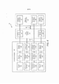
[0066] A figura 7 é um diagrama em blocos ilustrando a integração de componentes do conjunto robótico 70 com um controlador 116, de acordo com muitas modalidades. O controlador 116 inclui pelo menos um processador 118, que se comunica com um número de dispositivos periféricos via um subsistema de barramento 120. Esses dispositivos periféricos incluem, tipicamente, um subsistema de armazenamento 122.[0066] Figure 7 is a block diagram illustrating the integration of components of the
[0067] O subsistema de armazenamento 122 mantém a programação básica e construções de dados que proporcionam a funcionalidade do controlador 116. Módulos de software para implementação da funcionalidade do conjunto robótico, discutida acima são armazenados tipicamente no subsistema de armazenamento 122. O subsistema de armazenamento 122 inclui, tipicamente, um subsistema de memória 124 e um subsistema de armazenamento de arquivo 126.[0067] The
[0068] O subsistema de memória 124 inclui, tipicamente um número de memórias incluindo uma memória de acesso randômico principal (RAM) 128 para armazenamento de instruções e dados durante a execução do programa e uma memória somente de leitura (ROM) 130, em que instruções fixas são armazenadas.[0068]
[0069] O subsistema de armazenamento de arquivo 126 proporciona armazenamento persistente (não volátil) para arquivos de programas e de dados e pode incluir uma unidade de disco rígido, uma unidade de disco ou outra memória não volátil, tal como uma memória flash. Um dispositivo de entrada, por exemplo, uma unidade de disco, pode ser usado para entrada de módulos de software discutidos acima. Alternativamente, outras estruturas conhecidas, alternativamente, podem ser usadas para introdução dos módulos de software, por exemplo, uma porta USB.[0069] The
[0070] Neste contexto, o termo "subsistema de barramento" é usado genericamente de modo a incluir qualquer mecanismo para deixar os vários componentes e subsistemas se comunicarem uns com os outros, como pretendido. O subsistema de barramento 120 é mostrado esquematicamente como um barramento único, mas um sistema típico tem um número de barramentos, tais como um barramento local e um ou mais barramentos de expansão (por exemplo, ADB, SCSI, ISA, EISA, MCA, NuBus ou PCI), bem como portas seriais e paralelas.[0070] In this context, the term "bus subsystem" is used generically to include any mechanism for letting the various components and subsystems communicate with each other, as intended. The
[0071] O controlador 116 controla componentes do conjunto robótico 70 em resposta aos variados sinais recebidos, incluindo sinais do(s) dispositivo(s) de controle de entrada 36 (mostrados na figura 2), bem como do codificador de eixo principal 92, o primeiro codificador 98, o segundo codificador 104 do(s) codificador(es) de cabo de controle 110. Os componentes controlados incluem o motor de eixo principal 90, o primeiro motor 96, o segundo motor 102 e o(s) motor(es) de cabo de controle 108. Componentes adicionais (não mostrados), tais como conversores de digital/ analógico, podem ser usados para interface de componentes com o controlador 116.[0071]
[0072] A figura 8 é um diagrama em blocos simplificado, ilustrando a integração de um instrumento cirúrgico robótico 132 dentro de um sistema cirúrgico robótico 132, de acordo com muitas modalidades. O instrumento 132 inclui um chassi de instrumento proximal 134, configurado para ser montável, liberavelmente em um manipulador 136 tendo uma interface de instrumento, configurada para interface com o instrumento proximal 134. O instrumento 132 ainda inclui um eixo principal alongado 74, que é montado para girar em relação ao chassi de instrumento proximal 134, quando girado por um motor de eixo principal, conforme discutido acima. Um efetor de extremidade 140 está acoplado com uma extremidade distal do eixo principal 74 de modo a girar junto com o eixo principal. Um sistema de controle principal 142 é acoplado operativamente com o manipulador 136. Um sistema de controle principal 142 também pode ser acoplado operativamente com o manipulador 136. A combinação do sistema de controle principal 142 e do sistema de controle auxiliar 144 pode ser usada para controlar todas as articulações possíveis do instrumento 132 via o manipulador 136. Por exemplo, o sistema de controle auxiliar 144 pode controlar os motores de acionamento para rotação de primeiro eixo de transmissão e rotação de segundo eixo de transmissão. O sistema de controle principal 142 pode controlar um motor de acionamento para rotação do eixo principal e um ou mais motores de acionamento de cabos de controle. Esse controlador auxiliar pode ser usado para suplementar configurações existentes de cirurgia robótica, de modo a permitir o uso dos instrumentos robóticos presentemente divulgados, tendo um ou mais eixos de transmissão deslocados roteados dentro de um eixo principal independentemente giratório.[0072] Figure 8 is a simplified block diagram, illustrating the integration of a robotic
[0073] A figura 9 é uma vista em perspectiva de um instrumento cirúrgico robótico 132, de acordo com muitas modalidades. Conforme discutido acima, o instrumento 132 inclui um chassi de instrumento proximal 134, configurado para ser montável de modo liberável em um manipulador de instrumento 136. O eixo principal girável 74 acopla o efetor de extremidade 140 com o chassi de instrumento proximal 134.[0073] Figure 9 is a perspective view of a robotic
[0074] A figura 10 é uma vista em perspectiva do chassi de instrumento proximal 134 da figura 9 (sem a cobertura), mostrando um conjunto de atuação 142, de acordo com muitas modalidades. O conjunto de atuação 142 inclui um primeiro motor 96 para atuação de um primeiro eixo de transmissão deslocado e um segundo motor 102 para atuação de um segundo eixo de transmissão deslocado.. Os vários codificadores discutidos acima (por exemplo, o codificador de eixo principal 92, o primeiro codificador 98, o segundo codificador 104 e o(s) codificador(es) de cabo de controle 110) podem ser integrados dentro do conjunto de atuação 142. O primeiro motor 98 é acoplado com um conjunto de pinos de conexão elétrica 144, configurados para acoplar com o conector elétrico correspondente que é acoplado com um controlador para acionar, seletivamente, o primeiro motor 96. Igualmente, o segundo motor 102 é acoplado com um conjunto de pinos de conexão elétrica 146, configurados para acoplar com um conector elétrico correspondente, que é acoplado com o controlador para acionar, seletivamente, o segundo motor 102.[0074] Figure 10 is a perspective view of the
[0075] A figura 11 é uma vista em perspectiva de uma seção transversal do conjunto de atuação 142 da figura 10, ilustrando componentes usados para atuar um primeiro eixo de transmissão deslocado interno, de acordo com muitas modalidades. O primeiro motor 96 é acoplado rotacionalmente com um engrenagem de primeiro motor 148. A engrenagem de primeiro motor 148 encaixa e aciona uma engrenagem proximal de primeiro eixo de acoplamento 150, que aciona um primeiro eixo de acoplamento 152. O eixo de acoplamento 152, por sua vez, gira uma engrenagem distai de primeiro eixo de acoplamento 154 encaixa uma primeira engrenagem anular 156, que inclui dentes de engrenagem externa 158, que encaixam a engrenagem distai de primeiro eixo de acoplamento 154 e dentes de endoscópio interna de anel 160. A primeira engrenagem anular 156 é montada para girar em torno da linha central do eixo principal girável 74 via um primeiro mancai de engrenagem anular 162. O primeiro eixo de transmissão 86 é montado em torno de um eixo geométrico rotacional de primeiro eixo de transmissão que é deslocado do eixo geométrico rotacional de eixo principal girável. O primeiro eixo de transmissão 86 é montado no eixo principal via dois mancais de suporte de primeiro eixo de transmissão 164. O primeiro eixo de transmissão 86 é acoplado com uma engrenagem de primeiro eixo de transmissão 166, que inclui dentes de engrenagem externa que se projetam CE uma abertura em uma montagem de acoplamento de eixo principal 168 de modo a encaixar os dentes de engrenagem interna 160 da primeira engrenagem anular 156. Em operação, a rotação do primeiro motor 96 gira a engrenagem de primeiro motor 148, que gira a engrenagem proximal de primeiro eixo de acoplamento 150, que gira o eixo de acoplamento 162, que gira a engrenagem distai de primeiro eixo de acoplamento 154, que gira a engrenagem de primeiro eixo de acoplamento 166, que gira o primeiro eixo de transmissão 85 em relação ao eixo principal 74.[0075] Figure 11 is a perspective view of a cross section of the
[0076] Em muitas modalidades, o conjunto de atuação 142 é destinado a acomodar uma faixa de movimento axial do primeiro eixo de transmissão 86, por exemplo, através de projeção da primeira engrenagem anular 156 e da abertura na montagem de acoplamento de eixo principal 168 para uma faixa de movimento axial do primeiro eixo de transmissão 86 (por exemplo, através do aumento da dimensão da abertura e da engrenagem anular 156 na direção do movimento axial do primeiro eixo de transmissão 86 através de um tamanho suficiente para acomodar os dentes de engrenagem projetantes da engrenagem de primeiro eixo de transmissão 166, assim, permitindo que a engrenagem de primeiro eixo de transmissão 166 deslize axialmente em relação aos dentes de engrenagem interna de anel da primeira engrenagem anular 156). Esse movimento axial do primeiro eixo de transmissão 86 pode ocorrer durante articulação de uma base de efetor de extremidade em relação ao eixo principal onde a base de efetor de ex-tremidade gira em torno de um eixo pulso que é deslocado da linha central do primeiro eixo de transmissão 86.[0076] In many embodiments,
[0077] A figura 11 também ilustra componentes de atuação usados para atuar o segundo eixo de transmissão interno 88, de acordo com muitas modalidades. O segundo eixo de transmissão 88 é montado para girar em torno de um eixo geométrico rotacional de segundo eixo de transmissão que é deslocado do eixo geométrico rotacional de eixo principal girável. O segundo eixo de transmissão 88 é montado no eixo principal via segundos mancais de suporte de eixo de transmissão 170. O segundo eixo de transmissão 88 é acoplado com uma engrenagem de segundo eixo de transmissão 172, que inclui dentes de engrenagem externa que se projetam de uma abertura em uma montagem de acoplamento de eixo principal 168 de modo a encaixar dentes de engrenagem interna de anel de uma segunda engrenagem anular 174. A segunda engrenagem anular 174 é montada para girar em torno da linha central do eixo principal girável 74 via um segundo mancai de engrenagem anular 175. Conforme discutido acima com relação ao primeiro eixo de transmissão, o conjunto de atuação 142 também pode ser projetado para acomodar uma faixa de movimento axial do segundo eixo de transmissão 88, por exemplo, através da projeção da segunda engrenagem anular 174 e da abertura na montagem de acoplamento de eixo principal 158 para uma faixa de movimento axial do segundo eixo de transmissão 88.[0077] Figure 11 also illustrates actuation components used to act on the second
[0078] A figura 12 é uma vista em perspectiva ilustrando componentes do conjunto de atuação 142 da figura 10 que são usados para atuar um segundo eixo de transmissão deslocado interno, de acordo com muitas modalidades.O segundo motor 102 é acoplado rotacio- nalmente com uma engrenagem de segundo motor 176. A engrenagem de segundo motor 176 encaixa e aciona uma engrenagem proximal de segundo eixo de acoplamento 178, que aciona um segundo eixo de acoplamento 180. O segundo eixo de acoplamento 180, por sua vez, gira um engrenagem distai de segundo eixo de acoplamento 182. A engrenagem distai de segundo eixo de acoplamento 182 encaixa a segunda engrenagem anular 174, que inclui dentes de engrenagem externa que encaixam a engrenagem distai de segundo eixo de acoplamento 182 e os dentes de engrenagem interna de anel. A segunda engrenagem anular 174 é montada para girar em torno da linha central do eixo principal girável via um segundo mancai de engrenagem anular. Em operação, a rotação do segundo motor 102 gira a engrenagem de segundo motor 176, que gira a engrenagem proximal de segundo eixo de acoplamento 182, que gira a segunda engrenagem anular 174., que gira a engrenagem de segundo eixo de transmissão 172, que gira o segundo eixo de transmissão88 em relação ao eixo principal girável 74.[0078] Figure 12 is a perspective view illustrating components of
[0079] Em muitas modalidades, a montagem de acoplamento de eixo principal 168 inclui dentes de engrenagem externa 184 encaixados com uma interface de eixo principal 94 (não mostrada) que é acionada pelo motor de eixo principal 90 (na mostrado). A interface de eixo principal 94 e o motor de eixo principal 90 podem estar localizados em um manipulador de instrumento 136 (mostrado na figura 8) de modo a ser acoplado com a montagem de acoplamento de eixo principal 168, quando o chassi de instrumento proximal 134 é montado em um manipulador de instrumento 136.[0079] In many embodiments, the main
[0080] A figura 13 é uma vista em perspectiva de uma seção transversal de componentes do conjunto de atuação da figura 10, ilustrando vários componentes e o roteamento de cabos de controle de efetor de extremidade , de acordo com muitas modalidades. O chassi de instrumento proximal 134 inclui uma base 186 que proporciona uma base de montagem para vários componentes. A montagem de acoplamento de eixo principal 168 é montada para girar em relação à base 186 via dois mancais 188. A montagem de acoplamento de eixo principal 168 suporta o epg68 suporta o eixo principal girável 74. O eixo principal 74 tem um furo axial 20 através do qual o primeiro eixo de transmissão 86, o segundo eixo de transmissão 88 e dois pares de cabos de controle 144 são roteados. O primeiro eixo de transmissão 86 e o segundo eixo de transmissão 88 são deslocados da linha central da montagem de acoplamento de eixo principal 168 e do eixo principal girável 74, que permite que os cabos de controle 114 sejam roteados ao longo da linha central do eixo principal. Em muitas modalidades, a rotação do eixo principal em relação à base produz a torção dos cabos de controle 114 devido à rotação correspondente da base de efetor de extremidade em relação à base de chassi proximal 186. O roteamento dos cabos de controle 114 ao longo da linha central do eixo principal pode ajudar a reduzir impactos prejudiciais à operação dos cabos de controle que podem ocorrer em conexão com essa torção, por exemplo, através da redução das forças de atrito de cabo com cabo e/ ou pela redução de estiramento de cabo de controle associado.[0080] Figure 13 is a perspective view of a cross section of components of the actuation set of figure 10, illustrating various components and the routing of end effector control cables, according to many modalities. The
[0081] Em muitas modalidades, um par de cabos de controle é atuado por um mecanismo de atuação comum, por exemplo, por um eixo tracionador em torno do qual o par de cabos de controle é enrolado. Esse mecanismo de atuação comum pode ser usado para retrair um cabo de controle de um par de cabos de controle enquanto o outro cabo de controle do par é deixado sair por uma quantidade correspondente. A figura 13 ilustra um primeiro eixo tracionador 190 para atuar um primeiro par de cabos de controle e um segundo eixo tracionador 192 para atuar um segundo par de cabos de controle.[0081] In many modalities, a pair of control cables is actuated by a common actuation mechanism, for example, by a capstan around which the pair of control cables is wrapped. This common actuation mechanism can be used to retract a control cable from a pair of control cables while the other control cable from the pair is let out by a corresponding amount. Figure 13 illustrates a
[0082] Em muitas modalidades, o primeiro eixo de transmissão 86 é acoplado rotacionalmente com uma extensão de primeiro eixo de transmissão 200 via um primeiro acoplamento 194 que acopla uma extremidade distal do primeiro eixo de transmissão 86 com uma extremidade proximal da extensão do primeiro eixo de transmissão 200. O primeiro acoplamento estriado 194 também pode proporcionar a acomodação de uma faixa de movimento axial da extensão do primeiro eixo de transmissão 200, que, conforme discutido acima, pode resultar durante a articulação da base de efetor de extremidade em relação ao eixo principal , devido à extensão 200 do primeiro eixo de transmissão 200 ser deslocada da linha central do eixo principal Igualmente, um segundo acoplamento estriado 196 pode ser usado em conexão com o segundo eixo de transmissão deslocado 88 e pode proporcionar benefícios similares.[0082] In many embodiments, the
[0083] A figura 14 é uma vista seccional transversal de componentes do conjunto de atuação da figura 10, ainda ilustrando vários componentes e o roteamento dos cabos de controle do efetor de extremidade , de acordo com muitas modalidades. O dentes de engrenagem interna de anel da primeira engrenagem anular 156 interagem com a engrenagem de primeiro eixo de transmissão 166 de modo que a rotação da primeira engrenagem anular 156 em relação à montagem de acoplamento de eixo principal produz uma rotação correspondente do primeiro eixo de transmissão 86 em relação à montagem de acoplamento de eixo principal. Os dentes de engrenagem interna de anel da segunda engrenagem anular 174 em relação à montagem de acoplamento de eixo principal produz uma rotação correspondente do se-gundo eixo de transmissão 88 em relação à montagem de acoplamento de eixo principal.[0083] Figure 14 is a cross-sectional view of components of the actuation set of figure 10, still illustrating several components and the routing of the control cables of the end effector, according to many modalities. The inner ring gear teeth of the first
[0084] A figura 15A é uma vista em perspectiva da montagem de acoplamento de eixo principal 168, de acordo com muitas modalidades. A montagem de acoplamento de eixo principal 168 inclui um número de aberturas, fendas, furos de prendedores, bem como dentes de engrenagem externa. Uma primeira abertura 206 acomoda os dentes de engrenagem projetantes da engrenagem de segundo eixo de transmissão 172. Uma terceira abertura 210 acomoda um recurso pro- jetante de uma montagem de suporte de mancai de eixo de transmissão, usada para suportar a extremidade proximal do segundo eixo de transmissão. Um número de furos de prendedores 212 são proporcionados que acomodam recursos de montagem de mancai de suporte de eixo de transmissão. Em muitas modalidades, a montagem de acoplamento de eixo principal 168 inclui recursos simétricos de modo apermitir instalação reversível do primeiro e segundo eixos de transmissão. Os dentes de engrenagem externa 184 são usados para girar a montagem de acoplamento de eixo principal 168 em relação à base do chassi de instrumento proximal. Duas fendas 214 acomodam o primeiro acoplamento estriado 194 e o segundo acoplamento estriado 196.[0084] Figure 15A is a perspective view of the main
[0085] A figura 15B é uma vista em perspectiva de um subconjunto interno que inclui os dois eixos de transmissão deslocados internos e componentes de montagem de mancai de suporte, de acordo com muitas modalidades. A porção proximal de primeiro eixo de transmissão 198 e a porção proximal de segundo eixo de transmissão 202 são recebidas dentro dos mancais que são suportados por quatro montagens de suporte internas 216. As quatro montagens de suporte internas 216 são mantidas em posição dentro da montagem de acoplamento de eixo principal 168 via quatro montagens de suporte externas 218, que são acopladas com as montagens de suporte internas 216 via dois prendedores 220 por par de montagem.[0085] Figure 15B is a perspective view of an internal subset that includes the two internal displaced transmission shafts and support bearing assembly components, according to many modalities. The proximal portion of the
[0086] As figuras 15C e 15D são vistas mostrando a combinação dos componentes das figuras 15A e 15B, de acordo com muitas modalidades. A figura 15C é uma vista em perspectiva da combinação e a figura 15D mostra uma vista de extremidade, que mostra os prendedores 220, dentes de engrenagem externa 184, uma montagem de suporte externa 218, a engrenagem de primeiro eixo de transmissão 166, a engrenagem de segundo eixo de transmissão 172, duas montagens de suporte internas 216 e um anel retentor 222 usado para prender a extremidade proximal de segundo eixo de transmissão em relação a uma montagem de suporte interna 216. um espaço central 224 localizado entre montagens de suporte internas adjacentes 216 acomoda o roteamento dos cabos de controle (não mostrados).[0086] Figures 15C and 15D are seen showing the combination of the components of figures 15A and 15B, according to many modalities. Figure 15C is a perspective view of the combination and Figure 15D shows an end
[0087] Abordagens alternativas podem ser usadas para suportar um eixo de transmissão deslocado interno. Por exemplo, a figura 16 é uma vista em perspectiva de um conjunto de atuação 230 tendo uma configuração de contagem de parte reduzida. O conjunto de atuação 230 proporciona a atuação independente dos dois eixos de transmissão deslocados 86, 88 descritos acima, mas elimina alguns dos componentes descritos acima usados para suportar os dois eixos de transmissão deslocados 86, 88. O conjunto de atuação 230 inclui alguns dos componentes descritos acima, por exemplo, o primeiro eixo de transmissão 86 (oculto da visão), o segundo eixo de transmissão 88, a primeira engrenagem anular 156 e a segunda engrenagem anular 174. O conjunto de atuação 230 inclui uma montagem de acoplamento de eixo principal 168A que é configurada com suporte integrado para os mancais de suporte de eixo de transmissão. Similar à montagem de acoplamento de eixo principal 168 descrita acima, a monta-gem de acoplamento de eixo principal 168A inclui dentes de engrenagem externa 184 para encaixe com a interface de eixo principal 94 descrita acima (não mostrada).[0087] Alternative approaches can be used to support an internal displaced drive shaft. For example, figure 16 is a perspective view of an
[0088] A figura 17 é uma vista seccional transversal do conjunto de atuação 230, ilustrando detalhes da integração do suporte para os mancais de eixo de transmissão na montagem de acoplamento de eixo principal 168A. A montagem de acoplamento de eixo principal 168A é configurada com reentrâncias acessíveis externamente 232, 234, 236 que fazem interface com mancais de suporte de primeiro eixo de transmissão 164A, 164B e mancais de suporte de segundo eixo de transmissão 170A, 170B. anéis retentores 244, 246 são usados para reter os mancais de suporte 164A, 164B dentro da reentrância 234. Os anéis retentores 240, 242 são usados para reter os mancais de suporte 170A, 170B dentro da reentrância 236. A reentrância disposta dis- talmente 232 é moldada para acomodar a extremidade distal do primeiro eixo de transmissão 86. A reentrância disposta distalmente 232 é moldada para acomodar a extremidade distal do primeiro eixo de transmissão 86. A reentrância disposta proximalmente 234 é moldada para suportar os mancais de suporte dispostos proximalmente 164A, 164B e acomodar a extremidade proximal do primeiro eixo de trans-missão 86. A montagem de acoplamento de eixo principal 168A inclui um furo 238 configurado para receber deslizavelmente e acomodar o primeiro eixo de transmissão 86. A reentrância disposta distalmente 236 é moldada para suportar os mancais de suporte 170A, 170B e acomodar o segundo eixo de transmissão 88.[0088] Figure 17 is a cross sectional view of the actuation set 230, illustrating details of the support integration for the transmission shaft bearings in the main
[0089] O primeiro eixo de transmissão 86 pode ser montado no conjunto de atuação 230 usando a seguinte sequência de montagem. Primeiro, o mancai de suporte 164A é colocado em sua posição de instalado. O anel retentor 244 é, então, movido da extremidade proximal da montagem de acoplamento de eixo principal 168A para sua posição de instalado. Um subconjunto compreendendo a primeiro engrenagem anular 156 e o mancai de primeira engrenagem anular 162 é, então, movido da extremidade proximal da montagem de acoplamento de eixo principal 168A para sua posição de instalado. Um subconjunto compreendendo a primeira engrenagem anular 156 e o primeiro mancai de engrenagem anular 162 é, então, movido da extremidade proximal da montagem de acoplamento de eixo principal 168a para sua posição de instalado. O primeiro eixo de transmissão 86 é, então, instalado, através de rosqueamento da extremidade distal do primeiro eixo de transmissão 86 através do mancai de suporte 164A e através do furo 238. O mancai de suporte 164B é, então, deslizado ao longo da reentrância 234 para sua posição de instalado. Finalmente, o anel retentor 246 é, então, movido da extremidade proximal da montagem de acoplamento de eixo principal 168A para sua posição de instalado. Uma sequência similar pode ser usada para a instalação do segundo eixo de transmissão 88 no conjunto de atuação 230.[0089] The
[0090] As figuras 18a e 18B são vistas de extremidades proximal e distal, respectivamente, do conjunto de atuação 230. A figura 18A mostra o mancai de suporte localizado proximalmente 164B em relação à reentrância proximal 234 e ao primeiro eixo de transmissão 86. Os anéis retentores 240, 242, 244, 246 são moldados localmente para acomodar os mancais de suporte 170A, 170B, 164A, 164B, respectivamente. A figura 18B mostra as extremidades distais do primeiro eixo de transmissão 86 e do segundo eixo de transmissão 88, das reentrâncias associada 234, 236 na montagem de acoplamento de eixo principal 168A, bem como o mancai de suporte 170A disposto na reentrância 236.[0090] Figures 18a and 18B are seen from proximal and distal ends, respectively, of the
[0091] A figura 19 é uma ilustração em vista de plano da integração do conjunto de atuação 230 dentro de um chassi de instrumento proximal 250, de acordo com muitas modalidades. Além de suportar e atuar o conjunto de atuação 230, o chassi de instrumento proximal 250 ainda inclui a atuação e o roteamento de componentes para três pares de cabos de controle que são roteados dentro do eixo principal girável.[0091] Figure 19 is an illustration in plan view of the integration of actuation set 230 within a
[0092] A figura 20 é uma ilustração diagramática em vista em perspectiva simplificada de um conjunto cirúrgico 260, de acordo com muitas modalidades. O conjunto cirúrgico 260 inclui um mecanismo de atuação proximal 262, um eixo principal girável 264, um efetor de extremidade 266 e um mecanismo de pulso 268. O efetor de extremidade 266 pode incluir um ou mais mecanismos acionados de eixo (por exemplo, um mecanismo de aperto, um mecanismo de corte linear, um mecanismo de grampeamento). O conjunto cirúrgico 260 também pode incluir um ou mais mecanismos atuados por cabos, por exemplo, um mecanismo de atuação de cabo que articula uma base do efetor de extremidade em relação ao eixo principal via o mecanismo de pulso 268 e/ ou um mecanismo de atuação de cabo, que articula uma porção do efetor de extremidade em relação à base de efetor de extremidade. O mecanismo de atuação proximal 262 pode incluir o mecanismo de atuação discutido acima para a montagem e a atuação de um ou mais eixos de transmissão deslocados rateados dentro do eixo principal girável 264. O mecanismo de atuação proximal 262 pode ser configurado para uso em uma variedade de aplicações, por exemplo, como um dispositivo portátil com atuação manual e/ ou automatizada para a rotação do eixo principal 264 e/ ou um ou mais eixos de transmissão internos. Como tal, o conjunto cirúrgico 260 pode ter aplicações além da cirurgia robótica minimamente invasiva, por exemplo, cirurgia não robótica minimamente invasiva, cirurgia robótica não minimamente invasiva,cirurgia não minimamente invasiva não robótica, bem como outras aplicações onde o uso do um ou mais eixos de transmissão deslocados dentro de um eixo externo girável poderia ser benéfico.[0092] Figure 20 is a diagrammatic illustration in simplified perspective view of a 260 surgical set, according to many modalities.
[0093] A figura 21 é um diagrama de fluxo simplificado de um método 270 para transmitir torque através de um eixo de transmissão deslocado roteado dentro de um eixo principal girável,de acordo com muitas modalidades. Na etapa 272, um eixo principal é suportado para girar em relação a uma base. Na etapa 274, um eixo de transmissão é suportado para girar em relação ao eixo principal em torno de um eixo geométrico rotacional de esteira transportadora que é deslocado do eixo geométrico rotacional de eixo principal. na etapa 276, o eixo de transmissão deslocado é encaixado dom um recurso de transmissão tendo um eixo geométrico rotacional que é fixo em relação à base. Na etapa 278, o eixo principal é girado em relação à base. Na etapa 280, o eixo de transmissão é girado em relação ao eixo principal através da rotação do recurso de transmissão em relação ao eixo principal. As etapas do método 270 podem ser realizadas, por exemplo, usando as modalidades discutidas acima com relação às figuras de 6 a 19.[0093] Figure 21 is a simplified flow diagram of a
[0094] A figura 22 é um diagrama simplificado de um método cirúrgico minimamente invasivo 290, de acordo com muitas modalidades. Na etapa 292, um efetor de extremidade de um instrumento cirúrgico é introduzido em um local cirúrgico , por exemplo, um local cirúrgico interno, via uma abertura minimamente invasiva ou orifício natural do corpo. O efetor de extremidade é montado em uma extremidade distai de um eixo de instrumento alongado montado para girar em relação a uma base, de modo que o efetor de extremidade possa ser girado com o eixo de instrumento em relação à base. O efetor de extremidade é acoplado operativamente com um primeiro eixo de transmissão de modo que a rotação do primeiro eixo de transmissão em relação ao eixo de instrumento atua um primeiro mecanismo de efetor de extremidade , o primeiro eixo de transmissão sendo montado para girar em relação ao eixo de instrumento em torno de um eixo geométrico rotacional de primeiro eixo de transmissão que é deslocado do eixo geométrico rotacional do eixo de instrumento que é deslocado do eixo geométrico rotacional do instrumento. Na etapa 294, o efetor de extremidade é girado através da rotação do eixo de instrumento. Na etapa 296, uma tarefa cirúrgica é realizada com o efetor de extremidade por meio da atuação do primeiro mecanismo de efetor de extremidade.[0094] Figure 22 is a simplified diagram of a minimally invasive
[0095] Em muitas modalidades, o método 290 envolve o uso de um efetor de extremidade que é atuado por dois eixos de transmissão. Uma ampla faixa de mecanismos de efetor de extremidade pode ser atuado por eixo de transmissão. Por exemplo, o efetor de extremidade pode incluir um recurso de aperto atuado pelo primeiro eixo de transmissão. O efetor de extremidade pode incluir um recurso de corte móvel atuado pelo segundo eixo de transmissão. A tarefa cirúrgica pode incluir tecido de aperto com recurso de aperto e tecido de corte com recurso de corte móvel. O segundo eixo de transmissão pode ser montado para girar em relação ao eixo do instrumento em torno de um eixo geométrico rotacional de segundo eixo de transmissão, que é deslocado do eixo geométrico rotacional de eixo de instrumento. A efetor de extremidade pode incluir um dispositivo de corte e de grampeamento astuado pelo segundo eixo de transmissão. A tarefa cirúrgica pode incluir tecido de aperto com o recurso de aperto, tecido de grampeamento com o dispositivo de corte e grampeamento e tecido de corte com o dispositivo de corte e grampeamento..[0095] In many modalities,
[0096] Deve ser compreendido que os exemplos e modalidades aqui descritos são para fins ilustrativos e que várias modificações ou mudanças à luz dos mesmos serão sugeridas para pessoas habilidades na técnica e devem ser incluídos dentro do espírito e do alcance deste pedido e do escopo das reivindicações anexas. Numerosas combinações diferentes são possíveis e essas combinações devem ser consideradas como sendo parte da presente invenção.[0096] It should be understood that the examples and modalities described herein are for illustrative purposes and that various modifications or changes in light of them will be suggested to persons skilled in the art and should be included within the spirit and scope of this application and the scope of attached claims. Numerous different combinations are possible and these combinations should be considered to be part of the present invention.
Claims (19)
Applications Claiming Priority (3)
| Application Number | Priority Date | Filing Date | Title |
|---|---|---|---|
| US26091909P | 2009-11-13 | 2009-11-13 | |
| US61/260,919 | 2009-11-13 | ||
| PCT/US2010/056610 WO2011060318A1 (en) | 2009-11-13 | 2010-11-12 | Motor interface for parallel drive shafts within an independently rotating member |
Publications (2)
| Publication Number | Publication Date |
|---|---|
| BR112012011435A2 BR112012011435A2 (en) | 2016-05-03 |
| BR112012011435B1 true BR112012011435B1 (en) | 2020-06-23 |
Family
ID=43532833
Family Applications (1)
| Application Number | Title | Priority Date | Filing Date |
|---|---|---|---|
| BR112012011435-2A BR112012011435B1 (en) | 2009-11-13 | 2010-11-12 | Surgical instrument mechanism, robotic surgical instrument set and robotic surgical instrument system |
Country Status (7)
| Country | Link |
|---|---|
| US (5) | US8640788B2 (en) |
| EP (3) | EP3381397B1 (en) |
| JP (2) | JP5696158B2 (en) |
| KR (5) | KR101800723B1 (en) |
| CN (1) | CN102596087B (en) |
| BR (1) | BR112012011435B1 (en) |
| WO (1) | WO2011060318A1 (en) |
Families Citing this family (694)
| Publication number | Priority date | Publication date | Assignee | Title |
|---|---|---|---|---|
| US11229472B2 (en) | 2001-06-12 | 2022-01-25 | Cilag Gmbh International | Modular battery powered handheld surgical instrument with multiple magnetic position sensors |
| US9060770B2 (en) | 2003-05-20 | 2015-06-23 | Ethicon Endo-Surgery, Inc. | Robotically-driven surgical instrument with E-beam driver |
| US20070084897A1 (en) | 2003-05-20 | 2007-04-19 | Shelton Frederick E Iv | Articulating surgical stapling instrument incorporating a two-piece e-beam firing mechanism |
| US8182501B2 (en) | 2004-02-27 | 2012-05-22 | Ethicon Endo-Surgery, Inc. | Ultrasonic surgical shears and method for sealing a blood vessel using same |
| US11890012B2 (en) | 2004-07-28 | 2024-02-06 | Cilag Gmbh International | Staple cartridge comprising cartridge body and attached support |
| US8215531B2 (en) | 2004-07-28 | 2012-07-10 | Ethicon Endo-Surgery, Inc. | Surgical stapling instrument having a medical substance dispenser |
| JP5009159B2 (en) | 2004-10-08 | 2012-08-22 | エシコン・エンド−サージェリィ・インコーポレイテッド | Ultrasonic surgical instrument |
| US11246590B2 (en) | 2005-08-31 | 2022-02-15 | Cilag Gmbh International | Staple cartridge including staple drivers having different unfired heights |
| US9237891B2 (en) | 2005-08-31 | 2016-01-19 | Ethicon Endo-Surgery, Inc. | Robotically-controlled surgical stapling devices that produce formed staples having different lengths |
| US20070194079A1 (en) | 2005-08-31 | 2007-08-23 | Hueil Joseph C | Surgical stapling device with staple drivers of different height |
| US7669746B2 (en) | 2005-08-31 | 2010-03-02 | Ethicon Endo-Surgery, Inc. | Staple cartridges for forming staples having differing formed staple heights |
| US11484312B2 (en) | 2005-08-31 | 2022-11-01 | Cilag Gmbh International | Staple cartridge comprising a staple driver arrangement |
| US10159482B2 (en) | 2005-08-31 | 2018-12-25 | Ethicon Llc | Fastener cartridge assembly comprising a fixed anvil and different staple heights |
| US7934630B2 (en) | 2005-08-31 | 2011-05-03 | Ethicon Endo-Surgery, Inc. | Staple cartridges for forming staples having differing formed staple heights |
| US8800838B2 (en) | 2005-08-31 | 2014-08-12 | Ethicon Endo-Surgery, Inc. | Robotically-controlled cable-based surgical end effectors |
| US20070191713A1 (en) | 2005-10-14 | 2007-08-16 | Eichmann Stephen E | Ultrasonic device for cutting and coagulating |
| US20070106317A1 (en) | 2005-11-09 | 2007-05-10 | Shelton Frederick E Iv | Hydraulically and electrically actuated articulation joints for surgical instruments |
| US7621930B2 (en) | 2006-01-20 | 2009-11-24 | Ethicon Endo-Surgery, Inc. | Ultrasound medical instrument having a medical ultrasonic blade |
| US11278279B2 (en) | 2006-01-31 | 2022-03-22 | Cilag Gmbh International | Surgical instrument assembly |
| US8708213B2 (en) | 2006-01-31 | 2014-04-29 | Ethicon Endo-Surgery, Inc. | Surgical instrument having a feedback system |
| US20110290856A1 (en) | 2006-01-31 | 2011-12-01 | Ethicon Endo-Surgery, Inc. | Robotically-controlled surgical instrument with force-feedback capabilities |
| US9861359B2 (en) | 2006-01-31 | 2018-01-09 | Ethicon Llc | Powered surgical instruments with firing system lockout arrangements |
| US20120292367A1 (en) | 2006-01-31 | 2012-11-22 | Ethicon Endo-Surgery, Inc. | Robotically-controlled end effector |
| US7753904B2 (en) | 2006-01-31 | 2010-07-13 | Ethicon Endo-Surgery, Inc. | Endoscopic surgical instrument with a handle that can articulate with respect to the shaft |
| US20110024477A1 (en) | 2009-02-06 | 2011-02-03 | Hall Steven G | Driven Surgical Stapler Improvements |
| US20110006101A1 (en) | 2009-02-06 | 2011-01-13 | EthiconEndo-Surgery, Inc. | Motor driven surgical fastener device with cutting member lockout arrangements |
| US8763879B2 (en) | 2006-01-31 | 2014-07-01 | Ethicon Endo-Surgery, Inc. | Accessing data stored in a memory of surgical instrument |
| US8161977B2 (en) | 2006-01-31 | 2012-04-24 | Ethicon Endo-Surgery, Inc. | Accessing data stored in a memory of a surgical instrument |
| US7845537B2 (en) | 2006-01-31 | 2010-12-07 | Ethicon Endo-Surgery, Inc. | Surgical instrument having recording capabilities |
| US11224427B2 (en) | 2006-01-31 | 2022-01-18 | Cilag Gmbh International | Surgical stapling system including a console and retraction assembly |
| US8186555B2 (en) | 2006-01-31 | 2012-05-29 | Ethicon Endo-Surgery, Inc. | Motor-driven surgical cutting and fastening instrument with mechanical closure system |
| US11793518B2 (en) | 2006-01-31 | 2023-10-24 | Cilag Gmbh International | Powered surgical instruments with firing system lockout arrangements |
| US8820603B2 (en) | 2006-01-31 | 2014-09-02 | Ethicon Endo-Surgery, Inc. | Accessing data stored in a memory of a surgical instrument |
| US20070225562A1 (en) | 2006-03-23 | 2007-09-27 | Ethicon Endo-Surgery, Inc. | Articulating endoscopic accessory channel |
| US8992422B2 (en) | 2006-03-23 | 2015-03-31 | Ethicon Endo-Surgery, Inc. | Robotically-controlled endoscopic accessory channel |
| US8322455B2 (en) | 2006-06-27 | 2012-12-04 | Ethicon Endo-Surgery, Inc. | Manually driven surgical cutting and fastening instrument |
| US7506791B2 (en) | 2006-09-29 | 2009-03-24 | Ethicon Endo-Surgery, Inc. | Surgical stapling instrument with mechanical mechanism for limiting maximum tissue compression |
| US10568652B2 (en) | 2006-09-29 | 2020-02-25 | Ethicon Llc | Surgical staples having attached drivers of different heights and stapling instruments for deploying the same |
| US10130359B2 (en) | 2006-09-29 | 2018-11-20 | Ethicon Llc | Method for forming a staple |
| US11291441B2 (en) | 2007-01-10 | 2022-04-05 | Cilag Gmbh International | Surgical instrument with wireless communication between control unit and remote sensor |
| US8684253B2 (en) | 2007-01-10 | 2014-04-01 | Ethicon Endo-Surgery, Inc. | Surgical instrument with wireless communication between a control unit of a robotic system and remote sensor |
| US8652120B2 (en) | 2007-01-10 | 2014-02-18 | Ethicon Endo-Surgery, Inc. | Surgical instrument with wireless communication between control unit and sensor transponders |
| US8459520B2 (en) | 2007-01-10 | 2013-06-11 | Ethicon Endo-Surgery, Inc. | Surgical instrument with wireless communication between control unit and remote sensor |
| US11039836B2 (en) | 2007-01-11 | 2021-06-22 | Cilag Gmbh International | Staple cartridge for use with a surgical stapling instrument |
| US8540128B2 (en) | 2007-01-11 | 2013-09-24 | Ethicon Endo-Surgery, Inc. | Surgical stapling device with a curved end effector |
| US8727197B2 (en) | 2007-03-15 | 2014-05-20 | Ethicon Endo-Surgery, Inc. | Staple cartridge cavity configuration with cooperative surgical staple |
| US8911460B2 (en) | 2007-03-22 | 2014-12-16 | Ethicon Endo-Surgery, Inc. | Ultrasonic surgical instruments |
| US8142461B2 (en) | 2007-03-22 | 2012-03-27 | Ethicon Endo-Surgery, Inc. | Surgical instruments |
| US8057498B2 (en) | 2007-11-30 | 2011-11-15 | Ethicon Endo-Surgery, Inc. | Ultrasonic surgical instrument blades |
| US8893946B2 (en) | 2007-03-28 | 2014-11-25 | Ethicon Endo-Surgery, Inc. | Laparoscopic tissue thickness and clamp load measuring devices |
| US8931682B2 (en) | 2007-06-04 | 2015-01-13 | Ethicon Endo-Surgery, Inc. | Robotically-controlled shaft based rotary drive systems for surgical instruments |
| US11857181B2 (en) | 2007-06-04 | 2024-01-02 | Cilag Gmbh International | Robotically-controlled shaft based rotary drive systems for surgical instruments |
| US7753245B2 (en) | 2007-06-22 | 2010-07-13 | Ethicon Endo-Surgery, Inc. | Surgical stapling instruments |
| US8308040B2 (en) | 2007-06-22 | 2012-11-13 | Ethicon Endo-Surgery, Inc. | Surgical stapling instrument with an articulatable end effector |
| US11849941B2 (en) | 2007-06-29 | 2023-12-26 | Cilag Gmbh International | Staple cartridge having staple cavities extending at a transverse angle relative to a longitudinal cartridge axis |
| US8808319B2 (en) | 2007-07-27 | 2014-08-19 | Ethicon Endo-Surgery, Inc. | Surgical instruments |
| US8523889B2 (en) | 2007-07-27 | 2013-09-03 | Ethicon Endo-Surgery, Inc. | Ultrasonic end effectors with increased active length |
| US8512365B2 (en) | 2007-07-31 | 2013-08-20 | Ethicon Endo-Surgery, Inc. | Surgical instruments |
| US9044261B2 (en) | 2007-07-31 | 2015-06-02 | Ethicon Endo-Surgery, Inc. | Temperature controlled ultrasonic surgical instruments |
| US8430898B2 (en) | 2007-07-31 | 2013-04-30 | Ethicon Endo-Surgery, Inc. | Ultrasonic surgical instruments |
| US8623027B2 (en) | 2007-10-05 | 2014-01-07 | Ethicon Endo-Surgery, Inc. | Ergonomic surgical instruments |
| US10010339B2 (en) | 2007-11-30 | 2018-07-03 | Ethicon Llc | Ultrasonic surgical blades |
| US8561870B2 (en) | 2008-02-13 | 2013-10-22 | Ethicon Endo-Surgery, Inc. | Surgical stapling instrument |
| US8752749B2 (en) | 2008-02-14 | 2014-06-17 | Ethicon Endo-Surgery, Inc. | Robotically-controlled disposable motor-driven loading unit |
| US7819298B2 (en) | 2008-02-14 | 2010-10-26 | Ethicon Endo-Surgery, Inc. | Surgical stapling apparatus with control features operable with one hand |
| US8657174B2 (en) | 2008-02-14 | 2014-02-25 | Ethicon Endo-Surgery, Inc. | Motorized surgical cutting and fastening instrument having handle based power source |
| BRPI0901282A2 (en) | 2008-02-14 | 2009-11-17 | Ethicon Endo Surgery Inc | surgical cutting and fixation instrument with rf electrodes |
| US8758391B2 (en) | 2008-02-14 | 2014-06-24 | Ethicon Endo-Surgery, Inc. | Interchangeable tools for surgical instruments |
| US8636736B2 (en) | 2008-02-14 | 2014-01-28 | Ethicon Endo-Surgery, Inc. | Motorized surgical cutting and fastening instrument |
| US7866527B2 (en) | 2008-02-14 | 2011-01-11 | Ethicon Endo-Surgery, Inc. | Surgical stapling apparatus with interlockable firing system |
| US8573465B2 (en) | 2008-02-14 | 2013-11-05 | Ethicon Endo-Surgery, Inc. | Robotically-controlled surgical end effector system with rotary actuated closure systems |
| US9179912B2 (en) | 2008-02-14 | 2015-11-10 | Ethicon Endo-Surgery, Inc. | Robotically-controlled motorized surgical cutting and fastening instrument |
| US8584919B2 (en) | 2008-02-14 | 2013-11-19 | Ethicon Endo-Sugery, Inc. | Surgical stapling apparatus with load-sensitive firing mechanism |
| US11272927B2 (en) | 2008-02-15 | 2022-03-15 | Cilag Gmbh International | Layer arrangements for surgical staple cartridges |
| US9770245B2 (en) | 2008-02-15 | 2017-09-26 | Ethicon Llc | Layer arrangements for surgical staple cartridges |
| US9089360B2 (en) | 2008-08-06 | 2015-07-28 | Ethicon Endo-Surgery, Inc. | Devices and techniques for cutting and coagulating tissue |
| PL3476312T3 (en) | 2008-09-19 | 2024-03-11 | Ethicon Llc | Surgical stapler with apparatus for adjusting staple height |
| US7857186B2 (en) | 2008-09-19 | 2010-12-28 | Ethicon Endo-Surgery, Inc. | Surgical stapler having an intermediate closing position |
| US9050083B2 (en) | 2008-09-23 | 2015-06-09 | Ethicon Endo-Surgery, Inc. | Motorized surgical instrument |
| US9386983B2 (en) | 2008-09-23 | 2016-07-12 | Ethicon Endo-Surgery, Llc | Robotically-controlled motorized surgical instrument |
| US9005230B2 (en) | 2008-09-23 | 2015-04-14 | Ethicon Endo-Surgery, Inc. | Motorized surgical instrument |
| US11648005B2 (en) | 2008-09-23 | 2023-05-16 | Cilag Gmbh International | Robotically-controlled motorized surgical instrument with an end effector |
| US8210411B2 (en) | 2008-09-23 | 2012-07-03 | Ethicon Endo-Surgery, Inc. | Motor-driven surgical cutting instrument |
| US9339342B2 (en) | 2008-09-30 | 2016-05-17 | Intuitive Surgical Operations, Inc. | Instrument interface |
| US9259274B2 (en) | 2008-09-30 | 2016-02-16 | Intuitive Surgical Operations, Inc. | Passive preload and capstan drive for surgical instruments |
| US8608045B2 (en) | 2008-10-10 | 2013-12-17 | Ethicon Endo-Sugery, Inc. | Powered surgical cutting and stapling apparatus with manually retractable firing system |
| US8517239B2 (en) | 2009-02-05 | 2013-08-27 | Ethicon Endo-Surgery, Inc. | Surgical stapling instrument comprising a magnetic element driver |
| US8444036B2 (en) | 2009-02-06 | 2013-05-21 | Ethicon Endo-Surgery, Inc. | Motor driven surgical fastener device with mechanisms for adjusting a tissue gap within the end effector |
| CN102341048A (en) | 2009-02-06 | 2012-02-01 | 伊西康内外科公司 | Driven surgical stapler improvements |
| US8858547B2 (en) | 2009-03-05 | 2014-10-14 | Intuitive Surgical Operations, Inc. | Cut and seal instrument |
| US9700339B2 (en) | 2009-05-20 | 2017-07-11 | Ethicon Endo-Surgery, Inc. | Coupling arrangements and methods for attaching tools to ultrasonic surgical instruments |
| US8663220B2 (en) | 2009-07-15 | 2014-03-04 | Ethicon Endo-Surgery, Inc. | Ultrasonic surgical instruments |
| US10441345B2 (en) | 2009-10-09 | 2019-10-15 | Ethicon Llc | Surgical generator for ultrasonic and electrosurgical devices |
| US8986302B2 (en) | 2009-10-09 | 2015-03-24 | Ethicon Endo-Surgery, Inc. | Surgical generator for ultrasonic and electrosurgical devices |
| US10172669B2 (en) | 2009-10-09 | 2019-01-08 | Ethicon Llc | Surgical instrument comprising an energy trigger lockout |
| US11090104B2 (en) | 2009-10-09 | 2021-08-17 | Cilag Gmbh International | Surgical generator for ultrasonic and electrosurgical devices |
| US9259275B2 (en) | 2009-11-13 | 2016-02-16 | Intuitive Surgical Operations, Inc. | Wrist articulation by linked tension members |
| EP3444075B1 (en) | 2009-11-13 | 2022-05-11 | Intuitive Surgical Operations, Inc. | Surgical tool with a compact wrist |
| EP3381397B1 (en) | 2009-11-13 | 2020-01-08 | Intuitive Surgical Operations Inc. | Motor interface for parallel drive shafts within an independently rotating member |
| US8876857B2 (en) | 2009-11-13 | 2014-11-04 | Intuitive Surgical Operations, Inc. | End effector with redundant closing mechanisms |
| US8220688B2 (en) | 2009-12-24 | 2012-07-17 | Ethicon Endo-Surgery, Inc. | Motor-driven surgical cutting instrument with electric actuator directional control assembly |
| US8851354B2 (en) | 2009-12-24 | 2014-10-07 | Ethicon Endo-Surgery, Inc. | Surgical cutting instrument that analyzes tissue thickness |
| US8486096B2 (en) | 2010-02-11 | 2013-07-16 | Ethicon Endo-Surgery, Inc. | Dual purpose surgical instrument for cutting and coagulating tissue |
| US8951272B2 (en) | 2010-02-11 | 2015-02-10 | Ethicon Endo-Surgery, Inc. | Seal arrangements for ultrasonically powered surgical instruments |
| US8469981B2 (en) | 2010-02-11 | 2013-06-25 | Ethicon Endo-Surgery, Inc. | Rotatable cutting implement arrangements for ultrasonic surgical instruments |
| US8834518B2 (en) | 2010-04-12 | 2014-09-16 | Ethicon Endo-Surgery, Inc. | Electrosurgical cutting and sealing instruments with cam-actuated jaws |
| US8685020B2 (en) | 2010-05-17 | 2014-04-01 | Ethicon Endo-Surgery, Inc. | Surgical instruments and end effectors therefor |
| GB2480498A (en) | 2010-05-21 | 2011-11-23 | Ethicon Endo Surgery Inc | Medical device comprising RF circuitry |
| US8795327B2 (en) | 2010-07-22 | 2014-08-05 | Ethicon Endo-Surgery, Inc. | Electrosurgical instrument with separate closure and cutting members |
| US9192431B2 (en) | 2010-07-23 | 2015-11-24 | Ethicon Endo-Surgery, Inc. | Electrosurgical cutting and sealing instrument |
| US8783543B2 (en) | 2010-07-30 | 2014-07-22 | Ethicon Endo-Surgery, Inc. | Tissue acquisition arrangements and methods for surgical stapling devices |
| US8360296B2 (en) | 2010-09-09 | 2013-01-29 | Ethicon Endo-Surgery, Inc. | Surgical stapling head assembly with firing lockout for a surgical stapler |
| US9877720B2 (en) | 2010-09-24 | 2018-01-30 | Ethicon Llc | Control features for articulating surgical device |
| US9433419B2 (en) | 2010-09-30 | 2016-09-06 | Ethicon Endo-Surgery, Inc. | Tissue thickness compensator comprising a plurality of layers |
| US9055941B2 (en) | 2011-09-23 | 2015-06-16 | Ethicon Endo-Surgery, Inc. | Staple cartridge including collapsible deck |
| US9220501B2 (en) | 2010-09-30 | 2015-12-29 | Ethicon Endo-Surgery, Inc. | Tissue thickness compensators |
| US11812965B2 (en) | 2010-09-30 | 2023-11-14 | Cilag Gmbh International | Layer of material for a surgical end effector |
| US9517063B2 (en) | 2012-03-28 | 2016-12-13 | Ethicon Endo-Surgery, Llc | Movable member for use with a tissue thickness compensator |
| US10945731B2 (en) | 2010-09-30 | 2021-03-16 | Ethicon Llc | Tissue thickness compensator comprising controlled release and expansion |
| US11849952B2 (en) | 2010-09-30 | 2023-12-26 | Cilag Gmbh International | Staple cartridge comprising staples positioned within a compressible portion thereof |
| US9307989B2 (en) | 2012-03-28 | 2016-04-12 | Ethicon Endo-Surgery, Llc | Tissue stapler having a thickness compensator incorportating a hydrophobic agent |
| US8893949B2 (en) | 2010-09-30 | 2014-11-25 | Ethicon Endo-Surgery, Inc. | Surgical stapler with floating anvil |
| US9332974B2 (en) | 2010-09-30 | 2016-05-10 | Ethicon Endo-Surgery, Llc | Layered tissue thickness compensator |
| US9016542B2 (en) | 2010-09-30 | 2015-04-28 | Ethicon Endo-Surgery, Inc. | Staple cartridge comprising compressible distortion resistant components |
| US9204880B2 (en) | 2012-03-28 | 2015-12-08 | Ethicon Endo-Surgery, Inc. | Tissue thickness compensator comprising capsules defining a low pressure environment |
| US9629814B2 (en) | 2010-09-30 | 2017-04-25 | Ethicon Endo-Surgery, Llc | Tissue thickness compensator configured to redistribute compressive forces |
| US9211120B2 (en) | 2011-04-29 | 2015-12-15 | Ethicon Endo-Surgery, Inc. | Tissue thickness compensator comprising a plurality of medicaments |
| US9414838B2 (en) | 2012-03-28 | 2016-08-16 | Ethicon Endo-Surgery, Llc | Tissue thickness compensator comprised of a plurality of materials |
| US9282962B2 (en) | 2010-09-30 | 2016-03-15 | Ethicon Endo-Surgery, Llc | Adhesive film laminate |
| US9386988B2 (en) | 2010-09-30 | 2016-07-12 | Ethicon End-Surgery, LLC | Retainer assembly including a tissue thickness compensator |
| US9314246B2 (en) | 2010-09-30 | 2016-04-19 | Ethicon Endo-Surgery, Llc | Tissue stapler having a thickness compensator incorporating an anti-inflammatory agent |
| US9364233B2 (en) | 2010-09-30 | 2016-06-14 | Ethicon Endo-Surgery, Llc | Tissue thickness compensators for circular surgical staplers |
| US11298125B2 (en) | 2010-09-30 | 2022-04-12 | Cilag Gmbh International | Tissue stapler having a thickness compensator |
| EP2621356B1 (en) | 2010-09-30 | 2018-03-07 | Ethicon LLC | Fastener system comprising a retention matrix and an alignment matrix |
| US8979890B2 (en) | 2010-10-01 | 2015-03-17 | Ethicon Endo-Surgery, Inc. | Surgical instrument with jaw member |
| US8695866B2 (en) | 2010-10-01 | 2014-04-15 | Ethicon Endo-Surgery, Inc. | Surgical instrument having a power control circuit |
| KR102102708B1 (en) | 2010-11-15 | 2020-04-21 | 인튜어티브 서지컬 오퍼레이션즈 인코포레이티드 | Decoupling instrument shaft roll and end effector actuation in a surgical instrument |
| CN103370015B (en) | 2011-02-15 | 2016-12-21 | 直观外科手术操作公司 | For indicating the system of clamping prediction |
| KR102028644B1 (en) | 2011-02-18 | 2019-10-04 | 인튜어티브 서지컬 오퍼레이션즈 인코포레이티드 | Fusing and cutting surgical instrument and related methods |
| US8632462B2 (en) | 2011-03-14 | 2014-01-21 | Ethicon Endo-Surgery, Inc. | Trans-rectum universal ports |
| CA2834649C (en) | 2011-04-29 | 2021-02-16 | Ethicon Endo-Surgery, Inc. | Staple cartridge comprising staples positioned within a compressible portion thereof |
| US9072535B2 (en) | 2011-05-27 | 2015-07-07 | Ethicon Endo-Surgery, Inc. | Surgical stapling instruments with rotatable staple deployment arrangements |
| US11207064B2 (en) | 2011-05-27 | 2021-12-28 | Cilag Gmbh International | Automated end effector component reloading system for use with a robotic system |
| US9259265B2 (en) | 2011-07-22 | 2016-02-16 | Ethicon Endo-Surgery, Llc | Surgical instruments for tensioning tissue |
| US9044243B2 (en) | 2011-08-30 | 2015-06-02 | Ethcon Endo-Surgery, Inc. | Surgical cutting and fastening device with descendible second trigger arrangement |
| US9050084B2 (en) | 2011-09-23 | 2015-06-09 | Ethicon Endo-Surgery, Inc. | Staple cartridge including collapsible deck arrangement |
| WO2013059432A1 (en) | 2011-10-19 | 2013-04-25 | Ethicon Endo-Surgery, Inc. | Clip applier adapted for use with a surgical robot |
| US9314292B2 (en) | 2011-10-24 | 2016-04-19 | Ethicon Endo-Surgery, Llc | Trigger lockout mechanism |
| EP2811932B1 (en) | 2012-02-10 | 2019-06-26 | Ethicon LLC | Robotically controlled surgical instrument |
| US9044230B2 (en) | 2012-02-13 | 2015-06-02 | Ethicon Endo-Surgery, Inc. | Surgical cutting and fastening instrument with apparatus for determining cartridge and firing motion status |
| BR112014024102B1 (en) | 2012-03-28 | 2022-03-03 | Ethicon Endo-Surgery, Inc | CLAMP CARTRIDGE ASSEMBLY FOR A SURGICAL INSTRUMENT AND END ACTUATOR ASSEMBLY FOR A SURGICAL INSTRUMENT |
| BR112014024098B1 (en) | 2012-03-28 | 2021-05-25 | Ethicon Endo-Surgery, Inc. | staple cartridge |
| CN104379068B (en) | 2012-03-28 | 2017-09-22 | 伊西康内外科公司 | Holding device assembly including tissue thickness compensation part |
| US9198662B2 (en) | 2012-03-28 | 2015-12-01 | Ethicon Endo-Surgery, Inc. | Tissue thickness compensator having improved visibility |
| US9439668B2 (en) | 2012-04-09 | 2016-09-13 | Ethicon Endo-Surgery, Llc | Switch arrangements for ultrasonic surgical instruments |
| KR101327267B1 (en) * | 2012-04-26 | 2013-11-11 | 한양대학교 에리카산학협력단 | Driving force transmission apparatus for end-effector |
| US11135026B2 (en) | 2012-05-11 | 2021-10-05 | Peter L. Bono | Robotic surgical system |
| US9101358B2 (en) | 2012-06-15 | 2015-08-11 | Ethicon Endo-Surgery, Inc. | Articulatable surgical instrument comprising a firing drive |
| US9119657B2 (en) | 2012-06-28 | 2015-09-01 | Ethicon Endo-Surgery, Inc. | Rotary actuatable closure arrangement for surgical end effector |
| US9226751B2 (en) | 2012-06-28 | 2016-01-05 | Ethicon Endo-Surgery, Inc. | Surgical instrument system including replaceable end effectors |
| US9561038B2 (en) | 2012-06-28 | 2017-02-07 | Ethicon Endo-Surgery, Llc | Interchangeable clip applier |
| US8747238B2 (en) | 2012-06-28 | 2014-06-10 | Ethicon Endo-Surgery, Inc. | Rotary drive shaft assemblies for surgical instruments with articulatable end effectors |
| US11278284B2 (en) | 2012-06-28 | 2022-03-22 | Cilag Gmbh International | Rotary drive arrangements for surgical instruments |
| US20140005705A1 (en) | 2012-06-29 | 2014-01-02 | Ethicon Endo-Surgery, Inc. | Surgical instruments with articulating shafts |
| BR112014032776B1 (en) | 2012-06-28 | 2021-09-08 | Ethicon Endo-Surgery, Inc | SURGICAL INSTRUMENT SYSTEM AND SURGICAL KIT FOR USE WITH A SURGICAL INSTRUMENT SYSTEM |
| US20140001231A1 (en) | 2012-06-28 | 2014-01-02 | Ethicon Endo-Surgery, Inc. | Firing system lockout arrangements for surgical instruments |
| US9289256B2 (en) | 2012-06-28 | 2016-03-22 | Ethicon Endo-Surgery, Llc | Surgical end effectors having angled tissue-contacting surfaces |
| US9282974B2 (en) | 2012-06-28 | 2016-03-15 | Ethicon Endo-Surgery, Llc | Empty clip cartridge lockout |
| JP6290201B2 (en) | 2012-06-28 | 2018-03-07 | エシコン・エンド−サージェリィ・インコーポレイテッドEthicon Endo−Surgery,Inc. | Lockout for empty clip cartridge |
| US9028494B2 (en) | 2012-06-28 | 2015-05-12 | Ethicon Endo-Surgery, Inc. | Interchangeable end effector coupling arrangement |
| US20140005640A1 (en) | 2012-06-28 | 2014-01-02 | Ethicon Endo-Surgery, Inc. | Surgical end effector jaw and electrode configurations |
| US9125662B2 (en) | 2012-06-28 | 2015-09-08 | Ethicon Endo-Surgery, Inc. | Multi-axis articulating and rotating surgical tools |
| US9204879B2 (en) | 2012-06-28 | 2015-12-08 | Ethicon Endo-Surgery, Inc. | Flexible drive member |
| US9101385B2 (en) | 2012-06-28 | 2015-08-11 | Ethicon Endo-Surgery, Inc. | Electrode connections for rotary driven surgical tools |
| US9072536B2 (en) | 2012-06-28 | 2015-07-07 | Ethicon Endo-Surgery, Inc. | Differential locking arrangements for rotary powered surgical instruments |
| US9408622B2 (en) | 2012-06-29 | 2016-08-09 | Ethicon Endo-Surgery, Llc | Surgical instruments with articulating shafts |
| US9326788B2 (en) | 2012-06-29 | 2016-05-03 | Ethicon Endo-Surgery, Llc | Lockout mechanism for use with robotic electrosurgical device |
| US9198714B2 (en) | 2012-06-29 | 2015-12-01 | Ethicon Endo-Surgery, Inc. | Haptic feedback devices for surgical robot |
| US9351754B2 (en) | 2012-06-29 | 2016-05-31 | Ethicon Endo-Surgery, Llc | Ultrasonic surgical instruments with distally positioned jaw assemblies |
| US9393037B2 (en) | 2012-06-29 | 2016-07-19 | Ethicon Endo-Surgery, Llc | Surgical instruments with articulating shafts |
| US9820768B2 (en) | 2012-06-29 | 2017-11-21 | Ethicon Llc | Ultrasonic surgical instruments with control mechanisms |
| US20140005702A1 (en) | 2012-06-29 | 2014-01-02 | Ethicon Endo-Surgery, Inc. | Ultrasonic surgical instruments with distally positioned transducers |
| US9226767B2 (en) | 2012-06-29 | 2016-01-05 | Ethicon Endo-Surgery, Inc. | Closed feedback control for electrosurgical device |
| BR112015007010B1 (en) | 2012-09-28 | 2022-05-31 | Ethicon Endo-Surgery, Inc | end actuator |
| US9095367B2 (en) | 2012-10-22 | 2015-08-04 | Ethicon Endo-Surgery, Inc. | Flexible harmonic waveguides/blades for surgical instruments |
| US20140135804A1 (en) | 2012-11-15 | 2014-05-15 | Ethicon Endo-Surgery, Inc. | Ultrasonic and electrosurgical devices |
| CN104902826B (en) | 2012-12-31 | 2017-10-27 | 直观外科手术操作公司 | The surgical operation nail bin in the knife gap with increase |
| US9386984B2 (en) | 2013-02-08 | 2016-07-12 | Ethicon Endo-Surgery, Llc | Staple cartridge comprising a releasable cover |
| JP6382235B2 (en) | 2013-03-01 | 2018-08-29 | エシコン・エンド−サージェリィ・インコーポレイテッドEthicon Endo−Surgery,Inc. | Articulatable surgical instrument with a conductive path for signal communication |
| US20140246475A1 (en) | 2013-03-01 | 2014-09-04 | Ethicon Endo-Surgery, Inc. | Control methods for surgical instruments with removable implement portions |
| JP6345707B2 (en) | 2013-03-01 | 2018-06-20 | エシコン・エンド−サージェリィ・インコーポレイテッドEthicon Endo−Surgery,Inc. | Surgical instrument with soft stop |
| US9402687B2 (en) | 2013-03-13 | 2016-08-02 | Ethicon Endo-Surgery, Llc | Robotic electrosurgical device with disposable shaft |
| US20140263552A1 (en) | 2013-03-13 | 2014-09-18 | Ethicon Endo-Surgery, Inc. | Staple cartridge tissue thickness sensor system |
| US9220569B2 (en) * | 2013-03-13 | 2015-12-29 | Ethicon Endo-Surgery, Inc. | Electrosurgical device with disposable shaft having translating gear and snap fit |
| US9629629B2 (en) | 2013-03-14 | 2017-04-25 | Ethicon Endo-Surgey, LLC | Control systems for surgical instruments |
| US10226273B2 (en) | 2013-03-14 | 2019-03-12 | Ethicon Llc | Mechanical fasteners for use with surgical energy devices |
| US9332987B2 (en) | 2013-03-14 | 2016-05-10 | Ethicon Endo-Surgery, Llc | Control arrangements for a drive member of a surgical instrument |
| US9795384B2 (en) | 2013-03-27 | 2017-10-24 | Ethicon Llc | Fastener cartridge comprising a tissue thickness compensator and a gap setting element |
| US9572577B2 (en) | 2013-03-27 | 2017-02-21 | Ethicon Endo-Surgery, Llc | Fastener cartridge comprising a tissue thickness compensator including openings therein |
| US9332984B2 (en) | 2013-03-27 | 2016-05-10 | Ethicon Endo-Surgery, Llc | Fastener cartridge assemblies |
| BR112015026109B1 (en) | 2013-04-16 | 2022-02-22 | Ethicon Endo-Surgery, Inc | surgical instrument |
| US9844368B2 (en) | 2013-04-16 | 2017-12-19 | Ethicon Llc | Surgical system comprising first and second drive systems |
| US9574644B2 (en) | 2013-05-30 | 2017-02-21 | Ethicon Endo-Surgery, Llc | Power module for use with a surgical instrument |
| CN105636544B (en) | 2013-08-15 | 2019-01-18 | 直观外科手术操作公司 | Lead to the actuator interface of instrument sterile adaptor |
| KR102312595B1 (en) | 2013-08-15 | 2021-10-15 | 인튜어티브 서지컬 오퍼레이션즈 인코포레이티드 | Instrument sterile adapter drive features |
| US10550918B2 (en) | 2013-08-15 | 2020-02-04 | Intuitive Surgical Operations, Inc. | Lever actuated gimbal plate |
| US10076348B2 (en) | 2013-08-15 | 2018-09-18 | Intuitive Surgical Operations, Inc. | Rotary input for lever actuation |
| EP3730087A1 (en) * | 2013-08-15 | 2020-10-28 | Intuitive Surgical Operations, Inc. | Robotic instrument driven element |
| CN109247987B (en) | 2013-08-15 | 2021-07-23 | 直观外科手术操作公司 | Preloaded surgical instrument interface |
| WO2015023840A1 (en) | 2013-08-15 | 2015-02-19 | Intuitive Surgical Operations, Inc. | Instrument sterile adapter drive interface |
| EP3597135B1 (en) | 2013-08-15 | 2021-12-15 | Intuitive Surgical Operations, Inc. | Variable instrument preload mechanism controller |
| US20150053746A1 (en) | 2013-08-23 | 2015-02-26 | Ethicon Endo-Surgery, Inc. | Torque optimization for surgical instruments |
| JP6416260B2 (en) | 2013-08-23 | 2018-10-31 | エシコン エルエルシー | Firing member retractor for a powered surgical instrument |
| US9814514B2 (en) | 2013-09-13 | 2017-11-14 | Ethicon Llc | Electrosurgical (RF) medical instruments for cutting and coagulating tissue |
| US9265926B2 (en) | 2013-11-08 | 2016-02-23 | Ethicon Endo-Surgery, Llc | Electrosurgical devices |
| GB2521229A (en) | 2013-12-16 | 2015-06-17 | Ethicon Endo Surgery Inc | Medical device |
| GB2521228A (en) | 2013-12-16 | 2015-06-17 | Ethicon Endo Surgery Inc | Medical device |
| US9968354B2 (en) | 2013-12-23 | 2018-05-15 | Ethicon Llc | Surgical staples and methods for making the same |
| US20150173756A1 (en) | 2013-12-23 | 2015-06-25 | Ethicon Endo-Surgery, Inc. | Surgical cutting and stapling methods |
| US9724092B2 (en) | 2013-12-23 | 2017-08-08 | Ethicon Llc | Modular surgical instruments |
| US9839428B2 (en) | 2013-12-23 | 2017-12-12 | Ethicon Llc | Surgical cutting and stapling instruments with independent jaw control features |
| US9795436B2 (en) | 2014-01-07 | 2017-10-24 | Ethicon Llc | Harvesting energy from a surgical generator |
| US9962161B2 (en) | 2014-02-12 | 2018-05-08 | Ethicon Llc | Deliverable surgical instrument |
| CN106232029B (en) | 2014-02-24 | 2019-04-12 | 伊西康内外科有限责任公司 | Fastening system including firing member locking piece |
| US9839422B2 (en) | 2014-02-24 | 2017-12-12 | Ethicon Llc | Implantable layers and methods for altering implantable layers for use with surgical fastening instruments |
| CN106132344B (en) | 2014-03-17 | 2019-06-04 | 直观外科手术操作公司 | Determine the existing detection stitch of the surgical instruments and adapter on executor |
| CN106102632B (en) | 2014-03-17 | 2019-06-14 | 直观外科手术操作公司 | Repair the device control input orientation/orientation during restarting in a program |
| KR102437468B1 (en) | 2014-03-17 | 2022-08-30 | 인튜어티브 서지컬 오퍼레이션즈 인코포레이티드 | Systems and methods for confirming disc engagement |
| US9554854B2 (en) | 2014-03-18 | 2017-01-31 | Ethicon Endo-Surgery, Llc | Detecting short circuits in electrosurgical medical devices |
| US9913642B2 (en) | 2014-03-26 | 2018-03-13 | Ethicon Llc | Surgical instrument comprising a sensor system |
| US10004497B2 (en) | 2014-03-26 | 2018-06-26 | Ethicon Llc | Interface systems for use with surgical instruments |
| BR112016021943B1 (en) | 2014-03-26 | 2022-06-14 | Ethicon Endo-Surgery, Llc | SURGICAL INSTRUMENT FOR USE BY AN OPERATOR IN A SURGICAL PROCEDURE |
| US10201364B2 (en) | 2014-03-26 | 2019-02-12 | Ethicon Llc | Surgical instrument comprising a rotatable shaft |
| US9733663B2 (en) | 2014-03-26 | 2017-08-15 | Ethicon Llc | Power management through segmented circuit and variable voltage protection |
| US10463421B2 (en) | 2014-03-27 | 2019-11-05 | Ethicon Llc | Two stage trigger, clamp and cut bipolar vessel sealer |
| US10092310B2 (en) | 2014-03-27 | 2018-10-09 | Ethicon Llc | Electrosurgical devices |
| US10524852B1 (en) | 2014-03-28 | 2020-01-07 | Ethicon Llc | Distal sealing end effector with spacers |
| KR102455799B1 (en) * | 2014-03-31 | 2022-10-18 | 인튜어티브 서지컬 오퍼레이션즈 인코포레이티드 | Surgical instrument with shiftable transmission |
| US9737355B2 (en) | 2014-03-31 | 2017-08-22 | Ethicon Llc | Controlling impedance rise in electrosurgical medical devices |
| CN106163444B (en) | 2014-04-01 | 2019-06-28 | 直观外科手术操作公司 | The control input accuracy of the surgical operating instrument of remote control operation |
| US9913680B2 (en) | 2014-04-15 | 2018-03-13 | Ethicon Llc | Software algorithms for electrosurgical instruments |
| JP6636452B2 (en) | 2014-04-16 | 2020-01-29 | エシコン エルエルシーEthicon LLC | Fastener cartridge including extension having different configurations |
| JP6532889B2 (en) | 2014-04-16 | 2019-06-19 | エシコン エルエルシーEthicon LLC | Fastener cartridge assembly and staple holder cover arrangement |
| US10327764B2 (en) | 2014-09-26 | 2019-06-25 | Ethicon Llc | Method for creating a flexible staple line |
| US10561422B2 (en) | 2014-04-16 | 2020-02-18 | Ethicon Llc | Fastener cartridge comprising deployable tissue engaging members |
| BR112016023825B1 (en) | 2014-04-16 | 2022-08-02 | Ethicon Endo-Surgery, Llc | STAPLE CARTRIDGE FOR USE WITH A SURGICAL STAPLER AND STAPLE CARTRIDGE FOR USE WITH A SURGICAL INSTRUMENT |
| US20150297223A1 (en) | 2014-04-16 | 2015-10-22 | Ethicon Endo-Surgery, Inc. | Fastener cartridges including extensions having different configurations |
| US9757186B2 (en) | 2014-04-17 | 2017-09-12 | Ethicon Llc | Device status feedback for bipolar tissue spacer |
| CN106456256B (en) * | 2014-05-13 | 2019-03-26 | 柯惠Lp公司 | Robotic surgical system and instrument driving unit |
| US10045781B2 (en) | 2014-06-13 | 2018-08-14 | Ethicon Llc | Closure lockout systems for surgical instruments |
| US9700333B2 (en) | 2014-06-30 | 2017-07-11 | Ethicon Llc | Surgical instrument with variable tissue compression |
| US10285724B2 (en) | 2014-07-31 | 2019-05-14 | Ethicon Llc | Actuation mechanisms and load adjustment assemblies for surgical instruments |
| JP6560338B2 (en) | 2014-08-15 | 2019-08-14 | インテュイティブ サージカル オペレーションズ, インコーポレイテッド | Surgical system with variable entrance guide configuration |
| US9877776B2 (en) | 2014-08-25 | 2018-01-30 | Ethicon Llc | Simultaneous I-beam and spring driven cam jaw closure mechanism |
| US10194976B2 (en) | 2014-08-25 | 2019-02-05 | Ethicon Llc | Lockout disabling mechanism |
| US10194972B2 (en) | 2014-08-26 | 2019-02-05 | Ethicon Llc | Managing tissue treatment |
| US10111679B2 (en) | 2014-09-05 | 2018-10-30 | Ethicon Llc | Circuitry and sensors for powered medical device |
| US11311294B2 (en) | 2014-09-05 | 2022-04-26 | Cilag Gmbh International | Powered medical device including measurement of closure state of jaws |
| BR112017004361B1 (en) | 2014-09-05 | 2023-04-11 | Ethicon Llc | ELECTRONIC SYSTEM FOR A SURGICAL INSTRUMENT |
| EP3193767B1 (en) | 2014-09-15 | 2022-04-20 | Covidien LP | Robotically controlling surgical assemblies |
| US10105142B2 (en) | 2014-09-18 | 2018-10-23 | Ethicon Llc | Surgical stapler with plurality of cutting elements |
| JP6648119B2 (en) | 2014-09-26 | 2020-02-14 | エシコン エルエルシーEthicon LLC | Surgical stapling buttress and accessory materials |
| US11523821B2 (en) | 2014-09-26 | 2022-12-13 | Cilag Gmbh International | Method for creating a flexible staple line |
| US10076325B2 (en) | 2014-10-13 | 2018-09-18 | Ethicon Llc | Surgical stapling apparatus comprising a tissue stop |
| US9924944B2 (en) | 2014-10-16 | 2018-03-27 | Ethicon Llc | Staple cartridge comprising an adjunct material |
| US10517594B2 (en) | 2014-10-29 | 2019-12-31 | Ethicon Llc | Cartridge assemblies for surgical staplers |
| US11141153B2 (en) | 2014-10-29 | 2021-10-12 | Cilag Gmbh International | Staple cartridges comprising driver arrangements |
| US9844376B2 (en) | 2014-11-06 | 2017-12-19 | Ethicon Llc | Staple cartridge comprising a releasable adjunct material |
| US10639092B2 (en) | 2014-12-08 | 2020-05-05 | Ethicon Llc | Electrode configurations for surgical instruments |
| US10736636B2 (en) | 2014-12-10 | 2020-08-11 | Ethicon Llc | Articulatable surgical instrument system |
| US10117649B2 (en) | 2014-12-18 | 2018-11-06 | Ethicon Llc | Surgical instrument assembly comprising a lockable articulation system |
| US10188385B2 (en) | 2014-12-18 | 2019-01-29 | Ethicon Llc | Surgical instrument system comprising lockable systems |
| US10085748B2 (en) | 2014-12-18 | 2018-10-02 | Ethicon Llc | Locking arrangements for detachable shaft assemblies with articulatable surgical end effectors |
| US9844375B2 (en) | 2014-12-18 | 2017-12-19 | Ethicon Llc | Drive arrangements for articulatable surgical instruments |
| MX2017008108A (en) | 2014-12-18 | 2018-03-06 | Ethicon Llc | Surgical instrument with an anvil that is selectively movable about a discrete non-movable axis relative to a staple cartridge. |
| US9987000B2 (en) | 2014-12-18 | 2018-06-05 | Ethicon Llc | Surgical instrument assembly comprising a flexible articulation system |
| US9844374B2 (en) | 2014-12-18 | 2017-12-19 | Ethicon Llc | Surgical instrument systems comprising an articulatable end effector and means for adjusting the firing stroke of a firing member |
| US10004501B2 (en) | 2014-12-18 | 2018-06-26 | Ethicon Llc | Surgical instruments with improved closure arrangements |
| US10111699B2 (en) | 2014-12-22 | 2018-10-30 | Ethicon Llc | RF tissue sealer, shear grip, trigger lock mechanism and energy activation |
| US9848937B2 (en) | 2014-12-22 | 2017-12-26 | Ethicon Llc | End effector with detectable configurations |
| US10159524B2 (en) | 2014-12-22 | 2018-12-25 | Ethicon Llc | High power battery powered RF amplifier topology |
| US10092348B2 (en) | 2014-12-22 | 2018-10-09 | Ethicon Llc | RF tissue sealer, shear grip, trigger lock mechanism and energy activation |
| US10245095B2 (en) | 2015-02-06 | 2019-04-02 | Ethicon Llc | Electrosurgical instrument with rotation and articulation mechanisms |
| US9974619B2 (en) * | 2015-02-11 | 2018-05-22 | Engineering Services Inc. | Surgical robot |
| WO2016137611A1 (en) * | 2015-02-26 | 2016-09-01 | Covidien Lp | Instrument drive unit including lead screw rails |
| US10180463B2 (en) | 2015-02-27 | 2019-01-15 | Ethicon Llc | Surgical apparatus configured to assess whether a performance parameter of the surgical apparatus is within an acceptable performance band |
| US11154301B2 (en) | 2015-02-27 | 2021-10-26 | Cilag Gmbh International | Modular stapling assembly |
| US10321907B2 (en) | 2015-02-27 | 2019-06-18 | Ethicon Llc | System for monitoring whether a surgical instrument needs to be serviced |
| US9993258B2 (en) | 2015-02-27 | 2018-06-12 | Ethicon Llc | Adaptable surgical instrument handle |
| US10245033B2 (en) | 2015-03-06 | 2019-04-02 | Ethicon Llc | Surgical instrument comprising a lockable battery housing |
| US9924961B2 (en) | 2015-03-06 | 2018-03-27 | Ethicon Endo-Surgery, Llc | Interactive feedback system for powered surgical instruments |
| US10617412B2 (en) | 2015-03-06 | 2020-04-14 | Ethicon Llc | System for detecting the mis-insertion of a staple cartridge into a surgical stapler |
| US10687806B2 (en) | 2015-03-06 | 2020-06-23 | Ethicon Llc | Adaptive tissue compression techniques to adjust closure rates for multiple tissue types |
| US9993248B2 (en) | 2015-03-06 | 2018-06-12 | Ethicon Endo-Surgery, Llc | Smart sensors with local signal processing |
| US10045776B2 (en) | 2015-03-06 | 2018-08-14 | Ethicon Llc | Control techniques and sub-processor contained within modular shaft with select control processing from handle |
| JP2020121162A (en) | 2015-03-06 | 2020-08-13 | エシコン エルエルシーEthicon LLC | Time dependent evaluation of sensor data to determine stability element, creep element and viscoelastic element of measurement |
| US9808246B2 (en) | 2015-03-06 | 2017-11-07 | Ethicon Endo-Surgery, Llc | Method of operating a powered surgical instrument |
| US10548504B2 (en) | 2015-03-06 | 2020-02-04 | Ethicon Llc | Overlaid multi sensor radio frequency (RF) electrode system to measure tissue compression |
| US9895148B2 (en) | 2015-03-06 | 2018-02-20 | Ethicon Endo-Surgery, Llc | Monitoring speed control and precision incrementing of motor for powered surgical instruments |
| US9901342B2 (en) | 2015-03-06 | 2018-02-27 | Ethicon Endo-Surgery, Llc | Signal and power communication system positioned on a rotatable shaft |
| US10441279B2 (en) | 2015-03-06 | 2019-10-15 | Ethicon Llc | Multiple level thresholds to modify operation of powered surgical instruments |
| ES2779523T3 (en) * | 2015-03-10 | 2020-08-18 | Covidien Lp | Robotic Surgical Systems, Instrument Drive Units, and Drive Assemblies |
| US10342602B2 (en) | 2015-03-17 | 2019-07-09 | Ethicon Llc | Managing tissue treatment |
| US10321950B2 (en) | 2015-03-17 | 2019-06-18 | Ethicon Llc | Managing tissue treatment |
| US10595929B2 (en) | 2015-03-24 | 2020-03-24 | Ethicon Llc | Surgical instruments with firing system overload protection mechanisms |
| US10213201B2 (en) | 2015-03-31 | 2019-02-26 | Ethicon Llc | Stapling end effector configured to compensate for an uneven gap between a first jaw and a second jaw |
| US10314638B2 (en) | 2015-04-07 | 2019-06-11 | Ethicon Llc | Articulating radio frequency (RF) tissue seal with articulating state sensing |
| US10117702B2 (en) | 2015-04-10 | 2018-11-06 | Ethicon Llc | Surgical generator systems and related methods |
| US10130410B2 (en) | 2015-04-17 | 2018-11-20 | Ethicon Llc | Electrosurgical instrument including a cutting member decouplable from a cutting member trigger |
| US9872725B2 (en) | 2015-04-29 | 2018-01-23 | Ethicon Llc | RF tissue sealer with mode selection |
| CN107735044B (en) | 2015-05-11 | 2021-02-05 | 柯惠Lp公司 | Coupling instrument drive unit and robotic surgical instrument |
| JP6714618B2 (en) | 2015-06-03 | 2020-06-24 | コヴィディエン リミテッド パートナーシップ | Offset instrument drive |
| US11020140B2 (en) | 2015-06-17 | 2021-06-01 | Cilag Gmbh International | Ultrasonic surgical blade for use with ultrasonic surgical instruments |
| US10368861B2 (en) | 2015-06-18 | 2019-08-06 | Ethicon Llc | Dual articulation drive system arrangements for articulatable surgical instruments |
| US10667877B2 (en) | 2015-06-19 | 2020-06-02 | Covidien Lp | Controlling robotic surgical instruments with bidirectional coupling |
| US11197727B2 (en) * | 2015-06-23 | 2021-12-14 | Covidien Lp | Robotic surgical assemblies |
| US10034704B2 (en) | 2015-06-30 | 2018-07-31 | Ethicon Llc | Surgical instrument with user adaptable algorithms |
| US11129669B2 (en) | 2015-06-30 | 2021-09-28 | Cilag Gmbh International | Surgical system with user adaptable techniques based on tissue type |
| US10357303B2 (en) | 2015-06-30 | 2019-07-23 | Ethicon Llc | Translatable outer tube for sealing using shielded lap chole dissector |
| US10898256B2 (en) | 2015-06-30 | 2021-01-26 | Ethicon Llc | Surgical system with user adaptable techniques based on tissue impedance |
| US11051873B2 (en) | 2015-06-30 | 2021-07-06 | Cilag Gmbh International | Surgical system with user adaptable techniques employing multiple energy modalities based on tissue parameters |
| US11141213B2 (en) | 2015-06-30 | 2021-10-12 | Cilag Gmbh International | Surgical instrument with user adaptable techniques |
| US10154852B2 (en) | 2015-07-01 | 2018-12-18 | Ethicon Llc | Ultrasonic surgical blade with improved cutting and coagulation features |
| US11058425B2 (en) | 2015-08-17 | 2021-07-13 | Ethicon Llc | Implantable layers for a surgical instrument |
| US10357251B2 (en) | 2015-08-26 | 2019-07-23 | Ethicon Llc | Surgical staples comprising hardness variations for improved fastening of tissue |
| JP6828018B2 (en) | 2015-08-26 | 2021-02-10 | エシコン エルエルシーEthicon LLC | Surgical staple strips that allow you to change the characteristics of staples and facilitate filling into cartridges |
| US10238390B2 (en) | 2015-09-02 | 2019-03-26 | Ethicon Llc | Surgical staple cartridges with driver arrangements for establishing herringbone staple patterns |
| MX2022006192A (en) | 2015-09-02 | 2022-06-16 | Ethicon Llc | Surgical staple configurations with camming surfaces located between portions supporting surgical staples. |
| US10327769B2 (en) | 2015-09-23 | 2019-06-25 | Ethicon Llc | Surgical stapler having motor control based on a drive system component |
| US10085751B2 (en) | 2015-09-23 | 2018-10-02 | Ethicon Llc | Surgical stapler having temperature-based motor control |
| US10105139B2 (en) | 2015-09-23 | 2018-10-23 | Ethicon Llc | Surgical stapler having downstream current-based motor control |
| US10076326B2 (en) | 2015-09-23 | 2018-09-18 | Ethicon Llc | Surgical stapler having current mirror-based motor control |
| US10238386B2 (en) | 2015-09-23 | 2019-03-26 | Ethicon Llc | Surgical stapler having motor control based on an electrical parameter related to a motor current |
| US10363036B2 (en) | 2015-09-23 | 2019-07-30 | Ethicon Llc | Surgical stapler having force-based motor control |
| US10299878B2 (en) | 2015-09-25 | 2019-05-28 | Ethicon Llc | Implantable adjunct systems for determining adjunct skew |
| US10980539B2 (en) | 2015-09-30 | 2021-04-20 | Ethicon Llc | Implantable adjunct comprising bonded layers |
| US11033322B2 (en) | 2015-09-30 | 2021-06-15 | Ethicon Llc | Circuit topologies for combined generator |
| US10327777B2 (en) | 2015-09-30 | 2019-06-25 | Ethicon Llc | Implantable layer comprising plastically deformed fibers |
| US10285699B2 (en) | 2015-09-30 | 2019-05-14 | Ethicon Llc | Compressible adjunct |
| US11890015B2 (en) | 2015-09-30 | 2024-02-06 | Cilag Gmbh International | Compressible adjunct with crossing spacer fibers |
| US10959771B2 (en) | 2015-10-16 | 2021-03-30 | Ethicon Llc | Suction and irrigation sealing grasper |
| US10595930B2 (en) | 2015-10-16 | 2020-03-24 | Ethicon Llc | Electrode wiping surgical device |
| EP3397189A4 (en) | 2015-12-29 | 2019-09-04 | Covidien LP | Robotic surgical systems and instrument drive assemblies |
| US10292704B2 (en) | 2015-12-30 | 2019-05-21 | Ethicon Llc | Mechanisms for compensating for battery pack failure in powered surgical instruments |
| US10265068B2 (en) | 2015-12-30 | 2019-04-23 | Ethicon Llc | Surgical instruments with separable motors and motor control circuits |
| US10959806B2 (en) | 2015-12-30 | 2021-03-30 | Ethicon Llc | Energized medical device with reusable handle |
| US10179022B2 (en) | 2015-12-30 | 2019-01-15 | Ethicon Llc | Jaw position impedance limiter for electrosurgical instrument |
| US10368865B2 (en) | 2015-12-30 | 2019-08-06 | Ethicon Llc | Mechanisms for compensating for drivetrain failure in powered surgical instruments |
| US10575892B2 (en) | 2015-12-31 | 2020-03-03 | Ethicon Llc | Adapter for electrical surgical instruments |
| US10716615B2 (en) | 2016-01-15 | 2020-07-21 | Ethicon Llc | Modular battery powered handheld surgical instrument with curved end effectors having asymmetric engagement between jaw and blade |
| US11229471B2 (en) | 2016-01-15 | 2022-01-25 | Cilag Gmbh International | Modular battery powered handheld surgical instrument with selective application of energy based on tissue characterization |
| US11129670B2 (en) | 2016-01-15 | 2021-09-28 | Cilag Gmbh International | Modular battery powered handheld surgical instrument with selective application of energy based on button displacement, intensity, or local tissue characterization |
| US11051840B2 (en) | 2016-01-15 | 2021-07-06 | Ethicon Llc | Modular battery powered handheld surgical instrument with reusable asymmetric handle housing |
| US20170224332A1 (en) | 2016-02-09 | 2017-08-10 | Ethicon Endo-Surgery, Llc | Surgical instruments with non-symmetrical articulation arrangements |
| US11213293B2 (en) | 2016-02-09 | 2022-01-04 | Cilag Gmbh International | Articulatable surgical instruments with single articulation link arrangements |
| BR112018016098B1 (en) | 2016-02-09 | 2023-02-23 | Ethicon Llc | SURGICAL INSTRUMENT |
| US11224426B2 (en) | 2016-02-12 | 2022-01-18 | Cilag Gmbh International | Mechanisms for compensating for drivetrain failure in powered surgical instruments |
| US10258331B2 (en) | 2016-02-12 | 2019-04-16 | Ethicon Llc | Mechanisms for compensating for drivetrain failure in powered surgical instruments |
| US10448948B2 (en) | 2016-02-12 | 2019-10-22 | Ethicon Llc | Mechanisms for compensating for drivetrain failure in powered surgical instruments |
| US10555769B2 (en) | 2016-02-22 | 2020-02-11 | Ethicon Llc | Flexible circuits for electrosurgical instrument |
| US10350016B2 (en) | 2016-03-17 | 2019-07-16 | Intuitive Surgical Operations, Inc. | Stapler with cable-driven advanceable clamping element and dual distal pulleys |
| US10617413B2 (en) | 2016-04-01 | 2020-04-14 | Ethicon Llc | Closure system arrangements for surgical cutting and stapling devices with separate and distinct firing shafts |
| US10307159B2 (en) | 2016-04-01 | 2019-06-04 | Ethicon Llc | Surgical instrument handle assembly with reconfigurable grip portion |
| US11064997B2 (en) | 2016-04-01 | 2021-07-20 | Cilag Gmbh International | Surgical stapling instrument |
| US11284890B2 (en) | 2016-04-01 | 2022-03-29 | Cilag Gmbh International | Circular stapling system comprising an incisable tissue support |
| US10271851B2 (en) | 2016-04-01 | 2019-04-30 | Ethicon Llc | Modular surgical stapling system comprising a display |
| US10456137B2 (en) | 2016-04-15 | 2019-10-29 | Ethicon Llc | Staple formation detection mechanisms |
| US10426467B2 (en) | 2016-04-15 | 2019-10-01 | Ethicon Llc | Surgical instrument with detection sensors |
| US10405859B2 (en) | 2016-04-15 | 2019-09-10 | Ethicon Llc | Surgical instrument with adjustable stop/start control during a firing motion |
| US10492783B2 (en) | 2016-04-15 | 2019-12-03 | Ethicon, Llc | Surgical instrument with improved stop/start control during a firing motion |
| US11607239B2 (en) | 2016-04-15 | 2023-03-21 | Cilag Gmbh International | Systems and methods for controlling a surgical stapling and cutting instrument |
| US11179150B2 (en) | 2016-04-15 | 2021-11-23 | Cilag Gmbh International | Systems and methods for controlling a surgical stapling and cutting instrument |
| US10828028B2 (en) | 2016-04-15 | 2020-11-10 | Ethicon Llc | Surgical instrument with multiple program responses during a firing motion |
| US10335145B2 (en) | 2016-04-15 | 2019-07-02 | Ethicon Llc | Modular surgical instrument with configurable operating mode |
| US10357247B2 (en) | 2016-04-15 | 2019-07-23 | Ethicon Llc | Surgical instrument with multiple program responses during a firing motion |
| US11317917B2 (en) | 2016-04-18 | 2022-05-03 | Cilag Gmbh International | Surgical stapling system comprising a lockable firing assembly |
| US20170296173A1 (en) | 2016-04-18 | 2017-10-19 | Ethicon Endo-Surgery, Llc | Method for operating a surgical instrument |
| US10368867B2 (en) | 2016-04-18 | 2019-08-06 | Ethicon Llc | Surgical instrument comprising a lockout |
| US10856934B2 (en) | 2016-04-29 | 2020-12-08 | Ethicon Llc | Electrosurgical instrument with electrically conductive gap setting and tissue engaging members |
| US10646269B2 (en) | 2016-04-29 | 2020-05-12 | Ethicon Llc | Non-linear jaw gap for electrosurgical instruments |
| US10987156B2 (en) | 2016-04-29 | 2021-04-27 | Ethicon Llc | Electrosurgical instrument with electrically conductive gap setting member and electrically insulative tissue engaging members |
| US10702329B2 (en) | 2016-04-29 | 2020-07-07 | Ethicon Llc | Jaw structure with distal post for electrosurgical instruments |
| US10485607B2 (en) | 2016-04-29 | 2019-11-26 | Ethicon Llc | Jaw structure with distal closure for electrosurgical instruments |
| US10456193B2 (en) | 2016-05-03 | 2019-10-29 | Ethicon Llc | Medical device with a bilateral jaw configuration for nerve stimulation |
| CA3022149A1 (en) * | 2016-05-26 | 2017-11-30 | Covidien Lp | Robotic surgical assemblies |
| US11446099B2 (en) * | 2016-06-03 | 2022-09-20 | Covidien Lp | Control arm for robotic surgical systems |
| JP6957532B2 (en) | 2016-06-24 | 2021-11-02 | エシコン エルエルシーEthicon LLC | Staple cartridges including wire staples and punched staples |
| USD826405S1 (en) | 2016-06-24 | 2018-08-21 | Ethicon Llc | Surgical fastener |
| USD850617S1 (en) | 2016-06-24 | 2019-06-04 | Ethicon Llc | Surgical fastener cartridge |
| USD847989S1 (en) | 2016-06-24 | 2019-05-07 | Ethicon Llc | Surgical fastener cartridge |
| US10702270B2 (en) | 2016-06-24 | 2020-07-07 | Ethicon Llc | Stapling system for use with wire staples and stamped staples |
| US10245064B2 (en) | 2016-07-12 | 2019-04-02 | Ethicon Llc | Ultrasonic surgical instrument with piezoelectric central lumen transducer |
| US10893883B2 (en) | 2016-07-13 | 2021-01-19 | Ethicon Llc | Ultrasonic assembly for use with ultrasonic surgical instruments |
| US11007024B2 (en) | 2016-07-14 | 2021-05-18 | Intuitive Surgical Operations, Inc. | Geared grip actuation for medical instruments |
| US11000345B2 (en) | 2016-07-14 | 2021-05-11 | Intuitive Surgical Operations, Inc. | Instrument flushing system |
| KR102400881B1 (en) | 2016-07-14 | 2022-05-24 | 인튜어티브 서지컬 오퍼레이션즈 인코포레이티드 | multi-cable medical device |
| WO2018013187A1 (en) | 2016-07-14 | 2018-01-18 | Intuitive Surgical Operations, Inc. | Instrument release |
| US20190231451A1 (en) | 2016-07-14 | 2019-08-01 | Intuitive Surgical Operations, Inc. | Geared roll drive for medical instrument |
| US10842522B2 (en) | 2016-07-15 | 2020-11-24 | Ethicon Llc | Ultrasonic surgical instruments having offset blades |
| US10376305B2 (en) | 2016-08-05 | 2019-08-13 | Ethicon Llc | Methods and systems for advanced harmonic energy |
| US10285723B2 (en) | 2016-08-09 | 2019-05-14 | Ethicon Llc | Ultrasonic surgical blade with improved heel portion |
| USD847990S1 (en) | 2016-08-16 | 2019-05-07 | Ethicon Llc | Surgical instrument |
| US10952759B2 (en) | 2016-08-25 | 2021-03-23 | Ethicon Llc | Tissue loading of a surgical instrument |
| US10828056B2 (en) | 2016-08-25 | 2020-11-10 | Ethicon Llc | Ultrasonic transducer to waveguide acoustic coupling, connections, and configurations |
| US10591032B2 (en) | 2016-09-15 | 2020-03-17 | Intuitive Surgical Operations, Inc. | Split nut drive |
| WO2018052806A1 (en) * | 2016-09-15 | 2018-03-22 | Intuitive Surgical Operations, Inc. | Medical device drive system |
| WO2018052810A1 (en) | 2016-09-15 | 2018-03-22 | Intuitive Surgical Operations, Inc. | Medical device drive system |
| US10751117B2 (en) | 2016-09-23 | 2020-08-25 | Ethicon Llc | Electrosurgical instrument with fluid diverter |
| CN109890314B (en) * | 2016-11-02 | 2021-11-16 | 直观外科手术操作公司 | Robotic surgical stapler assembly configured to be reloaded using a stapler |
| WO2018094191A1 (en) | 2016-11-21 | 2018-05-24 | Intuitive Surgical Operations, Inc. | Cable length conserving medical instrument |
| US10603064B2 (en) | 2016-11-28 | 2020-03-31 | Ethicon Llc | Ultrasonic transducer |
| US11266430B2 (en) | 2016-11-29 | 2022-03-08 | Cilag Gmbh International | End effector control and calibration |
| JP7010956B2 (en) | 2016-12-21 | 2022-01-26 | エシコン エルエルシー | How to staple tissue |
| US10568624B2 (en) | 2016-12-21 | 2020-02-25 | Ethicon Llc | Surgical instruments with jaws that are pivotable about a fixed axis and include separate and distinct closure and firing systems |
| US11090048B2 (en) | 2016-12-21 | 2021-08-17 | Cilag Gmbh International | Method for resetting a fuse of a surgical instrument shaft |
| US11419606B2 (en) | 2016-12-21 | 2022-08-23 | Cilag Gmbh International | Shaft assembly comprising a clutch configured to adapt the output of a rotary firing member to two different systems |
| US10856868B2 (en) | 2016-12-21 | 2020-12-08 | Ethicon Llc | Firing member pin configurations |
| US10426471B2 (en) | 2016-12-21 | 2019-10-01 | Ethicon Llc | Surgical instrument with multiple failure response modes |
| US11134942B2 (en) | 2016-12-21 | 2021-10-05 | Cilag Gmbh International | Surgical stapling instruments and staple-forming anvils |
| US10588631B2 (en) | 2016-12-21 | 2020-03-17 | Ethicon Llc | Surgical instruments with positive jaw opening features |
| US11684367B2 (en) | 2016-12-21 | 2023-06-27 | Cilag Gmbh International | Stepped assembly having and end-of-life indicator |
| US20180168615A1 (en) | 2016-12-21 | 2018-06-21 | Ethicon Endo-Surgery, Llc | Method of deforming staples from two different types of staple cartridges with the same surgical stapling instrument |
| CN110099619B (en) | 2016-12-21 | 2022-07-15 | 爱惜康有限责任公司 | Lockout device for surgical end effector and replaceable tool assembly |
| US10973516B2 (en) | 2016-12-21 | 2021-04-13 | Ethicon Llc | Surgical end effectors and adaptable firing members therefor |
| US10695055B2 (en) | 2016-12-21 | 2020-06-30 | Ethicon Llc | Firing assembly comprising a lockout |
| US10888322B2 (en) | 2016-12-21 | 2021-01-12 | Ethicon Llc | Surgical instrument comprising a cutting member |
| US10687810B2 (en) | 2016-12-21 | 2020-06-23 | Ethicon Llc | Stepped staple cartridge with tissue retention and gap setting features |
| US20180168648A1 (en) | 2016-12-21 | 2018-06-21 | Ethicon Endo-Surgery, Llc | Durability features for end effectors and firing assemblies of surgical stapling instruments |
| US20180168633A1 (en) | 2016-12-21 | 2018-06-21 | Ethicon Endo-Surgery, Llc | Surgical stapling instruments and staple-forming anvils |
| US10959727B2 (en) | 2016-12-21 | 2021-03-30 | Ethicon Llc | Articulatable surgical end effector with asymmetric shaft arrangement |
| MX2019007311A (en) | 2016-12-21 | 2019-11-18 | Ethicon Llc | Surgical stapling systems. |
| US10682138B2 (en) | 2016-12-21 | 2020-06-16 | Ethicon Llc | Bilaterally asymmetric staple forming pocket pairs |
| US10918385B2 (en) | 2016-12-21 | 2021-02-16 | Ethicon Llc | Surgical system comprising a firing member rotatable into an articulation state to articulate an end effector of the surgical system |
| US10993715B2 (en) | 2016-12-21 | 2021-05-04 | Ethicon Llc | Staple cartridge comprising staples with different clamping breadths |
| US10945727B2 (en) | 2016-12-21 | 2021-03-16 | Ethicon Llc | Staple cartridge with deformable driver retention features |
| US20180168625A1 (en) | 2016-12-21 | 2018-06-21 | Ethicon Endo-Surgery, Llc | Surgical stapling instruments with smart staple cartridges |
| US11033325B2 (en) | 2017-02-16 | 2021-06-15 | Cilag Gmbh International | Electrosurgical instrument with telescoping suction port and debris cleaner |
| US10357321B2 (en) | 2017-02-24 | 2019-07-23 | Intuitive Surgical Operations, Inc. | Splayed cable guide for a medical instrument |
| EP3587054A4 (en) * | 2017-02-27 | 2020-11-11 | Asahi Intecc Co., Ltd. | Manipulator |
| US10799284B2 (en) | 2017-03-15 | 2020-10-13 | Ethicon Llc | Electrosurgical instrument with textured jaws |
| US11076926B2 (en) | 2017-03-21 | 2021-08-03 | Intuitive Surgical Operations, Inc. | Manual release for medical device drive system |
| US11497546B2 (en) | 2017-03-31 | 2022-11-15 | Cilag Gmbh International | Area ratios of patterned coatings on RF electrodes to reduce sticking |
| US10881399B2 (en) | 2017-06-20 | 2021-01-05 | Ethicon Llc | Techniques for adaptive control of motor velocity of a surgical stapling and cutting instrument |
| US11653914B2 (en) | 2017-06-20 | 2023-05-23 | Cilag Gmbh International | Systems and methods for controlling motor velocity of a surgical stapling and cutting instrument according to articulation angle of end effector |
| US10327767B2 (en) | 2017-06-20 | 2019-06-25 | Ethicon Llc | Control of motor velocity of a surgical stapling and cutting instrument based on angle of articulation |
| US10307170B2 (en) | 2017-06-20 | 2019-06-04 | Ethicon Llc | Method for closed loop control of motor velocity of a surgical stapling and cutting instrument |
| USD879809S1 (en) | 2017-06-20 | 2020-03-31 | Ethicon Llc | Display panel with changeable graphical user interface |
| US10624633B2 (en) | 2017-06-20 | 2020-04-21 | Ethicon Llc | Systems and methods for controlling motor velocity of a surgical stapling and cutting instrument |
| US10646220B2 (en) | 2017-06-20 | 2020-05-12 | Ethicon Llc | Systems and methods for controlling displacement member velocity for a surgical instrument |
| US11090046B2 (en) | 2017-06-20 | 2021-08-17 | Cilag Gmbh International | Systems and methods for controlling displacement member motion of a surgical stapling and cutting instrument |
| US10881396B2 (en) | 2017-06-20 | 2021-01-05 | Ethicon Llc | Surgical instrument with variable duration trigger arrangement |
| US10390841B2 (en) | 2017-06-20 | 2019-08-27 | Ethicon Llc | Control of motor velocity of a surgical stapling and cutting instrument based on angle of articulation |
| US10779820B2 (en) | 2017-06-20 | 2020-09-22 | Ethicon Llc | Systems and methods for controlling motor speed according to user input for a surgical instrument |
| USD879808S1 (en) | 2017-06-20 | 2020-03-31 | Ethicon Llc | Display panel with graphical user interface |
| US11517325B2 (en) | 2017-06-20 | 2022-12-06 | Cilag Gmbh International | Closed loop feedback control of motor velocity of a surgical stapling and cutting instrument based on measured displacement distance traveled over a specified time interval |
| US11382638B2 (en) | 2017-06-20 | 2022-07-12 | Cilag Gmbh International | Closed loop feedback control of motor velocity of a surgical stapling and cutting instrument based on measured time over a specified displacement distance |
| US10980537B2 (en) | 2017-06-20 | 2021-04-20 | Ethicon Llc | Closed loop feedback control of motor velocity of a surgical stapling and cutting instrument based on measured time over a specified number of shaft rotations |
| US11071554B2 (en) | 2017-06-20 | 2021-07-27 | Cilag Gmbh International | Closed loop feedback control of motor velocity of a surgical stapling and cutting instrument based on magnitude of velocity error measurements |
| US10813639B2 (en) | 2017-06-20 | 2020-10-27 | Ethicon Llc | Closed loop feedback control of motor velocity of a surgical stapling and cutting instrument based on system conditions |
| US10368864B2 (en) | 2017-06-20 | 2019-08-06 | Ethicon Llc | Systems and methods for controlling displaying motor velocity for a surgical instrument |
| US10888321B2 (en) | 2017-06-20 | 2021-01-12 | Ethicon Llc | Systems and methods for controlling velocity of a displacement member of a surgical stapling and cutting instrument |
| USD890784S1 (en) | 2017-06-20 | 2020-07-21 | Ethicon Llc | Display panel with changeable graphical user interface |
| US11266405B2 (en) | 2017-06-27 | 2022-03-08 | Cilag Gmbh International | Surgical anvil manufacturing methods |
| US10993716B2 (en) | 2017-06-27 | 2021-05-04 | Ethicon Llc | Surgical anvil arrangements |
| US11324503B2 (en) | 2017-06-27 | 2022-05-10 | Cilag Gmbh International | Surgical firing member arrangements |
| US20180368844A1 (en) | 2017-06-27 | 2018-12-27 | Ethicon Llc | Staple forming pocket arrangements |
| US10772629B2 (en) | 2017-06-27 | 2020-09-15 | Ethicon Llc | Surgical anvil arrangements |
| US10856869B2 (en) | 2017-06-27 | 2020-12-08 | Ethicon Llc | Surgical anvil arrangements |
| US10903685B2 (en) | 2017-06-28 | 2021-01-26 | Ethicon Llc | Surgical shaft assemblies with slip ring assemblies forming capacitive channels |
| EP3420947B1 (en) | 2017-06-28 | 2022-05-25 | Cilag GmbH International | Surgical instrument comprising selectively actuatable rotatable couplers |
| US11478242B2 (en) | 2017-06-28 | 2022-10-25 | Cilag Gmbh International | Jaw retainer arrangement for retaining a pivotable surgical instrument jaw in pivotable retaining engagement with a second surgical instrument jaw |
| US11259805B2 (en) | 2017-06-28 | 2022-03-01 | Cilag Gmbh International | Surgical instrument comprising firing member supports |
| USD851762S1 (en) | 2017-06-28 | 2019-06-18 | Ethicon Llc | Anvil |
| US11564686B2 (en) | 2017-06-28 | 2023-01-31 | Cilag Gmbh International | Surgical shaft assemblies with flexible interfaces |
| USD869655S1 (en) | 2017-06-28 | 2019-12-10 | Ethicon Llc | Surgical fastener cartridge |
| US10211586B2 (en) | 2017-06-28 | 2019-02-19 | Ethicon Llc | Surgical shaft assemblies with watertight housings |
| US10603117B2 (en) | 2017-06-28 | 2020-03-31 | Ethicon Llc | Articulation state detection mechanisms |
| US11246592B2 (en) | 2017-06-28 | 2022-02-15 | Cilag Gmbh International | Surgical instrument comprising an articulation system lockable to a frame |
| USD854151S1 (en) | 2017-06-28 | 2019-07-16 | Ethicon Llc | Surgical instrument shaft |
| USD906355S1 (en) | 2017-06-28 | 2020-12-29 | Ethicon Llc | Display screen or portion thereof with a graphical user interface for a surgical instrument |
| US11484310B2 (en) | 2017-06-28 | 2022-11-01 | Cilag Gmbh International | Surgical instrument comprising a shaft including a closure tube profile |
| US10765427B2 (en) | 2017-06-28 | 2020-09-08 | Ethicon Llc | Method for articulating a surgical instrument |
| US10716614B2 (en) | 2017-06-28 | 2020-07-21 | Ethicon Llc | Surgical shaft assemblies with slip ring assemblies with increased contact pressure |
| US10898183B2 (en) | 2017-06-29 | 2021-01-26 | Ethicon Llc | Robotic surgical instrument with closed loop feedback techniques for advancement of closure member during firing |
| US10258418B2 (en) | 2017-06-29 | 2019-04-16 | Ethicon Llc | System for controlling articulation forces |
| US10932772B2 (en) | 2017-06-29 | 2021-03-02 | Ethicon Llc | Methods for closed loop velocity control for robotic surgical instrument |
| US11007022B2 (en) | 2017-06-29 | 2021-05-18 | Ethicon Llc | Closed loop velocity control techniques based on sensed tissue parameters for robotic surgical instrument |
| US10398434B2 (en) | 2017-06-29 | 2019-09-03 | Ethicon Llc | Closed loop velocity control of closure member for robotic surgical instrument |
| US10820920B2 (en) | 2017-07-05 | 2020-11-03 | Ethicon Llc | Reusable ultrasonic medical devices and methods of their use |
| US11304695B2 (en) | 2017-08-03 | 2022-04-19 | Cilag Gmbh International | Surgical system shaft interconnection |
| US11944300B2 (en) | 2017-08-03 | 2024-04-02 | Cilag Gmbh International | Method for operating a surgical system bailout |
| US11471155B2 (en) | 2017-08-03 | 2022-10-18 | Cilag Gmbh International | Surgical system bailout |
| USD907648S1 (en) | 2017-09-29 | 2021-01-12 | Ethicon Llc | Display screen or portion thereof with animated graphical user interface |
| US11490951B2 (en) | 2017-09-29 | 2022-11-08 | Cilag Gmbh International | Saline contact with electrodes |
| US10796471B2 (en) | 2017-09-29 | 2020-10-06 | Ethicon Llc | Systems and methods of displaying a knife position for a surgical instrument |
| US10729501B2 (en) | 2017-09-29 | 2020-08-04 | Ethicon Llc | Systems and methods for language selection of a surgical instrument |
| US11399829B2 (en) | 2017-09-29 | 2022-08-02 | Cilag Gmbh International | Systems and methods of initiating a power shutdown mode for a surgical instrument |
| USD907647S1 (en) | 2017-09-29 | 2021-01-12 | Ethicon Llc | Display screen or portion thereof with animated graphical user interface |
| US11033323B2 (en) | 2017-09-29 | 2021-06-15 | Cilag Gmbh International | Systems and methods for managing fluid and suction in electrosurgical systems |
| US10765429B2 (en) | 2017-09-29 | 2020-09-08 | Ethicon Llc | Systems and methods for providing alerts according to the operational state of a surgical instrument |
| US11484358B2 (en) | 2017-09-29 | 2022-11-01 | Cilag Gmbh International | Flexible electrosurgical instrument |
| USD917500S1 (en) | 2017-09-29 | 2021-04-27 | Ethicon Llc | Display screen or portion thereof with graphical user interface |
| US10743872B2 (en) | 2017-09-29 | 2020-08-18 | Ethicon Llc | System and methods for controlling a display of a surgical instrument |
| CA3080151A1 (en) | 2017-10-23 | 2019-05-02 | Peter L. BONO | Rotary oscillating/reciprocating surgical tool |
| US11134944B2 (en) | 2017-10-30 | 2021-10-05 | Cilag Gmbh International | Surgical stapler knife motion controls |
| US11090075B2 (en) | 2017-10-30 | 2021-08-17 | Cilag Gmbh International | Articulation features for surgical end effector |
| US10842490B2 (en) | 2017-10-31 | 2020-11-24 | Ethicon Llc | Cartridge body design with force reduction based on firing completion |
| US10779903B2 (en) | 2017-10-31 | 2020-09-22 | Ethicon Llc | Positive shaft rotation lock activated by jaw closure |
| US10687813B2 (en) | 2017-12-15 | 2020-06-23 | Ethicon Llc | Adapters with firing stroke sensing arrangements for use in connection with electromechanical surgical instruments |
| US10779825B2 (en) | 2017-12-15 | 2020-09-22 | Ethicon Llc | Adapters with end effector position sensing and control arrangements for use in connection with electromechanical surgical instruments |
| US11197670B2 (en) | 2017-12-15 | 2021-12-14 | Cilag Gmbh International | Surgical end effectors with pivotal jaws configured to touch at their respective distal ends when fully closed |
| US10779826B2 (en) | 2017-12-15 | 2020-09-22 | Ethicon Llc | Methods of operating surgical end effectors |
| US10743875B2 (en) | 2017-12-15 | 2020-08-18 | Ethicon Llc | Surgical end effectors with jaw stiffener arrangements configured to permit monitoring of firing member |
| US11071543B2 (en) | 2017-12-15 | 2021-07-27 | Cilag Gmbh International | Surgical end effectors with clamping assemblies configured to increase jaw aperture ranges |
| US10966718B2 (en) | 2017-12-15 | 2021-04-06 | Ethicon Llc | Dynamic clamping assemblies with improved wear characteristics for use in connection with electromechanical surgical instruments |
| US10869666B2 (en) | 2017-12-15 | 2020-12-22 | Ethicon Llc | Adapters with control systems for controlling multiple motors of an electromechanical surgical instrument |
| US10828033B2 (en) | 2017-12-15 | 2020-11-10 | Ethicon Llc | Handheld electromechanical surgical instruments with improved motor control arrangements for positioning components of an adapter coupled thereto |
| US11033267B2 (en) | 2017-12-15 | 2021-06-15 | Ethicon Llc | Systems and methods of controlling a clamping member firing rate of a surgical instrument |
| US10743874B2 (en) | 2017-12-15 | 2020-08-18 | Ethicon Llc | Sealed adapters for use with electromechanical surgical instruments |
| US11006955B2 (en) | 2017-12-15 | 2021-05-18 | Ethicon Llc | End effectors with positive jaw opening features for use with adapters for electromechanical surgical instruments |
| US10716565B2 (en) | 2017-12-19 | 2020-07-21 | Ethicon Llc | Surgical instruments with dual articulation drivers |
| US11020112B2 (en) | 2017-12-19 | 2021-06-01 | Ethicon Llc | Surgical tools configured for interchangeable use with different controller interfaces |
| USD910847S1 (en) | 2017-12-19 | 2021-02-16 | Ethicon Llc | Surgical instrument assembly |
| US11045270B2 (en) | 2017-12-19 | 2021-06-29 | Cilag Gmbh International | Robotic attachment comprising exterior drive actuator |
| US10729509B2 (en) | 2017-12-19 | 2020-08-04 | Ethicon Llc | Surgical instrument comprising closure and firing locking mechanism |
| US10835330B2 (en) | 2017-12-19 | 2020-11-17 | Ethicon Llc | Method for determining the position of a rotatable jaw of a surgical instrument attachment assembly |
| US11076853B2 (en) | 2017-12-21 | 2021-08-03 | Cilag Gmbh International | Systems and methods of displaying a knife position during transection for a surgical instrument |
| US11311290B2 (en) | 2017-12-21 | 2022-04-26 | Cilag Gmbh International | Surgical instrument comprising an end effector dampener |
| US11179152B2 (en) | 2017-12-21 | 2021-11-23 | Cilag Gmbh International | Surgical instrument comprising a tissue grasping system |
| US11129680B2 (en) | 2017-12-21 | 2021-09-28 | Cilag Gmbh International | Surgical instrument comprising a projector |
| JP6972357B2 (en) | 2018-01-04 | 2021-11-24 | コヴィディエン リミテッド パートナーシップ | Robotic surgery system and instrument drive assembly |
| AU2019207913A1 (en) | 2018-01-12 | 2020-09-03 | Capstone Surgical Technologies, Llc | Robotic surgical control system |
| US11497567B2 (en) | 2018-02-08 | 2022-11-15 | Intuitive Surgical Operations, Inc. | Jointed control platform |
| US11118661B2 (en) | 2018-02-12 | 2021-09-14 | Intuitive Surgical Operations, Inc. | Instrument transmission converting roll to linear actuation |
| US10779821B2 (en) | 2018-08-20 | 2020-09-22 | Ethicon Llc | Surgical stapler anvils with tissue stop features configured to avoid tissue pinch |
| US11324501B2 (en) | 2018-08-20 | 2022-05-10 | Cilag Gmbh International | Surgical stapling devices with improved closure members |
| US10842492B2 (en) | 2018-08-20 | 2020-11-24 | Ethicon Llc | Powered articulatable surgical instruments with clutching and locking arrangements for linking an articulation drive system to a firing drive system |
| US10856870B2 (en) | 2018-08-20 | 2020-12-08 | Ethicon Llc | Switching arrangements for motor powered articulatable surgical instruments |
| USD914878S1 (en) | 2018-08-20 | 2021-03-30 | Ethicon Llc | Surgical instrument anvil |
| US11039834B2 (en) | 2018-08-20 | 2021-06-22 | Cilag Gmbh International | Surgical stapler anvils with staple directing protrusions and tissue stability features |
| US11083458B2 (en) | 2018-08-20 | 2021-08-10 | Cilag Gmbh International | Powered surgical instruments with clutching arrangements to convert linear drive motions to rotary drive motions |
| US11291440B2 (en) | 2018-08-20 | 2022-04-05 | Cilag Gmbh International | Method for operating a powered articulatable surgical instrument |
| US10912559B2 (en) | 2018-08-20 | 2021-02-09 | Ethicon Llc | Reinforced deformable anvil tip for surgical stapler anvil |
| US11253256B2 (en) | 2018-08-20 | 2022-02-22 | Cilag Gmbh International | Articulatable motor powered surgical instruments with dedicated articulation motor arrangements |
| US11045192B2 (en) | 2018-08-20 | 2021-06-29 | Cilag Gmbh International | Fabricating techniques for surgical stapler anvils |
| US11207065B2 (en) | 2018-08-20 | 2021-12-28 | Cilag Gmbh International | Method for fabricating surgical stapler anvils |
| JP6783274B2 (en) * | 2018-08-28 | 2020-11-11 | 株式会社メディカロイド | Surgical instruments |
| US11857351B2 (en) | 2018-11-06 | 2024-01-02 | Globus Medical, Inc. | Robotic surgical system and method |
| US10945797B2 (en) | 2019-01-29 | 2021-03-16 | Covidien Lp | Geared actuation mechanisms for surgical instruments such as for use in robotic surgical systems |
| US11717355B2 (en) * | 2019-01-29 | 2023-08-08 | Covidien Lp | Drive mechanisms for surgical instruments such as for use in robotic surgical systems |
| US11179206B2 (en) | 2019-01-29 | 2021-11-23 | Covidien Lp | Geared actuation mechanisms for surgical instruments such as for use in robotic surgical systems |
| US10898285B2 (en) | 2019-02-15 | 2021-01-26 | Covidien Lp | Articulation mechanisms for surgical instruments such as for use in robotic surgical systems |
| US10888387B2 (en) | 2019-02-15 | 2021-01-12 | Covidien Lp | Articulation mechanisms for surgical instruments such as for use in robotic surgical systems |
| US11484372B2 (en) | 2019-02-15 | 2022-11-01 | Covidien Lp | Articulation mechanisms for surgical instruments such as for use in robotic surgical systems |
| US11696761B2 (en) | 2019-03-25 | 2023-07-11 | Cilag Gmbh International | Firing drive arrangements for surgical systems |
| US11147551B2 (en) | 2019-03-25 | 2021-10-19 | Cilag Gmbh International | Firing drive arrangements for surgical systems |
| US11172929B2 (en) | 2019-03-25 | 2021-11-16 | Cilag Gmbh International | Articulation drive arrangements for surgical systems |
| US11147553B2 (en) | 2019-03-25 | 2021-10-19 | Cilag Gmbh International | Firing drive arrangements for surgical systems |
| US10952800B2 (en) | 2019-04-26 | 2021-03-23 | Covidien Lp | Articulation assembly for a surgical instrument such as for use in a robotic surgical system and methods of assembling the same |
| US11426251B2 (en) | 2019-04-30 | 2022-08-30 | Cilag Gmbh International | Articulation directional lights on a surgical instrument |
| US11648009B2 (en) | 2019-04-30 | 2023-05-16 | Cilag Gmbh International | Rotatable jaw tip for a surgical instrument |
| US11432816B2 (en) | 2019-04-30 | 2022-09-06 | Cilag Gmbh International | Articulation pin for a surgical instrument |
| US11471157B2 (en) | 2019-04-30 | 2022-10-18 | Cilag Gmbh International | Articulation control mapping for a surgical instrument |
| US11903581B2 (en) | 2019-04-30 | 2024-02-20 | Cilag Gmbh International | Methods for stapling tissue using a surgical instrument |
| US11253254B2 (en) | 2019-04-30 | 2022-02-22 | Cilag Gmbh International | Shaft rotation actuator on a surgical instrument |
| US11452528B2 (en) | 2019-04-30 | 2022-09-27 | Cilag Gmbh International | Articulation actuators for a surgical instrument |
| US11607278B2 (en) | 2019-06-27 | 2023-03-21 | Cilag Gmbh International | Cooperative robotic surgical systems |
| US11723729B2 (en) | 2019-06-27 | 2023-08-15 | Cilag Gmbh International | Robotic surgical assembly coupling safety mechanisms |
| US11547468B2 (en) | 2019-06-27 | 2023-01-10 | Cilag Gmbh International | Robotic surgical system with safety and cooperative sensing control |
| US11612445B2 (en) | 2019-06-27 | 2023-03-28 | Cilag Gmbh International | Cooperative operation of robotic arms |
| US11413102B2 (en) | 2019-06-27 | 2022-08-16 | Cilag Gmbh International | Multi-access port for surgical robotic systems |
| US11523822B2 (en) | 2019-06-28 | 2022-12-13 | Cilag Gmbh International | Battery pack including a circuit interrupter |
| US11771419B2 (en) | 2019-06-28 | 2023-10-03 | Cilag Gmbh International | Packaging for a replaceable component of a surgical stapling system |
| US11259803B2 (en) | 2019-06-28 | 2022-03-01 | Cilag Gmbh International | Surgical stapling system having an information encryption protocol |
| US11246678B2 (en) | 2019-06-28 | 2022-02-15 | Cilag Gmbh International | Surgical stapling system having a frangible RFID tag |
| US11478241B2 (en) | 2019-06-28 | 2022-10-25 | Cilag Gmbh International | Staple cartridge including projections |
| US11627959B2 (en) | 2019-06-28 | 2023-04-18 | Cilag Gmbh International | Surgical instruments including manual and powered system lockouts |
| US11376098B2 (en) | 2019-06-28 | 2022-07-05 | Cilag Gmbh International | Surgical instrument system comprising an RFID system |
| US11224497B2 (en) | 2019-06-28 | 2022-01-18 | Cilag Gmbh International | Surgical systems with multiple RFID tags |
| US11553971B2 (en) | 2019-06-28 | 2023-01-17 | Cilag Gmbh International | Surgical RFID assemblies for display and communication |
| US11464601B2 (en) | 2019-06-28 | 2022-10-11 | Cilag Gmbh International | Surgical instrument comprising an RFID system for tracking a movable component |
| US11426167B2 (en) | 2019-06-28 | 2022-08-30 | Cilag Gmbh International | Mechanisms for proper anvil attachment surgical stapling head assembly |
| US11684434B2 (en) | 2019-06-28 | 2023-06-27 | Cilag Gmbh International | Surgical RFID assemblies for instrument operational setting control |
| US11051807B2 (en) | 2019-06-28 | 2021-07-06 | Cilag Gmbh International | Packaging assembly including a particulate trap |
| US11350938B2 (en) | 2019-06-28 | 2022-06-07 | Cilag Gmbh International | Surgical instrument comprising an aligned rfid sensor |
| US11219455B2 (en) | 2019-06-28 | 2022-01-11 | Cilag Gmbh International | Surgical instrument including a lockout key |
| US11298132B2 (en) | 2019-06-28 | 2022-04-12 | Cilag GmbH Inlernational | Staple cartridge including a honeycomb extension |
| US11399837B2 (en) | 2019-06-28 | 2022-08-02 | Cilag Gmbh International | Mechanisms for motor control adjustments of a motorized surgical instrument |
| US11291451B2 (en) | 2019-06-28 | 2022-04-05 | Cilag Gmbh International | Surgical instrument with battery compatibility verification functionality |
| US11298127B2 (en) | 2019-06-28 | 2022-04-12 | Cilag GmbH Interational | Surgical stapling system having a lockout mechanism for an incompatible cartridge |
| US11638587B2 (en) | 2019-06-28 | 2023-05-02 | Cilag Gmbh International | RFID identification systems for surgical instruments |
| US11660163B2 (en) | 2019-06-28 | 2023-05-30 | Cilag Gmbh International | Surgical system with RFID tags for updating motor assembly parameters |
| US11497492B2 (en) | 2019-06-28 | 2022-11-15 | Cilag Gmbh International | Surgical instrument including an articulation lock |
| US11304696B2 (en) | 2019-12-19 | 2022-04-19 | Cilag Gmbh International | Surgical instrument comprising a powered articulation system |
| US11607219B2 (en) | 2019-12-19 | 2023-03-21 | Cilag Gmbh International | Staple cartridge comprising a detachable tissue cutting knife |
| US11234698B2 (en) | 2019-12-19 | 2022-02-01 | Cilag Gmbh International | Stapling system comprising a clamp lockout and a firing lockout |
| US11844520B2 (en) | 2019-12-19 | 2023-12-19 | Cilag Gmbh International | Staple cartridge comprising driver retention members |
| US11931033B2 (en) | 2019-12-19 | 2024-03-19 | Cilag Gmbh International | Staple cartridge comprising a latch lockout |
| US11911032B2 (en) | 2019-12-19 | 2024-02-27 | Cilag Gmbh International | Staple cartridge comprising a seating cam |
| US11504122B2 (en) | 2019-12-19 | 2022-11-22 | Cilag Gmbh International | Surgical instrument comprising a nested firing member |
| US11576672B2 (en) | 2019-12-19 | 2023-02-14 | Cilag Gmbh International | Surgical instrument comprising a closure system including a closure member and an opening member driven by a drive screw |
| US11701111B2 (en) | 2019-12-19 | 2023-07-18 | Cilag Gmbh International | Method for operating a surgical stapling instrument |
| US11529137B2 (en) | 2019-12-19 | 2022-12-20 | Cilag Gmbh International | Staple cartridge comprising driver retention members |
| US11291447B2 (en) | 2019-12-19 | 2022-04-05 | Cilag Gmbh International | Stapling instrument comprising independent jaw closing and staple firing systems |
| US11559304B2 (en) | 2019-12-19 | 2023-01-24 | Cilag Gmbh International | Surgical instrument comprising a rapid closure mechanism |
| US11464512B2 (en) | 2019-12-19 | 2022-10-11 | Cilag Gmbh International | Staple cartridge comprising a curved deck surface |
| US11446029B2 (en) | 2019-12-19 | 2022-09-20 | Cilag Gmbh International | Staple cartridge comprising projections extending from a curved deck surface |
| US11529139B2 (en) | 2019-12-19 | 2022-12-20 | Cilag Gmbh International | Motor driven surgical instrument |
| US11696776B2 (en) | 2019-12-30 | 2023-07-11 | Cilag Gmbh International | Articulatable surgical instrument |
| US11779329B2 (en) | 2019-12-30 | 2023-10-10 | Cilag Gmbh International | Surgical instrument comprising a flex circuit including a sensor system |
| US11950797B2 (en) | 2019-12-30 | 2024-04-09 | Cilag Gmbh International | Deflectable electrode with higher distal bias relative to proximal bias |
| US11684412B2 (en) | 2019-12-30 | 2023-06-27 | Cilag Gmbh International | Surgical instrument with rotatable and articulatable surgical end effector |
| US11452525B2 (en) | 2019-12-30 | 2022-09-27 | Cilag Gmbh International | Surgical instrument comprising an adjustment system |
| US11779387B2 (en) | 2019-12-30 | 2023-10-10 | Cilag Gmbh International | Clamp arm jaw to minimize tissue sticking and improve tissue control |
| US11744636B2 (en) | 2019-12-30 | 2023-09-05 | Cilag Gmbh International | Electrosurgical systems with integrated and external power sources |
| US11786291B2 (en) | 2019-12-30 | 2023-10-17 | Cilag Gmbh International | Deflectable support of RF energy electrode with respect to opposing ultrasonic blade |
| US11944366B2 (en) | 2019-12-30 | 2024-04-02 | Cilag Gmbh International | Asymmetric segmented ultrasonic support pad for cooperative engagement with a movable RF electrode |
| US20210196361A1 (en) | 2019-12-30 | 2021-07-01 | Ethicon Llc | Electrosurgical instrument with monopolar and bipolar energy capabilities |
| US11911063B2 (en) | 2019-12-30 | 2024-02-27 | Cilag Gmbh International | Techniques for detecting ultrasonic blade to electrode contact and reducing power to ultrasonic blade |
| US11937866B2 (en) | 2019-12-30 | 2024-03-26 | Cilag Gmbh International | Method for an electrosurgical procedure |
| US11812957B2 (en) | 2019-12-30 | 2023-11-14 | Cilag Gmbh International | Surgical instrument comprising a signal interference resolution system |
| US11937863B2 (en) | 2019-12-30 | 2024-03-26 | Cilag Gmbh International | Deflectable electrode with variable compression bias along the length of the deflectable electrode |
| US11786294B2 (en) | 2019-12-30 | 2023-10-17 | Cilag Gmbh International | Control program for modular combination energy device |
| US11660089B2 (en) | 2019-12-30 | 2023-05-30 | Cilag Gmbh International | Surgical instrument comprising a sensing system |
| US11602365B2 (en) | 2020-01-21 | 2023-03-14 | Covidien Lp | Cam driver for surgical instruments |
| US11331113B2 (en) | 2020-01-22 | 2022-05-17 | Covidien Lp | Drive and articulation mechanisms for surgical instruments for use in robotic surgical systems |
| US11648023B2 (en) | 2020-02-10 | 2023-05-16 | Covidien Lp | Drive mechanisms for surgical instruments |
| USD966512S1 (en) | 2020-06-02 | 2022-10-11 | Cilag Gmbh International | Staple cartridge |
| USD975850S1 (en) | 2020-06-02 | 2023-01-17 | Cilag Gmbh International | Staple cartridge |
| USD976401S1 (en) | 2020-06-02 | 2023-01-24 | Cilag Gmbh International | Staple cartridge |
| USD975851S1 (en) | 2020-06-02 | 2023-01-17 | Cilag Gmbh International | Staple cartridge |
| USD974560S1 (en) | 2020-06-02 | 2023-01-03 | Cilag Gmbh International | Staple cartridge |
| USD967421S1 (en) | 2020-06-02 | 2022-10-18 | Cilag Gmbh International | Staple cartridge |
| USD975278S1 (en) | 2020-06-02 | 2023-01-10 | Cilag Gmbh International | Staple cartridge |
| US20220031320A1 (en) | 2020-07-28 | 2022-02-03 | Cilag Gmbh International | Surgical instruments with flexible firing member actuator constraint arrangements |
| US11925428B2 (en) | 2020-08-07 | 2024-03-12 | Covidien Lp | Manual end effector activation for robotic surgical systems |
| US11737844B2 (en) | 2020-08-19 | 2023-08-29 | Covidien Lp | End effector assembly for use in a robotic surgical instrument |
| US11896333B2 (en) | 2020-08-19 | 2024-02-13 | Covidien Lp | Robotic surgical instrument |
| US11925406B2 (en) | 2020-09-14 | 2024-03-12 | Covidien Lp | End effector assemblies for surgical instruments |
| USD1013170S1 (en) | 2020-10-29 | 2024-01-30 | Cilag Gmbh International | Surgical instrument assembly |
| US11779330B2 (en) | 2020-10-29 | 2023-10-10 | Cilag Gmbh International | Surgical instrument comprising a jaw alignment system |
| US11534259B2 (en) | 2020-10-29 | 2022-12-27 | Cilag Gmbh International | Surgical instrument comprising an articulation indicator |
| US11617577B2 (en) | 2020-10-29 | 2023-04-04 | Cilag Gmbh International | Surgical instrument comprising a sensor configured to sense whether an articulation drive of the surgical instrument is actuatable |
| US11717289B2 (en) | 2020-10-29 | 2023-08-08 | Cilag Gmbh International | Surgical instrument comprising an indicator which indicates that an articulation drive is actuatable |
| US11931025B2 (en) | 2020-10-29 | 2024-03-19 | Cilag Gmbh International | Surgical instrument comprising a releasable closure drive lock |
| US11844518B2 (en) | 2020-10-29 | 2023-12-19 | Cilag Gmbh International | Method for operating a surgical instrument |
| USD980425S1 (en) | 2020-10-29 | 2023-03-07 | Cilag Gmbh International | Surgical instrument assembly |
| US11517390B2 (en) | 2020-10-29 | 2022-12-06 | Cilag Gmbh International | Surgical instrument comprising a limited travel switch |
| US11896217B2 (en) | 2020-10-29 | 2024-02-13 | Cilag Gmbh International | Surgical instrument comprising an articulation lock |
| US11452526B2 (en) | 2020-10-29 | 2022-09-27 | Cilag Gmbh International | Surgical instrument comprising a staged voltage regulation start-up system |
| US11944296B2 (en) | 2020-12-02 | 2024-04-02 | Cilag Gmbh International | Powered surgical instruments with external connectors |
| US11653915B2 (en) | 2020-12-02 | 2023-05-23 | Cilag Gmbh International | Surgical instruments with sled location detection and adjustment features |
| US11627960B2 (en) | 2020-12-02 | 2023-04-18 | Cilag Gmbh International | Powered surgical instruments with smart reload with separately attachable exteriorly mounted wiring connections |
| US11737751B2 (en) | 2020-12-02 | 2023-08-29 | Cilag Gmbh International | Devices and methods of managing energy dissipated within sterile barriers of surgical instrument housings |
| US11890010B2 (en) | 2020-12-02 | 2024-02-06 | Cllag GmbH International | Dual-sided reinforced reload for surgical instruments |
| US11849943B2 (en) | 2020-12-02 | 2023-12-26 | Cilag Gmbh International | Surgical instrument with cartridge release mechanisms |
| US11744581B2 (en) | 2020-12-02 | 2023-09-05 | Cilag Gmbh International | Powered surgical instruments with multi-phase tissue treatment |
| US11653920B2 (en) | 2020-12-02 | 2023-05-23 | Cilag Gmbh International | Powered surgical instruments with communication interfaces through sterile barrier |
| US11678882B2 (en) | 2020-12-02 | 2023-06-20 | Cilag Gmbh International | Surgical instruments with interactive features to remedy incidental sled movements |
| US11723657B2 (en) | 2021-02-26 | 2023-08-15 | Cilag Gmbh International | Adjustable communication based on available bandwidth and power capacity |
| US11812964B2 (en) | 2021-02-26 | 2023-11-14 | Cilag Gmbh International | Staple cartridge comprising a power management circuit |
| US11751869B2 (en) | 2021-02-26 | 2023-09-12 | Cilag Gmbh International | Monitoring of multiple sensors over time to detect moving characteristics of tissue |
| US11730473B2 (en) | 2021-02-26 | 2023-08-22 | Cilag Gmbh International | Monitoring of manufacturing life-cycle |
| US11744583B2 (en) | 2021-02-26 | 2023-09-05 | Cilag Gmbh International | Distal communication array to tune frequency of RF systems |
| US11701113B2 (en) | 2021-02-26 | 2023-07-18 | Cilag Gmbh International | Stapling instrument comprising a separate power antenna and a data transfer antenna |
| US11793514B2 (en) | 2021-02-26 | 2023-10-24 | Cilag Gmbh International | Staple cartridge comprising sensor array which may be embedded in cartridge body |
| US11950777B2 (en) | 2021-02-26 | 2024-04-09 | Cilag Gmbh International | Staple cartridge comprising an information access control system |
| US11925349B2 (en) | 2021-02-26 | 2024-03-12 | Cilag Gmbh International | Adjustment to transfer parameters to improve available power |
| US11696757B2 (en) | 2021-02-26 | 2023-07-11 | Cilag Gmbh International | Monitoring of internal systems to detect and track cartridge motion status |
| US11950779B2 (en) | 2021-02-26 | 2024-04-09 | Cilag Gmbh International | Method of powering and communicating with a staple cartridge |
| US11749877B2 (en) | 2021-02-26 | 2023-09-05 | Cilag Gmbh International | Stapling instrument comprising a signal antenna |
| US11737749B2 (en) | 2021-03-22 | 2023-08-29 | Cilag Gmbh International | Surgical stapling instrument comprising a retraction system |
| US11723658B2 (en) | 2021-03-22 | 2023-08-15 | Cilag Gmbh International | Staple cartridge comprising a firing lockout |
| US11826012B2 (en) | 2021-03-22 | 2023-11-28 | Cilag Gmbh International | Stapling instrument comprising a pulsed motor-driven firing rack |
| US11717291B2 (en) | 2021-03-22 | 2023-08-08 | Cilag Gmbh International | Staple cartridge comprising staples configured to apply different tissue compression |
| US11826042B2 (en) | 2021-03-22 | 2023-11-28 | Cilag Gmbh International | Surgical instrument comprising a firing drive including a selectable leverage mechanism |
| US11806011B2 (en) | 2021-03-22 | 2023-11-07 | Cilag Gmbh International | Stapling instrument comprising tissue compression systems |
| US11759202B2 (en) | 2021-03-22 | 2023-09-19 | Cilag Gmbh International | Staple cartridge comprising an implantable layer |
| US11832816B2 (en) | 2021-03-24 | 2023-12-05 | Cilag Gmbh International | Surgical stapling assembly comprising nonplanar staples and planar staples |
| US11849945B2 (en) | 2021-03-24 | 2023-12-26 | Cilag Gmbh International | Rotary-driven surgical stapling assembly comprising eccentrically driven firing member |
| US11744603B2 (en) | 2021-03-24 | 2023-09-05 | Cilag Gmbh International | Multi-axis pivot joints for surgical instruments and methods for manufacturing same |
| US11857183B2 (en) | 2021-03-24 | 2024-01-02 | Cilag Gmbh International | Stapling assembly components having metal substrates and plastic bodies |
| US11786239B2 (en) | 2021-03-24 | 2023-10-17 | Cilag Gmbh International | Surgical instrument articulation joint arrangements comprising multiple moving linkage features |
| US11793516B2 (en) | 2021-03-24 | 2023-10-24 | Cilag Gmbh International | Surgical staple cartridge comprising longitudinal support beam |
| US11896218B2 (en) | 2021-03-24 | 2024-02-13 | Cilag Gmbh International | Method of using a powered stapling device |
| US11786243B2 (en) | 2021-03-24 | 2023-10-17 | Cilag Gmbh International | Firing members having flexible portions for adapting to a load during a surgical firing stroke |
| US11849944B2 (en) | 2021-03-24 | 2023-12-26 | Cilag Gmbh International | Drivers for fastener cartridge assemblies having rotary drive screws |
| US11944336B2 (en) | 2021-03-24 | 2024-04-02 | Cilag Gmbh International | Joint arrangements for multi-planar alignment and support of operational drive shafts in articulatable surgical instruments |
| US11903582B2 (en) | 2021-03-24 | 2024-02-20 | Cilag Gmbh International | Leveraging surfaces for cartridge installation |
| US11896219B2 (en) | 2021-03-24 | 2024-02-13 | Cilag Gmbh International | Mating features between drivers and underside of a cartridge deck |
| US11826047B2 (en) | 2021-05-28 | 2023-11-28 | Cilag Gmbh International | Stapling instrument comprising jaw mounts |
| US11931026B2 (en) | 2021-06-30 | 2024-03-19 | Cilag Gmbh International | Staple cartridge replacement |
| US11877745B2 (en) | 2021-10-18 | 2024-01-23 | Cilag Gmbh International | Surgical stapling assembly having longitudinally-repeating staple leg clusters |
| US11937816B2 (en) | 2021-10-28 | 2024-03-26 | Cilag Gmbh International | Electrical lead arrangements for surgical instruments |
Family Cites Families (143)
| Publication number | Priority date | Publication date | Assignee | Title |
|---|---|---|---|---|
| US76819A (en) | 1868-04-14 | Improvement in shaft-coupling | ||
| US61581A (en) | 1867-01-29 | -taylor | ||
| GB195353A (en) | 1922-03-23 | 1924-03-27 | Georges Henri Ernest De Ram | Improvements relating to universal joints |
| US1665241A (en) | 1927-02-18 | 1928-04-10 | Carl W Weiss | Universal joint |
| FR38899E (en) | 1930-07-26 | 1931-08-08 | Compensated universal joint device applied to the driving and steering wheels of vehicles | |
| US2067286A (en) | 1935-05-04 | 1937-01-12 | John W B Pearce | Double universal joint |
| US2297457A (en) | 1939-05-25 | 1942-09-29 | Buchhart Josef | Universal joint |
| US2302599A (en) | 1940-04-10 | 1942-11-17 | Burney Robert William | Strap or handle for bags and the like |
| US2687025A (en) | 1945-07-31 | 1954-08-24 | Gleason Works | Toothed coupling |
| FR1012165A (en) | 1949-06-21 | 1952-07-07 | Improvements to universal joint devices | |
| GB802506A (en) | 1955-04-26 | 1958-10-08 | Rolls Royce | Improvements in or relating to manipulating devices |
| US3017755A (en) | 1960-05-31 | 1962-01-23 | Dana Corp | Double constant velocity universal joint |
| DE1223632B (en) | 1964-10-28 | 1966-08-25 | Walterscheid Kg Jean | Homokinetic universal joint for large flexion angles |
| FR2061305A5 (en) | 1970-09-11 | 1971-06-18 | Dba | |
| US3720954A (en) * | 1972-02-04 | 1973-03-13 | Mangood Corp | Recording device |
| BE794099A (en) | 1972-02-08 | 1973-05-16 | Uni Cardan Ag | JOINT COUPLING, IN THE FORM OF AT LEAST TWO HOMOKINETIC JOINT COUPLINGS |
| FR2200923A5 (en) | 1972-06-01 | 1974-04-19 | Glaenzer Spicer Sa | |
| US3940946A (en) | 1974-10-02 | 1976-03-02 | General Signal Corporation | Universal joint |
| JPS58217823A (en) | 1982-06-11 | 1983-12-17 | Katsutoshi Sasano | Journal joint |
| US4790225A (en) * | 1982-11-24 | 1988-12-13 | Panduit Corp. | Dispenser of discrete cable ties provided on a continuous ribbon of cable ties |
| US4642021A (en) | 1983-06-27 | 1987-02-10 | Toyoda Koki Kabushiki Kaisha | Manipulation arm mechanism for an industrial robot |
| US4606695A (en) * | 1984-05-18 | 1986-08-19 | Kurt Manufacturing Company, Inc. | Multiple axis robot arm |
| KR900003016B1 (en) | 1985-12-16 | 1990-05-04 | 하우스 쇼꾸힌 고오교오 가부시끼가이샤 | Process for boiled and dried rice |
| US4686866A (en) | 1986-01-21 | 1987-08-18 | Rosheim Mark E | Compact robot wrist acuator |
| DE3636194C1 (en) | 1986-10-24 | 1988-06-30 | Walterscheid Gmbh Jean | Homokinetic double joint |
| US5101681A (en) | 1987-06-09 | 1992-04-07 | Ameus Corporation | Interlocking-body connective joints |
| FR2620961B1 (en) * | 1987-09-30 | 1990-01-19 | Euritech | TELESCOPIC HANDLING ARM |
| US4892300A (en) * | 1988-05-25 | 1990-01-09 | Bell & Howell Company | Differential document drive |
| US4969533A (en) * | 1988-07-29 | 1990-11-13 | Deere & Company | Work vehicle |
| US4911033A (en) | 1989-01-03 | 1990-03-27 | Ross-Hime Designs, Incorporated | Robotic manipulator |
| US5069569A (en) | 1991-05-09 | 1991-12-03 | Ferro Tools Inc. | Universal joint |
| US5314466A (en) | 1992-04-13 | 1994-05-24 | Ep Technologies, Inc. | Articulated unidirectional microwave antenna systems for cardiac ablation |
| CA2167367A1 (en) | 1993-07-21 | 1995-02-02 | Charles H. Klieman | Surgical instrument for endoscopic and general surgery |
| US5405344A (en) | 1993-09-30 | 1995-04-11 | Ethicon, Inc. | Articulable socket joint assembly for an endoscopic instrument for surgical fastner track therefor |
| US7086926B2 (en) | 1993-12-03 | 2006-08-08 | Playtex Products, Inc. | Brassiere shoulder strap pad |
| US5507773A (en) | 1994-02-18 | 1996-04-16 | Ethicon Endo-Surgery | Cable-actuated jaw assembly for surgical instruments |
| EP0699418A1 (en) * | 1994-08-05 | 1996-03-06 | United States Surgical Corporation | Self-contained powered surgical apparatus |
| GB2294526A (en) | 1994-10-29 | 1996-05-01 | Clifford Grundy | Constant-velocity universal joint |
| US5740699A (en) | 1995-04-06 | 1998-04-21 | Spar Aerospace Limited | Wrist joint which is longitudinally extendible |
| US5710870A (en) | 1995-09-07 | 1998-01-20 | California Institute Of Technology | Decoupled six degree-of-freedom robot manipulator |
| US5828813A (en) | 1995-09-07 | 1998-10-27 | California Institute Of Technology | Six axis force feedback input device |
| US6010054A (en) | 1996-02-20 | 2000-01-04 | Imagyn Medical Technologies | Linear stapling instrument with improved staple cartridge |
| US6436107B1 (en) | 1996-02-20 | 2002-08-20 | Computer Motion, Inc. | Method and apparatus for performing minimally invasive surgical procedures |
| US5807377A (en) | 1996-05-20 | 1998-09-15 | Intuitive Surgical, Inc. | Force-reflecting surgical instrument and positioning mechanism for performing minimally invasive surgery with enhanced dexterity and sensitivity |
| US5792135A (en) | 1996-05-20 | 1998-08-11 | Intuitive Surgical, Inc. | Articulated surgical instrument for performing minimally invasive surgery with enhanced dexterity and sensitivity |
| US5797900A (en) | 1996-05-20 | 1998-08-25 | Intuitive Surgical, Inc. | Wrist mechanism for surgical instrument for performing minimally invasive surgery with enhanced dexterity and sensitivity |
| US5887778A (en) | 1997-01-23 | 1999-03-30 | Ethicon, Inc. | Method of and apparatus for welding surgical needle stock to a metal tape |
| US7758569B2 (en) | 1998-02-24 | 2010-07-20 | Hansen Medical, Inc. | Interchangeable surgical instrument |
| US6440138B1 (en) * | 1998-04-06 | 2002-08-27 | Kyphon Inc. | Structures and methods for creating cavities in interior body regions |
| JP3919947B2 (en) | 1998-07-09 | 2007-05-30 | アルフレッサファーマ株式会社 | Microwave surgical electrode device |
| US6394998B1 (en) | 1999-01-22 | 2002-05-28 | Intuitive Surgical, Inc. | Surgical tools for use in minimally invasive telesurgical applications |
| US8241322B2 (en) | 2005-07-27 | 2012-08-14 | Tyco Healthcare Group Lp | Surgical device |
| US7695485B2 (en) * | 2001-11-30 | 2010-04-13 | Power Medical Interventions, Llc | Surgical device |
| US6817972B2 (en) | 1999-10-01 | 2004-11-16 | Computer Motion, Inc. | Heart stabilizer |
| US7217240B2 (en) | 1999-10-01 | 2007-05-15 | Intuitive Surgical, Inc. | Heart stabilizer |
| US20020120265A1 (en) | 1999-12-23 | 2002-08-29 | Mayo Foundation For Medical Education And Research | Symmetric conization electrocautery device |
| US8016855B2 (en) * | 2002-01-08 | 2011-09-13 | Tyco Healthcare Group Lp | Surgical device |
| US6666876B2 (en) | 2000-02-24 | 2003-12-23 | Hitachi, Ltd. | Forceps and manipulator with using thereof |
| JP2001276091A (en) | 2000-03-29 | 2001-10-09 | Toshiba Corp | Medical manipulator |
| US7344546B2 (en) | 2000-04-05 | 2008-03-18 | Pathway Medical Technologies | Intralumenal material removal using a cutting device for differential cutting |
| US6746443B1 (en) | 2000-07-27 | 2004-06-08 | Intuitive Surgical Inc. | Roll-pitch-roll surgical tool |
| US6712773B1 (en) * | 2000-09-11 | 2004-03-30 | Tyco Healthcare Group Lp | Biopsy system |
| AUPR054000A0 (en) * | 2000-10-04 | 2000-10-26 | Austai Motors Designing Pty Ltd | A planetary gear apparatus |
| JP3996057B2 (en) * | 2000-11-27 | 2007-10-24 | タイコ ヘルスケア グループ リミテッド パートナーシップ | Tissue extractor |
| JP4202138B2 (en) | 2001-01-31 | 2008-12-24 | レックス メディカル インコーポレイテッド | Apparatus and method for stapling and ablating gastroesophageal tissue |
| US20030135204A1 (en) * | 2001-02-15 | 2003-07-17 | Endo Via Medical, Inc. | Robotically controlled medical instrument with a flexible section |
| US7699835B2 (en) | 2001-02-15 | 2010-04-20 | Hansen Medical, Inc. | Robotically controlled surgical instruments |
| JP2002306496A (en) | 2001-04-18 | 2002-10-22 | Olympus Optical Co Ltd | Surgical treating instrument |
| US7824401B2 (en) | 2004-10-08 | 2010-11-02 | Intuitive Surgical Operations, Inc. | Robotic tool with wristed monopolar electrosurgical end effectors |
| US6994708B2 (en) | 2001-04-19 | 2006-02-07 | Intuitive Surgical | Robotic tool with monopolar electro-surgical scissors |
| US8398634B2 (en) | 2002-04-18 | 2013-03-19 | Intuitive Surgical Operations, Inc. | Wristed robotic surgical tool for pluggable end-effectors |
| WO2003001987A2 (en) | 2001-06-29 | 2003-01-09 | Intuitive Surgical, Inc. | Platform link wrist mechanism |
| US20060178556A1 (en) | 2001-06-29 | 2006-08-10 | Intuitive Surgical, Inc. | Articulate and swapable endoscope for a surgical robot |
| US6817974B2 (en) | 2001-06-29 | 2004-11-16 | Intuitive Surgical, Inc. | Surgical tool having positively positionable tendon-actuated multi-disk wrist joint |
| US20060199999A1 (en) | 2001-06-29 | 2006-09-07 | Intuitive Surgical Inc. | Cardiac tissue ablation instrument with flexible wrist |
| US6676684B1 (en) | 2001-09-04 | 2004-01-13 | Intuitive Surgical, Inc. | Roll-pitch-roll-yaw surgical tool |
| DE60217393T2 (en) | 2001-11-27 | 2007-10-18 | Cellectricon Ab | METHOD FOR THE COMBINED PARALLEL INTRODUCTION OF AGENTS AND ELECTROPORATION FOR CELL STRUCTURES AND USE THEREOF |
| US20030114851A1 (en) | 2001-12-13 | 2003-06-19 | Csaba Truckai | Electrosurgical jaws for controlled application of clamping pressure |
| US7494499B2 (en) | 2002-02-15 | 2009-02-24 | Olympus Corporation | Surgical therapeutic instrument |
| US7174978B2 (en) * | 2002-03-29 | 2007-02-13 | Aisin Aw Co., Ltd. | Hybrid drive unit, and front-engine/rear-drive type automobile having the hybrid drive unit mounted thereon |
| JP2003305682A (en) | 2002-04-11 | 2003-10-28 | Fanuc Ltd | Robot wrist drive mechanism |
| US6969385B2 (en) | 2002-05-01 | 2005-11-29 | Manuel Ricardo Moreyra | Wrist with decoupled motion transmission |
| CN100389730C (en) | 2002-12-06 | 2008-05-28 | 直观外科手术公司 | Flexible wrist for surgical tool |
| FR2850143B1 (en) | 2003-01-22 | 2006-03-17 | Richard Chene | ARTICULATION SYSTEM, IN PARTICULAR FOR EQUIPMENT USED IN ROBOTICS AND FOR EYEWEAR MOUNTING |
| JP2004301234A (en) | 2003-03-31 | 2004-10-28 | Sumitomo Heavy Ind Ltd | Orthogonal axis gear reducer |
| DE10330604A1 (en) | 2003-04-01 | 2004-10-28 | Tuebingen Scientific Surgical Products Gmbh | Surgical instrument |
| CN1190171C (en) * | 2003-05-28 | 2005-02-23 | 天津大学 | Mechanical arm used in microsurgery operation robot |
| US7121781B2 (en) | 2003-06-11 | 2006-10-17 | Intuitive Surgical | Surgical instrument with a universal wrist |
| WO2004112618A2 (en) | 2003-06-17 | 2004-12-29 | Tyco Healthcare Group, Lp | Surgical stapling device |
| US7174326B2 (en) | 2003-07-17 | 2007-02-06 | Sybase, Inc. | Database system providing methodology for prepared statement cloning |
| US20050075664A1 (en) | 2003-10-03 | 2005-04-07 | Olympus Corporation | Surgical instrument |
| CN101014449B (en) | 2004-09-01 | 2011-07-27 | 松下电器产业株式会社 | Joint driving device |
| JP4300169B2 (en) | 2004-09-10 | 2009-07-22 | アロカ株式会社 | Ultrasound surgical device |
| US20060089202A1 (en) | 2004-10-25 | 2006-04-27 | Horizon Hobby, Inc. | Constant velocity universal joint system |
| US7641671B2 (en) | 2004-11-22 | 2010-01-05 | Design Standards Corporation | Closing assemblies for clamping device |
| US9700334B2 (en) | 2004-11-23 | 2017-07-11 | Intuitive Surgical Operations, Inc. | Articulating mechanisms and link systems with torque transmission in remote manipulation of instruments and tools |
| EP1838223A2 (en) | 2004-11-23 | 2007-10-03 | Novare Surgical Systems, Inc. | Articulating mechanisms and link systems with torque transmission in remote manipulation of instruments and tools |
| EP1674207B1 (en) * | 2004-12-23 | 2008-12-10 | BLACK & DECKER INC. | Power tool |
| GB2421912A (en) | 2005-01-11 | 2006-07-12 | Anthony Blacker | Laparoscopic forceps |
| EP2289454B1 (en) | 2005-06-06 | 2020-03-25 | Intuitive Surgical Operations, Inc. | Laparoscopic ultrasound robotic surgical system |
| CN102988087B (en) | 2005-07-27 | 2015-09-09 | 柯惠Lp公司 | Such as the axle of electro-mechanical surgical device |
| US20070027468A1 (en) | 2005-08-01 | 2007-02-01 | Wales Kenneth S | Surgical instrument with an articulating shaft locking mechanism |
| JP4232795B2 (en) | 2005-10-19 | 2009-03-04 | セイコーエプソン株式会社 | Parallel link mechanism and industrial robot |
| FR2892477B1 (en) | 2005-10-20 | 2008-02-01 | Richard Chene | MECHANISM FOR RELATIVE MOVEMENT BETWEEN TWO RIGID PIECES, BUT WITH AN ANTI-ROTATION MEANS |
| US20070106317A1 (en) | 2005-11-09 | 2007-05-10 | Shelton Frederick E Iv | Hydraulically and electrically actuated articulation joints for surgical instruments |
| US20070162062A1 (en) | 2005-12-08 | 2007-07-12 | Norton Britt K | Reciprocating apparatus and methods for removal of intervertebral disc tissues |
| US7464846B2 (en) | 2006-01-31 | 2008-12-16 | Ethicon Endo-Surgery, Inc. | Surgical instrument having a removable battery |
| US8721630B2 (en) | 2006-03-23 | 2014-05-13 | Ethicon Endo-Surgery, Inc. | Methods and devices for controlling articulation |
| US20080064931A1 (en) | 2006-06-13 | 2008-03-13 | Intuitive Surgical, Inc. | Minimally invasive surgical illumination |
| JP4654165B2 (en) | 2006-08-08 | 2011-03-16 | テルモ株式会社 | Working mechanism and manipulator |
| US7708758B2 (en) | 2006-08-16 | 2010-05-04 | Cambridge Endoscopic Devices, Inc. | Surgical instrument |
| US8231610B2 (en) | 2006-09-06 | 2012-07-31 | National Cancer Center | Robotic surgical system for laparoscopic surgery |
| EP1932608B1 (en) * | 2006-12-15 | 2011-07-06 | Black & Decker, Inc. | Drill/Driver |
| US7708182B2 (en) | 2007-04-17 | 2010-05-04 | Tyco Healthcare Group Lp | Flexible endoluminal surgical instrument |
| US8556151B2 (en) | 2007-09-11 | 2013-10-15 | Covidien Lp | Articulating joint for surgical instruments |
| WO2009039510A1 (en) | 2007-09-21 | 2009-03-26 | Power Medical Interventions, Inc. | Surgical device |
| EP2197363B1 (en) | 2007-09-21 | 2016-11-02 | Covidien LP | Surgical device |
| JP5403783B2 (en) | 2007-10-05 | 2014-01-29 | コヴィディエン リミテッド パートナーシップ | Surgical stapler with articulation mechanism |
| JP5364255B2 (en) | 2007-10-31 | 2013-12-11 | テルモ株式会社 | Medical manipulator |
| JP2009112538A (en) | 2007-11-07 | 2009-05-28 | Hoya Corp | Treatment instrument for endoscope |
| JP5033650B2 (en) | 2008-01-10 | 2012-09-26 | 三鷹光器株式会社 | Offset surgical manipulator and surgical microscope system |
| US20090183887A1 (en) * | 2008-01-18 | 2009-07-23 | Credo Technology Corporation | Power hand tool system with universal flexible shaft and method of operating |
| JP5154961B2 (en) | 2008-01-29 | 2013-02-27 | テルモ株式会社 | Surgery system |
| JP5258314B2 (en) | 2008-02-01 | 2013-08-07 | テルモ株式会社 | Medical manipulator and medical robot system |
| EP2268211B1 (en) | 2008-04-11 | 2018-02-14 | The Regents of the University of Michigan | Minimal access tool |
| US20090264931A1 (en) | 2008-04-18 | 2009-10-22 | Warsaw Orthopedic, Inc. | Implantable Article for Use with an Anchor and a Non-Metal Rod |
| US9186221B2 (en) * | 2008-07-16 | 2015-11-17 | Intuitive Surgical Operations Inc. | Backend mechanism for four-cable wrist |
| US8821480B2 (en) * | 2008-07-16 | 2014-09-02 | Intuitive Surgical Operations, Inc. | Four-cable wrist with solid surface cable channels |
| US9204923B2 (en) * | 2008-07-16 | 2015-12-08 | Intuitive Surgical Operations, Inc. | Medical instrument electronically energized using drive cables |
| US8771270B2 (en) * | 2008-07-16 | 2014-07-08 | Intuitive Surgical Operations, Inc. | Bipolar cautery instrument |
| US8827134B2 (en) | 2009-06-19 | 2014-09-09 | Covidien Lp | Flexible surgical stapler with motor in the head |
| EP3381397B1 (en) | 2009-11-13 | 2020-01-08 | Intuitive Surgical Operations Inc. | Motor interface for parallel drive shafts within an independently rotating member |
| EP3444075B1 (en) | 2009-11-13 | 2022-05-11 | Intuitive Surgical Operations, Inc. | Surgical tool with a compact wrist |
| US8876857B2 (en) | 2009-11-13 | 2014-11-04 | Intuitive Surgical Operations, Inc. | End effector with redundant closing mechanisms |
| US9259275B2 (en) | 2009-11-13 | 2016-02-16 | Intuitive Surgical Operations, Inc. | Wrist articulation by linked tension members |
| US8887595B2 (en) | 2009-12-22 | 2014-11-18 | Intuitive Surgical Operations, Inc. | Instrument wrist with cycloidal surfaces |
| US20140005640A1 (en) * | 2012-06-28 | 2014-01-02 | Ethicon Endo-Surgery, Inc. | Surgical end effector jaw and electrode configurations |
| US11317917B2 (en) * | 2016-04-18 | 2022-05-03 | Cilag Gmbh International | Surgical stapling system comprising a lockable firing assembly |
| US10973600B2 (en) * | 2017-09-29 | 2021-04-13 | Ethicon Llc | Power axle wrist for robotic surgical tool |
| US11083458B2 (en) * | 2018-08-20 | 2021-08-10 | Cilag Gmbh International | Powered surgical instruments with clutching arrangements to convert linear drive motions to rotary drive motions |
| US11291447B2 (en) * | 2019-12-19 | 2022-04-05 | Cilag Gmbh International | Stapling instrument comprising independent jaw closing and staple firing systems |
| US11304696B2 (en) * | 2019-12-19 | 2022-04-19 | Cilag Gmbh International | Surgical instrument comprising a powered articulation system |
| US11452526B2 (en) * | 2020-10-29 | 2022-09-27 | Cilag Gmbh International | Surgical instrument comprising a staged voltage regulation start-up system |
-
2010
- 2010-11-12 EP EP18171951.9A patent/EP3381397B1/en active Active
- 2010-11-12 EP EP10779428.1A patent/EP2498710B1/en active Active
- 2010-11-12 BR BR112012011435-2A patent/BR112012011435B1/en active IP Right Grant
- 2010-11-12 CN CN201080051059.3A patent/CN102596087B/en active Active
- 2010-11-12 WO PCT/US2010/056610 patent/WO2011060318A1/en active Application Filing
- 2010-11-12 US US12/945,461 patent/US8640788B2/en active Active
- 2010-11-12 KR KR1020177019800A patent/KR101800723B1/en active IP Right Grant
- 2010-11-12 EP EP19203804.0A patent/EP3616854A1/en active Pending
- 2010-11-12 KR KR1020187034282A patent/KR101999802B1/en active IP Right Grant
- 2010-11-12 KR KR1020197019800A patent/KR102115312B1/en active IP Right Grant
- 2010-11-12 KR KR1020177033270A patent/KR101924394B1/en active IP Right Grant
- 2010-11-12 JP JP2012539037A patent/JP5696158B2/en active Active
- 2010-11-12 KR KR1020127009555A patent/KR101760705B1/en active IP Right Grant
-
2013
- 2013-12-30 US US14/144,510 patent/US9763740B2/en active Active
-
2015
- 2015-02-09 JP JP2015023184A patent/JP2015144830A/en not_active Withdrawn
-
2017
- 2017-08-15 US US15/677,782 patent/US10779896B2/en active Active
-
2020
- 2020-08-20 US US16/998,838 patent/US11660152B2/en active Active
-
2023
- 2023-04-19 US US18/136,749 patent/US20230372033A1/en active Pending
Also Published As
| Publication number | Publication date |
|---|---|
| US20170367775A1 (en) | 2017-12-28 |
| US11660152B2 (en) | 2023-05-30 |
| EP3381397B1 (en) | 2020-01-08 |
| WO2011060318A1 (en) | 2011-05-19 |
| KR20120100916A (en) | 2012-09-12 |
| EP3616854A1 (en) | 2020-03-04 |
| BR112012011435A2 (en) | 2016-05-03 |
| US20230372033A1 (en) | 2023-11-23 |
| JP2013510686A (en) | 2013-03-28 |
| KR101999802B1 (en) | 2019-07-12 |
| US20140194894A1 (en) | 2014-07-10 |
| US9763740B2 (en) | 2017-09-19 |
| US20110118754A1 (en) | 2011-05-19 |
| KR102115312B1 (en) | 2020-05-26 |
| EP3381397A1 (en) | 2018-10-03 |
| EP2498710B1 (en) | 2018-05-16 |
| JP5696158B2 (en) | 2015-04-08 |
| CN102596087A (en) | 2012-07-18 |
| KR20190084355A (en) | 2019-07-16 |
| KR20180129982A (en) | 2018-12-05 |
| KR101760705B1 (en) | 2017-07-24 |
| EP2498710A1 (en) | 2012-09-19 |
| KR101924394B1 (en) | 2018-12-03 |
| CN102596087B (en) | 2015-07-22 |
| US10779896B2 (en) | 2020-09-22 |
| US20200382921A1 (en) | 2020-12-03 |
| KR20170086682A (en) | 2017-07-26 |
| JP2015144830A (en) | 2015-08-13 |
| KR101800723B1 (en) | 2017-11-23 |
| US8640788B2 (en) | 2014-02-04 |
| KR20170129968A (en) | 2017-11-27 |
Similar Documents
| Publication | Publication Date | Title |
|---|---|---|
| US11660152B2 (en) | Motor interface for parallel drive shafts within an independently rotating member | |
| US11684381B2 (en) | Surgical instrument with single drive input for two end effector mechanisms | |
| JP6522071B2 (en) | Decoupling of instrument shaft roll and end effector actuation in a surgical instrument | |
| JP6553232B2 (en) | End effector with redundant closing mechanism | |
| US9913694B2 (en) | Grip force control in a robotic surgical instrument |
Legal Events
| Date | Code | Title | Description |
|---|---|---|---|
| B15K | Others concerning applications: alteration of classification |
Ipc: A61B 34/30 (2016.01) |
|
| B06F | Objections, documents and/or translations needed after an examination request according [chapter 6.6 patent gazette] | ||
| B06T | Formal requirements before examination [chapter 6.20 patent gazette] | ||
| B07A | Application suspended after technical examination (opinion) [chapter 7.1 patent gazette] | ||
| B09A | Decision: intention to grant [chapter 9.1 patent gazette] | ||
| B16A | Patent or certificate of addition of invention granted [chapter 16.1 patent gazette] |
Free format text: PRAZO DE VALIDADE: 20 (VINTE) ANOS CONTADOS A PARTIR DE 12/11/2010, OBSERVADAS AS CONDICOES LEGAIS. |