JP3996057B2 - Tissue extractor - Google Patents
Tissue extractor Download PDFInfo
- Publication number
- JP3996057B2 JP3996057B2 JP2002543971A JP2002543971A JP3996057B2 JP 3996057 B2 JP3996057 B2 JP 3996057B2 JP 2002543971 A JP2002543971 A JP 2002543971A JP 2002543971 A JP2002543971 A JP 2002543971A JP 3996057 B2 JP3996057 B2 JP 3996057B2
- Authority
- JP
- Japan
- Prior art keywords
- tissue
- housing
- cutter
- needle
- gear
- Prior art date
- Legal status (The legal status is an assumption and is not a legal conclusion. Google has not performed a legal analysis and makes no representation as to the accuracy of the status listed.)
- Expired - Fee Related
Links
Images


Classifications
-
- A—HUMAN NECESSITIES
- A61—MEDICAL OR VETERINARY SCIENCE; HYGIENE
- A61B—DIAGNOSIS; SURGERY; IDENTIFICATION
- A61B10/00—Other methods or instruments for diagnosis, e.g. instruments for taking a cell sample, for biopsy, for vaccination diagnosis; Sex determination; Ovulation-period determination; Throat striking implements
- A61B10/02—Instruments for taking cell samples or for biopsy
- A61B10/0233—Pointed or sharp biopsy instruments
- A61B10/0266—Pointed or sharp biopsy instruments means for severing sample
- A61B10/0275—Pointed or sharp biopsy instruments means for severing sample with sample notch, e.g. on the side of inner stylet
-
- A—HUMAN NECESSITIES
- A61—MEDICAL OR VETERINARY SCIENCE; HYGIENE
- A61B—DIAGNOSIS; SURGERY; IDENTIFICATION
- A61B10/00—Other methods or instruments for diagnosis, e.g. instruments for taking a cell sample, for biopsy, for vaccination diagnosis; Sex determination; Ovulation-period determination; Throat striking implements
- A61B10/02—Instruments for taking cell samples or for biopsy
- A61B10/0233—Pointed or sharp biopsy instruments
- A61B10/0283—Pointed or sharp biopsy instruments with vacuum aspiration, e.g. caused by retractable plunger or by connected syringe
-
- A—HUMAN NECESSITIES
- A61—MEDICAL OR VETERINARY SCIENCE; HYGIENE
- A61B—DIAGNOSIS; SURGERY; IDENTIFICATION
- A61B10/00—Other methods or instruments for diagnosis, e.g. instruments for taking a cell sample, for biopsy, for vaccination diagnosis; Sex determination; Ovulation-period determination; Throat striking implements
- A61B10/02—Instruments for taking cell samples or for biopsy
- A61B2010/0208—Biopsy devices with actuators, e.g. with triggered spring mechanisms
-
- A—HUMAN NECESSITIES
- A61—MEDICAL OR VETERINARY SCIENCE; HYGIENE
- A61B—DIAGNOSIS; SURGERY; IDENTIFICATION
- A61B10/00—Other methods or instruments for diagnosis, e.g. instruments for taking a cell sample, for biopsy, for vaccination diagnosis; Sex determination; Ovulation-period determination; Throat striking implements
- A61B10/02—Instruments for taking cell samples or for biopsy
- A61B2010/0225—Instruments for taking cell samples or for biopsy for taking multiple samples
Description
【0001】
〔技術分野〕
本発明は、組織サンプルの取出し(組織取出し器具)に関するものであって、特に、胸部組織生体検査(生検)器械に関するものである。
【0002】
〔発明の背景〕
種々の公知の組織及び生検材料取出し器械及び方法が存在する。公知の器具としては、種々のタイプのニードル(針)による芯抜き及び可動切断器具が挙げられる。かかる器具の中には、有効な切断性能、多数のサンプルの取出し性能又は種々の付属品と併用した場合の観点からの及び種々の手技における融通性を欠いたものがある。例えば、或る特定の組織取出し器具は、或る特定のタイプの作業台又は画像化(イメージング)機器とのみ使用されることが必要であるという点において制約がある。作業台又は画像化機器の中には、高価であり又は取扱いが厄介なものがある。作業台又は画像化機器の中には、1又は限定された数のモデル及び生検材料又は組織取出し器具に適合し又はこれらと共に用いられるようになっているものがある。
【0003】
幾つかの手持ち生検材料又は組織取出し器具が存在するが、複雑な自動化器具との有効切断及び組織取出し機能を欠いており、これら複雑な自動化器具は、作業台及び大型機器との併用に限られるのが通例である。或る特定の手持ち器具は、1回の組織サンプル取出し作業に制限され、これを完全に抜去した後でなければ次のサンプルを採取することができず、かくして、先のサンプルの正確な採取位置が分からなくなる。
【0004】
〔発明の目的〕
本発明の目的は、優れた切断性能、組織サンプル部位を保持しながら多数のサンプルを取り出すことができる性能及び種々の付属品と併用した場合の観点からの及び種々の手技における融通性を持つ組織取出し器具を提供することにある。本発明のもう1つの目的は、キャリジ及び作業台と共に用いることができ、或いは、完全に手持ち方式で用いることができる組織取出し器具を提供することにある。本発明に固有のこれらの目的及び利点並びに他の目的及び利点が、本明細書において開示される。
【0005】
〔発明の概要〕
本発明は、手で保持することができ、又は従来型生検作業台及び画像化システムに用いられるキャリジに取り付けることができるハウジングを有する器具を利用した組織取出し器具及び方法に関する。組織取出し器具は、真空式組織サンプルバスケット付きの回転不能なニードル及び直線的に前進させ、又は引っ込めることができる回転ニードル(回転針)を有している。端部に駆動歯車が取り付けられた単一の再使用可能な駆動ケーブルが、遠隔の駆動モータに取り付けられている。単一の駆動ケーブルは、カッタの回転、前進及び引っ込め並びに切離されたサンプルを取り出したりニードルを再位置決めするための選択的なニードルの変位を行わせるよう選択的に回転する。
【0006】
作用を説明すると、ニードルを組織標的部位中に位置決めしてニードルの遠位端部の近くに位置した真空加圧バスケットが組織を吸い込むようにする。カッタを回転させながらバスケットを越えて前進させてバスケット内に保持されている組織サンプルを切離する。次に、ニードルを引っ込めている間、カッタを定位置に保持する。その目体は、組織取出しのために組織バスケットの場所が分かるようにすることにある。上記シーケンスを必要に応じて繰り返し行ってついには所望の数の組織サンプルが取り出されるようにする。器具全体を患者に関して回転させることにより次のサンプルの回転位置を制御することができる。
器具全体は、駆動ケーブルから取り外されて破棄されるよう設計されている。
【0007】
〔好ましい実施形態の説明〕
構造部品
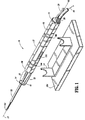
図1〜図5を参照すると、本発明の好ましい実施形態としての組織サンプル採取器具が示されている。器具10は、ハウジング12を有し、このハウジング12は、手で容易に持て又は図1に示す別の構造部材、例えば、クレードル14に回転自在に取り付けられる種々の形態のうちの任意の1つとして形作られている。ハウジング12は好ましくは全体が細長く、これを通る長手方向軸線16を定めている。ハウジング12の材料は、医用器具に用いるのに適し且つ本明細書に記載するように働くのに十分な強度及び剛性をもつ種々の材料のうちの任意のものであってよい。なお、かかる材料としては、金属又はプラスチックが挙げられる。好ましい実施形態では、ハウジング12全体及びその内部構成部品は、1人の患者に使用した後、処分されるようになっているので、ハウジング12は安価な材料から成るのが望ましい。好ましい実施形態のハウジング12は、ハウジング12を、以下に説明するように、患者又はクレードル14に対して選択的な回転位置に配置するための回転位置標識18を備えている。
【0008】
駆動ケーブルポート22及び真空ポート24が、ハウジング12の近位端部20のところで遠位端面25に取り付けられている。駆動ケーブルポート22は、駆動ケーブル80の駆動ケーブル端部26を受け入れ、真空ポート24は、真空導管28を受け入れ、これら各々の機能については以下に説明する。
ハウジング12の遠位端部30は、延長アーム32及び遠位支持体34を有し、この遠位支持体34は、これに対し近位側に隣接して組織検体又は標本取出しゾーン36を形成している。放射線透過性(ラジオルーセント)管38が、以下に説明するように、ハウジング12から遠位側へ調節可能に伸長できるような仕方でハウジング12の遠位端部30に取り付けられている。
【0009】
サンプル採取ニードル(サンプル採取針)40及び回転カッタ42が、遠位支持体34を通過した状態でハウジング12の遠位端部30から延びている。カッタ42は、ハウジング12に対して回転的に、しかも軸線方向に動くことができるような態様でハウジング12内に収納されている。ニードル40は、ハウジング12に対して軸線方向に動くことができるが、ハウジング12に対しニードル40の相対回転を阻止するような態様でハウジング12内に設けられている。
【0010】
図2に示す分解図を参照すると、ハウジング12は、第1の半部41及び第2の半部44で構成され、各半部は、他方と互いに嵌合して単一の密閉ハウジング12を形成するようになっている。カッタ42は、細長い中空管を有し、この細長い中空管は、組織を切断するための鋭利なエッジを備えた遠位端部46と、近位端部48と、近位端部48の近くに設けられた組織サンプル取出し窓50とを有している。カッタ42は、好ましくは、組織切断のための遠位端部46のエッジのところを鋭利に削ることができる金属又はこれに類似した剛性材料で作られる。第1のカッタ歯車52は、回転運動をカッタ42に伝えるためにカッタ42の近位端部48に固定関係をなして連結されている。第1のカッタ歯車52を、種々の適当な手段でカッタ42に連結するのがよく、かかる手段としては、図示のように、カッタ42に溶接でき、圧力嵌めでき、又は他の方法で取り付けることができる遠位延長部54が挙げられる。
【0011】
内歯車52が、回転運動自在にハウジング12の内部に設けられているが、この内歯車52は、回転運動を第1の歯車52に伝えるに過ぎず、この第1のカッタ歯車は、カッタ42を回転させる。第1のカッタ歯車及び内歯車56は、第1のカッタ歯車52が内歯車56の内部に位置決めされるように寸法決めされている。歯車の歯数及び歯車比は、所望の出力に応じて変えることができる。ハウジング12に対する長手方向のカッタ42の前進又は後退を容易にするために第1のカッタ歯車52は、内歯車56の内部で長手方向に並進するようになっている。内歯車56は、内歯車56の遠位端部58がハウジング12の内部に固定された第1の停止プレート60に当接するような態様でハウジング12内に設けられている。内歯車56の近位端部62は、歯車箱66の遠位端面64に当接し、この歯車箱は、以下に説明するように動かないような態様でハウジング12に内部に設けられている。
【0012】
内歯車56の回転運動は、第2のカッタ歯車68によって内歯車に直接伝えられる回転運動によって引き起こされ、かかる内歯車56の回転運動により、第1のカッタ歯車52及びカッタ42が駆動される。第2のカッタ歯車68は、カッタ駆動シャフト72の遠位端部70に直接固着されている。第3のカッタ歯車76が、カッタ駆動シャフト72の近位端部74に固着されている。第3のカッタ歯車76は、駆動されると、回転運動をカッタシャフト72を介して第2のカッタ歯車68に、かくして、内歯車62、第1のカッタ歯車52及び最終的にカッタ42に伝達する。回転運動は、マスタ駆動歯車78によって第3のカッタ歯車76に与えられ、このマスタ駆動歯車は、駆動ケーブル80によって駆動され、ケーブルハウジング端部84を備えたケーブルハウジング82内に収納されている。
【0013】
駆動ケーブル80は、遠くの場所に設置された従来型モータ86、又は、他の駆動手段によって回転駆動される。駆動ケーブル80は、従来型手段、例えば、ソレノイド、又は、他形式のリニアアクチュエータ88によってハウジング12に対し軸線方向に動かされる。リニアアクチュエータ88は、例えば、駆動ケーブル80に圧着され、又は、他の方法で取り付けられたディスク、又は、カラー92に係合するようになったプッシュプルピストン90を有するのがよい。駆動ケーブル80を選択的に動かすことにより、かくして、マスタ駆動歯車78を選択的に動かすことにより、第3のカッタ歯車76を選択的に稼働させ、又は、稼働解除させて、カッタ42を選択的に駆動させ、又は、駆動させないようにすることができる。カッタ前進歯車94が設けられており、このカッタ前進歯車94は、マスタ駆動歯車78が第3のカッタ歯車76に係合すると、マスタ駆動歯車78と同時に係合するような仕方でハウジング12内に配置されている。カッタ前進歯車94は、カッタ42を直線的に伸長させたり引っ込めるために、マスタ駆動歯車78の回転運動を直線運動に変換する以下に説明するような追加の構成部品と協働する。
【0014】
カッタ前進歯車94は、ばねクラッチ98によってカッタ前進シャフト96に連結されており、このばねクラッチは、親ナット99をシャフト96の螺設部分100に沿って直線的に前進させ又は引っ込めるために回転運動を歯車92からシャフト96に伝える。親ナット99は、延長アーム102を有し、この延長アームは、歯車箱66の遠位端面64を通って遠位側に延びていて、延長アーム102の遠位端部104が第1のカッタ歯車52の近位フェース106に当接するようになっている。カッタ前進シャフト96を第1の方向に回転させると、親ナット99は遠位側へ並進し、それにより、第1のカッタ歯車52及びかくしてカッタ42を押してこれらが内歯車56及びハウジング12に対して遠位側に動くようになっている。ばねクラッチ98は、所定の軸線方向抵抗力がカッタ42に加えられると、カッタ前進シャフト96とカッタ前進歯車92の相対的な滑りを可能にするように選択されている。カッタ42は、この抵抗を減少させ又はこの抵抗に打ち勝つまで回転を続けながら、軸線方向の運動を遅くし又は停止させる。ばねクラッチ98の延長フラグ108及び保持クリップ110により、ばねクラッチをカッタ前進歯車92に連結することができる。
【0015】
したがって、マスタ駆動歯車78の回転方向を逆にすることにより、以下に説明するように器具の作用に従ってカッタ42の回転及び直線運動の方向が制御されることになる。親ナット99が近位方向に向かって移動するような方向にカッタ前進歯車92を回転させるようにマスタ駆動歯車78の回転方向を設定すると、結果的に、第2の停止プレート116により遠位端部114が付勢されると共に第1のカッタ歯車52の遠位側フェース120によって近位端部118が付勢されるばね112が、第1のカッタ歯車52及びカッタ42を近位方向に押し戻す。このように、移動の率は、親ナット99の後退の度合いによって定められる。その理由は、親ナットが第1のカッタ歯車52の近位端部102に当接しているからである。
【0016】
以下に説明するような作用に従うニードル40の前進又は後退は、マスタ駆動歯車78をニードル駆動歯車(針駆動歯車)122と噛み合い状態に位置決めすることによって行われる。上述したように、マスタ駆動歯車78は、ハウジング12に対して軸線方向に動かされ、かくして、ニードル駆動歯車122と選択的に噛み合うことができる。図3に示すように、ニードル駆動歯車122は、第3のカッタ歯車76及びカッタ前進歯車94からオフセットしていて、ニードル駆動歯車を後に延びた2つの歯車が噛み合っていないときにのみ稼働させることができ、又その逆の関係も成り立つようにすることができる。マスタ駆動歯車78がニードル駆動歯車122と噛み合うと、マスタ駆動歯車78からの回転運動は、ニードル駆動歯車122を介してニードル親ねじ(針親ねじ)124に伝達され、このニードル親ねじには、ニードル駆動歯車122が固定されている。親ねじ124は、回転時に、雌ねじ128が設けられ、親ねじに装着されているトグルナット126が親ねじ124に沿って直線的に並進運動するように螺設されている。マスタ駆動歯車78の回転方向に応じて、トグルナット126は、親ねじ124に沿って遠位側に前進し、又は近位側に後退することになる。トグルナット126は、全体として半径方向に延び、図示のように軸線方向に互いにオフセットした2つのフラグ134,132を有している。
【0017】
トグルナット126の第1のフラグ130は、ニードルフランジ136の遠位端面134に選択的に係合するようにニードル40に対して位置決めされている。ニードルフランジ136は、ニードル40の近位端部138に固着されている。第1のフラグ130は、回転によりニードルフランジ136の一部と軸線方向に整列し、又はこの軸線方向整列関係を解くことによりニードルフランジ136に選択的に係合し又は離脱する。第1のフラグ130は、フランジ136と係合可能に位置決めされると、トグルナット126が上述したように親ねじ124に沿って近位側に移動しているときにフランジ136及びニードル40を引っ込み近位方向に引くことになる。
【0018】
トグルナット126の第2のフラグ132は、ニードルフランジ136の近位端面134に選択的に係合するようにニードル40に対して位置決めされている。ニードルフランジ136は、ニードル40の近位端部138に固着されている。第2のフラグ132は、回転によりニードルフランジ136の一部と軸線方向に整列し、又はこの軸線方向整列関係を解くことによりニードルフランジ136に選択的に係合し又は離脱する。第2のフラグ132は、フランジ136と係合可能に位置決めされると、トグルナット126が上述したように親ねじ124に沿って遠位側に移動しているときにフランジ136及びニードル40を伸長遠位方向に押すことになる。
【0019】
フラグ130,132は、互いに対して軸線方向に間隔を置いていることに加えて、角度的にオフセットしており、したがって、第2のフラグの遠位側に位置した第1のフラグ130がフランジ136と整列可能に位置決めされ、これに対し、第2のフラグ132がフランジ136との整列関係を解くように位置決めされるようになる。これにより、第2のフラグ132を、「発火(fire)」中、フランジ136の邪魔にならないようにすることにより、ニードル40の任意的な発火モードが容易になり、これについては以下に説明する。
【0020】
ニードル40と、これに取り付けられたフランジ136は、真空管144に対して相対的に軸線方向運動を行うことができるように真空管144の遠位端部142と入れ子式に嵌合している。真空管144は、ニードル40を上述したように軸線方向に移動させても、ハウジング12に対して固定状態のままである。真空管144の近位端部146は、真空導管28に取り付けられ、この真空導管は、従来タイプの遠隔真空圧力源150に取り付けられている。ニードル40は、組織を穿通し又は組織に切り込むようになった尖ったニードル先端部152を有している。先端部152に隣接して、組織サンプルバスケット154が設けられている。好ましくは、サンプルバスケット154は、吸引力をバスケット154内に受け入れられた組織サンプルに及ぼすための穴156を備えている。吸引力は、真空管144を介して提供される。
【0021】
上述した内部構成部品は、ハウジング12内に収納され、近位端部キャップ158が、ハウジングの近位端部20側のキャップを形成している。トグルナットストップ160が、トグルナット126及びかくしてニードル40の近位側への運動を制限するのに用いられている。トグルナット126及びニードル40の近位側への運動は、歯車箱遠位端部163の近位フェース162によって制限される。歯車箱の近位端部164は、一連の穴168,170,172,174を備えたプレートを含む。歯車箱66は、近位側に向かってハウジング12内に位置決めされている。第1の中央穴168が、真空管144及びニードル40を受け入れる。
【0022】
ニードル40は、歯車箱66の近位端部162に設けられた中央穴176を貫通し、そして遠位支持体134の中央穴178を貫通している。遠位支持体中央穴178と整列した中央穴182を有する放射線透過性スライダ180が設けられ、このスライダは、ニードル40を挿通状態で受け入れる。スライダ180は、放射線透過性管38に固定されており、かかるスライダにより、以下に説明する作用に従って軸線方向におけるハウジング12に対する調節が可能である。
残りの4つの穴168,170,172,174は、それぞれ、ニードル駆動歯車122、マスタ駆動歯車78、第3のカッタ歯車76、カッタ前進歯車94を回転自在に支持している。
【0023】
作 用
作用を説明すると、組織サンプル採取器具10を用いて1以上の組織サンプルを患者から取り出す。例えば、生検材料取出し手技では、2以上のサンプルを患者から採取して1以上の病変部の存在場所を突き止めることが望ましい場合がある。
組織取出し処置、例えば、胸部生検手技の際、患者を市販の生検作業台又は他の位置決め及び画像化機器上又はその近くに配置する。従来型画像化法、例えば、超音波を用いて、外科医は、組織サンプル取出しに望ましいターゲット領域を突き止める。
【0024】
装置10を外科医が手で持ってもよく、或いは、かかる器具を図1に示すように可動キャリジ184に取り付けられたクレードル14に取り付けてもよい。キャリジ184は、画像化作業台又は他の市販の公知の位置決め装置の一部である。器具10は、支承溝186を有し、この支承溝は、クレードル14と協働して器具10を摩擦が殆ど無い状態で回転運動を可能にするような仕方でクレードル14内に保持するよう設計されている。
組織サンプルを得る最初の段階では、ニードル先端部152を患者の皮膚に突き刺して刺入させる。ニードル先端部152を、2つのやり方のうちの一方で皮膚中へ前進させるのがよい。第1の方法は、器具を手で手だけの力を用いて前方に単に押すことである。外科医は、ニードル先端部152のかかる刺入中、超音波画像化法を用いて位置をモニタすることができる。ニードル先端部152を皮膚中へ前進させるもう1つの方法は、器具10及びかくしてこれと関連したニードル152を保持する機械式キャリジ184を前進させることである。キャリジの位置と関連した画像化手段又は所定の座標を用いて、ニードル先端部152を標的ゾーンまで前進させることができる。
【0025】
皮膚へのニードル先端部152の刺入後、先の段落中に記載した手段のうち何れかを用いることによりニードル先端部152を、これが図4Aに示すように組織サンプル標的ゾーン190に隣接するまで更に前進させる。次に、何れかの手段を用いてニードル先端部152を前進させて組織サンプル受入れバスケット154が図4Bに示すように標的ゾーン190内に位置するようにする。変形例として、ニードル先端部152を発火モードによって(これを利用するかどうかは任意である)標的ゾーン190に前進させてもよい。
【0026】
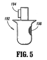
発火モードでは、組織をニードル先端部150の邪魔にならないところに押すのではなく、組織領域中へ切り込んで穿通するような迅速な発火の仕方で先端部152を所定の距離だけハウジング12に対して前進させる。迅速な発火を容易にするため、ばね押し発火ハンマ194を備えたモジュール式発火機構192が、ハンマ194をハウジング12の発火ポート196(図1)内に配置した状態で位置決めされている。ハンマ194は、ニードルフランジ136に対し近位側に一線をなしていて、発火機構192をそのトリガ198を引くことにより発火すると、ハンマ194は、フランジ136及びニードル先端部152を遠位側の方向に迅速に押すようになっている。この発火モードを実行するためには、フラグ130,132を、上述したように、第1のフラグ130がフランジ136と整列可能に位置決めされ、第2のフラグ132がフランジ136との整列関係を解くように位置決めされるよう位置決めすることが必要である。これにより、第2のフラグ132は発火中、フランジ136の邪魔にならないようになる。
【0027】
器具10は、好ましくは、フラグ130,132がすぐ前に記載した整列状態であるように、その元の未使用状態で出荷される。必要ならば、フラグ130,132の位置は、親ねじ124を一方向又はその逆の方向に回転させることによって制御される。その理由は、トグルナット126は、これが親ねじ124と一緒に限定された回転距離にわたって回転するのに足るほどの摩擦力で親ねじ124に係合し、ついには、トグルナットが何れか一方の側に接触するようになり、次に、親ねじ124が、トグルナット126に対し、これを親ねじ124に沿って直線的に前進させるよう回転するからである。親ねじ124の回転は、電子スイッチ200を作動させることによって生じさせることができ、この電子スイッチは、2方向遠隔回転モータ86を選択的に作動させるようハウジング12上に又は遠隔に設けられてもよい。モータ86は、駆動ケーブル80を回転させる。上述したように、従来手段、例えば、ソレノイド又は他形式のリニアアクチュエータ88により駆動ケーブル80をハウジング12に対して軸線方向に移動させ、かかる従来手段を、ハウジング12上に又は遠隔に設けられた電子スイッチ204によって作動させることができる。
【0028】
この組織サンプル受入れバスケット154を図4Bに示すように、標的ゾーン190内に配置した後、カッタ42を上述した機械的構成部品によって戻してニードル先端部154から遠ざける。その目的は、バスケット154を図4Cに示すように、サンプル採取されるべき組織に対して露出させることにある。カッタ42を移動させる段階を、ハウジング12に設けられ又は遠隔に設けられた電子スイッチ206の作動によって開始させるのがよい。いったん、バスケット154を組織サンプル標的ゾーン190に露出させると、上述したように、穴156を通り真空管144及び真空源150を経て吸引力を及ぼすのがよい。真空圧の印加をハウジング12に設けられ、又は、遠隔に設けられた電子スイッチ208によって開始させるのがよい。真空圧力を作用させ、組織をバスケット154内に引き入れた後、短時間のうちに、カッタ42を上述したように機械的手段によって回転させると共に直線的に前進させ、ついには、これが図4Dに示す位置に到達するようにするのがよい。真空を働かせてカッタ42を移動させるシーケンスを、ハウジング12上に又は遠隔に設けられた単一の電子スイッチ210によって開始させるのがよい。
【0029】
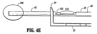
カッタ42が前進して図4Dに示すようにバスケット154を完全に通過した後においては、組織サンプルは切断されてバスケット154内に捕捉されている。今や遠位側伸長位置にあるカッタの移動を停止させて、サンプル部位を保持し、ニードル40を引っ込めてバスケット154が、組織サンプル212の取出しのために図4Eに示すように組織検体取出しゾーン36内に位置決めされるようにする。この組織サンプル212を鉗子又は他の公知の手段で掴み又はバスケット154から取り出すのがよい。
【0030】
次のサンプルの入手が望まれる場合、ハウジング12上に又は遠隔に設けられた電子スイッチ214を作動させることによってニードル40を前進させ、それにより、上述したように機械的構成部品を作動させて親ねじ124及びトグルナット126を用いてニードル40を直線的に前進させるようにする。ニードル先端部152を図4Bに示すようにカッタ42の遠位側に前進させる。次に、患者及び組織標的ゾーン190に対する器具10の直線運動又は回転運動を調節するのがよい。組織サンプルを取り出す次のシーケンスを開始させるには、カッタ42を戻してニードル先端部152から遠ざけ、それによりバスケット154を露出させるのがよい。上述したような真空、切断及び組織サンプル取出しシーケンスを繰り返して別のサンプルを得る。上述の手技を必要に応じて何回も繰り返すと所望の数のサンプルを得ることができる。
【0031】
所望数の組織サンプルの取出しの完了時、マスタ駆動歯車78及び駆動ケーブル80を器具10から取り外して器具10の構成部品の残部を破棄できるようにする。真空導管148を真空源150から取り外し、器具10と共に破棄する。駆動ケーブル80を、本明細書に記載した器具10と同一タイプの新品の器具に取り付けるのがよく、そして、別の真空導管148を器具10と真空源150との間に取り付けて、別の患者に、次に使えるようにするのがよい。
サンプル採取対象の組織野の長さを減少させることが望ましい場合、放射線透過性管38に固定されたスライダ180をハウジング12に対して所定の距離遠位側へ伸長させてニードル40が伸長位置にあるときに、サンプルバスケット154を部分的に閉塞するようにするのがよい。管38及びスライダ180が放射線透過性なので、処置の間、周囲の部位を見ることができないようにするものは何も無い。
【0032】
本発明の好ましい実施形態を開示したが、特許請求の範囲に記載された本発明の範囲から逸脱することなしに、変形例及び改造例を想到することができることは理解されよう。
【図面の簡単な説明】
【図1】 本発明の第1の実施形態の組織取出し器具の等角部分図である。
【図2】 図1に示す器具の分解等角図である。
【図3】 図1に示す器具の部分等角図である。
【図4A】 本発明の組織取出し器具に関連する方法の好ましい実施形態に従った方法で操作されている状態の図1に示す器具の部品の側面図である。
【図4B】 本発明の組織取出し器具に関連する方法の好ましい実施形態に従った方法で操作されている状態の図1に示す器具の部品の側面図である。
【図4C】 本発明の組織取出し器具に関連する方法の好ましい実施形態に従った方法で操作されている状態の図1に示す器具の部品の側面図である。
【図4D】 本発明の組織取出し器具に関連する方法の好ましい実施形態に従った方法で操作されている状態の図1に示す器具の部品の側面図である。
【図4E】 本発明の組織取出し器具に関連する方法の好ましい実施形態に従った方法で操作されている状態の図1に示す器具の部品の側面図である。
【図5】 本発明の第1の実施形態の任意使用の部品の正面図である。[0001]
〔Technical field〕
The present invention provides a tissue sampleRelated to removal (tissue removal device),In particular, chest tissue biopsy (biopsy)It relates to instruments.
[0002]
BACKGROUND OF THE INVENTION
There are a variety of known tissue and biopsy retrieval machines and methods. Known instruments include various types of needle (needle) centering and movable cutting instruments. Some such instruments lack effective cutting performance, multiple sample removal performance, or flexibility in various procedures from the standpoint when used in conjunction with various accessories. For example, certain tissue removal devices are limited in that they need only be used with certain types of workbench or imaging equipment. Some workbench or imaging equipment is expensive or cumbersome to handle. Some worktables or imaging devices are adapted to or used with one or a limited number of models and biopsy material or tissue removal devices.
[0003]
There are several hand-held biopsy or tissue removal instruments, but they lack effective cutting and tissue removal capabilities with complex automation instruments, and these complex automation instruments are limited to use with workbench and large equipment. It is customary to do so. Certain hand-held instruments are limited to a single tissue sample removal operation and can only be taken after the sample has been completely removed, thus the exact location of the previous sample. Is not understood.
[0004]
(Object of invention)
The object of the present invention is to have excellent cutting performance, ability to take out a large number of samples while holding the tissue sample site, and flexibility in terms of use in combination with various accessories and in various procedures Take outProvide equipmentThere is.Of the present inventionAnother purpose is tissue retrieval that can be used with a carriage and workbench, or can be used entirely in a handheld manner.Provide equipmentThere is. These and other objects and advantages inherent in the present invention are disclosed herein.
[0005]
[Summary of the Invention]
The present invention relates to a tissue removal instrument and method utilizing an instrument having a housing that can be held by hand or attached to a carriage used in conventional biopsy benches and imaging systems. The tissue removal device has a non-rotatable needle with a vacuum tissue sample basket and a rotating needle that can be linearly advanced or retracted. A single reusable drive cable with a drive gear attached to the end is attached to the remote drive motor. A single drive cable selectively rotates to allow cutter rotation, advancement and retraction, and selective needle displacement to remove detached samples and reposition the needle.
[0006]
In operation, the needle is positioned in the tissue target site such that a vacuum pressure basket located near the distal end of the needle inhales the tissue. The tissue sample held in the basket is separated by advancing over the basket while rotating the cutter. The cutter is then held in place while the needle is retracted. The eye is to make the location of the tissue basket known for tissue removal. The above sequence is repeated as necessary so that a desired number of tissue samples can be removed. By rotating the entire instrument relative to the patient, the rotational position of the next sample can be controlled.
The entire instrument is designed to be removed from the drive cable and discarded.
[0007]
DESCRIPTION OF PREFERRED EMBODIMENTS
Structural parts
Referring to FIGS. 1-5, a tissue sample collection device as a preferred embodiment of the present invention is shown. The
[0008]
A
The
[0009]
A
[0010]
Referring to the exploded view shown in FIG. 2, the
[0011]
An
[0012]
The rotational motion of the
[0013]
The
[0014]
The
[0015]
Accordingly, by reversing the direction of rotation of the
[0016]
The advancement or retraction of the
[0017]
The
[0018]
The
[0019]
The
[0020]
The
[0021]
The internal components described above are housed within the
[0022]
The
The remaining four
[0023]
Work
In operation, the tissue
During a tissue removal procedure, such as a chest biopsy procedure, the patient is placed on or near a commercially available biopsy table or other positioning and imaging device. Using conventional imaging methods, such as ultrasound, the surgeon locates the desired target area for tissue sample removal.
[0024]
The
In the initial stage of obtaining a tissue sample, the
[0025]
After insertion of
[0026]
In firing mode, rather than pushing tissue away from the needle tip 150 out of the way, the
[0027]
The
[0028]
After placing the tissue
[0029]
After the
[0030]
When it is desired to obtain the next sample, the
[0031]
Upon completion of the removal of the desired number of tissue samples, the
If it is desired to reduce the length of the tissue field to be sampled, the
[0032]
While preferred embodiments of the invention have been disclosed, it will be appreciated that variations and modifications can be devised without departing from the scope of the invention as set forth in the claims.
[Brief description of the drawings]
FIG. 1 is an isometric partial view of a tissue removal device of a first embodiment of the present invention.
FIG. 2 is an exploded isometric view of the instrument shown in FIG.
FIG. 3 is a partial isometric view of the instrument shown in FIG.
FIG. 4AMethods associated with the tissue removal device of the present invention2 is a side view of the parts of the instrument shown in FIG. 1 being operated in a manner according to the preferred embodiment of FIG.
FIG. 4BMethods associated with the tissue removal device of the present invention2 is a side view of the parts of the instrument shown in FIG. 1 being operated in a manner according to the preferred embodiment of FIG.
FIG. 4CMethods associated with the tissue removal device of the present invention2 is a side view of the parts of the instrument shown in FIG. 1 being operated in a manner according to the preferred embodiment of FIG.
FIG. 4DMethods associated with the tissue removal device of the present invention2 is a side view of the parts of the instrument shown in FIG. 1 being operated in a manner according to the preferred embodiment of FIG.
FIG. 4EMethods associated with the tissue removal device of the present invention2 is a side view of the parts of the instrument shown in FIG. 1 being operated in a manner according to the preferred embodiment of FIG.
FIG. 5 is a front view of an optional part of the first embodiment of the present invention.
Claims (4)
ハウジングと、
前記患者の組織を穿刺する穿刺部材と、
前記組織の一部を受け入れる前記穿刺部材の組織受入れ部分と、
組織の前記一部が前記受入れ部分内に保持されている間、組織の前記部分を選択的に切離する切断部材と、
一端が前記ハウジングに取り付けられており、かつ、別の端部が、前記切断部材を移動させて、前記切断部材が組織の前記部分を切離し、前記穿刺部材を前記ハウジングに対して選択的に移動させるようにする遠隔駆動手段に取り付けられた単一の機械的駆動ケーブルと、
を有することを特徴とする組織取出し器具。A tissue removal device for selectively removing one or more tissue portions from a medical patient,
A housing;
A puncture member for puncturing the patient's tissue;
A tissue receiving portion of the puncture member that receives a portion of the tissue;
A cutting member that selectively detaches the portion of tissue while the portion of tissue is retained within the receiving portion;
One end is attached to the housing, and another end moves the cutting member so that the cutting member separates the portion of tissue and selectively moves the puncture member relative to the housing A single mechanical drive cable attached to the remote drive means to allow
A tissue extraction device characterized by comprising:
使い捨て部分を有しており、
前記使い捨て部分は、
ハウジングと、
前記患者の組織を穿刺する穿刺部材と、
前記組織の一部を受け入れる前記穿刺部材の組織受入れ部分と、
組織の前記一部が前記受入れ部分内に保持されている間、組織の前記部分を選択的に切離する切断部材とを含んでおり、
さらに、前記組織取出し器具は、再使用可能部分を有しており、
前記再使用可能部分は、
一端が前記ハウジングに取り付けられており、かつ、別の端部が、前記切断部材を移動させて前記切断部材が組織の前記部分を切離し、前記穿刺部材を前記ハウジングに対して選択的に移動させるようにする遠隔駆動手段に取り付けられた単一の機械的駆動ケーブルを含んでいる、
ことを特徴とする組織取出し器具。A tissue removal device for selectively removing one or more tissue portions from a medical patient, the tissue removal device comprising:
Has a disposable part,
The disposable part is
A housing;
A puncture member for puncturing the patient's tissue;
A tissue receiving portion of the puncture member that receives a portion of the tissue;
A cutting member that selectively detaches the portion of tissue while the portion of tissue is retained within the receiving portion;
Furthermore, the tissue removal device has a reusable part,
The reusable part is
One end is attached to the housing, and another end moves the cutting member so that the cutting member separates the portion of tissue and selectively moves the puncture member relative to the housing Including a single mechanical drive cable attached to the remote drive means
A tissue removal device characterized by that.
Applications Claiming Priority (2)
| Application Number | Priority Date | Filing Date | Title |
|---|---|---|---|
| US25314700P | 2000-11-27 | 2000-11-27 | |
| PCT/US2001/048629 WO2002041787A2 (en) | 2000-11-27 | 2001-11-12 | Tissue sampling and removal apparatus and method |
Publications (3)
| Publication Number | Publication Date |
|---|---|
| JP2004535837A JP2004535837A (en) | 2004-12-02 |
| JP2004535837A5 JP2004535837A5 (en) | 2005-12-22 |
| JP3996057B2 true JP3996057B2 (en) | 2007-10-24 |
Family
ID=22959061
Family Applications (1)
| Application Number | Title | Priority Date | Filing Date |
|---|---|---|---|
| JP2002543971A Expired - Fee Related JP3996057B2 (en) | 2000-11-27 | 2001-11-12 | Tissue extractor |
Country Status (6)
| Country | Link |
|---|---|
| US (2) | US6860860B2 (en) |
| EP (1) | EP1339326B1 (en) |
| JP (1) | JP3996057B2 (en) |
| AU (2) | AU2002229070B2 (en) |
| CA (1) | CA2429040C (en) |
| WO (1) | WO2002041787A2 (en) |
Families Citing this family (152)
| Publication number | Priority date | Publication date | Assignee | Title |
|---|---|---|---|---|
| ITCE990004A1 (en) | 1999-10-25 | 2000-01-25 | Mario Immacolato Paternuosto | VALVE FOR BIOPSY FORCEPS IN DIGESTIVE ENDOSCOPY |
| US6814743B2 (en) * | 2001-12-26 | 2004-11-09 | Origin Medsystems, Inc. | Temporary seal and method for facilitating anastomosis |
| EP1524940B1 (en) | 2002-03-19 | 2011-08-24 | Bard Dublin ITC Limited | Biopsy device and biopsy needle module that can be inserted into the biopsy device |
| ES2247529T3 (en) | 2002-03-19 | 2006-03-01 | Bard Dublin Itc Limited | DEVICE FOR EMPTY BIOPSIES. |
| US10973545B2 (en) | 2002-05-31 | 2021-04-13 | Teleflex Life Sciences Limited | Powered drivers, intraosseous devices and methods to access bone marrow |
| IL165224A0 (en) * | 2002-05-31 | 2005-12-18 | Vidacare Corp | Apparatus and method to access bone marrow |
| US8142365B2 (en) * | 2002-05-31 | 2012-03-27 | Vidacare Corporation | Apparatus and method for accessing the bone marrow of the sternum |
| US9314228B2 (en) | 2002-05-31 | 2016-04-19 | Vidacare LLC | Apparatus and method for accessing the bone marrow |
| WO2008033871A2 (en) * | 2006-09-12 | 2008-03-20 | Vidacare Corporation | Apparatus and methods for biopsy and aspiration of bone marrow |
| US9072543B2 (en) | 2002-05-31 | 2015-07-07 | Vidacare LLC | Vascular access kits and methods |
| US11337728B2 (en) | 2002-05-31 | 2022-05-24 | Teleflex Life Sciences Limited | Powered drivers, intraosseous devices and methods to access bone marrow |
| US8641715B2 (en) | 2002-05-31 | 2014-02-04 | Vidacare Corporation | Manual intraosseous device |
| US9451968B2 (en) * | 2002-05-31 | 2016-09-27 | Vidacare LLC | Powered drivers, intraosseous devices and methods to access bone marrow |
| US7951089B2 (en) * | 2002-05-31 | 2011-05-31 | Vidacare Corporation | Apparatus and methods to harvest bone and bone marrow |
| US11298202B2 (en) | 2002-05-31 | 2022-04-12 | Teleflex Life Sciences Limited | Biopsy devices and related methods |
| US8690791B2 (en) | 2002-05-31 | 2014-04-08 | Vidacare Corporation | Apparatus and method to access the bone marrow |
| US7811260B2 (en) * | 2002-05-31 | 2010-10-12 | Vidacare Corporation | Apparatus and method to inject fluids into bone marrow and other target sites |
| US10973532B2 (en) | 2002-05-31 | 2021-04-13 | Teleflex Life Sciences Limited | Powered drivers, intraosseous devices and methods to access bone marrow |
| US8656929B2 (en) | 2002-05-31 | 2014-02-25 | Vidacare Corporation | Medical procedures trays and related methods |
| US8668698B2 (en) | 2002-05-31 | 2014-03-11 | Vidacare Corporation | Assembly for coupling powered driver with intraosseous device |
| US20070049945A1 (en) | 2002-05-31 | 2007-03-01 | Miller Larry J | Apparatus and methods to install, support and/or monitor performance of intraosseous devices |
| DE10314240A1 (en) | 2003-03-29 | 2004-10-07 | Bard Dublin Itc Ltd., Crawley | Pressure generating unit |
| US9504477B2 (en) | 2003-05-30 | 2016-11-29 | Vidacare LLC | Powered driver |
| ITPO20030007A1 (en) * | 2003-06-13 | 2004-12-14 | Aurelio Gironi | AGOBIOPTICO HALF FOR MULTIPLE WITHDRAWALS |
| US7960935B2 (en) | 2003-07-08 | 2011-06-14 | The Board Of Regents Of The University Of Nebraska | Robotic devices with agent delivery components and related methods |
| US7588545B2 (en) | 2003-09-10 | 2009-09-15 | Boston Scientific Scimed, Inc. | Forceps and collection assembly with accompanying mechanisms and related methods of use |
| US7942896B2 (en) | 2003-11-25 | 2011-05-17 | Scimed Life Systems, Inc. | Forceps and collection assembly and related methods of use and manufacture |
| WO2005072625A2 (en) * | 2004-01-26 | 2005-08-11 | Vidacare Corporation | Manual interosseous device |
| US7815642B2 (en) * | 2004-01-26 | 2010-10-19 | Vidacare Corporation | Impact-driven intraosseous needle |
| DK1768572T3 (en) * | 2004-07-09 | 2008-07-28 | Bard Peripheral Vascular Inc | Length detection system for biopsy device |
| US7296442B2 (en) * | 2004-07-15 | 2007-11-20 | Owens-Brockway Glass Container Inc. | Neck ring cooling |
| US8998848B2 (en) * | 2004-11-12 | 2015-04-07 | Vidacare LLC | Intraosseous device and methods for accessing bone marrow in the sternum and other target areas |
| US7611474B2 (en) * | 2004-12-29 | 2009-11-03 | Ethicon Endo-Surgery, Inc. | Core sampling biopsy device with short coupled MRI-compatible driver |
| US7517321B2 (en) | 2005-01-31 | 2009-04-14 | C. R. Bard, Inc. | Quick cycle biopsy system |
| USRE47376E1 (en) | 2005-04-01 | 2019-05-07 | Nexgen Medical Systems, Incorporated | Thrombus removal system and process |
| US8603122B2 (en) | 2005-04-01 | 2013-12-10 | Nexgen Medical Systems, Incorporated | Thrombus removal system and process |
| US7955344B2 (en) * | 2005-04-01 | 2011-06-07 | Nexgen Medical Systems, Inc. | Thrombus removal system and process |
| US7955345B2 (en) * | 2005-04-01 | 2011-06-07 | Nexgen Medical Systems, Inc. | Thrombus removal system and process |
| US10492749B2 (en) | 2005-05-03 | 2019-12-03 | The Regents Of The University Of California | Biopsy systems for breast computed tomography |
| US7762960B2 (en) | 2005-05-13 | 2010-07-27 | Boston Scientific Scimed, Inc. | Biopsy forceps assemblies |
| US7867173B2 (en) * | 2005-08-05 | 2011-01-11 | Devicor Medical Products, Inc. | Biopsy device with replaceable probe and incorporating vibration insertion assist and static vacuum source sample stacking retrieval |
| US8262585B2 (en) | 2005-08-10 | 2012-09-11 | C. R. Bard, Inc. | Single-insertion, multiple sampling biopsy device with linear drive |
| WO2007021904A2 (en) | 2005-08-10 | 2007-02-22 | C.R. Bard Inc. | Single-insertion, multiple sampling biopsy device usable with various transport systems and integrated markers |
| WO2007021905A2 (en) | 2005-08-10 | 2007-02-22 | C.R. Bard Inc. | Single-insertion, multiple sample biopsy device with integrated markers |
| US20070149881A1 (en) * | 2005-12-22 | 2007-06-28 | Rabin Barry H | Ultrasonically Powered Medical Devices and Systems, and Methods and Uses Thereof |
| US20070156125A1 (en) * | 2005-12-30 | 2007-07-05 | Russell Delonzor | Encodable cryogenic device |
| US7670299B2 (en) * | 2006-03-07 | 2010-03-02 | Ethincon Endo-Surgery, Inc. | Device for minimally invasive internal tissue removal |
| US7806834B2 (en) * | 2006-03-07 | 2010-10-05 | Devicor Medical Products, Inc. | Device for minimally invasive internal tissue removal |
| US7465278B2 (en) * | 2006-03-29 | 2008-12-16 | Ethicon Endo-Surgery, Inc. | Device for minimally invasive internal tissue removal |
| WO2007121383A2 (en) * | 2006-04-13 | 2007-10-25 | Solopower, Inc. | Method and apparatus to form thin layers of materials on a base |
| US20070270714A1 (en) * | 2006-05-19 | 2007-11-22 | E-Z-Em, Inc. | System and method for tissue specimen collection |
| JP5466004B2 (en) | 2006-06-22 | 2014-04-09 | ボード オブ リージェンツ オブ ザ ユニバーシティ オブ ネブラスカ | Magnetically connectable robotic device and associated method |
| US8679096B2 (en) | 2007-06-21 | 2014-03-25 | Board Of Regents Of The University Of Nebraska | Multifunctional operational component for robotic devices |
| US9579088B2 (en) | 2007-02-20 | 2017-02-28 | Board Of Regents Of The University Of Nebraska | Methods, systems, and devices for surgical visualization and device manipulation |
| US8974440B2 (en) | 2007-08-15 | 2015-03-10 | Board Of Regents Of The University Of Nebraska | Modular and cooperative medical devices and related systems and methods |
| WO2008024684A2 (en) | 2006-08-21 | 2008-02-28 | C.R. Bard, Inc. | Self-contained handheld biopsy needle |
| EP2073728B1 (en) * | 2006-09-12 | 2018-11-07 | Teleflex Medical Devices S.à.r.l. | Biopsy device |
| US8944069B2 (en) | 2006-09-12 | 2015-02-03 | Vidacare Corporation | Assemblies for coupling intraosseous (IO) devices to powered drivers |
| EP3189787B1 (en) | 2006-09-12 | 2019-01-09 | Teleflex Medical Devices S.à.r.l. | Medical procedures trays and related methods |
| ES2663296T3 (en) | 2006-10-06 | 2018-04-11 | Bard Peripheral Vascular, Inc. | Tissue handling system with reduced operator exposure |
| EP3714798A3 (en) | 2006-10-24 | 2020-12-16 | C. R. Bard, Inc. | Large sample low aspect ratio biopsy needle |
| US8974410B2 (en) | 2006-10-30 | 2015-03-10 | Vidacare LLC | Apparatus and methods to communicate fluids and/or support intraosseous devices |
| US8961551B2 (en) | 2006-12-22 | 2015-02-24 | The Spectranetics Corporation | Retractable separating systems and methods |
| US9028520B2 (en) | 2006-12-22 | 2015-05-12 | The Spectranetics Corporation | Tissue separating systems and methods |
| JP5591696B2 (en) | 2007-07-12 | 2014-09-17 | ボード オブ リージェンツ オブ ザ ユニバーシティ オブ ネブラスカ | Biopsy elements, arm devices, and medical devices |
| JP2010536435A (en) | 2007-08-15 | 2010-12-02 | ボード オブ リージェンツ オブ ザ ユニバーシティ オブ ネブラスカ | Medical inflation, attachment and delivery devices and associated methods |
| EP2205170A2 (en) * | 2007-10-31 | 2010-07-14 | Stanley I. Kim | Rotating biopsy device and biopsy robot |
| US8241225B2 (en) | 2007-12-20 | 2012-08-14 | C. R. Bard, Inc. | Biopsy device |
| US7854706B2 (en) | 2007-12-27 | 2010-12-21 | Devicor Medical Products, Inc. | Clutch and valving system for tetherless biopsy device |
| US20090253997A1 (en) * | 2008-04-03 | 2009-10-08 | Convergent Medical Solutions, Inc. | Skin biopsy with automated lesion stabilization and resection |
| US20090253998A1 (en) * | 2008-04-03 | 2009-10-08 | Convergent Medical Solutions, Inc. | Skin biopsy with suturing prior to resection |
| US20100081928A1 (en) * | 2008-09-29 | 2010-04-01 | Searete Llc, A Limited Liability Corporation Of The State Of Delaware | Histological Facilitation systems and methods |
| US9186128B2 (en) | 2008-10-01 | 2015-11-17 | Covidien Lp | Needle biopsy device |
| US8968210B2 (en) | 2008-10-01 | 2015-03-03 | Covidien LLP | Device for needle biopsy with integrated needle protection |
| US11298113B2 (en) | 2008-10-01 | 2022-04-12 | Covidien Lp | Device for needle biopsy with integrated needle protection |
| US9782565B2 (en) | 2008-10-01 | 2017-10-10 | Covidien Lp | Endoscopic ultrasound-guided biliary access system |
| US9332973B2 (en) | 2008-10-01 | 2016-05-10 | Covidien Lp | Needle biopsy device with exchangeable needle and integrated needle protection |
| CN102348418A (en) | 2009-03-16 | 2012-02-08 | C·R·巴德公司 | Biopsy device having rotational cutting |
| DE102009016859B4 (en) * | 2009-04-08 | 2018-06-14 | Erbe Elektromedizin Gmbh | Water jet surgical instrument |
| WO2010120294A1 (en) | 2009-04-15 | 2010-10-21 | C.R. Bard, Inc. | Biopsy apparatus having integrated fluid management |
| US8206316B2 (en) | 2009-06-12 | 2012-06-26 | Devicor Medical Products, Inc. | Tetherless biopsy device with reusable portion |
| WO2011019343A1 (en) | 2009-08-12 | 2011-02-17 | C.R. Bard, Inc. | Biopsy appaparatus having integrated thumbwheel mechanism for manual rotation of biopsy cannula |
| US8085488B2 (en) * | 2009-08-27 | 2011-12-27 | Hitachi Global Storage Technologies Netherlands B.V. | Predicting operational problems in a hard-disk drive (HDD) |
| US8283890B2 (en) | 2009-09-25 | 2012-10-09 | Bard Peripheral Vascular, Inc. | Charging station for battery powered biopsy apparatus |
| US8430824B2 (en) | 2009-10-29 | 2013-04-30 | Bard Peripheral Vascular, Inc. | Biopsy driver assembly having a control circuit for conserving battery power |
| US8485989B2 (en) | 2009-09-01 | 2013-07-16 | Bard Peripheral Vascular, Inc. | Biopsy apparatus having a tissue sample retrieval mechanism |
| US8597206B2 (en) | 2009-10-12 | 2013-12-03 | Bard Peripheral Vascular, Inc. | Biopsy probe assembly having a mechanism to prevent misalignment of components prior to installation |
| US9259275B2 (en) * | 2009-11-13 | 2016-02-16 | Intuitive Surgical Operations, Inc. | Wrist articulation by linked tension members |
| EP3616854A1 (en) * | 2009-11-13 | 2020-03-04 | Intuitive Surgical Operations Inc. | Motor interface for parallel drive shafts within an independently rotating member |
| US8852174B2 (en) | 2009-11-13 | 2014-10-07 | Intuitive Surgical Operations, Inc. | Surgical tool with a two degree of freedom wrist |
| KR102077004B1 (en) | 2009-11-13 | 2020-02-13 | 인튜어티브 서지컬 오퍼레이션즈 인코포레이티드 | End effector with redundant closing mechanisms |
| JP2013514835A (en) | 2009-12-17 | 2013-05-02 | ボード オブ リージェンツ オブ ザ ユニバーシティ オブ ネブラスカ | Modular and collaborative medical devices and related systems and methods |
| EP2549937B1 (en) | 2010-03-24 | 2017-05-03 | Nexgen Medical Systems, Inc. | Thrombus removal system |
| WO2011123446A1 (en) | 2010-03-30 | 2011-10-06 | Flatland Martin L | Tissue excision device |
| WO2013022423A1 (en) | 2010-08-06 | 2013-02-14 | Board Of Regents Of The University Of Nebraska | Methods and systems for handling or delivering materials for natural orifice surgery |
| US8764680B2 (en) * | 2010-11-01 | 2014-07-01 | Devicor Medical Products, Inc. | Handheld biopsy device with needle firing |
| US9968337B2 (en) * | 2010-12-20 | 2018-05-15 | Cook Medical Technologies Llc | Coring tissue biopsy needle and method of use |
| EP4275634A3 (en) | 2011-06-10 | 2024-01-10 | Board of Regents of the University of Nebraska | Surgical end effector |
| JP6106169B2 (en) | 2011-07-11 | 2017-03-29 | ボード オブ リージェンツ オブ ザ ユニバーシティ オブ ネブラスカ | Surgical robot system |
| US8540645B2 (en) * | 2011-07-27 | 2013-09-24 | Suros Surgical Systems, Inc. | Needle biopsy device and related method |
| CA2860754C (en) | 2012-01-10 | 2020-12-29 | Shane Farritor | Methods, systems, and devices for surgical access and insertion |
| EP2838435B1 (en) | 2012-04-16 | 2020-03-25 | Hathaway, Jeff M. | Biopsy device |
| EP2844181B1 (en) | 2012-05-01 | 2021-03-10 | Board of Regents of the University of Nebraska | Single site robotic device and related systems |
| EP3424651B1 (en) | 2012-06-22 | 2020-02-12 | Board of Regents of the University of Nebraska | Local control robotic surgical devices |
| US9347533B2 (en) | 2012-07-25 | 2016-05-24 | Cook Medical Technologies Llc | Rotational drive system for a biopsy member |
| WO2014025399A1 (en) | 2012-08-08 | 2014-02-13 | Board Of Regents Of The University Of Nebraska | Robotic surgical devices, systems, and related methods |
| US9770305B2 (en) | 2012-08-08 | 2017-09-26 | Board Of Regents Of The University Of Nebraska | Robotic surgical devices, systems, and related methods |
| US10531891B2 (en) | 2012-09-14 | 2020-01-14 | The Spectranetics Corporation | Tissue slitting methods and systems |
| US9301735B2 (en) | 2012-12-19 | 2016-04-05 | Cook Medical Technologies Llc | Drive system for a biopsy member |
| US9456872B2 (en) | 2013-03-13 | 2016-10-04 | The Spectranetics Corporation | Laser ablation catheter |
| US9883885B2 (en) | 2013-03-13 | 2018-02-06 | The Spectranetics Corporation | System and method of ablative cutting and pulsed vacuum aspiration |
| US10383691B2 (en) | 2013-03-13 | 2019-08-20 | The Spectranetics Corporation | Last catheter with helical internal lumen |
| US9291663B2 (en) | 2013-03-13 | 2016-03-22 | The Spectranetics Corporation | Alarm for lead insulation abnormality |
| US9283040B2 (en) | 2013-03-13 | 2016-03-15 | The Spectranetics Corporation | Device and method of ablative cutting with helical tip |
| US10835279B2 (en) | 2013-03-14 | 2020-11-17 | Spectranetics Llc | Distal end supported tissue slitting apparatus |
| US9743987B2 (en) | 2013-03-14 | 2017-08-29 | Board Of Regents Of The University Of Nebraska | Methods, systems, and devices relating to robotic surgical devices, end effectors, and controllers |
| CA2906672C (en) | 2013-03-14 | 2022-03-15 | Board Of Regents Of The University Of Nebraska | Methods, systems, and devices relating to force control surgical systems |
| US9918737B2 (en) | 2013-03-15 | 2018-03-20 | The Spectranetics Corporation | Medical device for removing an implanted object |
| US9668765B2 (en) | 2013-03-15 | 2017-06-06 | The Spectranetics Corporation | Retractable blade for lead removal device |
| EP2967634B1 (en) | 2013-03-15 | 2019-06-05 | The Spectranetics Corporation | Surgical instrument for removing an implanted object |
| US10842532B2 (en) | 2013-03-15 | 2020-11-24 | Spectranetics Llc | Medical device for removing an implanted object |
| WO2017048486A1 (en) | 2013-03-15 | 2017-03-23 | The Spectranetics Corporation | Medical device for removing an implanted object using laser cut hypotubes |
| WO2014144220A1 (en) | 2013-03-15 | 2014-09-18 | Board Of Regents Of The University Of Nebraska | Robotic surgical devices, systems, and related methdos |
| US10448999B2 (en) | 2013-03-15 | 2019-10-22 | The Spectranetics Corporation | Surgical instrument for removing an implanted object |
| WO2014153410A1 (en) | 2013-03-20 | 2014-09-25 | Bard Peripheral Vascular, Inc. | Biopsy device |
| WO2015009949A2 (en) | 2013-07-17 | 2015-01-22 | Board Of Regents Of The University Of Nebraska | Robotic surgical devices, systems and related methods |
| AU2013404993B2 (en) | 2013-11-05 | 2019-08-08 | C.R. Bard, Inc. | Biopsy device having integrated vacuum |
| EP3113701B1 (en) | 2014-03-03 | 2020-07-22 | The Spectranetics Corporation | Multiple configuration surgical cutting device |
| US10405924B2 (en) | 2014-05-30 | 2019-09-10 | The Spectranetics Corporation | System and method of ablative cutting and vacuum aspiration through primary orifice and auxiliary side port |
| US10342561B2 (en) | 2014-09-12 | 2019-07-09 | Board Of Regents Of The University Of Nebraska | Quick-release end effectors and related systems and methods |
| CN105520756B (en) * | 2014-09-29 | 2020-03-31 | 德昌电机(深圳)有限公司 | Drive device for medical equipment |
| JP6608928B2 (en) | 2014-11-11 | 2019-11-20 | ボード オブ リージェンツ オブ ザ ユニバーシティ オブ ネブラスカ | Robotic device with miniature joint design and related systems and methods |
| USD765243S1 (en) | 2015-02-20 | 2016-08-30 | The Spectranetics Corporation | Medical device handle |
| USD770616S1 (en) | 2015-02-20 | 2016-11-01 | The Spectranetics Corporation | Medical device handle |
| AU2015393933B2 (en) | 2015-05-01 | 2020-03-19 | C. R. Bard, Inc. | Biopsy device |
| WO2017024081A1 (en) | 2015-08-03 | 2017-02-09 | Board Of Regents Of The University Of Nebraska | Robotic surgical devices systems and related methods |
| CN114098975A (en) | 2016-05-18 | 2022-03-01 | 虚拟切割有限公司 | Robotic surgical devices, systems, and related methods |
| US11173617B2 (en) | 2016-08-25 | 2021-11-16 | Board Of Regents Of The University Of Nebraska | Quick-release end effector tool interface |
| CN114872081A (en) | 2016-08-30 | 2022-08-09 | 内布拉斯加大学董事会 | Robotic devices with compact joint design and additional degrees of freedom and related systems and methods |
| JP7100025B2 (en) * | 2016-10-12 | 2022-07-12 | デビコー・メディカル・プロダクツ・インコーポレイテッド | Core needle biopsy device for collecting multiple specimens with a single insertion |
| CN110139620B (en) | 2016-11-22 | 2022-09-20 | 内布拉斯加大学董事会 | Improved coarse positioning apparatus and related systems and methods |
| JP7099728B2 (en) | 2016-11-29 | 2022-07-12 | バーチャル インシジョン コーポレイション | User controller with user presence detection, related systems and methods |
| WO2018112199A1 (en) | 2016-12-14 | 2018-06-21 | Virtual Incision Corporation | Releasable attachment device for coupling to medical devices and related systems and methods |
| CN112826542B (en) | 2017-05-12 | 2024-02-09 | Devicor医疗产业收购公司 | Biopsy device with tip protector and mounting apparatus |
| US11116483B2 (en) | 2017-05-19 | 2021-09-14 | Merit Medical Systems, Inc. | Rotating biopsy needle |
| US11844500B2 (en) | 2017-05-19 | 2023-12-19 | Merit Medical Systems, Inc. | Semi-automatic biopsy needle device and methods of use |
| US11793498B2 (en) | 2017-05-19 | 2023-10-24 | Merit Medical Systems, Inc. | Biopsy needle devices and methods of use |
| US11051894B2 (en) | 2017-09-27 | 2021-07-06 | Virtual Incision Corporation | Robotic surgical devices with tracking camera technology and related systems and methods |
| CN117140580A (en) | 2018-01-05 | 2023-12-01 | 内布拉斯加大学董事会 | Single arm robotic device with compact joint design and related systems and methods |
| CN114302665A (en) | 2019-01-07 | 2022-04-08 | 虚拟切割有限公司 | Robot-assisted surgical system and related devices and methods |
| US20210220003A1 (en) * | 2020-01-17 | 2021-07-22 | Covidien Lp | Tissue resecting instrument |
| CN117064456B (en) * | 2023-10-17 | 2024-02-02 | 江西省水产科学研究所(江西省鄱阳湖渔业研究中心、江西省渔业资源生态环境监测中心) | Automatic sampling device for crucian immune tissues |
Family Cites Families (155)
| Publication number | Priority date | Publication date | Assignee | Title |
|---|---|---|---|---|
| US737293A (en) | 1900-11-01 | 1903-08-25 | George H Summerfeldt | Veterinary surgical instrument. |
| US1167014A (en) | 1915-06-25 | 1916-01-04 | William R O'brien | Veterinary surgical instrument. |
| US1255330A (en) | 1917-07-18 | 1918-02-05 | David Morgan | Machine for making reinforced-concrete blocks. |
| US1585934A (en) | 1923-12-29 | 1926-05-25 | Radium Emanation Corp | Diagnostic needle |
| US1663761A (en) | 1927-02-07 | 1928-03-27 | George A Johnson | Surgical instrument |
| US1867624A (en) | 1930-04-01 | 1932-07-19 | Memorial Hospital For The Trea | Device for obtaining biopsy specimens |
| US2505358A (en) | 1949-04-20 | 1950-04-25 | Sklar Mfg Co Inc J | Double-cutting biopsy bistoury |
| US2705949A (en) | 1953-08-25 | 1955-04-12 | Silverman Irving | Biopsy needle |
| US2729210A (en) | 1954-06-22 | 1956-01-03 | Frank C Spencer | Medical instrument |
| US2919692A (en) | 1956-02-23 | 1960-01-05 | Ackermann Wolfgang | Vertebral trephine biopsy instruments |
| US3400708A (en) | 1965-11-24 | 1968-09-10 | Robert A. Scheidt | Cytologic endocrine evaluation device |
| US3477423A (en) | 1967-01-09 | 1969-11-11 | Baxter Laboratories Inc | Biopsy instrument |
| US3561429A (en) | 1968-05-23 | 1971-02-09 | Eversharp Inc | Instrument for obtaining a biopsy specimen |
| US3590808A (en) | 1968-09-04 | 1971-07-06 | Us Catheter & Instr Corp | Biopsy tool |
| US3732858A (en) | 1968-09-16 | 1973-05-15 | Surgical Design Corp | Apparatus for removing blood clots, cataracts and other objects from the eye |
| US3606878A (en) | 1968-10-04 | 1971-09-21 | Howard B Kellogg Jr | Needle instrument for extracting biopsy sections |
| US3844272A (en) | 1969-02-14 | 1974-10-29 | A Banko | Surgical instruments |
| US3734099A (en) | 1971-04-07 | 1973-05-22 | H Bender | Powered surgical cutter |
| US3929123A (en) | 1973-02-07 | 1975-12-30 | Khosrow Jamshidi | Muscle biopsy needle |
| AR196829A1 (en) | 1973-12-06 | 1974-02-19 | Halpern D | SURGICAL INSTRUMENT FOR BIOPSIES |
| US3995619A (en) | 1975-10-14 | 1976-12-07 | Glatzer Stephen G | Combination subcutaneous suture remover, biopsy sampler and syringe |
| US4099518A (en) | 1976-05-10 | 1978-07-11 | Baylis Shelby M | Biopsy apparatus |
| US4243048A (en) | 1976-09-21 | 1981-01-06 | Jim Zegeer | Biopsy device |
| US4200106A (en) | 1977-10-11 | 1980-04-29 | Dinkelkamp Henry T | Fixed arc cyclic ophthalmic surgical instrument |
| US4203444A (en) | 1977-11-07 | 1980-05-20 | Dyonics, Inc. | Surgical instrument suitable for closed surgery such as of the knee |
| US4246902A (en) | 1978-03-10 | 1981-01-27 | Miguel Martinez | Surgical cutting instrument |
| US4220155A (en) | 1978-05-11 | 1980-09-02 | Colorado State University Research Foundation | Apparatus for spaying large animals |
| US4210146A (en) | 1978-06-01 | 1980-07-01 | Anton Banko | Surgical instrument with flexible blade |
| GB2022421B (en) | 1978-06-08 | 1982-09-15 | Wolf Gmbh Richard | Devices for obtaining tissure samples |
| US4513745A (en) | 1978-06-21 | 1985-04-30 | Amoils Selig P | Surgical instruments and methods particularly adapted for intra-ocular cutting and the like |
| US4274414A (en) | 1979-02-21 | 1981-06-23 | Dyonics, Inc. | Surgical instrument |
| US4314560A (en) | 1979-11-28 | 1982-02-09 | Helfgott Maxwell A | Powered handpiece for endophthalmic surgery |
| US4340066A (en) | 1980-02-01 | 1982-07-20 | Sherwood Medical Industries Inc. | Medical device for collecting a body sample |
| US4306570A (en) | 1980-08-20 | 1981-12-22 | Matthews Larry S | Counter rotating biopsy needle |
| US4396021A (en) | 1980-12-15 | 1983-08-02 | Baumgartner George C | Surgical instrument and process |
| US4517977A (en) | 1981-07-24 | 1985-05-21 | Unisearch Limited | Co-axial tube surgical infusion/suction cutter tip |
| US4461305A (en) | 1981-09-04 | 1984-07-24 | Cibley Leonard J | Automated biopsy device |
| US4403617A (en) | 1981-09-08 | 1983-09-13 | Waters Instruments, Inc. | Biopsy needle |
| US4530356A (en) | 1983-02-08 | 1985-07-23 | Helfgott Maxwell A | Ophthalmic surgical instrument with beveled tip |
| US4603694A (en) | 1983-03-08 | 1986-08-05 | Richards Medical Company | Arthroscopic shaver |
| US4660267A (en) | 1983-03-08 | 1987-04-28 | Richards Medical Company | Method for fabricating an arthroscopic shaver |
| JPS59200644A (en) | 1983-04-27 | 1984-11-14 | オリンパス光学工業株式会社 | Surgical incision instrument |
| US4577629A (en) | 1983-10-28 | 1986-03-25 | Coopervision, Inc. | Surgical cutting instrument for ophthalmic surgery |
| US4598710A (en) | 1984-01-20 | 1986-07-08 | Urban Engineering Company, Inc. | Surgical instrument and method of making same |
| US4776346A (en) | 1984-02-10 | 1988-10-11 | Dan Beraha | Biopsy instrument |
| US4600014A (en) | 1984-02-10 | 1986-07-15 | Dan Beraha | Transrectal prostate biopsy device and method |
| US4685458A (en) | 1984-03-01 | 1987-08-11 | Vaser, Inc. | Angioplasty catheter and method for use thereof |
| US4669496A (en) | 1984-03-12 | 1987-06-02 | Figgie International Inc. | Liquid proportioner |
| US5002553A (en) | 1984-05-14 | 1991-03-26 | Surgical Systems & Instruments, Inc. | Atherectomy system with a clutch |
| US4781186A (en) | 1984-05-30 | 1988-11-01 | Devices For Vascular Intervention, Inc. | Atherectomy device having a flexible housing |
| US4678459A (en) | 1984-07-23 | 1987-07-07 | E-Z-Em, Inc. | Irrigating, cutting and aspirating system for percutaneous surgery |
| USRE33258E (en) | 1984-07-23 | 1990-07-10 | Surgical Dynamics Inc. | Irrigating, cutting and aspirating system for percutaneous surgery |
| US4651753A (en) | 1984-10-12 | 1987-03-24 | Jayco Pharmaceuticals | Endoscopic multiple biopsy instrument |
| EP0186256B1 (en) | 1984-10-24 | 1988-10-26 | Hakko Electric Machine Works Co. Ltd. | Biopsy needle set |
| US4662869A (en) | 1984-11-19 | 1987-05-05 | Wright Kenneth W | Precision intraocular apparatus |
| US4667684A (en) | 1985-02-08 | 1987-05-26 | Bio-Medical Resources, Inc. | Biopsy device |
| US4708147A (en) | 1985-02-25 | 1987-11-24 | Haaga John R | Universal biopsy needle |
| US4651752A (en) | 1985-03-08 | 1987-03-24 | Fuerst Erwin J | Biopsy needle |
| US4702260A (en) | 1985-04-16 | 1987-10-27 | Ko Pen Wang | Flexible bronchoscopic needle assembly |
| US4702261A (en) | 1985-07-03 | 1987-10-27 | Sherwood Medical Company | Biopsy device and method |
| US4644951A (en) | 1985-09-16 | 1987-02-24 | Concept, Inc. | Vacuum sleeve for a surgical appliance |
| US4674502A (en) | 1985-09-27 | 1987-06-23 | Coopervision, Inc. | Intraocular surgical instrument |
| US4696298A (en) | 1985-11-19 | 1987-09-29 | Storz Instrument Company | Vitrectomy cutting mechanism |
| SE456886B (en) | 1986-02-19 | 1988-11-14 | Radiplast Ab | DEVICE FOR TAPE SAMPLING WITH A NATIONAL DISPENSER |
| USRE33569E (en) | 1986-02-28 | 1991-04-09 | Devices For Vascular Intervention, Inc. | Single lumen atherectomy catheter device |
| AT385890B (en) | 1987-04-13 | 1988-05-25 | Immuno Ag | BIOPSY DEVICE FOR OBTAINING TEST SAMPLES AND APPLICATION OF SUBSTANCES IN ONE WORKPROCESS |
| US4711250A (en) | 1986-09-09 | 1987-12-08 | Gilbaugh Jr James H | Hand-held medical syringe actuator device |
| US4893635A (en) | 1986-10-15 | 1990-01-16 | Groot William J De | Apparatus for performing a biopsy |
| US4799494A (en) | 1986-10-22 | 1989-01-24 | Wang Ko P | Percutaneous aspiration lung biopsy needle assembly |
| US4681123A (en) | 1986-10-31 | 1987-07-21 | Valtchev Konstantin L | Chorion biopsy instrument |
| US4735215A (en) | 1987-01-05 | 1988-04-05 | Goto David S | Soft tissue biopsy instrument |
| US4733662A (en) | 1987-01-20 | 1988-03-29 | Minnesota Mining And Manufacturing Company | Tissue gripping and cutting assembly for surgical instrument |
| US4733671A (en) | 1987-03-17 | 1988-03-29 | Mehl Donald N | Tissue needle |
| US4874375A (en) | 1987-04-13 | 1989-10-17 | Ellison Arthur E | Tissue retractor |
| GB8709021D0 (en) | 1987-04-15 | 1987-05-20 | Taylor J | Soft tissue biopsy device |
| US4850354A (en) | 1987-08-13 | 1989-07-25 | Baxter Travenol Laboratories, Inc. | Surgical cutting instrument |
| US4781202A (en) | 1987-08-31 | 1988-11-01 | Janese Woodrow W | Biopsy cannula |
| US4819635A (en) | 1987-09-18 | 1989-04-11 | Henry Shapiro | Tubular microsurgery cutting apparatus |
| SE459635B (en) | 1987-11-19 | 1989-07-24 | Radiplast Ab | DRIVER CONTAINS A DEVICE FOR TAPE SAMPLING |
| US4844088A (en) | 1987-12-11 | 1989-07-04 | Parviz Kambin | Surgical cutting device with reciprocating cutting member |
| US4907599A (en) | 1988-02-01 | 1990-03-13 | Hart Enterprises, Inc. | Soft tissue core biopsy instrument |
| US4881551A (en) | 1988-02-01 | 1989-11-21 | Hart Enterprises, Inc. | Soft tissue core biopsy instrument |
| US4989614A (en) | 1988-02-23 | 1991-02-05 | Vance Products Incorporated | Fine-needle aspiration cell sampling methods |
| US5009391A (en) | 1988-05-02 | 1991-04-23 | The Kendall Company | Valve assembly |
| US5080655A (en) * | 1988-05-26 | 1992-01-14 | Haaga John R | Medical biopsy needle |
| US4838280A (en) | 1988-05-26 | 1989-06-13 | Haaga John R | Hemostatic sheath for a biopsy needle and method of use |
| US5195988A (en) * | 1988-05-26 | 1993-03-23 | Haaga John R | Medical needle with removable sheath |
| US4936835A (en) | 1988-05-26 | 1990-06-26 | Haaga John R | Medical needle with bioabsorbable tip |
| US4950265A (en) | 1988-10-17 | 1990-08-21 | Hart Enterprises, Inc. | Arming device for a medical instrument |
| US4919146A (en) | 1988-10-25 | 1990-04-24 | Medrad, Inc. | Biopsy device |
| US4924878A (en) | 1988-11-07 | 1990-05-15 | Nottke James E | Actuating mechanism for biopsy needle |
| US5000745A (en) | 1988-11-18 | 1991-03-19 | Edward Weck Incorporated | Hemostatis valve |
| US4982739A (en) | 1989-02-06 | 1991-01-08 | Board Of Regents For The Univeristy Of Oklahoma | Biosample aspirator |
| DE3903956A1 (en) * | 1989-02-10 | 1990-08-16 | Guenter Dr Lohrmann | GUIDE DEVICE FOR A PUNCHING BIOPSIA NEEDLE CONNECTED TO A BIOPSI PUNCHING DEVICE |
| US5087265A (en) * | 1989-02-17 | 1992-02-11 | American Biomed, Inc. | Distal atherectomy catheter |
| US5617874A (en) * | 1989-03-29 | 1997-04-08 | Baran; Gregory W. | Automated biopsy instrument |
| US5005585A (en) | 1989-04-24 | 1991-04-09 | Marshfield Clinic | Biopsy needle construction |
| US5012818A (en) * | 1989-05-04 | 1991-05-07 | Joishy Suresh K | Two in one bone marrow surgical needle |
| US5078723A (en) * | 1989-05-08 | 1992-01-07 | Medtronic, Inc. | Atherectomy device |
| US4917100A (en) | 1989-05-08 | 1990-04-17 | Nottke James E | Biopsy needle for use with spring-operated actuating mechanism |
| US5011473A (en) * | 1989-06-06 | 1991-04-30 | Mitek Surgical Products Inc. | Device for securing and positioning a wire to a needle |
| US5018530A (en) * | 1989-06-15 | 1991-05-28 | Research Corporation Technologies, Inc. | Helical-tipped lesion localization needle device and method of using the same |
| US5106364A (en) * | 1989-07-07 | 1992-04-21 | Kabushiki Kaisha Topcon | Surgical cutter |
| US4958625A (en) | 1989-07-18 | 1990-09-25 | Boston Scientific Corporation | Biopsy needle instrument |
| US5282484A (en) * | 1989-08-18 | 1994-02-01 | Endovascular Instruments, Inc. | Method for performing a partial atherectomy |
| US5226909A (en) * | 1989-09-12 | 1993-07-13 | Devices For Vascular Intervention, Inc. | Atherectomy device having helical blade and blade guide |
| US4976269A (en) | 1989-10-26 | 1990-12-11 | Creative Research & Manufacturing | Tissue needle |
| US5176628A (en) * | 1989-10-27 | 1993-01-05 | Alcon Surgical, Inc. | Vitreous cutter |
| US5009659A (en) | 1989-10-30 | 1991-04-23 | Schneider (Usa) Inc. | Fiber tip atherectomy catheter |
| US5505210A (en) * | 1989-11-06 | 1996-04-09 | Mectra Labs, Inc. | Lavage with tissue cutting cannula |
| US5409013A (en) * | 1989-11-06 | 1995-04-25 | Mectra Labs, Inc. | Tissue removal assembly |
| US5078142A (en) * | 1989-11-21 | 1992-01-07 | Fischer Imaging Corporation | Precision mammographic needle biopsy system |
| US4940061A (en) | 1989-11-27 | 1990-07-10 | Ingress Technologies, Inc. | Biopsy instrument |
| US5019036A (en) * | 1989-11-28 | 1991-05-28 | Stahl Norman O | Method and apparatus for removing gelatinous tissue |
| US4991592A (en) | 1989-12-04 | 1991-02-12 | Christ Howard N | Device for obtaining tissue sample in performing a biopsy |
| US5011490A (en) * | 1989-12-07 | 1991-04-30 | Medical Innovative Technologies R&D Limited Partnership | Endoluminal tissue excision catheter system and method |
| US5178625A (en) * | 1989-12-07 | 1993-01-12 | Evi Corporation | Catheter atherotome |
| US5019089A (en) * | 1989-12-07 | 1991-05-28 | Interventional Technologies Inc. | Atherectomy advancing probe and method of use |
| US5092873A (en) * | 1990-02-28 | 1992-03-03 | Devices For Vascular Intervention, Inc. | Balloon configuration for atherectomy catheter |
| US5006114A (en) | 1990-04-20 | 1991-04-09 | Rogers Bobby E | Medical valve assembly |
| JPH06114070A (en) * | 1990-06-22 | 1994-04-26 | Vance Prod Inc | Tissue abscission device for surgery |
| US5275609A (en) * | 1990-06-22 | 1994-01-04 | Vance Products Incorporated | Surgical cutting instrument |
| US5090419A (en) * | 1990-08-23 | 1992-02-25 | Aubrey Palestrant | Apparatus for acquiring soft tissue biopsy specimens |
| US5111828A (en) * | 1990-09-18 | 1992-05-12 | Peb Biopsy Corporation | Device for percutaneous excisional breast biopsy |
| US5188118A (en) * | 1990-11-07 | 1993-02-23 | Terwilliger Richard A | Automatic biopsy instrument with independently actuated stylet and cannula |
| US5282476A (en) * | 1990-11-07 | 1994-02-01 | Terwilliger Richard A | Biopsy apparatus with tapered vacuum chamber |
| US5183052A (en) * | 1990-11-07 | 1993-02-02 | Terwilliger Richard A | Automatic biopsy instrument with cutting cannula |
| US5085659A (en) * | 1990-11-21 | 1992-02-04 | Everest Medical Corporation | Biopsy device with bipolar coagulation capability |
| US5292310A (en) * | 1990-12-27 | 1994-03-08 | Inbae Yoon | Safety needle |
| GB2256369B (en) * | 1991-06-04 | 1995-10-25 | Chiou Rei Kwen | Improved biopsy device |
| US5358474A (en) * | 1991-07-02 | 1994-10-25 | Intermed, Inc. | Subcutaneous drug delivery device |
| US5199441A (en) * | 1991-08-20 | 1993-04-06 | Hogle Hugh H | Fine needle aspiration biopsy apparatus and method |
| US5284156A (en) * | 1991-08-30 | 1994-02-08 | M3 Systems, Inc. | Automatic tissue sampling apparatus |
| US5183054A (en) * | 1991-09-09 | 1993-02-02 | Sherwood Medical Company | Actuated biopsy cutting needle with removable stylet |
| US5285795A (en) * | 1991-09-12 | 1994-02-15 | Surgical Dynamics, Inc. | Percutaneous discectomy system having a bendable discectomy probe and a steerable cannula |
| US5192291A (en) * | 1992-01-13 | 1993-03-09 | Interventional Technologies, Inc. | Rotationally expandable atherectomy cutter assembly |
| US5195533A (en) * | 1992-05-08 | 1993-03-23 | Boston Scientific Corporation | Biopsy needle instrument for storing multiple specimens |
| US5286253A (en) * | 1992-10-09 | 1994-02-15 | Linvatec Corporation | Angled rotating surgical instrument |
| US5306260A (en) * | 1992-10-30 | 1994-04-26 | Ryder International Corporation | Indexing cannula support mechanism |
| US5301684A (en) * | 1993-04-27 | 1994-04-12 | International Electronic Technology Corp. | Biopsy needle |
| US5392790A (en) * | 1993-04-30 | 1995-02-28 | Ryder International Corporation | Instrument for obtaining bore type tissue sampling |
| US5490521A (en) * | 1993-08-31 | 1996-02-13 | Medtronic, Inc. | Ultrasound biopsy needle |
| US5394887A (en) * | 1994-01-14 | 1995-03-07 | Haaga; John R. | Biopsy needle |
| US5511556A (en) * | 1994-04-11 | 1996-04-30 | Desantis; Stephen A. | Needle core biopsy instrument |
| JP3546074B2 (en) * | 1994-05-16 | 2004-07-21 | 株式会社八光 | Biopsy needle |
| US5595185A (en) * | 1994-08-11 | 1997-01-21 | N.M.B. Medical Applications Ltd. | Single puncture multi-biopsy gun |
| US5507298A (en) * | 1994-09-23 | 1996-04-16 | M3 Systems, Inc., D/B/A/ Manan Medical Products, Inc. | Forward-fired automatic tissue sampling apparatus |
| US6027458A (en) * | 1996-12-23 | 2000-02-22 | Janssens; Jacques Phillibert | Device for taking a tissue sample |
| US5849023A (en) * | 1996-12-27 | 1998-12-15 | Mericle; Robert William | Disposable remote flexible drive cutting apparatus |
| US6017316A (en) * | 1997-06-18 | 2000-01-25 | Biopsys Medical | Vacuum control system and method for automated biopsy device |
| US6022324A (en) * | 1998-01-02 | 2000-02-08 | Skinner; Bruce A. J. | Biopsy instrument |
| US6331166B1 (en) * | 1998-03-03 | 2001-12-18 | Senorx, Inc. | Breast biopsy system and method |
| US6540695B1 (en) * | 1998-04-08 | 2003-04-01 | Senorx, Inc. | Biopsy anchor device with cutter |
| US6086544A (en) * | 1999-03-31 | 2000-07-11 | Ethicon Endo-Surgery, Inc. | Control apparatus for an automated surgical biopsy device |
| US6610020B2 (en) * | 2000-10-13 | 2003-08-26 | Ethicon Endo-Surgery, Inc. | Fork assembly for a surgical biopsy device |
-
2001
- 2001-11-12 JP JP2002543971A patent/JP3996057B2/en not_active Expired - Fee Related
- 2001-11-12 CA CA2429040A patent/CA2429040C/en not_active Expired - Fee Related
- 2001-11-12 AU AU2002229070A patent/AU2002229070B2/en not_active Ceased
- 2001-11-12 EP EP01990207A patent/EP1339326B1/en not_active Expired - Lifetime
- 2001-11-12 AU AU2907002A patent/AU2907002A/en active Pending
- 2001-11-12 WO PCT/US2001/048629 patent/WO2002041787A2/en active IP Right Grant
- 2001-11-19 US US09/988,888 patent/US6860860B2/en not_active Expired - Lifetime
-
2004
- 2004-06-03 US US10/859,693 patent/US7513877B2/en not_active Expired - Fee Related
Also Published As
| Publication number | Publication date |
|---|---|
| WO2002041787A3 (en) | 2003-02-27 |
| JP2004535837A (en) | 2004-12-02 |
| WO2002041787A2 (en) | 2002-05-30 |
| EP1339326A2 (en) | 2003-09-03 |
| CA2429040A1 (en) | 2002-05-30 |
| US20020065474A1 (en) | 2002-05-30 |
| AU2907002A (en) | 2002-06-03 |
| US6860860B2 (en) | 2005-03-01 |
| US7513877B2 (en) | 2009-04-07 |
| US20040225229A1 (en) | 2004-11-11 |
| CA2429040C (en) | 2010-06-08 |
| EP1339326B1 (en) | 2013-03-06 |
| AU2002229070B2 (en) | 2005-06-16 |
Similar Documents
| Publication | Publication Date | Title |
|---|---|---|
| JP3996057B2 (en) | Tissue extractor | |
| AU2002229070A1 (en) | Tissue sampling and removal apparatus and method | |
| JP6001145B2 (en) | Biopsy equipment | |
| US8251917B2 (en) | Self-contained handheld biopsy needle | |
| US7470237B2 (en) | Biopsy instrument with improved needle penetration | |
| CA2833008C (en) | Biopsy device with motorized needle firing | |
| CA2331444C (en) | Reusable automated biopsy needle handle | |
| AU782423B2 (en) | Lockout for a surgical biopsy device | |
| CA2351331A1 (en) | Biopsy system | |
| JP2004535837A5 (en) | ||
| US20110208090A1 (en) | Spring Loaded Biopsy Device | |
| US11602335B2 (en) | Core needle biopsy device for collecting multiple samples in a single insertion | |
| US20220249075A1 (en) | Core needle biopsy device for collecting multiple samples in a single insertion | |
| WO2023211424A1 (en) | Core needle biopsy device for collecting multiple samples in a single insertion |
Legal Events
| Date | Code | Title | Description |
|---|---|---|---|
| A521 | Request for written amendment filed |
Free format text: JAPANESE INTERMEDIATE CODE: A523 Effective date: 20040902 |
|
| A621 | Written request for application examination |
Free format text: JAPANESE INTERMEDIATE CODE: A621 Effective date: 20040902 |
|
| A131 | Notification of reasons for refusal |
Free format text: JAPANESE INTERMEDIATE CODE: A131 Effective date: 20061120 |
|
| A521 | Request for written amendment filed |
Free format text: JAPANESE INTERMEDIATE CODE: A523 Effective date: 20070219 |
|
| A131 | Notification of reasons for refusal |
Free format text: JAPANESE INTERMEDIATE CODE: A131 Effective date: 20070319 |
|
| A521 | Request for written amendment filed |
Free format text: JAPANESE INTERMEDIATE CODE: A523 Effective date: 20070619 |
|
| TRDD | Decision of grant or rejection written | ||
| A01 | Written decision to grant a patent or to grant a registration (utility model) |
Free format text: JAPANESE INTERMEDIATE CODE: A01 Effective date: 20070723 |
|
| A61 | First payment of annual fees (during grant procedure) |
Free format text: JAPANESE INTERMEDIATE CODE: A61 Effective date: 20070801 |
|
| FPAY | Renewal fee payment (event date is renewal date of database) |
Free format text: PAYMENT UNTIL: 20100810 Year of fee payment: 3 |
|
| R150 | Certificate of patent or registration of utility model |
Ref document number: 3996057 Country of ref document: JP Free format text: JAPANESE INTERMEDIATE CODE: R150 Free format text: JAPANESE INTERMEDIATE CODE: R150 |
|
| FPAY | Renewal fee payment (event date is renewal date of database) |
Free format text: PAYMENT UNTIL: 20100810 Year of fee payment: 3 |
|
| FPAY | Renewal fee payment (event date is renewal date of database) |
Free format text: PAYMENT UNTIL: 20110810 Year of fee payment: 4 |
|
| R250 | Receipt of annual fees |
Free format text: JAPANESE INTERMEDIATE CODE: R250 |
|
| FPAY | Renewal fee payment (event date is renewal date of database) |
Free format text: PAYMENT UNTIL: 20110810 Year of fee payment: 4 |
|
| FPAY | Renewal fee payment (event date is renewal date of database) |
Free format text: PAYMENT UNTIL: 20120810 Year of fee payment: 5 |
|
| R250 | Receipt of annual fees |
Free format text: JAPANESE INTERMEDIATE CODE: R250 |
|
| FPAY | Renewal fee payment (event date is renewal date of database) |
Free format text: PAYMENT UNTIL: 20130810 Year of fee payment: 6 |
|
| R250 | Receipt of annual fees |
Free format text: JAPANESE INTERMEDIATE CODE: R250 |
|
| R250 | Receipt of annual fees |
Free format text: JAPANESE INTERMEDIATE CODE: R250 |
|
| R250 | Receipt of annual fees |
Free format text: JAPANESE INTERMEDIATE CODE: R250 |
|
| R250 | Receipt of annual fees |
Free format text: JAPANESE INTERMEDIATE CODE: R250 |
|
| R250 | Receipt of annual fees |
Free format text: JAPANESE INTERMEDIATE CODE: R250 |
|
| R250 | Receipt of annual fees |
Free format text: JAPANESE INTERMEDIATE CODE: R250 |
|
| R250 | Receipt of annual fees |
Free format text: JAPANESE INTERMEDIATE CODE: R250 |
|
| R250 | Receipt of annual fees |
Free format text: JAPANESE INTERMEDIATE CODE: R250 |
|
| R250 | Receipt of annual fees |
Free format text: JAPANESE INTERMEDIATE CODE: R250 |
|
| LAPS | Cancellation because of no payment of annual fees |