EP3842291B1 - Stromverteilerkasten, vorrichtung zur herstellung eines stromverteilerkastens, verfahren zur herstellung eines stromverteilerkastens und kabelbaum - Google Patents
Stromverteilerkasten, vorrichtung zur herstellung eines stromverteilerkastens, verfahren zur herstellung eines stromverteilerkastens und kabelbaum Download PDFInfo
- Publication number
- EP3842291B1 EP3842291B1 EP20216582.5A EP20216582A EP3842291B1 EP 3842291 B1 EP3842291 B1 EP 3842291B1 EP 20216582 A EP20216582 A EP 20216582A EP 3842291 B1 EP3842291 B1 EP 3842291B1
- Authority
- EP
- European Patent Office
- Prior art keywords
- frame
- jig
- cassette block
- junction box
- electrical junction
- Prior art date
- Legal status (The legal status is an assumption and is not a legal conclusion. Google has not performed a legal analysis and makes no representation as to the accuracy of the status listed.)
- Active
Links
Images








Classifications
-
- H—ELECTRICITY
- H02—GENERATION; CONVERSION OR DISTRIBUTION OF ELECTRIC POWER
- H02B—BOARDS, SUBSTATIONS OR SWITCHING ARRANGEMENTS FOR THE SUPPLY OR DISTRIBUTION OF ELECTRIC POWER
- H02B1/00—Frameworks, boards, panels, desks, casings; Details of substations or switching arrangements
- H02B1/26—Casings; Parts thereof or accessories therefor
- H02B1/46—Boxes; Parts thereof or accessories therefor
- H02B1/48—Mounting of devices therein
-
- B—PERFORMING OPERATIONS; TRANSPORTING
- B60—VEHICLES IN GENERAL
- B60R—VEHICLES, VEHICLE FITTINGS, OR VEHICLE PARTS, NOT OTHERWISE PROVIDED FOR
- B60R16/00—Electric or fluid circuits specially adapted for vehicles and not otherwise provided for; Arrangement of elements of electric or fluid circuits specially adapted for vehicles and not otherwise provided for
- B60R16/02—Electric or fluid circuits specially adapted for vehicles and not otherwise provided for; Arrangement of elements of electric or fluid circuits specially adapted for vehicles and not otherwise provided for electric constitutive elements
- B60R16/023—Electric or fluid circuits specially adapted for vehicles and not otherwise provided for; Arrangement of elements of electric or fluid circuits specially adapted for vehicles and not otherwise provided for electric constitutive elements for transmission of signals between vehicle parts or subsystems
- B60R16/0238—Electrical distribution centers
-
- B—PERFORMING OPERATIONS; TRANSPORTING
- B60—VEHICLES IN GENERAL
- B60R—VEHICLES, VEHICLE FITTINGS, OR VEHICLE PARTS, NOT OTHERWISE PROVIDED FOR
- B60R16/00—Electric or fluid circuits specially adapted for vehicles and not otherwise provided for; Arrangement of elements of electric or fluid circuits specially adapted for vehicles and not otherwise provided for
- B60R16/02—Electric or fluid circuits specially adapted for vehicles and not otherwise provided for; Arrangement of elements of electric or fluid circuits specially adapted for vehicles and not otherwise provided for electric constitutive elements
- B60R16/0207—Wire harnesses
-
- B—PERFORMING OPERATIONS; TRANSPORTING
- B60—VEHICLES IN GENERAL
- B60R—VEHICLES, VEHICLE FITTINGS, OR VEHICLE PARTS, NOT OTHERWISE PROVIDED FOR
- B60R16/00—Electric or fluid circuits specially adapted for vehicles and not otherwise provided for; Arrangement of elements of electric or fluid circuits specially adapted for vehicles and not otherwise provided for
- B60R16/02—Electric or fluid circuits specially adapted for vehicles and not otherwise provided for; Arrangement of elements of electric or fluid circuits specially adapted for vehicles and not otherwise provided for electric constitutive elements
- B60R16/0207—Wire harnesses
- B60R16/0215—Protecting, fastening and routing means therefor
-
- B—PERFORMING OPERATIONS; TRANSPORTING
- B60—VEHICLES IN GENERAL
- B60R—VEHICLES, VEHICLE FITTINGS, OR VEHICLE PARTS, NOT OTHERWISE PROVIDED FOR
- B60R16/00—Electric or fluid circuits specially adapted for vehicles and not otherwise provided for; Arrangement of elements of electric or fluid circuits specially adapted for vehicles and not otherwise provided for
- B60R16/02—Electric or fluid circuits specially adapted for vehicles and not otherwise provided for; Arrangement of elements of electric or fluid circuits specially adapted for vehicles and not otherwise provided for electric constitutive elements
- B60R16/023—Electric or fluid circuits specially adapted for vehicles and not otherwise provided for; Arrangement of elements of electric or fluid circuits specially adapted for vehicles and not otherwise provided for electric constitutive elements for transmission of signals between vehicle parts or subsystems
- B60R16/0239—Electronic boxes
-
- H—ELECTRICITY
- H01—ELECTRIC ELEMENTS
- H01R—ELECTRICALLY-CONDUCTIVE CONNECTIONS; STRUCTURAL ASSOCIATIONS OF A PLURALITY OF MUTUALLY-INSULATED ELECTRICAL CONNECTING ELEMENTS; COUPLING DEVICES; CURRENT COLLECTORS
- H01R13/00—Details of coupling devices of the kinds covered by groups H01R12/70 or H01R24/00 - H01R33/00
- H01R13/46—Bases; Cases
- H01R13/514—Bases; Cases composed as a modular blocks or assembly, i.e. composed of co-operating parts provided with contact members or holding contact members between them
-
- H—ELECTRICITY
- H02—GENERATION; CONVERSION OR DISTRIBUTION OF ELECTRIC POWER
- H02B—BOARDS, SUBSTATIONS OR SWITCHING ARRANGEMENTS FOR THE SUPPLY OR DISTRIBUTION OF ELECTRIC POWER
- H02B1/00—Frameworks, boards, panels, desks, casings; Details of substations or switching arrangements
- H02B1/20—Bus-bar or other wiring layouts, e.g. in cubicles, in switchyards
-
- H—ELECTRICITY
- H02—GENERATION; CONVERSION OR DISTRIBUTION OF ELECTRIC POWER
- H02B—BOARDS, SUBSTATIONS OR SWITCHING ARRANGEMENTS FOR THE SUPPLY OR DISTRIBUTION OF ELECTRIC POWER
- H02B3/00—Apparatus specially adapted for the manufacture, assembly, or maintenance of boards or switchgear
-
- H—ELECTRICITY
- H02—GENERATION; CONVERSION OR DISTRIBUTION OF ELECTRIC POWER
- H02G—INSTALLATION OF ELECTRIC CABLES OR LINES, OR OF COMBINED OPTICAL AND ELECTRIC CABLES OR LINES
- H02G3/00—Installations of electric cables or lines or protective tubing therefor in or on buildings, equivalent structures or vehicles
- H02G3/02—Details
- H02G3/08—Distribution boxes; Connection or junction boxes
- H02G3/16—Distribution boxes; Connection or junction boxes structurally associated with support for line-connecting terminals within the box
-
- H—ELECTRICITY
- H01—ELECTRIC ELEMENTS
- H01R—ELECTRICALLY-CONDUCTIVE CONNECTIONS; STRUCTURAL ASSOCIATIONS OF A PLURALITY OF MUTUALLY-INSULATED ELECTRICAL CONNECTING ELEMENTS; COUPLING DEVICES; CURRENT COLLECTORS
- H01R2201/00—Connectors or connections adapted for particular applications
- H01R2201/26—Connectors or connections adapted for particular applications for vehicles
Definitions
- the present invention relates to an electrical junction box including a frame and a cassette block. Further, the present invention relates to an assembly apparatus for assembling the electrical junction box and a manufacturing method of the electrical junction box. Further, the present invention relates to a wire harness including the electrical junction box.
- An electrical junction box as described in the preamble of claim 1 is already known from US 6 022 247 A .
- a related art electrical junction box is mounted on an automobile and supplies power to, for example, various machines (see JP2011-15467A , for example).
- the electrical junction box includes an electrical junction box body, an upper cover, and a lower cover.
- a bundle of electric wires is drawn out from the electrical junction box.
- the bundle of electric wires is a part of a wire harness.
- the electrical junction box body includes a frame having a shape defined by side walls, a plurality of cassette blocks to be fitted to the frame, and electronic components assembled to the cassette blocks, such as a fuse, a fusible link, and a relay.
- terminals terminal fittings
- bus bars of electric wire terminals to which the electronic components are connected are provided in the cassette blocks.
- the frame has a first opening at a side from which the bundle of electric wires is drawn out and that is covered by the lower cover, and a second opening at a side opposite to the first opening and covered by the upper cover.
- a plurality of frame-side lock portions with which the cassette blocks are to be attached to the frame are formed at an inner side of the side wall or a partition wall in the frame.
- the cassette blocks are fitted to the frame from a side of the first opening along/toward the fitting direction.
- the cassette blocks are provided with a plurality of block-side lock portions to be fitted to the frame-side lock portions.
- a plurality of electric wires are drawn out in/toward the removing direction.
- the plurality of drawn-out electric wires is a part of the bundle of electric wires.
- the worker When a temporary insertion of the plurality of cassette blocks into the frame is completed, the electric wires respectively drawn out from the plurality of cassette blocks are present in front of the worker. Next, the worker performs a work of bringing the cassette blocks into a fitted state by pushing the cassette blocks.
- the pushing of the cassette blocks is generally performed with a hand to prevent the electric wires from being damaged or disconnected, it is inevitable to use a hand tool (a pushing jig) when a pushing load is relatively high.
- a hand tool a pushing jig
- the worker pushes a portion of the cassette blocks while trying to avoid pushing the electric wires altogether with the cassette blocks.
- electric wires may be interposed between the hand tool and the cassette blocks since the size of the hand tool is relatively large. When the electric wires cannot be avoided and the hand tool is pushed hard against the cassette blocks with the electric wires being interposed between the hand tool and the cassette blocks, it is likely that the electric wires are damaged or disconnected.
- Illustrative aspects of the present invention provide an electrical junction box configured to prevent the electric wires from being damaged ordisconnected in a manufacturing-related work and improve quality thereof. Further, the present invention provides an assembly apparatus for the electrical junction box, a manufacturing method of the electrical junction box, and a wire harness. The above and other objects of the invention are achieved by the electrical junction box according to claim 1, the assembly apparatus according to claim 7, the manufacturing method according to claim 8 and the wire harness according to claim 9. Preferred embodiments are claimed in the dependent claims.
- an electrical junction box includes a frame and a cassette block from which a plurality of electric wires are drawn out.
- the frame has a side wall defining a shape of the frame, the frame having a first opening and a second opening provided at two ends of the side wall.
- the cassette block is configured to be attached to the frame from the first opening along a first direction and the plurality of electric wires are drawn out along a second direction when the cassette block is attached to the frame, the first direction being a direction oriented toward the second opening from the first opening, the second direction being another direction oriented toward the first opening from the second opening.
- the cassette block has a jig engagement portion.
- the jig engagement portion is configured such that a jig or device which has been inserted into the frame and the cassette block from a side of the second opening along the second direction can engage with the jig engagement portion and the cassette block can be drawn into the frame by the jig or device inserted into the cassette block moving in the first direction.
- a manufacturing method of the electrical junction box includes holding the frame by a holding device, putting the cassette block in the frame from the first opening along the first direction such that the plurality of electric wires are drawn out in the second direction, and attaching the cassette block to the frame by drawing the cassette block into the frame.
- the attaching includes a jig or device being inserted into the cassette block from a side of the second opening along the second direction, the jig or device getting engaged with the jig engagement portion of the cassette block after being inserted into the cassette block and the jig or device moving in the first direction, thereby attaching the cassette block to the frame.
- a wire harness includes the electrical junction box provided at a terminal of the wire harness and is to be routed in an automobile.
- the assembly apparatus for assembling the electrical junction box, and the manufacturing method of the electrical junction box of the prevent invention electric wires can be prevented from being damaged or disconnected in a manufacturing-related work and quality can be improved. Further, according to the wire harness of the present invention, a better wire harness can be provided by including the electrical junction box having the above effects.
- An electrical junction box includes a frame and a plurality of cassette blocks.
- the frame has a shape defined by a side wall and has a first opening and a second opening at two ends of the side wall.
- the cassette blocks are fitted to the frame from a side of the first opening, and a plurality of electric wires are drawn out in a direction opposite to a fitting direction.
- the cassette blocks have one or more jig engagement portions.
- a jig or a device inserted into a cassette block from a side of the second opening of the frame engages with the jig engagement portion, and then, when the jig or the device engaged with the jig engagement portion is moved in a drawn-out direction (second direction) opposite to an insertion direction (first direction), the cassette block is drawn into the frame.
- An assembly apparatus for assembling the electrical junction box includes a holding device configured to hold the frame, and a drawing-in device that brings the cassette blocks into a fitted state by drawing the cassette blocks into the frame.
- An manufacturing method of electrical junction box includes a first step of holding the frame by the holding device, a second step of setting (temporarily inserting) cassette blocks into the frame, and a third step of bringing the cassette blocks into a fitted state by drawing the cassette blocks into the frame.
- Fig. 1 is a configuration diagram showing an electrical junction box according to an embodiment of the present invention.
- Fig. 2 is a perspective view showing a frame.
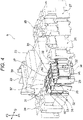
- Figs. 3 and 4 are perspective views showing a plurality of cassette blocks.
- Fig. 5 is a perspective view showing a drawing-in device.
- Fig. 6 is a perspective view showing the frame, a holding device, and the drawing-in device.
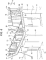
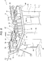
- Figs. 7 and 8 are perspective views showing a state in which the cassette blocks are temporarily inserted.
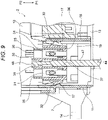
- Fig. 9 is a cross-sectional view taken along a line A-A in Fig. 8 .
- Figs. 1 is a configuration diagram showing an electrical junction box according to an embodiment of the present invention.
- Fig. 2 is a perspective view showing a frame.
- Figs. 3 and 4 are perspective views showing a plurality of cassette blocks.
- Fig. 5 is a perspective view showing a drawing-in device.
- Fig. 6 is a perspective view
- FIGS. 10 to 12 are perspective views showing a relationship between the cassette blocks in a temporarily inserted state and the drawing-in device.
- Fig. 13 is a perspective view showing a state in which the cassette blocks are fitted.
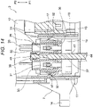
- Fig. 14 is a cross-sectional view taken along a line B-B in Fig. 13 .
- Fig. 15 is a perspective view showing a relationship between the cassette blocks in a fitted state and the drawing-in device.
- Figs. 16 and 17 are perspective views showing a relationship between the cassette blocks in a temporarily inserted state and the drawing-in device (before and after a sliding movement).
- an electrical junction box 1 according to the present embodiment that is mounted on an automobile supplies power to various devices and the like.
- the electrical junction box 1 includes an electrical junction box body 2, an upper cover 3, and a lower cover 4.
- Fig. 1 shows a state in which components are aligned on a manufacturing surface (when the electrical junction box 1 is mounted to the automobile, for example, the upper cover 3 is to be located at an upper side of the figure).
- Bundles of electric wires 5 and 6 are drawn out from the electrical junction box 1.
- the bundles of electric wires 5 and 6 are a part of a wire harness (not shown).
- the wire harness (not shown) is routed in the automobile along a predetermined path.
- the electrical junction box body 2 includes a frame 7 formed of a resin, a side cover 8 formed of the same type of resin, a group of cassette blocks 9, an external connection portion 10, and a plurality of several types of electronic components (fuses, relays, etc. (not shown)).
- the electrical junction box body 2 is manufactured by an assembly apparatus 39 (see Fig. 6 ) to be described later.
- the electrical junction box body 2 is manufactured according to a manufacturing method (a first step to a third step) to be described later.
- the electrical junction box body 2 is manufactured without performing a pushing work with a hand or a hand tool as in the related art.
- the frame 7 is a resin molded product, and is formed into a shape defined by a side wall 11.
- the frame 7 has a first opening 12 and a second opening 13 at two ends of the side wall 11.
- the first opening 12 is formed as an opening portion provided at an end portion (second end portion) of the frame 7 at a side in a direction (second direction) of an arrow P2 in the figure.
- the second opening 13 is formed as an opening portion provided at another end portion (first end portion) of the frame 7 at another side in another direction (first direction) of an arrow P1 in the figure.
- the side wall 11 When the second end portion at a second opening 13 side is set as a reference position, the side wall 11 is formed such that a height (a dimension along a direction of the arrows P1 and P2) thereof is partially different. In other words, the side wall 11 is formed such that the second opening 13 is opened in a planar manner and the first opening 12 is opened in a nonplanar manner.
- a plurality of lock portions (not shown) to be locked to the upper cover 3 and the lower cover 4 are formed on the side wall 11.
- the side wall 11 is formed with a fixed leg portion 14 for fixing the frame 7 to a vehicle body or the like, an attachment part (reference numeral omitted) for attaching the frame 7 to the side cover 8, an attachment portion 15 for attaching the frame 7 to the external connection portion 10, and a bundle of electric wires guide portion 16.
- a plurality of frame-side lock portions 17 are formed on an inner surface of the side wall 11.
- a plurality of partition walls 18 are formed at an inner side of the side wall 11 (inside the frame 7).
- a plurality of housing accommodation portions 19 are formed at the same inner side.
- the plurality of partition walls 18 are formed so as to partition accommodation portions for the cassette blocks (a first relay block 24, a second relay block 25 to be described later).
- the plurality of partition walls 18 are formed with a plurality of guide ribs 20 that function as guide portions when the cassette blocks are being attached.
- the guide ribs 20 are formed so as to extend straight along the direction of the arrows P1 and P2.
- the guide ribs 20 are formed at the inner side of the side wall 11 in a similar manner.
- the frame-side lock portions 17 see Fig.
- the accommodation portions for the cassette blocks are formed with stopper portions (reference numeral omitted) that prevent the cassette blocks from moving in the first direction (the direction of the arrow P1).
- the frame-side lock portions 17 are configured such that the cassette blocks accommodated in the accommodation portions are engaged to the frame-side lock portions 17.
- the frame-side lock portions 17 prevent the cassette blocks from escaping in the direction of the arrow P2.
- the bundle of electric wires guide portion 16 is formed into a substantially semi-cylindrical shape serving as a drawn-out portion for the bundle of electric wires 6. A portion that has the same function as the bundle of electric wires guide portion 16 is also formed at the side cover 8.
- a bundle of electric wires guide portion 21 formed at the side cover 8 is formed as a drawn-out portion for the bundle of electric wires 5.
- the attachment portion 15 is formed as an attachment portion for a holder 22 (see Fig. 3 ).
- the holder 22 is assembled to a fuse cassette block (fuse block 23) to be described later.
- the external connection portion 10 is provided at a portion of the holder 22.
- the external connection portion 10 is formed such that electric wires from a power supply (not shown) can be connected thereto.
- the group of cassette blocks 9 refers to all cassette blocks accommodated in the frame 7.
- the group of cassette blocks 9 in the present embodiment includes one fuse cassette block (fuse block 23) and five relay cassette blocks (first relay block 24 to fifth relay block 28).
- the second relay block 25 (a cassette block shown in solid lines with reference to Fig. 4 ) will be described as a representative example of the relay cassette blocks.
- the fuse cassette block, that is, the fuse block 23 will be described in the manufacturing method to be described later.
- the second relay block 25 is a relay cassette block as described above, and includes a housing 29 formed of a resin and a plurality of terminal fittings (not shown).
- the terminal fittings (not shown) are provided at terminals of electric wires 30 of the bundle of electric wires 5 and 6.
- the terminal fittings (not shown) are held by being inserted into a predetermined cavity 31 of the housing 29. That is, the terminal fittings are accommodated in the cavity 31.
- the housing 29 is formed into a substantially rectangular block shape (substantially rectangular parallelepiped shape).
- the housing 29 has a plurality of cavities 31.
- the cavity 31 is formed as a connection destination of a relay (not shown).
- the cavity 31 has a known shape.
- An outer shape (contour) of the housing 29 as viewed in a plane is fixed. This is because even when another second relay block 25 in which the number of cavities 31 is changed is adopted, the second relay block 25 can be accommodated without changing a shape of the frame 7.
- the housing 29 has a side portion 34 provided with a plurality of block-side locking portions 32 and guide grooves 33, an electric wire draw-out portion 35, and an electronic component connection portion 36.
- the housing 29 is formed into a substantially rectangular block shape.
- the block-side lock portion 32 is configured to be attached to the frame-side lock portion 17 of the frame 7 such that the second relay block 25 is prevented from escaping in the second direction (direction of the arrow P2).
- the guide grooves 33 is configured to be guided by being engaged with the guide ribs 20 of the frame 7.
- the guide grooves 33 are provided corresponding to a shape, the number, and an arrangement of the guide ribs 20.
- the electric wire draw-out portion 35 is a portion from which the electric wires 30 are drawn out.
- the electric wire draw-out portion 35 is provided at the side of the frame 7 where the first opening 12 is provided.
- the electronic component connection portion 36 is provided at an opposite side of the electric wire draw-out portion 35 and serves as a portion to which an electronic component such as a relay (not shown) is connected.
- the electronic component connection portion 36 is provided at the side of the frame 7 where the second opening 13 is provided.
- two hole portions 37 are formed in the housing 29.
- the hole portion 37 runs through the housing 29.
- the hole portion 37 runs through the housing 29 forming an opening each for the electric wire draw-out portion 35 and the electronic component connection portion 36.
- the hole portion 37 is formed to be a circular through-hole.
- the hole portion 37 extends straight.
- the hole portion 37 is an insertion portion into which a drawing-in pin 44 (see Fig. 5 ) of the assembly apparatus 39 (see Fig. 6 ) to be described later is to be inserted when the second relay block 25 is attached in the frame 7.
- the hole portion 37 can be used as a portion for detecting an erroneous assembly or the like (for example, an erroneous assembly can be detected when an arrangement of the hole portions 37 of the first relay block 24 or the third relay block 25 is different from that of the second relay block 25).
- the hole portion 37 is formed with an annular protruding portion (annular protruding wall) 50 having a relatively low height so as to separate the electric wires 30 drawn out from the electric wire draw-out portion 35 and the drawing-in pin 44.
- the annular protruding portion 50 has a height that does not interfere with an insertion work of the electric wires 30, that is, a low height as described above.
- a jig engagement portion 38 is formed on an inner surface of the hole portion 37.
- the jig engagement portion 38 is a portion with which the drawing-in pin 44 engages.
- the jig engagement portion 38 is formed in an intermediate portion inside the hole portion 37 and is formed at a side close to the electric wire draw-out portion 35 (just an example).
- the jig engagement portion 38 includes a pairof protruding portions protruding from an inner surface of the hole portion 37 toward the center of the hole portion 37.
- the jig engagement portion 38 is formed to allow a tip end portion 48 of the drawing-in pin 44 to pass through a space between the pair of the protruding portions.
- the jig engagement portion 38 is formed to be an engagement portion that engages with the tip end portion 48 when the drawing-in pin 44 is rotated by 90 degrees after the tip end portion 48 of the drawing-in pin 44 passes through the protruding portions inside the hole portion 37.
- the jig engagement portion 38 is an engagement portion formed for the drawing-in pin 44 of the assembly apparatus 39 according to the present embodiment, the jig engagement portion 38 may be an engagement portion of a simple jig.
- a jig engagement portion of the fuse cassette block (fuse block 23) is formed in a cave portion that passes through a side wall of a housing of the cassette block (to be described later with reference to Figs. 16 and 17 ).
- a drawing-in pin 45 to be described later slides into and engages with the cave portion.
- the upper cover 3 is a resin molded product and covers the side of the frame 7 where the second opening 13 is provided.
- the lower cover 4 is also a resin molded product and covers the side of the frame 7 where the first opening 12 is provided.
- the upper cover 3 and the lower cover 4 each includes a plurality of lock portions to be fitted to lock portions formed on an outer surface of the side wall 11 of the frame 7.
- a known structure is adopted for the upper cover 3 and the lower cover 4, and a detailed description thereof will be omitted here.
- the electrical junction box body 2 in Fig. 1 is manufactured by the assembly apparatus 39 in Fig. 6 .
- the assembly apparatus 39 includes a holding device 40 and a drawing-in device 41 (see Fig. 5 ).
- the holding device 40 is a device that holds the frame 7.
- the holding device 40 includes a holding table 42 (see Fig. 5 ) on which the frame 7 is to be placed, and a plurality of holding blocks 43 that hold the frame 7.
- a plurality of holding blocks 43 of various types are prepared corresponding to a shape of the side wall 11 of the frame 7.
- the holding table 42 also includes the drawing-in device 41 in addition to the plurality of holding blocks 43.
- the direction of the arrow P1 in the figure is defined as a fitting direction (first direction), and the direction of the arrow P2 is defined as a removing direction (second direction).
- the direction of the arrow P1 that is the fitting direction is a direction from the first opening 12 toward the second opening 13 of the frame 7.
- the direction of the arrow P2 that is the removing direction is a direction from the second opening 13 toward the first opening 12.
- the group of cassette blocks 9 in Fig. 3 is put in the frame 7 in the direction of the arrow P1 that is the fitting direction.
- a direction of an arrow Q is defined as a direction orthogonal to the direction of the arrow P1 that is the fitting direction and the direction of the arrow P2 that is the removing direction.
- the drawing-in device 41 includes a mechanism (not shown) that is movable in the direction of the arrow P1 that is the fitting direction and the direction of the arrow P2 that is the removing direction, a plurality of drawing-in pins 44 (jigs or devices) that performs a rotational movement, and a pair of drawing-in pins 45 (jigs or devices) that performs a sliding movement.
- the drawing-in device 41 is provided for accommodating the group of cassette blocks 9 in Fig. 3 in the frame 7, and can draw the group of cassette blocks 9 into the frame 7.
- the plurality of drawing-in pins 44 are assembled to a plurality of pin bases 46.
- the plurality of pin bases 46 are provided corresponding to the relay cassette blocks (the first relay block 24 to the fifth relay block 28).
- the rotational movement described above refers to a movement of rotating the plurality of drawing-in pins 44 by 90 degrees about an axis along the direction of the arrow P1 that is the fitting direction and the direction of the arrow P2 that is the removing direction.
- the drawing-in device 41 has a mechanism for performing a rotational movement.
- the plurality of drawing-in pins 44 each has a shaft portion 47 formed in a stepped pin shape (columnar shape having a stepped portion) and the tip end portion 48 provided at a tip end of the shaft portion 47.
- the drawing-in pins 44 are formed into a shape as shown in the figure.
- the shaft portion 47 is configured such that the shaft portion 47 is to be inserted into the hole portion 37 of the second relay block 25.
- the tip end portion 48 has a substantially semicircular shape when viewed from one angle and is flat when viewed from another angle.
- the tip end portion 48 can pass through the jig engagement portion 38 of the hole portion 37 (can pass through the space between the pair of protruding portions). When the tip end portion 48 is rotated by 90 degrees after the tip end portion 48 passes through the jig engagement portion 38, the tip end portion 48 engages with the jig engagement portion 38.
- a pair of drawing-in pins 45 are attached to a pair of brackets 49.
- the pair of drawing-in pins 45 has a short pin shape protruding in the direction of the arrow Q (protruding in a direction orthogonal to the first and second directions).
- the pair of drawing-in pins 45 are inserted into and engage with the cave portions (jig engagement portions 51, see Figs. 16 and 17 ) in the fuse cassette block (the fuse block 23).
- the pair of brackets 49 has a mechanism that enables movement in the direction of the arrow P1 and the direction of the arrow P2 and enables slide movement in the direction of the arrow Q.
- the jig engagement portions 51 to which the pair of drawing-in pins 45 are engaged are not limited to the cave portions, and may be portions the drawing-in pins 45 can engage with, such as stepped portions.
- the electrical junction box body 2 shown in Fig. 1 is manufactured by the following first to third steps (manufacturing method). First, the second relay block 25 will be described in an easy-to-understand manner, and then the fuse block 23 will be described in a brief manner.
- the frame 7 is held by the holding device 40 in the first step. Specifically, the frame 7 is placed on the holding table 42 with the side of the frame 7 where the first opening 12 is provided located upward, and then the plurality of holding blocks 43 are operated to bring the frame 7 into a held state shown in Fig. 6 . Although a plurality of drawing-in pins 44 are shown in Fig. 6 , in fact, the drawing-in pins 44 are to be at a lower position in the figure before rising in the direction of the arrow P2. When the frame 7 is held by the holding device 40, the manufacturing method proceeds to the second step.
- the cassette blocks (such as the second relay block 25) are set in the frame 7 one by one from the side where the first opening 12 is provided along the fitting direction indicated by the arrow P1.
- the second relay block 25 is inserted into the frame 7 from the first opening 12 with a side close to the electric wire draw-out portion 35 where the electric wires 30 are drawn out located upward and a side close to the electronic component connection portion 36 located downward.
- a worker temporarily inserts the second relay block 25 into a predetermined accommodation position of the frame 7.
- temporaryly insert refers to a state before the frame-side lock portion 17 and the block-side lock portion 32 are fitted.
- the cassette blocks are drawn into the frame 7 by the drawing-in device 41 and then the cassette blocks are brought into a state of being fitted to the frame 7 in the third step.
- the third step is described by taking the second relay block 25 as an example.
- the drawing-in pins 44 are raised in the direction of the arrow P2 to bring the drawing-in pins 44 into an insertion state of being inserted into the hole portions 37 of the second relay block 25.
- the tip end portion 48 of the drawing-in pin 44 passes through the space between the pair of protruding portions of the jig engagement portion 38.
- the tip end portion 48 does not protrude outward from the annular protruding portion 50 of the hole portion 37, and is not in contact with the electric wires 30.
- a direction of the tip end portion 48 changes from a state shown in Fig. 10 to a state shown in Fig. 15 . That is, the tip end portion 48 is changed into a state in which the tip end portion 48 can be engaged with the jig engagement portion 38.
- the drawing-in pin 44 is moved downward in the direction of the arrow P1 to draw the second relay block 25 into the frame 7, the frame-side lock portion 17 and the block-side lock portion 32 can be engaged with each other.
- the second relay block 25 can be brought into a fitted state with respect to the frame 7.
- the drawing-in pin 44 is moved downward in the direction of the arrow P1
- the tip end portion 48 is engaged with the jig engagement portion 38
- the second relay block 25 is drawn into the frame 7.
- the fuse block 23 includes a pair of jig engagement portions 51.
- the pair of jig engagement portions 51 are formed on a side wall 53 of a housing 52.
- circular hole portions that runs through predetermined positions of the side wall 53 are formed as the jig engagement portions 51.
- the drawing-in pins 45 are respectively inserted into the jig engagement portions 51.
- a bracket base 54 having a pair of brackets 49 is raised in the direction of the arrow P2, and the bracket base 54 is inserted into the housing 52.
- the bracket base 54 slides in the direction of the arrow Q after being inserted, the drawing-in pins 45 respectively provided on the pair of brackets 49 are inserted into the pair of jig engagement portions 51 and are brought into an engaged state as shown in Fig. 17 .
- the bracket base 54 is moved downward (not shown) in the direction of the arrow P1 from the engaged state, since the drawing-in pins 45 are engaged with the jig engagement portions 51, the fuse block 23 is drawn into the frame 7.
- the bracket base 54 is inserted into the housing 52, the present invention is not limited thereto. That is, the fuse block 23 may be drawn into the frame 7 by the bracket base 54 rising, sliding, and moving downward outside the housing 52.
- the second relay block 25 can be fitted to the frame 7 by being drawn into the frame 7 by using the jig engagement portion 38.
- the second relay block 25 can be fitted to the frame 7 without pushing, with a hand or a hand tool as in the related art, a side of the second relay block 25 where the electric wires 30 are drawn out.
- the electrical junction box 1 (the electrical junction box body 2)
- the electric wires 30 can be prevented from being damaged or disconnected during a manufacturing work. Accordingly, quality of the electrical junction box 1 (the electrical junction box body 2) can be improved compared with that in the related art.
- the cassette blocks can be fitted to the frame 7 without pushing, with a hand or a hand tool, the side of the cassette blocks where the electric wires 30 are drawn out. Further, a better wire harness can be provided that includes the electric connection box 1.
- an electrical junction box includes a frame and a cassette block from which a plurality of electric wires are drawn out.
- the frame has a side wall defining a shape of the frame, the frame having a first opening and a second opening provided at two ends of the side wall.
- the cassette block is configured to be attached to the frame from the first opening along a first direction and the plurality of electric wires are drawn out along a second direction when the cassette block is attached to the frame, the first direction being a direction oriented toward the second opening from the first opening, the second direction being another direction oriented toward the first opening from the second opening.
- the cassette block has a jig engagement portion.
- the jig engagement portion is configured such that a jig or device which has been inserted into the frame and the cassette block from a side of the second opening along the second direction can engage with the jig engagement portion and the cassette block can be drawn into the frame by the jig or device inserted into the cassette block moving in the first direction.
- the cassette block can be fitted to the frame by being drawn into the frame by using the jig engagement portion.
- the cassette block can be fitted to the frame without being pushed, with a hand or a hand tool, on a side where the electric wires are drawn out.
- the electric wires can be prevented from being damaged or disconnected during a manufacturing work. Therefore, quality of the electrical junction box can be improved compared with those in the related art.
- the jig or device inserted into the cassette block may engage with the jig engagement portion by the jig or device rotating about an axis along the first and second directions.
- the jig or device engages with the jig engagement portion when the jig or device is rotated after the jig or device is inserted into the cassette block. Therefore, the cassette block can be easily drawn into the frame without using a jig or device or a jig engagement portion having a complicated structure or mechanism.
- the jig or device inserted into the cassette block may engage with the jig engagement portion by the jig or device sliding along yet another direction orthogonal to the first and second directions.
- the jig or device engages with the jig engagement portion when the jig or device slides after the jig or device is inserted into the cassette block. Therefore, the cassette block can be easily drawn into the frame without using a jig or device or a jig engagement portion having a complicated structure or mechanism.
- the jig engagement portion may be provided in a hole portion of the cassette block, the hole portion being configured such that the jig or device can be inserted into or removed from the hole portion.
- the cassette block can be drawn into the frame without using a jig or device or a jig engagement portion having a complicated structure or mechanism. According to the present invention, since the jig or device can be inserted into or removed from the hole portion, the jig or device can be protected by being separated from a functional portion of the cassette block.
- the hole portion may run through the cassette block up to a portion from which the plurality of electric wires are drawn out, and is formed with an annular protruding wall at an opening portion of the hole portion, the annular protruding wall being provided on a same side of the cassette block as the portion from which the plurality of electric wires are drawn out and being configured to separate the jig or device from the plurality of electric wires.
- the hole portion that runs through the cassette block up to a position of the electric wire draw-out portion is formed with the annular protruding portion (annular protruding wall) at an opening portion of the hole portion provided on the same side of the cassette block as where the electric wire draw-out portion is provided, the electric wires drawn out from the electric wire draw-out portion and the jig or device can be separated. Therefore, the electric wires can be protected.
- the annular protruding portion is not a long cylinder but an annular protruding portion (that is, the annular protruding portion being a short/low cylinder), the annular protruding portion does not interfere with an insertion work of the electric wires, and as a result, the good workability can be maintained.
- a position where the hole portion is provided may vary depending on types of the cassette block.
- the hole portions can have a function of preventing an erroneous assembly.
- An assembly apparatus for assembling the electrical junction box includes a holding device and a drawing-in device.
- the holding device is configured to hold the frame.
- the drawing-in device is configured to attach the cassette block to the frame by drawing the cassette block into the frame.
- the drawing-in device includes the jig or device configured, when the cassette block is attached to the frame, to be inserted into the cassette block from the side of the second opening along the second direction, then to engage with the cassette block and to move toward the first direction.
- the assembly apparatus for assembling the electrical junction box having the above-described configuration, it is possible to provide an assembly apparatus for fitting the cassette block to the frame without the cassette block being pushed, with a hand or a hand tool, on a side where the electric wires are drawn out.
- the present invention since the side where the electric wires are drawn out is not pushed, the electric wires can be prevented from being damaged or disconnected during a manufacturing work. Therefore, quality of the electrical junction box can be improved compared with that in the related art.
- a manufacturing method of the electrical junction box includes holding the frame by a holding device, putting the cassette block, in the frame from the first opening along the first direction such that the plurality of electric wires are drawn out in the second direction, and attaching the cassette block to the frame by drawing the cassette block into the frame.
- the attaching includes a jig or device being inserted into the cassette block from a side of the second opening along the second direction, the jig or device getting engaged with the jig engagement portion of the cassette block after being inserted into the cassette block and the jig or device moving in the first direction, thereby attaching the cassette block to the frame.
- the manufacturing method of the electrical junction box having the above-described configuration, it is possible to provide a manufacturing method for fitting the cassette block to the frame without the cassette block being pushed, with a hand or a hand tool, on a side where the electric wires are drawn out.
- the present invention since the side where the electric wires are drawn out is not pushed, the electric wires can be prevented from being damaged or disconnected during a manufacturing work. Therefore, quality of the electrical junction box can be improved compared with those in the related art.
- a wire harness includes the electrical junction box provided at a terminal of the wire harness and is to be routed in an automobile.
Landscapes
- Engineering & Computer Science (AREA)
- Mechanical Engineering (AREA)
- Power Engineering (AREA)
- Architecture (AREA)
- Civil Engineering (AREA)
- Structural Engineering (AREA)
- Manufacturing & Machinery (AREA)
- Connection Or Junction Boxes (AREA)
- Insulated Conductors (AREA)
Claims (9)
- Elektrischer Verteilerkasten, der enthält:einen Rahmen (7) sowie einen Kassettenblock (23, 25), aus dem eine Vielzahl elektrischer Drähte (30) herausgeführt werden,wobei der Rahmen (7) eine Seitenwand (11) aufweist, die eine Form des Rahmens (7) bestimmt, der Rahmen (7) eine erste Öffnung (12) und eine zweite Öffnung (13) aufweist, die an zwei Enden der Seitenwand (11) vorhanden sind,der Kassettenblock (23, 25) so ausgeführt ist, dass er über die erste Öffnung (12) entlang einer ersten Richtung (P1) an dem Rahmen (7) angebracht wird und die Vielzahl elektrischer Drähte (30) entlang einer zweiten Richtung (P2) herausgeführt werden, wenn der Kassettenblock (23, 25) an dem Rahmen (7) angebracht ist, wobei die erste Richtung (P1) eine Richtung ist, die von der ersten Öffnung (12) zu der zweiten Öffnung (13) hin ausgerichtet ist, und die zweite Richtung (P2) eine andere Richtung ist, die von der zweiten Öffnung (13) zu der ersten Öffnung (12) hin ausgerichtet ist, undder Kassettenblock (23, 25) einen Werkzeug-Eingriffsabschnitt (38) aufweist,dadurch gekennzeichnet, dassder Werkzeug-Eingriffsabschnitt (38) so ausgeführt ist, dass ein Werkzeug oder eine Vorrichtung (44, 45), das/die in den Rahmen (7) und den Kassettenblock (23, 25) von einer Seite der zweiten Öffnung (13) her entlang der zweiten Richtung (P2) eingeführt worden ist, mit dem Werkzeug-Eingriffsabschnitt (38, 51) in Eingriff kommen kann und der Kassettenblock (23, 25) dadurch in den Rahmen (7) eingezogen werden kann, dass sich das/die in den Kassettenblock (23, 25) eingeführte Werkzeug oder Vorrichtung (44, 45) in der ersten Richtung (P1) bewegt.
- Elektrischer Verteilerkasten nach Anspruch 1,
wobei der Werkzeug-Eingriffsabschnitt (38) so ausgeführt ist, dass das Werkzeug oder die Vorrichtung (44), das/die in den Rahmen (7) und den Kassettenblock (25) eingeführt worden ist, mit dem Werkzeug-Eingriffsabschnitt (38) in Eingriff kommen kann, indem sich das Werkzeug oder die Vorrichtung (44) um eine Achse entlang der ersten und der zweiten Richtung (P1, P2) dreht. - Elektrischer Verteilerkasten nach Anspruch 1,
wobei der Werkzeug-Eingriffsabschnitt (51) so ausgeführt ist, dass das Werkzeug oder die Vorrichtung (45), das/die in den Rahmen (7) und den Kassettenblock (23) eingeführt worden ist, mit dem Werkzeug-Eingriffsabschnitt (51) in Eingriff kommen kann, indem das Werkzeug oder die Vorrichtung (45) entlang einer weiteren anderen Richtung orthogonal zu der ersten und der zweiten Richtung (P1, P2) gleitet. - Elektrischer Verteilerkasten nach Anspruch 2,
wobei der Werkzeug-Eingriffsabschnitt (38) in einem Lochabschnitt (37) des Kassettenblocks (25) vorhanden ist, wobei der Lochabschnitt (37) so ausgeführt ist, dass das Werkzeug oder die Vorrichtung (44) in den Lochabschnitt (37) eingeführt oder aus ihm entfernt werden kann. - Elektrischer Verteilerkasten nach Anspruch 4,
wobei der Lochabschnitt (37) durch den Kassettenblock (25) hindurch bis zu einem Abschnitt verläuft, über den die Vielzahl elektrischer Drähte (30) herausgeführt wird, und mit einer ringförmigen vorstehenden Wand (50) an einem Öffnungsabschnitt des Lochabschnitts (37) versehen ist, wobei die ringförmige vorstehende Wand (50) an der gleichen Seite des Kassettenblocks (25) vorhanden ist wie der Abschnitt, über den die Vielzahl elektrischer Drähte (30) herausgeführt wird, und so ausgeführt ist, dass sie das Werkzeug oder die Vorrichtung (44) von der Vielzahl elektrischer Drähte (30) trennt. - Elektrischer Verteilerkasten nach Anspruch 4 oder 5,
wobei eine Position, an der der Lochabschnitt (37) vorhanden ist, in Abhängigkeit von Typen des Kassettenblocks (25) variiert. - Montagevorrichtung zum Montieren des elektrischen Verteilerkastens (1) nach Anspruch 1, die enthält:eine Haltevorrichtung (40) und eine Einziehvorrichtung (41),wobei die Haltevorrichtung (40) so ausgeführt ist, dass sie den Rahmen (7) hält,die Einziehvorrichtung (41) so ausgeführt ist, dass sie den Kassettenblock (23, 25) an dem Rahmen (7) anbringt, indem sie den Kassettenblock (23, 25) in den Rahmen (7) hinein zieht, unddie Einziehvorrichtung (41) das Werkzeug oder die Vorrichtung (44, 45) einschließt, das/die so ausgeführt ist, dass es/sie, wenn der Kassettenblock (23, 25) an dem Rahmen (7) angebracht ist, von der Seite der zweiten Öffnung (13) her entlang der zweiten Richtung (P2) in den Kassettenblock (23, 25) eingeführt wird, dann mit dem Kassettenblock (23, 25) in Eingriff kommt und sich auf die erste Richtung (P1) zu bewegt.
- Verfahren zum Herstellen eines elektrischen Verteilerkastens (1) nach einem der Ansprüche 1 bis 6, das einschließt:Halten des Rahmens (7) mit einer Haltevorrichtung (40), Einsetzen des Kassettenblocks (23, 25) in den Rahmen (7) über die erste Öffnung (12) entlang der ersten Richtung (P1), so dass die Vielzahl elektrischer Drähte (30) in der zweiten Richtung (P2) herausgeführt wird, undAnbringen des Kassettenblocks (23, 25) an dem Rahmen (7) durch Hineinziehen des Kassettenblocks (23, 25) in den Rahmen (7),wobei das Anbringen einschließt, dass ein Werkzeug oder eine Vorrichtung (44, 45), das/die von einer Seite der zweiten Öffnung (13) her entlang der zweiten Richtung (P2) in den Kassettenblock (23, 25) eingeführt wird; das Werkzeug oder die Vorrichtung (44, 45) nach Einführen in den Kassettenblock (23, 25) mit dem Werkzeug-Eingriffsabschnitt (38) des Kassettenblocks (23, 25) in Eingriff gebracht wird; und das Werkzeug oder die Vorrichtung (44, 45) sich in der ersten Richtung (P1) bewegt und dadurch der Kassettenblock (23, 25) an dem Rahmen (7) angebracht wird.
- Kabelbaum, der den elektrischen Verteilerkasten (1) nach einem der Ansprüche 1 bis 6 enthält,
wobei der elektrische Verteilerkasten (1) an einem Anschluss des Kabelbaums vorhanden ist und der Kabelbaum in einem Kraftfahrzeug verlegt wird.
Applications Claiming Priority (1)
| Application Number | Priority Date | Filing Date | Title |
|---|---|---|---|
| JP2019233955A JP7017551B2 (ja) | 2019-12-25 | 2019-12-25 | 電気接続箱、電気接続箱の製造装置、電気接続箱の製造方法及びワイヤハーネス |
Publications (2)
| Publication Number | Publication Date |
|---|---|
| EP3842291A1 EP3842291A1 (de) | 2021-06-30 |
| EP3842291B1 true EP3842291B1 (de) | 2022-04-27 |
Family
ID=73856860
Family Applications (1)
| Application Number | Title | Priority Date | Filing Date |
|---|---|---|---|
| EP20216582.5A Active EP3842291B1 (de) | 2019-12-25 | 2020-12-22 | Stromverteilerkasten, vorrichtung zur herstellung eines stromverteilerkastens, verfahren zur herstellung eines stromverteilerkastens und kabelbaum |
Country Status (4)
| Country | Link |
|---|---|
| US (1) | US11318898B2 (de) |
| EP (1) | EP3842291B1 (de) |
| JP (1) | JP7017551B2 (de) |
| CN (1) | CN113036631B (de) |
Families Citing this family (1)
| Publication number | Priority date | Publication date | Assignee | Title |
|---|---|---|---|---|
| JP6919599B2 (ja) * | 2018-03-05 | 2021-08-18 | 住友電装株式会社 | 電気接続箱 |
Citations (1)
| Publication number | Priority date | Publication date | Assignee | Title |
|---|---|---|---|---|
| JP4348059B2 (ja) * | 2002-08-30 | 2009-10-21 | 矢崎総業株式会社 | 布線シートおよび電気接続箱ならびに電線の切断方法 |
Family Cites Families (20)
| Publication number | Priority date | Publication date | Assignee | Title |
|---|---|---|---|---|
| US6022247A (en) * | 1996-12-10 | 2000-02-08 | Yazaki Corporation | Electric wiring block |
| JP3489718B2 (ja) * | 1996-12-10 | 2004-01-26 | 矢崎総業株式会社 | 電気配線ブロック |
| JP2002231367A (ja) * | 2001-01-31 | 2002-08-16 | Fujikura Ltd | コネクタハウジング並びにそれを用いたコネクタ及びその製造方法 |
| ITTO20020701A1 (it) * | 2002-08-06 | 2004-02-07 | Framatome Connectors Int | Connettore elettrico. |
| JP5156499B2 (ja) * | 2008-06-19 | 2013-03-06 | 矢崎総業株式会社 | 電気接続箱 |
| KR101529067B1 (ko) * | 2009-06-29 | 2015-06-16 | 한국단자공업 주식회사 | 전원 연결 박스 |
| JP5420994B2 (ja) | 2009-06-30 | 2014-02-19 | 矢崎総業株式会社 | 電気接続箱 |
| JP5348495B2 (ja) * | 2009-11-26 | 2013-11-20 | 株式会社オートネットワーク技術研究所 | 回路構成体及び電気接続箱 |
| JP5885392B2 (ja) * | 2011-03-25 | 2016-03-15 | 矢崎総業株式会社 | 電気接続箱 |
| JP5846750B2 (ja) * | 2011-03-25 | 2016-01-20 | 矢崎総業株式会社 | 収納箱および電気接続箱 |
| JP5875154B2 (ja) * | 2012-07-25 | 2016-03-02 | 矢崎総業株式会社 | 電気接続箱 |
| DE112014001287B4 (de) * | 2013-03-14 | 2023-04-20 | Yazaki Corporation | Elektronische Baugruppenstruktur und elektrischer Verteilerkasten |
| JP6378939B2 (ja) * | 2014-06-06 | 2018-08-22 | 矢崎総業株式会社 | カセット式電気接続箱 |
| JP6294790B2 (ja) * | 2014-08-12 | 2018-03-14 | 矢崎総業株式会社 | 被支持部材と支持体との支持構造及び電気接続箱 |
| KR101553702B1 (ko) | 2014-12-24 | 2015-09-30 | 한국단자공업 주식회사 | 차량용 블럭 |
| US10355465B2 (en) * | 2015-10-12 | 2019-07-16 | Sumitomo Wiring Systems, Ltd. | Reduced height relay block for vehicle power distribution device |
| JP6510574B2 (ja) * | 2017-02-14 | 2019-05-08 | 矢崎総業株式会社 | 電子部品ユニット、及び、ワイヤハーネス |
| DE102017105077B4 (de) * | 2017-03-10 | 2018-09-20 | Phoenix Contact Gmbh & Co. Kg | Kontakteinsatz für ein Steckverbinderteil |
| DE102017108432A1 (de) * | 2017-04-20 | 2018-10-25 | Harting Electric Gmbh & Co. Kg | Halterahmen für einen Steckverbinder und Verfahren zur Bestückung |
| JP7076265B2 (ja) * | 2018-04-03 | 2022-05-27 | スリーエム イノベイティブ プロパティズ カンパニー | コネクタ |
-
2019
- 2019-12-25 JP JP2019233955A patent/JP7017551B2/ja active Active
-
2020
- 2020-12-22 EP EP20216582.5A patent/EP3842291B1/de active Active
- 2020-12-23 CN CN202011536585.0A patent/CN113036631B/zh active Active
- 2020-12-23 US US17/133,536 patent/US11318898B2/en active Active
Patent Citations (1)
| Publication number | Priority date | Publication date | Assignee | Title |
|---|---|---|---|---|
| JP4348059B2 (ja) * | 2002-08-30 | 2009-10-21 | 矢崎総業株式会社 | 布線シートおよび電気接続箱ならびに電線の切断方法 |
Also Published As
| Publication number | Publication date |
|---|---|
| US11318898B2 (en) | 2022-05-03 |
| EP3842291A1 (de) | 2021-06-30 |
| JP2021103914A (ja) | 2021-07-15 |
| CN113036631A (zh) | 2021-06-25 |
| CN113036631B (zh) | 2023-03-28 |
| US20210197742A1 (en) | 2021-07-01 |
| JP7017551B2 (ja) | 2022-02-08 |
Similar Documents
| Publication | Publication Date | Title |
|---|---|---|
| US9233615B2 (en) | Vehicle-side connector having a housing with wire draw-out openings in different directions | |
| JP5704350B2 (ja) | 電気接続箱 | |
| CN107317282B (zh) | 电气接线箱和线束 | |
| CN108475903B (zh) | 用于线束的保护器和用于制造线束的方法 | |
| JP2005237196A (ja) | ジャンクションボックス及びその組立方法 | |
| US20140256196A1 (en) | Connector and method of making the same | |
| EP3792115B1 (de) | Stromverteilerkasten | |
| JP2003324822A (ja) | 電気接続箱 | |
| JP7284134B2 (ja) | 電気接続箱の組付け構造及び保持部の収容方法 | |
| EP3842291B1 (de) | Stromverteilerkasten, vorrichtung zur herstellung eines stromverteilerkastens, verfahren zur herstellung eines stromverteilerkastens und kabelbaum | |
| KR20010103715A (ko) | 전기커넥터 | |
| JP2017127078A (ja) | 電気接続箱及びワイヤハーネス | |
| JPH01157073A (ja) | 電気装置ユニットの電気的端子結合デバイス,該デバイスを備えたしゃ段器および関連する部品の組立品 | |
| US11101627B2 (en) | Electrical connection box and wire harness | |
| JP2016208673A (ja) | 電気接続箱及びワイヤハーネス | |
| US10374370B2 (en) | Electronic unit attaching structure | |
| JP2018121448A (ja) | プロテクタ、及び、ワイヤハーネス | |
| JP2017171153A (ja) | クランプ | |
| JP6494397B2 (ja) | 電気接続箱及びワイヤハーネス | |
| CN111313341A (zh) | 电连接部位的罩结构 | |
| CN113471895B (zh) | 保护器以及线束 | |
| CN106505495B (zh) | 电气接线箱 | |
| JP2018063928A (ja) | ヒューズボックス | |
| JP4686407B2 (ja) | ハウジング保持治具 | |
| KR101350406B1 (ko) | 리테이너 체결지그 |
Legal Events
| Date | Code | Title | Description |
|---|---|---|---|
| PUAI | Public reference made under article 153(3) epc to a published international application that has entered the european phase |
Free format text: ORIGINAL CODE: 0009012 |
|
| STAA | Information on the status of an ep patent application or granted ep patent |
Free format text: STATUS: REQUEST FOR EXAMINATION WAS MADE |
|
| 17P | Request for examination filed |
Effective date: 20201222 |
|
| AK | Designated contracting states |
Kind code of ref document: A1 Designated state(s): AL AT BE BG CH CY CZ DE DK EE ES FI FR GB GR HR HU IE IS IT LI LT LU LV MC MK MT NL NO PL PT RO RS SE SI SK SM TR |
|
| STAA | Information on the status of an ep patent application or granted ep patent |
Free format text: STATUS: EXAMINATION IS IN PROGRESS |
|
| 17Q | First examination report despatched |
Effective date: 20211027 |
|
| GRAP | Despatch of communication of intention to grant a patent |
Free format text: ORIGINAL CODE: EPIDOSNIGR1 |
|
| STAA | Information on the status of an ep patent application or granted ep patent |
Free format text: STATUS: GRANT OF PATENT IS INTENDED |
|
| INTG | Intention to grant announced |
Effective date: 20220209 |
|
| GRAS | Grant fee paid |
Free format text: ORIGINAL CODE: EPIDOSNIGR3 |
|
| GRAA | (expected) grant |
Free format text: ORIGINAL CODE: 0009210 |
|
| STAA | Information on the status of an ep patent application or granted ep patent |
Free format text: STATUS: THE PATENT HAS BEEN GRANTED |
|
| AK | Designated contracting states |
Kind code of ref document: B1 Designated state(s): AL AT BE BG CH CY CZ DE DK EE ES FI FR GB GR HR HU IE IS IT LI LT LU LV MC MK MT NL NO PL PT RO RS SE SI SK SM TR |
|
| REG | Reference to a national code |
Ref country code: GB Ref legal event code: FG4D |
|
| REG | Reference to a national code |
Ref country code: CH Ref legal event code: EP |
|
| REG | Reference to a national code |
Ref country code: AT Ref legal event code: REF Ref document number: 1486717 Country of ref document: AT Kind code of ref document: T Effective date: 20220515 |
|
| REG | Reference to a national code |
Ref country code: DE Ref legal event code: R096 Ref document number: 602020002862 Country of ref document: DE |
|
| REG | Reference to a national code |
Ref country code: IE Ref legal event code: FG4D |
|
| REG | Reference to a national code |
Ref country code: LT Ref legal event code: MG9D |
|
| REG | Reference to a national code |
Ref country code: NL Ref legal event code: MP Effective date: 20220427 |
|
| REG | Reference to a national code |
Ref country code: AT Ref legal event code: MK05 Ref document number: 1486717 Country of ref document: AT Kind code of ref document: T Effective date: 20220427 |
|
| PG25 | Lapsed in a contracting state [announced via postgrant information from national office to epo] |
Ref country code: NL Free format text: LAPSE BECAUSE OF FAILURE TO SUBMIT A TRANSLATION OF THE DESCRIPTION OR TO PAY THE FEE WITHIN THE PRESCRIBED TIME-LIMIT Effective date: 20220427 |
|
| PG25 | Lapsed in a contracting state [announced via postgrant information from national office to epo] |
Ref country code: SE Free format text: LAPSE BECAUSE OF FAILURE TO SUBMIT A TRANSLATION OF THE DESCRIPTION OR TO PAY THE FEE WITHIN THE PRESCRIBED TIME-LIMIT Effective date: 20220427 Ref country code: PT Free format text: LAPSE BECAUSE OF FAILURE TO SUBMIT A TRANSLATION OF THE DESCRIPTION OR TO PAY THE FEE WITHIN THE PRESCRIBED TIME-LIMIT Effective date: 20220829 Ref country code: NO Free format text: LAPSE BECAUSE OF FAILURE TO SUBMIT A TRANSLATION OF THE DESCRIPTION OR TO PAY THE FEE WITHIN THE PRESCRIBED TIME-LIMIT Effective date: 20220727 Ref country code: LT Free format text: LAPSE BECAUSE OF FAILURE TO SUBMIT A TRANSLATION OF THE DESCRIPTION OR TO PAY THE FEE WITHIN THE PRESCRIBED TIME-LIMIT Effective date: 20220427 Ref country code: HR Free format text: LAPSE BECAUSE OF FAILURE TO SUBMIT A TRANSLATION OF THE DESCRIPTION OR TO PAY THE FEE WITHIN THE PRESCRIBED TIME-LIMIT Effective date: 20220427 Ref country code: GR Free format text: LAPSE BECAUSE OF FAILURE TO SUBMIT A TRANSLATION OF THE DESCRIPTION OR TO PAY THE FEE WITHIN THE PRESCRIBED TIME-LIMIT Effective date: 20220728 Ref country code: FI Free format text: LAPSE BECAUSE OF FAILURE TO SUBMIT A TRANSLATION OF THE DESCRIPTION OR TO PAY THE FEE WITHIN THE PRESCRIBED TIME-LIMIT Effective date: 20220427 Ref country code: BG Free format text: LAPSE BECAUSE OF FAILURE TO SUBMIT A TRANSLATION OF THE DESCRIPTION OR TO PAY THE FEE WITHIN THE PRESCRIBED TIME-LIMIT Effective date: 20220727 Ref country code: AT Free format text: LAPSE BECAUSE OF FAILURE TO SUBMIT A TRANSLATION OF THE DESCRIPTION OR TO PAY THE FEE WITHIN THE PRESCRIBED TIME-LIMIT Effective date: 20220427 |
|
| PG25 | Lapsed in a contracting state [announced via postgrant information from national office to epo] |
Ref country code: RS Free format text: LAPSE BECAUSE OF FAILURE TO SUBMIT A TRANSLATION OF THE DESCRIPTION OR TO PAY THE FEE WITHIN THE PRESCRIBED TIME-LIMIT Effective date: 20220427 Ref country code: PL Free format text: LAPSE BECAUSE OF FAILURE TO SUBMIT A TRANSLATION OF THE DESCRIPTION OR TO PAY THE FEE WITHIN THE PRESCRIBED TIME-LIMIT Effective date: 20220427 Ref country code: LV Free format text: LAPSE BECAUSE OF FAILURE TO SUBMIT A TRANSLATION OF THE DESCRIPTION OR TO PAY THE FEE WITHIN THE PRESCRIBED TIME-LIMIT Effective date: 20220427 Ref country code: IS Free format text: LAPSE BECAUSE OF FAILURE TO SUBMIT A TRANSLATION OF THE DESCRIPTION OR TO PAY THE FEE WITHIN THE PRESCRIBED TIME-LIMIT Effective date: 20220827 |
|
| REG | Reference to a national code |
Ref country code: DE Ref legal event code: R097 Ref document number: 602020002862 Country of ref document: DE |
|
| PG25 | Lapsed in a contracting state [announced via postgrant information from national office to epo] |
Ref country code: SM Free format text: LAPSE BECAUSE OF FAILURE TO SUBMIT A TRANSLATION OF THE DESCRIPTION OR TO PAY THE FEE WITHIN THE PRESCRIBED TIME-LIMIT Effective date: 20220427 Ref country code: SK Free format text: LAPSE BECAUSE OF FAILURE TO SUBMIT A TRANSLATION OF THE DESCRIPTION OR TO PAY THE FEE WITHIN THE PRESCRIBED TIME-LIMIT Effective date: 20220427 Ref country code: RO Free format text: LAPSE BECAUSE OF FAILURE TO SUBMIT A TRANSLATION OF THE DESCRIPTION OR TO PAY THE FEE WITHIN THE PRESCRIBED TIME-LIMIT Effective date: 20220427 Ref country code: ES Free format text: LAPSE BECAUSE OF FAILURE TO SUBMIT A TRANSLATION OF THE DESCRIPTION OR TO PAY THE FEE WITHIN THE PRESCRIBED TIME-LIMIT Effective date: 20220427 Ref country code: EE Free format text: LAPSE BECAUSE OF FAILURE TO SUBMIT A TRANSLATION OF THE DESCRIPTION OR TO PAY THE FEE WITHIN THE PRESCRIBED TIME-LIMIT Effective date: 20220427 Ref country code: DK Free format text: LAPSE BECAUSE OF FAILURE TO SUBMIT A TRANSLATION OF THE DESCRIPTION OR TO PAY THE FEE WITHIN THE PRESCRIBED TIME-LIMIT Effective date: 20220427 Ref country code: CZ Free format text: LAPSE BECAUSE OF FAILURE TO SUBMIT A TRANSLATION OF THE DESCRIPTION OR TO PAY THE FEE WITHIN THE PRESCRIBED TIME-LIMIT Effective date: 20220427 |
|
| PGFP | Annual fee paid to national office [announced via postgrant information from national office to epo] |
Ref country code: DE Payment date: 20221102 Year of fee payment: 3 |
|
| PLBE | No opposition filed within time limit |
Free format text: ORIGINAL CODE: 0009261 |
|
| STAA | Information on the status of an ep patent application or granted ep patent |
Free format text: STATUS: NO OPPOSITION FILED WITHIN TIME LIMIT |
|
| PG25 | Lapsed in a contracting state [announced via postgrant information from national office to epo] |
Ref country code: AL Free format text: LAPSE BECAUSE OF FAILURE TO SUBMIT A TRANSLATION OF THE DESCRIPTION OR TO PAY THE FEE WITHIN THE PRESCRIBED TIME-LIMIT Effective date: 20220427 |
|
| 26N | No opposition filed |
Effective date: 20230130 |
|
| PG25 | Lapsed in a contracting state [announced via postgrant information from national office to epo] |
Ref country code: SI Free format text: LAPSE BECAUSE OF FAILURE TO SUBMIT A TRANSLATION OF THE DESCRIPTION OR TO PAY THE FEE WITHIN THE PRESCRIBED TIME-LIMIT Effective date: 20220427 |
|
| REG | Reference to a national code |
Ref country code: BE Ref legal event code: MM Effective date: 20221231 |
|
| PG25 | Lapsed in a contracting state [announced via postgrant information from national office to epo] |
Ref country code: LU Free format text: LAPSE BECAUSE OF NON-PAYMENT OF DUE FEES Effective date: 20221222 |
|
| PG25 | Lapsed in a contracting state [announced via postgrant information from national office to epo] |
Ref country code: IE Free format text: LAPSE BECAUSE OF NON-PAYMENT OF DUE FEES Effective date: 20221222 |
|
| PG25 | Lapsed in a contracting state [announced via postgrant information from national office to epo] |
Ref country code: FR Free format text: LAPSE BECAUSE OF NON-PAYMENT OF DUE FEES Effective date: 20221231 Ref country code: BE Free format text: LAPSE BECAUSE OF NON-PAYMENT OF DUE FEES Effective date: 20221231 |
|
| PG25 | Lapsed in a contracting state [announced via postgrant information from national office to epo] |
Ref country code: IT Free format text: LAPSE BECAUSE OF FAILURE TO SUBMIT A TRANSLATION OF THE DESCRIPTION OR TO PAY THE FEE WITHIN THE PRESCRIBED TIME-LIMIT Effective date: 20220427 |
|
| PG25 | Lapsed in a contracting state [announced via postgrant information from national office to epo] |
Ref country code: CY Free format text: LAPSE BECAUSE OF FAILURE TO SUBMIT A TRANSLATION OF THE DESCRIPTION OR TO PAY THE FEE WITHIN THE PRESCRIBED TIME-LIMIT Effective date: 20220427 |
|
| PG25 | Lapsed in a contracting state [announced via postgrant information from national office to epo] |
Ref country code: MK Free format text: LAPSE BECAUSE OF FAILURE TO SUBMIT A TRANSLATION OF THE DESCRIPTION OR TO PAY THE FEE WITHIN THE PRESCRIBED TIME-LIMIT Effective date: 20220427 |
|
| PG25 | Lapsed in a contracting state [announced via postgrant information from national office to epo] |
Ref country code: MC Free format text: LAPSE BECAUSE OF FAILURE TO SUBMIT A TRANSLATION OF THE DESCRIPTION OR TO PAY THE FEE WITHIN THE PRESCRIBED TIME-LIMIT Effective date: 20220427 |
|
| PG25 | Lapsed in a contracting state [announced via postgrant information from national office to epo] |
Ref country code: TR Free format text: LAPSE BECAUSE OF FAILURE TO SUBMIT A TRANSLATION OF THE DESCRIPTION OR TO PAY THE FEE WITHIN THE PRESCRIBED TIME-LIMIT Effective date: 20220427 Ref country code: MC Free format text: LAPSE BECAUSE OF FAILURE TO SUBMIT A TRANSLATION OF THE DESCRIPTION OR TO PAY THE FEE WITHIN THE PRESCRIBED TIME-LIMIT Effective date: 20220427 |
|
| REG | Reference to a national code |
Ref country code: DE Ref legal event code: R119 Ref document number: 602020002862 Country of ref document: DE |
|
| REG | Reference to a national code |
Ref country code: CH Ref legal event code: PL |
|
| PG25 | Lapsed in a contracting state [announced via postgrant information from national office to epo] |
Ref country code: MT Free format text: LAPSE BECAUSE OF FAILURE TO SUBMIT A TRANSLATION OF THE DESCRIPTION OR TO PAY THE FEE WITHIN THE PRESCRIBED TIME-LIMIT Effective date: 20220427 |
|
| PG25 | Lapsed in a contracting state [announced via postgrant information from national office to epo] |
Ref country code: DE Free format text: LAPSE BECAUSE OF NON-PAYMENT OF DUE FEES Effective date: 20240702 |
|
| PG25 | Lapsed in a contracting state [announced via postgrant information from national office to epo] |
Ref country code: CH Free format text: LAPSE BECAUSE OF NON-PAYMENT OF DUE FEES Effective date: 20231231 |
|
| PG25 | Lapsed in a contracting state [announced via postgrant information from national office to epo] |
Ref country code: DE Free format text: LAPSE BECAUSE OF NON-PAYMENT OF DUE FEES Effective date: 20240702 Ref country code: CH Free format text: LAPSE BECAUSE OF NON-PAYMENT OF DUE FEES Effective date: 20231231 |
|
| PG25 | Lapsed in a contracting state [announced via postgrant information from national office to epo] |
Ref country code: BG Free format text: LAPSE BECAUSE OF FAILURE TO SUBMIT A TRANSLATION OF THE DESCRIPTION OR TO PAY THE FEE WITHIN THE PRESCRIBED TIME-LIMIT Effective date: 20220427 |
|
| PG25 | Lapsed in a contracting state [announced via postgrant information from national office to epo] |
Ref country code: BG Free format text: LAPSE BECAUSE OF FAILURE TO SUBMIT A TRANSLATION OF THE DESCRIPTION OR TO PAY THE FEE WITHIN THE PRESCRIBED TIME-LIMIT Effective date: 20220427 |
|
| PG25 | Lapsed in a contracting state [announced via postgrant information from national office to epo] |
Ref country code: HU Free format text: LAPSE BECAUSE OF FAILURE TO SUBMIT A TRANSLATION OF THE DESCRIPTION OR TO PAY THE FEE WITHIN THE PRESCRIBED TIME-LIMIT; INVALID AB INITIO Effective date: 20201222 |
|
| GBPC | Gb: european patent ceased through non-payment of renewal fee |
Effective date: 20241222 |
|
| PG25 | Lapsed in a contracting state [announced via postgrant information from national office to epo] |
Ref country code: GB Free format text: LAPSE BECAUSE OF NON-PAYMENT OF DUE FEES Effective date: 20241222 |