EP3801667B1 - Verfahren zur bestimmung eines fluid-gesamtvolumenstroms im bereich eines implantierten, vaskulären unterstützungssystems sowie implantierbares vaskuläres unterstützungssystem - Google Patents
Verfahren zur bestimmung eines fluid-gesamtvolumenstroms im bereich eines implantierten, vaskulären unterstützungssystems sowie implantierbares vaskuläres unterstützungssystem Download PDFInfo
- Publication number
- EP3801667B1 EP3801667B1 EP19729727.8A EP19729727A EP3801667B1 EP 3801667 B1 EP3801667 B1 EP 3801667B1 EP 19729727 A EP19729727 A EP 19729727A EP 3801667 B1 EP3801667 B1 EP 3801667B1
- Authority
- EP
- European Patent Office
- Prior art keywords
- support system
- motor
- electric motor
- temperature
- fluid
- Prior art date
- Legal status (The legal status is an assumption and is not a legal conclusion. Google has not performed a legal analysis and makes no representation as to the accuracy of the status listed.)
- Active
Links
Images


Classifications
-
- A—HUMAN NECESSITIES
- A61—MEDICAL OR VETERINARY SCIENCE; HYGIENE
- A61M—DEVICES FOR INTRODUCING MEDIA INTO, OR ONTO, THE BODY; DEVICES FOR TRANSDUCING BODY MEDIA OR FOR TAKING MEDIA FROM THE BODY; DEVICES FOR PRODUCING OR ENDING SLEEP OR STUPOR
- A61M60/00—Blood pumps; Devices for mechanical circulatory actuation; Balloon pumps for circulatory assistance
- A61M60/50—Details relating to control
- A61M60/508—Electronic control means, e.g. for feedback regulation
- A61M60/538—Regulation using real-time blood pump operational parameter data, e.g. motor current
-
- A—HUMAN NECESSITIES
- A61—MEDICAL OR VETERINARY SCIENCE; HYGIENE
- A61M—DEVICES FOR INTRODUCING MEDIA INTO, OR ONTO, THE BODY; DEVICES FOR TRANSDUCING BODY MEDIA OR FOR TAKING MEDIA FROM THE BODY; DEVICES FOR PRODUCING OR ENDING SLEEP OR STUPOR
- A61M60/00—Blood pumps; Devices for mechanical circulatory actuation; Balloon pumps for circulatory assistance
- A61M60/10—Location thereof with respect to the patient's body
- A61M60/122—Implantable pumps or pumping devices, i.e. the blood being pumped inside the patient's body
- A61M60/165—Implantable pumps or pumping devices, i.e. the blood being pumped inside the patient's body implantable in, on, or around the heart
- A61M60/178—Implantable pumps or pumping devices, i.e. the blood being pumped inside the patient's body implantable in, on, or around the heart drawing blood from a ventricle and returning the blood to the arterial system via a cannula external to the ventricle, e.g. left or right ventricular assist devices
-
- A—HUMAN NECESSITIES
- A61—MEDICAL OR VETERINARY SCIENCE; HYGIENE
- A61M—DEVICES FOR INTRODUCING MEDIA INTO, OR ONTO, THE BODY; DEVICES FOR TRANSDUCING BODY MEDIA OR FOR TAKING MEDIA FROM THE BODY; DEVICES FOR PRODUCING OR ENDING SLEEP OR STUPOR
- A61M60/00—Blood pumps; Devices for mechanical circulatory actuation; Balloon pumps for circulatory assistance
- A61M60/20—Type thereof
- A61M60/205—Non-positive displacement blood pumps
-
- A—HUMAN NECESSITIES
- A61—MEDICAL OR VETERINARY SCIENCE; HYGIENE
- A61M—DEVICES FOR INTRODUCING MEDIA INTO, OR ONTO, THE BODY; DEVICES FOR TRANSDUCING BODY MEDIA OR FOR TAKING MEDIA FROM THE BODY; DEVICES FOR PRODUCING OR ENDING SLEEP OR STUPOR
- A61M60/00—Blood pumps; Devices for mechanical circulatory actuation; Balloon pumps for circulatory assistance
- A61M60/20—Type thereof
- A61M60/205—Non-positive displacement blood pumps
- A61M60/216—Non-positive displacement blood pumps including a rotating member acting on the blood, e.g. impeller
-
- A—HUMAN NECESSITIES
- A61—MEDICAL OR VETERINARY SCIENCE; HYGIENE
- A61M—DEVICES FOR INTRODUCING MEDIA INTO, OR ONTO, THE BODY; DEVICES FOR TRANSDUCING BODY MEDIA OR FOR TAKING MEDIA FROM THE BODY; DEVICES FOR PRODUCING OR ENDING SLEEP OR STUPOR
- A61M60/00—Blood pumps; Devices for mechanical circulatory actuation; Balloon pumps for circulatory assistance
- A61M60/40—Details relating to driving
- A61M60/403—Details relating to driving for non-positive displacement blood pumps
- A61M60/408—Details relating to driving for non-positive displacement blood pumps the force acting on the blood contacting member being mechanical, e.g. transmitted by a shaft or cable
- A61M60/411—Details relating to driving for non-positive displacement blood pumps the force acting on the blood contacting member being mechanical, e.g. transmitted by a shaft or cable generated by an electromotor
-
- A—HUMAN NECESSITIES
- A61—MEDICAL OR VETERINARY SCIENCE; HYGIENE
- A61M—DEVICES FOR INTRODUCING MEDIA INTO, OR ONTO, THE BODY; DEVICES FOR TRANSDUCING BODY MEDIA OR FOR TAKING MEDIA FROM THE BODY; DEVICES FOR PRODUCING OR ENDING SLEEP OR STUPOR
- A61M60/00—Blood pumps; Devices for mechanical circulatory actuation; Balloon pumps for circulatory assistance
- A61M60/50—Details relating to control
- A61M60/508—Electronic control means, e.g. for feedback regulation
- A61M60/515—Regulation using real-time patient data
-
- A—HUMAN NECESSITIES
- A61—MEDICAL OR VETERINARY SCIENCE; HYGIENE
- A61M—DEVICES FOR INTRODUCING MEDIA INTO, OR ONTO, THE BODY; DEVICES FOR TRANSDUCING BODY MEDIA OR FOR TAKING MEDIA FROM THE BODY; DEVICES FOR PRODUCING OR ENDING SLEEP OR STUPOR
- A61M60/00—Blood pumps; Devices for mechanical circulatory actuation; Balloon pumps for circulatory assistance
- A61M60/50—Details relating to control
- A61M60/508—Electronic control means, e.g. for feedback regulation
- A61M60/515—Regulation using real-time patient data
- A61M60/523—Regulation using real-time patient data using blood flow data, e.g. from blood flow transducers
-
- A—HUMAN NECESSITIES
- A61—MEDICAL OR VETERINARY SCIENCE; HYGIENE
- A61M—DEVICES FOR INTRODUCING MEDIA INTO, OR ONTO, THE BODY; DEVICES FOR TRANSDUCING BODY MEDIA OR FOR TAKING MEDIA FROM THE BODY; DEVICES FOR PRODUCING OR ENDING SLEEP OR STUPOR
- A61M60/00—Blood pumps; Devices for mechanical circulatory actuation; Balloon pumps for circulatory assistance
- A61M60/50—Details relating to control
- A61M60/508—Electronic control means, e.g. for feedback regulation
- A61M60/538—Regulation using real-time blood pump operational parameter data, e.g. motor current
- A61M60/546—Regulation using real-time blood pump operational parameter data, e.g. motor current of blood flow, e.g. by adapting rotor speed
-
- A—HUMAN NECESSITIES
- A61—MEDICAL OR VETERINARY SCIENCE; HYGIENE
- A61M—DEVICES FOR INTRODUCING MEDIA INTO, OR ONTO, THE BODY; DEVICES FOR TRANSDUCING BODY MEDIA OR FOR TAKING MEDIA FROM THE BODY; DEVICES FOR PRODUCING OR ENDING SLEEP OR STUPOR
- A61M60/00—Blood pumps; Devices for mechanical circulatory actuation; Balloon pumps for circulatory assistance
- A61M60/80—Constructional details other than related to driving
- A61M60/802—Constructional details other than related to driving of non-positive displacement blood pumps
- A61M60/81—Pump housings
-
- A—HUMAN NECESSITIES
- A61—MEDICAL OR VETERINARY SCIENCE; HYGIENE
- A61M—DEVICES FOR INTRODUCING MEDIA INTO, OR ONTO, THE BODY; DEVICES FOR TRANSDUCING BODY MEDIA OR FOR TAKING MEDIA FROM THE BODY; DEVICES FOR PRODUCING OR ENDING SLEEP OR STUPOR
- A61M60/00—Blood pumps; Devices for mechanical circulatory actuation; Balloon pumps for circulatory assistance
- A61M60/80—Constructional details other than related to driving
- A61M60/855—Constructional details other than related to driving of implantable pumps or pumping devices
- A61M60/857—Implantable blood tubes
-
- A—HUMAN NECESSITIES
- A61—MEDICAL OR VETERINARY SCIENCE; HYGIENE
- A61M—DEVICES FOR INTRODUCING MEDIA INTO, OR ONTO, THE BODY; DEVICES FOR TRANSDUCING BODY MEDIA OR FOR TAKING MEDIA FROM THE BODY; DEVICES FOR PRODUCING OR ENDING SLEEP OR STUPOR
- A61M2205/00—General characteristics of the apparatus
- A61M2205/33—Controlling, regulating or measuring
- A61M2205/3368—Temperature
-
- A—HUMAN NECESSITIES
- A61—MEDICAL OR VETERINARY SCIENCE; HYGIENE
- A61M—DEVICES FOR INTRODUCING MEDIA INTO, OR ONTO, THE BODY; DEVICES FOR TRANSDUCING BODY MEDIA OR FOR TAKING MEDIA FROM THE BODY; DEVICES FOR PRODUCING OR ENDING SLEEP OR STUPOR
- A61M2205/00—General characteristics of the apparatus
- A61M2205/50—General characteristics of the apparatus with microprocessors or computers
-
- A—HUMAN NECESSITIES
- A61—MEDICAL OR VETERINARY SCIENCE; HYGIENE
- A61M—DEVICES FOR INTRODUCING MEDIA INTO, OR ONTO, THE BODY; DEVICES FOR TRANSDUCING BODY MEDIA OR FOR TAKING MEDIA FROM THE BODY; DEVICES FOR PRODUCING OR ENDING SLEEP OR STUPOR
- A61M2205/00—General characteristics of the apparatus
- A61M2205/70—General characteristics of the apparatus with testing or calibration facilities
- A61M2205/702—General characteristics of the apparatus with testing or calibration facilities automatically during use
Definitions
- the invention relates to a method for determining a total fluid volume flow in the area of an implanted vascular support system, a processing unit and an implantable vascular support system.
- the invention is particularly used in (fully) implanted left heart assist systems (LVAD).
- LVAD left heart assist systems
- Such a method, such a processing unit and such an implantable vascular support system are known from WO 2012/112378 A2 and from the WO 98/43688 A1 known.
- Implanted left heart assist systems exist in two main versions. On the one hand, there are (percutaneous) minimally invasive left heart assist systems.
- the second version is left heart assist systems that are invasively implanted under the chest opening.
- the first version pumps blood directly from the left ventricle into the aorta, since the (percutaneous) minimally invasive left heart assist system is positioned in the middle of the aortic valve.
- the second version pumps blood from the left ventricle into the aorta via a bypass tube.
- cardiac output refers to the total volume flow of blood (from a ventricle), particularly from the left ventricle to the aorta.
- the aim of recording this parameter as a measurement value during the operation of a cardiac support system is therefore obvious.
- the cardiac output or the total volume flow (Q cardiac output ) from the ventricle to the aorta is therefore usually the sum of the pump volume flow (Q p ) and the aortic valve volume flow (Q a ).
- An established method for determining cardiac output (Q HZV ) in a clinical setting is the use of dilution methods, but all of these rely on a transcutaneously inserted catheter and can therefore only provide cardiac output measurement data during cardiac surgery.
- An established method for measuring pump volume flow (Q p ) is the correlation of the operating parameters of the support system, especially the electrical power consumption, possibly supplemented by other physiological parameters such as blood pressure.
- the integration of dedicated ultrasound measurement technology into a support system has also already been proposed.
- the object of the invention is to provide an improved method for determining a total fluid volume flow in the region of an implanted vascular support system and to create an improved implantable vascular support system.
- the vascular support system is preferably a cardiac support system, particularly preferably a ventricular support system.
- the total volume flow refers in particular to the total volume flow through a blood vessel or through a cross-section of the blood vessel.
- the blood vessel is, for example, the aorta, in particular in a left heart assist system, or the common trunk (pulmonary trunk) in the two pulmonary arteries, in particular in a right heart assist system, preferably the aorta.
- the method is used to determine a total fluid volume flow from a ventricle of a heart, in particular from a (left) Ventricle of a heart towards the aorta in the area of a (fully) implanted, (left) ventricular (heart) support system.
- the fluid is usually blood.
- the support system is preferably arranged at the exit of the left ventricle of the heart or the left ventricle.
- the support system is particularly preferably arranged in the aortic valve position.
- the method is particularly suitable for determining the total cardiac output (CO, symbol Q CO ) of a patient, especially with a (fully) implanted left ventricular heart assist system (LVAD) in the aortic valve position and/or by the assist system itself.
- the method is based in particular on (thermal) anemometric (measurement) principles for flow measurement.
- the basic principle is that a flowing medium cools a hot body depending on the flow velocity.
- the method advantageously enables the cardiac output to be made available outside of the surgical scenario with comparable quality to when using a dilution catheter. This is particularly advantageous because the cardiac output (Q CO ) is more clinically relevant than the most commonly used pump volume flow (Q p ), which only quantifies the flow through the assist system itself.
- a particular advantage of the method is that, unlike with anemometric methods, no separate heating element is required to generate the heat flow to be measured. Rather, the thermal power loss that occurs anyway on the electric motor of the LVAD can be used for anemometric flow measurement.
- no (separate) heating element (apart from the electric motor) is used to determine the total fluid volume flow.
- the electric motor is the only heating element used in the solution proposed here.
- the solution proposed here uses the heat loss that occurs on and/or in the electric motor of the support system. Thermal power loss is used for (thermal) anemometric or calorimetric flow measurement. It is also preferred that the support system does not have a (separate) heating element (apart from the electric motor).
- a reference temperature of the fluid is determined, in particular measured.
- the reference temperature is preferably determined by a reference temperature sensor, which is particularly preferably part of the support system.
- the reference temperature sensor can be arranged, for example, in and/or on an (inlet) cannula of the support system.
- the reference temperature usually represents a background temperature of the fluid, in other words a fluid temperature that is not influenced in particular by the thermal power loss of the electric motor.
- a motor temperature of an electric motor of the support system is determined, in particular measured.
- the electric motor can be part of a turbomachine or a pump of the support system.
- the support system is preferably arranged on or in the fluid flow in such a way that a heat flow from the support system, in particular from its electric motor, can be released to the fluid flow.
- the motor temperature can also be understood as an internal temperature or (external) surface temperature of the support system, in particular in the area of the electric motor, which in particular allows a preferably direct conclusion to be drawn about the temperature of the electric motor, in particular about the temperature of a winding package of the electric motor.
- the support system is preferably implanted in such a way that it is located at least partially, preferably completely or with at least 50%, particularly preferably at least 85% or even at least 95% of its (outer) surface in the fluid flow. Furthermore, the support system is preferably located along at least 50%, particularly preferably at least 85% or even at least 95% of its length in the fluid flow.
- one end of the support system, in the area of or on which the electric motor is located is at least partially in the aorta.
- the opposite end of the support system, in the area of or on which an (inlet) cannula of the support system is located is at least partially in a (left) ventricle of the heart.
- the support system is at least partially, preferably completely or with at least 50%, particularly preferably at least 85% or even at least 95% of its (outer) surface arranged in a blood vessel, such as an artery, in particular the aorta.
- the support system is implanted in such a way that it is (completely) located in the (descending) aorta.
- step c) the thermal power loss of the electric motor is determined.
- the thermal power loss of the electric motor is determined using a current sensor, which preferably measures an electrical current of the electric motor.
- the total fluid volume flow is determined using the reference temperature, the motor temperature and the thermal power loss of the electric motor.
- the total fluid volume flow is determined as a function of the reference temperature, the motor temperature and the thermal power loss of the electric motor with the aid of at least one heat transfer specification, at least one heat transfer coefficient, at least one calibration factor and/or at least one blood vessel cross-section, in particular aortic cross-section.
- the reference temperature is measured, in particular spatially and/or temporally, before the fluid is heated by the electric motor.
- a Reference temperature sensor arranged at a distance from the electric motor, in particular upstream of the electric motor, preferably on an (inlet) cannula of the support system.
- the reference temperature sensor is particularly preferably arranged in the region of and/or on an end of the (inlet) cannula opposite the electric motor.
- the motor temperature of the electric motor is measured on a surface along which the fluid flows.
- the surface is usually an (outer) surface of the support system that is in contact with the fluid.
- the motor temperature can be measured, for example, with a motor temperature sensor that is arranged on an (outer) surface of the support system in the area of the (internal) electric motor.
- the motor temperature of the electric motor can be measured inside the motor.
- a motor temperature sensor can be arranged inside the electric motor.
- a flow velocity of the fluid is determined, in particular calculated, depending on calibration data, the reference temperature, the motor temperature and the thermal power loss of the electric motor.
- the calibration data preferably include a characteristic length (e.g. pipe diameter, possibly approximately in the area of the aortic valve), a kinematic viscosity of the fluid, a thermal conductivity of the fluid, a thermal conductivity of the fluid and/or a (surface) area of the support system wetted with fluid.
- a determined cross-sectional geometry of an aorta in the area of the implanted vascular support system is also taken into account.
- a (permeable) cross-section of the aorta in the area of the support system is taken into account.
- This value can be determined by the doctor, for example by ultrasound or computer tomography.
- the total fluid volume flow or the cardiac output can be determined, in particular calculated, depending on the flow velocity of the fluid, the (permeable) cross-section of the aorta and a (speed-dependent) calibration factor.
- the (speed-dependent) calibration factor can be determined, for example, by calibration during implantation, for example by using a dilution catheter as a reference standard.
- a fluid volume flow that flows through the support system is also determined.
- This fluid volume flow is usually the so-called pump volume flow (Q p ), which only quantifies the flow through the support system itself. If this value is known in addition to the total volume flow or cardiac output (Q HZV ), the so-called support level can be calculated from the ratio of Q p to Q HZV (ie Q p /Q HZV ).
- Q p pump volume flow
- Q HZV cardiac output
- the so-called support level can be calculated from the ratio of Q p to Q HZV (ie Q p /Q HZV ).
- the total fluid volume flow determined in step d) is provided as a control parameter for the support system, for example in a step e).
- a processing unit of the support system can provide this control parameter as an output variable, in particular to a control unit of the support system, which preferably regulates the power of the electric motor and thus in particular also the (blood) delivery capacity of the support system.
- a processing unit is proposed, set up to carry out a method proposed here and having a memory in which calibration data is stored.
- a memory in which calibration data is stored.
- at least one (speed-dependent) calibration factor and/or a thermal model of the electric motor can also be stored in the memory.
- the processing unit can comprise a microprocessor that can access the memory.
- the processing unit preferably receives data from a reference temperature sensor, a motor temperature sensor and/or a current sensor.
- the support system is preferably a left ventricular cardiac support system (LVAD) or a percutaneous, minimally invasive left heart support system. It is also preferably fully implantable. In other words, this means in particular that the means required for detection, in particular the reference temperature sensor, the motor temperature sensor and the current sensor, are located entirely in the patient's body and remain there.
- the support system is particularly preferably designed or suitable so that it can be arranged at least partially in a ventricle, preferably the left ventricle of a heart and/or an aorta, in particular in the aortic valve position.
- the current sensor is used to determine the current flow through the electric motor and/or the thermal power loss of the electric motor.
- the current sensor preferably measures the current flow through the electric motor and uses this to calculate the power loss of the electric motor. If the current sensor only supplies the current flow as an output variable, it is particularly intended that the current flow is converted into the power loss of the electric motor in a processing unit of the support system.
- the support system preferably also comprises a cannula, in particular an inflow cannula, and a flow machine, such as a pump.
- the electric motor is usually a component of the flow machine. The electric motor then drives the flow machine to convey the fluid.
- the (inflow) cannula is preferably designed so that, when implanted, it can guide fluid from a (left) ventricle of a heart to the flow machine. The fluid can be guided to the flow machine through the cannula.
- the cannula is preferably designed to guide fluid in the form of blood from a (left) ventricle of a heart into an aorta.
- the support system is preferably elongated and/or tubular.
- the inlet cannula and the flow machine are preferably arranged in the region of opposite ends of the support system.
- the reference temperature sensor can be arranged on or near a region of the cannula that is spaced apart from the turbomachine.
- the reference temperature sensor can be arranged on or near a region of the cannula that is facing away from the electric motor.
- the reference temperature sensor is particularly preferably arranged at a distal end of the cannula, ie where the blood flows from a ventricle into the cannula.
- the support system may comprise a tubular elongated structure having a cannula portion in which the cannula is formed, and having a motor housing portion connected to the cannula portion in which the electric motor is arranged in a motor housing.
- the reference temperature sensor is arranged in a region of the cannula section that is spaced apart from the motor housing section.
- the electric motor is preferably arranged in a motor housing around which blood can flow in the aorta.
- the support system can further comprise a processing unit which is set up to determine a total fluid volume flow in the region of the support system using the reference temperature, the motor temperature and the thermal power loss of the electric motor.
- the support system is preferably set up to carry out a method proposed here.
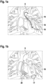
- Implanted left ventricular assist devices exist mainly in two versions, as described in the Fig. 1a and 1b are shown.
- Fig. 1a shows a (percutaneous) minimally invasive left heart assist system 16
- Fig. 1b shows a left heart support system 17 invasively implanted under the chest opening.
- the variant according to Fig. 1a delivers blood directly from the left ventricle 18 into the aorta 9, since the (percutaneous) minimally invasive left heart support system 16 is positioned centrally in the aortic valve 19.
- the variant according to Fig. 1b pumps blood from the left ventricle 18 via a bypass tube 20 into the aorta 9.
- the cardiac output or the total volume flow (Q HZV ) from the ventricle 18 to the aorta 9 is therefore usually the sum of the pump volume flow (Q p ) and the aortic valve volume flow (Q a ).
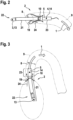
- Fig. 2 shows a schematic representation of an implanted vascular support system 2 in the aortic valve position.
- Fig. 3 shows a schematic representation of the support system 2 according to Fig. 3
- the support system 2 here is, for example, a left ventricular assist system (LVAD).
- LVAD left ventricular assist system
- the support system has a hose-like elongated structure with a cannula section in which an inlet cannula 21 is formed as a cannula, and has a motor housing section connected to the cannula section, in which an electric motor 5 is located in a motor housing 23.
- the support system 2 protrudes from the aorta 9 through the aortic valves 19 distally into the ventricle 18.
- the support system 2 here has, for example, an inlet cannula 21 that protrudes into the ventricle 18.
- a fluid volume flow 10 is conveyed, for example pumped, from the ventricle 18 into the aorta 9 through the inlet cannula 21 using an electric motor 5 of the support system 2, which drives a flow machine in the form of a pump in the support system 2.
- the fluid volume flow 10 is therefore also referred to as the pump volume flow (Q p ), which only quantifies the flow through the support system 2 itself.
- Fig. 2 and Fig. 3 to recognize that a certain aortic valve volume flow 24 via the physiological path through the aortic valve 19 into the aorta 9.
- the cardiac output or the total fluid volume flow 1 (Q HZV ) passing through a cross-sectional geometry 8 of the aorta 9 in the area of the support system 2 from the ventricle 18 to the aorta 9 is therefore the sum of the fluid volume flow 10 (Q p ) and the aortic valve volume flow 24 (Q a ). This is described by the following equation (1).
- Q cardiac output Qp + Qa
- the support system 2 comprises a reference temperature sensor 13 for determining a reference temperature 3 of a fluid, here for example blood.
- the support system 2 also comprises an electric motor 5 and a motor temperature sensor 14 for determining a motor temperature 4 of the electric motor 5.
- the support system 2 has a current sensor (not shown here) for determining the thermal power loss (not shown here) of the electric motor 5.
- the motor temperature sensor 14 is integrated, for example, in a motor housing 23 in which the thermal power loss of the electric motor 5 is dissipated to the surrounding fluid.
- the motor temperature sensor 14 is set up and arranged so that it can measure the motor temperature 4.
- the motor temperature sensor 14 can be set up and arranged so that it measures a surface temperature of the motor housing 23 or a temperature of the stator (not shown here) of the electric motor 5.
- the temperature of the stator can be approximated by an internal temperature in the motor housing 23 between the motor housing 23 and the winding package (not shown here). Alternatively, the temperature in the winding package can also be measured directly.
- the reference temperature sensor 13 records the reference temperature 3, which here is the background blood temperature as an example.
- the reference temperature sensor 13 is installed in the thermally unaffected blood flow in front of the The reference temperature sensor 13 is used for this purpose, as shown in the Fig. 2 shows, arranged in a region of the cannula section spaced from the motor housing section at a distal end of the inlet cannula 21, ie where the blood flows from a ventricle into the inlet cannula 21.
- Fig. 4 shows a schematic of a component architecture of a support system 2.
- the support system 2 comprises a reference temperature sensor 13 for determining a reference temperature 3 of a fluid, here for example blood.
- the support system 2 also comprises an electric motor 5 and a motor temperature sensor 14 for determining a motor temperature 4 of the electric motor 5.
- the support system 2 has a current sensor 15 for determining the thermal power loss 6 of the electric motor 5.
- the current sensor 15 determines the current flow (not shown here) through the motor 5 and converts this into the thermal power loss 6.
- the support system 2 comprises according to the illustration according to Fig.
- the support system 2 has an electronically readable memory 12 with calibration data 25.
- the measurement data of the reference temperature sensor 13, the motor temperature sensor 14 and the current sensor 15 are transmitted to the processing unit 11.
- the processing unit 11 processes the measurement data with calibration data 25 from the memory 12 for the blood flow velocity or the (total) blood volume flow.
- the processing unit 11 also has an output 26 to a communication unit (not shown here), an output 27 to a power supply (not shown here) and an output 28 to a motor control (not shown here).
- Fig. 5 shows a schematic illustration of an exemplary heat flow (horizontal arrows) through the electric motor 5 to the fluid flow (vertical arrow) or the total fluid volume flow 1.
- the electric motor 5 has, for example, a movably mounted rotor (not shown here) and a stationary winding package 22 which is offset externally by an air gap and is connected to the stator 29.
- the loss mechanisms in the electric motor 5 primarily concern the Joule current heat losses Pv (see equation (2) below).
- P V R TW ⁇ I 2
- R TW denotes the winding resistance of the winding package 22 at the operating temperature Tw.
- bearing losses occur from the bearing of the motor, which can usually be neglected.
- the thermal resistance between a heat source and a heat sink is measured in Kelvin per Watt (K/W).
- K/W Kelvin per Watt
- the determining heat conduction mechanism between the winding package and the blood flow is heat conduction through the layers of the motor to the outside, such as Fig. 5 shows.
- the heat capacities of the individual components through which the heat flow passes, as well as the respective heat transfer resistances, are required. Since it can be reasonably assumed that the electric motor is in stationary operation and thus in thermal equilibrium, the heat capacities can be neglected. All necessary parameters can be determined in advance and stored in a processing unit.
- Fig. 6 shows a schematic illustration of a temperature profile along the material layer sequence from the winding package 22 via the stator 29 and the motor housing 23 to the total fluid volume flow 1.
- Fig. 6 a temperature distribution resulting in thermal equilibrium for a heat flow according to Fig. 5 The highest temperature is in the heat source, the winding package 22 through which the electric current flows.
- the winding temperature 31 (symbol Tw) of the winding package 22 is in Fig. 6 hence the highest temperature.
- Tw winding temperature
- a constant heat distribution over the entire thickness of the winding package 22 was assumed here. Due to the finite thermal conductivity of the stator and housing material, a linear temperature gradient results over the stator 29 and the motor housing 23, or for the non-simplified case of a cylindrical motor housing 23, a logarithmic temperature gradient.
- the electrical current flow 30 (formula symbol I) and the surface temperature 32 (formula symbol T A ) are the only variable parameters.
- R th1 describes the thermal resistance between the winding package 22 and the stator 29.
- R th2 describes the thermal resistance between the stator 29 and the fluid flow.
- the current flow 30 (formula symbol I) can be determined by measuring with the current sensor 15, for example in a control unit of the current sensor, and is therefore known precisely.
- the surface temperature 32 (formula symbol T A ) describes the temperature on a surface 7 of the electric motor 5 along which the fluid flows. In other words, the surface 7 is in the blood flow.
- Fig. 7 shows a further schematic illustration of a temperature curve.
- Fig. 7 provides a detailed view of the representation Fig. 6 in the area of surface 7 at two different flow velocities.
- Fig. 7 the Dependence of the temperature(s) (surface temperature and thus also stator and winding package temperature) on the flow velocity of the fluid stream or blood.
- a liquid film of thickness 33 is formed near the surface 7.
- the thickness 33 of the liquid film and the temperature difference T A - T B between the surface temperature 32 (formula symbol T A ) and the reference temperature 3 (formula symbol T B ), which represents the background temperature of the fluid (the blood), depends on the flow velocity of the fluid, as shown in Fig. 7 According to the illustration in Fig. 7 a lower flow velocity of the fluid along the surface 7 leads to a higher surface temperature 32' than the surface temperature 32 which occurs at a comparatively higher flow velocity.
- the heat flow Q ⁇ is known from an energy balance. From the energy balance for the stationary case considered here, it follows that the heat flow Q ⁇ (in terms of magnitude) essentially corresponds to the thermal power loss 6 (symbol Pv).
- the surface temperature 32 (formula symbol T A ) can be measured here, for example, by means of the engine temperature sensor 14 directly on the surface 7 or the engine temperature sensor 14 can measure a temperature inside the engine and the surface temperature 32 (formula symbol T A ) is calculated from the logarithmic temperature relationship to the Temperature distribution in the engine housing (cf. Fig. 6 and 7 ).
- the reference temperature 3 (symbol T B ) is determined by the reference temperature sensor 13.
- the parameters L, v, a, ⁇ and A are usually stored in the system as calibration data.
- Q ⁇ ⁇ uL ⁇ , ⁇ a ⁇ L T A ⁇ T B A
- k(u) is a calibration factor depending on the flow profile
- u is the calculated flow velocity
- O is the measured aortic cross-section (cf. cross-sectional geometry 8).
Landscapes
- Health & Medical Sciences (AREA)
- Engineering & Computer Science (AREA)
- Heart & Thoracic Surgery (AREA)
- Cardiology (AREA)
- Life Sciences & Earth Sciences (AREA)
- Anesthesiology (AREA)
- Biomedical Technology (AREA)
- Hematology (AREA)
- Mechanical Engineering (AREA)
- Animal Behavior & Ethology (AREA)
- General Health & Medical Sciences (AREA)
- Public Health (AREA)
- Veterinary Medicine (AREA)
- Medical Informatics (AREA)
- External Artificial Organs (AREA)
- Measuring Pulse, Heart Rate, Blood Pressure Or Blood Flow (AREA)
Description
- Die Erfindung betrifft ein Verfahren zur Bestimmung eines Fluid-Gesamtvolumenstroms im Bereich eines implantierten, vaskulären Unterstützungssystems, eine Verarbeitungseinheit sowie ein implantierbares, vaskuläres Unterstützungssystem. Die Erfindung findet insbesondere Anwendung bei (voll-)implantierten Linksherz-Unterstützungssystemen (LVAD).
- Ein derartiges Verfahren, eine derartige Verarbeitungseinheit und ein derartiges implantierbares, vaskuläres Unterstützungssystem sind aus der
WO 2012/112378 A2 und aus derWO 98/43688 A1 - Implantierte Linksherz-Unterstützungssysteme (LVAD) existieren hauptsächlich in zwei Ausführungsvarianten. Einerseits gibt es (perkutane) minimalinvasive Linksherz-Unterstützungssysteme. Die zweite Variante sind unter der Brustkorböffnung invasiv implantierte Linksherz-Unterstützungssysteme. Die Variante nach erste Variante fördert Blut direkt aus dem linken Ventrikel in die Aorta, da das (perkutane) minimalinvasive Linksherz-Unterstützungssystem mittig in der Aortenklappe positioniert ist. Die zweite Variante fördert das Blut aus dem linken Ventrikel über einen Bypass-Schlauch in die Aorta.
- Die Aufgabe eines kardialen Unterstützungssystems ist die Förderung von Blut. Hierbei hat das sog. Herz-Zeit-Volumen (HZV, üblicherweise angegeben in Liter pro Minute) eine hohe klinische Relevanz. Das Herz-Zeit-Volumen betrifft hierbei mit anderen Worten den Gesamtvolumenstrom an Blut (aus einem Ventrikel), insbesondere vom linken Ventrikel hin zur Aorta. Entsprechend eingängig ist das Bestreben, diesen Parameter als Messwert während des Betriebs eines kardialen Unterstützungssystems zu erheben.
- Je nach Unterstützungsgrad, der den Anteil des durch ein Fördermittel wie etwa eine Pumpe des Unterstützungssystems geförderten Volumenstroms zum Gesamtvolumenstrom an Blut vom Ventrikel hin zur Aorta beschreibt, gelangt ein gewisser Volumenstrom über den physiologischen Weg durch die Aortenklappe in die Aorta. Das Herz-zeit-Volumen bzw. der Gesamtvolumenstrom (QHZV) vom Ventrikel hin zur Aorta ist demnach üblicherweise die Summe aus Pumpenvolumenstrom (Qp) und Aortenklappen-Volumenstrom (Qa).
- Ein etabliertes Verfahren zur Bestimmung des Herz-Zeit-Volumens (QHZV) im klinischen Umfeld ist die Verwendung von Dilutionsverfahren, die jedoch alle auf einen transkutan eingeführten Katheter setzen und daher nur während einer Herzoperation Herz-Zeit-Volumen-Messdaten liefern können. Ein etabliertes Verfahren zur Messung des Pumpenvolumenstroms (Qp) ist die Korrelation aus den Betriebsparametern des Unterstützungssystems, vor allem der elektrischen Leistungsaufnahme, eventuell ergänzt um weitere physiologische Parameter wie den Blutdruck. Auch die Integration dedizierter Ultraschall-Messtechnik in ein Unterstützungssystem wurde bereits vorgeschlagen.
- Eine (voll-)implantierte Erfassung des Herz-Zeit-Volumens, also von QHZV, insbesondere durch das Unterstützungssystem selbst, war bisher noch nicht vorgeschlagen oder realisiert worden. Voll-implantiert bedeutet hierbei insbesondere, dass die für die Erfassung erforderlichen Mittel sich vollständig im Körper des Patienten befinden und dort verbleiben. Dies ermöglicht es, das Herz-Zeit-Volumen auch außerhalb einer Herzoperation zu erfassen.
- Aufgabe der Erfindung ist es, ein verbessertes Verfahren zur Bestimmung eines Fluid-Gesamtvolumenstroms im Bereich eines implantierten, vaskulären Unterstützungssystems anzugeben und ein verbessertes implantierbares, vaskuläres Unterstützungssystem zu schaffen.
- Insbesondere ist es eine Aufgabe der Erfindung, ein Verfahren zur Bestimmung eines Fluid-Gesamtvolumenstroms im Bereich eines implantierten, vaskulären Unterstützungssystems anzugeben und ein implantierbares, vaskuläres Unterstützungssystem zu schaffen, mittels dessen ein Fluid-Gesamtvolumenstrom in einem mit Blut durchströmten Bereich in einem menschlichen oder tierischen Körper bestimmt werden kann, in dem das vaskuläre Unterstützungssystem implantiert bzw. angeordnet ist.
- Diese Aufgabe wird durch das in Anspruch 1 angegebene Verfahren, die in Anspruch 7 angegebene Verarbeitungseinheit und das in Anspruch 8 angegebene implantierbare vaskuläre Unterstützungssystem gelöst.
- Vorteilhafte Ausführungsformen der Erfindung sind insbesondere in den abhängigen Ansprüchen angegeben.
- Das in Anspruch 1 angegebene Verfahren zur Bestimmung eines Fluid-Gesamtvolumenstroms im Bereich eines implantierten, vaskulären Unterstützungssystems, umfasst folgende Schritte:
- a) Bestimmen einer Referenztemperatur des Fluids,
- b) Bestimmen einer Motortemperatur eines Elektromotors des Unterstützungssystems,
- c) Bestimmen der thermischen Verlustleistung des Elektromotors,
- d) Ermitteln des Fluid-Gesamtvolumenstroms unter Verwendung der Referenztemperatur, der Motortemperatur und der thermischen Verlustleistung des Elektromotors.
- Das vaskuläre Unterstützungssystem ist bevorzugt ein kardiales Unterstützungssystem, besonders bevorzugt ein ventrikuläres Unterstützungssystem. Mit dem Gesamtvolumenstrom ist insbesondere der gesamte Volumenstrom durch ein Blutgefäß bzw. durch einen Querschnitt des Blutgefäßes gemeint.
- Bei dem Blutgefäß handelt es sich beispielsweise um die Aorta, insbesondere bei einem Linksherz-Unterstützungssystem, oder um den gemeinsamen Stamm (Truncus pulmonalis) in die beiden Lungenarterien, insbesondere bei einem Rechtsherz-Unterstützungssystem, bevorzugt um die Aorta. Vorzugsweise dient das Verfahren zur Bestimmung eines Fluid-Gesamtvolumenstroms aus einem Ventrikel eines Herzens, insbesondere von einem (linken) Ventrikel eines Herzens hin zur Aorta im Bereich eines (voll-)implantierten, (links-)ventrikulären (Herz-)Unterstützungssystems. Bei dem Fluid handelt es sich regelmäßig um Blut. Das Unterstützungssystem ist bevorzugt am Ausgang des linken Ventrikels des Herzens bzw. der linken Herzkammer angeordnet. Besonders bevorzugt ist das Unterstützungssystem in Aortenklappenposition angeordnet.
- Das Verfahren ist insbesondere zur Bestimmung des gesamten Herz-Zeit-Volumens (HZV, Formelzeichen QHZV) eines Patienten, insbesondere mit (voll-)implantiertem linksventrikulären Herzunterstützungssystem (LVAD) in Aortenklappenposition und/oder durch das Unterstützungssystem selbst geeignet. Das Verfahren basiert insbesondere auf (thermisch) anemometrischen (Mess-)Prinzipien zur Flussmessung. Grundprinzip ist dabei, dass ein strömendes Medium einen heißen Körper in Abhängigkeit der Strömungsgeschwindigkeit kühlt. Das Verfahren ermöglich in vorteilhafter Weise, dass das Herz-Zeit-Volumen auch außerhalb des OP-Szenarios mit vergleichbarer Qualität wie bei Verwendung eines Dilutionskatheters zur Verfügung gestellt werden kann. Dies ist von besonderem Vorteil, da das Herz-Zeit-Volumen (QHZV) eine größere klinische Relevanz als der meist verwendete Pumpenvolumentstrom (Qp) hat, der nur den Fluss durch das Unterstützungssystem selbst quantifiziert.
- Ein besonderer Vorteil des Verfahrens besteht darin, dass anders als bei anemometrischen Verfahren üblich kein gesondertes Heizelement zur Erzeugung des zu messenden Wärmeflusses benötigt wird. Vielmehr kann die ohnehin am Elektromotor des LVAD auftretende thermische Verlustleistung zur anemometrischen Flussmessung genutzt werden. Bevorzugt wird zur Bestimmung des Fluid-Gesamtvolumenstroms kein (gesondertes) Heizelement (außer dem Elektromotor) verwendet. Mit anderen Worten ausgedrückt der Elektromotor das einzige Heizelement das bei der hier vorgeschlagenen Lösung zum Einsatz kommt. Insbesondere wird bei der hier vorgeschlagenen Lösung die am und/oder im Elektromotor des Unterstützungssystems auftretende thermische Verlustleistung zur (thermisch) anemometrischen bzw. kalorimetrischen Flussmessung verwendet. Weiterhin bevorzugt ist es, dass das Unterstützungssystem kein (gesondertes) Heizelement (außer dem Elektromotor) aufweist.
- In Schritt a) wird eine Referenztemperatur des Fluids bestimmt, insbesondere gemessen. Bevorzugt wird die Referenztemperatur durch einen Referenztemperatursensor bestimmt, der besonders bevorzugt Bestandteil des Unterstützungssystems ist. Der Referenztemperatursensor kann beispielsweise in und/oder an einer (Einlauf-)Kanüle des Unterstützungssystems angeordnet sein. Die Referenztemperatur stellt üblicherweise eine Hintergrundtemperatur des Fluids dar, mit anderen Worten eine Fluidtemperatur, die insbesondere nicht durch die thermische Verlustleistung des Elektromotors beeinflusst ist.
- In Schritt b) erfolgt ein Bestimmen, insbesondere Messen einer Motortemperatur eines Elektromotors des Unterstützungssystems. Der Elektromotor kann Bestandteil einer Strömungsmaschine bzw. einer Pumpe des Unterstützungssystems sein. Vorzugsweise ist das Unterstützungssystem so an oder in der Fluidströmung angeordnet, dass ein Wärmestrom von dem Unterstützungssystem, insbesondere von dessen Elektromotor, an die Fluidströmung abgegeben werden kann. Unter der Motortemperatur kann auch eine Innentemperatur oder (Außen-)Oberflächentemperatur des Unterstützungssystems, insbesondere im Bereich des Elektromotors, verstanden werden, die insbesondere einen bevorzugt unmittelbaren Rückschluss auf die Temperatur des Elektromotors, insbesondere auf die Temperatur eines Wicklungspakets des Elektromotors zulässt.
- Das Unterstützungssystem ist bevorzugt so implantiert, dass es sich zumindest teilweise, bevorzugt vollständig oder mit mindestens 50 %, besonders bevorzugt mindestens 85 % oder sogar mindestens 95 % seiner (Außen-)Oberfläche in der Fluidströmung befindet. Weiterhin bevorzugt befindet sich das Unterstützungssystem entlang mindestens 50 %, besonders bevorzugt mindestens 85 % oder sogar mindestens 95 % seiner Länge in der Fluidströmung. Bevorzugt befindet sich ein Ende des Unterstützungssystems, im Bereich dessen bzw. an dem sich der Elektromotor befindet, zumindest teilweise in der Aorta. Weiterhin bevorzugt befindet sich das gegenüberliegende Ende des Unterstützungssystems, im Bereich dessen bzw. an dem sich eine (Einlauf-)Kanüle des Unterstützungssystems befindet, zumindest teilweise in einem (dem linken) Ventrikel des Herzens. Weiterhin bevorzugt ist das Unterstützungssystem zumindest teilweise, bevorzugt vollständig oder mit mindestens 50 %, besonders bevorzugt mindestens 85 % oder sogar mindestens 95 % seiner (Außen-)Oberfläche in einem Blutgefäß, wie etwa einer Arterie, insbesondere der Aorta angeordnet. Besonders bevorzugt ist das Unterstützungssystem so implantiert, dass es sich (vollständig) in der (deszendenten) Aorta befindet.
- In Schritt c) wird die thermische Verlustleistung des Elektromotors bestimmt. Bevorzugt wird die thermische Verlustleistung des Elektromotors mit einem Stromsensor bestimmt, der vorzugsweise einen elektrischen Strom des Elektromotors misst.
- In Schritt d) wird der Fluid-Gesamtvolumenstrom unter Verwendung der Referenztemperatur, der Motortemperatur und der thermischen Verlustleistung des Elektromotors bestimmt. Bevorzugt wird in Schritt d) unter Zuhilfenahme von mindestens einer Wärmeübertragungsvorschrift, mindestens einem Wärmeübertragungskoeffizienten, mindestens einem Kalibrierfaktor und/oder mindestens einem Blutgefäßquerschnitt, insbesondere Aortenquerschnitt der Fluid-Gesamtvolumenstrom in Abhängigkeit von der Referenztemperatur, der Motortemperatur und der thermischen Verlustleistung des Elektromotors bestimmt.
- Nach einer vorteilhaften Ausgestaltung wird vorgeschlagen, dass die Referenztemperatur, insbesondere räumlich und/oder zeitlich vor einer Erwärmung des Fluids durch den Elektromotor gemessen wird. Bevorzugt ist ein Referenztemperatursensor beabstandet zu dem Elektromotor, insbesondere stromauf des Elektromotor, vorzugsweise an einer (Einlauf-)Kanüle des Unterstützungssystems angeordnet. Besonders bevorzugt ist der Referenztemperatursensor im Bereich eines und/oder an einem dem Elektromotor gegenüberliegenden Ende(s) der (Einlauf-)Kanüle angeordnet.
- Nach einer vorteilhaften Ausgestaltung wird vorgeschlagen, dass die Motortemperatur des Elektromotors an einer Oberfläche gemessen wird, an der das Fluid entlangströmt. Bei der Oberfläche handelt es sich in der Regel um eine (Außen-)Oberfläche des Unterstützungssystems, die in Kontakt mit dem Fluid steht. Die Motortemperatur kann beispielsweise mit einem Motortemperatursensor gemessen werden, der an einer (Außen-)Oberfläche des Unterstützungssystems im Bereich des (innenliegenden) Elektromotors angeordnet ist. Alternativ hierzu kann die Motortemperatur des Elektromotors im Motorinneren gemessen werden. Hierzu kann ein Motortemperatursensor im Inneren des Elektromotors angeordnet sein.
- Nach einer vorteilhaften Ausgestaltung wird vorgeschlagen, dass in Schritt d) in Abhängigkeit von Kalibrierdaten, der Referenztemperatur, der Motortemperatur und der thermischen Verlustleistung des Elektromotors eine Strömungsgeschwindigkeit des Fluids bestimmt, insbesondere berechnet wird. Die Kalibrierdaten umfassen bevorzugt eine charakteristische Länge (z. B. Rohrdurchmesser, ggf. angenähert im Bereich der Aortenklappe), eine kinematischen Viskosität des Fluids, eine Temperaturleitfähigkeit des Fluids, eine Wärmeleitfähigkeit des Fluids und/oder eine mit Fluid benetzte (Ober-)Fläche des Unterstützungssystems.
- Nach einer vorteilhaften Ausgestaltung wird vorgeschlagen, dass in Schritt d) weiterhin eine ermittelte Querschnittsgeometrie einer Aorta im Bereich des implantierten, vaskulären Unterstützungssystems berücksichtigt wird. Vorzugsweise wird ein (durchströmbarer) Querschnitt der Aorta im Bereich des Unterstützungssystems berücksichtigt. Dieser Wert kann vom Arzt beispielsweise durch Ultraschall oder Computertomografie ermittelt werden. Der Fluid-Gesamtvolumenstrom bzw. das Herz-Zeit-Volumen kann besonders vorteilhaft in Abhängigkeit der Strömungsgeschwindigkeit des Fluids, des (durchströmbaren) Querschnitts der Aorta und einem (geschwindigkeitsabhängigen) Kalibierfaktor bestimmt, insbesondere berechnet werden. Der (geschwindigkeitsabhängige) Kalibrierfaktor kann z. B. durch eine Kalibrierung im Rahmen der Implantation ermittelt werden, beispielsweise durch Einsatz eines Dilutionskatheters als Referenzstandard.
- Nach einer vorteilhaften Ausgestaltung wird vorgeschlagen, dass weiterhin ein Fluid-Volumenstrom bestimmt wird, der durch das Unterstützungssystems strömt. Dies betrifft mit anderen Worten insbesondere einen Fluid-Volumenstrom der nur durch das Unterstützungssystems selbst hindurch fließt. Bei diesem Fluid-Volumenstrom handelt es sich üblicherweise um den sog. Pumpenvolumentstrom (Qp), der nur den Fluss durch das Unterstützungssystem selbst quantifiziert. Ist dieser Wert zusätzlich zu dem Gesamtvolumenstrom bzw. Herz-Zeit-Volumen (QHZV) bekannt, so kann aus dem Verhältnis von Qp zu QHZV (d.h. Qp/QHZV) der sogenannte Unterstützungsgrad berechnet werden. Zur Bestimmung des Pumpenvolumenstroms kann ein Eingangs im Zusammenhang mit dem Stand der Technik erörtertes, etabliertes Verfahren zur Messung des Pumpenvolumenstroms verwendet werden.
- Bevorzugt wird der in Schritt d) ermittelte Fluid-Gesamtvolumenstrom beispielsweise in einem Schritt e) als Regelparameter für das Unterstützungssystem bereitgestellt. Eine Verarbeitungseinheit des Unterstützungssystems kann diesen Regelparameter als Ausgangsgröße, insbesondere einer Steuereinheit des Unterstützungssystems, dass vorzugsweise die Leistung des Elektromotors und damit insbesondere auch die (Blut-)Förderleistung des Unterstützungssystems regelt, bereitstellen.
- Nach einem weiteren Aspekt wird eine Verarbeitungseinheit vorgeschlagen, eingerichtet zur Durchführung eines hier vorgeschlagenen Verfahrens und aufweisend einen Speicher, in dem Kalibrierdaten hinterlegt sind. Alternativ oder zusätzlich zu den Kalibierdaten kann in dem Speicher auch mindestens ein (geschwindigkeitsabhängiger) Kalibierfaktor und/oder ein thermisches Modell des Elektromotors hinterlegt sein. Darüber hinaus kann die Verarbeitungseinheit einen Mikroprozessor umfassen, der auf den Speicher zugreifen kann. Die Verarbeitungseinheit empfängt vorzugsweise Daten von einem Referenztemperatursensor, einem Motortemperatursensor und/oder einem Stromsensor.
- Nach einem weiteren Aspekt wird ein implantierbares, vaskuläres Unterstützungssystem vorgeschlagen, umfassend:
- einen Referenztemperatursensor zur Bestimmung einer Referenztemperatur eines Fluids,
- einen Elektromotor,
- einen Motortemperatursensor zur Bestimmung einer Motortemperatur des Elektromotors,
- einen Stromsensor zur Bestimmung zumindest des Stromflusses durch den Elektromotor oder der thermischen Verlustleistung des Elektromotors.
- Bei dem Unterstützungssystem handelt es sich vorzugsweise um ein linksventrikuläres Herzunterstützungssystem (LVAD) bzw. ein perkutanes, minimalinvasives Linksherz-Unterstützungssystem. Weiterhin bevorzugt ist dieses voll-implantierbar. Das bedeutet mit anderen Worten insbesondere, dass die zur Erfassung erforderlichen Mittel, insbesondere der Referenztemperatursensor, der Motortemperatursensor und der Stromsensor sich vollständig im Körper des Patienten befinden und dort verbleiben. Besonders bevorzugt ist das Unterstützungssystem so eingerichtet bzw. dazu geeignet, dass es zumindest teilweise in einem Ventrikel, bevorzugt dem linken Ventrikel eines Herzens und/oder einer Aorta, insbesondere in Aortenklappenposition angeordnet werden kann.
- Der Stromsensor dient zur Bestimmung des Stromflusses durch den Elektromotor und/oder der thermischen Verlustleistung des Elektromotors. Bevorzugt misst der Stromsensor den Stromfluss durch den Elektromotor und berechnet hieraus die Verlustleistung des Elektromotos. Wenn der Stromsensor lediglich den Stromfluss als Ausgangsgröße liefert, ist insbesondere vorgesehen, dass der Stromfluss in einer Verarbeitungseinheit des Unterstützungssystems in die Verlustleistung des Elektromotors umgerechnet wird.
- Weiterhin bevorzugt umfasst das Unterstützungssystem eine Kanüle, insbesondere Einlaufkanüle und eine Strömungsmaschine, wie etwa eine Pumpe. Der Elektromotor ist dabei regelmäßig ein Bestandteil der Strömungsmaschine. Der Elektromotor treibt dann die Strömungsmaschine für das Fördern des Fluids an. Die (Einlauf-)Kanüle ist vorzugsweise so eingerichtet, dass sie im implantierten Zustand Fluid aus einem (linken) Ventrikel eines Herzens hin zu der Strömungsmaschine führen kann. Durch die Kanüle kann das Fluid zu der Strömungsmaschine geführt werden. Die die Kanüle ist dabei bevorzugt für das Führen von Fluid in Form von Blut aus einem (linken) Ventrikel eines Herzens in eine Aorta ausgelegt.
- Das Unterstützungssystem ist vorzugsweise länglich und/oder schlauchartig gebildet. Bevorzugt sind die Einlaufkanüle und die Strömungsmaschine im Bereich einander gegenüberliegender Enden des Unterstützungssystems angeordnet.
- Der Referenztemperatursensor kann an oder in der Nähe eines von der Strömungsmaschine beabstandeten Bereichs der Kanüle angeordnet sein. Insbesondere kann der Referenztemperatursensor an oder in der Nähe eines dem Elektromotor abgewandten Bereichs der Kanüle angeordnet sein. Besonders bevorzugt ist der Referenztemperatursensor ein einem distalen Ende der Kanüle angeordnet, d.h. dort wo das Blut aus einem Ventrikel in die Kanüle zuströmt.
- Das Unterstützungssystem kann eine schlauchartige längliche Struktur mit einem Kanülenabschnitt aufweisen, in dem die Kanüle ausgebildet ist, und mit einem an den Kanülenabschnitt angeschlossenen Motorgehäuseabschnitt, in dem der Elektromotor in einem Motorgehäuse angeordnet ist.
- Von Vorteil ist es, wenn der Referenztemperatursensor in einem von dem Motorgehäuseabschnitt beabstandeten Bereich des Kanülenabschnitts angeordnet ist. Der Elektromotor ist bevorzugt in einem in der Aorta mit Blut umströmbaren Motorgehäuse angeordnet.
- Das Unterstützungssystem kann weiterhin eine Verarbeitungseinheit umfassen, die eingerichtet ist zur Bestimmung eines Fluid-Gesamtvolumenstroms im Bereich des Unterstützungssystems unter Verwendung der Referenztemperatur, der Motortemperatur und der thermischen Verlustleistung des Elektromotors. Bevorzugt ist das Unterstützungssystem zur Durchführung eines hier vorgeschlagenen Verfahrens eingerichtet.
- Die im Zusammenhang mit dem Verfahren erörterten Details, Merkmale und vorteilhaften Ausgestaltungen können entsprechend auch bei der hier vorgestellten Verarbeitungseinheit und/oder dem Unterstützungssystem auftreten und umgekehrt. Insoweit wird auf die dortigen Ausführungen zur näheren Charakterisierung der Merkmale vollumfänglich Bezug genommen.
- Die hier vorgestellte Lösung sowie deren technisches Umfeld werden nachfolgend anhand der Figuren näher erläutert. Es ist darauf hinzuweisen, dass die Erfindung durch die gezeigten Ausführungsbeispiele nicht beschränkt werden soll. Es zeigen schematisch:
- Fig. 1a
- ein perkutanes, minimalinvasives Linksherz-Unterstützungssystem,
- Fig. 1b
- ein unter der Brustkorböffnung invasiv implantiertes Linksherz-Unterstützungssystem,
- Fig. 2
- ein implantiertes, vaskuläres Unterstützungssystem,
- Fig. 3
- eine Anordnung eines implantierten, vaskulären Unterstützungssystems,
- Fig. 4
- eine Komponentenarchitektur eines Unterstützungssystems,
- Fig. 5
- eine Veranschaulichung eines Wärmeflusses,
- Fig. 6
- eine Veranschaulichung eines Temperaturverlaufs, und
- Fig. 7
- eine weitere Veranschaulichung eines Temperaturverlaufs.
- Implantierte Linksherz-Unterstützungssysteme (LVAD) existieren hauptsächlich in zwei Ausführungsvarianten, wie sie in den
Fig. 1a und 1b gezeigt sind.Fig. 1a zeigt ein (perkutanes) minimalinvasives Linksherz-Unterstützungssystem 16, währendFig. 1b ein unter der Brustkorböffnung invasiv implantiertes Linksherz-Unterstützungssystem 17 zeigt. Die Variante nachFig. 1a fördert Blut direkt aus dem linken Ventrikel 18 in die Aorta 9, da das (perkutane) minimalinvasive Linksherz-Unterstützungssystem 16 mittig in der Aortenklappe 19 positioniert ist. Die Variante nachFig. 1b fördert das Blut aus dem linken Ventrikel 18 über einen Bypass-Schlauch 20 in die Aorta 9. - Je nach Unterstützungsgrad, der den Anteil des durch ein Fördermittel wie etwa eine Pumpe des Unterstützungssystems geförderten Volumenstroms zum Gesamtvolumenstrom an Blut vom Ventrikel 18 hin zur Aorta 9 beschreibt, gelangt ein gewisser Volumenstrom über den physiologischen Weg durch die Aortenklappe 19 in die Aorta 9. Das Herz-zeit-Volumen bzw. der Gesamtvolumenstrom (QHZV) vom Ventrikel 18 hin zur Aorta 9 ist demnach üblicherweise die Summe aus Pumpenvolumenstrom (Qp) und Aortenklappen-Volumenstrom (Qa).
-
Fig. 2 zeigt schematisch ein implantiertes, vaskuläres Unterstützungssystem 2 in Aortenklappenposition. Zur näheren Veranschaulichung wird gleichzeitig auch auf die schematisch Anordnung des Unterstützungssystems 2 gemäßFig. 3 Bezug genommen, wobei die Bezugszeichen einheitlich in allen Figuren verwendet werden. - Das Unterstützungssystem 2 ist hier beispielhaft ein linksventrikuläres Herzunterstützungssystem (LVAD).
- Das Unterstützungssystem hat eine schlauchartige längliche Struktur mit einem Kanülenabschnitt, in dem als Kanüle eine Einlaufkanüle 21 ausgebildet ist, und weist einen an den Kanülenabschnitt angeschlossenen Motorgehäuseabschnitt, in dem sich ein Elektromotor 5 in einem Motorgehäuse 23 befindet.
- Das Unterstützungssystem 2 ragt aus der Aorta 9 durch die Aortenklappen 19 distal in den Ventrikel 18. Das Unterstützungssystem 2 hat hier beispielhaft eine Einlaufkanüle 21, die in den Ventrikel 18 hineinragt. Durch die Einlaufkanüle 21 wird ein Fluid-Volumenstrom 10 unter Verwendung eines Elektromotors 5 des Unterstützungssystems 2, der in dem Unterstützungssystem 2 eine Strömungsmaschine in Form einer Pumpe antreibt, aus dem Ventrikel 18 in die Aorta 9 gefördert, beispielsweise gepumpt. Daher wird der Fluid-Volumenstrom 10 auch als Pumpenvolumenstrom (Qp) bezeichnet, der nur den Fluss durch das Unterstützungssystem 2 selbst quantifiziert.
- Zudem ist in
Fig. 2 und Fig. 3 zu erkennen, dass ein gewisser Aortenklappen-Volumenstrom 24 über den physiologischen Weg durch die Aortenklappe 19 in die Aorta 9 gelangt. Das Herz-zeit-Volumen bzw. der im Bereich des Unterstützungssystems 2 durch eine Querschnittsgeometrie 8 der Aorta 9 hindurchtretende Fluid-Gesamtvolumenstrom 1 (QHZV) vom Ventrikel 18 hin zur Aorta 9 ist demnach die Summe aus Fluid-Volumenstrom 10 (Qp) und Aortenklappen-Volumenstrom 24 (Qa). Dies wird durch nachstehende Gleichung (1) beschrieben.
- Das Unterstützungssystem 2 umfasst einen Referenztemperatursensor 13 zur Bestimmung einer Referenztemperatur 3 eines Fluids, hier beispielhaft Blut. Ferner umfasst das Unterstützungssystem 2 einen Elektromotor 5 sowie einen Motortemperatursensor 14 zur Bestimmung einer Motortemperatur 4 des Elektromotors 5. Zudem hat das Unterstützungssystem 2 einen Stromsensor (hier nicht dargestellt) zur Bestimmung der thermischen Verlustleistung (hier nicht dargestellt) des Elektromotors 5.
- Der Motortemperatursensor 14 ist beispielhaft in einem Motorgehäuse 23 integriert, in dem die thermische Verlustleistung des Elektromotors 5 an das umgebende Fluid abgeführt wird. Der Motortemperatursensor 14 ist so eingerichtet und angeordnet, dass er die Motortemperatur 4 messen kann. Hierzu kann der Motortemperatursensor 14 so eingerichtet und angeordnet sein, dass er eine Oberflächentemperatur des Motorgehäuses 23 oder eine Temperatur des Stators (hier nicht dargestellt) des Elektromotors 5 misst. Hierbei kann die Temperatur des Stators durch eine Innentemperatur im Motorgehäuse 23 zwischen Motorgehäuse 23 und Wicklungspaket (hier nicht dargestellt) angenähert werden. Alternativ kann auch die Temperatur im Wicklungspaket direkt gemessen werden.
- Der Referenztemperatursensor 13 erfasst die Referenztemperatur 3, die hier beispielhaft die Hintergrund-Bluttemperatur ist. Dazu ist der Referenztemperatursensor 13 im thermisch unbeeinflussten Blutfluss vor den die Wärmequelle darstellenden Elektromotor 5 platziert, hier beispielhaft im Bereich vor dem Elektromotor 5. Hierfür ist der Referenztemperatursensor 13, wie die
Fig. 2 zeigt, in einem von dem Motorgehäuseabschnitt beabstandeten Bereich des Kanülenabschnitts an einem distalen Ende der Einlaufkanüle 21 angeordnet, d.h. dort, wo das Blut aus einem Ventrikel in die Einlaufkanüle 21 strömt. -
Fig. 4 zeigt schematisch eine Komponentenarchitektur eines Unterstützungssystems 2. Das Unterstützungssystem 2 umfasst einen Referenztemperatursensor 13 zur Bestimmung einer Referenztemperatur 3 eines Fluids, hier beispielhaft Blut. Ferner umfasst das Unterstützungssystem 2 einen Elektromotor 5 sowie einen Motortemperatursensor 14 zur Bestimmung einer Motortemperatur 4 des Elektromotors 5. Zudem hat das Unterstützungssystem 2 einen Stromsensor 15 zur Bestimmung der thermischen Verlustleistung 6 des Elektromotors 5. Hierzu ermittelt der Stromsensor 15 beispielhaft den Stromfluss (hier nicht dargestellt) durch den Motor 5 und rechnet diesen in die thermische Verlustleistung 6 um. Das Unterstützungssystem 2 umfasst gemäß der Darstellung nachFig. 4 ferner eine Verarbeitungseinheit 11, die eingerichtet ist zur Bestimmung eines Fluid-Gesamtvolumenstroms (hier nicht dargestellt) im Bereich des Unterstützungssystems 2 unter Verwendung der Referenztemperatur 3, der Motortemperatur 4 und der thermischen Verlustleistung 6 des Elektromotors 5. Zudem hat das Unterstützungssystem 2 einen elektronisch lesbaren Speicher 12 mit Kalibrierdaten 25. - Die Messdaten des Referenztemperatursensors 13, des Motortemperatursensors 14 sowie des Stromsensors 15 werden an die Verarbeitungseinheit 11 übertragen. Die Verarbeitungseinheit 11 verarbeitet die Messdaten mit Kalibrierdaten 25 aus dem Speicher 12 zur Blutflussgeschwindigkeit bzw. dem (Gesamt-)Blutvolumen-Strom. Weiterhin weist die Verarbeitungseinheit 11 einen Ausgang 26 zu einer Kommunikationseinheit (hier nicht dargestellt), einen Ausgang 27 zu einer Stromversorgung (hier nicht dargestellt) und einen Ausgang 28 zu einer Motorsteuerung (hier nicht dargestellt) auf.
-
Fig. 5 zeigt schematisch eine Veranschaulichung eines beispielhaften Wärmeflusses (horizontale Pfeile) durch den Elektromotor 5 hin zu der Fluidströmung (vertikaler Pfeil) bzw. dem Fluid-Gesamtvolumenstrom 1. Der Elektromotor 5 weist hier beispielhaft einen beweglich gelagerten Rotor (hier nicht dargestellt) und ein durch einen Luftspalt außen abgesetztes stationäres Wicklungspaket 22 auf, das in Verbindung zum Stator 29 steht. Somit veranschaulichtFig. 5 mit anderen Worten schematisch die Wärmeleitübergänge von dem Wicklungspaket 22 des Elektromotors 5 über den Stator 29 zum Blutfluss. Die Verlustmechanismen im Elektromotor 5 betreffen in erster Linie die Joul'schen Stromwärmeverluste Pv (siehe nachstehende Gleichung (2)).
- Hierbei bezeichnet RTW den Wicklungswiderstand des Wicklungspakets 22 bei der Betriebstemperatur Tw. Der Wicklungswiderstand RTW ist im Fall von Kupfer linear von der Wicklungstemperatur Tw abhängig. Dies beschreibt die nachstehende Gleichung (3):

- Darüber hinaus treten noch Eisenverluste auf, beispielsweise Magnetisierungsverluste nach nachstehender Gleichung (4):


- Der Wärmewiderstand zwischen einer Wärmequelle und einer Wärmesenke wird in Kelvin pro Watt gemessen (K/W). Der bestimmende Wärmeleitmechanismus zwischen Wicklungspaket und Blutfluss ist hier Wärmeleitung durch die Schichten des Motors nach außen, wie
Fig. 5 zeigt. Zur Bestimmung der Temperaturen sind die Wärmekapazitäten der einzelnen vom Wärmefluss durchquerten Bauteile, sowie die jeweiligen Wärmeübergangswiderstände erforderlich. Da hinreichend angenommen werden kann, dass sich der Elektromotor in stationärem Betrieb und damit in thermischem Gleichgewicht befindet, können die Wärmekapazitäten vernachlässigt werden. Alle notwendigen Parameter sind vorab bestimmbar und können in einer Verarbeitungseinheit hinterlegt werden. -
Fig. 6 zeigt schematisch eine Veranschaulichung eines Temperaturverlaufs entlang der Materialschichtenfolge vom Wicklungspaket 22 über den Stator 29 und das Motorgehäuse 23 zum Fluid-Gesamtvolumenstrom 1. Hierbei stelltFig. 6 eine sich im thermischen Gleichgewicht ergebende Temperaturverteilung für einen Wärmefluss nachFig. 5 dar. Die höchste Temperatur liegt in der Wärmequelle, dem vom elektrischen Strom durchflossenen Wicklungspaket 22 vor. Die Wicklungstemperatur 31 (Formelzeichen Tw) des Wicklungspakets 22 ist inFig. 6 daher die höchst Temperatur. Zur Vereinfachung wurde hier eine konstante Wärmeverteilung über die gesamte Dicke des Wicklungspaketes 22 angenommen. Aufgrund der endlichen thermischen Leitfähigkeit von Stator- und Gehäusematerial ergibt sich ein lineares Temperaturgefälle über den Stator 29 und das Motorgehäuse 23, bzw. für den nicht-vereinfachten Fall eines zylinderförmigen Motorgehäuses 23 ein logarithmisches Temperaturgefälle. - Die sich im Wicklungspaket 23 einstellende Wicklungstemperatur 31 (Formelzeichen Tw) beträgt in der vereinfachten Prinzipbetrachtung:


- Hierbei sind der elektrische Stromfluss 30 (Formelzeichen I) und die Oberflächentemperatur 32 (Formelzeichen TA) die einzigen variablen Parameter. Rth1 beschreibt den Wärmewiderstand zwischen dem Wicklungspaket 22 und dem Stator 29. Rth2 beschreibt den Wärmewiderstand zwischen dem Stator 29 und der Fluidströmung. Der Stromfluss 30 (Formelzeichen I) kann durch Messung mit dem Stromsensor 15, bspw. in einem Steuergerät des Stromsensors ermittelt werden und ist somit genau bekannt. Die Oberflächentemperatur 32 (Formelzeichen TA) bezeichnet die Temperatur auf einer Oberfläche 7 des Elektromotors 5, an der das Fluid entlangströmt. Mit anderen Worten ist die Oberfläche 7 in der Blutströmung.
-
Fig. 7 zeigt schematisch eine weitere Veranschaulichung eines Temperaturverlaufs.Fig. 7 stellt hierbei eine Detailansicht der Darstellung nachFig. 6 im Bereich der Oberfläche 7 bei zwei unterschiedlichen Strömungsgeschwindigkeiten dar. Mit anderen Worten ausgedrückt veranschaulichtFig. 7 die Abhängigkeit der Temperatur(en) (Oberflächentemperatur und damit auch Stator- und damit auch Wicklungspakettemperatur) von der Strömungsgeschwindigkeit des Fluidstromes bzw. des Blutes. - Wie in
Fig. 7 gezeigt, stellt sich nahe der Oberfläche 7 ein Flüssigkeitsfilm der Dicke 33 ein. Die Dicke 33 des Flüssigkeitsfilms und der Temperaturunterschied TA - TB zwischen der Oberflächentemperatur 32 (Formelzeichen TA) und der Referenztemperatur 3 (Formelzeichen TB), die die Hintergrundtemperatur des Fluids (des Bluts) darstellt, ist von der Strömungsgeschwindigkeit des Fluids abhängig, wie dies inFig. 7 veranschaulicht ist. Gemäß der Darstellung nachFig. 7 führt eine geringere Strömungsgeschwindigkeit des Fluids entlang der Oberfläche 7 zu einer höheren Oberflächentemperatur 32' als der Oberflächentemperatur 32, die sich bei einer vergleichsweise höheren Strömungsgeschwindigkeit einstellt. - Der Wärmestrom durch den Flüssigkeitsfilm beträgt


- Diese können jeweils in Abhängigkeit von der Geometrie und der Strömung (Re und Pr) bzw. in Abhängigkeit der Fluideigenschaften (Pr) berechnet und im Kalibrierdatenspeicher abgelegt werden. Die Reynoldszahl ist definiert als


- Die Oberflächentemperatur 32 (Formelzeichen TA) kann hier beispielsweise mittels des Motortemperatursensors 14 direkt an der Oberfläche 7 gemessen werden oder der Motortemperatursensor 14 kann eine Temperatur im Motorinneren messen und die Oberflächentemperatur 32 (Formelzeichen TA) wird aus dem logarithmischen Temperaturzusammenhang zur Temperaturverteilung im Motorgehäuse (vgl.
Fig. 6 und 7 ) ermittelt. Die Referenztemperatur 3 (Formelzeichen TB) wird durch den Referenztemperatursensor 13 bestimmt. Die Parameter L, v, a, λ und A sind in der Regel als Kalibrierdaten im System hinterlegt.
- Bei bekannter Querschnittsgeometrie 8 der Aorta 9 des Patienten im Bereich des Unterstützungssystems (ermittelbar z.B. durch Ultraschall, Computertomografie oder Magnetresonanztomografie) kann aus der so bestimmten Strömungsgeschwindigkeit u der Fluid-Gesamtvolumenstrom 1 (Formelzeichen QHZV) bestimmt werden. Der entsprechende Zusammenhang ist in nachfolgender Gleichung (16) angegeben:

- Hierbei ist k(u) ein vom Strömungsprofil abhängiger Kalibrierfaktor, u die berechnete Strömungsgeschwindigkeit und O der gemessene Aortenquerschnitt (vgl. Querschnittsgeometrie 8).
- Die hier vorgeschlagene Lösung ermöglicht insbesondere einen der nachstehenden Vorteile:
- Vollimplantierte, insbesondere pumpenintegrierte und/oder automatische Bestimmung von QHZV statt nur Qp.
- Durch anemometrisches Messverfahren mit Nutzung der Abwärme eines VAD-Motors statt Verwendung eines zusätzlichen Heizelements findet kein zusätzlicher Wärmeeintrag in den Organismus statt.
- Dadurch wird zudem eine zusätzliche Stromaufnahme vermieden, wodurch die Batterielaufzeit autonomer Systeme verlängert wird.
Claims (15)
- Verfahren zur Bestimmung eines Fluid-Gesamtvolumenstroms (1) im Bereich eines implantierten, vaskulären Unterstützungssystems (2), umfassend folgende Schritte:a) Bestimmen einer Referenztemperatur (3) des Fluids,b) Bestimmen einer Motortemperatur (4) eines Elektromotors (5) des Unterstützungssystems (2),c) Bestimmen der thermischen Verlustleistung (6) des Elektromotors (5),d) Ermitteln des Fluid-Gesamtvolumenstroms (1) unter Verwendung der Referenztemperatur (3), der Motortemperatur (4) und der thermischen Verlustleistung (6) des Elektromotors (5).
- Verfahren nach Anspruch 1, dadurch gekennzeichnet, dass die Referenztemperatur (3) vor einer Erwärmung des Fluids durch den Elektromotor (5) gemessen wird.
- Verfahren nach Anspruch 1 oder 2, dadurch gekennzeichnet, dass die Motortemperatur (4) des Elektromotors (5) an einer Oberfläche (7) gemessen wird, an der das Fluid entlangströmt oder die Motortemperatur (4) des Elektromotors (5) im Motorinneren gemessen wird.
- Verfahren nach einem der vorhergehenden Ansprüche, dadurch gekennzeichnet, dass in Schritt d) in Abhängigkeit von Kalibrierdaten, der Referenztemperatur (3), der Motortemperatur (4) und der thermischen Verlustleistung (6) des Elektromotors (5) eine Strömungsgeschwindigkeit des Fluids bestimmt wird.
- Verfahren nach einem der vorhergehenden Ansprüche, dadurch gekennzeichnet, dass in Schritt d) weiterhin eine ermittelte Querschnittsgeometrie (8) einer Aorta (9) im Bereich des implantierten, vaskulären Unterstützungssystems (2) berücksichtigt wird.
- Verfahren nach einem der vorhergehenden Ansprüche, dadurch gekennzeichnet, dass weiterhin ein Fluid-Volumenstrom (10) bestimmt wird, der durch das Unterstützungssystem (2) strömt.
- Verarbeitungseinheit (11), eingerichtet zur Durchführung des Verfahren nach einem der Vorhergehenden Ansprüche und aufweisend einen Speicher (12), in dem Kalibrierdaten hinterlegt sind.
- Implantierbares, vaskuläres Unterstützungssystem (2), umfassend:- einen Elektromotor (5),- einen Motortemperatursensor (14) zur Bestimmung einer Motortemperatur (4) des Elektromotors (5),- einen Stromsensor (15) zur Bestimmung zumindest des Stromflusses durch den Elektromotor oder der thermischen Verlustleistung (6) des Elektromotors (5);gekennzeichnet durch:
einen Referenztemperatursensor (13) zur Bestimmung einer Referenztemperatur (3) eines Fluids. - Unterstützungssystem nach Anspruch 8, gekennzeichnet durch eine Verarbeitungseinheit (11), eingerichtet zur Bestimmung eines Fluid-Gesamtvolumenstroms (1) im Bereich des Unterstützungssystems (2) unter Verwendung der Referenztemperatur (3), der Motortemperatur (4) und der thermischen Verlustleistung (6) des Elektromotors (5) und/oder wobei der Motortemperatursensor (14) eine Temperatur eines Stators des Elektromotors (5) misst.
- Unterstützungssystem nach Anspruch 8 oder 9, gekennzeichnet durch eine mittels des Elektromotors (5) angetriebene Strömungsmaschine für das Fördern des Fluids und eine Kanüle (21), durch die das Fluid zu der Strömungsmaschine geführt werden kann.
- Unterstützungssystem nach Anspruch 10, dadurch gekennzeichnet, dass die Kanüle (21) für das Führen von Fluid in Form von Blut aus einem Ventrikel (18) eines Herzens in eine Aorta (9) ausgelegt ist und/oder dass der Referenztemperatursensor (13) an oder in der Nähe eines von der Strömungsmaschine beabstandeten Bereichs der Kanüle (21) angeordnet ist und/oder dass der Referenztemperatursensor (13) an oder in der Nähe eines dem Elektromotor (5) abgewandten Bereichs der Kanüle (21) angeordnet ist.
- Unterstützungssystem nach einem der Ansprüche 10 oder 11, gekennzeichnet durch eine schlauchartige längliche Struktur mit einem Kanülenabschnitt, in dem die Kanüle (21) ausgebildet ist, und mit einem an den Kanülenabschnitt angeschlossenen Motorgehäuseabschnitt, in dem der Elektromotor (5) in einem Motorgehäuse (23) angeordnet ist.
- Unterstützungssystem nach Anspruch 12, dadurch gekennzeichnet, dass der Referenztemperatursensor (13) in einem von dem Motorgehäuseabschnitt beabstandeten Bereich des Kanülenabschnitts angeordnet ist und/oder dass das Motorgehäuse (23) in der Aorta (9) mit Blut umströmbar ist.
- Unterstützungssystem nach einem der Ansprüche 8 bis 11, dadurch gekennzeichnet, dass der Elektromotor (23) in einem in der Aorta (9) mit Blut umströmbaren Motorgehäuse (23) angeordnet ist.
- Unterstützungssystem nach einem der Ansprüche 12 bis 14, dadurch gekennzeichnet, dass der Motortemperatursensor (14) eine Oberflächentemperatur des Motorgehäuses (23) misst.
Applications Claiming Priority (2)
| Application Number | Priority Date | Filing Date | Title |
|---|---|---|---|
| DE102018208879.9A DE102018208879A1 (de) | 2018-06-06 | 2018-06-06 | Verfahren zur Bestimmung eines Fluid-Gesamtvolumenstroms im Bereich eines implantierten, vaskuläres Unterstützungssystems |
| PCT/EP2019/064802 WO2019234162A1 (de) | 2018-06-06 | 2019-06-06 | Verfahren zur bestimmung eines fluid-gesamtvolumenstroms im bereich eines implantierten, vaskuläres unterstützungssystems sowie implantierbares vaskuläres unterstützungssystem |
Publications (2)
| Publication Number | Publication Date |
|---|---|
| EP3801667A1 EP3801667A1 (de) | 2021-04-14 |
| EP3801667B1 true EP3801667B1 (de) | 2024-11-20 |
Family
ID=66821250
Family Applications (1)
| Application Number | Title | Priority Date | Filing Date |
|---|---|---|---|
| EP19729727.8A Active EP3801667B1 (de) | 2018-06-06 | 2019-06-06 | Verfahren zur bestimmung eines fluid-gesamtvolumenstroms im bereich eines implantierten, vaskulären unterstützungssystems sowie implantierbares vaskuläres unterstützungssystem |
Country Status (7)
| Country | Link |
|---|---|
| US (1) | US12324906B2 (de) |
| EP (1) | EP3801667B1 (de) |
| JP (1) | JP7422407B2 (de) |
| CN (1) | CN112543657B (de) |
| DE (1) | DE102018208879A1 (de) |
| ES (1) | ES3006140T3 (de) |
| WO (1) | WO2019234162A1 (de) |
Families Citing this family (17)
| Publication number | Priority date | Publication date | Assignee | Title |
|---|---|---|---|---|
| DE102018208538A1 (de) | 2018-05-30 | 2019-12-05 | Kardion Gmbh | Intravasale Blutpumpe und Verfahren zur Herstellung von elektrischen Leiterbahnen |
| DE102018208870A1 (de) | 2018-06-06 | 2019-12-12 | Kardion Gmbh | Verfahren zur Bestimmung eines Fluid-Volumenstroms durch ein implantiertes, vaskuläres Unterstützungssystem |
| DE102018208899A1 (de) | 2018-06-06 | 2019-12-12 | Kardion Gmbh | Verfahren zum Ermitteln der Schallgeschwindigkeit in einem Fluid im Bereich eines implantierten, vaskulären Unterstützungssystems |
| DE102018208936A1 (de) | 2018-06-06 | 2019-12-12 | Kardion Gmbh | Bestimmvorrichtung und Verfahren zum Bestimmen einer Viskosität eines Fluids |
| DE102018208913A1 (de) | 2018-06-06 | 2019-12-12 | Kardion Gmbh | Verfahren zum Betreiben eines implantierten, ventrikulären Unterstützungssystems |
| DE102018208879A1 (de) | 2018-06-06 | 2020-01-30 | Kardion Gmbh | Verfahren zur Bestimmung eines Fluid-Gesamtvolumenstroms im Bereich eines implantierten, vaskuläres Unterstützungssystems |
| DE102018208931A1 (de) | 2018-06-06 | 2019-12-12 | Kardion Gmbh | Vorrichtung zum Bestimmen eines Herzzeitvolumens für ein Herzunterstützungssystem, Herzunterstützungssystem und Verfahren zum Bestimmen eines Herzzeitvolumens |
| DE102018208929A1 (de) | 2018-06-06 | 2019-12-12 | Kardion Gmbh | Verfahren zur Bestimmung einer Strömungsgeschwindigkeit eines durch ein implantiertes, vaskuläres Unterstützungssystem strömenden Fluids |
| DE102018208933A1 (de) | 2018-06-06 | 2019-12-12 | Kardion Gmbh | Verfahren zur Bestimmung einer Strömungsgeschwindigkeit eines durch ein implantiertes, vaskuläres Unterstützungssystem strömenden Fluids |
| DE102018208945A1 (de) | 2018-06-06 | 2019-12-12 | Kardion Gmbh | Analysevorrichtung und Verfahren zum Analysieren einer Viskosität eines Fluids |
| DE102018208892A1 (de) | 2018-06-06 | 2019-12-12 | Kardion Gmbh | Sensorkopfvorrichtung für ein minimalinvasives Herzunterstützungssystem und Verfahren zum Herstellen einer Sensorkopfvorrichtung für ein Herzunterstützungssystem |
| DE102018208862A1 (de) | 2018-06-06 | 2019-12-12 | Kardion Gmbh | Implantierbares, vaskuläres Unterstützungssystem |
| DE102018210076A1 (de) | 2018-06-21 | 2019-12-24 | Kardion Gmbh | Verfahren und Vorrichtung zum Erkennen eines Verschleißzustands eines Herzunterstützungssystems, Verfahren und Vorrichtung zum Betreiben eines Herzunterstützungssystems und Herzunterstützungssystem |
| DE102018213350A1 (de) | 2018-08-08 | 2020-02-13 | Kardion Gmbh | Vorrichtung und Verfahren zur Überwachung eines Gesundheitszustands des Patienten |
| EP4247476A1 (de) | 2020-11-20 | 2023-09-27 | Kardion GmbH | Spülfreies mechanisches kreislaufunterstützungssystem mit magnetantrieb |
| US12502524B2 (en) | 2021-12-03 | 2025-12-23 | Kardion Gmbh | Cardiac pump with optical fiber for laser doppler |
| CN116672596B (zh) * | 2022-02-23 | 2025-09-12 | 上海微创心力医疗科技有限公司 | 导管泵的温度控制方法、装置、控制设备和存储介质 |
Family Cites Families (587)
| Publication number | Priority date | Publication date | Assignee | Title |
|---|---|---|---|---|
| US3088323A (en) | 1960-02-10 | 1963-05-07 | Gulton Ind Inc | Piezoresistive transducer |
| US4023562A (en) | 1975-09-02 | 1977-05-17 | Case Western Reserve University | Miniature pressure transducer for medical use and assembly method |
| NO150015C (no) | 1981-11-13 | 1984-08-08 | Vingmed As | Fremgangsmaate ved blodstroemhastighetsmaaling med ultralyd, kombinert med ekko-amplitudeavbildning, for undersoekelse av levende biologiske strukturer |
| JPS5980229A (ja) | 1982-10-29 | 1984-05-09 | 株式会社島津製作所 | パルスドツプラ−超音波血流計 |
| JPS6015771A (ja) | 1983-07-08 | 1985-01-26 | Hitachi Ltd | ベクトルプロセッサ |
| JPS61125329A (ja) | 1984-11-21 | 1986-06-13 | テルモ株式会社 | 心拍出量測定装置 |
| JPS62113555A (ja) | 1985-11-13 | 1987-05-25 | Canon Inc | インクジエツト記録装置 |
| JPS62204733A (ja) | 1986-03-04 | 1987-09-09 | アロカ株式会社 | 超音波ドプラ診断装置 |
| JPS62282284A (ja) | 1986-05-30 | 1987-12-08 | Tokyo Keiki Co Ltd | 超音波による距離測定方法およびその装置 |
| US4902272A (en) | 1987-06-17 | 1990-02-20 | Abiomed Cardiovascular, Inc. | Intra-arterial cardiac support system |
| US4781525A (en) | 1987-07-17 | 1988-11-01 | Minnesota Mining And Manufacturing Company | Flow measurement system |
| JPS6468236A (en) | 1987-09-07 | 1989-03-14 | Aisin Seiki | Cannula equipped with detection electrode |
| US4889131A (en) | 1987-12-03 | 1989-12-26 | American Health Products, Inc. | Portable belt monitor of physiological functions and sensors therefor |
| US4888011A (en) | 1988-07-07 | 1989-12-19 | Abiomed, Inc. | Artificial heart |
| US4965713A (en) | 1988-08-15 | 1990-10-23 | Viking Pump Inc. | Terminal element |
| US4989609A (en) | 1989-01-26 | 1991-02-05 | Minnesota Mining And Manufacturing Company | Doppler blood flow system and method using special zero flow rate analysis |
| US5045051A (en) | 1989-03-14 | 1991-09-03 | Abiomed, Inc. | Leak detector |
| CA2004295C (en) | 1989-11-30 | 1998-02-10 | William F. Hayes | Primary fluid actuated, secondary fluid propelling system |
| AU1279092A (en) | 1991-02-04 | 1992-10-06 | Kensey Nash Corporation | Apparatus and method for determining viscosity of the blood of a living being |
| JP2952438B2 (ja) | 1991-09-20 | 1999-09-27 | トキコ株式会社 | 熱式流量計 |
| US5676651A (en) | 1992-08-06 | 1997-10-14 | Electric Boat Corporation | Surgically implantable pump arrangement and method for pumping body fluids |
| JP3312759B2 (ja) | 1993-01-22 | 2002-08-12 | テルモ株式会社 | 医療用ポンプ駆動装置 |
| US5456715A (en) | 1993-05-21 | 1995-10-10 | Liotta; Domingo S. | Implantable mechanical system for assisting blood circulation |
| US5289821A (en) | 1993-06-30 | 1994-03-01 | Swartz William M | Method of ultrasonic Doppler monitoring of blood flow in a blood vessel |
| JPH0747025A (ja) | 1993-08-06 | 1995-02-21 | Itoki Co Ltd | フレキシブルパ−ティション |
| US5527159A (en) | 1993-11-10 | 1996-06-18 | The United States Of America As Represented By The Administrator Of The National Aeronautics And Space Administration | Rotary blood pump |
| GB9404321D0 (en) | 1994-03-04 | 1994-04-20 | Thoratec Lab Corp | Driver and method for driving pneumatic ventricular assist devices |
| US5581038A (en) | 1994-04-04 | 1996-12-03 | Sentir, Inc. | Pressure measurement apparatus having a reverse mounted transducer and overpressure guard |
| NO942222D0 (no) | 1994-06-14 | 1994-06-14 | Vingmed Sound As | Fremgangsmåte ved bestemmelse av hastighet/tid-spektrum ved blodströmning |
| JPH0857042A (ja) | 1994-08-24 | 1996-03-05 | Terumo Corp | 医療用ポンプ |
| US5685989A (en) | 1994-09-16 | 1997-11-11 | Transonic Systems, Inc. | Method and apparatus to measure blood flow and recirculation in hemodialysis shunts |
| US5453576A (en) | 1994-10-24 | 1995-09-26 | Transonic Systems Inc. | Cardiovascular measurements by sound velocity dilution |
| US5613935A (en) | 1994-12-16 | 1997-03-25 | Jarvik; Robert | High reliability cardiac assist system |
| JPH08327527A (ja) | 1995-05-31 | 1996-12-13 | Toyobo Co Ltd | 細管式粘度計 |
| WO1999015212A1 (en) | 1997-09-24 | 1999-04-01 | The Cleveland Clinic Foundation | Flow controlled blood pump system |
| US5752976A (en) | 1995-06-23 | 1998-05-19 | Medtronic, Inc. | World wide patient location and data telemetry system for implantable medical devices |
| US5720771A (en) | 1995-08-02 | 1998-02-24 | Pacesetter, Inc. | Method and apparatus for monitoring physiological data from an implantable medical device |
| GB9604665D0 (en) | 1996-03-05 | 1996-05-01 | Montec Int Ltd | Flow measurement |
| US5980465A (en) | 1996-03-18 | 1999-11-09 | Medtronic, Inc. | Method for detecting changes in a patient s blood volume |
| US5911685A (en) | 1996-04-03 | 1999-06-15 | Guidant Corporation | Method and apparatus for cardiac blood flow assistance |
| JPH1052489A (ja) | 1996-08-12 | 1998-02-24 | Buaayu:Kk | カニューレ及び補助循環装置 |
| US5888242A (en) | 1996-11-01 | 1999-03-30 | Nimbus, Inc. | Speed control system for implanted blood pumps |
| ES2208963T3 (es) | 1997-01-03 | 2004-06-16 | Biosense, Inc. | Endoprotesis vascular sensible a la presion. |
| US5957861A (en) | 1997-01-31 | 1999-09-28 | Medtronic, Inc. | Impedance monitor for discerning edema through evaluation of respiratory rate |
| CN1222862A (zh) | 1997-04-02 | 1999-07-14 | 激励心脏技术有限公司 | 心内泵装置 |
| US5964694A (en) | 1997-04-02 | 1999-10-12 | Guidant Corporation | Method and apparatus for cardiac blood flow assistance |
| US5865759A (en) | 1997-04-11 | 1999-02-02 | Texon Technologies Ltd. | Method and apparatus for non-invasive assessment of cardiac function by monitoring acceleration of the heart |
| US5827203A (en) | 1997-04-21 | 1998-10-27 | Nita; Henry | Ultrasound system and method for myocardial revascularization |
| US6731976B2 (en) | 1997-09-03 | 2004-05-04 | Medtronic, Inc. | Device and method to measure and communicate body parameters |
| AU9787498A (en) | 1997-10-02 | 1999-04-27 | Micromed Technology, Inc. | Implantable pump system |
| US6610004B2 (en) | 1997-10-09 | 2003-08-26 | Orqis Medical Corporation | Implantable heart assist system and method of applying same |
| US6398734B1 (en) | 1997-10-14 | 2002-06-04 | Vascusense, Inc. | Ultrasonic sensors for monitoring the condition of flow through a cardiac valve |
| US6007478A (en) | 1997-11-13 | 1999-12-28 | Impella Cardiotechnik Aktiengesellschaft | Cannula having constant wall thickness with increasing distal flexibility and method of making |
| US6314322B1 (en) | 1998-03-02 | 2001-11-06 | Abiomed, Inc. | System and method for treating dilated cardiomyopathy using end diastolic volume (EDV) sensing |
| US5904708A (en) | 1998-03-19 | 1999-05-18 | Medtronic, Inc. | System and method for deriving relative physiologic signals |
| CN1192351A (zh) | 1998-03-26 | 1998-09-09 | 王明时 | 血粘度快速测量仪 |
| US6176822B1 (en) | 1998-03-31 | 2001-01-23 | Impella Cardiotechnik Gmbh | Intracardiac blood pump |
| US6023641A (en) | 1998-04-29 | 2000-02-08 | Medtronic, Inc. | Power consumption reduction in medical devices employing multiple digital signal processors |
| US6024704A (en) | 1998-04-30 | 2000-02-15 | Medtronic, Inc | Implantable medical device for sensing absolute blood pressure and barometric pressure |
| DE19821307C1 (de) | 1998-05-13 | 1999-10-21 | Impella Cardiotech Gmbh | Intrakardiale Blutpumpe |
| US7083588B1 (en) | 1998-05-26 | 2006-08-01 | Medtronic Vascular, Inc. | Apparatus for providing coronary retroperfusion and methods of use |
| US6575927B1 (en) | 1998-09-25 | 2003-06-10 | The Regents Of The University Of Michigan | System and method for determining blood flow rate in a vessel |
| US6167765B1 (en) | 1998-09-25 | 2001-01-02 | The Regents Of The University Of Michigan | System and method for determining the flow rate of blood in a vessel using doppler frequency signals |
| DE29821563U1 (de) | 1998-12-02 | 2000-07-13 | Impella Cardiotechnik AG, 52074 Aachen | Drucksensor |
| US6245007B1 (en) | 1999-01-28 | 2001-06-12 | Terumo Cardiovascular Systems Corporation | Blood pump |
| US6210318B1 (en) | 1999-03-09 | 2001-04-03 | Abiomed, Inc. | Stented balloon pump system and method for using same |
| US6438409B1 (en) | 1999-03-25 | 2002-08-20 | Medtronic, Inc. | Methods of characterizing ventricular operations and applications thereof |
| IT1315206B1 (it) | 1999-04-27 | 2003-02-03 | Salvatore Romano | Metodo e apparato per la misura della portata cardiaca. |
| US6190324B1 (en) | 1999-04-28 | 2001-02-20 | Medtronic, Inc. | Implantable medical device for tracking patient cardiac status |
| AUPQ090499A0 (en) | 1999-06-10 | 1999-07-01 | Peters, William S | Heart assist device and system |
| US6890329B2 (en) | 1999-06-15 | 2005-05-10 | Cryocath Technologies Inc. | Defined deflection structure |
| EP1063753B1 (de) | 1999-06-22 | 2009-07-22 | Levitronix LLC | Elektrischer Drehantrieb mit einem magnetisch gelagerten Rotor |
| US6231498B1 (en) | 1999-06-23 | 2001-05-15 | Pulsion Medical Systems Ag | Combined catheter system for IABP and determination of thermodilution cardiac output |
| US7138776B1 (en) | 1999-07-08 | 2006-11-21 | Heartware, Inc. | Method and apparatus for controlling brushless DC motors in implantable medical devices |
| US6512949B1 (en) | 1999-07-12 | 2003-01-28 | Medtronic, Inc. | Implantable medical device for measuring time varying physiologic conditions especially edema and for responding thereto |
| AU7354400A (en) | 1999-09-03 | 2001-04-10 | A-Med Systems, Inc. | Guidable intravascular blood pump and related methods |
| US7022100B1 (en) | 1999-09-03 | 2006-04-04 | A-Med Systems, Inc. | Guidable intravascular blood pump and related methods |
| US6579257B1 (en) | 1999-09-21 | 2003-06-17 | Medtronic, Inc. | Automated occlusion clamp for centrifugal blood pumps |
| US20010039828A1 (en) | 1999-11-12 | 2001-11-15 | Visco Technologies, Inc. | Mass detection capillary viscometer |
| EP1123687A3 (de) | 2000-02-10 | 2004-02-04 | Aloka Co., Ltd. | Diagnostisches Ultraschallgerät |
| US6406422B1 (en) | 2000-03-02 | 2002-06-18 | Levram Medical Devices, Ltd. | Ventricular-assist method and apparatus |
| US6561975B1 (en) | 2000-04-19 | 2003-05-13 | Medtronic, Inc. | Method and apparatus for communicating with medical device systems |
| US6432136B1 (en) | 2000-04-25 | 2002-08-13 | The Penn State Research Foundation | Apparatus and method for removing a pocket of air from a blood pump |
| US6530876B1 (en) | 2000-04-25 | 2003-03-11 | Paul A. Spence | Supplemental heart pump methods and systems for supplementing blood through the heart |
| US6540658B1 (en) | 2000-05-30 | 2003-04-01 | Abiomed, Inc. | Left-right flow control algorithm in a two chamber cardiac prosthesis |
| DE10040403A1 (de) | 2000-08-18 | 2002-02-28 | Impella Cardiotech Ag | Intrakardiale Blutpumpe |
| IL138073A0 (en) | 2000-08-24 | 2001-10-31 | Glucon Inc | Photoacoustic assay and imaging system |
| US6808508B1 (en) | 2000-09-13 | 2004-10-26 | Cardiacassist, Inc. | Method and system for closed chest blood flow support |
| GB0023412D0 (en) | 2000-09-23 | 2000-11-08 | Khaghani Asghar | Aortic counterpulsator |
| US6602182B1 (en) | 2000-11-28 | 2003-08-05 | Abiomed, Inc. | Cardiac assistance systems having multiple fluid plenums |
| US6540659B1 (en) | 2000-11-28 | 2003-04-01 | Abiomed, Inc. | Cardiac assistance systems having bi-directional pumping elements |
| DE10059714C1 (de) | 2000-12-01 | 2002-05-08 | Impella Cardiotech Ag | Intravasale Pumpe |
| DE10060275A1 (de) | 2000-12-05 | 2002-06-13 | Impella Cardiotech Ag | Verfahren zum Kalibrieren eines Drucksensors oder eines Flussensors an einer Rotationspumpe |
| US6912423B2 (en) | 2000-12-15 | 2005-06-28 | Cardiac Pacemakers, Inc. | Terminal connector assembly for a medical device and method therefor |
| US20020147495A1 (en) | 2001-04-09 | 2002-10-10 | Christopher Petroff | Reduced-size replacement heart |
| DE10123139B4 (de) | 2001-04-30 | 2005-08-11 | Berlin Heart Ag | Verfahren zur Regelung einer Unterstützungspumpe für Fluidfördersysteme mit pulsatilem Druck |
| US6511413B2 (en) | 2001-05-16 | 2003-01-28 | Levram Medical Devices, Ltd. | Single cannula ventricular-assist method and apparatus |
| US6879126B2 (en) | 2001-06-29 | 2005-04-12 | Medquest Products, Inc | Method and system for positioning a movable body in a magnetic bearing system |
| JP3882069B2 (ja) | 2001-07-06 | 2007-02-14 | 独立行政法人産業技術総合研究所 | 人工心臓用ポンプの異常判定方法及び異常判定装置 |
| US7191000B2 (en) | 2001-07-31 | 2007-03-13 | Cardiac Pacemakers, Inc. | Cardiac rhythm management system for edema |
| JP4440499B2 (ja) | 2001-08-29 | 2010-03-24 | 泉工医科工業株式会社 | 遠心ポンプ駆動装置 |
| DE10144269A1 (de) | 2001-09-08 | 2003-03-27 | Bosch Gmbh Robert | Sensorelement zur Erfassung einer physikalischen Messgröße zwischen tribologisch hoch beanspruchten Körpern |
| US6666826B2 (en) | 2002-01-04 | 2003-12-23 | Cardiac Pacemakers, Inc. | Method and apparatus for measuring left ventricular pressure |
| CA2472621A1 (en) | 2002-01-07 | 2003-07-17 | Micromed Technology, Inc. | Method and system for physiologic control of an implantable blood pump |
| US7396327B2 (en) | 2002-01-07 | 2008-07-08 | Micromed Technology, Inc. | Blood pump system and method of operation |
| JP2005514094A (ja) | 2002-01-08 | 2005-05-19 | マイクロメッド・テクノロジー・インコーポレイテッド | 心室破壊を検知するための方法およびシステム |
| DK2298370T3 (da) | 2002-02-21 | 2014-01-27 | Design Mentor Inc | Fluidpumpe |
| US7238151B2 (en) | 2002-02-26 | 2007-07-03 | Frazier O Howard | Permanent heart assist system |
| US6669624B2 (en) | 2002-03-26 | 2003-12-30 | O. Howard Frazier | Temporary heart-assist system |
| US10155082B2 (en) | 2002-04-10 | 2018-12-18 | Baxter International Inc. | Enhanced signal detection for access disconnection systems |
| US6991595B2 (en) | 2002-04-19 | 2006-01-31 | Thoratec Corporation | Adaptive speed control for blood pump |
| US6969369B2 (en) | 2002-04-22 | 2005-11-29 | Medtronic, Inc. | Implantable drug delivery system responsive to intra-cardiac pressure |
| US7024244B2 (en) | 2002-04-22 | 2006-04-04 | Medtronic, Inc. | Estimation of stroke volume cardiac output using an intracardiac pressure sensor |
| DE10226305C1 (de) | 2002-06-13 | 2003-10-30 | Infratec Gmbh Infrarotsensorik | Durchstimmbares, schmalbandiges Bandpassfilter für die Infrarot-Messtechnik |
| DE10227918A1 (de) | 2002-06-21 | 2004-01-15 | Bühler AG | Verfahren zum Bestimmen rheologischer Parameter eines Fluids |
| US20060122583A1 (en) | 2002-06-25 | 2006-06-08 | Glucon Inc | Method and apparatus for performing myocardial revascularization |
| US6949066B2 (en) | 2002-08-21 | 2005-09-27 | World Heart Corporation | Rotary blood pump diagnostics and cardiac output controller |
| AU2002951685A0 (en) | 2002-09-30 | 2002-10-17 | Ventrassist Pty Ltd | Physiological demand responsive control system |
| US6943434B2 (en) | 2002-10-03 | 2005-09-13 | Fairchild Semiconductor Corporation | Method for maintaining solder thickness in flipchip attach packaging processes |
| US7207939B2 (en) | 2002-10-03 | 2007-04-24 | Coulter International Corp. | Apparatus and method for analyzing a liquid in a capillary tube of a hematology instrument |
| EP1585441A4 (de) | 2003-01-24 | 2008-05-21 | Proteus Biomedical Inc | Verfahren und systeme zur messung von herzparametern |
| WO2004066825A2 (en) | 2003-01-31 | 2004-08-12 | The Board Of Trustees Of The Leland Stanford Junior University | Detection of apex motion for monitoring cardiac dysfunction |
| US6887207B2 (en) | 2003-02-26 | 2005-05-03 | Medtronic, Inc. | Methods and apparatus for estimation of ventricular afterload based on ventricular pressure measurements |
| US20040199052A1 (en) | 2003-04-01 | 2004-10-07 | Scimed Life Systems, Inc. | Endoscopic imaging system |
| CN1202871C (zh) | 2003-04-18 | 2005-05-25 | 清华大学 | 微型轴流式血泵的优化非恒速控制方法 |
| US7118525B2 (en) | 2003-04-23 | 2006-10-10 | Coleman Edward J | Implantable cardiac assist device |
| US20080262289A1 (en) | 2003-05-28 | 2008-10-23 | Goldowsky Michael P | Blood Pump Having A Passive Non-Contacting Bearing Suspension |
| US20040241019A1 (en) | 2003-05-28 | 2004-12-02 | Michael Goldowsky | Passive non-contacting smart bearing suspension for turbo blood-pumps |
| US7078796B2 (en) | 2003-07-01 | 2006-07-18 | Freescale Semiconductor, Inc. | Corrosion-resistant copper bond pad and integrated device |
| US7128538B2 (en) | 2003-07-07 | 2006-10-31 | Terumo Corporation | Centrifugal fluid pump apparatus |
| AU2003903726A0 (en) | 2003-07-18 | 2003-07-31 | Ventracor Limited | A device for detecting heart pumping state |
| US7951129B2 (en) | 2003-08-07 | 2011-05-31 | Medtronic, Inc. | Diastolic coronary perfusion detection for timed delivery of therapeutic and/or diagnostic agents |
| DE10336902C5 (de) | 2003-08-08 | 2019-04-25 | Abiomed Europe Gmbh | Intrakardiale Pumpvorrichtung |
| US7245117B1 (en) | 2004-11-01 | 2007-07-17 | Cardiomems, Inc. | Communicating with implanted wireless sensor |
| US20140296677A1 (en) | 2003-09-18 | 2014-10-02 | New Paradigm Concepts, LLC | Method of measuring total vascular hemoglobin mass |
| US7559894B2 (en) | 2003-09-18 | 2009-07-14 | New Paradigm Concepts, LLC | Multiparameter whole blood monitor and method |
| US20050137614A1 (en) | 2003-10-08 | 2005-06-23 | Porter Christopher H. | System and method for connecting implanted conduits |
| US8428717B2 (en) | 2003-10-14 | 2013-04-23 | Medtronic, Inc. | Method and apparatus for monitoring tissue fluid content for use in an implantable cardiac device |
| WO2005042089A1 (en) | 2003-10-31 | 2005-05-12 | Sunshine Heart Company Pty Ltd | Synchronisation control system |
| WO2005051838A2 (en) | 2003-11-19 | 2005-06-09 | Transoma Medical, Inc. | Feedback control of ventricular assist devices |
| AU2004294569A1 (en) | 2003-11-26 | 2005-06-16 | Separation Technology, Inc. | Method and apparatus for ultrasonic determination of hematocrit and hemoglobin concentrations |
| TWI231749B (en) | 2003-12-24 | 2005-05-01 | Mau-Chin Shen | Restoring/positioning device for slide rail of drawer |
| JP2005192687A (ja) | 2003-12-29 | 2005-07-21 | Sunao Kitamura | 回転型人工心臓ポンプを用いた部分補助における圧・流量・自然心拍出量の間接計測法 |
| JP2005241546A (ja) | 2004-02-27 | 2005-09-08 | Fuji Electric Systems Co Ltd | ドップラー式超音波流量計、その演算処理装置、プログラム |
| US11832793B2 (en) | 2004-03-23 | 2023-12-05 | Boston Scientific Scimed, Inc. | Vivo visualization system |
| US7160243B2 (en) | 2004-03-25 | 2007-01-09 | Terumo Corporation | Method and system for controlling blood pump flow |
| US7591777B2 (en) | 2004-05-25 | 2009-09-22 | Heartware Inc. | Sensorless flow estimation for implanted ventricle assist device |
| US7513864B2 (en) | 2004-07-09 | 2009-04-07 | Kantrowitz Allen B | Synchronization system between aortic valve and cardiac assist device |
| US20060030809A1 (en) | 2004-07-12 | 2006-02-09 | Amir Barzilay | Apparatus and method for multiple organ assist |
| US20070299325A1 (en) | 2004-08-20 | 2007-12-27 | Brian Farrell | Physiological status monitoring system |
| JP2008512195A (ja) | 2004-09-07 | 2008-04-24 | マイクロメツド・カーデイオバスキユラー・インコーポレイテツド | 血液ポンプの生理学的制御のための方法およびシステム |
| US20080269822A1 (en) | 2004-11-02 | 2008-10-30 | Karin Ljungstrom | Device for Evaluating Positions of an Implantable Medical Device |
| EP1812094B1 (de) | 2004-11-16 | 2011-08-17 | Micromed Technology, Inc. | Datenmonitor auf Abstand für ein Herzpumpensystem |
| US7339275B2 (en) | 2004-11-22 | 2008-03-04 | Freescale Semiconductor, Inc. | Multi-chips semiconductor device assemblies and methods for fabricating the same |
| DE102005003632A1 (de) | 2005-01-20 | 2006-08-17 | Fraunhofer-Gesellschaft zur Förderung der angewandten Forschung e.V. | Katheter für die transvaskuläre Implantation von Herzklappenprothesen |
| WO2006080011A2 (en) | 2005-01-25 | 2006-08-03 | Ramot At Tel Aviv University Ltd. | Using pulsed-wave ultrasonography for determining an aliasing-free radial velocity spectrum of matter moving in a region |
| US8594790B2 (en) | 2005-01-27 | 2013-11-26 | Medtronic, Inc. | System and method for monitoring a ventricular pressure index to predict worsening heart failure |
| US20060217771A1 (en) | 2005-02-07 | 2006-09-28 | Medtronic, Inc. | Potassium monitoring |
| US7563248B2 (en) * | 2005-03-17 | 2009-07-21 | Smisson-Cartledge Biomedical Llc | Infusion fluid heat exchanger and cartridge |
| DE102005017546A1 (de) | 2005-04-16 | 2006-10-19 | Impella Cardiosystems Gmbh | Verfahren zur Steuerung einer Blutpumpe |
| US9204819B2 (en) | 2005-05-06 | 2015-12-08 | Vasonova, Inc. | Endovenous access and guidance system utilizing non-image based ultrasound |
| CA2611313A1 (en) | 2005-06-06 | 2006-12-14 | The Cleveland Clinic Foundation | Blood pump |
| JP2008543378A (ja) | 2005-06-08 | 2008-12-04 | マイクロメッド・テクノロジー・インコーポレイテッド | 人工心臓システム |
| US7527599B2 (en) | 2005-06-17 | 2009-05-05 | The Research Foundation Of State University Of New York | Method of determining cardiac indicators |
| EP1893080A2 (de) | 2005-06-21 | 2008-03-05 | CardioMems, Inc. | Verfahren zur herstellung eines implantierbaren drahtlosen sensors für in-vivo-druckmessung |
| DE102005039446B4 (de) * | 2005-08-18 | 2009-06-25 | Ilias-Medical Gmbh | Vorrichtung zur An- und Abreicherung von Stoffen in einer Flüssigkeit |
| US8657875B2 (en) | 2005-09-26 | 2014-02-25 | Abiomed, Inc. | Method and apparatus for pumping blood |
| DE102005046008B4 (de) | 2005-09-26 | 2007-05-24 | Infineon Technologies Ag | Halbleitersensorbauteil mit Sensorchip und Verfahren zur Herstellung desselben |
| US20070073352A1 (en) | 2005-09-28 | 2007-03-29 | Euler David E | Method and apparatus for regulating a cardiac stimulation therapy |
| US20070088214A1 (en) | 2005-10-14 | 2007-04-19 | Cardiac Pacemakers Inc. | Implantable physiologic monitoring system |
| US20070142923A1 (en) | 2005-11-04 | 2007-06-21 | Ayre Peter J | Control systems for rotary blood pumps |
| EP1813302A1 (de) | 2006-01-25 | 2007-08-01 | Debiotech S.A. | Vorrichtung für medizinische Anwendung um Fluidvolumen zu messen |
| DE102006001180B4 (de) | 2006-01-06 | 2010-12-23 | Technische Universität Chemnitz | Rheometer und Auswerteverfahren zur Bestimmung von Fließkurve und Viskositätsfunktion von optisch transparenten Newtonschen und Nicht-Newtonschen Flüssigkeiten |
| US20110022057A1 (en) | 2006-02-03 | 2011-01-27 | Pacesetter, Inc. | Apparatus and methods for transferring an implanted elongate body to a remote site |
| EP1825873A3 (de) | 2006-02-23 | 2007-09-26 | Levitronix LLC | Drainagekanule, Perfusionskanüle und Blut-Managementsystem |
| AU2007201127B2 (en) | 2006-03-23 | 2012-02-09 | Thoratec Corporation | System For Preventing Diastolic Heart Failure |
| JP2009530041A (ja) | 2006-03-23 | 2009-08-27 | ザ・ペン・ステート・リサーチ・ファンデーション | 拡張可能なインペラポンプを有する心臓補助装置 |
| AT503628B1 (de) | 2006-04-25 | 2008-06-15 | Vc Trust Holding Gmbh | Verfahren zur überwachung der maximalentfernung zweier objekte |
| US20070255352A1 (en) | 2006-04-27 | 2007-11-01 | Roline Glen M | Implantable sensors having current-based switches for improved fault tolerance |
| US7549964B2 (en) | 2006-05-04 | 2009-06-23 | Viasys Healthcare, Inc. | Multiple frequency doppler ultrasound probe |
| US7850594B2 (en) | 2006-05-09 | 2010-12-14 | Thoratec Corporation | Pulsatile control system for a rotary blood pump |
| EP2023807B1 (de) | 2006-06-02 | 2013-08-14 | Cook Medical Technologies LLC | Druckverstellbare manschette |
| US7909770B2 (en) | 2006-07-05 | 2011-03-22 | Cardiomems, Inc. | Method for using a wireless pressure sensor to monitor pressure inside the human heart |
| DE102006032583A1 (de) | 2006-07-13 | 2008-01-17 | Biotronik Crm Patent Ag | Einführvorrichtung |
| DE102006035548B4 (de) | 2006-07-27 | 2009-02-12 | Deutsches Zentrum für Luft- und Raumfahrt e.V. | Kunstherz |
| US20080097595A1 (en) | 2006-08-22 | 2008-04-24 | Shlomo Gabbay | Intraventricular cardiac prosthesis |
| EP2061531B1 (de) | 2006-09-14 | 2016-04-13 | CircuLite, Inc. | Intravaskuläre blutpumpe und katheter |
| EP1903000B1 (de) | 2006-09-25 | 2019-09-18 | Sorin CRM SAS | Implantierbares biokompatibles Bauteil, das ein aktives integriertes Element wie etwa einen Messfühler für einen physiologischen Parameter, ein elektromechanisches Mikrosystem oder einen elektronischen Schaltkreis umfasst |
| US7963905B2 (en) | 2006-10-11 | 2011-06-21 | Thoratec Corporation | Control system for a blood pump |
| US20080091239A1 (en) | 2006-10-16 | 2008-04-17 | St. Jude Medical Ab | Cardiac assist device and method using epicardially placed microphone |
| US20080133006A1 (en) | 2006-10-27 | 2008-06-05 | Ventrassist Pty Ltd | Blood Pump With An Ultrasonic Transducer |
| JP5283888B2 (ja) | 2006-11-02 | 2013-09-04 | 株式会社東芝 | 超音波診断装置 |
| US20080108930A1 (en) | 2006-11-03 | 2008-05-08 | The Regents Of The University Of Michigan | Methods and Systems for Determining Volume Flow in a Blood or Fluid Conduit, Motion, and Mechanical Properties of Structures Within the Body |
| US8202224B2 (en) | 2006-11-13 | 2012-06-19 | Pacesetter, Inc. | System and method for calibrating cardiac pressure measurements derived from signals detected by an implantable medical device |
| AT504990B1 (de) | 2007-02-27 | 2008-12-15 | Miracor Medizintechnik Handels | Katheter zur unterstützung der leistung eines herzens |
| CN101678160A (zh) | 2007-04-05 | 2010-03-24 | 麦克罗美德技术公司 | 血泵系统 |
| EP1987774A1 (de) | 2007-05-03 | 2008-11-05 | BrainLAB AG | Messung der Sonographie-Schallgeschwindigkeit mittels Markereinrichtung |
| WO2008135988A2 (en) | 2007-05-03 | 2008-11-13 | Leviticus-Cardio Ltd. | Permanent ventricular assist device for treating heart failure |
| JP5266464B2 (ja) | 2007-05-10 | 2013-08-21 | ライニッシュ−ヴェストフェリッシェ・テクニッシェ・ホッホシューレ・アーヘン | 心機能変化評価装置 |
| EP2000159A1 (de) | 2007-06-07 | 2008-12-10 | NewCorTec S.p.A. | Leitung für eine ventrikuläre Hilfsvorrichtung |
| JP5201887B2 (ja) | 2007-06-20 | 2013-06-05 | テルモ株式会社 | 人工心臓用血液ポンプシステムおよび機器監視システム |
| US20090024042A1 (en) | 2007-07-03 | 2009-01-22 | Endotronix, Inc. | Method and system for monitoring ventricular function of a heart |
| EP2016961B1 (de) | 2007-07-18 | 2010-02-17 | Surgery in Motion Ltd. | Vorrichtung zur Unterstützung bei der Herzbehandlung |
| US20090025459A1 (en) | 2007-07-23 | 2009-01-29 | Cardiac Pacemakers, Inc. | Implantable viscosity monitoring device and method therefor |
| EP2020246A1 (de) | 2007-08-03 | 2009-02-04 | Berlin Heart GmbH | Steuerung einer Rotationsblutpumpe mit wählbaren therapeutischen Optionen |
| EP2037236A3 (de) * | 2007-09-11 | 2011-01-19 | Levitronix LLC | Verfahren zur Kalibrierung einer Durchflussmessung in einem Strömungssystem, sowie ein Strömungssystem zur Durchführung des Verfahrens |
| US20160166747A1 (en) | 2007-10-01 | 2016-06-16 | Oscar H. Frazier | Intraatrial ventricular assist device |
| US8439859B2 (en) | 2007-10-08 | 2013-05-14 | Ais Gmbh Aachen Innovative Solutions | Catheter device |
| US20090105799A1 (en) | 2007-10-23 | 2009-04-23 | Flowmedica, Inc. | Renal assessment systems and methods |
| US8323202B2 (en) | 2007-11-16 | 2012-12-04 | Pneumrx, Inc. | Method and system for measuring pulmonary artery circulation information |
| US7794384B2 (en) | 2007-12-07 | 2010-09-14 | Terumo Heart, Inc. | Dual communication interface for artificial heart system |
| US7969068B2 (en) | 2007-12-19 | 2011-06-28 | Ueda Japan Radio Co., Ltd. | Ultrasonic transducer with a retracted portion on a side surface of the piezoelectric layer |
| CN101214158A (zh) | 2007-12-29 | 2008-07-09 | 同济大学附属东方医院 | 可植入式实时流量检测仪 |
| US7856335B2 (en) | 2008-01-25 | 2010-12-21 | Micromed Technology, Inc. | Device, method, and system for calibration of a flow meter used in conjunction with a ventricular assist device |
| JP5211177B2 (ja) | 2008-02-11 | 2013-06-12 | カーディアック ペースメイカーズ, インコーポレイテッド | 心臓内の調律識別のための血行動態の監視方法 |
| JP5170751B2 (ja) | 2008-03-28 | 2013-03-27 | テルモ株式会社 | 血液ポンプ装置 |
| US8211028B2 (en) | 2008-04-30 | 2012-07-03 | Medtronic, Inc. | System and method of determining arterial blood pressure and ventricular fill parameters from ventricular blood pressure waveform data |
| CN101579233A (zh) | 2008-05-14 | 2009-11-18 | 深圳市盛力康实业发展有限公司 | 一种心血管功能检测方法、系统及装置 |
| US20090312650A1 (en) | 2008-06-12 | 2009-12-17 | Cardiac Pacemakers, Inc. | Implantable pressure sensor with automatic measurement and storage capabilities |
| DE102008040266A1 (de) | 2008-07-09 | 2010-01-14 | Biotronik Crm Patent Ag | Implantierbare Messanordnung |
| US9713701B2 (en) | 2008-07-31 | 2017-07-25 | Medtronic, Inc. | Using multiple diagnostic parameters for predicting heart failure events |
| WO2010014066A1 (en) | 2008-07-31 | 2010-02-04 | Medtronic, Inc. | Using multiple diagnostic parameters for predicting heart failure events |
| CA2734775C (en) | 2008-09-10 | 2015-02-03 | Heartware, Inc. | Tet system for implanted medical device |
| WO2010039876A1 (en) | 2008-09-30 | 2010-04-08 | Ihc Intellectual Asset Management, Llc | Physiological characteristic determination for a medical device user |
| EP2346401B1 (de) | 2008-09-30 | 2013-05-22 | St. Jude Medical AB | Detektor für herzversagen |
| JP2012504454A (ja) | 2008-10-01 | 2012-02-23 | 株式会社イルメディ | 心血管分析装置 |
| US8435182B1 (en) | 2008-10-02 | 2013-05-07 | Hitachi Aloka Medical, Ltd. | Methods and apparatus for ultrasound imaging |
| WO2010080717A1 (en) | 2009-01-12 | 2010-07-15 | The Board Of Trustees Of The Leland Stanford Junior University | Drainage device and method |
| DE102009007216A1 (de) | 2009-02-03 | 2010-08-12 | Siemens Aktiengesellschaft | Blutpumpe und medizintechnische Vorrichtung |
| US20100222878A1 (en) | 2009-02-27 | 2010-09-02 | Thoratec Corporation | Blood pump system with arterial pressure monitoring |
| US8562507B2 (en) | 2009-02-27 | 2013-10-22 | Thoratec Corporation | Prevention of aortic valve fusion |
| US20100222635A1 (en) | 2009-02-27 | 2010-09-02 | Thoratec Corporation | Maximizing blood pump flow while avoiding left ventricle collapse |
| US20100222633A1 (en) | 2009-02-27 | 2010-09-02 | Victor Poirier | Blood pump system with controlled weaning |
| US8449444B2 (en) | 2009-02-27 | 2013-05-28 | Thoratec Corporation | Blood flow meter |
| DE102009011726A1 (de) | 2009-03-04 | 2010-09-09 | Siemens Aktiengesellschaft | Medizintechnische Vorrichtung und Verfahren zur Kontrolle der Lage einer Blutpumpe |
| WO2010105250A2 (en) | 2009-03-13 | 2010-09-16 | Proteus Biomedical, Inc. | Volume sensing |
| CN102803923B (zh) | 2009-03-24 | 2016-03-09 | 圣克莱尔系统股份有限公司 | 不具有移动部件的内嵌式粘度计及用于维持所要的粘度的方法 |
| CN201437016U (zh) | 2009-03-26 | 2010-04-14 | 同济大学附属东方医院 | 植入式心室辅助装置 |
| RU2536418C2 (ru) | 2009-05-13 | 2014-12-20 | Конинклейке Филипс Электроникс Н.В. | Ультразвуковое допплеровское аудиоустройство контроля кровотока со смещением основного тона |
| US8231519B2 (en) | 2009-05-20 | 2012-07-31 | Thoratec Corporation | Multi-lumen cannula |
| US9782527B2 (en) | 2009-05-27 | 2017-10-10 | Tc1 Llc | Monitoring of redundant conductors |
| JP5224221B2 (ja) | 2009-06-09 | 2013-07-03 | 独立行政法人産業技術総合研究所 | 血管機能検査装置 |
| DE112010002450B4 (de) | 2009-06-12 | 2017-12-07 | Technische Universität Dresden | Anordnung und Verfahren zur kombinierten Bestimmung von Schallgeschwindigkeiten und Abständen in Medien mittels Ultraschall |
| DE102009025464A1 (de) | 2009-06-12 | 2011-01-27 | Technische Universität Dresden | Anordnung und Verfahren zur kombinierten Bestimmung von Schallgeschwindigkeiten und Abständen in flüssigen und festen Medien mittels Ultraschall |
| US20100324378A1 (en) | 2009-06-17 | 2010-12-23 | Tran Binh C | Physiologic signal monitoring using ultrasound signals from implanted devices |
| DE102009027195A1 (de) | 2009-06-25 | 2010-12-30 | Sorin Group Deutschland Gmbh | Vorrichtung zur Förderung von Blut in einem extrakorporalen Kreislauf |
| US8784310B2 (en) | 2009-07-02 | 2014-07-22 | Cardiac Pacemakers, Inc. | Vascular pressure sensor with electrocardiogram electrodes |
| US20160008531A1 (en) | 2009-08-11 | 2016-01-14 | W-Z Biotech, Llc | Dual lumen cannula for artificial lung and right ventricular assist device |
| US8628460B2 (en) | 2009-09-21 | 2014-01-14 | Heartware, Inc. | Hard-wired implanted controller system |
| US9943236B2 (en) | 2009-09-30 | 2018-04-17 | Medtronic, Inc. | Methods for guiding heart failure decompensation therapy |
| DE102009047845A1 (de) | 2009-09-30 | 2011-03-31 | Abiomed Europe Gmbh | Herzunterstützungssystem |
| CN101711683A (zh) | 2009-10-30 | 2010-05-26 | 中国人民解放军第三军医大学第一附属医院 | 一种测量动脉血液流速的方法 |
| CN201658687U (zh) | 2009-11-17 | 2010-12-01 | 陈洵 | 一种微型螺杆式血泵 |
| EP2333514A1 (de) | 2009-11-30 | 2011-06-15 | Berlin Heart GmbH | Einrichtung und Verfahren zur Messung von strömungsmechanisch wirksamen Materialparametern eines Fluids |
| WO2011069109A2 (en) | 2009-12-03 | 2011-06-09 | Richard Wampler | Total artificial heart |
| EP2338539A1 (de) | 2009-12-23 | 2011-06-29 | ECP Entwicklungsgesellschaft mbH | Pumpeneinrichtung mit einer Detektionseinrichtung |
| DE102009060668A1 (de) | 2009-12-28 | 2011-06-30 | Fresenius Medical Care Deutschland GmbH, 61352 | Vorrichtung und Verfahren zur Überwachung einer extrakorporalen Blutbehandlung |
| EP2525870B1 (de) | 2010-01-19 | 2019-03-13 | Heartware, Inc. | Physiologisch reagierendes ventrikuläres unterstützungssystem |
| US9028413B2 (en) | 2010-03-08 | 2015-05-12 | Siemens Medical Solutions Usa, Inc. | Prediction-based flow estimation for ultrasound diagnostic imaging |
| DE102010011798B4 (de) | 2010-03-17 | 2017-07-13 | Fresenius Medical Care Deutschland Gmbh | Verfahren und Vorrichtung zur Druck- oder Volumenstrombestimmung von medizinischen Fluiden |
| DE102010012042B4 (de) | 2010-03-19 | 2025-02-06 | Tdk Corporation | Bauelement mit einem Chip in einem Hohlraum und einer spannungsreduzierten Befestigung |
| DK3586887T3 (da) | 2010-05-26 | 2022-06-13 | Abiomed Inc | Anatomisk tilpasning af en perkutan vad til højre hjertestøtte |
| CA2802217A1 (en) | 2010-06-22 | 2011-12-29 | Thoratec Corporation | Fluid delivery system and method for monitoring fluid delivery system |
| WO2012012552A1 (en) | 2010-07-22 | 2012-01-26 | Thoratec Corporation | Controlling implanted blood pumps |
| WO2012018917A1 (en) | 2010-08-03 | 2012-02-09 | World Heart Corporation | Conformal cannula device and related methods |
| US9091271B2 (en) | 2010-08-20 | 2015-07-28 | Thoratec Corporation | Implantable blood pump |
| EP3020426B1 (de) | 2010-09-24 | 2017-12-27 | Tc1 Llc | Erzeugung eines künstlichen pulses |
| US8608636B2 (en) | 2010-11-12 | 2013-12-17 | Libraheart, Inc.V | Ventricular assist device cannula and ventricular assist device including the same |
| US10517667B2 (en) | 2014-05-16 | 2019-12-31 | Biosense Webster (Israel) Ltd. | Catheter tip with microelectrodes |
| AT510914B1 (de) | 2011-01-03 | 2012-10-15 | Lang Leonh | Medizinische elektrode mit gedruckter zuleitung und verfahren zu ihrer herstellung |
| WO2012094535A2 (en) | 2011-01-06 | 2012-07-12 | Thoratec Corporation | Percutaneous heart pump |
| CA2825354A1 (en) | 2011-01-21 | 2012-07-26 | Heartware, Inc. | Flow estimation in a blood pump |
| US9492601B2 (en) | 2011-01-21 | 2016-11-15 | Heartware, Inc. | Suction detection on an axial blood pump using BEMF data |
| US9283315B2 (en) | 2011-02-08 | 2016-03-15 | Fresenius Medical Care Holdings, Inc. | Apparatus and method for real time measurement of a constituent of blood to monitor blood volume |
| US8876686B2 (en) | 2011-02-18 | 2014-11-04 | Vascor, Inc | Control of blood flow assist systems |
| EP2693609B1 (de) | 2011-03-28 | 2017-05-03 | Thoratec Corporation | Dreh- und antriebsvorrichtung und zentrifugalpumpvorrichtung damit |
| EP2505847B1 (de) | 2011-03-29 | 2019-09-18 | ABB Schweiz AG | Verfahren zum erkennen des verschleisses in einer mit einem frequenzumrichter angetriebenen pumpe |
| US8818478B2 (en) | 2011-03-31 | 2014-08-26 | Adidas Ag | Sensor garment |
| WO2012170837A2 (en) | 2011-06-08 | 2012-12-13 | Nader Najafi | Implantable wireless sensor systems |
| DE102011106142A1 (de) | 2011-06-10 | 2012-12-27 | Rheinisch-Westfälische Technische Hochschule Aachen | Blutentnahmekanüle einer die Herzfunktion ersetzenden oder unterstützenden Pumpe |
| EP2723416B1 (de) | 2011-06-27 | 2019-07-31 | Heartware, Inc. | Strömungsmessung in einer blutpumpe |
| US8764621B2 (en) | 2011-07-11 | 2014-07-01 | Vascor, Inc. | Transcutaneous power transmission and communication for implanted heart assist and other devices |
| EP2739347B1 (de) | 2011-08-05 | 2016-07-06 | CircuLite, Inc. | Mit einem gewebeeinwachsmaterial verkleidete kanüle und verwendungsverfahren dafür |
| US8613696B2 (en) | 2011-08-15 | 2013-12-24 | Thoratec Corporation | Non-invasive diagnostics for ventricle assist device |
| AU2012296568A1 (en) | 2011-08-17 | 2014-03-06 | Flow Forward Medical, Inc. | Blood pump systems and methods |
| US8849398B2 (en) | 2011-08-29 | 2014-09-30 | Minnetronix, Inc. | Expandable blood pump for cardiac support |
| EP2564771A1 (de) | 2011-09-05 | 2013-03-06 | ECP Entwicklungsgesellschaft mbH | Medizinprodukt mit einem Funktionselement zum invasiven Einsatz im Körper eines Patienten |
| DE202011110389U1 (de) | 2011-09-05 | 2013-11-21 | Ecp Entwicklungsgesellschaft Mbh | Medizinprodukt mit einem Funktionselement zum invasivenEinsatz im Körper eines Patienten |
| US9517348B2 (en) | 2011-09-14 | 2016-12-13 | Biotronik Se & Co. Kg | Implantable cardiac therapy device |
| EP2570143B1 (de) | 2011-09-14 | 2014-01-15 | BIOTRONIK SE & Co. KG | Implantierbares kardiales Therapiergerät |
| WO2013056131A1 (en) | 2011-10-13 | 2013-04-18 | Reichenbach Steven H | Pump and method for mixed flow blood pumping |
| US20140243688A1 (en) | 2011-10-28 | 2014-08-28 | Three Rivers Cardiovascular Systems Inc. | Fluid temperature and flow sensor apparatus and system for cardiovascular and other medical applications |
| US20130116575A1 (en) | 2011-11-04 | 2013-05-09 | Marlin Mickle | Implantable doppler blood flow monitor and doppler probe |
| US8714017B2 (en) | 2011-11-15 | 2014-05-06 | Hema-Q, Inc. | Apparatus for non-invasive determination of sound velocity in a liquid and determining a parameter of the liquid from the sound velocity |
| CA2856400C (en) | 2011-11-23 | 2018-03-06 | Abiomed, Inc. | Use of a counterpulsation device and counterpulsation |
| WO2013082455A1 (en) | 2011-12-01 | 2013-06-06 | Maui Imaging, Inc. | Motion detection using ping-based and multiple aperture doppler ultrasound |
| CN104379507A (zh) | 2011-12-22 | 2015-02-25 | 环球油品公司 | 沸石的分层转化合成 |
| EP2617443B1 (de) | 2012-01-17 | 2015-10-21 | PulseCath B.V. | Druckbetätigte Einzellumen-Blutpumpvorrichtung |
| NL2008276C2 (en) | 2012-02-13 | 2013-09-02 | Egbert Jan Constant Ottevanger | Method and system for detecting cardiac tamponade in a patient. |
| WO2013148697A1 (en) | 2012-03-26 | 2013-10-03 | Procyrion, Inc. | Systems and methods for fluid flows and/or pressures for circulation and perfusion enhancement |
| DE102012207056B4 (de) | 2012-04-27 | 2021-11-11 | Abiomed Europe Gmbh | Kathethersystem und intravasale blutpumpe mit diesem kathetersystem |
| DE102012207053A1 (de) | 2012-04-27 | 2013-10-31 | Abiomed Europe Gmbh | Intravasale rotationsblutpumpe |
| DE102012207042B4 (de) | 2012-04-27 | 2017-09-07 | Abiomed Europe Gmbh | Pulsationsblutpumpe |
| DE102012207049A1 (de) | 2012-04-27 | 2015-08-13 | Abiomed Europe Gmbh | Intravasale rotationsblutpumpe |
| EP3566636B1 (de) | 2012-06-13 | 2024-02-21 | Boston Scientific Scimed, Inc. | Visualisierungssystem für medizinische vorrichtung |
| TR201207222A2 (tr) | 2012-06-21 | 2012-11-21 | Oran B�Lent | Damar içi kalp destek cihazı. |
| EP4186557A1 (de) | 2012-07-03 | 2023-05-31 | Tc1 Llc | Motoranordnung für katheterpumpe |
| WO2014011915A2 (en) | 2012-07-11 | 2014-01-16 | Robert Bosch Gmbh | Self-powered pressure sensor assembly |
| US20150174307A1 (en) | 2012-07-19 | 2015-06-25 | Regents Of The University Of Minnesota | Cardiac assist device with pulse wave analysis |
| JP5660737B2 (ja) | 2012-07-20 | 2015-01-28 | 日本ライフライン株式会社 | 電極カテーテルおよびその製造方法 |
| CN104768589B (zh) | 2012-09-05 | 2017-04-19 | 哈特威尔公司 | 集成流传感器的vad |
| HK1210062A1 (en) | 2012-09-13 | 2016-04-15 | Circulite, Inc. | Blood flow system with variable speed control |
| AU2012390067B2 (en) | 2012-09-21 | 2017-11-02 | Reinheart Gmbh | Method of controlling the speed of an ventricular assist device (VAD) and ventricular assist device. |
| DE102013012391A1 (de) | 2012-09-26 | 2014-03-27 | CircuLite GmbH | Pumpe, System mit einer Blutpumpe und Verfahren zur Herstellung einer Blutpumpe |
| EP2908880B1 (de) | 2012-10-16 | 2018-12-05 | Paul A. Spence | Vorrichtung zur erleichterung des flusses vom herzen zu einer blutpumpe |
| WO2014066470A1 (en) | 2012-10-24 | 2014-05-01 | Evergreen Medical Technologies, Inc. | Flex circuit ribbon based elongated members and attachments |
| US9792412B2 (en) | 2012-11-01 | 2017-10-17 | Boston Scientific Neuromodulation Corporation | Systems and methods for VOA model generation and use |
| US9713662B2 (en) | 2012-11-30 | 2017-07-25 | The Penn State Research Foundation | Smart tip LVAD inlet cannula |
| US8968174B2 (en) | 2013-01-16 | 2015-03-03 | Thoratec Corporation | Motor fault monitor for implantable blood pump |
| US8834345B2 (en) | 2013-01-16 | 2014-09-16 | Thoratec Corporation | Backflow detection for centrifugal blood pump |
| US9371826B2 (en) | 2013-01-24 | 2016-06-21 | Thoratec Corporation | Impeller position compensation using field oriented control |
| US9556873B2 (en) | 2013-02-27 | 2017-01-31 | Tc1 Llc | Startup sequence for centrifugal pump with levitated impeller |
| EP4233702A3 (de) | 2013-03-13 | 2023-12-20 | Magenta Medical Ltd. | Herstellung eines laufrads |
| US11033728B2 (en) | 2013-03-13 | 2021-06-15 | Tc1 Llc | Fluid handling system |
| US10583231B2 (en) | 2013-03-13 | 2020-03-10 | Magenta Medical Ltd. | Blood pump |
| JP6530367B2 (ja) | 2013-03-13 | 2019-06-12 | ティーシーワン エルエルシー | 流体導出入システム |
| US8882477B2 (en) | 2013-03-14 | 2014-11-11 | Circulite, Inc. | Magnetically levitated and driven blood pump and method for using the same |
| US9919088B2 (en) | 2013-03-14 | 2018-03-20 | Yale University | Implantable heart pump controller |
| US9789236B2 (en) | 2013-03-14 | 2017-10-17 | Yale University | Implantable heart pump controller |
| CN105246522B (zh) | 2013-03-15 | 2017-10-20 | 华思科公司 | 胸主动脉心室辅助系统 |
| US9848899B2 (en) | 2013-03-15 | 2017-12-26 | St. Jude Medical, Atrial Fibrillation Division, Inc. | Pressure sensing of irrigant backpressure for aligning directional medical devices with target tissue |
| EP3797810B1 (de) | 2013-03-15 | 2025-09-03 | Tc1 Llc | Katheterpumpenanordnung mit einem stator |
| JP5608848B2 (ja) | 2013-03-27 | 2014-10-15 | 株式会社サンメディカル技術研究所 | 人工心臓制御装置及び人工心臓システム |
| DE102013013700A1 (de) | 2013-04-05 | 2014-10-09 | CircuLite GmbH | Implantierbare Blutpumpe, Blutpumpensystem und Verfahren zur Datenübertragung in einem Blutpumpensystem |
| EP2796156A1 (de) | 2013-04-24 | 2014-10-29 | ETH Zurich | Biomedizinische Vorrichtung zum Pumpen von Blut eines Patienten oder eines Tieres durch einen sekundären intra- oder extrakorporalen Blutkreislauf |
| US10052420B2 (en) | 2013-04-30 | 2018-08-21 | Tc1 Llc | Heart beat identification and pump speed synchronization |
| US9713663B2 (en) | 2013-04-30 | 2017-07-25 | Tc1 Llc | Cardiac pump with speed adapted for ventricle unloading |
| US9631997B2 (en) | 2013-05-14 | 2017-04-25 | Infineon Technologies Ag | Apparatus for measuring a pressure, a method for manufacturing an apparatus for measuring a pressure and a battery |
| US10499820B2 (en) | 2013-05-22 | 2019-12-10 | Boston Scientific Scimed, Inc. | Pressure sensing guidewire systems including an optical connector cable |
| EP3003421B1 (de) | 2013-06-04 | 2021-10-13 | Heartware, Inc. | Absaugungsdetektion in einer blutpumpe |
| US9427508B2 (en) | 2013-06-04 | 2016-08-30 | Heartware, Inc. | Axial flow pump pressure algorithm |
| DE102013106352A1 (de) | 2013-06-18 | 2014-12-18 | Universität Zu Lübeck | Herzunterstützungssystem sowie Herzunterstützungsverfahren |
| GB201311494D0 (en) | 2013-06-27 | 2013-08-14 | Univ Oslo Hf | Monitoring of a cardiac assist device |
| US9968719B2 (en) | 2013-07-30 | 2018-05-15 | Heartware, Inc. | Wire scaffold device for ventricular assist device |
| EP2851100A1 (de) | 2013-09-20 | 2015-03-25 | Berlin Heart GmbH | Blutpumpensteuerungssystem und Verfahren zur Steuerung einer Blutpumpe |
| EP2851099A1 (de) | 2013-09-20 | 2015-03-25 | Berlin Heart GmbH | Blutpumpensteuerungssystem zur Steuerung einer Blutpumpe |
| EP2859911A1 (de) | 2013-10-11 | 2015-04-15 | qSTAR Medical SAS | Portvorrichtungen für vaskulären Zugang mit integrierten Sensoren |
| EP2860399A1 (de) | 2013-10-14 | 2015-04-15 | ECP Entwicklungsgesellschaft mbH | Verfahren zum Betrieb einer Versorgungseinrichtung, die einen Kanal mit einer Flüssigkeit beaufschlagt, sowie Versorgungseinrichtung |
| CN103519847A (zh) | 2013-10-25 | 2014-01-22 | 中国科学院深圳先进技术研究院 | 基于超声回波射频信号的多普勒血流速度估测方法和系统 |
| CN107773273B (zh) | 2013-11-19 | 2023-12-01 | 港大科桥有限公司 | 超声流体向量成像装置及其方法 |
| EP3076864B1 (de) | 2013-12-06 | 2021-03-10 | Philips Image Guided Therapy Corporation | Vorrichtung zur bewertung von intravaskulärem druck |
| US20150157216A1 (en) | 2013-12-06 | 2015-06-11 | Volcano Corporation | Device, system, and method for assessing intravascular pressure |
| JP2015122448A (ja) | 2013-12-24 | 2015-07-02 | 住友電工プリントサーキット株式会社 | フッ素樹脂基材、プリント配線板、生体情報測定デバイス及び人工臓器 |
| US20150365738A1 (en) | 2014-01-09 | 2015-12-17 | Rick Purvis | Telemetry arrangements for implantable devices |
| US9707402B2 (en) | 2014-02-14 | 2017-07-18 | Boston Scientific Neuromodulation Corporation | Plug-in accessory for configuring a mobile device into an external controller for an implantable medical device |
| US9616159B2 (en) | 2014-03-05 | 2017-04-11 | Medtronic Vascular Galway | Modular implantable ventricular assist device |
| JP6301696B2 (ja) | 2014-03-25 | 2018-03-28 | テルモ株式会社 | 流量センサ及び流量センサを備えた体外循環装置、及びその制御方法 |
| DE102015004177A1 (de) | 2014-04-02 | 2015-10-08 | Em-Tec Gmbh | lmplantierbare Sensorik zur lntegration in Herzunterstützungssysteme, Herzunterstützungssystem und Verfahren zur Kontrolle und Steuerung einer Sensorik |
| EP3131615B1 (de) | 2014-04-15 | 2021-06-09 | Tc1 Llc | Sensoren für katheterpumpen |
| EP3131600B1 (de) | 2014-04-15 | 2021-06-16 | Tc1 Llc | Verfahren und systeme zur bereitstellung von batteriefeedback an patienten |
| US10583232B2 (en) | 2014-04-15 | 2020-03-10 | Tc1 Llc | Catheter pump with off-set motor position |
| EP3131602B1 (de) | 2014-04-15 | 2020-05-06 | Tc1 Llc | Ventrikelunterstützungsvorrichtungen |
| EP3131596B1 (de) | 2014-04-15 | 2020-07-22 | Tc1 Llc | Verfahren und systeme zur steuerung einer blutpumpe |
| US9827356B2 (en) | 2014-04-15 | 2017-11-28 | Tc1 Llc | Catheter pump with access ports |
| DE102014105861B4 (de) | 2014-04-25 | 2015-11-05 | Infineon Technologies Ag | Sensorvorrichtung und Verfahren zum Herstellen einer Sensorvorrichtung |
| US10293090B2 (en) | 2014-04-25 | 2019-05-21 | Yale University | Percutaneous device and method for promoting movement of a bodily fluid |
| JP6652933B2 (ja) | 2014-05-19 | 2020-02-26 | マジェンタ・メディカル・リミテッド | 血液ポンプ |
| AU2015268105B2 (en) | 2014-05-29 | 2019-12-12 | Boston Scientific Scimed, Inc. | Ventricular assist device method and apparatus |
| DE102014108530A1 (de) | 2014-06-17 | 2015-12-17 | B. Braun Avitum Ag | Verfahren zur Sterilisierung eines Hohlfaserfiltermoduls, Hohlfaserfiltermodul mit Verschluss und Sauerstoff absorbierender Verschluss |
| US9308305B2 (en) | 2014-06-18 | 2016-04-12 | Ch Biomedical (Usa) Inc. | Implantable blood pump with integrated controller |
| CN107073183A (zh) | 2014-06-18 | 2017-08-18 | 心脏器械股份有限公司 | 用于识别抽吸事件的方法和设备 |
| US20160183808A1 (en) | 2014-06-26 | 2016-06-30 | Cardiovascular Systems, Inc. | Methods, devices and systems for sensing, measuring and/or characterizing vessel and/or lesion compliance and/or elastance changes during vascular procedures |
| EP2962710A1 (de) | 2014-07-03 | 2016-01-06 | Berlin Heart GmbH | Verfahren und Herzunterstützungssystem zur Bestimmung eines Auslassdrucks |
| US9345824B2 (en) | 2014-07-07 | 2016-05-24 | Assistocor Gmbh & Co Kg | Ventricular assist device |
| DE102014213233A1 (de) | 2014-07-08 | 2016-01-14 | Continental Automotive Gmbh | Vorrichtung zum Bestimmung einer Schallgeschwindigkeit eines Schallsignals in einem Fluid |
| US10149933B2 (en) | 2014-07-25 | 2018-12-11 | Minnetronix, Inc. | Coil parameters and control |
| AU2014402333A1 (en) | 2014-08-01 | 2017-02-16 | Vadovations, Inc. | Coring dilator for defining an aperture in a tissue wall |
| US20160302672A1 (en) | 2014-08-04 | 2016-10-20 | Yamil Kuri | System and Method for Determining Arterial Compliance and Stiffness |
| WO2016028583A1 (en) | 2014-08-18 | 2016-02-25 | St. Jude Medical, Cardiology Division, Inc. | Sensors for prosthetic heart devices |
| WO2016053688A1 (en) | 2014-10-01 | 2016-04-07 | Heartware, Inc. | Backup controller system with updating |
| EP3212097B1 (de) | 2014-10-30 | 2018-07-11 | Peter Osypka Stiftung | Transmyokardiale einsetzeinheit |
| US11007345B2 (en) | 2016-10-05 | 2021-05-18 | Orbusneich Medical Pte. Ltd. | Modular vascular catheter |
| AU2015349961A1 (en) | 2014-11-19 | 2017-06-29 | Epix Therapeutics, Inc. | Ablation devices, systems and methods of using a high-resolution electrode assembly |
| US20160144166A1 (en) | 2014-11-25 | 2016-05-26 | Medtronic Bakken Research Center B.V. | Medical lead with thin film |
| CN106999643B (zh) | 2014-12-12 | 2019-09-17 | 泰尔茂株式会社 | 体外循环装置 |
| EP4643926A3 (de) | 2015-02-11 | 2025-12-24 | Tc1 Llc | Herzschlagidentifizierung und pumpengeschwindigkeitssynchronisierung |
| US10371152B2 (en) | 2015-02-12 | 2019-08-06 | Tc1 Llc | Alternating pump gaps |
| CN107405489B (zh) | 2015-02-24 | 2021-03-12 | 心脏器械股份有限公司 | 用于心动过缓治疗的血泵 |
| EP3069741A1 (de) | 2015-03-17 | 2016-09-21 | Berlin Heart GmbH | Herzpumpeneinrichtung und Verfahren zu ihrem Betrieb |
| EP3088016A1 (de) | 2015-04-29 | 2016-11-02 | Berlin Heart GmbH | Pumpeneinrichtung sowie verfahren zum betrieb einer pumpe für flüssigkeiten |
| US20160317043A1 (en) | 2015-04-30 | 2016-11-03 | Withings | Weighing scale with extended functions |
| AU2016259860B2 (en) | 2015-05-11 | 2020-05-07 | White Swell Medical Ltd | Systems and methods for reducing pressure at an outflow of a duct |
| EP3103391B1 (de) | 2015-05-21 | 2018-10-10 | BIOTRONIK SE & Co. KG | Implantierbare vorrichtung mit einem sauerstoffsensor |
| US10391683B2 (en) | 2015-05-31 | 2019-08-27 | Purdue Research Foundation | Method to genberate an ultra-stretchable electrical and heat conductive arrangement |
| DE202015009422U1 (de) | 2015-06-16 | 2017-07-12 | Berlin Heart Gmbh | Implantierbare Herzpumpe |
| EP3115755B1 (de) | 2015-07-06 | 2022-02-16 | ABB Schweiz AG | System und verfahren zur messung einer schallgeschwindigkeit in einer flüssigen oder gasförmigen medium |
| CN106333707B (zh) | 2015-07-09 | 2020-12-01 | 深圳迈瑞生物医疗电子股份有限公司 | 超声多普勒图谱校正方法、装置及超声诊断系统 |
| JP6937299B2 (ja) | 2015-07-20 | 2021-09-22 | エル.アイ.エフ.イー. コーポレーション エス.エー.L.I.F.E. Corporation S.A. | センサ及び電子機器を有する衣類用の可撓性織物リボンコネクタ |
| EP3324840A4 (de) | 2015-07-20 | 2019-03-20 | Tc1 Llc | Dehnungsmessstreifen zur flussschätzung |
| WO2017015268A1 (en) | 2015-07-20 | 2017-01-26 | Thoratec Corporation | Flow estimation using hall-effect sensors |
| EP3135325A1 (de) | 2015-08-24 | 2017-03-01 | Berlin Heart GmbH | Regeleinrichtung und verfahren für eine herzpumpe |
| EP3135326A1 (de) | 2015-08-24 | 2017-03-01 | Berlin Heart GmbH | Herzpumpe sowie verfahren zum betrieb einer herzpumpe |
| US11857345B2 (en) | 2015-09-04 | 2024-01-02 | Boston Scientific Scimed, Inc. | Pressure sensing guidewires |
| WO2017053988A1 (en) | 2015-09-25 | 2017-03-30 | Procyrion, Inc. | Non-occluding intravascular blood pump providing reduced hemolysis |
| US10206651B2 (en) | 2015-09-30 | 2019-02-19 | General Electric Company | Methods and systems for measuring cardiac output |
| DE102015219263A1 (de) | 2015-10-06 | 2017-04-06 | Robert Bosch Gmbh | Pumpe für ein ventrikuläres Unterstützungssystem mit tribologischem Beanspruchungssensor und Verwendung |
| WO2017066257A1 (en) | 2015-10-14 | 2017-04-20 | St. Jude Medical, Cardiology Division, Inc. | Vascular sensor implantation devices and methods |
| US10632240B2 (en) | 2015-10-23 | 2020-04-28 | Heartware, Inc. | Physiologically responsive blood pump for ischemia detection and treatment |
| CN108289984B (zh) | 2015-11-02 | 2024-03-19 | 心脏器械股份有限公司 | 用于使用泵操作数据的不良事件预测的方法和系统 |
| DE102015222199A1 (de) | 2015-11-11 | 2017-05-11 | Robert Bosch Gmbh | Herzunterstützungspumpe, Verfahren zum Betreiben einer Herzunterstützungspumpe und Steuergerät |
| US10117983B2 (en) | 2015-11-16 | 2018-11-06 | Tc1 Llc | Pressure/flow characteristic modification of a centrifugal pump in a ventricular assist device |
| WO2017085668A1 (en) | 2015-11-17 | 2017-05-26 | Yeatts Dale J | Wireless diagnostic system for indirect flow measurement in artificial heart pumps |
| WO2017087380A1 (en) | 2015-11-20 | 2017-05-26 | Tc1 Llc | System architecture that allows patient replacement of vad controller/interface module without disconnection of old module |
| WO2017087717A1 (en) | 2015-11-20 | 2017-05-26 | Tc1 Llc | Blood pump controllers having daisy-chained batteries |
| EP3377136B1 (de) | 2015-11-20 | 2020-05-06 | Tc1 Llc | Energieverwaltung von blutpumpensteuergeräten |
| US11324442B1 (en) | 2015-11-25 | 2022-05-10 | Maquet Cardiovascular Llc | Broadband impedance spectroscopy and its use for tissue welding |
| EP3181163A1 (de) | 2015-12-14 | 2017-06-21 | Berlin Heart GmbH | Blutpumpe zur herzunterstützung und verfahren zu ihrem betrieb |
| WO2017106190A1 (en) | 2015-12-14 | 2017-06-22 | Heartware, Inc. | Blood pump with restart lockout |
| WO2017117185A1 (en) | 2015-12-28 | 2017-07-06 | Heartware, Inc. | Pump motor control with adaptive startup |
| EP3397147B1 (de) | 2015-12-28 | 2024-03-27 | Boston Scientific Scimed, Inc. | Medizinprodukte mit antithrombotischen beschichtungen |
| CN108430531B (zh) | 2015-12-28 | 2020-09-22 | 心脏器械股份有限公司 | Vad控制器测试仪 |
| US9883836B2 (en) | 2016-02-08 | 2018-02-06 | International Business Machines Corporation | Embedded device for flow monitoring |
| EP3205360B1 (de) | 2016-02-11 | 2018-08-29 | Abiomed Europe GmbH | Blutpumpe |
| EP3205359B1 (de) | 2016-02-11 | 2018-08-29 | Abiomed Europe GmbH | Blutpumpensystem |
| EP3419688A4 (de) | 2016-02-24 | 2019-08-14 | Oscar H. Frazier | Vorrichtung zur intraatrialen ventrikulären unterstützung |
| JP6757400B2 (ja) | 2016-03-08 | 2020-09-16 | テルモ株式会社 | 成分測定装置、成分測定方法及び成分測定プログラム |
| JP2017176719A (ja) | 2016-03-31 | 2017-10-05 | 日本ゼオン株式会社 | カテーテル |
| TW202233270A (zh) | 2016-04-29 | 2022-09-01 | 美商亞提歐醫藥公司 | 用於運輸血液至血泵系統之導管及血泵系統 |
| CN206007680U (zh) | 2016-05-16 | 2017-03-15 | 北京精密机电控制设备研究所 | 一种植入式心室辅助装置 |
| EP3463505B1 (de) | 2016-06-06 | 2021-09-01 | Abiomed, Inc. | Blutpumpenanordnung mit einem sensor und einer sensorabdeckung |
| EP3263148B1 (de) | 2016-06-29 | 2019-05-08 | Berlin Heart GmbH | Verfahren zur ermittlung von betriebsparametern einer blutpumpe |
| US10376621B2 (en) | 2016-07-01 | 2019-08-13 | Heartware, Inc. | Systems and methods for maintaining fluid balance |
| CN109475671B (zh) | 2016-07-19 | 2021-08-03 | 心脏器械股份有限公司 | 心室辅助设备及其集成传感器 |
| EP3490629B1 (de) | 2016-08-01 | 2020-05-13 | Heartware, Inc. | Bestimmung der herzfrequenz auf der basis von vad-stromkurven |
| US10258724B2 (en) | 2016-08-01 | 2019-04-16 | Heartware, Inc. | VAD with aortic valve opening detection |
| US10660998B2 (en) | 2016-08-12 | 2020-05-26 | Tci Llc | Devices and methods for monitoring bearing and seal performance |
| ES2754405T3 (es) | 2016-08-23 | 2020-04-17 | Abiomed Europe Gmbh | Dispositivo de asistencia ventricular |
| CN109641092B (zh) | 2016-09-06 | 2021-03-12 | 心脏器械股份有限公司 | 用于心室内vad的集成传感器 |
| EP3511033A4 (de) | 2016-09-08 | 2020-04-22 | Kabushiki Kaisya Advance | System zur verwaltung von informationen bezüglich der unterschiede zwischen personen in der dialysebehandlung |
| EP3848088B1 (de) | 2016-09-19 | 2025-08-06 | Abiomed, Inc. | Kardiovaskuläres unterstützungssystem zur quantifizierung der herzfunktion und zur ermöglichung der herzerholung |
| EP3520705B1 (de) | 2016-09-29 | 2024-11-06 | Terumo Kabushiki Kaisha | Steuerungsvorrichtung und programm |
| DK3311859T3 (da) | 2016-10-19 | 2020-02-03 | Abiomed Europe Gmbh | Ventrikulær hjælpeindretningsstyring |
| DE102016013334B3 (de) | 2016-11-10 | 2018-04-05 | Fresenius Medical Care Deutschland Gmbh | Medizinisches Gerät mit einem Verbindungsstück für die Herstellung einer Flüssigkeitsverbindung zwischen flüssigkeitsführenden Leitungen |
| EP3335741A1 (de) | 2016-12-14 | 2018-06-20 | Berlin Heart GmbH | Steuervorrichtung für eine implantierbare herzpumpe mit zwei implantierbaren steuereinheiten und mit einem mit diesen verbundenen implantierbaren schalter |
| JP6309606B1 (ja) | 2016-12-21 | 2018-04-11 | 三井電気精機株式会社 | 遠心分離システム |
| ES2856975T3 (es) | 2017-02-07 | 2021-09-28 | Abiomed Europe Gmbh | Bomba de sangre |
| AU2018239421B2 (en) | 2017-03-21 | 2023-03-16 | Abiomed, Inc. | System and method for determining native cardiac output while continuing support to the heart with a catheter-mounted intracardiac blood pump having an imbedded thermistor |
| WO2018183568A1 (en) | 2017-03-29 | 2018-10-04 | Tc1 Llc | Pressure sensing ventricular assist devices and methods of use |
| WO2018183565A1 (en) | 2017-03-29 | 2018-10-04 | Harjes Daniel I | Adjusting protocol based on irregular heart rhythm |
| US11065436B2 (en) | 2017-03-29 | 2021-07-20 | Tc1 Llc | Communication methods and architecture for heart treatment systems |
| AU2018242620B2 (en) | 2017-03-31 | 2023-11-16 | CorWave SA | Implantable pump system having a rectangular membrane |
| US10863915B2 (en) | 2017-04-18 | 2020-12-15 | Boston Scientific Scimed Inc | Annotation histogram |
| EP3615103B1 (de) | 2017-04-25 | 2021-03-24 | Heartware, Inc. | Antithrombus-oberflächenpotenzial-keramikelement |
| US10404093B2 (en) | 2017-04-26 | 2019-09-03 | Biosense Webster (Israel) Ltd. | Using location transmission signals for charging a wireless medical tool of an electromagnetic navigation system |
| EP3398626B1 (de) | 2017-05-04 | 2021-02-24 | Abiomed Europe GmbH | Intravaskuläre blutpumpe mit ballon |
| CN110650756B (zh) | 2017-05-16 | 2022-12-27 | 心脏器械股份有限公司 | 心室内流动可植入pv环路系统 |
| WO2018220143A1 (en) | 2017-05-31 | 2018-12-06 | Foundry Innovation And Research 1, Ltd | Implantable ultrasonic vascular sensor |
| DK3634526T3 (da) | 2017-06-09 | 2024-03-11 | Abiomed Inc | Bestemmelse af hjerteparametre til modulation af blodpumpestøtte |
| US10959627B2 (en) | 2017-06-20 | 2021-03-30 | Boston Scientific Scimed, Inc. | Devices and methods for determining blood flow around a body lumen |
| US11217344B2 (en) | 2017-06-23 | 2022-01-04 | Abiomed, Inc. | Systems and methods for capturing data from a medical device |
| WO2019013088A1 (ja) | 2017-07-10 | 2019-01-17 | テルモ株式会社 | 圧力検知装置および体外循環装置 |
| EP3651822B1 (de) | 2017-07-13 | 2022-03-30 | Heartware, Inc. | Hvad-zirkadian-tracker (phi+) |
| EP3443993A1 (de) | 2017-08-17 | 2019-02-20 | Berlin Heart GmbH | Pumpe mit einem rotorsensor zur erfassung von physiologischen parametern, strömungs- und bewegungsparametern |
| CN110997032A (zh) | 2017-08-18 | 2020-04-10 | 心脏器械股份有限公司 | 使用柔性电子传感器和发射器的血栓检测和去除 |
| WO2019036206A1 (en) | 2017-08-18 | 2019-02-21 | Heartware, Inc. | THERAPEUTIC TREATMENT OF BLOOD BY UV IN A BLOOD PUMP |
| CN107632167B (zh) | 2017-08-21 | 2019-12-06 | 天津大学 | 基于超声脉冲多普勒与电学多传感器的两相流流速测量方法 |
| IL273355B2 (en) | 2017-09-19 | 2023-12-01 | Abiomed Inc | Systems and methods for time-based one-time password management for a medical device |
| CN111132707B (zh) | 2017-09-26 | 2023-05-30 | 心脏器械股份有限公司 | 使用柔性人造皮肤传感阵列的仪器化传动系 |
| US10806840B2 (en) | 2017-10-13 | 2020-10-20 | Heartware, Inc. | Dynamic HQ for closed loop control |
| EP3473279B1 (de) | 2017-10-20 | 2020-07-08 | PulseCath B.V. | Katheterpumpensystem |
| JP2019080749A (ja) | 2017-10-30 | 2019-05-30 | テルモ株式会社 | 治療方法 |
| CN111491677B (zh) | 2017-12-05 | 2023-12-01 | 心脏器械股份有限公司 | 具有叶轮洗涤操作的血泵 |
| JP7713297B2 (ja) | 2017-12-12 | 2025-07-25 | ボストン サイエンティフィック サイムド,インコーポレイテッド | 回転式医療デバイス |
| EP3727492B1 (de) | 2017-12-19 | 2025-01-29 | Boston Scientific Scimed, Inc. | Herzfrequenzmessung unter verwendung der blutpumpenlaufradposition |
| DK3729449T3 (da) | 2017-12-21 | 2024-08-19 | Abiomed Inc | Systemer og fremgangsmåder til forudsigelse af patientsundhedsstatus |
| EP3508230A1 (de) | 2018-01-09 | 2019-07-10 | Abiomed Europe GmbH | Verfahren und vorrichtung zur kalibrierung und verwendung bei der schätzung des blutflusses in einer intravaskulären blutpumpe |
| KR20250162831A (ko) | 2018-01-10 | 2025-11-19 | 터프츠 메디컬 센터, 인크 | 심근 경색 치료시 좌심실 언로딩 시스템 및 방법 |
| EP4039321B1 (de) | 2018-01-10 | 2026-03-25 | Magenta Medical Ltd. | Ventrikelunterstützungsvorrichtung |
| EP3737310B1 (de) | 2018-01-10 | 2022-07-27 | Boston Scientific Scimed, Inc. | Medizinische drehvorrichtung |
| US11154702B2 (en) | 2018-01-26 | 2021-10-26 | Heartware, Inc. | Early warning of LVAD thrombus formation |
| CN111655307B (zh) | 2018-01-31 | 2023-12-12 | 心脏器械股份有限公司 | 具有叶轮冲洗操作的轴向血泵 |
| US11540732B2 (en) | 2018-02-22 | 2023-01-03 | Welling Medical B.V. | Dual pressure sensor aortic-valve catheter |
| CN112004468B (zh) | 2018-02-23 | 2023-11-14 | 波士顿科学国际有限公司 | 用连续生理测量值评估脉管的方法 |
| US11517740B2 (en) | 2018-03-15 | 2022-12-06 | Tc1 Llc | Methods for controlling a left ventricular assist device |
| IL277236B2 (en) | 2018-03-16 | 2024-12-01 | Abiomed Inc | Systems and methods for assessing the position of a heart pump |
| US10940251B2 (en) | 2018-03-20 | 2021-03-09 | Tc1 Llc | Mechanical gauge for estimating inductance changes in resonant power transfer systems with flexible coils for use with implanted medical devices |
| US11389641B2 (en) | 2018-03-21 | 2022-07-19 | Tc1 Llc | Modular flying lead cable and methods for use with heart pump controllers |
| US10953145B2 (en) | 2018-03-21 | 2021-03-23 | Tci Llc | Driveline connectors and methods for use with heart pump controllers |
| US11850073B2 (en) | 2018-03-23 | 2023-12-26 | Boston Scientific Scimed, Inc. | Medical device with pressure sensor |
| JP7254773B2 (ja) | 2018-03-29 | 2023-04-10 | テルモ株式会社 | 撮像デバイス |
| US11554260B2 (en) | 2018-04-06 | 2023-01-17 | Heartware, Inc. | Multi-input speed response algorithm for a blood pump |
| EP3773245B1 (de) | 2018-04-06 | 2026-04-29 | Singru, Kanha Vijay | Ventrikuläre dekompression und unterstützungsvorrichtung |
| CN112292073B (zh) | 2018-04-18 | 2024-12-13 | 波士顿科学国际有限公司 | 用连续生理测量值评估脉管的系统 |
| US11298519B2 (en) | 2018-05-08 | 2022-04-12 | Abiomed, Inc. | Use of cardiac assist device to improve kidney function |
| EP3790606B1 (de) | 2018-05-10 | 2024-02-21 | Heartware, Inc. | Algorithmus für axialpumpendruck mit feldorientierter steuerung |
| US11141580B2 (en) | 2018-05-15 | 2021-10-12 | Cardiovascular Systems, Inc. | Intravascular blood pump system with integrated conductor(s) in housing and methods thereof |
| US11167121B2 (en) | 2018-05-15 | 2021-11-09 | Cardiovascular Systems, Inc. | Intravascular pump with integrated isolated conductor(s) and methods thereof |
| DE102018207611A1 (de) | 2018-05-16 | 2019-11-21 | Kardion Gmbh | Rotorlagerungssystem |
| US11235139B2 (en) | 2018-05-17 | 2022-02-01 | Heartware, Inc. | Current-speed relationship for instantaneous suction detection algorithm in LVADS |
| EP3574932A1 (de) | 2018-05-28 | 2019-12-04 | Berlin Heart GmbH | Blutpumpe |
| DE102018208538A1 (de) | 2018-05-30 | 2019-12-05 | Kardion Gmbh | Intravasale Blutpumpe und Verfahren zur Herstellung von elektrischen Leiterbahnen |
| DE102018208536A1 (de) | 2018-05-30 | 2019-12-05 | Kardion Gmbh | Leitungsvorrichtung zum Leiten eines Blutstroms für ein Herzunterstützungssystem, Verfahren zum Herstellen einer Leitungsvorrichtung und Verfahren zum Montieren eines Herzunterstützungssystems |
| US11224736B2 (en) | 2018-05-31 | 2022-01-18 | Tc1 Llc | Blood pump controllers |
| EP3801671B1 (de) | 2018-06-01 | 2022-08-03 | FBR Medical, Inc. | Katheterpumpe mit laufrad mit festem durchmesser |
| DE102018208929A1 (de) | 2018-06-06 | 2019-12-12 | Kardion Gmbh | Verfahren zur Bestimmung einer Strömungsgeschwindigkeit eines durch ein implantiertes, vaskuläres Unterstützungssystem strömenden Fluids |
| DE102018208936A1 (de) | 2018-06-06 | 2019-12-12 | Kardion Gmbh | Bestimmvorrichtung und Verfahren zum Bestimmen einer Viskosität eines Fluids |
| DE102018208945A1 (de) | 2018-06-06 | 2019-12-12 | Kardion Gmbh | Analysevorrichtung und Verfahren zum Analysieren einer Viskosität eines Fluids |
| DE102018208927A1 (de) | 2018-06-06 | 2019-12-12 | Kardion Gmbh | Implantierbare Einrichtung zum Ermitteln eines Fluid-Volumenstroms durch ein Blutgefäß |
| DE102018208870A1 (de) | 2018-06-06 | 2019-12-12 | Kardion Gmbh | Verfahren zur Bestimmung eines Fluid-Volumenstroms durch ein implantiertes, vaskuläres Unterstützungssystem |
| DE102018208916A1 (de) | 2018-06-06 | 2019-12-12 | Kardion Gmbh | Sensorikeinheit für ein Implantationssystem zur medizinischen Unterstützung eines Patienten und Verfahren zum Herstellen einer Sensorikeinheit |
| DE102018208933A1 (de) | 2018-06-06 | 2019-12-12 | Kardion Gmbh | Verfahren zur Bestimmung einer Strömungsgeschwindigkeit eines durch ein implantiertes, vaskuläres Unterstützungssystem strömenden Fluids |
| DE102018208879A1 (de) | 2018-06-06 | 2020-01-30 | Kardion Gmbh | Verfahren zur Bestimmung eines Fluid-Gesamtvolumenstroms im Bereich eines implantierten, vaskuläres Unterstützungssystems |
| DE102018208862A1 (de) | 2018-06-06 | 2019-12-12 | Kardion Gmbh | Implantierbares, vaskuläres Unterstützungssystem |
| DE102018208931A1 (de) | 2018-06-06 | 2019-12-12 | Kardion Gmbh | Vorrichtung zum Bestimmen eines Herzzeitvolumens für ein Herzunterstützungssystem, Herzunterstützungssystem und Verfahren zum Bestimmen eines Herzzeitvolumens |
| DE102018208899A1 (de) | 2018-06-06 | 2019-12-12 | Kardion Gmbh | Verfahren zum Ermitteln der Schallgeschwindigkeit in einem Fluid im Bereich eines implantierten, vaskulären Unterstützungssystems |
| DE102018208911A1 (de) | 2018-06-06 | 2019-12-12 | Kardion Gmbh | Leitungsvorrichtung für ein Herzunterstützungssystem und Verfahren zum Herstellen einer Leitungsvorrichtung |
| DE102018208913A1 (de) | 2018-06-06 | 2019-12-12 | Kardion Gmbh | Verfahren zum Betreiben eines implantierten, ventrikulären Unterstützungssystems |
| DE102018208892A1 (de) | 2018-06-06 | 2019-12-12 | Kardion Gmbh | Sensorkopfvorrichtung für ein minimalinvasives Herzunterstützungssystem und Verfahren zum Herstellen einer Sensorkopfvorrichtung für ein Herzunterstützungssystem |
| NZ771868A (en) | 2018-06-19 | 2025-08-29 | Massachusetts Inst Technology | Systems and methods for system identification |
| DE102018210076A1 (de) | 2018-06-21 | 2019-12-24 | Kardion Gmbh | Verfahren und Vorrichtung zum Erkennen eines Verschleißzustands eines Herzunterstützungssystems, Verfahren und Vorrichtung zum Betreiben eines Herzunterstützungssystems und Herzunterstützungssystem |
| US11241570B2 (en) | 2018-07-17 | 2022-02-08 | Tc1 Llc | Systems and methods for inertial sensing for VAD diagnostics and closed loop control |
| DE102018212153A1 (de) | 2018-07-20 | 2020-01-23 | Kardion Gmbh | Zulaufleitung für eine Pumpeneinheit eines Herzunterstützungssystems, Herzunterstützungssystem und Verfahren zum Herstellen einer Zulaufleitung für eine Pumpeneinheit eines Herzunterstützungssystems |
| DE102018213151A1 (de) | 2018-08-07 | 2020-02-13 | Kardion Gmbh | Implantierbares, vaskuläres Unterstützungssystem |
| DE102018213350A1 (de) | 2018-08-08 | 2020-02-13 | Kardion Gmbh | Vorrichtung und Verfahren zur Überwachung eines Gesundheitszustands des Patienten |
| US11120908B2 (en) | 2018-09-20 | 2021-09-14 | Abiomed, Inc. | Data storage and retrieval system for non-contiguous medical device operational data |
| CN112703032B (zh) | 2018-09-21 | 2024-06-11 | 阿比奥梅德公司 | 使用光纤传感器作为基于导管的医疗设备中的诊断工具 |
| WO2020068333A1 (en) | 2018-09-25 | 2020-04-02 | Tc1 Llc | Adaptive speed control algorithms and controllers for optimizing flow in ventricular assist devices |
| DE102018216305A1 (de) | 2018-09-25 | 2020-03-26 | Kardion Gmbh | Verfahren zur Bestimmung einer Strömungsgeschwindigkeit eines durch ein implantiertes, vaskuläres Unterstützungssystem strömenden Fluids |
| EP3856275B1 (de) | 2018-09-27 | 2023-01-18 | Heartware, Inc. | Mad-schätzung an vad-patienten |
| DE102018218770A1 (de) | 2018-11-02 | 2020-05-07 | Kardion Gmbh | System und Verfahren zur Steuerung eines Herzunterstützungssystems |
| CN209790495U (zh) | 2018-11-15 | 2019-12-17 | 安徽通灵仿生科技有限公司 | 一种辅助左心室功能的搏动式导管装置 |
| EP3656411A1 (de) | 2018-11-26 | 2020-05-27 | Berlin Heart GmbH | Blutpumpe zum unterstützen einer herzfunktion und verfahren zur herstellung eines pumpengehäuses einer blutpumpe |
| DE102018220658A1 (de) | 2018-11-30 | 2020-06-04 | Kardion Gmbh | Herzunterstützungssystem und Verfahren zur optischen Spektroskopie unter Verwendung eines Herzunterstützungssystems |
| AU2019404039B2 (en) | 2018-12-19 | 2022-07-07 | Boston Scientific Scimed, Inc. | Dampening element for fluid management system |
| DE102018222505A1 (de) | 2018-12-20 | 2020-06-25 | Kardion Gmbh | Dehnbares Textil und Tragesystem zur Anwendung an einem Körper eines Patienten sowie Herzunterstützungssystem |
| EP3873554B1 (de) | 2018-12-21 | 2024-11-20 | Tc1 Llc | Implantierbare blutpumpe mit drucksensor und verfahren zur montage davon |
| US11521723B2 (en) | 2018-12-21 | 2022-12-06 | Abiomed, Inc. | Using natural language processing to find adverse events |
| CA3125985A1 (en) | 2019-01-16 | 2020-07-23 | Abiomed, Inc. | Left ventricular volume and cardiac output estimation using machine learning model |
| CN115040778B (zh) | 2019-01-24 | 2025-07-25 | 马真塔医药有限公司 | 心室辅助装置 |
| JP7527300B2 (ja) | 2019-02-28 | 2024-08-02 | ティーシーワン エルエルシー | 拡張可能なスリーブを含む流入カニューレ、及びそれを植え込むための方法 |
| US11413445B2 (en) | 2019-03-12 | 2022-08-16 | Heartware, Inc. | Method of monitoring health conditions of a patient having an implantable blood pump |
| US12097016B2 (en) | 2019-03-14 | 2024-09-24 | Abiomed, Inc. | Blood flow rate measurement system |
| US11337724B2 (en) | 2019-03-15 | 2022-05-24 | Terumo Kabushiki Kaisha | Method and system for controlling rotational speed of an agitator or catheter |
| US10824898B2 (en) | 2019-03-21 | 2020-11-03 | Abiomed, Inc. | Intelligent image segmentation prior to optical character recognition (OCR) |
| US12257021B2 (en) | 2019-03-26 | 2025-03-25 | Abiomed, Inc. | Dynamically adjustable frame rate from medical device controller |
| US20200312450A1 (en) | 2019-03-30 | 2020-10-01 | Abiomed, Inc. | Medical Device Location and Tracking System |
| CN210020563U (zh) | 2019-04-23 | 2020-02-07 | 四川大学 | 一种经皮左心辅助循环系统 |
| CN109939282A (zh) | 2019-04-23 | 2019-06-28 | 四川大学 | 一种经皮左心辅助循环系统 |
| WO2020223433A1 (en) | 2019-04-30 | 2020-11-05 | Gentuity, Llc | Imaging probe with fluid pressurization element |
| US11931073B2 (en) | 2019-05-17 | 2024-03-19 | Boston Scientific Scimed, Inc. | Medical imaging devices, systems, and methods |
| EP3968851B1 (de) | 2019-05-17 | 2025-10-22 | Opsens Inc. | Druckbasierte strukturelle herzbewertungssysteme |
| EP3972661B1 (de) | 2019-05-23 | 2024-09-11 | Magenta Medical Ltd. | Blutpumpen |
| KR20220020287A (ko) | 2019-05-31 | 2022-02-18 | 아비오메드, 인크. | 대동맥 내압 예측 |
| EP3979940A1 (de) | 2019-06-07 | 2022-04-13 | Boston Scientific Scimed Inc. | Nullkraftkatheter |
| EP3753594A1 (de) | 2019-06-18 | 2020-12-23 | Abiomed Europe GmbH | System und verfahren zur vorbereitung eines katheters vor gebruach |
| KR20220030255A (ko) | 2019-06-28 | 2022-03-10 | 아비오메드, 인크. | 심전도(ekg) 기능이 있는 혈액 펌프, 및 혈액 펌프의 모니터링, 제세동 및 페이싱 방법 |
| US11527322B2 (en) | 2019-06-30 | 2022-12-13 | Abiomed, Inc. | Context-based user interface to medical database |
| EP4501393A3 (de) | 2019-09-25 | 2025-04-09 | Shifamed Holdings, LLC | Katheterblutpumpen und zusammenklappbare pumpengehäuse |
| US11583347B2 (en) | 2019-10-31 | 2023-02-21 | Terumo Cardiovascular Systems Corporation | Heart-lung machine with augmented reality display |
| US11923078B2 (en) | 2019-11-01 | 2024-03-05 | Terumo Cardiovascular Systems Corporation | Semi-autonomous medical systems and methods |
| US11707617B2 (en) | 2019-11-22 | 2023-07-25 | Heartware, Inc. | Method to extract and quantify the cardiac end diastolic point/mitral valve closing point from the HVAD estimated flow waveform |
| WO2021126683A1 (en) | 2019-12-20 | 2021-06-24 | Tc1 Llc | Systems and methods for personalized cardiovascular analyses |
| US11806518B2 (en) | 2020-01-10 | 2023-11-07 | Heartware, Inc. | Passive thrust bearing angle |
| US11832868B2 (en) | 2020-01-28 | 2023-12-05 | Boston Scientific Scimed, Inc. | Measuring the presence time of a catheter in a patient during a medical procedure |
| DE102020102473A1 (de) | 2020-01-31 | 2021-08-05 | Kardion Gmbh | Pumpe zum Fördern eines Fluids und Verfahren zum Herstellen einer Pumpe |
| EP3884970A1 (de) | 2020-03-27 | 2021-09-29 | Abiomed Europe GmbH | Vorrichtung und verfahren zur bestimmung eines co2-partialdruckwerts auf der blutseite eines oxygenators |
| WO2021207034A1 (en) | 2020-04-06 | 2021-10-14 | Boston Scientific Scimed, Inc. | Image processing systems and methods of using the same |
| EP4039320B1 (de) | 2020-04-07 | 2025-03-19 | Magenta Medical Ltd. | Seitliche bluteinlassöffnungen |
| EP4138649B1 (de) | 2020-04-23 | 2025-09-24 | Shifamed Holdings, LLC | Intrakardiale sensoren mit schaltbaren konfigurationen und zugehörige systeme und verfahren |
| US11694539B2 (en) | 2020-06-16 | 2023-07-04 | Heartware, Inc. | Notification system for low-level preventative LVAD alerts |
| USD1017699S1 (en) | 2020-09-25 | 2024-03-12 | Boston Scientific Scimed, Inc. | Indicator sticker with combined inner and outer portions |
| WO2022067301A1 (en) | 2020-09-25 | 2022-03-31 | Boston Scientific Scimed, Inc. | Medical imaging device |
| US11576223B2 (en) | 2020-09-30 | 2023-02-07 | Boston Scientific Neuromodulation Corporation | Adjustment of advertising interval in communications between an implantable medical device and an external device |
| JP7783267B2 (ja) | 2020-10-07 | 2025-12-09 | アビオメド オイローパ ゲーエムベーハー | コンダクタンスおよびアドミタンス測定のための電極アセンブリパッチ |
| EP4247476A1 (de) | 2020-11-20 | 2023-09-27 | Kardion GmbH | Spülfreies mechanisches kreislaufunterstützungssystem mit magnetantrieb |
| EP4291286A4 (de) | 2021-02-10 | 2025-01-22 | Shifamed Holdings, LLC | Katheterblutpumpen mit zusammenklappbarem pumpengehäuse und sensorsystem |
| US20240245902A1 (en) | 2021-09-23 | 2024-07-25 | Kardion Gmbh | Method and apparatus for manufacturing a cardiac support system |
| US20230191141A1 (en) | 2021-10-07 | 2023-06-22 | Kardion Gmbh | Transcutaneous energy transfer |
| EP4252826B1 (de) | 2021-10-11 | 2026-02-25 | Magenta Medical Ltd. | Ventrikuläre hilfsvorrichtung |
| USD1014552S1 (en) | 2021-11-02 | 2024-02-13 | Abiomed, Inc. | Display panel or portion thereof with graphical user interface |
| USD1017634S1 (en) | 2021-11-02 | 2024-03-12 | Abiomed, Inc. | Display panel or portion thereof with graphical user interface |
| US12502524B2 (en) | 2021-12-03 | 2025-12-23 | Kardion Gmbh | Cardiac pump with optical fiber for laser doppler |
| USD1001146S1 (en) | 2021-12-10 | 2023-10-10 | Abiomed, Inc. | Display panel or portion thereof with graphical user interface |
| USD1001145S1 (en) | 2021-12-10 | 2023-10-10 | Abiomed, Inc. | Display panel or portion thereof with graphical user interface |
| USD1012284S1 (en) | 2022-02-09 | 2024-01-23 | Boston Scientific Scimed, Inc. | Medical device system and removable connectors set |
| US20240011808A1 (en) | 2022-07-11 | 2024-01-11 | Kardion Gmbh | Laser doppler velocimetry flow measurement |
| DE102023123778A1 (de) | 2022-09-06 | 2024-03-07 | Kardion Gmbh | Halte- und montagesystem für medizinische vorrichtungen |
-
2018
- 2018-06-06 DE DE102018208879.9A patent/DE102018208879A1/de active Pending
-
2019
- 2019-06-06 EP EP19729727.8A patent/EP3801667B1/de active Active
- 2019-06-06 CN CN201980048727.8A patent/CN112543657B/zh active Active
- 2019-06-06 JP JP2020567986A patent/JP7422407B2/ja active Active
- 2019-06-06 US US15/734,010 patent/US12324906B2/en active Active
- 2019-06-06 WO PCT/EP2019/064802 patent/WO2019234162A1/de not_active Ceased
- 2019-06-06 ES ES19729727T patent/ES3006140T3/es active Active
Also Published As
| Publication number | Publication date |
|---|---|
| JP7422407B2 (ja) | 2024-01-26 |
| JP2021525612A (ja) | 2021-09-27 |
| CN112543657B (zh) | 2025-01-07 |
| US20210346677A1 (en) | 2021-11-11 |
| DE102018208879A1 (de) | 2020-01-30 |
| CN112543657A (zh) | 2021-03-23 |
| US12324906B2 (en) | 2025-06-10 |
| WO2019234162A1 (de) | 2019-12-12 |
| ES3006140T3 (en) | 2025-03-17 |
| EP3801667A1 (de) | 2021-04-14 |
Similar Documents
| Publication | Publication Date | Title |
|---|---|---|
| DE102018208879A1 (de) | Verfahren zur Bestimmung eines Fluid-Gesamtvolumenstroms im Bereich eines implantierten, vaskuläres Unterstützungssystems | |
| EP3801666B1 (de) | Implantiertes, vaskuläres unterstützungssystem mit mitteln zur bestimmung des fluid-volumenstroms eines durch dieses fliessenden fluids | |
| DE60025535T2 (de) | Vorrichtung zur bestimmung des durchflusses durch zugeführte volumenänderung | |
| EP1813188B1 (de) | System zum Einrichten einer Dilutionsmessstelle | |
| EP4033100B1 (de) | Verfahren zum betrieb einer versorgungseinrichtung, die einen kanal mit einer flüssigkeit beaufschlagt, sowie versorgungseinrichtung, hohlkatheter und katheterpumpe | |
| DE102018208913A1 (de) | Verfahren zum Betreiben eines implantierten, ventrikulären Unterstützungssystems | |
| WO2019234153A1 (de) | Implantierbares, vaskuläres unterstützungssystem | |
| DE69420710T2 (de) | Verbesserung an einer injektionsvorrichtung | |
| DE19738942A1 (de) | Verfahren und Vorrichtung zur Injektionszeitpunkt- und Injektionsdauerbestimmung bei Thermodilutionsmessungen | |
| WO2019234151A1 (de) | Implantierbare einrichtung zum ermitteln eines fluid-volumenstroms durch ein blutgefäss | |
| DE102011106142A1 (de) | Blutentnahmekanüle einer die Herzfunktion ersetzenden oder unterstützenden Pumpe | |
| DE112016005603T5 (de) | Verfahren und system zum berechnen einer blutgefässdruckdifferenz und der fraktionellen flussreserve | |
| DE102018208933A1 (de) | Verfahren zur Bestimmung einer Strömungsgeschwindigkeit eines durch ein implantiertes, vaskuläres Unterstützungssystem strömenden Fluids | |
| DE69121924T2 (de) | Sonde für Strömungsgeschwindigkeit | |
| DE102007008197A1 (de) | Massendurchflussmesser | |
| DE112018007628T5 (de) | Verfahren und Vorrichtung zum Erhalten von Blutgefäßdruckwerten basierend auf spezifischen physiologischen Parametern | |
| Mulder et al. | The influence of contrast agent injection on physiological flow in the circle of Willis | |
| DE102022126750A1 (de) | Überwachung der kühlfluidströmungsrate für interstitielle laser-thermotherapie | |
| WO2017037025A1 (de) | Pumpe zur förderung von flüssigkeiten sowie verfahren zur ermittlung einer flussrate | |
| DE102010015664A1 (de) | Verfahren und Vorrichtung zur Bestimmung des Fistelflusses einer Fistel für die Dialysebehandlung | |
| DE19952440A1 (de) | Therapeutisches Notfall-Set bei Schlaganfall zur Erzielung einer moderaten Hypothermie | |
| EP3917592A1 (de) | Extrakorporale blutbehandlungsvorrichtung mit funktionsüberwachungssystem | |
| Rajasekaran et al. | Thermal measurement of cerebrospinal fluid flow rate in hydrocephalus shunt | |
| US20250367431A1 (en) | Systems and methods for determining a total blood volume flow in a cardiac support system and vascular support system | |
| Rajasekaran et al. | Mechanism for measurement of flow rate of cerebrospinal fluid in hydrocephalus shunts |
Legal Events
| Date | Code | Title | Description |
|---|---|---|---|
| STAA | Information on the status of an ep patent application or granted ep patent |
Free format text: STATUS: UNKNOWN |
|
| STAA | Information on the status of an ep patent application or granted ep patent |
Free format text: STATUS: THE INTERNATIONAL PUBLICATION HAS BEEN MADE |
|
| PUAI | Public reference made under article 153(3) epc to a published international application that has entered the european phase |
Free format text: ORIGINAL CODE: 0009012 |
|
| STAA | Information on the status of an ep patent application or granted ep patent |
Free format text: STATUS: REQUEST FOR EXAMINATION WAS MADE |
|
| 17P | Request for examination filed |
Effective date: 20201014 |
|
| AK | Designated contracting states |
Kind code of ref document: A1 Designated state(s): AL AT BE BG CH CY CZ DE DK EE ES FI FR GB GR HR HU IE IS IT LI LT LU LV MC MK MT NL NO PL PT RO RS SE SI SK SM TR |
|
| AX | Request for extension of the european patent |
Extension state: BA ME |
|
| DAV | Request for validation of the european patent (deleted) | ||
| DAX | Request for extension of the european patent (deleted) | ||
| REG | Reference to a national code |
Ref country code: DE Ref legal event code: R079 Ipc: A61M0060546000 Ref country code: DE Ref legal event code: R079 Ref document number: 502019012514 Country of ref document: DE Free format text: PREVIOUS MAIN CLASS: A61M0001100000 Ipc: A61M0060546000 |
|
| GRAP | Despatch of communication of intention to grant a patent |
Free format text: ORIGINAL CODE: EPIDOSNIGR1 |
|
| STAA | Information on the status of an ep patent application or granted ep patent |
Free format text: STATUS: GRANT OF PATENT IS INTENDED |
|
| RIC1 | Information provided on ipc code assigned before grant |
Ipc: A61M 60/411 20210101ALI20240503BHEP Ipc: A61M 60/216 20210101ALI20240503BHEP Ipc: A61M 60/178 20210101ALI20240503BHEP Ipc: A61M 60/546 20210101AFI20240503BHEP |
|
| INTG | Intention to grant announced |
Effective date: 20240528 |
|
| GRAJ | Information related to disapproval of communication of intention to grant by the applicant or resumption of examination proceedings by the epo deleted |
Free format text: ORIGINAL CODE: EPIDOSDIGR1 |
|
| STAA | Information on the status of an ep patent application or granted ep patent |
Free format text: STATUS: REQUEST FOR EXAMINATION WAS MADE |
|
| GRAS | Grant fee paid |
Free format text: ORIGINAL CODE: EPIDOSNIGR3 |
|
| STAA | Information on the status of an ep patent application or granted ep patent |
Free format text: STATUS: GRANT OF PATENT IS INTENDED |
|
| GRAP | Despatch of communication of intention to grant a patent |
Free format text: ORIGINAL CODE: EPIDOSNIGR1 |
|
| GRAA | (expected) grant |
Free format text: ORIGINAL CODE: 0009210 |
|
| STAA | Information on the status of an ep patent application or granted ep patent |
Free format text: STATUS: THE PATENT HAS BEEN GRANTED |
|
| INTC | Intention to grant announced (deleted) | ||
| INTG | Intention to grant announced |
Effective date: 20241011 |
|
| AK | Designated contracting states |
Kind code of ref document: B1 Designated state(s): AL AT BE BG CH CY CZ DE DK EE ES FI FR GB GR HR HU IE IS IT LI LT LU LV MC MK MT NL NO PL PT RO RS SE SI SK SM TR |
|
| REG | Reference to a national code |
Ref country code: GB Ref legal event code: FG4D Free format text: NOT ENGLISH |
|
| REG | Reference to a national code |
Ref country code: CH Ref legal event code: EP |
|
| REG | Reference to a national code |
Ref country code: DE Ref legal event code: R096 Ref document number: 502019012514 Country of ref document: DE |
|
| REG | Reference to a national code |
Ref country code: IE Ref legal event code: FG4D Free format text: LANGUAGE OF EP DOCUMENT: GERMAN |
|
| REG | Reference to a national code |
Ref country code: ES Ref legal event code: FG2A Ref document number: 3006140 Country of ref document: ES Kind code of ref document: T3 Effective date: 20250317 |
|
| REG | Reference to a national code |
Ref country code: LT Ref legal event code: MG9D |
|
| REG | Reference to a national code |
Ref country code: NL Ref legal event code: MP Effective date: 20241120 |
|
| PG25 | Lapsed in a contracting state [announced via postgrant information from national office to epo] |
Ref country code: PT Free format text: LAPSE BECAUSE OF FAILURE TO SUBMIT A TRANSLATION OF THE DESCRIPTION OR TO PAY THE FEE WITHIN THE PRESCRIBED TIME-LIMIT Effective date: 20250320 Ref country code: IS Free format text: LAPSE BECAUSE OF FAILURE TO SUBMIT A TRANSLATION OF THE DESCRIPTION OR TO PAY THE FEE WITHIN THE PRESCRIBED TIME-LIMIT Effective date: 20250320 Ref country code: HR Free format text: LAPSE BECAUSE OF FAILURE TO SUBMIT A TRANSLATION OF THE DESCRIPTION OR TO PAY THE FEE WITHIN THE PRESCRIBED TIME-LIMIT Effective date: 20241120 |
|
| PG25 | Lapsed in a contracting state [announced via postgrant information from national office to epo] |
Ref country code: FI Free format text: LAPSE BECAUSE OF FAILURE TO SUBMIT A TRANSLATION OF THE DESCRIPTION OR TO PAY THE FEE WITHIN THE PRESCRIBED TIME-LIMIT Effective date: 20241120 Ref country code: NL Free format text: LAPSE BECAUSE OF FAILURE TO SUBMIT A TRANSLATION OF THE DESCRIPTION OR TO PAY THE FEE WITHIN THE PRESCRIBED TIME-LIMIT Effective date: 20241120 |
|
| PG25 | Lapsed in a contracting state [announced via postgrant information from national office to epo] |
Ref country code: BG Free format text: LAPSE BECAUSE OF FAILURE TO SUBMIT A TRANSLATION OF THE DESCRIPTION OR TO PAY THE FEE WITHIN THE PRESCRIBED TIME-LIMIT Effective date: 20241120 |
|
| PG25 | Lapsed in a contracting state [announced via postgrant information from national office to epo] |
Ref country code: NO Free format text: LAPSE BECAUSE OF FAILURE TO SUBMIT A TRANSLATION OF THE DESCRIPTION OR TO PAY THE FEE WITHIN THE PRESCRIBED TIME-LIMIT Effective date: 20250220 |
|
| PG25 | Lapsed in a contracting state [announced via postgrant information from national office to epo] |
Ref country code: LV Free format text: LAPSE BECAUSE OF FAILURE TO SUBMIT A TRANSLATION OF THE DESCRIPTION OR TO PAY THE FEE WITHIN THE PRESCRIBED TIME-LIMIT Effective date: 20241120 Ref country code: GR Free format text: LAPSE BECAUSE OF FAILURE TO SUBMIT A TRANSLATION OF THE DESCRIPTION OR TO PAY THE FEE WITHIN THE PRESCRIBED TIME-LIMIT Effective date: 20250221 |
|
| PG25 | Lapsed in a contracting state [announced via postgrant information from national office to epo] |
Ref country code: PL Free format text: LAPSE BECAUSE OF FAILURE TO SUBMIT A TRANSLATION OF THE DESCRIPTION OR TO PAY THE FEE WITHIN THE PRESCRIBED TIME-LIMIT Effective date: 20241120 |
|
| PG25 | Lapsed in a contracting state [announced via postgrant information from national office to epo] |
Ref country code: RS Free format text: LAPSE BECAUSE OF FAILURE TO SUBMIT A TRANSLATION OF THE DESCRIPTION OR TO PAY THE FEE WITHIN THE PRESCRIBED TIME-LIMIT Effective date: 20250220 |
|
| PG25 | Lapsed in a contracting state [announced via postgrant information from national office to epo] |
Ref country code: SM Free format text: LAPSE BECAUSE OF FAILURE TO SUBMIT A TRANSLATION OF THE DESCRIPTION OR TO PAY THE FEE WITHIN THE PRESCRIBED TIME-LIMIT Effective date: 20241120 |
|
| PGFP | Annual fee paid to national office [announced via postgrant information from national office to epo] |
Ref country code: DE Payment date: 20250618 Year of fee payment: 7 |
|
| PG25 | Lapsed in a contracting state [announced via postgrant information from national office to epo] |
Ref country code: DK Free format text: LAPSE BECAUSE OF FAILURE TO SUBMIT A TRANSLATION OF THE DESCRIPTION OR TO PAY THE FEE WITHIN THE PRESCRIBED TIME-LIMIT Effective date: 20241120 |
|
| PGFP | Annual fee paid to national office [announced via postgrant information from national office to epo] |
Ref country code: GB Payment date: 20250618 Year of fee payment: 7 |
|
| PG25 | Lapsed in a contracting state [announced via postgrant information from national office to epo] |
Ref country code: EE Free format text: LAPSE BECAUSE OF FAILURE TO SUBMIT A TRANSLATION OF THE DESCRIPTION OR TO PAY THE FEE WITHIN THE PRESCRIBED TIME-LIMIT Effective date: 20241120 |
|
| PGFP | Annual fee paid to national office [announced via postgrant information from national office to epo] |
Ref country code: FR Payment date: 20250626 Year of fee payment: 7 |
|
| P01 | Opt-out of the competence of the unified patent court (upc) registered |
Free format text: CASE NUMBER: APP_28064/2025 Effective date: 20250613 |
|
| PG25 | Lapsed in a contracting state [announced via postgrant information from national office to epo] |
Ref country code: RO Free format text: LAPSE BECAUSE OF FAILURE TO SUBMIT A TRANSLATION OF THE DESCRIPTION OR TO PAY THE FEE WITHIN THE PRESCRIBED TIME-LIMIT Effective date: 20241120 |
|
| PG25 | Lapsed in a contracting state [announced via postgrant information from national office to epo] |
Ref country code: SK Free format text: LAPSE BECAUSE OF FAILURE TO SUBMIT A TRANSLATION OF THE DESCRIPTION OR TO PAY THE FEE WITHIN THE PRESCRIBED TIME-LIMIT Effective date: 20241120 |
|
| PG25 | Lapsed in a contracting state [announced via postgrant information from national office to epo] |
Ref country code: CZ Free format text: LAPSE BECAUSE OF FAILURE TO SUBMIT A TRANSLATION OF THE DESCRIPTION OR TO PAY THE FEE WITHIN THE PRESCRIBED TIME-LIMIT Effective date: 20241120 |
|
| PGFP | Annual fee paid to national office [announced via postgrant information from national office to epo] |
Ref country code: IE Payment date: 20250618 Year of fee payment: 7 |
|
| REG | Reference to a national code |
Ref country code: DE Ref legal event code: R097 Ref document number: 502019012514 Country of ref document: DE |
|
| PG25 | Lapsed in a contracting state [announced via postgrant information from national office to epo] |
Ref country code: SE Free format text: LAPSE BECAUSE OF FAILURE TO SUBMIT A TRANSLATION OF THE DESCRIPTION OR TO PAY THE FEE WITHIN THE PRESCRIBED TIME-LIMIT Effective date: 20241120 |
|
| PLBE | No opposition filed within time limit |
Free format text: ORIGINAL CODE: 0009261 |
|
| STAA | Information on the status of an ep patent application or granted ep patent |
Free format text: STATUS: NO OPPOSITION FILED WITHIN TIME LIMIT |
|
| PGFP | Annual fee paid to national office [announced via postgrant information from national office to epo] |
Ref country code: ES Payment date: 20250731 Year of fee payment: 7 |
|
| PGFP | Annual fee paid to national office [announced via postgrant information from national office to epo] |
Ref country code: IT Payment date: 20250619 Year of fee payment: 7 |
|
| PGFP | Annual fee paid to national office [announced via postgrant information from national office to epo] |
Ref country code: CH Payment date: 20250701 Year of fee payment: 7 |
|
| 26N | No opposition filed |
Effective date: 20250821 |
|
| PG25 | Lapsed in a contracting state [announced via postgrant information from national office to epo] |
Ref country code: MC Free format text: LAPSE BECAUSE OF FAILURE TO SUBMIT A TRANSLATION OF THE DESCRIPTION OR TO PAY THE FEE WITHIN THE PRESCRIBED TIME-LIMIT Effective date: 20241120 |
|
| PG25 | Lapsed in a contracting state [announced via postgrant information from national office to epo] |
Ref country code: LU Free format text: LAPSE BECAUSE OF NON-PAYMENT OF DUE FEES Effective date: 20250606 |
|
| REG | Reference to a national code |
Ref country code: BE Ref legal event code: MM Effective date: 20250630 |
|
| PG25 | Lapsed in a contracting state [announced via postgrant information from national office to epo] |
Ref country code: BE Free format text: LAPSE BECAUSE OF NON-PAYMENT OF DUE FEES Effective date: 20250630 |