EP3729944A1 - Tonte robotisée de multiple zones de gazon - Google Patents
Tonte robotisée de multiple zones de gazon Download PDFInfo
- Publication number
- EP3729944A1 EP3729944A1 EP20180099.2A EP20180099A EP3729944A1 EP 3729944 A1 EP3729944 A1 EP 3729944A1 EP 20180099 A EP20180099 A EP 20180099A EP 3729944 A1 EP3729944 A1 EP 3729944A1
- Authority
- EP
- European Patent Office
- Prior art keywords
- traversal
- robot
- lawn
- areas
- route
- Prior art date
- Legal status (The legal status is an assumption and is not a legal conclusion. Google has not performed a legal analysis and makes no representation as to the accuracy of the status listed.)
- Granted
Links
- 238000000034 method Methods 0.000 claims abstract description 68
- 230000000977 initiatory effect Effects 0.000 claims abstract description 14
- 244000025254 Cannabis sativa Species 0.000 claims description 21
- 230000003993 interaction Effects 0.000 claims description 2
- 239000004984 smart glass Substances 0.000 claims description 2
- 238000012549 training Methods 0.000 description 76
- 210000004027 cell Anatomy 0.000 description 70
- 230000006399 behavior Effects 0.000 description 21
- 230000033001 locomotion Effects 0.000 description 19
- 230000008569 process Effects 0.000 description 16
- 230000004913 activation Effects 0.000 description 13
- 239000003550 marker Substances 0.000 description 12
- 230000006870 function Effects 0.000 description 11
- 230000005055 memory storage Effects 0.000 description 11
- 240000008042 Zea mays Species 0.000 description 7
- 235000005824 Zea mays ssp. parviglumis Nutrition 0.000 description 7
- 235000002017 Zea mays subsp mays Nutrition 0.000 description 7
- 235000005822 corn Nutrition 0.000 description 7
- 238000012545 processing Methods 0.000 description 6
- 238000004891 communication Methods 0.000 description 5
- 241000220317 Rosa Species 0.000 description 4
- 241001494496 Leersia Species 0.000 description 3
- 230000004888 barrier function Effects 0.000 description 3
- 230000009286 beneficial effect Effects 0.000 description 3
- 230000009849 deactivation Effects 0.000 description 3
- 238000010586 diagram Methods 0.000 description 3
- 238000005457 optimization Methods 0.000 description 3
- 230000005855 radiation Effects 0.000 description 3
- 238000010079 rubber tapping Methods 0.000 description 3
- 240000006394 Sorghum bicolor Species 0.000 description 2
- 230000003044 adaptive effect Effects 0.000 description 2
- 210000003888 boundary cell Anatomy 0.000 description 2
- 238000001514 detection method Methods 0.000 description 2
- 238000003384 imaging method Methods 0.000 description 2
- 230000004807 localization Effects 0.000 description 2
- 238000005259 measurement Methods 0.000 description 2
- 230000004048 modification Effects 0.000 description 2
- 238000012986 modification Methods 0.000 description 2
- 238000003032 molecular docking Methods 0.000 description 2
- 230000004044 response Effects 0.000 description 2
- 240000004752 Laburnum anagyroides Species 0.000 description 1
- 230000008901 benefit Effects 0.000 description 1
- 230000008859 change Effects 0.000 description 1
- 238000013507 mapping Methods 0.000 description 1
- 239000000203 mixture Substances 0.000 description 1
- 230000003287 optical effect Effects 0.000 description 1
- 230000010363 phase shift Effects 0.000 description 1
- 230000002459 sustained effect Effects 0.000 description 1
- XLYOFNOQVPJJNP-UHFFFAOYSA-N water Substances O XLYOFNOQVPJJNP-UHFFFAOYSA-N 0.000 description 1
Images


Classifications
-
- A—HUMAN NECESSITIES
- A01—AGRICULTURE; FORESTRY; ANIMAL HUSBANDRY; HUNTING; TRAPPING; FISHING
- A01D—HARVESTING; MOWING
- A01D34/00—Mowers; Mowing apparatus of harvesters
- A01D34/006—Control or measuring arrangements
- A01D34/008—Control or measuring arrangements for automated or remotely controlled operation
-
- B—PERFORMING OPERATIONS; TRANSPORTING
- B25—HAND TOOLS; PORTABLE POWER-DRIVEN TOOLS; MANIPULATORS
- B25J—MANIPULATORS; CHAMBERS PROVIDED WITH MANIPULATION DEVICES
- B25J5/00—Manipulators mounted on wheels or on carriages
- B25J5/007—Manipulators mounted on wheels or on carriages mounted on wheels
-
- B—PERFORMING OPERATIONS; TRANSPORTING
- B25—HAND TOOLS; PORTABLE POWER-DRIVEN TOOLS; MANIPULATORS
- B25J—MANIPULATORS; CHAMBERS PROVIDED WITH MANIPULATION DEVICES
- B25J9/00—Programme-controlled manipulators
- B25J9/0081—Programme-controlled manipulators with master teach-in means
-
- B—PERFORMING OPERATIONS; TRANSPORTING
- B25—HAND TOOLS; PORTABLE POWER-DRIVEN TOOLS; MANIPULATORS
- B25J—MANIPULATORS; CHAMBERS PROVIDED WITH MANIPULATION DEVICES
- B25J9/00—Programme-controlled manipulators
- B25J9/16—Programme controls
- B25J9/1674—Programme controls characterised by safety, monitoring, diagnostic
-
- G—PHYSICS
- G05—CONTROLLING; REGULATING
- G05D—SYSTEMS FOR CONTROLLING OR REGULATING NON-ELECTRIC VARIABLES
- G05D1/00—Control of position, course, altitude or attitude of land, water, air or space vehicles, e.g. using automatic pilots
- G05D1/02—Control of position or course in two dimensions
- G05D1/021—Control of position or course in two dimensions specially adapted to land vehicles
- G05D1/0212—Control of position or course in two dimensions specially adapted to land vehicles with means for defining a desired trajectory
- G05D1/0219—Control of position or course in two dimensions specially adapted to land vehicles with means for defining a desired trajectory ensuring the processing of the whole working surface
-
- G—PHYSICS
- G05—CONTROLLING; REGULATING
- G05D—SYSTEMS FOR CONTROLLING OR REGULATING NON-ELECTRIC VARIABLES
- G05D1/00—Control of position, course, altitude or attitude of land, water, air or space vehicles, e.g. using automatic pilots
- G05D1/02—Control of position or course in two dimensions
- G05D1/021—Control of position or course in two dimensions specially adapted to land vehicles
- G05D1/0212—Control of position or course in two dimensions specially adapted to land vehicles with means for defining a desired trajectory
- G05D1/0221—Control of position or course in two dimensions specially adapted to land vehicles with means for defining a desired trajectory involving a learning process
-
- G—PHYSICS
- G05—CONTROLLING; REGULATING
- G05D—SYSTEMS FOR CONTROLLING OR REGULATING NON-ELECTRIC VARIABLES
- G05D1/00—Control of position, course, altitude or attitude of land, water, air or space vehicles, e.g. using automatic pilots
- G05D1/02—Control of position or course in two dimensions
- G05D1/021—Control of position or course in two dimensions specially adapted to land vehicles
- G05D1/0231—Control of position or course in two dimensions specially adapted to land vehicles using optical position detecting means
- G05D1/0234—Control of position or course in two dimensions specially adapted to land vehicles using optical position detecting means using optical markers or beacons
-
- A—HUMAN NECESSITIES
- A01—AGRICULTURE; FORESTRY; ANIMAL HUSBANDRY; HUNTING; TRAPPING; FISHING
- A01D—HARVESTING; MOWING
- A01D2101/00—Lawn-mowers
-
- G—PHYSICS
- G05—CONTROLLING; REGULATING
- G05D—SYSTEMS FOR CONTROLLING OR REGULATING NON-ELECTRIC VARIABLES
- G05D1/00—Control of position, course, altitude or attitude of land, water, air or space vehicles, e.g. using automatic pilots
- G05D1/02—Control of position or course in two dimensions
- G05D1/021—Control of position or course in two dimensions specially adapted to land vehicles
- G05D1/0259—Control of position or course in two dimensions specially adapted to land vehicles using magnetic or electromagnetic means
- G05D1/0265—Control of position or course in two dimensions specially adapted to land vehicles using magnetic or electromagnetic means using buried wires
-
- Y—GENERAL TAGGING OF NEW TECHNOLOGICAL DEVELOPMENTS; GENERAL TAGGING OF CROSS-SECTIONAL TECHNOLOGIES SPANNING OVER SEVERAL SECTIONS OF THE IPC; TECHNICAL SUBJECTS COVERED BY FORMER USPC CROSS-REFERENCE ART COLLECTIONS [XRACs] AND DIGESTS
- Y10—TECHNICAL SUBJECTS COVERED BY FORMER USPC
- Y10S—TECHNICAL SUBJECTS COVERED BY FORMER USPC CROSS-REFERENCE ART COLLECTIONS [XRACs] AND DIGESTS
- Y10S901/00—Robots
- Y10S901/01—Mobile robot
Definitions
- This invention relates to mowing lawn areas and other areas with an autonomous robot, and more particularly to mowing multiple, discontiguous areas.
- Autonomous robots can be programmed to mow lawn areas. Care must be taken to keep such robots from mowing outside intended areas. Buried electrical wires often define lawn boundaries that the robots are programmed to not cross. Other forms of navigation have also been considered.
- One aspect of the invention features a method of mowing multiple areas separated by a space.
- the method includes training a robotic mower to mow the areas, including moving the robotic mower about the areas while storing data indicative of location of boundaries of each area relative to boundary markers.
- the method further includes training the robotic mower to move across the space separating the areas, including moving the robotic mower to a traversal launch point of a first of the areas, storing data indicative of location of the traversal launch point, moving the robotic mower to a traversal landing point of a second of the areas, and storing data indicative of location of the traversal landing point.
- Initiating a mowing operation causes the robotic mower to autonomously, and in sequence: mow the first of the areas, move to the traversal launch point, move from the traversal launch point across the space to the traversal landing point, and then mow the second of the areas.
- the method further includes training the robotic mower to move across a second space separating the second area from a third area to be mowed.
- the method may also include generating a 2D grid of cells representing one or more of the areas and the space, and assigning a value to each of the cells.
- the value indicates whether a particular cell is mowable.
- the value may also indicate whether the cell is on one or more of the boundaries.
- the value may indicate whether the cell is along a path between the traversal launch point and the traversal landing point.
- training of the robotic mower to move across the space separating the areas is performed after training the robotic mower to mow the first of the areas and before training the robotic mower to mow the second of the areas.
- the mower and each of the boundary markers may include a respective wideband transceiver that operates from a frequency of 5925 MHz to 7250 MHz.
- Training the robotic mower to move across the space can further include storing data indicative of at least one intermediate position along a path between the traversal launch point and the traversal landing point, and initiating the mowing operation may cause the robotic mower to move along the path through the intermediate position.
- initiating the mowing operation may cause the robotic mower to mow the first area according to a mowing pattern determined in part by a shape of the first area.
- the mowing pattern may be a corn row pattern, for example.
- Initiating the mowing operation may cause the robotic mower to automatically conclude the mowing operation after mowing the second of the areas, without again mowing within the first of the areas.
- the traversal launch point is on the boundary of the first area.
- the traversal landing point may be on the boundary of the second area.
- the mower moves in a straight line from the traversal launch point across the space to the traversal landing point.
- the robotic mower may automatically disable a mowing function while moving across the space and then may reactivate the mowing function in the second area.
- Another aspect of the invention features a robotic mower with a wheeled chassis, a motorized grass cutter carried by the wheeled chassis, and a controller.
- the controller is configured to store data indicative of location of boundaries of each of at least two areas to be mowed, wherein the at least two areas are separated by a space not to be mowed, store data indicative of a traversal path across the space not to be mowed, wherein a traversal launch point of a first of the areas and a traversal landing point of a second of the areas are located along the traversal path, and control the robotic mower to perform a mowing operation.
- the robotic mower autonomously and in sequence mows the first of the areas, moves to the traversal launch point, moves from the traversal launch point across the space and along the traversal path to the traversal landing point, and mows the second of the areas.
- the controller is further configured to move the robotic mower in a straight line from the traversal launch point to the traversal landing point.
- the controller can be further configured to train the robotic mower to move across a second space separating the second area from a third area to be mowed.
- the controller can also be configured to automatically disable the grass cutter while the robotic mower moves along the traversal path, and to reactivate the grass cutter once the robotic mower is in the second area.
- the controller may store data indicative of at least one intermediate position along the traversal path, and wherein the mowing operation causes the robotic mower to move along the traversal path through the intermediate position.
- the controller may be configured to generate a 2D grid of cells representing one or more of the areas and the space, and assign a value to each of the cells.
- the value may indicates whether a cell is mowable, for example.
- the value may further indicate whether the cell is on one or more of the boundaries.
- the value may also indicate whether the cell is along a path between the traversal launch point and the traversal landing point.
- the controller trains the robotic mower to move across the space separating the areas after the robotic mower is trained to mow the first of the areas and before the robotic mower is trained to mow the second of the areas.
- the robotic mower and each of the boundary markers may include a respective wideband transceiver that operates from a frequency of 5925 MHz to 7250 MHz., for example.
- the controller may store data indicative of at least one intermediate position along the traversal path, and the mowing operation may involve the robotic mower moving along the path through the intermediate position.
- a lawn may include multiple different mowable areas separated by a non-mowable area such as a path or driveway.
- a non-mowable area such as a path or driveway.
- the robot lawnmower described herein navigates between the separated lawn areas to mow the multiple areas.
- the robot includes a controller and sub-systems configured to guide the robot to traverse non-mowable areas separating a first lawn area from a second lawn area.
- the robot controls its sub-systems such that the cutting system is operable during a mowing operation and not operable during traversal of the non-mowable areas between lawn areas and bypass of a lawn area to travel to another lawn area.
- a single robot can be used to care for two or more physically separate lawn areas.
- the system may further allow for automated methods, manual methods, or a selectable combination of automated and manual methods of training routes that the robot takes to complete mowing, bypass, and traversal operations and move between the lawn areas.
- the automated methods may include optimization techniques to increase efficiency of mowing operations.
- the user may also have the flexibility to override the automated methods with manual training methods.
- the robotic lawnmower described below can mow discontiguous lawn areas as it autonomously moves about the lawn areas and crosses traversal regions or spaces that separate the lawn areas.
- the robot includes a cutting system with cutting blades to cut grass on the lawn areas as it moves along a lawn route (A "route” is hereby also referred to as a "path.") via a drive system with wheels that mobilizes the robot.
- the cutting system is decoupled from the drive system such that the robot can deactivate the cutting system while the drive system is running. For example, while the robot follows traversal routes across the traversal regions between the lawn areas, the robot can deactivate the cutting system.
- a controller is coupled to a memory storage element that stores the behavior of robot during various operations and the schedules for mowing the discontiguous lawn areas.
- the robot can be programmed to mow a target lawn area that is separated from the robot's current location.
- the robot can be programmed to move along bypass routes across the lawn areas with the cutting system deactivated so that the robot can reach a target lawn area without mowing the lawn areas that are in between the location of the robot and the target lawn area.
- the memory storage element further stores, for example, data corresponding to points or segments along the lawn routes, the traversal routes, and the bypass routes.
- a combination of manual training by a user or automatic path planning by subroutines programmed on the robot determines the routes, and the memory storage element can data pertaining to the routes.
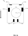
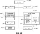
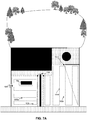
- FIGS. 1A-B are general schematic overviews of an example of the autonomous lawnmower robot 10, and FIG. 1C shows a block diagram of a control system that operates the autonomous lawnmower robot 10.
- FIG. 1A shows a schematic bottom view of the robot 10 with a forward direction F, which includes a main body 20 that contains wheel modules 610a-b of a drive system 600 (shown in FIG. 1C ) and a cutter 410 of a cutting system 400 (shown in FIG. 1C ).
- the wheel modules 610a-b include the wheels, motor, and gearbox for driving the robot 10 in a forward or backward direction.
- the wheel modules 610a-b can be differentially operated such that the robot can turn based on a level of drive supplied to each wheel.
- the drive system 600 further includes caster wheels 620a-b that partially supports the weight of the robot 10.
- the cutter 410 is, for example, rotatable reciprocating blades that can cut grass as a cutter drive sub-system 420 (shown in FIG. 1C ) drives the cutter 410 to rotate.
- the cutter 410 has a mowing width W M that defines the width of grass that the robot 10 cuts as the robot 10 moves over uncut grass.
- the cutter drive sub-system 420 includes a high-power motor and a high-torque gearbox that operate the cutter 410 such that, at highest power, the motor, gearbox, and the cutter 410 can cut thick swaths of grass.
- the bottom portion of the robot 10 can further include sensors part of a sensor system 650 (shown in FIG. 1C ). These sensors may include cut edge sensors 510a-b that differentiate between cut grass and uncut grass, grass height sensors that measure the height of grass beneath the robot 10, and cliff sensors that detect drop-offs in the terrain underneath the robot 10.
- FIG. 1B is a schematic side view of the exemplary robot 10.
- the robot 10 includes a power system 800 with a power source 810, a controller 1000, a communication system 1100, and a memory storage element 900.
- the controller 1000 controls the systems of the robot 10, which will be described in more detail later in reference to FIG. 1C .
- the power system 800 supplies power via the power source 810 to the other robot systems.
- the communication system 1100 allows the controller 1000 to wirelessly communicate with external computing devices, such a mobile device or web-based device.
- the communication system 1100 can include, for example, a Bluetooth transceiver and/or a WiFi transceiver.
- the power system 800 which includes a power source 810, provides power to the systems operable with the robot.
- the power source 810 is adjustable such that the power system 800 can provide a percent of full power.
- a charging system 820 within the power system 800 is connectable to an external charging dock to charge the power source 810.
- the sensor system 650 (shown in FIG. 1C ) of the robot 10 further includes a location estimation system 655 (shown in FIG. 1C ).
- the location estimation system 655 is a time-of-flight based system that uses a time-of-flight between a boundary marker (hereby also referred to as a "beacon” or a "marker") and the robot to determine the pose of the robot.
- boundary markers may be placed along the boundary of the lawn. While the time-of-flight system uses markers that have been described as boundary markers, the marker can also be placed within or near the lawn to aid localization of the robot lawnmower.
- the boundary markers send out a signal that the robot lawnmower interprets to determine its position relative to the boundary marker.
- the boundary markers are passive and a radiation source on the robot lawnmower emits radiation that reflects off surfaces situated in the lawn area and is detected by a radiation detector on the robot.
- the localization can use triangulation to determine the robot position within the boundary.
- the signals sent between the boundary markers and the robot positioned on the property allow the robot to estimate the angles and the distance by calculating time of flight to each of the boundary markers, and using trigonometry to calculate the robot's current position.
- the system can triangulate the distance to an object using a fixed-angle laser pointer and a CMOS imager, with a known baseline between the two.
- the pixel location of the received signal at the imager is indicative of the distance to the object.
- the boundary markers are wideband transceivers in the 5,925 to 7,250 MHz range or ultra-wideband transceivers.
- other time-of-flight transceivers could be used.
- the sensor system 650 includes an obstacle sensing system 657 that further includes the proximity sensors 680 disposed on the lateral sides of the robot 10 such that the robot can detect when it has made contact with a physical barrier or when it is in close proximity to a physical barrier.
- the proximity sensors 680 can take the form of contact sensors (e.g. a sensor that detects an impact of a bumper on the robot with a physical barrier) and/or LIDAR (Light Detection And Ranging, which can entail optical remote sensing that measures properties of scattered light to find range and/or other information of a distant target) sensors that detect when the robot is in close proximity to nearby objects.
- contact sensors e.g. a sensor that detects an impact of a bumper on the robot with a physical barrier
- LIDAR Light Detection And Ranging, which can entail optical remote sensing that measures properties of scattered light to find range and/or other information of a distant target
- the sensor system 650 also includes a handle sensing system 670 (shown in FIG. 1C ), which detects when a detachable handle 675 is attached to the robot 10.
- the detachable handle 675 is usable in a training mode as well as a mowing mode.
- Other sensors of the sensor system 650 include a global positioning system (GPS) as an additional means to determine the location of the robot 10, a tilt sensor to detect the level of the terrain beneath the robot, a rain sensor to detect water from, e.g. rain, that could damage the electromechanical components of the robot 10, and sensors and encoders operable with other systems to assist in control of the robot 10.
- GPS global positioning system
- the sensor system 650 can include, but not limited to, wheel drop sensors, sonar, radar, etc., infrared cliff sensors, a camera (e.g., volumetric point cloud imaging, three-dimensional (3D) imaging or depth map sensors, visible light camera and/or infrared camera), etc.
- a camera e.g., volumetric point cloud imaging, three-dimensional (3D) imaging or depth map sensors, visible light camera and/or infrared camera
- the robot 10 includes the controller 1000 that operates the memory storage element 900, the communication system 1100, the cutting system 400, the sensor system 650, the drive system 600, the navigation system 700, and the power system 800.
- the cutting system 400 includes the cutter drive sub-system 420, which can comprise a motor and gearbox to drive the cutter.
- the sensor system 650 further includes the handle sensing system 670 and the location estimation system 655 as well as other sensors mentioned earlier.
- the controller 1000 operates the navigation system 700 configured to maneuver the robot 10 in a path or route stored in the memory storage element 900 across the lawn areas and/or traversal regions.
- the navigation system 700 is a behavior-based system executed on the controller 1000.
- the navigation system 700 communicates with the sensor system 650 to determine and issue drive commands to the drive system 600.
- the controller includes obstacle detection and avoidance methods and behaviors implemented in response to sensor signals from the obstacle sensing system 657.
- the robot can use its proximity sensors to detect the general geometry of an obstacle in the general vicinity in front of the robot 10 so that the robot 10 can determine what direction to turn. For example, using proximity sensors 680 disposed on the front portion of the robot 10, the controller 1000 can determine when the robot is about to collide with an obstacle and communicate instructions to the navigation system 700 and the drive system 600 to avoid the obstacle.
- the memory storage element 900 stores data pertaining to operations - such as mowing operations or traversal operations -and the subroutines of the robot that can be implemented for, for example, training or mowing operations.
- the data further includes lawn route data, traversal route data, bypass route data, path behavior data, and scheduling data all of which will be described in more detail later.
- the controller 1000 communicates with the memory storage element 900 to determine which systems to activate or deactivate during an operation.
- a system e.g. the cutting system 400, the drive system 600, the power system 800
- the memory storage element 900 includes data associated with a level of activation for an operation.
- the controller 1000 activates the power system 800 at a 50% activation level due to lower power requirements for the traversal operations.
- the controller 1000 can have a high power mode (e.g. 75% - 100% activation level of the power system 800) to accommodate greater mechanical stresses in the cutting system 400 when mowing large and thick swaths of grass.
- the electromechanical systems including sensing, cutting, drive, navigation, power, communication systems, disclosed and illustrated herein may include the additional elements and features as disclosed in U.S. patent application Ser. No. 11/688,213, filed Mar. 19, 2007 , titled “Robot Confinement,” the disclosure of which is incorporated by reference herein in its entirety.
- a lawn may include multiple different mowable areas separated by a non-mowable area such as a path or driveway.
- a non-mowable area such as a path or driveway.
- the robot lawnmower described herein navigates between the separated lawn areas to mow the multiple areas.
- FIG. 2 depicts a schematic view of an example of a property 100 with three discontiguous lawn areas 102a-c.
- the lawn areas 102a-c have boundaries 106a-c, respectively.
- a traversal region 104a separates the lawn area 102a and the lawn area 102b, and a traversal region 104b separates the lawn area 102b and the lawn area 102c.
- the lawn area 102a has a rose garden 125, which is an un-mowable feature (e.g., a keep-out or non-mowable space within the boundary of area 102a).
- the traversal region 104a includes a concrete walkway 115 that separates the lawn area 102a from the lawn area 102b and a floral divider 116 within the concrete walkway 115.
- the robotic lawn mower if it is to mow both lawn area 102a and area 102b, it must cross the concrete walkway 115 in a region free of the floral divider 116.
- the lawn area 102c has an amorphous shape with trees 127 located at segments of the boundary 106c.
- the traversal region 104b is a rocky area 117 that includes a circular fire pit 131. Thus, to navigate between lawn area 102b and lawn area 102c, the robot must traverse region 104b while avoiding the fire pit 131.
- the robot 10 shown parked at a charging dock 50, mows the lawn areas 102a-c according to a schedule pre-determined by the user.
- the charging dock 50 restores the power source (described earlier) of the robot 10 and also serves as a launch point 1001 for route data that the robot stores (described later in more detail).
- the robot 10 can move from one lawn area to another via the traversal regions 104a-b.
- FIG. 3 shows an example of training data 303 stored in the memory storage element 900 (depicted in FIG. 1C ) that the robot can execute to mow a discontiguous set of lawn areas.
- the training data 303 can be generated in automated methods, manual methods, or a combination of the two methods.
- the training data 303 includes boundary data 305, internal boundary data 310, traversal route data 315, bypass route data 320, lawn route data 325, path behavior data 330, and scheduling data 335.
- the controller 1000 (depicted in FIG. 1C ) can process and execute at least some of the training data 303 to move about lawn areas and traversal regions and mow target lawn areas.
- the boundary data 305 is the set of points that bounds a lawn area.
- the boundary 106a-c of the lawn areas 102a-c can be represented by a set of discrete points stored as the boundary data 305a-c, respectively, or as a set of labelled cells in a Cartesian grid, which will be described in more detail later.
- the controller can determine geometric characteristics of the lawn area, including length, width, area, and shape.
- the internal boundary data 310 is the set of points that bound obstacles that cannot be traversed.
- the internal boundary data 310 defines the keep-out zones within a mowable area where the robot lawn mower should not mow.
- the rose garden 125 and the fire pit 131 can be represented by a set of discrete points stored as the internal boundary data 310.
- the traversal route data 315, the bypass route data 320, and the lawn route data 325 each include a set of points.
- Each point stored in the traversal route data 315, the bypass route data 320, and the lawn route data 325 includes one or more locations (e.g. X-, Y-coordinates measured from one or more datum points).
- the one or more datum points can correspond to locations relative to boundary markers placed along the boundary.
- the locations of the boundary markers serve as reference points for other points stored in the boundary data 305, the traversal route data 315, the bypass route data 320, and the lawn route data 325. Locations of points herein are generally measured relative to a coordinate system established relative to the boundary markers.
- the controller can use the route data 315, 320, 325 to generate one or more paths of movements that the robot 10 follows as it executes mowing, traversal, or bypass operations.
- the points and the orientation angle can be measured with respect to a Cartesian coordinate system, defined by for example, Cardinal directions and a reference point on the lawn.
- the points correspond to a position of the robot, and the orientation corresponds to the direction that the front of the robot is facing.
- the controller can control the drive system and navigation system such that the robot is placed into the position of the point and the orientation associated with that point.
- the controller uses the points of the route data 315, 320, 325 to generate routes to move about the lawn areas and traversal regions.
- the traversal route data 315 includes traversal route data 315a and traversal route data 315b for the traversal region 104a and the traversal region 104b, respectively.
- a robot starts on the boundary of a first lawn area, follows a route that crosses a traversal region, and ends on a second lawn area.
- the controller uses the points stored in the traversal route data 315a to generate a traversal route for the robot to move from the lawn area 102a across the traversal region 104a to arrive at the lawn area 102b.
- Traversal route data includes at least a traversal launch point and a traversal landing point.
- the traversal launch and landing points can be geolocations or positions (e.g., X, Y positions in a coordinate system) relative to the boundary markers.
- Traversal route data can further include intermediate traversal points.
- the traversal launch points generally correspond to an end point of a first lawn route; the intermediate traversal points generally correspond to points in the traversal region where the robot travels (e.g., the path or the route); and the traversal landing points generally correspond to a start point of a second lawn route.
- the first lawn route terminates at a first interface between the first lawn area and the traversable region.
- the first interface is defined by a subset of points of the boundary data for the first lawn area.
- the intermediate traversal points within the traversal route correspond to points that the robot follows while traversing the area.
- the intermediate traversal points can further correspond to other changes in behavior of the systems of the robot, such as the drive system, the power system, the navigation system, etc.
- the controller could increase the power level at the intermediate traversal point in order to compensate for a change in terrain at the intermediate traversal point.
- the terrain could be more difficult for the robot to traverse after crossing the intermediate traversal point, and it would thus be beneficial to increase the power level of the power system.
- the intermediate traversal routes can include one or more additional intermediate points that, with the intermediate traversal points, can define line geometries that can be represented by two or more points. For example, two intermediate traversal points and an intermediate point can define an arc.
- the traversal landing point corresponds to the end of the traversal region and may additionally correspond to a start point of a second lawn route.
- the second lawn route can begin at a second interface between the second lawn area and the traversal region.
- the second interface is defined by a subset of points of the boundary data for the second lawn area.
- the traversal route data 305a includes a traversal launch point, intermediate traversal points, and a traversal landing point.
- the traversal route data 305b includes a traversal launch point, intermediate traversal points, an intermediate traversal route, and a traversal landing point. The points described above for the traversal route data 305a-b will be elaborated in more detail herein.
- Bypass route data 320a-b provides a path for the robot lawnmower to follow to traverse a particular lawn area without mowing the area.
- the bypass route data includes the bypass route data 320a for the lawn area 102a and the bypass route data 320b for the lawn area 102b. Also referring briefly to FIG. 2 , the points stored in the bypass route data 320a allow the controller to generate a bypass route going from the launch point 1001 across the lawn area 102a to the start of the traversal route for the traversal region 104a. The bypass route data 320b allow the controller to generate a bypass route going from the start of the traversal route for the traversal region 104a across the lawn area 102b to the start of the traversal route for the traversal region 104b.
- the robot lawnmower can follow a predetermined path or pattern to complete cutting of the grass in the lawn area.
- the information about the path is stored as lawn route data.
- the robot lawnmower can store separate route data for each of the different lawn areas allowing each to be mowed according to a pattern that is appropriate for the lawn area.
- the lawn route data 325 includes lawn route data 325a for lawn area 102a, lawn route data 325b for lawn area 102b, and lawn route data 325c for lawn area 102c.
- the controller uses the lawn route data 325a-c to guide the robot through movement patterns (described in more detail below in relation to FIG. 7 ) that cover the areas of the lawn area 102a-c.
- the covered area of the robot is defined by the product of the mowing width W M (described above) and the length of distance traveled by the robot while executing a lawn route.
- the lawn route data 325a-c each include a start point and an end point as well as the movement pattern for each lawn area 102a-c, respectively.
- the controller can further compute the area of each lawn to determine the movement pattern. During a mowing operation, the computed area allows the controller to compare the computed area of the lawn to the covered area of the lawn to determine whether the robot has achieved enough coverage of the lawn. In some implementations, sufficient coverage is defined by a ratio of covered area to computed area greater than 1.
- the path behavior data 330 indicates the operations of the robot systems (e.g. the drive system, the cutting system, the navigation system) along segments of the routes defined by the route data 315, 320, 325.
- the robot systems e.g. the drive system, the cutting system, the navigation system
- parts of or all of the routes corresponding to the lawn route data 325 can be associated with path behavior data 330 that instructs the controller to set the power system such that the drive system and the cutting system are both on and the grass is cut while the robot traverses the route.
- Parts of or all of the routes corresponding to the traversal route data 315 and the bypass data 320 can be associated with path behavior data 330 that sets the drive system to a predetermined drive speed (e.g., slower than mowing when the robot is likely to maneuver difficult turns or faster than during the mowing if the robot traverses a long distance) and the cutting system to an activation level of 0% (e.g., mowing is disabled).
- the path behavior data 330 can further include instructions to the navigation and/or drive systems to navigate the robot through turning and forward drive.
- the scheduling data 335 can be set by the user via the mobile application or a user interface on the robot.
- the user can set a schedule that automates the robot to mow each lawn at a different time.
- the robot can be set to mow lawn areas 102a-b at a user-selected time on one day of the week and can be set to mow lawn area 102c at another user-selected time on another day of the week.
- the scheduling data 335 determines which routes 315, 320, 325 to combine to generate a path for the mowing operation at the given time.
- FIGS. 4-8 depict aspects of both automated and manual methods of training the robot.
- FIGS. 4A-C show different examples of generating the boundary data 305 that can be used by the controller or the user to generate the route data 315, 320, 325.
- FIGS. 5A-C show different examples of generating the traversal route data 315.
- FIG. 6 depicts an example of generating the bypass route data 320.
- FIG. 7 shows examples of route data (e.g., lawn route data, traversal route data, and bypass route data) that can be generated based on the results from FIGS. 4-6 .
- route data e.g., lawn route data, traversal route data, and bypass route data
- the path behavior data 330 can be automatically (described in association with FIG. 7 ) or manually (described in association with FIG. 8 ) associated with each of the route data 315, 320, 325 such that appropriate systems of the robot 10 are activated and deactivated. While the examples shown in each of FIGS. 6-8 are for the lawn areas and the traversal regions of the shown geometry, it should be understood that each training mode can be implemented to train the robot 10 for a variety of lawn geometries and configurations.
- FIG. 4A shows an exemplary lawn area 102c in which the robot 10 determines its pose within the lawn area 102c by detecting boundary markers 128a-c.
- Each boundary marker is positioned at a known location and situated so that the robot can detect each boundary marker as the robot navigates the lawn.
- the robot receives signals from the individual boundary markers. The robot determines its pose based on the signals, which can represent the robot's location relative to the three boundary markers.
- the pose of the robot (e.g., P 1 , P 2 ) can be determined based on the signals received from the boundary markers (e.g., a signal sent from the robot and reflected by the boundary marker or a signal generated by the boundary marker and received by the robot).
- the robot lawnmower determines the distance between the robot and the boundary marker based on the time-of-flight between the marker and the robot.
- the robot's pose can be determined by trilaterating based on received range/heading information from each of the boundary markers.
- trilateration is the process of determining absolute or relative locations of points by measuring distances, using the geometry of circles, spheres, or triangles.
- trilateration can be based on a least squares algorithm using the distance/time-of-flight measurements.
- time-of-flight can be measured indirectly by measuring the phase shift between the signal and the receipt of the reflect signal.
- distance can be determined by transmitting a signal from the robot, measuring the time the signal arrives at each boundary marker, and using a time-difference-of-arrival technique to estimate the robot's location.
- the boundary 106b is trained using a teach-and-playback routing in which the user pushes the robot around the boundary 106b and the robot stores information about the location of the trained boundary. Further details of an exemplary process for determining the lawn boundary can be found, for example, in US 14/512,098 filed on October 10, 2014 and titled "Robotic Lawn Mowing Boundary Determination," the contents of which is hereby incorporated by reference in its entirety.
- FIG. 4B shows a manual process of generating the lawn boundary data for the lawn area 102b.
- the user manually navigates the robot 10 around the boundary 106b of the lawn area 102b by guiding the robot 10 with the detachable handle 675, and the robot 10 generates the boundary data 305b as it is moved around the lawn area 102b.
- the user 70 manually maneuvers the robot 10 by pushing and pulling the handle 675.
- the robot 10 can automatically store points, or the user 70 can manually trigger a point to be stored.
- the robot 10 can be programmed to store the point corresponding to its current position route under the boundary data 305b (described in reference to FIG. 3 above) for the boundary 106b of the lawn area 102b.
- the robot 10 can be programmed to automatically store its current position every second.
- the user 70 can also manually instruct the robot 10 to store its current position, via, for example, the application on the mobile device, which will be described in more detail later.
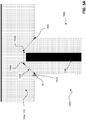
- a data processing unit generates a 2D grid of cells to represent the lawn areas. As the robot lawnmower determines its position relative to the beacons, the data processing unit determines and saves the coordinates of each cell containing the robot lawnmower during its motion. For each lawn area, each cell in the grid can be assigned a mowing-area value indicating whether the cell is understood to be NONMOWABLE (i.e. outside the boundary), MOWABLE (i.e., inside the boundary), or BOUNDARY (i.e., on the boundary). Each cell of the grid can be assigned (X, Y) coordinates based on a chosen origin (0,0) cell. Each cell can represent a square area, with each cell having a side length between 1 and 100 cm.
- the grid can be a grid of cells, each 10 cm x 10 cm.
- the robot lawnmower stores the (X, Y) coordinates of each cell traversed by the robot lawnmower along the actual teaching path travelled during the teaching mode.
- the robot lawnmower can mark the actual teaching path as a simple line tracing the path of the robot through single cells.
- the robot can mark all cells under the footprint of the robot as BOUNDARY cells.
- the values of all cells are initialized to NONMOWABLE. The operator presses the start button to start the training process and then drives around the boundary of the mowing area.
- the values of all cells along its actual teaching path are set to BOUNDARY, the location of the cells being determined by the distance to the beacons.
- the operator presses a button to end the teaching process.
- the operator positions the robot lawnmower anywhere within the mowing area and presses a button, indicating to the robot lawnmower that it is inside the boundary.
- the system performs a flood fill to set the values of all cells inside boundary defined by the BOUNDARY cells to mark them as MOWABLE cells to be mowed.
- the traversal route data 315 instructs the robot with a route to move across the traversal regions between the separated lawn areas, such as the traversal regions 104a-b shown in FIG. 2 .
- the controller determines and stores at least a traversal launch point and a traversal landing point.
- the controller further determines and stores intermediate traversal points.
- FIGS. 5A and 5B depict examples of points generated for the traversal route data 315a and 315b (described earlier in relation to FIG. 3 ), respectively.
- the traversal route data 315a contain points that define a traversal route 1500 within the traversal region 104a that the robot takes to move from the lawn area 102a to the lawn area 102b.
- the traversal route data 315b contain points that define a traversal route 1600 within the traversal region 104b that the robot follows to move from the lawn area 102b to the lawn area 102c.
- FIGS. 5A-B show examples of the traversal routes 1500, 1600, respectively, generated for the traversal regions 104a-b, respectively.
- the robot 10 navigates across the traversal regions 104a-b by going sequentially through points that define the traversal routes 1500, 1600.
- the traversal route 1500 is defined by a first traversal launch point 1540, intermediate traversal points 1550a-b, and a first traversal landing point 1560.
- the robot 10 moves sequentially in straight line segments from point 1540, to point 1550a, to point 1550b, to point 1560.
- the traversal route 1600 is defined by a second traversal launch point 1640, an intermediate traversal point 1650, and a second traversal landing point 1660.
- traversal route data can be generated for other traversable configurations of traversal regions.
- the route between the traversal launch point and the traversal landing point can be trained using a process similar to the process used to train the boundary of the lawn.
- the user can place the robot into a traversal training mode and the traversal launch point can be the robot's location relative to the beacons. The user then pushes the robot along a path and the robot stores the path in a memory. The end of the path is stored as the traversal landing point.
- the controller automatically generates the traversal route 1500.
- the controller determines and stores the shortest traversable route between a source boundary (the boundary 106a) and a destination boundary (the boundary 106b).
- the robot 10 can identify the shortest traversable route in various ways. For example, the robot can identify locations where the robot is able to drive between one area and the other (e.g., determine regions free of obstacles). Given a grid-based representation of the lawn as described earlier, a path planning algorithm such as A*, rapidly exploring random trees (RRTs), or probabilistic roadmaps can then be used to find the shortest path from the robot's current location to the destination.
- the robot 10 is manually driven via a detachable handle (described earlier in relation to FIG. 4C but not shown in FIG. 5 ).
- the controller initiates a training mode.
- the user navigates the robot 10 through the traversal route 1500, and the robot systems (e.g. the controller and the memory storage elements) generate points corresponding to the traversal route 1500.
- the robot systems via the manual navigation of the robot 10, can generate points substantially similar to the ones described above, e.g., the traversal launch point 1540, the traversal landing point 1560, and the intermediate traversal points 1550a-b, though it should be understood that the user can navigate the robot 10 along a different route with fewer or more intermediate traversal points.
- the controller of the robot 10 confirms this departure and generates the traversal launch point 1540 corresponding to the point where the robot 10 exits the lawn area 102a.
- the user of the robot 10 guides the robot through the traversal route 1500 turning to avoid the floral divider 116 and the robot 10 stores information about the path the robot 10 follows during the traversal route training.
- the controller can detect the crossing based on mapping data of the lawn 104b and automatically generate the traversal landing point 1560.
- the user pushes the robot 10 across the boundary 106b in a diagonal direction, and the controller generates the traversal launch point 1640.
- the user manually navigates the robot 10 toward the boundary 106c avoiding the fire pit 131 and the robot 10 stores the path followed by the robot 10.
- the controller When the robot 10 crosses the boundary 106c, the controller generates the traversal landing point 1660 and completes the traversal route training for the traversal region 104b.
- the data processing unit generates a 2D grid of cells to represent the lawn areas and each cell is indicated as MOWABLE, NONMOWABLE, or BOUNDARY.
- the data processing unit determines and saves the coordinates of each cell containing the robot lawnmower during its motion (e,g., while traversing the boundary area between the lawn areas).
- Each cell of the grid can be assigned (X, Y) coordinates based on a chosen origin (0,0) cell.
- the robot lawnmower stores the (X, Y) coordinates of each cell traversed by the robot lawnmower along the actual teaching path travelled during the teaching of the traversal path.
- the robot lawnmower can mark the actual teaching path as a simple line tracing the path of the robot through single cells. Alternatively, the robot can mark all cells under the footprint of the robot as TRAVERSAL PATH cells.
- the values of all cells between the multiple mowing lawn areas are initialized to NONMOWABLE.
- the operator presses the start button to start the teach process and then drives from one lawn area to another lawn area.
- the values of all cells along its actual teaching path are set to TRAVERSAL PATH, the location of the cells being determined by the distance to the beacons.
- the operator presses a button to end the teaching process.
- the robot lawnmower traverses calls marked as TRAVERSAL PATH, the robot lawnmower disables (turns off) its cutting system.
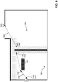
- FIG. 6 is an example of training bypass route data 320a, 320b, which provides data the controller uses to cross through the lawn area 102a, 102b, respectively.
- the controller generates a bypass launch point 1740 corresponding to the launch point 1001.
- the controller further generates a bypass landing point 1760, which coincides with the traversal launch point 1540.
- the bypass launch and landing points are locations relative to the beacons.
- the controller determines and stores the shortest route between the bypass launch point 1740 and the bypass landing point 1760 avoiding any keep-out zones within the lawn area.
- the controller selects initial points for the shortest route.
- the controller directs the robot 10 to move from the bypass launch point 1740 to the bypass landing point 1760 via the shortest route (e.g., a straight line).
- the controller knows the location of the rose garden 125 from the keep-out zone training of the mowable space and uses internal boundary data (e.g., internal boundary data 310 depicted in FIG. 3 ) for the rose garden 125 to determine a bypass route 1700 that avoids traversal of the prohibited space. As a result of this route determination, the controller stores the bypass launch point 1740, an intermediate bypass point 1750, and the bypass landing point 1760 as shown in FIG. 6 .
- internal boundary data e.g., internal boundary data 310 depicted in FIG. 3
- the controller to train the bypass route data 320b representing the bypass route 1800, the controller generates a bypass launch point 1840 that coincides with the traversal landing point 1560 and a bypass landing point 1860 that coincides with the traversal launch point 1640.
- the controller determines and stores the shortest route between the bypass launch point 1840 and the bypass landing point 1860 that avoids prohibited or keep-out areas (e.g., determines a path that stays within the mowable space).
- a user can train the bypass routes in a similar manner to the process used to train the boundary by pushing the mower along a desired path while the robot stores information about the path.
- the data processing unit generates a 2D grid of cells to represent the lawn areas, and each cell is indicated as MOWABLE, NONMOWABLE, or BOUNDARY. Regions between the lawn areas can have connection paths marked as TRAVERSAL PATH cells.
- the data processing unit determines and saves the coordinates of each cell containing the robot lawnmower during its motion (e.g., while traversing across the lawn area).
- Each cell of the grid can be assigned (X, Y) coordinates based on a chosen origin (0,0) cell.
- the robot lawnmower stores the (X, Y) coordinates of each cell traversed by the robot lawnmower along the actual teaching path travelled during the teaching of the bypass path.
- the robot lawnmower can mark the actual teaching path as a simple line tracing the path of the robot through single cells. Alternatively, the robot can mark all cells under the footprint of the robot as BYPASS cells.
- the values of all cells are MOWABLE.
- the operator presses the start button to start the teach process and then drives from one position within the lawn area to another position within the lawn area.
- the values of all cells along its actual teaching path are set to BYPASS (or MOWABLE/BYPASS), the location of the cells being determined by the distance to the beacons.
- BYPASS or MOWABLE/BYPASS
- the operator presses a button to end the teaching process.
- FIGS. 7A-B depict automatic generation of the lawn route data 325a-c as well as the different path behaviors 330 associated with the route data 315, 320 generated above.
- the lawn route data 325a-c includes a start point, an end point, and a movement pattern.
- the movement pattern can be, for example, a spiral pattern, a corn row pattern, zig-zag pattern, etc.
- a user can select a desired movement pattern for each of the lawn areas and different patterns may be selected for different areas of the same lawn.
- a yard may be too large to mow on a single charge of the robot lawnmower battery.
- the robot can mow different areas of the yard at different times allowing the robot to return to the dock and charge its battery between mowing the different areas.
- FIG. 7A depicts the execution of a mowing operation of lawn area 102a, 102b, after which the robot returns to the charging dock 50.
- FIG. 7B depicts the execution of a mowing operation of lawn area 102c after which the robot returns to the charging dock 50.
- the lawn routes 1900a-b are automatically generated based on the start points, the end points, and default movement patterns.
- the robot is beginning at the launch point 1001 and proceeds in a corn row movement pattern until the robot has determined that it has covered the lawn area 102a (e.g., completed the coverage pattern or determined that the covered area-defined by, for example, the distance covered by the robot multiplied by the width of the cutting element-is greater than 100% of the computed area for the lawn area 102a).
- the corn row movement pattern guides the robot back and forth across the lawn such that the robot moves perpendicular to the longitudinal movement of the pattern slightly between each traversal.
- the controller executes the traversal route data 320a which defines the traversal route 1500.
- the associated path behavior data 330 for the traversal route data 320 includes a deactivation of the cutting system.
- the start point is defined as the traversal landing point 1560
- the end point is defined as the traversal launch point 1640.
- the robot Upon entry into lawn area 102b, the robot activates the cutting system. After completion, the robot returns to the launch point 1001.
- the robot continues to mow the lawn by mowing lawn area 102c.
- the controller executes the bypass route data 320a, the traversal route data 315a, the bypass route data 320b, and the traversal route data 315b.
- the data 320a-b, 315a-b together define a bypass route 2100 to move the robot from the launch point 1001 to lawn area 102c.
- the associated path behavior data 330 for the bypass route 2100 to bypass the lawn areas 102a-b includes a deactivation of the cutting system.
- the robot activates the cutting system.
- the start point of the lawn route 1900c corresponds to the end point of the bypass route 2100.
- the robot proceeds in a corn row movement pattern until the robot has determined that it has covered the lawn area 102c.
- the controller directs the robot 10 to return to the launch point 1001.
- the user can monitor and control various aspects of the robot and the training of the robot through an application installed on a computing device, which allows a user to enable functionality such as scheduling, bypassing, movement selection, lawn area selection, among other functions.
- the user can interact with the computing device via user interface features, such as a touchscreen display, a keyboard, voice command, gestures, or another type of interaction.
- user interface features such as a touchscreen display, a keyboard, voice command, gestures, or another type of interaction.
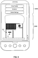
- the computing device as shown in FIG. 8 is a smartphone, in other implementations, the device could be a portable device such as smart glasses, smart watch, a laptop computer, or a computing device such as a desktop computer.
- FIG. 8 shows a screenshot of the user interface of the exemplary lawn area shown in FIG. 2 .
- the mobile device displays a menu portion 3000 and a map portion 3500.
- the menu portion 3000 shows options including "Show Routes", “Schedule”, and "Default Settings”.
- Tapping "Show Routes” on the menu portion 3000 will reveal the points or cells stored as a result of training the traversal routes, bypass routes, and lawn routes. As will be discussed, the user can interact with these points.
- Tapping "Schedule” allows the user to modify the schedule for the mowing operations of the robot.
- Tapping "Default Settings” allows the user to modify the default settings for the training subroutines.
- the map portion 3500 includes a satellite map of the lawn areas that the user would like to mow.
- the satellite map can be selected by the user and can be downloaded from a map provider service.
- the processor of the mobile device can further recognize boundaries and delineations on the satellite map.
- the user can interact with the satellite map to give a general area corresponding to the lawn areas that the user wishes to mow.
- the user can use the touchscreen to draw geometric shapes that function as virtual regions that can assist the robot in training.
- a user can set a virtual region as a lawn area, which can give the controller a general location for the boundary of the lawn areas.
- the user can further set virtual regions for the traversal regions and for obstacles.
- the map includes the launch point 1001 corresponding to the location of the charging dock as well as the current location of the robot 10. The user can also select default settings for the training methods described herein.
- the map can include the points of the boundary data 305 (described above). While the traversal launch point and traversal landing point for each traversal region have been described as set automatically, the user can also override the automatically selected points by selecting one of the points of the boundaries shown on the map on the application. After the user selects traversal launch points and traversal landing points for each traversal region, the controller can further implement optimization algorithms (e.g. quasi-Newton methods) that consider the location of the traversal launch points and traversal landing points to compute the shortest route between the traversal launch points and the traversal landing points. In some implementations, the user can mark on the mobile device the boundaries that are traversable and non-traversable.
- optimization algorithms e.g. quasi-Newton methods
- the user can initiate the automated or manual traversal route training described in detail earlier.
- the mowing pattern can be defined after a lawn route start point and a lawn route end point have been defined, the user can also select the mowing pattern of each lawn prior to implementing the traversal route training.
- the user can further create a schedule for the robot.
- Each area of the lawn can be separately scheduled.
- the robot stores scheduling data for each of multiple lawn areas. For example, if the user would like the robot to mow lawn area 102c separately from lawn areas 102a-b, the user can select the lawn area 102c via the user interface and set a schedule (e.g. time and day of week) to mow the lawn area 102c.
- the robot can be scheduled to mow the lawn areas 102a-b in one mowing operation and the lawn area 102c in another mowing operation.
- the robot will follow the routes as described in FIG. 7A .
- the robot When the robot is scheduled to mow lawn area 102c, the robot will bypass the lawn areas 102a-b to mow the lawn area 102c, as shown in FIG. 7B .
- FIG. 9 is a flow chart for training a robot to mow a first and a second lawn with a traversal region that separates the first lawn from the second lawn, such as lawn areas 102a-b of FIG. 2 .
- the process involves identifying the boundary of the first lawn, identifying the boundary of the second lawn, selecting a traversal launch point, train first lawn route, selecting intermediate traversal points, selecting a traversal landing point, training a bypass route for the first lawn, selecting a movement pattern for the first lawn, and selecting a movement pattern for the second lawn area.
- the controller trains the robot to identify the boundary of the first lawn area.
- the controller implements one or more of the boundary training methods described with respect to FIGS. 4A-C to generate the points corresponding to the boundary of the first lawn area.
- the controller trains the robot to identify the boundary of the second lawn area.
- the controller implements one or more of the boundary training methods described with respect to FIGS. 4A-C to generate the points corresponding to the boundary of the second lawn area.
- the controller trains the traversal launch point.
- the controller can train the traversal launch point via a user selection on the application as described in FIG. 8 , or the controller can implement route training (e.g., as described in FIG. 5 ) to automatically select the traversal launch point.
- the controller trains a first lawn route for the first lawn area.
- the first lawn area route uses a start point generally pre-determined by the location of a charging station and uses an end point determined by the traversal launch point trained in step S910.
- the controller selects a first mowing pattern for the first lawn route that can be a default pattern (e.g. corn row pattern) for the geometry of the first lawn area.
- the controller can further set the associated path behavior for the first lawn route.
- the controller trains the intermediate traversal points and the traversal landing point for the traversal region by implementing the traversal route training as described with respect FIG. 5A-B .
- the controller navigates the robot to the traversal launch point selected in step S910 and directs the robot through the traversal region as the controller implements the traversal route training. If there are obstacles within the traversal region, the controller can generate intermediate traversal points as the robot avoids the obstacles. As the robot crosses the traversal region and enters the second lawn, the controller generates the traversal landing point and thus completes the training of the traversal route.
- the controller can further set the associated path behavior for the traversal route including turning off the cutting system of the robot lawnmower.
- the controller trains a second lawn route for the second lawn area.
- the mowing pattern for the second lawn uses a start point generally determined by the location of the traversal landing point training in step S920.
- the mowing pattern for the second lawn uses an end point generally determined by the boundary points trained in step S905 and the traversal landing point. In some implementations, the end point is the boundary point farthest from the traversal landing point.
- the controller selects a second mowing pattern for the second lawn route that can be a default pattern (e.g. corn row pattern) for the geometry of the first lawn area.
- the controller can further set the associated path behavior for the second lawn route.
- the controller trains the bypass route to move from a launch point corresponding to the location of the charging station across the first lawn area to the start of the traversal route.
- the controller implements bypass route training described in FIG. 7 to generate the points of the bypass route.
- the controller can further set the associated path behavior for the bypass route.
- FIG. 10A-B are flow charts for the mowing operations after the robot has been trained following the method of FIG. 9 .
- FIG. 10A is a flow chart of a mowing operation that mows both the first lawn area and the second lawn area.
- the robot enables a cutting system of the robot and mows the first lawn area.
- the robot follows the first mowing pattern determined in step S915. After the robot has covered an area of at least 100% of the area of the first lawn, the mowing pattern ends at the traversal launch point determined in step S910.
- step S1005A after the robot reaches the traversal launch point of the traversal route, the robot disables the cutting system and begins traversing the traversal region via the traversal route (including the traversal start point, the intermediate traversal points, and the traversal end point) determined in steps S910 and S920. The robot completes the traversal route at the traversal end point determined in step S920.
- step S1010A after the robot traverses the traversal region, the robot enables the cutting system and begins to mow the second lawn via the second lawn route determined in step S925.
- the robot follows the second mowing pattern until the robot has covered an area at least 100% of the area of the second lawn area. The robot then terminates the second lawn route at the end point determined in step S925.
- step S1015A after the robot reaches the end point of the second lawn route, the robot disables the cutting system and returns to the launch point.
- FIG. 10B is a flow chart of a mowing operation that bypasses the first lawn and mows the second lawn area.
- the robot disables a mowing function, bypasses the first lawn via the bypass route trained in step S935, traverses the first traversal region via the traversal route trained in steps S910 and S920 to reach the traversal landing point on the second lawn area.
- step S1005B after the robot reaches the traversal landing point of the traversal route, the robot enables the cutting system and begins to mow the second lawn via the second lawn route determined in step S925.
- the robot follows the second mowing pattern until the robot has covered an area at least 100% of the area of the second lawn area. The robot then terminates the second lawn route at the end point determined in step S925.
- step S1010B after the robot reaches the end point of the second lawn route, the robot disables the cutting system and returns to the launch point.
- the robot can be trained to mow more or fewer lawn areas.
- the robot can be trained to mow a continuous lawn and consequently does not require traversal route data to move across traversal regions.
- the robot can be trained to mow several discontiguous lawn areas (e.g. four or more).
- the robot can be scheduled to execute several mowing operations at different times so that the power system of the robot can be sustained through the entire mowing operation.
- the robot can be trained to include several bypass routes that allow the robot to bypass lawn areas that are not to be mowed in a mowing operation.
- the setting of the activation levels can be adaptive. For example, as the robot executes training operations, the robot may have swath sensors that can detect the stiffness of grass that the robot passes over. As the robot detects the stiffness of the grass, it can modify the activation level of the cutting system during mowing operations to accommodate the stiffness. If the grass is stiff, then the activation level of the cutting system can be increased.
- the robot can further include torque or force sensors in the drive system to determine the level of activation for the drive system to drive the wheel modules to cross various terrains.
- the controller can be configured to automatically set the scheduling data.
- the controller can, for example, compute the area of each of the discontiguous lawn areas and the distance of potential routes, and use those computations to estimate an amount of power consumption associated with particular route options.
- the controller can then set a schedule of routes such that the robot can execute each mowing operation with a full charge of power.
- path planning algorithms such as A*, rapidly exploring random trees (RRTs), or probabilistic roadmaps have been described to be used to train the traversal and bypass routes
- other algorithms such as Floyd-Warshall algorithm, Johnson's algorithm, and Dijkstra's algorithm
- a single source or single destination shortest path algorithm such as Dijkstra's algorithm can be used.
- threshold mowing area coverage has been described to be 100% of the area of the lawn, in some implementations the threshold mowing area coverage can be greater. In other implementations, the threshold mowing area coverage can be greater than, for example, 150% of the area of the lawn area 102a.
- the user can manually instruct the robot that the handle has been attached.
- the robot has been described to store a point every second.
- the duration of time between storing points can be modified by the user to be more or less. For example, for larger lawn areas, it can be beneficial to store fewer points in order to reduce the amount of storage space dedicated to the lawn route data.
- the handle 675 has been described as detachable, in other implementations, the handle remains on the robot but is collapsible or stowable.
- the handle can be telescoping so that the handle can be collapsed into a small form factor when not in use.
- the user can use the application on the computing device to manually define general boundaries.
- the manually defined boundaries on the application can generate virtual markers that the robot follows to map the boundaries.
- the cells of the 2D grid of cells to represent the lawn have been described to represent a square area with side lengths between 1 and 100 cm, in other implementations the cells can be larger or smaller depending on the property. For example, for larger properties (e.g. a football field, a golf course), the side lengths could be between 1 and 10 m. In some implementations, the user manually sets the side lengths. In other implementations, the controller selects a cell size based on an input for the area of the lawn or property. In further examples, the controller implements an adaptive algorithm that determines the cell size based on the geometry of the lawn. For example, for amorphous lawn shapes, a larger number of cells can be used to reflect the amorphous geometry.
- the user can select objective functions for the path planning algorithm. For example, instead of requesting a route with minimum distance between the traversal launch point and the traversal landing point, the user may select an objective function that the controller minimizes to select a route with the fewest number of turns, a route that begins and ends at specific points (e.g., the user pre-defines the traversal launch point and the traversal landing point).
- the user can also select more than one objective function to minimize. For example, the user may want to minimize the number of turns as well as the distance between the traversal launch point and the traversal landing point.
- the training method for the traversal routes 1500, 1600 and the bypass routes 1700, 1800 have been described to include one or less obstacles in between the respective launch and landing points, in some implementations, additional obstacles are detected during training.
- the controller After generating the intermediate points and attempting the traversal or bypass route generated during the training, the controller determines the presence of an additional obstacle.
- the controller maps the additional obstacle and generates additional intermediate points to find an optimized path to avoid the obstacle.
- the controller continues to iterate through the training method until the controller directs the robot through a route without detecting an additional obstacle.
- the boundary markers placed along the boundary can also serve as traversal launch points and traversal landing points.
- the user can place a physical marker (e.g., the boundary markers) that represent the traversal launch points and traversal landing points.
- route segments shown in this disclosure focus on straight line segments between points, it should be understood that other curve geometries, such as arcs, can be generated with points on a route.
- Associating a polynomial with two points on a route can, for example, generate spline geometry connecting the two points.
- the controller when the robot reaches one of the points of the spline geometry, can correlate the navigation system with the polynomial function such that the robot moves along the spline geometry. For example, for obstacles with geometries not easily defined by arcs, the controller can generate spline geometries to approximate a route to avoid the obstacle geometries.
- first traversal launch points 1540, 1640 have been described as selected during the process training the traversal route, in other implementations, the default traversal launch point can be the charging dock.
- the last lawn can have a trained bypass route that can be used as part of the return route.
- a bypass route can be trained for lawn area such that the robot can take the reverse of the bypass route in order to return to the charging station.
- the bypass route can use the end point of the mowing pattern for lawn area.
- the controller can be programmed such that the mowing pattern of a lawn route terminates at the traversal launch point.
- the end point of the lawn route can terminate at the traversal launch point of the traversal route.
- the return route that the robot takes at the conclusion of a mowing operation can be a composition of bypass routes and traversal routes.
- the robot 10 can follow the bypass route 1800, the traversal route 1500, and the bypass route 1700 in the reverse direction.
- the path behavior data 330 has been described to be assigned to the traversal route data 315 and the bypass route data 320 with respect to FIG. 7 after the lawn route data 325 has been generated, it should be understood that the path behavior data 330 can be generated as each route data is being generated. For example, as the points for the traversal route data and the bypass route data are being generated, the path behavior data associated with those routes can be set such that the drive system is set at a mid-range activation level and the cutting system is deactivated. In some implementations, the controller can be programmed such that training the bypass route data and the traversal route data automatically associates those route data with a deactivation of the cutting system, and training the lawn route data automatically associates the lawn route data to an activation of the cutting system.
- a lawn route described herein applies to a continuous lawn
- a lawn can be segmented into two separate lawn regions contiguous lawn regions.
- the robot can be scheduled to mow the lawn regions at different times.
- the modification of the traversal launch point and the traversal landing point can be a manual operation.
- the user can view the boundary data stored for the lawn areas on the application of the mobile device and manually select locations for the traversal launch points and traversal landing points.
- training the traversal route between the first area and the second area can occur after training the mowing operation for the first area and the second area.
- Training the bypass route can occur before training the second lawn route or training the traversal route.
Landscapes
- Engineering & Computer Science (AREA)
- Physics & Mathematics (AREA)
- General Physics & Mathematics (AREA)
- Aviation & Aerospace Engineering (AREA)
- Radar, Positioning & Navigation (AREA)
- Remote Sensing (AREA)
- Automation & Control Theory (AREA)
- Robotics (AREA)
- Mechanical Engineering (AREA)
- Environmental Sciences (AREA)
- Life Sciences & Earth Sciences (AREA)
- Electromagnetism (AREA)
- Control Of Position, Course, Altitude, Or Attitude Of Moving Bodies (AREA)
- Harvester Elements (AREA)
- Guiding Agricultural Machines (AREA)
Applications Claiming Priority (3)
| Application Number | Priority Date | Filing Date | Title |
|---|---|---|---|
| US14/579,080 US9538702B2 (en) | 2014-12-22 | 2014-12-22 | Robotic mowing of separated lawn areas |
| EP15778430.7A EP3236731B1 (fr) | 2014-12-22 | 2015-09-16 | Tonte par tondeuse à gazon robotisée de zones de gazon séparées |
| PCT/US2015/050482 WO2016105609A1 (fr) | 2014-12-22 | 2015-09-16 | Tonte par tondeuse à gazon robotisée de zones de gazon séparées |
Related Parent Applications (1)
| Application Number | Title | Priority Date | Filing Date |
|---|---|---|---|
| EP15778430.7A Division EP3236731B1 (fr) | 2014-12-22 | 2015-09-16 | Tonte par tondeuse à gazon robotisée de zones de gazon séparées |
Publications (2)
| Publication Number | Publication Date |
|---|---|
| EP3729944A1 true EP3729944A1 (fr) | 2020-10-28 |
| EP3729944B1 EP3729944B1 (fr) | 2022-08-10 |
Family
ID=54291603
Family Applications (2)
| Application Number | Title | Priority Date | Filing Date |
|---|---|---|---|
| EP15778430.7A Active EP3236731B1 (fr) | 2014-12-22 | 2015-09-16 | Tonte par tondeuse à gazon robotisée de zones de gazon séparées |
| EP20180099.2A Active EP3729944B1 (fr) | 2014-12-22 | 2015-09-16 | Tonte robotisée de multiple zones de gazon |
Family Applications Before (1)
| Application Number | Title | Priority Date | Filing Date |
|---|---|---|---|
| EP15778430.7A Active EP3236731B1 (fr) | 2014-12-22 | 2015-09-16 | Tonte par tondeuse à gazon robotisée de zones de gazon séparées |
Country Status (7)
| Country | Link |
|---|---|
| US (5) | US9538702B2 (fr) |
| EP (2) | EP3236731B1 (fr) |
| CN (2) | CN106535614B (fr) |
| AU (1) | AU2015370367B2 (fr) |
| CA (1) | CA2953581A1 (fr) |
| IL (1) | IL249416A0 (fr) |
| WO (1) | WO2016105609A1 (fr) |
Families Citing this family (103)
| Publication number | Priority date | Publication date | Assignee | Title |
|---|---|---|---|---|
| US11835343B1 (en) * | 2004-08-06 | 2023-12-05 | AI Incorporated | Method for constructing a map while performing work |
| US20170325400A1 (en) * | 2012-11-12 | 2017-11-16 | Ariel Scientific Innovations Ltd | Method for navigation and joint coordination of automated devices |
| EP3018987B1 (fr) * | 2013-07-10 | 2020-09-02 | Agco Corporation | Distribution automatisée du travail dans un champ |
| US10448565B2 (en) * | 2014-06-19 | 2019-10-22 | Husqvarna Ab | Garden visualization and mapping via robotic vehicle |
| US9734670B2 (en) * | 2014-07-21 | 2017-08-15 | Sam Johnson | Providing a secondary service for a client application which is associated with a primary service |
| CN105446350B (zh) * | 2014-09-26 | 2018-05-29 | 科沃斯机器人股份有限公司 | 自移动机器人移动界限划定方法 |
| US9804594B2 (en) * | 2014-11-07 | 2017-10-31 | Clearpath Robotics, Inc. | Self-calibrating sensors and actuators for unmanned vehicles |
| GB201419883D0 (en) * | 2014-11-07 | 2014-12-24 | F Robotics Acquisitions Ltd | Domestic robotic system and method |
| US9538702B2 (en) | 2014-12-22 | 2017-01-10 | Irobot Corporation | Robotic mowing of separated lawn areas |
| US10643377B2 (en) * | 2014-12-22 | 2020-05-05 | Husqvarna Ab | Garden mapping and planning via robotic vehicle |
| WO2016103164A1 (fr) * | 2014-12-27 | 2016-06-30 | Husqvarna Ab | Vue de rues pour jardins |
| US9801517B2 (en) | 2015-03-06 | 2017-10-31 | Wal-Mart Stores, Inc. | Shopping facility assistance object detection systems, devices and methods |
| US20180099846A1 (en) | 2015-03-06 | 2018-04-12 | Wal-Mart Stores, Inc. | Method and apparatus for transporting a plurality of stacked motorized transport units |
| JP5973608B1 (ja) * | 2015-03-27 | 2016-08-23 | 本田技研工業株式会社 | 無人作業車の制御装置 |
| DE102015121972A1 (de) * | 2015-12-16 | 2017-06-22 | Vorwerk & Co. Interholding Gmbh | System und Verfahren zur Bearbeitung eines Bodens mit einer mobilen Robotereinheit |
| US20170329347A1 (en) * | 2016-05-11 | 2017-11-16 | Brain Corporation | Systems and methods for training a robot to autonomously travel a route |
| US10234856B2 (en) * | 2016-05-12 | 2019-03-19 | Caterpillar Inc. | System and method for controlling a machine |
| KR102635529B1 (ko) * | 2016-10-10 | 2024-02-13 | 엘지전자 주식회사 | 공항용 로봇 및 그의 동작 방법 |
| GB2556036A (en) * | 2016-11-03 | 2018-05-23 | Fleet Line Markers Ltd | Service vehicle and management system |
| EP3540552B1 (fr) | 2016-11-11 | 2022-06-01 | Positec Power Tools (Suzhou) Co., Ltd | Système de travail automatique et procédé de commande correspondant |
| CA3043498A1 (fr) | 2016-11-22 | 2018-05-31 | Left Hand Robotics, Inc. | Systemes autonomes et procedes de traitement de chemin |
| JP6701064B2 (ja) * | 2016-12-14 | 2020-05-27 | 株式会社クボタ | 走行経路生成装置 |
| JP6681326B2 (ja) * | 2016-12-27 | 2020-04-15 | 本田技研工業株式会社 | 作業システムおよび作業方法 |
| DE102017203055A1 (de) | 2017-02-24 | 2018-08-30 | Robert Bosch Gmbh | Verfahren zu einer Erfassung zumindest eines Arbeitsbereichs eines autonomen Arbeitsgeräts |
| CN110300940A (zh) * | 2017-02-28 | 2019-10-01 | 本田技研工业株式会社 | 作业系统以及作业机 |
| JP6815479B2 (ja) * | 2017-03-03 | 2021-01-20 | 本田技研工業株式会社 | 表示制御装置、表示制御方法及び記憶媒体 |
| SE541842C2 (en) | 2017-03-28 | 2019-12-27 | Husqvarna Ab | Improved perimeter marking for a robotic working tool |
| US11582903B1 (en) * | 2017-05-17 | 2023-02-21 | Hydro-Gear Limited Partnership | Vision based guidance system and method for lawn mowing devices |
| SE541868C2 (en) | 2017-08-23 | 2020-01-02 | Husqvarna Ab | Improved work area marking for a robotic working tool |
| GB2566067B (en) * | 2017-09-01 | 2020-02-19 | Intelligent Play Ltd | Maintenance of playing surfaces |
| US11200795B2 (en) * | 2017-10-18 | 2021-12-14 | Sony Corporation | Information processing apparatus, information processing method, moving object, and vehicle |
| EP3698618B1 (fr) | 2017-11-16 | 2022-01-05 | Nanjing Chervon Industry Co., Ltd. | Système intelligent de tondeuse à gazon |
| DE212018000352U1 (de) * | 2017-11-16 | 2020-08-20 | Positec Power Tools (Suzhou) Co., Ltd | Sich autonom bewegendes Gerätearbeitssystem |
| CA3079525A1 (fr) | 2017-11-20 | 2019-05-23 | The Toro Company | Systeme et procede de fonctionnement d'une machine de travail robotique autonome a l'interieur d'une zone de confinement de deplacement |
| CN109690436B (zh) * | 2018-02-07 | 2021-12-17 | 格力博(江苏)股份有限公司 | 用于将机器人割草机与充电站对接的系统和系统执行方法 |
| KR102090649B1 (ko) * | 2018-02-28 | 2020-03-18 | 엘지전자 주식회사 | 이동로봇과 이동로봇 시스템 |
| DE112018007178T5 (de) * | 2018-02-28 | 2020-12-10 | Honda Motor Co., Ltd. | Steuervorrichtung, bewegliches objekt, steuerverfahren und programm |
| SE544035C2 (en) * | 2018-04-04 | 2021-11-16 | Husqvarna Ab | Improved maintenance for a robotic working tool |
| CN113197526A (zh) | 2018-05-01 | 2021-08-03 | 尚科宁家运营有限公司 | 自动清洁系统及用于机器人清洁器的对接站 |
| CN108605516B (zh) * | 2018-05-10 | 2022-01-25 | 宁波东贝智能科技有限公司 | 一种能分区割草的智能割草机及其分区控制方法 |
| US11243540B2 (en) | 2018-05-17 | 2022-02-08 | University Of Connecticut | System and method for complete coverage of unknown environments |
| EP3800978B1 (fr) * | 2018-05-25 | 2022-03-30 | The Toro Company | Systèmes et procédés de commande d'une machine robotisée dans un mode autonome et un mode manuel |
| US10831211B1 (en) * | 2018-06-11 | 2020-11-10 | United Services Automobile Association (Usaa) | Marker based navigation system for robotic vehicle |
| SE544055C2 (en) * | 2018-06-26 | 2021-11-23 | Husqvarna Ab | A method for collision detection in a self-propelled robotic tool and a self-propelled robotic tool |
| CN108781705B (zh) * | 2018-06-27 | 2021-04-30 | 长安大学 | 一种基于激光扫描雷达传感器的智能割草机及其控制方法 |
| CN115089055B (zh) | 2018-07-20 | 2024-02-13 | 尚科宁家运营有限公司 | 用于机器人清洁器的对接站和清洁系统 |
| KR102242713B1 (ko) | 2018-08-03 | 2021-04-22 | 엘지전자 주식회사 | 이동 로봇 및 그 제어방법, 및 단말기 |
| KR102291884B1 (ko) * | 2018-08-03 | 2021-08-20 | 엘지전자 주식회사 | 이동 로봇 및 그 제어방법 |
| KR102266713B1 (ko) | 2018-08-03 | 2021-06-21 | 엘지전자 주식회사 | 이동 로봇, 이동 로봇 시스템 및 이동 로봇 시스템의 제어 방법 |
| KR102242714B1 (ko) | 2018-08-03 | 2021-04-22 | 엘지전자 주식회사 | 이동 로봇 및 그 제어방법, 이동 로봇 시스템 |
| KR102238352B1 (ko) | 2018-08-05 | 2021-04-09 | 엘지전자 주식회사 | 스테이션 장치 및 이동 로봇 시스템 |
| US11960278B2 (en) | 2018-08-05 | 2024-04-16 | Lg Electronics Inc. | Moving robot and controlling method thereof |
| CN112512300A (zh) * | 2018-08-08 | 2021-03-16 | 托罗公司 | 用于训练自主车辆的手柄和方法及其存放方法 |
| CN109287246B (zh) * | 2018-08-24 | 2020-09-22 | 宁波市德霖机械有限公司 | 基于激光雷达构建地图的智能割草机 |
| US11202545B2 (en) * | 2018-10-04 | 2021-12-21 | Toyota Research Institute, Inc. | Lifting robot devices, systems, and methods |
| US10695646B2 (en) * | 2018-10-04 | 2020-06-30 | Dish Network L.L.C. | Systems and methods for grounds monitoring |
| US11292449B2 (en) | 2018-10-19 | 2022-04-05 | GEOSAT Aerospace & Technology | Unmanned ground vehicle and method for operating unmanned ground vehicle |
| CN111123905B (zh) * | 2018-10-31 | 2022-08-26 | 苏州科瓴精密机械科技有限公司 | 行走机器人的控制方法及系统 |
| WO2020117699A1 (fr) * | 2018-12-02 | 2020-06-11 | Mtd Products Inc | Système et procédé de navigation de tondeuse autonome |
| DE102018132144A1 (de) * | 2018-12-13 | 2020-06-18 | Claas E-Systems Gmbh | Landwirtschaftliche Arbeitssystem |
| KR102255273B1 (ko) * | 2019-01-04 | 2021-05-24 | 삼성전자주식회사 | 청소 공간의 지도 데이터를 생성하는 장치 및 방법 |
| US11510361B2 (en) * | 2019-01-17 | 2022-11-29 | Renu Robotics Corporation | System and method for automated grounds maintenance |
| EP3686704B1 (fr) * | 2019-01-22 | 2023-08-09 | Honda Research Institute Europe GmbH | Procédé pour générer une représentation et système d'enseignement d'un dispositif autonome fonctionnant sur la base d'une telle représentation |
| WO2020155862A1 (fr) * | 2019-02-02 | 2020-08-06 | 苏州宝时得电动工具有限公司 | Procédé et dispositif de fonctionnement d'appareil autonome, et appareil autonome |
| DE102019201692A1 (de) * | 2019-02-11 | 2020-08-13 | Zf Friedrichshafen Ag | Verfahren und System zur Begrenzung und Überwachung mindestens eines Arbeitsbereichs für zumindest ein autonom betriebenes Fahrzeug |
| CN109828584A (zh) * | 2019-03-01 | 2019-05-31 | 重庆润通智能装备有限公司 | 待割草坪移除、添加障碍物后的路径规划方法及系统 |
| US20220129000A1 (en) * | 2019-03-22 | 2022-04-28 | The Toro Company | Smart scheduling for autonomous machine operation |
| WO2020209394A1 (fr) * | 2019-04-08 | 2020-10-15 | 엘지전자 주식회사 | Procédé de commande de mouvement de robot de chariot en fonction d'un changement de surface de déplacement à l'aide de l'intelligence artificielle, et robot de chariot |
| US11548151B2 (en) | 2019-04-12 | 2023-01-10 | Boston Dynamics, Inc. | Robotically negotiating stairs |
| US11599128B2 (en) | 2020-04-22 | 2023-03-07 | Boston Dynamics, Inc. | Perception and fitting for a stair tracker |
| US11457558B1 (en) | 2019-05-15 | 2022-10-04 | Hydro-Gear Limited Partnership | Autonomous vehicle navigation |
| AU2020282712A1 (en) * | 2019-05-28 | 2021-12-23 | Mtd Products Inc | Device and method for calibrating outdoor power equipment and quality of cut |
| SE543941C2 (en) * | 2019-06-18 | 2021-09-28 | Husqvarna Ab | Boundary system with two work areas for robotic working tool |
| NL2023387B1 (nl) * | 2019-06-26 | 2021-02-01 | Lely Patent Nv | Systeem voor het maaien van gewas, in het bijzonder gras, en werkwijze voor het voeren van dieren met een dergelijk systeem |
| JP7356829B2 (ja) * | 2019-07-10 | 2023-10-05 | ヤンマーパワーテクノロジー株式会社 | 自動走行システム |
| CN110414384B (zh) * | 2019-07-11 | 2021-07-27 | 东南大学 | 智能稻麦收获机导航线跟踪方法 |
| US20210046205A1 (en) * | 2019-08-16 | 2021-02-18 | Patten Seed Company | Autonomous robot to remove pathogens from a target area |
| US20210379762A1 (en) * | 2019-08-23 | 2021-12-09 | Scott Denenberg | Motion planning and task execution using potential occupancy envelopes |
| US11937539B2 (en) | 2019-08-28 | 2024-03-26 | Samsung Electronics Co., Ltd. | Sensor fusion for localization and path planning |
| SE543576C2 (en) * | 2019-08-29 | 2021-04-06 | Husqvarna Ab | Energy efficient lawn care vehicle |
| US11605961B2 (en) | 2019-09-13 | 2023-03-14 | Echo Incorporated | System for facilitating the charging of a battery-operated apparatus |
| SE544288C2 (en) * | 2019-09-30 | 2022-03-29 | Husqvarna Ab | Robotic work tool system and method for transporting a robotic work tool between different areas |
| US20210103286A1 (en) * | 2019-10-04 | 2021-04-08 | Hong Kong Applied Science And Technology Research Institute Co., Ltd. | Systems and methods for adaptive path planning |
| JP7078192B2 (ja) * | 2019-12-05 | 2022-05-31 | オムロン株式会社 | 自律走行システム、自律走行方法、及び自律走行プログラム |
| US20230015335A1 (en) * | 2019-12-13 | 2023-01-19 | Positec Power Tools (Suzhou), Co., Ltd. | Working map construction method and apparatus, robot, and storage medium |
| CN113128747B (zh) * | 2019-12-30 | 2024-03-19 | 南京泉峰科技有限公司 | 智能割草系统及其自主建图方法 |
| CN111273659A (zh) * | 2020-01-21 | 2020-06-12 | 杭州大数云智科技有限公司 | 一种用于移动机器人示教运行的部署应用方案 |
| CA3092826C (fr) | 2020-01-23 | 2022-01-25 | Left Hand Robotics, Inc. | Procede de couverture de champ par robot non holonome |
| US20210255638A1 (en) * | 2020-02-19 | 2021-08-19 | Positec Power Tools (Suzhou) Co., Ltd. | Area Division and Path Forming Method and Apparatus for Self-Moving Device and Automatic Working System |
| CN115515416A (zh) * | 2020-05-08 | 2022-12-23 | 胡斯华纳有限公司 | 设置有将封闭空间分隔为上部空间和切割空间的分隔板的割草机 |
| CN113625701A (zh) * | 2020-05-09 | 2021-11-09 | 苏州宝时得电动工具有限公司 | 一种割草机器人路径规划方法及割草机器人 |
| US20220039313A1 (en) * | 2020-08-05 | 2022-02-10 | Scythe Robotics, Inc. | Autonomous lawn mower |
| US11730328B2 (en) * | 2020-08-14 | 2023-08-22 | Irobot Corporation | Visual fiducial for behavior control zone |
| US11966232B2 (en) * | 2020-10-03 | 2024-04-23 | Viabot Inc. | Systems for setting and programming zoning for use by autonomous modular robots |
| CN112731934B (zh) * | 2020-12-23 | 2023-10-03 | 南京苏美达智能技术有限公司 | 基于区域分割的智能割草机快速回充电站的方法 |
| SE544910C2 (en) * | 2021-02-15 | 2022-12-27 | Husqvarna Ab | Improved navigation for a robotic work tool |
| JP2022169128A (ja) | 2021-04-27 | 2022-11-09 | 株式会社やまびこ | ロボット作業装置 |
| SE545830C2 (en) * | 2021-05-03 | 2024-02-13 | Husqvarna Ab | System and method for operating a robotic work tool in a first and a second work area |
| CA3227432A1 (fr) * | 2021-07-28 | 2023-02-02 | Graze, Inc. | Systeme de tondeuse electrique autonome et procedes associes |
| SE2151016A1 (en) | 2021-08-23 | 2023-02-24 | Husqvarna Ab | Improved navigation for a robotic work tool system |
| SE546086C2 (en) * | 2022-03-02 | 2024-05-14 | Husqvarna Ab | Robotic lawnmower arranged to operate in an operational area and a method therefor |
| US20230345855A1 (en) * | 2022-04-27 | 2023-11-02 | Deere & Company | Headland guidance tracks for farm machinery |
| EP4311417A3 (fr) * | 2022-07-27 | 2024-05-15 | Techtronic Cordless GP | Interconnexion d'un environnement de réalité virtuelle avec un outil de jardin robotisé |
Citations (6)
| Publication number | Priority date | Publication date | Assignee | Title |
|---|---|---|---|---|
| US20020156556A1 (en) * | 1999-07-12 | 2002-10-24 | Ruffner Bryan J. | Multifunctional mobile appliance |
| EP1933467A2 (fr) * | 2006-12-06 | 2008-06-18 | F. Robotics Aquisitions Ltd. | Robot autonome |
| EP2390746A2 (fr) * | 2010-05-27 | 2011-11-30 | Deere & Company | Accès interdit pour machines basé sur la condition |
| US20130041526A1 (en) * | 2011-08-11 | 2013-02-14 | Chien Ouyang | Robotic Lawn Mower with Network Sensors |
| WO2016098023A2 (fr) * | 2014-12-17 | 2016-06-23 | Husqvarna Ab | Véhicule robotisé autonome à plusieurs capteurs |
| WO2016103066A1 (fr) * | 2014-12-23 | 2016-06-30 | Husqvarna Ab | Système de commande de zone pour véhicule robotisé |
Family Cites Families (376)
| Publication number | Priority date | Publication date | Assignee | Title |
|---|---|---|---|---|
| US2751030A (en) | 1952-11-13 | 1956-06-19 | Null Fay Edison | Light sensitive automatically controlled steering system |
| US3128840A (en) | 1962-04-23 | 1964-04-14 | Barrett Electronics Corp | Random control for power-driven unit |
| US3550714A (en) | 1964-10-20 | 1970-12-29 | Mowbot Inc | Lawn mower |
| US3385041A (en) | 1965-08-31 | 1968-05-28 | Donald R. Douglas | Comb attachment for lawnmowers |
| DE1503746B1 (de) | 1965-12-23 | 1970-01-22 | Bissell Gmbh | Teppichkehrmaschine |
| US3674316A (en) | 1970-05-14 | 1972-07-04 | Robert J De Brey | Particle monitor |
| US3946543A (en) | 1971-12-10 | 1976-03-30 | Templeton William E | Power mower with hydraulic drive |
| FR2211202B3 (fr) | 1972-12-21 | 1976-10-15 | Haaga Hermann | |
| US3924389A (en) | 1973-03-27 | 1975-12-09 | Stanley B Kita | Automatic lawn mower |
| US4119900A (en) | 1973-12-21 | 1978-10-10 | Ito Patent-Ag | Method and system for the automatic orientation and control of a robot |
| US4133404A (en) | 1975-04-25 | 1979-01-09 | Agile Systems, Inc. | Automatic lawn mower |
| US4163977A (en) | 1977-12-21 | 1979-08-07 | Polstorff Jurgen K | Double loop receiver-transmitter combination |
| GB2038615B (en) | 1978-12-31 | 1983-04-13 | Nintendo Co Ltd | Self-moving type vacuum cleaner |
| US4369543A (en) | 1980-04-14 | 1983-01-25 | Jen Chen | Remote-control radio vacuum cleaner |
| US4556313A (en) | 1982-10-18 | 1985-12-03 | United States Of America As Represented By The Secretary Of The Army | Short range optical rangefinder |
| US4513469A (en) | 1983-06-13 | 1985-04-30 | Godfrey James O | Radio controlled vacuum cleaner |
| JPS609403A (ja) | 1983-06-28 | 1985-01-18 | 株式会社クボタ | 自動走行作業車 |
| US4603753A (en) | 1983-08-29 | 1986-08-05 | Kubota, Ltd. | Automatic running work vehicle |
| EP0142594B1 (fr) | 1983-10-26 | 1989-06-28 | Automax Kabushiki Kaisha | Commande pour un robot mobile |
| US4700301A (en) | 1983-11-02 | 1987-10-13 | Dyke Howard L | Method of automatically steering agricultural type vehicles |
| US4626995A (en) | 1984-03-26 | 1986-12-02 | Ndc Technologies, Inc. | Apparatus and method for optical guidance system for automatic guided vehicle |
| IT8423851V0 (it) | 1984-11-21 | 1984-11-21 | Cavalli Alfredo | Apparecchio elettrodomestico polifunzionale particolarmente per la pulitura di pavimenti, tappeti e moquettes in opera e simili. |
| US4679152A (en) | 1985-02-20 | 1987-07-07 | Heath Company | Navigation system and method for a mobile robot |
| JPS6215336A (ja) | 1985-06-21 | 1987-01-23 | Murata Mach Ltd | 自動集綿排出システム |
| IT206218Z2 (it) | 1985-07-26 | 1987-07-13 | Dulevo Spa | Motospazzatrice con contenitore estraibile |
| SE451770B (sv) | 1985-09-17 | 1987-10-26 | Hyypae Ilkka Kalevi | Sett for navigering av en i ett plan rorlig farkost, t ex en truck, samt truck for utovning av settet |
| NO864109L (no) | 1985-10-17 | 1987-04-21 | Knepper Hans Reinhard | Fremgangsmaate for automatisk foering av selvgaaende gulvrengjoeringsmaskiner samt gulvrengjoeringsmaskin for utfoerelse av fremgangsmaaten. |
| JPS62120510A (ja) | 1985-11-21 | 1987-06-01 | Hitachi Ltd | 自動掃除機の制御方法 |
| JPS62154008A (ja) | 1985-12-27 | 1987-07-09 | Hitachi Ltd | 自走ロボツトの走行制御方法 |
| JPS62120510U (fr) | 1986-01-24 | 1987-07-31 | ||
| JPS62154008U (fr) | 1986-03-19 | 1987-09-30 | ||
| US4777416A (en) | 1986-05-16 | 1988-10-11 | Denning Mobile Robotics, Inc. | Recharge docking system for mobile robot |
| US4767237A (en) | 1986-08-26 | 1988-08-30 | Minnesota Mining And Manufacturing Company | Marking tape with wire conductors and methods for use |
| IE59553B1 (en) | 1986-10-30 | 1994-03-09 | Inst For Ind Res & Standards | Position sensing apparatus |
| US4733431A (en) | 1986-12-09 | 1988-03-29 | Whirlpool Corporation | Vacuum cleaner with performance monitoring system |
| JPS63183032A (ja) | 1987-01-26 | 1988-07-28 | 松下電器産業株式会社 | 掃除ロボツト |
| JPH0786767B2 (ja) | 1987-03-30 | 1995-09-20 | 株式会社日立製作所 | 自走ロボツトの走行制御方法 |
| JPS63183032U (fr) | 1987-05-15 | 1988-11-25 | ||
| DE3779649D1 (de) | 1987-12-16 | 1992-07-09 | Hako Gmbh & Co | Handgefuehrte kehrmaschine. |
| US5002145A (en) | 1988-01-29 | 1991-03-26 | Nec Corporation | Method and apparatus for controlling automated guided vehicle |
| US4782550A (en) | 1988-02-12 | 1988-11-08 | Von Schrader Company | Automatic surface-treating apparatus |
| US4919224A (en) | 1988-05-16 | 1990-04-24 | Industrial Technology Research Institute | Automatic working vehicular system |
| JPH01175669U (fr) | 1988-05-23 | 1989-12-14 | ||
| US4887415A (en) | 1988-06-10 | 1989-12-19 | Martin Robert L | Automated lawn mower or floor polisher |
| KR910006887B1 (ko) | 1988-06-15 | 1991-09-10 | 마쯔시다덴기산교 가부시기가이샤 | 전기소제기의 쓰레기 검지장치 |
| JPH026312U (fr) | 1988-06-27 | 1990-01-17 | ||
| US4933864A (en) | 1988-10-04 | 1990-06-12 | Transitions Research Corporation | Mobile robot navigation employing ceiling light fixtures |
| US4962453A (en) | 1989-02-07 | 1990-10-09 | Transitions Research Corporation | Autonomous vehicle for working on a surface and method of controlling same |
| US4918441A (en) | 1988-12-22 | 1990-04-17 | Ford New Holland, Inc. | Non-contact sensing unit for row crop harvester guidance system |
| US4893025A (en) | 1988-12-30 | 1990-01-09 | Us Administrat | Distributed proximity sensor system having embedded light emitters and detectors |
| US4909024A (en) | 1989-02-14 | 1990-03-20 | Trim-A-Lawn Corporation | Apparatus for trimming lawns |
| FR2648071B1 (fr) | 1989-06-07 | 1995-05-19 | Onet | Procede et appareil autonomes de nettoyage automatique de sol par execution de missions programmees |
| JPH0351023A (ja) | 1989-07-20 | 1991-03-05 | Matsushita Electric Ind Co Ltd | 自走式掃除機 |
| US5017415A (en) | 1989-09-18 | 1991-05-21 | Minnesota Mining And Manufacturing Company | Self-dispensing spaced electronic markers |
| US5142985A (en) | 1990-06-04 | 1992-09-01 | Motorola, Inc. | Optical detection device |
| US5109566A (en) | 1990-06-28 | 1992-05-05 | Matsushita Electric Industrial Co., Ltd. | Self-running cleaning apparatus |
| US5093955A (en) | 1990-08-29 | 1992-03-10 | Tennant Company | Combined sweeper and scrubber |
| KR100189345B1 (ko) | 1990-09-24 | 1999-06-01 | 앙드레 코렌스 | 연속적 자율적인 초삭(草削)기 |
| US5086535A (en) | 1990-10-22 | 1992-02-11 | Racine Industries, Inc. | Machine and method using graphic data for treating a surface |
| US5204814A (en) * | 1990-11-13 | 1993-04-20 | Mobot, Inc. | Autonomous lawn mower |
| JPH0542088A (ja) | 1990-11-26 | 1993-02-23 | Matsushita Electric Ind Co Ltd | 電気機器の制御装置 |
| KR930000081B1 (ko) | 1990-12-07 | 1993-01-08 | 주식회사 금성사 | 청소기의 자동 청소방법 |
| US5165064A (en) | 1991-03-22 | 1992-11-17 | Cyberotics, Inc. | Mobile robot guidance and navigation system |
| US5163273A (en) | 1991-04-01 | 1992-11-17 | Wojtkowski David J | Automatic lawn mower vehicle |
| JPH04320612A (ja) | 1991-04-17 | 1992-11-11 | Tohoku Pioneer Kk | 自動芝刈機 |
| US5321614A (en) | 1991-06-06 | 1994-06-14 | Ashworth Guy T D | Navigational control apparatus and method for autonomus vehicles |
| JP2738610B2 (ja) | 1991-09-07 | 1998-04-08 | 富士重工業株式会社 | 自走台車の走行制御装置 |
| US5239720A (en) | 1991-10-24 | 1993-08-31 | Advance Machine Company | Mobile surface cleaning machine |
| US5269030A (en) | 1991-11-13 | 1993-12-14 | Ssi Medical Services, Inc. | Apparatus and method for managing waste from patient care, maintenance, and treatment |
| KR940006561B1 (ko) | 1991-12-30 | 1994-07-22 | 주식회사 금성사 | 자동주행 청소용 로버트의 장애물 감지장치 |
| IL123225A (en) | 1992-01-12 | 1999-07-14 | Israel State | Large area movement robot |
| DE4201596C2 (de) | 1992-01-22 | 2001-07-05 | Gerhard Kurz | Bodendüse für Staubsauger |
| US5568589A (en) | 1992-03-09 | 1996-10-22 | Hwang; Jin S. | Self-propelled cleaning machine with fuzzy logic control |
| KR940004375B1 (ko) | 1992-03-25 | 1994-05-23 | 삼성전자 주식회사 | 자주식 청소기의 구동방법 |
| DE4217093C1 (fr) | 1992-05-22 | 1993-07-01 | Siemens Ag, 8000 Muenchen, De | |
| US5279672A (en) | 1992-06-29 | 1994-01-18 | Windsor Industries, Inc. | Automatic controlled cleaning machine |
| US5303448A (en) | 1992-07-08 | 1994-04-19 | Tennant Company | Hopper and filter chamber for direct forward throw sweeper |
| US5410479A (en) | 1992-08-17 | 1995-04-25 | Coker; William B. | Ultrasonic furrow or crop row following sensor |
| US5324948A (en) | 1992-10-27 | 1994-06-28 | The United States Of America As Represented By The United States Department Of Energy | Autonomous mobile robot for radiologic surveys |
| US5548511A (en) | 1992-10-29 | 1996-08-20 | White Consolidated Industries, Inc. | Method for controlling self-running cleaning apparatus |
| JPH06149350A (ja) | 1992-10-30 | 1994-05-27 | Johnson Kk | 自走車の誘導システム |
| US5319828A (en) | 1992-11-04 | 1994-06-14 | Tennant Company | Low profile scrubber |
| US5261139A (en) | 1992-11-23 | 1993-11-16 | Lewis Steven D | Raised baseboard brush for powered floor sweeper |
| JPH06327598A (ja) | 1993-05-21 | 1994-11-29 | Tokyo Electric Co Ltd | 電気掃除機の吸込口体 |
| US5440216A (en) | 1993-06-08 | 1995-08-08 | Samsung Electronics Co., Ltd. | Robot cleaner |
| US5460124A (en) | 1993-07-15 | 1995-10-24 | Perimeter Technologies Incorporated | Receiver for an electronic animal confinement system |
| IT1264951B1 (it) | 1993-07-20 | 1996-10-17 | Anna Maria Boesi | Apparecchiatura aspirante per la pulizia di superfici |
| KR0140499B1 (ko) | 1993-08-07 | 1998-07-01 | 김광호 | 청소기와 그 제어방법 |
| KR0161031B1 (ko) | 1993-09-09 | 1998-12-15 | 김광호 | 로보트의 위치오차보정장치 |
| KR100197676B1 (ko) | 1993-09-27 | 1999-06-15 | 윤종용 | 로보트 청소기 |
| JP3319093B2 (ja) | 1993-11-08 | 2002-08-26 | 松下電器産業株式会社 | 移動作業ロボット |
| GB9323316D0 (en) | 1993-11-11 | 1994-01-05 | Crowe Gordon M | Motorized carrier |
| US5528888A (en) * | 1993-12-27 | 1996-06-25 | Fuji Jukogyo Kabushiki Kaisha | Autonomous mowing vehicle and apparatus for detecting boundary of mowed field |
| JP2594880B2 (ja) | 1993-12-29 | 1997-03-26 | 西松建設株式会社 | 自律走行型知能作業ロボット |
| SE502428C2 (sv) | 1994-02-21 | 1995-10-16 | Electrolux Ab | Dammsugarmunstycke |
| SE502834C2 (sv) | 1994-03-29 | 1996-01-29 | Electrolux Ab | Förfarande och anordning för avkänning av hinder vid självgående anordning |
| JPH07265240A (ja) | 1994-03-31 | 1995-10-17 | Hookii:Kk | 床面掃除機における壁際用清掃体 |
| KR970000582B1 (ko) | 1994-03-31 | 1997-01-14 | 삼성전자 주식회사 | 로보트청소기의 주행제어방법 |
| JP3293314B2 (ja) | 1994-04-14 | 2002-06-17 | ミノルタ株式会社 | 清掃ロボット |
| US5455982A (en) | 1994-04-22 | 1995-10-10 | Advance Machine Company | Hard and soft floor surface cleaning apparatus |
| US5485653A (en) | 1994-04-25 | 1996-01-23 | Windsor Industries, Inc. | Floor cleaning apparatus |
| US5507067A (en) | 1994-05-12 | 1996-04-16 | Newtronics Pty Ltd. | Electronic vacuum cleaner control system |
| SE514791C2 (sv) | 1994-06-06 | 2001-04-23 | Electrolux Ab | Förbättrat förfarande för lokalisering av fyrar vid självgående anordning |
| JP3051023B2 (ja) | 1994-06-10 | 2000-06-12 | 東芝セラミックス株式会社 | 珪素質分析試料中の不純物高精度分析のための処理方法及びその装置 |
| JPH0816776A (ja) | 1994-06-30 | 1996-01-19 | Tokyo Koku Keiki Kk | 平滑化処理回路を有するグラフィック表示回路 |
| US5682213A (en) | 1994-07-01 | 1997-10-28 | Adaptive Optics Associates, Inc. | Optical illuminator for liquid crystal displays |
| BE1008470A3 (fr) | 1994-07-04 | 1996-05-07 | Colens Andre | Dispositif et systeme automatique de depoussierage de sol et engin y adapte. |
| JPH0822322A (ja) | 1994-07-07 | 1996-01-23 | Johnson Kk | 床面洗浄車制御方法及び装置 |
| JP3296105B2 (ja) | 1994-08-26 | 2002-06-24 | ミノルタ株式会社 | 自律移動ロボット |
| US5454129A (en) | 1994-09-01 | 1995-10-03 | Kell; Richard T. | Self-powered pool vacuum with remote controlled capabilities |
| JP3188116B2 (ja) | 1994-09-26 | 2001-07-16 | 日本輸送機株式会社 | 自走式掃除機 |
| US5560077A (en) | 1994-11-25 | 1996-10-01 | Crotchett; Diane L. | Vacuum dustpan apparatus |
| JP3396977B2 (ja) | 1994-11-30 | 2003-04-14 | 松下電器産業株式会社 | 移動作業ロボット |
| BE1009086A5 (fr) | 1995-02-10 | 1996-11-05 | Solar And Robotics Sa | Tete de coupe auto-nettoyante. |
| US5634237A (en) | 1995-03-29 | 1997-06-03 | Paranjpe; Ajit P. | Self-guided, self-propelled, convertible cleaning apparatus |
| IT236779Y1 (it) | 1995-03-31 | 2000-08-17 | Dulevo Int Spa | Macchina spazzatrice aspirante e filtrante |
| SE9501810D0 (sv) | 1995-05-16 | 1995-05-16 | Electrolux Ab | Skrapa av elastiskt material |
| IL113913A (en) * | 1995-05-30 | 2000-02-29 | Friendly Machines Ltd | Navigation method and system |
| JPH08335112A (ja) | 1995-06-08 | 1996-12-17 | Minolta Co Ltd | 移動作業ロボットシステム |
| JP2640736B2 (ja) | 1995-07-13 | 1997-08-13 | 株式会社エイシン技研 | クリーニングマシンおよびボーリングレーンメンテナンスマシン |
| US5555587A (en) | 1995-07-20 | 1996-09-17 | The Scott Fetzer Company | Floor mopping machine |
| JP4014662B2 (ja) | 1995-09-18 | 2007-11-28 | ファナック株式会社 | ロボット教示操作盤 |
| US5819008A (en) | 1995-10-18 | 1998-10-06 | Rikagaku Kenkyusho | Mobile robot sensor system |
| EP0774702B1 (fr) | 1995-11-07 | 2001-10-10 | Friendly Robotics Ltd. | Système de détection des lignes de démarcation pour un robot automatisé |
| JP3467136B2 (ja) * | 1995-11-07 | 2003-11-17 | 富士重工業株式会社 | 自律走行車の走行制御装置 |
| KR970032722A (ko) | 1995-12-19 | 1997-07-22 | 최진호 | 무선조정 청소기 |
| JPH09179625A (ja) | 1995-12-26 | 1997-07-11 | Hitachi Electric Syst:Kk | 自律走行車の走行制御方法及び走行制御装置 |
| JPH09185410A (ja) | 1996-01-08 | 1997-07-15 | Hitachi Electric Syst:Kk | 自律走行車の走行制御方法及び走行制御装置 |
| US5611106A (en) | 1996-01-19 | 1997-03-18 | Castex Incorporated | Carpet maintainer |
| US6830120B1 (en) | 1996-01-25 | 2004-12-14 | Penguin Wax Co., Ltd. | Floor working machine with a working implement mounted on a self-propelled vehicle for acting on floor |
| US6574536B1 (en) | 1996-01-29 | 2003-06-03 | Minolta Co., Ltd. | Moving apparatus for efficiently moving on floor with obstacle |
| JPH09244730A (ja) | 1996-03-11 | 1997-09-19 | Komatsu Ltd | ロボットシステムおよびロボットの制御装置 |
| SE509317C2 (sv) | 1996-04-25 | 1999-01-11 | Electrolux Ab | Munstycksarrangemang för en självgående dammsugare |
| SE506372C2 (sv) | 1996-04-30 | 1997-12-08 | Electrolux Ab | Självgående anordning |
| US5935179A (en) | 1996-04-30 | 1999-08-10 | Aktiebolaget Electrolux | System and device for a self orienting device |
| SE506907C2 (sv) | 1996-04-30 | 1998-03-02 | Electrolux Ab | System och anordning vid självorienterande anordning |
| US5709007A (en) | 1996-06-10 | 1998-01-20 | Chiang; Wayne | Remote control vacuum cleaner |
| US5812267A (en) | 1996-07-10 | 1998-09-22 | The United States Of America As Represented By The Secretary Of The Navy | Optically based position location system for an autonomous guided vehicle |
| US5926909A (en) | 1996-08-28 | 1999-07-27 | Mcgee; Daniel | Remote control vacuum cleaner and charging system |
| US5974348A (en) | 1996-12-13 | 1999-10-26 | Rocks; James K. | System and method for performing mobile robotic work operations |
| JP3375843B2 (ja) | 1997-01-29 | 2003-02-10 | 本田技研工業株式会社 | ロボットの自律走行方法および自律走行ロボットの制御装置 |
| US6049745A (en) | 1997-02-10 | 2000-04-11 | Fmc Corporation | Navigation system for automatic guided vehicle |
| US5942869A (en) | 1997-02-13 | 1999-08-24 | Honda Giken Kogyo Kabushiki Kaisha | Mobile robot control device |
| KR200155821Y1 (ko) | 1997-05-12 | 1999-10-01 | 최진호 | 원격제어 진공청소기 |
| JP2002512757A (ja) | 1997-05-19 | 2002-04-23 | クリエイター・リミテッド | 家庭用機具の制御装置及び方法 |
| US6009358A (en) | 1997-06-25 | 1999-12-28 | Thomas G. Xydis | Programmable lawn mower |
| US6226830B1 (en) | 1997-08-20 | 2001-05-08 | Philips Electronics North America Corp. | Vacuum cleaner with obstacle avoidance |
| WO1999009874A1 (fr) | 1997-08-25 | 1999-03-04 | Koninklijke Philips Electronics N.V. | Dispositif electrique de traitement des surfaces avec detecteur acoustique de type de surface |
| SE510524C2 (sv) | 1997-09-19 | 1999-05-31 | Electrolux Ab | Elektroniskt avgränsningssystem |
| AU4222197A (en) | 1997-09-19 | 1999-04-12 | Hitachi Limited | Synchronous integrated circuit device |
| SE511504C2 (sv) | 1997-10-17 | 1999-10-11 | Apogeum Ab | Sätt och anordning för associering av anonyma reflektorer till detekterade vinkellägen |
| US5943730A (en) | 1997-11-24 | 1999-08-31 | Tennant Company | Scrubber vac-fan seal |
| WO1999028800A1 (fr) | 1997-11-27 | 1999-06-10 | Solar & Robotics | Ameliorations a des robots mobiles et a leur systeme de commande |
| US6532404B2 (en) | 1997-11-27 | 2003-03-11 | Colens Andre | Mobile robots and their control system |
| SE523080C2 (sv) | 1998-01-08 | 2004-03-23 | Electrolux Ab | Dockningssystem för självgående arbetsredskap |
| SE511254C2 (sv) | 1998-01-08 | 1999-09-06 | Electrolux Ab | Elektroniskt söksystem för arbetsredskap |
| JP3051023U (ja) | 1998-01-29 | 1998-08-11 | 株式会社鈴機商事 | 履帯用パッド |
| DE19804195A1 (de) | 1998-02-03 | 1999-08-05 | Siemens Ag | Bahnplanungsverfahren für eine mobile Einheit zur Flächenbearbeitung |
| US6041471A (en) | 1998-04-09 | 2000-03-28 | Madvac International Inc. | Mobile walk-behind sweeper |
| AUPP299498A0 (en) | 1998-04-15 | 1998-05-07 | Commonwealth Scientific And Industrial Research Organisation | Method of tracking and sensing position of objects |
| US6133730A (en) | 1998-04-22 | 2000-10-17 | Winn; William E. | Apparatus for positioning a detection device for monitoring a rotatable machine element |
| IL124413A (en) * | 1998-05-11 | 2001-05-20 | Friendly Robotics Ltd | System and method for area coverage with an autonomous robot |
| US6073427A (en) | 1998-06-11 | 2000-06-13 | Nichols; Stephen W. | Method and apparatus for counting crops |
| CA2337609C (fr) | 1998-07-20 | 2007-01-02 | The Procter & Gamble Company | Systeme robotique |
| US6112143A (en) | 1998-08-06 | 2000-08-29 | Caterpillar Inc. | Method and apparatus for establishing a perimeter defining an area to be traversed by a mobile machine |
| JP2002522839A (ja) | 1998-08-10 | 2002-07-23 | シーメンス アクチエンゲゼルシヤフト | 所定の基準位置の周囲の経路を検出するための方法及び装置 |
| US6166706A (en) | 1998-11-04 | 2000-12-26 | Checkpoint Systems, Inc. | Rotating field antenna with a magnetically coupled quadrature loop |
| GB9827779D0 (en) | 1998-12-18 | 1999-02-10 | Notetry Ltd | Improvements in or relating to appliances |
| GB2344888A (en) | 1998-12-18 | 2000-06-21 | Notetry Ltd | Obstacle detection system |
| GB2344745B (en) | 1998-12-18 | 2002-06-05 | Notetry Ltd | Vacuum cleaner |
| US6108076A (en) | 1998-12-21 | 2000-08-22 | Trimble Navigation Limited | Method and apparatus for accurately positioning a tool on a mobile machine using on-board laser and positioning system |
| US6339735B1 (en) | 1998-12-29 | 2002-01-15 | Friendly Robotics Ltd. | Method for operating a robot |
| US6124694A (en) | 1999-03-18 | 2000-09-26 | Bancroft; Allen J. | Wide area navigation for a robot scrubber |
| US6338013B1 (en) | 1999-03-19 | 2002-01-08 | Bryan John Ruffner | Multifunctional mobile appliance |
| EP1191982B1 (fr) | 1999-06-17 | 2004-06-02 | Solar & Robotics S.A. | Dispositif automatique de ramassage d'objets |
| DE19932552C2 (de) | 1999-07-13 | 2002-08-01 | Gunter Arnold | Selbstfahrender, graserkennender Rasenmäher |
| GB9917232D0 (en) | 1999-07-23 | 1999-09-22 | Notetry Ltd | Method of operating a floor cleaning device |
| GB9917348D0 (en) | 1999-07-24 | 1999-09-22 | Procter & Gamble | Robotic system |
| US6140146A (en) | 1999-08-03 | 2000-10-31 | Intermec Ip Corp. | Automated RFID transponder manufacturing on flexible tape substrates |
| DE69927590T2 (de) | 1999-08-31 | 2006-07-06 | Swisscom Ag | Mobiler Roboter und Steuerverfahren für einen mobilen Roboter |
| JP4207336B2 (ja) | 1999-10-29 | 2009-01-14 | ソニー株式会社 | 移動ロボットのための充電システム、充電ステーションを探索する方法、移動ロボット、コネクタ、及び、電気的接続構造 |
| US6548982B1 (en) | 1999-11-19 | 2003-04-15 | Regents Of The University Of Minnesota | Miniature robotic vehicles and methods of controlling same |
| US6374155B1 (en) | 1999-11-24 | 2002-04-16 | Personal Robotics, Inc. | Autonomous multi-platform robot system |
| US7155308B2 (en) | 2000-01-24 | 2006-12-26 | Irobot Corporation | Robot obstacle detection system |
| US8412377B2 (en) | 2000-01-24 | 2013-04-02 | Irobot Corporation | Obstacle following sensor scheme for a mobile robot |
| US6594844B2 (en) | 2000-01-24 | 2003-07-22 | Irobot Corporation | Robot obstacle detection system |
| GB2358843B (en) | 2000-02-02 | 2002-01-23 | Logical Technologies Ltd | An autonomous mobile apparatus for performing work within a pre-defined area |
| US6285930B1 (en) | 2000-02-28 | 2001-09-04 | Case Corporation | Tracking improvement for a vision guidance system |
| JP2001258807A (ja) | 2000-03-16 | 2001-09-25 | Sharp Corp | 自走式電気掃除機 |
| NO314388B1 (no) | 2000-03-16 | 2003-03-17 | Sb Produksjon As | Övelsesanordning for golfslag |
| USD451931S1 (en) | 2000-03-21 | 2001-12-11 | Friendly Robotics Ltd. | Robotic lawnmower |
| US8136333B1 (en) | 2000-03-21 | 2012-03-20 | F Robotics Acquisitions Ltd. | Lawnmower cutting deck and releasable blade |
| US6443509B1 (en) | 2000-03-21 | 2002-09-03 | Friendly Robotics Ltd. | Tactile sensor |
| JP2001275908A (ja) | 2000-03-30 | 2001-10-09 | Matsushita Seiko Co Ltd | 清掃装置 |
| US6956348B2 (en) | 2004-01-28 | 2005-10-18 | Irobot Corporation | Debris sensor for cleaning apparatus |
| US6870792B2 (en) | 2000-04-04 | 2005-03-22 | Irobot Corporation | Sonar Scanner |
| WO2001084260A2 (fr) | 2000-05-01 | 2001-11-08 | Irobot Corporation | Procede et systeme permettant de commander un robot mobile a distance |
| US6845297B2 (en) | 2000-05-01 | 2005-01-18 | Irobot Corporation | Method and system for remote control of mobile robot |
| AU2001281276A1 (en) | 2000-05-02 | 2001-11-12 | Personal Robotics, Inc. | Autonomous floor mopping apparatus |
| US6385515B1 (en) | 2000-06-15 | 2002-05-07 | Case Corporation | Trajectory path planner for a vision guidance system |
| JP3674481B2 (ja) | 2000-09-08 | 2005-07-20 | 松下電器産業株式会社 | 自走式掃除機 |
| US6658693B1 (en) | 2000-10-12 | 2003-12-09 | Bissell Homecare, Inc. | Hand-held extraction cleaner with turbine-driven brush |
| NO313533B1 (no) | 2000-10-30 | 2002-10-21 | Torbjoern Aasen | Mobil robot |
| US6496754B2 (en) | 2000-11-17 | 2002-12-17 | Samsung Kwangju Electronics Co., Ltd. | Mobile robot and course adjusting method thereof |
| AUPR154400A0 (en) | 2000-11-17 | 2000-12-14 | Duplex Cleaning Machines Pty. Limited | Robot machine |
| US6571415B2 (en) | 2000-12-01 | 2003-06-03 | The Hoover Company | Random motion cleaner |
| US6661239B1 (en) | 2001-01-02 | 2003-12-09 | Irobot Corporation | Capacitive sensor systems and methods with increased resolution and automatic calibration |
| US6444003B1 (en) | 2001-01-08 | 2002-09-03 | Terry Lee Sutcliffe | Filter apparatus for sweeper truck hopper |
| JP2002204768A (ja) | 2001-01-12 | 2002-07-23 | Matsushita Electric Ind Co Ltd | 自走式掃除機 |
| US6658325B2 (en) | 2001-01-16 | 2003-12-02 | Stephen Eliot Zweig | Mobile robotic with web server and digital radio links |
| US6690134B1 (en) | 2001-01-24 | 2004-02-10 | Irobot Corporation | Method and system for robot localization and confinement |
| US6883201B2 (en) | 2002-01-03 | 2005-04-26 | Irobot Corporation | Autonomous floor-cleaning robot |
| CN1229068C (zh) | 2001-01-25 | 2005-11-30 | 皇家菲利浦电子有限公司 | 以摆线运动进行表面真空除尘的自动装置 |
| FR2820216B1 (fr) | 2001-01-26 | 2003-04-25 | Wany Sa | Procede et dispositif de detection d'obstacle et de mesure de distance par rayonnement infrarouge |
| ITFI20010021A1 (it) | 2001-02-07 | 2002-08-07 | Zucchetti Ct Sistemi S P A | Apparecchio pulitore aspirante automatico per pavimenti |
| SE518483C2 (sv) | 2001-02-28 | 2002-10-15 | Electrolux Ab | Hjulupphängning för en självgående städapparat |
| SE518482C2 (sv) | 2001-02-28 | 2002-10-15 | Electrolux Ab | Hinderavkänningssystem för en självgående städapparat |
| SE0100924D0 (sv) | 2001-03-15 | 2001-03-15 | Electrolux Ab | Energy-efficient navigation of an autonomous surface treatment apparatus |
| SE518683C2 (sv) | 2001-03-15 | 2002-11-05 | Electrolux Ab | Förfarande och anordning för positionsbestämning av en autonom apparat |
| SE0100926L (sv) | 2001-03-15 | 2002-10-01 | Electrolux Ab | Närhetsavkännande system för en autonom anordning och ultraljudgivare |
| US6925679B2 (en) | 2001-03-16 | 2005-08-09 | Vision Robotics Corporation | Autonomous vacuum cleaner |
| KR100437372B1 (ko) | 2001-04-18 | 2004-06-25 | 삼성광주전자 주식회사 | 이동통신망을 이용한 로봇 청소 시스템 |
| US6438456B1 (en) | 2001-04-24 | 2002-08-20 | Sandia Corporation | Portable control device for networked mobile robots |
| US6408226B1 (en) | 2001-04-24 | 2002-06-18 | Sandia Corporation | Cooperative system and method using mobile robots for testing a cooperative search controller |
| JP2002323925A (ja) | 2001-04-26 | 2002-11-08 | Matsushita Electric Ind Co Ltd | 移動作業ロボット |
| US20040187457A1 (en) | 2001-05-28 | 2004-09-30 | Andre Colens | Robotic lawnmower |
| JP2002355206A (ja) | 2001-06-04 | 2002-12-10 | Matsushita Electric Ind Co Ltd | 自走式電気掃除機 |
| JP3356170B1 (ja) | 2001-06-05 | 2002-12-09 | 松下電器産業株式会社 | 掃除ロボット |
| JP4017840B2 (ja) | 2001-06-05 | 2007-12-05 | 松下電器産業株式会社 | 自走式掃除機 |
| US6901624B2 (en) | 2001-06-05 | 2005-06-07 | Matsushita Electric Industrial Co., Ltd. | Self-moving cleaner |
| EP2386924B1 (fr) | 2001-06-12 | 2019-05-29 | iRobot Corporation | Robot mobile |
| US6507773B2 (en) | 2001-06-14 | 2003-01-14 | Sharper Image Corporation | Multi-functional robot with remote and video system |
| JP2003005296A (ja) | 2001-06-18 | 2003-01-08 | Noritsu Koki Co Ltd | 写真処理装置 |
| GB2377034B (en) * | 2001-06-27 | 2005-03-02 | Agco Gmbh & Co | Apparatus & method for the variable rate application of substances to land |
| JP2003010076A (ja) | 2001-06-27 | 2003-01-14 | Figla Co Ltd | 電気掃除機 |
| JP2003036116A (ja) | 2001-07-25 | 2003-02-07 | Toshiba Tec Corp | 自律走行ロボット |
| US7051399B2 (en) | 2001-07-30 | 2006-05-30 | Tennant Company | Cleaner cartridge |
| JP2003038401A (ja) | 2001-08-01 | 2003-02-12 | Toshiba Tec Corp | 掃除装置 |
| JP2003038402A (ja) | 2001-08-02 | 2003-02-12 | Toshiba Tec Corp | 掃除装置 |
| FR2828589B1 (fr) | 2001-08-07 | 2003-12-05 | France Telecom | Systeme de connexion electrique entre un vehicule et une station de recharge ou similaire |
| KR100420171B1 (ko) | 2001-08-07 | 2004-03-02 | 삼성광주전자 주식회사 | 로봇 청소기와 그 시스템 및 제어방법 |
| US6580246B2 (en) | 2001-08-13 | 2003-06-17 | Steven Jacobs | Robot touch shield |
| US6652398B2 (en) | 2001-08-27 | 2003-11-25 | Innercore Grip Company | Vibration dampening grip cover for the handle of an implement |
| JP2003061882A (ja) | 2001-08-28 | 2003-03-04 | Matsushita Electric Ind Co Ltd | 自走式掃除機 |
| US6540683B1 (en) | 2001-09-14 | 2003-04-01 | Gregory Sharat Lin | Dual-frequency ultrasonic array transducer and method of harmonic imaging |
| IL145680A0 (en) | 2001-09-26 | 2002-06-30 | Friendly Robotics Ltd | Robotic vacuum cleaner |
| AU2002341358A1 (en) | 2001-09-26 | 2003-04-07 | Friendly Robotics Ltd. | Robotic vacuum cleaner |
| GB0126497D0 (en) | 2001-11-03 | 2002-01-02 | Dyson Ltd | An autonomous machine |
| GB0126492D0 (en) | 2001-11-03 | 2002-01-02 | Dyson Ltd | An autonomous machine |
| US20030121325A1 (en) | 2001-12-28 | 2003-07-03 | Nanya Technology Corporation | Portable liquid level detector |
| EP1331537B1 (fr) | 2002-01-24 | 2005-08-03 | iRobot Corporation | Methode et système pour localisation d'un robot et restriction de l'espace de travail |
| US20030144774A1 (en) * | 2002-01-29 | 2003-07-31 | Trissel Ronald L. | Kit and method for converting conventional lawnmower to a robotic lawnmower |
| US7787989B2 (en) | 2002-01-31 | 2010-08-31 | Husqvarna | Method for controlling an autonomous mobile robot and related device |
| US7418324B2 (en) | 2002-03-06 | 2008-08-26 | Vssl Commercial, Inc. | Active suspension for a marine platform |
| JP2002360482A (ja) | 2002-03-15 | 2002-12-17 | Matsushita Electric Ind Co Ltd | 自走式掃除機 |
| AU2003220444A1 (en) | 2002-03-21 | 2003-10-08 | Rapistan System Advertising Corp. | Graphical system configuration program for material handling |
| GB2386971B (en) * | 2002-03-26 | 2005-11-30 | Mcmurtry Ltd | Method of operating an automated land maintenance vehicle |
| JP3683226B2 (ja) | 2002-03-27 | 2005-08-17 | 株式会社クボタ | 草刈機の集草案内構造 |
| US7239944B2 (en) * | 2002-03-28 | 2007-07-03 | Dean Jason A | Programmable lawn mower |
| US7103457B2 (en) * | 2002-03-28 | 2006-09-05 | Dean Technologies, Inc. | Programmable lawn mower |
| WO2003083594A1 (fr) * | 2002-03-28 | 2003-10-09 | Jason Dean | Tondeuse a gazon programmable |
| US7174836B2 (en) | 2002-04-05 | 2007-02-13 | Jervis B. Webb Company | Station control system for a driverless vehicle |
| US6580978B1 (en) | 2002-04-15 | 2003-06-17 | United Defense, Lp | Path following using bounded beacon-aided inertial navigation |
| KR20030082040A (ko) | 2002-04-16 | 2003-10-22 | 삼성광주전자 주식회사 | 로봇 청소기 |
| US20040068416A1 (en) | 2002-04-22 | 2004-04-08 | Neal Solomon | System, method and apparatus for implementing a mobile sensor network |
| US20040068415A1 (en) | 2002-04-22 | 2004-04-08 | Neal Solomon | System, methods and apparatus for coordination of and targeting for mobile robotic vehicles |
| US20040068351A1 (en) | 2002-04-22 | 2004-04-08 | Neal Solomon | System, methods and apparatus for integrating behavior-based approach into hybrid control model for use with mobile robotic vehicles |
| US20040030571A1 (en) | 2002-04-22 | 2004-02-12 | Neal Solomon | System, method and apparatus for automated collective mobile robotic vehicles used in remote sensing surveillance |
| WO2004003680A2 (fr) | 2002-04-22 | 2004-01-08 | Neal Solomon | Systeme, procede et appareil destines a des vehicules automatiques mobiles collectifs et robotises utilises pour surveiller une detection distante |
| US20040030448A1 (en) | 2002-04-22 | 2004-02-12 | Neal Solomon | System, methods and apparatus for managing external computation and sensor resources applied to mobile robotic network |
| DE10231384A1 (de) | 2002-07-08 | 2004-02-05 | Alfred Kärcher Gmbh & Co. Kg | Verfahren zum Betreiben eines Bodenreinigungssystems sowie Bodenreinigungssystem zur Anwendung des Verfahrens |
| DE10231391A1 (de) | 2002-07-08 | 2004-02-12 | Alfred Kärcher Gmbh & Co. Kg | Bodenbearbeitungssystem |
| US20040031113A1 (en) | 2002-08-14 | 2004-02-19 | Wosewick Robert T. | Robotic surface treating device with non-circular housing |
| WO2004016400A2 (fr) | 2002-08-16 | 2004-02-26 | Evolution Robotics, Inc. | Systemes et procedes pour la detection automatique du mouvement dans un robot mobile au moyen de donnees visuelles |
| ES2674568T3 (es) | 2002-09-13 | 2018-07-02 | Irobot Corporation | Sistema de control de navegación para un dispositivo robótico |
| KR100459465B1 (ko) | 2002-10-22 | 2004-12-03 | 엘지전자 주식회사 | 로봇 청소기의 먼지흡입구조 |
| US7069124B1 (en) | 2002-10-28 | 2006-06-27 | Workhorse Technologies, Llc | Robotic modeling of voids |
| KR100468107B1 (ko) | 2002-10-31 | 2005-01-26 | 삼성광주전자 주식회사 | 외부충전장치를 갖는 로봇청소기 시스템 및 로봇청소기의외부충전장치 접속방법 |
| DE10261787B3 (de) | 2002-12-23 | 2004-01-22 | Alfred Kärcher Gmbh & Co. Kg | Mobiles Bodenbearbeitungsgerät |
| JP2004237075A (ja) | 2003-02-06 | 2004-08-26 | Samsung Kwangju Electronics Co Ltd | 外部充電装置を有するロボット掃除機システム及びロボット掃除機の外部充電装置の接続方法。 |
| KR100485696B1 (ko) | 2003-02-07 | 2005-04-28 | 삼성광주전자 주식회사 | 로봇청소기의 위치인식표지 검출방법 및 이 검출방법을적용한 로봇청소기 |
| US20040200505A1 (en) | 2003-03-14 | 2004-10-14 | Taylor Charles E. | Robot vac with retractable power cord |
| US20040244138A1 (en) | 2003-03-14 | 2004-12-09 | Taylor Charles E. | Robot vacuum |
| US20050010331A1 (en) | 2003-03-14 | 2005-01-13 | Taylor Charles E. | Robot vacuum with floor type modes |
| US7805220B2 (en) | 2003-03-14 | 2010-09-28 | Sharper Image Acquisition Llc | Robot vacuum with internal mapping system |
| US7216033B2 (en) * | 2003-03-31 | 2007-05-08 | Deere & Company | Path planner and method for planning a contour path of a vehicle |
| US6907336B2 (en) * | 2003-03-31 | 2005-06-14 | Deere & Company | Method and system for efficiently traversing an area with a work vehicle |
| TWM241097U (en) | 2003-07-24 | 2004-08-21 | Modern Molded Products Ltd | Improved structure of sheath for handle of golf club |
| US7076348B2 (en) * | 2003-09-09 | 2006-07-11 | Ariens Company | Data collection apparatus and method |
| US7110881B2 (en) * | 2003-10-07 | 2006-09-19 | Deere & Company | Modular path planner |
| US20050097952A1 (en) | 2003-11-12 | 2005-05-12 | Steph James C. | Conductive sensor for fluid level sensing |
| US6983583B2 (en) | 2003-11-21 | 2006-01-10 | Ariens Company | Lawnmower tilt sensor apparatus and method |
| US7024842B2 (en) * | 2003-11-21 | 2006-04-11 | Deere & Company | Self-propelled mower having enhanced maneuverability |
| DE10357637A1 (de) | 2003-12-10 | 2005-07-07 | Vorwerk & Co. Interholding Gmbh | Selbstfahrendes oder zu verfahrendes Kehrgerät sowie Kombination eines Kehrgeräts mit einer Basisstation |
| US7332890B2 (en) | 2004-01-21 | 2008-02-19 | Irobot Corporation | Autonomous robot auto-docking and energy management systems and methods |
| US7729801B2 (en) | 2004-02-03 | 2010-06-01 | F Robotics Acquisitions Ltd. | Robot docking station and robot for use therewith |
| WO2005077244A1 (fr) | 2004-02-04 | 2005-08-25 | S. C. Johnson & Son, Inc. | Dispositif de traitement des sols a systeme de nettoyage a base de cartouches |
| US7203576B1 (en) | 2004-02-09 | 2007-04-10 | Orbit Irrigation Products, Inc. | Moisture sensor timer |
| USD510066S1 (en) | 2004-05-05 | 2005-09-27 | Irobot Corporation | Base station for robot |
| KR101142564B1 (ko) | 2004-06-24 | 2012-05-24 | 아이로보트 코퍼레이션 | 자동 로봇 장치용의 원격 제어 스케줄러 및 방법 |
| US7525287B2 (en) | 2004-10-08 | 2009-04-28 | Husqvarna Zenoah Co., Ltd. | Battery pack for driving electric motor of compact engine starting device, engine starting device driven by the battery pack, and manual working machine having the engine starting device |
| KR100588061B1 (ko) | 2004-12-22 | 2006-06-09 | 주식회사유진로보틱스 | 이중흡입장치가 구비된 청소용 로봇 |
| US7256388B2 (en) * | 2005-02-04 | 2007-08-14 | Novariant, Inc. | System and method for interactive selection of agricultural vehicle guide paths through a graphical user interface other than moving the vehicle |
| DE602006014364D1 (de) | 2005-02-18 | 2010-07-01 | Irobot Corp | Autonomer oberflächenreinigungsroboter für nass- und trockenreinigung |
| DE102005013365A1 (de) | 2005-03-23 | 2006-09-28 | Wolf-Garten Ag | Messvorrichtung und Verfahren zur Bodenoberflächenanalyse für Rasenpflege-Roboter |
| US7877166B2 (en) | 2005-06-28 | 2011-01-25 | S.C. Johnson & Son, Inc. | RFID navigational system for robotic floor treater |
| US7481036B2 (en) | 2005-09-02 | 2009-01-27 | Husqvarna Ab | Accessible lawn mower deck |
| US7441392B2 (en) | 2005-09-02 | 2008-10-28 | Husqvarna Ab | Cutting height adjustment for lawn mower |
| ES2706729T3 (es) * | 2005-12-02 | 2019-04-01 | Irobot Corp | Sistema de robot |
| DE102005059003A1 (de) * | 2005-12-08 | 2008-03-27 | Claas Selbstfahrende Erntemaschinen Gmbh | Routenplanungssystem für landwirtschaftliche Arbeitsmaschinen |
| US8239083B2 (en) * | 2006-01-18 | 2012-08-07 | I-Guide Robotics, Inc. | Robotic vehicle controller |
| SE0600259L (sv) * | 2006-02-07 | 2007-08-08 | Hexagon Metrology Ab | Förfarande för styrning av trädgårds- eller hushållsmaskiner, samt trädgårds- eller hushållsmaskin |
| EP2013671B1 (fr) | 2006-03-17 | 2018-04-25 | iRobot Corporation | Robot d'entretien de pelouses |
| US20080039991A1 (en) * | 2006-08-10 | 2008-02-14 | May Reed R | Methods and systems for providing accurate vehicle positioning |
| US7499155B2 (en) * | 2006-08-23 | 2009-03-03 | Bryan Cappelletti | Local positioning navigation system |
| US8046103B2 (en) * | 2006-09-29 | 2011-10-25 | F Robotics Acquisitions Ltd. | System and method for determining the location of a machine |
| CN101091428A (zh) * | 2006-10-20 | 2007-12-26 | 大连理工大学 | 一种自动割草机器人 |
| US8413616B2 (en) | 2006-11-24 | 2013-04-09 | Husqvarna Ab | Arrangement related to a motor-driven tool |
| USD573610S1 (en) | 2007-03-16 | 2008-07-22 | F Robotics Acquisitions Ltd. | Robotic lawnmower deck |
| USD559867S1 (en) | 2007-03-16 | 2008-01-15 | F Robotics Acquisitions Ltd. | Robotic lawnmower |
| US8204654B2 (en) * | 2008-03-20 | 2012-06-19 | Deere & Company | System and method for generation of an inner boundary of a work area |
| FR2931957B1 (fr) * | 2008-06-02 | 2010-07-30 | Nav On Time | Dispositif de commande d'appareil(s) mobile(s) autopropulse(s) |
| US8069639B2 (en) | 2008-10-29 | 2011-12-06 | Husqvarna Outdoor Products Inc. | Wheel height adjuster for walk-behind mower |
| US8706297B2 (en) * | 2009-06-18 | 2014-04-22 | Michael Todd Letsky | Method for establishing a desired area of confinement for an autonomous robot and autonomous robot implementing a control system for executing the same |
| US8428776B2 (en) * | 2009-06-18 | 2013-04-23 | Michael Todd Letsky | Method for establishing a desired area of confinement for an autonomous robot and autonomous robot implementing a control system for executing the same |
| WO2011002512A1 (fr) * | 2009-07-01 | 2011-01-06 | Mtd Products Inc | Segmentation visuelle de gazon |
| JP6162955B2 (ja) * | 2009-11-06 | 2017-07-12 | アイロボット コーポレイション | 自律ロボットにより表面を完全にカバーする方法およびシステム |
| CN201674791U (zh) * | 2009-12-04 | 2010-12-22 | 浙江华商控股有限公司 | 智能割草机 |
| US8224516B2 (en) * | 2009-12-17 | 2012-07-17 | Deere & Company | System and method for area coverage using sector decomposition |
| US8666550B2 (en) * | 2010-01-05 | 2014-03-04 | Deere & Company | Autonomous cutting element for sculpting grass |
| US8295979B2 (en) * | 2010-01-06 | 2012-10-23 | Deere & Company | Adaptive scheduling of a service robot |
| US8234010B2 (en) * | 2010-02-16 | 2012-07-31 | Deere & Company | Tethered robot positioning |
| AU2010348406B2 (en) | 2010-03-17 | 2014-10-23 | Husqvarna Ab | Method and system for guiding a robotic garden tool to a predetermined position |
| WO2011115534A1 (fr) * | 2010-03-17 | 2011-09-22 | Husqvarna Ab | Procédé et système de navigation d'un outil de jardin robotisé |
| GB201005259D0 (en) | 2010-03-29 | 2010-05-12 | F Robotics Acquisitions Ltd | Improvements relating to lawnmowers |
| EP2558918B1 (fr) | 2010-04-14 | 2018-02-28 | Husqvarna AB | Outil de jardin robotisé suivant des fils à distance, par utilisation de signaux multiples |
| EP2571344B1 (fr) | 2010-05-19 | 2017-09-13 | Husqvarna AB | Charge efficace par points de contact multiples |
| US8744626B2 (en) * | 2010-05-27 | 2014-06-03 | Deere & Company | Managing autonomous machines across multiple areas |
| US8838291B2 (en) | 2010-07-07 | 2014-09-16 | Husqvarna Ab | Communication and safety device for boundary aided systems |
| BE1019422A3 (nl) * | 2010-07-14 | 2012-07-03 | Cnh Belgium Nv | Werkwijze en toestel voor voorspellende sturing van een landbouwvoertuigsysteem. |
| CN103188928B (zh) | 2010-08-31 | 2017-05-10 | 胡斯华纳有限公司 | 中央后部排放甲板 |
| US9405294B2 (en) | 2010-10-01 | 2016-08-02 | Husqvarna Ab | Method and system for guiding a robotic garden tool |
| US8498788B2 (en) * | 2010-10-26 | 2013-07-30 | Deere & Company | Method and system for determining a planned path of a vehicle |
| KR101188891B1 (ko) * | 2010-12-16 | 2012-10-09 | (주)마이크로인피니티 | 이미지 도안용 잔디관리장치 |
| CN102541056A (zh) * | 2010-12-16 | 2012-07-04 | 莱克电气股份有限公司 | 机器人的障碍物处理方法 |
| AU2010366653B2 (en) | 2010-12-28 | 2016-02-11 | Husqvarna Ab | Short turn radius steering system |
| DE102011003064A1 (de) * | 2010-12-29 | 2012-07-05 | Robert Bosch Gmbh | Verfahren zur Bearbeitung einer Fläche mittels eines Roboter-Fahrzeugs |
| USD656163S1 (en) | 2011-03-08 | 2012-03-20 | Husqvarna Ab | Robotic lawnmower |
| USD652431S1 (en) | 2011-03-18 | 2012-01-17 | Husqvarna Ab | Robotic lawnmower |
| US20120290165A1 (en) * | 2011-05-09 | 2012-11-15 | Chien Ouyang | Flexible Robotic Mower |
| US9257925B2 (en) | 2011-06-20 | 2016-02-09 | Husqvarna Ab | Speed control for power tools |
| DE102012001289A1 (de) * | 2012-01-25 | 2013-07-25 | Wirtgen Gmbh | Selbstfahrende Baumaschine und Verfahren zum Steuern einer selbstfahrenden Baumaschine |
| JP2013228821A (ja) * | 2012-04-24 | 2013-11-07 | Mamiya-Op Nequos Co Ltd | 作業機械及びその構成装置、コンピュータプログラム |
| CN102662400A (zh) * | 2012-05-10 | 2012-09-12 | 慈溪思达电子科技有限公司 | 割草机器人的路径规划算法 |
| US9020757B2 (en) * | 2012-05-11 | 2015-04-28 | Trimble Navigation Limited | Path planning autopilot |
| JP5869954B2 (ja) * | 2012-05-23 | 2016-02-24 | 本田技研工業株式会社 | 無人走行作業システム |
| US9848532B2 (en) * | 2012-06-15 | 2017-12-26 | Mauno Keski-Luopa | Modular lawn maintenance machine and method |
| US9072218B2 (en) * | 2012-07-09 | 2015-07-07 | Deere & Company | Boundary sensor assembly for a robotic lawn mower, robotic lawn mower and robotic lawn mower system |
| EP2689650B1 (fr) * | 2012-07-27 | 2014-09-10 | Honda Research Institute Europe GmbH | Tondeuse à gazon autonome pouvant être entraînée |
| JP6240384B2 (ja) * | 2012-11-29 | 2017-11-29 | ヤンマー株式会社 | 自律走行作業システム |
| US9043951B2 (en) * | 2013-07-18 | 2015-06-02 | Appareo Systems, Llc | System and method for creating agricultural tramlines |
| CN103472823B (zh) * | 2013-08-20 | 2015-11-18 | 苏州两江科技有限公司 | 一种智能机器人用的栅格地图创建方法 |
| US9375842B2 (en) * | 2014-05-15 | 2016-06-28 | Irobot Corporation | Autonomous mobile robot confinement system |
| US9168922B1 (en) * | 2014-06-05 | 2015-10-27 | Jaybridge Robotics, Inc. | Computer-implemented methods and systems for predicting an area to be traversed by a moving vehicle |
| EP3158410B1 (fr) * | 2014-06-19 | 2021-01-27 | Husqvarna AB | Détermination automatique de position de balise |
| CN104035444B (zh) * | 2014-06-27 | 2016-08-24 | 东南大学 | 机器人地图构建存储方法 |
| US9516806B2 (en) * | 2014-10-10 | 2016-12-13 | Irobot Corporation | Robotic lawn mowing boundary determination |
| US9510505B2 (en) * | 2014-10-10 | 2016-12-06 | Irobot Corporation | Autonomous robot localization |
| US9420741B2 (en) * | 2014-12-15 | 2016-08-23 | Irobot Corporation | Robot lawnmower mapping |
| US9538702B2 (en) | 2014-12-22 | 2017-01-10 | Irobot Corporation | Robotic mowing of separated lawn areas |
| WO2016103065A1 (fr) * | 2014-12-23 | 2016-06-30 | Husqvarna Ab | Véhicule robotique doté d'une zone d'opération réglable |
| JP6193898B2 (ja) * | 2015-02-10 | 2017-09-06 | 本田技研工業株式会社 | 自律走行作業車の制御装置 |
| US10034421B2 (en) * | 2015-07-24 | 2018-07-31 | Irobot Corporation | Controlling robotic lawnmowers |
| US20180035606A1 (en) * | 2016-08-05 | 2018-02-08 | Romello Burdoucci | Smart Interactive and Autonomous Robotic Property Maintenance Apparatus, System, and Method |
| WO2020117699A1 (fr) * | 2018-12-02 | 2020-06-11 | Mtd Products Inc | Système et procédé de navigation de tondeuse autonome |
| CN109597420B (zh) * | 2019-01-22 | 2021-06-08 | 重庆润通智能装备有限公司 | 一种智能割草机边界自动闭合处理系统及方法 |
-
2014
- 2014-12-22 US US14/579,080 patent/US9538702B2/en active Active
-
2015
- 2015-09-16 EP EP15778430.7A patent/EP3236731B1/fr active Active
- 2015-09-16 CN CN201580035206.0A patent/CN106535614B/zh active Active
- 2015-09-16 CA CA2953581A patent/CA2953581A1/fr not_active Abandoned
- 2015-09-16 CN CN202010669673.1A patent/CN111771510B/zh active Active
- 2015-09-16 AU AU2015370367A patent/AU2015370367B2/en active Active
- 2015-09-16 EP EP20180099.2A patent/EP3729944B1/fr active Active
- 2015-09-16 WO PCT/US2015/050482 patent/WO2016105609A1/fr active Application Filing
-
2016
- 2016-12-01 US US15/367,047 patent/US9826678B2/en active Active
- 2016-12-06 IL IL249416A patent/IL249416A0/en active IP Right Grant
-
2017
- 2017-10-26 US US15/794,603 patent/US10159180B2/en active Active
-
2018
- 2018-11-09 US US16/185,422 patent/US10874045B2/en active Active
-
2020
- 2020-10-09 US US17/067,009 patent/US11589503B2/en active Active
Patent Citations (6)
| Publication number | Priority date | Publication date | Assignee | Title |
|---|---|---|---|---|
| US20020156556A1 (en) * | 1999-07-12 | 2002-10-24 | Ruffner Bryan J. | Multifunctional mobile appliance |
| EP1933467A2 (fr) * | 2006-12-06 | 2008-06-18 | F. Robotics Aquisitions Ltd. | Robot autonome |
| EP2390746A2 (fr) * | 2010-05-27 | 2011-11-30 | Deere & Company | Accès interdit pour machines basé sur la condition |
| US20130041526A1 (en) * | 2011-08-11 | 2013-02-14 | Chien Ouyang | Robotic Lawn Mower with Network Sensors |
| WO2016098023A2 (fr) * | 2014-12-17 | 2016-06-23 | Husqvarna Ab | Véhicule robotisé autonome à plusieurs capteurs |
| WO2016103066A1 (fr) * | 2014-12-23 | 2016-06-30 | Husqvarna Ab | Système de commande de zone pour véhicule robotisé |
Also Published As
| Publication number | Publication date |
|---|---|
| CN106535614A (zh) | 2017-03-22 |
| EP3236731A1 (fr) | 2017-11-01 |
| US9826678B2 (en) | 2017-11-28 |
| US20190141888A1 (en) | 2019-05-16 |
| EP3236731B1 (fr) | 2020-06-17 |
| CN111771510B (zh) | 2022-12-02 |
| US10159180B2 (en) | 2018-12-25 |
| US20210100161A1 (en) | 2021-04-08 |
| AU2015370367B2 (en) | 2019-11-14 |
| US10874045B2 (en) | 2020-12-29 |
| US20160174459A1 (en) | 2016-06-23 |
| CA2953581A1 (fr) | 2016-06-30 |
| CN106535614B (zh) | 2020-08-07 |
| US20170079202A1 (en) | 2017-03-23 |
| EP3729944B1 (fr) | 2022-08-10 |
| CN111771510A (zh) | 2020-10-16 |
| US20180116105A1 (en) | 2018-05-03 |
| WO2016105609A1 (fr) | 2016-06-30 |
| IL249416A0 (en) | 2017-02-28 |
| AU2015370367A1 (en) | 2017-01-12 |
| US11589503B2 (en) | 2023-02-28 |
| US9538702B2 (en) | 2017-01-10 |
Similar Documents
| Publication | Publication Date | Title |
|---|---|---|
| US11589503B2 (en) | Robotic mowing of separated lawn areas | |
| US11452257B2 (en) | Robotic lawn mowing boundary determination | |
| US11334082B2 (en) | Autonomous machine navigation and training using vision system | |
| CN111273666B (zh) | 一种用于机器人草坪割草的操作者反馈单元及方法 | |
| US20230236604A1 (en) | Autonomous machine navigation using reflections from subsurface objects |
Legal Events
| Date | Code | Title | Description |
|---|---|---|---|
| PUAI | Public reference made under article 153(3) epc to a published international application that has entered the european phase |
Free format text: ORIGINAL CODE: 0009012 |
|
| STAA | Information on the status of an ep patent application or granted ep patent |
Free format text: STATUS: REQUEST FOR EXAMINATION WAS MADE |
|
| STAA | Information on the status of an ep patent application or granted ep patent |
Free format text: STATUS: EXAMINATION IS IN PROGRESS |
|
| 17P | Request for examination filed |
Effective date: 20200615 |
|
| AC | Divisional application: reference to earlier application |
Ref document number: 3236731 Country of ref document: EP Kind code of ref document: P |
|
| AK | Designated contracting states |
Kind code of ref document: A1 Designated state(s): AL AT BE BG CH CY CZ DE DK EE ES FI FR GB GR HR HU IE IS IT LI LT LU LV MC MK MT NL NO PL PT RO RS SE SI SK SM TR |
|
| STAA | Information on the status of an ep patent application or granted ep patent |
Free format text: STATUS: EXAMINATION IS IN PROGRESS |
|
| 17Q | First examination report despatched |
Effective date: 20201012 |
|
| RIN1 | Information on inventor provided before grant (corrected) |
Inventor name: YAMAUCHI, BRIAN Inventor name: BALUTIS, PAUL C. Inventor name: BEAULIEU, ANDREW |
|
| RIN1 | Information on inventor provided before grant (corrected) |
Inventor name: BALUTIS, PAUL C. Inventor name: BEAULIEU, ANDREW Inventor name: YAMAUCHI, BRIAN |
|
| GRAP | Despatch of communication of intention to grant a patent |
Free format text: ORIGINAL CODE: EPIDOSNIGR1 |
|
| STAA | Information on the status of an ep patent application or granted ep patent |
Free format text: STATUS: GRANT OF PATENT IS INTENDED |
|
| RIC1 | Information provided on ipc code assigned before grant |
Ipc: G05D 1/02 20200101ALI20220126BHEP Ipc: A01D 34/00 20060101AFI20220126BHEP |
|
| INTG | Intention to grant announced |
Effective date: 20220222 |
|
| GRAS | Grant fee paid |
Free format text: ORIGINAL CODE: EPIDOSNIGR3 |
|
| GRAA | (expected) grant |
Free format text: ORIGINAL CODE: 0009210 |
|
| STAA | Information on the status of an ep patent application or granted ep patent |
Free format text: STATUS: THE PATENT HAS BEEN GRANTED |
|
| AC | Divisional application: reference to earlier application |
Ref document number: 3236731 Country of ref document: EP Kind code of ref document: P |
|
| AK | Designated contracting states |
Kind code of ref document: B1 Designated state(s): AL AT BE BG CH CY CZ DE DK EE ES FI FR GB GR HR HU IE IS IT LI LT LU LV MC MK MT NL NO PL PT RO RS SE SI SK SM TR |
|
| REG | Reference to a national code |
Ref country code: AT Ref legal event code: REF Ref document number: 1509817 Country of ref document: AT Kind code of ref document: T Effective date: 20220815 Ref country code: CH Ref legal event code: EP |
|
| REG | Reference to a national code |
Ref country code: DE Ref legal event code: R096 Ref document number: 602015080342 Country of ref document: DE |
|
| REG | Reference to a national code |
Ref country code: IE Ref legal event code: FG4D |
|
| REG | Reference to a national code |
Ref country code: NL Ref legal event code: MP Effective date: 20220810 |
|
| REG | Reference to a national code |
Ref country code: LT Ref legal event code: MG9D |
|
| PG25 | Lapsed in a contracting state [announced via postgrant information from national office to epo] |
Ref country code: SE Free format text: LAPSE BECAUSE OF FAILURE TO SUBMIT A TRANSLATION OF THE DESCRIPTION OR TO PAY THE FEE WITHIN THE PRESCRIBED TIME-LIMIT Effective date: 20220810 Ref country code: RS Free format text: LAPSE BECAUSE OF FAILURE TO SUBMIT A TRANSLATION OF THE DESCRIPTION OR TO PAY THE FEE WITHIN THE PRESCRIBED TIME-LIMIT Effective date: 20220810 Ref country code: PT Free format text: LAPSE BECAUSE OF FAILURE TO SUBMIT A TRANSLATION OF THE DESCRIPTION OR TO PAY THE FEE WITHIN THE PRESCRIBED TIME-LIMIT Effective date: 20221212 Ref country code: NO Free format text: LAPSE BECAUSE OF FAILURE TO SUBMIT A TRANSLATION OF THE DESCRIPTION OR TO PAY THE FEE WITHIN THE PRESCRIBED TIME-LIMIT Effective date: 20221110 Ref country code: NL Free format text: LAPSE BECAUSE OF FAILURE TO SUBMIT A TRANSLATION OF THE DESCRIPTION OR TO PAY THE FEE WITHIN THE PRESCRIBED TIME-LIMIT Effective date: 20220810 Ref country code: LV Free format text: LAPSE BECAUSE OF FAILURE TO SUBMIT A TRANSLATION OF THE DESCRIPTION OR TO PAY THE FEE WITHIN THE PRESCRIBED TIME-LIMIT Effective date: 20220810 Ref country code: LT Free format text: LAPSE BECAUSE OF FAILURE TO SUBMIT A TRANSLATION OF THE DESCRIPTION OR TO PAY THE FEE WITHIN THE PRESCRIBED TIME-LIMIT Effective date: 20220810 Ref country code: FI Free format text: LAPSE BECAUSE OF FAILURE TO SUBMIT A TRANSLATION OF THE DESCRIPTION OR TO PAY THE FEE WITHIN THE PRESCRIBED TIME-LIMIT Effective date: 20220810 |
|
| REG | Reference to a national code |
Ref country code: AT Ref legal event code: MK05 Ref document number: 1509817 Country of ref document: AT Kind code of ref document: T Effective date: 20220810 |
|
| PG25 | Lapsed in a contracting state [announced via postgrant information from national office to epo] |
Ref country code: PL Free format text: LAPSE BECAUSE OF FAILURE TO SUBMIT A TRANSLATION OF THE DESCRIPTION OR TO PAY THE FEE WITHIN THE PRESCRIBED TIME-LIMIT Effective date: 20220810 Ref country code: IS Free format text: LAPSE BECAUSE OF FAILURE TO SUBMIT A TRANSLATION OF THE DESCRIPTION OR TO PAY THE FEE WITHIN THE PRESCRIBED TIME-LIMIT Effective date: 20221210 Ref country code: HR Free format text: LAPSE BECAUSE OF FAILURE TO SUBMIT A TRANSLATION OF THE DESCRIPTION OR TO PAY THE FEE WITHIN THE PRESCRIBED TIME-LIMIT Effective date: 20220810 Ref country code: GR Free format text: LAPSE BECAUSE OF FAILURE TO SUBMIT A TRANSLATION OF THE DESCRIPTION OR TO PAY THE FEE WITHIN THE PRESCRIBED TIME-LIMIT Effective date: 20221111 |
|
| PG25 | Lapsed in a contracting state [announced via postgrant information from national office to epo] |
Ref country code: SM Free format text: LAPSE BECAUSE OF FAILURE TO SUBMIT A TRANSLATION OF THE DESCRIPTION OR TO PAY THE FEE WITHIN THE PRESCRIBED TIME-LIMIT Effective date: 20220810 Ref country code: RO Free format text: LAPSE BECAUSE OF FAILURE TO SUBMIT A TRANSLATION OF THE DESCRIPTION OR TO PAY THE FEE WITHIN THE PRESCRIBED TIME-LIMIT Effective date: 20220810 Ref country code: ES Free format text: LAPSE BECAUSE OF FAILURE TO SUBMIT A TRANSLATION OF THE DESCRIPTION OR TO PAY THE FEE WITHIN THE PRESCRIBED TIME-LIMIT Effective date: 20220810 Ref country code: DK Free format text: LAPSE BECAUSE OF FAILURE TO SUBMIT A TRANSLATION OF THE DESCRIPTION OR TO PAY THE FEE WITHIN THE PRESCRIBED TIME-LIMIT Effective date: 20220810 Ref country code: CZ Free format text: LAPSE BECAUSE OF FAILURE TO SUBMIT A TRANSLATION OF THE DESCRIPTION OR TO PAY THE FEE WITHIN THE PRESCRIBED TIME-LIMIT Effective date: 20220810 Ref country code: AT Free format text: LAPSE BECAUSE OF FAILURE TO SUBMIT A TRANSLATION OF THE DESCRIPTION OR TO PAY THE FEE WITHIN THE PRESCRIBED TIME-LIMIT Effective date: 20220810 |
|
| REG | Reference to a national code |
Ref country code: CH Ref legal event code: PL |
|
| REG | Reference to a national code |
Ref country code: DE Ref legal event code: R097 Ref document number: 602015080342 Country of ref document: DE |
|
| REG | Reference to a national code |
Ref country code: BE Ref legal event code: MM Effective date: 20220930 |
|
| PG25 | Lapsed in a contracting state [announced via postgrant information from national office to epo] |
Ref country code: SK Free format text: LAPSE BECAUSE OF FAILURE TO SUBMIT A TRANSLATION OF THE DESCRIPTION OR TO PAY THE FEE WITHIN THE PRESCRIBED TIME-LIMIT Effective date: 20220810 Ref country code: MC Free format text: LAPSE BECAUSE OF FAILURE TO SUBMIT A TRANSLATION OF THE DESCRIPTION OR TO PAY THE FEE WITHIN THE PRESCRIBED TIME-LIMIT Effective date: 20220810 Ref country code: EE Free format text: LAPSE BECAUSE OF FAILURE TO SUBMIT A TRANSLATION OF THE DESCRIPTION OR TO PAY THE FEE WITHIN THE PRESCRIBED TIME-LIMIT Effective date: 20220810 |
|
| PLBE | No opposition filed within time limit |
Free format text: ORIGINAL CODE: 0009261 |
|
| STAA | Information on the status of an ep patent application or granted ep patent |
Free format text: STATUS: NO OPPOSITION FILED WITHIN TIME LIMIT |
|
| PG25 | Lapsed in a contracting state [announced via postgrant information from national office to epo] |
Ref country code: LU Free format text: LAPSE BECAUSE OF NON-PAYMENT OF DUE FEES Effective date: 20220916 Ref country code: AL Free format text: LAPSE BECAUSE OF FAILURE TO SUBMIT A TRANSLATION OF THE DESCRIPTION OR TO PAY THE FEE WITHIN THE PRESCRIBED TIME-LIMIT Effective date: 20220810 |
|
| 26N | No opposition filed |
Effective date: 20230511 |
|
| PG25 | Lapsed in a contracting state [announced via postgrant information from national office to epo] |
Ref country code: LI Free format text: LAPSE BECAUSE OF NON-PAYMENT OF DUE FEES Effective date: 20220930 Ref country code: IE Free format text: LAPSE BECAUSE OF NON-PAYMENT OF DUE FEES Effective date: 20220916 Ref country code: CH Free format text: LAPSE BECAUSE OF NON-PAYMENT OF DUE FEES Effective date: 20220930 |
|
| PG25 | Lapsed in a contracting state [announced via postgrant information from national office to epo] |
Ref country code: SI Free format text: LAPSE BECAUSE OF FAILURE TO SUBMIT A TRANSLATION OF THE DESCRIPTION OR TO PAY THE FEE WITHIN THE PRESCRIBED TIME-LIMIT Effective date: 20220810 |
|
| PG25 | Lapsed in a contracting state [announced via postgrant information from national office to epo] |
Ref country code: BE Free format text: LAPSE BECAUSE OF NON-PAYMENT OF DUE FEES Effective date: 20220930 |
|
| PGFP | Annual fee paid to national office [announced via postgrant information from national office to epo] |
Ref country code: GB Payment date: 20230821 Year of fee payment: 9 |
|
| PGFP | Annual fee paid to national office [announced via postgrant information from national office to epo] |
Ref country code: FR Payment date: 20230817 Year of fee payment: 9 Ref country code: DE Payment date: 20230808 Year of fee payment: 9 |
|
| PG25 | Lapsed in a contracting state [announced via postgrant information from national office to epo] |
Ref country code: CY Free format text: LAPSE BECAUSE OF FAILURE TO SUBMIT A TRANSLATION OF THE DESCRIPTION OR TO PAY THE FEE WITHIN THE PRESCRIBED TIME-LIMIT Effective date: 20220810 |