EP3675930B1 - Verfahren zur mechanischen kalibrierung der antriebselementposition und eines fluidinjektorsystems - Google Patents
Verfahren zur mechanischen kalibrierung der antriebselementposition und eines fluidinjektorsystems Download PDFInfo
- Publication number
- EP3675930B1 EP3675930B1 EP18766492.5A EP18766492A EP3675930B1 EP 3675930 B1 EP3675930 B1 EP 3675930B1 EP 18766492 A EP18766492 A EP 18766492A EP 3675930 B1 EP3675930 B1 EP 3675930B1
- Authority
- EP
- European Patent Office
- Prior art keywords
- syringe
- fluid
- piston
- drive member
- injector
- Prior art date
- Legal status (The legal status is an assumption and is not a legal conclusion. Google has not performed a legal analysis and makes no representation as to the accuracy of the status listed.)
- Active
Links
Images


Classifications
-
- A—HUMAN NECESSITIES
- A61—MEDICAL OR VETERINARY SCIENCE; HYGIENE
- A61M—DEVICES FOR INTRODUCING MEDIA INTO, OR ONTO, THE BODY; DEVICES FOR TRANSDUCING BODY MEDIA OR FOR TAKING MEDIA FROM THE BODY; DEVICES FOR PRODUCING OR ENDING SLEEP OR STUPOR
- A61M5/00—Devices for bringing media into the body in a subcutaneous, intra-vascular or intramuscular way; Accessories therefor, e.g. filling or cleaning devices, arm-rests
- A61M5/14—Infusion devices, e.g. infusing by gravity; Blood infusion; Accessories therefor
- A61M5/142—Pressure infusion, e.g. using pumps
- A61M5/145—Pressure infusion, e.g. using pumps using pressurised reservoirs, e.g. pressurised by means of pistons
- A61M5/1452—Pressure infusion, e.g. using pumps using pressurised reservoirs, e.g. pressurised by means of pistons pressurised by means of pistons
- A61M5/14546—Front-loading type injectors
-
- A—HUMAN NECESSITIES
- A61—MEDICAL OR VETERINARY SCIENCE; HYGIENE
- A61M—DEVICES FOR INTRODUCING MEDIA INTO, OR ONTO, THE BODY; DEVICES FOR TRANSDUCING BODY MEDIA OR FOR TAKING MEDIA FROM THE BODY; DEVICES FOR PRODUCING OR ENDING SLEEP OR STUPOR
- A61M5/00—Devices for bringing media into the body in a subcutaneous, intra-vascular or intramuscular way; Accessories therefor, e.g. filling or cleaning devices, arm-rests
- A61M5/14—Infusion devices, e.g. infusing by gravity; Blood infusion; Accessories therefor
- A61M5/1407—Infusion of two or more substances
-
- A—HUMAN NECESSITIES
- A61—MEDICAL OR VETERINARY SCIENCE; HYGIENE
- A61M—DEVICES FOR INTRODUCING MEDIA INTO, OR ONTO, THE BODY; DEVICES FOR TRANSDUCING BODY MEDIA OR FOR TAKING MEDIA FROM THE BODY; DEVICES FOR PRODUCING OR ENDING SLEEP OR STUPOR
- A61M5/00—Devices for bringing media into the body in a subcutaneous, intra-vascular or intramuscular way; Accessories therefor, e.g. filling or cleaning devices, arm-rests
- A61M5/14—Infusion devices, e.g. infusing by gravity; Blood infusion; Accessories therefor
- A61M5/142—Pressure infusion, e.g. using pumps
- A61M5/145—Pressure infusion, e.g. using pumps using pressurised reservoirs, e.g. pressurised by means of pistons
- A61M5/1452—Pressure infusion, e.g. using pumps using pressurised reservoirs, e.g. pressurised by means of pistons pressurised by means of pistons
- A61M5/14566—Pressure infusion, e.g. using pumps using pressurised reservoirs, e.g. pressurised by means of pistons pressurised by means of pistons with a replaceable reservoir for receiving a piston rod of the pump
-
- A—HUMAN NECESSITIES
- A61—MEDICAL OR VETERINARY SCIENCE; HYGIENE
- A61M—DEVICES FOR INTRODUCING MEDIA INTO, OR ONTO, THE BODY; DEVICES FOR TRANSDUCING BODY MEDIA OR FOR TAKING MEDIA FROM THE BODY; DEVICES FOR PRODUCING OR ENDING SLEEP OR STUPOR
- A61M5/00—Devices for bringing media into the body in a subcutaneous, intra-vascular or intramuscular way; Accessories therefor, e.g. filling or cleaning devices, arm-rests
- A61M5/14—Infusion devices, e.g. infusing by gravity; Blood infusion; Accessories therefor
- A61M5/168—Means for controlling media flow to the body or for metering media to the body, e.g. drip meters, counters ; Monitoring media flow to the body
- A61M5/16877—Adjusting flow; Devices for setting a flow rate
- A61M5/16881—Regulating valves
-
- A—HUMAN NECESSITIES
- A61—MEDICAL OR VETERINARY SCIENCE; HYGIENE
- A61M—DEVICES FOR INTRODUCING MEDIA INTO, OR ONTO, THE BODY; DEVICES FOR TRANSDUCING BODY MEDIA OR FOR TAKING MEDIA FROM THE BODY; DEVICES FOR PRODUCING OR ENDING SLEEP OR STUPOR
- A61M5/00—Devices for bringing media into the body in a subcutaneous, intra-vascular or intramuscular way; Accessories therefor, e.g. filling or cleaning devices, arm-rests
- A61M5/14—Infusion devices, e.g. infusing by gravity; Blood infusion; Accessories therefor
- A61M5/142—Pressure infusion, e.g. using pumps
- A61M2005/14208—Pressure infusion, e.g. using pumps with a programmable infusion control system, characterised by the infusion program
-
- A—HUMAN NECESSITIES
- A61—MEDICAL OR VETERINARY SCIENCE; HYGIENE
- A61M—DEVICES FOR INTRODUCING MEDIA INTO, OR ONTO, THE BODY; DEVICES FOR TRANSDUCING BODY MEDIA OR FOR TAKING MEDIA FROM THE BODY; DEVICES FOR PRODUCING OR ENDING SLEEP OR STUPOR
- A61M5/00—Devices for bringing media into the body in a subcutaneous, intra-vascular or intramuscular way; Accessories therefor, e.g. filling or cleaning devices, arm-rests
- A61M5/14—Infusion devices, e.g. infusing by gravity; Blood infusion; Accessories therefor
- A61M5/142—Pressure infusion, e.g. using pumps
- A61M5/145—Pressure infusion, e.g. using pumps using pressurised reservoirs, e.g. pressurised by means of pistons
- A61M5/1452—Pressure infusion, e.g. using pumps using pressurised reservoirs, e.g. pressurised by means of pistons pressurised by means of pistons
- A61M5/14546—Front-loading type injectors
- A61M2005/14553—Front-loading type injectors comprising a pressure jacket
-
- A—HUMAN NECESSITIES
- A61—MEDICAL OR VETERINARY SCIENCE; HYGIENE
- A61M—DEVICES FOR INTRODUCING MEDIA INTO, OR ONTO, THE BODY; DEVICES FOR TRANSDUCING BODY MEDIA OR FOR TAKING MEDIA FROM THE BODY; DEVICES FOR PRODUCING OR ENDING SLEEP OR STUPOR
- A61M2205/00—General characteristics of the apparatus
- A61M2205/33—Controlling, regulating or measuring
- A61M2205/3306—Optical measuring means
-
- A—HUMAN NECESSITIES
- A61—MEDICAL OR VETERINARY SCIENCE; HYGIENE
- A61M—DEVICES FOR INTRODUCING MEDIA INTO, OR ONTO, THE BODY; DEVICES FOR TRANSDUCING BODY MEDIA OR FOR TAKING MEDIA FROM THE BODY; DEVICES FOR PRODUCING OR ENDING SLEEP OR STUPOR
- A61M2205/00—General characteristics of the apparatus
- A61M2205/33—Controlling, regulating or measuring
- A61M2205/332—Force measuring means
-
- A—HUMAN NECESSITIES
- A61—MEDICAL OR VETERINARY SCIENCE; HYGIENE
- A61M—DEVICES FOR INTRODUCING MEDIA INTO, OR ONTO, THE BODY; DEVICES FOR TRANSDUCING BODY MEDIA OR FOR TAKING MEDIA FROM THE BODY; DEVICES FOR PRODUCING OR ENDING SLEEP OR STUPOR
- A61M2205/00—General characteristics of the apparatus
- A61M2205/35—Communication
- A61M2205/3546—Range
- A61M2205/3561—Range local, e.g. within room or hospital
-
- A—HUMAN NECESSITIES
- A61—MEDICAL OR VETERINARY SCIENCE; HYGIENE
- A61M—DEVICES FOR INTRODUCING MEDIA INTO, OR ONTO, THE BODY; DEVICES FOR TRANSDUCING BODY MEDIA OR FOR TAKING MEDIA FROM THE BODY; DEVICES FOR PRODUCING OR ENDING SLEEP OR STUPOR
- A61M5/00—Devices for bringing media into the body in a subcutaneous, intra-vascular or intramuscular way; Accessories therefor, e.g. filling or cleaning devices, arm-rests
- A61M5/14—Infusion devices, e.g. infusing by gravity; Blood infusion; Accessories therefor
- A61M5/1407—Infusion of two or more substances
- A61M5/1408—Infusion of two or more substances in parallel, e.g. manifolds, sequencing valves
-
- A—HUMAN NECESSITIES
- A61—MEDICAL OR VETERINARY SCIENCE; HYGIENE
- A61M—DEVICES FOR INTRODUCING MEDIA INTO, OR ONTO, THE BODY; DEVICES FOR TRANSDUCING BODY MEDIA OR FOR TAKING MEDIA FROM THE BODY; DEVICES FOR PRODUCING OR ENDING SLEEP OR STUPOR
- A61M5/00—Devices for bringing media into the body in a subcutaneous, intra-vascular or intramuscular way; Accessories therefor, e.g. filling or cleaning devices, arm-rests
- A61M5/14—Infusion devices, e.g. infusing by gravity; Blood infusion; Accessories therefor
- A61M5/168—Means for controlling media flow to the body or for metering media to the body, e.g. drip meters, counters ; Monitoring media flow to the body
- A61M5/16804—Flow controllers
- A61M5/16827—Flow controllers controlling delivery of multiple fluids, e.g. sequencing, mixing or via separate flow-paths
Definitions
- the present disclosure relates generally to a method for calibrating a fluid injector, such as a medical fluid injector, and further, to a method for drive member position calibration of the fluid injector and characterization and correcting for mechanical slack in fluid injector systems.
- a medical practitioner such as a physician injects a patient with one or more medical fluids.
- a number of fluid delivery systems having injector-actuated syringes and fluid injectors for pressurized injection of fluids, such as a contrast solution (often referred to simply as "contrast"), a flushing agent, such as saline, and other medical fluids have been developed for use in procedures such as angiography, computed tomography (CT), ultrasound, magnetic resonance imaging (MRI), positron emission tomography (PET), and other imaging procedures.
- CT computed tomography
- MRI magnetic resonance imaging
- PET positron emission tomography
- these fluid delivery systems are designed to deliver a preset amount of fluid at a desired flow rate.
- An actual flow rate (or delivered volume) of fluid that is delivered to the patient is targeted to be as close as possible to the desired flow rate (or desired volume).
- the actual performance of the fluid delivery system is a function of many factors due to overall impedance and capacitance of the fluid delivery system.
- impedance and capacitance of the fluid delivery system may cause a fluid flow over-rate or under-rate (or volume over- or under-delivery) from a desired flow rate (or desired volume).
- WO 2010/027636 A1 discloses an injector calibration apparatus operable to be interconnected to, and impart a predeterminable force on, a ram of a power injector.
- the injector calibration apparatus may include a ram operable to interface with the ram of the power injector.
- a force gauge may be disposed to measure the amount of force imparted on the ram of the power injector by the ram of the injector calibration apparatus. The output of the force gauge may be amplified and fed into the power injector.
- the power injector may be operable to control the level of force imparted on the ram of the power injector by the injector calibration apparatus such that a series of powerhead motor current levels for a variety of powerhead ram speed and force combinations may be measured and recorded in a calibration look up table.
- an improved method for calibrating the zero position of the drive member of an injector system is disclosed.
- an automated method of position calibration of the drive member of a fluid injector is disclosed. This method addresses sources of error in positional accuracy, such as disposable syringe tolerance and injector wear over time.
- methods and fluid injector systems for determining and correcting for the amount of slack in a fluid injection apparatus are described. An understanding of the calibration and the amount of slack in a fluid injection system allows a processor to correct for the slack, thereby ensuring more accurate fluid delivery to the patient and more accurate imaging processes.
- the position of the drive member of the fluid injector system may be calibrated according to the following steps. At least one disposable syringe comprising a drive member is inserted in a syringe port and an injector piston is operably connected to the drive member.
- the drive member is driven distally from a proximal position in the syringe body, until it contacts the distal end of the interior of the syringe, and cannot travel further or a specified level or magnitude of resistance is detected.
- the drive member continues to be driven distally until a load force value on the distal end of the syringe is reached.
- the force on the drive member slowly is decreased until the load force value reaches zero or a predetermined load force value.
- the position of the drive member is recorded as the zero volume position for that syringe.
- the zero position may be recorded and saved by the injector for each individual syringe, such as by recording the zero position by a processor within its memory, and then used during injection protocols utilizing that syringe to more accurately deliver a desired fluid volume and/or flow rate.
- the position of the drive member of the fluid injector system may be calibrated according to the following steps. At least one disposable syringe comprising a drive member is inserted in a syringe port and an injector piston is operably connected to the drive member. The drive member is moved proximally from a distal position in the syringe body thereby drawing a vacuum load, until it reaches a predetermined vacuum load. The force on the drive member may then be released and the drive member may move distally until the vacuum load force value reaches zero or a predetermined vacuum load force value. The position of the drive member is recorded as the zero volume position for that syringe.
- the zero position may be recorded and saved by the injector for each individual syringe, such as by recording the zero position by a processor within its memory, and then used during injection protocols utilizing that syringe to more accurately deliver a desired fluid volume and/or flow rate.
- this method may be stored on memory, controlled by a processor, and carried out automatically whenever a new syringe or set of syringes is connected to the injector. According to other examples, this method may be carried out at the prompting of a user or the processor may prompt a user and recommend that the method be carried out.
- a method of the present disclosure may be used to track wear on a syringe if it is applied multiple times, wherein the changes in the zero volume position are tracked over the use-life of the syringe.
- the method of the present disclosure may be used to track wear on the injector components and/or a batch of syringes if applied to the batch of syringes over time, wherein the zero volume positions of the syringes are tracked and changes in the zero volume position is monitored over time. This may have applications in predictive maintenance of the injector, and the syringes.
- a method according to the present disclosure may be used to verify whether a syringe is faulty, for example if the zero volume position is outside of a pre-determined range, wherein the determined range is representative of normal variance within the accepted syringe tolerances.
- a zero volume position that is too proximal along the longitudinal axis, relative to the predetermined range may indicate a fault condition, such as a cocked or misaligned plunger.
- a zero volume position that is too far distal along the longitudinal axis, relative to the predetermined range may indicate other problems or fault conditions. Either boundary issue relative to the expected predetermined range may indicate an error or alarm condition to the user with respective notification to the user via a visual and/or audible alert, and in certain conditions may cause the injector to cease injection procedures.
- the method according to the present disclosure may be used to measure recoil of a plunger or a syringe as an indication of wear of injector components or wear of syringe components in a multi-use syringe set.
- the method according to the present disclosure may measure static or dynamic friction of the plunger and/or the interior surface of the syringe body at the beginning of injection procedures, and initial values may be compared to expected, standard values, or measured values over time for a syringe design.
- Static and/or dynamic friction may be compared to known coefficients of friction of silicone, silicone compounds, and/or mixtures containing silicone to assess the presence or absence of silicone in the plunger and/or syringe. This may provide information on production standards for various production batches of syringes.
- a fluid injector system for delivering fluid to a patient includes a fluid injector having a processor and at least one piston, and at least one syringe removeably connected to the fluid injector and including a plunger disposed in a barrel of the at least one syringe and reversibly moveable along a longitudinal axis of the syringe.
- the at least one piston of the fluid injector is configured to engage the plunger and travel along the longitudinal axis inside the barrel of the at least one syringe, and at least one valve is in fluid communication with the at least one syringe and at least one fluid container.
- the valve is switchable between a first position in which the at least one syringe is in fluid communication with the at least one fluid container, a second position in which the at least one syringe is isolated from the at least one fluid container, and a third position where the at least one syringe is in fluid communication with a patient.
- the processor of the fluid injector is programmed or configured to drive the at least one piston of the fluid injector to a distal end of the at least one syringe, retract the at least one piston toward a proximal end of the at least one syringe to draw fluid into the at least one syringe from the at least one fluid container, measure and store a reference position of the at least one piston within the at least one syringe, switch the at least one valve from the first position to the second position, drive the at least one piston toward the distal end of the at least one syringe until a desired load on the piston is reached, measure and store a contact position of the at least one piston within the at least one syringe, wherein the contact position is a position where the desired load is reached, and derive a slack correction volume based at least partially on the difference between the reference position and the contact position.
- the processor of the fluid injector is programmed or configured to switch the at least one valve between the first position and the second position.
- the processor of the fluid injector is programmed or configured to relieve pressure in the at least one syringe.
- the system may repeatedly determine and store a slack correction volume over a specified time period, for example, at an initial use of the at least one syringe or at the beginning of the day, week, month, or other selected time period.
- the fluid injector for example the processor, may develop a slack curve for each piston of the injector as a function of time. The injector may then be configured to provide an alert to a user if a measured slack correction volume for at least one piston is significantly different from an expected slack correction volume based on the slack curve for the at least one piston.
- a method for characterizing and correcting fluid injection system slack includes: driving at least one drive member of a fluid injector to a distal end of at least one syringe connected to the fluid injector, retracting the at least one drive member toward a proximal end of the at least one syringe to draw fluid into the at least one syringe from at least one fluid container in fluid communication with the at least one syringe, switching at least one valve, which may be a stopcock, from a first position where the at least one syringe is in fluid communication with the at least one fluid container a second position where the at least one syringe is isolated from the at least one fluid container to isolate the at least one syringe from the at least one part of the fluid injection system, measuring and storing a reference position of the at least one drive member within the at least one syringe, driving the at least one drive member toward the distal end of the at least one syringe until
- a method for characterizing and correcting fluid injection system slack includes driving at least one drive member of a fluid injector to a distal end of at least one syringe connected to the fluid injector, retracting the at least one drive member toward a proximal end of the at least one syringe to draw fluid into the at least one syringe from at least one fluid container in fluid communication with the at least one syringe, switching at least one valve from a first position where the at least one syringe is in fluid communication with the at least one fluid container to a second position where the at least one syringe is isolated from the at least one fluid container to isolate the at least one syringe from the at least one part of the fluid injection system, driving the at least one drive member toward the distal end of the at least one syringe until a desired load on the at least one drive member is reached, measuring and storing a contact position of the at least one drive member within the at least one s
- the methods further include evacuating the fluid from the at least one syringe, filling the at least one syringe with a desired volume of fluid plus an additional volume of fluid equal to the slack correction volume, and delivering the fluid from the at least one syringe to a patient.
- the method steps are performed at least partially by a processor configured to control a motor driving the drive member of the injector.
- the methods may include the system repeatedly determining and storing a slack correction volume over a specified time period, for example, at an initial use of the at least one syringe or at the beginning of the day, week, month, or other selected time period.
- the method may further include the fluid injector, for example the processor, developing a slack curve for each drive member of the injector as a function of time.
- the method may then include providing an alert to a user if a measured slack correction volume for at least one drive member is significantly different from an expected slack correction volume based on the slack curve for the at least one drive member.
- proximal refers to a portion of a syringe and/or a plunger nearest a fluid injector when a syringe and/or a plunger is oriented for connecting to a fluid injector.
- distal refers to a portion of a syringe and/or a plunger farthest away from a fluid injector when a syringe and/or a plunger is oriented for connecting to a fluid injector.
- radial refers to a direction in a cross-sectional plane normal to a longitudinal axis of a syringe, a plunger, and/or a piston extending between proximal and distal ends.
- circumferential refers to a direction around an inner or outer surface of a sidewall of a syringe, a plunger, and/or a piston.
- axial refers to a direction along a longitudinal axis of a syringe, a piston, and/or a piston extending between the proximal and distal ends.
- open when used to refer to a fluid delivery component means that the system is in fluid connection with an outlet, for example through a nozzle or the open end of a tubing component or catheter.
- fluid flow may be constrained, for example by forcing a fluid through a small diameter fluid path where flow may be determined by physical parameters of the system and the fluid, such as tubing diameter, fluid path constrictions, applied pressure, viscosity, etc.
- closed when used to refer to a fluid delivery component means that the system is not in fluid connection with an outlet, for example where fluid flow is stopped by a valve, such as a stopcock, high crack pressure valve, pinch valve, and the like.
- slack means mechanical slack, including a clearance or lost motion in a mechanism caused by gaps between parts, compression of mechanical components under applied load (such as by applied pressure), deflection of mechanical components under applied load (such as by applied pressure), that results in a delay of pressurized delivery of a fluid from a fluid injection after application of force.
- Characterizing an impedance of a fluid delivery system to minimize a difference between desired and actual fluid delivery system performance requires consideration of how energy from an energy source is used in or moves through the system.
- the energy output or loss from the fluid delivery system may be in the form of heat losses through frictional forces or of work done on the fluid delivery system. For example, some of the energy carried by the pressurized fluid as it is delivered under pressure through a catheter is lost through resistive, frictional, or dissipative heating of the fluid.
- pressurized delivery of fluid can also increase the potential energy of the system in terms of an increase in overall volume of system components or compressive forces on system components, as discussed herein.
- the kinetic energy of pressurized fluid moving through the fluid delivery system can affect the overall performance of the fluid delivery system.
- inertial forces of moving contrast material and expansion of the containers and/or tubing associated with the system may cause a phase lag between movement of the syringe plunger within the injector syringe and movement of contrast material out of the catheter and into the patient.
- capacitance is directly correlative to injection pressure and inversely correlative to volume of contrast medium and saline in the syringes. In other words, capacitance increases with an increase in injection pressure and an increase in volume of fluid in the syringes.
- Total system capacitance is inherent to each fluid delivery system and depends on a plurality of factors beyond pressure and volume of fluid remaining in the system, including, without limitation, injector construction, mechanical properties of materials used to construct the syringe, plunger, pressure jacket surrounding the syringe, and fluid lines delivering the fluid to the patient, size of the syringe, plunger, pressure jacket, diameter of tubing or other orifices through which the fluid must pass under pressure, and fluid properties, such as temperature, viscosity, and density.
- inefficiencies in the drivetrain of the injection system can add further uncertainty to the difference between a desired volume and flow rate of fluid to be delivered, and the volume and flow rate that are actually delivered. These inefficiencies may create slack, and can result in an aggregated difference between the desired volume and/or flow rate of fluid to be delivered, and the actual volume and or flow rate of fluid delivered.
- the accuracy of fluid delivery is based on the ability of the fluid injector to accurately characterize the pressure in the syringes. This characterization is based, at least in part, on calibrating the drive member using a calibration station or fixtures configured for accurately measuring the pressure imparted on a fluid by the drive member.
- Traditional pressure calibration of fluid injectors may be performed by pushing fluid at varying rates through a frictionless fixture with a fixed orifice.
- Pressure of the fluid is then measured using a pressure gauge, where a real pressure signal is either recorded or fed back into the fluid injector to correlate the load signal of the drive member, such as voltage or current measurement, to a real pressure value.
- Conventional calibration stations are cumbersome, difficult to set up and operate, and have compounded errors, leading to inaccurate pressure characterization of the drive member. For example, errors include friction in the fixture, air in the fluid path, lack of data points on a correlative timescale, and gauge reading inaccuracies.
- conventional calibration does not provide for real-time adjustment based on factors, such as component wear, differences in syringe tolerance, fluid characteristics, and volumes of syringes used since it is performed infrequently, such as when the injector is serviced. Changes in injector components can add up over time to increase volume inaccuracies, such as by changing a zero point used to calibrate the volume accuracies of fluid delivery.
- a related problem common to fluid delivery systems is the inability to characterize and correct for slack at the interface of the plunger of the syringe and the piston of the fluid injector.
- Slack results from an imperfect connection between the piston and plunger which allows some degree of separation of the plunger relative to the piston during operation of the fluid delivery system.
- Major contributing factors to slack include the manufacturing tolerances for components of the plunger, the piston, and/or components of a drive motor, which result in components that fit together with varying degrees of imperfection or tolerance. Tolerances may also be designed into the components for ease of use.
- Another major source of slack includes component wear which causes the fit between the plunger and piston to loosen with repeated use. Slack may also be introduced from other sources, including backlash on gears and/or ball screws driving the fluid injector, the interface between the syringe and the injector, the interface between piston and plunger, and any other surfaces which experience load during fluid injection.
- Slack is most evident in the fluid delivery system during the transition from a filling operation to a delivery operation.
- the piston of the fluid injector is drawn away from the tip of the syringe, i.e., in the proximal direction, pulling the plunger along with it.
- system slack for example at the interface of the piston and plunger, may allow the piston to move a small but significant distance without movement of the plunger, creating a gap between the piston and the plunger. Due to friction between the plunger and the syringe barrel, the gap may be maintained throughout the filling operation.
- the piston changes direction and moves toward the tip of the syringe, i.e., in the distal direction.
- distal movement of the piston may not immediately induce movement of the plunger, and thus does not cause fluid to be injected until the piston travels the length of the gap corresponding to the slack of the system. This travel may produce inaccuracies in volume of fluid delivered by the fluid injector, such as under delivery, during an injection procedure.
- This ideal injector slack distance may be derived from aggregating delivery data of many fluid delivery systems including multiple syringes and plungers, as well as statistical analyses of the machining tolerances of the components of the fluid delivery system. Such delivery data can be used to determine the extra volume of fluid necessary to deliver the desired total volume of fluid. The extra volume may then be converted to overdrive of the piston, and programmed into the individual fluid delivery system.
- the position of the drive member of the fluid injector system may be calibrated.
- At least one fluid reservoir optionally comprising a drive member, may be engaged with the injector and an injector pressurization feature may be operably connected to the drive member.
- Suitable fluid reservoirs include a syringe (such as a disposable or reusable syringe), a peristaltic pump reservoir, a compressible bag, and combinations thereof.
- the fluid injector may include one fluid reservoir, while other embodiments the fluid injector may include a plurality of fluid reservoirs, such as two, three, or even more fluid reservoirs.
- Drive members may include plungers for syringes, end walls of enclosed rolling diaphragm syringes, peristaltic pump roller, and compressible clam shell-type drive members.
- Injector pressurization features include pistons, peristaltic pump drive, and the like.
- Drive members may be driven by a motive force, such as a reciprocally operable via electro-mechanical drive components such as a ball screw shaft driven by the motor, a voice coil actuator, a rack-and-pinion gear drive, a linear motor, a linear actuator, a rotary motor, and the like.
- the motor may be an electric motor.
- the drive member may be driven distally from a proximal position in the syringe body to a specified distal potion in the syringe body, for example until it contacts the distal end of the interior of the syringe.
- the drive member continues to be driven distally until a load force value on the distal end of the syringe is reached.
- the load force value may, for example, be as a result of compressive forces, such as mechanical slack, plunger compression, friction, and deflection, among other forces on the system.
- the force on the drive member slowly may then be decreased until the load force value reaches zero or a predetermined load force value.
- the position of the drive member may be recorded as the zero volume, for example, the zero volume position (e.g., in milliliters), for that syringe where all fluid has been expelled from the syringe.
- the zero volume position may be recorded and saved by a processor associated with the injector for each individual syringe, such as by recording the zero volume position by a processor within its memory, and then used during injection protocols utilizing that syringe to more accurately deliver a desired fluid volume and/or flow rate.
- Measuring the force and associated change in position between the compressed position and the zero position may be used, for example, to identify or determine the position where at least one of the following occur: the piston contacts the plunger, when the fluid is first compressed, when the plunger first contacts the end of the syringe, when a deflection is detected on a restraint such as a syringe/injector engagement restraint, when a valve is cracked such as a high pressure crack valve, when a sidewall of a rolling diaphragm syringe (as described herein) first starts to roll in upon itself, and when the exterior of the syringe contacts a pressure jacket feature.
- measuring the force and associated change in position between the compressed position and the zero position may be used to determine a priming volume as part of a start of day or start of new injector protocol process.
- the measuring of force and/or change in associated position may be used to detect when a priming or purging operation is completed, for example by detecting a change in pressure force associated with the transition from expelling air to expelling a liquid.
- the measuring of force and/or change in associated position may be used to check the fidelity of a valve seal or other component in the fluid injector system.
- the load or strain on a system component may be measured, for example by a pressure sensor, a strain gauge, a measure of motor current or combinations of any thereof.
- the processor may determine and store the strain on a linear motor and/or displacement of the piston and/or plunger.
- the processor may store the amount of partial or full rotations of the roller pump and in embodiments where the reservoir is a compressible bag, the processor may determine and store the distance to compress the bag.
- the methods described herein may also provide calibration of the drive member.
- the method may include placing the fluid reservoir or pump in fluid isolation, for example by closing a valve, as described herein.
- the drive member for example a rotor pump or angularly compressive force, may pressurize the fluid in the reservoir to a first predetermined pressure.
- the displacement of the drive member required to reach the first predetermined pressure is recorded and the drive member is further driven to pressurize the fluid in the closed system to a second predetermined pressure and the additional displacement of the drive member to reach the second predetermined pressure is recorded.
- the difference between the drive member displacement to reach the first predetermined pressure and the displacement required to reach the second predetermined pressure is calculated and the value is used to calibrate the fluid injection system and position of the drive member to account for mechanical slack and/or system compliance. Once the system is calibrated, the processor may use this calibration to correct for fluid flow inaccuracies during an injection procedure to deliver an accurate fluid volume.
- the drive member may pull a vacuum on the fluid reservoir for determining the zero positon for the reservoir and drive member.
- the position of the drive member of the fluid injector system may be calibrated according to the following process.
- the drive member may be moved proximally from a distal position in the syringe body thereby drawing a vacuum load within the reservoir, for example a syringe, until it reaches a predetermined vacuum load.
- the force on the drive member may then be released and the drive member may move distally until the vacuum load force value reaches zero or a predetermined vacuum load force value.
- the position of the drive member is recorded as the zero volume position for that syringe.
- the zero volume position may be recorded and saved by the injector for each individual syringe, such as by recording the zero position by a processor within its memory, and then used during injection protocols utilizing that syringe to more accurately deliver a desired fluid volume and/or flow rate.
- injector may be in communication with a processor, for example a processor associated with the injector, a separate processing unit, a hospital information network processor, or a processor connected by a wired or wireless method.
- the various embodiments of the method may be stored in memory, controlled by a processor and/or an operator, and carried out automatically or manually whenever a new syringe or set of syringes is connected to the injector or at the start of a new injection protocol. According to other examples, this method may be carried out at the prompting of a user or the processor may prompt a user and recommend that the method be carried out.
- a method of the present disclosure may be used to track wear on injector mechanical components, such as the motor or drive train, or on a fluid reservoir or fluid path, for example a syringe and/or tube set, over multiple uses or injection protocols.
- changes in the zero volume position may be tracked over a period of time, such as over a specified period of use for the injector or the use-life of the fluid reservoir/syringe and or tube set to monitor component wear or failure.
- the methods of the present disclosure may be used to track wear on the injector components and/or a batch of syringes if applied to the batch of syringes over time, wherein the zero volume positions of the syringes are tracked and changes in the zero volume position is monitored over time. This may have applications in predictive maintenance of the injector, and the syringes. If excessive or sudden wear or failure is detected, the component may be repaired or replaced to avoid additional damage to the injector or injury to the patient or operator.
- a method according to the present disclosure may be used to verify whether a fluid reservoir, such as a syringe or fluid path, is faulty, for example if the zero volume position is outside of a pre-determined range, wherein the determined range is representative of normal variance within the accepted syringe tolerances.
- a zero volume position that is too proximal along the longitudinal axis, relative to the predetermined range may indicate a fault condition, such as a cocked or misaligned plunger.
- a zero volume position that is too far distal along the longitudinal axis, relative to the predetermined range may indicate other problems or fault conditions such as a leak or weakness in a valve, fluid path, or fluid reservoir.
- Either boundary issue relative to the expected predetermined range may indicate an error or alarm condition to the user with respective notification to the user via a visual and/or audible alert, and in certain conditions may cause the injector to cease injection procedures until the error is corrected.
- the method according to the present disclosure may be used to measure recoil of a plunger or a syringe as an indication of wear of injector components or wear of syringe components in a multi-use syringe set.
- the method according to the present disclosure may measure static or dynamic friction of the plunger and/or the interior surface of the syringe body at the beginning of injection procedures, and initial values may be compared to expected, standard values, or measured values over time for a syringe design.
- Static and/or dynamic friction may be compared to known coefficients of friction of silicone, silicone compounds, and/or mixtures containing silicone to assess the presence or absence of silicone in the plunger and/or syringe. This may provide information on production standards for various production batches of syringes.
- a fluid injector system for delivering fluid to a patient includes a fluid injector having a processor and at least one piston, and at least one syringe removeably connected to the fluid injector and including a plunger disposed in a barrel of the at least one syringe and reversibly moveable along a longitudinal axis of the syringe.
- the fluid injector may include two or more syringes, three syringes, or even greater than three syringes for injecting saline and one or more contrast media or other medical fluids.
- the at least one piston of the fluid injector may be configured to engage the plunger of the at least one syringe and travel along the longitudinal axis inside the barrel of the at least one syringe, and at least one valve is in fluid communication with the at least one syringe and at least one fluid container.
- the valve may be switchable between a first position in which the at least one syringe is in fluid communication with the at least one fluid container and isolated from fluid communication with a patient (i.e., a first open position), a second position in which the at least one syringe is isolated from fluid communication with both the at least one fluid container and the patient (i.e., a closed position), and a third position where the at least one syringe is isolated from fluid communication with the fluid container and in fluid communication with a patient (i.e., a second open position).
- the processor may be associated with the fluid injector and may be programmed or configured to provide one or more commands including commands to drive the at least one piston of the fluid injector to a distal end of the at least one syringe, retract the at least one piston toward a proximal end of the at least one syringe to draw fluid into the at least one syringe from the at least one fluid container, measure and store a reference position of the at least one piston within the at least one syringe, switch the at least one valve from the first position to the second position, drive the at least one piston toward the distal end of the at least one syringe until a desired load on the piston is reached, measure and store a contact position of the at least one piston within the at least one syringe, wherein the contact position is a position where the desired load is reached, and derive a slack correction volume based at least partially on the difference between the reference position and the contact position.
- the processor may then calibrate the injector and/or syringe based on the stored correction volume.
- the processor of the fluid injector may be programmed or configured to switch the at least one valve between the first open position and the second closed position. By controlling the valve position, the injector may calculate and calibrate the system in the open state or the closed state.
- the processor of the fluid injector may be programmed or configured to relieve pressure in the at least one syringe after a pressurizing stroke by the drive member when the syringe is part of a closed system, for example by either moving the drive member and plunger in a proximal direction, for example by small incremental releases of the load force or by releasing the load force at a predetermined rate until the load force value is reduced to zero, which may indicate a zero position (i.e., no further proximal movement of the plunger) is observed, or alternatively by releasing all load force applied to the plunger and allowing the drive member to move freely in the proximal direction as the pressure within the syringe is equalized.
- measurement of when the proximal movement of the plunger ceases may provide a zero position that may be used to calibrate the injector components associated with the syringe.
- the system may repeatedly determine and store a slack correction volume over a specified time period, for example, at an initial use of the at least one syringe or at the beginning of the day, week, month, or other selected time period.
- the fluid injector for example the processor, may develop a slack curve for each piston of the injector as a function of time. The injector may then be configured to provide an alert to a user if a measured slack correction volume for at least one piston is significantly different from an expected slack correction volume based on the slack curve for the at least one piston.
- a fluid injector 10 such as an automated or powered fluid injector, is adapted to interface with and actuate one or more syringes 12 (hereinafter referred to as “syringe 1 2”), which may be filed with a fluid F, such as contrast media, saline solution, or any desired medical fluid.
- the injector 10 may be used during a medical procedure to inject the medical fluid into the body of a patient by driving a plunger 14 of each syringe 12 with a drive member, such as piston 19 (shown in FIG. 2 ), such as linear actuator or a piston element.
- the injector 10 may be a multi-syringe injector having two, three or more syringes, wherein the several syringes 12 may be oriented in a side-by-side or other relationship and may be separately actuated by respective drive members/pistons 16 associated with the injector 10.
- the injector 10 may be configured to deliver fluid from one or both of the syringes 12, sequentially or concurrently.
- the fluid injector 10 may have at least one bulk fluid source (not shown) for filling the syringes 12 with fluid.
- the injector 10 may be operably connected to a computing device 300 having a controller and memory.
- a fluid path set 17 may be in fluid communication with each syringe 12 to place each syringe in fluid communication with a catheter for delivering the fluid F from each syringes 12 to a catheter (not shown) inserted into a patient at a vascular access site.
- fluid flow from the one or more syringes 12 may be regulated by a fluid control module (not shown) that operates various valves, stopcocks, and flow regulating structures to regulate the delivery of the saline solution and contrast to the patient based on user selected injection parameters, such as injection flow rate, duration, total injection volume, and ratio of fluids from the syringes 12, including specific ratios of each fluid in a dual flow injection protocol.
- the drive member 19, such as a reciprocally driven piston moved by a motor 31, may be configured to extend into and from the respective syringe port 13 through an opening in the front end of the injector housing.
- a separate drive member/piston 19 may be provided for each syringe 12.
- Each drive member/piston 19 is configured to impart a motive force to at least a portion of the syringe 12, such as the plunger 14 or a distal end of a rolling diaphragm syringe (for example, as described in PCT/US2017/056747 ; WO 2016/172467 ; and WO 2015/164783 ).
- the drive member or piston 19 may be reciprocally operable via electro-mechanical drive components such as a ball screw shaft driven by the motor 31, a voice coil actuator, a rack-and-pinion gear drive, a linear motor, a linear actuator, and the like.
- the motor 31 may be an electric motor.
- Suitable front-loading fluid injectors 10 are disclosed in U.S. Patent Nos. 5,383,858 ; 7,553,294 , 7,666,169 , 9,173,995 ; 9,199,033 , and 9,474,857 ; and in PCT Application Publication Nos. WO 2016/191485 and WO 2016/112163 .
- the syringe 12 generally has a cylindrical syringe barrel 18 formed from glass, metal, or a suitable medical-grade plastic.
- the barrel 18 has a proximal end 20 and a distal end 24, with a sidewall 119 extending therebetween along a length of a longitudinal axis 15 extending through a center of the barrel 18.
- the distal end 24 may have a conical shape that narrows in a distal direction from the cylindrical barrel 18.
- a nozzle 22 extends from the distal end 24.
- the barrel 18 has an outer surface 21 and an inner surface 23 with an interior volume 25 configured for receiving the fluid therein.
- the proximal end 20 of the barrel 18 may be sealed with the plunger 14 that is reciprocally movable through the barrel 18 by reciprocal movement of the corresponding piston 19 or drive member.
- the plunger 14 forms a liquid-tight seal against the inner surface 23 of the barrel 18 as the plunger 14 is advanced moved through the barrel 18.
- the injector 10 may be associated with and operatively connected to a processor 300, such as a computing device having a controller and memory, for example by a wired or wireless (wifi, Bluetooth etc.) connection such that operation of the injector and various data points determined therefrom may be stored and utilized in calculations and injector protocols.
- the proximal end 20 of the syringe 12 is sized and adapted for being removably inserted in a syringe port 13 of an injector 10 (shown in FIG. 1 ).
- the proximal end 20 of the syringe 12 defines an insertion section 30 that is configured to be removably inserted into the syringe port 13 of the injector 10 while the remaining portion of the syringe 12 remains outside of the syringe port 13.
- the syringe 12 may be made of any suitable medical-grade plastic or polymeric material, desirably a clear or substantially translucent plastic material.
- the material of the syringe 12 is desirably selected to meet the required tensile and planar stress requirements, water vapor transmission, and chemical/biological compatibility. Exemplary syringes suitable for use with the injector 10 depicted in FIG. 1 are described in United States Patent Nos. 5,383,858 ; 6,322,535 ; 6,652,489 ; 9,173,995 ; and 9,199,033 .
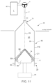
- the injector 10 may be configured for receiving and retaining a pressure jacket 32 within each syringe port 13 of the injector 10. While FIGS. 1 and 3 illustrate fluid injectors 10 with two syringe ports 13, which for the injector 10 shown in FIG. 3 each having a corresponding pressure jacket 32, other examples of the fluid injector 10 may include a single syringe port 13 and optionally, a corresponding pressure jacket 32 or more than two syringe ports 13 with an optional corresponding number of pressure jackets 32.
- each pressure jacket 32 may be configured to receive a syringe, such as a syringe for an angiographic (CV) procedure, or a rolling diaphragm syringe 34 (suitable examples of which are described in described in PCT/US2017/056747 ; WO 2016/172467 ; and WO 2015/164783 ).
- a fluid path set similar to the fluid path set 17 shown in FIG. 1 , may be fluidly connected with a discharge end of each rolling diaphragm syringe 34 for delivering fluid from the syringes 34 through tubing connected to a catheter, needle, or other fluid delivery connection (not shown) inserted into a patient at a vascular access site.
- the syringe 12 or 34 may be a pre-filled syringe, i.e., the syringe may be prefilled with a medical fluid, such as a contrast agent or saline, when provided by the syringe manufacturer.
- the pre-filled syringe may be required to be spiked or otherwise punctured at the discharge end prior to an injection procedure to allow fluid to be expelled from the syringe into a fluid line to the patient, as described herein.
- the fluid injector 10 may have at least one bulk fluid source (not shown) for filling the syringes 12 with fluid.
- the injector 10 may be operably connected to a computing device 300 having a controller and memory.
- the rolling diaphragm syringe 34 generally includes a hollow body 36 defining an interior volume 38.
- the body 36 has a forward or distal end 40, a rearward or proximal end 42, and a flexible sidewall 44 extending therebetween.
- the proximal end 42 may be configured to act as piston to pressurize the syringe interior to draw in or expel fluid therefrom, as described herein.
- the sidewall 44 of the rolling diaphragm syringe 34 defines a soft, pliable or flexible, yet self-supporting body that is configured to roll upon itself, as a "rolling diaphragm", under the action of the a drive member or piston of the fluid injector 10.
- the drive member/piston 19 may be configured to releasably engage a drive member engagement portion 52 at the proximal end 42 of the rolling diaphragm syringe 34 (examples of which are described in PCT/US2017/056747 ).
- the sidewall 44 is configured to roll such that its outer surface is folded and inverted in a radially inward direction as the drive member/piston 19 moves the proximal end 42 in a distal direction and unrolled and unfolded in the opposite manner in a radially outward direction as the drive member/piston 19 retract the proximal end 42 in a proximal direction.
- the rearward or proximal portion of the sidewall 44 connects to a closed end wall 46, and a forward or distal portion of the sidewall 44 defines a discharge neck 48 opposite the closed end wall 46.
- the closed end wall 46 may have a concave shape to facilitate the initiation of the inversion or rolling of the sidewall 44, enhance mechanical strength of the closed end wall 46, and/or to provide a receiving pocket to receive a distal end of drive member/piston 19.
- the closed end wall 46 may define a receiving end pocket for interfacing directly with a similarly-shaped distal end of the drive member/piston 19.
- At least a portion of the drive member/piston 19 may be shaped to substantially match the shape of the closed end wall 46 or, alternatively, pressure from the drive member/piston 19 as it is moved distally may conform the end wall 46 to substantially match the shape of at least a portion of the drive member/piston 19.
- the end wall 46 may have a central portion 50 having a substantially dome-shaped structure and a drive member engagement portion 52 extending proximally from the central portion 50.
- the drive member engagement portion 52 is configured for releasably interacting with a corresponding engagement mechanism on the drive member/piston 19 of the fluid injector 10, for example as the drive member/piston is retracted.
- the rolling diaphragm syringe 34 may be made of any suitable medical-grade plastic or polymeric material, desirably a clear or substantially translucent plastic material. The material of the rolling diaphragm syringe 34 is desirably selected to meet the required tensile and planar stress requirements, water vapor transmission, and chemical/biological compatibility.
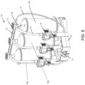
- a fluid injector 10 is shown in accordance with another example of the present disclosure.
- the injector 10 has a housing 54 that encloses various mechanical drive components, electrical and power components necessary to drive the mechanical drive components, and control components, such as electronic memory and electronic control devices used to control operation of reciprocally movable pistons (not shown).
- the fluid injector 10 further has a multi-patient disposable system (MUDS) 56 that is removably connectable with the fluid injector 10.
- the MUDS 56 has one or more syringes or pumps 58.
- the number of syringes 58 corresponds to the number of pistons on the fluid injector 10. In some examples, such as shown in FIG.
- the MUDS 56 has three syringes 58 in a side-by-side arrangement.
- Each syringe 58 has a bulk fluid connector 60 for connecting to a respective bulk fluid source (not shown) via a MUDS fluid path 62.
- the MUDS fluid path 62 may be formed as a flexible tube with a spike element at its terminal end that connects to the bulk fluid connector 60.
- the fluid injector 10 may have at least one bulk fluid source (not shown) for filling the syringes 12 with fluid.
- the injector 10 may be operably connected to a computing device 300 having a controller and memory. Injector 10 and the corresponding MUDS 56 as illustrated in FIG. 5 are described in detail in WO 2016/112163 .
- the MUDS 56 has a frame 64 for supporting the one or more syringes 58.
- the syringes 58 may be removably or non-removably connected to the frame 64.
- Each syringe 58 has an elongated, substantially cylindrical syringe body.
- Each syringe 58 has a filling port 66 in fluid communication with the MUDS fluid path 62 for filling the syringe 58 with fluid from a bulk fluid source.
- Each syringe 58 further has a discharge outlet or conduit 68 at the terminal portion of its distal end. The discharge outlet 68 of each syringe 58 is in fluid communication with a manifold 69.
- a valve 72 is associated with each discharge outlet 68 and is operable between a filling position, where the filling port 66 is in fluid communication with the syringe interior while the discharge outlet 68 is in fluid isolation from the syringe interior, and a delivery position, where the discharge outlet 68 is in fluid communication with the syringe interior while the filling port 66 is in fluid isolation from the syringe interior.
- the manifold 69 has a fluid pathway that is in fluid communication with each syringe 58 and with a fluid outlet line 74 in fluid communication with a port 76 configured for connecting to a single use fluid path element (not shown) for delivering fluid to the patient. Examples of suitable MUDSs are disclosed in PCT Application Publication No. WO 2016/112163 .
- the motor 31 ( FIG. 2 ) provides the motive force to reciprocally drive the drive member/piston 19 in a distal direction and discharges fluid within the syringes 12, 34 or MUDS 56.
- the motor 31 may have drive components, such as gears and shafts, that are operatively connected to the drive member/piston 19 to reciprocally move the drive member/piston 19.
- Each motor 31 must be calibrated to correlate its operating characteristics, such as input current or output torque, to a flow rate or pressure and tolerances associated therewith.
- calibration may be desirable to compensate for any variations or out of specification behavior from any of the different components of the fluid injectors 10, such as any variations in motor performance characteristics, particularly in fluid injectors with two or more syringes driven by two or more motors.
- conversion of motor input torque for one motor 31 to an injector output pressure may be different for another motor 31.
- This variation may be further compounded by variations in tolerances of the drivetrain of the fluid injector 10.
- the accuracy of flow rate or pressure in a fluid injector 10 is directly correlative to a system and method used to calibrate the motor 31.
- the fluid injector 10 may have at least one bulk fluid source (not shown) for filling the syringes 12 with fluid.
- the injector 10 may be operably connected to a computing device 300 having a controller and memory.
- an example according to the present disclosure may include at least one syringe, such as a previously described MUDS.
- Each empty syringe 58 is engaged in the injector 54 and plungers 14 are operatively connected to a corresponding piston 19.
- the piston 19, such as one or more linear actuators or reciprocally driven pistons moved by a motor 31 as in FIG. 2 , drive the plungers 14 distally along the longitudinal axis 15 of the bodies of the syringes 58, until the plungers contact the distal ends 24 of the syringes 58.
- sensors 160 are depicted schematically. Sensors 160 may be pressure sensors, voltage sensors, transducers, or any sensor consistent with the present disclosure known in the art.
- the plungers 14 may comprise a material that compresses under the load force.
- the force may be applied by the plungers 14 and/or pistons 19 depicted by arrows 150 until the reciprocal load force depicted by arrows 155 reaches a predetermined level or range.
- the load depicted by arrows 155 may range from 25 to 200 psi or in other embodiments range from 50 to 100 psi.
- the force applied may be a load anywhere between zero and the maximum load capable by the motor or piston used by the injector system.
- the load may not be a pre-determined level, but may be the maximum amount of force that can be generated by a piston 19. It is to be understood that a particular load may be more preferable depending on the architecture of the fluid injector used. For example, different types of syringes used in the same injector may result in different capacitance, and it may be preferable to set a different zero volume position based on different syringes.
- the force exerted by the plunger 14 may be gradually lessened until the load force value measured by each of the sensors 160 is a second predetermined value, such as zero load force (i.e., when there is no reciprocal force or load, or some other predetermined value that is less than the predetermined level or range depicted by arrows 155 in FIG. 7C .
- the piston 19 may gradually be retracted in a proximal direction, or the force applied in the distal direction gradually may be released and the released load force may move the piston 19 in the proximal direction until a zero load force value is obtained.
- this may be a passive retraction which allows the potential energy created by the kinetic loading of the motor driving the pistons to unwind, or release, like a spring until it has reached a predetermined load less than that which was generated at maximum.
- the direction of the gradual proximal motion is depicted by arrows 170.
- the position or positions of the piston 19 in this state may be recorded or stored on a memory device, such as external or internal memory of a computing device or the fluid injector, not shown, and calibrated as the position of zero volume of fluid in the syringes, or the "zero volume” position. It is to be understood that the zero volume position may vary depending on the elasticity of the plunger 14, the piston 19, or other parameters of the fluid injector 10.
- a mechanical stop can be utilized to identify the zero volume position.
- this may comprise a trip switch set by the position reached by the plunger 14 and/or the piston 19 at maximum load.
- FIGS. 7A-7D The schematic depiction in FIGS. 7A-7D is not applicable only to a MUDS. It is to be understood that the schematic depiction therein also would apply to injectors 10 including syringes 12 according to FIG. 1 and/or FIG. 2 , as well as rolling diaphragm syringes 34 according to FIG. 3 and FIG. 4 . Embodiments may be applied to pre-filled syringes, as described herein.
- the zero volume position is to be understood to be the position when the piston 19, 52 is incapable of injecting any additional fluid during injection proceedings.
- the zero volume position may be utilized to accurately determine the volume of fluid held within the syringe at any time by comparison of the current piston position to the zero volume position.
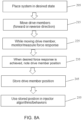
- FIG. 8A is flow chart illustrating an embodiment of a method of the present disclosure.
- the fluid injector system is placed into a state 205 in preparation for a calibration protocol, for example by installing the one or more fluid reservoirs, for example the at least one syringe 12, 58, 34, and engaging the respective drive members, such as a plunger, in operable communication with at least one piston 19.
- the drive members, such as the at least one piston 19, is driven 215 in a distal direction when pressurization of the fluid reservoir is desired or in the proximal direction when pulling a vacuum or relieving pressure is desired. While moving the drive member, the force response of the system may be monitored and/or measured 225 to determine a load force on the system.
- the position of the drive member is determined and noted 235 by the injector processor 300 and stored 245 in the processor memory.
- the stored drive member position may then be used by the processor 300 of the injector 10 in stored algorithms and/or other programmed behaviors 255 as required by the stored injector protocols.
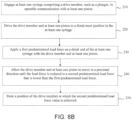
- FIG. 8B is a flow chart depicting a method according to an embodiment of the present disclosure.
- Step 210 is to engage at least one syringe 12, 58, 34 comprising a drive member, such as a plunger, in operable communication with at least one piston 19.
- Step 220 is to drive the drive member and at least one piston 19 to a distal-most position in the at least one syringe 12, 58, 34.
- Step 230 is to apply a first predetermined load force on a distal end of the at least one syringe 12, 58, 34 with the drive member and at least one piston 19.
- the position of the drive member and at least one piston 19 in step 230 may be recorded in certain embodiments (not shown).
- Step 240 is to allow the drive member and at least one piston 19 to move in a proximal direction until the load force is reduced to a second predetermined load force that is lower than the first predetermined load force.
- the second predetermined load force may be zero.
- the term "allow” according to step 240 is inclusive, in various examples, of driving the drive member and at least one piston 19 in a proximal direction, releasing or lessening force applied on the drive member in a distal direction.
- Step 250 is to store a position of the drive member at which the second predetermined load force value is achieved. It is to be understood that additional steps consistent with the present disclosure may be included in this method.
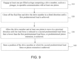
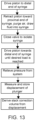
- FIG. 9 is a flow chart depicting another method according to an embodiment of the present disclosure.
- Step 310 is to engage at least one pre-filled syringe comprising a drive member, such as a plunger, in operable communication with at least one piston. 19.
- Step 320 is to close off the fluid line and drive the drive member in a distal direction until a first predetermined load is achieved.
- the piston extension in this state may be measured.
- Step 330 is to allow the drive member and at least one piston to move in a proximal direction until the load force is reduced to a second predetermined load force that is lower than the first predetermined load force, or a predetermined piston extension, is achieved.
- the second predetermined load force may be zero.
- Step 330 is inclusive, in various examples, of driving the drive member and at least one piston 19 in a proximal direction, releasing or lessening force applied on the drive member in a distal direction.
- Step 340 is to store a position of the drive member at which the second predetermined load force value or piston extension is achieved. It is to be understood that additional steps consistent with the present disclosure may be included in this method.
- the system and method according to the present disclosure is beneficial because it allows calibration without the presence of medical fluid, thereby reducing waste and potential contamination.
- the various methods allow for monitoring of changes of zero volume position over time for a specific injector or syringe set up.
- Examples according to the present disclosure may be used to track wear on a syringe if the syringe is used multiple times by tracking changes in the zero volume position over multiple uses.
- the method of the present disclosure may be used to track wear on a batch of syringes by tracking changes in the zero volume positions of the syringes in the batch.
- Further examples of the present disclosure may be used to track wear on the injector, such as by tracking changes in the zero volume position of the drive member of the injector. Over time, the anticipated position of the drive member may change due to wear on various components of the drive member. This may have applications in predictive maintenance of the injector, and the syringes.
- Various embodiments according to the present disclosure may be used to determine whether a syringe is damaged (for example, whether the syringe is punctured or cracked) based on whether the determined zero volume position is at a more proximal or distal position than anticipated.
- the determined zero volume position may also be used to determine defects in a syringe or batch of syringes if the zero volume position is outside of expected parameters, such as factory settings.
- a cocked or misaligned plunger may be indicated if the determined zero volume position is too proximal. If the determined zero volume position is too distal, another error or failure may be indicated, such as, for example a failure in the syringe or reservoir restraint where the restraint has failed or the tolerances have increased over the use life of the injector to a point where they fall outside the approved tolerances. Errors warning the user of these conditions may be returned by software in the memory of a computing device 300, and/or the injection procedure may be halted by the controller until the error has been rectified.
- Examples according the present disclosure also may be used to determine the amount of recoil in a plunger, or recoil due to syringe capacitance. This may be used to determine whether the plunger and/or syringe is fit for use, or the amount of wear on the plunger and/or syringe.
- Examples consistent with this disclosure may involve determining whether a syringe is new or used based on the zero volume position when compared to an expected zero volume position.
- Examples consistent with this disclosure may be used to measure breakaway (i.e., static) and dynamic friction on the way up, at the start of the day or initial use of a multi-use syringe.
- the initially measured values for friction may be correlated with measured values over time. This may be used to assess silicone presence - or gross silicone absence - if the measured value falls outside the expected range or tolerance. This may be useful in order to assure the quality of the syringe production. This may be useful to measure the accuracy of the system's pressure prediction algorithm. For example, if silicone is not present, the running friction of the plunger will be high, and the system may mistake that frictional loss for pressure - disarming or limiting the injection.
- Examples consistent with the present disclosure may be applied to pre-filled syringes.
- an embodiment of the method and/or system herein may be applied to a pre-filled syringe with a closed stopcock prior to the start of an injection.
- the piston of a fluid injector may apply a load to a predetermined value, and the extension of the piston required to generate that load may be measured.
- Load applied to a piston or other drive member may be determined, for example, by a strain gauge, measured motor current or effort, or change in motor current/effort, a pressure sensor, force sensor, measured compression, and the like.
- This measurement may be utilized to calculate compliance values of the fluid injector, and those values can be used to over-drive the piston to provide a corrected volume of fluid during an injection procedure in a system using active fluid control.
- the calculated compliance values may be used to determine a zero volume position.
- the present disclosure provides for a method for characterizing and correcting a fluid injector system for volume discrepancies associated with mechanical slack from injector components, component deflection under an applied force, and compliance due to volume expansion resulting from hydraulic pressurization of fluid delivery components.
- the present disclosure provides methods and fluid injector systems configured for characterizing and correcting for fluid injection system slack.
- System slack as defined herein, may lead to inaccuracies in fluid volume delivery and lowered image quality.
- System slack according to these methods may be determined on an open system or a closed system, depending on injector configuration. While various embodiments are described fully with a syringe-type fluid reservoir, similar methodologies may be applied to fluid injectors comprising peristaltic pump-based and compressible bag based fluid reservoirs and drive systems.
- the methods may include driving at least one drive member of a fluid injector, such as a piston engaged with a plunger or with the proximal end wall of a rolling diaphragm, to a distal end of at least one syringe connected to the fluid injector; retracting the at least one drive member toward a proximal end of the at least one syringe to draw in a volume of fluid, such as a liquid medical fluid, into the at least one syringe from at least one fluid container in fluid communication with the at least one syringe when the valve is in a first, fill position; switching at least one valve, which may be a stopcock, one-way valve, high pressure cracking valve, or pinch valve, from the first, fill position where the at least one syringe is in fluid communication with the at least one fluid container to a second, closed position where the at least one syringe is isolated from the at least one fluid container
- the slack correction volume may then be stored within a memory of a processor associated with the fluid injector and used to determine more accurate fluid delivery volumes for the particular syringe, for example where the syringe is a multi-use syringe, multi-use syringe set, or multi-use injection reservoir.
- the slack correction value may also be used to provide more accurate fluid delivery volumes for subsequent similar syringes (e.g., syringes from same manufacturer and/or having the same fluid volume capacity) utilized by the injector system.
- the method may involve pulling a vacuum on the fluid in the syringe by proximally retracting the drive member until a desired applied vacuum is achieved, as measured for example by strain sensor, a force sensor, a pressure sensor, motor current or effort, or similar measurement, and measuring the vacuum position of the drive member; releasing the applied retraction force on the drive member, either gradually, in a step-wise fashion, or at one time and allowing the drive member to return to a position where no vacuum force is applied to the drive member; measuring the neutral position of the drive member; and deriving a slack correction volume from the difference in volume of the fluid when the drive member is in the vacuum position and when the drive member is in the neutral position, where the slack correction volume includes a component associated with the mechanical slack of the drive member and motor associated with the at least one syringe.
- the processor may store and monitor a series of slack correction values over a time period and provide an alert when sudden deviations in the slack correction value are observed or the change in slack correction reaches a level indicating service of the injector is desired or required.
- the derived slack correction volume may be, at least in part, the difference of fluid volume ( ⁇ V) in the syringe under the desired load compared to the volume of the fluid in the syringe when the syringe is not under applied load, such as after drawing in fluid and closing of the valve.
- the desired applied load may be substantially similar to a load applied during a typical fluid injection, for example, from 1 psi to 300 psi for a CT injection or from 300 psi to 1,200 psi for an angiography injection.
- the desired load may be equal to the amount of load necessary to take up all slack, with may be measured, for example by applying an increasing amount of load until no further movement of the drive member due to slack uptake is observed.
- the various components of the slack value include, but are not limited to, mechanical slack, deflection, compression of components under mechanical load or fluid pressure, such as compression of the plunger cover under fluid pressure, and volume expansion under fluid pressure of system components upstream of the valve, including the syringe sidewalls, valve components, and upstream fluid path surfaces.
- the method may further include evacuating the fluid from the at least one syringe, filling the at least one syringe with a desired volume of fluid plus an additional volume of fluid equal to the slack correction volume, and delivering the fluid from the at least one syringe to a patient.
- evacuating the fluid from the at least one syringe filling the at least one syringe with a desired volume of fluid plus an additional volume of fluid equal to the slack correction volume, and delivering the fluid from the at least one syringe to a patient.
- the method steps may be performed at least partially by a processor configured to control a motor driving the at least one drive member of the fluid injector.
- the processor may include programming machine language to direct the processor to conduct the method at specified times.
- the method may include the system repeatedly determining and storing a slack correction volume over a specified time period, for example, at an initial use of the at least one syringe or at the beginning of the day, week, month, or other selected time period.
- the method may further include the fluid injector, for example the processor, developing a slack curve for each drive member of the injector as a function of time.
- the method may then include providing an alert to a user if a measured slack correction volume for at least one drive member is significantly different from an expected slack correction volume based on the slack curve for the at least one drive member.
- the processor may monitor the slack correction volume, for example with a slack curve, and when a slack volume degrades to a certain value, the processor may alert the technician, hospital, or even notify the service personnel directly that service is desired or required.
- a method for characterizing and correcting fluid injection system slack may include driving at least one drive member, for example a piston engaged with a syringe plunger or a proximal end wall of a rolling diaphragm syringe, of a fluid injector to a distal end of at least one syringe connected to the fluid injector; retracting the at least one drive member toward a proximal end of the at least one syringe to draw fluid, such as a liquid medical fluid, into the at least one syringe from at least one fluid container in fluid communication with the at least one syringe when the valve is in a first, fill position; switching at least one valve, which may be a stopcock, one-way valve, high pressure cracking valve, or pinch valve, from the first, fill position where the at least one syringe is in fluid communication with the at least one fluid container to a second, closed position where the at least one syringe is isolated
- the method may further include evacuating the fluid from the at least one syringe, filling the at least one syringe with a desired volume of fluid plus an additional volume of fluid equal to the slack correction volume, and delivering the fluid from the at least one syringe to a patient as part of a fluid injection protocol.
- the method steps may be performed at least partially by a processor configured to control a motor driving the drive member of the injector.
- the method may include the system repeatedly determining and storing a slack correction volume over a specified time period, for example, at an initial use of the at least one syringe or at the beginning of the day, week, month, or other selected time period.
- the method may further include the fluid injector, for example the processor, developing a slack curve for each drive member of the injector as a function of time.
- the method may then include providing an alert to a user if a measured slack correction volume for at least one drive member is significantly different from an expected slack correction volume based on the slack curve for the at least one drive member.
- the processor may monitor the slack correction volume, for example with a slack curve, and when a slack volume degrades to a certain value, the processor may alert the technician, hospital, or even notify the service personnel directly that service is desired or required.
- FIG. 10 shows the syringe 12 of FIGS. 2 or 5 , but illustrates an imperfect interface between a piston 19, and the plunger 14 of the syringe 12.
- the syringe 12 is shown in fluid communication with a valve 72 in a first position and a fluid container 80 storing a fluid F such as a contrast imaging agent, saline, or other medical fluid.
- a fluid F such as a contrast imaging agent, saline, or other medical fluid.
- the imperfect interface between the piston 19 and the plunger 14 permits slack 70 to propagate between the piston 19 and the plunger 14 when opposing loads are applied to the piston 19 and the plunger 14. Additional components of the slack may arise from tolerances, imperfect contact, and wear in injector components such as gears and mechanical connections associated with the piston 19 and motor 31 of the injector.
- fluid F is drawn from the container 80 into the interior volume 25 of the syringe 12 by moving the plunger 14 from the distal end 24 to the proximal end 20 of the syringe 12.
- the motor 31 draws the piston 19, which is connected to the plunger 14, towards the proximal end 20 of the syringe 12.
- Engagement between the plunger 14 and the piston 19 permit movement between the plunger 14 and the piston 19 allowing the slack 70 to propagate.
- the motor 31 may distally drive the piston 19 a distance corresponding to a calculated volume equal to the slack following any proximal movement of the piston 19 so that any subsequent distal movement of the piston 19 will have pre-compensated for the slack so that fluid delivery is accurate based on the pre-compensated piston position.
- processor 300 implementing software for controlling the motor 31 may be configured to characterize and correct for the slack 70 in the fluid delivery system. Further, slack values may be continually calculated and adjusted for to account for continuing wear to the injector over time.
- the slack 70 between the piston 19 and plunger 14 as described herein is intended as an exemplary illustration of how one source of slack 70 propagates in the system. It is not to be construed as the principal or only source of slack 70 contemplated by the present disclosure. Other sources of slack 70 in the system are propagated and may be accounted for in a similar manner to provide improved accuracies for actual injection volumes. These sources of slack 70 may also include, but are not limited to, slack 70 from backlash on gears and/or ball screws in the motor 31, the interface between the syringe 12 and the injector 10, and any other surfaces which experience load during fluid injection. Other sources of slack in the system may be known to one of ordinary skill in the art and may be accounted for by the system and methods described herein, including the stacking of tolerances between the injector 10, syringe 12, and drive components.
- the amount of slack 70 remains substantially the same for each cycle of filling and delivery operations of the injector 10 over a specific period of time, so long as the components of the injector 10 (e.g., disposable syringes, MUDS, etc.), particularly the piston 19 and plunger 14, are not changed, for example due to wear, during this period. As such, the slack calculation may not need to be constantly updated. Therefore, once the slack 70 is characterized for one cycle, the processor 300 may be programmed or configured to account for the slack 70 for any subsequent cycles by converting the slack 70 into an overdrive distance or volume necessary to deliver the desired amount of the fluid F.
- the processor 300 may be programmed or configured to account for the slack 70 for any subsequent cycles by converting the slack 70 into an overdrive distance or volume necessary to deliver the desired amount of the fluid F.
- the slack 70 may also be continually monitored, for example if there is particular concern with component wear in a particular configuration.
- the process of deriving a slack correction volume is set forth with reference to FIGS. 12 and 10 .
- any sequence or method steps are understood to be implemented by the processor 300, but, where context allows, may also be implemented by a technician, physician, nurse, or the like.
- FIG. 12 A step diagram for characterizing the slack 70 according to one example of the present disclosure is illustrated in FIG. 12 .
- the injector 10 and syringe 12 are setup with the piston 19 extended distally such that the plunger 14 is located at an end-of-travel position towards the distal end 24 of the barrel 18.
- the plunger 14 is retracted by the piston 19 via operation of the motor 31 toward the proximal end 20 of the syringe 12, drawing a predetermined volume of the fluid F from the container 80 into the interior volume 25 of the syringe 12.
- the fluid path set 17 may be purged of air by first drawing a partial volume of fluid F into the syringe 12 and then driving the piston 19 distally to force the fluid F through the fluid path set 17 to displace the air. Purging the air may be necessary to accurately measure the slack 70 in the system. After purging the fluid path set 17 of air, the remaining fluid necessary to achieve the predetermined volume of the fluid F may be drawn into the syringe 12.
- the predetermined volume of the fluid F may be equal to the volume intended for delivery to the patient, plus an additional slack volume to account for the slack 70 between the piston 19 and the plunger 14 and any necessary excess volume necessary to correct for system capacitance and impedance.
- the plunger 14 may be drawn back to the 210 milliliter position and then driven forward to the 200 milliliter position to account for the 10milliliters of slack 70.
- the predetermined volume of the fluid F may not be the intended fluid volume for delivery to the patient, but rather some intermediate volume to determine the slack 70 at some intermediate time of the delivery operation. Regardless of the predetermined volume, the additional slack volume at this stage may be derived from methods for characterizing slack as described herein.
- the valve 72 which may be, for example, a stopcock valve, is then switched at step 903 to a position isolating the syringe 12 from the container 80.
- the position of the piston 19 is measured and stored as reference position X1 at step 904 (see FIG. 10 ).
- the motor 31 is then driven to move the piston 19 toward the distal end 24 of the syringe 12 step 905. Because the valve 72 is in the second, closed position, none of the fluid F is actually delivered to the patient, causing pressure to build in the fluid F between the plunger 14 and the valve 72. This rising pressure results from the piston 19 moving in a distal direction, pressing the piston 19 and plunger 14 together and compressing the fluid F and the plunger surface.
- the piston 19 is driven in the distal direction until a desired load on the piston 19 is reached.
- the desired load may be the load at which fluid is to be delivered to the patient under a normal delivery operation, such as in the range of 0 psi to 300 psi, for example 50 psi. More generally, the desired load is determined based on contact between the plunger 14 and the piston 19.
- pressure may be directly measured by a transducer at any location between the syringe 12 and the valve 72.
- the load may be derived from the current of the motor 31 or from deformation of any component between the syringe 12 and the valve 72.
- the load may be determined from a strain gauge located on some component of the injection 10 or syringe 12, particularly the piston 19.
- the load may be determined by deformation of the restraint holding the syringe 12 to the injector 10.
- FIGS. 14-15 show graphical representations of slack removal using current of the motor 31 and the signal from the strain gauge, respectively.
- a slack correction volume may be derived by subtracting the volume between the conical engagement surfaces of the piston 19 and the plunger 14 at the reference position X1 from the volume between the conical engagement surfaces of the piston 19 and the plunger 14 at the contact position X2. The slack correction volume is then stored for use as the additional volume of fluid F to draw from the container 80 in subsequent filling operations.
- the slack correction may be determined as the time at a specific piston movement rate to move the piston from the reference positon X1 to the contact position X2. In this manner, the exact amount of additional movement of the piston 19 may be executed during each transition from a filling operation to a delivery operation, and vice versa.
- the distal movement of the piston 19 to account for the volume due to the slack correction may be done after any proximal movement of the piston 19, even if not immediately transitioning to fluid delivery by further distal movement of the piston, so that the slack volume has been accounted for the next distal movement of the syringe.
- the fluid reservoir is pre-corrected and any distal movement has accounted for the slack, thereby accurately begining fluid delivering and minimizing any time to actual fluid delivery due to slack.
- the determined value of the slack 70 may be used during each subsequent delivery operation, preventing under delivery, over delivery, waste and spillage of fluid, and pressure damage to system components. Following the attainment of the slack correction volume at step 907, pressure may be relieved from the syringe 12.
- the reference position X1 is measured after the syringe 12 is pressurized, as illustrated in the step diagram of FIG. 13 .
- the injector 10 and syringe 21 are setup with the piston 19 extended distally at step 1001, the piston 19 is retracted to draw a predetermined volume of the fluid F from the container 80 into the interior volume 25 at step 1002, and the valve 72 is switched to a second, closed position at step 1003.
- Steps 1001-1003 are performed substantially as described above in reference to steps 901-903 of FIG. 12 , including the purging of air from the fluid path set 17.
- the piston 19 is then driven in the distal direction until a desired load on the piston 19 is reached at step 1004, substantially as described above in reference to step 905 of FIG. 12 .
- the drive current is then removed from the motor 31 to relieve the applied pressure in the system at step 1005, allowing unwanted pressure to be removed from the fluid path set 17.
- the displacement of the position of the plunger 14 is then measured and stored while the slack 70 is removed from the system at step 1006. Accuracy may be enhanced by measuring the displacement of the plunger 14 rapidly upon relieving pressure in the system.
- the slack correction volume is calculated and stored substantially based on the displacement measured at step 906.
- the slack correction volume may be derived by converting the displacement measured at step 906 to a volume between the conical engagement surfaces of the piston 19 and the plunger 14 at the reference position X1 from the volume between the conical engagement surfaces of the piston 19 and the plunger 14 at the contact position X2.
- the slack correction volume is then stored for use as the additional volume of fluid F to draw from the container 80 in subsequent filling operations.
- the step of relieving pressure from the syringe 12 in the method of either of FIGS. 12 or 13 may occur at alternative times during the execution of the methods to remove unwanted and/or undesirable pressure.
- pressure relief may be performed prior to measuring and storing the contact position X2 at step 906.
- Characterizing and storing the slack 70 according to the systems and methods described herein is particularly suited for use during the initial filling of each disposable component, such as the syringe 12, when the disposable component is placed into service.
- each disposable component such as the syringe 12
- the present disclosure is not limited in the time and manner of implementation.
- characterizing and storing the slack 70 may be performed at periodic intervals, such as each injection, each day, each week, or each month throughout the life of the injector 10 to recalibrate for component wear.
- the measured slack 70 may be used in a statistical analysis or as part of a predictive maintenance protocol to intelligently alert users and/or service technicians that an injector 10, syringe 12, diaphragm syringe 34, and/or MUDS 56 is operating abnormally or otherwise requires service.
- a slack curve based on repeated slack volume measurements as a function of time may be prepared. At a selected time, a new slack measurement may be taken and compared to the slack curve.
- Any significant or unexpected deviation of the measured slack from that expected from the slack curve may be indicative of unexpected wear or potential failure of the mechanical components of the injector 10 or potential issues with a particular syringe set.
- the system may then alert the user of the abnormal reading so that a new syringe set may be installed and/or a service call may be scheduled.
Landscapes
- Health & Medical Sciences (AREA)
- Vascular Medicine (AREA)
- Engineering & Computer Science (AREA)
- Anesthesiology (AREA)
- Biomedical Technology (AREA)
- Heart & Thoracic Surgery (AREA)
- Hematology (AREA)
- Life Sciences & Earth Sciences (AREA)
- Animal Behavior & Ethology (AREA)
- General Health & Medical Sciences (AREA)
- Public Health (AREA)
- Veterinary Medicine (AREA)
- Physics & Mathematics (AREA)
- Fluid Mechanics (AREA)
- Infusion, Injection, And Reservoir Apparatuses (AREA)
Claims (13)
- Verfahren zur Kalibrierung einer Position eines Antriebselements eines Fluidinjektorsystems, wobei das Verfahren folgende Schritte umfasst:Herstellen eines Eingriffs mindestens einer Spritze (58), die ein Antriebselement (14) umfasst, mit mindestens einem Kolben (19) eines Fluidinjektors (10), so dass der mindestens eine Kolben (19) mit dem Antriebselement (14) wirkverbunden ist;Treiben des Antriebselements (14) mit dem mindestens einen Kolben (19) zu einer distalsten Position in der mindestens einen Spritze (58);Anwenden einer ersten vorbestimmten Belastungskraft auf ein distales Ende der mindestens einen Spritze (58) mit dem Antriebselement (14), gemessen durch den mindestens einen Kraftsensor;Erfassen einer Position des Antriebselements (14), an der die erste vorbestimmte Belastungskraft erreicht ist;Bewegen des Antriebselements (14) in einer proximalen Richtung in einer vorbestimmten Rate, bis eine zweite vorbestimmte Belastungskraft, gemessen von dem Kraftsensor, die kleiner als die erste vorbestimmte Belastungskraft ist, erreicht ist; undErfassen einer Position des Antriebselements (14), in der die zweite vorbestimmte Belastungskraft erreicht ist.
- Verfahren nach Anspruch 1, wobei das Antriebselement (14) einen Stempel (14) umfasst und wobei mindestens ein Kolben (19) den Stempel (14) antreibt.
- Verfahren nach einem der Ansprüche 1 oder 2, wobei der mindestens eine Kolben (19) von einem Linearaktor oder einem Motor (31) angetrieben wird.
- Verfahren nach einem der Ansprüche 1 bis 3, ferner umfassend das Freigeben der auf das Antriebselement (14) angewendeten Belastungskraft in einer vorbestimmten Rate, bis der Belastungskraftwert auf null reduziert ist.
- Verfahren nach einem der Ansprüche 1 bis 4, ferner umfassend das Antreiben des Antriebselements (14) in einer proximalen Richtung in einer vorbestimmten Rate, bis der Belastungskraftwert auf null reduziert ist.
- Verfahren nach Anspruch 1, wobei das Fluidinjektorsystem umfasst:mindestens ein Ventil (72) in Fluidaustausch mit der mindestens einen Spritze (58) und mindestens einem Fluidbehälter (80), wobei das Ventil (72) zwischen einer ersten Position, in der die Spritze (58) in Fluidaustausch mit dem Fluidbehälter (80) ist, einer zweiten Position, in der die mindestens eine Spritze (58) von dem Fluidbehälter (80) isoliert ist, und einer dritten Position, in der die mindestens eine Spritze (58) in Fluidaustausch mit einem Patienten ist, schaltbar ist;wobei das Verfahren ferner umfasst:Zurückziehen des mindestens einen Kolbens (19) in Richtung eines proximalen Endes der mindestens einen Spritze (58), um Fluid aus dem mindestens einen Fluidbehälter (80) in die mindestens eine Spritze (58) zu ziehen;Messen und Speichern einer Referenzposition (X1) des mindestens einen Kolbens (19) innerhalb der mindestens einen Spritze (58);Schalten des mindestens einen Ventils (72) von der ersten Position in die zweite Position;Treiben des mindestens einen Kolbens (19) in Richtung des distalen Endes der mindestens einen Spritze (58), bis eine gewünschte Last an dem mindestens einen Kolben (19), gemessen durch den Kraftsensor, erreicht ist;Messen und Speichern einer Kontaktposition (X2) des mindestens einen Kolbens (19) innerhalb der mindestens einen Spritze (58), wobei die Kontaktposition (X2) eine Position ist, in der die gewünschte Last erreicht ist; undAbleiten eines Spielkorrekturvolumens auf Grundlage der Differenz zwischen der Referenzposition (X1) und der Kontaktposition (X2).
- Verfahren nach Anspruch 6, wobei ein Prozessor des Fluidinjektors (10) dazu programmiert oder konfiguriert ist, das mindestens eine Ventil (72) zwischen der ersten Position, der zweiten Position und der dritten Position zu schalten.
- Verfahren nach Anspruch 1, wobei das Verfahren ferner zum Charakterisieren und Korrigieren von Fluidinjektionssystemspiel (70) konfiguriert ist, wobei das Verfahren zum Charakterisieren und Korrigieren von Fluidinjektionssystemspiel (70) umfasst:Treiben mindestens eines Antriebselements (14) eines Fluidinjektors (10) zu einem distalen Ende mindestens einer mit dem Fluidinjektor (10) verbundenen Spritze (58);Zurückziehen des mindestens einen Antriebselements (14) in Richtung eines proximalen Endes der mindestens einen Spritze (10), um Fluid (F) aus dem mindestens einen Fluidbehälter (80), der in Fluidaustausch mit der mindestens einen Spritze (58) ist, in die mindestens eine Spritze (58) zu ziehen;Schalten des mindestens einen Ventils (72) von einer ersten Position, in der die mindestens eine Spritze (58) in Fluidaustausch mit dem mindestens einen Fluidbehälter (80) ist, in eine zweite Position, in der die mindestens eine Spritze (58) von dem mindestens einen Fluidbehälter (80) isoliert ist, um die mindestens eine Spritze (58) von dem mindestens einen Teil des Fluidinjektionssystems zu isolieren,Messen und Speichern einer Referenzposition (X1) des mindestens einen Antriebselements (14) innerhalb der mindestens einen Spritze (58);Treiben des mindestens einen Antriebselements (14) in Richtung des distalen Endes der mindestens einen Spritze (58), bis eine gewünschte Last an dem mindestens einen Antriebselement (14), gemessen durch den Kraftsensor, erreicht ist;Messen und Speichern einer Kontaktposition (X2) des mindestens einen Antriebselements (14) innerhalb der mindestens einen Spritze (58), wobei die Kontaktposition (X2) eine Position ist, in der die gewünschte Last erreicht ist; undAbleiten eines Spielkorrekturvolumens auf Grundlage der Differenz zwischen der Referenzposition (X1) und der Kontaktposition (X2).
- Verfahren nach Anspruch 8, wobei das Verfahren zum Charakterisieren und Korrigieren von Fluidinjektionssystemspiel (70) ferner umfasst:Evakuieren des Fluids (F) aus der mindestens einen Spritze (58); undFüllen der mindestens einen Spritze (58) mit einem gewünschten Volumen von Fluid (F) plus einem zusätzlichen Volumen von Fluid (F), das gleich dem Spielkorrekturvolumen ist.
- Verfahren nach Anspruch 8 oder 9, wobei die Verfahrensschritte zum Charakterisieren und Korrigieren von Fluidinjektionssystemspiel (70) mindestens teilweise durch einen Prozessor (300) ausgeführt werden, der dazu konfiguriert ist, einen Motor (31), der den mindestens einen Kolben (19) des Injektors (10) antreibt, zu steuern.
- Verfahren nach einem der Ansprüche 8 bis 10, wobei das Spielkorrekturvolumen bei einer erstmaligen Verwendung der mindestens einen Spritze (58) ermittelt wird.
- Verfahren nach einem der Ansprüche 8 bis 11, ferner umfassend ein wiederholtes Messen und Speichern des Spielkorrekturvolumens im Laufe der Zeit, um eine Spielkurve des mindestens einen Kolbens (19) des mindestens einen Injektors (10) als eine Funktion der Zeit zu entwickeln.
- Verfahren nach einem der Ansprüche 8 bis 12, ferner umfassend das Warnen eines Benutzers, wenn sich ein gemessenes Spielkorrekturvolumen für den mindestens einen Kolben (19) substanziell von einem erwarteten Spielkorrekturvolumen, basierend auf der Spielkurve für den mindestens einen Kolben (19), unterscheidet.
Applications Claiming Priority (3)
| Application Number | Priority Date | Filing Date | Title |
|---|---|---|---|
| US201762552589P | 2017-08-31 | 2017-08-31 | |
| US201762552427P | 2017-08-31 | 2017-08-31 | |
| PCT/US2018/048284 WO2019046261A1 (en) | 2017-08-31 | 2018-08-28 | SYSTEM AND METHOD FOR MECHANICAL CALIBRATION OF FLUID INJECTOR SYSTEM AND DRIVE ELEMENT POSITION |
Publications (2)
| Publication Number | Publication Date |
|---|---|
| EP3675930A1 EP3675930A1 (de) | 2020-07-08 |
| EP3675930B1 true EP3675930B1 (de) | 2024-01-17 |
Family
ID=63528958
Family Applications (1)
| Application Number | Title | Priority Date | Filing Date |
|---|---|---|---|
| EP18766492.5A Active EP3675930B1 (de) | 2017-08-31 | 2018-08-28 | Verfahren zur mechanischen kalibrierung der antriebselementposition und eines fluidinjektorsystems |
Country Status (7)
| Country | Link |
|---|---|
| US (1) | US11786652B2 (de) |
| EP (1) | EP3675930B1 (de) |
| JP (1) | JP7252143B2 (de) |
| CN (1) | CN110891630B (de) |
| AU (1) | AU2018326380B2 (de) |
| CA (1) | CA3067740A1 (de) |
| WO (1) | WO2019046261A1 (de) |
Families Citing this family (12)
| Publication number | Priority date | Publication date | Assignee | Title |
|---|---|---|---|---|
| PT1762259E (pt) | 2005-09-12 | 2010-12-10 | Unomedical As | Insersor para um conjunto de infusão com uma primeira e uma segunda unidades de mola |
| WO2012123274A1 (en) | 2011-03-14 | 2012-09-20 | Unomedical A/S | Inserter system with transport protection |
| WO2019035986A1 (en) | 2017-08-18 | 2019-02-21 | Bayer Healthcare Llc | SYSTEM, METHOD, AND PREDICTIVE MAINTENANCE COMPUTER PROGRAM PRODUCT |
| AU2018326386B2 (en) | 2017-08-31 | 2024-03-28 | Bayer Healthcare Llc | Fluid injector system volume compensation system and method |
| CA3110859A1 (en) | 2018-08-28 | 2020-03-05 | Bayer Healthcare Llc | Fluid injector system, method of preventing fluid backflow, and computer program product |
| JP7040392B2 (ja) * | 2018-10-03 | 2022-03-23 | 株式会社島津製作所 | 試料注入装置および試料注入装置の調整方法 |
| BR112021023304A2 (pt) | 2019-05-20 | 2022-02-01 | Unomedical As | Dispositivo de infusão rotativo e métodos do mesmo |
| CA3162002A1 (en) * | 2019-11-21 | 2021-05-27 | Bayer Healthcare Llc | System, method, and computer program product for smart fluid injector performance monitoring |
| CA3181544A1 (en) | 2020-04-30 | 2021-11-04 | Bayer Healthcare Llc | System, device, and method for safeguarding wellbeing of patients for fluid injection |
| US11957542B2 (en) | 2020-04-30 | 2024-04-16 | Automed Patent Holdco, Llc | Sensing complete injection for animal injection device |
| MX2023006007A (es) * | 2020-12-15 | 2023-06-08 | Becton Dickinson Co | Aparatos y metodos para normalizar datos del motor de bomba cargados con datos del motor de bomba descargados durante una operacion de movimiento de fluido. |
| WO2023052592A1 (en) | 2021-09-30 | 2023-04-06 | Guerbet | Injection device receiving a syringe |
Family Cites Families (543)
| Publication number | Priority date | Publication date | Assignee | Title |
|---|---|---|---|---|
| US508584A (en) | 1893-11-14 | Device for mixing hot and gold water for bathing | ||
| US383858A (en) | 1888-06-05 | mepartland | ||
| US945143A (en) | 1909-07-28 | 1910-01-04 | Iacques Szamek | Apparatus for mixing liquids. |
| GB201800A (en) | 1922-09-18 | 1923-08-09 | Robert Sowter Hubbard | An improved toy |
| US2511291A (en) | 1947-03-12 | 1950-06-13 | Grover C Mueller | Mixer for liquids |
| US2583206A (en) | 1949-12-01 | 1952-01-22 | Separator Ab | Apparatus for homogenizing |
| US3156236A (en) | 1961-12-07 | 1964-11-10 | Cordis Corp | Medical injector |
| US3159312A (en) | 1962-09-28 | 1964-12-01 | Budd Co | Dispensing device for mixing two viscous fluids |
| US3276472A (en) | 1963-12-03 | 1966-10-04 | Medex Inc | Medical valve |
| DE1220394B (de) | 1964-09-12 | 1966-07-07 | Glanzstoff Koeln Ges Mit Besch | Vorrichtung zum kontinuierlichen Mischen und Homogenisieren von Fluessigkeiten verschiedener Viskositaet |
| CH456051A (de) | 1966-06-30 | 1968-05-15 | Contraves Ag | Medizinisches Kontrastmittel-Einspritzgerät |
| US3623474A (en) | 1966-07-25 | 1971-11-30 | Medrad Inc | Angiographic injection equipment |
| US3520295A (en) | 1968-03-06 | 1970-07-14 | Gen Electric | Cardiac r-wave detector with automatic gain control |
| BE758739A (fr) | 1969-11-13 | 1971-04-16 | Fuji Photo Film Co Ltd | Procede et appareil en vue de transporter un fluide |
| US3635444A (en) | 1970-09-08 | 1972-01-18 | Amvit | Static mixer |
| US3701345A (en) | 1970-09-29 | 1972-10-31 | Medrad Inc | Angiographic injector equipment |
| US3671208A (en) | 1970-10-09 | 1972-06-20 | Wayne G Medsker | Fluid mixing apparatus |
| US3793600A (en) | 1971-03-16 | 1974-02-19 | Strategic Automated Systems In | Record medium with validating and cancelling feature and method |
| US3817843A (en) | 1971-04-13 | 1974-06-18 | Electricity Council | Electrodeposition of iron foil |
| US4001549A (en) | 1971-06-10 | 1977-01-04 | Corwin Edward J | Marking document and template assembly and method of making the assembly |
| US3927955A (en) | 1971-08-23 | 1975-12-23 | East West Medical Products Inc | Medical cassette pump |
| US3755655A (en) | 1971-10-26 | 1973-08-28 | Tac Ind Inc | Machine processed data card |
| US3839708A (en) | 1972-06-28 | 1974-10-01 | Searle Medidata Inc | Input-output terminal for hospital information system |
| US3868967A (en) | 1973-02-16 | 1975-03-04 | Shropshire Kenneth W | Adapter for mixing fluids |
| US3812843A (en) | 1973-03-12 | 1974-05-28 | Lear Siegler Inc | Method and apparatus for injecting contrast media into the vascular system |
| JPS5011296A (de) | 1973-05-31 | 1975-02-05 | ||
| JPS5418908B2 (de) | 1973-06-15 | 1979-07-11 | ||
| US3895220A (en) | 1973-09-07 | 1975-07-15 | Docutronix Inc | Selectively encodable envelope insert and related apparatus |
| US3898983A (en) | 1973-10-03 | 1975-08-12 | James O Elam | Device and method for detecting the degree of muscle relaxation of a medical patient |
| US3968195A (en) | 1974-06-17 | 1976-07-06 | Marilyn Bishop | Method for making sterile connections |
| US3888239A (en) | 1974-06-21 | 1975-06-10 | Morton K Rubinstein | Fluid injection system |
| US4038981A (en) | 1974-07-26 | 1977-08-02 | Burron Medical Products, Inc. | Electronically controlled intravenous infusion set |
| US3941126A (en) | 1974-08-08 | 1976-03-02 | Dietrich Joseph W | Apparatus for long term intravenous administration of diluted incompatible multiple medications |
| US4006736A (en) | 1974-11-27 | 1977-02-08 | Medrad, Inc. | Angiographic injector |
| US3995381A (en) | 1975-06-27 | 1976-12-07 | Ken Max Manfred | Low visibility answer sheet and method of testing |
| JPS5226193A (en) | 1975-08-22 | 1977-02-26 | Houseikai | Remote control barium injector |
| US4044757A (en) | 1976-01-14 | 1977-08-30 | The Kendall Company | Cholangiography device and method |
| US4273122A (en) | 1976-11-12 | 1981-06-16 | Whitney Douglass G | Self contained powered injection system |
| US4135247A (en) | 1977-08-15 | 1979-01-16 | Siemens Aktiengesellschaft | Tomography signal processing system |
| US4284073A (en) | 1977-10-11 | 1981-08-18 | Krause Horst E | Method and apparatus for pumping blood within a vessel |
| US4191183A (en) | 1977-10-31 | 1980-03-04 | Barry Mendelson | Mixing chamber for use in plural medical liquid intravenous administration set |
| US4151845A (en) | 1977-11-25 | 1979-05-01 | Miles Laboratories, Inc. | Blood glucose control apparatus |
| US4187057A (en) | 1978-01-11 | 1980-02-05 | Stewart-Naumann Laboratories, Inc. | Peristaltic infusion pump and disposable cassette for use therewith |
| US4262824A (en) | 1978-02-17 | 1981-04-21 | Baxter Travenol Laboratories, Inc. | Low-current E-frame electronic magnet with a permanent magnet armature for an I. V. valving controller |
| US4263916A (en) | 1978-03-27 | 1981-04-28 | University Of Southern California | Image averaging for angiography by registration and combination of serial images |
| US4448200A (en) | 1978-03-27 | 1984-05-15 | University Of Southern California | System and method for dynamic background subtraction |
| US4329067A (en) | 1978-04-19 | 1982-05-11 | Bruce J. Landis | Fluid mixer |
| US4207871A (en) | 1978-06-07 | 1980-06-17 | Imed Corporation | System for controlling the flow of intravenous fluids to a patient |
| US4199000A (en) | 1978-07-19 | 1980-04-22 | Edstrom William E | Cross-contamination isolator |
| US4223675A (en) | 1978-07-24 | 1980-09-23 | Baxter Travenol Laboratories, Inc. | Solution containers such as blood bags and system for preparing same |
| US4204775A (en) | 1978-08-08 | 1980-05-27 | General Dynamics Corporation Pomona Division | Mixing device for simultaneously dispensing two-part liquid compounds from packaging kit |
| US4208136A (en) | 1978-12-01 | 1980-06-17 | Komax Systems, Inc. | Static mixing apparatus |
| WO1980001754A1 (en) | 1979-02-28 | 1980-09-04 | Abbott Lab | Novel valve employing hydrophobic and hydrophilic membranes |
| US4280494A (en) | 1979-06-26 | 1981-07-28 | Cosgrove Robert J Jun | System for automatic feedback-controlled administration of drugs |
| US4315247A (en) | 1979-08-13 | 1982-02-09 | Germanton Charles E | Security systems employing an electronic lock and key apparatus |
| US4319568A (en) | 1979-10-29 | 1982-03-16 | Vickers Limited | Liquid dispensing apparatus |
| CA1171030A (en) | 1979-11-05 | 1984-07-17 | David Bellamy | Fluid transfer assembly |
| JPS5675131A (en) | 1979-11-22 | 1981-06-22 | Olympus Optical Co | Endoscope apparatus |
| US4341153A (en) | 1980-01-08 | 1982-07-27 | Truswal Systems Corp. | Splicing and truss assembly apparatus and methods |
| FR2493708A1 (fr) | 1980-11-07 | 1982-05-14 | Mecaserto | Appareil de preparation d'un produit de traitement destine a etre injecte dans l'organisme d'un patient |
| US4340153A (en) | 1980-11-28 | 1982-07-20 | Spivey David L | Method and apparatus for medication dispensing |
| US4396385A (en) | 1980-12-05 | 1983-08-02 | Baxter Travenol Laboratories, Inc. | Flow metering apparatus for a fluid infusion system |
| US4409966A (en) | 1981-05-29 | 1983-10-18 | Lambrecht Richard M | Method and apparatus for injecting a substance into the bloodstream of a subject |
| JPS5815842A (ja) | 1981-07-20 | 1983-01-29 | 株式会社東芝 | 画像輪郭抽出装置 |
| US4392849A (en) | 1981-07-27 | 1983-07-12 | The Cleveland Clinic Foundation | Infusion pump controller |
| US4447230A (en) | 1981-08-05 | 1984-05-08 | Quest Medical, Inc. | Intravenous administration set assembly |
| US4444198A (en) | 1981-12-21 | 1984-04-24 | Petre John H | Circulatory monitoring system and method |
| DE3203594A1 (de) | 1982-02-03 | 1983-08-11 | Siemens AG, 1000 Berlin und 8000 München | Roentgendiagnostikanlage fuer angiographische roentgenaufnahmen |
| JPS58152542A (ja) | 1982-03-05 | 1983-09-10 | 株式会社東芝 | X線診断装置 |
| US4504908A (en) | 1982-03-15 | 1985-03-12 | General Electric Company | Matched filter for X-ray temporal subtraction |
| US4434820A (en) | 1982-05-05 | 1984-03-06 | Glass John P | Syringe loader and method |
| US4823833A (en) | 1982-06-24 | 1989-04-25 | Baxter Healthcare Corporation | Fluid communication device |
| US4515584A (en) | 1982-07-06 | 1985-05-07 | Fujisawa Pharmaceutical Co., Ltd. | Artificial pancreas |
| US4441823A (en) | 1982-07-19 | 1984-04-10 | Power Harold H | Static line mixer |
| US4474476A (en) | 1982-08-05 | 1984-10-02 | Jack Thomsen | Chemical printing liquid method and system |
| US4512764A (en) | 1982-09-27 | 1985-04-23 | Wunsch Richard E | Manifold for controlling administration of multiple intravenous solutions and medications |
| US4542459A (en) | 1982-11-26 | 1985-09-17 | General Electric Company | Matched filter for x-ray hybrid subtraction |
| US4655197A (en) | 1982-12-01 | 1987-04-07 | Snyder Laboratories, Inc. | Lavage system with variable frequency, flow rate and pressure |
| US4479762A (en) | 1982-12-28 | 1984-10-30 | Baxter Travenol Laboratories, Inc. | Prepackaged fluid processing module having pump and valve elements operable in response to applied pressures |
| US4479761A (en) | 1982-12-28 | 1984-10-30 | Baxter Travenol Laboratories, Inc. | Actuator apparatus for a prepackaged fluid processing module having pump and valve elements operable in response to externally applied pressures |
| US4479760A (en) | 1982-12-28 | 1984-10-30 | Baxter Travenol Laboratories, Inc. | Actuator apparatus for a prepackaged fluid processing module having pump and valve elements operable in response to applied pressures |
| US4509526A (en) | 1983-02-08 | 1985-04-09 | Lawrence Medical Systems, Inc. | Method and system for non-invasive ultrasound Doppler cardiac output measurement |
| US4585009A (en) | 1983-02-28 | 1986-04-29 | E. R. Squibb & Sons, Inc. | Strontium-rubidium infusion pump with in-line dosimetry |
| JPS59160431A (ja) | 1983-03-01 | 1984-09-11 | オリンパス光学工業株式会社 | 内視鏡の送気送液装置 |
| JPS59180452A (ja) | 1983-03-31 | 1984-10-13 | Toshiba Corp | パルスx線診断装置 |
| US4625494A (en) | 1983-04-28 | 1986-12-02 | Pfrimmer & Co. Pharmazeutische Werke Erlangen | Method and apparatus for making mixtures of pharmaceutical liquids |
| JPS59214432A (ja) | 1983-05-20 | 1984-12-04 | 株式会社東芝 | 放射線診断装置 |
| JPS59214431A (ja) | 1983-05-20 | 1984-12-04 | 株式会社東芝 | 放射線診断装置 |
| US4610670A (en) | 1983-06-13 | 1986-09-09 | E. I. Du Pont De Nemours And Company | Sterile connection process, apparatus and system |
| JPS607292A (ja) | 1983-06-27 | 1985-01-16 | Toshiba Corp | 立体x線テレビ装置 |
| GB8318670D0 (en) | 1983-07-11 | 1983-08-10 | Ici Plc | Fluid delivery apparatus |
| DE3329977C2 (de) | 1983-08-19 | 1985-10-17 | B. Braun Melsungen Ag, 3508 Melsungen | Vorrichtung zur dosierten gleichzeitigen Infusion von Lösungen |
| DE3433207A1 (de) | 1983-09-09 | 1985-04-18 | Nippon Gakki Seizo K.K., Hamamatsu, Shizuoka | Resonanzboden fuer musikinstrumente |
| US4798590A (en) | 1983-11-22 | 1989-01-17 | Medical Technology Products, Inc. | Intravenous infusion pumping system including independent pump set |
| JPS60114987A (ja) | 1983-11-25 | 1985-06-21 | 株式会社東芝 | 料金収受装置 |
| US4559036A (en) | 1983-12-14 | 1985-12-17 | Wunsch Richard E | Apparatus for controlling administration of multiple intravenous solutions and medications |
| US4563175A (en) | 1983-12-19 | 1986-01-07 | Lafond Margaret | Multiple syringe pump |
| NL8304397A (nl) | 1983-12-22 | 1985-07-16 | Philips Nv | Roentgenonderzoekapparaat met beeldsubstractie. |
| JPS60150729A (ja) | 1984-01-19 | 1985-08-08 | 株式会社東芝 | X線診断装置 |
| US4854324A (en) | 1984-01-31 | 1989-08-08 | Medrad, Inc. | Processor-controlled angiographic injector device |
| US5100380A (en) | 1984-02-08 | 1992-03-31 | Abbott Laboratories | Remotely programmable infusion system |
| US4610790A (en) | 1984-02-10 | 1986-09-09 | Sterimatics Company Limited Partnership | Process and system for producing sterile water and sterile aqueous solutions |
| JPS60194935A (ja) | 1984-03-19 | 1985-10-03 | 株式会社日立メデイコ | X線血管像透視撮影装置 |
| JPS60194934A (ja) | 1984-03-19 | 1985-10-03 | 株式会社日立メデイコ | X線血管像透視撮影装置 |
| CH663739A5 (de) | 1984-03-21 | 1988-01-15 | Urma Werkzeug Maschf | Vorrichtung an einem durchmesserverstellbaren ausdrehwerkzeug mit schneidplattenhalter. |
| FR2561949B1 (fr) | 1984-03-29 | 1991-05-03 | Arc Services | Systeme de transport de colis |
| US4572724A (en) | 1984-04-12 | 1986-02-25 | Pall Corporation | Blood filter |
| US4551133A (en) | 1984-04-16 | 1985-11-05 | American Hospital Supply Corporation | Patient controlled medication infusion system |
| JPS60253197A (ja) | 1984-05-29 | 1985-12-13 | Toshiba Corp | X線診断装置 |
| JPH0614746B2 (ja) | 1984-09-13 | 1994-02-23 | 株式会社東芝 | X線画像処理装置 |
| JPS61115539A (ja) | 1984-11-09 | 1986-06-03 | 株式会社 日立メデイコ | デイジタル型x線撮影装置 |
| US4634426A (en) | 1984-12-11 | 1987-01-06 | Baxter Travenol Laboratories | Medical infusion controller and user interface |
| US4676776A (en) | 1985-01-18 | 1987-06-30 | Intelligent Medicine, Inc. | Device and method for effecting application of a therapeutic agent |
| US5088981A (en) | 1985-01-18 | 1992-02-18 | Howson David C | Safety enhanced device and method for effecting application of a therapeutic agent |
| EP0192786B1 (de) | 1985-02-18 | 1990-02-07 | Medrad Incorporated | Angiographischer Injektor mit einer Steuereinheit |
| JPS61220628A (ja) | 1985-03-28 | 1986-09-30 | 株式会社 日立メデイコ | X線動態像計測装置 |
| DE8516350U1 (de) | 1985-06-04 | 1988-10-27 | Baxter Travenol Laboratories, Inc., Deerfield, Ill. | Mehrwegeventil für eine Anordnung zur Herstellung oder Verabreichung von Infusionslösungen |
| US4935005A (en) | 1985-06-05 | 1990-06-19 | Nestle, S.A. | Opthalmic fluid flow control system |
| WO1987000758A1 (en) | 1985-08-06 | 1987-02-12 | Baxter Travenol Laboratories, Inc. | Patient-controlled delivery of beneficial agents |
| US4710166A (en) | 1985-11-08 | 1987-12-01 | Quest Medical, Inc. | Automated drug additive infusion system |
| JPS62216199A (ja) | 1986-03-18 | 1987-09-22 | Toshiba Corp | X線ct装置 |
| JPH0672866B2 (ja) | 1986-03-19 | 1994-09-14 | 本田技研工業株式会社 | 酸素濃度検出装置 |
| JPH072182B2 (ja) | 1986-04-07 | 1995-01-18 | テルモ株式会社 | 輸液ポンプ |
| FR2598583A1 (fr) | 1986-05-06 | 1987-11-13 | Thomson Cgr | Installation de radiologie a reseau de communication |
| US4750643A (en) | 1986-08-04 | 1988-06-14 | Sugrin Surgical Instrumentation, Inc. | Sterile fluid dispensing system and method |
| JPS6340538A (ja) | 1986-08-06 | 1988-02-20 | 株式会社東芝 | Ct画像診断方法 |
| US4754786A (en) | 1986-09-05 | 1988-07-05 | Roderick Roberts | Sterile fluid storage and dispensing apparatus and method for filling same |
| US4781687A (en) | 1986-10-16 | 1988-11-01 | Baxter Travenol Laboratories, Inc. | Irrigation system utilizing air bladder pressure regulator and method of use |
| US4854301A (en) | 1986-11-13 | 1989-08-08 | Olympus Optical Co., Ltd. | Endoscope apparatus having a chair with a switch |
| US4793357A (en) | 1986-11-24 | 1988-12-27 | Picker International, Inc. | CT blood flow mapping with xenon gas enhancement |
| US4936832A (en) | 1986-11-24 | 1990-06-26 | Vaillancourt Vincent L | Ambulatory disposable infusion delivery system |
| US5056568A (en) | 1986-12-05 | 1991-10-15 | Clintec Nutrition Company | Automated system for adding multiple fluids to a single container |
| US4789014A (en) | 1986-12-05 | 1988-12-06 | Baxter International Inc. | Automated system for adding multiple fluids to a single container |
| JPS63164931A (ja) | 1986-12-27 | 1988-07-08 | 株式会社東芝 | 内視鏡の定圧装置 |
| SE457056B (sv) | 1987-01-29 | 1988-11-28 | Gambro Ab | System foer beredning av en vaetska avsedd foer en medicinsk behandling |
| JP2602823B2 (ja) | 1987-03-11 | 1997-04-23 | 株式会社東芝 | 内視鏡の送液送気装置 |
| US4976687A (en) | 1987-05-11 | 1990-12-11 | James Martin | Apparatus for controlling the supplying of intravenous fluids |
| JPS63290547A (ja) | 1987-05-25 | 1988-11-28 | Hitachi Medical Corp | テレビ断層撮影装置 |
| US4887554A (en) | 1987-05-27 | 1989-12-19 | Whitford Darryl R | Animal drench |
| US4838856A (en) | 1987-07-02 | 1989-06-13 | Truckee Meadows Research & Development | Fluid infusion flow control system |
| DE3826550C2 (de) | 1987-08-07 | 1994-01-13 | Toshiba Kawasaki Kk | Einrichtung zum Darstellen von Röntgenbildern |
| US4925444A (en) | 1987-08-07 | 1990-05-15 | Baxter Travenol Laboratories, Inc. | Closed multi-fluid delivery system and method |
| US5207642A (en) | 1987-08-07 | 1993-05-04 | Baxter International Inc. | Closed multi-fluid delivery system and method |
| DE3726452A1 (de) | 1987-08-08 | 1989-02-16 | Schael Wilfried | Schlauchpumpe fuer medizinische zwecke |
| US4880014A (en) | 1987-08-14 | 1989-11-14 | Zarowitz Barbara J | Method for determining therapeutic drug dosage using bioelectrical resistance and reactance measurements |
| US4795429A (en) | 1987-10-28 | 1989-01-03 | Feldstein Marvin A | Method and apparatus for use in the control of intravenous medication introduction |
| US6796296B2 (en) | 2002-06-05 | 2004-09-28 | Jay S. Kim | Fluid swirling device for an internal combustion engine |
| US4835521A (en) | 1987-11-05 | 1989-05-30 | Emhart Industries, Inc. | Fluid status detector |
| DE3739230A1 (de) | 1987-11-19 | 1989-06-01 | Siemens Ag | Medizinische untersuchungsanlage |
| DE3739229A1 (de) | 1987-11-19 | 1989-06-01 | Siemens Ag | Medizinische untersuchungsanlage |
| US5040537A (en) | 1987-11-24 | 1991-08-20 | Hitachi, Ltd. | Method and apparatus for the measurement and medical treatment using an ultrasonic wave |
| US4863425A (en) | 1987-12-04 | 1989-09-05 | Pacesetter Infusion, Ltd. | Patient-side occlusion detection system for a medication infusion system |
| US4874359A (en) | 1987-12-14 | 1989-10-17 | White Frederick R | Power infuser |
| US4887208A (en) | 1987-12-18 | 1989-12-12 | Schneider Bruce H | Sales and inventory control system |
| US4853521A (en) | 1987-12-28 | 1989-08-01 | Claeys Ronald W | System for verifying and recording drug administration to a patient |
| US5053002A (en) | 1988-01-11 | 1991-10-01 | Olympus Corporation | Irrigation system for angioscope |
| JP2627294B2 (ja) | 1988-02-13 | 1997-07-02 | 株式会社日立メディコ | 造影剤濃度調節機能付ct装置 |
| US5108363A (en) | 1988-02-19 | 1992-04-28 | Gensia Pharmaceuticals, Inc. | Diagnosis, evaluation and treatment of coronary artery disease by exercise simulation using closed loop drug delivery of an exercise simulating agent beta agonist |
| US5123121A (en) | 1988-03-07 | 1992-06-23 | Bell Helmets, Inc. | Helmet retention system with adjustable buckle |
| GB8808305D0 (en) | 1988-04-08 | 1988-05-11 | Nycomed As | Compositions |
| DE3812584A1 (de) | 1988-04-13 | 1989-10-26 | Mic Medical Instr Corp | Vorrichtung zur biofeedbackkontrolle von koerperfunktionen |
| US4901731A (en) | 1988-04-27 | 1990-02-20 | Millar Instruments, Inc. | Single sensor pressure differential device |
| US4943779A (en) | 1988-05-19 | 1990-07-24 | Worcester Polytechnic Institute | Digital sweep generator |
| DE3817411A1 (de) | 1988-05-21 | 1989-11-30 | Fresenius Ag | Mehrfachinfusionssystem |
| US4857056A (en) | 1988-07-06 | 1989-08-15 | Sherwood Medical Company | Auto-flush syringe pump |
| US4950245A (en) | 1988-07-08 | 1990-08-21 | I-Flow Corporation | Multiple fluid cartridge and pump |
| US4954129A (en) | 1988-07-25 | 1990-09-04 | Abbott Laboratories | Hydrodynamic clot flushing |
| US5021046A (en) | 1988-08-10 | 1991-06-04 | Utah Medical Products, Inc. | Medical pressure sensing and display system |
| US4946439A (en) | 1988-08-15 | 1990-08-07 | Critikon, Inc. | Dual source parenteral infusion system with secondary infusion module |
| GB8822708D0 (en) | 1988-09-28 | 1988-11-02 | Core Consulting Group | Improved microwave-powered heating device |
| US4943279A (en) | 1988-09-30 | 1990-07-24 | C. R. Bard, Inc. | Medical pump with infusion controlled by a detachable coded label |
| JPH02109546A (ja) | 1988-10-18 | 1990-04-23 | Toshiba Corp | X線ct装置を用いた診断装置 |
| US5262946A (en) | 1988-10-20 | 1993-11-16 | Picker International, Inc. | Dynamic volume scanning for CT scanners |
| US5228070A (en) | 1988-10-20 | 1993-07-13 | Picker International, Inc. | Constant image quality CT scanner with variable radiation flux density |
| US5276614A (en) | 1989-11-17 | 1994-01-04 | Picker International, Inc. | Dynamic bandwidth reconstruction |
| US4947412A (en) | 1988-10-20 | 1990-08-07 | Picker International, Inc. | X-ray detector for CT scanners |
| US5166961A (en) | 1988-10-20 | 1992-11-24 | Picker International, Inc. | CT scanner having multiple detector widths |
| US4965726A (en) | 1988-10-20 | 1990-10-23 | Picker International, Inc. | CT scanner with segmented detector array |
| US5069662A (en) | 1988-10-21 | 1991-12-03 | Delcath Systems, Inc. | Cancer treatment |
| US4929818A (en) | 1988-11-15 | 1990-05-29 | Rainbarrel Corporation | Method and apparatus for vending a containerized product on multiple occasions following at least one refill of the container with the product |
| EP0378896A3 (de) | 1988-11-23 | 1991-05-22 | Picker International, Inc. | Strahlungsdetektoren |
| JP2781914B2 (ja) | 1988-12-09 | 1998-07-30 | 日本アイデント・グラフ株式会社 | 連続立体撮影観察装置 |
| US4946256A (en) | 1989-01-11 | 1990-08-07 | Nm Laser Products, Inc. | Right angle shutter for laser beam |
| US4879880A (en) | 1989-01-17 | 1989-11-14 | Frank Harrison | Air temperature regulator |
| US5153827A (en) | 1989-01-30 | 1992-10-06 | Omni-Flow, Inc. | An infusion management and pumping system having an alarm handling system |
| JP2849396B2 (ja) | 1989-02-28 | 1999-01-20 | 株式会社日立メディコ | X線ct造影撮影システム |
| JPH02234747A (ja) | 1989-03-09 | 1990-09-17 | Toshiba Corp | 同期画像撮影装置 |
| US5009654A (en) | 1989-03-10 | 1991-04-23 | Baxter International Inc. | Sterile product and method for sterilizing and assembling such product |
| US4952068A (en) | 1989-03-21 | 1990-08-28 | Flint Theodore R | Static mixing device and container |
| US5113905A (en) | 1989-03-27 | 1992-05-19 | Michael D. Hoyle | Carbon dioxide fill manifold and method |
| JPH0412994Y2 (de) | 1989-04-04 | 1992-03-27 | ||
| JPH0355040A (ja) | 1989-07-21 | 1991-03-08 | Shimadzu Corp | X線回転式ステレオ・ディジタル・サブトラクション装置 |
| EP1327454A3 (de) | 1989-08-02 | 2003-12-03 | Mitra Medical Technology AB | Verfahren zur Behandlung mit Arzneimitteln |
| US5010473A (en) | 1989-08-31 | 1991-04-23 | Duke University | Method and apparatus for model-based control of an open-loop process |
| US5267174A (en) | 1989-09-29 | 1993-11-30 | Healthtech Services Corp. | Interactive medication delivery system |
| US5084828A (en) | 1989-09-29 | 1992-01-28 | Healthtech Services Corp. | Interactive medication delivery system |
| US4978335A (en) | 1989-09-29 | 1990-12-18 | Medex, Inc. | Infusion pump with bar code input to computer |
| US5150292A (en) | 1989-10-27 | 1992-09-22 | Arch Development Corporation | Method and system for determination of instantaneous and average blood flow rates from digital angiograms |
| US5032112A (en) | 1989-11-22 | 1991-07-16 | Baxter International Inc. | Dual source intravenous administration set having an intravenous pump |
| US5388139A (en) | 1989-12-07 | 1995-02-07 | Electromed International | High-voltage power supply and regulator circuit for an X-ray tube with closed-loop feedback for controlling X-ray exposure |
| US5104374A (en) | 1990-01-16 | 1992-04-14 | Bishko Jay R | Electronic fluid flow rate controller for controlling the infusion of intravenous drugs into a patient |
| US4995064A (en) | 1990-01-29 | 1991-02-19 | Siemens Medical Systems, Inc. | Continuously sweeping multiple-pass image acquisition system for peripheral angiography |
| US5123056A (en) | 1990-02-02 | 1992-06-16 | Siemens Medical Systems, Inc. | Whole-leg x-ray image processing and display techniques |
| US4981467A (en) | 1990-02-27 | 1991-01-01 | Baxter International Inc. | Apparatus and method for the detection of air in fluid delivery systems |
| US5190744A (en) | 1990-03-09 | 1993-03-02 | Salutar | Methods for detecting blood perfusion variations by magnetic resonance imaging |
| US5249579A (en) | 1990-03-09 | 1993-10-05 | E-Z-Em, Inc. | Contrast media injector |
| US5249122A (en) | 1990-03-15 | 1993-09-28 | Mount Sinai School Of Medicine Of The City University Of New York | Method and apparatus for forming images using orthogonal polynomials for temporal deconvolution |
| US5287273A (en) | 1990-03-15 | 1994-02-15 | Mount Sinai School Of Medicine | Functional organ images |
| US5059173A (en) | 1990-04-04 | 1991-10-22 | Sacco John J | IV apparatus |
| US5191878A (en) | 1990-04-12 | 1993-03-09 | Olympus Optical Co., Ltd. | Endoscope device |
| US5078683A (en) | 1990-05-04 | 1992-01-07 | Block Medical, Inc. | Programmable infusion system |
| US5199604A (en) | 1990-05-04 | 1993-04-06 | Sultan Chemists, Inc. | Irrigation system and method for delivering a selected one of multiple liquid solutions to a treatment site |
| US5104387A (en) | 1990-05-25 | 1992-04-14 | St. Jude Medical, Inc. | Bi-planar fluid control valve |
| US5108365A (en) | 1990-06-20 | 1992-04-28 | Woods Jr Walter T | Transluminal infusion of magnesium during coronary angioplasty |
| US5059171A (en) | 1990-06-21 | 1991-10-22 | Boc Health Care, Inc. | Bubble detection system |
| JPH0462798A (ja) | 1990-06-29 | 1992-02-27 | Toshiba Corp | X線診断装置 |
| FR2664153B1 (fr) | 1990-07-06 | 1992-09-11 | Gen Electric Cgr | Systeme de radiodiagnostic pour examen angiographique avec dispositif automatique de suivi d'embole. |
| CA2045070A1 (en) | 1990-07-31 | 1992-02-01 | Kazuaki Mizoguchi | Control system for dsa and ptca |
| US5215095A (en) | 1990-08-10 | 1993-06-01 | University Technologies International | Optical imaging system for neurosurgery |
| US5438989A (en) | 1990-08-10 | 1995-08-08 | Hochman; Darryl | Solid tumor, cortical function, and nerve tissue imaging methods and device |
| JP2871037B2 (ja) | 1990-08-31 | 1999-03-17 | 株式会社島津製作所 | デジタルx線撮影装置 |
| MY106779A (en) | 1990-09-07 | 1995-07-31 | Mitsubishi Heavy Ind Ltd | Magnetic recording method and circuit for toll road ticket. |
| IL95743A (en) | 1990-09-19 | 1993-02-21 | Univ Ramot | Method of measuring blood flow |
| US5392849A (en) | 1990-09-28 | 1995-02-28 | Matsushita Refrigeration Company | Layer-built heat exchanger |
| US5180896A (en) | 1990-10-11 | 1993-01-19 | University Of Florida | System and method for in-line heating of medical fluid |
| US5133336A (en) | 1990-10-22 | 1992-07-28 | Endoscopy Support Services, Inc. | Disposable liquid supply system for use in an endoscope |
| JPH04160469A (ja) | 1990-10-23 | 1992-06-03 | Matsushita Electric Ind Co Ltd | ファクシミリ利用自動受注販売管理システム |
| US5400792A (en) | 1990-11-20 | 1995-03-28 | Siemens Aktiengesellschaft | Medical diagnostics installation controllable from a central work station |
| DE4042101C2 (de) * | 1990-12-28 | 1996-09-19 | Medical Support Gmbh | Prüfgerät für Spritzen- und Infusionspumpen |
| US5140862A (en) * | 1991-02-06 | 1992-08-25 | Pappalardo Joseph T | Injection pump calibration device |
| GB2252656B (en) | 1991-02-11 | 1994-12-14 | Keymed | Improvements in endoscopy training apparatus |
| JPH04322633A (ja) | 1991-04-19 | 1992-11-12 | Olympus Optical Co Ltd | 内視鏡 |
| US5450847A (en) | 1991-04-22 | 1995-09-19 | Schering Aktiengesellschaft | Process for making doses formulation of contrast media from concentrate |
| DE4121568C2 (de) | 1991-04-22 | 1997-07-03 | Schering Ag | Verfahren und Vorrichtung zur Herstellung eines Kontrastmediums aus einem Konzentrat |
| US5339799A (en) | 1991-04-23 | 1994-08-23 | Olympus Optical Co., Ltd. | Medical system for reproducing a state of contact of the treatment section in the operation unit |
| US5242390A (en) | 1991-05-03 | 1993-09-07 | Goldrath Milton H | Endometrium coagulating surgical method for thermal destruction of the endometrium |
| JPH0767490B2 (ja) | 1991-05-14 | 1995-07-26 | 株式会社根本杏林堂 | 医療用注入機器 |
| US5300031A (en) | 1991-06-07 | 1994-04-05 | Liebel-Flarsheim Company | Apparatus for injecting fluid into animals and disposable front loadable syringe therefor |
| US5196007A (en) | 1991-06-07 | 1993-03-23 | Alan Ellman | Electrosurgical handpiece with activator |
| US5207645A (en) | 1991-06-25 | 1993-05-04 | Medication Delivery Devices | Infusion pump, treatment fluid bag therefor, and method for the use thereof |
| JPH053867A (ja) | 1991-06-28 | 1993-01-14 | Toshiba Corp | 三次元画像診断装置 |
| US5368570A (en) | 1991-11-12 | 1994-11-29 | Imed Corporation | Apparatus for infusing medical solutions |
| DE4218321A1 (de) | 1991-12-09 | 1993-06-17 | Siemens Ag | Diagnostikanlage |
| WO1993012828A1 (en) | 1991-12-20 | 1993-07-08 | Abbott Laboratories | Drug channel identification and security system for infusion and pumping systems |
| AU3415893A (en) | 1991-12-20 | 1993-07-28 | Abbott Laboratories | Automated drug infusion system with autopriming |
| US5903454A (en) | 1991-12-23 | 1999-05-11 | Hoffberg; Linda Irene | Human-factored interface corporating adaptive pattern recognition based controller apparatus |
| GB9203132D0 (en) | 1992-02-14 | 1992-04-01 | Univ Southampton | Computer assisted dynamic digital angiography |
| US5273537A (en) | 1992-03-06 | 1993-12-28 | Scimed Life Systems, Inc. | Power-assisted inflation apparatus |
| US5382232A (en) | 1992-03-13 | 1995-01-17 | Ivac Corporation | Infusion system with air-in-line clear function |
| DE4210120C1 (en) | 1992-03-27 | 1993-08-05 | Siemens Ag, 8000 Muenchen, De | X=ray appts. for peripheral angiography - calculates relative positioning of appts. and patient support using data derived from patient |
| US5311568A (en) | 1992-05-01 | 1994-05-10 | Picker International, Inc. | Optical alignment means utilizing inverse projection of a test pattern/target |
| US5230614A (en) | 1992-06-03 | 1993-07-27 | Allergan, Inc. | Reduced pulsation tapered ramp pump head |
| US5361761A (en) | 1992-06-17 | 1994-11-08 | Wisconsin Alumni Research Foundation | Method and apparatus for measuring blood iodine concentration |
| US5334141A (en) | 1992-06-26 | 1994-08-02 | Medrad, Inc. | Extravasation detection system and apparatus |
| EP0652786B1 (de) | 1992-07-27 | 1998-07-22 | Schneider (Usa) Inc. | Dilatationskatheter mit zuspritzlumen |
| US5352979A (en) | 1992-08-07 | 1994-10-04 | Conturo Thomas E | Magnetic resonance imaging with contrast enhanced phase angle reconstruction |
| US5383858B1 (en) | 1992-08-17 | 1996-10-29 | Medrad Inc | Front-loading medical injector and syringe for use therewith |
| US5292689A (en) | 1992-09-04 | 1994-03-08 | International Business Machines Corporation | Method for planarizing semiconductor structure using subminimum features |
| US5310997A (en) | 1992-09-10 | 1994-05-10 | Tandy Corporation | Automated order and delivery system |
| US5328463A (en) | 1992-09-18 | 1994-07-12 | Namic U.S.A. Corporation | Contrast media and fluid introduction system |
| US5338662A (en) | 1992-09-21 | 1994-08-16 | Bio-Preserve Medical Corporation | Organ perfusion device |
| US5295967A (en) | 1992-09-23 | 1994-03-22 | Becton, Dickinson And Company | Syringe pump having continuous pressure monitoring and display |
| US5376070A (en) | 1992-09-29 | 1994-12-27 | Minimed Inc. | Data transfer system for an infusion pump |
| DE69329774T2 (de) | 1992-10-15 | 2001-06-21 | Baxter International Inc., Deerfield | Infusionspumpe mit elektronisch ladbarer medikamentenbibliothek |
| US5269756A (en) | 1992-11-13 | 1993-12-14 | Medicpro Inc. | Irrigation apparatus and method for suction catheters |
| US5349635A (en) | 1992-11-19 | 1994-09-20 | At&T Bell Laboratories | Half-duplex or full-duplex automode operation for use in data communications equipment |
| US5378231A (en) | 1992-11-25 | 1995-01-03 | Abbott Laboratories | Automated drug infusion system |
| GB9225014D0 (en) | 1992-11-30 | 1993-01-20 | Univ Hospital London Dev Corp | Pulse injector for quantitative angiographic blood-flow measurements |
| JPH06211323A (ja) | 1992-11-30 | 1994-08-02 | Olympus Optical Co Ltd | 物流管理システム |
| US5468240A (en) | 1992-12-03 | 1995-11-21 | Conmed Corporation | Manual control device for laparoscopic instrument |
| US5313992A (en) | 1992-12-11 | 1994-05-24 | Abbott Laboratories | Transfer tubing set for compounding solutions |
| US5354273A (en) | 1992-12-14 | 1994-10-11 | Mallinckrodt Medical, Inc. | Delivery apparatus with pressure controlled delivery |
| WO1994015664A1 (en) | 1993-01-07 | 1994-07-21 | Man Fai Shiu | Manifold |
| US5474683A (en) | 1993-03-03 | 1995-12-12 | Deka Products Limited Partnership | Peritoneal dialysis systems and methods employing pneumatic pressure and temperature-corrected liquid volume measurements |
| EP0619122A1 (de) | 1993-04-08 | 1994-10-12 | Getz Bros. Co.,Ltd. | Spritzen-Kontrollsystem für DSA und PTCA |
| US5472403A (en) | 1993-05-11 | 1995-12-05 | The Regents Of The University Of California | Device for automatic injection of radionuclide |
| US5385540A (en) | 1993-05-26 | 1995-01-31 | Quest Medical, Inc. | Cardioplegia delivery system |
| US5417213A (en) | 1993-06-07 | 1995-05-23 | Prince; Martin R. | Magnetic resonance arteriography with dynamic intravenous contrast agents |
| US5579767A (en) | 1993-06-07 | 1996-12-03 | Prince; Martin R. | Method for imaging abdominal aorta and aortic aneurysms |
| US5590654A (en) | 1993-06-07 | 1997-01-07 | Prince; Martin R. | Method and apparatus for magnetic resonance imaging of arteries using a magnetic resonance contrast agent |
| US5373231A (en) | 1993-06-10 | 1994-12-13 | G. G. B. Industries, Inc. | Integrated circuit probing apparatus including a capacitor bypass structure |
| US5469849A (en) | 1993-06-14 | 1995-11-28 | Kabushiki Kaisha Toshiba | Ultrasound diagnosis apparatus |
| DE4320365C2 (de) | 1993-06-19 | 2000-07-13 | Uvo Hoelscher | Mehrkanal-Dosiersystem |
| US5456255A (en) | 1993-07-12 | 1995-10-10 | Kabushiki Kaisha Toshiba | Ultrasonic diagnosis apparatus |
| FR2708166A1 (fr) | 1993-07-22 | 1995-01-27 | Philips Laboratoire Electroniq | Procédé de traitement d'images numérisées pour la détection automatique de sténoses. |
| DE4426387A1 (de) | 1993-07-28 | 1995-08-24 | Manfred Linner | Pumpensystem zur echtzeitregelbaren Injektion von R¦ntgenkontrastmittel und Dilatation von Blutgefäßstenosen |
| US5368562A (en) | 1993-07-30 | 1994-11-29 | Pharmacia Deltec, Inc. | Systems and methods for operating ambulatory medical devices such as drug delivery devices |
| US5515851A (en) | 1993-07-30 | 1996-05-14 | Goldstein; James A. | Angiographic fluid control system |
| EP1258262A3 (de) | 1993-10-28 | 2002-12-18 | Medrad, Inc. | System zur Kontrastmittelabgabe |
| US5569181A (en) | 1993-10-28 | 1996-10-29 | Medrad, Inc. | Sterility assurance for contrast delivery system |
| DE69432582T2 (de) | 1993-10-28 | 2003-11-27 | Medrad, Inc. | System zur Administration von Flüssigkeiten bei mehreren Patienten |
| US5827219A (en) | 1993-10-28 | 1998-10-27 | Medrad, Inc. | Injection system and pumping system for use therein |
| US5431627A (en) | 1993-11-12 | 1995-07-11 | Abbott Laboratories | Cassette identification system for use with a multi-program drug infusion pump |
| US5460609A (en) | 1993-11-22 | 1995-10-24 | Advanced Cardiovascular Systems, Inc. | Electromechanical inflation/deflation system |
| US5531697A (en) | 1994-04-15 | 1996-07-02 | Sims Deltec, Inc. | Systems and methods for cassette identification for drug pumps |
| CA2129284C (en) * | 1993-11-24 | 1999-03-09 | Kenneth J. Niehoff | Controlling plunger drives for fluid injection in animals |
| US5494036A (en) | 1993-11-26 | 1996-02-27 | Medrad, Inc. | Patient infusion system for use with MRI |
| JPH07178169A (ja) | 1993-12-24 | 1995-07-18 | Nemoto Kyorindo:Kk | Mri用注入装置 |
| US5566092A (en) | 1993-12-30 | 1996-10-15 | Caterpillar Inc. | Machine fault diagnostics system and method |
| US5464391A (en) | 1994-03-03 | 1995-11-07 | Northgate Technologies Inc. | Irrigation system for a surgical site |
| US5531679A (en) | 1994-03-14 | 1996-07-02 | Schulman; Joseph H. | Fluidic infusion system for catheter or probe |
| US5881124A (en) | 1994-03-31 | 1999-03-09 | Arch Development Corporation | Automated method and system for the detection of lesions in medical computed tomographic scans |
| DE4415337A1 (de) | 1994-05-02 | 1995-11-09 | Bayer Ag | Verfahren zur kontinuierlichen Herstellung von Nitrosylchlorid |
| US5489265A (en) | 1994-06-15 | 1996-02-06 | Ivac Corporation | Restrictor fitting for an infusion pump |
| US5458128A (en) | 1994-06-17 | 1995-10-17 | Polanyi; Michael | Method and apparatus for noninvasively measuring concentration of a dye in arterial blood |
| US5513855A (en) | 1994-07-05 | 1996-05-07 | Ishikawa Gasket Co., Ltd. | Metal laminate gasket with engaging device having curved edges |
| DE69526613T2 (de) | 1994-07-12 | 2002-08-29 | Medrad, Inc. | Informationswegregelkreis für ein System, das medizinische Flüssigkeiten ausliefert |
| US5840026A (en) | 1994-09-21 | 1998-11-24 | Medrad, Inc. | Patient specific dosing contrast delivery systems and methods |
| US5522798A (en) | 1994-10-17 | 1996-06-04 | Abbott Laboratories | Control of a multi-channel drug infusion pump using a pharmacokinetic model |
| US5560317A (en) | 1994-10-19 | 1996-10-01 | N J Phillips Pty Limited | Mechanism to dispense medication to animals |
| US5533978A (en) | 1994-11-07 | 1996-07-09 | Teirstein; Paul S. | Method and apparatus for uninterrupted delivery of radiographic dye |
| US5459769A (en) | 1994-11-09 | 1995-10-17 | General Electric Company | Procedure for monitoring contrast agent application in a CT imaging system |
| IL116328A (en) | 1994-12-16 | 1999-09-22 | Bracco Research Sa | Frozen suspension of gas microbubbles in frozen aqueous carrier for use as contrast agent in ultrasonic imaging |
| US5724976A (en) | 1994-12-28 | 1998-03-10 | Kabushiki Kaisha Toshiba | Ultrasound imaging preferable to ultrasound contrast echography |
| US5544215A (en) | 1995-01-13 | 1996-08-06 | Picker International, Inc. | Digital angiography system with automatically determined frame rates |
| US6221045B1 (en) | 1995-04-20 | 2001-04-24 | Acist Medical Systems, Inc. | Angiographic injector system with automatic high/low pressure switching |
| US5573515A (en) | 1995-04-20 | 1996-11-12 | Invasatec, Inc. | Self purging angiographic injector |
| EP0821600B1 (de) | 1995-04-20 | 2003-12-10 | ACIST Medical Systems, Inc. | Selbsttätig sich reinigender injektor für die angiographie |
| US6099502A (en) | 1995-04-20 | 2000-08-08 | Acist Medical Systems, Inc. | Dual port syringe |
| CA2216946C (en) | 1995-04-20 | 2008-07-08 | Invasatec, Inc. | Radiographic contrast material injector |
| US5882343A (en) | 1995-04-20 | 1999-03-16 | Invasatec, Inc. | Dual port syringe |
| US6656157B1 (en) | 1995-04-20 | 2003-12-02 | Acist Medical Systems, Inc. | Infinitely refillable syringe |
| US7267666B1 (en) | 1995-04-20 | 2007-09-11 | Acist Medical Systems, Inc. | Angiographic injector system with multiple processor redundancy |
| US5743266A (en) | 1995-04-25 | 1998-04-28 | Molecular Biosystems, Inc. | Method for processing real-time contrast enhanced ultrasonic images |
| US5601086A (en) | 1995-05-12 | 1997-02-11 | The United States Of America As Represented By The Administrator Of The National Aeronautics And Space Administration | Beat frequency ultrasonic microsphere contrast agent detection system |
| GB9511169D0 (en) | 1995-06-02 | 1995-07-26 | Lilly Co Eli | Containers for liquid medicaments |
| US5902525A (en) | 1995-06-19 | 1999-05-11 | Hettinga; Siebolt | Method of molding a plastic article including injecting based upon a pressure-dominated control algorithm after detecting an indicia of a decrease in the surface area of the melt front |
| US5569208A (en) | 1995-08-01 | 1996-10-29 | Merit Medical Systems, Inc. | System for managing delivery of contrast media |
| US5687208A (en) | 1995-10-06 | 1997-11-11 | Bhb General Partnership | Method of and apparatus for predicting computed tomography contrast enhancement with feedback |
| US5583902A (en) | 1995-10-06 | 1996-12-10 | Bhb General Partnership | Method of and apparatus for predicting computed tomography contrast enhancement |
| US5687708A (en) | 1995-10-30 | 1997-11-18 | Gas Research Institute | Gas-fired batch booster water heater apparatus |
| AU2149497A (en) | 1996-01-19 | 1997-08-11 | Schering Aktiengesellschaft | Optimizing doses of contrasting agent for imaging diagnostic methods |
| FR2744058B1 (fr) | 1996-01-31 | 1998-04-30 | Canon Research Centre France S | Procede et dispositif d'economie d'energie pour systeme de transfert d'images |
| US5814022A (en) | 1996-02-06 | 1998-09-29 | Plasmaseal Llc | Method and apparatus for applying tissue sealant |
| US5611344A (en) | 1996-03-05 | 1997-03-18 | Acusphere, Inc. | Microencapsulated fluorinated gases for use as imaging agents |
| US5713358A (en) | 1996-03-26 | 1998-02-03 | Wisconsin Alumni Research Foundation | Method for producing a time-resolved series of 3D magnetic resonance angiograms during the first passage of contrast agent |
| AU2454397A (en) | 1996-04-24 | 1997-11-12 | Shriners Hospital For Children | Method and apparatus for recording three-dimensional topographies |
| CN1225023A (zh) * | 1996-07-05 | 1999-08-04 | 诺沃挪第克公司 | 剂量设定装置 |
| NO303927B1 (no) | 1996-07-31 | 1998-09-28 | Medinnova Sf | Anordning ved venekateter for koaksial blodstr°m og anvendelse av en splittnÕl for innf°ring av dette i en vene |
| US5796862A (en) | 1996-08-16 | 1998-08-18 | Eastman Kodak Company | Apparatus and method for identification of tissue regions in digital mammographic images |
| US6186146B1 (en) | 1996-08-30 | 2001-02-13 | Delcath Systems Inc | Cancer treatment method |
| US5846517A (en) | 1996-09-11 | 1998-12-08 | Imarx Pharmaceutical Corp. | Methods for diagnostic imaging using a renal contrast agent and a vasodilator |
| US5865744A (en) | 1996-09-16 | 1999-02-02 | Lemelson; Jerome H. | Method and system for delivering therapeutic agents |
| DE19647701A1 (de) | 1996-11-08 | 1998-05-14 | Schering Ag | Vorrichtung zur Erzielung von konstanten Dichten von Kontrastmitteln in Geweben und Organen |
| US5947935A (en) | 1996-11-12 | 1999-09-07 | Medrad, Inc. | Syringes, syringe plungers and injector systems |
| US5873861A (en) | 1996-11-12 | 1999-02-23 | Medrad, Inc. | Plunger systems |
| US5944694A (en) | 1996-11-12 | 1999-08-31 | Medrad, Inc. | Prefillable syringes and injectors for use therewith |
| US6397093B1 (en) | 1996-12-05 | 2002-05-28 | Essential Medical Devices, Inc. | Non-invasive carboxyhemoglobin analyzer |
| US6236706B1 (en) | 1996-12-12 | 2001-05-22 | General Electric Company | Methods and apparatus for predicting contrast agent uptake in a computed tomography system |
| JP3678382B2 (ja) | 1997-01-30 | 2005-08-03 | 株式会社東芝 | X線ct装置 |
| CN1177611C (zh) | 1997-03-12 | 2004-12-01 | 村松乔 | 用于药物诱导型肾病和肝病的预防或治疗组合物 |
| US5808203A (en) | 1997-05-12 | 1998-09-15 | Medrad, Inc. | Fluid pressure measurement devices |
| US6537222B1 (en) | 1997-08-26 | 2003-03-25 | Koninklijke Philips Electronics N.V. | Methods for the detection of contrast agents in ultrasonic imaging |
| US6073042A (en) | 1997-09-25 | 2000-06-06 | Siemens Medical Systems, Inc. | Display of three-dimensional MRA images in which arteries can be distinguished from veins |
| US5924987A (en) | 1997-10-06 | 1999-07-20 | Meaney; James F. M. | Method and apparatus for magnetic resonance arteriography using contrast agents |
| US5988587A (en) | 1997-10-10 | 1999-11-23 | Invasatec, Inc. | Control device for providing a variable control signal to a fluid-supplying machine |
| US5916165A (en) | 1997-11-06 | 1999-06-29 | Invasatec, Inc. | Pneumatic controller and method |
| EP1611911B1 (de) | 1997-11-07 | 2009-01-14 | ACIST Medical Systems, Inc. | Angiographie-Spritze mit mehrfachredundanten Prozessoren |
| US5987347A (en) | 1997-12-15 | 1999-11-16 | General Electric Company | Method for removing streak artifacts in medical images |
| DE19811349C1 (de) | 1998-03-16 | 1999-10-07 | Siemens Ag | Verfahren zur Kontrastmittelverfolgung mittels eines bildgebenden medizinischen Geräts und Steuervorrichtung zur Durchführung des Verfahrens |
| US6200289B1 (en) * | 1998-04-10 | 2001-03-13 | Milestone Scientific, Inc. | Pressure/force computer controlled drug delivery system and the like |
| US7449008B2 (en) * | 1998-04-10 | 2008-11-11 | Milestone Scientific, Inc. | Drug infusion device with tissue identification using pressure sensing |
| US6381486B1 (en) | 1999-01-08 | 2002-04-30 | Wisconsin Alumni Research Foundation | Magnetic resonance angiography with vessel segmentation |
| US6554798B1 (en) | 1998-08-18 | 2003-04-29 | Medtronic Minimed, Inc. | External infusion device with remote programming, bolus estimator and/or vibration alarm capabilities |
| JP2002523150A (ja) | 1998-08-21 | 2002-07-30 | メドラッド インコーポレーテッド | シリンジ用コネクターとチューブ装置 |
| US7621893B2 (en) | 1998-10-29 | 2009-11-24 | Medtronic Minimed, Inc. | Methods and apparatuses for detecting occlusions in an ambulatory infusion pump |
| US6248093B1 (en) | 1998-10-29 | 2001-06-19 | Minimed Inc. | Compact pump drive system |
| JP4406104B2 (ja) | 1998-12-16 | 2010-01-27 | 東芝医用システムエンジニアリング株式会社 | X線ct装置 |
| DE19859811C2 (de) | 1998-12-23 | 2001-05-10 | Hilekes Guido | Kontrastmittelinjektionssystem |
| JP2000189515A (ja) | 1998-12-28 | 2000-07-11 | Nemoto Kyorindo:Kk | 薬液充填装置および薬液充填方法 |
| US20010018937A1 (en) | 1998-12-28 | 2001-09-06 | Shigeru Nemoto | Method and device for pre-filling a syringe with a contrast agent |
| JP2002535024A (ja) | 1999-01-21 | 2002-10-22 | メタセンサーズ,インコーポレイティド | 呼吸ガス分析技術および生理学的モデルを使用した非侵襲的な心拍出量および肺機能のモニタリング |
| US6478735B1 (en) | 1999-01-28 | 2002-11-12 | The United States Of America As Represented By The Administrator Of The National Aeronautics And Space Administration | Physiological feedback method and system |
| US6556695B1 (en) | 1999-02-05 | 2003-04-29 | Mayo Foundation For Medical Education And Research | Method for producing high resolution real-time images, of structure and function during medical procedures |
| US6423719B1 (en) | 1999-02-16 | 2002-07-23 | Upsher-Smith Laboratories, Inc. | Method for treating benign prostate hyperplasia |
| US6313131B1 (en) | 1999-02-16 | 2001-11-06 | Upsher-Smith Laboratories, Inc. | Method of kidney treatment |
| US6575930B1 (en) | 1999-03-12 | 2003-06-10 | Medrad, Inc. | Agitation devices and dispensing systems incorporating such agitation devices |
| US6317623B1 (en) | 1999-03-12 | 2001-11-13 | Medrad, Inc. | Apparatus and method for controlling contrast enhanced imaging procedures |
| EP1166026B1 (de) | 1999-03-27 | 2006-12-20 | CHART HEAT EXCHANGERS Limited Partnership | Wärmetauscher |
| US6055985A (en) | 1999-04-09 | 2000-05-02 | B.H.B., L.C. | Methods for injecting a contrast medium to generate prolonged uniform vascular enhancement |
| US6635030B1 (en) | 1999-04-09 | 2003-10-21 | B.H.B. Llc | Contrast injector for injecting a contrast medium to generate prolonged uniform vascular enhancement |
| DE19919572C2 (de) | 1999-04-29 | 2002-04-18 | Fresenius Medical Care De Gmbh | Verfahren und Vorrichtung zur Bestimmung von Gas in medizinischen Flüssigkeiten |
| US6574496B1 (en) | 1999-05-19 | 2003-06-03 | Amersham Health As | Magnetic resonance imaging |
| US6339718B1 (en) | 1999-07-30 | 2002-01-15 | Medrad, Inc. | Programmable injector control |
| ES2162573B1 (es) | 1999-08-04 | 2002-08-01 | Probitas Pharma Sa | Aparato de angiografia por inyeccion de co2. |
| US6527718B1 (en) | 1999-08-20 | 2003-03-04 | Brian G Connor | Ultrasound system for continuous imaging and delivery of an encapsulated agent |
| US6387098B1 (en) | 1999-10-21 | 2002-05-14 | Peter Alexander Cole | Intramedullary catheter nail apparatus and method |
| US6520930B2 (en) | 1999-11-24 | 2003-02-18 | Medrad, Inc. | Injectors, injector systems and injector control |
| US6673033B1 (en) * | 1999-11-24 | 2004-01-06 | Medrad, Inc. | Injectors, injector systems and injector control |
| WO2001041835A2 (en) | 1999-12-07 | 2001-06-14 | Medrad, Inc. | Syringes, syringe tubing and fluid transfer systems |
| US6652489B2 (en) | 2000-02-07 | 2003-11-25 | Medrad, Inc. | Front-loading medical injector and syringes, syringe interfaces, syringe adapters and syringe plungers for use therewith |
| US6535821B2 (en) | 2000-02-11 | 2003-03-18 | University Of Iowa Research Foundation | System and method of bolus-chasing angiography with adaptive real-time computed tomography (CT) |
| US6691047B1 (en) | 2000-03-16 | 2004-02-10 | Aksys, Ltd. | Calibration of pumps, such as blood pumps of dialysis machine |
| US6626862B1 (en) | 2000-04-04 | 2003-09-30 | Acist Medical Systems, Inc. | Fluid management and component detection system |
| US6471674B1 (en) | 2000-04-21 | 2002-10-29 | Medrad, Inc. | Fluid delivery systems, injector systems and methods of fluid delivery |
| US20030120171A1 (en) | 2000-09-08 | 2003-06-26 | Leonidas Diamantopoulos | Vasular temperature measuring device and process for measuring vascular temperature |
| US7094216B2 (en) | 2000-10-18 | 2006-08-22 | Medrad, Inc. | Injection system having a pressure isolation mechanism and/or a handheld controller |
| US6554819B2 (en) | 2001-01-09 | 2003-04-29 | Mount Sinai School Of Medicine Of New York University | Method and device for preventing contrast associated nephropathy |
| IL156917A0 (en) | 2001-01-23 | 2004-02-08 | Univ California | Method and apparatus to remove substances from vessels of the heart and other parts of the body to minimize or avoid renal or other harm or dysfunction |
| US20020143294A1 (en) | 2001-02-14 | 2002-10-03 | Duchon Douglas J. | Catheter fluid control system |
| WO2002068055A1 (en) | 2001-02-26 | 2002-09-06 | Rheologics, Inc. | Method and apparatus for mitigating renal failure using mechanical vibration including ultrasound and / or heat |
| US6775764B1 (en) | 2001-04-24 | 2004-08-10 | Cisco Technology, Inc | Search function for data lookup |
| US7308300B2 (en) | 2001-05-30 | 2007-12-11 | Acist Medical Systems, Inc. | Medical injection system |
| US6597938B2 (en) | 2001-08-16 | 2003-07-22 | Koninklijke Philips Electronics, N.V. | System for assistance of parameter determination and diagnosis in MRI dynamic uptake studies |
| JP4669644B2 (ja) | 2001-09-21 | 2011-04-13 | ジーイー・メディカル・システムズ・グローバル・テクノロジー・カンパニー・エルエルシー | 造影剤量計算装置、造影剤注入装置および断層像撮影装置 |
| JP4216496B2 (ja) | 2001-10-16 | 2009-01-28 | 株式会社東芝 | 脳組織内毛細血管の血流動態に関するインデックス演算方法、装置及びプログラムコード |
| US7611503B2 (en) | 2004-04-16 | 2009-11-03 | Medrad, Inc. | Fluid delivery system, fluid path set, sterile connector and improved drip chamber and pressure isolation mechanism |
| US20070161970A1 (en) | 2004-04-16 | 2007-07-12 | Medrad, Inc. | Fluid Delivery System, Fluid Path Set, and Pressure Isolation Mechanism with Hemodynamic Pressure Dampening Correction |
| US7563249B2 (en) | 2002-12-20 | 2009-07-21 | Medrad, Inc. | Syringe having an alignment flange, an extending lip and a radial expansion section of reduced wall thickness |
| US8540698B2 (en) | 2004-04-16 | 2013-09-24 | Medrad, Inc. | Fluid delivery system including a fluid path set and a check valve connector |
| US7291126B2 (en) | 2001-11-26 | 2007-11-06 | Nilimedix Ltd. | Drug delivery device and method |
| JP4230724B2 (ja) | 2001-12-20 | 2009-02-25 | 株式会社東芝 | X線コンピュータ断層撮影装置 |
| JP2003210456A (ja) | 2002-01-21 | 2003-07-29 | Toshiba Corp | 時系列画像の処理装置 |
| WO2004069153A2 (en) | 2003-01-27 | 2004-08-19 | Medrad, Inc. | Apparatus, system and method for generating bubbles on demand |
| JP4193168B2 (ja) | 2002-02-01 | 2008-12-10 | 株式会社日立メディコ | 血流動態解析装置及び方法 |
| US6776764B2 (en) | 2002-03-01 | 2004-08-17 | University Of Pittsburgh Of The Commonwealth System Of Higher Education | Use of aortic pulse pressure and flow in bedside hemodynamic management |
| US6685733B1 (en) | 2002-04-10 | 2004-02-03 | Radiant Medical, Inc. | Methods and systems for reducing substance-induced renal damage |
| US7553294B2 (en) | 2002-05-30 | 2009-06-30 | Medrad, Inc. | Syringe plunger sensing mechanism for a medical injector |
| US7553295B2 (en) | 2002-06-17 | 2009-06-30 | Iradimed Corporation | Liquid infusion apparatus |
| US7163520B2 (en) | 2002-06-26 | 2007-01-16 | Chf Solutions, Inc. | Method and device for removal of radiocontrast media from blood |
| US20040011740A1 (en) | 2002-06-26 | 2004-01-22 | Bernard Steven J. | Method and device for removal of radiocontrast media from blood |
| DE10230877A1 (de) | 2002-07-09 | 2004-02-12 | Siemens Ag | Kernspintomographiegerät mit einer Einrichtung zur graphischen Planung Kontrastmittel-gestützter angiographischer Messungen |
| US7267667B2 (en) | 2002-07-11 | 2007-09-11 | Boston Scientific Scimed, Inc. | Fluid management system for coronary intervention |
| US6929619B2 (en) | 2002-08-02 | 2005-08-16 | Liebel-Flarshiem Company | Injector |
| JP2004065736A (ja) | 2002-08-08 | 2004-03-04 | Nemoto Kyorindo:Kk | 薬液注入装置 |
| US20040025452A1 (en) | 2002-08-12 | 2004-02-12 | Mclean Frederick Bruce | Baluster retaining member |
| JP4620929B2 (ja) | 2002-09-26 | 2011-01-26 | 株式会社根本杏林堂 | 薬液注入装置 |
| WO2004035116A1 (en) | 2002-10-16 | 2004-04-29 | Abbott Laboratories | Medical cassette pump with single force sensor to determine the operating status |
| US6983590B2 (en) | 2002-10-22 | 2006-01-10 | General Motors Corporation | Secondary air injection diagnostic system using pressure feedback |
| US6866653B2 (en) | 2002-10-31 | 2005-03-15 | Kyongtae T. Bae | Method and apparatus for sequential delivery of multiple injectable substances stored in a prefilled syringe |
| ITMO20020321A1 (it) | 2002-11-06 | 2004-05-07 | Sidam Di Azzolini Graziano E C S A S | Gruppo per la miscelazione di fluidi inseribile lungo linee |
| US7599730B2 (en) | 2002-11-19 | 2009-10-06 | Medtronic Navigation, Inc. | Navigation system for cardiac therapies |
| JP2004174008A (ja) | 2002-11-28 | 2004-06-24 | Olympus Corp | 内視鏡情報システム、内視鏡、及びプログラム |
| JP4180936B2 (ja) | 2003-02-06 | 2008-11-12 | ジーイー・メディカル・システムズ・グローバル・テクノロジー・カンパニー・エルエルシー | 磁気共鳴撮影装置 |
| JP4731795B2 (ja) | 2003-02-18 | 2011-07-27 | 株式会社根本杏林堂 | 薬液注入装置 |
| WO2004075948A2 (en) | 2003-02-24 | 2004-09-10 | Plc Systems, Inc. | A method and catheter system applicable to acute renal failure |
| JP4481582B2 (ja) | 2003-04-01 | 2010-06-16 | 株式会社根本杏林堂 | 薬液注入システム |
| WO2004091688A2 (en) | 2003-04-08 | 2004-10-28 | Medrad, Inc. | Fluid delivery systems, devices and methods for delivery of hazardous fluids |
| AU2003275052A1 (en) | 2003-08-05 | 2005-03-07 | Flowmedica, Inc. | System and method for prevention of radiocontrast induced nephropathy |
| GB0323918D0 (en) | 2003-10-11 | 2003-11-12 | Kvaerner Process Systems As | Fluid phase distribution adjuster |
| US7666169B2 (en) | 2003-11-25 | 2010-02-23 | Medrad, Inc. | Syringe and syringe plungers for use with medical injectors |
| JP4801040B2 (ja) | 2004-03-05 | 2011-10-26 | ウオーターズ・テクノロジーズ・コーポレイシヨン | 流体通路利用の圧力監視装置の最適化 |
| US7556619B2 (en) | 2004-04-16 | 2009-07-07 | Medrad, Inc. | Fluid delivery system having a fluid level sensor and a fluid control device for isolating a patient from a pump device |
| US8038682B2 (en) | 2004-08-17 | 2011-10-18 | Boston Scientific Scimed, Inc. | Apparatus and methods for delivering compounds into vertebrae for vertebroplasty |
| US20060074294A1 (en) | 2004-10-06 | 2006-04-06 | E-Z-Em, Inc. | Medical imaging system, dispensing system, method, and computer program product for assessing patient renal function prior to dispensing a contrast media as part of a medical imaging procedure |
| US20060079842A1 (en) | 2004-10-13 | 2006-04-13 | Liebel-Flarsheim Company | Powerhead control in a power injection system |
| US7507221B2 (en) | 2004-10-13 | 2009-03-24 | Mallinckrodt Inc. | Powerhead of a power injection system |
| EP2684521A1 (de) | 2004-11-16 | 2014-01-15 | Medrad Inc. | Modellierung von pharmazeutischer Verbreitung |
| EP1835959B1 (de) | 2004-11-24 | 2013-03-13 | Medrad, Inc. | Vorrichtungen, systeme und verfahren für die flüssigkeitsabgabe |
| US7927270B2 (en) | 2005-02-24 | 2011-04-19 | Ethicon Endo-Surgery, Inc. | External mechanical pressure sensor for gastric band pressure measurements |
| US7766883B2 (en) | 2007-10-30 | 2010-08-03 | Medrad, Inc. | System and method for proportional mixing and continuous delivery of fluids |
| WO2006124634A1 (en) | 2005-05-16 | 2006-11-23 | Mallinckrodt Inc. | Multi-barrel syringe having integral manifold |
| US20070066939A1 (en) * | 2005-09-19 | 2007-03-22 | Lifescan, Inc. | Electrokinetic Infusion Pump System |
| JP2007090138A (ja) | 2005-09-27 | 2007-04-12 | Yokogawa Electric Corp | 化学処理用カートリッジおよびその使用方法 |
| US8852167B2 (en) | 2005-12-01 | 2014-10-07 | Bayer Medical Care Inc. | Medical connector |
| MX343851B (es) | 2006-02-09 | 2016-11-24 | Deka Products Ltd Partnership * | Sistemas y métodos de suministro de fluido de bombeo que usan un montaje de aplicación de fuerza. |
| US8579884B2 (en) | 2006-02-09 | 2013-11-12 | Deka Products Limited Partnership | Infusion pump assembly |
| WO2007116840A1 (ja) | 2006-04-04 | 2007-10-18 | Nemoto Kyorindo Co., Ltd. | 薬液注入装置 |
| US20090234226A1 (en) | 2006-04-04 | 2009-09-17 | Nemoto Kyorindo Co., Ltd. | Chemical liquid injector |
| WO2007116862A1 (ja) | 2006-04-05 | 2007-10-18 | Nemoto Kyorindo Co., Ltd. | 薬液注入装置 |
| WO2007116891A1 (ja) | 2006-04-06 | 2007-10-18 | Nemoto Kyorindo Co., Ltd. | 薬液注入装置 |
| WO2007133942A2 (en) | 2006-05-11 | 2007-11-22 | Acist Medical System, Inc. | Air purge in a fluid injection system |
| US7674244B2 (en) | 2006-05-23 | 2010-03-09 | Medrad, Inc. | Devices, systems and methods for detecting increase fluid levels in tissue |
| US20080045925A1 (en) | 2006-06-19 | 2008-02-21 | Stepovich Matthew J | Drug delivery system |
| EP1875933A1 (de) | 2006-07-06 | 2008-01-09 | Debiotech S.A. | Medizinische Einrichtung zur Verabreichung einer Lösung |
| US7861893B2 (en) | 2006-11-10 | 2011-01-04 | Ethicon Endo-Surgery, Inc. | Adhesive dispenser for surgery |
| WO2008078604A1 (ja) | 2006-12-22 | 2008-07-03 | Nemoto Kyorindo Co., Ltd. | 薬液注入装置 |
| NZ579013A (en) | 2007-02-26 | 2012-04-27 | Carefusion 303 Inc | Automatic pressure controlled relay pump system for a plurality of medication fluid inputs and a multiple of liquid outputs with flow through reflux barriers |
| USD847985S1 (en) | 2007-03-14 | 2019-05-07 | Bayer Healthcare Llc | Syringe plunger cover |
| JP5178709B2 (ja) * | 2007-04-02 | 2013-04-10 | 株式会社根本杏林堂 | 薬液注入装置 |
| RU2009140665A (ru) | 2007-04-05 | 2011-05-10 | Микромед Текнолоджи, Инк. (Us) | Система нагнетания крови и способ ее эксплуатации |
| JP5723151B2 (ja) | 2007-05-04 | 2015-05-27 | マリンクロッド エルエルシー | 医療用流体注入を制御する造影媒体インジェクター |
| US9333293B2 (en) | 2007-05-09 | 2016-05-10 | Acist Medical Systems, Inc. | Injector device, method, and computer program product for detecting a vacuum within a syringe |
| US7688057B2 (en) | 2007-07-10 | 2010-03-30 | Rosemount Inc. | Noise diagnosis of operating conditions for an electromagnetic flowmeter |
| JP4960180B2 (ja) | 2007-08-31 | 2012-06-27 | 株式会社根本杏林堂 | 薬液注入装置及び薬液注入システム |
| WO2009051995A1 (en) | 2007-10-19 | 2009-04-23 | Medrad, Inc. | Methods for capicitance volume correction in fluid delivery systems |
| WO2009067200A2 (en) | 2007-11-19 | 2009-05-28 | Mallinckrodt Inc. | Fluid delivery system with multi-dose fluid source |
| EP2222357B1 (de) | 2007-11-20 | 2012-04-18 | Mallinckrodt LLC | Motorisiertes injektionsgerät mit druckkolben-rückzug |
| WO2009086182A1 (en) | 2007-12-21 | 2009-07-09 | Carticept Medical, Inc. | Articular injection system |
| WO2009091851A2 (en) * | 2008-01-18 | 2009-07-23 | Mallinckrodt Inc. | Medical fluid injector with auto-calibration based on system wear and usage |
| US9408971B2 (en) | 2008-03-31 | 2016-08-09 | Covidien Lp | Self-capping syringe assembly with one-way valve |
| US8834446B2 (en) | 2008-06-12 | 2014-09-16 | DePuy Synthes Products, LLC | Pulsatile flux drug delivery |
| WO2010027636A1 (en) * | 2008-08-25 | 2010-03-11 | Mallinckrodt Inc. | Medical fluid injector calibration apparatus |
| US8608699B2 (en) | 2009-03-31 | 2013-12-17 | Tandem Diabetes Care, Inc. | Systems and methods to address air, leaks and occlusions in an insulin pump system |
| RU2553935C2 (ru) * | 2009-05-05 | 2015-06-20 | Кэафьюжн 303, Инк. | Устройство контроля участка инфузии, основанное на модели |
| US8343098B2 (en) | 2009-06-29 | 2013-01-01 | Acist Medical Systems, Inc. | Method and system for removing air from a flow path of a fluid injection device |
| US9867788B2 (en) | 2009-07-09 | 2018-01-16 | Boston Scientific Scimed, Inc. | Multi-chamber cellular mixing and delivery system and method |
| DK2456572T3 (da) | 2009-07-24 | 2014-05-26 | Bayer Medical Care Inc | Medicinsk system til flervæskeinjektion |
| US8175222B2 (en) | 2009-08-27 | 2012-05-08 | Varian Medical Systems, Inc. | Electron emitter and method of making same |
| US9480791B2 (en) | 2009-12-21 | 2016-11-01 | Bayer Healthcare Llc | Pumping devices, systems and methods for use with medical fluids including compensation for variations in pressure or flow rate |
| CA2789141C (en) | 2010-02-05 | 2018-06-12 | Deka Products Limited Partnership | Infusion pump apparatus, method and system |
| JP5804543B2 (ja) | 2010-04-05 | 2015-11-04 | 株式会社根本杏林堂 | ミキシングデバイス、ミキシングチューブ、薬液注入システム及び薬液の混合方法 |
| CN102933241A (zh) | 2010-04-06 | 2013-02-13 | 株式会社根本杏林堂 | 医疗液体注射设备 |
| US8366658B2 (en) | 2010-05-06 | 2013-02-05 | Becton, Dickinson And Company | Systems and methods for providing a closed venting hazardous drug IV set |
| US9750875B2 (en) * | 2010-09-24 | 2017-09-05 | Perqflo, Llc | Infusion pumps |
| CN103269737B (zh) | 2010-10-07 | 2017-06-06 | 麻省理工学院 | 使用伺服控制的无针注射器的注射方法 |
| EP2643035B1 (de) | 2010-11-24 | 2015-09-30 | Liebel-Flarsheim Company LLC | Medizinisches flüssigkeitsinjektorsystem |
| CA2820557A1 (en) | 2010-11-29 | 2012-06-07 | Sanofi-Aventis Deutschland Gmbh | Auto-injector device with a medicated module |
| US8469942B2 (en) * | 2010-12-22 | 2013-06-25 | Medtronic Minimed, Inc. | Occlusion detection for a fluid infusion device |
| JP2014505585A (ja) | 2010-12-23 | 2014-03-06 | エボニック コーポレイション | エマルジョンを製造するための装置および方法 |
| US20120204997A1 (en) | 2011-02-15 | 2012-08-16 | Acist Medical Systems, Inc. | Monitoring injector operation |
| US20120245560A1 (en) | 2011-03-22 | 2012-09-27 | Hochman Mark N | Multi-vessel computer control drug delivery |
| US20130123619A1 (en) | 2011-05-04 | 2013-05-16 | Acist Medical Systems, Inc. | Hemodynamic pressure sensor test system and method |
| EP4257165A3 (de) | 2011-05-12 | 2023-11-15 | Bayer Healthcare LLC | Flüssigkeitseinspritzsystem mit verschiedenen systemen zur steuerung eines einspritzverfahrens |
| EP2734253A1 (de) | 2011-07-18 | 2014-05-28 | Mallinckrodt LLC | Injektionssystem mit kapazitiver messung |
| EP2551523A1 (de) | 2011-07-29 | 2013-01-30 | Debiotech S.A. | Verfahren und Vorrichtung zur Betätigung einer präzisen MEMS-Mikropumpe mit niedrigem Verbrauch |
| US9649436B2 (en) | 2011-09-21 | 2017-05-16 | Bayer Healthcare Llc | Assembly method for a fluid pump device for a continuous multi-fluid delivery system |
| JP5490840B2 (ja) | 2012-03-21 | 2014-05-14 | 株式会社根本杏林堂 | 薬液注入装置及び薬液注入システム |
| AU2013239778B2 (en) | 2012-03-30 | 2017-09-28 | Icu Medical, Inc. | Air detection system and method for detecting air in a pump of an infusion system |
| US9259527B2 (en) | 2012-10-17 | 2016-02-16 | Bayer Healthcare Llc | Fluid delivery system with high and low pressure hand manifold |
| US9480788B2 (en) | 2012-11-30 | 2016-11-01 | Acist Medical Systems, Inc. | Medical injection systems and methods related to user activated control devices |
| EP2934318B1 (de) | 2012-12-19 | 2020-05-13 | Koninklijke Philips N.V. | Röntgengesteuerte kontraktionsmitteleinspritzung |
| CN106421978B (zh) * | 2012-12-21 | 2020-03-24 | 德卡产品有限公司 | 注射泵系统 |
| US9555379B2 (en) | 2013-03-13 | 2017-01-31 | Bayer Healthcare Llc | Fluid path set with turbulent mixing chamber, backflow compensator |
| US20140276379A1 (en) | 2013-03-15 | 2014-09-18 | Medrad, Inc. | Intelligent and configurable fluid delivery system and methods for its use |
| US11058811B2 (en) | 2013-03-15 | 2021-07-13 | Bayer Healthcare Llc | Intelligent and configurable fluid delivery system and methods for its use |
| US9517305B2 (en) | 2013-03-15 | 2016-12-13 | Bayer Healthcare Llc | Medical fluid injector |
| EP2991721B1 (de) | 2013-05-01 | 2020-03-11 | Bayer Healthcare LLC | Bolussteuerungsvorrichtung mit festgelegter fluidbahn |
| WO2014190264A1 (en) | 2013-05-24 | 2014-11-27 | Hospira, Inc. | Multi-sensor infusion system for detecting air or an occlusion in the infusion system |
| DE102013113387A1 (de) | 2013-12-03 | 2015-06-03 | Ulrich Gmbh & Co. Kg | Injektor zur Injektion eines Fluids und Verfahren zur Steuerung eines Injektors |
| PT3092017T (pt) | 2014-01-10 | 2024-10-22 | Bayer Healthcare Llc | Conetor de conjunto descartável de utilização única |
| WO2015111401A1 (ja) | 2014-01-22 | 2015-07-30 | 株式会社根本杏林堂 | 撮像システム及び注入装置 |
| DK3110475T3 (da) * | 2014-02-26 | 2019-09-23 | Tecpharma Licensing Ag | Indretning til administration af et fluidprodukt |
| US20170143898A1 (en) | 2014-04-02 | 2017-05-25 | David Grosse-Wentrup | Infusion system and method for integrity monitoring of an infusion system |
| WO2015160906A1 (en) | 2014-04-18 | 2015-10-22 | Covidien Lp | Mixing nozzle |
| BR112016024965B1 (pt) | 2014-04-25 | 2022-07-19 | Bayer Healthcare Llc | Diafragma de rolamento para receber um fluido medicinal no mesmo, seringa para um sistema de administração de fluido e sistema de administração de fluido |
| WO2015191438A2 (en) | 2014-06-09 | 2015-12-17 | Bayer Medical Care Inc. | Tubing assembly |
| DE102014013152A1 (de) | 2014-09-04 | 2016-03-10 | Fresenius Medical Care Deutschland Gmbh | Verfahren zur Bestimmung eines Systemkompressibilitätswertes eines medizinischen Membranpumpenantriebs |
| NO2689315T3 (de) | 2014-10-28 | 2018-04-14 | ||
| US9199033B1 (en) | 2014-10-28 | 2015-12-01 | Bayer Healthcare Llc | Self-orienting syringe and syringe interface |
| US10507319B2 (en) | 2015-01-09 | 2019-12-17 | Bayer Healthcare Llc | Multiple fluid delivery system with multi-use disposable set and features thereof |
| EP3285649A4 (de) | 2015-04-24 | 2019-01-09 | Bayer Healthcare LLC | Spritze mit rollmembran |
| KR20180012758A (ko) | 2015-05-27 | 2018-02-06 | 바이엘 헬쓰케어 엘엘씨 | 유체 주입 시스템 및 특징 |
| CN107847671B (zh) | 2015-07-20 | 2021-01-05 | 费森尤斯维尔公司 | 用于执行连续输液过程的方法及系统 |
| JP6839853B2 (ja) | 2015-08-28 | 2021-03-10 | 株式会社根本杏林堂 | 薬液注入回路、該薬液注入回路を備えた薬液注入システムおよび医用画像撮像システム |
| CN107949407B (zh) | 2015-08-28 | 2021-01-12 | 拜耳医药保健有限公司 | 用于注射器流体填充验证和动力注入器系统特征的图像识别的系统及方法 |
| JP6710758B2 (ja) | 2015-12-04 | 2020-06-17 | アイシーユー・メディカル・インコーポレーテッド | 医療用流体を移送するための電子式医療用流体移送装置 |
| EP3423130B1 (de) | 2016-03-03 | 2025-05-14 | Bayer Healthcare LLC | System und verfahren zur verbesserten fluidabgabe in injektorsystem für mehrere fluide |
| US20170258982A1 (en) | 2016-03-10 | 2017-09-14 | Bayer Healthcare Llc | System and methods for pre-injection pressure prediction in injection procedures |
| US11517669B2 (en) | 2016-09-29 | 2022-12-06 | Koninklijke Philips N.V. | Piezoelectric membrane pump for the infusion of liquids |
| AU2017345167B2 (en) | 2016-10-17 | 2022-12-15 | Bayer Healthcare Llc | Fluid injector with syringe engagement mechanism |
| EP3538182A1 (de) | 2016-11-14 | 2019-09-18 | Bayer Healthcare LLC | Verfahren und systeme zur verifizierung des inhalts einer zur abgabe einer medizinischen flüssigkeit verwendeten spritze |
| JP6884367B2 (ja) | 2016-11-17 | 2021-06-09 | 株式会社根本杏林堂 | 注入プロトコルの生成装置、該生成装置を備える注入装置及び撮像システム、注入プロトコル生成方法、及び注入プロトコル生成プログラム |
-
2018
- 2018-08-28 EP EP18766492.5A patent/EP3675930B1/de active Active
- 2018-08-28 WO PCT/US2018/048284 patent/WO2019046261A1/en not_active Ceased
- 2018-08-28 CN CN201880044345.3A patent/CN110891630B/zh active Active
- 2018-08-28 US US16/623,828 patent/US11786652B2/en active Active
- 2018-08-28 AU AU2018326380A patent/AU2018326380B2/en active Active
- 2018-08-28 CA CA3067740A patent/CA3067740A1/en active Pending
- 2018-08-28 JP JP2019572078A patent/JP7252143B2/ja active Active
Also Published As
| Publication number | Publication date |
|---|---|
| CN110891630B (zh) | 2022-04-26 |
| EP3675930A1 (de) | 2020-07-08 |
| WO2019046261A1 (en) | 2019-03-07 |
| AU2018326380B2 (en) | 2024-02-29 |
| JP7252143B2 (ja) | 2023-04-04 |
| AU2018326380A1 (en) | 2020-01-16 |
| JP2020532338A (ja) | 2020-11-12 |
| US11786652B2 (en) | 2023-10-17 |
| US20200179595A1 (en) | 2020-06-11 |
| CN110891630A (zh) | 2020-03-17 |
| CA3067740A1 (en) | 2019-03-07 |
Similar Documents
| Publication | Publication Date | Title |
|---|---|---|
| EP3675930B1 (de) | Verfahren zur mechanischen kalibrierung der antriebselementposition und eines fluidinjektorsystems | |
| EP3675931B1 (de) | System und verfahren zur einspritzdruckkalibrierung | |
| US11779702B2 (en) | Method for dynamic pressure control in a fluid injector system | |
| US12214155B2 (en) | Fluid injector system volume compensation system and method | |
| JP2023171736A (ja) | 流体送達性能を改善するための流体経路インピーダンス評価 | |
| JP7191821B2 (ja) | 医用流体送出に使用されるシリンジの内容物を確認するための方法およびシステム | |
| US20230226285A1 (en) | Injector pressure calibration system and method |
Legal Events
| Date | Code | Title | Description |
|---|---|---|---|
| STAA | Information on the status of an ep patent application or granted ep patent |
Free format text: STATUS: UNKNOWN |
|
| STAA | Information on the status of an ep patent application or granted ep patent |
Free format text: STATUS: THE INTERNATIONAL PUBLICATION HAS BEEN MADE |
|
| PUAI | Public reference made under article 153(3) epc to a published international application that has entered the european phase |
Free format text: ORIGINAL CODE: 0009012 |
|
| STAA | Information on the status of an ep patent application or granted ep patent |
Free format text: STATUS: REQUEST FOR EXAMINATION WAS MADE |
|
| 17P | Request for examination filed |
Effective date: 20200331 |
|
| AK | Designated contracting states |
Kind code of ref document: A1 Designated state(s): AL AT BE BG CH CY CZ DE DK EE ES FI FR GB GR HR HU IE IS IT LI LT LU LV MC MK MT NL NO PL PT RO RS SE SI SK SM TR |
|
| AX | Request for extension of the european patent |
Extension state: BA ME |
|
| RIN1 | Information on inventor provided before grant (corrected) |
Inventor name: BARONE, WILLIAM Inventor name: MCDERMOTT, MICHAEL Inventor name: TAHERI, SHAHAB Inventor name: MARSH, CHELSEA Inventor name: THU, HAN MIN Inventor name: COLEMAN, DAVID Inventor name: DELBRUGGE, VINCE Inventor name: YOO, JEE HOON Inventor name: SPOHN, MICHAEL |
|
| DAV | Request for validation of the european patent (deleted) | ||
| DAX | Request for extension of the european patent (deleted) | ||
| GRAP | Despatch of communication of intention to grant a patent |
Free format text: ORIGINAL CODE: EPIDOSNIGR1 |
|
| STAA | Information on the status of an ep patent application or granted ep patent |
Free format text: STATUS: GRANT OF PATENT IS INTENDED |
|
| INTG | Intention to grant announced |
Effective date: 20230811 |
|
| GRAS | Grant fee paid |
Free format text: ORIGINAL CODE: EPIDOSNIGR3 |
|
| GRAA | (expected) grant |
Free format text: ORIGINAL CODE: 0009210 |
|
| STAA | Information on the status of an ep patent application or granted ep patent |
Free format text: STATUS: THE PATENT HAS BEEN GRANTED |
|
| AK | Designated contracting states |
Kind code of ref document: B1 Designated state(s): AL AT BE BG CH CY CZ DE DK EE ES FI FR GB GR HR HU IE IS IT LI LT LU LV MC MK MT NL NO PL PT RO RS SE SI SK SM TR |
|
| REG | Reference to a national code |
Ref country code: GB Ref legal event code: FG4D |
|
| REG | Reference to a national code |
Ref country code: CH Ref legal event code: EP |
|
| REG | Reference to a national code |
Ref country code: DE Ref legal event code: R096 Ref document number: 602018064253 Country of ref document: DE |
|
| REG | Reference to a national code |
Ref country code: IE Ref legal event code: FG4D |
|
| P01 | Opt-out of the competence of the unified patent court (upc) registered |
Effective date: 20240223 |
|
| REG | Reference to a national code |
Ref country code: LT Ref legal event code: MG9D |
|
| REG | Reference to a national code |
Ref country code: NL Ref legal event code: MP Effective date: 20240117 |
|
| REG | Reference to a national code |
Ref country code: AT Ref legal event code: MK05 Ref document number: 1650147 Country of ref document: AT Kind code of ref document: T Effective date: 20240117 |
|
| PG25 | Lapsed in a contracting state [announced via postgrant information from national office to epo] |
Ref country code: NL Free format text: LAPSE BECAUSE OF FAILURE TO SUBMIT A TRANSLATION OF THE DESCRIPTION OR TO PAY THE FEE WITHIN THE PRESCRIBED TIME-LIMIT Effective date: 20240117 |
|
| PG25 | Lapsed in a contracting state [announced via postgrant information from national office to epo] |
Ref country code: NL Free format text: LAPSE BECAUSE OF FAILURE TO SUBMIT A TRANSLATION OF THE DESCRIPTION OR TO PAY THE FEE WITHIN THE PRESCRIBED TIME-LIMIT Effective date: 20240117 |
|
| PG25 | Lapsed in a contracting state [announced via postgrant information from national office to epo] |
Ref country code: IS Free format text: LAPSE BECAUSE OF FAILURE TO SUBMIT A TRANSLATION OF THE DESCRIPTION OR TO PAY THE FEE WITHIN THE PRESCRIBED TIME-LIMIT Effective date: 20240517 |
|
| PG25 | Lapsed in a contracting state [announced via postgrant information from national office to epo] |
Ref country code: LT Free format text: LAPSE BECAUSE OF FAILURE TO SUBMIT A TRANSLATION OF THE DESCRIPTION OR TO PAY THE FEE WITHIN THE PRESCRIBED TIME-LIMIT Effective date: 20240117 |
|
| PG25 | Lapsed in a contracting state [announced via postgrant information from national office to epo] |
Ref country code: GR Free format text: LAPSE BECAUSE OF FAILURE TO SUBMIT A TRANSLATION OF THE DESCRIPTION OR TO PAY THE FEE WITHIN THE PRESCRIBED TIME-LIMIT Effective date: 20240418 |
|
| PG25 | Lapsed in a contracting state [announced via postgrant information from national office to epo] |
Ref country code: RS Free format text: LAPSE BECAUSE OF FAILURE TO SUBMIT A TRANSLATION OF THE DESCRIPTION OR TO PAY THE FEE WITHIN THE PRESCRIBED TIME-LIMIT Effective date: 20240417 Ref country code: HR Free format text: LAPSE BECAUSE OF FAILURE TO SUBMIT A TRANSLATION OF THE DESCRIPTION OR TO PAY THE FEE WITHIN THE PRESCRIBED TIME-LIMIT Effective date: 20240117 |
|
| PG25 | Lapsed in a contracting state [announced via postgrant information from national office to epo] |
Ref country code: ES Free format text: LAPSE BECAUSE OF FAILURE TO SUBMIT A TRANSLATION OF THE DESCRIPTION OR TO PAY THE FEE WITHIN THE PRESCRIBED TIME-LIMIT Effective date: 20240117 |
|
| PG25 | Lapsed in a contracting state [announced via postgrant information from national office to epo] |
Ref country code: AT Free format text: LAPSE BECAUSE OF FAILURE TO SUBMIT A TRANSLATION OF THE DESCRIPTION OR TO PAY THE FEE WITHIN THE PRESCRIBED TIME-LIMIT Effective date: 20240117 |
|
| PG25 | Lapsed in a contracting state [announced via postgrant information from national office to epo] |
Ref country code: RS Free format text: LAPSE BECAUSE OF FAILURE TO SUBMIT A TRANSLATION OF THE DESCRIPTION OR TO PAY THE FEE WITHIN THE PRESCRIBED TIME-LIMIT Effective date: 20240417 Ref country code: NO Free format text: LAPSE BECAUSE OF FAILURE TO SUBMIT A TRANSLATION OF THE DESCRIPTION OR TO PAY THE FEE WITHIN THE PRESCRIBED TIME-LIMIT Effective date: 20240417 Ref country code: LT Free format text: LAPSE BECAUSE OF FAILURE TO SUBMIT A TRANSLATION OF THE DESCRIPTION OR TO PAY THE FEE WITHIN THE PRESCRIBED TIME-LIMIT Effective date: 20240117 Ref country code: IS Free format text: LAPSE BECAUSE OF FAILURE TO SUBMIT A TRANSLATION OF THE DESCRIPTION OR TO PAY THE FEE WITHIN THE PRESCRIBED TIME-LIMIT Effective date: 20240517 Ref country code: HR Free format text: LAPSE BECAUSE OF FAILURE TO SUBMIT A TRANSLATION OF THE DESCRIPTION OR TO PAY THE FEE WITHIN THE PRESCRIBED TIME-LIMIT Effective date: 20240117 Ref country code: GR Free format text: LAPSE BECAUSE OF FAILURE TO SUBMIT A TRANSLATION OF THE DESCRIPTION OR TO PAY THE FEE WITHIN THE PRESCRIBED TIME-LIMIT Effective date: 20240418 Ref country code: FI Free format text: LAPSE BECAUSE OF FAILURE TO SUBMIT A TRANSLATION OF THE DESCRIPTION OR TO PAY THE FEE WITHIN THE PRESCRIBED TIME-LIMIT Effective date: 20240117 Ref country code: ES Free format text: LAPSE BECAUSE OF FAILURE TO SUBMIT A TRANSLATION OF THE DESCRIPTION OR TO PAY THE FEE WITHIN THE PRESCRIBED TIME-LIMIT Effective date: 20240117 Ref country code: BG Free format text: LAPSE BECAUSE OF FAILURE TO SUBMIT A TRANSLATION OF THE DESCRIPTION OR TO PAY THE FEE WITHIN THE PRESCRIBED TIME-LIMIT Effective date: 20240117 Ref country code: AT Free format text: LAPSE BECAUSE OF FAILURE TO SUBMIT A TRANSLATION OF THE DESCRIPTION OR TO PAY THE FEE WITHIN THE PRESCRIBED TIME-LIMIT Effective date: 20240117 |
|
| PG25 | Lapsed in a contracting state [announced via postgrant information from national office to epo] |
Ref country code: PL Free format text: LAPSE BECAUSE OF FAILURE TO SUBMIT A TRANSLATION OF THE DESCRIPTION OR TO PAY THE FEE WITHIN THE PRESCRIBED TIME-LIMIT Effective date: 20240117 Ref country code: PT Free format text: LAPSE BECAUSE OF FAILURE TO SUBMIT A TRANSLATION OF THE DESCRIPTION OR TO PAY THE FEE WITHIN THE PRESCRIBED TIME-LIMIT Effective date: 20240517 |
|
| PG25 | Lapsed in a contracting state [announced via postgrant information from national office to epo] |
Ref country code: SE Free format text: LAPSE BECAUSE OF FAILURE TO SUBMIT A TRANSLATION OF THE DESCRIPTION OR TO PAY THE FEE WITHIN THE PRESCRIBED TIME-LIMIT Effective date: 20240117 Ref country code: PT Free format text: LAPSE BECAUSE OF FAILURE TO SUBMIT A TRANSLATION OF THE DESCRIPTION OR TO PAY THE FEE WITHIN THE PRESCRIBED TIME-LIMIT Effective date: 20240517 Ref country code: PL Free format text: LAPSE BECAUSE OF FAILURE TO SUBMIT A TRANSLATION OF THE DESCRIPTION OR TO PAY THE FEE WITHIN THE PRESCRIBED TIME-LIMIT Effective date: 20240117 Ref country code: LV Free format text: LAPSE BECAUSE OF FAILURE TO SUBMIT A TRANSLATION OF THE DESCRIPTION OR TO PAY THE FEE WITHIN THE PRESCRIBED TIME-LIMIT Effective date: 20240117 |
|
| PG25 | Lapsed in a contracting state [announced via postgrant information from national office to epo] |
Ref country code: DK Free format text: LAPSE BECAUSE OF FAILURE TO SUBMIT A TRANSLATION OF THE DESCRIPTION OR TO PAY THE FEE WITHIN THE PRESCRIBED TIME-LIMIT Effective date: 20240117 |
|
| PG25 | Lapsed in a contracting state [announced via postgrant information from national office to epo] |
Ref country code: SM Free format text: LAPSE BECAUSE OF FAILURE TO SUBMIT A TRANSLATION OF THE DESCRIPTION OR TO PAY THE FEE WITHIN THE PRESCRIBED TIME-LIMIT Effective date: 20240117 |
|
| REG | Reference to a national code |
Ref country code: DE Ref legal event code: R097 Ref document number: 602018064253 Country of ref document: DE |
|
| PG25 | Lapsed in a contracting state [announced via postgrant information from national office to epo] |
Ref country code: EE Free format text: LAPSE BECAUSE OF FAILURE TO SUBMIT A TRANSLATION OF THE DESCRIPTION OR TO PAY THE FEE WITHIN THE PRESCRIBED TIME-LIMIT Effective date: 20240117 Ref country code: CZ Free format text: LAPSE BECAUSE OF FAILURE TO SUBMIT A TRANSLATION OF THE DESCRIPTION OR TO PAY THE FEE WITHIN THE PRESCRIBED TIME-LIMIT Effective date: 20240117 |
|
| PG25 | Lapsed in a contracting state [announced via postgrant information from national office to epo] |
Ref country code: SK Free format text: LAPSE BECAUSE OF FAILURE TO SUBMIT A TRANSLATION OF THE DESCRIPTION OR TO PAY THE FEE WITHIN THE PRESCRIBED TIME-LIMIT Effective date: 20240117 |
|
| PG25 | Lapsed in a contracting state [announced via postgrant information from national office to epo] |
Ref country code: SM Free format text: LAPSE BECAUSE OF FAILURE TO SUBMIT A TRANSLATION OF THE DESCRIPTION OR TO PAY THE FEE WITHIN THE PRESCRIBED TIME-LIMIT Effective date: 20240117 Ref country code: SK Free format text: LAPSE BECAUSE OF FAILURE TO SUBMIT A TRANSLATION OF THE DESCRIPTION OR TO PAY THE FEE WITHIN THE PRESCRIBED TIME-LIMIT Effective date: 20240117 Ref country code: RO Free format text: LAPSE BECAUSE OF FAILURE TO SUBMIT A TRANSLATION OF THE DESCRIPTION OR TO PAY THE FEE WITHIN THE PRESCRIBED TIME-LIMIT Effective date: 20240117 Ref country code: EE Free format text: LAPSE BECAUSE OF FAILURE TO SUBMIT A TRANSLATION OF THE DESCRIPTION OR TO PAY THE FEE WITHIN THE PRESCRIBED TIME-LIMIT Effective date: 20240117 Ref country code: DK Free format text: LAPSE BECAUSE OF FAILURE TO SUBMIT A TRANSLATION OF THE DESCRIPTION OR TO PAY THE FEE WITHIN THE PRESCRIBED TIME-LIMIT Effective date: 20240117 Ref country code: CZ Free format text: LAPSE BECAUSE OF FAILURE TO SUBMIT A TRANSLATION OF THE DESCRIPTION OR TO PAY THE FEE WITHIN THE PRESCRIBED TIME-LIMIT Effective date: 20240117 |
|
| PLBE | No opposition filed within time limit |
Free format text: ORIGINAL CODE: 0009261 |
|
| STAA | Information on the status of an ep patent application or granted ep patent |
Free format text: STATUS: NO OPPOSITION FILED WITHIN TIME LIMIT |
|
| PG25 | Lapsed in a contracting state [announced via postgrant information from national office to epo] |
Ref country code: IT Free format text: LAPSE BECAUSE OF FAILURE TO SUBMIT A TRANSLATION OF THE DESCRIPTION OR TO PAY THE FEE WITHIN THE PRESCRIBED TIME-LIMIT Effective date: 20240117 |
|
| 26N | No opposition filed |
Effective date: 20241018 |
|
| PG25 | Lapsed in a contracting state [announced via postgrant information from national office to epo] |
Ref country code: IT Free format text: LAPSE BECAUSE OF FAILURE TO SUBMIT A TRANSLATION OF THE DESCRIPTION OR TO PAY THE FEE WITHIN THE PRESCRIBED TIME-LIMIT Effective date: 20240117 |
|
| REG | Reference to a national code |
Ref country code: CH Ref legal event code: PL |
|
| PG25 | Lapsed in a contracting state [announced via postgrant information from national office to epo] |
Ref country code: LU Free format text: LAPSE BECAUSE OF NON-PAYMENT OF DUE FEES Effective date: 20240828 |
|
| PG25 | Lapsed in a contracting state [announced via postgrant information from national office to epo] |
Ref country code: SI Free format text: LAPSE BECAUSE OF FAILURE TO SUBMIT A TRANSLATION OF THE DESCRIPTION OR TO PAY THE FEE WITHIN THE PRESCRIBED TIME-LIMIT Effective date: 20240117 Ref country code: CH Free format text: LAPSE BECAUSE OF NON-PAYMENT OF DUE FEES Effective date: 20240831 Ref country code: MC Free format text: LAPSE BECAUSE OF FAILURE TO SUBMIT A TRANSLATION OF THE DESCRIPTION OR TO PAY THE FEE WITHIN THE PRESCRIBED TIME-LIMIT Effective date: 20240117 |
|
| REG | Reference to a national code |
Ref country code: BE Ref legal event code: MM Effective date: 20240831 |
|
| PG25 | Lapsed in a contracting state [announced via postgrant information from national office to epo] |
Ref country code: BE Free format text: LAPSE BECAUSE OF NON-PAYMENT OF DUE FEES Effective date: 20240831 |
|
| PG25 | Lapsed in a contracting state [announced via postgrant information from national office to epo] |
Ref country code: IE Free format text: LAPSE BECAUSE OF NON-PAYMENT OF DUE FEES Effective date: 20240828 |
|
| PGFP | Annual fee paid to national office [announced via postgrant information from national office to epo] |
Ref country code: DE Payment date: 20250722 Year of fee payment: 8 |
|
| PGFP | Annual fee paid to national office [announced via postgrant information from national office to epo] |
Ref country code: GB Payment date: 20250717 Year of fee payment: 8 |
|
| PGFP | Annual fee paid to national office [announced via postgrant information from national office to epo] |
Ref country code: FR Payment date: 20250721 Year of fee payment: 8 |