EP3605780A1 - Aufzuladende vorrichtung, drahtlose ladevorrichtung, drahtloses ladeverfahren und system - Google Patents
Aufzuladende vorrichtung, drahtlose ladevorrichtung, drahtloses ladeverfahren und system Download PDFInfo
- Publication number
- EP3605780A1 EP3605780A1 EP18781213.6A EP18781213A EP3605780A1 EP 3605780 A1 EP3605780 A1 EP 3605780A1 EP 18781213 A EP18781213 A EP 18781213A EP 3605780 A1 EP3605780 A1 EP 3605780A1
- Authority
- EP
- European Patent Office
- Prior art keywords
- circuit
- voltage
- output voltage
- wireless
- charged
- Prior art date
- Legal status (The legal status is an assumption and is not a legal conclusion. Google has not performed a legal analysis and makes no representation as to the accuracy of the status listed.)
- Granted
Links
- 238000007600 charging Methods 0.000 title claims abstract description 486
- 238000000034 method Methods 0.000 title claims abstract description 25
- 238000004891 communication Methods 0.000 claims abstract description 71
- 230000005540 biological transmission Effects 0.000 claims abstract description 62
- 230000007423 decrease Effects 0.000 claims description 18
- 230000003247 decreasing effect Effects 0.000 claims description 10
- 210000004460 N cell Anatomy 0.000 claims description 2
- 238000010438 heat treatment Methods 0.000 abstract description 16
- 230000004044 response Effects 0.000 description 23
- 210000004027 cell Anatomy 0.000 description 21
- 230000006870 function Effects 0.000 description 10
- 238000010277 constant-current charging Methods 0.000 description 9
- 238000010586 diagram Methods 0.000 description 5
- 238000012546 transfer Methods 0.000 description 5
- 238000005516 engineering process Methods 0.000 description 4
- 230000001413 cellular effect Effects 0.000 description 3
- 238000006243 chemical reaction Methods 0.000 description 3
- 230000005674 electromagnetic induction Effects 0.000 description 3
- 239000003999 initiator Substances 0.000 description 3
- 238000010295 mobile communication Methods 0.000 description 3
- 230000008569 process Effects 0.000 description 3
- 238000012545 processing Methods 0.000 description 3
- 230000000087 stabilizing effect Effects 0.000 description 3
- 230000005856 abnormality Effects 0.000 description 2
- 230000009286 beneficial effect Effects 0.000 description 2
- 230000008878 coupling Effects 0.000 description 2
- 238000010168 coupling process Methods 0.000 description 2
- 238000005859 coupling reaction Methods 0.000 description 2
- 238000012986 modification Methods 0.000 description 2
- 230000004048 modification Effects 0.000 description 2
- 230000003287 optical effect Effects 0.000 description 2
- 238000012360 testing method Methods 0.000 description 2
- WHXSMMKQMYFTQS-UHFFFAOYSA-N Lithium Chemical compound [Li] WHXSMMKQMYFTQS-UHFFFAOYSA-N 0.000 description 1
- 239000003990 capacitor Substances 0.000 description 1
- 238000010280 constant potential charging Methods 0.000 description 1
- 238000001514 detection method Methods 0.000 description 1
- 230000005670 electromagnetic radiation Effects 0.000 description 1
- 238000001914 filtration Methods 0.000 description 1
- 229910052744 lithium Inorganic materials 0.000 description 1
- 230000007246 mechanism Effects 0.000 description 1
- 230000006641 stabilisation Effects 0.000 description 1
- 238000011105 stabilization Methods 0.000 description 1
Images


Classifications
-
- H—ELECTRICITY
- H01—ELECTRIC ELEMENTS
- H01F—MAGNETS; INDUCTANCES; TRANSFORMERS; SELECTION OF MATERIALS FOR THEIR MAGNETIC PROPERTIES
- H01F27/00—Details of transformers or inductances, in general
- H01F27/28—Coils; Windings; Conductive connections
-
- H—ELECTRICITY
- H02—GENERATION; CONVERSION OR DISTRIBUTION OF ELECTRIC POWER
- H02J—CIRCUIT ARRANGEMENTS OR SYSTEMS FOR SUPPLYING OR DISTRIBUTING ELECTRIC POWER; SYSTEMS FOR STORING ELECTRIC ENERGY
- H02J7/00—Circuit arrangements for charging or depolarising batteries or for supplying loads from batteries
- H02J7/00032—Circuit arrangements for charging or depolarising batteries or for supplying loads from batteries characterised by data exchange
- H02J7/00034—Charger exchanging data with an electronic device, i.e. telephone, whose internal battery is under charge
-
- G—PHYSICS
- G01—MEASURING; TESTING
- G01R—MEASURING ELECTRIC VARIABLES; MEASURING MAGNETIC VARIABLES
- G01R19/00—Arrangements for measuring currents or voltages or for indicating presence or sign thereof
- G01R19/25—Arrangements for measuring currents or voltages or for indicating presence or sign thereof using digital measurement techniques
- G01R19/2506—Arrangements for conditioning or analysing measured signals, e.g. for indicating peak values ; Details concerning sampling, digitizing or waveform capturing
- G01R19/2509—Details concerning sampling, digitizing or waveform capturing
-
- H—ELECTRICITY
- H02—GENERATION; CONVERSION OR DISTRIBUTION OF ELECTRIC POWER
- H02J—CIRCUIT ARRANGEMENTS OR SYSTEMS FOR SUPPLYING OR DISTRIBUTING ELECTRIC POWER; SYSTEMS FOR STORING ELECTRIC ENERGY
- H02J50/00—Circuit arrangements or systems for wireless supply or distribution of electric power
-
- H—ELECTRICITY
- H02—GENERATION; CONVERSION OR DISTRIBUTION OF ELECTRIC POWER
- H02J—CIRCUIT ARRANGEMENTS OR SYSTEMS FOR SUPPLYING OR DISTRIBUTING ELECTRIC POWER; SYSTEMS FOR STORING ELECTRIC ENERGY
- H02J50/00—Circuit arrangements or systems for wireless supply or distribution of electric power
- H02J50/005—Mechanical details of housing or structure aiming to accommodate the power transfer means, e.g. mechanical integration of coils, antennas or transducers into emitting or receiving devices
-
- H—ELECTRICITY
- H02—GENERATION; CONVERSION OR DISTRIBUTION OF ELECTRIC POWER
- H02J—CIRCUIT ARRANGEMENTS OR SYSTEMS FOR SUPPLYING OR DISTRIBUTING ELECTRIC POWER; SYSTEMS FOR STORING ELECTRIC ENERGY
- H02J50/00—Circuit arrangements or systems for wireless supply or distribution of electric power
- H02J50/10—Circuit arrangements or systems for wireless supply or distribution of electric power using inductive coupling
- H02J50/12—Circuit arrangements or systems for wireless supply or distribution of electric power using inductive coupling of the resonant type
-
- H—ELECTRICITY
- H02—GENERATION; CONVERSION OR DISTRIBUTION OF ELECTRIC POWER
- H02J—CIRCUIT ARRANGEMENTS OR SYSTEMS FOR SUPPLYING OR DISTRIBUTING ELECTRIC POWER; SYSTEMS FOR STORING ELECTRIC ENERGY
- H02J50/00—Circuit arrangements or systems for wireless supply or distribution of electric power
- H02J50/80—Circuit arrangements or systems for wireless supply or distribution of electric power involving the exchange of data, concerning supply or distribution of electric power, between transmitting devices and receiving devices
-
- H—ELECTRICITY
- H02—GENERATION; CONVERSION OR DISTRIBUTION OF ELECTRIC POWER
- H02J—CIRCUIT ARRANGEMENTS OR SYSTEMS FOR SUPPLYING OR DISTRIBUTING ELECTRIC POWER; SYSTEMS FOR STORING ELECTRIC ENERGY
- H02J7/00—Circuit arrangements for charging or depolarising batteries or for supplying loads from batteries
- H02J7/0029—Circuit arrangements for charging or depolarising batteries or for supplying loads from batteries with safety or protection devices or circuits
-
- H—ELECTRICITY
- H02—GENERATION; CONVERSION OR DISTRIBUTION OF ELECTRIC POWER
- H02J—CIRCUIT ARRANGEMENTS OR SYSTEMS FOR SUPPLYING OR DISTRIBUTING ELECTRIC POWER; SYSTEMS FOR STORING ELECTRIC ENERGY
- H02J7/00—Circuit arrangements for charging or depolarising batteries or for supplying loads from batteries
- H02J7/0068—Battery or charger load switching, e.g. concurrent charging and load supply
-
- H—ELECTRICITY
- H02—GENERATION; CONVERSION OR DISTRIBUTION OF ELECTRIC POWER
- H02J—CIRCUIT ARRANGEMENTS OR SYSTEMS FOR SUPPLYING OR DISTRIBUTING ELECTRIC POWER; SYSTEMS FOR STORING ELECTRIC ENERGY
- H02J7/00—Circuit arrangements for charging or depolarising batteries or for supplying loads from batteries
- H02J7/007—Regulation of charging or discharging current or voltage
- H02J7/00712—Regulation of charging or discharging current or voltage the cycle being controlled or terminated in response to electric parameters
- H02J7/00714—Regulation of charging or discharging current or voltage the cycle being controlled or terminated in response to electric parameters in response to battery charging or discharging current
-
- H—ELECTRICITY
- H02—GENERATION; CONVERSION OR DISTRIBUTION OF ELECTRIC POWER
- H02J—CIRCUIT ARRANGEMENTS OR SYSTEMS FOR SUPPLYING OR DISTRIBUTING ELECTRIC POWER; SYSTEMS FOR STORING ELECTRIC ENERGY
- H02J7/00—Circuit arrangements for charging or depolarising batteries or for supplying loads from batteries
- H02J7/007—Regulation of charging or discharging current or voltage
- H02J7/00712—Regulation of charging or discharging current or voltage the cycle being controlled or terminated in response to electric parameters
- H02J7/007182—Regulation of charging or discharging current or voltage the cycle being controlled or terminated in response to electric parameters in response to battery voltage
-
- H—ELECTRICITY
- H04—ELECTRIC COMMUNICATION TECHNIQUE
- H04B—TRANSMISSION
- H04B1/00—Details of transmission systems, not covered by a single one of groups H04B3/00 - H04B13/00; Details of transmission systems not characterised by the medium used for transmission
- H04B1/02—Transmitters
- H04B1/04—Circuits
-
- H—ELECTRICITY
- H04—ELECTRIC COMMUNICATION TECHNIQUE
- H04B—TRANSMISSION
- H04B1/00—Details of transmission systems, not covered by a single one of groups H04B3/00 - H04B13/00; Details of transmission systems not characterised by the medium used for transmission
- H04B1/06—Receivers
- H04B1/16—Circuits
-
- H—ELECTRICITY
- H04—ELECTRIC COMMUNICATION TECHNIQUE
- H04B—TRANSMISSION
- H04B5/00—Near-field transmission systems, e.g. inductive or capacitive transmission systems
- H04B5/70—Near-field transmission systems, e.g. inductive or capacitive transmission systems specially adapted for specific purposes
- H04B5/79—Near-field transmission systems, e.g. inductive or capacitive transmission systems specially adapted for specific purposes for data transfer in combination with power transfer
-
- H—ELECTRICITY
- H02—GENERATION; CONVERSION OR DISTRIBUTION OF ELECTRIC POWER
- H02J—CIRCUIT ARRANGEMENTS OR SYSTEMS FOR SUPPLYING OR DISTRIBUTING ELECTRIC POWER; SYSTEMS FOR STORING ELECTRIC ENERGY
- H02J2207/00—Indexing scheme relating to details of circuit arrangements for charging or depolarising batteries or for supplying loads from batteries
- H02J2207/20—Charging or discharging characterised by the power electronics converter
-
- H—ELECTRICITY
- H02—GENERATION; CONVERSION OR DISTRIBUTION OF ELECTRIC POWER
- H02J—CIRCUIT ARRANGEMENTS OR SYSTEMS FOR SUPPLYING OR DISTRIBUTING ELECTRIC POWER; SYSTEMS FOR STORING ELECTRIC ENERGY
- H02J50/00—Circuit arrangements or systems for wireless supply or distribution of electric power
- H02J50/70—Circuit arrangements or systems for wireless supply or distribution of electric power involving the reduction of electric, magnetic or electromagnetic leakage fields
-
- H—ELECTRICITY
- H02—GENERATION; CONVERSION OR DISTRIBUTION OF ELECTRIC POWER
- H02J—CIRCUIT ARRANGEMENTS OR SYSTEMS FOR SUPPLYING OR DISTRIBUTING ELECTRIC POWER; SYSTEMS FOR STORING ELECTRIC ENERGY
- H02J7/00—Circuit arrangements for charging or depolarising batteries or for supplying loads from batteries
- H02J7/0042—Circuit arrangements for charging or depolarising batteries or for supplying loads from batteries characterised by the mechanical construction
- H02J7/0044—Circuit arrangements for charging or depolarising batteries or for supplying loads from batteries characterised by the mechanical construction specially adapted for holding portable devices containing batteries
-
- H—ELECTRICITY
- H04—ELECTRIC COMMUNICATION TECHNIQUE
- H04B—TRANSMISSION
- H04B10/00—Transmission systems employing electromagnetic waves other than radio-waves, e.g. infrared, visible or ultraviolet light, or employing corpuscular radiation, e.g. quantum communication
- H04B10/11—Arrangements specific to free-space transmission, i.e. transmission through air or vacuum
-
- H—ELECTRICITY
- H04—ELECTRIC COMMUNICATION TECHNIQUE
- H04W—WIRELESS COMMUNICATION NETWORKS
- H04W4/00—Services specially adapted for wireless communication networks; Facilities therefor
- H04W4/80—Services using short range communication, e.g. near-field communication [NFC], radio-frequency identification [RFID] or low energy communication
-
- H—ELECTRICITY
- H04—ELECTRIC COMMUNICATION TECHNIQUE
- H04W—WIRELESS COMMUNICATION NETWORKS
- H04W84/00—Network topologies
- H04W84/02—Hierarchically pre-organised networks, e.g. paging networks, cellular networks, WLAN [Wireless Local Area Network] or WLL [Wireless Local Loop]
- H04W84/10—Small scale networks; Flat hierarchical networks
- H04W84/12—WLAN [Wireless Local Area Networks]
-
- Y—GENERAL TAGGING OF NEW TECHNOLOGICAL DEVELOPMENTS; GENERAL TAGGING OF CROSS-SECTIONAL TECHNOLOGIES SPANNING OVER SEVERAL SECTIONS OF THE IPC; TECHNICAL SUBJECTS COVERED BY FORMER USPC CROSS-REFERENCE ART COLLECTIONS [XRACs] AND DIGESTS
- Y02—TECHNOLOGIES OR APPLICATIONS FOR MITIGATION OR ADAPTATION AGAINST CLIMATE CHANGE
- Y02B—CLIMATE CHANGE MITIGATION TECHNOLOGIES RELATED TO BUILDINGS, e.g. HOUSING, HOUSE APPLIANCES OR RELATED END-USER APPLICATIONS
- Y02B40/00—Technologies aiming at improving the efficiency of home appliances, e.g. induction cooking or efficient technologies for refrigerators, freezers or dish washers
Definitions
- This disclosure relates to the field of charging and more particularly, to a device to-be-charged, a wireless charging apparatus, a wireless charging method, and a wireless charging system.
- the manner of wireless electrical power/energy transfer in wireless charging technology includes electromagnetic induction, electromagnetic resonance, and electromagnetic radiation.
- electromagnetic induction electromagnetic induction
- electromagnetic resonance electromagnetic radiation
- the principle of wireless electrical power transfer based on electromagnetic induction lies in that, energy transfer is conducted through coil coupling and a transmitting end and a receiving end are respectively provided with a coil.
- the transmitting end is coupled with a high frequency alternating signal to generate an electromagnetic signal.
- the receiving end converts through a coil the electromagnetic signal received into a current.
- the current is used for providing electrical power to a device after being subjected to processing of a rectifier circuit, a voltage stabilizing circuit, etc.
- an interface of a device to-be-charged which is configured to be coupled with a charging cable can be removed, and it is unnecessary to be coupled with a cable for charging, which makes charging more convenient.
- wireless charging technology in the related art has at least a disadvantage of serious heating in wireless charging.
- Implementations of the present disclosure provides a device to-be-charged, a wireless charging apparatus, a wireless charging method, and a wireless charging system, to overcome disadvantages of the related art.
- a wireless charging apparatus includes a voltage converting circuit, a wireless transmitting circuit, and a first control circuit.
- the voltage converting circuit is configured to receive an input voltage and convert the input voltage to obtain an output voltage and an output current of the voltage converting circuit.
- the wireless transmitting circuit is configured to transmit an electromagnetic signal according to the output voltage and the output current of the voltage converting circuit to conduct wireless charging on a device to-be-charged.
- the first control circuit is configured for wireless communication with the device to-be-charged during the wireless charging to acquire at least one of an output voltage and an output current of a step-down circuit fed back by the device to-be-charged, and adjust at least one of the output voltage and the output current of the voltage converting circuit according to at least one of the output voltage and the output current of the step-down circuit to adjust a transmission power of the electromagnetic signal, to make a voltage difference between an input voltage of the step-down circuit and the output voltage of the step-down circuit meet a preset condition.
- the first control circuit is configured to adjust the output voltage of the voltage converting circuit according to the output voltage of the step-down circuit fed back by the device to-be-charged and a preset threshold current.
- the threshold current comprises a first threshold current and a second threshold current.
- the first control circuit is configured to increase the output voltage of the voltage converting circuit when the output current of the step-down circuit is larger than the first threshold current and decrease the output voltage of the voltage converting circuit when the output current of the step-down circuit is smaller than the second threshold current.
- the first control circuit is further configured to adjust the output voltage of the voltage converting circuit according to the output voltage of the step-down circuit fed back by the device to-be-charged and a correspondence relationship between voltage differences and charging efficiencies.
- the voltage converting circuit is coupled with an external power supply device.
- the first control circuit is further configured to communicate with the external power supply device to make the external power supply device adjust, according to at least one of the output voltage and output current of the step-down circuit, a voltage value and/or a current value of a current provided to the voltage converting circuit.
- the first control circuit is further configured to communicate with the device to-be-charged to determine a charging mode, where the charging mode includes a first charging mode and a second charging mode, and a maximum transmission power of the wireless transmitting circuit in the first charging mode is higher than that in the second charging mode.
- the step-down circuit is a Buck circuit or a charge pump.
- the second control circuit is further configured to control switching between the step-down circuit and the converting circuit according to a temperature of the battery.
- the output current of the step-down circuit is a constant direct current, a pulsating direct current, or an alternating current.
- At least one of the output voltage and the output current of the voltage converting circuit is adjusted according to at least one of the output voltage and the output current of the step-down circuit to adjust a transmission power of the electromagnetic signal, to make a voltage difference between an input voltage of the step-down circuit and the output voltage of the step-down circuit meet a preset condition.
- the wireless charging system 10 includes a power supply device 100, a wireless charging apparatus 200, and a device to-be-charged 300.
- the wireless transmitting circuit 201 includes an inverter circuit and a resonant circuit.
- the inverter circuit includes multiple switch transistors. An output power can be adjusted by controlling turn-on time (duty cycle) of the switch transistor.
- the resonant circuit is configured to transfer electrical power out.
- the resonant circuit includes a capacitor and a transmitting coil. By adjusting a resonant frequency of a switch transistor of the resonant circuit, an output power of the wireless transmitting circuit 201 can be adjusted.
- the wireless charging apparatus 200 can be a wireless charging base or a device with an power storage function.
- the wireless charging apparatus 200 further includes an power storage module (such as a lithium battery 305), which can obtain electrical power/energy from an external power supply device for storage, such that the power storage module can provide the electrical power to the wireless transmitting circuit 201.
- the wireless charging apparatus 200 can obtain electrical power from the external power supply device in a wired or wireless manner.
- the wireless charging apparatus 200 is coupled with the external power supply device via a charging interface (such as a Type-C interface) to obtain electrical power.
- the wireless charging apparatus 200 includes a wireless receiving circuit 301, which can obtain electrical power wirelessly from a device with a wireless charging function.
- the wireless charging apparatus 200 can further include other related hardware, logic components, circuits, and/or codes for achieving respective functions.
- the wireless charging apparatus 200 further includes a display module (such as a light emitting diode (LED) or an LED display screen), which is configured to display in real time a charging state (for example, in charging, or charging completed) during wireless charging.
- a display module such as a light emitting diode (LED) or an LED display screen
- the wireless charging apparatus 200 further includes a voltage converting circuit 203.
- the voltage converting circuit 203 is configured to conduct voltage conversion on a voltage provided to the wireless transmitting circuit 201 when the voltage provided to the wireless transmitting circuit 201 does not satisfy a preset condition.
- the current provided to the wireless transmitting circuit 201 may be provided by the DC/DC converter 307, the power supply device, or the power storage module described above.
- the voltage converting circuit 203 can be omitted, to simplify the implementation of the wireless charging apparatus. Requirements on input voltage of the wireless transmitting circuit 201 can be set according to actual needs, for example, the input voltage required can be set to 10V.
- the expression "the voltage of the current provided to the wireless transmitting circuit 201 does not satisfy the preset condition" can be comprehended as follows. Such a voltage is lower or higher than a voltage required by the wireless transmitting circuit 201.
- the wireless charging is conducted in a charging mode of high-voltage and small-current (such as 20V/1A), and such a mode has high requirements on input voltage (such as 10V or 20V) of the wireless transmitting circuit 201. If the voltage provided to the wireless transmitting circuit 201 is unable to reach the input voltage required by the wireless transmitting circuit 201, the voltage converting circuit 203 will increase the input voltage to meet requirements on input voltage of the wireless transmitting circuit 201. If an output voltage of the power supply device is higher than the input voltage required by the wireless transmitting circuit 201, the voltage converting circuit 203 will decrease the input voltage to meet requirements on input voltage of the wireless transmitting circuit 201.
- a device to-be-charged 300 includes a wireless receiving circuit 301, a second control circuit 302, a step-down circuit 303, a detecting circuit 304, a battery 305, and a first charging channel 306.
- the wireless receiving circuit 301 is configured to convert, through a receiving coil, an electromagnetic signal transmitted by the wireless transmitting circuit 201 of the wireless charging apparatus 200 into an AC and conduct rectification and/or filtering on the AC to convert the AC into a steady DC, to charge the battery 305.
- the wireless receiving circuit 301 includes a receiving coil and an AC/DC converter 307.
- the AC/DC converter 307 is configured to convert an AC received by the receiving coil into a DC.
- the first charging channel 306 can be a wire.
- the first charging channel 306 can be provided with the step-down circuit 303.
- the step-down circuit 303 is configured to decrease a voltage of a DC outputted by the wireless receiving circuit 301 to obtain an output voltage and an output current of the first charging channel 306.
- a voltage value and a current value of a DC outputted by the first charging channel 306 meet charging requirements of the battery 305, and thus the DC outputted by the first charging channel 306 can be directly applied to the battery 305.
- the detecting circuit 304 is configured to detect a voltage value and/or a current value of the first charging channel 306.
- the voltage value and/or the current value of the first charging channel 306 may be a voltage value and/or a current value between the wireless receiving circuit 301 and the step-down circuit 303, that is, an output voltage value and/or an output current value of the wireless receiving circuit 301.
- the voltage value and/or the current value of the first charging channel 306 may be a voltage value and/or a current value between the step-down circuit 303 and the battery 305, that is, an output voltage and/or an output current of the step-down circuit 303.
- the detecting circuit 304 includes a voltage detecting circuit 304 and a current detecting circuit 304.
- the voltage detecting circuit 304 is configured to sample a voltage in the first charging channel 306 and transmit sampled voltage value to the second control circuit 302.
- the voltage detecting circuit 304 is configured to sample the voltage in the first charging channel 306 by voltage division in series.
- the current detecting circuit 304 is configured to sample a current in the first charging channel 306 and transmit sampled current value to the second control circuit 302.
- the current detecting circuit 304 is configured to sample and/or detect the current in the first charging channel 306 via a current sensing resistor and a current detector.
- the second control circuit 302 is configured to communicate with the first control circuit 202 of the wireless charging apparatus and feed back a voltage value and/or a current value detected by the detecting circuit 304 to the first control circuit 202.
- the first control circuit 202 can adjust the transmission power of the wireless transmitting circuit 201 according to the voltage value and/or the current value fed back, to make the voltage value and/or the current value of the DC outputted by the first charging channel 306 match a charging voltage value and/or a charging current value required by the battery 305.
- the expression "match the charging voltage value and/or the charging current value required by the battery 305" can be comprehended as follows.
- the voltage value and/or the current value of the DC outputted by the first charging channel 306 is equal to the charging voltage value and/or the charging current value required by the battery 305, or a difference between the voltage value and/or the current value of the DC outputted by the first charging channel 306 and the charging voltage value and/or the charging current value required by the battery 305 is within a preset range (for example, the voltage value is 100mV ⁇ 200mV higher or lower than the charging voltage value required).
- the step-down circuit 303 can be implemented in various forms.
- the step-down circuit 303 is a Buck circuit.
- the step-down circuit 303 is a charge pump.
- the charge pump is composed of multiple switch components. Heat produced when current flows through the multiple switch components is small, almost the same as heat produced when current flows directly through a wire. Therefore, by adopting the charge pump as the step-down circuit 303, not only can voltage be decreased, but also heating is low.
- the step-down circuit 303 can also be a half voltage circuit.
- a step-up factor of the voltage converting circuit 203 of the wireless charging apparatus 200 and a step-down factor of the step down circuit 303 of the device to-be-charged 300 depend on an output voltage that the power supply device is able to provide, a charging voltage required by the battery 305, or the like.
- the step-up factor of the voltage converting circuit 203 may or may not be equal to the step-down factor of the step down circuit 303, which is not particularly limited herein.
- the step-up factor of the voltage converting circuit 203 is equal to the step-down factor of the step-down circuit 303.
- the voltage converting circuit 203 is a voltage multiplier circuit (also known as a voltage doubler circuit or doubler circuit) configured to double the output voltage of the power supply device.
- the step-down circuit 303 is a half voltage circuit configured to decrease the output voltage of the wireless receiving circuit 301 by half.
- the step-up factor of the voltage converting circuit 203 is set to be equal to the step-down factor of the step-down circuit 303.
- the output voltage and the output current of the step-down circuit 303 are equal to the output voltage and the output current of the power supply device respectively, which is beneficial to simplifying the structure of control circuits 202 and 302.
- a charging current required by the battery 305 is 5A.
- the second control circuit 302 knows through the detecting circuit 304 that the output current of the step-down circuit 303 is 4.5A, it is necessary to adjust an output power of the power supply device to make the output current of the step-down circuit 303 reach 5A.
- the step-up factor of the voltage converting circuit 203 is not equal to the step-down factor of the step-down circuit 303, when the output power of the power supply device is adjusted, it is necessary for the first control circuit 202 or the second control circuit 302 to re-calculate an adjustment range of the output power of the power supply device according to a difference between a present output current of the step-down circuit 303 and an expected output current.
- the step-up factor of the voltage converting circuit 203 is set to be equal to the step-down factor of the step-down circuit 303, in this way, the second control circuit 302 can simply instruct the first control circuit 202 to increasing the output current of the power supply device to 5A, thereby simplifying feedback adjustment of a wireless charging path.
- the device to-be-charged 300 further includes a second charging channel 308.
- the second charging channel 308 can be a wire.
- the second charging channel 308 can be provided with a converting circuit 307 configured to conduct voltage control on the DC outputted by the wireless receiving circuit 301 to obtain an output voltage and an output current of the second charging channel 308 to charge the battery 305.
- the converting circuit 307 includes a circuit for voltage stabilization (such as a voltage stabilizing circuit) and a circuit for achieving constant current and constant voltage.
- the voltage stabilizing circuit is coupled with the wireless receiving circuit 301.
- the circuit for achieving constant current and constant voltage is coupled with the battery 305.
- the transmission power of the wireless transmitting circuit 201 can be constant.
- the converting circuit 307 converts the electromagnetic signal into a voltage and a current that meet charging requirements of the battery 305 and then inputs the converted voltage and the converted current into the battery 305 for charging.
- a constant transmission power does not necessarily refer to a transmission power that remains completely constant. Instead, the constant transmission power may vary within a certain range, for example, the transmission power is 7.5W (watt) and can fluctuate by 0.5W.
- wireless transfer of electrical power can be controlled as follows.
- the second control circuit 302 determines an error value by comparing the output voltage value of the second charging channel 308 detected with a preset target value and then transmits the error value to a first controller in the form of data package.
- the first controller determines a difference according to a present current value of a transmitting coil and information of the data package including the error value and determines, according to the difference, a new working frequency to adjust the transmission power of the wireless transmitting circuit 201.
- a charging mode in which the battery 305 is charged through the first charging channel 306 is referred to as a first charging mode
- a charging mode in which the battery 305 is charged through the second charging channel 308 is referred to as a second charging mode.
- the wireless charging apparatus can communicate with the device to-be-charged to determine to enable the first charging mode or the second charging mode to charge the battery 305.
- a maximum transmission power of the wireless transmitting circuit 201 can be a first transmission power (value).
- the maximum transmission power of the wireless transmitting circuit 201 can be a second transmission power (value).
- the first transmission power (value) is higher than the second transmission power (value), such that a speed at which the device to-be-charged is charged in the first charging mode is higher than that in the second charging mode.
- the wireless transmitting circuit 201 can adopt a high voltage and a small current, that is, an output voltage of the wireless transmitting circuit 201 in the first charging mode is higher than that in the second charging mode, such that the first transmission power (value) is higher than the second transmission power (value).
- the second control circuit 302 controls switching between the first charging channel 306 and the second charging channel 308 according to the charging mode.
- the second control circuit 302 controls the step-down circuit 303 in the first charging channel 306 to work.
- the second control circuit 302 controls the converting circuit 307 in the second charging channel 308 to work.
- the wireless charging apparatus does not charge the device to-be-charged indiscriminately in the first charging mode or in the second charging mode. Instead, the wireless charging apparatus conducts a two-way communication with the device to-be-charged to negotiate for use of the charging mode, which makes a charging process safer.
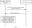
- FIG. 5 is a schematic flowchart of communication between a wireless charging apparatus and a device to-be-charged according to an implementation of the present disclosure.
- a wireless charging apparatus sends a first instruction to a device to-be-charged.
- the first instruction is used for enquiring whether the device to-be-charged is operable in a first charging mode or requesting at least one of the following information of the device to-be-charged: a type or a model of the device to-be-charged (for example, a model set before leaving the factory), an identification code of the device to-be-charged (such as a character string preset for the device to-be-charged indicative of whether the device to-be-charged is operable in or supports the first charging mode), a maximum charging voltage and a maximum charging current supported by the device to-be-charged, etc.
- a type or a model of the device to-be-charged for example, a model set before leaving the factory
- an identification code of the device to-be-charged such as a character string preset for the device to-be-charged indicative of whether the device to-be-charged is operable in or supports the first charging mode
- the maximum charging voltage and the maximum charging current supported by the device to-be-charged relate to circuit parameters of the step-down circuit 303 or the converting circuit 307 of the device to-be-charged and/or the number of cells in the battery 305 of the device to-be-charged.
- the wireless charging apparatus determines a charging mode for use according to a response message fed back by the device to-be-charged.
- the wireless charging apparatus determines to enable the first charging mode.
- the wireless charging apparatus determines to enable a second charging mode.
- the response message fed back by the device to-be-charged includes at least one of: the type or model of the device to-be-charged, the identification code of the device to-be-charged, the maximum charging voltage and the maximum charging current supported by the device to-be-charged, etc.
- the wireless charging apparatus determines the charging mode for use according to the response message received. For example, when the type or model of the device to-be-charged indicates that the device to-be-charged is operable in the first charging mode, the wireless charging apparatus determines to use the first charging mode to conduct wireless charging on the device to-be-charged.
- the wireless charging apparatus feeds back the charging mode determined to the device to-be-charged, such that the device to-be-charged can control on-off states of the first charging channel 306 or the second charging channel 308.
- communication between the wireless charging apparatus and the device to-be-charged can be Bluetooth communication, wireless fidelity (Wi-Fi) communication, near field communication (NFC) based on a high carrier frequency, optical communication, ultrasonic communication, ultra-wideband communication, or mobile communication.
- Wi-Fi wireless fidelity
- NFC near field communication
- an optical communication module includes an infrared communication module.
- the infrared communication module can transmit information with an infrared ray.
- a mobile communication module can transmit information based on the fifth-generation (5G) communication protocol, the 4G communication protocol, the 3G communication protocol, and other mobile communication protocols.
- 5G fifth-generation
- the power supply device can be a quick-charging power supply device and a non-quick-charging power supply device.
- An output voltage that the quick-charging power supply device is able to provide is higher than an output voltage that the non-quick-charging power supply device is able to provide.
- an output voltage/an output current of the non-quick-charging power supply device is 5V/2A
- an output voltage/an output current of the quick-charging power supply device is 15V/2A.
- a voltage provided to the wireless charging apparatus by the power supply device can make the wireless charging apparatus be operable in the first charging mode.
- the power supply device is the non-quick-charging power supply device
- the voltage provided to the wireless charging apparatus by the power supply device can make the wireless charging apparatus be operable in the second charging mode.
- the wireless charging apparatus communicates with the power supply device to determine a type of the power supply device, communicates with the device to-be-charged in the communication manner given above to determine a charging mode in which the device to-be-charged is operable, and determines a charging mode for use according to the type of the power supply device and/or the charging mode in which the device to-be-charged is operable.
- the wireless charging apparatus can still convert, with the voltage converting circuit 203, the voltage provided by the power supply device to enable the first charging mode.
- the voltage converting circuit 203 can convert the voltage provided by the power supply device (for example, decrease the voltage provided by the power supply device) to enable the second charging mode.
- the wireless charging apparatus determines to enable the second charging mode.
- the wireless charging apparatus is provided with the voltage converting circuit 203.
- the device to-be-charged is provided with the first charging channel 306 (such as a wire) coupled with the battery 305.
- the first charging channel 306 is provided with the step-down circuit 303 configured to decrease the output voltage of the wireless receiving circuit 301 to make an output voltage and an output current of the first charging channel 306 meet charging requirements of the battery 305.
- the wireless charging apparatus 200 uses a 20W output power to charge the battery 305 with one single cell of the device to-be-charged.
- an input voltage of the wireless transmitting circuit 201 is required to be 5V
- an input current of the wireless transmitting circuit 201 is required to be 4A.
- a 4A current used will certainly result in heating of a coil, which reduces charging efficiency.
- the input voltage of the wireless transmitting circuit 201 can be increased, such that the input current of the wireless transmitting circuit 201 can be decreased.
- the step-down circuit 303 is a half voltage circuit, that is, an input voltage of the step-down circuit 303 is twice the output voltage of the step-down circuit 303, thereby further reducing heating of the step-down circuit 303.
- the step-down circuit 303 is the half voltage circuit.
- the input voltage of the wireless transmitting circuit 201 is 10V
- the input current of the wireless transmitting circuit 201 is 2A.
- the output voltage of the wireless receiving circuit 301 is 10V (it should be understood that, considering electrical power loss, an actual output voltage of the wireless receiving circuit 301 will be close to 10V).
- the output voltage of the first charging channel 306 is 5V to charge the battery 305. It is to be understood that, in this example, the voltage required by the battery 305 is 5V.
- the second control circuit 302 feeds back the output voltage and/or the output current of the step-down 303 detected in real time by the detecting circuit 304 to the first control circuit 202.
- the first control circuit 202 adjusts, according to the output voltage and/or the output current fed back, the output power of the wireless transmitting circuit 201 to make a voltage difference between the input voltage of the step-down 303 and the output voltage of the step-down 303 satisfy a preset condition.
- the manner in which the wireless charging apparatus 200 adjusts the output power of the wireless transmitting circuit 201 can be various, which may include any one or more of the following three manners.
- the above preset condition is that the input voltage of the step-down circuit 303 is twice the output voltage of the step-down circuit 303.
- the first control circuit 202 controls to make the input voltage of the step-down circuit 303 be 2 ⁇ D1V (it is to be understood that, considering energy loss, an actual input voltage of the step-down circuit 303 can be higher than 2 ⁇ D1V), such that the voltage difference of the step-down circuit 303 satisfies the preset condition, thereby reducing heating and improving charging efficiency.
- the first control circuit 202 determines the tuning frequency or the duty ratio of the switch transistor according to D1 and D2 to make the input voltage of the step-down circuit 303 be 2 ⁇ D1V (it is to be understood that, considering energy loss, an actual input voltage of the step-down circuit 303 can be higher than 2 ⁇ D1V).
- the first control circuit 202 communicates with the power supply device according to D1 to make a voltage that the power supply device provides to the wireless transmitting circuit 201 be 2 ⁇ D1V to make the output voltage of the wireless transmitting circuit 201 be 2 ⁇ D1V (it is to be understood that, considering energy loss, an actual output voltage of the wireless transmitting circuit 201 can be higher than 2 ⁇ D1V), such that the input voltage of the step-down circuit 303 is 2 ⁇ D1V.
- the manner of communication between the first control circuit 202 and the power supply device is no limited herein.
- the first control circuit 202 can be coupled with and communicate with the power supply device via another communication interface other than a charging interface.
- the first control circuit 202 can communicate with the power supply device in a wireless manner.
- the first control circuit 202 can conduct an NFC with the power supply device.
- the first control circuit 202 can communicate with the power supply device via the charging interface without providing any extra communication interface or another wireless communication module, which can simplify the implementation of the wireless charging apparatus.
- the charging interface is a universal serial bus (USB) interface.
- the first control circuit 202 can communicate with the power supply device via a data line (such as a D+ line and/or a D- line) of the USB interface.
- a data line such as a D+ line and/or a D- line
- the charging interface is a USB interface supporting a power delivery (PD) communication protocol (such as a USB TYPE-C interface).
- the first control circuit 202 can communicate with the power supply device based on the PD communication protocol.
- the power supply device adjusts its own output power is not limited herein.
- the power supply device can be provided with a voltage feedback loop and a current feedback loop to adjust the output voltage and/or the output current of the power supply device according to actual needs.
- the wireless charging apparatus 200 can be in various shapes, such as a circular shape, a rectangular shape, etc.
- a charging surface a surface provided with a transmitting coil
- the wireless charging apparatus 200 begins wireless charging in a wireless charging procedure illustrated in FIG. 6 .
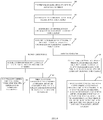
- FIG. 6 is a schematic flowchart of wireless charging according to an implementation of the present disclosure.
- the wireless charging apparatus transmits a signal at a preset time interval to detect whether an object is placed on a surface of the wireless charging apparatus.
- the wireless charging apparatus determines whether the object detected is a legal (that is, proper) device to-be-charged.
- the wireless charging apparatus acquires identity information and configuration information of the device to-be-charged.
- the identity information may be the identification code of the device to-be-charged described above.
- the configuration information may be the type or model of the device to-be-charged described above.
- the wireless charging apparatus determines a charging mode according to the identity information and the configuration information of the device to-be-charged.
- the charging mode can be determined in the above manner, that is, determined according to the type of the power supply device and/or the charging mode in which the device to-be-charged is operable.
- wireless charging at S65 to S67 is conducted.
- wireless charging at S68 to S69 is conducted.
- control information fed back by the device to-be-charged is acquired during wireless charging.
- the transmission power of the wireless transmitting circuit 201 is adjusted according to the error information.
- the output voltage and/or the output current of the voltage converting circuit 203 is adjusted according to the output voltage and/or the output current of the step-down circuit 303 to adjust a transmission power of an electromagnetic signal, to make the voltage difference between the input voltage of the step-down circuit 303 and the output voltage of the step-down circuit 303 satisfy the preset condition.
- the transmission power can be adjusted in any one or more of the above manners (1) to (3).
- the wireless charging apparatus and/or the device to-be-charged in implementations of the disclosure can be operable only in the first charging mode for wireless charging, or be operable in the first charging mode or in the second charging mode for wireless charging, which is not limited herein.
- the current threshold includes a first current threshold and a second current threshold, where the first current threshold is greater than the second current threshold.
- the first control circuit 202 is configured to control to increase the output voltage of the voltage converting circuit 203 when the output current of the step-down circuit 303 is larger than the first current threshold and configured to control to decrease the output voltage of the voltage converting circuit 203 when the output current of the step-down circuit 303 is smaller than the second current threshold.
- At S74 communicate with the wireless charging apparatus according to the output voltage and/or the output current of the step-down circuit 303, whereby the wireless charging apparatus adjusts a transmission power of the electromagnetic signal to make a voltage difference between an input voltage of the step-down circuit 303 and the output voltage of the step-down circuit 303 meet a preset condition.
- a voltage converting circuit 203 receives an input voltage and converts the input voltage to obtain an output voltage and an output current of the voltage converting circuit 203.
- charging on the battery 305 through the first charging channel 306 or through the second charging channel 308 includes a trickle charging stage, a constant-current charging stage, and a constant-voltage charging stage.
- the constant-current charging stage referred to herein does not require that the charging current remain completely constant, and may be, for example, a peak value (that is, peak current) or an average value of the charging current remaining constant within a certain time period.
- a multi-stage constant current charging manner is usually adopted for charging.
- a first stage of charging begins with a pre-determined charging current.
- the N constant-current stages of the multi-stage constant current charging are executed in sequence from the first stage to the N th stage.
- the charging current may be decreased.
- the multi-stage constant current charging proceeds to a subsequent constant-current stage, that is, the previous constant-current stage ends and the next constant-current stage begins. Current conversion between two adjacent constant-current stages may be gradual or in a step-like manner.
- the manner and order of communication between the wireless charging apparatus and the device to-be-charged are not limited herein.
- the wireless communication between the wireless charging apparatus and the device to-be-charged is a one-way wireless communication.
- the device to-be-charged is an initiator of communication and the wireless charging apparatus is a receiver of communication.
- the device to-be-charged can detect in real time the charging current of the battery 305 (that is, the output current of the wireless receiving circuit 301) through the detecting circuit 304.
- the device to-be-charged can send adjustment information to the wireless charging apparatus to instruct the wireless charging apparatus to adjust the transmission power of the wireless transmitting circuit 201.
- the wireless communication between the wireless charging apparatus and the device to-be-charged is a two-way wireless communication.
- the two-way wireless communication generally requires that the receiver sends response information to the initiator after receiving communication request initiated by the initiator. Two-way communication mechanism can make communication safer.
- any one of the wireless charging apparatus and the device to-be-charged can function as a master device to initiate a two-way communication, and correspondingly the other one of the wireless charging apparatus and the device to-be-charged can function as a slave device to make a first response or a first reply to the communication initiated by the master device.
- the master device and the slave device can be determined by comparing link states between the wireless charging apparatus and the device to-be-charged.
- a wireless link in which the wireless charging apparatus sends information to the device to-be-charged is an uplink and a wireless link in which the device to-be-charged sends information to the wireless charging apparatus is a downlink.
- the wireless charging apparatus can be determined as the master device of communication.
- the device to-be-charged can be determined as the master device of communication.
- any one of the wireless charging apparatus and the device to-be-charged can function as the master device to initiate the two-way communication, and correspondingly the other one of the wireless charging apparatus and the device to-be-charged can function as the slave device to make the first response or the first reply to the communication initiated by the master device.
- the master device can make a second response to the first response or the first reply of the slave device, and as such, the master device and the slave device complete one communication negotiation.
- the master device can make the second response to the first response or the first reply of the slave device as follows.
- the master device receives from the slave device the first response or the first reply to the communication and makes the second response to the first response or the first reply of the slave device.
- the master device can also make the second response to the first response or the first reply of the slave device as follows.
- the master device fails to receive from the slave device the first response or the first reply to the communication within a preset time period, the master device can still make the second response to the first response or the first reply made by the slave device.
- the wireless charging apparatus after the device to-be-charged, as the master device, initiates the communication and the wireless charging apparatus, as the slave device, makes the first response or the first reply to the communication initiated by the master device, it can be considered that the wireless charging apparatus and the device to-be-charged have completed a communication negotiation without requiring the device to-be-charged to make the second response to the first response or the first reply of the wireless charging apparatus.
- the second control circuit 302 can be configured to conduct the wireless communication with the first control circuit 202 according to a voltage and/or a current in the first charging channel 306 detected by the detecting circuit 304, whereby the first control circuit 202 adjusts the transmission power of the wireless transmitting circuit 201.
- contents communicated between the second control circuit 302 and the first control circuit 202 is not limited herein.
- the second control circuit 302 can send to the first control circuit 202 the output voltage and/or the output current of the first charging channel 306 detected by the detecting circuit 304.
- the second control circuit 302 can further send state information of the battery 305 to the first control circuit 202.
- the state information of the battery 305 includes a present power and/or a present voltage of the battery 305 of the device to-be-charged.
- the first control circuit 202 can determine a present charging stage of the battery 305 according to the state information of the battery 305, to further determine a target charging voltage and/or a target charging current that matches a charging voltage and/or the charging current currently required by the battery 305.
- the first control circuit 202 can compare the output voltage and/or the output current of the first charging channel 306 received from the second control circuit 302 with the above target charging voltage and/or the above target charging current to determine whether the output voltage and/or the output current of the first charging channel 306 matches the charging voltage and/or the charging current currently required by the battery 305.
- the first control circuit 202 can adjust the transmission power of the wireless transmitting circuit 201 until the output voltage and/or the output current of the first charging channel 306 matches the charging voltage and/or the charging current currently required by the battery 305.
- the first control circuit 202 adjusts the transmission power of the wireless transmitting circuit 201 by one grade until the output voltage and/or the output current of the first charging channel 306 matches the charging voltage and/or the charging current currently required by the battery 305.
- the first control circuit 202 and the second control circuit 302 can also exchange other types of communication information.
- the first control circuit 202 and the second control circuit 302 can exchange information for safety protection, abnormality detection, or fault handling, such as temperature information of the battery 305, information indicative of over-voltage protection or over-current protection, etc., or power-transmission efficiency information (for indicating efficiency in power transmission between the wireless transmitting circuit 201 and the wireless receiving circuit 301).
- the first control circuit 202 and/or the second control circuit 302 can control a charging loop to a protection state, such as controlling the charging loop to stop the wireless charging.
- the first control circuit 202 can reduce the transmission power, or control the wireless transmitting circuit 201 to stop working.
- the first control circuit 202 can control the wireless transmitting circuit 201 to stop working if power-transmission efficiency is lower than a preset threshold and notify a user of the event.
- the fact that the power-transmission efficiency is excessively low can be displayed via a display screen, or be indicated by an indicator lamp in order for the user to adjust wireless charging environment.
- the first control circuit 202 and the second control circuit 302 can exchange other types of information for adjusting the transmission power of the wireless transmitting circuit 201, such as the temperature information of the battery 305, information indicative of a peak value or an average value of the voltage in the first charging channel 306, information indicative a peak value or an average value of the current in the first charging channel 306, the power-transmission efficiency information (indicative of efficiency in power transmission between the wireless transmitting circuit 201 and the wireless receiving circuit 301), etc.
- other types of information for adjusting the transmission power of the wireless transmitting circuit 201 such as the temperature information of the battery 305, information indicative of a peak value or an average value of the voltage in the first charging channel 306, information indicative a peak value or an average value of the current in the first charging channel 306, the power-transmission efficiency information (indicative of efficiency in power transmission between the wireless transmitting circuit 201 and the wireless receiving circuit 301), etc.
- the second control circuit 302 can send the power-transmission efficiency information to the first control circuit 202.
- the first control circuit 202 can be further configured to determine an adjustment range of the transmission power of the wireless transmitting circuit 201 according to the power-transmission efficiency information. Specifically, when the power-transmission efficiency information indicates that the efficiency in power transmission between the wireless transmitting circuit 201 and the wireless receiving circuit 301 is low, the first control circuit 202 can increase the adjustment range of the transmission power of the wireless transmitting circuit 201 to make the transmission power of the wireless transmitting circuit 201 reach promptly a target power.
- the first control circuit 202 will adjust the transmission power of the wireless transmitting circuit 201.
Landscapes
- Engineering & Computer Science (AREA)
- Power Engineering (AREA)
- Computer Networks & Wireless Communication (AREA)
- Signal Processing (AREA)
- Physics & Mathematics (AREA)
- General Physics & Mathematics (AREA)
- Electromagnetism (AREA)
- Charge And Discharge Circuits For Batteries Or The Like (AREA)
- Circuits Of Receivers In General (AREA)
- Secondary Cells (AREA)
Applications Claiming Priority (3)
| Application Number | Priority Date | Filing Date | Title |
|---|---|---|---|
| PCT/CN2017/079784 WO2018184230A1 (zh) | 2017-04-07 | 2017-04-07 | 无线充电系统、装置、方法及待充电设备 |
| PCT/CN2017/080334 WO2018188006A1 (zh) | 2017-04-13 | 2017-04-13 | 待充电设备和充电方法 |
| PCT/CN2018/082011 WO2018184583A1 (zh) | 2017-04-07 | 2018-04-04 | 待充电设备、无线充电装置、无线充电方法及系统 |
Publications (3)
| Publication Number | Publication Date |
|---|---|
| EP3605780A1 true EP3605780A1 (de) | 2020-02-05 |
| EP3605780A4 EP3605780A4 (de) | 2020-03-25 |
| EP3605780B1 EP3605780B1 (de) | 2022-02-16 |
Family
ID=63712012
Family Applications (6)
| Application Number | Title | Priority Date | Filing Date |
|---|---|---|---|
| EP18781213.6A Active EP3605780B1 (de) | 2017-04-07 | 2018-04-04 | Aufzuladende vorrichtung, drahtlose ladevorrichtung, drahtloses ladeverfahren und system |
| EP18781210.2A Active EP3609040B1 (de) | 2017-04-07 | 2018-04-04 | System zum drahtlosen laden, einrichtung, verfahren und aufzuladende vorrichtung |
| EP18780783.9A Active EP3609038B1 (de) | 2017-04-07 | 2018-04-04 | Aufzuladende vorrichtung, vorrichtung zum drahtlosen laden, verfahren zum drahtlosen laden und system |
| EP18780344.0A Active EP3609036B1 (de) | 2017-04-07 | 2018-04-04 | Zu ladende vorrichtung, vorrichtung zum drahtlosen laden, verfahren zum drahtlosen laden und system |
| EP18781214.4A Active EP3605781B1 (de) | 2017-04-07 | 2018-04-04 | Vorrichtung und verfahren zum drahtlosen laden und aufzuladende vorrichtung |
| EP18780892.8A Active EP3582361B1 (de) | 2017-04-07 | 2018-04-04 | Drahtloses ladegerät, zu ladende vorrichtung und steuerungsverfahren dafür |
Family Applications After (5)
| Application Number | Title | Priority Date | Filing Date |
|---|---|---|---|
| EP18781210.2A Active EP3609040B1 (de) | 2017-04-07 | 2018-04-04 | System zum drahtlosen laden, einrichtung, verfahren und aufzuladende vorrichtung |
| EP18780783.9A Active EP3609038B1 (de) | 2017-04-07 | 2018-04-04 | Aufzuladende vorrichtung, vorrichtung zum drahtlosen laden, verfahren zum drahtlosen laden und system |
| EP18780344.0A Active EP3609036B1 (de) | 2017-04-07 | 2018-04-04 | Zu ladende vorrichtung, vorrichtung zum drahtlosen laden, verfahren zum drahtlosen laden und system |
| EP18781214.4A Active EP3605781B1 (de) | 2017-04-07 | 2018-04-04 | Vorrichtung und verfahren zum drahtlosen laden und aufzuladende vorrichtung |
| EP18780892.8A Active EP3582361B1 (de) | 2017-04-07 | 2018-04-04 | Drahtloses ladegerät, zu ladende vorrichtung und steuerungsverfahren dafür |
Country Status (13)
| Country | Link |
|---|---|
| US (6) | US11437848B2 (de) |
| EP (6) | EP3605780B1 (de) |
| JP (7) | JP7046094B2 (de) |
| KR (6) | KR102268987B1 (de) |
| CN (6) | CN110168844B (de) |
| AU (4) | AU2018247552A1 (de) |
| BR (2) | BR112019018588B1 (de) |
| CA (3) | CA3051027C (de) |
| MX (3) | MX2019011391A (de) |
| RU (3) | RU2727724C1 (de) |
| SG (3) | SG11201907726VA (de) |
| WO (6) | WO2018184581A1 (de) |
| ZA (3) | ZA201906558B (de) |
Cited By (2)
| Publication number | Priority date | Publication date | Assignee | Title |
|---|---|---|---|---|
| EP3869660A1 (de) * | 2020-02-18 | 2021-08-25 | LG Electronics Inc. | Vorrichtung zur drahtlosen stromübertragung, vorrichtung zum drahtlosen stromempfang und system damit |
| EP3869666A1 (de) * | 2020-02-18 | 2021-08-25 | LG Electronics Inc. | Drahtlose leistungsübertragungsvorrichtung und verfahren zu deren betrieb |
Families Citing this family (37)
| Publication number | Priority date | Publication date | Assignee | Title |
|---|---|---|---|---|
| HUE033128T2 (en) † | 2013-11-28 | 2017-11-28 | Pan-Dur Holding Gmbh & Co Kg | Glass plate layout |
| KR102222153B1 (ko) | 2017-04-07 | 2021-03-03 | 광동 오포 모바일 텔레커뮤니케이션즈 코포레이션 리미티드 | 무선 충전 장치, 무선 충전 방법, 및 충전 대기 설비 |
| KR102328496B1 (ko) * | 2017-04-07 | 2021-11-17 | 광동 오포 모바일 텔레커뮤니케이션즈 코포레이션 리미티드 | 무선 충전 시스템, 장치, 방법 및 충전 대기 기기 |
| CN110089040B (zh) * | 2017-04-07 | 2022-04-15 | Oppo广东移动通信有限公司 | 数据传输的方法和发送端设备 |
| CA3051027C (en) | 2017-04-07 | 2021-05-11 | Guangdong Oppo Mobile Telecommunications Corp., Ltd. | Wireless charging device, device to-be-charged, and method for controlling the same |
| JP7204766B2 (ja) | 2018-05-15 | 2023-01-16 | オッポ広東移動通信有限公司 | 被充電機器及び充電制御方法 |
| CN111262348B (zh) * | 2018-11-30 | 2022-06-10 | 北京小米移动软件有限公司 | 无线充电装置的控制方法、装置以及无线充电装置 |
| EP3872950A4 (de) * | 2018-12-21 | 2021-11-03 | Guangdong Oppo Mobile Telecommunications Corp., Ltd. | Sendevorrichtung, empfangsvorrichtung, stromversorgungsvorrichtung und verfahren zum drahtlosen laden |
| EP3879669A4 (de) * | 2018-12-21 | 2021-11-10 | Guangdong Oppo Mobile Telecommunications Corp., Ltd. | Verfahren zum drahtlosen laden, aufzuladende vorrichtung, stromversorgungsvorrichtung und speichermedium |
| CN112956109A (zh) * | 2018-12-21 | 2021-06-11 | Oppo广东移动通信有限公司 | 接收装置和无线充电方法 |
| WO2020124571A1 (zh) * | 2018-12-21 | 2020-06-25 | Oppo广东移动通信有限公司 | 充电装置、待充电设备、充电方法及计算机存储介质 |
| CN113169561B (zh) * | 2018-12-21 | 2024-04-02 | Oppo广东移动通信有限公司 | 无线充电方法、待充电设备、无线充电装置及存储介质 |
| CN109546711A (zh) * | 2018-12-28 | 2019-03-29 | 维沃移动通信有限公司 | 无线充电控制方法、电路及终端设备 |
| KR20200101228A (ko) | 2019-02-19 | 2020-08-27 | 삼성전자주식회사 | 외부 장치를 무선 충전하기 위한 전자 장치 |
| WO2020217881A1 (ja) * | 2019-04-22 | 2020-10-29 | パイオニア株式会社 | 電磁波送信装置及び電磁波通信システム |
| US11594904B2 (en) * | 2019-04-25 | 2023-02-28 | II Richard Brian Murray | Method and apparatus for reducing battery stress |
| KR20200136594A (ko) * | 2019-05-28 | 2020-12-08 | 삼성전자주식회사 | 전압 분배 비율을 적응적으로 변경하는 전압 분배 회로를 포함하는 전자 장치 |
| CN112636399B (zh) * | 2019-09-24 | 2023-08-04 | 北京小米移动软件有限公司 | 充电方法和装置、终端设备及存储介质 |
| CN115275365A (zh) * | 2019-09-25 | 2022-11-01 | 荣耀终端有限公司 | 支持高功率快充的电池模组、充电模组和电子设备 |
| CN110649688B (zh) * | 2019-10-21 | 2023-03-14 | 广西电网有限责任公司电力科学研究院 | 一种基于电池温度检测的无线充电控制系统及方法 |
| CN113036828A (zh) * | 2019-12-24 | 2021-06-25 | Oppo广东移动通信有限公司 | 电子设备 |
| CN113067395A (zh) * | 2019-12-31 | 2021-07-02 | 华为技术有限公司 | 电子设备、无线充电接收装置及控制方法、无线充电系统 |
| US11239672B2 (en) * | 2020-03-23 | 2022-02-01 | Duracell U.S. Operations, Inc. | Monitoring charging efficiency of a mobile computing device via a power bank |
| JP7437631B2 (ja) * | 2020-03-31 | 2024-02-26 | パナソニックIpマネジメント株式会社 | 通信制御装置、通信制御システム、および、通信制御方法 |
| CN111439141A (zh) * | 2020-04-09 | 2020-07-24 | 西交利物浦大学 | 无线充电控制系统及装置 |
| CN113725931A (zh) * | 2020-05-25 | 2021-11-30 | Oppo广东移动通信有限公司 | 电池组充电电路、电池组放电电路和电池组 |
| US11196487B1 (en) | 2020-07-31 | 2021-12-07 | Scidatek Inc. | Free-space communication and wireless power transfer system and method of using same |
| CN114356126B (zh) * | 2020-09-29 | 2023-09-05 | 宝德科技股份有限公司 | 具动态调整组态的多线圈鼠标垫 |
| US20240039345A1 (en) * | 2021-02-09 | 2024-02-01 | The Governing Council Of The University Of Toronto | Excitation-quadrature-quadrature transmitter wireless power transfer system |
| US11710977B2 (en) | 2021-03-11 | 2023-07-25 | Duracell U.S. Operations, Inc. | Integrated monitoring charging efficiency of a rechargeable device via a power bank |
| CN113131568B (zh) * | 2021-03-30 | 2023-04-28 | 联想(北京)有限公司 | 一种电池的无线充电控制方法及电路 |
| CN113098143A (zh) * | 2021-03-30 | 2021-07-09 | 北京小米移动软件有限公司 | 电子设备的充电系统、无线充电端、终端及充电方法 |
| US11936211B2 (en) * | 2021-05-05 | 2024-03-19 | Aira, Inc. | Mixed analog front-end for wireless charging |
| JP2023552245A (ja) * | 2021-06-29 | 2023-12-14 | 深▲セン▼市質友精密電子有限公司 | lightningレセプタクル付き電源アダプタ、充電装置及びシステム |
| CN113433704B (zh) * | 2021-07-26 | 2023-11-21 | Oppo广东移动通信有限公司 | 眼镜及其充电方法、电子设备系统 |
| TWI788165B (zh) * | 2021-12-28 | 2022-12-21 | 台達電子工業股份有限公司 | 電源傳輸系統及方法 |
| CN115021379B (zh) * | 2022-08-04 | 2022-11-04 | 深圳市微源半导体股份有限公司 | 一种充电电路和电子设备 |
Family Cites Families (307)
| Publication number | Priority date | Publication date | Assignee | Title |
|---|---|---|---|---|
| JPS6277025A (ja) * | 1985-09-26 | 1987-04-09 | セイコーエプソン株式会社 | 集積回路 |
| JPH03189569A (ja) | 1989-12-20 | 1991-08-19 | Toshiba Corp | 電圧測定装置 |
| JPH05168149A (ja) * | 1991-12-16 | 1993-07-02 | Nec Home Electron Ltd | Acアダプタ付き情報処理装置 |
| US5638540A (en) | 1993-06-08 | 1997-06-10 | U.S. Robotics Mobile Communication Corp. | Portable computer/radio power management system |
| JPH07177658A (ja) | 1993-12-20 | 1995-07-14 | Matsushita Electric Works Ltd | 給電回路 |
| JPH07177653A (ja) | 1993-12-20 | 1995-07-14 | Toshiba Corp | 系統連系保護装置 |
| JP3620118B2 (ja) * | 1995-10-24 | 2005-02-16 | 松下電器産業株式会社 | 定電流・定電圧充電装置 |
| JP3439013B2 (ja) | 1996-02-29 | 2003-08-25 | 三洋電機株式会社 | 二次電池のパルス充電方法 |
| JP3595646B2 (ja) * | 1997-03-19 | 2004-12-02 | 株式会社カージオペーシングリサーチ・ラボラトリー | 生体植え込み装置 |
| WO1998058437A1 (en) | 1997-06-16 | 1998-12-23 | Yehuda Binder | Battery substitute pack |
| JPH1189103A (ja) * | 1997-09-11 | 1999-03-30 | Sanyo Electric Co Ltd | 非接触型充電装置 |
| JP2000333377A (ja) | 1999-05-21 | 2000-11-30 | Sony Computer Entertainment Inc | エンタテインメントシステムおよび充電システム |
| US7386238B2 (en) * | 2000-08-15 | 2008-06-10 | Lockheed Martin Corporation | Method and system for infrared data communications |
| CN2464002Y (zh) | 2000-12-16 | 2001-12-05 | 蒋冠珞 | 自生反向脉冲的快速充电机 |
| JP2004064938A (ja) | 2002-07-31 | 2004-02-26 | Fuji Photo Film Co Ltd | 充電システム |
| US7203048B2 (en) | 2002-10-24 | 2007-04-10 | 02Micro International Limited | DC to DC controller with inrush current protection |
| JP2004328916A (ja) * | 2003-04-25 | 2004-11-18 | Fuji Photo Film Co Ltd | 充電装置 |
| CN2741264Y (zh) | 2003-05-08 | 2005-11-16 | 美国凹凸微系有限公司 | 带有浪涌电流保护的直流/直流控制器 |
| TWI242994B (en) * | 2004-01-06 | 2005-11-01 | Huges Hi Tech Inc | Wireless earphone and its charging circuit and its charging method |
| KR100853889B1 (ko) | 2005-07-29 | 2008-08-25 | 엘에스전선 주식회사 | 무 접점 충전 배터리 및 충전기, 이들을 포함하는 배터리충전 세트, 및 충전제어 방법 |
| KR100792311B1 (ko) * | 2005-07-30 | 2008-01-07 | 엘에스전선 주식회사 | 충전전력 공급장치, 충전 장치, 배터리 장치, 무접점 충전 시스템 및 무접점 충전 방법 |
| JP4991194B2 (ja) | 2005-09-12 | 2012-08-01 | 株式会社リコー | 画像形成装置 |
| US20070139012A1 (en) | 2005-11-01 | 2007-06-21 | Aerovironment, Inc. | Motive power dual battery pack |
| CA2632755C (en) | 2005-12-07 | 2014-06-17 | Boston Scientific Neuromodulation Corporation | Battery protection and zero-volt battery recovery system for an implantable medical device |
| US7880445B2 (en) | 2006-02-16 | 2011-02-01 | Summit Microelectronics, Inc. | System and method of charging a battery using a switching regulator |
| JP5020530B2 (ja) | 2006-04-14 | 2012-09-05 | パナソニック株式会社 | 充電方法ならびに電池パックおよびその充電器 |
| JP4187001B2 (ja) | 2006-04-14 | 2008-11-26 | 船井電機株式会社 | 光ディスク記録再生装置 |
| JP2007305820A (ja) * | 2006-05-12 | 2007-11-22 | Asuka Electron Kk | 積層平面コイル |
| WO2008030398A2 (en) | 2006-09-05 | 2008-03-13 | Summit Microelectronics, Inc | Circuits and methods for controlling power in a battery operated system |
| JP4311687B2 (ja) | 2006-10-06 | 2009-08-12 | 日本テキサス・インスツルメンツ株式会社 | 電源回路およびバッテリ装置 |
| US8159364B2 (en) * | 2007-06-14 | 2012-04-17 | Omnilectric, Inc. | Wireless power transmission system |
| CN101330229A (zh) | 2007-06-21 | 2008-12-24 | 北京市北邮信息科技发展有限责任公司 | 一种非接触式电能传输装置 |
| JP4453741B2 (ja) * | 2007-10-25 | 2010-04-21 | トヨタ自動車株式会社 | 電動車両および車両用給電装置 |
| BRPI0820583A8 (pt) | 2007-12-10 | 2015-09-22 | Bayer Healthcare Llc | carregamento rápido e gerenciamento de energia de medidor de analitos em fluido acionado a bateria |
| WO2009114671A1 (en) * | 2008-03-13 | 2009-09-17 | Access Business Group International Llc | Inductive power supply system with multiple coil primary |
| JP2009273327A (ja) * | 2008-05-10 | 2009-11-19 | Sanyo Electric Co Ltd | 電池内蔵機器と充電台 |
| US20100007293A1 (en) * | 2008-07-09 | 2010-01-14 | Ives Burr Meadors | Programmable power-control circuit and methods of operation |
| US8111042B2 (en) * | 2008-08-05 | 2012-02-07 | Broadcom Corporation | Integrated wireless resonant power charging and communication channel |
| JP5139941B2 (ja) * | 2008-09-26 | 2013-02-06 | Necエンベデッドプロダクツ株式会社 | Rfid用アンテナ |
| US8947042B2 (en) * | 2008-11-13 | 2015-02-03 | Qualcomm Incorporated | Wireless power and data transfer for electronic devices |
| JP2010130729A (ja) * | 2008-11-25 | 2010-06-10 | Canon Inc | 充電装置、送電装置及び非接触充電システム |
| CN102362408B (zh) | 2009-03-30 | 2015-01-21 | 富士通株式会社 | 无线供电系统、无线送电装置及无线受电装置 |
| JP5353376B2 (ja) * | 2009-03-31 | 2013-11-27 | 富士通株式会社 | 無線電力装置、無線電力受信方法 |
| US8558411B2 (en) * | 2009-07-24 | 2013-10-15 | Access Business Group International Llc | Power supply |
| JP2011034306A (ja) | 2009-07-31 | 2011-02-17 | Toshiba Corp | 情報処理装置及び給電制御方法 |
| US8374545B2 (en) * | 2009-09-02 | 2013-02-12 | Qualcomm Incorporated | De-tuning in wireless power reception |
| US8928284B2 (en) | 2009-09-10 | 2015-01-06 | Qualcomm Incorporated | Variable wireless power transmission |
| JP2011078191A (ja) | 2009-09-30 | 2011-04-14 | Nec Casio Mobile Communications Ltd | 充電装置及び電子機器並びにプログラム |
| US8390249B2 (en) * | 2009-11-30 | 2013-03-05 | Broadcom Corporation | Battery with integrated wireless power receiver and/or RFID |
| US20110127953A1 (en) * | 2009-11-30 | 2011-06-02 | Broadcom Corporation | Wireless power system |
| JP5550097B2 (ja) | 2009-12-02 | 2014-07-16 | Necカシオモバイルコミュニケーションズ株式会社 | 無接点充電装置及び電子機器並びにプログラム |
| KR101097262B1 (ko) | 2009-12-28 | 2011-12-21 | 삼성에스디아이 주식회사 | 배터리 팩, 이의 충전방법 |
| US8666437B2 (en) * | 2010-01-05 | 2014-03-04 | Iota, Inc. | Mobile communications resource management system |
| WO2011084942A2 (en) | 2010-01-05 | 2011-07-14 | Access Business Group International Llc | Integrated wireless power system |
| JP2011151891A (ja) | 2010-01-19 | 2011-08-04 | Sony Corp | 二次電池の充電方法および充電装置 |
| JP2011152018A (ja) | 2010-01-25 | 2011-08-04 | Sony Corp | ワイヤレス蓄電システムおよびワイヤレス給電システム |
| WO2011122003A1 (ja) | 2010-03-30 | 2011-10-06 | パナソニック株式会社 | 無線電力伝送システム |
| JP5024420B2 (ja) | 2010-04-27 | 2012-09-12 | 沖電気工業株式会社 | 太陽電池電源装置 |
| JP2011259534A (ja) * | 2010-06-05 | 2011-12-22 | Sanyo Electric Co Ltd | 電池内蔵機器と充電台 |
| JP2012016125A (ja) * | 2010-06-30 | 2012-01-19 | Panasonic Electric Works Co Ltd | 非接触給電システム及び非接触給電システムの金属異物検出装置 |
| CN101902043B (zh) * | 2010-07-23 | 2014-06-04 | 中兴通讯股份有限公司 | 充电电路管理装置及无线终端 |
| CN101924387A (zh) * | 2010-09-21 | 2010-12-22 | 福州大学 | 反馈式无线充电器 |
| JP5071545B2 (ja) * | 2010-10-06 | 2012-11-14 | 株式会社デンソー | 電力需給システム |
| US20120104997A1 (en) | 2010-11-01 | 2012-05-03 | Qualcomm Incorporated | Wireless charging device |
| JP5710220B2 (ja) * | 2010-11-15 | 2015-04-30 | 株式会社シバタ | 非接触式電力伝送装置、並びにこれに用いられる給電装置、受電装置及び電磁誘導用コイル |
| US10079090B2 (en) | 2010-12-01 | 2018-09-18 | Triune Systems, LLC | Multiple coil data transmission system |
| CN102013717B (zh) * | 2010-12-03 | 2013-01-16 | 清华大学 | 植入式医疗仪器用具有对位自动提示功能的无线充电方法 |
| KR101813029B1 (ko) * | 2010-12-17 | 2017-12-28 | 엘지전자 주식회사 | 무선전력전송방법, 무선전력수신방법, 무선전력전송장치 및 무선전력수신장치 |
| US9496732B2 (en) | 2011-01-18 | 2016-11-15 | Mojo Mobility, Inc. | Systems and methods for wireless power transfer |
| US10141770B2 (en) * | 2011-01-18 | 2018-11-27 | Mojo Mobility, Inc. | Powering and/or charging with a plurality of protocols |
| JP5713714B2 (ja) | 2011-02-10 | 2015-05-07 | キヤノン株式会社 | 給電装置及び制御方法 |
| KR101267076B1 (ko) | 2011-03-24 | 2013-05-24 | 주식회사 한림포스텍 | 무선 전력 전송 어셈블리에서의 전력 제어 방법 및 무선 전력 전송 어셈블리 |
| US10332676B2 (en) | 2011-03-24 | 2019-06-25 | Triune Systems, LLC | Coupled inductor system having multi-tap coil |
| US9735623B2 (en) | 2011-05-17 | 2017-08-15 | Samsung Electronics Co., Ltd. | Power transmitting method and power transmitter for communication with power receiver |
| JP2012239814A (ja) * | 2011-05-24 | 2012-12-10 | Fujifilm Corp | 放射線撮影装置 |
| JP2012249410A (ja) * | 2011-05-27 | 2012-12-13 | Sharp Corp | 電気自動車充電用の充電器及び充電装置 |
| KR102012684B1 (ko) * | 2011-05-31 | 2019-08-26 | 삼성전자주식회사 | 무선 전력을 이용한 통신 장치 및 방법 |
| US9099885B2 (en) | 2011-06-17 | 2015-08-04 | Semiconductor Energy Laboratory Co., Ltd. | Wireless power feeding system |
| JP5767873B2 (ja) | 2011-06-28 | 2015-08-26 | 株式会社東芝 | 蓄電装置および蓄電システム |
| JP5505375B2 (ja) | 2011-06-29 | 2014-05-28 | 株式会社豊田自動織機 | セルバランス制御装置及びセルバランス制御方法 |
| US9379571B2 (en) * | 2011-07-11 | 2016-06-28 | Delphi Technologies, Inc. | Electrical charging system having energy coupling arrangement for wireless energy transmission therebetween |
| JP5893285B2 (ja) * | 2011-08-04 | 2016-03-23 | キヤノン株式会社 | 給電装置及びプログラム |
| KR20130024757A (ko) | 2011-08-29 | 2013-03-08 | 주식회사 케이더파워 | 이종 충전 방식을 가진 무선 충전 시스템 |
| KR101580342B1 (ko) * | 2011-08-29 | 2015-12-24 | 삼성전기주식회사 | 무선 전력 전송 시스템 및 그의 제어방법 |
| JP2013078171A (ja) * | 2011-09-29 | 2013-04-25 | Semiconductor Energy Lab Co Ltd | 受電装置及び非接触給電システム |
| JP2013085386A (ja) | 2011-10-11 | 2013-05-09 | Panasonic Corp | 蓄電池制御装置、蓄電池制御方法、電力貯蔵システム及び電気自動車の駆動システム |
| US9348381B2 (en) * | 2011-10-19 | 2016-05-24 | Zeco Systems Pte Ltd | Methods and apparatuses for charging of electric vehicles |
| KR101818773B1 (ko) | 2011-10-24 | 2018-02-22 | 삼성전자주식회사 | 공진 방식 무선 충전 시스템용 수신 전력 변환 장치 |
| KR101327081B1 (ko) | 2011-11-04 | 2013-11-07 | 엘지이노텍 주식회사 | 무선전력 수신장치 및 그 제어 방법 |
| KR101338732B1 (ko) | 2011-11-10 | 2013-12-06 | 엘지이노텍 주식회사 | 무선전력 송신장치, 무선전력 수신장치, 무선전력 전송 방법, 무선전력 수신 방법, 정보 전송 방법 및 정보 수신 방법 |
| JP2013115859A (ja) | 2011-11-25 | 2013-06-10 | Hitachi Maxell Ltd | ワイヤレス電力伝送装置 |
| CN102427260A (zh) | 2011-12-02 | 2012-04-25 | 苏州冠硕新能源有限公司 | 充电管理系统及采用该充电管理系统的充电器 |
| JP6045141B2 (ja) * | 2011-12-05 | 2016-12-14 | キヤノン株式会社 | 電子機器及びプログラム |
| US8928182B2 (en) | 2011-12-16 | 2015-01-06 | Tdk Corporation | Wireless power feeder and wireless power transmission system |
| CN102522799A (zh) | 2011-12-30 | 2012-06-27 | 成都林海电子有限责任公司 | 一种移动终端电源 |
| JP5880122B2 (ja) * | 2012-02-21 | 2016-03-08 | 株式会社豊田自動織機 | 非接触電力伝送装置 |
| KR101882800B1 (ko) | 2012-02-28 | 2018-08-01 | 삼성전자주식회사 | 무선 전력 수신기 및 그 제어 방법 |
| JP2013183496A (ja) | 2012-02-29 | 2013-09-12 | Equos Research Co Ltd | 電力伝送システム |
| JP2013183523A (ja) | 2012-03-01 | 2013-09-12 | Nissan Motor Co Ltd | 電動車両 |
| JP2013191913A (ja) * | 2012-03-12 | 2013-09-26 | Renesas Electronics Corp | ワイヤレス充電回路、ワイヤレス充電システム及び半導体装置 |
| JP2013198260A (ja) | 2012-03-19 | 2013-09-30 | Ihi Corp | 電力伝送システム |
| JP2013211932A (ja) | 2012-03-30 | 2013-10-10 | Equos Research Co Ltd | 電力伝送システム |
| JP2013223301A (ja) * | 2012-04-13 | 2013-10-28 | Toyota Industries Corp | 非接触電力伝送装置の受電機器及び送電機器 |
| JP5872373B2 (ja) * | 2012-04-25 | 2016-03-01 | 三洋電機株式会社 | 無接点給電方法 |
| KR101438884B1 (ko) | 2012-05-07 | 2014-09-05 | 엘지이노텍 주식회사 | 무선전력 송신장치 및 그의 무선전력 전송 방법 |
| JP6024195B2 (ja) * | 2012-05-15 | 2016-11-09 | スミダコーポレーション株式会社 | 非接触給電システムおよび非接触給電システム用の送電コイル |
| US9218031B2 (en) | 2012-05-18 | 2015-12-22 | Dell Products, Lp | System and method for providing wireless power feedback in a wireless power delivery system |
| JP2013243890A (ja) * | 2012-05-22 | 2013-12-05 | Heads Corp | 非接触給電装置 |
| CN103457362B (zh) * | 2012-06-04 | 2016-02-03 | 比亚迪股份有限公司 | 无线充电的发送装置、无线充电系统及无线充电控制方法 |
| JP2014017893A (ja) * | 2012-07-05 | 2014-01-30 | Toyota Industries Corp | 非接触電力伝送装置 |
| JP2014017927A (ja) * | 2012-07-06 | 2014-01-30 | Toshiba Digital Media Engineering Corp | 送電装置、受電装置、送電方法及び受電方法 |
| US9973021B2 (en) * | 2012-07-06 | 2018-05-15 | Energous Corporation | Receivers for wireless power transmission |
| US9859756B2 (en) * | 2012-07-06 | 2018-01-02 | Energous Corporation | Transmittersand methods for adjusting wireless power transmission based on information from receivers |
| US9893554B2 (en) * | 2014-07-14 | 2018-02-13 | Energous Corporation | System and method for providing health safety in a wireless power transmission system |
| KR101848303B1 (ko) | 2012-07-10 | 2018-04-13 | 삼성전자주식회사 | 전력 전송을 제어하기 위한 방법 및 이를 위한 전력 송신기 |
| US9142999B2 (en) * | 2012-07-13 | 2015-09-22 | Qualcomm Incorporated | Systems, methods, and apparatus for small device wireless charging modes |
| JP2014023348A (ja) | 2012-07-20 | 2014-02-03 | Nikon Corp | 携帯端末の充電装置 |
| KR101270675B1 (ko) | 2012-08-28 | 2013-06-03 | 한국과학기술원 | 급전장치 |
| CN103683523B (zh) * | 2012-09-07 | 2018-04-13 | 捷通国际有限公司 | 用于双向无线功率传输的系统和方法 |
| JP2014057185A (ja) * | 2012-09-12 | 2014-03-27 | Ricoh Co Ltd | 無線給電装置及び電子機器 |
| KR101947980B1 (ko) | 2012-09-12 | 2019-02-14 | 삼성전자주식회사 | 무선 전력 전송 장치 및 방법, 무선 전력 수신 장치 |
| US20140091623A1 (en) | 2012-09-28 | 2014-04-03 | Keith Shippy | Power share controller |
| CN202998182U (zh) | 2012-10-17 | 2013-06-12 | 广东欧珀移动通信有限公司 | 可与手机通信的多功能保护套 |
| WO2014080671A1 (ja) * | 2012-11-22 | 2014-05-30 | 住友電気工業株式会社 | 非接触送電システム及び受電装置 |
| CN203036282U (zh) | 2012-11-27 | 2013-07-03 | 李昊致 | 睡眠灯 |
| CN103036282A (zh) * | 2012-12-06 | 2013-04-10 | 捷普科技(上海)有限公司 | 一种电压自适应无线充电装置及方法 |
| JP5976516B2 (ja) | 2012-12-12 | 2016-08-23 | 三洋電機株式会社 | 無接点充電方法 |
| CN103001297B (zh) | 2012-12-31 | 2014-12-10 | 中南大学 | 一种串联电容器组谐振式电压均衡充电方法及其系统 |
| USD712888S1 (en) | 2012-12-31 | 2014-09-09 | Motorola Mobility Llc | Communication device |
| US20140191568A1 (en) | 2013-01-04 | 2014-07-10 | Mojo Mobility, Inc. | System and method for powering or charging multiple receivers wirelessly with a power transmitter |
| US9419465B2 (en) * | 2013-01-07 | 2016-08-16 | Nxp B.V. | Wireless charger |
| JP6236636B2 (ja) | 2013-01-24 | 2017-11-29 | パナソニックIpマネジメント株式会社 | 蓄電池装置 |
| CN103078381B (zh) * | 2013-01-27 | 2015-06-17 | 中国科学院电工研究所 | 一种电动汽车无线充电装置及其输出控制方法 |
| KR102019064B1 (ko) * | 2013-01-29 | 2019-09-10 | 엘지이노텍 주식회사 | 무선 전력 송신 장치 및 방법 |
| JP6100011B2 (ja) * | 2013-02-06 | 2017-03-22 | キヤノン株式会社 | 給電装置、給電方法及びプログラム |
| JP6188351B2 (ja) * | 2013-03-01 | 2017-08-30 | キヤノン株式会社 | 給電装置、給電装置の制御方法、プログラム |
| US9197094B2 (en) * | 2013-03-07 | 2015-11-24 | Ford Global Technologies, Llc | Wireless charger and charging system with multi-compatibility |
| US9998180B2 (en) | 2013-03-13 | 2018-06-12 | Integrated Device Technology, Inc. | Apparatuses and related methods for modulating power of a wireless power receiver |
| US9318915B2 (en) * | 2013-03-20 | 2016-04-19 | Halo2Cloud Llc | Portable power charger with wireless and direct charging connectivity |
| MY162393A (en) | 2013-03-29 | 2017-06-15 | Nissan Motor | Non-contact power supply system |
| TWI482391B (zh) | 2013-04-02 | 2015-04-21 | Wistron Corp | 用於一電子裝置之充電電路及其相關充電方法 |
| KR101490732B1 (ko) * | 2013-04-23 | 2015-02-09 | 엘지이노텍 주식회사 | 무선전력 송신장치, 무선전력 수신장치, 무선전력 전송 방법, 무선전력 수신 방법, 정보 전송 방법 및 정보 수신 방법 |
| CN104124775B (zh) | 2013-04-28 | 2018-09-21 | 海尔集团技术研发中心 | 无线电能传输系统及其智能控制方法、智能控制系统 |
| WO2014179818A1 (en) | 2013-05-03 | 2014-11-06 | CommSense LLC | Antenna environment sensing device |
| CN103280870B (zh) * | 2013-05-09 | 2015-08-26 | 北京航空航天大学 | 一种电动汽车非接触充电负载自适应匹配装置及控制方法 |
| KR102082415B1 (ko) * | 2013-05-27 | 2020-02-27 | 엘지전자 주식회사 | 무선 전력 전송 장치 및 그 방법 |
| CN103269108B (zh) | 2013-06-04 | 2015-04-29 | 奇瑞汽车股份有限公司 | 一种电池电量均衡电路 |
| US9155900B2 (en) | 2013-06-20 | 2015-10-13 | Cochlear Limited | Medical device battery charging system and methods |
| JP2015006068A (ja) | 2013-06-21 | 2015-01-08 | 三洋電機株式会社 | 無接点給電方法 |
| CN103354376A (zh) * | 2013-06-26 | 2013-10-16 | 清华大学深圳研究生院 | 一种智能的通用型手机无线充电系统 |
| US9446674B2 (en) * | 2013-07-15 | 2016-09-20 | Qualcomm Incorporated | Systems, methods, and apparatus related to mutual detection and identification of electric vehicle and charging station |
| EP3022817B1 (de) | 2013-07-19 | 2018-03-28 | Philips Lighting Holding B.V. | Leistungsverhandlung in systemen mit verkettung |
| WO2015009329A1 (en) | 2013-07-19 | 2015-01-22 | Intel Corporation | Apparatus, system and method of wireless power transfer |
| TWI552483B (zh) | 2013-07-22 | 2016-10-01 | 光寶電子(廣州)有限公司 | 電池模組、電池模組供電管理方法及其裝置 |
| KR101420366B1 (ko) | 2013-07-23 | 2014-07-16 | 김현민 | 전기자동차용 무선전력 전송장치 |
| KR102126713B1 (ko) | 2013-08-13 | 2020-06-25 | 삼성전자주식회사 | 무선 전력 전송 시스템에서 무선 충전 제어 방법 및 장치 |
| CN104426245B (zh) * | 2013-08-29 | 2017-03-15 | 海尔集团技术研发中心 | 无线供电方法、供电装置及供电系统 |
| JP1524224S (de) | 2013-09-09 | 2015-05-25 | ||
| JP6208503B2 (ja) * | 2013-09-11 | 2017-10-04 | ローム株式会社 | ワイヤレス受電装置、その制御回路および制御方法 |
| JP6165009B2 (ja) | 2013-09-27 | 2017-07-19 | エスアイアイ・セミコンダクタ株式会社 | 給電システム、給電装置、及び給電方法 |
| KR20150045602A (ko) * | 2013-10-21 | 2015-04-29 | 주식회사 리더브라이트 | 공진방식 기반의 무선충전장치 |
| CN104578209A (zh) * | 2013-10-22 | 2015-04-29 | 中兴通讯股份有限公司 | 一种无线充电终端及用户终端、无线充电方法 |
| USD756949S1 (en) | 2013-11-11 | 2016-05-24 | Lg Electronics Inc. | Cellular phone |
| USD756948S1 (en) | 2013-11-11 | 2016-05-24 | Lg Electronics Inc. | Cellular phone |
| US20150236538A1 (en) | 2013-11-15 | 2015-08-20 | uNu Electronics, Inc. | Mobile Device Case with Fast Charging Battery Pack |
| CN104659925A (zh) * | 2013-11-20 | 2015-05-27 | 中兴通讯股份有限公司 | 无线电能收发方法和装置 |
| US9673651B2 (en) | 2013-11-21 | 2017-06-06 | Qualcomm Incorporated | Dynamic voltage adjust circuits and methods |
| KR102199469B1 (ko) * | 2013-12-09 | 2021-01-06 | 한화디펜스 주식회사 | 전기차량에서 외부 차량과 상호 전력 공급을 수행하는 방법 및 장치 |
| KR102280579B1 (ko) * | 2013-12-19 | 2021-07-22 | 삼성전자주식회사 | 충전 회로, 이를 포함하는 충전 시스템 및 무선전력 수신기 |
| CN105247755A (zh) | 2013-12-26 | 2016-01-13 | 联发科技股份有限公司 | 多路径充电器及其充电方法 |
| KR102035307B1 (ko) | 2013-12-30 | 2019-10-22 | 주식회사 위츠 | 충전 장치 및 배터리 장치 |
| TWM488138U (zh) * | 2014-01-17 | 2014-10-11 | 林榮聰 | 蓄電池之無線充電模組 |
| US20150214748A1 (en) | 2014-01-24 | 2015-07-30 | Mediatek Inc. | Wireless power supply scheme capable of dynamically adjusting output power of wireless power transmitter according to voltage/current/power information of portable electronic device to be charged |
| CN104810877B (zh) * | 2014-01-28 | 2016-12-14 | 广东欧珀移动通信有限公司 | 电池充电装置及方法 |
| JP6329386B2 (ja) | 2014-02-21 | 2018-05-23 | ルネサスエレクトロニクス株式会社 | 非接触給電方法及び非接触給電システム |
| JP6493385B2 (ja) | 2014-02-24 | 2019-04-03 | ソニー株式会社 | 受電装置、給電制御方法、および給電システム |
| KR101747064B1 (ko) | 2014-02-25 | 2017-06-14 | 닛산 지도우샤 가부시키가이샤 | 비접촉 급전 시스템 및 송전 장치 |
| MX349020B (es) | 2014-02-25 | 2017-07-07 | Nissan Motor | Sistema de suministro de energia sin contacto y dispositivo de transmision de energia. |
| TW201533561A (zh) | 2014-02-25 | 2015-09-01 | Novatek Microelectronics Corp | 可攜式電腦及無線鍵盤與平板電腦 |
| CN103944243B (zh) * | 2014-02-27 | 2016-05-11 | 北京航空航天大学 | 一种电动汽车用带有精确对中功能的感应式非接触充电装置 |
| JP6249223B2 (ja) | 2014-03-04 | 2017-12-20 | パナソニックIpマネジメント株式会社 | 非接触充電システム |
| DE102014002876A1 (de) * | 2014-03-05 | 2015-09-10 | Supa Wireless Gmbh | Anordnung für eine induktive Energieübertragung |
| KR102187437B1 (ko) * | 2014-03-11 | 2020-12-08 | 엘지이노텍 주식회사 | 무선전력 전송 장치를 구비한 무선전력전송 시스템 |
| CN106104963B (zh) | 2014-03-18 | 2018-12-28 | 株式会社Ihi | 供电装置以及非接触供电系统 |
| US10298048B1 (en) | 2014-04-15 | 2019-05-21 | Mediatek Inc. | Wireless charging system and charging control method for dynamically adjusting output power |
| US9698632B2 (en) * | 2014-05-09 | 2017-07-04 | Otter Products, Llc | Wireless battery charger and charge-receiving device |
| CN104113104B (zh) * | 2014-05-22 | 2017-01-04 | 深圳天珑无线科技有限公司 | 一种充电方法及系统 |
| CN104124483B (zh) | 2014-05-23 | 2016-05-04 | 东莞市钜大电子有限公司 | 一种移动电源快速充电方法及系统 |
| RU149860U1 (ru) * | 2014-06-03 | 2015-01-20 | Общество с ограниченной ответственностью "Электронная корпорация "Радуга" | Станция для зарядки электротранспорта |
| JP2016015808A (ja) * | 2014-07-01 | 2016-01-28 | 株式会社豊田自動織機 | 受電機器及び非接触電力伝送装置 |
| JP2016015862A (ja) | 2014-07-03 | 2016-01-28 | 株式会社Ihi | 受電装置 |
| US10148096B2 (en) | 2014-07-07 | 2018-12-04 | Mediatek Singapore Pte. Ltd. | Wireless or wired power delivery using a controllable power adapter |
| WO2016006892A1 (en) * | 2014-07-07 | 2016-01-14 | Lg Electronics Inc. | Wireless power transfer method, apparatus and system |
| CN104037918A (zh) * | 2014-07-08 | 2014-09-10 | 江苏天行健汽车科技有限公司 | 一种磁共振式车载移动终端无线充电系统及方法 |
| US10355527B2 (en) * | 2014-07-16 | 2019-07-16 | Taiwan Semiconductor Manufacturing Company Limited | Wireless charging receiver with variable resonant frequency |
| US9680531B2 (en) * | 2014-08-01 | 2017-06-13 | Qualcomm Incorporated | System and method for detecting inadequate wireless coupling and improving in-band signaling in wireless power transfer systems |
| JP6181614B2 (ja) * | 2014-08-04 | 2017-08-16 | 株式会社Soken | 非接触電力伝送システム |
| EP2983266B1 (de) * | 2014-08-05 | 2017-02-22 | Panasonic Corporation | Stromübertragungsvorrichtung und drahtloses stromübertragungssystem |
| CN104158269B (zh) * | 2014-08-11 | 2016-03-16 | 长城信息产业股份有限公司 | 一种无线充电发射器、接收器、充电装置及无线充电方法 |
| CN204190475U (zh) * | 2014-08-11 | 2015-03-04 | 长城信息产业股份有限公司 | 一种无线充电发射器及无线充电装置 |
| CN105471001A (zh) | 2014-08-19 | 2016-04-06 | 中兴通讯股份有限公司 | 一种使用多电芯电池的移动终端及其充放电电路 |
| KR102320853B1 (ko) | 2014-09-02 | 2021-11-02 | 삼성전자 주식회사 | 전자 장치, 전자 장치의 충전 제어 방법, 전원 공급 장치, 및 전원 공급 장치의 전력 공급 방법 |
| KR20160028537A (ko) | 2014-09-03 | 2016-03-14 | 주식회사 케이더파워 | 휴대용 충전기 |
| KR101994742B1 (ko) * | 2014-09-12 | 2019-07-01 | 삼성전기주식회사 | 비접촉 방식 충전 장치, 비접촉 방식 배터리 장치 및 비접촉 방식 전력 전송 방법 |
| US10559970B2 (en) | 2014-09-16 | 2020-02-11 | Qorvo Us, Inc. | Method for wireless charging power control |
| JP6400407B2 (ja) | 2014-09-18 | 2018-10-03 | Ntn株式会社 | 充電装置 |
| CN104253468A (zh) * | 2014-09-18 | 2014-12-31 | 青岛众海汇智能源科技有限责任公司 | 一种移动式无线充电系统及控制方法 |
| JP2016063726A (ja) | 2014-09-22 | 2016-04-25 | 株式会社豊田自動織機 | 受電機器及び非接触電力伝送装置 |
| JP2016063725A (ja) | 2014-09-22 | 2016-04-25 | 株式会社豊田自動織機 | 受電機器及び非接触電力伝送装置 |
| CN105515210A (zh) | 2014-09-26 | 2016-04-20 | 国家电网公司 | 非接触充电桩、车载充电装置和充电系统 |
| US20160094080A1 (en) * | 2014-09-29 | 2016-03-31 | Chervon Intellectual Property Limited | Charging system and charging method thereof and battery pack |
| CN105529802B (zh) * | 2014-09-29 | 2019-01-04 | 南京德朔实业有限公司 | 一种充电系统 |
| CN104283293B (zh) * | 2014-09-29 | 2016-06-29 | 深圳市泰金田科技有限公司 | 谐振-移频实现汽车无线充电的方法及系统 |
| KR102197580B1 (ko) | 2014-10-07 | 2021-01-04 | 주식회사 히타치엘지 데이터 스토리지 코리아 | 무선 전력 전송 장치 및 방법 |
| JP6049669B2 (ja) * | 2014-10-23 | 2016-12-21 | 株式会社ダイヘン | 直流電力供給装置および直流電力供給方法 |
| JP2016092959A (ja) | 2014-11-04 | 2016-05-23 | 株式会社豊田自動織機 | 送電機器及び非接触電力伝送装置 |
| JP2016092986A (ja) * | 2014-11-05 | 2016-05-23 | 株式会社豊田自動織機 | 非接触電力伝送装置及び受電機器 |
| CN104467130A (zh) | 2014-11-10 | 2015-03-25 | 深圳市兴吉胜电子有限公司 | 无线充电器 |
| US20170244265A1 (en) | 2014-11-11 | 2017-08-24 | Guangdong Oppo Mobile Telecommunications Corp., Ltd. | Communication method, power adaptor and terminal |
| JP6013442B2 (ja) * | 2014-12-24 | 2016-10-25 | 株式会社ダイヘン | 非接触給電システム、送電装置、および、異物検出方法 |
| US10122415B2 (en) * | 2014-12-27 | 2018-11-06 | Energous Corporation | Systems and methods for assigning a set of antennas of a wireless power transmitter to a wireless power receiver based on a location of the wireless power receiver |
| CN104539033B (zh) * | 2015-01-15 | 2016-08-24 | 东北大学 | 一种电动汽车自调整无线充电系统及方法 |
| DE102015202032A1 (de) * | 2015-02-05 | 2016-08-11 | Würth Elektronik eiSos Gmbh & Co. KG | Induktor, insbesondere zur magnetisch gekoppelten Energieübertragung, sowie Verfahren zum Betreiben eines derartigen Induktors |
| CN104682494A (zh) * | 2015-02-09 | 2015-06-03 | 成都杰联祺业电子有限责任公司 | 一种快速无线太阳能充电的方法和装置 |
| CN104617632B (zh) | 2015-02-16 | 2017-01-04 | 荆涛 | 可适配不同电子设备的充电装置及其充电方法、电子设备 |
| JP2016152722A (ja) | 2015-02-18 | 2016-08-22 | 株式会社東芝 | 半導体装置及びワイヤレス給電システム |
| KR102381085B1 (ko) | 2015-02-27 | 2022-04-01 | 삼성전자주식회사 | 전압 컨버터, 그것을 갖는 충전 집적회로 및 전자 장치, 및 그것의 배터리 충전 방법 |
| CN104701955B (zh) | 2015-03-03 | 2017-03-22 | 惠州Tcl移动通信有限公司 | 一种无线充电装置 |
| EP3068017B1 (de) * | 2015-03-10 | 2021-05-05 | Samsung Electronics Co., Ltd. | Verfahren und vorrichtung zum drahtlosen laden |
| KR102154779B1 (ko) * | 2015-03-10 | 2020-09-10 | 삼성전자주식회사 | 무선 충전 방법 및 장치 |
| TWI533552B (zh) * | 2015-03-16 | 2016-05-11 | 國立雲林科技大學 | 具最大功率追蹤之無線電力傳輸快速充電系統及方法 |
| US20160301238A1 (en) * | 2015-04-10 | 2016-10-13 | Intel Corporation | Managing presence and long beacon extension pulses |
| CN104752046B (zh) * | 2015-04-21 | 2017-03-01 | 浙江东尼电子股份有限公司 | 一种无线充电器用接收线圈 |
| CN106208172B (zh) | 2015-04-30 | 2020-06-16 | 微软技术许可有限责任公司 | 移动客户端设备无线充电、通信及认证技术 |
| CN106063073B (zh) | 2015-05-13 | 2018-09-28 | 广东欧珀移动通信有限公司 | 快速充电方法、电源适配器和移动终端 |
| JP6651711B2 (ja) * | 2015-05-13 | 2020-02-19 | セイコーエプソン株式会社 | 制御装置、電子機器及び無接点電力伝送システム |
| US9583970B2 (en) * | 2015-05-15 | 2017-02-28 | National Yunlin University Of Science And Technology | Wireless power transfer and rapid charging system and method with maximum power tracking |
| TWI591952B (zh) | 2015-05-15 | 2017-07-11 | 立錡科技股份有限公司 | 諧振式無線電源接收電路及其控制電路與無線電源轉換方法 |
| CN104901401A (zh) | 2015-05-22 | 2015-09-09 | 深圳天珑无线科技有限公司 | 一种充电方法及充电系统 |
| CN104821644B (zh) * | 2015-05-25 | 2017-07-14 | 青岛大学 | 一种机器人无线充电方法 |
| US9425644B1 (en) | 2015-06-03 | 2016-08-23 | Thor Charger Company | Method and apparatus for charging an electrically chargeable device utilizing resonating magnetic oscillations in the apparatus |
| US20160380467A1 (en) | 2015-06-26 | 2016-12-29 | Lei Shao | Managing the output power of a wireless charger |
| DE102015212403B4 (de) * | 2015-07-02 | 2021-03-25 | Dialog Semiconductor (Uk) Limited | Batterieladesystem mit regelungsschleife |
| JP6525775B2 (ja) * | 2015-07-07 | 2019-06-05 | キヤノン株式会社 | 送電装置及びその制御方法 |
| JP6526507B2 (ja) | 2015-07-15 | 2019-06-05 | シチズン時計株式会社 | 降圧回路及びこれを用いた降圧充電回路 |
| US10170926B2 (en) | 2015-07-27 | 2019-01-01 | Samsung Electronics Co., Ltd | Method for transmitting wireless power in wireless charging system including a wireless power transmitting unit and wireless power receiving unit |
| CN106410303B (zh) | 2015-07-27 | 2019-02-19 | 小米科技有限责任公司 | 充电方法及装置 |
| CN105148402B (zh) * | 2015-08-03 | 2018-03-20 | 北京品驰医疗设备有限公司 | 具有保护和限制功能的充电式植入医疗装置 |
| CN105098900B (zh) | 2015-08-05 | 2018-05-29 | 青岛海信移动通信技术股份有限公司 | 移动终端、可直充电源适配器及充电方法 |
| KR102514140B1 (ko) * | 2015-08-12 | 2023-03-27 | 삼성전자주식회사 | 전자 장치 및 전자 장치의 팬 제어 방법 |
| KR102184527B1 (ko) * | 2015-08-19 | 2020-11-30 | 삼성전자주식회사 | 전자 장치 및 전자 장치에서 유무선 충전 방법 |
| JP6278012B2 (ja) | 2015-08-28 | 2018-02-14 | トヨタ自動車株式会社 | 非接触電力伝送システム及び送電装置 |
| KR102445714B1 (ko) | 2015-08-28 | 2022-09-23 | 삼성전자 주식회사 | 배터리를 충전하는 방법 및 이를 구현하는 전자장치 |
| CN108141060B (zh) | 2015-09-17 | 2021-10-08 | 株式会社Ihi | 送电装置以及非接触供电系统 |
| JP2017060328A (ja) | 2015-09-17 | 2017-03-23 | トヨタ自動車株式会社 | 非接触受電装置及び電力伝送システム |
| CN105162206B (zh) | 2015-09-30 | 2018-03-23 | 环旭电子股份有限公司 | 充电电池的充电控制方法 |
| CN105245025B (zh) | 2015-10-12 | 2018-07-13 | 华中科技大学 | 一种用于实现动态无线恒定功率充电的系统及其控制方法 |
| CN105226779B (zh) | 2015-10-19 | 2017-06-20 | 广东欧珀移动通信有限公司 | 无线充电设备及其控制方法和控制装置 |
| JP6671920B2 (ja) | 2015-10-26 | 2020-03-25 | キヤノン株式会社 | 送電装置及びその制御方法 |
| CN105978049A (zh) | 2015-10-26 | 2016-09-28 | 乐视移动智能信息技术(北京)有限公司 | 电池倍压充电电路和移动终端 |
| USD814455S1 (en) | 2015-10-26 | 2018-04-03 | Lenovo (Beijing) Co., Ltd. | Flexible electronic device |
| CN105262189A (zh) * | 2015-11-24 | 2016-01-20 | 江南大学 | 一种物流电动车agv无线电能充电系统 |
| USD813214S1 (en) | 2015-12-18 | 2018-03-20 | Lenovo (Beijing) Co., Ltd. | Electronic device |
| USD802571S1 (en) | 2015-12-18 | 2017-11-14 | Lenovo (Beijing) Co., Ltd. | Electronic device |
| JP2017131020A (ja) * | 2016-01-19 | 2017-07-27 | 株式会社ダイヘン | 非接触給電システムおよび受電装置 |
| AU2017215236B2 (en) | 2016-02-05 | 2019-05-09 | Guangdong Oppo Mobile Telecommunications Corp., Ltd. | Adapter and charging control method, charging system |
| SG11201700428UA (en) | 2016-02-05 | 2017-09-28 | Guangdong Oppo Mobile Telecommunications Corp Ltd | Charge method, adapter and mobile terminal |
| CN205544421U (zh) | 2016-02-17 | 2016-08-31 | 深圳市坤兴科技有限公司 | 具有高兼容性的快充充电电路及电源适配器 |
| CN205355893U (zh) | 2016-02-25 | 2016-06-29 | 深圳天珑无线科技有限公司 | 移动终端与充电器 |
| JP6151396B2 (ja) * | 2016-03-07 | 2017-06-21 | パイオニア株式会社 | 非接触充電システム、送電装置及び方法、並びに受電装置及び方法 |
| CN105656217A (zh) * | 2016-03-10 | 2016-06-08 | 武汉大学 | 协议自适应电动汽车快速无线充电系统 |
| KR102534961B1 (ko) * | 2016-05-04 | 2023-05-23 | 삼성전자주식회사 | 무선 전력 송신기 및 무선 전력 수신기와 그 동작 방법 |
| CN105826066B (zh) * | 2016-05-16 | 2019-02-22 | 上海墨百意信息科技有限公司 | 一种应用于无线充电系统的线圈及电感调节方法 |
| US10637272B2 (en) * | 2016-05-19 | 2020-04-28 | Shenzhen Yichong Wireless Power Technology Co. Ltd | Wireless charging systems and methods with adaptive efficiency optimization |
| CN105896670A (zh) * | 2016-05-25 | 2016-08-24 | 乐视控股(北京)有限公司 | 一种充电装置及移动终端 |
| CN106026231B (zh) | 2016-05-30 | 2019-12-10 | Oppo广东移动通信有限公司 | 一种无线充电方法及装置 |
| CN106026237A (zh) * | 2016-06-06 | 2016-10-12 | 薛寿贞 | 无线充电器及无线充电系统 |
| CN106026257B (zh) | 2016-06-24 | 2018-09-04 | 青岛海信移动通信技术股份有限公司 | 一种移动终端 |
| CN105958656B (zh) * | 2016-06-27 | 2018-12-07 | 中惠创智(深圳)无线供电技术有限公司 | 多旋翼飞行器无线充电设备及方法 |
| CN106059110B (zh) * | 2016-07-27 | 2018-11-06 | 东南大学 | 一种恒流-恒压无线充电系统及其充电方法 |
| KR102602243B1 (ko) | 2016-07-29 | 2023-11-16 | 삼성전자주식회사 | 무선 전력 수신 장치 및 그 제어 방법 |
| CN205945131U (zh) * | 2016-07-29 | 2017-02-08 | 武汉大学 | 近场谐振与感应耦合协同式生物遥测装置无线充电系统 |
| JP6658403B2 (ja) | 2016-08-29 | 2020-03-04 | 株式会社Ihi | 送電装置 |
| CN106300539B (zh) | 2016-09-12 | 2018-12-18 | 南昌黑鲨科技有限公司 | 一种充电系统及方法 |
| CN106208408B (zh) * | 2016-09-13 | 2019-04-30 | 宁波柔印电子科技有限责任公司 | 无线充电接收线圈及其制备方法 |
| CN106169798A (zh) * | 2016-09-28 | 2016-11-30 | 北京小米移动软件有限公司 | 高压充电系统、高压充电电池及终端设备 |
| CN106169799A (zh) | 2016-09-29 | 2016-11-30 | 昆山工研院新型平板显示技术中心有限公司 | 无线充电装置、无线充电设备及利用该无线充电设备进行充电的方法 |
| US10541542B2 (en) | 2016-09-30 | 2020-01-21 | O2Micro Inc. | System and method for charging a battery pack |
| JP6765923B2 (ja) | 2016-10-05 | 2020-10-07 | 東芝テック株式会社 | 受電装置及び充電制御プログラム |
| JP1586458S (de) | 2016-10-11 | 2017-12-18 | ||
| CN206077085U (zh) * | 2016-10-17 | 2017-04-05 | 南京信息职业技术学院 | 一种多负载自适应无线充电系统 |
| CN107959358B (zh) | 2016-10-17 | 2020-05-05 | 宁波微鹅电子科技有限公司 | 一种无线充电装置的控制方法及无线充电装置 |
| WO2018072209A1 (zh) | 2016-10-21 | 2018-04-26 | 北京小米移动软件有限公司 | 充电方法及电子设备 |
| USD806705S1 (en) | 2016-11-01 | 2018-01-02 | Apple Inc. | Electronic device |
| USD834553S1 (en) | 2016-11-07 | 2018-11-27 | Hmd Global Oy | Mobile phone |
| CN106505751B (zh) * | 2016-11-29 | 2020-03-27 | 努比亚技术有限公司 | 基于WiFi通信的无线充电方法及装置 |
| CN106410979B (zh) * | 2016-12-05 | 2019-03-12 | 青岛鲁渝能源科技有限公司 | 无线电能传输系统及其控制方法 |
| CN106451685B (zh) * | 2016-12-09 | 2018-09-25 | 重庆理工大学 | 手机非接触式快速充电系统 |
| CN106451705B (zh) | 2016-12-20 | 2019-02-12 | 北京小米移动软件有限公司 | 电子设备、无线充电系统、设备、方法和装置 |
| CN106532989A (zh) * | 2016-12-26 | 2017-03-22 | 宇龙计算机通信科技(深圳)有限公司 | 无线充电控制电路、无线充电控制方法及电子装置 |
| KR102328496B1 (ko) * | 2017-04-07 | 2021-11-17 | 광동 오포 모바일 텔레커뮤니케이션즈 코포레이션 리미티드 | 무선 충전 시스템, 장치, 방법 및 충전 대기 기기 |
| CA3051027C (en) | 2017-04-07 | 2021-05-11 | Guangdong Oppo Mobile Telecommunications Corp., Ltd. | Wireless charging device, device to-be-charged, and method for controlling the same |
| USD858514S1 (en) | 2017-08-28 | 2019-09-03 | Apple Inc. | Electronic device |
| CN207251274U (zh) | 2017-09-27 | 2018-04-17 | 中国矿业大学 | 一种无线充电磁感应式传感节点装置及系统 |
| KR20190054416A (ko) | 2017-11-13 | 2019-05-22 | 삼성전기주식회사 | 무선 전력 송신 장치 |
| CN110603708B (zh) | 2018-05-15 | 2023-12-19 | Oppo广东移动通信有限公司 | 待充电设备、无线充电方法及系统 |
| CN208522543U (zh) | 2018-07-24 | 2019-02-19 | 昆山联滔电子有限公司 | 无线充电线圈装置 |
-
2018
- 2018-04-04 CA CA3051027A patent/CA3051027C/en active Active
- 2018-04-04 JP JP2019553926A patent/JP7046094B2/ja active Active
- 2018-04-04 AU AU2018247552A patent/AU2018247552A1/en not_active Abandoned
- 2018-04-04 KR KR1020197030202A patent/KR102268987B1/ko active IP Right Grant
- 2018-04-04 EP EP18781213.6A patent/EP3605780B1/de active Active
- 2018-04-04 EP EP18781210.2A patent/EP3609040B1/de active Active
- 2018-04-04 KR KR1020197031258A patent/KR102325154B1/ko active IP Right Grant
- 2018-04-04 JP JP2019553923A patent/JP6952127B2/ja active Active
- 2018-04-04 CA CA3053269A patent/CA3053269C/en active Active
- 2018-04-04 EP EP18780783.9A patent/EP3609038B1/de active Active
- 2018-04-04 KR KR1020197030856A patent/KR102243241B1/ko active IP Right Grant
- 2018-04-04 WO PCT/CN2018/082009 patent/WO2018184581A1/zh unknown
- 2018-04-04 RU RU2019133506A patent/RU2727724C1/ru active
- 2018-04-04 AU AU2018249241A patent/AU2018249241B2/en active Active
- 2018-04-04 WO PCT/CN2018/081962 patent/WO2018184573A1/zh unknown
- 2018-04-04 CN CN201880005718.6A patent/CN110168844B/zh active Active
- 2018-04-04 MX MX2019011391A patent/MX2019011391A/es unknown
- 2018-04-04 CN CN201880007013.8A patent/CN110199453B/zh active Active
- 2018-04-04 WO PCT/CN2018/082010 patent/WO2018184582A1/zh unknown
- 2018-04-04 CN CN201880005272.7A patent/CN110100368B/zh active Active
- 2018-04-04 EP EP18780344.0A patent/EP3609036B1/de active Active
- 2018-04-04 WO PCT/CN2018/082011 patent/WO2018184583A1/zh unknown
- 2018-04-04 WO PCT/CN2018/082013 patent/WO2018184584A1/zh unknown
- 2018-04-04 CN CN201880007014.2A patent/CN110178283B/zh active Active
- 2018-04-04 RU RU2019125331A patent/RU2724645C1/ru active
- 2018-04-04 MX MX2019009633A patent/MX2019009633A/es unknown
- 2018-04-04 EP EP18781214.4A patent/EP3605781B1/de active Active
- 2018-04-04 JP JP2019553061A patent/JP7013480B2/ja active Active
- 2018-04-04 KR KR1020197031259A patent/KR102397746B1/ko active IP Right Grant
- 2018-04-04 AU AU2018249245A patent/AU2018249245B2/en active Active
- 2018-04-04 WO PCT/CN2018/081972 patent/WO2018184578A1/zh unknown
- 2018-04-04 CA CA3057731A patent/CA3057731A1/en active Pending
- 2018-04-04 EP EP18780892.8A patent/EP3582361B1/de active Active
- 2018-04-04 JP JP2019552162A patent/JP6871409B2/ja active Active
- 2018-04-04 JP JP2019553917A patent/JP6918135B2/ja active Active
- 2018-04-04 JP JP2019552867A patent/JP6842566B2/ja active Active
- 2018-04-04 KR KR1020197030203A patent/KR102335722B1/ko active IP Right Grant
- 2018-04-04 CN CN201880005719.0A patent/CN110214402B/zh active Active
- 2018-04-04 RU RU2019127748A patent/RU2735154C1/ru active
- 2018-04-04 BR BR112019018588-7A patent/BR112019018588B1/pt active IP Right Grant
- 2018-04-04 SG SG11201907726VA patent/SG11201907726VA/en unknown
- 2018-04-04 SG SG11201909124U patent/SG11201909124UA/en unknown
- 2018-04-04 CN CN201880007016.1A patent/CN110192322B/zh active Active
- 2018-04-04 BR BR112019016542-8A patent/BR112019016542B1/pt active IP Right Grant
- 2018-04-04 KR KR1020197031260A patent/KR102325155B1/ko active IP Right Grant
- 2018-04-04 SG SG11201906965SA patent/SG11201906965SA/en unknown
- 2018-04-04 MX MX2019010614A patent/MX2019010614A/es unknown
-
2019
- 2019-08-02 US US16/530,585 patent/US11437848B2/en active Active
- 2019-08-20 US US16/546,244 patent/US11368050B2/en active Active
- 2019-08-26 US US16/551,573 patent/US11075542B2/en active Active
- 2019-09-18 US US16/575,086 patent/US11539219B2/en active Active
- 2019-09-26 US US16/584,166 patent/US11355963B2/en active Active
- 2019-09-30 US US16/589,024 patent/US11233423B2/en active Active
- 2019-10-04 ZA ZA2019/06558A patent/ZA201906558B/en unknown
- 2019-10-04 ZA ZA2019/06543A patent/ZA201906543B/en unknown
- 2019-11-06 ZA ZA2019/07368A patent/ZA201907368B/en unknown
-
2021
- 2021-06-04 JP JP2021094397A patent/JP7203901B2/ja active Active
- 2021-06-10 AU AU2021203830A patent/AU2021203830B2/en active Active
Cited By (5)
| Publication number | Priority date | Publication date | Assignee | Title |
|---|---|---|---|---|
| EP3869660A1 (de) * | 2020-02-18 | 2021-08-25 | LG Electronics Inc. | Vorrichtung zur drahtlosen stromübertragung, vorrichtung zum drahtlosen stromempfang und system damit |
| EP3869666A1 (de) * | 2020-02-18 | 2021-08-25 | LG Electronics Inc. | Drahtlose leistungsübertragungsvorrichtung und verfahren zu deren betrieb |
| US11271441B2 (en) | 2020-02-18 | 2022-03-08 | Lg Electronics Inc. | Wireless power transfer apparatus, wireless power reception apparatus, and system including the same |
| US11658515B2 (en) | 2020-02-18 | 2023-05-23 | Lg Electronics Inc. | Wireless power transmission apparatus and method of operating the same |
| US11949246B2 (en) | 2020-02-18 | 2024-04-02 | Lg Electronics Inc. | Wireless power transmission apparatus and method of operating the same |
Also Published As
Similar Documents
| Publication | Publication Date | Title |
|---|---|---|
| US11075542B2 (en) | Device to-be-charged, wireless charging apparatus, and wireless charging method | |
| US11387686B2 (en) | Device to be charged, wireless charging method and system | |
| US20210313846A1 (en) | Wireless charging method, device to-be-charged and wireless charging system | |
| US20210305847A1 (en) | Power supply device, wireless charging device, system, and wireless charging method |
Legal Events
| Date | Code | Title | Description |
|---|---|---|---|
| STAA | Information on the status of an ep patent application or granted ep patent |
Free format text: STATUS: THE INTERNATIONAL PUBLICATION HAS BEEN MADE |
|
| PUAI | Public reference made under article 153(3) epc to a published international application that has entered the european phase |
Free format text: ORIGINAL CODE: 0009012 |
|
| STAA | Information on the status of an ep patent application or granted ep patent |
Free format text: STATUS: REQUEST FOR EXAMINATION WAS MADE |
|
| 17P | Request for examination filed |
Effective date: 20191029 |
|
| AK | Designated contracting states |
Kind code of ref document: A1 Designated state(s): AL AT BE BG CH CY CZ DE DK EE ES FI FR GB GR HR HU IE IS IT LI LT LU LV MC MK MT NL NO PL PT RO RS SE SI SK SM TR |
|
| AX | Request for extension of the european patent |
Extension state: BA ME |
|
| A4 | Supplementary search report drawn up and despatched |
Effective date: 20200221 |
|
| RIC1 | Information provided on ipc code assigned before grant |
Ipc: H02J 7/00 20060101ALN20200217BHEP Ipc: H02J 50/00 20160101AFI20200217BHEP Ipc: H02J 50/10 20160101ALI20200217BHEP Ipc: H02J 7/02 20160101ALI20200217BHEP Ipc: H02J 7/04 20060101ALI20200217BHEP Ipc: H02J 50/80 20160101ALI20200217BHEP |
|
| DAV | Request for validation of the european patent (deleted) | ||
| DAX | Request for extension of the european patent (deleted) | ||
| STAA | Information on the status of an ep patent application or granted ep patent |
Free format text: STATUS: EXAMINATION IS IN PROGRESS |
|
| 17Q | First examination report despatched |
Effective date: 20200724 |
|
| STAA | Information on the status of an ep patent application or granted ep patent |
Free format text: STATUS: EXAMINATION IS IN PROGRESS |
|
| REG | Reference to a national code |
Ref country code: DE Ref legal event code: R079 Ref document number: 602018030945 Country of ref document: DE Free format text: PREVIOUS MAIN CLASS: H02J0007000000 Ipc: H02J0050000000 |
|
| RIC1 | Information provided on ipc code assigned before grant |
Ipc: H02J 7/00 20060101ALN20211103BHEP Ipc: H02J 50/80 20160101ALI20211103BHEP Ipc: H02J 50/10 20160101ALI20211103BHEP Ipc: H02J 7/04 20060101ALI20211103BHEP Ipc: H02J 7/02 20160101ALI20211103BHEP Ipc: H02J 50/00 20160101AFI20211103BHEP |
|
| GRAP | Despatch of communication of intention to grant a patent |
Free format text: ORIGINAL CODE: EPIDOSNIGR1 |
|
| STAA | Information on the status of an ep patent application or granted ep patent |
Free format text: STATUS: GRANT OF PATENT IS INTENDED |
|
| RIC1 | Information provided on ipc code assigned before grant |
Ipc: H02J 7/00 20060101ALN20211119BHEP Ipc: H02J 50/80 20160101ALI20211119BHEP Ipc: H02J 50/10 20160101ALI20211119BHEP Ipc: H02J 7/04 20060101ALI20211119BHEP Ipc: H02J 7/02 20160101ALI20211119BHEP Ipc: H02J 50/00 20160101AFI20211119BHEP |
|
| INTG | Intention to grant announced |
Effective date: 20211210 |
|
| GRAS | Grant fee paid |
Free format text: ORIGINAL CODE: EPIDOSNIGR3 |
|
| GRAA | (expected) grant |
Free format text: ORIGINAL CODE: 0009210 |
|
| STAA | Information on the status of an ep patent application or granted ep patent |
Free format text: STATUS: THE PATENT HAS BEEN GRANTED |
|
| AK | Designated contracting states |
Kind code of ref document: B1 Designated state(s): AL AT BE BG CH CY CZ DE DK EE ES FI FR GB GR HR HU IE IS IT LI LT LU LV MC MK MT NL NO PL PT RO RS SE SI SK SM TR |
|
| REG | Reference to a national code |
Ref country code: GB Ref legal event code: FG4D |
|
| REG | Reference to a national code |
Ref country code: CH Ref legal event code: EP |
|
| REG | Reference to a national code |
Ref country code: DE Ref legal event code: R096 Ref document number: 602018030945 Country of ref document: DE |
|
| REG | Reference to a national code |
Ref country code: AT Ref legal event code: REF Ref document number: 1469499 Country of ref document: AT Kind code of ref document: T Effective date: 20220315 |
|
| REG | Reference to a national code |
Ref country code: IE Ref legal event code: FG4D |
|
| REG | Reference to a national code |
Ref country code: LT Ref legal event code: MG9D |
|
| REG | Reference to a national code |
Ref country code: NL Ref legal event code: MP Effective date: 20220216 |
|
| REG | Reference to a national code |
Ref country code: AT Ref legal event code: MK05 Ref document number: 1469499 Country of ref document: AT Kind code of ref document: T Effective date: 20220216 |
|
| PG25 | Lapsed in a contracting state [announced via postgrant information from national office to epo] |
Ref country code: SE Free format text: LAPSE BECAUSE OF FAILURE TO SUBMIT A TRANSLATION OF THE DESCRIPTION OR TO PAY THE FEE WITHIN THE PRESCRIBED TIME-LIMIT Effective date: 20220216 Ref country code: RS Free format text: LAPSE BECAUSE OF FAILURE TO SUBMIT A TRANSLATION OF THE DESCRIPTION OR TO PAY THE FEE WITHIN THE PRESCRIBED TIME-LIMIT Effective date: 20220216 Ref country code: PT Free format text: LAPSE BECAUSE OF FAILURE TO SUBMIT A TRANSLATION OF THE DESCRIPTION OR TO PAY THE FEE WITHIN THE PRESCRIBED TIME-LIMIT Effective date: 20220616 Ref country code: NO Free format text: LAPSE BECAUSE OF FAILURE TO SUBMIT A TRANSLATION OF THE DESCRIPTION OR TO PAY THE FEE WITHIN THE PRESCRIBED TIME-LIMIT Effective date: 20220516 Ref country code: NL Free format text: LAPSE BECAUSE OF FAILURE TO SUBMIT A TRANSLATION OF THE DESCRIPTION OR TO PAY THE FEE WITHIN THE PRESCRIBED TIME-LIMIT Effective date: 20220216 Ref country code: LT Free format text: LAPSE BECAUSE OF FAILURE TO SUBMIT A TRANSLATION OF THE DESCRIPTION OR TO PAY THE FEE WITHIN THE PRESCRIBED TIME-LIMIT Effective date: 20220216 Ref country code: HR Free format text: LAPSE BECAUSE OF FAILURE TO SUBMIT A TRANSLATION OF THE DESCRIPTION OR TO PAY THE FEE WITHIN THE PRESCRIBED TIME-LIMIT Effective date: 20220216 Ref country code: ES Free format text: LAPSE BECAUSE OF FAILURE TO SUBMIT A TRANSLATION OF THE DESCRIPTION OR TO PAY THE FEE WITHIN THE PRESCRIBED TIME-LIMIT Effective date: 20220216 Ref country code: BG Free format text: LAPSE BECAUSE OF FAILURE TO SUBMIT A TRANSLATION OF THE DESCRIPTION OR TO PAY THE FEE WITHIN THE PRESCRIBED TIME-LIMIT Effective date: 20220516 |
|
| PG25 | Lapsed in a contracting state [announced via postgrant information from national office to epo] |
Ref country code: PL Free format text: LAPSE BECAUSE OF FAILURE TO SUBMIT A TRANSLATION OF THE DESCRIPTION OR TO PAY THE FEE WITHIN THE PRESCRIBED TIME-LIMIT Effective date: 20220216 Ref country code: LV Free format text: LAPSE BECAUSE OF FAILURE TO SUBMIT A TRANSLATION OF THE DESCRIPTION OR TO PAY THE FEE WITHIN THE PRESCRIBED TIME-LIMIT Effective date: 20220216 Ref country code: GR Free format text: LAPSE BECAUSE OF FAILURE TO SUBMIT A TRANSLATION OF THE DESCRIPTION OR TO PAY THE FEE WITHIN THE PRESCRIBED TIME-LIMIT Effective date: 20220517 Ref country code: FI Free format text: LAPSE BECAUSE OF FAILURE TO SUBMIT A TRANSLATION OF THE DESCRIPTION OR TO PAY THE FEE WITHIN THE PRESCRIBED TIME-LIMIT Effective date: 20220216 Ref country code: AT Free format text: LAPSE BECAUSE OF FAILURE TO SUBMIT A TRANSLATION OF THE DESCRIPTION OR TO PAY THE FEE WITHIN THE PRESCRIBED TIME-LIMIT Effective date: 20220216 |
|
| PG25 | Lapsed in a contracting state [announced via postgrant information from national office to epo] |
Ref country code: IS Free format text: LAPSE BECAUSE OF FAILURE TO SUBMIT A TRANSLATION OF THE DESCRIPTION OR TO PAY THE FEE WITHIN THE PRESCRIBED TIME-LIMIT Effective date: 20220617 |
|
| PG25 | Lapsed in a contracting state [announced via postgrant information from national office to epo] |
Ref country code: SM Free format text: LAPSE BECAUSE OF FAILURE TO SUBMIT A TRANSLATION OF THE DESCRIPTION OR TO PAY THE FEE WITHIN THE PRESCRIBED TIME-LIMIT Effective date: 20220216 Ref country code: SK Free format text: LAPSE BECAUSE OF FAILURE TO SUBMIT A TRANSLATION OF THE DESCRIPTION OR TO PAY THE FEE WITHIN THE PRESCRIBED TIME-LIMIT Effective date: 20220216 Ref country code: RO Free format text: LAPSE BECAUSE OF FAILURE TO SUBMIT A TRANSLATION OF THE DESCRIPTION OR TO PAY THE FEE WITHIN THE PRESCRIBED TIME-LIMIT Effective date: 20220216 Ref country code: EE Free format text: LAPSE BECAUSE OF FAILURE TO SUBMIT A TRANSLATION OF THE DESCRIPTION OR TO PAY THE FEE WITHIN THE PRESCRIBED TIME-LIMIT Effective date: 20220216 Ref country code: DK Free format text: LAPSE BECAUSE OF FAILURE TO SUBMIT A TRANSLATION OF THE DESCRIPTION OR TO PAY THE FEE WITHIN THE PRESCRIBED TIME-LIMIT Effective date: 20220216 Ref country code: CZ Free format text: LAPSE BECAUSE OF FAILURE TO SUBMIT A TRANSLATION OF THE DESCRIPTION OR TO PAY THE FEE WITHIN THE PRESCRIBED TIME-LIMIT Effective date: 20220216 |
|
| REG | Reference to a national code |
Ref country code: DE Ref legal event code: R097 Ref document number: 602018030945 Country of ref document: DE |
|
| PG25 | Lapsed in a contracting state [announced via postgrant information from national office to epo] |
Ref country code: AL Free format text: LAPSE BECAUSE OF FAILURE TO SUBMIT A TRANSLATION OF THE DESCRIPTION OR TO PAY THE FEE WITHIN THE PRESCRIBED TIME-LIMIT Effective date: 20220216 |
|
| REG | Reference to a national code |
Ref country code: CH Ref legal event code: PL |
|
| PLBE | No opposition filed within time limit |
Free format text: ORIGINAL CODE: 0009261 |
|
| STAA | Information on the status of an ep patent application or granted ep patent |
Free format text: STATUS: NO OPPOSITION FILED WITHIN TIME LIMIT |
|
| REG | Reference to a national code |
Ref country code: BE Ref legal event code: MM Effective date: 20220430 |
|
| 26N | No opposition filed |
Effective date: 20221117 |
|
| PG25 | Lapsed in a contracting state [announced via postgrant information from national office to epo] |
Ref country code: MC Free format text: LAPSE BECAUSE OF FAILURE TO SUBMIT A TRANSLATION OF THE DESCRIPTION OR TO PAY THE FEE WITHIN THE PRESCRIBED TIME-LIMIT Effective date: 20220216 Ref country code: LU Free format text: LAPSE BECAUSE OF NON-PAYMENT OF DUE FEES Effective date: 20220404 Ref country code: LI Free format text: LAPSE BECAUSE OF NON-PAYMENT OF DUE FEES Effective date: 20220430 Ref country code: CH Free format text: LAPSE BECAUSE OF NON-PAYMENT OF DUE FEES Effective date: 20220430 |
|
| PG25 | Lapsed in a contracting state [announced via postgrant information from national office to epo] |
Ref country code: SI Free format text: LAPSE BECAUSE OF FAILURE TO SUBMIT A TRANSLATION OF THE DESCRIPTION OR TO PAY THE FEE WITHIN THE PRESCRIBED TIME-LIMIT Effective date: 20220216 Ref country code: BE Free format text: LAPSE BECAUSE OF NON-PAYMENT OF DUE FEES Effective date: 20220430 |
|
| PG25 | Lapsed in a contracting state [announced via postgrant information from national office to epo] |
Ref country code: IE Free format text: LAPSE BECAUSE OF NON-PAYMENT OF DUE FEES Effective date: 20220404 |
|
| P01 | Opt-out of the competence of the unified patent court (upc) registered |
Effective date: 20230412 |
|
| PG25 | Lapsed in a contracting state [announced via postgrant information from national office to epo] |
Ref country code: IT Free format text: LAPSE BECAUSE OF FAILURE TO SUBMIT A TRANSLATION OF THE DESCRIPTION OR TO PAY THE FEE WITHIN THE PRESCRIBED TIME-LIMIT Effective date: 20220216 |
|
| PGFP | Annual fee paid to national office [announced via postgrant information from national office to epo] |
Ref country code: FR Payment date: 20230424 Year of fee payment: 6 Ref country code: DE Payment date: 20230424 Year of fee payment: 6 |
|
| PGFP | Annual fee paid to national office [announced via postgrant information from national office to epo] |
Ref country code: GB Payment date: 20230424 Year of fee payment: 6 |
|
| PG25 | Lapsed in a contracting state [announced via postgrant information from national office to epo] |
Ref country code: MK Free format text: LAPSE BECAUSE OF FAILURE TO SUBMIT A TRANSLATION OF THE DESCRIPTION OR TO PAY THE FEE WITHIN THE PRESCRIBED TIME-LIMIT Effective date: 20220216 Ref country code: CY Free format text: LAPSE BECAUSE OF FAILURE TO SUBMIT A TRANSLATION OF THE DESCRIPTION OR TO PAY THE FEE WITHIN THE PRESCRIBED TIME-LIMIT Effective date: 20220216 |