EP3516940B1 - Autonomer rasenmäher und system zur navigation dafür - Google Patents
Autonomer rasenmäher und system zur navigation dafür Download PDFInfo
- Publication number
- EP3516940B1 EP3516940B1 EP19151703.6A EP19151703A EP3516940B1 EP 3516940 B1 EP3516940 B1 EP 3516940B1 EP 19151703 A EP19151703 A EP 19151703A EP 3516940 B1 EP3516940 B1 EP 3516940B1
- Authority
- EP
- European Patent Office
- Prior art keywords
- mower
- autonomous lawn
- module
- mower body
- controller
- Prior art date
- Legal status (The legal status is an assumption and is not a legal conclusion. Google has not performed a legal analysis and makes no representation as to the accuracy of the status listed.)
- Active
Links
- 238000003032 molecular docking Methods 0.000 claims description 71
- 238000005520 cutting process Methods 0.000 claims description 66
- 230000003287 optical effect Effects 0.000 claims description 36
- 230000033001 locomotion Effects 0.000 claims description 34
- 238000010438 heat treatment Methods 0.000 claims description 4
- 238000006073 displacement reaction Methods 0.000 claims description 3
- 230000001681 protective effect Effects 0.000 claims description 2
- 238000007789 sealing Methods 0.000 claims description 2
- 238000000034 method Methods 0.000 description 34
- 230000008569 process Effects 0.000 description 28
- 230000006870 function Effects 0.000 description 20
- 238000001514 detection method Methods 0.000 description 19
- 244000025254 Cannabis sativa Species 0.000 description 17
- 238000010586 diagram Methods 0.000 description 13
- 238000005259 measurement Methods 0.000 description 9
- 230000007246 mechanism Effects 0.000 description 9
- 238000004891 communication Methods 0.000 description 7
- 238000012545 processing Methods 0.000 description 7
- 238000001914 filtration Methods 0.000 description 6
- 230000001133 acceleration Effects 0.000 description 5
- 230000004807 localization Effects 0.000 description 5
- 230000013011 mating Effects 0.000 description 5
- 230000009471 action Effects 0.000 description 4
- 230000006698 induction Effects 0.000 description 4
- XLYOFNOQVPJJNP-UHFFFAOYSA-N water Substances O XLYOFNOQVPJJNP-UHFFFAOYSA-N 0.000 description 4
- 230000005540 biological transmission Effects 0.000 description 3
- 238000003384 imaging method Methods 0.000 description 3
- 238000013507 mapping Methods 0.000 description 3
- 230000009182 swimming Effects 0.000 description 3
- 238000009966 trimming Methods 0.000 description 3
- 238000004804 winding Methods 0.000 description 3
- 238000012935 Averaging Methods 0.000 description 2
- 229930040373 Paraformaldehyde Natural products 0.000 description 2
- 238000005452 bending Methods 0.000 description 2
- 238000004364 calculation method Methods 0.000 description 2
- 230000008859 change Effects 0.000 description 2
- 230000002708 enhancing effect Effects 0.000 description 2
- 230000007613 environmental effect Effects 0.000 description 2
- 238000012423 maintenance Methods 0.000 description 2
- 238000012544 monitoring process Methods 0.000 description 2
- 229920006324 polyoxymethylene Polymers 0.000 description 2
- 125000006850 spacer group Chemical group 0.000 description 2
- 238000009987 spinning Methods 0.000 description 2
- 230000000007 visual effect Effects 0.000 description 2
- 241001465754 Metazoa Species 0.000 description 1
- -1 Polyoxymethylene Polymers 0.000 description 1
- 230000003213 activating effect Effects 0.000 description 1
- 238000004458 analytical method Methods 0.000 description 1
- 238000013459 approach Methods 0.000 description 1
- 230000008901 benefit Effects 0.000 description 1
- 239000003990 capacitor Substances 0.000 description 1
- 238000012937 correction Methods 0.000 description 1
- 230000008878 coupling Effects 0.000 description 1
- 238000010168 coupling process Methods 0.000 description 1
- 238000005859 coupling reaction Methods 0.000 description 1
- 238000013016 damping Methods 0.000 description 1
- 230000001419 dependent effect Effects 0.000 description 1
- 238000013461 design Methods 0.000 description 1
- 239000000428 dust Substances 0.000 description 1
- 238000010304 firing Methods 0.000 description 1
- 230000005484 gravity Effects 0.000 description 1
- 238000003973 irrigation Methods 0.000 description 1
- 230000002262 irrigation Effects 0.000 description 1
- 238000004519 manufacturing process Methods 0.000 description 1
- 230000009347 mechanical transmission Effects 0.000 description 1
- 238000012986 modification Methods 0.000 description 1
- 230000004048 modification Effects 0.000 description 1
- 229920001296 polysiloxane Polymers 0.000 description 1
- 230000002035 prolonged effect Effects 0.000 description 1
- 238000007670 refining Methods 0.000 description 1
- 230000003252 repetitive effect Effects 0.000 description 1
- 230000000284 resting effect Effects 0.000 description 1
- 230000002441 reversible effect Effects 0.000 description 1
- 239000011435 rock Substances 0.000 description 1
- 238000007790 scraping Methods 0.000 description 1
- 238000006748 scratching Methods 0.000 description 1
- 230000002393 scratching effect Effects 0.000 description 1
- 230000035945 sensitivity Effects 0.000 description 1
- 230000003068 static effect Effects 0.000 description 1
- 238000003860 storage Methods 0.000 description 1
- 238000006467 substitution reaction Methods 0.000 description 1
- 230000001360 synchronised effect Effects 0.000 description 1
Images


Classifications
-
- A—HUMAN NECESSITIES
- A01—AGRICULTURE; FORESTRY; ANIMAL HUSBANDRY; HUNTING; TRAPPING; FISHING
- A01D—HARVESTING; MOWING
- A01D34/00—Mowers; Mowing apparatus of harvesters
- A01D34/006—Control or measuring arrangements
- A01D34/008—Control or measuring arrangements for automated or remotely controlled operation
-
- A—HUMAN NECESSITIES
- A01—AGRICULTURE; FORESTRY; ANIMAL HUSBANDRY; HUNTING; TRAPPING; FISHING
- A01D—HARVESTING; MOWING
- A01D34/00—Mowers; Mowing apparatus of harvesters
- A01D34/01—Mowers; Mowing apparatus of harvesters characterised by features relating to the type of cutting apparatus
- A01D34/412—Mowers; Mowing apparatus of harvesters characterised by features relating to the type of cutting apparatus having rotating cutters
- A01D34/42—Mowers; Mowing apparatus of harvesters characterised by features relating to the type of cutting apparatus having rotating cutters having cutters rotating about a horizontal axis, e.g. cutting-cylinders
- A01D34/54—Cutting-height adjustment
-
- A—HUMAN NECESSITIES
- A01—AGRICULTURE; FORESTRY; ANIMAL HUSBANDRY; HUNTING; TRAPPING; FISHING
- A01D—HARVESTING; MOWING
- A01D34/00—Mowers; Mowing apparatus of harvesters
- A01D34/01—Mowers; Mowing apparatus of harvesters characterised by features relating to the type of cutting apparatus
- A01D34/412—Mowers; Mowing apparatus of harvesters characterised by features relating to the type of cutting apparatus having rotating cutters
- A01D34/63—Mowers; Mowing apparatus of harvesters characterised by features relating to the type of cutting apparatus having rotating cutters having cutters rotating about a vertical axis
- A01D34/67—Mowers; Mowing apparatus of harvesters characterised by features relating to the type of cutting apparatus having rotating cutters having cutters rotating about a vertical axis hand-guided by a walking operator
- A01D34/68—Mowers; Mowing apparatus of harvesters characterised by features relating to the type of cutting apparatus having rotating cutters having cutters rotating about a vertical axis hand-guided by a walking operator with motor driven cutters or wheels
- A01D34/69—Mowers; Mowing apparatus of harvesters characterised by features relating to the type of cutting apparatus having rotating cutters having cutters rotating about a vertical axis hand-guided by a walking operator with motor driven cutters or wheels with motor driven wheels
-
- A—HUMAN NECESSITIES
- A01—AGRICULTURE; FORESTRY; ANIMAL HUSBANDRY; HUNTING; TRAPPING; FISHING
- A01D—HARVESTING; MOWING
- A01D34/00—Mowers; Mowing apparatus of harvesters
- A01D34/835—Mowers; Mowing apparatus of harvesters specially adapted for particular purposes
- A01D34/84—Mowers; Mowing apparatus of harvesters specially adapted for particular purposes for edges of lawns or fields, e.g. for mowing close to trees or walls
-
- B—PERFORMING OPERATIONS; TRANSPORTING
- B60—VEHICLES IN GENERAL
- B60L—PROPULSION OF ELECTRICALLY-PROPELLED VEHICLES; SUPPLYING ELECTRIC POWER FOR AUXILIARY EQUIPMENT OF ELECTRICALLY-PROPELLED VEHICLES; ELECTRODYNAMIC BRAKE SYSTEMS FOR VEHICLES IN GENERAL; MAGNETIC SUSPENSION OR LEVITATION FOR VEHICLES; MONITORING OPERATING VARIABLES OF ELECTRICALLY-PROPELLED VEHICLES; ELECTRIC SAFETY DEVICES FOR ELECTRICALLY-PROPELLED VEHICLES
- B60L50/00—Electric propulsion with power supplied within the vehicle
- B60L50/50—Electric propulsion with power supplied within the vehicle using propulsion power supplied by batteries or fuel cells
- B60L50/60—Electric propulsion with power supplied within the vehicle using propulsion power supplied by batteries or fuel cells using power supplied by batteries
- B60L50/66—Arrangements of batteries
-
- B—PERFORMING OPERATIONS; TRANSPORTING
- B60—VEHICLES IN GENERAL
- B60L—PROPULSION OF ELECTRICALLY-PROPELLED VEHICLES; SUPPLYING ELECTRIC POWER FOR AUXILIARY EQUIPMENT OF ELECTRICALLY-PROPELLED VEHICLES; ELECTRODYNAMIC BRAKE SYSTEMS FOR VEHICLES IN GENERAL; MAGNETIC SUSPENSION OR LEVITATION FOR VEHICLES; MONITORING OPERATING VARIABLES OF ELECTRICALLY-PROPELLED VEHICLES; ELECTRIC SAFETY DEVICES FOR ELECTRICALLY-PROPELLED VEHICLES
- B60L53/00—Methods of charging batteries, specially adapted for electric vehicles; Charging stations or on-board charging equipment therefor; Exchange of energy storage elements in electric vehicles
- B60L53/60—Monitoring or controlling charging stations
- B60L53/62—Monitoring or controlling charging stations in response to charging parameters, e.g. current, voltage or electrical charge
-
- G—PHYSICS
- G05—CONTROLLING; REGULATING
- G05D—SYSTEMS FOR CONTROLLING OR REGULATING NON-ELECTRIC VARIABLES
- G05D1/00—Control of position, course or altitude of land, water, air, or space vehicles, e.g. automatic pilot
- G05D1/02—Control of position or course in two dimensions
- G05D1/021—Control of position or course in two dimensions specially adapted to land vehicles
- G05D1/0212—Control of position or course in two dimensions specially adapted to land vehicles with means for defining a desired trajectory
- G05D1/0219—Control of position or course in two dimensions specially adapted to land vehicles with means for defining a desired trajectory ensuring the processing of the whole working surface
-
- G—PHYSICS
- G05—CONTROLLING; REGULATING
- G05D—SYSTEMS FOR CONTROLLING OR REGULATING NON-ELECTRIC VARIABLES
- G05D1/00—Control of position, course or altitude of land, water, air, or space vehicles, e.g. automatic pilot
- G05D1/02—Control of position or course in two dimensions
- G05D1/021—Control of position or course in two dimensions specially adapted to land vehicles
- G05D1/0212—Control of position or course in two dimensions specially adapted to land vehicles with means for defining a desired trajectory
- G05D1/0225—Control of position or course in two dimensions specially adapted to land vehicles with means for defining a desired trajectory involving docking at a fixed facility, e.g. base station or loading bay
-
- G—PHYSICS
- G05—CONTROLLING; REGULATING
- G05D—SYSTEMS FOR CONTROLLING OR REGULATING NON-ELECTRIC VARIABLES
- G05D1/00—Control of position, course or altitude of land, water, air, or space vehicles, e.g. automatic pilot
- G05D1/02—Control of position or course in two dimensions
- G05D1/021—Control of position or course in two dimensions specially adapted to land vehicles
- G05D1/0231—Control of position or course in two dimensions specially adapted to land vehicles using optical position detecting means
-
- G—PHYSICS
- G05—CONTROLLING; REGULATING
- G05D—SYSTEMS FOR CONTROLLING OR REGULATING NON-ELECTRIC VARIABLES
- G05D1/00—Control of position, course or altitude of land, water, air, or space vehicles, e.g. automatic pilot
- G05D1/02—Control of position or course in two dimensions
- G05D1/021—Control of position or course in two dimensions specially adapted to land vehicles
- G05D1/0268—Control of position or course in two dimensions specially adapted to land vehicles using internal positioning means
- G05D1/027—Control of position or course in two dimensions specially adapted to land vehicles using internal positioning means comprising intertial navigation means, e.g. azimuth detector
-
- G—PHYSICS
- G05—CONTROLLING; REGULATING
- G05D—SYSTEMS FOR CONTROLLING OR REGULATING NON-ELECTRIC VARIABLES
- G05D1/00—Control of position, course or altitude of land, water, air, or space vehicles, e.g. automatic pilot
- G05D1/02—Control of position or course in two dimensions
- G05D1/021—Control of position or course in two dimensions specially adapted to land vehicles
- G05D1/0268—Control of position or course in two dimensions specially adapted to land vehicles using internal positioning means
- G05D1/0272—Control of position or course in two dimensions specially adapted to land vehicles using internal positioning means comprising means for registering the travel distance, e.g. revolutions of wheels
-
- A—HUMAN NECESSITIES
- A01—AGRICULTURE; FORESTRY; ANIMAL HUSBANDRY; HUNTING; TRAPPING; FISHING
- A01D—HARVESTING; MOWING
- A01D2101/00—Lawn-mowers
-
- A—HUMAN NECESSITIES
- A01—AGRICULTURE; FORESTRY; ANIMAL HUSBANDRY; HUNTING; TRAPPING; FISHING
- A01D—HARVESTING; MOWING
- A01D34/00—Mowers; Mowing apparatus of harvesters
- A01D34/01—Mowers; Mowing apparatus of harvesters characterised by features relating to the type of cutting apparatus
- A01D34/412—Mowers; Mowing apparatus of harvesters characterised by features relating to the type of cutting apparatus having rotating cutters
- A01D34/63—Mowers; Mowing apparatus of harvesters characterised by features relating to the type of cutting apparatus having rotating cutters having cutters rotating about a vertical axis
- A01D34/74—Cutting-height adjustment
-
- A—HUMAN NECESSITIES
- A01—AGRICULTURE; FORESTRY; ANIMAL HUSBANDRY; HUNTING; TRAPPING; FISHING
- A01D—HARVESTING; MOWING
- A01D34/00—Mowers; Mowing apparatus of harvesters
- A01D34/01—Mowers; Mowing apparatus of harvesters characterised by features relating to the type of cutting apparatus
- A01D34/412—Mowers; Mowing apparatus of harvesters characterised by features relating to the type of cutting apparatus having rotating cutters
- A01D34/63—Mowers; Mowing apparatus of harvesters characterised by features relating to the type of cutting apparatus having rotating cutters having cutters rotating about a vertical axis
- A01D34/76—Driving mechanisms for the cutters
- A01D34/78—Driving mechanisms for the cutters electric
-
- G—PHYSICS
- G05—CONTROLLING; REGULATING
- G05D—SYSTEMS FOR CONTROLLING OR REGULATING NON-ELECTRIC VARIABLES
- G05D1/00—Control of position, course or altitude of land, water, air, or space vehicles, e.g. automatic pilot
- G05D1/02—Control of position or course in two dimensions
- G05D1/021—Control of position or course in two dimensions specially adapted to land vehicles
- G05D1/0231—Control of position or course in two dimensions specially adapted to land vehicles using optical position detecting means
- G05D1/0242—Control of position or course in two dimensions specially adapted to land vehicles using optical position detecting means using non-visible light signals, e.g. IR or UV signals
-
- G—PHYSICS
- G05—CONTROLLING; REGULATING
- G05D—SYSTEMS FOR CONTROLLING OR REGULATING NON-ELECTRIC VARIABLES
- G05D1/00—Control of position, course or altitude of land, water, air, or space vehicles, e.g. automatic pilot
- G05D1/02—Control of position or course in two dimensions
- G05D1/021—Control of position or course in two dimensions specially adapted to land vehicles
- G05D1/0231—Control of position or course in two dimensions specially adapted to land vehicles using optical position detecting means
- G05D1/0246—Control of position or course in two dimensions specially adapted to land vehicles using optical position detecting means using a video camera in combination with image processing means
-
- G—PHYSICS
- G05—CONTROLLING; REGULATING
- G05D—SYSTEMS FOR CONTROLLING OR REGULATING NON-ELECTRIC VARIABLES
- G05D1/00—Control of position, course or altitude of land, water, air, or space vehicles, e.g. automatic pilot
- G05D1/02—Control of position or course in two dimensions
- G05D1/021—Control of position or course in two dimensions specially adapted to land vehicles
- G05D1/0255—Control of position or course in two dimensions specially adapted to land vehicles using acoustic signals, e.g. ultra-sonic singals
-
- G—PHYSICS
- G05—CONTROLLING; REGULATING
- G05D—SYSTEMS FOR CONTROLLING OR REGULATING NON-ELECTRIC VARIABLES
- G05D1/00—Control of position, course or altitude of land, water, air, or space vehicles, e.g. automatic pilot
- G05D1/02—Control of position or course in two dimensions
- G05D1/021—Control of position or course in two dimensions specially adapted to land vehicles
- G05D1/0257—Control of position or course in two dimensions specially adapted to land vehicles using a radar
-
- G—PHYSICS
- G05—CONTROLLING; REGULATING
- G05D—SYSTEMS FOR CONTROLLING OR REGULATING NON-ELECTRIC VARIABLES
- G05D1/00—Control of position, course or altitude of land, water, air, or space vehicles, e.g. automatic pilot
- G05D1/02—Control of position or course in two dimensions
- G05D1/021—Control of position or course in two dimensions specially adapted to land vehicles
- G05D1/0276—Control of position or course in two dimensions specially adapted to land vehicles using signals provided by a source external to the vehicle
- G05D1/0278—Control of position or course in two dimensions specially adapted to land vehicles using signals provided by a source external to the vehicle using satellite positioning signals, e.g. GPS
-
- Y—GENERAL TAGGING OF NEW TECHNOLOGICAL DEVELOPMENTS; GENERAL TAGGING OF CROSS-SECTIONAL TECHNOLOGIES SPANNING OVER SEVERAL SECTIONS OF THE IPC; TECHNICAL SUBJECTS COVERED BY FORMER USPC CROSS-REFERENCE ART COLLECTIONS [XRACs] AND DIGESTS
- Y02—TECHNOLOGIES OR APPLICATIONS FOR MITIGATION OR ADAPTATION AGAINST CLIMATE CHANGE
- Y02T—CLIMATE CHANGE MITIGATION TECHNOLOGIES RELATED TO TRANSPORTATION
- Y02T90/00—Enabling technologies or technologies with a potential or indirect contribution to GHG emissions mitigation
- Y02T90/10—Technologies relating to charging of electric vehicles
- Y02T90/12—Electric charging stations
Definitions
- the present invention relates to an autonomous lawn mower and a system for navigating thereof, and particularly, although not exclusively, to an autonomous lawn mower which uses a navigating system to control the navigation of the autonomous lawn mower during its operation.
- an autonomous law mower according to claim 1.
- an autonomous lawn mower comprising: a mower body having at least one motor arranged to drive a cutting blade and to propel the mower body on an operating surface via a wheel arrangement, wherein the mower body includes a navigation system arranged to assist a controller to control the operation of the mower body within a predefined operating area.
- the autonomous lawn mower 100 is arranged to operate on a lawn or grass grown surface so as to cut the grass. This action is commonly known as "mow the lawn” and is often undertaken by gardeners and landscape workers to maintain a lawn surface.
- the term autonomous lawn mower 100 may also include any type of grass cutting device or lawn mower which can operate autonomously, that is, with minimum user intervention. It is expected that user intervention at some point is required to set up or initialize the mower or to calibrate the mower with specific commands, but once these procedures have been undertaken, the mower 100 is largely adapted to operate on its own until further commands are required or if servicing, calibration or error correction is required. Accordingly, autonomous lawn mowers may also be known as automatic lawn mowers, self-driven lawn mowers, robotic lawn mowers or the like.
- the autonomous lawn mower 100 or referred to as the lawn mower or mower, includes a frame or housing 102 which supports the operating components of the mower 100.
- These operating components may include, without limitation at least one motor, such as an electric motor, which is arranged to drive the blades of the mower so as to cut the grass of a lawn to which the mower is mowing.
- the at least one motor may also be used to drive the mower itself via the means of transmission systems, such as gearing mechanisms or gearboxes which transmit a driving force to its wheel arrangements 104, although preferably, as is the case of this embodiment, separate motors are used to drive the mower along its operating surface with each rear wheel 104R having its own individual motor and gearbox.
- wheel arrangements may also include driving arrangements that are formed from various different types and combination of wheels, including tracks (such as in tank tracks), chains, belts (such as in snow belts) or other forms of driving arrangements.
- the mower 100 includes a navigation system which operates to locate and navigate the mower around a working area so that the mower can cut the grass of a working area.
- the navigation system may include a number of specific navigation modules each arranged to provide individual navigation information obtained for the mower 100.
- the navigation information obtained or determined by each of these navigation modules are then returned to the navigation system for transmission to a controller.
- the controller may then generate commands which are used to control the movement and operation of the mower within a work or operation area.
- These navigation modules may include at least the follow:
- These navigation modules are each arranged to obtain, detect and determine a set of navigation related information, which are in turn arranged to be processed by a processor on the controller to devise suitable commands to operate the mower 100.
- the autonomous lawn mower will operate by moving away from a docking station (not shown) which will form a start and return point for the mower.
- the mower 100 when departing the docking station may then use the navigation system to assist with navigating the mower 100 around a work or operation area by cutting the lawn in the operating area, and then proceeding to navigate its way back to the docking station.
- the mower 100 includes a controller/processor 202 which may be implemented as a computing device, or as one or more control boards, with each having one or more processors arranged to receive and analyse the information received and to provide instructions to the mower in order to operate the mower.
- the controller/processor 202 is implemented with a main printed circuit board assembly (PCBA) arranged to have two processors on the PCBA and to operate together with an additional computing module.
- PCBA main printed circuit board assembly
- MCUs Microcontroller units
- the controller/processors 202 is arranged to receive navigation information from the navigation system 204 of the mower 100 and in turn, upon the receipt of this navigation information, will process the navigation information with existing information already accessible by the controller 202 such as the control algorithm 206 or predefined map of the operating area 208 to generate various commands to each of the mower operating components, including the drive motors arranged to drive the mower 210 and/or the blade motors which operates the blades 212.
- the navigation system 204 includes the odometry module 220, which includes wheel sensors 232 to detect the rotational displacement of the wheels of the mower 100, the optical surveying module 222 (such as an LIDAR unit 222L), the IMU unit 226, the sonic obstacle detection module 224, which may include Sonar sensors 230 although other sound wave based obstacle detections methods are possible.
- the odometry module 220 which includes wheel sensors 232 to detect the rotational displacement of the wheels of the mower 100
- the optical surveying module 222 such as an LIDAR unit 222L
- the IMU unit 226 such as an LIDAR unit 222L
- the sonic obstacle detection module 224 which may include Sonar sensors 230 although other sound wave based obstacle detections methods are possible.
- Each of these modules are arranged to provide a specific function which are described below with reference to Figures 3 to 7 and return individual navigation information either detected, calculated, gathered or surveyed, as in the case of the LIDAR unit 222L which is arranged to generate
- the controller 202 is also arranged to control the mower drive motors 210 to drive the mower 100 along a work surface within a work area.
- the mower is driven by having a motor placed adjacent to each of the rear wheels with each motor being arranged to drive each rear wheel.
- the controller 202 can direct electric current from a power source, such as a battery 214, to the motors 210 so as to perform a controlled operation of one or both motors 210. This can allow for forward, reverse and turning actions of the mower 100 by turning one or more wheels at different speeds or directions.
- a power source such as a battery 214
- the controller 202 can also command the blade motor 212 to operate so as to operate the blades to cut the grass of a work surface. To perform these functions, the controller 202 will execute a control routine or process 206 which determines the conditions for and when the mower is to be operated. These commands at least include instructions to command the direction of travel of the mower 100 and the operation of the blades. Other commands are also possible, including the command of the mower 100 to travel to a particular location within a work area, or to return to a specific location, such as a docking station as well as specific commands such as the operating speed of the blade motor 212 or the height of the blade so as to determine the level of grass that is cut.
- the controller 202 may also be pre-programmed with an initialization routine 228 wherein the mower's working area and work surfaces are initially identified. These process may assist in identify the boundaries of a working area and the categorization that certain surfaces within the boundaries should be avoided (no travel zones) or should not have the blade motor activated 212. Once these working areas are identified, the mower 100 can then be controlled by the controller 202 to navigate to a starting point from the docking station, wherein the mower can proceed to cut the grass from the starting point as stipulated by the control algorithm 206.
- the control algorithm 206 may include a specific cutting program, which mows the lawn along a longitudinal axis and then work each longitudinal axis in a latitudinal form within the working area defined so as to cut the grass in the working area.
- Other cutting programs are also possible and can be chosen base on the shape and profile of the working area of the desired operation of a user.
- the controller 202 may, during initialisation and general operation, receive a large amount of different navigation information from each of these navigation modules 202.
- the controller 202 may first apply a filter or an averaging function to all of navigation information received from the navigation system.
- a filtering function may allow the controller 202 to ignore or minimize any weighting placed on navigation information obtained from a first navigation module that appears to be incorrect when compared with navigation information obtained from other navigation modules.
- Example filters which can be used includes the Kalman Filter which can be applied to assist with identifying a "best fit" trend for all navigation information received by the controller and in turn, allowing anomalies, deviations or inconsistencies, which may be far away from the average or best fit trend, to be ignored or further investigated.
- the controller 202 may receive navigation information from the, odometry module 220, the sonic obstacle detection module 224 and the optical surveying module 222.
- the odometry module 220 may have tracked that the mower 100 has travelled to a particular co-ordinate on a virtual map obtained during the initialization of the mower 100.
- the location of the mower 100 may be at a distance substantially far away from the co-ordinates obtained from the odometry module 220.
- the filtering function when the filtering function is applied to all navigation information of the sonic obstacle detection module 224, the optical surveying module 222 and the odometry module 220, the "best fit" or “average” may in turn indicate that the co-ordinates of the odometry module 220 is an anomaly, as it is completely inconsistent with the other navigation modules. Accordingly, the controller 202 may then proceed to ignore this anomaly in generating commands to the mower. It is also expected that the controller 202 may also apply a similar filtering function to all data obtained from the navigation system and other sensors such as GPS sensors, compass, cliff sensors, water sensors etc.
- the Extended Kalman Filter for example, may be advantageous in they are able to reduce/eliminate bad data points from each source and to assist in determining which sources of navigation/localization data are most reliable and use select these sources instead.
- the filtering function or averaging function such as the Kalman Filter can also be applied by each navigation module to any navigation information obtained before the navigation information is communicated to the controller 202.
- sensors and other electronic navigation modules are arranged to obtain data from environmental readings, it is possible that due to uncontrolled incidents or other environmental factors may cause certain readings to be incorrect within a short timeframe. Examples of these may include the mower experiencing wheel spin, and thus causing erroneous readings by the odometry module 220, or a random or accidental collision with an object, such as a football, in which case the navigation information obtained from the IMU module 226 may also be erroneous.
- an odometry module 220 arranged to be implemented with an autonomous mower 100.
- the odometry module 220 is arranged to be implemented into each of two motors arranged to drive the rear wheels 104R of the mower 100, although as a person skilled in the art would appreciate, if additional motors are used to drive other wheels of the mower 100, than this odometry module 220 can also be implemented into each of the motor windings 302.
- the odometry module 202 is arranged to measure the number of rotations of the wheels 104R to which the odometry module 202 is implemented to operate with. In turn, the number of rotations, when coupled with the circumference of the wheel 104R will provide an estimation as to the distance travelled by the mower 100 on a work surface (taking into account any gear ratios, if applicable). As the mower 100 may also turn along its work surface by allowing its opposing wheels to spin in opposite directions, such movements and rotation can also be detected and measured so as to determine the direction and rate of turn of the mower 100 along a work surface.
- the odometry module 202 is implemented onto a motor 302 and gearbox arrangement 304 which drives one of the rear wheels 104R, with each rear wheel 104R having its own motor 302 and gearbox 304.
- the motor 302 is energised by its power source, in most instances by command of the controller 202, the motor will rotate 302 and thus also driving a gearbox 304 which is rotatably attached to the motor 302.
- the gearbox 304 will then also transmit this rotational force to the wheels 104R and thus turning the wheels 104R in a desired direction.
- the gearbox ratio is known, either by presetting at the factory, or user adjustment, the odometry module 202 can thus operate by detecting the number of rotation of the motor 302 which can in turn be used to calculate the number of rotations of the wheel 104R.
- the motor has a Print Circuit Board (PCB) 306 connected to the motor windings 302 and rotor which is implemented with a number of hall sensors 308.
- PCB Print Circuit Board
- These hall sensors 308 allow a magnetic signal to be detected upon each sensor 308 being rotated passed a magnet (or have a magnet rotated pass the sensor 308) and thus when the motor is rotated, the PCB 306, which is static, will detect the magnets held in the rotor of the motor 302.
- the hall sensors 308 located on the PCB 306 can thus detect a magnet as it is passed during the rotation of the motor windings 302. In turn, this data from the hall sensors 308 can then be used to calculate the number of or portions of rotations of the motor 302, which can then be used to calculate the number of rotations of the wheel 104R via the gearbox 304.
- the controller 202 can then process this result with other information from the navigation system 204 to ascertain the location of the mower 100.
- the wheels of the mower 100 may undergo some wheel spin when the mower 100 is in operation, as the surface type may cause the wheels 104R to spin without moving the mower 100. Such wheel spins will result in error when determining the position of the mower 100. However, such errors are factored into the calculation by the controller 202 as other navigation information obtained by other modules of the navigation system 204 will be used to compensate for any errors of one individual navigation module.
- the amount of electric current drawn by the motor 302 may also be measured and compared against the rotation rate detected by the odometry module 202. In such examples, if the current drawn by the motor 302 is very low relative to the number of rotations detected of the wheel 104R, then the wheels 104R of the mower 100 may indeed be spinning along its working surface. Accordingly, such information may also be considered by the controller 202 in determining the distance of the mower 100 based on its odometry measurement.
- an autonomous lawn mower 100 comprising: a mower body 102 having at least one motor arranged to drive a cutting blade 212b and to propel the mower body 102 on an operating surface via a wheel arrangement, wherein the mower body 102 includes a navigation system 204 arranged to assist a controller 202 to control the operation of the mower body 102 within a predefined operating area; wherein the navigation system 204 includes an odometry module 202 arranged to track the movement of the mower body 102 on the operating surface, the odometry module 202 includes one or more encoder sensors 309 arranged to detect a rate of rotation of at least one wheel 104 of the wheel arrangement.
- absolute encoders 309 for determining the rotational position of the motor 304 accurately for an application such as aforesaid wheel odometry measurement.
- one or more encoder sensors 309 may be disposed onto each driving motor 304 e.g. the motor housing.
- a magnetic component 310 may be disposed onto the shaft of the driving motor 304 and preferably adjacent to the encoder sensors 309.
- the encoder sensor 309 may determine the angular movement of the adjacent magnetic component 310.
- the absolute encoders 309 may track the number or rotations made by each wheel 104 and therefore, through calculation of the motor rotations, gearbox ratio, i.e. the transmission ratio, and outer diameter of the wheels 104, the rotation distance travelled by each wheel 104 may be determined.
- the odometry module 202 may communicate with the one or more encoder sensors 309 disposed onto each driving motor 304 to determine the distance and direction travelled of each wheel 104, and in turn transmit the rotation distance and the direction of rotation of each wheel 104 to the navigation system 204.
- the absolute encoder 309 may increase the angular measurement precision of the wheel 104 and thus also the position precision of the mower 100.
- the absolute encoders 309 may be a substitution of the aforesaid hall sensors 308, and alternatively the absolute encoders 309 may cooperate with the hall sensors 308 for embodying the aforesaid wheel odometry measurement.
- an optical surveying module 222 arranged to be implemented with an autonomous mower 100.
- the optical surveying module 222 is implemented by the placement of a Light Detection and Ranging (LIDAR) unit 222L on the mower body 102 so as to scan and survey a surrounding area 402 to produce a dynamic map of the immediate spatial environment proximate to the mower 100.
- LIDAR Light Detection and Ranging
- the optical surveying module 222 is a LIDAR unit 222L on the mower body 102.
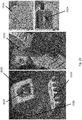
- the LIDAR unit 222L may be implemented to fire rapid pulses of laser light which come into contact with objects (such as the tree 404, chair 406 or LIDAR stakes 408) in the surrounding spatial environment circumferential to the mower 100.
- Instrumentation that is part the LIDAR unit 222L receives the reflected laser light from these objects and measures the amount of time taken for each pulse to be reflected back to the LIDAR unit 222L. As the speed of light is known, the distance between the objects and the LIDAR unit 222L can be calculated. A dynamic map of the spatial environment proximate to the mower is built as a result of rapid successive measurements of reflected laser light.
- the optical surveying module 222 scanning and surveying the surrounding environment proximate to a mower 100.
- the optical surveying module 222 exemplified by a LIDAR unit 222L as mentioned previously, is represented by the circle located at the centre of the square, which represents the mower 100.
- the arrows emanating from the circle represent the laser light 405 fired by the LIDAR unit 222L and indicate their direction of propagation.
- the LIDAR unit 222L surveys the spatial environment around the mower 100 by firing rapid pulses of laser light 405 that are incident on objects within the surveyed environment. In this example, such objects are a tree 404 and a chair 406.
- the laser light 405 is reflected from the objects and detected by the LIDAR unit 222L, and the LIDAR unit 222L may then calculate the distance between the mower 100 and the object.
- the map produced is dynamic because the position of the mower 100 relative to any object constantly changes since the mower 100 may move during its operation.
- LIDAR Stakes 408 represented by rectangles.
- a LIDAR Stake 408 may be composed of a plastic stake top and a stake cover.
- a LIDAR stake 408 may be a LIDAR object or a plurality of grouped LIDAR stakes 408.
- Each LIDAR stake 408 may pertain to fix the LIDAR object to the lawn, and meanwhile provide a visible portion for the LIDAR system to "see" the yard.
- the fixation and the visible portion may be formed integrally.
- the LIDAR Stake 408 is inserted vertically into the ground so that the plastic stake top remains above the surface of the ground.
- LIDAR Stakes Laser light 405L fired from a LIDAR unit that is incident on a LIDAR Stake will be reflected back to the LIDAR unit 222L.
- a number of LIDAR Stakes each suggests an image of a narrow object, may be planted in series to denote a boundary, several objects grouped closely together, or alternatively a single large object, e.g. fake, plastic rocks having a size of approximately 30 cm (L) x 50 cm (W) x 50 cm (H) .
- the LIDAR unit on a mower will detect a boundary formed by a series of LIDAR Stakes and the mower will be prevented from crossing the boundary.
- each of the LIDAR Stakes 408 may have a unique signature so that the LIDAR unit 222L may differentiate one LIDAR Stake 408 from another, in turn allowing the controller 202 to trigger specific operation commands, such as "no go zones” or "dedicated zones”.
- a work surface over which a mower 100 will operate may contain a swimming pool. It is undesirable for a mower 100 to come into contact with the water in a swimming pool because this may damage the electronics within the mower 100.
- a series of LIDAR Stakes 408 may be inserted periodically around the perimeter of the swimming pool to form a boundary. The LIDAR unit 222L on a mower will detect this boundary and the mower will not come into contact with the pool enclosed within the boundary.
- the optical surveying module 222 may be a single LIDAR unit 222L on the mower body 102.
- the LIDAR unit 222L is located centrally on the upwards-facing surface of the mower body 102 as this allow the LIDAR unit 222L to be positioned so that no other part of the mower body 102 can obstructs any laser light emanating from the LIDAR unit 222L.
- the LIDAR unit 222L is implemented to be driven by a motor via a gearing mechanism or belt.
- this embodiment of autonomous lawn mower 100 includes a controller 202 which may be implemented as a computing device.
- the controller can direct electric current from a power source to the LIDAR unit's motor.
- the motor When the motor is energized by its power source, in most instances by command of the controller, the motor will rotate and thus also rotating the LIDAR unit 222L. This enables circumferential coverage of the laser pulses fired from the LIDAR unit 222L.
- the aforementioned controller 202 may also be pre-programmed with an initialization routine 228 which serves to initially define the mower's work area and work surfaces.
- an initialization routine 228 which serves to initially define the mower's work area and work surfaces.
- the LIDAR unit 222L as implemented on the mower body 102 in this example embodiment may then proceed to survey the surrounding environment and in turn identifies the boundaries of a working area during an initialization process. Certain surfaces within the boundaries may also be categorized as areas to be avoided or surfaces where the blade motor should not be activated.
- the data gathered by the LIDAR unit 222L during this initialization routine may then be used to build a map that can be referred to as the virtual survey map 208 that can be used when the mower 100 operates autonomously.
- a house may have a front lawn and a back lawn connected by a concrete path.
- a LIDAR unit 222L on a mower 100 may then proceed to survey the surrounding environment and identify the cutting perimeters enclosing the front lawn and the back lawn.
- the controller can activate the blade motor on surfaces within this perimeter.
- the user may not desire the blade motor to operate along the concrete path that joins the front lawn and back lawn; hence the path taken by the mower across the concrete path is identified as a non-cutting path.
- the LIDAR unit 222L builds a dynamic map in real-time which can then be used to be compared with the stored survey map 208 for the purpose of identifying the mower's location on the survey map 208 and in turn, operating the mower as needed based on the location.
- the controller 202 may have a command to increase the height of the blade over a particular area of the mower's working area so that the grass over such area is cut longer than the grass over the rest of the working area.
- the dynamic map produced by the LIDAR unit 222L is compared to the previously generated survey map 208, so that location of the mower is known and hence the command can be executed by the controller over the correct area of the working area.
- the use of LIDAR may be a primary sensor for the navigation and localization of the autonomous mower 100.
- the LIDAR or also known as the LIDAR Unit or LIDAR module, may include a laser module mounted to a rotatable base.
- the laser module includes a laser or LED sender which sends out a light pulse or signal and a receiver that receives the rebounded pulse or signal along with other electronics for control and filtering.
- these pulses or signals captured by the receiver may then be compared to the signal sent by the laser/LED and processed to determine how far away the object that rebounded is from the system.
- the rotation of the laser module is controlled and synchronized with the action of the laser module so that a 2-dimensional map of the area surrounding the LIDAR can be obtained.
- the frequency of the laser module and rotating unit determines the measurement sensitivity of the LIDAR unit.
- the LIDAR unit will be used preliminarily in order to create a virtual map of the lawn environment as the mower is electronically walked around the lawn boundary and any fixed obstacles within said boundary during the initialization process. This virtual map may then be saved in the mower's memory or storage.
- the LIDAR system may be arranged to scan and compare what it is currently detecting against the stored virtual map in order to determine the mower's position within the known garden.
- the LIDAR could also be used for obstacle avoidance by in some examples where the mower was programmed to avoid detected obstacles that are not part of the mapped lawn.
- the navigation and localization of the autonomous mower 100 may be achieved by camera /visual sensor based navigation methods such as visual Simultaneous Localization and Mapping (vSLAM).
- vSLAM visual Simultaneous Localization and Mapping
- an autonomous lawn mower 100 comprising: a mower body 102 having at least one motor arranged to drive a cutting blade 212b and to propel the mower body 102 on an operating surface via a wheel arrangement, wherein the mower body 102 includes a navigation system 204 arranged to assist a controller 202 to control the operation of the mower body 102 within a predefined operating area; wherein the navigation system 204 includes a rotatable optical surveying module 222 arranged to scan and survey the proximate area around the mower 100 to devise the surveyed representation of the predefined operating area.
- the laser module on the laser unit 222L there are numerous requirements, e.g. optical requirements, structural requirements etc. to be fulfilled by the laser module on the laser unit 222L.
- the LIDAR unit 222L of the optical surveying module 222 may be placed at an elevated position on the mower body 102.
- Optical means of the optical surveying module 222 e.g. the LIDAR unit 222L may scan and survey the proximate area around the mower 102 to produce a clear dynamic map.
- the optical surveying module 222 i.e. the cap, may be preferably integrated into the spinning mechanism of the mower 100.
- an upper portion 222A of the optical surveying module 222 i.e. the components above line AA may be rotatable relative to the underneath lower portion 222B of the optical surveying module 222, i.e. the components below line AA.
- the lower portion 222B may remain stationary at all times.
- sonic obstacle detection module 224 arranged to be implemented with an autonomous mower 100.
- the sonic obstacle detection module 224 is implemented by the placement of Sound Navigation and Ranging (SONAR) sensors 602 on the mower 100 to use sound waves to detect if there are any obstacles proximate to the mower 100 so as to assist the mower with avoiding these obstacles.
- SONAR Sound Navigation and Ranging
- the sonic obstacle detection module 224 is implemented with a plurality of SONAR sensors 602 on the mower body 102.
- the SONAR sensors 602 fire pulses of sound waves which come into contact with objects in the surrounding spatial environment in front of the mower 100.
- Instrumentation that is part a SONAR sensor 602 receives the reflected pulse (echo) and measures the amount of time taken for each pulse to be reflected back to the SONAR sensor 602. As the speed of sound is known, the distance between the objects and the SONAR sensors can be calculated.
- the sonic obstacle detection module 202 may include four SONAR sensors 602 on the mower body 102.
- the four SONAR sensors 602 may be located on the front-facing surface of the mower body as this allows the sensors 602 to detect obstacles in the path of forward travel.
- the four SONAR sensors 602 are positioned such that no part of the mower body 102 obstructs any pulses of sound emanating from the SONAR sensors 602.
- the SONAR sensors may be located on the front-facing surface of the mower body 102 in order to detect object(s) positioned in front of the mower 100 in the direction of the mower's motion, although it is possible to also have sonar sensors 602 implemented on the side and rear of the mower body 102. Detecting object(s) that may obstruct the motion of the mower 100 would enable the controller to execute appropriate commands to avoid colliding with said object(s).
- a work surface over which a mower 100 will operate may contain an object, such as a chair at some distance away from the mower 100 which the SONAR sensors 602 detect.
- the controller 202 may in turn be arranged to receive this navigation information and, after processing this navigation information, will generate an appropriate command necessary to avoiding this obstacle.
- Such commands may include a change of the direction of motion of the mower,stopping the motion of the mower, or shutting off the cutting mechanism of the mower depending on the information received from the sensors.
- the navigation information of the sonar sensors 602 is particularly useful as obstacles may be placed in front of the mower 100 during its operation or may otherwise not be detected during the initialisation procedures. This is because an operation area of the mower 100, such as a yard, may have traffic from humans, animals or other objects which changes the number of obstacles in a work environment.
- the sonar sensors 602 are thus able to detect these obstacles and in turn allow the controller 202 to adjust the operation of the mower 100 to accommodate for these obstacles.
- the sonar sensors 602 may also be helpful as it may be implemented to have a short scope of vision and thus the sensors 602 may be mounted lower on the mower to see objects that are not tall enough to be seen by the LIDAR units.
- sonar sensors 602 may be cheaper to implement, particularly for lower portions of the mower where obstacle avoidance is advantageous.
- the mower 100 may use a plurality of SONAR modules (SONAR) about the edges of the unit to prevent bumping and/or scraping side obtrusions.
- SONAR SONAR
- a SONAR located and facing outwards from the front of the unit is used for obstacle avoidance.
- This SONAR may be arranged to be capable of identifying obstacles in front of the unit and notifies the mower.
- the mower may then check the location of the obstruction against the known lawn map (or virtual map) created and saved from the mower's LIDAR system and uses the information of the obstacle in front of it in conjunction with the information of the known lawn map to navigate around/away from the object.
- This example is advantageous in that such an arrangement as described is not standard for many existing autonomous mowers as most current mowers use the bumping sensors to detect objects and change direction.
- the mower 100 may also have an additional set of SONAR on the right side of the unit which is the same side as the perimeter cutter.
- mowers 100 may have an edge mowing function in which the mower traces around the edge of the mapped boundary and uses a secondary cutting mechanism to trim the grass closer to the edge than the primary cutting means is able.
- the side SONAR may in turn be used to measure the distance from the edge of the mower to objects, such as fences, along the boundary in order to allow the mower to navigate close to the object, but avoid bumping and thus scratching the mower's top cover to keep a nicer appearance.
- an autonomous lawn mower 100 comprising: a mower body 102 having at least one motor arranged to drive a cutting blade 212b and to propel the mower body 102 on an operating surface via a wheel arrangement, wherein the mower body 102 includes a navigation system 204 arranged to assist a controller 202 to control the operation of the mower body 102 within a predefined operating area; wherein the navigation system 204 further includes a sonic obstacle detection module 224 arranged to use sound waves to detect any obstacles proximate to the mower 100, the sonic obstacle detection module 224 is disposed at an elevated position on the mower body 102 for detecting the obstacles adjacent to the mower body 102.
- the sonic obstacle detection module 224 may be implemented with a plurality of SONAR sensors 602 at an elevated position e.g. on the top of the mower body 102 as depicted in Figures 6A and 6B , or alternatively positioned on the rear of the mower body 102 or on the side (e.g. left or right) of the upper mower body 102.
- the vision of the pair of SONAR sensors 602 positioned on the top of the mower body 102 is represented by the two light beams BB and CC, which are emitted from the pair of SONAR sensors 602 positioned on the top left and right of the mower body 102 respectively.
- the position of the SONAR sensors 602 at the upper portion of the mower body 102 allows the detection of obstacles from a wider viewing angle. Any "false positives" that would otherwise be detected should the SONAR sensors 602 be positioned at the lower portion of the mower body 102 may be avoided.
- IMU inertial measurement unit
- the IMU module 226 is implemented by the placement of a removable IMU unit within the body of the mower 100 which is arranged to measure the force of movement of the mower by detecting and recording various forces which are subjected to the mower 100.
- the IMU module 226 is a removable IMU unit within the body 102 of the mower 100.
- the IMU 226 detects and records various forces which are subjected on the mower 100, including the direction of movement, force of movement, magnetic bearing of movement, acceleration and gyroscopic movements.
- the IMU 226 functions by using at least one accelerometer to detect the rate of acceleration or deceleration of the mower, at least one gyroscope to detect the gyroscopic movements of the mower and a magnetometer to detect the magnetic bearing of movement of the mower.
- the IMU may also further comprise an IMU chip and power supply, such as a battery such that it can continue to be energized when it is removed from the mower 100.
- the IMU module 226 is connected to the controller 202.
- the controller 202 may be implemented as a computing device which is arranged to receive the navigation information detected by the IMU module 226. Following processing by a processor, suitable commands to operate the mower 10 can be developed based on the navigation information supplied by the IMU module 226.
- the IMU module 226 is implemented within the body of the mower 100 as an electronic component.
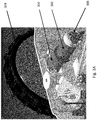
- the IMU module 226 is represented by a rectangle and a possible position of the IMU is indicated by an arrow, being placed below a removable or latched on logo plate which acts as a door to access the IMU 226.
- the IMU 226 is placed below an openable cover 702 marked by the mower's manufacturer's logo on the upward-facing surface of the mower. The openable cover would allow access to the IMU 226, whilst protecting the IMU 226 from debris and moisture. Once the cover is opened, a user can then remove the IMU 226 by lifting it out.
- the advantage of a mower 100 in having a removable IMU 226 is that the calibration of the IMU 226 would be much simpler.
- the IMU 226 may detect at least the acceleration and gyroscopic movements of a unit, it may be required to undergo calibration after shipping such that it can be calibrated for its full range of movement.
- the user can calibrate the IMU 226 for the mower by moving it in all three dimensions, such as by shaking or moving the IMU in their hand without having to shake or move the entire autonomous mower 100.
- the IMU may only be connected to the mower via a cable, and thus allowing a user to shake or move the IMU, although in some examples, where the IMU is entirely removable from the mower, the IMU may have its own power supply to remain functional when it is removed entirely from the mower body and thus it may have its own battery or capacitor to store sufficient power for the calibration process.
- a user may be required to calibrate the IMU 226.
- a user would remove the IMU 226 from the mower body 102 and move the IMU 226 in a "figure of 8" pattern in order to give the accelerometer and gyroscope components of the IMU a varied range of accelerations and gyroscopic motions to detect and record.
- Being able to remove the IMU for this purpose is advantageous as the IMU 226 is easier to handle and manipulate when compared with having to perform the same actions with an entire mower 100, which would be more heavy, cumbersome and potentially dangerous.
- the initialisation process or routine 228, is a set of procedures which may be performed by a user so as to initialise the mower 100 for self-operation in a work area.
- the user may proceed to teach the mower 100 the boundaries for operation. In so doing, the mower 100 can then be taught by the user as to the location and definition of the working area as well as any travel paths which are required to get to the different portions of the working area.
- the user can firstly manual operate the mower 100 along the perimeters of one or more operation areas so as to teach the mower the operation areas which are needed to be mowed by the mower.
- the mower can be operated in this mode by having a handheld controller 804 to be operated by a user 802.
- the handheld controller 804 may include a number of switches and a joystick similar to that of a gaming controller which allows a user 802 to drive the mower 100 along the perimeters of the operating surface. This may sometimes be referred to as the "dog walking mode" 800, representative of a user in "walking" the mower along a path.
- the mower 100 When the user 802 drives the mower 100 along these perimeters, the mower 100, which would be in an initialization mode (or called the dog walking mode), may then operate its navigation system so as to continuously create navigation information associated with its proximate environment. This may include, for example:
- the mower 100 may then store this navigation information for use in autonomous operation.
- This stored navigation information which may be in the form of a virtual map, may then be processed by the mower 100 with new navigation information that is obtained in real time by the navigation system during mower operation to devise the location of the mower 100 when in operation.
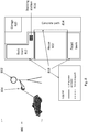
- the user may start the initialization process by firstly "dog walking" 800 the mower 100 around its operating areas so as to define the operating areas in which the mower 100 will operate.
- a user's home may include a front lawn 810 and a back lawn 812 with a concrete path 814 in between the front lawn and back lawn.
- the user may start the dog walking process 800 by firstly controlling the mower 100 from the mower docking station 816, which is the base for which the mower 100 may operate from.
- This docking station 816 may provide a base for the mower and can provide several functions, including diagnostic, connectivity to external devices and recharging capabilities.
- the user can drive the mower 100 from the docking station 816 to a perimeter 818 of the work area and select on the handheld controller 804 to start recording the perimeter 818.
- the user can then drive the mower around the perimeter 818 of their back lawn 812, as an example and in turn, allow the back lawn 812 to be marked by the mower 100 as a first work area.
- the mower 100 is continuously operating its navigation system so as to survey the first work area, including the distance of travel of the perimeter 818, the direction of travel and any obstacles which can be used as a reference to assist with its navigation such as the docking station 816, garage 820 and house 822.
- the user may then drive the mower onto the concrete path 814 so as to move the mower 100 towards the front lawn 810 to set a second work area for the mower 100.
- the user can then drive the mower along the concrete path 816 towards the front lawn 810 and simultaneously, set the mower to travel mode whilst the mower is on the concrete path 814.
- This travel mode would set that this path travelled by the mower is for the transportation of the mower towards a second work area and thus the blades of the mower 100 do not need to be powered (as there is no grass to be cut in during its movement on the concrete path).
- the mower 100 is continuously activating its navigation system so as to survey the areas around the path to its second operating area (front lawn 810).
- the user can drive the mower along the perimeter 818 of the front lawn so as to set the working area of the front lawn 810.
- the mower is once again surveying its surrounding areas with its navigation system.
- the user may then drive the mower 100 back to its docking station 816 which will in turn record a return path for the mower 100.
- the navigation system of the mower can survey its surrounding areas, it may be able to find its path back to the docking station 816 since its travel paths have previously been recorded when the user had driven the mower from the docking station 816 to the front lawn 810.
- FIG. 9 there is provided a block diagram illustrating the process flow of the initialization process of the autonomous mower 100.
- the user may start to issue commands to the mower to drive the mower. These commands are received (902) and processed (904) by the controller 202 so as to drive the mower 100 along a surface.
- the navigation system is operated (906) so as continuously survey and records any navigation information for the mower during its initialization process.
- the navigation system may then active each of its navigation modules 910 (IMU, Odometry, SONAR, LIDAR and other sensors) to record such navigation information (908) which can be used for navigation purposes when the mower is put into autonomous operation.
- an autonomous lawn mower 100 comprising: a mower body 102 having at least one motor arranged to drive a cutting blade 212b and to propel the mower body 102 on an operating surface via a wheel arrangement, wherein the mower body 102 includes a navigation system 204 arranged to assist a controller 202 to control the operation of the mower body 102 within a predefined operating area; and a battery module 1000 arranged to provide power supply to the motor; wherein the battery module 1000 is placed at a lower position within the rear mower body 102.
- the autonomous lawn mower 100 is provided a battery module 1000 within the rear mower body 102 at a lower position adjacent to and between the two rear wheels.
- the battery module 1000 is received by a battery holder 1010 resting on the mower body 102 and positioned at a titled angle with respect to the operating surface. For instance, one end of the battery module 1000 is projected downwards and towards the rear end of the mower body 102, such that the user may access the battery module 1000 through an opening of the lower rear mower body 102.
- the mower body is further provided a battery cover 1020 to enclose the opening of the mower body 102, thereby preventing any dust or mowed grass from reaching the interior of the mower body 102.
- the battery cover 1020 may be secured to the mower body 102 firmly by coupling means 1030 such as screws.
- an autonomous lawn mower 100 comprising: a mower body 102 having at least one motor arranged to drive a cutting blade 212b and to propel the mower body 102 on an operating surface via a wheel arrangement, wherein the mower body 102 includes a navigation system 204 arranged to assist a controller 202 to control the operation of the mower body 102 within a predefined operating area; wherein the mower body 102 further includes a height adjustment system 1100 arranged to assist the controller 202 to control the operation of the cutting blade 212b within a predefined operating height.
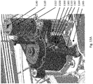
- the autonomous lawn mower 100 includes a height adjustment system 1100 comprising a height adjustment motor 1110, a worm shaft 1120 driven by the height adjustment motor 1110, a micro switch 1130, and a hall sensor 1140.
- the motor 1110 may manipulate the rotating direction of the worm shaft 1120 in clockwise or anticlockwise directions, such that the height of the cutting blade 212b with respect to the operating surface may be manipulated by the motor 1110 indirectly.
- the motor 1110 may be secured to the mower body 102 and remains stationary throughout the height adjusting operations. For instance, the cutting blade 212b may be moved towards the operating surface when the worm shaft 1120 rotates in a clockwise direction, and on the other hand, moved further away from the operating surface when the worm shaft 1120 rotates in an anti-clockwise direction.
- the mechanical transmission between the motor 1110 and the cutting blade 212b through the worm shaft 1120 may be enhanced by the use of a ring shaped structure 1150.
- the ring shaped structure 1150 preferably comprises a plurality of bushings 1152, e.g. made of Polyoxymethylene (POM), a plurality of linear bearings 1156, or alternatively a combination thereof for supporting the height adjustment system 1100.
- the linear bearing 1156 may counter the torsional force induced by the distance between the worm shaft 1120 and the opposite support.
- the plurality of bushings 1152 may be disposed about the blade motor 212.
- a plurality of through holes 1154 may be disposed preferably equidistantly for receiving these bushings 1152, and at least one linear bearing 1156 may be disposed about the lower end of the bushing 1152 opposed to the worm shaft 1120.
- the ring shaped structure 1150 may reinforce the worm shaft 1120, such that the rotational force of the motor 1110 is converted into lateral forces steadily without out any vibrations or at least with minimal vibrations.
- the linear bearing 1156 may advantageously reduce the friction between the shaft 1120 and the ring shaped structure 1150 due to the bending moment. Accordingly, the rotational force of the motor 1110 is converted into lateral forces steadily without transmitting the bending moment to the height adjustment system 1100.
- the micro switch 1130 is disposed on the blade motor 212, with a thin and elongated portion 1132 further extended away from the blade motor 212 and towards the inner mower body 102.
- the hall sensor 1140 is disposed on top of the motor 1110 for detecting the presence of the elongated portion 1132 of the micro switch 1130, thereby determining if the cutting blade 212b has reached the maximum height with respect to the operating surface.
- the hall sensor 1140 may further derive the number of rotations required by the motor 1110 to reach the predefined desirable operating height, and in turn assist the controller 202 to control the operation of the cutting blade 212b.
- the combination of micro switch 1130 and hall sensor 1140 may be substituted by sensors e.g. photoelectric sensors.
- the photoelectric sensor may provide a signal to the height adjustment system 1100, indicating the height position of the cutting blade 212b, upon detecting the presence of the elongated portion 1132, or alternatively in the absence of the elongated portion 1132.
- the sensing function may be achieved by other alternative sensing means.
- an autonomous lawn mower 100 comprising: a mower body 102 having at least one motor arranged to drive a cutting blade 212b and to propel the mower body 102 on an operating surface via a wheel arrangement, wherein the mower body 102 includes a navigation system 204 arranged to assist a controller 202 to control the operation of the mower body 102 within a predefined operating area; wherein the mower body 102 further includes a height adjustment system 1100 arranged to assist the controller 202 to restrict the operation of the cutting blade 212b within a predefined operating height.
- the mower 100 may include an automatic height adjustment function for monitoring the height of the cutting blade 212b throughout the operation.
- the primary means of monitoring the position/motion of the cutting blade 212b may be a hall sensor 1140 positioned on top of the motor 1110 for counting the number of rotations of the motor 1110. Based on the direction and number of rotations of the motor 1110 in conjunction with the gearbox ratio of the gearbox 1112 and the thread pitch of the worm shaft 1120, the vertical displacement of the switch 1160 and the cut height carrier 1161 may be determined.
- the current of the motor 1110 may also be used to determine whether the carrier 1161 reaches the top or bottom of its travel distance. For instance, the current may increase when the carrier 1161 can no longer be driven by the motor 1110.
- the height adjustment system 1100 may further include one or more sensors 1150 for detecting the presence of the carrier 1161 and thus the cutting blade 212b at the predetermined vertical position. Upon the carrier 1161 reached the predetermined vertical position and detected by the sensors 1160, the height adjustment system 1100 may communicate with the controller 202 for terminating the rotation of the cutting blade 212b.
- a switch 1160 with a rollerball 1162 on the lever arm 1163 being attached to the carrier 1161.
- the rollerball 1162 and cantilever lever 1163 are free to remain in their standard position between the minimum and maximum cut heights.
- the rollerball 1162 makes contact with a profile 1164 attached to the mower chassis 165 that engages the switch 1160 and in turn alerts the mower 100 to stop the motion of the carrier 1161.
- the switch 1160 may be mounted to the mower chassis 1165 while the profile 1164 may be provided on the carrier 1161.
- an autonomous lawn mower 100 comprising: a mower body 102 having at least one motor arranged to drive a cutting blade 212b and to propel the mower body 102 on an operating surface via a wheel arrangement, wherein the mower body 102 includes a navigation system 204 arranged to assist a controller 202 to control the operation of the mower body 102 within a predefined operating area; wherein the cutting blade 212b is pivotally connected to and driven by a motor-driven disc 211.
- the autonomous lawn mower 100 further includes a motor-driven disc 211, a plurality of cutting blades 212b e.g. razor blades attached to the outer circumference of the motor-driven disc 211 through a specific arrangement.
- the cutting blades 212b are mounted to the motor-driven disc 211 with a spacer 213 therebetween, such that the cutting blades 212b are not fixed and allowed for certain degree of free rotations.
- the cutting blade 212b may swing in a first direction corresponds to the rotating direction of the motor/ motor-driven disc 211 by the motor-driven disc 211 i.e. swing outward for cutting operation, and alternatively, swing in a second direction opposite to the first direction or the rotating direction of the motor/ motor-driven disc 211 i.e. swing inward and away from the obstacles if the cutting blade 212b contacts any obstacles.
- this arrangement acts as a resilient means for damping the impact force exerted on the cutting blade 212b by the obstacle, such that the cutting blade 212b may swing inward without absorbing the force by the engaging mechanism i.e. the spacer 213 between the cutting blades 212b and the motor-driven disc 211.
- the cutting blade 212b may swing towards the object to be trimmed through the centrifugal force of the motor-driven disc 211. This ensures that the desired orientation of the cutting blades 212b is maintained throughout the trimming operation, such that the sharp edge on the cutting blades 212b is always facing/normal to the object to be trimmed.
- the present embodiment provides an enhanced trimming experience, for example, prolonged lifespan, less maintenance or repairing over conventional lawn mowers.
- an autonomous lawn mower 100 comprising: a mower body 102 having at least one motor arranged to drive a cutting blade 212b and to propel the mower body 102 on an operating surface via a wheel arrangement, wherein the mower body 102 includes a navigation system 204 arranged to assist a controller 202 to control the operation of the mower body 102 within a predefined operating area; wherein the mower body 102 further includes a cutter module 1500 arranged to trim the edges of the predefined operating area.
- the autonomous lawn mower 100 includes a cutter module 1500 comprising a perimeter cutter 1510 for trimming the edges of a predefined operating area, and a locking mechanism 1520 for engaging the cutter module 1500 with the mower body 102.
- the locking mechanism 1520 may provide a male mating portion 1522 on the cutter module 1500 for engaging with a female mating portion 1524 provided on the mower body 102 positioned e.g. underneath the mower body 102 and adjacent to the operating circumference of the cutting blade 212b, such that the mower body 102 and the cutter module 1500 are electrically communicated.
- the locking mechanism 1520 may further provide a push button 1526 to disengage the male mating portion 1522 from the female mating portion 1524, thereby removing the cutter module 1500 from the mower body 102 instantly.
- a cover 1530 for enclosing the female mating portion 1524 when the lawn mower 100 is operated without the cutter module 1500.
- an autonomous lawn mower 100 comprising: a mower body 102 having at least one motor arranged to drive a cutting blade 212b and to propel the mower body 102 on an operating surface via a wheel arrangement, wherein the mower body 102 includes a navigation system 204 arranged to assist a controller 202 to control the operation of the mower body 102 within a predefined operating area; wherein at least part of the cutting blade 212b is surrounded by a blade guard 1600.
- the autonomous lawn mower 100 includes a blade guard 1600 for surrounding the cutting blade 212b.
- a toothed comb 1610 between the two front wheels for combing the grass to be mowed before being trimmed by the cutting blade 212b.
- the toothed comb 1610 may minimise the undesirable interruption of the mowing operation by over-sized objects, thereby enhancing the efficiency of the cutting operation to a certain degree.
- a plurality of protection ribs 1620 may also be provided on the side edges of the blade guard 1600 to prevent any undesirable objects from reaching the cutting blade 212b from the side directions.
- an autonomous lawn mower 100 comprising: a mower body 102 having at least one motor arranged to drive a cutting blade 212b and to propel the mower body 102 on an operating surface via a wheel arrangement, wherein the mower body 102 includes a navigation system 204 arranged to assist a controller 202 to control the operation of the mower body 102 within a predefined operating area; a battery module 1000 arranged to provide power supply to the motor; and a detachable docking module 900 arranged to provide battery charging to the battery module 1000.
- the autonomous lawn mower 100 includes a battery module 1000 for providing power supply to the motor, a detachable docking module 900 in electrical communication with a power plug for charging the battery module 1000, and a navigation system 204 for locating the mower 100 with reference to the position of the docking module 900.
- the navigation system 204 may direct or guide the mower 100 towards the docking module 900 through a "docking" process, such that the mower 100 may be switched off and/or the battery module 1000 may be recharged once the mower 100 is received by the docking module 900.
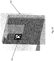
- the navigation system 204 may include an imaging module 205, e.g. a web camera 205 for obtaining the information associated with the position of the docking module 900.
- the docking module 900 may provide the imaging module 205 an indication 910 representing the position of the docking module 900.
- the indication 910 may be represented in a graphical representation at a visible area on the docking module 900 (as shown in Figure 19 ), thereby allowing the imaging module 205 to capture the indication 910, and in turn calculate the present position of the mower 100 with respect to the docking module 900 through an image processing based on the rotation and distortion of the captured indication 910.
- each indication 910 may provide a unique ID, such that one mower 100 may only map with one designated docking module 900.
- the navigation system 204 may include an optical surveying module 222 for obtaining the information associated with the position of the docking module 900.
- the optical surveying module 222 may be the aforesaid single LIDAR unit 222L.
- the LIDAR unit 222L may scan and survey the proximate area around the mower 100 to devise the surveyed representation of the predefined operation area.
- the optical surveying module 222 may then map the target LIDAR object with the sensed LIDAR object with the closest dimension to the docking module 900, thereby locating the position of the docking module 900, or determining the present position of the mower 100 with reference to the position of the docking module 900.
- the navigation system 204 may include an induction wire system 240 for obtaining the information associated with the position of the detachable docking module 900.
- the induction wire system 240 may include a plurality of sensors 242, 244 and 246 positioned at any desirable positions within the mower 100.
- the docking module 900 may provide a core 248 (not shown) for communicating with the sensors 242, 244 and 246 in an electromagnetic communication.
- the induction wire system 240 may calculate the present position of the mower 100 with respect to the docking module 900 based on the electromagnetic communication between the sensors 242, 244, 246 and the core 248 in a repetitive manner, thereby providing a docking assistance to the mower 100 during the docking process.
- an autonomous lawn mower 100 comprising: a mower body 102 having at least one motor arranged to drive a cutting blade 212b and to propel the mower body 102 on an operating surface via a wheel arrangement, wherein the mower body 102 includes a navigation system 204 arranged to assist a controller 202 to control the operation of the mower body 102 within a predefined operating area; a detachable docking module 900 arranged to receive the mower body 102; wherein the mower body 102 further includes a sensor 920 arranged to assist the controller 202 to terminate the movement of the mower body 102 upon the mower body 102 is received by the detachable docking module 900.
- the mower body 102 may stop upon being received by the docking station 900 when the charging circuit is completed i.e. the docking station terminals made contact with the mower charging terminals.
- the docking station 900 lost power or lacks a power supply e.g. the power plug of the docking station 900 is unplugged from the socket, the mower 100 would keep trying to push on and the motor may burn out.
- the detachable docking module 900 may include a magnetic member 930 while the mower body 102 may include a sensor 920 for sensing the magnetic field of the magnetic member 930 upon the mower body 102 is reaching the docking module 900.
- the mower body 102 may include an opening 922 on the front body within which the sensor 920 may be received and positioned.
- the magnetic member 930 may be inserted into the opening 922 upon the mower body 102 is received by the detachable docking module 900.
- a hall sensor PCBA 920 on the mower 100 side and a magnet 930 to the docking station 900 side so that the mower 100 may always sense when it is arriving on the charging terminals.
- the mower body 102 may stop moving further and push against the docking module 900 even if an incomplete charging circuit is determined.
- an autonomous lawn mower 100 comprising: a mower body 102 having at least one motor arranged to drive a cutting blade 212b and to propel the mower body 102 on an operating surface via a wheel arrangement, wherein the mower body 102 includes a navigation system 204 arranged to assist a controller 202 to control the operation of the mower body 102 within a predefined operating area; wherein the mower body 102 further includes a heat absorbing unit 1700 on the outer surface of the mower body 102 for directing the heat generated within the mower body 102 towards the atmosphere.
- the inside of the mower 100 needs to be protected from moisture and other weather phenomenon as there are numerous expensive, vulnerable electronic components.
- the main PCBA 202 may generate a lot of heat.
- a unique heatsink design has been employed in the present invention.
- the heat absorbing unit 1700 e.g. the heat sink may be shaped to pull heat from the hottest components to the outside air while the weather-tight of the inner mower body 102 is not traded off for the heat conduction.
- the heat absorbing unit 1700 may be further provided sealing means for protecting the mower body 102 against moisture of the atmosphere.
- a heat sink 1700 may be mounted to the housing and exposed to the outside.
- a silicone seal may be used between the heat sink 1700 and housing to make it weather-tight.
- the controller 202 may be attached directly to the heating absorbing unit 1700.
- a heat conducting layer 1710 may also be presented between the controller 202 and the heating absorbing unit 1700.
- the main PCBA 202 may be attached to the heat sink 1700 directly and additionally, a thermal paste 1710 may be applied therebetween to ensure conductivity of the heat from the motor body 102 to the outside air.
- an autonomous lawn mower 100 comprising: a mower body 102 having at least one motor arranged to drive a cutting blade 212b and to propel the mower body 102 on an operating surface via a wheel arrangement, wherein the mower body 102 includes a navigation system 204 arranged to assist a controller 202 to control the operation of the mower body 102 within a predefined operating area; a detachable docking module 900 arranged to provide battery charging to the mower body 102; wherein the detachable docking module 900 further includes a rotatable member 940 arranged to contact the mower body 102 with a predefined vertical offset relative to the detachable docking module 900 for battery charging.
- the opening 922 of the motor body 102 may be shifted upwards relative to the docking station 900.
- the wheels 104 wear down over time, the height of the charging area on the mower 100 may be lowered relative to the docking station 900.
- a rotatable charging member 940 may compensate such vertical offset between the docking station 900 and the mower body 102.
- a rotatable, spring loaded charging terminals 940 there may be provided a rotatable, spring loaded charging terminals 940.
- the rotatable member 940 may extend laterally from the detachable docking module 900 and pivotable about a horizontal axis that is parallel to the operating surface.
- the mower body 102 may include an opening 922 for receiving the rotatable member 940.
- the charging terminals 940 may be pivotable about an axis perpendicular to the charging terminals 940 such that the terminal 940 may rotate only in the vertical direction within a desirable range of rotation angles, rather than rotate in the horizontal direction.
- the docking module 900 may provide a pair of resilient means 942 for acting against the opposite sides of the rotatable member 940.
- a pair of springs 942 may be used to ensure that the terminals 940 rest at the nominal designed position and do not sag due to gravity.
- the rotatable member 940 may further provide a flexible, protective gasket 944 e.g. made of rubber for reducing the impact between the rotatable member 940 and the mower body 102 during the docking process.
- a flexible, protective gasket 944 e.g. made of rubber for reducing the impact between the rotatable member 940 and the mower body 102 during the docking process.
- an autonomous lawn mower 100 comprising: a mower body 102 having at least one motor arranged to drive a cutting blade 212b and to propel the mower body 102 on an operating surface via a wheel arrangement, wherein the mower body 102 includes a navigation system 204 arranged to assist a controller 202 to control the operation of the mower body 102 within a predefined operating area; wherein the mower body 102 further includes a hinge system 1800 to move a cover 1810 between first and second positions for covering and exposing an user interface area 1820 without hindering an exposed portion of the navigation system 204 positioned on the mower body 102.
- a remote controller for controlling the movement of the mower body manually by the user.
- the remote control must be plugged into the user interface area 1820 and interact with the user interface display and knobs. The user may then manipulate the movement of the mower body 102 through the matched remote control.
- the access door 1810 In order to allow this function, the access door 1810 must be opened such that the exposed user interface area 1820 may receive a remote control therein. However, the door 1820 must not hinder the function of the LIDAR unit 222L. To fulfill these requirements, there may be provided a hinge system 1800 for opening the user interface door 1810 over the STOP button 1830 when it is released. Preferably, the folded and unfolded positions of the cover 1810 would not obstruct the vision of the LIDAR unit 222L and affect the function of the optical surveying module 222.
- an autonomous lawn mower 100 comprising: a mower body 102 having at least one motor arranged to drive a cutting blade 212b and to propel the mower body 102 on an operating surface via a wheel arrangement, wherein the mower body 102 includes a navigation system 204 arranged to assist a controller 202 to control the operation of the mower body 102 within a predefined operating area; wherein the navigation system 204 includes an optical surveying module 222 arranged to scan and survey the proximate area around the mower 100 to devise the surveyed representation of the predefined operating area; wherein the mower body 102 further includes a guiding member 950 extending laterally therefrom for indicating the minimum clearance distance of the optical surveying module 222 from a predefined perimeter or obstacle 2000.
- the mower 100 may use a virtual boundary created by the user during the preliminary mapping of the garden.
- the accuracy of the mower 100 has a plus/minus tolerance based on the precision of the navigation sensors e.g. optical surveying module 110.
- the embodiments described with reference to the Figures can be implemented as an application programming interface (API) or as a series of libraries for use by a developer or can be included within another software application, such as a terminal or personal computer operating system or a portable computing device operating system.
- API application programming interface
- program modules include routines, programs, objects, components and data files assisting in the performance of particular functions, the skilled person will understand that the functionality of the software application may be distributed across a number of routines, objects or components to achieve the same functionality desired herein.
- any appropriate computing system architecture may be utilised. This will include stand alone computers, network computers and dedicated hardware devices. Where the terms “computing system” and “computing device” are used, these terms are intended to cover any appropriate arrangement of computer hardware capable of implementing the function described.
Landscapes
- Engineering & Computer Science (AREA)
- Remote Sensing (AREA)
- Radar, Positioning & Navigation (AREA)
- Physics & Mathematics (AREA)
- Life Sciences & Earth Sciences (AREA)
- Aviation & Aerospace Engineering (AREA)
- Automation & Control Theory (AREA)
- General Physics & Mathematics (AREA)
- Environmental Sciences (AREA)
- Mechanical Engineering (AREA)
- Transportation (AREA)
- Power Engineering (AREA)
- Electromagnetism (AREA)
- Sustainable Energy (AREA)
- Sustainable Development (AREA)
- Harvester Elements (AREA)
- Acoustics & Sound (AREA)
- Computer Vision & Pattern Recognition (AREA)
- Multimedia (AREA)
- Guiding Agricultural Machines (AREA)
- Control Of Position, Course, Altitude, Or Attitude Of Moving Bodies (AREA)
Claims (15)
- Autonomer Rasenmäher (100), umfassend:einen Mäherkörper (102) mitmindestens einem Motor, der so angeordnet ist, dass er ein Schneidmesser (212b) antreibt und den Mäherkörper (102) über eine Radanordnung (104) auf einer Bearbeitungsoberfläche vorwärtstreibt;einer Steuerung (202);einem Navigationssystem (204), das so angeordnet ist, um die Steuerung (202) dabei zu unterstützen, den Betrieb des Mäherkörpers (102) innerhalb eines vordefinierten Bearbeitungsbereichs zu steuern; undein Höheneinstellsystem (1100);dadurch gekennzeichnet, dass das Höheneinstellsystem (1100) so angeordnet ist, um die Steuerung (202) dabei zu unterstützen, den Betrieb des Schneidmessers (212b) innerhalb einer vordefinierten Bearbeitungshöhe zu begrenzen;wobei das Höheneinstellsystem (1100) umfasst:einen Höheneinstellmotor (1110);eine Schneckenwelle (1120), die so angeordnet ist, um von dem Höheneinstellmotor (1110) angetrieben zu sein;einen Träger (1161), der mit dem Schneidmesser (212b) verbunden und so angeordnet ist, um durch den Motor (1100) angetrieben zu sein, um sich zwischen einer oberen Position und einer unteren Position zu bewegen; undeinen oder mehrere Sensoren, die so angeordnet sind, um das Vorhandensein des Schneidmessers (212b) in einer vorbestimmten vertikalen Position zu erfassen.
- Autonomer Rasenmäher (100) nach Anspruch 1, wobei das Höheneinstellsystem (1100) so angeordnet ist, um mit der Steuerung (202) zu kommunizieren, um die Drehung des Schneidmessers (212b) zu beenden, wenn das Schneidmesser (212b) eine vorbestimmte vertikale Position erreicht.
- Autonomer Rasenmäher (100) nach Anspruch 1 oder2, wobei dereine oder die mehreren Sensoren einen Hallsensor (1140) umfassen, der oben auf dem Höheneinstellmotor (1110) positioniert ist, um die Anzahl der Umdrehungen des Höheneinstellmotors (1110) zu zählen, um die vertikale Verschiebung des Trägers (1161) basierend auf der Richtung und der Anzahl der Umdrehungen des Höheneinstellmotors (1110) in Verbindung mit einem Übersetzungsverhältnis eines Getriebes (1112), das dem Höheneinstellmotor (1110) zugeordnet ist, und einer Gewindesteigung der Schneckenwelle (1120), zu bestimmen.
- Autonomer Rasenmäher (100) nach Anspruch 1 oder2, wobei dereine oder die mehreren Sensoren (1160) ferner so angeordnet sind, um eine Stromstärke des Höheneinstellmotors (1110) zu verwenden, um zu bestimmen, ob der Träger (1161) die obere Position und die untere Position erreicht hat.
- Autonomer Rasenmäher (100) nach Anspruch 1 oder 2, wobei der Mäherkörper (102) ferner ein Mäherchassis (1165) und ein an dem Mäherchassis (1165) angebrachtes Profil (1164) umfasst;
wobei der eine oder die mehreren Sensoren (1160) einen Schalter (1160) mit einer Kugelrolle (1162) umfasst, der an einem am Träger (1161) angebrachten Hebelarm (1163) angeordnet ist; und
wobei die Kugelrolle (1162) mit dem Profil (1164) in Kontakt kommt, wenn sich der Träger (1161) in der oberen Position oder in der unteren Position befindet, was den Schalter betätigt und wiederum den autonomen Rasenmäher (100) alarmiert, die Bewegung des Trägers (1161) zu stoppen. - Autonomer Rasenmäher (100) nach Anspruch 1 oder 2, wobei der Mäherkörper (102) ferner ein Mäherchassis (1165) und ein an dem Träger (1161) angebrachtes Profil (1164) umfasst;
wobei der eine oder die mehreren Sensoren einen Schalter (1160) mit einer Kugelrolle (1162) umfasst, der an einem am Mäherchassis (1165) angebrachten Hebelarm (1163) angeordnet ist; und
wobei die Kugelrolle (1162) mit dem Profil (1164) in Kontakt kommt, wenn sich der Träger (1161) in der oberen Position oder in der unteren Position befindet, was den Schalter (1160) betätigt und wiederum den autonomen Rasenmäher (100) alarmiert, die Bewegung des Trägers (1161) zu stoppen. - Autonomer Rasenmäher (100) nach einem der Ansprüche 1 bis 6, ferner umfassend ein abnehmbares Kopplungsmodul (900), das zur Aufnahme des Mäherkörpers (102) eingerichtet ist; und
wobei der Mäherkörper (102) ferner einen Sensor enthält, der so eingerichtet ist, die Steuerung (202) zu unterstützen, die Bewegung des Mäherkörpers (102) zu beenden, wenn der Mäherkörper (102) von dem abnehmbaren Kopplungsmodul (900) aufgenommen wird. - Autonomer Rasenmäher (100) nach Anspruch 7, wobei das abnehmbare Kopplungsmodul (900) ein magnetisches Element (930) umfasst, das eingerichtet ist, um mit dem Sensor zu kommunizieren, und wobei der Mäherkörper (102) optional eine Öffnung umfasst, in der der Sensor positioniert ist, und wobei das magnetische Element (930) optional in die Öffnung eingeführt wird, wenn der Mäherkörper (102) von dem abnehmbaren Kopplungsmodul (900) aufgenommen wird.
- Autonomer Rasenmäher (100) nach einem der Ansprüche 1 bis 8,
wobei der Mäherkörper ferner eine wärmeabsorbierende Einheit (1700) an der Außenfläche des Mäherkörpers (102) aufweist, um die im Mäherkörper (102) erzeugte Wärme an die Atmosphäre zu leiten. - Autonomer Rasenmäher (100) nach Anspruch 9, wobei die wärmeabsorbierende Einheit (1700) ferner mit Dichtungsmitteln zum Schutz des Mäherkörpers (102) gegen Feuchtigkeit aus der Atmosphäre versehen ist; und/oder
wobei die Steuerung (202) an der wärmeabsorbierenden Einheit (1700) angebracht ist,
und, optional, weiter eine wärmeleitende Schicht (1710) umfasst, die zwischen der Steuerung (202) und der wärmeabsorbierenden Einheit (1700) angeordnet ist,
und/oder wobei die wärmeabsorbierende Einheit (1700) eine Wärmesenke ist. - Autonomer Rasenmäher (100) nach einem der Ansprüche 1 bis 10, ferner umfassend ein abnehmbares Kopplungsmodul (900), das eingerichtet ist, um eine Batterieaufladung für den Mäherkörper (102) zur Verfügung zu stellen;
wobei das abnehmbare Kopplungsmodul (900) ferner ein drehbares Element (940) umfasst, das eingerichtet ist, um zur Batterieaufladung mit einem vordefinierten vertikalen Versatz relativ zu dem abnehmbaren Kopplungsmodul (900) mit dem Mäherkörper (102) in Kontakt zu stehen. - Autonomer Rasenmäher (100) nach Anspruch 11,
wobei sich das drehbare Element (940) seitlich von dem abnehmbaren Kopplungsmodul (900) erstreckt,
und/oder, wobei das drehbare Element (940) um eine horizontale Achse schwenkbar ist, die parallel zu der Bearbeitungsoberfläche verläuft,
und/oder, wobei der Mäherkörper (102) eine Öffnung (922) zur Aufnahme des drehbaren Elements (940) aufweist,
und/oder, wobei das abnehmbare Kopplungsmodul (900) mit einem Paar von elastischen Mitteln (942) versehen ist, die auf die gegenüberliegenden Seiten des drehbaren Elements (940) wirken, um die Ausrichtung des drehbaren Elements (940) beizubehalten
und/oder, wobei das drehbare Element (940) mit einer Schutzdichtung (944) versehen ist, um den Aufprall zwischen dem drehbaren Element (940) und dem Mäherkörper (102) zu verringern. - Autonomer Rasenmäher (100) nach einem der Ansprüche 1 bis 12, wobei der Mäherkörper (102) ferner ein Scharniersystem (1800) aufweist, um eine Abdeckung (1810) zwischen einer ersten und einer zweiten Position zu bewegen, um einen Benutzer-Schnittstellenbereich (1820) abzudecken und freizulegen, ohne einen freiliegenden Abschnitt des Navigationssystems (204) zu behindern, der auf dem Mäherkörper (102) angeordnet ist.
- Autonomer Rasenmäher (100) nach Anspruch 13, wobei der freiliegende Benutzer-Schnittstellenbereich darin eine Steuerung aufnimmt, und optional, wobei die Steuerung so angeordnet ist, dass sie die Bewegung des Mäherkörpers (102) steuert.
- Autonomer Rasenmäher (100) nach einem der Ansprüche 1 bis 14, wobei das Navigationssystem (204) ein optisches Vermessungsmodul (222) umfasst, das eingerichtet ist, dass es den Nahbereich um den autonomen Rasenmäher (100) herum abzutasten und zu vermessen, um eine geprüfte vermessene Darstellung des vordefinierten Bearbeitungsbereichs zu erstellen;
wobei der Mäherkörper (102) ferner ein Führungselement (950) umfasst, das sich seitlich davon erstreckt, um den minimalen Abstand des optischen Vermessungsmoduls (222) von einem vordefinierten Umkreis oder Hindernis anzuzeigen.
Priority Applications (1)
| Application Number | Priority Date | Filing Date | Title |
|---|---|---|---|
| EP21163720.2A EP3858127A1 (de) | 2016-06-30 | 2017-06-30 | Autonomer rasenmäher und system zur navigation davon |
Applications Claiming Priority (4)
| Application Number | Priority Date | Filing Date | Title |
|---|---|---|---|
| HK16107657 | 2016-06-30 | ||
| PCT/CN2017/082005 WO2018000922A1 (en) | 2016-06-30 | 2017-04-26 | An autonomous lawn mower and a system for navigating thereof |
| EP17819355.3A EP3469443A4 (de) | 2016-06-30 | 2017-06-30 | Autonomer rasenmäher und system zur navigation dafür |
| PCT/CN2017/091129 WO2018001358A1 (en) | 2016-06-30 | 2017-06-30 | An autonomous lawn mower and a system for navigating thereof |
Related Parent Applications (2)
| Application Number | Title | Priority Date | Filing Date |
|---|---|---|---|
| EP17819355.3A Division EP3469443A4 (de) | 2016-06-30 | 2017-06-30 | Autonomer rasenmäher und system zur navigation dafür |
| EP17819355.3A Division-Into EP3469443A4 (de) | 2016-06-30 | 2017-06-30 | Autonomer rasenmäher und system zur navigation dafür |
Related Child Applications (2)
| Application Number | Title | Priority Date | Filing Date |
|---|---|---|---|
| EP21163720.2A Division-Into EP3858127A1 (de) | 2016-06-30 | 2017-06-30 | Autonomer rasenmäher und system zur navigation davon |
| EP21163720.2A Division EP3858127A1 (de) | 2016-06-30 | 2017-06-30 | Autonomer rasenmäher und system zur navigation davon |
Publications (4)
| Publication Number | Publication Date |
|---|---|
| EP3516940A2 EP3516940A2 (de) | 2019-07-31 |
| EP3516940A3 EP3516940A3 (de) | 2019-09-04 |
| EP3516940B1 true EP3516940B1 (de) | 2021-05-19 |
| EP3516940B2 EP3516940B2 (de) | 2024-03-13 |
Family
ID=60785077
Family Applications (5)
| Application Number | Title | Priority Date | Filing Date |
|---|---|---|---|
| EP19151715.0A Active EP3508049B1 (de) | 2016-06-30 | 2017-04-26 | Autonomer rasenmäher |
| EP17818919.7A Pending EP3469442A4 (de) | 2016-06-30 | 2017-04-26 | Autonomer rasenmäher und system zur navigation dafür |
| EP17819355.3A Withdrawn EP3469443A4 (de) | 2016-06-30 | 2017-06-30 | Autonomer rasenmäher und system zur navigation dafür |
| EP19151703.6A Active EP3516940B2 (de) | 2016-06-30 | 2017-06-30 | Autonomer rasenmäher und system zur navigation dafür |
| EP21163720.2A Pending EP3858127A1 (de) | 2016-06-30 | 2017-06-30 | Autonomer rasenmäher und system zur navigation davon |
Family Applications Before (3)
| Application Number | Title | Priority Date | Filing Date |
|---|---|---|---|
| EP19151715.0A Active EP3508049B1 (de) | 2016-06-30 | 2017-04-26 | Autonomer rasenmäher |
| EP17818919.7A Pending EP3469442A4 (de) | 2016-06-30 | 2017-04-26 | Autonomer rasenmäher und system zur navigation dafür |
| EP17819355.3A Withdrawn EP3469443A4 (de) | 2016-06-30 | 2017-06-30 | Autonomer rasenmäher und system zur navigation dafür |
Family Applications After (1)
| Application Number | Title | Priority Date | Filing Date |
|---|---|---|---|
| EP21163720.2A Pending EP3858127A1 (de) | 2016-06-30 | 2017-06-30 | Autonomer rasenmäher und system zur navigation davon |
Country Status (4)
| Country | Link |
|---|---|
| US (5) | US11172605B2 (de) |
| EP (5) | EP3508049B1 (de) |
| CN (6) | CN109874487B (de) |
| WO (2) | WO2018000922A1 (de) |
Cited By (2)
| Publication number | Priority date | Publication date | Assignee | Title |
|---|---|---|---|---|
| US20210022292A1 (en) * | 2018-04-09 | 2021-01-28 | Vitirover | Robot and method for controlling the robot |
| EP4215035A1 (de) * | 2022-01-25 | 2023-07-26 | Nanjing Chervon Industry Co., Ltd. | Mäher |
Families Citing this family (61)
| Publication number | Priority date | Publication date | Assignee | Title |
|---|---|---|---|---|
| US11048268B2 (en) * | 2011-08-11 | 2021-06-29 | Chien Ouyang | Mapping and tracking system for robots |
| CN107438363B (zh) * | 2015-04-10 | 2018-09-28 | 胡斯华纳有限公司 | 具有适应性部件的浇水系统 |
| US11582903B1 (en) | 2017-05-17 | 2023-02-21 | Hydro-Gear Limited Partnership | Vision based guidance system and method for lawn mowing devices |
| SE541895C2 (en) | 2018-01-31 | 2020-01-02 | Husqvarna Ab | System and method for navigating a robotic lawnmower into a docking position |
| KR102218183B1 (ko) * | 2018-04-06 | 2021-02-22 | 엘지전자 주식회사 | 잔디깍기 로봇 |
| EP3549424B1 (de) | 2018-04-06 | 2022-01-05 | Lg Electronics Inc. | Rasenmäherroboter |
| EP3549426B1 (de) | 2018-04-06 | 2021-09-08 | LG Electronics Inc. | Rasenmäherroboter |
| US11166409B2 (en) | 2018-04-06 | 2021-11-09 | Lg Electronics Inc. | Lawn mower robot |
| EP3549423B1 (de) | 2018-04-06 | 2021-06-16 | Lg Electronics Inc. | Rasenmäherroboter |
| EP3560312B1 (de) * | 2018-04-06 | 2021-10-20 | LG Electronics Inc. | Rasenmäherroboter |
| EP3549427B1 (de) | 2018-04-06 | 2021-09-01 | LG Electronics Inc. | Rasenmäherroboter |
| EP3549429B1 (de) | 2018-04-06 | 2021-10-27 | LG Electronics Inc. | Rasenmäherroboter |
| EP3549425B1 (de) | 2018-04-06 | 2021-08-04 | LG Electronics Inc. | Rasenmäherroboter |
| EP3798781B1 (de) * | 2018-05-22 | 2024-05-01 | Positec Power Tools (Suzhou) Co., Ltd | Automatischer mäher und steuerungsverfahren |
| US20210235619A1 (en) * | 2018-05-25 | 2021-08-05 | The Toro Company | Systems and methods for operating a robotic machine in an autonomous mode and a manual mode |
| CN112424629B (zh) * | 2018-06-26 | 2024-04-09 | 苏州宝时得电动工具有限公司 | 应用雷达的电动设备 |
| SE544055C2 (en) | 2018-06-26 | 2021-11-23 | Husqvarna Ab | A method for collision detection in a self-propelled robotic tool and a self-propelled robotic tool |
| WO2020033522A2 (en) | 2018-08-08 | 2020-02-13 | The Toro Company | Handle and method for training an autonomous vehicle, and methods of storing same |
| CN109287246B (zh) * | 2018-08-24 | 2020-09-22 | 宁波市德霖机械有限公司 | 基于激光雷达构建地图的智能割草机 |
| US20210176915A1 (en) * | 2018-08-28 | 2021-06-17 | Techtronic Cordless Gp | An autonomous lawn mower and a system for navigating thereof |
| WO2020051882A1 (en) * | 2018-09-14 | 2020-03-19 | Tti (Macao Commercial Offshore) Limited | Navigation system for use in automomous tool and method for controlling autonomous tool |
| EP3855881A4 (de) * | 2018-09-28 | 2022-04-20 | Techtronic Cordless GP | Graspflegesystem |
| CN112888616A (zh) * | 2018-10-22 | 2021-06-01 | 皮亚吉奥科技有限公司 | 具有可替换有效载荷的移动载具 |
| CN109463095A (zh) * | 2018-11-26 | 2019-03-15 | 常州格力博有限公司 | 割草机 |
| FR3089313B1 (fr) | 2018-12-04 | 2021-05-07 | Mabis | robot de cartographie d’un terrain de sport synthetique |
| CN109429674B (zh) * | 2018-12-08 | 2020-12-15 | 浙江昌新生物纤维股份有限公司 | 自适应式草坪修剪机 |
| DE102018222136A1 (de) * | 2018-12-18 | 2020-06-18 | Robert Bosch Gmbh | Autonomes Arbeitsgerät |
| JPWO2020194383A1 (ja) * | 2019-03-22 | 2021-12-02 | 本田技研工業株式会社 | 充電制御システム、充電ステーション、自律走行作業機、及び充電制御システムの制御方法 |
| US11483968B2 (en) * | 2019-08-05 | 2022-11-01 | Firefly Automatix, Inc. | Dynamically adjusting the cutting height of a mower deck based on a mower's location |
| CN110268858A (zh) * | 2019-08-05 | 2019-09-24 | 兰州石化职业技术学院 | 一种草坪修剪和图案造型机器人及其控制系统与控制方法 |
| CN112567958A (zh) * | 2019-09-12 | 2021-03-30 | 南京德朔实业有限公司 | 自行走割草系统及其漏割区域的补充作业的方法 |
| CN110915409A (zh) * | 2019-11-15 | 2020-03-27 | 江苏若博机器人科技有限公司 | 一种单核四轮驱动的割草机器人及其控制方法 |
| CN110989601B (zh) * | 2019-12-11 | 2023-05-02 | 许昌学院 | 一种基于图像识别的道路绿化带修剪机 |
| CN111137439B (zh) * | 2020-01-07 | 2021-08-13 | 吉林大学 | 一种飞行机器人避障装置及飞行机器人的避障方法 |
| CN113099820B (zh) * | 2020-01-09 | 2023-03-28 | 苏州宝时得电动工具有限公司 | 一种智能割草机 |
| IT202000003107A1 (it) * | 2020-02-17 | 2021-08-17 | Fabrizio Bernini | Procedimento di pilotaggio di un robot tagliaerba, robot tagliaerba, sistema e prodotto informatico corrispondenti |
| EP4125321A4 (de) * | 2020-03-31 | 2023-09-13 | Globe (Jiangsu) Co., Ltd. | Robotischer mäher mit integrierten anordnungen |
| EP4149237A4 (de) * | 2020-05-14 | 2023-11-08 | Globe (Jiangsu) Co., Ltd. | Robotischer mäher mit kollisions- und detektionsanordnungen |
| SE544203C2 (en) | 2020-07-06 | 2022-03-01 | Husqvarna Ab | Means for adjusting cutting height of a powered lawn mower |
| US11765992B2 (en) | 2020-07-08 | 2023-09-26 | Scythe Robotics, Inc. | Orientation-based mower control |
| NL2026196B1 (nl) * | 2020-08-01 | 2022-04-04 | Richard Henricus Adrianus Lieshout | Teeltsysteem voorzien van een oogstrobot |
| CN112102429A (zh) * | 2020-08-03 | 2020-12-18 | 深圳拓邦股份有限公司 | 一种割草机的建图方法、存储介质以及割草机 |
| JP2023536727A (ja) | 2020-08-06 | 2023-08-29 | ピアジオ ファスト フォワード インク | ペアモードおよびスマート行動モードを有するエチケットベースの車両およびその制御システム |
| US11579618B2 (en) | 2020-09-18 | 2023-02-14 | Scythe Robotics, Inc. | Coverage planner |
| DE102020132205A1 (de) * | 2020-12-03 | 2022-06-09 | Vorwerk & Co. Interholding Gesellschaft mit beschränkter Haftung | Sich selbsttätig fortbewegendes Bodenbearbeitungsgerät mit mindestens einem Absturzsensor |
| US20220174865A1 (en) * | 2020-12-04 | 2022-06-09 | Scythe Robotics, Inc. | Autonomous lawn mower |
| USD965030S1 (en) | 2020-12-04 | 2022-09-27 | Scythe Robotics, Inc. | Autonomous lawn mower |
| US20240061439A1 (en) * | 2020-12-18 | 2024-02-22 | Husqvarna Ab | Concrete surface mapping robots, systems, and methods for processing concrete surfaces |
| SE2051496A1 (en) * | 2020-12-18 | 2022-06-19 | Husqvarna Ab | Concrete surface processing machines, systems, and methods for processing concrete surfaces |
| CN112715133B (zh) * | 2020-12-28 | 2022-06-07 | 南京苏美达智能技术有限公司 | 一种智能割草机系统及割草方法 |
| US11803188B1 (en) * | 2021-03-12 | 2023-10-31 | Amazon Technologies, Inc. | System for docking an autonomous mobile device using inductive sensors |
| IT202100009035A1 (it) * | 2021-04-09 | 2022-10-09 | Stiga S P A In Breve Anche St S P A | Sistema di manutenzione di terreni, in particolare configurato per eseguire una procedura di monitoraggio diagnostico di dispositivi mobili |
| SE545372C2 (en) * | 2021-06-11 | 2023-07-18 | Husqvarna Ab | Method of assisting a user of a robotic tool system based on the inclination of the tool at a docking station, a robotic tool and robotic tool system |
| CN113740868B (zh) * | 2021-09-06 | 2024-01-30 | 中国联合网络通信集团有限公司 | 植被距离测量方法及装置,和植被修剪装置 |
| AU2023200381A1 (en) | 2022-01-31 | 2023-08-17 | Techtronic Cordless Gp | Robotic garden tool |
| AU2023201513A1 (en) | 2022-03-16 | 2023-10-05 | Techtronic Cordless Gp | Controlling movement of a robotic garden tool for docking purposes |
| EP4298883A1 (de) | 2022-03-16 | 2024-01-03 | Techtronic Cordless GP | Intelligente planung des betriebs eines robotischen gartenwerkzeugs |
| USD1017156S1 (en) | 2022-05-09 | 2024-03-05 | Dupray Ventures Inc. | Cleaner |
| US11932268B2 (en) * | 2022-05-27 | 2024-03-19 | Plusai, Inc. | Methods and apparatus for tamper detection of a vehicle system |
| EP4311417A3 (de) | 2022-07-27 | 2024-05-15 | Techtronic Cordless GP | Verbindung einer umgebung der virtuellen realität mit einem robotischen gartenwerkzeug |
| WO2024069479A1 (en) * | 2022-09-30 | 2024-04-04 | Volta Robots S.R.L. | Lawnmower robot and charging station assembly |
Citations (20)
| Publication number | Priority date | Publication date | Assignee | Title |
|---|---|---|---|---|
| US6009358A (en) | 1997-06-25 | 1999-12-28 | Thomas G. Xydis | Programmable lawn mower |
| EP1016946A1 (de) | 1998-12-29 | 2000-07-05 | Friendly Machines Ltd. | Roboter und Verfahren zum Betrieb eines Roboters |
| US6502017B2 (en) | 1999-03-19 | 2002-12-31 | Bryan John Ruffner | Multifunctional mobile appliance |
| US20060021315A1 (en) | 2004-07-27 | 2006-02-02 | Dennis Brandon | Electric linear deck lift assembly |
| EP1704766A1 (de) | 2005-03-23 | 2006-09-27 | Wolf-Garten AG | Messvorrichtung und Verfahren zur Bodenoberflächenanalyse für Rasenpflege-Roboter |
| JP2007312637A (ja) | 2006-05-24 | 2007-12-06 | Honda Motor Co Ltd | 自走式芝刈機の電子制御装置の配置構造 |
| DE102007059118A1 (de) | 2007-12-07 | 2009-06-10 | Robert Bosch Gmbh | Autonom arbeitende Vorrichtung |
| DE202010008414U1 (de) | 2010-08-31 | 2011-12-07 | Al-Ko Kober Ag | Gartengerät |
| EP2620050A1 (de) | 2012-01-25 | 2013-07-31 | Honda Research Institute Europe GmbH | System, Verfahren und Vorrichtung zur unbeaufsichtigten Anpassung der Wahrnehmung eines automatischen Mähers |
| EP2658073A1 (de) | 2010-12-20 | 2013-10-30 | Positec Power Tools (Suzhou) Co., Ltd | Automatische gehhilfevorrichtung sowie andocksystem und andockverfahren dafür |
| WO2014007694A1 (en) | 2012-07-04 | 2014-01-09 | Husqvarna Ab | Calibration of cutting height for a robotic mower |
| EP2717109A1 (de) | 2012-10-04 | 2014-04-09 | Viking GmbH | Ladevorrichtung für ein selbstfahrendes Arbeitsgerät |
| WO2015040987A1 (ja) | 2013-09-19 | 2015-03-26 | 日立工機株式会社 | 自走式草刈機 |
| EP2870853A1 (de) | 2013-11-11 | 2015-05-13 | Honda Research Institute Europe GmbH | Rasenmäher mit Fernsteuerung |
| EP2875711A1 (de) | 2013-11-21 | 2015-05-27 | Robert Bosch Gmbh | Rasenmäherelektronikgehäuse |
| US20150181805A1 (en) | 2012-07-04 | 2015-07-02 | Husqvarna Ab | Secured screw-nut interface for a robotic mower |
| CN204598689U (zh) | 2014-02-18 | 2015-09-02 | 日立工机株式会社 | 电动工作机 |
| EP2625763B1 (de) | 2010-10-08 | 2015-11-04 | Robert Bosch GmbH | Verfahren und ladestation zum elektrischen aufladen eines elektrischen energiespeichers |
| EP2959764A1 (de) | 2014-06-27 | 2015-12-30 | Robert Bosch Gmbh | Autonomes fortbewegungsgerät |
| EP2997872A1 (de) | 2014-09-20 | 2016-03-23 | Viking GmbH | Selbstfahrendes Arbeitsgerät |
Family Cites Families (392)
| Publication number | Priority date | Publication date | Assignee | Title |
|---|---|---|---|---|
| US1013657A (en) | 1907-02-28 | 1912-01-02 | Carborundum Co | Method of making abrasive articles. |
| US1018532A (en) | 1910-02-18 | 1912-02-27 | Twombly Motors Company | Internal-combustion engine. |
| US1007833A (en) | 1910-03-11 | 1911-11-07 | George B Upham | Manufacture of compressed asphalt paving-blocks. |
| US1003152A (en) | 1910-11-07 | 1911-09-12 | John Howarth Rapp | Means for operating motor-cycle exhaust-whistles. |
| US1010819A (en) | 1911-02-02 | 1911-12-05 | Hiram F Thompson | Irrigating device for trees. |
| US1014943A (en) | 1911-03-25 | 1912-01-16 | Richard S Haseltine | Separator for removing gas from oil or other liquids. |
| FR1479591A (fr) | 1966-04-14 | 1967-05-05 | Dispositif destiné à être associé à un appareil électrique mobile | |
| IT8436106V0 (it) | 1983-10-08 | 1984-09-28 | Skf Kugellagerfabriken Gmbh | Gabbia per cuscinetti a sfere, in special modo gabbia in materiale plastico per cuscinetti a quattro punti |
| US4649678A (en) | 1986-01-21 | 1987-03-17 | Lamson Frederick W | Marker post system |
| US4777785A (en) | 1986-02-04 | 1988-10-18 | Rafaels Raymond J | Method of guiding a robotic lawnmower |
| US4887415A (en) | 1988-06-10 | 1989-12-19 | Martin Robert L | Automated lawn mower or floor polisher |
| US5204814A (en) * | 1990-11-13 | 1993-04-20 | Mobot, Inc. | Autonomous lawn mower |
| GB9310526D0 (en) | 1993-05-21 | 1993-07-07 | Siron Dev Limited | Grass cutting device |
| AU7600894A (en) * | 1993-09-22 | 1995-04-10 | Briggs & Stratton Corporation | Battery-powered vegetation cutting system and method of using same |
| US5572856A (en) | 1994-02-18 | 1996-11-12 | Ku; Chingyu J. | Remotely controlled lawn mower |
| ZA951682B (en) | 1994-03-11 | 1995-12-12 | Southern Cross Ind Proprietary | Lawnmower |
| GB2305840A (en) | 1995-10-03 | 1997-04-23 | Electrolux Outdoor Prod Ltd | Lawn mower |
| EP0788211B1 (de) | 1996-01-30 | 2002-08-28 | Sumitomo Wiring Systems, Ltd. | Verbindungssystem mit zugehörigem Verfahren |
| JP3160759B2 (ja) * | 1996-09-17 | 2001-04-25 | 本田技研工業株式会社 | 電動芝刈機 |
| DE19644057A1 (de) | 1996-10-31 | 1998-05-07 | Friedrich Hensberg | Federnde Zugstange mit Schnitthöhenverstell-Gewinde für zentrale Schnitthöhenverstellungen motorisch betriebener handgeführter Rasenmäher |
| US5974347A (en) * | 1997-03-14 | 1999-10-26 | Nelson; Russell G. | Automated lawn mower |
| AU6387898A (en) | 1997-03-18 | 1998-10-12 | Solar And Robotics S.A. | Improvements to self-propelled lawn mower |
| DE19719939A1 (de) | 1997-05-13 | 1998-11-19 | Claas Ohg | Automatisch lenkbare Erntemaschine |
| DE19738163A1 (de) | 1997-09-01 | 1999-03-11 | Siemens Ag | Verfahren zur Andockpositionierung einer autonomen mobilen Einheit unter Verwendung eines Leitstrahles |
| SE510524C2 (sv) | 1997-09-19 | 1999-05-31 | Electrolux Ab | Elektroniskt avgränsningssystem |
| SE511254C2 (sv) * | 1998-01-08 | 1999-09-06 | Electrolux Ab | Elektroniskt söksystem för arbetsredskap |
| SE523080C2 (sv) | 1998-01-08 | 2004-03-23 | Electrolux Ab | Dockningssystem för självgående arbetsredskap |
| IL124413A (en) | 1998-05-11 | 2001-05-20 | Friendly Robotics Ltd | System and method for area coverage with an autonomous robot |
| US6611738B2 (en) | 1999-07-12 | 2003-08-26 | Bryan J. Ruffner | Multifunctional mobile appliance |
| GB2358843B (en) * | 2000-02-02 | 2002-01-23 | Logical Technologies Ltd | An autonomous mobile apparatus for performing work within a pre-defined area |
| US6870792B2 (en) | 2000-04-04 | 2005-03-22 | Irobot Corporation | Sonar Scanner |
| US6481515B1 (en) | 2000-05-30 | 2002-11-19 | The Procter & Gamble Company | Autonomous mobile surface treating apparatus |
| US6604348B2 (en) | 2001-02-06 | 2003-08-12 | Deere & Company | Mower with engine-driven blade and electrical propulsion |
| ITFI20010021A1 (it) | 2001-02-07 | 2002-08-07 | Zucchetti Ct Sistemi S P A | Apparecchio pulitore aspirante automatico per pavimenti |
| SE0100924D0 (sv) | 2001-03-15 | 2001-03-15 | Electrolux Ab | Energy-efficient navigation of an autonomous surface treatment apparatus |
| SE518395C2 (sv) | 2001-03-15 | 2002-10-01 | Electrolux Ab | Närhetsavkännande system för en autonom anordning och ultraljudgivare |
| GB0126499D0 (en) | 2001-11-03 | 2002-01-02 | Dyson Ltd | An autonomous machine |
| US20030144774A1 (en) | 2002-01-29 | 2003-07-31 | Trissel Ronald L. | Kit and method for converting conventional lawnmower to a robotic lawnmower |
| WO2003065140A2 (fr) | 2002-01-31 | 2003-08-07 | Solar & Robotics Sa | Amelioration a un procede de controle d'un robot mobile autonome et dispositif associe |
| SE0201740D0 (sv) | 2002-06-07 | 2002-06-07 | Electrolux Ab | Electroniskt diregeringssystem |
| SE0201741D0 (sv) | 2002-06-07 | 2002-06-07 | Electrolux Ab | Automatisk anordning på hjul |
| KR100478452B1 (ko) | 2002-06-12 | 2005-03-23 | 삼성전자주식회사 | 이동 로봇의 위치 및 방향 인식 장치 및 방법 |
| KR100483548B1 (ko) | 2002-07-26 | 2005-04-15 | 삼성광주전자 주식회사 | 로봇 청소기와 그 시스템 및 제어 방법 |
| US20040000823A1 (en) | 2002-06-27 | 2004-01-01 | Gary Patridge | Actuator device |
| DE10302908A1 (de) | 2003-01-24 | 2004-08-05 | Trolliet, Patrick, Dipl.-Ing. | Automatische Rasenmäher-Vorrichtung |
| GB2398394B (en) | 2003-02-14 | 2006-05-17 | Dyson Ltd | An autonomous machine |
| US6813557B2 (en) | 2003-03-27 | 2004-11-02 | Deere & Company | Method and system for controlling a vehicle having multiple control modes |
| US7114318B2 (en) | 2003-04-30 | 2006-10-03 | Deere & Company | Height-of-cut adjustment system for reel mower |
| SE527498C2 (sv) | 2003-05-27 | 2006-03-21 | Stockholmsmaessan Ab | Robotsystem och förfarande för behandling av en yta |
| DE10330691A1 (de) | 2003-07-03 | 2005-01-27 | Hedström-Lang, Lars | Rasenmäher |
| US7133746B2 (en) | 2003-07-11 | 2006-11-07 | F Robotics Acquistions, Ltd. | Autonomous machine for docking with a docking station and method for docking |
| KR100548272B1 (ko) | 2003-07-23 | 2006-02-02 | 엘지전자 주식회사 | 이동로봇의 위치검출장치 및 방법 |
| US7677344B2 (en) | 2003-08-05 | 2010-03-16 | Medina Luis M | Hybrid remote control lawn mower |
| US7076348B2 (en) | 2003-09-09 | 2006-07-11 | Ariens Company | Data collection apparatus and method |
| KR100820743B1 (ko) | 2003-10-21 | 2008-04-10 | 삼성전자주식회사 | 이동 로봇의 충전 장치 |
| US7089721B2 (en) | 2003-10-30 | 2006-08-15 | Deere & Company | Modular vehicle system having engine unit and mower unit for communication therewith |
| US6983583B2 (en) | 2003-11-21 | 2006-01-10 | Ariens Company | Lawnmower tilt sensor apparatus and method |
| US7024842B2 (en) * | 2003-11-21 | 2006-04-11 | Deere & Company | Self-propelled mower having enhanced maneuverability |
| AU2011204422B2 (en) | 2004-01-21 | 2012-09-13 | Irobot Corporation | Method of docking an autonomous robot |
| JP3841220B2 (ja) | 2004-01-30 | 2006-11-01 | 船井電機株式会社 | 自律走行ロボットクリーナー |
| DE602005017749D1 (de) | 2004-02-03 | 2009-12-31 | F Robotics Acquisitions Ltd | Roboter-dockstation und roboter zur verwendung damit |
| US20060010844A1 (en) | 2004-06-30 | 2006-01-19 | Self Guided Systems, L.L.C. | Unmanned utility vehicle |
| US20060059880A1 (en) * | 2004-09-13 | 2006-03-23 | Angott Paul G | Unmanned utility vehicle |
| KR100600487B1 (ko) | 2004-10-12 | 2006-07-13 | 삼성광주전자 주식회사 | 로봇 청소기의 좌표보정방법 및 이를 이용한 로봇 청소기시스템 |
| US8078338B2 (en) | 2004-10-22 | 2011-12-13 | Irobot Corporation | System and method for behavior based control of an autonomous vehicle |
| US20060212191A1 (en) | 2005-03-08 | 2006-09-21 | Funai Electric Co., Ltd. | Rechargeable traveling system |
| JP2006268499A (ja) | 2005-03-24 | 2006-10-05 | Funai Electric Co Ltd | 走行機および自走式掃除機。 |
| DE102005015615B4 (de) | 2005-04-05 | 2010-12-09 | Mulag Fahrzeugwerk Heinz Wössner GmbH u. Co KG | Verfahren und Vorrichtung zur Steuerung eines Arbeitskopfes |
| KR100696134B1 (ko) | 2005-04-25 | 2007-03-22 | 엘지전자 주식회사 | 이동로봇의 위치 산출 시스템과 그를 이용한 충전대 복귀시스템 및 그 방법 |
| US7185478B1 (en) | 2005-04-28 | 2007-03-06 | Willis Ii Hulen J | Automated lawn cutting and vacuum system |
| WO2007051972A1 (en) | 2005-10-31 | 2007-05-10 | Qinetiq Limited | Navigation system |
| JP2007155675A (ja) * | 2005-12-08 | 2007-06-21 | Denso Corp | 超音波センサ |
| JP2007181286A (ja) | 2005-12-27 | 2007-07-12 | Funai Electric Co Ltd | 充電装置及び自走式掃除機用の充電装置 |
| SE0600259L (sv) | 2006-02-07 | 2007-08-08 | Hexagon Metrology Ab | Förfarande för styrning av trädgårds- eller hushållsmaskiner, samt trädgårds- eller hushållsmaskin |
| ES2681523T3 (es) | 2006-03-17 | 2018-09-13 | Irobot Corporation | Robot para el cuidado del césped |
| JP4826308B2 (ja) | 2006-03-24 | 2011-11-30 | 三菱自動車工業株式会社 | 車両の旋回挙動制御装置 |
| US20070234698A1 (en) | 2006-04-11 | 2007-10-11 | Deere & Company, A Delaware Corporation | DC electric motor to adjust reel functions |
| US7805918B2 (en) | 2006-04-11 | 2010-10-05 | Deere & Company | Manual or self-adjusting reel mower |
| FI120330B (fi) | 2006-04-13 | 2009-09-30 | Actioneco Oy | Nurmikon leikkuuyksikkö |
| KR101245832B1 (ko) | 2006-05-23 | 2013-03-21 | 삼성전자주식회사 | 장애물을 감지하는 장치 및 방법 |
| JP2007316966A (ja) | 2006-05-26 | 2007-12-06 | Fujitsu Ltd | 移動ロボット、その制御方法及びプログラム |
| DE102006027018A1 (de) | 2006-06-08 | 2007-12-20 | BRILL Gloria Haus- und Gartengeräte GmbH | Selbstfahrender Rasenmäher |
| CN100515695C (zh) | 2006-07-07 | 2009-07-22 | 南京理工大学 | 智能割草机器人 |
| GB0615241D0 (en) * | 2006-08-01 | 2006-09-06 | Bosch Gmbh Robert | Lawn-care apparatus |
| US7679298B2 (en) * | 2006-08-17 | 2010-03-16 | General Electric Company | Locomotive wheel speed control |
| US8046103B2 (en) | 2006-09-29 | 2011-10-25 | F Robotics Acquisitions Ltd. | System and method for determining the location of a machine |
| JP5063970B2 (ja) * | 2006-10-02 | 2012-10-31 | 富士重工業株式会社 | 可搬式動力作業機 |
| US7741793B2 (en) | 2006-10-17 | 2010-06-22 | Mtd Products Inc | Hybrid electric device |
| CN101091428A (zh) * | 2006-10-20 | 2007-12-26 | 大连理工大学 | 一种自动割草机器人 |
| US8306659B2 (en) | 2006-12-06 | 2012-11-06 | F Robotics Acquisitions Ltd. | Autonomous robot |
| US7918305B2 (en) | 2007-02-05 | 2011-04-05 | The Toro Company | All-wheel steering system and vehicle incorporating the same |
| DE202007001868U1 (de) | 2007-02-08 | 2007-06-21 | Kurz, Brigitte | Höhenverstellbarer Rasenmäher / Untersatz für Rasenmäher |
| US7395648B1 (en) | 2007-02-16 | 2008-07-08 | Deere & Company | Height of cut adjustment system for reel mower |
| US8554478B2 (en) | 2007-02-23 | 2013-10-08 | Honeywell International Inc. | Correlation position determination |
| CN101259000A (zh) | 2007-03-07 | 2008-09-10 | 得利诚健康生活科技股份有限公司 | 地面清洁装置 |
| US20080229528A1 (en) | 2007-03-23 | 2008-09-25 | Gooten Innolife Corporation | Floor-cleaning device |
| US7730705B2 (en) | 2007-04-20 | 2010-06-08 | Parker-Hannifin Corporation | Electro-hydraulic lift mechanism for lawn mower deck |
| EP2995235B1 (de) * | 2007-05-09 | 2021-08-11 | iRobot Corporation | Kompakter roboter mit autonomer reichweite |
| US8207693B2 (en) | 2007-09-11 | 2012-06-26 | Hydro-Gear Limited Partnership | Controller assemblies for electric drive utility vehicles |
| CN100485567C (zh) * | 2007-09-21 | 2009-05-06 | 浙江大学 | 一种割草机器人智能控制系统 |
| WO2009036644A1 (en) | 2007-09-21 | 2009-03-26 | Zhejiang University | Robot mower system |
| US20110040427A1 (en) | 2007-10-31 | 2011-02-17 | Pinhas Ben-Tzvi | Hybrid mobile robot |
| DE102007053310A1 (de) | 2007-11-08 | 2009-06-10 | Robert Bosch Gmbh | Roboterfahrzeug sowie Ansteuerverfahren für ein Roboterfahrzeug |
| KR101461185B1 (ko) | 2007-11-09 | 2014-11-14 | 삼성전자 주식회사 | 스트럭쳐드 라이트를 이용한 3차원 맵 생성 장치 및 방법 |
| KR20090069595A (ko) | 2007-12-26 | 2009-07-01 | 삼성전자주식회사 | 이동 로봇의 이동 오류 검출 장치 및 방법 |
| US20090172955A1 (en) * | 2008-01-03 | 2009-07-09 | Morris John F | String trimmer head |
| US7707812B2 (en) | 2008-01-22 | 2010-05-04 | Edward Kwok-Yen Cheung | Compact lawn mower |
| DE102008011947A1 (de) | 2008-02-29 | 2009-09-03 | Robert Bosch Gmbh | Roboterfahrzeug sowie Ansteuerverfahren für ein Roboterfahrzeug |
| CN201226676Y (zh) | 2008-04-03 | 2009-04-29 | 杭州亿脑智能科技有限公司 | 一种割草刀盘可自动升降的割草机 |
| CN201226677Y (zh) | 2008-04-03 | 2009-04-29 | 杭州亿脑智能科技有限公司 | 一种割草刀片可手动升降的割草机 |
| CN201260303Y (zh) | 2008-05-04 | 2009-06-24 | 上海创绘机器人科技有限公司 | 绿地护理机器人 |
| FR2931957B1 (fr) | 2008-06-02 | 2010-07-30 | Nav On Time | Dispositif de commande d'appareil(s) mobile(s) autopropulse(s) |
| US8275506B1 (en) | 2008-06-08 | 2012-09-25 | Richard Anthony Bishel | Boundary sensor |
| CN101607399A (zh) | 2008-06-19 | 2009-12-23 | 鸿富锦精密工业(深圳)有限公司 | 充电装置 |
| DE102008038199B4 (de) | 2008-08-18 | 2011-03-17 | Robocut Gmbh | Rasenmäher mit Abschaltautomatik |
| US20100057286A1 (en) | 2008-08-26 | 2010-03-04 | Robert Kerchner | Solar crawling lawn mower |
| US20100053593A1 (en) | 2008-08-26 | 2010-03-04 | Honeywell International Inc. | Apparatus, systems, and methods for rotating a lidar device to map objects in an environment in three dimensions |
| US8237389B2 (en) | 2008-11-12 | 2012-08-07 | Irobot Corporation | Multi mode safety control module |
| CN201557392U (zh) | 2008-12-03 | 2010-08-25 | 杭州罗盟智能科技有限公司 | 智能草地修剪机器人 |
| WO2010077198A1 (en) | 2008-12-30 | 2010-07-08 | Husqvarna Ab | An autonomous robotic lawn mower and a method for establishing a wireless communication link between the lawn mower and a user |
| EP2248409B1 (de) | 2009-05-07 | 2012-11-28 | MA.RI.NA Systems S.r.l. | Schnitthöheneinstellsystem für einen Rasenmäher |
| US8373110B2 (en) | 2009-05-26 | 2013-02-12 | Honeywell International Inc. | System and method for linear and angular measurements of a moving object |
| CN201497509U (zh) * | 2009-06-12 | 2010-06-02 | 西安星展测控科技有限公司 | 一种双天线gps/ins组合导航仪 |
| KR101672787B1 (ko) | 2009-06-19 | 2016-11-17 | 삼성전자주식회사 | 로봇청소기와 도킹스테이션 및 이를 가지는 로봇청소기 시스템 및 그 제어방법 |
| US8186135B2 (en) | 2009-06-26 | 2012-05-29 | Leonardi Manufacturing Co. Inc. | Electrically-powered combination lawn mower, trimmer and edger |
| DE102009027602A1 (de) | 2009-07-10 | 2011-01-20 | Robert Bosch Gmbh | Selbststeuerndes Fahrzeug |
| US9236637B2 (en) | 2009-08-05 | 2016-01-12 | Lawrence Everett Anderson | Electric vehicle solar charging system |
| CN201491509U (zh) | 2009-09-04 | 2010-06-02 | 浙江亚特电器有限公司 | 智能割草机的割草高度调节结构 |
| US20150255994A1 (en) * | 2009-09-25 | 2015-09-10 | Witricity Corporation | Safety systems for wireless energy transfer in vehicle applications |
| CN201562735U (zh) | 2009-10-14 | 2010-08-25 | 浙江亚特电器有限公司 | 一种智能割草机充电座及智能割草机 |
| US8666550B2 (en) * | 2010-01-05 | 2014-03-04 | Deere & Company | Autonomous cutting element for sculpting grass |
| CN102686100B (zh) | 2010-01-13 | 2016-03-30 | 株式会社Ihi | 草坪修剪车辆 |
| US8996171B2 (en) | 2010-02-02 | 2015-03-31 | Deere & Company | Pheromone for robotic boundary |
| CN102811604B (zh) | 2010-03-17 | 2016-03-30 | 胡斯华纳有限公司 | 用于将机器人园林工具引导至预定位置的方法和系统 |
| WO2011115534A1 (en) | 2010-03-17 | 2011-09-22 | Husqvarna Ab | Method and system for navigating a robotic garden tool |
| WO2011115536A1 (en) * | 2010-03-18 | 2011-09-22 | Husqvarna Ab | Robotic lawn mower with edge cutting |
| JP5530780B2 (ja) | 2010-03-30 | 2014-06-25 | 本田技研工業株式会社 | 歩行型芝刈機 |
| CN102844722B (zh) | 2010-04-14 | 2015-09-30 | 胡斯华纳有限公司 | 利用多个信号以一距离跟随引线的机器人园艺工具 |
| WO2011145989A1 (en) | 2010-05-19 | 2011-11-24 | Husqvarna Ab | Effective charging by multiple contact points |
| US8442682B2 (en) | 2010-05-28 | 2013-05-14 | Toyota Motor Engineering & Manufacturing North America, Inc. | Autonomous robot charging stations and methods |
| CN101847805B (zh) | 2010-06-04 | 2012-06-20 | 杭州市电力局 | 一种可移动的充电联接器 |
| DE202010007832U1 (de) | 2010-06-10 | 2010-08-26 | Fiedler Maschinenbau Und Technikvertrieb Gmbh | Verfahrbares Rotormähwerk zum Rasenschneiden |
| EP2590495B1 (de) | 2010-07-07 | 2020-04-15 | Husqvarna AB | Kommunikations- und sicherheitsvorrichtung für grenzunterstützte systeme |
| US8433468B2 (en) | 2010-07-28 | 2013-04-30 | Deere & Company | Robotic mower home finding system |
| US8392044B2 (en) | 2010-07-28 | 2013-03-05 | Deere & Company | Robotic mower boundary sensing system |
| US8234848B2 (en) | 2010-07-28 | 2012-08-07 | Deere & Company | Robotic mower height of cut adjustment assembly |
| US8336282B2 (en) | 2010-07-28 | 2012-12-25 | Deere & Company | Robotic mower housing |
| US20120029752A1 (en) | 2010-07-28 | 2012-02-02 | Johnson David A | Robotic Mower Stuck Detection System |
| US8352113B2 (en) | 2010-07-28 | 2013-01-08 | Deere & Company | Robotic mower boundary coverage system |
| CN201797741U (zh) | 2010-08-31 | 2011-04-20 | 浙江亚特电器有限公司 | 智能割草机的割草高度自动调节结构 |
| CN101982037A (zh) | 2010-08-31 | 2011-03-02 | 浙江亚特电器有限公司 | 智能割草机的割草高度自动调节结构 |
| DE102010044275B8 (de) | 2010-09-02 | 2020-09-10 | Al-Ko Gardentech Austria Gmbh | System mit einem autonom fahrenden Rasenmäher und einer Ladestation |
| JP5420510B2 (ja) | 2010-09-30 | 2014-02-19 | 本田技研工業株式会社 | 自律走行作業車の制御装置 |
| JP5712097B2 (ja) | 2010-09-30 | 2015-05-07 | 本田技研工業株式会社 | 自律走行作業車の制御装置 |
| WO2012044220A1 (en) | 2010-10-01 | 2012-04-05 | Husqvarna Ab | Method and system for guiding a robotic garden tool |
| CN201936191U (zh) | 2011-01-26 | 2011-08-17 | 宋红丽 | 保洁机器人 |
| US20120215380A1 (en) | 2011-02-23 | 2012-08-23 | Microsoft Corporation | Semi-autonomous robot that supports multiple modes of navigation |
| DE102011005386B4 (de) | 2011-03-10 | 2023-03-09 | Compleo Charging Solutions Ag | Lademodul und Verfahren zum Betrieb desselben |
| CN102687620B (zh) * | 2011-03-21 | 2015-04-22 | 苏州宝时得电动工具有限公司 | 自驱动装置 |
| CN202077380U (zh) | 2011-04-01 | 2011-12-21 | 上海大学 | 一种gps导航割草机器人 |
| CN102934565B (zh) | 2011-07-16 | 2015-12-09 | 苏州宝时得电动工具有限公司 | 割草机及对接充电系统 |
| US8549826B2 (en) | 2011-07-25 | 2013-10-08 | Deere & Company | Robotic mower launch point system |
| KR101334960B1 (ko) | 2011-08-03 | 2013-11-29 | 엘지전자 주식회사 | 잔디 깎기용 이동로봇 시스템 및 이의 제어방법 |
| US9471063B2 (en) | 2011-08-11 | 2016-10-18 | Chien Ouyang | Robotic lawn mower with network sensors |
| DE102011110612A1 (de) | 2011-08-16 | 2013-02-21 | GM Global Technology Operations LLC (n. d. Gesetzen des Staates Delaware) | Verfahren zum Erfassen eines Burnoutzustands, in dem angetriebene Räder zum Durchdrehen gebracht werden |
| KR101931362B1 (ko) | 2011-08-22 | 2018-12-24 | 삼성전자주식회사 | 로봇청소기 및 그 제어방법 |
| NL2007566C2 (en) | 2011-10-11 | 2013-04-15 | Lely Patent Nv | Vehicle system. |
| US9596971B2 (en) | 2011-10-21 | 2017-03-21 | Samsung Electronics Co., Ltd. | Robot cleaner and control method for the same |
| EP2776278B1 (de) | 2011-10-28 | 2020-05-06 | Husqvarna AB | Anzeigesystem für motorgeräte zur verwendung im freien |
| DE102011085565A1 (de) | 2011-11-02 | 2013-05-02 | Robert Bosch Gmbh | Autonomes Arbeitsgerät |
| CN103098605B (zh) * | 2011-11-11 | 2017-10-10 | 创科户外产品技术有限公司 | 可变切割高度剪切头 |
| WO2013081516A1 (en) | 2011-12-01 | 2013-06-06 | Husqvarna Ab | A robotic garden tool with protection for sensor |
| US9543680B2 (en) | 2011-12-30 | 2017-01-10 | Husqvarna Ab | Contact assembly of a robotic garden tool charging device |
| JP2013146302A (ja) | 2012-01-17 | 2013-08-01 | Sharp Corp | 自走式電子機器 |
| WO2013107374A1 (zh) | 2012-01-20 | 2013-07-25 | 苏州宝时得电动工具有限公司 | 自动工作设备及其控制方法 |
| EP2625946B1 (de) | 2012-02-07 | 2015-05-13 | Fabrizio Bernini | Vorrichtung zum Schneiden von Gras |
| JP5859870B2 (ja) | 2012-02-10 | 2016-02-16 | 本田技研工業株式会社 | 無人走行作業車の誘導装置 |
| JP2013165588A (ja) | 2012-02-10 | 2013-08-22 | Honda Motor Co Ltd | 無人走行作業車の制御装置 |
| JP5836151B2 (ja) | 2012-02-10 | 2015-12-24 | 本田技研工業株式会社 | 無人走行作業車用エリアワイヤの配置構造およびその制御装置 |
| JP5828776B2 (ja) | 2012-02-10 | 2015-12-09 | 本田技研工業株式会社 | 無人走行作業車の制御装置 |
| CN103251360A (zh) | 2012-02-16 | 2013-08-21 | 恩斯迈电子(深圳)有限公司 | 扫地机器人的控制方法 |
| EP2816886B1 (de) | 2012-02-22 | 2017-11-22 | Husqvarna Ab | Automatischer rasenmäher |
| WO2013125991A1 (en) | 2012-02-22 | 2013-08-29 | Husqvarna Ab | Robotic lawnmower |
| WO2013125992A1 (en) | 2012-02-22 | 2013-08-29 | Husqvarna Ab | Robotic lawn mower with joystick sensor. |
| CN103283404B (zh) | 2012-03-02 | 2016-10-05 | 苏州宝时得电动工具有限公司 | 自动行走设备及其控制方法 |
| WO2013139372A1 (en) | 2012-03-19 | 2013-09-26 | Husqvarna Ab | Power adapter for cordless power tools |
| WO2013134709A1 (en) | 2012-03-08 | 2013-09-12 | Husqvarna Ab | Fleet management portal for outdoor power equipment |
| EP2639128B1 (de) | 2012-03-13 | 2023-09-06 | Kanzaki Kokyukoki Mfg. Co., Ltd. | Nutzfahrzeug |
| EP2656718B1 (de) | 2012-04-24 | 2018-07-04 | Robert Bosch Gmbh | Bodenpflegeapparat und Ladestationsvorrichtung dafür |
| EP2656719B1 (de) * | 2012-04-24 | 2014-11-26 | Robert Bosch Gmbh | Luftdurchsatzmanagement |
| CN102662400A (zh) * | 2012-05-10 | 2012-09-12 | 慈溪思达电子科技有限公司 | 割草机器人的路径规划算法 |
| JP5869954B2 (ja) | 2012-05-23 | 2016-02-24 | 本田技研工業株式会社 | 無人走行作業システム |
| US9223312B2 (en) | 2012-06-08 | 2015-12-29 | Irobot Corporation | Carpet drift estimation using differential sensors or visual measurements |
| CN103488172B (zh) | 2012-06-13 | 2016-10-05 | 苏州宝时得电动工具有限公司 | 自动工作系统及其控制方法 |
| EP2866980A4 (de) | 2012-06-26 | 2016-07-20 | Husqvarna Ab | Abnehmbare benutzerschnittstelle für ein roboterfahrzeug |
| EP2679084B1 (de) | 2012-06-28 | 2014-05-14 | Fabrizio Bernini | Vorrichtung zum Schneiden von Gras |
| CN102771246B (zh) | 2012-07-05 | 2014-12-10 | 芜湖鸿宇智能科技有限公司 | 一种智能割草机系统及其智能割草方法 |
| CN104470351A (zh) | 2012-07-05 | 2015-03-25 | 胡斯华纳有限公司 | 检测抬起事件和碰撞事件的机器人车的位移传感器 |
| US9491904B2 (en) | 2012-07-05 | 2016-11-15 | Husqvarna Ab | Modular robotic vehicle |
| US9072218B2 (en) | 2012-07-09 | 2015-07-07 | Deere & Company | Boundary sensor assembly for a robotic lawn mower, robotic lawn mower and robotic lawn mower system |
| US9026299B2 (en) | 2012-07-09 | 2015-05-05 | Deere & Company | Navigation system and method for autonomous mower |
| DE202012102637U1 (de) | 2012-07-17 | 2013-10-21 | Al-Ko Kober Se | Selbstfahrendes Bodenbearbeitungsgerät |
| EP2689650B1 (de) | 2012-07-27 | 2014-09-10 | Honda Research Institute Europe GmbH | Lernender autonomer Rasenmäher |
| EP3373097A1 (de) | 2012-08-14 | 2018-09-12 | Husqvarna AB | Robotermäher mit objekterkennungssystem |
| US9497901B2 (en) | 2012-08-14 | 2016-11-22 | Husqvarna Ab | Boundary definition system for a robotic vehicle |
| CN103631262B (zh) | 2012-08-29 | 2017-07-04 | 科沃斯机器人股份有限公司 | 自移动机器人行走范围限制系统及其限制方法 |
| CN103650753B (zh) | 2012-08-31 | 2016-08-17 | 苏州宝时得电动工具有限公司 | 智能割草机及其控制方法 |
| CN102841592A (zh) | 2012-09-19 | 2012-12-26 | 兰州赛科信息科技有限责任公司 | 基于无线互联技术的温棚控制系统 |
| PL2717110T3 (pl) * | 2012-10-04 | 2016-01-29 | Viking Gmbh | Samobieżne narzędzie pracy ze stacją ładującą |
| EP2906032B1 (de) | 2012-10-09 | 2022-06-22 | Husqvarna AB | System zur verbesserung der reichweitenverteilung eines robotischen gartenwerkzeugs |
| TWM451103U (zh) | 2012-10-30 | 2013-04-21 | Agait Technology Corp | 行走裝置 |
| US20170325400A1 (en) | 2012-11-12 | 2017-11-16 | Ariel Scientific Innovations Ltd | Method for navigation and joint coordination of automated devices |
| DE202012011298U1 (de) | 2012-11-23 | 2013-01-15 | Herbert Zemann | Rasenmäher mit Benzinmotor |
| CN202958189U (zh) | 2012-11-27 | 2013-06-05 | 上海大学 | 智能割草机器人 |
| CN102934561A (zh) * | 2012-11-28 | 2013-02-20 | 沈阳信达信息科技有限公司 | 自动割茬机 |
| PL401996A1 (pl) | 2012-12-11 | 2014-06-23 | Robotics Inventions Spółka Z Ograniczoną Odpowiedzialnością | Układ kontroli kolizji robota z przeszkodą, robot wyposażony w taki układ oraz sposób kontroli kolizji robota z przeszkodą |
| DE102012112401B3 (de) | 2012-12-17 | 2014-03-27 | Miele & Cie. Kg | Selbstfahrender Roboter und Verfahren zur Bestimmung einer Drehstellung mindestens eines Antriebsrads eines selbstfahrenden Roboters |
| EP2939508B1 (de) * | 2012-12-28 | 2021-05-19 | Positec Power Tools (Suzhou) Co., Ltd | Automatisiertes mähsystem |
| CN103891468B (zh) * | 2012-12-28 | 2016-02-17 | 苏州宝时得电动工具有限公司 | 手推式割草机 |
| FR3001168A3 (fr) | 2013-01-22 | 2014-07-25 | Renault Sa | Dispositif permettant de modifier la direction d'alignement d'un element d'alignement d'un organe monte sur un support |
| GB2509991B (en) | 2013-01-22 | 2015-03-11 | Dyson Technology Ltd | Docking station for a mobile robot |
| GB2509989B (en) | 2013-01-22 | 2015-03-04 | Dyson Technology Ltd | Docking station for a mobile robot |
| GB2509990B (en) * | 2013-01-22 | 2014-12-10 | Dyson Technology Ltd | Docking station for a mobile robot |
| JP2014147353A (ja) | 2013-02-01 | 2014-08-21 | Makita Corp | 電動芝刈機 |
| WO2014137533A2 (en) | 2013-02-07 | 2014-09-12 | Brown Owen J Jr | Wireless monitor maintenance and control system |
| CN203180568U (zh) | 2013-02-20 | 2013-09-04 | 群耀光电科技(苏州)有限公司 | 清洁机器人的充电系统及充电站 |
| US9429950B2 (en) | 2013-02-20 | 2016-08-30 | Husqvarna Ab | Method and a robotic work tool system with a charging station and a boundary wire |
| WO2014129941A1 (en) | 2013-02-20 | 2014-08-28 | Husqvarna Ab | A robotic work tool configured for improved turning in a slope, a robotic work tool system, and a method for use in the robot work tool. |
| EP2959348B1 (de) | 2013-02-20 | 2018-09-19 | Husqvarna AB | Robotisches arbeitswerkzeugsystem und -verfahren mit einer ladestation |
| CN103151813B (zh) | 2013-02-20 | 2015-10-28 | 群耀光电科技(苏州)有限公司 | 清洁机器人的充电系统及其自动回站充电的方法及充电站 |
| US9713303B2 (en) | 2013-02-21 | 2017-07-25 | Husqvarna Ab | Robotic working tool |
| US20140330496A1 (en) | 2013-02-28 | 2014-11-06 | Austin Crouse | Trainable robotic apparatus, system and method |
| CA2906934C (en) | 2013-03-15 | 2021-11-16 | Mtd Products Inc | Autonomous mobile work system comprising a variable reflectivity base station |
| GB201306437D0 (en) | 2013-04-09 | 2013-05-22 | F Robotics Acquisitions Ltd | Domestic robotic system and robot therfor |
| US9179596B2 (en) * | 2013-05-10 | 2015-11-10 | Deere & Company | End of cut speed control system |
| US9072219B2 (en) | 2013-06-20 | 2015-07-07 | Deere & Company | Robotic mower navigation system |
| KR101799977B1 (ko) | 2013-07-05 | 2017-11-22 | 한국기술교육대학교 산학협력단 | 로봇의 주행 제어 방법 및 그 장치 |
| US10201022B2 (en) | 2013-07-10 | 2019-02-05 | Agco Corporation | Automation of networking a group of machines |
| DE102013107492A1 (de) | 2013-07-15 | 2015-01-15 | Koubachi AG | System zur Überwachung und Steuerung von Aktivitäten zumindest eines Gartengeräts innerhalb zumindest eines Aktivitätsgebiets |
| US20150045992A1 (en) | 2013-08-08 | 2015-02-12 | Autonomous Solutions, Inc. | Work vehicle robotic platform |
| IL227860B (en) | 2013-08-08 | 2019-05-30 | Israel Aerospace Ind Ltd | Classification of objects in a scanned environment |
| US9804604B2 (en) | 2013-08-16 | 2017-10-31 | Husqvarna Ab | Intelligent grounds management system integrating robotic rover |
| DE102014112587A1 (de) | 2013-09-02 | 2015-03-05 | Michael Niedermayer | Verfahren und Vorrichtung zum Auftragen von Markierungen auf Flächen |
| US9376027B2 (en) * | 2013-09-13 | 2016-06-28 | Deere & Company | Robotic mower inductive charging station |
| EP2851760A1 (de) | 2013-09-19 | 2015-03-25 | Rigas Tehniska universitate | System mit mehreren Robotern |
| US9425654B2 (en) | 2013-09-30 | 2016-08-23 | Google Inc. | Contactless electrical coupling for a rotatable LIDAR device |
| KR101526334B1 (ko) | 2013-10-11 | 2015-06-09 | 김도조 | 예초용 로봇 |
| CN104571102A (zh) | 2013-10-21 | 2015-04-29 | 苏州宝时得电动工具有限公司 | 一种对接系统 |
| CN203575087U (zh) | 2013-10-23 | 2014-05-07 | 济南大学 | 自动修草车 |
| AU2014339699B2 (en) | 2013-10-24 | 2019-02-28 | Peck Tech Consulting Ltd. | Dead reckoning-augmented GPS for tracked vehicles |
| EP3069203B1 (de) | 2013-11-12 | 2020-07-01 | Husqvarna AB | Verbesserte navigation für ein robotisches arbeitswerkzeug |
| EP3069204B1 (de) * | 2013-11-12 | 2023-05-17 | Husqvarna AB | Verbesserte navigation für ein robotisches arbeitswerkzeug |
| WO2015082017A1 (de) | 2013-12-06 | 2015-06-11 | Alfred Kärcher Gmbh & Co. Kg | Reinigungssystem |
| EP2884364B1 (de) | 2013-12-12 | 2018-09-26 | Hexagon Technology Center GmbH | Autonomes Gartenarbeitsfahrzeug mit Kamera |
| CN104704980A (zh) | 2013-12-12 | 2015-06-17 | 苏州宝时得电动工具有限公司 | 一种自动割草机 |
| ITMI20132099A1 (it) | 2013-12-16 | 2015-06-17 | Fabrizio Bernini | Apparecchiatura per il taglio di erba |
| CN104704979B (zh) | 2013-12-17 | 2016-12-07 | 苏州宝时得电动工具有限公司 | 一种自动割草装置 |
| JP2017503267A (ja) | 2013-12-18 | 2017-01-26 | アイロボット コーポレイション | 自律移動ロボット |
| US10078336B2 (en) | 2013-12-19 | 2018-09-18 | Husqvarna Ab | System and method for navigating a robotic working tool |
| EP3084541B1 (de) | 2013-12-19 | 2019-05-08 | Husqvarna AB | Navigation für ein robotisches arbeitswerkzeug |
| US10185325B2 (en) | 2013-12-19 | 2019-01-22 | Husqvarna Ab | Obstacle detection for a robotic working tool |
| CN104737698A (zh) | 2013-12-27 | 2015-07-01 | 苏州宝时得电动工具有限公司 | 自动割草机 |
| JP6218610B2 (ja) | 2014-01-06 | 2017-10-25 | 三菱重工工作機械株式会社 | 切屑清掃用ロボット |
| EP2894532B1 (de) | 2014-01-10 | 2018-12-26 | Honda Research Institute Europe GmbH | Sensorreinigungssystem für eine autonome Robotervorrichtung, Basisstation und zugehöriges Verfahren |
| US20160112004A1 (en) * | 2014-10-16 | 2016-04-21 | LAT Enterprises, Inc., d/b/a MediPak Energy Systems | Material for Dissipating Heat From and/or Reducing Heat Signature of Electronic Devices and Clothing |
| US10518651B2 (en) | 2014-01-16 | 2019-12-31 | Husqvarna Ab | Robotic work tool system and a charging connector arrangement for a robotic work tool system |
| US20160338262A1 (en) | 2014-01-21 | 2016-11-24 | Positec Power Tools (Suzhou) Co., Ltd. | Autonomous mower |
| WO2015115949A1 (en) | 2014-01-30 | 2015-08-06 | Husqvarna Ab | Robotic working tool system with a boundary wire |
| EP3102914B1 (de) | 2014-02-03 | 2018-08-08 | Husqvarna AB | Hinderniserkennung für ein robotisches arbeitswerkzeug |
| CN203691948U (zh) | 2014-02-14 | 2014-07-09 | 上海创绘机器人科技有限公司 | 智能割草机器人 |
| WO2015127954A1 (de) | 2014-02-25 | 2015-09-03 | Alfred Kärcher Gmbh & Co. Kg | Verfahren zum andocken eines bodenbearbeitungsgerätes an einer basisstation und bodenbearbeitungssystem |
| CA2941533A1 (en) | 2014-03-06 | 2015-09-11 | Raven Industries, Inc. | System and method for sensing an edge |
| JP6115502B2 (ja) | 2014-03-24 | 2017-04-19 | トヨタ自動車株式会社 | 充電器 |
| WO2015153109A1 (en) | 2014-03-31 | 2015-10-08 | Irobot Corporation | Autonomous mobile robot |
| WO2015154822A1 (en) | 2014-04-11 | 2015-10-15 | Husqvarna Ab | Improved robotic working tool |
| DE102014105460A1 (de) | 2014-04-16 | 2015-10-22 | Vorwerk & Co. Interholding Gmbh | Selbstfahrendes Bodenreinigungsgerät mit einem einem Führungsfahrzeug folgenden Folgewerkzeug |
| CN103997082B (zh) | 2014-04-21 | 2016-01-13 | 伍小军 | 移动机器人自主充电装置及其自主充电方法 |
| CN203951212U (zh) | 2014-04-21 | 2014-11-19 | 伍小军 | 移动机器人自主充电装置 |
| JP6345973B2 (ja) | 2014-04-22 | 2018-06-20 | 東芝ライフスタイル株式会社 | 自律走行体 |
| EP3133911A1 (de) | 2014-04-25 | 2017-03-01 | Husqvarna AB | Verbessertes roboter-arbeitswerkzeug |
| KR101622693B1 (ko) | 2014-04-30 | 2016-05-19 | 엘지전자 주식회사 | 잔디 깎기 로봇 및 그 제어 방법 |
| CN103999627B (zh) | 2014-04-30 | 2015-09-09 | 福州大学 | 智能割草机器人的机械结构装置 |
| CN203840762U (zh) | 2014-05-06 | 2014-09-24 | 杭州菲沃机器人科技有限公司 | 障碍物检测机构的支撑系统 |
| US9375842B2 (en) | 2014-05-15 | 2016-06-28 | Irobot Corporation | Autonomous mobile robot confinement system |
| DE202014102390U1 (de) | 2014-05-21 | 2014-09-02 | Multokon Gmbh | Höhenverstellung für Maschinenträger insbesondere Rasenmäher |
| CN104007765B (zh) | 2014-06-16 | 2016-05-04 | 成都北斗群星智能科技有限公司 | 扫地机器人避障、定位方法 |
| EP2957158B1 (de) | 2014-06-18 | 2017-10-18 | Deere & Company | Anordnung zur kontrolle einer geräteschnittstelle eines landwirtschaftlichen arbeitsfahrzeugs |
| EP3158410B1 (de) | 2014-06-19 | 2021-01-27 | Husqvarna AB | Automatische bakenpositionsbestimmung |
| US10448565B2 (en) | 2014-06-19 | 2019-10-22 | Husqvarna Ab | Garden visualization and mapping via robotic vehicle |
| CN106458273B (zh) | 2014-06-19 | 2019-11-01 | 胡斯华纳有限公司 | 改进的机器人工作工具 |
| DE102014212427A1 (de) | 2014-06-27 | 2016-01-14 | Robert Bosch Gmbh | Servicerobotersystem |
| DE102014212408A1 (de) | 2014-06-27 | 2015-12-31 | Robert Bosch Gmbh | Autonomes Arbeitsgerät |
| US10365661B2 (en) | 2014-06-30 | 2019-07-30 | Husqvarna Ab | Navigation for a robotic working tool |
| US10425488B2 (en) | 2014-08-14 | 2019-09-24 | Husqvarna Ab | Distributed intelligent grounds management system |
| JP6522905B2 (ja) * | 2014-08-20 | 2019-05-29 | 東芝ライフスタイル株式会社 | 電気掃除機 |
| CN104172993B (zh) * | 2014-08-21 | 2018-01-16 | 广东宝乐机器人股份有限公司 | 一种在智能扫地机上具有多种清洁方式的方法及其装置 |
| JP6214496B2 (ja) | 2014-08-27 | 2017-10-18 | 本田技研工業株式会社 | 自律走行作業車の制御装置 |
| US9851718B2 (en) * | 2014-09-26 | 2017-12-26 | Steven R. Booher | Intelligent control apparatus, system, and method of use |
| US9510505B2 (en) | 2014-10-10 | 2016-12-06 | Irobot Corporation | Autonomous robot localization |
| US9516806B2 (en) | 2014-10-10 | 2016-12-13 | Irobot Corporation | Robotic lawn mowing boundary determination |
| DE102014015075B4 (de) | 2014-10-11 | 2019-07-25 | Audi Ag | Verfahren zum Betrieb eines automatisiert geführten, fahrerlosen Kraftfahrzeugs und Überwachungssystem |
| CN104360684B (zh) | 2014-10-23 | 2017-01-11 | 河南农业大学 | 一种田间自走机械的自动对行装置及控制方法 |
| US9804594B2 (en) * | 2014-11-07 | 2017-10-31 | Clearpath Robotics, Inc. | Self-calibrating sensors and actuators for unmanned vehicles |
| GB201419883D0 (en) * | 2014-11-07 | 2014-12-24 | F Robotics Acquisitions Ltd | Domestic robotic system and method |
| US10377035B2 (en) * | 2014-11-19 | 2019-08-13 | Positec Technology (China) Co., Ltd | Self-moving robot |
| WO2016083870A1 (en) | 2014-11-26 | 2016-06-02 | Husqvarna Ab | Remote interaction with a robotic vehicle |
| JP2016114984A (ja) | 2014-12-11 | 2016-06-23 | 福田 敏男 | 作業車両 |
| EP3230815B1 (de) | 2014-12-11 | 2020-05-06 | Husqvarna AB | Verbesserte navigation für ein robotisches arbeitswerkzeug |
| CN204495362U (zh) | 2014-12-15 | 2015-07-22 | 刘丙炎 | 车辆行进距离检测装置 |
| US20170303466A1 (en) | 2014-12-17 | 2017-10-26 | Husqvarna Ab | Robotic vehicle with automatic camera calibration capability |
| CN104521417B (zh) * | 2014-12-17 | 2016-09-21 | 济南大学 | 一种智能割草机系统 |
| EP3234721B1 (de) | 2014-12-17 | 2021-11-24 | Husqvarna AB | Autonomes roboterfahrzeug mit mehreren sensoren und kartierungsfähigkeit |
| US10444760B2 (en) | 2014-12-17 | 2019-10-15 | Husqvarna Ab | Robotic vehicle learning site boundary |
| WO2016097897A1 (en) | 2014-12-18 | 2016-06-23 | Husqvarna Ab | Robotic patrol vehicle |
| WO2016097891A1 (en) | 2014-12-18 | 2016-06-23 | Husqvarna Ab | Robotic vehicle for detecting gps shadow zones |
| WO2016097892A1 (en) | 2014-12-18 | 2016-06-23 | Husqvarna Ab | Multi-function docking/charging station |
| WO2016103067A1 (en) | 2014-12-22 | 2016-06-30 | Husqvarna Ab | Garden mapping and planning via robotic vehicle |
| WO2016103070A1 (en) | 2014-12-22 | 2016-06-30 | Husqvarna Ab | Area exclusion for operation of a robotic vehicle |
| WO2016103068A1 (en) | 2014-12-22 | 2016-06-30 | Husqvarna Ab | Robotic vehicle grass structure detection |
| SE538373C2 (en) | 2014-12-23 | 2016-05-31 | Husqvarna Ab | Improved navigation for a robotic lawnmower |
| SE538773C2 (en) | 2014-12-23 | 2016-11-15 | Husqvarna Ab | Robotic tool and method for detecting tool damage or loss of tool |
| WO2016103066A1 (en) | 2014-12-23 | 2016-06-30 | Husqvarna Ab | Zone control system for a robotic vehicle |
| WO2016103065A1 (en) | 2014-12-23 | 2016-06-30 | Husqvarna Ab | Robotic vehicle with adjustable operating area |
| SE538372C2 (en) | 2014-12-23 | 2016-05-31 | Husqvarna Ab | Improved map generation by a robotic work tool |
| SE539760C2 (en) | 2014-12-23 | 2017-11-21 | Husqvarna Ab | Control of downhill movement for a robotic work tool |
| SE540131C2 (en) | 2014-12-24 | 2018-04-10 | Husqvarna Ab | Robotic work tool with trajectory correction |
| WO2016103189A1 (en) | 2014-12-27 | 2016-06-30 | Husqvarna Ab | Weather collection and aggregation via robotic vehicle |
| US10777000B2 (en) | 2014-12-27 | 2020-09-15 | Husqvarna Ab | Garden street view |
| WO2016108104A1 (en) | 2014-12-29 | 2016-07-07 | Husqvarna Ab | Power machine system and usage planning method |
| WO2016108105A1 (en) | 2014-12-29 | 2016-07-07 | Husqvarna Ab | User identification and customization for outdoor power machines |
| WO2016109721A1 (en) | 2014-12-31 | 2016-07-07 | Robert Bosch Gmbh | Autonomous painting apparatus |
| US10130037B2 (en) | 2014-12-31 | 2018-11-20 | Mean Green Products, LLC | Electric mower apparatus and method of use |
| US10328573B2 (en) * | 2015-01-06 | 2019-06-25 | Discovery Robotics | Robotic platform with teach-repeat mode |
| CN204443108U (zh) | 2015-01-15 | 2015-07-08 | 杭州菲沃机器人科技有限公司 | 用于手推式割草机的刀盘升降机构 |
| WO2016131399A1 (zh) | 2015-02-16 | 2016-08-25 | 苏州宝时得电动工具有限公司 | 自动行走设备 |
| KR102398329B1 (ko) | 2015-03-16 | 2022-05-16 | 엘지전자 주식회사 | 이동 로봇의 충전 장치 및 그 제어방법 |
| EP3273764B1 (de) | 2015-03-26 | 2019-03-06 | Husqvarna AB | Verbesserte hebe-/kollisionserkennung |
| JP6038990B2 (ja) | 2015-03-27 | 2016-12-07 | 本田技研工業株式会社 | 無人作業車の制御装置 |
| JP6080887B2 (ja) | 2015-03-27 | 2017-02-15 | 本田技研工業株式会社 | 充電ステーションおよび無人作業車の充電ステーション誘導装置 |
| CN204462853U (zh) | 2015-04-01 | 2015-07-08 | 山东农业大学 | 烟草采收机垄上自动行走装置 |
| CN104793617B (zh) | 2015-04-01 | 2017-08-01 | 山东农业大学 | 烟草采收机垄上自动行走装置 |
| KR20160123613A (ko) | 2015-04-16 | 2016-10-26 | 엘지전자 주식회사 | 로봇 청소기 |
| CN106168484B (zh) | 2015-05-19 | 2020-12-11 | 苏州宝时得电动工具有限公司 | 边界线的脉冲信号识别系统、方法及智能割草系统 |
| US10379172B2 (en) | 2015-06-05 | 2019-08-13 | Irobot Corporation | Magnetic field localization and navigation |
| CN204649212U (zh) | 2015-06-16 | 2015-09-16 | 黄洁 | 智能割草机里程表 |
| CN105212840B (zh) | 2015-09-07 | 2017-09-19 | 河池学院 | 清洁机器人及其控制方法 |
| DE112016004306T5 (de) | 2015-09-24 | 2018-07-19 | Hitachi Koki Co., Ltd. | Selbstangetriebener Rasenmäher |
| CN205179745U (zh) * | 2015-10-13 | 2016-04-27 | 苏州宝时得电动工具有限公司 | 割草机 |
| CN205284170U (zh) | 2015-10-23 | 2016-06-08 | 科沃斯机器人有限公司 | 高度调节机构及其自动割草机 |
| CN106647727A (zh) | 2015-10-28 | 2017-05-10 | 苏州宝时得电动工具有限公司 | 智能割草机的定位系统 |
| CN105353758A (zh) * | 2015-11-10 | 2016-02-24 | 闫夙 | 一种精密自动割草机分布式信标激光定位与轨迹控制系统 |
| CN105230225A (zh) * | 2015-11-10 | 2016-01-13 | 闫夙 | 一种智能化精密自动割草机及其控制装置 |
| DE102015119865B4 (de) | 2015-11-17 | 2023-12-21 | RobArt GmbH | Robotergestützte Bearbeitung einer Oberfläche mittels eines Roboters |
| EP3384318B1 (de) | 2015-12-02 | 2022-05-18 | Husqvarna AB | Verbesserte navigation für ein fahrzeug durch implementierung von zwei betriebsarten |
| US10928833B2 (en) | 2015-12-02 | 2021-02-23 | Husqvarna Ab | Navigation for a robotic work tool |
| EP3392729B1 (de) | 2015-12-17 | 2021-10-27 | Positec Power Tools (Suzhou) Co., Ltd | Robotersystem mit automatischer bewegung |
| CN205196323U (zh) | 2015-12-21 | 2016-05-04 | 广东工业大学 | 一种基于物联网的太阳能智能割草机器人 |
| CN105511473A (zh) | 2016-01-08 | 2016-04-20 | 莱克电气股份有限公司 | 机器人充电座及其引导机器人回归充电的方法 |
| SE539613C2 (en) | 2016-01-11 | 2017-10-17 | Husqvarna Ab | Self-propelled robotic tool navigation |
| SE1650023A1 (en) | 2016-01-11 | 2017-07-12 | Husqvarna Ab | A method and a system for navigating a self-propelled robotic tool |
| WO2017125089A1 (zh) | 2016-01-21 | 2017-07-27 | 苏州宝时得电动工具有限公司 | 自移动设备及自移动设备的控制方法 |
| CN105684630B (zh) | 2016-01-26 | 2018-01-30 | 北京林业大学 | 一种远程控制智能草坪艺术修整机 |
| JP6285979B2 (ja) | 2016-03-31 | 2018-02-28 | 本田技研工業株式会社 | 充電ステーションおよび自律走行作業車の充電ステーション誘導装置 |
| JP6243951B2 (ja) | 2016-03-31 | 2017-12-06 | 本田技研工業株式会社 | 自律走行作業車の制御装置 |
| JP6498627B2 (ja) | 2016-03-31 | 2019-04-10 | 本田技研工業株式会社 | 自律走行作業車の制御装置 |
| JP6212590B2 (ja) | 2016-03-31 | 2017-10-11 | 本田技研工業株式会社 | 自律走行作業車の制御装置 |
| JP6263567B2 (ja) | 2016-03-31 | 2018-01-17 | 本田技研工業株式会社 | 自律走行作業車の制御装置 |
| WO2017181995A1 (zh) | 2016-04-21 | 2017-10-26 | 苏州宝时得电动工具有限公司 | 自动工作系统及其控制方法 |
| US9559461B1 (en) | 2016-04-25 | 2017-01-31 | Fetch Robotics, Inc. | System and method for aligning a robotic charging connector with a mating connector |
| KR101856503B1 (ko) | 2016-04-29 | 2018-05-11 | 엘지전자 주식회사 | 이동 로봇 및 그 제어방법 |
| EP3459334B1 (de) | 2016-05-19 | 2022-09-07 | Positec Power Tools (Suzhou) Co., Ltd. | Selbstbewegende vorrichtung und steuerungsverfahren dafür |
| WO2018010650A1 (zh) | 2016-07-11 | 2018-01-18 | 苏州宝时得电动工具有限公司 | 自动工作系统及自移动园艺设备的回归控制方法 |
| EP3484265A1 (de) | 2016-07-12 | 2019-05-22 | Husqvarna AB | Roboterfahrzeug mit allradantrieb mit lenkungsbremse |
| CN106200640A (zh) | 2016-07-24 | 2016-12-07 | 广东大仓机器人科技有限公司 | 一种基于图像识别定位技术的自动充电系统及其充电方法 |
| CN106155056B (zh) | 2016-07-26 | 2019-09-03 | 广东宝乐机器人股份有限公司 | 自移动机器人行走方法与装置 |
| CN106020207B (zh) | 2016-07-26 | 2019-04-16 | 广东宝乐机器人股份有限公司 | 自移动机器人行走方法与装置 |
| CN206115269U (zh) | 2016-08-26 | 2017-04-19 | 苏州宝时得电动工具有限公司 | 停靠站及自动工作系统 |
| WO2018041146A1 (zh) | 2016-08-31 | 2018-03-08 | 苏州宝时得电动工具有限公司 | 智能割草机、自移动设备及其识别障碍物的方法 |
| US10588255B2 (en) | 2016-09-05 | 2020-03-17 | Lg Electronics Inc. | Charging device of moving robot and control method thereof |
| CN106489412B (zh) | 2016-09-23 | 2019-12-31 | 珠海巧力林业机械科技有限公司 | 一种割灌机半自动遥控系统与方法 |
| GB2560868B (en) | 2016-09-29 | 2023-02-15 | Mtd Products Inc | Demarcating system |
| CN106385069B (zh) | 2016-09-30 | 2019-01-08 | 宁波介量机器人技术有限公司 | 一种自动对接充电装置 |
| CN206302168U (zh) | 2016-10-14 | 2017-07-04 | 四川超影科技有限公司 | 巡检机器人自动充电激光对准系统 |
| CN106325280B (zh) | 2016-10-20 | 2019-05-31 | 上海物景智能科技有限公司 | 一种多机器人防碰撞方法及系统 |
| CN206193537U (zh) | 2016-11-17 | 2017-05-24 | 西安科技大学 | 履带机器人自主定位充电系统 |
| JP6559112B2 (ja) * | 2016-11-25 | 2019-08-14 | 本田技研工業株式会社 | 作業機 |
| KR101915547B1 (ko) | 2017-01-02 | 2018-11-06 | 엘지전자 주식회사 | 잔디깎기 로봇 |
| SE540436C2 (en) | 2017-01-11 | 2018-09-18 | Husqvarna Ab | Improved collision detection for a robotic work tool |
| EP3571561B1 (de) | 2017-01-19 | 2022-03-02 | Husqvarna AB | Verbesserte arbeitsablaufplanung für einen roboterrasenmäher |
| SE540605C2 (en) | 2017-03-02 | 2018-10-02 | Husqvarna Ab | Improved reduction of wheel tracks for robotic lawnmower |
| CN106980320B (zh) | 2017-05-18 | 2020-06-19 | 上海思岚科技有限公司 | 机器人充电方法及装置 |
| CN107039844A (zh) | 2017-05-27 | 2017-08-11 | 厦门大学 | 面向智能车自主充电的柔性对接装置 |
-
2017
- 2017-04-26 WO PCT/CN2017/082005 patent/WO2018000922A1/en unknown
- 2017-04-26 CN CN201910062007.9A patent/CN109874487B/zh active Active
- 2017-04-26 EP EP19151715.0A patent/EP3508049B1/de active Active
- 2017-04-26 CN CN201910062030.8A patent/CN109874488B/zh active Active
- 2017-04-26 EP EP17818919.7A patent/EP3469442A4/de active Pending
- 2017-04-26 CN CN201780040184.6A patent/CN109416543B/zh active Active
- 2017-04-26 US US16/312,215 patent/US11172605B2/en active Active
- 2017-06-30 EP EP17819355.3A patent/EP3469443A4/de not_active Withdrawn
- 2017-06-30 CN CN201910084841.8A patent/CN109937677B/zh active Active
- 2017-06-30 WO PCT/CN2017/091129 patent/WO2018001358A1/en unknown
- 2017-06-30 EP EP19151703.6A patent/EP3516940B2/de active Active
- 2017-06-30 CN CN201780040111.7A patent/CN109478064A/zh active Pending
- 2017-06-30 CN CN201910084833.3A patent/CN110115148B/zh active Active
- 2017-06-30 US US16/312,236 patent/US11832552B2/en active Active
- 2017-06-30 EP EP21163720.2A patent/EP3858127A1/de active Pending
-
2019
- 2019-03-21 US US16/360,243 patent/US11357166B2/en active Active
- 2019-03-21 US US16/360,245 patent/US11172609B2/en active Active
-
2023
- 2023-10-26 US US18/495,284 patent/US20240049628A1/en active Pending
Patent Citations (20)
| Publication number | Priority date | Publication date | Assignee | Title |
|---|---|---|---|---|
| US6009358A (en) | 1997-06-25 | 1999-12-28 | Thomas G. Xydis | Programmable lawn mower |
| EP1016946A1 (de) | 1998-12-29 | 2000-07-05 | Friendly Machines Ltd. | Roboter und Verfahren zum Betrieb eines Roboters |
| US6502017B2 (en) | 1999-03-19 | 2002-12-31 | Bryan John Ruffner | Multifunctional mobile appliance |
| US20060021315A1 (en) | 2004-07-27 | 2006-02-02 | Dennis Brandon | Electric linear deck lift assembly |
| EP1704766A1 (de) | 2005-03-23 | 2006-09-27 | Wolf-Garten AG | Messvorrichtung und Verfahren zur Bodenoberflächenanalyse für Rasenpflege-Roboter |
| JP2007312637A (ja) | 2006-05-24 | 2007-12-06 | Honda Motor Co Ltd | 自走式芝刈機の電子制御装置の配置構造 |
| DE102007059118A1 (de) | 2007-12-07 | 2009-06-10 | Robert Bosch Gmbh | Autonom arbeitende Vorrichtung |
| DE202010008414U1 (de) | 2010-08-31 | 2011-12-07 | Al-Ko Kober Ag | Gartengerät |
| EP2625763B1 (de) | 2010-10-08 | 2015-11-04 | Robert Bosch GmbH | Verfahren und ladestation zum elektrischen aufladen eines elektrischen energiespeichers |
| EP2658073A1 (de) | 2010-12-20 | 2013-10-30 | Positec Power Tools (Suzhou) Co., Ltd | Automatische gehhilfevorrichtung sowie andocksystem und andockverfahren dafür |
| EP2620050A1 (de) | 2012-01-25 | 2013-07-31 | Honda Research Institute Europe GmbH | System, Verfahren und Vorrichtung zur unbeaufsichtigten Anpassung der Wahrnehmung eines automatischen Mähers |
| WO2014007694A1 (en) | 2012-07-04 | 2014-01-09 | Husqvarna Ab | Calibration of cutting height for a robotic mower |
| US20150181805A1 (en) | 2012-07-04 | 2015-07-02 | Husqvarna Ab | Secured screw-nut interface for a robotic mower |
| EP2717109A1 (de) | 2012-10-04 | 2014-04-09 | Viking GmbH | Ladevorrichtung für ein selbstfahrendes Arbeitsgerät |
| WO2015040987A1 (ja) | 2013-09-19 | 2015-03-26 | 日立工機株式会社 | 自走式草刈機 |
| EP2870853A1 (de) | 2013-11-11 | 2015-05-13 | Honda Research Institute Europe GmbH | Rasenmäher mit Fernsteuerung |
| EP2875711A1 (de) | 2013-11-21 | 2015-05-27 | Robert Bosch Gmbh | Rasenmäherelektronikgehäuse |
| CN204598689U (zh) | 2014-02-18 | 2015-09-02 | 日立工机株式会社 | 电动工作机 |
| EP2959764A1 (de) | 2014-06-27 | 2015-12-30 | Robert Bosch Gmbh | Autonomes fortbewegungsgerät |
| EP2997872A1 (de) | 2014-09-20 | 2016-03-23 | Viking GmbH | Selbstfahrendes Arbeitsgerät |
Cited By (2)
| Publication number | Priority date | Publication date | Assignee | Title |
|---|---|---|---|---|
| US20210022292A1 (en) * | 2018-04-09 | 2021-01-28 | Vitirover | Robot and method for controlling the robot |
| EP4215035A1 (de) * | 2022-01-25 | 2023-07-26 | Nanjing Chervon Industry Co., Ltd. | Mäher |
Also Published As
Similar Documents
| Publication | Publication Date | Title |
|---|---|---|
| US20240049628A1 (en) | Autonomous lawn mower and a system for navigating thereof | |
| US11172608B2 (en) | Autonomous lawn mower and a system for navigating thereof | |
| US11172607B2 (en) | Autonomous lawn mower and a system for navigating thereof | |
| AU2019200410B2 (en) | An autonomous lawn mower and a system for navigating thereof | |
| CN114766014A (zh) | 各种照明环境下的自主机器导航 | |
| AU2021201061B2 (en) | An autonomous lawn mower and a system for navigating thereof | |
| AU2022209222B2 (en) | An autonomous lawn mower and a system for navigating thereof | |
| AU2019101783A4 (en) | An autonomous lawn mower and a system for navigating thereof | |
| AU2019200411A1 (en) | An autonomous lawn mower and a system for navigating thereof | |
| AU2019200406A1 (en) | An autonomous lawn mower and a system for navigating thereof | |
| AU2019200408A1 (en) | An autonomous lawn mower and a system for navigating thereof |
Legal Events
| Date | Code | Title | Description |
|---|---|---|---|
| PUAI | Public reference made under article 153(3) epc to a published international application that has entered the european phase |
Free format text: ORIGINAL CODE: 0009012 |
|
| STAA | Information on the status of an ep patent application or granted ep patent |
Free format text: STATUS: THE APPLICATION HAS BEEN PUBLISHED |
|
| AC | Divisional application: reference to earlier application |
Ref document number: 3469443 Country of ref document: EP Kind code of ref document: P |
|
| AK | Designated contracting states |
Kind code of ref document: A2 Designated state(s): AL AT BE BG CH CY CZ DE DK EE ES FI FR GB GR HR HU IE IS IT LI LT LU LV MC MK MT NL NO PL PT RO RS SE SI SK SM TR |
|
| AX | Request for extension of the european patent |
Extension state: BA ME |
|
| PUAL | Search report despatched |
Free format text: ORIGINAL CODE: 0009013 |
|
| AK | Designated contracting states |
Kind code of ref document: A3 Designated state(s): AL AT BE BG CH CY CZ DE DK EE ES FI FR GB GR HR HU IE IS IT LI LT LU LV MC MK MT NL NO PL PT RO RS SE SI SK SM TR |
|
| AX | Request for extension of the european patent |
Extension state: BA ME |
|
| RIC1 | Information provided on ipc code assigned before grant |
Ipc: A01D 34/00 20060101AFI20190801BHEP |
|
| STAA | Information on the status of an ep patent application or granted ep patent |
Free format text: STATUS: REQUEST FOR EXAMINATION WAS MADE |
|
| 17P | Request for examination filed |
Effective date: 20200304 |
|
| RBV | Designated contracting states (corrected) |
Designated state(s): AL AT BE BG CH CY CZ DE DK EE ES FI FR GB GR HR HU IE IS IT LI LT LU LV MC MK MT NL NO PL PT RO RS SE SI SK SM TR |
|
| RAP1 | Party data changed (applicant data changed or rights of an application transferred) |
Owner name: TTI (MACAO COMMERCIAL OFFSHORE) LIMITED |
|
| GRAP | Despatch of communication of intention to grant a patent |
Free format text: ORIGINAL CODE: EPIDOSNIGR1 |
|
| STAA | Information on the status of an ep patent application or granted ep patent |
Free format text: STATUS: GRANT OF PATENT IS INTENDED |
|
| INTG | Intention to grant announced |
Effective date: 20201222 |
|
| GRAS | Grant fee paid |
Free format text: ORIGINAL CODE: EPIDOSNIGR3 |
|
| RAP1 | Party data changed (applicant data changed or rights of an application transferred) |
Owner name: TECHTRONIC CORDLESS GP |
|
| GRAA | (expected) grant |
Free format text: ORIGINAL CODE: 0009210 |
|
| STAA | Information on the status of an ep patent application or granted ep patent |
Free format text: STATUS: THE PATENT HAS BEEN GRANTED |
|
| AC | Divisional application: reference to earlier application |
Ref document number: 3469443 Country of ref document: EP Kind code of ref document: P |
|
| AK | Designated contracting states |
Kind code of ref document: B1 Designated state(s): AL AT BE BG CH CY CZ DE DK EE ES FI FR GB GR HR HU IE IS IT LI LT LU LV MC MK MT NL NO PL PT RO RS SE SI SK SM TR |
|
| REG | Reference to a national code |
Ref country code: GB Ref legal event code: FG4D |
|
| REG | Reference to a national code |
Ref country code: CH Ref legal event code: EP |
|
| REG | Reference to a national code |
Ref country code: DE Ref legal event code: R096 Ref document number: 602017039073 Country of ref document: DE |
|
| REG | Reference to a national code |
Ref country code: AT Ref legal event code: REF Ref document number: 1393083 Country of ref document: AT Kind code of ref document: T Effective date: 20210615 |
|
| REG | Reference to a national code |
Ref country code: IE Ref legal event code: FG4D |
|
| REG | Reference to a national code |
Ref country code: SE Ref legal event code: TRGR |
|
| REG | Reference to a national code |
Ref country code: LT Ref legal event code: MG9D |
|
| REG | Reference to a national code |
Ref country code: AT Ref legal event code: MK05 Ref document number: 1393083 Country of ref document: AT Kind code of ref document: T Effective date: 20210519 |
|
| REG | Reference to a national code |
Ref country code: NL Ref legal event code: MP Effective date: 20210519 |
|
| PG25 | Lapsed in a contracting state [announced via postgrant information from national office to epo] |
Ref country code: BG Free format text: LAPSE BECAUSE OF FAILURE TO SUBMIT A TRANSLATION OF THE DESCRIPTION OR TO PAY THE FEE WITHIN THE PRESCRIBED TIME-LIMIT Effective date: 20210819 Ref country code: AT Free format text: LAPSE BECAUSE OF FAILURE TO SUBMIT A TRANSLATION OF THE DESCRIPTION OR TO PAY THE FEE WITHIN THE PRESCRIBED TIME-LIMIT Effective date: 20210519 Ref country code: FI Free format text: LAPSE BECAUSE OF FAILURE TO SUBMIT A TRANSLATION OF THE DESCRIPTION OR TO PAY THE FEE WITHIN THE PRESCRIBED TIME-LIMIT Effective date: 20210519 Ref country code: HR Free format text: LAPSE BECAUSE OF FAILURE TO SUBMIT A TRANSLATION OF THE DESCRIPTION OR TO PAY THE FEE WITHIN THE PRESCRIBED TIME-LIMIT Effective date: 20210519 Ref country code: LT Free format text: LAPSE BECAUSE OF FAILURE TO SUBMIT A TRANSLATION OF THE DESCRIPTION OR TO PAY THE FEE WITHIN THE PRESCRIBED TIME-LIMIT Effective date: 20210519 |
|
| PG25 | Lapsed in a contracting state [announced via postgrant information from national office to epo] |
Ref country code: IS Free format text: LAPSE BECAUSE OF FAILURE TO SUBMIT A TRANSLATION OF THE DESCRIPTION OR TO PAY THE FEE WITHIN THE PRESCRIBED TIME-LIMIT Effective date: 20210919 Ref country code: GR Free format text: LAPSE BECAUSE OF FAILURE TO SUBMIT A TRANSLATION OF THE DESCRIPTION OR TO PAY THE FEE WITHIN THE PRESCRIBED TIME-LIMIT Effective date: 20210820 Ref country code: LV Free format text: LAPSE BECAUSE OF FAILURE TO SUBMIT A TRANSLATION OF THE DESCRIPTION OR TO PAY THE FEE WITHIN THE PRESCRIBED TIME-LIMIT Effective date: 20210519 Ref country code: NO Free format text: LAPSE BECAUSE OF FAILURE TO SUBMIT A TRANSLATION OF THE DESCRIPTION OR TO PAY THE FEE WITHIN THE PRESCRIBED TIME-LIMIT Effective date: 20210819 Ref country code: PL Free format text: LAPSE BECAUSE OF FAILURE TO SUBMIT A TRANSLATION OF THE DESCRIPTION OR TO PAY THE FEE WITHIN THE PRESCRIBED TIME-LIMIT Effective date: 20210519 Ref country code: PT Free format text: LAPSE BECAUSE OF FAILURE TO SUBMIT A TRANSLATION OF THE DESCRIPTION OR TO PAY THE FEE WITHIN THE PRESCRIBED TIME-LIMIT Effective date: 20210920 Ref country code: RS Free format text: LAPSE BECAUSE OF FAILURE TO SUBMIT A TRANSLATION OF THE DESCRIPTION OR TO PAY THE FEE WITHIN THE PRESCRIBED TIME-LIMIT Effective date: 20210519 |
|
| PG25 | Lapsed in a contracting state [announced via postgrant information from national office to epo] |
Ref country code: NL Free format text: LAPSE BECAUSE OF FAILURE TO SUBMIT A TRANSLATION OF THE DESCRIPTION OR TO PAY THE FEE WITHIN THE PRESCRIBED TIME-LIMIT Effective date: 20210519 |
|
| PG25 | Lapsed in a contracting state [announced via postgrant information from national office to epo] |
Ref country code: SK Free format text: LAPSE BECAUSE OF FAILURE TO SUBMIT A TRANSLATION OF THE DESCRIPTION OR TO PAY THE FEE WITHIN THE PRESCRIBED TIME-LIMIT Effective date: 20210519 Ref country code: ES Free format text: LAPSE BECAUSE OF FAILURE TO SUBMIT A TRANSLATION OF THE DESCRIPTION OR TO PAY THE FEE WITHIN THE PRESCRIBED TIME-LIMIT Effective date: 20210519 Ref country code: EE Free format text: LAPSE BECAUSE OF FAILURE TO SUBMIT A TRANSLATION OF THE DESCRIPTION OR TO PAY THE FEE WITHIN THE PRESCRIBED TIME-LIMIT Effective date: 20210519 Ref country code: SM Free format text: LAPSE BECAUSE OF FAILURE TO SUBMIT A TRANSLATION OF THE DESCRIPTION OR TO PAY THE FEE WITHIN THE PRESCRIBED TIME-LIMIT Effective date: 20210519 Ref country code: RO Free format text: LAPSE BECAUSE OF FAILURE TO SUBMIT A TRANSLATION OF THE DESCRIPTION OR TO PAY THE FEE WITHIN THE PRESCRIBED TIME-LIMIT Effective date: 20210519 Ref country code: DK Free format text: LAPSE BECAUSE OF FAILURE TO SUBMIT A TRANSLATION OF THE DESCRIPTION OR TO PAY THE FEE WITHIN THE PRESCRIBED TIME-LIMIT Effective date: 20210519 Ref country code: CZ Free format text: LAPSE BECAUSE OF FAILURE TO SUBMIT A TRANSLATION OF THE DESCRIPTION OR TO PAY THE FEE WITHIN THE PRESCRIBED TIME-LIMIT Effective date: 20210519 |
|
| REG | Reference to a national code |
Ref country code: CH Ref legal event code: PL |
|
| REG | Reference to a national code |
Ref country code: DE Ref legal event code: R026 Ref document number: 602017039073 Country of ref document: DE |
|
| PLBI | Opposition filed |
Free format text: ORIGINAL CODE: 0009260 |
|
| PLAX | Notice of opposition and request to file observation + time limit sent |
Free format text: ORIGINAL CODE: EPIDOSNOBS2 |
|
| REG | Reference to a national code |
Ref country code: BE Ref legal event code: MM Effective date: 20210630 |
|
| 26 | Opposition filed |
Opponent name: ANDREAS STIHL AG & CO. KG Effective date: 20220217 |
|
| PG25 | Lapsed in a contracting state [announced via postgrant information from national office to epo] |
Ref country code: MC Free format text: LAPSE BECAUSE OF FAILURE TO SUBMIT A TRANSLATION OF THE DESCRIPTION OR TO PAY THE FEE WITHIN THE PRESCRIBED TIME-LIMIT Effective date: 20210519 Ref country code: LU Free format text: LAPSE BECAUSE OF NON-PAYMENT OF DUE FEES Effective date: 20210630 |
|
| PG25 | Lapsed in a contracting state [announced via postgrant information from national office to epo] |
Ref country code: LI Free format text: LAPSE BECAUSE OF NON-PAYMENT OF DUE FEES Effective date: 20210630 Ref country code: IE Free format text: LAPSE BECAUSE OF NON-PAYMENT OF DUE FEES Effective date: 20210630 Ref country code: CH Free format text: LAPSE BECAUSE OF NON-PAYMENT OF DUE FEES Effective date: 20210630 |
|
| PG25 | Lapsed in a contracting state [announced via postgrant information from national office to epo] |
Ref country code: IS Free format text: LAPSE BECAUSE OF FAILURE TO SUBMIT A TRANSLATION OF THE DESCRIPTION OR TO PAY THE FEE WITHIN THE PRESCRIBED TIME-LIMIT Effective date: 20210919 Ref country code: AL Free format text: LAPSE BECAUSE OF FAILURE TO SUBMIT A TRANSLATION OF THE DESCRIPTION OR TO PAY THE FEE WITHIN THE PRESCRIBED TIME-LIMIT Effective date: 20210519 |
|
| PLBB | Reply of patent proprietor to notice(s) of opposition received |
Free format text: ORIGINAL CODE: EPIDOSNOBS3 |
|
| PG25 | Lapsed in a contracting state [announced via postgrant information from national office to epo] |
Ref country code: IT Free format text: LAPSE BECAUSE OF FAILURE TO SUBMIT A TRANSLATION OF THE DESCRIPTION OR TO PAY THE FEE WITHIN THE PRESCRIBED TIME-LIMIT Effective date: 20210519 Ref country code: BE Free format text: LAPSE BECAUSE OF NON-PAYMENT OF DUE FEES Effective date: 20210630 |
|
| REG | Reference to a national code |
Ref country code: DE Ref legal event code: R082 Ref document number: 602017039073 Country of ref document: DE Ref country code: DE Ref legal event code: R082 Ref document number: 602017039073 Country of ref document: DE Representative=s name: HOFFMANN - EITLE PATENT- UND RECHTSANWAELTE PA, DE |
|
| PG25 | Lapsed in a contracting state [announced via postgrant information from national office to epo] |
Ref country code: CY Free format text: LAPSE BECAUSE OF FAILURE TO SUBMIT A TRANSLATION OF THE DESCRIPTION OR TO PAY THE FEE WITHIN THE PRESCRIBED TIME-LIMIT Effective date: 20210519 |
|
| PG25 | Lapsed in a contracting state [announced via postgrant information from national office to epo] |
Ref country code: HU Free format text: LAPSE BECAUSE OF FAILURE TO SUBMIT A TRANSLATION OF THE DESCRIPTION OR TO PAY THE FEE WITHIN THE PRESCRIBED TIME-LIMIT; INVALID AB INITIO Effective date: 20170630 |
|
| PGFP | Annual fee paid to national office [announced via postgrant information from national office to epo] |
Ref country code: FR Payment date: 20230626 Year of fee payment: 7 Ref country code: DE Payment date: 20230626 Year of fee payment: 7 |
|
| PGFP | Annual fee paid to national office [announced via postgrant information from national office to epo] |
Ref country code: SE Payment date: 20230627 Year of fee payment: 7 |
|
| PGFP | Annual fee paid to national office [announced via postgrant information from national office to epo] |
Ref country code: GB Payment date: 20230627 Year of fee payment: 7 |
|
| PUAH | Patent maintained in amended form |
Free format text: ORIGINAL CODE: 0009272 |
|
| STAA | Information on the status of an ep patent application or granted ep patent |
Free format text: STATUS: PATENT MAINTAINED AS AMENDED |
|
| 27A | Patent maintained in amended form |
Effective date: 20240313 |
|
| AK | Designated contracting states |
Kind code of ref document: B2 Designated state(s): AL AT BE BG CH CY CZ DE DK EE ES FI FR GB GR HR HU IE IS IT LI LT LU LV MC MK MT NL NO PL PT RO RS SE SI SK SM TR |
|
| REG | Reference to a national code |
Ref country code: DE Ref legal event code: R102 Ref document number: 602017039073 Country of ref document: DE |
|
| REG | Reference to a national code |
Ref country code: DE Ref legal event code: R082 Ref document number: 602017039073 Country of ref document: DE |
|
| PG25 | Lapsed in a contracting state [announced via postgrant information from national office to epo] |
Ref country code: MK Free format text: LAPSE BECAUSE OF FAILURE TO SUBMIT A TRANSLATION OF THE DESCRIPTION OR TO PAY THE FEE WITHIN THE PRESCRIBED TIME-LIMIT Effective date: 20210519 |