EP3354627B1 - Method of producing porous quartz glass preform - Google Patents
Method of producing porous quartz glass preform Download PDFInfo
- Publication number
- EP3354627B1 EP3354627B1 EP18153555.0A EP18153555A EP3354627B1 EP 3354627 B1 EP3354627 B1 EP 3354627B1 EP 18153555 A EP18153555 A EP 18153555A EP 3354627 B1 EP3354627 B1 EP 3354627B1
- Authority
- EP
- European Patent Office
- Prior art keywords
- seed rod
- quartz glass
- semi
- soot body
- produced
- Prior art date
- Legal status (The legal status is an assumption and is not a legal conclusion. Google has not performed a legal analysis and makes no representation as to the accuracy of the status listed.)
- Active
Links
- VYPSYNLAJGMNEJ-UHFFFAOYSA-N Silicium dioxide Chemical compound O=[Si]=O VYPSYNLAJGMNEJ-UHFFFAOYSA-N 0.000 title claims description 75
- 238000000034 method Methods 0.000 title claims description 49
- 238000011282 treatment Methods 0.000 claims description 31
- 238000000151 deposition Methods 0.000 claims description 27
- 238000004519 manufacturing process Methods 0.000 claims description 24
- 230000008021 deposition Effects 0.000 claims description 21
- 239000010419 fine particle Substances 0.000 claims description 21
- 238000007788 roughening Methods 0.000 claims description 21
- 239000011521 glass Substances 0.000 claims description 14
- 230000003746 surface roughness Effects 0.000 claims description 12
- 239000004071 soot Substances 0.000 description 83
- 238000010438 heat treatment Methods 0.000 description 14
- IJGRMHOSHXDMSA-UHFFFAOYSA-N Atomic nitrogen Chemical compound N#N IJGRMHOSHXDMSA-UHFFFAOYSA-N 0.000 description 11
- 239000001257 hydrogen Substances 0.000 description 10
- 229910052739 hydrogen Inorganic materials 0.000 description 10
- 239000000567 combustion gas Substances 0.000 description 9
- UFHFLCQGNIYNRP-UHFFFAOYSA-N Hydrogen Chemical compound [H][H] UFHFLCQGNIYNRP-UHFFFAOYSA-N 0.000 description 8
- QVGXLLKOCUKJST-UHFFFAOYSA-N atomic oxygen Chemical compound [O] QVGXLLKOCUKJST-UHFFFAOYSA-N 0.000 description 8
- 239000001301 oxygen Substances 0.000 description 8
- 229910052760 oxygen Inorganic materials 0.000 description 8
- 239000000377 silicon dioxide Substances 0.000 description 8
- 230000000052 comparative effect Effects 0.000 description 7
- 239000000843 powder Substances 0.000 description 7
- 239000010453 quartz Substances 0.000 description 7
- 239000002994 raw material Substances 0.000 description 7
- 239000000463 material Substances 0.000 description 6
- 230000002035 prolonged effect Effects 0.000 description 6
- VXEGSRKPIUDPQT-UHFFFAOYSA-N 4-[4-(4-methoxyphenyl)piperazin-1-yl]aniline Chemical compound C1=CC(OC)=CC=C1N1CCN(C=2C=CC(N)=CC=2)CC1 VXEGSRKPIUDPQT-UHFFFAOYSA-N 0.000 description 5
- 239000007789 gas Substances 0.000 description 5
- 238000006460 hydrolysis reaction Methods 0.000 description 5
- 239000005049 silicon tetrachloride Substances 0.000 description 5
- 238000002485 combustion reaction Methods 0.000 description 4
- 238000000227 grinding Methods 0.000 description 4
- 229910052757 nitrogen Inorganic materials 0.000 description 4
- 238000012545 processing Methods 0.000 description 4
- 230000000694 effects Effects 0.000 description 3
- 230000015572 biosynthetic process Effects 0.000 description 2
- 238000006243 chemical reaction Methods 0.000 description 2
- 150000002431 hydrogen Chemical class 0.000 description 2
- 238000000465 moulding Methods 0.000 description 2
- 239000013307 optical fiber Substances 0.000 description 2
- 239000004065 semiconductor Substances 0.000 description 2
- 239000007858 starting material Substances 0.000 description 2
- 208000005156 Dehydration Diseases 0.000 description 1
- 229910052581 Si3N4 Inorganic materials 0.000 description 1
- XUIMIQQOPSSXEZ-UHFFFAOYSA-N Silicon Chemical compound [Si] XUIMIQQOPSSXEZ-UHFFFAOYSA-N 0.000 description 1
- 230000002411 adverse Effects 0.000 description 1
- PNEYBMLMFCGWSK-UHFFFAOYSA-N aluminium oxide Inorganic materials [O-2].[O-2].[O-2].[Al+3].[Al+3] PNEYBMLMFCGWSK-UHFFFAOYSA-N 0.000 description 1
- 238000005422 blasting Methods 0.000 description 1
- 239000000919 ceramic Substances 0.000 description 1
- 238000005520 cutting process Methods 0.000 description 1
- 230000018044 dehydration Effects 0.000 description 1
- 238000006297 dehydration reaction Methods 0.000 description 1
- 238000005516 engineering process Methods 0.000 description 1
- 238000002474 experimental method Methods 0.000 description 1
- 238000007496 glass forming Methods 0.000 description 1
- 230000007062 hydrolysis Effects 0.000 description 1
- 238000010191 image analysis Methods 0.000 description 1
- 238000012423 maintenance Methods 0.000 description 1
- 238000001393 microlithography Methods 0.000 description 1
- 238000012986 modification Methods 0.000 description 1
- 230000004048 modification Effects 0.000 description 1
- 238000009740 moulding (composite fabrication) Methods 0.000 description 1
- 230000003287 optical effect Effects 0.000 description 1
- 239000002245 particle Substances 0.000 description 1
- 238000004439 roughness measurement Methods 0.000 description 1
- 229910052710 silicon Inorganic materials 0.000 description 1
- 239000010703 silicon Substances 0.000 description 1
- HBMJWWWQQXIZIP-UHFFFAOYSA-N silicon carbide Chemical compound [Si+]#[C-] HBMJWWWQQXIZIP-UHFFFAOYSA-N 0.000 description 1
- 229910010271 silicon carbide Inorganic materials 0.000 description 1
- HQVNEWCFYHHQES-UHFFFAOYSA-N silicon nitride Chemical compound N12[Si]34N5[Si]62N3[Si]51N64 HQVNEWCFYHHQES-UHFFFAOYSA-N 0.000 description 1
- 238000005245 sintering Methods 0.000 description 1
- 239000000126 substance Substances 0.000 description 1
- 238000005979 thermal decomposition reaction Methods 0.000 description 1
- 239000012808 vapor phase Substances 0.000 description 1
- 238000004017 vitrification Methods 0.000 description 1
Images
Classifications
-
- C—CHEMISTRY; METALLURGY
- C03—GLASS; MINERAL OR SLAG WOOL
- C03B—MANUFACTURE, SHAPING, OR SUPPLEMENTARY PROCESSES
- C03B29/00—Reheating glass products for softening or fusing their surfaces; Fire-polishing; Fusing of margins
-
- C—CHEMISTRY; METALLURGY
- C03—GLASS; MINERAL OR SLAG WOOL
- C03B—MANUFACTURE, SHAPING, OR SUPPLEMENTARY PROCESSES
- C03B37/00—Manufacture or treatment of flakes, fibres, or filaments from softened glass, minerals, or slags
- C03B37/01—Manufacture of glass fibres or filaments
- C03B37/012—Manufacture of preforms for drawing fibres or filaments
- C03B37/014—Manufacture of preforms for drawing fibres or filaments made entirely or partially by chemical means, e.g. vapour phase deposition of bulk porous glass either by outside vapour deposition [OVD], or by outside vapour phase oxidation [OVPO] or by vapour axial deposition [VAD]
- C03B37/01486—Means for supporting, rotating or translating the preforms being formed, e.g. lathes
- C03B37/01493—Deposition substrates, e.g. targets, mandrels, start rods or tubes
-
- C—CHEMISTRY; METALLURGY
- C03—GLASS; MINERAL OR SLAG WOOL
- C03B—MANUFACTURE, SHAPING, OR SUPPLEMENTARY PROCESSES
- C03B19/00—Other methods of shaping glass
- C03B19/14—Other methods of shaping glass by gas- or vapour- phase reaction processes
- C03B19/1484—Means for supporting, rotating or translating the article being formed
- C03B19/1492—Deposition substrates, e.g. targets
-
- C—CHEMISTRY; METALLURGY
- C03—GLASS; MINERAL OR SLAG WOOL
- C03B—MANUFACTURE, SHAPING, OR SUPPLEMENTARY PROCESSES
- C03B20/00—Processes specially adapted for the production of quartz or fused silica articles, not otherwise provided for
Definitions
- the present invention relates to a method of producing a porous quartz glass preform, and the use of a seed rod for the production of the porous quartz glass preform.
- Synthetic quartz glass is widely used in the optical, semiconductor, and chemical industries, and is often used particularly as a lens material for a projection or exposure system in microlithography, or a material for a semiconductor manufacturing jig or an optical fiber.
- a cylindrical porous quartz glass preform (soot body) is produced, and the resultant porous quartz glass preform is sintered to transparency.
- a vapor phase axial deposition (VAD) method is known as a production method for the soot body.
- the soot body is produced by depositing a silicon-containing raw material on a surface of a rotating seed rod while converting the raw material into silica fine particles through flame hydrolysis or thermal decomposition.
- the silica fine particles are deposited on a starting material (seed rod) and the seed rod is pulled up while being rotated, to thereby grow the soot body in an axial direction.
- the soot body is supported by the seed rod so as to hang therefrom, and hence a mechanical strength at a bonding site between the seed rod and the soot body is important.
- the soot body is increased in its own weight in the case of a quartz ingot having a large size and a heavy weight, and hence a higher mechanical strength is required.
- Various technologies have been invented in order to achieve an increase in mechanical strength, but no method has achieved such increase inexpensively without an increase in production cost.
- Patent Document 1 in order to increase a fixation force so that a soot body produced by a VAD method is prevented from falling by its own weight, there is a description of a method involving, at the time of production of the soot body, heating a bonding site between a seed rod and the soot body with a heater or the like in a soot body production reaction device or at an outside of the device to semi-vitrify the bonding site, to thereby increase a mechanical strength.
- the arrangement of the heater in the reaction device or at the outside of the device entails an increase in device cost and a reduction in maintenance property, and is not easy when regular production is performed.
- Patent Document 1 there is a description of "in order to increase adhesiveness, it is also conceived that a temperature at the time of a flame hydrolysis reaction with a burner is increased by increasing the supply amount of hydrogen, to thereby form an oxide powder rod into a semi-vitrified state, but it is not technically established what level of amount is set as the amount of hydrogen," (in the upper left column on page 2 of Specification of Patent Document 1).
- the present invention is directed to providing a method for easily and stably achieving semi-vitrification with oxyhydrogen flame, which has been described to be not established in Patent Document 1.
- Patent Document 2 as a method for increasing a connecting strength between a seed rod and a soot body, there is a description of a method involving forming a molded body on an outside of a support rod formed of a quartz-based material by a powder molding method, and using the resultant as the seed rod.
- Patent Document 2 as a mode of operation, there is described that irregularities corresponding to the dimensions of silica powder particles serving as a material for forming the powder molded body are generated, and a mechanical strength is increased by an increase in contact area with the soot body.
- the powder molding method is performed on the seed rod, the cost, time, and labor are considerably increased.
- the soot body in view of the shape of the seed rod, the soot body is obtained by depositing the silica fine particles on the powder molded body, and hence the soot body grows in accordance with the shape of the powder molded body in its early stage of growth. Accordingly, when a step or a protrusion is formed in the seed rod with the aim of increasing the contact area, the soot body is formed into a shape remarkably reflecting the shape of the seed rod along with its growth. This contrarily causes cracks owing to a large variation in density in the soot body.
- Patent Document 3 there is a proposal of a cylindrical seed rod having at least one annular groove.
- a number of cracks occur in the seed rods having the shapes described in Patent Documents 2 and 3 owing to excessively large changes in their shapes, and these seed rods cannot be stably produced without a skilled technique for a production operation.
- Patent Document 4 relates to the production of optical fibers using a starting material of a quartz glass rod prepared by stretching one end of a growing porous preform in the form of a tapered conical form.
- the present invention has been made in view of the above-mentioned problems of the related art, and an object of the present invention is to provide a seed rod capable of easily and inexpensively ensuring a mechanical strength enough to withstand a heavy weight in a VAD method, and a method of producing a porous quartz glass preform including using the seed rod, and a method of producing a quartz glass ingot.
- a method of producing a porous quartz glass preform having a weight of 35 kg or more comprising depositing glass fine particles on a rotating seed rod to produce a porous quartz glass preform, at least a surface of a tip end portion of a deposition portion of the seed rod on which the glass fine particles are to be deposited being subjected to roughening treatment, wherein a surface of the seed rod subjected to the roughening treatment has a surface roughness Rz, measured with a surface roughness meter based on JIS B 0601:2001, of 35 ⁇ m or more, and wherein a surface of the seed rod subjected to the roughening treatment has irregularities having a pitch of 1 mm or less and a depth of 0.5 mm or more and 1.5 mm or less.
- the seed rod includes a cylindrical seed rod including a semi-spherical portion having a semi-spherical tip end, and at least a surface of the semi-spherical portion be subjected to the roughening treatment.
- the porous quartz glass preform obtained by the above-mentioned production method can be used for producing a quartz glass ingot.
- a seed rod is used for the above-mentioned production method, in which at least a surface of a tip end portion of a deposition portion of the seed rod on which the glass fine particles are to be deposited is subjected to the roughening treatment as disclosed above.
- the seed rod capable of easily and inexpensively ensuring a mechanical strength enough to withstand a heavy weight in a VAD method, and the method of producing a porous quartz glass preform including using the seed rod.
- the present invention is directed to providing a method of producing a porous quartz glass preform including depositing glass fine particles on a rotating seed rod, the method including using a seed rod in which at least a surface of a tip end portion of a deposition portion on which the glass fine particles are to be deposited is subjected to roughening treatment.
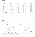
- FIG. 1(a), FIG. 1(b), FIG. 1(c), FIG. 1(d), and FIG. 1(e) are each a schematic explanatory view for illustrating an example of a shape of a seed rod, in which FIG. 1(a) to FIG. 1(c) are each a view for illustrating an example of a seed rod of the present invention, and FIG. 1(d) and FIG. 1(e) are each a view for illustrating an example of a seed rod of the related art.
- FIG. 2(a) and FIG. 2(b) are each a schematic explanatory view for illustrating heat concentration on a heated surface, in which FIG. 2(a) is a view for illustrating an example of a surface having been subjected to roughening treatment, and FIG. 2(b) is a view for illustrating an example of a smooth surface.
- FIG. 1(a) to FIG. 1(c) An example of a seed rod used in the present invention including a roughened region R in a deposition portion for glass fine particles is illustrated in each of FIG. 1(a) to FIG. 1(c) .
- a surface of the deposition region for silica fine particles is roughened, an apex of a fine convexity is locally heated to high temperature at the time of heating with oxyhydrogen flame.
- the silica fine particles each become a semi-vitrified state almost at the same time as the silica fine particles are deposited on the fine portion locally heated to high temperature.
- the portion in a semi-vitrified state has a higher thermal conductivity than a portion on which only the silica fine particles are deposited, and a semi-vitrified region is expanded from the portion in a semi-vitrified state as a core.
- FIG. 1(d) is an illustration of a related-art cylindrical seed rod having a semi-spherical tip end which is entirely formed of a smooth surface.
- heat is dispersed and a local high temperature portion is not generated as illustrated in FIG. 2(b) .
- there is no core for forming a semi-vitrified region and hence the amount of the semi-vitrified region to be spontaneously generated and its timing from the beginning of a deposition step are not stabilized, resulting in extremely poor production stability.
- FIG. 1(a) to FIG. 1(c) are each an illustration of the seed rod used in the present invention.
- FIG. 1(a) is an illustration of a cylindrical seed rod including a semi-spherical portion having a semi-spherical tip end, in which the entire surface of the semi-spherical portion is a roughened surface
- FIG. 1(b) is an illustration of a cylindrical seed rod including a semi-spherical portion having a semi-spherical tip end, in which the entire surface of the semi-spherical portion and a lower side surface are each a roughened surface
- FIG. 1(a) is an illustration of a cylindrical seed rod including a semi-spherical portion having a semi-spherical tip end, in which the entire surface of the semi-spherical portion and a lower side surface are each a roughened surface
- FIG. 1(a) is an illustration of a cylindrical seed rod including a semi-spherical portion having a semi-spherical
- FIG. 1(c) is an illustration of a cylindrical seed rod including a flat tip end portion, in which the surface of the tip end portion and a lower side surface are each a roughened surface.
- a roughened region is denoted by R.
- the seed rod to be used in the present invention is a seed rod in which at least a surface of a tip end portion of a deposition portion on which glass fine particles are to be deposited is a roughened surface.
- the roughened region R of the seed rod may be formed only on the tip end portion of the deposition portion, or may be formed on the tip end portion and a lower side surface of the deposition portion or on the entire surface of the deposition portion.
- the seed rod having a roughened surface at its bonding site to a soot body in an extremely early stage of a deposition step for the glass fine particles is used, a semi-vitrified state can be easily and stably formed, with the result that a mechanical strength can be increased with a layer of the semi-vitrified region so that the soot body is not escaped from the seed rod.
- the thickness t of the semi-vitrified region in an axial direction is particularly suitably 20 mm or more and 40 mm or less.
- the shape of the seed rod is not particularly limited, but is preferably a simple shape, and is more preferably a cylindrical shape as illustrated in each of FIG. 1(a) to FIG. 1(c) .
- the shape of the tip end portion of the cylindrical seed rod is suitably a semi-spherical shape, a shape formed of a smooth curve line without an abrupt change, or a flat surface.
- the diameter of the cylindrical seed rod is not particularly limited, and may be appropriately selected depending on the size of a porous quartz glass preform to be produced, but is preferably from 30 mm to 100 mm.
- FIG. 1(e) is an illustration of an example of a seed rod having a shape change.
- the seed rod has a shape change, a large variation in density in the soot body occurs owing to its influence, and the soot body may have problems of falling or having cracks even without a weight problem. Therefore, in the present invention, the simple shape described above is suitable.
- the seed rod of the present invention is used, a semi-vitrified region capable of increasing the strength can be produced highly reproducibly and stably, and hence can be easily produced without any skilled technique.
- a material for the seed rod used in the present invention is not particularly limited as long as the material has heat resistance, but examples thereof include quartz glass and fine ceramic, such as alumina, silicon carbide, or silicon nitride. Quartz glass is suitable.
- a method for the roughening treatment is not particularly limited, and the roughening treatment may be performed by, for example, grinding, cutting, forming, or blasting.
- the surface of the seed rod having been subjected to the roughening treatment has a maximum height-surface roughness Rz of 35 ⁇ m or more, preferably 50 ⁇ m or more, more preferably 100 ⁇ m or more.
- Rz maximum height-surface roughness
- a surface of the seed rod subjected to the roughening treatment has irregularities having a pitch of 1 mm or less and a depth of 0.5 mm or more and 1.5 mm or less.
- a method of depositing the glass fine particles on the seed rod is not particularly limited, and may be a VAD method under known conditions.
- a glass forming raw material such as silicon tetrachloride
- oxyhydrogen flame to generate glass fine particles
- the glass fine particles are deposited on a deposition portion of a rotatably supported seed rod to form a semi-vitrified region.
- a porous quartz glass preform is produced.
- a method of producing a porous quartz glass preform of the present invention is capable of easily and inexpensively ensuring a mechanical strength enough to withstand a heavy weight in a VAD method, and hence is suitable for production of a heavy porous quartz glass preform having a weight of more than 35 kg, and particularly suitable for production of a heavy porous quartz glass preform having a weight of 75 kg or more.
- the heavy porous quartz glass preform having a weight of 35 kg or more can be stably produced.
- the heavy porous quartz glass preform having a weight of 75 kg or more can be stably produced, which has hitherto been difficult. Further, even an extremely heavy porous quartz glass preform having a weight of 150 kg or more can be produced.
- the porous quartz glass preform obtained by the method of producing a porous quartz glass preform of the present invention can be used for producing a quartz glass ingot.
- the method of producing a quartz glass ingot is not particularly limited as long as the porous quartz glass preform is used to be vitrified by a known method to produce a quartz glass ingot.
- a method including subjecting the porous quartz glass preform to dehydration treatment and sintering to transparency to produce a quartz glass ingot is suitable.
- falling is less liable to occur not only in the deposition step but also in a step subsequent to the deposition step, and hence the quartz glass ingot can be produced stably without falling.
- a hemisphere of R50 was formed on a tip end of an intact cylindrical quartz rod (diameter: ⁇ 100 mm) by grinding processing, and the surface roughness Rz of the processed surface was set to 50 ⁇ m.
- a seed rod was produced.
- the surface roughness of the roughened surface of the seed rod was measured with a surface roughness meter (a compact surface roughness measurement instrument: Surftest SJ-210, manufactured by Mitutoyo Corporation) based on JIS B 0601:2001.
- a soot body was produced by using the seed rod and by a VAD method in which silicon tetrachloride as a raw material, hydrogen as a combustion gas, oxygen as a combustion-supporting gas, and nitrogen as a non-combustion gas were introduced in a concentric multi-tubular burner to be subjected to a hydrolysis reaction in combustion flame. Thus, a semi-vitrified region was produced.
- the details of the production conditions are shown in Table 1.
- soot bodies each having a weight excluding the weight of the seed rod of 40 ⁇ 5 kg were produced.
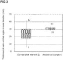
- the results of the thickness of the semi-vitrified region of the produced 20 soot bodies in an axial direction are shown in FIG. 3 .
- the thickness of the semi-vitrified region in an axial direction was measured through image analysis on a growing tip end portion during the growth of the soot body with a CCD camera.
- a time from the beginning of a deposition step to the formation of the semi-vitrified region was from 7 minutes to 15 minutes, and had less variation.
- the soot body having been deposited was dehydrated through heating at from 1,000°C to 1,300°C, and further sintered to transparency through heating at from 1,300°C to 1,500°C.
- the soot body did not fall or break during its handling or those treatments.
- a synthetic quartz glass ingot having a weight of 40 ⁇ 5 kg was able to be obtained.
- a hemisphere of R50 was formed on a tip end of an intact cylindrical quartz rod (diameter: ⁇ 100 mm) by grinding processing, and further, irregularities having a pitch of 1 mm or less and a depth d of 0.5 mm or more and 1.5 mm or less were formed on the resultant semi-spherical portion through processing. Thus, a seed rod was produced.
- a soot body was produced by using the seed rod and by a VAD method in which silicon tetrachloride as a raw material, hydrogen as a combustion gas, oxygen as a combustion-supporting gas, and nitrogen as a non-combustion gas were introduced in a concentric multi-tubular burner to be subjected to a hydrolysis reaction in combustion flame. Thus, a semi-vitrified region was produced.
- the details of the production conditions are shown in Table 1.
- a soot body having a weight excluding the weight of the seed rod of 40 kg was produced.
- the soot body was able to be produced without breakage or cracks.
- the thickness t of the semi-vitrified region was 32 mm, which was substantially the same as in Reference-Example 1.
- soot body was dehydrated and sintered to transparency in a heating furnace.
- the soot body did not fall or break during its handling or those treatments.
- a synthetic quartz glass ingot having a weight of 40 kg was able to be obtained.
- a hemisphere of R50 was formed on a tip end of an intact cylindrical quartz rod (diameter: ⁇ 100 mm) by grinding processing, and the surface roughness Rz of the processed surface was set to 100 ⁇ m. Thus, a seed rod was produced.
- a soot body was produced by using the seed rod and by a VAD method in which silicon tetrachloride as a raw material, hydrogen as a combustion gas, oxygen as a combustion-supporting gas, and nitrogen as a non-combustion gas were introduced in a concentric multi-tubular burner to be subjected to a hydrolysis reaction in combustion flame. Thus, a semi-vitrified region was produced.
- the details of the production conditions are shown in Table 1.
- a soot body having a weight excluding the weight of the seed rod of 40 kg was produced.
- the soot body was able to be produced without breakage or cracks.
- the thickness t of the semi-vitrified region was 34 mm, which was substantially the same as in Reference-Example 1.
- similar soot bodies were produced five times.
- the thicknesses of their semi-vitrified regions ranged from 32 mm to 34 mm, and a variation in thickness was smaller than in Reference-Example 1.
- soot body was dehydrated and sintered to transparency in a heating furnace.
- the soot body did not fall or break during its handling or those treatments.
- a synthetic quartz glass ingot having a weight of 40 kg was able to be obtained.
- a soot body having a weight excluding the weight of the seed rod of 80 kg was produced under exactly the same conditions as in Reference-Example 1 except that only the growth time was prolonged. As a result, the soot body was able to be produced without breakage or cracks.
- soot body was dehydrated and sintered to transparency in a heating furnace.
- the soot body did not fall or break during its handling or those treatments.
- a synthetic quartz glass ingot having a weight of 80 kg was able to be obtained.
- a soot body having a weight excluding the weight of the seed rod of 160 kg was produced under exactly the same conditions as in Reference-Example 1 except that only the growth time was prolonged. As a result, the soot body was able to be produced without breakage or cracks.
- soot body was dehydrated and sintered to transparency in a heating furnace.
- the soot body did not fall or break during its handling or those treatments.
- a synthetic quartz glass ingot having a weight of 160 kg was able to be obtained.
- a soot body having a weight excluding the weight of the seed rod of 80 kg was produced under exactly the same conditions as in Reference-Example 2 except that only the growth time was prolonged. As a result, the soot body was able to be produced without breakage or cracks.
- soot body was dehydrated and sintered to transparency in a heating furnace.
- the soot body did not fall or break during its handling or those treatments.
- a synthetic quartz glass ingot having a weight of 80 kg was able to be obtained.
- a soot body having a weight excluding the weight of the seed rod of 160 kg was produced under exactly the same conditions as in Reference-Example 2 except that only the growth time was prolonged. As a result, the soot body was able to be produced without breakage or cracks.
- soot body was dehydrated and sintered to transparency in a heating furnace.
- the soot body did not fall or break during its handling or those treatments.
- a synthetic quartz glass ingot having a weight of 160 kg was able to be obtained.
- a soot body having a weight excluding the weight of the seed rod of 80 kg was produced under exactly the same conditions as in Reference-Example 3 except that only the growth time was prolonged. As a result, the soot body was able to be produced without breakage or cracks.
- soot body was dehydrated and sintered to transparency in a heating furnace.
- the soot body did not fall or break during its handling or those treatments.
- a synthetic quartz glass ingot having a weight of 80 kg was able to be obtained.
- a soot body having a weight excluding the weight of the seed rod of 160 kg was produced under exactly the same conditions as in Reference-Example 3 except that only the growth time was prolonged. As a result, the soot body was able to be produced without breakage or cracks.
- soot body was dehydrated and sintered to transparency in a heating furnace.
- the soot body did not fall or break during its handling or those treatments.
- a synthetic quartz glass ingot having a weight of 160 kg was able to be obtained.
- a seed rod which was formed of a quartz rod having the same size as in Example 1 and in which a semi-spherical portion at its tip end had a smooth surface having Rz of 3 ⁇ m or less was used as a seed rod.
- a soot body was produced by the same method as in Reference-Example 1 except that the seed rod was changed. As a result, a semi-vitrified region was not able to be produced with hydrogen and oxygen in the same amounts as in Reference-Example 1.
- a seed rod which was formed of a quartz rod having the same size as in Reference-Example 1 and in which a semi-spherical portion at its tip end had a smooth surface having Rz of 3 ⁇ m or less was used as a seed rod.
- a soot body was produced by the same method as in Reference-Example 1 except that the seed rod was changed and the amounts of hydrogen and oxygen were increased until a semi-vitrified region was generated. The details of the production conditions are shown in Table 1.
- the production cost is increased owing to increases in amounts of hydrogen and oxygen to be used.
- a seed rod having a shape change illustrated in FIG. 1(e) was used as a seed rod.
- a main body of the seed rod had a diameter of ⁇ 50, and a portion having a length of 50 mm from a tip end which was to be bonded to a soot body was formed into a hemisphere of R50.
- a soot body was produced by the same method as in Example 1 except that the seed rod was changed. The details of the production conditions are shown in Table 1.
- a bonding area was increased, but a step portion at which the seed rod abruptly changed in diameter became a larger step along with growth of the soot body. Cracks occurred in the soot body in its early stage of growth, and the soot body was not able to continue growing.
Landscapes
- Chemical & Material Sciences (AREA)
- Engineering & Computer Science (AREA)
- Materials Engineering (AREA)
- Organic Chemistry (AREA)
- Chemical Kinetics & Catalysis (AREA)
- Manufacturing & Machinery (AREA)
- General Chemical & Material Sciences (AREA)
- Life Sciences & Earth Sciences (AREA)
- General Life Sciences & Earth Sciences (AREA)
- Geochemistry & Mineralogy (AREA)
- Glass Melting And Manufacturing (AREA)
Applications Claiming Priority (1)
| Application Number | Priority Date | Filing Date | Title |
|---|---|---|---|
| JP2017012788A JP6916622B2 (ja) | 2017-01-27 | 2017-01-27 | 多孔質石英ガラス母材の製造方法 |
Publications (2)
| Publication Number | Publication Date |
|---|---|
| EP3354627A1 EP3354627A1 (en) | 2018-08-01 |
| EP3354627B1 true EP3354627B1 (en) | 2021-05-05 |
Family
ID=61027610
Family Applications (1)
| Application Number | Title | Priority Date | Filing Date |
|---|---|---|---|
| EP18153555.0A Active EP3354627B1 (en) | 2017-01-27 | 2018-01-26 | Method of producing porous quartz glass preform |
Country Status (3)
| Country | Link |
|---|---|
| EP (1) | EP3354627B1 (ja) |
| JP (1) | JP6916622B2 (ja) |
| CN (1) | CN108358437B (ja) |
Families Citing this family (1)
| Publication number | Priority date | Publication date | Assignee | Title |
|---|---|---|---|---|
| CN115072985A (zh) * | 2022-06-13 | 2022-09-20 | 山东富通光导科技有限公司 | 一种解决大尺寸vad芯棒断裂的方法 |
Family Cites Families (9)
| Publication number | Priority date | Publication date | Assignee | Title |
|---|---|---|---|---|
| CA712238A (en) * | 1965-06-22 | E. Tragert William | Electrical conductor | |
| JPS57200236A (en) | 1981-06-03 | 1982-12-08 | Nippon Telegr & Teleph Corp <Ntt> | Method for deposition of oxide soot for forming glass rod |
| JPS58135147A (ja) * | 1982-02-08 | 1983-08-11 | Hitachi Ltd | 光フアイバ母材の製造方法 |
| JPH06183770A (ja) | 1992-12-16 | 1994-07-05 | Furukawa Electric Co Ltd:The | 光ファイバ用母材の製造方法 |
| JP3202863B2 (ja) * | 1994-03-18 | 2001-08-27 | 日本板硝子株式会社 | 光触媒担持線状物品 |
| WO2008105102A1 (ja) * | 2007-02-28 | 2008-09-04 | Shin-Etsu Chemical Co., Ltd. | 多孔質ガラス母材の製造装置 |
| JP2011256069A (ja) | 2010-06-09 | 2011-12-22 | Nikon Corp | ターゲット棒、多孔質ガラス母材の製造装置、多孔質ガラス母材の製造方法及びガラス部材の製造方法 |
| JP6049056B2 (ja) * | 2012-08-23 | 2016-12-21 | 神島化学工業株式会社 | 光学用セラミックスとその製造方法 |
| JP2015000169A (ja) * | 2013-06-14 | 2015-01-05 | ユーヴィックス株式会社 | 光浄化処理プローブ |
-
2017
- 2017-01-27 JP JP2017012788A patent/JP6916622B2/ja active Active
-
2018
- 2018-01-17 CN CN201810047374.7A patent/CN108358437B/zh active Active
- 2018-01-26 EP EP18153555.0A patent/EP3354627B1/en active Active
Non-Patent Citations (1)
| Title |
|---|
| None * |
Also Published As
| Publication number | Publication date |
|---|---|
| CN108358437B (zh) | 2021-10-08 |
| JP2018118887A (ja) | 2018-08-02 |
| JP6916622B2 (ja) | 2021-08-11 |
| CN108358437A (zh) | 2018-08-03 |
| EP3354627A1 (en) | 2018-08-01 |
Similar Documents
| Publication | Publication Date | Title |
|---|---|---|
| KR101725359B1 (ko) | 석영 유리 실린더의 제조 방법 및 그 제조 방법을 수행하기 위한 지지체 | |
| US8393179B2 (en) | Method for producing a semifinished product from synthetic quartz glass | |
| JP5916967B2 (ja) | 光ファイバ母材の製造方法および光ファイバの製造方法 | |
| EP3354627B1 (en) | Method of producing porous quartz glass preform | |
| JP2006193370A (ja) | 光ファイバ母材及びその製造方法 | |
| KR102419522B1 (ko) | 수율 개선 및 기공 제어가 가능한 합성 석영유리 제조방법 | |
| JP6545925B2 (ja) | 光ファイバ用ガラス母材の製造方法 | |
| KR102545711B1 (ko) | 다공질 유리 모재의 제조 장치 및 제조 방법 | |
| KR102569042B1 (ko) | 유리 미립자 퇴적체의 제조 방법, 유리 모재의 제조 방법 및 유리 미립자 퇴적체 | |
| JP2011256069A (ja) | ターゲット棒、多孔質ガラス母材の製造装置、多孔質ガラス母材の製造方法及びガラス部材の製造方法 | |
| JP4429993B2 (ja) | 光ファイバ母材の製造方法 | |
| JP2014043360A (ja) | 多孔質ガラス体の製造方法および多孔質ガラス体 | |
| JP4501850B2 (ja) | ガラス体製造方法 | |
| JP4420082B2 (ja) | ガラス母材の製造方法 | |
| US8110277B2 (en) | Fused silica blank and method of forming a fused silica plate from the same | |
| CN110636992B (zh) | 光纤母材的制造方法及光纤母材 | |
| JP2008239454A (ja) | 合成シリカガラスの製造方法 | |
| JP2007153678A (ja) | 石英ガラス多孔質母材の製造方法 | |
| JP4506681B2 (ja) | ガラス母材の製造方法 | |
| WO2004101457A1 (ja) | 光ファイバ用ガラス母材の製造方法 | |
| JP2003171136A (ja) | 光ファイバ用多孔質材およびその製造方法、光ファイバ母材およびその製造方法 | |
| JPS61101429A (ja) | ガラス管の製造方法 | |
| JP2009007227A (ja) | 透明ガラス体の製造方法 | |
| JP2020100537A (ja) | 光ファイバ用母材の製造方法 | |
| JP2007320781A (ja) | ガラス母材の製造方法 |
Legal Events
| Date | Code | Title | Description |
|---|---|---|---|
| PUAI | Public reference made under article 153(3) epc to a published international application that has entered the european phase |
Free format text: ORIGINAL CODE: 0009012 |
|
| STAA | Information on the status of an ep patent application or granted ep patent |
Free format text: STATUS: THE APPLICATION HAS BEEN PUBLISHED |
|
| AK | Designated contracting states |
Kind code of ref document: A1 Designated state(s): AL AT BE BG CH CY CZ DE DK EE ES FI FR GB GR HR HU IE IS IT LI LT LU LV MC MK MT NL NO PL PT RO RS SE SI SK SM TR |
|
| AX | Request for extension of the european patent |
Extension state: BA ME |
|
| STAA | Information on the status of an ep patent application or granted ep patent |
Free format text: STATUS: REQUEST FOR EXAMINATION WAS MADE |
|
| 17P | Request for examination filed |
Effective date: 20190129 |
|
| RBV | Designated contracting states (corrected) |
Designated state(s): AL AT BE BG CH CY CZ DE DK EE ES FI FR GB GR HR HU IE IS IT LI LT LU LV MC MK MT NL NO PL PT RO RS SE SI SK SM TR |
|
| STAA | Information on the status of an ep patent application or granted ep patent |
Free format text: STATUS: EXAMINATION IS IN PROGRESS |
|
| 17Q | First examination report despatched |
Effective date: 20191206 |
|
| GRAP | Despatch of communication of intention to grant a patent |
Free format text: ORIGINAL CODE: EPIDOSNIGR1 |
|
| STAA | Information on the status of an ep patent application or granted ep patent |
Free format text: STATUS: GRANT OF PATENT IS INTENDED |
|
| GRAJ | Information related to disapproval of communication of intention to grant by the applicant or resumption of examination proceedings by the epo deleted |
Free format text: ORIGINAL CODE: EPIDOSDIGR1 |
|
| GRAP | Despatch of communication of intention to grant a patent |
Free format text: ORIGINAL CODE: EPIDOSNIGR1 |
|
| GRAJ | Information related to disapproval of communication of intention to grant by the applicant or resumption of examination proceedings by the epo deleted |
Free format text: ORIGINAL CODE: EPIDOSDIGR1 |
|
| STAA | Information on the status of an ep patent application or granted ep patent |
Free format text: STATUS: EXAMINATION IS IN PROGRESS |
|
| INTG | Intention to grant announced |
Effective date: 20201019 |
|
| GRAP | Despatch of communication of intention to grant a patent |
Free format text: ORIGINAL CODE: EPIDOSNIGR1 |
|
| STAA | Information on the status of an ep patent application or granted ep patent |
Free format text: STATUS: GRANT OF PATENT IS INTENDED |
|
| INTG | Intention to grant announced |
Effective date: 20201111 |
|
| INTG | Intention to grant announced |
Effective date: 20201127 |
|
| GRAS | Grant fee paid |
Free format text: ORIGINAL CODE: EPIDOSNIGR3 |
|
| GRAA | (expected) grant |
Free format text: ORIGINAL CODE: 0009210 |
|
| STAA | Information on the status of an ep patent application or granted ep patent |
Free format text: STATUS: THE PATENT HAS BEEN GRANTED |
|
| AK | Designated contracting states |
Kind code of ref document: B1 Designated state(s): AL AT BE BG CH CY CZ DE DK EE ES FI FR GB GR HR HU IE IS IT LI LT LU LV MC MK MT NL NO PL PT RO RS SE SI SK SM TR |
|
| REG | Reference to a national code |
Ref country code: GB Ref legal event code: FG4D |
|
| REG | Reference to a national code |
Ref country code: CH Ref legal event code: EP |
|
| REG | Reference to a national code |
Ref country code: AT Ref legal event code: REF Ref document number: 1389630 Country of ref document: AT Kind code of ref document: T Effective date: 20210515 |
|
| REG | Reference to a national code |
Ref country code: IE Ref legal event code: FG4D |
|
| REG | Reference to a national code |
Ref country code: DE Ref legal event code: R096 Ref document number: 602018016407 Country of ref document: DE |
|
| REG | Reference to a national code |
Ref country code: NL Ref legal event code: FP |
|
| REG | Reference to a national code |
Ref country code: LT Ref legal event code: MG9D |
|
| REG | Reference to a national code |
Ref country code: AT Ref legal event code: MK05 Ref document number: 1389630 Country of ref document: AT Kind code of ref document: T Effective date: 20210505 |
|
| PG25 | Lapsed in a contracting state [announced via postgrant information from national office to epo] |
Ref country code: LT Free format text: LAPSE BECAUSE OF FAILURE TO SUBMIT A TRANSLATION OF THE DESCRIPTION OR TO PAY THE FEE WITHIN THE PRESCRIBED TIME-LIMIT Effective date: 20210505 Ref country code: FI Free format text: LAPSE BECAUSE OF FAILURE TO SUBMIT A TRANSLATION OF THE DESCRIPTION OR TO PAY THE FEE WITHIN THE PRESCRIBED TIME-LIMIT Effective date: 20210505 Ref country code: HR Free format text: LAPSE BECAUSE OF FAILURE TO SUBMIT A TRANSLATION OF THE DESCRIPTION OR TO PAY THE FEE WITHIN THE PRESCRIBED TIME-LIMIT Effective date: 20210505 Ref country code: BG Free format text: LAPSE BECAUSE OF FAILURE TO SUBMIT A TRANSLATION OF THE DESCRIPTION OR TO PAY THE FEE WITHIN THE PRESCRIBED TIME-LIMIT Effective date: 20210805 Ref country code: AT Free format text: LAPSE BECAUSE OF FAILURE TO SUBMIT A TRANSLATION OF THE DESCRIPTION OR TO PAY THE FEE WITHIN THE PRESCRIBED TIME-LIMIT Effective date: 20210505 |
|
| PG25 | Lapsed in a contracting state [announced via postgrant information from national office to epo] |
Ref country code: IS Free format text: LAPSE BECAUSE OF FAILURE TO SUBMIT A TRANSLATION OF THE DESCRIPTION OR TO PAY THE FEE WITHIN THE PRESCRIBED TIME-LIMIT Effective date: 20210905 Ref country code: GR Free format text: LAPSE BECAUSE OF FAILURE TO SUBMIT A TRANSLATION OF THE DESCRIPTION OR TO PAY THE FEE WITHIN THE PRESCRIBED TIME-LIMIT Effective date: 20210806 Ref country code: SE Free format text: LAPSE BECAUSE OF FAILURE TO SUBMIT A TRANSLATION OF THE DESCRIPTION OR TO PAY THE FEE WITHIN THE PRESCRIBED TIME-LIMIT Effective date: 20210505 Ref country code: RS Free format text: LAPSE BECAUSE OF FAILURE TO SUBMIT A TRANSLATION OF THE DESCRIPTION OR TO PAY THE FEE WITHIN THE PRESCRIBED TIME-LIMIT Effective date: 20210505 Ref country code: LV Free format text: LAPSE BECAUSE OF FAILURE TO SUBMIT A TRANSLATION OF THE DESCRIPTION OR TO PAY THE FEE WITHIN THE PRESCRIBED TIME-LIMIT Effective date: 20210505 Ref country code: PT Free format text: LAPSE BECAUSE OF FAILURE TO SUBMIT A TRANSLATION OF THE DESCRIPTION OR TO PAY THE FEE WITHIN THE PRESCRIBED TIME-LIMIT Effective date: 20210906 Ref country code: NO Free format text: LAPSE BECAUSE OF FAILURE TO SUBMIT A TRANSLATION OF THE DESCRIPTION OR TO PAY THE FEE WITHIN THE PRESCRIBED TIME-LIMIT Effective date: 20210805 Ref country code: PL Free format text: LAPSE BECAUSE OF FAILURE TO SUBMIT A TRANSLATION OF THE DESCRIPTION OR TO PAY THE FEE WITHIN THE PRESCRIBED TIME-LIMIT Effective date: 20210505 |
|
| PG25 | Lapsed in a contracting state [announced via postgrant information from national office to epo] |
Ref country code: RO Free format text: LAPSE BECAUSE OF FAILURE TO SUBMIT A TRANSLATION OF THE DESCRIPTION OR TO PAY THE FEE WITHIN THE PRESCRIBED TIME-LIMIT Effective date: 20210505 Ref country code: DK Free format text: LAPSE BECAUSE OF FAILURE TO SUBMIT A TRANSLATION OF THE DESCRIPTION OR TO PAY THE FEE WITHIN THE PRESCRIBED TIME-LIMIT Effective date: 20210505 Ref country code: CZ Free format text: LAPSE BECAUSE OF FAILURE TO SUBMIT A TRANSLATION OF THE DESCRIPTION OR TO PAY THE FEE WITHIN THE PRESCRIBED TIME-LIMIT Effective date: 20210505 Ref country code: EE Free format text: LAPSE BECAUSE OF FAILURE TO SUBMIT A TRANSLATION OF THE DESCRIPTION OR TO PAY THE FEE WITHIN THE PRESCRIBED TIME-LIMIT Effective date: 20210505 Ref country code: ES Free format text: LAPSE BECAUSE OF FAILURE TO SUBMIT A TRANSLATION OF THE DESCRIPTION OR TO PAY THE FEE WITHIN THE PRESCRIBED TIME-LIMIT Effective date: 20210505 Ref country code: SM Free format text: LAPSE BECAUSE OF FAILURE TO SUBMIT A TRANSLATION OF THE DESCRIPTION OR TO PAY THE FEE WITHIN THE PRESCRIBED TIME-LIMIT Effective date: 20210505 Ref country code: SK Free format text: LAPSE BECAUSE OF FAILURE TO SUBMIT A TRANSLATION OF THE DESCRIPTION OR TO PAY THE FEE WITHIN THE PRESCRIBED TIME-LIMIT Effective date: 20210505 |
|
| REG | Reference to a national code |
Ref country code: DE Ref legal event code: R097 Ref document number: 602018016407 Country of ref document: DE |
|
| PLBE | No opposition filed within time limit |
Free format text: ORIGINAL CODE: 0009261 |
|
| STAA | Information on the status of an ep patent application or granted ep patent |
Free format text: STATUS: NO OPPOSITION FILED WITHIN TIME LIMIT |
|
| 26N | No opposition filed |
Effective date: 20220208 |
|
| PG25 | Lapsed in a contracting state [announced via postgrant information from national office to epo] |
Ref country code: IS Free format text: LAPSE BECAUSE OF FAILURE TO SUBMIT A TRANSLATION OF THE DESCRIPTION OR TO PAY THE FEE WITHIN THE PRESCRIBED TIME-LIMIT Effective date: 20210905 Ref country code: AL Free format text: LAPSE BECAUSE OF FAILURE TO SUBMIT A TRANSLATION OF THE DESCRIPTION OR TO PAY THE FEE WITHIN THE PRESCRIBED TIME-LIMIT Effective date: 20210505 |
|
| PG25 | Lapsed in a contracting state [announced via postgrant information from national office to epo] |
Ref country code: MC Free format text: LAPSE BECAUSE OF FAILURE TO SUBMIT A TRANSLATION OF THE DESCRIPTION OR TO PAY THE FEE WITHIN THE PRESCRIBED TIME-LIMIT Effective date: 20210505 |
|
| REG | Reference to a national code |
Ref country code: CH Ref legal event code: PL |
|
| GBPC | Gb: european patent ceased through non-payment of renewal fee |
Effective date: 20220126 |
|
| REG | Reference to a national code |
Ref country code: BE Ref legal event code: MM Effective date: 20220131 |
|
| PG25 | Lapsed in a contracting state [announced via postgrant information from national office to epo] |
Ref country code: LU Free format text: LAPSE BECAUSE OF NON-PAYMENT OF DUE FEES Effective date: 20220126 Ref country code: GB Free format text: LAPSE BECAUSE OF NON-PAYMENT OF DUE FEES Effective date: 20220126 |
|
| PG25 | Lapsed in a contracting state [announced via postgrant information from national office to epo] |
Ref country code: FR Free format text: LAPSE BECAUSE OF NON-PAYMENT OF DUE FEES Effective date: 20220131 Ref country code: BE Free format text: LAPSE BECAUSE OF NON-PAYMENT OF DUE FEES Effective date: 20220131 |
|
| PG25 | Lapsed in a contracting state [announced via postgrant information from national office to epo] |
Ref country code: LI Free format text: LAPSE BECAUSE OF NON-PAYMENT OF DUE FEES Effective date: 20220131 Ref country code: CH Free format text: LAPSE BECAUSE OF NON-PAYMENT OF DUE FEES Effective date: 20220131 |
|
| PG25 | Lapsed in a contracting state [announced via postgrant information from national office to epo] |
Ref country code: IE Free format text: LAPSE BECAUSE OF NON-PAYMENT OF DUE FEES Effective date: 20220126 |
|
| PGFP | Annual fee paid to national office [announced via postgrant information from national office to epo] |
Ref country code: IT Payment date: 20221213 Year of fee payment: 6 |
|
| PGFP | Annual fee paid to national office [announced via postgrant information from national office to epo] |
Ref country code: NL Payment date: 20231215 Year of fee payment: 7 |
|
| PG25 | Lapsed in a contracting state [announced via postgrant information from national office to epo] |
Ref country code: HU Free format text: LAPSE BECAUSE OF FAILURE TO SUBMIT A TRANSLATION OF THE DESCRIPTION OR TO PAY THE FEE WITHIN THE PRESCRIBED TIME-LIMIT; INVALID AB INITIO Effective date: 20180126 |
|
| P01 | Opt-out of the competence of the unified patent court (upc) registered |
Effective date: 20240226 |
|
| PG25 | Lapsed in a contracting state [announced via postgrant information from national office to epo] |
Ref country code: MK Free format text: LAPSE BECAUSE OF FAILURE TO SUBMIT A TRANSLATION OF THE DESCRIPTION OR TO PAY THE FEE WITHIN THE PRESCRIBED TIME-LIMIT Effective date: 20210505 Ref country code: CY Free format text: LAPSE BECAUSE OF FAILURE TO SUBMIT A TRANSLATION OF THE DESCRIPTION OR TO PAY THE FEE WITHIN THE PRESCRIBED TIME-LIMIT Effective date: 20210505 |
|
| PGFP | Annual fee paid to national office [announced via postgrant information from national office to epo] |
Ref country code: DE Payment date: 20231128 Year of fee payment: 7 |