EP3319120A1 - Halbleiterbauelement - Google Patents
Halbleiterbauelement Download PDFInfo
- Publication number
- EP3319120A1 EP3319120A1 EP15897654.8A EP15897654A EP3319120A1 EP 3319120 A1 EP3319120 A1 EP 3319120A1 EP 15897654 A EP15897654 A EP 15897654A EP 3319120 A1 EP3319120 A1 EP 3319120A1
- Authority
- EP
- European Patent Office
- Prior art keywords
- wiring layer
- pattern
- wiring
- layer
- insulating layer
- Prior art date
- Legal status (The legal status is an assumption and is not a legal conclusion. Google has not performed a legal analysis and makes no representation as to the accuracy of the status listed.)
- Withdrawn
Links
- 239000004065 semiconductor Substances 0.000 title claims abstract description 152
- 239000000758 substrate Substances 0.000 claims abstract description 182
- 229910000679 solder Inorganic materials 0.000 claims abstract description 64
- 238000007789 sealing Methods 0.000 claims abstract description 15
- 230000001681 protective effect Effects 0.000 claims description 34
- 230000002093 peripheral effect Effects 0.000 claims description 15
- 239000000463 material Substances 0.000 claims description 8
- 239000000853 adhesive Substances 0.000 claims description 2
- 239000010410 layer Substances 0.000 description 453
- RYGMFSIKBFXOCR-UHFFFAOYSA-N Copper Chemical compound [Cu] RYGMFSIKBFXOCR-UHFFFAOYSA-N 0.000 description 51
- 230000017525 heat dissipation Effects 0.000 description 47
- 239000011889 copper foil Substances 0.000 description 45
- 238000012986 modification Methods 0.000 description 32
- 230000004048 modification Effects 0.000 description 32
- 238000000034 method Methods 0.000 description 25
- 230000015572 biosynthetic process Effects 0.000 description 19
- 229920005989 resin Polymers 0.000 description 17
- 239000011347 resin Substances 0.000 description 17
- 238000010586 diagram Methods 0.000 description 11
- 238000004519 manufacturing process Methods 0.000 description 9
- 238000011161 development Methods 0.000 description 8
- 230000018109 developmental process Effects 0.000 description 8
- 239000012792 core layer Substances 0.000 description 7
- 238000005530 etching Methods 0.000 description 7
- 238000007747 plating Methods 0.000 description 7
- 238000000465 moulding Methods 0.000 description 6
- 230000000052 comparative effect Effects 0.000 description 5
- 229910052802 copper Inorganic materials 0.000 description 5
- 239000010949 copper Substances 0.000 description 5
- 229910000365 copper sulfate Inorganic materials 0.000 description 4
- ARUVKPQLZAKDPS-UHFFFAOYSA-L copper(II) sulfate Chemical compound [Cu+2].[O-][S+2]([O-])([O-])[O-] ARUVKPQLZAKDPS-UHFFFAOYSA-L 0.000 description 4
- 230000000694 effects Effects 0.000 description 4
- 238000003475 lamination Methods 0.000 description 4
- 238000012360 testing method Methods 0.000 description 4
- 239000010931 gold Substances 0.000 description 3
- 230000020169 heat generation Effects 0.000 description 3
- 238000010438 heat treatment Methods 0.000 description 3
- 239000011229 interlayer Substances 0.000 description 3
- 239000011159 matrix material Substances 0.000 description 3
- 238000010330 laser marking Methods 0.000 description 2
- 238000002360 preparation method Methods 0.000 description 2
- 238000003825 pressing Methods 0.000 description 2
- 238000012545 processing Methods 0.000 description 2
- 238000004381 surface treatment Methods 0.000 description 2
- 230000008961 swelling Effects 0.000 description 2
- 229910000881 Cu alloy Inorganic materials 0.000 description 1
- 239000000470 constituent Substances 0.000 description 1
- 239000013078 crystal Substances 0.000 description 1
- 230000007547 defect Effects 0.000 description 1
- 230000002950 deficient Effects 0.000 description 1
- 238000007791 dehumidification Methods 0.000 description 1
- 239000003822 epoxy resin Substances 0.000 description 1
- 238000005755 formation reaction Methods 0.000 description 1
- 230000014509 gene expression Effects 0.000 description 1
- PCHJSUWPFVWCPO-UHFFFAOYSA-N gold Chemical compound [Au] PCHJSUWPFVWCPO-UHFFFAOYSA-N 0.000 description 1
- 230000012447 hatching Effects 0.000 description 1
- 239000011810 insulating material Substances 0.000 description 1
- 230000001678 irradiating effect Effects 0.000 description 1
- 239000002184 metal Substances 0.000 description 1
- 229910052751 metal Inorganic materials 0.000 description 1
- 239000004033 plastic Substances 0.000 description 1
- 229920000647 polyepoxide Polymers 0.000 description 1
- 230000003252 repetitive effect Effects 0.000 description 1
- 229910052710 silicon Inorganic materials 0.000 description 1
- 239000010703 silicon Substances 0.000 description 1
- 229920001187 thermosetting polymer Polymers 0.000 description 1
Images


Classifications
-
- H—ELECTRICITY
- H01—ELECTRIC ELEMENTS
- H01L—SEMICONDUCTOR DEVICES NOT COVERED BY CLASS H10
- H01L23/00—Details of semiconductor or other solid state devices
- H01L23/48—Arrangements for conducting electric current to or from the solid state body in operation, e.g. leads, terminal arrangements ; Selection of materials therefor
- H01L23/488—Arrangements for conducting electric current to or from the solid state body in operation, e.g. leads, terminal arrangements ; Selection of materials therefor consisting of soldered or bonded constructions
- H01L23/498—Leads, i.e. metallisations or lead-frames on insulating substrates, e.g. chip carriers
- H01L23/49838—Geometry or layout
-
- H—ELECTRICITY
- H01—ELECTRIC ELEMENTS
- H01L—SEMICONDUCTOR DEVICES NOT COVERED BY CLASS H10
- H01L21/00—Processes or apparatus adapted for the manufacture or treatment of semiconductor or solid state devices or of parts thereof
- H01L21/02—Manufacture or treatment of semiconductor devices or of parts thereof
- H01L21/04—Manufacture or treatment of semiconductor devices or of parts thereof the devices having potential barriers, e.g. a PN junction, depletion layer or carrier concentration layer
- H01L21/48—Manufacture or treatment of parts, e.g. containers, prior to assembly of the devices, using processes not provided for in a single one of the subgroups H01L21/06 - H01L21/326
- H01L21/4814—Conductive parts
- H01L21/4846—Leads on or in insulating or insulated substrates, e.g. metallisation
- H01L21/4853—Connection or disconnection of other leads to or from a metallisation, e.g. pins, wires, bumps
-
- H—ELECTRICITY
- H01—ELECTRIC ELEMENTS
- H01L—SEMICONDUCTOR DEVICES NOT COVERED BY CLASS H10
- H01L21/00—Processes or apparatus adapted for the manufacture or treatment of semiconductor or solid state devices or of parts thereof
- H01L21/02—Manufacture or treatment of semiconductor devices or of parts thereof
- H01L21/04—Manufacture or treatment of semiconductor devices or of parts thereof the devices having potential barriers, e.g. a PN junction, depletion layer or carrier concentration layer
- H01L21/48—Manufacture or treatment of parts, e.g. containers, prior to assembly of the devices, using processes not provided for in a single one of the subgroups H01L21/06 - H01L21/326
- H01L21/4814—Conductive parts
- H01L21/4846—Leads on or in insulating or insulated substrates, e.g. metallisation
- H01L21/4857—Multilayer substrates
-
- H—ELECTRICITY
- H01—ELECTRIC ELEMENTS
- H01L—SEMICONDUCTOR DEVICES NOT COVERED BY CLASS H10
- H01L21/00—Processes or apparatus adapted for the manufacture or treatment of semiconductor or solid state devices or of parts thereof
- H01L21/02—Manufacture or treatment of semiconductor devices or of parts thereof
- H01L21/04—Manufacture or treatment of semiconductor devices or of parts thereof the devices having potential barriers, e.g. a PN junction, depletion layer or carrier concentration layer
- H01L21/50—Assembly of semiconductor devices using processes or apparatus not provided for in a single one of the subgroups H01L21/06 - H01L21/326, e.g. sealing of a cap to a base of a container
- H01L21/56—Encapsulations, e.g. encapsulation layers, coatings
- H01L21/561—Batch processing
-
- H—ELECTRICITY
- H01—ELECTRIC ELEMENTS
- H01L—SEMICONDUCTOR DEVICES NOT COVERED BY CLASS H10
- H01L21/00—Processes or apparatus adapted for the manufacture or treatment of semiconductor or solid state devices or of parts thereof
- H01L21/02—Manufacture or treatment of semiconductor devices or of parts thereof
- H01L21/04—Manufacture or treatment of semiconductor devices or of parts thereof the devices having potential barriers, e.g. a PN junction, depletion layer or carrier concentration layer
- H01L21/50—Assembly of semiconductor devices using processes or apparatus not provided for in a single one of the subgroups H01L21/06 - H01L21/326, e.g. sealing of a cap to a base of a container
- H01L21/56—Encapsulations, e.g. encapsulation layers, coatings
- H01L21/565—Moulds
-
- H—ELECTRICITY
- H01—ELECTRIC ELEMENTS
- H01L—SEMICONDUCTOR DEVICES NOT COVERED BY CLASS H10
- H01L21/00—Processes or apparatus adapted for the manufacture or treatment of semiconductor or solid state devices or of parts thereof
- H01L21/70—Manufacture or treatment of devices consisting of a plurality of solid state components formed in or on a common substrate or of parts thereof; Manufacture of integrated circuit devices or of parts thereof
- H01L21/77—Manufacture or treatment of devices consisting of a plurality of solid state components or integrated circuits formed in, or on, a common substrate
- H01L21/78—Manufacture or treatment of devices consisting of a plurality of solid state components or integrated circuits formed in, or on, a common substrate with subsequent division of the substrate into plural individual devices
-
- H—ELECTRICITY
- H01—ELECTRIC ELEMENTS
- H01L—SEMICONDUCTOR DEVICES NOT COVERED BY CLASS H10
- H01L23/00—Details of semiconductor or other solid state devices
- H01L23/12—Mountings, e.g. non-detachable insulating substrates
-
- H—ELECTRICITY
- H01—ELECTRIC ELEMENTS
- H01L—SEMICONDUCTOR DEVICES NOT COVERED BY CLASS H10
- H01L23/00—Details of semiconductor or other solid state devices
- H01L23/28—Encapsulations, e.g. encapsulating layers, coatings, e.g. for protection
- H01L23/31—Encapsulations, e.g. encapsulating layers, coatings, e.g. for protection characterised by the arrangement or shape
- H01L23/3107—Encapsulations, e.g. encapsulating layers, coatings, e.g. for protection characterised by the arrangement or shape the device being completely enclosed
- H01L23/3114—Encapsulations, e.g. encapsulating layers, coatings, e.g. for protection characterised by the arrangement or shape the device being completely enclosed the device being a chip scale package, e.g. CSP
-
- H—ELECTRICITY
- H01—ELECTRIC ELEMENTS
- H01L—SEMICONDUCTOR DEVICES NOT COVERED BY CLASS H10
- H01L23/00—Details of semiconductor or other solid state devices
- H01L23/34—Arrangements for cooling, heating, ventilating or temperature compensation ; Temperature sensing arrangements
- H01L23/36—Selection of materials, or shaping, to facilitate cooling or heating, e.g. heatsinks
- H01L23/367—Cooling facilitated by shape of device
-
- H—ELECTRICITY
- H01—ELECTRIC ELEMENTS
- H01L—SEMICONDUCTOR DEVICES NOT COVERED BY CLASS H10
- H01L23/00—Details of semiconductor or other solid state devices
- H01L23/48—Arrangements for conducting electric current to or from the solid state body in operation, e.g. leads, terminal arrangements ; Selection of materials therefor
- H01L23/482—Arrangements for conducting electric current to or from the solid state body in operation, e.g. leads, terminal arrangements ; Selection of materials therefor consisting of lead-in layers inseparably applied to the semiconductor body
- H01L23/485—Arrangements for conducting electric current to or from the solid state body in operation, e.g. leads, terminal arrangements ; Selection of materials therefor consisting of lead-in layers inseparably applied to the semiconductor body consisting of layered constructions comprising conductive layers and insulating layers, e.g. planar contacts
-
- H—ELECTRICITY
- H01—ELECTRIC ELEMENTS
- H01L—SEMICONDUCTOR DEVICES NOT COVERED BY CLASS H10
- H01L24/00—Arrangements for connecting or disconnecting semiconductor or solid-state bodies; Methods or apparatus related thereto
- H01L24/01—Means for bonding being attached to, or being formed on, the surface to be connected, e.g. chip-to-package, die-attach, "first-level" interconnects; Manufacturing methods related thereto
- H01L24/26—Layer connectors, e.g. plate connectors, solder or adhesive layers; Manufacturing methods related thereto
- H01L24/31—Structure, shape, material or disposition of the layer connectors after the connecting process
- H01L24/32—Structure, shape, material or disposition of the layer connectors after the connecting process of an individual layer connector
-
- H—ELECTRICITY
- H01—ELECTRIC ELEMENTS
- H01L—SEMICONDUCTOR DEVICES NOT COVERED BY CLASS H10
- H01L24/00—Arrangements for connecting or disconnecting semiconductor or solid-state bodies; Methods or apparatus related thereto
- H01L24/01—Means for bonding being attached to, or being formed on, the surface to be connected, e.g. chip-to-package, die-attach, "first-level" interconnects; Manufacturing methods related thereto
- H01L24/42—Wire connectors; Manufacturing methods related thereto
- H01L24/47—Structure, shape, material or disposition of the wire connectors after the connecting process
- H01L24/48—Structure, shape, material or disposition of the wire connectors after the connecting process of an individual wire connector
-
- H—ELECTRICITY
- H01—ELECTRIC ELEMENTS
- H01L—SEMICONDUCTOR DEVICES NOT COVERED BY CLASS H10
- H01L24/00—Arrangements for connecting or disconnecting semiconductor or solid-state bodies; Methods or apparatus related thereto
- H01L24/73—Means for bonding being of different types provided for in two or more of groups H01L24/10, H01L24/18, H01L24/26, H01L24/34, H01L24/42, H01L24/50, H01L24/63, H01L24/71
-
- H—ELECTRICITY
- H01—ELECTRIC ELEMENTS
- H01L—SEMICONDUCTOR DEVICES NOT COVERED BY CLASS H10
- H01L24/00—Arrangements for connecting or disconnecting semiconductor or solid-state bodies; Methods or apparatus related thereto
- H01L24/93—Batch processes
- H01L24/95—Batch processes at chip-level, i.e. with connecting carried out on a plurality of singulated devices, i.e. on diced chips
- H01L24/97—Batch processes at chip-level, i.e. with connecting carried out on a plurality of singulated devices, i.e. on diced chips the devices being connected to a common substrate, e.g. interposer, said common substrate being separable into individual assemblies after connecting
-
- H—ELECTRICITY
- H01—ELECTRIC ELEMENTS
- H01L—SEMICONDUCTOR DEVICES NOT COVERED BY CLASS H10
- H01L2224/00—Indexing scheme for arrangements for connecting or disconnecting semiconductor or solid-state bodies and methods related thereto as covered by H01L24/00
- H01L2224/01—Means for bonding being attached to, or being formed on, the surface to be connected, e.g. chip-to-package, die-attach, "first-level" interconnects; Manufacturing methods related thereto
- H01L2224/02—Bonding areas; Manufacturing methods related thereto
- H01L2224/04—Structure, shape, material or disposition of the bonding areas prior to the connecting process
- H01L2224/05—Structure, shape, material or disposition of the bonding areas prior to the connecting process of an individual bonding area
- H01L2224/0554—External layer
- H01L2224/0555—Shape
- H01L2224/05552—Shape in top view
- H01L2224/05554—Shape in top view being square
-
- H—ELECTRICITY
- H01—ELECTRIC ELEMENTS
- H01L—SEMICONDUCTOR DEVICES NOT COVERED BY CLASS H10
- H01L2224/00—Indexing scheme for arrangements for connecting or disconnecting semiconductor or solid-state bodies and methods related thereto as covered by H01L24/00
- H01L2224/01—Means for bonding being attached to, or being formed on, the surface to be connected, e.g. chip-to-package, die-attach, "first-level" interconnects; Manufacturing methods related thereto
- H01L2224/26—Layer connectors, e.g. plate connectors, solder or adhesive layers; Manufacturing methods related thereto
- H01L2224/31—Structure, shape, material or disposition of the layer connectors after the connecting process
- H01L2224/32—Structure, shape, material or disposition of the layer connectors after the connecting process of an individual layer connector
- H01L2224/321—Disposition
- H01L2224/32151—Disposition the layer connector connecting between a semiconductor or solid-state body and an item not being a semiconductor or solid-state body, e.g. chip-to-substrate, chip-to-passive
- H01L2224/32221—Disposition the layer connector connecting between a semiconductor or solid-state body and an item not being a semiconductor or solid-state body, e.g. chip-to-substrate, chip-to-passive the body and the item being stacked
- H01L2224/32225—Disposition the layer connector connecting between a semiconductor or solid-state body and an item not being a semiconductor or solid-state body, e.g. chip-to-substrate, chip-to-passive the body and the item being stacked the item being non-metallic, e.g. insulating substrate with or without metallisation
-
- H—ELECTRICITY
- H01—ELECTRIC ELEMENTS
- H01L—SEMICONDUCTOR DEVICES NOT COVERED BY CLASS H10
- H01L2224/00—Indexing scheme for arrangements for connecting or disconnecting semiconductor or solid-state bodies and methods related thereto as covered by H01L24/00
- H01L2224/01—Means for bonding being attached to, or being formed on, the surface to be connected, e.g. chip-to-package, die-attach, "first-level" interconnects; Manufacturing methods related thereto
- H01L2224/42—Wire connectors; Manufacturing methods related thereto
- H01L2224/44—Structure, shape, material or disposition of the wire connectors prior to the connecting process
- H01L2224/45—Structure, shape, material or disposition of the wire connectors prior to the connecting process of an individual wire connector
- H01L2224/45001—Core members of the connector
- H01L2224/45099—Material
- H01L2224/451—Material with a principal constituent of the material being a metal or a metalloid, e.g. boron (B), silicon (Si), germanium (Ge), arsenic (As), antimony (Sb), tellurium (Te) and polonium (Po), and alloys thereof
- H01L2224/45138—Material with a principal constituent of the material being a metal or a metalloid, e.g. boron (B), silicon (Si), germanium (Ge), arsenic (As), antimony (Sb), tellurium (Te) and polonium (Po), and alloys thereof the principal constituent melting at a temperature of greater than or equal to 950°C and less than 1550°C
- H01L2224/45144—Gold (Au) as principal constituent
-
- H—ELECTRICITY
- H01—ELECTRIC ELEMENTS
- H01L—SEMICONDUCTOR DEVICES NOT COVERED BY CLASS H10
- H01L2224/00—Indexing scheme for arrangements for connecting or disconnecting semiconductor or solid-state bodies and methods related thereto as covered by H01L24/00
- H01L2224/01—Means for bonding being attached to, or being formed on, the surface to be connected, e.g. chip-to-package, die-attach, "first-level" interconnects; Manufacturing methods related thereto
- H01L2224/42—Wire connectors; Manufacturing methods related thereto
- H01L2224/44—Structure, shape, material or disposition of the wire connectors prior to the connecting process
- H01L2224/45—Structure, shape, material or disposition of the wire connectors prior to the connecting process of an individual wire connector
- H01L2224/45001—Core members of the connector
- H01L2224/45099—Material
- H01L2224/451—Material with a principal constituent of the material being a metal or a metalloid, e.g. boron (B), silicon (Si), germanium (Ge), arsenic (As), antimony (Sb), tellurium (Te) and polonium (Po), and alloys thereof
- H01L2224/45138—Material with a principal constituent of the material being a metal or a metalloid, e.g. boron (B), silicon (Si), germanium (Ge), arsenic (As), antimony (Sb), tellurium (Te) and polonium (Po), and alloys thereof the principal constituent melting at a temperature of greater than or equal to 950°C and less than 1550°C
- H01L2224/45147—Copper (Cu) as principal constituent
-
- H—ELECTRICITY
- H01—ELECTRIC ELEMENTS
- H01L—SEMICONDUCTOR DEVICES NOT COVERED BY CLASS H10
- H01L2224/00—Indexing scheme for arrangements for connecting or disconnecting semiconductor or solid-state bodies and methods related thereto as covered by H01L24/00
- H01L2224/01—Means for bonding being attached to, or being formed on, the surface to be connected, e.g. chip-to-package, die-attach, "first-level" interconnects; Manufacturing methods related thereto
- H01L2224/42—Wire connectors; Manufacturing methods related thereto
- H01L2224/47—Structure, shape, material or disposition of the wire connectors after the connecting process
- H01L2224/48—Structure, shape, material or disposition of the wire connectors after the connecting process of an individual wire connector
- H01L2224/4805—Shape
- H01L2224/4809—Loop shape
- H01L2224/48091—Arched
-
- H—ELECTRICITY
- H01—ELECTRIC ELEMENTS
- H01L—SEMICONDUCTOR DEVICES NOT COVERED BY CLASS H10
- H01L2224/00—Indexing scheme for arrangements for connecting or disconnecting semiconductor or solid-state bodies and methods related thereto as covered by H01L24/00
- H01L2224/01—Means for bonding being attached to, or being formed on, the surface to be connected, e.g. chip-to-package, die-attach, "first-level" interconnects; Manufacturing methods related thereto
- H01L2224/42—Wire connectors; Manufacturing methods related thereto
- H01L2224/47—Structure, shape, material or disposition of the wire connectors after the connecting process
- H01L2224/48—Structure, shape, material or disposition of the wire connectors after the connecting process of an individual wire connector
- H01L2224/481—Disposition
- H01L2224/48151—Connecting between a semiconductor or solid-state body and an item not being a semiconductor or solid-state body, e.g. chip-to-substrate, chip-to-passive
- H01L2224/48221—Connecting between a semiconductor or solid-state body and an item not being a semiconductor or solid-state body, e.g. chip-to-substrate, chip-to-passive the body and the item being stacked
- H01L2224/48225—Connecting between a semiconductor or solid-state body and an item not being a semiconductor or solid-state body, e.g. chip-to-substrate, chip-to-passive the body and the item being stacked the item being non-metallic, e.g. insulating substrate with or without metallisation
- H01L2224/48227—Connecting between a semiconductor or solid-state body and an item not being a semiconductor or solid-state body, e.g. chip-to-substrate, chip-to-passive the body and the item being stacked the item being non-metallic, e.g. insulating substrate with or without metallisation connecting the wire to a bond pad of the item
- H01L2224/48228—Connecting between a semiconductor or solid-state body and an item not being a semiconductor or solid-state body, e.g. chip-to-substrate, chip-to-passive the body and the item being stacked the item being non-metallic, e.g. insulating substrate with or without metallisation connecting the wire to a bond pad of the item the bond pad being disposed in a recess of the surface of the item
-
- H—ELECTRICITY
- H01—ELECTRIC ELEMENTS
- H01L—SEMICONDUCTOR DEVICES NOT COVERED BY CLASS H10
- H01L2224/00—Indexing scheme for arrangements for connecting or disconnecting semiconductor or solid-state bodies and methods related thereto as covered by H01L24/00
- H01L2224/01—Means for bonding being attached to, or being formed on, the surface to be connected, e.g. chip-to-package, die-attach, "first-level" interconnects; Manufacturing methods related thereto
- H01L2224/42—Wire connectors; Manufacturing methods related thereto
- H01L2224/47—Structure, shape, material or disposition of the wire connectors after the connecting process
- H01L2224/48—Structure, shape, material or disposition of the wire connectors after the connecting process of an individual wire connector
- H01L2224/484—Connecting portions
- H01L2224/48463—Connecting portions the connecting portion on the bonding area of the semiconductor or solid-state body being a ball bond
- H01L2224/48465—Connecting portions the connecting portion on the bonding area of the semiconductor or solid-state body being a ball bond the other connecting portion not on the bonding area being a wedge bond, i.e. ball-to-wedge, regular stitch
-
- H—ELECTRICITY
- H01—ELECTRIC ELEMENTS
- H01L—SEMICONDUCTOR DEVICES NOT COVERED BY CLASS H10
- H01L2224/00—Indexing scheme for arrangements for connecting or disconnecting semiconductor or solid-state bodies and methods related thereto as covered by H01L24/00
- H01L2224/01—Means for bonding being attached to, or being formed on, the surface to be connected, e.g. chip-to-package, die-attach, "first-level" interconnects; Manufacturing methods related thereto
- H01L2224/42—Wire connectors; Manufacturing methods related thereto
- H01L2224/47—Structure, shape, material or disposition of the wire connectors after the connecting process
- H01L2224/49—Structure, shape, material or disposition of the wire connectors after the connecting process of a plurality of wire connectors
- H01L2224/491—Disposition
- H01L2224/4912—Layout
- H01L2224/49171—Fan-out arrangements
-
- H—ELECTRICITY
- H01—ELECTRIC ELEMENTS
- H01L—SEMICONDUCTOR DEVICES NOT COVERED BY CLASS H10
- H01L2224/00—Indexing scheme for arrangements for connecting or disconnecting semiconductor or solid-state bodies and methods related thereto as covered by H01L24/00
- H01L2224/73—Means for bonding being of different types provided for in two or more of groups H01L2224/10, H01L2224/18, H01L2224/26, H01L2224/34, H01L2224/42, H01L2224/50, H01L2224/63, H01L2224/71
- H01L2224/732—Location after the connecting process
- H01L2224/73251—Location after the connecting process on different surfaces
- H01L2224/73265—Layer and wire connectors
-
- H—ELECTRICITY
- H01—ELECTRIC ELEMENTS
- H01L—SEMICONDUCTOR DEVICES NOT COVERED BY CLASS H10
- H01L2224/00—Indexing scheme for arrangements for connecting or disconnecting semiconductor or solid-state bodies and methods related thereto as covered by H01L24/00
- H01L2224/93—Batch processes
- H01L2224/95—Batch processes at chip-level, i.e. with connecting carried out on a plurality of singulated devices, i.e. on diced chips
- H01L2224/97—Batch processes at chip-level, i.e. with connecting carried out on a plurality of singulated devices, i.e. on diced chips the devices being connected to a common substrate, e.g. interposer, said common substrate being separable into individual assemblies after connecting
-
- H—ELECTRICITY
- H01—ELECTRIC ELEMENTS
- H01L—SEMICONDUCTOR DEVICES NOT COVERED BY CLASS H10
- H01L23/00—Details of semiconductor or other solid state devices
- H01L23/34—Arrangements for cooling, heating, ventilating or temperature compensation ; Temperature sensing arrangements
- H01L23/36—Selection of materials, or shaping, to facilitate cooling or heating, e.g. heatsinks
- H01L23/373—Cooling facilitated by selection of materials for the device or materials for thermal expansion adaptation, e.g. carbon
- H01L23/3735—Laminates or multilayers, e.g. direct bond copper ceramic substrates
-
- H—ELECTRICITY
- H01—ELECTRIC ELEMENTS
- H01L—SEMICONDUCTOR DEVICES NOT COVERED BY CLASS H10
- H01L23/00—Details of semiconductor or other solid state devices
- H01L23/48—Arrangements for conducting electric current to or from the solid state body in operation, e.g. leads, terminal arrangements ; Selection of materials therefor
- H01L23/488—Arrangements for conducting electric current to or from the solid state body in operation, e.g. leads, terminal arrangements ; Selection of materials therefor consisting of soldered or bonded constructions
- H01L23/498—Leads, i.e. metallisations or lead-frames on insulating substrates, e.g. chip carriers
- H01L23/49811—Additional leads joined to the metallisation on the insulating substrate, e.g. pins, bumps, wires, flat leads
- H01L23/49816—Spherical bumps on the substrate for external connection, e.g. ball grid arrays [BGA]
-
- H—ELECTRICITY
- H01—ELECTRIC ELEMENTS
- H01L—SEMICONDUCTOR DEVICES NOT COVERED BY CLASS H10
- H01L23/00—Details of semiconductor or other solid state devices
- H01L23/48—Arrangements for conducting electric current to or from the solid state body in operation, e.g. leads, terminal arrangements ; Selection of materials therefor
- H01L23/488—Arrangements for conducting electric current to or from the solid state body in operation, e.g. leads, terminal arrangements ; Selection of materials therefor consisting of soldered or bonded constructions
- H01L23/498—Leads, i.e. metallisations or lead-frames on insulating substrates, e.g. chip carriers
- H01L23/49822—Multilayer substrates
-
- H—ELECTRICITY
- H01—ELECTRIC ELEMENTS
- H01L—SEMICONDUCTOR DEVICES NOT COVERED BY CLASS H10
- H01L23/00—Details of semiconductor or other solid state devices
- H01L23/48—Arrangements for conducting electric current to or from the solid state body in operation, e.g. leads, terminal arrangements ; Selection of materials therefor
- H01L23/488—Arrangements for conducting electric current to or from the solid state body in operation, e.g. leads, terminal arrangements ; Selection of materials therefor consisting of soldered or bonded constructions
- H01L23/498—Leads, i.e. metallisations or lead-frames on insulating substrates, e.g. chip carriers
- H01L23/49827—Via connections through the substrates, e.g. pins going through the substrate, coaxial cables
-
- H—ELECTRICITY
- H01—ELECTRIC ELEMENTS
- H01L—SEMICONDUCTOR DEVICES NOT COVERED BY CLASS H10
- H01L24/00—Arrangements for connecting or disconnecting semiconductor or solid-state bodies; Methods or apparatus related thereto
- H01L24/01—Means for bonding being attached to, or being formed on, the surface to be connected, e.g. chip-to-package, die-attach, "first-level" interconnects; Manufacturing methods related thereto
- H01L24/42—Wire connectors; Manufacturing methods related thereto
- H01L24/44—Structure, shape, material or disposition of the wire connectors prior to the connecting process
- H01L24/45—Structure, shape, material or disposition of the wire connectors prior to the connecting process of an individual wire connector
-
- H—ELECTRICITY
- H01—ELECTRIC ELEMENTS
- H01L—SEMICONDUCTOR DEVICES NOT COVERED BY CLASS H10
- H01L2924/00—Indexing scheme for arrangements or methods for connecting or disconnecting semiconductor or solid-state bodies as covered by H01L24/00
- H01L2924/15—Details of package parts other than the semiconductor or other solid state devices to be connected
- H01L2924/151—Die mounting substrate
- H01L2924/153—Connection portion
- H01L2924/1531—Connection portion the connection portion being formed only on the surface of the substrate opposite to the die mounting surface
- H01L2924/15311—Connection portion the connection portion being formed only on the surface of the substrate opposite to the die mounting surface being a ball array, e.g. BGA
-
- H—ELECTRICITY
- H01—ELECTRIC ELEMENTS
- H01L—SEMICONDUCTOR DEVICES NOT COVERED BY CLASS H10
- H01L2924/00—Indexing scheme for arrangements or methods for connecting or disconnecting semiconductor or solid-state bodies as covered by H01L24/00
- H01L2924/15—Details of package parts other than the semiconductor or other solid state devices to be connected
- H01L2924/181—Encapsulation
Definitions
- the present invention relates to a semiconductor device, for example, a technique effectively applied to a semiconductor device in which a semiconductor chip is mounted on a multilayer wiring substrate.
- a pattern for heat dissipation or a pattern for power supply/GND having a large area is provided in the lowermost wiring layer of the multilayer wiring substrate in order to improve the electrical characteristics and ensure the heat dissipation path.
- a pattern for heat dissipation of a BGA Ball Grid Array
- a plurality of solder balls for heat dissipation are provided, so that the heat is conducted to the mounting board (mother board) via these solder balls.
- Patent Document 1 a structure of a plastic wiring substrate having two wiring layers is disclosed in, for example, Japanese Patent Application Laid-Open Publication No. H10-303334 (Patent Document 1). Also, a structure of a multilayer wiring substrate having four wiring layers is disclosed in, for example, Japanese Patent Application Laid-Open Publication No. 2006-147676 (Patent Document 2) and Japanese Patent Application Laid-Open Publication No. 2014-123783 (Patent Document 3). Further, a land for a solder ball of the NSMD (Non-Solder Mask Defined) structure in a wiring substrate is disclosed in, for example, Japanese Patent Application Laid-Open Publication No. 2014-103152 (Patent Document 4).
- NSMD Non-Solder Mask Defined
- reflow is performed at about 250°C to 260°C, but when the multilayer wiring substrate is heated to a high temperature by the reflow, gas (outgas) is generated from an insulating layer or the like inside the multilayer wiring substrate.
- gas outgas
- Such a phenomenon will occur also at the time of heating in a test of post-process performed after assembly of the semiconductor device and when the mother board having a semiconductor device mounted thereon is used under a high-temperature environment.
- the gas generated from the resin of the insulating layer or the like in the multilayer wiring substrate is difficult to escape to the outside from the lower layer side of the multilayer wiring substrate.
- the inventors of the present application have found that the gas generated from the resin or the like of the multilayer wiring substrate is difficult to release to the outside of the semiconductor device due to the large heat dissipation pattern, and thus the pressure inside the multilayer wiring substrate locally increases and peeling of the wiring layer occurs between the wiring layer on the lower layer side with low adhesion and the insulating layer just below the wiring layer.
- a semiconductor device include: a wiring substrate having a first insulating layer, a first protective film covering a first surface of the first insulating layer, a first wiring layer bonded with a second surface of the first insulating layer, a second insulating layer bonded with a first surface of the first wiring layer, a second wiring layer bonded with a first surface of the second insulating layer, and a second protective film covering a first surface of the second wiring layer; and a semiconductor chip fixed to a first surface of the first protective film.
- a degree of flatness of a second surface of the first wiring layer is lower than a degree of flatness of the first surface of the first wiring layer
- the first wiring layer includes a first pattern
- the second wiring layer includes a first pattern and a plurality of second patterns
- the first pattern provided in the second wiring layer is arranged at a position overlapping the first pattern provided in the first wiring layer.
- an area of the first pattern provided in the second wiring layer is larger than a total area of the plurality of second patterns provided in the second wiring layer in a plan view, and opening portions through which a part of the second insulating layer is exposed are formed in the first pattern provided in the second wiring layer.
- another semiconductor device includes: a wiring substrate having a first insulating layer, a first protective film located on a first surface side of the first insulating layer, a first wiring layer bonded with a second surface of the first insulating layer, a second insulating layer bonded with a first surface of the first wiring layer, a second wiring layer bonded with a first surface of the second insulating layer, and a second protective film covering a first surface of the second wiring layer.
- the semiconductor device further includes: a semiconductor chip mounted on a first surface of the first protective film; and a sealing body that seals the semiconductor chip and the first surface of the first protective film of the wiring substrate, a degree of flatness of a second surface of the first wiring layer is lower than a degree of flatness of the first surface of the first wiring layer, the first wiring layer includes a first pattern, and the second wiring layer includes a first pattern and a plurality of second patterns.
- the first pattern provided in the second wiring layer is arranged at a position overlapping the first pattern provided in the first wiring layer, a total area of the first pattern provided in the second wiring layer is larger than a total area of the plurality of second patterns provided in the second wiring layer, and opening portions through which a surface of the second insulating layer is exposed are formed in the first pattern provided in the second wiring layer.
- the reliability of the semiconductor device can be improved.
- the number of the elements is not limited to a specific number unless otherwise stated or except the case where the number is apparently limited to a specific number in principle, and the number larger or smaller than the specified number is also applicable.
- a semiconductor device is a resin-sealed semiconductor package in which a semiconductor chip 1 is mounted on an upper surface 2a of a wiring substrate 2 and this semiconductor chip 1 is sealed with a sealing body 4 made of resin. Further, the semiconductor chip 1 is electrically connected to bonding leads (electrodes) 2c of the wiring substrate 2 via wires (conductive members) 7, and a BGA 9 in which solder balls 5 which are a plurality of external terminals are provided on a lower surface 2b of the wiring substrate 2 will be described as an example of the semiconductor device in the present embodiment.
- the structure of the semiconductor device is not limited to the BGA, and may be LGA (Land Grid Array).
- the BGA 9 includes a wiring substrate (multilayer wiring substrate) 2 having four wiring layers, a semiconductor chip 1 mounted on an upper surface 2a of a solder resist film (first protective film) 2d of the wiring substrate 2 via a die bond material 6, and a plurality of solder balls 5 (external terminals) provided on a lower surface 2b of the wiring substrate 2.
- the semiconductor chip 1 has a main surface 1a and a back surface 1b opposite to the main surface 1a, and a plurality of electrode pads 1c are formed along the periphery of the main surface 1a. Further, the semiconductor chip 1 is mounted (fixed) on the upper surface 2a of the wiring substrate 2 (upper surface 2da of the solder resist film 2d) via the die bond material (adhesive agent made of resin or the like) 6 so that the back surface 1b faces the wiring substrate 2.
- the BGA 9 further includes a plurality of wires 7 that electrically connect a plurality of electrode pads 1c formed on the main surface 1a of the semiconductor chip 1 and a plurality of bonding leads 2c formed in a second wiring layer (first conductive layer L1) 2m of the wiring substrate 2 and a sealing body 4 that seals the semiconductor chip 1 and the upper surface 2a of the solder resist film 2d of the wiring substrate 2.
- each of the plurality of bonding leads 2c exposed in the resist openings 2db and each of the plurality of electrode pads 1c formed in the periphery of the main surface 1a of the semiconductor chip 1 are electrically connected by the wires 7.
- the plurality of solder balls 5 are provided in a peripheral arrangement as shown in FIG. 3 .
- the arrangement of the solder balls 5 is not limited to the peripheral arrangement, and may be a matrix arrangement or the like.
- the semiconductor chip 1 is made of, for example, silicon
- the wire 7 is made of, for example, a gold wire or a copper wire.
- the sealing resin forming the sealing body 4 is, for example, thermosetting epoxy resin.
- the wiring substrate 2 is provided with a first insulating layer (second interlayer insulating layer IL2) 2f which is a core layer, a first wiring layer (second conductive layer L2) 2k bonded with (pasted to) an upper surface (first surface) 2fa of the first insulating layer 2f, a second insulating layer 2g bonded with (pasted to) an upper surface (first surface) 2ka of the first wiring layer 2k, and a second wiring layer 2m (L1) bonded with (pasted to) an upper surface (first surface) 2ga of the second insulating layer 2g.
- first insulating layer second interlayer insulating layer IL2f which is a core layer
- first wiring layer (second conductive layer L2) 2k bonded with (pasted to) an upper surface (first surface) 2fa of the first insulating layer 2f
- a second insulating layer 2g bonded with (pasted to) an upper surface (first surface) 2ka of the first wiring layer 2k
- the wiring substrate 2 is provided with a solder resist film (first protective film) 2d that covers the upper surface 2fa of the first insulating layer 2f, a first wiring layer (third conductive layer L3) 2i bonded with (pasted to) a lower surface (second surface) 2fb of the first insulating layer 2f on the side opposite to the upper surface 2fa, and a second insulating layer 2h bonded with (pasted to) a lower surface (first surface) 2ib of the first wiring layer 2i.
- first protective film first protective film
- the wiring substrate 2 is provided with a second wiring layer (fourth conductive layer L4) 2j bonded with (pasted to) a lower surface (first surface) 2hb of the second insulating layer 2h and a solder resist film (second protective film) 2e that covers a lower surface (first surface) 2jb of the second wiring layer 2j and the lower surface 2hb of the second insulating layer (third interlayer insulating layer IL3) 2h.
- a second wiring layer (fourth conductive layer L4) 2j bonded with (pasted to) a lower surface (first surface) 2hb of the second insulating layer 2h and a solder resist film (second protective film) 2e that covers a lower surface (first surface) 2jb of the second wiring layer 2j and the lower surface 2hb of the second insulating layer (third interlayer insulating layer IL3) 2h.
- the degree of flatness of an upper surface (second surface) 2ia on the side opposite to the lower surface 2ib of the first wiring layer 2i (L3) is lower than the degree of flatness of the lower surface 2ib of the first wiring layer 2i (L3) .
- the upper surface 2ia of the first wiring layer 2i (L3) is rougher than the lower surface 2ib of the first wiring layer 2i (L3) . This is due to the copper foil forming process described below in which the surface of the copper foil is formed to be uneven.
- the degree of adhesion between the first wiring layer 2i (L3) and the first insulating layer (core layer) 2f provided above the first wiring layer 2i (L3) is higher than the degree of adhesion between the first wiring layer 2i (L3) and the second insulating layer 2h below the first wiring layer 2i (L3).
- the degree of flatness of the lower surface 2kb of the first wiring layer 2k (L2) on the side opposite to the upper surface 2ka is lower than the degree of flatness of the upper surface 2ka. More specifically, the lower surface 2kb of the first wiring layer 2k (L2) is rougher than the upper surface 2ka. This is also due to the copper foil forming process described later in which the surface of the copper foil is formed to be uneven.
- the degree of adhesion between the first wiring layer 2k (L2) and the first insulating layer (core layer) 2f provided below the first wiring layer 2k (L2) is higher than the degree of adhesion between the first wiring layer 2k (L2) and the second insulating layer (first interlayer insulating layer IL1) 2g above the first wiring layer 2k (L2).
- the insulating layers (the first insulating layer 2f which is the core layer and the second insulating layers 2g and 2h) in the wiring substrate 2 are made of, for example, a resin-based insulating material, and on the other hand, the wiring layers (the second wiring layer 2m (L1), the first wiring layer 2k (L2), the first wiring layer 2i (L3), and the second wiring layer 2j (L4)) are made of, for example, copper alloy.
- the wiring layer shown in FIG. 6 is a wiring pattern (conductive pattern) of the second wiring layer 2m (L1) which is the uppermost wiring layer in the wiring substrate 2.
- a first pattern 2mc (first plane, first conductive pattern, first conductive plane) is formed substantially at the center of the second wiring layer 2m.
- the first pattern 2mc is formed in a substantially square shape in a plan view, and can be used (referred to) as, for example, a first heat dissipation pattern (first heat dissipation plane), a first power supply pattern (first power supply plane), a first GND pattern (first GND plane), or the like.
- a plurality of bonding leads (bonding pads) 2c are arranged side by side so as to form a substantially square shape. Further, the bonding leads 2c include those for signals and those for GND or power supply and the wiring 2md is connected to each of them, and the bonding leads 2c are electrically connected to other wiring layers via through holes (vias) 2me.
- a plurality of through holes 2mf are provided in a scattered manner in the first pattern 2mc. These through holes 2mf are electrically connected to the second wiring layer 2j (L4) which is the lowermost wiring layer shown in FIG. 9 . Further, a plurality of opening portions 2mg for exposing parts of the upper surface (first surface) 2ga of the second insulating layer 2g are formed in the vicinity of the four corners of the peripheral portion of the substantially square first pattern 2mc. Further, since a part of the solder resist film 2d is formed in the opening portion 2mg, the adhesion between the first pattern 2mc and the solder resist film 2d is improved.
- the opening portion 2mg may be referred to also as a slit, a dent portion or the like.
- the planar shape of the opening portion 2mg shown in FIG. 6 is a circle, but the planar shape of the opening portion 2mg is not limited to the circle, and may be a square or the like.
- the wiring layer shown in FIG. 7 is a wiring pattern of the first wiring layer 2k (L2) which is the second wiring layer from the top in the wiring substrate 2.
- the first wiring layer 2k is divided into three regions.
- a block that is located near the center and has the largest area is a first pattern 2kc (first plane, first conductive pattern, first conductive plane, first division plane), and can be used (referred to) as, for example, a first heat dissipation pattern (first heat dissipation plane), a first power supply pattern (first power supply plane), a first GND pattern (first GND plane), or the like.
- one of the patterns divided (electrically separated) from the first pattern 2kc is a second pattern 2kd (second plane, second conductive pattern, second conductive plane, second division plane), and the second pattern 2kd has an area much smaller than that of the first pattern 2kc.
- the second pattern 2kd can be used (referred to) as, for example, a second heat dissipation pattern (second heat dissipation plane), a second power supply pattern (second power supply plane), a second GND pattern (second GND plane), or the like.
- the other of the patterns divided (electrically separated) from the first pattern 2kc is a second pattern 2ke (or third pattern, third plane, third conductive pattern, third conductive plane, third division plane), and the second pattern 2ke is divided (electrically separated) also from the second pattern 2kd.
- the second pattern 2ke can be used (referred to) as a third heat dissipation pattern (third heat dissipation plane), a third power supply pattern (third power supply plane), a third GND pattern (third GND plane), or the like.
- the patterns for the power supply/GND are divided into several functional blocks in many cases in order to avoid the influence caused by the noises generated from respective functional units, and as a result, the wiring pattern is divided into a plurality of patterns (even power supplies with the same potential may be separated depending on the supply destination).
- the first pattern 2kc, the second pattern 2kd, and the second pattern 2ke may all have different potentials. Further, for example, the pattern may be separated depending on the purposes in such a manner that the first pattern 2kc is used for GND/power supply for the core, the second pattern 2kd is used for GND/power supply for analog, and the second pattern 2ke is used for GND/power supply for 10.
- a through hole 2kf is connected to the through hole 2me connected to the bonding lead 2c of the second wiring layer 2m (L1) in the first layer.
- the bonding lead 2c and the first pattern 2kc of the first wiring layer 2k are electrically connected to each other via the through hole 2kf.
- a through hole 2kg is connected to the through hole 2me connected to the bonding lead 2c of the second wiring layer 2m (L1) in the first layer, but is not connected to the first pattern 2kc of the first wiring layer 2k.
- the bonding lead 2c and the first pattern 2kc of the first wiring layer 2k are not electrically connected to each other via the through hole 2kg.
- a through hole 2kh is connected to the through hole 2mf connected to the first pattern 2mc in the first layer, but is not connected to the first pattern 2kc of the first wiring layer 2k.
- the first pattern 2mc in the first layer and the first pattern 2kc of the first wiring layer 2k are not electrically connected to each other via the through hole 2kh.
- the wiring layer shown in FIG. 8 is a wiring pattern of the first wiring layer 2i (L3) which is the third wiring layer from the top in the wiring substrate 2.
- the first wiring layer 2i is divided into two regions.
- the region located near the center is a first pattern 2ic (first plane, first conductive pattern, first conductive plane, first division plane), and can be used (referred to) as, for example, a first heat dissipation pattern (first heat dissipation plane), a first power supply pattern (first power supply plane), a first GND pattern (first GND plane), or the like.
- a region divided from the first pattern 2ic is a second pattern 2id arranged around the first pattern 2ic.
- the second pattern 2id (second plane, second conductive pattern, second conductive plane, second division plane) can be used (referred to) as a second heat dissipation pattern (second heat dissipation plane), a second power supply pattern (second power supply plane), a second GND pattern (second GND plane), or the like.
- the reason why the pattern of the first wiring layer 2i (L3) is divided is similar to the reason related to the first wiring layer 2k (L2) described above.
- a through hole 2ie formed in the first pattern 2ic is connected to the through hole 2me connected to the bonding lead 2c of the second wiring layer 2m (L1) in the first layer.
- the bonding lead 2c and the first pattern 2ic of the first wiring layer 2i are electrically connected via the through hole 2ie.
- a through hole 2ig is connected to the through hole 2me connected to the bonding lead 2c of the second wiring layer 2m (L1) in the first layer, but is not connected to the second pattern 2id of the first wiring layer 2i.
- the bonding lead 2c and the second pattern 2id of the first wiring layer 2i are not electrically connected to each other via the through hole 2ig.
- a through hole 2ih is connected to the through hole 2mf connected to the first pattern 2mc in the first layer, but is not connected to the first pattern 2ic of the first wiring layer 2i.
- the first pattern 2mc in the first layer and the first pattern 2ic of the first wiring layer 2i are not electrically connected to each other via the through hole 2ih.
- a through hole 2if formed in the second pattern 2id of the first wiring layer 2i is connected to the through hole 2mh of the second wiring layer 2m (L1) in the first layer.
- the first pattern 2ic of the first wiring layer 2i is arranged at a position overlapping the semiconductor chip 1 in a cross-sectional view ( FIG. 4 ) or a plan view ( FIG. 8 ).
- the wiring layer shown in FIG. 9 is a wiring pattern of the second wiring layer 2j (L4) which is the lowermost wiring layer in the wiring substrate 2.
- the second wiring layer 2j includes a first pattern 2jc (first plane, first conductive pattern, first conductive plane) arranged at a position overlapping the semiconductor chip 1 in a cross-sectional view ( FIG. 4 ) or a plan view ( FIG. 14 described later) and a plurality of second patterns 2jd (second conductive patterns) arranged around the first pattern 2jc.
- the first pattern 2jc can be used (referred to) as, for example, a first heat dissipation pattern (first heat dissipation plane), a first power supply pattern (first power supply plane), a first GND pattern (first GND plane), or the like.
- the second pattern 2jd is referred to also as, for example, a signal pattern, a signal wiring, a power supply wiring, a GND wiring, or the like.
- the first pattern 2jc of the second wiring layer 2j is arranged at the position overlapping the first pattern 2ic provided in the first wiring layer 2i (L3) in a transparent plan view.
- an external diameter of the first pattern 2jc provided in the second wiring layer 2j (L4) is larger than external diameters of the plurality of (for example, two) second patterns 2jd provided in the second wiring layer 2j (L4) in a plan view ( FIG. 9 ).
- an area (or total area) of the first pattern 2jc provided in the second wiring layer 2j (L4) is larger than an area (or total area) of the plurality of (for example, two) second patterns 2jd provided in the second wiring layer 2j (L4) in a plan view.
- the plurality of second patterns 2jd are formed in two rows in the peripheral portion of the second wiring layer 2j, and are provided with a plurality of lands 2jg to which the solder balls 5 shown in FIG. 2 are connected.
- the land 2jg is referred to also as, for example, a ball land, an electrode pad, or an external electrode pad.
- a through hole 2jj formed in the first pattern 2jc is connected to the through hole 2mf connected to the first pattern 2mc of the second wiring layer 2m (L1) in the first layer.
- the first pattern 2mc of the second wiring layer 2m and the first pattern 2jc of the second wiring layer 2j are electrically connected to each other via the through hole 2jj.
- the through hole 2jj is not electrically connected to the first pattern 2kc of the first wiring layer 2k and the first pattern 2ic of the first wiring layer 2i.
- the through hole 2jk connected to the second pattern 2jd of the second wiring layer 2j (L4) is electrically connected to other wiring layers (for example, the second wiring layer 2m (L1), the first wiring layer 2k (L2), and the first wiring layer 2i (L3)) via the through hole 2jk.
- first opening portions (opening portions) 2jm for exposing parts (surface) of the lower surface 2hb of the second insulating layer 2h shown in FIG. 4 are formed in the first pattern 2jc provided in the second wiring layer 2j (L4).
- the first opening portion 2jm is referred to also as, for example, a first gas vent hole, a first slit portion, a first dent portion, or the like, and the planar shape thereof is a circle, but the planar shape thereof is not limited to the circle, and may be a square, a slit, or the like.
- a plurality of second opening portions 2jn for exposing parts (surface) of the lower surface 2hb of the second insulating layer 2h are provided outside the region where the plurality of first opening portions 2jm of the first pattern 2jc of the second wiring layer 2j (L4) are provided.
- the second opening portion 2jn is referred to also as, for example, a second gas vent hole, a second slit portion, a second dent portion, or the like, and the planar shape thereof is a circle, but the planar shape thereof is not limited to the circle, and may be a square, a slit, or the like.
- three second opening portions 2jn are provided in the vicinity of each of the four corner portions of the peripheral portion of the substantially square first pattern 2jc.
- the number of second opening portions 2jn is not limited to the number described above.
- the first pattern 2jc provided in the second wiring layer 2j (L4) is arranged to overlap the first pattern 2ic of the first wiring layer 2i (L3) in a transparent plan view. Further, the first pattern 2jc provided in the second wiring layer 2j (L4) is arranged inside the first pattern 2ic of the first wiring layer 2i (L3). Thus, the first pattern 2ic of the first wiring layer 2i (L3) is provided in the upper layer of the first pattern 2jc in the center portion of the lowermost layer (L4), and as indicated by T portion of FIG.
- the first pattern 2jc of the second wiring layer 2j (L4) includes a plurality of first lands 2jh and second lands 2ji exposed from the solder resist film (second protective film) 2e shown in FIG. 4 , and the plurality of solder balls 5 shown in FIG. 4 are mounted on the first lands 2jh and the second lands 2ji. Since the first pattern 2jc of the second wiring layer 2j (L4) is not electrically connected to the semiconductor chip 1, the plurality of solder balls 5 mounted on the first lands 2 jh and the second lands 2ji are solder balls for heat dissipation that are not electrically connected to the semiconductor chip 1.
- the plurality of second patterns 2jd in the second wiring layer 2j have a plurality of lands 2jg exposed from the solder resist film 2e, and the plurality of solder balls 5 are mounted as external terminals on the plurality of lands 2jg.
- FIG. 10 shows an example of arrangement of the lands 2jg on the back surface (lower surface 2b) of the wiring substrate 2.
- the first lands 2jh and the second lands 2ji to which the solder balls 5 for heat dissipation (referred to also as thermal balls) are connected are exposed. Also, the plurality of lands 2jg to which the solder balls 5 serving as external terminals are connected are exposed and arranged in two rows along the peripheral portion of the lower surface 2b.
- each of the plurality of lands 2jg, the plurality of first lands 2jh, and the plurality of second lands 2ji is covered with the solder resist film (second protective film) 2e, and has an SMD (Solder Mask Defined) structure.
- FIG. 11 is a cross-sectional view showing a heat conduction state in a mounting structure of a semiconductor device according to an examination example
- FIG. 12 is a cross-sectional view showing a structure before and after mounting the semiconductor device according to the examination example
- FIG. 13 is a cross-sectional view and a partially enlarged cross-sectional view showing the mounting structure of the semiconductor device according to the examination example.
- the heat dissipation pattern 31 is provided with a plurality of thermal balls (solder balls 5) for the purpose of heat dissipation, it has been considered that it is not preferable to form an opening that blocks the heat dissipation path between these balls (it has been considered that it is preferable to perform heat dissipation as uniformly as possible in the heat dissipation pattern 31).
- the large wiring pattern of the lowermost layer (outermost layer) is provided with an aim to enhance the shielding effect, and therefore, it has been considered that it is not preferable to provide a plurality of openings in the large wiring pattern for the improvement of the electrical characteristics.
- the semiconductor chip 1 with larger amount of heat generation is often mounted along with the improvement in performance of semiconductor chip 1, and it is necessary to form the larger heat dissipation pattern 31 in order to improve the heat dissipation and the electrical characteristics.
- the wiring substrate 2 is also heated to a high temperature when the BGA 30 is heated by reflow or the like at the time of mounting on the mother board (mounting board) 11.
- the wiring substrate (multilayer wiring substrate) 2 is heated to a high temperature, the internal pressure rises at the R portion inside the substrate, and gas G is generated from the insulating layer or the like (the gas G shown in FIG. 12 is out gas generated from the base material at a high temperature, and arrows G indicate dehumidification paths of the gas) .
- heat dissipation pattern (heat dissipation plane) 31 is provided in the central portion of the lowermost wiring layer in the wiring substrate 2 of the BGA 30 and the plurality of solder balls 5 for heat dissipation are provided in this heat dissipation pattern 31, the gas generated from the substrate is difficult to escape to the outside from the lower layer side.
- the semiconductor chip 1 is mounted in the central portion on the upper side of the substrate and a mold resin 32 is disposed so as to cover the semiconductor chip 1. Therefore, even if an internal pressure is applied in the upward direction inside the substrate, the strength of the wiring substrate 2 is high and the upper layer side of the wiring substrate 2 is difficult to deform because the semiconductor chip 1 and the mold resin 32 are provided. In other words, among the four wiring layers, the wiring layers L3 and L4 are easier to deform than the wiring layers L1 and L2.
- the gas G is easy to release upward.
- the area of the heat dissipation pattern 31 tends to increase for the purpose of improving the heat dissipation property and the electric characteristics such as the shielding effect described above, and therefore, the gas G is difficult to release from the lower layer side.
- the gas G generated from the heated substrate, resin, and the like is difficult to release from the central portion of the substrate, and therefore, the pressure inside the substrate increases locally.
- the inventors of the present application have found that a peeling (crack) 34 of the wiring layer L3 occurs between the wiring layer L3 on the lower surface side and the insulating layer 33 immediately below the wiring layer L3 as shown in the enlarged cross-sectional view of FIG. 13 .
- the multilayer wiring substrate (wiring substrate 2) described later, first, copper foils are bonded with the front and back surfaces of an insulating layer such as the core layer. At that time, the surface of the copper foil having a high degree of roughness is bonded with the insulating layer. This is because the uneven surface of the copper foil is bonded with the insulating layer in order to improve the adhesion between the copper foil and the insulating layer. More specifically, when the copper foil is bonded with the insulating layer, pressure is applied to both after the copper foil is attached to the insulating layer.
- the one surface (side to be pasted) of the copper foil is an uneven surface formed by the crystal growth of copper through electrolytic reaction.
- the uneven surface of the copper foil and the insulating layer have a high degree of adhesion, but the surface of the copper foil on the opposite side has a high degree of flatness and a low degree of adhesion to the resin layer.
- the inventors of the present application have found that the peeling 34 is likely to occur between the wiring layer L3 of the wiring substrate 2 having four wiring layers and the insulating layer (insulating layer on the side opposite to the core side) 33 immediately below the wiring layer L3.
- the surfaces of the copper foils having a high degree of roughness are bonded with both sides of the insulating layer. Therefore, since the degree of adhesion between the copper foil (wiring layer) and the insulating layer is high, the peeling is less likely to occur between the wiring layer and the insulating layer.
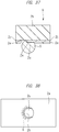
- FIG. 14 is a plan view showing the first pattern 2jc in the central portion of the second wiring layer 2j (L4) in the lowermost layer of the wiring substrate (multilayer wiring substrate) 2 of the BGA 9 according to the present embodiment, and FIG. 15 shows a cross section taken along A-A in FIG. 14 .
- the area of the first pattern 2jc provided in the second wiring layer 2j is larger than the area of the semiconductor chip 1 shown in FIG. 4 in a plan view.
- the area of the first pattern 2jc is larger than the area of the chip mounting region (chip region, third region) 2jp.
- the semiconductor chip 1 is located inside the first pattern 2jc provided in the second wiring layer 2j.
- the plurality of first opening portions 2jm are formed in this first pattern 2jc.
- the first lands 2jh and the second lands 2ji which are a plurality of lands for heat dissipation and arranged to be adjacent to each other are formed, and the solder balls 5 shown in FIG. 4 are connected to the first lands 2jh and the second lands 2ji, and the heat dissipation is performed through the solder balls 5.
- the plurality of first opening portions 2jm are provided in a first region (land region, thermal ball region) 2je in which the first lands 2jh and the second lands 2ji are provided.
- the plurality of second opening portions 2jn are formed in a second region (region outside the land region, land-outside region) 2jf located outside the first region 2je.
- first opening portion 2jm is formed between the first land 2jh and the second land 2ji as shown in FIG. 14 and FIG. 15 .
- unevenness 2n is formed on the lower surface 2mb of the second wiring layer 2m (L1), the lower surface 2kb of the first wiring layer 2k (L2), the upper surface 2ia of the first wiring layer 2i (L3), and the upper surface 2ja of the second wiring layer 2j (L4), and the degree of flatness is low.
- the surfaces of wiring layers each having the unevenness 2n formed thereon have high degree of adhesion with the insulating layers in contact with these surfaces.
- each wiring layer when the surface having the unevenness 2n (surface with a lower degree of flatness) and the surface on the side opposite thereto (surface with a higher degree of flatness) are compared, the surface having the unevenness 2n has a higher degree of adhesion with the insulating layer.
- the upper surface 2ia thereof has the unevenness 2n while the lower surface 2ib thereof has almost no unevenness 2n, and thus, the upper surface 2ia has a higher degree of adhesion with the insulating layer than the lower surface 2ib.
- the lower surface 2ib is easier to peel off from the insulating layer.
- FIG. 16 is a plan view showing the first pattern 2jc in the central portion of the second wiring layer 2j (L4) in the lowermost layer of the wiring substrate (multilayer wiring substrate) 2 of the BGA 9 according to the present embodiment
- FIG. 17 shows a cross section taken along B-B in FIG. 16 .
- the first pattern 2jc of the second wiring layer 2j (L4) has a first region 2je in which a plurality of lands 2jg are formed and a second region 2jf located outside (around) the first region 2je. Then, as the opening portions through which gas can be released in the first pattern 2jc, the first opening portions 2jm and the second opening portions 2jn different from the first opening portions 2jm are provided, and the first opening portions 2jm are arranged in the first region 2je and the second opening portions 2jn are arranged in the second region 2jf outside the first region 2je.
- the width of the first opening portion 2jm in a plan view is narrower than the width of the second opening portion 2jn. More specifically, in a plan view ( FIG. 16 ) and a cross-sectional view ( FIG. 17 ), the size of the first opening portion 2jm (W1 of FIG. 17 ) is smaller than the size of the second opening portion 2jn (W2 of FIG. 17 ) (W1 ⁇ W2) . In other words, since the interval of pitch between the first land 2jh and the second land 2ji is narrow, the width of the first opening portion 2jm is narrow.
- the size of the second opening portion 2jn is larger than that of the first opening portion 2jm, the degree of adhesion with the solder resist film 2e can be increased.
- the size (W1) of the first opening portion 2jm is approximately the same as or slightly smaller than the size (W3) of the through hole 2jj.
- a plurality of lands 2jg are formed in the first region 2je of the first pattern 2jc of the second wiring layer 2j (L4) .
- These lands 2jg are lands for mounting the thermal balls (solder balls 5). Since the plurality of lands 2jg (the first lands 2jh, the second lands 2ji) are formed in the first region 2je as described above, it is preferable that the first opening portions 2jm are arranged between the lands.
- the first lands 2jh and the second lands 2ji are arranged in a matrix form in the first region 2je. Further, the through holes 2jj are provided between the first lands 2jh and between the second lands 2ji arranged in an oblique direction. Therefore, it is effective that the first opening portions 2jm with reduced size in a plan view are provided between the first lands 2jh and the second lands 2ji (between the balls arranged in the matrix form in the vertical and horizontal directions), so that the plurality of first opening portions 2jm can be arranged in the first region 2je.
- the plurality of first opening portions 2jm are arranged in the horizontal direction (X direction) or the vertical direction (Y direction) in a plan view.
- the second opening portions 2jn are formed in the second region 2jf, which is the region outside (around) the first region 2je.
- the lands 2jg are not arranged and only a predetermined number of through holes 2jj are formed in the second region 2jf, the plurality of second opening portions 2jn having a larger opening area than the first opening portion 2jm can be arranged in the second region 2jf.
- the plurality of first opening portions 2jm are formed in the first region 2je of the first pattern 2jc in the central portion of the second wiring layer 2j (L4) in the lowermost layer, and therefore, the gas (out gas) generated inside the substrate can be released to the outside from near the central portion on the lower surface side of the substrate. Also, since the plurality of second opening portions 2jn are formed in the second region 2jf outside the first region 2je, the out gas generated within the substrate can be released more from the lower surface side of the substrate to the outside through the first opening portions 2jm and the second opening portions 2jn.
- the out gas can be released from the lower surface side of the substrate through the first opening portions 2jm and the second opening portions 2jn.
- the portion where the first opening portions 2jm are arranged is not limited to the position between the first land 2jh and the second land 2ji.
- the first opening portion 2jm may be arranged in that vacant space.
- the size of the opening of the first opening portion 2jm may not be necessarily smaller than the size of the opening of the second opening portion 2jn.
- the first opening portion 2jm having the larger opening may be of course provided in the first region 2je.
- the first opening portion 2jm and the second opening portion 2jn may have the same size. More specifically, there may be various relationships between the size of the first opening portion 2jm and the size of the second opening portion 2jn.
- first opening portion 2jm and the second opening portion 2jn are openings that expose the surface or the inside of the second insulating layer 2h in the upper layer of these opening portions and the out gas generated within the substrate can be released from the openings, but the first opening portion 2jm and the second opening portion 2jn have structures different from an ordinary through hole.
- the through hole 2jj shown in the Q portion of FIG. 15 is a through hole wiring that electrically connects the wiring pattern of the lowermost layer and the wiring pattern of the uppermost layer, a conductive pattern 2p is formed on the inner wall surface of the hole, and the through hole 2jj is not an opening that exposes the surface or the inside of the second insulating layer 2h. More specifically, since the second insulating layer 2h is surrounded by the conductive pattern 2p, the out gas generated in the second insulating layer 2h and the like cannot be released to the outside of the substrate through the through hole 2jj.
- a hole (including a dent, a slit, or the like) that does not have the conductive pattern 2p formed on the inner wall and can expose the surface or the inside of the insulating layer unlike an ordinary through hole may be provided as an opening portion of the present embodiment.
- FIG. 18 , FIG. 19 , and FIG. 20 are flow diagrams and cross-sectional views showing an example of a procedure for assembling the wiring substrate of the semiconductor device shown in FIG. 1 .
- a copper foil is formed by electrolytic copper foil manufacturing method. More specifically, an electrolytic copper foil 2q is formed on a drum electrode (cathode) 13 by using copper sulfate solution 12.
- an electrolytic copper foil 2q is formed on a drum electrode (cathode) 13 by using copper sulfate solution 12.
- copper is deposited on the surface of a drum-shaped cathode (drum electrode 13) by electrolytic reaction of the copper sulfate solution 12, and the deposited copper is wound up when it reaches a desired thickness to manufacture the copper foil.
- step S2 copper-clad laminate formation shown in step S2 is performed.
- the copper foil electrolytic copper foil 2q
- the first insulating layer 2f which is the insulating layer serving as the core layer in such a manner that the surface of each copper foil having the high degree of roughness faces the insulating layer.
- a resist formation (exposure/development) shown in step S3 is performed. More specifically, a desired pattern is exposed and developed on the copper foil (electrolytic copper foil 2q) with using a resist film as a mask.
- step S4 etching shown in step S4 is performed. More specifically, the copper foil (electrolytic copper foil 2q) is etched to form a desired pattern on the copper foil (electrolytic copper foil 2q).
- step S5 lamination shown in step S5 is performed. More specifically, the second insulating layer 2g and the second insulating layer 2h are pasted by applying pressure by a block 22 to the upper and lower surfaces of the first insulating layer 2f having the wiring patterns (first wiring layer 2k, first wiring layer 2i) formed on the upper and lower surfaces thereof. At this time, the second wiring layer 2m is pasted to the upper layer of the second insulating layer 2g and the second wiring layer 2j is pasted to the lower layer of the second insulating layer 2h in such a manner that each surface having the high degree of roughness faces the insulating layer.
- through hole processing shown in step S6 of FIG. 19 is performed.
- a plurality of through holes 2r are formed at desired positions by using, for example, a drill 14. Note that it is also possible to form the through holes 2r by laser.
- step S7 through hole plating formation shown in step S7 is performed. More specifically, a copper plating 2s is formed on the inner wall of each through hole, so that the second wiring layer 2m in the uppermost layer and the second wiring layer 2j in the lowermost layer are connected with the copper plating 2s.
- step S8 After the through hole plating formation is performed, resist formation, exposure/development, and etching shown in step S8 are performed. More specifically, a desired wiring pattern is formed by performing resist formation, exposure/development, and etching on each of the second wiring layer 2m in the uppermost layer and the second wiring layer 2j in the lowermost layer.
- the solder resist application shown in step S9 of FIG. 20 is performed. More specifically, the solder resist film 2d is formed on the upper layer of the second wiring layer 2m in the uppermost layer, while the solder resist film 2e is formed on the lower layer of the second wiring layer 2j in the lowermost layer, and the solder resist 2t is further formed in the through holes 2jj.
- step S10 exposure/development shown in step S10 is performed.
- exposure and development are performed on the solder resist film 2d in the upper layer and the solder resist film 2e in the lower layer, so that a desired pattern is formed on each of the desired solder resist films.
- step S11 the surface treatment shown in step S11 is performed.
- surface treatment is performed on the bonding leads 2c exposed on the upper surface side and the lands 2jg exposed on the lower surface side. More specifically, Ni/Au plating 2u is formed.
- the wiring substrate 2 including four wiring layers is completed.
- the unevenness 2n is formed in the copper foil forming process on each of the lower surface 2mb of the second wiring layer 2m (L1) (see FIG. 15 ), the lower surface 2kb of the first wiring layer 2k (L2) (see FIG. 15 ), the upper surface 2ia of the first wiring layer 2i (L3) (see FIG.
- FIG. 21 to FIG. 24 is a flow diagram and a cross-sectional view showing a procedure for assembling the semiconductor device of FIG. 1 .
- the BGA 9 is assembled by the so-called MAP (Mold Array Package) method in which the assembly is performed by using a multi-chip substrate 10 having a plurality of semiconductor device regions will be described.
- MAP Mold Array Package
- step S21 shown in FIG. 21 First, a wafer preparation in step S21 shown in FIG. 21 is performed.
- step S22 After the wafer preparation, dicing shown in step S22 is performed. In this case, the semiconductor wafer 15 held by a wafer ring 16 is diced by a dicing blade 17 to obtain a non-defective semiconductor chip 1.
- step S23 die bonding shown in step S23 is performed.
- a die bond material 6 such as a resin paste material is applied onto the substrate by using, for example, a multi-point nozzle 18, and the semiconductor chip 1 is then mounted on the substrate via the die bond material 6.
- step S24 of FIG. 22 After the die bonding, wire bonding shown in step S24 of FIG. 22 is performed.
- the electrode pads 1c of the semiconductor chip 1 and the bonding leads 2c of the wiring substrate 2 (multi-chip substrate 10) are electrically connected by the metal wires 7.
- step S25 resin molding in step S25 is performed. More specifically, the semiconductor chips 1 and the plurality of wires 7 are sealed with sealing resin on the multi-chip substrate 10 to form a batch sealing body 8 on the multi-chip substrate 10.
- step S26 of FIG. 23 After completion of the resin molding, laser marking shown in step S26 of FIG. 23 is performed. More specifically, desired marks 19 are placed on the surface of the batch sealing body 8 formed by the resin molding by irradiating the surface with a laser.
- step S27 After completion of the laser marking, bump formation shown in step S27 is performed.
- the plurality of solder balls 5 are mounted on the lower surface of the multi-chip substrate 10 (wiring substrate 2).
- step S28 of FIG. 24 is performed. More specifically, the batch sealing body 8 shown in FIG. 24 formed by the resin molding and the multi-chip substrate 10 are cut together by the dicing blade 17 to separate them into pieces, and furthermore, a test shown in step S29 is performed. As a result, the assembly of the BGA 9 shown in FIG. 24 is completed.
- FIG. 25 is a cross-sectional view showing an example of the mounting structure of the semiconductor device shown in FIG. 1 .
- the assembled BGA 9 is mounted on the mother board 11 which is the mounting board. At that time, the solder balls 5 are melted by reflowing, so that the solder balls 5 which are external terminals and the bump electrodes 11a formed on the upper surface 11c of the mother board 11 are electrically connected. On the other hand, the solder balls 5 for heat dissipation (thermal balls) placed in the central portion of the BGA 9 and the pattern 11b for heat dissipation of the mother board 11 are electrically connected.
- the out gas can be released from the lower surface side of the substrate through the first opening portions 2jm and the second opening portions 2jn.
- the reliability as the module can also be improved.
- FIG. 26 is a partial plan view showing a first modification example of the positional relationship of the semiconductor chip and the wiring pattern of the lowermost wiring layer in the wiring substrate of the semiconductor device of FIG. 1
- FIG. 27 is a partial plan view showing the first modification example of the positional relationship of the semiconductor chip and the wiring pattern of the lowermost wiring layer in the wiring substrate of the semiconductor device of FIG. 1
- FIG. 28 is a partial plan view showing the first modification example of the wiring pattern on the back surface of the lowermost wiring layer in the wiring substrate of the semiconductor device of FIG. 1 .
- FIG. 26 shows a case where the region of the semiconductor chip 1 is larger than the first region (thermal ball region) 2je in the first pattern 2jc of the second wiring layer 2j
- FIG. 27 shows a structure in which the region of the mounted semiconductor chip 1 is displaced relative to the first pattern 2jc.
- the plurality of first opening portions 2jm are formed in the first region 2je and the plurality of second opening portions 2jn are formed in the second region 2jf outside the first region 2je, and therefore, the out gas generated within the substrate in the heating can be released from the lower surface side of the substrate to the outside through the first opening portions 2jm and the second opening portions 2jn.
- the structure in FIG. 28 shows a case where a plurality of third patterns 2v different from the second pattern 2jd are provided also in a region other than the first pattern 2jc (other than the chip region) in the second wiring layer 2j
- the third pattern 2v has a plurality of lands 2jg, and can be used as, for example, a power supply pattern, a GND pattern, a heat dissipation plane, a heat dissipation pattern, or the like.
- These patterns are provided with the through holes 2jk connected to the bonding lead 2c of the wiring layer L1, the pattern of the wiring layer L2, the pattern of the wiring layer L3, and the like shown in FIG. 4 , and some of the third patterns 2v are provided with the first opening portions 2jm. Also, some of the third patterns 2v are provided with the second opening portions 2jn.
- the out gas generated within the substrate can be released to the outside through the first opening portions 2jm and the second opening portions 2jn.
- FIG. 29 is a plan view showing a second modification example of the wiring pattern of the second wiring layer (L2) from the top in the wiring substrate of the semiconductor device shown in FIG. 1
- FIG. 30 is a plan view showing the second modification example of the wiring pattern of the third wiring layer (L3) from the top in the wiring substrate of the semiconductor device shown in FIG. 1 .
- the structure in FIG. 29 shows the case where the first wiring layer 2k (L2) is comprised of one type of pattern instead of the divided patterns
- the structure in FIG. 30 similarly shows the case where the first wiring layer 2i (L3) is comprised of one type of pattern instead of the divided patterns.
- the out gas generated inside the substrate can be released to the outside through the first opening portions 2jm and the second opening portions 2jn, and as a result, the reliability of the BGA 9 can be improved.
- the out gas is difficult to release when any one of the patterns is larger than the first pattern 2jc of the second wiring layer 2j (L4) . Therefore, also in this case, by providing the first opening portions 2jm and the second opening portions 2jn in the second wiring layer 2j (L4) of the wiring substrate 2 similarly to the above, the out gas generated within the substrate can be released to the outside from the first opening portions 2jm and the second opening portions 2jn.
- FIG. 31 is a cross-sectional view showing a structure of a semiconductor device of a third modification example of the embodiment.
- a BGA 20 shown in FIG. 31 is a semiconductor device assembled by single molding. More specifically, the BGA 20 has the sealing body 4 formed by a cavity corresponding to each semiconductor device unlike those formed by batch molding. Therefore, the BGA 20 is a semiconductor device having a structure in which the peripheral portion of the upper surface 2a of the wiring substrate 2 is exposed.
- the out gas generated inside the substrate can be released to the outside through the first opening portions 2jm and the second opening portions 2jn, and as a result, the reliability of the BGA 20 can be improved.
- FIG. 32 is a plan view showing a fourth modification example of the wiring pattern of the uppermost wiring layer in the wiring substrate of the semiconductor device of FIG. 1
- FIG. 33 is a cross-sectional view showing the fourth modification example of the structure of the semiconductor device taken along line A-A in FIG. 32 .
- the first pattern 2mc of the second wiring layer 2m (L1) in the uppermost layer indicates the GND/power supply pattern.
- the bonding lead 2c shown in FIG. 33 is electrically connected to the semiconductor chip 1 via the wire 7.
- the first pattern 2mc and the through hole 2me connected to the bonding lead 2c are electrically connected via the wiring 2y in the pattern of the second wiring layer 2m (L1) in the uppermost layer.
- the bonding lead 2c and the first pattern 2mc are electrically connected to each other.
- the first pattern 2mc of the second wiring layer 2m (L1) in the upper most layer is connected to the first pattern 2jc of the second wiring layer 2j (L4) in the lowermost layer via the through hole 2mf of the second wiring layer 2m (L1) in the uppermost layer and the through hole 2jj of the second wiring layer 2j (L4) in the lowermost layer.
- the first pattern 2mc of the second wiring layer 2m (L1) in the uppermost layer is electrically connected to the first pattern 2jc of the second wiring layer 2j (L4) in the lowermost layer.
- the bonding lead 2c of the second wiring layer 2m (L1) in the uppermost layer is connected to the second pattern 2jd of the second wiring layer 2j (L4) in the lowermost layer shown in FIG. 9 via the through hole 2me of the second wiring layer 2m (L1) in the uppermost layer and the through hole 2jk of the second wiring layer 2j (L4) in the lowermost layer.
- the bonding lead 2c of the second wiring layer 2m (L1) in the uppermost layer of FIG. 33 is connected to the third pattern 2v of the second wiring layer 2j (L4) in the lowermost layer shown in FIG.
- the bonding lead 2c of the second wiring layer 2m in the uppermost layer is electrically connected to the second pattern 2jd of the second wiring layer 2j (L4) in the lowermost layer or the third pattern 2v of the second wiring layer 2j (L4) in the lowermost layer.
- the first pattern 2mc of the second wiring layer 2m in the uppermost layer, the first pattern 2jc of the second wiring layer 2j (L4) in the lowermost layer, and the second pattern 2jd of the second wiring layer 2j (L4) in the lowermost layer are the GND patterns.
- the third pattern 2v of the second wiring layer 2j (L4) in the lowermost layer is also the GND pattern.
- the first pattern 2mc of the second wiring layer 2m in the uppermost layer, the first pattern 2jc of the second wiring layer 2j (L4) in the lowermost layer, and the second pattern 2jd of the second wiring layer 2j (L4) in the lowermost layer are the power supply patterns.
- the third pattern 2v of the second wiring layer 2j (L4) in the lowermost layer is also the power supply pattern.
- the out gas generated inside the substrate can be released to the outside through the first opening portions 2jm and the second opening portions 2jn.
- FIG. 34 is a flow diagram and a cross-sectional view showing a procedure for assembling a wiring substrate according to a fifth modification example of the embodiment, and FIG. 34 shows a manufacturing method of a wiring substrate 21 having three wiring layers. However, illustrations of the process similar to that of the wiring substrate 2 having four wiring layers are omitted in FIG. 34 .
- the copper foil formation shown in step S31 of FIG. 34 is performed.
- a copper foil is formed by electrolytic copper foil manufacturing method in the same manner as the case of the four wiring layers. More specifically, the electrolytic copper foil 2q is formed on the drum electrode (cathode) 13 by using copper sulfate solution 12 shown in FIG. 18 .
- the copper-clad laminate formation shown in step S32 is performed.
- the copper foil is pasted on the upper and lower surfaces of the first insulating layer 2f which is the insulating layer serving as the core layer in such a manner that the roughened surface of each copper foil faces the insulating layer.
- the resist formation exposure/development
- etching are performed in the same manner as the method shown in FIG. 18 .
- step S35 lamination shown in step S35 is performed. More specifically, the second insulating layer 2h is pasted by applying pressure by a block 22 to the lower surface 21bb of the first insulating layer 2f having the wiring patterns (upper first wiring layer 21a, lower first wiring layer 21b) made of the copper foil formed on the upper and lower surfaces thereof. At this time, the second wiring layer 2j is pasted to the lower layer (lower surface 2hb) of the second insulating layer 2h in such a manner that the surface having the high degree of roughness faces the second wiring insulating layer 2h.
- the wiring substrate 21 having three wiring layers is assembled through the assembly process similar to that of the wiring substrate 2 having four wiring layers.
- the unevenness 2n is formed in the copper foil forming process on each of the lower surface 21aa of the upper first wiring layer 21a (L1, first wiring layer 2k), the upper surface 21ba of lower first wiring layer 21b (L2, first wiring layer 2i), and the upper surface 2ja of the second wiring layer 2j (L3), and the degree of adhesion with the insulating layer is high.
- the lower surface 21bb of the lower first wiring layer 21b (L2) has a high degree of flatness, the degree of adhesion with the insulating layer is lower than the surface having high degree of roughness, and the peeling 34 shown in FIG. 13 is likely to occur.
- the out gas generated within the substrate can be released to the outside through the first opening portions 2jm and the second opening portions 2jn.
- FIG. 35 is a partial cross-sectional view showing an SMD structure in a wiring substrate of a semiconductor device according to a comparative examination example
- FIG. 36 is a partial plan view showing the SMD structure shown in FIG. 35
- FIG. 37 is a partial cross-sectional view showing an NSMD structure in a wiring substrate of a semiconductor device according to a comparative examination example
- FIG. 38 is a partial plan view showing the NSMD structure shown in FIG. 37 .
- FIG. 35 shows a connection structure between the land 2jg and the solder ball 5 adopted in the BGA 9 according to the present embodiment
- FIG. 36 shows a planar structure of the land 2jg of FIG. 35 .
- the land structure shown in FIG. 35 and FIG. 36 is the SMD (Solder Mask Defined) structure.
- SMD solder Mask Defined
- the peripheral portion of each of the plurality of lands 2jg is covered with the solder resist film (second protective film) 2e, and therefore, the underlying insulating layer of the land 2jg is not seen in the plan view.
- each of the plurality of solder balls 5 is provided to be bonded with each of the plurality of lands 2jg and the solder resist film 2e on the peripheral portion of each of the lands 2jg. Ni/Au plating 2u is formed on the land 2jg.
- the land 2jg having the SMD structure described above since the peripheral portion of the land 2jg is covered with the solder resist film 2e, the out gas generated inside the substrate is difficult to release. However, since the land 2jg is difficult to peel off, it has the feature that the reliability of the wiring substrate 2 is high.
- FIG. 37 shows a connection structure between a land 2x and the solder ball 5 examined by the inventors of the present application
- FIG. 38 shows a planar structure of the land 2x of FIG. 37
- the land structure shown in FIG. 37 and FIG. 38 is the NSMD (Non-Solder Mask Defined) structure.
- the NSMD structure each of the plurality of lands 2x is not covered with the solder resist film (second protective film) 2e and the entire land 2x is exposed.
- Ni/Au plating 2u is formed on the land 2x.
- the underlying insulating layer (second insulating layer 2h) of the land 2x is visible (exposed) in the plan view in the NSMD structure.
- each of the plurality of solder balls 5 is provided to connect to each of the plurality of lands 2x.
- the underling insulating layer (second insulating layer 2h) of the land 2x is visible (exposed) as described above, and thus the out gas generated inside the substrate is easy to release in the NSMD structure.
- the connection area between the solder ball 5 and the land 2x increases, the connection strength of the solder can be increased and the lifetime of the solder connection portion can be increased.
- the connection strength of the solder is high, a problem that the land 2x peels off from the substrate is likely to occur when an impact is applied to the solder ball 5 from the outside, and the NSMD structure has a feature that the reliability of the substrate is lower than that of the SMD structure.
- the NSMD structure when the NSMD structure is adopted as the land structure, the effect for preventing the peeling of the wiring layer and the insulating layer can be obtained from the viewpoint of gas release.
- the impact resistance when the impact resistance is taken into consideration, it is preferable to adopt the SMD structure, and the reliability of the substrate and semiconductor device can be increased in such a case.
- thermal balls are provided in the first pattern in the lowermost layer, but the thermal balls may not be necessarily provided.
- the wiring substrate 2 is a substrate including the core
- the wiring substrate 2 may be a coreless substrate. More specifically, this is because since a copper foil is pasted onto the insulating layer to form the substrate even in the case of the coreless substrate, the degree of adhesion of the roughened surface is high and the degree of adhesion with the insulating layer pasted to both sides (or one side (in the case of three-layer substrate)) is low, and the peeling is likely to occur particularly in the lowermost wiring layer.
Landscapes
- Engineering & Computer Science (AREA)
- Microelectronics & Electronic Packaging (AREA)
- Computer Hardware Design (AREA)
- Power Engineering (AREA)
- Physics & Mathematics (AREA)
- Condensed Matter Physics & Semiconductors (AREA)
- General Physics & Mathematics (AREA)
- Manufacturing & Machinery (AREA)
- Chemical & Material Sciences (AREA)
- Materials Engineering (AREA)
- Ceramic Engineering (AREA)
- Geometry (AREA)
- Production Of Multi-Layered Print Wiring Board (AREA)
- Cooling Or The Like Of Semiconductors Or Solid State Devices (AREA)
Applications Claiming Priority (1)
| Application Number | Priority Date | Filing Date | Title |
|---|---|---|---|
| PCT/JP2015/069294 WO2017006391A1 (ja) | 2015-07-03 | 2015-07-03 | 半導体装置 |
Publications (1)
| Publication Number | Publication Date |
|---|---|
| EP3319120A1 true EP3319120A1 (de) | 2018-05-09 |
Family
ID=57685256
Family Applications (1)
| Application Number | Title | Priority Date | Filing Date |
|---|---|---|---|
| EP15897654.8A Withdrawn EP3319120A1 (de) | 2015-07-03 | 2015-07-03 | Halbleiterbauelement |
Country Status (7)
| Country | Link |
|---|---|
| US (1) | US10134665B2 (de) |
| EP (1) | EP3319120A1 (de) |
| JP (1) | JP6439046B2 (de) |
| KR (1) | KR20180022628A (de) |
| CN (1) | CN107210267B (de) |
| HK (1) | HK1244353A1 (de) |
| WO (1) | WO2017006391A1 (de) |
Families Citing this family (5)
| Publication number | Priority date | Publication date | Assignee | Title |
|---|---|---|---|---|
| KR20180098009A (ko) * | 2017-02-24 | 2018-09-03 | 삼성전자주식회사 | 인쇄회로기판 및 이를 가지는 반도체 패키지 |
| CN217363376U (zh) * | 2019-05-15 | 2022-09-02 | 株式会社村田制作所 | 树脂多层基板以及电子部件 |
| JP7331521B2 (ja) * | 2019-07-24 | 2023-08-23 | Tdk株式会社 | 電子部品内蔵基板 |
| US11212912B1 (en) * | 2020-06-30 | 2021-12-28 | Microsoft Technology Licensing, Llc | Printed circuit board mesh routing to reduce solder ball joint failure during reflow |
| WO2022202487A1 (ja) * | 2021-03-25 | 2022-09-29 | ソニーセミコンダクタソリューションズ株式会社 | 半導体装置、半導体装置の製造方法及び電子機器 |
Family Cites Families (16)
| Publication number | Priority date | Publication date | Assignee | Title |
|---|---|---|---|---|
| JPH06104350A (ja) * | 1992-09-21 | 1994-04-15 | Toshiba Corp | 多層配線基板 |
| JP3260941B2 (ja) | 1993-06-18 | 2002-02-25 | 株式会社日立製作所 | 多層配線基板および多層配線基板の製造方法 |
| JPH09153679A (ja) | 1995-11-30 | 1997-06-10 | Kyocera Corp | 積層ガラスセラミック回路基板 |
| JPH10303334A (ja) | 1997-04-28 | 1998-11-13 | Sumitomo Kinzoku Electro Device:Kk | プラスチック配線基板 |
| EP1207730B1 (de) * | 1999-08-06 | 2009-09-16 | Ibiden Co., Ltd. | Lösung für die elektrochemische abscheidung, methode, eine leiterplatte unter verwendung dieser lösung herzustellen und mehrschichtige leiterplatte |
| DE60027141T2 (de) * | 1999-10-26 | 2006-12-28 | Ibiden Co., Ltd., Ogaki | Gedruckte mehrschichtleiterplatte und herstellungsverfahren für gedruckte mehrschichtleiterplatte |
| JP3879461B2 (ja) | 2001-09-05 | 2007-02-14 | 日立電線株式会社 | 配線基板及びその製造方法 |
| WO2005076683A1 (ja) * | 2004-02-04 | 2005-08-18 | Ibiden Co., Ltd. | 多層プリント配線板 |
| JP2005353835A (ja) * | 2004-06-10 | 2005-12-22 | Ngk Spark Plug Co Ltd | 配線基板 |
| JP2006147676A (ja) | 2004-11-17 | 2006-06-08 | Nec Corp | 半導体集積回路パッケージ用配線基板とその配線基板を用いた半導体集積回路装置 |
| JPWO2008053833A1 (ja) * | 2006-11-03 | 2010-02-25 | イビデン株式会社 | 多層プリント配線板 |
| JP4843538B2 (ja) | 2007-03-22 | 2011-12-21 | 富士通株式会社 | 回路基板及びその製造方法 |
| JP2011146513A (ja) | 2010-01-14 | 2011-07-28 | Renesas Electronics Corp | 半導体装置 |
| JP6081044B2 (ja) | 2010-09-16 | 2017-02-15 | 富士通株式会社 | パッケージ基板ユニットの製造方法 |
| JP5970348B2 (ja) | 2012-11-16 | 2016-08-17 | ルネサスエレクトロニクス株式会社 | 半導体装置 |
| JP2014123783A (ja) | 2014-03-31 | 2014-07-03 | Renesas Electronics Corp | 半導体装置 |
-
2015
- 2015-07-03 WO PCT/JP2015/069294 patent/WO2017006391A1/ja active Application Filing
- 2015-07-03 CN CN201580073418.8A patent/CN107210267B/zh active Active
- 2015-07-03 JP JP2017526799A patent/JP6439046B2/ja active Active
- 2015-07-03 US US15/563,214 patent/US10134665B2/en active Active
- 2015-07-03 EP EP15897654.8A patent/EP3319120A1/de not_active Withdrawn
- 2015-07-03 KR KR1020177027511A patent/KR20180022628A/ko unknown
-
2018
- 2018-03-19 HK HK18103772.8A patent/HK1244353A1/zh unknown
Also Published As
| Publication number | Publication date |
|---|---|
| WO2017006391A1 (ja) | 2017-01-12 |
| KR20180022628A (ko) | 2018-03-06 |
| HK1244353A1 (zh) | 2018-08-03 |
| US10134665B2 (en) | 2018-11-20 |
| US20180090429A1 (en) | 2018-03-29 |
| JP6439046B2 (ja) | 2018-12-19 |
| JPWO2017006391A1 (ja) | 2017-10-19 |
| CN107210267B (zh) | 2020-06-02 |
| CN107210267A (zh) | 2017-09-26 |
Similar Documents
| Publication | Publication Date | Title |
|---|---|---|
| US7518250B2 (en) | Semiconductor device and a method for manufacturing of the same | |
| US9263374B2 (en) | Semiconductor device and manufacturing method therefor | |
| JP5400094B2 (ja) | 半導体パッケージ及びその実装方法 | |
| US20140312476A1 (en) | No-exposed-pad ball grid array (bga) packaging structures and method for manufacturing the same | |
| EP3319120A1 (de) | Halbleiterbauelement | |
| JP2011146489A (ja) | 半導体装置 | |
| KR20070119521A (ko) | 반도체 장치의 제조 방법 | |
| JP2007235009A (ja) | 半導体装置 | |
| US10304767B2 (en) | Semiconductor device | |
| JP2011066344A (ja) | 半導体装置および電子装置 | |
| JP2009094434A (ja) | 半導体装置およびその製造方法 | |
| JP5405749B2 (ja) | 半導体装置の配線基板、半導体装置、電子装置およびマザーボード | |
| JP2010161419A (ja) | 半導体装置の製造方法 | |
| JP5159750B2 (ja) | 半田ボール及び半導体パッケージ | |
| JP2009111279A (ja) | 半導体装置の配線基板、半導体装置、電子装置、マザーボード、半導体装置の配線基板の製造方法、マザーボードの製造方法、電子装置の製造方法 | |
| JP4963989B2 (ja) | 半導体素子搭載用基板およびその製造方法 | |
| KR20160084666A (ko) | 인쇄회로기판, 반도체 패키지 및 이들의 제조방법 | |
| JP2010232616A (ja) | 半導体装置及び配線基板 | |
| JP2007059493A (ja) | 半導体装置およびその製造方法 | |
| JP2006210796A (ja) | 回路装置およびその製造方法 | |
| JP5171720B2 (ja) | 半導体装置 | |
| JP6105773B2 (ja) | 半導体装置 | |
| JP2012119540A (ja) | 半導体装置およびその製造方法 | |
| JP2008282980A (ja) | 半導体装置およびその製造方法 | |
| JP2013077735A (ja) | 半導体装置およびその製造方法 |
Legal Events
| Date | Code | Title | Description |
|---|---|---|---|
| PUAI | Public reference made under article 153(3) epc to a published international application that has entered the european phase |
Free format text: ORIGINAL CODE: 0009012 |
|
| 17P | Request for examination filed |
Effective date: 20170921 |
|
| AK | Designated contracting states |
Kind code of ref document: A1 Designated state(s): AL AT BE BG CH CY CZ DE DK EE ES FI FR GB GR HR HU IE IS IT LI LT LU LV MC MK MT NL NO PL PT RO RS SE SI SK SM TR |
|
| AX | Request for extension of the european patent |
Extension state: BA ME |
|
| DAV | Request for validation of the european patent (deleted) | ||
| DAX | Request for extension of the european patent (deleted) | ||
| STAA | Information on the status of an ep patent application or granted ep patent |
Free format text: STATUS: THE APPLICATION HAS BEEN WITHDRAWN |
|
| 18W | Application withdrawn |
Effective date: 20190312 |