KR20180098009A - 인쇄회로기판 및 이를 가지는 반도체 패키지 - Google Patents
인쇄회로기판 및 이를 가지는 반도체 패키지 Download PDFInfo
- Publication number
- KR20180098009A KR20180098009A KR1020170024920A KR20170024920A KR20180098009A KR 20180098009 A KR20180098009 A KR 20180098009A KR 1020170024920 A KR1020170024920 A KR 1020170024920A KR 20170024920 A KR20170024920 A KR 20170024920A KR 20180098009 A KR20180098009 A KR 20180098009A
- Authority
- KR
- South Korea
- Prior art keywords
- layer
- pad
- connection pad
- wiring
- cover layer
- Prior art date
- Legal status (The legal status is an assumption and is not a legal conclusion. Google has not performed a legal analysis and makes no representation as to the accuracy of the status listed.)
- Withdrawn
Links
Images


Classifications
-
- H—ELECTRICITY
- H10—SEMICONDUCTOR DEVICES; ELECTRIC SOLID-STATE DEVICES NOT OTHERWISE PROVIDED FOR
- H10W—GENERIC PACKAGES, INTERCONNECTIONS, CONNECTORS OR OTHER CONSTRUCTIONAL DETAILS OF DEVICES COVERED BY CLASS H10
- H10W70/00—Package substrates; Interposers; Redistribution layers [RDL]
- H10W70/60—Insulating or insulated package substrates; Interposers; Redistribution layers
- H10W70/62—Insulating or insulated package substrates; Interposers; Redistribution layers characterised by their interconnections
- H10W70/65—Shapes or dispositions of interconnections
-
- H—ELECTRICITY
- H05—ELECTRIC TECHNIQUES NOT OTHERWISE PROVIDED FOR
- H05K—PRINTED CIRCUITS; CASINGS OR CONSTRUCTIONAL DETAILS OF ELECTRIC APPARATUS; MANUFACTURE OF ASSEMBLAGES OF ELECTRICAL COMPONENTS
- H05K1/00—Printed circuits
- H05K1/02—Details
- H05K1/11—Printed elements for providing electric connections to or between printed circuits
- H05K1/111—Pads for surface mounting, e.g. lay-out
-
- H01L23/481—
-
- H01L23/4952—
-
- H01L24/12—
-
- H01L24/44—
-
- H—ELECTRICITY
- H05—ELECTRIC TECHNIQUES NOT OTHERWISE PROVIDED FOR
- H05K—PRINTED CIRCUITS; CASINGS OR CONSTRUCTIONAL DETAILS OF ELECTRIC APPARATUS; MANUFACTURE OF ASSEMBLAGES OF ELECTRICAL COMPONENTS
- H05K3/00—Apparatus or processes for manufacturing printed circuits
- H05K3/22—Secondary treatment of printed circuits
- H05K3/28—Applying non-metallic protective coatings
-
- H—ELECTRICITY
- H10—SEMICONDUCTOR DEVICES; ELECTRIC SOLID-STATE DEVICES NOT OTHERWISE PROVIDED FOR
- H10P—GENERIC PROCESSES OR APPARATUS FOR THE MANUFACTURE OR TREATMENT OF DEVICES COVERED BY CLASS H10
- H10P72/00—Handling or holding of wafers, substrates or devices during manufacture or treatment thereof
- H10P72/70—Handling or holding of wafers, substrates or devices during manufacture or treatment thereof for supporting or gripping
- H10P72/74—Handling or holding of wafers, substrates or devices during manufacture or treatment thereof for supporting or gripping using temporarily an auxiliary support
-
- H—ELECTRICITY
- H10—SEMICONDUCTOR DEVICES; ELECTRIC SOLID-STATE DEVICES NOT OTHERWISE PROVIDED FOR
- H10W—GENERIC PACKAGES, INTERCONNECTIONS, CONNECTORS OR OTHER CONSTRUCTIONAL DETAILS OF DEVICES COVERED BY CLASS H10
- H10W20/00—Interconnections in chips, wafers or substrates
- H10W20/20—Interconnections within wafers or substrates, e.g. through-silicon vias [TSV]
-
- H—ELECTRICITY
- H10—SEMICONDUCTOR DEVICES; ELECTRIC SOLID-STATE DEVICES NOT OTHERWISE PROVIDED FOR
- H10W—GENERIC PACKAGES, INTERCONNECTIONS, CONNECTORS OR OTHER CONSTRUCTIONAL DETAILS OF DEVICES COVERED BY CLASS H10
- H10W70/00—Package substrates; Interposers; Redistribution layers [RDL]
- H10W70/01—Manufacture or treatment
- H10W70/05—Manufacture or treatment of insulating or insulated package substrates, or of interposers, or of redistribution layers
- H10W70/093—Connecting or disconnecting other interconnections thereto or therefrom, e.g. connecting bond wires or bumps
-
- H—ELECTRICITY
- H10—SEMICONDUCTOR DEVICES; ELECTRIC SOLID-STATE DEVICES NOT OTHERWISE PROVIDED FOR
- H10W—GENERIC PACKAGES, INTERCONNECTIONS, CONNECTORS OR OTHER CONSTRUCTIONAL DETAILS OF DEVICES COVERED BY CLASS H10
- H10W70/00—Package substrates; Interposers; Redistribution layers [RDL]
- H10W70/01—Manufacture or treatment
- H10W70/05—Manufacture or treatment of insulating or insulated package substrates, or of interposers, or of redistribution layers
- H10W70/095—Manufacture or treatment of insulating or insulated package substrates, or of interposers, or of redistribution layers of vias therein
-
- H—ELECTRICITY
- H10—SEMICONDUCTOR DEVICES; ELECTRIC SOLID-STATE DEVICES NOT OTHERWISE PROVIDED FOR
- H10W—GENERIC PACKAGES, INTERCONNECTIONS, CONNECTORS OR OTHER CONSTRUCTIONAL DETAILS OF DEVICES COVERED BY CLASS H10
- H10W70/00—Package substrates; Interposers; Redistribution layers [RDL]
- H10W70/40—Leadframes
- H10W70/464—Additional interconnections in combination with leadframes
- H10W70/465—Bumps or wires
-
- H—ELECTRICITY
- H10—SEMICONDUCTOR DEVICES; ELECTRIC SOLID-STATE DEVICES NOT OTHERWISE PROVIDED FOR
- H10W—GENERIC PACKAGES, INTERCONNECTIONS, CONNECTORS OR OTHER CONSTRUCTIONAL DETAILS OF DEVICES COVERED BY CLASS H10
- H10W70/00—Package substrates; Interposers; Redistribution layers [RDL]
- H10W70/60—Insulating or insulated package substrates; Interposers; Redistribution layers
- H10W70/62—Insulating or insulated package substrates; Interposers; Redistribution layers characterised by their interconnections
- H10W70/63—Vias, e.g. via plugs
- H10W70/635—Through-vias
-
- H—ELECTRICITY
- H10—SEMICONDUCTOR DEVICES; ELECTRIC SOLID-STATE DEVICES NOT OTHERWISE PROVIDED FOR
- H10W—GENERIC PACKAGES, INTERCONNECTIONS, CONNECTORS OR OTHER CONSTRUCTIONAL DETAILS OF DEVICES COVERED BY CLASS H10
- H10W70/00—Package substrates; Interposers; Redistribution layers [RDL]
- H10W70/60—Insulating or insulated package substrates; Interposers; Redistribution layers
- H10W70/62—Insulating or insulated package substrates; Interposers; Redistribution layers characterised by their interconnections
- H10W70/66—Conductive materials thereof
-
- H—ELECTRICITY
- H10—SEMICONDUCTOR DEVICES; ELECTRIC SOLID-STATE DEVICES NOT OTHERWISE PROVIDED FOR
- H10W—GENERIC PACKAGES, INTERCONNECTIONS, CONNECTORS OR OTHER CONSTRUCTIONAL DETAILS OF DEVICES COVERED BY CLASS H10
- H10W70/00—Package substrates; Interposers; Redistribution layers [RDL]
- H10W70/60—Insulating or insulated package substrates; Interposers; Redistribution layers
- H10W70/67—Insulating or insulated package substrates; Interposers; Redistribution layers characterised by their insulating layers or insulating parts
- H10W70/69—Insulating materials thereof
- H10W70/695—Organic materials
-
- H—ELECTRICITY
- H10—SEMICONDUCTOR DEVICES; ELECTRIC SOLID-STATE DEVICES NOT OTHERWISE PROVIDED FOR
- H10W—GENERIC PACKAGES, INTERCONNECTIONS, CONNECTORS OR OTHER CONSTRUCTIONAL DETAILS OF DEVICES COVERED BY CLASS H10
- H10W72/00—Interconnections or connectors in packages
- H10W72/20—Bump connectors, e.g. solder bumps or copper pillars; Dummy bumps; Thermal bumps
-
- H—ELECTRICITY
- H10—SEMICONDUCTOR DEVICES; ELECTRIC SOLID-STATE DEVICES NOT OTHERWISE PROVIDED FOR
- H10W—GENERIC PACKAGES, INTERCONNECTIONS, CONNECTORS OR OTHER CONSTRUCTIONAL DETAILS OF DEVICES COVERED BY CLASS H10
- H10W72/00—Interconnections or connectors in packages
- H10W72/50—Bond wires
-
- H—ELECTRICITY
- H10—SEMICONDUCTOR DEVICES; ELECTRIC SOLID-STATE DEVICES NOT OTHERWISE PROVIDED FOR
- H10W—GENERIC PACKAGES, INTERCONNECTIONS, CONNECTORS OR OTHER CONSTRUCTIONAL DETAILS OF DEVICES COVERED BY CLASS H10
- H10W90/00—Package configurations
- H10W90/701—Package configurations characterised by the relative positions of pads or connectors relative to package parts
-
- H—ELECTRICITY
- H05—ELECTRIC TECHNIQUES NOT OTHERWISE PROVIDED FOR
- H05K—PRINTED CIRCUITS; CASINGS OR CONSTRUCTIONAL DETAILS OF ELECTRIC APPARATUS; MANUFACTURE OF ASSEMBLAGES OF ELECTRICAL COMPONENTS
- H05K2201/00—Indexing scheme relating to printed circuits covered by H05K1/00
- H05K2201/09—Shape and layout
- H05K2201/09209—Shape and layout details of conductors
- H05K2201/09372—Pads and lands
- H05K2201/09436—Pads or lands on permanent coating which covers the other conductors
-
- H—ELECTRICITY
- H10—SEMICONDUCTOR DEVICES; ELECTRIC SOLID-STATE DEVICES NOT OTHERWISE PROVIDED FOR
- H10P—GENERIC PROCESSES OR APPARATUS FOR THE MANUFACTURE OR TREATMENT OF DEVICES COVERED BY CLASS H10
- H10P72/00—Handling or holding of wafers, substrates or devices during manufacture or treatment thereof
- H10P72/70—Handling or holding of wafers, substrates or devices during manufacture or treatment thereof for supporting or gripping
- H10P72/74—Handling or holding of wafers, substrates or devices during manufacture or treatment thereof for supporting or gripping using temporarily an auxiliary support
- H10P72/7424—Handling or holding of wafers, substrates or devices during manufacture or treatment thereof for supporting or gripping using temporarily an auxiliary support used as a support during the manufacture of self-supporting substrates
-
- H—ELECTRICITY
- H10—SEMICONDUCTOR DEVICES; ELECTRIC SOLID-STATE DEVICES NOT OTHERWISE PROVIDED FOR
- H10P—GENERIC PROCESSES OR APPARATUS FOR THE MANUFACTURE OR TREATMENT OF DEVICES COVERED BY CLASS H10
- H10P72/00—Handling or holding of wafers, substrates or devices during manufacture or treatment thereof
- H10P72/70—Handling or holding of wafers, substrates or devices during manufacture or treatment thereof for supporting or gripping
- H10P72/74—Handling or holding of wafers, substrates or devices during manufacture or treatment thereof for supporting or gripping using temporarily an auxiliary support
- H10P72/743—Handling or holding of wafers, substrates or devices during manufacture or treatment thereof for supporting or gripping using temporarily an auxiliary support used as a support during manufacture of interconnect decals or build up layers
-
- H—ELECTRICITY
- H10—SEMICONDUCTOR DEVICES; ELECTRIC SOLID-STATE DEVICES NOT OTHERWISE PROVIDED FOR
- H10W—GENERIC PACKAGES, INTERCONNECTIONS, CONNECTORS OR OTHER CONSTRUCTIONAL DETAILS OF DEVICES COVERED BY CLASS H10
- H10W70/00—Package substrates; Interposers; Redistribution layers [RDL]
- H10W70/01—Manufacture or treatment
- H10W70/05—Manufacture or treatment of insulating or insulated package substrates, or of interposers, or of redistribution layers
-
- H—ELECTRICITY
- H10—SEMICONDUCTOR DEVICES; ELECTRIC SOLID-STATE DEVICES NOT OTHERWISE PROVIDED FOR
- H10W—GENERIC PACKAGES, INTERCONNECTIONS, CONNECTORS OR OTHER CONSTRUCTIONAL DETAILS OF DEVICES COVERED BY CLASS H10
- H10W70/00—Package substrates; Interposers; Redistribution layers [RDL]
- H10W70/60—Insulating or insulated package substrates; Interposers; Redistribution layers
- H10W70/67—Insulating or insulated package substrates; Interposers; Redistribution layers characterised by their insulating layers or insulating parts
- H10W70/68—Shapes or dispositions thereof
- H10W70/685—Shapes or dispositions thereof comprising multiple insulating layers
-
- H—ELECTRICITY
- H10—SEMICONDUCTOR DEVICES; ELECTRIC SOLID-STATE DEVICES NOT OTHERWISE PROVIDED FOR
- H10W—GENERIC PACKAGES, INTERCONNECTIONS, CONNECTORS OR OTHER CONSTRUCTIONAL DETAILS OF DEVICES COVERED BY CLASS H10
- H10W72/00—Interconnections or connectors in packages
- H10W72/071—Connecting or disconnecting
- H10W72/075—Connecting or disconnecting of bond wires
- H10W72/07551—Connecting or disconnecting of bond wires characterised by changes in properties of the bond wires during the connecting
- H10W72/07555—Connecting or disconnecting of bond wires characterised by changes in properties of the bond wires during the connecting changes in materials
-
- H—ELECTRICITY
- H10—SEMICONDUCTOR DEVICES; ELECTRIC SOLID-STATE DEVICES NOT OTHERWISE PROVIDED FOR
- H10W—GENERIC PACKAGES, INTERCONNECTIONS, CONNECTORS OR OTHER CONSTRUCTIONAL DETAILS OF DEVICES COVERED BY CLASS H10
- H10W72/00—Interconnections or connectors in packages
- H10W72/30—Die-attach connectors
- H10W72/351—Materials of die-attach connectors
- H10W72/353—Materials of die-attach connectors not comprising solid metals or solid metalloids, e.g. ceramics
- H10W72/354—Materials of die-attach connectors not comprising solid metals or solid metalloids, e.g. ceramics comprising polymers
-
- H—ELECTRICITY
- H10—SEMICONDUCTOR DEVICES; ELECTRIC SOLID-STATE DEVICES NOT OTHERWISE PROVIDED FOR
- H10W—GENERIC PACKAGES, INTERCONNECTIONS, CONNECTORS OR OTHER CONSTRUCTIONAL DETAILS OF DEVICES COVERED BY CLASS H10
- H10W72/00—Interconnections or connectors in packages
- H10W72/50—Bond wires
- H10W72/541—Dispositions of bond wires
- H10W72/5445—Dispositions of bond wires being orthogonal to a side surface of the chip, e.g. parallel arrangements
-
- H—ELECTRICITY
- H10—SEMICONDUCTOR DEVICES; ELECTRIC SOLID-STATE DEVICES NOT OTHERWISE PROVIDED FOR
- H10W—GENERIC PACKAGES, INTERCONNECTIONS, CONNECTORS OR OTHER CONSTRUCTIONAL DETAILS OF DEVICES COVERED BY CLASS H10
- H10W72/00—Interconnections or connectors in packages
- H10W72/50—Bond wires
- H10W72/551—Materials of bond wires
- H10W72/552—Materials of bond wires comprising metals or metalloids, e.g. silver
- H10W72/5522—Materials of bond wires comprising metals or metalloids, e.g. silver comprising gold [Au]
-
- H—ELECTRICITY
- H10—SEMICONDUCTOR DEVICES; ELECTRIC SOLID-STATE DEVICES NOT OTHERWISE PROVIDED FOR
- H10W—GENERIC PACKAGES, INTERCONNECTIONS, CONNECTORS OR OTHER CONSTRUCTIONAL DETAILS OF DEVICES COVERED BY CLASS H10
- H10W72/00—Interconnections or connectors in packages
- H10W72/50—Bond wires
- H10W72/551—Materials of bond wires
- H10W72/552—Materials of bond wires comprising metals or metalloids, e.g. silver
- H10W72/5528—Intermetallic compounds
-
- H—ELECTRICITY
- H10—SEMICONDUCTOR DEVICES; ELECTRIC SOLID-STATE DEVICES NOT OTHERWISE PROVIDED FOR
- H10W—GENERIC PACKAGES, INTERCONNECTIONS, CONNECTORS OR OTHER CONSTRUCTIONAL DETAILS OF DEVICES COVERED BY CLASS H10
- H10W72/00—Interconnections or connectors in packages
- H10W72/50—Bond wires
- H10W72/59—Bond pads specially adapted therefor
-
- H—ELECTRICITY
- H10—SEMICONDUCTOR DEVICES; ELECTRIC SOLID-STATE DEVICES NOT OTHERWISE PROVIDED FOR
- H10W—GENERIC PACKAGES, INTERCONNECTIONS, CONNECTORS OR OTHER CONSTRUCTIONAL DETAILS OF DEVICES COVERED BY CLASS H10
- H10W72/00—Interconnections or connectors in packages
- H10W72/851—Dispositions of multiple connectors or interconnections
- H10W72/874—On different surfaces
- H10W72/884—Die-attach connectors and bond wires
-
- H—ELECTRICITY
- H10—SEMICONDUCTOR DEVICES; ELECTRIC SOLID-STATE DEVICES NOT OTHERWISE PROVIDED FOR
- H10W—GENERIC PACKAGES, INTERCONNECTIONS, CONNECTORS OR OTHER CONSTRUCTIONAL DETAILS OF DEVICES COVERED BY CLASS H10
- H10W72/00—Interconnections or connectors in packages
- H10W72/90—Bond pads, in general
- H10W72/951—Materials of bond pads
- H10W72/952—Materials of bond pads comprising metals or metalloids, e.g. PbSn, Ag or Cu
-
- H—ELECTRICITY
- H10—SEMICONDUCTOR DEVICES; ELECTRIC SOLID-STATE DEVICES NOT OTHERWISE PROVIDED FOR
- H10W—GENERIC PACKAGES, INTERCONNECTIONS, CONNECTORS OR OTHER CONSTRUCTIONAL DETAILS OF DEVICES COVERED BY CLASS H10
- H10W74/00—Encapsulations, e.g. protective coatings
- H10W74/10—Encapsulations, e.g. protective coatings characterised by their shape or disposition
- H10W74/111—Encapsulations, e.g. protective coatings characterised by their shape or disposition the semiconductor body being completely enclosed
- H10W74/114—Encapsulations, e.g. protective coatings characterised by their shape or disposition the semiconductor body being completely enclosed by a substrate and the encapsulations
- H10W74/117—Encapsulations, e.g. protective coatings characterised by their shape or disposition the semiconductor body being completely enclosed by a substrate and the encapsulations the substrate having spherical bumps for external connection
-
- H—ELECTRICITY
- H10—SEMICONDUCTOR DEVICES; ELECTRIC SOLID-STATE DEVICES NOT OTHERWISE PROVIDED FOR
- H10W—GENERIC PACKAGES, INTERCONNECTIONS, CONNECTORS OR OTHER CONSTRUCTIONAL DETAILS OF DEVICES COVERED BY CLASS H10
- H10W90/00—Package configurations
- H10W90/701—Package configurations characterised by the relative positions of pads or connectors relative to package parts
- H10W90/731—Package configurations characterised by the relative positions of pads or connectors relative to package parts of die-attach connectors
- H10W90/734—Package configurations characterised by the relative positions of pads or connectors relative to package parts of die-attach connectors between a chip and a stacked insulating package substrate, interposer or RDL
-
- H—ELECTRICITY
- H10—SEMICONDUCTOR DEVICES; ELECTRIC SOLID-STATE DEVICES NOT OTHERWISE PROVIDED FOR
- H10W—GENERIC PACKAGES, INTERCONNECTIONS, CONNECTORS OR OTHER CONSTRUCTIONAL DETAILS OF DEVICES COVERED BY CLASS H10
- H10W90/00—Package configurations
- H10W90/701—Package configurations characterised by the relative positions of pads or connectors relative to package parts
- H10W90/751—Package configurations characterised by the relative positions of pads or connectors relative to package parts of bond wires
- H10W90/754—Package configurations characterised by the relative positions of pads or connectors relative to package parts of bond wires between a chip and a stacked insulating package substrate, interposer or RDL
Landscapes
- Engineering & Computer Science (AREA)
- Microelectronics & Electronic Packaging (AREA)
- Manufacturing & Machinery (AREA)
- Production Of Multi-Layered Print Wiring Board (AREA)
- Physics & Mathematics (AREA)
- Geometry (AREA)
Abstract
신뢰성을 가지는 연결 패드를 포함하는 인쇄회로기판, 및 이를 가지는 반도체 패키지를 제공한다. 본 발명에 따른 인쇄회로기판은, 베이스 기판층, 베이스 기판층의 일면 및 타면에 각각 배치되며 제1 금속으로 이루어지는 제1 연결 패드 및 제2 연결 패드, 제1 연결 패드의 상면을 덮으며 제1 금속과 다른 제2 금속의 절연성 산화물로 이루어지는 제1 패드 커버층을 포함한다.
Description
본 발명은 인쇄회로기판 및 이를 가지는 반도체 패키지에 관한 것으로, 더욱 상세하게는 본딩 와이어 또는 솔더 조인트와 같은 연결 단자와 상호 연결되는 연결 패드를 가지는 인쇄회로기판, 및 인쇄회로기판을 가지는 반도체 패키지에 관한 것이다.
전자 산업의 비약적인 발전 및 사용자의 요구에 따라 전자기기는 더욱 더 소형화 및 고성능화되고 있다. 따라서 전자기기에 포함되는 반도체 패키지 또한 소형화 및 고성능화가 진행됨에 따라, 반도체 패키지가 가지는 인쇄회로기판의 연결 패드의 신뢰성이 요구되고 있다.
본 발명의 기술적 과제는, 신뢰성을 가지는 연결 패드를 포함하는 인쇄회로기판, 및 이를 가지는 반도체 패키지를 제공하는 것이다.
상기 기술적 과제를 달성하기 위하여, 본 발명은 다음과 같은 인쇄회로기판 및 이를 가지는 반도체 패키지를 제공한다. 본 발명에 따른 인쇄회로기판은, 베이스 기판층, 상기 베이스 기판층의 일면 및 타면에 각각 배치되며 제1 금속으로 이루어지는 제1 연결 패드 및 제2 연결 패드, 상기 제1 연결 패드의 상면을 덮으며 상기 제1 금속과 다른 제2 금속의 절연성 산화물로 이루어지는 제1 패드 커버층을 포함한다.
본 발명에 따른 반도체 패키지는, 베이스 기판층, 상기 베이스 기판층의 일면 및 타면에 배치되며 제1 금속으로 이루어지는 제1 연결 패드 및 제2 연결 패드, 상기 제1 연결 패드의 상면을 덮으며 상기 제1 금속과 다른 제2 금속의 절연성 산화물로 이루어지는 제1 패드 커버층을 포함하는 인쇄회로기판, 상기 인쇄회로기판 상에 부착되며 칩 패드를 가지는 반도체 칩, 일단이 상기 칩 패드와 연결되고, 타단이 상기 제1 패드 커버층을 관통하여 상기 제1 연결 패드와 연결되며 상기 제1 금속과 다른 제3 금속으로 이루어지는 본딩 와이어를 포함한다.
본 발명에 따른 인쇄회로기판 및 이를 가지는 반도체 패키지는, 연결 패드가 패드 커버층에 의하여 산화 또는 오염 등으로부터 보호되며, 본딩 와이어 또는 솔더 조인트가 패드 커버층을 관통하거나 파괴하여 연결 패드에 연결될 수 있므로, 연결 패드와 본딩 와이어 또는 솔더 조인트 사이의 상호 연결이 신뢰성을 가질 수 있다.
도 1a 내지 도 1k는 본 발명의 일 실시 예에 따른 인쇄회로기판의 제조 방법을 단계적으로 나타내는 단면도들이다.
도 1l은 본 발명의 일 실시 예에 따른 반도체 패키지를 나타내는 단면도이다.
도 1m은 본 발명의 일 실시 예에 따른 반도체 패키지의 일부분을 나타내는 확대 단면도이다.
도 2a 내지 도 2g는 본 발명의 일 실시 예에 따른 인쇄회로기판의 제조 방법을 단계적으로 나타내는 단면도들이다.
도 2h는 본 발명의 일 실시 예에 따른 반도체 패키지를 나타내는 단면도이다.
도 2i는 본 발명의 일 실시 예에 따른 반도체 패키지의 일부분을 나타내는 확대 단면도이다.
도 3a는 본 발명의 일 실시 예에 따른 인쇄회로기판을 나타내는 단면도이다.
도 3b는 본 발명의 일 실시 예에 따른 반도체 패키지를 나타내는 단면도이다.
도 3c는 본 발명의 일 실시 예에 따른 반도체 패키지의 일부분을 나타내는 확대 단면도이다.
도 4a는 본 발명의 일 실시 예에 따른 인쇄회로기판을 나타내는 단면도이다.
도 4b는 본 발명의 일 실시 예에 따른 반도체 패키지를 나타내는 단면도이다.
도 4c는 본 발명의 일 실시 예에 따른 반도체 패키지의 일부분을 나타내는 확대 단면도이다.
도 4d는 본 발명의 일 실시 예에 따른 인쇄회로기판을 나타내는 단면도이다.
도 5a 내지 도 5f는 본 발명의 일 실시 예에 따른 인쇄회로기판의 제조 방법을 단계적으로 나타내는 단면도들이다.
도 6a 내지 도 6h는 본 발명의 일 실시 예에 따른 인쇄회로기판의 제조 방법을 단계적으로 나타내는 단면도들이다.
도 7은 본 발명의 일 실시 예에 따른 전자 시스템의 블록 다이어그램이다.
이하, 첨부한 도면을 참조하여 본 발명의 바람직한 실시 예를 설명함으로써 본 발명을 상세히 설명한다.
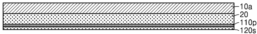
도 1a 내지 도 1k는 본 발명의 일 실시 예에 따른 인쇄회로기판의 제조 방법을 단계적으로 나타내는 단면도들이다.
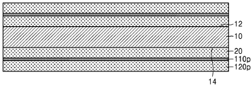
도 1a를 참조하면, 양면(12, 14)에 각각 더미층(20), 절연 금속 산화층(110p) 및 제1 시드층(120s)을 가지는 캐리어 기판(10)을 준비한다.
예를 들면, 캐리어 기판(10)은 프리프레그(prepreg)있고, 더미층(20)은 동박일 수 있다. 이 경우, 캐리어 기판(10) 및 더미층(20)은 CCL(Copper Clad Laminate)일 수 있다. 제1 시드층(120s)은 제1 금속으로 이루어질 수 있고, 절연 금속 산화층(110p)은 상기 제1 금속과 다른 제2 금속의 절연성의 산화물일 수 있다. 절연 금속 산화층(110p)은 예를 들면, 알루미늄 산화물로 이루어질 수 있고, 제1 시드층(120s)은 예를 들면, 구리로 이루어질 수 있다.
일부 실시 예에서, 절연 금속 산화층(110p) 및/또는 제1 시드층(120s)은 스퍼터링 방법과 같은 물리적 기상 증착(PVD) 방법으로 형성할 수 있다. 절연 금속 산화층(110p)은 예를 들면, 0.5㎚ 이상 내지 5㎚ 미만의 두께를 가지도록 형성할 수 있다.
금속층을 형성한 후, 상기 금속층을 산화하여 절연 금속 산화층을 형성하는 경우, 상대적으로 얇은 두께를 가지는 자연 산화의 경우에도 상기 절연 금속 산화층은 5㎚ 이상의 상대적으로 두꺼운 두께를 가지게 된다. 그러나 본 발명의 일 실시 예에 따른 절연 금속 산화층(110p)은 물리적 기상 증착 방법으로 형성하여 상대적으로 얇은 두께, 예를 들면, 5㎚ 미만의 두께를 가지도록 형성할 수 있다.
후술하겠으나, 캐리어 기판(10)의 상면(12) 및 하면(14) 상에 각각 형성된 절연 금속 산화층(110p) 및 제1 시드층(120s)은 서로 다른 인쇄회로기판을 일부분을 구성할 수 있다. 즉, 하나의 캐리어 기판(10)을 사용하여 2개의 인쇄회로기판을 형성할 수 있다.
도 1a 및 도 1b를 함께 참조하면, 제1 시드층(120s)을 시드(seed)로 사용한 도금(plating)에 의하여 제1 도금층(120p)을 형성할 수 있다. 제1 도금층(120p)은 예를 들면, 이머젼 도금(immersion plating), 무전해 도금(electroless plating), 전기도금(electroplating) 또는 이들의 조합에 의하여 형성될 수 있다. 제1 도금층(120p)은 제1 시드층(120s)을 이루는 제1 금속과 동일한 금속으로 이루어질 수 있다. 제1 도금층(120p)은 예를 들면, 구리로 이루어질 수 있다.
일부 실시 예에서, 절연 금속 산화층(110p)이 상기 제1 금속과 다른 제2 금속의 절연성의 산화물인 경우, 제1 도금층(120p)은 상기 제1 금속 및 상기 제2 금속 각각과 다른 금속으로 이루어질 수 있다.
도 1b 및 도 1c를 함께 참조하면, 절연 금속 산화층(110p) 및 제1 도금층(120p)을 패터닝하여, 절연 금속 산화물 패턴(110, 110l) 및 제1 도금 패턴(120, 120l)을 형성한다.
제1 도금 패턴(120, 120l)은 제1 연결 패드(120) 및 제1 배선(120l)으로 이루어질 수 있다. 절연 금속 산화물 패턴(110, 110l)은 제1 패드 커버층(110) 및 배선 커버층(110l)으로 이루어질 수 있다. 제1 도금 패턴(120, 120l)을 이루는 제1 연결 패드(120) 및 제1 배선(120l)은 제1 도금층(120p)을 패터닝하여 동시에 형성되며, 제1 연결 패드(120)는 제1 도금 패턴(120, 120l) 중 인쇄회로기판의 연결 패드로 사용되는 부분을 의미하고, 제1 배선(120l)은 인쇄회로기판의 배선으로 사용되는 부분을 의미한다. 따라서 제1 연결 패드(120) 및 제1 배선(120l)은 동일한 물질로 이루어질 수 있다.
마찬가지로, 절연 금속 산화물 패턴(110, 110l)을 이루는 제1 패드 커버층(110) 및 배선 커버층(110l)은 절연 금속 산화층(110p)을 패터닝하여 동시에 형성되며, 제1 패드 커버층(110)은 절연 금속 산화물 패턴(110, 110l) 중 제1 연결 패드(120)의 상면을 덮는 부분을 의미하고, 배선 커버층(110l)은 제1 배선(120l)의 상면을 덮는 부분을 의미한다. 따라서 제1 패드 커버층(110) 및 배선 커버층(110l)은 동일한 물질로 이루어질 수 있다.
제1 패드 커버층(110) 및 배선 커버층(110l)은 각각 제1 연결 패드(120)의 상면 및 제1 배선(120l)의 상면과 모두 덮을 수 있다. 제1 패드 커버층(110)의 하면 및 배선 커버층(110l)의 하면은 각각 제1 연결 패드(120)의 상면 및 제1 배선(120l)의 상면과 직접 접촉할 수 있다.
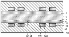
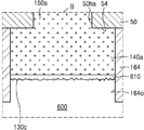
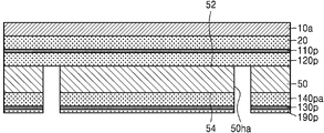
도 1d를 참조하면, 캐리어 기판(10)의 양면(12, 14) 상에 절연 금속 산화물 패턴(110, 110l) 및 제1 도금 패턴(120, 120l)을 감싸는 베이스 기판층(50) 및 베이스 기판층(50) 상을 덮는 제2 시드층(140s)을 형성한다.
베이스 기판층(50)은 에폭시 수지, 폴리이미드 수지, 비스말레마이드 트리아진(BT) 수지, FR-4(Flame Retardant 4), FR-5, 세라믹, 실리콘, 또는 유리를 포함할 수 있으나, 이는 예시적이며, 본 발명은 이에 한정되는 것은 아니다. 베이스 기판층(50)은 단일층이거나 또는 그 내부에 배선 패턴들을 포함하는 다층 구조를 포함할 수 있다. 예를 들어, 베이스 기판층(50)은 하나의 강성(Rigid) 평판이거나, 복수의 강성 평판이 접착되어 형성되거나, 얇은 가요성 기판과 강성 평판이 접착되어 형성될 수 있다. 서로 접착되는 복수의 강성 평판들, 또는 가요성 기판들은 배선 패턴을 각각 포함할 수 있다. 제2 시드층(140s)은 예를 들면, 구리로 이루어질 수 있다. 베이스 기판층(50)은 일면(52)이 캐리어 기판(10)을 향할 수 있다.
일부 실시 예에서, 베이스 기판층(50) 및 제2 시드층(140s)은 CCL일 수 있다. 이 경우, 베이스 기판층(50)의 타면(54) 상에 제2 시드층(140s)을 형성된 CCL은, 라미네이션(lamination) 공정을 통하여, 베이스 기판층(50)의 일면(52)가 캐리어 기판(10)을 향하며 캐리어 기판(10) 상에 부착될 수 있다.
일부 실시 예에서, 베이스 기판층(50)을 캐리어 기판(10) 상에 먼저 부착한 후, 베이스 기판층(50)의 타면(54) 상에 제2 시드층(140s)을 형성할 수 있다.
절연 금속 산화물 패턴(110, 110l) 및 제1 도금 패턴(120, 120l)의 적층 구조물은 베이스 기판층(50) 및 더미층(20)에 의하여 포위될 수 있다.
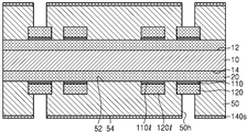
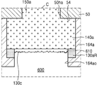
도 1e를 참조하면, 베이스 기판층(50)을 관통하며, 제1 도금 패턴(120, 120l)의 일부를 노출시키는 관통홀(50h)을 형성한다. 베이스 기판층(50)의 타면(54) 상에 제2 시드층(140s)이 위치하므로, 관통홀(50h)은 제2 시드층(140s) 및 베이스 기판층(50)을 함께 관통하여, 제1 도금 패턴(120, 120l)의 일부를 노출시킬 수 있다.
도 1e에서는 관통홀(50h)이 제1 연결 패드(120)의 일부분을 노출시키는 것으로 도시되었으나, 이는 도시의 편의를 위한 것으로 이에 한정되지 않는다. 예를 들면, 관통홀(50h)은 제1 연결 패드(120)의 일부분을 노출시킬 수도 있고, 제1 배선(120l)의 일부분을 노출시킬 수도 있고, 제1 연결 패드(120) 및 제1 배선(120l) 각각의 일부분을 노출시킬 수도 있다.
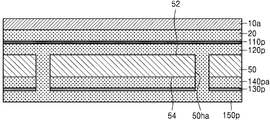
도 1e 및 도 1f를 함께 참조하면, 제2 시드층(140s), 및 관통홀(50h)을 통하여 노출되는 제1 도금 패턴(120, 120l)의 부분을 시드로 사용한 도금(plating)에 의하여 제2 도금층(140p) 및 비아 배선(150)을 형성할 수 있다. 제2 도금층(140p) 및 비아 배선(150)은 예를 들면, 이머젼 도금, 무전해 도금, 전기도금 또는 이들의 조합에 의하여 형성될 수 있다. 제2 도금층(140p) 및 비아 배선(150)은 예를 들면, 구리로 이루어질 수 있다.
제2 도금층(140p) 및 비아 배선(150)은 일체로 이루어질 수 있다. 비아 배선(150)은 일체로 이루어진 제2 도금층(140p) 및 비아 배선(150) 중 관통홀(50h) 내를 채우는 부분이고, 제2 도금층(140p)은 베이스 기판층(50)의 타면(54) 상에 형성된 부분일 수 있다. 비아 배선(150)은 제1 도금 패턴(120, 120l)의 일부와 접하며 전기적으로 연결될 수 있다. 따라서 제2 도금층(140p)은 비아 배선(150)을 통하여 제1 도금 패턴(120, 120l)의 일부와 전기적으로 연결될 수 있다.
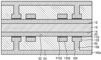
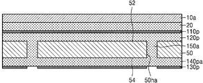
도 1f 및 도 1g를 함께 참조하면, 제2 도금층(140p)을 패터닝하여, 절연 금속 제2 도금 패턴(140, 140l)을 형성한다. 제2 도금 패턴(140, 140l)은 제2 연결 패드(140) 및 제2 배선(140l)으로 이루어질 수 있다. 제2 도금 패턴(140, 140l)을 이루는 제2 연결 패드(140) 및 제2 배선(140l)은 제2 도금층(140p)을 패터닝하여 동시에 형성되며, 제2 연결 패드(140)는 제2 도금 패턴(140, 140l) 중 인쇄회로기판의 연결 패드로 사용되는 부분을 의미하고, 제2 배선(140l)은 인쇄회로기판의 배선으로 사용되는 부분을 의미한다. 따라서 제2 연결 패드(140) 및 제2 배선(140l)은 동일한 물질로 이루어질 수 있다.
일부 실시 예에서, 베이스 기판층(50)의 타면(54), 제2 도금 패턴(140, 140l)이 형성된 이외의 부분에는 제2 도금층(140p)의 일부분인 잔류 도금층(140R)이 잔류할 수 있다. 잔류 도금층(140R)은 후속 공정에서 베이스 기판층(50)의 타면(54)를 보호하는 기능을 수행할 수 있다. 일부 실시 예에서, 제2 도금 패턴(140, 140l)을 형성하는 과정 중에 잔류 도금층(140R)이 잔류하지 않고 모두 제거되어, 베이스 기판층(50)의 타면(54)의 일부분을 노출시킬 수 있다.
도 1g 및 도 1h를 함께 참조하면, 캐리어 기판(10)을 베이스 기판층(50)으로부터 분리한다. 캐리어 기판(10)을 분리하는 과정에서 베이스 기판층(50)의 일면(52) 상에 더미층(20)의 일부분인 잔류 더미층(20R)이 잔류할 수 있다. 일부 실시 예에서, 캐리어 기판(10)을 분리하는 과정에서, 베이스 기판층(50)의 일면(52) 상에 잔류 더미층(20R)이 잔류하지 않고 모두 제거될 수 있다.
도 1h 및 도 1i를 함께 참조하면, 베이스 기판층(50)의 일면(52) 및 타면(54) 상의 잔류 도금층(140R) 및 잔류 더미층(20R)을 제거하여, 베이스 기판층(50)의 일면(52) 및 타면(54) 각각의 일부분을 노출시킬 수 있다.
제1 연결 패드(120) 및 제1 배선(120l)은 베이스 기판층(50)의 주면에 대하여 동일 레벨에 위치할 수 있다. 또한 제1 패드 커버층(110) 및 배선 커버층(110l)도 베이스 기판층(50)의 주면에 대하여 동일 레벨에 위치할 수 있다. 제2 연결 패드(140) 및 제2 배선(140l)은 베이스 기판층(50)의 주면에 대하여 동일 레벨에 위치할 수 있다.
일부 실시 예에서, 제2 연결 패드(140)의 적어도 일부분은 비아 배선(150)과 수직 방향으로 중첩될 수 있다. 일부 실시 예에서, 제2 배선(140l)은 비아 배선(150)과 수직 방향으로 중첩되지 않을 수 있다.
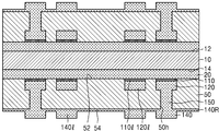
도 1j를 참조하면, 베이스 기판층(50)의 일면(52) 및 타면(54) 상에 각각 제1 솔더 레지스트층(162) 및 제2 솔더 레지스트층(164)을 형성한다. 제1 솔더 레지스트층(162) 및 제2 솔더 레지스트층(164)은 각각 제1 연결 패드(120) 상에 형성된 제1 패드 커버층(110), 및 제2 연결 패드(140)를 노출시키는 제1 오프닝(162o) 및 제2 오프닝(164o)을 가질 수 있다.
일부 실시 예에서, 제1 솔더 레지스트층(162) 및 제2 솔더 레지스트층(164) 각각은 예를 들면, 솔더 마스크(solder mask) 절연 잉크를 스크린 인쇄 방법 또는 잉크젯 인쇄에 의하여 베이스 기판층(50)의 일면(52) 및 타면(54) 상에 도포한 후 열, UV 또는 IR로 경화하여 형성할 수 있다.
일부 실시 예에서, 제1 솔더 레지스트층(162) 및 제2 솔더 레지스트층(164) 각각은 베이스 기판층(50)의 일면(52) 및 타면(54) 상에 감광성 솔더 레지스트(Photo-Imageable Solder Resist)를 스크린 인쇄 방법 또는 스프레이 코팅 방법으로 전체 도포하거나 필름형 솔더 레지스트 물질을 라미네이팅(laminating) 방법으로 접착한 후, 불필요한 부분을 노광 및 현상으로 제거하고, 열, UV 또는 IR로 경화하여 형성할 수 있다.
일부 실시 예에서, 제1 오프닝(162o)은 제1 연결 패드(120) 상에 형성된 제1 패드 커버층(110)의 상면을 모두 노출시킬 수 있다. 일부 실시 예에서, 제1 오프닝(162o)은 제1 연결 패드(120) 상에 형성된 제1 패드 커버층(110)의 상면에 인접하는 베이스 기판층(50)의 일면(52)의 일부분을 더 노출시킬 수 있다.
제1 배선(120l) 상에 형성된 배선 커버층(110l)의 상면, 및 제2 배선(140l)의 상면은 각각 제1 솔더 레지스트층(162), 및 제2 솔더 레지스트층(164)에 의하여 모두 덮일 수 있다.
일부 실시 예에서, 제1 오프닝(162o)은 제1 연결 패드(120) 상에 형성된 제1 패드 커버층(110)의 상면의 일부분을 노출시키고, 나머지 부분은 노출시키지 않을 수 있다. 이 경우, 제1 오프닝(162o)에 의하여 베이스 기판층(50)의 일면(52)은 노출되지 않을 수 있다. 즉, 제1 솔더 레지스트층(162)은 제1 패드 커버층(110)이 형성되지 않은 베이스 기판층(50)의 일면(52)을 모두 덮을 수 있고, 제1 오프닝(162o)에 의하여 노출되지 않는 제1 패드 커버층(110)의 상면의 나머지 부분도 함께 덮을 수 있다.
제1 오프닝(162o)이 제1 패드 커버층(110)의 상면의 일부분을 노출시키지 않거나, 제1 패드 커버층(110)의 상면을 모두 노출시키거나, 또는 제1 패드 커버층(110)의 상면에 인접하는 베이스 기판층(50)의 일면(52)의 일부분을 더 노출시키는지의 여부은, 제1 연결 패드(120)의 피치(pitch)를 고려하여 결정될 수 있다.
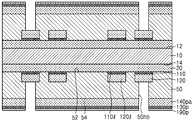
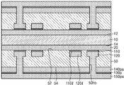
도 1k를 참조하면, 제2 오프닝(164o)에 의하여 노출되는 제2 연결 패드(140)의 상면 상에 제2 패드 커버층(170)을 형성하여 인쇄회로기판(100)을 형성한다. 제2 패드 커버층(170)은, 예를 들면, OSP(organic solderability preservative) 표면 처리를 통해 형성되는 물질을 포함할 수 있다.
예를 들어, 제2 연결 패드(140)가 구리로 이루어진 때, 제2 패드 커버층(170)은 제2 연결 패드(140)의 상면에 에 부착되어 구리 원소와 화학 결합을 형성할 수 있는 벤조트리아졸(benzotriazole), 이미다졸(imidazole) 또는 벤지미다졸(benzimidazole) 등의 유기 화합물을 포함할 수 있다. 제2 패드 커버층(170)은 제2 연결 패드(140)의 표면에 원치 않는 산화 반응이 발생하거나 표면의 손상이 발생하는 것을 방지할 수 있다. 제2 패드 커버층(170)은 예를 들면, 0.5㎛ 이하의 두께를 가질 수 있다.
본 발명의 일 실시 예에 따른 인쇄회로기판(100)은 베이스 기판층(50), 및 베이스 기판층(50)의 일면(52)에 배치되는 제1 연결 패드(120), 베이스 기판층(50)의 타면(54) 상에 배치되는 제2 연결 패드(140)를 포함한다. 도 1l에서 후술하겠으나, 예를 들면, 제1 연결 패드(120)에는 본딩 와이어가 연결될 수 있고, 제2 연결 패드(140)에는 솔더 조인트가 연결될 수 있다.
제1 연결 패드(120)는 임베디드 트레이스 구조(ETS, embedded traces structure)를 가지도록 베이스 기판층(50) 내에 함침된 형상을 가질 수 있다. 제2 연결 패드(140)는 베이스 기판층(50)의 타면(54)으로부터 돌출된 형상을 가질 수 있다.
인쇄회로기판(100)은 베이스 기판층(50)의 일면(52)에 배치되는 제1 배선(120l), 및 타면(54) 상에 배치되는 제2 배선(140l)을 더 포함할 수 있다. 제1 연결 패드(120) 및 제1 배선(120l) 중 일부와 제2 연결 패드(140) 및 제2 배선(140l) 중 일부는 베이스 기판층(50) 내에 배치되는 비아 배선(150)에 의하여 전기적으로 연결될 수 있다.
도 1k에는 인쇄회로기판(100)이 양면(52, 54)에 배치된 제1 배선(120l)과 제2 배선(140l)이 각각 이루는 2개의 레이어(layer)를 가지는 것으로 도시되었으나, 이에 한정되지 않는다. 예를 들면, 인쇄회로기판(100)은 베이스 기판층(50) 내에 적어도 하나의 레이어를 이루는 내부 배선을 더 포함하여 적어도 3개의 레이어를 가질 수 있다. 명세서에서 인쇄회로기판(100)의 양면(52, 54) 또는 내부에 배치되며, 동일 레벨을 가지며 배치되는 배선들은 하나의 레이어를 구성하며, 서로 다른 레이어에 있는 배선들은 비아 배선에 의하여 전기적으로 연결될 수 있다.
따라서 도 1k에는 제1 연결 패드(120)와 제2 연결 패드(140)가 비아 배선(150)을 통하여 직접 연결되는 것으로 도시되었으나, 이는 도시의 편의를 위한 것으로 이에 한정되지 않는다. 예를 들면, 제1 연결 패드(120)와 제2 연결 패드(140)는 제1 배선(120l), 상기 내부 배선, 제2 배선(140l) 중 적어도 하나, 및 적어도 하나의 비아 배선(150)을 통하여 전기적으로 연결될 수 있다. 제1 연결 패드(120) 및 제2 연결 패드(140) 각각의 상면에는 제1 패드 커버층(110) 및 제2 패드 커버층(170)이 배치될 수 있다. 제1 배선(120l) 상에는 배선 커버층(110l)이 배치될 수 있다.
베이스 기판층(50)의 일면(52) 및 타면(54) 상에는 각각 제1 솔더 레지스트층(162) 및 제2 솔더 레지스트층(164)이 배치될 수 있다. 제1 솔더 레지스트층(162)은 제1 연결 패드(120) 상에 배치된 제1 패드 커버층(110)을 노출시키는 제1 오프닝(162o)을 가질 수 있다. 제1 솔더 레지스트층(162)은 제1 배선(120l) 상에 배치된 배선 커버층(110l)의 상면을 모두 덮을 수 있다. 제2 솔더 레지스트층(164)은 제2 연결 패드(140) 상에 배치된 제2 패드 커버층(170)을 노출시키는 제2 오프닝(164o)을 가질 수 있다. 제2 솔더 레지스트층(164)은 제2 배선(140l)의 상면을 모두 덮을 수 있다. 제1 솔더 레지스트층(162)은 제1 배선(120l)과 직접 접촉하지 않고, 배선 커버층(110l)의 상면과 직접 접촉할 수 있다. 제2 솔더 레지스트층(164)은 제2 배선(140l)의 상면과 직접 접촉할 수 있다.
제1 패드 커버층(110)은 제1 연결 패드(120)의 상면을 모두 덮을 수 있다. 제2 패드 커버층(170)은 제2 연결 패드(140)의 상면을 모두 덮거나, 제2 솔더 레지스트층(164)에 의하여 덮이지 않은 제2 연결 패드(140)의 상면의 부분을 모두 덮을 수 있다.
제1 패드 커버층(110)과 제2 패드 커버층(170)은 서로 다른 물질로 이루어질 수 있다. 예를 들면, 제1 패드 커버층(110)은 알루미늄 산화물과 같은 금속의 절연성의 산화물로 이루어지고, 제2 패드 커버층(170)은 OSP 표면 처리를 통해 형성되는 유기 화합물로 이루어질 수 있다.
제1 패드 커버층(110) 및 배선 커버층(110l)은 동일 물질로 이루어질 수 있다. 제1 연결 패드(120) 및 제1 배선(120l)이 구리와 같은 제1 금속으로 이루어지는 경우, 제1 패드 커버층(110) 및 배선 커버층(110l)은 상기 제1 금속과 다른 제2 금속의 절연성의 산화물로 이루어질 수 있다.
일부 실시 예에서, 제1 패드 커버층(110) 및 배선 커버층(110l)은 0.5㎚ 이상 내지 5㎚ 미만의 두께를 가질 수 있다. 일부 실시 예에서, 제2 패드 커버층(170)은 0.5㎛ 이하의 두께를 가지되, 제1 패드 커버층(110) 및 배선 커버층(110l)보다 큰 값의 두께를 가질 수 있다.
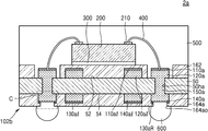
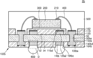
도 1l은 본 발명의 일 실시 예에 따른 반도체 패키지를 나타내는 단면도이다.
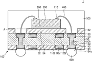
도 1l을 참조하면, 반도체 패키지(1)는 인쇄회로기판(100) 및 반도체 칩(200)을 포함한다. 인쇄회로기판(100)에 대해서는 도 1k에서 상세히 설명된 바, 자세한 구성에 대한 설명은 생략하도록 한다.
반도체 칩(200)은 예를 들면, 메모리 반도체 칩일 수 있다. 메모리 반도체 칩은 예를 들면, DRAM(Dynamic Random Access Memory) 또는 SRAM(Static Random Access Memory)과 같은 휘발성 메모리 반도체 칩이거나, PRAM(Phase-change Random Access Memory), MRAM(Magnetoresistive Random Access Memory), FeRAM(Ferroelectric Random Access Memory) 또는 RRAM(ResistiveRandom Access Memory)과 같은 비휘발성 메모리 반도체 칩일 수 있다. 반도체 칩(200)은 예를 들면, 중앙처리장치(CPU, MPU), 애플리케이션 프로세서(AP) 등과 같은 로직 반도체 칩일 수 있다.
반도체 칩(200)은 인쇄회로기판(100)의 상면 상에 부착될 수 있다. 일부 실시 예에서, 반도체 칩(200)은 비활성면이 인쇄회로기판(100)을 향하며, 다이 접착 필름(300)을 사이에 두고, 인쇄회로기판(100) 상에 부착될 수 있다. 반도체 칩(200)의 상면 상에는 칩 패드(210)가 배치될 수 있다. 반도체 칩(200)의 칩 패드(210)와 인쇄회로기판(100)의 제1 연결 패드(120)는 본딩 와이어(400)를 통하여 전기적으로 연결될 수 있다. 본딩 와이어(400)의 일단은 반도체 칩(200)의 칩 패드(210)와 연결되고, 타단은 인쇄회로기판(100)의 제1 연결 패드(120)와 연결될 수 있다. 본딩 와이어(400)의 상기 타단은 제1 패드 커버층(110)을 관통하여, 제1 연결 패드(120)와 연결될 수 있다. 제1 연결 패드(120)와 본딩 와이어(400) 사이에는 제1 금속간 화합물(intermetallic compound, intermetallics)(도 1m의 410)이 형성될 수 있다. 또한 본딩 와이어(400)의 타단과 제1 금속간 화합물(410) 사이의 계면에는 파편들(fragments, 도 1m의 110c)이 위치할 수 있다. 파편들(110c)은 본딩 와이어(400)가 제1 패드 커버층(110)의 관통하는 과정에서 생성된 제1 패드 커버층(110)의 부분들일 수 있다. 이에 대해서는 도 1m에서 자세히 도시 및 설명하도록 한다.
제2 연결 패드(140) 상에는 솔더 조인트(600)가 부착될 수 있다. 솔더 조인트(600)는 예를 들면, 솔더볼, 또는 솔더 범프일 수 있다. 제2 연결 패드(140) 상에 형성된 제2 패드 커버층(170)이 유기 화합물을 포함하는 경우, 솔더 조인트(600)를 형성하는 리플로우(reflow) 공정 중에 제거될 수 있으며, 제2 연결 패드(140)과 솔더 조인트(600) 사이에는 제2 금속간 화합물(도시 생략)이 형성될 수 있다. 제2 연결 패드(140)이 구리(Cu)를 포함하고, 솔더 조인트(600)가 주석(Sn)을 포함하는 경우, 상기 제2 금속간 화합물은 예를 들면, 구리와 주석을 포함하는 화합물일 수 있다.
인쇄회로기판(100)의 상면 상에는, 인쇄회로기판(100)의 상면을 덮고, 반도체 칩(200) 및 본딩 와이어(400)를 감싸는 몰드층(500)이 형성될 수 있다. 몰드층(500)은 예를 들면, EMC(Epoxy Mold Compound)로 이루어질 수 있다.
본 발명의 일 실시 예에 따른 반도체 패키지(1)는 제1 연결 패드(120)의 상면을 덮는 제1 패드 커버층(110) 및 제2 연결 패드(140)의 상면을 덮는 제2 패드 커버층(170)을 가지는 인쇄회로기판(100)을 사용하여 제조할 수 있다. 제1 패드 커버층(110)은 산화 방법에 의하여 형성하지 않고, 물리적 기상 증착 방법으로 형성하므로, 상대적으로 얇은 두께를 가지도록 형성할 수 있다. 또한 제1 연결 패드(120)는 제1 금속으로 이루어지고, 제1 패드 커버층(110)은 상기 제1 금속과 다른 제2 금속의 절연성 산화물로 이루어지는 바, 제1 패드 커버층(110)은 추가적인 자연 산화가 발생하지 않아, 상대적으로 얇은 두께를 유지할 수 있다.
따라서 제1 연결 패드(120)는 제1 패드 커버층(110)에 의하여 산화 또는 오염 등으로부터 보호될 수 있고, 본딩 와이어(400)는 제1 패드 커버층(110)을 관통하여 제1 연결 패드(120)에 연결될 수 있다. 따라서 본딩 와이어(400)와 제1 연결 패드(120) 사이의 상호 연결(interconnection)이 신뢰성을 가질 수 있다.
도 1m은 본 발명의 일 실시 예에 따른 반도체 패키지의 일부분을 나타내는 확대 단면도이다. 구체적으로 도 1m은 도 1l의 A 부분을 나타내는 확대 단면도이다.
도 1m을 참조하면, 본딩 와이어(400)는 제1 금속간 화합물(410)을 사이에 두고, 제1 연결 패드(120)와 연결될 수 있다. 본딩 와이어(400)가 금(Au)을 포함하고, 제1 연결 패드(120)가 구리(Cu)를 포함하는 경우, 제1 금속간 화합물(410)은 금과 구리를 포함하는 화합물일 수 있다.
본딩 와이어(400)는 제1 패드 커버층(110)을 관통하여 제1 연결 패드(120)와 연결될 수 있다. 따라서, 제1 연결 패드(120)의 상면 중, 본딩 와이어(400)가 연결되는 부분에는 제1 금속간 화합물(410)이 배치되고, 나머지 부분은 제1 패드 커버층(110)에 의하여 덮일 수 있다. 제1 금속간 화합물(410)과 본딩 와이어(400) 사이의 계면에는 본딩 와이어(400)가 제1 패드 커버층(110)을 관통하는 과정에서 생성된 제1 패드 커버층(110)의 파편들(110c)이 배치될 수 있다.
본딩 와이어(400)를 제1 연결 패드(120)의 상면에 연결시키는 과정에서, 본딩 와이어(400)의 타단과 접하는 제1 패드 커버층(110)의 부분은 파괴되어, 파편들(110c)을 형성하고, 본딩 와이어(400)의 타단으로부터 본딩 와이어(400)를 이루는 금속 원자들이 제1 연결 패드(120)로 확산하여, 제1 금속간 화합물(410)을 형성할 수 있다. 따라서 파편들(110c)은 제1 금속간 화합물(410)과 본딩 와이어(400) 사이의 계면에 배치될 수 있다. 또한 파편들(110c)은 제1 패드 커버층(110)과 동일한 물질로 이루어질 수 있다.
예를 들면, 제1 연결 패드(120)가 제1 금속으로 이루어지고, 제1 패드 커버층(110)이 상기 제1 금속과는 다른 제2 금속의 절연성 산화물로 이루어지고, 본딩 와이어(400)가 상기 제1 금속과 다른 제3 금속으로 이루어지는 경우, 제1 금속간 화합물(410)은 상기 제1 금속과 상기 제3 금속의 화합물로 이루어지고, 파편들(110c)은 상기 제2 금속의 절연성 산화물로 이루어질 수 있다.
도 1l을 다시 참조하면, 제1 배선(120l)의 상면은 배선 커버층(110l)과 직접 접촉하며 배선 커버층(110l)에 의하여 모두 덮일 수 있다. 배선 커버층(110l)은 예를 들면, 상기 제2 금속의 절연성 산화물로 이루어질 수 있다.
반면, 제2 배선(140l)의 상면은 제2 솔더 레지스트층(164)과 직접 접촉하며 제2 솔더 레지스트층(164)에 의하여 모두 덮일 수 있다.
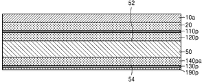
도 2a 내지 도 2g는 본 발명의 일 실시 예에 따른 인쇄회로기판의 제조 방법을 단계적으로 나타내는 단면도들이다.
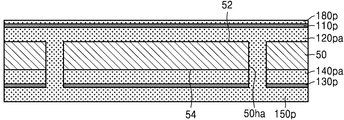
도 2a를 참조하면, 양면(52, 54)에 각각 배치된 제1 금속층(120pa) 및 제2 금속층(140pa)을 가지는 베이스 기판층(50)을 준비한다. 제1 금속층(120pa) 및 제2 금속층(140pa)은 제1 금속으로 이루어질 수 있다. 예를 들면, 제1 금속층(120pa) 및 제2 금속층(140pa)은 구리층로 이루어질 수 있다. 제1 금속층(120pa) 및 제2 금속층(140pa)은 예를 들면, ED(electrolytically deposited) 구리 호일(copper foil), RA(rolled-annealed) 구리 호일, 최극박 구리 호일(ultra-thin copper foils), 스퍼터된 구리(sputtered copper), 구리 합금(copper alloys) 등으로 이루어질 수 있다.
일부 실시 예에서, 베이스 기판층(50), 및 그 양면(52, 54)에 배치되는 제1 및 제2 금속층(120pa, 140pa)은 CCL일 수 있다. 일부 실시 예에서, 제1 및 제2 금속층(120pa, 140pa) 각각은 베이스 기판층(50)의 양면(52, 54)에 배치되는 시드층을 시드로 사용한 도금에 의하여 형성된 도금층일 수 있다. 이 경우, 베이스 기판층(50), 및 그 양면(52, 54)에 배치되는 상기 시드층은 CCL일 수 있다.
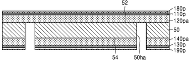
제1 금속층(120pa) 상에는 제1 절연 금속 산화층(110p) 및 제1 금속 보호층(180p)을 적층하고, 제2 금속층(140pa) 상에는 제2 절연 금속 산화층(130p) 및 제2 금속 보호층(190p)을 적층한다. 제1 및 제2 절연 금속 산화층(110p, 130p)은 상기 제1 금속과 다른 제2 금속의 절연성의 산화물일 수 있다. 제1 및 제2 절연 금속 산화층(110p, 130p)은 예를 들면, 알루미늄 산화물로 이루어질 수 있다. 제1 및 제2 금속 보호층(180p, 190p)은 예를 들면, 상기 제1 금속으로 이루어질 수 있다.
일부 실시 예에서, 제1 및 제2 절연 금속 산화층(110p, 130p) 및/또는 제1 및 제2 금속 보호층(180p, 190p)은 스퍼터링 방법과 같은 물리적 기상 증착 방법으로 형성할 수 있다. 제1 절연 금속 산화층(110p)은 예를 들면, 각각 0.5㎚ 이상 내지 5㎚ 미만의 두께를 가지도록 형성할 수 있다. 제2 절연 금속 산화층(130p)은 예를 들면, 0.5㎚ 이상 내지 100㎚ 이하의 두께를 가지도록 형성할 수 있다.
베이스 기판층(50)을 중심으로, 제1 금속층(120pa), 제1 절연 금속 산화층(110p) 및 제1 금속 보호층(180p)과 제2 금속층(140pa), 제2 절연 금속 산화층(130p) 및 제2 금속 보호층(190p)은 실질적으로 대칭 구조를 가질 수 있다.
도 2b를 참조하면, 제2 금속 보호층(190p), 제2 절연 금속 산화층(130p), 제2 금속층(140pa) 및 베이스 기판층(50)을 관통하여, 제1 금속층(120pa)의 일부를 노출시키는 관통홀(50ha)을 형성한다.
일부 실시 예에서, 관통홀(50ha)은 제1 금속 보호층(180p), 제1 절연 금속 산화층(110p), 제1 금속층(120pa) 및 베이스 기판층(50)을 관통하여, 제2 금속층(140pa)의 일부를 노출시키도록 형성할 수도 있다.
도 2b 및 도 2c를 함께 참조하면, 제2 금속 보호층(190p), 및 관통홀(50ha)을 통하여 노출되는 제1 금속층(120pa)의 부분을 시드로 사용한 도금에 의하여, 비아층(150p)을 형성할 수 있다. 비아층(150p)은 관통홀(50ha)을 채우며, 제2 절연 금속 산화층(130p) 상을 덮도록 형성될 수 있다. 비아층(150p)은 예를 들면, 구리로 이루어질 수 있다.
도 2c 및 도 2d를 함께 참조하면, 비아층(150p) 중 제2 절연 금속 산화층(130p) 상을 덮는 부분을 제거하여, 비아 배선(150a)을 형성한다. 비아 배선(150a)을 형성하기 위하여, 비아층(150p)을 부분을 제거하는 과정에서, 제1 금속 보호층(180p)도 함께 제거될 수 있다. 따라서 제1 절연 금속 산화층(110p) 및 제2 절연 금속 산화층(130p) 각각의 상면이 모두 노출될 수 있다.
본 명세서에서는, 비아층(150p) 중 도 2c의 제2 금속층(140pa)과 동일 레벨에 잔류하는 부분은, 편의상 제2 금속층(140pa)의 일부분으로 취급하며, 비아층(150p) 중 관통홀(50ha)을 채우는 부분을 비아 배선(150a)이라 호칭한다.
도 2e를 참조하면, 제1 절연 금속 산화층(110p) 및 제2 절연 금속 산화층(130p)의 상면의 일부를 각각 덮는 제1 마스크층(80) 및 제2 마스크층(90)을 형성한다.
도 2e에는 제2 마스크층(90)이 제2 절연 금속 산화층(130p)에 의하여 덮이지 않고 노출되는 제2 금속층(140pa)의 부분도 함께 덮는 것으로 도시되었으나, 이에 한정되지 않는다. 일부 실시 예에서, 복수개의 제2 마스크층(90) 중 적어도 일부개는 제2 절연 금속 산화층(130p)의 부분만을 덮을 수 있다. 이에 대해서는 도 4a 내지 도 4d를 통하여 자세히 설명하도록 한다.
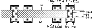
도 2e 및 도 2f를 함께 참조하면, 제1 마스크층(80)을 식각 마스크로 사용하여, 제1 절연 금속 산화층(110p) 및 제1 금속층(120pa)을 패터닝하여, 제1 절연 금속 산화물 패턴(110a, 110al) 및 제1 금속 패턴(120a, 120al)을 형성한다.
제1 금속 패턴(120a, 120al)은 제1 연결 패드(120a) 및 제1 배선(120al)으로 이루어질 수 있다. 제1 절연 금속 산화물 패턴(110a, 110al)은 제1 패드 커버층(110a) 및 제1 배선 커버층(110al)으로 이루어질 수 있다. 제1 패드 커버층(110a)은 제1 연결 패드(120a)의 상면을 모두 덮을 수 있다. 제1 배선 커버층(110al)은 제1 배선(120al)의 상면을 모두 덮을 수 있다.
마찬가지로, 제2 마스크층(90)을 식각 마스크로 사용하여, 제2 절연 금속 산화층(130p) 및 제2 금속층(140pa)을 패터닝하여, 제2 절연 금속 산화물 패턴(130a, 130al) 및 제2 금속 패턴(140a, 140al)을 형성한다.
제2 금속 패턴(140a, 140al)은 제2 연결 패드(140a) 및 제2 배선(140al)으로 이루어질 수 있다. 제2 절연 금속 산화물 패턴(130a, 130al)은 제2 패드 커버층(130a) 및 제2 배선 커버층(130al)으로 이루어질 수 있다. 제2 연결 패드(140a)와 제2 배선(140al)은 동일한 물질로 이루어질 수 있다. 제2 패드 커버층(130a)과 제2 배선 커버층(130al)은 동일한 물질로 이루어질 수 있다.
일부 실시 예에서, 제2 연결 패드(140a)의 적어도 일부분은 비아 배선(150a)과 수직 방향으로 중첩될 수 있다. 일부 실시 예에서, 제2 배선(140al)은 비아 배선(150a)과 수직 방향으로 중첩되지 않을 수 있다.
제2 패드 커버층(130a)은 제2 연결 패드(140a)의 상면을 덮을 수 있다. 제2 배선 커버층(130al)은 제2 배선(140al)의 상면을 덮을 수 있다. 일부 실시 예에서, 제2 패드 커버층(130a)은 제2 연결 패드(140a)의 상면의 일부분만을 덮을 수 있다. 예를 들면, 제2 패드 커버층(130a)은, 제2 연결 패드(140a)의 상면의 비아 배선(150a)과 수직 방향으로 중첩되지 않는 부분만을 덮을 수 있고, 비아 배선(150a)과 수직 방향으로 중첩되는 부분은 덮지 않을 수 있다. 일부 실시 예에서, 제2 배선 커버층(130al)은 제2 배선(140al)의 상면의 일부분만을 덮을 수 있다.
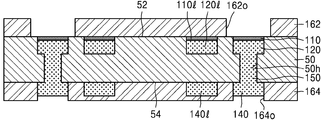
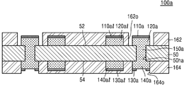
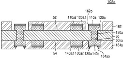
도 2g를 참조하면, 베이스 기판층(50)의 일면(52) 및 타면(54) 상에 각각 제1 솔더 레지스트층(162) 및 제2 솔더 레지스트층(164)을 형성하여 인쇄회로기판(100a)을 형성한다. 제1 솔더 레지스트층(162) 및 제2 솔더 레지스트층(164)은 각각 제1 연결 패드(120a) 상에 형성된 제1 패드 커버층(110a), 및 제2 연결 패드(140a) 상에 형성된 제2 패드 커버층(130a)을 노출시키는 제1 오프닝(162o) 및 제2 오프닝(164o)을 가질 수 있다.
제1 연결 패드(120) 및 제2 연결 패드(140)는 각각 베이스 기판층(50)의 일면(52) 및 타면(54)으로부터 돌출된 형상을 가질 수 있다.
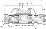
도 2h는 본 발명의 일 실시 예에 따른 반도체 패키지를 나타내는 단면도이다.
도 2h를 참조하면, 반도체 패키지(2)는 인쇄회로기판(100a) 및 반도체 칩(200)을 포함한다. 인쇄회로기판(100a)에 대해서는 도 2g에서 상세히 설명된 바, 자세한 구성에 대한 설명은 생략하도록 한다.
반도체 칩(200)은 다이 접착 필름(300)을 사이에 두고 인쇄회로기판(100a)의 상면 상에 부착될 수 있다. 반도체 칩(200)의 칩 패드(210)와 인쇄회로기판(100a)의 제1 연결 패드(120a)는 본딩 와이어(400)를 통하여 전기적으로 연결될 수 있다. 본딩 와이어(400)의 일단은 반도체 칩(200)의 칩 패드(210)와 연결되고, 타단은 인쇄회로기판(100a)의 제1 연결 패드(120a)와 연결될 수 있다. 본딩 와이어(400)의 상기 타단은 제1 패드 커버층(110a)을 관통하여, 제1 연결 패드(120a)와 연결될 수 있다. 제1 연결 패드(120)와 본딩 와이어(400) 사이에는 제1 금속간 화합물이 형성될 수 있다. 또한 본딩 와이어(400)와 제1 금속간 화합물 사이의 계면에는 제1 파편들이 위치할 수 있다. 상기 제1 파편들은 본딩 와이어(400)가 제1 패드 커버층(110a)의 관통하는 과정에서 생성된 제1 패드 커버층(110a)의 부분들일 수 있다. 제1 패드 커버층(110a), 상기 제1 파편들, 및 상기 제1 금속간 화합물은 도 1m의 제1 패드 커버층(110), 파편들(110c), 및 제1 금속간 화합물(410)과 실질적으로 동일한 바, 자세한 설명은 생략하도록 한다.
제2 연결 패드(140a) 상에는 솔더 조인트(600)가 부착될 수 있다. 제2 연결 패드(140a)와 솔더 조인트(600) 사이에는 제2 금속간 화합물(도 2i의 610)이 형성될 수 있다. 또한 솔더 조인트(600)와 제2 금속간 화합물(610) 사이의 계면에는 제2 파편들(도 2i의 130c)이 위치할 수 있다. 제2 파편들(130c)은 솔더 조인트(600)를 제2 연결 패드(140a) 상에 부착시키는 과정에서 생성된 파괴된 제2 패드 커버층(130a)의 부분들일 수 있다. 이에 대해서는 도 2i에서 자세히 도시 및 설명하도록 한다.
인쇄회로기판(100a)의 상면 상에는, 인쇄회로기판(100a)의 상면을 덮고, 반도체 칩(200) 및 본딩 와이어(400)를 감싸는 몰드층(500)이 형성될 수 있다.
본 발명의 일 실시 예에 따른 반도체 패키지(2)는 제1 연결 패드(120a)의 상면을 덮는 제1 패드 커버층(110a) 및 제2 연결 패드(140a)의 상면을 덮는 제2 패드 커버층(130a)을 가지는 인쇄회로기판(100a)을 사용하여 제조할 수 있다. 제1 패드 커버층(110a) 및 제2 패드 커버층(130a)은 산화 방법에 의하여 형성하지 않고, 물리적 기상 증착 방법으로 형성하므로, 상대적으로 얇은 두께를 가지도록 형성할 수 있다. 따라서 제1 연결 패드(120a) 및 제2 연결 패드(140a)의 상면은 각각 제1 패드 커버층(110a) 및 제2 패드 커버층(130a)에 의하여 보호될 수 있다. 본딩 와이어(400)는 제1 패드 커버층(110a)을 관통하여 제1 연결 패드(120a)에 연결될 수 있고, 솔더 조인트(600)는 제2 패드 커버층(130a)를 파괴하여, 제2 연결 패드(140a)에 연결될 수 있다. 따라서 본딩 와이어(400)와 제1 연결 패드(120a) 사이, 및 솔더 조인트(600)와 제2 연결 패드(140a) 사이의 상호 연결이 신뢰성을 가질 수 있다.
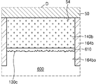
도 2i는 본 발명의 일 실시 예에 따른 반도체 패키지의 일부분을 나타내는 확대 단면도이다. 구체적으로 도 2i는 도 2h의 B 부분을 나타내는 확대 단면도이다.
도 2i를 참조하면, 솔더 조인트(600)는 제2 금속간 화합물(610)을 사이에 두고, 제2 연결 패드(140a)와 연결될 수 있다. 솔더 조인트(600)가 주석(Sn)을 포함하고, 제2 연결 패드(140a)가 구리(Cu)를 포함하는 경우, 제2 금속간 화합물(610)은 구리와 주석을 포함하는 화합물일 수 있다.
제2 패드 커버층(도 2g의 130a)의 부분들은 솔더 조인트(600)를 제2 연결 패드(140a)와 연결시키기 위한 열 압착 과정 및/또는 리플로우 과정에서 파괴되거나, 솔더 플럭스에 의하여 분해되어, 제2 파편들(130c)을 생성하고, 솔더 조인트(600)를 이루는 금속 원자들이 제2 연결 패드(140a)로 확산하여, 제2 금속간 화합물(610)을 형성할 수 있다. 따라서 제2 파편들(130c)은 제2 금속간 화합물(610)과 솔더 조인트(600) 사이의 계면에 배치될 수 있다. 또한 제2 파편들(130c)은 제2 패드 커버층(130a)과 동일한 물질로 이루어질 수 있다.
예를 들면, 제2 연결 패드(140a)가 제1 금속으로 이루어지고, 제2 패드 커버층(130a)이 상기 제1 금속과는 다른 제2 금속의 절연성 산화물로 이루어지고, 솔더 조인트(600)가 제4 금속으로 이루어지는 경우, 제2 금속간 화합물(610)은 상기 제1 금속과 상기 제4 금속의 화합물로 이루어지고, 제2 파편들(130c)은 상기 제2 금속의 절연성 산화물로 이루어질 수 있다.
도 2g에 보인 것과 같이 제2 패드 커버층(130a)이 제2 연결 패드(140a)의 일부분만을 덮는 경우, 파편들(130c)은 제2 금속간 화합물(610)과 솔더 조인트(600) 사이의 계면 중 일부분에만 배치될 수 있다. 일부 실시 예에서, 파편들(130c)은 제2 금속간 화합물(610)과 솔더 조인트(600) 사이의 계면 중 내측에는 배치되지 않고, 상기 내측을 감싸는 외측에만 배치될 수 있다. 예를 들면, 파편들(130c)은 제2 금속간 화합물(610)과 솔더 조인트(600) 사이의 계면 중 비아 배선(150a)과 수직 방향으로 중첩되는 부분에는 배치되지 않고, 비아 배선(150a)과 수직 방향으로 중첩되지 않는 부분에만 배치될 수 있다.
도 2h를 다시 참조하면, 제2 배선(140al)의 상면은 제2 배선 커버층(130al)과 직접 접촉하며 제2 배선 커버층(130al)에 의하여 덮일 수 있다.
도 3a는 본 발명의 일 실시 예에 따른 인쇄회로기판을 나타내는 단면도이다. 도 3a에 대한 설명 중, 도 2g와 중복되는 내용은 생략될 수 있다.
도 3a를 참조하면, 인쇄회로기판(102a)은 베이스 기판층(50), 제1 오프닝(162o)을 가지는 제1 솔더 레지스트층(162) 및 제2 오프닝(164ao)을 가지는 제2 솔더 레지스트층(164a)을 포함한다. 제2 솔더 레지스트층(164a)은 제2 패드 커버층(130a)의 적어도 일부분을 덮을 수 있다.
일부 실시 예에서, 제2 오프닝(164ao)은 제2 패드 커버층(130a)의 상면의 일부분을 노출시키고, 나머지 부분은 노출시키지 않을 수 있다. 즉, 제2 솔더 레지스트층(164a)은 제2 패드 커버층(130a)의 상면의 일부분을 덮지 않고, 제2 오프닝(164o)에 의하여 노출되지 않는 제2 패드 커버층(130a)의 상면의 나머지 부분을 덮을 수 있다. 또한 제2 솔더 레지스트층(164a)은 제2 배선 커버층(130al)의 상면을 모두 덮을 수 있다.
도 3b는 본 발명의 일 실시 예에 따른 반도체 패키지를 나타내는 단면도이다. 도 3b에 대한 설명 중, 도 2h와 중복되는 내용은 생략될 수 있다.
도 3b를 참조하면, 반도체 패키지(2a)는 인쇄회로기판(102a) 및 반도체 칩(200)을 포함한다. 인쇄회로기판(102a)에 대해서는 도 2g 및 도 3a에서 자세히 설명된 바, 자세한 구성에 대한 설명은 생략하도록 한다.
제2 연결 패드(140a) 상에는 솔더 조인트(600)가 부착될 수 있다. 제2 연결 패드(140a)와 솔더 조인트(600) 사이에는 제2 금속간 화합물(도 3c의 610)이 형성될 수 있다. 또한 솔더 조인트(600)와 제2 금속간 화합물(610) 사이의 계면에는 제2 파편들(도 3c의 130c)이 위치할 수 있다.
도 3c는 본 발명의 일 실시 예에 따른 반도체 패키지의 일부분을 나타내는 확대 단면도이다. 구체적으로 도 3c는 도 3b의 C 부분을 나타내는 확대 단면도이다. 도 3c에 대한 설명 중, 도 2i와 중복되는 내용은 생략될 수 있다.
도 3c를 참조하면, 솔더 조인트(600)는 제2 금속간 화합물(610)을 사이에 두고, 제2 연결 패드(140a)와 연결될 수 있다.
도 3b에 보인 것과 같이 제2 솔더 레지스트층(164a)이 제2 패드 커버층(130a)의 적어도 일부분을 덮는 경우, 제2 솔더 레지스트층(164a)과 제2 연결 패드(140a) 사이에는 제2 패드 커버층(도 3b의 130a)의 일부분(130aR)이 잔류할 수 있다. 즉, 제2 솔더 레지스트층(164a)은 제2 패드 커버층의 일부분(130aR)의 상면을 덮을 수 있다. 도 3b에서 제2 오프닝(164ao)에 의하여 노출되는 제2 패드 커버층(130a)의 부분이 파괴된 제2 파편들(130c)은, 제2 금속간 화합물(610)과 솔더 조인트(600) 사이의 계면 중 일부분에만 배치될 수 있다. 예를 들면, 파편들(130c)은 제2 금속간 화합물(610)과 솔더 조인트(600) 사이의 계면 중 비아 배선(150a)과 수직 방향으로 중첩되는 부분에는 배치되지 않고, 비아 배선(150a)과 수직 방향으로 중첩되지 않는 부분에만 배치될 수 있다.
도 4a는 본 발명의 일 실시 예에 따른 인쇄회로기판을 나타내는 단면도이다. 도 4a에 대한 설명 중, 도 2g 및 도 3a와 중복되는 내용은 생략될 수 있다.
도 4a를 참조하면, 인쇄회로기판(102b)은 베이스 기판층(50), 제1 오프닝(162o)을 가지는 제1 솔더 레지스트층(162), 및 제2 오프닝(164bo)을 가지는 제2 솔더 레지스트층(164b)을 포함한다.
제2 연결 패드(140b)는 비아 배선(150a)과 수직 방향으로 중첩되지 않고, 제2 배선(140bl)은 비아 배선(150a)과 수직 방향으로 중첩될 수 있다. 제2 패드 커버층(130b)은 제2 연결 패드(140b)의 상면을 모두 덮을 수 있고, 제2 배선 커버층(130bl)은 제2 배선(140bl)의 상면의 일부분만을 덮을 수 있다. 예를 들면, 제2 배선 커버층(130bl)은 비아 배선(150a)과 수직 방향으로 중첩되지 않는 제2 배선(140bl)의 상면의 부분만을 덮고, 비아 배선(150a)과 수직 방향으로 중첩되는 제2 배선(140bl)의 상면의 부분은 덮지 않을 수 있다.
별도로 도시하지는 않았으나, 제2 연결 패드(140b)는 베이스 기판층(50)의 타면(54) 상을 따라서 연장되는 제2 배선(140bl)을 통하여 비아 배선(150a)과 전기적으로 연결될 수 있다.
또한 별도로 도시하지는 않았으나, 일부 실시 예에서, 도 2g에 보인 것과 같이 비아 배선(150a)과 수직 방향으로 중첩되는 제2 연결 패드(140a)와 도 4a에 보인 것과 같이 비아 배선(150a)과 수직 방향으로 중첩되지 않는 제2 연결 패드(140b)을 모두 가지는 인쇄회로기판, 및/또는 도 2g에 보인 것과 같이 비아 배선(150a)과 수직 방향으로 중첩되지 않는 제2 배선(140al)과 도 4a에 보인 것과 같이 비아 배선(150a)과 수직 방향으로 중첩되는 제2 배선(140bl)을 모두 가지는 인쇄회로기판도 본 발명의 기술적 사상에 포함될 수 있다.
도 4b는 본 발명의 일 실시 예에 따른 반도체 패키지를 나타내는 단면도이다. 도 4b에 대한 설명 중, 도 2h 및 도 3b와 중복되는 내용은 생략될 수 있다.
도 4b를 참조하면, 반도체 패키지(2b)는 인쇄회로기판(102b), 반도체 칩(200) 을 포함한다. 제2 연결 패드(140b) 상에는 솔더 조인트(600)가 부착될 수 있다. 제2 연결 패드(140b)와 솔더 조인트(600) 사이에는 제2 금속간 화합물(도 4c의 610)이 형성될 수 있다. 또한 솔더 조인트(600)와 제2 금속간 화합물(610) 사이의 계면에는 제2 파편들(도 4c의 130c)이 위치할 수 있다.
도 4c는 본 발명의 일 실시 예에 따른 반도체 패키지의 일부분을 나타내는 확대 단면도이다. 구체적으로 도 4c는 도 4b의 D 부분을 나타내는 확대 단면도이다. 도 4c에 대한 설명 중, 도 3c 및 도 2i와 중복되는 내용은 생략될 수 있다.
도 4c를 참조하면, 솔더 조인트(600)는 제2 금속간 화합물(610)을 사이에 두고, 제2 연결 패드(140b)와 연결될 수 있다. 제2 파편들(130c)은, 제2 금속간 화합물(610)과 솔더 조인트(600) 사이의 계면 중 비아 배선(150a)과 수직 방향으로 중첩되는 부분 및 비아 배선(150a)과 수직 방향으로 중첩되지 않는 부분에 모두 배치될 수 있다.
또한 별도로 도시하지는 않았으나, 도 3b에 보인 것과 유사하게, 제2 솔더 레지스트층(164b)이 제2 패드 커버층(도 4b의 130b)의 적어도 일부분을 덮는 경우, 제2 솔더 레지스트층(164b)과 제2 연결 패드(140b) 사이에는 제2 패드 커버층(130b)의 일부분이 잔류할 수 있다.
도 4d는 본 발명의 일 실시 예에 따른 인쇄회로기판을 나타내는 단면도이다. 도 4d에 대한 설명 중, 도 4a 내지 도 4c와 중복되는 내용은 생략될 수 있다.
도 4d를 참조하면, 인쇄회로기판(102c)은 베이스 기판층(50), 제1 연결 패드(120a) 상에 형성된 제1 패드 커버층(110a), 및 제2 연결 패드(140b) 상에 형성된 제2 패드 커버층(130t)을 포함한다.
제1 패드 커버층(110a)은 제1 두께(t1)를 가지고, 제2 패드 커버층(130t)은 제1 두께(t1)보다 같거나 큰 값인 제2 두께(t2)를 가질 수 있다. 예를 들면, 제1 두께(t1)는 0.5㎚ 이상 내지 5㎚ 미만일 수 있고, 제2 두께(t2)는 0.5㎚ 이상 내지 100㎚ 이하일 수 있다. 제2 배선 커버층(130tl)은 제2 패드 커버층(130t)과 동일한 두께를 가질 수 있다.
도 4b에 보인 것과 같이, 제2 패드 커버층(130t)이 덮고 있는 제2 연결 패드(140b) 상에 솔더 조인트(600)를 부착하면, 제2 패드 커버층(130t)은 솔더 조인트(600)를 제2 연결 패드(140b)와 연결시키기 위한 열 압착 과정 및/또는 리플로우 과정에서 파괴되거나, 솔더 플럭스에 의하여 분해되어, 제2 파편들(130c)을 생성할 수 있다.
일부 실시 예에서, 제2 패드 커버층(130t)이 제1 패드 커버층(110a)보다 두꺼운 경우에도, 솔더 조인트(600)를 제2 연결 패드(140b)에 연결시키는 과정에서 제2 패드 커버층(130t)은 분해되어 제2 파편들(130c)을 생성할 수 있다.
또한 별도로 도시하지 않았으나, 도 2g, 도 3a 및 도 6h의 인쇄회로기판(100a, 102a, 100b) 각각의 제2 패드 커버층(130a) 및 제2 배선 커버층(130al) 또한, 제1 패드 커버층(110, 100a)보다 큰 두께를 가지도록 형성할 수 있다.
도 5a 내지 도 5f는 본 발명의 일 실시 예에 따른 인쇄회로기판의 제조 방법을 단계적으로 나타내는 단면도들이다.
도 5a를 참조하면, 일면 상에 더미층(20), 절연 금속 산화층(110p) 및 제1 시드층(120s)을 가지는 캐리어 기판(10a)을 준비한다.
도 5a 및 5b를 함께 참조하면, 제1 시드층(120s)을 시드(seed)로 사용한 도금에 의하여 제1 도금층(120p)을 형성할 수 있다. 제1 도금층(120p)은 제1 금속층(120p)으로도 호칭할 수 있다.
도 5c를 참조하면, 베이스 기판층(50)을 준비한 후, 라미네이션 공정을 통하여, 베이스 기판층(50)의 일면(52)을 제1 금속층(120p) 상에 부착한다.
베이스 기판층(50)의 타면(54) 상에는 제2 금속층(140pa), 제2 절연 금속 산화층(130p) 및 제2 금속 보호층(190p)이 적층될 수 있다. 일부 실시 예에서, 제2 금속층(140pa), 제2 절연 금속 산화층(130p) 및 제2 금속 보호층(190p)은 베이스 기판층(50)은 제1 금속층(120p) 상에 부착하기 전에, 베이스 기판층(50)의 타면(54) 상에 적층될 수 있다. 일부 실시 예에서, 제2 금속층(140pa), 제2 절연 금속 산화층(130p) 및 제2 금속 보호층(190p)은 베이스 기판층(50)은 제1 금속층(120p) 상에 부착한 후에, 베이스 기판층(50) 상에 적층될 수 있다.
도 5d를 참조하면, 제2 금속 보호층(190p), 제2 절연 금속 산화층(130p), 제2 금속층(140pa) 및 베이스 기판층(50)을 관통하여, 제1 금속층(120p)의 일부를 노출시키는 관통홀(50ha)을 형성한다.
도 5d 및 도 5e를 함께 참조하면, 제2 금속 보호층(190p), 및 관통홀(50ha)을 통하여 노출되는 제1 금속층(120p)의 부분을 시드로 사용한 도금에 의하여, 비아층(150p)을 형성할 수 있다.
도 5e 및 도 5f를 함께 참조하면, 비아층(150p) 중 제2 절연 금속 산화층(130p) 상을 덮는 부분을 제거하여, 비아 배선(150a)을 형성한다.
본 명세서에서는, 비아층(150p) 중 도 5d의 제2 금속층(140pa)과 동일 레벨에 잔류하는 부분은, 편의상 제2 금속층(140pa)의 일부분으로 취급하며, 비아층(150p) 중 관통홀(50ha)을 채우는 부분을 비아 배선(150a)이라 호칭한다.
이후, 캐리어 기판(10a) 및 더미층(20)을 제거한 후, 도 2e 내지 도 2g에서 설명한 방법을 통하여 인쇄회로기판을 형성할 수 있다.
도 6a 내지 도 6h는 본 발명의 일 실시 예에 따른 인쇄회로기판의 제조 방법을 단계적으로 나타내는 단면도들이다.
도 6a를 참조하면, 도 1a 내지 도 1c에서 설명한 방법을 통하여, 캐리어 기판(10)의 앙면(12, 14) 상에 각각 더미층(20) 및 더미층(20) 상에 배치되는 절연 금속 산화물 패턴(110, 110l)과 제1 도금 패턴(120, 120l)을 형성한다.
이후, 캐리어 기판(10)의 양면(12, 14) 상에 제1 절연 금속 산화물 패턴(110, 110l) 및 제1 도금 패턴(120, 120l)을 감싸는 베이스 기판층(50)을 부착한다.
베이스 기판층(50)은 일면(52)이 캐리어 기판(10)을 향하도록, 캐리어 기판(10)의 양면(12, 14) 상에 부착될 수 있다. 베이스 기판층(50)의 타면(54) 상에는 제2 금속층(140pa), 제2 절연 금속 산화층(130p) 및 제2 금속 보호층(190p)이 적층될 수 있다.
도 6b를 참조하면, 제2 금속 보호층(190p), 제2 절연 금속 산화층(130p), 제2 금속층(140pa) 및 베이스 기판층(50)을 관통하여, 제1 연결 패드(120)의 상면의 적어도 일부분를 노출시키는 관통홀(50hb)을 형성한다.
도 6b 및 도 6c를 함께 참조하면, 제2 금속 보호층(190p), 및 관통홀(50hb)을 통하여 노출되는 제1 연결 패드(120)의 부분을 시드로 사용한 도금에 의하여, 비아층(150pa)을 형성할 수 있다.
도 6c 및 도 6d를 함께 참조하면, 비아층(150pa) 중 제2 절연 금속 산화층(130p) 상을 덮는 부분을 제거하여, 비아 배선(150b)을 형성한다.
본 명세서에서는, 비아층(150pa) 중 도 6c의 제2 금속층(140pa)과 동일 레벨에 잔류하는 부분은, 편의상 제2 금속층(140pa)의 일부분으로 취급하며, 비아층(150pa) 중 관통홀(50hb)을 채우는 부분을 비아 배선(150b)이라 호칭한다.
도 6e를 참조하면, 제2 절연 금속 산화층(130p)의 상면의 일부를 덮는 마스크층(90)을 형성한다. 도 6e에는 마스크층(90)이 제2 절연 금속 산화층(130p)에 의하여 덮이지 않고 노출되는 제2 금속층(140pa)의 부분도 함께 덮는 것으로 도시되었으나, 이에 한정되지 않는다.
도 6f를 참조하면, 마스크층(90)을 식각 마스크로 사용하여, 제2 절연 금속 산화층(130p) 및 제2 금속층(140pa)을 패터닝하여, 제2 절연 금속 산화물 패턴(130a, 130al) 및 제2 금속 패턴(140a, 140al)을 형성한다.
도 6f 및 도 6g를 함께 참조하면, 캐리어 기판(10)을 베이스 기판층(50)으로부터 분리한다. 일부 실시 예에서, 캐리어 기판(10)을 분리하는 과정에서 더미층(20)이 함께 분리될 수 있다. 일부 실시 예에서, 캐리어 기판(10)을 분리하는 과정에서 베이스 기판층(50)의 일면 상에 잔류하는 더미층(20)의 부분은 별도로 제거할 수 있다.
도 6h를 참조하면, 베이스 기판층(50)의 일면(52) 및 타면(54) 상에 각각 제1 솔더 레지스트층(162) 및 제2 솔더 레지스트층(164)을 형성하여, 인쇄회로기판(100b)을 형성한다.
도 6h에 보인 인쇄회로기판(100b)은 제1 연결 패드(120), 제1 배선(120l), 제1 패드 커버층(110) 및 제1 배선 커버층(110l)은 도 1k에 보인 인쇄회로기판(100)의 제1 연결 패드(120), 제1 배선(120l)은 제1 패드 커버층(110) 및 배선 커버층(110l)과 실질적으로 동일하며, 제2 연결 패드(140a), 제2 배선(140al), 제2 패드 커버층(130a) 및 제2 배선 커버층(130al)은 도 2g에 보인 인쇄회로기판(100a)의 제2 연결 패드(140a), 제2 배선(140al), 제2 패드 커버층(130a) 및 제2 배선 커버층(130al)과 실질적으로 동일한 바, 자세한 설명은 생략하도록 한다.
인쇄회로기판(100b)을 포함하는 반도체 패키지 또한 도 1l의 보인 반도체 패키지(1)와 도 2h에 보인 반도체 패키지(2)의 조합으로 나타낼 수 있는 바, 별도의 도시는 생략하도록 한다.
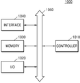
도 7은 본 발명의 일 실시 예에 따른 전자 시스템의 블록 다이어그램이다.
도 7을 참조하면, 전자 시스템(1000)은 콘트롤러(1010), 입출력 장치 (I/O)(1020), 메모리(1030), 및 인터페이스(1040)를 포함하며, 이들은 각각 버스(1050)를 통해 상호 연결되어 있다.
콘트롤러(1010)는 마이크로프로세서 (microprocessor), 디지탈 신호 프로세서, 또는 이들과 유사한 처리 장치 중 적어도 하나를 포함할 수 있다. 입출력 장치(1020)는 키패드 (keypad), 키보드 (keyboard), 또는 디스플레이 (display) 중 적어도 하나를 포함할 수 있다. 메모리(1030)는 콘트롤러(1010)에 의해 실행된 명령을 저장하는 데 사용될 수 있다. 예를 들면, 메모리(1030)는 유저 데이타 (user data)를 저장하는 데 사용될 수 있다.
전자 시스템(1000)은 무선 통신 장치, 또는 무선 환경 하에서 정보를 전송 및/또는 수신할 수 있는 장치를 구성할 수 있다. 전자 시스템(1000)에서 무선 커뮤니케이션 네트워크를 통해 데이타를 전송/수신하기 위하여 인터페이스(1040)는 무선 인터페이스로 구성될 수 있다. 인터페이스(1040)는 안테나 및/또는 무선 트랜시버 (wireless transceiver)를 포함할 수 있다. 일부 실시예에서, 전자 시스템(1000)은 제3 세대 통신 시스템, 예를 들면, CDMA(code division multiple access), GSM (global system for mobile communications), NADC (north American digital cellular), E-TDMA (extended-time division multiple access), 및/또는 WCDMA (wide band code division multiple access)와 같은 제3 세대 통신 시스템의 통신 인터페이스 프로토콜에 사용될 수 있다. 전자 시스템(1000)은 도 1a 내지 도 6h에서 설명한 인쇄회로기판 및/또는 반도체 패키지와, 이들로부터 본 발명의 기술적 사상의 범위 내에서 변형 및 변경된 다양한 제조 방법으로 제조된 인쇄회로기판 및/또는 반도체 패키지들 중 적어도 하나를 포함한다.
이상, 본 발명을 바람직한 실시예를 들어 상세하게 설명하였으나, 본 발명은 상기 실시예에 한정되지 않고, 본 발명의 기술적 사상 및 범위 내에서 당 분야에서 통상의 지식을 가진 자에 의하여 여러가지 변형 및 변경이 가능하다.
1, 2, 2a, 2b : 반도체 패키지, 100, 100a, 100b, 102a, 102b, 102c : 인쇄회로기판, 50 : 베이스 기판층, 110, 110a : 제1 패드 커버층, 120, 120a : 제1 연결 패드, 130a, 130b : 제2 패드 커버층, 140, 140a, 140b : 제2 연결 패드, 400 : 본딩 와이어, 600 : 솔더 조인트
Claims (10)
- 베이스 기판층;
상기 베이스 기판층의 일면 및 타면에 각각 배치되며 제1 금속으로 이루어지는 제1 연결 패드 및 제2 연결 패드;
상기 제1 연결 패드의 상면을 덮으며, 상기 제1 금속과 다른 제2 금속의 절연성 산화물로 이루어지는 제1 패드 커버층;을 포함하는 인쇄회로기판. - 제1 항에 있어서,
상기 베이스 기판층의 주면에 대하여 상기 제1 연결 패드와 동일 레벨에 위치하도록 상기 베이스 기판층의 상기 일면에 배치되며, 상기 제1 연결 패드와 동일한 물질로 이루어지는 제1 배선;
상기 제1 배선의 상면을 덮으며, 상기 제1 패드 커버층과 동일한 물질로 이루어지는 제1 배선 커버층; 및
상기 베이스 기판층의 일면 상에 위치하며, 상기 제1 배선 커버층의 상면을 모두 덮고, 상기 제1 패드 커버층의 상면의 적어도 일부분을 덮지 않는 제1 솔더 레지스트층;을 더 포함하는 것을 특징으로 하는 인쇄회로기판. - 제1 항에 있어서,
상기 제2 연결 패드의 상면을 덮으며, 상기 제2 금속의 절연성 산화물로 이루어지는 제2 패드 커버층;을 더 포함하는 것을 특징으로 하는 인쇄회로기판. - 제3 항에 있어서,
상기 베이스 기판층의 주면에 대하여 상기 제2 연결 패드와 동일 레벨에 위치하도록 상기 베이스 기판층의 상기 타면에 배치되며, 상기 제2 연결 패드와 동일한 물질로 이루어지는 제2 배선;
상기 제2 배선의 상면을 적어도 일부분을 덮으며, 상기 제2 패드 커버층과 동일한 물질로 이루어지는 제2 배선 커버층; 및
상기 베이스 기판층의 타면 상에 위치하며, 상기 제2 배선 커버층의 상면을 모두 덮고, 상기 제2 패드 커버층의 상면의 적어도 일부분을 덮지 않는 제2 솔더 레지스트층;을 더 포함하는 것을 특징으로 하는 인쇄회로기판. - 베이스 기판층, 상기 베이스 기판층의 일면 및 타면에 배치되며 제1 금속으로 이루어지는 제1 연결 패드 및 제2 연결 패드, 상기 제1 연결 패드의 상면을 덮으며 상기 제1 금속과 다른 제2 금속의 절연성 산화물로 이루어지는 제1 패드 커버층을 포함하는 인쇄회로기판;
상기 인쇄회로기판 상에 부착되며 칩 패드를 가지는 반도체 칩;
일단이 상기 칩 패드와 연결되고, 타단이 상기 제1 패드 커버층을 관통하여 상기 제1 연결 패드와 연결되며 상기 제1 금속과 다른 제3 금속으로 이루어지는 본딩 와이어;를 포함하는 반도체 패키지. - 제5 항에 있어서,
상기 본딩 와이어의 타단과 상기 제1 연결 패드 사이에 배치되며, 상기 제1 금속과 상기 제3 금속의 화합물로 이루어지는 제1 금속간 화합물; 및
상기 본딩 와이어의 타단과 상기 제1 금속간 화합물 사이의 계면에 위치하며, 상기 제1 패드 커버층과 동일한 물질로 이루어지는 제1 파편들(fragments);을 더 포함하는 것을 특징으로 하는 반도체 패키지. - 제6 항에 있어서,
상기 베이스 기판층의 주면에 대하여 동일 레벨에 위치하도록 상기 베이스 기판층의 상기 일면에 배치되며, 상기 제1 연결 패드와 동일한 물질로 이루어지는 제1 배선;
상기 제1 배선의 상면을 모두 덮으며, 상기 제1 패드 커버층과 동일한 물질로 이루어지는 배선 커버층; 및
상기 베이스 기판층의 일면 상에 위치하며, 상기 배선 커버층의 상면을 모두 덮고, 상기 제1 패드 커버층의 상면의 적어도 일부분을 덮지 않는 제1 솔더 레지스트층;을 더 포함하는 것을 특징으로 하는 반도체 패키지. - 제5 항에 있어서,
상기 제2 연결 패드 상에 부착되며 제4 금속으로 이루어지는 솔더 조인트;
상기 제2 연결 패드와 상기 솔더 조인트 사이에 배치되며 상기 제1 금속과 상기 제4 금속의 화합물로 이루어지는 제2 금속간 화합물;
상기 솔더 조인트와 상기 제2 금속간 화합물 사이의 계면에 위치하며, 상기 제2 금속의 절연성 산화물로 이루어지는 제2 파편들;을 더 포함하는 것을 특징으로 하는 반도체 패키지. - 제8 항에 있어서,
상기 제2 연결 패드의 상면의 일부분을 덮으며, 상기 제2 금속의 절연성 산화물로 이루어지는 제2 패드 커버층;을 더 포함하는 것을 특징으로 하는 반도체 패키지. - 제8 항에 있어서,
상기 제1 연결 패드와 상기 제2 연결 패드를 전기적으로 연결하며 상기 베이스 기판층 내에 배치되는 비아 배선;을 더 포함하며,
상기 제2 파편들은, 상기 솔더 조인트와 상기 제2 금속간 화합물 사이의 계면 중 상기 비아 배선과 수직 방향으로 중첩되지 않는 부분에 위치하고, 중첩되는 부분에는 위치하지 않는 것을 특징으로 하는 반도체 패키지.
Priority Applications (2)
| Application Number | Priority Date | Filing Date | Title |
|---|---|---|---|
| KR1020170024920A KR20180098009A (ko) | 2017-02-24 | 2017-02-24 | 인쇄회로기판 및 이를 가지는 반도체 패키지 |
| US15/803,831 US10770384B2 (en) | 2017-02-24 | 2017-11-05 | Printed circuit board having insulating metal oxide layer covering connection pad |
Applications Claiming Priority (1)
| Application Number | Priority Date | Filing Date | Title |
|---|---|---|---|
| KR1020170024920A KR20180098009A (ko) | 2017-02-24 | 2017-02-24 | 인쇄회로기판 및 이를 가지는 반도체 패키지 |
Publications (1)
| Publication Number | Publication Date |
|---|---|
| KR20180098009A true KR20180098009A (ko) | 2018-09-03 |
Family
ID=63246458
Family Applications (1)
| Application Number | Title | Priority Date | Filing Date |
|---|---|---|---|
| KR1020170024920A Withdrawn KR20180098009A (ko) | 2017-02-24 | 2017-02-24 | 인쇄회로기판 및 이를 가지는 반도체 패키지 |
Country Status (2)
| Country | Link |
|---|---|
| US (1) | US10770384B2 (ko) |
| KR (1) | KR20180098009A (ko) |
Cited By (1)
| Publication number | Priority date | Publication date | Assignee | Title |
|---|---|---|---|---|
| KR20220077751A (ko) * | 2020-12-02 | 2022-06-09 | 삼성전기주식회사 | 인쇄회로기판 및 전자부품 패키지 |
Families Citing this family (5)
| Publication number | Priority date | Publication date | Assignee | Title |
|---|---|---|---|---|
| US11021786B2 (en) * | 2018-12-04 | 2021-06-01 | Texas Instruments Incorporated | Copper passivation |
| JP7159119B2 (ja) * | 2019-06-27 | 2022-10-24 | ルネサスエレクトロニクス株式会社 | 電子装置 |
| TWI740716B (zh) * | 2020-11-16 | 2021-09-21 | 旭德科技股份有限公司 | 基板結構 |
| CN113948506B (zh) * | 2021-09-29 | 2025-05-30 | 弘凯光电(江苏)有限公司 | 光源器件、光源器件的制备方法及显示设备 |
| KR102737071B1 (ko) * | 2024-01-02 | 2024-12-03 | 엘지이노텍 주식회사 | 회로기판 및 이를 포함하는 반도체 패키지 기판 |
Family Cites Families (14)
| Publication number | Priority date | Publication date | Assignee | Title |
|---|---|---|---|---|
| CN101326634B (zh) | 2005-12-08 | 2011-06-01 | 富士通半导体股份有限公司 | 半导体器件 |
| EP2173407B1 (en) | 2007-07-02 | 2020-02-19 | Roche Diabetes Care GmbH | A device for drug delivery |
| JP5396750B2 (ja) | 2008-06-16 | 2014-01-22 | 富士通セミコンダクター株式会社 | 半導体装置の製造方法 |
| US8207052B2 (en) | 2009-01-16 | 2012-06-26 | Globalfoundries Singapore Pte. Ltd. | Method to prevent corrosion of bond pad structure |
| US20120175772A1 (en) | 2011-01-07 | 2012-07-12 | Leung Andrew K | Alternative surface finishes for flip-chip ball grid arrays |
| JP5909852B2 (ja) | 2011-02-23 | 2016-04-27 | ソニー株式会社 | 半導体装置の製造方法 |
| ITTO20120374A1 (it) | 2012-04-27 | 2013-10-28 | St Microelectronics Srl | Struttura a semiconduttore con regioni conduttive a bassa temperatura di fusione e metodo per riparare una struttura a semiconduttore |
| US20140110838A1 (en) * | 2012-10-22 | 2014-04-24 | Infineon Technologies Ag | Semiconductor devices and processing methods |
| US20140144682A1 (en) | 2012-11-28 | 2014-05-29 | Rf Micro Devices, Inc. | Surface finish for conductive features on substrates |
| JP6300533B2 (ja) | 2014-01-15 | 2018-03-28 | ルネサスエレクトロニクス株式会社 | 半導体装置の製造方法および半導体装置 |
| KR20160132229A (ko) | 2015-05-07 | 2016-11-17 | 삼성전자주식회사 | 패키지 기판, 반도체 패키지 및 이를 제조하는 방법 |
| JP6439046B2 (ja) * | 2015-07-03 | 2018-12-19 | ルネサスエレクトロニクス株式会社 | 半導体装置 |
| JP6608108B2 (ja) * | 2015-12-25 | 2019-11-20 | 新光電気工業株式会社 | 配線基板、半導体装置及び配線基板の製造方法 |
| KR102497595B1 (ko) | 2016-01-05 | 2023-02-08 | 삼성전자주식회사 | 패키지 기판, 이를 제조하는 방법 및 패키지 기판을 포함하는 패키지 장치 |
-
2017
- 2017-02-24 KR KR1020170024920A patent/KR20180098009A/ko not_active Withdrawn
- 2017-11-05 US US15/803,831 patent/US10770384B2/en not_active Expired - Fee Related
Cited By (1)
| Publication number | Priority date | Publication date | Assignee | Title |
|---|---|---|---|---|
| KR20220077751A (ko) * | 2020-12-02 | 2022-06-09 | 삼성전기주식회사 | 인쇄회로기판 및 전자부품 패키지 |
Also Published As
| Publication number | Publication date |
|---|---|
| US10770384B2 (en) | 2020-09-08 |
| US20180247887A1 (en) | 2018-08-30 |
Similar Documents
| Publication | Publication Date | Title |
|---|---|---|
| US9793219B2 (en) | Semiconductor element built-in wiring board and method for manufacturing the same | |
| US8181342B2 (en) | Method for manufacturing a coreless packaging substrate | |
| TWI557859B (zh) | 內埋式半導體封裝件及其製作方法 | |
| CN102044520B (zh) | 封装载板、封装结构以及封装载板制作工艺 | |
| JP6711509B2 (ja) | プリント回路基板、半導体パッケージ及びその製造方法 | |
| US8132320B2 (en) | Circuit board process | |
| KR20180098009A (ko) | 인쇄회로기판 및 이를 가지는 반도체 패키지 | |
| US20110018123A1 (en) | Semiconductor package and method of manufacturing the same | |
| CN102054710B (zh) | 无核层封装基板的制法 | |
| KR102194722B1 (ko) | 패키지 기판, 패키지 기판의 제조 방법 및 이를 포함하는 적층형 패키지 | |
| KR20110003453A (ko) | 회로판 및 그 제조방법 | |
| JP2016063130A (ja) | プリント配線板および半導体パッケージ | |
| US7705245B2 (en) | Electronic device substrate and its fabrication method, and electronic device and its fabrication method | |
| JP6699043B2 (ja) | 印刷回路基板、その製造方法、及び電子部品モジュール | |
| US20160143137A1 (en) | Printed circuit board and method of manufacturing the same, and electronic component module | |
| US20090224378A1 (en) | Package structure with embedded die and method of fabricating the same | |
| KR20150135046A (ko) | 패키지 기판, 패키지 기판의 제조 방법 및 이를 포함하는 적층형 패키지 | |
| KR102254874B1 (ko) | 패키지 기판 및 패키지 기판 제조 방법 | |
| KR102473416B1 (ko) | 인쇄회로기판 및 인쇄회로기판의 제조 방법 | |
| KR20150121790A (ko) | 임베디드 인쇄회로기판 및 그 제조 방법 | |
| CN101299413B (zh) | 线路板制造工艺 | |
| KR101440327B1 (ko) | 칩 내장형 임베디드 인쇄회로기판 및 그 제조방법 | |
| KR102881360B1 (ko) | 인쇄회로기판 및 전자부품 패키지 | |
| KR102240704B1 (ko) | 패키지 기판, 패키지 기판의 제조 방법 및 이를 이용한 적층형 패키지 | |
| CN104576402B (zh) | 封装载板及其制作方法 |
Legal Events
| Date | Code | Title | Description |
|---|---|---|---|
| PA0109 | Patent application |
St.27 status event code: A-0-1-A10-A12-nap-PA0109 |
|
| PG1501 | Laying open of application |
St.27 status event code: A-1-1-Q10-Q12-nap-PG1501 |
|
| A201 | Request for examination | ||
| PA0201 | Request for examination |
St.27 status event code: A-1-2-D10-D11-exm-PA0201 |
|
| D13-X000 | Search requested |
St.27 status event code: A-1-2-D10-D13-srh-X000 |
|
| D14-X000 | Search report completed |
St.27 status event code: A-1-2-D10-D14-srh-X000 |
|
| E902 | Notification of reason for refusal | ||
| PE0902 | Notice of grounds for rejection |
St.27 status event code: A-1-2-D10-D21-exm-PE0902 |
|
| PC1202 | Submission of document of withdrawal before decision of registration |
St.27 status event code: N-1-6-B10-B11-nap-PC1202 |
|
| P22-X000 | Classification modified |
St.27 status event code: A-2-2-P10-P22-nap-X000 |