EP3276205B1 - Parallelverbindungsmechanismus, gleichlaufgelenk und verbindungsaktuator - Google Patents
Parallelverbindungsmechanismus, gleichlaufgelenk und verbindungsaktuator Download PDFInfo
- Publication number
- EP3276205B1 EP3276205B1 EP17185740.2A EP17185740A EP3276205B1 EP 3276205 B1 EP3276205 B1 EP 3276205B1 EP 17185740 A EP17185740 A EP 17185740A EP 3276205 B1 EP3276205 B1 EP 3276205B1
- Authority
- EP
- European Patent Office
- Prior art keywords
- link
- end side
- proximal
- hub
- bearing
- Prior art date
- Legal status (The legal status is an assumption and is not a legal conclusion. Google has not performed a legal analysis and makes no representation as to the accuracy of the status listed.)
- Active
Links
- 230000007246 mechanism Effects 0.000 title claims description 143
- 230000010355 oscillation Effects 0.000 claims description 56
- 238000005452 bending Methods 0.000 claims description 29
- 238000005096 rolling process Methods 0.000 claims description 13
- 238000007789 sealing Methods 0.000 description 49
- 230000002093 peripheral effect Effects 0.000 description 36
- 125000006850 spacer group Chemical group 0.000 description 36
- 230000009467 reduction Effects 0.000 description 17
- 238000004891 communication Methods 0.000 description 11
- 239000000470 constituent Substances 0.000 description 11
- 230000000694 effects Effects 0.000 description 10
- 239000000314 lubricant Substances 0.000 description 9
- 230000036316 preload Effects 0.000 description 7
- 230000005540 biological transmission Effects 0.000 description 6
- 230000009466 transformation Effects 0.000 description 6
- 230000008859 change Effects 0.000 description 5
- 238000001514 detection method Methods 0.000 description 5
- 238000009877 rendering Methods 0.000 description 5
- 238000002788 crimping Methods 0.000 description 2
- 238000010586 diagram Methods 0.000 description 2
- 230000004044 response Effects 0.000 description 2
- 230000002159 abnormal effect Effects 0.000 description 1
- 230000004075 alteration Effects 0.000 description 1
- XAGFODPZIPBFFR-UHFFFAOYSA-N aluminium Chemical compound [Al] XAGFODPZIPBFFR-UHFFFAOYSA-N 0.000 description 1
- 229910052782 aluminium Inorganic materials 0.000 description 1
- 239000004411 aluminium Substances 0.000 description 1
- 238000010276 construction Methods 0.000 description 1
- 230000007797 corrosion Effects 0.000 description 1
- 238000005260 corrosion Methods 0.000 description 1
- 230000008878 coupling Effects 0.000 description 1
- 238000010168 coupling process Methods 0.000 description 1
- 238000005859 coupling reaction Methods 0.000 description 1
- 230000007423 decrease Effects 0.000 description 1
- 238000012423 maintenance Methods 0.000 description 1
- 238000004519 manufacturing process Methods 0.000 description 1
- 239000000463 material Substances 0.000 description 1
- 229910001220 stainless steel Inorganic materials 0.000 description 1
- 239000010935 stainless steel Substances 0.000 description 1
Images


Classifications
-
- B—PERFORMING OPERATIONS; TRANSPORTING
- B25—HAND TOOLS; PORTABLE POWER-DRIVEN TOOLS; MANIPULATORS
- B25J—MANIPULATORS; CHAMBERS PROVIDED WITH MANIPULATION DEVICES
- B25J11/00—Manipulators not otherwise provided for
-
- F—MECHANICAL ENGINEERING; LIGHTING; HEATING; WEAPONS; BLASTING
- F16—ENGINEERING ELEMENTS AND UNITS; GENERAL MEASURES FOR PRODUCING AND MAINTAINING EFFECTIVE FUNCTIONING OF MACHINES OR INSTALLATIONS; THERMAL INSULATION IN GENERAL
- F16H—GEARING
- F16H21/00—Gearings comprising primarily only links or levers, with or without slides
- F16H21/46—Gearings comprising primarily only links or levers, with or without slides with movements in three dimensions
- F16H21/48—Gearings comprising primarily only links or levers, with or without slides with movements in three dimensions for conveying rotary motions
-
- B—PERFORMING OPERATIONS; TRANSPORTING
- B25—HAND TOOLS; PORTABLE POWER-DRIVEN TOOLS; MANIPULATORS
- B25J—MANIPULATORS; CHAMBERS PROVIDED WITH MANIPULATION DEVICES
- B25J19/00—Accessories fitted to manipulators, e.g. for monitoring, for viewing; Safety devices combined with or specially adapted for use in connection with manipulators
- B25J19/0062—Lubrication means
-
- B—PERFORMING OPERATIONS; TRANSPORTING
- B25—HAND TOOLS; PORTABLE POWER-DRIVEN TOOLS; MANIPULATORS
- B25J—MANIPULATORS; CHAMBERS PROVIDED WITH MANIPULATION DEVICES
- B25J3/00—Manipulators of master-slave type, i.e. both controlling unit and controlled unit perform corresponding spatial movements
-
- B—PERFORMING OPERATIONS; TRANSPORTING
- B25—HAND TOOLS; PORTABLE POWER-DRIVEN TOOLS; MANIPULATORS
- B25J—MANIPULATORS; CHAMBERS PROVIDED WITH MANIPULATION DEVICES
- B25J9/00—Programme-controlled manipulators
- B25J9/003—Programme-controlled manipulators having parallel kinematics
- B25J9/0045—Programme-controlled manipulators having parallel kinematics with kinematics chains having a rotary joint at the base
- B25J9/0048—Programme-controlled manipulators having parallel kinematics with kinematics chains having a rotary joint at the base with kinematics chains of the type rotary-rotary-rotary
-
- B—PERFORMING OPERATIONS; TRANSPORTING
- B25—HAND TOOLS; PORTABLE POWER-DRIVEN TOOLS; MANIPULATORS
- B25J—MANIPULATORS; CHAMBERS PROVIDED WITH MANIPULATION DEVICES
- B25J9/00—Programme-controlled manipulators
- B25J9/10—Programme-controlled manipulators characterised by positioning means for manipulator elements
- B25J9/108—Bearings specially adapted therefor
-
- F—MECHANICAL ENGINEERING; LIGHTING; HEATING; WEAPONS; BLASTING
- F16—ENGINEERING ELEMENTS AND UNITS; GENERAL MEASURES FOR PRODUCING AND MAINTAINING EFFECTIVE FUNCTIONING OF MACHINES OR INSTALLATIONS; THERMAL INSULATION IN GENERAL
- F16C—SHAFTS; FLEXIBLE SHAFTS; ELEMENTS OR CRANKSHAFT MECHANISMS; ROTARY BODIES OTHER THAN GEARING ELEMENTS; BEARINGS
- F16C19/00—Bearings with rolling contact, for exclusively rotary movement
- F16C19/02—Bearings with rolling contact, for exclusively rotary movement with bearing balls essentially of the same size in one or more circular rows
- F16C19/04—Bearings with rolling contact, for exclusively rotary movement with bearing balls essentially of the same size in one or more circular rows for radial load mainly
- F16C19/06—Bearings with rolling contact, for exclusively rotary movement with bearing balls essentially of the same size in one or more circular rows for radial load mainly with a single row or balls
-
- F—MECHANICAL ENGINEERING; LIGHTING; HEATING; WEAPONS; BLASTING
- F16—ENGINEERING ELEMENTS AND UNITS; GENERAL MEASURES FOR PRODUCING AND MAINTAINING EFFECTIVE FUNCTIONING OF MACHINES OR INSTALLATIONS; THERMAL INSULATION IN GENERAL
- F16C—SHAFTS; FLEXIBLE SHAFTS; ELEMENTS OR CRANKSHAFT MECHANISMS; ROTARY BODIES OTHER THAN GEARING ELEMENTS; BEARINGS
- F16C19/00—Bearings with rolling contact, for exclusively rotary movement
- F16C19/22—Bearings with rolling contact, for exclusively rotary movement with bearing rollers essentially of the same size in one or more circular rows, e.g. needle bearings
- F16C19/24—Bearings with rolling contact, for exclusively rotary movement with bearing rollers essentially of the same size in one or more circular rows, e.g. needle bearings for radial load mainly
- F16C19/26—Bearings with rolling contact, for exclusively rotary movement with bearing rollers essentially of the same size in one or more circular rows, e.g. needle bearings for radial load mainly with a single row of rollers
-
- F—MECHANICAL ENGINEERING; LIGHTING; HEATING; WEAPONS; BLASTING
- F16—ENGINEERING ELEMENTS AND UNITS; GENERAL MEASURES FOR PRODUCING AND MAINTAINING EFFECTIVE FUNCTIONING OF MACHINES OR INSTALLATIONS; THERMAL INSULATION IN GENERAL
- F16C—SHAFTS; FLEXIBLE SHAFTS; ELEMENTS OR CRANKSHAFT MECHANISMS; ROTARY BODIES OTHER THAN GEARING ELEMENTS; BEARINGS
- F16C19/00—Bearings with rolling contact, for exclusively rotary movement
- F16C19/22—Bearings with rolling contact, for exclusively rotary movement with bearing rollers essentially of the same size in one or more circular rows, e.g. needle bearings
- F16C19/44—Needle bearings
- F16C19/46—Needle bearings with one row or needles
-
- F—MECHANICAL ENGINEERING; LIGHTING; HEATING; WEAPONS; BLASTING
- F16—ENGINEERING ELEMENTS AND UNITS; GENERAL MEASURES FOR PRODUCING AND MAINTAINING EFFECTIVE FUNCTIONING OF MACHINES OR INSTALLATIONS; THERMAL INSULATION IN GENERAL
- F16C—SHAFTS; FLEXIBLE SHAFTS; ELEMENTS OR CRANKSHAFT MECHANISMS; ROTARY BODIES OTHER THAN GEARING ELEMENTS; BEARINGS
- F16C33/00—Parts of bearings; Special methods for making bearings or parts thereof
- F16C33/30—Parts of ball or roller bearings
- F16C33/66—Special parts or details in view of lubrication
- F16C33/6637—Special parts or details in view of lubrication with liquid lubricant
- F16C33/6659—Details of supply of the liquid to the bearing, e.g. passages or nozzles
- F16C33/6674—Details of supply of the liquid to the bearing, e.g. passages or nozzles related to the amount supplied, e.g. gaps to restrict flow of the liquid
-
- F—MECHANICAL ENGINEERING; LIGHTING; HEATING; WEAPONS; BLASTING
- F16—ENGINEERING ELEMENTS AND UNITS; GENERAL MEASURES FOR PRODUCING AND MAINTAINING EFFECTIVE FUNCTIONING OF MACHINES OR INSTALLATIONS; THERMAL INSULATION IN GENERAL
- F16C—SHAFTS; FLEXIBLE SHAFTS; ELEMENTS OR CRANKSHAFT MECHANISMS; ROTARY BODIES OTHER THAN GEARING ELEMENTS; BEARINGS
- F16C33/00—Parts of bearings; Special methods for making bearings or parts thereof
- F16C33/72—Sealings
- F16C33/76—Sealings of ball or roller bearings
- F16C33/80—Labyrinth sealings
-
- F—MECHANICAL ENGINEERING; LIGHTING; HEATING; WEAPONS; BLASTING
- F16—ENGINEERING ELEMENTS AND UNITS; GENERAL MEASURES FOR PRODUCING AND MAINTAINING EFFECTIVE FUNCTIONING OF MACHINES OR INSTALLATIONS; THERMAL INSULATION IN GENERAL
- F16D—COUPLINGS FOR TRANSMITTING ROTATION; CLUTCHES; BRAKES
- F16D3/00—Yielding couplings, i.e. with means permitting movement between the connected parts during the drive
- F16D3/16—Universal joints in which flexibility is produced by means of pivots or sliding or rolling connecting parts
- F16D3/26—Hooke's joints or other joints with an equivalent intermediate member to which each coupling part is pivotally or slidably connected
- F16D3/30—Hooke's joints or other joints with an equivalent intermediate member to which each coupling part is pivotally or slidably connected in which the coupling is specially adapted to constant velocity-ratio
-
- F—MECHANICAL ENGINEERING; LIGHTING; HEATING; WEAPONS; BLASTING
- F16—ENGINEERING ELEMENTS AND UNITS; GENERAL MEASURES FOR PRODUCING AND MAINTAINING EFFECTIVE FUNCTIONING OF MACHINES OR INSTALLATIONS; THERMAL INSULATION IN GENERAL
- F16D—COUPLINGS FOR TRANSMITTING ROTATION; CLUTCHES; BRAKES
- F16D3/00—Yielding couplings, i.e. with means permitting movement between the connected parts during the drive
- F16D3/84—Shrouds, e.g. casings, covers; Sealing means specially adapted therefor
-
- F—MECHANICAL ENGINEERING; LIGHTING; HEATING; WEAPONS; BLASTING
- F16—ENGINEERING ELEMENTS AND UNITS; GENERAL MEASURES FOR PRODUCING AND MAINTAINING EFFECTIVE FUNCTIONING OF MACHINES OR INSTALLATIONS; THERMAL INSULATION IN GENERAL
- F16H—GEARING
- F16H21/00—Gearings comprising primarily only links or levers, with or without slides
- F16H21/46—Gearings comprising primarily only links or levers, with or without slides with movements in three dimensions
-
- F—MECHANICAL ENGINEERING; LIGHTING; HEATING; WEAPONS; BLASTING
- F16—ENGINEERING ELEMENTS AND UNITS; GENERAL MEASURES FOR PRODUCING AND MAINTAINING EFFECTIVE FUNCTIONING OF MACHINES OR INSTALLATIONS; THERMAL INSULATION IN GENERAL
- F16C—SHAFTS; FLEXIBLE SHAFTS; ELEMENTS OR CRANKSHAFT MECHANISMS; ROTARY BODIES OTHER THAN GEARING ELEMENTS; BEARINGS
- F16C19/00—Bearings with rolling contact, for exclusively rotary movement
- F16C19/02—Bearings with rolling contact, for exclusively rotary movement with bearing balls essentially of the same size in one or more circular rows
- F16C19/14—Bearings with rolling contact, for exclusively rotary movement with bearing balls essentially of the same size in one or more circular rows for both radial and axial load
- F16C19/16—Bearings with rolling contact, for exclusively rotary movement with bearing balls essentially of the same size in one or more circular rows for both radial and axial load with a single row of balls
- F16C19/163—Bearings with rolling contact, for exclusively rotary movement with bearing balls essentially of the same size in one or more circular rows for both radial and axial load with a single row of balls with angular contact
-
- F—MECHANICAL ENGINEERING; LIGHTING; HEATING; WEAPONS; BLASTING
- F16—ENGINEERING ELEMENTS AND UNITS; GENERAL MEASURES FOR PRODUCING AND MAINTAINING EFFECTIVE FUNCTIONING OF MACHINES OR INSTALLATIONS; THERMAL INSULATION IN GENERAL
- F16C—SHAFTS; FLEXIBLE SHAFTS; ELEMENTS OR CRANKSHAFT MECHANISMS; ROTARY BODIES OTHER THAN GEARING ELEMENTS; BEARINGS
- F16C19/00—Bearings with rolling contact, for exclusively rotary movement
- F16C19/54—Systems consisting of a plurality of bearings with rolling friction
- F16C19/541—Systems consisting of juxtaposed rolling bearings including at least one angular contact bearing
- F16C19/542—Systems consisting of juxtaposed rolling bearings including at least one angular contact bearing with two rolling bearings with angular contact
- F16C19/543—Systems consisting of juxtaposed rolling bearings including at least one angular contact bearing with two rolling bearings with angular contact in O-arrangement
-
- Y—GENERAL TAGGING OF NEW TECHNOLOGICAL DEVELOPMENTS; GENERAL TAGGING OF CROSS-SECTIONAL TECHNOLOGIES SPANNING OVER SEVERAL SECTIONS OF THE IPC; TECHNICAL SUBJECTS COVERED BY FORMER USPC CROSS-REFERENCE ART COLLECTIONS [XRACs] AND DIGESTS
- Y10—TECHNICAL SUBJECTS COVERED BY FORMER USPC
- Y10S—TECHNICAL SUBJECTS COVERED BY FORMER USPC CROSS-REFERENCE ART COLLECTIONS [XRACs] AND DIGESTS
- Y10S464/00—Rotary shafts, gudgeons, housings, and flexible couplings for rotary shafts
- Y10S464/904—Homokinetic coupling
- Y10S464/905—Torque transmitted via radially extending pin
-
- Y—GENERAL TAGGING OF NEW TECHNOLOGICAL DEVELOPMENTS; GENERAL TAGGING OF CROSS-SECTIONAL TECHNOLOGIES SPANNING OVER SEVERAL SECTIONS OF THE IPC; TECHNICAL SUBJECTS COVERED BY FORMER USPC CROSS-REFERENCE ART COLLECTIONS [XRACs] AND DIGESTS
- Y10—TECHNICAL SUBJECTS COVERED BY FORMER USPC
- Y10T—TECHNICAL SUBJECTS COVERED BY FORMER US CLASSIFICATION
- Y10T74/00—Machine element or mechanism
- Y10T74/20—Control lever and linkage systems
- Y10T74/20207—Multiple controlling elements for single controlled element
- Y10T74/20305—Robotic arm
- Y10T74/20329—Joint between elements
- Y10T74/20335—Wrist
Definitions
- the present invention relates to a parallel link mechanism which can operate in a precise and wide operating range in a three-dimensional space, and relates to a constant velocity universal joint and a link actuator each equipped with the parallel link mechanism and used in a medical device, an industrial device, or the like.
- Patent Document 1 One example of a working device equipped with a parallel link mechanism is disclosed in Patent Document 1, one example of a constant velocity universal joint which performs power transmission between two shafts is disclosed in Patent Document 2, and one example of a link actuator used in a medical device, an industrial device, or the like is disclosed in Patent Document 3.
- Patent Document 4 Another example of a parallel link mechanism is disclosed in Patent Document 4.
- the parallel link mechanism of Patent Document 1 the operation angle of each link is small. Therefore, in order to increase the operating range of the travelling plate, the parallel link mechanism is required to have an increased link length. Accordingly, a problem has been found that the dimensions of the mechanism as a whole increase and the apparatus tends to be bulky in size. Also, if the link length is increased, the rigidity of the mechanism as a whole tends to be lowered. For this reason, there has also been a problem that the weight of a tool mounted on the travelling plate, that is, the weight capacity of the travelling plate, is limited to a small value. For these reasons, the parallel link mechanism is difficult to be used in a medical device or the like which requires the parallel link mechanism to be compact in size and to operate in a precise and wide operating range.
- the constant velocity universal joint of Patent Document 2 and the link actuator of Patent Document 3 each employ a parallel link mechanism which includes three or more trinodal chain link mechanisms, and thus, can perform power transmission in a wide operating range and precise operation despite their compactness in size.
- a parallel link mechanism which includes three or more trinodal chain link mechanisms, and thus, can perform power transmission in a wide operating range and precise operation despite their compactness in size.
- each link mechanism is required to have an increased link length, which causes another problem that the dimensions of the mechanism as a whole increase.
- the revolute pair sections of the link mechanisms oscillate, the lives of the bearings provided in the revolute pair sections may be reduced depending on their operating ranges.
- An object of the present invention is to provide a parallel link mechanism that can perform fast operation in a precise and wide operating range and that is light in weight and compact in size as a whole, and in addition, to provide a parallel link mechanism that can realize long lives of the bearings provided in the revolute pair sections.
- Another object of the present invention is to provide a constant velocity universal joint in which the input shaft thereof and the output shaft thereof are maintained to rotate at a constant speed even when the bending angle between the central axis of the proximal end side link hub and the central axis of the distal end side link hub changes, which can perform fast operation in a precise and wide operating range, and which is light in weight and compact in size as a whole, and in addition to this object, to provide a constant velocity universal joint which can realize long lives of the bearings provided in the revolute pair sections.
- a still another object of the present invention is to provide a link actuator which can alter the position of the distal end side link hub to any position relative to the proximal end side link hub, which can perform fast operation in a precise and wide operating range, and which is light in weight and compact in size as a whole, and in addition this object, to provide a link actuator which can realize long lives of the bearings provided in the revolute pair sections.
- a parallel link mechanism is a parallel link mechanism including: a proximal end side link hub; a distal end side link hub; and three or more link mechanisms that connect the distal end side link hub to the proximal end side link hub in a position-changeable fashion, each link mechanisms having a trinodal structure with four revolute pairs, and including a proximal side end link member, one end of the proximal side end link member being pivotably connected to the proximal end side link hub; a distal side end link member, one end of the distal side end link member being pivotably connected to the distal end side link hub; and an intermediate link member which is pivotably connected to the other ends of the proximal side end link member and the distal side end link member, and each of the link mechanisms having such a shape that a geometric model of the link mechanism represented by lines shows symmetry between a proximal end side portion thereof and a distal end side portion thereof with respect to a center portion of the intermediate link member.
- the proximal end side link hub, the distal end side link hub, and the three or more link mechanisms form a two-degrees-of-freedom mechanism in which the distal end side link hub is movable in two axial directions perpendicular to each other relative to the proximal end side link hub.
- the mechanism allows the distal end side link hub to rotate with two degrees of freedom to alter its position, relative to the proximal end side link hub.
- This two-degrees-of-freedom mechanism is compact in size, but can realize a wide range of movement of the distal end side link hub relative to the proximal end side link hub.
- the bending angle between the central axis of the proximal end side link hub and the central axis of the distal end side link hub is about ⁇ 90° at maximum, and a turning angle of the distal end side link hub relative to the proximal end side link hub can be set within a range of 0° to 360°.
- the frictional resistance in each revolute pair can be reduced, whereby the rotational resistance can be relieved. Accordingly, a smooth power transmission can be secured, and also the durability thereof can be increased.
- a bearing that has a critical oscillation angle smaller than a maximum value in a possible range of a bending angle which is defined as an angle between a central axis of the proximal end side link hub and a central axis of the distal end side link hub is employed.
- the critical oscillation angle is a minimum oscillation angle allowable in a bearing, and is a minimum oscillation angle that is defined by the specification or the like of the bearing and that can provide a rated life.
- the bearing of each revolute pair section oscillates.
- the life of the bearing under oscillation becomes long, but when the oscillation angle is reduced to some level or lower, fretting is caused and the bearing reaches the end of life early.
- fretting is caused and the bearing reaches the end of life early.
- the bearing to be provided in the revolute pair section if a bearing is used whose critical oscillation angle is smaller than the maximum bending angle between the central axis of the proximal end side link hub and the central axis of the distal end side link hub, a long life of the bearing can be realized. The basis thereof is described below.
- the rotation angle of the proximal side end link member relative to the proximal end side link hub is ⁇ n
- the angle between the connection end axis of the intermediate link member pivotably connected to the proximal side end link member and the connection end axis of the intermediate link member pivotably connected to the distal side end link member is ⁇
- the angle of spacing in the circumferential direction of each proximal side end link member relative to a proximal side end link member that serves as a reference is ⁇ n
- the bending angle being a vertical angle formed when the central axis of the distal end side link hub is inclined relative to the central axis of the proximal end side link hub is ⁇
- the turning angle being a horizontal angle formed when the central axis of the distal end side link hub is inclined relative to the central axis of the proximal end side link hub is ⁇
- the critical oscillation angle may be smaller than a maximum value of the bending angle in a predetermined work operation.
- the "predetermined work operation” mentioned above refers to operation necessarily determined due to the configuration of the apparatus where the parallel link mechanism is disposed, that is, for example, operation when the parallel link mechanism is used in a constant velocity universal joint, or work operation determined, when an actuator to drive the parallel link mechanism is provided, by a control device which controls the actuator.
- the work operation determined due to the functions, such as the operation range and the like, of the actuator also corresponds to the work operation above.
- the bearing may be a deep groove ball bearing, and where the number of rolling elements of the deep groove ball bearing is Z, the critical oscillation angle may be set to be 2 ⁇ 180/(0.555 ⁇ Z ⁇ )[deg].
- the value of the critical oscillation angle determined as described above substantially matches the optimum value of the critical oscillation angle obtained from experimental data.
- the bearing may be a cylindrical roller bearing, and where the number of rolling elements of the cylindrical roller bearing is Z, the critical oscillation angle may be set to be 2 ⁇ 180/(0.37 ⁇ (Z + 0.1) ⁇ )[deg].
- the value of the critical oscillation angle determined as described above substantially matches the optimum value of the critical oscillation angle obtained from experimental data.
- the bearing may be a needle roller bearing, and where the number of rolling elements of the needle roller bearing is Z, the critical oscillation angle may be set to be 2 ⁇ 180/(0.544-Z ⁇ )[deg].
- the value of the critical oscillation angle determined as described above substantially matches the optimum value of the critical oscillation angle obtained from experimental data.
- a constant velocity universal joint of the present invention includes any one of the parallel link mechanisms above, wherein the proximal end side link hub of this parallel link mechanism is provided with an input shaft, and the distal end side link hub of this parallel link mechanism is provided with an output shaft.
- Each link mechanism of the parallel link mechanism has such a shape that a geometric model of the link mechanism depicted in lines shows symmetry between a proximal end side portion thereof and a distal end side portion thereof with respect to an intermediate portion of the intermediate link member.
- the proximal end side link hub and the proximal side end link member, and the distal end side link hub and the distal side end link member move in the same manner, and the proximal end side and the distal end side have the same rotation angle and rotate at an equal speed. Accordingly, even when the bending angle between the central axis of the proximal end side link hub and the central axis of the distal end side link hub changes, the input shaft and the output shaft are maintained to rotate at a constant speed.
- a link actuator of the present invention is a link actuator in which two or more link mechanisms among the three or more link mechanisms in any one of the parallel link mechanisms above are each provided with a position changing actuator which alters an angle of at least one revolute pair among the four revolute pairs thereof.
- the position of the distal end side link hub relative to the proximal end side link hub is also determined.
- the position of the distal end side link hub can be altered to any position relative to the proximal end side link hub.
- the link actuator can be made light in weight and compact in size.
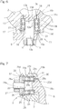
- FIG. 1 and Fig. 2 are front views respectively showing different states of the parallel link mechanism 1.
- the parallel link mechanism 1 is of a type in which a distal end side link hub 3 is connected to a proximal end side link hub 2 via three link mechanisms 4 in a position-changeable fashion. In Fig. 1 and Fig. 2 , only one link mechanism 4 is shown.
- Fig. 3 is a perspective view showing a three-dimensional representation of the parallel link mechanism 1.
- Each link mechanism 4 includes a proximal side end link member 5, a distal side end link member 6, and an intermediate link member 7, and forms a trinodal link mechanism including four revolute pairs.
- Each of the proximal side and distal side end link members 5 and 6 has an L-shape.
- the proximal end portion of the proximal side end link member 5 is pivotably connected to the proximal end side link hub 2, and the proximal end portion of the distal side end link member 6 is pivotably connected to the distal end side link hub 3.
- the intermediate link member 7 has its opposite ends respectively connected pivotably with the distal end portion of the proximal side end link member 5 and the distal end portion of the distal side end link member 6.
- Each of the proximal side and distal side end link members 5 and 6 each has a spherical link structure.
- the three link mechanisms 4 have common spherical link centers PA and PB (shown in Fig. 1, Fig. 2 ), and a distance D between the spherical link centers PA and PB is the same among the three link mechanisms 4.
- the central axis of the revolute pair between the end link member 5 and the intermediate link member 7 and the central axis of the revolute pair between the end link member 6 and the intermediate link member 7 may form an angle or may be parallel to each other.
- the three link mechanisms 4 have a geometrically identical configuration.
- the geometrically identical configuration means that a geometric model depicted in lines representing the link members 5, 6, and 7, that is, a model depicted with the revolute pairs and lines connecting these revolute pairs, represents a shape in which the proximal end side portion thereof and the distal end side portion thereof are symmetrical with each other with respect to the intermediate portion of the intermediate link member 7.
- Fig. 4 is a schematic diagram showing one link mechanism 4 represented in lines.
- the link mechanism 4 is of a rotation symmetrical type, and employs a positional structure in which the positional relationship between the proximal end side link hub 2 and the proximal side end link member 5, and the distal end side link hub 3 and the distal side end link member 6, is in rotational symmetry relative to a center line C of the intermediate link member 7.
- Fig. 1 shows a state where a central axis QA of the proximal end side link hub 2 and a central axis QB of the distal end side link hub 3 are on the same line, and Fig.
- the proximal end side link hub 2, the distal end side link hub 3, and the three link mechanisms 4 cooperatively form a two-degrees-of- freedom mechanism in which the distal end side link hub 3 is movable in two axial directions perpendicular to each other relative to the proximal end side link hub 2.
- the mechanism allows the distal end side link hub 3 to rotate with two degrees of freedom to alter its position, relative to the proximal end side link hub 2.
- This two-degrees-of-freedom mechanism is compact in size, but can realize a wide range of movement of the distal end side link hub 3 relative to the proximal end side link hub 2. For example, the maximum value (maximum bending angle) of a bending angle ⁇ ( Fig.
- a turning angle ⁇ ( Fig. 3 ) of the distal end side link hub 3 relative to the proximal end side link hub 2 can be set within a range of 0° to 360°.
- the bending angle ⁇ is defined as a vertical angle representing an inclination of the central axis QB of the distal end side link hub 3 relative to the central axis QA of the proximal end side link hub 2.
- the turning angle ⁇ is defined as a horizontal angle representing an inclination the central axis QB of the distal end side link hub 3 relative to the central axis QA of the proximal end side link hub 2.
- Each of the proximal end side link hub 2 and the distal end side link hub 3 is of a doughnut-like shape which has a through-hole 10 formed in a center portion thereof and extending along the axial direction thereof, and an outer periphery of a spherical shape.
- the proximal side end link members 5 and the distal side end link members 6 are respectively pivotably connected to the outer peripheral faces of the proximal end side link hub 2 and the distal end side link hub 3, at equal intervals in the circumferential direction thereof.
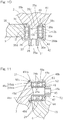
- Fig. 5 is a horizontal sectional view showing the proximal end side link hub 2 and the like, and shows a revolute pair section T1 between the proximal end side link hub 2 and the proximal side end link member 5, a revolute pair section T2 between the proximal side end link member 5 and the intermediate link member 7, and a revolute pair section T3 between the distal side end link member 6 and the intermediate link member 7.
- the revolute pair sections T2 and T3 only those of one link mechanism 4 are shown.
- proximal end side link hub 2 In the proximal end side link hub 2, communication holes 11 extending in radial directions are formed at three circumferential locations of the proximal end side link hub 2, each communication hole 11 allowing the through-hole 10 extending in the axial direction to communicate with the outer periphery of the proximal end side link hub 2.
- Two bearings 12 provided in each communication hole 11 rotatably support a shaft member 13. An outer end portion of each shaft member 13 protrudes from the proximal end side link hub 2, and to the portion protruding therefrom, the proximal side end link member 5 is coupled to be fixed and fastened, together with a spacer member 16, by means of a nut 14 threadedly engaged on a tip end threaded portion 13a.
- the proximal end side link hub 2 which is one pair constituent member and the proximal side end link member 5 which is the other pair constituent member are pivotably connected to each other via the bearings 12.
- each communication hole 11 in the proximal end side link hub 2 forms an annular inner face forming portion 15 defined in the claims.
- the annular inner face forming portion 15 is a part of the link hub 2, but the annular inner face forming portion 15 may be provided separately from the link hub 2.
- the shaft member 13 forms the shaft portion defined in the claims. In the example shown, the shaft member 13 being the shaft portion is provided separately from the end link member 5, but the shaft portion may be provided integrally with the proximal side end link member 5.
- the two bearings 12 may be angular contact ball bearings and may be arranged in back-to-back relation with each other, for example.
- the shaft member 13 has an inner end portion in the form of a stepped portion 13c which has an outer diameter greater than that of a portion 13b fitted to the inner periphery of the inner rings 12a of the bearings 12.
- the stepped portion 13c has a stepped surface 13d abutting against an end face of the inner ring 12a of the bearing 12 on the axially inner side to axially position the inner rings 12a.
- the spacer member 16 is provided with its opposite ends in contact with the inner ring 12a and the spacer member 16, respectively. Accordingly, by fastening the nut 14, the inner rings 12a are fastened and fixed with one of the inner rings 12a being urged against the stepped surface 13d via the proximal side end link member 5 and the spacer member 16, and also a preload is applied to the bearings 12.
- the nut 14 in this example serves as an inner ring fixation element that fixes the position in the axial direction of each inner ring 12a.
- the annular inner face forming portion 15 has a portion in the form of a stepped portion 15b having an inner diameter smaller than that of an outer ring fit portion 15a, which is a portion fitted on the outer peripheries of outer rings 12b of the bearings 12.
- the stepped portion 15b has a stepped surface 15c abutting against an end face of the outer ring 12b of the bearing 12 on the axially inner side to axially position the outer rings 12b.
- the outer ring 12b of the bearing 12 on the axially outer side is prevented from slipping off by a retaining ring 17 mounted to the annular inner face forming portion 15.
- a sealing structure 19 is formed to regulate the flow of a lubricant or the like between inside and outside of the bearings 12 while allowing the stepped portion 13c of the shaft member 13 and the stepped portion 15b of the annular inner face forming portion 15 to rotate with respect to each other. That is, by rendering the gap 18 to be narrow, the lubricant inside the bearings 12 is prevented from leaking to the outside, and foreign matter is prevented from entering the inside of the bearings 12 from the outside. The narrower the gap 18 is, the higher the sealing effect is.
- the spacer member 16 has an axially outer portion formed with a collar portion 16a extending toward the outer diameter side in such a manner as to circumvent the retaining ring 17.
- the outer peripheral face of the collar portion 16a and an outer end portion 15d being a part of the annular inner face forming portion 15 confront each other via a small gap 20 in a noncontact manner.
- a sealing structure 21 is formed to function similarly as described above while allowing the collar portion 16a of the spacer member 16 and the outer end portion 15d of the annular inner face forming portion 15 to rotate with respect to each other.
- the revolute pair section T2 between the proximal side end link member 5 and the intermediate link member 7 has a structure in which two bearings 24 are provided in a communication hole 23 of the intermediate link member 7, and these bearings 24 rotatably support a shaft portion 25 at the distal end of the proximal side end link member 5.
- the proximal side end link member 5 which is one pair constituent member and the intermediate link member 7 which is the other pair constituent member are pivotably connected to each other via the bearings 24.
- the bearings 24 are fastened and fixed, via a spacer member 26, by means of a nut 27 threadedly engaged on a tip end threaded portion 25a of the shaft portion 25.
- a peripheral portion of the communication hole 23 in the intermediate link member 7 is formed as an annular inner face forming portion 28 defined in the claims.
- the annular inner face forming portion 28 is a part of the intermediate link member 7, but the annular inner face forming portion 28 may be provided separately from the intermediate link member 7.
- the shaft portion 25 is provided integrally with the end link member 5, but the shaft portion 25 may be provided separately from the end link member 5.
- the two bearings 24 may be angular contact ball bearings and may be arranged in back-to-back relation with each other, for example.
- the shaft portion 25 has a base end portion formed with a stepped portion 25c having an outer diameter greater than that of a portion 25b fitted on the inner peripheries of inner rings 24a of the bearings 24.
- the stepped portion 25c has a stepped surface 25d abutting against an end face of the inner ring 24a of the bearing 24 on the proximal end side to axially position the inner rings 24a.
- the inner ring 24a of the bearing 24 on the distal end side is in contact with the spacer member 26.
- the inner rings 24a are fastened and fixed with one of the inner rings 24a being urged against the stepped surface 25d via the spacer member 26, and also a preload is applied to the bearings 24.
- the nut 27 serves as an inner ring fixation element which fixes the position in the axial direction of each inner ring 24a.
- the annular inner face forming portion 28 has a portion formed as a stepped portion 28b having an inner diameter smaller than that of an outer ring fit portion 28a, which is a portion fitted on the outer peripheries of outer rings 24b of the bearings 24.
- the stepped portion 28b has a stepped surface 28c abutting against an end face of the outer ring 24b of the bearing 24 on the proximal end side to axially position the outer rings 24b.
- the outer ring 24b of the bearing 24 on the distal end side is prevented from slipping off by a retaining ring 29 mounted on the annular inner face forming portion 28.
- a sealing structure 31 is formed to regulate the flow of a lubricant or the like between inside and outside of the bearings 24 while allowing the stepped portion 25c of the shaft portion 25 and the stepped portion 28b of the annular inner face forming portion 28 to rotate with respect to each other.
- the gap 30 by rendering the gap 30 to be narrow, the lubricant inside the bearings 24 is prevented from leaking to the outside, and foreign matter is prevented from entering the inside of the bearings 24 from the outside.
- the narrower the gap 30 is, the higher the sealing effect is.
- the spacer member 26 has an axial end side portion formed with a collar portion 26a extending toward the outer diameter side in such a manner as to circumvent the retaining ring 29.
- the outer peripheral face of the collar portion 26a and a distal end portion 28d being a part of the annular inner face forming portion 28 confront each other via a small gap 32 in a noncontact manner.
- a sealing structure 33 is formed to function similarly as described above while allowing the collar portion 26a of the spacer member 26 and the distal end portion 28d of the annular inner face forming portion 28 to rotate with respect to each other.
- the revolute pair section T1 between the proximal end side link hub 2 and the proximal side end link member 5, and the revolute pair section T2 between the proximal side end link member 5 and the intermediate link member 7 have been described. Although detailed description is omitted, the revolute pair section T4 between the distal end side link hub 3 and the distal side end link member 6 has the same structure as that of the revolute pair section T1, and the revolute pair section T3 between the distal side end link member 6 and the intermediate link member 7 has the same structure as that of the revolute pair section T2.
- an angular contact ball bearing may be used, for example.
- An angular contact ball bearing is a bearing having a small size and a high rigidity, and thus, is most appropriate for the bearing 12, 24 which is disposed in the revolute pair sections T1 to T4 of the parallel link mechanism 1 which receives a moment load and which is required to have a compact configuration.
- standard small angular contact ball bearings with seals have been rarely available, and thus, are difficult to be used in a parallel link mechanism.
- a ball bearing of a type other than the angular contact ball bearing may be used, or a roller bearing may be used.
- each bearing 12 embedded in the annular inner face forming portion 15 of the proximal end side link hub 2 and the distal end side link hub 3 without enlarging the external shape of the entirety of the parallel link mechanism 1, the external dimensions of each of the proximal end side link hub 2 and the distal end side link hub 3 can be increased. Accordingly, the mounting space for mounting the proximal end side link hub 2 and the distal end side link hub 3 to other members can be easily secured.
- the sealing structure 19 is formed cooperatively by the shaft member 13 provided in the proximal side end link member 5 (the distal side end link member 6) which is one pair constituent member of the revolute pair, and the annular inner face forming portion 15 provided in the proximal end side link hub 2 (the distal end side link hub 3) which is the other pair constituent member of the revolute pair; and on the other side in the axial direction, the sealing structure 21 is constructed by the spacer member 16 fitted on the outer periphery of the shaft member 13 and the annular inner face forming portion 15.
- the proximal end side link hub 2 (the distal end side link hub 3) and the proximal side end link member 5 (the distal side end link member 6) are components forming the parallel link mechanism 1.
- the spacer member 16 is a component generally provided between the inner rings 12a and the nut 14 such that a load is uniformly applied to the inner rings 12a when the inner rings 12a of the bearings 12 are to be fastened and fixed with the nut 14 being the inner ring fixation element. Therefore, by forming the sealing structures 19 and 21 only with components generally used, there is no need to provide seals implemented by other members, and thus, increase of the width dimension of each bearing 12 can be suppressed.
- each link mechanism 4 Accordingly, interference between components of each link mechanism 4 is less likely to occur, and thus, the work range is expanded.
- the parallel link mechanism 1 as a whole can be made light in weight and compact in size.
- the sealing structure 31 is constructed by the shaft portion 25 provided in the proximal side end link member 5 (the distal side end link member 6) being one pair constituent member of the revolute pair, and the annular inner face forming portion 28 provided in the intermediate link member 7 being the other pair constituent member of the revolute pair; and on the other side in the axial direction, the sealing structure 33 is formed by the spacer member 26 fitted on the outer periphery of the shaft portion 25 and the annular inner face forming portion 28.
- each link mechanism 4 is less likely to occur, and thus, the working range is expanded.
- the parallel link mechanism 1 as a whole can be made light in weight and compact in size.
- the sealing structure 19 ( Fig. 6 ) is defined in the form of the gap 18 between the outer peripheral face of the stepped portion 13c being a part of the shaft member 13 and the inner peripheral face of the stepped portion 15b being a part of the annular inner face forming portion 15.
- the stepped portion 13c of the shaft member 13 is used for positioning of the inner rings 12a and the stepped portion 15b of the annular inner face forming portion 15 is used for positioning of the outer rings 12b. Since the stepped portions 13c and 15b are at a short distance from each other, the sealing structure 19 can be easily constructed in the form of the gap 18, without providing additional members.
- the sealing structure 21 ( Fig. 6 ) is defined in the form of the gap 20 between the outer peripheral face of the collar portion 16a being a part of the spacer member 16 and the inner peripheral face of the outer end portion 15d being a part of the annular inner face forming portion 15.
- the spacer member 16 is used for fastening and fixing the inner rings 12a and the outer end portion 15d of the annular inner face forming portion 15 is used for retaining the retaining ring 17.
- the sealing structure 31 ( Fig. 7 ) is defined in the form of the gap 30 between the outer peripheral face of the stepped portion 25c being a part of the shaft portion 25 and the inner peripheral face of the stepped portion 28b being a part of the annular inner face forming portion 28.
- the stepped portion 25c of the shaft portion 25 is used for positioning of the inner rings 24a and the stepped portion 28b of the annular inner face forming portion 28 is used for positioning of the outer rings 24b. Since the stepped portions 25c and 28b are at a short distance from each other, the sealing structure 31 can be easily constructed in the form of the gap 30, without providing additional members.
- the sealing structure 33 ( Fig. 7 ) is defined in the form of the gap 32 between the outer peripheral face of the collar portion 26a being a part of the spacer member 26 and the inner peripheral face of the outer end portion 28d being a part of the annular inner face forming portion 28.
- the spacer member 26 is used for fastening and fixing the inner rings 24a, and the outer end portion 28d of the annular inner face forming portion 28 is used for retaining the retaining ring 29.
- Figs. 8 to 11 show a second embodiment of the present invention, in which a different type of the parallel link mechanism is used.
- This parallel link mechanism 1 has the bearings 12 ( Fig. 9 ), of an outer ring rotation type, which rotatably support each end link member 5 relative to the proximal end side link hub 2 and each end link member 6 relative to the distal end side link hub 3.
- the revolute pair section T1 between the proximal end side link hub 2 and the proximal side end link member 5 as an example.
- the proximal end side link hub 2 has shaft portions 35 formed at three circumferential locations thereof.
- the end link member 5 On the outer periphery of each shaft portion 35, the end link member 5 is rotatably supported via the two bearings 12 juxtaposed to each other.
- the two bearings 12 are provided in a communication hole 34 formed in the end link member 5, and are fastened and fixed, via a spacer member 36, by means of a nut 37 threadedly engaged on a tip end threaded portion 35a of the shaft portion 35.
- a peripheral portion of the communication hole 34 in the end link member 5 is an annular inner face forming portion 38 defined in the claims.
- the annular inner face forming portion 38 is formed as a part of the end link member 5, but the annular inner face forming portion 38 may be provided separately from the end link member 5.
- the shaft portion 35 is provided integrally with the link hub 2, the shaft portion 35 may be provided separately from the link hub 2.
- the two bearings 12 may be angular contact ball bearings and may be arranged in back-to-back relation with each other, for example.
- the shaft portion 35 has a base end portion formed with a stepped portion 35c having an outer diameter greater than that of a portion 35b fitted to the inner peripheries of the inner rings 12a of the bearings 12.
- the stepped portion 35c has a stepped surface 35d abutting against an end face of the inner ring 12a of the bearing 12 on the proximal end side to axially position the inner rings 12a.
- the inner ring 12a of the bearing 12 on the distal end side is in contact with the spacer member 36.
- the inner rings 12a are fastened and fixed with one of the inner rings 12a being urged against the stepped surface 35d via the spacer member 36, and also a preload is applied to the bearings 12.
- the nut 37 serves as an inner ring fixation element which fixes the position in the axial direction of each inner ring 12a.
- the annular inner face forming portion 38 has a portion formed as a stepped portion 38b having an inner diameter smaller than that of an outer ring fit portion 38a, which is a portion fitted on the outer peripheries of the outer rings 12b of the bearings 12.
- the stepped portion 38b has a stepped surface 38c abutting against an end face of the outer ring 12b of the bearing 12 on the proximal end side to axially position the outer rings 12b.
- the end link member 5 has a collar portion 38d of an annular shape, protruding from a side face of the end link member 5 and having a base end forming a part of the outer ring fit portion 38a.
- the collar portion 38d may have a tip end portion 38da protruding beyond the outer ring 12b that has a base end engaging with an end face of an outer ring 12b to position the outer rings 12b between the stepped portion 38b and the crimped portion, while preventing from slipping off in the axial direction.
- a sealing structure 41 is formed to regulate the flow of a lubricant or the like between inside and outside of the bearings 12 while allowing the stepped portion 35c of the shaft portion 35 and the stepped portion 38b of the annular inner face forming portion 38 to rotate with respect to each other. That is, by rendering the gap 40 to be narrow, the lubricant inside the bearings 12 is prevented from leaking to the outside, and foreign matter is prevented from entering the inside of the bearings 12 from the outside. The narrower the gap 40 is, the higher the sealing effect is.
- the spacer member 36 has an axial end side portion formed with a collar portion 36a extending toward the outer diameter side in such a manner as to circumvent the outer ring 12b.
- the outer peripheral face of the collar portion 36a and the inner peripheral face of the distal end portion 38da which is a part of the annular inner face forming portion 38 confront each other via a small gap 42 in a noncontact manner.
- a sealing structure 43 is formed to function similarly as described above while allowing the collar portion 36a of the spacer member 36 and the distal end portion 38da of the annular inner face forming portion 38 to rotate with respect to each other.
- the revolute pair section T2 between the proximal side end link member 5 and the intermediate link member 7 has a structure in which the two bearings 24 are provided in a communication hole 44 of the proximal side end link member 5, and these bearings 24 rotatably support a shaft portion 45 of the intermediate link member 7.
- the proximal side end link member 5 which is one pair constituent member and the intermediate link member 7 which is the other pair constituent member are pivotably connected to each other via the bearings 24.
- the bearings 24 are fastened and fixed, via a spacer member 46, by means of a nut 47 threadedly engaged on a distal end threaded portion 45a of the shaft portion 45.
- a peripheral portion of the communication hole 44 in the proximal side end link member 5 forms an annular inner face forming portion 48 defined in the claims.
- the annular inner face forming portion 48 is a part of the proximal side end link member 5, but the annular inner face forming portion 48 may be provided separately from the end link member 5.
- the shaft portion 45 is provided integrally with the intermediate link member 7, but the shaft portion 45 may be provided separately from the intermediate link member 7.
- the two bearings 24 may be angular contact ball bearings and may be arranged in back-to-back relation with each other, for example.
- the shaft portion 45 has a base end portion formed with a stepped portion 45c having an outer diameter greater than that of a portion 45b fitted on the inner peripheries of the inner rings 24a of the bearings 24.
- the stepped portion 45c has two-step shoulders 45ca and 45cb.
- the first shoulder 45ca has a stepped surface 45d abutting against an end face of the inner ring 24a of the bearing 24 on the base end side to axially position the inner rings 24a.
- the second shoulder 45cb may be provided as a separate member.
- the second shoulder 45cb may be provided as a ring member, having an inner peripheral face fitted on the outer peripheral face of the first shoulder 45ca, whereby the shoulder 45cb may be fixed.
- the inner ring 24a of the bearing 24 on the tip end side is in contact with the spacer member 46. Accordingly, by fastening the nut 47, the inner rings 24a are fastened and fixed with one of the inner rings 24a being urged against the stepped surface 45d via the spacer member 46, and also a preload is applied to the bearings 24.
- the nut 47 is inner ring fixation element which fixes the position in the axial direction of each inner ring 24a.
- the annular inner face forming portion 48 has a portion formed as a stepped portion 48b having an inner diameter smaller than that of an outer ring fit portion 48a, which is a portion fitted on the outer peripheries of the outer rings 24b of the bearings 24.
- the stepped portion 48b has a stepped surface 48c abutting against an end face of the outer ring 24b of the bearing 24 on the tip end side to axially position the outer rings 24b.
- the proximal side end link member 5 has a collar portion 48d of an annular shape protruding from a side face of the proximal side end link member 5 and having a base end forming a part of the outer ring fit portion 48a.
- the collar portion 48d may have a distal end portion 48da protruding beyond the outer ring 24b and having a base end engaging with an end face of an outer ring 24b to position the outer rings 24b between the stepped portion 48b and the crimped portion, while preventing from slipping off in the axial direction.
- a sealing structure 51 is formed to regulate the flow of a lubricant or the like between inside and outside of the bearings 24 while allowing the stepped portion 45c of the shaft portion 45 and the distal end portion 48da of the annular inner face forming portion 48 to rotate with respect to each other. That is, by rendering the gap 50 to be narrow, the lubricant inside the bearings 24 is prevented from leaking to the outside, and foreign matter is prevented from entering the inside of the bearings 24 from the outside. The narrower the gap 50 is, the higher the sealing effect is.
- a sealing structure 53 is formed to function similarly as described above, while allowing the spacer member 46 and the stepped portion 48b of the annular inner face forming portion 48 to rotate with respect to each other.
- the revolute pair section T4 between the distal end side link hub 3 and the distal side end link member 6 has the same structure as that of the revolute pair section T1
- the revolute pair section T3 between the distal side end link member 6 and the intermediate link member 7 has the same structure as that of the revolute pair section T2.
- Fig. 12 shows a different example of the sealing structures.
- This sealing structure is applied to the revolute pair section T1 (T4) between the proximal end side link hub 2 (the distal end side link hub 3) and the proximal side end link member 5 (the distal side end link member 6) of the second embodiment described with reference to Fig. 8 to Fig. 11 .
- the outer peripheral face of the stepped portion 35c of the shaft portion 35 and the outer peripheral face of the collar portion 36a of the spacer member 36 are respectively provided with a plurality of grooves 55 and 56 extending along the circumferential direction.
- each sealing structure 57, 58 includes a labyrinth sealing structure, and thus, sealing ability is further increased than in the sealing structure 41, 42 using only the gap 40, 42 ( Fig. 10 ).
- This sealing structure may be applied to the revolute pair section T2 (T3) between the proximal side end link member 5 (the distal side end link member 6) and the intermediate link member 7. Further, this sealing structure may be applied to the revolute pair sections T1 to T4 of the first embodiment described with reference to Fig. 1 to Fig. 7 .
- Fig. 13 shows a constant velocity universal joint according to a third embodiment of the present invention, which uses a parallel link mechanism.
- This constant velocity universal joint 61 is of a type in which an input shaft 63 is mounted via a mounting plate 62 to the proximal end side link hub 2 of the parallel link mechanism 1 shown in Fig. 1 to Fig. 7 and an output shaft 65 is mounted via a mounting plate 64 to the distal end side link hub 3 thereof.
- the axes of the input shaft 63 and the output shaft 65 are respectively aligned with the central axis QA of the proximal end side link hub 2 and the central axis QB of the proximal end side link hub 3.
- the geometrical shapes of the proximal side end link member 5 and the distal side end link member 6 are identical with each other, and the shapes at the proximal end side and the distal end side of the intermediate link member 7 are identical with each other, it is assumed that the angular positional relationship between the intermediate link member 7 and the proximal side end link member 5 and the angular positional relationship between the intermediate link member 7 and the distal side end link member 6 are rendered to be identical with each other relative to the symmetry plane of the intermediate link member 7, between the proximal end side and the distal end side.
- the proximal end side link hub 2 and the proximal side end link member 5, and the distal end side link hub 3 and the distal side end link member 6 will move in the same manner.
- the input shaft 63 and the output shaft 65 are provided in the proximal end side and distal end side link hubs 2 and 3 in a manner coaxial with the central axes QA and QB, respectively, and rotation transmission is made from the proximal end side to the distal end side, the input shaft 63 and the output shaft 65 will have the same rotation angle and rotate at an equal speed.
- the symmetry plane of the intermediate link member 7 at the time of the constant speed rotation is known as a constant velocity bisecting plane.
- the intermediate link members 7 are limited to move on their respective constant velocity bisecting planes. Accordingly, even when the proximal end side and the distal end side assume any operation angle, the input shaft 63 and the output shaft 65 rotate at a constant speed.
- Fig. 14 shows a link actuator according to a fourth embodiment of the present invention, which uses a parallel link mechanism.
- This link actuator 71 includes: the parallel link mechanism 1 shown in Fig. 1 to Fig. 7 ; a base 72 which supports the parallel link mechanism 1; two or more position changing actuators 73 which activate the parallel link mechanism 1; and a controller 74 which operates those position changing actuators 73.
- the base 72 is of a shape elongated in the vertical direction, and on the top face thereof, the proximal end side link hub 2 of the parallel link mechanism 1 is fixed.
- a drive source mounting board 75 having a collar shape is provided on the outer periphery of an upper portion of the base 72.
- the position changing actuators 73 are secured to the drive source mounting board 75 so as to be suspended therefrom.
- the number of the position changing actuators 73 is two, for example.
- Each position changing actuator 73 may be comprised of a rotary actuator.
- a bevel gear 76 mounted on the output shaft of the position changing actuator 73 is meshed with a bevel gear 77 having a sector shape mounted on the shaft member 13 ( Fig. 5 ) of the proximal end side link hub 2.
- the controller 74 is operated to drive each position changing actuator 73 to rotate, to thereby actuate the parallel link mechanism 1. Specifically, when the position changing actuator 73 is driven to rotate, its rotation is transmitted to the shaft member 13 via a pair of the bevel gears 76 and 77, to thereby change the angle of the proximal side end link member 5 relative to the proximal end side link hub 2. In this way, the position and position of the distal end side link hub 3 is determined.
- the reason why the number of the link mechanisms 4 to which the position changing actuators 73 are respectively provided is two or more is that two or more position changing actuators 73 are necessary in order to determine the location and position of the distal end side link hub 3 relative to the proximal end side link hub 2.
- the position changing actuators 73 may be provided to all of the three link mechanisms 4.
- the rotation drive of the position changing actuator 73 for actuating the parallel link mechanism 1 may be manually performed by using a manipulation tool (not shown) provided in the controller 74, or may be automatically controlled by a control device 78 to attain a set amount defined by a setting instrument (not shown) provided in the controller 74.
- the control device 78 may be provided within the controller 74 or may be provided outside the controller 74.
- a control target value of a rotation angle ⁇ n of the proximal side end link member 5 is calculated in response to the position of the distal end side link hub 3 set by the setting instrument.
- the rotation angle ⁇ n represents an operating position of the position changing actuator 73.
- the calculation of the rotation angle ⁇ n is carried out by inverse transformation of the following equation 1.
- the inverse transformation is a transformation for calculating the rotation angle ⁇ n of the proximal side end link member 5 from the bending angle ⁇ ( Fig. 3 ) of the central axis QB of the distal end side link hub 3 relative to the central axis QA of the proximal end side link hub 2 and the turning angle ⁇ ( Fig.
- the bending angle ⁇ is a vertical angle formed when the central axis QB of the distal end side link hub 3 is inclined relative to the central axis QA of the proximal end side link hub 2
- the turning angle ⁇ is a horizontal angle formed when the central axis QB of the distal end side link hub 3 is inclined relative to the central axis QA of the proximal end side link hub 2.
- ⁇ ( Fig. 3 ) is the angle between the connection end axis of the intermediate link member 7 pivotably connected to the proximal side end link member 5 and the connection end axis of the intermediate link member 7 pivotably connected to the distal side end link member 6.
- ⁇ n ( ⁇ 1, ⁇ 2, and ⁇ 3 shown in Fig. 3 ) is the angle of spacing, in the circumferential direction, of each proximal side end link member 5 relative to a proximal side end link member 5 that serves as a reference.
- the position detection unit 79 detects the rotation angle ⁇ n ( ⁇ 1 and ⁇ 2 shown in Fig. 3 ) of the proximal side end link member 5 as shown in Fig. 3 , for example.
- the bending angle ⁇ and the turning angle ⁇ have a mutual relationship with the rotation angle ⁇ n, and accordingly, from one value, the other value can be obtained.
- the location and position of the distal end side link hub 3 relative to the proximal end side link hub 2 may be determined. Since only two of the three link mechanisms 4 are respectively provided with the position changing actuators 73, it is sufficient to control only the two position changing actuators 73. Compared with the case where all of the three link mechanisms 4 are respectively provided with the position changing actuators 73, smooth operation of the position changing actuators 73 are allowed, and a fast operation speed may be realized.
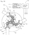
- Figs. 15 to 17 show a different link actuator according to a fifth embodiment of the present invention, which uses a parallel link mechanism.
- this link actuator 81 is of a type in which a distal end mounting member 83, on which a various type of instrument or the like is mounted, is connected to a base 82 via the parallel link mechanism 1 shown in Fig. 8 to Fig. 11 , such that alteration in position is allowed.
- a spacer 84 is interposed between the base 82 and the proximal end side link hub 2 of the parallel link mechanism 1.
- At least two of the three link mechanisms 4 of the parallel link mechanism 1 are each provided with a position changing actuator 90 which arbitrarily changes the position of the distal end side link hub 3 relative to the proximal end side link hub 2 by driving its corresponding proximal side end link member 5 to pivot, and a reduction gear unit 91 which transmits the amount of operation of the position changing actuator 90 to the proximal side end link member 5 after reducing the speed thereof.
- all of the three link mechanisms 4 are each provided with the position changing actuator 90 and the reduction gear unit 91.
- the position changing actuator 90 may be in the form of a rotary actuator, more specifically, a servomotor equipped with a reduction gear 90a, and is fixed to the base 82 by means of a motor fixing member 92.
- the reduction gear unit 91 may be composed of the reduction gear 90a of the position changing actuator 90 and a geared speed reducing section 93.
- the geared speed reducing section 93 includes a small gear 96 connected to an output shaft 90b of the position changing actuator 90 via a coupling 95 in a rotation transmittable manner, and a large gear 97 fixed to the proximal side end link member 5 and configured to be meshed with the small gear 96.
- each of the small gear 96 and the large gear 97 is a spur gear
- the large gear 97 is a sector gear of a sector shape having gear teeth formed only on a peripheral surface thereof.
- the large gear 97 has a radius of pitch circle greater than that of the small gear 96, and the rotation of the output shaft 90b of the position changing actuator 90 is transmitted to the proximal side end link member 5 after the rotation has been reduced in speed and made into rotation about a rotation axis O1 of the revolute pair between the proximal end side link hub 2 and the proximal side end link member 5.
- the speed reduction ratio is set to be 10 or higher.
- the radius of the pitch circle of the large gear 97 is set to be greater than or equal to 1/2 of an arm length L of the proximal side end link member 5.
- the arm length L is defined as a distance from an axial center point P1 of a central axis O1 of the revolute pair between the proximal end side link hub 2 and the proximal side end link member 5, to a point P3, the point P3 being obtained by projecting an axial center point P2 of a central axis O2 of the revolute pair between the proximal side end link member 5 and the intermediate link member 7 onto a plane that is orthogonal to the axis O1 of the revolute pair between the proximal end side link hub 2 and the proximal side end link member 5 and that contains the axial center point P1.
- the radius of the pitch circle of the large gear 97 is greater than or equal to the arm length L, which is advantageous for obtaining a high speed reduction ratio.
- the small gear 96 has a tooth portion 96a meshed with the large gear 97 and shank portions 96b protruding towards opposite sides of the tooth portion 96a.
- Each shank portion 96b is rotatably supported by two bearings 100 provided on a corresponding one of rotation support members 99 disposed on the base 82.
- Each bearing 100 may be a ball bearing such as, for example, a deep groove ball bearing or an angular contact ball bearing. In place of the ball bearings disposed in a plurality of rows as in the example shown, a roller bearing and/or a slide bearing may be employed.
- the outer rings (not shown) of the respective two bearings 100 have a shim (not shown) disposed therebetween, and by fastening a nut 101 threadedly engaged on the shank portion 96b, each bearing 100 is to receive a preload.
- the outer ring of the bearing 100 is press-fitted into the rotation support member 99.
- the large gear 97 is a member separate from the proximal side end link member 5, and is removably mounted on the proximal side end link member 5 by means of connecting members 102 such as bolts or the like.
- the large gear 97 may be provided integrally with the proximal side end link member 5.
- a rotation axis O3 of the position changing actuator 90 is aligned with a rotation axis O4 of the small gear 96.
- These rotation axes O3 and O4 are set to be parallel to the axis O1 of the revolute pair between the proximal end side link hub 2 and the proximal side end link member 5, and at the same level in height from the base 82.
- each position changing actuator 90 is controlled by a control device 110.
- the control device 110 is of a type capable of being numerically controlled by a computer, and provides each position changing actuator 90 with an output command based on a signal from a position setting unit 111, which sets a position of the distal end side link hub 3 relative to the proximal end side link hub 2, and a signal from a position detection unit 112, which detects the position of the distal end side link hub 3 relative to the proximal end side link hub 2.
- the position setting unit 111 sets the position of the distal end side link hub 3, by determining, for example, the bending angle ⁇ (refer to Fig. 3 ) and the turning angle ⁇ (refer to Fig. 3 ).
- the position detection unit 112 detects the rotation angle ⁇ n ( ⁇ 1 and ⁇ 2 in Fig. 3 ) of each proximal side end link member 5 by means of, for example, an encoder (not shown). Alternatively, an encoder (not shown) of the position changing actuator 90 may be used for detecting the position of the distal end side link hub 3.
- the bending angle ⁇ and the turning angle ⁇ have a mutual relationship with each rotation angle ⁇ n, and from one value, the other value can be obtained.
- a control target value of the rotation angle ⁇ n of each proximal side end link member 5 is calculated in response to the position of the distal end side link hub 3 set by the position setting unit 111.
- the rotation angle ⁇ n above represents the operating position of the position changing actuator 90.
- the calculation of the rotation angle ⁇ n is carried out by inverse transformation of equation 1 above.
- the inverse transformation is a transformation for calculating the rotation angle ⁇ n of the proximal side end link member 5 from the bending angle ⁇ and the turning angle ⁇ .
- each position changing actuator 90 is controlled such that the actual rotation angle ⁇ n becomes the control target value. Accordingly, the proximal side end link members 5 of all of the link mechanisms 4 are each rotated by the determined rotation angle ⁇ n, thereby causing the distal end side link hub 3 to have the position set by the position setting unit 111.
- the link actuator 81 can have a wide range of movement of the distal end side link hub 3 relative to the proximal end side link hub 2.
- operability of a medical instrument or the like mounted on the distal end mounting member 83 is good.
- all of the three link mechanisms 4 are each provided with the position changing actuator 90 and the reduction gear unit 91, drive can be realized in good balance no matter what position is taken by the distal end side link hub 3 relative to the proximal end side link hub 2. In other words, the balance of driving force is good. Accordingly, each of the position changing actuators 90 can be made compact in size.
- the provision of the position changing actuator 90 and the reduction gear unit 91 in all of the three link mechanisms 4 makes it possible to perform control such that rattling of the parallel link mechanism 1 and/or the reduction gear unit 91 can be cut down.
- the positioning accuracy of the distal end side link hub 3 can be increased, and also, the link actuator 81 itself can have a high rigidity.
- the geared speed reducing section 93 of the reduction gear unit 91 is composed of a combination of the small gear 96 and the large gear 97, and is capable of providing the high speed reduction ratio of 10 or higher. Where the speed reduction ratio is high, the positioning resolution by the encoder and the like becomes high, and therefore, the positioning resolution of the distal end side link hub 3 increases. Also, the position changing actuator 90 of a low output may be used. In the fifth embodiment, although the position changing actuator 90 with the reduction gear 90a is used, if the speed reduction ratio of the geared speed reducing section 93 is high, it is possible to use the position changing actuator 90 having no reduction gear, and as a result, the position changing actuator 90 can be made compact in size.
- the radius of the pitch circle of the large gear 97 is set to be greater than or equal to 1/2 of the arm length L of the proximal side end link member 5, the bending moment of the proximal side end link member 5, which is caused by a distal end loading, becomes small. For this reason, the rigidity of the link actuator 81 as a whole can be maintained at a value not higher than necessary, and also the weight of the proximal side end link member 5 can be reduced.
- the material of the proximal side end link member 5 can be changed from stainless steel (SUS) to aluminium.
- SUS stainless steel
- the large gear 97 comes to have a sufficiently larger diameter than the outer diameter of each bearing 12 that is disposed at the revolute pair section between the proximal end side link hub 2 and the proximal side end link member 5. Accordingly, space is created between the tooth portion of the large gear 97 and the bearing 12, and thus, the large gear 97 is easy to be disposed.
- the radius of the pitch circle of the large gear 97 is greater than or equal to the arm length L, the radius of the pitch circle of the large gear 97 is further increased, and the operations and effects are further remarkably exhibited.
- the small gear 96 and the large gear 97 are each a spur gear, the manufacture thereof is easy and the transmission efficiency of rotation is high. Since the small gear 96 is supported by the bearings 100 on axially opposite sides, the support rigidity of the small gear 96 is high. Accordingly, the angle retaining rigidity of the proximal side end link member 5 under the distal end loading increases, and as a result, increase of the rigidity and the positioning accuracy of the link actuator 81 is achieved.
- the link actuator 81 can be applied to various applications merely by changing the large gear 97.
- the maintenance is good. For example, when any trouble occurs in the geared speed reducing section 93, mere replacement of only the geared speed reducing section 93 is enough.
- Fig. 1 to Fig. 5 , Fig. 8 and Fig. 9 , Fig. 13 to Fig. 17 used in the description of the first to the fifth embodiments described above are also applicable to this embodiment, and thus, by incorporating these figures in this embodiment, detailed description thereof is omitted.
- the sealing structure 19 (21), described in each embodiment above, which regulates the flow of a lubricant or the like between inside and outside of the bearings 12 (24) is constructed in the same manner also in this embodiment.
- each bearing 12, 24 in each revolute pair section oscillates. If the oscillation angle thereof is small, the life of the bearing under oscillation becomes long, but if the oscillation angle is reduced to some level or lower, fretting is caused and the bearing reaches the end of life early. Therefore, in order to realize a long life of the bearing 12, 24 arranged in each revolute pair section, as shown in Fig. 18 and Fig.
- a bearing which has a critical oscillation angle ⁇ , which is the minimum oscillation angle in a practically available range for a bearing, is smaller than the maximum value (maximum bending angle) ⁇ max of the bending angle ⁇ between the central axis QA of the proximal end side link hub 2 and the central axis QB of the distal end side link hub 3.
- the maximum bending angle ⁇ max is the maximum value of the bending angle ⁇ within a range possible under the structure of the parallel link mechanism 1, and more preferably, the maximum value of the bending angle ⁇ in a predetermined work operation. The basis thereof is described below.
- Equation 1 obtained with reference to Fig. 3 in the first embodiment described above, from a change amount of the rotation angle ⁇ n obtained when the turning angle ⁇ is changed while the maximum bending angle is set to ⁇ max , the range of oscillation of the proximal side end link member 5 relative to the proximal end side link hub 2, and the range of oscillation of the distal side end link member 6 relative to the distal end side link hub 3 are obtained.
- Each obtained range of oscillation is ⁇ max ( Fig. 18 ).
- the range of oscillation of the intermediate link member 7 relative to the end link member 5, 6 becomes greater than ⁇ max due to the structure of the parallel link mechanism 1 ( Fig. 19 ), although description of the structural calculation equation is omitted.
- the critical oscillation angle ⁇ is set to be 2 ⁇ 180/(0.555 ⁇ Z ⁇ )[deg].
- the critical oscillation angle ⁇ is set to be 2 ⁇ 180/(0.37 ⁇ (Z + 0.1) ⁇ )[deg].
- the critical oscillation angle ⁇ is set to be 2 ⁇ 180/(0.544 ⁇ Z ⁇ )[deg]. The values of the critical oscillation angle determined as described above substantially match optimum values of the critical oscillation angle ⁇ obtained from experimental data.
- the revolute pair section between the distal side end link member 6 and the intermediate link member 7 has the same structure as that described above.
- this parallel link mechanism 1 also uses, as the bearing 12, 24, a bearing whose critical oscillation angle ⁇ is smaller than the maximum bending angle ⁇ max .
Landscapes
- Engineering & Computer Science (AREA)
- General Engineering & Computer Science (AREA)
- Mechanical Engineering (AREA)
- Robotics (AREA)
- Transmission Devices (AREA)
- Rolling Contact Bearings (AREA)
Claims (7)
- Gelenkantriebsvorrichtung (1), aufweisend:eine proximale Endseitengelenknabe (2),eine distale Endseitengelenknabe (3) unddrei oder mehr Gelenkmechanismen (4), die die distale Endseitengelenknabe (3) auf eine positionsändernde Weise mit der Endseitengelenknabe (2) verbinden,wobei jeder der Gelenkmechanismen (4) Folgendes aufweist:ein proximalseitiges Endgelenkelement (5), wobei ein Ende des proximalseitigen Endgelenkelements (5) schwenkbar mit der proximalen Endseitengelenknabe (2) verbunden ist,ein distalseitiges Endgelenkelement (6), wobei ein Ende des distalseitigen Endgelenkelements (6) schwenkbar mit der distalen Endseitengelenknabe (3) verbunden ist, undein Zwischenelement (7), dessen gegenüberliegende Enden schwenkbar mit den anderen Enden des proximalseitigen Endgelenkelements (5) bzw. des distalseitigen Endgelenkelements (6) verbunden sind, und wobei jeder der Gelenkmechanismen (4) eine solche Form hat, dass ein durch Linien dargestelltes geometrisches Modell des Gelenkmechanismus (4) eine Symmetrie zwischen einem proximalen endseitigen Abschnitt davon und einem distalen endseitigen Abschnitt davon bezüglich eines Zwischenabschnitts des Zwischenelements (7) zeigt, wobei ein Drehpaar zwischen der proximalen Endseitengelenknabe (2) und dem einen Ende des proximalseitigen Endgelenkelements (5), ein Drehpaar zwischen der distalen Endseitengelenknabe (3) und dem einen Ende des distalseitigen Endgelenkelements (6) und Drehpaare zwischen den anderen Enden des proximalseitigen und des distalseitigen Endgelenkelements (5, 6) und den gegenüberliegenden Enden des Zwischenelementes (7) jeweils ein dazwischenliegendes Lager (12, 24) aufweisen, dadurch gekennzeichnet, dassals jedes Lager (12, 24) ein Lager (12, 24) mit einem kritischen Schwingwinkel verwendet wird, der kleiner als der Höchstwert in einem möglichen Bereich eines Biegewinkels ist, der als ein Winkel zwischen einer mittleren Achse (QA) der proximalen Endseitengelenknabe (2) und einer mittleren Achse (QB) der distalen Endseitengelenknabe (3) definiert ist.
- Gelenkantriebsvorrichtung (1) nach Anspruch 1, wobei der kritische Schwingwinkel kleiner als ein Höchstwert des Biegewinkels ist, der bei einem vorbestimmten Arbeitsbetrieb bestimmt worden ist.
- Gelenkantriebsvorrichtung nach Anspruch 1 oder 2, wobei das Lager ein Rillenkugellager ist und wobei Z für die Anzahl der Rollelemente des Rillenkugellagers steht und der kritische Schwingwinkel auf 2*180/(0,555*Z*π)[Grad] eingestellt ist.
- Gelenkantriebsvorrichtung nach Anspruch 1 oder 2, wobei das Lager ein Zylinderrollenlager ist und wobei Z für die Anzahl der Rollelemente des Zylinderrollenlagers steht und der kritische Schwingwinkel auf 2*180/(0,37*(Z + 0,1)*π)[Grad] eingestellt ist.
- Gelenkantriebsvorrichtung nach Anspruch 1 oder 2, wobei das Lager ein Nadelrollenlager ist und wobei Z für die Anzahl der Rollelemente des Nadelrollenlagers steht und der kritische Schwingwinkel auf 2*180/(0,544*Z*π)[Grad] eingestellt ist.
- Gleichlaufuniversalgelenk (61), umfassend die Gelenkantriebsvorrichtung (1) nach einem der Ansprüche 1 bis 5, wobei die proximale Endseitengelenknabe (2) der Gelenkantriebsvorrichtung (1) mit einer Eingangswelle (63) versehen ist und die distale Endseitengelenknabe (3) der Gelenkantriebsvorrichtung (1) mit einer Ausgangswelle (65) versehen ist.
- Gelenkaktuator (71, 81), wobei jeder der zwei oder mehr Gelenkmechanismen (4) der drei oder mehr Gelenkmechanismen (4) in der Gelenkantriebsvorrichtung (1) nach einem der Ansprüche 1 bis 5 mit einem Aktuator versehen ist, der die Position der distalen Endseitengelenknabe (3) bezüglich der proximalen Endseitengelenknabe (2) durch Drehen des proximalseitigen Endgelenkelements (5) ändert.
Applications Claiming Priority (5)
| Application Number | Priority Date | Filing Date | Title |
|---|---|---|---|
| JP2011242605A JP5911697B2 (ja) | 2011-11-04 | 2011-11-04 | パラレルリンク機構、等速自在継手、およびリンク作動装置 |
| JP2011243462 | 2011-11-07 | ||
| JP2012236452A JP6128797B2 (ja) | 2011-11-07 | 2012-10-26 | パラレルリンク機構、等速自在継手、およびリンク作動装置 |
| PCT/JP2012/078017 WO2013065675A1 (ja) | 2011-11-04 | 2012-10-30 | パラレルリンク機構、等速自在継手およびリンク作動装置 |
| EP12846455.9A EP2775169B1 (de) | 2011-11-04 | 2012-10-30 | Parallelverbindungsmechanismus, gleichlaufgelenk und verbindungsaktuator |
Related Parent Applications (2)
| Application Number | Title | Priority Date | Filing Date |
|---|---|---|---|
| EP12846455.9A Division EP2775169B1 (de) | 2011-11-04 | 2012-10-30 | Parallelverbindungsmechanismus, gleichlaufgelenk und verbindungsaktuator |
| EP12846455.9A Division-Into EP2775169B1 (de) | 2011-11-04 | 2012-10-30 | Parallelverbindungsmechanismus, gleichlaufgelenk und verbindungsaktuator |
Publications (2)
| Publication Number | Publication Date |
|---|---|
| EP3276205A1 EP3276205A1 (de) | 2018-01-31 |
| EP3276205B1 true EP3276205B1 (de) | 2021-10-13 |
Family
ID=50997506
Family Applications (2)
| Application Number | Title | Priority Date | Filing Date |
|---|---|---|---|
| EP12846455.9A Active EP2775169B1 (de) | 2011-11-04 | 2012-10-30 | Parallelverbindungsmechanismus, gleichlaufgelenk und verbindungsaktuator |
| EP17185740.2A Active EP3276205B1 (de) | 2011-11-04 | 2012-10-30 | Parallelverbindungsmechanismus, gleichlaufgelenk und verbindungsaktuator |
Family Applications Before (1)
| Application Number | Title | Priority Date | Filing Date |
|---|---|---|---|
| EP12846455.9A Active EP2775169B1 (de) | 2011-11-04 | 2012-10-30 | Parallelverbindungsmechanismus, gleichlaufgelenk und verbindungsaktuator |
Country Status (4)
| Country | Link |
|---|---|
| US (2) | US9316266B2 (de) |
| EP (2) | EP2775169B1 (de) |
| CN (2) | CN106863313B (de) |
| WO (1) | WO2013065675A1 (de) |
Families Citing this family (18)
| Publication number | Priority date | Publication date | Assignee | Title |
|---|---|---|---|---|
| JP5951224B2 (ja) * | 2011-11-02 | 2016-07-13 | Ntn株式会社 | リンク作動装置の原点位置初期設定方法およびリンク作動装置 |
| JP6289973B2 (ja) * | 2014-03-31 | 2018-03-07 | Ntn株式会社 | パラレルリンク機構およびリンク作動装置 |
| CN104454961B (zh) * | 2014-11-20 | 2017-03-15 | 泰尔重工股份有限公司 | 一种受拉的等效复合球铰 |
| JP6453066B2 (ja) * | 2014-12-05 | 2019-01-16 | Ntn株式会社 | リンク作動装置の制御方法 |
| JP6602620B2 (ja) | 2015-09-24 | 2019-11-06 | Ntn株式会社 | 組合せ型リンク作動装置 |
| CN105598954B (zh) * | 2016-03-24 | 2017-09-22 | 褚宏鹏 | 大工作空间两转动并联机构 |
| JP6719956B2 (ja) * | 2016-04-20 | 2020-07-08 | Ntn株式会社 | 双腕型作動装置 |
| WO2017213034A1 (ja) | 2016-06-08 | 2017-12-14 | Ntn株式会社 | リンク作動装置 |
| JP6882878B2 (ja) * | 2016-10-28 | 2021-06-02 | Ntn株式会社 | 三次元造形装置 |
| JP2018075689A (ja) | 2016-11-11 | 2018-05-17 | Ntn株式会社 | 作動装置および双腕型作動装置 |
| CN106523534B (zh) * | 2016-12-29 | 2019-08-09 | 浙江舜宇光学有限公司 | 轴承组旋转装置、操作设备及其调节方法 |
| CN108397700A (zh) * | 2017-02-04 | 2018-08-14 | 宁波福泰电器有限公司 | 可调工作灯及其调光方法 |
| JP6498738B1 (ja) * | 2017-09-26 | 2019-04-10 | Ntn株式会社 | リンク作動装置 |
| JP7037375B2 (ja) * | 2018-01-29 | 2022-03-16 | Ntn株式会社 | インホイールモータ駆動装置 |
| JP7022008B2 (ja) * | 2018-06-08 | 2022-02-17 | Ntn株式会社 | リンク作動装置 |
| JP7340196B2 (ja) * | 2019-06-05 | 2023-09-11 | 国立大学法人九州工業大学 | リンク作動装置 |
| CN112560197B (zh) * | 2020-12-16 | 2023-08-22 | 温州大学 | 一种考虑元素分离位置的转动副间隙监测方法及装置 |
| RU2760496C1 (ru) * | 2021-05-31 | 2021-11-25 | Владимир Иванович Пожбелко | Стержневая вращательная кинематическая пара |
Family Cites Families (32)
| Publication number | Priority date | Publication date | Assignee | Title |
|---|---|---|---|---|
| US3477249A (en) | 1968-07-08 | 1969-11-11 | Southwestern Ind Inc | Constant velocity universal joint |
| JPS5970276A (ja) * | 1982-10-14 | 1984-04-20 | 本田技研工業株式会社 | 自動二輪車のハンドル操舵装置 |
| US4573698A (en) | 1982-10-14 | 1986-03-04 | Honda Giken Kogyo Kabushiki Kaisha | Motorcycle steering mechanism |
| JPS61184153A (ja) | 1985-02-08 | 1986-08-16 | Nissan Motor Co Ltd | ブレ−キ液圧制御装置 |
| JPS61184153U (de) * | 1985-05-09 | 1986-11-17 | ||
| JPS647917A (en) | 1987-06-29 | 1989-01-11 | Kurita Machinery Manuf | Filter press |
| JPH0854024A (ja) * | 1994-08-09 | 1996-02-27 | Ntn Corp | 揺動型転がり軸受 |
| JPH09287570A (ja) | 1996-04-19 | 1997-11-04 | Anest Iwata Corp | オイルフリー二段往復圧縮機の連接棒小端部 |
| US5893296A (en) | 1997-03-13 | 1999-04-13 | Ross-Hime Designs, Incorporated | Multiple rotatable links robotic manipulator |
| JPH10286792A (ja) | 1997-04-12 | 1998-10-27 | Hitachi Seiki Co Ltd | 平行リンクで構成された脚を有する位置決め装置及び工作機械 |
| JP2000094245A (ja) | 1998-09-17 | 2000-04-04 | Fanuc Ltd | パラレルリンク機構を具備する作業装置 |
| JP2000252696A (ja) * | 1999-03-04 | 2000-09-14 | Matsushita Electric Ind Co Ltd | 電子部品装着装置 |
| JP2002349593A (ja) | 2001-05-31 | 2002-12-04 | Ntn Corp | 等速自在継手 |
| JP2003254448A (ja) | 2002-03-04 | 2003-09-10 | Nok Corp | 磁性流体シール装置 |
| JP2004261886A (ja) * | 2003-02-18 | 2004-09-24 | Ntn Corp | リンク作動装置 |
| JP2005127475A (ja) * | 2003-10-27 | 2005-05-19 | Ntn Corp | リンク作動装置 |
| JP2005144627A (ja) * | 2003-11-18 | 2005-06-09 | Ntn Corp | リンク作動装置 |
| EP1690650A4 (de) * | 2003-12-03 | 2008-01-09 | Ntn Toyo Bearing Co Ltd | Verbindungsgliedbetätigungsvorrichtung |
| JP2005199828A (ja) * | 2004-01-14 | 2005-07-28 | Toyota Motor Corp | インホイールモータの冷却装置 |
| US7971505B2 (en) * | 2004-03-11 | 2011-07-05 | Ntn Corporation | Link actuating device |
| JP2005299828A (ja) * | 2004-04-13 | 2005-10-27 | Ntn Corp | リンク作動装置 |
| JP2006118620A (ja) | 2004-10-22 | 2006-05-11 | Toshiba Mach Co Ltd | ベアリング押えのシール方法 |
| WO2006102393A2 (en) * | 2005-03-22 | 2006-09-28 | Ross-Hime Designs, Incorporated | Robotic manipulator |
| JP2008185062A (ja) | 2007-01-26 | 2008-08-14 | Nsk Ltd | 荷重支持装置 |
| JP2009174683A (ja) * | 2008-01-28 | 2009-08-06 | Ntn Corp | 樹脂プーリ付き軸受 |
| JP4805301B2 (ja) | 2008-04-10 | 2011-11-02 | 村田機械株式会社 | パラレルメカニズム |
| WO2009148603A1 (en) * | 2008-06-04 | 2009-12-10 | Ross-Hime Designs, Inc. | Robotic manipulator |
| JP5434483B2 (ja) | 2009-11-02 | 2014-03-05 | 日本精工株式会社 | ロボットアーム |
| CN101797435A (zh) * | 2010-03-17 | 2010-08-11 | 上海大学 | 三自由度球面并联机构仿生眼睛 |
| JP5680925B2 (ja) * | 2010-09-30 | 2015-03-04 | Ntn株式会社 | 遠隔操作型アクチュエータ |
| JP5785055B2 (ja) * | 2011-11-07 | 2015-09-24 | Ntn株式会社 | リンク作動装置 |
| CN105269557B (zh) * | 2012-03-23 | 2017-06-23 | Ntn株式会社 | 连杆动作装置 |
-
2012
- 2012-10-30 WO PCT/JP2012/078017 patent/WO2013065675A1/ja active Application Filing
- 2012-10-30 CN CN201610862291.4A patent/CN106863313B/zh active Active
- 2012-10-30 CN CN201280054040.3A patent/CN103906947B/zh active Active
- 2012-10-30 EP EP12846455.9A patent/EP2775169B1/de active Active
- 2012-10-30 US US14/352,005 patent/US9316266B2/en active Active
- 2012-10-30 EP EP17185740.2A patent/EP3276205B1/de active Active
-
2016
- 2016-03-11 US US15/067,680 patent/US9976603B2/en active Active
Also Published As
| Publication number | Publication date |
|---|---|
| US20140248965A1 (en) | 2014-09-04 |
| WO2013065675A1 (ja) | 2013-05-10 |
| EP3276205A1 (de) | 2018-01-31 |
| EP2775169B1 (de) | 2017-10-04 |
| US9316266B2 (en) | 2016-04-19 |
| EP2775169A4 (de) | 2016-07-06 |
| CN106863313A (zh) | 2017-06-20 |
| US9976603B2 (en) | 2018-05-22 |
| CN103906947A (zh) | 2014-07-02 |
| CN106863313B (zh) | 2019-05-21 |
| US20160195141A1 (en) | 2016-07-07 |
| EP2775169A1 (de) | 2014-09-10 |
| CN103906947B (zh) | 2016-11-02 |
Similar Documents
| Publication | Publication Date | Title |
|---|---|---|
| EP3276205B1 (de) | Parallelverbindungsmechanismus, gleichlaufgelenk und verbindungsaktuator | |
| US10022827B2 (en) | Method for initially setting position of origin of link actuators, and link actuator | |
| EP2778474B1 (de) | Verknüpfungsbetätigungsvorrichtung | |
| EP3128206B1 (de) | Parallelverbindungsmechanismus und verbindungsbetätigungsvorrichtung | |
| JP5316691B2 (ja) | 動力伝達装置 | |
| EP2759741B1 (de) | Verbindungsbetätigungsvorrichtung | |
| US9249869B2 (en) | Link actuating device | |
| JP6282764B2 (ja) | パラレルリンク機構、等速自在継手、およびリンク作動装置 | |
| EP2998081B1 (de) | Verknüpfungsbetätigungsvorrichtung | |
| EP3396204B1 (de) | Verbindungsbetätigungsvorrichtung | |
| JP2013096547A (ja) | パラレルリンク機構、等速自在継手、およびリンク作動装置 | |
| US20200206897A1 (en) | Link actuating device | |
| JP2014119069A (ja) | リンク作動装置 | |
| WO2017051866A1 (ja) | リンク作動装置の診断装置 | |
| JP6133162B2 (ja) | リンク作動装置 | |
| WO2015182557A1 (ja) | パラレルリンク機構およびリンク作動装置 | |
| JP6352054B2 (ja) | パラレルリンク機構およびリンク作動装置 | |
| JP2021000704A (ja) | ロボット | |
| JP2020012534A (ja) | 無段変速機 |
Legal Events
| Date | Code | Title | Description |
|---|---|---|---|
| PUAI | Public reference made under article 153(3) epc to a published international application that has entered the european phase |
Free format text: ORIGINAL CODE: 0009012 |
|
| STAA | Information on the status of an ep patent application or granted ep patent |
Free format text: STATUS: THE APPLICATION HAS BEEN PUBLISHED |
|
| AC | Divisional application: reference to earlier application |
Ref document number: 2775169 Country of ref document: EP Kind code of ref document: P |
|
| AK | Designated contracting states |
Kind code of ref document: A1 Designated state(s): AL AT BE BG CH CY CZ DE DK EE ES FI FR GB GR HR HU IE IS IT LI LT LU LV MC MK MT NL NO PL PT RO RS SE SI SK SM TR |
|
| STAA | Information on the status of an ep patent application or granted ep patent |
Free format text: STATUS: REQUEST FOR EXAMINATION WAS MADE |
|
| 17P | Request for examination filed |
Effective date: 20180702 |
|
| RBV | Designated contracting states (corrected) |
Designated state(s): AL AT BE BG CH CY CZ DE DK EE ES FI FR GB GR HR HU IE IS IT LI LT LU LV MC MK MT NL NO PL PT RO RS SE SI SK SM TR |
|
| RIC1 | Information provided on ipc code assigned before grant |
Ipc: F16H 21/48 20060101AFI20210330BHEP Ipc: F16D 3/30 20060101ALI20210330BHEP Ipc: F16J 15/447 20060101ALI20210330BHEP Ipc: F16J 15/54 20060101ALI20210330BHEP Ipc: B25J 9/00 20060101ALI20210330BHEP Ipc: B25J 9/10 20060101ALI20210330BHEP Ipc: B25J 19/00 20060101ALI20210330BHEP Ipc: F16H 21/46 20060101ALI20210330BHEP Ipc: F16C 19/16 20060101ALI20210330BHEP Ipc: F16C 19/54 20060101ALI20210330BHEP Ipc: F16C 33/66 20060101ALI20210330BHEP |
|
| GRAP | Despatch of communication of intention to grant a patent |
Free format text: ORIGINAL CODE: EPIDOSNIGR1 |
|
| STAA | Information on the status of an ep patent application or granted ep patent |
Free format text: STATUS: GRANT OF PATENT IS INTENDED |
|
| INTG | Intention to grant announced |
Effective date: 20210507 |
|
| RIN1 | Information on inventor provided before grant (corrected) |
Inventor name: SONE, KEISUKE Inventor name: ISOBE, HIROSHI Inventor name: YAMADA, HIROYUKI |
|
| GRAS | Grant fee paid |
Free format text: ORIGINAL CODE: EPIDOSNIGR3 |
|
| GRAA | (expected) grant |
Free format text: ORIGINAL CODE: 0009210 |
|
| STAA | Information on the status of an ep patent application or granted ep patent |
Free format text: STATUS: THE PATENT HAS BEEN GRANTED |
|
| AC | Divisional application: reference to earlier application |
Ref document number: 2775169 Country of ref document: EP Kind code of ref document: P |
|
| AK | Designated contracting states |
Kind code of ref document: B1 Designated state(s): AL AT BE BG CH CY CZ DE DK EE ES FI FR GB GR HR HU IE IS IT LI LT LU LV MC MK MT NL NO PL PT RO RS SE SI SK SM TR |
|
| REG | Reference to a national code |
Ref country code: GB Ref legal event code: FG4D |
|
| REG | Reference to a national code |
Ref country code: CH Ref legal event code: EP |
|
| REG | Reference to a national code |
Ref country code: DE Ref legal event code: R096 Ref document number: 602012076925 Country of ref document: DE |
|
| REG | Reference to a national code |
Ref country code: IE Ref legal event code: FG4D |
|
| REG | Reference to a national code |
Ref country code: AT Ref legal event code: REF Ref document number: 1438416 Country of ref document: AT Kind code of ref document: T Effective date: 20211115 |
|
| REG | Reference to a national code |
Ref country code: LT Ref legal event code: MG9D |
|
| REG | Reference to a national code |
Ref country code: NL Ref legal event code: MP Effective date: 20211013 |
|
| REG | Reference to a national code |
Ref country code: AT Ref legal event code: MK05 Ref document number: 1438416 Country of ref document: AT Kind code of ref document: T Effective date: 20211013 |
|
| PG25 | Lapsed in a contracting state [announced via postgrant information from national office to epo] |
Ref country code: RS Free format text: LAPSE BECAUSE OF FAILURE TO SUBMIT A TRANSLATION OF THE DESCRIPTION OR TO PAY THE FEE WITHIN THE PRESCRIBED TIME-LIMIT Effective date: 20211013 Ref country code: LT Free format text: LAPSE BECAUSE OF FAILURE TO SUBMIT A TRANSLATION OF THE DESCRIPTION OR TO PAY THE FEE WITHIN THE PRESCRIBED TIME-LIMIT Effective date: 20211013 Ref country code: FI Free format text: LAPSE BECAUSE OF FAILURE TO SUBMIT A TRANSLATION OF THE DESCRIPTION OR TO PAY THE FEE WITHIN THE PRESCRIBED TIME-LIMIT Effective date: 20211013 Ref country code: BG Free format text: LAPSE BECAUSE OF FAILURE TO SUBMIT A TRANSLATION OF THE DESCRIPTION OR TO PAY THE FEE WITHIN THE PRESCRIBED TIME-LIMIT Effective date: 20220113 Ref country code: AT Free format text: LAPSE BECAUSE OF FAILURE TO SUBMIT A TRANSLATION OF THE DESCRIPTION OR TO PAY THE FEE WITHIN THE PRESCRIBED TIME-LIMIT Effective date: 20211013 |
|
| REG | Reference to a national code |
Ref country code: CH Ref legal event code: PL |
|
| PG25 | Lapsed in a contracting state [announced via postgrant information from national office to epo] |
Ref country code: IS Free format text: LAPSE BECAUSE OF FAILURE TO SUBMIT A TRANSLATION OF THE DESCRIPTION OR TO PAY THE FEE WITHIN THE PRESCRIBED TIME-LIMIT Effective date: 20220213 Ref country code: SE Free format text: LAPSE BECAUSE OF FAILURE TO SUBMIT A TRANSLATION OF THE DESCRIPTION OR TO PAY THE FEE WITHIN THE PRESCRIBED TIME-LIMIT Effective date: 20211013 Ref country code: PT Free format text: LAPSE BECAUSE OF FAILURE TO SUBMIT A TRANSLATION OF THE DESCRIPTION OR TO PAY THE FEE WITHIN THE PRESCRIBED TIME-LIMIT Effective date: 20220214 Ref country code: PL Free format text: LAPSE BECAUSE OF FAILURE TO SUBMIT A TRANSLATION OF THE DESCRIPTION OR TO PAY THE FEE WITHIN THE PRESCRIBED TIME-LIMIT Effective date: 20211013 Ref country code: NO Free format text: LAPSE BECAUSE OF FAILURE TO SUBMIT A TRANSLATION OF THE DESCRIPTION OR TO PAY THE FEE WITHIN THE PRESCRIBED TIME-LIMIT Effective date: 20220113 Ref country code: NL Free format text: LAPSE BECAUSE OF FAILURE TO SUBMIT A TRANSLATION OF THE DESCRIPTION OR TO PAY THE FEE WITHIN THE PRESCRIBED TIME-LIMIT Effective date: 20211013 Ref country code: LV Free format text: LAPSE BECAUSE OF FAILURE TO SUBMIT A TRANSLATION OF THE DESCRIPTION OR TO PAY THE FEE WITHIN THE PRESCRIBED TIME-LIMIT Effective date: 20211013 Ref country code: HR Free format text: LAPSE BECAUSE OF FAILURE TO SUBMIT A TRANSLATION OF THE DESCRIPTION OR TO PAY THE FEE WITHIN THE PRESCRIBED TIME-LIMIT Effective date: 20211013 Ref country code: GR Free format text: LAPSE BECAUSE OF FAILURE TO SUBMIT A TRANSLATION OF THE DESCRIPTION OR TO PAY THE FEE WITHIN THE PRESCRIBED TIME-LIMIT Effective date: 20220114 Ref country code: ES Free format text: LAPSE BECAUSE OF FAILURE TO SUBMIT A TRANSLATION OF THE DESCRIPTION OR TO PAY THE FEE WITHIN THE PRESCRIBED TIME-LIMIT Effective date: 20211013 |
|
| REG | Reference to a national code |
Ref country code: BE Ref legal event code: MM Effective date: 20211031 |
|
| REG | Reference to a national code |
Ref country code: DE Ref legal event code: R097 Ref document number: 602012076925 Country of ref document: DE |
|
| PG25 | Lapsed in a contracting state [announced via postgrant information from national office to epo] |
Ref country code: SM Free format text: LAPSE BECAUSE OF FAILURE TO SUBMIT A TRANSLATION OF THE DESCRIPTION OR TO PAY THE FEE WITHIN THE PRESCRIBED TIME-LIMIT Effective date: 20211013 Ref country code: SK Free format text: LAPSE BECAUSE OF FAILURE TO SUBMIT A TRANSLATION OF THE DESCRIPTION OR TO PAY THE FEE WITHIN THE PRESCRIBED TIME-LIMIT Effective date: 20211013 Ref country code: RO Free format text: LAPSE BECAUSE OF FAILURE TO SUBMIT A TRANSLATION OF THE DESCRIPTION OR TO PAY THE FEE WITHIN THE PRESCRIBED TIME-LIMIT Effective date: 20211013 Ref country code: MC Free format text: LAPSE BECAUSE OF FAILURE TO SUBMIT A TRANSLATION OF THE DESCRIPTION OR TO PAY THE FEE WITHIN THE PRESCRIBED TIME-LIMIT Effective date: 20211013 Ref country code: LU Free format text: LAPSE BECAUSE OF NON-PAYMENT OF DUE FEES Effective date: 20211030 Ref country code: EE Free format text: LAPSE BECAUSE OF FAILURE TO SUBMIT A TRANSLATION OF THE DESCRIPTION OR TO PAY THE FEE WITHIN THE PRESCRIBED TIME-LIMIT Effective date: 20211013 Ref country code: DK Free format text: LAPSE BECAUSE OF FAILURE TO SUBMIT A TRANSLATION OF THE DESCRIPTION OR TO PAY THE FEE WITHIN THE PRESCRIBED TIME-LIMIT Effective date: 20211013 Ref country code: CZ Free format text: LAPSE BECAUSE OF FAILURE TO SUBMIT A TRANSLATION OF THE DESCRIPTION OR TO PAY THE FEE WITHIN THE PRESCRIBED TIME-LIMIT Effective date: 20211013 Ref country code: BE Free format text: LAPSE BECAUSE OF NON-PAYMENT OF DUE FEES Effective date: 20211031 |
|
| PLBE | No opposition filed within time limit |
Free format text: ORIGINAL CODE: 0009261 |
|
| STAA | Information on the status of an ep patent application or granted ep patent |
Free format text: STATUS: NO OPPOSITION FILED WITHIN TIME LIMIT |
|
| PG25 | Lapsed in a contracting state [announced via postgrant information from national office to epo] |
Ref country code: CH Free format text: LAPSE BECAUSE OF NON-PAYMENT OF DUE FEES Effective date: 20211031 Ref country code: LI Free format text: LAPSE BECAUSE OF NON-PAYMENT OF DUE FEES Effective date: 20211031 |
|
| 26N | No opposition filed |
Effective date: 20220714 |
|
| GBPC | Gb: european patent ceased through non-payment of renewal fee |
Effective date: 20220113 |
|
| PG25 | Lapsed in a contracting state [announced via postgrant information from national office to epo] |
Ref country code: IE Free format text: LAPSE BECAUSE OF NON-PAYMENT OF DUE FEES Effective date: 20211030 Ref country code: GB Free format text: LAPSE BECAUSE OF NON-PAYMENT OF DUE FEES Effective date: 20220113 Ref country code: AL Free format text: LAPSE BECAUSE OF FAILURE TO SUBMIT A TRANSLATION OF THE DESCRIPTION OR TO PAY THE FEE WITHIN THE PRESCRIBED TIME-LIMIT Effective date: 20211013 |
|
| PG25 | Lapsed in a contracting state [announced via postgrant information from national office to epo] |
Ref country code: SI Free format text: LAPSE BECAUSE OF FAILURE TO SUBMIT A TRANSLATION OF THE DESCRIPTION OR TO PAY THE FEE WITHIN THE PRESCRIBED TIME-LIMIT Effective date: 20211013 |
|
| PG25 | Lapsed in a contracting state [announced via postgrant information from national office to epo] |
Ref country code: IT Free format text: LAPSE BECAUSE OF FAILURE TO SUBMIT A TRANSLATION OF THE DESCRIPTION OR TO PAY THE FEE WITHIN THE PRESCRIBED TIME-LIMIT Effective date: 20211013 Ref country code: HU Free format text: LAPSE BECAUSE OF FAILURE TO SUBMIT A TRANSLATION OF THE DESCRIPTION OR TO PAY THE FEE WITHIN THE PRESCRIBED TIME-LIMIT; INVALID AB INITIO Effective date: 20121030 Ref country code: CY Free format text: LAPSE BECAUSE OF FAILURE TO SUBMIT A TRANSLATION OF THE DESCRIPTION OR TO PAY THE FEE WITHIN THE PRESCRIBED TIME-LIMIT Effective date: 20211013 |
|
| PGFP | Annual fee paid to national office [announced via postgrant information from national office to epo] |
Ref country code: FR Payment date: 20230921 Year of fee payment: 12 |
|
| PGFP | Annual fee paid to national office [announced via postgrant information from national office to epo] |
Ref country code: DE Payment date: 20230912 Year of fee payment: 12 |
|
| PG25 | Lapsed in a contracting state [announced via postgrant information from national office to epo] |
Ref country code: MK Free format text: LAPSE BECAUSE OF FAILURE TO SUBMIT A TRANSLATION OF THE DESCRIPTION OR TO PAY THE FEE WITHIN THE PRESCRIBED TIME-LIMIT Effective date: 20211013 |