EP3237704B1 - Jeu de panneaux de plancher identiques avec un système de verrouillage méchanique - Google Patents
Jeu de panneaux de plancher identiques avec un système de verrouillage méchanique Download PDFInfo
- Publication number
- EP3237704B1 EP3237704B1 EP15873741.1A EP15873741A EP3237704B1 EP 3237704 B1 EP3237704 B1 EP 3237704B1 EP 15873741 A EP15873741 A EP 15873741A EP 3237704 B1 EP3237704 B1 EP 3237704B1
- Authority
- EP
- European Patent Office
- Prior art keywords
- locking
- edge
- strip
- groove
- panel
- Prior art date
- Legal status (The legal status is an assumption and is not a legal conclusion. Google has not performed a legal analysis and makes no representation as to the accuracy of the status listed.)
- Active
Links
- 238000006073 displacement reaction Methods 0.000 claims description 54
- 238000005452 bending Methods 0.000 claims description 34
- 238000007906 compression Methods 0.000 claims description 20
- 230000006835 compression Effects 0.000 claims description 20
- 239000011162 core material Substances 0.000 description 46
- 239000000463 material Substances 0.000 description 38
- 210000002105 tongue Anatomy 0.000 description 35
- 230000009471 action Effects 0.000 description 22
- 238000000926 separation method Methods 0.000 description 21
- 238000004519 manufacturing process Methods 0.000 description 13
- 238000000034 method Methods 0.000 description 12
- 229920005989 resin Polymers 0.000 description 12
- 239000011347 resin Substances 0.000 description 12
- 230000008901 benefit Effects 0.000 description 10
- 239000010410 layer Substances 0.000 description 10
- 239000002344 surface layer Substances 0.000 description 7
- 230000007704 transition Effects 0.000 description 7
- 229920002522 Wood fibre Polymers 0.000 description 6
- 238000007373 indentation Methods 0.000 description 6
- 230000009191 jumping Effects 0.000 description 6
- 238000007514 turning Methods 0.000 description 6
- 238000009434 installation Methods 0.000 description 5
- 239000004033 plastic Substances 0.000 description 5
- 229920003023 plastic Polymers 0.000 description 5
- 239000000843 powder Substances 0.000 description 5
- 229920001187 thermosetting polymer Polymers 0.000 description 5
- 239000002023 wood Substances 0.000 description 5
- 229920000877 Melamine resin Polymers 0.000 description 4
- 238000009408 flooring Methods 0.000 description 4
- 238000005304 joining Methods 0.000 description 4
- 238000003475 lamination Methods 0.000 description 4
- 239000002245 particle Substances 0.000 description 4
- PNEYBMLMFCGWSK-UHFFFAOYSA-N Alumina Chemical compound [O-2].[O-2].[O-2].[Al+3].[Al+3] PNEYBMLMFCGWSK-UHFFFAOYSA-N 0.000 description 3
- 239000000835 fiber Substances 0.000 description 3
- 239000000945 filler Substances 0.000 description 3
- 239000011888 foil Substances 0.000 description 3
- 239000000203 mixture Substances 0.000 description 3
- 239000012815 thermoplastic material Substances 0.000 description 3
- 239000011155 wood-plastic composite Substances 0.000 description 3
- 239000003638 chemical reducing agent Substances 0.000 description 2
- 239000003795 chemical substances by application Substances 0.000 description 2
- 230000000295 complement effect Effects 0.000 description 2
- 238000005520 cutting process Methods 0.000 description 2
- 238000005516 engineering process Methods 0.000 description 2
- 230000002349 favourable effect Effects 0.000 description 2
- 238000007667 floating Methods 0.000 description 2
- IVJISJACKSSFGE-UHFFFAOYSA-N formaldehyde;1,3,5-triazine-2,4,6-triamine Chemical compound O=C.NC1=NC(N)=NC(N)=N1 IVJISJACKSSFGE-UHFFFAOYSA-N 0.000 description 2
- 229910052500 inorganic mineral Inorganic materials 0.000 description 2
- 238000003754 machining Methods 0.000 description 2
- 238000003801 milling Methods 0.000 description 2
- 239000011707 mineral Substances 0.000 description 2
- 230000000737 periodic effect Effects 0.000 description 2
- 230000002093 peripheral effect Effects 0.000 description 2
- 239000004814 polyurethane Substances 0.000 description 2
- 238000004080 punching Methods 0.000 description 2
- 230000002787 reinforcement Effects 0.000 description 2
- 238000007790 scraping Methods 0.000 description 2
- 229920001169 thermoplastic Polymers 0.000 description 2
- 239000004416 thermosoftening plastic Substances 0.000 description 2
- XLYOFNOQVPJJNP-UHFFFAOYSA-N water Substances O XLYOFNOQVPJJNP-UHFFFAOYSA-N 0.000 description 2
- WURBVZBTWMNKQT-UHFFFAOYSA-N 1-(4-chlorophenoxy)-3,3-dimethyl-1-(1,2,4-triazol-1-yl)butan-2-one Chemical compound C1=NC=NN1C(C(=O)C(C)(C)C)OC1=CC=C(Cl)C=C1 WURBVZBTWMNKQT-UHFFFAOYSA-N 0.000 description 1
- KXGFMDJXCMQABM-UHFFFAOYSA-N 2-methoxy-6-methylphenol Chemical compound [CH]OC1=CC=CC([CH])=C1O KXGFMDJXCMQABM-UHFFFAOYSA-N 0.000 description 1
- 239000004640 Melamine resin Substances 0.000 description 1
- 240000005561 Musa balbisiana Species 0.000 description 1
- 235000018290 Musa x paradisiaca Nutrition 0.000 description 1
- 238000003848 UV Light-Curing Methods 0.000 description 1
- 229920001807 Urea-formaldehyde Polymers 0.000 description 1
- 229920001587 Wood-plastic composite Polymers 0.000 description 1
- 239000004411 aluminium Substances 0.000 description 1
- XAGFODPZIPBFFR-UHFFFAOYSA-N aluminium Chemical compound [Al] XAGFODPZIPBFFR-UHFFFAOYSA-N 0.000 description 1
- 229910052782 aluminium Inorganic materials 0.000 description 1
- 238000010420 art technique Methods 0.000 description 1
- 230000015572 biosynthetic process Effects 0.000 description 1
- 239000012792 core layer Substances 0.000 description 1
- 230000005489 elastic deformation Effects 0.000 description 1
- 239000006260 foam Substances 0.000 description 1
- 239000002783 friction material Substances 0.000 description 1
- 239000003292 glue Substances 0.000 description 1
- 239000004922 lacquer Substances 0.000 description 1
- 239000007788 liquid Substances 0.000 description 1
- JDSHMPZPIAZGSV-UHFFFAOYSA-N melamine Chemical compound NC1=NC(N)=NC(N)=N1 JDSHMPZPIAZGSV-UHFFFAOYSA-N 0.000 description 1
- 239000012764 mineral filler Substances 0.000 description 1
- 230000004048 modification Effects 0.000 description 1
- 238000012986 modification Methods 0.000 description 1
- 239000003921 oil Substances 0.000 description 1
- 229920001568 phenolic resin Polymers 0.000 description 1
- 239000000049 pigment Substances 0.000 description 1
- ODGAOXROABLFNM-UHFFFAOYSA-N polynoxylin Chemical compound O=C.NC(N)=O ODGAOXROABLFNM-UHFFFAOYSA-N 0.000 description 1
- 229920002635 polyurethane Polymers 0.000 description 1
- 238000003825 pressing Methods 0.000 description 1
- 238000007639 printing Methods 0.000 description 1
- 230000009467 reduction Effects 0.000 description 1
- 239000007779 soft material Substances 0.000 description 1
- 239000000126 substance Substances 0.000 description 1
- 230000008961 swelling Effects 0.000 description 1
- 230000001360 synchronised effect Effects 0.000 description 1
- 210000003813 thumb Anatomy 0.000 description 1
- 125000000391 vinyl group Chemical group [H]C([*])=C([H])[H] 0.000 description 1
- 229920002554 vinyl polymer Polymers 0.000 description 1
- 239000002699 waste material Substances 0.000 description 1
Images


Classifications
-
- B—PERFORMING OPERATIONS; TRANSPORTING
- B26—HAND CUTTING TOOLS; CUTTING; SEVERING
- B26D—CUTTING; DETAILS COMMON TO MACHINES FOR PERFORATING, PUNCHING, CUTTING-OUT, STAMPING-OUT OR SEVERING
- B26D3/00—Cutting work characterised by the nature of the cut made; Apparatus therefor
- B26D3/06—Grooving involving removal of material from the surface of the work
- B26D3/065—On sheet material
-
- E—FIXED CONSTRUCTIONS
- E04—BUILDING
- E04F—FINISHING WORK ON BUILDINGS, e.g. STAIRS, FLOORS
- E04F15/00—Flooring
- E04F15/02—Flooring or floor layers composed of a number of similar elements
- E04F15/02038—Flooring or floor layers composed of a number of similar elements characterised by tongue and groove connections between neighbouring flooring elements
-
- E—FIXED CONSTRUCTIONS
- E04—BUILDING
- E04C—STRUCTURAL ELEMENTS; BUILDING MATERIALS
- E04C2/00—Building elements of relatively thin form for the construction of parts of buildings, e.g. sheet materials, slabs, or panels
- E04C2/30—Building elements of relatively thin form for the construction of parts of buildings, e.g. sheet materials, slabs, or panels characterised by the shape or structure
- E04C2/40—Building elements of relatively thin form for the construction of parts of buildings, e.g. sheet materials, slabs, or panels characterised by the shape or structure composed of a number of smaller components rigidly or movably connected together, e.g. interlocking, hingedly connected of particular shape, e.g. not rectangular of variable shape or size, e.g. flexible or telescopic panels
-
- E—FIXED CONSTRUCTIONS
- E04—BUILDING
- E04F—FINISHING WORK ON BUILDINGS, e.g. STAIRS, FLOORS
- E04F15/00—Flooring
- E04F15/02—Flooring or floor layers composed of a number of similar elements
- E04F15/10—Flooring or floor layers composed of a number of similar elements of other materials, e.g. fibrous or chipped materials, organic plastics, magnesite tiles, hardboard, or with a top layer of other materials
- E04F15/102—Flooring or floor layers composed of a number of similar elements of other materials, e.g. fibrous or chipped materials, organic plastics, magnesite tiles, hardboard, or with a top layer of other materials of fibrous or chipped materials, e.g. bonded with synthetic resins
-
- E—FIXED CONSTRUCTIONS
- E04—BUILDING
- E04F—FINISHING WORK ON BUILDINGS, e.g. STAIRS, FLOORS
- E04F15/00—Flooring
- E04F15/02—Flooring or floor layers composed of a number of similar elements
- E04F15/10—Flooring or floor layers composed of a number of similar elements of other materials, e.g. fibrous or chipped materials, organic plastics, magnesite tiles, hardboard, or with a top layer of other materials
- E04F15/107—Flooring or floor layers composed of a number of similar elements of other materials, e.g. fibrous or chipped materials, organic plastics, magnesite tiles, hardboard, or with a top layer of other materials composed of several layers, e.g. sandwich panels
-
- E—FIXED CONSTRUCTIONS
- E04—BUILDING
- E04F—FINISHING WORK ON BUILDINGS, e.g. STAIRS, FLOORS
- E04F2201/00—Joining sheets or plates or panels
- E04F2201/01—Joining sheets, plates or panels with edges in abutting relationship
- E04F2201/0138—Joining sheets, plates or panels with edges in abutting relationship by moving the sheets, plates or panels perpendicular to the main plane
- E04F2201/0146—Joining sheets, plates or panels with edges in abutting relationship by moving the sheets, plates or panels perpendicular to the main plane with snap action of the edge connectors
-
- E—FIXED CONSTRUCTIONS
- E04—BUILDING
- E04F—FINISHING WORK ON BUILDINGS, e.g. STAIRS, FLOORS
- E04F2201/00—Joining sheets or plates or panels
- E04F2201/01—Joining sheets, plates or panels with edges in abutting relationship
- E04F2201/0153—Joining sheets, plates or panels with edges in abutting relationship by rotating the sheets, plates or panels around an axis which is parallel to the abutting edges, possibly combined with a sliding movement
- E04F2201/0161—Joining sheets, plates or panels with edges in abutting relationship by rotating the sheets, plates or panels around an axis which is parallel to the abutting edges, possibly combined with a sliding movement with snap action of the edge connectors
-
- E—FIXED CONSTRUCTIONS
- E04—BUILDING
- E04F—FINISHING WORK ON BUILDINGS, e.g. STAIRS, FLOORS
- E04F2201/00—Joining sheets or plates or panels
- E04F2201/01—Joining sheets, plates or panels with edges in abutting relationship
- E04F2201/0169—Joining sheets, plates or panels with edges in abutting relationship by rotating the sheets, plates or panels around an axis which is perpendicular to the abutting edges and parallel to the main plane, possibly combined with a sliding movement
- E04F2201/0176—Joining sheets, plates or panels with edges in abutting relationship by rotating the sheets, plates or panels around an axis which is perpendicular to the abutting edges and parallel to the main plane, possibly combined with a sliding movement with snap action of the edge connectors
-
- E—FIXED CONSTRUCTIONS
- E04—BUILDING
- E04F—FINISHING WORK ON BUILDINGS, e.g. STAIRS, FLOORS
- E04F2201/00—Joining sheets or plates or panels
- E04F2201/02—Non-undercut connections, e.g. tongue and groove connections
- E04F2201/027—Non-undercut connections, e.g. tongue and groove connections connected by tongues and grooves, the centerline of the connection being inclined to the top surface
-
- E—FIXED CONSTRUCTIONS
- E04—BUILDING
- E04F—FINISHING WORK ON BUILDINGS, e.g. STAIRS, FLOORS
- E04F2201/00—Joining sheets or plates or panels
- E04F2201/04—Other details of tongues or grooves
- E04F2201/042—Other details of tongues or grooves with grooves positioned on the rear-side of the panel
-
- E—FIXED CONSTRUCTIONS
- E04—BUILDING
- E04F—FINISHING WORK ON BUILDINGS, e.g. STAIRS, FLOORS
- E04F2201/00—Joining sheets or plates or panels
- E04F2201/04—Other details of tongues or grooves
- E04F2201/043—Other details of tongues or grooves with tongues and grooves being formed by projecting or recessed parts of the panel layers
Definitions
- the disclosure generally relates to the field of mechanical locking systems for floor panels and building panels.
- the disclosure includes panels, floorboards, locking systems and production methods.
- Embodiments of the present invention are particularly suitable for use in floating floors, which are formed of floor panels having one or more upper layers comprising, e.g., thermoplastic or thermosetting material or wood veneer, an intermediate core of wood-fibre-based material or plastic material and preferably a lower balancing layer on the rear side of the core.
- Embodiments of the invention may also be used for joining building panels which preferably contain a board material for instance wall panels, ceilings, furniture components and similar.
- the long and short edges are mainly used to simplify the description of the invention.
- the panels may be square.
- Floor panels are generally produced with the surface layer pointing downwards in order to eliminate thickness tolerances of the core material. Some embodiments and production methods are shown with the surface pointing upwards in order to simplify the description.
- embodiments of the invention may be used in any floor panel on long and/or short edges and it may be combined with all types of known locking systems on long or short edges that lock the panels in the horizontal and/or vertical direction.
- Laminate flooring usually comprise a 6-8 mm wood based core, a 0.2 mm thick upper decorative surface layer of laminate and a 0.1 mm thick lower balancing layer.
- the laminate surface and the balancing layer comprise melamine-impregnated paper.
- the most common core material is fibreboard with high density and good stability usually called HDF - High Density Fibreboard.
- the impregnated surface and balancing papers are laminated to the core with heat and pressure.
- HDF material is hard and has a low flexibility, especially in the vertical direction perpendicular to the fibre orientation.
- Impregnated paper is replaced with a dry powder mix comprising wood fibres, melamine particles, aluminium oxide and pigments.
- the powder is applied on an HDF core and cured under heat and pressure.
- high quality HDF is used with a high resin content and low water swelling.
- Advanced decors may be formed with digital printing. Water based ink is injected into the powder prior to pressing.
- Decorative vinyl tile, LVT, flooring with a thickness of 3 - 6 mm usually comprises a transparent wear layer which may be coated with an ultraviolet, UV, cured polyurethane, PU, lacquer and a decorative plastic foil under the transparent foil.
- the wear layer and the decorative foil are laminated to one or several core layers comprising a mix of thermoplastic material and mineral fillers.
- the plastic core may be rather soft and flexible but also rather rigid depending on the filler content.
- Wood Plastic Composite floors are similar to LVT floors.
- the core comprises thermosetting material mixed with wood fibre fillers and is generally stronger and much more rigid than the mineral based LVT core.
- Thermoplastic material such as PVC, PP or PE may be combined with a mix of wood fibres and mineral particles and this may provide a wide variety of floor panels with different densities and flexibilities.
- Moisture resistant HDF with a high resin content, and WPC floors comprise stronger and more flexible core materials than conventional HDF based laminate floors and they are generally produced with a lower thickness.
- the above mentioned floor types comprise different core materials with different flexibility, density and strengths. Locking systems formed in one piece with the core must be adapted to such different material properties in order to provide a strong and cost efficient locking function.
- front side or “floor surface”
- rear side The edge between the front and rear side.
- horizontal plane is meant a plane, which extends parallel to the front side.
- vertical plane perpendicular to the horizontal plane.
- vertical locking is meant locking parallel to the vertical plane.
- horizontal locking is meant locking parallel to the horizontal plane.
- up is meant towards the front side, by “down” towards the rear side, by “inwardly” mainly horizontally towards an inner and centre part of the panel and by “outwardly” mainly horizontally away from the centre part of the panel.
- essentially vertical surface or wall is meant a surface or a wall that is inclined less than 45 degrees against a vertical plane.
- essentially horizontal surface is meant a surface that is inclined less than 45 degrees against a horizontal plane.
- locking angle of a surface locking panels in the horizontal direction is meant the angle of the surface relative a vertical plane
- locking angle of a surface locking panels in the vertical direction is meant the angle of the surface relative a horizontal plane.
- a tangent line defines the inclination of a curved wall or surface.
- the long edges are installed by angling.
- Horizontal snapping locks the short edges.
- the vertical connection is generally a tongue and a groove and the horizontal connection is a strip with a locking element in one edge that cooperates with a locking groove in the adjacent edge. Locking by snapping is obtained with a flexible strip that during the initial stage of locking bends downwards and during the final stage of locking snaps upwards such that the locking element is inserted into the locking groove.
- Similar locking systems may also be produced with a rigid strip and they are connected with an angling-angling method where both short and long edges are angled into a locked position.
- a floor panel of this type is presented in WO 2006/043893 . It discloses a floor panel with a short edge locking system comprising a locking element cooperating with a locking groove, for horizontal locking, and a flexible bow shaped so called “banana tongue” cooperating with a tongue groove, for locking in a vertical direction.
- the flexible bow shaped tongue is inserted during production into a displacement groove formed at the edge. The tongue bends horizontally along the edge during connection and makes it possible to install the panels by vertical movement.
- This invention provides a fold down locking system with an improved flexible tongue so called “bristle tongue” comprising a straight outer tongue edge over substantially the whole length of the tongue.
- An inner part of the tongue comprises bendable protrusions extending horizontally along the tongue body.
- the above known fold down "5G system” has been very successful and has captured a major market share of the premium world laminate and wood flooring markets.
- the locking is strong and reliable mainly due to the flexibility and pretension of the separate flexible tongue that allows a locking with large overlapping essentially horizontal locking surfaces.
- the 5G system and similar system have been less successful in the low priced market segments.
- the major reason is that the cost of the separate tongues and investments in special inserting equipment that is needed to insert a flexible tongue into a displacement groove are regarded as rather high in relation to the rather low price of the floor panels.
- a protruding strip for horizontal snapping may extend over a substantial distance from the upper edge and may protrude 8 - 10 mm beyond the upper edge. This may be used to facilitate a downward bending of the strip and the locking element.
- HDF comprises a fibre orientation substantially parallel with the floor surface. The material properties are such that bending of horizontally protruding parts is easier to accomplish than bending of vertically protruding parts.
- lower parts of an HDF board comprise a higher density and a higher resin content than middle parts and such properties are also favourable for the horizontal snapping systems where the strip is formed in the lower part of the core.
- WO 2012/084604 A1 discloses a panel comprising a body having at least one plastic layer, complementary locking means provided in pairs on opposite panel edges, and at least one pair of locking means having hook profiles, namely a receiving hook and a locking hook opposite thereto.
- the receiving hook comprises a receiving recess disposed near the body and the locking hook has a locking recess disposed near the body and comprising a locking step disposed away from the body and fitting in the receiving recess of the receiving hook in the vertical joining direction.
- the locking hook comprises a joint surface and a vertically active locking contour away from the body
- the receiving hook comprises a joint surface and a form-fit contour closer to the body and fitting together with the locking contour away from the body of the locking hood in a form-fit manner, so that a vertical locking can be brought about.
- the locking hook comprises a horizontal locking surface disposed closer to the body on the locking step thereof
- the receiving hook comprises a horizontal locking surface disposed away from the body in the receiving recess.
- a narrowed receiving opening is formed on the receiving hook, through which the locking step can be inserted into the receiving recess substantially in the vertical joint direction, wherein the free step end of the locking step is designed narrower than the width of the receiving opening of the receiving hook.
- the locking contour away from the body of the locking hook is short of the plane of the joint surface of the locking hook.
- the form-fit contour closer to the body of the receiving hook protrudes at least partially past the plane of the joint surface of the receiving hook.
- the locking step and the receiving opening are designed so that the step end fits into the receiving opening far enough at first that a part of the horizontal locking surface of the locking hook makes contact with the horizontal locking surface of the receiving hook during a joining motion without elastic deformation of the hook profiles and that the receiving hook comprises a bending bar implemented so that the width of the receiving opening can be expanded by the elastic flexibility thereof, so that the locking step can be inserted entirely into the receiving recess and the locking contour of the locking hook is further inserted into the form-fit contour of the receiving hook.
- a one-piece fold down locking system may be formed with a quality and locking function similar to the advanced 5G systems.
- An objective of embodiments of the present invention is to provide an improved and more cost efficient fold down locking system for vertical and horizontal locking of adjacent panels wherein the locking system is produced in one piece with the core.
- a first specific objective is to provide a locking system wherein a horizontally extending flexible strip may be used to accomplish the vertical and horizontal locking.
- a second specific objective is to provide a locking system with essentially horizontally extending locking surfaces for the vertical locking such that a strong locking force may be obtained in the vertical direction.
- a third specific objective is to prevent separation forces between the edges during locking and to decrease the snapping resistance such that a tool-less installation may be obtained with low pressure against the short edges.
- a fourth specific objective is to provide a cost efficient method to form locking elements in a double-end tenor comprising a lower chain and an upper belt that displace the panel in relation to several tool stations.
- a set of essentially identical floor panels are provided with a mechanical locking system comprising a strip extending horizontally from a lower part of a first edge and a downwardly open locking groove formed in an adjacent second edge.
- the strip comprises an upwardly protruding locking element that is configured to cooperate with the locking groove and locks the first and the second edge in a horizontal direction parallel to a main plane of the first and the second panel and in a vertical direction perpendicularly to the horizontal direction.
- the locking system is configured to be locked with a vertical displacement of the second edge against the first edge wherein the strip, preferably an outer portion of the strip, during an initial stage of the vertical displacement is configured to bend upwards towards the second panel and during a final stage of the vertical displacement is configured to bend downwards towards its initial unlocked position.
- An upper portion of the locking element may be configured to be displaced during locking into a space provided between an outer groove wall of the locking groove and an inner surface of the locking element.
- the displacement may be caused by at least one of a bending, a compression and a twisting of the strip.
- the upper portion of the locking element may during locking be further configured to be displaced out from the space.
- Bending may comprise rotation and/or a displacement of at least portions of the strip.
- the space between the outer groove wall and the inner surface is a cavity arranged in the inner surface of the locking element.
- the space is a cavity arranged in the outer groove wall of the locking groove.
- the space is partly a cavity arranged in the inner surface and partly a cavity arranged in the outer groove wall.
- the strip may be configured to bend upwards towards a portion of a front side of the second panel.
- the portion may be an outer portion of the front side.
- the upward and/or downward bending of the strip may be combined with at least one of a twisting or a compression of the strip.
- the strip may be configured to bend upwards from the unlocked position to an end position. Moreover, the strip may be configured to bend downwards from the end position and at least partly back to the unlocked position.
- an outer, lower portion of the strip is displaced vertically upwards from the unlocked position to the end position by a first distance and then is displaced vertically downwards by a second distance, wherein the second distance is between 10% and 95% of the first distance, e.g. 40% or 50%.
- the strip bends completely back to a position corresponding to the unlocked position so that the second distance is essentially the same as the first distance.
- the first and second panels may comprise a pair of parallel short edges and a pair of parallel long edges, wherein the long edges are perpendicular to the short edges.
- the first and second edges may be short edges.
- the main plane of the first and the second panel may be a horizontal plane that is essentially parallel with the front side and/or the rear side of the first and/or the second panel.
- a vertical displacement is meant that the edges of the panels are displaced against each other at least in a vertical direction.
- the vertical displacement may also be combined with an angling action.
- the vertical displacement is a vertical scissor movement caused by the same angling action that is used to connect the edges of the panels that are perpendicular to the first and the second edges.
- the first and second edges may be short edges and the perpendicular edges may be long edges.
- front sides of the first and second panels are essentially parallel to each other during the the vertical displacement.
- the first and the second edge may comprise a first edge section and a second edge section along the first and the second edge, wherein a cross section of the locking groove or a cross section of the locking element varies along the first edge and/or the second edge, in a locked position.
- the cross section of the locking groove or of the locking element may be a cross section as seen from a side view of the floor panels.
- first edge section There may be at least one first edge section and at least one second edge section.
- a shape of the each of the first edge sections may be similar.
- a shape of each of the second edge sections may be similar.
- the shapes of the first edge sections and/or the second edge sections may vary.
- the first edge sections and the second edge sections may be arranged alternately along the first and the second edge.
- first and the second edge sections along the edge may be smooth transition between the first and the second edge sections along the edge.
- the transition between the first and the second edge sections along the edge may be stepped.
- a first edge section is arranged at a first and/or a second corner section of the first and second edges.
- a second edge section is arranged at a first and/or a second corner section of the first and second edges.
- the first and second corner sections may be arranged adjacent to long edges of the panels.
- the first and second edges are locked vertically by means of engagement of an upper locking surface provided on an outer surface of the locking element and a lower locking surface provided on an inner groove wall of the locking groove.
- the upper locking surface is provided along the entire first edge and the lower locking surface is provided along a part of the second edge.
- the upper locking surface is provided along a part of the first edge and the lower locking surface is provided along the entire second edge.
- the locking element may be snapped into the locked position such that the upper and lower locking surfaces engage with each other in the locking position.
- the locking element may assume the locked position by means of a smooth displacement upwards and/or downwards such that the upper and lower locking surfaces engage with each other in the locking position.
- the latter may be achieved with a bevelled upper and/or lower locking surface.
- the strip may also be pressed down by a lower part of the second panel that presses against an upper part of the protruding strip and/or the locking element.
- a set of essentially identical rectangular floor panels each comprising long edges and a first short edge and a second short edge are provided.
- the first short edge and the second short edge are provided with a mechanical locking system comprising a strip extending horizontally from a lower part of a first short edge and a downwardly open locking groove formed in the second short edge.
- the strip comprises an upwardly protruding locking element that is configured to cooperate with the locking groove for locking the first short edge and the second short edge in a horizontal direction parallel to the main plane of the panels and in a vertical direction perpendicularly to the horizontal direction.
- the locking element comprises an inner surface, an outer surface and a top surface. The inner surface is positioned closer to an upper edge of the first panel than the outer surface.
- the locking groove comprises an outer groove wall, an inner groove wall and an upper groove wall, the outer groove wall being positioned closer to an upper edge of the second panel than the inner groove wall.
- the locking element comprises an upper locking surface and the locking groove comprises a lower locking surface.
- the first short edge and the second short edge comprise a first and a second joint edge section located along the first short edge and the second short edge.
- the first edge section is configured such that the outer groove wall of the locking groove and the inner surface of the locking element along are in contact with each other along a horizontal plane HP and lock the first short edge and the second short edge horizontally
- the second edge section is configured such that along the horizontal plane HP there is a space between the outer groove wall of the locking groove and the inner surface of the locking element.
- the upper locking surface of the locking element and the lower locking surface of the locking groove are configured to be in contact with each other and to lock the first short edge and the second short edge vertically.
- Embodiments of the space between the outer groove wall and the inner surface are largely analogous to the embodiments described above in relation to the first aspect, wherein reference is made to the above.
- a length of the space in a length direction of the short edges may correspond to a length of the second edge section.
- the length of the space may be longer than the length of the second edge section.
- the upper locking surface of the locking element and the lower locking surface of the locking groove may be configured to be in contact with each other in the second edge section.
- the upper locking surface and the lower locking surface form an overlap in a direction parallel with the main plane of the panels and perpendicularly to the short edges.
- there is an overlap only along a portion of the short edges e.g. in the second edge section(s).
- the overlap is constant along the short edges. More specifically, the overlap is constant in the second edge section(s).
- the overlap varies along the short edges.
- the varying overlap may be periodic with a constant periodicity along the second edge section(s).
- the upper locking surface extends along the entire first short edge. In a non-limiting example, there is no lower locking surface provided in the first edge section.
- the lower locking surface extends along the entire second short edge. In a non-limiting example, there is no upper locking surface provided in the first edge section.
- the upper locking surface or the lower locking surface may extend along a portion of the first and second short edge, respectively.
- the upper locking surface is arranged only in a middle section of the first short edge and the lower locking surface is provided along the entire second short edge.
- the upper locking surface is missing from corner sections of the first short edge, wherein the middle section is a second edge section and the corner sections are first edge sections, the middle section being arranged between the corner sections.
- the overlap is thereby formed only in the middle section.
- the space is formed as a cavity in a middle portion of the outer groove wall and/or in a middle portion of the inner surface.
- the upper edge of a panel may be a portion of the panel along a short edge thereof.
- the upper edge may be closer to the front side than the rear side of the panel.
- the upper edge of the first panel may be provided in a side wall of an indentation provided along the first short edge of the first panel.
- a projection along the second short edge of the second panel may be adapted to be inserted in the indentation.
- the upper edge of the second panel may be provided in the second short edge of the second panel.
- the first edge section may be located closer to a long edge than the second edge section.
- the second edge section may be located closer to a long edge than the first edge section.
- the first and/or second edge sections may be arranged at corner sections in precise analogy to the first aspect explained above.
- the locking system may be configured to be locked with a vertical displacement of the second short edge against the first short edge.
- vertical displacement has been defined above in relation to the first aspect.
- the locking system may be configured such that a vertical displacement of the second short edge against the first short edge during an initial stage of the vertical displacement bends the strip upwards towards the second panel such that the upper locking surface and lower locking surface overlap each other.
- the strip may be configured to bend upwards towards a portion of a front side of the second panel.
- the portion may be an outer portion of the front side.
- the upward bending of the strip may comprise at least one of an upward vertical displacement, a horizontal displacement inwards, and a rotation.
- the upward bending may be combined with a twisting and/or a compression of the strip.
- the lower locking surface may be essentially horizontal. Alternatively, the lower locking surface may be inclined.
- the angle of the lower locking surface with respect to a main plane of the second panel may be between 0° and 45° degrees, e.g. 15°, 20° or 25°.
- the lower locking surface is planar. According to an alternative embodiment, however, the lower locking surface may be curved.
- the curvature may be positive or negative, i.e. convex or concave, in a direction perpendicular to the vertical plane.
- a shape of the lower locking surface may correspond to a shape of the upper locking surface - partly or entirely.
- a tangent line TL to the lower locking surface may intersect the outer wall of the locking groove.
- the upper locking surface may be located on the outer surface of the locking element.
- the lower locking surface may be located on the inner grove wall of the locking groove.
- the upper locking surface may be spaced vertically upwards from an upper strip surface.
- the upper strip surface may be surface provided on the strip of the first short edge.
- the upper strip surface may be at least partially planar.
- a portion of the upper strip surface may be curved.
- at least a portion of the upper strip surface may engage with a projection of the second short edge of the second panel.
- at least a portion of the upper strip surface may engage with the projection in a first edge section as well as in a second edge section.
- a set of essentially identical floor panels are provided with a mechanical locking system comprising a strip extending horizontally from a lower part of a first edge and a downwardly open locking groove formed in an adjacent second edge.
- the strip comprising an upwardly protruding locking element which is configured to cooperate with the locking groove for locking the first edge and the second edge in a horizontal direction parallel to a main plane of the panels and in a vertical direction perpendicularly to the horizontal direction.
- the locking element and the locking groove comprise an upper and a lower locking surface, which are configured to lock the panels vertically.
- the floor panels are characterized in that the upper locking surface is located on an upper part of the locking element facing an upper edge of the first panel, and that the upper locking surface is inclined or rounded and extends from the locking element and towards an inner part of the panel such that a tangent line to the upper locking surface of the locking element intersects the edge.
- the upper part of the locking element may face the upper edge of the first panel.
- the tangent line may intersect the first edge.
- the tangent line may be specified in a cross-sectional side view of the panels.
- the tangent line may intersect the first edge at an upper part of the first edge.
- the upper locking surface is planar.
- the planar upper locking surface may be inclined with respect to a front side of the first panel by an angle between 0° and 45°, e.g. 20° or 25°.
- the upper locking surface is rounded or, equivalently, curved.
- the curvature of the upper locking surface may be positive or negative, or put differently: the upper locking surface may be convex or concave in a direction perpendicular to the vertical plane.
- tangent lines at one or several points of the upper locking surface may intersect the first edge, as seen from a cross-sectional side view of the panels.
- a shape of the upper locking surface may correspond to a shape of the lower locking surface - partly or entirely.
- the locking system may be configured to be locked with a vertical displacement of the second edge against the first edge.
- the locking system may be configured such that a vertical displacement of the second edge against the first edge during locking bends the strip downwards and turns the upper part of the locking element outwardly away from the upper edge.
- the locking surfaces may be configured such that the upper and lower locking surfaces comprise upper and lower guiding surfaces that overlap each other during the downward bending of the strip.
- a method for producing a locking system at edges of building panels comprise a core and a locking surface formed in the core and extending essentially horizontally such that a tangent line to a part of the locking surface intersects an essentially vertical adjacent wall formed in the panel edge adjacent to the locking surface.
- the method comprises:
- a set of essentially identical floor panels are provided with a mechanical locking system comprising a strip extending horizontally from a lower part of a first edge and a downwardly open locking groove formed in an adjacent second edge.
- the strip comprises an upwardly protruding locking element that is configured to cooperate with the locking groove and locks the first and the second edge in a horizontal direction parallel to a main plane of the first and the second panel and in a vertical direction perpendicularly to the horizontal direction.
- the locking system is configured to be locked with a vertical displacement of the second edge against the first edge, wherein an upper portion of the strip is configured to bend upwards towards the second panel.
- the upward bending of the strip may be combined with at least one of a twisting or a compression of the strip and/or the locking element.
- the fifth aspect of the disclosure is largely analogous to the first aspect, except for the final stage of the vertical displacement downwards, wherein reference is made to the above embodiments and examples discussed in relation therewith.
- the locking element may assume the locked position by means of a smooth displacement upwards such that upper and lower locking surfaces may engage with each other in the locking position. Alternatively, it may snap into the locked position.
- a set of essentially identical floor panels are provided with a mechanical locking system comprising a strip extending horizontally from a lower part of a first edge and a downwardly open locking groove formed in an adjacent second edge.
- the strip comprises an upwardly protruding locking element that is configured to cooperate with the locking groove and locks the first and the second edge in a horizontal direction parallel to a main plane of the first and the second panel and in a vertical direction perpendicularly to the horizontal direction.
- the locking system is configured to be locked with a vertical displacement of the second edge against the first edge, wherein a portion of the strip is configured to be displaced in a direction inwards by twisting and/or compressing the strip.
- the portion of the strip may be a portion of the locking element, e.g. an upper portion of the locking element.
- the upper portion of the locking element may be configured to be displaced during locking into a space provided between an outer groove wall of the locking groove and an inner surface of the locking element.
- the locking system may be further configured to be locked with a displacement of the portion of the strip in a direction outwards.
- the strip may be untwisted and/or decompressed at least partly towards an initial unlocked position of the strip.
- a set of essentially identical floor panels comprising a first panel and an adjacent second panel and being provided with a mechanical locking system comprising a strip extending horizontally from a lower part of a first edge of the first panel and a first downwardly open locking groove and a second downwardly open locking groove formed in a second edge of the second panel.
- the strip comprises a first upwardly protruding locking element and a second upwardly protruding locking element provided inwardly of the first locking element.
- the second locking element is configured to cooperate with the second locking groove and to lock the first and the second edges in a horizontal direction perpendicular to a vertical plane defined by the joint adjacent first and second edges.
- the first locking element is configured to cooperate with the first locking groove and to lock the first and second edges in a vertical direction perpendicularly to said horizontal direction.
- the locking system is configured to be locked with a vertical displacement of the second edge against the first edge whereby an upper portion of the locking element is displaced into a space.
- the space is defined by a cavity between an outer groove wall of the first locking groove and an inner surface of the first locking element in a locked state of the panels.
- the first and the second locking grooves are separated by a downwardly extending projection.
- the first and the second locking groove are part of a common groove.
- the common groove may have an inner wall coinciding with a wall of the first locking groove and an outer wall coinciding with a wall of the second locking groove.
- the common groove may have an intermediate wall connecting upper groove walls of the first and the second locking groove.
- the seventh aspect of the disclosure is largely analogous to the first aspect, wherein reference is made to the above embodiments and examples discussed in relation therewith.
- the upper portion of the locking element may optionally bend upwards, may be compressed and/or twisted, and may possibly also be bended downwards.
- all the embodiments of the space according to the first aspect may be combined with the seventh aspect.
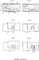
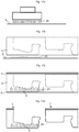
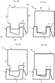
- Figures 1a - 1f show some examples of known fold down locking systems made in one piece with the core 5 that are intended to lock short edges with a vertical displacement of a second edge of a second panel 1' against a first edge of a first panel 1.
- All systems comprise a horizontally protruding strip 6 with a locking element 8 in the first edge of the first panel 1 that cooperates with a locking groove 14 in the second edge of the second panel 1' and locks the edges of the panels 1, 1' horizontally. Different methods are used to lock the edges vertically.
- Figure 1a shows that a small tongue 10 that cooperates with a tongue groove 9 may be used for the vertical locking. Compression of the tongue 10 is required to accomplish the locking.
- the upper edges are, during the vertical displacement, spaced from each other with a space S that corresponds to the horizontal protrusion of the tongue 10.
- the adjacent edges must be pulled together during the final stage of the locking. The friction between the long edges, that during the final stage of the locking are practically aligned horizontally and are in a locked position, prevents such pulling together and there is a major risk that the edges are locked with a space or that the locking element 8 is damaged.
- the locking system is not suitable to lock panels comprising, for example, an HDF core or other non-compressible materials.
- Figure 1b shows a similar locking system with two tongues 10a, 10b and two tongue grooves 9a, 9b.
- This system requires material compression and creates edge separation during locking.
- the locking surfaces are almost vertical and have a locking angle LA of about 60 degrees against a horizontal plane H.
- the protruding tongues are very small and protrude a few tenths of a millimetre and this corresponds to normal production tolerances resulting in locking system that are not possible to lock or without any overlapping locking surfaces.
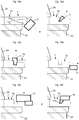
- Figure 1c shows a locking system with two tongues 10a, 10b.
- the locking element comprises a locking surface that is inclined upwardly towards the upper edge in order to increase the vertical locking strength.
- This locking system is even more difficult to lock than the locking systems described above and suffers from the same disadvantages.
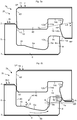
- Figure 1d shows an embodiment that is based on downwardly protruding locking elements that are intended to bend inwardly against each other such that two tongues 10a, 10b may be inserted into tongue grooves.
- the flexibility that may be obtained over the limited vertical extension of the locking elements in an HDF material is not sufficient to obtain a locking force necessary for flooring applications.
- the locking system eliminates separation forces during locking.
- Figure 1e shows a locking system wherein similar flexibility is obtained with a groove formed behind the locking groove 14.
- Such locking systems suffer from the same disadvantages as the locking system shown in figure 1d .
- Similar locking system may also comprise locking surfaces 10b, 9b that are shortened in regions, for example as described in WO 2010/100046 , in order to reduce damages of the locking means during installation when material is compressed. In practice no reduction of damages may be obtained.
- Figure 1f shows a locking system comprising a strip 6 that is bended downwards during the vertical displacement.
- the locking system is intended to be used together with an installation method wherein the long edges of the first and the second panels are in an angled position such that the friction forces are reduced to a level where the locking element during upward snapping is capable to automatically pull the edges together.
- the major disadvantage is that the installation must be made with panels in angled position and this is more complicated than the conventional single action fold down installation.
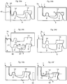
- Figure 1g shows locking systems that may comprise slits 6a in the locking strip, for example as described in US 2010/0037550 or slits 14a behind the locking groove, for example as described in WO 2008/116623 .
- Such slits may increase the flexibility and the horizontal displacement possibilities of the locking elements considerably and a very easy locking may be obtained.
- the main problem is that such slits also increase the vertical flexibility and flexibility. This will result in a very low locking strength in the vertical direction. Therefore attempts to introduce such locking systems have failed.
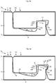
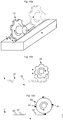
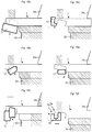
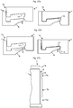
- Figures 2a - 2c show that the geometry of the locking systems is restricted in several ways by the production methods wherein double-end tenors comprising a chain 33, a belt 34 and several large rotating tools 17 with a diameter of about 20 cm are used.
- Figures 2a and 2b show that efficient production methods require that grooves and protrusions are formed with rotating tools 17 that rotate vertically or horizontally or that are angled away from the chain 33 and the belt 34.
- Figure 2c shows that only essentially vertical locking surfaces may be formed on an inner part of the locking element 8 or on the locking groove 14 and that very small rotating tools with a low milling capacity may be used.
- Several of the known locking systems are not possible to produce in a cost efficient way.
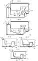
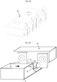
- Figures 3a - 3e explain the separation forces that may occur during vertical folding when a second panel 1' is angled against a previously installed panel 1" in a previous row and wherein this angling action also connects a short edge of the second panel 1' to a short edge of a first panel 1 as shown in figure 3a .
- the short edges are locked with a scissor like movement wherein the short edges are gradually locked from one long edge to the other long edge.
- the adjacent short edges of the first and the second panels 1, 1' have along their edges a start section 30 that becomes active during a first initial step of the folding action, a middle section 31 that becomes active during a second stage of the folding action and an end section 32 that becomes active during a final third step of the folding action.
- the shown locking system is based on an embodiment with a strip 6 that during vertical displacement bends downwards and thereafter snaps upwards.
- Figure 3b shows that one part of the edge, that is close to the long edge where the angling takes place, is almost in locked position, as shown by the cross section A-A, when the locking element 8 and the locking groove 14 of middle sections B-B are still spaced from each other vertically, as shown in figure 3c , and when edge sections C-C that are most distant to the long edge where angling takes place are spaced from each other vertically without any contact between the cross sections C-C as shown in figure 3d.
- Figure 3e shows the final step of the locking when the edges must be pulled together with a pulling force that is sufficient to overcome the friction between long edges of the first installed panel 1" and the second panel 1'.
- the friction may be substantial, especially when the panels are long or when a high friction material is used as a core.
- the high friction is to a large extent caused by the geometry of the long edge locking system that must be formed with a tight fit between the tongue and the tongue groove in order to avoid squeaking sound.
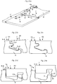
- FIGs 4a and 4b show a one piece locking system formed in a laminate floor panel comprising an HDF core.
- the locking system is locked with horizontal snapping.
- the HDF material comprises wood fibres 24 that during HDF production obtain an essentially horizontal position in the core material.
- the density profile is such that the upper 5a and the lower 5b parts of the core 5 have a higher density than the middle parts.
- These outer portions are also reinforced by the melamine resin from the impregnated paper of the surface 2 and in the balancing layers 3 that during lamination penetrates into the core 5. This allows that a strong and flexible strip 6 may be formed that, during locking, bends downwards.
- the snapping function is supported by the upper lip 9' that bends slightly upwards and the protruding tongue 10 that bends slightly downwards.
- the locking element may easily be formed with a high locking angle and with essentially vertical locking surfaces.
- FIGS 4c-4f bending of vertically protruding locking elements 8 are shown in figures 4c-4f.
- Figures 4c and 4d show a locking element 8 that during vertical displacement is bended outwardly. The bending takes place in the rather soft part of the HDF core and a crack 23 will generally occur in the lower part of the locking element 8.
- Figures 4e and 4f show a locking element 8 that is used to lock against a locking groove 14 in a horizontal H and a vertical direction V. The locking can only take place with material compression and this causes damages and cracks 23, 23' in the locking system.
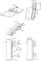
- FIGS 5a and 5b show a first embodiment of the invention according to a first main principle.
- a set of similar floor panels 1, 1' are provided, wherein each floor panel preferably comprises a surface layer 2, a core 5, a balancing layer 3 and a first and a second short edge.
- a first short edge 4c of a first floor panel 1 may be locked to an adjacent second short edge 4d of a similar second floor panel 1' with a vertical displacement of the second edge against the first edge.
- the vertical displacement is a vertical scissor movement caused by the same angling action that is used to connect the long edges of the panels.
- the first short edge 4c comprises a horizontally protruding strip 6 with a vertically protruding locking element 8 at its outer part that cooperates with a downwardly open locking groove 14 formed in the adjacent second edge 4d.
- the locking element 8 is essentially rigid and is not intended to be bended or compressed during locking that contrary to known technology is accomplished essentially with a horizontal displacement of the upper part of the locking element 8 towards the upper first edge 43.
- essentially rigid is here meant that during locking the locking element itself is bended and/or compressed in a horizontal direction by a distance HD that is less than 50% of a horizontally protruding upper locking surface 11a located in the upper part of the locking element 8 as shown in figure 6b .
- the displacement of the locking element 8 is mainly accomplished with a bending and/or deformation of the strip 6.
- the locking element comprises an inner surface 8a, an outer surface 8b and an upper or top surface 8c.
- the inner surface 8a is closer to an upper edge 43 of the first panel 1 than the outer surface 8b. More specifically, a horizontal distance between the inner surface 8a and the upper edge 43 is smaller than a horizontal distance between the outer surface 8b and the upper edge 43.
- the upper edge 43 is a portion of the first edge close to the front side of the first panel 1.
- the upper edge 43 is provided in a side wall 45 of an indentation 44 which is provided in the first edge.
- the indentation 44 is upwardly open and, in a locked position, an upper support surface 16 of a projection 46 provided in the second edge engages with a lower support surface 15 of the indentation which is a portion of an upper strip surface 6a of the strip 6.
- the locking groove 14 comprises an outer groove wall 14a, an inner groove wall 14b and an upper groove wall 14c.
- the projection 46 is provided outside of the locking groove 14 and share the outer groove wall 14a with the locking groove 14.
- the outer groove wall 14a is closer to an upper edge 43' of the second panel 1' than the inner groove wall 14b. More specifically, a horizontal distance between the outer groove wall 14a and the upper edge 43' is smaller than a horizontal distance between the inner groove wall 14b and the upper edge 43'.
- the locking element 8 comprises an upper locking surface 11a formed in the outer surface 8b of the locking element 8 that cooperates with a lower locking surface 11b formed in the inner groove wall 14b and that locks the adjacent edges in a vertical direction.
- the upper 11a and the lower 11b locking surfaces are spaced vertically upwards from the upper surface 6a of the strip 6.
- the upper 11a and the lower 11b locking surfaces may be spaced vertically upwards with a vertical locking distance VLD from the entire upper surface 6a or from an uppermost part of the upper surface 6a, e.g. the lower support surface 15 of the indentation 40.
- VLD may be between 20% and 70%, e.g. 30%, 40% or 50%, of a thickness T of the floor panels in the vertical direction.
- the locking element 8 comprises a first locking surface 12a formed in the inner surface 8a of the locking element 8 that cooperates with a second locking surface 12b formed in the outer groove wall 14a and that locks the adjacent edges in a horizontal direction.
- the locking element 8 may be configured to bend during locking.
- Adjacent edges comprise in locked position a first edge section 7a and a second edge section 7b.
- the edge sections are characterized in that a cross section of the locking groove 14 and/or a cross section of the locking element 8 varies along the adjacent edges of the panels 1, 1' which are formed with a basic geometry that is thereafter modified such that the first 7a and the second 7b cooperating edge sections are formed with different geometries and different locking functions.
- the geometries and cross sections are specified in a side view of the panels as shown in Figs. 5a and 5b .
- the first edge section 7a is preferably a start section 30 that becomes active during a first initial step of the folding action and the second edge section 7b is preferably a subsequent section 31 or a middle section 31 that becomes active during a second step of the folding action.
- the second edge section 7b may be a start section 30 that becomes active during a first initial step of the folding action and that the first edge section 7a may be a subsequent section 31 or a middle section 31 that becomes active during a second step of the folding action. This is shown in figure 26b .
- Figure 5a shows a first cooperating edge section 7a that is used to prevent edge separation during locking and to lock adjacent edges horizontally in the locked position.
- the first edge section 7a has no vertical locking function since one of the locking surfaces, in this preferred embodiment the upper locking surface 11a, has been removed.
- the first 12a and the second 12b locking surfaces are preferably vertical and they are used to guide the second panel 1' during the vertical displacement along a vertical plane VP that intersects the upper and outer edge 21 of the first panel 1.
- the first 12a and the second 12b locking surfaces may be inclined against the vertical plane VP. Such geometry may be used to facilitate unlocking of the short edges with an angling action.
- a locking system with vertical first 12a and second 12b locking surfaces may be unlocked with a sliding action along the short edges.
- Figure 5b shows the second edge section 7b that is used to lock the adjacent edges vertically.
- the second edge section 7b cannot prevent edge separation and has no horizontal locking function since a part of the locking element 8 and/or the locking groove 14 has been removed in order to form a space S along a horizontal plane HP that allows a turning or displacement of the locking element 8 inwardly during locking when the second edge 1' is displaced vertically along the vertical plane VP.
- the turning of the locking element 8 is mainly caused by an upward bending of a part of the strip 6 within the second edge section 7b that takes place when a horizontal pressure is applied by a part of the inner groove wall 14b on the outer surface 8b of the locking element 8 during the vertical displacement of the second edge 4d against the first edge 4c.
- Such locking function provides major advantages. No material compression is required and the material properties of the protruding strip may be used to obtain the necessary flexibility that is needed to displace the upper part of the locking element 8 in order to bring the upper and lower locking surfaces 11a, 11b in a
- the space S has a vertical extension substantially corresponding to a vertical extension of the inner surface 8a so that it extends down to the upper strip surface 6a. It is clear that, according to alternative embodiments (not shown), the space S may have a smaller vertical extension. Preferably, however, the space S is located at an upper part of the locking element 8. Moreover, the vertical extension is preferably larger than a vertical extension of an upper protruding part 25 formed on an outer and upper part of the locking element 8, e.g. 1.5, 2 or 3 times larger.
- the vertical extension of the space S varies along the edge.
- the vertical extension may vary along the edge from a minimal vertical extension to a maximal vertical extension and then, optionally, back to a minimal vertical extension.
- the variation may be smooth.
- the vertical extension of the space S is constant along the edge.
- a first and a second wall of the space S that are spaced from each other along the edge may be vertical and parallel.
- the space S may be formed by means of milling, scraping, punching, perforation or cutting.
- the strip 6 and the locking element 8 are during locking twisted along the first short edge.
- the strip 6 In the first edge section 7a, the strip 6 is essentially in a flat horizontal position during locking and in the second edge section 7b the strip 6 is bended upwards and the locking element 8 with its upper locking surface is turned and/or displaced inwardly during locking.
- At least portions of the strip 6 may be twisted and/or compressed during locking.
- a portion between a lower part of the strip 6b and the upper strip surface 6a and/or the locking element 8 of the strip 6 may be twisted and/or compressed.
- the twisting may occur at least around an axis that is perpendicular to the vertical plane VP.
- the compression may occur at least inwardly in a horizontal direction that is perpendicular to the vertical plane VP.
- the strip 6 may be twisted in the transition regions between the first 7a and second 7b edge sections.
- the strip 6 may become compressed in the second edge section 7b and such compression may facilitate a displacement of the locking element 8 even in rather rigid materials since the material content of the strip 6 is much larger than the material content of the locking element 8.
- the locking element 8 may have a horizontal extension of about 4 mm and the strip 6 may protrude horizontally about 8 mm from the side wall 45 and to the inner surface 8a of the locking element.
- the locking element will contribute with 0.04 mm or with about 1/3 of a total compression and the strip with 0.08 mm or with about 2/3 of the total compression.
- the locking element in an HDF based laminate floor must be displaced horizontally with a distance of at least 0.2 mm in order to provide sufficient locking strength. 0.4 mm is even more preferred.
- about 1/3 of the necessary displacement may be accomplished with material compression and 2/3 with bending and turning or twisting of the strip and the locking element.
- the upper 11a and lower 11b locking surfaces are preferably essentially horizontal.
- the locking surfaces are in the showed embodiment inclined against a horizontal plane HP with a locking angle LA that is about 20 degrees.
- the locking angle LA is preferably 0 - 45 degrees. Locking surfaces with low locking angles are preferred since they provide a stronger vertical locking.
- the most preferred locking angle LA is about 5 - 25 degrees. However it is possible to reach sufficient locking strength in some applications with locking angles between 45 and 60 degrees. Even higher locking angles may be used but such geometries will decrease the locking strengths considerably.
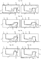
- Figures 6a and 6b show the first 7a and the second 7b edge sections in a locked position.
- the first edge section 7a is configured such that the outer groove wall 14a of the locking groove 14 and the inner surface 8a of the locking element 8 are in contact with each other along a horizontal plane HP and lock the first short edge and the second short edge horizontally and the second edge section 7b is configured such that along the same horizontal plane HP there is a space S between the outer groove wall 14a of the locking groove 14 and the inner surface 8a of the locking element 8.
- the space S allows that the locking element 8 may be turned and/or displaced inwardly.
- the first edge section 7a is also preferably configured such that there is no vertical locking and no turning and/or displacement of the locking element 8 since at least one of the locking surfaces 11a, 11b has been removed and the second edge section 7b is configured such that it comprises upper 11a and lower 11b locking surfaces that lock the edges vertically and upper 25 and lower 26 protruding parts that during locking press, displace and/or turn the locking element 8 inwardly. Also compression and/or twisting are possible.
- Figure 6a shows the first edge section 7a in a locked position.
- the first locking surface 12a formed on the inner surface 8a of the locking element 8 is in contact with the second locking surface 12b formed on the inner groove wall 14a of the locking groove 14.
- the first 12a and the second 12b locking surfaces lock the adjacent edges horizontally and prevent a horizontal separation of the panels 1, 1'.
- Figure 6b shows the second edge section 7b in a locked position.
- the upper locking surface 11a formed on the outer surface 8b of the locking element 8 is in contact with the lower locking surface 11b formed on the inner groove wall 14b of the locking groove 14.
- the upper 11a and lower 11b locking surfaces lock the adjacent edges vertically and prevent a vertical separation of the panels 1, 1'.
- the strip 6 there is an intermediate cavity 47 provided between a portion of the upper support surface 16 and a portion of the upper strip surface 6a. Since a thickness of the strip 6 in this area is smaller than at the location of the lower support surface 15, the strip may be bended more easily.
- the upper support surface 16 preferably is a planar surface and the projection 50 preferably has a constant thickness in a direction perpendicular to the vertical plane VP as measured from its surface layer 2. The thickness is preferably also constant along the edge of the second panel 1'.
- the thickness of the projection 50 may vary in a direction perpendicular to the vertical plane VP. Thereby, least a portion of the projection 46 may extend below the lower support surface 15.
- the space S is an essential feature in this embodiment of the invention.
- a horizontal extension of the space S along a horizontal plane HP that intersects the upper 11a and lower 11b locking surfaces preferably exceeds a horizontal distance HD of the upper and lower locking surfaces.
- the horizontal extension of the space S may be a maximal horizontal extension.
- Figure 7a shows a preferred embodiment of the first edge section 7a where a part of the inner groove wall 14b and the lower locking surface 11b have been removed.
- Figure 7b shows a preferred embodiment of the second edge section 7b where a part of the outer groove wall 14a has been removed in order to form the space S that allows the locking element 8 to turn inwardly during locking.
- the space S has a vertical extension substantially corresponding to a vertical extension of the outer groove wall 14a so that it extends up to the upper groove wall 14c. It is clear that, according to alternative embodiments (not shown), the space S may have a smaller vertical extension. Preferably, however, the space S is located adjacent to the upper groove wall 14c. Moreover, the vertical extension is preferably larger than a vertical extension of the upper protruding part 25, e.g. 1.5, 2 or 3 times larger.
- the vertical extension of the space S may vary or may be constant along the edge as explained above in relation to the embodiment in Figs. 5a-b .
- Figures 7c and 7d show that the embodiments shown in figures 5a, 5b and 7a, 7b may be combined.
- the first edge section 7a configured to prevent edge separation and to lock horizontally may be formed according to figure 7a and the second edge section 7b comprising the space S and configured to bend and to lock vertically may be formed according to figure 5b and 6b .
- the first edge 7a section may be formed according to figure 5a or 6a and the second edge section 7b may be formed according to figure 7b .
- an upper cavity 48 between the upper groove wall 14c and the upper surface 8c in a locked position of the first 1 and second 1' panel.
- the upper cavity 48 may be located in the second edge second 7b and optionally also in the first edge section 7a. Thereby, there is more space provided in the second edge section 7b for the upwardly bending locking element 8.
- first edge section 7a and at least one second edge section 7b there may be at least one first edge section 7a and at least one second edge section 7b.
- first 7a and second 7b edge sections may be arranged alternately.
- the edge sections may be arranged in a sequence along the edges such as ⁇ 7a, 7b, 7a ⁇ , ⁇ 7a, 7b, 7a, 7b, 7a ⁇ or ⁇ 7a, 7b, 7a, 7b, 7a, 7b, 7a ⁇ ⁇ with a first edge section 7a at the corners of the edges.
- Figures 8a - 8c show vertical displacement of the first edge section 7a that according to the present embodiment constitutes a start section 30 and that is active from an initial first step of the folding action.
- the embodiments in figures 8a - 8c and 9a - 9d may be understood in conjunction with Fig. 13a .
- the end section 32 that is active during the final step of the folding action is preferably also formed with geometry similar or identical to the first edge section 7a.
- the start 30 and end 32 sections are arranged at a first and a second corner section, respectively, of the first 1 and second 1' panels, adjacent to their long edges 4a, 4b.
- a part of the inner surface 8a of the locking element 8 is formed as a first locking surface 12a that is essentially parallel with a vertical plane VP and a part of the outer groove wall 14a is formed as a cooperating second locking surface 12b that preferably is essentially parallel with the vertical plane VP.
- the first and the second locking surfaces 12a, 12b guide the edges of the panels 1, 1' during the folding action and counteract separation forces that are caused by the second edge section 7b that becomes active in a second step of the folding action when the major part of the first section 7a is in a horizontally locked position with the first 12a and the second 12b locking surfaces in contact with each other as shown in figure 8b.
- Figure 8c shows the adjacent edges in a final locked position.
- Figures 9a - 9d show locking of the second edge section 7b that according to the present embodiment constitutes a middle section 31 and that is active from a second step of the folding action when the guiding and locking surfaces 12a, 12b of the first edge section 7a are active and in contact with each other.
- Figure 9a shows that a horizontally extending upper protruding part 25 is formed on the outer and upper part of the locking element 8 and above the upper locking surface 11a and is in initial contact with a sliding surface 27 formed on a lower part of the inner groove wall 14b.
- the sliding surface 27 extends essentially vertically upwards to a horizontally extending lower protruding part 26 formed below the lower locking surface 11b.
- the sliding surface 27 will during the vertical displacement create a pressure force F against the upper protruding part 25 and this will press the locking element 8 inwardly towards the upper edge of the first panel 1 and bend the strip 6 upwards as shown in figure 9b .
- the pressure against the locking element 8 will create separation forces tending to displace the second panel 1' horizontally away from the first panel 1, but that are counteracted by the first and the second locking surfaces 12a, 12b of the first edge section 7a.
- the pressure that is needed to lock the edges may be reduced if the sliding surface 27 is essentially vertical and extends over a substantial vertical sliding distance SD, measured vertically over a distance where the inner groove wall 14b is in contact with the outer surface 8b of the locking element during the vertical displacement, and/or if the vertical extension VE of the locking element 8, defined as the vertical distance from the lowest point on the upper surface of the strip 6a and to the upper surface 8c of the locking element 8, is large.
- the inclination of the sliding surface 27 is 10 - 30 degrees in relation to a vertical plane VP and the vertical sliding distance SD is 0.2 - 0.6 times the size of floor thickness T.
- a vertical sliding distance SD of 0.3 - 0.5 times the size of floor thickness T is even more preferred.
- the vertical extension VE of the locking element 8 is 0.1 - 0.6 times the size of floor thickness T. 0.2 ⁇ T - 0.5 ⁇ T is even more preferred.
- An upward bending of a strip is suitable for wood based cores, such as for example HDF, since the fibres in the upper part of the strip that are sensitive to pulling forces and shear stress will be compressed and the fibres in the lower and stronger part of the strip that are more resistant to pulling forces and shear stress will be stretched.
- a considerable amount of bending deflection 29 may be reached and a strip 6 that extends horizontally from the upper edge about 8 mm or with the same distance as the floor thickness T may be bended upwards about 0.05 - 1.0 mm, e.g. 0.1 mm or 0.5 mm.
- a bending deflection 29 is defined as a vertical distance, in a direction perpendicular to the horizontal plane HP, from a horizontal plane HR being parallel and essentially coinciding with the rear side 60 of the first panel 1 in an unlocked state to an outermost and lowermost part of the strip 6.
- the bending deflection 29 typically varies along the edge of the first panel 1 and also varies during the various stages of the locking.
- a maximal bending deflection 29 may be located in a middle portion of a second edge section 7b along a length direction of the edges.
- Figure 9c shows an embodiment according to which the upper and lower locking surfaces 11a, 11b will start to overlap each other already when the upper surfaces of panels 1, 1' are still spaced vertically.
- the strip 6 will pull the second panel 1' comprising an upper support surface 16 towards a lower support surface 15 formed on the edge of a first panel 1 to a final locked position and this will reduce the pressure force that is required to lock the panels 1, 1'.
- the vertical locking may be made with a pretension such that the strip 6 is slightly bended upwards in locked position as shown in figure 9d .
- the remaining bending deflection 29 in the locked position may be about 0.05 - 0.30 mm, e.g.
- the locking system is configured such that in the locked position a middle section 31 comprises a strip 6 that is upwardly bended compared to its unlocked position and a start section 30 that comprises a strip which is essentially in a similar locked position than in an unlocked position. It is understood that there may be transition parts between the first 7a and second 7b edge sections wherein the strip is upwardly bended. According to a different embodiment, the strip of the start section may even be slightly bended backwards in locked position.
- Another advantage is that problems related to thickness tolerances of the panels may be avoided since even in the case that the second panel 1' is thicker than the first panel 1 and normally will hit the sub floor 35 before the upper surfaces are in the same horizontal plane, locking may be made with offset upper edges where the surface of the second edge is above the first edge and the strip will pull the panels to a correct position with horizontally aligned upper surfaces and upper and lower support surfaces 15, 16 in contact with each other.
- Such locking function is also favourable when the floor panels are installed on a soft underlay, such as foam, and a counterpressure from the sub floor cannot be used to prevent a downward bending of the strip 6.
- a strip formed in soft materials such as an LVT core comprising thermoplastic materials and filler may not snap back towards the initial position after the locking.
- This may be solved with a joint geometry where the upper groove wall 14c is formed to be in contact with the upper surface 8c of the locking element 8 during the final stage of the locking action such that the locking element 8 and the strip 6 are pressed downwards.
- the locking system may also be formed with an outer and lower support surface 15a that cooperates with the projection 46 during locking in order to press the strip 6 downward to or towards its initial position as shown in figure 9b .
- Figure 9e shows that the strip 6 may be formed such that an inner part 6c is bended slightly downwards and an outer part 6d is bended slightly upwards. Such strip bending and compression will also bend and displace the locking element 8 inwards toward the first upper edge 43.
- the upper and lower locking surfaces 11a, 11b may even in this embodiment overlap each other during locking when the first and the second panels are still vertically displaced in relation to the final locked position with the second panel 1' spaced vertically upward from the first panel 1.
- Figures 10a and 10b show in a not claimed embodiment that rotating jumping tool heads 18 may be displaced horizontally and may be used to form cavities 42, nonlinear grooves 36 or may be displaced vertically and may be used to form grooves 37 with different depths in a panel 1.
- Figure 10c shows another cost efficient method to form cavities 42 or grooves 36, 37 with a rotating carving tool 40.
- a tool rotation of the rotating carving tool 40 is synchronized with a displacement of the panel 1 and each tooth 41 forms one cavity 42 at a predetermined position and with a predetermined horizontal extension along an edge of a panel 1. It is not necessary to displace the carving tool 40 vertically.
- a carving tool 40 may have several sets of teeth 41 and each set may be used to form one cavity.
- the cavities 42 may have different cross sections depending on the geometry of the teeth.
- the panel 1 may be displaced with or against the tool rotation.
- This production technology may be used to form the first 7a and the second 7b edge sections.
- Figures 11a - 11f show that a rotating tool 17 may be displaced horizontally along the locking element 8 or the locking groove 14 and a first 7a and a second 7b edge section will be formed when the tool initially removes the upper protruding part 25 of the locking element and then a part of the inner surface 8a of the locking element, or initially removes the lower protruding part 26 of the locking groove 14 and then a part of the outer groove wall 14a of the locking groove 14.
- This not claimed method may be used to form the edge sections in a very efficient way.
- the horizontal displacement of the rotation tool 17 may be at or less than about 1.0 mm, e.g. 0.5 mm or 0.2 mm.
- Figures 12a - 12b show a fixed carving tool 22 and a part of the edge of the second panel 1' that is shown with the surface layer 2 pointing downwards.
- Carving methods are not claimed, but may be used to form an essentially horizontal locking surface 11b in an inner groove wall 14b of the locking groove 14 even when the locking surface 11b comprises a tangent line TL that intersects the outer groove wall 14a.
- a more detailed description of carving may be found in WO 2013/191632 .
- Figure 13a shows a vertical folding of a second panel 1' against a first panel 1, comprising a locking system according to figures 8a-c and 9a-d .
- the edges comprise a start section 30 that is formed as a first section 7a, a middle section 31 that is formed as a second section 7b and an end section 32 that is formed as a first section 7a.
- the first 12a and second 12b locking surfaces are guiding surfaces of the start section that prevent separation and the panels 1, 1' are folded together with upper edges in contact.
- Figure 13b shows an embodiment of a short edge 4c of the first panel 1 comprising a middle section being a second edge section 7b and having an upper protruding part 25 with an upper locking surface 11a and a first edge section 7a on each side of the middle section 7b comprising guiding surfaces 12a.
- a part of the inner surface 8a of the locking element 8 has been removed at the middle section 7b in order to form a space S that allows an inward turning of the locking element 8, cf. figure 5b .
- Figure 13c is a top view of the short edge 4c of the first panel 1 as shown in figures 13a and 13b and shows that a part of the strip 6 at a transition part 6c, located between the first 7a and the second 7b edge section, is twisted during the vertical folding since the strip is flat in the first edge section 7a and bended upwards in the second section 7b.
- the twisting increases the locking pressure that has to be used to lock the edges. Twisting may be reduced or even eliminated if needed with a horizontal cavity 28 formed in the strip 6 between the first 7a and the second 7b edge sections as shown in figure 13d .
- Figures 14a - 14e show different embodiments of the disclosure.
- the embodiments in figures 14a-e may be combined with any of the embodiments of the disclosure.
- Figure 14a shows floor panels comprising an HDF core 5 and a strip 6 which is essentially formed in the lower part 5b of the core 5 that has a higher density than the middle part.
- At least parts of the locking groove 14 and/or the locking element 8 may be coated with a friction reducer 22 in order to reduce friction during locking.
- the friction reducer 22 may comprise wax.
- Other exemplary friction reducing substances include oils.
- Parts of the locking groove 14 and/or the locking element 8 may be impregnated with a reinforcement agent, e.g. resins, in order to reinforce parts adjacent to upper and lower locking surfaces 11a, 11b.
- Exemplary reinforcement agents include a thermoplastic, a thermosetting resin or a UV curing glue.
- Figure 14b shows a locking system formed in a rather soft core 5.
- the strip 6 and the locking element 8 have been made larger.
- a lower essentially horizontal locking surface 11b may be formed by an inclined rotating tool 17 and with a locking angle LA that may be as low as 20 degrees. It is clear that other locking angles LA are equally conceivable. In non-limiting examples, a locking angle LA between 0° and 45° may be formed by the inclined tool 17.
- Figure 14c shows that forming of the lower locking surface 11b may be made with a rotating jumping tool that only removes material mainly within the second edge section 7b.
- An advantage is that the lower locking surface 11b may be formed with a rotating tool that will not reduce the vertical extension of the second locking surface 12b.
- Figure 14d shows that in some embodiments the first section 7a may comprise locking means 11a, 11b that lock the edges vertically, preferably mainly by material compression.
- the locking means may be locking surfaces 11a, 11b.
- the edge sections 7a, 7b may comprise complementary locking means as described in figures 1a - 1e , for example a small tongue 10 and groove 9 at the adjacent edges as shown in figure 1a .
- Figure 14e shows that panels 1, 1' with different thicknesses may be produced with the same tool position in relation to the surface layer 2. This means that the strip 6 will be thicker and more rigid in thicker panels. This may be compensated by removal of materials at the lower part 6d of the strip 6 and all panels may comprise a strip 6 with similar flexibility and deflection properties.
- FIGS 15a - 15d show a not claimed second principle of the invention.
- the locking element 8 comprises an upper locking surface 11a formed at the inner surface 8a and the locking groove 14 comprises a lower locking surface 11b formed in the outer groove wall 14a.
- a strong vertical locking may be accomplished if the locking surfaces 11a, 11b are essentially horizontal, e.g., within 20 degrees of horizontal.
- a tangent line TL of the upper locking surface 11a intersects an adjacent wall of the upper edge.
- a tangent line TL of the lower locking surface 11b preferably intersects an adjacent wall of the locking groove 14. Locking is accomplished with a downward bending of the strip 6 wherein the locking element 8 is turned outwards as shown in figure 15b .
- a problem is that the strip 6 may still be in a backward bended position and the locking surfaces 11a, 11b may be spaced vertically when the upper edges of the panels 1, 1' are aligned horizontally as shown in figure 15c .
- An upper guiding surface 13a is therefore formed as an extension of the upper locking surface 11a and a lower guiding surface 13b is formed as an extension of the lower locking surface 11b.
- the locking surfaces 11a, 11b and the guiding surfaces 13a, 13b are configured such that the guiding surfaces 13a, 13b overlap each other during locking and during the downward bending of the strip 6 when the upper surface 2 of the second panel 1' is spaced vertically upwards from the upper surface 2 of the first panel 1.
- Figures 16a - 16b show that a locking system according to the second principle may comprise a first 7a and a second edge section 7b such that the geometry of the locking element 8 and/or the locking groove 14 varies along the edge.
- the first edge section 7a comprises only locking means that lock the edges in a horizontal direction
- the second edge section 7b that according to this embodiment is a middle section 31, comprises horizontal and vertical locking means.
- a start section 30 and an end section 32 both are first edge sections 7a.
- FIG. 16c shows that the locking system may be configured such that a controlled crack 23 occurs in the material of the core 5, e.g. a material comprising wood fibres.
- the material may be HDF material or material from a particle board.
- the crack 23 may be provided parallel to a fibre direction of the material. The crack 23 may extend to a depth of about 1 mm to about 5 mm.
- the crack 23 may extend along the entire edge of the first panel 1 or, alternatively, only along a part thereof, e.g. in a middle part.
- the advantage is that the strip 6 will be easier to bend downward during locking than upwards in the locked position.
- lower and upper support surfaces 15, 16 are formed in an upper part of the panels 1, 1'.
- Figures 17a - 17d show in not claimed embodiments that a core material 5 may be locally modified such that it becomes more suitable to form a flexible and strong strip 6. Such a modification may be used in all embodiments of the disclosure.
- Figure 17a shows that a resin 20, for example a thermosetting resin 20 such as, for example, melamine formaldehyde, urea formaldehyde or phenol formaldehyde resin, may be applied in liquid or dry powder form on a balancing paper 3 or directly on a core material 5.
- the balancing paper 3 may be a melamine formaldehyde impregnated balancing paper 3.
- the resin may also be locally injected into the core 5 with high pressure.
- Figure 17b shows that a core material 5, preferably a wood based panel for example an HDF board or a particle board, may be applied on impregnated paper 3 with the added resin 20 prior to lamination.
- Figure 17c shows a floor board after lamination when the surface layers 2 and the balancing layer 3 have been laminated to the core 6. The resins 20 have penetrated into the core 5 and cured during lamination under heat and pressure.
- Figure 17d shows an edge of a first panel 1 comprising a strip 6 formed in one piece with the core 5.
- the strip 6 is more flexible and comprises a higher resin content than other parts of the core 5.
- the increased resin content provides a material that is very suitable to form a strong flexible strip 6 that during locking may be bended.
- Figures 18a - 18f show that the entire edge of the second panel 1' comprising an essentially horizontal lower locking surface 11b having a tangent line TL that intersects a wall of the locking groove 14 may be formed with rotating tools 17 that are angled away from the chain 33 and the belt 34 and a carving tool 19 that preferably as a last machining step forms the locking surface 11b.
- Figures 19a - 19e show that the edge of the first panel 1 may be formed initially with large rotating tools 17 that are angled away from the chain 33 and the belt 34.
- the first and the second edge sections 7a, 7b are formed with a jumping tool 18 as shown in figure 19f .
- a rotating scraping tool may also be used.
- Figures 20a - 20d show a locking system that is particularly suitable and adapted to be used on the long edges of panels 1, 1' that are locked with a fold down system according to a not claimed embodiment of the invention.
- the locking system comprises an upper 10a and a lower tongue 10b that cooperate with an upper 9a and a lower 9b tongue groove and that lock the edges vertically at least in a first direction upwards.
- a locking strip 6 with a locking element 8 cooperates with a locking groove 14 in an adjacent panel and locks the panel edges horizontally.
- a lower protrusion 38 is formed on an edge of the second panel 1' and an upper part 6a of the strip 6 locks the edges in a second vertical direction downwards.
- the locking system is configured such that a high friction is obtained between the long edges and along the edges when they are in an almost locked position and when the first and second locking surfaces 12a, 12b of the first edge section 7a of the short edge locking system are in contact with each other and the upper 11a and lower 11b locking surfaces of the second edge section 7b are spaced vertically such that no separation forces are active. This is explained more in detail in figures 21a - 21e .
- the high friction is mainly obtained with locking surfaces formed on the locking element 8 and the locking groove 14 that are more inclined against a horizontal plane HP and comprises a higher locking angle LA than the so called "free angle” defined by a tangent line TL to a circle with a radius R equal to the distance from the locking surfaces of the locking element and the locking groove to the upper part of the adjacent edges.
- Figure 20b shows that the locking system is configured such that in an up angled and locked position there are at least three contact points where the edges are pressed against each other: a first contact point Cp1 between the upper edges, a second contact point Cp2 between the locking element 8 and the locking groove 14, and a third contact point Cp3 between the lower tongue 10b and the lower tongue groove 9b.
- the contact points may be contact surfaces. It is understood that each of the contact points forms a contact line or a contact surface along the edges.
- Figures 20c and 20d show that the locking system may be formed with a low material waste in connection with the first cutting step comprising large rotating saw blades 17 and carving tools 19 when a large laminated board is separated into individual panels 1, 1'.
- Figures 21a - 21e show the position of the long 4a, 4b and short edges 4c, 4d during the vertical folding.
- Figure 21a shows in a not claimed embodiment a second panel 1' that is angled with its long edge 4b against a long edge 4a of previously installed panel 1" in a previous row and folded with its short edge 4d against a short edge 4c of an installed first panel 1 in the same row.
- Figure 21b shows in a not claimed embodiment the long edges 4a, 4b of the second 1' and the previously installed panel 1" in a partly locked and up angled position when three contact points Cp1, Cp2, Cp3 are pressed against each other in order to create a friction along the long edges in an up angled position.
- Figure 21c shows in a not claimed embodiment the long edges 4a, 4b of the previously installed panel 1" and the first panel 1 in a completely locked position.
- Figure 21d shows that the first and second locking surfaces 12a, 12b are in contact with each other in the first edge section 7a and figure 21e shows that at the same time the locking element 8 and its upper protruding part 25 in the second edge section 7b is spaced from the locking groove 14 and its sliding surface 27 such that no separation forces are active.
- the locking system may be formed with a first edge section 7a that extends with an edge distance ED of about 2 - 8 cm, for example 5 cm, from a long edge 4a as shown in figure 21a and with a locking element comprising a vertical extension of about 0.5 - 6 mm, for example 2, 3 or 4 mm.
- the second edge section 7b may start at a horizontal distance from a long edge of about 15 - 35%, e.g. 20%, of the length of the edge.
- the long edges may be folded to an angle of about 1 - 7 degrees, for example 3 degrees, before the locking element 8 is in contact with the locking groove 14 and such a low angle may be used to form a long edge locking system that creates a very high friction along the long edges in a partly locked position where the upper part of the locking element 8 of one long edge overlaps vertically a lower part of the locking groove 14 of an adjacent long edge.
- the long edge locking system is configured such that a locking angle of 3 - 5 degrees may be reached before the locking element and the locking groove of the second section 7b are in contact with each other.
- Figures 22a - 22d show not claimed embodiments of locking systems that may be formed with pretension in a partly locked position as described above.
- the locking systems according to figures 22a - 22d are particularly suitable and adapted to be used on the long edges of panels 1, 1'.
- the shown locking systems in figures 22a-d illustrate that the locking systems in figures 21b and 21c may be formed with a fourth contact point Cp4 located at an upper part of a tongue 10 and a tongue groove 9.
- Figure 23a - 23d show not claimed embodiments that may be used to lock for example furniture components where a second panel 1' comprising a locking groove 14 is locked vertically and perpendicularly to a first panel 1 comprising a strip 6 and with a locking element 8.
- the strip 6 may initially bend upwards or downwards during the vertical displacement of the second panel 1' against the first panel 1 and the locking element 8 may comprise locking means that lock horizontally parallel to a main plane M1 of the first panel and vertically parallel to the a plane M2 of the second panel 1'.
- the main plane M1 of the first panel 1 may be defined as a horizontal plane that is essentially parallel with a lower side 80 of the first panel 1.
- the main plane M2 of the second panel 1' may be defined as a vertical plane that is essentially parallel with an outer side 82 of the second panel 1'.
- the panels 1, 1' may have a first 7a and a second 7b edge section as described above.
- the first edge section 7a may be formed such that the locking element 8 is in contact with the locking groove 14 when the locking element 8 and the locking groove 14 of the second section 7b are spaced from each other as shown in figures 23a and 23c .
- Figures 24a - 24e show in not claimed embodiments that the locking system of a first 1 and a second 1' panel may be formed with a first and a second locking element 8, 8' and a first and a second locking groove 14, 14'.
- the first 8 and second 8' locking elements and the first 14 and second 14' locking grooves extend along the entire edge of the first panel 1 and second panel 1', respectively.
- the second locking element 8' and the second locking groove 14' may extend along a part of the edge of the first panel 1 and second panel 1', respectively, wherein an extension of the second locking element 8' is smaller than or substantially equal to an extension of the second locking groove 14'.
- the second locking element 8' and the second locking groove 14' may be used to prevent edge separation and to lock the panels horizontally and may replace the first and second locking surfaces 12a, 12b.
- the lower and inner part(s) of the second locking groove 14' and the upper and outer part(s) of the second locking element 8' comprise guiding surfaces, for example rounded parts as shown in figure 24a , that engage with each other and press the upper edges towards each other such that separation forces are counteracted.
- the one or both overlapping locking surfaces 11a, 11b may be removed or the entire first locking element 8 may be removed at a corner section of first edge, e.g. between 5% and 20% of a total length of the first edge.
- a vertical extension of the second locking element 8' and/or the second locking groove 14' may vary along the first and/or second edge, respectively.
- the vertical extension may vary from a maximal extension to a minimal extension.
- the variation may be periodic.
- a top surface of the second locking element 8' may engage with an upper groove wall of the second locking groove 14'.
- there may be a cavity between the top surface of the second locking element 8' and the upper groove wall of the second locking groove 14'.
- a vertical flex groove 39 may be formed adjacent to and preferably inwardly of the locking groove 14 in all embodiments of the invention.
- a locking system with high vertical and horizontal locking strength may be formed.
- the space S between the first locking element 8 and the first locking groove 14 allows a turning and/or displacement of the locking element 8 as described in the previous embodiments.
- the horizontal distance D1 between the inner surfaces 8a of the first locking element 8 and the outer surface 8b' of the second 8' locking element is preferably at least about 30%the floor thickness FT in order to provide sufficient flexibility and locking strength.
- the horizontal distance D1 may be as small as about 20% of the floor thickness. More generally, D1 may be between 20% and 80% of FT.
- An upper part of the first locking element 8 is preferably located closer to the panel surface than an upper part of the second locking element 8'. Alternatively, however, the upper part of the first locking element 8 may be located closer to the panel surface than the upper part of the second locking element 8'. This may reduce separation forces since the second locking element 8' will become actived before the first element 8 is in contact with the locking groove 14.
- Figure 24f shows a more compact version wherein the first 14 and the second 14' locking grooves are connected to each other.
- the second locking groove 14' forms an outer part of the first locking groove 14.
- the locking system may have one or a plurality of pairs lower and upper support surfaces that are configured to cooperate in a locked state of the panels.
- support surfaces 15, 16 may be provided between the inner and lower part of the first panel 1 and the outer and lower part of the second panel 1', and/or support surfaces 15', 16' may be provided between the upper part of the second locking element 8' and the upper part of the second locking groove 14'.
- a part of the locking strip 6 and the second locking element 8' protruding beyond an outer strip portion 50, preferably outside the second locking element 8', may be removed at a corner section of the first edge in order to eliminate separation forces during the initial stage of the locking when the second panel 1' is angled down towards the first panel 1.
- Figures 25a-e illustrate various embodiments of one or a plurality of flex grooves 39.
- the second locking element 8' and the second locking groove 14' are not shown but may be formed in the edge of the first 1 and second panel 1' in all embodiments of figures 25a-d and 26a-d .
- Figure 25a shows a first panel 1 with a plurality of first and second edge sections 7a, 7b and a flex groove 39 that extends along the entire edge of the second panel 1'.
- Figure 25a also shows that at least a part of the projection 46 may be removed and this may in some embodiments simplify the forming of second edge section 7b.
- the flex groove 39 may also extend along a part of the edge of the second panel 1'.
- the flex groove 39 has two walls in a direction along the edge and is located in a centre portion of the edge in the length direction thereof.
- the flex groove is formed in a centre portion that corresponds to the location of the second edge portion(s) 7b where the bending of the strip 6 and vertical locking takes place.
- Figure 25b shows that the first 7a and the second 7b edge portions may be formed by removal of material in the locking groove 14 only.
- An advantage is that only one jumping tool or rotating carving tool is needed at one short edge in order to form the first and second section.
- the flex groove 39 is at least partly open towards one edge side and only has one wall in a direction along the edge so that it is located in a peripheral portion of the edge in the length direction thereof.
- each wall of the flex groove may be vertical or, alternatively, have a transition region so that a depth of the flex groove increases along the edge from a minimal depth to a maximal depth.
- flex grooves 39 there may be two or more flex grooves 39 arranged along the edge.
- the flex groove 39 does not extend entirely through the second panel 1'.
- the flex groove 39 may have a vertical extension between 30% and 60% of a maximal thickness of the panel, e.g. 40% or 50%.
- one or a plurality of slits 49 may be formed in the strip 6 along the edge of the first panel 1 in order to increase the flexibility of the strip while still maintaining sufficient locking strength.
- a cross-sectional shape of the slit 49 may be rectangular, square, circular, oval, triangular, polygon shaped, etc.
- the shapes of the slits 49 are the same along the edge, but varying shapes are also conceivable.
- the slits may be formed in a cost efficient way with a rotating punching tool.
- the slits 49 may be provided in all embodiments described in the disclosure. Such slits and the previously described flex grooves 39 may be combined in all embodiments of the invention.
- the first panel 1 may have a slit 49 and the second panel may have a flex groove 39.
- the slits 49 are preferably provided inwardly of the locking element 8.
- the slits 49 extend entirely through the strip 6 to the rear side 60.
- the slits 49 may not extend through the strip.
- the slits may have a vertical extension between 30% and 60% of a minimal thickness of the strip.
- the slits may be provided in the upper strip surface 6a.
- the slits 49 may be provided in a strip surface 66 connecting the side wall 45 and the second locking element 8' or in a strip surface 67 connecting the first locking element 8 and the second locking element 8'.
- the slits may be provided in the rear side 60 of the first panel 1.
- the slit 49 is open towards one edge side and has only one wall in a direction along the edge.
- Such slit offers the advantage that the second section 7b may be used as a start section.
- the slit 49 will increase the flexibility of the strip and separation forces will be lower during the initial stage of the locking until the first edge section 7a becomes active.
- a similar slit 49 may be formed in the opposite side edge.
- each wall of the slits may be vertical, i.e. parallel with a direction perpendicular to the horizontal plane.
- the inner surface of the slit 49 may be cylindrical.
- the wall may have a transition region so that a depth of the slit increases from a minimal depth to a maximal depth.
- the inner surface of the slit 49 may be frustoconical.
- Figures 27a - 27c show a not claimed embodiment comprising a flexible locking element 8 that may be bended and/or compressed inwardly during locking.
- the flexible locking element 8 is provided at an outer part of the strip 6 and is configured to engage with the locking groove 14.
- An outer, lower part of the locking element 8 engages with a locking surface 11b of the second panel 1' in the second edge section 7b.
- an outer part of the locking element 8 is free with respect to the locking surface 11b in the first edge section 7a.
- Alternative embodiments of the locking surfaces have been described above in relation to other embodiments of the disclosure wherein reference is made thereto.
- the outer part of the locking element 8 may be constant along the first edge and the locking surface 11b may be shortened in the first edge sections 7a, cf. the embodiment in figure 7a-b .
- the flexible locking element may also be bended upwards and/or downwards during locking.
- Such embodiments may be used in floor panels with flexible core materials, for example a core comprising thermosetting plastic material, but may also be used in other applications.
- the locking system may be formed according to any previous embodiment of the disclosure.
- a horizontal extension of the locking element 8 may be larger than a horizontal extension of the upper surface of the strip 6a.
- Outer parts of the locking element 8 may have a smaller vertical extension than inner parts of the locking element for increasing the flexibility of the locking element.
- the major difference as compared to the embodiments disclosed above is that no space S is needed since the locking element 8 may be bended upwards and/or compressed inwardly as shown in figure 27b .
- the first 7a, 7a' and the second edge sections 7b may be formed with a simple removal of material located at the outer part of the locking element 8, as shown in figure 27c , or at the inner part of the locking groove 14 (not shown).
- the first edge section 7a' in figure 27c is optional and may be replaced by a second edge section 7b.
- the second edge section 7b may extend all the way to one side edge of the first panel 1.
Claims (15)
- Jeu de panneaux de plancher rectangulaires essentiellement identiques (1, 1'), chacun comprenant des bords longs (4a, 4b) et un premier bord court (4c) et un second bord court (4d), le premier bord court et le second bord court étant prévus avec un système de verrouillage mécanique comprenant une bande (6) s'étendant horizontalement à partir d'une partie inférieure du premier bord court (4c) et une rainure de verrouillage ouverte vers le bas (14) formée dans le second bord court (4d), dans lequel la bande (6) comprend un élément de verrouillage faisant saillie vers le haut (8) qui est configuré pour coopérer avec la rainure de verrouillage (14) pour verrouiller le premier bord court et le second bord court dans une direction horizontale parallèle au plan principal des panneaux et dans une direction verticale perpendiculairement à la direction horizontale, dans lequel l'élément de verrouillage (8) comprend une surface interne (8a), une surface externe (8b) et une surface supérieure (8c), la surface interne (8a) étant positionnée plus à proximité d'un bord supérieur du premier panneau (1) que la surface externe (8b), et dans lequel la rainure de verrouillage (14) comprend une paroi de rainure externe (14a), une paroi de rainure interne (14b) et une paroi de rainure supérieure (14c), la paroi de rainure externe (14a) étant positionnée plus à proximité du bord supérieur du second panneau (1') que la paroi de rainure interne (14b),
l'élément de verrouillage (8) comprenant une surface de verrouillage supérieure (11a) et la rainure de verrouillage (14) comprenant une surface de verrouillage inférieure (11b), dans lequel, dans une position verrouillée,
la surface de verrouillage supérieure (11a) de l'élément de verrouillage (8) et la surface de verrouillage inférieure (11b) de la rainure de verrouillage (14) sont configurées pour être en contact entre elles et pour verrouiller le premier bord court et le second bord court verticalement, et
le premier bord court et le second bord court comprennent un plan horizontal (HP) et une première section de bord de joint (7a) positionnée le long du premier bord court et du second bord court,
la première section de bord de joint (7a) étant configurée de sorte que la paroi de rainure externe (14a) de la rainure de verrouillage (14) et la surface interne (8a) de l'élément de verrouillage (8) le long du plan horizontal (HP) sont en contact entre elles et verrouillent le premier bord court et le second bord court horizontalement,
caractérisé en ce que dans ladite position verrouillée,
le premier bord court et le second bord court comprennent en outre une seconde section de bord de joint (7b) positionnée le long du premier bord court et du second bord court, la seconde section de bord de joint (7b) étant configurée de sorte que le long du plan horizontal (HP), il y a un espace (S) entre la paroi de rainure externe (14a) de la rainure de verrouillage (14) et la surface interne (8a) de l'élément de verrouillage (8). - Jeu de panneaux de plancher selon la revendication 1, dans lequel la première section de bord de joint (7a) est positionnée plus à proximité d'un bord long (4a, 4b) que la seconde section de bord de joint (7b).
- Jeu de panneaux de plancher selon la revendication 1 ou 2, dans lequel le système de verrouillage est configuré pour être verrouillé avec un déplacement vertical du second bord court contre le premier bord court.
- Jeu de panneaux de plancher selon la revendication 3, dans lequel le système de verrouillage est configuré de sorte qu'un déplacement vertical du second bord court contre le premier bord court pendant une étape initiale dudit placement vertical plie la bande vers le haut vers le second panneau de sorte que la surface de verrouillage supérieure (11a) et la surface de verrouillage inférieure (11b) se chevauchent.
- Jeu de panneaux de plancher selon la revendication 4, dans lequel le pliage vers le haut est combiné avec une torsion et/ou une compression de la bande (6).
- Jeu de panneaux de plancher selon l'une quelconque des revendications précédentes, dans lequel la surface de verrouillage inférieure (11b) est essentiellement horizontale.
- Jeu de panneaux de plancher selon l'une quelconque des revendications précédentes, dans lequel une ligne tangente (TL) à la surface de verrouillage inférieure (11b) coupe la paroi externe (14a) de la rainure de verrouillage (14).
- Jeu de panneaux de plancher selon l'une quelconque des revendications précédentes, dans lequel la surface de verrouillage supérieure (11a) est positionnée sur la surface externe (8b) de l'élément de verrouillage (8) et la surface de verrouillage inférieure (11b) est positionnée sur la paroi de rainure interne (14b) de la rainure de verrouillage (14).
- Jeu de panneaux de plancher selon l'une quelconque des revendications précédentes, dans lequel la surface de verrouillage supérieure (11a) est verticalement espacée vers le haut par rapport à une surface de bande supérieure (6a).
- Jeu de panneaux de plancher selon l'une quelconque des revendications précédentes, dans lequel l'espace (S) entre la paroi de rainure externe (14a) et la surface interne (8a) est une cavité agencée dans la surface interne (8a) de l'élément de verrouillage (8).
- Jeu de panneaux de plancher selon l'une quelconque des revendications 1 à 9, dans lequel l'espace (S) est une cavité agencée dans la paroi de rainure externe (14a) de la rainure de verrouillage (8).
- Jeu de panneaux de plancher selon l'une quelconque des revendications précédentes, dans lequel il n'y a pas de surface de verrouillage supérieure (11a) prévue dans la première section de bord de joint (7a).
- Jeu de panneaux de plancher selon l'une quelconque des revendications 1 à 11, dans lequel il n'y a pas de surface de verrouillage inférieure (11b) prévue dans la première section de bord de joint (7a).
- Jeu de panneaux de plancher selon l'une quelconque des revendications précédentes, dans lequel la surface de verrouillage supérieure (11a) de l'élément de verrouillage (8) et la surface de verrouillage inférieure (11b) de la rainure de verrouillage (14) sont configurées pour être en contact entre elles dans la seconde section de bord de joint (7b).
- Jeu de panneaux de plancher selon l'une quelconque des revendications précédentes, comprenant une pluralité de premières sections de bord de joint (7a) et de secondes sections de bord de joint (7b) le long du bord.
Priority Applications (3)
| Application Number | Priority Date | Filing Date | Title |
|---|---|---|---|
| PL15873741T PL3237704T3 (pl) | 2014-12-22 | 2015-12-17 | Mechaniczny układ blokujący dla paneli podłogowych |
| EP19209651.9A EP3636855A1 (fr) | 2014-12-22 | 2015-12-17 | Jeu de panneaux de plancher avec système de verrouillage mécanique |
| HRP20192225TT HRP20192225T1 (hr) | 2014-12-22 | 2019-12-11 | Komplet identičnih podnih ploča koji je opremljen mehaničkim sustavom za zaključavanje |
Applications Claiming Priority (2)
| Application Number | Priority Date | Filing Date | Title |
|---|---|---|---|
| SE1451632 | 2014-12-22 | ||
| PCT/SE2015/051367 WO2016105266A1 (fr) | 2014-12-22 | 2015-12-17 | Système de verrouillage mécanique pour panneaux de plancher |
Related Child Applications (1)
| Application Number | Title | Priority Date | Filing Date |
|---|---|---|---|
| EP19209651.9A Division EP3636855A1 (fr) | 2014-12-22 | 2015-12-17 | Jeu de panneaux de plancher avec système de verrouillage mécanique |
Publications (3)
| Publication Number | Publication Date |
|---|---|
| EP3237704A1 EP3237704A1 (fr) | 2017-11-01 |
| EP3237704A4 EP3237704A4 (fr) | 2018-06-06 |
| EP3237704B1 true EP3237704B1 (fr) | 2019-11-20 |
Family
ID=56151127
Family Applications (2)
| Application Number | Title | Priority Date | Filing Date |
|---|---|---|---|
| EP19209651.9A Pending EP3636855A1 (fr) | 2014-12-22 | 2015-12-17 | Jeu de panneaux de plancher avec système de verrouillage mécanique |
| EP15873741.1A Active EP3237704B1 (fr) | 2014-12-22 | 2015-12-17 | Jeu de panneaux de plancher identiques avec un système de verrouillage méchanique |
Family Applications Before (1)
| Application Number | Title | Priority Date | Filing Date |
|---|---|---|---|
| EP19209651.9A Pending EP3636855A1 (fr) | 2014-12-22 | 2015-12-17 | Jeu de panneaux de plancher avec système de verrouillage mécanique |
Country Status (13)
| Country | Link |
|---|---|
| US (5) | US9803374B2 (fr) |
| EP (2) | EP3636855A1 (fr) |
| JP (1) | JP6736556B2 (fr) |
| KR (1) | KR102434995B1 (fr) |
| CN (2) | CN110644720B (fr) |
| BR (1) | BR112017012681B1 (fr) |
| CA (1) | CA2969191C (fr) |
| EA (1) | EA032721B1 (fr) |
| ES (1) | ES2768959T3 (fr) |
| HR (1) | HRP20192225T1 (fr) |
| MY (1) | MY183576A (fr) |
| PL (1) | PL3237704T3 (fr) |
| WO (1) | WO2016105266A1 (fr) |
Families Citing this family (75)
| Publication number | Priority date | Publication date | Assignee | Title |
|---|---|---|---|---|
| EP2287419A3 (fr) | 2002-04-03 | 2011-11-30 | Välinge Innovation AB | Plancher |
| SI1650375T2 (sl) | 2004-10-22 | 2011-04-29 | Vaelinge Innovation Ab | Set talnih panelov |
| US7841144B2 (en) | 2005-03-30 | 2010-11-30 | Valinge Innovation Ab | Mechanical locking system for panels and method of installing same |
| US8061104B2 (en) | 2005-05-20 | 2011-11-22 | Valinge Innovation Ab | Mechanical locking system for floor panels |
| SE533410C2 (sv) | 2006-07-11 | 2010-09-14 | Vaelinge Innovation Ab | Golvpaneler med mekaniska låssystem med en flexibel och förskjutbar tunga samt tunga därför |
| US11725394B2 (en) | 2006-11-15 | 2023-08-15 | Välinge Innovation AB | Mechanical locking of floor panels with vertical folding |
| US8689512B2 (en) | 2006-11-15 | 2014-04-08 | Valinge Innovation Ab | Mechanical locking of floor panels with vertical folding |
| SE531111C2 (sv) | 2006-12-08 | 2008-12-23 | Vaelinge Innovation Ab | Mekanisk låsning av golvpaneler |
| US8353140B2 (en) | 2007-11-07 | 2013-01-15 | Valinge Innovation Ab | Mechanical locking of floor panels with vertical snap folding |
| EP3910131A3 (fr) | 2008-01-31 | 2022-03-30 | Välinge Innovation AB | Verrouillage mécanique de panneaux de revêtement de sol |
| US8713886B2 (en) * | 2009-01-30 | 2014-05-06 | Valinge Innovation Ab | Mechanical lockings of floor panels and a tongue blank |
| US11725395B2 (en) | 2009-09-04 | 2023-08-15 | Välinge Innovation AB | Resilient floor |
| US8365499B2 (en) | 2009-09-04 | 2013-02-05 | Valinge Innovation Ab | Resilient floor |
| CA3209449A1 (fr) * | 2010-01-11 | 2011-07-14 | Valinge Innovation Ab | Revetement de sol a conception verrouillee |
| EP2524093B1 (fr) | 2010-01-12 | 2020-02-05 | Välinge Innovation AB | Système de verrouillage mécanique pour panneaux de plancher |
| US8806832B2 (en) | 2011-03-18 | 2014-08-19 | Inotec Global Limited | Vertical joint system and associated surface covering system |
| UA114715C2 (uk) | 2011-07-05 | 2017-07-25 | Сералок Інновейшн Аб | Механічна фіксація панелей настилу підлоги до язичка з нанесеним шаром клею |
| US9725912B2 (en) | 2011-07-11 | 2017-08-08 | Ceraloc Innovation Ab | Mechanical locking system for floor panels |
| US8650826B2 (en) | 2011-07-19 | 2014-02-18 | Valinge Flooring Technology Ab | Mechanical locking system for floor panels |
| US8857126B2 (en) | 2011-08-15 | 2014-10-14 | Valinge Flooring Technology Ab | Mechanical locking system for floor panels |
| US9216541B2 (en) | 2012-04-04 | 2015-12-22 | Valinge Innovation Ab | Method for producing a mechanical locking system for building panels |
| US8596013B2 (en) | 2012-04-04 | 2013-12-03 | Valinge Innovation Ab | Building panel with a mechanical locking system |
| WO2014081382A1 (fr) | 2012-11-22 | 2014-05-30 | Välinge Flooring Technology AB | Système de verrouillage mécanique pour panneaux de plancher |
| US9194134B2 (en) | 2013-03-08 | 2015-11-24 | Valinge Innovation Ab | Building panels provided with a mechanical locking system |
| EP3656944A1 (fr) | 2013-03-25 | 2020-05-27 | Välinge Innovation AB | Panneaux de plancher dotés d'un système de verrouillage mécanique et procédé de production d'un tel système de verrouillage |
| PT3613919T (pt) | 2013-06-27 | 2023-02-13 | Vaelinge Innovation Ab | Painel de construção com um sistema de travamento mecânico |
| US10246883B2 (en) | 2014-05-14 | 2019-04-02 | Valinge Innovation Ab | Building panel with a mechanical locking system |
| CN106460394B (zh) | 2014-05-14 | 2019-09-17 | 瓦林格创新股份有限公司 | 具有机械锁定系统的建筑面板 |
| CA3149239C (fr) | 2014-06-04 | 2023-08-15 | Sti Holdings, Inc. | Traitement de bord de panneau composite, et joints et corps de cargo en comportant |
| WO2016029255A1 (fr) | 2014-08-29 | 2016-03-03 | Kell Richard William | Système de joint vertical pour un panneau de recouvrement de surface |
| EP3198089B1 (fr) | 2014-09-26 | 2021-03-31 | Flooring Industries Limited, SARL | Panneau de plancher permettant de former un revêtement de sol et procédé de fabrication d'un panneau de plancher |
| CN107002411B (zh) | 2014-11-27 | 2020-06-16 | 瓦林格创新股份有限公司 | 用于地板镶板的机械锁定系统 |
| BR112017012681B1 (pt) | 2014-12-22 | 2022-05-03 | Ceraloc Innovation Ab | Conjunto de painéis de chão essencialmente idênticos |
| BE1022985B1 (nl) | 2015-01-16 | 2016-10-27 | Flooring Industries Limited Sarl | Vloerpaneel voor het vormen van een vloerbekleding |
| EP3247844B1 (fr) | 2015-01-16 | 2022-03-16 | Ceraloc Innovation AB | Système de verrouillage mécanique pour panneaux de plancher |
| BE1023310B1 (nl) | 2015-07-02 | 2017-01-31 | Unilin, Bvba | Vloerpaneel en werkwijze voor het vervaardigen van vloerpanelen. |
| EP3390744A4 (fr) * | 2015-12-17 | 2019-07-31 | Välinge Innovation AB | Procédé de production d'un système de verrouillage mécanique destiné à des panneaux |
| WO2018004438A1 (fr) | 2016-06-29 | 2018-01-04 | Välinge Innovation AB | Procédé et dispositif d'insertion d'une languette |
| CN109415906B (zh) | 2016-06-29 | 2021-11-05 | 瓦林格创新股份有限公司 | 用于从榫舌坯料管理和分离榫舌的方法和装置 |
| CN109312566B (zh) | 2016-06-29 | 2021-05-28 | 瓦林格创新股份有限公司 | 用于插入榫舌的方法和装置 |
| WO2018004435A1 (fr) | 2016-06-30 | 2018-01-04 | Välinge Innovation AB | Dispositif d'insertion d'une languette |
| BR112019005906B1 (pt) | 2016-09-30 | 2023-02-14 | Välinge Innovation AB | Conjunto de painéis montados por deslocamento vertical e travados na direção vertical e horizontal |
| BE1024723B1 (nl) * | 2016-11-10 | 2018-06-11 | Ivc Bvba | Vloerpaneel en werkwijze voor het vervaardigen van een vloerpaneel. |
| US10953566B2 (en) | 2016-12-22 | 2021-03-23 | Valinge Innovation Ab | Device for inserting a tongue |
| RU2754157C2 (ru) * | 2017-03-21 | 2021-08-30 | Флоринг Индастриз Лимитед, Сарл | Панель пола для образования напольного покрытия |
| DE102017003191A1 (de) * | 2017-04-01 | 2018-10-04 | Wabco Europe Bvba | Heckspoilereinrichtung für ein Nutzfahrzeug |
| CN107435426A (zh) * | 2017-08-14 | 2017-12-05 | 合肥耀世同辉科技有限公司 | 一种用于室外的塑胶地板 |
| US11199010B2 (en) | 2017-10-25 | 2021-12-14 | Xylo Technologies Ag | Flooring system with enhanced flexibility |
| US10808410B2 (en) | 2018-01-09 | 2020-10-20 | Valinge Innovation Ab | Set of panels |
| SE542114C2 (en) * | 2018-01-27 | 2020-02-25 | Ipendor Ab | Joining system for floor panels |
| US10814581B2 (en) * | 2018-07-03 | 2020-10-27 | STI Holdings, Iinc. | Composite sidewall and cargo body having same |
| US11136072B2 (en) | 2018-08-07 | 2021-10-05 | Sti Holdings, Inc. | Cargo body with recessed logistics track |
| NL2021885B1 (en) * | 2018-10-26 | 2020-05-13 | I4F Licensing Nv | Multi-purpose tile system, tile covering, and tile |
| NL2022114B1 (en) * | 2018-12-03 | 2020-06-30 | I4F Licensing Nv | Decorative panel, and decorative floor covering consisting of said panels |
| US11060302B2 (en) * | 2019-01-10 | 2021-07-13 | Valinge Innovation Ab | Unlocking system for panels |
| CN114008280B (zh) * | 2019-01-30 | 2023-09-19 | I4F许可有限责任公司 | 镶板和包括镶板的覆盖物 |
| BE1027083B1 (nl) * | 2019-02-26 | 2020-09-24 | Flooring Ind Ltd Sarl | Glij- of drukschoen voor een doorloopfreesmachine en werkwijze voor het vervaardigen van panelen |
| CN113840699B (zh) | 2019-03-05 | 2023-10-24 | 塞拉洛克创新股份有限公司 | 用于在板块元件中形成沟槽的方法以及相关镶板 |
| US11377855B2 (en) | 2019-03-25 | 2022-07-05 | Ceraloc Innovation Ab | Mineral-based panel comprising grooves and a method for forming grooves |
| EP3718437A1 (fr) | 2019-04-05 | 2020-10-07 | Välinge Innovation AB | Méthode d'assemblage d'un meuble |
| AU2019464484A1 (en) * | 2019-09-06 | 2022-03-31 | I4F Licensing Nv | Floor panel and floor |
| EP3798386A1 (fr) | 2019-09-24 | 2021-03-31 | Välinge Innovation AB | Ensemble de panneaux avec bords verrouillables mécaniquement |
| CA3153635A1 (fr) | 2019-09-25 | 2021-04-01 | Valinge Innovation Ab | Panneau dote d'un dispositif de verrouillage |
| US11479976B2 (en) | 2019-09-25 | 2022-10-25 | Valinge Innovation Ab | Panel with locking device |
| WO2021059176A1 (fr) | 2019-09-25 | 2021-04-01 | Välinge Innovation AB | Ensemble de panneaux comprenant une rainure de flexion |
| NL2024191B1 (en) * | 2019-11-08 | 2021-07-20 | I4F Licensing Nv | Panel, in particular a floor panel or a wall panel |
| US11725398B2 (en) | 2019-12-27 | 2023-08-15 | Ceraloc Innovation Ab | Thermoplastic-based building panel comprising a balancing layer |
| WO2021225715A1 (fr) | 2020-05-05 | 2021-11-11 | Owens Corning Intellectual Capital, Llc | Panneaux isolants à bords à feuillure emboîtables |
| CN115989131A (zh) * | 2020-09-02 | 2023-04-18 | 塞拉洛克创新股份有限公司 | 用于在板块元件中形成沟槽的方法和设施 |
| EP3971366A1 (fr) * | 2020-09-17 | 2022-03-23 | Surface Technologies GmbH & Co. KG | Panneau |
| CN113305517B (zh) * | 2021-06-21 | 2022-10-11 | 成都爱乐达航空制造股份有限公司 | 一种筋条、缘条侧壁孔加工方法 |
| CN113833228B (zh) * | 2021-09-29 | 2023-03-10 | 中山市大自然格瑞新型材料有限公司 | 一种地板锁扣及地板 |
| WO2023059248A1 (fr) * | 2021-10-04 | 2023-04-13 | Välinge Innovation AB | Agencement de liaison mécanique pour panneaux |
| DE202022102571U1 (de) | 2022-05-11 | 2023-08-17 | Lignum Technologies Ag | Fußbodensystem mit verbesserter Widerstandsfähigkeit gegenüber Feuchtigkeitseinwirkung |
| KR102552313B1 (ko) * | 2023-03-16 | 2023-07-07 | 주식회사 브리텍 | 조립형 데크 패널 |
Family Cites Families (189)
| Publication number | Priority date | Publication date | Assignee | Title |
|---|---|---|---|---|
| US753791A (en) | 1903-08-25 | 1904-03-01 | Elisha J Fulghum | Method of making floor-boards. |
| US1581345A (en) | 1924-05-19 | 1926-04-20 | Fisk Rubber Co | Paving block |
| US3077703A (en) | 1959-04-17 | 1963-02-19 | Wood Conversion Co | Roof deck structure |
| SE0001325L (sv) | 2000-04-10 | 2001-06-25 | Valinge Aluminium Ab | Låssystem för hopfogning av golvskivor samt golvskivor försedda med sådana låssystem och golv bildat av sådana golvskivor |
| SE0002342L (sv) | 2000-06-22 | 2001-07-16 | Tarkett Sommer Ab | Golvbräda med kopplingsorgan |
| NL7102276A (fr) | 1970-02-20 | 1971-08-24 | ||
| US3619961A (en) | 1970-03-24 | 1971-11-16 | Lois M Chamberlain | Venting roof insulation product |
| US3889736A (en) | 1973-05-18 | 1975-06-17 | Firks Exhibitions Inc | Display screen for exhibits and the like |
| US3998015A (en) | 1973-07-26 | 1976-12-21 | United States Gypsum Company | Resilient-edged wallboard and wall assembled therewith |
| DE2516843A1 (de) | 1975-04-17 | 1976-10-28 | Koepp Zellkautschuk Wilhelm | Bodenmatten, insbesondere fuer sportler |
| US4123885A (en) | 1976-04-30 | 1978-11-07 | Cyclops Corporation | Building panel joint |
| US4426820A (en) | 1979-04-24 | 1984-01-24 | Heinz Terbrack | Panel for a composite surface and a method of assembling same |
| EP0085196A1 (fr) | 1982-01-29 | 1983-08-10 | JANSSEN & FRITSEN B.V. | Tapis assemblable |
| US4698945A (en) | 1983-01-05 | 1987-10-13 | Munn John B | Panel assembly and a method of installing same |
| US4953341A (en) | 1989-08-14 | 1990-09-04 | Bob Joos | Spacers for laying tile and method of use |
| US5182892A (en) | 1991-08-15 | 1993-02-02 | Louisiana-Pacific Corporation | Tongue and groove board product |
| US5274979A (en) | 1992-12-22 | 1994-01-04 | Tsai Jui Hsing | Insulating plate unit |
| US5456053A (en) | 1993-08-02 | 1995-10-10 | Fischer; Kenneth A. | Flooring installation apparatus |
| US5616389A (en) | 1995-10-30 | 1997-04-01 | Blatz; Warren J. | Surface covering tile |
| BE1010487A6 (nl) | 1996-06-11 | 1998-10-06 | Unilin Beheer Bv | Vloerbekleding bestaande uit harde vloerpanelen en werkwijze voor het vervaardigen van dergelijke vloerpanelen. |
| US6808777B2 (en) | 1996-11-08 | 2004-10-26 | Ab Golvabia | Flooring |
| US5845548A (en) | 1996-12-06 | 1998-12-08 | Nelson; Jerome S. C. | Flooring tools |
| US5735097A (en) | 1996-12-16 | 1998-04-07 | Cheyne; Donald C. | Platform assembly system |
| US6324809B1 (en) * | 1997-11-25 | 2001-12-04 | Premark Rwp Holdings, Inc. | Article with interlocking edges and covering product prepared therefrom |
| US7992358B2 (en) | 1998-02-04 | 2011-08-09 | Pergo AG | Guiding means at a joint |
| SE512313C2 (sv) | 1998-06-03 | 2000-02-28 | Valinge Aluminium Ab | Låssystem samt golvskiva |
| US7386963B2 (en) | 1998-06-03 | 2008-06-17 | Valinge Innovation Ab | Locking system and flooring board |
| SE514645C2 (sv) | 1998-10-06 | 2001-03-26 | Perstorp Flooring Ab | Golvbeläggningsmaterial innefattande skivformiga golvelement avsedda att sammanfogas av separata sammanfogningsprofiler |
| SE515789C2 (sv) | 1999-02-10 | 2001-10-08 | Perstorp Flooring Ab | Golvbeläggningsmaterial innefattande golvelement vilka är avsedda att sammanfogas vertikalt |
| DE19851200C1 (de) | 1998-11-06 | 2000-03-30 | Kronotex Gmbh Holz Und Kunstha | Fußbodenpaneele |
| SE517478C2 (sv) | 1999-04-30 | 2002-06-11 | Valinge Aluminium Ab | Låssystem för mekanisk hofogning av golvskivor, golvskiva försedd med låssystemet samt metod för framställning av mekaniskt hopfogningsbara golvskivor |
| ATE222634T1 (de) | 1999-06-30 | 2002-09-15 | Akzenta Paneele & Profile Gmbh | Paneel sowie befestigungssystem für paneele |
| DE10001076C1 (de) | 2000-01-13 | 2001-10-04 | Huelsta Werke Huels Kg | Paneelelement |
| SE517183C2 (sv) * | 2000-01-24 | 2002-04-23 | Valinge Aluminium Ab | Låssystem för mekanisk hopfogning av golvskivor, golvskiva försedd med låssystemet och metod för framställning av sådana golvskivor |
| SE518184C2 (sv) | 2000-03-31 | 2002-09-03 | Perstorp Flooring Ab | Golvbeläggningsmaterial innefattande skivformiga golvelement vilka sammanfogas med hjälp av sammankopplingsorgan |
| DE20008708U1 (de) | 2000-05-16 | 2000-09-14 | Kronospan Tech Co Ltd | Paneele mit Kupplungsmitteln |
| BE1013569A3 (nl) | 2000-06-20 | 2002-04-02 | Unilin Beheer Bv | Vloerbekleding. |
| DE10031639C2 (de) | 2000-06-29 | 2002-08-14 | Hw Ind Gmbh & Co Kg | Fussbodenplatte |
| CA2434168C (fr) * | 2001-01-12 | 2009-10-27 | Vaelinge Aluminium Ab | Panneau de plancher et procede de fabrication et d'installation |
| US6769218B2 (en) | 2001-01-12 | 2004-08-03 | Valinge Aluminium Ab | Floorboard and locking system therefor |
| US6851241B2 (en) | 2001-01-12 | 2005-02-08 | Valinge Aluminium Ab | Floorboards and methods for production and installation thereof |
| US7081300B2 (en) | 2001-01-22 | 2006-07-25 | Formica Corporation | Decorative laminate assembly and method of producing same |
| US8028486B2 (en) | 2001-07-27 | 2011-10-04 | Valinge Innovation Ab | Floor panel with sealing means |
| SE519791C2 (sv) | 2001-07-27 | 2003-04-08 | Valinge Aluminium Ab | System för bildande av en fog mellan två golvskivor, golvskivor därför försedd med tätningsorgan vid fogkanterna samt sätt att tillverka en kärna som bearbetas till golvskivor |
| DE20122553U1 (de) | 2001-08-10 | 2006-03-23 | Akzenta Paneele + Profile Gmbh | Paneel sowie Befestigungssystem für Paneele |
| SE525558C2 (sv) | 2001-09-20 | 2005-03-08 | Vaelinge Innovation Ab | System för bildande av en golvbeläggning, sats av golvskivor samt förfarande för tillverkning av två olika typer av golvskivor |
| FR2831908B1 (fr) | 2001-11-02 | 2004-10-22 | Europ De Laquage Et De Faconna | Dispositif d'assemblage des bords de panneaux, lattes ou lambris |
| DE10159284B4 (de) | 2001-12-04 | 2005-04-21 | Kronotec Ag | Gebäudeplatte, insbesondere Bodenpaneel |
| EP2287419A3 (fr) | 2002-04-03 | 2011-11-30 | Välinge Innovation AB | Plancher |
| EP1350904B2 (fr) | 2002-04-05 | 2012-10-24 | tilo GmbH | Planches de plancher |
| US7051486B2 (en) | 2002-04-15 | 2006-05-30 | Valinge Aluminium Ab | Mechanical locking system for floating floor |
| US7739849B2 (en) | 2002-04-22 | 2010-06-22 | Valinge Innovation Ab | Floorboards, flooring systems and methods for manufacturing and installation thereof |
| EP1710368A3 (fr) | 2002-04-22 | 2009-01-21 | Välinge Innovation AB | Plancher avec des planches rectangulaires verrouillables mécaniquement |
| DE10232996A1 (de) | 2002-07-19 | 2004-03-11 | Leitz Gmbh & Co. Kg | Verbindungsprofil für plattenartige Paneelen |
| DE10252866B3 (de) | 2002-11-12 | 2004-04-29 | Kronotec Ag | Paneel und Verfahren zur Herstellung eines Paneels |
| US7617651B2 (en) | 2002-11-12 | 2009-11-17 | Kronotec Ag | Floor panel |
| ATE395481T1 (de) | 2002-11-15 | 2008-05-15 | Flooring Technologies Ltd | Einrichtung bestehend aus zwei miteinander verbindbaren bauplatten und einem einsatz zum verriegeln dieser bauplatten |
| BE1015239A3 (nl) | 2002-12-09 | 2004-11-09 | Flooring Ind Ltd | Vloerpaneel en werkwijze voor het koppelen, respectievelijk ontkoppelen van vloerpanelen. |
| DE10305695B4 (de) | 2003-02-12 | 2008-01-17 | Stefan Coors | Verkleidungsplatte, insbesondere Fussbodenplatte |
| SE0300642D0 (sv) | 2003-03-11 | 2003-03-11 | Pergo Europ Ab | Process for sealing a joint |
| DE10313112B4 (de) | 2003-03-24 | 2007-05-03 | Fritz Egger Gmbh & Co. | Belag mit einer Mehrzahl von Paneelen, insbesondere Fußbodenbelag, sowie Verfahren zum Verlegen von Paneelen |
| DE20304761U1 (de) | 2003-03-24 | 2004-04-08 | Kronotec Ag | Einrichtung zum Verbinden von Bauplatten, insbesondere Bodenpaneele |
| US7550192B2 (en) | 2003-04-30 | 2009-06-23 | Congoleum Corporation | Resilient floor tile |
| SI1639215T1 (sl) | 2003-07-02 | 2011-11-30 | Interglarion Ltd | Plošče z zapahnilnimi spojnimi profili |
| US20050021081A1 (en) | 2003-07-24 | 2005-01-27 | Clozex Medical, Llc | Device for laceration or incision closure |
| NL1024046C2 (nl) | 2003-08-05 | 2005-02-10 | Niegel Profiel Ommanteling B V | Bekleding van vormvaste delen, in het bijzonder voor een vloer, daarbij toe te passen bekledingsdelen en werkwijze voor het verbinden van de bekledingsdelen. |
| DE20313661U1 (de) | 2003-09-05 | 2003-11-13 | Kaindl Wals M | Paneel mit geschützter V-Fuge |
| US7886497B2 (en) | 2003-12-02 | 2011-02-15 | Valinge Innovation Ab | Floorboard, system and method for forming a flooring, and a flooring formed thereof |
| DE102004001363A1 (de) | 2004-01-07 | 2005-08-04 | Hamberger Industriewerke Gmbh | Verbindung für Fußbodenelemente |
| US7516588B2 (en) | 2004-01-13 | 2009-04-14 | Valinge Aluminium Ab | Floor covering and locking systems |
| US7004790B2 (en) | 2004-05-28 | 2006-02-28 | Tyco Electronics Corporation | Electrical connector having improved terminal retention |
| BE1016216A5 (nl) | 2004-09-24 | 2006-05-02 | Flooring Ind Ltd | Vloerpaneel en vloerbekleding samengesteld uit dergeljke vloerpanelen. |
| US7454875B2 (en) | 2004-10-22 | 2008-11-25 | Valinge Aluminium Ab | Mechanical locking system for floor panels |
| US7841144B2 (en) | 2005-03-30 | 2010-11-30 | Valinge Innovation Ab | Mechanical locking system for panels and method of installing same |
| SI1650375T2 (sl) | 2004-10-22 | 2011-04-29 | Vaelinge Innovation Ab | Set talnih panelov |
| US7617647B2 (en) | 2004-10-26 | 2009-11-17 | Tilediy, Llc | Underlayment for tile surface |
| CN100365234C (zh) * | 2004-12-01 | 2008-01-30 | 周祖全 | 一种仿实木强化复合木地板的滚压制备方法 |
| US8061104B2 (en) | 2005-05-20 | 2011-11-22 | Valinge Innovation Ab | Mechanical locking system for floor panels |
| DE102005024366A1 (de) | 2005-05-27 | 2006-11-30 | Kaindl Flooring Gmbh | Verfahren zum Verlegen und mechanischen Verbinden von Paneelen |
| DE102005028072B4 (de) | 2005-06-16 | 2010-12-30 | Akzenta Paneele + Profile Gmbh | Fußbodenpaneel |
| SE529076C2 (sv) | 2005-07-11 | 2007-04-24 | Pergo Europ Ab | En fog till paneler |
| DE102005059540A1 (de) | 2005-08-19 | 2007-06-14 | Bauer, Jörg R. | Lösbar aneinander zu befestigende, flächige Bauteile, sowie Bauteil |
| WO2007051500A1 (fr) | 2005-10-31 | 2007-05-10 | Handy Tiling Holding B.V. | Systeme pour poser des carreaux |
| SE530653C2 (sv) | 2006-01-12 | 2008-07-29 | Vaelinge Innovation Ab | Fuktsäker golvskiva samt golv med ett elastiskt ytskikt omfattande ett dekorativt spår |
| DE102006011887A1 (de) | 2006-01-13 | 2007-07-19 | Akzenta Paneele + Profile Gmbh | Sperrelement, Paneel mit separatem Sperrelement, Verfahren zur Installation eines Paneelbelags aus Paneelen mit Sperrelementen sowie Verfahren und Vorrichtung zur Vormontage eines Sperrelements an einem Paneel |
| DE102006006124A1 (de) | 2006-02-10 | 2007-08-23 | Flooring Technologies Ltd. | Einrichtung zum Verriegeln zweier Bauplatten |
| JP2007224523A (ja) * | 2006-02-21 | 2007-09-06 | Toppan Printing Co Ltd | 連結組立用化粧材 |
| GB2436570A (en) | 2006-03-30 | 2007-10-03 | Sonae | Floorboard with rebated side and end edges |
| US7900416B1 (en) | 2006-03-30 | 2011-03-08 | Connor Sport Court International, Inc. | Floor tile with load bearing lattice |
| BE1017157A3 (nl) | 2006-06-02 | 2008-03-04 | Flooring Ind Ltd | Vloerbekleding, vloerelement en werkwijze voor het vervaardigen van vloerelementen. |
| SE533410C2 (sv) | 2006-07-11 | 2010-09-14 | Vaelinge Innovation Ab | Golvpaneler med mekaniska låssystem med en flexibel och förskjutbar tunga samt tunga därför |
| US7861482B2 (en) | 2006-07-14 | 2011-01-04 | Valinge Innovation Ab | Locking system comprising a combination lock for panels |
| BE1017350A6 (nl) * | 2006-10-31 | 2008-06-03 | Flooring Ind Ltd | Vloerpaneel en vloerbekleding bestaande uit dergelijke vloerpanelen. |
| US8689512B2 (en) | 2006-11-15 | 2014-04-08 | Valinge Innovation Ab | Mechanical locking of floor panels with vertical folding |
| SE531111C2 (sv) | 2006-12-08 | 2008-12-23 | Vaelinge Innovation Ab | Mekanisk låsning av golvpaneler |
| DE102007020271A1 (de) * | 2007-02-01 | 2008-08-07 | August Hipper | Verbindung für Fußbodenelemente |
| US7886785B2 (en) | 2007-02-15 | 2011-02-15 | Julius Young | Machine and method for installing curved hardwood flooring |
| DE202007018662U1 (de) | 2007-03-26 | 2009-02-19 | Kronotec Ag | Paneel, insbesondere Bodenpaneel |
| DE102007017087B4 (de) | 2007-04-10 | 2009-06-25 | Kronotec Ag | Paneel, insbesondere Bodenpaneel |
| CN201083008Y (zh) * | 2007-06-05 | 2008-07-09 | 圣象实业(深圳)有限公司 | 一种易安装的锁扣型强化地板 |
| US8220217B2 (en) | 2007-07-20 | 2012-07-17 | Innovaris Ag | Flooring system |
| DE102007042840B4 (de) | 2007-09-10 | 2010-04-22 | Flooring Technologies Ltd. | Paneel, insbesondere Bodenpaneel |
| DE602007006316D1 (de) | 2007-09-25 | 2010-06-17 | Etruria Design S R L | Eckverbindungselement für Fliesen mit Schrägkante |
| EP2235286B1 (fr) | 2007-11-07 | 2019-01-02 | Välinge Innovation AB | Blocage mécanique de panneaux de sol avec encliquetage sur pliure verticale et procédé d'installation pour relier ces panneaux |
| US8353140B2 (en) | 2007-11-07 | 2013-01-15 | Valinge Innovation Ab | Mechanical locking of floor panels with vertical snap folding |
| US8011163B2 (en) | 2007-11-13 | 2011-09-06 | Sebastian Bazzano | Methods and apparatus for laying marble tile flooring |
| US7793471B2 (en) | 2007-11-30 | 2010-09-14 | David Tilghman Hill | Floating floor assembled from an array of interconnected subunits, each of which includes a stone, ceramic, or porcelain tile bonded to an injection molded polyolefin substrate |
| DE102007062430B3 (de) | 2007-12-20 | 2009-07-02 | Flooring Technologies Ltd. | Verfahren zum spanabhebenden Bearbeiten einer Seitenkante eines Paneels und Vorrichtung zum Durchführen des Verfahrens |
| US8505257B2 (en) | 2008-01-31 | 2013-08-13 | Valinge Innovation Ab | Mechanical locking of floor panels |
| EP3910131A3 (fr) | 2008-01-31 | 2022-03-30 | Välinge Innovation AB | Verrouillage mécanique de panneaux de revêtement de sol |
| US8112967B2 (en) | 2008-05-15 | 2012-02-14 | Valinge Innovation Ab | Mechanical locking of floor panels |
| DE102008031167B4 (de) | 2008-07-03 | 2015-07-09 | Flooring Technologies Ltd. | Verfahren zum Verbinden und Verriegeln leimlos zu verlegender Fußbodenpaneele |
| US8037656B2 (en) | 2008-08-08 | 2011-10-18 | Liu David C | Flooring boards with press down locking mechanism |
| DE202008010555U1 (de) | 2008-08-08 | 2009-12-17 | Akzenta Paneele + Profile Gmbh | Kunststoffpaneel mit Hakenprofil |
| CN201261936Y (zh) | 2008-09-11 | 2009-06-24 | 乐山吉象地板制品有限公司 | 太极锁扣地板 |
| US20100083603A1 (en) | 2008-10-08 | 2010-04-08 | Goodwin Milton W | Flooring panel with first and second decorative surfaces |
| CN201269936Y (zh) | 2008-10-10 | 2009-07-08 | 湖南省康普通信技术有限责任公司 | 尾纤走线槽 |
| PL2208835T3 (pl) * | 2009-01-16 | 2012-10-31 | Vaelinge Innovation Ab | Panel, zwłaszcza panel podłogowy |
| EP2213812B1 (fr) * | 2009-01-28 | 2012-03-07 | Flooring Technologies Ltd. | Panneau, en particulier panneau de sol |
| US8713886B2 (en) | 2009-01-30 | 2014-05-06 | Valinge Innovation Ab | Mechanical lockings of floor panels and a tongue blank |
| EP2226447B1 (fr) | 2009-02-27 | 2012-06-06 | Flooring Technologies Ltd. | Panneau, en particulier panneau de sol |
| DE102009040114A1 (de) | 2009-03-03 | 2010-09-16 | Fritz Egger Gmbh & Co. | Paneel zur Bildung eines Belags und Verfahren zur Herstellung eines solchen Paneels |
| WO2010138616A2 (fr) | 2009-05-27 | 2010-12-02 | Mcfarland Cascade Holdings, Inc. | Modules et panneaux de plateforme d'interverrouillage |
| NL2003019C2 (nl) | 2009-06-12 | 2010-12-15 | 4Sight Innovation Bv | Vloerpaneel en vloerbedekking bestaande uit meerdere van dergelijke vloerpanelen. |
| BE1018802A3 (nl) | 2009-06-29 | 2011-09-06 | Flooring Ind Ltd Sarl | Paneel, meer speciaal vloerpaneel. |
| US20110011020A1 (en) | 2009-07-15 | 2011-01-20 | Chi-Feng Shen | Interlocking type plastic tile structure |
| JP5714582B2 (ja) * | 2009-07-31 | 2015-05-07 | ベーリンゲ、イノベイション、アクチボラグVaelinge Innovation Ab | 建築用パネルの縁加工に関する方法及び構成 |
| US20110030300A1 (en) | 2009-08-10 | 2011-02-10 | Liu David C | Floor And Tile With Padding |
| US8365499B2 (en) | 2009-09-04 | 2013-02-05 | Valinge Innovation Ab | Resilient floor |
| DE102009048050B3 (de) | 2009-10-02 | 2011-01-20 | Guido Schulte | Belag aus mechanischen miteinander verbindbaren Elementen |
| US8534294B2 (en) | 2009-10-09 | 2013-09-17 | Philip Morris Usa Inc. | Method for manufacture of smoking article filter assembly including electrostatically charged fiber |
| US8281529B2 (en) | 2009-11-05 | 2012-10-09 | Jacob Cluff | Interlocking building structure |
| EP2524093B1 (fr) | 2010-01-12 | 2020-02-05 | Välinge Innovation AB | Système de verrouillage mécanique pour panneaux de plancher |
| US8881482B2 (en) | 2010-01-22 | 2014-11-11 | Connor Sport Court International, Llc | Modular flooring system |
| US8234830B2 (en) | 2010-02-04 | 2012-08-07 | Välinge Innovations AB | Mechanical locking system for floor panels |
| WO2011096879A1 (fr) | 2010-02-04 | 2011-08-11 | Välinge Innovation AB | Système de verrouillage mécanique pour panneaux de plancher et languette pour celui-ci |
| KR101245963B1 (ko) | 2010-03-02 | 2013-03-21 | 오광석 | 바닥재 및 이에 이용되는 회전체 |
| CN201665978U (zh) | 2010-03-19 | 2010-12-08 | 李琳 | 嵌压锁合式弹性基材板 |
| BE1019501A5 (nl) | 2010-05-10 | 2012-08-07 | Flooring Ind Ltd Sarl | Vloerpaneel en werkwijze voor het vervaardigen van vloerpanelen. |
| CA2743287C (fr) | 2010-06-15 | 2018-10-02 | Joseph D. D'agostino | Articles et procedes pour la pose de plancher en carreaux de ceramique |
| DE202010010620U1 (de) | 2010-07-24 | 2011-11-10 | Wolfgang Heinz | Bodenabdeckung |
| US8601909B2 (en) | 2010-10-07 | 2013-12-10 | Mark L. Gelormino | Deck tool |
| UA108512C2 (en) * | 2010-10-20 | 2015-05-12 | Kronoplus Technical Ag | Surface coating that consists of laminated panels and external locking element |
| DE102010063976B4 (de) * | 2010-12-22 | 2013-01-17 | Akzenta Paneele + Profile Gmbh | Paneel |
| US8844225B2 (en) | 2011-01-14 | 2014-09-30 | Rubber Designs, LLC | Safety surfacing tile support |
| DE102011086846A1 (de) * | 2011-01-28 | 2012-08-02 | Akzenta Paneele + Profile Gmbh | Paneel |
| EP3597836B1 (fr) * | 2011-03-18 | 2022-01-12 | Välinge Innovation AB | Systeme de joint vertical pour recouvrement de surface |
| US8806832B2 (en) | 2011-03-18 | 2014-08-19 | Inotec Global Limited | Vertical joint system and associated surface covering system |
| UA109938C2 (uk) | 2011-05-06 | 2015-10-26 | Механічна фіксуюча система для будівельних панелей | |
| US8925264B2 (en) | 2011-05-09 | 2015-01-06 | Parallax Group International, Llc | Floor tiles with hybrid interlocking system |
| UA114715C2 (uk) | 2011-07-05 | 2017-07-25 | Сералок Інновейшн Аб | Механічна фіксація панелей настилу підлоги до язичка з нанесеним шаром клею |
| BR112014000016B1 (pt) * | 2011-07-11 | 2020-12-22 | Ceraloc Innovation Ab | sistema de travamento mecânico para painéis de piso |
| US9725912B2 (en) | 2011-07-11 | 2017-08-08 | Ceraloc Innovation Ab | Mechanical locking system for floor panels |
| US8650826B2 (en) | 2011-07-19 | 2014-02-18 | Valinge Flooring Technology Ab | Mechanical locking system for floor panels |
| EP2577527A4 (fr) | 2011-07-29 | 2015-04-22 | American Express Travel Relate | Système et procédé permettant d'activer des canaux de commercialisation dans un marché ip |
| US8857126B2 (en) | 2011-08-15 | 2014-10-14 | Valinge Flooring Technology Ab | Mechanical locking system for floor panels |
| US8769905B2 (en) | 2011-08-15 | 2014-07-08 | Valinge Flooring Technology Ab | Mechanical locking system for floor panels |
| US8763340B2 (en) | 2011-08-15 | 2014-07-01 | Valinge Flooring Technology Ab | Mechanical locking system for floor panels |
| PL3115161T3 (pl) | 2011-08-29 | 2020-05-18 | Ceraloc Innovation Ab | Mechaniczny układ blokujący dla paneli podłogowych |
| WO2013030686A2 (fr) | 2011-08-31 | 2013-03-07 | Flooring Industries Limited, Sarl | Panneau et revêtement assemblé à partir de tels panneaux |
| DE102011056494A1 (de) * | 2011-12-15 | 2013-06-20 | Pergo (Europe) Ab | Set aus Paneelen mit Clip |
| CN104204379B (zh) | 2012-04-04 | 2016-10-19 | 瓦林格创新股份有限公司 | 具有机械锁定系统的建筑镶板 |
| US8596013B2 (en) | 2012-04-04 | 2013-12-03 | Valinge Innovation Ab | Building panel with a mechanical locking system |
| US9216541B2 (en) | 2012-04-04 | 2015-12-22 | Valinge Innovation Ab | Method for producing a mechanical locking system for building panels |
| CN104582916A (zh) | 2012-06-19 | 2015-04-29 | 瓦林格创新股份有限公司 | 用于将板块分为第一镶板和第二镶板的方法、形成用于锁定第一和第二镶板的机械锁定系统的方法以及建筑镶板 |
| WO2014081382A1 (fr) | 2012-11-22 | 2014-05-30 | Välinge Flooring Technology AB | Système de verrouillage mécanique pour panneaux de plancher |
| US9194134B2 (en) | 2013-03-08 | 2015-11-24 | Valinge Innovation Ab | Building panels provided with a mechanical locking system |
| PT3613919T (pt) | 2013-06-27 | 2023-02-13 | Vaelinge Innovation Ab | Painel de construção com um sistema de travamento mecânico |
| US9260870B2 (en) * | 2014-03-24 | 2016-02-16 | Ivc N.V. | Set of mutually lockable panels |
| US10246883B2 (en) | 2014-05-14 | 2019-04-02 | Valinge Innovation Ab | Building panel with a mechanical locking system |
| CN106460394B (zh) | 2014-05-14 | 2019-09-17 | 瓦林格创新股份有限公司 | 具有机械锁定系统的建筑面板 |
| EP3198089B1 (fr) * | 2014-09-26 | 2021-03-31 | Flooring Industries Limited, SARL | Panneau de plancher permettant de former un revêtement de sol et procédé de fabrication d'un panneau de plancher |
| CN107002411B (zh) | 2014-11-27 | 2020-06-16 | 瓦林格创新股份有限公司 | 用于地板镶板的机械锁定系统 |
| BR112017012681B1 (pt) | 2014-12-22 | 2022-05-03 | Ceraloc Innovation Ab | Conjunto de painéis de chão essencialmente idênticos |
| EP3247844B1 (fr) | 2015-01-16 | 2022-03-16 | Ceraloc Innovation AB | Système de verrouillage mécanique pour panneaux de plancher |
| CN109415906B (zh) | 2016-06-29 | 2021-11-05 | 瓦林格创新股份有限公司 | 用于从榫舌坯料管理和分离榫舌的方法和装置 |
| CN109312566B (zh) | 2016-06-29 | 2021-05-28 | 瓦林格创新股份有限公司 | 用于插入榫舌的方法和装置 |
| WO2018004438A1 (fr) | 2016-06-29 | 2018-01-04 | Välinge Innovation AB | Procédé et dispositif d'insertion d'une languette |
| WO2018004435A1 (fr) | 2016-06-30 | 2018-01-04 | Välinge Innovation AB | Dispositif d'insertion d'une languette |
| US10953566B2 (en) | 2016-12-22 | 2021-03-23 | Valinge Innovation Ab | Device for inserting a tongue |
| US10801213B2 (en) | 2018-01-10 | 2020-10-13 | Valinge Innovation Ab | Subfloor joint |
| US11578495B2 (en) | 2018-12-05 | 2023-02-14 | Valinge Innovation Ab | Subfloor joint |
| US11060302B2 (en) | 2019-01-10 | 2021-07-13 | Valinge Innovation Ab | Unlocking system for panels |
| EP3718437A1 (fr) | 2019-04-05 | 2020-10-07 | Välinge Innovation AB | Méthode d'assemblage d'un meuble |
| EP3798386A1 (fr) | 2019-09-24 | 2021-03-31 | Välinge Innovation AB | Ensemble de panneaux avec bords verrouillables mécaniquement |
| CA3153635A1 (fr) | 2019-09-25 | 2021-04-01 | Valinge Innovation Ab | Panneau dote d'un dispositif de verrouillage |
| WO2021059176A1 (fr) | 2019-09-25 | 2021-04-01 | Välinge Innovation AB | Ensemble de panneaux comprenant une rainure de flexion |
| US11479976B2 (en) | 2019-09-25 | 2022-10-25 | Valinge Innovation Ab | Panel with locking device |
| BR112022018037A2 (pt) | 2020-04-07 | 2022-10-18 | Vaelinge Innovation Ab | Painéis de construção compreendendo um sistema de travamento |
-
2015
- 2015-12-17 BR BR112017012681-8A patent/BR112017012681B1/pt active IP Right Grant
- 2015-12-17 EP EP19209651.9A patent/EP3636855A1/fr active Pending
- 2015-12-17 ES ES15873741T patent/ES2768959T3/es active Active
- 2015-12-17 CN CN201910938296.4A patent/CN110644720B/zh active Active
- 2015-12-17 JP JP2017531897A patent/JP6736556B2/ja active Active
- 2015-12-17 CN CN201580068629.2A patent/CN107109850B/zh active Active
- 2015-12-17 CA CA2969191A patent/CA2969191C/fr active Active
- 2015-12-17 EP EP15873741.1A patent/EP3237704B1/fr active Active
- 2015-12-17 US US14/973,179 patent/US9803374B2/en active Active
- 2015-12-17 KR KR1020177019452A patent/KR102434995B1/ko active IP Right Grant
- 2015-12-17 WO PCT/SE2015/051367 patent/WO2016105266A1/fr active Application Filing
- 2015-12-17 MY MYPI2017701693A patent/MY183576A/en unknown
- 2015-12-17 PL PL15873741T patent/PL3237704T3/pl unknown
- 2015-12-17 EA EA201791326A patent/EA032721B1/ru not_active IP Right Cessation
-
2017
- 2017-10-06 US US15/726,754 patent/US10161139B2/en active Active
-
2018
- 2018-11-29 US US16/204,185 patent/US10570625B2/en active Active
-
2019
- 2019-12-11 HR HRP20192225TT patent/HRP20192225T1/hr unknown
-
2020
- 2020-01-17 US US16/745,613 patent/US11174646B2/en active Active
-
2021
- 2021-10-22 US US17/508,357 patent/US11913236B2/en active Active
Non-Patent Citations (1)
| Title |
|---|
| None * |
Also Published As
| Publication number | Publication date |
|---|---|
| CN110644720A (zh) | 2020-01-03 |
| US20160201336A1 (en) | 2016-07-14 |
| US10570625B2 (en) | 2020-02-25 |
| US20190093371A1 (en) | 2019-03-28 |
| US10161139B2 (en) | 2018-12-25 |
| PL3237704T3 (pl) | 2020-05-18 |
| EP3237704A4 (fr) | 2018-06-06 |
| US11174646B2 (en) | 2021-11-16 |
| CN110644720B (zh) | 2022-03-04 |
| EA032721B1 (ru) | 2019-07-31 |
| CA2969191A1 (fr) | 2016-06-30 |
| MY183576A (en) | 2021-02-26 |
| JP6736556B2 (ja) | 2020-08-05 |
| CN107109850A (zh) | 2017-08-29 |
| US20220042320A1 (en) | 2022-02-10 |
| EP3237704A1 (fr) | 2017-11-01 |
| EA201791326A1 (ru) | 2017-10-31 |
| BR112017012681A2 (pt) | 2018-01-02 |
| KR20170098248A (ko) | 2017-08-29 |
| BR112017012681B1 (pt) | 2022-05-03 |
| EP3636855A1 (fr) | 2020-04-15 |
| HRP20192225T1 (hr) | 2020-03-06 |
| JP2017538880A (ja) | 2017-12-28 |
| US20200149289A1 (en) | 2020-05-14 |
| CN107109850B (zh) | 2019-10-25 |
| CA2969191C (fr) | 2024-02-20 |
| US9803374B2 (en) | 2017-10-31 |
| WO2016105266A1 (fr) | 2016-06-30 |
| ES2768959T3 (es) | 2020-06-24 |
| US11913236B2 (en) | 2024-02-27 |
| US20180030737A1 (en) | 2018-02-01 |
| KR102434995B1 (ko) | 2022-08-23 |
Similar Documents
| Publication | Publication Date | Title |
|---|---|---|
| EP3237704B1 (fr) | Jeu de panneaux de plancher identiques avec un système de verrouillage méchanique | |
| US11274453B2 (en) | Mechanical locking system for floor panels | |
| US10995501B2 (en) | Mechanical locking system for floor panels | |
| EP3567185B1 (fr) | Système de verrouillage mécanique pour panneaux de plancher | |
| US10731358B2 (en) | Mechanical locking system for floor panels | |
| EP3135838B1 (fr) | Système de verrouillage mécanique pour panneaux de plancher |
Legal Events
| Date | Code | Title | Description |
|---|---|---|---|
| STAA | Information on the status of an ep patent application or granted ep patent |
Free format text: STATUS: THE INTERNATIONAL PUBLICATION HAS BEEN MADE |
|
| PUAI | Public reference made under article 153(3) epc to a published international application that has entered the european phase |
Free format text: ORIGINAL CODE: 0009012 |
|
| STAA | Information on the status of an ep patent application or granted ep patent |
Free format text: STATUS: REQUEST FOR EXAMINATION WAS MADE |
|
| 17P | Request for examination filed |
Effective date: 20170612 |
|
| AK | Designated contracting states |
Kind code of ref document: A1 Designated state(s): AL AT BE BG CH CY CZ DE DK EE ES FI FR GB GR HR HU IE IS IT LI LT LU LV MC MK MT NL NO PL PT RO RS SE SI SK SM TR |
|
| AX | Request for extension of the european patent |
Extension state: BA ME |
|
| DAV | Request for validation of the european patent (deleted) | ||
| DAX | Request for extension of the european patent (deleted) | ||
| A4 | Supplementary search report drawn up and despatched |
Effective date: 20180509 |
|
| RIC1 | Information provided on ipc code assigned before grant |
Ipc: E04F 15/02 20060101AFI20180503BHEP Ipc: B26D 3/06 20060101ALI20180503BHEP Ipc: E04C 2/40 20060101ALI20180503BHEP Ipc: E04F 15/10 20060101ALI20180503BHEP |
|
| GRAP | Despatch of communication of intention to grant a patent |
Free format text: ORIGINAL CODE: EPIDOSNIGR1 |
|
| STAA | Information on the status of an ep patent application or granted ep patent |
Free format text: STATUS: GRANT OF PATENT IS INTENDED |
|
| INTG | Intention to grant announced |
Effective date: 20190128 |
|
| RIN1 | Information on inventor provided before grant (corrected) |
Inventor name: PERVAN, DARKO |
|
| GRAJ | Information related to disapproval of communication of intention to grant by the applicant or resumption of examination proceedings by the epo deleted |
Free format text: ORIGINAL CODE: EPIDOSDIGR1 |
|
| STAA | Information on the status of an ep patent application or granted ep patent |
Free format text: STATUS: REQUEST FOR EXAMINATION WAS MADE |
|
| GRAP | Despatch of communication of intention to grant a patent |
Free format text: ORIGINAL CODE: EPIDOSNIGR1 |
|
| STAA | Information on the status of an ep patent application or granted ep patent |
Free format text: STATUS: GRANT OF PATENT IS INTENDED |
|
| INTC | Intention to grant announced (deleted) | ||
| INTG | Intention to grant announced |
Effective date: 20190619 |
|
| GRAS | Grant fee paid |
Free format text: ORIGINAL CODE: EPIDOSNIGR3 |
|
| GRAA | (expected) grant |
Free format text: ORIGINAL CODE: 0009210 |
|
| STAA | Information on the status of an ep patent application or granted ep patent |
Free format text: STATUS: THE PATENT HAS BEEN GRANTED |
|
| AK | Designated contracting states |
Kind code of ref document: B1 Designated state(s): AL AT BE BG CH CY CZ DE DK EE ES FI FR GB GR HR HU IE IS IT LI LT LU LV MC MK MT NL NO PL PT RO RS SE SI SK SM TR |
|
| REG | Reference to a national code |
Ref country code: GB Ref legal event code: FG4D |
|
| REG | Reference to a national code |
Ref country code: CH Ref legal event code: EP |
|
| REG | Reference to a national code |
Ref country code: IE Ref legal event code: FG4D Ref country code: HR Ref legal event code: TUEP Ref document number: P20192225T Country of ref document: HR |
|
| REG | Reference to a national code |
Ref country code: DE Ref legal event code: R096 Ref document number: 602015042310 Country of ref document: DE |
|
| REG | Reference to a national code |
Ref country code: AT Ref legal event code: REF Ref document number: 1204350 Country of ref document: AT Kind code of ref document: T Effective date: 20191215 |
|
| REG | Reference to a national code |
Ref country code: RO Ref legal event code: EPE |
|
| REG | Reference to a national code |
Ref country code: SE Ref legal event code: TRGR |
|
| REG | Reference to a national code |
Ref country code: NL Ref legal event code: FP |
|
| REG | Reference to a national code |
Ref country code: HR Ref legal event code: ODRP Ref document number: P20192225T Country of ref document: HR Payment date: 20191213 Year of fee payment: 5 |
|
| REG | Reference to a national code |
Ref country code: HR Ref legal event code: T1PR Ref document number: P20192225 Country of ref document: HR |
|
| PG25 | Lapsed in a contracting state [announced via postgrant information from national office to epo] |
Ref country code: BG Free format text: LAPSE BECAUSE OF FAILURE TO SUBMIT A TRANSLATION OF THE DESCRIPTION OR TO PAY THE FEE WITHIN THE PRESCRIBED TIME-LIMIT Effective date: 20200220 Ref country code: FI Free format text: LAPSE BECAUSE OF FAILURE TO SUBMIT A TRANSLATION OF THE DESCRIPTION OR TO PAY THE FEE WITHIN THE PRESCRIBED TIME-LIMIT Effective date: 20191120 Ref country code: LV Free format text: LAPSE BECAUSE OF FAILURE TO SUBMIT A TRANSLATION OF THE DESCRIPTION OR TO PAY THE FEE WITHIN THE PRESCRIBED TIME-LIMIT Effective date: 20191120 Ref country code: GR Free format text: LAPSE BECAUSE OF FAILURE TO SUBMIT A TRANSLATION OF THE DESCRIPTION OR TO PAY THE FEE WITHIN THE PRESCRIBED TIME-LIMIT Effective date: 20200221 Ref country code: NO Free format text: LAPSE BECAUSE OF FAILURE TO SUBMIT A TRANSLATION OF THE DESCRIPTION OR TO PAY THE FEE WITHIN THE PRESCRIBED TIME-LIMIT Effective date: 20200220 |
|
| PG25 | Lapsed in a contracting state [announced via postgrant information from national office to epo] |
Ref country code: RS Free format text: LAPSE BECAUSE OF FAILURE TO SUBMIT A TRANSLATION OF THE DESCRIPTION OR TO PAY THE FEE WITHIN THE PRESCRIBED TIME-LIMIT Effective date: 20191120 Ref country code: IS Free format text: LAPSE BECAUSE OF FAILURE TO SUBMIT A TRANSLATION OF THE DESCRIPTION OR TO PAY THE FEE WITHIN THE PRESCRIBED TIME-LIMIT Effective date: 20200320 |
|
| REG | Reference to a national code |
Ref country code: ES Ref legal event code: FG2A Ref document number: 2768959 Country of ref document: ES Kind code of ref document: T3 Effective date: 20200624 |
|
| PG25 | Lapsed in a contracting state [announced via postgrant information from national office to epo] |
Ref country code: AL Free format text: LAPSE BECAUSE OF FAILURE TO SUBMIT A TRANSLATION OF THE DESCRIPTION OR TO PAY THE FEE WITHIN THE PRESCRIBED TIME-LIMIT Effective date: 20191120 |
|
| PG25 | Lapsed in a contracting state [announced via postgrant information from national office to epo] |
Ref country code: CZ Free format text: LAPSE BECAUSE OF FAILURE TO SUBMIT A TRANSLATION OF THE DESCRIPTION OR TO PAY THE FEE WITHIN THE PRESCRIBED TIME-LIMIT Effective date: 20191120 Ref country code: EE Free format text: LAPSE BECAUSE OF FAILURE TO SUBMIT A TRANSLATION OF THE DESCRIPTION OR TO PAY THE FEE WITHIN THE PRESCRIBED TIME-LIMIT Effective date: 20191120 Ref country code: PT Free format text: LAPSE BECAUSE OF FAILURE TO SUBMIT A TRANSLATION OF THE DESCRIPTION OR TO PAY THE FEE WITHIN THE PRESCRIBED TIME-LIMIT Effective date: 20200412 Ref country code: DK Free format text: LAPSE BECAUSE OF FAILURE TO SUBMIT A TRANSLATION OF THE DESCRIPTION OR TO PAY THE FEE WITHIN THE PRESCRIBED TIME-LIMIT Effective date: 20191120 |
|
| REG | Reference to a national code |
Ref country code: DE Ref legal event code: R097 Ref document number: 602015042310 Country of ref document: DE |
|
| PG25 | Lapsed in a contracting state [announced via postgrant information from national office to epo] |
Ref country code: SK Free format text: LAPSE BECAUSE OF FAILURE TO SUBMIT A TRANSLATION OF THE DESCRIPTION OR TO PAY THE FEE WITHIN THE PRESCRIBED TIME-LIMIT Effective date: 20191120 Ref country code: MC Free format text: LAPSE BECAUSE OF FAILURE TO SUBMIT A TRANSLATION OF THE DESCRIPTION OR TO PAY THE FEE WITHIN THE PRESCRIBED TIME-LIMIT Effective date: 20191120 Ref country code: SM Free format text: LAPSE BECAUSE OF FAILURE TO SUBMIT A TRANSLATION OF THE DESCRIPTION OR TO PAY THE FEE WITHIN THE PRESCRIBED TIME-LIMIT Effective date: 20191120 |
|
| PLBE | No opposition filed within time limit |
Free format text: ORIGINAL CODE: 0009261 |
|
| STAA | Information on the status of an ep patent application or granted ep patent |
Free format text: STATUS: NO OPPOSITION FILED WITHIN TIME LIMIT |
|
| 26N | No opposition filed |
Effective date: 20200821 |
|
| PG25 | Lapsed in a contracting state [announced via postgrant information from national office to epo] |
Ref country code: IE Free format text: LAPSE BECAUSE OF NON-PAYMENT OF DUE FEES Effective date: 20191217 Ref country code: LU Free format text: LAPSE BECAUSE OF NON-PAYMENT OF DUE FEES Effective date: 20191217 |
|
| PG25 | Lapsed in a contracting state [announced via postgrant information from national office to epo] |
Ref country code: SI Free format text: LAPSE BECAUSE OF FAILURE TO SUBMIT A TRANSLATION OF THE DESCRIPTION OR TO PAY THE FEE WITHIN THE PRESCRIBED TIME-LIMIT Effective date: 20191120 |
|
| REG | Reference to a national code |
Ref country code: HR Ref legal event code: ODRP Ref document number: P20192225 Country of ref document: HR Payment date: 20201126 Year of fee payment: 6 |
|
| PG25 | Lapsed in a contracting state [announced via postgrant information from national office to epo] |
Ref country code: IT Free format text: LAPSE BECAUSE OF FAILURE TO SUBMIT A TRANSLATION OF THE DESCRIPTION OR TO PAY THE FEE WITHIN THE PRESCRIBED TIME-LIMIT Effective date: 20191120 |
|
| PG25 | Lapsed in a contracting state [announced via postgrant information from national office to epo] |
Ref country code: CY Free format text: LAPSE BECAUSE OF FAILURE TO SUBMIT A TRANSLATION OF THE DESCRIPTION OR TO PAY THE FEE WITHIN THE PRESCRIBED TIME-LIMIT Effective date: 20191120 |
|
| PG25 | Lapsed in a contracting state [announced via postgrant information from national office to epo] |
Ref country code: MT Free format text: LAPSE BECAUSE OF FAILURE TO SUBMIT A TRANSLATION OF THE DESCRIPTION OR TO PAY THE FEE WITHIN THE PRESCRIBED TIME-LIMIT Effective date: 20191120 Ref country code: HU Free format text: LAPSE BECAUSE OF FAILURE TO SUBMIT A TRANSLATION OF THE DESCRIPTION OR TO PAY THE FEE WITHIN THE PRESCRIBED TIME-LIMIT; INVALID AB INITIO Effective date: 20151217 |
|
| REG | Reference to a national code |
Ref country code: HR Ref legal event code: ODRP Ref document number: P20192225 Country of ref document: HR Payment date: 20211216 Year of fee payment: 7 |
|
| REG | Reference to a national code |
Ref country code: AT Ref legal event code: UEP Ref document number: 1204350 Country of ref document: AT Kind code of ref document: T Effective date: 20191120 |
|
| PG25 | Lapsed in a contracting state [announced via postgrant information from national office to epo] |
Ref country code: MK Free format text: LAPSE BECAUSE OF FAILURE TO SUBMIT A TRANSLATION OF THE DESCRIPTION OR TO PAY THE FEE WITHIN THE PRESCRIBED TIME-LIMIT Effective date: 20191120 |
|
| REG | Reference to a national code |
Ref country code: HR Ref legal event code: ODRP Ref document number: P20192225 Country of ref document: HR Payment date: 20221216 Year of fee payment: 8 |
|
| PGFP | Annual fee paid to national office [announced via postgrant information from national office to epo] |
Ref country code: PL Payment date: 20221122 Year of fee payment: 8 Ref country code: BE Payment date: 20221122 Year of fee payment: 8 |
|
| PGFP | Annual fee paid to national office [announced via postgrant information from national office to epo] |
Ref country code: ES Payment date: 20230102 Year of fee payment: 8 Ref country code: CH Payment date: 20230101 Year of fee payment: 8 |
|
| P01 | Opt-out of the competence of the unified patent court (upc) registered |
Effective date: 20230522 |
|
| REG | Reference to a national code |
Ref country code: HR Ref legal event code: ODRP Ref document number: P20192225 Country of ref document: HR Payment date: 20231129 Year of fee payment: 9 |
|
| PGFP | Annual fee paid to national office [announced via postgrant information from national office to epo] |
Ref country code: NL Payment date: 20231121 Year of fee payment: 9 |
|
| PGFP | Annual fee paid to national office [announced via postgrant information from national office to epo] |
Ref country code: GB Payment date: 20231121 Year of fee payment: 9 |
|
| PGFP | Annual fee paid to national office [announced via postgrant information from national office to epo] |
Ref country code: TR Payment date: 20231123 Year of fee payment: 9 Ref country code: SE Payment date: 20231121 Year of fee payment: 9 Ref country code: RO Payment date: 20231218 Year of fee payment: 9 Ref country code: LT Payment date: 20231121 Year of fee payment: 9 Ref country code: HR Payment date: 20231129 Year of fee payment: 9 Ref country code: FR Payment date: 20231122 Year of fee payment: 9 Ref country code: DE Payment date: 20231121 Year of fee payment: 9 Ref country code: AT Payment date: 20231123 Year of fee payment: 9 |
|
| PGFP | Annual fee paid to national office [announced via postgrant information from national office to epo] |
Ref country code: PL Payment date: 20231124 Year of fee payment: 9 Ref country code: BE Payment date: 20231121 Year of fee payment: 9 |