EP3227940B1 - Improved coated separators for lithium batteries and related methods - Google Patents
Improved coated separators for lithium batteries and related methods Download PDFInfo
- Publication number
- EP3227940B1 EP3227940B1 EP15865326.1A EP15865326A EP3227940B1 EP 3227940 B1 EP3227940 B1 EP 3227940B1 EP 15865326 A EP15865326 A EP 15865326A EP 3227940 B1 EP3227940 B1 EP 3227940B1
- Authority
- EP
- European Patent Office
- Prior art keywords
- coating
- pvdf
- separator
- coated
- ceramic
- Prior art date
- Legal status (The legal status is an assumption and is not a legal conclusion. Google has not performed a legal analysis and makes no representation as to the accuracy of the status listed.)
- Active
Links
Images


Classifications
-
- H—ELECTRICITY
- H01—ELECTRIC ELEMENTS
- H01M—PROCESSES OR MEANS, e.g. BATTERIES, FOR THE DIRECT CONVERSION OF CHEMICAL ENERGY INTO ELECTRICAL ENERGY
- H01M10/00—Secondary cells; Manufacture thereof
- H01M10/05—Accumulators with non-aqueous electrolyte
- H01M10/052—Li-accumulators
- H01M10/0525—Rocking-chair batteries, i.e. batteries with lithium insertion or intercalation in both electrodes; Lithium-ion batteries
-
- H—ELECTRICITY
- H01—ELECTRIC ELEMENTS
- H01M—PROCESSES OR MEANS, e.g. BATTERIES, FOR THE DIRECT CONVERSION OF CHEMICAL ENERGY INTO ELECTRICAL ENERGY
- H01M10/00—Secondary cells; Manufacture thereof
- H01M10/05—Accumulators with non-aqueous electrolyte
- H01M10/052—Li-accumulators
-
- H—ELECTRICITY
- H01—ELECTRIC ELEMENTS
- H01M—PROCESSES OR MEANS, e.g. BATTERIES, FOR THE DIRECT CONVERSION OF CHEMICAL ENERGY INTO ELECTRICAL ENERGY
- H01M10/00—Secondary cells; Manufacture thereof
- H01M10/42—Methods or arrangements for servicing or maintenance of secondary cells or secondary half-cells
- H01M10/4235—Safety or regulating additives or arrangements in electrodes, separators or electrolyte
-
- H—ELECTRICITY
- H01—ELECTRIC ELEMENTS
- H01M—PROCESSES OR MEANS, e.g. BATTERIES, FOR THE DIRECT CONVERSION OF CHEMICAL ENERGY INTO ELECTRICAL ENERGY
- H01M4/00—Electrodes
- H01M4/02—Electrodes composed of, or comprising, active material
- H01M4/36—Selection of substances as active materials, active masses, active liquids
- H01M4/48—Selection of substances as active materials, active masses, active liquids of inorganic oxides or hydroxides
- H01M4/50—Selection of substances as active materials, active masses, active liquids of inorganic oxides or hydroxides of manganese
- H01M4/505—Selection of substances as active materials, active masses, active liquids of inorganic oxides or hydroxides of manganese of mixed oxides or hydroxides containing manganese for inserting or intercalating light metals, e.g. LiMn2O4 or LiMn2OxFy
-
- H—ELECTRICITY
- H01—ELECTRIC ELEMENTS
- H01M—PROCESSES OR MEANS, e.g. BATTERIES, FOR THE DIRECT CONVERSION OF CHEMICAL ENERGY INTO ELECTRICAL ENERGY
- H01M4/00—Electrodes
- H01M4/02—Electrodes composed of, or comprising, active material
- H01M4/64—Carriers or collectors
- H01M4/66—Selection of materials
- H01M4/661—Metal or alloys, e.g. alloy coatings
-
- H—ELECTRICITY
- H01—ELECTRIC ELEMENTS
- H01M—PROCESSES OR MEANS, e.g. BATTERIES, FOR THE DIRECT CONVERSION OF CHEMICAL ENERGY INTO ELECTRICAL ENERGY
- H01M50/00—Constructional details or processes of manufacture of the non-active parts of electrochemical cells other than fuel cells, e.g. hybrid cells
- H01M50/40—Separators; Membranes; Diaphragms; Spacing elements inside cells
- H01M50/403—Manufacturing processes of separators, membranes or diaphragms
-
- H—ELECTRICITY
- H01—ELECTRIC ELEMENTS
- H01M—PROCESSES OR MEANS, e.g. BATTERIES, FOR THE DIRECT CONVERSION OF CHEMICAL ENERGY INTO ELECTRICAL ENERGY
- H01M50/00—Constructional details or processes of manufacture of the non-active parts of electrochemical cells other than fuel cells, e.g. hybrid cells
- H01M50/40—Separators; Membranes; Diaphragms; Spacing elements inside cells
- H01M50/409—Separators, membranes or diaphragms characterised by the material
- H01M50/411—Organic material
- H01M50/414—Synthetic resins, e.g. thermoplastics or thermosetting resins
- H01M50/417—Polyolefins
-
- H—ELECTRICITY
- H01—ELECTRIC ELEMENTS
- H01M—PROCESSES OR MEANS, e.g. BATTERIES, FOR THE DIRECT CONVERSION OF CHEMICAL ENERGY INTO ELECTRICAL ENERGY
- H01M50/00—Constructional details or processes of manufacture of the non-active parts of electrochemical cells other than fuel cells, e.g. hybrid cells
- H01M50/40—Separators; Membranes; Diaphragms; Spacing elements inside cells
- H01M50/409—Separators, membranes or diaphragms characterised by the material
- H01M50/411—Organic material
- H01M50/414—Synthetic resins, e.g. thermoplastics or thermosetting resins
- H01M50/426—Fluorocarbon polymers
-
- H—ELECTRICITY
- H01—ELECTRIC ELEMENTS
- H01M—PROCESSES OR MEANS, e.g. BATTERIES, FOR THE DIRECT CONVERSION OF CHEMICAL ENERGY INTO ELECTRICAL ENERGY
- H01M50/00—Constructional details or processes of manufacture of the non-active parts of electrochemical cells other than fuel cells, e.g. hybrid cells
- H01M50/40—Separators; Membranes; Diaphragms; Spacing elements inside cells
- H01M50/409—Separators, membranes or diaphragms characterised by the material
- H01M50/411—Organic material
- H01M50/429—Natural polymers
- H01M50/4295—Natural cotton, cellulose or wood
-
- H—ELECTRICITY
- H01—ELECTRIC ELEMENTS
- H01M—PROCESSES OR MEANS, e.g. BATTERIES, FOR THE DIRECT CONVERSION OF CHEMICAL ENERGY INTO ELECTRICAL ENERGY
- H01M50/00—Constructional details or processes of manufacture of the non-active parts of electrochemical cells other than fuel cells, e.g. hybrid cells
- H01M50/40—Separators; Membranes; Diaphragms; Spacing elements inside cells
- H01M50/409—Separators, membranes or diaphragms characterised by the material
- H01M50/431—Inorganic material
- H01M50/434—Ceramics
-
- H—ELECTRICITY
- H01—ELECTRIC ELEMENTS
- H01M—PROCESSES OR MEANS, e.g. BATTERIES, FOR THE DIRECT CONVERSION OF CHEMICAL ENERGY INTO ELECTRICAL ENERGY
- H01M50/00—Constructional details or processes of manufacture of the non-active parts of electrochemical cells other than fuel cells, e.g. hybrid cells
- H01M50/40—Separators; Membranes; Diaphragms; Spacing elements inside cells
- H01M50/409—Separators, membranes or diaphragms characterised by the material
- H01M50/44—Fibrous material
-
- H—ELECTRICITY
- H01—ELECTRIC ELEMENTS
- H01M—PROCESSES OR MEANS, e.g. BATTERIES, FOR THE DIRECT CONVERSION OF CHEMICAL ENERGY INTO ELECTRICAL ENERGY
- H01M50/00—Constructional details or processes of manufacture of the non-active parts of electrochemical cells other than fuel cells, e.g. hybrid cells
- H01M50/40—Separators; Membranes; Diaphragms; Spacing elements inside cells
- H01M50/409—Separators, membranes or diaphragms characterised by the material
- H01M50/443—Particulate material
-
- H—ELECTRICITY
- H01—ELECTRIC ELEMENTS
- H01M—PROCESSES OR MEANS, e.g. BATTERIES, FOR THE DIRECT CONVERSION OF CHEMICAL ENERGY INTO ELECTRICAL ENERGY
- H01M50/00—Constructional details or processes of manufacture of the non-active parts of electrochemical cells other than fuel cells, e.g. hybrid cells
- H01M50/40—Separators; Membranes; Diaphragms; Spacing elements inside cells
- H01M50/409—Separators, membranes or diaphragms characterised by the material
- H01M50/446—Composite material consisting of a mixture of organic and inorganic materials
-
- H—ELECTRICITY
- H01—ELECTRIC ELEMENTS
- H01M—PROCESSES OR MEANS, e.g. BATTERIES, FOR THE DIRECT CONVERSION OF CHEMICAL ENERGY INTO ELECTRICAL ENERGY
- H01M50/00—Constructional details or processes of manufacture of the non-active parts of electrochemical cells other than fuel cells, e.g. hybrid cells
- H01M50/40—Separators; Membranes; Diaphragms; Spacing elements inside cells
- H01M50/409—Separators, membranes or diaphragms characterised by the material
- H01M50/449—Separators, membranes or diaphragms characterised by the material having a layered structure
- H01M50/451—Separators, membranes or diaphragms characterised by the material having a layered structure comprising layers of only organic material and layers containing inorganic material
-
- H—ELECTRICITY
- H01—ELECTRIC ELEMENTS
- H01M—PROCESSES OR MEANS, e.g. BATTERIES, FOR THE DIRECT CONVERSION OF CHEMICAL ENERGY INTO ELECTRICAL ENERGY
- H01M50/00—Constructional details or processes of manufacture of the non-active parts of electrochemical cells other than fuel cells, e.g. hybrid cells
- H01M50/40—Separators; Membranes; Diaphragms; Spacing elements inside cells
- H01M50/409—Separators, membranes or diaphragms characterised by the material
- H01M50/449—Separators, membranes or diaphragms characterised by the material having a layered structure
- H01M50/457—Separators, membranes or diaphragms characterised by the material having a layered structure comprising three or more layers
-
- H—ELECTRICITY
- H01—ELECTRIC ELEMENTS
- H01M—PROCESSES OR MEANS, e.g. BATTERIES, FOR THE DIRECT CONVERSION OF CHEMICAL ENERGY INTO ELECTRICAL ENERGY
- H01M50/00—Constructional details or processes of manufacture of the non-active parts of electrochemical cells other than fuel cells, e.g. hybrid cells
- H01M50/40—Separators; Membranes; Diaphragms; Spacing elements inside cells
- H01M50/46—Separators, membranes or diaphragms characterised by their combination with electrodes
-
- H—ELECTRICITY
- H01—ELECTRIC ELEMENTS
- H01M—PROCESSES OR MEANS, e.g. BATTERIES, FOR THE DIRECT CONVERSION OF CHEMICAL ENERGY INTO ELECTRICAL ENERGY
- H01M50/00—Constructional details or processes of manufacture of the non-active parts of electrochemical cells other than fuel cells, e.g. hybrid cells
- H01M50/40—Separators; Membranes; Diaphragms; Spacing elements inside cells
- H01M50/489—Separators, membranes, diaphragms or spacing elements inside the cells, characterised by their physical properties, e.g. swelling degree, hydrophilicity or shut down properties
-
- H—ELECTRICITY
- H01—ELECTRIC ELEMENTS
- H01M—PROCESSES OR MEANS, e.g. BATTERIES, FOR THE DIRECT CONVERSION OF CHEMICAL ENERGY INTO ELECTRICAL ENERGY
- H01M2220/00—Batteries for particular applications
- H01M2220/20—Batteries in motive systems, e.g. vehicle, ship, plane
-
- H—ELECTRICITY
- H01—ELECTRIC ELEMENTS
- H01M—PROCESSES OR MEANS, e.g. BATTERIES, FOR THE DIRECT CONVERSION OF CHEMICAL ENERGY INTO ELECTRICAL ENERGY
- H01M50/00—Constructional details or processes of manufacture of the non-active parts of electrochemical cells other than fuel cells, e.g. hybrid cells
- H01M50/40—Separators; Membranes; Diaphragms; Spacing elements inside cells
- H01M50/409—Separators, membranes or diaphragms characterised by the material
- H01M50/449—Separators, membranes or diaphragms characterised by the material having a layered structure
- H01M50/454—Separators, membranes or diaphragms characterised by the material having a layered structure comprising a non-fibrous layer and a fibrous layer superimposed on one another
-
- Y—GENERAL TAGGING OF NEW TECHNOLOGICAL DEVELOPMENTS; GENERAL TAGGING OF CROSS-SECTIONAL TECHNOLOGIES SPANNING OVER SEVERAL SECTIONS OF THE IPC; TECHNICAL SUBJECTS COVERED BY FORMER USPC CROSS-REFERENCE ART COLLECTIONS [XRACs] AND DIGESTS
- Y02—TECHNOLOGIES OR APPLICATIONS FOR MITIGATION OR ADAPTATION AGAINST CLIMATE CHANGE
- Y02E—REDUCTION OF GREENHOUSE GAS [GHG] EMISSIONS, RELATED TO ENERGY GENERATION, TRANSMISSION OR DISTRIBUTION
- Y02E60/00—Enabling technologies; Technologies with a potential or indirect contribution to GHG emissions mitigation
- Y02E60/10—Energy storage using batteries
-
- Y—GENERAL TAGGING OF NEW TECHNOLOGICAL DEVELOPMENTS; GENERAL TAGGING OF CROSS-SECTIONAL TECHNOLOGIES SPANNING OVER SEVERAL SECTIONS OF THE IPC; TECHNICAL SUBJECTS COVERED BY FORMER USPC CROSS-REFERENCE ART COLLECTIONS [XRACs] AND DIGESTS
- Y02—TECHNOLOGIES OR APPLICATIONS FOR MITIGATION OR ADAPTATION AGAINST CLIMATE CHANGE
- Y02P—CLIMATE CHANGE MITIGATION TECHNOLOGIES IN THE PRODUCTION OR PROCESSING OF GOODS
- Y02P70/00—Climate change mitigation technologies in the production process for final industrial or consumer products
- Y02P70/50—Manufacturing or production processes characterised by the final manufactured product
Definitions
- new, optimized or improved coated separators, membranes, films, or the like for use in lithium batteries such as lithium ion batteries or lithium ion polymer batteries, new or improved batteries including such coated separators, membranes, films, or the like, and methods of making or using such coated separators, membranes, films or the like are disclosed herein.
- new, optimized and/or improved ceramic coated separators, membranes, films, or the like for use in lithium batteries such as lithium ion batteries or lithium ion polymer batteries
- new or improved batteries including such ceramic coated separators, membranes, films, or the like, and methods of making or using such ceramic coated separators, membranes, films or the like are disclosed herein.
- aqueous polymeric coated separators, membranes, films, or the like for use in lithium batteries, such as lithium ion batteries or lithium ion polymer batteries, new or improved batteries including such aqueous polymeric coated separators, membranes, films, or the like, and methods of making or using such aqueous polymeric coated separators, membranes, films or the like are disclosed herein.
- aqueous polyvinylidene fluoride (PVDF) polymeric coated separators, membranes, films, or the like for use in lithium batteries, such as lithium ion batteries or lithium ion polymer batteries, new or improved batteries including such aqueous polyvinylidene fluoride (PVDF) polymeric coated separators, membranes, films, or the like, and methods of making or using such aqueouspolyvinylidene fluoride (PVDF) polymeric coated separators, membranes, films, or the like, new or improved copolymers of PVDF with hexafluoropropylene (HFP or [-CF(CF 3 )-CF 2 -]) and blends and/or mixtures thereof, coated separators, membranes, films or the like, new or improved porous separators for use in lithium batteries, new or improved coating or application methods for applying a coating or ceramic coating to a separator for use in lithium batteries, new or improved coating or application methods for applying a coating or ceramic
- porous or microporous membranes used as separators in lithium batteries such as, for example, lithium ion batteries
- One such method is the application of a porous coating onto the surface of a porous or microporous membrane in order to change or enhance the chemical and physical properties of the coated porous separator in a rechargeable lithium ion battery.
- a porous coating layer containing ceramic particles in a polymer matrix or binder may have thermal stability due to the presence of the ceramic particles.
- the ceramic particles may retain their physical integrity and serve to maintain the physical separation barrier between the electrodes in a lithium ion battery, preventing contact of the cathode and anode, which contact likely would result in a major internal short.
- the polymeric matrix or binder may serve to provide adhesion between the ceramic particles, adhesion of the coating to the porous base membrane, and/or adhesion of the ceramic coated separator to the electrode or electrodes (adjacent or abutting the ceramic coating) in a lithium ion battery.
- Good contact between separator and electrodes may be important for optimal cycle life in a lithium battery, as the presence of voids or spaces between a separator and the electrodes may have an adverse effect on long term cycle life or battery performance.
- PVDF ceramic/polyvinylidene fluoride
- solvents such as acetone, dimethyl acetamide, N-methyl pyrrolidone, combinations of these, or the like.
- PVDF has been used in such coatings because, for example, PVDF is inert and stable in a lithium ion battery system.
- the non-aqueous solvents used to dissolve PVDF often are volatile and may require careful use, disposal and/or recycling, as they may not be environmentally friendly and may produce unwanted emissions if not handled properly.
- Coating processes based on non-aqueous systems can be costly, may have an unfavorable environmental footprint, and may be difficult to handle due to safety concerns related to their flammability.
- oxidation and/or reduction reactions may occur during the formation stage of a lithium ion battery and/or during charging or discharging of a lithium ion battery, and these reactions may generate byproducts that can harm battery systems.
- Coatings may slow down or may prevent oxidation reactions that could occur for uncoated polypropylene (PP) or polyethylene (PE) separators.
- Ceramics such as aluminum oxide (Al 2 O 3 ), are chemically inert and do not undergo oxidation with an electrolyte. Oxidative stability improvement may be obtained by placing the coated side of the separator described herein facing or against one or more electrodes in the battery, by way of example, the cathode or positive electrode.
- an exemplary inventive ceramic coating may enable a rechargeable lithium ion battery to reach a higher voltage level and/or may result in an increase in the energy density in a rechargeable lithium ion battery.
- an improved separator may have or exhibit one or more of the following characteristics or improvements: (a) desirable level of porosity as observed by SEMs and as measured; (b) desirable Gurley numbers (ASTM Gurley and/or JIS Gurley) to show permeability; (c) desirable thickness such that desirable Gurley and other properties are obtained; (d) a desired level of coalescing of the one or more of the polymeric binders such that the coating is improved relative to known coatings; (e) desirable properties due to processing of the coated separator, including, but not limited to, how the coating is mixed, how the coating is applied to the substrate, and how the coating is dried on the substrate; (f) improved thermal stability as shown, for example, by desirable behavior in hot tip hole propagation studies; (g) reduced shrinkage when used in a lithium battery, such as a lithium ion battery; (h) improved adhesion between the ceramic particles in the coating; (i) improved adhesion between the coating and the substrate; and/or (j) improved adhesion between the coated separator and
- a separator for a lithium battery such as, for example, a lithium ion battery (though the use of the separator is contemplated with other batteries as well), which separator comprises a porous composite having a microporous substrate and a coating layer formed on at least one surface of the porous substrate, wherein the coating layer is formed from particles and/or a mixture of particles (inorganic and/or organic particles) and an aqueous polymeric binder.
- the present invention further provides a process for producing a separator for a lithium ion battery, which process involves forming a porous composite by providing a porous substrate, such as a polyolefin substrate, and applying a coating layer on at least one surface of the porous substrate, wherein the coating layer includes particles and/or a mixture of particles (inorganic and/or organic particles) and an aqueous polymeric binder, where the aqueous polymeric binder may include one or more typically water-insoluble polymers (such as PVDF) and may further include one or more typically water-soluble polymers (such as, by way of example, polyvinyl alcohol or polyacrylic acid).
- This invention further provides for the use of a separator in a lithium ion battery.
- the separator described herein may be advantageous because of its high temperature integrity and improved safety performance when used in a lithium ion battery.
- This improved, optimized, new, or modified separator for a lithium ion battery is coated with a mixture of one or more types of particles (e.g., inorganic particles, such as, for example, ceramic particles, and/or organic particles, such as, for example, high temperature polymer particles) and one or more aqueous polymeric binders, where an aqueous polymeric binders may include one or more typically water-insoluble polymers (such as PVDF and/or various copolymers thereof) and may, in certain embodiments, further include one or more typically water-soluble polymers (such as, by way of example, polyvinyl alcohol or polyacrylic acid).
- typically water-insoluble polymers such as PVDF and/or various copolymers thereof
- typically water-soluble polymers such as, by way of example, polyvinyl alcohol or polyacrylic acid
- the coating layer may prevent oxidation reactions from occurring at the interfaces of the coated separator and the electrodes in the battery and/or may improve the safety and/or the overall performance of a lithium ion battery.
- the coated surface may be placed against either electrode in a lithium ion battery, and in certain embodiments, against the cathode.
- more than one surface of a separator substrate may be coated with the above-described coating mixture.
- Preferred particles suitable for the coating described herein range in size from about 50 nm to about 1,000 nm in average diameter, preferably about 50 nm to about 800 nm in average diameter, and most preferably about 50 nm to about 600 nm in average diameter.
- the particles can be of a variety of shapes, such as, but not limited to, rectangular, spherical, elliptical, cylindrical, oval, dog-bone shaped, or amorphous.
- the "particles" can also be fibrous-shaped or fibers. The particles in some embodiments are quite small and thus may have a large surface area per gram, which may enhance the absorption performance of the coating material and the interaction of the particles with the polymer matrix.
- the particles may, for example, be pre-coated with some material to enhance the compatibility of the particle with a polymeric matrix, to improve, possibly making more uniform, the dissolution of the particles in some portion of the polymer matrix, the dispersibility of the particles in the polymer matrix, to avoid particle agglomeration, and/or to stabilize the particles in the coating slurry.
- organic particles may be used, such as, for example, high temperature polymer particles.
- inorganic particles may be used to prepare the coatings described herein.
- inorganic particles suitable for the coating discussed herein include various inorganic particles, such as ceramics, metal oxides, and may include aluminum oxide (Al 2 O 3 ), titanium oxide (TiO 2 ), silicon oxide (SiO 2 ), zinc oxide (ZnO 2 ), metal hydroxides, metal carbonates, silicates, kaolin, talc, minerals, glass, and the like, as well as mixtures thereof.
- the type of ceramic may be selected based on its electrochemical stability, wettability with electrolyte, oxidation resistance, and chemical inertness in a lithium ion battery.
- Al 2 O 3 particles may be used as the ceramic particles in the coating for the battery separator.
- Al 2 O 3 may act as a scavenger for "junk" chemical species, species that could possibly cause capacity fade in a lithium ion battery.
- Al 2 O 3 particles may have excellent electrolyte wettability and good affinity to the electrolyte, which may result in good electrolyte absorptivity and may endow the lithium ion battery with better cycling performance.
- the coating layer described herein has an internal structure which is finely porous.
- the irregular shapes and stacking of ceramic particles in this coating layer create a coating layer which is not so dense as to limit the transport of ions through the battery system, as evidenced by the coating layer having a measurable Gurley, which is a measurement of air permeability.
- Gurley which is a measurement of air permeability.
- the finely porous internal structure of the ceramic/polymer coating may provide a tortuous, winding pathway for the electrolyte ions to travel as they migrate through the coating layer.
- the high surface area of nanoscale-sized ceramic particles may increase the amount of electrolyte wetting and may enhance electrolyte absorption resulting in improved overall battery performance.
- the tortuous pathway existing in the stacked arrangement of the ceramic particles may present a longer pathway the ions must travel, not only through the coating layer, but also at the ceramic/electrode interface which together may serve to block lithium dendrite growth.
- the preferred, typically water-insoluble polymer may be selected from, for example, polyvinylidene fluoride (PVDF) homopolymer or copolymers of PVDF and/or vinylidene fluoride (VF 2 ) with hexafluoropropylene (HFP or [-CF(CF 3 )-CF 2 -]), or chlorotrifluoroethylene (CTFE), or tetrafluoroethylene (TFE), and/or the like and mixtures thereof.
- PVDF polyvinylidene fluoride
- VF 2 vinylidene fluoride
- HFP hexafluoropropylene
- CTFE chlorotrifluoroethylene
- TFE tetrafluoroethylene
- the preferred polymers may provide the matrix for the ceramic particles and may serve as the binding agent (or binder) to provide and promote adhesion between 1) the particles in the ceramic/polymer coating layer, 2) the coating layer and the base substrate or porous membrane, and/or 3) the coated separator membrane and the battery electrodes.
- Good adhesion between particles may be important so that the resulting coating layer has physical integrity and does not flake apart.
- Good adhesion between the ceramic/polymer coating layer and the base substrate and between the coated separator membrane and the battery electrodes may be important to ensure sufficient and optimal ion conductivity of the electrolyte during charge and discharge cycles in the battery and to reduce impedance to the ion mobility at such boundary layers.
- the polymer binder such as a water-insoluble polymer component like PVDF polymer or copolymer
- the ceramic particles in certain preferred embodiments, should be chemically stable with the electrolyte and not react or dissolve in the electrolyte, which could result in the production of undesirable byproducts which may adversely affect the battery performance.
- the PVDF polymer or copolymer acts like a filler within the coating.
- the coating described herein is formed from a solution (or suspension or slurry) comprising one or more PVDF homopolymers or copolymers in water.
- PVDF homopolymers and copolymers are typically not soluble in water.
- PVDF homopolymer and copolymers traditionally are dissolved in solvents, such as acetone or the like.
- the coating described herein results from the application of a slurry that contains ceramic particles and an aqueous-based PVDF solution or suspension, where the PVDF solution or suspension preferably is made stable using one or more performance additives.
- Such performance additives may include, but are not limited to, de-bubbling agents, de-foaming agents, fillers, anti-settling agents, levelers, rheology modifiers, wetting agents, pH buffers, surfactants, including fluorinated and non-fluorinated surfactants, thickeners, emulsification agents or emulsifiers, including fluorinated and non-fluorinated emulsifiers, and fugitive adhesion promoters.
- Some of these performance additives are discussed in U.S. Patent Publication Numbers 2012/0015246 and 2013/0079461 , now U.S. Patent Number 9,068,071 .
- the coating formulation described herein combines the water-insoluble PVDF polymer or copolymer in an aqueous solution or suspension with the preferred ceramic particles in a stable, uniformly dispersed slurry.
- it is the typically water-insoluble polymer (such as PVDF polymer or copolymer) that helps adhere the ceramic particles together at various points of contact.
- PVDF polymer or copolymer the typically water-insoluble polymer that helps adhere the ceramic particles together at various points of contact.
- the coating described herein includes the typically water-insoluble polymer described just above, but further includes one or more typically water-soluble binders or components or polymers.
- the coating applied to a microporous base membrane or substrate includes at least two components, including particles, such as organic and/or inorganic particles, and one or more typically water-insoluble components such as a typically water-insoluble polymer such as a PVDF homopolymer or copolymer.
- the coating applied to a microporous base membrane or substrate includes at least three components, including particles, such as organic and/or inorganic particles, one or more typically water-insoluble components (such as a PVDF copolymer or homopolymer), and one or more typically water-soluble binders or components or polymers.
- the one or more typically water-soluble polymers or binders may enhance the adhesion of the ceramic particles to each other at various points of contact and/or may achieve excellent adhesion of the polymer ceramic coating to the base microporous substrate and/or to one or more electrodes.
- water-soluble polymers or binders useful herein may include, but are not limited to, polyvinyl alcohols, carboxymethyl cellulose, polylactams, polyacrylic acid, polyacrylates, and polyvinyl acetate.
- the preferred water-soluble polymers or components may provide the matrix for the ceramic particles and may serve as the binding agent (or binder) to provide and promote adhesion between 1) the particles in the ceramic/polymer coating layer and/or 2) the coating layer and the base substrate or porous membrane and/or the coating layer and one or more electrodes.
- the slurry containing the aqueous solution of water-insoluble polymer, such as PVDF, the optional one or more water-soluble binders or polymer or components and the ceramic particles should be properly mixed in order to minimize or avoid undesirable agglomeration of the ceramic particles, in order to avoid undesirable increases in viscosity, in order to ensure uniform mixing of the ceramic particles in the matrix, in order to obtain a smooth, uniform coating, and/or in order to achieve a stable coating slurry.
- water-insoluble polymer such as PVDF
- the optional one or more water-soluble binders or polymer or components and the ceramic particles should be properly mixed in order to minimize or avoid undesirable agglomeration of the ceramic particles, in order to avoid undesirable increases in viscosity, in order to ensure uniform mixing of the ceramic particles in the matrix, in order to obtain a smooth, uniform coating, and/or in order to achieve a stable coating slurry.
- the method of mixing the ceramic particles with the aqueous solution of water- insoluble polymer, such as PVDF, and in some embodiments described herein, one or more water-soluble binders or polymers, to form a coating slurry may be important in the overall success of producing a stable, uniformly mixed coating slurry that is free from, or minimizes, particle agglomeration and settling and that results in an improved separator when applied to a porous or microporous substrate.
- the coating slurry described herein which may exhibit Newtonian rheology, may be made using high shear mixing, for example, at 5,000 to 6,000 rpm, alone and/or combined with Ball milling (or Ball mill mixing) to produce a well-mixed, stable ceramic/PVDF slurry and, in some embodiments, to produce a well-mixed, stable ceramic/water-insoluble PVDF/water-soluble binder(s) slurry.
- Such a well-mixed, stable ceramic/PVDF slurry and, in some embodiments, a well-mixed, stable ceramic/water- insoluble PVDF/water-soluble binder(s) slurry may exhibit excellent dispersion, meaning the slurry may be stable, may be homogenously mixed at the time of mixing, and may remain stable and homogeneously mixed, thereby avoiding much settling during any time between mixing and application of the slurry to the porous membrane substrate.
- the viscosity may be independent of shear rate, certain non-preferred methods of mixing could result in particle agglomeration and could produce a non-uniform coating layer which may be non-uniform in thickness and density.
- the range of ceramic to polymeric binder content of the coatings described herein may preferably be varied from about 50-95% by weight ceramic and about 5-50% by weight PVDF (or polymer) in order to achieve adequate adhesion from the PVDF binder between ceramic particles, between the ceramic/PVDF coating and the separator substrate/membrane, and/or between the ceramic/PVDF coated separator and the electrodes of the lithium ion battery.
- the optimal balance of ceramic particles and PVDF (or polymer) is that which provides good to excellent adhesion 1) between the ceramic particles, 2) between the ceramic/PVDF coating and the base separator or substrate (the porous membrane or film), and/or 3) between the ceramic/PVDF coated separator and one or both electrodes of the lithium ion battery. Balancing good to excellent adhesion for the three above-described "types" of adhesion may allow for the desired level of ion conductivity through the separator during the life of the lithium ion battery (and therefore may lead to a better overall performing battery).
- More preferred ranges of ceramic and PVDF (or polymer) in order to achieve the desired adhesion performance and high thermal stability in a lithium ion battery, as well as to provide an oxidation resistant barrier at the coating-electrode interface may include about 50-95% by weight ceramic and about 5-50% PVDF (or polymer), or in some embodiments, about 60-90% by weight ceramic and about 10-40% PVDF (or polymer), or in some embodiments, about 70-90% by weight ceramic and about 10-30% PVDF (or polymer), or in still some embodiments, about 80-90% by weight ceramic and about 10-20% PVDF (or polymer).
- Non-limiting examples of the base substrate porous and/or microporous membrane may include any commercially available single layer, bilayer, trilayer and/or multilayer (co-extruded or laminated) porous membranes manufactured by a dry process or by a wet process, both of which are commonly known by those skilled in the art.
- the substrate may be a polymeric porous or microporous layer that may be adapted for blocking or shutting down ion conductivity or flow between the anode and the cathode of a lithium ion battery during the event of thermal runaway.
- Porous membranes useful as a substrate with the coatings described herein may include those commercially available membrane products from, for example but not limited to, Celgard, LLC of Charlotte, North Carolina, Asahi Kasei of Tokyo, Japan, and Tonen of Tokyo, Japan.
- the substrate may have a porosity in the range of about 20-80%, preferably in the range of about 28-60%, and may have an average pore size in the range of about 0.02 to about 2 microns, preferably in the range of about 0.03 to about 0.5 microns, and in some embodiments, in the range of about 0.08 to about 0.5 microns.
- the substrate also may have a Gurley Number in the range of about 5 to 300 seconds, preferably about 15 to about 150 seconds, more preferably about 20 to about 80 seconds, in some embodiments, about 30 to about 80 seconds, where this Gurley Number is an ASTM Gurley and refers to the time it takes for 10 cc of air at 12.2 inches of water to pass through one square inch of membrane.
- Gurley Number is an ASTM Gurley and refers to the time it takes for 10 cc of air at 12.2 inches of water to pass through one square inch of membrane.
- the substrate may be polyolefinic and include, for example, polyethylene, polypropylene, or combinations thereof, including homopolymers and/or copolymers of such polyolefin(s).
- the preferred thickness of the ceramic/PVDF coating layer can range from about 2 to about 10 ⁇ m, more preferably between about 2 and about 8 ⁇ m, and most preferably between about 3 and about 5 ⁇ m. In certain embodiments, the coating layer is even thinner and is less than 2 microns in thickness. Possible methods of application of the ceramic/PVDF coating are Mayer rod, dip, gravure, slot die, printing, doctor blade application, and spray methods, these being non-limiting examples. The coating process may be conducted at room temperature or elevated temperature.
- the ASTM Gurley value of the improved coated separator described herein may, in some embodiments, be about 5 to 300 seconds, preferably about 15 to about 150 seconds, in some embodiments, less than about 75 seconds, in some embodiments, less than about 50 seconds, in some embodiments, less than about 40 seconds, in some embodiments, less than about 30 seconds, and in some embodiments, less than about 20 seconds. Additionally, in some embodiments, the Gurley testing for the coated separator may be performed using the JIS Gurley method described herein.
- the JIS Gurley value for coated separators in accordance with the present invention may range according to the various Examples set forth herein, and in some particularly preferred embodiments, may be less than about 300 seconds, in others, less than about 250 seconds, in still others, less than about 200 seconds, in others, less than about 150 seconds, and in still others, less than about 125 seconds.
- the coated substrate may be dried at room temperature in air and/or, depending on film speed through the drying oven, in an oven at a temperature of from about 40-100°C or at a temperature below the melt temperature of the base membrane. In certain embodiments, drying in an oven may be preferred, as the adhesion of the coating to the substrate may be improved upon drying in an oven versus drying in air at room temperature.
- the drying step in the coating application process may serve to evaporate much, or close to all, of the water originally present in the coating slurry containing ceramic particles, one or more water-insoluble polymers (such as PVDF homopolymer or copolymer) and, optionally, one or more water-soluble binders or polymers.
- Figure 7 is an SEM, taken at a magnification of 40,000x, of a side view of what may be called “non-coalesced” or water-insoluble PVDF spherical nanoparticles or nanospheres (particles that may be, for example, 1/10 the particle size of the ceramic particles used in the inventive coatings) in a coating layer containing just the PVDF particles without ceramic particles, coated onto a substrate, and dried in air at room temperature.
- the spherical PVDF particles appear to simply reside on the surface of the substrate without necessarily providing the desired adhesion of the coating layer to the substrate.
- spherical or substantially spherical PVDF particles act as sort of a filler.
- the water-insoluble polymer particles for example, lower melt temperature ( ⁇ 100 degrees C) PVDF nanoparticles or nanospheres
- the water-insoluble polymer particles appear to somewhat "coalesce” or soften or melt, possibly increasing the resulting adhesion among or within the ceramic particles and the polymeric material, and/or the resulting adhesion of the ceramic/PVDF coating to the microporous base membrane, and/or the resulting adhesion of the coated separator to any battery electrode. This may simulate what happens to the PVDF spherical-type particles when such a coated separator is laminated to an electrode.
- the water-insoluble PVDF particles may remain spherical in shape after drying (for example, see Figures 5 , 13 , 17, 18 , 25 , 27, and 28 ) and upon lamination of the coated separator to an electrode, a process which is accompanied by heat and pressure, may contribute to the excellent adhesion of the inventive coated separator to the electrode.
- the water-insoluble PVDF particles may swell in electrolyte and may enhance the adhesion of the coated separator membrane to an electrode.
- Figure 33 is a photograph of the inventive coated separator which had been laminated to an electrode and undergone a dry adhesion peel test where the coated separator was hand pulled apart from the electrode. The black areas on the surface of the coated separator may demonstrate a layer of the electrode adhered to the coated separator, indicating the excellent adhesion of the coating layer to the electrode.
- various new or improved coated separators, membranes, films, or the like for use in lithium batteries such as lithium-ion batteries or lithium-ion polymer batteries, new or improved batteries including such coated separators, membranes, films, or the like, and methods of making or using such coated separators, membranes, films or the like
- new or improved ceramic coated separators, membranes, films, or the like for use in lithium batteries such as lithium-ion batteries or lithium-ion polymer batteries, new or improved batteries including such ceramic coated separators, membranes, films, or the like, and methods of making or using such ceramic coated separators, membranes, films or the like
- new or improved aqueous polymeric coated separators, membranes, films, or the like for use in lithium batteries such as lithium-ion batteries or lithium-ion polymer batteries, new or improved batteries including such aqueous polymeric coated separators, membranes, films, or the like, and methods of making or using such
- An aqueous-based PVDF/ceramic coating slurry was prepared by uniformly dispersing 25 grams of high purity alumina particles having a D50 average particle diameter of 0.65 ⁇ m, a bulk tapped density of 0.8 g/cm 3 and a BET surface area of 4.6 m 2 /g with 18.7 grams of Formulation #1, a 50:50 blend of Formulation #2 and Formulation #3, two aqueous solutions or suspensions of PVDF:HFP (available from Arkema Inc. of King of Prussia, Pennsylvania, under the product line Kynar® Latex) which differ by content of HFP and are described in more detail below. Improved mixing was achieved by first pre-wetting the alumina particles with the Formulation #1 solution or suspension.
- Dispersion was accomplished using a Silverson High Shear L4M-5 mixer at 5000 rpm for 12 minutes at room temperature.
- the slurry was applied to the surface of a Celgard®2400 PP microporous membrane (a membrane made by a dry process, also known as the Celgard® process and having a thickness of about 25 ⁇ m, a porosity of about 41%, a pore size of about 0.04 ⁇ m, and a JIS Gurley value of about 620 sec, which is equivalent to an ASTM Gurley value of about 25 sec) by hand coating using a doctor blade.
- the coated sample was allowed to dry in air at room temperature.
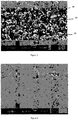
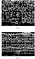
- FIG. 1 A scanning electron micrograph (SEM) of the surface of this coated separator membrane, taken at 10,000x magnification, is shown in Figure 1 .
- Irregularly shaped ceramic particles 10 can be seen in the SEM of Figure 1 as well as PVDF binder 12, which has been coalesced or somewhat melted or bound together to form the coating layer with the ceramic particles 10.
- voids 14 can be seen in the SEM of Figure 1 .
- An aqueous-based PVDF/ceramic coating slurry was prepared by dispersing 39 grams of high purity alumina particles having a D50 average particle diameter of 0.65 ⁇ m, a bulk tapped density of 0.8 g/cm 3 and a BET surface area of 4.6 m 2 /g with 16.8 grams of the PVDF Formulation #1 blend described in Example 1 above. Improved mixing was achieved by first pre-wetting the alumina particles with the Formulation #1 solution or suspension. Dispersion was accomplished using a Silverson High Shear L4M-5 mixer at 5000 rpm for 12 minutes at room temperature and then using a Ball mill mixer (MTI Shimmy Ball Mixer) for 20 minutes.
- MTI Shimmy Ball Mixer Ball mill mixer
- the ceramic/PVDF slurry was hand coated on a surface of a Celgard®2400 PP microporous membrane (the features of which membrane are described in Example 1 above) using a doctor blade, and the water was removed by oven drying at 79°C.
- Components of the coating formed during this Example are shown below in Table 1, while properties of the coated separator membrane are reported in Table 2 below.
- An aqueous-based PVDF/ceramic coating slurry was prepared by mixing and uniformly dispersing 66 grams of high purity alumina particles having a D50 average particle diameter of 0.65 ⁇ m, a bulk tapped density of 0.8 g/cm 3 and a BET surface area of 4.6 m 2 /g with 23.5 grams of Formulation #2, a Kynar® Latex product available from Arkema and generally described as an aqueous suspension of water (55-65%) and PVDF:HFP, which PVDF:HFP has a melt temperature in the range of about 114-120°C. Improved mixing was achieved by first pre-wetting the alumina particles with the Formulation #2 solution or suspension.
- Dispersion was accomplished using a Silverson High Shear L4M-5 mixer at 3000 rpm for 5 minutes at room temperature followed by mixing in Ball mill mixer (MTI Shimmy Ball Mixer) for 20 minutes.
- the slurry was hand coated onto the surface of a Celgard®EK0940 polyethylene microporous membrane (a membrane made from a wet process and having a thickness of about 9 ⁇ m, a porosity of about 40%, a JIS Gurley value of about 130 sec, which is equivalent to an ASTM Gurley value of about 5 sec) using a doctor blade, and the coated sample was oven dried at 65°C.
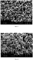
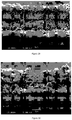
- An SEM of the surface of this coated separator membrane, taken at 10,000x magnification, is shown in Figure 3 .
- Components of the coating prepared in this Example are shown below in Table 1, while properties of the coated separator membrane are reported in Table 2 below.
- An aqueous-based PVDF/ceramic coating slurry was prepared by mixing and uniformly dispersing 66 grams of high purity alumina particles having a D50 average particle diameter of 0.65 ⁇ m, a bulk tapped density of 0.8 g/cm 3 and a BET surface area of 4.6 m 2 /g with 16.4 grams of Formulation #2 (described above). Improved mixing was achieved by first pre-wetting the alumina particles with the Formulation #2 solution or suspension. Dispersion was accomplished using a Silverson High Shear L4M-5 mixer at 5000 rpm for 10 minutes at room temperature followed by mixing in Ball mill mixer (MTI Shimmy Ball Mixer) for 15 minutes.
- MTI Shimmy Ball Mixer Ball mill mixer
- the slurry was applied to the surface of a Celgard®EK0940 polyethylene microporous membrane (as described above in Example 3) by hand coating using a Mayer rod size 3, and the coated sample was oven dried at 60°C. Components of the coating formed during this Example are shown below in Table 1, while properties of the coated separator membrane are reported in Table 2 below.
- Example 4 The aqueous-based PVDF/ceramic coating slurry used in Example 4 was used to coat a Celgard®EK0940 polyethylene microporous membrane using a Mayer rod size 24, and the coated sample was oven dried at 60°C. Components of the coating formed for this Example are shown below in Table 1, while properties of the coated separator membrane are reported in Table 2 below.
- Example 4 The aqueous-based PVDF/ceramic coating slurry used in Example 4 was used to coat a Celgard®2400 polypropylene microporous membrane using a doctor blade, and the coated sample was oven dried at 60°C. An SEM of the surface of this coated separator membrane, taken at 20,000x magnification, is shown in Figure 4 . Components of the coating formed for this Example are shown below in Table 1, while properties of the coated separator membrane are reported in Table 2 below.
- An aqueous-based PVDF/ceramic coating slurry was prepared by uniformly dispersing 138 grams of high purity alumina particles having a D50 average particle diameter of 0.65 ⁇ m, a bulk tapped density of 0.8 g/cm 3 and a BET surface area of 4.6 m 2 /g with 30 grams of Formulation #3, a Kynar® Latex product available from Arkema and generally described as an aqueous suspension of water (55-65%) and PVDF:HFP, whichPVDF:HFP has a melt temperature in the range of about 152-155°C. Improved mixing was achieved by first pre-wetting the alumina particles with the Formulation #3 solution or suspension.
- the lower content of HFP copolymer in the PVDF:HFP in Formulation #3 may account for the higher melt temperature of the PVDF:HFP in Formulation #3 compared with that of the PVDF:HFP in Formulation #2.
- the varying amounts of copolymer may affect adhesion of the polymer solution or suspension to the ceramic particles and overall adhesion of the coating to the membrane and ultimately the adhesion between the coated separator and one or both electrodes of the lithium ion battery.
- too much or too little copolymer could affect the crystallinity of the coating and could affect the tackiness of the coating, thereby affecting the adhesion of the coating.
- Dispersion was accomplished using a Silverson High Shear L4M-5 mixer at 5000 rpm for 5 minutes and at 6700 rpm for 10 minutes at room temperature.
- the slurry was applied to the surface of a Celgard®EK0940 polyethylene microporous membrane by hand coating using a Mayer rod size 24.
- the coated sample was dried in the oven at 60°C for 10 minutes and further allowed to dry in air at room temperature.
- An SEM of the surface of this coated separator membrane, taken at 35,000x magnification, is shown in Figure 5 .
- Components of the coating of this Example are shown below in Table 1, while properties of the coated separator membrane are reported in Table 2 below.
- An aqueous-based PVDF/ceramic coating slurry was prepared by mixing and uniformly dispersing 112 grams of high purity alumina particles having a D50 average particle diameter of 0.65 ⁇ m, a bulk tapped density of 0.8 g/cm 3 and a BET surface area of 4.6 m 2 /g with 18.7 grams of the Formulation #1 blend described in Example 1 above. Improved mixing was achieved by first pre-wetting the alumina particles with the Formulation #1 solution or suspension. Dispersion was accomplished using a Silverson High Shear L4M-5 mixer at 2500 rpm for 10 minutes and 5000 rpm for 10 minutes at room temperature followed by mixing in Ball mill mixer (MTI Shimmy Ball Mixer) for 10 minutes.
- MTI Shimmy Ball Mixer Ball mill mixer
- the slurry was applied to the surface of a Celgard®2400 polypropylene microporous membrane by hand coating using a doctor blade, and the coated sample was oven dried at 60°C.
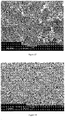
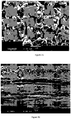
- Two SEMs of the surface of this coated separator membrane are shown in Figures 6(a) (10,000x magnification) and 6(b) (20,000x magnification), and an SEM of the cross section of this coated separator membrane, taken at 1,000x magnification, is shown in Figure 6(c) .
- Components of the coating for this Example are shown below in Table 1, while properties of the coated separator membrane are reported in Table 2 below.
- a non-aqueous based PVDF ceramic coating solution was prepared by mixing 30 grams of high purity fumed alumina particles having an average diameter of 100 nm with 30 grams of Solef 21216 PVDF:HFP (commercially available from Solvay) in acetone. The coating was hand coated using a doctor blade onto a Celgard®EK0940 polyethylene microporous membrane and allowed to dry in air at room temperature. An SEM of the surface of this coated separator membrane, taken at 10,000x magnification, is shown in Figure 8 . Components of the coating of this Comparative Example are shown below in Table 1, while properties of the coated separator membrane are reported in Table 2.
- Example 1-8 useful in a rechargeable lithium ion battery, were coated with ceramic particles and an aqueous or water based polymeric binder.
- Table 1 above listed the formulation information related to the composition of Examples 1-8, which have a range of ceramic/PVDF:HFP ratio from about 1:1 to about 6:1.
- Examples 1-8 were coated using a water or aqueous based coating which does not contain any non-aqueous solvents such as acetone, N-methyl pyrrolidone, dimethyl acetamide, or the like.
- Comparative Example 1 (CE1) which has a ceramic/PVDF:HFP ratio of 1:1, was coated using acetone as the primary solvent.
- Various coatings in the Examples are porous, as indicated by the samples having a Gurley value and also by the presence of voids in the surface of the coated samples shown in the SEMs of Figures 1-6 .
- the internal structure of the ceramic/PVDF coating layer is shown in Figure 6(c) , which shows a cross sectional view of the coated separator.
- Examples 9-18 were prepared by 1) mixing aluminum oxide (Al 2 O 3 ) ceramic particles with neutralized polyacrylic acid (PAA) in a ball mill mixer, 2) adding one or more water-soluble binders (such as polyacrylates) into the mixed Al 2 O 3 -dispersant mixture, followed by the addition of an aqueous PVDF solution or suspension to form a uniform, well-mixed slurry.
- Al 2 O 3 aluminum oxide
- PAA neutralized polyacrylic acid
- Example 9 is a PP/PE/PP trilayer microporous base membrane having an uncoated thickness of 12.3 ⁇ m, which is single-side coated with an aqueous coating formulation having a 50:50 weight percent ratio of polyvinylidene fluoride (PVDF) polymer to aluminum oxide (Al 2 O 3 ) ceramic particles.
- the coating formulation contains a PVDF with a molecular weight > 300,000.
- the thickness of the coating layer is 3.4 ⁇ m.
- Example 10 is a PP/PE/PP trilayer microporous base membrane having an uncoated thickness of 12.3 ⁇ m, which is single-side coated with an aqueous coating formulation having a 50:50 weight percent ratio of polyvinylidene fluoride (PVDF) polymer to aluminum oxide (Al 2 O 3 ) ceramic particles.
- the coating formulation contains a PVDF with a molecular weight > 1,000,000.
- the thickness of the coating layer is 4.0 ⁇ m.
- Example 11 is a PP/PE/PP trilayer microporous base membrane having an uncoated thickness of 17.8 ⁇ m, which is single-side coated with an aqueous coating formulation having a 50:50 weight percent ratio of polyvinylidene fluoride (PVDF) polymer to aluminum oxide (Al 2 O 3 ) ceramic particles.
- the coating formulation contains a PVDF with a molecular weight > 1,000,000.
- the thickness of the coating layer is 2.8 ⁇ m.
- Example 12 is a PP/PE/PP trilayer microporous base membrane having an uncoated thickness of 17.8 ⁇ m, which is single-side coated with an aqueous coating formulation having a 50:50 weight percent ratio of polyvinylidene fluoride (PVDF) polymer to aluminum oxide (Al 2 O 3 ) ceramic particles.
- the coating formulation contains a PVDF with a molecular weight > 300,000.
- the thickness of the coating layer is 2.1 ⁇ m.
- Example 13 is a PP/PE/PP trilayer microporous base membrane having an uncoated thickness of 17.8 ⁇ m, which is single-side coated with an aqueous coating formulation having a 50:50 weight percent ratio of polyvinylidene fluoride (PVDF) polymer to aluminum oxide (Al 2 O 3 ) ceramic particles.
- the coating formulation contains a PVDF with a molecular weight > 300,000.
- the thickness of the coating layer is 1.0 ⁇ m.
- Table 4 below lists separator property data for Examples 9-13, all of which were coated at a binder:ceramic ratio of 50:50.
- the Al 2 O 3 ceramic particles in the PVDF - Al 2 O 3 aqueous slurry are 0.5 ⁇ m in diameter and have a particle size distribution of D50.
- the PVDF particle size is 100 nm to 1,000 nm.
- Example 14 is a PE microporous base membrane having an uncoated thickness of 9 ⁇ m, which is single-side coated with an aqueous coating formulation having a 20:80 weight percent ratio of polyvinylidene fluoride (PVDF) polymer to aluminum oxide (Al 2 O 3 ) ceramic particles.
- the coating formulation contains a PVDF with a molecular weight > 300,000.
- the thickness of the coating layer is 4.2 ⁇ m.
- Example 15 is a PE microporous base membrane having an uncoated thickness of 9 ⁇ m, which is single-side coated with an aqueous coating formulation having a 20:80 weight percent ratio of polyvinylidene fluoride (PVDF) polymer to aluminum oxide (Al 2 O 3 ) ceramic particles.
- PVDF polyvinylidene fluoride
- Al 2 O 3 aluminum oxide
- Example 16 is a PE microporous base membrane having an uncoated thickness of 9 ⁇ m, which is single-side coated with an aqueous coating formulation having a 20:80 weight percent ratio of polyvinylidene fluoride (PVDF) polymer to aluminum oxide (Al 2 O 3 ) ceramic particles.
- PVDF polyvinylidene fluoride
- Al 2 O 3 aluminum oxide
- Example 17 is a PE microporous base membrane having an uncoated thickness of 9 ⁇ m, which is single-side coated with an aqueous coating formulation having a 20:80 weight percent ratio of polyvinylidene fluoride (PVDF) polymer to aluminum oxide (Al 2 O 3 ) ceramic particles.
- the coating formulation contains a PVDF with a molecular weight > 300,000.
- the thickness of the coating layer is 5.6 ⁇ m.
- Table 5 below lists separator property data for Examples 14-17, all of which were coated at a binder:ceramic ratio of 20:80.
- the Al 2 O 3 ceramic particles in the PVDF - Al 2 O 3 aqueous slurry are 0.5 ⁇ m in diameter and have a particle size distribution of D50.
- the PVDF particle size is 100 nm to 1,000 nm.
- Example 18 is a PE microporous base membrane having an uncoated thickness of 9 ⁇ m, which is single-side coated with an aqueous coating formulation having a 10:90 weight percent ratio of polyvinylidene fluoride (PVDF) polymer to aluminum oxide (Al 2 O 3 ) ceramic particles.
- PVDF polyvinylidene fluoride
- Al 2 O 3 aluminum oxide
- Table 6 below lists separator property data for the separators of Examples 13 and 14 (repeating data from Tables 4 and 5 above) as well as the separator of Example 18, which are coated at PVDF binder:ceramic ratios of 50:50, 20:80 and 10:90, respectively.
- the Al 2 O 3 ceramic particles in the PVDF - Al 2 O 3 aqueous slurry are 0.5 ⁇ m in diameter and have a particle size distribution of D50.
- the PVDF particle size is 100 nm to 1,000 nm.
- the ratio of polymer to ceramic content may be selected to balance excellent adhesion of the polymer-ceramic coating to an electrode where the adhesion may be attributed to the swelling of the water-insoluble binder in electrolyte and/or to the melting of the PVDF when the PVDF has a low melt temperature of ⁇ 100 deg C, more preferably ⁇ 80 deg C and most preferably ⁇ 60 deg C.
- the ratio of polymer to ceramic content may be selected to optimize and/or to reduce thermal shrinkage of the polymer-ceramic coated separator.
- the 20:80 water-insoluble polymer binder:ceramic ratio in Examples 14, 15, 16 and 17 may demonstrate a low Machine direction (MD) thermal shrinkage ⁇ 11.4% and a low Transverse (TD) thermal shrinkage ⁇ 7%.
- the 10:90 water-insoluble polymer binder:ceramic ratio in Example 18 may demonstrate a low Machine direction (MD) thermal shrinkage ⁇ 1.3% and a low Transverse (TD) thermal shrinkage ⁇ 2.4%.
- the ratio of water-soluble to water-insoluble binder content may be selected to optimize the adhesion of the polymer-ceramic coating to a base separator.
- new or improved coated separators, membranes, films, or the like for use in lithium batteries, such as lithium ion batteries or lithium ion polymer batteries, new or improved batteries including such coated separators, membranes, films, or the like, and methods of making or using such coated separators, membranes, films or the like are disclosed herein.
- new or improved ceramic coated separators, membranes, films, or the like for use in lithium batteries such as lithium ion batteries or lithium ion polymer batteries
- new or improved batteries including such ceramic coated separators, membranes, films, or the like and methods of making or using such ceramic coated separators, membranes, films or the like are disclosed herein.
- aqueous polymeric coated separators, membranes, films, or the like for use in lithium batteries, such as lithium ion batteries or lithium ion polymer batteries, new or improved batteries including such aqueous polymeric coated separators, membranes, films, or the like, and methods of making or using such aqueous polymeric coated separators, membranes, films or the like are disclosed herein.
- aqueous polyvinylidene fluoride (PVDF) polymeric coated separators, membranes, films, or the like for use in lithium batteries, such as lithium ion batteries or lithium ion polymer batteries, new or improved batteries including such aqueous polyvinylidene fluoride (PVDF) polymeric coated separators, membranes, films, or the like, and methods of making or using such aqueous polyvinylidene fluoride (PVDF) polymeric coated separators, membranes, films or the like, new or improved polyvinylidene fluoride or polyvinylidene difluoride (PVDF) homopolymer or copolymers of PVDF and/or vinylidene fluoride (VF 2 ) with hexafluoropropylene (HFP or [-CF(CF 3 )-CF 2 -]), chlorotrifluoroethylene (CTFE), tetrafluoro
- a separator membrane for a lithium ion battery which separator membrane has a porous coating layer formed on at least one surface of a porous substrate.
- the coating layer may be formed from a coating slurry that includes a mixture of water, ceramic particles, one or more water-insoluble polymers or binders, and, in some embodiments, one or more water-soluble polymers or binders.
- the present invention further provides a process for producing a separator membrane for a lithium ion battery where a porous coating layer, which may be formed from a coating slurry that includes the mixture described just above is formed on at least one surface of a porous substrate.
- This improved, new or modified separator may be advantageous because of its high temperature melt integrity and improved safety performance when used in a lithium ion battery.
- the ceramic/polymer coating layer may prevent oxidation from occurring at the interface of the coated separator and the electrodes of a lithium ion battery and may improve the safety and the overall performance of a lithium ion battery.
- Gurley is a resistance to air flow measured by the Gurley densometer (e.g., Model 4120). ASTM Gurley is the time in seconds required to pass 10 cc of air through one square inch of product under a pressure of 12.2 inches of water.
- JIS Gurley is defined as the Japanese Industrial Standard (JIS Gurley) JIS P8117 and is an air permeability test measured using the OHKEN permeability tester. JIS Gurley is the time in seconds required for 100 cc of air to pass through one square inch of film at constant pressure of 4.8 inches of water.
- Thickness is measured using the Emveco Microgage 210-A precision micrometer thickness tester according to test procedure ASTM D374. Thickness values are reported in units of micrometers, ⁇ m.
- a calibrated metal template is used to cut a test sample 1 ft 2 in area (and converted to cm 2 ). The sample is weighed and basis weight in mg/cm 2 is calculated.
- Shrinkage is measured by placing a coated test sample between two sheets of paper which is then clipped together to hold the sample between the papers and suspended in an oven. For the '130°C for 1 hour' testing, a sample is placed in an oven at 130°C for 1 hour. After the designated heating time in the oven, each sample was removed and taped to a flat counter surface using single side sticky tape to flatten and smooth out the sample for accurate length and width measurement. Shrinkage is measured in the both the Machine direction (MD) and Transverse direction (TD) direction and is expressed as a % MD shrinkage and % TD shrinkage
- Hot Electrical Resistance (Hot ER):
- Hot Electrical Resistance is a measure of resistance of a separator film while the temperature is linearly increased.
- the rise in resistance measured as impedance corresponds to a collapse in pore structure due to melting or "shutdown" of the separator membrane.
- the drop in resistance corresponds to opening of the separator due to coalescence of the polymer; this phenomenon is referred to as a loss in "melt integrity".
- Adhesion of a coating to a base substrate can be subjectively evaluated by any or all of the following methods listed in order of increasing durability or adhesive strength of coating layer to base substrate, 1) rubbing the surface of the coating with a tip of the tester's index finger to see if the coating rubs off the underlying substrate, 2) attaching a 3M Post-it® note to the coating side of the coated membrane substrate, pulling the 3M Post-it® note away from the coated membrane substrate to test if the coating peels away from the substrate, and 3) attaching a piece of Scotch® tape to the coating side of the coated membrane substrate, pulling the Scotch® tape away to test if the coating peels away from the substrate.
- the examples described herein were tested for adhesion by rubbing the surface of the coated sample (rubbing the surface of the coating) using a tip of the tester's index finger and observing whether the coating rubs off the underlying substrate. If the coating adhered to the substrate with normal rubbing pressure using the tip of the tester's index finger, then the adhesion was described as "good”. If the coating adhered to the substrate after very firm rubbing pressure using the tip of the tester's index finger, then the adhesion was described as "excellent”.
- Adhesion of a coated separator membrane to an electrode can be evaluated by a dry method adhesion test where a sample of a coated membrane is laminated to an electrode using heat and pressure. After cooling to room temperature, the electrode/coated membrane sample is hand pulled apart. The surface of the coated membrane is observed for the presence of electrode material, which is often black in appearance. The presence of electrode material on the surface of the pulled-apart coated separator membrane indicates the coating layer was very well adhered to the electrode.
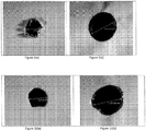
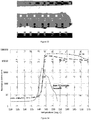
- a hot tip probe at a temperature of 450°C with a tip diameter of 0.5 mm is moved toward a surface of a test sample of separator that sits atop aluminum foil situated on a glass substrate as shown in Figure 12 .
- the hot tip probe is advanced towards the sample at a speed of 10mm/min and is allowed to contact the surface of the test sample for a period of 10 seconds.
- Results of the test are presented as a digital image taken with an optical microscope showing both the shape of the hole and the size of the hole in millimeters after the hot tip probe is removed.
- Minimal propagation of a hole in a separator test sample from contact with the hot tip probe simulates the desired response of the separator to a localized hot spot, which may occur during an internal short circuit in a lithium ion battery.
Landscapes
- Chemical & Material Sciences (AREA)
- Electrochemistry (AREA)
- General Chemical & Material Sciences (AREA)
- Chemical Kinetics & Catalysis (AREA)
- Engineering & Computer Science (AREA)
- Manufacturing & Machinery (AREA)
- Inorganic Chemistry (AREA)
- Materials Engineering (AREA)
- Ceramic Engineering (AREA)
- Composite Materials (AREA)
- Life Sciences & Earth Sciences (AREA)
- Wood Science & Technology (AREA)
- Cell Separators (AREA)
- Laminated Bodies (AREA)
Priority Applications (2)
| Application Number | Priority Date | Filing Date | Title |
|---|---|---|---|
| PL15865326T PL3227940T3 (pl) | 2014-12-05 | 2015-12-04 | Ulepszone, powlekane separatory do akumulatorów litowych i powiązane sposoby |
| EP21166724.1A EP3866244A1 (en) | 2014-12-05 | 2015-12-04 | Improved coated separators for lithium batteries and related methods |
Applications Claiming Priority (2)
| Application Number | Priority Date | Filing Date | Title |
|---|---|---|---|
| US201462087953P | 2014-12-05 | 2014-12-05 | |
| PCT/US2015/063868 WO2016090199A1 (en) | 2014-12-05 | 2015-12-04 | Improved coated separators for lithium batteries and related methods |
Related Child Applications (1)
| Application Number | Title | Priority Date | Filing Date |
|---|---|---|---|
| EP21166724.1A Division EP3866244A1 (en) | 2014-12-05 | 2015-12-04 | Improved coated separators for lithium batteries and related methods |
Publications (3)
| Publication Number | Publication Date |
|---|---|
| EP3227940A1 EP3227940A1 (en) | 2017-10-11 |
| EP3227940A4 EP3227940A4 (en) | 2018-06-06 |
| EP3227940B1 true EP3227940B1 (en) | 2021-04-07 |
Family
ID=56092503
Family Applications (2)
| Application Number | Title | Priority Date | Filing Date |
|---|---|---|---|
| EP15865326.1A Active EP3227940B1 (en) | 2014-12-05 | 2015-12-04 | Improved coated separators for lithium batteries and related methods |
| EP21166724.1A Pending EP3866244A1 (en) | 2014-12-05 | 2015-12-04 | Improved coated separators for lithium batteries and related methods |
Family Applications After (1)
| Application Number | Title | Priority Date | Filing Date |
|---|---|---|---|
| EP21166724.1A Pending EP3866244A1 (en) | 2014-12-05 | 2015-12-04 | Improved coated separators for lithium batteries and related methods |
Country Status (8)
| Country | Link |
|---|---|
| US (1) | US20160164060A1 (pl) |
| EP (2) | EP3227940B1 (pl) |
| JP (4) | JP2017536677A (pl) |
| KR (3) | KR20240152420A (pl) |
| CN (2) | CN107210411A (pl) |
| HU (1) | HUE054492T2 (pl) |
| PL (1) | PL3227940T3 (pl) |
| WO (1) | WO2016090199A1 (pl) |
Families Citing this family (81)
| Publication number | Priority date | Publication date | Assignee | Title |
|---|---|---|---|---|
| JP6840396B2 (ja) * | 2015-08-26 | 2021-03-10 | 厦▲門▼大学 | 改質のセラミックセパレータ複合体及びその製造方法 |
| US10770707B2 (en) * | 2015-12-04 | 2020-09-08 | Toray Industries, Inc. | Battery separator and method of manufacturing same |
| US11289769B2 (en) * | 2016-03-03 | 2022-03-29 | Apple Inc. | Binders for wet and dry lamination of battery cells |
| JP2017212040A (ja) * | 2016-05-23 | 2017-11-30 | オートモーティブエナジーサプライ株式会社 | リチウムイオン二次電池 |
| US20180048020A1 (en) * | 2016-08-12 | 2018-02-15 | Lenovo (Beijing) Co., Ltd. | Lithium-ion polymer battery and electronic device |
| CN107785519A (zh) | 2016-08-29 | 2018-03-09 | 比亚迪股份有限公司 | 一种聚合物复合膜及其制备方法以及包括其的锂离子电池 |
| WO2018047871A1 (ja) * | 2016-09-09 | 2018-03-15 | 住友化学株式会社 | アルミナ粉末、アルミナスラリー、アルミナ含有コート層、積層分離膜及び二次電池 |
| US10707531B1 (en) | 2016-09-27 | 2020-07-07 | New Dominion Enterprises Inc. | All-inorganic solvents for electrolytes |
| CN107887551A (zh) * | 2016-09-30 | 2018-04-06 | 天津凯普瑞特新能源科技有限公司 | 一种锂离子电池陶瓷隔膜和制造方法 |
| EP3518317B1 (en) * | 2016-11-18 | 2020-09-23 | LG Chem, Ltd. | Separator and electrochemical device comprising same |
| EP3602652A4 (en) * | 2017-03-20 | 2020-12-09 | Celgard, LLC | ENHANCED BATTERY SEPARATORS, ELECTRODES, CELLS, LITHIUM BATTERIES AND RELATED PROCESSES |
| US10595599B2 (en) * | 2017-06-13 | 2020-03-24 | Danglz Llc | Direct printed jewelry charm |
| CN109390532A (zh) * | 2017-08-07 | 2019-02-26 | 上海凯矜新材料科技有限公司 | 锂电池基膜涂布用浆料及其制备方法 |
| KR102244908B1 (ko) * | 2017-10-25 | 2021-04-26 | 주식회사 엘지화학 | 리튬-황 전지용 분리막 및 이를 포함하는 리튬-황 전지 |
| KR102256534B1 (ko) * | 2017-11-08 | 2021-05-25 | 삼성에스디아이 주식회사 | 리튬 이차 전지용 음극 활물질 및 이를 포함하는 리튬 이차 전지 |
| KR102351490B1 (ko) | 2017-11-24 | 2022-01-17 | 주식회사 엘지에너지솔루션 | 세퍼레이터의 제조방법, 이로부터 형성된 세퍼레이터 및 이를 포함하는 전기화학소자 |
| KR102132756B1 (ko) | 2017-12-06 | 2020-07-13 | 주식회사 엘지화학 | 이차전지 분리막 코팅용 슬러리 조성물 및 이를 이용한 이차전지 분리막 |
| CN109980158A (zh) * | 2017-12-27 | 2019-07-05 | 中国电子科技集团公司第十八研究所 | 一种长循环锂二次电池 |
| PL3671899T3 (pl) | 2017-12-27 | 2022-01-10 | Lg Chem, Ltd. | Sposób wytwarzania separatora, tak utworzony separator i zawierające go urządzenie elektrochemiczne |
| JP2021511637A (ja) * | 2018-01-22 | 2021-05-06 | セルガード エルエルシー | 改良されたコーティングされたセパレータ、リチウム電池および関連方法 |
| CN111463391A (zh) * | 2018-01-22 | 2020-07-28 | 赛尔格有限责任公司 | 改善的涂覆的分隔件、锂电池及相关方法 |
| JPWO2019156161A1 (ja) * | 2018-02-09 | 2021-01-28 | 株式会社村田製作所 | リチウムイオン二次電池 |
| CN108550762A (zh) * | 2018-03-15 | 2018-09-18 | 桑顿新能源科技有限公司 | 一种三元锂离子电池的涂覆隔膜及其制备方法 |
| US11870037B2 (en) * | 2018-04-10 | 2024-01-09 | Apple Inc. | Porous ceramic separator materials and formation processes |
| CN110364660B (zh) * | 2018-04-10 | 2022-07-15 | 浙江浙能中科储能科技有限公司 | 一种水系锌离子电池复合隔膜及制备方法 |
| US10637100B2 (en) | 2018-04-20 | 2020-04-28 | Ut-Battelle, Llc | Fabrication of films and coatings used to activate shear thickening, impact resistant electrolytes |
| CN110398413A (zh) * | 2018-04-25 | 2019-11-01 | 银隆新能源股份有限公司 | 陶瓷隔膜的基膜与陶瓷涂层之间粘结力的表征方法 |
| WO2019218327A1 (en) * | 2018-05-18 | 2019-11-21 | GM Global Technology Operations LLC | Hybrid lithium ion capacitor battery having a carbon coated separate layer and method of making the same |
| JP2019204689A (ja) * | 2018-05-24 | 2019-11-28 | 株式会社日立製作所 | 絶縁層、電池セルシート、二次電池 |
| KR102613190B1 (ko) * | 2018-05-29 | 2023-12-14 | 현대자동차주식회사 | 리튬 이차전지용 전해액 및 이를 포함하는 리튬 이차전지 |
| CN109037551A (zh) * | 2018-08-01 | 2018-12-18 | 河北金力新能源科技股份有限公司 | 一种锂离子电池隔膜及其制备方法 |
| WO2020067845A1 (ko) * | 2018-09-28 | 2020-04-02 | 주식회사 엘지화학 | 개선된 전극접착력 및 저항 특성을 갖는 리튬이차전지용 분리막 및 상기 분리막을 포함하는 리튬이차전지 |
| WO2020080774A1 (ko) * | 2018-10-15 | 2020-04-23 | 주식회사 엘지화학 | 전기화학소자용 세퍼레이터 및 이의 제조방법 |
| CN109346650A (zh) * | 2018-10-25 | 2019-02-15 | 苏州捷力新能源材料有限公司 | 一种陶瓷pvdf混涂的锂离子电池隔膜及制备方法 |
| CN111192995A (zh) * | 2018-11-15 | 2020-05-22 | 微宏动力系统(湖州)有限公司 | 一种高粘结性电池隔膜、其制备方法及锂离子电池 |
| CN109616605B (zh) * | 2018-12-27 | 2023-12-26 | 江苏理士电池有限公司 | 一种锂离子电池隔膜及其制备方法 |
| CN111490213A (zh) * | 2019-01-25 | 2020-08-04 | 辽源鸿图锂电隔膜科技股份有限公司 | 一种高安全性水性pvdf隔膜浆料及其制备方法 |
| KR102421619B1 (ko) * | 2019-02-22 | 2022-07-15 | 주식회사 엘지에너지솔루션 | 리튬이차전지용 세퍼레이터 및 이의 제조방법 |
| US11217781B2 (en) | 2019-04-08 | 2022-01-04 | GM Global Technology Operations LLC | Methods for manufacturing electrodes including fluoropolymer-based solid electrolyte interface layers |
| KR102181876B1 (ko) * | 2019-05-17 | 2020-11-24 | 강창기 | 이차전지 폐분리막을 이용한 복합수지 조성물의 제조 방법 |
| KR102477279B1 (ko) | 2019-06-14 | 2022-12-12 | 주식회사 엘지에너지솔루션 | 세퍼레이터 및 이를 포함하는 전기화학소자 |
| US11333544B2 (en) * | 2019-06-17 | 2022-05-17 | Honeywell International Inc. | Apparatus for simultaneously determining weights of composite sheets |
| KR102407048B1 (ko) | 2019-07-04 | 2022-06-08 | 삼성에스디아이 주식회사 | 이차 전지용 분리막 및 이를 포함하는 리튬 이차 전지 |
| US20210050576A1 (en) * | 2019-08-12 | 2021-02-18 | Sparkle Power Llc | Separator for an energy storage device |
| KR102748043B1 (ko) * | 2019-09-11 | 2024-12-31 | 주식회사 엘지에너지솔루션 | 전해액 함침성이 우수한 이차전지용 분리막 |
| CN112563664B (zh) * | 2019-09-26 | 2022-03-18 | 比亚迪股份有限公司 | 隔膜及锂离子电池 |
| CN110808349A (zh) * | 2019-09-29 | 2020-02-18 | 南通百川新材料有限公司 | 一种宽温度范围应用的锂离子电池隔膜的制备方法 |
| WO2021086088A1 (ko) * | 2019-10-29 | 2021-05-06 | 주식회사 엘지화학 | 개선된 전극접착력 및 저항 특성을 갖는 리튬이차전지용 분리막 및 상기 리튬이차전지용 분리막을 포함하는 리튬이차전지 |
| CN111072317B (zh) * | 2019-12-04 | 2022-05-17 | 乐凯胶片股份有限公司 | 陶瓷浆料、陶瓷隔膜和锂离子电池 |
| CN111116963B (zh) * | 2019-12-27 | 2022-07-22 | 深圳中兴新材技术股份有限公司 | 一种陶瓷涂层隔膜的制备方法、隔膜及陶瓷涂覆浆料 |
| CN113363672A (zh) * | 2020-03-06 | 2021-09-07 | 中材锂膜有限公司 | 一种锂离子电池用喷涂隔膜及其制备方法 |
| JP7485314B2 (ja) * | 2020-03-25 | 2024-05-16 | エルジー エナジー ソリューション リミテッド | 単位セルの製造装置および方法 |
| CN111509173A (zh) * | 2020-03-26 | 2020-08-07 | 合肥国轩高科动力能源有限公司 | 一种锂离子电池用功能涂层隔膜及其制备方法 |
| CN111599971A (zh) * | 2020-06-08 | 2020-08-28 | 德州东鸿制膜科技有限公司 | 一种高安全性规则矩阵涂覆粘结性锂离子电池隔膜及其制备方法和应用 |
| CN111628131B (zh) * | 2020-06-09 | 2022-02-01 | 江苏厚生新能源科技有限公司 | 具备低温关断性能的涂覆隔膜及制备方法、锂电池、汽车 |
| CN116195123B (zh) | 2020-10-19 | 2026-03-17 | 株式会社Lg新能源 | 用于锂二次电池的隔板和包括其的锂二次电池 |
| CN114497468B (zh) * | 2020-11-11 | 2023-07-14 | 比亚迪股份有限公司 | 锂离子电池 |
| CN112490588A (zh) * | 2020-12-11 | 2021-03-12 | 易佰特新能源科技有限公司 | 一种电池隔离膜及含该隔离膜的锂离子电池 |
| US20240234950A9 (en) * | 2021-02-17 | 2024-07-11 | Celgard, Llc | Improved adhesive coating, coated membranes, coated battery separators, and related methods |
| CN113300058B (zh) * | 2021-04-28 | 2022-11-04 | 湖南立方新能源科技有限责任公司 | 一种锂电池的注液方法、锂电池的制作方法及锂电池 |
| CN113178663A (zh) * | 2021-04-28 | 2021-07-27 | 惠州亿纬锂能股份有限公司 | 一种复合隔膜及其制备方法和用途 |
| CN113675530A (zh) * | 2021-08-23 | 2021-11-19 | 长园泽晖新能源材料研究院(珠海)有限公司 | 一种以纳米二氧化硅为填料的pvdf隔膜 |
| CN117099254A (zh) * | 2021-08-27 | 2023-11-21 | 株式会社Lg新能源 | 用于电化学装置的隔板以及包括该隔板的电极组件和电化学装置 |
| EP4156400A1 (en) | 2021-09-27 | 2023-03-29 | LG Energy Solution, Ltd. | Separator for secondary battery |
| CN113964294B (zh) * | 2021-10-28 | 2024-04-12 | 西安交通大学 | 一种锂离子电池负极及其制备方法和应用 |
| CN114335904B (zh) * | 2022-02-28 | 2022-07-12 | 湖南中锂新材料科技有限公司 | 一种锂电池复合隔膜及其制备方法和应用 |
| CN115411459B (zh) * | 2022-09-27 | 2024-08-13 | 惠州锂威新能源科技有限公司 | 隔膜、电池及隔膜的制备方法 |
| CN115642368A (zh) * | 2022-10-13 | 2023-01-24 | 吉林师范大学 | 一种高岭土涂层锂离子电池隔膜 |
| WO2024089553A1 (en) * | 2022-10-24 | 2024-05-02 | Electrovaya Inc. | Ceramic composite separator and method for manufacturing the same |
| CN118040237A (zh) * | 2022-11-04 | 2024-05-14 | 中材锂膜(宁乡)有限公司 | 一种低内阻陶瓷涂覆隔膜及其制备方法、锂离子电池 |
| CN116505192A (zh) * | 2022-12-29 | 2023-07-28 | 重庆太蓝新能源有限公司 | 一种电芯以及锂离子电池 |
| JP2025515027A (ja) * | 2023-01-20 | 2025-05-13 | エルジー エナジー ソリューション リミテッド | 電気化学素子用分離膜、その製造方法及びそれを含む電気化学素子 |
| EP4641702A1 (en) * | 2023-04-17 | 2025-10-29 | Contemporary Amperex Technology Co., Limited | Battery cell, battery, and electric device |
| CN116190913B (zh) * | 2023-04-21 | 2023-08-29 | 安徽利科新材料科技有限公司 | 一种生物基涂覆浆料的制备方法及装置 |
| CN116231231B (zh) * | 2023-05-09 | 2023-08-01 | 合肥长阳新能源科技有限公司 | 一种层间交联共挤电池隔膜及其制备方法与电池 |
| CN116454542B (zh) * | 2023-06-15 | 2023-09-15 | 中材锂膜有限公司 | 一种电池隔膜及其制备方法以及电池 |
| US12567600B2 (en) | 2023-12-14 | 2026-03-03 | Safire Technology Group, Inc. | Systems and methods for enhancing safety of electrochemical cells via electrolyte thickening |
| WO2025137228A1 (en) | 2023-12-19 | 2025-06-26 | Arkema Inc. | Lithium-ion battery capable of fast charging |
| CN118231958A (zh) * | 2023-12-28 | 2024-06-21 | 比亚迪股份有限公司 | 电池用隔膜、电池以及用电设备 |
| KR20260005800A (ko) * | 2024-07-03 | 2026-01-12 | 주식회사 엘지화학 | 전지 분리막 및 전지 |
| US20260074370A1 (en) * | 2024-09-06 | 2026-03-12 | Sila Nanotechnologies, Inc. | Highly permeable ceramic coated separators and related components, batteries, and methods |
Citations (1)
| Publication number | Priority date | Publication date | Assignee | Title |
|---|---|---|---|---|
| US20070082993A1 (en) * | 2005-06-10 | 2007-04-12 | Ramin Amin-Sanayei | Aqueous process for making a stable fluoropolymer dispersion |
Family Cites Families (28)
| Publication number | Priority date | Publication date | Assignee | Title |
|---|---|---|---|---|
| JPH08244152A (ja) * | 1995-03-15 | 1996-09-24 | Nitto Denko Corp | 多孔質フィルムおよびその製造法 |
| TW473834B (en) * | 1998-05-01 | 2002-01-21 | Ibm | Method of doping a gate and creating a very shallow source/drain extension and resulting semiconductor |
| US10003058B2 (en) * | 2006-11-17 | 2018-06-19 | Celgard, Llc | Method of making a co-extruded, multi-layered battery separator |
| KR100727248B1 (ko) * | 2007-02-05 | 2007-06-11 | 주식회사 엘지화학 | 다공성 활성층이 코팅된 유기/무기 복합 분리막 및 이를구비한 전기화학소자 |
| US20120015246A1 (en) | 2010-05-27 | 2012-01-19 | Arkema Inc. | Waterborne fluoropolymer composition |
| CN101789499B (zh) * | 2010-01-19 | 2012-04-25 | 中国海诚工程科技股份有限公司 | 一种锂离子电池隔膜的涂层组合物及泡沫施胶方法 |
| JP5707961B2 (ja) * | 2010-01-21 | 2015-04-30 | 東レ株式会社 | 蓄電デバイス用セパレータ |
| US20110183203A1 (en) * | 2010-01-27 | 2011-07-28 | Molecular Nanosystems, Inc. | Polymer supported electrodes |
| KR101173202B1 (ko) * | 2010-02-25 | 2012-08-13 | 주식회사 엘지화학 | 세퍼레이터의 제조방법, 이로부터 형성된 세퍼레이터 및 이를 포함하는 전기화학소자의 제조방법 |
| KR101117126B1 (ko) * | 2010-04-19 | 2012-02-24 | 한국과학기술연구원 | 금속산화물 초극세 섬유-기반 내열성 복합 분리막 및 이를 이용한 이차전지 |
| CN102181204B (zh) * | 2011-03-01 | 2014-06-18 | 广东精进能源有限公司 | 锂离子电池用耐高温隔膜用涂层及耐高温隔膜的制备方法 |
| JP5920638B2 (ja) * | 2011-05-02 | 2016-05-18 | トヨタ自動車株式会社 | 非水電解質二次電池 |
| CN102381697A (zh) * | 2011-07-19 | 2012-03-21 | 中国人民解放军63971部队 | 一种球形炭材料的制备方法 |
| JP2015512124A (ja) * | 2012-02-21 | 2015-04-23 | アーケマ・インコーポレイテッド | 水性ポリフッ化ビニリデン組成物 |
| JP5889749B2 (ja) * | 2012-08-09 | 2016-03-22 | 三洋電機株式会社 | 非水電解質二次電池及びその製造方法 |
| KR101341196B1 (ko) * | 2012-12-10 | 2013-12-12 | 삼성토탈 주식회사 | 수계 코팅액을 이용한 유/무기 복합 코팅 다공성 분리막과 그의 제조방법 및 상기 분리막을 이용한 전기화학소자 |
| KR101611229B1 (ko) * | 2013-01-31 | 2016-04-11 | 제일모직 주식회사 | 분리막의 제조 방법과 그 분리막, 및 이를 이용한 전지 |
| JP2014175055A (ja) | 2013-03-06 | 2014-09-22 | Nippon Zeon Co Ltd | 二次電池用多孔膜、二次電池多孔膜用スラリー、及び二次電池用多孔膜の製造方法、並びに二次電池用電極、二次電池用セパレータ、及び二次電池 |
| US20140272526A1 (en) * | 2013-03-14 | 2014-09-18 | GM Global Technology Operations LLC | Porous separator for a lithium ion battery and a method of making the same |
| WO2014148036A1 (ja) * | 2013-03-19 | 2014-09-25 | ソニー株式会社 | セパレータ、電池、電池パック、電子機器、電動車両、蓄電装置および電力システム |
| WO2014147888A1 (ja) * | 2013-03-19 | 2014-09-25 | 帝人株式会社 | 非水系二次電池用セパレータ及び非水系二次電池 |
| JP2014208780A (ja) * | 2013-03-27 | 2014-11-06 | 三菱樹脂株式会社 | 塗工液の製造方法、積層多孔フィルム、非水電解液二次電池用セパレータ、及び非水電解液二次電池 |
| US9609753B2 (en) * | 2013-07-11 | 2017-03-28 | Samsung Electro-Mechanics Co., Ltd. | Multilayer ceramic capacitor and board for mounting of the same |
| CN103400953B (zh) * | 2013-07-19 | 2016-01-13 | 中国科学院金属研究所 | 一种具有无机涂层的锌银电池复合隔膜及其制备方法 |
| CN103515564B (zh) * | 2013-10-15 | 2017-06-30 | 深圳市星源材质科技股份有限公司 | 一种复合隔膜及其制备方法 |
| CN103647034A (zh) * | 2013-12-04 | 2014-03-19 | 合肥国轩高科动力能源股份公司 | 一种应用于锂离子电池的氮化物陶瓷涂层的制备方法 |
| CN103915591A (zh) * | 2014-04-09 | 2014-07-09 | 深圳市星源材质科技股份有限公司 | 水性陶瓷涂层锂离子电池隔膜及其加工方法 |
| CN104617328B (zh) * | 2014-07-10 | 2017-05-31 | 天津东皋膜技术有限公司 | 一种长寿命锂离子二次电池及其制造方法 |
-
2015
- 2015-12-04 CN CN201580074209.5A patent/CN107210411A/zh active Pending
- 2015-12-04 WO PCT/US2015/063868 patent/WO2016090199A1/en not_active Ceased
- 2015-12-04 HU HUE15865326A patent/HUE054492T2/hu unknown
- 2015-12-04 EP EP15865326.1A patent/EP3227940B1/en active Active
- 2015-12-04 US US14/958,990 patent/US20160164060A1/en active Pending
- 2015-12-04 CN CN202210189915.6A patent/CN114552128A/zh active Pending
- 2015-12-04 PL PL15865326T patent/PL3227940T3/pl unknown
- 2015-12-04 KR KR1020247033531A patent/KR20240152420A/ko active Pending
- 2015-12-04 EP EP21166724.1A patent/EP3866244A1/en active Pending
- 2015-12-04 JP JP2017528108A patent/JP2017536677A/ja active Pending
- 2015-12-04 KR KR1020177018435A patent/KR20170091149A/ko not_active Ceased
- 2015-12-04 KR KR1020237024414A patent/KR20230113649A/ko not_active Ceased
-
2021
- 2021-06-01 JP JP2021092277A patent/JP2021141078A/ja active Pending
-
2023
- 2023-02-03 JP JP2023015189A patent/JP2023058556A/ja active Pending
-
2025
- 2025-03-27 JP JP2025054618A patent/JP2025098210A/ja active Pending
Patent Citations (1)
| Publication number | Priority date | Publication date | Assignee | Title |
|---|---|---|---|---|
| US20070082993A1 (en) * | 2005-06-10 | 2007-04-12 | Ramin Amin-Sanayei | Aqueous process for making a stable fluoropolymer dispersion |
Also Published As
| Publication number | Publication date |
|---|---|
| JP2025098210A (ja) | 2025-07-01 |
| US20160164060A1 (en) | 2016-06-09 |
| CN107210411A (zh) | 2017-09-26 |
| JP2021141078A (ja) | 2021-09-16 |
| JP2023058556A (ja) | 2023-04-25 |
| PL3227940T3 (pl) | 2021-10-18 |
| EP3866244A1 (en) | 2021-08-18 |
| KR20230113649A (ko) | 2023-07-31 |
| JP2017536677A (ja) | 2017-12-07 |
| EP3227940A1 (en) | 2017-10-11 |
| EP3227940A4 (en) | 2018-06-06 |
| KR20170091149A (ko) | 2017-08-08 |
| CN114552128A (zh) | 2022-05-27 |
| HUE054492T2 (hu) | 2021-09-28 |
| KR20240152420A (ko) | 2024-10-21 |
| WO2016090199A1 (en) | 2016-06-09 |
Similar Documents
| Publication | Publication Date | Title |
|---|---|---|
| EP3227940B1 (en) | Improved coated separators for lithium batteries and related methods | |
| JP5932161B1 (ja) | 積層体、セパレータ及び非水二次電池 | |
| CN104396048B (zh) | 用于锂离子电池的整合式电极隔膜组件 | |
| JP6185133B2 (ja) | 積層多孔質フィルム及びその製造方法、積層電極シート並びに非水電解液二次電池 | |
| CN101687404B (zh) | 多层多孔膜 | |
| US20180013118A1 (en) | Laminated porous film, separator for non-aqueous electrolyte secondary battery and non-aqueous electrolyte secondary battery | |
| JP6193333B2 (ja) | セパレータ及びその製造方法 | |
| JP5865168B2 (ja) | 積層多孔質フィルムの製造方法及び積層多孔質フィルム、並びに非水電解液二次電池 | |
| JP2019143008A (ja) | ポリオレフィン微多孔膜 | |
| WO2012043501A1 (ja) | スラリー及び該スラリーを使用したセパレータの製造方法 | |
| US11594786B2 (en) | Nonaqueous electrolyte secondary battery laminated separator | |
| WO2024010091A1 (ja) | 蓄電デバイス用セパレータ | |
| EP4282026A1 (en) | Improved adhesive coating, coated membranes, coated battery separators, and related methods | |
| WO2018221503A1 (ja) | セパレータ | |
| JP2019117761A (ja) | 非水電解質二次電池およびその製造方法 | |
| KR20230038268A (ko) | 향상된 안전성 성능을 갖는 나노-복합체 중합체 분리막 및 그의 제조 방법 | |
| JP2013133418A (ja) | 塗工液、積層多孔質フィルム及び積層多孔質フィルムの製造方法 |
Legal Events
| Date | Code | Title | Description |
|---|---|---|---|
| STAA | Information on the status of an ep patent application or granted ep patent |
Free format text: STATUS: THE INTERNATIONAL PUBLICATION HAS BEEN MADE |
|
| PUAI | Public reference made under article 153(3) epc to a published international application that has entered the european phase |
Free format text: ORIGINAL CODE: 0009012 |
|
| STAA | Information on the status of an ep patent application or granted ep patent |
Free format text: STATUS: REQUEST FOR EXAMINATION WAS MADE |
|
| 17P | Request for examination filed |
Effective date: 20170524 |
|
| AK | Designated contracting states |
Kind code of ref document: A1 Designated state(s): AL AT BE BG CH CY CZ DE DK EE ES FI FR GB GR HR HU IE IS IT LI LT LU LV MC MK MT NL NO PL PT RO RS SE SI SK SM TR |
|
| AX | Request for extension of the european patent |
Extension state: BA ME |
|
| DAV | Request for validation of the european patent (deleted) | ||
| DAX | Request for extension of the european patent (deleted) | ||
| RIC1 | Information provided on ipc code assigned before grant |
Ipc: H01M 10/0525 20100101ALI20180425BHEP Ipc: H01M 2/14 20060101ALI20180425BHEP Ipc: H01M 10/058 20100101ALI20180425BHEP Ipc: H01M 2/16 20060101AFI20180425BHEP |
|
| A4 | Supplementary search report drawn up and despatched |
Effective date: 20180507 |
|
| STAA | Information on the status of an ep patent application or granted ep patent |
Free format text: STATUS: EXAMINATION IS IN PROGRESS |
|
| 17Q | First examination report despatched |
Effective date: 20190211 |
|
| GRAP | Despatch of communication of intention to grant a patent |
Free format text: ORIGINAL CODE: EPIDOSNIGR1 |
|
| STAA | Information on the status of an ep patent application or granted ep patent |
Free format text: STATUS: GRANT OF PATENT IS INTENDED |
|
| INTG | Intention to grant announced |
Effective date: 20200527 |
|
| GRAJ | Information related to disapproval of communication of intention to grant by the applicant or resumption of examination proceedings by the epo deleted |
Free format text: ORIGINAL CODE: EPIDOSDIGR1 |
|
| STAA | Information on the status of an ep patent application or granted ep patent |
Free format text: STATUS: EXAMINATION IS IN PROGRESS |
|
| INTC | Intention to grant announced (deleted) | ||
| GRAP | Despatch of communication of intention to grant a patent |
Free format text: ORIGINAL CODE: EPIDOSNIGR1 |
|
| STAA | Information on the status of an ep patent application or granted ep patent |
Free format text: STATUS: GRANT OF PATENT IS INTENDED |
|
| INTG | Intention to grant announced |
Effective date: 20201118 |
|
| GRAS | Grant fee paid |
Free format text: ORIGINAL CODE: EPIDOSNIGR3 |
|
| GRAA | (expected) grant |
Free format text: ORIGINAL CODE: 0009210 |
|
| STAA | Information on the status of an ep patent application or granted ep patent |
Free format text: STATUS: THE PATENT HAS BEEN GRANTED |
|
| AK | Designated contracting states |
Kind code of ref document: B1 Designated state(s): AL AT BE BG CH CY CZ DE DK EE ES FI FR GB GR HR HU IE IS IT LI LT LU LV MC MK MT NL NO PL PT RO RS SE SI SK SM TR |
|
| REG | Reference to a national code |
Ref country code: GB Ref legal event code: FG4D |
|
| REG | Reference to a national code |
Ref country code: AT Ref legal event code: REF Ref document number: 1380835 Country of ref document: AT Kind code of ref document: T Effective date: 20210415 Ref country code: CH Ref legal event code: EP |
|
| REG | Reference to a national code |
Ref country code: DE Ref legal event code: R096 Ref document number: 602015067923 Country of ref document: DE |
|
| REG | Reference to a national code |
Ref country code: IE Ref legal event code: FG4D |
|
| REG | Reference to a national code |
Ref country code: SE Ref legal event code: TRGR |
|
| REG | Reference to a national code |
Ref country code: LT Ref legal event code: MG9D |
|
| REG | Reference to a national code |
Ref country code: NL Ref legal event code: MP Effective date: 20210407 Ref country code: AT Ref legal event code: MK05 Ref document number: 1380835 Country of ref document: AT Kind code of ref document: T Effective date: 20210407 |
|
| REG | Reference to a national code |
Ref country code: HU Ref legal event code: AG4A Ref document number: E054492 Country of ref document: HU |
|
| PG25 | Lapsed in a contracting state [announced via postgrant information from national office to epo] |
Ref country code: HR Free format text: LAPSE BECAUSE OF FAILURE TO SUBMIT A TRANSLATION OF THE DESCRIPTION OR TO PAY THE FEE WITHIN THE PRESCRIBED TIME-LIMIT Effective date: 20210407 Ref country code: AT Free format text: LAPSE BECAUSE OF FAILURE TO SUBMIT A TRANSLATION OF THE DESCRIPTION OR TO PAY THE FEE WITHIN THE PRESCRIBED TIME-LIMIT Effective date: 20210407 Ref country code: BG Free format text: LAPSE BECAUSE OF FAILURE TO SUBMIT A TRANSLATION OF THE DESCRIPTION OR TO PAY THE FEE WITHIN THE PRESCRIBED TIME-LIMIT Effective date: 20210707 Ref country code: LT Free format text: LAPSE BECAUSE OF FAILURE TO SUBMIT A TRANSLATION OF THE DESCRIPTION OR TO PAY THE FEE WITHIN THE PRESCRIBED TIME-LIMIT Effective date: 20210407 Ref country code: NL Free format text: LAPSE BECAUSE OF FAILURE TO SUBMIT A TRANSLATION OF THE DESCRIPTION OR TO PAY THE FEE WITHIN THE PRESCRIBED TIME-LIMIT Effective date: 20210407 Ref country code: FI Free format text: LAPSE BECAUSE OF FAILURE TO SUBMIT A TRANSLATION OF THE DESCRIPTION OR TO PAY THE FEE WITHIN THE PRESCRIBED TIME-LIMIT Effective date: 20210407 |
|
| PG25 | Lapsed in a contracting state [announced via postgrant information from national office to epo] |
Ref country code: GR Free format text: LAPSE BECAUSE OF FAILURE TO SUBMIT A TRANSLATION OF THE DESCRIPTION OR TO PAY THE FEE WITHIN THE PRESCRIBED TIME-LIMIT Effective date: 20210708 Ref country code: IS Free format text: LAPSE BECAUSE OF FAILURE TO SUBMIT A TRANSLATION OF THE DESCRIPTION OR TO PAY THE FEE WITHIN THE PRESCRIBED TIME-LIMIT Effective date: 20210807 Ref country code: LV Free format text: LAPSE BECAUSE OF FAILURE TO SUBMIT A TRANSLATION OF THE DESCRIPTION OR TO PAY THE FEE WITHIN THE PRESCRIBED TIME-LIMIT Effective date: 20210407 Ref country code: NO Free format text: LAPSE BECAUSE OF FAILURE TO SUBMIT A TRANSLATION OF THE DESCRIPTION OR TO PAY THE FEE WITHIN THE PRESCRIBED TIME-LIMIT Effective date: 20210707 Ref country code: PT Free format text: LAPSE BECAUSE OF FAILURE TO SUBMIT A TRANSLATION OF THE DESCRIPTION OR TO PAY THE FEE WITHIN THE PRESCRIBED TIME-LIMIT Effective date: 20210809 Ref country code: RS Free format text: LAPSE BECAUSE OF FAILURE TO SUBMIT A TRANSLATION OF THE DESCRIPTION OR TO PAY THE FEE WITHIN THE PRESCRIBED TIME-LIMIT Effective date: 20210407 |
|
| REG | Reference to a national code |
Ref country code: DE Ref legal event code: R097 Ref document number: 602015067923 Country of ref document: DE |
|
| PG25 | Lapsed in a contracting state [announced via postgrant information from national office to epo] |
Ref country code: SK Free format text: LAPSE BECAUSE OF FAILURE TO SUBMIT A TRANSLATION OF THE DESCRIPTION OR TO PAY THE FEE WITHIN THE PRESCRIBED TIME-LIMIT Effective date: 20210407 Ref country code: SM Free format text: LAPSE BECAUSE OF FAILURE TO SUBMIT A TRANSLATION OF THE DESCRIPTION OR TO PAY THE FEE WITHIN THE PRESCRIBED TIME-LIMIT Effective date: 20210407 Ref country code: CZ Free format text: LAPSE BECAUSE OF FAILURE TO SUBMIT A TRANSLATION OF THE DESCRIPTION OR TO PAY THE FEE WITHIN THE PRESCRIBED TIME-LIMIT Effective date: 20210407 Ref country code: DK Free format text: LAPSE BECAUSE OF FAILURE TO SUBMIT A TRANSLATION OF THE DESCRIPTION OR TO PAY THE FEE WITHIN THE PRESCRIBED TIME-LIMIT Effective date: 20210407 Ref country code: EE Free format text: LAPSE BECAUSE OF FAILURE TO SUBMIT A TRANSLATION OF THE DESCRIPTION OR TO PAY THE FEE WITHIN THE PRESCRIBED TIME-LIMIT Effective date: 20210407 Ref country code: RO Free format text: LAPSE BECAUSE OF FAILURE TO SUBMIT A TRANSLATION OF THE DESCRIPTION OR TO PAY THE FEE WITHIN THE PRESCRIBED TIME-LIMIT Effective date: 20210407 Ref country code: ES Free format text: LAPSE BECAUSE OF FAILURE TO SUBMIT A TRANSLATION OF THE DESCRIPTION OR TO PAY THE FEE WITHIN THE PRESCRIBED TIME-LIMIT Effective date: 20210407 |
|
| PLBE | No opposition filed within time limit |
Free format text: ORIGINAL CODE: 0009261 |
|
| STAA | Information on the status of an ep patent application or granted ep patent |
Free format text: STATUS: NO OPPOSITION FILED WITHIN TIME LIMIT |
|
| 26N | No opposition filed |
Effective date: 20220110 |
|
| PG25 | Lapsed in a contracting state [announced via postgrant information from national office to epo] |
Ref country code: IS Free format text: LAPSE BECAUSE OF FAILURE TO SUBMIT A TRANSLATION OF THE DESCRIPTION OR TO PAY THE FEE WITHIN THE PRESCRIBED TIME-LIMIT Effective date: 20210807 Ref country code: AL Free format text: LAPSE BECAUSE OF FAILURE TO SUBMIT A TRANSLATION OF THE DESCRIPTION OR TO PAY THE FEE WITHIN THE PRESCRIBED TIME-LIMIT Effective date: 20210407 |
|
| PG25 | Lapsed in a contracting state [announced via postgrant information from national office to epo] |
Ref country code: MC Free format text: LAPSE BECAUSE OF FAILURE TO SUBMIT A TRANSLATION OF THE DESCRIPTION OR TO PAY THE FEE WITHIN THE PRESCRIBED TIME-LIMIT Effective date: 20210407 Ref country code: IT Free format text: LAPSE BECAUSE OF FAILURE TO SUBMIT A TRANSLATION OF THE DESCRIPTION OR TO PAY THE FEE WITHIN THE PRESCRIBED TIME-LIMIT Effective date: 20210407 |
|
| REG | Reference to a national code |
Ref country code: CH Ref legal event code: PL |
|
| REG | Reference to a national code |
Ref country code: BE Ref legal event code: MM Effective date: 20211231 |
|
| PG25 | Lapsed in a contracting state [announced via postgrant information from national office to epo] |
Ref country code: LU Free format text: LAPSE BECAUSE OF NON-PAYMENT OF DUE FEES Effective date: 20211204 Ref country code: IE Free format text: LAPSE BECAUSE OF NON-PAYMENT OF DUE FEES Effective date: 20211204 |
|
| PG25 | Lapsed in a contracting state [announced via postgrant information from national office to epo] |
Ref country code: BE Free format text: LAPSE BECAUSE OF NON-PAYMENT OF DUE FEES Effective date: 20211231 |
|
| PG25 | Lapsed in a contracting state [announced via postgrant information from national office to epo] |
Ref country code: LI Free format text: LAPSE BECAUSE OF NON-PAYMENT OF DUE FEES Effective date: 20211231 Ref country code: CH Free format text: LAPSE BECAUSE OF NON-PAYMENT OF DUE FEES Effective date: 20211231 |
|
| P01 | Opt-out of the competence of the unified patent court (upc) registered |
Effective date: 20230516 |
|
| PG25 | Lapsed in a contracting state [announced via postgrant information from national office to epo] |
Ref country code: CY Free format text: LAPSE BECAUSE OF FAILURE TO SUBMIT A TRANSLATION OF THE DESCRIPTION OR TO PAY THE FEE WITHIN THE PRESCRIBED TIME-LIMIT Effective date: 20210407 |
|
| PGFP | Annual fee paid to national office [announced via postgrant information from national office to epo] |
Ref country code: PL Payment date: 20230915 Year of fee payment: 9 |
|
| PG25 | Lapsed in a contracting state [announced via postgrant information from national office to epo] |
Ref country code: MK Free format text: LAPSE BECAUSE OF FAILURE TO SUBMIT A TRANSLATION OF THE DESCRIPTION OR TO PAY THE FEE WITHIN THE PRESCRIBED TIME-LIMIT Effective date: 20210407 |
|
| PG25 | Lapsed in a contracting state [announced via postgrant information from national office to epo] |
Ref country code: TR Free format text: LAPSE BECAUSE OF FAILURE TO SUBMIT A TRANSLATION OF THE DESCRIPTION OR TO PAY THE FEE WITHIN THE PRESCRIBED TIME-LIMIT Effective date: 20210407 |
|
| PG25 | Lapsed in a contracting state [announced via postgrant information from national office to epo] |
Ref country code: MT Free format text: LAPSE BECAUSE OF FAILURE TO SUBMIT A TRANSLATION OF THE DESCRIPTION OR TO PAY THE FEE WITHIN THE PRESCRIBED TIME-LIMIT Effective date: 20210407 |
|
| PGFP | Annual fee paid to national office [announced via postgrant information from national office to epo] |
Ref country code: DE Payment date: 20241111 Year of fee payment: 10 |
|
| PGFP | Annual fee paid to national office [announced via postgrant information from national office to epo] |
Ref country code: GB Payment date: 20241114 Year of fee payment: 10 |
|
| PGFP | Annual fee paid to national office [announced via postgrant information from national office to epo] |
Ref country code: HU Payment date: 20241204 Year of fee payment: 10 |
|
| PGFP | Annual fee paid to national office [announced via postgrant information from national office to epo] |
Ref country code: SE Payment date: 20241209 Year of fee payment: 10 |
|
| PGFP | Annual fee paid to national office [announced via postgrant information from national office to epo] |
Ref country code: FR Payment date: 20251226 Year of fee payment: 11 |