EP3115819B1 - Dispositif d'entraînement de lentille, et module d'appareil de prise de vues comportant ce dispositif - Google Patents
Dispositif d'entraînement de lentille, et module d'appareil de prise de vues comportant ce dispositif Download PDFInfo
- Publication number
- EP3115819B1 EP3115819B1 EP15758167.9A EP15758167A EP3115819B1 EP 3115819 B1 EP3115819 B1 EP 3115819B1 EP 15758167 A EP15758167 A EP 15758167A EP 3115819 B1 EP3115819 B1 EP 3115819B1
- Authority
- EP
- European Patent Office
- Prior art keywords
- bobbin
- driving device
- magnet
- lens driving
- sensing
- Prior art date
- Legal status (The legal status is an assumption and is not a legal conclusion. Google has not performed a legal analysis and makes no representation as to the accuracy of the status listed.)
- Active
Links
- 230000005291 magnetic effect Effects 0.000 claims description 116
- 230000003287 optical effect Effects 0.000 claims description 94
- 230000002093 peripheral effect Effects 0.000 claims description 41
- 239000000853 adhesive Substances 0.000 claims description 26
- 230000001070 adhesive effect Effects 0.000 claims description 26
- 238000005192 partition Methods 0.000 claims description 22
- 238000006073 displacement reaction Methods 0.000 description 115
- 238000010168 coupling process Methods 0.000 description 75
- 230000008878 coupling Effects 0.000 description 74
- 238000005859 coupling reaction Methods 0.000 description 74
- 230000004308 accommodation Effects 0.000 description 57
- 230000005415 magnetization Effects 0.000 description 20
- 230000008859 change Effects 0.000 description 14
- 238000003466 welding Methods 0.000 description 12
- 238000000034 method Methods 0.000 description 9
- 230000003247 decreasing effect Effects 0.000 description 7
- 238000013461 design Methods 0.000 description 6
- 239000004593 Epoxy Substances 0.000 description 5
- 238000001514 detection method Methods 0.000 description 5
- 230000008569 process Effects 0.000 description 5
- 238000005476 soldering Methods 0.000 description 5
- 230000003993 interaction Effects 0.000 description 4
- 238000004904 shortening Methods 0.000 description 4
- 230000000052 comparative effect Effects 0.000 description 3
- 230000004907 flux Effects 0.000 description 3
- 239000000696 magnetic material Substances 0.000 description 3
- 239000000463 material Substances 0.000 description 3
- 239000000126 substance Substances 0.000 description 3
- 229910000828 alnico Inorganic materials 0.000 description 2
- 230000002950 deficient Effects 0.000 description 2
- 230000006866 deterioration Effects 0.000 description 2
- 238000007667 floating Methods 0.000 description 2
- 230000006872 improvement Effects 0.000 description 2
- 239000007769 metal material Substances 0.000 description 2
- 229910052761 rare earth metal Inorganic materials 0.000 description 2
- 150000002910 rare earth metals Chemical class 0.000 description 2
- 229910000679 solder Inorganic materials 0.000 description 2
- 238000012360 testing method Methods 0.000 description 2
- 229910000859 α-Fe Inorganic materials 0.000 description 2
- 229910000831 Steel Inorganic materials 0.000 description 1
- 101001045744 Sus scrofa Hepatocyte nuclear factor 1-beta Proteins 0.000 description 1
- 230000001133 acceleration Effects 0.000 description 1
- 230000009471 action Effects 0.000 description 1
- 239000002390 adhesive tape Substances 0.000 description 1
- 230000002457 bidirectional effect Effects 0.000 description 1
- 230000015572 biosynthetic process Effects 0.000 description 1
- 238000004891 communication Methods 0.000 description 1
- 239000004020 conductor Substances 0.000 description 1
- 239000000470 constituent Substances 0.000 description 1
- 230000001419 dependent effect Effects 0.000 description 1
- 238000011161 development Methods 0.000 description 1
- 239000000428 dust Substances 0.000 description 1
- 230000000694 effects Effects 0.000 description 1
- 230000005489 elastic deformation Effects 0.000 description 1
- 238000010292 electrical insulation Methods 0.000 description 1
- 230000005294 ferromagnetic effect Effects 0.000 description 1
- 238000003780 insertion Methods 0.000 description 1
- 230000037431 insertion Effects 0.000 description 1
- 229910052751 metal Inorganic materials 0.000 description 1
- 239000002184 metal Substances 0.000 description 1
- 238000012544 monitoring process Methods 0.000 description 1
- 229920001690 polydopamine Polymers 0.000 description 1
- 238000012545 processing Methods 0.000 description 1
- 230000004044 response Effects 0.000 description 1
- 238000007789 sealing Methods 0.000 description 1
- 230000035939 shock Effects 0.000 description 1
- 239000010959 steel Substances 0.000 description 1
- 238000004804 winding Methods 0.000 description 1
Images


Classifications
-
- G—PHYSICS
- G02—OPTICS
- G02B—OPTICAL ELEMENTS, SYSTEMS OR APPARATUS
- G02B7/00—Mountings, adjusting means, or light-tight connections, for optical elements
- G02B7/02—Mountings, adjusting means, or light-tight connections, for optical elements for lenses
- G02B7/04—Mountings, adjusting means, or light-tight connections, for optical elements for lenses with mechanism for focusing or varying magnification
- G02B7/08—Mountings, adjusting means, or light-tight connections, for optical elements for lenses with mechanism for focusing or varying magnification adapted to co-operate with a remote control mechanism
-
- G—PHYSICS
- G03—PHOTOGRAPHY; CINEMATOGRAPHY; ANALOGOUS TECHNIQUES USING WAVES OTHER THAN OPTICAL WAVES; ELECTROGRAPHY; HOLOGRAPHY
- G03B—APPARATUS OR ARRANGEMENTS FOR TAKING PHOTOGRAPHS OR FOR PROJECTING OR VIEWING THEM; APPARATUS OR ARRANGEMENTS EMPLOYING ANALOGOUS TECHNIQUES USING WAVES OTHER THAN OPTICAL WAVES; ACCESSORIES THEREFOR
- G03B3/00—Focusing arrangements of general interest for cameras, projectors or printers
- G03B3/10—Power-operated focusing
-
- H—ELECTRICITY
- H02—GENERATION; CONVERSION OR DISTRIBUTION OF ELECTRIC POWER
- H02K—DYNAMO-ELECTRIC MACHINES
- H02K41/00—Propulsion systems in which a rigid body is moved along a path due to dynamo-electric interaction between the body and a magnetic field travelling along the path
- H02K41/02—Linear motors; Sectional motors
- H02K41/035—DC motors; Unipolar motors
- H02K41/0352—Unipolar motors
- H02K41/0354—Lorentz force motors, e.g. voice coil motors
- H02K41/0356—Lorentz force motors, e.g. voice coil motors moving along a straight path
-
- G—PHYSICS
- G03—PHOTOGRAPHY; CINEMATOGRAPHY; ANALOGOUS TECHNIQUES USING WAVES OTHER THAN OPTICAL WAVES; ELECTROGRAPHY; HOLOGRAPHY
- G03B—APPARATUS OR ARRANGEMENTS FOR TAKING PHOTOGRAPHS OR FOR PROJECTING OR VIEWING THEM; APPARATUS OR ARRANGEMENTS EMPLOYING ANALOGOUS TECHNIQUES USING WAVES OTHER THAN OPTICAL WAVES; ACCESSORIES THEREFOR
- G03B2205/00—Adjustment of optical system relative to image or object surface other than for focusing
- G03B2205/0053—Driving means for the movement of one or more optical element
- G03B2205/0069—Driving means for the movement of one or more optical element using electromagnetic actuators, e.g. voice coils
Definitions
- Another embodiment as disclosed provides a lens driving device capable of shortening a lens auto-focusing time and a camera module including the same. Further, embodiments provide a lens driving device capable of positioning a lens at a focal distance of the lens more accurately and rapidly and a camera module including the same. Further, embodiments provide a lens driving device capable of improving an auto-focusing function, space efficiency and durability and a camera module including the same.
- the bobbin may include an accommodation recess formed to a predetermined depth in an inward direction from the outer peripheral surface of the bobbin so as to accommodate the sensing magnet. At least a portion of the accommodation recess may be located inside the coil. The depth between the inner surface of the accommodation recess, by which one surface of the sensing magnet is supported, and the outer peripheral surface, on which the coil is disposed, may be equal to or smaller than the thickness of the sensing magnet.
- the first point may correspond to the height of the middle portion of the first side surface.
- the bidirectional movement of the bobbin 30 in the optical axis direction may be supported by the upper and lower elastic members 51 and 52. That is, since the bobbin 30 is spaced a predetermined distance apart from the base 20, the bobbin 30 may be controlled so as to move upwards and downwards from its original position. Alternatively, the bobbin 30 may be originally positioned in the top surface of the base 20, and accordingly the bobbin 30 may be controlled so as to move only upwards from its original position.
- the coil unit 31 may be embodied as a ring-shaped coil block, which is coupled to the outer peripheral surface of the bobbin 30.
- the coil unit is not limited to this configuration.
- the coil unit 31 may be embodied as a coil that is directly wound around the outer peripheral surface of the bobbin 30.
- the coil unit 31, as shown in FIG. 3 may be mounted to a position near the bottom surface of the bobbin 30, and may include straight surfaces and curved surfaces depending on the shape of the bobbin 30.
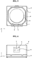
- the cover can 102 may have an opening 101 formed in the top surface thereof, through which the lens (not illustrated), coupled to the bobbin 110A, is exposed to external light.
- the opening 101 may be provided with a window that is made of a light-transmitting material, so as to prevent foreign substances, such as dust, moisture, etc., from being introduced into the camera module.
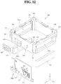
- the housing member 140 may include four flat side surfaces 141.
- the area of each of the side surfaces 141 of the housing member 140 may be the same as or larger than that of each of the driving magnets 130.
- first driving magnet 131 One (hereinafter, referred to as a "first driving magnet 131") of the driving magnets 130 and the other (hereinafter, referred to as a “second driving magnet 132") of the driving magnets 130 may be provided in a corresponding one of the first and second through holes 141a and 141a' for magnets in a mounting, inserting, seating, contacting, coupling, securing, supporting, or disposing manner.
- total two driving magnets 130 are illustrated in the embodiment, the embodiment is not limited to this configuration. Of course, four driving magnets 130 may be provided.
- the third and fourth through holes for magnets may be arranged in a straight line in a symmetrical manner about the center of the housing member 140. That is, the third and fourth driving magnets (not shown) may be arranged based on the center of the housing member 140 or in a straight line in a symmetrical manner based on the center of the housing member 140.
- the first and second driving magnets 131 and 132 may be formed in a rectangular parallelepiped shape having a predetermined width, and may be respectively seated in the first and second through holes 141a and 141a' for magnets such that all or some of the surfaces of the first and second driving magnets 131 and 132 may serve as a portion of the side surface (the outer surface or the inner surface) of the housing member 140.
- the first and second driving magnets 131 and 132 may be disposed on the side surfaces of the housing member 140, may be disposed on or coupled to the inner surface of the above-described yoke, or may be coupled or secured to the inner surface of the yoke without the housing member 140.
- the driving magnets 131 and 132 which face each other, may be mounted parallel to each other.
- the surface of each of the driving magnets 130 and the surface of the first coil 120 of the bobbin 110A, which face each other, may be arranged parallel to each other.
- the embodiment is not limited to this configuration, and as specified by some design, only one of the driving magnets 130 and the first coil 120 of the bobbin 110A may be configured as a flat surface, and the other may be configured as a curved surface.
- both the surface of the first coil 120 of the bobbin 110A and the surface of each of the driving magnets 130, which face each other may be curved surfaces, in which case the surface of the first coil 120 of the bobbin 110A and the surface of each of the driving magnets 130 that face each other may have the same curvature.
- connection portions 153 of the upper elastic member 150A may connect the inner frame 151 and the outer frame 152 so that the inner frame 151 is capable of being elastically deformed within a predetermined range in the first direction relative to the outer frame 152.
- the lower support protrusions 114 and the third through holes 161a may be secured to each other using heat welding, or may also be secured to each other using an adhesive member such as epoxy or the like.
- the lower support protrusions 114 may be provided in a plural number.
- the distance between the lower support protrusions 114 may be set within a suitable range capable of avoiding interference with peripheral components. That is, the lower support protrusions 114 may be equidistantly arranged in a symmetrical manner about the center of the bobbin 110A.
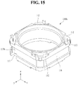
- the upper escape recesses 112 and the lower escape recesses 118 Due to the upper escape recesses 112 and the lower escape recesses 118, when the bobbin 110A is moved in the first direction relative to the housing member 140, spatial interference between the connection portions 153 and 163 and the bobbin 110A may be prevented, and elastic deformation of the connection portions 153 and 163 may be more easily achieved. As illustrated in FIG. 15 or 16 , the upper escape recesses 112 or the lower escape recesses 118 may be located in the corners of the bobbin 110, but alternatively, may be located in the side surfaces of the bobbin depending on the shape and/or position of the connection portions of the elastic members.
- the first coil 120 may be positioned around the bobbin 110A in a mounting, inserting or disposing manner from above or below the bobbin 110A.
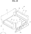
- FIG. 25 is a schematic bottom perspective view of the driving magnet 130, the housing member 140 and the first circuit board 170B according to still another embodiment
- FIG. 26 is a schematic exploded perspective view of the driving magnet 130, the housing member 140, the first circuit board 170B and the displacement sensing part 180 according to still another embodiment
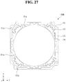
- FIG. 27 is a schematic plan view of the upper elastic member 150B according to another embodiment
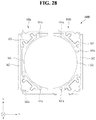
- FIG. 28 is a schematic plan view of the lower elastic member 160B according to another embodiment.
- the lens driving device 3000 according to the 3 rd embodiment is a device that performs an auto-focusing function.
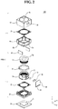
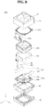
- the lens driving device 3000 may include a cover member 102, a bobbin 110B, a first coil 120, a driving magnet 130, a housing member 140, an upper elastic member 150B, a lower elastic member 160B, a first circuit board (or a printed circuit board) 170B, a sensing unit for detecting the amount of displacement of the bobbin 110B in the optical axis direction (that is, the first direction), and a base 190.
- the sensing unit may include a displacement sensing part (or a position sensor) 180 and a sensing magnet 182B.
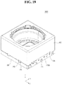
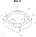
- FIG. 29 is a schematic perspective view of the bobbin 110B according to still another embodiment
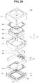
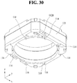
- FIG. 30 is a schematic bottom perspective view of the bobbin 110B and the sensing magnet 182B according to still another embodiment
- FIG. 31 is a schematic exploded perspective view of the bobbin 110B, the first coil 120 and the sensing magnet 182B according to still another embodiment
- FIG. 32 is a partially enlarged perspective view of the state in which the bobbin 110B and the sensing magnet 182B are coupled
- FIG. 33 is a partially enlarged bottom view of the state in which the bobbin 110B and the sensing magnet 182B are coupled
- FIG. 34 is a partially enlarged perspective view for explaining the accommodation recess 117 in the bobbin 110B according to the embodiment
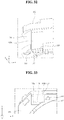
- FIG. 35 is a schematic longitudinal sectional view of the bobbin 110B, the first coil 120 and the sensing magnet 182B according to still another embodiment.
- lens driving devices 200A to 200F according to a 4 th embodiment will be explained with reference to the attached drawings.
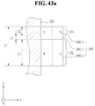
- the bipolar-magnetized magnet 250 may be arranged to face the position sensor 260 in the y-axis direction, which is the magnetization direction perpendicular to the optical axis direction.
- the first point may be a certain point located between the top 251 and the bottom of the first side surface 252, for example, the height at which the middle of the first side surface 252 is positioned.
- the bipolar-magnetized magnet 250C may include first and second sensing magnets 250C-1 and 250C-2, and may further include a non-magnetic partition wall 250C-3.
- the bipolar-magnetized magnet 250D may include first and second sensing magnets 250D-1 and 250D-2, and may further include a non-magnetic partition wall 250D-3.
- a third length L3 of the non-magnetic partition wall 250C-3 or 250C-3 may be five percent or more or fifty percent or less of the overall length LT of the bipolar-magnetized magnet 250C or 250C in the direction parallel to the optical axis direction.
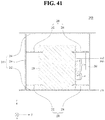
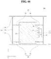
- FIG. 44 shows a sectional view of a lens driving device 200D according to a 4-4 th embodiment.
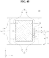
- the first point may be a certain point located between the top and the bottom of the first side surface 252, for example, the height at which the middle of the first side surface 252 is positioned.
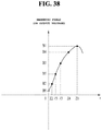
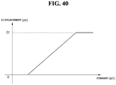
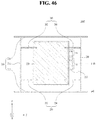
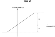
- FIG. 47 is a graph showing the displacement of the movable unit 220 depending on electric current supplied to the first coil in the lens driving devices 200E and 200F depicted in FIGS. 45 and 46 , in which the horizontal axis represents current supplied to the first coil, and the vertical axis represents the displacement. Further, the right side of the horizontal axis from the vertical axis may represent forward current, current in the forward direction, or +current, and the left side of the horizontal axis from the vertical axis may represent reverse current, current in the reverse direction, or -current.
- the difference between the second point and the first point may be calculated using the following Equation 1.
- H2 may be a height of the second point
- HI may be a height of the first point
- ⁇ D may be a value calculated by subtracting the downward-displacement range D2 from the upward-displacement range D3 of the movable unit 220
- D may be the displacement range (D2+D3) of the movable unit 220.
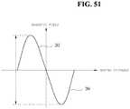
- the third length L3 of the above-described non-magnetic partition wall 250A-1 or 250C-1 is decreased to fifty percent or less of the overall length LT of the bipolar-magnetized magnet 250, as illustrated in FIG. 51 , the mutual zone (MZ) may be almost eliminated.
- the intensity of a magnetic field 282 having a first polarity and the intensity of a magnetic field 284 having a second polarity may be changed substantially linearly.
- the embodiment may have relatively higher resolution than the configuration in which the position sensor 260 senses a magnetic field that has only one of the first and second polarities and has intensity that is changed linearly.
- the above-described camera module according to the 1 st to 4 th embodiments may further include the camera module control unit (or the control unit) (not illustrated).
- the camera module control unit may compare a first displacement value, which is calculated based on a code value or an electric current change value, sensed by the displacement sensing part 82 and 180 or the position sensor 260, with a focal distance of the lens depending on the distance between the subject and the lens.
- an additional terminal member for electrical connection with the second circuit board may be mounted to the base 190, and such a terminal member may be integrally formed with the base 190 using a surface electrode.
- a lens driving device and a camera module including the same are applicable to mobile appliances such as mobile phones (or, portable phone) and smart phones, and are also applicable to various multimedia fields including notebook type personal computers, tablet PCs, camera phones, PDAs, smart phones and toys, and to image input equipment including monitoring cameras and information terminals for video tape recorders.
Claims (15)
- Un dispositif d'entraînement de lentille, comprenant :un élément (60) formant couvercle et un élément (40) formant boîtier, comprenant chacun :une première surface latérale ;une deuxième surface latérale disposée à l'opposé de la première surface latérale ;une troisième surface latérale située entre la première surface latérale et la deuxième surface latérale ; etune quatrième surface latérale disposée à l'opposé de la troisième surface latérale ;l'élément (40) formant boîtier étant disposé dans l'élément (60) formant couvercle ;une bobine (30) disposée dans l'élément (40) formant boîtier ;une unité (31) formant bobinage disposée autour d'une surface périphérique extérieure de la bobine (30) ;des premier et deuxième aimants d'entraînement (41) situés en regard de l'unité (31) formant bobinage, les premier et deuxième aimants d'entraînement (41) étant fixés à la première surface latérale et à la deuxième surface latérale de l'élément (40) formant boîtier par un adhésif, respectivement ;un élément élastique supérieur (51) relié à une surface supérieure de la bobine (30) ;un élément élastique inférieur (52) relié à une surface inférieure de la bobine (30) ;un aimant de détection (70) ;un capteur de position (82) ; etune première carte à circuit imprimé (170A) reliée au capteur de position (82) ;l'élément (40) formant boîtier ayant des surfaces latérales en forme de colonne, les premier et deuxième aimants d'entraînement (41) disposés sur la forme de colonne étant placés face à la bobine (30) ; l'aimant de détection (60) étant relié à la bobine (30), l'aimant de détection (70) étant disposé sur une paroi latérale, parmi les parois latérales de la bobine (30), positionnée vers la troisième surface latérale de l'élément (60) formant couvercle, etle capteur de position (82) étant en regard de l'aimant de détection (70) et étant configuré pour détecter le mouvement de la bobine (30) dans une première direction le long d'une direction d'axe optique d'une lentille (32a), ou parallèlement à cette direction,l'aimant de détection (70) ne chevauchant pas l'unité (31) formant bobinage dans une troisième direction perpendiculaire à la première direction et perpendiculaire à la quatrième surface latérale,l'aimant de détection (70) ne chevauchant pas la troisième surface latérale de l'élément (60) formant couvercle dans la troisième direction.
- Le dispositif d'entraînement de lentille selon la revendication 1, dans lequel la bobine (30) comprend un évidement (117) sur la paroi latérale de la bobine (30) qui est positionnée vers la troisième surface latérale de l'élément (60) formant couvercle, l'aimant de détection (70) étant disposé dans l'évidement (117) de la bobine (30).
- Le dispositif d'entraînement de lentille selon la revendication 1 ou la revendication 2, dans lequel l'aimant de détection (70) est disposé au-dessus de l'unité (31) formant bobinage dans la première direction, et
dans lequel l'unité (31) formant bobinage est enroulée autour de la surface périphérique extérieure de la bobine (30). - Le dispositif d'entraînement de lentille selon l'une quelconque des revendications 1 à 3, dans lequel l'élément élastique inférieur (52) comprend un premier élément élastique inférieur (160a) et un deuxième élément élastique inférieur (160b),
dans lequel les premier et deuxième éléments élastiques inférieurs (160a, 160b) sont connectés à deux extrémités de l'unité (31) formant bobinage, respectivement, et
dans lequel l'élément élastique inférieur (52) est connecté électriquement à la première carte à circuit imprimé (170A). - Le dispositif d'entraînement de lentille selon l'une quelconque des revendications 1 à 4, dans lequel au moins une partie de l'aimant de détection (70) est disposée plus à l'intérieur vers l'axe optique que l'unité (31) formant bobinage, au niveau de la surface périphérique extérieure de la bobine (30).
- Le dispositif d'entraînement de lentille selon l'une quelconque des revendications 1 à 5, dans lequel l'aimant de détection comprend :une première surface latérale étant en regard du capteur de position (82) et ayant une première polarité ; etune deuxième surface latérale étant en regard du capteur de position (82), disposée de manière à être espacée de la première surface latérale, ou en contact avec celle-ci, dans la première direction, et ayant une deuxième polarité opposée à la première polarité, etune longueur de la première surface latérale dans la première direction étant égale ou supérieure à une longueur de la deuxième surface latérale dans la première direction.
- Le dispositif d'entraînement de lentille selon l'une quelconque des revendications 1 à 6, dans lequel la troisième surface latérale de l'élément (60) formant couvercle présente une fenêtre (90) en une position correspondant à l'aimant de détection (70).
- Le dispositif d'entraînement de lentille selon l'une quelconque des revendications 1 à 7, comprenant en outre :une base (20) reliée à l'élément (40) formant boîtier,la première carte à circuit imprimé (170A) comprenant une pluralité de bornes, etla première carte à circuit imprimé (170A) étant disposée en une position correspondant à une paroi latérale d'au moins l'un parmi : la bobine (30), de l'élément (40) formant boîtier ou de l'élément (60) formant couvercle dans la troisième direction.
- Le dispositif d'entraînement de lentille selon la revendication 2, dans lequel la bobine (30) comprend en outre un évidement supplémentaire disposé à l'opposé de l'évidement (117) ; et
dans lequel un élément d'équilibrage de poids est disposé dans l'évidement supplémentaire et ayant le même poids que l'aimant de détection (70). - Le dispositif d'entraînement de lentille selon la revendication 1, dans lequel l'aimant de détection (70) comprend un aimant magnétisé bipolaire (250), et
dans lequel l'aimant magnétisé bipolaire comprend des premier et deuxième aimants de détection disposés de manière à être espacés l'un de l'autre et une paroi de séparation non magnétique disposée entre les premier et deuxième aimants de détection, et les premier et deuxième aimants de détection sont disposés de manière à être espacés l'un de l'autre dans la première direction. - Le dispositif d'entraînement de lentille selon l'une quelconque des revendications 1 à 10, dans lequel les premier et deuxième aimants d'entraînement (41) sont collés et fixés aux première et deuxième surfaces latérales de l'élément (40) formant boîtier, et
dans lequel l'aimant de détection (70) est plus petit que chacun des premier et deuxième aimants d'entraînement (41). - Le dispositif d'entraînement de lentille selon l'une quelconque des revendications 1 à 11, comprenant en outre une culasse intérieure (61) formée d'un seul tenant avec l'élément (60) formant couvercle,
la culasse intérieure (61) étant disposée sur une position correspondant à un coin de l'élément (40) formant boîtier, et
la culasse intérieure (61) comprenant :
une partie courbée vers le bas à partir de l'élément (60) formant couvercle et formant une portion en col de bouteille. - Le dispositif d'entraînement de lentille selon l'une quelconque des revendications 1 à 12, dans lequel les deux extrémités de l'unité (31) formant bobinage sont disposées sur des côtés opposés de la bobine (30).
- Le dispositif d'entraînement de lentille selon l'une quelconque des revendications 1 à 13, dans lequel la bobine (30) comprend une pluralité de saillies de support inférieures faisant saillie de sa surface inférieure,
dans lequel l'élément élastique inférieur (52) comprend une pluralité de trous traversants formés dans des positions correspondant aux saillies de support inférieures, et
dans lequel les saillies de support inférieures fixées aux trous traversants sont disposées de manière symétrique autour d'un centre de la bobine (30). - Un module formant appareil de prise de vues, comprenant :un capteur d'images (11) ;une deuxième carte à circuit imprimé sur laquelle le capteur d'images (11) est monté ; etle dispositif d'entraînement de lentille selon l'une des revendications 1 à 14.
Priority Applications (1)
| Application Number | Priority Date | Filing Date | Title |
|---|---|---|---|
| EP20168004.8A EP3706298A1 (fr) | 2014-03-05 | 2015-02-25 | Dispositif de commande de lentille et module de caméra le comprenant |
Applications Claiming Priority (4)
| Application Number | Priority Date | Filing Date | Title |
|---|---|---|---|
| KR1020140026062A KR102201258B1 (ko) | 2014-03-05 | 2014-03-05 | 렌즈 구동장치 및 이를 구비한 카메라 모듈 |
| KR1020140055364A KR102230966B1 (ko) | 2014-05-09 | 2014-05-09 | 렌즈 구동장치 |
| KR1020140108487A KR102319554B1 (ko) | 2014-08-20 | 2014-08-20 | 렌즈 구동 장치 및 이를 포함하는 카메라 모듈 |
| PCT/KR2015/001825 WO2015133759A1 (fr) | 2014-03-05 | 2015-02-25 | Dispositif d'entraînement de lentille, et module d'appareil de prise de vues comportant ce dispositif |
Related Child Applications (2)
| Application Number | Title | Priority Date | Filing Date |
|---|---|---|---|
| EP20168004.8A Division-Into EP3706298A1 (fr) | 2014-03-05 | 2015-02-25 | Dispositif de commande de lentille et module de caméra le comprenant |
| EP20168004.8A Division EP3706298A1 (fr) | 2014-03-05 | 2015-02-25 | Dispositif de commande de lentille et module de caméra le comprenant |
Publications (3)
| Publication Number | Publication Date |
|---|---|
| EP3115819A1 EP3115819A1 (fr) | 2017-01-11 |
| EP3115819A4 EP3115819A4 (fr) | 2017-03-01 |
| EP3115819B1 true EP3115819B1 (fr) | 2020-05-13 |
Family
ID=54055514
Family Applications (2)
| Application Number | Title | Priority Date | Filing Date |
|---|---|---|---|
| EP20168004.8A Pending EP3706298A1 (fr) | 2014-03-05 | 2015-02-25 | Dispositif de commande de lentille et module de caméra le comprenant |
| EP15758167.9A Active EP3115819B1 (fr) | 2014-03-05 | 2015-02-25 | Dispositif d'entraînement de lentille, et module d'appareil de prise de vues comportant ce dispositif |
Family Applications Before (1)
| Application Number | Title | Priority Date | Filing Date |
|---|---|---|---|
| EP20168004.8A Pending EP3706298A1 (fr) | 2014-03-05 | 2015-02-25 | Dispositif de commande de lentille et module de caméra le comprenant |
Country Status (5)
| Country | Link |
|---|---|
| US (5) | USRE48667E1 (fr) |
| EP (2) | EP3706298A1 (fr) |
| JP (4) | JP6615770B2 (fr) |
| CN (3) | CN106461908B (fr) |
| WO (1) | WO2015133759A1 (fr) |
Families Citing this family (67)
| Publication number | Priority date | Publication date | Assignee | Title |
|---|---|---|---|---|
| PT3061509T (pt) | 2011-08-10 | 2019-09-10 | New Health Sciences Inc | Depleção de leucócito, oxigénio e/ou co2 integrada e dispositivo de filtro de separação de plasma |
| KR102117107B1 (ko) * | 2013-07-12 | 2020-05-29 | 엘지이노텍 주식회사 | 카메라 모듈 |
| KR102232029B1 (ko) | 2014-03-17 | 2021-03-26 | 엘지이노텍 주식회사 | 렌즈 구동장치 및 이를 구비한 카메라 모듈 |
| US9791713B2 (en) | 2014-07-24 | 2017-10-17 | Lg Innotek Co., Ltd. | Lens moving apparatus |
| CN204068636U (zh) * | 2014-07-28 | 2014-12-31 | 台湾东电化股份有限公司 | 电磁驱动模块及应用该电磁驱动模块的镜头装置 |
| EP3040753B1 (fr) * | 2014-12-30 | 2024-02-21 | LG Innotek Co., Ltd. | Appareil de déplacement de lentille |
| CN112363295B (zh) | 2015-02-04 | 2022-11-22 | Lg伊诺特有限公司 | 透镜驱动装置及包括该透镜驱动装置的摄像装置模块 |
| CA2978940C (fr) | 2015-03-10 | 2023-10-17 | New Health Sciences, Inc. | Kits jetables de reduction des niveaux d'oxygene, dispositifs et procedes d'utilisation de ceux-ci |
| KR102311663B1 (ko) | 2015-03-18 | 2021-10-13 | 엘지이노텍 주식회사 | 렌즈 구동 장치, 및 이를 포함하는 카메라 모듈 |
| EP3086154B1 (fr) * | 2015-04-24 | 2022-08-31 | LG Innotek Co., Ltd. | Appareil de déplacement de lentille, module de caméra et terminal portable équipé de celui-ci |
| EP3355113B1 (fr) | 2015-09-24 | 2020-08-12 | LG Innotek Co., Ltd. | Module d'appareil photo |
| JP2017067908A (ja) * | 2015-09-29 | 2017-04-06 | アルプス電気株式会社 | レンズ駆動装置 |
| KR20170116749A (ko) | 2016-04-12 | 2017-10-20 | 엘지이노텍 주식회사 | 렌즈 구동 장치, 및 이를 포함하는 카메라 모듈 및 광학 기기 |
| JP6679143B2 (ja) * | 2016-05-16 | 2020-04-15 | アルプスアルパイン株式会社 | レンズ駆動装置 |
| TWI650587B (zh) | 2016-08-04 | 2019-02-11 | 台灣東電化股份有限公司 | 鏡頭驅動裝置 |
| WO2018056770A1 (fr) * | 2016-09-26 | 2018-03-29 | 엘지이노텍 주식회사 | Barillet de lentille de caméra, module de caméra et dispositif optique |
| KR102638687B1 (ko) * | 2016-10-25 | 2024-02-21 | 엘지이노텍 주식회사 | 카메라 모듈 및 광학 장치 |
| US11294172B2 (en) * | 2017-01-03 | 2022-04-05 | Tdk Taiwan Corp. | Optical element driving mechanism |
| JP6852432B2 (ja) * | 2017-02-09 | 2021-03-31 | Tdk株式会社 | レンズ駆動装置及び電磁駆動ユニット |
| JP6852433B2 (ja) * | 2017-02-09 | 2021-03-31 | Tdk株式会社 | レンズ駆動装置及び電磁駆動ユニット |
| KR102250447B1 (ko) * | 2017-03-15 | 2021-05-11 | 삼성전자주식회사 | 전기물을 포함하는 전자 장치 |
| TWI650582B (zh) * | 2017-03-30 | 2019-02-11 | 台灣東電化股份有限公司 | 鏡頭驅動模組 |
| KR102071925B1 (ko) * | 2017-03-31 | 2020-01-31 | 삼성전기주식회사 | 카메라 모듈 |
| KR102361051B1 (ko) * | 2017-04-21 | 2022-02-10 | 엘지이노텍 주식회사 | 렌즈 구동 장치, 광출력 모듈 및 라이다 |
| KR101886361B1 (ko) * | 2017-05-26 | 2018-08-09 | 주식회사 동운아나텍 | 액츄에이터 이동감지 소자의 슬레이브 식별정보 설정방법 |
| KR102402617B1 (ko) * | 2017-05-26 | 2022-05-27 | 엘지이노텍 주식회사 | 렌즈 구동 장치 및 이를 포함하는 카메라 모듈 및 광학 기기 |
| CN107045175B (zh) * | 2017-06-15 | 2023-08-08 | 惠州萨至德光电科技有限公司 | 一种闭环透镜驱动装置 |
| CN107070169B (zh) * | 2017-06-21 | 2019-07-16 | 新沂经济开发区建设发展有限公司 | 一种基于红外测距的音圈马达 |
| KR102029953B1 (ko) * | 2017-09-18 | 2019-10-08 | (주)아이엠 | 카메라 모듈 |
| KR102435025B1 (ko) * | 2017-09-25 | 2022-08-23 | 삼성전자주식회사 | 다른 자기장의 방향을 갖는 복수의 구동부를 포함하는 카메라 모듈 |
| TWI663462B (zh) | 2017-10-18 | 2019-06-21 | 大陽科技股份有限公司 | 鏡頭驅動裝置、攝影模組與電子裝置 |
| USD902981S1 (en) * | 2018-01-12 | 2020-11-24 | Tdk Taiwan Corp. | Driving unit for a camera lens |
| KR102471186B1 (ko) * | 2018-01-29 | 2022-11-25 | 엘지이노텍 주식회사 | 카메라 모듈 |
| KR102527790B1 (ko) * | 2018-01-30 | 2023-04-28 | 엘지이노텍 주식회사 | 카메라 모듈 |
| JP7021434B2 (ja) * | 2018-02-05 | 2022-02-17 | ミツミ電機株式会社 | レンズ駆動装置、カメラモジュール、及びカメラ搭載装置 |
| JP7186010B2 (ja) * | 2018-04-16 | 2022-12-08 | 日本電産サンキョー株式会社 | アクチュエータの製造方法 |
| CN209858825U (zh) * | 2018-05-11 | 2019-12-27 | 台湾东电化股份有限公司 | 光学元件驱动机构 |
| US11314037B2 (en) * | 2018-05-11 | 2022-04-26 | Tdk Taiwan Corp. | Optical member driving mechanism |
| US11796348B2 (en) | 2018-05-11 | 2023-10-24 | Tdk Taiwan Corp. | Optical driving mechanism |
| CN108627947B (zh) * | 2018-06-26 | 2024-01-30 | 惠州萨至德光电科技有限公司 | 透镜驱动装置 |
| CN110750024B (zh) * | 2018-07-24 | 2021-09-07 | 铭异科技股份有限公司 | 单轴光学致动器的悬吊系统 |
| US10670948B2 (en) * | 2018-07-26 | 2020-06-02 | Min Aik Technology Co., Ltd. | Suspension system of biaxial optical actuator |
| EP3879327A4 (fr) * | 2018-11-06 | 2022-08-17 | LG Innotek Co., Ltd. | Dispositif d'entraînement de lentille, ainsi que module de caméra et dispositif optique le comprenant |
| KR102645131B1 (ko) * | 2018-12-17 | 2024-03-07 | 엘지이노텍 주식회사 | 액체 렌즈를 포함하는 카메라 모듈 및 그의 제어 방법 |
| EP4130836A3 (fr) * | 2018-12-27 | 2023-05-24 | Tdk Taiwan Corp. | Système optique |
| US11586006B2 (en) * | 2018-12-27 | 2023-02-21 | Tdk Taiwan Corp. | Reflective element driving module |
| US11513308B2 (en) * | 2019-04-01 | 2022-11-29 | Samsung Electro-Mechanics Co., Ltd. | Camera module |
| CN110049192B (zh) * | 2019-04-22 | 2021-08-13 | 维沃移动通信有限公司 | 一种检测方法及移动终端 |
| CN114258505B (zh) * | 2019-08-30 | 2023-09-29 | 华为技术有限公司 | 光学装置、成像装置及电子设备 |
| TWI718900B (zh) | 2019-09-19 | 2021-02-11 | 大陽科技股份有限公司 | 鏡頭模組與電子裝置 |
| TW202129361A (zh) * | 2019-10-09 | 2021-08-01 | 台灣東電化股份有限公司 | 光學元件驅動機構 |
| TW202115476A (zh) | 2019-10-09 | 2021-04-16 | 台灣東電化股份有限公司 | 光學系統 |
| KR20210073906A (ko) * | 2019-12-11 | 2021-06-21 | 삼성전자주식회사 | 카메라 구조체 및 카메라 구조체를 포함하는 전자 장치 |
| JP7393196B2 (ja) | 2019-12-17 | 2023-12-06 | アルプスアルパイン株式会社 | レンズ駆動装置、カメラモジュール、及びレンズ駆動装置の製造方法 |
| JP7242593B2 (ja) * | 2020-02-12 | 2023-03-20 | 株式会社三共 | 遊技機 |
| JP7242592B2 (ja) * | 2020-02-12 | 2023-03-20 | 株式会社三共 | 遊技機 |
| JP7242591B2 (ja) * | 2020-02-12 | 2023-03-20 | 株式会社三共 | 遊技機 |
| CN113359311B (zh) * | 2020-03-06 | 2024-01-12 | 台湾东电化股份有限公司 | 光学元件驱动机构、光学系统、以及组装光学系统的方法 |
| CN111405157B (zh) * | 2020-03-24 | 2022-03-29 | Oppo广东移动通信有限公司 | 一种摄像模组及电子设备 |
| KR102356804B1 (ko) * | 2020-04-23 | 2022-01-28 | 삼성전기주식회사 | 카메라 모듈 |
| CN111556237A (zh) * | 2020-05-22 | 2020-08-18 | 上海创功通讯技术有限公司 | 电子设备以及电子设备调整方法 |
| EP4228240A4 (fr) * | 2020-10-05 | 2024-03-27 | Lg Innotek Co Ltd | Dispositif de caméra et instrument optique |
| KR20220055916A (ko) * | 2020-10-27 | 2022-05-04 | 엘지이노텍 주식회사 | 거리 측정 카메라 장치 |
| CN112492165B (zh) * | 2020-11-30 | 2022-03-15 | 维沃移动通信有限公司 | 摄像头模组、成像方法和电子设备 |
| CN112702484B (zh) * | 2020-12-23 | 2022-02-08 | 维沃移动通信有限公司 | 摄像头模组及电子设备 |
| TWI770806B (zh) * | 2021-02-04 | 2022-07-11 | 台灣創意分析股份有限公司 | 音圈馬達的基座 |
| CN217546538U (zh) * | 2022-02-15 | 2022-10-04 | 诚瑞光学(南宁)有限公司 | 摄像模组 |
Citations (2)
| Publication number | Priority date | Publication date | Assignee | Title |
|---|---|---|---|---|
| US20070097530A1 (en) * | 2005-11-03 | 2007-05-03 | Industrial Technology Research Institute | Optical devices |
| JP2007121850A (ja) * | 2005-10-31 | 2007-05-17 | Konica Minolta Opto Inc | 撮像装置 |
Family Cites Families (105)
| Publication number | Priority date | Publication date | Assignee | Title |
|---|---|---|---|---|
| US2152040A (en) | 1935-10-14 | 1939-03-28 | Bendix Prod Corp | Brake |
| US2598925A (en) | 1946-06-25 | 1952-06-03 | Rca Corp | Method and means for generating electrical energy from a radioactive source |
| JPS61211846A (ja) | 1985-03-18 | 1986-09-19 | Pioneer Electronic Corp | 光学式情報記録再生装置におけるピツクアツプ装置 |
| US5289318A (en) | 1990-07-31 | 1994-02-22 | Canon Kabushiki Kaisha | Optical apparatus provided with a driving unit for moving a lens |
| JPH04119306A (ja) | 1990-09-10 | 1992-04-20 | Sony Corp | カメラ用レンズ鏡筒 |
| KR100282055B1 (ko) | 1993-03-30 | 2001-02-15 | 이데이 노부유끼 | 전자구동장치 및 전자구동장치를 이용한 포커스 제어장치 |
| JP3387173B2 (ja) * | 1993-10-27 | 2003-03-17 | ソニー株式会社 | 電磁駆動装置 |
| JPH08234677A (ja) | 1994-10-06 | 1996-09-13 | Ncr Internatl Inc | 電子ディスプレイモジュール |
| TW421763B (en) * | 1996-05-31 | 2001-02-11 | Mustek Systems Inc | Holographic optical scanner |
| JP3750251B2 (ja) | 1997-02-10 | 2006-03-01 | 松下電器産業株式会社 | リニアアクチュエータとこれを用いた光学機器 |
| GB2323716B (en) * | 1997-02-10 | 2001-02-07 | Matsushita Electric Ind Co Ltd | Linear actuator and optical equipment using the same |
| JPH11289743A (ja) * | 1998-04-01 | 1999-10-19 | Matsushita Electric Ind Co Ltd | リニアアクチュエータとこれを用いたレンズ駆動装置及びレンズ鏡筒 |
| AT410382B (de) | 2000-06-28 | 2003-04-25 | Fronius Schweissmasch Prod | Elektronische schaltung für ein energieversorgungsgerät, insbesondere für ein ladegerät für akkumulatoren |
| JP4094497B2 (ja) * | 2003-06-25 | 2008-06-04 | 東京コスモス電機株式会社 | 非接触型位置センサ |
| KR100522232B1 (ko) * | 2003-12-24 | 2005-10-17 | 엘지전자 주식회사 | 슬림형 광 픽업 액츄에이터 |
| US7053514B2 (en) | 2004-02-03 | 2006-05-30 | Sony Corporation | Image apparatus and drive motor |
| US20070177279A1 (en) | 2004-02-27 | 2007-08-02 | Ct Electronics Co., Ltd. | Mini camera device for telecommunication devices |
| JP4923535B2 (ja) | 2005-01-27 | 2012-04-25 | コニカミノルタオプト株式会社 | レンズユニットおよび撮像ユニット |
| KR100674833B1 (ko) * | 2005-02-16 | 2007-01-26 | 삼성전기주식회사 | 카메라 모듈 |
| JP4525430B2 (ja) * | 2005-04-06 | 2010-08-18 | ソニー株式会社 | 位置検出装置 |
| JP4455407B2 (ja) | 2005-05-31 | 2010-04-21 | キヤノン株式会社 | 駆動装置 |
| CN101614940B (zh) * | 2005-06-15 | 2013-01-23 | 宾得理光映像有限公司 | 台架设备和利用该台架设备的照相机图像移动校正设备 |
| TWI302629B (en) * | 2005-08-25 | 2008-11-01 | Powergate Optical Inc | A vcm auto-focusing device having position feedback and an auto-focusing method |
| JP2007121734A (ja) * | 2005-10-28 | 2007-05-17 | Sony Corp | レンズ鏡筒および撮像装置 |
| US20070097532A1 (en) | 2005-11-03 | 2007-05-03 | Industrial Technology Research Institute | Optical devices |
| JP2007156352A (ja) * | 2005-12-08 | 2007-06-21 | Sony Corp | レンズ装置及び撮像装置 |
| CN101055342A (zh) | 2006-04-12 | 2007-10-17 | 鸿富锦精密工业(深圳)有限公司 | 自动对焦镜头模组 |
| JP2008058391A (ja) * | 2006-08-29 | 2008-03-13 | Samsung Yokohama Research Institute Co Ltd | 撮像レンズユニットおよび撮像装置 |
| WO2008072892A1 (fr) * | 2006-12-13 | 2008-06-19 | Lg Innotek Co., Ltd | Appareil de commande d'objectif |
| KR101506254B1 (ko) * | 2007-04-02 | 2015-03-26 | 삼성전자 주식회사 | 무선 단말 장치 및 시스템 보호 방법 |
| CN101038361A (zh) * | 2007-04-27 | 2007-09-19 | 金仁召 | 透镜驱动装置 |
| KR100880672B1 (ko) | 2007-07-18 | 2009-02-02 | 자화전자 주식회사 | 자동초점 기능을 구비한 카메라 시스템 및 그 제어방법 |
| KR100941436B1 (ko) * | 2008-04-16 | 2010-02-11 | 엘지이노텍 주식회사 | 렌즈 구동용 모터 |
| WO2009133691A1 (fr) * | 2008-04-30 | 2009-11-05 | 日本電産サンキョー株式会社 | Unité optique avec fonction de correction de vibrations |
| WO2009133690A1 (fr) | 2008-04-30 | 2009-11-05 | 日本電産サンキョー株式会社 | Unité optique ayant une fonction de correction de déviation, et dispositif optique de photographie |
| JP2010008446A (ja) * | 2008-06-24 | 2010-01-14 | Shicoh Engineering Co Ltd | レンズ駆動装置、カメラ及びカメラ付き携帯電話 |
| CN201233466Y (zh) * | 2008-07-31 | 2009-05-06 | 宁波金诚泰电子有限公司 | 一种照相机透镜驱动机构用簧片 |
| JP2010096803A (ja) * | 2008-10-14 | 2010-04-30 | Nidec Sankyo Corp | 撮影用光学装置 |
| JP5465500B2 (ja) * | 2008-10-20 | 2014-04-09 | 日本電産サンキョー株式会社 | 振れ補正機能付き光学ユニット、および振れ補正機能付き光学ユニットにおける振れ補正制御方法 |
| KR101643771B1 (ko) * | 2008-10-30 | 2016-07-29 | 삼성전자주식회사 | 카메라 렌즈 어셈블리 |
| JP2010112978A (ja) * | 2008-11-04 | 2010-05-20 | Nikon Corp | レンズ駆動装置、レンズ位置検出装置、及びそれらを用いた撮像装置 |
| JP2010160435A (ja) * | 2009-01-09 | 2010-07-22 | Sanyo Electric Co Ltd | レンズ駆動装置及びこのレンズ駆動装置を搭載したカメラモジュール |
| JP5373432B2 (ja) * | 2009-02-27 | 2013-12-18 | 日本電産コパル株式会社 | 光学装置 |
| TWI426683B (zh) | 2009-03-17 | 2014-02-11 | Vasstek Int Corp | A voice coil motor with a flat coil |
| KR101022859B1 (ko) * | 2009-07-27 | 2011-03-16 | 삼성전기주식회사 | 홀 오프셋이 제거된 자동초점 모듈 및 그 제어 장치 |
| JP5846346B2 (ja) * | 2009-08-21 | 2016-01-20 | ミツミ電機株式会社 | カメラの手振れ補正装置 |
| WO2011027685A1 (fr) * | 2009-09-02 | 2011-03-10 | 三洋電機株式会社 | Dispositif de commande de lentille, et module de caméra et téléphone portable qui ont le dispositif de commande de lentille monté sur ceux-ci |
| JP5449988B2 (ja) * | 2009-11-10 | 2014-03-19 | 日本電産サンキョー株式会社 | レンズ駆動装置 |
| JP5079049B2 (ja) | 2009-11-17 | 2012-11-21 | 台湾東電化股▲ふん▼有限公司 | レンズ駆動装置 |
| US8254046B2 (en) * | 2009-11-19 | 2012-08-28 | Mcnex Co., Ltd. | Camera module with autofocus function |
| JPWO2011105470A1 (ja) * | 2010-02-26 | 2013-06-20 | 三洋電機株式会社 | レンズ駆動装置およびカメラモジュール |
| JP5556429B2 (ja) * | 2010-06-24 | 2014-07-23 | ソニー株式会社 | 像ぶれ補正装置及び撮像装置 |
| US8638510B2 (en) | 2010-07-06 | 2014-01-28 | Lg Innotek Co., Ltd. | Voice coil motor, coil block for voice coil motor, method of manufacturing the coil block, and voice coil motor having the coil block |
| JP5617408B2 (ja) | 2010-07-20 | 2014-11-05 | パナソニック株式会社 | 駆動装置及び撮像装置 |
| TWI427350B (zh) * | 2010-07-27 | 2014-02-21 | Tdk Taiwan Corp | 電磁式鏡頭驅動裝置 |
| CN102870043B (zh) | 2010-07-29 | 2015-07-08 | 日本电产科宝株式会社 | 倾斜修正单元 |
| KR101705522B1 (ko) | 2010-07-30 | 2017-02-22 | 엘지이노텍 주식회사 | 보이스 코일 모터 |
| KR101721263B1 (ko) | 2010-09-08 | 2017-04-10 | 엘지이노텍 주식회사 | 보이스 코일 모터 |
| JP2012068339A (ja) | 2010-09-22 | 2012-04-05 | Ps-Tokki Inc | 位置検出センサ及びレンズ駆動装置 |
| TWI491161B (zh) * | 2010-12-09 | 2015-07-01 | Hon Hai Prec Ind Co Ltd | 致動器及具有該致動器之相機模組 |
| KR101875552B1 (ko) | 2011-01-03 | 2018-07-09 | 엘지이노텍 주식회사 | 복합 기능 보이스 코일 모터, 이를 갖는 카메라 모듈 및 복합 기능 보이스 코일 모터의 구동 방법 |
| US9035502B2 (en) | 2011-02-07 | 2015-05-19 | Lg Innotek Co., Ltd. | Multifunctional voice coil motor |
| KR101804575B1 (ko) | 2011-02-07 | 2017-12-04 | 엘지이노텍 주식회사 | 복합 기능 보이스 코일 모터 |
| KR101197077B1 (ko) | 2011-02-24 | 2012-11-07 | 주식회사 하이소닉 | 카메라용 자동 초점 및 손떨림 보정 장치 그리고 이러한 장치가 장착된 소형 카메라 |
| JP2012177753A (ja) | 2011-02-25 | 2012-09-13 | Shicoh Engineering Co Ltd | レンズ駆動装置、オートフォーカスカメラ及びカメラ付きモバイル端末装置 |
| US8670195B2 (en) | 2011-06-09 | 2014-03-11 | Panasonic Corporation | Lens actuator |
| JP2013127492A (ja) | 2011-06-09 | 2013-06-27 | Panasonic Corp | レンズアクチュエータ |
| JP2013003246A (ja) * | 2011-06-14 | 2013-01-07 | Alps Electric Co Ltd | レンズ駆動装置 |
| JP2013033179A (ja) * | 2011-07-29 | 2013-02-14 | Shicoh Engineering Co Ltd | レンズ駆動装置、オートフォーカスカメラ及びカメラ付き携帯端末装置 |
| KR101853346B1 (ko) | 2011-08-04 | 2018-05-02 | 마이크로엑츄에이터(주) | 초소형 카메라모듈의 자동초점조절장치 |
| JP5512783B2 (ja) | 2011-08-12 | 2014-06-04 | シャープ株式会社 | カメラモジュール |
| US9151963B2 (en) | 2011-08-24 | 2015-10-06 | Mitsumi Electric Co., Ltd. | Lens holder driving device including damper compound suppressing undesired resonance |
| JP5821120B2 (ja) | 2011-10-07 | 2015-11-24 | 株式会社タムロン | 防振アクチュエータ、及びそれを備えたレンズユニット、カメラ |
| US8817116B2 (en) * | 2011-10-28 | 2014-08-26 | Lg Innotek Co., Ltd. | Camera module |
| WO2013062309A1 (fr) * | 2011-10-28 | 2013-05-02 | Lg Innotek Co., Ltd. | Module d'appareil photographique |
| KR101931183B1 (ko) | 2011-12-23 | 2018-12-21 | 엘지이노텍 주식회사 | 보이스 코일 모터 |
| KR102001621B1 (ko) | 2011-11-30 | 2019-07-18 | 엘지이노텍 주식회사 | 보이스 코일 모터 및 이의 구동 방법 |
| CN103166415B (zh) * | 2011-12-08 | 2017-03-01 | 日本电产株式会社 | 马达以及包括该马达的数字光处理式投影机 |
| CN103166417A (zh) * | 2011-12-09 | 2013-06-19 | 鸿富锦精密工业(深圳)有限公司 | 音圈马达及使用该音圈马达的相机模组 |
| KR101285412B1 (ko) | 2011-12-21 | 2013-07-19 | 자화전자(주) | 카메라 렌즈 어셈블리의 구동 장치 |
| KR101300353B1 (ko) | 2011-12-22 | 2013-08-28 | 삼성전기주식회사 | 손떨림 보정장치 |
| JP5905275B2 (ja) | 2012-01-30 | 2016-04-20 | 日本電産コパル株式会社 | レンズ駆動装置 |
| JP2013190705A (ja) | 2012-03-15 | 2013-09-26 | Ps-Tokki Inc | 絞り羽根駆動装置 |
| KR101991860B1 (ko) | 2012-05-07 | 2019-06-24 | 삼성전자주식회사 | 카메라 모듈에서 액추에이터 제어 방법 및 장치 |
| CN107678121B (zh) * | 2012-05-09 | 2021-08-03 | Lg伊诺特有限公司 | 音圈电机 |
| JP2014021397A (ja) | 2012-07-20 | 2014-02-03 | Iwatani Internatl Corp | レンズ駆動装置 |
| KR101314178B1 (ko) * | 2012-08-06 | 2013-10-02 | 쓰리에이치비젼주식회사 | 카메라 렌즈 모듈 |
| JP2014035367A (ja) | 2012-08-07 | 2014-02-24 | Iwatani Internatl Corp | レンズ駆動装置 |
| JP3179634U (ja) * | 2012-08-30 | 2012-11-08 | アルプス電気株式会社 | レンズ駆動装置 |
| KR101343197B1 (ko) * | 2012-09-07 | 2013-12-19 | 삼성전기주식회사 | 카메라 모듈 |
| KR102054493B1 (ko) | 2012-11-07 | 2020-01-22 | 엘지이노텍 주식회사 | 보이스 코일 모터 |
| KR102079758B1 (ko) * | 2012-12-14 | 2020-02-20 | 엘지이노텍 주식회사 | 보이스 코일 모터 |
| JP3183101U (ja) * | 2013-02-13 | 2013-04-25 | アルプス電気株式会社 | レンズ駆動装置 |
| TWM457901U (zh) * | 2013-03-04 | 2013-07-21 | yan-jun Chen | 一種嵌入式紅外線阻斷鏡頭 |
| KR102148988B1 (ko) * | 2013-07-12 | 2020-08-27 | 엘지이노텍 주식회사 | 카메라 모듈 |
| JP2015034912A (ja) * | 2013-08-09 | 2015-02-19 | ミツミ電機株式会社 | レンズホルダ駆動装置、カメラモジュール、およびカメラ付き携帯端末 |
| US9310584B2 (en) * | 2013-09-11 | 2016-04-12 | Sunming Technologies (Hk) Limited | Lens driving apparatus |
| TWI544723B (zh) | 2013-11-29 | 2016-08-01 | 台灣東電化股份有限公司 | 電磁驅動模組及應用該電磁驅動模組之鏡頭裝置 |
| EP2887514B1 (fr) * | 2013-12-23 | 2020-06-24 | LG Innotek Co., Ltd. | Appareil de déplacement de lentille |
| CN106575025B (zh) * | 2014-07-03 | 2020-01-31 | Lg伊诺特有限公司 | 透镜驱动装置 |
| JP6414400B2 (ja) * | 2014-07-04 | 2018-10-31 | ミツミ電機株式会社 | レンズホルダ駆動装置およびカメラ付き携帯端末 |
| CN105807538B (zh) * | 2015-01-20 | 2020-10-09 | Lg伊诺特有限公司 | 透镜驱动装置、摄影机模块及光学设备 |
| EP3457188A4 (fr) * | 2016-05-09 | 2020-01-29 | LG Innotek Co., Ltd. | Dispositif d'entraînement d'objectif, module de caméra et dispositif optique |
| JP2020052238A (ja) * | 2018-09-27 | 2020-04-02 | アルプスアルパイン株式会社 | レンズ駆動装置、カメラモジュール、及び、レンズ駆動装置の製造方法 |
| JP2020154254A (ja) * | 2019-03-22 | 2020-09-24 | アルプスアルパイン株式会社 | レンズ駆動装置、カメラモジュール、及び、レンズ駆動装置の製造方法 |
-
2015
- 2015-02-25 EP EP20168004.8A patent/EP3706298A1/fr active Pending
- 2015-02-25 CN CN201580024027.7A patent/CN106461908B/zh active Active
- 2015-02-25 EP EP15758167.9A patent/EP3115819B1/fr active Active
- 2015-02-25 WO PCT/KR2015/001825 patent/WO2015133759A1/fr active Application Filing
- 2015-02-25 CN CN201910661265.9A patent/CN110568578B/zh active Active
- 2015-02-25 JP JP2016555679A patent/JP6615770B2/ja active Active
- 2015-02-25 US US16/655,943 patent/USRE48667E1/en active Active
- 2015-02-25 CN CN201910661282.2A patent/CN110531480B/zh active Active
- 2015-02-25 US US15/123,906 patent/US10295781B2/en not_active Ceased
-
2019
- 2019-02-28 US US16/289,466 patent/US11353679B2/en active Active
- 2019-11-06 JP JP2019201698A patent/JP6910411B2/ja active Active
-
2021
- 2021-07-06 JP JP2021112328A patent/JP7331046B2/ja active Active
-
2022
- 2022-05-02 US US17/661,686 patent/US11698509B2/en active Active
-
2023
- 2023-05-23 US US18/322,272 patent/US20230296858A1/en active Pending
- 2023-08-09 JP JP2023130061A patent/JP2023162242A/ja active Pending
Patent Citations (2)
| Publication number | Priority date | Publication date | Assignee | Title |
|---|---|---|---|---|
| JP2007121850A (ja) * | 2005-10-31 | 2007-05-17 | Konica Minolta Opto Inc | 撮像装置 |
| US20070097530A1 (en) * | 2005-11-03 | 2007-05-03 | Industrial Technology Research Institute | Optical devices |
Also Published As
| Publication number | Publication date |
|---|---|
| US20220260803A1 (en) | 2022-08-18 |
| JP6615770B2 (ja) | 2019-12-04 |
| WO2015133759A1 (fr) | 2015-09-11 |
| EP3115819A4 (fr) | 2017-03-01 |
| CN110531480A (zh) | 2019-12-03 |
| CN106461908B (zh) | 2019-08-16 |
| EP3115819A1 (fr) | 2017-01-11 |
| US20170017056A1 (en) | 2017-01-19 |
| CN110531480B (zh) | 2022-10-11 |
| JP2023162242A (ja) | 2023-11-08 |
| EP3706298A1 (fr) | 2020-09-09 |
| JP7331046B2 (ja) | 2023-08-22 |
| CN110568578B (zh) | 2022-09-13 |
| US10295781B2 (en) | 2019-05-21 |
| US20190196136A1 (en) | 2019-06-27 |
| USRE48667E1 (en) | 2021-08-03 |
| JP6910411B2 (ja) | 2021-07-28 |
| US20230296858A1 (en) | 2023-09-21 |
| US11698509B2 (en) | 2023-07-11 |
| CN110568578A (zh) | 2019-12-13 |
| US11353679B2 (en) | 2022-06-07 |
| CN106461908A (zh) | 2017-02-22 |
| JP2021167969A (ja) | 2021-10-21 |
| JP2017510841A (ja) | 2017-04-13 |
| JP2020021100A (ja) | 2020-02-06 |
Similar Documents
| Publication | Publication Date | Title |
|---|---|---|
| US20230296858A1 (en) | Lens driving device and camera module comprising same | |
| US11579402B2 (en) | Lens driving apparatus | |
| CN113064315B (zh) | 透镜移动装置 | |
| KR102466568B1 (ko) | 렌즈 구동 장치 및 이를 포함하는 카메라 모듈 | |
| KR102644217B1 (ko) | 렌즈 구동 장치 | |
| KR102391890B1 (ko) | 렌즈 구동 장치, 및 이를 포함하는 카메라 모듈 | |
| KR102508495B1 (ko) | 렌즈 구동 장치 및 이를 포함하는 카메라 모듈 | |
| EP3879327A1 (fr) | Dispositif d'entraînement de lentille, ainsi que module de caméra et dispositif optique le comprenant |
Legal Events
| Date | Code | Title | Description |
|---|---|---|---|
| STAA | Information on the status of an ep patent application or granted ep patent |
Free format text: STATUS: THE INTERNATIONAL PUBLICATION HAS BEEN MADE |
|
| PUAI | Public reference made under article 153(3) epc to a published international application that has entered the european phase |
Free format text: ORIGINAL CODE: 0009012 |
|
| STAA | Information on the status of an ep patent application or granted ep patent |
Free format text: STATUS: REQUEST FOR EXAMINATION WAS MADE |
|
| 17P | Request for examination filed |
Effective date: 20161005 |
|
| AK | Designated contracting states |
Kind code of ref document: A1 Designated state(s): AL AT BE BG CH CY CZ DE DK EE ES FI FR GB GR HR HU IE IS IT LI LT LU LV MC MK MT NL NO PL PT RO RS SE SI SK SM TR |
|
| AX | Request for extension of the european patent |
Extension state: BA ME |
|
| REG | Reference to a national code |
Ref country code: DE Ref legal event code: R079 Ref document number: 602015052765 Country of ref document: DE Free format text: PREVIOUS MAIN CLASS: G02B0007040000 Ipc: H02K0041035000 |
|
| A4 | Supplementary search report drawn up and despatched |
Effective date: 20170131 |
|
| RIC1 | Information provided on ipc code assigned before grant |
Ipc: G03B 3/10 20060101ALI20170125BHEP Ipc: G02B 7/09 20060101ALI20170125BHEP Ipc: H02K 11/00 20160101ALI20170125BHEP Ipc: G02B 7/08 20060101ALI20170125BHEP Ipc: H02K 41/035 20060101AFI20170125BHEP |
|
| RAP1 | Party data changed (applicant data changed or rights of an application transferred) |
Owner name: LG INNOTEK CO., LTD. |
|
| DAX | Request for extension of the european patent (deleted) | ||
| STAA | Information on the status of an ep patent application or granted ep patent |
Free format text: STATUS: EXAMINATION IS IN PROGRESS |
|
| 17Q | First examination report despatched |
Effective date: 20190325 |
|
| GRAP | Despatch of communication of intention to grant a patent |
Free format text: ORIGINAL CODE: EPIDOSNIGR1 |
|
| STAA | Information on the status of an ep patent application or granted ep patent |
Free format text: STATUS: GRANT OF PATENT IS INTENDED |
|
| INTG | Intention to grant announced |
Effective date: 20191204 |
|
| GRAS | Grant fee paid |
Free format text: ORIGINAL CODE: EPIDOSNIGR3 |
|
| GRAA | (expected) grant |
Free format text: ORIGINAL CODE: 0009210 |
|
| STAA | Information on the status of an ep patent application or granted ep patent |
Free format text: STATUS: THE PATENT HAS BEEN GRANTED |
|
| AK | Designated contracting states |
Kind code of ref document: B1 Designated state(s): AL AT BE BG CH CY CZ DE DK EE ES FI FR GB GR HR HU IE IS IT LI LT LU LV MC MK MT NL NO PL PT RO RS SE SI SK SM TR |
|
| REG | Reference to a national code |
Ref country code: GB Ref legal event code: FG4D |
|
| REG | Reference to a national code |
Ref country code: CH Ref legal event code: EP |
|
| REG | Reference to a national code |
Ref country code: DE Ref legal event code: R096 Ref document number: 602015052765 Country of ref document: DE |
|
| REG | Reference to a national code |
Ref country code: AT Ref legal event code: REF Ref document number: 1271550 Country of ref document: AT Kind code of ref document: T Effective date: 20200615 |
|
| REG | Reference to a national code |
Ref country code: NL Ref legal event code: FP |
|
| REG | Reference to a national code |
Ref country code: LT Ref legal event code: MG4D |
|
| PG25 | Lapsed in a contracting state [announced via postgrant information from national office to epo] |
Ref country code: IS Free format text: LAPSE BECAUSE OF FAILURE TO SUBMIT A TRANSLATION OF THE DESCRIPTION OR TO PAY THE FEE WITHIN THE PRESCRIBED TIME-LIMIT Effective date: 20200913 Ref country code: PT Free format text: LAPSE BECAUSE OF FAILURE TO SUBMIT A TRANSLATION OF THE DESCRIPTION OR TO PAY THE FEE WITHIN THE PRESCRIBED TIME-LIMIT Effective date: 20200914 Ref country code: FI Free format text: LAPSE BECAUSE OF FAILURE TO SUBMIT A TRANSLATION OF THE DESCRIPTION OR TO PAY THE FEE WITHIN THE PRESCRIBED TIME-LIMIT Effective date: 20200513 Ref country code: SE Free format text: LAPSE BECAUSE OF FAILURE TO SUBMIT A TRANSLATION OF THE DESCRIPTION OR TO PAY THE FEE WITHIN THE PRESCRIBED TIME-LIMIT Effective date: 20200513 Ref country code: NO Free format text: LAPSE BECAUSE OF FAILURE TO SUBMIT A TRANSLATION OF THE DESCRIPTION OR TO PAY THE FEE WITHIN THE PRESCRIBED TIME-LIMIT Effective date: 20200813 Ref country code: GR Free format text: LAPSE BECAUSE OF FAILURE TO SUBMIT A TRANSLATION OF THE DESCRIPTION OR TO PAY THE FEE WITHIN THE PRESCRIBED TIME-LIMIT Effective date: 20200814 Ref country code: LT Free format text: LAPSE BECAUSE OF FAILURE TO SUBMIT A TRANSLATION OF THE DESCRIPTION OR TO PAY THE FEE WITHIN THE PRESCRIBED TIME-LIMIT Effective date: 20200513 |
|
| PG25 | Lapsed in a contracting state [announced via postgrant information from national office to epo] |
Ref country code: BG Free format text: LAPSE BECAUSE OF FAILURE TO SUBMIT A TRANSLATION OF THE DESCRIPTION OR TO PAY THE FEE WITHIN THE PRESCRIBED TIME-LIMIT Effective date: 20200813 Ref country code: LV Free format text: LAPSE BECAUSE OF FAILURE TO SUBMIT A TRANSLATION OF THE DESCRIPTION OR TO PAY THE FEE WITHIN THE PRESCRIBED TIME-LIMIT Effective date: 20200513 Ref country code: RS Free format text: LAPSE BECAUSE OF FAILURE TO SUBMIT A TRANSLATION OF THE DESCRIPTION OR TO PAY THE FEE WITHIN THE PRESCRIBED TIME-LIMIT Effective date: 20200513 Ref country code: HR Free format text: LAPSE BECAUSE OF FAILURE TO SUBMIT A TRANSLATION OF THE DESCRIPTION OR TO PAY THE FEE WITHIN THE PRESCRIBED TIME-LIMIT Effective date: 20200513 |
|
| REG | Reference to a national code |
Ref country code: AT Ref legal event code: MK05 Ref document number: 1271550 Country of ref document: AT Kind code of ref document: T Effective date: 20200513 |
|
| PG25 | Lapsed in a contracting state [announced via postgrant information from national office to epo] |
Ref country code: AL Free format text: LAPSE BECAUSE OF FAILURE TO SUBMIT A TRANSLATION OF THE DESCRIPTION OR TO PAY THE FEE WITHIN THE PRESCRIBED TIME-LIMIT Effective date: 20200513 |
|
| PG25 | Lapsed in a contracting state [announced via postgrant information from national office to epo] |
Ref country code: SM Free format text: LAPSE BECAUSE OF FAILURE TO SUBMIT A TRANSLATION OF THE DESCRIPTION OR TO PAY THE FEE WITHIN THE PRESCRIBED TIME-LIMIT Effective date: 20200513 Ref country code: EE Free format text: LAPSE BECAUSE OF FAILURE TO SUBMIT A TRANSLATION OF THE DESCRIPTION OR TO PAY THE FEE WITHIN THE PRESCRIBED TIME-LIMIT Effective date: 20200513 Ref country code: AT Free format text: LAPSE BECAUSE OF FAILURE TO SUBMIT A TRANSLATION OF THE DESCRIPTION OR TO PAY THE FEE WITHIN THE PRESCRIBED TIME-LIMIT Effective date: 20200513 Ref country code: DK Free format text: LAPSE BECAUSE OF FAILURE TO SUBMIT A TRANSLATION OF THE DESCRIPTION OR TO PAY THE FEE WITHIN THE PRESCRIBED TIME-LIMIT Effective date: 20200513 Ref country code: RO Free format text: LAPSE BECAUSE OF FAILURE TO SUBMIT A TRANSLATION OF THE DESCRIPTION OR TO PAY THE FEE WITHIN THE PRESCRIBED TIME-LIMIT Effective date: 20200513 Ref country code: IT Free format text: LAPSE BECAUSE OF FAILURE TO SUBMIT A TRANSLATION OF THE DESCRIPTION OR TO PAY THE FEE WITHIN THE PRESCRIBED TIME-LIMIT Effective date: 20200513 Ref country code: CZ Free format text: LAPSE BECAUSE OF FAILURE TO SUBMIT A TRANSLATION OF THE DESCRIPTION OR TO PAY THE FEE WITHIN THE PRESCRIBED TIME-LIMIT Effective date: 20200513 Ref country code: ES Free format text: LAPSE BECAUSE OF FAILURE TO SUBMIT A TRANSLATION OF THE DESCRIPTION OR TO PAY THE FEE WITHIN THE PRESCRIBED TIME-LIMIT Effective date: 20200513 |
|
| REG | Reference to a national code |
Ref country code: DE Ref legal event code: R097 Ref document number: 602015052765 Country of ref document: DE |
|
| PG25 | Lapsed in a contracting state [announced via postgrant information from national office to epo] |
Ref country code: PL Free format text: LAPSE BECAUSE OF FAILURE TO SUBMIT A TRANSLATION OF THE DESCRIPTION OR TO PAY THE FEE WITHIN THE PRESCRIBED TIME-LIMIT Effective date: 20200513 Ref country code: SK Free format text: LAPSE BECAUSE OF FAILURE TO SUBMIT A TRANSLATION OF THE DESCRIPTION OR TO PAY THE FEE WITHIN THE PRESCRIBED TIME-LIMIT Effective date: 20200513 |
|
| PLBE | No opposition filed within time limit |
Free format text: ORIGINAL CODE: 0009261 |
|
| STAA | Information on the status of an ep patent application or granted ep patent |
Free format text: STATUS: NO OPPOSITION FILED WITHIN TIME LIMIT |
|
| 26N | No opposition filed |
Effective date: 20210216 |
|
| PG25 | Lapsed in a contracting state [announced via postgrant information from national office to epo] |
Ref country code: SI Free format text: LAPSE BECAUSE OF FAILURE TO SUBMIT A TRANSLATION OF THE DESCRIPTION OR TO PAY THE FEE WITHIN THE PRESCRIBED TIME-LIMIT Effective date: 20200513 |
|
| PG25 | Lapsed in a contracting state [announced via postgrant information from national office to epo] |
Ref country code: MC Free format text: LAPSE BECAUSE OF FAILURE TO SUBMIT A TRANSLATION OF THE DESCRIPTION OR TO PAY THE FEE WITHIN THE PRESCRIBED TIME-LIMIT Effective date: 20200513 |
|
| REG | Reference to a national code |
Ref country code: BE Ref legal event code: MM Effective date: 20210228 |
|
| PG25 | Lapsed in a contracting state [announced via postgrant information from national office to epo] |
Ref country code: LI Free format text: LAPSE BECAUSE OF NON-PAYMENT OF DUE FEES Effective date: 20210228 Ref country code: LU Free format text: LAPSE BECAUSE OF NON-PAYMENT OF DUE FEES Effective date: 20210225 Ref country code: CH Free format text: LAPSE BECAUSE OF NON-PAYMENT OF DUE FEES Effective date: 20210228 |
|
| PG25 | Lapsed in a contracting state [announced via postgrant information from national office to epo] |
Ref country code: IE Free format text: LAPSE BECAUSE OF NON-PAYMENT OF DUE FEES Effective date: 20210225 |
|
| PG25 | Lapsed in a contracting state [announced via postgrant information from national office to epo] |
Ref country code: BE Free format text: LAPSE BECAUSE OF NON-PAYMENT OF DUE FEES Effective date: 20210228 |
|
| PGFP | Annual fee paid to national office [announced via postgrant information from national office to epo] |
Ref country code: FR Payment date: 20230119 Year of fee payment: 9 |
|
| PG25 | Lapsed in a contracting state [announced via postgrant information from national office to epo] |
Ref country code: HU Free format text: LAPSE BECAUSE OF FAILURE TO SUBMIT A TRANSLATION OF THE DESCRIPTION OR TO PAY THE FEE WITHIN THE PRESCRIBED TIME-LIMIT; INVALID AB INITIO Effective date: 20150225 |
|
| PGFP | Annual fee paid to national office [announced via postgrant information from national office to epo] |
Ref country code: GB Payment date: 20230119 Year of fee payment: 9 Ref country code: DE Payment date: 20230119 Year of fee payment: 9 |
|
| PG25 | Lapsed in a contracting state [announced via postgrant information from national office to epo] |
Ref country code: CY Free format text: LAPSE BECAUSE OF FAILURE TO SUBMIT A TRANSLATION OF THE DESCRIPTION OR TO PAY THE FEE WITHIN THE PRESCRIBED TIME-LIMIT Effective date: 20200513 |
|
| PGFP | Annual fee paid to national office [announced via postgrant information from national office to epo] |
Ref country code: NL Payment date: 20240123 Year of fee payment: 10 |
|
| PG25 | Lapsed in a contracting state [announced via postgrant information from national office to epo] |
Ref country code: MK Free format text: LAPSE BECAUSE OF FAILURE TO SUBMIT A TRANSLATION OF THE DESCRIPTION OR TO PAY THE FEE WITHIN THE PRESCRIBED TIME-LIMIT Effective date: 20200513 |
|
| PGFP | Annual fee paid to national office [announced via postgrant information from national office to epo] |
Ref country code: DE Payment date: 20240122 Year of fee payment: 10 Ref country code: GB Payment date: 20240122 Year of fee payment: 10 |