EP3012139A2 - Véhicule hybride et procédé de commande de changement de vitesse et système d'entraînement de celui-ci - Google Patents
Véhicule hybride et procédé de commande de changement de vitesse et système d'entraînement de celui-ci Download PDFInfo
- Publication number
- EP3012139A2 EP3012139A2 EP15158699.7A EP15158699A EP3012139A2 EP 3012139 A2 EP3012139 A2 EP 3012139A2 EP 15158699 A EP15158699 A EP 15158699A EP 3012139 A2 EP3012139 A2 EP 3012139A2
- Authority
- EP
- European Patent Office
- Prior art keywords
- motor
- gear
- generator
- engine
- electromotor controller
- Prior art date
- Legal status (The legal status is an assumption and is not a legal conclusion. Google has not performed a legal analysis and makes no representation as to the accuracy of the status listed.)
- Withdrawn
Links
Images


Classifications
-
- B—PERFORMING OPERATIONS; TRANSPORTING
- B60—VEHICLES IN GENERAL
- B60W—CONJOINT CONTROL OF VEHICLE SUB-UNITS OF DIFFERENT TYPE OR DIFFERENT FUNCTION; CONTROL SYSTEMS SPECIALLY ADAPTED FOR HYBRID VEHICLES; ROAD VEHICLE DRIVE CONTROL SYSTEMS FOR PURPOSES NOT RELATED TO THE CONTROL OF A PARTICULAR SUB-UNIT
- B60W10/00—Conjoint control of vehicle sub-units of different type or different function
- B60W10/04—Conjoint control of vehicle sub-units of different type or different function including control of propulsion units
- B60W10/08—Conjoint control of vehicle sub-units of different type or different function including control of propulsion units including control of electric propulsion units, e.g. motors or generators
-
- B—PERFORMING OPERATIONS; TRANSPORTING
- B60—VEHICLES IN GENERAL
- B60K—ARRANGEMENT OR MOUNTING OF PROPULSION UNITS OR OF TRANSMISSIONS IN VEHICLES; ARRANGEMENT OR MOUNTING OF PLURAL DIVERSE PRIME-MOVERS IN VEHICLES; AUXILIARY DRIVES FOR VEHICLES; INSTRUMENTATION OR DASHBOARDS FOR VEHICLES; ARRANGEMENTS IN CONNECTION WITH COOLING, AIR INTAKE, GAS EXHAUST OR FUEL SUPPLY OF PROPULSION UNITS IN VEHICLES
- B60K6/00—Arrangement or mounting of plural diverse prime-movers for mutual or common propulsion, e.g. hybrid propulsion systems comprising electric motors and internal combustion engines
- B60K6/20—Arrangement or mounting of plural diverse prime-movers for mutual or common propulsion, e.g. hybrid propulsion systems comprising electric motors and internal combustion engines the prime-movers consisting of electric motors and internal combustion engines, e.g. HEVs
- B60K6/50—Architecture of the driveline characterised by arrangement or kind of transmission units
- B60K6/54—Transmission for changing ratio
- B60K6/547—Transmission for changing ratio the transmission being a stepped gearing
-
- B—PERFORMING OPERATIONS; TRANSPORTING
- B60—VEHICLES IN GENERAL
- B60W—CONJOINT CONTROL OF VEHICLE SUB-UNITS OF DIFFERENT TYPE OR DIFFERENT FUNCTION; CONTROL SYSTEMS SPECIALLY ADAPTED FOR HYBRID VEHICLES; ROAD VEHICLE DRIVE CONTROL SYSTEMS FOR PURPOSES NOT RELATED TO THE CONTROL OF A PARTICULAR SUB-UNIT
- B60W10/00—Conjoint control of vehicle sub-units of different type or different function
- B60W10/10—Conjoint control of vehicle sub-units of different type or different function including control of change-speed gearings
-
- B—PERFORMING OPERATIONS; TRANSPORTING
- B60—VEHICLES IN GENERAL
- B60K—ARRANGEMENT OR MOUNTING OF PROPULSION UNITS OR OF TRANSMISSIONS IN VEHICLES; ARRANGEMENT OR MOUNTING OF PLURAL DIVERSE PRIME-MOVERS IN VEHICLES; AUXILIARY DRIVES FOR VEHICLES; INSTRUMENTATION OR DASHBOARDS FOR VEHICLES; ARRANGEMENTS IN CONNECTION WITH COOLING, AIR INTAKE, GAS EXHAUST OR FUEL SUPPLY OF PROPULSION UNITS IN VEHICLES
- B60K6/00—Arrangement or mounting of plural diverse prime-movers for mutual or common propulsion, e.g. hybrid propulsion systems comprising electric motors and internal combustion engines
- B60K6/20—Arrangement or mounting of plural diverse prime-movers for mutual or common propulsion, e.g. hybrid propulsion systems comprising electric motors and internal combustion engines the prime-movers consisting of electric motors and internal combustion engines, e.g. HEVs
- B60K6/22—Arrangement or mounting of plural diverse prime-movers for mutual or common propulsion, e.g. hybrid propulsion systems comprising electric motors and internal combustion engines the prime-movers consisting of electric motors and internal combustion engines, e.g. HEVs characterised by apparatus, components or means specially adapted for HEVs
- B60K6/36—Arrangement or mounting of plural diverse prime-movers for mutual or common propulsion, e.g. hybrid propulsion systems comprising electric motors and internal combustion engines the prime-movers consisting of electric motors and internal combustion engines, e.g. HEVs characterised by apparatus, components or means specially adapted for HEVs characterised by the transmission gearings
-
- B—PERFORMING OPERATIONS; TRANSPORTING
- B60—VEHICLES IN GENERAL
- B60W—CONJOINT CONTROL OF VEHICLE SUB-UNITS OF DIFFERENT TYPE OR DIFFERENT FUNCTION; CONTROL SYSTEMS SPECIALLY ADAPTED FOR HYBRID VEHICLES; ROAD VEHICLE DRIVE CONTROL SYSTEMS FOR PURPOSES NOT RELATED TO THE CONTROL OF A PARTICULAR SUB-UNIT
- B60W10/00—Conjoint control of vehicle sub-units of different type or different function
- B60W10/04—Conjoint control of vehicle sub-units of different type or different function including control of propulsion units
- B60W10/06—Conjoint control of vehicle sub-units of different type or different function including control of propulsion units including control of combustion engines
-
- B—PERFORMING OPERATIONS; TRANSPORTING
- B60—VEHICLES IN GENERAL
- B60W—CONJOINT CONTROL OF VEHICLE SUB-UNITS OF DIFFERENT TYPE OR DIFFERENT FUNCTION; CONTROL SYSTEMS SPECIALLY ADAPTED FOR HYBRID VEHICLES; ROAD VEHICLE DRIVE CONTROL SYSTEMS FOR PURPOSES NOT RELATED TO THE CONTROL OF A PARTICULAR SUB-UNIT
- B60W10/00—Conjoint control of vehicle sub-units of different type or different function
- B60W10/10—Conjoint control of vehicle sub-units of different type or different function including control of change-speed gearings
- B60W10/11—Stepped gearings
- B60W10/113—Stepped gearings with two input flow paths, e.g. double clutch transmission selection of one of the torque flow paths by the corresponding input clutch
-
- B—PERFORMING OPERATIONS; TRANSPORTING
- B60—VEHICLES IN GENERAL
- B60W—CONJOINT CONTROL OF VEHICLE SUB-UNITS OF DIFFERENT TYPE OR DIFFERENT FUNCTION; CONTROL SYSTEMS SPECIALLY ADAPTED FOR HYBRID VEHICLES; ROAD VEHICLE DRIVE CONTROL SYSTEMS FOR PURPOSES NOT RELATED TO THE CONTROL OF A PARTICULAR SUB-UNIT
- B60W20/00—Control systems specially adapted for hybrid vehicles
- B60W20/20—Control strategies involving selection of hybrid configuration, e.g. selection between series or parallel configuration
-
- B—PERFORMING OPERATIONS; TRANSPORTING
- B60—VEHICLES IN GENERAL
- B60W—CONJOINT CONTROL OF VEHICLE SUB-UNITS OF DIFFERENT TYPE OR DIFFERENT FUNCTION; CONTROL SYSTEMS SPECIALLY ADAPTED FOR HYBRID VEHICLES; ROAD VEHICLE DRIVE CONTROL SYSTEMS FOR PURPOSES NOT RELATED TO THE CONTROL OF A PARTICULAR SUB-UNIT
- B60W20/00—Control systems specially adapted for hybrid vehicles
- B60W20/30—Control strategies involving selection of transmission gear ratio
-
- B—PERFORMING OPERATIONS; TRANSPORTING
- B60—VEHICLES IN GENERAL
- B60W—CONJOINT CONTROL OF VEHICLE SUB-UNITS OF DIFFERENT TYPE OR DIFFERENT FUNCTION; CONTROL SYSTEMS SPECIALLY ADAPTED FOR HYBRID VEHICLES; ROAD VEHICLE DRIVE CONTROL SYSTEMS FOR PURPOSES NOT RELATED TO THE CONTROL OF A PARTICULAR SUB-UNIT
- B60W20/00—Control systems specially adapted for hybrid vehicles
- B60W20/40—Controlling the engagement or disengagement of prime movers, e.g. for transition between prime movers
-
- B—PERFORMING OPERATIONS; TRANSPORTING
- B60—VEHICLES IN GENERAL
- B60W—CONJOINT CONTROL OF VEHICLE SUB-UNITS OF DIFFERENT TYPE OR DIFFERENT FUNCTION; CONTROL SYSTEMS SPECIALLY ADAPTED FOR HYBRID VEHICLES; ROAD VEHICLE DRIVE CONTROL SYSTEMS FOR PURPOSES NOT RELATED TO THE CONTROL OF A PARTICULAR SUB-UNIT
- B60W30/00—Purposes of road vehicle drive control systems not related to the control of a particular sub-unit, e.g. of systems using conjoint control of vehicle sub-units
- B60W30/18—Propelling the vehicle
- B60W30/19—Improvement of gear change, e.g. by synchronisation or smoothing gear shift
-
- B—PERFORMING OPERATIONS; TRANSPORTING
- B60—VEHICLES IN GENERAL
- B60K—ARRANGEMENT OR MOUNTING OF PROPULSION UNITS OR OF TRANSMISSIONS IN VEHICLES; ARRANGEMENT OR MOUNTING OF PLURAL DIVERSE PRIME-MOVERS IN VEHICLES; AUXILIARY DRIVES FOR VEHICLES; INSTRUMENTATION OR DASHBOARDS FOR VEHICLES; ARRANGEMENTS IN CONNECTION WITH COOLING, AIR INTAKE, GAS EXHAUST OR FUEL SUPPLY OF PROPULSION UNITS IN VEHICLES
- B60K6/00—Arrangement or mounting of plural diverse prime-movers for mutual or common propulsion, e.g. hybrid propulsion systems comprising electric motors and internal combustion engines
- B60K6/20—Arrangement or mounting of plural diverse prime-movers for mutual or common propulsion, e.g. hybrid propulsion systems comprising electric motors and internal combustion engines the prime-movers consisting of electric motors and internal combustion engines, e.g. HEVs
- B60K6/42—Arrangement or mounting of plural diverse prime-movers for mutual or common propulsion, e.g. hybrid propulsion systems comprising electric motors and internal combustion engines the prime-movers consisting of electric motors and internal combustion engines, e.g. HEVs characterised by the architecture of the hybrid electric vehicle
- B60K6/48—Parallel type
- B60K2006/4808—Electric machine connected or connectable to gearbox output shaft
-
- B—PERFORMING OPERATIONS; TRANSPORTING
- B60—VEHICLES IN GENERAL
- B60W—CONJOINT CONTROL OF VEHICLE SUB-UNITS OF DIFFERENT TYPE OR DIFFERENT FUNCTION; CONTROL SYSTEMS SPECIALLY ADAPTED FOR HYBRID VEHICLES; ROAD VEHICLE DRIVE CONTROL SYSTEMS FOR PURPOSES NOT RELATED TO THE CONTROL OF A PARTICULAR SUB-UNIT
- B60W50/00—Details of control systems for road vehicle drive control not related to the control of a particular sub-unit, e.g. process diagnostic or vehicle driver interfaces
- B60W2050/0001—Details of the control system
- B60W2050/0002—Automatic control, details of type of controller or control system architecture
- B60W2050/0008—Feedback, closed loop systems or details of feedback error signal
- B60W2050/0011—Proportional Integral Differential [PID] controller
-
- B—PERFORMING OPERATIONS; TRANSPORTING
- B60—VEHICLES IN GENERAL
- B60W—CONJOINT CONTROL OF VEHICLE SUB-UNITS OF DIFFERENT TYPE OR DIFFERENT FUNCTION; CONTROL SYSTEMS SPECIALLY ADAPTED FOR HYBRID VEHICLES; ROAD VEHICLE DRIVE CONTROL SYSTEMS FOR PURPOSES NOT RELATED TO THE CONTROL OF A PARTICULAR SUB-UNIT
- B60W2510/00—Input parameters relating to a particular sub-units
- B60W2510/08—Electric propulsion units
- B60W2510/081—Speed
-
- B—PERFORMING OPERATIONS; TRANSPORTING
- B60—VEHICLES IN GENERAL
- B60W—CONJOINT CONTROL OF VEHICLE SUB-UNITS OF DIFFERENT TYPE OR DIFFERENT FUNCTION; CONTROL SYSTEMS SPECIALLY ADAPTED FOR HYBRID VEHICLES; ROAD VEHICLE DRIVE CONTROL SYSTEMS FOR PURPOSES NOT RELATED TO THE CONTROL OF A PARTICULAR SUB-UNIT
- B60W2510/00—Input parameters relating to a particular sub-units
- B60W2510/10—Change speed gearings
- B60W2510/1005—Transmission ratio engaged
-
- B—PERFORMING OPERATIONS; TRANSPORTING
- B60—VEHICLES IN GENERAL
- B60W—CONJOINT CONTROL OF VEHICLE SUB-UNITS OF DIFFERENT TYPE OR DIFFERENT FUNCTION; CONTROL SYSTEMS SPECIALLY ADAPTED FOR HYBRID VEHICLES; ROAD VEHICLE DRIVE CONTROL SYSTEMS FOR PURPOSES NOT RELATED TO THE CONTROL OF A PARTICULAR SUB-UNIT
- B60W2520/00—Input parameters relating to overall vehicle dynamics
- B60W2520/10—Longitudinal speed
- B60W2520/105—Longitudinal acceleration
-
- B—PERFORMING OPERATIONS; TRANSPORTING
- B60—VEHICLES IN GENERAL
- B60W—CONJOINT CONTROL OF VEHICLE SUB-UNITS OF DIFFERENT TYPE OR DIFFERENT FUNCTION; CONTROL SYSTEMS SPECIALLY ADAPTED FOR HYBRID VEHICLES; ROAD VEHICLE DRIVE CONTROL SYSTEMS FOR PURPOSES NOT RELATED TO THE CONTROL OF A PARTICULAR SUB-UNIT
- B60W2540/00—Input parameters relating to occupants
- B60W2540/10—Accelerator pedal position
-
- B—PERFORMING OPERATIONS; TRANSPORTING
- B60—VEHICLES IN GENERAL
- B60W—CONJOINT CONTROL OF VEHICLE SUB-UNITS OF DIFFERENT TYPE OR DIFFERENT FUNCTION; CONTROL SYSTEMS SPECIALLY ADAPTED FOR HYBRID VEHICLES; ROAD VEHICLE DRIVE CONTROL SYSTEMS FOR PURPOSES NOT RELATED TO THE CONTROL OF A PARTICULAR SUB-UNIT
- B60W2540/00—Input parameters relating to occupants
- B60W2540/16—Ratio selector position
-
- B—PERFORMING OPERATIONS; TRANSPORTING
- B60—VEHICLES IN GENERAL
- B60W—CONJOINT CONTROL OF VEHICLE SUB-UNITS OF DIFFERENT TYPE OR DIFFERENT FUNCTION; CONTROL SYSTEMS SPECIALLY ADAPTED FOR HYBRID VEHICLES; ROAD VEHICLE DRIVE CONTROL SYSTEMS FOR PURPOSES NOT RELATED TO THE CONTROL OF A PARTICULAR SUB-UNIT
- B60W2710/00—Output or target parameters relating to a particular sub-units
- B60W2710/06—Combustion engines, Gas turbines
- B60W2710/0644—Engine speed
-
- B—PERFORMING OPERATIONS; TRANSPORTING
- B60—VEHICLES IN GENERAL
- B60W—CONJOINT CONTROL OF VEHICLE SUB-UNITS OF DIFFERENT TYPE OR DIFFERENT FUNCTION; CONTROL SYSTEMS SPECIALLY ADAPTED FOR HYBRID VEHICLES; ROAD VEHICLE DRIVE CONTROL SYSTEMS FOR PURPOSES NOT RELATED TO THE CONTROL OF A PARTICULAR SUB-UNIT
- B60W2710/00—Output or target parameters relating to a particular sub-units
- B60W2710/08—Electric propulsion units
- B60W2710/081—Speed
-
- B—PERFORMING OPERATIONS; TRANSPORTING
- B60—VEHICLES IN GENERAL
- B60W—CONJOINT CONTROL OF VEHICLE SUB-UNITS OF DIFFERENT TYPE OR DIFFERENT FUNCTION; CONTROL SYSTEMS SPECIALLY ADAPTED FOR HYBRID VEHICLES; ROAD VEHICLE DRIVE CONTROL SYSTEMS FOR PURPOSES NOT RELATED TO THE CONTROL OF A PARTICULAR SUB-UNIT
- B60W2710/00—Output or target parameters relating to a particular sub-units
- B60W2710/08—Electric propulsion units
- B60W2710/083—Torque
-
- B—PERFORMING OPERATIONS; TRANSPORTING
- B60—VEHICLES IN GENERAL
- B60W—CONJOINT CONTROL OF VEHICLE SUB-UNITS OF DIFFERENT TYPE OR DIFFERENT FUNCTION; CONTROL SYSTEMS SPECIALLY ADAPTED FOR HYBRID VEHICLES; ROAD VEHICLE DRIVE CONTROL SYSTEMS FOR PURPOSES NOT RELATED TO THE CONTROL OF A PARTICULAR SUB-UNIT
- B60W2710/00—Output or target parameters relating to a particular sub-units
- B60W2710/10—Change speed gearings
- B60W2710/1005—Transmission ratio engaged
-
- B—PERFORMING OPERATIONS; TRANSPORTING
- B60—VEHICLES IN GENERAL
- B60W—CONJOINT CONTROL OF VEHICLE SUB-UNITS OF DIFFERENT TYPE OR DIFFERENT FUNCTION; CONTROL SYSTEMS SPECIALLY ADAPTED FOR HYBRID VEHICLES; ROAD VEHICLE DRIVE CONTROL SYSTEMS FOR PURPOSES NOT RELATED TO THE CONTROL OF A PARTICULAR SUB-UNIT
- B60W2720/00—Output or target parameters relating to overall vehicle dynamics
- B60W2720/10—Longitudinal speed
- B60W2720/106—Longitudinal acceleration
-
- Y—GENERAL TAGGING OF NEW TECHNOLOGICAL DEVELOPMENTS; GENERAL TAGGING OF CROSS-SECTIONAL TECHNOLOGIES SPANNING OVER SEVERAL SECTIONS OF THE IPC; TECHNICAL SUBJECTS COVERED BY FORMER USPC CROSS-REFERENCE ART COLLECTIONS [XRACs] AND DIGESTS
- Y02—TECHNOLOGIES OR APPLICATIONS FOR MITIGATION OR ADAPTATION AGAINST CLIMATE CHANGE
- Y02T—CLIMATE CHANGE MITIGATION TECHNOLOGIES RELATED TO TRANSPORTATION
- Y02T10/00—Road transport of goods or passengers
- Y02T10/60—Other road transportation technologies with climate change mitigation effect
- Y02T10/62—Hybrid vehicles
-
- Y—GENERAL TAGGING OF NEW TECHNOLOGICAL DEVELOPMENTS; GENERAL TAGGING OF CROSS-SECTIONAL TECHNOLOGIES SPANNING OVER SEVERAL SECTIONS OF THE IPC; TECHNICAL SUBJECTS COVERED BY FORMER USPC CROSS-REFERENCE ART COLLECTIONS [XRACs] AND DIGESTS
- Y10—TECHNICAL SUBJECTS COVERED BY FORMER USPC
- Y10S—TECHNICAL SUBJECTS COVERED BY FORMER USPC CROSS-REFERENCE ART COLLECTIONS [XRACs] AND DIGESTS
- Y10S903/00—Hybrid electric vehicles, HEVS
- Y10S903/902—Prime movers comprising electrical and internal combustion motors
Definitions
- Embodiments of the present disclosure relate to vehicle technologies, and more particularly, a power transmission system of a hybrid vehicle, a shifting control method for the power transmission system, and a hybrid vehicle including the power transmission system and the control method thereof
- a shifting control method for a hybrid vehicle having an AMT is provided in a related art, which typically includes the following steps.
- an HCU hybrid control unit
- HCU transmits instructions to a motor and an engine simultaneously to reduce their torque to zero respectively.
- TCU controls a synchronizer to move to a neutral position.
- HCU sends an instruction to the motor to generate reverse torque to perform speed adjustment, and when the torque of the motor is zero, TCU controls the synchronizer to move to a preset gear and lock.
- the above shifting control method has the following disadvantage: switching of modes (for example, between an electric-vehicle mode and a hybrid-electric-vehicle mode) is lacking, and only a single controlling mode is provided; therefore, driving requirements of different modes cannot be satisfied, while fuel economy is low.
- the present disclosure aims to solve one of the technical problems at least to some extent. Therefore, it is an objective of the present disclosure to provide a shifting control method for a hybrid vehicle.
- the method considers motor speed adjustment and shifting control under various working conditions, thereby making the use scope wider. This improves smoothness and comfort of the vehicle and enlarges use scope.
- a first-aspect embodiment of the present disclosure provides a shifting control method for a hybrid vehicle including a power transmission system.
- the power transmission system includes an engine, a number of input shafts, a number of output shafts, a motor shaft and a first motor-generator.
- the engine is configured to selectively couple with at least one of the input shafts.
- a gear driving gear is set on each of the input shafts.
- a gear driven gear set is on each of the output shafts.
- the gear driven gear meshes with the gear driving gear correspondingly.
- the motor shaft is configured to rotate together with one of the input shafts.
- the first motor-generator is configured to rotate together with the motor shaft.
- the shifting control method includes following steps: detecting operating parameters of the hybrid vehicle, wherein the operating parameters of the hybrid vehicle includes vehicle speed, vehicle acceleration as reflected from an accelerator-pedal signal and a current gear of the hybrid vehicle; determining a work mode of the hybrid vehicle; performing speed adjustment and shifting control to the first motor-generator according to a work mode and the operating parameters of the hybrid vehicle to implement shifting control of the hybrid vehicle, wherein the work mode includes an electric-vehicle mode and a hybrid-electric-vehicle mode.
- the shifting control method for the hybrid vehicle detects operating parameters of the hybrid vehicle, determines work mode of the hybrid vehicle, then performs speed adjustment and shifting control to the first motor-generator according to work mode and the operating parameters of the hybrid vehicle to implement shifting control of the hybrid vehicle.
- the method includes various working conditions for performing speed adjustment and shifting control to the first motor-generator, for example speed adjustment and shifting control when upshifting/downshifting under the EV mode, speed adjustment and shifting control when upshifting/downshifting under the HEV mode, speed adjustment and shifting control when upshifting/downshifting under switching from the EV mode to the HEV mode, speed adjustment and shifting control when generating electric power in place to moving at gear D. This improves smoothness and comfort of the vehicle.
- the method considers a lot of working conditions, thereby making the use scope wider.
- a power transmission system of a hybrid vehicle of a second-aspect embodiment of the present disclosure includes: an engine; a number of input shafts, the engine being configured to selectively couple with at least one of the input shafts, a gear driving gear being set on each of the input shafts; a number of output shafts, a gear driven gear being set on each of the output shafts, the gear driven gear meshing with the gear driving gear correspondingly; a motor shaft, the motor shaft being configured to rotate together with one of the input shafts; a first motor-generator, the first motor-generator being configured to rotate together with the motor shaft; a detecting module configured to detect operating parameters of the hybrid vehicle, where the operating parameters of the hybrid vehicle includes vehicle speed, vehicle acceleration as reflected from an accelerator-pedal signal and a current gear of the hybrid vehicle; an electromotor controller configured to determine a work mode of the hybrid vehicle, and perform speed adjustment and shifting control to the first motor-generator according to a work mode and the operating parameters of the hybrid
- the detecting module detects operating parameters of the hybrid vehicle.
- the electromotor controller determines a work mode of the hybrid vehicle, then performs speed adjustment and shifting control to the first motor-generator according to work mode and the operating parameters of the hybrid vehicle to implement shifting control of the hybrid vehicle.
- the system includes various working conditions for performing speed adjustment and shifting control to the first motor-generator, for example speed adjustment and shifting control when upshifting/downshifting under the EV mode, speed adjustment and shifting control when upshifting/downshifting under the HEV mode, speed adjustment and shifting control when upshifting/downshifting under switching from the EV mode to the HEV mode, speed adjustment and shifting control when generating electric power in place to moving at gear D. This improves smoothness and comfort of the vehicle.
- the system considers a lot of working conditions, thereby making the use scope wider.
- a hybrid vehicle of a third-aspect embodiment of the present disclosure includes the power transmission system of the hybrid vehicle of the second-aspect embodiment of the present disclosure.
- the hybrid vehicle of embodiments of the present disclosure has the power transmission system of the hybrid vehicle, and considers performing speed adjustment and shifting control under various working conditions. This improves smoothness and comfort of the vehicle and enlarges the use scope.
- the power transmission system 100 is suitable for a vehicle, for example a hybrid vehicle and is used for a power system of the vehicle and provides enough driving power and electric power for normal movement of the vehicle.
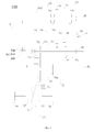
- the power transmission system 100 mainly includes two parts: one can be a power source, which can be an engine 4, a motor-generator, etc; another can be a transmission (as shown in FIG. 1 ), and the transmission is used for implementing shifting function of power outputted by the power source, which satisfies with moving requirement or charging requirement of the vehicle.
- the power transmission system 100 can include, but is not limited to, an engine 4, a first motor-generator 51 and a transmission system.
- the engine 4 uses mixture of liquid fuel (for example gasoline, diesel oil, etc.) and air directly inputted to a combustion chamber to be burnt to generate energy and then transforms it into mechanical energy.
- the engine 4 can include a housing assembly, a crank mechanism, an air distributing mechanism, a supply system, an ignition system, a cooling system and a lubrication system, etc.
- the housing assembly is an assembly body for every mechanism, system of the engine 4.
- the crank mechanism is configured to change a linear reciprocating motion of a piston into a rotational motion of a crankshaft and to output driving power.
- the air distributing mechanism is configured to introduce air and eject air on time, which ensures smooth cycles of the engine 4.
- the supple system is configured to supply mixture of gas and air into a cylinder to be burnt.
- the cooling system is configured to cool the engine 4, which ensures that work temperature of the engine 4 is in a proper temperature range.
- the lubrication system is configured to lubricate every movement inside the engine 4, which reduces wear and energy loss.
- the transmission system includes a number of input shafts (for example, a first input shaft 11, a second input shaft 12), a number of output shafts (for example, a first output shaft 21, a second output shaft 22), and a motor shaft 3 and related gears and shifting elements (for example, synchronizers) on each shaft.
- a number of input shafts for example, a first input shaft 11, a second input shaft 12
- a number of output shafts for example, a first output shaft 21, a second output shaft 22
- a motor shaft 3 and related gears and shifting elements for example, synchronizers
- the engine 4 When driving power is transferred between the engine 4 and the input shaft, the engine 4 is configured to selectively couple with at least one of the input shafts. For example, when the engine 4 transfers the driving power to the input shaft, the engine 4 can couple with one of the input shafts to transfer the driving power, or the engine 4 also can couple with two or more of the input shafts simultaneously to transfer the driving power.
- a number of input shafts can include two input shafts: a first input shaft 11 and a second input shaft 12.
- the engine 4 can selectively couple with either the first input shaft 11 or the second input shaft 12.In some embodiments, the engine 4 can also couple with the first input shaft 11 and the second input shaft 12 simultaneously. The engine 4 also can uncouple from the first input shaft 11 and the second input shaft 12.
- Gear pairs can be used between the input shafts and the output shafts to transfer the driving power.
- a gear driving gear is set on each input shaft
- a gear driven gear is set on each output shaft.
- the gear driven gear meshes with the gear driving gear correspondingly, thereby forming a number of gear pairs having different speed ratios.
- the transmission system can be a five-forward-gear transmission and can include: a gear-one gear pair, a gear-two gear pair, a gear-three gear pair, a gear-four gear pair and a gear-five gear pair.
- a gear-one gear pair can be increased or reduced according to a transmission requirement and is not limited to the five-gear transmission shown in embodiments of the present disclosure.
- the motor shaft 3 is configured to rotate together with one of the input shafts (for example, the second input shaft 12). In some embodiments, when the driving power from the input shaft is to be transferred to the motor shaft 3, the motor shaft 3 rotates together with the input shaft to transfer the driving power. In some embodiments, when the driving power from the motor shaft 3 is to be transferred to the input shaft, the input shaft rotates together with the motor shaft 3 to transfer the driving power.
- the input shaft is configured to rotate together with the motor shaft 3.
- a gear rotates together with a shaft, i.e. when the gear rotates, the relative shaft rotates correspondingly; alternatively, when the shaft rotates, the relative gear rotates correspondingly.
- one shaft rotates together with the other one shaft, i.e. when the one shaft rotates, the other one shaft rotates correspondingly.
- one gear rotate together with the other one gear, i.e. when the one gear rotates, the other one gear rotates correspondingly.
- the first motor-generator 51 is configured to rotate together with the motor shaft 3.
- the driving power generated by the first motor-generator 51 can be outputted to the motor shaft 3.
- the driving power from the motor shaft 3 can also be outputted to the first motor-generator to drive the first motor-generator 51 to generate electric power.
- the motor-generator can be understood to be a motor having functions of an electric-power generator and an electric motor.
- the motor shaft 3 can rotate together with one of the input shafts.
- the first motor-generator 51 can use at least parts of the driving power outputted by the engine 4 to generate electric power when the vehicle moves and is parked.
- the motor shaft 3 is configured to rotate together with one of the output shafts (e.g., the second output shaft 22).
- the motor shaft 3 can rotate together with the output shaft to transfer the driving power.
- the first motor-generator 51 can output the driving power generated through the one of the output shafts, thereby driving the vehicle to move.
- the first motor-generator 51 can be used as an electric motor and output the driving power to drive the vehicle to move.
- the motor shaft 3 can be a motor shaft of the first motor-generator 51 itself. It is also understood that the motor shaft 3 and the motor shaft of the first motor-generator 51 can be two independent shafts.
- the power transmission system 100 can achieve the charging function when the vehicle moves and is parked, thereby adding different charging modes and improves the low charging efficiency of current power transmission system which allows a single charging mode.
- the power transmission system 100 allows two kinds of charging modes: moving-and-charging, and parked-and-charging.
- first motor shaft gear 31 and the second motor shaft gear 32 are sleeved on the motor shaft 3, i.e., the motor shaft 3 and the first motor shaft gear 31 can rotate at different speeds.
- the motor shaft 3 and the second motor shaft gear 32 can rotate at different speeds.
- the first motor shaft gear 31 is configured to rotate together with the one of the input shafts.
- the second motor shaft gear 32 is configured to rotate together with the one of the output shafts.
- the first motor shaft gear 31 is rotating together with the second input shaft 12, and the second motor shaft gear 32 is rotating together with the second output shaft 22, but the present disclosure is not limited to these.
- the motor shaft synchronizer 33c is set between the first motor shaft gear 31 and the second motor shaft gear 32.
- a coupling sleeve of the motor shaft synchronizer 33c can move along an axial direction of the motor shaft 3.
- the coupling sleeve of the motor shaft synchronizer 33c can move left or right along the axial direction of the motor shaft 3 under the drive of a fork mechanism.
- the motor shaft synchronizer 33c is set between the first motor shaft gear 31 and the second motor shaft gear 32, the motor shaft synchronizer 33c is configured to selectively couple one of the first motor shaft gear 31 or the second motor shaft gear 32 with the motor shaft 3.
- the coupling sleeve of the motor shaft synchronizer 33c moves left along the axial direction and can couple the first motor shaft gear 31 with the motor shaft 3, enabling the motor shaft 3 and the first motor shaft gear 31 to rotate synchronously.
- the coupling sleeve of the motor shaft synchronizer 33c moves right along the axial direction and can couple the second motor shaft gear 32 with the motor shaft 3, enabling the motor shaft 3 and the second motor shaft gear 32 to rotate synchronously.
- the coupling sleeve of the motor shaft synchronizer 33c also can stay in a middle position (for example, an initial position). What that happens, the motor shaft synchronizer 33cuncouples from the first motor shaft gear 31 and the second motor shaft 32.
- coupling teeth rings can be set on sides of the first motor shaft gear 31 and the second motor shaft gear 32 facing the motor shaft synchronizer 33c.
- the motor shaft 3 is configured to selectively rotate together with the one of the input shafts or the one of the output shafts through synchronization of the motor shaft synchronizer 33c (i.e., synchronization for the first motor shaft gear 31 or the second motor shaft gear 32).
- the motor shaft synchronizer 33c can perform synchronization for the first motor shaft gear 31 by, for example, coupling the first motor shaft gear 31 with the motor shaft 3, thereby allowing the motor shaft 3 to rotate together with the one of the input shafts (e.g., the second input shaft 12).
- the motor shaft synchronizer 33c can perform synchronization for the second motor shaft gear 32 by, for example, coupling the second motor shaft gear 32 with the motor shaft 3, thereby allowing the motor shaft 3 to rotate together with the one of the output shafts (e.g., the second output shaft 22).
- the first motor shaft gear 31 rotates together with the one of the input shafts.
- the first motor shaft gear 31 engages directly or indirectly with a driving gear on the one of the input shafts, thereby achieving rotating together with the input shaft.
- the first motor shaft gear 31 engages with a corresponding driving gear, for example a gear-two driving gear 2a, through an intermediate idler gear 73.
- the intermediate idler gear 73 meshes with the corresponding driving gear and the first motor shaft gear 31.
- a reverse gear 71 is sleeved on the motor shaft 3
- a reverse intermediate gear 72 meshes with the reverse gear 71.
- the reverse intermediate gear 72 is configured to selectively rotate together with the intermediate idler gear 73.
- the reverse intermediate gear 72 is sleeved on the second output shaft 22, and can rotate at different speeds with the intermediate idler gear 73and, when necessary, can couple with each other to rotate synchronously.
- intermediate idler gear 73 and the reverse intermediate gear 72 can rotate together with each other through a reverse-gear synchronizer 74c by, for example, including the reverse-gear synchronizer 74c configured to synchronize the reverse intermediate gear 72 and the intermediate idler gear 73.
- number of the input shaft can be two, i.e., the input shafts include a first input shaft 11 and a second input shaft 12.
- the second input shaft 12 can be a hollow shaft and the first input shaft 11 can be a solid shaft.
- One part of the first input shaft 11 can be embedded into the second input shaft 12, and another part of the first input shaft 11 can extend outwards from the second input shaft 12 along an axial direction.
- the first input shaft 11 and the second input shaft 12 can be set coaxially.
- Number of the output shaft can be two, i.e., a first output shaft 21 and a second output shaft 22.
- the first output shaft 21 and the second output shaft 22 are set in parallel with the input shafts.
- the first output shaft 21 and the second output shaft 22 can be solid shafts.
- the power transmission system 100 can have five forward gears. Specifically, gear driving gears of odd number can be set on the first input shaft 11 and gear driving gears of even number can be set on the second input shaft 12. Therefore, the first input shaft 11 is responsible for power transmission of odd-gear gear pairs and the second input shaft 12 is responsible for power transmission of even-gear gear pairs.
- a gear-one driving gear 1a, a gear-three driving gear 3a and a gear-five driving gear 5a can be set on the first input shaft 11.
- a gear-two driving gear 2a and a gear-four driving gear 4a can be set on the second input shaft 12.
- Each gear driving gear rotates synchronously as the corresponding input shaft rotates.
- a gear-one driven gear 1b, a gear-two driven gear 2b, a gear-three driven gear 3b and a gear-four driven gear 4b are set on the first output shaft 21.
- a gear-five driven gear 5b is set on the second output shaft 22.
- Each driven gear is sleeved on the corresponding output shaft, i.e., each driven gear can rotate at a different speed compared with the corresponding output shaft.
- the gear-one driven gear 1b meshes with the gear-one driving gear 1a to cooperatively form a gear-one gear pair.
- the gear-two driven gear 2b meshes with the gear-two driving gear 2a to cooperatively form a gear-two gear pair.
- the gear-three driven gear 3b meshes with the gear-three driving gear 3a to cooperatively form a gear-three gear pair.
- the gear-four driven gear 4b meshes with the gear-four driving gear 4a to cooperatively form a gear-four gear pair.
- the gear-five driven gear 5b meshes with the gear-five driving gear 5a to cooperatively form a gear-five gear pair.
- a synchronizer is needed to synchronize the corresponding driven gear and the output shaft, thereby achieving output of the driving power.
- the power transmission system 100 includes a gear-one-three synchronizer 13c, a gear-two-four synchronizer 24c and a gear-five synchronizer 5c.
- the gear-one-three synchronizer 13c is set on the first output shaft 21 and between the gear-one driven gear 1b and the gear-three driven gear 3b.
- the gear-one-three synchronizer 13c can couple the gear-one driven gear 1b or the gear-three driven gear 3b with the first input shaft 11, enabling the driven gear to rotate synchronously with the output shaft.
- a coupling sleeve of the gear-one-three synchronizer 13c moves left to couple the gear-three driven gear 3b with the first input shaft 11, enabling the gear-three driven gear 3b and the first output shaft 21 to rotate synchronously.
- the coupling sleeve of the gear-one-three synchronizer 13c moves right to couple the gear-one driven gear 1b with the first input shaft 11, enabling the gear-one driven gear 1b and the first output shaft 21 to rotate synchronously.
- the gear-two-four synchronizer 24c is set on the first output shaft 21 and between the gear-two driven gear 2b and gear-four driven gear 4b.
- the gear-two-four synchronizer 24c can couple the gear-two driven gear 2b or the gear-four driven gear 4b with the first input shaft 11, enabling the driven gear to rotate synchronously with the output shaft.
- a coupling sleeve of the gear-two-four synchronizer 24c moves left to couple the gear-two driven gear 2b with the first output shaft 21, enabling the gear-two driven gear 2b and the first output shaft 21 to rotate synchronously.
- the coupling sleeve of the gear-two-four synchronizer 24c moves right to couple the gear-four driven gear 4b with the first output shaft 21, enabling the gear-four driven gear 4b and the first output shaft 21 to rotate synchronously.
- the gear-five synchronizer 5c is set on the second output shaft 22.
- the gear-five synchronizer 5c is at a side, for example a left side, of the gear-five driven gear 5b.
- the gear-five synchronizer 5c is configured to couple the gear-five driven gear 5b with the second output shaft 22.
- a coupling sleeve of the gear-five synchronizer 5c moves right and can couple the gear-five driven gear 5b with the second output shaft 22, thereby enabling the gear-five driven gear 5b and the second output shaft 22 to rotate synchronously.
- the reverse intermediate gear 72 and the intermediate idler gear 73 are on the second output shaft 22, and the gear-five driven gear 5b is also on the second output shaft 22, and the gear-five synchronizer 5c is only configured to couple the gear-five driven gear 5b, and the reverse-gear synchronizer 74c is only configured to couple the intermediate idler gear 73 and the reverse intermediate gear 72. Therefore, as a preferable embodiment, the reverse-gear synchronizer 74c and the gear-five synchronizer 5c share one fork mechanism. Therefore, another fork mechanism is omitted, which makes the power transmission system 100 more compact and smaller in size.
- the coupling sleeve of the reverse-gear synchronizer 74c When the coupling sleeve of the reverse-gear synchronizer 74c is driven through the fork of the fork mechanism to couple with the reverse intermediate gear 72 and the intermediate idler gear 73, the coupling sleeve of the gear-five synchronizer 5c does not couple with the gear-five driven gear 5b.
- the operating process of the fork mechanism driving the reverse-gear synchronizer 74c and the gear-five synchronizer 5c is exemplary and cannot be understood as a limitation to the present disclosure.
- transmission or separate of the driving power between the engine 4 and the first input shaft 11 and the second input shaft 12 can be implemented through a dual clutch transmission 2d.
- the dual clutch transmission 2d has an input terminal 23d, a first output terminal 21 d and a second output terminal 22d.
- the engine 4 is connected with the input terminal 23d of the dual clutch transmission 2d.
- the engine 4 can be connected with the input terminal 23d through various ways, for example, a flywheel, a shock absorber or a reversing plate.
- the first output terminal 21d of the dual clutch transmission 2d is connected with the first input shaft 11, thereby enabling the first output terminal 21d and the first input shaft 11 to rotate synchronously.
- the second output terminal 22d of the dual clutch transmission 2d is connected with the second input shaft 12, thereby enabling the second output terminal 22d and the second input shaft 12 to rotate synchronously.
- the input terminal 23d of the dual clutch transmission 2d can be a housing of the dual clutch transmission 2d, and the first output terminal 21d and the second output terminal 22d thereof can be two driven plates.
- the housing uncouples from the two driven plates, i.e., the input terminal 23d uncouples from the first output terminal 21d and the second output terminal 22d.
- the housing can be controlled to couple with corresponding driven plate, thereby enabling to rotate synchronously. That is to say, the input terminal 23d couples with one of the first output terminal 21d or the second output terminal 22d. Therefore, the driving power transferred from the input terminal 23d can be outputted through the first output terminal 21 d or the second output terminal 22d.
- the housing can couple with the two driven plates simultaneously, i.e., the input terminal 23d can couple with the first output terminal 21d and the second output terminal 22d simultaneously. Therefore, the driving power transferred from the input terminal 23d can be outputted through the first output terminal 21d and the second output terminal 22d simultaneously.
- the specific coupling state of the dual clutch transmission 2d is affected by a control strategy.
- the control strategy can be set correspondingly according to practical transmission modes. Therefore, multiple modes, for example a mode of the input terminal 23d uncoupling from the two output terminals and a mode of the input terminal 23d coupling from at least one of the two output terminals, can be switched.
- the second motor shaft gear 32 is configured to rotate together with the one of the output shafts.
- a transmission gear 6 is set on the second output shaft 22.
- the transmission gear 6 meshes with the second motor shaft gear 32 directly.
- the differential 75 of the vehicle can be arranged between a pair of front wheels or between a pair of rear wheels. In some examples of the present disclosure, the differential 75 is arranged between the pair of front wheels. Function of the differential 75 is for, when the vehicle is turning or moving on an uneven road surface, making left and right driving wheels to roll at different angular speeds, thereby ensuring pure rolling motions between two-side driving wheels and the road surface.
- a primary decelerator driven gear 74 is set on the differential 75.
- the primary decelerator driven gear 74 can be arranged on the housing of the differential 75.
- the primary decelerator driven gear 74 can be, but is not limited to, a bevel gear.
- a first output-shaft output gear 211 is fixed on the first output shaft 21.
- the first output-shaft output gear 211 rotates synchronously as the first output shaft 21 rotates.
- the first output-shaft output gear 211 meshes with the primary decelerator driven gear 74. Therefore, the driving power from the first output shaft 21 can be transferred from the first output-shaft output gear 211 to the primary decelerator driven gear 74 and the differential 75.
- a second output-shaft output gear 221 is fixed on the second output shaft 22.
- the second output-shaft output gear 221 can rotate synchronously as the second output shaft 22 rotates.
- the second output-shaft output gear 221 meshes with the primary decelerator driven gear 74. Therefore, the driving power from the second output shaft 22 can be transferred from the second output-shaft output gear 221 to the primary decelerator driven gear 74 and the differential 75.
- the reverse gear 71 is used as the driving power output terminal of a reverse mode mostly. Therefore, the reverse gear 71 also meshes with the primary decelerator driven gear 74. Because the reverse gear 71 also meshes with the reverse intermediate gear 72 simultaneously, and to obtain a proper reverse-gear speed ratio, as an optional embodiment, the reverse gear 71 can be configured to be a double helical gear. One part of the reverse gear 71 with the double-helical-gear configuration meshes with the reverse intermediate gear 72 and another part of the reverse gear 71 with the double-helical-gear configuration meshes with the primary decelerator driven gear 74.
- one teeth portion 712 of the reverse gear 71 meshes with the reverse intermediate gear 72 and another teeth portion 711 meshes with the primary decelerator driven gear 74. Therefore, not only that a better reverse-gear speed ratio can be obtained, but also that when the reverse driving power is transferred, the gears are not intervened, thereby facilitating a reliable transmission of the reverse driving power.
- Some typical working conditions of the power transmission system 100 include parked and electric power generation, driving while charging under a condition of simultaneous coupling of the dual clutch transmission 2d, and a gear-two speed adjustment of the first motor-generator 51.
- the engine 4 is configured to output the driving power generated to the one of the input shafts (i.e., the input shaft, for example the second input shaft 12, which rotates together with the first motor shaft gear 31), and output the driving power to the first motor-generator 51 through synchronization of the motor shaft synchronizer 33c to the first motor shaft gear 31, thereby driving the first motor-generator 51 to generate electric power.
- the one of the input shafts i.e., the input shaft, for example the second input shaft 12, which rotates together with the first motor shaft gear 31
- the driving power to the first motor-generator 51 through synchronization of the motor shaft synchronizer 33c to the first motor shaft gear 31, thereby driving the first motor-generator 51 to generate electric power.
- the engine 4 can output the driving power to the second input shaft 12 through the dual clutch transmission 2d.
- the second input shaft 12 rotates together with the first motor shaft gear 31 on the motor shaft 3.
- the motor shaft synchronizer 33c is controlled to couple the motor shaft 3 with the first motor shaft gear 31.
- the driving power outputted by the engine 4 is outputted to the motor shaft 3 from the second input shaft 12, the intermediate idler gear 73, the first motor shaft gear 31 and the motor shaft synchronizer 33c.
- the driving power is outputted to the first motor-generator 51 from the motor shaft 3, thereby driving the first motor-generator 51 as an electric-power generator to generate electric power.
- the engine 4 can output part of the driving power to the wheels as a driving power for driving the vehicle through one output shaft, and output another part of the driving power to the first motor-generator 51 through the motor shaft 3, thereby driving the first motor-generator 51 to generate electric power.
- part of the driving power of the engine 4 can be outputted from the first output shaft 21 or the second output shaft 22 through, for example, the gear-one gear pair, the gear-three gear pair, or the gear-five gear pair.
- Another part of the driving power of the engine 4 can be outputted to the first motor-generator 51 through a path from the first motor shaft gear 31, the motor shaft synchronizer 33c, and the motor shaft 3, thereby driving the first motor-generator 51 to generate electric power.
- the power transmission system 100 can achieve an efficient application for the dual transmission clutch 2d, such that under the coupling state of two clutches of the dual clutch transmission 2d (the input terminal 23d couples with the first output terminal 21d and the second output terminal 22d simultaneously), part of the driving power of the engine 4 can be outputted by one output shaft for driving the vehicle to move and another part of the driving power to be outputted to the first motor-generator 51 for driving the first motor-generator 51 to generate electric power, which enriches the transmission modes and meets the vehicle driving and charging requirements.
- synchronous switching of the motor shaft synchronizer 33c may be needed.
- the coupling sleeve of the motor shaft synchronizer 33c may need to be switched from a position where the coupling sleeve couples with the first motor shaft gear 31 to a position where the coupling sleeve couples with the second motor shaft gear 32.
- the second motor shaft gear 32 and the motor shaft 3 may rotate at different speeds. This can increase synchronization time of the synchronizer and wear of the synchronizer, and reduce transmission efficiency, which can create excessive vibration.
- the rotational speed of the motor shaft 3 can be adjusted based on the rotational speed of the second motor shaft gear 32, by controlling the first motor-generator 51.
- the rotational speed of the second motor shaft gear 32 can be used as a target to increase or reduce the rotational speed of the motor shaft 3, which makes the rotational speed of the motor shaft 3 to match with the second motor shaft gear 32 (i.e., approximately equal or close to) in a shortest time, thereby making the motor shaft synchronizer 33c to couple the second motor shaft gear 32 with the motor shaft 3 quickly, reducing synchronization time of the motor shaft synchronizer 33c, and improving the transmission efficiency, synchronization controllability and real-time synchronization of the vehicle greatly.
- lifetime of the motor shaft synchronizer 33c can be extended, which reduces maintenance cost of the whole vehicle.
- the first motor-generator 51 can adjust the rotational speed of the motor shaft 3 based on the rotational speed of the first motor shaft gear 31.
- the rotational speed of the first motor shaft gear 31 can be used as a target to increase or reduce the rotational speed of the motor shaft 3, which makes the rotational speed of the motor shaft 3 to match with the first motor shaft gear 31 in a shortest time, thereby increasing the coupling efficiency of the motor shaft synchronizer 33c.
- the first motor-generator 51 is configured to perform speed adjustment to the motor shaft 3 according to the rotational speed of the another of the first motor shaft gear 31 or the second motor shaft gear 32 as the target.
- the typical working condition is under electric-vehicle mode where the first motor-generator 51 drives the vehicle to move.
- the present disclosure is not limited to this condition.
- the motor shaft synchronizer 33c may needed to switch the first motor shaft gear 31 and the second motor shaft gear 32
- the first motor-generator 51 can be used to perform speed adjustment to the motor shaft 3.
- the power transmission system 100 when the coupling position is switched between the first motor shaft gear 31 and the second motor shaft gear 32, makes the rotational speed of the motor shaft 3 to match with the rotational speed of a to-be-coupled gear (e.g., the rotational speed of the first motor shaft gear 31 or the second motor shaft gear 32) through the first motor-generator 51 performing speed adjustment to the motor shaft 3.
- a to-be-coupled gear e.g., the rotational speed of the first motor shaft gear 31 or the second motor shaft gear 32
- the first motor-generator 51 can use the rotational speed of the to-be-coupled gear as a target to perform the speed adjustment to the rotational speed of the motor shaft 3, which makes the rotational speed of the motor shaft 3 to match with the rotational speed of the to-be-coupled gear in a short time and is convenient for coupling of the motor shaft synchronizer 33c, thereby increasing the transmission efficiency greatly and reducing the transmission loss of intermediate energy.
- the power transmission system 100 can further add a second motor-generator 52 to increase power performance of the power transmission system 100 and to increase the number of transmission modes.
- the second motor-generator 52 can transfer the driving power with the primary decelerator driven gear 74.
- gears can be set on a motor shaft of the second motor-generator 52 and the gears mesh with the primary decelerator driven gear 74 directly.
- the second motor-generator 52 can also be set to be connected with the first input shaft 11 or with the first output shaft 21.
- the number of the second motor-generator 52 is two and the second motor-generators 52 are set at two sides of the differential 75.
- the two second motor-generators 52 can be integrated with the differential 75.
- the engine 4 is connected with the input terminal 23d of the dual clutch transmission 2d.
- the first output terminal 21d of the dual clutch transmission 2d is connected with the first input shaft 11.
- the second output terminal 22d of the dual clutch transmission 2d is connected with the second input shaft 12.
- the input terminal 23d of the dual clutch transmission 2d can uncouple from the first output terminal 21d and the second output terminal 22d of the dual clutch transmission 2d simultaneously, or the input terminal 23d of the dual clutch transmission 2d can couple with one of the first output terminal 21d or the second output terminal 22d, or the input terminal 23d of the dual clutch transmission 2d can couple with the first output terminal 21d and the second output terminal 22d simultaneously.
- the second input shaft 12 is a hollow-shaft structure.
- the first input shaft 11 is a solid shaft.
- the second input shaft 12 is sleeved on the first input shaft 11 coaxially, and one part of the first input shaft 11 extends outwards from the second input shaft 12 along an axial direction.
- a gear-one driving gear 1a, a gear-three driving gear 3a, and a gear-five driving gear 5a, which rotate synchronously with the first input shaft 11, are set on the first input shaft 11.
- the gear-one driving gear 1a is at a right side of the gear-five driving gear 5a.
- the gear-three driving gear 3a is at a left side of the gear-five driving gear 5a.
- the gear-two driving gear 2a is at a left side and the gear-four driving gear 4a is at a right side.
- the first output shaft 21 is arranged in parallel with the two input shafts.
- a gear-one driven gear 1b, a gear-two driven gear 2b, a gear-three driven gear 3b and a gear-four driven gear 4b are sleeved on the first output shaft 21.
- the gear-one driven gear 1b meshes with the gear-one driving gear 1a directly.
- the gear-two driven gear 2b meshes with the gear-two driving gear 2a directly.
- the gear-three driven gear 3b meshes with the gear-three driving gear 3a directly.
- the gear-four driven gear 4b meshes with the gear-four driving gear 4a directly.
- a gear-one-three synchronizer 13c and a gear-two-four synchronizer 24c are set on the first output shaft 21.
- the gear-one-three synchronizer 13c is located between the gear-one driven gear 1b and the gear-three driven gear 3b and can selectively synchronize the gear-one driven gear 1b or the gear-three driven gear 3b with the first output shaft 21.
- the gear-two-four synchronizer 24c is located between the gear-two driven gear 2b and the gear-four driven gear 4b and can selectively synchronize the gear-two driven gear 2b or the gear-four driven gear 4b with the first output shaft 21.
- the second output shaft 22 is also arranged in parallel with the two input shafts.
- a gear-five driven gear 5b is sleeved on the second output shaft 22.
- the gear-five driven gear 5b meshes with the gear-five driving gear 5a directly.
- a gear-five synchronizer 5c is further set on the second output shaft 22.
- the gear-five synchronizer 5c is configured to synchronize the gear-five driven gear 5b with the second output shaft 22.
- the motor shaft 3 is arranged in parallel with the two input shafts and the two output shafts.
- the first motor shaft gear 31 and the second motor shaft gear 32 are sleeved on the motor shaft 3.
- the first motor shaft gear 31 is on a left side.
- the second motor shaft gear 32 is on a right side.
- the motor shaft synchronizer 33c is set on the motor shaft 3.
- the motor shaft synchronizer 33c is configured to selectively synchronize the first motor shaft gear 31 and the motor shaft 3, or synchronize the second motor shaft gear 32 and the motor shaft 3.
- a transmission gear 6, rotating synchronously with the second output shaft 22, is set on the second output shaft 22 and a reverse intermediate gear 72 is sleeved on the second output shaft 22.
- the transmission gear 6 meshes with the second motor shaft gear 32 directly.
- a gear sleeve 721 is formed on a side of the reverse intermediate gear 72.
- the gear sleeve 721 is sleeved on the second output shaft 22.
- the intermediate idler gear 73 is sleeved on the gear sleeve 721.
- the intermediate idler gear 73 meshes with the gear-two driving gear 2a and the first motor shaft gear 31.
- the reverse-gear synchronizer 74c is arranged on the gear sleeve 721 and is configured to couple with the intermediate idler gear 73.
- Reverse gear 71 can be configured as a double helical gear.
- One teeth portion 712 of the reverse gear 71 meshes with the reverse intermediate gear 72 and another teeth portion 711 meshes with the primary decelerator driven gear 74.
- a first output-shaft output gear 211 meshing with the primary decelerator driven gear 74, is fixed on the first output shaft 21.
- the first motor-generator 51 is connected with the motor shaft 3 coaxially.
- the input terminal 23d of the dual clutch transmission 2d couples with the second output terminal 22d and becomes uncoupling from the first output terminal 21d.
- the motor shaft synchronizer 22c couples with the first motor shaft gear 31. Therefore, the driving power outputted by the engine 4 is transferred to the first motor-generator 51 through the input terminal 23d of the dual clutch transmission 2d, the second output terminal 22d, the second input shaft 12, the gear-two driving gear 2a, the intermediate idler gear 73, the first motor shaft gear 31, the motor shaft synchronizer 33c and the motor shaft 3, thereby driving the first motor-generator 51 to generate electric power.
- the working condition can achieve a fixed-speed-ratio charging.
- the transmission efficiency of energy is higher.
- the choice of speed ratio can be determined by various factors, for example, the rotational speed of the engine 4 when the vehicle is parked, type of the first motor-generator 51, and the highest rotational speed tolerated by additional components, for example peripheral bearings.
- the transmission speed ratio can be flexibly designed by considering the above factors, which allows the power transmission system 100, under the aforementioned working condition, to maximize the use of energy of the engine 4 and to achieve the goal of fast charging.
- Path 1 the motor shaft synchronizer 33c couples with the first motor shaft gear 31.
- the driving power outputted by the first motor-generator 51 is outputted to the second input shaft 12 through the first motor shaft gear 31 and the intermediate idler gear 73.
- the gear-two-four synchronizer 24c couples with the gear-two driven gear 2b or the gear-four driven gear 4b, enabling the driving power of the first motor-generator 51 to be outputted through the gear-two gear pair or the gear-four gear pair.
- Path 2 the motor shaft synchronizer 33c couples with the second motor shaft gear 32.
- the driving power outputted by the first motor-generator 51 is outputted from the second output shaft 22 through the second motor shaft gear 32 and the transmission gear 6.
- the first motor-generator 51 can output the driving power to the wheels through the above two paths of different speed ratios, thereby driving the vehicle to move.
- the first motor-generator 51 can perform speed adjustment to the motor shaft 3.
- the switching from Path 1 to Path 2 is described as follows.
- the motor shaft synchronizer 33c moves from a position where the motor shaft synchronizer 33c couples with the first motor shaft gear 31, to a position where the motor shaft synchronizer 33c couples with the second motor shaft gear 32.
- the first motor-generator 51 can use the rotational speed of the second motor shaft gear 32 as a target to perform speed adjustment to the motor shaft 3, which makes the rotational speed of the motor shaft 3 to match with the second motor shaft gear 32, thereby enabling the motor shaft synchronizer 33c to become coupling with the second motor shaft gear 32 quickly, and synchronization efficiency can be improved.
- the switching from Path 2 to Path 1 is described as follows.
- the motor shaft synchronizer 33c moves from a position where the motor shaft synchronizer 33c couples with the second motor shaft gear 32 to a position where the motor shaft synchronizer 33c couples with the first motor shaft gear 31.
- the first motor-generator 51 can use the rotational speed of the first motor shaft gear 31 as a target to perform speed adjustment to the motor shaft 3, which makes the rotational speed of the motor shaft 3 to match with the first motor shaft gear 31, thereby enabling the motor shaft synchronizer 33c to become coupling with the first motor shaft gear 31 quickly, and synchronization efficiency can be improved.
- the above speed-adjustment mode is not only for the electric-vehicle working condition, but also for other working conditions, for example a hybrid-electric-vehicle working condition, etc.
- the above speed-adjustment mode can be use as long as it relates to working conditions where the coupling state of the motor shaft synchronizer 33c changes (e.g., switching from coupling with the first motor shaft gear 31 to coupling with the second motor shaft gear 32, or from coupling with the second motor shaft gear 32 to coupling with the first motor shaft gear 31).
- the gear-one-three synchronizer 13c couples with the gear-one driven gear 1b.
- the input terminal 23d of the dual clutch transmission 2d couples with the first output terminal 21d and uncouples from the second output terminal 22d.
- the motor shaft synchronizer 33c couples with the second motor shaft gear 32. Therefore, the driving power outputted by the engine 4 is outputted from the first output shaft 21 through the first input shaft 11 and the gear-one gear pair.
- the driving power outputted by the first motor-generator 51 is outputted from the second output shaft 22 through the second motor shaft gear 32 and the transmission gear 6.
- the two parts of driving power are then coupled at the primary decelerator driven gear 74.
- the coupled driving power is distributed to two-side wheels from the differential 75.
- the first motor-generator 51 can perform speed adjustment, which allows the primary decelerator driven gear 74 to receive the driving power from the engine 4 and from the first motor-generator 51 synchronously in a balanced manner.
- the smoothness and coordination of transmission is improved.
- the gear-two-four synchronizer 24c couples with the gear-two driven gear 2b.
- the input terminal 23d of the dual clutch transmission 2d couples with the second output terminal 22d and uncouples from the first output terminal 21d.
- the motor shaft synchronizer 33c couples with the second motor shaft gear 32. Therefore, the driving power outputted by the engine 4 is outputted from the first output shaft 21 through the second input shaft 12 and the gear-two gear pair.
- the driving power outputted by the first motor-generator 51 is outputted from the second output shaft 22 through the second motor shaft gear 32 and the transmission gear 6.
- the two parts of driving power are then coupled at the primary decelerator driven gear 74.
- the coupled driving power is distributed to two-side wheels from the differential 75.
- the first motor-generator 51 can perform speed adjustment, which allows the primary decelerator driven gear 74 to receive the driving power from the engine 4 and from the first motor-generator 51 synchronously in a balanced manner.
- the smoothness and coordination of transmission is improved.
- the power transmission system 100 When the power transmission system 100 is under gear-three hybrid-electric-vehicle working condition, it operates similarly to when it is under gear-one hybrid working condition.
- the differences can be that the gear-one-three synchronizer 13c couples with the gear-three driven gear 3b, and the driving power of the engine 4 is outputted through the gear-three gear pair.
- the rest are substantially the same as the gear-one hybrid-electric-vehicle transmission and are not repeated here.
- the power transmission system 100 When the power transmission system 100 is under gear-four hybrid-electric-vehicle working condition, it operates similarly to when it is under gear-two hybrid-electric-vehicle working condition.
- the differences can be that the gear-two-four synchronizer 24c couples with the gear-four driven gear 4b, and the driving power of the engine 4 is outputted through the gear-four gear pair.
- the rest are substantially the same as the gear-two hybrid-electric-vehicle transmission and are not repeated here.
- the gear-five synchronizer 5c couples with the gear-five driven gear 5b.
- the input terminal 23d of the dual clutch transmission 2d couples with the first output terminal 21d and uncouples from the second output terminal 22d.
- the motor shaft synchronizer 33c couples with the second motor shaft gear 32. Therefore, the driving power outputted by the engine 4 is outputted from the second output shaft 22 through the first input shaft 11 and the gear-five gear pair.
- the driving power outputted by the first motor-generator 51 is outputted from the second output shaft 22 through the second motor shaft gear 32 and the transmission gear 6.
- the two parts of driving power are then coupled at the second output shaft 22.
- the coupled driving power is distributed to two-side wheels from the differential 75.
- the first motor-generator 51 can perform speed adjustment, which allows the second output shaft 22 to receive the driving power from the engine 4 and from the first motor-generator 51 synchronously in a balanced manner.
- the smoothness and coordination of transmission is improved.
- the gear-one-three synchronizer 13c couples with the gear-one driven gear 1b.
- the gear-two-four synchronizer 24c couples with the gear-two driven gear 2b (or the gear-four gear pair).
- the input terminal 23d of the dual clutch transmission 2d couples with the first output terminal 21d and uncouples from the second output terminal 22d.
- the motor shaft synchronizer 33c couples with the first motor shaft gear 31.
- the driving power outputted by the engine 4 is outputted to the first output shaft 21 through the first input shaft 11 and the gear-one gear pair.
- the driving power outputted by the first motor-generator 51 is outputted to the first output shaft 21 through the first motor shaft gear 31, the intermediate idler gear 73, the gear-two gear pair and the gear-two-four synchronizer 24c.
- the two parts of driving power are then coupled at the first output shaft 21.
- the coupled driving power is distributed to two-side wheels from the differential 75.
- the first motor-generator 51 can perform speed adjustment, which allows the first output shaft 21 to receive the driving power from the engine 4 and the first motor-generator 51 synchronously in a balanced manner.
- the smoothness and coordination of transmission is improved.
- the gear-two-four synchronizer 24c couples with the gear-two driven gear 2b.
- the input terminal 23d of the dual clutch transmission 2d couples with the second output terminal 22d and uncouples from the first output terminal 21d.
- the motor shaft synchronizer 33c couples with the first motor shaft gear 31. Therefore, the driving power outputted by the engine 4 is outputted to the gear-two gear pair through the second input shaft 12.
- the driving power outputted by the first motor-generator 51 is outputted to the gear-two gear pair through the first motor shaft gear 31 and the intermediate idler gear 73.
- the two parts of driving power are then coupled at the gear-two gear pair.
- the coupled driving power is outputted from the first output shaft 21.
- the first motor-generator 51 can perform speed adjustment, which allows the gear-two gear pair to receive the driving power from the engine 4 and the first motor-generator 51 synchronously in a balanced manner.
- the smoothness and coordination of transmission is improved.
- the power transmission system 100 When the power transmission system 100 is under gear-three hybrid-electric-vehicle working condition, it operates similarly to when it is under gear-one hybrid-electric-vehicle working condition.
- the differences can be that the gear-one-three synchronizer 13c couples with the gear-three driven gear 3b, and the driving power of the engine 4 is outputted through the gear-three gear pair.
- the rest are substantially the same as the gear-one hybrid-electric-vehicle transmission and are not repeated here.
- the gear-five synchronizer 5c couples with the gear-five driven gear 5b.
- the gear-two-four synchronizer 24c couples with the gear-two driven gear 2b.
- the input terminal 23d of the dual clutch transmission 2d couples with the first output terminal 21d and uncouples from the second output terminal 22d.
- the motor shaft synchronizer 33c couples with the first motor shaft gear 31.
- the driving power outputted by the engine 4 is outputted to the second output shaft 22 through the first input shaft 11 and the gear-five gear pair.
- the driving power outputted by the first motor-generator 51 is outputted to the first output shaft 21 through the first motor shaft gear 31, the intermediate idler gear 73, the gear-two gear pair and the gear-two-four synchronizer 24c.
- the two parts of driving power are then coupled at the primary decelerator driven gear 74.
- the coupled driving power is distributed to two-side wheels from the differential 75.
- the first motor-generator 51 can perform speed adjustment, which allows the primary decelerator driven gear 74 to receive the driving power from the engine 4 and from the first motor-generator 51 synchronously in a balanced manner.
- the smoothness and coordination of transmission is improved.
- the above scheme two for the hybrid-electric-vehicle working conditions at different gears takes the gear-two-four synchronizer 24c coupling with the gear-two driven gear 2b for an example.
- the gear-two-four synchronizer 24c can also couple with the gear-four driven gear 4b under this mode.
- the hybrid principle is substantially the same as the above and is not repeated here. The principle is the same as that in the above mode of not implementing the gear-four hybrid-electric-vehicle working condition.
- any hybrid paths in Scheme one and Scheme two can be selected flexibly according to a practical need. This enriches the transmission mode of the power transmission system 100 greatly, and improves the driving joy, and allows the vehicle to better adapt to different road conditions, and improves power performance and fuel economy of the vehicle.
- the gear-one-three synchronizer 13c couples with the gear-one driven gear 1b.
- the input terminal 23d of the dual clutch transmission 2d couples with the first output terminal 21d and uncouples from the second output terminal 22d.
- the motor shaft synchronizer 33c couples with the second motor shaft gear 32. Therefore, the driving power outputted by the engine 4 is outputted from the first output shaft 21 through the first input shaft 11 and the gear-one gear pair. Meanwhile, anti-dragging energy from the wheels is outputted to the first motor-generator 51 through the second output shaft 22, the transmission gear 6, the second motor shaft gear 32 and the motor shaft 3, thereby driving the first motor-generator 51 to generate electric power.
- the gear-two-four synchronizer 24c couples with the gear-two driven gear 2b.
- the input terminal 23d of the dual clutch transmission 2d couples with the second output terminal 22d and uncouples from the first output terminal 21d.
- the motor shaft synchronizer 33c couples with the first motor shaft gear 31. Therefore, part of the driving power outputted by the engine 4 is outputted from the first output shaft 21 through the second input shaft 12 and the gear-two gear pair.
- Another part of the driving power outputted by the engine 4 is outputted to the first motor-generator 51 through the second input shaft 22, the intermediate idler gear 73, the first motor shaft gear 31 and the motor shaft 3, thereby driving the first motor-generator 51 to generate electric power.
- the power transmission system 100 When the power transmission system 100 is under a gear-four driving-while-charging working condition, it is substantially the same as when the power transmission system 100 is under the gear-two driving-while-charging working condition.
- the differences can be that the gear-two-four synchronizer 24c couples with the gear-four driven gear 4b.
- the gear-five synchronizer 5c couples with the gear-five driven gear 5b.
- the input terminal 23d of the dual clutch transmission 2d couples with the first output terminal 21d and uncouples from the second output terminal 22d.
- the motor shaft synchronizer 33c couples with the second motor shaft gear 32. Therefore, the driving power outputted by the engine 4 is outputted from the second output shaft 22 through the first input shaft 11 and the gear-five gear pair. Meanwhile, part of the driving power on the second output shaft 22 is further outputted to the first motor-generator 51 through the transmission 6, the second motor shaft gear 32 and the motor shaft 3, thereby driving the first motor-generator 51 to generate electric power.
- the power transmission system 100 can also achieve a driving-while-charging working condition under a condition of the input terminal 23d of the dual clutch transmission 2d coupling with the first output terminal 21d and the second output terminal 22d simultaneously.
- the input terminal 23d of the dual clutch transmission 2d couples with the first output terminal 21d and the second output terminal 22d simultaneously.
- the gear-one-three synchronizer 13c couples with the gear-one driven gear 1b.
- the motor shaft synchronizer 33c couples with the first motor shaft gear 31. Therefore, one part of the driving power outputted by the engine 4 is outputted from the first output shaft 21 through the first input shaft 11 and the gear-one gear pair.
- Another part of the driving power outputted by the engine 4 is outputted to the first motor-generator 51 through the second input shaft 12, the intermediate idler gear 73, the first motor shaft gear 31 and the motor shaft 3, thereby driving the first motor-generator 51 to generator electric power.
- the power transmission system 100 when the power transmission system 100 is under a gear-three driving-while-charging working condition, or under a gear-five driving-while-charging working condition, its operation is substantially the same as when under the gear-one driving-while-charging working condition.
- the differences can be that, when in gear-three transmission, the gear-one-three synchronizer 13c couples with the gear-three driven gear 3b, when in gear-five transmission, the gear-five synchronizer 5c couples with the gear-five driven gear 5b and the driving power is outputted from the second output shaft 22.
- any transmission paths in Scheme one and Scheme two can be selected flexibly according to a practical need. This enriches the transmission mode of the power transmission system 100 greatly, and improves the driving joy, and allows the vehicle to better adapt to different road conditions, and improves power performance and fuel economy of the vehicle.
- the reverse-gear synchronizer 74c synchronizes the reverse intermediate gear 72 and the intermediate idler gear 73.
- the input terminal 23d of the dual clutch transmission 2d couples with the second output terminal 22d and uncouples from the first output terminal 21d.
- the driving power outputted by the engine 4 is outputted from the reverse gear 71 through the second input shaft 12, the intermediate idler gear 73, and the reverse intermediate gear 72.
- the motor shaft synchronizer 33c synchronizes the motor shaft 3 and the first motor shaft gear 31.
- the reverse-gear synchronizer 74c synchronizes the reverse intermediate gear 72 and the intermediate idler gear 73.
- the driving power outputted by the first motor-generator 51 is outputted from the reverse gear 71 through the motor shaft 3, the first motor shaft gear 31, the intermediate idler gear 73 and the reverse intermediate gear 72.
- the motor shaft synchronizer 33c synchronizes the motor shaft 3 and the first motor shaft gear 31.
- the reverse-gear synchronizer 74c synchronizes the reverse intermediate gear 72 and the intermediate idler gear 73.
- the driving power outputted by the engine 4 is outputted to the intermediate idler gear 73 through the second input shaft 12.
- the driving power outputted by the first motor-generator 51 is outputted to the intermediate idler gear 73 through the motor shaft 3 and the first motor shaft gear 31.
- the two parts of driving power are coupled at the intermediate idler gear 73, and then are outputted from the reverse gear 71 through the reverse intermediate gear 72.
- the first motor-generator 51 can rotate along a same preset direction, i.e., when working as an electric motor and as a power generator, the first motor-generator 51 can rotate along the same preset direction.
- the first motor-generator 51 may not need to change direction, which allows the first motor-generator 51 to keep rotating along the same direction under any involved working conditions. This can reduce vibration brought by changing direction of the electric motor, and extends the lifetime of the power transmission system 100.
- the reverse intermediate gear 72, the intermediate idler gear 73 and the reverse-gear synchronizer 74c are sleeved on the second output shaft 22 next to each other.
- the reverse-gear synchronizer 74c is set on the intermediate idler gear 73 and is configured to couple with the reverse intermediate gear 72. The rest are substantially the same as those in the power transmission system 100 in the embodiment of FIG. 2 , and are not repeated here.
- the intermediate idler gear 73 is configured to be a double helical gear and has teeth portions 731, 732.
- One teeth portion 731 meshes with a gear-two driving gear (i.e., with the driving gear on the one of the input shafts), and another teeth portion 732 meshes with the first motor shaft gear 31.
- the rest are substantially the same as those in the power transmission system 100 in the embodiment of FIG. 3 , and are not repeated here.
- embodiments of the present disclosure further provide a vehicle including the above power transmission system 100. It is understood that, other structures, for example a driving system, a turning system, a braking system, etc. of the vehicle are current technologies and are known by those skilled in the art. Therefore, detailed descriptions of these known structures are omitted here.
- FIG. 5 is a flow chart illustrating an exemplary shifting control method for a hybrid vehicle, according to one embodiment of the present disclosure.
- the power transmission system of the hybrid vehicle includes an engine 4, a number of input shafts, a number of output shafts, a motor shaft 3 and a first motor-generator 51.
- the engine 4 is configured to selectively couple with at least one of the input shafts.
- a gear driving gear is set on each of the input shafts.
- a gear driven gear is set on each of the output shafts.
- the gear driven gear meshes with the gear driving gear correspondingly.
- the motor shaft 3 is configured to rotate together with one of the input shafts.
- the first motor-generator 51 is configured to rotate together with the motor shaft, and when the motor shaft rotates together with one of the input shafts, the first motor-generator can use at least parts of driving power outputted by the engine to generate electric power when the vehicle moves or is parked.
- the shifting control method includes following steps:
- the first motor-generator has three gears: a first gear, a second gear and a third gear, i.e., EV1 gear, direct gear and EV2 gear.
- the motor shaft synchronizer 33c and the gear-two-four synchronizer 24c move left.
- the driving power of the first motor-generator 51 is transferred to the wheels through the motor shaft synchronizer 33c, the first motor shaft gear 31, the intermediate idler gear 73, the gear-two driving gear 2a, the gear-two driven gear 2b, the gear-two-four synchronizer 24c, the first output shaft 21, the first output-shaft output gear 211, the primary decelerator driven gear 74 and the power transmission system of the vehicle, thereby achieving a speed control.
- the motor shaft synchronizer 33c moves left, and the gear-two-four synchronizer 24c move right.
- the driving power of the first motor-generator 51 is transferred to the wheels through the motor shaft synchronizer 33c, the first motor shaft gear 31, the intermediate idler gear 73, the gear-four driving gear 4a, the gear-four driven gear 4b, the gear-two-four synchronizer 24c, the first output shaft 21, the first output-shaft output gear 211, the primary decelerator driven gear 74 and the power transmission system of the vehicle, thereby achieving a speed control.
- the motor shaft synchronizer 33c moves right. At this time, the driving power of the first motor-generator 51 is transferred to the wheels through the motor shaft synchronizer 33c, the second motor shaft gear 32, the transmission gear 6, the second output shaft 22, the second output-shaft output gear 221, the primary decelerator driven gear 74 and the power transmission system of the vehicle, thereby achieving a speed control.
- a direct gear e.g., the second gear
- the first motor-generator 51 When the hybrid vehicle is under EV mode, as the vehicle speed increases, the first motor-generator 51 is to be switched from the EV1 gear to the direct gear. However, because, when the motor shaft synchronizer moves from the left position to the right position, the rotational speed of the first motor-generator may not meet the requirement according to the current vehicle speed and the difference is larger, performing speed adjustment to the first motor-generator is needed until the rotational speed of the first motor-generator is adjusted to a target rotational speed corresponding to a target gear. The motor shaft synchronizer acts to shift. This improves smoothness and comfort of the vehicle.
- the work mode of the hybrid vehicle is the electric-vehicle mode (EV mode)
- ECN electronic-vehicle controller
- performing speed adjustment and shifting control to the first motor-generator includes following steps:
- the preset rotational speed range is in a preset motor shifting target rotational speed range, and the preset motor shifting target rotational speed range is obtained according to a target shifting rotational speed of the first motor-generator.
- the preset motor shifting target rotational speed range is plus or minus 500 rpm on the basis of the target shifting rotational speed of the first motor-generator.
- the motor shaft synchronizer can be connected or disconnected successfully.
- the motor In the process of speed adjustment of the motor, if the motor torque starts to be unloaded when the rotational speed of the motor reaches the target shifting rotational speed, and because unloading of the motor takes time, the motor can be over-adjusted easily. In addition, if the motor torque starts to be unloaded when the rotational speed of the motor reaches the target shifting rotational speed range, because of rotation inertia of the motor itself, the rotation speed can be over-adjusted in a certain degree. Because there is a time lag between a transmission control unit (TCU) receiving finish of unloading torque, and controlling synchronizer to couple and shift, during the time lag the synchronizer couples to shift, the rotational speed of the motor changes out of the shifting target rotational speed range.
- TCU transmission control unit
- the synchronizer cannot be shifted, or shifting smoothness can be affected.
- the rotational speed of the first motor-generator reaches the shifting target rotational speed range and the motor shaft synchronizer is about to couple, if over-adjustment exists at this time, this will result in that the rotational speed of the first motor-generator deviates from the shifting target rotational speed, and the shifting time will be affected.
- step S12 when the electromotor controller determines that the first motor-generator needs to be performed upshifting control, the preset rotational speed range is greater than an upper limit of a target shifting rotational speed range of the first motor-generator.
- the first motor-generator may need to slow down. Within a time lag, the rotational speed of the first motor-generator has a downward trend.
- the rotational speed of the first motor-generator is larger than the upper limit of the target shifting rotational speed range of the first motor-generator, speed adjustment starts to be performed to the first motor-generator; as a result, after finishing the second unloading of torque to the first motor-generator, the rotational speed of the first motor-generator can be in the target shifting rotational speed range. This avoids the problem of over-adjustment of the first motor-generator.
- the electromotor controller determines that the first motor-generator needs to be performed downshifting control, the preset rotational speed range is smaller than a lower limit of the target shifting rotational speed range of the first motor-generator.
- the first motor-generator When the first motor-generator needs to be downshifted, the first motor-generator may need to speed up. Within a time lag, the rotational speed of the first motor-generator has an upward trend.
- speed adjustment starts to be performed to the first motor-generator; as a result, after finishing the second unloading of torque to the first motor-generator, the rotational speed of the first motor-generator can be in the target shifting rotational speed range. This avoids the problem of over-adjustment of the first motor-generator.
- a method of speed adjustment and shifting control of the first motor-generator under EV mode includes:
- the method when performing speed adjustment and shifting control to the first motor-generator, the method further includes: the motor controller performs PID adjustment to the first motor-generator to reduce speed-adjustment time of the first motor-generator.
- the electromotor controller performing PID adjustment to the first motor-generator includes:
- the proportional coefficient Kp is determined.
- the integral term and the differential term of PID are removed firstly.
- input is set to be 60% ⁇ 70% of maximum of output which the first motor-generator allows.
- the proportional coefficient Kp is adjusted to increase from 0 gradually until oscillation appears in the output of the first motor-generator. Then the proportional coefficient Kp is adjusted to reduce gradually until the system oscillation disappears.
- the current proportional coefficient Kp is recorded.
- a proportional coefficient Kp of PID is set to 60% ⁇ 70% of the current value; (2) The integral time constant Ti is determined. After the proportional coefficient Kp is determined, Td is set to 0 and a bigger the integral time constant Ti is set. Then the integral time constant Ti is reduced gradually until oscillation appears in the output of the first motor-generator. Then Ti is increased gradually until the oscillation disappears. The current Ti is recorded. An integral time constant Ti of PID is set to 150 % ⁇ 180% of the current value; (3) the differential time constant Td is determined. Generally, the differential time constant Td does not need to be set, and is equal to 0. At this time, PID adjustment is switched to PI adjustment. If it needs to be set, the method is the same as the method of determining Ti.
- a bigger differential time constant Td may be set. Then Td is reduced gradually until oscillation appears in the output of the first motor-generator. Then Td is increased gradually until the oscillation disappears. The current Td is recorded. A differential time constant Td of PID is set to 30% of the current value.
- SA2 controlling the first motor generator to increase an output load, adjusting the proportional coefficient, the integral time constant and the differential time constant when outputting without load until oscillation which the first motor-generator outputs disappears and recording a current proportional coefficient, a current integral time constant and a current differential time constant.
- SA3 calculating an integral coefficient and a differential coefficient according the current proportional coefficient, the current integral time constant and the current differential time constant.
- Ki Kp/Ti
- Kd Kp/Td.
- the transmission control unit determines that the engine needs to be performed upshifting control according to the vehicle speed and the vehicle acceleration of the hybrid vehicle, referring to FIG. 9 , performing speed adjustment and shifting control to the first motor-generator (speed adjustment and shifting control performed to the first motor-generator is based on the gear of the engine, when the gear of the vehicle changes, sometimes, this can cause that the gear of the first motor-generator needs to change, i.e., when to shift the gear of the first motor-generator is determined according to the gear of the engine) includes:
- the power transmission system further includes a dual clutch transmission, and after determining the first motor-generator is shifted successfully, the transmission control unit controls a first clutch of the dual clutch transmission to disengage (i.e., the input terminal of the dual clutch transmission is disconnected with the first output terminal), that is, controls the clutch corresponding to the target gear of the engine to disengage and a second clutch to engage (i.e., the input terminal of the dual clutch transmission is connected with the second output terminal), and determines the engine is upshifted successfully.
- a first clutch of the dual clutch transmission to disengage i.e., the input terminal of the dual clutch transmission is disconnected with the first output terminal
- a second clutch to engage i.e., the input terminal of the dual clutch transmission is connected with the second output terminal
- the gear-two-four synchronizer 24c needs to move right, while the gear-two-four synchronizer 24c is at left position when the first motor-generator is at EV1 gear. Therefore, in order to prevent the above situation, before the engine is upshifted from gear three to gear four, if the current gear of the first motor-generator is at EV1 gear, the first motor-generator can be shifted from EV1 gear to direct gear. When the first motor-generator works at direct gear, the driving power thereof does not pass the gear-two-four synchronizer 24c, then the engine is upshifted from gear three to gear four.
- speed adjustment and shifting control of the first motor-generator under HEV mode includes:
- the electromotor controller determines whether the engine needs to be started; if no, the electromotor controller further determines whether the first motor-generator needs to be performed speed adjustment and shifting control; if the electromotor controller determines that the first motor-generator needs to be performed speed adjustment and shifting control, steps S11 ⁇ S14of FIG. 6 are executed.
- performing speed adjustment and shifting control to the first motor-generator includes:
- the power transmission system further includes a dual clutch transmission, and after determining the first motor-generator is shifted successfully, the transmission control unit controls a first clutch of the dual clutch transmission to disengage and a second clutch of the dual clutch transmission to engage, and determines that the engine is upshifted successfully.
- speed adjustment and shifting control of the first motor-generator includes:
- performing speed adjustment and shifting control to the first motor-generator includes:
- the power transmission system further includes a dual clutch transmission, and after determining the first motor-generator is shifted successfully, the transmission control unit controls a first clutch of the dual clutch transmission to disengage and a second clutch of the dual clutch transmission to engage, and determines that the engine is downshifted successfully.
- the first motor-generator needs to be downshifted from direct gear to EV1 gear.
- the engine is first downshifted from gear three to gear two, because the second clutch is at an engaging state, there is driving power outputted from the first motor shaft gear.
- the motor shaft synchronizer cannot move left, and as a result, the first motor-generator cannot be shifted to EV1 gear.
- the first motor-generator may need to be first downshifted from direct gear to EV1 gear. This ensures that the first motor-generator is first downshifted from direct gear to EV1 gear.
- the motor shaft synchronizer moves left, and then the engine is downshifted from gear three to gear two.
- speed adjustment and shifting control of the first motor-generator under HEV mode includes:
- the electromotor controller determines whether the engine needs to be started; if no, the electromotor controller further determines whether the first motor-generator needs to be performed speed adjustment and shifting control; if the electromotor controller determines that the first motor-generator needs to be performed speed adjustment and shifting control, steps S11 ⁇ S14 are executed.
- performing speed adjustment and shifting control to the first motor-generator includes:
- the power transmission system further includes a dual clutch transmission, and after determining the first motor-generator is shifted successfully, the transmission control unit controls a first clutch of the dual clutch transmission to disengage and a second clutch of the dual clutch transmission to engage, and determines that the engine is downshifted successfully.
- speed adjustment and shifting control of the first motor-generator includes:
- the first motor-generator may not need to be performed shifting control.
- the gear-five synchronizer needs to be at right position.
- the first motor-generator is at direct gear, which may not cause effect to the engine at gear five position. Therefore, the first motor-generator may not need to be performed shifting control.
- the gear-five synchronizer may need to be at right position.
- the first motor-generator is at direct gear, which may not cause effect to the engine at gear five position. Therefore, the first motor-generator may not need to be performed shifting control.
- the gear-one-three synchronizer is at left position.
- the first motor-generator is at direct gear, which may not cause effect to the engine at gear three position. Therefore, the first motor-generator may not need to be performed shifting control.
- the gear-one-three synchronizer is at right position.
- the first motor-generator is at EV1 gear, which may not cause effect to the engine at gear one position. Therefore, the first motor-generator does not need to be performed shifting control.
- performing speed adjustment and shifting control to the first motor-generator includes:
- S61 controlling, by the electromotor controller, to perform unloading of generating-electric-power torque to the first motor-generator and the engine, and controlling, by an engine controller, the engine to keep at a running state.
- the vehicle stays in place to generate electric power, and the second clutch engages, and the motor shaft synchronizer moves left.
- the engine drives the first motor-generator to generate electric power at a certain rotational speed.
- speed adjustment may need to be performed to the first motor-generator, causing its rotational speed to zero.
- shifting is performed to the first motor-generator. If the engine is stopped while the speed adjustment and shifting of the first motor-generator are going on, the first motor-generator may not respond in time to the accelerator opening degree, resulting in the delayed movement of vehicle.
- a process of speed adjustment and shifting control of the first motor-generator when generating electric power in place to moving at gear D, includes:
- the shifting control method for the hybrid vehicle detects operating parameters of the hybrid vehicle, determines work mode of the hybrid vehicle, then performs speed adjustment and shifting control to the first motor-generator 51 according to work mode and the operating parameters of the hybrid vehicle to implement shifting control of the hybrid vehicle.
- the method includes various configurations for performing speed adjustment and shifting control to the first motor-generator, for example speed adjustment and shifting control when upshifting/downshifting under the EV mode, speed adjustment and shifting control when upshifting/downshifting under the HEV mode, speed adjustment and shifting control when upshifting/downshifting under switching from the EV mode to the HEV mode, speed adjustment and shifting control when generating electric power in place to moving at gear D. This improves smoothness and comfort of the vehicle.
- the method is applicable to various working conditions, thereby widening the scope of usage.
- the present disclosure also provides a power transmission system 100 of a hybrid vehicle.
- the power transmission system 100 of the hybrid vehicle includes an engine 4, a number of input shafts 10, a number of output shafts 20, a motor shaft 3, a first motor-generator 51, a detecting module 40 and an electromotor controller 60.
- the engine4 is configured to selectively couple with at least one of the input shafts10.
- a gear driving gear is set on each of the input shafts 10.
- the output shafts20, a gear driven gear is set on each of the output shafts 20.
- the gear driven gear meshes with the gear driving gear correspondingly.
- the motor shaft 3 is configured to rotate together with one of the input shafts 10.
- the first motor-generator 51 is configured to rotate together with the motor shaft 3.
- the detecting module 40 is configured to detect operating parameters of the hybrid vehicle, where the operating parameters of the hybrid vehicle include vehicle speed, vehicle acceleration as reflected from accelerator pedal signal, and a current gear of the hybrid vehicle.
- the electromotor controller (ECN) 60 is configured to determine a work mode of the hybrid vehicle, and perform speed adjustment and shifting control to the first motor-generator 51 according to a work mode and the operating parameters of the hybrid vehicle to implement shifting control of the hybrid vehicle, where the work mode includes an electric-vehicle mode and a hybrid-electric-vehicle mode.
- the electromotor controller 60 performs speed adjustment and shifting control to the first motor-generator 51 according to a work mode and the operating parameters of the hybrid vehicle, where there are several working conditions in performing speed adjustment and shifting control to the first motor-generator 51, for example speed adjustment and shifting control when upshifting/downshifting under the EV mode, speed adjustment and shifting control when upshifting/downshifting under the HEV mode, speed adjustment and shifting control when upshifting/downshifting under switching from the EV mode to the HEV mode, speed adjustment and shifting control when generating electric power in place to moving at gear D, etc.
- the first motor-generator 51 has three gears: a first gear, a second gear and a third gear, i.e., EV1 gear, direct gear and EV2 gear.
- the first motor-generator 51 When the hybrid vehicle is under EV mode, as the vehicle speed increases, the first motor-generator 51 can be switched from EV1 gear to direct gear. However, when a motor shaft synchronizer 33c moves from the left position to the right position, the rotational speed of the first motor-generator 51 may not meet the requirement according to the current vehicle speed and the difference can be larger; therefore, performing speed adjustment to the first motor-generator 51 is needed until the rotational speed of the first motor-generator 51 is adjusted to a target rotational speed corresponding to a target gear.
- the motor shaft synchronizer 33c acts to shift. This improves smoothness and comfort of the vehicle. Detailed descriptions are made to a specific process of speed adjustment and shifting control of the first motor-generator 51 when the hybrid vehicle is under EV mode.
- the power transmission system 100 of the hybrid vehicle further includes a transmission control unit (TCU) 70.
- the transmission control unit 70 communicates with the electromotor controller 60 by a communication network of the hybrid vehicle.
- the work mode of the hybrid vehicle is the electric-vehicle mode
- the electromotor controller 60 determines that the first motor-generator 51 needs to be performed the shifting control according to the vehicle speed, the vehicle acceleration and the current gear of the hybrid vehicle
- the electromotor controller 60 performing speed adjustment and shifting control to the first motor-generator 51 includes:
- the electromotor controller 60 controlling to perform a first unloading of torque to the first motor-generator 51;after the first unloading of torque of the first motor-generator 51 is finished, the transmission control unit 70 controlling the motor shaft synchronizer 33c of the power transmission system 100 to disconnect according to a motor speed adjustment request sent by the electromotor controller 60, and when the first motor-generator 51 is at neutral, the electromotor controller 60 calculating a target shifting rotational speed of the first motor-generator 51 and controlling to perform loading of torque to the first motor-generator to perform speed adjustment until a rotational speed of the first motor-generator 51 reaches a preset rotational speed range; the electromotor controller 60 controlling to perform a second unloading of torque to the first motor-generator 51 until the second unloading of torque of the first motor-generator is finished, the transmission control unit 70 controlling the motor shaft synchronizer 33c to start connecting
- the preset rotational speed range is in a preset motor shifting target rotational speed range, and the preset motor shifting target rotational speed range is obtained according to a target shifting rotational speed of the first motor-generator 51.
- the preset motor shifting target rotational speed range is plus or minus 500 rpm on the basis of the target shifting rotational speed of the first motor-generator 51.
- the motor shaft synchronizer 33c can be connected or disconnected successfully.
- the preset rotational speed range is greater than an upper limit of a target shifting rotational speed range of the first motor-generator 51.
- the preset rotational speed range is smaller than a lower limit of the target shifting rotational speed range of the first motor-generator 51.
- the electromotor controller 60 when performing speed adjustment and shifting control to the first motor-generator, 51 the electromotor controller 60 further performs PID adjustment to the first motor-generator 51 to reduce speed-adjustment time of the first motor-generator 51.
- the electromotor controller 60 performs PID adjustment to the first motor-generator 51 includes: obtaining a proportional coefficient, an integral time constant and a differential time constant of the first motor-generator 51 when the first motor-generator 51 outputs without load; controlling the first motor generator 51 to increase an output load, adjusting the proportional coefficient, the integral time constant and the differential time constant when outputting without load until oscillation which the first motor-generator 51 outputs disappears and recording a current proportional coefficient, a current integral time constant and a current differential time constant; and calculating an integral coefficient and a differential coefficient according the current proportional coefficient, the current integral time constant and the current differential time constant.
- the transmission control unit 70 determines that the engine 4 needs to be performed upshifting control according to the vehicle speed and the vehicle acceleration of the hybrid vehicle, then before the electromotor controller 60performs speed adjustment and shifting control to the first motor-generator 51, if the current gear of the first motor-generator 51 is a first gear, the electromotor controller 60 further controls a gear of the first motor-generator 51 to adjust from the first gear (EV1 gear) to a second gear (direct gear).
- the control process of the electromotor controller 60 performing speed adjustment and shifting control to the first motor-generator 51 is the same as that in the above embodiment.
- the power transmission system 100 of the hybrid vehicle further includes a dual clutch transmission 2d, and after the electromotor controller60 determines the first motor-generator 51 is shifted successfully, the transmission control unit 70 controls a first clutch of the dual clutch transmission 2d to disengage and a second clutch of the dual clutch transmission 2d to engage, and the electromotor controller 60 determines that the engine 4 is upshifted successfully.
- the electromotor controller 60 determines whether the engine 4 needs to be started; if no, the electromotor controller 60 further determines whether the first motor-generator 51 needs to be performed speed adjustment and shifting control; if the electromotor controller 60 determines that the first motor-generator 51 needs to be performed speed adjustment and shifting control, then the electromotor controller 60 performs specific speed adjustment and shifting control to the first motor-generator 51.
- the electromotor controller 60 determines that the engine 4 needs to be started, and the transmission control unit 70 determines that the engine 4 needs to be performed upshifting control according to the vehicle speed and the vehicle acceleration of the hybrid vehicle, before the electromotor controller 60 performs speed adjustment and shifting control to the first motor-generator 51, the engine 4 is started by the first motor-generator 51 anti-dragging the engine 4 or directly by a starter 80. After the engine 4 is started successfully, if the current gear of the first motor-generator 51 is a first gear, the electromotor controller 60 further controls a gear of the first motor-generator 51 to adjust from the first gear (EV1 gear) to a second gear (direct gear).
- the power transmission system 100 of the hybrid vehicle further includes a dual clutch transmission 2d, and after the electromotor controller60 determines the first motor-generator 51 is shifted successfully, the transmission control unit 70 controls a first clutch of the dual clutch transmission 2d to disengage and a second clutch of the dual clutch transmission 2d to engage, and the electromotor controller 60determines that the engine 4 is upshifted successfully.
- the transmission control unit 70 determines that the engine needs to be performed downshifting control according to the vehicle speed and the vehicle acceleration signal of the hybrid vehicle, before the electromotor controller 60 performs speed adjustment and shifting control to the first motor-generator 51, the electromotor controller 60 further controls a gear of the first motor-generator 51 to adjust from a second gear (direct gear) to a first gear (EV1 gear).
- the power transmission system 100 of the hybrid vehicle further includes a dual clutch transmission 2d, and after the electromotor controller 60determines the first motor-generator 51 is shifted successfully, the transmission control unit 70 controls a first clutch of the dual clutch transmission 2d to disengage and a second clutch of the dual clutch transmission 2d to engage, and the electromotor controller 60determines that the engine 4 is downshifted successfully.
- the electromotor controller 60 determines that the engine 4 needs to be started, and the transmission control unit 70 determines that the engine 4 needs to be performed downshifting control according to the vehicle speed and the vehicle acceleration of the hybrid vehicle, before the electromotor controller 60 performs speed adjustment and shifting control to the first motor-generator 51, the engine 4 is started by the first motor-generator 51 anti-dragging the engine 4 or directly by a starter 80, and after the engine 4 is started successfully, if the current gear of the first motor-generator 51 is a second gear (direct gear), the electromotor controller 60 further controls a gear of the first motor-generator 51 to adjust from the second gear (direct gear) to a first gear (EV1 gear).
- the power transmission system 100 of the hybrid vehicle further includes a dual clutch transmission 2d, and after the electromotor controller 60 determines the first motor-generator 51 is shifted successfully, the transmission control unit 70 controls a first clutch of the dual clutch transmission 2d to disengage and a second clutch of the dual clutch transmission 2d to engage, and the electromotor controller 60 determining that the engine 4 is downshifted successfully.
- the engine 4 drives the first motor-generator 51 to generate electric power at a certain rotational speed.
- speed adjustment needs to be performed to the first motor-generator 51, causing its rotational speed to zero.
- shifting is performed to the first motor-generator. If the engine 4 is stopped at this time while the speed adjustment and shifting of the first motor-generator 51 needs a certain time to be finished, the first motor-generator 51 cannot respond in time to the accelerator opening degree, resulting in the delayed movement of vehicle.
- a transmission control unit 70 controls the engine 4 to be pre-shifted to gear one and controls a gear-one-three synchronizer in the power transmission system 100 to move towards a first direction (i.e., move right).
- a brake pedal of the hybrid vehicle is released and the electromotor controller 60 cancels generating electric power in place of the hybrid vehicle and the transmission control unit 70 controls a first clutch to engage
- the electromotor controller 60 performs speed adjustment and shifting control to the first motor-generator 51 includes:
- the electromotor controller 60 controlling to perform unloading of generating-electric-power torque to the first motor-generator 51 and the engine 4, and an engine controller in the power transmission system 100 controlling the engine 4 to keep at a running state; after the unloading of generating-electric-power torque of the first motor-generator 51 and the engine is finished, the transmission control unit 70 controlling a second clutch to disengage, the electromotor controller 60 controlling to perform loading of torque to the first motor-generator 51 to perform speed adjustment until a rotational speed of the first motor-generator 51 reaches a target rotational speed of the first motor-generator 51; when the rotational speed of the first motor-generator 51 reaches the target rotational speed of the first motor-generator 51, the electromotor controller 60 controlling to perform unloading of torque to the first motor-generator 51 until the unloading of torque of the first motor-generator 51 is finished, the transmission control unit 70 controlling a gear-two-four synchronizer in the power transmission system 100 to engage with a motor shaft
- the motor shaft 3 is further configured to rotate together with one of the output shafts10.
- the first motor-generator 51 is capable of outputting driving force generated through the one of the output shafts 20.
- the power transmission system 100 further includes: a motor shaft synchronizer 33c, the motor shaft synchronizer 33c being set on the motor shaft 3, the motor shaft 3 being configured to selectively engage with one of the input shafts 10 or one of the output shafts 20 through synchronization of the motor shaft synchronizer 33c.
- the power transmission system 100 further includes: a first motor shaft gear and a second motor shaft gear.
- the first motor gear and the second motor shaft gear are sleeved on the motor shaft 3.
- the first motor shaft gear is configured to rotate together with one of the input shafts 10.
- the second motor shaft gear is configured to rotate together with one of the output shafts 20.
- the motor shaft synchronizer 33c is set between the first motor shaft gear and the second motor shaft gear.
- the first motor-generator 51 is configured to perform speed adjustment to the motor shaft using a rotational speed of the another of the first motor shaft gear or the second motor shaft gear as a target, to make a gear of the first motor-generator switch between a first gear and a second gear.
- the electromotor controller 60 determines a work mode of the hybrid vehicle, then performs speed adjustment and shifting control to the first motor-generator 51 according to work mode and the operating parameters of the hybrid vehicle to implement shifting control of the hybrid vehicle.
- the system 100 includes various working conditions for performing speed adjustment and shifting control to the first motor-generator 51, for example, speed adjustment and shifting control when upshifting/downshifting under the EV mode, speed adjustment and shifting control when upshifting/downshifting under the HEV mode, speed adjustment and shifting control when upshifting/downshifting under switching from the EV mode to the HEV mode, speed adjustment and shifting control when generating electric power in place to moving at gear D.
- speed adjustment and shifting control when upshifting/downshifting under the EV mode
- speed adjustment and shifting control when upshifting/downshifting under switching from the EV mode to the HEV mode
- speed adjustment and shifting control when generating electric power in place to moving at gear D.
- the present disclosure further provides a hybrid vehicle.
- the hybrid vehicle includes a power transmission system 100 of the hybrid vehicle of the embodiments of the present disclosure.
- the hybrid vehicle of embodiments of the present disclosure has the power transmission system 100 of the hybrid vehicle, and considers performing speed adjustment and shifting control under various working conditions. This improves smoothness and comfort of the vehicle and enlarges the use scope.
- first and second are used herein for purposes of description and are not intended to indicate or imply relative importance or significance or imply a number of technical features indicated. Therefore, a “first” or “second” feature may explicitly or implicitly include one or more features. Further, in the description, unless indicated otherwise, "a number of” refers to two or more.
- install should be understood broadly.
- it can be a fixed connection, it also can be a detachable connection or an integration.
- It can be a mechanical connection, or can be an electrical connection.
- It can be a direct connection and also can be an indirect connection through an intermediate media.
- It can be a connection inside two elements or mutual relationships of two elements, unless indicated otherwise.
- specific meaning of the above terms in the present disclosure can be understood according to specific situations.
- a first feature "on” or “under” a second feature may include an embodiment in which the first feature directly contacts the second feature, and may also include an embodiment in which an additional feature is formed between the first feature and the second feature so that the first feature does not directly contact the second feature.
Landscapes
- Engineering & Computer Science (AREA)
- Transportation (AREA)
- Mechanical Engineering (AREA)
- Chemical & Material Sciences (AREA)
- Combustion & Propulsion (AREA)
- Automation & Control Theory (AREA)
- Electric Propulsion And Braking For Vehicles (AREA)
- Hybrid Electric Vehicles (AREA)
- Control Of Transmission Device (AREA)
Applications Claiming Priority (1)
| Application Number | Priority Date | Filing Date | Title |
|---|---|---|---|
| CN201410559860.9A CN104608760B (zh) | 2014-10-20 | 2014-10-20 | 混合动力汽车及其换挡控制方法、动力传动系统 |
Publications (2)
| Publication Number | Publication Date |
|---|---|
| EP3012139A2 true EP3012139A2 (fr) | 2016-04-27 |
| EP3012139A3 EP3012139A3 (fr) | 2016-07-27 |
Family
ID=52705997
Family Applications (1)
| Application Number | Title | Priority Date | Filing Date |
|---|---|---|---|
| EP15158699.7A Withdrawn EP3012139A3 (fr) | 2014-10-20 | 2015-03-11 | Véhicule hybride et procédé de commande de changement de vitesse et système d'entraînement de celui-ci |
Country Status (4)
| Country | Link |
|---|---|
| US (1) | US9421966B2 (fr) |
| EP (1) | EP3012139A3 (fr) |
| CN (1) | CN104608760B (fr) |
| WO (1) | WO2016061973A1 (fr) |
Cited By (1)
| Publication number | Priority date | Publication date | Assignee | Title |
|---|---|---|---|---|
| CN110929334A (zh) * | 2019-10-30 | 2020-03-27 | 中国北方车辆研究所 | 一种履带装甲车辆换档动态工况传动效率计算方法 |
Families Citing this family (44)
| Publication number | Priority date | Publication date | Assignee | Title |
|---|---|---|---|---|
| JP5929866B2 (ja) * | 2013-10-03 | 2016-06-08 | トヨタ自動車株式会社 | 移動支援装置、移動支援方法、及び運転支援システム |
| US9919698B2 (en) * | 2014-03-05 | 2018-03-20 | Aisin Aw Co., Ltd. | Control device for vehicle driving device |
| KR101664704B1 (ko) * | 2015-06-16 | 2016-10-10 | 현대자동차주식회사 | 하이브리드 차량의 엔진클러치 제어장치 및 제어방법 |
| DE102015214751A1 (de) * | 2015-08-03 | 2017-02-09 | Robert Bosch Gmbh | Antriebsvorrichtung für ein Kraftfahrzeug und Verfahren zum Betreiben einer Antriebsvorrichtung für ein Kraftfahrzeug |
| KR101673816B1 (ko) * | 2015-10-13 | 2016-11-08 | 현대자동차주식회사 | 하이브리드 차량의 제어방법 |
| CN106585620B (zh) * | 2015-10-13 | 2019-07-16 | 上海汽车集团股份有限公司 | 一种动力切换控制方法、装置及hcu |
| CN105387198A (zh) * | 2015-11-24 | 2016-03-09 | 怀宁县群力汽车配件有限公司 | 一种汽车的换档控制方法 |
| CN106904162B (zh) * | 2015-12-23 | 2019-09-20 | 北京宝沃汽车有限公司 | 混合动力汽车及其模式切换控制方法和装置 |
| CN107364329B (zh) * | 2016-05-12 | 2020-07-10 | 上海汽车集团股份有限公司 | 一种混合动力汽车及其动力系统 |
| US9988041B2 (en) * | 2016-06-13 | 2018-06-05 | Ford Global Technologies, Llc | System and method for controlling a vehicle powertrain |
| CN106608175A (zh) * | 2016-10-26 | 2017-05-03 | 联合汽车电子有限公司 | 混合动力汽车动力系统及其动力传动方法 |
| CN108068798B (zh) * | 2016-11-16 | 2019-10-01 | 上海汽车集团股份有限公司 | 档位预选的方法及装置 |
| CN107187317B (zh) * | 2017-05-22 | 2020-03-27 | 北京新能源汽车股份有限公司 | 汽车行驶速度的控制方法、装置、整车控制器和汽车 |
| CN109505969B (zh) * | 2017-09-14 | 2021-09-03 | 比亚迪股份有限公司 | 车辆的换档控制系统及其方法 |
| CN109572445B (zh) * | 2017-09-29 | 2021-05-14 | 比亚迪股份有限公司 | 电动车辆的越级换挡系统、越级换挡方法以及电动车辆 |
| CN109910862B (zh) * | 2017-12-12 | 2020-10-23 | 比亚迪股份有限公司 | 车辆远程控制系统及其挡位匹配方法、受控车辆 |
| CN108099894A (zh) * | 2018-01-02 | 2018-06-01 | 北京汽车股份有限公司 | 混合动力汽车的控制方法、动力驱动系统和混合动力汽车 |
| CN108454613B (zh) * | 2018-03-28 | 2020-12-04 | 重庆长安汽车股份有限公司 | 一种混合动力汽车及用于混合动力汽车的换挡控制方法 |
| CN108394412B (zh) * | 2018-04-25 | 2020-10-30 | 吉利汽车研究院(宁波)有限公司 | 一种混合动力汽车的换挡控制系统及方法 |
| CN108583577A (zh) * | 2018-04-25 | 2018-09-28 | 吉利汽车研究院(宁波)有限公司 | 一种混合动力汽车静态换挡控制系统及方法 |
| CN109177743A (zh) * | 2018-08-24 | 2019-01-11 | 株洲欧格瑞传动股份有限公司 | 基于电动汽车换挡过程驱动电机转速的调节方法及其设备 |
| CN111350809B (zh) * | 2018-12-24 | 2021-04-20 | 长城汽车股份有限公司 | 混合动力汽车及其双离合变速器的预选挡控制方法 |
| CN110103943B (zh) * | 2019-04-18 | 2020-11-03 | 浙江吉利控股集团有限公司 | 一种混合动力汽车发动机熄火控制方法及系统 |
| CN110296213B (zh) * | 2019-05-08 | 2021-03-09 | 浙江吉利控股集团有限公司 | 一种混动系统换挡扭矩补偿方法及系统 |
| CN112406846B (zh) * | 2019-08-23 | 2022-08-09 | 比亚迪股份有限公司 | 车辆的控制方法、装置及车辆 |
| CN112498330A (zh) * | 2019-08-26 | 2021-03-16 | 上海汽车集团股份有限公司 | 混合动力汽车并联电机换挡调速目标计算方法及装置 |
| IT201900017519A1 (it) * | 2019-09-30 | 2021-03-30 | Ferrari Spa | Metodo di controllo automatico di una trasmissione provvista di un cambio servoassistito |
| CN111762151B (zh) * | 2020-06-30 | 2021-09-10 | 北京汽车股份有限公司 | 混合动力汽车及其目标档位控制方法、装置 |
| CN113135176B (zh) * | 2020-07-06 | 2022-05-31 | 长城汽车股份有限公司 | 混合动力车辆的模式切换控制方法、装置和车辆 |
| CN111976712A (zh) * | 2020-08-18 | 2020-11-24 | 东风汽车集团有限公司 | 一种改善动力变化冲击的多档混合动力系统控制方法 |
| CN112606817B (zh) * | 2020-12-15 | 2022-06-07 | 武汉格罗夫氢能汽车有限公司 | 一种燃料电池氢能汽车的换档系统及其控制方法 |
| CN112622865B (zh) * | 2020-12-24 | 2022-04-26 | 潍柴动力股份有限公司 | 汽车的挂挡控制方法、装置、电子设备以及存储介质 |
| CN112622871B (zh) * | 2020-12-28 | 2022-03-08 | 蜂巢传动科技河北有限公司 | 一种混合动力系统换挡控制方法 |
| CN112706774B (zh) * | 2021-01-12 | 2022-07-15 | 潍柴动力股份有限公司 | 并联系统发动机模式换挡的控制方法、装置和介质 |
| CN113154029B (zh) * | 2021-05-12 | 2022-06-14 | 浙江吉利控股集团有限公司 | 一种车辆的换挡控制方法和换挡控制系统 |
| CN113550987B (zh) * | 2021-07-19 | 2023-01-10 | 北京汽车股份有限公司 | 一种变速箱扭矩控制方法、系统、单元及车辆 |
| CN113733898B (zh) * | 2021-09-03 | 2024-06-04 | 浙江吉利控股集团有限公司 | 双电机变速器和车辆 |
| CN115056761B (zh) * | 2021-09-18 | 2025-08-19 | 长城汽车股份有限公司 | 混合动力驱动的方法、系统和车辆 |
| KR20230055427A (ko) | 2021-10-18 | 2023-04-26 | 현대자동차주식회사 | 하이브리드 자동차 및 그를 위한 모터 제어 방법 |
| CN116255453A (zh) * | 2021-12-10 | 2023-06-13 | 广州汽车集团股份有限公司 | 混动汽车换挡控制方法、车载控制器、汽车及介质 |
| CN117268773B (zh) * | 2022-06-13 | 2025-03-25 | 东风汽车集团股份有限公司 | 一种多档电驱动总成的下线检测方法及系统 |
| CN115743085B (zh) * | 2022-11-17 | 2026-02-17 | 中国第一汽车股份有限公司 | 模式切换方法、装置、电子设备及存储介质 |
| CN115837901B (zh) * | 2022-12-01 | 2026-03-20 | 中国重汽集团济南动力有限公司 | 一种p2架构车辆的调速方法及装置 |
| CN118597101B (zh) * | 2024-05-24 | 2025-12-30 | 奇瑞汽车股份有限公司 | 一种混动系统起步换挡方法、系统、设备和介质 |
Family Cites Families (145)
| Publication number | Priority date | Publication date | Assignee | Title |
|---|---|---|---|---|
| US4132133A (en) | 1976-12-20 | 1979-01-02 | Allis-Chalmers Corporation | Auxiliary transmission |
| US4610177A (en) | 1985-02-25 | 1986-09-09 | General Motors Corporation | Preselected multiratio transmission |
| US4676115A (en) | 1985-05-13 | 1987-06-30 | Eaton Corporation | Semi-automatic transmission |
| JPS6343856A (ja) | 1986-08-08 | 1988-02-24 | Mazda Motor Corp | 自動車のスリツプ制御装置 |
| JP3196593B2 (ja) | 1995-09-20 | 2001-08-06 | 三菱自動車工業株式会社 | 電気自動車の駆動装置 |
| EP1038346A2 (fr) | 1997-10-21 | 2000-09-27 | Stridsberg Innovation Ab | Groupe motopropulseur hybride |
| US7252020B2 (en) | 2000-01-10 | 2007-08-07 | The United States Of America As Represented By The Administrator Of The U.S. Environmental Protection Agency | Vehicle drive-train including a clutchless transmission, and method of operation |
| JP3706290B2 (ja) | 2000-02-04 | 2005-10-12 | 株式会社日立製作所 | ハイブリッド自動車の制御装置 |
| DE10133695B4 (de) | 2000-07-18 | 2015-08-13 | Schaeffler Technologies AG & Co. KG | Doppelkuplungsgetriebe |
| JP3556893B2 (ja) * | 2000-10-11 | 2004-08-25 | 本田技研工業株式会社 | 動力伝達機構 |
| US6490945B2 (en) | 2001-01-10 | 2002-12-10 | New Venture Gear, Inc. | Twin clutch automated transmission with integrated transfer case |
| DE10209514B4 (de) | 2001-03-30 | 2016-06-09 | Schaeffler Technologies AG & Co. KG | Antriebsstrang |
| DE10239540A1 (de) | 2001-07-15 | 2004-03-11 | Boisch, Richard, Prof. Dr. | Rückwärtsgang und Zentralsynchronisierung für Lastschaltgetriebe |
| US7223200B2 (en) | 2001-10-22 | 2007-05-29 | Toyota Jidosha Kabushiki Kaisha | Hybrid-vehicle drive system and operation method with a transmission |
| JP4147850B2 (ja) | 2002-02-15 | 2008-09-10 | 日産自動車株式会社 | 制動制御装置 |
| US20030183467A1 (en) | 2002-03-28 | 2003-10-02 | Ford Global Technologies, Inc. | Placement of an auxilliary mass damper to eliminate torsional resonances in driving range in a parallel-series hybrid system |
| CN2602978Y (zh) | 2002-08-14 | 2004-02-11 | 同济大学新能源汽车工程中心 | 汽车电子稳定控制系统 |
| JP3864950B2 (ja) | 2003-11-18 | 2007-01-10 | 日産自動車株式会社 | ハイブリッド変速機 |
| KR100634589B1 (ko) * | 2003-12-24 | 2006-10-13 | 현대자동차주식회사 | 하이브리드 전기자동차용 이중 클러치 변속기 및 그모드별 작동방법 |
| CN2716053Y (zh) | 2004-02-27 | 2005-08-10 | 周飞 | 汽车混合动力驱动机构 |
| DE112005000758A5 (de) | 2004-04-16 | 2008-06-26 | Avl List Gmbh | Verfahren zur Steuerung des Anfahrvorganges eines Kraftfahrzeuges |
| JP4069901B2 (ja) | 2004-05-20 | 2008-04-02 | トヨタ自動車株式会社 | ハイブリッド車のドライブトレーン |
| JP4453468B2 (ja) | 2004-07-16 | 2010-04-21 | 日産自動車株式会社 | 先行車追従走行制御装置 |
| JP4569493B2 (ja) | 2005-06-06 | 2010-10-27 | 日産自動車株式会社 | ハイブリッド車両のオイルポンプ駆動制御装置 |
| JP2007118751A (ja) | 2005-10-27 | 2007-05-17 | Toyota Motor Corp | 動力出力装置、それを搭載した車両及び動力出力装置の制御方法 |
| JP4341610B2 (ja) | 2005-11-09 | 2009-10-07 | 日産自動車株式会社 | ハイブリッド車両のエンジン再始動制御装置 |
| DE102005063248B4 (de) | 2005-12-21 | 2010-09-30 | Getrag Getriebe- Und Zahnradfabrik Hermann Hagenmeyer Gmbh & Cie Kg | Doppelkupplungsanordnung |
| CN101516708B (zh) | 2006-09-15 | 2012-07-04 | 舍弗勒技术股份两合公司 | 用来运行用于机动车的混合动力总成系统的方法 |
| JP4562195B2 (ja) | 2006-09-20 | 2010-10-13 | 三菱ふそうトラック・バス株式会社 | ハイブリッド電気自動車の変速制御装置 |
| US7691026B2 (en) | 2006-11-17 | 2010-04-06 | Gm Global Technology Operations, Inc. | Control architecture for optimization and control of a hybrid powertrain system |
| CN101535075A (zh) | 2006-12-08 | 2009-09-16 | 比亚迪股份有限公司 | 混合动力输出装置 |
| CN101209666A (zh) | 2006-12-25 | 2008-07-02 | 比亚迪股份有限公司 | 混合动力输出装置 |
| CN101209675B (zh) | 2006-12-26 | 2010-05-19 | 比亚迪股份有限公司 | 电动汽车能量回馈控制方法 |
| US20100145589A1 (en) | 2007-04-24 | 2010-06-10 | Mitsubishi Electric Corporation | Electric Drive System and Hybrid Drive System |
| KR100887797B1 (ko) | 2007-09-28 | 2009-03-09 | 현대자동차주식회사 | 하이브리드 차량의 오토크루즈 주행 제어 방법 |
| US8408342B2 (en) | 2007-10-22 | 2013-04-02 | BYD Company Ltd. | Hybrid power driving system and driving method thereof |
| US8594867B2 (en) | 2007-11-04 | 2013-11-26 | GM Global Technology Operations LLC | System architecture for a blended braking system in a hybrid powertrain system |
| CN101450607B (zh) | 2007-12-03 | 2014-04-02 | 比亚迪股份有限公司 | 混合动力驱动系统及其驱动方法 |
| CN201214410Y (zh) | 2007-12-29 | 2009-04-01 | 桂林吉星电子等平衡动力有限公司 | 一种油电混合动力电动车的速度巡航控制装置 |
| WO2009086700A1 (fr) | 2008-01-08 | 2009-07-16 | Guilin Geely Stars Oil-Electric Hybrid Engine Co., Ltd. | Régulateur de vitesse d'un véhicule hybride et procédé associé |
| CN101980881B (zh) | 2008-03-27 | 2013-12-18 | 力至优三菱叉车株式会社 | 混合动力工业车辆 |
| CN101983150B (zh) | 2008-03-31 | 2013-05-29 | 爱信Ai株式会社 | 混合动力装置 |
| JP4942212B2 (ja) | 2008-04-21 | 2012-05-30 | アイシン・エーアイ株式会社 | ハイブリッド動力装置 |
| DE102008002381A1 (de) | 2008-06-12 | 2009-12-17 | Zf Friedrichshafen Ag | Hybridantriebsstrang für ein Kraftfahrzeug und Verfahren zum Betreiben des Hybridantriebsstrangs |
| CN101659203A (zh) | 2008-08-28 | 2010-03-03 | 比亚迪股份有限公司 | 一种混合动力驱动系统及其驱动方法 |
| CN101380887B (zh) | 2008-10-23 | 2012-11-07 | 上海交通大学 | 含有驱动电机工作模式切换装置的混合动力轿车驱动系统 |
| US8523734B2 (en) | 2008-11-07 | 2013-09-03 | Ricardo, Inc. | Multi-mode hybrid transmission |
| CN101407179B (zh) | 2008-11-28 | 2011-01-26 | 清华大学 | 有防抱死制动功能的混合制动系统及控制方法 |
| CN101474969B (zh) * | 2009-01-21 | 2011-03-30 | 清华大学 | 电动汽车用驱动电机-变速器一体化系统控制方法及系统 |
| US8340850B2 (en) * | 2009-03-12 | 2012-12-25 | Toyota Jidosha Kabushiki Kaisha | Mislocking preventing apparatus |
| CN102348568B (zh) | 2009-03-30 | 2014-06-25 | 本田技研工业株式会社 | 混合动力车辆用动力传递装置 |
| CN201390137Y (zh) | 2009-04-22 | 2010-01-27 | 重庆恒通客车有限公司 | 前置后驱气电混合动力客车 |
| CN101549634A (zh) | 2009-05-14 | 2009-10-07 | 上海交通大学 | 多模式无级变速混联式混合动力系统 |
| EP2478257B1 (fr) | 2009-09-14 | 2014-07-16 | Mack Trucks, Inc. | Transmission à embrayages multiples |
| EP2474434B1 (fr) | 2009-10-05 | 2018-06-20 | Honda Motor Co., Ltd. | Dispositif de propulsion d'un véhicule |
| CN201511806U (zh) | 2009-10-19 | 2010-06-23 | 重庆恒通客车有限公司 | 同轴并联式油电/气电混合动力客车三类底盘 |
| JP4877382B2 (ja) | 2009-11-20 | 2012-02-15 | トヨタ自動車株式会社 | ハイブリッド自動車およびその制御方法 |
| US8251850B2 (en) | 2009-11-30 | 2012-08-28 | GM Global Technology Operations LLC | Strong two-mode hybrid powertrain with two motor/generators |
| CN102085795B (zh) | 2009-12-04 | 2015-04-15 | 上海汽车集团股份有限公司 | 一种车用离合器动力藕合同步器换档混合动力驱动系统 |
| DE112010004705T5 (de) | 2009-12-08 | 2013-01-17 | Honda Motor Co., Ltd. | Hybridfahrzeug |
| CN101716880A (zh) * | 2009-12-16 | 2010-06-02 | 浙江吉利汽车研究院有限公司 | 基于双离合器自动变速器的混合动力驱动系统 |
| BR112012014767B1 (pt) | 2009-12-16 | 2021-02-23 | Honda Motor Co., Ltd | veículo híbrido e método de controle do mesmo |
| WO2011078189A1 (fr) | 2009-12-22 | 2011-06-30 | 本田技研工業株式会社 | Dispositif de commande pour véhicule hybride |
| WO2011086801A1 (fr) | 2010-01-18 | 2011-07-21 | 日立建機株式会社 | Dispositif de commande de propulsion pour engin |
| JP5273069B2 (ja) | 2010-03-02 | 2013-08-28 | アイシン精機株式会社 | ハイブリッド駆動装置 |
| DE112011101150T5 (de) | 2010-03-31 | 2013-01-31 | Honda Motor Co., Ltd. | Hybridfahrzeug |
| JP2011218836A (ja) | 2010-04-02 | 2011-11-04 | Toyota Motor Corp | 車両用ハイブリッド駆動装置 |
| US8425377B2 (en) | 2010-04-27 | 2013-04-23 | Ford Global Technologies, Llc | Multiple-mode power split hybrid powertrain |
| EP2385270B1 (fr) | 2010-05-03 | 2012-05-23 | C.R.F. Società Consortile per Azioni | Transmission hybride pour automobile avec un double barillet de changement de vitesse |
| GB201007566D0 (en) | 2010-05-06 | 2010-06-23 | Agco Sa | Tractor with hybrid power system |
| DE102010028935A1 (de) | 2010-05-12 | 2011-11-17 | Zf Friedrichshafen Ag | Verfahren zum Betreiben eines Antriebsstrangs |
| CN102259583B (zh) * | 2010-05-31 | 2014-03-19 | 比亚迪股份有限公司 | 混合动力驱动系统及具有该系统的车辆 |
| CN102259584B (zh) | 2010-05-31 | 2014-07-02 | 比亚迪股份有限公司 | 混合动力驱动系统及包含该驱动系统的车辆 |
| US8647231B2 (en) | 2010-07-07 | 2014-02-11 | Ford Global Technologies, Llc | Transitioning between electric-drive and parallel-drive in a hybrid-electric vehicle powertrain |
| CN102343824B (zh) | 2010-07-30 | 2013-07-10 | 北汽福田汽车股份有限公司 | 电动车制动能量回收控制方法及其装置 |
| CN102371893A (zh) | 2010-08-13 | 2012-03-14 | 上海捷能汽车技术有限公司 | 车辆用电驱动变速装置 |
| CN101947915B (zh) | 2010-09-03 | 2013-01-02 | 中国汽车技术研究中心 | 一种强混合动力汽车工作模式切换中发动机起停控制方法 |
| CN101973260B (zh) | 2010-09-25 | 2012-09-19 | 徐工集团工程机械股份有限公司江苏徐州工程机械研究院 | 液压混合动力车辆制动转矩控制方法 |
| CN202242966U (zh) | 2010-09-26 | 2012-05-30 | 比亚迪股份有限公司 | 电动车辆的驱动系统 |
| CN101973207B (zh) | 2010-09-30 | 2015-05-27 | 长城汽车股份有限公司 | 一种混合动力汽车变速器 |
| CN201849307U (zh) | 2010-09-30 | 2011-06-01 | 长城汽车股份有限公司 | 汽车混合动力系统 |
| CN201849308U (zh) | 2010-09-30 | 2011-06-01 | 长城汽车股份有限公司 | 汽车混合动力系统 |
| JP5201190B2 (ja) | 2010-10-08 | 2013-06-05 | 三菱自動車工業株式会社 | ハイブリット車のクラッチ制御装置 |
| DE102011115780A1 (de) | 2010-10-15 | 2012-04-19 | Gm Global Technology Operations Llc (N.D.Ges.D. Staates Delaware) | Hydraulisches Steuersystem für Vollhybridfahrzeuge auf der Basis eines elektromechanischen Mikrosystems (MEMS) |
| DE112011103538T5 (de) | 2010-10-21 | 2013-07-25 | Honda Motor Co., Ltd. | Antriebsvorrichtung für Hybridfahrzeug |
| EP2631103B1 (fr) | 2010-10-22 | 2021-03-10 | Nissan Motor Co., Ltd | Dispositif de commande de freinage à récupération de véhicule |
| CN102009587B (zh) | 2010-11-19 | 2012-11-14 | 中国汽车技术研究中心 | 基于电控机械式变速器的混合动力装置 |
| CN102030005B (zh) | 2010-12-10 | 2013-07-03 | 上海中科深江电动车辆有限公司 | 电动汽车惯性滑行状态下的自动式机械变速器控制方法 |
| CN201907400U (zh) | 2010-12-20 | 2011-07-27 | 浙江吉利汽车研究院有限公司 | 并联混合动力驱动系统 |
| CN103298637B (zh) | 2011-02-08 | 2016-03-30 | 本田技研工业株式会社 | 混合动力车辆的驱动装置 |
| JP2012187962A (ja) | 2011-03-09 | 2012-10-04 | Toyota Motor Corp | 車両制御装置 |
| DE102011005451A1 (de) | 2011-03-11 | 2012-09-13 | Zf Friedrichshafen Ag | Hybridantrieb eines Kraftfahrzeugs und Verfahren zur Steuerung eines Hybridantriebs |
| CN102303517B (zh) | 2011-06-23 | 2014-03-19 | 苏州安远新能源动力有限公司 | 采用同步器实现模式切换的增程式混合动力汽车动力系统 |
| JP2013032119A (ja) | 2011-08-02 | 2013-02-14 | Honda Motor Co Ltd | ハイブリッド駆動装置 |
| CN102381178B (zh) | 2011-08-24 | 2014-07-02 | 奇瑞汽车股份有限公司 | 插电式混合动力汽车动力系统及其再生制动控制方法 |
| JP5720893B2 (ja) | 2011-09-01 | 2015-05-20 | 三菱自動車工業株式会社 | ハイブリット車両の制御装置 |
| US8771138B2 (en) | 2011-09-16 | 2014-07-08 | Eaton Corporation | Hybrid hydraulic drive system architecture |
| CN103029558A (zh) | 2011-09-30 | 2013-04-10 | 比亚迪股份有限公司 | 一种混合动力系统及包括该系统的车辆 |
| CN202319868U (zh) | 2011-11-18 | 2012-07-11 | 同济大学 | 采用同步器和离合器的模块化混合动力电动汽车动力系统 |
| CN202319954U (zh) | 2011-11-18 | 2012-07-11 | 同济大学 | 采用惯性同步器电机模块的双电机动力耦合驱动装置 |
| CN202345366U (zh) | 2011-11-18 | 2012-07-25 | 同济大学 | 一种采用双同步器的模块化混合动力电动汽车动力系统 |
| DE102011086743A1 (de) | 2011-11-21 | 2013-05-23 | Schaeffler Technologies AG & Co. KG | Elektromechanische Fahrzeugantriebseinrichtung |
| EP2783935B1 (fr) * | 2011-11-24 | 2017-03-08 | Toyota Jidosha Kabushiki Kaisha | Dispositif indicateur de changement de rapport pour véhicule hybride |
| JP2013112073A (ja) | 2011-11-25 | 2013-06-10 | Daimler Ag | ハイブリッド自動車の制御装置 |
| CN102490588B (zh) | 2011-12-02 | 2013-12-11 | 吉林大学 | 基于机械自动变速器的插电式混合动力驱动装置 |
| CN102678839B (zh) | 2011-12-08 | 2015-05-13 | 河南科技大学 | 一种拖拉机中使用的双离合器变速器 |
| CN103158708B (zh) * | 2011-12-16 | 2016-01-13 | 北汽福田汽车股份有限公司 | 一种带amt变速箱的混合动力汽车的换挡控制方法 |
| JP5856465B2 (ja) | 2011-12-16 | 2016-02-09 | トヨタ自動車株式会社 | 車両 |
| DE102011089467B4 (de) * | 2011-12-21 | 2023-10-05 | Zf Friedrichshafen Ag | Hybridantrieb eines Kraftfahrzeugs und Verfahren zum Betreiben desselben |
| CN202429065U (zh) | 2011-12-30 | 2012-09-12 | 比亚迪股份有限公司 | 电动车辆及其驱动系统 |
| CN103183026B (zh) | 2011-12-31 | 2016-01-13 | 上海汽车集团股份有限公司 | 一种混合动力车辆的能量回馈控制方法 |
| CN102555766B (zh) | 2012-01-10 | 2014-11-26 | 重庆青山工业有限责任公司 | 一种混合动力变速器总成 |
| JP2013169831A (ja) | 2012-02-18 | 2013-09-02 | Honda Motor Co Ltd | ハイブリット車両 |
| US9181895B2 (en) | 2012-03-01 | 2015-11-10 | Johnson Controls Technology Company | Start-stop retrofit systems and methods |
| CN102555769B (zh) | 2012-03-12 | 2014-12-10 | 重庆大学 | 一种混联式双电机多工作模式混合动力驱动总成 |
| DE102012204719A1 (de) | 2012-03-23 | 2013-09-26 | Zf Friedrichshafen Ag | Verfahren zum Betreiben eines Antriebsstrangs eines Fahrzeugs mit Parallel-Hybrid-Antrieb |
| CN102642474B (zh) | 2012-04-12 | 2014-04-09 | 清华大学 | 基于加速踏板及制动踏板的电驱动汽车回馈制动控制方法 |
| CN102678871A (zh) | 2012-05-09 | 2012-09-19 | 北京汽车新能源汽车有限公司 | 一种用于电动车的三离合变速器装置及电动车 |
| CN202656855U (zh) | 2012-05-11 | 2013-01-09 | 北京智行鸿远汽车技术有限公司 | 一种单轴并联混合动力系统 |
| CN102673382A (zh) | 2012-05-16 | 2012-09-19 | 同济大学 | 轮边动力混合的驱动系统 |
| JP5899047B2 (ja) | 2012-05-18 | 2016-04-06 | 本田技研工業株式会社 | ハイブリッド車両の制御装置及び制御方法 |
| CN102673365A (zh) | 2012-06-01 | 2012-09-19 | 同济大学 | 采用同步带传动的混合动力电动汽车驱动系统 |
| CN202641355U (zh) | 2012-06-12 | 2013-01-02 | 福建省福工动力技术股份公司 | 具有停车熄火功能的混联式混合动力系统 |
| CN102975607A (zh) | 2012-11-02 | 2013-03-20 | 同济大学 | 以非对称式行星锥齿轮机构作为动力耦合装置的混合动力汽车驱动和传动系统 |
| US8801566B2 (en) | 2012-11-08 | 2014-08-12 | Gm Global Technology Operations, Llc | Quad-clutch multi-speed transmission |
| DE102012220828A1 (de) * | 2012-11-15 | 2014-05-15 | Zf Friedrichshafen Ag | Verfahren zum Betreiben einer Antriebseinheit für ein Hybridfahrzeug |
| DE102012221889A1 (de) | 2012-11-29 | 2014-06-05 | Zf Friedrichshafen Ag | Zugkraftunterstütztes Mehrgruppengetriebe |
| KR101362059B1 (ko) | 2012-12-10 | 2014-02-12 | 현대자동차 주식회사 | 더블 클러치 변속기 |
| CN103010214B (zh) * | 2012-12-14 | 2015-04-08 | 清华大学 | 一种并联混合动力汽车换挡控制方法 |
| DE102013201744A1 (de) | 2013-02-04 | 2014-08-07 | Zf Friedrichshafen Ag | Hybridisiertes Kraftfahrzeuggetriebe |
| CN103144528B (zh) | 2013-02-20 | 2015-10-07 | 上海中科深江电动车辆有限公司 | 应用于混合动力汽车的双离合变速器及其使用方法 |
| CN203283020U (zh) | 2013-04-28 | 2013-11-13 | 长城汽车股份有限公司 | 混合动力变速器及相应的车辆 |
| CN203305832U (zh) | 2013-05-14 | 2013-11-27 | 北汽福田汽车股份有限公司 | 用于混合动力车辆的双离合自动变速器和混合动力车辆 |
| CN105346370B (zh) | 2013-07-17 | 2017-10-03 | 合肥工业大学 | 一种油电混合动力扫路车用动力耦合器的控制方法 |
| CN103527726B (zh) | 2013-10-14 | 2016-02-24 | 谢晋 | 变速器 |
| CN203516615U (zh) | 2013-10-14 | 2014-04-02 | 谢晋 | 变速器 |
| CN103697118A (zh) | 2013-12-26 | 2014-04-02 | 天津市松正电动汽车技术股份有限公司 | 多用变速器 |
| CN103832263B (zh) | 2014-02-26 | 2016-09-07 | 长城汽车股份有限公司 | 用于车辆的动力传动系统及具有其的车辆 |
| CN103912640A (zh) | 2014-04-09 | 2014-07-09 | 天津天海同步科技股份有限公司 | 电动车用两挡自动变速器 |
| CN103921674A (zh) | 2014-04-19 | 2014-07-16 | 诸暨市中汽机械零部件有限公司 | 一种电动汽车用变速箱 |
| CN104002799B (zh) * | 2014-05-12 | 2017-01-04 | 潍柴动力股份有限公司 | 混合动力车辆模式切换及换档动态协调控制方法和装置 |
| CN203962884U (zh) | 2014-06-04 | 2014-11-26 | 上海通用汽车有限公司 | 用于混合动力车的双离合变速器系统及装设其的汽车 |
| CN203876574U (zh) | 2014-06-04 | 2014-10-15 | 合肥工业大学 | 一种两挡电动汽车的动力系统总成 |
| CN204095490U (zh) | 2014-07-31 | 2015-01-14 | 比亚迪股份有限公司 | 动力传动系统及具有该动力传动系统的车辆 |
| CN104608769B (zh) * | 2014-10-20 | 2016-04-13 | 比亚迪股份有限公司 | 电动汽车的换挡控制方法和基于换挡的电机转速调节方法 |
-
2014
- 2014-10-20 CN CN201410559860.9A patent/CN104608760B/zh active Active
-
2015
- 2015-03-11 US US14/644,740 patent/US9421966B2/en active Active
- 2015-03-11 EP EP15158699.7A patent/EP3012139A3/fr not_active Withdrawn
- 2015-03-11 WO PCT/CN2015/074028 patent/WO2016061973A1/fr not_active Ceased
Non-Patent Citations (1)
| Title |
|---|
| None |
Cited By (2)
| Publication number | Priority date | Publication date | Assignee | Title |
|---|---|---|---|---|
| CN110929334A (zh) * | 2019-10-30 | 2020-03-27 | 中国北方车辆研究所 | 一种履带装甲车辆换档动态工况传动效率计算方法 |
| CN110929334B (zh) * | 2019-10-30 | 2023-04-28 | 中国北方车辆研究所 | 一种履带装甲车辆换挡动态工况传动效率计算方法 |
Also Published As
| Publication number | Publication date |
|---|---|
| US9421966B2 (en) | 2016-08-23 |
| EP3012139A3 (fr) | 2016-07-27 |
| CN104608760B (zh) | 2016-05-25 |
| US20160107632A1 (en) | 2016-04-21 |
| CN104608760A (zh) | 2015-05-13 |
| WO2016061973A1 (fr) | 2016-04-28 |
Similar Documents
| Publication | Publication Date | Title |
|---|---|---|
| EP3012139A2 (fr) | Véhicule hybride et procédé de commande de changement de vitesse et système d'entraînement de celui-ci | |
| US10166973B2 (en) | Vehicle and shifting control method and power transmission system thereof | |
| US11912119B2 (en) | Dual-motor electrical transmission and control method | |
| CN104608769B (zh) | 电动汽车的换挡控制方法和基于换挡的电机转速调节方法 | |
| CN104276163B (zh) | 车辆中发动机单元的控制方法和车辆 | |
| JP5935942B2 (ja) | 車両用変速機及び制御装置 | |
| US9682700B2 (en) | Hybrid system control device | |
| EP2730814B1 (fr) | Procédé de commande de transmission à double embrayage, transmission à double embrayage et véhicule équipé de cette transmission | |
| JP2015227140A (ja) | 車両の制御装置 | |
| CN104918813A (zh) | 混合动力车辆 | |
| JP2011161982A (ja) | ツインクラッチ式変速機 | |
| US20220176798A1 (en) | Hybrid Transmission Assembly, Motor Vehicle Powertrain, and Motor Vehicle | |
| JP5867589B2 (ja) | 車両用駆動装置 | |
| US20220134863A1 (en) | Hybrid Transmission Assembly for a Motor Vehicle Powertrain, and Method for Operating a Hybrid Powertrain | |
| CN107226085B (zh) | 湿式双离合变速器混合动力汽车的换挡控制方法 | |
| JP2013166417A (ja) | ハイブリッド車両の駆動装置 | |
| JP5685160B2 (ja) | 機械式自動変速装置の制御システム | |
| JP5989303B2 (ja) | ハイブリッド車両 | |
| JP5376154B2 (ja) | ハイブリッド電気自動車の変速制御装置 | |
| CN105317991B (zh) | 控制变速器的方法 | |
| JP5947059B2 (ja) | ハイブリッド車両の制御装置 | |
| JP5862797B2 (ja) | 車両用変速機及び制御装置 | |
| JP2013035404A (ja) | ハイブリッド車両及びその制御方法 | |
| US12392407B2 (en) | System and method for seamless shifting in a dual motor transmission with minimal gears | |
| JP5339081B2 (ja) | ハイブリッド電気自動車の変速制御装置 |
Legal Events
| Date | Code | Title | Description |
|---|---|---|---|
| PUAI | Public reference made under article 153(3) epc to a published international application that has entered the european phase |
Free format text: ORIGINAL CODE: 0009012 |
|
| 17P | Request for examination filed |
Effective date: 20150318 |
|
| AK | Designated contracting states |
Kind code of ref document: A2 Designated state(s): AL AT BE BG CH CY CZ DE DK EE ES FI FR GB GR HR HU IE IS IT LI LT LU LV MC MK MT NL NO PL PT RO RS SE SI SK SM TR |
|
| AX | Request for extension of the european patent |
Extension state: BA ME |
|
| PUAL | Search report despatched |
Free format text: ORIGINAL CODE: 0009013 |
|
| AK | Designated contracting states |
Kind code of ref document: A3 Designated state(s): AL AT BE BG CH CY CZ DE DK EE ES FI FR GB GR HR HU IE IS IT LI LT LU LV MC MK MT NL NO PL PT RO RS SE SI SK SM TR |
|
| AX | Request for extension of the european patent |
Extension state: BA ME |
|
| RIC1 | Information provided on ipc code assigned before grant |
Ipc: B60W 10/06 20060101ALI20160623BHEP Ipc: B60W 20/20 20160101ALI20160623BHEP Ipc: B60W 10/113 20120101ALI20160623BHEP Ipc: B60W 50/00 20060101ALN20160623BHEP Ipc: B60W 20/40 20160101ALI20160623BHEP Ipc: B60K 6/48 20071001ALI20160623BHEP Ipc: B60W 30/19 20120101ALI20160623BHEP Ipc: B60W 20/30 20160101AFI20160623BHEP Ipc: B60K 6/547 20071001ALI20160623BHEP Ipc: B60W 10/08 20060101ALI20160623BHEP |
|
| RBV | Designated contracting states (corrected) |
Designated state(s): AL AT BE BG CH CY CZ DE DK EE ES FI FR GB GR HR HU IE IS IT LI LT LU LV MC MK MT NL NO PL PT RO RS SE SI SK SM TR |
|
| STAA | Information on the status of an ep patent application or granted ep patent |
Free format text: STATUS: EXAMINATION IS IN PROGRESS |
|
| 17Q | First examination report despatched |
Effective date: 20190513 |
|
| REG | Reference to a national code |
Ref country code: DE Ref legal event code: R079 Free format text: PREVIOUS MAIN CLASS: B60K0006442000 Ipc: B60W0020300000 |
|
| GRAP | Despatch of communication of intention to grant a patent |
Free format text: ORIGINAL CODE: EPIDOSNIGR1 |
|
| STAA | Information on the status of an ep patent application or granted ep patent |
Free format text: STATUS: GRANT OF PATENT IS INTENDED |
|
| RIC1 | Information provided on ipc code assigned before grant |
Ipc: B60W 50/00 20060101ALN20220706BHEP Ipc: B60W 20/20 20160101ALI20220706BHEP Ipc: B60W 20/40 20160101ALI20220706BHEP Ipc: B60W 30/19 20120101ALI20220706BHEP Ipc: B60W 10/113 20120101ALI20220706BHEP Ipc: B60W 10/08 20060101ALI20220706BHEP Ipc: B60W 10/06 20060101ALI20220706BHEP Ipc: B60K 6/547 20071001ALI20220706BHEP Ipc: B60K 6/48 20071001ALI20220706BHEP Ipc: B60W 20/30 20160101AFI20220706BHEP |
|
| INTG | Intention to grant announced |
Effective date: 20220809 |
|
| STAA | Information on the status of an ep patent application or granted ep patent |
Free format text: STATUS: THE APPLICATION IS DEEMED TO BE WITHDRAWN |
|
| 18D | Application deemed to be withdrawn |
Effective date: 20221220 |