EP3000577B1 - Machine de moulage par injection pour moulage de deux matériaux et procédés pour son contrôle - Google Patents
Machine de moulage par injection pour moulage de deux matériaux et procédés pour son contrôle Download PDFInfo
- Publication number
- EP3000577B1 EP3000577B1 EP15192977.5A EP15192977A EP3000577B1 EP 3000577 B1 EP3000577 B1 EP 3000577B1 EP 15192977 A EP15192977 A EP 15192977A EP 3000577 B1 EP3000577 B1 EP 3000577B1
- Authority
- EP
- European Patent Office
- Prior art keywords
- die plate
- rotational
- mold
- movable
- closing
- Prior art date
- Legal status (The legal status is an assumption and is not a legal conclusion. Google has not performed a legal analysis and makes no representation as to the accuracy of the status listed.)
- Active
Links
- 238000000465 moulding Methods 0.000 title claims description 105
- 238000001746 injection moulding Methods 0.000 title claims description 67
- 238000000034 method Methods 0.000 title claims description 28
- 239000000463 material Substances 0.000 claims description 86
- NJPPVKZQTLUDBO-UHFFFAOYSA-N novaluron Chemical compound C1=C(Cl)C(OC(F)(F)C(OC(F)(F)F)F)=CC=C1NC(=O)NC(=O)C1=C(F)C=CC=C1F NJPPVKZQTLUDBO-UHFFFAOYSA-N 0.000 claims description 72
- 238000002347 injection Methods 0.000 claims description 48
- 239000007924 injection Substances 0.000 claims description 48
- 230000033001 locomotion Effects 0.000 claims description 35
- 239000011347 resin Substances 0.000 claims description 25
- 229920005989 resin Polymers 0.000 claims description 25
- 230000001133 acceleration Effects 0.000 claims description 18
- 230000008569 process Effects 0.000 claims description 12
- 238000012423 maintenance Methods 0.000 claims description 3
- 238000001816 cooling Methods 0.000 claims description 2
- 238000012544 monitoring process Methods 0.000 claims 1
- 238000003780 insertion Methods 0.000 description 10
- 230000037431 insertion Effects 0.000 description 10
- 238000010586 diagram Methods 0.000 description 6
- 238000004891 communication Methods 0.000 description 4
- 230000000694 effects Effects 0.000 description 4
- 239000010720 hydraulic oil Substances 0.000 description 3
- 230000009467 reduction Effects 0.000 description 3
- 230000008901 benefit Effects 0.000 description 2
- 230000005540 biological transmission Effects 0.000 description 2
- 239000003638 chemical reducing agent Substances 0.000 description 2
- 238000004519 manufacturing process Methods 0.000 description 2
- 230000007246 mechanism Effects 0.000 description 2
- 239000012768 molten material Substances 0.000 description 2
- 230000002787 reinforcement Effects 0.000 description 2
- 230000000452 restraining effect Effects 0.000 description 2
- 230000035939 shock Effects 0.000 description 2
- 206010013642 Drooling Diseases 0.000 description 1
- 208000008630 Sialorrhea Diseases 0.000 description 1
- 238000005299 abrasion Methods 0.000 description 1
- 239000003086 colorant Substances 0.000 description 1
- 238000000748 compression moulding Methods 0.000 description 1
- 239000000470 constituent Substances 0.000 description 1
- 238000010097 foam moulding Methods 0.000 description 1
- 230000001771 impaired effect Effects 0.000 description 1
- 230000002265 prevention Effects 0.000 description 1
- 238000004904 shortening Methods 0.000 description 1
- 230000007704 transition Effects 0.000 description 1
Images


Classifications
-
- B—PERFORMING OPERATIONS; TRANSPORTING
- B29—WORKING OF PLASTICS; WORKING OF SUBSTANCES IN A PLASTIC STATE IN GENERAL
- B29C—SHAPING OR JOINING OF PLASTICS; SHAPING OF MATERIAL IN A PLASTIC STATE, NOT OTHERWISE PROVIDED FOR; AFTER-TREATMENT OF THE SHAPED PRODUCTS, e.g. REPAIRING
- B29C45/00—Injection moulding, i.e. forcing the required volume of moulding material through a nozzle into a closed mould; Apparatus therefor
- B29C45/16—Making multilayered or multicoloured articles
- B29C45/1615—The materials being injected at different moulding stations
- B29C45/1628—The materials being injected at different moulding stations using a mould carrier rotatable about an axis perpendicular to the opening and closing axis of the moulding stations
-
- B—PERFORMING OPERATIONS; TRANSPORTING
- B29—WORKING OF PLASTICS; WORKING OF SUBSTANCES IN A PLASTIC STATE IN GENERAL
- B29C—SHAPING OR JOINING OF PLASTICS; SHAPING OF MATERIAL IN A PLASTIC STATE, NOT OTHERWISE PROVIDED FOR; AFTER-TREATMENT OF THE SHAPED PRODUCTS, e.g. REPAIRING
- B29C45/00—Injection moulding, i.e. forcing the required volume of moulding material through a nozzle into a closed mould; Apparatus therefor
- B29C45/17—Component parts, details or accessories; Auxiliary operations
- B29C45/64—Mould opening, closing or clamping devices
- B29C45/68—Mould opening, closing or clamping devices hydro-mechanical
-
- B—PERFORMING OPERATIONS; TRANSPORTING
- B29—WORKING OF PLASTICS; WORKING OF SUBSTANCES IN A PLASTIC STATE IN GENERAL
- B29C—SHAPING OR JOINING OF PLASTICS; SHAPING OF MATERIAL IN A PLASTIC STATE, NOT OTHERWISE PROVIDED FOR; AFTER-TREATMENT OF THE SHAPED PRODUCTS, e.g. REPAIRING
- B29C45/00—Injection moulding, i.e. forcing the required volume of moulding material through a nozzle into a closed mould; Apparatus therefor
- B29C45/17—Component parts, details or accessories; Auxiliary operations
- B29C45/76—Measuring, controlling or regulating
- B29C45/80—Measuring, controlling or regulating of relative position of mould parts
-
- B—PERFORMING OPERATIONS; TRANSPORTING
- B29—WORKING OF PLASTICS; WORKING OF SUBSTANCES IN A PLASTIC STATE IN GENERAL
- B29C—SHAPING OR JOINING OF PLASTICS; SHAPING OF MATERIAL IN A PLASTIC STATE, NOT OTHERWISE PROVIDED FOR; AFTER-TREATMENT OF THE SHAPED PRODUCTS, e.g. REPAIRING
- B29C45/00—Injection moulding, i.e. forcing the required volume of moulding material through a nozzle into a closed mould; Apparatus therefor
- B29C45/17—Component parts, details or accessories; Auxiliary operations
- B29C2045/1784—Component parts, details or accessories not otherwise provided for; Auxiliary operations not otherwise provided for
- B29C2045/1792—Machine parts driven by an electric motor, e.g. electric servomotor
-
- B—PERFORMING OPERATIONS; TRANSPORTING
- B29—WORKING OF PLASTICS; WORKING OF SUBSTANCES IN A PLASTIC STATE IN GENERAL
- B29C—SHAPING OR JOINING OF PLASTICS; SHAPING OF MATERIAL IN A PLASTIC STATE, NOT OTHERWISE PROVIDED FOR; AFTER-TREATMENT OF THE SHAPED PRODUCTS, e.g. REPAIRING
- B29C2945/00—Indexing scheme relating to injection moulding, i.e. forcing the required volume of moulding material through a nozzle into a closed mould
- B29C2945/76—Measuring, controlling or regulating
- B29C2945/76177—Location of measurement
- B29C2945/76314—Auxiliary devices
-
- B—PERFORMING OPERATIONS; TRANSPORTING
- B29—WORKING OF PLASTICS; WORKING OF SUBSTANCES IN A PLASTIC STATE IN GENERAL
- B29C—SHAPING OR JOINING OF PLASTICS; SHAPING OF MATERIAL IN A PLASTIC STATE, NOT OTHERWISE PROVIDED FOR; AFTER-TREATMENT OF THE SHAPED PRODUCTS, e.g. REPAIRING
- B29C2945/00—Indexing scheme relating to injection moulding, i.e. forcing the required volume of moulding material through a nozzle into a closed mould
- B29C2945/76—Measuring, controlling or regulating
- B29C2945/76494—Controlled parameter
- B29C2945/76595—Velocity
- B29C2945/76598—Velocity linear movement
-
- B—PERFORMING OPERATIONS; TRANSPORTING
- B29—WORKING OF PLASTICS; WORKING OF SUBSTANCES IN A PLASTIC STATE IN GENERAL
- B29C—SHAPING OR JOINING OF PLASTICS; SHAPING OF MATERIAL IN A PLASTIC STATE, NOT OTHERWISE PROVIDED FOR; AFTER-TREATMENT OF THE SHAPED PRODUCTS, e.g. REPAIRING
- B29C2945/00—Indexing scheme relating to injection moulding, i.e. forcing the required volume of moulding material through a nozzle into a closed mould
- B29C2945/76—Measuring, controlling or regulating
- B29C2945/76494—Controlled parameter
- B29C2945/76595—Velocity
- B29C2945/76605—Velocity rotational movement
-
- B—PERFORMING OPERATIONS; TRANSPORTING
- B29—WORKING OF PLASTICS; WORKING OF SUBSTANCES IN A PLASTIC STATE IN GENERAL
- B29C—SHAPING OR JOINING OF PLASTICS; SHAPING OF MATERIAL IN A PLASTIC STATE, NOT OTHERWISE PROVIDED FOR; AFTER-TREATMENT OF THE SHAPED PRODUCTS, e.g. REPAIRING
- B29C2945/00—Indexing scheme relating to injection moulding, i.e. forcing the required volume of moulding material through a nozzle into a closed mould
- B29C2945/76—Measuring, controlling or regulating
- B29C2945/76822—Phase or stage of control
- B29C2945/76866—Mould closing
-
- B—PERFORMING OPERATIONS; TRANSPORTING
- B29—WORKING OF PLASTICS; WORKING OF SUBSTANCES IN A PLASTIC STATE IN GENERAL
- B29C—SHAPING OR JOINING OF PLASTICS; SHAPING OF MATERIAL IN A PLASTIC STATE, NOT OTHERWISE PROVIDED FOR; AFTER-TREATMENT OF THE SHAPED PRODUCTS, e.g. REPAIRING
- B29C2945/00—Indexing scheme relating to injection moulding, i.e. forcing the required volume of moulding material through a nozzle into a closed mould
- B29C2945/76—Measuring, controlling or regulating
- B29C2945/76929—Controlling method
- B29C2945/76936—The operating conditions are corrected in the next phase or cycle
-
- B—PERFORMING OPERATIONS; TRANSPORTING
- B29—WORKING OF PLASTICS; WORKING OF SUBSTANCES IN A PLASTIC STATE IN GENERAL
- B29C—SHAPING OR JOINING OF PLASTICS; SHAPING OF MATERIAL IN A PLASTIC STATE, NOT OTHERWISE PROVIDED FOR; AFTER-TREATMENT OF THE SHAPED PRODUCTS, e.g. REPAIRING
- B29C45/00—Injection moulding, i.e. forcing the required volume of moulding material through a nozzle into a closed mould; Apparatus therefor
- B29C45/03—Injection moulding apparatus
- B29C45/04—Injection moulding apparatus using movable moulds or mould halves
- B29C45/0441—Injection moulding apparatus using movable moulds or mould halves involving a rotational movement
- B29C45/045—Injection moulding apparatus using movable moulds or mould halves involving a rotational movement mounted on the circumference of a rotating support having a rotating axis perpendicular to the mould opening, closing or clamping direction
Definitions
- the present invention relates to an injection molding machine for two-material molding that injects different types of resin from two sets of injection units into two respective cavities defined by a mold of a movable die plate, a mold of a fixed die plate, and molds on both sides of a rotational die plate provided between the two die plates, and rotates the rotational die plate 180 degrees to perform two-layer injection, whereby the two materials are integrally molded.
- the present invention relates to an injection molding machine for two-material molding that includes a moving unit that facilitates control of the movement speeds of the movable die plate and the rotational die plate and a rotating unit that facilitates control of the rotational speed of the rotational die plate, and to a method of controlling the movement speeds and the rotational speed.
- An example of a molding method for producing a molding of different materials and different colors with an injection molding machine is to injection-mold one resin material into a primary side mold, feed the resultant primary molding to a secondary side mold, and injection-mold the other resin material into a gap between the cavity of the secondary side mold and the primary molding.
- Various types of injection molding apparatuses for two-material molding have been proposed (see Patent Documents 1 and 2).
- Patent Document 1 An injection molding machine for two-material molding injection-molds one resin material from two sets of injection units into a primary side of two cavities defined by a mold of a movable platen, a mold of a fixed platen, and molds on both sides of a rotational platen provided between the two platens, rotates the rotational platen 180 degrees, and injects the other resin material into a secondary side cavity, whereby the two materials are integrally molded.
- the rotational platen is moved by a specific hydraulic cylinder.
- the movable platen is opened and closed by a hydraulic cylinder composed of a ram on an end of a tie bar provided to penetrate the movable platen, the rotational platen, and the fixed platen and a cylinder fixedly provided to the fixed platen.
- the rotational platen is rotated by rotation driving means that is not specified.
- the movable platen, the rotational platen, and the fixed platen after mold closing are mold-clamped by a mold clamping cylinder composed of a large-diameter hydraulic cylinder incorporated in the fixed platen and a ram that is slidable in the cylinder.
- the ram having a large diameter has a function detachable from the tie bar.
- the molding effects achieved by this injection molding machine are: drawing the rotational platen by the specific hydraulic cylinder toward the fixed platen side, moving the movable platen for mold closing toward the fixed platen side by the hydraulic cylinder provided between an end of the tie bar and the fixed platen, clamping both the movable platen and the rotational platen by the mold clamping cylinder to boost the pressure of hydraulic oil, injection-molding one resin material from one injection unit into the primary side cavity, rotating the rotational platen 180 degrees to clamp both the movable platen and the rotational platen again, and injecting the other resin material from the other injection unit into the secondary side cavity, whereby the two materials are integrally molded.
- a conventional multi-material injection molding machine described in Patent Document 2 is a molding machine that produces a multi-material molding by using molds composed of a fixed mold, a movable mold, and a rotational mold rotating between the fixed mold and the movable mold.
- the machine includes a first injection machine that injects a molten material into the fixed mold, a second injection machine that injects a molten material into the movable mold, a rotational mold supporting device that supports the rotational mold rotatably and movably toward the movable mold side with a fixed platen, and pressure-clamping means for pressure-clamping the fixed mold and the movable mold through the rotational mold.
- Patent Document 1 employs the hydraulic cylinders for mold opening and closing of the movable platen and the rotational platen.
- the mold platens have large weights, it is difficult to perform highly accurate control of their speeds and positions depending on changes in the temperature of hydraulic oil during their operations. Therefore, high-speed mold opening and closing may damage the molds.
- hydraulic systems with a common hydraulic pump are employed for operating the mold opening and closing of the movable platen and the mold opening and closing of the rotational platen in parallel, the flow of hydraulic oil supplied to each mold opening and closing hydraulic cylinder is unstable, which may result in fluctuations in their operations. It is thus not easy to achieve high-speed mold opening and closing operation by hydraulic cylinders.
- the rotational platen While no description is made about the rotation driving means of the rotational platen, the rotational platen also has a large weight and a large rotational moment; therefore, it will arise the same problem as mentioned above if a hydraulic cylinder or a hydraulic motor is employed therefor.
- driving means for moving the molds is driving means that uses hydraulic cylinders. While linear moving means and rotating means by servomotors and ball screws are cited to replace hydraulic driving, hydraulic driving is employed in the description of embodiments.
- the rotational mold is supported rotatably and movably toward the movable mold side by a member extended from the fixed platen; however, because it is a cantilever member and cannot ensure sufficient stiffness structurally, it is difficult to support the rotational mold having a large weight with no flexure and with high accuracy.
- the mold clamping unit is a hydraulic mold clamping unit that mold-clamps the three sets of die plates simultaneously
- the movable die plate opening and closing unit is a movable die plate opening and closing unit driven by an electric motor
- the rotational die plate opening and closing unit is a rotational die plate opening and closing unit driven by an electric motor
- a rotating unit for the rotational die plate is a rotation driving unit driven by an electric motor attached to the reversal pedestal.
- the movable die plate opening and closing unit includes a ball screw shaft driven by an electric motor fixed to the fixed die plate or a base, and a ball screw nut attached to the movable die plate and threaded onto the ball screw shaft.
- the movable die plate opening and closing unit includes a ball screw shaft driven by an electric motor fixed to the reversal pedestal and rotatably supported through a ball bearing by a support base fixedly provided to the reversal pedestal with an axial direction of the ball screw shaft restrained, and a ball screw nut fixedly provided to the movable die plate and threaded onto the ball screw shaft.
- the rotating unit for the rotational die plate drives a horizontal large gear provided 180-degree rotatably with respect to a vertical central axis of the reversal pedestal and attached to the rotational die plate through a toothed belt or a chain and a pinion with an electric motor provided to the reversal pedestal.
- the injection molding machine for two-material molding further includes a positioning pin provided to the reversal pedestal and on which the rotational die plate rotating on the reversal pedestal abuts at rotational limits thereof, the positioning pin being made to protrude so that the rotational die plate is placed face to face with an opposite die plate at a position where the rotational die plate reaches one rotational limit and at a position of another rotational limit in a returning direction thereof.
- the injection molding machine for two-material molding further includes: a mold clamping apparatus that is hydraulically driven and mold-clamps the three sets of die plates simultaneously; a movable die plate opening and closing apparatus that is driven by an electric motor and moves the movable die plate forwardly and backwardly with respect to the fixed die plate; a rotational die plate opening and closing apparatus that is driven by an electric motor and operates the rotational die plate and the reversal pedestal in a direction same as the movable die plate; a reversal pedestal rotating apparatus that is driven by an electric motor and rotates the reversal pedestal in a horizontal direction; and a control apparatus that is capable of feedback control of operation of each of the electric motors.
- the injection molding machine for two-material molding further includes: a mold clamping apparatus that is hydraulically driven and mold-clamps the three sets of die plates simultaneously; a movable die plate opening and closing apparatus that is driven by an electric motor and moves the movable die plate forwardly and backwardly with respect to the fixed die plate; a rotational die plate opening and closing apparatus that is driven by an electric motor and operates the rotational die plate and the reversal pedestal in a direction same as the movable die plate; a reversal pedestal rotating apparatus that is driven by an electric motor and rotates the reversal pedestal in a horizontal direction; and a control apparatus that is capable of feedback control of operation of each of the electric motors. At least one of the electric motors is a servomotor.
- the injection molding machine for two-material molding further includes: a mold clamping apparatus that is hydraulically driven and mold-clamps the three sets of die plates simultaneously; a movable die plate opening and closing apparatus that is driven by an electric motor and moves the movable die plate forwardly and backwardly with respect to the fixed die plate; a rotational die plate opening and closing apparatus that is driven by an electric motor and operates the rotational die plate and the reversal pedestal in a direction same as the movable die plate; a reversal pedestal rotating apparatus that is driven by an electric motor and rotates the reversal pedestal in a horizontal direction; and a control apparatus that is capable of feedback control of operation of each of the electric motors.
- speed control for acceleration or deceleration causes acceleration or deceleration to follow a primary linear line with a constant gradient
- speed control for acceleration or deceleration from a constant speed causes speed control to follow a quadric curve that is tangent to each primary linear speed of the constant speed and acceleration or the constant speed and deceleration.
- the injection molding machine for two-material molding further includes: a mold clamping apparatus that is hydraulically driven and mold-clamps the three sets of die plates simultaneously; a movable die plate opening and closing apparatus that is driven by an electric motor and moves the movable die plate forwardly and backwardly with respect to the fixed die plate; a rotational die plate opening and closing apparatus that is driven by an electric motor and operates the rotational die plate and the reversal pedestal 7 in a direction same as the movable die plate; a reversal pedestal rotating apparatus that is driven by an electric motor and rotates the reversal pedestal in a horizontal direction; and a control apparatus that is capable of feedback control of operation of each of the electric motors.
- the positioning pin In positioning to the reversal pedestal with the pin, the positioning pin is insertable into a positioning pin insertion hole at a position where the rotational die plate rotating on the reversal pedestal is placed face to face with an opposite die plate.
- the injection molding machine for two-material molding further includes: a mold clamping apparatus that is hydraulically driven and mold-clamps the three sets of die plates simultaneously; a movable die plate opening and closing apparatus that is driven by an electric motor and moves the movable die plate forwardly and backwardly with respect to the fixed die plate; a rotational die plate opening and closing apparatus that is driven by an electric motor and operates the rotational die plate and the reversal pedestal in a direction same as the movable die plate; a reversal pedestal rotating apparatus that is driven by an electric motor and rotates the reversal pedestal in a horizontal direction; and a control apparatus that is capable of feedback control of operation of each of the electric motors.
- the positioning pin In positioning to the reversal pedestal with the pin, the positioning pin is insertable into a positioning pin insertion hole at a position where the rotational die plate rotating on the reversal pedestal is placed face to face with an opposite die plate, and the injection molding machine for two-material molding further includes: a control apparatus that enables control to start insertion operation of the positioning pin at a predetermined position in a rotational direction of the reversal pedestal that is reversely rotating where center of the positioning pin insertion hole is just ahead of coinciding with center of the positioning pin of a positioning pin insertion apparatus.
- a reinforcement rib of the rotational die plate has a thickness that reduces outwardly from center of the rotational die plate gradually.
- the injection molding machine for two-material molding further includes: a driving apparatus provided in the rotational die plate and performing operations of movable members in the molds, such as molding ejection operation, movable nesting operation, and gate valve operation in the molds; and a communication apparatus capable of sending and receiving control signals wirelessly for operational control of a molding ejection apparatus.
- a driving apparatus provided in the rotational die plate and performing operations of movable members in the molds, such as molding ejection operation, movable nesting operation, and gate valve operation in the molds
- a communication apparatus capable of sending and receiving control signals wirelessly for operational control of a molding ejection apparatus.
- one set out of the two sets of injection units is provided on the fixed die plate side and forwardly and backwardly movably with respect to the fixed die plate, another set is provided on a slidable based fixed on the movable die plate side and forwardly and backwardly movably with respect to the movable die plate, in mold opening and closing of the movable die plate, the other set of injection units is movable while abutting to the mold attached to the movable die plate.
- a method of controlling an injection molding machine for two-material molding that uses the injection molding machine for two-material molding described above includes: in a molding process of: mold closing of the movable die plate and the reversal pedestal on which the rotational die plate is mounted, mold clamping thereof, injection filling of molten resin, cooling thereof, mold opening movement of the movable die plate and the reversal pedestal on which the rotational die plate is mounted, 180-degree rotation of the rotational die plate, mold re-closing of the movable die plate and the reversal pedestal on which the rotational die plate is mounted, and mold clamping thereof, performing control for acceleration, speed maintenance, and deceleration with an electric motor to make mold opening and closing movement time of the movable die plate and the reversal pedestal on which the rotational die plate is mounted shortest.
- a distance required for stopping the movable die plate or the rotational die plate that is moving is set as a collision avoidance distance, and each movement leading end position of the movable die plate and the mold thereof and the rotational die plate and the mold thereof is monitored, and when a relative position of the movement leading ends of both die plates or the molds thereof falls within the collision avoidance distance, an approaching one of the die plates that is moving is automatically decelerated or stopped to avoid collision during opening and closing movement of the movable die plate and the rotational die plate.
- a distance required for stopping the movable die plate or the rotational die plate that is moving is set as a collision avoidance distance, and each movement leading end position of the movable die plate and the mold thereof and the rotational die plate and the mold thereof is monitored, and when a relative position of the movement leading ends of both die plates or the molds thereof falls within the collision avoidance distance, an approaching one of the die plates that is moving is automatically decelerated or stopped to avoid collision during opening and closing movement of the movable die plate and the rotational die plate, and when the opening and closing movement of the movable die plate and the rotational die plate and rotation of the rotational die plate are performed in an overlapping manner, a relative distance between the rotational die plate or the mold thereof and the fixed die plate or the mold thereof and a relative distance between the rotational die plate or the mold thereof and the movable die plate or the mold thereof during the rotation of the rotational die plate are calculated based on a position of the movable die
- the speed accuracy and the positional accuracy of the movable die plate and the rotational die plate are enhanced, whereby collision can be avoided even in high-speed operation, and damage to the molds caused by impact can be prevented.
- dedicated moving units e.g., the ball screw shaft, the ball screw nut, servomotors
- dedicated moving units e.g., the ball screw shaft, the ball screw nut, servomotors
- their mold opening and closing can be controlled with high accuracy while being linked with a molding ejection apparatus. This is effective for shortening the molding cycle and provides high reproducibility of the positions of the molds, and thus can avoid chuck failure when a molding is ejected.
- the time for which a molding is exposed to the atmosphere should be about 40 seconds to 50 seconds practically, equal to or less than 30 seconds preferably, and equal to or less than 20 seconds more preferably.
- Highly accurate control of the position where rotation stops has an advantageous effect of facilitating and ensuring fit with the positioning pin.
- This embodiment provides an injection molding machine for two-material molding that injects different types of resin into two respective cavities defined by a mold of a movable die plate, a mold of a fixed die plate, and molds on both sides of a rotational die plate provided between the two die plates, and rotates the rotational die plate 180 degrees to perform double injection, whereby the two materials are integrally molded.
- the injection molding machine for two-material molding includes electric driving units that facilitate control to move the movable die plate and the rotational die plate and to drive rotation of the rotational die plate.
- Fig. 1 is a schematic plan view of the injection molding machine for two-material molding according to the present invention.
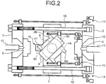
- Fig. 2 is a diagram for illustrating the rotational operation of rotational die plate in the injection molding machine for two-material molding in Fig. 1 .
- Fig. 3 is a side view of the injection molding machine for two-material molding in Fig. 1 .
- Fig. 4 is a side view taken through X-X, illustrating the schematic configuration of the rotational die plate in Fig. 1 .
- Fig. 5 is a process chart of two-material molding performed by the injection molding machine for two-material molding according to the present invention.
- Fig. 6 is a diagram for illustrating a collision avoidance method during opening and closing of die plates in the injection molding machine for two-material molding in Fig. 1 .
- reference numeral 1 denotes a base.
- a fixed die plate 2 to which a fixed side mold 4 is attached is fixedly provided.
- a rotational die plate 9 to which a rotational mold A (6A) and a rotational mold B (6B) are attached to face the fixed die plate 2 and a movable die plate 3 to which a movable side mold 5 is attached are movably mounted.
- the rotational die plate 9 is mounted on a reversal pedestal 7, rotated 180 degrees forwardly and reversely from a predetermined angular position, and positioned at another angular position that is placed face to face with the fixed die plate 2 and the movable die plate 3 by a positioning pin 44a of a positioning apparatus 44 and a hydraulic cylinder 48.
- the movable die plate 3 and the reversal pedestal 7 on which the rotational die plate 9 is mounted are guided to move on the base 1 by a guide rail 19 fixedly provided to the base 1 through a linear bearing (not illustrated).
- the rotational mold A (6A) and the rotational mold B (6B) are attached that have the same shape to fit with the movable side mold 5 and the fixed side mold 4 and form cavities.
- Two sets of an injection unit A (11) and an injection unit B (12) plasticize different resin materials and inject the materials to fill two respective cavities formed by simultaneous mold clamping of the fixed die plate 2, the rotational die plate 9, and the movable die plate 3 by a mold clamping unit.
- the injection unit A (11) is provided on the fixed die plate 2 side and is used for resin injection into the cavity defined by the fixed side mold 4 and the rotational mold A (6A) (or the rotational mold B (6B)), while the injection unit B (12) is provided on the movable die plate 3 side and is used for resin injection into the cavity defined by the movable side mold 5 and the rotational mold B (6B) (or the rotational mold A (6A)) and moves during its operation along with opening and closing movement of the movable die plate 3.
- the injection unit B (12) moves by a large stroke together with the movable die plate 3. Because the injection unit B (12) is mounted on a slidable base 64 connected and fixed to the movable die plate 3 with a connecting and fixing member 63 interposed therebetween, with the movement of the slidable base 64 guided by the guide rail 19, the injection unit B (12) can move to follow the motion of the movable die plate 3 without delay.
- reference numeral 62 denotes a nozzle touch cylinder for the injection unit B (12), and the nozzle touch cylinder enables the injection unit B (12) to slide on the slidable base 64.
- reference numeral 61 denotes a nozzle touch cylinder for the injection unit A (11).
- Fig. 10 illustrates a nozzle touch state
- a nozzle 12a for the injection unit B (12) is in contact with the movable side mold 5, and a nozzle touch state is achieved during mold opening and closing. Therefore, resin can be injected through the nozzle once mold closing and pressure boosting are completed, which makes the process cycle shorter.
- the nozzle 12a When the mold is open, the nozzle 12a does not leave the movable side mold 5, whereby drooling of resin at the tip of the nozzle 12a can be prevented.
- the injection unit B (12) can be operated integrally with the movable platen. Therefore, reduction in shock accompanying operational start or operational stop is achieved, and prevention of collision between the injection unit B (12) and the mold caused by such shock is also achieved.
- Opening and closing units for the movable die plate 3 and the rotational die plate 9 and a rotating unit for the rotational die plate 9 will now be described.
- Movable die plate opening and closing units 14 provided in a pair symmetrically on both sides of the injection molding machine 10 for two-material molding each include a servomotor A (21) fixedly provided to the base 1 or the fixed die plate 2, a ball screw shaft A (22), a support base 26 fixedly provided to the base 1 or the fixed die plate 2 and rotatably supporting the ball screw shaft A (22) while restraining the shaft A (22) in the axial direction, a ball screw nut A (24) threaded onto a ball screw 22a of the ball screw shaft A (22), a nut support base 25 to which the ball screw nut A (24) is attached and that is fixedly provided to the movable die plate 3, and a power transmission mechanism 23 (e.g., a gear pulley and a toothed belt, a geared speed reducer) transmitting the rotational force of the servomotor A (21) to the ball screw shaft A (22). Operations of a pair of such servomotors A (21) are in synchronization, whereby
- Rotational die plate opening and closing units 15 provided in a pair symmetrically on both sides of the injection molding machine 10 for two-material molding each include a servomotor B (31) fixedly provided to the base 1 or the fixed die plate 2, a ball screw shaft B (32), a support base 34 fixedly provided to the base 1 or the fixed die plate 2 and rotatably supporting the ball screw shaft B (32) while restraining the shaft B (32) in the axial direction, a ball screw nut B (33) threaded onto a ball screw 32a of the ball screw shaft B (32), a nut support base 35 to which the ball screw nut B (33) is attached and that is fixedly provided to the reversal pedestal 7, and a power transmission mechanism 36 (e.g., a gear pulley and a toothed belt, a geared speed reducer) transmitting the rotational force of the servomotor B (31) to the ball screw shaft B (32). Operations of a pair of such servomotors (31) are in synchronization, whereby the
- a rotational die plate rotating unit 16 includes, as illustrated in Fig. 4 , a servomotor C (41) attached to the reversal pedestal 7, a pinion 42 attached to the servomotor C (41), a large gear 43 meshing with the pinion 42 and integrally provided to the rotational die plate 9, and a positioning pin 44 for positioning at a position for the fixed die plate 2 (or the movable die plate 3) set by the rotational die plate 9 and at another position rotated 180 degrees from the first position, and is a rotation driving unit that makes the rotational die plate 9 one-half turn in a forward-and-backward direction.
- Reference numeral 8 denotes a lower shaft integral with the rotational die plate 9, and the shaft is rotatable with respect to the reversal pedestal 7 through a bearing.
- the hydraulic cylinder 48 may cause the positioning pin 44a to be insertable into a positioning pin insertion hole (not illustrated).
- a control apparatus may be further provided that enables control to start insertion operation of the positioning pin 44a at a predetermined position in the rotational direction of the reversal pedestal that is reversely rotating where the center of the positioning pin insertion hole is just ahead of coinciding with the center of the positioning pin of a positioning pin insertion apparatus.
- the insertion hole for the positioning pin 44a preferably has a shape somewhat tapered from the pin side.
- a hydraulic mold clamping unit includes, as illustrated in Fig. 1 , four hydraulic cylinders 2a incorporated in the fixed die plate 2, four tie bars 18 having ring grooves 18a on their leading ends, the tie bars 18 being connected to rams 18b of the respective cylinders 2a and provided to penetrate the movable die plate 3, and four sets of split nuts 17 provided outside of the movable die plate 3 and engageable with the ring grooves 18a of the tie bars 18; and is a hydraulic mold clamping unit that mold-clamps the three sets of die plates 2, 9, 3 simultaneously.
- molten resin A from the injection unit A (11) is injected to fill the cavity defined by the rotational mold B (6B) and the fixed side mold 4.
- molten resin B from the injection unit B (12) is injected to fill the cavity defined by the molding attached to the rotational mold A (6A) and the movable side mold 5. Accordingly, a two-material molding in which the two materials overlap is formed.
- injection filling operations performed by the injection unit A (11) and the injection unit B (12) are performed simultaneously.
- injection compression molding, foam molding, gas-assisted molding, and insert molding injection filling operations performed by the injection unit A (11) and the injection unit B (12) may be performed sequentially.
- a die plate to which a mold is attached has a large weight; therefore, its movement speed and acceleration rate need to be determined carefully.
- a rotational mold has a weight of 18 tons (9 tons/mold ⁇ 2 molds), and the rotational die plate 9 for rotating a mold has a weight of 20 tons. Therefore, if a high movement speed is selected, necessary acceleration force becomes large or acceleration takes time, resulting in a large load on the driving unit. In addition, abrupt acceleration and deceleration can cause vibrations.
- a ball screw apparatus driven by a servomotor facilitates control of the movement speed and the stop position of a driven object by programmed control of the rotational speed of the servomotor.
- a servomotor and a ball screw driving unit may be employed as a moving unit for the movable die plate 3 and the rotational die plate 9 in the injection molding machine 10 for two-material molding
- an acceleration profile e.g., a sine curve
- smooth acceleration deceleration
- a control apparatus not illustrated
- a speed and positional control program may be so built as to enable set inputs that are adjustable to make the movable die plate 3 and the reversal pedestal 7 on which the rotational die plate 9 is mounted move for mold opening and closing at the shortest mold opening and closing movement time, and the servomotor is controlled thereby.
- the use of the servomotor enables operation with high accuracy.
- a control apparatus that is capable of feedback control of operation of each of the electric motors may be also provided, thereby enabling feedback control.
- the speed of the cycle of two-material molding can be thus increased, which also enables operation with high accuracy.
- speed control for acceleration or deceleration causes acceleration or deceleration to follow a primary linear line with a constant gradient
- speed control for acceleration or deceleration from a constant speed causes speed control to follow a quadric curve that is tangent to each primary linear speed of the constant speed and acceleration or the constant speed and deceleration. In this manner, smooth control can be achieved.
- a rotational speed control program is so built as to enable set inputs to make rotational acceleration and rotational speed adjustable in a manner that the rotational die plate 9 on the reversal pedestal 7 rotates 180 degrees in the shortest rotation time, and the servomotor is controlled thereby.
- the weight of a reinforcement rib 9a of the rotational die plate 9 may be reduced in a manner that the thickness thereof reduces outwardly from the center of the rotational die plate gradually as illustrated in Figs. 11 and 12 .
- a molding may be released from the molds with a driving apparatus provided in the rotational die plate 9 and performing operations of movable members in the molds, such as molding ejection operation, movable nesting operation, and gate valve operation in the molds.
- a communication apparatus capable of sending and receiving control signals wirelessly may be provided, thereby reducing the weight with simplified wiring and reduced wiring members.
- a distance required for stopping the movable die plate 3 or the reversal pedestal 7 on which the rotational die plate 9 is mounted is set as a collision avoidance distance e (not illustrated), the positions of the fixed die plate 2, the movable die plate 3, and the rotational die plate 9 are monitored. When any of their relative positions falls within the collision avoidance distance e, the approaching one is automatically decelerated or stopped to avoid collision during the opening and closing movement of the movable die plate 3 and the rotational die plate 9.
- c2 denotes a corner of the rotational die plate 9 or a corner of the rotational mold A (6A) that follows a rotational trajectory with the largest distance r2 on the fixed die plate 2 side from the rotational axis of the rotational die plate 9 in the direction perpendicular to the rotational axis
- c1 denotes a corner of the rotational die plate 9 or a corner of the rotational mold B (6B) that follows a rotational trajectory with the largest distance r1 on the movable die plate 3 side from the rotational axis in the direction perpendicular to the rotational axis
- L2 denotes a distance from the rotational axis of the rotational die plate 9 to c2
- L1 denotes a distance
- Fig. 6 illustrates an example with the corner c2 of the rotational mold A (6A) and the corner c1 of the rotational mold B (6B).
- L1 and L2 are variables determined uniquely based on the rotational angle of the rotational die plate 9 and the distances r1 and r2.
- the distance between the rotational die plate 9 and the fixed die plate 2 and the distance between the rotational die plate 9 and the movable die plate 3 during the rotation of the rotational die plate 9 are calculated based on the position of the movable die plate and the position and the rotational angle of the rotational die plate.
- the approaching one may be automatically decelerated or stopped to avoid collision during the opening and closing movement of the movable die plate 3 and the rotational die plate 9 and the rotation of the rotational die plate 9.
- the second embodiment differs from the first embodiment in that, as illustrated in the schematic plan view of an injection molding machine 30 for two-material molding in Fig. 7 , the servomotor A (21) for a movable die plate opening and closing unit 46 that drives the movable die plate 3 and the support base 26 for a ball screw shaft 47 are provided to the reversal pedestal 7.
- the second embodiment is the same as the first embodiment in other respects; therefore, the description of other configurations thereof will be omitted.
- An advantage of the second embodiment is to make the ball screw shaft 47 short, and thus to enhance the critical speed of the ball screw shaft 4 and increase the opening and closing speed of the movable die plate 3. Because the rotational die plate 9 and the movable die plate 3 are connected directly with a ball screw, calculation of the relative position of the rotational die plate 9 and the movable die plate 3 is not required for detecting and controlling the relative distance between the rotational die plate 9 and the movable plate 3 during mold opening and closing, etc., which facilitates control.
- a rotational die plate rotating unit 50 includes the servomotor C (41) attached to the reversal pedestal 7, a pinion 53 attached to the servomotor C (41), a large gear 52 meshing with the pinion 53 and integrally provided to the rotational die plate 9, and an endless toothed belt 54 wound around the pinion 53 and the large gear 52; and is a rotation driving unit that makes the rotational die plate 9 one-half turn in a forward-and-backward direction.
- the third embodiment is the same as the first embodiment in other respects; therefore, the description of other configurations thereof will be omitted.
- the direct drive system by the servomotor D (56) involves no gear or belt. Therefore, the rotational die plate 9 rotates according to program commands, resulting in no backlash in operation.
Landscapes
- Engineering & Computer Science (AREA)
- Manufacturing & Machinery (AREA)
- Mechanical Engineering (AREA)
- Injection Moulding Of Plastics Or The Like (AREA)
- Moulds For Moulding Plastics Or The Like (AREA)
Claims (4)
- Machine de moulage par injection (10, 30) pour un moulage à deux matières comportant :une base (1),une plaque de matrice mobile (3) sur laquelle un moule latéral mobile (5) est fixé, la plaque de matrice mobile (3) étant montée de manière mobile sur la base (1),une plaque de matrice fixe (2) sur laquelle un moule latéral fixe (4) est fixé, la plaque de matrice fixe (2) étant prévue de façon fixe à l'extrémité de la base (1),un socle d'inversion (7) qui est prévu entre la plaque de matrice mobile (3) et la plaque de matrice fixe (2) et mobile dans une même direction que la plaque de matrice mobile (3) ;une plaque de matrice rotative (9) qui peut tourner sur 180 degrés sur le socle d'inversion (7) et sur laquelle des moules sont fixés des deux côtés pour correspondre au moule latéral mobile (5) et au moule latéral fixe (4) et pour définir des cavités respectives ;une unité d'ouverture et de fermeture de moule de plaque de matrice mobile (14 ; 46) qui ouvre et ferme le moule de la plaque de matrice mobile (3) ;une unité d'ouverture et de fermeture de moule de plaque de matrice rotative (15) qui ouvre et ferme les moules de la plaque de matrice rotative (9) ;une unité de serrage de moule qui serre simultanément les moules des trois ensembles de plaques de matrice après la fermeture de moule ; etdeux ensembles d'unités d'injection (11, 12) qui plastifient les différentes matières de résine et injectent les matières jusqu'à remplissage, dans laquellel'unité de serrage de moule est une unité de serrage de moule hydraulique qui serre simultanément les moules des trois ensembles de plaques de matrice,l'unité d'ouverture et de fermeture de plaque de matrice mobile (14 ; 46) est une unité d'ouverture et de fermeture de plaque de matrice mobile (14 ; 46) entraînée par un moteur électrique,l'unité d'ouverture et de fermeture de plaque de matrice rotative (15) est une unité d'ouverture et de fermeture de plaque de matrice rotative (15) entraînée par un moteur électrique, etune unité de rotation (16 ; 50 ; 60) pour la plaque de matrice rotative (9) est une unité d'entraînement en rotation entraînée par un moteur électrique fixé au socle d'inversion (7),caractérisée en ce queun ensemble parmi les deux ensembles d'unités d'injection (11, 12) est prévu sur le côté de plaque de matrice fixe et mobile vers l'avant et vers l'arrière par rapport à la plaque de matrice fixeun autre ensemble (11, 12) est prévu sur une base coulissante (64), la base coulissante (64) étant fixée sur la plaque de matrice mobile (3) avec un élément de raccordement et de fixation (63) interposé entre elles, l'autre ensemble (11, 12) étant mobile vers l'avant et vers l'arrière par rapport à la plaque de matrice mobile (3),dans l'ouverture et la fermeture de moule de la plaque de matrice mobile (3), l'autre ensemble d'unités d'injection (11, 12) est mobile grâce à un cylindre de contact de buse (62) tout en butant sur le moule fixé sur la plaque de matrice mobile (3), le cylindre de contact de buse (62) permettant à l'autre unité d'injection (11, 12) de coulisser sur la base coulissante (64).
- Machine de moulage par injection (10 ; 30) pour le moulage à deux matières selon la revendication 1, dans laquelle la plaque de matrice rotative (9) et la plaque de matrice mobile (3) sont reliées directement à une vis à billes.
- Procédé de commande d'une machine de moulage par injection (10 ; 30) pour le moulage à deux matières qui utilise la machine de moulage par injection (10 ; 30) pour le moulage à deux matières selon la revendication 1 ou 2, le procédé comportant :dans un processus de moulage de : fermeture de moule de la plaque de matrice mobile (3) et du socle d'inversion (7) sur lequel la plaque de matrice rotative (9) est montée, serrage de moule, remplissage par injection de résine fondue, refroidissement de celle-ci, mouvement d'ouverture de moule de la plaque de matrice mobile (3) et du socle d'inversion (7) sur lequel la plaque de matrice rotative (9) est montée, rotation à 180 degrés de la plaque de matrice rotative (9), refermeture de moule de la plaque de matrice mobile (3) et du socle d'inversion (7) sur lequel la plaque de matrice rotative (9) est montée, et serrage de moule,l'établissement d'une distance exigée pour arrêter la plaque de matrice mobile (3) ou la plaque de matrice rotative (9) qui se déplace comme une distance d'évitement de collision, etla surveillance de chaque position de fin de mouvement de la plaque de matrice mobile (3) et du moule de celle-ci et de la plaque de matrice rotative (9) et du moule de celle-ci, etquand une position relative des fins de mouvement des deux plaques de matrice ou des moules de celles-ci tombent dans la distance d'évitement de collision, une plaque qui s'approche des plaques de matrice qui se déplace est automatiquement ralentie ou arrêtée pour éviter une collision pendant un mouvement d'ouverture et de fermeture de la plaque de matrice mobile (3) et de la plaque de matrice rotative (9).
- Procédé de commande d'une machine de moulage par injection pour le moulage à deux matières selon la revendication 3, comportant le fait de réaliser une commande d'accélération, de maintien de vitesse, et de décélération avec un moteur électrique pour rendre un temps de mouvement d'ouverture et de fermeture de moule de la plaque de matrice mobile (3) et du socle d'inversion (7) sur lequel la plaque de matrice rotative (9) est monté le plus court.
Priority Applications (1)
| Application Number | Priority Date | Filing Date | Title |
|---|---|---|---|
| EP15192977.5A EP3000577B1 (fr) | 2008-03-25 | 2008-03-25 | Machine de moulage par injection pour moulage de deux matériaux et procédés pour son contrôle |
Applications Claiming Priority (3)
| Application Number | Priority Date | Filing Date | Title |
|---|---|---|---|
| PCT/JP2008/055596 WO2009118833A1 (fr) | 2008-03-25 | 2008-03-25 | Machine de moulage par injection pour moulage de deux matériaux et procédé pour son contrôle |
| EP08722806.0A EP2269796B1 (fr) | 2008-03-25 | 2008-03-25 | Machine de moulage par injection pour moulage de deux matériaux et procédés pour son contrôle |
| EP15192977.5A EP3000577B1 (fr) | 2008-03-25 | 2008-03-25 | Machine de moulage par injection pour moulage de deux matériaux et procédés pour son contrôle |
Related Parent Applications (2)
| Application Number | Title | Priority Date | Filing Date |
|---|---|---|---|
| EP08722806.0A Division EP2269796B1 (fr) | 2008-03-25 | 2008-03-25 | Machine de moulage par injection pour moulage de deux matériaux et procédés pour son contrôle |
| EP08722806.0A Division-Into EP2269796B1 (fr) | 2008-03-25 | 2008-03-25 | Machine de moulage par injection pour moulage de deux matériaux et procédés pour son contrôle |
Publications (2)
| Publication Number | Publication Date |
|---|---|
| EP3000577A1 EP3000577A1 (fr) | 2016-03-30 |
| EP3000577B1 true EP3000577B1 (fr) | 2018-02-21 |
Family
ID=41113074
Family Applications (2)
| Application Number | Title | Priority Date | Filing Date |
|---|---|---|---|
| EP15192977.5A Active EP3000577B1 (fr) | 2008-03-25 | 2008-03-25 | Machine de moulage par injection pour moulage de deux matériaux et procédés pour son contrôle |
| EP08722806.0A Active EP2269796B1 (fr) | 2008-03-25 | 2008-03-25 | Machine de moulage par injection pour moulage de deux matériaux et procédés pour son contrôle |
Family Applications After (1)
| Application Number | Title | Priority Date | Filing Date |
|---|---|---|---|
| EP08722806.0A Active EP2269796B1 (fr) | 2008-03-25 | 2008-03-25 | Machine de moulage par injection pour moulage de deux matériaux et procédés pour son contrôle |
Country Status (5)
| Country | Link |
|---|---|
| US (1) | US8163218B2 (fr) |
| EP (2) | EP3000577B1 (fr) |
| JP (1) | JP4902785B2 (fr) |
| CN (1) | CN101888921B (fr) |
| WO (1) | WO2009118833A1 (fr) |
Families Citing this family (39)
| Publication number | Priority date | Publication date | Assignee | Title |
|---|---|---|---|---|
| CN102211379A (zh) * | 2010-04-09 | 2011-10-12 | 海尔集团公司 | 双色注塑模具、注塑机及双色注塑工艺 |
| JP5030116B2 (ja) | 2010-04-27 | 2012-09-19 | 株式会社名機製作所 | 複合成形品用射出成形機およびその成形方法 |
| US8747094B2 (en) * | 2011-02-28 | 2014-06-10 | Ube Machinery Corporation, Ltd. | Multilayer molding apparatus and injection molding method |
| CN102941648B (zh) * | 2011-08-15 | 2014-12-17 | 天津三星电子有限公司 | 一种用于注塑厚肉产品的模具 |
| AT13306U1 (de) * | 2012-03-02 | 2013-10-15 | Engel Austria Gmbh | Schließeinheit für eine Spritzgießmaschine |
| CN102729428A (zh) * | 2012-06-11 | 2012-10-17 | 无锡天惠塑机有限公司 | 合模模板装置 |
| CN102806628B (zh) * | 2012-07-23 | 2014-10-29 | 浙江申达机器制造股份有限公司 | 双模同步注射成型机 |
| CN102896739B (zh) * | 2012-09-29 | 2015-04-22 | 鸿利达模具(深圳)有限公司 | 多零件注塑组装多用模 |
| DE102013006713A1 (de) | 2013-04-19 | 2014-10-23 | Otto Männer Innovation GmbH | Multishot-Spitzgussvorrichtung |
| CN103317661A (zh) * | 2013-05-31 | 2013-09-25 | 宁波京阪工业有限公司 | 一种带双注射装置的注塑机 |
| JP5883045B2 (ja) * | 2014-02-10 | 2016-03-09 | ファナック株式会社 | 射出成形機の固定プラテン |
| FR3017323B1 (fr) * | 2014-02-11 | 2016-02-26 | Groupe Jbt | Procede de fabrication de pieces en polymere par injection dans une cavite et systeme associe |
| CN104002261B (zh) * | 2014-05-15 | 2016-06-22 | 华南理工大学 | 用于批次过程装备的牵引式直线位移及夹持装置与方法 |
| US10946570B2 (en) | 2014-06-06 | 2021-03-16 | Mitsubishi Heavy Industries Plastic Technology Co., Ltd. | Injection molding method and injection molding machine |
| CN104526980B (zh) * | 2014-12-23 | 2017-02-22 | 深圳创维精密科技有限公司 | 三色注塑模具 |
| JP6161214B2 (ja) * | 2015-03-25 | 2017-07-12 | 株式会社名機製作所 | 複合成形品成形用の射出成形機 |
| JP6247258B2 (ja) * | 2015-08-04 | 2017-12-13 | ファナック株式会社 | 金型回転装置を具備する射出成形機 |
| WO2017107132A1 (fr) * | 2015-12-24 | 2017-06-29 | Hui Wai Kee | Système et procédé pour le moulage par injection de constituants à matériaux multiples |
| JP6395188B2 (ja) * | 2016-01-19 | 2018-09-26 | 株式会社日本製鋼所 | 型締装置及び方法 |
| CN109311194B (zh) * | 2016-06-08 | 2021-01-19 | 尼根机械有限公司 | 具有旋转装置的注射成型机器 |
| JP6400057B2 (ja) * | 2016-08-23 | 2018-10-03 | 株式会社名機製作所 | 金型回転式射出成形機の金型交換システム |
| JP7114284B2 (ja) * | 2017-03-29 | 2022-08-08 | 住友重機械工業株式会社 | 射出成形機 |
| JP6537209B2 (ja) * | 2017-03-30 | 2019-07-03 | 株式会社名機製作所 | 射出成形機の制御方法および射出成形機 |
| CN108688104B (zh) * | 2017-03-30 | 2021-01-26 | 株式会社日本制钢所 | 注塑成形机的控制方法和注塑成形机 |
| CN107599433A (zh) * | 2017-09-04 | 2018-01-19 | 广东泰安模塑科技股份有限公司 | 一种模内注塑与发泡包覆一体化工艺 |
| CN107379392A (zh) * | 2017-09-04 | 2017-11-24 | 广东泰安模塑科技股份有限公司 | 一种模内注塑与涂装工艺 |
| JP6725797B2 (ja) * | 2017-10-06 | 2020-07-22 | U−Mhiプラテック株式会社 | 型盤、型締装置、射出成形機 |
| CN109968617A (zh) * | 2017-12-28 | 2019-07-05 | 海天塑机集团有限公司 | 一种注塑机的水平旋转合模机构 |
| JP6666639B2 (ja) | 2018-04-02 | 2020-03-18 | 株式会社名機製作所 | 成形機および成形機の制御方法 |
| WO2019228628A1 (fr) * | 2018-05-30 | 2019-12-05 | HELLA GmbH & Co. KGaA | Procédé et système d'outil pour la fabrication d'une pièce moulée en plastique à éléments multiples |
| CN109248989A (zh) * | 2018-10-12 | 2019-01-22 | 深圳思创达自动化设备有限公司 | 一种蜡模制造设备 |
| JP6845837B2 (ja) * | 2018-10-25 | 2021-03-24 | 株式会社日本製鋼所 | 射出成形機の型開閉制御方法および射出成形機 |
| EP3930979A4 (fr) | 2019-03-01 | 2022-11-23 | Canon Virginia, Inc. | Système de moulage par injection doté de transporteurs servant à insérer ou éjecter des moules |
| KR20200113850A (ko) * | 2019-03-26 | 2020-10-07 | 주식회사 엘지화학 | 사출 성형 장치 및 사출 성형 방법 |
| CN112549436A (zh) * | 2019-09-10 | 2021-03-26 | 深圳兴精科塑胶模具有限公司 | 一种模内旋转多物料成型模具 |
| CN111923318A (zh) * | 2020-08-03 | 2020-11-13 | 歌尔股份有限公司 | 发声装置及其成型方法 |
| JP6961119B1 (ja) * | 2021-01-28 | 2021-11-05 | 住友重機械工業株式会社 | 射出成形機 |
| CN114750350B (zh) * | 2022-04-01 | 2022-12-06 | 东莞市信天游实业有限公司 | 一种半蚀刻喇叭网底壳加工用循环注塑设备 |
| CN117817947A (zh) * | 2024-03-06 | 2024-04-05 | 宁波力劲塑机智造有限公司 | 一种水平对射机 |
Family Cites Families (20)
| Publication number | Priority date | Publication date | Assignee | Title |
|---|---|---|---|---|
| US2447101A (en) * | 1944-02-15 | 1948-08-17 | Stock Hubert Arthur | Die casting machine |
| US4307057A (en) * | 1980-06-13 | 1981-12-22 | Siebolt Hettinga | Method for aligning an injection mold with a nozzle at the mold injection station |
| US4439133A (en) * | 1981-02-24 | 1984-03-27 | Husky Injection Molding Systems Ltd. | Turret-type injection-molding machine |
| JPS5811117A (ja) * | 1981-07-14 | 1983-01-21 | Sumitomo Heavy Ind Ltd | 射出延伸吹込成形装置 |
| JPS6260618A (ja) | 1985-09-11 | 1987-03-17 | Japan Steel Works Ltd:The | 射出積層成形装置 |
| JPH0351207A (ja) * | 1990-06-19 | 1991-03-05 | Daifuku Co Ltd | ローラコンベヤ |
| DE4022020A1 (de) | 1990-07-11 | 1992-01-16 | Gao Ges Automation Org | Vorrichtung und verfahren zur pruefung von dokumenten |
| JPH04371360A (ja) * | 1991-06-20 | 1992-12-24 | Toshiba Mach Co Ltd | 鋳造機の制御装置 |
| JPH06254906A (ja) | 1993-03-09 | 1994-09-13 | Mitsubishi Heavy Ind Ltd | 多材質射出成形機 |
| US5728409A (en) | 1996-03-06 | 1998-03-17 | Husky Injection Molding Systems Ltd. | Turret article molding machine |
| US5817345A (en) | 1996-03-06 | 1998-10-06 | Husky Injection Molding System Ltd. | Turrent article molding machine and method of use |
| JP3333090B2 (ja) | 1996-06-14 | 2002-10-07 | 株式会社名機製作所 | ロータリテーブルの回転位置決め方法および回転位置決め装置 |
| EP0922556A1 (fr) * | 1997-12-03 | 1999-06-16 | FOBOHA GmbH | Machine à mouler par injection avec des moules mobiles, dispositif de fixation ainsi que support de moule pour une telle machine à mouler par injection |
| JP4682483B2 (ja) | 2001-08-29 | 2011-05-11 | 株式会社村田製作所 | 射出成形装置 |
| JP2003205538A (ja) * | 2002-01-16 | 2003-07-22 | Mitsubishi Heavy Ind Ltd | 射出成形機の型締装置及び型締制御方法 |
| DE10347638A1 (de) * | 2003-10-09 | 2005-05-19 | Krauss-Maffei Kunststofftechnik Gmbh | Horizontal-Spritzgießmaschine mit Dreheinrichtung |
| CN1319720C (zh) * | 2003-12-30 | 2007-06-06 | 刘津平 | 高分子材料挤出-注射成型方法及其装置 |
| JP4347791B2 (ja) * | 2004-12-16 | 2009-10-21 | 株式会社名機製作所 | 多材質射出成形機 |
| JP4874565B2 (ja) * | 2005-04-08 | 2012-02-15 | 東芝機械株式会社 | 中子を有する金型を取付けたダイカストマシンの電動式型締方法 |
| JP4410192B2 (ja) | 2005-12-07 | 2010-02-03 | 株式会社名機製作所 | 射出成形機 |
-
2008
- 2008-03-25 JP JP2010505074A patent/JP4902785B2/ja active Active
- 2008-03-25 WO PCT/JP2008/055596 patent/WO2009118833A1/fr active Application Filing
- 2008-03-25 EP EP15192977.5A patent/EP3000577B1/fr active Active
- 2008-03-25 EP EP08722806.0A patent/EP2269796B1/fr active Active
- 2008-03-25 CN CN2008801191687A patent/CN101888921B/zh active Active
- 2008-03-25 US US12/746,331 patent/US8163218B2/en active Active
Non-Patent Citations (1)
| Title |
|---|
| None * |
Also Published As
| Publication number | Publication date |
|---|---|
| WO2009118833A1 (fr) | 2009-10-01 |
| JP4902785B2 (ja) | 2012-03-21 |
| EP3000577A1 (fr) | 2016-03-30 |
| US8163218B2 (en) | 2012-04-24 |
| EP2269796A4 (fr) | 2013-11-06 |
| EP2269796A1 (fr) | 2011-01-05 |
| EP2269796B1 (fr) | 2016-03-23 |
| JPWO2009118833A1 (ja) | 2011-07-21 |
| US20100244314A1 (en) | 2010-09-30 |
| CN101888921B (zh) | 2013-06-19 |
| CN101888921A (zh) | 2010-11-17 |
Similar Documents
| Publication | Publication Date | Title |
|---|---|---|
| EP3000577B1 (fr) | Machine de moulage par injection pour moulage de deux matériaux et procédés pour son contrôle | |
| JP4942088B2 (ja) | 二材成形用射出成形機及び制御方法 | |
| EP1726426B1 (fr) | Dispositif de serrage de moule et procédé de réglage d'épaisseur de moule | |
| US7316259B2 (en) | Diecasting machine | |
| WO2011070608A1 (fr) | Machine à injecter pour moulage bi-matériau | |
| EP1795325B1 (fr) | Dispositif de serrage de moule | |
| JP5105087B2 (ja) | 二材成形用射出成形機 | |
| CN103895193A (zh) | 注射成型机 | |
| CN103317685B (zh) | 注射成型机 | |
| JP5394335B2 (ja) | 射出成形機の中間型盤 | |
| CN103722664B (zh) | 双材料成型用注塑成型机及其控制方法 | |
| CN103895194A (zh) | 注射成型机 | |
| US5190714A (en) | Mold clamping system | |
| US5102327A (en) | Mold clamping system | |
| US20080185119A1 (en) | Control Method of Die-Casting Machine | |
| CN103862643A (zh) | 一种微型注塑机 | |
| CN213618179U (zh) | 一种混合动力注塑机 | |
| JP5654327B2 (ja) | ダイカストマシン及びダイカストマシンの増圧制御方法 | |
| US20160184887A1 (en) | Clamping device and molding apparatus | |
| JP4153466B2 (ja) | 電動射出成形機の射出装置 | |
| US20090214687A1 (en) | Injection Molding Machine | |
| JP6077427B2 (ja) | 射出成形機の制御装置及び制御方法 | |
| JP2002192563A (ja) | 金型交換方法および金型交換装置 | |
| JP4657251B2 (ja) | ダイカストマシンの制御方法 | |
| JP4646695B2 (ja) | ダイカストマシン |
Legal Events
| Date | Code | Title | Description |
|---|---|---|---|
| PUAI | Public reference made under article 153(3) epc to a published international application that has entered the european phase |
Free format text: ORIGINAL CODE: 0009012 |
|
| AC | Divisional application: reference to earlier application |
Ref document number: 2269796 Country of ref document: EP Kind code of ref document: P |
|
| AK | Designated contracting states |
Kind code of ref document: A1 Designated state(s): AT BE BG CH CY CZ DE DK EE ES FI FR GB GR HR HU IE IS IT LI LT LU LV MC MT NL NO PL PT RO SE SI SK TR |
|
| 17P | Request for examination filed |
Effective date: 20160908 |
|
| RBV | Designated contracting states (corrected) |
Designated state(s): AT BE BG CH CY CZ DE DK EE ES FI FR GB GR HR HU IE IS IT LI LT LU LV MC MT NL NO PL PT RO SE SI SK TR |
|
| GRAP | Despatch of communication of intention to grant a patent |
Free format text: ORIGINAL CODE: EPIDOSNIGR1 |
|
| INTG | Intention to grant announced |
Effective date: 20170927 |
|
| GRAS | Grant fee paid |
Free format text: ORIGINAL CODE: EPIDOSNIGR3 |
|
| GRAA | (expected) grant |
Free format text: ORIGINAL CODE: 0009210 |
|
| AC | Divisional application: reference to earlier application |
Ref document number: 2269796 Country of ref document: EP Kind code of ref document: P |
|
| AK | Designated contracting states |
Kind code of ref document: B1 Designated state(s): AT BE BG CH CY CZ DE DK EE ES FI FR GB GR HR HU IE IS IT LI LT LU LV MC MT NL NO PL PT RO SE SI SK TR |
|
| REG | Reference to a national code |
Ref country code: GB Ref legal event code: FG4D |
|
| REG | Reference to a national code |
Ref country code: CH Ref legal event code: EP |
|
| REG | Reference to a national code |
Ref country code: DE Ref legal event code: R096 Ref document number: 602008054176 Country of ref document: DE Ref country code: AT Ref legal event code: REF Ref document number: 971221 Country of ref document: AT Kind code of ref document: T Effective date: 20180315 |
|
| REG | Reference to a national code |
Ref country code: IE Ref legal event code: FG4D |
|
| REG | Reference to a national code |
Ref country code: LT Ref legal event code: MG4D |
|
| PG25 | Lapsed in a contracting state [announced via postgrant information from national office to epo] |
Ref country code: CY Free format text: LAPSE BECAUSE OF FAILURE TO SUBMIT A TRANSLATION OF THE DESCRIPTION OR TO PAY THE FEE WITHIN THE PRESCRIBED TIME-LIMIT Effective date: 20180221 Ref country code: LT Free format text: LAPSE BECAUSE OF FAILURE TO SUBMIT A TRANSLATION OF THE DESCRIPTION OR TO PAY THE FEE WITHIN THE PRESCRIBED TIME-LIMIT Effective date: 20180221 Ref country code: HR Free format text: LAPSE BECAUSE OF FAILURE TO SUBMIT A TRANSLATION OF THE DESCRIPTION OR TO PAY THE FEE WITHIN THE PRESCRIBED TIME-LIMIT Effective date: 20180221 Ref country code: FI Free format text: LAPSE BECAUSE OF FAILURE TO SUBMIT A TRANSLATION OF THE DESCRIPTION OR TO PAY THE FEE WITHIN THE PRESCRIBED TIME-LIMIT Effective date: 20180221 Ref country code: NO Free format text: LAPSE BECAUSE OF FAILURE TO SUBMIT A TRANSLATION OF THE DESCRIPTION OR TO PAY THE FEE WITHIN THE PRESCRIBED TIME-LIMIT Effective date: 20180521 Ref country code: ES Free format text: LAPSE BECAUSE OF FAILURE TO SUBMIT A TRANSLATION OF THE DESCRIPTION OR TO PAY THE FEE WITHIN THE PRESCRIBED TIME-LIMIT Effective date: 20180221 Ref country code: NL Free format text: LAPSE BECAUSE OF FAILURE TO SUBMIT A TRANSLATION OF THE DESCRIPTION OR TO PAY THE FEE WITHIN THE PRESCRIBED TIME-LIMIT Effective date: 20180221 |
|
| PG25 | Lapsed in a contracting state [announced via postgrant information from national office to epo] |
Ref country code: GR Free format text: LAPSE BECAUSE OF FAILURE TO SUBMIT A TRANSLATION OF THE DESCRIPTION OR TO PAY THE FEE WITHIN THE PRESCRIBED TIME-LIMIT Effective date: 20180522 Ref country code: LV Free format text: LAPSE BECAUSE OF FAILURE TO SUBMIT A TRANSLATION OF THE DESCRIPTION OR TO PAY THE FEE WITHIN THE PRESCRIBED TIME-LIMIT Effective date: 20180221 Ref country code: SE Free format text: LAPSE BECAUSE OF FAILURE TO SUBMIT A TRANSLATION OF THE DESCRIPTION OR TO PAY THE FEE WITHIN THE PRESCRIBED TIME-LIMIT Effective date: 20180221 Ref country code: BG Free format text: LAPSE BECAUSE OF FAILURE TO SUBMIT A TRANSLATION OF THE DESCRIPTION OR TO PAY THE FEE WITHIN THE PRESCRIBED TIME-LIMIT Effective date: 20180521 |
|
| PG25 | Lapsed in a contracting state [announced via postgrant information from national office to epo] |
Ref country code: EE Free format text: LAPSE BECAUSE OF FAILURE TO SUBMIT A TRANSLATION OF THE DESCRIPTION OR TO PAY THE FEE WITHIN THE PRESCRIBED TIME-LIMIT Effective date: 20180221 Ref country code: IT Free format text: LAPSE BECAUSE OF FAILURE TO SUBMIT A TRANSLATION OF THE DESCRIPTION OR TO PAY THE FEE WITHIN THE PRESCRIBED TIME-LIMIT Effective date: 20180221 Ref country code: RO Free format text: LAPSE BECAUSE OF FAILURE TO SUBMIT A TRANSLATION OF THE DESCRIPTION OR TO PAY THE FEE WITHIN THE PRESCRIBED TIME-LIMIT Effective date: 20180221 Ref country code: PL Free format text: LAPSE BECAUSE OF FAILURE TO SUBMIT A TRANSLATION OF THE DESCRIPTION OR TO PAY THE FEE WITHIN THE PRESCRIBED TIME-LIMIT Effective date: 20180221 |
|
| REG | Reference to a national code |
Ref country code: CH Ref legal event code: PL |
|
| REG | Reference to a national code |
Ref country code: DE Ref legal event code: R097 Ref document number: 602008054176 Country of ref document: DE |
|
| PG25 | Lapsed in a contracting state [announced via postgrant information from national office to epo] |
Ref country code: SK Free format text: LAPSE BECAUSE OF FAILURE TO SUBMIT A TRANSLATION OF THE DESCRIPTION OR TO PAY THE FEE WITHIN THE PRESCRIBED TIME-LIMIT Effective date: 20180221 Ref country code: CZ Free format text: LAPSE BECAUSE OF FAILURE TO SUBMIT A TRANSLATION OF THE DESCRIPTION OR TO PAY THE FEE WITHIN THE PRESCRIBED TIME-LIMIT Effective date: 20180221 Ref country code: MC Free format text: LAPSE BECAUSE OF FAILURE TO SUBMIT A TRANSLATION OF THE DESCRIPTION OR TO PAY THE FEE WITHIN THE PRESCRIBED TIME-LIMIT Effective date: 20180221 Ref country code: DK Free format text: LAPSE BECAUSE OF FAILURE TO SUBMIT A TRANSLATION OF THE DESCRIPTION OR TO PAY THE FEE WITHIN THE PRESCRIBED TIME-LIMIT Effective date: 20180221 |
|
| REG | Reference to a national code |
Ref country code: BE Ref legal event code: MM Effective date: 20180331 |
|
| REG | Reference to a national code |
Ref country code: IE Ref legal event code: MM4A |
|
| PLBE | No opposition filed within time limit |
Free format text: ORIGINAL CODE: 0009261 |
|
| STAA | Information on the status of an ep patent application or granted ep patent |
Free format text: STATUS: NO OPPOSITION FILED WITHIN TIME LIMIT |
|
| PG25 | Lapsed in a contracting state [announced via postgrant information from national office to epo] |
Ref country code: LU Free format text: LAPSE BECAUSE OF NON-PAYMENT OF DUE FEES Effective date: 20180325 |
|
| 26N | No opposition filed |
Effective date: 20181122 |
|
| GBPC | Gb: european patent ceased through non-payment of renewal fee |
Effective date: 20180521 |
|
| PG25 | Lapsed in a contracting state [announced via postgrant information from national office to epo] |
Ref country code: IE Free format text: LAPSE BECAUSE OF NON-PAYMENT OF DUE FEES Effective date: 20180325 |
|
| PG25 | Lapsed in a contracting state [announced via postgrant information from national office to epo] |
Ref country code: SI Free format text: LAPSE BECAUSE OF FAILURE TO SUBMIT A TRANSLATION OF THE DESCRIPTION OR TO PAY THE FEE WITHIN THE PRESCRIBED TIME-LIMIT Effective date: 20180221 Ref country code: CH Free format text: LAPSE BECAUSE OF NON-PAYMENT OF DUE FEES Effective date: 20180331 Ref country code: BE Free format text: LAPSE BECAUSE OF NON-PAYMENT OF DUE FEES Effective date: 20180331 Ref country code: LI Free format text: LAPSE BECAUSE OF NON-PAYMENT OF DUE FEES Effective date: 20180331 |
|
| PG25 | Lapsed in a contracting state [announced via postgrant information from national office to epo] |
Ref country code: FR Free format text: LAPSE BECAUSE OF NON-PAYMENT OF DUE FEES Effective date: 20180421 Ref country code: GB Free format text: LAPSE BECAUSE OF NON-PAYMENT OF DUE FEES Effective date: 20180521 |
|
| PG25 | Lapsed in a contracting state [announced via postgrant information from national office to epo] |
Ref country code: MT Free format text: LAPSE BECAUSE OF NON-PAYMENT OF DUE FEES Effective date: 20180325 |
|
| PG25 | Lapsed in a contracting state [announced via postgrant information from national office to epo] |
Ref country code: TR Free format text: LAPSE BECAUSE OF FAILURE TO SUBMIT A TRANSLATION OF THE DESCRIPTION OR TO PAY THE FEE WITHIN THE PRESCRIBED TIME-LIMIT Effective date: 20180221 |
|
| PG25 | Lapsed in a contracting state [announced via postgrant information from national office to epo] |
Ref country code: PT Free format text: LAPSE BECAUSE OF FAILURE TO SUBMIT A TRANSLATION OF THE DESCRIPTION OR TO PAY THE FEE WITHIN THE PRESCRIBED TIME-LIMIT Effective date: 20180221 |
|
| PG25 | Lapsed in a contracting state [announced via postgrant information from national office to epo] |
Ref country code: HU Free format text: LAPSE BECAUSE OF FAILURE TO SUBMIT A TRANSLATION OF THE DESCRIPTION OR TO PAY THE FEE WITHIN THE PRESCRIBED TIME-LIMIT; INVALID AB INITIO Effective date: 20080325 |
|
| PG25 | Lapsed in a contracting state [announced via postgrant information from national office to epo] |
Ref country code: IS Free format text: LAPSE BECAUSE OF FAILURE TO SUBMIT A TRANSLATION OF THE DESCRIPTION OR TO PAY THE FEE WITHIN THE PRESCRIBED TIME-LIMIT Effective date: 20180621 |
|
| REG | Reference to a national code |
Ref country code: AT Ref legal event code: UEP Ref document number: 971221 Country of ref document: AT Kind code of ref document: T Effective date: 20180221 |
|
| REG | Reference to a national code |
Ref country code: DE Ref legal event code: R082 Ref document number: 602008054176 Country of ref document: DE Representative=s name: CBDL PATENTANWAELTE GBR, DE |
|
| PGFP | Annual fee paid to national office [announced via postgrant information from national office to epo] |
Ref country code: AT Payment date: 20240226 Year of fee payment: 17 |
|
| PGFP | Annual fee paid to national office [announced via postgrant information from national office to epo] |
Ref country code: DE Payment date: 20240130 Year of fee payment: 17 |