EP2980926B1 - Charging connector - Google Patents
Charging connector Download PDFInfo
- Publication number
- EP2980926B1 EP2980926B1 EP14774923.8A EP14774923A EP2980926B1 EP 2980926 B1 EP2980926 B1 EP 2980926B1 EP 14774923 A EP14774923 A EP 14774923A EP 2980926 B1 EP2980926 B1 EP 2980926B1
- Authority
- EP
- European Patent Office
- Prior art keywords
- connector
- arm
- releasing
- locking
- latching
- Prior art date
- Legal status (The legal status is an assumption and is not a legal conclusion. Google has not performed a legal analysis and makes no representation as to the accuracy of the status listed.)
- Active
Links
- 210000000078 claw Anatomy 0.000 claims description 51
- 239000011435 rock Substances 0.000 claims description 15
- 230000002093 peripheral effect Effects 0.000 claims description 12
- 239000000126 substance Substances 0.000 description 12
- 239000000428 dust Substances 0.000 description 7
- XLYOFNOQVPJJNP-UHFFFAOYSA-N water Substances O XLYOFNOQVPJJNP-UHFFFAOYSA-N 0.000 description 6
- 230000000694 effects Effects 0.000 description 2
- 238000005516 engineering process Methods 0.000 description 2
- 238000000926 separation method Methods 0.000 description 2
- 238000009825 accumulation Methods 0.000 description 1
- 230000007613 environmental effect Effects 0.000 description 1
- 238000012986 modification Methods 0.000 description 1
- 230000004048 modification Effects 0.000 description 1
- 238000007789 sealing Methods 0.000 description 1
Images


Classifications
-
- H—ELECTRICITY
- H01—ELECTRIC ELEMENTS
- H01R—ELECTRICALLY-CONDUCTIVE CONNECTIONS; STRUCTURAL ASSOCIATIONS OF A PLURALITY OF MUTUALLY-INSULATED ELECTRICAL CONNECTING ELEMENTS; COUPLING DEVICES; CURRENT COLLECTORS
- H01R13/00—Details of coupling devices of the kinds covered by groups H01R12/70 or H01R24/00 - H01R33/00
- H01R13/62—Means for facilitating engagement or disengagement of coupling parts or for holding them in engagement
- H01R13/629—Additional means for facilitating engagement or disengagement of coupling parts, e.g. aligning or guiding means, levers, gas pressure electrical locking indicators, manufacturing tolerances
- H01R13/633—Additional means for facilitating engagement or disengagement of coupling parts, e.g. aligning or guiding means, levers, gas pressure electrical locking indicators, manufacturing tolerances for disengagement only
-
- B—PERFORMING OPERATIONS; TRANSPORTING
- B60—VEHICLES IN GENERAL
- B60L—PROPULSION OF ELECTRICALLY-PROPELLED VEHICLES; SUPPLYING ELECTRIC POWER FOR AUXILIARY EQUIPMENT OF ELECTRICALLY-PROPELLED VEHICLES; ELECTRODYNAMIC BRAKE SYSTEMS FOR VEHICLES IN GENERAL; MAGNETIC SUSPENSION OR LEVITATION FOR VEHICLES; MONITORING OPERATING VARIABLES OF ELECTRICALLY-PROPELLED VEHICLES; ELECTRIC SAFETY DEVICES FOR ELECTRICALLY-PROPELLED VEHICLES
- B60L53/00—Methods of charging batteries, specially adapted for electric vehicles; Charging stations or on-board charging equipment therefor; Exchange of energy storage elements in electric vehicles
- B60L53/10—Methods of charging batteries, specially adapted for electric vehicles; Charging stations or on-board charging equipment therefor; Exchange of energy storage elements in electric vehicles characterised by the energy transfer between the charging station and the vehicle
- B60L53/14—Conductive energy transfer
- B60L53/16—Connectors, e.g. plugs or sockets, specially adapted for charging electric vehicles
-
- H—ELECTRICITY
- H01—ELECTRIC ELEMENTS
- H01R—ELECTRICALLY-CONDUCTIVE CONNECTIONS; STRUCTURAL ASSOCIATIONS OF A PLURALITY OF MUTUALLY-INSULATED ELECTRICAL CONNECTING ELEMENTS; COUPLING DEVICES; CURRENT COLLECTORS
- H01R13/00—Details of coupling devices of the kinds covered by groups H01R12/70 or H01R24/00 - H01R33/00
- H01R13/62—Means for facilitating engagement or disengagement of coupling parts or for holding them in engagement
- H01R13/639—Additional means for holding or locking coupling parts together, after engagement, e.g. separate keylock, retainer strap
-
- H—ELECTRICITY
- H01—ELECTRIC ELEMENTS
- H01R—ELECTRICALLY-CONDUCTIVE CONNECTIONS; STRUCTURAL ASSOCIATIONS OF A PLURALITY OF MUTUALLY-INSULATED ELECTRICAL CONNECTING ELEMENTS; COUPLING DEVICES; CURRENT COLLECTORS
- H01R13/00—Details of coupling devices of the kinds covered by groups H01R12/70 or H01R24/00 - H01R33/00
- H01R13/62—Means for facilitating engagement or disengagement of coupling parts or for holding them in engagement
- H01R13/627—Snap or like fastening
- H01R13/6275—Latching arms not integral with the housing
-
- Y—GENERAL TAGGING OF NEW TECHNOLOGICAL DEVELOPMENTS; GENERAL TAGGING OF CROSS-SECTIONAL TECHNOLOGIES SPANNING OVER SEVERAL SECTIONS OF THE IPC; TECHNICAL SUBJECTS COVERED BY FORMER USPC CROSS-REFERENCE ART COLLECTIONS [XRACs] AND DIGESTS
- Y02—TECHNOLOGIES OR APPLICATIONS FOR MITIGATION OR ADAPTATION AGAINST CLIMATE CHANGE
- Y02T—CLIMATE CHANGE MITIGATION TECHNOLOGIES RELATED TO TRANSPORTATION
- Y02T10/00—Road transport of goods or passengers
- Y02T10/60—Other road transportation technologies with climate change mitigation effect
- Y02T10/70—Energy storage systems for electromobility, e.g. batteries
-
- Y—GENERAL TAGGING OF NEW TECHNOLOGICAL DEVELOPMENTS; GENERAL TAGGING OF CROSS-SECTIONAL TECHNOLOGIES SPANNING OVER SEVERAL SECTIONS OF THE IPC; TECHNICAL SUBJECTS COVERED BY FORMER USPC CROSS-REFERENCE ART COLLECTIONS [XRACs] AND DIGESTS
- Y02—TECHNOLOGIES OR APPLICATIONS FOR MITIGATION OR ADAPTATION AGAINST CLIMATE CHANGE
- Y02T—CLIMATE CHANGE MITIGATION TECHNOLOGIES RELATED TO TRANSPORTATION
- Y02T10/00—Road transport of goods or passengers
- Y02T10/60—Other road transportation technologies with climate change mitigation effect
- Y02T10/7072—Electromobility specific charging systems or methods for batteries, ultracapacitors, supercapacitors or double-layer capacitors
-
- Y—GENERAL TAGGING OF NEW TECHNOLOGICAL DEVELOPMENTS; GENERAL TAGGING OF CROSS-SECTIONAL TECHNOLOGIES SPANNING OVER SEVERAL SECTIONS OF THE IPC; TECHNICAL SUBJECTS COVERED BY FORMER USPC CROSS-REFERENCE ART COLLECTIONS [XRACs] AND DIGESTS
- Y02—TECHNOLOGIES OR APPLICATIONS FOR MITIGATION OR ADAPTATION AGAINST CLIMATE CHANGE
- Y02T—CLIMATE CHANGE MITIGATION TECHNOLOGIES RELATED TO TRANSPORTATION
- Y02T90/00—Enabling technologies or technologies with a potential or indirect contribution to GHG emissions mitigation
- Y02T90/10—Technologies relating to charging of electric vehicles
- Y02T90/14—Plug-in electric vehicles
Definitions
- the present invention relates to charging connectors and, in particular, to a charging connector that is fitted to a vehicle-side inlet provided in a vehicle.
- an electrically driven vehicle for example, an electric vehicle (EV) and a hybrid electric vehicle (HEV)
- a battery mounted thereon
- a battery charger Expansion of battery chargers has been achieved as infrastructure development for the spread.
- One example of a charging connector of the battery charger side will be explained with reference to Fig. 11 .
- a charging connector 100 includes: a connector case 110 that houses a connector fitting portion 111 that is fitted to a vehicle-side inlet (not shown) as a counterpart connector; a locking arm 120; and a releasing lever 140.
- a locking claw 121 is provided at a tip of the locking arm 120, and the locking arm 120 is configured to rock centering around a rocking shaft 122 between a locking position where the locking claw 121 engages with the vehicle-side inlet, and a releasing position where the engagement of the vehicle-side inlet and the locking claw 121 is released.
- a coil spring 130 that biases the locking arm 120 toward the locking position is provided at the releasing lever 140, and when a user operates the releasing lever 140, the releasing lever 140 releases latching of the vehicle-side inlet and the locking claw 121.
- the locking claw 121 of the locking arm 120 comes into contact with an inner peripheral surface of the vehicle-side inlet to be pushed in the connector fitting portion 111.
- the locking claw 121 of the locking arm 120 projects from an outer peripheral surface of the connector fitting portion 111, and is latched to a concave portion (not shown) provided at the inner peripheral surface of the vehicle-side inlet.
- the charging connector 100 is locked to the vehicle-side inlet by the latching of the concave portion (not shown) provided at the inner peripheral surface of the vehicle-side inlet and the locking claw 121.
- the charging connector 100 when the charging connector 100 is removed from the vehicle-side inlet after electric power is supplied to a battery, the user performs pushing operation of the releasing lever 140, the releasing lever 140 abuts against the locking arm 120, and the locking arm 120 rocks to the releasing position. As a result of this, the locking claw 121 of the locking arm 120 becomes a state of being pushed into the connector fitting portion 111, and the charging connector 100 can be removed from the vehicle-side inlet.
- a through hole 112 is provided in an upper part of the connector case 110, thereby the user can insert a jig (not shown) into the through hole 112 to push the locking claw 121 of the locking arm 120 into the connector fitting portion 111, and the latching of the concave portion (not shown) of the vehicle-side inlet and the locking claw 121 can be released even when the failure occurs in the releasing lever 140.
- the charging connector 100 can be removed from the vehicle-side inlet.
- the present invention has been made in order to solve the above-mentioned problems, and an object thereof is to provide a charging connector that can rock a locking arm so as to be at a releasing position from an outside of a connector case, and moreover, can prevent a jig from touching various parts in the connector case, even though a latching state of a vehicle-side inlet and a locking claw of the locking arm cannot be released by normal operation of a releasing lever.
- a first feature of the present invention is a charging connector including: a connector case that houses a connector fitting portion that is fitted to a counterpart connector; a locking arm in which a locking claw retractable from an outer peripheral surface of the connector fitting portion is provided at a tip, and that rocks centering around a rocking shaft between a locking position where the locking claw engages with the counterpart connector and a releasing position where engagement of the counterpart connector and the locking claw is released; and a biasing member that biases the locking arm toward the locking position, in which the locking arm includes a lock releasing portion that is inserted into a through hole formed in the connector case, and with which the locking arm can be operated to the releasing position from an outside of the connector case, and wherein the locking arm is pivotally supported around the through hole via the lock releasing portion.
- the lock releasing portion is configured by a rocking shaft of the locking arm.
- a cap to close the through hole is applied to the through hole.
- a latching portion is provided at either one of the through hole and the cap, and that a latched portion to which the latching portion is latched is provided at the other.
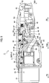
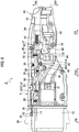
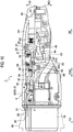
- FIGS. 1 to 4 are views showing the charging connector 1 in accordance with the embodiment.
- a vehicle-side inlet 90 side (left sides of Figs. 1 to 3 and a right side of Fig. 4 ), which is a counterpart in the charging connector 1, is set as a "tip side", and a direction toward the tip side is set as a "fitting direction FD".
- a side opposite to the vehicle-side inlet 90 side (right sides of Figs. 1 to 3 and a left side of Fig. 4 ) in the charging connector 1 is set as a "rear end side", and a direction toward the rear end side is set as a "separating direction SD".
- the charging connector 1 is fitted to the vehicle-side inlet 90 (refer to Fig. 2 ) at which a receiving-side terminal (not shown) has been provided, and is utilized to supply electric power to a battery of a vehicle.
- the charging connector 1 is attached to a tip of an electric wire W (not shown) extended from a power supply device (not shown).
- the charging connector 1 includes connector cases 3A, 3B as substantially mirror-image symmetrical two divided bodies whose mutual end surfaces are combined with each other.
- the connector cases 3A, 3B have a case body portion 5 and a handle portion 7 inclined from a rear of the case body portion 5 and held by a worker.
- Fig. 2 shows a state where the connector case 3B of the charging connector 1 is removed, and where the charging connector 1 is seen from a direction perpendicular to mirror-image symmetrical surfaces of the connector cases 3A, 3B.
- the connector cases 3A, 3B are set as the substantially mirror-image symmetrical two divided bodies whose mutual end surfaces are combined with each other, the connector cases 3A, 3B may just be combined with each other to thereby configure an exterior of the charging connector 1, and need not necessarily be strictly mirror-image symmetrical.
- a connector fitting portion 10 that is fitted to the vehicle-side inlet 90 is provided in front of such case body portion 5.
- a notch 11 is formed in an outer peripheral surface of the connector fitting portion 10.
- a supplying-side terminal (not shown) that is connected to the receiving-side terminal (not shown) in the vehicle-side inlet 90 is stored inside the connector fitting portion 10. Note that alignment of the supplying-side terminal (not shown), etc. are compliant with various standards, and that explanation thereof will be omitted here.
- a through hole 6 is formed in a tip side of the case body portion 5.
- the through hole 6 is configured by a cap inserting portion 6A to which a cap 9 to close the through hole 6 is applied, and a shaft core inserting portion 6B in which a lock releasing portion 24, which will be mentioned later, of the locking arm 20 is inserted.
- a size and a contour shape of the through hole 6 are preferably substantially equal to respective sizes and contour shapes of the cap 9 and the lock releasing portion 24 in order to prevent entry of foreign substances (dust, water, etc.).
- the shape of the cap 9 can be appropriately set and, for example, may just achieve a level to be able to seal the cap inserting portion 6A, and may be a columnar body or a frustum shape, etc.
- Fig. 4 is the cross-sectional view showing a part of the connector case 3B and the cap 9.
- Fig. 4 there is shown a cross section in a surface perpendicular to the mirror-image symmetrical surfaces of the connector cases 3A, 3B and parallel to the fitting direction FD.
- a latching portion 9A is provided at a peripheral wall of the cap 9, and a latched portion 6C to which the latching portion 9A is latched is provided at a side wall of the cap inserting portion 6A.
- the cap 9 is a removable type that closes the through hole 6 and the cap inserting portion 6A by being inserted in the cap inserting portion 6A.
- the cap 9 need not necessarily be the removable type, and that, for example, may be a screwed type screwed into the cap inserting portion 6A, or an openable type opened and closed to the cap inserting portion 6A.
- the electric wire W that is extended from the connector fitting portion 10 is arranged at a lower part in such case body portion 5, and this electric wire W passes through the handle portion 7 to be pulled out to an outside.
- the locking arm 20, a fitting detecting arm 30, the releasing lever 40, and a lever holding arm 50 are provided at an upper part in the case body portion 5.
- the locking arm 20 prevents separation of the charging connector 1 from the vehicle-side inlet 90 in a fitted state of the vehicle-side inlet 90 and the connector fitting portion 10.
- the locking arm 20 is configured by a main arm 21 provided rockably centering around a shaft core 21J in the case body portion 5, and a lock auxiliary arm 26 that rocks together with the main arm 21.
- the main arm 21, as shown in Figs. 1 to 3 includes: a locking claw 22 as a locking claw that is provided at a tip side of the main arm 21, and is retractable from the notch 11 of the connector fitting portion 10; a lock engaging piece 23 as an engaging portion that is provided at a rear end of the main arm 21, and is latched to a lower engaging groove portion 46, which will be mentioned later, of the releasing lever 40; and the lock releasing portion 24 with which the main arm 21 can be operated to a releasing position from an outside of the case body portion 5.
- the main arm 21 is supported by the shaft core 21J and provided rockably centering around the shaft core 21J as a rocking shaft between a locking position where the locking claw 22 is latched to a latching groove portion 91 (refer to Fig. 2 ) provided at an inner peripheral surface of the vehicle-side inlet 90, and an unlocking position (a releasing position) where the latching of the locking claw 22 and the latching groove portion 91 is released.
- the main arm 21 is biased toward a direction (a top direction TD) in which the locking claw 22 projects from the notch 11 of the connector fitting portion 10 by a coil spring 25 as a biasing member.
- the main arm 21 is bent in a bottom direction BD near the releasing lever 40.
- the main arm 21 extends along the separating direction SD from the bent lower end, and the lock engaging piece 23 is provided at a tip thereof.
- the lock engaging piece 23 engages with the lower engaging groove portion 46, which will be mentioned later, of the releasing lever 40 at the unlocking position of the main arm 21 (i.e. a state where the locking claw 22 has retreated in the notch 11). Meanwhile, engagement of the lock engaging piece 23 with an upper latching groove portion 45, which will be mentioned later, of the releasing lever 40 is released at the locking position of the main arm 21 (i.e., a state where the locking claw 22 has projected from the notch 11).
- the lock releasing portion 24 is inserted into the through hole 6 formed in the case body portion 5. That is, the lock releasing portion 24 is provided in the cap inserting portion 6A that forms the through hole 6.
- the lock releasing portion 24 is configured by the shaft core 21J of the main arm 21 of the connector case 3B side.
- a jig inserting hole 24A into which a jig (not shown), such as a hexagonal bar spanner, is inserted is formed in the shaft core 21J.
- the lock auxiliary arm 26, as shown in Figs. 2 and 3 includes an auxiliary latching piece 27 that is provided at a rear end of the lock auxiliary arm 26, and is latched to the upper latching groove portion 45, which will be mentioned later, of the releasing lever 40.
- the lock auxiliary arm 26 is provided rockably to the main arm 21 centering around a shaft core 26A provided at the main arm 21 between a locking position where the auxiliary latching piece 27 is latched to the upper latching groove portion 45, which will be mentioned later, of the releasing lever 40, and an unlatching position (a releasing position) where the latching of the auxiliary latching piece 27 and the upper latching groove portion 45 is released.
- the lock auxiliary arm 26 is biased in a latching direction (the bottom direction BD) of the auxiliary latching piece 27 by a coil spring 28.
- one end of the coil spring 28 is fixed to a position closer to a rear end side than the shaft core 21J in the main arm 21, and that an other end thereof is fixed to a position closer to a tip side than the shaft core 26A in the lock auxiliary arm 26. For that reason, in a situation where the auxiliary latching piece 27 has not been latched to the upper latching groove portion 45, the main arm 21 and the lock auxiliary arm 26 are provided rockably around the shaft core 21J, keeping a positional relation relative to each other by a restoring force of the coil spring 28.
- the auxiliary latching piece 27 extends toward the bottom direction BD, and is provided latchably to the upper latching groove portion 45, which will be mentioned later, of the releasing lever 40.
- the auxiliary latching piece 27 is provided at a position facing the above-mentioned lock engaging piece 23.
- the auxiliary latching piece 27 is provided closer to the separating direction SD side than a detecting latching piece 32, which will be mentioned later, of the fitting detecting arm 30 and a holding latching piece 51, which will be mentioned later, of the lever holding arm 50.
- the shaft core 26A moves in the bottom direction BD.
- the lock auxiliary arm 26 moves in the bottom direction BD, and further, the auxiliary latching piece 27 moves in the bottom direction BD by the restoring force of the coil spring 28, the auxiliary latching piece 27 can be latched with the upper latching groove portion 45, which will be mentioned later, of the releasing lever 40.
- the fitting detecting arm 30 detects a completely fitted state of the vehicle-side inlet 90 and the connector fitting portion 10.
- the fitting detecting arm 30, as shown in Figs. 2 and 3 includes: a detecting claw 31 that is provided at a tip side of the fitting detecting arm 30, and is retractable from the notch 11 of the connector fitting portion 10; and the detecting latching piece 32 that is provided at a rear end side of the fitting detecting arm 30, and is latched to the upper latching groove portion 45, which will be mentioned later, of the releasing lever 40, which will be mentioned later.
- the fitting detecting arm 30 is provided rockably centering around a shaft core 33 between a fitting position where the detecting claw 31 comes into contact with a tip surface of the vehicle-side inlet 90, and detects fitting of the connector fitting portion 10 to the vehicle-side inlet 90, and a separating position where the contact of the detecting claw 31 and the vehicle-side inlet 90 is released, and where separation of the connector fitting portion 10 from the vehicle-side inlet 90 is detected.
- the fitting detecting arm 30 is biased toward a direction in which the detecting claw 31 projects to the notch 11 of the connector fitting portion 10 (i.e., a latching direction of the detecting latching piece 32) by a coil spring 34.
- the detecting claw 31 is provided retractably (retreatably) from the notch 11 of the connector fitting portion 10 to an outside.
- the detecting claw 31 is provided closer to the separating direction SD side than the above-mentioned locking claw 22 of the main arm 21.
- the detecting latching piece 32 extends toward the bottom direction BD, and is provided latchably to the upper latching groove portion 45, which will be mentioned later, of the releasing lever 40.
- the detecting latching piece 32 is provided closer to the fitting direction FD side than the auxiliary latching piece 27 of the lock auxiliary arm 26, and is provided closer to the separating direction SD side than the holding latching piece 51, which will be mentioned later, of the lever holding arm 50.
- the fitting detecting arm 30 rocks centering around the shaft core 33, and thereby latching of the detecting latching piece 32 with the upper latching groove portion 45, which will be mentioned later, of the releasing lever 40 is released.
- the fitting detecting arm 30 rocks centering around the shaft core 33, and thereby the detecting latching piece 32 is latched with the upper latching groove portion 45, which will be mentioned later, of the releasing lever 40.
- a projection 35 (refer to Figs. 2 and 3 ) projecting toward the bottom direction BD is provided between the detecting latching piece 32 and the shaft core 33.
- a tip side of the lever holding arm 50 (closer to the tip side than a shaft core 52, which will be mentioned later) is pressed toward the bottom direction BD, and thereby the projection 35 releases latching of the upper latching groove portion 45, which will be mentioned later, of the releasing lever 40 and the holding latching piece 51, which will be mentioned later, of the lever holding arm 50.
- the releasing lever 40 releases latching of the latching groove portion 91 in the vehicle-side inlet 90 and the locking claw 22.
- the releasing lever 40 is slidably provided from a starting position of pushing operation to the case body portion 5 to a completing position (i.e., in a fitting separating direction FSD).
- the releasing lever 40 as shown in Figs. 2 and 3 , has: a releasing switch 41 whose rear end is projected from the case body portion 5, and that moves in the fitting separating direction FSD; and a releasing body portion 42 that is provided in the case body portion 5 and is formed integrally with the releasing switch 41.
- the releasing switch 41 is biased to a starting position of pushing operation of the releasing switch 41 (i.e., the separating direction SD side) by a coil spring 43.
- the releasing body portion 42 has a tip abutting portion 44 that abuts against and pushes up the auxiliary latching piece 27 of the lock auxiliary arm 26, the detecting latching piece 32 of the fitting detecting arm 30, and the holding latching piece 51, which will be mentioned later, of the lever holding arm 50, at the time of pushing operation of the releasing switch 41.
- the tip abutting portion 44 rocks the main arm 21 to the unlocking position by abutting against an inclined surface 21A of the main arm 21 at a completing position of the pushing operation of the releasing switch 41.
- the tip abutting portion 44 is formed in a curved shape.
- the upper latching groove portion 45 to which the auxiliary latching piece 27 of the lock auxiliary arm 26, the detecting latching piece 32 of the fitting detecting arm 30, and the holding latching piece 51, which will be mentioned later, of the lever holding arm 50 are respectively latched is provided at an upper part of a tip of the releasing body portion 42.
- the lower engaging groove portion 46 as an engaged portion with which the lock engaging piece 23 of the main arm 21 engages is provided at a lower part of the tip of the releasing body portion 42.
- the lever holding arm 50 holds the releasing lever 40 at the completing position of the releasing lever 40.
- the lever holding arm 50 includes the holding latching piece 51 that is latched to the upper latching groove portion 45 of the releasing lever 40 at a pressing position of the releasing lever 40, at a rear end side of the lever holding arm 50.
- the lever holding arm 50 is provided rockably centering around the shaft core 52 between a lever holding position where the releasing lever 40 is held at the completing position (i.e., a state where the holding latching piece 51 is latched to the upper latching groove portion 45), and a lever non-holding position where the releasing lever 40 is not held (i.e., a state where the latching of the holding latching piece 51 and the upper latching groove portion 45 has been released).
- a coil spring 53 is provided closer to the holding latching piece 51 side than the shaft core 52 of the lever holding arm 50, and the holding latching piece 51 side is biased toward the bottom direction BD by the coil spring 53.
- a side closer to a tip than the shaft core 52 of the lever holding arm 50 can abut against the projection 35 of the fitting detecting arm 30.
- the holding latching piece 51 extends toward the bottom direction BD, and is provided latchably to the upper latching groove portion 45 of the releasing lever 40.
- the holding latching piece 51 is provided closer to the fitting direction FD side than the auxiliary latching piece 27 of the lock auxiliary arm 26, and the detecting latching piece 32 of the fitting detecting arm 30.
- the holding latching piece 51 latches with the upper latching groove portion 45 of the releasing lever 40 at the lever holding position. Meanwhile, at the lever non-holding position, the side closer to the tip than the shaft core 52 of the lever holding arm 50 is pressed by the projection 35, and the latching of the upper latching groove portion 45 of the releasing lever 40 and the holding latching piece 51 is released.
- FIGS. 5 to 10 are views for illustrating the behavior of the charging connector 1 in accordance with the embodiment.
- the locking claw 22 of the main arm 21 and the detecting claw 31 of the fitting detecting arm 30 project from the notch 11 of the connector fitting portion 10 by biasing of the coil spring 25 and the coil spring 34, respectively.
- the detecting latching piece 32 of the fitting detecting arm 30 is latched to the upper latching groove portion 45 of the releasing lever 40.
- the auxiliary latching piece 27 is in a state of not being completely latched to the upper latching groove portion 45.
- the releasing body portion 42 of the releasing switch 41 moves toward the starting position of the pushing operation of the releasing switch 41 (i.e., the separating direction SD side) by a function of the coil spring 43, and the auxiliary latching piece 27 is latched to the upper latching groove portion 45.
- the auxiliary latching piece 27 is in a state of being able to be immediately latched with the upper latching groove portion 45, when the detecting latching piece 32 and the upper latching groove portion 45 are unlatched.
- the charging connector 1 reaches the completely fitted state via each state of the first intermediately fitted state and the second intermediately fitted state in that order from the separated state.
- the tip abutting portion 44 of the releasing body portion 42 abuts against the inclined surface 21A of the main arm 21, the main arm 21 rocks, the locking claw 22 is pushed into the notch 11 of the connector fitting portion 10, and thereby the main arm 21 is set to be at the unlocking position.
- the charging connector 1 When the charging connector 1 is completely separated from the vehicle-side inlet 90, the charging connector 1 becomes a state before the above-mentioned inserting operation thereof (refer to Fig. 5 ).
- the charging connector 1 reaches the separated state via each state of the first intermediately extracted state and the second intermediately extracted state in that order from the completely fitted state.
- the locking arm 20 (the main arm 21) includes the lock releasing portion 24 that is inserted into the through hole 6 formed in the connector cases 3A, 3B, and with which the locking arm 20 can be operated to the releasing position from an outside of the connector cases 3A, 3B, and thereby the main arm 21 can be rocked so as to be at the releasing position from the outside of the connector cases 3A, 3B, even though a failure occurs in the releasing lever 40.
- the lock releasing portion 24 is inserted into the through hole 6, the tip of the lock releasing portion 24 projects or is exposed to the inside of the through hole 6 from the shaft core inserting portion 6B, and thereby the gap between the shaft core inserting portion 6B and the lock releasing portion 24 is sealed.
- foreign substances dust, water, etc.
- the jig inserted in the lock releasing portion 24 need not be inserted in the connector cases 3A, 3B from the through hole 6, it can also be prevented that the jig touches various parts (for example, the electric wire W and various terminals) in the connector cases 3A, 3B.
- the main arm 21 can be rocked so as to be at the releasing position from the outside of the connector cases 3A, 3B, and moreover, the jig can be prevented from touching the various parts in the connector cases 3A, 3B.
- the lock releasing portion 24 is configured by the shaft core 21J (the rocking shaft) provided at the main arm 21 of the locking arm 20, and thereby the lock releasing portion 24 need not be provided separately in addition to being provided at the shaft core 21J, reduction in weight, reduction in cost, etc. of the charging connector 1 can be achieved.
- the cap 9 is applied to the cap inserting portion 6A formed around the through hole 6, and closes the through hole 6, whereby erroneous operation in a normal condition of the charging connector 1 can be prevented, and foreign substances can be prevented from entering the cap inserting portion 6A and the jig inserting hole 24A of the shaft core 21J, and moreover, the charging connector 1 is superior also in appearance since the lock releasing portion 24 is not exposed.
- the through hole 6 and the cap inserting portion 6A are closed, and foreign substances are prevented from entering the inside of the through hole 6. Additionally, since foreign substances (dust, water, etc.) are prevented from accumulating in the jig inserting hole 24A of the lock releasing portion 24 arranged so as to project or be exposed to the inside of the through hole 6, the locking arm 20 does not become non-releasable by accumulation of the foreign substances in the jig inserting hole 24A.
- the latching portion 9A is provided at the peripheral wall of the cap 9, and the latched portion 6C is provided at the side wall of the cap inserting portion 6A. That is, the cap 9 is a removable type that closes the through hole 6 and the cap inserting portion 6A by being inserted in the cap inserting portion 6A. As a result of this, application of the cap 9 to the cap inserting portion 6A becomes easy.
- the embodiment of the present invention can be changed as follows.
- the charging connector 1 has been explained as the one utilized for supplying electric power to the battery of the vehicle, the present invention is not limited to this, and can also be applied to an inlet of a power storage device mounted in transportation, such as a ship, a submarine, and an airplane other than the vehicle, an inlet of a power storage device installed in a home, a building, a factory, etc., and the like.
- lock releasing portion 24 has been explained as the one configured by the shaft core 21J of the main arm 21, the present invention is not limited to this and, for example, the lock releasing portion 24 may be the one in which the locking claw 22 can be pushed near the locking claw 22 of the main arm 21.
- the through hole 6 has been explained as the one configured by the cap inserting portion 6A and the shaft core inserting portion 6B, the present invention is not limited to this, and the through hole 6 may be configured only by the shaft core inserting portion 6B.
- cap 9 has been explained as the one applied to the shaft core inserting portion 6B, the present invention is not limited to this, and the cap 9 need not necessarily be provided.
- the locking arm includes the lock releasing portion with which the locking arm can be operated to the releasing position from the outside of the connector case, and thereby the locking arm can be rocked so as to be at the releasing position from the outside of the connector case, even though the failure occurs in the releasing lever.
- the lock releasing portion is inserted into the through hole, and thereby foreign substances can be prevented from entering the inside of the through hole.
- the jig need not be inserted in the connector case from the through hole, and can also be prevented from touching various parts in the connector case.
- the locking arm can be rocked so as to be at the releasing position from the outside of the connector case, and moreover, the jig can be prevented from touching the various parts in the connector case.
Landscapes
- Engineering & Computer Science (AREA)
- Power Engineering (AREA)
- Transportation (AREA)
- Mechanical Engineering (AREA)
- Details Of Connecting Devices For Male And Female Coupling (AREA)
- Electric Propulsion And Braking For Vehicles (AREA)
Applications Claiming Priority (2)
| Application Number | Priority Date | Filing Date | Title |
|---|---|---|---|
| JP2013069004 | 2013-03-28 | ||
| PCT/JP2014/058272 WO2014157196A1 (ja) | 2013-03-28 | 2014-03-25 | 充電コネクタ |
Publications (3)
| Publication Number | Publication Date |
|---|---|
| EP2980926A1 EP2980926A1 (en) | 2016-02-03 |
| EP2980926A4 EP2980926A4 (en) | 2016-10-26 |
| EP2980926B1 true EP2980926B1 (en) | 2017-11-01 |
Family
ID=51624165
Family Applications (1)
| Application Number | Title | Priority Date | Filing Date |
|---|---|---|---|
| EP14774923.8A Active EP2980926B1 (en) | 2013-03-28 | 2014-03-25 | Charging connector |
Country Status (5)
| Country | Link |
|---|---|
| US (1) | US9509095B2 (zh) |
| EP (1) | EP2980926B1 (zh) |
| JP (1) | JP5945067B2 (zh) |
| CN (1) | CN105103385B (zh) |
| WO (1) | WO2014157196A1 (zh) |
Families Citing this family (18)
| Publication number | Priority date | Publication date | Assignee | Title |
|---|---|---|---|---|
| EP2980926B1 (en) * | 2013-03-28 | 2017-11-01 | Yazaki Corporation | Charging connector |
| JP6009528B2 (ja) * | 2014-12-18 | 2016-10-19 | 住友電装株式会社 | 充電用インレット |
| JP6423748B2 (ja) * | 2015-03-26 | 2018-11-14 | 住電機器システム株式会社 | 充電コネクタ |
| DE102015113875A1 (de) * | 2015-08-21 | 2017-02-23 | Phoenix Contact E-Mobility Gmbh | Steckverbinderteil mit einem Verriegelungselement |
| CN105421900B (zh) * | 2015-12-02 | 2018-04-24 | 上海挚达科技发展有限公司 | 一种用于充电枪的电子锁及具有该电子锁的充电枪 |
| DE102016105371A1 (de) * | 2016-03-22 | 2017-09-28 | Phoenix Contact E-Mobility Gmbh | Steckverbinderteil zum steckenden Verbinden mit einem Gegensteckverbinderteil |
| US10014615B2 (en) * | 2016-09-19 | 2018-07-03 | Lear Corporation | Connector assemblies for vehicle charging |
| WO2018101748A1 (ko) * | 2016-11-30 | 2018-06-07 | 엘지이노텍 주식회사 | 전기충전 플러그 장치, 전기충전 접속장치, 전기충전장치 및 전기자동차 |
| CN108666811B (zh) * | 2017-03-27 | 2024-03-12 | 汪志强 | 充电枪的锁止装置及充电装置 |
| JP6819515B2 (ja) * | 2017-08-29 | 2021-01-27 | トヨタ自動車株式会社 | 車両 |
| CN108039616B (zh) * | 2017-11-13 | 2019-05-21 | 中国航空工业集团公司西安航空计算技术研究所 | 一种快速拔插装置 |
| DE102018100825B4 (de) * | 2018-01-16 | 2019-09-05 | Dr. Ing. H.C. F. Porsche Aktiengesellschaft | Landseitiger Elektrofahrzeug-Ladestecker |
| DE102018131610A1 (de) * | 2018-12-10 | 2020-06-10 | Phoenix Contact E-Mobility Gmbh | Ladestecker mit einer Rastverbindungsdetektion |
| US11139616B2 (en) * | 2020-02-17 | 2021-10-05 | Japan Aviation Electronics Industry, Limited | Charging connector |
| JP7446183B2 (ja) * | 2020-08-28 | 2024-03-08 | 日本航空電子工業株式会社 | 充電コネクタ |
| CN114552277A (zh) * | 2020-11-24 | 2022-05-27 | 台达电子工业股份有限公司 | 充电枪 |
| US20220219630A1 (en) * | 2021-01-12 | 2022-07-14 | Ford Global Technologies, Llc | Vehicle roof rail integrated power outlet systems |
| KR102655227B1 (ko) * | 2022-08-25 | 2024-04-05 | 주식회사 경신 | 전기차량용 아웃렛 충전커넥터 |
Family Cites Families (98)
| Publication number | Priority date | Publication date | Assignee | Title |
|---|---|---|---|---|
| JP2978348B2 (ja) * | 1992-12-18 | 1999-11-15 | 矢崎総業株式会社 | 給電コネクタ |
| JP3042816B2 (ja) * | 1992-12-18 | 2000-05-22 | 矢崎総業株式会社 | 給電コネクタ |
| JP3316049B2 (ja) * | 1993-06-14 | 2002-08-19 | 住友電装株式会社 | 電気自動車の充電装置 |
| US5458496A (en) * | 1993-07-12 | 1995-10-17 | Sumitomo Wiring Systems, Ltd. | Charge coupling for electric vehicle |
| JP2752032B2 (ja) * | 1993-09-20 | 1998-05-18 | 矢崎総業株式会社 | 給電コネクタ |
| JP2879810B2 (ja) * | 1993-12-28 | 1999-04-05 | 矢崎総業株式会社 | コネクタ |
| JP3433432B2 (ja) * | 1993-12-28 | 2003-08-04 | 矢崎総業株式会社 | 給電コネクタ |
| JP2921640B2 (ja) * | 1994-03-17 | 1999-07-19 | 矢崎総業株式会社 | 給電コネクタ |
| JP3463820B2 (ja) * | 1994-04-01 | 2003-11-05 | 矢崎総業株式会社 | 給電コネクタ |
| JP2904024B2 (ja) * | 1994-08-08 | 1999-06-14 | 住友電装株式会社 | 電気自動車のチャージ用コネクタ |
| DE19544942C2 (de) * | 1994-12-01 | 2001-12-06 | Yazaki Corp | Verbindungsvorrichtung mit einem Spannungszufuhrsteckverbinder und einem Spannungsaufnahmesteckverbinder und Verfahren zum Verbinden/Trennen einer Spannungszufuhreinrichtung |
| JP3135040B2 (ja) * | 1995-11-30 | 2001-02-13 | 矢崎総業株式会社 | 電気自動車の充電用コネクタ |
| JPH09161882A (ja) * | 1995-12-06 | 1997-06-20 | Yazaki Corp | 電気自動車の充電用コネクタ |
| JP3292278B2 (ja) * | 1995-12-06 | 2002-06-17 | 矢崎総業株式会社 | 電気自動車の充電用コネクタ |
| JP3262203B2 (ja) * | 1996-02-16 | 2002-03-04 | 矢崎総業株式会社 | 低挿抜力コネクタ |
| JPH10112349A (ja) * | 1996-10-04 | 1998-04-28 | Yazaki Corp | 電気自動車用充電コネクタ |
| US6371768B1 (en) * | 1998-03-31 | 2002-04-16 | Daimlerchrysler Corporation | Universal charge port connector for electric vehicles |
| US6203355B1 (en) * | 1998-03-31 | 2001-03-20 | Daimlerchrysler Corporation | Universal charge port connector for electric vehicles |
| US6225153B1 (en) * | 1999-03-24 | 2001-05-01 | Daimlerchrysler Corporation | Universal charge port connector for electric vehicles |
| NL1024850C2 (nl) | 2003-11-24 | 2005-05-26 | Framatome Connectors Int | Connectorsysteem met verbeterde ontkoppel-functionaliteit. |
| JP2007511054A (ja) * | 2003-11-07 | 2007-04-26 | エフシーアイ | プラグ解除機能を備えてなるコネクタシステム |
| JP5123144B2 (ja) * | 2008-11-21 | 2013-01-16 | 矢崎総業株式会社 | 充電用コネクタ |
| JP5312214B2 (ja) * | 2009-06-11 | 2013-10-09 | 矢崎総業株式会社 | 誤操作防止機構付きレバー式電気コネクタ |
| US7963793B2 (en) * | 2009-09-24 | 2011-06-21 | Lear Corporation | Hybrid/electric vehicle charge handle latch mechanism |
| JP5231381B2 (ja) * | 2009-11-17 | 2013-07-10 | 株式会社東海理化電機製作所 | バッテリ充電用受電コネクタのコネクタロック構造 |
| EP2426791B1 (en) * | 2009-12-28 | 2016-09-14 | Fujikura Ltd. | Power-feed connector |
| JP5393440B2 (ja) * | 2009-12-28 | 2014-01-22 | 株式会社フジクラ | 給電コネクタ |
| US8016607B2 (en) * | 2010-01-08 | 2011-09-13 | Lear Corporation | Connector assembly for electric vehicle charging |
| JP5447962B2 (ja) * | 2010-02-19 | 2014-03-19 | 住友電装株式会社 | 充電用コネクタ |
| JP5482295B2 (ja) * | 2010-03-01 | 2014-05-07 | 住友電装株式会社 | 充電用コネクタ |
| JP5392151B2 (ja) * | 2010-03-09 | 2014-01-22 | 住友電装株式会社 | 充電用コネクタ |
| JP5504987B2 (ja) * | 2010-03-11 | 2014-05-28 | 住友電装株式会社 | 充電用コネクタ |
| JP2011198566A (ja) * | 2010-03-18 | 2011-10-06 | Sumitomo Wiring Syst Ltd | 充電用コネクタ |
| JP5096518B2 (ja) * | 2010-05-12 | 2012-12-12 | 株式会社東海理化電機製作所 | 給電プラグロック装置 |
| JP5437903B2 (ja) * | 2010-05-12 | 2014-03-12 | 株式会社東海理化電機製作所 | 給電プラグロック装置のロック手動解除構造 |
| JP5411059B2 (ja) * | 2010-05-18 | 2014-02-12 | 株式会社東海理化電機製作所 | 充電インレット装置 |
| US8075329B1 (en) * | 2010-06-08 | 2011-12-13 | Ford Global Technologies, Llc | Method and system for preventing disengagement between an electrical plug and a charge port on an electric vehicle |
| JP5471890B2 (ja) * | 2010-06-28 | 2014-04-16 | 住友電装株式会社 | 充電用コネクタ |
| US7878866B1 (en) * | 2010-07-02 | 2011-02-01 | Lear Corporation | Connector assembly for vehicle charging |
| JP5197699B2 (ja) * | 2010-09-09 | 2013-05-15 | 住友電装株式会社 | 充電用コネクタ |
| JP2012080646A (ja) * | 2010-09-30 | 2012-04-19 | Tokai Rika Co Ltd | 給電プラグロック装置 |
| JP5890091B2 (ja) * | 2010-10-29 | 2016-03-22 | 日本航空電子工業株式会社 | 電気コネクタ、電気コネクタユニット、及び電気自動車用充電器 |
| JP5739644B2 (ja) * | 2010-11-02 | 2015-06-24 | 矢崎総業株式会社 | 給電コネクタ |
| US20120129378A1 (en) * | 2010-11-19 | 2012-05-24 | Delphi Technologies, Inc. | Battery charger having handle that includes light source that emits light through aperture in handle connector |
| US20120126747A1 (en) * | 2010-11-19 | 2012-05-24 | Delphi Technologies, Inc. | Battery charger having non-contact electrical switch |
| US8568155B2 (en) * | 2010-12-30 | 2013-10-29 | General Cable Technologies Corporation | Laminous multi-polymeric high amperage over-molded connector assembly for plug-in hybrid electric vehicle charging |
| JP5080662B2 (ja) * | 2011-01-27 | 2012-11-21 | 日本航空電子工業株式会社 | コネクタ |
| JP5625969B2 (ja) * | 2011-02-04 | 2014-11-19 | 住友電装株式会社 | 充電用コネクタ |
| JP5775332B2 (ja) * | 2011-03-04 | 2015-09-09 | 矢崎総業株式会社 | コネクタ |
| JP5609725B2 (ja) * | 2011-03-17 | 2014-10-22 | 住友電装株式会社 | 電線保持部材 |
| JP5645077B2 (ja) * | 2011-03-17 | 2014-12-24 | 住友電装株式会社 | 充電用コネクタ |
| JP2012212647A (ja) * | 2011-03-18 | 2012-11-01 | Tokai Rika Co Ltd | 給電プラグロック装置 |
| JP5650572B2 (ja) * | 2011-03-29 | 2015-01-07 | 株式会社東海理化電機製作所 | 給電プラグロック装置 |
| DE102011002024A1 (de) * | 2011-04-13 | 2012-10-18 | Tyco Electronics Amp Gmbh | Ladestecker mit berührungsloser Schaltvorrichtung |
| JP2012234775A (ja) * | 2011-05-09 | 2012-11-29 | Sumiden Asahi Industries Ltd | 充電コネクタ |
| JP5721536B2 (ja) * | 2011-05-20 | 2015-05-20 | 矢崎総業株式会社 | 半嵌合防止コネクタ |
| JP5715879B2 (ja) * | 2011-05-20 | 2015-05-13 | 矢崎総業株式会社 | アーク放電防止コネクタ |
| JP5659444B2 (ja) * | 2011-05-23 | 2015-01-28 | 住電朝日精工株式会社 | 充電コネクタ |
| US8834202B2 (en) * | 2011-06-13 | 2014-09-16 | Lear Corporation | Connector assembly for vehicle charging |
| JP2013008465A (ja) * | 2011-06-22 | 2013-01-10 | Daiden Co Ltd | 給電用コネクタ |
| JP2013053471A (ja) * | 2011-09-05 | 2013-03-21 | Tokai Rika Co Ltd | 給電プラグロック装置 |
| JP2013053470A (ja) * | 2011-09-05 | 2013-03-21 | Tokai Rika Co Ltd | ロック装置 |
| JP5970767B2 (ja) * | 2011-09-27 | 2016-08-17 | 日産自動車株式会社 | 充電装置 |
| JP5770588B2 (ja) * | 2011-09-28 | 2015-08-26 | 株式会社東海理化電機製作所 | 給電プラグロック装置 |
| EP2768109B1 (en) * | 2011-10-11 | 2019-11-20 | Nissan Motor Co., Ltd | Charging port lock device |
| US9178312B2 (en) * | 2011-10-13 | 2015-11-03 | Nissan Motor Co., Ltd. | Charging port locking device |
| EP2767429B1 (en) * | 2011-10-13 | 2020-02-26 | Nissan Motor Co., Ltd. | Charging port lock device |
| JP5813462B2 (ja) * | 2011-10-31 | 2015-11-17 | 矢崎総業株式会社 | コネクタ嵌合構造 |
| US8506315B2 (en) * | 2011-11-17 | 2013-08-13 | Schneider Electric USA, Inc. | Docking station for connector for electric vehicle charging station |
| DE102012100235B4 (de) * | 2012-01-12 | 2015-12-24 | Phoenix Contact Gmbh & Co. Kg | Kabelstecker mit Abdeckeinrichtung |
| JP5815424B2 (ja) * | 2012-01-17 | 2015-11-17 | 矢崎総業株式会社 | 電気コネクタ |
| JP5798935B2 (ja) * | 2012-01-17 | 2015-10-21 | 矢崎総業株式会社 | 電気コネクタ |
| JP5815423B2 (ja) * | 2012-01-17 | 2015-11-17 | 矢崎総業株式会社 | 電気コネクタ |
| JP5815425B2 (ja) * | 2012-01-17 | 2015-11-17 | 矢崎総業株式会社 | 電気コネクタ |
| USD697869S1 (en) | 2012-01-17 | 2014-01-21 | Yazaki Corporation | Charging connector for an electric vehicle |
| JP5798934B2 (ja) * | 2012-01-17 | 2015-10-21 | 矢崎総業株式会社 | 電気コネクタ |
| JP5895618B2 (ja) * | 2012-03-09 | 2016-03-30 | 日産自動車株式会社 | 電動車両の充電ポート制御装置 |
| JP5982897B2 (ja) * | 2012-03-14 | 2016-08-31 | 日産自動車株式会社 | 電動車両の充電ポート制御装置 |
| JP5912740B2 (ja) * | 2012-03-27 | 2016-04-27 | 本田技研工業株式会社 | 電動車両用の充電装置 |
| JP5916476B2 (ja) * | 2012-03-29 | 2016-05-11 | 古河電気工業株式会社 | 給電コネクタ |
| KR20130131033A (ko) * | 2012-05-23 | 2013-12-03 | 엘에스전선 주식회사 | 전기자동차 충전장치의 커넥터 |
| JP5939927B2 (ja) * | 2012-08-06 | 2016-06-22 | 矢崎総業株式会社 | 充電コネクタ |
| CN103907245B (zh) * | 2012-09-03 | 2016-10-05 | 古河电气工业株式会社 | 供电连接器 |
| JP6055260B2 (ja) * | 2012-10-05 | 2016-12-27 | 矢崎総業株式会社 | 充電コネクタ |
| JP5889432B2 (ja) * | 2012-10-22 | 2016-03-22 | 古河電気工業株式会社 | 給電コネクタ |
| JP2014086338A (ja) * | 2012-10-25 | 2014-05-12 | Yazaki Corp | 充電コネクタ |
| EP2903099B1 (en) * | 2012-10-31 | 2017-01-25 | Nissan Motor Company, Limited | Power supply connector and method for unlocking power supply connector |
| JP6178071B2 (ja) * | 2012-12-13 | 2017-08-09 | 株式会社東海理化電機製作所 | ロック装置 |
| JP5947202B2 (ja) * | 2012-12-13 | 2016-07-06 | 株式会社東海理化電機製作所 | ロック装置 |
| JP5922565B2 (ja) * | 2012-12-13 | 2016-05-24 | 株式会社東海理化電機製作所 | ロック装置 |
| JP5902602B2 (ja) * | 2012-12-13 | 2016-04-13 | 株式会社東海理化電機製作所 | ロック装置 |
| JP5878457B2 (ja) * | 2012-12-13 | 2016-03-08 | 株式会社東海理化電機製作所 | 充電ケーブルロック装置 |
| JP2014117974A (ja) * | 2012-12-13 | 2014-06-30 | Tokai Rika Co Ltd | ロック装置 |
| JP6092662B2 (ja) * | 2013-03-05 | 2017-03-08 | 矢崎総業株式会社 | 充電コネクタ |
| EP2980926B1 (en) * | 2013-03-28 | 2017-11-01 | Yazaki Corporation | Charging connector |
| EP2787577A1 (en) * | 2013-04-02 | 2014-10-08 | Delphi International Operations Luxembourg S.à r.l. | Power plug |
| JP6023632B2 (ja) * | 2013-04-08 | 2016-11-09 | 矢崎総業株式会社 | 充電コネクタ |
| JP6148964B2 (ja) * | 2013-10-17 | 2017-06-14 | 日本航空電子工業株式会社 | コネクタ |
-
2014
- 2014-03-25 EP EP14774923.8A patent/EP2980926B1/en active Active
- 2014-03-25 JP JP2015508543A patent/JP5945067B2/ja active Active
- 2014-03-25 CN CN201480017306.6A patent/CN105103385B/zh active Active
- 2014-03-25 WO PCT/JP2014/058272 patent/WO2014157196A1/ja active Application Filing
-
2015
- 2015-09-24 US US14/863,809 patent/US9509095B2/en active Active
Non-Patent Citations (1)
| Title |
|---|
| None * |
Also Published As
| Publication number | Publication date |
|---|---|
| US9509095B2 (en) | 2016-11-29 |
| CN105103385B (zh) | 2017-02-22 |
| EP2980926A1 (en) | 2016-02-03 |
| JPWO2014157196A1 (ja) | 2017-02-16 |
| US20160020555A1 (en) | 2016-01-21 |
| JP5945067B2 (ja) | 2016-07-05 |
| EP2980926A4 (en) | 2016-10-26 |
| CN105103385A (zh) | 2015-11-25 |
| WO2014157196A1 (ja) | 2014-10-02 |
Similar Documents
| Publication | Publication Date | Title |
|---|---|---|
| EP2980926B1 (en) | Charging connector | |
| US9391399B2 (en) | Charging connector | |
| JP5503619B2 (ja) | 給電コネクタ | |
| JP5231381B2 (ja) | バッテリ充電用受電コネクタのコネクタロック構造 | |
| JP5972391B2 (ja) | 給電コネクタおよび給電コネクタのロック解除方法 | |
| JP6119670B2 (ja) | コネクタ | |
| JP5798935B2 (ja) | 電気コネクタ | |
| CN101359794A (zh) | 电连接器 | |
| JP5815424B2 (ja) | 電気コネクタ | |
| US9318845B2 (en) | Charging connector | |
| JP2009043642A (ja) | ジョイントコネクタ | |
| EP2805383B1 (en) | Electrical connector | |
| EP2805386B1 (en) | Electrical connector | |
| JP2015170489A (ja) | コネクタ | |
| JP5815423B2 (ja) | 電気コネクタ | |
| CN111295807A (zh) | 连接器 | |
| WO2014111133A1 (en) | Sealed electrical connector assembly | |
| JP4924901B2 (ja) | ロック構造およびコネクタ | |
| JP6166083B2 (ja) | 充電コネクタ | |
| JP2020155222A (ja) | コネクタ | |
| JP2014102940A (ja) | 給電コネクタ | |
| JP2015099644A (ja) | コネクタ | |
| JP2014060055A (ja) | 回路導通遮断装置 |
Legal Events
| Date | Code | Title | Description |
|---|---|---|---|
| PUAI | Public reference made under article 153(3) epc to a published international application that has entered the european phase |
Free format text: ORIGINAL CODE: 0009012 |
|
| 17P | Request for examination filed |
Effective date: 20151007 |
|
| AK | Designated contracting states |
Kind code of ref document: A1 Designated state(s): AL AT BE BG CH CY CZ DE DK EE ES FI FR GB GR HR HU IE IS IT LI LT LU LV MC MK MT NL NO PL PT RO RS SE SI SK SM TR |
|
| AX | Request for extension of the european patent |
Extension state: BA ME |
|
| DAX | Request for extension of the european patent (deleted) | ||
| A4 | Supplementary search report drawn up and despatched |
Effective date: 20160923 |
|
| RIC1 | Information provided on ipc code assigned before grant |
Ipc: H01R 13/639 20060101AFI20160919BHEP Ipc: H01R 13/627 20060101ALN20160919BHEP Ipc: B60L 11/18 20060101ALI20160919BHEP |
|
| GRAP | Despatch of communication of intention to grant a patent |
Free format text: ORIGINAL CODE: EPIDOSNIGR1 |
|
| RIC1 | Information provided on ipc code assigned before grant |
Ipc: B60L 11/18 20060101ALI20170627BHEP Ipc: H01R 13/639 20060101AFI20170627BHEP Ipc: H01R 13/627 20060101ALN20170627BHEP |
|
| INTG | Intention to grant announced |
Effective date: 20170803 |
|
| GRAS | Grant fee paid |
Free format text: ORIGINAL CODE: EPIDOSNIGR3 |
|
| GRAA | (expected) grant |
Free format text: ORIGINAL CODE: 0009210 |
|
| AK | Designated contracting states |
Kind code of ref document: B1 Designated state(s): AL AT BE BG CH CY CZ DE DK EE ES FI FR GB GR HR HU IE IS IT LI LT LU LV MC MK MT NL NO PL PT RO RS SE SI SK SM TR |
|
| REG | Reference to a national code |
Ref country code: GB Ref legal event code: FG4D |
|
| REG | Reference to a national code |
Ref country code: CH Ref legal event code: EP Ref country code: AT Ref legal event code: REF Ref document number: 942917 Country of ref document: AT Kind code of ref document: T Effective date: 20171115 |
|
| REG | Reference to a national code |
Ref country code: IE Ref legal event code: FG4D |
|
| REG | Reference to a national code |
Ref country code: DE Ref legal event code: R096 Ref document number: 602014016667 Country of ref document: DE |
|
| REG | Reference to a national code |
Ref country code: NL Ref legal event code: MP Effective date: 20171101 |
|
| REG | Reference to a national code |
Ref country code: LT Ref legal event code: MG4D |
|
| REG | Reference to a national code |
Ref country code: FR Ref legal event code: PLFP Year of fee payment: 5 |
|
| REG | Reference to a national code |
Ref country code: AT Ref legal event code: MK05 Ref document number: 942917 Country of ref document: AT Kind code of ref document: T Effective date: 20171101 |
|
| PG25 | Lapsed in a contracting state [announced via postgrant information from national office to epo] |
Ref country code: NO Free format text: LAPSE BECAUSE OF FAILURE TO SUBMIT A TRANSLATION OF THE DESCRIPTION OR TO PAY THE FEE WITHIN THE PRESCRIBED TIME-LIMIT Effective date: 20180201 Ref country code: FI Free format text: LAPSE BECAUSE OF FAILURE TO SUBMIT A TRANSLATION OF THE DESCRIPTION OR TO PAY THE FEE WITHIN THE PRESCRIBED TIME-LIMIT Effective date: 20171101 Ref country code: SE Free format text: LAPSE BECAUSE OF FAILURE TO SUBMIT A TRANSLATION OF THE DESCRIPTION OR TO PAY THE FEE WITHIN THE PRESCRIBED TIME-LIMIT Effective date: 20171101 Ref country code: LT Free format text: LAPSE BECAUSE OF FAILURE TO SUBMIT A TRANSLATION OF THE DESCRIPTION OR TO PAY THE FEE WITHIN THE PRESCRIBED TIME-LIMIT Effective date: 20171101 Ref country code: ES Free format text: LAPSE BECAUSE OF FAILURE TO SUBMIT A TRANSLATION OF THE DESCRIPTION OR TO PAY THE FEE WITHIN THE PRESCRIBED TIME-LIMIT Effective date: 20171101 Ref country code: NL Free format text: LAPSE BECAUSE OF FAILURE TO SUBMIT A TRANSLATION OF THE DESCRIPTION OR TO PAY THE FEE WITHIN THE PRESCRIBED TIME-LIMIT Effective date: 20171101 |
|
| PG25 | Lapsed in a contracting state [announced via postgrant information from national office to epo] |
Ref country code: IS Free format text: LAPSE BECAUSE OF FAILURE TO SUBMIT A TRANSLATION OF THE DESCRIPTION OR TO PAY THE FEE WITHIN THE PRESCRIBED TIME-LIMIT Effective date: 20180301 Ref country code: AT Free format text: LAPSE BECAUSE OF FAILURE TO SUBMIT A TRANSLATION OF THE DESCRIPTION OR TO PAY THE FEE WITHIN THE PRESCRIBED TIME-LIMIT Effective date: 20171101 Ref country code: HR Free format text: LAPSE BECAUSE OF FAILURE TO SUBMIT A TRANSLATION OF THE DESCRIPTION OR TO PAY THE FEE WITHIN THE PRESCRIBED TIME-LIMIT Effective date: 20171101 Ref country code: LV Free format text: LAPSE BECAUSE OF FAILURE TO SUBMIT A TRANSLATION OF THE DESCRIPTION OR TO PAY THE FEE WITHIN THE PRESCRIBED TIME-LIMIT Effective date: 20171101 Ref country code: RS Free format text: LAPSE BECAUSE OF FAILURE TO SUBMIT A TRANSLATION OF THE DESCRIPTION OR TO PAY THE FEE WITHIN THE PRESCRIBED TIME-LIMIT Effective date: 20171101 Ref country code: GR Free format text: LAPSE BECAUSE OF FAILURE TO SUBMIT A TRANSLATION OF THE DESCRIPTION OR TO PAY THE FEE WITHIN THE PRESCRIBED TIME-LIMIT Effective date: 20180202 Ref country code: BG Free format text: LAPSE BECAUSE OF FAILURE TO SUBMIT A TRANSLATION OF THE DESCRIPTION OR TO PAY THE FEE WITHIN THE PRESCRIBED TIME-LIMIT Effective date: 20180201 |
|
| PG25 | Lapsed in a contracting state [announced via postgrant information from national office to epo] |
Ref country code: DK Free format text: LAPSE BECAUSE OF FAILURE TO SUBMIT A TRANSLATION OF THE DESCRIPTION OR TO PAY THE FEE WITHIN THE PRESCRIBED TIME-LIMIT Effective date: 20171101 Ref country code: SK Free format text: LAPSE BECAUSE OF FAILURE TO SUBMIT A TRANSLATION OF THE DESCRIPTION OR TO PAY THE FEE WITHIN THE PRESCRIBED TIME-LIMIT Effective date: 20171101 Ref country code: EE Free format text: LAPSE BECAUSE OF FAILURE TO SUBMIT A TRANSLATION OF THE DESCRIPTION OR TO PAY THE FEE WITHIN THE PRESCRIBED TIME-LIMIT Effective date: 20171101 Ref country code: CY Free format text: LAPSE BECAUSE OF FAILURE TO SUBMIT A TRANSLATION OF THE DESCRIPTION OR TO PAY THE FEE WITHIN THE PRESCRIBED TIME-LIMIT Effective date: 20171101 Ref country code: CZ Free format text: LAPSE BECAUSE OF FAILURE TO SUBMIT A TRANSLATION OF THE DESCRIPTION OR TO PAY THE FEE WITHIN THE PRESCRIBED TIME-LIMIT Effective date: 20171101 |
|
| REG | Reference to a national code |
Ref country code: DE Ref legal event code: R097 Ref document number: 602014016667 Country of ref document: DE |
|
| PG25 | Lapsed in a contracting state [announced via postgrant information from national office to epo] |
Ref country code: PL Free format text: LAPSE BECAUSE OF FAILURE TO SUBMIT A TRANSLATION OF THE DESCRIPTION OR TO PAY THE FEE WITHIN THE PRESCRIBED TIME-LIMIT Effective date: 20171101 Ref country code: SM Free format text: LAPSE BECAUSE OF FAILURE TO SUBMIT A TRANSLATION OF THE DESCRIPTION OR TO PAY THE FEE WITHIN THE PRESCRIBED TIME-LIMIT Effective date: 20171101 Ref country code: IT Free format text: LAPSE BECAUSE OF FAILURE TO SUBMIT A TRANSLATION OF THE DESCRIPTION OR TO PAY THE FEE WITHIN THE PRESCRIBED TIME-LIMIT Effective date: 20171101 Ref country code: RO Free format text: LAPSE BECAUSE OF FAILURE TO SUBMIT A TRANSLATION OF THE DESCRIPTION OR TO PAY THE FEE WITHIN THE PRESCRIBED TIME-LIMIT Effective date: 20171101 |
|
| PLBE | No opposition filed within time limit |
Free format text: ORIGINAL CODE: 0009261 |
|
| STAA | Information on the status of an ep patent application or granted ep patent |
Free format text: STATUS: NO OPPOSITION FILED WITHIN TIME LIMIT |
|
| 26N | No opposition filed |
Effective date: 20180802 |
|
| REG | Reference to a national code |
Ref country code: CH Ref legal event code: PL |
|
| PG25 | Lapsed in a contracting state [announced via postgrant information from national office to epo] |
Ref country code: SI Free format text: LAPSE BECAUSE OF FAILURE TO SUBMIT A TRANSLATION OF THE DESCRIPTION OR TO PAY THE FEE WITHIN THE PRESCRIBED TIME-LIMIT Effective date: 20171101 Ref country code: MC Free format text: LAPSE BECAUSE OF FAILURE TO SUBMIT A TRANSLATION OF THE DESCRIPTION OR TO PAY THE FEE WITHIN THE PRESCRIBED TIME-LIMIT Effective date: 20171101 |
|
| REG | Reference to a national code |
Ref country code: BE Ref legal event code: MM Effective date: 20180331 |
|
| REG | Reference to a national code |
Ref country code: IE Ref legal event code: MM4A |
|
| PG25 | Lapsed in a contracting state [announced via postgrant information from national office to epo] |
Ref country code: LU Free format text: LAPSE BECAUSE OF NON-PAYMENT OF DUE FEES Effective date: 20180325 |
|
| PG25 | Lapsed in a contracting state [announced via postgrant information from national office to epo] |
Ref country code: IE Free format text: LAPSE BECAUSE OF NON-PAYMENT OF DUE FEES Effective date: 20180325 |
|
| PG25 | Lapsed in a contracting state [announced via postgrant information from national office to epo] |
Ref country code: CH Free format text: LAPSE BECAUSE OF NON-PAYMENT OF DUE FEES Effective date: 20180331 Ref country code: BE Free format text: LAPSE BECAUSE OF NON-PAYMENT OF DUE FEES Effective date: 20180331 Ref country code: LI Free format text: LAPSE BECAUSE OF NON-PAYMENT OF DUE FEES Effective date: 20180331 |
|
| PG25 | Lapsed in a contracting state [announced via postgrant information from national office to epo] |
Ref country code: MT Free format text: LAPSE BECAUSE OF NON-PAYMENT OF DUE FEES Effective date: 20180325 |
|
| PG25 | Lapsed in a contracting state [announced via postgrant information from national office to epo] |
Ref country code: TR Free format text: LAPSE BECAUSE OF FAILURE TO SUBMIT A TRANSLATION OF THE DESCRIPTION OR TO PAY THE FEE WITHIN THE PRESCRIBED TIME-LIMIT Effective date: 20171101 |
|
| PGFP | Annual fee paid to national office [announced via postgrant information from national office to epo] |
Ref country code: GB Payment date: 20200318 Year of fee payment: 7 |
|
| PG25 | Lapsed in a contracting state [announced via postgrant information from national office to epo] |
Ref country code: PT Free format text: LAPSE BECAUSE OF FAILURE TO SUBMIT A TRANSLATION OF THE DESCRIPTION OR TO PAY THE FEE WITHIN THE PRESCRIBED TIME-LIMIT Effective date: 20171101 |
|
| PG25 | Lapsed in a contracting state [announced via postgrant information from national office to epo] |
Ref country code: MK Free format text: LAPSE BECAUSE OF NON-PAYMENT OF DUE FEES Effective date: 20171101 Ref country code: HU Free format text: LAPSE BECAUSE OF FAILURE TO SUBMIT A TRANSLATION OF THE DESCRIPTION OR TO PAY THE FEE WITHIN THE PRESCRIBED TIME-LIMIT; INVALID AB INITIO Effective date: 20140325 |
|
| PGFP | Annual fee paid to national office [announced via postgrant information from national office to epo] |
Ref country code: FR Payment date: 20200214 Year of fee payment: 7 |
|
| PG25 | Lapsed in a contracting state [announced via postgrant information from national office to epo] |
Ref country code: AL Free format text: LAPSE BECAUSE OF FAILURE TO SUBMIT A TRANSLATION OF THE DESCRIPTION OR TO PAY THE FEE WITHIN THE PRESCRIBED TIME-LIMIT Effective date: 20171101 |
|
| GBPC | Gb: european patent ceased through non-payment of renewal fee |
Effective date: 20210325 |
|
| PG25 | Lapsed in a contracting state [announced via postgrant information from national office to epo] |
Ref country code: FR Free format text: LAPSE BECAUSE OF NON-PAYMENT OF DUE FEES Effective date: 20210331 Ref country code: GB Free format text: LAPSE BECAUSE OF NON-PAYMENT OF DUE FEES Effective date: 20210325 |
|
| PGFP | Annual fee paid to national office [announced via postgrant information from national office to epo] |
Ref country code: DE Payment date: 20240130 Year of fee payment: 11 |