EP2959034B1 - Dispositif de dépôt chimique en phase vapeur - Google Patents
Dispositif de dépôt chimique en phase vapeur Download PDFInfo
- Publication number
- EP2959034B1 EP2959034B1 EP14706038.8A EP14706038A EP2959034B1 EP 2959034 B1 EP2959034 B1 EP 2959034B1 EP 14706038 A EP14706038 A EP 14706038A EP 2959034 B1 EP2959034 B1 EP 2959034B1
- Authority
- EP
- European Patent Office
- Prior art keywords
- wall
- reaction chamber
- side wall
- gas
- chamber
- Prior art date
- Legal status (The legal status is an assumption and is not a legal conclusion. Google has not performed a legal analysis and makes no representation as to the accuracy of the status listed.)
- Active
Links
Images

Classifications
-
- C—CHEMISTRY; METALLURGY
- C23—COATING METALLIC MATERIAL; COATING MATERIAL WITH METALLIC MATERIAL; CHEMICAL SURFACE TREATMENT; DIFFUSION TREATMENT OF METALLIC MATERIAL; COATING BY VACUUM EVAPORATION, BY SPUTTERING, BY ION IMPLANTATION OR BY CHEMICAL VAPOUR DEPOSITION, IN GENERAL; INHIBITING CORROSION OF METALLIC MATERIAL OR INCRUSTATION IN GENERAL
- C23C—COATING METALLIC MATERIAL; COATING MATERIAL WITH METALLIC MATERIAL; SURFACE TREATMENT OF METALLIC MATERIAL BY DIFFUSION INTO THE SURFACE, BY CHEMICAL CONVERSION OR SUBSTITUTION; COATING BY VACUUM EVAPORATION, BY SPUTTERING, BY ION IMPLANTATION OR BY CHEMICAL VAPOUR DEPOSITION, IN GENERAL
- C23C16/00—Chemical coating by decomposition of gaseous compounds, without leaving reaction products of surface material in the coating, i.e. chemical vapour deposition [CVD] processes
- C23C16/44—Chemical coating by decomposition of gaseous compounds, without leaving reaction products of surface material in the coating, i.e. chemical vapour deposition [CVD] processes characterised by the method of coating
- C23C16/4401—Means for minimising impurities, e.g. dust, moisture or residual gas, in the reaction chamber
- C23C16/4408—Means for minimising impurities, e.g. dust, moisture or residual gas, in the reaction chamber by purging residual gases from the reaction chamber or gas lines
-
- C—CHEMISTRY; METALLURGY
- C23—COATING METALLIC MATERIAL; COATING MATERIAL WITH METALLIC MATERIAL; CHEMICAL SURFACE TREATMENT; DIFFUSION TREATMENT OF METALLIC MATERIAL; COATING BY VACUUM EVAPORATION, BY SPUTTERING, BY ION IMPLANTATION OR BY CHEMICAL VAPOUR DEPOSITION, IN GENERAL; INHIBITING CORROSION OF METALLIC MATERIAL OR INCRUSTATION IN GENERAL
- C23C—COATING METALLIC MATERIAL; COATING MATERIAL WITH METALLIC MATERIAL; SURFACE TREATMENT OF METALLIC MATERIAL BY DIFFUSION INTO THE SURFACE, BY CHEMICAL CONVERSION OR SUBSTITUTION; COATING BY VACUUM EVAPORATION, BY SPUTTERING, BY ION IMPLANTATION OR BY CHEMICAL VAPOUR DEPOSITION, IN GENERAL
- C23C16/00—Chemical coating by decomposition of gaseous compounds, without leaving reaction products of surface material in the coating, i.e. chemical vapour deposition [CVD] processes
- C23C16/44—Chemical coating by decomposition of gaseous compounds, without leaving reaction products of surface material in the coating, i.e. chemical vapour deposition [CVD] processes characterised by the method of coating
- C23C16/455—Chemical coating by decomposition of gaseous compounds, without leaving reaction products of surface material in the coating, i.e. chemical vapour deposition [CVD] processes characterised by the method of coating characterised by the method used for introducing gases into reaction chamber or for modifying gas flows in reaction chamber
- C23C16/45502—Flow conditions in reaction chamber
- C23C16/45504—Laminar flow
-
- C—CHEMISTRY; METALLURGY
- C23—COATING METALLIC MATERIAL; COATING MATERIAL WITH METALLIC MATERIAL; CHEMICAL SURFACE TREATMENT; DIFFUSION TREATMENT OF METALLIC MATERIAL; COATING BY VACUUM EVAPORATION, BY SPUTTERING, BY ION IMPLANTATION OR BY CHEMICAL VAPOUR DEPOSITION, IN GENERAL; INHIBITING CORROSION OF METALLIC MATERIAL OR INCRUSTATION IN GENERAL
- C23C—COATING METALLIC MATERIAL; COATING MATERIAL WITH METALLIC MATERIAL; SURFACE TREATMENT OF METALLIC MATERIAL BY DIFFUSION INTO THE SURFACE, BY CHEMICAL CONVERSION OR SUBSTITUTION; COATING BY VACUUM EVAPORATION, BY SPUTTERING, BY ION IMPLANTATION OR BY CHEMICAL VAPOUR DEPOSITION, IN GENERAL
- C23C16/00—Chemical coating by decomposition of gaseous compounds, without leaving reaction products of surface material in the coating, i.e. chemical vapour deposition [CVD] processes
- C23C16/44—Chemical coating by decomposition of gaseous compounds, without leaving reaction products of surface material in the coating, i.e. chemical vapour deposition [CVD] processes characterised by the method of coating
- C23C16/455—Chemical coating by decomposition of gaseous compounds, without leaving reaction products of surface material in the coating, i.e. chemical vapour deposition [CVD] processes characterised by the method of coating characterised by the method used for introducing gases into reaction chamber or for modifying gas flows in reaction chamber
- C23C16/45517—Confinement of gases to vicinity of substrate
-
- C—CHEMISTRY; METALLURGY
- C23—COATING METALLIC MATERIAL; COATING MATERIAL WITH METALLIC MATERIAL; CHEMICAL SURFACE TREATMENT; DIFFUSION TREATMENT OF METALLIC MATERIAL; COATING BY VACUUM EVAPORATION, BY SPUTTERING, BY ION IMPLANTATION OR BY CHEMICAL VAPOUR DEPOSITION, IN GENERAL; INHIBITING CORROSION OF METALLIC MATERIAL OR INCRUSTATION IN GENERAL
- C23C—COATING METALLIC MATERIAL; COATING MATERIAL WITH METALLIC MATERIAL; SURFACE TREATMENT OF METALLIC MATERIAL BY DIFFUSION INTO THE SURFACE, BY CHEMICAL CONVERSION OR SUBSTITUTION; COATING BY VACUUM EVAPORATION, BY SPUTTERING, BY ION IMPLANTATION OR BY CHEMICAL VAPOUR DEPOSITION, IN GENERAL
- C23C16/00—Chemical coating by decomposition of gaseous compounds, without leaving reaction products of surface material in the coating, i.e. chemical vapour deposition [CVD] processes
- C23C16/44—Chemical coating by decomposition of gaseous compounds, without leaving reaction products of surface material in the coating, i.e. chemical vapour deposition [CVD] processes characterised by the method of coating
- C23C16/455—Chemical coating by decomposition of gaseous compounds, without leaving reaction products of surface material in the coating, i.e. chemical vapour deposition [CVD] processes characterised by the method of coating characterised by the method used for introducing gases into reaction chamber or for modifying gas flows in reaction chamber
- C23C16/45519—Inert gas curtains
- C23C16/45521—Inert gas curtains the gas, other than thermal contact gas, being introduced the rear of the substrate to flow around its periphery
-
- C—CHEMISTRY; METALLURGY
- C23—COATING METALLIC MATERIAL; COATING MATERIAL WITH METALLIC MATERIAL; CHEMICAL SURFACE TREATMENT; DIFFUSION TREATMENT OF METALLIC MATERIAL; COATING BY VACUUM EVAPORATION, BY SPUTTERING, BY ION IMPLANTATION OR BY CHEMICAL VAPOUR DEPOSITION, IN GENERAL; INHIBITING CORROSION OF METALLIC MATERIAL OR INCRUSTATION IN GENERAL
- C23C—COATING METALLIC MATERIAL; COATING MATERIAL WITH METALLIC MATERIAL; SURFACE TREATMENT OF METALLIC MATERIAL BY DIFFUSION INTO THE SURFACE, BY CHEMICAL CONVERSION OR SUBSTITUTION; COATING BY VACUUM EVAPORATION, BY SPUTTERING, BY ION IMPLANTATION OR BY CHEMICAL VAPOUR DEPOSITION, IN GENERAL
- C23C16/00—Chemical coating by decomposition of gaseous compounds, without leaving reaction products of surface material in the coating, i.e. chemical vapour deposition [CVD] processes
- C23C16/44—Chemical coating by decomposition of gaseous compounds, without leaving reaction products of surface material in the coating, i.e. chemical vapour deposition [CVD] processes characterised by the method of coating
- C23C16/455—Chemical coating by decomposition of gaseous compounds, without leaving reaction products of surface material in the coating, i.e. chemical vapour deposition [CVD] processes characterised by the method of coating characterised by the method used for introducing gases into reaction chamber or for modifying gas flows in reaction chamber
- C23C16/45587—Mechanical means for changing the gas flow
- C23C16/45591—Fixed means, e.g. wings, baffles
Definitions
- the invention relates to the field of manufacturing integrated circuits or microsystems, and more particularly equipment and chemical vapor deposition processes.
- the latter are also referred to in the "CVD” equipment and process technique, or "Chemical Vapor Deposition", an equivalent term in English.
- Integrated circuits and microsystems are made from wafers, or substrates, made of silicon or other semiconductor material, which undergo a series of stages of deposition of thin layers of various materials, masking and lithography of these layers, then engraving these same layers. Between these stages of manufacturing come stages of cleaning of the equipment as well as steps of inspection of the quality of the products.
- the CVD equipment generally comprises a treatment chamber in which are housed a substrate support and a gas distribution assembly, also known as a showerhead, or "showerhead” in the English language.
- the latter delivers gaseous chemical agents, also called treatment gases, or precursors, near the substrate.
- the support has an upper face adapted to hold the substrates and a lower face, opposite to its upper face.
- the substrate support divides the interior space of the process chamber into an upper space and a lower space.
- the upper space is on the side of the upper face of the support and is delimited by walls of the treatment chamber.
- the lower space is on the side of the underside of the support and is delimited by walls of the treatment chamber.
- a purge gas is injected into the lower space of the treatment chamber to limit contamination of the chamber walls by chemical agents injected by the shower into the upper space of the chamber.
- the invention improves the situation.
- the purge gas injector comprises an injection channel defined by the side wall of the chamber and a first wall of an additional piece, said channel opening into the reaction chamber through an annular mouth, the side wall of the reaction chamber and the first wall of the additional part being parallel in a portion of said injection channel comprising the mouth, so as to allow the injection of a laminar flow of purge gas by the annular mouth and the flow of said flow in said annular passage to the opening of the gas evacuation system.
- the additional piece comprises a second wall opposite to the first wall and having a concave shape defining a housing adapted to receive at least part of the substrate support.
- the substrate support is movable in translation in the reaction chamber to a so-called loading position in which said support is housed at least partly in said housing of the additional piece.
- the device further comprises a plurality of fins carried by the side wall and projecting into the annular passage.
- said fins are oriented so as to guide the flow of purge gas along the side wall.
- the side wall of the reaction chamber and the first wall of the additional part are parallel in a portion of the injection channel having a length to the mouth greater than or equal to 1 cm.
- the length of the portion of the channel in which the side wall of the reaction chamber and the first wall of the additional part are parallel is sized to inject a laminar flow of purge gas for a flow rate of said gas included between 0.35 m / s and 0.55 m / s.
- the chemical vapor deposition reactor device according to the invention comprises a reaction chamber having a side wall, a substrate support having a peripheral surface, the substrate support being disposed in the reaction chamber to form a passageway. annular between the peripheral surface of the substrate holder and the side wall of the reaction chamber, an additional piece and a purge gas injector opening into the reaction chamber.
- the additional room once mounted in the reactor device, forms at least part of an annular mouth of the injector.
- said part is arranged to form, once mounted in the reactor device, an additional wall, the side wall of the reaction chamber and said additional wall delimiting a channel opening into the reaction chamber through the mouth. annular, the side wall and the additional wall being parallel in a portion of the channel comprising the mouth.
- said piece has a symmetry of revolution.
- the figures show a treatment device, or reactor referenced 1 as a whole.
- the processing device 1 has a symmetry of revolution along a central axis XX. This promotes the homogeneity of the chemical reactions and facilitates the manufacture. This symmetry may have some exceptions.
- this axis is vertical, which corresponds to the usual arrangement of the device in operation. In the following, the terms high, low, horizontal and vertical are used in accordance with the representation in figures 1 , 2 and 5 .
- the reactor 1 is at controlled pressure and temperature.
- the reactor 1 comprises a hollow body 2 and a lid 3 closing the body 2 to form a reaction chamber 4.
- the reaction chamber 4 may also be called enclosure.
- the chamber 4 houses a support 5, or susceptor, for substrates.
- the reactor 1 is designed to allow the injection into the chamber 4 of at least one reactive gas from an upper part of the chamber 4 and that of a purge gas from a lower part of the chamber 4.
- the reaction chamber 4 delimits a reaction environment and its walls guide the flow of gas present to promote reactions only in certain areas on the one hand and to evacuate the mixed gas on the other.
- the chamber 4 is delimited by a lower inner wall 15, an upper inner wall 17 and a lateral inner wall 19 which connects the lower wall 15 to the upper wall 17.
- the lower wall 15 and the upper wall 17 each have a shape general disc
- the side wall 19 has a general shape of revolution and connects the peripheral edge of the lower wall 15 to the periphery of the upper wall 17.
- the lower wall 15 has a diameter smaller than that of the upper wall 17. Consequently, the side wall 19 comprises a substantially cylindrical upper portion 19a and a substantially frustoconical lower portion 19b connected to one another. The lower portion 19b flares towards the upper wall 17.
- the side wall 19 is connected to the top wall 15 and the bottom wall 17 by connecting fillet.
- the support 5 here comprises a plate 7 and an elongate foot 6.
- the plate 7 has a lower main face fixed to an upper end of the foot 6.
- the foot 6 and the plate 7 of the support 5 are made of material.
- the foot 6 passes through an opening 2a of the body 2 through the bottom wall 15.
- the support 5 is mounted to move in translation relative to the chamber 4.
- the support 5 can be moved between a high position, called working position, in which the plate 7 is close to the upper wall 17 and a low position, called loading, in which the plate 7 is remote from the upper wall 17.
- the support 5 is in the working position. In this position, the plate 7 is at a vertical distance from the upper wall 17, less than 20 millimeters and preferably greater than 5 millimeters.
- the plate 7 can be mounted to rotate relative to the chamber 4 and rotate along the vertical axis XX of the foot 6.
- the rotation speed is a function of the desired flow rate of the gases on the support 5, the size of the substrate, and the required / desired deposit rate.
- the plate 7 has an upper main face 5a opposite to the lower face and intended to support one or more substrates to be treated.
- the upper main face 5a is disposed opposite the upper wall 17.
- the plate 7 has a peripheral surface 5b which connects the main face 5a to the lower face.
- the peripheral surface 5b extends substantially to the right of the upper main face 5a and the thickness of the plate 7.
- the support 5 may be provided with a thermal regulation device, not shown, for example of the type described in the patent application published under the number EP 0 619 381 filed on behalf of Applied Materials Inc., March 31, 1994.
- the thermal regulator is selectively used to heat and / or cool.
- the thermal regulator is used here to adjust the temperature of the substrates according to the desired chemical reactions.
- the distance separating the upper wall 17 from the upper main face 5a is small. This limits the effect of a vertical convection gradient, due to a temperature difference between the upper wall 17 and the main face 5a.
- the peripheral surface 5b and the portion of the corresponding side wall 19, the upper portion 19a in the working position, have a symmetry of revolution.
- the peripheral surface 5b and the portion of the corresponding side wall 19 are concentric and vis-à-vis one another.
- the side wall 19 and the peripheral surface 5b may follow a periphery of shape other than circular, for example square, rectangular, or oval.
- the plate 7 has a general disc shape.
- the support 5 and in particular the plate 7 is made of a thermally conductive material supporting temperatures above 800 ° C.
- the materials used make it possible to maintain the integrity of the support 5 in highly reducing environments, as is the case in the presence of dihydrogen and ammonia.
- the support 5 is made of a material which also has a low thermal inertia to allow it to quickly rise and fall in temperature during the various phases of use
- the support 5 is here made of aluminum nitride (AIN). Alternatively, it can be made of graphite and coated with a layer of silicon carbide, so that the carrier 5 has increased resistance to chemical environments.
- a heat transfer fluid is circulated in conduits provided for this purpose in the body 2.
- the lid 3 After placing a substrate on the support 5, the lid 3 is sealed.
- the introduction and removal of the substrates on the support 5 can be achieved via a vacuum transfer chamber, possibly equipped with a robot.
- the lid 3 comprises a main part 10, in which are provided a first gas inlet 11 forming a source of reactive gas for the reactor 1 and means for thermal regulation of said gas.
- the lid 3 comprises an outer portion 9 resting on the body 2 and supporting the main portion 10.
- the outer portion 9 of the lid 3 has a general shape of a crown resting on an upper surface of a main portion 8 in the upper part of the body 2
- the cover 3 comprises an injection disk 30 forming at least part of the upper wall 17 of the chamber 4 and fixed to the main part 10, for example by screwing.
- the injection disk 30 further houses a portion of a reactive gas injection system from the first inlet 11.
- the main part 8 of the body 2 is made of a metal alloy.
- most of the components housed at least partially inside the chamber 4 may be made of aluminum or an aluminum alloy with little degassing at high temperature.
- the main part 10 of the lid 3 takes a general form of disc.
- the main part 10 can be made of light alloy, here aluminum.
- the main portion 10 is thermally conductive and pierced with a central hole fluidly connecting the first gas inlet 11 of the reactor 1 to the reactive gas injection system of the injection disc 30.
- the reactive gas injection system housed in the injection disc 30 comprises means for thermal regulation of the reactive gas.
- the thermal regulation means of the reactive gas here comprise a heating element 14 which includes an annular piece containing a heat transfer fluid circulated in a cooling / heating circuit.
- a gas injection system and such a thermal regulation system are for example described in the French patent application. published under the number FR 2 930 561 and filed on April 28, 2008 in the name of the Applicant.
- the injection disc 30 is held axially between a lower surface of the main part 10 of the cover 3 and a gas evacuation ring 49 of the reactor 1.
- the injection disc 30 forms a large part, central, of the wall upper chamber 17 of the chamber 4.
- the space between the injection disc 30 and the substrate support 5 can be seen as a working space 60 extending between the main upper surface 5a of the support 5 and the upper wall 17 of the 4.
- the working space 60 is the desired reaction location between the reactant gas and the substrates and / or between the reactive gases.
- the injection disc 30 houses channels 45 that fluidly communicate the central hole of the main portion 10 and the chamber 4.
- the channels 45 extend through the injection disc 30 substantially vertically.
- the channels 45 open into the upper wall 17, in the working space 60 of the chamber 4.
- the channels 45 are evenly distributed in the injection disc 30 while their mouths are evenly distributed on the surface of the chamber 4 by the upper wall 17.
- the inlet 11 of the cover 3, the central hole of the main part 10 and the channels 45 of the injection disc 30 together form, from upstream to downstream, a reactive gas feed for the room 4.
- an additional gas supply for a second reactive gas is provided.
- the injection disc 30 is provided with a plurality of additional channels forming part of the additional reactant gas supply.
- the additional channels open into the working space 60 of the chamber 4 between the upper main surface 5a and the upper wall 17.
- the additional channels are fed from a second gas inlet of the reactor 1 substantially similar to and distinct from the first inlet 11
- the additional gas supply is not shown.
- the heating element 14 makes it possible to maintain the reaction gas or gases, upstream of the chamber 4, at a temperature at which the latter are chemically stable, for example a temperature above their dew point temperature to prevent condensation phenomena.
- the injection disc 30 may be made of a material with a high thermal conductivity, for example based on a light alloy of aluminum (Al), which makes it possible to regulate the temperature of the injection disc 30 by contact with the main part 10 of the cover 3 and thermal conduction.
- the temperature of the injection disc 30 is chosen to limit the spurious reactions of the gaseous reactants flush with the injection disc 30.
- the reactive gas enters the reactor 1 through the inlet 11 of the lid 3. Downstream of the inlet 11, the reactive gas enters the reaction chamber 4 through the mouths of the channels 45.
- the channels 45 form a gas inlet reagent in the reaction chamber 4.
- a gas evacuation ring 49 is mounted on an annular surface 8a of the main portion 8 of the substantially horizontal body 2 and is surrounded by a cylindrical surface 8b of the body 2 forming a bore.
- the ring 49 is, in the example described here, an insert in the body 2.
- the ring 49 may be integral or even integral with the body 2.
- the gas evacuation ring 49 may also be being in contact with a peripheral portion of a lower surface of the injection disc 30.
- the ring 49 surrounds the working space 60.
- the ring 49 is also arranged at least partially around the plate 7 of the support 5.
- a part of the ring 49 forms a part of the side wall 19, and another part of the ring 49 forms part of the upper wall 17.
- the mutual conformation of the ring 49 and the support 5 is such that in a working position, the support 5 is arranged partly in the ring 49 and a passage 107 is formed between the peripheral surface 5b of the support 5 and a part of the side wall 19 belonging here to the ring 49.
- passage 107 here takes the form of a peripheral annular channel in the upper part of the chamber 4.
- the horizontal distance between the side wall 19 and the support 5, that is to say here between the ring 49 and the peripheral surface 5b, is here between 10 and 30 millimeters.
- the gas injection channels 45 of the upper wall 17, the upper main surface 5a and the gas evacuation ring 49 are arranged in such a way that a flow of reactive gas flows from the injection channels 45 to the gas evacuation ring 49 through the working space 60.
- the reactive gases are introduced through the inlet 11 of the reactor 1, through the injection disc 30, and flow into the working space 60 at the outcropping of the upper main surface 5a. Unused precursors continue their path towards the ring 49 in substantially radial directions from the center to the periphery of the plate 7 of the support 5.
- the ring 49 takes the form of an assembly of several pieces.
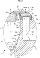
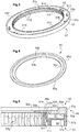
- the ring 49 comprises an upper portion 50 shown isolated on the figure 4 and a lower part 51 isolated on the figure 3 .
- the longitudinal sections along a half plane comprising the axis of revolution of the upper part 50 and the lower part 51 in an assembled state are visible in figure 5 .
- the upper part 50 takes the form of an annular piece of substantially regular section on its circumference.
- the upper portion 50 includes a bottom surface (not visible on the figure 4 ).
- the lower surface includes, here, a radially outer bottom surface 50a and a radially inner bottom surface 50b interconnected by a frustoconical lower surface 50c.
- the radially outer bottom surface 50a and the radially inner bottom surface 50b are generally flat and parallel to each other.
- the radially inner bottom surface 50b is shifted upwardly, i.e. towards the injection disk 30 in the mounted state, with respect to the radially outer bottom surface 50a so that the frustoconical lower surface 50c is oriented towards the center of the chamber 4.
- the upper portion 50 comprises a top surface.
- the upper surface here includes a radially outer upper surface 50d and a radially inner upper surface 50e interconnected by a frustoconical upper surface 50f.
- the radially outer upper surface 50d and the radially inner upper surface 50e are flat and parallel to each other.
- the radially inner upper surface 50e is offset downward, i.e. toward the lower portion 51 in the assembled state relative to the radially outer upper surface 50d so that the frustoconical upper surface 50f is oriented towards the center of the injection disc 30.
- the thickness of the upper part 50 in the vertical direction is higher in line with the radially outer upper surface 50d than on the right of the radially inner upper surface 50e.
- the upper portion 50 also comprises a substantially cylindrical outer surface 50g corresponding in shape with the bore 8b of the body 2 and an inner surface 50h of small axial dimension, here slightly frustoconical.
- the outer surface 50g fits the bore 8b of the body 2 to be inserted therein.
- the radially inner upper surface 50e, the frustoconical upper surface 50f and the inner surface 50h correspond in shape with the periphery of the injection disk 30.
- the shapes and dimensions of the ring 49 allow an adjustment thereof to the times with the injection disc 30 and in the bore 8b.
- the radially outer upper surface 50d is in contact with a lower surface of the main portion 10.
- the inner lower surface 50b and the lower surface of the injection disc 30 are substantially aligned and almost continuous.
- An inner portion of the upper portion 50 carrying the radially inner bottom surface 50b forms a peripheral portion of the top wall 17.
- the inner portion of the inner portion 50 and the injection disk 30 together form at least a portion of the upper wall 17 of the chamber 4.
- the upper part 50 serves as a spacer between the main part 10 of the cover 3 and the lower part 51 of the ring 49.
- the upper part 50 of the ring gas evacuation 49 is made of a material supporting rapid temperature variations without deterioration, for example here aluminum.
- the lower portion 51 has a generally annular shape with a cross-section in the shape of "H".
- the lower portion 51 comprises an outer wall 51a, an inner wall 51b and a connecting wall 51c connecting the outer wall 51a to the inner wall 51b.
- the outer wall 51a and the inner wall 51b are generally cylindrical in shape.
- the inner wall 51b has a height strictly less than the vertical distance separating the radially inner bottom surface 50b from the upper part 50 and the annular surface 8a of the body 2 in the assembled state.
- a circumferential opening or gap 49a is formed between the upper part 50 and the inner wall 51b of the lower part 51.
- the gap 49a is then formed in said room.
- the connecting wall 51c is disposed between one third and two thirds of the height of the outer wall 51a, for example here substantially half of it.
- the outer wall 51a and the inner wall 51b are substantially vertical while the connecting wall 51c is substantially horizontal.
- the inner wall 51b forms part of the side wall 19.
- a lower annular channel 54 is formed between the inner wall 51a, the outer wall 51b, the connecting wall 51c and the annular surface 8a of the body 2.
- An upper annular channel 52 is formed between the outer wall 51a, the inner wall 51b, the connecting wall 51c and the radially outer bottom surface 50a of the upper part 50, cf. figure 5 .
- the connecting wall 51c is pierced with a plurality of communication holes 53.
- the holes 53 put in communication the upper channel 52 and the lower channel 54.
- the lower channel 54 is in communication with a pumping channel 59 formed in the body 8 and a gas evacuation outlet of the reactor 1.
- the holes 53 and the pumping channel 59 are exceptions to the symmetry of revolution of the reactor 1.
- the assembly comprising, from upstream to downstream, the upper channel 52, the holes 53, the lower channel 54 and the pumping channel 59 forms a gas evacuation channel 100.
- the gap 49a belongs to the The gap 49a then forms a gas outlet of the chamber 4 and a gas inlet for the gas evacuation channel 100.
- the gap 49a forms a circumferential gap in the gas evacuation ring 49 opening around the working space 60.
- the gap 49a fluidically communicates the chamber 4 of the inner side of the inner wall 51b and the gas discharge channel 100.
- the circumferential opening 49a formed in the side wall 19 fluidly connects the passage 107 to the upper channel 52 for discharging gases from the reaction chamber 4 towards the outside of the reactor 1.
- the upper surface of the inner wall 51b comprises studs 51d projecting towards the upper part 50, cf. figure 3 .
- the pads 51d have a height substantially equal to the height of the gap 49a.
- the pads 51d are in contact with the radially inner bottom surface 50b of the upper part 50.
- the pads 51d of the lower part 51 form bearing portions of the upper part 50 of the ring 49.
- pads 51d keep the upper portion 50 and the lower portion 51 away from each other to form the gap 49a.
- the pads 51d are evenly distributed around the circumference and form interruptions of the gap 49a on small angular portions relative to the total circumference of the ring 49.
- the pads 51d form exceptions to the symmetry of revolution of the ring 49.
- gap 49a consists of a succession of open portions and studs 51d, gap 49a is considered continuous from the point of view of the flow of gases.
- An angular aperture of the gap 49a on the total or near circumference of the ring 49 allows for homogeneous, laminar flow suction discharge in the contemplated flow rate range. It can be implemented, for example, a flow rate less than 10 slm under a pressure of between 200 and 300 Torr, or 10 liters per minute under standard temperature conditions (about 20 ° C) and 266 to 400 hPa.
- the reactive gases come from the channels 45 and are evacuated by the gap 49a disposed at the periphery of the working space 60 of the chamber 4 and close to the passageway 107. This makes it possible to regulate the flow lines of the chamber. In operation, a flow of reactive gas flows in the working space 60 of the chamber 4, from the channels 45 to the gap 49a.
- the gap 49a between the upper part 50 and the lower part 51 of the ring 49 has a maximum height of between 0.5 and 2 millimeters.
- the inner wall 51b whose inner surface partially defines the chamber 4, forms part of the side wall 19 and here defines the passage 107.
- the inner wall 51b here carries on the inner side an upper cylindrical surface 51e above the connecting wall 51c and a lower frustoconical surface 51f, in the continuity of the cylindrical surface 51e, under the connecting wall 51c, and oriented towards the center of the chamber 4.
- the inner surface of the ring 49 may comprise a lower frustoconical surface and an upper frustoconical surface. The angle inclination of the lower frustoconical surface is greater than that of the upper frustoconical surface.
- the reactor 1 comprises an additional piece 101.
- the additional piece 101 takes the general shape of a piece of revolution or tubular piece with a diameter varying along an axis of revolution.
- the additional piece 101 comprises a cylindrical portion 101a, a shoulder portion 101b and a frustoconical portion 101c.
- the additional piece has a first wall comprising respective surfaces 111, 112, 113 of portions 101a, 101b, 101c arranged opposite the bottom wall 15 and the lower portion 19b of the side wall of the reaction chamber. .
- Said first wall of the additional piece 101 has shapes and dimensions corresponding to the shapes and dimensions of a lower part of the chamber 4 and the opening 2a of the body 2.
- the additional part 101 is arranged partly in the chamber 4 and partly in the opening 2a, under the substrate support 5 and at a distance from the gas evacuation ring 49. In the working position, the plate 7 is at a distance from the additional part 101.
- the position of the additional part 101 is here the same in the working position as in the loading position.
- the outside diameter of the cylindrical portion 101a is strictly smaller than the inside diameter of the bore of the opening 2a of the body 2 so that the cylindrical portion 101a can be inserted into the opening 2a, without contact with the surface of the opening 2a.
- the cylindrical portion 101a is aligned and centered in the opening 2a.
- the foot 6 of the support 5 is disposed inside the cylinder formed by the cylindrical portion 101a.
- An annular space is preserved between the outer surface of the cylindrical portion 101a and the bore of the opening 2a.
- the cylindrical portion 101a is fixed at its lower end to the remainder of the chamber 4 (not shown in the figures).
- the cylindrical portion 101a is here an attachment portion of the insert in the reaction chamber 4.
- the shoulder portion 101b takes the form of a ring extending substantially perpendicularly and outwardly of the cylindrical portion 101a.
- the shoulder portion 101b is integrally connected to the upper end of the cylindrical portion 101a.
- the shoulder portion 101b forms a plane radial wall and of a thickness substantially equal to that of the wall of the cylindrical portion 101a.
- the inside diameter of the shoulder portion 101b corresponds to the diameter of the cylindrical portion 101a.
- the outer diameter of the shoulder portion 101b is strictly smaller than the diameter of the bottom wall 15 of the chamber 4.
- the shoulder portion 101b is disposed substantially parallel and above the wall lower part 15 of the chamber 4.
- the shoulder portion 101b is without contact with the bottom wall 15. A space is preserved between the bottom wall 15 of the chamber 4 and the surface 112 of the first wall in the shoulder portion 101b .
- the frustoconical portion 101c extends upwardly away from the axis of revolution from the periphery of the shoulder portion 101b.
- the frustoconical portion 101c is connected to the shoulder portion 101b.
- the frustoconical portion 101c is of a thickness substantially equal to that of the cylindrical portion 101a and the shoulder portion 101b.
- the taper of the cylindrical portion 101a is substantially equal to that of the lower portion 19b of the side wall 19. At least part of the lower portion 19b is opposite the surface 113 of the first wall in the portion frustoconical 101c, this part forming a second portion of the side wall 19.
- the outer radius of the frustoconical portion 101c increases homogeneously in a vertical progression directed upwards, so that the wall of the frustoconical portion 101c is straight on a sectional view as on the figures 1 and 2 .
- the outer radius of each section of the frustoconical portion 101c is strictly less than the inside diameter of the section of the second portion of the side wall 19 which is vis-à-vis.
- the frustoconical portion 101c is concentrically disposed at the side wall 19 of the chamber 4.
- the frustoconical portion 101c is not in contact with the side wall 19. A space is preserved between the side wall 19 of the chamber 4 and the surface 113 of the first wall in the frustoconical portion 101c.
- the frustoconical portion 101c extends over a height, in the vertical direction, preferably greater than 10 millimeters, for example here 15 millimeters.
- the position and the height of the frustoconical portion 101c are such that the additional piece 101 does not hinder the descent of the plate 7 to reach a loading position.
- the support 5 and the additional piece 101 are mutually shaped and arranged so that the support 5 can be translated into the chamber 4 to a position where it is surrounded by the additional piece 101, for example in position loading.
- the diameter of the peripheral surface 5b is smaller than the inside diameter of at least a portion of the frustoconical portion 101c.
- the additional piece 101 has a second wall opposite the first wall and facing the support 5, said second wall having a concave shape forming a housing of the peripheral surface 5b in the loading position of the support 5.
- the additional piece 101 is disposed in a lower part of the chamber 4, the annular spaces between the first wall of the additional piece 101 formed by the surfaces 111, 112, 113 and the surfaces of the chamber 4 forming sections of a channel 103. annular shape.
- a first section 103a defined between the portion cylindrical 101a and the bore 2a is of substantially cylindrical shape.
- a second section 103b defined between the shoulder portion 101b and the bottom wall 15 is of substantially crown shape.
- a third section 103c defined between the frustoconical portion 101c and the second portion of the side wall 19 is of substantially frustoconical shape.
- the shape and dimensions of the additional piece 101 are a function of the configuration of the chamber 4 so that the channel 103 has a section as regular as possible.
- the shape and dimensions of the first wall of the additional piece 101 are a function of the chamber 4 so that a possible laminar flow of the purge gas stream 200 in the channel 103 is preferred.
- the side wall 19 of the reaction chamber and the first wall of the additional part 101 are parallel in the third section 103c to the mouth 106 of the duct in the chamber 4.
- the side wall 19 of the reaction chamber and the first wall of the additional piece 101 are parallel over a length greater than or equal to 1 cm to the mouthpiece 106.
- the length of the portion of the channel in which the side wall 19 of the reaction chamber and the first wall of the additional piece 101 are parallel is sized to inject a laminar flow of purge gas for a flow rate of said gas between 0 , 35 m / s and 0.55 m / s.
- the radially outer surface of the additional part 101 forms guide surfaces 111, 112, 113.
- the channel 103 follows the shape of the guide surfaces 111, 112, 113 and the bottom shape of the chamber 4.
- the channel 103 thus presents a diameter varying according to the section of the additional piece 101 and the section of the chamber 4 which delimit it. In other words, the diameter of the channel 103 is greater than that of the section of the additional piece 101 which delimits it and less than that of the section of the chamber 4 which delimits it.
- the side wall 19 and the first wall of the additional piece 101 together define the channel 103 and in particular the third section 103c.
- the free end of the frustoconical portion 101c and the part of the side wall 19 which is the closest define a mouth 106.
- the channel 103 ends at the mouth 106.
- the channel 103 opens into the chamber 4 via the mouth 106.
- a purge gas injector 105 comprises, from upstream to downstream, a second gas inlet 104 of the reactor 1, the channel 103 and the mouthpiece 106.
- the channel 103 opens on the reaction chamber 4 through the mouth 106.
- the second inlet or gas inlet 104 for forming the source of a purge gas for the reactor 1.
- the inlet 104 allows inject a purge gas, for example based on nitrogen (N) or Argon (Ar), from the bottom of the chamber 4.
- the second inlet 104 opens at the bottom of the first section 103a of the channel 103. In other words, the second inlet 104 is upstream of the channel 103, itself upstream of the mouthpiece 106.
- the channel 103 defined between the first wall of the additional piece 101 and the wall Lateral 19 forms an extension of the gas injector 105.
- the channel 103 is arranged to direct a flow of purge gas 200 parallel to the side wall 19.
- the purge gas injector 105 opens into the reaction chamber 4.
- the second gas inlet 104 forms an inlet for purge gas into the reactor 1 while the mouth 106 forms an inlet for purge gas into the chamber 4.
- the laminar flow of the purge gas along the sidewall and through the passageway 107 prevents the reactant gases from the working space 60 from entering the lower space of the reaction chamber 4.
- the gas flow of purge 200, laminar as it passes through the passage 107, creates an overpressure and drives the reaction gases to the gas evacuation ring 49.
- the Applicant has found that the availability of a chemical vapor deposition equipment equipped with such a purge gas system is at least twice as high as when the purge gas flow 200 is turbulent. It is therefore possible to reduce the frequency of cleaning of the reaction chamber 4 without affecting the quality of the layers deposited.
- the flow of purge gas required when the flow is turbulent is greater than that of a laminar flow for a given efficiency, other parameters being similar elsewhere.
- the flow rate of purge gas flow 200 is about 5 liters per minute, while it is greater than 10 liters per minute in presence of turbulence (under standard temperature conditions).
- the purge gas tends to partially dilute the reactant gases in the upper space.
- the reduction in the flow rate of the reactive gases further limits the contamination of the reaction chamber 4.
- the Applicant has been able to reduce the flow of reactive gas (of silane, for example) in a reaction chamber having a purge system. according to the invention at 20 sccm whereas in the presence of a conventional system, the flow should be about 50 sccm, or 20 milliliters per minute instead of 50 milliliters per minute (under standard temperature conditions).
- the reduction of the purge gas flow initiates a virtuous circle and several advantages: the concentration of reactive gas in the upper space is increased, the yield of the desired chemical reactions is increased, the waste and therefore the Reactive gas consumption can be reduced. Reducing the consumption of consumable species generates a reduction in costs.
- an accessory part is attached and mounted in the reactor to form the additional part 101.
- the shape of the accessory part here a piece of hollow revolution, is adapted to the reactor of the example.
- the additional piece 101 may be integral or even monobloc, other components of the reactor 1. Conforming an accessory part for the return in a reactor makes it easier to manufacture and even to equip pre-existing reactors.
- the second wall of the additional piece is one of the surfaces of the reaction chamber most likely to give rise to undesirable deposits; the fact that said part is removable makes it easier to clean and possibly replace it with a clean part, which minimizes the downtime of the reactor.
- the shapes of the additional piece 101 differ from those described here depending on the shapes of the reaction chamber 4.
- the additional piece 101 is made in one piece by plastic deformation of a section of aluminum tube (Al).
- the additional piece 101 is made by assembling several pieces.
- the additional piece 101 can be made by molding and any other material having comparable mechanical characteristics and corrosion resistance.
- the additional piece 101 has homothetic profiles or forms a piece of revolution. This simplifies its manufacture and avoids assembly errors in a chamber 4.
- the flow of purge gas 200 flows from bottom to top in the channel 103. From the inlet 104, the purge gas rises in the first section 103a, in the second section 103b, in the third section 103c and out the channel 103 at the upper end of the frustoconical portion 101c through the mouth 106 to emerge in the chamber 4.
- the frustoconical portion 101c is at a distance from the side wall 19 less than 10 millimeters, and preferably between 4 and 8 millimeters.
- An end portion of the channel 103 is substantially parallel to the portion of the side wall 19 immediately downstream of the mouth 106.
- the channel 103 is arranged to direct the flow of purge gas 200 parallel to the side wall 19 at least on one side. part of it near the mouth 106.
- the purge gas flow 200 is guided from the channel 103, between the second portion of the side wall 19 and the surface 113 of the additional piece 101, so that at least a portion of the flow of the gas 200 terminates in the passage 107.
- the channel 103 and the passage 107 are arranged substantially in the extension of one another so that a gas injected from the inlet 104, flowing along the channel 103 and opening into the chamber 4 through the mouth 106 along the side wall 19, flows substantially in a laminar regime along the side wall 19.
- the purge gas then rises along the side wall 19 of the chamber 4 to the passage 107.
- the mouth 106 and the passage 107 each have an annular shape. This shape identity improves the laminar behavior of the flow of gas between the mouth 106 and the passage 107. Although the shape of the channel 103 upstream of the mouth 106 allows to further improve the orientation of the gas flow. 200, the shape identity between the mouth 106 and the passage 107 alone allows to improve the laminar behavior of the purge gas flow 200.
- the side wall 19 is advantageously arranged to support a laminar flow of purge gas along said wall at least from the mouth 106 to the passage 107.
- the gas flow 200 is devoid of physical support on the diametrically inner side of the reactor 1.
- the side wall 19 is sufficient to guide the flow of purge gas 200.
- the flow of gas 200 leaving the channel 103 by the mouthpiece 106 parallel to the side wall 19 at a selected speed has a thickness corresponding to the mouth 106. The speed being non-zero, a vacuum is generated between the gas flow 200 and the side wall 19.
- the side wall 19 attracts the gas flow 200 and the guide between the mouth 106 and the passage 107.
- the side wall 19 on the diametrically outer side, supports the rising gas between the mouth 106 and the passage 107.
- the side wall 19 may have a shape right, slightly concave or slightly convex in the direction of flow, while continuing to guide the flow of gas in the absence of corresponding surface opposite.
- the upper portion 19a and the lower portion 19b of the side wall 19 form, here, a slight change of direction (a slightly concave shape) for the gas flow without affecting the laminar behavior of the flow.
- a change of direction of an angle of between 10 ° and 30 ° limits the risk of creating a turbulent regime.
- the change of direction corresponds to a right angle at which ⁇ (90 ° - alpha) is subtracted.
- the angle ⁇ (alpha) between the lower portion 19b and a horizontal wall plane is between 60 and 80 °.
- the outcropping of the mouth 106 with the side wall 19 improves the laminar behavior of the flow downstream of the mouth 106.
- the side wall 19 forms an extension of the periphery of the mouth 106 which is able to deflect the gas flow 200 to make it follow the direction of the side wall 19 to the passage 107.
- the purge gas reaches the passage 107, between the first portion of the side wall 19, here the inner wall 51b of the ring 49, and the peripheral surface 5b of the support 5.
- the passage 107 is shaped to guide the flow of gas purge 200 from the channel 103 so that at least a portion of the gas flow 200 passes through the circumferential opening 49a.
- the purge gas flow 200 increases the heat exchange between the ring 49 and the interior of the the chamber 4.
- the flow of purge gas 200 participates in the cooling of the ring 49 which tends to heat up in contact, direct or indirect, with heating elements.
- the side wall 19 carries fins 51g.
- the fins 51g are similar to each other.
- the fins 51g project from the inner surface of the ring 49 in the direction of the center of the ring 49.
- the fins 51g project into the passage 107.
- fins 51g are of substantially elongate shape in the vertical direction and the height of the inner wall 51b.
- the fins 51g project from the side wall 19 by at least 1millimeter, preferably at least 5 millimeters. The projecting dimension of the fins 51g is not taken into account for the calculation of the gap between the substrate support 5 and the side wall 19.
- the fins 51g are spaced from the peripheral surface 5b.
- the vertical ends of the fins 51g are connected to the vertical ends of the inner wall 51b by fillet connections.
- the fins 51g are distributed evenly around the circumference of the ring 49, here on the inner wall 51b.
- the peripheral surface 5b being opposite the fins 51g, the fins 51g are distributed here regularly around the plate 7.
- the thickness of the fins 51g is substantially equal to their mutual spacing.
- the distance separating two fins 51g adjacent to each other is equal to the thickness of one of said fins 51g.
- the fins 51g In a sectional view along a plane perpendicular to the axis of revolution of the ring 49, the fins 51g have a rectangular profile. In other words, at the curvature of ring 49, the succession of fins 51g forms a succession of slots in a repetition of patterns.
- the crenellations, as well as the holes 53 and the pads 51d form exceptions to the symmetry of revolution of the ring 49.
- the fins 51g are formed in the inner wall 51b of the insert that forms the ring 49. This facilitates the manufacture.
- the fins 51g are formed in the side wall 19.
- the shapes and dimensions of the fins 51g are such that the inner surface of the ring 49 provided with the fins 51g has a contact surface in the chamber 4 (here with the gases in the chamber 4) important.
- One of the functions of the fins 51g is that of heat exchanger fins. Such a contact surface improves heat exchange between the ring 49 and the interior of the chamber 4.
- the shapes and dimensions of the fins 51g are further selected so that a contact between the support 5 and the ring 49 is avoid.
- the fins 51g confer on the inner wall 51b of the ring 49, and therefore on the side wall 19, a free surface greater than that of a similar configuration but without a fin.
- the ring 49 is maintained at a temperature lower than that of a similar ring without a cooling fin.
- the fins 51g allow for example to maintain the temperature of the ring 49 below 300 ° C. Such a temperature limits the softening of the ring 49 and the parasitic deposits on surfaces of the ring 49.
- the cooling of the ring 49, thanks to the fins 51g, is more effective than a flow of purge gas 200 circulates on contact. This is all the more effective thanks to the additional piece 101 which makes it possible to generate a laminar flow of purge gas flowing between the mouth 106 and the passage 107.
- the passages between the fins 51g are taken by the purge gas which flows away from the working space 60.
- the purge gas flow has a quasi-neutral effect on the dynamics of the gases in the working space 60.
- the flow of purge gas being laminar, its time residence in chamber 4 is minimized compared to that of a turbulent flow, which increases the efficiency of heat exchange.
- the presence of the fins 51g tends to reduce the passage section of the passage 107 and to limit the migration of the reactive gases to the lower space.
- the shapes and dimensions of the fins 51g described here are an exemplary embodiment. Other shapes and dimensions can be envisaged.
- the fins 51g may have a thickness in the circumferential direction different from the mutual spacing of the fins.
- the fins may for example have a triangular profile, "sawtooth", rounded or domed.
- the fins 51g may also advantageously be arranged to guide the flow of gas through In this case, the fins 51g further improve the laminar properties of the gas flow. The gas flow is better guided between each fin 51g while remaining supported by the side wall 19.
- the fins 51g are in contact with the flow of purge gas 200 and oriented parallel thereto (vertical).
- the fins 51g are arranged elongated in a direction different from the vertical, for example in a slightly helical direction in the image of an internal thread of the ring 49.
- the fins 51g are disposed on the inner wall 51b of the ring 49.
- the heat exchange between the fins 51g and the chamber 4 occurs in the immediate vicinity of the gas evacuation channel 100 for regulating the temperature of the inner surfaces of said gas evacuation channel 100.
- the fins 51g are distributed away from the reactive gas flow to prevent stray deposits from occurring therein.
- the fins 51g may be disposed at different locations of the side wall 19 of the inner wall 51b.
- the purge gas flow 200 causes the flow of gaseous precursors to the ring 49 through the circumferential opening 49a. This prevents reactive gases flowing under the support 5 and are deposited, that is to say form deposits.
- the purge gas stream 200 around the substrate support 5 prevents the reactants from descending into the reaction chamber 4.
- the purge gas stream 200 and the mixed reactant gas stream are evacuated through the circumferential opening. 49a, the upper channel 52, the holes 53, the lower channel 54 of the ring 49 and the purge channel 59, in other words by the gas evacuation channel 100.
- reaction gases flow over the substrate and the upper main surface 5a of the support 5 to the ring 49.
- the gas flow is essentially parallel to the surfaces of the substrate and the support 5 and has a laminar regime. This ensures a uniform deposit thickness for all substrates supported on the support 5.
- the reactor 1 can thus use temperatures suitable for the gases used for new generations of devices made on substrates, in particular vaporized solutions of solid precursors or gases with a tendency to condensation or deposition of solid residues. High temperatures can be used.
- the gas evacuation ring 49 tends to be heated indirectly by thermal conduction of the other heating elements and by convection in contact with the hot reactive gases. In order to limit the parasitic reactions of the gases in the evacuation circuit, which could lead to fillings, the gas evacuation ring 49 is maintained at a temperature below the reaction temperature of the gases.
- the reactor 1 is provided with the passage 107 defined by the support 5 and the side wall 19, and the mouth 106 of shape corresponding to the passage 107 and flush with the side wall 19, while the side wall 19 is arranged to support the flow of purge gas 200 at least from the mouth 106 to the passage 107.
- This configuration promotes the laminar behavior of the gaseous flows in the chamber 4.
- the deposits become more homogeneous and have better reproducibility.
- the parasitic reactions in the chamber 4 are reduced, in particular under the support 5.
- the presence of 51g fins is optional. However, the fins 51g also improve the laminar nature of the gaseous flows by guiding the flow of gas inside the passage 107.
- fins 51g increases the heat exchange between the side wall 19 and the interior of the chamber 4.
- the temperature of the side wall 19 is regulated by thermal conduction. This thermal regulation limits the spurious reactions in the gas evacuation channel 100.
- the proposed reactor 1 is particularly advantageous in uses employing at least two gaseous reactants capable of reacting with each other.
- the reactor 1 remains usable with a single reactive gas intended to react with the substrates.
- the improvement of the laminar behavior of the purge gas stream 200 tends to homogenize the flow of the reactive gas flow at the outcrop of the substrates, which improves the homogeneity of the desired chemical processes and therefore the quality products obtained.
- the circumferential components of the gaseous flows within the chamber 4 are reduced, whether it is the reactive gas, the purge gas or a mixture thereof. Reproducibility is improved.
Landscapes
- Chemical & Material Sciences (AREA)
- General Chemical & Material Sciences (AREA)
- Chemical Kinetics & Catalysis (AREA)
- Engineering & Computer Science (AREA)
- Materials Engineering (AREA)
- Mechanical Engineering (AREA)
- Metallurgy (AREA)
- Organic Chemistry (AREA)
- Physics & Mathematics (AREA)
- Fluid Mechanics (AREA)
- Chemical Vapour Deposition (AREA)
Description
- L'invention relève du domaine de la fabrication de circuits intégrés ou de microsystèmes, et plus particulièrement des équipements et procédés de dépôt chimique en phase vapeur. Ces derniers sont aussi désignés dans la technique équipement et procédés "CVD", ou "Chemical Vapor Déposition", terme équivalent en anglais.
- Les circuits intégrés et les microsystèmes sont fabriqués à partir de plaquettes, ou substrats, en silicium ou autre matériau semi-conducteur, qui subissent une succession d'étapes de dépôt de couches minces de divers matériaux, de masquage et de lithographie de ces couches, puis de gravure de ces mêmes couches. Entre ces étapes de fabrication viennent s'intercaler des étapes de nettoyage des équipements ainsi que des étapes d'inspection de la qualité des produits.
- Dans les dépôts chimiques, une adsorption, une chimisorption ou une réaction hétérogène se produit à la surface du substrat à recouvrir. Dans le cas d'un dépôt en phase vapeur, cette réaction se produit sur toutes les surfaces où les conditions de température, de pression et de concentration des réactifs se trouvent réunies. Il en résulte que les dépôts chimiques recouvrent uniformément la surface de motifs formés sur les substrats, même celles sensiblement verticales. Cette caractéristique est particulièrement utile dans la fabrication des circuits et des microsystèmes récents où les motifs à recouvrir peuvent présenter des facteurs de forme (rapport entre la largeur et la hauteur du motif) très élevés.
- Les équipements CVD comprennent généralement une chambre de traitement dans laquelle sont logés un support de substrat et un ensemble de distribution de gaz, également connu sous le terme de douche, ou "showerhead" en langue anglaise. Ce dernier délivre des agents chimiques sous forme gazeuse, appelés également gaz de traitement, ou précurseurs, à proximité du substrat. Le support présente une face supérieure adaptée pour maintenir les substrats et une face inférieure, opposée à sa face supérieure. Le support de substrat partage l'espace intérieur de la chambre de traitement en un espace supérieur et un espace inférieur. L'espace supérieur se trouve du côté de la face supérieure du support et est délimité par des parois de la chambre de traitement. L'espace inférieur se trouve du côté de la face inférieure du support et est délimité par des parois de la chambre de traitement.
- Un gaz de purge est injecté dans l'espace inférieur de la chambre de traitement pour limiter la contamination des parois de la chambre par les agents chimiques injectés par la douche dans l'espace supérieur de la chambre. (voir par exemple le document
US2005/0170090 A1 ) Malgré ces dispositions, des réactions parasites conduisant à des dépôts non souhaités subsistent, notamment dans l'espace de la chambre situé sous le support. La contamination particulaire des équipements qui en découle nuit à leur efficacité. Les contaminations imposent de nettoyer fréquemment la chambre de traitement ce qui affecte sa disponibilité. Un but de l'invention est de proposer un dispositif de réacteur dans lequel la contamination par des dépôts parasites est limitée afin d'améliorer la disponibilité. - Ces dépôts parasites sont d'autant plus importants que la température est élevée. Or, le support pour les substrats est chauffé pour que les substrats atteignent la température nécessaire aux réactions désirées. Afin de limiter les phénomènes de condensation des gaz réactifs au contact du système de distribution, celui-ci est chauffé. Le reste des dispositifs a donc tendance à être chauffé également.
- Dans des conditions dites de haute température, typiquement comprise entre 600 et 800°C, ces dépôts obligent à des nettoyages encore plus fréquents et une maintenance qui rendent les appareils pratiquement inutilisables industriellement dans ces domaines.
- L'invention vient améliorer la situation.
- A cet effet, il est proposé un dispositif de réacteur pour dépôt chimique en phase vapeur comprenant :
- une chambre de réaction présentant une paroi intérieure latérale ;
- un injecteur de gaz réactif débouchant dans la chambre de réaction ;
- un support de substrat présentant :
- une face principale destinée à supporter au moins un substrat, agencée en regard de l'injecteur de gaz réactif de sorte que ledit injecteur et ladite face principale (5a) définissent entre eux un espace de travail, et
- une surface périphérique en regard de la paroi latérale de la chambre de réaction,
- un système d'évacuation des gaz en liaison fluidique avec la chambre de réaction par une ouverture agencée dans la paroi latérale de la chambre de réaction en regard de l'espace de travail,
le support de substrat étant disposé dans la chambre de réaction de manière à former un passage annulaire entre la surface périphérique du support de substrat et la paroi latérale de la chambre de réaction ; - un injecteur de gaz de purge débouchant dans la chambre de réaction.
- Conformément à l'invention, l'injecteur de gaz de purge comprend un canal d'injection délimité par la paroi latérale de la chambre et une première paroi d'une pièce additionnelle, ledit canal débouchant dans la chambre de réaction par une embouchure annulaire, la paroi latérale de la chambre de réaction et la première paroi de la pièce additionnelle étant parallèles dans une portion dudit canal d'injection comprenant l'embouchure, de sorte à permettre l'injection d'un flux laminaire de gaz de purge par l'embouchure annulaire et l'écoulement dudit flux dans ledit passage annulaire jusqu'à l'ouverture du système d'évacuation des gaz.
- Selon un mode de réalisation, la pièce additionnelle comprend une deuxième paroi opposée à la première paroi et présentant une forme concave définissant un logement adapté pour recevoir au moins en partie le support de substrat.
- Selon un mode de réalisation, le support de substrat est mobile en translation dans la chambre de réaction vers une position dite de chargement dans laquelle ledit support est logé au moins en partie dans ledit logement de la pièce additionnelle.
- De manière avantageuse, le dispositif comprend en outre une pluralité d'ailettes portées par la paroi latérale et faisant saillie dans le passage annulaire.
- De manière particulièrement avantageuse, lesdites ailettes sont orientées de sorte à guider le flux de gaz de purge le long de la paroi latérale.
- De préférence, la paroi latérale de la chambre de réaction et la première paroi de la pièce additionnelle sont parallèles dans une portion du canal d'injection présentant une longueur jusqu'à l'embouchure supérieure ou égale à 1 cm.
- De préférence, la longueur de la portion du canal dans laquelle la paroi latérale de la chambre de réaction et la première paroi de la pièce additionnelle sont parallèles est dimensionnée pour injecter un flux laminaire de gaz de purge pour une vitesse d'écoulement dudit gaz comprise entre 0,35 m/s et 0,55 m/s. Le dispositif de réacteur pour dépôt chimique en phase vapeur selon l'invention comprend une chambre de réaction présentant une paroi latérale, un support de substrat présentant une surface périphérique, le support de substrat étant disposé dans la chambre de réaction de manière à former un passage annulaire entre la surface périphérique du support de substrat et la paroi latérale de la chambre de réaction, une pièce additionnelle et un injecteur de gaz de purge débouchant dans la chambre de réaction. La pièce additionnelle, une fois montée dans le dispositif de réacteur, forme une partie au moins d'une embouchure annulaire de l'injecteur.
- De manière particulièrement avantageuse, ladite pièce est agencée pour former, une fois montée dans le dispositif de réacteur, une paroi additionnelle, la paroi latérale de la chambre de réaction et ladite paroi additionnelle délimitant un canal débouchant dans la chambre de réaction par l'embouchure annulaire, la paroi latérale et la paroi additionnelle étant parallèles dans une portion du canal comprenant l'embouchure.
- Selon une forme d'exécution, ladite pièce présente une symétrie de révolution.
- Un autre objet de l'invention concerne un procédé de dépôt chimique en phase vapeur sur un substrat supporté par un support de substrat, ledit support de substrat étant agencé dans une chambre de réaction présentant une paroi intérieure latérale de sorte à former un passage annulaire entre la surface périphérique du support de substrat et la paroi intérieure latérale de la chambre de réaction,
- l'injection d'un gaz réactif vers le substrat au travers d'un espace de travail ;
- l'injection d'un gaz de purge sous la forme d'un flux laminaire s'écoulant le long de la paroi intérieure latérale jusqu'au passage annulaire,
- l'évacuation du gaz réactif et du gaz de purge au travers d'une ouverture agencée dans la paroi intérieure latérale de la chambre de réaction, ladite ouverture étant agencée en aval dudit passage annulaire et en regard de l'espace de travail.
- D'autres caractéristiques, détails et avantages de l'invention apparaîtront à la lecture de la description détaillée ci-après, et des dessins annexés, sur lesquels :
- la
figure 1 montre une vue en coupe axiale d'un réacteur selon l'invention ; - la
figure 2 montre une vue du détail II de lafigure 1 ; - la
figure 3 montre une vue en perspective d'une partie d'un anneau d'évacuation de gaz du réacteur desfigures 1 et2 ; - la
figure 4 montre une vue en perspective d'une partie d'un anneau d'évacuation de gaz complémentaire de celle de lafigure 3 ; et - la
figure 5 montre une partie en coupe axiale de l'anneau d'évacuation formé par l'assemblage des parties desfigures 3 et 4 . - Les dessins annexés comprennent des éléments de caractère certain. Ils pourront donc, non seulement servir à compléter l'invention, mais aussi contribuer à sa définition, le cas échéant.
- Les figures montrent un dispositif de traitement, ou réacteur référencé 1 dans son ensemble. De manière générale, le dispositif de traitement 1 présente une symétrie de révolution selon un axe central XX. Ceci favorise l'homogénéité des réactions chimiques et facilite la fabrication. Cette symétrie peut présenter quelques exceptions. Sur les dessins, cet axe est vertical, ce qui correspond à la disposition habituelle du dispositif en fonctionnement. Dans la suite, les termes haut, bas, horizontal et vertical sont utilisés conformément à la représentation en
figures 1 ,2 et5 . Le réacteur 1 est à pression et température contrôlées. Le réacteur 1 comprend un corps creux 2 et un couvercle 3 fermant le corps 2 pour former une chambre de réaction 4. La chambre de réaction 4 peut aussi être appelée enceinte. La chambre 4 loge un support 5, ou suscepteur, pour des substrats. Le réacteur 1 est conçu pour permettre l'injection dans la chambre 4 d'au moins un gaz réactif depuis une partie supérieure de la chambre 4 et celle d'un gaz de purge depuis une partie basse de la chambre 4. La chambre de réaction 4 délimite un environnement de réaction et ses parois guident les flux de gaz en présence pour favoriser les réactions seulement en certaines zones d'une part et pour évacuer les gaz mélangés d'autre part. - La chambre 4 est délimitée par une paroi intérieure inférieure 15, une paroi intérieure supérieure 17 et une paroi intérieure latérale 19 qui relie la paroi inférieure 15 à la paroi supérieure 17. Ici, la paroi inférieure 15 et la paroi supérieure 17 présentent chacune une forme générale de disque, tandis que la paroi latérale 19 présente une forme générale de révolution et relie le bord périphérique de la paroi inférieure 15 à la périphérie de la paroi supérieure 17. Dans l'exemple des
figures 1 et2 , la paroi inférieure 15 présente un diamètre inférieur à celui de la paroi supérieure 17. En conséquence, la paroi latérale 19 comprend une portion haute 19a sensiblement cylindrique et une portion basse 19b sensiblement tronconique reliées l'une à l'autre. La portion basse 19b s'évase en direction de la paroi supérieure 17. - La paroi latérale 19 est reliée à la paroi supérieure 15 et à la paroi inférieure 17 par des congés de raccordement.
- Le support 5 comprend ici un plateau 7 et un pied 6 allongé. Le plateau 7 présente une face principale inférieure fixée à une extrémité supérieure du pied 6. Dans l'exemple décrit ici, le pied 6 et le plateau 7 du support 5 sont venus de matière. Le pied 6 traverse une ouverture 2a du corps 2 au travers de la paroi inférieure 15. Le support 5 est monté mobile en translation par rapport à la chambre 4. Le support 5 peut être déplacé entre une position haute, dite de travail, dans laquelle le plateau 7 est proche de la paroi supérieure 17 et une position basse, dite de chargement, dans laquelle le plateau 7 est éloigné de la paroi supérieure 17. Sur les
figures 1 et2 , le support 5 se trouve en position de travail. Dans cette position, le plateau 7 est à une distance verticale de la paroi supérieure 17, inférieure à 20 millimètres et de préférence supérieure à 5 millimètres. - Le plateau 7 peut être monté à rotation par rapport à la chambre 4 et tourner selon l'axe vertical XX du pied 6. La vitesse de rotation est fonction de la vitesse recherchée d'écoulement des gaz sur le support 5, de la taille du substrat, et de la vitesse de dépôt requise/souhaitée.
- Le plateau 7 présente une face principale supérieure 5a opposée à la face inférieure et destinée à supporter un ou plusieurs substrats à traiter. La face principale supérieure 5a est disposée en regard de la paroi supérieure 17. Le plateau 7 présente une surface périphérique 5b qui relie la face principale 5a à la face inférieure. La surface périphérique 5b s'étend sensiblement au droit de la face principale supérieure 5a et sur l'épaisseur du plateau 7.
- Le support 5 peut être muni d'un organe de régulation thermique, non représenté, par exemple du type décrit dans la demande de brevet publiée sous le numéro
EP 0 619 381 déposée au nom de Applied Materials Inc., le 31 mars 1994. L'organe de régulation thermique est sélectivement utilisé pour chauffer et/ou refroidir. L'organe de régulation thermique est utilisé ici pour ajuster la température des substrats en fonction des réactions chimiques voulues. - En position de travail, la distance séparant la paroi supérieure 17 de la face principale supérieure 5a est faible. Ceci limite l'effet d'un gradient de convection vertical, dû à un écart de température entre la paroi supérieure 17 et la face principale 5a.
- La surface périphérique 5b et la portion de la paroi latérale 19 correspondante, la portion haute 19a en position de travail, présentent une symétrie de révolution. En position de travail, la surface périphérique 5b et la portion de la paroi latérale 19 correspondante sont concentriques et en vis-à-vis l'une de l'autre. En variante, la paroi latérale 19 et la surface périphérique 5b peuvent suivre une périphérie de forme autre que circulaire, par exemple carrée, rectangulaire, ou encore ovale.
- Le plateau 7 présente une forme générale de disque. Le support 5 et en particulier le plateau 7 est réalisé en un matériau thermiquement conducteur supportant des températures supérieures à 800°C. Les matériaux utilisés permettent de maintenir l'intégrité du support 5 dans des ambiances hautement réductrices comme c'est le cas en présence de dihydrogène et d'ammoniac. Le support 5 est réalisé en un matériau qui présente en outre une faible inertie thermique pour lui permettre de rapidement monter et descendre en température durant les différentes phases d'utilisation
- Le support 5 est, ici, réalisé en nitrure d'aluminium (AIN). En variante, il peut être réalisé en graphite et revêtu d'une couche de carbure de silicium, en sorte que le support 5 présente une résistance accrue aux environnements chimiques.
- Dans une variante non représentée, un fluide caloporteur est mis en circulation dans des conduits ménagés à cet effet dans le corps 2.
- Le refroidissement des parois inférieure 15 et latérale 19 délimitant la chambre 4 réduit les dépôts parasites de surface. Le temps nécessaire au nettoyage de la chambre 4 s'en trouve réduit, augmentant ainsi la productivité du réacteur 1.
- Après avoir posé un substrat sur le support 5, on ferme le couvercle 3 de manière étanche. En variante, l'introduction et le retrait des substrats sur le support 5 peuvent être réalisés via une chambre de transfert sous vide, éventuellement munie d'un robot.
- Le couvercle 3 comprend une partie principale 10, dans laquelle sont ménagées une première entrée de gaz 11 formant une source de gaz réactif pour le réacteur 1 et des moyens de régulation thermique dudit gaz. Le couvercle 3 comprend une partie externe 9 reposant sur le corps 2 et supportant la partie principale 10. La partie externe 9 du couvercle 3 présente une forme générale de couronne reposant sur une surface supérieure d'une partie principale 8 en partie haute du corps 2. Le couvercle 3 comprend un disque d'injection 30 formant partie au moins de la paroi supérieure 17 de la chambre 4 et fixé à la partie principale 10, par exemple par vissage. Le disque d'injection 30 loge en outre une partie d'un système d'injection de gaz réactif provenant de la première entrée 11.
- La partie principale 8 du corps 2 est réalisée en un alliage métallique. De manière générale, la plupart des composants logés au moins partiellement à l'intérieur de la chambre 4 peuvent être réalisés en aluminium ou en un alliage d'aluminium présentant peu de dégazage à haute température.
- La partie principale 10 du couvercle 3 prend une forme générale de disque. La partie principale 10 peut être réalisée en alliage léger, ici de l'aluminium. La partie principale 10 est conductrice thermiquement et percée d'un trou central reliant fluidiquement la première entrée de gaz 11 du réacteur 1 au système d'injection de gaz réactif du disque d'injection 30.
- Le système d'injection de gaz réactif logé dans le disque d'injection 30 comprend des moyens de régulation thermique du gaz réactif. Les moyens de régulation thermique du gaz réactif comprennent ici un élément de chauffage 14 qui inclut une pièce annulaire renfermant un fluide caloporteur mis en circulation dans un circuit de refroidissement/chauffage. Un tel système d'injection de gaz et un tel système de régulation thermique sont par exemple décrits dans la demande de brevet français publiée sous le numéro
FR 2 930 561 - Le disque d'injection 30 est maintenu axialement entre une surface inférieure de la partie principale 10 du couvercle 3 et un anneau d'évacuation des gaz 49 du réacteur 1. Le disque d'injection 30 forme une grande partie, centrale, de la paroi supérieure 17 de la chambre 4. L'espace séparant le disque d'injection 30 du support de substrat 5 peut être vu comme un espace de travail 60 s'étendant entre la surface supérieure principale 5a du support 5 et la paroi supérieure 17 de la chambre 4. L'espace de travail 60 est le lieu de réaction souhaité entre le gaz réactif et les substrats et/ou entre les gaz réactifs.
- Le disque d'injection 30 loge des canaux 45 mettant en communication fluidique le trou central de la partie principale 10 et la chambre 4. Les canaux 45 s'étendent au travers du disque d'injection 30 sensiblement verticalement. Les canaux 45 débouchent en la paroi supérieure 17, dans l'espace de travail 60 de la chambre 4. Les canaux 45 sont répartis régulièrement dans le disque d'injection 30 tandis que leurs embouchures sont réparties régulièrement en la surface de la chambre 4 portée par la paroi supérieure 17. L'entrée 11 du couvercle 3, le trou central de la partie principale 10 et les canaux 45 du disque d'injection 30 forment ensemble, de l'amont vers l'aval, une alimentation en gaz réactif pour la chambre 4.
- Dans le mode de réalisation décrit ici, une alimentation en gaz supplémentaire, pour un second gaz réactif, est prévue. Le disque d'injection 30 est pourvu d'une pluralité de canaux supplémentaires formant une partie de l'alimentation en gaz réactif supplémentaire. Les canaux supplémentaires débouchent dans l'espace de travail 60 de la chambre 4 entre la surface principale supérieure 5a et la paroi supérieure 17. Les canaux supplémentaires sont alimentés depuis une seconde entrée de gaz du réacteur 1 sensiblement similaire et distincte de la première entrée 11. L'alimentation en gaz supplémentaire n'est pas représentée.
- L'élément chauffant 14 permet de maintenir le ou les gaz de réaction, en amont de la chambre 4, à une température à laquelle ces derniers sont stables chimiquement, par exemple une température supérieure à leur température de rosée pour éviter les phénomènes de condensation. Par ailleurs, le disque d'injection 30 peut être réalisé en un matériau à haute conductivité thermique, par exemple à base d'alliage léger d'aluminium (Al), ce qui permet de réguler la température du disque d'injection 30 par contact avec la partie principale 10 du couvercle 3 et conduction thermique. La température du disque d'injection 30 est choisie pour limiter les réactions parasites des réactifs gazeux à l'affleurement du disque d'injection 30.
- Le gaz réactif pénètre dans le réacteur 1 par l'entrée 11 du couvercle 3. En aval de l'entrée 11, le gaz réactif pénètre dans la chambre de réaction 4 par les embouchures des canaux 45. Les canaux 45 forment une arrivée de gaz réactif dans la chambre de réaction 4.
- Un anneau d'évacuation des gaz 49 est monté sur une surface annulaire 8a de la partie principale 8 du corps 2 sensiblement horizontale et est entouré d'une surface cylindrique 8b du corps 2 formant un alésage. L'anneau 49 est, dans l'exemple décrit ici, une pièce rapportée dans le corps 2. En variante, l'anneau 49 peut être solidaire, voire monobloc, du corps 2. L'anneau d'évacuation des gaz 49 peut également être en contact avec une partie périphérique d'une surface inférieure du disque d'injection 30.
- Dans la position de travail représentée en
figure 2 , l'anneau 49 entoure l'espace de travail 60. L'anneau 49 est aussi disposé au moins partiellement autour du plateau 7 du support 5. Comme cela est visible enfigures 1 et2 , une partie de l'anneau 49 forme une partie de la paroi latérale 19, et une autre partie de l'anneau 49 forme une partie de la paroi supérieure 17. La conformation mutuelle de l'anneau 49 et du support 5 est telle que, dans une position de travail, le support 5 est disposé en partie dans l'anneau 49 et un passage 107 est formé entre la surface périphérique 5b du support 5 et une partie de la paroi latérale 19 appartenant ici à l'anneau 49. Le passage 107 prend ici la forme d'un canal annulaire périphérique en partie haute de la chambre 4. La distance horizontale entre la paroi latérale 19 et le support 5, c'est-à-dire ici entre l'anneau 49 et la surface périphérique 5b, est ici comprise entre 10 et 30 millimètres. - Les canaux 45 d'injection de gaz de la paroi supérieure 17, la surface principale supérieure 5a et l'anneau d'évacuation des gaz 49 sont disposés de façon qu'un flux de gaz réactif s'écoule depuis les canaux d'injection 45 jusqu'à l'anneau d'évacuation des gaz 49 en passant par l'espace de travail 60. Les gaz réactifs sont introduits par l'entrée 11 du réacteur 1, au travers du disque d'injection 30, et s'écoulent dans l'espace de travail 60 à l'affleurement de la surface principale supérieure 5a. Les précurseurs non consommés poursuivent leur trajet vers l'anneau 49 selon des directions sensiblement radiales du centre vers la périphérie du plateau 7 du support 5.
- Dans l'exemple décrit ici, l'anneau 49 prend la forme d'un assemblage de plusieurs pièces. L'anneau 49 comprend une partie supérieure 50 représentée isolée sur la
figure 4 et une partie inférieure 51 isolée sur lafigure 3 . Les sections longitudinales selon un demi-plan comprenant l'axe de révolution de la partie supérieure 50 et de la partie inférieure 51 dans un état assemblé sont visibles enfigure 5 . - La partie supérieure 50 prend la forme d'une pièce annulaire de section sensiblement régulière sur sa circonférence. La partie supérieure 50 comprend une surface inférieure (non visible sur la
figure 4 ). La surface inférieure inclut, ici, une surface inférieure radialement extérieure 50a et une surface inférieure radialement intérieure 50b reliées entre elles par une surface inférieure tronconique 50c. La surface inférieure radialement extérieure 50a et la surface inférieure radialement intérieure 50b sont généralement planes et parallèles entre elles. La surface inférieure radialement intérieure 50b est décalée vers le haut, c'est-à-dire vers le disque d'injection 30 à l'état monté, par rapport à la surface inférieure radialement extérieure 50a de sorte que la surface inférieure tronconique 50c soit orientée vers le centre de la chambre 4. - La partie supérieure 50 comprend une surface supérieure. La surface supérieure inclut ici une surface supérieure radialement extérieure 50d et une surface supérieure radialement intérieure 50e reliées entre elles par une surface supérieure tronconique 50f. La surface supérieure radialement extérieure 50d et la surface supérieure radialement intérieure 50e sont planes et parallèles entre elles. La surface supérieure radialement intérieure 50e est décalée vers le bas, c'est-à-dire vers la partie inférieure 51 à l'état assemblé par rapport à la surface supérieure radialement extérieure 50d de sorte que la surface supérieure tronconique 50f est orientée vers le centre du disque d'injection 30.
- L'épaisseur de la partie supérieure 50 selon la direction verticale est plus élevée au droit de la surface supérieure radialement extérieure 50d qu'au droit de la surface supérieure radialement intérieure 50e. La partie supérieure 50 comprend également une surface extérieure 50g sensiblement cylindrique en correspondance de forme avec l'alésage 8b du corps 2 et une surface intérieure 50h de faible dimension axiale, ici légèrement tronconique. La surface extérieure 50g s'ajuste à l'alésage 8b du corps 2 pour pouvoir y être insérée. La surface supérieure radialement intérieure 50e, la surface supérieure tronconique 50f et la surface intérieure 50h sont en correspondance de forme avec la périphérie du disque d'injection 30. Les formes et dimensions de l'anneau 49 permettent un ajustement de celui-ci à la fois avec le disque d'injection 30 et dans l'alésage 8b. La surface supérieure radialement extérieure 50d est en contact avec une surface inférieure de la partie principale 10. À l'état monté de l'anneau 49 dans le corps 2, la surface inférieure intérieure 50b et la surface inférieure du disque d'injection 30 sont sensiblement alignées et quasi-continues. Une portion interne de la partie supérieure 50 portant la surface inférieure radialement intérieure 50b forme une partie, périphérique, de la paroi supérieure 17. La portion interne de la partie intérieure 50 et le disque d'injection 30 forment ensemble une partie au moins de la paroi supérieure 17 de la chambre 4.
- La partie supérieure 50 sert d'entretoise entre la partie principale 10 du couvercle 3 et la partie inférieure 51 de l'anneau 49. La partie supérieure 50 de l'anneau d'évacuation de gaz 49 est réalisée en un matériau supportant des variations rapides de températures sans détérioration, par exemple ici de l'aluminium.
- Comme cela est mieux visible en
figure 5 , la partie inférieure 51 présente une forme générale annulaire à section transversale en forme de "H". La partie inférieure 51 comprend une paroi extérieure 51a, une paroi intérieure 51b et une paroi de liaison 51c reliant la paroi extérieure 51a à la paroi intérieure 51b. La paroi extérieure 51a et la paroi intérieure 51b sont de forme générale cylindrique. La paroi intérieure 51b présente une hauteur strictement inférieure à la distance verticale séparant la surface inférieure radialement intérieure 50b de la partie supérieure 50 et la surface annulaire 8a du corps 2 à l'état assemblé. Ainsi, une ouverture ou un interstice 49a circonférentiel est formé entre la partie supérieure 50 et la paroi intérieure 51b de la partie inférieure 51. Dans la variante où l'anneau 49 est réalisé d'une seule pièce au lieu d'un assemblage de pièces, l'interstice 49a est alors ménagé dans ladite pièce. - La paroi de liaison 51c est disposée entre un tiers et deux tiers de la hauteur de la paroi extérieure 51a, par exemple ici sensiblement à la moitié de celle-ci. À l'état installé, la paroi extérieure 51a et la paroi intérieure 51b sont sensiblement verticales tandis que la paroi de liaison 51c est sensiblement horizontale. Lorsque l'anneau 49 est disposé dans le corps 2, la paroi intérieure 51b forme une partie de la paroi latérale 19.
- Un canal annulaire inférieur 54 est formé entre la paroi intérieure 51a, la paroi extérieure 51b, la paroi de liaison 51c et la surface annulaire 8a du corps 2. Un canal annulaire supérieur 52 est formé entre la paroi extérieure 51a, la paroi intérieure 51b, la paroi de liaison 51c et la surface inférieure radialement extérieure 50a de la partie supérieure 50, cf.
figure 5 . La paroi de liaison 51c est percée d'une pluralité de trous de communication 53. Les trous 53 mettent en communication le canal supérieur 52 et le canal inférieur 54. Le canal inférieur 54 est en communication avec un canal de pompage 59 ménagé dans le corps 8 et une sortie d'évacuation de gaz du réacteur 1. Les trous 53 et le canal de pompage 59 sont des exceptions à la symétrie de révolution du réacteur 1. - L'ensemble comprenant, de l'amont vers l'aval, le canal supérieur 52, les trous 53, le canal inférieur 54 et le canal de pompage 59 forme un canal d'évacuation de gaz 100. L'interstice 49a appartient à la fois à la chambre de réaction 4 et au canal d'évacuation de gaz 100. L'interstice 49a forme alors une sortie de gaz de la chambre 4 et une entrée de gaz pour le canal d'évacuation des gaz 100.
- L'interstice 49a forme un espace circonférentiel dans l'anneau d'évacuation des gaz 49 s'ouvrant autour de l'espace de travail 60. L'interstice 49a met en communication fluidique la chambre 4 du côté intérieur de la paroi intérieure 51b et le canal d'évacuation des gaz 100. L'ouverture circonférentielle 49a ménagée dans la paroi latérale 19 relie fluidiquement le passage 107 au canal supérieur 52 pour évacuer des gaz depuis la chambre de réaction 4 vers l'extérieur du réacteur 1.
- La surface supérieure de la paroi intérieure 51b comprend des plots 51d en saillie vers la partie supérieure 50, cf.
figure 3 . Les plots 51d ont une hauteur sensiblement égale à la hauteur de l'interstice 49a. Les plots 51d sont en contact avec la surface inférieure radialement intérieure 50b de la partie supérieure 50. Dans un état assemblé, les plots 51d de la partie inférieure 51 forment des portions d'appui de la partie supérieure 50 de l'anneau 49. Les plots 51d maintiennent la partie supérieure 50 et la partie inférieure 51 à distance l'une de l'autre pour former l'interstice 49a. Les plots 51d sont régulièrement répartis sur la circonférence et forment des interruptions de l'interstice 49a sur de faibles portions angulaires par rapport à la circonférence totale de l'anneau 49. Les plots 51d forment des exceptions à la symétrie de révolution de l'anneau 49. Bien que l'interstice 49a soit formé d'une succession de parties ouvertes et de plots 51d, l'interstice 49a est considéré comme continu du point de vue de la circulation des gaz. - Une ouverture angulaire de l'interstice 49a sur la circonférence totale ou presque de l'anneau 49 permet une évacuation avec aspiration de gaz homogène et à écoulement laminaire dans la gamme de débit envisagée. Il peut être mis en oeuvre, par exemple, un débit inférieur à 10 slm sous une pression comprise entre 200 et 300 Torr, soit 10 litres par minute sous condition de température standard (environ 20°C) et sous 266 à 400 hPa.
- Les gaz réactifs proviennent des canaux 45 et sont évacués par l'interstice 49a disposé à la périphérie de l'espace de travail 60 de la chambre 4 et à proximité au-dessus du passage 107. Cela permet de régulariser les lignes d'écoulement de fluide dans la chambre 4. En fonctionnement, un flux de gaz réactif circule dans l'espace de travail 60 de la chambre 4, des canaux 45 à l'interstice 49a. L'interstice 49a entre la partie supérieure 50 et la partie inférieure 51 de l'anneau 49 présente une hauteur maximale comprise entre 0,5 et 2 millimètres.
- La paroi intérieure 51b, dont la surface intérieure définit en partie la chambre 4, forme une partie de la paroi latérale 19 et définit ici le passage 107. La paroi intérieure 51b porte ici du côté intérieur une surface cylindrique supérieure 51e au-dessus de la paroi de liaison 51c et une surface tronconique inférieure 51f, dans la continuité de la surface cylindrique 51e, sous la paroi de liaison 51c, et orientée vers le centre de la chambre 4. En variante, la surface intérieure de l'anneau 49 peut comprendre une surface tronconique inférieure et une surface tronconique supérieure. L'angle d'inclinaison de la surface tronconique inférieure est supérieur à celui de la surface tronconique supérieure.
- Le réacteur 1 comprend une pièce additionnelle 101. La pièce additionnelle 101 prend la forme générale d'une pièce de révolution ou de pièce tubulaire au diamètre variant selon un axe de révolution.
- Successivement et du bas vers le haut à l'état monté dans la chambre 4, la pièce additionnelle 101 comprend une portion cylindrique 101a, une portion d'épaulement 101b et une portion tronconique 101c. La pièce additionnelle présente une première paroi comprenant des surfaces 111, 112, 113 respectives des portions 101a, 101b, 101c agencées en vis-à-vis de la paroi inférieure 15 et de la portion basse 19b de la paroi latérale de la chambre de réaction. Ladite première paroi de la pièce additionnelle 101 présente des formes et des dimensions correspondant aux formes et aux dimensions d'une partie inférieure de la chambre 4 et de l'ouverture 2a du corps 2. La pièce additionnelle 101 est disposée en partie dans la chambre 4 et en partie dans l'ouverture 2a, sous le support de substrat 5 et à distance de l'anneau 49 d'évacuation des gaz. En position de travail, le plateau 7 est à distance de la pièce additionnelle 101. La position de la pièce additionnelle 101 est, ici, la même en position de travail qu'en position de chargement.
- Le diamètre extérieur de la portion cylindrique 101a est strictement inférieur au diamètre intérieur de l'alésage de l'ouverture 2a du corps 2 de sorte que la portion cylindrique 101a puisse être insérée dans l'ouverture 2a, sans contact avec la surface de l'ouverture 2a. La portion cylindrique 101a est alignée et centrée dans l'ouverture 2a. Le pied 6 du support 5 est disposé à l'intérieur du cylindre formé par la portion cylindrique 101a. Un espace annulaire est préservé entre la surface extérieure de la portion cylindrique 101a et l'alésage de l'ouverture 2a. La portion cylindrique 101a est fixée par son extrémité inférieure au reste de la chambre 4 (non représenté sur les figures). La portion cylindrique 101a est ici une portion de fixation de la pièce rapportée dans la chambre de réaction 4.
- La portion d'épaulement 101b prend la forme d'une couronne s'étendant sensiblement perpendiculairement et vers l'extérieur de la portion cylindrique 101a. La portion d'épaulement 101b est reliée solidairement à l'extrémité haute de la portion cylindrique 101a. La portion d'épaulement 101b forme une paroi radiale plane et d'épaisseur sensiblement égale à celle de la paroi de la portion cylindrique 101a. Le diamètre intérieur de la portion d'épaulement 101b correspond au diamètre de la portion cylindrique 101a. Le diamètre extérieur de la portion d'épaulement 101b est strictement inférieur au diamètre de la paroi inférieure 15 de la chambre 4. La portion d'épaulement 101b est disposée sensiblement parallèle et au-dessus de la paroi inférieure 15 de la chambre 4. La portion d'épaulement 101b est sans contact avec la paroi inférieure 15. Un espace est préservé entre la paroi inférieure 15 de la chambre 4 et la surface 112 de la première paroi dans la portion d'épaulement 101b.
- La portion tronconique 101c s'étend vers le haut en s'éloignant de l'axe de révolution depuis la périphérie de la portion d'épaulement 101b. La portion tronconique 101c est reliée à la portion d'épaulement 101b. La portion tronconique 101c est d'épaisseur sensiblement égale à celle de la portion cylindrique 101a et de la portion d'épaulement 101b. La conicité de la portion cylindrique 101a est sensiblement égale à celle de la portion basse 19b de la paroi latérale 19. Une partie au moins de la portion basse 19b est en vis-à-vis de la surface 113 de la première paroi dans la portion tronconique 101c, cette partie formant une seconde portion de la paroi latérale 19. Le rayon extérieur de la portion tronconique 101c augmente de manière homogène selon une progression verticale dirigée vers le haut, de sorte que la paroi de la portion tronconique 101c soit droite sur une vue en coupe telle que sur les
figures 1 et2 . Le rayon extérieur de chaque section de la portion tronconique 101c est strictement inférieur au diamètre intérieur de la section de la seconde portion de la paroi latérale 19 qui est en vis-à-vis. La portion tronconique 101c est disposée concentriquement à la paroi latérale 19 de la chambre 4. La portion tronconique 101c est sans contact avec la paroi latérale 19. Un espace est préservé entre la paroi latérale 19 de la chambre 4 et la surface 113 de la première paroi dans la portion tronconique 101c. La portion tronconique 101c s'étend sur une hauteur, dans la direction verticale, de préférence supérieure à 10 millimètres, par exemple ici 15 millimètres. La position et la hauteur de la portion tronconique 101c sont telles que la pièce additionnelle 101 n'entrave pas la descente du plateau 7 pour atteindre une position de chargement. - Dans l'exemple décrit ici, le support 5 et la pièce additionnelle 101 sont mutuellement conformés et agencés de manière que le support 5 puisse être translaté dans la chambre 4 vers une position où il est entouré par la pièce additionnelle 101, par exemple en position de chargement. Le diamètre de la surface périphérique 5b est inférieur au diamètre intérieur d'une partie au moins de la portion tronconique 101c. La pièce additionnelle 101 présente une deuxième paroi opposée à la première paroi et orientée vers le support 5, ladite deuxième paroi présentant une forme concave formant un logement de la surface périphérique 5b dans la position de chargement du support 5.
- La pièce additionnelle 101 est disposée dans une partie basse de la chambre 4, les espaces annulaires entre la première paroi de la pièce additionnelle 101 formée des surfaces 111, 112, 113 et les surfaces de la chambre 4 formant des tronçons d'un canal 103 de forme annulaire. Un premier tronçon 103a défini entre la portion cylindrique 101a et l'alésage 2a est de forme sensiblement cylindrique. Un second tronçon 103b défini entre la portion d'épaulement 101b et la paroi inférieure 15 est de forme sensiblement en couronne. Un troisième tronçon 103c défini entre la portion tronconique 101c et la seconde portion de la paroi latérale 19 est de forme sensiblement tronconique. La forme et les dimensions de la pièce additionnelle 101 sont fonction de la configuration de la chambre 4 pour que le canal 103 présente une section la plus régulière possible. La forme et les dimensions de la première paroi de la pièce additionnelle 101 sont fonction de la chambre 4 de sorte qu'un écoulement le plus laminaire possible du flux de gaz de purge 200 dans le canal 103 soit privilégié.
- En particulier, pour favoriser un tel écoulement laminaire, on fait en sorte que la paroi latérale 19 de la chambre de réaction et la première paroi de la pièce additionnelle 101 soient parallèles dans le troisième tronçon 103c jusqu'à l'embouchure 106 du conduit dans la chambre 4. A cet égard, la paroi latérale 19 de la chambre de réaction et la première paroi de la pièce additionnelle 101 sont parallèles sur une longueur supérieure ou égale à 1 cm jusqu'à l'embouchure 106. De manière avantageuse, la longueur de la portion du canal dans laquelle la paroi latérale 19 de la chambre de réaction et la première paroi de la pièce additionnelle 101 sont parallèles est dimensionnée pour injecter un flux laminaire de gaz de purge pour une vitesse d'écoulement dudit gaz comprise entre 0,35 m/s et 0,55 m/s.
- La surface radialement extérieure de la pièce additionnelle 101 forme des surfaces de guidage 111, 112, 113. Le canal 103 suit la forme des surfaces de guidage 111, 112, 113 et la forme du bas de la chambre 4. Le canal 103 présente donc un diamètre variant en fonction de la section de la pièce additionnelle 101 et de la section de la chambre 4 qui le délimitent. Autrement dit, le diamètre du canal 103 est supérieur à celui de la section de la pièce additionnelle 101 qui le délimite et inférieur à celui de la section de la chambre 4 qui le délimite. La paroi latérale 19 et la première paroi de la pièce additionnelle 101 délimitent ensemble le canal 103 et en particulier le troisième tronçon 103c.
- L'extrémité libre de la partie tronconique 101c et la partie de la paroi latérale 19 qui en est la plus proche définissent une embouchure 106. Autrement dit, le canal 103 se termine par l'embouchure 106. Le canal 103 débouche dans la chambre 4 par l'intermédiaire de l'embouchure 106.
- Un injecteur de gaz de purge 105 comprend, de l'amont vers l'aval, une seconde entrée de gaz 104 du réacteur 1, le canal 103 et l'embouchure 106. Le canal 103 s'ouvre sur la chambre de réaction 4 par l'embouchure 106. Au fond de la chambre 4 et de l'ouverture 2a est ménagée la seconde entrée ou arrivée de gaz 104 destinée à former la source d'un gaz de purge pour le réacteur 1. L'entrée 104 permet d'injecter un gaz de purge, par exemple à base d'azote (N) ou d'Argon (Ar), depuis le fond de la chambre 4. La seconde entrée 104 débouche dans le bas du premier tronçon 103a du canal 103. Autrement dit, la seconde entrée 104 est en amont du canal 103, lui-même en amont de l'embouchure 106. Lorsque la pièce additionnelle 101 est montée dans la chambre 4, le canal 103 défini entre la première paroi de la pièce additionnelle 101 et la paroi latérale 19 forme une prolongation de l'injecteur de gaz 105. Le canal 103 est agencé pour diriger un flux de gaz de purge 200 parallèlement à la paroi latérale 19. L'injecteur de gaz de purge 105 débouche dans la chambre de réaction 4. La seconde entrée de gaz 104 forme une entrée pour du gaz de purge dans le réacteur 1 tandis que l'embouchure 106 forme une entrée pour du gaz de purge dans la chambre 4.
- L'écoulement laminaire du gaz de purge le long de la paroi latérale et dans le passage 107 empêche les gaz réactifs provenant de l'espace de travail 60 de pénétrer dans l'espace inférieur de la chambre de réaction 4. Le flux de gaz de purge 200, laminaire lors de sa traversée du passage 107, crée une surpression et entraîne les gaz de réaction vers l'anneau d'évacuation des gaz 49.
- La Demanderesse a constaté que la disponibilité d'un équipement de dépôt chimique en phase vapeur équipé d'un tel système de gaz de purge est au moins deux fois plus importante que lorsque le flux de gaz de purge 200 est turbulent. Il est donc possible de réduire la fréquence des nettoyages de la chambre de réaction 4 sans pour autant nuire à la qualité des couches déposés.
- Par ailleurs, le débit de gaz de purge nécessaire lorsque l'écoulement est turbulent est supérieur à celui d'un écoulement laminaire pour une efficacité donnée, autres paramètres étant semblables par ailleurs. À titre d'exemple, lors d'un dépôt en phase vapeur de silicium amorphe ou polycristallin, le débit du flux de gaz de purge 200 est d'environ 5 litres par minute, alors qu'il est supérieur à 10 litres par minute en présence de turbulences (sous conditions standard de température).
- Dans les systèmes existants, le gaz de purge tend à diluer en partie les gaz réactifs dans l'espace supérieur. La diminution du débit des gaz réactifs limite encore la contamination de la chambre de réaction 4. À titre d'exemple, la Demanderesse a pu réduire le débit de gaz réactif (du silane par exemple) dans une chambre de réaction présentant un système de purge selon l'invention à 20 sccm alors qu'en présence d'un système classique, le débit devrait être d'environ 50 sccm, soit 20 millilitres par minute au lieu de 50 millilitres par minute (sous conditions standard de température).
- La réduction du débit de gaz de purge initie un cercle vertueux et plusieurs avantages : la concentration en gaz réactif dans l'espace supérieur est augmentée, le rendement des réactions chimiques souhaitées est augmenté, le gaspillage et donc la consommation de gaz réactif peuvent être réduits. La réduction de consommation des espèces consommables génère une réduction des coûts.
- Sur les figures, une pièce accessoire est rapportée et montée dans le réacteur pour former la pièce additionnelle 101. La forme de la pièce accessoire, ici une pièce de révolution creuse, est adaptée au réacteur de l'exemple. Dans des variantes, la pièce additionnelle 101 peut être solidaire, voire monobloc, d'autres composants du réacteur 1. Conformer une pièce accessoire en vue de la rapporter dans un réacteur permet de faciliter la fabrication et même d'équiper des réacteurs préexistants. En outre, la deuxième paroi de la pièce additionnelle est l'une des surfaces de la chambre de réaction la plus susceptible de donner lieu à des dépôts inopportuns ; le fait que ladite pièce soit amovible permet de la nettoyer plus facilement et éventuellement de la remplacer par une pièce propre, ce qui minimise le temps d'immobilisation du réacteur. Dans des variantes, les formes de la pièce additionnelle 101 diffèrent de celles décrites ici en fonction des formes de la chambre de réaction 4.
- Dans l'exemple décrit ici la pièce additionnelle 101 est réalisée d'un seul tenant par déformation plastique d'un tronçon de tube en aluminium (Al). En variante, la pièce additionnelle 101 est réalisée par assemblage de plusieurs pièces. La pièce additionnelle 101 peut être réalisée par moulage et en tout autre matériau présentant des caractéristiques mécaniques et de résistance à la corrosion, comparables. De manière préférée, la pièce additionnelle 101 présente des profils homothétiques ou forme une pièce de révolution. Cela permet de simplifier sa fabrication et d'éviter des erreurs de montage dans une chambre 4.
- Le flux de gaz de purge 200 s'écoule du bas vers le haut dans le canal 103. Depuis l'entrée 104, le gaz de purge remonte dans le premier tronçon 103a, dans le second tronçon 103b, dans le troisième tronçon 103c et sort du canal 103 à l'extrémité haute de la portion tronconique 101c au travers de l'embouchure 106 pour émerger dans la chambre 4. Au niveau de l'embouchure 106, la portion tronconique 101c est à une distance de la paroi latérale 19 inférieure à 10 millimètres, et de préférence comprise entre 4 et 8 millimètres. Une portion terminale du canal 103 est sensiblement parallèle à la portion de la paroi latérale 19 immédiatement en aval de l'embouchure 106. Le canal 103 est agencé pour diriger le flux de gaz de purge 200 parallèlement à la paroi latérale 19 au moins sur une partie de celle-ci à proximité de l'embouchure 106.
- Durant la phase de travail, le flux de gaz de purge 200 est guidé depuis le canal 103, entre la seconde portion de la paroi latérale 19 et la surface 113 de la pièce additionnelle 101, de manière qu'une partie au moins du flux de gaz 200 aboutisse dans le passage 107. Le canal 103 et le passage 107 sont disposés sensiblement dans le prolongement l'un de l'autre de sorte qu'un gaz injecté depuis l'entrée 104, s'écoulant le long du canal 103 et débouchant dans la chambre 4 par l'embouchure 106 le long de la paroi latérale 19, s'écoule sensiblement selon un régime laminaire le long de la paroi latérale 19. Le gaz de purge remonte alors le long de la paroi latérale 19 de la chambre 4 jusqu'au passage 107.
- L'embouchure 106 et le passage 107 présentent chacun une forme annulaire. Cette identité de forme améliore le comportement laminaire de l'écoulement de gaz entre l'embouchure 106 et le passage 107. Bien que la forme du canal 103 en amont de l'embouchure 106 permette d'améliorer encore l'orientation du flux de gaz de purge 200, l'identité de forme entre l'embouchure 106 et le passage 107 permet à elle seule d'améliorer le comportement laminaire du flux de gaz de purge 200.
- La paroi latérale 19 est avantageusement agencée pour supporter un flux laminaire de gaz de purge le long de ladite paroi au moins de l'embouchure 106 au passage 107. Comme cela est visible sur les
figures 1 et2 en position du travail, le flux de gaz 200 est dépourvu de support physique du côté diamétralement intérieur du réacteur 1. La paroi latérale 19 est suffisante pour guider le flux de gaz de purge 200. Le flux de gaz 200 sortant du canal 103 par l'embouchure 106 parallèlement à la paroi latérale 19 à une vitesse choisie présente une épaisseur correspondant à l'embouchure 106. La vitesse étant non nulle, une dépression est engendrée entre le flux de gaz 200 et la paroi latérale 19. La paroi latérale 19 attire le flux de gaz 200 et le guide entre l'embouchure 106 et le passage 107. La paroi latérale 19, du côté diamétralement extérieur, supporte le gaz ascendant entre l'embouchure 106 et le passage 107. La paroi latérale 19 peut présenter une forme droite, légèrement concave ou légèrement convexe selon la direction d'écoulement, tout en continuant de guider le flux de gaz en l'absence de surface correspondante en regard. - La portion haute 19a et la portion basse 19b de la paroi latérale 19 forment, ici, un léger changement de direction (une forme légèrement concave) pour l'écoulement gazeux sans pour autant que cela nuise au comportement laminaire du flux. Au contraire, la Demanderesse a constaté qu'un changement de direction d'un angle compris entre 10° et 30° limite le risque de créer un régime turbulent. Comme cela est visible sur les figures, le changement de direction correspond à un angle droit auquel on retranche α (90° - alpha). L'angle α (alpha) entre la portion basse 19b et un plan horizontal paroi est compris entre 60 et 80°.
- L'affleurement de l'embouchure 106 avec la paroi latérale 19 améliore le comportement laminaire du flux en aval de l'embouchure 106. La paroi latérale 19 forme une prolongation du pourtour de l'embouchure 106 qui est à même de dévier le flux de gaz 200 pour lui faire suivre la direction de la paroi latérale 19 jusqu'au passage 107.
- Le gaz de purge atteint le passage 107, entre la première portion de la paroi latérale 19, ici la paroi intérieure 51b de l'anneau 49, et la surface périphérique 5b du support 5. Le passage 107 est conformé pour guider le flux de gaz de purge 200 en provenance du canal 103 de manière qu'une partie au moins du flux de gaz 200 passe par l'ouverture circonférentielle 49a.
- En passant le long de la surface cylindrique supérieure 51e et de la surface cylindrique inférieure 51f de la paroi intérieure 51b de l'anneau 49, le flux de gaz de purge 200 augmente l'échange thermique entre l'anneau 49 et l'intérieur de la chambre 4. Le flux de gaz de purge 200 participe au refroidissement de l'anneau 49 qui a tendance à s'échauffer au contact, direct ou indirect, avec des éléments chauffants.
- Comme cela est visible en
figure 3 de l'exemple décrit ici, la paroi latérale 19 porte des ailettes 51g. Les ailettes 51g sont semblables les unes aux autres. Les ailettes 51g font saillie depuis la surface intérieure de l'anneau 49 en direction du centre de l'anneau 49. À l'état installé de l'anneau 49 dans le corps 2, les ailettes 51g font saillie dans le passage 107. Les ailettes 51g sont de forme sensiblement allongée selon la direction verticale et sur la hauteur de la paroi intérieure 51b. Les ailettes 51g font saillie depuis la paroi latérale 19 d'au moins 1millimètre, de préférence au moins 5 millimètres. La dimension en saillie des ailettes 51g n'est pas prise en compte pour le calcul de l'écart entre le support de substrat 5 et la paroi latérale 19. Néanmoins, des extrémités horizontales des ailettes 51g sont à distance de la surface périphérique 5b. Les extrémités verticales des ailettes 51g sont reliées aux extrémités verticales de la paroi intérieure 51b par des congés de raccordement. Les ailettes 51g se répartissent de manière régulière sur la circonférence de l'anneau 49, ici sur la paroi intérieure 51b. La surface périphérique 5b étant en regard des ailettes 51g, les ailettes 51g se répartissent ici régulièrement autour du plateau 7. - Comme cela est visible sur les
figures 3 et 5 , l'épaisseur des ailettes 51g est sensiblement égale à leur écartement mutuel. La distance séparant deux ailettes 51g adjacentes l'une de l'autre est égale à l'épaisseur d'une desdites ailettes 51g. Dans une vue en coupe selon un plan perpendiculaire à l'axe de révolution de l'anneau 49, les ailettes 51g présentent un profil rectangulaire. Autrement dit, à la courbure de l'anneau 49 près, la succession des ailettes 51g forme une succession de créneaux en une répétition de motifs. Les créneaux, ainsi que les trous 53 et les plots 51d forment des exceptions à la symétrie de révolution de l'anneau 49. - Dans l'exemple décrit ici, les ailettes 51g sont ménagées dans la paroi intérieure 51b de la pièce rapportée que forme l'anneau 49. Cela facilite la fabrication. En variante, les ailettes 51g sont ménagées dans la paroi latérale 19.
- De manière générale, les formes et dimensions des ailettes 51g sont telles que la surface intérieure de l'anneau 49 munie des ailettes 51g présente une surface de contact dans la chambre 4 (ici avec les gaz dans la chambre 4) importante. L'une des fonctions des ailettes 51g est celle d'ailettes d'échangeur de chaleur. Une telle surface de contact améliore les échanges thermiques entre l'anneau 49 et l'intérieure de la chambre 4. Les formes et dimensions des ailettes 51g sont en outre choisies de sorte qu'un contact entre le support 5 et l'anneau 49 soit évité. Les ailettes 51g confèrent à la paroi intérieure 51b de l'anneau 49, et donc à la paroi latérale 19, une surface libre supérieure à celle d'une configuration semblable mais dépourvue d'ailette. En fonctionnement, l'anneau 49 est maintenu à une température inférieure à celle d'un anneau similaire dépourvu d'ailette de refroidissement. Les ailettes 51g permettent par exemple de maintenir la température de l'anneau 49 en dessous de 300°C. Une telle température limite le ramollissement de l'anneau 49 et les dépôts parasites sur des surfaces de l'anneau 49.
- Cette régulation de la température permet de limiter les réactions parasites des gaz de réaction qui entrent en contact avec l'anneau 49 et avec la paroi latérale 19. Les dépôts solides résultant de telles réactions sont limités.
- Le refroidissement de l'anneau 49, grâce aux ailettes 51g, est d'autant plus efficace qu'un flux de gaz de purge 200 circule à leur contact. Cela est d'autant plus efficace grâce à la pièce additionnelle 101 qui permet de générer un flux laminaire de gaz de purge s'écoulant entre l'embouchure 106 et le passage 107. Les passages entre les ailettes 51g sont empruntés par le gaz de purge qui s'écoule à distance de l'espace de travail 60. Le flux de gaz de purge est d'effet quasi neutre sur la dynamique des gaz dans l'espace de travail 60. Le flux de gaz de purge étant laminaire, son temps de résidence dans la chambre 4 est minimisé par rapport à celui d'un flux turbulent, ce qui augmente l'efficacité des échanges thermiques.
- La présence des ailettes 51g tend à réduire la section de passage du passage 107 et à limiter la migration des gaz réactifs vers l'espace inférieur.
- Les formes et les dimensions des ailettes 51g décrites ici sont un exemple de réalisation. D'autres formes et dimensions peuvent être envisagées. En variante, les ailettes 51g peuvent présenter une épaisseur dans la direction de la circonférence différente de l'écartement mutuel des ailettes. Les ailettes peuvent par exemple présenter un profil triangulaire, en "dents de scie", arrondi ou en dôme.
- Dans le cas où un flux de gaz, par exemple un flux de gaz de purge 200, s'écoule contre la paroi intérieure 51b, contre la paroi latérale 19, les ailettes 51g peuvent en outre être avantageusement agencées pour guider le flux de gaz traversant le passage 107. Dans ce cas, les ailettes 51g améliorent encore les propriétés laminaires de l'écoulement gazeux. Le flux de gaz est mieux guidé entre chaque ailette 51g tout en restant supporté par la paroi latérale 19. Ici, les ailettes 51g sont au contact du flux de gaz de purge 200 et orientées parallèlement à ce dernier (verticales).
- En variantes, les ailettes 51g sont disposées allongées selon une direction différente de la verticale, par exemple selon une direction légèrement hélicoïdale à l'image d'un filetage intérieur de l'anneau 49.
- Dans le mode de réalisation représenté sur les figures, les ailettes 51g sont disposées sur la paroi intérieure 51b de l'anneau 49. L'échange thermique entre les ailettes 51g et la chambre 4 survient à proximité immédiate du canal d'évacuation de gaz 100 pour réguler la température des surfaces intérieures dudit canal d'évacuation des gaz 100. Les ailettes 51g sont réparties à l'écart du flux de gaz réactif pour éviter que des dépôts parasites ne s'y produisent. En variante, les ailettes 51g peuvent être disposées en des emplacements de la paroi latérale 19 différents de la paroi intérieure 51b.
- Comme cela est représenté sur les
figures 1 et2 , le flux de gaz de purge 200 entraîne le flux de précurseurs gazeux vers l'anneau 49 au travers de l'ouverture circonférentielle 49a. On évite ainsi que des gaz réactifs s'écoulent sous le support 5 et se déposent, c'est-à-dire y forment des dépôts. Le flux de gaz de purge 200 autour du support de substrat 5 empêche les réactifs de descendre dans la chambre de réaction 4. Le flux de gaz de purge 200 et le flux de gaz réactif mêlés sont évacués par l'intermédiaire de l'ouverture circonférentielle 49a, du canal supérieur 52, des trous 53, du canal inférieur 54 de l'anneau 49 et par le canal de purge 59, autrement dit par le canal d'évacuation de gaz 100. - Les gaz de réaction s'écoulent sur le substrat et la surface principale supérieure 5a du support 5 jusqu'à l'anneau 49. Le flux gazeux est essentiellement parallèle aux surfaces du substrat et du support 5 et présente un régime laminaire. On garantit ainsi une épaisseur uniforme de dépôt pour tous les substrats s'appuyant sur le support 5.
- Le réacteur 1 peut ainsi mettre en oeuvre des températures adaptées aux gaz utilisés pour les nouvelles générations de dispositifs réalisés sur des substrats, notamment des solutions vaporisées de précurseurs solides ou bien des gaz présentant une tendance à la condensation ou au dépôt de résidus solides. De hautes températures peuvent être utilisées.
- L'anneau d'évacuation des gaz 49 tend à être échauffé indirectement par conduction thermique des autres éléments chauffants et par convexion au contact des gaz réactifs chauds. Afin de limiter les réactions parasites des gaz dans le circuit d'évacuation, qui pourraient conduire à des obturations, l'anneau d'évacuation des gaz 49 est maintenu à une température inférieure à la température de réaction des gaz.
- On vient de décrire un réacteur pour dépôt chimique en phase vapeur amélioré.
- Le réacteur 1 est pourvu du passage 107 délimité par le support 5 et la paroi latérale 19, et de l'embouchure 106 de forme correspondante au passage 107 et en affleurement de la paroi latérale 19, tandis que la paroi latérale 19 est agencée pour supporter le flux de gaz de purge 200 au moins de l'embouchure 106 au passage 107. Cette configuration favorise le comportement laminaire des écoulements gazeux dans la chambre 4. Les dépôts deviennent plus homogènes et présentent une meilleure reproductibilité. Et les réactions parasites dans la chambre 4 sont réduites, en particulier sous le support 5.
- La présence des ailettes 51g est optionnelle. Toutefois, les ailettes 51g améliorent également le caractère laminaire des écoulements gazeux en guidant le flux de gaz à l'intérieur du passage 107.
- En outre, la présence d'ailettes 51g augmente les échanges thermiques entre la paroi latérale 19 et l'intérieur de la chambre 4. La température de la paroi latérale 19 se trouve régulée par conduction thermique. Cette régulation thermique limite les réactions parasites dans le canal d'évacuation de gaz 100.
- Le réacteur 1 proposé est particulièrement avantageux lors d'utilisations mettant en oeuvre au moins deux réactifs gazeux susceptibles de réagir l'un avec l'autre. Cependant, le réacteur 1 reste utilisable avec un seul gaz réactif destiné à réagir au contact des substrats. Dans ce dernier cas, l'amélioration du comportement laminaire du flux de gaz de purge 200 tend à homogénéiser l'écoulement du flux de gaz réactif à l'affleurement des substrats, ce qui améliore l'homogénéité des processus chimiques souhaités et donc la qualité des produits obtenus. Les composantes circonférentielles des écoulements gazeux au sein de la chambre 4 sont réduits, qu'il s'agisse du gaz réactif, du gaz de purge ou d'un mélange de ceux-ci. La reproductibilité est améliorée.
Claims (8)
- Dispositif de réacteur (1) pour dépôt chimique en phase vapeur comprenant :- une chambre de réaction (4) présentant une paroi intérieure latérale (19) ;- un injecteur (30) de gaz réactif débouchant dans la chambre de réaction (4) ;- un support de substrat (5) présentant :- une face principale (5a) destinée à supporter au moins un substrat, agencée en regard de l'injecteur (30) de gaz réactif de sorte que ledit injecteur (30) et ladite face principale (5a) définissent entre eux un espace de travail (60), et- une surface périphérique (5b),- un système (49) d'évacuation des gaz en liaison fluidique avec la chambre de réaction (4) par une ouverture (49a) agencée dans la paroi latérale (19) de la chambre de réaction (4) en regard de l'espace de travail (60),
le support de substrat (5) étant disposé dans la chambre de réaction (4) de manière à former un passage annulaire (107) entre la surface périphérique (5b) du support de substrat (5) et la paroi latérale (19) de la chambre de réaction (4) ;- un injecteur (105) de gaz de purge débouchant dans la chambre de réaction (4) ;caractérisé en ce que l'injecteur (105) de gaz de purge comprend un canal d'injection (103) délimité par la paroi latérale (19) de la chambre et une première paroi d'une pièce additionnelle (101), ledit canal débouchant dans la chambre de réaction (4) par une embouchure (106) annulaire, la paroi latérale (19) de la chambre de réaction et la première paroi (113) de la pièce additionnelle (101) étant parallèles dans une portion (103c) dudit canal d'injection comprenant l'embouchure (106),
de sorte à permettre l'injection d'un flux laminaire de gaz de purge (200) par l'embouchure annulaire (106) et l'écoulement dudit flux dans ledit passage annulaire (107) jusqu'à l'ouverture (49a) du système d'évacuation des gaz. - Dispositif selon la revendication 1, dans lequel la pièce additionnelle (101) comprend une deuxième paroi opposée à la première paroi et présentant une forme concave définissant un logement adapté pour recevoir au moins en partie le support de substrat (5).
- Dispositif selon la revendication 2, dans lequel le support de substrat (5) est mobile en translation dans la chambre de réaction (4) vers une position dite de chargement dans laquelle ledit support (5) est logé au moins en partie dans ledit logement de la pièce additionnelle (101).
- Dispositif selon l'une des revendications 1 à 3, comprenant en outre une pluralité d'ailettes (51g), les ailettes (51g) étant portées par la paroi latérale (19) de la chambre de réaction, les ailettes (51g) faisant saillie dans le passage annulaire (107).
- Dispositif selon la revendication 4, dans lequel les ailettes (51g) sont orientées de sorte à guider le flux de gaz de purge (200) le long de la paroi latérale (19).
- Dispositif selon l'une des revendications 1 à 5, dans lequel la paroi latérale (19) de la chambre de réaction et la première paroi de la pièce additionnelle (101) sont parallèles dans une portion dudit canal d'injection présentant une longueur jusqu'à l'embouchure (106) supérieure ou égale à 1 cm.
- Dispositif selon l'une des revendications 1 à 6, caractérisée en ce que la longueur de la portion canal (103c) dans laquelle la paroi latérale (19) de la chambre de réaction et la première paroi de la pièce additionnelle (101) sont parallèles est dimensionnée pour injecter un flux laminaire de gaz de purge pour une vitesse d'écoulement dudit gaz comprise entre 0,35 m/s et 0,55 m/s.
- Procédé de dépôt chimique en phase vapeur sur un substrat supporté par un support de substrat (5), ledit support de substrat (5) étant agencé dans une chambre de réaction (4) présentant une paroi intérieure latérale (19) de sorte à former un passage annulaire (107) entre la surface périphérique (5b) du support de substrat (5) et la paroi intérieure latérale (19) de la chambre de réaction (4),- l'injection d'un gaz réactif vers le substrat au travers d'un espace de travail (60) ;- l'injection d'un gaz de purge sous la forme d'un flux laminaire (200) s'écoulant le long de la paroi intérieure latérale (19) jusqu'au passage annulaire (107),- l'évacuation du gaz réactif et du gaz de purge au travers d'une ouverture (49a) agencée dans la paroi intérieure latérale (19) de la chambre de réaction (4), ladite ouverture (49a) étant agencée en aval dudit passage annulaire (107) et en regard de l'espace de travail (60).
Applications Claiming Priority (2)
| Application Number | Priority Date | Filing Date | Title |
|---|---|---|---|
| FR1351525A FR3002241B1 (fr) | 2013-02-21 | 2013-02-21 | Dispositif de depot chimique en phase vapeur |
| PCT/EP2014/053463 WO2014128269A1 (fr) | 2013-02-21 | 2014-02-21 | Dispositif de dépôt chimique en phase vapeur |
Publications (2)
| Publication Number | Publication Date |
|---|---|
| EP2959034A1 EP2959034A1 (fr) | 2015-12-30 |
| EP2959034B1 true EP2959034B1 (fr) | 2018-09-12 |
Family
ID=48521210
Family Applications (1)
| Application Number | Title | Priority Date | Filing Date |
|---|---|---|---|
| EP14706038.8A Active EP2959034B1 (fr) | 2013-02-21 | 2014-02-21 | Dispositif de dépôt chimique en phase vapeur |
Country Status (6)
| Country | Link |
|---|---|
| US (2) | US20160002776A1 (fr) |
| EP (1) | EP2959034B1 (fr) |
| KR (1) | KR102222947B1 (fr) |
| CN (1) | CN105143507B (fr) |
| FR (1) | FR3002241B1 (fr) |
| WO (1) | WO2014128269A1 (fr) |
Families Citing this family (353)
| Publication number | Priority date | Publication date | Assignee | Title |
|---|---|---|---|---|
| US9394608B2 (en) | 2009-04-06 | 2016-07-19 | Asm America, Inc. | Semiconductor processing reactor and components thereof |
| US8802201B2 (en) | 2009-08-14 | 2014-08-12 | Asm America, Inc. | Systems and methods for thin-film deposition of metal oxides using excited nitrogen-oxygen species |
| US9312155B2 (en) | 2011-06-06 | 2016-04-12 | Asm Japan K.K. | High-throughput semiconductor-processing apparatus equipped with multiple dual-chamber modules |
| US10854498B2 (en) | 2011-07-15 | 2020-12-01 | Asm Ip Holding B.V. | Wafer-supporting device and method for producing same |
| US20130023129A1 (en) | 2011-07-20 | 2013-01-24 | Asm America, Inc. | Pressure transmitter for a semiconductor processing environment |
| US9017481B1 (en) | 2011-10-28 | 2015-04-28 | Asm America, Inc. | Process feed management for semiconductor substrate processing |
| US10714315B2 (en) | 2012-10-12 | 2020-07-14 | Asm Ip Holdings B.V. | Semiconductor reaction chamber showerhead |
| US20160376700A1 (en) | 2013-02-01 | 2016-12-29 | Asm Ip Holding B.V. | System for treatment of deposition reactor |
| US10683571B2 (en) | 2014-02-25 | 2020-06-16 | Asm Ip Holding B.V. | Gas supply manifold and method of supplying gases to chamber using same |
| US10167557B2 (en) | 2014-03-18 | 2019-01-01 | Asm Ip Holding B.V. | Gas distribution system, reactor including the system, and methods of using the same |
| US11015245B2 (en) | 2014-03-19 | 2021-05-25 | Asm Ip Holding B.V. | Gas-phase reactor and system having exhaust plenum and components thereof |
| US10858737B2 (en) | 2014-07-28 | 2020-12-08 | Asm Ip Holding B.V. | Showerhead assembly and components thereof |
| US9890456B2 (en) | 2014-08-21 | 2018-02-13 | Asm Ip Holding B.V. | Method and system for in situ formation of gas-phase compounds |
| US9657845B2 (en) | 2014-10-07 | 2017-05-23 | Asm Ip Holding B.V. | Variable conductance gas distribution apparatus and method |
| US10941490B2 (en) | 2014-10-07 | 2021-03-09 | Asm Ip Holding B.V. | Multiple temperature range susceptor, assembly, reactor and system including the susceptor, and methods of using the same |
| US10276355B2 (en) | 2015-03-12 | 2019-04-30 | Asm Ip Holding B.V. | Multi-zone reactor, system including the reactor, and method of using the same |
| USD801942S1 (en) * | 2015-04-16 | 2017-11-07 | Applied Materials, Inc. | Target profile for a physical vapor deposition chamber target |
| USD797067S1 (en) | 2015-04-21 | 2017-09-12 | Applied Materials, Inc. | Target profile for a physical vapor deposition chamber target |
| US10458018B2 (en) | 2015-06-26 | 2019-10-29 | Asm Ip Holding B.V. | Structures including metal carbide material, devices including the structures, and methods of forming same |
| US10600673B2 (en) | 2015-07-07 | 2020-03-24 | Asm Ip Holding B.V. | Magnetic susceptor to baseplate seal |
| USD810705S1 (en) * | 2016-04-01 | 2018-02-20 | Veeco Instruments Inc. | Self-centering wafer carrier for chemical vapor deposition |
| US10211308B2 (en) | 2015-10-21 | 2019-02-19 | Asm Ip Holding B.V. | NbMC layers |
| US11139308B2 (en) | 2015-12-29 | 2021-10-05 | Asm Ip Holding B.V. | Atomic layer deposition of III-V compounds to form V-NAND devices |
| US10529554B2 (en) | 2016-02-19 | 2020-01-07 | Asm Ip Holding B.V. | Method for forming silicon nitride film selectively on sidewalls or flat surfaces of trenches |
| US10343920B2 (en) | 2016-03-18 | 2019-07-09 | Asm Ip Holding B.V. | Aligned carbon nanotubes |
| US10865475B2 (en) | 2016-04-21 | 2020-12-15 | Asm Ip Holding B.V. | Deposition of metal borides and silicides |
| US10190213B2 (en) | 2016-04-21 | 2019-01-29 | Asm Ip Holding B.V. | Deposition of metal borides |
| US10367080B2 (en) | 2016-05-02 | 2019-07-30 | Asm Ip Holding B.V. | Method of forming a germanium oxynitride film |
| US10032628B2 (en) | 2016-05-02 | 2018-07-24 | Asm Ip Holding B.V. | Source/drain performance through conformal solid state doping |
| US10297575B2 (en) * | 2016-05-06 | 2019-05-21 | Amkor Technology, Inc. | Semiconductor device utilizing an adhesive to attach an upper package to a lower die |
| US11453943B2 (en) | 2016-05-25 | 2022-09-27 | Asm Ip Holding B.V. | Method for forming carbon-containing silicon/metal oxide or nitride film by ALD using silicon precursor and hydrocarbon precursor |
| US9859151B1 (en) | 2016-07-08 | 2018-01-02 | Asm Ip Holding B.V. | Selective film deposition method to form air gaps |
| US10612137B2 (en) | 2016-07-08 | 2020-04-07 | Asm Ip Holdings B.V. | Organic reactants for atomic layer deposition |
| US10714385B2 (en) | 2016-07-19 | 2020-07-14 | Asm Ip Holding B.V. | Selective deposition of tungsten |
| US9812320B1 (en) | 2016-07-28 | 2017-11-07 | Asm Ip Holding B.V. | Method and apparatus for filling a gap |
| US9887082B1 (en) | 2016-07-28 | 2018-02-06 | Asm Ip Holding B.V. | Method and apparatus for filling a gap |
| KR102532607B1 (ko) | 2016-07-28 | 2023-05-15 | 에이에스엠 아이피 홀딩 비.브이. | 기판 가공 장치 및 그 동작 방법 |
| USD836572S1 (en) | 2016-09-30 | 2018-12-25 | Applied Materials, Inc. | Target profile for a physical vapor deposition chamber target |
| US10643826B2 (en) | 2016-10-26 | 2020-05-05 | Asm Ip Holdings B.V. | Methods for thermally calibrating reaction chambers |
| US11532757B2 (en) | 2016-10-27 | 2022-12-20 | Asm Ip Holding B.V. | Deposition of charge trapping layers |
| US10643904B2 (en) | 2016-11-01 | 2020-05-05 | Asm Ip Holdings B.V. | Methods for forming a semiconductor device and related semiconductor device structures |
| US10229833B2 (en) | 2016-11-01 | 2019-03-12 | Asm Ip Holding B.V. | Methods for forming a transition metal nitride film on a substrate by atomic layer deposition and related semiconductor device structures |
| US10714350B2 (en) | 2016-11-01 | 2020-07-14 | ASM IP Holdings, B.V. | Methods for forming a transition metal niobium nitride film on a substrate by atomic layer deposition and related semiconductor device structures |
| US10134757B2 (en) | 2016-11-07 | 2018-11-20 | Asm Ip Holding B.V. | Method of processing a substrate and a device manufactured by using the method |
| KR102546317B1 (ko) | 2016-11-15 | 2023-06-21 | 에이에스엠 아이피 홀딩 비.브이. | 기체 공급 유닛 및 이를 포함하는 기판 처리 장치 |
| KR102762543B1 (ko) | 2016-12-14 | 2025-02-05 | 에이에스엠 아이피 홀딩 비.브이. | 기판 처리 장치 |
| US11447861B2 (en) | 2016-12-15 | 2022-09-20 | Asm Ip Holding B.V. | Sequential infiltration synthesis apparatus and a method of forming a patterned structure |
| US11581186B2 (en) | 2016-12-15 | 2023-02-14 | Asm Ip Holding B.V. | Sequential infiltration synthesis apparatus |
| KR102700194B1 (ko) * | 2016-12-19 | 2024-08-28 | 에이에스엠 아이피 홀딩 비.브이. | 기판 처리 장치 |
| US10269558B2 (en) | 2016-12-22 | 2019-04-23 | Asm Ip Holding B.V. | Method of forming a structure on a substrate |
| US10867788B2 (en) | 2016-12-28 | 2020-12-15 | Asm Ip Holding B.V. | Method of forming a structure on a substrate |
| US11390950B2 (en) | 2017-01-10 | 2022-07-19 | Asm Ip Holding B.V. | Reactor system and method to reduce residue buildup during a film deposition process |
| US10655221B2 (en) | 2017-02-09 | 2020-05-19 | Asm Ip Holding B.V. | Method for depositing oxide film by thermal ALD and PEALD |
| US10468261B2 (en) | 2017-02-15 | 2019-11-05 | Asm Ip Holding B.V. | Methods for forming a metallic film on a substrate by cyclical deposition and related semiconductor device structures |
| US10529563B2 (en) | 2017-03-29 | 2020-01-07 | Asm Ip Holdings B.V. | Method for forming doped metal oxide films on a substrate by cyclical deposition and related semiconductor device structures |
| USD876504S1 (en) * | 2017-04-03 | 2020-02-25 | Asm Ip Holding B.V. | Exhaust flow control ring for semiconductor deposition apparatus |
| KR102457289B1 (ko) | 2017-04-25 | 2022-10-21 | 에이에스엠 아이피 홀딩 비.브이. | 박막 증착 방법 및 반도체 장치의 제조 방법 |
| US10770286B2 (en) | 2017-05-08 | 2020-09-08 | Asm Ip Holdings B.V. | Methods for selectively forming a silicon nitride film on a substrate and related semiconductor device structures |
| US10892156B2 (en) | 2017-05-08 | 2021-01-12 | Asm Ip Holding B.V. | Methods for forming a silicon nitride film on a substrate and related semiconductor device structures |
| CN107195526A (zh) * | 2017-06-08 | 2017-09-22 | 上海华力微电子有限公司 | 一种减少机台的部件之间摩擦的方法 |
| US12040200B2 (en) | 2017-06-20 | 2024-07-16 | Asm Ip Holding B.V. | Semiconductor processing apparatus and methods for calibrating a semiconductor processing apparatus |
| US11306395B2 (en) | 2017-06-28 | 2022-04-19 | Asm Ip Holding B.V. | Methods for depositing a transition metal nitride film on a substrate by atomic layer deposition and related deposition apparatus |
| US10685834B2 (en) | 2017-07-05 | 2020-06-16 | Asm Ip Holdings B.V. | Methods for forming a silicon germanium tin layer and related semiconductor device structures |
| KR20190009245A (ko) | 2017-07-18 | 2019-01-28 | 에이에스엠 아이피 홀딩 비.브이. | 반도체 소자 구조물 형성 방법 및 관련된 반도체 소자 구조물 |
| US11018002B2 (en) | 2017-07-19 | 2021-05-25 | Asm Ip Holding B.V. | Method for selectively depositing a Group IV semiconductor and related semiconductor device structures |
| US10541333B2 (en) | 2017-07-19 | 2020-01-21 | Asm Ip Holding B.V. | Method for depositing a group IV semiconductor and related semiconductor device structures |
| US11374112B2 (en) | 2017-07-19 | 2022-06-28 | Asm Ip Holding B.V. | Method for depositing a group IV semiconductor and related semiconductor device structures |
| US10590535B2 (en) | 2017-07-26 | 2020-03-17 | Asm Ip Holdings B.V. | Chemical treatment, deposition and/or infiltration apparatus and method for using the same |
| TWI815813B (zh) | 2017-08-04 | 2023-09-21 | 荷蘭商Asm智慧財產控股公司 | 用於分配反應腔內氣體的噴頭總成 |
| US10770336B2 (en) | 2017-08-08 | 2020-09-08 | Asm Ip Holding B.V. | Substrate lift mechanism and reactor including same |
| US10692741B2 (en) | 2017-08-08 | 2020-06-23 | Asm Ip Holdings B.V. | Radiation shield |
| US11139191B2 (en) | 2017-08-09 | 2021-10-05 | Asm Ip Holding B.V. | Storage apparatus for storing cassettes for substrates and processing apparatus equipped therewith |
| US10249524B2 (en) | 2017-08-09 | 2019-04-02 | Asm Ip Holding B.V. | Cassette holder assembly for a substrate cassette and holding member for use in such assembly |
| US11769682B2 (en) | 2017-08-09 | 2023-09-26 | Asm Ip Holding B.V. | Storage apparatus for storing cassettes for substrates and processing apparatus equipped therewith |
| USD900036S1 (en) | 2017-08-24 | 2020-10-27 | Asm Ip Holding B.V. | Heater electrical connector and adapter |
| US11830730B2 (en) | 2017-08-29 | 2023-11-28 | Asm Ip Holding B.V. | Layer forming method and apparatus |
| KR102491945B1 (ko) | 2017-08-30 | 2023-01-26 | 에이에스엠 아이피 홀딩 비.브이. | 기판 처리 장치 |
| US11056344B2 (en) | 2017-08-30 | 2021-07-06 | Asm Ip Holding B.V. | Layer forming method |
| US11295980B2 (en) | 2017-08-30 | 2022-04-05 | Asm Ip Holding B.V. | Methods for depositing a molybdenum metal film over a dielectric surface of a substrate by a cyclical deposition process and related semiconductor device structures |
| KR102401446B1 (ko) | 2017-08-31 | 2022-05-24 | 에이에스엠 아이피 홀딩 비.브이. | 기판 처리 장치 |
| KR102630301B1 (ko) | 2017-09-21 | 2024-01-29 | 에이에스엠 아이피 홀딩 비.브이. | 침투성 재료의 순차 침투 합성 방법 처리 및 이를 이용하여 형성된 구조물 및 장치 |
| US10844484B2 (en) | 2017-09-22 | 2020-11-24 | Asm Ip Holding B.V. | Apparatus for dispensing a vapor phase reactant to a reaction chamber and related methods |
| US10658205B2 (en) | 2017-09-28 | 2020-05-19 | Asm Ip Holdings B.V. | Chemical dispensing apparatus and methods for dispensing a chemical to a reaction chamber |
| US10403504B2 (en) | 2017-10-05 | 2019-09-03 | Asm Ip Holding B.V. | Method for selectively depositing a metallic film on a substrate |
| USD851613S1 (en) | 2017-10-05 | 2019-06-18 | Applied Materials, Inc. | Target profile for a physical vapor deposition chamber target |
| US10319588B2 (en) | 2017-10-10 | 2019-06-11 | Asm Ip Holding B.V. | Method for depositing a metal chalcogenide on a substrate by cyclical deposition |
| US10923344B2 (en) | 2017-10-30 | 2021-02-16 | Asm Ip Holding B.V. | Methods for forming a semiconductor structure and related semiconductor structures |
| US10910262B2 (en) | 2017-11-16 | 2021-02-02 | Asm Ip Holding B.V. | Method of selectively depositing a capping layer structure on a semiconductor device structure |
| KR102443047B1 (ko) | 2017-11-16 | 2022-09-14 | 에이에스엠 아이피 홀딩 비.브이. | 기판 처리 장치 방법 및 그에 의해 제조된 장치 |
| US11022879B2 (en) | 2017-11-24 | 2021-06-01 | Asm Ip Holding B.V. | Method of forming an enhanced unexposed photoresist layer |
| CN111316417B (zh) | 2017-11-27 | 2023-12-22 | 阿斯莫Ip控股公司 | 与批式炉偕同使用的用于储存晶圆匣的储存装置 |
| JP7206265B2 (ja) | 2017-11-27 | 2023-01-17 | エーエスエム アイピー ホールディング ビー.ブイ. | クリーン・ミニエンバイロメントを備える装置 |
| USD868124S1 (en) | 2017-12-11 | 2019-11-26 | Applied Materials, Inc. | Target profile for a physical vapor deposition chamber target |
| US10872771B2 (en) | 2018-01-16 | 2020-12-22 | Asm Ip Holding B. V. | Method for depositing a material film on a substrate within a reaction chamber by a cyclical deposition process and related device structures |
| TWI799494B (zh) | 2018-01-19 | 2023-04-21 | 荷蘭商Asm 智慧財產控股公司 | 沈積方法 |
| CN111630203A (zh) | 2018-01-19 | 2020-09-04 | Asm Ip私人控股有限公司 | 通过等离子体辅助沉积来沉积间隙填充层的方法 |
| USD903477S1 (en) | 2018-01-24 | 2020-12-01 | Asm Ip Holdings B.V. | Metal clamp |
| US11018047B2 (en) | 2018-01-25 | 2021-05-25 | Asm Ip Holding B.V. | Hybrid lift pin |
| USD880437S1 (en) | 2018-02-01 | 2020-04-07 | Asm Ip Holding B.V. | Gas supply plate for semiconductor manufacturing apparatus |
| US11081345B2 (en) | 2018-02-06 | 2021-08-03 | Asm Ip Holding B.V. | Method of post-deposition treatment for silicon oxide film |
| JP7124098B2 (ja) | 2018-02-14 | 2022-08-23 | エーエスエム・アイピー・ホールディング・ベー・フェー | 周期的堆積プロセスにより基材上にルテニウム含有膜を堆積させる方法 |
| US10896820B2 (en) | 2018-02-14 | 2021-01-19 | Asm Ip Holding B.V. | Method for depositing a ruthenium-containing film on a substrate by a cyclical deposition process |
| US10731249B2 (en) | 2018-02-15 | 2020-08-04 | Asm Ip Holding B.V. | Method of forming a transition metal containing film on a substrate by a cyclical deposition process, a method for supplying a transition metal halide compound to a reaction chamber, and related vapor deposition apparatus |
| KR102636427B1 (ko) | 2018-02-20 | 2024-02-13 | 에이에스엠 아이피 홀딩 비.브이. | 기판 처리 방법 및 장치 |
| US10658181B2 (en) | 2018-02-20 | 2020-05-19 | Asm Ip Holding B.V. | Method of spacer-defined direct patterning in semiconductor fabrication |
| US10975470B2 (en) | 2018-02-23 | 2021-04-13 | Asm Ip Holding B.V. | Apparatus for detecting or monitoring for a chemical precursor in a high temperature environment |
| US11473195B2 (en) | 2018-03-01 | 2022-10-18 | Asm Ip Holding B.V. | Semiconductor processing apparatus and a method for processing a substrate |
| USD877101S1 (en) | 2018-03-09 | 2020-03-03 | Applied Materials, Inc. | Target profile for a physical vapor deposition chamber target |
| US11629406B2 (en) | 2018-03-09 | 2023-04-18 | Asm Ip Holding B.V. | Semiconductor processing apparatus comprising one or more pyrometers for measuring a temperature of a substrate during transfer of the substrate |
| US11114283B2 (en) | 2018-03-16 | 2021-09-07 | Asm Ip Holding B.V. | Reactor, system including the reactor, and methods of manufacturing and using same |
| KR102646467B1 (ko) | 2018-03-27 | 2024-03-11 | 에이에스엠 아이피 홀딩 비.브이. | 기판 상에 전극을 형성하는 방법 및 전극을 포함하는 반도체 소자 구조 |
| US11230766B2 (en) | 2018-03-29 | 2022-01-25 | Asm Ip Holding B.V. | Substrate processing apparatus and method |
| US11088002B2 (en) | 2018-03-29 | 2021-08-10 | Asm Ip Holding B.V. | Substrate rack and a substrate processing system and method |
| KR102501472B1 (ko) | 2018-03-30 | 2023-02-20 | 에이에스엠 아이피 홀딩 비.브이. | 기판 처리 방법 |
| KR102600229B1 (ko) | 2018-04-09 | 2023-11-10 | 에이에스엠 아이피 홀딩 비.브이. | 기판 지지 장치, 이를 포함하는 기판 처리 장치 및 기판 처리 방법 |
| US12025484B2 (en) | 2018-05-08 | 2024-07-02 | Asm Ip Holding B.V. | Thin film forming method |
| KR102709511B1 (ko) | 2018-05-08 | 2024-09-24 | 에이에스엠 아이피 홀딩 비.브이. | 기판 상에 산화물 막을 주기적 증착 공정에 의해 증착하기 위한 방법 및 관련 소자 구조 |
| US12272527B2 (en) | 2018-05-09 | 2025-04-08 | Asm Ip Holding B.V. | Apparatus for use with hydrogen radicals and method of using same |
| TWI816783B (zh) | 2018-05-11 | 2023-10-01 | 荷蘭商Asm 智慧財產控股公司 | 用於基板上形成摻雜金屬碳化物薄膜之方法及相關半導體元件結構 |
| KR102596988B1 (ko) | 2018-05-28 | 2023-10-31 | 에이에스엠 아이피 홀딩 비.브이. | 기판 처리 방법 및 그에 의해 제조된 장치 |
| TWI840362B (zh) | 2018-06-04 | 2024-05-01 | 荷蘭商Asm Ip私人控股有限公司 | 水氣降低的晶圓處置腔室 |
| US11718913B2 (en) | 2018-06-04 | 2023-08-08 | Asm Ip Holding B.V. | Gas distribution system and reactor system including same |
| US11286562B2 (en) | 2018-06-08 | 2022-03-29 | Asm Ip Holding B.V. | Gas-phase chemical reactor and method of using same |
| US10797133B2 (en) | 2018-06-21 | 2020-10-06 | Asm Ip Holding B.V. | Method for depositing a phosphorus doped silicon arsenide film and related semiconductor device structures |
| KR102568797B1 (ko) | 2018-06-21 | 2023-08-21 | 에이에스엠 아이피 홀딩 비.브이. | 기판 처리 시스템 |
| KR20250134000A (ko) | 2018-06-27 | 2025-09-09 | 에이에스엠 아이피 홀딩 비.브이. | 금속 함유 재료를 형성하기 위한 주기적 증착 방법 및 금속 함유 재료를 포함하는 필름 및 구조체 |
| US11499222B2 (en) | 2018-06-27 | 2022-11-15 | Asm Ip Holding B.V. | Cyclic deposition methods for forming metal-containing material and films and structures including the metal-containing material |
| US10612136B2 (en) | 2018-06-29 | 2020-04-07 | ASM IP Holding, B.V. | Temperature-controlled flange and reactor system including same |
| KR102686758B1 (ko) | 2018-06-29 | 2024-07-18 | 에이에스엠 아이피 홀딩 비.브이. | 박막 증착 방법 및 반도체 장치의 제조 방법 |
| US10755922B2 (en) | 2018-07-03 | 2020-08-25 | Asm Ip Holding B.V. | Method for depositing silicon-free carbon-containing film as gap-fill layer by pulse plasma-assisted deposition |
| US10388513B1 (en) | 2018-07-03 | 2019-08-20 | Asm Ip Holding B.V. | Method for depositing silicon-free carbon-containing film as gap-fill layer by pulse plasma-assisted deposition |
| US10767789B2 (en) | 2018-07-16 | 2020-09-08 | Asm Ip Holding B.V. | Diaphragm valves, valve components, and methods for forming valve components |
| US11053591B2 (en) | 2018-08-06 | 2021-07-06 | Asm Ip Holding B.V. | Multi-port gas injection system and reactor system including same |
| US10883175B2 (en) | 2018-08-09 | 2021-01-05 | Asm Ip Holding B.V. | Vertical furnace for processing substrates and a liner for use therein |
| US10829852B2 (en) | 2018-08-16 | 2020-11-10 | Asm Ip Holding B.V. | Gas distribution device for a wafer processing apparatus |
| US11430674B2 (en) | 2018-08-22 | 2022-08-30 | Asm Ip Holding B.V. | Sensor array, apparatus for dispensing a vapor phase reactant to a reaction chamber and related methods |
| KR102707956B1 (ko) | 2018-09-11 | 2024-09-19 | 에이에스엠 아이피 홀딩 비.브이. | 박막 증착 방법 |
| US11024523B2 (en) | 2018-09-11 | 2021-06-01 | Asm Ip Holding B.V. | Substrate processing apparatus and method |
| US11049751B2 (en) | 2018-09-14 | 2021-06-29 | Asm Ip Holding B.V. | Cassette supply system to store and handle cassettes and processing apparatus equipped therewith |
| CN110970344B (zh) | 2018-10-01 | 2024-10-25 | Asmip控股有限公司 | 衬底保持设备、包含所述设备的系统及其使用方法 |
| US11232963B2 (en) | 2018-10-03 | 2022-01-25 | Asm Ip Holding B.V. | Substrate processing apparatus and method |
| KR102592699B1 (ko) | 2018-10-08 | 2023-10-23 | 에이에스엠 아이피 홀딩 비.브이. | 기판 지지 유닛 및 이를 포함하는 박막 증착 장치와 기판 처리 장치 |
| US10847365B2 (en) | 2018-10-11 | 2020-11-24 | Asm Ip Holding B.V. | Method of forming conformal silicon carbide film by cyclic CVD |
| US10811256B2 (en) | 2018-10-16 | 2020-10-20 | Asm Ip Holding B.V. | Method for etching a carbon-containing feature |
| KR102546322B1 (ko) | 2018-10-19 | 2023-06-21 | 에이에스엠 아이피 홀딩 비.브이. | 기판 처리 장치 및 기판 처리 방법 |
| KR102605121B1 (ko) | 2018-10-19 | 2023-11-23 | 에이에스엠 아이피 홀딩 비.브이. | 기판 처리 장치 및 기판 처리 방법 |
| USD948463S1 (en) | 2018-10-24 | 2022-04-12 | Asm Ip Holding B.V. | Susceptor for semiconductor substrate supporting apparatus |
| US12378665B2 (en) | 2018-10-26 | 2025-08-05 | Asm Ip Holding B.V. | High temperature coatings for a preclean and etch apparatus and related methods |
| US11087997B2 (en) | 2018-10-31 | 2021-08-10 | Asm Ip Holding B.V. | Substrate processing apparatus for processing substrates |
| KR102748291B1 (ko) | 2018-11-02 | 2024-12-31 | 에이에스엠 아이피 홀딩 비.브이. | 기판 지지 유닛 및 이를 포함하는 기판 처리 장치 |
| US11572620B2 (en) | 2018-11-06 | 2023-02-07 | Asm Ip Holding B.V. | Methods for selectively depositing an amorphous silicon film on a substrate |
| US11031242B2 (en) | 2018-11-07 | 2021-06-08 | Asm Ip Holding B.V. | Methods for depositing a boron doped silicon germanium film |
| US10818758B2 (en) | 2018-11-16 | 2020-10-27 | Asm Ip Holding B.V. | Methods for forming a metal silicate film on a substrate in a reaction chamber and related semiconductor device structures |
| US10847366B2 (en) | 2018-11-16 | 2020-11-24 | Asm Ip Holding B.V. | Methods for depositing a transition metal chalcogenide film on a substrate by a cyclical deposition process |
| US10559458B1 (en) | 2018-11-26 | 2020-02-11 | Asm Ip Holding B.V. | Method of forming oxynitride film |
| US12040199B2 (en) | 2018-11-28 | 2024-07-16 | Asm Ip Holding B.V. | Substrate processing apparatus for processing substrates |
| US11217444B2 (en) | 2018-11-30 | 2022-01-04 | Asm Ip Holding B.V. | Method for forming an ultraviolet radiation responsive metal oxide-containing film |
| KR102636428B1 (ko) | 2018-12-04 | 2024-02-13 | 에이에스엠 아이피 홀딩 비.브이. | 기판 처리 장치를 세정하는 방법 |
| US11158513B2 (en) | 2018-12-13 | 2021-10-26 | Asm Ip Holding B.V. | Methods for forming a rhenium-containing film on a substrate by a cyclical deposition process and related semiconductor device structures |
| JP7504584B2 (ja) | 2018-12-14 | 2024-06-24 | エーエスエム・アイピー・ホールディング・ベー・フェー | 窒化ガリウムの選択的堆積を用いてデバイス構造体を形成する方法及びそのためのシステム |
| JP7477515B2 (ja) * | 2019-01-08 | 2024-05-01 | アプライド マテリアルズ インコーポレイテッド | 基板処理チャンバ用のポンピング装置及び方法 |
| TWI819180B (zh) | 2019-01-17 | 2023-10-21 | 荷蘭商Asm 智慧財產控股公司 | 藉由循環沈積製程於基板上形成含過渡金屬膜之方法 |
| KR102727227B1 (ko) | 2019-01-22 | 2024-11-07 | 에이에스엠 아이피 홀딩 비.브이. | 기판 처리 장치 |
| CN111524788B (zh) | 2019-02-01 | 2023-11-24 | Asm Ip私人控股有限公司 | 氧化硅的拓扑选择性膜形成的方法 |
| TWI845607B (zh) | 2019-02-20 | 2024-06-21 | 荷蘭商Asm Ip私人控股有限公司 | 用來填充形成於基材表面內之凹部的循環沉積方法及設備 |
| US11482533B2 (en) | 2019-02-20 | 2022-10-25 | Asm Ip Holding B.V. | Apparatus and methods for plug fill deposition in 3-D NAND applications |
| KR102638425B1 (ko) | 2019-02-20 | 2024-02-21 | 에이에스엠 아이피 홀딩 비.브이. | 기판 표면 내에 형성된 오목부를 충진하기 위한 방법 및 장치 |
| KR102626263B1 (ko) | 2019-02-20 | 2024-01-16 | 에이에스엠 아이피 홀딩 비.브이. | 처리 단계를 포함하는 주기적 증착 방법 및 이를 위한 장치 |
| TWI842826B (zh) | 2019-02-22 | 2024-05-21 | 荷蘭商Asm Ip私人控股有限公司 | 基材處理設備及處理基材之方法 |
| KR102858005B1 (ko) | 2019-03-08 | 2025-09-09 | 에이에스엠 아이피 홀딩 비.브이. | 실리콘 질화물 층을 선택적으로 증착하는 방법, 및 선택적으로 증착된 실리콘 질화물 층을 포함하는 구조체 |
| KR102782593B1 (ko) | 2019-03-08 | 2025-03-14 | 에이에스엠 아이피 홀딩 비.브이. | SiOC 층을 포함한 구조체 및 이의 형성 방법 |
| KR102762833B1 (ko) | 2019-03-08 | 2025-02-04 | 에이에스엠 아이피 홀딩 비.브이. | SiOCN 층을 포함한 구조체 및 이의 형성 방법 |
| JP2020167398A (ja) | 2019-03-28 | 2020-10-08 | エーエスエム・アイピー・ホールディング・ベー・フェー | ドアオープナーおよびドアオープナーが提供される基材処理装置 |
| KR102809999B1 (ko) | 2019-04-01 | 2025-05-19 | 에이에스엠 아이피 홀딩 비.브이. | 반도체 소자를 제조하는 방법 |
| US11447864B2 (en) | 2019-04-19 | 2022-09-20 | Asm Ip Holding B.V. | Layer forming method and apparatus |
| KR20200125453A (ko) | 2019-04-24 | 2020-11-04 | 에이에스엠 아이피 홀딩 비.브이. | 기상 반응기 시스템 및 이를 사용하는 방법 |
| KR102869364B1 (ko) | 2019-05-07 | 2025-10-10 | 에이에스엠 아이피 홀딩 비.브이. | 비정질 탄소 중합체 막을 개질하는 방법 |
| KR102929471B1 (ko) | 2019-05-07 | 2026-02-20 | 에이에스엠 아이피 홀딩 비.브이. | 딥 튜브가 있는 화학물질 공급원 용기 |
| KR102929472B1 (ko) | 2019-05-10 | 2026-02-20 | 에이에스엠 아이피 홀딩 비.브이. | 표면 상에 재료를 증착하는 방법 및 본 방법에 따라 형성된 구조 |
| JP7598201B2 (ja) | 2019-05-16 | 2024-12-11 | エーエスエム・アイピー・ホールディング・ベー・フェー | ウェハボートハンドリング装置、縦型バッチ炉および方法 |
| JP7612342B2 (ja) | 2019-05-16 | 2025-01-14 | エーエスエム・アイピー・ホールディング・ベー・フェー | ウェハボートハンドリング装置、縦型バッチ炉および方法 |
| USD947913S1 (en) | 2019-05-17 | 2022-04-05 | Asm Ip Holding B.V. | Susceptor shaft |
| USD975665S1 (en) | 2019-05-17 | 2023-01-17 | Asm Ip Holding B.V. | Susceptor shaft |
| USD935572S1 (en) | 2019-05-24 | 2021-11-09 | Asm Ip Holding B.V. | Gas channel plate |
| USD922229S1 (en) | 2019-06-05 | 2021-06-15 | Asm Ip Holding B.V. | Device for controlling a temperature of a gas supply unit |
| KR20200141003A (ko) | 2019-06-06 | 2020-12-17 | 에이에스엠 아이피 홀딩 비.브이. | 가스 감지기를 포함하는 기상 반응기 시스템 |
| CN113906159B (zh) * | 2019-06-06 | 2024-07-19 | 应用材料公司 | 用于改进底部净化气流均匀性的挡板实现 |
| KR102918757B1 (ko) | 2019-06-10 | 2026-01-28 | 에이에스엠 아이피 홀딩 비.브이. | 석영 에피택셜 챔버를 세정하는 방법 |
| CN112071735B (zh) * | 2019-06-10 | 2023-09-29 | 中微半导体设备(上海)股份有限公司 | 气体调节装置及应用该装置的等离子体刻蚀设备 |
| KR20200143254A (ko) | 2019-06-11 | 2020-12-23 | 에이에스엠 아이피 홀딩 비.브이. | 개질 가스를 사용하여 전자 구조를 형성하는 방법, 상기 방법을 수행하기 위한 시스템, 및 상기 방법을 사용하여 형성되는 구조 |
| USD944946S1 (en) | 2019-06-14 | 2022-03-01 | Asm Ip Holding B.V. | Shower plate |
| USD931978S1 (en) | 2019-06-27 | 2021-09-28 | Asm Ip Holding B.V. | Showerhead vacuum transport |
| KR102911421B1 (ko) | 2019-07-03 | 2026-01-12 | 에이에스엠 아이피 홀딩 비.브이. | 기판 처리 장치용 온도 제어 조립체 및 이를 사용하는 방법 |
| CN113994024A (zh) | 2019-07-04 | 2022-01-28 | 应用材料公司 | 用于基板处理腔室的隔离器设备和方法 |
| JP7499079B2 (ja) | 2019-07-09 | 2024-06-13 | エーエスエム・アイピー・ホールディング・ベー・フェー | 同軸導波管を用いたプラズマ装置、基板処理方法 |
| CN112216646B (zh) | 2019-07-10 | 2026-02-10 | Asmip私人控股有限公司 | 基板支撑组件及包括其的基板处理装置 |
| KR102895115B1 (ko) | 2019-07-16 | 2025-12-03 | 에이에스엠 아이피 홀딩 비.브이. | 기판 처리 장치 |
| KR102955799B1 (ko) | 2019-07-17 | 2026-04-21 | 에이에스엠 아이피 홀딩 비.브이. | 라디칼 보조 점화 플라즈마 시스템 및 방법 |
| KR102860110B1 (ko) | 2019-07-17 | 2025-09-16 | 에이에스엠 아이피 홀딩 비.브이. | 실리콘 게르마늄 구조를 형성하는 방법 |
| US11643724B2 (en) | 2019-07-18 | 2023-05-09 | Asm Ip Holding B.V. | Method of forming structures using a neutral beam |
| TWI839544B (zh) | 2019-07-19 | 2024-04-21 | 荷蘭商Asm Ip私人控股有限公司 | 形成形貌受控的非晶碳聚合物膜之方法 |
| KR102903090B1 (ko) | 2019-07-19 | 2025-12-19 | 에이에스엠 아이피 홀딩 비.브이. | 토폴로지-제어된 비정질 탄소 중합체 막을 형성하는 방법 |
| TWI851767B (zh) | 2019-07-29 | 2024-08-11 | 荷蘭商Asm Ip私人控股有限公司 | 用於利用n型摻雜物及/或替代摻雜物選擇性沉積以達成高摻雜物併入之方法 |
| CN112309899B (zh) | 2019-07-30 | 2025-11-14 | Asmip私人控股有限公司 | 基板处理设备 |
| KR20210015655A (ko) | 2019-07-30 | 2021-02-10 | 에이에스엠 아이피 홀딩 비.브이. | 기판 처리 장치 및 방법 |
| CN112309900B (zh) | 2019-07-30 | 2025-11-04 | Asmip私人控股有限公司 | 基板处理设备 |
| US11587814B2 (en) | 2019-07-31 | 2023-02-21 | Asm Ip Holding B.V. | Vertical batch furnace assembly |
| US12622218B2 (en) | 2019-07-31 | 2026-05-05 | Asm Ip Holding B.V. | Cassette lid opening device |
| US11587815B2 (en) | 2019-07-31 | 2023-02-21 | Asm Ip Holding B.V. | Vertical batch furnace assembly |
| US11227782B2 (en) | 2019-07-31 | 2022-01-18 | Asm Ip Holding B.V. | Vertical batch furnace assembly |
| CN112323048B (zh) | 2019-08-05 | 2024-02-09 | Asm Ip私人控股有限公司 | 用于化学源容器的液位传感器 |
| KR20210018761A (ko) | 2019-08-09 | 2021-02-18 | 에이에스엠 아이피 홀딩 비.브이. | 냉각 장치를 포함한 히터 어셈블리 및 이를 사용하는 방법 |
| USD965044S1 (en) | 2019-08-19 | 2022-09-27 | Asm Ip Holding B.V. | Susceptor shaft |
| USD965524S1 (en) | 2019-08-19 | 2022-10-04 | Asm Ip Holding B.V. | Susceptor support |
| JP7810514B2 (ja) | 2019-08-21 | 2026-02-03 | エーエスエム・アイピー・ホールディング・ベー・フェー | 成膜原料混合ガス生成装置及び成膜装置 |
| USD930782S1 (en) | 2019-08-22 | 2021-09-14 | Asm Ip Holding B.V. | Gas distributor |
| USD979506S1 (en) | 2019-08-22 | 2023-02-28 | Asm Ip Holding B.V. | Insulator |
| USD949319S1 (en) | 2019-08-22 | 2022-04-19 | Asm Ip Holding B.V. | Exhaust duct |
| KR20210024423A (ko) | 2019-08-22 | 2021-03-05 | 에이에스엠 아이피 홀딩 비.브이. | 홀을 구비한 구조체를 형성하기 위한 방법 |
| USD940837S1 (en) | 2019-08-22 | 2022-01-11 | Asm Ip Holding B.V. | Electrode |
| KR102928101B1 (ko) | 2019-08-23 | 2026-02-13 | 에이에스엠 아이피 홀딩 비.브이. | 비스(디에틸아미노)실란을 사용하여 peald에 의해 개선된 품질을 갖는 실리콘 산화물 막을 증착하기 위한 방법 |
| US11286558B2 (en) | 2019-08-23 | 2022-03-29 | Asm Ip Holding B.V. | Methods for depositing a molybdenum nitride film on a surface of a substrate by a cyclical deposition process and related semiconductor device structures including a molybdenum nitride film |
| USD908645S1 (en) | 2019-08-26 | 2021-01-26 | Applied Materials, Inc. | Sputtering target for a physical vapor deposition chamber |
| CN112442674A (zh) | 2019-09-03 | 2021-03-05 | Asm Ip私人控股有限公司 | 用于沉积硫族化物膜的方法和设备以及包括膜的结构 |
| KR102806450B1 (ko) | 2019-09-04 | 2025-05-12 | 에이에스엠 아이피 홀딩 비.브이. | 희생 캡핑 층을 이용한 선택적 증착 방법 |
| KR102733104B1 (ko) | 2019-09-05 | 2024-11-22 | 에이에스엠 아이피 홀딩 비.브이. | 기판 처리 장치 |
| US12469693B2 (en) | 2019-09-17 | 2025-11-11 | Asm Ip Holding B.V. | Method of forming a carbon-containing layer and structure including the layer |
| US11562901B2 (en) | 2019-09-25 | 2023-01-24 | Asm Ip Holding B.V. | Substrate processing method |
| CN112593212B (zh) | 2019-10-02 | 2023-12-22 | Asm Ip私人控股有限公司 | 通过循环等离子体增强沉积工艺形成拓扑选择性氧化硅膜的方法 |
| TWI846953B (zh) | 2019-10-08 | 2024-07-01 | 荷蘭商Asm Ip私人控股有限公司 | 基板處理裝置 |
| US12428726B2 (en) | 2019-10-08 | 2025-09-30 | Asm Ip Holding B.V. | Gas injection system and reactor system including same |
| KR102948143B1 (ko) | 2019-10-08 | 2026-04-07 | 에이에스엠 아이피 홀딩 비.브이. | 활성 종을 이용하기 위한 가스 분배 어셈블리를 포함한 반응기 시스템 및 이를 사용하는 방법 |
| TWI846966B (zh) | 2019-10-10 | 2024-07-01 | 荷蘭商Asm Ip私人控股有限公司 | 形成光阻底層之方法及包括光阻底層之結構 |
| US12009241B2 (en) | 2019-10-14 | 2024-06-11 | Asm Ip Holding B.V. | Vertical batch furnace assembly with detector to detect cassette |
| TWI834919B (zh) | 2019-10-16 | 2024-03-11 | 荷蘭商Asm Ip私人控股有限公司 | 氧化矽之拓撲選擇性膜形成之方法 |
| US11637014B2 (en) | 2019-10-17 | 2023-04-25 | Asm Ip Holding B.V. | Methods for selective deposition of doped semiconductor material |
| KR102845724B1 (ko) | 2019-10-21 | 2025-08-13 | 에이에스엠 아이피 홀딩 비.브이. | 막을 선택적으로 에칭하기 위한 장치 및 방법 |
| US11996292B2 (en) | 2019-10-25 | 2024-05-28 | Asm Ip Holding B.V. | Methods for filling a gap feature on a substrate surface and related semiconductor structures |
| US11646205B2 (en) | 2019-10-29 | 2023-05-09 | Asm Ip Holding B.V. | Methods of selectively forming n-type doped material on a surface, systems for selectively forming n-type doped material, and structures formed using same |
| KR102890638B1 (ko) | 2019-11-05 | 2025-11-25 | 에이에스엠 아이피 홀딩 비.브이. | 도핑된 반도체 층을 갖는 구조체 및 이를 형성하기 위한 방법 및 시스템 |
| US11501968B2 (en) | 2019-11-15 | 2022-11-15 | Asm Ip Holding B.V. | Method for providing a semiconductor device with silicon filled gaps |
| KR102861314B1 (ko) | 2019-11-20 | 2025-09-17 | 에이에스엠 아이피 홀딩 비.브이. | 기판의 표면 상에 탄소 함유 물질을 증착하는 방법, 상기 방법을 사용하여 형성된 구조물, 및 상기 구조물을 형성하기 위한 시스템 |
| CN112951697B (zh) | 2019-11-26 | 2025-07-29 | Asmip私人控股有限公司 | 基板处理设备 |
| KR20210065848A (ko) | 2019-11-26 | 2021-06-04 | 에이에스엠 아이피 홀딩 비.브이. | 제1 유전체 표면과 제2 금속성 표면을 포함한 기판 상에 타겟 막을 선택적으로 형성하기 위한 방법 |
| CN120998766A (zh) | 2019-11-29 | 2025-11-21 | Asm Ip私人控股有限公司 | 基板处理设备 |
| CN120432376A (zh) | 2019-11-29 | 2025-08-05 | Asm Ip私人控股有限公司 | 基板处理设备 |
| JP7527928B2 (ja) | 2019-12-02 | 2024-08-05 | エーエスエム・アイピー・ホールディング・ベー・フェー | 基板処理装置、基板処理方法 |
| KR20210070898A (ko) | 2019-12-04 | 2021-06-15 | 에이에스엠 아이피 홀딩 비.브이. | 기판 처리 장치 |
| JP7703317B2 (ja) | 2019-12-17 | 2025-07-07 | エーエスエム・アイピー・ホールディング・ベー・フェー | 窒化バナジウム層および窒化バナジウム層を含む構造体を形成する方法 |
| KR102943768B1 (ko) | 2019-12-19 | 2026-03-26 | 에이에스엠 아이피 홀딩 비.브이. | 기판 상의 갭 피처를 충진하는 방법 및 이와 관련된 반도체 소자 구조 |
| TWI887322B (zh) | 2020-01-06 | 2025-06-21 | 荷蘭商Asm Ip私人控股有限公司 | 反應器系統、抬升銷、及處理方法 |
| TWI901623B (zh) | 2020-01-06 | 2025-10-21 | 荷蘭商Asm Ip私人控股有限公司 | 氣體供應總成以及閥板總成 |
| US11993847B2 (en) | 2020-01-08 | 2024-05-28 | Asm Ip Holding B.V. | Injector |
| KR102882467B1 (ko) | 2020-01-16 | 2025-11-05 | 에이에스엠 아이피 홀딩 비.브이. | 고 종횡비 피처를 형성하는 방법 |
| KR102675856B1 (ko) | 2020-01-20 | 2024-06-17 | 에이에스엠 아이피 홀딩 비.브이. | 박막 형성 방법 및 박막 표면 개질 방법 |
| TWI889744B (zh) | 2020-01-29 | 2025-07-11 | 荷蘭商Asm Ip私人控股有限公司 | 污染物捕集系統、及擋板堆疊 |
| TWI871421B (zh) | 2020-02-03 | 2025-02-01 | 荷蘭商Asm Ip私人控股有限公司 | 包括釩或銦層的裝置、結構及其形成方法、系統 |
| KR20210100010A (ko) | 2020-02-04 | 2021-08-13 | 에이에스엠 아이피 홀딩 비.브이. | 대형 물품의 투과율 측정을 위한 방법 및 장치 |
| US11776846B2 (en) | 2020-02-07 | 2023-10-03 | Asm Ip Holding B.V. | Methods for depositing gap filling fluids and related systems and devices |
| KR20210103953A (ko) | 2020-02-13 | 2021-08-24 | 에이에스엠 아이피 홀딩 비.브이. | 가스 분배 어셈블리 및 이를 사용하는 방법 |
| KR102916725B1 (ko) | 2020-02-13 | 2026-01-23 | 에이에스엠 아이피 홀딩 비.브이. | 수광 장치를 포함하는 기판 처리 장치 및 수광 장치의 교정 방법 |
| US11781243B2 (en) | 2020-02-17 | 2023-10-10 | Asm Ip Holding B.V. | Method for depositing low temperature phosphorous-doped silicon |
| TWI895326B (zh) | 2020-02-28 | 2025-09-01 | 荷蘭商Asm Ip私人控股有限公司 | 專用於零件清潔的系統 |
| TWI914330B (zh) | 2020-03-04 | 2026-02-11 | 荷蘭商Asm Ip私人控股有限公司 | 反應器系統、及對準夾具 |
| KR20210116249A (ko) | 2020-03-11 | 2021-09-27 | 에이에스엠 아이피 홀딩 비.브이. | 록아웃 태그아웃 어셈블리 및 시스템 그리고 이의 사용 방법 |
| KR20210116240A (ko) | 2020-03-11 | 2021-09-27 | 에이에스엠 아이피 홀딩 비.브이. | 조절성 접합부를 갖는 기판 핸들링 장치 |
| CN113394086A (zh) | 2020-03-12 | 2021-09-14 | Asm Ip私人控股有限公司 | 用于制造具有目标拓扑轮廓的层结构的方法 |
| US12173404B2 (en) | 2020-03-17 | 2024-12-24 | Asm Ip Holding B.V. | Method of depositing epitaxial material, structure formed using the method, and system for performing the method |
| USD937329S1 (en) | 2020-03-23 | 2021-11-30 | Applied Materials, Inc. | Sputter target for a physical vapor deposition chamber |
| KR102755229B1 (ko) | 2020-04-02 | 2025-01-14 | 에이에스엠 아이피 홀딩 비.브이. | 박막 형성 방법 |
| TWI887376B (zh) | 2020-04-03 | 2025-06-21 | 荷蘭商Asm Ip私人控股有限公司 | 半導體裝置的製造方法 |
| TWI888525B (zh) | 2020-04-08 | 2025-07-01 | 荷蘭商Asm Ip私人控股有限公司 | 用於選擇性蝕刻氧化矽膜之設備及方法 |
| US11821078B2 (en) | 2020-04-15 | 2023-11-21 | Asm Ip Holding B.V. | Method for forming precoat film and method for forming silicon-containing film |
| KR20210128343A (ko) | 2020-04-15 | 2021-10-26 | 에이에스엠 아이피 홀딩 비.브이. | 크롬 나이트라이드 층을 형성하는 방법 및 크롬 나이트라이드 층을 포함하는 구조 |
| US11996289B2 (en) | 2020-04-16 | 2024-05-28 | Asm Ip Holding B.V. | Methods of forming structures including silicon germanium and silicon layers, devices formed using the methods, and systems for performing the methods |
| KR102901748B1 (ko) | 2020-04-21 | 2025-12-17 | 에이에스엠 아이피 홀딩 비.브이. | 기판을 처리하기 위한 방법 |
| KR20210132612A (ko) | 2020-04-24 | 2021-11-04 | 에이에스엠 아이피 홀딩 비.브이. | 바나듐 화합물들을 안정화하기 위한 방법들 및 장치 |
| US11898243B2 (en) | 2020-04-24 | 2024-02-13 | Asm Ip Holding B.V. | Method of forming vanadium nitride-containing layer |
| KR20210132600A (ko) | 2020-04-24 | 2021-11-04 | 에이에스엠 아이피 홀딩 비.브이. | 바나듐, 질소 및 추가 원소를 포함한 층을 증착하기 위한 방법 및 시스템 |
| KR102934380B1 (ko) | 2020-04-24 | 2026-03-05 | 에이에스엠 아이피 홀딩 비.브이. | 바나듐 보라이드 및 바나듐 포스파이드 층을 포함한 구조체를 형성하는 방법 |
| KR102866804B1 (ko) | 2020-04-24 | 2025-09-30 | 에이에스엠 아이피 홀딩 비.브이. | 냉각 가스 공급부를 포함한 수직형 배치 퍼니스 어셈블리 |
| KR102783898B1 (ko) | 2020-04-29 | 2025-03-18 | 에이에스엠 아이피 홀딩 비.브이. | 고체 소스 전구체 용기 |
| KR20210134869A (ko) | 2020-05-01 | 2021-11-11 | 에이에스엠 아이피 홀딩 비.브이. | Foup 핸들러를 이용한 foup의 빠른 교환 |
| JP7726664B2 (ja) | 2020-05-04 | 2025-08-20 | エーエスエム・アイピー・ホールディング・ベー・フェー | 基板を処理するための基板処理システム |
| JP7736446B2 (ja) | 2020-05-07 | 2025-09-09 | エーエスエム・アイピー・ホールディング・ベー・フェー | 同調回路を備える反応器システム |
| KR102788543B1 (ko) | 2020-05-13 | 2025-03-27 | 에이에스엠 아이피 홀딩 비.브이. | 반응기 시스템용 레이저 정렬 고정구 |
| TWI915365B (zh) | 2020-05-15 | 2026-02-21 | 荷蘭商Asm Ip私人控股有限公司 | 形成矽鍺層之方法、半導體結構、半導體裝置、形成沉積層之方法、及沉積系統 |
| TWI911214B (zh) | 2020-05-19 | 2026-01-11 | 荷蘭商Asm Ip私人控股有限公司 | 基材處理設備 |
| KR20210145079A (ko) | 2020-05-21 | 2021-12-01 | 에이에스엠 아이피 홀딩 비.브이. | 기판을 처리하기 위한 플랜지 및 장치 |
| KR102795476B1 (ko) | 2020-05-21 | 2025-04-11 | 에이에스엠 아이피 홀딩 비.브이. | 다수의 탄소 층을 포함한 구조체 및 이를 형성하고 사용하는 방법 |
| TWI873343B (zh) | 2020-05-22 | 2025-02-21 | 荷蘭商Asm Ip私人控股有限公司 | 用於在基材上形成薄膜之反應系統 |
| KR20210146802A (ko) | 2020-05-26 | 2021-12-06 | 에이에스엠 아이피 홀딩 비.브이. | 붕소 및 갈륨을 함유한 실리콘 게르마늄 층을 증착하는 방법 |
| TWI876048B (zh) | 2020-05-29 | 2025-03-11 | 荷蘭商Asm Ip私人控股有限公司 | 基板處理方法 |
| TW202212620A (zh) | 2020-06-02 | 2022-04-01 | 荷蘭商Asm Ip私人控股有限公司 | 處理基板之設備、形成膜之方法、及控制用於處理基板之設備之方法 |
| KR20210156219A (ko) | 2020-06-16 | 2021-12-24 | 에이에스엠 아이피 홀딩 비.브이. | 붕소를 함유한 실리콘 게르마늄 층을 증착하는 방법 |
| TWI908816B (zh) | 2020-06-24 | 2025-12-21 | 荷蘭商Asm Ip私人控股有限公司 | 形成含矽層之方法 |
| TWI873359B (zh) | 2020-06-30 | 2025-02-21 | 荷蘭商Asm Ip私人控股有限公司 | 基板處理方法 |
| TWI896694B (zh) | 2020-07-01 | 2025-09-11 | 荷蘭商Asm Ip私人控股有限公司 | 沉積方法、半導體結構、及沉積系統 |
| TW202202649A (zh) | 2020-07-08 | 2022-01-16 | 荷蘭商Asm Ip私人控股有限公司 | 基板處理方法 |
| TWI864307B (zh) | 2020-07-17 | 2024-12-01 | 荷蘭商Asm Ip私人控股有限公司 | 用於光微影之結構、方法與系統 |
| TWI878570B (zh) | 2020-07-20 | 2025-04-01 | 荷蘭商Asm Ip私人控股有限公司 | 用於沉積鉬層之方法及系統 |
| KR20220011092A (ko) | 2020-07-20 | 2022-01-27 | 에이에스엠 아이피 홀딩 비.브이. | 전이 금속층을 포함하는 구조체를 형성하기 위한 방법 및 시스템 |
| US12322591B2 (en) | 2020-07-27 | 2025-06-03 | Asm Ip Holding B.V. | Thin film deposition process |
| TW202605918A (zh) | 2020-08-11 | 2026-02-01 | 荷蘭商Asm Ip私人控股有限公司 | 閘極堆疊 |
| KR102915124B1 (ko) | 2020-08-14 | 2026-01-19 | 에이에스엠 아이피 홀딩 비.브이. | 기판 처리 방법 |
| US12040177B2 (en) | 2020-08-18 | 2024-07-16 | Asm Ip Holding B.V. | Methods for forming a laminate film by cyclical plasma-enhanced deposition processes |
| TWI911263B (zh) | 2020-08-25 | 2026-01-11 | 荷蘭商Asm Ip私人控股有限公司 | 清潔基板的方法、選擇性沉積的方法、及反應器系統 |
| US11725280B2 (en) | 2020-08-26 | 2023-08-15 | Asm Ip Holding B.V. | Method for forming metal silicon oxide and metal silicon oxynitride layers |
| TWI911265B (zh) | 2020-08-27 | 2026-01-11 | 荷蘭商Asm Ip私人控股有限公司 | 形成圖案化結構的方法、操控機械特性的方法、及裝置結構 |
| TWI904232B (zh) | 2020-09-10 | 2025-11-11 | 荷蘭商Asm Ip私人控股有限公司 | 沉積間隙填充流體之方法及相關系統和裝置 |
| USD990534S1 (en) | 2020-09-11 | 2023-06-27 | Asm Ip Holding B.V. | Weighted lift pin |
| KR20220036866A (ko) | 2020-09-16 | 2022-03-23 | 에이에스엠 아이피 홀딩 비.브이. | 실리콘 산화물 증착 방법 |
| US20220084845A1 (en) * | 2020-09-17 | 2022-03-17 | Applied Materials, Inc. | High conductance process kit |
| USD1012873S1 (en) | 2020-09-24 | 2024-01-30 | Asm Ip Holding B.V. | Electrode for semiconductor processing apparatus |
| TWI889903B (zh) | 2020-09-25 | 2025-07-11 | 荷蘭商Asm Ip私人控股有限公司 | 基板處理方法 |
| US12009224B2 (en) | 2020-09-29 | 2024-06-11 | Asm Ip Holding B.V. | Apparatus and method for etching metal nitrides |
| KR20220045900A (ko) | 2020-10-06 | 2022-04-13 | 에이에스엠 아이피 홀딩 비.브이. | 실리콘 함유 재료를 증착하기 위한 증착 방법 및 장치 |
| CN114388427A (zh) | 2020-10-06 | 2022-04-22 | Asm Ip私人控股有限公司 | 用于在特征的侧壁上形成氮化硅的方法和系统 |
| CN114293174A (zh) | 2020-10-07 | 2022-04-08 | Asm Ip私人控股有限公司 | 气体供应单元和包括气体供应单元的衬底处理设备 |
| KR102855834B1 (ko) | 2020-10-14 | 2025-09-04 | 에이에스엠 아이피 홀딩 비.브이. | 단차형 구조 상에 재료를 증착하는 방법 |
| KR102873665B1 (ko) | 2020-10-15 | 2025-10-17 | 에이에스엠 아이피 홀딩 비.브이. | 반도체 소자의 제조 방법, 및 ether-cat을 사용하는 기판 처리 장치 |
| TW202217037A (zh) | 2020-10-22 | 2022-05-01 | 荷蘭商Asm Ip私人控股有限公司 | 沉積釩金屬的方法、結構、裝置及沉積總成 |
| TW202223136A (zh) | 2020-10-28 | 2022-06-16 | 荷蘭商Asm Ip私人控股有限公司 | 用於在基板上形成層之方法、及半導體處理系統 |
| TW202229620A (zh) | 2020-11-12 | 2022-08-01 | 特文特大學 | 沉積系統、用於控制反應條件之方法、沉積方法 |
| TW202229795A (zh) | 2020-11-23 | 2022-08-01 | 荷蘭商Asm Ip私人控股有限公司 | 具注入器之基板處理設備 |
| TW202235649A (zh) | 2020-11-24 | 2022-09-16 | 荷蘭商Asm Ip私人控股有限公司 | 填充間隙之方法與相關之系統及裝置 |
| KR20220076343A (ko) | 2020-11-30 | 2022-06-08 | 에이에스엠 아이피 홀딩 비.브이. | 기판 처리 장치의 반응 챔버 내에 배열되도록 구성된 인젝터 |
| USD940765S1 (en) | 2020-12-02 | 2022-01-11 | Applied Materials, Inc. | Target profile for a physical vapor deposition chamber target |
| KR20220077875A (ko) | 2020-12-02 | 2022-06-09 | 에이에스엠 아이피 홀딩 비.브이. | 샤워헤드 어셈블리용 세정 고정구 |
| US12255053B2 (en) | 2020-12-10 | 2025-03-18 | Asm Ip Holding B.V. | Methods and systems for depositing a layer |
| US12159788B2 (en) | 2020-12-14 | 2024-12-03 | Asm Ip Holding B.V. | Method of forming structures for threshold voltage control |
| US11946137B2 (en) | 2020-12-16 | 2024-04-02 | Asm Ip Holding B.V. | Runout and wobble measurement fixtures |
| TW202232639A (zh) | 2020-12-18 | 2022-08-16 | 荷蘭商Asm Ip私人控股有限公司 | 具有可旋轉台的晶圓處理設備 |
| KR20220090438A (ko) | 2020-12-22 | 2022-06-29 | 에이에스엠 아이피 홀딩 비.브이. | 전이금속 증착 방법 |
| TW202226899A (zh) | 2020-12-22 | 2022-07-01 | 荷蘭商Asm Ip私人控股有限公司 | 具匹配器的電漿處理裝置 |
| KR20220090435A (ko) | 2020-12-22 | 2022-06-29 | 에이에스엠 아이피 홀딩 비.브이. | 전구체 캡슐, 용기 및 방법 |
| CN112877673B (zh) * | 2020-12-31 | 2022-04-15 | 华灿光电(浙江)有限公司 | 金属有机化合物化学气相沉淀设备腔盖及其隔离挡板 |
| USD1072774S1 (en) | 2021-02-06 | 2025-04-29 | Applied Materials, Inc. | Target profile for a physical vapor deposition chamber target |
| CN113136567B (zh) * | 2021-03-12 | 2022-11-15 | 拓荆科技股份有限公司 | 改善腔体气流均匀性的薄膜沉积装置及方法 |
| CN113249707A (zh) * | 2021-04-21 | 2021-08-13 | 拓荆科技股份有限公司 | 一种薄膜沉积装置和薄膜沉积方法 |
| USD1007449S1 (en) | 2021-05-07 | 2023-12-12 | Applied Materials, Inc. | Target profile for a physical vapor deposition chamber target |
| USD981973S1 (en) | 2021-05-11 | 2023-03-28 | Asm Ip Holding B.V. | Reactor wall for substrate processing apparatus |
| USD1023959S1 (en) | 2021-05-11 | 2024-04-23 | Asm Ip Holding B.V. | Electrode for substrate processing apparatus |
| USD980814S1 (en) | 2021-05-11 | 2023-03-14 | Asm Ip Holding B.V. | Gas distributor for substrate processing apparatus |
| USD980813S1 (en) | 2021-05-11 | 2023-03-14 | Asm Ip Holding B.V. | Gas flow control plate for substrate processing apparatus |
| USD990441S1 (en) | 2021-09-07 | 2023-06-27 | Asm Ip Holding B.V. | Gas flow control plate |
| USD1099184S1 (en) | 2021-11-29 | 2025-10-21 | Asm Ip Holding B.V. | Weighted lift pin |
| USD1060598S1 (en) | 2021-12-03 | 2025-02-04 | Asm Ip Holding B.V. | Split showerhead cover |
| USD1038901S1 (en) | 2022-01-12 | 2024-08-13 | Applied Materials, Inc. | Collimator for a physical vapor deposition chamber |
| CN114783909B (zh) * | 2022-03-31 | 2026-03-24 | 北京北方华创微电子装备有限公司 | 半导体工艺设备及其工艺腔室 |
| TW202400822A (zh) * | 2022-05-13 | 2024-01-01 | 荷蘭商Asm Ip私人控股有限公司 | 膜形成設備 |
| USD1053230S1 (en) | 2022-05-19 | 2024-12-03 | Applied Materials, Inc. | Sputter target for a physical vapor deposition chamber |
| CN115354304B (zh) * | 2022-08-25 | 2023-11-17 | 拓荆科技(上海)有限公司 | 半导体反应腔 |
Family Cites Families (19)
| Publication number | Priority date | Publication date | Assignee | Title |
|---|---|---|---|---|
| US5173336A (en) * | 1991-01-22 | 1992-12-22 | Santa Barbara Research Center | Metal organic chemical vapor deposition (MOCVD) reactor with recirculation suppressing flow guide |
| JP2763222B2 (ja) * | 1991-12-13 | 1998-06-11 | 三菱電機株式会社 | 化学気相成長方法ならびにそのための化学気相成長処理システムおよび化学気相成長装置 |
| US5374313A (en) * | 1992-06-24 | 1994-12-20 | Energy Conversion Devices, Inc. | Magnetic roller gas gate employing transonic sweep gas flow to isolate regions of differing gaseous composition or pressure |
| US5695568A (en) | 1993-04-05 | 1997-12-09 | Applied Materials, Inc. | Chemical vapor deposition chamber |
| JP2934565B2 (ja) * | 1993-05-21 | 1999-08-16 | 三菱電機株式会社 | 半導体製造装置及び半導体製造方法 |
| US6308654B1 (en) * | 1996-10-18 | 2001-10-30 | Applied Materials, Inc. | Inductively coupled parallel-plate plasma reactor with a conical dome |
| JPH1136076A (ja) * | 1997-07-16 | 1999-02-09 | Tokyo Electron Ltd | Cvd成膜装置およびcvd成膜方法 |
| US20030101938A1 (en) * | 1998-10-27 | 2003-06-05 | Applied Materials, Inc. | Apparatus for the deposition of high dielectric constant films |
| US6159299A (en) * | 1999-02-09 | 2000-12-12 | Applied Materials, Inc. | Wafer pedestal with a purge ring |
| US6530992B1 (en) * | 1999-07-09 | 2003-03-11 | Applied Materials, Inc. | Method of forming a film in a chamber and positioning a substitute in a chamber |
| JP3723712B2 (ja) * | 2000-02-10 | 2005-12-07 | 株式会社日立国際電気 | 基板処理装置及び基板処理方法 |
| US6656838B2 (en) * | 2001-03-16 | 2003-12-02 | Hitachi, Ltd. | Process for producing semiconductor and apparatus for production |
| US7138336B2 (en) * | 2001-08-06 | 2006-11-21 | Asm Genitech Korea Ltd. | Plasma enhanced atomic layer deposition (PEALD) equipment and method of forming a conducting thin film using the same thereof |
| DE10340253A1 (de) * | 2003-08-29 | 2005-03-24 | Basf Ag | Sprühpolymerisationsverfahren |
| KR100580062B1 (ko) * | 2004-02-03 | 2006-05-12 | 마츠시타 덴끼 산교 가부시키가이샤 | 화학기상성장장치 및 막 성장방법 |
| WO2008014449A2 (fr) * | 2006-07-28 | 2008-01-31 | Caracal, Inc. | Support de germes cristallins pour réacteurs de croissance cristalline |
| FR2930561B1 (fr) | 2008-04-28 | 2011-01-14 | Altatech Semiconductor | Dispositif et procede de traitement chimique en phase vapeur. |
| US20120009765A1 (en) * | 2010-07-12 | 2012-01-12 | Applied Materials, Inc. | Compartmentalized chamber |
| JP5212455B2 (ja) * | 2010-12-16 | 2013-06-19 | 株式会社デンソー | 炭化珪素単結晶の製造装置 |
-
2013
- 2013-02-21 FR FR1351525A patent/FR3002241B1/fr active Active
-
2014
- 2014-02-21 KR KR1020157024964A patent/KR102222947B1/ko active Active
- 2014-02-21 EP EP14706038.8A patent/EP2959034B1/fr active Active
- 2014-02-21 CN CN201480015908.8A patent/CN105143507B/zh active Active
- 2014-02-21 US US14/769,687 patent/US20160002776A1/en not_active Abandoned
- 2014-02-21 WO PCT/EP2014/053463 patent/WO2014128269A1/fr not_active Ceased
-
2018
- 2018-07-19 US US16/040,251 patent/US20180320266A1/en not_active Abandoned
Non-Patent Citations (1)
| Title |
|---|
| None * |
Also Published As
| Publication number | Publication date |
|---|---|
| WO2014128269A1 (fr) | 2014-08-28 |
| FR3002241A1 (fr) | 2014-08-22 |
| CN105143507A (zh) | 2015-12-09 |
| KR20150122680A (ko) | 2015-11-02 |
| US20180320266A1 (en) | 2018-11-08 |
| US20160002776A1 (en) | 2016-01-07 |
| KR102222947B1 (ko) | 2021-03-03 |
| EP2959034A1 (fr) | 2015-12-30 |
| FR3002241B1 (fr) | 2015-11-20 |
| CN105143507B (zh) | 2017-12-08 |
Similar Documents
| Publication | Publication Date | Title |
|---|---|---|
| EP2959035B1 (fr) | Dispositif de dépôt chimique en phase vapeur | |
| EP2959034A1 (fr) | Dispositif de dépôt chimique en phase vapeur | |
| EP2271790B1 (fr) | Dispositif et procede de traitement chimique en phase vapeur | |
| US11932939B2 (en) | Lids and lid assembly kits for atomic layer deposition chambers | |
| JP7467723B2 (ja) | 垂直炉用のライナーおよびフランジ組立品ならびにライナーおよび垂直炉 | |
| US7235139B2 (en) | Wafer carrier for growing GaN wafers | |
| TW202035777A (zh) | Cvd反應器之進氣裝置 | |
| TWI838379B (zh) | 用於測量cvd反應器中之基板座的表面溫度的裝置 | |
| TWI614837B (zh) | 具有受控制的封閉間隙之基板支撐件 | |
| CN102325921A (zh) | 带有圆柱形进气机构的金属有机化合物化学气相沉积反应器 | |
| JP7008509B2 (ja) | 高成長率のepiチャンバのための遮熱リング | |
| CN106796867A (zh) | 用于epi腔室的上圆顶 | |
| EP3808869A1 (fr) | Cellule d'évaporation pour chambre d'évaporation sous vide et procédé d'évaporation associé | |
| JP2016039356A (ja) | バッフル及びこれを含む基板処理装置 | |
| KR20190027084A (ko) | 기판 처리 장치 | |
| WO2012013869A1 (fr) | Réacteur de dépôt chimique en phase gazeuse amélioré | |
| KR101585924B1 (ko) | 탄화규소 써멀 화학기상증착장치의 가스반응로 | |
| EP3650577A1 (fr) | Dispositif d'évaporation pour système d'évaporation sous vide, appareil et procédé de dépôt d'un film de matière | |
| CN101115862A (zh) | 用于生长GaN晶片的晶片承载器 | |
| JP6372310B2 (ja) | 化学気相成長装置に用いられるサセプタおよびそれを備えた化学気相成長装置 | |
| TWI872131B (zh) | Cvd反應器之出氣元件 | |
| KR102477770B1 (ko) | 막 형성 장치, 막 형성 방법 및 막 형성 장치를 이용한 반도체 장치의 제조 방법 | |
| FR2970977A1 (fr) | Reacteur de depot sur un substrat d'un materiau issu de la decomposition d'un gaz a haute temperature | |
| TWM561913U (zh) | 用於高溫真空處理的晶片基座及真空處理室 |
Legal Events
| Date | Code | Title | Description |
|---|---|---|---|
| PUAI | Public reference made under article 153(3) epc to a published international application that has entered the european phase |
Free format text: ORIGINAL CODE: 0009012 |
|
| 17P | Request for examination filed |
Effective date: 20150819 |
|
| AK | Designated contracting states |
Kind code of ref document: A1 Designated state(s): AL AT BE BG CH CY CZ DE DK EE ES FI FR GB GR HR HU IE IS IT LI LT LU LV MC MK MT NL NO PL PT RO RS SE SI SK SM TR |
|
| AX | Request for extension of the european patent |
Extension state: BA ME |
|
| DAX | Request for extension of the european patent (deleted) | ||
| REG | Reference to a national code |
Ref country code: DE Ref legal event code: R079 Ref document number: 602014032208 Country of ref document: DE Free format text: PREVIOUS MAIN CLASS: C23C0016455000 Ipc: C23C0016440000 |
|
| RAP1 | Party data changed (applicant data changed or rights of an application transferred) |
Owner name: UNITY SEMICONDUCTOR |
|
| RIC1 | Information provided on ipc code assigned before grant |
Ipc: C23C 16/455 20060101ALI20180312BHEP Ipc: C23C 16/44 20060101AFI20180312BHEP |
|
| GRAP | Despatch of communication of intention to grant a patent |
Free format text: ORIGINAL CODE: EPIDOSNIGR1 |
|
| STAA | Information on the status of an ep patent application or granted ep patent |
Free format text: STATUS: GRANT OF PATENT IS INTENDED |
|
| RAP1 | Party data changed (applicant data changed or rights of an application transferred) |
Owner name: KOBUS SAS |
|
| INTG | Intention to grant announced |
Effective date: 20180504 |
|
| GRAS | Grant fee paid |
Free format text: ORIGINAL CODE: EPIDOSNIGR3 |
|
| GRAA | (expected) grant |
Free format text: ORIGINAL CODE: 0009210 |
|
| STAA | Information on the status of an ep patent application or granted ep patent |
Free format text: STATUS: THE PATENT HAS BEEN GRANTED |
|
| AK | Designated contracting states |
Kind code of ref document: B1 Designated state(s): AL AT BE BG CH CY CZ DE DK EE ES FI FR GB GR HR HU IE IS IT LI LT LU LV MC MK MT NL NO PL PT RO RS SE SI SK SM TR |
|
| REG | Reference to a national code |
Ref country code: GB Ref legal event code: FG4D Free format text: NOT ENGLISH |
|
| REG | Reference to a national code |
Ref country code: CH Ref legal event code: EP |
|
| REG | Reference to a national code |
Ref country code: IE Ref legal event code: FG4D Free format text: LANGUAGE OF EP DOCUMENT: FRENCH |
|
| REG | Reference to a national code |
Ref country code: DE Ref legal event code: R096 Ref document number: 602014032208 Country of ref document: DE |
|
| REG | Reference to a national code |
Ref country code: AT Ref legal event code: REF Ref document number: 1040685 Country of ref document: AT Kind code of ref document: T Effective date: 20181015 |
|
| REG | Reference to a national code |
Ref country code: NL Ref legal event code: MP Effective date: 20180912 |
|
| REG | Reference to a national code |
Ref country code: LT Ref legal event code: MG4D |
|
| PG25 | Lapsed in a contracting state [announced via postgrant information from national office to epo] |
Ref country code: GR Free format text: LAPSE BECAUSE OF FAILURE TO SUBMIT A TRANSLATION OF THE DESCRIPTION OR TO PAY THE FEE WITHIN THE PRESCRIBED TIME-LIMIT Effective date: 20181213 Ref country code: SE Free format text: LAPSE BECAUSE OF FAILURE TO SUBMIT A TRANSLATION OF THE DESCRIPTION OR TO PAY THE FEE WITHIN THE PRESCRIBED TIME-LIMIT Effective date: 20180912 Ref country code: NO Free format text: LAPSE BECAUSE OF FAILURE TO SUBMIT A TRANSLATION OF THE DESCRIPTION OR TO PAY THE FEE WITHIN THE PRESCRIBED TIME-LIMIT Effective date: 20181212 Ref country code: RS Free format text: LAPSE BECAUSE OF FAILURE TO SUBMIT A TRANSLATION OF THE DESCRIPTION OR TO PAY THE FEE WITHIN THE PRESCRIBED TIME-LIMIT Effective date: 20180912 Ref country code: BG Free format text: LAPSE BECAUSE OF FAILURE TO SUBMIT A TRANSLATION OF THE DESCRIPTION OR TO PAY THE FEE WITHIN THE PRESCRIBED TIME-LIMIT Effective date: 20181212 Ref country code: LT Free format text: LAPSE BECAUSE OF FAILURE TO SUBMIT A TRANSLATION OF THE DESCRIPTION OR TO PAY THE FEE WITHIN THE PRESCRIBED TIME-LIMIT Effective date: 20180912 |
|
| PG25 | Lapsed in a contracting state [announced via postgrant information from national office to epo] |
Ref country code: AL Free format text: LAPSE BECAUSE OF FAILURE TO SUBMIT A TRANSLATION OF THE DESCRIPTION OR TO PAY THE FEE WITHIN THE PRESCRIBED TIME-LIMIT Effective date: 20180912 Ref country code: LV Free format text: LAPSE BECAUSE OF FAILURE TO SUBMIT A TRANSLATION OF THE DESCRIPTION OR TO PAY THE FEE WITHIN THE PRESCRIBED TIME-LIMIT Effective date: 20180912 Ref country code: HR Free format text: LAPSE BECAUSE OF FAILURE TO SUBMIT A TRANSLATION OF THE DESCRIPTION OR TO PAY THE FEE WITHIN THE PRESCRIBED TIME-LIMIT Effective date: 20180912 |
|
| REG | Reference to a national code |
Ref country code: AT Ref legal event code: MK05 Ref document number: 1040685 Country of ref document: AT Kind code of ref document: T Effective date: 20180912 |
|
| PG25 | Lapsed in a contracting state [announced via postgrant information from national office to epo] |
Ref country code: NL Free format text: LAPSE BECAUSE OF FAILURE TO SUBMIT A TRANSLATION OF THE DESCRIPTION OR TO PAY THE FEE WITHIN THE PRESCRIBED TIME-LIMIT Effective date: 20180912 Ref country code: IS Free format text: LAPSE BECAUSE OF FAILURE TO SUBMIT A TRANSLATION OF THE DESCRIPTION OR TO PAY THE FEE WITHIN THE PRESCRIBED TIME-LIMIT Effective date: 20190112 Ref country code: AT Free format text: LAPSE BECAUSE OF FAILURE TO SUBMIT A TRANSLATION OF THE DESCRIPTION OR TO PAY THE FEE WITHIN THE PRESCRIBED TIME-LIMIT Effective date: 20180912 Ref country code: EE Free format text: LAPSE BECAUSE OF FAILURE TO SUBMIT A TRANSLATION OF THE DESCRIPTION OR TO PAY THE FEE WITHIN THE PRESCRIBED TIME-LIMIT Effective date: 20180912 Ref country code: ES Free format text: LAPSE BECAUSE OF FAILURE TO SUBMIT A TRANSLATION OF THE DESCRIPTION OR TO PAY THE FEE WITHIN THE PRESCRIBED TIME-LIMIT Effective date: 20180912 Ref country code: PL Free format text: LAPSE BECAUSE OF FAILURE TO SUBMIT A TRANSLATION OF THE DESCRIPTION OR TO PAY THE FEE WITHIN THE PRESCRIBED TIME-LIMIT Effective date: 20180912 Ref country code: CZ Free format text: LAPSE BECAUSE OF FAILURE TO SUBMIT A TRANSLATION OF THE DESCRIPTION OR TO PAY THE FEE WITHIN THE PRESCRIBED TIME-LIMIT Effective date: 20180912 Ref country code: RO Free format text: LAPSE BECAUSE OF FAILURE TO SUBMIT A TRANSLATION OF THE DESCRIPTION OR TO PAY THE FEE WITHIN THE PRESCRIBED TIME-LIMIT Effective date: 20180912 Ref country code: IT Free format text: LAPSE BECAUSE OF FAILURE TO SUBMIT A TRANSLATION OF THE DESCRIPTION OR TO PAY THE FEE WITHIN THE PRESCRIBED TIME-LIMIT Effective date: 20180912 |
|
| PGFP | Annual fee paid to national office [announced via postgrant information from national office to epo] |
Ref country code: CH Payment date: 20190215 Year of fee payment: 6 |
|
| PG25 | Lapsed in a contracting state [announced via postgrant information from national office to epo] |
Ref country code: SM Free format text: LAPSE BECAUSE OF FAILURE TO SUBMIT A TRANSLATION OF THE DESCRIPTION OR TO PAY THE FEE WITHIN THE PRESCRIBED TIME-LIMIT Effective date: 20180912 Ref country code: PT Free format text: LAPSE BECAUSE OF FAILURE TO SUBMIT A TRANSLATION OF THE DESCRIPTION OR TO PAY THE FEE WITHIN THE PRESCRIBED TIME-LIMIT Effective date: 20190112 Ref country code: SK Free format text: LAPSE BECAUSE OF FAILURE TO SUBMIT A TRANSLATION OF THE DESCRIPTION OR TO PAY THE FEE WITHIN THE PRESCRIBED TIME-LIMIT Effective date: 20180912 |
|
| REG | Reference to a national code |
Ref country code: DE Ref legal event code: R097 Ref document number: 602014032208 Country of ref document: DE |
|
| PLBE | No opposition filed within time limit |
Free format text: ORIGINAL CODE: 0009261 |
|
| STAA | Information on the status of an ep patent application or granted ep patent |
Free format text: STATUS: NO OPPOSITION FILED WITHIN TIME LIMIT |
|
| PG25 | Lapsed in a contracting state [announced via postgrant information from national office to epo] |
Ref country code: DK Free format text: LAPSE BECAUSE OF FAILURE TO SUBMIT A TRANSLATION OF THE DESCRIPTION OR TO PAY THE FEE WITHIN THE PRESCRIBED TIME-LIMIT Effective date: 20180912 |
|
| 26N | No opposition filed |
Effective date: 20190613 |
|
| PG25 | Lapsed in a contracting state [announced via postgrant information from national office to epo] |
Ref country code: SI Free format text: LAPSE BECAUSE OF FAILURE TO SUBMIT A TRANSLATION OF THE DESCRIPTION OR TO PAY THE FEE WITHIN THE PRESCRIBED TIME-LIMIT Effective date: 20180912 |
|
| PG25 | Lapsed in a contracting state [announced via postgrant information from national office to epo] |
Ref country code: LU Free format text: LAPSE BECAUSE OF NON-PAYMENT OF DUE FEES Effective date: 20190221 Ref country code: MC Free format text: LAPSE BECAUSE OF FAILURE TO SUBMIT A TRANSLATION OF THE DESCRIPTION OR TO PAY THE FEE WITHIN THE PRESCRIBED TIME-LIMIT Effective date: 20180912 |
|
| REG | Reference to a national code |
Ref country code: BE Ref legal event code: MM Effective date: 20190228 |
|
| REG | Reference to a national code |
Ref country code: IE Ref legal event code: MM4A |
|
| PG25 | Lapsed in a contracting state [announced via postgrant information from national office to epo] |
Ref country code: IE Free format text: LAPSE BECAUSE OF NON-PAYMENT OF DUE FEES Effective date: 20190221 |
|
| PG25 | Lapsed in a contracting state [announced via postgrant information from national office to epo] |
Ref country code: BE Free format text: LAPSE BECAUSE OF NON-PAYMENT OF DUE FEES Effective date: 20190228 |
|
| PG25 | Lapsed in a contracting state [announced via postgrant information from national office to epo] |
Ref country code: TR Free format text: LAPSE BECAUSE OF FAILURE TO SUBMIT A TRANSLATION OF THE DESCRIPTION OR TO PAY THE FEE WITHIN THE PRESCRIBED TIME-LIMIT Effective date: 20180912 |
|
| PG25 | Lapsed in a contracting state [announced via postgrant information from national office to epo] |
Ref country code: MT Free format text: LAPSE BECAUSE OF FAILURE TO SUBMIT A TRANSLATION OF THE DESCRIPTION OR TO PAY THE FEE WITHIN THE PRESCRIBED TIME-LIMIT Effective date: 20180912 |
|
| REG | Reference to a national code |
Ref country code: CH Ref legal event code: PL |
|
| PG25 | Lapsed in a contracting state [announced via postgrant information from national office to epo] |
Ref country code: LI Free format text: LAPSE BECAUSE OF NON-PAYMENT OF DUE FEES Effective date: 20200229 Ref country code: CH Free format text: LAPSE BECAUSE OF NON-PAYMENT OF DUE FEES Effective date: 20200229 |
|
| PG25 | Lapsed in a contracting state [announced via postgrant information from national office to epo] |
Ref country code: CY Free format text: LAPSE BECAUSE OF FAILURE TO SUBMIT A TRANSLATION OF THE DESCRIPTION OR TO PAY THE FEE WITHIN THE PRESCRIBED TIME-LIMIT Effective date: 20180912 |
|
| PG25 | Lapsed in a contracting state [announced via postgrant information from national office to epo] |
Ref country code: HU Free format text: LAPSE BECAUSE OF FAILURE TO SUBMIT A TRANSLATION OF THE DESCRIPTION OR TO PAY THE FEE WITHIN THE PRESCRIBED TIME-LIMIT; INVALID AB INITIO Effective date: 20140221 |
|
| PG25 | Lapsed in a contracting state [announced via postgrant information from national office to epo] |
Ref country code: MK Free format text: LAPSE BECAUSE OF FAILURE TO SUBMIT A TRANSLATION OF THE DESCRIPTION OR TO PAY THE FEE WITHIN THE PRESCRIBED TIME-LIMIT Effective date: 20180912 |
|
| P01 | Opt-out of the competence of the unified patent court (upc) registered |
Effective date: 20230524 |
|
| PGFP | Annual fee paid to national office [announced via postgrant information from national office to epo] |
Ref country code: DE Payment date: 20250218 Year of fee payment: 12 |
|
| REG | Reference to a national code |
Ref country code: DE Ref legal event code: R082 Ref document number: 602014032208 Country of ref document: DE Representative=s name: HOFFMANN EITLE PATENT- UND RECHTSANWAELTE PART, DE |
|
| PGFP | Annual fee paid to national office [announced via postgrant information from national office to epo] |
Ref country code: GB Payment date: 20260324 Year of fee payment: 13 |
|
| PGFP | Annual fee paid to national office [announced via postgrant information from national office to epo] |
Ref country code: FI Payment date: 20260226 Year of fee payment: 13 |
|
| PGFP | Annual fee paid to national office [announced via postgrant information from national office to epo] |
Ref country code: FR Payment date: 20260227 Year of fee payment: 13 |