EP2953757B1 - Verfahren und lötvorrichtung mit einer vorrichtung zum reinigen einer lötdüse unter verwendung von einer schallquelle - Google Patents
Verfahren und lötvorrichtung mit einer vorrichtung zum reinigen einer lötdüse unter verwendung von einer schallquelle Download PDFInfo
- Publication number
- EP2953757B1 EP2953757B1 EP13811424.4A EP13811424A EP2953757B1 EP 2953757 B1 EP2953757 B1 EP 2953757B1 EP 13811424 A EP13811424 A EP 13811424A EP 2953757 B1 EP2953757 B1 EP 2953757B1
- Authority
- EP
- European Patent Office
- Prior art keywords
- solder
- soldering
- nozzle
- cleaning
- khz
- Prior art date
- Legal status (The legal status is an assumption and is not a legal conclusion. Google has not performed a legal analysis and makes no representation as to the accuracy of the status listed.)
- Active
Links
Images



Classifications
-
- B—PERFORMING OPERATIONS; TRANSPORTING
- B08—CLEANING
- B08B—CLEANING IN GENERAL; PREVENTION OF FOULING IN GENERAL
- B08B3/00—Cleaning by methods involving the use or presence of liquid or steam
- B08B3/04—Cleaning involving contact with liquid
- B08B3/10—Cleaning involving contact with liquid with additional treatment of the liquid or of the object being cleaned, e.g. by heat, by electricity or by vibration
- B08B3/12—Cleaning involving contact with liquid with additional treatment of the liquid or of the object being cleaned, e.g. by heat, by electricity or by vibration by sonic or ultrasonic vibrations
-
- B—PERFORMING OPERATIONS; TRANSPORTING
- B08—CLEANING
- B08B—CLEANING IN GENERAL; PREVENTION OF FOULING IN GENERAL
- B08B7/00—Cleaning by methods not provided for in a single other subclass or a single group in this subclass
- B08B7/02—Cleaning by methods not provided for in a single other subclass or a single group in this subclass by distortion, beating, or vibration of the surface to be cleaned
- B08B7/026—Using sound waves
- B08B7/028—Using ultrasounds
-
- B—PERFORMING OPERATIONS; TRANSPORTING
- B23—MACHINE TOOLS; METAL-WORKING NOT OTHERWISE PROVIDED FOR
- B23K—SOLDERING OR UNSOLDERING; WELDING; CLADDING OR PLATING BY SOLDERING OR WELDING; CUTTING BY APPLYING HEAT LOCALLY, e.g. FLAME CUTTING; WORKING BY LASER BEAM
- B23K1/00—Soldering, e.g. brazing, or unsoldering
- B23K1/08—Soldering by means of dipping in molten solder
- B23K1/085—Wave soldering
-
- B—PERFORMING OPERATIONS; TRANSPORTING
- B23—MACHINE TOOLS; METAL-WORKING NOT OTHERWISE PROVIDED FOR
- B23K—SOLDERING OR UNSOLDERING; WELDING; CLADDING OR PLATING BY SOLDERING OR WELDING; CUTTING BY APPLYING HEAT LOCALLY, e.g. FLAME CUTTING; WORKING BY LASER BEAM
- B23K3/00—Tools, devices or special appurtenances for soldering, e.g. brazing, or unsoldering, not specially adapted for particular methods
- B23K3/06—Solder feeding devices; Solder melting pans
- B23K3/0646—Solder baths
-
- B—PERFORMING OPERATIONS; TRANSPORTING
- B23—MACHINE TOOLS; METAL-WORKING NOT OTHERWISE PROVIDED FOR
- B23K—SOLDERING OR UNSOLDERING; WELDING; CLADDING OR PLATING BY SOLDERING OR WELDING; CUTTING BY APPLYING HEAT LOCALLY, e.g. FLAME CUTTING; WORKING BY LASER BEAM
- B23K3/00—Tools, devices or special appurtenances for soldering, e.g. brazing, or unsoldering, not specially adapted for particular methods
- B23K3/08—Auxiliary devices therefor
Definitions
- the present invention relates to a method for cleaning a solder nozzle according to the preamble of claim 1, as well as a soldering apparatus according to the preamble of claim 6 (see, for example DE 20 2009 002 666 U1 ).
- Soldering devices are already known from the prior art, by means of which electronic components can be fixed on printed circuit boards.
- the basic structure of such a soldering device is for example from the DE 84 08 427 U1 known.
- the soldering device described therein has a container in which liquid solder is located. Within the container, a solder pressure chamber is arranged, on which an upwardly directed nozzle is provided. When used as intended, liquid solder is pumped into the solder pressure chamber by means of a pump.
- the liquid solder flows through the nozzle and exits at its upper end.
- the exiting solder then flows back into the container via the outside of the nozzle. In this way, a solder wave, in which a connection to be soldered can be immersed, whereby it is wetted with solder and soldered by subsequent cooling.
- soldering method and a soldering device are described. It is provided that in the region of the parts to be joined arranged liquid flux and / or solder are additionally caused to vibrate by means of ultrasound. According to this device, the solder flows in a counter rotating shaft on a curved plate (Wellenformer) counter to the conveying direction of the supplied board. It can also be provided that the solder wave flows in two directions. Below the sheet, an ultrasonic source is arranged in the area of the board. Thus, mainly the waveshaper is subjected to the ultrasonic waves.
- the curved sheet metal and thus the liquid tin flowing therefrom are intended to vibrate in such a way that, when the electrical connections of the components to the printed conductors of the sinkers are soldered, good cleaning and wetting is achieved. In this way, the occurrence of cold solder joints should be avoided.
- a device for fluxless soldering by means of ultrasound emerges.
- this device is provided to guide printed circuit boards over the solder wave of a wave soldering nozzle, wherein the solder is vibrated with at least one ultrasonic electrode (sonotrode) in vibration.
- the surface of the sonotrode is flushed directly by the solder wave and the printed circuit boards are guided tightly over the surface of the sonotrode.
- the sonotrode is part of the Wellenformers or the baffle is.
- the ultrasonic vibrations of the sonotrode should cause a good cleaning and wetting of the surfaces of the parts to be soldered. In this way, pretreatment of the parts to be soldered by means of fluxes should no longer be necessary.
- a mini-wave is provided for the area-wise soldering of printed circuit boards.
- a solder container is a sonotrode, which is part of an annular nozzle.
- the sonotrode and the ring nozzle are provided with a vertical bore and a horizontal connection bore, to which a pump is connected.
- solder can be pumped from the solder container via the sonotrode to the nozzle, so that a solder wave at the Lotaustrittsö réelle the bore forms.
- the solder outlet opening is arranged centrally within the annular nozzle, wherein its angular or annular edge region forms the guide surface for the solder flow to build up the solder wave.
- a nozzle in direct contact with the sonotrode and the solder flowing therein are vibrated.
- a sonotrode can be integrated in the liquid soldered around the body of a miniature wave soldering, since there are temperatures that can not withstand known compact sonotrodes in the long run. Furthermore, it is also not possible for a sonotrode to be arranged outside the soldering bath and coupled to the miniature wave soldering nozzle, since the sound waves are transmitted not only to the miniature wave soldering nozzle but also to the entire solder bath. A targeted loading of the soldering area with sound is not possible.
- the soldering quality is to be improved by the use of ultrasonic waves and also can be dispensed with the use of flux.
- the ultrasound source extends into the molten solder.
- it is provided to suspend the component to be soldered the ultrasonic waves and to remove by cavitation air bubbles, fats and oils.
- an oxide layer should be removed by means of the ultrasonic waves. In this way, the quality of the solder joint should be increased.
- a soldering device with an ultrasonic source for ultrasonic soldering goes out a soldering device with an ultrasonic source for ultrasonic soldering.
- it is provided to arrange a component to be soldered in the solder bath of a soldering nozzle.
- the ultrasonic source On one side of the component to be soldered in the solder bath, the ultrasonic source, and opposite to the ultrasonic source, a reflector is arranged.
- the distance from the ultrasonic source to the reflector should correspond approximately to the wavelength of the ultrasonic waves used. In this way, the component to be soldered should probably be arranged in the region of the maximum amplitude of the shaft.
- the reflector is intended to reduce the energy consumption during ultrasonic soldering.
- JP H08-31 703 A and the JP H06-315 765 A disclosed devices are not suitable for selective soldering, as in these devices by the construction of the ultrasonic devices and the soldering device moving a circuit board over these these devices and also moving the device towards a circuit board is not possible. Furthermore, ultrasonic generators can not be positioned arbitrarily far away, since the ultrasound can not be transmitted over an arbitrarily long distance.
- nozzles are known from the prior art, in which the solder does not run over the outside of the nozzle.
- an insert for example in the form of a sheet metal tongue, arranged, which divides the interior of the nozzle.
- part of the interior conveys the solder, Exits at the top of the nozzle and flows over the insert into the second part of the interior and can then be routed away.
- soldering devices that do not use a pump.
- a soldering punch of the soldering nozzle dips into a soldering bath, taking up a certain amount of solder in a kind of groove on its upper side.
- the soldering nozzle is then moved to the location to be soldered, wherein the location to be soldered is immersed in the Kuhle so that it is wetted with solder and thereby finally soldered.
- All types of nozzles may be tinned at least partially, since the solder preferably runs on tinned surfaces and the solder can be kept away from the other surfaces in this way.
- the insert is tin-plated so that the solder runs along it.
- the outer surface is at least partially tinned.
- dross consists of flux residues and wastes from the soldered oxide which form on contact of the solder with atmospheric oxygen.
- the nozzles must be cleaned from time to time to guarantee a continuous flow of solder.
- the nozzle be mechanically cleaned from time to time by means of a needle which can be guided in and out of the nozzle.
- cleaning devices eliminate the dross insufficient and can also damage the nozzle.
- activators One way to reduce the formation of dross is the use of so-called activators. From the EP 0 536 472 B1 a soldering iron is known in which carboxylic acids are used as activators. The activators are added to a protective gas, which flows around the solder joint, which should lead to the fact that at the solder joint as well as in surrounding areas no scabies or that existing dross is broken down. A disadvantage of this method is in particular that additional substances, namely the activators, must be used. These Fabrics can mix with the solder, which can affect the quality of the solder joints. In addition, the activators may contaminate the solder bath of a soldering apparatus in which the solder circulates. Finally, despite the use of activators, drossing can not be completely avoided.
- From the DE 20 2009 002 666 U1 is a device for cleaning and / or activation of soldering nozzles with a cleaning and / or activating agent, wherein the cleaning and / or activating agent is automatically supplied by means of a control unit of the solder nozzle.
- a device for loading printed circuit boards comprises a nozzle head, a monitoring device with a camera and a nozzle cleaning device.
- An opening of the nozzle head has in the vertical direction downwards.
- the condition of the nozzle is checked by means of the camera. If the nozzle is outside of specified tolerances due to adhesions, the nozzle is moved to the cleaning device and cleaned there by means of an electrostrictive element.
- the JP H04 274399 A goes out a mounting device for electronic components.
- This device has an ultrasonic cleaning device.
- the ultrasonic cleaning device should be moved from time to time relative to a nozzle to clean it.
- the method according to the invention for cleaning a soldering nozzle, in particular an at least partially tin-plated soldering nozzle is characterized in particular by removing impurities, in particular unwanted oxides, from the soldering nozzle by means of sound of any frequency of a sound source. It has been found that a cleaning of soldering nozzles by means of sound is particularly well suited to completely rid a soldering nozzle of unwanted impurities. It is particularly advantageous that the material of the solder nozzle is not affected per se. The sound only removes the contaminants from the surface of the nozzle and the nozzle is fully functional again.
- the method according to the invention and a device according to the invention are designed in particular for selective soldering.
- liquid solder flows through a miniature wave soldering nozzle movable relative to the assembly and exits at its upper end.
- the exiting solder then flows back into a solder bath via an outside of the nozzle.
- a solder wave in which individual soldering areas or points of a connection to be soldered a subassembly are immersed, whereby they are wetted with solder and soldered by subsequent cooling.
- a sound source means a sound source for generating frequencies of 16 Hz to 300 kHz and thus for generating sound and / or ultrasound.
- the sound source is brought close to the impurities. It is particularly advantageous if the sound source is brought into contact with liquid solder, in particular a solder wave, which is formed at one end of the soldering nozzle. In the liquid solder, the sound propagates significantly better, which means that the cleaning is much more thorough and complete.
- a sound source in the sense of the present invention is a device for producing audible sound and / or ultrasound, preferably one or more piezo elements, such as e.g. piezoelectric quartz or ceramic transducers, or an ultrasonic source, such as e.g. a piezoceramic element, or a coil.
- piezo elements such as e.g. piezoelectric quartz or ceramic transducers
- ultrasonic source such as e.g. a piezoceramic element, or a coil.
- sound is understood to mean both audible sound and ultrasound.
- soldering nozzle If the soldering nozzle is put into operation then the cleaning of the soldering nozzle takes place after the starting up, since the soldering nozzles, in particular their tinned sections, oxidize during prolonged downtimes and scabies form.
- soldering nozzle When the soldering nozzle is used as intended, it is often the case that it is constantly in operation, so that there is always a soldering wave.
- incrustations occur due to burnt-on oxides and / or residues of fluxes on the surface of the soldering nozzle, in particular on its outer surface.
- connection or electronic component to be soldered or a part of a printed circuit board or an assembly does not dip into the soldering wave at any time.
- the idle phase is also defined as a period of time between two or more cycles.
- the soldering of an assembly and the process toward or away from a solder nozzle is referred to as a cycle.
- a cycle normally lasts between 30 seconds and 10 minutes or between 1 minute and 6 minutes.
- it may be provided to clean the soldering nozzle after 5 to 20 cycles and preferably every eighth to fifteenth cycle.
- a cleaning of a solder nozzle is provided after one or more cycles, eliminating the time-consuming and costly known from the prior art cleaning steps and the soldering process is only slightly delayed by the necessary cleaning a solder nozzle by the method according to the invention.
- a soldering nozzle is cleaned for about 3 seconds to 1.5 minutes, or for 5 seconds to 45 seconds and especially for 10 seconds to 30 seconds with sound or ultrasound.
- the sound source is introduced into at least one opening of the soldering nozzle.
- Injected solder nozzles not only catch contaminants at the top edge of the soldering nozzle or insert, but also in deeper regions.
- these impurities are also safely eliminated.
- the constant flow of solder through the soldering nozzle ensures that the contaminants are removed.
- the sound source is moved within at least one opening of the soldering nozzle and / or along at least one edge and / or an insert of the soldering nozzle ,
- the sound source may be inserted into one end of the opening and then moved along the length of the nozzle. This removes contaminants in all areas of the opening.
- the outer surface are traversed while maintaining a small distance, so that the entire outer surface of the nozzle can be freed of impurities in a simple manner and with little use of material.
- sound in the range from 30 kHz to 40 kHz, in particular 35 kHz, is used for the method according to the invention.
- These frequency ranges have been found to be particularly advantageous for the cleaning of soldering nozzles. At such a frequency is advantageous that little oxygen when transferring stored by the solder in the solder and thus little oxidation takes place.
- the device for cleaning a solder nozzle is intended for use in a soldering device according to the invention and is also referred to below as a cleaning device.
- a cleaning device By the ultrasonic source of the device according to the invention an effective and thorough cleaning of a solder nozzle is possible.
- the sound source preferably has a sound generator and a sound conducting device.
- the sound generator is responsible for the actual generation of the sound, while the sound conducting directs the sound from the sound generator to the solder wave or the soldering nozzle.
- the sound generator can thereby be arranged at a distance from the soldering nozzle, which is advantageous since sound generators are generally susceptible to elevated temperatures, as occurs with soldering nozzles.
- the ultrasound source preferably has an ultrasound generator and an ultrasound conducting device.
- the ultrasound generator is responsible for the actual generation of the ultrasound, while the ultrasound conducting device conducts the ultrasound from the ultrasound generator to the solder wave or the soldering nozzle.
- the ultrasound generator can thereby be located at some distance from the soldering nozzle, which is advantageous because ultrasound generators are generally susceptible to elevated temperatures, such as those found in soldering nozzles.
- the sound or the ultrasonic guiding device can be configured tubular, since the ultrasound can be well guided by the tube shape. At one end of the sound or the ultrasonic guiding device sits the sound or the ultrasonic generator, the other end can be immersed in the solder wave.
- the ultrasonic guiding device can also conduct the sound or the ultrasound by means of a rod-like body. Even in solids, the sound or the ultrasound can spread well. The rod-like body can then also be held in the solder wave or directly to the solder nozzle, whereby the impurities are released.
- the sound or the ultrasonic source is located between several positions movable, wherein the sound or the ultrasonic source can touch the solder wave in a first cleaning position and does not touch the solder wave in a second standby position.
- a movement device is provided.
- the device can be installed in the ongoing operation of the soldering nozzle.
- an assembly or connection to be soldered so the ultrasonic source is in the standby position. In this position, it does not interfere with the assembly so that the soldering process can be accomplished as known in the art.
- the ultrasound source can be brought into the first cleaning position, in which it frees the soldering nozzle from impurities.
- These idle phases in which no assembly is to be soldered, can be fully utilized by the device for cleaning a soldering nozzle.
- the device according to the invention is again moved into the standby position, so that the next module can be soldered as usual and without any time delay.
- the ultrasound source can also be stationary. Then the soldering nozzle or the selective soldering device is moved for cleaning to the sound or ultrasound source by means of the movement device.
- the ultrasound source may be stationary. Then the soldering nozzle and optionally the solder bath is moved around the ultrasonic source for cleaning.
- this has a cap-shaped element in which the sound or the ultrasound source is arranged.
- the cap-shaped element is advantageously designed so that it is ajar against the outer shape of the nozzle at a small distance.
- the cap-shaped element is placed over the soldering nozzle.
- the cap-shaped element forms with the outer geometry of the soldering nozzle a space in which the sound or the ultrasound can spread more easily, so that a thorough cleaning of the soldering nozzle is ensured.
- the sound is transmitted via the solder, which is located in the intermediate space.
- a plurality of sound or ultrasound sources it is also considered to be particularly advantageous within the scope of the invention to provide a plurality of sound or ultrasound sources. In this way, several areas of the solder nozzle can be cleaned at the same time.
- a device with two sound or ultrasound sources is suitable, wherein in each case a sound or ultrasound source is introduced into each of the two partial openings of the nozzle, which are separated from the insert.
- the use of several sonic or ultrasonic sources is advantageous, since in this way the entire outer surface of the nozzle can be cleaned without a movement of the cap-shaped element would be necessary. Nevertheless, the device can perform a movement even if a plurality of sound or ultrasonic sources is provided. In this case, the majority of the sound or ultrasonic sources serves to reduce the cleaning time.
- the device according to the invention comprises at least one rod-shaped element or is formed as a rod-shaped element, wherein on the rod-shaped element, the sound - Is arranged or ultrasonic source. This also allows cleaning of deeper lying areas of a soldering nozzle. The rod-shaped element can then be inserted into an opening of the soldering nozzle and clean the deeper areas.
- the device has a fork-shaped area.
- This form of development is particularly suitable for solder nozzles with several parallel openings.
- the fork-shaped region has a plurality of prongs, wherein at least two prongs an ultrasonic source is arranged.
- the fork-shaped region can be designed such that one prong dives into one opening of the soldering nozzle and another prong into another opening of the soldering nozzle so that a prong with a sound or ultrasound source is simultaneously located in both openings. In this way, both openings can be cleaned at the same time.
- sound or ultrasound sources can also be provided on the other prongs.
- a sonic or ultrasonic source is arranged on each tine.
- the ultrasound source of the device according to the invention preferably generates ultrasound in the range of 15 kHz to 2 MHz, in particular 20 kHz to 300 kHz. These frequency ranges are particularly advantageous for cleaning soldering nozzles.
- a splash protection device for diverting the soldering solder around when the soldering nozzle is being cleaned.
- the splash guard is designed as a tubular body so that it surrounds the sound or ultrasound source when cleaning slightly spaced.
- the sonic or ultrasonic source preferably generates a standing wave. In the area of the zero crossing of the standing wave there are no or only slight vibrations.
- the splash guard is therefore preferably attached to the ultrasonic device in the region of the zero crossing, so that it does not vibrate and thus can not solve.
- the splash guard can also be attached above the sonotrode.
- the tubular body is preferably an elastic glass fiber tube which can be pulled over the sonic or ultrasonic source such that it of this in about 2 mm to 2.5 cm or 5 mm to 1.5 cm and especially 7 mm to 1 cm protruding.
- This end of the splash guard can due to the elastic training be formed conically tapered in the direction of soldering the hose.
- Other suitable materials that allow derivation of solder are conceivable.
- the splash guard may also be formed from another suitable solderable top but also solder absorbing material.
- the soldering device has at least one soldering nozzle and at least one device for cleaning a soldering nozzle according to the above descriptions.
- the ultrasonic source of the device for cleaning a soldering nozzle is preferably insertable in at least one opening of the soldering nozzle and or surrounds it in the shape of a cap.
- the number of sound or ultrasonic sources and the geometry of the cleaning device are adapted to the existing nozzles.
- a central cleaning device can be provided in a soldering device with a plurality of soldering nozzles, which is designed such that all soldering nozzles can be cleaned with this device.
- a plurality of cleaning devices can be provided, in particular for each soldering nozzle or each form of soldering nozzle a specially adapted cleaning device.
- two cleaning devices could be provided. One for the tubular soldering nozzles and another for the elongated soldering nozzle.
- the soldering device according to the invention is preferably a wave soldering device, in particular a miniature wave soldering device and / or a multi-shaft and / or a selective soldering device, or a soldering device with one or more soldering nozzles in the form of a soldering punch.
- the cleaning device in a Selektivlötvorraum with a solder nozzle are moved in the circuit board and solder nozzle relative to each other and controlled by a coordinate system.
- a soldering device can Already by means of a single cleaning device, the single nozzle to be cleaned, which in turn is particularly economical.
- a device for cleaning a soldering nozzle (hereinafter cleaning device 2) is arranged or can be arranged.
- the cleaning device 2 has a cap-shaped element 7, which is adapted to the shape of the soldering nozzle 3 and therefore also has a tubular cross-section, the inner diameter being slightly larger than the outer diameter of the soldering nozzle 3.
- an ultrasonic source 4 is arranged in a central region of the cap-shaped element 7.
- the cap-shaped element may be formed as an ultrasonic device, which is part of the ultrasound source.
- the ultrasound source 4 is switched on, so that it emits ultrasound.
- the ultrasonic source 4 is in contact with the solder wave 5.
- the ultrasound may propagate in the intermediate space 11 formed between the cap-shaped element 7 and the soldering nozzle 3 and, in particular, in the solder wave 5.
- the ultrasound reaches impurities that are present in particular on the outer surface of the soldering nozzle 3 and dissolves them from the soldering nozzle 3. Due to the continuous flow of solder, the impurities are transported away, so that they do not adhere to the soldering nozzle 3 after the completion of the cleaning process.
- FIG. 2 a further embodiment of the cleaning device 2 is shown, in which no cap-shaped element is present.
- the cleaning device 2 there consists of an arm 12, at the end of an ultrasonic source 4 is arranged.
- the ultrasonic source 4 is aligned, starting from the arm 12 on the outer surface of the soldering nozzle 3.
- the arm 12 is rotatably supported about an axis corresponding to the central axis of the soldering nozzle 3. When the arm 12 is rotated about this axis of rotation, the ultrasonic source 4 gradually removes the entire circumference of the soldering nozzle 3.
- the arm 12 is telescopic and thus adaptable to solder nozzles with different diameters.
- the ultrasonic source 4 also dips into the solder wave 5. This leads to a particularly thorough cleaning, since the ultrasonic waves of the ultrasonic source 4 can propagate particularly well in the liquid solder.
- the liquid solder does not flow from the outer surface of the soldering nozzle 3, but from a first sub-chamber 13 into a second sub-chamber 14.
- the two sub-chambers 13, 14 are of the use 9 separated. This results in a solder wave 5, which jumps from the first sub-chamber 13 via the insert 9 in the second sub-chamber 14.
- the insert 9 is tinned in such nozzles usually.
- a fork-shaped portion 10 is provided, at which the device 2 branches into a plurality of prongs 15. In the illustrated embodiment, these are two prongs 15.
- an ultrasonic source 4 is arranged. The one ultrasonic source 4 is introduced into the first partial chamber 13 and the second ultrasonic source 4 is introduced into the second partial chamber 14. As a result, both ultrasonic sources 4 are in contact with the solder wave 5. In this way, impurities in the first sub-chamber 13 and in the second sub-chamber 14 can be solved simultaneously.
- the soldering nozzle may have tinned inserts with a plurality of first sub-chambers, wherein the insert 9 described above according to this embodiment forms an overflow edge.
- soldering nozzles which have tinned inserts, they can thus be cleaned on both sides or simultaneously.
- the cleaning device 2 In the embodiment of the cleaning device 2 according to FIG. 4 are also two ultrasonic sources 4 are provided.
- the cleaning device 2 has a cap-shaped element 7, which is slipped over the soldering nozzle 3. Since in this type of soldering nozzle 3, the outer sides must primarily be cleaned, the ultrasonic sources 4 are arranged so that they come into contact with the solder wave 5 in the region of the outer surface of the soldering nozzle 3. In this way, the outer surface is thoroughly cleaned.
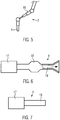
- the FIG. 5 shows an embodiment of the cleaning device 2, with the differently shaped solder nozzles can be cleaned.
- the cleaning device 2 has a manipulator arm 16, at the end of which an ultrasound source 4 is arranged.
- the ultrasonic source 4 may be fixedly mounted on the manipulator arm 16.
- the manipulator arm 16 may be equipped with a gripping device (not shown) with which an ultrasound source 4 can be selectively picked up and stored. Since the manipulator arm 16 move freely in the room and can be programmed accordingly, it is possible that the manipulator arm 16 moves off different soldering nozzles and in each case the ultrasonic source 4 is immersed in the solder wave. In this way, a thorough cleaning of various soldering nozzles is possible.
- FIG. 6 shows an embodiment of an ultrasonic source 4 for the cleaning device.
- the ultrasonic source 4 has at one end an ultrasonic generator 17 which generates ultrasound.
- the ultrasound passes after generation in an ultrasonic amplifier 18, which amplifies the ultrasound.
- the ultrasound by a tubular ultrasonic guide 19 in the directed by the arrow direction and thereby occurs concentrated at the widening end of the ultrasound source 4 from. This end is brought into contact with the soldering nozzle or the solder wave when used as intended, whereby the ultrasound then propagates further in the solder wave or the soldering nozzle.
- FIG. 7 shows an alternative embodiment of the ultrasonic source 4, in which the ultrasonic guide 19 is rod-shaped, that is formed of solid material.
- the ultrasound is transmitted directly from the ultrasound generator 17 to the ultrasonic device 19 and spreads there.
- the free end of the ultrasonic guiding device 19 can then be brought into contact with the solder wave or the soldering nozzle when used as intended.
- soldering device 1 comprises at least one soldering nozzle 3 and at least one device 2 for cleaning a soldering nozzle.
- the device 2 for cleaning a solder nozzle comprises an ultrasound source 4 with an ultrasound generator 17 on which an ultrasound guide device 19 is arranged. Furthermore, the ultrasound source 4 may comprise an ultrasound amplifier (not shown).
- the ultrasonic guide 19 is formed as a cap-shaped element.
- the soldering nozzle 3 and the device 2 for cleaning a soldering nozzle are movable by means of a moving device relative to each other such that the soldering nozzle 3 in the area below the device 2 for cleaning a solder nozzle can be arranged such that a sound or Ultraschallleit adopted 19 with the from the Lötdüse, in particular a Miniwellenlötdüse leaking solder contacted.
- the sound waves emitted by the sound or ultrasound source can be transmitted via the solder in the direction of the nozzle 3, in particular to the outer surface of a soldering nozzle for selective soldering.
- soldering device 1 comprises at least one soldering nozzle 3 and at least one device 2 for cleaning a soldering nozzle.
- the device 2 for cleaning a solder nozzle comprises an ultrasound source 4 with an ultrasound generator 17 on which an ultrasound guide device 19 is arranged. Furthermore, the ultrasound source 4 may comprise an ultrasound amplifier (not shown).
- the ultrasonic guide 19 is formed as a rod-shaped element. The ultrasonic guiding device 19 is surrounded by a cap-shaped element 7.
- the device 2 for cleaning a solder nozzle is arranged stationary in the present embodiment.
- a traversing device of the wave soldering device with solder bath can be used as a moving device to move the soldering nozzle relative to being arranged as described above.
- soldering nozzle 3 is fixed and the device 2 is movable for cleaning a soldering nozzle is possible. Also, the soldering nozzle 3 and the device 2 for cleaning a soldering nozzle can both be designed to be movable by means of the movement device.
- the soldering device is preferably a Selektivlot adopted with a Miniwellenlötdüse.
- a splash guard device 20 is provided for diverting solder that spills over during cleaning of the soldering nozzle ( FIG. 8 ).
- the splash guard 20 is formed as a tubular or tubular body that it surrounds the cleaning device in particular the ultrasonic device, especially if it is designed as a cap-shaped element, or even the sound or ultrasonic source and the solder nozzle during cleaning slightly spaced. Spewing solder sprayed during cleaning against an inner jacket wall of the tubular body and runs from there due to gravity down either into the liquefied solder or a separate collection container.
- the tubular body 20 is preferably a glass fiber tube. Other suitable materials that are sufficiently heat-stable and allow dissipation of solder are conceivable.
- the sonic or ultrasonic source preferably generates a standing wave. In the area of the zero crossing of the standing wave there are no or only slight vibrations.
- the splash guard 20 is therefore preferably attached to the ultrasonic device 19 in the region of the zero crossing, so that it does not vibrate and thus can not solve. Furthermore, the splash guard can also be attached above the sonotrode.
- the device 2 for cleaning a solder nozzle can also be designed as a manual device for manually cleaning a solder nozzle such that a solder nozzle is cleaned manually after a predetermined number of cycles.
- a hand-held device comprises at least one ultrasound source 4 with an ultrasound generator and an ultrasound conducting device, as well as possibly an ultrasound amplifier.
- the cleaning device is particularly preferred in Selektivlöt sexualen used because in such soldering individual solder nozzles are present, which can be cleaned well by the cleaning device according to the invention.
- the cleaning device can indeed be used, but there the cleaning takes more time.
Landscapes
- Engineering & Computer Science (AREA)
- Mechanical Engineering (AREA)
- Electric Connection Of Electric Components To Printed Circuits (AREA)
- Molten Solder (AREA)
- Cleaning By Liquid Or Steam (AREA)
Priority Applications (1)
| Application Number | Priority Date | Filing Date | Title |
|---|---|---|---|
| PL13811424T PL2953757T3 (pl) | 2013-01-17 | 2013-12-13 | Metody i aparatura do czyszczenia dyszy lutowniczej |
Applications Claiming Priority (2)
| Application Number | Priority Date | Filing Date | Title |
|---|---|---|---|
| DE102013100473.3A DE102013100473A1 (de) | 2013-01-17 | 2013-01-17 | Verfahren und Vorrichtung zum Reinigen einer Lötdüse |
| PCT/EP2013/076625 WO2014111213A2 (de) | 2013-01-17 | 2013-12-13 | Verfahren und vorrichtung zum reinigen einer lötdüse |
Publications (2)
| Publication Number | Publication Date |
|---|---|
| EP2953757A2 EP2953757A2 (de) | 2015-12-16 |
| EP2953757B1 true EP2953757B1 (de) | 2018-05-23 |
Family
ID=49876572
Family Applications (1)
| Application Number | Title | Priority Date | Filing Date |
|---|---|---|---|
| EP13811424.4A Active EP2953757B1 (de) | 2013-01-17 | 2013-12-13 | Verfahren und lötvorrichtung mit einer vorrichtung zum reinigen einer lötdüse unter verwendung von einer schallquelle |
Country Status (9)
| Country | Link |
|---|---|
| US (1) | US20150343546A1 (pl) |
| EP (1) | EP2953757B1 (pl) |
| CN (1) | CN105163890B (pl) |
| DE (1) | DE102013100473A1 (pl) |
| DK (1) | DK2953757T5 (pl) |
| ES (1) | ES2683052T3 (pl) |
| HU (1) | HUE040094T2 (pl) |
| PL (1) | PL2953757T3 (pl) |
| WO (1) | WO2014111213A2 (pl) |
Families Citing this family (19)
| Publication number | Priority date | Publication date | Assignee | Title |
|---|---|---|---|---|
| CN101980738A (zh) | 2008-02-07 | 2011-02-23 | 华盛顿大学 | 圆周气雾设备 |
| EP2680913B1 (en) | 2011-03-03 | 2020-05-06 | Impel NeuroPharma Inc. | Nasal drug delivery device |
| CN107376071B (zh) | 2011-05-09 | 2021-07-09 | 英倍尔药业股份有限公司 | 用于将化合物递送到使用者的上部嗅觉区的喷嘴 |
| HK1222358A1 (zh) | 2013-04-28 | 2017-06-30 | Impel Neuropharma Inc. | 医用单位剂量容器 |
| CN105379443B (zh) * | 2013-07-10 | 2018-09-28 | 富士机械制造株式会社 | 吸嘴清洗时间管理装置及管理方法 |
| US9884406B2 (en) | 2014-01-15 | 2018-02-06 | Flow International Corporation | High-pressure waterjet cutting head systems, components and related methods |
| US10596717B2 (en) | 2015-07-13 | 2020-03-24 | Flow International Corporation | Methods of cutting fiber reinforced polymer composite workpieces with a pure waterjet |
| EP3341059B1 (en) | 2015-09-10 | 2022-03-02 | Impel NeuroPharma Inc. | In-line nasal delivery device |
| EP3210779B1 (en) | 2016-02-25 | 2018-12-12 | OCE-Technologies B.V. | Jetting device |
| US10286424B2 (en) * | 2016-04-26 | 2019-05-14 | Ethicon Llc | Ultrasonic cleaning of surgical instrument |
| DE102017114801A1 (de) * | 2017-07-03 | 2019-01-03 | Ersa Gmbh | Verfahren zum Betreiben einer Lötanlage |
| DE102017114954B4 (de) | 2017-07-05 | 2024-11-28 | Ersa Gmbh | Verfahren zum Betreiben einer Lötvorrichtung, Lötvorrichtung |
| US11571532B2 (en) | 2017-11-21 | 2023-02-07 | Impel Pharmaceuticals Inc. | Intranasal device with dip tube |
| US11395887B2 (en) | 2017-11-21 | 2022-07-26 | Impel Pharmaceuticals Inc. | Intranasal device with inlet interface |
| EP3735223A4 (en) | 2018-01-05 | 2021-10-13 | Impel Neuropharma Inc. | INTRANASAL ADMINISTRATION OF OLANZAPINE BY A PRECISION OLFACTORY DEVICE |
| BR112020013744A8 (pt) | 2018-01-05 | 2022-10-18 | Impel Neuropharma Inc | Dispensação intranasal de di-hidroergotamina por dispositivo olfativo de precisão |
| JP2021532098A (ja) | 2018-07-19 | 2021-11-25 | インペル ニューロファーマ インコーポレイテッド | パーキンソン病の治療のためのレボドパおよびドーパデカルボキシラーゼ阻害剤の呼吸管路送達 |
| CN113473967B (zh) | 2019-01-03 | 2022-09-09 | 英倍尔制药公司 | 经鼻药物递送装置 |
| AU2020277313A1 (en) | 2019-05-17 | 2022-01-20 | Impel Pharmaceuticals Inc. | Single-use nasal delivery device |
Citations (1)
| Publication number | Priority date | Publication date | Assignee | Title |
|---|---|---|---|---|
| DE202009002666U1 (de) * | 2009-02-26 | 2009-04-30 | Ersa Gmbh | Vorrichtung zur Reinigung und/oder Aktivierung von Lötdüsen |
Family Cites Families (30)
| Publication number | Priority date | Publication date | Assignee | Title |
|---|---|---|---|---|
| US3430332A (en) * | 1966-04-01 | 1969-03-04 | Electrovert Mfg Co Ltd | Production line soldering with application of ultrasonic energy directing to molten solder |
| JPS537386B2 (pl) * | 1972-03-31 | 1978-03-17 | ||
| US3795358A (en) * | 1972-12-11 | 1974-03-05 | Ibm | Immersion solder leveling apparatus using ultrasonic cavitation |
| US3945618A (en) * | 1974-08-01 | 1976-03-23 | Branson Ultrasonics Corporation | Sonic apparatus |
| JPS54148137A (en) * | 1978-05-15 | 1979-11-20 | Hitachi Ltd | Plating apparatus |
| DE3218338A1 (de) * | 1982-05-14 | 1983-11-17 | Royonic Elektronik Produktionsmaschinen GmbH, 8057 Eching | Loetverfahren und -vorrichtung |
| DE8408427U1 (de) | 1984-03-20 | 1985-07-18 | Robert Bosch Gmbh, 7000 Stuttgart | Lötgerät zum maschinellen Löten von Werkstücken |
| US5113882A (en) * | 1990-08-28 | 1992-05-19 | Electrovert Ltd. | Method of cleaning workpieces with a potentially flammable or explosive liquid and drying in the tunnel |
| JPH04274399A (ja) * | 1991-03-01 | 1992-09-30 | Matsushita Electric Ind Co Ltd | 電子部品装着装置 |
| DE4133645A1 (de) | 1991-10-11 | 1993-04-15 | Ernst Hohnerlein | Verfahren zum loeten und loetkolben zur durchfuehrung dieses verfahrens |
| US5156324A (en) * | 1992-03-17 | 1992-10-20 | Electrovert Lgd | Solder apparatus with dual hollow wave nozzles |
| JP2651558B2 (ja) * | 1993-04-30 | 1997-09-10 | 黒田電気株式会社 | 超音波はんだ付装置 |
| JPH0831703A (ja) * | 1994-07-11 | 1996-02-02 | Matsushita Electric Ind Co Ltd | 電子部品の超音波半田付け装置 |
| DE4432402C2 (de) * | 1994-08-30 | 1998-07-02 | Ersa Loettechnik Gmbh | Schwall-Lötdüse zum flußmittelfreien Löten |
| JPH1157572A (ja) * | 1997-08-14 | 1999-03-02 | Matsushita Electric Ind Co Ltd | 接着剤塗布装置 |
| KR100409201B1 (ko) * | 1999-09-01 | 2003-12-11 | 주식회사 포스코 | 전자기 초음파 진동을 이용한 노즐막힘 방지장치 및 그 방법 |
| JP2002248437A (ja) * | 2001-02-26 | 2002-09-03 | Kao Corp | 超音波洗浄装置及びその方法 |
| NL1017843C2 (nl) * | 2001-04-12 | 2002-10-22 | Vitronics Soltec B V | Inrichting voor selectief solderen. |
| JP2003031535A (ja) * | 2001-07-11 | 2003-01-31 | Mitsubishi Electric Corp | 半導体製造装置の超音波洗浄方法 |
| JP3876167B2 (ja) * | 2002-02-13 | 2007-01-31 | 川崎マイクロエレクトロニクス株式会社 | 洗浄方法および半導体装置の製造方法 |
| KR100459710B1 (ko) * | 2002-04-15 | 2004-12-04 | 삼성전자주식회사 | 웨이퍼 세정 장비 |
| TWI220393B (en) * | 2002-04-30 | 2004-08-21 | Asm Assembly Automation Ltd | Ultrasonic cleaning module |
| JP4428014B2 (ja) * | 2003-02-25 | 2010-03-10 | パナソニック電工株式会社 | 超音波生体洗浄装置 |
| SG185136A1 (en) * | 2003-04-11 | 2012-11-29 | Nikon Corp | Cleanup method for optics in immersion lithography |
| DE102004053337A1 (de) * | 2004-11-04 | 2006-05-11 | Steag Hama Tech Ag | Verfahren und Vorrichtung zum Behandeln von Substraten und Düseneinheit hierfür |
| CN101181842A (zh) * | 2006-11-14 | 2008-05-21 | 珠海天威技术开发有限公司 | 喷墨打印机墨盒回收方法 |
| US20080142037A1 (en) * | 2006-12-19 | 2008-06-19 | Dempski James L | Apparatus and method for cleaning liquid dispensing equipment |
| EP2135700B1 (en) * | 2008-06-18 | 2013-05-22 | Henkel AG & Co. KGaA | Method and apparatus for automated servicing of a welding torch head |
| US8440937B2 (en) * | 2008-12-11 | 2013-05-14 | GM Global Technology Operations LLC | Self-cleaning welding nozzle |
| DE202011050852U1 (de) * | 2011-07-28 | 2011-09-07 | Seho Systemtechnik Gmbh | Lötdüse für eine Miniwellenlötvorrichtung und Miniwellenlötvorrichtung mit einer solchen Lötdüse |
-
2013
- 2013-01-17 DE DE102013100473.3A patent/DE102013100473A1/de not_active Withdrawn
- 2013-12-13 ES ES13811424.4T patent/ES2683052T3/es active Active
- 2013-12-13 CN CN201380070853.6A patent/CN105163890B/zh active Active
- 2013-12-13 US US14/761,231 patent/US20150343546A1/en not_active Abandoned
- 2013-12-13 WO PCT/EP2013/076625 patent/WO2014111213A2/de not_active Ceased
- 2013-12-13 HU HUE13811424A patent/HUE040094T2/hu unknown
- 2013-12-13 EP EP13811424.4A patent/EP2953757B1/de active Active
- 2013-12-13 PL PL13811424T patent/PL2953757T3/pl unknown
- 2013-12-13 DK DK13811424.4T patent/DK2953757T5/en active
Patent Citations (1)
| Publication number | Priority date | Publication date | Assignee | Title |
|---|---|---|---|---|
| DE202009002666U1 (de) * | 2009-02-26 | 2009-04-30 | Ersa Gmbh | Vorrichtung zur Reinigung und/oder Aktivierung von Lötdüsen |
Also Published As
| Publication number | Publication date |
|---|---|
| WO2014111213A3 (de) | 2014-10-23 |
| DE102013100473A1 (de) | 2014-07-17 |
| DK2953757T5 (en) | 2018-09-10 |
| WO2014111213A2 (de) | 2014-07-24 |
| DK2953757T3 (en) | 2018-08-20 |
| CN105163890A (zh) | 2015-12-16 |
| ES2683052T3 (es) | 2018-09-24 |
| CN105163890B (zh) | 2019-05-07 |
| PL2953757T3 (pl) | 2018-11-30 |
| EP2953757A2 (de) | 2015-12-16 |
| US20150343546A1 (en) | 2015-12-03 |
| HUE040094T2 (hu) | 2019-02-28 |
Similar Documents
| Publication | Publication Date | Title |
|---|---|---|
| WO2014111213A2 (de) | Verfahren und vorrichtung zum reinigen einer lötdüse | |
| DE2004005C3 (de) | Ultraschall-Reinigungsgerät, insbesondere für den zahnärztlichen Bereich | |
| EP3302864B1 (de) | Verfahren und vorrichtung zur herstellung eines strukturierten elements durch materialabtragende bearbeitung mit gepulster lasersstrahlung | |
| EP2288470B1 (de) | VORRICHTUNG UND VERFAHREN ZUM REINIGEN VON SCHWEIßBRENNER | |
| DE4336000A1 (de) | Verfahren und Vorrichtung zum Kontaktieren des Wicklungsdrahtes einer Spule mit einem Anschlußstift | |
| WO2017178580A1 (de) | Vorrichtung zur bearbeitung einer oberfläche eines werkstücks mit einem laserstrahl und verfahren zum betrieb der vorrichtung | |
| AT411693B (de) | Elektrochemisches verfahren zum reinigen von oberflächen metallischer werkstücke | |
| DE10001344A1 (de) | Verfahren und Vorrichtung zum mehrstufigen Lichtbogenschweißen | |
| EP1378312A2 (de) | Verfahren und Vorrichtung zum Lichtbogenschweissen von Elementen auf beschichtete Bauteile und Element geeignet für das Lichtbogenschweissverfahren | |
| WO2005097362A1 (de) | Reinigungsvorrichtung zum reinigen von schweissbrennern | |
| DE102004027229B4 (de) | Verfahren zum Schweißen von Werkstücken aus Aluminium oder einer Aluminiumlegierung | |
| DE3236314C2 (pl) | ||
| DE102013112367A1 (de) | Verfahren und Vorrichtung zum Löten von Leiterplatten | |
| DE4009721A1 (de) | Vorrichtung zum reinigen von werkstuecken | |
| DE720629C (de) | Verfahren und Vorrichtung zum Verloeten von Gegenstaenden aus Aluminium untereinander oder mit Gegenstaenden aus anderen Metallen | |
| EP3238871B1 (de) | Verfahren zur herstellung eines rohres aus metall durch laserschweissen | |
| DE3235547A1 (de) | Verfahren und vorrichtungen zum festen verbinden von bau- bzw. konstruktionselementen | |
| WO2008089835A1 (de) | Vorrichtung zum reinigen der keramik-gasdüse eines schweissbrenners | |
| EP3984681A1 (de) | Verfahren zur vorbereitung eines automatisierten schweissverfahrens auf einen schweissprozess und schweissvorrichtung zur durchführung eines automatisierten schweissverfahrens | |
| DE8309227U1 (de) | Reinigungseinrichtung fuer schweissbrenner | |
| DE3209805C2 (de) | Verfahren und Vorrichtung zum Entfernen der Sicherungsringe bei Flaschen mit Schraubverschluß | |
| DE19917323A1 (de) | Schweißkopf oder Schweißpistole zum Bolzenschweißen mit Hubzündung | |
| DE102011077242A1 (de) | Schutzgaszuführung | |
| EP3511108B1 (de) | Verfahren zur herstellung eines lotmittels | |
| DE202007004709U1 (de) | Schweißautomat |
Legal Events
| Date | Code | Title | Description |
|---|---|---|---|
| PUAI | Public reference made under article 153(3) epc to a published international application that has entered the european phase |
Free format text: ORIGINAL CODE: 0009012 |
|
| 17P | Request for examination filed |
Effective date: 20150701 |
|
| AK | Designated contracting states |
Kind code of ref document: A2 Designated state(s): AL AT BE BG CH CY CZ DE DK EE ES FI FR GB GR HR HU IE IS IT LI LT LU LV MC MK MT NL NO PL PT RO RS SE SI SK SM TR |
|
| AX | Request for extension of the european patent |
Extension state: BA ME |
|
| DAX | Request for extension of the european patent (deleted) | ||
| 17Q | First examination report despatched |
Effective date: 20160506 |
|
| GRAP | Despatch of communication of intention to grant a patent |
Free format text: ORIGINAL CODE: EPIDOSNIGR1 |
|
| INTG | Intention to grant announced |
Effective date: 20171220 |
|
| GRAS | Grant fee paid |
Free format text: ORIGINAL CODE: EPIDOSNIGR3 |
|
| GRAA | (expected) grant |
Free format text: ORIGINAL CODE: 0009210 |
|
| AK | Designated contracting states |
Kind code of ref document: B1 Designated state(s): AL AT BE BG CH CY CZ DE DK EE ES FI FR GB GR HR HU IE IS IT LI LT LU LV MC MK MT NL NO PL PT RO RS SE SI SK SM TR |
|
| REG | Reference to a national code |
Ref country code: GB Ref legal event code: FG4D Free format text: NOT ENGLISH |
|
| REG | Reference to a national code |
Ref country code: CH Ref legal event code: EP |
|
| REG | Reference to a national code |
Ref country code: IE Ref legal event code: FG4D Free format text: LANGUAGE OF EP DOCUMENT: GERMAN |
|
| REG | Reference to a national code |
Ref country code: AT Ref legal event code: REF Ref document number: 1001131 Country of ref document: AT Kind code of ref document: T Effective date: 20180615 |
|
| REG | Reference to a national code |
Ref country code: DE Ref legal event code: R096 Ref document number: 502013010209 Country of ref document: DE |
|
| REG | Reference to a national code |
Ref country code: RO Ref legal event code: EPE |
|
| REG | Reference to a national code |
Ref country code: DK Ref legal event code: T3 Effective date: 20180814 |
|
| REG | Reference to a national code |
Ref country code: NL Ref legal event code: FP |
|
| REG | Reference to a national code |
Ref country code: DK Ref legal event code: T5 Effective date: 20180903 |
|
| REG | Reference to a national code |
Ref country code: SE Ref legal event code: TRGR |
|
| REG | Reference to a national code |
Ref country code: ES Ref legal event code: FG2A Ref document number: 2683052 Country of ref document: ES Kind code of ref document: T3 Effective date: 20180924 |
|
| REG | Reference to a national code |
Ref country code: LT Ref legal event code: MG4D |
|
| PG25 | Lapsed in a contracting state [announced via postgrant information from national office to epo] |
Ref country code: LT Free format text: LAPSE BECAUSE OF FAILURE TO SUBMIT A TRANSLATION OF THE DESCRIPTION OR TO PAY THE FEE WITHIN THE PRESCRIBED TIME-LIMIT Effective date: 20180523 Ref country code: NO Free format text: LAPSE BECAUSE OF FAILURE TO SUBMIT A TRANSLATION OF THE DESCRIPTION OR TO PAY THE FEE WITHIN THE PRESCRIBED TIME-LIMIT Effective date: 20180823 Ref country code: FI Free format text: LAPSE BECAUSE OF FAILURE TO SUBMIT A TRANSLATION OF THE DESCRIPTION OR TO PAY THE FEE WITHIN THE PRESCRIBED TIME-LIMIT Effective date: 20180523 |
|
| PG25 | Lapsed in a contracting state [announced via postgrant information from national office to epo] |
Ref country code: RS Free format text: LAPSE BECAUSE OF FAILURE TO SUBMIT A TRANSLATION OF THE DESCRIPTION OR TO PAY THE FEE WITHIN THE PRESCRIBED TIME-LIMIT Effective date: 20180523 Ref country code: GR Free format text: LAPSE BECAUSE OF FAILURE TO SUBMIT A TRANSLATION OF THE DESCRIPTION OR TO PAY THE FEE WITHIN THE PRESCRIBED TIME-LIMIT Effective date: 20180824 Ref country code: HR Free format text: LAPSE BECAUSE OF FAILURE TO SUBMIT A TRANSLATION OF THE DESCRIPTION OR TO PAY THE FEE WITHIN THE PRESCRIBED TIME-LIMIT Effective date: 20180523 Ref country code: LV Free format text: LAPSE BECAUSE OF FAILURE TO SUBMIT A TRANSLATION OF THE DESCRIPTION OR TO PAY THE FEE WITHIN THE PRESCRIBED TIME-LIMIT Effective date: 20180523 |
|
| REG | Reference to a national code |
Ref country code: SK Ref legal event code: T3 Ref document number: E 28187 Country of ref document: SK |
|
| PG25 | Lapsed in a contracting state [announced via postgrant information from national office to epo] |
Ref country code: EE Free format text: LAPSE BECAUSE OF FAILURE TO SUBMIT A TRANSLATION OF THE DESCRIPTION OR TO PAY THE FEE WITHIN THE PRESCRIBED TIME-LIMIT Effective date: 20180523 |
|
| PGFP | Annual fee paid to national office [announced via postgrant information from national office to epo] |
Ref country code: SE Payment date: 20181219 Year of fee payment: 6 Ref country code: RO Payment date: 20181210 Year of fee payment: 6 Ref country code: SK Payment date: 20181203 Year of fee payment: 6 Ref country code: PL Payment date: 20181203 Year of fee payment: 6 Ref country code: IE Payment date: 20181214 Year of fee payment: 6 Ref country code: AT Payment date: 20181129 Year of fee payment: 6 Ref country code: NL Payment date: 20181217 Year of fee payment: 6 Ref country code: CZ Payment date: 20181203 Year of fee payment: 6 Ref country code: DK Payment date: 20181219 Year of fee payment: 6 Ref country code: HU Payment date: 20181205 Year of fee payment: 6 |
|
| REG | Reference to a national code |
Ref country code: DE Ref legal event code: R097 Ref document number: 502013010209 Country of ref document: DE |
|
| PG25 | Lapsed in a contracting state [announced via postgrant information from national office to epo] |
Ref country code: SM Free format text: LAPSE BECAUSE OF FAILURE TO SUBMIT A TRANSLATION OF THE DESCRIPTION OR TO PAY THE FEE WITHIN THE PRESCRIBED TIME-LIMIT Effective date: 20180523 |
|
| PGFP | Annual fee paid to national office [announced via postgrant information from national office to epo] |
Ref country code: CH Payment date: 20181126 Year of fee payment: 6 Ref country code: BG Payment date: 20181218 Year of fee payment: 6 |
|
| REG | Reference to a national code |
Ref country code: HU Ref legal event code: AG4A Ref document number: E040094 Country of ref document: HU |
|
| PLBE | No opposition filed within time limit |
Free format text: ORIGINAL CODE: 0009261 |
|
| STAA | Information on the status of an ep patent application or granted ep patent |
Free format text: STATUS: NO OPPOSITION FILED WITHIN TIME LIMIT |
|
| PGFP | Annual fee paid to national office [announced via postgrant information from national office to epo] |
Ref country code: ES Payment date: 20190121 Year of fee payment: 6 |
|
| 26N | No opposition filed |
Effective date: 20190226 |
|
| PG25 | Lapsed in a contracting state [announced via postgrant information from national office to epo] |
Ref country code: SI Free format text: LAPSE BECAUSE OF FAILURE TO SUBMIT A TRANSLATION OF THE DESCRIPTION OR TO PAY THE FEE WITHIN THE PRESCRIBED TIME-LIMIT Effective date: 20180523 |
|
| REG | Reference to a national code |
Ref country code: CH Ref legal event code: PL |
|
| GBPC | Gb: european patent ceased through non-payment of renewal fee |
Effective date: 20181213 |
|
| PG25 | Lapsed in a contracting state [announced via postgrant information from national office to epo] |
Ref country code: LU Free format text: LAPSE BECAUSE OF NON-PAYMENT OF DUE FEES Effective date: 20181213 Ref country code: MC Free format text: LAPSE BECAUSE OF FAILURE TO SUBMIT A TRANSLATION OF THE DESCRIPTION OR TO PAY THE FEE WITHIN THE PRESCRIBED TIME-LIMIT Effective date: 20180523 |
|
| REG | Reference to a national code |
Ref country code: BE Ref legal event code: MM Effective date: 20181231 |
|
| PG25 | Lapsed in a contracting state [announced via postgrant information from national office to epo] |
Ref country code: BE Free format text: LAPSE BECAUSE OF NON-PAYMENT OF DUE FEES Effective date: 20181231 Ref country code: AL Free format text: LAPSE BECAUSE OF FAILURE TO SUBMIT A TRANSLATION OF THE DESCRIPTION OR TO PAY THE FEE WITHIN THE PRESCRIBED TIME-LIMIT Effective date: 20180523 |
|
| PG25 | Lapsed in a contracting state [announced via postgrant information from national office to epo] |
Ref country code: LI Free format text: LAPSE BECAUSE OF NON-PAYMENT OF DUE FEES Effective date: 20181231 Ref country code: GB Free format text: LAPSE BECAUSE OF NON-PAYMENT OF DUE FEES Effective date: 20181213 Ref country code: CH Free format text: LAPSE BECAUSE OF NON-PAYMENT OF DUE FEES Effective date: 20181231 |
|
| PG25 | Lapsed in a contracting state [announced via postgrant information from national office to epo] |
Ref country code: MT Free format text: LAPSE BECAUSE OF FAILURE TO SUBMIT A TRANSLATION OF THE DESCRIPTION OR TO PAY THE FEE WITHIN THE PRESCRIBED TIME-LIMIT Effective date: 20180523 |
|
| PG25 | Lapsed in a contracting state [announced via postgrant information from national office to epo] |
Ref country code: PT Free format text: LAPSE BECAUSE OF FAILURE TO SUBMIT A TRANSLATION OF THE DESCRIPTION OR TO PAY THE FEE WITHIN THE PRESCRIBED TIME-LIMIT Effective date: 20180523 |
|
| PG25 | Lapsed in a contracting state [announced via postgrant information from national office to epo] |
Ref country code: MK Free format text: LAPSE BECAUSE OF NON-PAYMENT OF DUE FEES Effective date: 20180523 Ref country code: CY Free format text: LAPSE BECAUSE OF FAILURE TO SUBMIT A TRANSLATION OF THE DESCRIPTION OR TO PAY THE FEE WITHIN THE PRESCRIBED TIME-LIMIT Effective date: 20180523 |
|
| REG | Reference to a national code |
Ref country code: DK Ref legal event code: EBP Effective date: 20191231 |
|
| REG | Reference to a national code |
Ref country code: SE Ref legal event code: EUG |
|
| PG25 | Lapsed in a contracting state [announced via postgrant information from national office to epo] |
Ref country code: CZ Free format text: LAPSE BECAUSE OF NON-PAYMENT OF DUE FEES Effective date: 20191213 Ref country code: RO Free format text: LAPSE BECAUSE OF NON-PAYMENT OF DUE FEES Effective date: 20191213 Ref country code: IS Free format text: LAPSE BECAUSE OF FAILURE TO SUBMIT A TRANSLATION OF THE DESCRIPTION OR TO PAY THE FEE WITHIN THE PRESCRIBED TIME-LIMIT Effective date: 20180923 |
|
| REG | Reference to a national code |
Ref country code: NL Ref legal event code: MM Effective date: 20200101 |
|
| REG | Reference to a national code |
Ref country code: AT Ref legal event code: MM01 Ref document number: 1001131 Country of ref document: AT Kind code of ref document: T Effective date: 20191213 |
|
| REG | Reference to a national code |
Ref country code: SK Ref legal event code: MM4A Ref document number: E 28187 Country of ref document: SK Effective date: 20191213 |
|
| PG25 | Lapsed in a contracting state [announced via postgrant information from national office to epo] |
Ref country code: NL Free format text: LAPSE BECAUSE OF NON-PAYMENT OF DUE FEES Effective date: 20200101 |
|
| PG25 | Lapsed in a contracting state [announced via postgrant information from national office to epo] |
Ref country code: SK Free format text: LAPSE BECAUSE OF NON-PAYMENT OF DUE FEES Effective date: 20191213 Ref country code: IE Free format text: LAPSE BECAUSE OF NON-PAYMENT OF DUE FEES Effective date: 20191213 Ref country code: FR Free format text: LAPSE BECAUSE OF NON-PAYMENT OF DUE FEES Effective date: 20191231 Ref country code: SE Free format text: LAPSE BECAUSE OF NON-PAYMENT OF DUE FEES Effective date: 20191214 |
|
| PG25 | Lapsed in a contracting state [announced via postgrant information from national office to epo] |
Ref country code: AT Free format text: LAPSE BECAUSE OF NON-PAYMENT OF DUE FEES Effective date: 20191213 Ref country code: BG Free format text: LAPSE BECAUSE OF NON-PAYMENT OF DUE FEES Effective date: 20200630 Ref country code: HU Free format text: LAPSE BECAUSE OF NON-PAYMENT OF DUE FEES Effective date: 20191214 |
|
| PG25 | Lapsed in a contracting state [announced via postgrant information from national office to epo] |
Ref country code: DK Free format text: LAPSE BECAUSE OF NON-PAYMENT OF DUE FEES Effective date: 20191231 |
|
| REG | Reference to a national code |
Ref country code: ES Ref legal event code: FD2A Effective date: 20210528 |
|
| PG25 | Lapsed in a contracting state [announced via postgrant information from national office to epo] |
Ref country code: ES Free format text: LAPSE BECAUSE OF NON-PAYMENT OF DUE FEES Effective date: 20191214 |
|
| REG | Reference to a national code |
Ref country code: DE Ref legal event code: R081 Ref document number: 502013010209 Country of ref document: DE Owner name: SEHO VERMOEGENSVERWALTUNGS GMBH & CO. KG, DE Free format text: FORMER OWNER: SEHO SYSTEMTECHNIK GMBH, 97892 KREUZWERTHEIM, DE |
|
| PG25 | Lapsed in a contracting state [announced via postgrant information from national office to epo] |
Ref country code: PL Free format text: LAPSE BECAUSE OF NON-PAYMENT OF DUE FEES Effective date: 20191213 |
|
| PG25 | Lapsed in a contracting state [announced via postgrant information from national office to epo] |
Ref country code: TR Free format text: LAPSE BECAUSE OF NON-PAYMENT OF DUE FEES Effective date: 20191213 |
|
| P01 | Opt-out of the competence of the unified patent court (upc) registered |
Effective date: 20230530 |
|
| PGFP | Annual fee paid to national office [announced via postgrant information from national office to epo] |
Ref country code: DE Payment date: 20251210 Year of fee payment: 13 |
|
| PGFP | Annual fee paid to national office [announced via postgrant information from national office to epo] |
Ref country code: IT Payment date: 20251203 Year of fee payment: 13 |