EP2802025A1 - Batteriezelle mit einer treppenstruktur - Google Patents
Batteriezelle mit einer treppenstruktur Download PDFInfo
- Publication number
- EP2802025A1 EP2802025A1 EP13772747.5A EP13772747A EP2802025A1 EP 2802025 A1 EP2802025 A1 EP 2802025A1 EP 13772747 A EP13772747 A EP 13772747A EP 2802025 A1 EP2802025 A1 EP 2802025A1
- Authority
- EP
- European Patent Office
- Prior art keywords
- battery case
- electrode assembly
- battery
- battery cell
- case
- Prior art date
- Legal status (The legal status is an assumption and is not a legal conclusion. Google has not performed a legal analysis and makes no representation as to the accuracy of the status listed.)
- Granted
Links
- 238000004519 manufacturing process Methods 0.000 claims description 35
- 238000000034 method Methods 0.000 claims description 22
- 239000003792 electrolyte Substances 0.000 claims description 16
- 238000007789 sealing Methods 0.000 claims description 10
- HBBGRARXTFLTSG-UHFFFAOYSA-N Lithium ion Chemical compound [Li+] HBBGRARXTFLTSG-UHFFFAOYSA-N 0.000 claims description 9
- 229910001416 lithium ion Inorganic materials 0.000 claims description 9
- 230000003247 decreasing effect Effects 0.000 claims description 5
- 238000007599 discharging Methods 0.000 claims description 5
- 238000000465 moulding Methods 0.000 claims description 5
- 239000011347 resin Substances 0.000 claims description 5
- 229920005989 resin Polymers 0.000 claims description 5
- 229910052751 metal Inorganic materials 0.000 claims description 4
- 239000002184 metal Substances 0.000 claims description 4
- 229920000642 polymer Polymers 0.000 claims description 4
- 238000003825 pressing Methods 0.000 claims description 4
- 238000003860 storage Methods 0.000 claims description 4
- 230000004913 activation Effects 0.000 claims description 3
- 210000004027 cell Anatomy 0.000 description 115
- 230000008569 process Effects 0.000 description 15
- 230000000712 assembly Effects 0.000 description 12
- 238000000429 assembly Methods 0.000 description 12
- WHXSMMKQMYFTQS-UHFFFAOYSA-N Lithium Chemical compound [Li] WHXSMMKQMYFTQS-UHFFFAOYSA-N 0.000 description 10
- 229910052744 lithium Inorganic materials 0.000 description 10
- 238000013461 design Methods 0.000 description 7
- 239000000463 material Substances 0.000 description 6
- 238000004804 winding Methods 0.000 description 6
- 239000002131 composite material Substances 0.000 description 5
- 238000003466 welding Methods 0.000 description 5
- 238000001994 activation Methods 0.000 description 4
- 230000015572 biosynthetic process Effects 0.000 description 4
- 238000007689 inspection Methods 0.000 description 4
- OKTJSMMVPCPJKN-UHFFFAOYSA-N Carbon Chemical compound [C] OKTJSMMVPCPJKN-UHFFFAOYSA-N 0.000 description 3
- 239000006183 anode active material Substances 0.000 description 3
- 229910052799 carbon Inorganic materials 0.000 description 3
- 239000006182 cathode active material Substances 0.000 description 3
- 230000020411 cell activation Effects 0.000 description 2
- 238000010276 construction Methods 0.000 description 2
- 230000000994 depressogenic effect Effects 0.000 description 2
- 230000000694 effects Effects 0.000 description 2
- 230000004048 modification Effects 0.000 description 2
- 238000012986 modification Methods 0.000 description 2
- 239000011255 nonaqueous electrolyte Substances 0.000 description 2
- 210000004508 polar body Anatomy 0.000 description 2
- 238000012545 processing Methods 0.000 description 2
- 229910032387 LiCoO2 Inorganic materials 0.000 description 1
- -1 LiPF6 Chemical class 0.000 description 1
- 229910001290 LiPF6 Inorganic materials 0.000 description 1
- 238000007792 addition Methods 0.000 description 1
- 239000002390 adhesive tape Substances 0.000 description 1
- 230000008859 change Effects 0.000 description 1
- 230000007547 defect Effects 0.000 description 1
- 230000001747 exhibiting effect Effects 0.000 description 1
- 238000009434 installation Methods 0.000 description 1
- 150000002500 ions Chemical class 0.000 description 1
- 230000001788 irregular Effects 0.000 description 1
- 238000002955 isolation Methods 0.000 description 1
- 229910003002 lithium salt Inorganic materials 0.000 description 1
- 159000000002 lithium salts Chemical class 0.000 description 1
- 229910021437 lithium-transition metal oxide Inorganic materials 0.000 description 1
- 230000014759 maintenance of location Effects 0.000 description 1
- 230000035515 penetration Effects 0.000 description 1
- 229920000098 polyolefin Polymers 0.000 description 1
- 238000000926 separation method Methods 0.000 description 1
- 239000007784 solid electrolyte Substances 0.000 description 1
- 238000006467 substitution reaction Methods 0.000 description 1
- 230000008961 swelling Effects 0.000 description 1
- 238000012546 transfer Methods 0.000 description 1
Images


Classifications
-
- H—ELECTRICITY
- H01—ELECTRIC ELEMENTS
- H01M—PROCESSES OR MEANS, e.g. BATTERIES, FOR THE DIRECT CONVERSION OF CHEMICAL ENERGY INTO ELECTRICAL ENERGY
- H01M10/00—Secondary cells; Manufacture thereof
- H01M10/04—Construction or manufacture in general
- H01M10/0436—Small-sized flat cells or batteries for portable equipment
-
- H—ELECTRICITY
- H01—ELECTRIC ELEMENTS
- H01M—PROCESSES OR MEANS, e.g. BATTERIES, FOR THE DIRECT CONVERSION OF CHEMICAL ENERGY INTO ELECTRICAL ENERGY
- H01M10/00—Secondary cells; Manufacture thereof
- H01M10/04—Construction or manufacture in general
- H01M10/0463—Cells or batteries with horizontal or inclined electrodes
-
- H—ELECTRICITY
- H01—ELECTRIC ELEMENTS
- H01M—PROCESSES OR MEANS, e.g. BATTERIES, FOR THE DIRECT CONVERSION OF CHEMICAL ENERGY INTO ELECTRICAL ENERGY
- H01M10/00—Secondary cells; Manufacture thereof
- H01M10/05—Accumulators with non-aqueous electrolyte
- H01M10/052—Li-accumulators
- H01M10/0525—Rocking-chair batteries, i.e. batteries with lithium insertion or intercalation in both electrodes; Lithium-ion batteries
-
- H—ELECTRICITY
- H01—ELECTRIC ELEMENTS
- H01M—PROCESSES OR MEANS, e.g. BATTERIES, FOR THE DIRECT CONVERSION OF CHEMICAL ENERGY INTO ELECTRICAL ENERGY
- H01M10/00—Secondary cells; Manufacture thereof
- H01M10/05—Accumulators with non-aqueous electrolyte
- H01M10/058—Construction or manufacture
- H01M10/0585—Construction or manufacture of accumulators having only flat construction elements, i.e. flat positive electrodes, flat negative electrodes and flat separators
-
- H—ELECTRICITY
- H01—ELECTRIC ELEMENTS
- H01M—PROCESSES OR MEANS, e.g. BATTERIES, FOR THE DIRECT CONVERSION OF CHEMICAL ENERGY INTO ELECTRICAL ENERGY
- H01M10/00—Secondary cells; Manufacture thereof
- H01M10/42—Methods or arrangements for servicing or maintenance of secondary cells or secondary half-cells
- H01M10/44—Methods for charging or discharging
- H01M10/446—Initial charging measures
-
- H—ELECTRICITY
- H01—ELECTRIC ELEMENTS
- H01M—PROCESSES OR MEANS, e.g. BATTERIES, FOR THE DIRECT CONVERSION OF CHEMICAL ENERGY INTO ELECTRICAL ENERGY
- H01M50/00—Constructional details or processes of manufacture of the non-active parts of electrochemical cells other than fuel cells, e.g. hybrid cells
- H01M50/10—Primary casings, jackets or wrappings of a single cell or a single battery
- H01M50/102—Primary casings, jackets or wrappings of a single cell or a single battery characterised by their shape or physical structure
- H01M50/103—Primary casings, jackets or wrappings of a single cell or a single battery characterised by their shape or physical structure prismatic or rectangular
-
- H—ELECTRICITY
- H01—ELECTRIC ELEMENTS
- H01M—PROCESSES OR MEANS, e.g. BATTERIES, FOR THE DIRECT CONVERSION OF CHEMICAL ENERGY INTO ELECTRICAL ENERGY
- H01M50/00—Constructional details or processes of manufacture of the non-active parts of electrochemical cells other than fuel cells, e.g. hybrid cells
- H01M50/10—Primary casings, jackets or wrappings of a single cell or a single battery
- H01M50/102—Primary casings, jackets or wrappings of a single cell or a single battery characterised by their shape or physical structure
- H01M50/105—Pouches or flexible bags
-
- H—ELECTRICITY
- H01—ELECTRIC ELEMENTS
- H01M—PROCESSES OR MEANS, e.g. BATTERIES, FOR THE DIRECT CONVERSION OF CHEMICAL ENERGY INTO ELECTRICAL ENERGY
- H01M50/00—Constructional details or processes of manufacture of the non-active parts of electrochemical cells other than fuel cells, e.g. hybrid cells
- H01M50/10—Primary casings, jackets or wrappings of a single cell or a single battery
- H01M50/116—Primary casings, jackets or wrappings of a single cell or a single battery characterised by the material
- H01M50/117—Inorganic material
- H01M50/119—Metals
-
- H—ELECTRICITY
- H01—ELECTRIC ELEMENTS
- H01M—PROCESSES OR MEANS, e.g. BATTERIES, FOR THE DIRECT CONVERSION OF CHEMICAL ENERGY INTO ELECTRICAL ENERGY
- H01M50/00—Constructional details or processes of manufacture of the non-active parts of electrochemical cells other than fuel cells, e.g. hybrid cells
- H01M50/10—Primary casings, jackets or wrappings of a single cell or a single battery
- H01M50/116—Primary casings, jackets or wrappings of a single cell or a single battery characterised by the material
- H01M50/121—Organic material
-
- H—ELECTRICITY
- H01—ELECTRIC ELEMENTS
- H01M—PROCESSES OR MEANS, e.g. BATTERIES, FOR THE DIRECT CONVERSION OF CHEMICAL ENERGY INTO ELECTRICAL ENERGY
- H01M50/00—Constructional details or processes of manufacture of the non-active parts of electrochemical cells other than fuel cells, e.g. hybrid cells
- H01M50/10—Primary casings, jackets or wrappings of a single cell or a single battery
- H01M50/116—Primary casings, jackets or wrappings of a single cell or a single battery characterised by the material
- H01M50/124—Primary casings, jackets or wrappings of a single cell or a single battery characterised by the material having a layered structure
-
- H—ELECTRICITY
- H01—ELECTRIC ELEMENTS
- H01M—PROCESSES OR MEANS, e.g. BATTERIES, FOR THE DIRECT CONVERSION OF CHEMICAL ENERGY INTO ELECTRICAL ENERGY
- H01M50/00—Constructional details or processes of manufacture of the non-active parts of electrochemical cells other than fuel cells, e.g. hybrid cells
- H01M50/10—Primary casings, jackets or wrappings of a single cell or a single battery
- H01M50/131—Primary casings, jackets or wrappings of a single cell or a single battery characterised by physical properties, e.g. gas-permeability or size
- H01M50/133—Thickness
-
- H—ELECTRICITY
- H01—ELECTRIC ELEMENTS
- H01M—PROCESSES OR MEANS, e.g. BATTERIES, FOR THE DIRECT CONVERSION OF CHEMICAL ENERGY INTO ELECTRICAL ENERGY
- H01M50/00—Constructional details or processes of manufacture of the non-active parts of electrochemical cells other than fuel cells, e.g. hybrid cells
- H01M50/10—Primary casings, jackets or wrappings of a single cell or a single battery
- H01M50/183—Sealing members
- H01M50/186—Sealing members characterised by the disposition of the sealing members
-
- H—ELECTRICITY
- H01—ELECTRIC ELEMENTS
- H01M—PROCESSES OR MEANS, e.g. BATTERIES, FOR THE DIRECT CONVERSION OF CHEMICAL ENERGY INTO ELECTRICAL ENERGY
- H01M50/00—Constructional details or processes of manufacture of the non-active parts of electrochemical cells other than fuel cells, e.g. hybrid cells
- H01M50/50—Current conducting connections for cells or batteries
- H01M50/543—Terminals
- H01M50/547—Terminals characterised by the disposition of the terminals on the cells
- H01M50/55—Terminals characterised by the disposition of the terminals on the cells on the same side of the cell
-
- H—ELECTRICITY
- H01—ELECTRIC ELEMENTS
- H01M—PROCESSES OR MEANS, e.g. BATTERIES, FOR THE DIRECT CONVERSION OF CHEMICAL ENERGY INTO ELECTRICAL ENERGY
- H01M50/00—Constructional details or processes of manufacture of the non-active parts of electrochemical cells other than fuel cells, e.g. hybrid cells
- H01M50/50—Current conducting connections for cells or batteries
- H01M50/543—Terminals
- H01M50/552—Terminals characterised by their shape
- H01M50/553—Terminals adapted for prismatic, pouch or rectangular cells
- H01M50/557—Plate-shaped terminals
-
- H—ELECTRICITY
- H01—ELECTRIC ELEMENTS
- H01M—PROCESSES OR MEANS, e.g. BATTERIES, FOR THE DIRECT CONVERSION OF CHEMICAL ENERGY INTO ELECTRICAL ENERGY
- H01M50/00—Constructional details or processes of manufacture of the non-active parts of electrochemical cells other than fuel cells, e.g. hybrid cells
- H01M50/60—Arrangements or processes for filling or topping-up with liquids; Arrangements or processes for draining liquids from casings
- H01M50/609—Arrangements or processes for filling with liquid, e.g. electrolytes
- H01M50/627—Filling ports
-
- H—ELECTRICITY
- H01—ELECTRIC ELEMENTS
- H01M—PROCESSES OR MEANS, e.g. BATTERIES, FOR THE DIRECT CONVERSION OF CHEMICAL ENERGY INTO ELECTRICAL ENERGY
- H01M2220/00—Batteries for particular applications
- H01M2220/10—Batteries in stationary systems, e.g. emergency power source in plant
-
- H—ELECTRICITY
- H01—ELECTRIC ELEMENTS
- H01M—PROCESSES OR MEANS, e.g. BATTERIES, FOR THE DIRECT CONVERSION OF CHEMICAL ENERGY INTO ELECTRICAL ENERGY
- H01M2220/00—Batteries for particular applications
- H01M2220/20—Batteries in motive systems, e.g. vehicle, ship, plane
-
- H—ELECTRICITY
- H01—ELECTRIC ELEMENTS
- H01M—PROCESSES OR MEANS, e.g. BATTERIES, FOR THE DIRECT CONVERSION OF CHEMICAL ENERGY INTO ELECTRICAL ENERGY
- H01M2220/00—Batteries for particular applications
- H01M2220/30—Batteries in portable systems, e.g. mobile phone, laptop
-
- Y—GENERAL TAGGING OF NEW TECHNOLOGICAL DEVELOPMENTS; GENERAL TAGGING OF CROSS-SECTIONAL TECHNOLOGIES SPANNING OVER SEVERAL SECTIONS OF THE IPC; TECHNICAL SUBJECTS COVERED BY FORMER USPC CROSS-REFERENCE ART COLLECTIONS [XRACs] AND DIGESTS
- Y02—TECHNOLOGIES OR APPLICATIONS FOR MITIGATION OR ADAPTATION AGAINST CLIMATE CHANGE
- Y02E—REDUCTION OF GREENHOUSE GAS [GHG] EMISSIONS, RELATED TO ENERGY GENERATION, TRANSMISSION OR DISTRIBUTION
- Y02E60/00—Enabling technologies; Technologies with a potential or indirect contribution to GHG emissions mitigation
- Y02E60/10—Energy storage using batteries
-
- Y—GENERAL TAGGING OF NEW TECHNOLOGICAL DEVELOPMENTS; GENERAL TAGGING OF CROSS-SECTIONAL TECHNOLOGIES SPANNING OVER SEVERAL SECTIONS OF THE IPC; TECHNICAL SUBJECTS COVERED BY FORMER USPC CROSS-REFERENCE ART COLLECTIONS [XRACs] AND DIGESTS
- Y02—TECHNOLOGIES OR APPLICATIONS FOR MITIGATION OR ADAPTATION AGAINST CLIMATE CHANGE
- Y02P—CLIMATE CHANGE MITIGATION TECHNOLOGIES IN THE PRODUCTION OR PROCESSING OF GOODS
- Y02P70/00—Climate change mitigation technologies in the production process for final industrial or consumer products
- Y02P70/50—Manufacturing or production processes characterised by the final manufactured product
-
- Y—GENERAL TAGGING OF NEW TECHNOLOGICAL DEVELOPMENTS; GENERAL TAGGING OF CROSS-SECTIONAL TECHNOLOGIES SPANNING OVER SEVERAL SECTIONS OF THE IPC; TECHNICAL SUBJECTS COVERED BY FORMER USPC CROSS-REFERENCE ART COLLECTIONS [XRACs] AND DIGESTS
- Y10—TECHNICAL SUBJECTS COVERED BY FORMER USPC
- Y10T—TECHNICAL SUBJECTS COVERED BY FORMER US CLASSIFICATION
- Y10T29/00—Metal working
- Y10T29/49—Method of mechanical manufacture
- Y10T29/49002—Electrical device making
- Y10T29/49108—Electric battery cell making
- Y10T29/4911—Electric battery cell making including sealing
Definitions
- the present invention relates to a battery cell configured to have a structure in which an electrode assembly including a separator disposed between a cathode and an anode is mounted in a battery case, wherein the battery case includes an upper case and a lower case, the upper case and/or the lower case being provided with a receiving part, in which the electrode assembly is mounted, the electrode assembly includes a plurality of electrodes or unit cells stacked in a height direction on the basis of a plane, two or more of the electrodes or the unit cells having different planar sizes, and the receiving part of the battery case is provided with stair-like steps corresponding to an external appearance of the electrode assembly.
- a lithium secondary battery may be classified as a cylindrical battery, a prismatic battery or a pouch-shaped battery. Based on the kind of an electrolyte, a lithium secondary battery may also be classified as a lithium-ion battery, a lithium-ion polymer battery or a lithium polymer battery.
- a recent trend in the miniaturization of mobile devices has increased the demand for a prismatic battery or a pouch-shaped battery, which has a small thickness.
- much interest is currently focused on such a pouch-shaped battery because it is easy to modify the shape of the pouch-shaped battery, the manufacturing cost of the pouch-shaped battery is low, and the pouch-shaped battery is lightweight.
- a pouch-shaped battery is a battery having an electrode assembly and an electrolyte in a pouch-shaped battery case, formed of a laminate sheet including a resin layer and a metal layer, in a sealed state.
- the electrode assembly mounted in the battery case may be configured in a jelly-roll (wound) type structure, a stacked type structure or a combination (stacked/folded) type structure.
- FIG. 1 is a view typically showing the structure of a pouch-shaped secondary battery including a stacked type electrode assembly.
- a pouch-shaped secondary battery 10 may be configured to have a structure in which an electrode assembly 30, including cathodes, anodes and separators disposed respectively between the cathodes and the anodes, is mounted in a pouch-shaped battery case 20 in a sealed state such that two electrode leads 40 and 41 electrically connected to cathode tabs 31 and anode tabs 32 of the electrode assembly 30 are exposed to the outside.
- the battery case 20 may include a case body 21 having a depressed receiving part 23, in which the electrode assembly 30 is located, and a cover 22 integrally connected to the case body 21.
- the battery case may include a lower case having a depressed receiving part, in which the electrode assembly is located, and an upper case covering the lower case to seal the electrode assembly.
- the battery case 20 may be formed of a laminate sheet including an outer resin layer 20A constituting the outermost portion of the laminate sheet, an isolation metal layer 20B to prevent penetration of materials, and an inner resin layer 20C for sealing.
- the cathode tabs 31 and the anode tabs 32 of the stacked type electrode assembly 30 may be respectively coupled to the electrode leads 40 and 41 by welding.
- insulative films 50 may be attached to the top and bottom of each of the electrode leads 40 and 41 to prevent the occurrence of a short circuit between a thermal welding device (not shown) and the electrode leads 40 and 41 and to achieve sealing between the electrode leads 40 and 41 and the battery case 20 when the upper end 24 of the case body 21 and the upper end of the cover 22 are thermally welded to each other using the thermal welding device.
- the above-mentioned battery cells are configured to include electrode assemblies having the same size or the same capacity. For this reason, in order to manufacture a battery cell having a novel structure in consideration of the design of a device, to which the battery cell is applied, it is necessary to reduce the capacity of the battery cell or modify the design of the device so that the size of the device is increased.
- the battery case may also be necessary to manufacture the battery case based on the shape of the electrode assembly.
- the present invention has been made to solve the above problems, and other technical problems that have yet to be resolved.
- a battery cell configured to have a structure in which the battery cell can be mounted in various spaces of a device, thereby maximizing utilization of the inner space of the device and also configured to have a structure in which the battery cell can be efficiently mounted in devices having various external appearances in addition to a rectangular external appearance.
- a battery cell configured to have a structure in which an electrode assembly including a separator disposed between a cathode and an anode is mounted in a battery case, wherein the battery case includes an upper case and a lower case, the upper case and/or the lower case being provided with a receiving part, in which the electrode assembly is mounted, the electrode assembly includes one or more electrode assemblies or composite electrode assemblies selected from a group consisting of an electrode assembly including a plurality of electrodes or unit cells stacked in a height direction on the basis of a plane, two or more of the electrodes or the unit cells having different planar sizes, a wound type electrode assembly including two electrode rolls having different radii or major axis lengths, a composite electrode assembly configured to have a structure in which two or more wound type electrode assemblies including two electrode rolls having different radii or major axis lengths are stacked, and a stacked and folded type electrode assembly configured to have a structure in which a
- the battery cell according to the present invention may be manufactured so as to have various capacities and sizes based on the specific structure as described above. In a case in which the battery cell is mounted in a device, therefore, it is possible for the battery cell to be mounted in various spaces of the device, thereby maximizing utilization of inner space of the device.
- the stair-like step structure may have n steps, where, n is a natural number equal to or greater than 2 and may be properly adjusted in consideration of the capacity of a device or the curvature of the outside of the device.
- the number of electrodes and/or unit cells having different planar sizes included in the electrode assembly may be flexibly adjusted based on the shape or required capacity of a device in which the battery cell is installed.
- the electrode assembly may include two or three unit cells.
- the electrode assembly may include four or more unit cells.
- the electrode assembly including the plurality of electrodes or unit cells stacked in the height direction on the basis of the plane, two or more of the electrodes or the unit cells having different planar sizes, i.e. the stacked type electrode assembly may include a first electrode group configured to have a structure in which a cathode plate or an anode plate is disposed between separator plates and the cathode plate, the anode plate, and the separator plates are laminated while being stacked such that the cathode plate or the anode plate and one of the separator plates are located at the outermost sides of the stacked type electrode assembly.
- the stacked type electrode assembly may include a second electrode group configured to have a structure in which a cathode plate, an anode plate, and separator plates are laminated while being stacked such that the separator plates are located at the outermost sides of the stacked type electrode assembly.
- one of the separator plates may be a second separator.
- the first electrode group may be configured to have a structure in which a cathode plate, a separator plate, an anode plate, and a separator plate are laminated while being sequentially stacked or a structure in which an anode plate, a separator plate, a cathode plate, and a separator plate are laminated while being sequentially stacked.
- the stacked type electrode assembly may include a third electrode group configured to have a structure in which a cathode plate, an anode plate, and a separator plate are laminated while being stacked in a state in which the separator plate is disposed between the cathode plate and the anode plate such that the cathode plate and the anode plate are located at the outermost sides of the stacked type electrode assembly.
- the stacked type electrode assembly may be configured to have a structure in which only first electrode groups are stacked, a structure in which only second electrode groups are stacked, a structure in which only third electrode groups are stacked, a structure in which only fourth electrode groups are stacked, or a structure in which the first, second, third, and fourth electrode groups are combined.
- the second electrode group may be stacked at the uppermost end or the lowermost end of the first electrode group.
- a cathode plate or an anode plate may be disposed between the second electrode groups.
- a fixing member to more securely maintain the stack structure of the cathode plate, the separator plate, and the anode plate may be added to the first electrode group to the fourth electrode group.
- the fixing member may be an additional external member different from the first electrode group or the second electrode group.
- the fixing member may be an adhesive tape or a bonding tape to cover a portion or the entirety of the outside of each electrode group.
- each electrode group may include sides, a top, a front, and a rear of each electrode group.
- the fixing member may be a portion of the separator plate constituting each electrode group.
- the ends of the separator plate may be thermally welded to fix each electrode group.
- the present invention is not limited thereto.
- Ends of the separator plate may extend such that the separator plate has a length larger than the size of the cathode plate and the anode plate, i.e. the horizontal length or the vertical length.
- the extending ends of the separator plate may be connected to each other by thermal welding.
- the fixing member may include all members that are capable of fixing the first electrode group or the second electrode group.
- the stacked type electrode assembly is configured to include the first electrode group and the second electrode group, it possible to improve productivity and yield as compared with the stacked type electrode assembly configured to have a structure in which the cathode plate, the anode plate, and the separator plate are simply stacked.
- the cathode plate, the separator plate, and the anode plate are laminated in unit of the first electrode group, and therefore, it is possible to minimize expansion in volume of the stacked type electrode assembly due to swelling.
- the stacked type electrode assembly is configured to include the first electrode group and the second electrode group, misalignment of the electrode assembly caused during a folding process is prevented and omission of processing equipment is possible.
- a single-sided organic and inorganic composite separator e.g. a safety reinforced separator (SRS)
- SRS safety reinforced separator
- the electrodes or the unit cells having different sizes are vertically stacked, it is possible to increase the capacity of the battery and, at the same time, to improve utilization of a surplus space based on a compact structure.
- the two or more electrodes or unit cells having different planar sizes may be different from each other in terms of at least one selected from among a thickness, a breadth (horizontal length), and a width (vertical length) of each electrode or each unit cell.
- the difference in size between the electrodes or the unit cells is not particularly restricted.
- the electrodes or the unit cells may be different from each other in terms of at least one selected from among a thickness, a breadth (horizontal length), and a width (vertical length) of each electrode or each unit cell.
- the thickness of the relatively small electrode or unit cell may be equivalent to 20 % to 95 %, concretely 30 % to 90 %, of that of the relatively large electrode or unit cell under conditions that the electrodes or the unit cells have the same breadth and width.
- the breadth of the relatively small electrode or unit cell may be equivalent to 20 % to 95 %, concretely 30 % to 90 %, of that of the relatively large electrode or unit cell under conditions that the electrodes or the unit cells have the same thickness and width.
- the width of the relatively small electrode or unit cell may be equivalent to 20 % to 95 %, concretely 30 % to 90 %, of that of the relatively large electrode or unit cell under conditions that the electrodes or the unit cells have the same thickness and breadth.
- the 'thickness' of each electrode or each unit cell means the height of each electrode or each unit cell in the direction in which the electrodes or the unit cells are stacked.
- the breadth (horizontal length) and the width (vertical length) of each electrode or each unit cell mean the horizontal length and the vertical length of each electrode or each unit cell in the direction perpendicular to the direction in which the electrodes or the unit cells are stacked.
- each of the unit cells may have different kinds of electrodes or the same kind of electrodes located at opposite sides of a structure in which one or more cathodes and one or more anodes are stacked in a state in which a separator is disposed respectively between the cathodes and the anodes.
- electrode terminals of the unit cells may be electrically connected to each other.
- the stacked structure of the unit cells is not particularly restricted.
- the unit cells may be stacked such that the sizes of the unit cells are decreased from a lower part to an upper part of the electrode assembly. Consequently, it is possible to minimize a dead space as compared with a conventional structure in which battery cells having different sizes are stacked, thereby increasing a ratio of capacity to size of the battery.
- the battery cell may be, for example, a pouch-shaped battery cell having an electrode assembly mounted in a pouch-shaped battery case; however, the present invention is not limited thereto.
- the pouch-shaped battery cell may be configured to have a structure in which an electrode assembly is mounted in a battery case formed of a laminate sheet comprising a metal layer and a resin layer such that the electrode assembly is connected to electrode terminals protruding outward from the battery case.
- the battery case is manufactured to have sufficient flexibility and thickness to form the stair-like steps. If the thickness of the battery case is too large, the battery case may be broken due to lack of flexibility during formation of the stair-like steps. In addition, the volume and weight of the battery cell are increased. On the other hand, if the thickness of the battery case is too small, the battery case may be easily broken due to external impact. Consequently, the battery case may have a thickness of 50 to 200 ⁇ m such that the steps are formed at the battery case while the battery case exhibits proper flexibility and impact resistance.
- the upper case and the lower case constituting the battery case may be separated members or a single member configured to have a structure in which one end of the upper case is connected to a corresponding end of the lower case.
- the stair-like steps may be formed at the receiving part of the battery case using various methods.
- the battery case may be inserted into a die having stair-like steps formed at the inside thereof and pressure may be applied to the battery case such that the stair-like steps are formed at the receiving part of the battery case.
- an electrode assembly configured to have a structure in which electrodes or unit cells having different sizes are stacked may be inserted into the receiving part of the battery case and a vacuum may be applied into the receiving part of the battery case such that the receiving part of the battery case is shrunk and thus the stair-like steps are formed at the receiving part of the battery case.
- the electrode assembly may be configured to have a structure in which a plurality of electrodes or unit cells having different planar sizes is stacked.
- the electrode assembly may be a wound type electrode assembly including two electrode rolls having different radii or major axis lengths.
- the electrode assembly may be configured to have a structure in which two or more wound type electrode assemblies having different radii or major axis lengths are stacked.
- the stair-like steps may be formed by placing the electrode assembly in the receiving part of the battery case and applying a vacuum into the receiving part to shrink and deform the battery case such that the battery case corresponds to the external appearance of the electrode assembly.
- the vacuum application method may solve a problem of manufacturing a new battery case whenever the design of the electrode assembly is changed and restrain the occurrence of a local stress concentration phenomenon.
- the receiving part of the battery case may be formed to have a sufficient size to receive the electrode assembly.
- a portion, at which the stair-like steps are to be formed, of the receiving part of the battery case may be curved in vertical section to correspond to the shape of the stair-like steps. Consequently, it is possible to minimize the size of the receiving part shrunk when the curved portion of the receiving part comes into tight contact with the electrode assembly to remove a surplus space defined between the curved portion of the receiving part and the electrode assembly upon application of a vacuum.
- the receiving part of the battery case may be formed in a hemispherical shape including a planar portion corresponding to the size of the upper end of the electrode assembly.
- the hemispherical portion of the receiving part may be deformed such that the stair-like steps are formed at the receiving part.
- primary stair-like steps approximately corresponding to the external appearance of the electrode assembly may be formed at the receiving part of the battery case, for example, by molding and then a vacuum may be applied into the battery case to form secondary stair-like steps, thereby completing the stair-like steps.
- This process has an effect of preventing damage to the battery case due to excessive deformation of the battery case during the vacuum application and easily forming the stair-like steps even in a case in which the thickness of the battery case is large.
- the stair-like steps are formed by pressing the receiving part of the battery case using a stair-like press member having a structure corresponding to the external appearance of the electrode assembly and then, or at the same time, applying a vacuum into the battery case to form the stair-like steps.
- the stair-like press member is used in the process of forming the stair-like steps, it is possible to reduce a defect rate during formation of the stair-like steps and to more accurately form the stair-like steps.
- the battery cell may be a lithium ion battery cell or a lithium ion polymer battery cell; however, the present invention is not limited thereto.
- the battery cells according to the present invention may be manufactured using various manufacturing methods.
- a first manufacturing method may include manufacturing a battery case having a receiving part to receive an electrode assembly, stacking a plurality of electrodes or unit cells including two or more electrodes or unit cells having different planar sizes in a height direction on the basis of a plane to manufacture an electrode assembly, sequentially stacking sheet type cathodes, sheet type separators, and sheet type anodes such that the sheet type separators are disposed respectively between the sheet type cathodes and the sheet type anodes and winding one end or the other end of a stack in a clockwise direction or in a counterclockwise direction to manufacture a wound type electrode assembly including two electrode rolls, sequentially stacking sheet type cathodes, sheet type separators, and sheet type anodes such that the sheet type separators are disposed respectively between the sheet type cathodes and the sheet type anodes, winding one end of a stack to manufacture a wound type electrode assembly, and stacking two or more wound type electrode assemblies in a height direction on the basis of a plane to manufacture a composite electrode assembly,
- a second manufacturing method may include manufacturing a battery case having a receiving part to receive an electrode assembly, stacking a plurality of electrodes or unit cells including two or more electrodes or unit cells having different planar sizes in a height direction on the basis of a plane to manufacture an electrode assembly, sequentially stacking sheet type cathodes, sheet type separators, and sheet type anodes such that the sheet type separators are disposed respectively between the sheet type cathodes and the sheet type anodes and winding one end or the other end of a stack in a clockwise direction or in a counterclockwise direction to manufacture a wound type electrode assembly including two electrode rolls, sequentially stacking sheet type cathodes, sheet type separators, and sheet type anodes such that the sheet type separators are disposed respectively between the sheet type cathodes and the sheet type anodes, winding one end of a stack to manufacture a wound type electrode assembly, and stacking two or more wound type electrode assemblies in a height direction on the basis of a plane to manufacture a composite electrode assembly,
- the above battery cell manufacturing methods may further include charging and discharging the battery cell once or more to activate the battery cell and removing gas generated during activation of the battery cell, wherein the step of charging and discharging the battery cell and the step of removing gas may be performed after the step of impregnating the electrode assembly with the electrolyte.
- a lithium secondary battery uses lithium transition metal oxide, such as LiCoO 2 , as a cathode active material, and carbon as an anode active material.
- LiCoO 2 lithium transition metal oxide
- Polyolefin-based porous separators are disposed between anodes and cathodes and a non-aqueous electrolyte including lithium salt, such as LiPF 6 , is injected into the lithium secondary battery.
- LiPF 6 lithium salt
- the lithium secondary battery is manufactured.
- lithium ions are discharged from the cathode active material and inserted into a carbon layer of the anode.
- lithium ions are discharged from the carbon layer of the anode and inserted into the cathode active material.
- the non-aqueous electrolyte serves as a medium to move the lithium ions between the respective anodes and cathodes. It is necessary for the lithium secondary battery to be basically stable within the operating voltage range of the battery and exhibit a performance to transfer ions at a sufficiently high speed.
- the electrolyte is decomposed at the surface of the anode active material, during the continuous charge and discharge of the battery, with the result that gas is generated.
- a solid electrolyte interface (SEI) film is formed at the surface of the anode active material to restrain further generation of gas. Consequently, the battery cell activation process is necessary to form the SEI film, which is required before the completion of the battery.
- the step of applying the vacuum into the receiving part to remove the surplus space defined between the battery case and the electrode assembly and the step of removing gas may be simultaneously performed. That is, the vacuum may be applied into the receiving part to remove gas generated during the battery cell activation process and, at the same time, to deform the receiving part of the battery case such that the stair-like steps are formed at the receiving part of the battery case. Consequently, the step of forming the stair-like steps at the receiving part of the battery case may be easily performed using an existing process without the use of additional equipment.
- the step of applying the vacuum through the one side of the outer circumference, which is not sealed, of the battery case to remove the surplus space defined between the battery case and the electrode assembly may include pressing the receiving part of the battery case using a stair-like press member having a structure corresponding to the external appearance of the electrode assembly and then, or at the same time, applying a vacuum into the battery case to form the stair-like steps at the receiving part of the battery case. Since the stair-like press member is used during formation of the stair-like steps, it is possible to more accurately form the stair-like steps.
- a device including the battery cell with the above-stated construction as a power source.
- the device may be selected from among a mobile phone, a portable computer, a smartphone, a tablet personal computer (PC), a smart pad, a netbook computer, a light electric vehicle (LEV), an electric vehicle, a hybrid electric vehicle, a plug-in hybrid electric vehicle, and a power storage device.
- a battery pack including the battery cell with the above-stated construction as a unit battery, wherein the battery cell includes two or more battery cells. That is, there is provided a battery pack configured to have a structure in which two or more battery cells, as unit batteries, are connected in series and/or parallel to each other.
- the battery pack may be used in a device selected from among a mobile phone, a portable computer, a smartphone, a tablet PC, a smart pad, a netbook computer, an LEV, an electric vehicle, a hybrid electric vehicle, a plug-in hybrid electric vehicle, and a power storage device.
- the structure of the device and a method of manufacturing the device are well known in the art to which the present invention pertains, and therefore, a detailed description thereof will be omitted.
- the battery cell according to the present invention has stair-like steps. Consequently, it is possible to easily secure a battery cell installation space of a device, to maximize utilization of the inner space of the device. Furthermore, a battery cell having a large capacity may be used in the device and the size of the device may be further decreased.
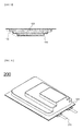
- FIG. 2 is a plan view showing a battery cell according to an embodiment of the present invention and FIG. 3 is a vertical sectional view of FIG. 2 .
- a battery cell 100 is configured to have a structure in which an electrode assembly 120 is mounted in a pouch-shaped battery case 110 formed of a laminate sheet and electrode leads 130 electrically connected to the electrode assembly 120 protrude outward from the battery case 110.
- the battery case 110 includes an upper case 111 and a lower case 112.
- the upper case 111 is provided with a receiving part 116, in which the electrode assembly 120 is mounted.
- the electrode assembly 120 is configured to have a structure in which a plurality of unit cells 122, 124, and 126 having different sizes is stacked in the height direction on the basis of a plane.
- the receiving part of the battery case 110 is configured to have a structure in which stair-like steps are formed so as to correspond to the external shape of the stacked structure of the unit cells 122, 124, and 126.
- the battery cell 100 having the above structure may be manufactured to have various capacities and sizes.
- the battery cell 100 having the above structure may be easily mounted in a space, in which it is difficult for a conventional battery cell to be mounted.
- the battery cell 100 having the above structure may be mounted in a limited space while having a larger capacity depending upon the internal structure of a device. Consequently, it is possible to maximize the use of the internal structure of the device.
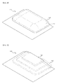
- FIG. 4 is a perspective view showing a battery case having a receiving part
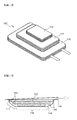
- FIG. 5 is a perspective view of a battery case showing that primary stair-like steps are formed at a receiving part of the battery case by molding
- FIG. 6 is a perspective view showing an electrode assembly configured to have a structure in which unit cells having different sizes are stacked.
- the electrode assembly 120 is configured to have a structure in which the unit cells 122, 124, and 126 are stacked such that the sizes of the unit cells 122, 124, and 126 are decreased from the lower part to the upper part of the electrode assembly 120.
- the receiving part 116 of the battery case 110 has a sufficient size to receive the electrode assembly 120 including the stacked unit cells 122, 124, and 126.
- the receiving part 116 has a curved portion 117, at which steps are to be formed. That is, the receiving part 116 is formed in a hemispherical shape while a planar portion corresponding to the size of the upper end of the electrode assembly 120 is formed at the upper end of the receiving part 116.
- a receiving part 116' of a battery case 110' has stair-like steps 114' approximately corresponding to the external appearance of the electrode assembly.
- the stair-like steps 114' are formed by molding.
- the stair-like steps 114' of the battery case 110' are of a sufficient size to receive the electrode assembly 120. During a subsequent vacuum application process, a surplus space is removed, and therefore, the stair-like steps are formed in more tight contact with the electrode assembly 120.
- FIGS. 7 to 9 are typical views showing a process of deforming the receiving part of the battery case.
- the electrode assembly 120 is mounted in the receiving part 116 of the battery case 110 and an outer circumference 119 of the battery case 110 is sealed by thermal welding except one side of the outer circumference 119. Subsequently, a vacuum is applied through the one side of the outer circumference 119, which is not sealed, of the battery case 110 to remove a surplus space 140 defined between the receiving part 116 of the battery case 110 and the electrode assembly 120. During application of the vacuum, the curved portion 117 of the receiving part 116 comes into contact with the electrode assembly 120. As a result, stair-like steps 114 are formed at the receiving part 116 such that the stair-like steps 114 correspond to the external appearance of a stack constituted by the unit cells having different sizes.
- the receiving part 116 of the battery case 110 includes a planar portion 118 corresponding to the size of the unit cell located at the upper part of the electrode assembly 120 and the curved portion 117, at which the stair-like steps 114 are formed.
- processes of placing the electrode assembly 120 in the battery case 110, injecting an electrolyte into the battery case 110 to impregnate the electrode assembly 120 with the electrolyte, charging and discharging the battery cell 100 once or more to activate the battery cell 100, and removing gas generated during activation of the battery cell 100 may be included.
- the process of removing the gas and the process of applying the vacuum into the receiving part 116 to remove the surplus space 140 between the battery case 110 and the electrode assembly 120 and to form the stair-like steps 114 may be simultaneously carried out to improve manufacturing efficiency.
- FIG. 8 shows a process of forming stair-like steps using a stair-like press member.
- the receiving part 116 of the battery case 110 is pressed using a stair-like press member having a structure corresponding to the external appearance of the electrode assembly 120. After that or at the same time, a vacuum is applied into the battery case 110 to form the stair-like steps 114. Since the stair-like press member is used during formation of the stair-like steps 114, it is possible to more accurately form the stair-like steps 114.
- FIG. 10 is a perspective view showing a battery cell according to another embodiment of the present invention and FIG. 11 is a vertical sectional view of FIG. 10 .
- a battery cell 200 is configured to have a structure in which electrode assemblies 212, 214, and 216 having different lengths AL, BL, and CL and different capacities are mounted in a battery case 220 while being vertically stacked.
- the vertical stack is configured to have a structure in which the thickness of the vertical stack is increased toward electrode terminals 270 protruding outward from the battery case 220.
- the capacities of the electrode assemblies 212, 214, and 216 are proportional to the products of the lengths AL, BL, and CL, heights AH-BH, BH-CH, and CH, and widths (not shown) of the electrode assemblies 212, 214, and 216.
- a margin space S3 is formed at the right upper end of the stack constituted by the electrode assemblies 212, 214, and 216 having different sizes.
- the margin space S3 is inversely proportional to the lengths, the heights, and the widths of the electrode assemblies 212, 214, and 216.
- the above space is provided to cope with various conditions, such as an irregular inner space of a device, to which the battery cell 200 is applied, or interference with other parts of the device.
- a thickness increasing direction and an increasing degree of stack thickness may be flexibly changed according to circumferences or situations.
- a first electrode group is configured to have a structure in which a separator plate 310, a cathode plate 320, a separator plate 330, and an anode plate 340 are laminated while being sequentially stacked.
- a second electrode group is configured to have a structure in which a separator plate 410, an anode plate 420, and a separator plate 430 are laminated while being sequentially stacked.
- FIG. 14 shows a stacked type electrode assembly configured to have a structure in which the second electrode group of FIG. 13 is stacked on the uppermost end of a first electrode group stack constituted by first electrode groups, one of which is shown in FIG. 12 .
- FIG. 15 shows an embodiment in which a fixing member T 1 is added to the first electrode group of FIG. 12 .
- the fixing member T 1 is added to the side or the front of the first electrode group 300.
- an additional fixing member may be added to the side of the stack structure to fix the stack structure.
- the fixing member may be realized as a tape T 1 surrounding the entire surface of the first electrode group 300 as shown in FIG. 15(a) .
- the fixing member may be realized as a fixing member T 2 to fix only each side of the electrode group 300 as shown in FIG. 15(b).
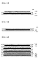
- FIG. 16 is a view typically showing a process of manufacturing the first electrode group according to the present invention.
- materials for a separator plate 310, a cathode plate 320, a separator plate 330, and an anode plate 340 are simultaneously loaded (using sheet type loading units).
- the material for the cathode plate 320 which is used as a middle layer, is cut into a designed size and is then loaded into laminators L 1 and L 2 .
- the materials for the separator plates 310 and 330, which are disposed under and above the material for the cathode plate 320 are simultaneously loaded into the laminators L 1 and L 2 .
- the material for the anode plate 340 is loaded into the laminators L 1 and L 2 .
- the laminators L 1 and L 2 form a structural body in which the two electrode plates and the two separator plates are laminated to each other using heat and pressure, i.e. a first electrode group.
- a cutter C 3 cuts the structural body into a plurality of first electrode groups.
- various inspection processes such as a thickness inspection (a), a vision inspection (b), and a short circuit inspection (c), may be performed with respect to each first electrode group.
- each first electrode group manufactured as described above is fixed using a fixing member, and the first electrode groups are stacked to constitute a structural body in which the first electrode groups are stacked.
- the second electrode group shown in FIG. 13 is stacked on the structural body and then the second electrode group and the structural body are fixed using a fixing member, thereby completing a stacked type electrode assembly.
- FIG. 17 is a typical view showing an electrode assembly 500 configured to have a structure in which electrode groups having different sizes are stacked.
- a first electrode group 510 has a larger size in plane than a second electrode group 520.
- the second electrode group 520 is stacked on the first electrode group 510 to form stair-like steps.
Applications Claiming Priority (3)
| Application Number | Priority Date | Filing Date | Title |
|---|---|---|---|
| KR20120035303 | 2012-04-05 | ||
| KR1020120127726A KR20130113301A (ko) | 2012-04-05 | 2012-11-12 | 계단 구조의 전지셀 |
| PCT/KR2013/002127 WO2013151249A1 (ko) | 2012-04-05 | 2013-03-15 | 계단 구조의 전지셀 |
Publications (3)
| Publication Number | Publication Date |
|---|---|
| EP2802025A1 true EP2802025A1 (de) | 2014-11-12 |
| EP2802025A4 EP2802025A4 (de) | 2015-09-30 |
| EP2802025B1 EP2802025B1 (de) | 2017-03-08 |
Family
ID=49633955
Family Applications (1)
| Application Number | Title | Priority Date | Filing Date |
|---|---|---|---|
| EP13772747.5A Active EP2802025B1 (de) | 2012-04-05 | 2013-03-15 | Batteriezelle mit einer treppenstruktur |
Country Status (7)
| Country | Link |
|---|---|
| US (2) | US9300006B2 (de) |
| EP (1) | EP2802025B1 (de) |
| JP (2) | JP2015508223A (de) |
| KR (3) | KR20130113301A (de) |
| CN (1) | CN104303332B (de) |
| TW (1) | TWI496335B (de) |
| WO (1) | WO2013151249A1 (de) |
Cited By (5)
| Publication number | Priority date | Publication date | Assignee | Title |
|---|---|---|---|---|
| EP2814103A4 (de) * | 2013-02-15 | 2015-06-03 | Lg Chemical Ltd | Elektrodenanordnung und polymersekundärbatteriezelle damit |
| EP2876721A4 (de) * | 2013-02-15 | 2015-09-30 | Lg Chemical Ltd | Elektrodenanordnung |
| EP2882028A4 (de) * | 2013-05-23 | 2015-12-30 | Lg Chemical Ltd | Verfahren zur herstellung einer elektrodenanordnung |
| EP2772978A4 (de) * | 2012-05-23 | 2015-12-30 | Lg Chemical Ltd | Elektrodenanordnung und elektrochemische vorrichtung damit |
| US10147932B2 (en) | 2012-05-23 | 2018-12-04 | Lg Chem, Ltd. | Fabricating method of electrode assembly and electrochemical cell containing the same |
Families Citing this family (52)
| Publication number | Priority date | Publication date | Assignee | Title |
|---|---|---|---|---|
| KR101192619B1 (ko) * | 2012-03-23 | 2012-10-18 | 주식회사 엘지화학 | 전지케이스 |
| KR101595643B1 (ko) | 2013-02-15 | 2016-02-18 | 주식회사 엘지화학 | 전극조립체 및 이를 포함하는 폴리머 이차전지 셀 |
| KR102018256B1 (ko) * | 2013-04-18 | 2019-10-14 | 에스케이이노베이션 주식회사 | 이차 전지용 배터리 셀 및 이를 포함하는 배터리 팩 |
| US20140321033A1 (en) * | 2013-04-26 | 2014-10-30 | Motorola Mobility Llc | Enhanced mobile electronic device and battery pack |
| KR101587322B1 (ko) * | 2013-08-05 | 2016-01-20 | 주식회사 엘지화학 | 전극조립체용 사행보정장치 |
| US9300003B2 (en) | 2013-08-05 | 2016-03-29 | Lg Chem, Ltd. | Meandering correction apparatus for electrode assembly |
| TWI491099B (zh) * | 2013-08-29 | 2015-07-01 | Htc Corp | 電池結構、電子裝置及電池結構的製造方法 |
| KR101868643B1 (ko) * | 2013-11-29 | 2018-06-18 | 주식회사 엘지화학 | 리세스 홈이 형성된 배터리 셀의 제작방법 |
| KR101538272B1 (ko) | 2014-01-06 | 2015-07-22 | 주식회사 엘지화학 | 스텝드 배터리와 이의 제조 방법 및 그 장치 |
| WO2015102242A1 (ko) * | 2014-01-06 | 2015-07-09 | 주식회사 엘지화학 | 스텝드 배터리와 이의 제조 방법 및 그 장치 |
| KR101688569B1 (ko) * | 2014-02-06 | 2016-12-21 | 주식회사 엘지화학 | 단차 구조를 포함하는 전지셀 및 절연저항 불량 확인 방법 |
| JP2016076475A (ja) | 2014-08-06 | 2016-05-12 | 株式会社半導体エネルギー研究所 | 二次電池を有する電子機器及び眼鏡型デバイス |
| KR101725903B1 (ko) * | 2014-09-19 | 2017-04-11 | 주식회사 엘지화학 | 계단 구조의 전극조립체에 대응하는 돌출부가 형성되어 있는 전지케이스를 포함하는 전지셀 |
| KR101776885B1 (ko) * | 2014-09-25 | 2017-09-08 | 주식회사 엘지화학 | 둘 이상의 케이스 부재들을 포함하는 각형 전지셀 |
| KR101725901B1 (ko) * | 2014-10-07 | 2017-04-11 | 주식회사 엘지화학 | 계단 구조의 전극조립체에 대응하는 형상으로 형성되어 있는 전지케이스를 포함하는 전지셀 |
| KR101723035B1 (ko) * | 2014-10-22 | 2017-04-04 | 주식회사 엘지화학 | 가스 센서를 포함하는 전지셀 |
| KR102497816B1 (ko) * | 2014-10-24 | 2023-02-08 | 주식회사 아모그린텍 | 플렉서블 배터리가 내장된 시계줄 |
| KR102497815B1 (ko) * | 2014-10-24 | 2023-02-09 | 주식회사 아모그린텍 | 플렉서블 배터리가 내장된 시계줄 |
| KR101870314B1 (ko) | 2015-04-16 | 2018-06-22 | 주식회사 엘지화학 | 전극 탭들과 전극 리드의 탭-리드 결합부가 공간부에 위치하는 전극조립체 |
| KR20170002013A (ko) * | 2015-06-29 | 2017-01-06 | 에스케이이노베이션 주식회사 | 이차 전지 및 이의 제조 방법 |
| KR102006669B1 (ko) * | 2015-08-13 | 2019-08-02 | 주식회사 엘지화학 | 열가소성 수지를 적용한 전지케이스 및 이를 포함하는 전지셀 제조방법 |
| CN108701867B (zh) * | 2016-02-29 | 2021-07-09 | 松下知识产权经营株式会社 | 层叠型非水电解质二次电池 |
| US11171375B2 (en) * | 2016-03-25 | 2021-11-09 | Enevate Corporation | Stepped electrochemical cells with folded sealed portion |
| US10367175B2 (en) * | 2016-04-22 | 2019-07-30 | Bosch Bettery Systems LLC | Multicavity battery module |
| CN109196704A (zh) * | 2016-05-31 | 2019-01-11 | 株式会社村田制作所 | 蓄电设备 |
| WO2017208509A1 (ja) * | 2016-05-31 | 2017-12-07 | 株式会社村田製作所 | 蓄電デバイス及びその製造方法 |
| KR102016643B1 (ko) | 2016-09-19 | 2019-08-30 | 주식회사 엘지화학 | 이차전지 |
| KR102246030B1 (ko) * | 2016-10-07 | 2021-04-29 | 주식회사 엘지화학 | 서로 다른 크기의 단위셀들을 포함하는 파우치형 전지셀 |
| KR102395482B1 (ko) * | 2016-11-07 | 2022-05-06 | 삼성에스디아이 주식회사 | 이차전지 |
| JP6620729B2 (ja) * | 2016-11-18 | 2019-12-18 | トヨタ自動車株式会社 | 二次電池の製造方法 |
| KR102264685B1 (ko) * | 2016-11-30 | 2021-06-15 | (주)엘지에너지솔루션 | 전극조립체 제조장치 및 전극조립체를 제조하는 방법 |
| KR102187172B1 (ko) * | 2016-12-01 | 2020-12-07 | 주식회사 엘지화학 | 커브드 케이스용 금형장치 및 그를 이용한 커브드 이차전지 제조방법 |
| WO2018105276A1 (ja) * | 2016-12-06 | 2018-06-14 | 株式会社村田製作所 | 二次電池 |
| CN110121797B (zh) | 2017-01-12 | 2022-06-24 | 株式会社村田制作所 | 二次电池 |
| CN110088967B (zh) * | 2017-01-13 | 2022-07-22 | 株式会社村田制作所 | 二次电池 |
| WO2018173700A1 (ja) * | 2017-03-24 | 2018-09-27 | 株式会社村田製作所 | 二次電池の製造方法および製造装置 |
| KR102278994B1 (ko) * | 2017-05-24 | 2021-07-20 | 주식회사 엘지에너지솔루션 | 이차전지 및 그 제조방법 |
| KR102075618B1 (ko) * | 2017-09-14 | 2020-02-10 | 주식회사 엘지화학 | 파우치형 이차전지 및 파우치 필름 포밍 장치 |
| KR102383163B1 (ko) * | 2017-11-13 | 2022-04-05 | 주식회사 엘지에너지솔루션 | 이차전지 |
| GB2574023A (en) * | 2018-05-23 | 2019-11-27 | Robert Murray Smith | Method of construction of an elongated bipolar plate battery |
| EP3651226B1 (de) | 2018-11-09 | 2021-09-29 | Lg Chem, Ltd. | Beutelherstellungsverfahren und beutelherstellungsvorrichtung |
| US10992005B2 (en) * | 2018-12-06 | 2021-04-27 | Robert Bosch Battery Systems Llc | Deep pouch cell and method of manufacturing same |
| CN209822691U (zh) * | 2019-04-25 | 2019-12-20 | 宁德新能源科技有限公司 | 一种电池 |
| CN110380100B (zh) * | 2019-07-24 | 2021-05-25 | 蜂巢能源科技有限公司 | 电芯的制造方法 |
| US11600882B1 (en) * | 2019-09-19 | 2023-03-07 | Apple Inc. | Thin battery pack architecture |
| KR20210072322A (ko) * | 2019-12-09 | 2021-06-17 | 주식회사 엘지에너지솔루션 | 보호필름을 이용한 파우치형 전지셀의 제조방법 및 이를 이용하여 제조된 파우치형 전지셀 |
| KR20210072316A (ko) * | 2019-12-09 | 2021-06-17 | 주식회사 엘지에너지솔루션 | 고정지그를 이용한 파우치형 전지셀의 제조방법 및 이를 이용하여 제조된 파우치형 전지셀 |
| JP6893575B1 (ja) * | 2020-10-12 | 2021-06-23 | エナックス株式会社 | シート状二次電池及びシート状二次電池の製造方法 |
| CN114188639B (zh) * | 2021-12-17 | 2022-06-24 | 南京航空航天大学 | 一种复合材料模块化电池结构、装置及制备方法 |
| CN115832443B (zh) * | 2022-02-10 | 2023-12-12 | 宁德时代新能源科技股份有限公司 | 用电设备、电池、电池单体及其制造方法 |
| WO2023211258A1 (ko) * | 2022-04-29 | 2023-11-02 | 주식회사 엘지에너지솔루션 | 파우치형 전지 케이스 및 이를 포함하는 파우치형 이차 전지, 파우치형 전지 케이스의 제조 방법, 그리고 파우치형 전지 케이스 제조용 성형 지그 |
| CN116544523B (zh) * | 2023-07-04 | 2024-02-27 | 宁德新能源科技有限公司 | 电化学装置及用电终端 |
Family Cites Families (125)
| Publication number | Priority date | Publication date | Assignee | Title |
|---|---|---|---|---|
| US2702310A (en) | 1953-09-22 | 1955-02-15 | Mallory & Co Inc P R | Battery construction |
| DE1252292B (de) | 1964-10-02 | 1967-10-19 | VARTA AKTIENGESELLSCHAFT, Frankfurt/M | Vorrichtung zum Belegen von Elektroden fur Akkumulatoren mit Scheidermarenal |
| US4092464A (en) | 1976-07-19 | 1978-05-30 | P. R. Mallory & Co. Inc. | Flexible cells and batteries formed therefrom |
| US4964877A (en) | 1986-01-14 | 1990-10-23 | Wilson Greatbatch Ltd. | Non-aqueous lithium battery |
| JP2783811B2 (ja) | 1988-08-20 | 1998-08-06 | 三洋電機株式会社 | 電池及びその極板の製造方法 |
| JPH05234598A (ja) | 1992-02-21 | 1993-09-10 | Matsushita Electric Ind Co Ltd | 蓄電池の渦巻状極板群 |
| JPH06260209A (ja) | 1993-03-01 | 1994-09-16 | Japan Storage Battery Co Ltd | 鉛蓄電池 |
| WO1994023465A1 (en) | 1993-04-07 | 1994-10-13 | William Brown Miller | Improvements in or relating to electrochemical cells |
| JPH08171930A (ja) | 1994-12-16 | 1996-07-02 | Matsushita Electric Ind Co Ltd | 電 池 |
| JP3622285B2 (ja) | 1995-08-28 | 2005-02-23 | 日本電池株式会社 | 蓄電池用極板の製造方法 |
| JPH0982361A (ja) | 1995-09-08 | 1997-03-28 | Sony Corp | 角形非水電解液二次電池 |
| US5652074A (en) | 1996-01-11 | 1997-07-29 | Gnb Technologies, Inc. | Battery grids, a method for making such battery grids and lead-acid batteries using such battery grids |
| JP3511443B2 (ja) | 1996-12-20 | 2004-03-29 | 株式会社リコー | 電池装置 |
| JP3997573B2 (ja) * | 1997-01-28 | 2007-10-24 | 三菱電機株式会社 | リチウムイオン二次電池およびその製造方法 |
| US6224995B1 (en) | 1997-03-06 | 2001-05-01 | Mitsubishi Chemical Corporation | Three dimensional free form battery apparatus |
| US6040078A (en) | 1997-03-06 | 2000-03-21 | Mitsubishi Chemical Corporation | Free form battery apparatus |
| JP3637408B2 (ja) | 1997-03-27 | 2005-04-13 | 宇部興産株式会社 | シート状電極とこれを用いた電池 |
| JP3737600B2 (ja) | 1997-04-28 | 2006-01-18 | 大日本印刷株式会社 | 包装体製造装置 |
| WO1999031748A1 (fr) * | 1997-12-15 | 1999-06-24 | Mitsubishi Denki Kabushiki Kaisha | Accumulateur aux ions lithium |
| US6032725A (en) | 1998-06-02 | 2000-03-07 | Marquip, Inc. | Rotary steam joint and valve assembly |
| KR200207948Y1 (ko) | 1998-09-03 | 2001-01-15 | 김순택 | 리튬 이온 폴리머 전지 |
| JP2000133317A (ja) | 1998-10-26 | 2000-05-12 | Mitsubishi Chemicals Corp | 自由形状電池装置 |
| JP4288737B2 (ja) * | 1999-01-13 | 2009-07-01 | パナソニック株式会社 | 扁平電池 |
| CN100353584C (zh) | 1999-04-08 | 2007-12-05 | 大日本印刷株式会社 | 电池用包装材料、电池包装用袋体及其制造方法 |
| JP2000306607A (ja) * | 1999-04-19 | 2000-11-02 | Japan Storage Battery Co Ltd | 非水電解質電池 |
| US6300002B1 (en) | 1999-05-13 | 2001-10-09 | Moltech Power Systems, Inc. | Notched electrode and method of making same |
| JP2001028275A (ja) | 1999-06-25 | 2001-01-30 | Mitsubishi Chemicals Corp | 立体自由形状バッテリー装置 |
| JP3611765B2 (ja) * | 1999-12-09 | 2005-01-19 | シャープ株式会社 | 二次電池及びそれを用いた電子機器 |
| KR100404883B1 (ko) | 1999-12-13 | 2003-11-10 | 주식회사 엘지화학 | 전기 화학 소자를 위한 고분자 전해질 |
| KR100515571B1 (ko) | 2000-02-08 | 2005-09-20 | 주식회사 엘지화학 | 중첩 전기 화학 셀 |
| KR100515572B1 (ko) | 2000-02-08 | 2005-09-20 | 주식회사 엘지화학 | 중첩 전기화학 셀 및 그의 제조 방법 |
| US6635381B2 (en) | 2000-05-11 | 2003-10-21 | Wilson Greatbatch Ltd. | Electrochemical lithium ion secondary cell having a scalloped electrode assembly |
| KR100365824B1 (ko) | 2000-05-13 | 2002-12-26 | 한국 파워셀 주식회사 | 리튬이온 이차전지 |
| US6498951B1 (en) | 2000-10-13 | 2002-12-24 | Medtronic, Inc. | Implantable medical device employing integral housing for a formable flat battery |
| CN1269253C (zh) | 2000-11-21 | 2006-08-09 | 索尼株式会社 | 聚合物电解质电池的制造方法 |
| JP2002199910A (ja) | 2000-12-18 | 2002-07-16 | Reynolds Consumer Products Inc | 横断配置された咬合子およびスライダーの供給具を使用する再封止可能なパッケージの製造方法 |
| JP4124972B2 (ja) | 2001-02-23 | 2008-07-23 | Necトーキン株式会社 | 積層型リチウムイオン電池 |
| JP3822445B2 (ja) | 2001-02-28 | 2006-09-20 | Tdk株式会社 | 電気化学デバイス |
| US6610443B2 (en) | 2001-03-19 | 2003-08-26 | Wilson Greatbatch Ltd. | One-piece header assembly for hermetic battery terminal feedthrough, fill and closure designs |
| JP5159007B2 (ja) | 2001-05-11 | 2013-03-06 | パナソニック株式会社 | 電池用極板の製造方法 |
| CN1799162A (zh) | 2001-06-07 | 2006-07-05 | 三菱化学株式会社 | 锂二次电池 |
| JP2002367679A (ja) * | 2001-06-11 | 2002-12-20 | Japan Storage Battery Co Ltd | 非水電解質二次電池の製造方法 |
| JP4233826B2 (ja) | 2001-08-10 | 2009-03-04 | パナソニック株式会社 | コイン形電池とその製造方法 |
| CN1316645C (zh) | 2001-08-24 | 2007-05-16 | 皇家飞利浦电子股份有限公司 | 制造锂电池的方法、锂电池和电器 |
| US6946220B2 (en) | 2001-10-19 | 2005-09-20 | Wilson Greatbatch Technologies, Inc. | Electrochemical cell having a multiplate electrode assembly housed in an irregularly shaped casing |
| US7960054B2 (en) | 2002-01-10 | 2011-06-14 | Excellatron Solid State Llc | Packaged thin film batteries |
| KR100440934B1 (ko) * | 2002-02-06 | 2004-07-21 | 삼성에스디아이 주식회사 | 이차전지 |
| JP3680797B2 (ja) * | 2002-02-08 | 2005-08-10 | 日本電池株式会社 | 非水電解質電池 |
| JP2003303622A (ja) | 2002-04-10 | 2003-10-24 | Sony Corp | 電池およびその製造方法 |
| JP2004111219A (ja) * | 2002-09-18 | 2004-04-08 | Nissan Motor Co Ltd | ラミネート二次電池、複数のラミネート二次電池からなる組電池モジュール、複数の組電池モジュールからなる組電池ならびにこれらいずれかの電池を搭載した電気自動車 |
| KR100922742B1 (ko) | 2002-12-17 | 2009-10-22 | 삼성에스디아이 주식회사 | 파우치형 케이스와, 이를 적용한 리튬 이차 전지 |
| KR100958647B1 (ko) | 2002-12-18 | 2010-05-20 | 삼성에스디아이 주식회사 | 파우치형 이차전지 유니트 |
| US7479349B2 (en) | 2002-12-31 | 2009-01-20 | Cardiac Pacemakers, Inc. | Batteries including a flat plate design |
| US7083878B2 (en) | 2003-02-27 | 2006-08-01 | Mitsubishi Chemical Corporation | Nonaqueous electrolytic solution and lithium secondary battery |
| JP4565810B2 (ja) * | 2003-03-31 | 2010-10-20 | 三洋電機株式会社 | ラミネート電池 |
| JP4155100B2 (ja) * | 2003-05-16 | 2008-09-24 | トヨタ自動車株式会社 | 二次電池の製造方法 |
| KR20050020357A (ko) | 2003-08-22 | 2005-03-04 | 삼성에스디아이 주식회사 | 파우치 케이스 및 이를 구비한 파우치형 이차 전지 |
| KR100553753B1 (ko) | 2003-10-16 | 2006-02-20 | 삼성에스디아이 주식회사 | 파우치형 이차전지 |
| JP2005169728A (ja) | 2003-12-09 | 2005-06-30 | Murata Mfg Co Ltd | 成形品のゲート処理方法及びゲート処理装置 |
| EP1716606B1 (de) | 2004-01-30 | 2011-04-20 | LG Chem, Ltd. | Batterie mit spezifischer kapselungsstruktur |
| US20050214642A1 (en) | 2004-03-29 | 2005-09-29 | Kim Ki-Ho | Electrode package and secondary battery using the same |
| KR100601510B1 (ko) | 2004-09-22 | 2006-07-19 | 삼성에스디아이 주식회사 | 파우치형 리튬 이차 전지 및 그의 제조 방법 |
| JP2006127882A (ja) | 2004-10-28 | 2006-05-18 | Nissan Motor Co Ltd | 薄型電池および組電池 |
| JP2006134604A (ja) | 2004-11-02 | 2006-05-25 | Ngk Spark Plug Co Ltd | 蓄電装置の製造方法 |
| KR100670492B1 (ko) | 2004-11-29 | 2007-01-16 | 삼성에스디아이 주식회사 | 리튬 이차전지용 캔 및 이를 이용한 리튬 이차전지 |
| WO2006077192A1 (en) | 2005-01-20 | 2006-07-27 | Oticon A/S | Hearing aid with rechargeable battery and rechargeable battery |
| JP4932263B2 (ja) | 2005-01-28 | 2012-05-16 | Necエナジーデバイス株式会社 | 積層型二次電池及びその製造方法 |
| US7981548B2 (en) | 2005-01-28 | 2011-07-19 | Nec Energy Devices, Ltd. | Multilayer secondary battery and method of making same |
| JP4905861B2 (ja) | 2005-02-10 | 2012-03-28 | 日立化成工業株式会社 | エネルギーデバイス電極用バインダ樹脂エマルション及びこれを用いたエネルギーデバイス電極並びにエネルギーデバイス |
| US7682735B2 (en) | 2005-03-28 | 2010-03-23 | Samsung Sdi Co., Ltd. | Pouch type lithium secondary battery and method of fabricating the same |
| US7935442B2 (en) | 2005-05-17 | 2011-05-03 | Lg Chem, Ltd. | Polymer binder for electrochemical device comprising multiply stacked electrochemical cells |
| KR100821442B1 (ko) | 2005-05-31 | 2008-04-10 | 마쯔시다덴기산교 가부시키가이샤 | 비수전해질 2차전지 및 전지모듈 |
| US20060286456A1 (en) | 2005-06-20 | 2006-12-21 | Zhiguo Fu | Nano-lithium-ion batteries and methos for manufacturing nano-lithium-ion batteries |
| JP4561542B2 (ja) | 2005-09-02 | 2010-10-13 | ソニー株式会社 | 二次電池 |
| KR100825207B1 (ko) | 2005-12-22 | 2008-04-25 | 주식회사 엘지화학 | 안전성이 향상된 이차전지 |
| KR100896133B1 (ko) | 2006-01-17 | 2009-05-08 | 주식회사 엘지화학 | 향상된 안전성의 이차전지 |
| US7785741B2 (en) | 2006-02-28 | 2010-08-31 | Medtronic, Inc. | Flat electrochemical cells and method for manufacture |
| KR100925857B1 (ko) | 2006-03-14 | 2009-11-06 | 주식회사 엘지화학 | 향상된 안전성의 다중 중첩식 전기화학 셀 |
| KR100884945B1 (ko) | 2006-04-03 | 2009-02-23 | 주식회사 엘지화학 | 파우치형 이차전지 |
| KR100894409B1 (ko) * | 2006-05-15 | 2009-04-24 | 주식회사 엘지화학 | 전지케이스에 분리막을 고정시켜 안전성을 향상시킨이차전지 |
| KR100874387B1 (ko) * | 2006-06-13 | 2008-12-18 | 주식회사 엘지화학 | 둘 이상의 작동 전압을 제공하는 중첩식 이차전지 |
| KR100866767B1 (ko) | 2006-07-10 | 2008-11-04 | 주식회사 엘지화학 | 이차전지용 안전부재 |
| KR100879893B1 (ko) | 2006-07-10 | 2009-01-21 | 주식회사 엘지화학 | 실링부의 안전성이 향상된 이차전지 |
| WO2008023903A1 (en) | 2006-08-21 | 2008-02-28 | Lg Chem, Ltd. | Pouch-typed secondary battery with improved safety and excellent manufacturing process property |
| KR101264430B1 (ko) | 2006-09-08 | 2013-05-14 | 삼성에스디아이 주식회사 | 이차전지의 파우치 |
| US8734997B2 (en) | 2006-10-10 | 2014-05-27 | Panasonic Corporation | Negative electrode for nonaqueous electrolyte secondary battery |
| KR100829553B1 (ko) | 2006-11-22 | 2008-05-14 | 삼성에스디아이 주식회사 | 연료전지의 스택 구조체 |
| JP5157354B2 (ja) * | 2006-11-30 | 2013-03-06 | 日産自動車株式会社 | バイポーラ電池およびその製造方法 |
| KR20080058772A (ko) | 2006-12-22 | 2008-06-26 | 에스케이에너지 주식회사 | 전지용 전극의 제조 방법 |
| JP2008269819A (ja) * | 2007-04-17 | 2008-11-06 | Sony Corp | 非水電解液二次電池 |
| KR101209010B1 (ko) | 2007-04-26 | 2012-12-06 | 주식회사 엘지화학 | 스택형 전극조립체 및 이의 제조방법 |
| JP4402134B2 (ja) | 2007-05-30 | 2010-01-20 | Necトーキン株式会社 | 積層型二次電池およびその製造方法 |
| KR100987300B1 (ko) | 2007-07-04 | 2010-10-12 | 주식회사 엘지화학 | 스택-폴딩형 전극조립체 및 그것의 제조방법 |
| KR100917736B1 (ko) * | 2007-09-14 | 2009-09-15 | 삼성에스디아이 주식회사 | 전지용 파우치 및 파우치형 전지 |
| KR20090003823U (ko) | 2007-10-19 | 2009-04-23 | 이영학 | 비상용 피난 사다리 |
| KR100998301B1 (ko) | 2007-11-08 | 2010-12-03 | 삼성에스디아이 주식회사 | 배터리 팩 및 이를 구비하는 전자기기 |
| KR100964017B1 (ko) | 2007-12-13 | 2010-06-15 | 지에스나노텍 주식회사 | 전극의 표면적 및 전극과 전해질의 접촉면적을 증가시킨박막형 전지 및 그의 제조방법 |
| FR2925768B1 (fr) | 2007-12-21 | 2012-06-08 | Commissariat Energie Atomique | Batterie multipolaire a etancheite interplaque amelioree |
| JP5408686B2 (ja) | 2008-03-11 | 2014-02-05 | Necエナジーデバイス株式会社 | 積層型電池 |
| KR101049841B1 (ko) | 2008-03-12 | 2011-07-15 | 주식회사 엘지화학 | 휘어진 형상의 전지셀 및 이를 포함하는 전지팩 |
| JP2010076980A (ja) | 2008-09-26 | 2010-04-08 | T Rad Co Ltd | 改質器 |
| DE102009006117A1 (de) | 2009-01-26 | 2010-07-29 | Li-Tec Battery Gmbh | Elektrochemische Energiespeicherzelle |
| KR20100137290A (ko) | 2009-06-22 | 2010-12-30 | 에너원코리아 주식회사 | 와인딩 방식의 전극적층체 제조방법 및 그에 의한 리튬이온 이차전지용 전극적층체 |
| US8568929B2 (en) | 2009-09-02 | 2013-10-29 | Samsung Sdi Co., Ltd. | Electrode assembly including separators having crossing pores and rechargeable battery |
| JP2011070975A (ja) * | 2009-09-26 | 2011-04-07 | Nissin Electric Co Ltd | ラミネート型電池の押圧構造 |
| JP2011081931A (ja) | 2009-10-05 | 2011-04-21 | Hitachi Maxell Ltd | リチウムイオン二次電池 |
| KR101831401B1 (ko) | 2010-01-26 | 2018-02-23 | 사임베트 코퍼레이션 | 배터리 배열, 구성 및 방법 |
| CN103098256B (zh) | 2010-03-19 | 2016-01-20 | 株式会社Lg化学 | 袋式壳体和包括该袋式壳体的电池组 |
| JP5383571B2 (ja) | 2010-03-26 | 2014-01-08 | 三菱重工業株式会社 | 電極板製造装置 |
| JP2011210524A (ja) * | 2010-03-30 | 2011-10-20 | Sanyo Electric Co Ltd | 積層式電池 |
| JP5717038B2 (ja) | 2010-04-06 | 2015-05-13 | エルジー・ケム・リミテッド | 二次電池用電極組立体の製造方法 |
| KR101191635B1 (ko) * | 2010-05-24 | 2012-10-17 | 삼성에스디아이 주식회사 | 이차 전지용 파우치, 그의 제조 방법 및 상기 파우치를 포함하는 이차 전지 |
| US9040187B2 (en) | 2010-07-13 | 2015-05-26 | Apple, Inc. | Battery pack with cells of different capacities electrically coupled in parallel |
| US8940429B2 (en) * | 2010-07-16 | 2015-01-27 | Apple Inc. | Construction of non-rectangular batteries |
| KR101217780B1 (ko) | 2010-10-19 | 2013-01-02 | 주식회사 엘지화학 | 케이블형 이차전지 |
| US8592065B2 (en) | 2010-11-02 | 2013-11-26 | Apple Inc. | Rechargeable battery with a jelly roll having multiple thicknesses |
| KR101326630B1 (ko) | 2010-12-02 | 2013-11-07 | 주식회사 엘지화학 | 신규한 노칭 장치 및 이를 사용하여 생산되는 이차전지 |
| KR101223729B1 (ko) | 2010-12-16 | 2013-01-17 | 삼성에스디아이 주식회사 | 전지용 케이스, 이를 구비한 이차 전지 및 상기 이차전지 제조방법 |
| US20120183825A1 (en) | 2011-01-14 | 2012-07-19 | Seung-Hun Lee | Secondary battery and method of manufacturing the same |
| JP5844052B2 (ja) | 2011-02-04 | 2016-01-13 | 三洋電機株式会社 | 積層式電池およびその製造方法 |
| WO2013054593A1 (ja) | 2011-10-14 | 2013-04-18 | 日立マクセルエナジー株式会社 | シート状電極の製造方法、シート状電極、及びリチウムイオン二次電池 |
| US9276287B2 (en) | 2011-10-28 | 2016-03-01 | Apple Inc. | Non-rectangular batteries for portable electronic devices |
| KR20130062153A (ko) | 2011-12-02 | 2013-06-12 | 삼성전자주식회사 | 병변 주변 정보를 이용한 병변 진단 장치 및 방법 |
| WO2013141279A1 (ja) | 2012-03-21 | 2013-09-26 | 新神戸電機株式会社 | 角形非水電解液蓄電セル用極板 |
| KR20130133640A (ko) | 2012-05-29 | 2013-12-09 | 주식회사 엘지화학 | 코너부 형상이 다양한 단차를 갖는 전극 조립체, 이를 포함하는 전지셀, 전지팩 및 디바이스 |
-
2012
- 2012-11-12 KR KR1020120127726A patent/KR20130113301A/ko active Search and Examination
-
2013
- 2013-03-15 CN CN201380010268.7A patent/CN104303332B/zh active Active
- 2013-03-15 JP JP2014558691A patent/JP2015508223A/ja active Pending
- 2013-03-15 WO PCT/KR2013/002127 patent/WO2013151249A1/ko active Application Filing
- 2013-03-15 KR KR1020130028283A patent/KR20130113366A/ko active Application Filing
- 2013-03-15 EP EP13772747.5A patent/EP2802025B1/de active Active
- 2013-03-18 US US13/845,762 patent/US9300006B2/en active Active
- 2013-03-20 TW TW102109877A patent/TWI496335B/zh active
-
2014
- 2014-08-14 KR KR1020140105862A patent/KR101636371B1/ko active IP Right Grant
-
2016
- 2016-02-25 US US15/053,596 patent/US9548517B2/en active Active
-
2017
- 2017-02-17 JP JP2017027656A patent/JP6644373B2/ja active Active
Cited By (15)
| Publication number | Priority date | Publication date | Assignee | Title |
|---|---|---|---|---|
| US10147932B2 (en) | 2012-05-23 | 2018-12-04 | Lg Chem, Ltd. | Fabricating method of electrode assembly and electrochemical cell containing the same |
| US11081682B2 (en) | 2012-05-23 | 2021-08-03 | Lg Chem, Ltd. | Fabricating method of electrode assembly and electrochemical cell containing the same |
| US10770713B2 (en) | 2012-05-23 | 2020-09-08 | Lg Chem, Ltd. | Fabricating method of electrode assembly and electrochemical cell containing the same |
| EP2772978A4 (de) * | 2012-05-23 | 2015-12-30 | Lg Chemical Ltd | Elektrodenanordnung und elektrochemische vorrichtung damit |
| US10516185B2 (en) | 2012-05-23 | 2019-12-24 | Lg Chem. Ltd. | Electrode assembly and electrochemical cell containing the same |
| US10615448B2 (en) | 2013-02-15 | 2020-04-07 | Lg Chem, Ltd. | Electrode assembly |
| US10418609B2 (en) | 2013-02-15 | 2019-09-17 | Lg Chem, Ltd. | Electrode assembly and polymer secondary battery cell including the same |
| US9923230B2 (en) | 2013-02-15 | 2018-03-20 | Lg Chem, Ltd. | Electrode assembly |
| EP2814103A4 (de) * | 2013-02-15 | 2015-06-03 | Lg Chemical Ltd | Elektrodenanordnung und polymersekundärbatteriezelle damit |
| US10804520B2 (en) | 2013-02-15 | 2020-10-13 | Lg Chem, Ltd. | Electrode assembly and polymer secondary battery cell including the same |
| US10971751B2 (en) | 2013-02-15 | 2021-04-06 | Lg Chem, Ltd. | Electrode assembly |
| EP2876721A4 (de) * | 2013-02-15 | 2015-09-30 | Lg Chemical Ltd | Elektrodenanordnung |
| US11476546B2 (en) | 2013-02-15 | 2022-10-18 | Lg Energy Solution, Ltd. | Electrode assembly and polymer secondary battery cell including the same |
| US10270134B2 (en) | 2013-05-23 | 2019-04-23 | Lg Chem, Ltd. | Method of manufacturing electrode assembly |
| EP2882028A4 (de) * | 2013-05-23 | 2015-12-30 | Lg Chemical Ltd | Verfahren zur herstellung einer elektrodenanordnung |
Also Published As
| Publication number | Publication date |
|---|---|
| US20140011070A1 (en) | 2014-01-09 |
| CN104303332A (zh) | 2015-01-21 |
| EP2802025B1 (de) | 2017-03-08 |
| JP2017092047A (ja) | 2017-05-25 |
| CN104303332B (zh) | 2018-06-08 |
| JP6644373B2 (ja) | 2020-02-12 |
| US20160181667A1 (en) | 2016-06-23 |
| KR101636371B1 (ko) | 2016-07-05 |
| EP2802025A4 (de) | 2015-09-30 |
| KR20140114803A (ko) | 2014-09-29 |
| TWI496335B (zh) | 2015-08-11 |
| US9300006B2 (en) | 2016-03-29 |
| WO2013151249A1 (ko) | 2013-10-10 |
| KR20130113301A (ko) | 2013-10-15 |
| KR20130113366A (ko) | 2013-10-15 |
| JP2015508223A (ja) | 2015-03-16 |
| TW201345018A (zh) | 2013-11-01 |
| US9548517B2 (en) | 2017-01-17 |
Similar Documents
| Publication | Publication Date | Title |
|---|---|---|
| US9548517B2 (en) | Battery cell of stair-like structure | |
| US9741974B2 (en) | Battery cell having round corner | |
| US9478773B2 (en) | Battery cell of asymmetric structure and battery pack employed with the same | |
| EP2779269B1 (de) | Batteriezelle mit neuartigem aufbau | |
| EP2802034B1 (de) | Elektrodenanordnung mit stufenförmiger struktur | |
| KR101402657B1 (ko) | 비정형 구조의 전지팩 | |
| EP2587566B1 (de) | Wiederaufladbare batterie von erhöhter sicherheit | |
| EP2958177B1 (de) | Elektrodenanordnung mit abgerundeten ecken | |
| US9318733B2 (en) | Electrode assembly of stair-like structure | |
| KR20140102385A (ko) | 안전성이 향상된 신규한 구조의 전지셀 | |
| US9786874B2 (en) | Electrode having round corner | |
| KR20120123851A (ko) | 2 이상의 양극 및 음극을 포함하는 전극 조립체 및 이에 의한 전기 화학 소자 | |
| EP2916365B1 (de) | Elektrische vorrichtung mit runder ecke | |
| US9484560B2 (en) | Electric device having a round corner and including a secondary battery |
Legal Events
| Date | Code | Title | Description |
|---|---|---|---|
| PUAI | Public reference made under article 153(3) epc to a published international application that has entered the european phase |
Free format text: ORIGINAL CODE: 0009012 |
|
| 17P | Request for examination filed |
Effective date: 20140808 |
|
| AK | Designated contracting states |
Kind code of ref document: A1 Designated state(s): AL AT BE BG CH CY CZ DE DK EE ES FI FR GB GR HR HU IE IS IT LI LT LU LV MC MK MT NL NO PL PT RO RS SE SI SK SM TR |
|
| RIN1 | Information on inventor provided before grant (corrected) |
Inventor name: KIM, YOUNG HUN Inventor name: KIM, DONG-MYUNG Inventor name: KIM, KI WOONG Inventor name: KWON, SUNGJIN Inventor name: RYU, SEUNGMIN Inventor name: AHN, SOONHO |
|
| RIN1 | Information on inventor provided before grant (corrected) |
Inventor name: KIM, KI WOONG Inventor name: KIM, YOUNG HUN Inventor name: RYU, SEUNGMIN Inventor name: AHN, SOONHO Inventor name: KWON, SUNGJIN Inventor name: KIM, DONG-MYUNG |
|
| DAX | Request for extension of the european patent (deleted) | ||
| RA4 | Supplementary search report drawn up and despatched (corrected) |
Effective date: 20150902 |
|
| RIC1 | Information provided on ipc code assigned before grant |
Ipc: H01M 10/0525 20100101ALI20150827BHEP Ipc: H01M 2/36 20060101ALI20150827BHEP Ipc: H01M 2/10 20060101AFI20150827BHEP Ipc: H01M 10/04 20060101ALI20150827BHEP Ipc: H01M 10/0585 20100101ALI20150827BHEP Ipc: H01M 2/02 20060101ALI20150827BHEP Ipc: H01M 10/44 20060101ALI20150827BHEP |
|
| 17Q | First examination report despatched |
Effective date: 20160523 |
|
| REG | Reference to a national code |
Ref country code: DE Ref legal event code: R079 Ref document number: 602013018341 Country of ref document: DE Free format text: PREVIOUS MAIN CLASS: H01M0002100000 Ipc: H01M0002080000 |
|
| GRAP | Despatch of communication of intention to grant a patent |
Free format text: ORIGINAL CODE: EPIDOSNIGR1 |
|
| RIC1 | Information provided on ipc code assigned before grant |
Ipc: H01M 2/02 20060101ALI20161207BHEP Ipc: H01M 2/36 20060101ALI20161207BHEP Ipc: H01M 10/0585 20100101ALI20161207BHEP Ipc: H01M 2/08 20060101AFI20161207BHEP Ipc: H01M 10/04 20060101ALI20161207BHEP Ipc: H01M 10/44 20060101ALI20161207BHEP Ipc: H01M 10/0525 20100101ALI20161207BHEP |
|
| INTG | Intention to grant announced |
Effective date: 20161223 |
|
| GRAS | Grant fee paid |
Free format text: ORIGINAL CODE: EPIDOSNIGR3 |
|
| GRAA | (expected) grant |
Free format text: ORIGINAL CODE: 0009210 |
|
| AK | Designated contracting states |
Kind code of ref document: B1 Designated state(s): AL AT BE BG CH CY CZ DE DK EE ES FI FR GB GR HR HU IE IS IT LI LT LU LV MC MK MT NL NO PL PT RO RS SE SI SK SM TR |
|
| REG | Reference to a national code |
Ref country code: GB Ref legal event code: FG4D |
|
| REG | Reference to a national code |
Ref country code: CH Ref legal event code: EP Ref country code: AT Ref legal event code: REF Ref document number: 874264 Country of ref document: AT Kind code of ref document: T Effective date: 20170315 |
|
| REG | Reference to a national code |
Ref country code: FR Ref legal event code: PLFP Year of fee payment: 5 |
|
| REG | Reference to a national code |
Ref country code: IE Ref legal event code: FG4D |
|
| REG | Reference to a national code |
Ref country code: DE Ref legal event code: R096 Ref document number: 602013018341 Country of ref document: DE |
|
| REG | Reference to a national code |
Ref country code: LT Ref legal event code: MG4D |
|
| REG | Reference to a national code |
Ref country code: NL Ref legal event code: MP Effective date: 20170308 |
|
| PG25 | Lapsed in a contracting state [announced via postgrant information from national office to epo] |
Ref country code: LT Free format text: LAPSE BECAUSE OF FAILURE TO SUBMIT A TRANSLATION OF THE DESCRIPTION OR TO PAY THE FEE WITHIN THE PRESCRIBED TIME-LIMIT Effective date: 20170308 Ref country code: FI Free format text: LAPSE BECAUSE OF FAILURE TO SUBMIT A TRANSLATION OF THE DESCRIPTION OR TO PAY THE FEE WITHIN THE PRESCRIBED TIME-LIMIT Effective date: 20170308 Ref country code: NO Free format text: LAPSE BECAUSE OF FAILURE TO SUBMIT A TRANSLATION OF THE DESCRIPTION OR TO PAY THE FEE WITHIN THE PRESCRIBED TIME-LIMIT Effective date: 20170608 Ref country code: HR Free format text: LAPSE BECAUSE OF FAILURE TO SUBMIT A TRANSLATION OF THE DESCRIPTION OR TO PAY THE FEE WITHIN THE PRESCRIBED TIME-LIMIT Effective date: 20170308 Ref country code: GR Free format text: LAPSE BECAUSE OF FAILURE TO SUBMIT A TRANSLATION OF THE DESCRIPTION OR TO PAY THE FEE WITHIN THE PRESCRIBED TIME-LIMIT Effective date: 20170609 |
|
| REG | Reference to a national code |
Ref country code: AT Ref legal event code: MK05 Ref document number: 874264 Country of ref document: AT Kind code of ref document: T Effective date: 20170308 |
|
| PG25 | Lapsed in a contracting state [announced via postgrant information from national office to epo] |
Ref country code: RS Free format text: LAPSE BECAUSE OF FAILURE TO SUBMIT A TRANSLATION OF THE DESCRIPTION OR TO PAY THE FEE WITHIN THE PRESCRIBED TIME-LIMIT Effective date: 20170308 Ref country code: BG Free format text: LAPSE BECAUSE OF FAILURE TO SUBMIT A TRANSLATION OF THE DESCRIPTION OR TO PAY THE FEE WITHIN THE PRESCRIBED TIME-LIMIT Effective date: 20170608 Ref country code: LV Free format text: LAPSE BECAUSE OF FAILURE TO SUBMIT A TRANSLATION OF THE DESCRIPTION OR TO PAY THE FEE WITHIN THE PRESCRIBED TIME-LIMIT Effective date: 20170308 Ref country code: ES Free format text: LAPSE BECAUSE OF FAILURE TO SUBMIT A TRANSLATION OF THE DESCRIPTION OR TO PAY THE FEE WITHIN THE PRESCRIBED TIME-LIMIT Effective date: 20170308 Ref country code: SE Free format text: LAPSE BECAUSE OF FAILURE TO SUBMIT A TRANSLATION OF THE DESCRIPTION OR TO PAY THE FEE WITHIN THE PRESCRIBED TIME-LIMIT Effective date: 20170308 |
|
| PG25 | Lapsed in a contracting state [announced via postgrant information from national office to epo] |
Ref country code: NL Free format text: LAPSE BECAUSE OF FAILURE TO SUBMIT A TRANSLATION OF THE DESCRIPTION OR TO PAY THE FEE WITHIN THE PRESCRIBED TIME-LIMIT Effective date: 20170308 |
|
| PG25 | Lapsed in a contracting state [announced via postgrant information from national office to epo] |
Ref country code: RO Free format text: LAPSE BECAUSE OF FAILURE TO SUBMIT A TRANSLATION OF THE DESCRIPTION OR TO PAY THE FEE WITHIN THE PRESCRIBED TIME-LIMIT Effective date: 20170308 Ref country code: CZ Free format text: LAPSE BECAUSE OF FAILURE TO SUBMIT A TRANSLATION OF THE DESCRIPTION OR TO PAY THE FEE WITHIN THE PRESCRIBED TIME-LIMIT Effective date: 20170308 Ref country code: AT Free format text: LAPSE BECAUSE OF FAILURE TO SUBMIT A TRANSLATION OF THE DESCRIPTION OR TO PAY THE FEE WITHIN THE PRESCRIBED TIME-LIMIT Effective date: 20170308 Ref country code: SK Free format text: LAPSE BECAUSE OF FAILURE TO SUBMIT A TRANSLATION OF THE DESCRIPTION OR TO PAY THE FEE WITHIN THE PRESCRIBED TIME-LIMIT Effective date: 20170308 Ref country code: IT Free format text: LAPSE BECAUSE OF FAILURE TO SUBMIT A TRANSLATION OF THE DESCRIPTION OR TO PAY THE FEE WITHIN THE PRESCRIBED TIME-LIMIT Effective date: 20170308 Ref country code: EE Free format text: LAPSE BECAUSE OF FAILURE TO SUBMIT A TRANSLATION OF THE DESCRIPTION OR TO PAY THE FEE WITHIN THE PRESCRIBED TIME-LIMIT Effective date: 20170308 |
|
| REG | Reference to a national code |
Ref country code: CH Ref legal event code: PL |
|
| PG25 | Lapsed in a contracting state [announced via postgrant information from national office to epo] |
Ref country code: PL Free format text: LAPSE BECAUSE OF FAILURE TO SUBMIT A TRANSLATION OF THE DESCRIPTION OR TO PAY THE FEE WITHIN THE PRESCRIBED TIME-LIMIT Effective date: 20170308 Ref country code: SM Free format text: LAPSE BECAUSE OF FAILURE TO SUBMIT A TRANSLATION OF THE DESCRIPTION OR TO PAY THE FEE WITHIN THE PRESCRIBED TIME-LIMIT Effective date: 20170308 Ref country code: PT Free format text: LAPSE BECAUSE OF FAILURE TO SUBMIT A TRANSLATION OF THE DESCRIPTION OR TO PAY THE FEE WITHIN THE PRESCRIBED TIME-LIMIT Effective date: 20170710 Ref country code: IS Free format text: LAPSE BECAUSE OF FAILURE TO SUBMIT A TRANSLATION OF THE DESCRIPTION OR TO PAY THE FEE WITHIN THE PRESCRIBED TIME-LIMIT Effective date: 20170708 |
|
| REG | Reference to a national code |
Ref country code: DE Ref legal event code: R097 Ref document number: 602013018341 Country of ref document: DE |
|
| REG | Reference to a national code |
Ref country code: IE Ref legal event code: MM4A |
|
| PLBE | No opposition filed within time limit |
Free format text: ORIGINAL CODE: 0009261 |
|
| STAA | Information on the status of an ep patent application or granted ep patent |
Free format text: STATUS: NO OPPOSITION FILED WITHIN TIME LIMIT |
|
| PG25 | Lapsed in a contracting state [announced via postgrant information from national office to epo] |
Ref country code: DK Free format text: LAPSE BECAUSE OF FAILURE TO SUBMIT A TRANSLATION OF THE DESCRIPTION OR TO PAY THE FEE WITHIN THE PRESCRIBED TIME-LIMIT Effective date: 20170308 Ref country code: MC Free format text: LAPSE BECAUSE OF FAILURE TO SUBMIT A TRANSLATION OF THE DESCRIPTION OR TO PAY THE FEE WITHIN THE PRESCRIBED TIME-LIMIT Effective date: 20170308 Ref country code: LU Free format text: LAPSE BECAUSE OF NON-PAYMENT OF DUE FEES Effective date: 20170315 |
|
| 26N | No opposition filed |
Effective date: 20171211 |
|
| REG | Reference to a national code |
Ref country code: FR Ref legal event code: PLFP Year of fee payment: 6 |
|
| PG25 | Lapsed in a contracting state [announced via postgrant information from national office to epo] |
Ref country code: LI Free format text: LAPSE BECAUSE OF NON-PAYMENT OF DUE FEES Effective date: 20170331 Ref country code: SI Free format text: LAPSE BECAUSE OF FAILURE TO SUBMIT A TRANSLATION OF THE DESCRIPTION OR TO PAY THE FEE WITHIN THE PRESCRIBED TIME-LIMIT Effective date: 20170308 Ref country code: IE Free format text: LAPSE BECAUSE OF NON-PAYMENT OF DUE FEES Effective date: 20170315 Ref country code: CH Free format text: LAPSE BECAUSE OF NON-PAYMENT OF DUE FEES Effective date: 20170331 |
|
| REG | Reference to a national code |
Ref country code: BE Ref legal event code: MM Effective date: 20170331 |
|
| PG25 | Lapsed in a contracting state [announced via postgrant information from national office to epo] |
Ref country code: BE Free format text: LAPSE BECAUSE OF NON-PAYMENT OF DUE FEES Effective date: 20170331 |
|
| PG25 | Lapsed in a contracting state [announced via postgrant information from national office to epo] |
Ref country code: MT Free format text: LAPSE BECAUSE OF NON-PAYMENT OF DUE FEES Effective date: 20170315 |
|
| PG25 | Lapsed in a contracting state [announced via postgrant information from national office to epo] |
Ref country code: HU Free format text: LAPSE BECAUSE OF FAILURE TO SUBMIT A TRANSLATION OF THE DESCRIPTION OR TO PAY THE FEE WITHIN THE PRESCRIBED TIME-LIMIT; INVALID AB INITIO Effective date: 20130315 |
|
| PG25 | Lapsed in a contracting state [announced via postgrant information from national office to epo] |
Ref country code: CY Free format text: LAPSE BECAUSE OF FAILURE TO SUBMIT A TRANSLATION OF THE DESCRIPTION OR TO PAY THE FEE WITHIN THE PRESCRIBED TIME-LIMIT Effective date: 20170308 |
|
| PG25 | Lapsed in a contracting state [announced via postgrant information from national office to epo] |
Ref country code: MK Free format text: LAPSE BECAUSE OF FAILURE TO SUBMIT A TRANSLATION OF THE DESCRIPTION OR TO PAY THE FEE WITHIN THE PRESCRIBED TIME-LIMIT Effective date: 20170308 |
|
| PG25 | Lapsed in a contracting state [announced via postgrant information from national office to epo] |
Ref country code: TR Free format text: LAPSE BECAUSE OF FAILURE TO SUBMIT A TRANSLATION OF THE DESCRIPTION OR TO PAY THE FEE WITHIN THE PRESCRIBED TIME-LIMIT Effective date: 20170308 |
|
| PG25 | Lapsed in a contracting state [announced via postgrant information from national office to epo] |
Ref country code: AL Free format text: LAPSE BECAUSE OF FAILURE TO SUBMIT A TRANSLATION OF THE DESCRIPTION OR TO PAY THE FEE WITHIN THE PRESCRIBED TIME-LIMIT Effective date: 20170308 |
|
| REG | Reference to a national code |
Ref country code: DE Ref legal event code: R079 Ref document number: 602013018341 Country of ref document: DE Free format text: PREVIOUS MAIN CLASS: H01M0002080000 Ipc: H01M0050183000 |
|
| PGFP | Annual fee paid to national office [announced via postgrant information from national office to epo] |
Ref country code: FR Payment date: 20230221 Year of fee payment: 11 |
|
| REG | Reference to a national code |
Ref country code: DE Ref legal event code: R081 Ref document number: 602013018341 Country of ref document: DE Owner name: LG ENERGY SOLUTION LTD., KR Free format text: FORMER OWNER: LG CHEM, LTD., SEOUL, KR Ref country code: DE Ref legal event code: R081 Ref document number: 602013018341 Country of ref document: DE Owner name: LG ENERGY SOLUTION, LTD., KR Free format text: FORMER OWNER: LG CHEM, LTD., SEOUL, KR |
|
| PGFP | Annual fee paid to national office [announced via postgrant information from national office to epo] |
Ref country code: GB Payment date: 20230220 Year of fee payment: 11 Ref country code: DE Payment date: 20230220 Year of fee payment: 11 |
|
| P01 | Opt-out of the competence of the unified patent court (upc) registered |
Effective date: 20230323 |
|
| REG | Reference to a national code |
Ref country code: GB Ref legal event code: 732E Free format text: REGISTERED BETWEEN 20230824 AND 20230831 |
|
| REG | Reference to a national code |
Ref country code: DE Ref legal event code: R081 Ref document number: 602013018341 Country of ref document: DE Owner name: LG ENERGY SOLUTION, LTD., KR Free format text: FORMER OWNER: LG ENERGY SOLUTION LTD., SEOUL, KR |