EP2701495B2 - Vision system for robotic attacher - Google Patents
Vision system for robotic attacher Download PDFInfo
- Publication number
- EP2701495B2 EP2701495B2 EP12719835.6A EP12719835A EP2701495B2 EP 2701495 B2 EP2701495 B2 EP 2701495B2 EP 12719835 A EP12719835 A EP 12719835A EP 2701495 B2 EP2701495 B2 EP 2701495B2
- Authority
- EP
- European Patent Office
- Prior art keywords
- camera
- dairy livestock
- image
- robotic attacher
- dairy cow
- Prior art date
- Legal status (The legal status is an assumption and is not a legal conclusion. Google has not performed a legal analysis and makes no representation as to the accuracy of the status listed.)
- Active
Links
- 235000013365 dairy product Nutrition 0.000 claims description 208
- 244000144972 livestock Species 0.000 claims description 44
- 210000000481 breast Anatomy 0.000 claims description 34
- 230000000153 supplemental effect Effects 0.000 claims description 17
- 238000003860 storage Methods 0.000 claims description 12
- 230000004044 response Effects 0.000 claims description 10
- 241000283690 Bos taurus Species 0.000 description 164
- 210000002445 nipple Anatomy 0.000 description 114
- 238000000034 method Methods 0.000 description 28
- 239000008267 milk Substances 0.000 description 28
- 235000013336 milk Nutrition 0.000 description 28
- 210000004080 milk Anatomy 0.000 description 28
- 238000002360 preparation method Methods 0.000 description 22
- 239000002699 waste material Substances 0.000 description 6
- 239000000645 desinfectant Substances 0.000 description 5
- 238000000926 separation method Methods 0.000 description 4
- 238000004891 communication Methods 0.000 description 3
- 210000003608 fece Anatomy 0.000 description 3
- 230000036541 health Effects 0.000 description 3
- 239000010871 livestock manure Substances 0.000 description 3
- 238000012986 modification Methods 0.000 description 3
- 230000004048 modification Effects 0.000 description 3
- 238000012545 processing Methods 0.000 description 3
- 238000007792 addition Methods 0.000 description 2
- 238000009434 installation Methods 0.000 description 2
- 230000002452 interceptive effect Effects 0.000 description 2
- 210000003141 lower extremity Anatomy 0.000 description 2
- 239000000463 material Substances 0.000 description 2
- 238000005259 measurement Methods 0.000 description 2
- 238000005507 spraying Methods 0.000 description 2
- 241000030939 Bubalus bubalis Species 0.000 description 1
- 241000283707 Capra Species 0.000 description 1
- 206010061218 Inflammation Diseases 0.000 description 1
- 241001465754 Metazoa Species 0.000 description 1
- 241001494479 Pecora Species 0.000 description 1
- 230000009471 action Effects 0.000 description 1
- 230000004075 alteration Effects 0.000 description 1
- 238000013459 approach Methods 0.000 description 1
- 235000008429 bread Nutrition 0.000 description 1
- 238000004140 cleaning Methods 0.000 description 1
- 239000000356 contaminant Substances 0.000 description 1
- 238000003977 dairy farming Methods 0.000 description 1
- 238000001514 detection method Methods 0.000 description 1
- 239000012530 fluid Substances 0.000 description 1
- 230000005802 health problem Effects 0.000 description 1
- 208000015181 infectious disease Diseases 0.000 description 1
- 230000004054 inflammatory process Effects 0.000 description 1
- 230000006651 lactation Effects 0.000 description 1
- 208000004396 mastitis Diseases 0.000 description 1
- 230000003287 optical effect Effects 0.000 description 1
- 230000010349 pulsation Effects 0.000 description 1
- 230000000284 resting effect Effects 0.000 description 1
- 239000007787 solid Substances 0.000 description 1
- 239000007921 spray Substances 0.000 description 1
- 230000004936 stimulating effect Effects 0.000 description 1
- 238000006467 substitution reaction Methods 0.000 description 1
- 238000012360 testing method Methods 0.000 description 1
- 230000000007 visual effect Effects 0.000 description 1
- 210000000707 wrist Anatomy 0.000 description 1
Images


Classifications
-
- A—HUMAN NECESSITIES
- A01—AGRICULTURE; FORESTRY; ANIMAL HUSBANDRY; HUNTING; TRAPPING; FISHING
- A01J—MANUFACTURE OF DAIRY PRODUCTS
- A01J5/00—Milking machines or devices
- A01J5/017—Automatic attaching or detaching of clusters
- A01J5/0175—Attaching of clusters
-
- A—HUMAN NECESSITIES
- A01—AGRICULTURE; FORESTRY; ANIMAL HUSBANDRY; HUNTING; TRAPPING; FISHING
- A01J—MANUFACTURE OF DAIRY PRODUCTS
- A01J5/00—Milking machines or devices
- A01J5/007—Monitoring milking processes; Control or regulation of milking machines
-
- A—HUMAN NECESSITIES
- A01—AGRICULTURE; FORESTRY; ANIMAL HUSBANDRY; HUNTING; TRAPPING; FISHING
- A01J—MANUFACTURE OF DAIRY PRODUCTS
- A01J5/00—Milking machines or devices
- A01J5/017—Automatic attaching or detaching of clusters
-
- A—HUMAN NECESSITIES
- A01—AGRICULTURE; FORESTRY; ANIMAL HUSBANDRY; HUNTING; TRAPPING; FISHING
- A01K—ANIMAL HUSBANDRY; CARE OF BIRDS, FISHES, INSECTS; FISHING; REARING OR BREEDING ANIMALS, NOT OTHERWISE PROVIDED FOR; NEW BREEDS OF ANIMALS
- A01K1/00—Housing animals; Equipment therefor
- A01K1/12—Milking stations
-
- G—PHYSICS
- G06—COMPUTING; CALCULATING OR COUNTING
- G06T—IMAGE DATA PROCESSING OR GENERATION, IN GENERAL
- G06T7/00—Image analysis
- G06T7/0002—Inspection of images, e.g. flaw detection
- G06T7/0004—Industrial image inspection
- G06T7/001—Industrial image inspection using an image reference approach
-
- G—PHYSICS
- G06—COMPUTING; CALCULATING OR COUNTING
- G06T—IMAGE DATA PROCESSING OR GENERATION, IN GENERAL
- G06T7/00—Image analysis
- G06T7/70—Determining position or orientation of objects or cameras
- G06T7/73—Determining position or orientation of objects or cameras using feature-based methods
- G06T7/74—Determining position or orientation of objects or cameras using feature-based methods involving reference images or patches
-
- G—PHYSICS
- G06—COMPUTING; CALCULATING OR COUNTING
- G06T—IMAGE DATA PROCESSING OR GENERATION, IN GENERAL
- G06T7/00—Image analysis
- G06T7/70—Determining position or orientation of objects or cameras
- G06T7/77—Determining position or orientation of objects or cameras using statistical methods
-
- H—ELECTRICITY
- H04—ELECTRIC COMMUNICATION TECHNIQUE
- H04N—PICTORIAL COMMUNICATION, e.g. TELEVISION
- H04N13/00—Stereoscopic video systems; Multi-view video systems; Details thereof
- H04N13/20—Image signal generators
- H04N13/204—Image signal generators using stereoscopic image cameras
-
- G—PHYSICS
- G06—COMPUTING; CALCULATING OR COUNTING
- G06T—IMAGE DATA PROCESSING OR GENERATION, IN GENERAL
- G06T2207/00—Indexing scheme for image analysis or image enhancement
- G06T2207/10—Image acquisition modality
- G06T2207/10004—Still image; Photographic image
- G06T2207/10012—Stereo images
Definitions
- This invention relates generally to dairy farming and more particularly to a vision system for a robotic attacher.
- WO 2007/050012 A1 discloses an arrangement and method for visual detection in a milking system.
- WO 98/07311 A1 discloses an arrangement and method for performing an animal-related action.
- a system which includes the features recited in claim 1 and non-transitory computer readable storage medium is provided which includes the features recited in claim 7.
- a system includes a controller operable to access a first image generated by a first camera.
- the controller determines a reference point from at least one main feature of a dairy livestock included in the first image.
- the controller is further operable to access a second image generated by the second camera.
- the second image includes at least a portion of an udder of the dairy livestock.
- the controller determines a location of a teat of the dairy livestock based on the second image.
- the system of the present disclosure includes multiple cameras to facilitate locating the teats of a dairy livestock. Using multiple cameras may improve the visibility of the teats and may facilitate attaching milking equipment from a position to the rear of the cow, rather than to the side of the cow as in certain conventional systems.
- the system of the present disclosure in searching for the teats of a dairy livestock, may account for (1) a determined reference point relative to the dairy livestock, and/or (2) historical data describing a previous location of the teats relative to the reference point. Accounting for the determined reference point and/or the historical data in searching for the teats of a dairy livestock may allow for more accurate teat location, which may allow a robotic attacher to more efficiently attach milking equipment to the dairy livestock.
- FIGURES 1A-1B illustrate example configurations of an enclosure 100 in which one or more milking boxes 120 are installed, according to certain embodiments of the present disclosure.
- Enclosure 100 may be divided into a number of regions 110 (e.g., regions 110a and 110b), and each region 110 may include resting stalls, feeding troughs, walking paths, and/or other structure suitable for housing dairy livestock.
- regions 110 e.g., regions 110a and 110b
- each region 110 may include resting stalls, feeding troughs, walking paths, and/or other structure suitable for housing dairy livestock.
- any suitable dairy livestock e.g., dairy cows, goats, sheep, water buffalo, etc.
- Each milking box 120 may include a stall portion 122 configured to house a dairy cow being milked.
- the stall portion 122 of each milking box 120 may be defined by a number of walls 124, each of which may each be constructed from any suitable materials arranged in any suitable configuration operable to maintain a dairy cow within stall portion 122 during milking.
- stall portion 122 of milking box 120 may include walls 124a, 124b, 124c, and 124d.
- wall 124a may be designated as the front of milking box 120 such that the head of a dairy cow being milked would be facing wall 124a.
- Wall 124c may be positioned opposite wall 124a and may be designated as the rear of milking box 120.
- Walls 124b and 124d may each form a side extending between the front and rear of milking box 120. Walls 124a, 124b, 124c, and 124d may be spaced apart a suitable distance to ensure the comfort of the dairy cow within stall portion 122.
- Walls 124b and/or 124d may comprise one or more gates 126.
- wall 124b and/or wall 124d may comprise an entry gate 126a and an exit gate 126b.
- a dairy cow may enter milking box 120 through an opened entry gate 126a and exit milking box 120 through an opened exit gate 126b.
- Closing gates 126 may maintain the dairy cow within milking box 120 during milking, while opening one or more gates 126 may allow the dairy cow to exit milking box 120.
- gates 126 may each be coupled to a corresponding actuator such that the gates 126 may be automatically opened and/or closed.
- the actuators corresponding to gates 126 may each be configured to communicate (e.g., via wireless or wireline communication) with a controller 200, depicted in detail in FIGURE 2 .
- Controller 200 may include one or more computer systems at one or more locations. Examples of computer systems may include a personal computer, workstation, network computer, kiosk, wireless data port, personal data assistant (PDA), one or more processors within these or other devices, or any other suitable device for receiving, processing, storing, and communicating data. In short, controller 200 may include any suitable combination of software, firmware, and hardware. Controller 200 may include any appropriate interface 210 for receiving inputs and providing outputs, logic 220, one or more processing modules 230, and memory module 240. Logic 220 includes any information, logic, applications, rules, and/or instructions stored and/or executed by controller 200.
- PDA personal data assistant
- Processing modules 230 may each include one or more microprocessors, controllers, or any other suitable computing devices or resources and may work, either alone or with other components, to provide a portion or all of the functionality described herein.
- Controller 200 may additionally include (or be communicatively coupled to via wireless or wireline communication) one or more memory modules 240.
- Memory modules 240 may be non-transitory and may each include any memory or database module.
- Memory modules 240 may take the form of volatile or non-volatile memory, including, without limitation, magnetic media, optical media, random access memory (RAM), read-only memory (ROM), removable media, or any other suitable local or remote memory component.
- controller 200 may be operable to determine, using any appropriate logic in conjunction with signals received from other components of milking box 120 (e.g., presence sensor 132, gate sensors 134, and/or identification sensor 136, each of which is described with regard to FIGURE 3 , below), which gates 126 should be open and/or closed. Controller 200 may then communicate signals to the actuators coupled to the determined gates 126, the signals causing the gates 126 to open or close. The automated control of gates 126 using controller 200 is described in further with regard to FIGURE 3 , below
- Each milking box 120 may additionally include an equipment portion 128 located to the rear of stall portion 122 (i.e., adjacent to rear wall 124c of stall portion 122).
- Equipment portion 128 may comprise any structure suitable for housing and/or storing a robotic attacher (e.g., robotic attacher 150, described below with regard to FIGURE 3 ), one or more preparation cups, teat cups, receiver jars, separation containers, and/or any other suitable milking equipment.
- Rear wall 124c (which may include a backplane 138, as described below with regard to FIGURE 3 ) may separate stall portion 122 from equipment portion 128 such that equipment portion 128 is substantially inaccessible to a dairy cow located in stall portion 122. Accordingly a dairy cow located in stall portion 122 may be prevented from accidentally damaging the milking equipment by kicking, biting, trampling, or exposing the milking equipment to dirt, fluids, etc.
- the equipment portion 128 being located to the rear of stall portion 122 may allow milking boxes 120 to be aligned in a single row such that walls 124b and 124d of each milking box 120 may comprise an entry gate 126a and an exit gate 126b (as illustrated in FIGURE 1A ).
- milking boxes 120 may be used to sort dairy cows into particular regions 110 by controlling the opening/closing of each gate 126 (e.g., in response to signals from a controller 200, as described above). For example, a dairy cow needing a health check or medical attention my be sorted into an appropriate region 110 (e.g., a veterinary pen).
- a dairy cow determined to be finished milking for the year and needing to be dried off and bread may be sorted out of the milking heard.
- a dairy cow may be sorted into one of a number of regions 110 based on the stage of lactation of the dairy cow (as dairy cows in different stages may require different feeds).
- the equipment portion 128 being located to the rear of stall portion 122 may allow pairs of milking boxes 120 to be located side by side such that the milking boxes share a wall 124 (e.g., wall 124b may be shared between milking box 120c and milking box 120d, as depicted in FIGURE 1B ).
- a single robotic attacher e.g., robotic attacher 150, described below with regard to FIGURE 3
- FIGURE 3 illustrates a detailed perspective view of an example milking box 120, according to certain embodiments of the present disclosure.
- milking box 120 may comprise a stall portion 122 (defined by walls 124 and gates 126) and equipment portion 128 located to the rear of stall portion 122.
- stall portion 122 of milking box 120 may include a feed bowl 130, a presence sensor 132, one or more gate sensors 134, and an identification sensor 136. Additionally, one or more of feed bowl 130, presence sensor 132, gate sensor(s) 134, and identification sensor 136 may be communicatively coupled to controller 200 (described above with regard to FIGURE 2 ).
- feed bowl 130 may dispense feed in order to attract a dairy cow so that the dairy cow will enter milking box 120 voluntarily. Accordingly, at least one of the entry gates 126a may remain open when there is no dairy cow present to allow a dairy cow to enter.
- presence sensor 132 may detect the presence of the dairy cow. For example, presence sensor 132 may detect when the dairy cow has passed through the entrance gate 126a and/or when the dairy cow is generally centered in the stall portion 122.
- presence sensor 132 may send a signal to controller 200.
- controller 200 may cause one or more actuators to close gates 126.
- Gate sensor 134 may determine when gates 126 have closed. Gate sensor 134 may communicate a signal to controller 200 upon determining that gates 126 have closed. Controller 200 may initiate a milking procedure in response to the signal.
- identification sensor 136 may determine the identity of the dairy cow.
- identification sensor 136 may comprise an antenna operable to read a radio frequency identification (RFID) from an ear tag, a collar, or other identifier associated with the dairy cow. Once the dairy cow has been identified, the identification sensor 136 may optionally be turned off to prevent wasting power and/or to minimize the dairy cow's exposure to radio waves.
- RFID radio frequency identification
- Identification sensor 136 may communicate the identity of the dairy cow to controller 200 to facilitate retrieving information describing the dairy cow (e.g., from memory 240 or any other suitable location).
- Information describing the dairy cow may comprise historical data describing the particular dairy cow during a previous time period, such as a previous milking cycle.
- the previous milking cycle may refer to a milking cycle in which milking equipment was manually attached (e.g., by a user) or a milking cycle in which milking equipment was automatically attached (e.g., by a robotic attacher 150, described below).
- milking equipment may be attached manually the first time the dairy cow is milked in order to establish initial information describing the dairy cow, such as where the teats are located.
- the location of the dairy cow's teats may be described relative to a feature of the dairy cow, such as relative to the rear of the dairy cow, the hind legs, and/or a portion of the dairy cow's udder, such as a mid-line of the udder or relative to one or more of the other teats.
- a robotic attacher e.g., robotic attacher 150, described below
- Examples of historical data include measurements, statistics, health information, and any other information describing the dairy cow during a previous time period.
- measurements include the length of the dairy cow (e.g., from head to tail) and the location of the dairy cow's teats during a previous milking cycle.
- statistics may include statistics describing when the dairy cow was last milked, the amount of milk produced in previous milking cycles, and so on.
- health information may include a designation not to milk the dairy cow due to a health problem or a designation to sort the dairy cow into a veterinary pen.
- a user may set an indicator in the database to indicate that the dairy cow should be sorted into the veterinary pen because the dairy cow is due for a check-up or because the user noticed the dairy cow appears to be ill or injured.
- Controller 200 may use the information retrieved according to the identity of the dairy cow to determine how the particular dairy cow should be handled. If the information indicates the dairy cow should not be milked, controller 200 may cause an actuator to open one or more of the exit gates 126b. For example, if controller 200 determines that the dairy cow should be sorted into a particular region 110 of enclosure 100, such as a veterinary pen, it may cause the exit gate 126b that accesses the selected region 110 to open. Alternatively, controller 200 may cause multiple exit gates 126b to open if the dairy cow is to be given the option of which region 110 to occupy upon exiting milking box 120. In certain embodiments, a prod may be used to encourage the dairy cow to exit. Examples of prods include a noise, a mechanical device, or a mild electric shock.
- controller 200 may continue the milking procedure.
- controller 200 may cause a dispenser to drop feed into feed bowl 130.
- controller 200 may cause feed bowl 130 to move toward the dairy cow in order to encourage the dairy cow to move to a pre-determined part of stall portion 122.
- feed bowl 130 may be initially positioned in the front of stall portion 122 when the dairy cow enters. Feed bowl 130 may then move back toward the dairy cow to encourage the dairy cow to move to the rear of stall portion 122 (e.g., against backplane 138, described below) in order to facilitate attaching the milking equipment to the dairy cow.
- the amount of movement of feed bowl 130 may be customized to the size of the dairy cow. For example, a user may determine an appropriate location for feed bowl 130 the first time the dairy cow enters milking box 120. The location may be stored (e.g., in memory module 240 of controller 200) such that it may be retrieved during subsequent milkings according to the identity of the dairy cow. Alternatively, the feed bowl 130 may be configured to continue moving toward the rear of the stall portion 122 until the dairy cow contacts backplane 138 (described below), which may indicate that the dairy cow is positioned in a location that is suitable for attaching the milking equipment.
- backplane 138 described below
- rear wall 124c of stall portion 122 includes a backplane 138.
- Backplane 138 may comprise any suitable configuration of materials suitable for locating the rear of the dairy cow in order to facilitate the efficient attachment of the milking equipment.
- the dairy cow may be backed toward backplane 138 by moving feed bowl 130 as described above.
- backplane 138 may be moved forward toward the dairy cow.
- a combination of backing the dairy cow toward backplane 138 and moving backplane 138 forward toward the dairy cow may be used.
- Backplane 138 may additionally include a manure gutter for directing manure toward a side of stall portion 122 (e.g., away from the dairy cow's udder and the milking equipment).
- stall portion 122 may additionally include a waste grate 140 for disposing of waste.
- Waste grate 140 may have a rough surface to discourage the dairy cow from standing on it.
- waste grate 140 may be dimensioned such that when the dairy cow's hind legs are positioned on opposite sides of waste grate 140, the hind legs are separated to facilitate attachment of the milking equipment to the dairy cow's teats.
- equipment portion 128 of milking box 120 may include a robotic attacher 150, one or more preparation cups 166, teat cups 168, pumps 170, receiver jars 172, milk separation containers 174, and/or any other suitable milking equipment.
- robotic attacher 150 may be suspended into equipment portion 128 from a rail 160.
- Rail 160 may be generally located above the level of the udder of a dairy cow located in stall portion 122 such that the teats of the dairy cow may be accessible to robotic attacher 150 when suspended from rail 160.
- rail 160 may extend across the top of equipment portion 128 of milking box 120 and may be oriented substantially parallel to rear wall 124c.
- Robotic attacher 150 is communicatively coupled to controller 200 (e.g., via a network facilitating wireless or wireline communication). Controller 200 may cause robotic attacher to attach certain milking equipment to the dairy cow's teats. For example, in certain embodiments, robotic attacher 150 may access a storage area 164 to retrieve preparation cups 166 and/or teat cups 168. Preparation cups 166 may be adapted to clean the teats, stimulate the flow of milk, and discard fore milk from the teat (e.g., the first few millimeters of milk that may be dirty). Teat cups 168 may be adapted to extract milk from the dairy cow.
- Preparation cups 166 may be adapted to clean the teats, stimulate the flow of milk, and discard fore milk from the teat (e.g., the first few millimeters of milk that may be dirty).
- Teat cups 168 may be adapted to extract milk from the dairy cow.
- Preparation cups 166 and/or teat cups 168 attached to extendable hoses may by hung within storage area 164 between milkings to protect the cups from manure and flies.
- robotic attacher 150 may pull preparation cups 166 from storage area 164 and attach them to the dairy cow one at a time, two at a time, or four at a time.
- preparation cups 166 may be removed and teat cups 168 may be attached one at a time, two at a time, or four at a time.
- robotic attacher 150 may withdraw to prevent the dairy cow from causing accidental damage to the equipment, and the system may proceed with milking the dairy cow.
- pump 170 may pump good milk from teat cup 168 to receiver jar 172 to be stored at a cool temperature. Pump 170 may pump bad milk to milk separation container 174 to be discarded. Milk may be determined to be bad based on testing the milk and/or based on the particular dairy cow from which the milk has been extracted. For example, information retrieved from a database according to the dairy cow's identifier may indicate that the milk should be discarded because the dairy cow is ill or has recently calved.
- Robotic attacher 150 comprises a main arm 152, a supplemental arm 154, a gripping portion 156, and a vision system 158.
- the movement of main arm 152, supplemental arm 154, and gripping portion 156 may be varied in response to signals received from controller 200 (as described in further detail in FIGURE 4 below).
- controller 200 as described in further detail in FIGURE 4 below.
- main arm 152, supplemental arm 154, and gripping portion 156 may work together to facilitate movement in three dimensions, for example, according to an x-axis, a y-axis, and a z-axis.
- the x-axis extends in the direction of the dairy cow's length (e.g., from head-to-tail)
- the y-axis extends in the direction of the dairy cow's height
- the z-axis extends in the direction of the dairy coves width.
- Main arm 152 may comprise a vertical arm movably coupled to rail 160.
- a hydraulic cylinder may movably couple main arm 152 to rail 160.
- Main arm 152 may traverse rail 160 to facilitate movement of robotic attacher 150 along the z-axis.
- rail 160 may comprise a track and rollers adapted to support the weight of robotic attacher 150 and to facilitate movement of main arm 152 back- and- forth along rail 160.
- guides 162 may be used to loosely hold the wires and hoses in place.
- guides 162 may comprise U-shaped brackets that allow the wires and hoses to extend a sufficient amount to accommodate movements of main arm 152, but prevent the wires and hoses from dangling in the path of main arm 152.
- Main arm 152 attaches to supplemental arm 154.
- Supplemental arm 154 facilitates movements in any direction. That is, supplemental arm 154 moves in-and-out along the x-axis, up-and-down along the y-axis, and/or from side-to-side along the z-axis. Accordingly, supplemental arm may extend between the rear legs of the dairy cow located within stall portion 122 in order to attach milking equipment to the dairy cow Supplemental arm 154 may comprise gripping portion 156. Gripping portion 156 may grip a preparation cup 166 or a teat cup 168 for attachment to the dairy cow's teat.
- Gripping portion 156 may comprise a wrist adapted to perform fine movements, such as pivot and tilt movements, to navigate around the dairy cow's legs and to access the dairy cow's teats.
- robotic attacher 150 may use vision system 158.
- An example embodiment of vision system 158 is described with respect to FIGURE 4 below.
- FIGURE 4 illustrates a detailed perspective view of an example of robotic attacher 150, according to certain embodiments of the present disclosure.
- Robotic attacher 150 includes a main arm 152, a supplemental arm 154, a gripping portion 156, and a vision system 158.
- robotic attacher 150 is communicatively coupled to controller 200.
- Controller 200 may cause robotic attacher to retrieve a cup, such as preparation cup 166 or teat cup 168, move the cup toward a teat of a dairy cow within milking box 120, and attach the cup to the teat.
- a cup such as preparation cup 166 or teat cup 168
- Vision system 158 may facilitate locating the teats from a position to the rear of the dairy cow.
- Vision system 158 includes a first camera 158a and a second camera 158b. Cameras 158a, 158b are coupled to robotic attacher 150 and are positioned at any suitable location along main arm 152 or supplemental arm 154.
- second camera 158b may be coupled to gripping portion 156 of supplemental arm 154 at a location proximate to the part of gripping portion 156 adapted to hold a teat cup
- first camera 158a may be coupled to supplemental arm 154 at a location between second camera 158b and main arm 152.
- controller 200 accesses a first image 176 generated by first camera 158a (e.g., from memory module 240) and usees first image 176 to determine, using any suitable logic 220, a reference point 178 proximate to the udder, which may then be stored (e.g., in memory module 240).
- the reference point 178 may be defined relative to certain features of the dairy cow, such as the hind legs and/or the udder.
- Controller 200 sends a signal to robotic attacher 150 causing robotic attacher 150 to position second camera 158b relative to the reference point 178. Accordingly, second camera 158b may have a consistent point of reference from one milking cycle to the next, which may allow the teats to be located efficiently.
- Controller 200 accesses a second image 180 generated by second camera 158b (e.g., from memory module 240) in order to determine, using any suitable logic 220, a location of a teat.
- first camera 158a may comprise a three-dimensional camera adapted to generate a first image 176 depicting the rear of the dairy cow, including the hind legs and the udder. Using a three-dimensional camera may facilitate generating a relatively complete image of the rear of the dairy cow within approximately a couple of seconds (e.g., one second), which may be faster than the amount of time it would take for a two-dimensional camera to generate a similar image.
- second camera 158b may comprise a two-dimensional camera adapted to generate a second image 180 depicting at least a portion of the udder to facilitate locating the teats. Second camera 158b may facilitate locating the end of each teat with a relatively high degree of accuracy, such as within a few millimeters. The location of the teat may be used to instruct robotic attacher 150 where to attach the milking equipment.
- First camera 158a may begin generating the first image 176 in response to a signal from controller 200 indicating that the dairy cow is positioned proximate to the milking equipment.
- the signal may indicate that the rear of the daily cow has been detected by the backplane 138 of the milking box 120.
- First camera 158a may begin generating the first image 176 from a starting point and may update the first image 176 in real-time as robotic attacher 150 approaches the dairy cow.
- the starting point may be determined according to a default position of robotic attacher 150 (e.g., a position determined relative to milking stall 122). Thus, the starting point may be determined without the use of historical data associated with the particular dairy cow being milked.
- First camera 158a may communicate the first image 176 to controller 200, and controller 200 may use the image to locate main features of the dairy cow, such as the right hind leg, the left hind leg, the udder, and/or the tail.
- Controller 200 determines the reference point 178 based on the location of the main features of the dairy cow.
- the reference point 178 may be defined relative to certain features of the dairy cow, such as the hind legs and/or the udder.
- the reference point 178 may be defined between the hind legs and/or below the udder.
- the reference point 178 may be located proximate to a mid-point of the udder.
- the mid-point of the udder may refer to a point generally located between the front teats and the rear teats in the x-direction and/or between the left teats and the right teats in the z-direction.
- the mid-point of the udder may be estimated prior to determining the precise location of the teats, for example, according to the general size and location of the udder.
- the reference point 178 may be spaced apart from the dairy cow in the y-direction to minimize the likelihood that second camera 158b touches the dairy cow. For example, the reference point 178 may be located a few inches below the midpoint of the udder.
- Controller 200 may communicate the reference point 178 and/or information describing the main features of the dairy cow to robotic attacher 150.
- the reference point 178 may be used to position second camera 158b.
- the information describing the main features of the dairy cow may be used to prevent robotic attacher 150 from colliding with the dairy cow when navigating second camera 158b toward the reference point 178.
- Information describing the main features of the dairy cow may include the position of the hind legs, the space between the hind legs, the position of the udder, the height of the udder, the position of the tail, and/or other information.
- second camera 158b may determine where to look for one or more of the teats according to historical data.
- the historical data may be received from controller 200 and may describe a previously-determined location of the teats relative to the reference point 178.
- the previously-determined location may be based on the location of the teats during one or more previous milking cycles.
- the previously-determined location may comprise the location of the teats during the most recent milking cycle.
- the previously-determined location may comprise an average of the locations of the teats during a number of previous milking cycles.
- the previously-determined location may comprise the location of the teats during a previous milking cycle in which the udder was likely to be as full of milk as the current milking cycle.
- the previously- determined location may be determined from a previous milking cycle in which the dairy cow had not been milked for approximately eight hours. Referring to historical data may minimize the area that second camera 158b must scan in order to locate the teat and may reduce the amount of time required to locate the teat.
- Second camera 158b may communicate the second image 180 to controller 200, and controller 200 accesses the second image 180 to locate the teats of the dairy cow.
- second camera 158b may comprise a two-dimensional camera, such as a horizontal laser. If the horizontal laser may scan a portion of the udder other than the teats (e.g., a relatively even surface of the udder), the scan communicated to controller 200 may generally resemble a substantially solid line. If the horizontal laser scans a portion of the udder that includes the teats, the scan communicated to controller 200 may generally resemble a broken line depicting the teats and the spaces between the teats.
- controller 200 may determine that a teat has been located if the scan comprises a broken line in which a solid portion of the line generally corresponds to the width of a teat and the broken portions of the line generally correspond to the proportions of the space between teats.
- robotic attacher 150 may further comprise a nozzle 182.
- Nozzle 182 may be coupled to gripping portion 156.
- Nuzzle 182 may spray disinfectant on the teats of the dairy cow at the end of a milking cycle, that is, after the dairy cow has been milked and the teat cups have been removed. The disinfectant may be sprayed to prevent mastitis or other inflammation or infection.
- gripping portion may be operable to rotate 180° around the x-axis.
- second camera 158b may be generally oriented on top of gripping portion 156, and nozzle 182 may be generally oriented underneath gripping portion 156 (i.e., opposite second camera 158b).
- Orienting nozzle 182 underneath gripping portion 156 during milking may prevent milk or other contaminants from accessing nozzle 182.
- gripping portion 156 may rotate such that nozzle 182 may be generally oriented on top of gripping portion 156, and second camera 158b may be generally oriented underneath gripping portion 156.
- Orienting nozzle 182 on top of gripping portion 156 after milking may facilitate spraying the teats with disinfectant from nozzle 182.
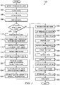
- FIGURE 5 illustrates an example method 500 for milking a dairy cow using the example milking box 120 depicted in FIGURES 1-4 , according to certain embodiments of the present disclosure.
- milking box 120 may be positioned within enclosure 100, and at least one of the gates 126 of stall portion 122 may be opened to allow the dairy cow to voluntarily enter milking box 120.
- presence sensor 132 detects the presence of the dairy cow. Presence sensor 132 communicates a signal to controller 200 indicating the presence of the dairy cow has been detected. Controller 200 sends a signal to an actuator causing gates 126 to close at step 504. Thus, the dairy cow is prevented from exiting the milking box.
- Gate closed sensor 134 determines that the gates are closed and communicates a gate-closed signal to controller 200.
- controller 200 causes the milking procedure to proceed to the next step. For example, controller 200 sends a signal requesting identification sensor 136 to provide an identifier associated with the dairy cow.
- identification sensor 136 reads an ear tag, collar, or other identifier (e.g., an RFID signal) associated with the dairy cow. Identification sensor 136 communicates the identifier to controller 200 to facilitate determining the identity of the cow.
- controller 200 retrieves information associated with the particular dairy cow according to the determined identity of the dairy cow. For example, information may be retrieved from memory 240. Controller 200 determines whether to proceed with milking the dairy cow at step 510. The determination may be made according to the information associated with the dairy cow. For example, if the information indicates that the dairy cow is ill or that the dairy cow has already been milked in the current milking cycle, a determination may be made not to proceed with milking the dairy cow.
- step 512 If the dairy cow is not to be milked, the method skips to step 548.
- controller 200 causes a dispenser to drop feed into feed bowl 130 and positions feed bowl 130.
- feed bowl 130 may move toward the rear of the stall to encourage the dairy cow to back-up toward the milking equipment.
- Controller 200 determines that the dairy cow is positioned near the milking equipment at step 514. For example, a signal received from backplane 138 of milking box 120 may be used to determine that the dairy cow is positioned near the milking equipment. The signal may indicate when the rear of the dairy cow touches a portion of backplane 138.
- controller 200 Upon determining the dairy cow is positioned near the milking equipment (e.g., toward the rear of the stall portion of the milking box), controller 200 instructs first cam-era 158a to generate a first image 176 of the rear of the dairy cow at step 516.
- first camera 158a is positioned on robotic attacher 150, and first camera 158a may begin generating the first image 176 in-flight, that is, as robotic attacher 150 retrieves a preparation cup 166 or teat cup 168 from storage and begins moving the cup toward the udder.
- controller 200 receives the first image 176.
- the first image 176 includes main features of the dairy cow, such as the hind legs, the udder, and/or the tail.
- Controller 200 accesses the first image 176 to determine a reference point 178 at step 520.
- the reference point 178 may comprise a point between the dairy cow's hind legs, a point below the dairy cow's udder, and/or a point proximate to a midpoint of the udder.
- the mid-point may refer to a point between a first teat and a second teat (e.g., between a left teat and a right teat and/or between a front teat and a rear teat).
- controller 200 sends a signal causing robotic attacher 150 to position second camera 158b relative the reference point 178.
- Controller 200 communicates historical data to second camera 158b at step 524.
- the historical data may comprise data retrieved from a database that indicates a previously-determined location of the teats during a previous milking cycle. The previously-determined location may be described relative to the reference point 178.
- controller 200 sends a signal causing second camera 158b to generate a second image 180.
- Second camera 158b may generate the second image 180 by scanning a portion of the udder indicated by the historical data. Second camera 158b may scan the whole teat to facilitate identifying the angle of the teat and the point attachment.
- the controller 200 receives the second image 180 from the second camera. Controller 200 accesses the second image 180 to determine the location of the teats at step 530.
- the teats may be located in any suitable manner, such as one at a time, two at a time, or four at a time.
- controller 200 Upon determining the location of the teats, controller 200 causes robotic attacher 150 to attach one or more preparation cups 166 at step 532.
- Second camera 158b may continue to scan the teat while the preparation cup is being attached. Continuing to scan the teat may allow for efficient attachment of the preparation cup. In addition, continuing to scan the teat may allow the preparation cup to be attached at a suitable angle, with the mouthpiece centered on the teat, to prevent folding the teat into the preparation cup. Vacuum pressure may be used to hold the preparation cups in place.
- Preparation cup 166 facilitates preparing the teat at step 534. Preparation may include cleaning the teat, stimulating the flow of milk, and discarding fore milk from the teat. After each of the teats have been prepared, preparation cups 166 may be removed at step 536. For example, the vacuum pressure may be released to remove the preparation cups and the preparation cups may be returned to the storage area.
- step 538 controller 200 causes robotic attacher 150 to attach a teat cup 168.
- teat cup 168 may be retrieved from storage area 164 and navigated to the teat.
- Second camera 158b may continue to scan the teat while the teat cup 168 is being attached to ensure proper placement of the teat cups.
- Vacuum pressure may be used to attach the teat cup 168.
- a sensor may be used to determine the vacuum pressure associated with each teat cup 168. If the vacuum level is low, it may indicate that teat cup 168 has fallen off and needs to be reattached.
- additional teat cups 168 may be attached by re-performing steps 522-530 to locate additional teats.
- robotic attacher 150 may retract and the method may proceed to step 540 to extract milk from the dairy cow.
- milk may be extracted by applying pulsation to the teat cup.
- a sensor may monitor the flow of milk. If the flow becomes low, it may be determined whether teat cup 168 should be removed or reattached. For example, if teat cup 168 has been attached for at least approximately one-and-a-half minutes and/or the amount of milk extracted is consistent with previous milking cycles, it may be determined that teat cup 168 should be removed, otherwise, it may be determined that teat cup 168 should be reattached.
- controller 200 When it is determined that teat cup 168 should be removed, controller 200 initiates step 542 to remove teat cups 168. For example, controller 200 may send a signal causing the vacuum pressure to be released to allow teat cups 168 to drop from the teats. Teat cups 168 may be returned to storage area 164 by retracting hoses attached to teat cups 168 or by any other suitable method. Controller 200 then sends a signal to robotic attacher 150 to cause gripping portion 156 to rotate at step 544 in order to orient nozzle 182 toward the teat. The method applies disinfectant to the teat at step 546 by spraying the disinfectant through nozzle 182.
- controller 200 determines which gate(s) 126 to open. Selectively opening gates 126 may allow the dairy cow to be sorted into a particular region 110 of enclosure 100. The dairy cow may be sorted if its milk tested bad, if it failed to produce a sufficient amount of milk, if information retrieved from a database indicates the dairy cow should be sorted, or for other suitable reasons. Controller 200 sends a signal causing an actuator to open the selected gate(s) at step 550. In certain embodiments, a prod may be used to encourage the dairy cow to exit the milking box. The dairy cow exits the milking box and the method ends.
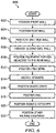
- FIGURE 6 illustrates an example method 600 for installation of milking box 120, according to certain embodiments of the present disclosure.
- the method may begin by positioning walls 124 in order to define stall portion 122. For example, the method positions a front wall 124a at step 602.
- the method proceeds to step 604 where a rear wall 124c is positioned substantially parallel to front wall 124a. Rear wall 124c may be spaced apart from front wall 124a a suitable distance to accommodate a dairy cow.
- a first side wall 124b is positioned to extend between front wall 124a and rear wall 124c.
- the first side wall may include one or more gates, such as an entry gate 126a and an exit gate 126b.
- step 608 to position a second side wall 124d to extend between front wall 124a and rear wall 124c.
- Second side wall 124d may be spaced apart from first side wall 124d in order to accommodate a dairy livestock within stall portion 122.
- Second side wall 124d may or may not include gates 126.
- second side wall 124d may comprise a second entry gate 126a and a second exit gate 126b.
- second side wall 124d may be positioned adjacent a second milking box and may define a boundary between milking box 120 and the adjacent milking box.
- an equipment portion 128 is positioned to the rear of milking box 120, adjacent rear wall 124c.
- Rear wall 124c may comprise a backplane 138 adapted to physically contact a mid-flank portion of the dairy livestock when the dairy livestock is positioned proximate to equipment portion 128 of milking box 120.
- a movable feed bowl 130 may be positioned within milking box 120. Movable feed bowl 130 may be adapted to move from the front of milking box 120 toward the rear of milking box 120 to encourage the dairy livestock to back-up toward backplane 138.
- the method may proceed to step 614 to install a plurality of sensors within milking box 120. Examples of sensors include a presence sensor 132 adapted to detect the presence of the dairy livestock within milking box 120, one or more gate closed sensors 134 to detect whether gates 126 are closed, and a livestock identification sensor 136 adapted to determine the identity of the dairy livestock present within milking box 120.
- a waste grate 140 may be positioned within milking box 120.
- the method may proceed to step 618 to position a rail 160.
- Rail 160 may be positioned to extend in a horizontal direction substantially parallel to rear wall 124c.
- the horizontal direction may refer to the z-axis illustrated in FIGURE 3 .
- rail 160 may be positioned proximate to rear wall 124c.
- a robotic attacher 150 may be positioned in milking box 120.
- Robotic attacher may comprise a main arm 152, a supplemental arm 154, including a gripping portion 156, and a vision system 158.
- robotic attacher 150 may be positioned in equipment portion 128 of milking box 120 by suspending main arm 152 from rail 160.
- main arm 152 may be operable to traverse rail 160 in the horizontal direction.
- one or more guides 162 may be positioned proximate to rail 160.
- Guides 162 may be adapted to guide the path of hoses and wires connected to robotic attacher 150 to prevent the hoses and wires from interfering with the movement of main arm 152 along rail 160
- Supplemental arm 154 may be positioned to facilitate selectively extending supplemental arm 154 between the rear legs of the dairy livestock located within stall portion 122.
- step 622 The method proceeds to step 622 to position other milking equipment in equipment portion 128 of milking box 120.
- Other milking equipment may include one or more preparation cups 164, teat cups 168, pumps 170, milk receiver jars 172, and/or milk separation containers 174.
- the method then ends.
Description
- This invention relates generally to dairy farming and more particularly to a vision system for a robotic attacher.
-
WO 2007/050012 A1 discloses an arrangement and method for visual detection in a milking system. -
WO 98/07311 A1 - Over time, the size and complexity of dairy milking operations has increased. Accordingly, the need for efficient and scalable systems and methods that support dairy milking operations has also increased. Systems and methods supporting dairy milking operations, however, have proven inadequate in various respects.
- According to embodiments of the present disclosure, disadvantages and problems associated with previous systems supporting dairy milking operations may be reduced or eliminated.
- In certain embodiments a system is provided which includes the features recited in claim 1 and non-transitory computer readable storage medium is provided which includes the features recited in claim 7.
- In certain embodiments, a system includes a controller operable to access a first image generated by a first camera. The controller determines a reference point from at least one main feature of a dairy livestock included in the first image. The controller is further operable to access a second image generated by the second camera. The second image includes at least a portion of an udder of the dairy livestock. The controller determines a location of a teat of the dairy livestock based on the second image.
- Particular embodiments of the present disclosure may provide one or more technical advantages. For example, in some embodiments, the system of the present disclosure includes multiple cameras to facilitate locating the teats of a dairy livestock. Using multiple cameras may improve the visibility of the teats and may facilitate attaching milking equipment from a position to the rear of the cow, rather than to the side of the cow as in certain conventional systems. As another example, in some embodiments, the system of the present disclosure, in searching for the teats of a dairy livestock, may account for (1) a determined reference point relative to the dairy livestock, and/or (2) historical data describing a previous location of the teats relative to the reference point. Accounting for the determined reference point and/or the historical data in searching for the teats of a dairy livestock may allow for more accurate teat location, which may allow a robotic attacher to more efficiently attach milking equipment to the dairy livestock.
- Certain embodiments of the present disclosure may include some, all, or none of the above advantages. One or more other technical advantages may be readily apparent to those skilled in the art from the figures, descriptions, and claims included herein.
- To provide a more complete understanding of the present invention and the features and advantages thereof, reference is made to the following description taken in conjunction with the accompanying drawings, in which:
-
FIGURES 1A-1B illustrate example configurations of anenclosure 100 in which one or more milking boxes are installed, according to certain embodiments of the present disclosure; -
FIGURE 2 illustrates an example controller that may be used to control one or more components of the example milking box depicted inFIGURE 1 , according to certain embodiments of the present disclosure; -
FIGURE 3 illustrates a detailed perspective view of the example milking box depicted inFIGURE 1 , according to certain embodiments of the present disclosure; -
FIGURE 4 illustrates a detailed perspective view of the example robotic attacher depicted inFIGURE 3 , according to certain embodiments of the present disclosure; -
FIGURE 5 illustrates an example method for milking a dairy cow using the example milking box depicted inFIGURES 1-4 , according to certain embodiments of the present disclosure; and -
FIGURE 6 illustrates an example method for installation of the example milking box depicted inFIGURES 1-4 , according to certain embodiments of the present disclosure. -
FIGURES 1A-1B illustrate example configurations of anenclosure 100 in which one ormore milking boxes 120 are installed, according to certain embodiments of the present disclosure.Enclosure 100 may be divided into a number of regions 110 (e.g.,regions enclosure 100 as housing any suitable dairy livestock (e.g., dairy cows, goats, sheep, water buffalo, etc.), the remainder of this description is detailed with respect to dairy cows. - Each
milking box 120 may include astall portion 122 configured to house a dairy cow being milked. Thestall portion 122 of eachmilking box 120 may be defined by a number of walls 124, each of which may each be constructed from any suitable materials arranged in any suitable configuration operable to maintain a dairy cow withinstall portion 122 during milking. In certain embodiments,stall portion 122 ofmilking box 120 may includewalls wall 124a may be designated as the front ofmilking box 120 such that the head of a dairy cow being milked would be facingwall 124a.Wall 124c may be positionedopposite wall 124a and may be designated as the rear ofmilking box 120.Walls milking box 120. Walls 124a, 124b, 124c, and 124d may be spaced apart a suitable distance to ensure the comfort of the dairy cow withinstall portion 122. -
Walls 124b and/or 124d may comprise one or more gates 126. In certain embodiments,wall 124b and/orwall 124d may comprise anentry gate 126a and anexit gate 126b. A dairy cow may entermilking box 120 through an openedentry gate 126a and exitmilking box 120 through an openedexit gate 126b. Closing gates 126 may maintain the dairy cow withinmilking box 120 during milking, while opening one or more gates 126 may allow the dairy cow to exitmilking box 120. In certain embodiments, gates 126 may each be coupled to a corresponding actuator such that the gates 126 may be automatically opened and/or closed. For example, the actuators corresponding to gates 126 may each be configured to communicate (e.g., via wireless or wireline communication) with acontroller 200, depicted in detail inFIGURE 2 . -
Controller 200 may include one or more computer systems at one or more locations. Examples of computer systems may include a personal computer, workstation, network computer, kiosk, wireless data port, personal data assistant (PDA), one or more processors within these or other devices, or any other suitable device for receiving, processing, storing, and communicating data. In short,controller 200 may include any suitable combination of software, firmware, and hardware.Controller 200 may include anyappropriate interface 210 for receiving inputs and providing outputs,logic 220, one ormore processing modules 230, andmemory module 240.Logic 220 includes any information, logic, applications, rules, and/or instructions stored and/or executed bycontroller 200.Processing modules 230 may each include one or more microprocessors, controllers, or any other suitable computing devices or resources and may work, either alone or with other components, to provide a portion or all of the functionality described herein.Controller 200 may additionally include (or be communicatively coupled to via wireless or wireline communication) one ormore memory modules 240.Memory modules 240 may be non-transitory and may each include any memory or database module.Memory modules 240 may take the form of volatile or non-volatile memory, including, without limitation, magnetic media, optical media, random access memory (RAM), read-only memory (ROM), removable media, or any other suitable local or remote memory component. Turning toFIGURE 3 ,controller 200 may be operable to determine, using any appropriate logic in conjunction with signals received from other components of milking box 120 (e.g.,presence sensor 132,gate sensors 134, and/oridentification sensor 136, each of which is described with regard toFIGURE 3 , below), which gates 126 should be open and/or closed.Controller 200 may then communicate signals to the actuators coupled to the determined gates 126, the signals causing the gates 126 to open or close. The automated control of gates 126 usingcontroller 200 is described in further with regard toFIGURE 3 , below - Each
milking box 120 may additionally include anequipment portion 128 located to the rear of stall portion 122 (i.e., adjacent torear wall 124c of stall portion 122).Equipment portion 128 may comprise any structure suitable for housing and/or storing a robotic attacher (e.g.,robotic attacher 150, described below with regard toFIGURE 3 ), one or more preparation cups, teat cups, receiver jars, separation containers, and/or any other suitable milking equipment.Rear wall 124c (which may include abackplane 138, as described below with regard toFIGURE 3 ) mayseparate stall portion 122 fromequipment portion 128 such thatequipment portion 128 is substantially inaccessible to a dairy cow located install portion 122. Accordingly a dairy cow located install portion 122 may be prevented from accidentally damaging the milking equipment by kicking, biting, trampling, or exposing the milking equipment to dirt, fluids, etc. - In certain embodiments, the
equipment portion 128 being located to the rear ofstall portion 122 may allowmilking boxes 120 to be aligned in a single row such thatwalls milking box 120 may comprise anentry gate 126a and anexit gate 126b (as illustrated inFIGURE 1A ). As a result, milkingboxes 120 may be used to sort dairy cows into particular regions 110 by controlling the opening/closing of each gate 126 (e.g., in response to signals from acontroller 200, as described above). For example, a dairy cow needing a health check or medical attention my be sorted into an appropriate region 110 (e.g., a veterinary pen). As another example, a dairy cow determined to be finished milking for the year and needing to be dried off and bread may be sorted out of the milking heard. As yet another example, a dairy cow may be sorted into one of a number of regions 110 based on the stage of lactation of the dairy cow (as dairy cows in different stages may require different feeds). - In certain other embodiments, the
equipment portion 128 being located to the rear ofstall portion 122 may allow pairs of milkingboxes 120 to be located side by side such that the milking boxes share a wall 124 (e.g.,wall 124b may be shared betweenmilking box 120c andmilking box 120d, as depicted inFIGURE 1B ). As a result, a single robotic attacher (e.g.,robotic attacher 150, described below with regard toFIGURE 3 ) may be shared by the pair of milkingboxes 120, which may reduce to cost of installing multiple milkingboxes 120 in theenclosure 100. -
FIGURE 3 illustrates a detailed perspective view of anexample milking box 120, according to certain embodiments of the present disclosure. As described above with regard toFIGURE 1 , milkingbox 120 may comprise a stall portion 122 (defined by walls 124 and gates 126) andequipment portion 128 located to the rear ofstall portion 122. In certain embodiments,stall portion 122 ofmilking box 120 may include afeed bowl 130, apresence sensor 132, one ormore gate sensors 134, and anidentification sensor 136. Additionally, one or more offeed bowl 130,presence sensor 132, gate sensor(s) 134, andidentification sensor 136 may be communicatively coupled to controller 200 (described above with regard toFIGURE 2 ). - In certain embodiments,
feed bowl 130 may dispense feed in order to attract a dairy cow so that the dairy cow will enter milkingbox 120 voluntarily. Accordingly, at least one of theentry gates 126a may remain open when there is no dairy cow present to allow a dairy cow to enter. Once the dairy cow has enteredmilking box 120,presence sensor 132 may detect the presence of the dairy cow. For example,presence sensor 132 may detect when the dairy cow has passed through theentrance gate 126a and/or when the dairy cow is generally centered in thestall portion 122. Upon detecting the presence of the dairy cow,presence sensor 132 may send a signal tocontroller 200. In response to the signal,controller 200 may cause one or more actuators to close gates 126.Gate sensor 134 may determine when gates 126 have closed.Gate sensor 134 may communicate a signal tocontroller 200 upon determining that gates 126 have closed.Controller 200 may initiate a milking procedure in response to the signal. - In certain embodiments,
identification sensor 136 may determine the identity of the dairy cow. As an example,identification sensor 136 may comprise an antenna operable to read a radio frequency identification (RFID) from an ear tag, a collar, or other identifier associated with the dairy cow. Once the dairy cow has been identified, theidentification sensor 136 may optionally be turned off to prevent wasting power and/or to minimize the dairy cow's exposure to radio waves. -
Identification sensor 136 may communicate the identity of the dairy cow tocontroller 200 to facilitate retrieving information describing the dairy cow (e.g., frommemory 240 or any other suitable location). Information describing the dairy cow may comprise historical data describing the particular dairy cow during a previous time period, such as a previous milking cycle. The previous milking cycle may refer to a milking cycle in which milking equipment was manually attached (e.g., by a user) or a milking cycle in which milking equipment was automatically attached (e.g., by arobotic attacher 150, described below). In certain embodiments, milking equipment may be attached manually the first time the dairy cow is milked in order to establish initial information describing the dairy cow, such as where the teats are located. The location of the dairy cow's teats may be described relative to a feature of the dairy cow, such as relative to the rear of the dairy cow, the hind legs, and/or a portion of the dairy cow's udder, such as a mid-line of the udder or relative to one or more of the other teats. A robotic attacher (e.g.,robotic attacher 150, described below) may use the information describing the location of the teats during subsequent milkings to facilitate automatically attaching the milking equipment. - Examples of historical data include measurements, statistics, health information, and any other information describing the dairy cow during a previous time period. Examples of measurements include the length of the dairy cow (e.g., from head to tail) and the location of the dairy cow's teats during a previous milking cycle. Examples of statistics may include statistics describing when the dairy cow was last milked, the amount of milk produced in previous milking cycles, and so on. Examples of health information may include a designation not to milk the dairy cow due to a health problem or a designation to sort the dairy cow into a veterinary pen. In certain embodiments, a user may set an indicator in the database to indicate that the dairy cow should be sorted into the veterinary pen because the dairy cow is due for a check-up or because the user noticed the dairy cow appears to be ill or injured.
-
Controller 200 may use the information retrieved according to the identity of the dairy cow to determine how the particular dairy cow should be handled. If the information indicates the dairy cow should not be milked,controller 200 may cause an actuator to open one or more of theexit gates 126b. For example, ifcontroller 200 determines that the dairy cow should be sorted into a particular region 110 ofenclosure 100, such as a veterinary pen, it may cause theexit gate 126b that accesses the selected region 110 to open. Alternatively,controller 200 may causemultiple exit gates 126b to open if the dairy cow is to be given the option of which region 110 to occupy upon exitingmilking box 120. In certain embodiments, a prod may be used to encourage the dairy cow to exit. Examples of prods include a noise, a mechanical device, or a mild electric shock. - Upon a determination that the dairy cow should be milked,
controller 200 may continue the milking procedure. In certain embodiments,controller 200 may cause a dispenser to drop feed intofeed bowl 130. Additionally,controller 200 may causefeed bowl 130 to move toward the dairy cow in order to encourage the dairy cow to move to a pre-determined part ofstall portion 122. As an example, feedbowl 130 may be initially positioned in the front ofstall portion 122 when the dairy cow enters.Feed bowl 130 may then move back toward the dairy cow to encourage the dairy cow to move to the rear of stall portion 122 (e.g., againstbackplane 138, described below) in order to facilitate attaching the milking equipment to the dairy cow. To ensurefeed bowl 130 does not crowd the dairy cow, the amount of movement offeed bowl 130 may be customized to the size of the dairy cow. For example, a user may determine an appropriate location forfeed bowl 130 the first time the dairy cow enters milkingbox 120. The location may be stored (e.g., inmemory module 240 of controller 200) such that it may be retrieved during subsequent milkings according to the identity of the dairy cow. Alternatively, thefeed bowl 130 may be configured to continue moving toward the rear of thestall portion 122 until the dairy cow contacts backplane 138 (described below), which may indicate that the dairy cow is positioned in a location that is suitable for attaching the milking equipment. - In certain embodiments,
rear wall 124c ofstall portion 122 includes abackplane 138.Backplane 138 may comprise any suitable configuration of materials suitable for locating the rear of the dairy cow in order to facilitate the efficient attachment of the milking equipment. In certain embodiments, the dairy cow may be backed towardbackplane 138 by movingfeed bowl 130 as described above. In certain other embodiments,backplane 138 may be moved forward toward the dairy cow. In certain other embodiments, a combination of backing the dairy cow towardbackplane 138 and movingbackplane 138 forward toward the dairy cow may be used. It may be determined that the rear of the dairy cow has been located when a portion ofbackplane 138, such as a pipe or bracket, touches the rear of the dairy cow at any suitable location, such as approximately mid-flank (i.e., between the udder and the tail).Backplane 138 may additionally include a manure gutter for directing manure toward a side of stall portion 122 (e.g., away from the dairy cow's udder and the milking equipment). - In certain embodiments,
stall portion 122 may additionally include awaste grate 140 for disposing of waste.Waste grate 140 may have a rough surface to discourage the dairy cow from standing on it. In addition,waste grate 140 may be dimensioned such that when the dairy cow's hind legs are positioned on opposite sides ofwaste grate 140, the hind legs are separated to facilitate attachment of the milking equipment to the dairy cow's teats. - In certain embodiments,
equipment portion 128 ofmilking box 120 may include arobotic attacher 150, one or more preparation cups 166, teat cups 168, pumps 170,receiver jars 172,milk separation containers 174, and/or any other suitable milking equipment. In certain embodiments,robotic attacher 150 may be suspended intoequipment portion 128 from arail 160.Rail 160 may be generally located above the level of the udder of a dairy cow located install portion 122 such that the teats of the dairy cow may be accessible torobotic attacher 150 when suspended fromrail 160. For example,rail 160 may extend across the top ofequipment portion 128 ofmilking box 120 and may be oriented substantially parallel torear wall 124c. -
Robotic attacher 150 is communicatively coupled to controller 200 (e.g., via a network facilitating wireless or wireline communication).Controller 200 may cause robotic attacher to attach certain milking equipment to the dairy cow's teats. For example, in certain embodiments,robotic attacher 150 may access astorage area 164 to retrievepreparation cups 166 and/or teat cups 168. Preparation cups 166 may be adapted to clean the teats, stimulate the flow of milk, and discard fore milk from the teat (e.g., the first few millimeters of milk that may be dirty). Teat cups 168 may be adapted to extract milk from the dairy cow. Preparation cups 166 and/orteat cups 168 attached to extendable hoses may by hung withinstorage area 164 between milkings to protect the cups from manure and flies. When it is time to milk the dairy cow,robotic attacher 150 may pullpreparation cups 166 fromstorage area 164 and attach them to the dairy cow one at a time, two at a time, or four at a time. After the teats have been prepared, preparation cups 166 may be removed andteat cups 168 may be attached one at a time, two at a time, or four at a time. Once the cups are attached,robotic attacher 150 may withdraw to prevent the dairy cow from causing accidental damage to the equipment, and the system may proceed with milking the dairy cow. - During milking, pump 170 may pump good milk from
teat cup 168 toreceiver jar 172 to be stored at a cool temperature. Pump 170 may pump bad milk tomilk separation container 174 to be discarded. Milk may be determined to be bad based on testing the milk and/or based on the particular dairy cow from which the milk has been extracted. For example, information retrieved from a database according to the dairy cow's identifier may indicate that the milk should be discarded because the dairy cow is ill or has recently calved. -
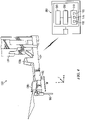
Robotic attacher 150 comprises amain arm 152, asupplemental arm 154, a grippingportion 156, and avision system 158. In certain embodiments, the movement ofmain arm 152,supplemental arm 154, and grippingportion 156 may be varied in response to signals received from controller 200 (as described in further detail inFIGURE 4 below). Although the components ofrobotic attacher 150 are depicted and primarily described as oriented in a particular manner, the present disclosure contemplates the components having any suitable orientation, according to particular needs. - In order to obtain access to the dairy cow's teats,
main arm 152,supplemental arm 154, and grippingportion 156 may work together to facilitate movement in three dimensions, for example, according to an x-axis, a y-axis, and a z-axis. As illustrated, the x-axis extends in the direction of the dairy cow's length (e.g., from head-to-tail), the y-axis extends in the direction of the dairy cow's height, and the z-axis extends in the direction of the dairy coves width. -
Main arm 152 may comprise a vertical arm movably coupled torail 160. For example, a hydraulic cylinder may movably couplemain arm 152 torail 160.Main arm 152 may traverserail 160 to facilitate movement ofrobotic attacher 150 along the z-axis. Accordingly,rail 160 may comprise a track and rollers adapted to support the weight ofrobotic attacher 150 and to facilitate movement ofmain arm 152 back- and- forth alongrail 160. To prevent wires and hoses from interfering with the movement ofmain arm 152 alongrail 160. guides 162 may be used to loosely hold the wires and hoses in place. For example, guides 162 may comprise U-shaped brackets that allow the wires and hoses to extend a sufficient amount to accommodate movements ofmain arm 152, but prevent the wires and hoses from dangling in the path ofmain arm 152. -
Main arm 152 attaches tosupplemental arm 154.Supplemental arm 154 facilitates movements in any direction. That is,supplemental arm 154 moves in-and-out along the x-axis, up-and-down along the y-axis, and/or from side-to-side along the z-axis. Accordingly, supplemental arm may extend between the rear legs of the dairy cow located withinstall portion 122 in order to attach milking equipment to the dairy cowSupplemental arm 154 may comprise grippingportion 156. Grippingportion 156 may grip apreparation cup 166 or ateat cup 168 for attachment to the dairy cow's teat. Grippingportion 156 may comprise a wrist adapted to perform fine movements, such as pivot and tilt movements, to navigate around the dairy cow's legs and to access the dairy cow's teats. To determine the location of the dairy cow's legs and teats,robotic attacher 150 may usevision system 158. An example embodiment ofvision system 158 is described with respect toFIGURE 4 below. -
FIGURE 4 illustrates a detailed perspective view of an example ofrobotic attacher 150, according to certain embodiments of the present disclosure.Robotic attacher 150 includes amain arm 152, asupplemental arm 154, a grippingportion 156, and avision system 158. As described with respect toFIGURE 3 ,robotic attacher 150 is communicatively coupled tocontroller 200.Controller 200 may cause robotic attacher to retrieve a cup, such aspreparation cup 166 orteat cup 168, move the cup toward a teat of a dairy cow withinmilking box 120, and attach the cup to the teat. - In general, the teats of the dairy cow may be relatively less visible when looking at the dairy cow from the rear and relatively more visible when looking at the dairy cow from the side.
Vision system 158 may facilitate locating the teats from a position to the rear of the dairy cow.Vision system 158 includes afirst camera 158a and asecond camera 158b.Cameras robotic attacher 150 and are positioned at any suitable location alongmain arm 152 orsupplemental arm 154. As an example,second camera 158b may be coupled to grippingportion 156 ofsupplemental arm 154 at a location proximate to the part of grippingportion 156 adapted to hold a teat cup, andfirst camera 158a may be coupled tosupplemental arm 154 at a location betweensecond camera 158b andmain arm 152. - In operation,
controller 200 accesses afirst image 176 generated byfirst camera 158a (e.g., from memory module 240) and useesfirst image 176 to determine, using anysuitable logic 220, areference point 178 proximate to the udder, which may then be stored (e.g., in memory module 240). Thereference point 178 may be defined relative to certain features of the dairy cow, such as the hind legs and/or the udder.Controller 200 sends a signal torobotic attacher 150 causingrobotic attacher 150 to positionsecond camera 158b relative to thereference point 178. Accordingly,second camera 158b may have a consistent point of reference from one milking cycle to the next, which may allow the teats to be located efficiently.Controller 200 accesses asecond image 180 generated bysecond camera 158b (e.g., from memory module 240) in order to determine, using anysuitable logic 220, a location of a teat. - In certain embodiments,
first camera 158a may comprise a three-dimensional camera adapted to generate afirst image 176 depicting the rear of the dairy cow, including the hind legs and the udder. Using a three-dimensional camera may facilitate generating a relatively complete image of the rear of the dairy cow within approximately a couple of seconds (e.g., one second), which may be faster than the amount of time it would take for a two-dimensional camera to generate a similar image. In certain embodiments,second camera 158b may comprise a two-dimensional camera adapted to generate asecond image 180 depicting at least a portion of the udder to facilitate locating the teats.Second camera 158b may facilitate locating the end of each teat with a relatively high degree of accuracy, such as within a few millimeters. The location of the teat may be used to instructrobotic attacher 150 where to attach the milking equipment. -
First camera 158a may begin generating thefirst image 176 in response to a signal fromcontroller 200 indicating that the dairy cow is positioned proximate to the milking equipment. As an example, the signal may indicate that the rear of the daily cow has been detected by thebackplane 138 of themilking box 120.First camera 158a may begin generating thefirst image 176 from a starting point and may update thefirst image 176 in real-time asrobotic attacher 150 approaches the dairy cow. The starting point may be determined according to a default position of robotic attacher 150 (e.g., a position determined relative to milking stall 122). Thus, the starting point may be determined without the use of historical data associated with the particular dairy cow being milked.First camera 158a may communicate thefirst image 176 tocontroller 200, andcontroller 200 may use the image to locate main features of the dairy cow, such as the right hind leg, the left hind leg, the udder, and/or the tail. -
Controller 200 determines thereference point 178 based on the location of the main features of the dairy cow. Thereference point 178 may be defined relative to certain features of the dairy cow, such as the hind legs and/or the udder. As an example, thereference point 178 may be defined between the hind legs and/or below the udder. For example, in certain embodiments, thereference point 178 may be located proximate to a mid-point of the udder. The mid-point of the udder may refer to a point generally located between the front teats and the rear teats in the x-direction and/or between the left teats and the right teats in the z-direction. In certain embodiments, the mid-point of the udder may be estimated prior to determining the precise location of the teats, for example, according to the general size and location of the udder. Thereference point 178 may be spaced apart from the dairy cow in the y-direction to minimize the likelihood thatsecond camera 158b touches the dairy cow. For example, thereference point 178 may be located a few inches below the midpoint of the udder. -
Controller 200 may communicate thereference point 178 and/or information describing the main features of the dairy cow torobotic attacher 150. Thereference point 178 may be used to positionsecond camera 158b. The information describing the main features of the dairy cow may be used to preventrobotic attacher 150 from colliding with the dairy cow when navigatingsecond camera 158b toward thereference point 178. Information describing the main features of the dairy cow may include the position of the hind legs, the space between the hind legs, the position of the udder, the height of the udder, the position of the tail, and/or other information. Oncerobotic attacher 150 has positionedsecond camera 158b relative to thereference point 178,second camera 158b may begin scanning the udder. - In certain embodiments,
second camera 158b may determine where to look for one or more of the teats according to historical data. The historical data may be received fromcontroller 200 and may describe a previously-determined location of the teats relative to thereference point 178. The previously-determined location may be based on the location of the teats during one or more previous milking cycles. As an example, the previously-determined location may comprise the location of the teats during the most recent milking cycle. As another example, the previously-determined location may comprise an average of the locations of the teats during a number of previous milking cycles. As another example, the previously-determined location may comprise the location of the teats during a previous milking cycle in which the udder was likely to be as full of milk as the current milking cycle. For example, if eight hours have elapsed since the dairy cow was last milked, the previously- determined location may be determined from a previous milking cycle in which the dairy cow had not been milked for approximately eight hours. Referring to historical data may minimize the area thatsecond camera 158b must scan in order to locate the teat and may reduce the amount of time required to locate the teat. -
Second camera 158b may communicate thesecond image 180 tocontroller 200, andcontroller 200 accesses thesecond image 180 to locate the teats of the dairy cow. As described above, in certain embodiments,second camera 158b may comprise a two-dimensional camera, such as a horizontal laser. If the horizontal laser may scan a portion of the udder other than the teats (e.g., a relatively even surface of the udder), the scan communicated tocontroller 200 may generally resemble a substantially solid line. If the horizontal laser scans a portion of the udder that includes the teats, the scan communicated tocontroller 200 may generally resemble a broken line depicting the teats and the spaces between the teats. As an example,controller 200 may determine that a teat has been located if the scan comprises a broken line in which a solid portion of the line generally corresponds to the width of a teat and the broken portions of the line generally correspond to the proportions of the space between teats. - In certain embodiments,
robotic attacher 150 may further comprise anozzle 182.Nozzle 182 may be coupled to grippingportion 156.Nuzzle 182 may spray disinfectant on the teats of the dairy cow at the end of a milking cycle, that is, after the dairy cow has been milked and the teat cups have been removed. The disinfectant may be sprayed to prevent mastitis or other inflammation or infection. In certain embodiments, gripping portion may be operable to rotate 180° around the x-axis. During milking,second camera 158b may be generally oriented on top of grippingportion 156, andnozzle 182 may be generally oriented underneath gripping portion 156 (i.e., oppositesecond camera 158b). Orientingnozzle 182 underneath grippingportion 156 during milking may prevent milk or other contaminants from accessingnozzle 182. Once the milking has been completed, grippingportion 156 may rotate such thatnozzle 182 may be generally oriented on top of grippingportion 156, andsecond camera 158b may be generally oriented underneath grippingportion 156. Orientingnozzle 182 on top of grippingportion 156 after milking may facilitate spraying the teats with disinfectant fromnozzle 182. -
FIGURE 5 illustrates anexample method 500 for milking a dairy cow using theexample milking box 120 depicted inFIGURES 1-4 , according to certain embodiments of the present disclosure. In certain embodiments, milkingbox 120 may be positioned withinenclosure 100, and at least one of the gates 126 ofstall portion 122 may be opened to allow the dairy cow to voluntarily entermilking box 120. Atstep 502,presence sensor 132 detects the presence of the dairy cow.Presence sensor 132 communicates a signal tocontroller 200 indicating the presence of the dairy cow has been detected.Controller 200 sends a signal to an actuator causing gates 126 to close atstep 504. Thus, the dairy cow is prevented from exiting the milking box. Gate closedsensor 134 determines that the gates are closed and communicates a gate-closed signal tocontroller 200. In response to the gate-closed signal,controller 200 causes the milking procedure to proceed to the next step. For example,controller 200 sends a signal requestingidentification sensor 136 to provide an identifier associated with the dairy cow. - At
step 506,identification sensor 136 reads an ear tag, collar, or other identifier (e.g., an RFID signal) associated with the dairy cow.Identification sensor 136 communicates the identifier tocontroller 200 to facilitate determining the identity of the cow. Atstep 508,controller 200 retrieves information associated with the particular dairy cow according to the determined identity of the dairy cow. For example, information may be retrieved frommemory 240.Controller 200 determines whether to proceed with milking the dairy cow atstep 510. The determination may be made according to the information associated with the dairy cow. For example, if the information indicates that the dairy cow is ill or that the dairy cow has already been milked in the current milking cycle, a determination may be made not to proceed with milking the dairy cow. Alternatively, if the information indicates that the dairy cow is healthy and that it is time to milk the dairy cow, a determination may be made to proceed with milking the dairy cow. If the dairy cow is to be milked, the method continues to step 512. If the dairy cow is not to be milked, the method skips to step 548. - At
step 512,controller 200 causes a dispenser to drop feed intofeed bowl 130 and positions feedbowl 130. In certain embodiments,feed bowl 130 may move toward the rear of the stall to encourage the dairy cow to back-up toward the milking equipment.Controller 200 determines that the dairy cow is positioned near the milking equipment atstep 514. For example, a signal received frombackplane 138 ofmilking box 120 may be used to determine that the dairy cow is positioned near the milking equipment. The signal may indicate when the rear of the dairy cow touches a portion ofbackplane 138. Upon determining the dairy cow is positioned near the milking equipment (e.g., toward the rear of the stall portion of the milking box),controller 200 instructs first cam-era 158a to generate afirst image 176 of the rear of the dairy cow atstep 516. In certain embodiments,first camera 158a is positioned onrobotic attacher 150, andfirst camera 158a may begin generating thefirst image 176 in-flight, that is, asrobotic attacher 150 retrieves apreparation cup 166 orteat cup 168 from storage and begins moving the cup toward the udder. Atstep 518,controller 200 receives thefirst image 176. Thefirst image 176 includes main features of the dairy cow, such as the hind legs, the udder, and/or the tail.Controller 200 accesses thefirst image 176 to determine areference point 178 atstep 520. As an example, thereference point 178 may comprise a point between the dairy cow's hind legs, a point below the dairy cow's udder, and/or a point proximate to a midpoint of the udder. The mid-point may refer to a point between a first teat and a second teat (e.g., between a left teat and a right teat and/or between a front teat and a rear teat). - At
step 522,controller 200 sends a signal causingrobotic attacher 150 to positionsecond camera 158b relative thereference point 178.Controller 200 communicates historical data tosecond camera 158b atstep 524. The historical data may comprise data retrieved from a database that indicates a previously-determined location of the teats during a previous milking cycle. The previously-determined location may be described relative to thereference point 178. The method proceeds to step 526 wherecontroller 200 sends a signal causingsecond camera 158b to generate asecond image 180.Second camera 158b may generate thesecond image 180 by scanning a portion of the udder indicated by the historical data.Second camera 158b may scan the whole teat to facilitate identifying the angle of the teat and the point attachment. Atstep 528, thecontroller 200 receives thesecond image 180 from the second camera.Controller 200 accesses thesecond image 180 to determine the location of the teats atstep 530. The teats may be located in any suitable manner, such as one at a time, two at a time, or four at a time. - Upon determining the location of the teats,
controller 200 causesrobotic attacher 150 to attach one or more preparation cups 166 atstep 532.Second camera 158b may continue to scan the teat while the preparation cup is being attached. Continuing to scan the teat may allow for efficient attachment of the preparation cup. In addition, continuing to scan the teat may allow the preparation cup to be attached at a suitable angle, with the mouthpiece centered on the teat, to prevent folding the teat into the preparation cup. Vacuum pressure may be used to hold the preparation cups in place.Preparation cup 166 facilitates preparing the teat atstep 534. Preparation may include cleaning the teat, stimulating the flow of milk, and discarding fore milk from the teat. After each of the teats have been prepared, preparation cups 166 may be removed atstep 536. For example, the vacuum pressure may be released to remove the preparation cups and the preparation cups may be returned to the storage area. - The method continues to step 538, where
controller 200 causesrobotic attacher 150 to attach ateat cup 168. For example,teat cup 168 may be retrieved fromstorage area 164 and navigated to the teat.Second camera 158b may continue to scan the teat while theteat cup 168 is being attached to ensure proper placement of the teat cups. Vacuum pressure may be used to attach theteat cup 168. A sensor may be used to determine the vacuum pressure associated with eachteat cup 168. If the vacuum level is low, it may indicate thatteat cup 168 has fallen off and needs to be reattached. In certain embodiments, additional teat cups 168 may be attached by re-performing steps 522-530 to locate additional teats. - Once teat cups 168 have been attached to all four teats,
robotic attacher 150 may retract and the method may proceed to step 540 to extract milk from the dairy cow. As an example, milk may be extracted by applying pulsation to the teat cup. A sensor may monitor the flow of milk. If the flow becomes low, it may be determined whetherteat cup 168 should be removed or reattached. For example, ifteat cup 168 has been attached for at least approximately one-and-a-half minutes and/or the amount of milk extracted is consistent with previous milking cycles, it may be determined thatteat cup 168 should be removed, otherwise, it may be determined thatteat cup 168 should be reattached. When it is determined thatteat cup 168 should be removed,controller 200 initiates step 542 to removeteat cups 168. For example,controller 200 may send a signal causing the vacuum pressure to be released to allowteat cups 168 to drop from the teats. Teat cups 168 may be returned tostorage area 164 by retracting hoses attached to teatcups 168 or by any other suitable method.Controller 200 then sends a signal torobotic attacher 150 to causegripping portion 156 to rotate atstep 544 in order to orientnozzle 182 toward the teat. The method applies disinfectant to the teat atstep 546 by spraying the disinfectant throughnozzle 182. - At
step 548,controller 200 determines which gate(s) 126 to open. Selectively opening gates 126 may allow the dairy cow to be sorted into a particular region 110 ofenclosure 100. The dairy cow may be sorted if its milk tested bad, if it failed to produce a sufficient amount of milk, if information retrieved from a database indicates the dairy cow should be sorted, or for other suitable reasons.Controller 200 sends a signal causing an actuator to open the selected gate(s) atstep 550. In certain embodiments, a prod may be used to encourage the dairy cow to exit the milking box. The dairy cow exits the milking box and the method ends. -
FIGURE 6 illustrates anexample method 600 for installation ofmilking box 120, according to certain embodiments of the present disclosure. The method may begin by positioning walls 124 in order to definestall portion 122. For example, the method positions afront wall 124a atstep 602. The method proceeds to step 604 where arear wall 124c is positioned substantially parallel tofront wall 124a.Rear wall 124c may be spaced apart fromfront wall 124a a suitable distance to accommodate a dairy cow. Atstep 606, afirst side wall 124b is positioned to extend betweenfront wall 124a andrear wall 124c. The first side wall may include one or more gates, such as anentry gate 126a and anexit gate 126b. The method proceeds to step 608 to position asecond side wall 124d to extend betweenfront wall 124a andrear wall 124c.Second side wall 124d may be spaced apart fromfirst side wall 124d in order to accommodate a dairy livestock withinstall portion 122.Second side wall 124d may or may not include gates 126. For example, in certain embodiments,second side wall 124d may comprise asecond entry gate 126a and asecond exit gate 126b. In alternative embodiments,second side wall 124d may be positioned adjacent a second milking box and may define a boundary betweenmilking box 120 and the adjacent milking box. Instep 610, anequipment portion 128 is positioned to the rear of milkingbox 120, adjacentrear wall 124c.Rear wall 124c may comprise abackplane 138 adapted to physically contact a mid-flank portion of the dairy livestock when the dairy livestock is positioned proximate toequipment portion 128 ofmilking box 120. - At
step 612, amovable feed bowl 130 may be positioned within milkingbox 120.Movable feed bowl 130 may be adapted to move from the front ofmilking box 120 toward the rear of milkingbox 120 to encourage the dairy livestock to back-up towardbackplane 138. The method may proceed to step 614 to install a plurality of sensors withinmilking box 120. Examples of sensors include apresence sensor 132 adapted to detect the presence of the dairy livestock withinmilking box 120, one or more gate closedsensors 134 to detect whether gates 126 are closed, and alivestock identification sensor 136 adapted to determine the identity of the dairy livestock present withinmilking box 120. Atstep 616, awaste grate 140 may be positioned within milkingbox 120. - The method may proceed to step 618 to position a
rail 160.Rail 160 may be positioned to extend in a horizontal direction substantially parallel torear wall 124c. For example, the horizontal direction may refer to the z-axis illustrated inFIGURE 3 . In certain embodiments,rail 160 may be positioned proximate torear wall 124c. Atstep 620, arobotic attacher 150 may be positioned in milkingbox 120. Robotic attacher may comprise amain arm 152, asupplemental arm 154, including agripping portion 156, and avision system 158. In certain embodiments,robotic attacher 150 may be positioned inequipment portion 128 ofmilking box 120 by suspendingmain arm 152 fromrail 160. Accordingly,main arm 152 may be operable to traverserail 160 in the horizontal direction. In certain embodiments, one ormore guides 162 may be positioned proximate torail 160.Guides 162 may be adapted to guide the path of hoses and wires connected torobotic attacher 150 to prevent the hoses and wires from interfering with the movement ofmain arm 152 alongrail 160,Supplemental arm 154 may be positioned to facilitate selectively extendingsupplemental arm 154 between the rear legs of the dairy livestock located withinstall portion 122. - The method proceeds to step 622 to position other milking equipment in
equipment portion 128 ofmilking box 120. Other milking equipment may include one or more preparation cups 164, teat cups 168, pumps 170,milk receiver jars 172, and/ormilk separation containers 174. The method then ends. - Modifications, additions, or omissions may be made to the systems described herein without departing from the scope of the invention. The components may be integrated or separated. Moreover, the operations may be performed by more, fewer, or other components, Additionally, the operations may be performed using any suitable logic comprising software, hardware, and/or other logic. As used in this document, "each" refers to each member of a set or each member of a subset of a set.
- Modifications, additions, or omissions may be made to the methods described herein. For example, the steps may be combined, modified, or deleted where appropriate, and additional steps may be added. Additionally, the steps may be performed in any suitable order without departing from the scope of the present disclosure.
- Although the present invention has been described with several embodiments, diverse changes, substitutions, variations, alterations, and modifications may be suggested to one skilled in the art. The invention is only limited by the appended claims.
Claims (10)
- A system comprising:a robotic attacher (150) comprising a main arm (152), a supplemental arm (154), a gripping portion (156) and a vision system (158), wherein the vision system (158) comprises a first camera (158a) and a second camera (158b) that are each positioned on the robotic attacher (150), anda controller (200) communicatively coupled to the robotic attacher (150) and operable to:access a first image (176) generated by the first camera (158a), the first image (176) including one or more main features of a dairy livestock;determine a reference point (178) based at least in part on the first image (158a), the reference point (178) determined based at least in part upon the one or more main features of the dairy livestock;cause the robotic attacher (150) to position the second camera (158b) relative to the reference point (178) based at least in part upon the one or more main features of the dairy livestock;access a second image (180) generated by the second camera (158b) positioned relative to the reference point (178), the second image (180) including at least a portion of an udder of the dairy livestock; anddetermine a location of a teat of the dairy livestock based at least in part on the second image (180).
- The system of Claim 1, wherein the first camera (158a) comprises a three-dimensional camera and the second camera (158b) comprises a two-dimensional camera.
- The system of Claim 1, wherein the controller (200) is further operable to:communicate, in response to determining the reference point (178), a first signal to the robotic attacher (150), the first signal causing the robotic attacher (150) to be positioned relative to the reference point (178) such that the second camera (158b) may generate the second image (180) including at least a portion of the udder of the dairy livestock;communicate, in response to determining a location of the teat of the dairy livestock, a second signal to the robotic attacher (150), the second signal causing the robotic attacher (150) to position milking equipment (166; 168) relative to the determined location of the teat of the dairy livestock such that the robotic attacher (150) may attach the milking equipment (166; 168) to the teat.
- The system of Claim 3, wherein the second camera (158b) is positioned on a gripping portion (156) of the robotic attacher (150).
- The system of Claim 1, wherein:the one or more main features of the dairy livestock include the hind legs of the dairy livestock; andthe reference point (178) is located between the hind legs of the dairy livestock.
- The system of Claim 1, wherein the controller (200) is further operable to:access identification information associated with the dairy livestock;access historical data associated with the dairy livestock based on the identification information, the historical data including a previously-determined location of the teat of the dairy livestock; andcommunicate a signal to the second camera (158b), the signal causing the second camera (158b), to be directed toward the previously-determined location of the teat of the dairy livestock when generating the second image (180).
- A non-transitory computer readable storage medium comprising logic, the logic, when executed by a processor, operable to:communicate with a robotic attacher (150) comprising a main arm (152), a supplemental arm (154), a gripping portion (156) and a vision system (158), wherein the vision system (158) comprises a first camera (158a) and a second camera (158b) that are each positioned on the robotic attacher (150),access a first image (176) generated by the first camera (158a), the first image including (176) one or more main features of a dairy livestock;determine a reference point (178) based at least in part on the first image (176), the reference point (178) determined based at least in part upon the one or more main features of the dairy livestock;cause the robotic attacher (150) to position the second camera (158b) relative to the reference point (178) based at least in part upon the one or more main features of the dairy livestock;access a second image (180) generated by the second camera (158b) positioned relative to the reference point (178), the second image (158b) including at least a portion of an udder of the dairy livestock; anddetermine a location of a teat of the dairy livestock based at least in part on the second image (180).
- The non-transitory computer readable storage medium of Claim 7, wherein:the first image (176) comprises a three-dimensional image; andthe second image (178) comprises a two-dimensional image.
- The non-transitory computer readable storage medium of Claim 7, wherein-the logic is further operable to:communicate, in response to determining the reference point (178), a first signal to the robotic attacher (150), the first signal causing the robotic attacher (150) to be positioned relative to the reference point (178) such that the second camera (158b) may generate the second image (180) including at least a portion of the udder of the dairy livestock;communicate, in response to determining a location of the teat of the dairy livestock, a second signal to the robotic attacher (150), the second signal causing the robotic attacher (150) to position milking equipment (166; 168) relative to the determined location of the teat of the dairy livestock such that the robotic attacher (150) may attach the milking equipment (166; 168) to the teat.
- The non-transitory computer readable storage medium of Claim 7, wherein:the one or more main features of the dairy livestock include the hind legs of the dairy livestock; andthe reference point (178) is located between the hind legs of the dairy livestock.
Applications Claiming Priority (2)
| Application Number | Priority Date | Filing Date | Title |
|---|---|---|---|
| US13/095,994 US8671885B2 (en) | 2011-04-28 | 2011-04-28 | Vision system for robotic attacher |
| PCT/US2012/033894 WO2012148732A1 (en) | 2011-04-28 | 2012-04-17 | Vision system for robotic attacher |
Publications (3)
| Publication Number | Publication Date |
|---|---|
| EP2701495A1 EP2701495A1 (en) | 2014-03-05 |
| EP2701495B1 EP2701495B1 (en) | 2017-12-20 |
| EP2701495B2 true EP2701495B2 (en) | 2022-09-28 |
Family
ID=46046307
Family Applications (1)
| Application Number | Title | Priority Date | Filing Date |
|---|---|---|---|
| EP12719835.6A Active EP2701495B2 (en) | 2011-04-28 | 2012-04-17 | Vision system for robotic attacher |
Country Status (6)
| Country | Link |
|---|---|
| US (3) | US8671885B2 (en) |
| EP (1) | EP2701495B2 (en) |
| CA (1) | CA2833270C (en) |
| DK (1) | DK2701495T3 (en) |
| HU (1) | HUE036792T2 (en) |
| WO (1) | WO2012148732A1 (en) |
Families Citing this family (14)
| Publication number | Priority date | Publication date | Assignee | Title |
|---|---|---|---|---|
| US9149018B2 (en) * | 2010-08-31 | 2015-10-06 | Technologies Holdings Corp. | System and method for determining whether to operate a robot in conjunction with a rotary milking platform based on detection of a milking claw |
| US8707905B2 (en) | 2010-08-31 | 2014-04-29 | Technologies Holdings Corp. | Automated system for applying disinfectant to the teats of dairy livestock |
| US10127446B2 (en) | 2011-04-28 | 2018-11-13 | Technologies Holdings Corp. | System and method for filtering data captured by a 2D camera |
| US9258975B2 (en) | 2011-04-28 | 2016-02-16 | Technologies Holdings Corp. | Milking box with robotic attacher and vision system |
| DK3203834T3 (en) * | 2014-10-06 | 2020-03-16 | Delaval Holding Ab | HEAD TREATMENT EVENT |
| NL2015338B1 (en) * | 2015-08-24 | 2017-03-16 | Lely Patent Nv | System and method for milking a group of dairy animals. |
| NL2015335B1 (en) * | 2015-08-24 | 2017-03-16 | Lely Patent Nv | System and method for milking a group of dairy animals. |
| NL2015334B1 (en) * | 2015-08-24 | 2017-03-16 | Lely Patent Nv | System and method for milking a group of dairy animals. |
| US10349613B2 (en) * | 2016-08-17 | 2019-07-16 | Technologies Holdings Corp. | Vision system for teat detection |
| US10499609B2 (en) * | 2016-08-17 | 2019-12-10 | Technologies Holdings Corp. | Vision system for teat detection |
| US10499607B2 (en) * | 2016-08-17 | 2019-12-10 | Technologies Holdings Corp. | Vision system for teat detection |
| US10349615B2 (en) * | 2016-08-17 | 2019-07-16 | Technologies Holdings Corp. | Vision system for teat detection |
| US10653102B2 (en) * | 2018-01-31 | 2020-05-19 | Technologies Holdings Corp. | Robotic arm |
| CN112849574A (en) * | 2021-01-08 | 2021-05-28 | 广州南沙珠江啤酒有限公司 | Beer packaging abnormity detection method, computer equipment, system and medium |
Citations (8)
| Publication number | Priority date | Publication date | Assignee | Title |
|---|---|---|---|---|
| WO2002000011A1 (en) † | 2000-06-28 | 2002-01-03 | Idento Electronics B.V. | Milking system with three-dimensional imaging |
| EP0862360B1 (en) † | 1996-08-01 | 2003-03-12 | Maasland N.V. | An implement for automatically milking animals |
| EP1170987B1 (en) † | 1999-04-19 | 2004-03-17 | Delaval Holding AB | Method and apparatus for recognising and determining a position and robot including such an apparatus |
| EP1442657B1 (en) † | 2003-02-03 | 2007-10-10 | Lely Enterprises AG | A device for automatically milking an animal |
| EP1933168A1 (en) † | 2006-12-15 | 2008-06-18 | Maasland N.V. | Implement for automatically milking an animal |
| WO2010002457A1 (en) † | 2008-07-01 | 2010-01-07 | Boston Scientific Scimed, Inc. | Dissecting-swatting surgical stapling device and device and methods of use |
| WO2010020457A1 (en) † | 2008-08-19 | 2010-02-25 | Delaval Holding Ab | Arrangement and method for controlling a movable robot arm |
| WO2011059315A1 (en) † | 2009-11-13 | 2011-05-19 | Lely Patent N.V. | Animal position sensor |
Family Cites Families (196)
| Publication number | Priority date | Publication date | Assignee | Title |
|---|---|---|---|---|
| US2731300A (en) | 1953-03-09 | 1956-01-17 | Raymond K Jansen | Cow washer |
| US2830559A (en) | 1955-04-27 | 1958-04-15 | Arthur A Mcmurray | Harness supported animal spraying device |
| GB976025A (en) | 1962-06-25 | 1964-11-25 | Noel Lyttle | An improved device for use in washing the udders of cows |
| US3835814A (en) | 1972-07-14 | 1974-09-17 | Circle Milking Inc | Rotating milking platform |
| GB1415318A (en) | 1972-12-28 | 1975-11-26 | Hosier Equipment Collingbourne | Spray device |
| FR2408300A1 (en) * | 1977-11-12 | 1979-06-08 | Akermann David | PROCESS AND APPARATUS FOR MILKING COWS |
| SE7909054L (en) | 1978-11-03 | 1980-05-04 | Foss Electric As N | FLOW SEATING SET AND APPARATUS |
| DK144542C (en) | 1978-11-03 | 1982-08-30 | Foss N A S Electric | METHOD AND APPARATUS FOR MEASURING A FLUID FLOW |
| SE419901B (en) | 1980-01-17 | 1981-08-31 | Alfa Laval Ab | Arrangement for sampling system for dairy facilities |
| DK147721C (en) | 1980-01-18 | 1985-06-17 | Christensen & Co As S A | MILK INDICATOR |
| SE425821B (en) | 1981-04-06 | 1982-11-08 | Alfa Laval Ab | Arrangement in an apparatus for measuring the volume of milk or the like |
| SE430559B (en) | 1982-04-08 | 1983-11-28 | Alfa Laval Ab | SET FOR MILK AND DEVICE HERE |
| DK156023C (en) | 1982-05-14 | 1989-11-20 | Thomas Leslie Seaborne | VACUUM PULSOR FOR MILK MACHINERY |
| SE433553B (en) | 1982-05-14 | 1984-06-04 | Thomas Leslie Seaborne | Vacuum pulsator |
| DK150790C (en) | 1982-07-21 | 1988-01-18 | Primodan Dairy Equipment A S | PROCEDURE FOR CLEANING OR RINSE OF A TANKER AND PLANT FOR EXERCISING THE PROCEDURE |
| FI65697C (en) | 1982-08-20 | 1984-07-10 | Lauri Ojala | PROCEDURE AND DEVICE FOR IMPROVEMENT OF MILKING |
| AT386922B (en) | 1983-11-10 | 1988-11-10 | Jahoda Dieter | Cleaning system for a pipe milking system |
| SE8400704D0 (en) | 1984-02-10 | 1984-02-10 | Alfa Laval Agri Int | MJOLKNINGSORGAN |
| US4617876A (en) | 1984-11-28 | 1986-10-21 | Hayes Norman J | Animal identification and control system |
| NL8500088A (en) | 1985-01-16 | 1986-08-18 | Lely Nv C Van Der | DEVICE FOR AUTOMATIC MILKING OF AN ANIMAL. |
| DE3650089T2 (en) | 1985-01-28 | 1995-04-27 | Lely Nv C Van Der | Device for milking animals, e.g. Cows. |
| NL8501884A (en) | 1985-07-01 | 1987-02-02 | Lely Nv C Van Der | DEVICE FOR MILKING ANIMALS. |
| NL8502039A (en) | 1985-07-16 | 1987-02-16 | Nedap Nv | DEVICE FOR AUTOMATIC APPLICATION OF A MILK. |
| NL8502434A (en) | 1985-09-04 | 1987-04-01 | Multinorm Bv | MILK MACHINE. |
| WO1987003719A1 (en) | 1985-12-16 | 1987-06-18 | National Research Development Corporation | Inspection apparatus |
| NL8503580A (en) | 1985-12-27 | 1987-07-16 | Multinorm Bv | SYSTEM FOR CONTROLLING AN ORGAN FOR TRACKING A MOVING OBJECT. |
| NL8600076A (en) | 1986-01-16 | 1987-08-17 | Lely Nv C Van Der | METHOD AND APPARATUS FOR MILKING AN ANIMAL. |
| FR2595197B1 (en) | 1986-03-07 | 1988-11-18 | Cemagref | AUTOMATIC MILKING INSTALLATION |
| NL192559C (en) | 1986-10-28 | 1997-10-03 | Lely Nv C Van Der | Device for determining the position of a teat of an udder of an animal. |
| NL8602942A (en) | 1986-11-19 | 1988-06-16 | Multinorm Bv | MOVABLE ROOM CONTAINING AN AUTOMATIC MILKING DEVICE OF AN ANIMAL. |
| AT387686B (en) | 1987-05-14 | 1989-02-27 | Jahoda Dieter | Milking equipment having a collection piece for connecting teat cups |
| SE457846B (en) | 1987-05-27 | 1989-02-06 | Alfa Laval Agri Int | MILKING PLANT FOR A BAZLADUGAARD |
| US4819875A (en) | 1987-06-22 | 1989-04-11 | Rain Bird Consumer Products Mfg. Corp. | Contour control device for rotary irrigation sprinklers |
| NL193715C (en) | 1987-07-23 | 2000-08-04 | Lely Nv C Van Der | Device for milking an animal. |
| DE3775773D1 (en) | 1987-09-08 | 1992-02-13 | Cemagref | AUTOMATIC MILKING MACHINE. |
| NL8702285A (en) | 1987-09-24 | 1989-04-17 | Gascoigne Melotte Bv | MILK MACHINE. |
| DE3742867C3 (en) | 1987-12-17 | 1998-04-09 | Fraunhofer Ges Forschung | Device for joining elements into corresponding receiving elements of an object |
| NL8801785A (en) | 1988-07-13 | 1990-02-01 | Multinorm Bv | Ultrasonic detector for automatic milking device - uses ultrasonic sensors for feeding and-or following teat of cow, and terminal appts. for controlling milking operation |
| NL8800042A (en) | 1988-01-08 | 1989-08-01 | Multinorm Bv | Ultrasonic detector for automatic milking device - uses ultrasonic sensors for feeding and-or following teat of cow, and terminal appts. for controlling milking operation |
| EP0440313B1 (en) | 1988-01-08 | 1997-12-10 | Prolion B.V. | Element for positioning an animal, terminal apparatus for an automatic milking system, and method for automatically milking an animal |
| DE3803145A1 (en) | 1988-02-03 | 1989-08-17 | Henry Ehrenberg | PLANT PROTECTION DISCHARGE DEVICE |
| NL193181C (en) | 1988-02-16 | 1999-02-02 | Lely Nv C Van Der | Device for milking an animal. |
| US4941433A (en) | 1988-05-23 | 1990-07-17 | Agri-Automation Company, Ltd. | Milking method and related apparatus |
| NL8802332A (en) | 1988-09-21 | 1990-04-17 | Lely Nv C Van Der | APPARATUS FOR MILKING AN ANIMAL. |
| GB8900084D0 (en) | 1989-01-04 | 1989-03-01 | British Res Agricult Eng | Milking |
| NL193553C (en) | 1989-02-27 | 2003-01-10 | Lely Entpr Ag | Milking installation. |
| DE3938077C2 (en) | 1989-11-16 | 2000-12-07 | Westfalia Landtechnik Gmbh | Method and device for locating teats to be milked automatically |
| NL9000836A (en) | 1990-04-10 | 1991-11-01 | Lely Nv C Van Der | DEVICE FOR POSITIONING ANIMALS. |
| NL9001076A (en) | 1990-05-04 | 1991-12-02 | Lely Nv C Van Der | DEVICE FOR DETERMINING THE DISTANCE OF AN APPARATUS TO AN OBJECT. |
| US5088447A (en) | 1990-07-16 | 1992-02-18 | Alfa-Laval Agri, Inc. | Transponder reader arm assembly |
| GB9022804D0 (en) | 1990-10-19 | 1990-12-05 | British Res Agricult Eng | Animal stall |
| GB9113405D0 (en) | 1991-06-20 | 1991-08-07 | Silsoe Research Inst | Automatic milking |
| NL9101088A (en) | 1991-06-24 | 1993-01-18 | Prolion Dev B V | Method and device for measuring in a short time the temperature of a substance whose temperature is roughly known |
| NL9200258A (en) | 1991-10-04 | 1993-05-03 | Lely Nv C Van Der | METHOD FOR CLEANING MILK BEAKERS AND / OR AFTER-TREATMENT OF THE WEANING OF A MILKED ANIMAL, ANIMAL MILKING APPARATUS FOR USING THIS METHOD (S), AND A RINSE TOOL APPLIED IN SUCH AN APPARATUS. |
| NL9200418A (en) | 1992-03-06 | 1993-10-01 | Lely Nv C Van Der | DEVICE FOR MILKING ANIMALS. |
| NL9200639A (en) | 1992-04-06 | 1993-11-01 | Lely Nv C Van Der | DEVICE FOR AUTOMATIC MILKING OF ANIMALS. |
| DK169247B1 (en) | 1992-05-04 | 1994-09-26 | Joergen Krab | Piped milking unit |
| NL9201434A (en) | 1992-08-10 | 1994-03-01 | Gascoigne Melotte Bv | Teat cup position determination with the aid of a Hall switching system |
| NL9201902A (en) | 1992-11-02 | 1994-06-01 | Lely Nv C Van Der | Device for milking animals |
| GB9224406D0 (en) | 1992-11-20 | 1993-01-13 | Silsoe Research Inst | Examination of milking animals |
| US5285746A (en) | 1993-02-05 | 1994-02-15 | Norbco, Inc. | Self-indexing exit gate for milking parlor |
| NL9301098A (en) | 1993-06-24 | 1995-01-16 | Texas Industries Inc | Device for automatic milking of animals. |
| NL9301214A (en) | 1993-07-12 | 1995-02-01 | Texas Industries Inc | Device for automatic milking of animals. |
| NL9400220A (en) | 1994-02-11 | 1995-09-01 | Prolion Bv | Sensor system for determining the position of objects |
| NL9400241A (en) | 1994-02-17 | 1995-10-02 | Prolion Bv | Control method for a milking treatment system and milking device controlled in this way. |
| NL9400471A (en) | 1994-03-25 | 1995-11-01 | Maasland Nv | Structure with device for milking animals |
| EP0763970B1 (en) | 1994-06-09 | 1998-09-30 | Alfa Laval Agri Ab | Herringbone-type rotary milking parlour |
| NL9401069A (en) | 1994-06-28 | 1996-02-01 | Maasland Nv | Device for automatic milking of animals. |
| US5596945A (en) | 1994-07-01 | 1997-01-28 | Van Der Lely; Cornelis | Construction for automatically milking animals |
| NL9401113A (en) | 1994-07-04 | 1996-02-01 | Maasland Nv | Construction with a device for automatic milking of animals. |
| NL9500006A (en) | 1995-01-02 | 1996-08-01 | Gascoigne Melotte Bv | Method and device for positioning teat cups. |
| NL9500566A (en) | 1995-03-24 | 1996-11-01 | Maasland Nv | Flow meter and apparatus for milking animals provided with such a meter |
| NL9500276A (en) | 1995-02-15 | 1996-09-02 | Maasland Nv | Device for the automatic milking of animals |
| NL9500277A (en) | 1995-02-15 | 1996-09-02 | Maasland Nv | Device for the automatic milking of animals |
| NL1001336C1 (en) | 1995-02-24 | 1996-08-28 | Maasland Nv | Construction with a device for milking animals. |
| NL9500363A (en) | 1995-02-24 | 1996-10-01 | Maasland Nv | Structure with a device for milking animals |
| NL1000010C2 (en) | 1995-04-03 | 1996-10-04 | Maasland Nv | Method for positioning means required for automatic milking under the udder of an animal, as well as a device in which this method can be applied. |
| JPH11514470A (en) | 1995-10-27 | 1999-12-07 | アルファ ラヴァル アーグリ アクチエボラゲット | Color analysis in images for animal breeding |
| SE9503793D0 (en) | 1995-10-27 | 1995-10-27 | Tetra Laval Holdings & Finance | An apparatus for moving an animal related means and a method therefor |
| SE9503792D0 (en) | 1995-10-27 | 1995-10-27 | Tetra Laval Holdings & Finance | Teat location for milking |
| JP3508369B2 (en) | 1996-01-23 | 2004-03-22 | 株式会社ニコン | Image measuring machine |
| NL1002319C2 (en) | 1996-02-13 | 1997-08-14 | Maasland Nv | Device for automatic milking of animals. |
| JPH09243315A (en) | 1996-03-11 | 1997-09-19 | Kubota Corp | Device for measuring position of bodily part of walking animal and milking device |
| US6050219A (en) | 1996-04-04 | 2000-04-18 | Van Der Lely; Cornelis | Apparatus for milking animals |
| NL1004917C1 (en) | 1996-04-09 | 1997-10-14 | Prolion Bv | Device and method for automatic milking of animals. |
| JPH09275834A (en) | 1996-04-11 | 1997-10-28 | M Ee T:Kk | Teat position detector for automatic milking machine |
| JPH09285234A (en) | 1996-04-24 | 1997-11-04 | M Ee T:Kk | Bovine body position detector in automatic milking machine |
| JP3703498B2 (en) | 1996-07-05 | 2005-10-05 | マースランド エヌ・ヴィ | Animal automatic milking equipment |
| DE69739291D1 (en) | 1996-08-16 | 2009-04-16 | Maasland Nv | Method and device for automatically connecting milking cups to the teat of an animal to be milked |
| SE9603054D0 (en) * | 1996-08-22 | 1996-08-22 | Tetra Laval Holdings & Finance | An arrangement for and a method of performing an animal-related action |
| SE9603077D0 (en) | 1996-08-29 | 1996-08-29 | Tetra Laval Holdings & Finance | An apparatus for and method of performing an animal-related action regarding at least a portion of the body of an animal |
| DE19636551C2 (en) | 1996-09-09 | 2001-09-27 | Westfalia Landtechnik Gmbh | Method and device for locating individual teats of a cow |
| DK173139B1 (en) | 1996-10-01 | 2000-02-07 | Alleroed Holdings A/S | Combination cock |
| NL1005255C2 (en) | 1997-02-12 | 1998-08-13 | Maasland Nv | Method of milking animals. |
| WO1998045808A1 (en) | 1997-04-04 | 1998-10-15 | Alfa Laval Agri Ab | Method and apparatus for generating image information when carrying out animal related operations |
| SE9701231D0 (en) | 1997-04-04 | 1997-04-04 | Alfa Laval Agri Ab | Apparatus and method for recognizing and determining the position of part of an animal |
| SE9701547D0 (en) | 1997-04-23 | 1997-04-23 | Alfa Laval Agri Ab | Apparatus and method for recognizing and determining the positon of a part of an animal |
| AT404537B (en) | 1997-04-23 | 1998-12-28 | Buchrucker Karlheinz Mag | Teat cup |
| NL1006175C2 (en) | 1997-05-30 | 1998-12-01 | Maasland Nv | Device for milking animals. |
| SE9702628D0 (en) | 1997-07-07 | 1997-07-07 | Alfa Laval Agri Ab | An animal related apparatus |
| NL1006590C2 (en) | 1997-07-16 | 1999-01-19 | Prolion Bv | Milking machine with control system and sensors. |
| NL1006804C2 (en) | 1997-08-20 | 1999-02-23 | Maasland Nv | Sensor device, as well as a method for determining the position of an object, in particular a teat of an animal to be milked. |
| NL1006934C2 (en) | 1997-09-04 | 1999-03-05 | Idento Electronics Bv | Milking installation. |
| SE9704515D0 (en) | 1997-12-04 | 1997-12-04 | Alfa Laval Agri Ab | Combined cleaning and pre-milking device |
| SE9704589D0 (en) | 1997-12-09 | 1997-12-09 | Alfa Laval Agri Ab | An apparatus and a method for monitoring an animal related space |
| SE9704779D0 (en) | 1997-12-19 | 1997-12-19 | Alfa Laval Agri Ab | A device for gripping an animal related means |
| JPH11276002A (en) | 1998-03-27 | 1999-10-12 | Kubota Corp | Individual information identification system for animal |
| JPH11281340A (en) | 1998-03-27 | 1999-10-15 | Kubota Corp | Device for measuring body position of walking animal and milking device |
| US6105536A (en) | 1998-04-29 | 2000-08-22 | Dewaard; Dave | Wash system, apparatus and method for a rotary milking apparatus |
| AT406108B (en) | 1998-05-29 | 2000-02-25 | Laschober Gerhard | Vacuum generation for milking installations |
| SE512334C2 (en) | 1998-06-24 | 2000-02-28 | Alfa Laval Agri Ab | Teat cup holder and way to clean teat cups in a teat cup holder |
| NL1009632C2 (en) | 1998-07-13 | 2000-01-17 | Gascoigne Melotte Bv | Automated milking parlor for dairy cattle uses optical sensors to detect positions of teats and attach suction pipes, requires minimal human labor |
| NL1009711C2 (en) | 1998-07-22 | 2000-01-25 | Prolion Bv | Device and method for automatic milking of animals. |
| SE512611C2 (en) | 1998-07-24 | 2000-04-10 | Alfa Laval Agri Ab | Apparatus for automatic application of a teat cup to an animal teat |
| SE9802919L (en) | 1998-08-31 | 2000-03-01 | Alfa Laval Agri Ab | Device and method for monitoring an animal related area |
| SE9802920L (en) | 1998-08-31 | 2000-03-01 | Alfa Laval Agri Ab | Device for monitoring an animal-related volume |
| SE9802923L (en) | 1998-08-31 | 2000-03-01 | Alfa Laval Agri Ab | Method and apparatus for locating an animal's teats |
| SE515212C2 (en) | 1998-09-04 | 2001-07-02 | Delaval Holding Ab | Method and apparatus for controlling animal feeding |
| US6323942B1 (en) | 1999-04-30 | 2001-11-27 | Canesta, Inc. | CMOS-compatible three-dimensional image sensor IC |
| SE517531C2 (en) | 1999-05-06 | 2002-06-18 | Alfa Laval Agri Ab | Device and method for cleaning teats |
| SE515440C2 (en) | 1999-09-09 | 2001-08-06 | Delaval Holding Ab | Method and apparatus for washing teats in an animal |
| NL1013026C2 (en) | 1999-09-10 | 2001-03-13 | Prolion Bv | Device for detecting the position of an object. |
| SE517052C2 (en) | 1999-09-15 | 2002-04-09 | Alfa Laval Agri Ab | Apparatus and method for teat cup application using two alternating light sources and a camera |
| SE515114C2 (en) | 1999-09-15 | 2001-06-11 | Delaval Holding Ab | Method and arrangement for washing a tension washing device |
| US6443094B1 (en) | 1999-12-10 | 2002-09-03 | Dewaard Dave | Method and apparatus for cleaning the udder of a cow |
| SE0000153L (en) | 2000-01-19 | 2001-07-20 | Delaval Holding Ab | A method and apparatus for locating the teats of a dairy animal |
| NZ502723A (en) | 2000-02-07 | 2000-07-28 | John Murray Bowers | Teat spray for a rotary milking platform with spray nozzle reciprocating and moving up and down to pass through rotary platform prior to milking |
| JP4409035B2 (en) | 2000-03-22 | 2010-02-03 | 本田技研工業株式会社 | Image processing apparatus, singular part detection method, and recording medium recording singular part detection program |
| ATE310382T1 (en) | 2000-06-22 | 2005-12-15 | Delaval Holding Ab | METHOD AND DEVICE FOR TREATING THE TEAT OF AN ANIMAL |
| SE0002720D0 (en) | 2000-07-19 | 2000-07-19 | Delaval Holding Ab | A method and apparatus for examining milking animals |
| NL1016023C2 (en) | 2000-08-25 | 2002-02-26 | Idento Electronics Bv | Milking device and holder for receiving teat cups. |
| FI109310B (en) | 2000-10-02 | 2002-06-28 | Jakki Oy | Apparatus and method for measuring the quantity of an unevenly flowing substance |
| NL1017354C2 (en) | 2001-02-13 | 2002-08-14 | Lely Entpr Ag | Device and method for milking an animal, device for monitoring an animal. |
| JP4405154B2 (en) | 2001-04-04 | 2010-01-27 | インストロ プレシジョン リミテッド | Imaging system and method for acquiring an image of an object |
| NL1018563C1 (en) | 2001-07-17 | 2003-01-20 | Lely Entpr Ag | Animal teat spatial position determination device, for milking assembly, includes polygonal mirror for changing orientation of its reflective surface during its rotation relative to teat |
| CA2383101C (en) | 2001-04-24 | 2010-03-16 | Lely Enterprises Ag | A device for determining the position of a teat of an animal |
| NL1018146C2 (en) | 2001-05-23 | 2002-12-03 | Lely Entpr Ag | Device for cooling a dairy animal, such as a cow. |
| SE0103367D0 (en) | 2001-10-10 | 2001-10-10 | Delaval Holding Ab | A device and a method of treatment of a teat of an animal |
| SE0103614D0 (en) | 2001-10-31 | 2001-10-31 | Delaval Holding Ab | A method for performing milking operations and performing aftertreatment operations |
| DE10158979B4 (en) | 2001-11-30 | 2006-05-04 | Westfaliasurge Gmbh | Method and device for dairy cattle farming |
| WO2003055297A1 (en) | 2001-12-28 | 2003-07-10 | Idento Electronics B.V. | Method and apparatus for detection of teats |
| DE10212676C1 (en) | 2002-03-22 | 2003-06-12 | Westfalia Landtechnik Gmbh | Operation of milking plant, employs system determining degree of carousel rotation and angular location of milking positions |
| NL1020934C2 (en) | 2002-06-25 | 2003-12-30 | Lely Entpr Ag | Cleaning device. |
| SE522975C2 (en) | 2002-07-19 | 2004-03-23 | Delaval Holding Ab | Method and arrangement to automatically verify the identities of milk producing animals |
| US6974373B2 (en) | 2002-08-02 | 2005-12-13 | Geissler Technologies, Llc | Apparatus and methods for the volumetric and dimensional measurement of livestock |
| NL1021430C1 (en) | 2002-08-06 | 2004-02-10 | Lely Entpr Ag | Device for monitoring a milk tank, assembly of a milking robot with automatic start-up device and such a device. |
| US7039220B2 (en) | 2002-08-14 | 2006-05-02 | C-Scan, L.L.P. | Methods and apparatus for the dimensional measurement of livestock using a single camera |
| US6729262B2 (en) | 2002-10-04 | 2004-05-04 | Innovative Automation, Inc. | Live capture automated milking apparatus and method |
| NL1022699C2 (en) | 2003-02-15 | 2004-08-17 | Prolion Bv | Device and method for milking animals. |
| EP1460453B1 (en) | 2003-03-19 | 2007-04-25 | C.R.F. Società Consortile per Azioni | Three-dimension vision system |
| US7128024B2 (en) | 2003-07-15 | 2006-10-31 | Doyle Ii John Conan | System and method for measuring animals |
| DE10332418A1 (en) | 2003-07-16 | 2005-02-10 | Westfaliasurge Gmbh | Barn arrangement and stable facility for dairy cattle husbandry |
| US6976644B2 (en) | 2003-08-07 | 2005-12-20 | Kevin Troudt | Extension pole with swivel spray nozzle |
| GB0318733D0 (en) | 2003-08-11 | 2003-09-10 | Icerobotics Ltd | Improvements in or relating to milking machines |
| NL1024402C2 (en) | 2003-09-30 | 2005-03-31 | Lely Entpr Ag | Device and method for applying a fluid to a teat of a dairy animal. |
| EP1520468B1 (en) | 2003-09-30 | 2006-04-26 | Lely Enterprises AG | A device for and a method of milking a dairy animal |
| NL1024518C2 (en) | 2003-10-13 | 2005-04-14 | Lely Entpr Ag | Assembly and method for feeding and milking animals, feed platform, milking system, feeding system, milk pre-treatment device, milk after-treatment device, cleaning device and separation device, all suitable for use in such an assembly. |
| NL1024935C2 (en) | 2003-12-03 | 2005-06-06 | Lely Entpr Ag | Device for milking animals. |
| NL1024934C2 (en) | 2003-12-03 | 2005-06-07 | Lely Entpr Ag | Device for milking animals and method therefor. |
| DE102004033637B4 (en) | 2004-03-23 | 2012-07-26 | Wilfried Hatzack | Holding device for milking cup with a drive for generating a movement |
| WO2005094565A1 (en) | 2004-03-30 | 2005-10-13 | Delaval Holding Ab | Arrangement and method for determining positions of the teats of a milking animal |
| SE527691C2 (en) | 2004-10-01 | 2006-05-09 | Delaval Holding Ab | Apparatus and method for automatic milking of animals |
| SE0500043D0 (en) | 2005-01-10 | 2005-01-10 | Delaval Holding Ab | A milking arrangement |
| DE102005009741A1 (en) | 2005-03-03 | 2006-09-14 | Westfaliasurge Gmbh | Method and device for providing at least one information about a milking place occupancy in a milking facility |
| EP1940218B1 (en) * | 2005-10-24 | 2016-03-16 | DeLaval Holding AB | Arrangement and method for visual detection in a milking system |
| NL1030679C2 (en) | 2005-12-15 | 2007-06-18 | Maasland Nv | Method and device for milking an animal. |
| CA2539645C (en) * | 2006-03-15 | 2020-04-28 | Lmi Technologies Inc. | Time of flight teat location system |
| US20070223057A1 (en) | 2006-03-21 | 2007-09-27 | Sony Corporation | Method of estimating noise in spatial filtering of images |
| SE530339C2 (en) * | 2006-07-13 | 2008-05-06 | Delaval Holding Ab | An apparatus and method for recognizing and determining a position |
| NL1032429C2 (en) * | 2006-09-05 | 2008-03-06 | Maasland Nv | Method for controlling milking device, as well as software program for and device with this method. |
| NL1032435C2 (en) | 2006-09-05 | 2008-03-06 | Maasland Nv | Device for automatically milking a dairy animal. |
| AU2007293771B2 (en) | 2006-09-08 | 2013-07-11 | Tru-Test Limited | Dairy platform measurement systems and methods |
| DE102006053602A1 (en) | 2006-11-14 | 2008-05-15 | Jakob Maier | Cleaning system for milking cups |
| SE531033C2 (en) | 2007-02-28 | 2008-11-25 | Delaval Holding Ab | A rotating stable for automatic milking of animals |
| EP2131649B1 (en) | 2007-03-23 | 2019-02-27 | DeLaval Holding AB | A rotary parlour for automatic milking of animals and a method for attaching teat cups to milking animals on a rotary platform. |
| US20100282172A1 (en) | 2007-05-09 | 2010-11-11 | Delaval Holding Ab | Teat preparation station and method for teat preparation |
| KR101367282B1 (en) | 2007-12-21 | 2014-03-12 | 삼성전자주식회사 | Method and Apparatus for Adaptive Information representation of 3D Depth Image |
| EP3520605B1 (en) | 2008-01-22 | 2021-05-19 | DeLaval Holding AB | Arrangement and method for determining a weight of an animal |
| KR100914961B1 (en) | 2008-01-23 | 2009-09-02 | 성균관대학교산학협력단 | Method and system for determining optimal exposure of structured light based 3d camera |
| NL1035763C2 (en) | 2008-07-28 | 2010-01-29 | Lely Patent Nv | Automatic milking installation. |
| DE102008035384A1 (en) | 2008-07-29 | 2010-02-04 | Gea Westfaliasurge Gmbh | Method and device for applying a teat cup to a teat of an animal |
| US8717416B2 (en) | 2008-09-30 | 2014-05-06 | Texas Instruments Incorporated | 3D camera using flash with structured light |
| GB0819604D0 (en) | 2008-10-25 | 2008-12-03 | Green Source Automation Llc | Milking apparatus and process |
| NL1036328C2 (en) | 2008-12-18 | 2010-06-21 | Lely Patent Nv | SYSTEM FOR FITTING A TOOTH CUP ON A TOOT. |
| NL2002678C2 (en) | 2009-03-27 | 2010-09-28 | Rotec Engineering B V | Robot and method for milking a cow by this robot. |
| EP2241179B1 (en) | 2009-04-16 | 2017-05-17 | DeLaval Holding AB | A milking parlour and method for operating the same |
| US20120143375A1 (en) | 2009-08-26 | 2012-06-07 | Delaval Holding Ab | Milking robot and method for teat cup attachment |
| WO2011032901A2 (en) | 2009-09-18 | 2011-03-24 | Delaval Holding Ab | An arrangement and a method for attaching at least one teat cup to a teat of an animal by means of a robot arm |
| RU2683548C2 (en) | 2010-02-10 | 2019-03-28 | Дейримастер | Rotary milking platform |
| CA2789625A1 (en) | 2010-02-15 | 2011-08-18 | Delaval Holding Ab | An animal treating arrangement |
| NL2004272C2 (en) | 2010-02-19 | 2011-08-23 | Rotec Special Projects B V | Milking box and cow stable comprising such a milking box. |
| WO2011117386A2 (en) | 2010-03-25 | 2011-09-29 | Delaval Holding Ab | A milking system |
| US9161511B2 (en) | 2010-07-06 | 2015-10-20 | Technologies Holdings Corp. | Automated rotary milking system |
| US8707905B2 (en) | 2010-08-31 | 2014-04-29 | Technologies Holdings Corp. | Automated system for applying disinfectant to the teats of dairy livestock |
| US8794181B2 (en) * | 2011-03-17 | 2014-08-05 | Mirobot Ltd. | System and method for three dimensional teat modeling for use with a milking system |
| US9107378B2 (en) * | 2011-04-28 | 2015-08-18 | Technologies Holdings Corp. | Milking box with robotic attacher |
-
2011
- 2011-04-28 US US13/095,994 patent/US8671885B2/en active Active
-
2012
- 2012-04-17 WO PCT/US2012/033894 patent/WO2012148732A1/en active Application Filing
- 2012-04-17 HU HUE12719835A patent/HUE036792T2/en unknown
- 2012-04-17 EP EP12719835.6A patent/EP2701495B2/en active Active
- 2012-04-17 DK DK12719835.6T patent/DK2701495T3/en active
- 2012-04-17 CA CA2833270A patent/CA2833270C/en not_active Expired - Fee Related
-
2014
- 2014-03-18 US US14/217,750 patent/US9462780B2/en active Active
-
2016
- 2016-08-17 US US15/238,898 patent/US9706745B2/en active Active
Patent Citations (8)
| Publication number | Priority date | Publication date | Assignee | Title |
|---|---|---|---|---|
| EP0862360B1 (en) † | 1996-08-01 | 2003-03-12 | Maasland N.V. | An implement for automatically milking animals |
| EP1170987B1 (en) † | 1999-04-19 | 2004-03-17 | Delaval Holding AB | Method and apparatus for recognising and determining a position and robot including such an apparatus |
| WO2002000011A1 (en) † | 2000-06-28 | 2002-01-03 | Idento Electronics B.V. | Milking system with three-dimensional imaging |
| EP1442657B1 (en) † | 2003-02-03 | 2007-10-10 | Lely Enterprises AG | A device for automatically milking an animal |
| EP1933168A1 (en) † | 2006-12-15 | 2008-06-18 | Maasland N.V. | Implement for automatically milking an animal |
| WO2010002457A1 (en) † | 2008-07-01 | 2010-01-07 | Boston Scientific Scimed, Inc. | Dissecting-swatting surgical stapling device and device and methods of use |
| WO2010020457A1 (en) † | 2008-08-19 | 2010-02-25 | Delaval Holding Ab | Arrangement and method for controlling a movable robot arm |
| WO2011059315A1 (en) † | 2009-11-13 | 2011-05-19 | Lely Patent N.V. | Animal position sensor |
Also Published As
| Publication number | Publication date |
|---|---|
| CA2833270C (en) | 2015-12-29 |
| US9706745B2 (en) | 2017-07-18 |
| CA2833270A1 (en) | 2012-11-01 |
| EP2701495A1 (en) | 2014-03-05 |
| EP2701495B1 (en) | 2017-12-20 |
| US20120277913A1 (en) | 2012-11-01 |
| HUE036792T2 (en) | 2018-07-30 |
| US8671885B2 (en) | 2014-03-18 |
| US9462780B2 (en) | 2016-10-11 |
| WO2012148732A1 (en) | 2012-11-01 |
| DK2701495T3 (en) | 2018-04-09 |
| US20140196665A1 (en) | 2014-07-17 |
| US20160353701A1 (en) | 2016-12-08 |
Similar Documents
| Publication | Publication Date | Title |
|---|---|---|
| US9686959B2 (en) | Milking box with robotic attacher | |
| US9706745B2 (en) | Vision system for robotic attacher | |
| CA2775132C (en) | Milking box with robotic attacher |
Legal Events
| Date | Code | Title | Description |
|---|---|---|---|
| PUAI | Public reference made under article 153(3) epc to a published international application that has entered the european phase |
Free format text: ORIGINAL CODE: 0009012 |
|
| 17P | Request for examination filed |
Effective date: 20131128 |
|
| AK | Designated contracting states |
Kind code of ref document: A1 Designated state(s): AL AT BE BG CH CY CZ DE DK EE ES FI FR GB GR HR HU IE IS IT LI LT LU LV MC MK MT NL NO PL PT RO RS SE SI SK SM TR |
|
| DAX | Request for extension of the european patent (deleted) | ||
| 17Q | First examination report despatched |
Effective date: 20141211 |
|
| STAA | Information on the status of an ep patent application or granted ep patent |
Free format text: STATUS: EXAMINATION IS IN PROGRESS |
|
| GRAP | Despatch of communication of intention to grant a patent |
Free format text: ORIGINAL CODE: EPIDOSNIGR1 |
|
| STAA | Information on the status of an ep patent application or granted ep patent |
Free format text: STATUS: GRANT OF PATENT IS INTENDED |
|
| INTG | Intention to grant announced |
Effective date: 20170705 |
|
| GRAS | Grant fee paid |
Free format text: ORIGINAL CODE: EPIDOSNIGR3 |
|
| GRAA | (expected) grant |
Free format text: ORIGINAL CODE: 0009210 |
|
| STAA | Information on the status of an ep patent application or granted ep patent |
Free format text: STATUS: THE PATENT HAS BEEN GRANTED |
|
| AK | Designated contracting states |
Kind code of ref document: B1 Designated state(s): AL AT BE BG CH CY CZ DE DK EE ES FI FR GB GR HR HU IE IS IT LI LT LU LV MC MK MT NL NO PL PT RO RS SE SI SK SM TR |
|
| REG | Reference to a national code |
Ref country code: GB Ref legal event code: FG4D |
|
| REG | Reference to a national code |
Ref country code: CH Ref legal event code: EP |
|
| REG | Reference to a national code |
Ref country code: IE Ref legal event code: FG4D |
|
| REG | Reference to a national code |
Ref country code: AT Ref legal event code: REF Ref document number: 955506 Country of ref document: AT Kind code of ref document: T Effective date: 20180115 |
|
| REG | Reference to a national code |
Ref country code: DE Ref legal event code: R096 Ref document number: 602012041078 Country of ref document: DE |
|
| REG | Reference to a national code |
Ref country code: FR Ref legal event code: PLFP Year of fee payment: 7 |
|
| REG | Reference to a national code |
Ref country code: NL Ref legal event code: FP |
|
| REG | Reference to a national code |
Ref country code: DK Ref legal event code: T3 Effective date: 20180404 |
|
| PG25 | Lapsed in a contracting state [announced via postgrant information from national office to epo] |
Ref country code: SE Free format text: LAPSE BECAUSE OF FAILURE TO SUBMIT A TRANSLATION OF THE DESCRIPTION OR TO PAY THE FEE WITHIN THE PRESCRIBED TIME-LIMIT Effective date: 20171220 Ref country code: NO Free format text: LAPSE BECAUSE OF FAILURE TO SUBMIT A TRANSLATION OF THE DESCRIPTION OR TO PAY THE FEE WITHIN THE PRESCRIBED TIME-LIMIT Effective date: 20180320 Ref country code: FI Free format text: LAPSE BECAUSE OF FAILURE TO SUBMIT A TRANSLATION OF THE DESCRIPTION OR TO PAY THE FEE WITHIN THE PRESCRIBED TIME-LIMIT Effective date: 20171220 Ref country code: LT Free format text: LAPSE BECAUSE OF FAILURE TO SUBMIT A TRANSLATION OF THE DESCRIPTION OR TO PAY THE FEE WITHIN THE PRESCRIBED TIME-LIMIT Effective date: 20171220 |
|
| REG | Reference to a national code |
Ref country code: LT Ref legal event code: MG4D |
|
| REG | Reference to a national code |
Ref country code: AT Ref legal event code: MK05 Ref document number: 955506 Country of ref document: AT Kind code of ref document: T Effective date: 20171220 |
|
| PG25 | Lapsed in a contracting state [announced via postgrant information from national office to epo] |
Ref country code: GR Free format text: LAPSE BECAUSE OF FAILURE TO SUBMIT A TRANSLATION OF THE DESCRIPTION OR TO PAY THE FEE WITHIN THE PRESCRIBED TIME-LIMIT Effective date: 20180321 Ref country code: LV Free format text: LAPSE BECAUSE OF FAILURE TO SUBMIT A TRANSLATION OF THE DESCRIPTION OR TO PAY THE FEE WITHIN THE PRESCRIBED TIME-LIMIT Effective date: 20171220 Ref country code: BG Free format text: LAPSE BECAUSE OF FAILURE TO SUBMIT A TRANSLATION OF THE DESCRIPTION OR TO PAY THE FEE WITHIN THE PRESCRIBED TIME-LIMIT Effective date: 20180320 Ref country code: HR Free format text: LAPSE BECAUSE OF FAILURE TO SUBMIT A TRANSLATION OF THE DESCRIPTION OR TO PAY THE FEE WITHIN THE PRESCRIBED TIME-LIMIT Effective date: 20171220 Ref country code: RS Free format text: LAPSE BECAUSE OF FAILURE TO SUBMIT A TRANSLATION OF THE DESCRIPTION OR TO PAY THE FEE WITHIN THE PRESCRIBED TIME-LIMIT Effective date: 20171220 |
|
| REG | Reference to a national code |
Ref country code: SK Ref legal event code: T3 Ref document number: E 26857 Country of ref document: SK |
|
| REG | Reference to a national code |
Ref country code: HU Ref legal event code: AG4A Ref document number: E036792 Country of ref document: HU |
|
| PG25 | Lapsed in a contracting state [announced via postgrant information from national office to epo] |
Ref country code: ES Free format text: LAPSE BECAUSE OF FAILURE TO SUBMIT A TRANSLATION OF THE DESCRIPTION OR TO PAY THE FEE WITHIN THE PRESCRIBED TIME-LIMIT Effective date: 20171220 Ref country code: EE Free format text: LAPSE BECAUSE OF FAILURE TO SUBMIT A TRANSLATION OF THE DESCRIPTION OR TO PAY THE FEE WITHIN THE PRESCRIBED TIME-LIMIT Effective date: 20171220 Ref country code: CY Free format text: LAPSE BECAUSE OF FAILURE TO SUBMIT A TRANSLATION OF THE DESCRIPTION OR TO PAY THE FEE WITHIN THE PRESCRIBED TIME-LIMIT Effective date: 20171220 |
|
| PG25 | Lapsed in a contracting state [announced via postgrant information from national office to epo] |
Ref country code: AT Free format text: LAPSE BECAUSE OF FAILURE TO SUBMIT A TRANSLATION OF THE DESCRIPTION OR TO PAY THE FEE WITHIN THE PRESCRIBED TIME-LIMIT Effective date: 20171220 Ref country code: RO Free format text: LAPSE BECAUSE OF FAILURE TO SUBMIT A TRANSLATION OF THE DESCRIPTION OR TO PAY THE FEE WITHIN THE PRESCRIBED TIME-LIMIT Effective date: 20171220 Ref country code: IS Free format text: LAPSE BECAUSE OF FAILURE TO SUBMIT A TRANSLATION OF THE DESCRIPTION OR TO PAY THE FEE WITHIN THE PRESCRIBED TIME-LIMIT Effective date: 20180420 Ref country code: PL Free format text: LAPSE BECAUSE OF FAILURE TO SUBMIT A TRANSLATION OF THE DESCRIPTION OR TO PAY THE FEE WITHIN THE PRESCRIBED TIME-LIMIT Effective date: 20171220 Ref country code: SM Free format text: LAPSE BECAUSE OF FAILURE TO SUBMIT A TRANSLATION OF THE DESCRIPTION OR TO PAY THE FEE WITHIN THE PRESCRIBED TIME-LIMIT Effective date: 20171220 |
|
| REG | Reference to a national code |
Ref country code: DE Ref legal event code: R026 Ref document number: 602012041078 Country of ref document: DE |
|
| PLBI | Opposition filed |
Free format text: ORIGINAL CODE: 0009260 |
|
| PLAX | Notice of opposition and request to file observation + time limit sent |
Free format text: ORIGINAL CODE: EPIDOSNOBS2 |
|
| 26 | Opposition filed |
Opponent name: DELAVAL INTERNATIONAL AB Effective date: 20180920 |
|
| PG25 | Lapsed in a contracting state [announced via postgrant information from national office to epo] |
Ref country code: MC Free format text: LAPSE BECAUSE OF FAILURE TO SUBMIT A TRANSLATION OF THE DESCRIPTION OR TO PAY THE FEE WITHIN THE PRESCRIBED TIME-LIMIT Effective date: 20171220 |
|
| REG | Reference to a national code |
Ref country code: CH Ref legal event code: PL |
|
| REG | Reference to a national code |
Ref country code: BE Ref legal event code: MM Effective date: 20180430 |
|
| REG | Reference to a national code |
Ref country code: IE Ref legal event code: MM4A |
|
| PG25 | Lapsed in a contracting state [announced via postgrant information from national office to epo] |
Ref country code: LU Free format text: LAPSE BECAUSE OF NON-PAYMENT OF DUE FEES Effective date: 20180417 |
|
| PLBB | Reply of patent proprietor to notice(s) of opposition received |
Free format text: ORIGINAL CODE: EPIDOSNOBS3 |
|
| PG25 | Lapsed in a contracting state [announced via postgrant information from national office to epo] |
Ref country code: LI Free format text: LAPSE BECAUSE OF NON-PAYMENT OF DUE FEES Effective date: 20180430 Ref country code: CH Free format text: LAPSE BECAUSE OF NON-PAYMENT OF DUE FEES Effective date: 20180430 Ref country code: BE Free format text: LAPSE BECAUSE OF NON-PAYMENT OF DUE FEES Effective date: 20180430 Ref country code: SI Free format text: LAPSE BECAUSE OF FAILURE TO SUBMIT A TRANSLATION OF THE DESCRIPTION OR TO PAY THE FEE WITHIN THE PRESCRIBED TIME-LIMIT Effective date: 20171220 |
|
| PG25 | Lapsed in a contracting state [announced via postgrant information from national office to epo] |
Ref country code: IE Free format text: LAPSE BECAUSE OF NON-PAYMENT OF DUE FEES Effective date: 20180417 |
|
| PGFP | Annual fee paid to national office [announced via postgrant information from national office to epo] |
Ref country code: LU Payment date: 20190409 Year of fee payment: 9 |
|
| PG25 | Lapsed in a contracting state [announced via postgrant information from national office to epo] |
Ref country code: MT Free format text: LAPSE BECAUSE OF NON-PAYMENT OF DUE FEES Effective date: 20180417 |
|
| PG25 | Lapsed in a contracting state [announced via postgrant information from national office to epo] |
Ref country code: TR Free format text: LAPSE BECAUSE OF FAILURE TO SUBMIT A TRANSLATION OF THE DESCRIPTION OR TO PAY THE FEE WITHIN THE PRESCRIBED TIME-LIMIT Effective date: 20171220 |
|
| PG25 | Lapsed in a contracting state [announced via postgrant information from national office to epo] |
Ref country code: PT Free format text: LAPSE BECAUSE OF FAILURE TO SUBMIT A TRANSLATION OF THE DESCRIPTION OR TO PAY THE FEE WITHIN THE PRESCRIBED TIME-LIMIT Effective date: 20171220 |
|
| PG25 | Lapsed in a contracting state [announced via postgrant information from national office to epo] |
Ref country code: MK Free format text: LAPSE BECAUSE OF NON-PAYMENT OF DUE FEES Effective date: 20171220 |
|
| PG25 | Lapsed in a contracting state [announced via postgrant information from national office to epo] |
Ref country code: AL Free format text: LAPSE BECAUSE OF FAILURE TO SUBMIT A TRANSLATION OF THE DESCRIPTION OR TO PAY THE FEE WITHIN THE PRESCRIBED TIME-LIMIT Effective date: 20171220 |
|
| REG | Reference to a national code |
Ref country code: SK Ref legal event code: MM4A Ref document number: E 26857 Country of ref document: SK Effective date: 20200417 |
|
| PG25 | Lapsed in a contracting state [announced via postgrant information from national office to epo] |
Ref country code: SK Free format text: LAPSE BECAUSE OF NON-PAYMENT OF DUE FEES Effective date: 20200417 |
|
| PGFP | Annual fee paid to national office [announced via postgrant information from national office to epo] |
Ref country code: CZ Payment date: 20210326 Year of fee payment: 10 |
|
| PGFP | Annual fee paid to national office [announced via postgrant information from national office to epo] |
Ref country code: GB Payment date: 20210324 Year of fee payment: 10 |
|
| PGFP | Annual fee paid to national office [announced via postgrant information from national office to epo] |
Ref country code: HU Payment date: 20210317 Year of fee payment: 10 Ref country code: DK Payment date: 20210412 Year of fee payment: 10 |
|
| PG25 | Lapsed in a contracting state [announced via postgrant information from national office to epo] |
Ref country code: IT Free format text: LAPSE BECAUSE OF NON-PAYMENT OF DUE FEES Effective date: 20200417 |
|
| APAH | Appeal reference modified |
Free format text: ORIGINAL CODE: EPIDOSCREFNO |
|
| APBM | Appeal reference recorded |
Free format text: ORIGINAL CODE: EPIDOSNREFNO |
|
| APBP | Date of receipt of notice of appeal recorded |
Free format text: ORIGINAL CODE: EPIDOSNNOA2O |
|
| APBU | Appeal procedure closed |
Free format text: ORIGINAL CODE: EPIDOSNNOA9O |
|
| PGFP | Annual fee paid to national office [announced via postgrant information from national office to epo] |
Ref country code: DE Payment date: 20220302 Year of fee payment: 11 |
|
| PUAH | Patent maintained in amended form |
Free format text: ORIGINAL CODE: 0009272 |
|
| STAA | Information on the status of an ep patent application or granted ep patent |
Free format text: STATUS: PATENT MAINTAINED AS AMENDED |
|
| 27A | Patent maintained in amended form |
Effective date: 20220928 |
|
| AK | Designated contracting states |
Kind code of ref document: B2 Designated state(s): AL AT BE BG CH CY CZ DE DK EE ES FI FR GB GR HR HU IE IS IT LI LT LU LV MC MK MT NL NO PL PT RO RS SE SI SK SM TR |
|
| REG | Reference to a national code |
Ref country code: DE Ref legal event code: R102 Ref document number: 602012041078 Country of ref document: DE |
|
| REG | Reference to a national code |
Ref country code: DK Ref legal event code: EBP Effective date: 20220502 |
|
| GBPC | Gb: european patent ceased through non-payment of renewal fee |
Effective date: 20220417 |
|
| REG | Reference to a national code |
Ref country code: NL Ref legal event code: FP |
|
| PG25 | Lapsed in a contracting state [announced via postgrant information from national office to epo] |
Ref country code: HU Free format text: LAPSE BECAUSE OF NON-PAYMENT OF DUE FEES Effective date: 20220418 Ref country code: GB Free format text: LAPSE BECAUSE OF NON-PAYMENT OF DUE FEES Effective date: 20220417 Ref country code: CZ Free format text: LAPSE BECAUSE OF NON-PAYMENT OF DUE FEES Effective date: 20220417 |
|
| PG25 | Lapsed in a contracting state [announced via postgrant information from national office to epo] |
Ref country code: DK Free format text: LAPSE BECAUSE OF NON-PAYMENT OF DUE FEES Effective date: 20220502 |
|
| PGFP | Annual fee paid to national office [announced via postgrant information from national office to epo] |
Ref country code: FR Payment date: 20230309 Year of fee payment: 12 |
|
| PGFP | Annual fee paid to national office [announced via postgrant information from national office to epo] |
Ref country code: NL Payment date: 20230314 Year of fee payment: 12 |
|
| REG | Reference to a national code |
Ref country code: DE Ref legal event code: R119 Ref document number: 602012041078 Country of ref document: DE |
|
| PG25 | Lapsed in a contracting state [announced via postgrant information from national office to epo] |
Ref country code: DE Free format text: LAPSE BECAUSE OF NON-PAYMENT OF DUE FEES Effective date: 20231103 |